Staple forming pocket arrangements comprising primary sidewalls and pocket sidewalls
Bakos , et al. January 26, 2
U.S. patent number 10,898,186 [Application Number 15/385,900] was granted by the patent office on 2021-01-26 for staple forming pocket arrangements comprising primary sidewalls and pocket sidewalls. This patent grant is currently assigned to Ethicon LLC. The grantee listed for this patent is Ethicon Endo-Surgery, LLC. Invention is credited to Gregory J. Bakos, Jason L. Harris, Zhifan F. Huang, Frederick E. Shelton, IV.


View All Diagrams
| United States Patent | 10,898,186 |
| Bakos , et al. | January 26, 2021 |
Staple forming pocket arrangements comprising primary sidewalls and pocket sidewalls
Abstract
In various embodiments, a stapling assembly is disclosed. The stapling assembly comprises, among other things, an anvil configured to deform staples. The anvil comprises a tissue-engaging surface and a pair of forming pockets defined in the tissue-engaging surface and aligned along a longitudinal pocket axis, wherein the pair of forming pockets is configured to deform corresponding legs of a staple. The pair of forming pockets comprises a proximal forming pocket and a distal forming pocket. Each pocket comprises a pair of sidewalls extending between the forming surface and the tissue-engaging surface. Each sidewall comprises discrete sidewall portions oriented at different angles with respect to the tissue-engaging surface.
| Inventors: | Bakos; Gregory J. (Mason, OH), Shelton, IV; Frederick E. (Hillsboro, OH), Harris; Jason L. (Lebanon, OH), Huang; Zhifan F. (Mason, OH) | ||||||||||
|---|---|---|---|---|---|---|---|---|---|---|---|
| Applicant: |
|
||||||||||
| Assignee: | Ethicon LLC (Guaynabo,
PR) |
||||||||||
| Appl. No.: | 15/385,900 | ||||||||||
| Filed: | December 21, 2016 |
Prior Publication Data
| Document Identifier | Publication Date | |
|---|---|---|
| US 20180168601 A1 | Jun 21, 2018 | |
| Current U.S. Class: | 1/1 |
| Current CPC Class: | A61B 17/0644 (20130101); A61B 17/07207 (20130101); A61B 17/072 (20130101); A61B 34/30 (20160201); A61B 2017/07257 (20130101); A61B 2017/2902 (20130101); A61B 2017/2936 (20130101); A61B 17/068 (20130101); A61B 17/115 (20130101); A61B 2017/07278 (20130101); A61B 2017/00464 (20130101); A61B 2017/00526 (20130101); A61B 2017/00398 (20130101); A61B 2017/2927 (20130101); A61B 2017/07235 (20130101); A61B 2017/2933 (20130101); A61B 2017/07285 (20130101); A61B 2017/0046 (20130101); A61B 2017/07264 (20130101); A61B 2017/07228 (20130101); A61B 2017/07242 (20130101) |
| Current International Class: | A61B 17/072 (20060101); A61B 34/30 (20160101); A61B 17/068 (20060101); A61B 17/064 (20060101); A61B 17/29 (20060101); A61B 17/00 (20060101); A61B 17/115 (20060101) |
References Cited [Referenced By]
U.S. Patent Documents
| 66052 | June 1867 | Smith |
| 662587 | November 1900 | Blake |
| 670748 | March 1901 | Weddeler |
| 719487 | February 1903 | Minor |
| 804229 | November 1905 | Hutchinson |
| 951393 | March 1910 | Hahn |
| 1188721 | June 1916 | Bittner |
| 1306107 | June 1919 | Elliott |
| 1314601 | September 1919 | McCaskey |
| 1677337 | July 1928 | Grove |
| 1794907 | March 1931 | Kelly |
| 1849427 | March 1932 | Hook |
| 1944116 | January 1934 | Stratman |
| 1954048 | April 1934 | Jeffrey et al. |
| 2028635 | January 1936 | Wappler |
| 2037727 | April 1936 | La Chapelle |
| 2132295 | October 1938 | Hawkins |
| 2161632 | June 1939 | Nattenheimer |
| D120434 | May 1940 | Gold |
| 2211117 | August 1940 | Hess |
| 2214870 | September 1940 | West |
| 2224882 | December 1940 | Peck |
| 2318379 | May 1943 | Davis et al. |
| 2329440 | September 1943 | La Place |
| 2377581 | June 1945 | Shaffrey |
| 2406389 | August 1946 | Lee |
| 2441096 | May 1948 | Happe |
| 2448741 | September 1948 | Scott et al. |
| 2450527 | October 1948 | Smith |
| 2507872 | May 1950 | Unsinger |
| 2526902 | October 1950 | Rublee |
| 2527256 | October 1950 | Jackson |
| 2578686 | December 1951 | Fish |
| 2638901 | May 1953 | Sugarbaker |
| 2674149 | April 1954 | Benson |
| 2701489 | February 1955 | Osborn |
| 2711461 | June 1955 | Happe |
| 2742955 | April 1956 | Dominguez |
| 2804848 | September 1957 | O'Farrell et al. |
| 2808482 | October 1957 | Zanichkowsky et al. |
| 2853074 | September 1958 | Olson |
| 2856192 | October 1958 | Schuster |
| 2887004 | May 1959 | Stewart |
| 2957353 | October 1960 | Lewis |
| 2959974 | November 1960 | Emrick |
| 3032769 | May 1962 | Palmer |
| 3060972 | October 1962 | Sheldon |
| 3075062 | January 1963 | Iaccarino |
| 3078465 | February 1963 | Bobrov |
| 3079606 | March 1963 | Bobrov et al. |
| 3080564 | March 1963 | Strekopitov et al. |
| 3166072 | January 1965 | Sullivan, Jr. |
| 3180236 | April 1965 | Beckett |
| 3196869 | July 1965 | Scholl |
| 3204731 | September 1965 | Bent et al. |
| 3266494 | August 1966 | Brownrigg et al. |
| 3269630 | August 1966 | Fleischer |
| 3269631 | August 1966 | Takaro |
| 3275211 | September 1966 | Hirsch et al. |
| 3317103 | May 1967 | Cullen et al. |
| 3317105 | May 1967 | Astafjev et al. |
| 3357296 | December 1967 | Lefever |
| 3359978 | December 1967 | Smith, Jr. |
| 3377893 | April 1968 | Shorb |
| 3480193 | November 1969 | Ralston |
| 3490675 | January 1970 | Green et al. |
| 3494533 | February 1970 | Green et al. |
| 3499591 | March 1970 | Green |
| 3503396 | March 1970 | Pierie et al. |
| 3509629 | May 1970 | Kidokoro |
| 3551987 | January 1971 | Wilkinson |
| 3568675 | March 1971 | Harvey |
| 3572159 | March 1971 | Tschanz |
| 3583393 | June 1971 | Takahashi |
| 3589589 | June 1971 | Akopov |
| 3598943 | August 1971 | Barrett |
| 3608549 | September 1971 | Merrill |
| 3618842 | November 1971 | Bryan |
| 3638652 | February 1972 | Kelley |
| 3640317 | February 1972 | Panfili |
| 3643851 | February 1972 | Green et al. |
| 3650453 | March 1972 | Smith, Jr. |
| 3661666 | May 1972 | Foster et al. |
| 3662939 | May 1972 | Bryan |
| 3688966 | September 1972 | Perkins et al. |
| 3695646 | October 1972 | Mommsen |
| 3709221 | January 1973 | Riely |
| 3717294 | February 1973 | Green |
| 3726755 | April 1973 | Shannon |
| 3727904 | April 1973 | Gabbey |
| 3734207 | May 1973 | Fishbein |
| 3740994 | June 1973 | De Carlo, Jr. |
| 3744495 | July 1973 | Johnson |
| 3746002 | July 1973 | Haller |
| 3747603 | July 1973 | Adler |
| 3747692 | July 1973 | Davidson |
| 3751902 | August 1973 | Kingsbury et al. |
| 3752161 | August 1973 | Bent |
| 3799151 | March 1974 | Fukaumi et al. |
| 3808452 | April 1974 | Hutchinson |
| 3815476 | June 1974 | Green et al. |
| 3819100 | June 1974 | Noiles et al. |
| 3821919 | July 1974 | Knohl |
| 3826978 | July 1974 | Kelly |
| 3836171 | September 1974 | Hayashi et al. |
| 3837555 | September 1974 | Green |
| 3841474 | October 1974 | Maier |
| 3851196 | November 1974 | Hinds |
| 3863639 | February 1975 | Kleaveland |
| 3863940 | February 1975 | Cummings |
| 3883624 | May 1975 | McKenzie et al. |
| 3885491 | May 1975 | Curtis |
| 3892228 | July 1975 | Mitsui |
| 3894174 | July 1975 | Cartun |
| 3902247 | September 1975 | Fleer et al. |
| 3940844 | March 1976 | Colby et al. |
| 3944163 | March 1976 | Hayashi et al. |
| 3950686 | April 1976 | Randall |
| 3952747 | April 1976 | Kimmell, Jr. |
| 3955581 | May 1976 | Spasiano et al. |
| 3959879 | June 1976 | Sellers |
| RE28932 | August 1976 | Noiles et al. |
| 3972734 | August 1976 | King |
| 3981051 | September 1976 | Brumlik |
| 4025216 | May 1977 | Hives |
| 4027746 | June 1977 | Kine |
| 4034143 | July 1977 | Sweet |
| 4038987 | August 1977 | Komiya |
| 4054108 | October 1977 | Gill |
| 4060089 | November 1977 | Noiles |
| 4066133 | January 1978 | Voss |
| 4085337 | April 1978 | Moeller |
| 4100820 | July 1978 | Evett |
| 4106446 | August 1978 | Yamada et al. |
| 4106620 | August 1978 | Brimmer et al. |
| 4108211 | August 1978 | Tanaka |
| 4111206 | September 1978 | Vishnevsky et al. |
| 4127227 | November 1978 | Green |
| 4129059 | December 1978 | Van Eck |
| 4132146 | January 1979 | Uhlig |
| 4135517 | January 1979 | Reale |
| 4154122 | May 1979 | Severin |
| 4169990 | October 1979 | Lerdman |
| 4180285 | December 1979 | Reneau |
| 4185701 | January 1980 | Boys |
| 4190042 | February 1980 | Sinnreich |
| 4198734 | April 1980 | Brumlik |
| 4198982 | April 1980 | Fortner et al. |
| 4207898 | June 1980 | Becht |
| 4213562 | July 1980 | Garrett et al. |
| 4226242 | October 1980 | Jarvik |
| 4239431 | December 1980 | Davini |
| 4241861 | December 1980 | Fleischer |
| 4244372 | January 1981 | Kapitanov et al. |
| 4250436 | February 1981 | Weissman |
| 4261244 | April 1981 | Becht et al. |
| 4272002 | June 1981 | Moshofsky |
| 4272662 | June 1981 | Simpson |
| 4274304 | June 1981 | Curtiss |
| 4274398 | June 1981 | Scott, Jr. |
| 4275813 | June 1981 | Noiles |
| 4278091 | July 1981 | Borzone |
| 4282573 | August 1981 | Imai et al. |
| 4289131 | September 1981 | Mueller |
| 4289133 | September 1981 | Rothfuss |
| 4290542 | September 1981 | Fedotov et al. |
| D261356 | October 1981 | Robinson |
| 4293604 | October 1981 | Campbell |
| 4296654 | October 1981 | Mercer |
| 4296881 | October 1981 | Lee |
| 4304236 | December 1981 | Conta et al. |
| 4305539 | December 1981 | Korolkov et al. |
| 4312363 | January 1982 | Rothfuss et al. |
| 4312685 | January 1982 | Riedl |
| 4317451 | March 1982 | Cerwin et al. |
| 4319576 | March 1982 | Rothfuss |
| 4321002 | March 1982 | Froehlich |
| 4321746 | March 1982 | Grinage |
| 4328839 | May 1982 | Lyons et al. |
| 4331277 | May 1982 | Green |
| 4340331 | July 1982 | Savino |
| 4347450 | August 1982 | Colligan |
| 4348603 | September 1982 | Huber |
| 4349028 | September 1982 | Green |
| 4350151 | September 1982 | Scott |
| 4353371 | October 1982 | Cosman |
| 4357940 | November 1982 | Muller |
| 4361057 | November 1982 | Kochera |
| 4366544 | December 1982 | Shima et al. |
| 4369013 | January 1983 | Abildgaard et al. |
| 4373147 | February 1983 | Carlson, Jr. |
| 4376380 | March 1983 | Burgess |
| 4379457 | April 1983 | Gravener et al. |
| 4380312 | April 1983 | Landrus |
| 4382326 | May 1983 | Rabuse |
| 4383634 | May 1983 | Green |
| 4393728 | July 1983 | Larson et al. |
| 4394613 | July 1983 | Cole |
| 4396139 | August 1983 | Hall et al. |
| 4397311 | August 1983 | Kanshin et al. |
| 4402445 | September 1983 | Green |
| 4406621 | September 1983 | Bailey |
| 4408692 | October 1983 | Sigel et al. |
| 4409057 | October 1983 | Molenda et al. |
| 4415112 | November 1983 | Green |
| 4416276 | November 1983 | Newton et al. |
| 4417890 | November 1983 | Dennehey et al. |
| 4423456 | December 1983 | Zaidenweber |
| 4428376 | January 1984 | Mericle |
| 4429695 | February 1984 | Green |
| 4430997 | February 1984 | DiGiovanni et al. |
| 4434796 | March 1984 | Karapetian et al. |
| 4438659 | March 1984 | Desplats |
| 4442964 | April 1984 | Becht |
| 4448194 | May 1984 | DiGiovanni et al. |
| 4451743 | May 1984 | Suzuki et al. |
| 4452376 | June 1984 | Klieman et al. |
| 4454887 | June 1984 | Kruger |
| 4459519 | July 1984 | Erdman |
| 4461305 | July 1984 | Cibley |
| 4467805 | August 1984 | Fukuda |
| 4468597 | August 1984 | Baumard et al. |
| 4469481 | September 1984 | Kobayashi |
| 4470414 | September 1984 | Imagawa et al. |
| 4471780 | September 1984 | Menges et al. |
| 4471781 | September 1984 | Di Giovanni et al. |
| 4473077 | September 1984 | Noiles et al. |
| 4475679 | October 1984 | Fleury, Jr. |
| 4478220 | October 1984 | Di Giovanni et al. |
| 4480641 | November 1984 | Failla et al. |
| 4483562 | November 1984 | Schoolman |
| 4485816 | December 1984 | Krumme |
| 4485817 | December 1984 | Swiggett |
| 4486928 | December 1984 | Tucker et al. |
| 4488523 | December 1984 | Shichman |
| 4489875 | December 1984 | Crawford et al. |
| 4493983 | January 1985 | Taggert |
| 4494057 | January 1985 | Hotta |
| 4499895 | February 1985 | Takayama |
| 4500024 | February 1985 | DiGiovanni et al. |
| D278081 | March 1985 | Green |
| 4503842 | March 1985 | Takayama |
| 4505272 | March 1985 | Utyamyshev et al. |
| 4505273 | March 1985 | Braun et al. |
| 4505414 | March 1985 | Filipi |
| 4506671 | March 1985 | Green |
| 4512038 | April 1985 | Alexander et al. |
| 4520817 | June 1985 | Green |
| 4522327 | June 1985 | Korthoff et al. |
| 4526174 | July 1985 | Froehlich |
| 4527724 | July 1985 | Chow et al. |
| 4530357 | July 1985 | Pawloski et al. |
| 4530453 | July 1985 | Green |
| 4531522 | July 1985 | Bedi et al. |
| 4532927 | August 1985 | Miksza, Jr. |
| 4540202 | September 1985 | Amphoux et al. |
| 4548202 | October 1985 | Duncan |
| 4556058 | December 1985 | Green |
| 4560915 | December 1985 | Soultanian |
| 4565109 | January 1986 | Tsay |
| 4565189 | January 1986 | Mabuchi |
| 4566620 | January 1986 | Green et al. |
| 4569346 | February 1986 | Poirier |
| 4569469 | February 1986 | Mongeon et al. |
| 4571213 | February 1986 | Ishimoto |
| 4573468 | March 1986 | Conta et al. |
| 4573469 | March 1986 | Golden et al. |
| 4573622 | March 1986 | Green et al. |
| 4576165 | March 1986 | Green et al. |
| 4576167 | March 1986 | Noiles |
| 4580712 | April 1986 | Green |
| 4585153 | April 1986 | Failla et al. |
| 4586501 | May 1986 | Claracq |
| 4586502 | May 1986 | Bedi et al. |
| 4589416 | May 1986 | Green |
| 4589582 | May 1986 | Bilotti |
| 4589870 | May 1986 | Citrin et al. |
| 4591085 | May 1986 | Di Giovanni |
| RE32214 | July 1986 | Schramm |
| 4597753 | July 1986 | Turley |
| 4600037 | July 1986 | Hatten |
| 4604786 | August 1986 | Howie, Jr. |
| 4605001 | August 1986 | Rothfuss et al. |
| 4605004 | August 1986 | Di Giovanni et al. |
| 4606343 | August 1986 | Conta et al. |
| 4607636 | August 1986 | Kula et al. |
| 4607638 | August 1986 | Crainich |
| 4608981 | September 1986 | Rothfuss et al. |
| 4610250 | September 1986 | Green |
| 4610383 | September 1986 | Rothfuss et al. |
| 4612933 | September 1986 | Brinkerhoff et al. |
| D286180 | October 1986 | Korthoff |
| D286442 | October 1986 | Korthoff et al. |
| 4617893 | October 1986 | Donner et al. |
| 4617914 | October 1986 | Ueda |
| 4619262 | October 1986 | Taylor |
| 4619391 | October 1986 | Sharkany et al. |
| D287278 | December 1986 | Spreckelmeier |
| 4628459 | December 1986 | Shinohara et al. |
| 4628636 | December 1986 | Folger |
| 4629107 | December 1986 | Fedotov et al. |
| 4632290 | December 1986 | Green et al. |
| 4633861 | January 1987 | Chow et al. |
| 4633874 | January 1987 | Chow et al. |
| 4634419 | January 1987 | Kreizman et al. |
| 4635638 | January 1987 | Weintraub et al. |
| 4641076 | February 1987 | Linden |
| 4642618 | February 1987 | Johnson et al. |
| 4643173 | February 1987 | Bell et al. |
| 4643731 | February 1987 | Eckenhoff |
| 4646722 | March 1987 | Silverstein et al. |
| 4646745 | March 1987 | Noiles |
| 4651734 | March 1987 | Doss et al. |
| 4652820 | March 1987 | Maresca |
| 4654028 | March 1987 | Suma |
| 4655222 | April 1987 | Florez et al. |
| 4662555 | May 1987 | Thornton |
| 4663874 | May 1987 | Sano et al. |
| 4664305 | May 1987 | Blake, III et al. |
| 4665916 | May 1987 | Green |
| 4667674 | May 1987 | Korthoff et al. |
| 4669647 | June 1987 | Storace |
| 4671278 | June 1987 | Chin |
| 4671280 | June 1987 | Dorband et al. |
| 4671445 | June 1987 | Barker et al. |
| 4672964 | June 1987 | Dee et al. |
| 4675944 | June 1987 | Wells |
| 4676245 | June 1987 | Fukuda |
| 4679460 | July 1987 | Yoshigai |
| 4679719 | July 1987 | Kramer |
| 4684051 | August 1987 | Akopov et al. |
| 4688555 | August 1987 | Wardle |
| 4691703 | September 1987 | Auth et al. |
| 4693248 | September 1987 | Failla |
| 4698579 | October 1987 | Richter et al. |
| 4700703 | October 1987 | Resnick et al. |
| 4705038 | November 1987 | Sjostrom et al. |
| 4708141 | November 1987 | Inoue et al. |
| 4709120 | November 1987 | Pearson |
| 4715520 | December 1987 | Roehr, Jr. et al. |
| 4719917 | January 1988 | Barrows et al. |
| 4721099 | January 1988 | Chikama |
| 4722340 | February 1988 | Takayama et al. |
| 4724840 | February 1988 | McVay et al. |
| 4727308 | February 1988 | Huljak et al. |
| 4728020 | March 1988 | Green et al. |
| 4728876 | March 1988 | Mongeon et al. |
| 4729260 | March 1988 | Dudden |
| 4730726 | March 1988 | Holzwarth |
| 4741336 | May 1988 | Failla et al. |
| 4743214 | May 1988 | Tai-Cheng |
| 4744363 | May 1988 | Hasson |
| 4747820 | May 1988 | Hornlein et al. |
| 4750902 | June 1988 | Wuchinich et al. |
| 4752024 | June 1988 | Green et al. |
| 4754909 | July 1988 | Barker et al. |
| 4755070 | July 1988 | Cerutti |
| 4761326 | August 1988 | Barnes et al. |
| 4763669 | August 1988 | Jaeger |
| 4767044 | August 1988 | Green |
| D297764 | September 1988 | Hunt et al. |
| 4773420 | September 1988 | Green |
| 4777780 | October 1988 | Holzwarth |
| 4781186 | November 1988 | Simpson et al. |
| 4784137 | November 1988 | Kulik et al. |
| 4787387 | November 1988 | Burbank, III et al. |
| 4788485 | November 1988 | Kawagishi et al. |
| D298967 | December 1988 | Hunt |
| 4790225 | December 1988 | Moody et al. |
| 4790314 | December 1988 | Weaver |
| 4805617 | February 1989 | Bedi et al. |
| 4805823 | February 1989 | Rothfuss |
| 4807628 | February 1989 | Peters et al. |
| 4809695 | March 1989 | Gwathmey et al. |
| 4815460 | March 1989 | Porat et al. |
| 4817643 | April 1989 | Olson |
| 4817847 | April 1989 | Redtenbacher et al. |
| 4819853 | April 1989 | Green |
| 4821939 | April 1989 | Green |
| 4827911 | May 1989 | Broadwin et al. |
| 4828542 | May 1989 | Hermann |
| 4828944 | May 1989 | Yabe et al. |
| 4830855 | May 1989 | Stewart |
| 4832158 | May 1989 | Farrar et al. |
| 4833937 | May 1989 | Nagano |
| 4834096 | May 1989 | Oh et al. |
| 4834720 | May 1989 | Blinkhorn |
| 4838859 | June 1989 | Strassmann |
| 4844068 | July 1989 | Arata et al. |
| 4848637 | July 1989 | Pruitt |
| 4856078 | August 1989 | Konopka |
| 4860644 | August 1989 | Kohl et al. |
| 4862891 | September 1989 | Smith |
| 4863423 | September 1989 | Wallace |
| 4865030 | September 1989 | Polyak |
| 4868530 | September 1989 | Ahs |
| 4869414 | September 1989 | Green et al. |
| 4869415 | September 1989 | Fox |
| 4873977 | October 1989 | Avant et al. |
| 4875486 | October 1989 | Rapoport et al. |
| 4880015 | November 1989 | Nierman |
| 4890613 | January 1990 | Golden et al. |
| 4892244 | January 1990 | Fox et al. |
| 4893622 | January 1990 | Green et al. |
| 4894051 | January 1990 | Shiber |
| 4896584 | January 1990 | Stoll et al. |
| 4896678 | January 1990 | Ogawa |
| 4900303 | February 1990 | Lemelson |
| 4903697 | February 1990 | Resnick et al. |
| 4909789 | March 1990 | Taguchi et al. |
| 4915100 | April 1990 | Green |
| 4919679 | April 1990 | Averill et al. |
| 4921479 | May 1990 | Grayzel |
| 4925082 | May 1990 | Kim |
| 4928699 | May 1990 | Sasai |
| 4930503 | June 1990 | Pruitt |
| 4930674 | June 1990 | Barak |
| 4931047 | June 1990 | Broadwin et al. |
| 4931737 | June 1990 | Hishiki |
| 4932960 | June 1990 | Green et al. |
| 4933800 | June 1990 | Yang |
| 4933843 | June 1990 | Scheller et al. |
| D309350 | July 1990 | Sutherland et al. |
| 4938408 | July 1990 | Bedi et al. |
| 4941623 | July 1990 | Pruitt |
| 4943182 | July 1990 | Hoblingre |
| 4944443 | July 1990 | Oddsen et al. |
| 4946067 | August 1990 | Kelsall |
| 4948327 | August 1990 | Crupi, Jr. |
| 4949707 | August 1990 | LeVahn et al. |
| 4951860 | August 1990 | Peters et al. |
| 4951861 | August 1990 | Schulze et al. |
| 4954960 | September 1990 | Lo et al. |
| 4955959 | September 1990 | Tompkins et al. |
| 4957212 | September 1990 | Duck et al. |
| 4962877 | October 1990 | Hervas |
| 4964559 | October 1990 | Deniega et al. |
| 4964863 | October 1990 | Kanshin et al. |
| 4965709 | October 1990 | Ngo |
| 4970656 | November 1990 | Lo et al. |
| 4973274 | November 1990 | Hirukawa |
| 4973302 | November 1990 | Armour et al. |
| 4978049 | December 1990 | Green |
| 4978333 | December 1990 | Broadwin et al. |
| 4979952 | December 1990 | Kubota et al. |
| 4984564 | January 1991 | Yuen |
| 4986808 | January 1991 | Broadwin et al. |
| 4987049 | January 1991 | Komamura et al. |
| 4988334 | January 1991 | Hornlein et al. |
| 4995877 | February 1991 | Ams et al. |
| 4995959 | February 1991 | Metzner |
| 4996975 | March 1991 | Nakamura |
| 5001649 | March 1991 | Lo et al. |
| 5002543 | March 1991 | Bradshaw et al. |
| 5002553 | March 1991 | Shiber |
| 5005754 | April 1991 | Van Overloop |
| 5009661 | April 1991 | Michelson |
| 5012411 | April 1991 | Policastro et al. |
| 5014898 | May 1991 | Heidrich |
| 5014899 | May 1991 | Presty et al. |
| 5015227 | May 1991 | Broadwin et al. |
| 5018515 | May 1991 | Gilman |
| 5018657 | May 1991 | Pedlick et al. |
| 5024652 | June 1991 | Dumenek et al. |
| 5024671 | June 1991 | Tu et al. |
| 5025559 | June 1991 | McCullough |
| 5027834 | July 1991 | Pruitt |
| 5030226 | July 1991 | Green et al. |
| 5031814 | July 1991 | Tompkins et al. |
| 5035040 | July 1991 | Kerrigan et al. |
| 5037018 | August 1991 | Matsuda et al. |
| 5038109 | August 1991 | Goble et al. |
| 5038247 | August 1991 | Kelley et al. |
| 5040715 | August 1991 | Green et al. |
| 5042707 | August 1991 | Taheri |
| 5060658 | October 1991 | Dejter, Jr. et al. |
| 5061269 | October 1991 | Muller |
| 5062491 | November 1991 | Takeshima et al. |
| 5062563 | November 1991 | Green et al. |
| 5065929 | November 1991 | Schulze et al. |
| 5071052 | December 1991 | Rodak et al. |
| 5071430 | December 1991 | de Salis et al. |
| 5074454 | December 1991 | Peters |
| 5077506 | December 1991 | Krause |
| 5079006 | January 1992 | Urquhart |
| 5080556 | January 1992 | Carreno |
| 5083695 | January 1992 | Foslien et al. |
| 5084057 | January 1992 | Green et al. |
| 5088979 | February 1992 | Filipi et al. |
| 5088997 | February 1992 | Delahuerga et al. |
| 5089606 | February 1992 | Cole et al. |
| 5094247 | March 1992 | Hernandez et al. |
| 5098004 | March 1992 | Kerrigan |
| 5098360 | March 1992 | Hirota |
| 5100042 | March 1992 | Gravener et al. |
| 5100420 | March 1992 | Green et al. |
| 5104025 | April 1992 | Main et al. |
| 5104397 | April 1992 | Vasconcelos et al. |
| 5104400 | April 1992 | Berguer et al. |
| 5106008 | April 1992 | Tompkins et al. |
| 5108368 | April 1992 | Hammerslag et al. |
| 5109722 | May 1992 | Hufnagle et al. |
| 5111987 | May 1992 | Moeinzadeh et al. |
| 5116349 | May 1992 | Aranyi |
| D327323 | June 1992 | Hunt |
| 5119009 | June 1992 | McCaleb et al. |
| 5122156 | June 1992 | Granger et al. |
| 5124990 | June 1992 | Williamson |
| 5129570 | July 1992 | Schulze et al. |
| 5137198 | August 1992 | Nobis et al. |
| 5139513 | August 1992 | Segato |
| 5141144 | August 1992 | Foslien et al. |
| 5142932 | September 1992 | Moya et al. |
| 5151102 | September 1992 | Kamiyama et al. |
| 5155941 | October 1992 | Takahashi et al. |
| 5156315 | October 1992 | Green et al. |
| 5156609 | October 1992 | Nakao et al. |
| 5156614 | October 1992 | Green et al. |
| 5158222 | October 1992 | Green et al. |
| 5158567 | October 1992 | Green |
| D330699 | November 1992 | Gill |
| 5163598 | November 1992 | Peters et al. |
| 5168605 | December 1992 | Bartlett |
| 5170925 | December 1992 | Madden et al. |
| 5171247 | December 1992 | Hughett et al. |
| 5171249 | December 1992 | Stefanchik et al. |
| 5171253 | December 1992 | Klieman |
| 5173053 | December 1992 | Swanson et al. |
| 5173133 | December 1992 | Morin et al. |
| 5176677 | January 1993 | Wuchinich |
| 5176688 | January 1993 | Narayan et al. |
| 5181514 | January 1993 | Solomon et al. |
| 5187422 | February 1993 | Izenbaard et al. |
| 5188102 | February 1993 | Idemoto et al. |
| 5188111 | February 1993 | Yates et al. |
| 5190517 | March 1993 | Zieve et al. |
| 5190544 | March 1993 | Chapman et al. |
| 5190560 | March 1993 | Woods et al. |
| 5190657 | March 1993 | Heagle et al. |
| 5192288 | March 1993 | Thompson et al. |
| 5193731 | March 1993 | Aranyi |
| 5195505 | March 1993 | Josefsen |
| 5195968 | March 1993 | Lundquist et al. |
| 5197648 | March 1993 | Gingold |
| 5197649 | March 1993 | Bessler et al. |
| 5197966 | March 1993 | Sommerkamp |
| 5197970 | March 1993 | Green et al. |
| 5200280 | April 1993 | Karasa |
| 5201750 | April 1993 | Hocherl et al. |
| 5205459 | April 1993 | Brinkerhoff et al. |
| 5207672 | May 1993 | Roth et al. |
| 5207697 | May 1993 | Carusillo et al. |
| 5209747 | May 1993 | Knoepfler |
| 5209756 | May 1993 | Seedhom et al. |
| 5211649 | May 1993 | Kohler et al. |
| 5211655 | May 1993 | Hasson |
| 5217457 | June 1993 | Delahuerga et al. |
| 5217478 | June 1993 | Rexroth |
| 5219111 | June 1993 | Bilotti et al. |
| 5220269 | June 1993 | Chen et al. |
| 5221036 | June 1993 | Takase |
| 5221281 | June 1993 | Klicek |
| 5222945 | June 1993 | Basnight |
| 5222963 | June 1993 | Brinkerhoff et al. |
| 5222975 | June 1993 | Crainich |
| 5222976 | June 1993 | Yoon |
| 5223675 | June 1993 | Taft |
| D338729 | August 1993 | Sprecklemeier et al. |
| 5234447 | August 1993 | Kaster et al. |
| 5236269 | August 1993 | Handy |
| 5236424 | August 1993 | Imran |
| 5236440 | August 1993 | Hlavacek |
| 5239981 | August 1993 | Anapliotis |
| 5240163 | August 1993 | Stein et al. |
| 5242456 | September 1993 | Nash et al. |
| 5242457 | September 1993 | Akopov et al. |
| 5244462 | September 1993 | Delahuerga et al. |
| 5246156 | September 1993 | Rothfuss et al. |
| 5246443 | September 1993 | Mai |
| 5253793 | October 1993 | Green et al. |
| 5258007 | November 1993 | Spetzler et al. |
| 5258008 | November 1993 | Wilk |
| 5258009 | November 1993 | Conners |
| 5258010 | November 1993 | Green et al. |
| 5258012 | November 1993 | Luscombe et al. |
| 5259366 | November 1993 | Reydel et al. |
| 5259835 | November 1993 | Clark et al. |
| 5260637 | November 1993 | Pizzi |
| 5261135 | November 1993 | Mitchell |
| 5261877 | November 1993 | Fine et al. |
| 5261922 | November 1993 | Hood |
| 5263629 | November 1993 | Trumbull et al. |
| 5263937 | November 1993 | Shipp |
| 5263973 | November 1993 | Cook |
| 5264218 | November 1993 | Rogozinski |
| 5268622 | December 1993 | Philipp |
| 5271543 | December 1993 | Grant et al. |
| 5271544 | December 1993 | Fox et al. |
| RE34519 | January 1994 | Fox et al. |
| 5275322 | January 1994 | Brinkerhoff et al. |
| 5275323 | January 1994 | Schulze et al. |
| 5275608 | January 1994 | Forman et al. |
| 5279416 | January 1994 | Malec et al. |
| 5281216 | January 1994 | Klicek |
| 5282806 | February 1994 | Haber et al. |
| 5282826 | February 1994 | Quadri |
| 5282829 | February 1994 | Hermes |
| 5284128 | February 1994 | Hart |
| 5285381 | February 1994 | Iskarous et al. |
| 5285945 | February 1994 | Brinkerhoff et al. |
| 5286253 | February 1994 | Fucci |
| 5289963 | March 1994 | McGarry et al. |
| 5290271 | March 1994 | Jernberg |
| 5290310 | March 1994 | Makower et al. |
| 5292053 | March 1994 | Bilotti et al. |
| 5293024 | March 1994 | Sugahara et al. |
| 5297714 | March 1994 | Kramer |
| 5304204 | April 1994 | Bregen |
| D347474 | May 1994 | Olson |
| 5307976 | May 1994 | Olson et al. |
| 5308576 | May 1994 | Green et al. |
| 5309387 | May 1994 | Mori et al. |
| 5309927 | May 1994 | Welch |
| 5312023 | May 1994 | Green et al. |
| 5312024 | May 1994 | Grant et al. |
| 5312329 | May 1994 | Beaty et al. |
| 5313935 | May 1994 | Kortenbach et al. |
| 5313967 | May 1994 | Lieber et al. |
| 5314424 | May 1994 | Nicholas |
| 5314445 | May 1994 | Heidmueller et al. |
| 5314466 | May 1994 | Stern et al. |
| 5318221 | June 1994 | Green et al. |
| 5320627 | June 1994 | Sorensen et al. |
| D348930 | July 1994 | Olson |
| 5326013 | July 1994 | Green et al. |
| 5329923 | July 1994 | Lundquist |
| 5330487 | July 1994 | Thornton et al. |
| 5330502 | July 1994 | Hassler et al. |
| 5331971 | July 1994 | Bales et al. |
| 5332142 | July 1994 | Robinson et al. |
| 5333422 | August 1994 | Warren et al. |
| 5333772 | August 1994 | Rothfuss et al. |
| 5333773 | August 1994 | Main et al. |
| 5334183 | August 1994 | Wuchinich |
| 5336130 | August 1994 | Ray |
| 5336229 | August 1994 | Noda |
| 5336232 | August 1994 | Green et al. |
| 5338317 | August 1994 | Hasson et al. |
| 5339799 | August 1994 | Kami et al. |
| 5341724 | August 1994 | Vatel |
| 5341807 | August 1994 | Nardella |
| 5341810 | August 1994 | Dardel |
| 5342380 | August 1994 | Hood |
| 5342381 | August 1994 | Tidemand |
| 5342385 | August 1994 | Norelli et al. |
| 5342395 | August 1994 | Jarrett et al. |
| 5342396 | August 1994 | Cook |
| 5343382 | August 1994 | Hale et al. |
| 5343391 | August 1994 | Mushabac |
| 5344059 | September 1994 | Green et al. |
| 5344060 | September 1994 | Gravener et al. |
| 5344454 | September 1994 | Clarke et al. |
| 5346504 | September 1994 | Ortiz et al. |
| 5348259 | September 1994 | Blanco et al. |
| 5350355 | September 1994 | Sklar |
| 5350388 | September 1994 | Epstein |
| 5350391 | September 1994 | Iacovelli |
| 5350400 | September 1994 | Esposito |
| 5352229 | October 1994 | Goble et al. |
| 5352235 | October 1994 | Koros et al. |
| 5352238 | October 1994 | Green et al. |
| 5353798 | October 1994 | Sieben |
| 5354250 | October 1994 | Christensen |
| 5354303 | October 1994 | Spaeth et al. |
| 5356006 | October 1994 | Alpern et al. |
| 5356064 | October 1994 | Green et al. |
| 5358506 | October 1994 | Green et al. |
| 5358510 | October 1994 | Luscombe et al. |
| 5359231 | October 1994 | Flowers et al. |
| D352780 | November 1994 | Glaeser et al. |
| 5359993 | November 1994 | Slater et al. |
| 5360305 | November 1994 | Kerrigan |
| 5360428 | November 1994 | Hutchinson, Jr. |
| 5361902 | November 1994 | Abidin et al. |
| 5364001 | November 1994 | Bryan |
| 5364002 | November 1994 | Green et al. |
| 5364003 | November 1994 | Williamson, IV |
| 5366133 | November 1994 | Geiste |
| 5366134 | November 1994 | Green et al. |
| 5366479 | November 1994 | McGarry et al. |
| 5368015 | November 1994 | Wilk |
| 5368592 | November 1994 | Stern et al. |
| 5369565 | November 1994 | Chen et al. |
| 5370645 | December 1994 | Klicek et al. |
| 5372124 | December 1994 | Takayama et al. |
| 5372596 | December 1994 | Klicek et al. |
| 5372602 | December 1994 | Burke |
| 5374277 | December 1994 | Hassler |
| 5375588 | December 1994 | Yoon |
| 5376095 | December 1994 | Ortiz |
| 5379933 | January 1995 | Green et al. |
| 5381649 | January 1995 | Webb |
| 5381782 | January 1995 | DeLaRama et al. |
| 5381943 | January 1995 | Allen et al. |
| 5382247 | January 1995 | Cimino et al. |
| 5383460 | January 1995 | Jang et al. |
| 5383874 | January 1995 | Jackson et al. |
| 5383880 | January 1995 | Hooven |
| 5383881 | January 1995 | Green et al. |
| 5383882 | January 1995 | Buess et al. |
| 5383888 | January 1995 | Zvenyatsky et al. |
| 5383895 | January 1995 | Holmes et al. |
| 5388568 | February 1995 | van der Heide |
| 5389098 | February 1995 | Tsuruta et al. |
| 5389102 | February 1995 | Green et al. |
| 5389104 | February 1995 | Hahnen et al. |
| 5391180 | February 1995 | Tovey et al. |
| 5392979 | February 1995 | Green et al. |
| 5395030 | March 1995 | Kuramoto et al. |
| 5395033 | March 1995 | Byrne et al. |
| 5395034 | March 1995 | Allen et al. |
| 5395312 | March 1995 | Desai |
| 5395384 | March 1995 | Duthoit et al. |
| 5397046 | March 1995 | Savage et al. |
| 5397324 | March 1995 | Carroll et al. |
| 5400267 | March 1995 | Denen et al. |
| 5403276 | April 1995 | Schechter et al. |
| 5403312 | April 1995 | Yates et al. |
| 5404106 | April 1995 | Matsuda |
| 5404870 | April 1995 | Brinkerhoff et al. |
| 5404960 | April 1995 | Wada et al. |
| 5405072 | April 1995 | Zlock et al. |
| 5405073 | April 1995 | Porter |
| 5405344 | April 1995 | Williamson et al. |
| 5405360 | April 1995 | Tovey |
| 5407293 | April 1995 | Crainich |
| 5408409 | April 1995 | Glassman et al. |
| 5409498 | April 1995 | Braddock et al. |
| 5409703 | April 1995 | McAnalley et al. |
| D357981 | May 1995 | Green et al. |
| 5411481 | May 1995 | Allen et al. |
| 5411508 | May 1995 | Bessler et al. |
| 5413107 | May 1995 | Oakley et al. |
| 5413267 | May 1995 | Solyntjes et al. |
| 5413268 | May 1995 | Green et al. |
| 5413272 | May 1995 | Green et al. |
| 5413573 | May 1995 | Koivukangas |
| 5415334 | May 1995 | Williamson et al. |
| 5415335 | May 1995 | Knodell, Jr. |
| 5417203 | May 1995 | Tovey et al. |
| 5417361 | May 1995 | Williamson, IV |
| 5419766 | May 1995 | Chang et al. |
| 5421829 | June 1995 | Olichney et al. |
| 5422567 | June 1995 | Matsunaga |
| 5423471 | June 1995 | Mastri et al. |
| 5423809 | June 1995 | Klicek |
| 5423835 | June 1995 | Green et al. |
| 5425355 | June 1995 | Kulick |
| 5425745 | June 1995 | Green et al. |
| 5427298 | June 1995 | Tegtmeier |
| 5431322 | July 1995 | Green et al. |
| 5431323 | July 1995 | Smith et al. |
| 5431654 | July 1995 | Nic |
| 5431668 | July 1995 | Burbank, III et al. |
| 5433721 | July 1995 | Hooven et al. |
| 5437681 | August 1995 | Meade et al. |
| 5438302 | August 1995 | Goble |
| 5438997 | August 1995 | Sieben et al. |
| 5439155 | August 1995 | Viola |
| 5439156 | August 1995 | Grant et al. |
| 5439479 | August 1995 | Shichman et al. |
| 5441191 | August 1995 | Linden |
| 5441193 | August 1995 | Gravener |
| 5441483 | August 1995 | Avitall |
| 5441494 | August 1995 | Ortiz |
| 5441499 | August 1995 | Fritzsch |
| 5443197 | August 1995 | Malis et al. |
| 5443198 | August 1995 | Viola et al. |
| 5443463 | August 1995 | Stern et al. |
| 5444113 | August 1995 | Sinclair et al. |
| 5445155 | August 1995 | Sieben |
| 5445304 | August 1995 | Plyley et al. |
| 5445604 | August 1995 | Lang |
| 5445644 | August 1995 | Pietrafitta et al. |
| 5446646 | August 1995 | Miyazaki |
| 5447265 | September 1995 | Vidal et al. |
| 5447417 | September 1995 | Kuhl et al. |
| 5447513 | September 1995 | Davison et al. |
| 5449355 | September 1995 | Rhum et al. |
| 5449365 | September 1995 | Green et al. |
| 5449370 | September 1995 | Vaitekunas |
| 5452836 | September 1995 | Huitema et al. |
| 5452837 | September 1995 | Williamson, IV et al. |
| 5454378 | October 1995 | Palmer et al. |
| 5454822 | October 1995 | Schob et al. |
| 5454827 | October 1995 | Aust et al. |
| 5456401 | October 1995 | Green et al. |
| 5456917 | October 1995 | Wise et al. |
| 5458279 | October 1995 | Plyley |
| 5458579 | October 1995 | Chodorow et al. |
| 5462215 | October 1995 | Viola et al. |
| 5464013 | November 1995 | Lemelson |
| 5464144 | November 1995 | Guy et al. |
| 5464300 | November 1995 | Crainich |
| 5465819 | November 1995 | Weilant et al. |
| 5465894 | November 1995 | Clark et al. |
| 5465895 | November 1995 | Knodel et al. |
| 5465896 | November 1995 | Allen et al. |
| 5466020 | November 1995 | Page et al. |
| 5467911 | November 1995 | Tsuruta et al. |
| 5468253 | November 1995 | Bezwada et al. |
| 5470006 | November 1995 | Rodak |
| 5470007 | November 1995 | Plyley et al. |
| 5470008 | November 1995 | Rodak |
| 5470009 | November 1995 | Rodak |
| 5470010 | November 1995 | Rothfuss et al. |
| 5471129 | November 1995 | Mann |
| 5472132 | December 1995 | Savage et al. |
| 5472442 | December 1995 | Klicek |
| 5473204 | December 1995 | Temple |
| 5474057 | December 1995 | Makower et al. |
| 5474223 | December 1995 | Viola et al. |
| 5474566 | December 1995 | Alesi et al. |
| 5474570 | December 1995 | Kockerling et al. |
| 5476206 | December 1995 | Green et al. |
| 5476479 | December 1995 | Green et al. |
| 5476481 | December 1995 | Schondorf |
| 5478003 | December 1995 | Green et al. |
| 5478354 | December 1995 | Tovey et al. |
| 5480089 | January 1996 | Blewett |
| 5480409 | January 1996 | Riza |
| 5482197 | January 1996 | Green et al. |
| 5483952 | January 1996 | Aranyi |
| 5484095 | January 1996 | Green et al. |
| 5484398 | January 1996 | Stoddard |
| 5484451 | January 1996 | Akopov et al. |
| 5485947 | January 1996 | Olson et al. |
| 5485952 | January 1996 | Fontayne |
| 5487499 | January 1996 | Sorrentino et al. |
| 5487500 | January 1996 | Knodel et al. |
| 5489058 | February 1996 | Plyley et al. |
| 5489256 | February 1996 | Adair |
| 5489290 | February 1996 | Furnish |
| 5490819 | February 1996 | Nicholas et al. |
| 5492671 | February 1996 | Krafft |
| 5496312 | March 1996 | Klicek |
| 5496317 | March 1996 | Goble et al. |
| 5497933 | March 1996 | DeFonzo et al. |
| 5498164 | March 1996 | Ward et al. |
| 5498838 | March 1996 | Furman |
| 5501654 | March 1996 | Failla et al. |
| 5503320 | April 1996 | Webster et al. |
| 5503635 | April 1996 | Sauer et al. |
| 5503638 | April 1996 | Cooper et al. |
| 5505363 | April 1996 | Green et al. |
| 5507425 | April 1996 | Ziglioli |
| 5507426 | April 1996 | Young et al. |
| 5509596 | April 1996 | Green et al. |
| 5509916 | April 1996 | Taylor |
| 5511564 | April 1996 | Wilk |
| 5514129 | May 1996 | Smith |
| 5514149 | May 1996 | Green et al. |
| 5514157 | May 1996 | Nicholas et al. |
| 5518163 | May 1996 | Hooven |
| 5518164 | May 1996 | Hooven |
| 5520609 | May 1996 | Moll et al. |
| 5520634 | May 1996 | Fox et al. |
| 5520678 | May 1996 | Heckele et al. |
| 5520700 | May 1996 | Beyar et al. |
| 5522817 | June 1996 | Sander et al. |
| 5522831 | June 1996 | Sleister et al. |
| 5527264 | June 1996 | Moll et al. |
| 5527320 | June 1996 | Carruthers et al. |
| 5529235 | June 1996 | Boiarski et al. |
| D372086 | July 1996 | Grasso et al. |
| 5531305 | July 1996 | Roberts et al. |
| 5531744 | July 1996 | Nardella et al. |
| 5531856 | July 1996 | Moll et al. |
| 5533521 | July 1996 | Granger |
| 5533581 | July 1996 | Barth et al. |
| 5533661 | July 1996 | Main et al. |
| 5535934 | July 1996 | Boiarski et al. |
| 5535935 | July 1996 | Vidal et al. |
| 5535937 | July 1996 | Boiarski et al. |
| 5540375 | July 1996 | Bolanos et al. |
| 5540705 | July 1996 | Meade et al. |
| 5541376 | July 1996 | Ladtkow et al. |
| 5541489 | July 1996 | Dunstan |
| 5542594 | August 1996 | McKean et al. |
| 5542945 | August 1996 | Fritzsch |
| 5542949 | August 1996 | Yoon |
| 5543119 | August 1996 | Sutter et al. |
| 5543695 | August 1996 | Culp et al. |
| 5544802 | August 1996 | Crainich |
| 5547117 | August 1996 | Hamblin et al. |
| 5549583 | August 1996 | Sanford et al. |
| 5549621 | August 1996 | Bessler et al. |
| 5549627 | August 1996 | Kieturakis |
| 5549628 | August 1996 | Cooper et al. |
| 5549637 | August 1996 | Crainich |
| 5551622 | September 1996 | Yoon |
| 5553624 | September 1996 | Francese et al. |
| 5553675 | September 1996 | Pitzen et al. |
| 5553765 | September 1996 | Knodel et al. |
| 5554148 | September 1996 | Aebischer et al. |
| 5554169 | September 1996 | Green et al. |
| 5556020 | September 1996 | Hou |
| 5556416 | September 1996 | Clark et al. |
| 5558533 | September 1996 | Hashizawa et al. |
| 5558665 | September 1996 | Kieturakis |
| 5558671 | September 1996 | Yates |
| 5560530 | October 1996 | Bolanos et al. |
| 5560532 | October 1996 | DeFonzo et al. |
| 5561881 | October 1996 | Klinger et al. |
| 5562239 | October 1996 | Boiarski et al. |
| 5562241 | October 1996 | Knodel et al. |
| 5562682 | October 1996 | Oberlin et al. |
| 5562690 | October 1996 | Green et al. |
| 5562701 | October 1996 | Huitema et al. |
| 5562702 | October 1996 | Huitema et al. |
| 5563481 | October 1996 | Krause |
| 5564615 | October 1996 | Bishop et al. |
| 5569161 | October 1996 | Ebling et al. |
| 5569270 | October 1996 | Weng |
| 5569284 | October 1996 | Young et al. |
| 5571090 | November 1996 | Sherts |
| 5571100 | November 1996 | Goble et al. |
| 5571116 | November 1996 | Bolanos et al. |
| 5571285 | November 1996 | Chow et al. |
| 5571488 | November 1996 | Beerstecher et al. |
| 5573169 | November 1996 | Green et al. |
| 5573543 | November 1996 | Akopov et al. |
| 5574431 | November 1996 | McKeown et al. |
| 5575054 | November 1996 | Klinzing et al. |
| 5575789 | November 1996 | Bell et al. |
| 5575799 | November 1996 | Bolanos et al. |
| 5575803 | November 1996 | Cooper et al. |
| 5575805 | November 1996 | Li |
| 5577654 | November 1996 | Bishop |
| 5578052 | November 1996 | Koros et al. |
| 5579978 | December 1996 | Green et al. |
| 5580067 | December 1996 | Hamblin et al. |
| 5582611 | December 1996 | Tsuruta et al. |
| 5582617 | December 1996 | Klieman et al. |
| 5582907 | December 1996 | Pall |
| 5583114 | December 1996 | Barrows et al. |
| 5584425 | December 1996 | Savage et al. |
| 5586711 | December 1996 | Plyley et al. |
| 5588579 | December 1996 | Schnut et al. |
| 5588580 | December 1996 | Paul et al. |
| 5588581 | December 1996 | Conlon et al. |
| 5591170 | January 1997 | Spievack et al. |
| 5591187 | January 1997 | Dekel |
| 5597107 | January 1997 | Knodel et al. |
| 5599151 | February 1997 | Daum et al. |
| 5599279 | February 1997 | Slotman et al. |
| 5599344 | February 1997 | Paterson |
| 5599350 | February 1997 | Schulze et al. |
| 5599852 | February 1997 | Scopelianos et al. |
| 5601224 | February 1997 | Bishop et al. |
| 5601573 | February 1997 | Fogelberg et al. |
| 5601604 | February 1997 | Vincent |
| 5602449 | February 1997 | Krause et al. |
| 5603443 | February 1997 | Clark et al. |
| 5605272 | February 1997 | Witt et al. |
| 5605273 | February 1997 | Hamblin et al. |
| 5607094 | March 1997 | Clark et al. |
| 5607095 | March 1997 | Smith et al. |
| 5607433 | March 1997 | Polla et al. |
| 5607450 | March 1997 | Zvenyatsky et al. |
| 5607474 | March 1997 | Athanasiou et al. |
| 5609285 | March 1997 | Grant et al. |
| 5609601 | March 1997 | Kolesa et al. |
| 5611709 | March 1997 | McAnulty |
| 5613499 | March 1997 | Palmer et al. |
| 5613937 | March 1997 | Garrison et al. |
| 5613966 | March 1997 | Makower et al. |
| 5614887 | March 1997 | Buchbinder |
| 5615820 | April 1997 | Viola |
| 5618294 | April 1997 | Aust et al. |
| 5618303 | April 1997 | Marlow et al. |
| 5618307 | April 1997 | Donlon et al. |
| 5619992 | April 1997 | Guthrie et al. |
| 5620289 | April 1997 | Curry |
| 5620326 | April 1997 | Younker |
| 5620452 | April 1997 | Yoon |
| 5624398 | April 1997 | Smith et al. |
| 5624452 | April 1997 | Yates |
| 5626587 | May 1997 | Bishop et al. |
| 5626595 | May 1997 | Sklar et al. |
| 5628446 | May 1997 | Geiste et al. |
| 5628743 | May 1997 | Cimino |
| 5628745 | May 1997 | Bek |
| 5630539 | May 1997 | Plyley et al. |
| 5630540 | May 1997 | Blewett |
| 5630541 | May 1997 | Williamson, IV et al. |
| 5630782 | May 1997 | Adair |
| 5631973 | May 1997 | Green |
| 5632432 | May 1997 | Schulze et al. |
| 5632433 | May 1997 | Grant et al. |
| 5633374 | May 1997 | Humphrey et al. |
| 5634584 | June 1997 | Okorocha et al. |
| 5636779 | June 1997 | Palmer |
| 5636780 | June 1997 | Green et al. |
| 5638582 | June 1997 | Klatt et al. |
| 5639008 | June 1997 | Gallagher et al. |
| D381077 | July 1997 | Hunt |
| 5643291 | July 1997 | Pier et al. |
| 5643293 | July 1997 | Kogasaka et al. |
| 5643294 | July 1997 | Tovey et al. |
| 5643319 | July 1997 | Green et al. |
| 5645209 | July 1997 | Green et al. |
| 5647526 | July 1997 | Green et al. |
| 5647869 | July 1997 | Goble et al. |
| 5649937 | July 1997 | Bito et al. |
| 5649956 | July 1997 | Jensen et al. |
| 5651491 | July 1997 | Heaton et al. |
| 5651762 | July 1997 | Bridges |
| 5651821 | July 1997 | Uchida |
| 5653373 | August 1997 | Green et al. |
| 5653374 | August 1997 | Young et al. |
| 5653677 | August 1997 | Okada et al. |
| 5653721 | August 1997 | Knodel et al. |
| 5653748 | August 1997 | Strecker |
| 5655698 | August 1997 | Yoon |
| 5657417 | August 1997 | Di Troia |
| 5657429 | August 1997 | Wang et al. |
| 5657921 | August 1997 | Young et al. |
| 5658238 | August 1997 | Suzuki et al. |
| 5658281 | August 1997 | Heard |
| 5658298 | August 1997 | Vincent et al. |
| 5658300 | August 1997 | Bito et al. |
| 5658307 | August 1997 | Exconde |
| 5662258 | September 1997 | Knodel et al. |
| 5662260 | September 1997 | Yoon |
| 5662662 | September 1997 | Bishop et al. |
| 5662667 | September 1997 | Knodel |
| 5665085 | September 1997 | Nardella |
| 5667517 | September 1997 | Hooven |
| 5667526 | September 1997 | Levin |
| 5667527 | September 1997 | Cook |
| 5667864 | September 1997 | Landoll |
| 5669544 | September 1997 | Schulze et al. |
| 5669904 | September 1997 | Platt, Jr. et al. |
| 5669907 | September 1997 | Platt, Jr. et al. |
| 5669918 | September 1997 | Balazs et al. |
| 5672945 | September 1997 | Krause |
| 5673840 | October 1997 | Schulze et al. |
| 5673841 | October 1997 | Schulze et al. |
| 5673842 | October 1997 | Bittner et al. |
| 5674184 | October 1997 | Hassler, Jr. |
| 5674286 | October 1997 | D'Alessio et al. |
| 5678748 | October 1997 | Plyley et al. |
| 5680981 | October 1997 | Mililli et al. |
| 5680982 | October 1997 | Schulze et al. |
| 5680983 | October 1997 | Plyley et al. |
| 5681341 | October 1997 | Lunsford et al. |
| 5683349 | November 1997 | Makower et al. |
| 5685474 | November 1997 | Seeber |
| 5686090 | November 1997 | Schilder et al. |
| 5688270 | November 1997 | Yates et al. |
| 5690269 | November 1997 | Bolanos et al. |
| 5690675 | November 1997 | Sawyer et al. |
| 5692668 | December 1997 | Schulze et al. |
| 5693020 | December 1997 | Rauh |
| 5693042 | December 1997 | Boiarski et al. |
| 5693051 | December 1997 | Schulze et al. |
| 5695494 | December 1997 | Becker |
| 5695502 | December 1997 | Pier et al. |
| 5695504 | December 1997 | Gifford, III et al. |
| 5695524 | December 1997 | Kelley et al. |
| 5697542 | December 1997 | Knodel et al. |
| 5697543 | December 1997 | Burdorff |
| 5697909 | December 1997 | Eggers et al. |
| 5697943 | December 1997 | Sauer et al. |
| 5700270 | December 1997 | Peyser et al. |
| 5700276 | December 1997 | Benecke |
| 5702387 | December 1997 | Arts et al. |
| 5702408 | December 1997 | Wales et al. |
| 5702409 | December 1997 | Rayburn et al. |
| 5704087 | January 1998 | Strub |
| 5704534 | January 1998 | Huitema et al. |
| 5706997 | January 1998 | Green et al. |
| 5706998 | January 1998 | Plyley et al. |
| 5707392 | January 1998 | Kortenbach |
| 5709334 | January 1998 | Sorrentino et al. |
| 5709335 | January 1998 | Heck |
| 5709680 | January 1998 | Yates et al. |
| 5709706 | January 1998 | Kienzle et al. |
| 5711472 | January 1998 | Bryan |
| 5711960 | January 1998 | Shikinami |
| 5712460 | January 1998 | Carr et al. |
| 5713128 | February 1998 | Schrenk et al. |
| 5713505 | February 1998 | Huitema |
| 5713895 | February 1998 | Lontine et al. |
| 5713896 | February 1998 | Nardella |
| 5713920 | February 1998 | Bezwada et al. |
| 5715604 | February 1998 | Lanzoni |
| 5715987 | February 1998 | Kelley et al. |
| 5715988 | February 1998 | Palmer |
| 5716366 | February 1998 | Yates |
| 5718359 | February 1998 | Palmer et al. |
| 5718360 | February 1998 | Green et al. |
| 5718548 | February 1998 | Cotellessa |
| 5718714 | February 1998 | Livneh |
| 5720744 | February 1998 | Eggleston et al. |
| D393067 | March 1998 | Geary et al. |
| 5724025 | March 1998 | Tavori |
| 5725536 | March 1998 | Oberlin et al. |
| 5725554 | March 1998 | Simon et al. |
| 5728110 | March 1998 | Vidal et al. |
| 5728113 | March 1998 | Sherts |
| 5728121 | March 1998 | Bimbo et al. |
| 5730758 | March 1998 | Allgeyer |
| 5732821 | March 1998 | Stone et al. |
| 5732871 | March 1998 | Clark et al. |
| 5732872 | March 1998 | Bolduc et al. |
| 5733308 | March 1998 | Daugherty et al. |
| 5735445 | April 1998 | Vidal et al. |
| 5735848 | April 1998 | Yates et al. |
| 5735874 | April 1998 | Measamer et al. |
| 5738474 | April 1998 | Blewett |
| 5738629 | April 1998 | Moll et al. |
| 5738648 | April 1998 | Lands et al. |
| 5741271 | April 1998 | Nakao et al. |
| 5743456 | April 1998 | Jones et al. |
| 5747953 | May 1998 | Philipp |
| 5749889 | May 1998 | Bacich et al. |
| 5749893 | May 1998 | Vidal et al. |
| 5749896 | May 1998 | Cook |
| 5749968 | May 1998 | Melanson et al. |
| 5752644 | May 1998 | Bolanos et al. |
| 5752965 | May 1998 | Francis et al. |
| 5752970 | May 1998 | Yoon |
| 5752973 | May 1998 | Kieturakis |
| 5755717 | May 1998 | Yates et al. |
| 5758814 | June 1998 | Gallagher et al. |
| 5762255 | June 1998 | Chrisman et al. |
| 5762256 | June 1998 | Mastri et al. |
| 5765565 | June 1998 | Adair |
| 5766188 | June 1998 | Igaki |
| 5766205 | June 1998 | Zvenyatsky et al. |
| 5769303 | June 1998 | Knodel et al. |
| 5769748 | June 1998 | Eyerly et al. |
| 5769791 | June 1998 | Benaron et al. |
| 5769892 | June 1998 | Kingwell |
| 5772379 | June 1998 | Evensen |
| 5772578 | June 1998 | Heimberger et al. |
| 5772659 | June 1998 | Becker et al. |
| 5773991 | June 1998 | Chen |
| 5776130 | July 1998 | Buysse et al. |
| 5778939 | July 1998 | Hok-Yin |
| 5779130 | July 1998 | Alesi et al. |
| 5779131 | July 1998 | Knodel et al. |
| 5779132 | July 1998 | Knodel et al. |
| 5782396 | July 1998 | Mastri et al. |
| 5782397 | July 1998 | Koukline |
| 5782748 | July 1998 | Palmer et al. |
| 5782749 | July 1998 | Riza |
| 5782859 | July 1998 | Nicholas et al. |
| 5784934 | July 1998 | Izumisawa |
| 5785232 | July 1998 | Vidal et al. |
| 5785647 | July 1998 | Tompkins et al. |
| 5787897 | August 1998 | Kieturakis |
| 5791231 | August 1998 | Cohn et al. |
| 5792135 | August 1998 | Madhani et al. |
| 5792162 | August 1998 | Jolly et al. |
| 5792165 | August 1998 | Klieman et al. |
| 5792573 | August 1998 | Pitzen et al. |
| 5794834 | August 1998 | Hamblin et al. |
| 5796188 | August 1998 | Bays |
| 5797536 | August 1998 | Smith et al. |
| 5797537 | August 1998 | Oberlin et al. |
| 5797538 | August 1998 | Heaton et al. |
| 5797637 | August 1998 | Ervin |
| 5797900 | August 1998 | Madhani et al. |
| 5797906 | August 1998 | Rhum et al. |
| 5797927 | August 1998 | Yoon |
| 5797941 | August 1998 | Schulze et al. |
| 5797959 | August 1998 | Castro et al. |
| 5799857 | September 1998 | Robertson et al. |
| 5800379 | September 1998 | Edwards |
| 5800423 | September 1998 | Jensen |
| 5804726 | September 1998 | Geib et al. |
| 5804936 | September 1998 | Brodsky et al. |
| 5806676 | September 1998 | Wasgien |
| 5807376 | September 1998 | Viola et al. |
| 5807378 | September 1998 | Jensen et al. |
| 5807393 | September 1998 | Williamson, IV et al. |
| 5809441 | September 1998 | McKee |
| 5810721 | September 1998 | Mueller et al. |
| 5810811 | September 1998 | Yates et al. |
| 5810846 | September 1998 | Virnich et al. |
| 5810855 | September 1998 | Rayburn et al. |
| 5812188 | September 1998 | Adair |
| 5813813 | September 1998 | Daum et al. |
| 5814055 | September 1998 | Knodel et al. |
| 5814057 | September 1998 | Oi et al. |
| 5816471 | October 1998 | Plyley et al. |
| 5817084 | October 1998 | Jensen |
| 5817091 | October 1998 | Nardella et al. |
| 5817093 | October 1998 | Williamson, IV et al. |
| 5817109 | October 1998 | McGarry et al. |
| 5817119 | October 1998 | Klieman et al. |
| 5820009 | October 1998 | Melling et al. |
| 5823066 | October 1998 | Huitema et al. |
| 5824333 | October 1998 | Scopelianos et al. |
| 5826776 | October 1998 | Schulze et al. |
| 5827271 | October 1998 | Buysse et al. |
| 5827298 | October 1998 | Hart et al. |
| 5827323 | October 1998 | Klieman et al. |
| 5829662 | November 1998 | Allen et al. |
| 5830598 | November 1998 | Patterson |
| 5833690 | November 1998 | Yates et al. |
| 5833695 | November 1998 | Yoon |
| 5833696 | November 1998 | Whitfield et al. |
| 5836503 | November 1998 | Ehrenfels et al. |
| 5836960 | November 1998 | Kolesa et al. |
| 5839369 | November 1998 | Chatterjee et al. |
| 5839639 | November 1998 | Sauer et al. |
| 5841284 | November 1998 | Takahashi |
| 5843021 | December 1998 | Edwards et al. |
| 5843096 | December 1998 | Igaki et al. |
| 5843097 | December 1998 | Mayenberger et al. |
| 5843122 | December 1998 | Riza |
| 5843132 | December 1998 | Ilvento |
| 5843169 | December 1998 | Taheri |
| 5846254 | December 1998 | Schulze et al. |
| 5847566 | December 1998 | Marritt et al. |
| 5849011 | December 1998 | Jones et al. |
| 5849020 | December 1998 | Long et al. |
| 5849023 | December 1998 | Mericle |
| 5851179 | December 1998 | Ritson et al. |
| 5851212 | December 1998 | Zirps et al. |
| 5853366 | December 1998 | Dowlatshahi |
| 5855311 | January 1999 | Hamblin et al. |
| 5855583 | January 1999 | Wang et al. |
| 5860581 | January 1999 | Robertson et al. |
| 5860975 | January 1999 | Goble et al. |
| 5865361 | February 1999 | Milliman et al. |
| 5865638 | February 1999 | Trafton |
| 5868361 | February 1999 | Rinderer |
| 5868760 | February 1999 | McGuckin, Jr. |
| 5868790 | February 1999 | Vincent et al. |
| 5871135 | February 1999 | Williamson, IV et al. |
| 5873885 | February 1999 | Weidenbenner |
| 5876401 | March 1999 | Schulze et al. |
| 5878193 | March 1999 | Wang et al. |
| 5878607 | March 1999 | Nunes et al. |
| 5878937 | March 1999 | Green et al. |
| 5878938 | March 1999 | Bittner et al. |
| 5881777 | March 1999 | Bassi et al. |
| 5891094 | April 1999 | Masterson et al. |
| 5891160 | April 1999 | Williamson, IV et al. |
| 5891558 | April 1999 | Bell et al. |
| 5893506 | April 1999 | Powell |
| 5893835 | April 1999 | Witt et al. |
| 5893878 | April 1999 | Pierce |
| 5894979 | April 1999 | Powell |
| 5897552 | April 1999 | Edwards et al. |
| 5897562 | April 1999 | Bolanos et al. |
| 5899824 | May 1999 | Kurtz et al. |
| 5899914 | May 1999 | Zirps et al. |
| 5901895 | May 1999 | Heaton et al. |
| 5902312 | May 1999 | Frater et al. |
| 5903117 | May 1999 | Gregory |
| 5904647 | May 1999 | Ouchi |
| 5904693 | May 1999 | Dicesare et al. |
| 5904702 | May 1999 | Ek et al. |
| 5906577 | May 1999 | Beane et al. |
| 5906625 | May 1999 | Bito et al. |
| 5907211 | May 1999 | Hall et al. |
| 5908402 | June 1999 | Blythe |
| 5908427 | June 1999 | McKean et al. |
| 5909062 | June 1999 | Krietzman |
| 5911353 | June 1999 | Bolanos et al. |
| 5915616 | June 1999 | Viola et al. |
| 5916225 | June 1999 | Kugel |
| 5918791 | July 1999 | Sorrentino et al. |
| 5919198 | July 1999 | Graves, Jr. et al. |
| 5921956 | July 1999 | Grinberg et al. |
| 5924864 | July 1999 | Loge et al. |
| 5928137 | July 1999 | Green |
| 5928256 | July 1999 | Riza |
| 5931847 | August 1999 | Bittner et al. |
| 5931853 | August 1999 | McEwen et al. |
| 5937951 | August 1999 | Izuchukwu et al. |
| 5938667 | August 1999 | Peyser et al. |
| 5941442 | August 1999 | Geiste et al. |
| 5941890 | August 1999 | Voegele et al. |
| 5944172 | August 1999 | Hannula |
| 5944715 | August 1999 | Goble et al. |
| 5946978 | September 1999 | Yamashita |
| 5947984 | September 1999 | Whipple |
| 5947996 | September 1999 | Logeman |
| 5948030 | September 1999 | Miller et al. |
| 5948429 | September 1999 | Bell et al. |
| 5951301 | September 1999 | Younker |
| 5951516 | September 1999 | Bunyan |
| 5951552 | September 1999 | Long et al. |
| 5951574 | September 1999 | Stefanchik et al. |
| 5951575 | September 1999 | Bolduc et al. |
| 5951581 | September 1999 | Saadat et al. |
| 5954259 | September 1999 | Viola et al. |
| 5957831 | September 1999 | Adair |
| 5964394 | October 1999 | Robertson |
| 5964774 | October 1999 | McKean et al. |
| 5966126 | October 1999 | Szabo |
| 5971916 | October 1999 | Koren |
| 5973221 | October 1999 | Collyer et al. |
| D416089 | November 1999 | Barton et al. |
| 5976122 | November 1999 | Madhani et al. |
| 5977746 | November 1999 | Hershberger et al. |
| 5980248 | November 1999 | Kusakabe et al. |
| 5984949 | November 1999 | Levin |
| 5988479 | November 1999 | Palmer |
| 5990379 | November 1999 | Gregory |
| 5993466 | November 1999 | Yoon |
| 5997528 | December 1999 | Bisch et al. |
| 5997552 | December 1999 | Person et al. |
| 6001108 | December 1999 | Wang et al. |
| 6003517 | December 1999 | Sheffield et al. |
| 6004319 | December 1999 | Goble et al. |
| 6004335 | December 1999 | Vaitekunas et al. |
| 6007521 | December 1999 | Bidwell et al. |
| 6010054 | January 2000 | Johnson et al. |
| 6010513 | January 2000 | Tormala et al. |
| 6010520 | January 2000 | Pattison |
| 6012494 | January 2000 | Balazs |
| 6013076 | January 2000 | Goble et al. |
| 6015406 | January 2000 | Goble et al. |
| 6015417 | January 2000 | Reynolds, Jr. |
| 6017322 | January 2000 | Snoke et al. |
| 6017354 | January 2000 | Culp et al. |
| 6017356 | January 2000 | Frederick et al. |
| 6018227 | January 2000 | Kumar et al. |
| 6019745 | February 2000 | Gray |
| 6022352 | February 2000 | Vandewalle |
| 6023641 | February 2000 | Thompson |
| 6024708 | February 2000 | Bales et al. |
| 6024741 | February 2000 | Williamson, IV et al. |
| 6024748 | February 2000 | Manzo et al. |
| 6024750 | February 2000 | Mastri et al. |
| 6024764 | February 2000 | Schroeppel |
| 6027501 | February 2000 | Goble et al. |
| 6030384 | February 2000 | Nezhat |
| 6032849 | March 2000 | Mastri et al. |
| 6033105 | March 2000 | Barker et al. |
| 6033378 | March 2000 | Lundquist et al. |
| 6033399 | March 2000 | Gines |
| 6033427 | March 2000 | Lee |
| 6036641 | March 2000 | Taylor et al. |
| 6036667 | March 2000 | Manna et al. |
| 6037724 | March 2000 | Buss et al. |
| 6037927 | March 2000 | Rosenberg |
| 6039733 | March 2000 | Buysse et al. |
| 6039734 | March 2000 | Goble |
| 6042601 | March 2000 | Smith |
| 6042607 | March 2000 | Williamson, IV et al. |
| 6043626 | March 2000 | Snyder et al. |
| 6045560 | April 2000 | McKean et al. |
| 6047861 | April 2000 | Vidal et al. |
| 6049145 | April 2000 | Austin et al. |
| 6050172 | April 2000 | Corves et al. |
| 6050472 | April 2000 | Shibata |
| 6050989 | April 2000 | Fox et al. |
| 6050990 | April 2000 | Tankovich et al. |
| 6050996 | April 2000 | Schmaltz et al. |
| 6053390 | April 2000 | Green et al. |
| 6053899 | April 2000 | Slanda et al. |
| 6053922 | April 2000 | Krause et al. |
| 6054142 | April 2000 | Li et al. |
| 6055062 | April 2000 | Dina et al. |
| RE36720 | May 2000 | Green et al. |
| 6056735 | May 2000 | Okada et al. |
| 6056746 | May 2000 | Goble et al. |
| 6059806 | May 2000 | Hoegerle |
| 6062360 | May 2000 | Shields |
| 6063020 | May 2000 | Jones et al. |
| 6063025 | May 2000 | Bridges et al. |
| 6063050 | May 2000 | Manna et al. |
| 6063095 | May 2000 | Wang et al. |
| 6063097 | May 2000 | Oi et al. |
| 6063098 | May 2000 | Houser et al. |
| 6065679 | May 2000 | Levie et al. |
| 6065919 | May 2000 | Peck |
| 6066132 | May 2000 | Chen et al. |
| 6066151 | May 2000 | Miyawaki et al. |
| 6068627 | May 2000 | Orszulak et al. |
| 6071233 | June 2000 | Ishikawa et al. |
| 6072299 | June 2000 | Kurle et al. |
| 6074386 | June 2000 | Goble et al. |
| 6074401 | June 2000 | Gardiner et al. |
| 6075441 | June 2000 | Maloney |
| 6077280 | June 2000 | Fossum |
| 6077286 | June 2000 | Cuschieri et al. |
| 6077290 | June 2000 | Marini |
| 6079606 | June 2000 | Milliman et al. |
| 6080181 | June 2000 | Jensen et al. |
| 6082577 | July 2000 | Coates et al. |
| 6083191 | July 2000 | Rose |
| 6083223 | July 2000 | Baker |
| 6083234 | July 2000 | Nicholas et al. |
| 6083242 | July 2000 | Cook |
| 6086544 | July 2000 | Hibner et al. |
| 6086600 | July 2000 | Kortenbach |
| 6090106 | July 2000 | Goble et al. |
| 6093186 | July 2000 | Goble |
| D429252 | August 2000 | Haitani et al. |
| 6099537 | August 2000 | Sugai et al. |
| 6099551 | August 2000 | Gabbay |
| 6102271 | August 2000 | Longo et al. |
| 6102926 | August 2000 | Tartaglia et al. |
| 6104162 | August 2000 | Sainsbury et al. |
| 6104304 | August 2000 | Clark et al. |
| 6106511 | August 2000 | Jensen |
| 6109500 | August 2000 | Alli et al. |
| 6110187 | August 2000 | Donlon |
| 6113618 | September 2000 | Nic |
| 6117148 | September 2000 | Ravo et al. |
| 6117158 | September 2000 | Measamer et al. |
| 6119913 | September 2000 | Adams et al. |
| 6120433 | September 2000 | Mizuno et al. |
| 6120462 | September 2000 | Hibner et al. |
| 6123241 | September 2000 | Walter et al. |
| 6123701 | September 2000 | Nezhat |
| H1904 | October 2000 | Yates et al. |
| 6126058 | October 2000 | Adams et al. |
| 6126359 | October 2000 | Dittrich et al. |
| 6126670 | October 2000 | Walker et al. |
| 6131789 | October 2000 | Schulze et al. |
| 6131790 | October 2000 | Piraka |
| 6132368 | October 2000 | Cooper |
| 6134962 | October 2000 | Sugitani |
| 6139546 | October 2000 | Koenig et al. |
| 6142149 | November 2000 | Steen |
| 6142933 | November 2000 | Longo et al. |
| 6147135 | November 2000 | Yuan et al. |
| 6149660 | November 2000 | Laufer et al. |
| 6151323 | November 2000 | O'Connell et al. |
| 6152935 | November 2000 | Kammerer et al. |
| 6155473 | December 2000 | Tompkins et al. |
| 6156056 | December 2000 | Kearns et al. |
| 6157169 | December 2000 | Lee |
| 6159146 | December 2000 | El Gazayerli |
| 6159200 | December 2000 | Verdura et al. |
| 6159224 | December 2000 | Yoon |
| 6162208 | December 2000 | Hipps |
| 6162220 | December 2000 | Nezhat |
| 6162537 | December 2000 | Martin et al. |
| 6165175 | December 2000 | Wampler et al. |
| 6165184 | December 2000 | Verdura et al. |
| 6165188 | December 2000 | Saadat et al. |
| 6167185 | December 2000 | Smiley et al. |
| 6168605 | January 2001 | Measamer et al. |
| 6171305 | January 2001 | Sherman |
| 6171316 | January 2001 | Kovac et al. |
| 6171330 | January 2001 | Benchetrit |
| 6173074 | January 2001 | Russo |
| 6174308 | January 2001 | Goble et al. |
| 6174309 | January 2001 | Wrublewski et al. |
| 6174318 | January 2001 | Bates et al. |
| 6175290 | January 2001 | Forsythe et al. |
| 6179195 | January 2001 | Adams et al. |
| 6179776 | January 2001 | Adams et al. |
| 6181105 | January 2001 | Cutolo et al. |
| 6182673 | February 2001 | Kindermann et al. |
| 6185356 | February 2001 | Parker et al. |
| 6186142 | February 2001 | Schmidt et al. |
| 6186957 | February 2001 | Milam |
| 6187003 | February 2001 | Buysse et al. |
| 6190386 | February 2001 | Rydell |
| 6193129 | February 2001 | Bittner et al. |
| 6197042 | March 2001 | Ginn et al. |
| 6200311 | March 2001 | Danek et al. |
| 6200330 | March 2001 | Benderev et al. |
| 6202914 | March 2001 | Geiste et al. |
| 6206894 | March 2001 | Thompson et al. |
| 6206897 | March 2001 | Jamiolkowski et al. |
| 6206903 | March 2001 | Ramans |
| 6206904 | March 2001 | Ouchi |
| 6209414 | April 2001 | Uneme |
| 6210403 | April 2001 | Klicek |
| 6211626 | April 2001 | Lys et al. |
| 6213999 | April 2001 | Platt, Jr. et al. |
| 6214028 | April 2001 | Yoon et al. |
| 6220368 | April 2001 | Ark et al. |
| 6221007 | April 2001 | Green |
| 6221023 | April 2001 | Matsuba et al. |
| 6223100 | April 2001 | Green |
| 6223835 | May 2001 | Habedank et al. |
| 6224617 | May 2001 | Saadat et al. |
| 6228080 | May 2001 | Gines |
| 6228081 | May 2001 | Goble |
| 6228083 | May 2001 | Lands et al. |
| 6228084 | May 2001 | Kirwan, Jr. |
| 6228089 | May 2001 | Wahrburg |
| 6228098 | May 2001 | Kayan et al. |
| 6231565 | May 2001 | Tovey et al. |
| 6234178 | May 2001 | Goble et al. |
| 6237604 | May 2001 | Burnside et al. |
| 6238384 | May 2001 | Peer |
| 6241139 | June 2001 | Milliman et al. |
| 6241140 | June 2001 | Adams et al. |
| 6241723 | June 2001 | Heim et al. |
| 6245084 | June 2001 | Mark et al. |
| 6248116 | June 2001 | Chevillon et al. |
| 6248117 | June 2001 | Blatter |
| 6249076 | June 2001 | Madden et al. |
| 6249105 | June 2001 | Andrews et al. |
| 6250532 | June 2001 | Green et al. |
| 6251485 | June 2001 | Harris et al. |
| D445745 | July 2001 | Norman |
| 6254534 | July 2001 | Butler et al. |
| 6254619 | July 2001 | Garabet et al. |
| 6254642 | July 2001 | Taylor |
| 6258107 | July 2001 | Balazs et al. |
| 6261246 | July 2001 | Pantages et al. |
| 6261286 | July 2001 | Goble et al. |
| 6261679 | July 2001 | Chen et al. |
| 6264086 | July 2001 | McGuckin, Jr. |
| 6264087 | July 2001 | Whitman |
| 6264617 | July 2001 | Bales et al. |
| 6269997 | August 2001 | Balazs et al. |
| 6270508 | August 2001 | Klieman et al. |
| 6270916 | August 2001 | Sink et al. |
| 6273252 | August 2001 | Mitchell |
| 6273876 | August 2001 | Klima et al. |
| 6273897 | August 2001 | Dalessandro et al. |
| 6277114 | August 2001 | Bullivant et al. |
| 6280407 | August 2001 | Manna et al. |
| 6283981 | September 2001 | Beaupre |
| 6293927 | September 2001 | McGuckin, Jr. |
| 6293942 | September 2001 | Goble et al. |
| 6296640 | October 2001 | Wampler et al. |
| 6302311 | October 2001 | Adams et al. |
| 6302743 | October 2001 | Chiu et al. |
| 6305891 | October 2001 | Burlingame |
| 6306134 | October 2001 | Goble et al. |
| 6306149 | October 2001 | Meade |
| 6306424 | October 2001 | Vyakarnam et al. |
| 6309397 | October 2001 | Julian et al. |
| 6309400 | October 2001 | Beaupre |
| 6309403 | October 2001 | Minor et al. |
| 6312435 | November 2001 | Wallace et al. |
| 6315184 | November 2001 | Whitman |
| 6319510 | November 2001 | Yates |
| 6320123 | November 2001 | Reimers |
| 6322494 | November 2001 | Bullivant et al. |
| 6324339 | November 2001 | Hudson et al. |
| 6325799 | December 2001 | Goble |
| 6325805 | December 2001 | Ogilvie et al. |
| 6325810 | December 2001 | Hamilton et al. |
| 6328498 | December 2001 | Mersch |
| 6330965 | December 2001 | Milliman et al. |
| 6331181 | December 2001 | Tierney et al. |
| 6331761 | December 2001 | Kumar et al. |
| 6333029 | December 2001 | Vyakarnam et al. |
| 6334860 | January 2002 | Dorn |
| 6334861 | January 2002 | Chandler et al. |
| 6336926 | January 2002 | Goble |
| 6338737 | January 2002 | Toledano |
| 6343731 | February 2002 | Adams et al. |
| 6346077 | February 2002 | Taylor et al. |
| 6348061 | February 2002 | Whitman |
| 6349868 | February 2002 | Mattingly et al. |
| D454951 | March 2002 | Bon |
| 6352503 | March 2002 | Matsui et al. |
| 6352532 | March 2002 | Kramer et al. |
| 6355699 | March 2002 | Vyakarnam et al. |
| 6356072 | March 2002 | Chass |
| 6358224 | March 2002 | Tims et al. |
| 6358263 | March 2002 | Mark et al. |
| 6358459 | March 2002 | Ziegler et al. |
| 6364877 | April 2002 | Goble et al. |
| 6364888 | April 2002 | Niemeyer et al. |
| 6366441 | April 2002 | Ozawa et al. |
| 6370981 | April 2002 | Watarai |
| 6371114 | April 2002 | Schmidt et al. |
| 6373152 | April 2002 | Wang et al. |
| 6377011 | April 2002 | Ben-Ur |
| 6383201 | May 2002 | Dong |
| 6387092 | May 2002 | Burnside et al. |
| 6387113 | May 2002 | Hawkins et al. |
| 6387114 | May 2002 | Adams |
| 6391038 | May 2002 | Vargas et al. |
| 6392854 | May 2002 | O'Gorman |
| 6394998 | May 2002 | Wallace et al. |
| 6398779 | June 2002 | Buysse et al. |
| 6398781 | June 2002 | Goble et al. |
| 6398797 | June 2002 | Bombard et al. |
| 6402766 | June 2002 | Bowman et al. |
| 6406440 | June 2002 | Stefanchik |
| 6406472 | June 2002 | Jensen |
| 6409724 | June 2002 | Penny et al. |
| H2037 | July 2002 | Yates et al. |
| 6412639 | July 2002 | Hickey |
| 6413274 | July 2002 | Pedros |
| 6415542 | July 2002 | Bates et al. |
| 6416486 | July 2002 | Wampler |
| 6416509 | July 2002 | Goble et al. |
| 6419695 | July 2002 | Gabbay |
| 6423079 | July 2002 | Blake, III |
| 6424885 | July 2002 | Niemeyer et al. |
| RE37814 | August 2002 | Allgeyer |
| 6428070 | August 2002 | Takanashi et al. |
| 6428487 | August 2002 | Burdorff et al. |
| 6429611 | August 2002 | Li |
| 6430298 | August 2002 | Kettl et al. |
| 6432065 | August 2002 | Burdorff et al. |
| 6436097 | August 2002 | Nardella |
| 6436107 | August 2002 | Wang et al. |
| 6436110 | August 2002 | Bowman et al. |
| 6436115 | August 2002 | Beaupre |
| 6436122 | August 2002 | Frank et al. |
| 6439439 | August 2002 | Rickard et al. |
| 6439446 | August 2002 | Perry et al. |
| 6440146 | August 2002 | Nicholas et al. |
| 6441577 | August 2002 | Blumenkranz et al. |
| D462758 | September 2002 | Epstein et al. |
| 6443973 | September 2002 | Whitman |
| 6445530 | September 2002 | Baker |
| 6447518 | September 2002 | Krause et al. |
| 6447523 | September 2002 | Middleman et al. |
| 6447799 | September 2002 | Ullman |
| 6447864 | September 2002 | Johnson et al. |
| 6450391 | September 2002 | Kayan et al. |
| 6450989 | September 2002 | Dubrul et al. |
| 6454781 | September 2002 | Witt et al. |
| 6457625 | October 2002 | Tormala et al. |
| 6458077 | October 2002 | Boebel et al. |
| 6458142 | October 2002 | Faller et al. |
| 6458147 | October 2002 | Cruise et al. |
| 6460627 | October 2002 | Below et al. |
| 6468275 | October 2002 | Wampler et al. |
| 6468286 | October 2002 | Mastri et al. |
| 6471106 | October 2002 | Reining |
| 6471659 | October 2002 | Eggers et al. |
| 6478210 | November 2002 | Adams et al. |
| 6482200 | November 2002 | Shippert |
| 6482217 | November 2002 | Pintor et al. |
| 6485490 | November 2002 | Wampler et al. |
| 6485503 | November 2002 | Jacobs et al. |
| 6485667 | November 2002 | Tan |
| 6486286 | November 2002 | McGall et al. |
| 6488196 | December 2002 | Fenton, Jr. |
| 6488197 | December 2002 | Whitman |
| 6488659 | December 2002 | Rosenman |
| 6491201 | December 2002 | Whitman |
| 6491690 | December 2002 | Goble et al. |
| 6491701 | December 2002 | Tierney et al. |
| 6491702 | December 2002 | Heilbrun et al. |
| 6492785 | December 2002 | Kasten et al. |
| 6494882 | December 2002 | Lebouitz et al. |
| 6494885 | December 2002 | Dhindsa |
| 6494888 | December 2002 | Laufer et al. |
| 6494896 | December 2002 | D'Alessio et al. |
| 6498480 | December 2002 | Manara |
| 6500176 | December 2002 | Truckai et al. |
| 6500194 | December 2002 | Benderev et al. |
| D468749 | January 2003 | Friedman |
| 6503139 | January 2003 | Coral |
| 6503257 | January 2003 | Grant et al. |
| 6503259 | January 2003 | Huxel et al. |
| 6505768 | January 2003 | Whitman |
| 6506197 | January 2003 | Rollero et al. |
| 6510854 | January 2003 | Goble |
| 6511468 | January 2003 | Cragg et al. |
| 6512360 | January 2003 | Goto et al. |
| 6514252 | February 2003 | Nezhat et al. |
| 6516073 | February 2003 | Schulz et al. |
| 6517528 | February 2003 | Pantages et al. |
| 6517535 | February 2003 | Edwards |
| 6517565 | February 2003 | Whitman et al. |
| 6517566 | February 2003 | Hovland et al. |
| 6520971 | February 2003 | Perry et al. |
| 6520972 | February 2003 | Peters |
| 6522101 | February 2003 | Malackowski |
| 6524180 | February 2003 | Simms et al. |
| 6525499 | February 2003 | Naganuma |
| D471206 | March 2003 | Buzzard et al. |
| 6527782 | March 2003 | Hogg et al. |
| 6527785 | March 2003 | Sancoff et al. |
| 6530942 | March 2003 | Fogarty et al. |
| 6532958 | March 2003 | Buan et al. |
| 6533157 | March 2003 | Whitman |
| 6533723 | March 2003 | Lockery et al. |
| 6533784 | March 2003 | Truckai et al. |
| 6535764 | March 2003 | Imran et al. |
| 6539297 | March 2003 | Weiberle et al. |
| D473239 | April 2003 | Cockerill |
| 6539816 | April 2003 | Kogiso et al. |
| 6540737 | April 2003 | Bacher et al. |
| 6543456 | April 2003 | Freeman |
| 6545384 | April 2003 | Pelrine et al. |
| 6547786 | April 2003 | Goble |
| 6550546 | April 2003 | Thurler et al. |
| 6551333 | April 2003 | Kuhns et al. |
| 6554861 | April 2003 | Knox et al. |
| 6555770 | April 2003 | Kawase |
| 6558378 | May 2003 | Sherman et al. |
| 6558379 | May 2003 | Batchelor et al. |
| 6558429 | May 2003 | Taylor |
| 6561187 | May 2003 | Schmidt et al. |
| 6565560 | May 2003 | Goble et al. |
| 6566619 | May 2003 | Gillman et al. |
| 6569085 | May 2003 | Kortenbach et al. |
| 6569171 | May 2003 | DeGuillebon et al. |
| 6578751 | June 2003 | Hartwick |
| 6582364 | June 2003 | Butler et al. |
| 6582427 | June 2003 | Goble et al. |
| 6582441 | June 2003 | He et al. |
| 6583533 | June 2003 | Pelrine et al. |
| 6585144 | July 2003 | Adams et al. |
| 6585664 | July 2003 | Burdorff et al. |
| 6586898 | July 2003 | King et al. |
| 6587750 | July 2003 | Gerbi et al. |
| 6588277 | July 2003 | Giordano et al. |
| 6588643 | July 2003 | Bolduc et al. |
| 6588931 | July 2003 | Betzner et al. |
| 6589118 | July 2003 | Soma et al. |
| 6589164 | July 2003 | Flaherty |
| 6592538 | July 2003 | Hotchkiss et al. |
| 6592572 | July 2003 | Suzuta |
| 6592597 | July 2003 | Grant et al. |
| 6594552 | July 2003 | Nowlin et al. |
| 6596296 | July 2003 | Nelson et al. |
| 6596304 | July 2003 | Bayon et al. |
| 6596432 | July 2003 | Kawakami et al. |
| 6599295 | July 2003 | Tornier et al. |
| 6599323 | July 2003 | Melican et al. |
| D478665 | August 2003 | Isaacs et al. |
| D478986 | August 2003 | Johnston et al. |
| 6601749 | August 2003 | Sullivan et al. |
| 6602252 | August 2003 | Mollenauer |
| 6602262 | August 2003 | Griego et al. |
| 6603050 | August 2003 | Heaton |
| 6605078 | August 2003 | Adams |
| 6605669 | August 2003 | Awokola et al. |
| 6605911 | August 2003 | Klesing |
| 6607475 | August 2003 | Doyle et al. |
| 6611793 | August 2003 | Burnside et al. |
| 6613069 | September 2003 | Boyd et al. |
| 6616686 | September 2003 | Coleman et al. |
| 6619529 | September 2003 | Green et al. |
| 6620111 | September 2003 | Stephens et al. |
| 6620161 | September 2003 | Schulze et al. |
| 6620166 | September 2003 | Wenstrom, Jr. et al. |
| 6625517 | September 2003 | Bogdanov et al. |
| 6626834 | September 2003 | Dunne et al. |
| H2086 | October 2003 | Amsler |
| 6629630 | October 2003 | Adams |
| 6629974 | October 2003 | Penny et al. |
| 6629988 | October 2003 | Weadock |
| 6635838 | October 2003 | Kornelson |
| 6636412 | October 2003 | Smith |
| 6638108 | October 2003 | Tachi |
| 6638285 | October 2003 | Gabbay |
| 6638297 | October 2003 | Huitema |
| RE38335 | November 2003 | Aust et al. |
| 6641528 | November 2003 | Torii |
| 6644532 | November 2003 | Green et al. |
| 6645201 | November 2003 | Utley et al. |
| 6646307 | November 2003 | Yu et al. |
| 6648816 | November 2003 | Irion et al. |
| 6648901 | November 2003 | Fleischman et al. |
| 6652595 | November 2003 | Nicolo |
| D484243 | December 2003 | Ryan et al. |
| D484595 | December 2003 | Ryan et al. |
| D484596 | December 2003 | Ryan et al. |
| 6656177 | December 2003 | Truckai et al. |
| 6656193 | December 2003 | Grant et al. |
| 6659940 | December 2003 | Adler |
| 6660008 | December 2003 | Foerster et al. |
| 6663623 | December 2003 | Oyama et al. |
| 6663641 | December 2003 | Kovac et al. |
| 6666854 | December 2003 | Lange |
| 6666860 | December 2003 | Takahashi |
| 6666875 | December 2003 | Sakurai et al. |
| 6667825 | December 2003 | Lu et al. |
| 6669073 | December 2003 | Milliman et al. |
| 6670806 | December 2003 | Wendt et al. |
| 6671185 | December 2003 | Duval |
| D484977 | January 2004 | Ryan et al. |
| 6676660 | January 2004 | Wampler et al. |
| 6677687 | January 2004 | Ho et al. |
| 6679269 | January 2004 | Swanson |
| 6679410 | January 2004 | Wursch et al. |
| 6681978 | January 2004 | Geiste et al. |
| 6681979 | January 2004 | Whitman |
| 6682527 | January 2004 | Strul |
| 6682528 | January 2004 | Frazier et al. |
| 6682544 | January 2004 | Mastri et al. |
| 6685698 | February 2004 | Morley et al. |
| 6685727 | February 2004 | Fisher et al. |
| 6689153 | February 2004 | Skiba |
| 6692507 | February 2004 | Pugsley et al. |
| 6692692 | February 2004 | Stetzel |
| 6695198 | February 2004 | Adams et al. |
| 6695199 | February 2004 | Whitman |
| 6695774 | February 2004 | Hale et al. |
| 6695849 | February 2004 | Michelson |
| 6696814 | February 2004 | Henderson et al. |
| 6697048 | February 2004 | Rosenberg et al. |
| 6698643 | March 2004 | Whitman |
| 6699177 | March 2004 | Wang et al. |
| 6699214 | March 2004 | Gellman |
| 6699235 | March 2004 | Wallace et al. |
| 6704210 | March 2004 | Myers |
| 6705503 | March 2004 | Pedicini et al. |
| 6709445 | March 2004 | Boebel et al. |
| 6712773 | March 2004 | Viola |
| 6716215 | April 2004 | David et al. |
| 6716223 | April 2004 | Leopold et al. |
| 6716232 | April 2004 | Vidal et al. |
| 6716233 | April 2004 | Whitman |
| 6720734 | April 2004 | Norris |
| 6722550 | April 2004 | Ricordi et al. |
| 6722552 | April 2004 | Fenton, Jr. |
| 6723087 | April 2004 | O'Neill et al. |
| 6723091 | April 2004 | Goble et al. |
| 6723106 | April 2004 | Charles et al. |
| 6723109 | April 2004 | Solingen |
| 6726697 | April 2004 | Nicholas et al. |
| 6726706 | April 2004 | Dominguez |
| 6729119 | May 2004 | Schnipke et al. |
| 6731976 | May 2004 | Penn et al. |
| 6736810 | May 2004 | Hoey et al. |
| 6736825 | May 2004 | Blatter et al. |
| 6736854 | May 2004 | Vadurro et al. |
| 6740030 | May 2004 | Martone et al. |
| 6743230 | June 2004 | Lutze et al. |
| 6744385 | June 2004 | Kazuya et al. |
| 6747121 | June 2004 | Gogolewski |
| 6747300 | June 2004 | Nadd et al. |
| 6749560 | June 2004 | Konstorum et al. |
| 6749600 | June 2004 | Levy |
| 6752768 | June 2004 | Burdorff et al. |
| 6752816 | June 2004 | Culp et al. |
| 6754959 | June 2004 | Guiette, III et al. |
| 6755195 | June 2004 | Lemke et al. |
| 6755338 | June 2004 | Hahnen et al. |
| 6755843 | June 2004 | Chung et al. |
| 6756705 | June 2004 | Pulford, Jr. |
| 6758846 | July 2004 | Goble et al. |
| 6761685 | July 2004 | Adams et al. |
| 6762339 | July 2004 | Klun et al. |
| 6763307 | July 2004 | Berg et al. |
| 6764445 | July 2004 | Ramans et al. |
| 6766957 | July 2004 | Matsuura et al. |
| 6767352 | July 2004 | Field et al. |
| 6767356 | July 2004 | Kanner et al. |
| 6769590 | August 2004 | Vresh et al. |
| 6769594 | August 2004 | Orban, III |
| 6770027 | August 2004 | Banik et al. |
| 6770070 | August 2004 | Balbierz |
| 6770072 | August 2004 | Truckai et al. |
| 6770078 | August 2004 | Bonutti |
| 6773409 | August 2004 | Truckai et al. |
| 6773437 | August 2004 | Ogilvie et al. |
| 6773438 | August 2004 | Knodel et al. |
| 6775575 | August 2004 | Bommannan et al. |
| 6777838 | August 2004 | Miekka et al. |
| 6778846 | August 2004 | Martinez et al. |
| 6780151 | August 2004 | Grabover et al. |
| 6780180 | August 2004 | Goble et al. |
| 6783524 | August 2004 | Anderson et al. |
| 6786382 | September 2004 | Hoffman |
| 6786864 | September 2004 | Matsuura et al. |
| 6786896 | September 2004 | Madhani et al. |
| 6788018 | September 2004 | Blumenkranz |
| 6790173 | September 2004 | Saadat et al. |
| 6793652 | September 2004 | Whitman et al. |
| 6793661 | September 2004 | Hamilton et al. |
| 6793663 | September 2004 | Kneifel et al. |
| 6793669 | September 2004 | Nakamura et al. |
| 6796921 | September 2004 | Buck et al. |
| 6799669 | October 2004 | Fukumura et al. |
| 6802822 | October 2004 | Dodge |
| 6802843 | October 2004 | Truckai et al. |
| 6802844 | October 2004 | Ferree |
| 6805273 | October 2004 | Bilotti et al. |
| 6806808 | October 2004 | Watters et al. |
| 6806867 | October 2004 | Arruda et al. |
| 6808525 | October 2004 | Latterell et al. |
| 6810359 | October 2004 | Sakaguchi |
| 6814154 | November 2004 | Chou |
| 6814741 | November 2004 | Bowman et al. |
| 6817508 | November 2004 | Racenet et al. |
| 6817509 | November 2004 | Geiste et al. |
| 6817974 | November 2004 | Cooper et al. |
| 6818018 | November 2004 | Sawhney |
| 6820791 | November 2004 | Adams |
| 6821273 | November 2004 | Mollenauer |
| 6821282 | November 2004 | Perry et al. |
| 6821284 | November 2004 | Sturtz et al. |
| 6827246 | December 2004 | Sullivan et al. |
| 6827712 | December 2004 | Tovey et al. |
| 6827725 | December 2004 | Batchelor et al. |
| 6828902 | December 2004 | Casden |
| 6830174 | December 2004 | Hillstead et al. |
| 6831629 | December 2004 | Nishino et al. |
| 6832998 | December 2004 | Goble |
| 6834001 | December 2004 | Myono |
| 6835173 | December 2004 | Couvillon, Jr. |
| 6835199 | December 2004 | McGuckin, Jr. et al. |
| 6835336 | December 2004 | Watt |
| 6836611 | December 2004 | Popovic et al. |
| 6837846 | January 2005 | Jaffe et al. |
| 6837883 | January 2005 | Moll et al. |
| 6838493 | January 2005 | Williams et al. |
| 6840423 | January 2005 | Adams et al. |
| 6840938 | January 2005 | Morley et al. |
| 6841967 | January 2005 | Kim et al. |
| 6843403 | January 2005 | Whitman |
| 6843789 | January 2005 | Goble |
| 6843793 | January 2005 | Brock et al. |
| 6846307 | January 2005 | Whitman et al. |
| 6846308 | January 2005 | Whitman et al. |
| 6846309 | January 2005 | Whitman et al. |
| 6847190 | January 2005 | Schaefer et al. |
| 6849071 | February 2005 | Whitman et al. |
| 6850817 | February 2005 | Green |
| 6852122 | February 2005 | Rush |
| 6852330 | February 2005 | Bowman et al. |
| 6853879 | February 2005 | Sunaoshi |
| 6858005 | February 2005 | Ohline et al. |
| 6859882 | February 2005 | Fung |
| RE38708 | March 2005 | Bolanos et al. |
| D502994 | March 2005 | Blake, III |
| 6861142 | March 2005 | Wilkie et al. |
| 6861954 | March 2005 | Levin |
| 6863668 | March 2005 | Gillespie et al. |
| 6863694 | March 2005 | Boyce et al. |
| 6863924 | March 2005 | Ranganathan et al. |
| 6866178 | March 2005 | Adams et al. |
| 6866668 | March 2005 | Giannetti et al. |
| 6866671 | March 2005 | Tierney et al. |
| 6867248 | March 2005 | Martin et al. |
| 6869430 | March 2005 | Balbierz et al. |
| 6869435 | March 2005 | Blake, III |
| 6872214 | March 2005 | Sonnenschein et al. |
| 6874669 | April 2005 | Adams et al. |
| 6876850 | April 2005 | Maeshima et al. |
| 6877647 | April 2005 | Green et al. |
| 6878106 | April 2005 | Herrmann |
| 6882127 | April 2005 | Konigbauer |
| 6883199 | April 2005 | Lundell et al. |
| 6884392 | April 2005 | Malkin et al. |
| 6884428 | April 2005 | Binette et al. |
| 6886730 | May 2005 | Fujisawa et al. |
| 6887710 | May 2005 | Call et al. |
| 6889116 | May 2005 | Jinno |
| 6893435 | May 2005 | Goble |
| 6894140 | May 2005 | Roby |
| 6895176 | May 2005 | Archer et al. |
| 6899538 | May 2005 | Matoba |
| 6899593 | May 2005 | Moeller et al. |
| 6899705 | May 2005 | Niemeyer |
| 6899915 | May 2005 | Yelick et al. |
| 6905057 | June 2005 | Swayze et al. |
| 6905497 | June 2005 | Truckai et al. |
| 6905498 | June 2005 | Hooven |
| 6908472 | June 2005 | Wiener et al. |
| 6911033 | June 2005 | de Guillebon et al. |
| 6911916 | June 2005 | Wang et al. |
| 6913579 | July 2005 | Truckai et al. |
| 6913608 | July 2005 | Liddicoat et al. |
| 6913613 | July 2005 | Schwarz et al. |
| 6921397 | July 2005 | Corcoran et al. |
| 6921412 | July 2005 | Black et al. |
| 6923093 | August 2005 | Ullah |
| 6923803 | August 2005 | Goble |
| 6923819 | August 2005 | Meade et al. |
| 6925849 | August 2005 | Jairam |
| 6926716 | August 2005 | Baker et al. |
| 6928902 | August 2005 | Eyssallenne |
| 6929641 | August 2005 | Goble et al. |
| 6929644 | August 2005 | Truckai et al. |
| 6931830 | August 2005 | Liao |
| 6932218 | August 2005 | Kosann et al. |
| 6932810 | August 2005 | Ryan |
| 6936042 | August 2005 | Wallace et al. |
| 6936948 | August 2005 | Bell et al. |
| D509297 | September 2005 | Wells |
| D509589 | September 2005 | Wells |
| 6938706 | September 2005 | Ng |
| 6939358 | September 2005 | Palacios et al. |
| 6942662 | September 2005 | Goble et al. |
| 6942674 | September 2005 | Belef et al. |
| 6945444 | September 2005 | Gresham et al. |
| 6945981 | September 2005 | Donofrio et al. |
| 6951562 | October 2005 | Zwirnmann |
| 6953138 | October 2005 | Dworak |
| 6953139 | October 2005 | Milliman et al. |
| 6953461 | October 2005 | McClurken et al. |
| 6957758 | October 2005 | Aranyi |
| 6958035 | October 2005 | Friedman et al. |
| D511525 | November 2005 | Hernandez et al. |
| 6959851 | November 2005 | Heinrich |
| 6959852 | November 2005 | Shelton, IV et al. |
| 6960107 | November 2005 | Schaub et al. |
| 6960163 | November 2005 | Ewers et al. |
| 6960220 | November 2005 | Marino et al. |
| 6962587 | November 2005 | Johnson et al. |
| 6963792 | November 2005 | Green |
| 6964363 | November 2005 | Wales et al. |
| 6966907 | November 2005 | Goble |
| 6966909 | November 2005 | Marshall et al. |
| 6968908 | November 2005 | Tokunaga et al. |
| 6969385 | November 2005 | Moreyra |
| 6969395 | November 2005 | Eskuri |
| 6971988 | December 2005 | Orban, III |
| 6972199 | December 2005 | Lebouitz et al. |
| 6974435 | December 2005 | Daw et al. |
| 6974462 | December 2005 | Sater |
| 6978921 | December 2005 | Shelton, IV et al. |
| 6978922 | December 2005 | Bilotti et al. |
| 6981628 | January 2006 | Wales |
| 6981941 | January 2006 | Whitman et al. |
| 6981978 | January 2006 | Gannoe |
| 6984203 | January 2006 | Tartaglia et al. |
| 6984231 | January 2006 | Goble et al. |
| 6986451 | January 2006 | Mastri et al. |
| 6988649 | January 2006 | Shelton, IV et al. |
| 6988650 | January 2006 | Schwemberger et al. |
| 6989034 | January 2006 | Hammer et al. |
| 6990731 | January 2006 | Haytayan |
| 6990796 | January 2006 | Schnipke et al. |
| 6991146 | January 2006 | Sinisi et al. |
| 6993200 | January 2006 | Tastl et al. |
| 6993413 | January 2006 | Sunaoshi |
| 6994708 | February 2006 | Manzo |
| 6995729 | February 2006 | Govari et al. |
| 6996433 | February 2006 | Burbank et al. |
| 6997931 | February 2006 | Sauer et al. |
| 6997935 | February 2006 | Anderson et al. |
| 6998736 | February 2006 | Lee et al. |
| 6998816 | February 2006 | Wieck et al. |
| 6999821 | February 2006 | Jenney et al. |
| 7000818 | February 2006 | Shelton, IV et al. |
| 7000819 | February 2006 | Swayze et al. |
| 7000911 | February 2006 | McCormick et al. |
| 7001380 | February 2006 | Goble |
| 7001408 | February 2006 | Knodel et al. |
| 7004174 | February 2006 | Eggers et al. |
| 7007176 | February 2006 | Goodfellow et al. |
| 7008433 | March 2006 | Voellmicke et al. |
| 7008435 | March 2006 | Cummins |
| 7009039 | March 2006 | Yayon et al. |
| 7011213 | March 2006 | Clark et al. |
| 7011657 | March 2006 | Truckai et al. |
| 7014640 | March 2006 | Kemppainen et al. |
| 7018357 | March 2006 | Emmons |
| 7018390 | March 2006 | Turovskiy et al. |
| 7021669 | April 2006 | Lindermeir et al. |
| 7022131 | April 2006 | Derowe et al. |
| 7023159 | April 2006 | Gorti et al. |
| 7025064 | April 2006 | Wang et al. |
| 7025732 | April 2006 | Thompson et al. |
| 7025743 | April 2006 | Mann et al. |
| 7025774 | April 2006 | Freeman et al. |
| 7025775 | April 2006 | Gadberry et al. |
| 7028570 | April 2006 | Ohta et al. |
| 7029435 | April 2006 | Nakao |
| 7029439 | April 2006 | Roberts et al. |
| 7030904 | April 2006 | Adair et al. |
| 7032798 | April 2006 | Whitman et al. |
| 7032799 | April 2006 | Viola et al. |
| 7033356 | April 2006 | Latterell et al. |
| 7033378 | April 2006 | Smith et al. |
| 7035716 | April 2006 | Harris et al. |
| 7035762 | April 2006 | Menard et al. |
| 7036680 | May 2006 | Flannery |
| 7037314 | May 2006 | Armstrong |
| 7037344 | May 2006 | Kagan et al. |
| 7041088 | May 2006 | Nawrocki et al. |
| 7041102 | May 2006 | Truckai et al. |
| 7041868 | May 2006 | Greene et al. |
| 7043852 | May 2006 | Hayashida et al. |
| 7044350 | May 2006 | Kameyama et al. |
| 7044352 | May 2006 | Shelton, IV et al. |
| 7044353 | May 2006 | Mastri et al. |
| 7046082 | May 2006 | Komiya et al. |
| 7048165 | May 2006 | Haramiishi |
| 7048687 | May 2006 | Reuss et al. |
| 7048716 | May 2006 | Kucharczyk et al. |
| 7048745 | May 2006 | Tierney et al. |
| 7052454 | May 2006 | Taylor |
| 7052494 | May 2006 | Goble et al. |
| 7052499 | May 2006 | Steger et al. |
| 7055730 | June 2006 | Ehrenfels et al. |
| 7055731 | June 2006 | Shelton, IV et al. |
| 7056123 | June 2006 | Gregorio et al. |
| 7056284 | June 2006 | Martone et al. |
| 7056330 | June 2006 | Gayton |
| 7059331 | June 2006 | Adams et al. |
| 7059508 | June 2006 | Shelton, IV et al. |
| 7063671 | June 2006 | Couvillon, Jr. |
| 7063712 | June 2006 | Vargas et al. |
| 7064509 | June 2006 | Fu et al. |
| 7066879 | June 2006 | Fowler et al. |
| 7066944 | June 2006 | Laufer et al. |
| 7067038 | June 2006 | Trokhan et al. |
| 7070083 | July 2006 | Jankowski |
| 7070559 | July 2006 | Adams et al. |
| 7070597 | July 2006 | Truckai et al. |
| 7071287 | July 2006 | Rhine et al. |
| 7075770 | July 2006 | Smith |
| 7077856 | July 2006 | Whitman |
| 7080769 | July 2006 | Vresh et al. |
| 7081114 | July 2006 | Rashidi |
| 7083073 | August 2006 | Yoshie et al. |
| 7083075 | August 2006 | Swayze et al. |
| 7083571 | August 2006 | Wang et al. |
| 7083615 | August 2006 | Peterson et al. |
| 7083619 | August 2006 | Truckai et al. |
| 7083620 | August 2006 | Jahns et al. |
| 7083626 | August 2006 | Hart et al. |
| 7086267 | August 2006 | Dworak et al. |
| 7087049 | August 2006 | Nowlin et al. |
| 7087054 | August 2006 | Truckai et al. |
| 7087071 | August 2006 | Nicholas et al. |
| 7090637 | August 2006 | Danitz et al. |
| 7090673 | August 2006 | Dycus et al. |
| 7090683 | August 2006 | Brock et al. |
| 7090684 | August 2006 | McGuckin, Jr. et al. |
| 7091191 | August 2006 | Laredo et al. |
| 7091412 | August 2006 | Wang et al. |
| 7093492 | August 2006 | Treiber et al. |
| 7094202 | August 2006 | Nobis et al. |
| 7094247 | August 2006 | Monassevitch et al. |
| 7094916 | August 2006 | DeLuca et al. |
| 7096972 | August 2006 | Orozco, Jr. |
| 7097089 | August 2006 | Marczyk |
| 7097644 | August 2006 | Long |
| 7097650 | August 2006 | Weller et al. |
| 7098794 | August 2006 | Lindsay et al. |
| 7100949 | September 2006 | Williams et al. |
| 7101187 | September 2006 | Deconinck et al. |
| 7101371 | September 2006 | Dycus et al. |
| 7101394 | September 2006 | Hamm et al. |
| 7104741 | September 2006 | Krohn |
| 7108695 | September 2006 | Witt et al. |
| 7108701 | September 2006 | Evens et al. |
| 7108709 | September 2006 | Cummins |
| 7111768 | September 2006 | Cummins et al. |
| 7111769 | September 2006 | Wales et al. |
| 7112214 | September 2006 | Peterson et al. |
| RE39358 | October 2006 | Goble |
| D530339 | October 2006 | Hernandez et al. |
| 7114642 | October 2006 | Whitman |
| 7116100 | October 2006 | Mock et al. |
| 7118020 | October 2006 | Lee et al. |
| 7118528 | October 2006 | Piskun |
| 7118563 | October 2006 | Weckwerth et al. |
| 7118582 | October 2006 | Wang et al. |
| 7119534 | October 2006 | Butzmann |
| 7121446 | October 2006 | Arad et al. |
| 7121773 | October 2006 | Mikiya et al. |
| 7122028 | October 2006 | Looper et al. |
| 7125403 | October 2006 | Julian et al. |
| 7125409 | October 2006 | Truckai et al. |
| 7126303 | October 2006 | Farritor et al. |
| 7126879 | October 2006 | Snyder |
| 7128253 | October 2006 | Mastri et al. |
| 7128254 | October 2006 | Shelton, IV et al. |
| 7128748 | October 2006 | Mooradian et al. |
| 7131445 | November 2006 | Amoah |
| 7133601 | November 2006 | Phillips et al. |
| 7134364 | November 2006 | Kageler et al. |
| 7134587 | November 2006 | Schwemberger et al. |
| 7135027 | November 2006 | Delmotte |
| 7137980 | November 2006 | Buysse et al. |
| 7137981 | November 2006 | Long |
| 7139016 | November 2006 | Squilla et al. |
| 7140527 | November 2006 | Ehrenfels et al. |
| 7140528 | November 2006 | Shelton, IV |
| 7141055 | November 2006 | Abrams et al. |
| 7143923 | December 2006 | Shelton, IV et al. |
| 7143924 | December 2006 | Scirica et al. |
| 7143925 | December 2006 | Shelton, IV et al. |
| 7143926 | December 2006 | Shelton, IV et al. |
| 7146191 | December 2006 | Kerner et al. |
| 7147138 | December 2006 | Shelton, IV |
| 7147139 | December 2006 | Schwemberger et al. |
| 7147140 | December 2006 | Wukusick et al. |
| 7147637 | December 2006 | Goble |
| 7147648 | December 2006 | Lin |
| 7147650 | December 2006 | Lee |
| 7150748 | December 2006 | Ebbutt et al. |
| 7153300 | December 2006 | Goble |
| 7153314 | December 2006 | Laufer et al. |
| 7155316 | December 2006 | Sutherland et al. |
| 7156863 | January 2007 | Sonnenschein et al. |
| 7159750 | January 2007 | Racenet et al. |
| 7160296 | January 2007 | Pearson et al. |
| 7160299 | January 2007 | Baily |
| 7161036 | January 2007 | Oikawa et al. |
| 7161580 | January 2007 | Bailey et al. |
| 7162758 | January 2007 | Skinner |
| 7163563 | January 2007 | Schwartz et al. |
| 7166117 | January 2007 | Hellenkamp |
| 7166133 | January 2007 | Evans et al. |
| 7168604 | January 2007 | Milliman et al. |
| 7170910 | January 2007 | Chen et al. |
| 7171279 | January 2007 | Buckingham et al. |
| 7172104 | February 2007 | Scirica et al. |
| 7172593 | February 2007 | Trieu et al. |
| 7172615 | February 2007 | Morriss et al. |
| 7174202 | February 2007 | Bladen et al. |
| 7174636 | February 2007 | Lowe |
| 7177533 | February 2007 | McFarlin et al. |
| 7179223 | February 2007 | Motoki et al. |
| 7179267 | February 2007 | Nolan et al. |
| 7182239 | February 2007 | Myers |
| 7182763 | February 2007 | Nardella |
| 7183737 | February 2007 | Kitagawa |
| 7187960 | March 2007 | Abreu |
| 7188758 | March 2007 | Viola et al. |
| 7189207 | March 2007 | Viola |
| 7190147 | March 2007 | Gileff et al. |
| 7193199 | March 2007 | Jang |
| 7195627 | March 2007 | Amoah et al. |
| 7196911 | March 2007 | Takano et al. |
| D541418 | April 2007 | Schechter et al. |
| 7199537 | April 2007 | Okamura et al. |
| 7199545 | April 2007 | Oleynikov et al. |
| 7202576 | April 2007 | Dechene et al. |
| 7202653 | April 2007 | Pai |
| 7204404 | April 2007 | Nguyen et al. |
| 7204835 | April 2007 | Latterell et al. |
| 7206626 | April 2007 | Quaid, III |
| 7207233 | April 2007 | Wadge |
| 7207471 | April 2007 | Heinrich et al. |
| 7207472 | April 2007 | Wukusick et al. |
| 7207556 | April 2007 | Saitoh et al. |
| 7208005 | April 2007 | Frecker et al. |
| 7210609 | May 2007 | Leiboff et al. |
| 7211081 | May 2007 | Goble |
| 7211084 | May 2007 | Goble et al. |
| 7211092 | May 2007 | Hughett |
| 7211979 | May 2007 | Khatib et al. |
| 7213736 | May 2007 | Wales et al. |
| 7214224 | May 2007 | Goble |
| 7215517 | May 2007 | Takamatsu |
| 7217285 | May 2007 | Vargas et al. |
| 7220260 | May 2007 | Fleming et al. |
| 7220272 | May 2007 | Weadock |
| 7225959 | June 2007 | Patton et al. |
| 7225963 | June 2007 | Scirica |
| 7225964 | June 2007 | Mastri et al. |
| 7226450 | June 2007 | Athanasiou et al. |
| 7228505 | June 2007 | Shimazu et al. |
| 7229408 | June 2007 | Douglas et al. |
| 7234624 | June 2007 | Gresham et al. |
| 7235072 | June 2007 | Sartor et al. |
| 7235089 | June 2007 | McGuckin, Jr. |
| 7235302 | June 2007 | Jing et al. |
| 7237708 | July 2007 | Guy et al. |
| 7238195 | July 2007 | Viola |
| 7238901 | July 2007 | Kim et al. |
| 7239657 | July 2007 | Gunnarsson |
| 7241288 | July 2007 | Braun |
| 7241289 | July 2007 | Braun |
| 7246734 | July 2007 | Shelton, IV |
| 7247161 | July 2007 | Johnston et al. |
| 7249267 | July 2007 | Chapuis |
| 7252641 | August 2007 | Thompson et al. |
| 7252660 | August 2007 | Kunz |
| 7255012 | August 2007 | Hedtke |
| 7255696 | August 2007 | Goble et al. |
| 7256695 | August 2007 | Hamel et al. |
| 7258262 | August 2007 | Mastri et al. |
| 7258546 | August 2007 | Beier et al. |
| 7260431 | August 2007 | Libbus et al. |
| 7265374 | September 2007 | Lee et al. |
| 7267677 | September 2007 | Johnson et al. |
| 7267679 | September 2007 | McGuckin, Jr. et al. |
| 7272002 | September 2007 | Drapeau |
| 7273483 | September 2007 | Wiener et al. |
| D552623 | October 2007 | Vong et al. |
| 7275674 | October 2007 | Racenet et al. |
| 7276044 | October 2007 | Ferry et al. |
| 7276068 | October 2007 | Johnson et al. |
| 7278562 | October 2007 | Mastri et al. |
| 7278563 | October 2007 | Green |
| 7278949 | October 2007 | Bader |
| 7278994 | October 2007 | Goble |
| 7282048 | October 2007 | Goble et al. |
| 7283096 | October 2007 | Geisheimer et al. |
| 7286850 | October 2007 | Frielink et al. |
| 7287682 | October 2007 | Ezzat et al. |
| 7289139 | October 2007 | Amling et al. |
| 7293685 | November 2007 | Ehrenfels et al. |
| 7295893 | November 2007 | Sunaoshi |
| 7295907 | November 2007 | Lu et al. |
| 7296722 | November 2007 | Ivanko |
| 7296724 | November 2007 | Green et al. |
| 7297149 | November 2007 | Vitali et al. |
| 7300373 | November 2007 | Jinno et al. |
| 7300431 | November 2007 | Dubrovsky |
| 7300450 | November 2007 | Vleugels et al. |
| 7303106 | December 2007 | Milliman et al. |
| 7303107 | December 2007 | Milliman et al. |
| 7303108 | December 2007 | Shelton, IV |
| 7303502 | December 2007 | Thompson |
| 7303556 | December 2007 | Metzger |
| 7306597 | December 2007 | Manzo |
| 7308998 | December 2007 | Mastri et al. |
| 7311238 | December 2007 | Liu |
| 7313430 | December 2007 | Urquhart et al. |
| 7314473 | January 2008 | Jinno et al. |
| 7322859 | January 2008 | Evans |
| 7322975 | January 2008 | Goble et al. |
| 7322994 | January 2008 | Nicholas et al. |
| 7324572 | January 2008 | Chang |
| 7326203 | February 2008 | Papineau et al. |
| 7326213 | February 2008 | Benderev et al. |
| 7328828 | February 2008 | Ortiz et al. |
| 7328829 | February 2008 | Arad et al. |
| 7330004 | February 2008 | DeJonge et al. |
| 7331340 | February 2008 | Barney |
| 7331343 | February 2008 | Schmidt et al. |
| 7331403 | February 2008 | Berry et al. |
| 7331406 | February 2008 | Wottreng, Jr. et al. |
| 7331969 | February 2008 | Inganas et al. |
| 7334717 | February 2008 | Rethy et al. |
| 7334718 | February 2008 | McAlister et al. |
| 7335199 | February 2008 | Goble et al. |
| 7335401 | February 2008 | Finke et al. |
| 7336045 | February 2008 | Clermonts |
| 7336048 | February 2008 | Lohr |
| 7336184 | February 2008 | Smith et al. |
| 7337774 | March 2008 | Webb |
| 7338505 | March 2008 | Belson |
| 7338513 | March 2008 | Lee et al. |
| 7341554 | March 2008 | Sekine et al. |
| 7341555 | March 2008 | Ootawara et al. |
| 7341591 | March 2008 | Grinberg |
| 7343920 | March 2008 | Toby et al. |
| 7344532 | March 2008 | Goble et al. |
| 7344533 | March 2008 | Pearson et al. |
| 7346344 | March 2008 | Fontaine |
| 7346406 | March 2008 | Brotto et al. |
| 7348763 | March 2008 | Reinhart et al. |
| 7348875 | March 2008 | Hughes et al. |
| RE40237 | April 2008 | Bilotti et al. |
| 7351258 | April 2008 | Ricotta et al. |
| 7354447 | April 2008 | Shelton, IV et al. |
| 7354502 | April 2008 | Polat et al. |
| 7357287 | April 2008 | Shelton, IV et al. |
| 7357806 | April 2008 | Rivera et al. |
| 7361168 | April 2008 | Makower et al. |
| 7361195 | April 2008 | Schwartz et al. |
| 7362062 | April 2008 | Schneider et al. |
| 7364060 | April 2008 | Milliman |
| 7364061 | April 2008 | Swayze et al. |
| 7367485 | May 2008 | Shelton, IV et al. |
| 7368124 | May 2008 | Chun et al. |
| 7371210 | May 2008 | Brock et al. |
| 7371403 | May 2008 | McCarthy et al. |
| 7375493 | May 2008 | Calhoon et al. |
| 7377918 | May 2008 | Amoah |
| 7377928 | May 2008 | Zubik et al. |
| 7378817 | May 2008 | Calhoon et al. |
| RE40388 | June 2008 | Gines |
| D570868 | June 2008 | Hosokawa et al. |
| 7380695 | June 2008 | Doll et al. |
| 7380696 | June 2008 | Shelton, IV et al. |
| 7384403 | June 2008 | Sherman |
| 7384417 | June 2008 | Cucin |
| 7386365 | June 2008 | Nixon |
| 7386730 | June 2008 | Uchikubo |
| 7388217 | June 2008 | Buschbeck et al. |
| 7388484 | June 2008 | Hsu |
| 7391173 | June 2008 | Schena |
| 7394190 | July 2008 | Huang |
| 7396356 | July 2008 | Mollenauer |
| 7397364 | July 2008 | Govari |
| 7398707 | July 2008 | Morley et al. |
| 7398907 | July 2008 | Racenet et al. |
| 7398908 | July 2008 | Holsten et al. |
| 7400107 | July 2008 | Schneider et al. |
| 7400752 | July 2008 | Zacharias |
| 7401000 | July 2008 | Nakamura |
| 7401721 | July 2008 | Holsten et al. |
| 7404449 | July 2008 | Bermingham et al. |
| 7404508 | July 2008 | Smith et al. |
| 7404509 | July 2008 | Ortiz et al. |
| 7404822 | July 2008 | Viart et al. |
| D575793 | August 2008 | Ording |
| 7407074 | August 2008 | Ortiz et al. |
| 7407075 | August 2008 | Holsten et al. |
| 7407076 | August 2008 | Racenet et al. |
| 7407077 | August 2008 | Ortiz et al. |
| 7407078 | August 2008 | Shelton, IV et al. |
| 7408310 | August 2008 | Hong et al. |
| 7410085 | August 2008 | Wolf et al. |
| 7410086 | August 2008 | Ortiz et al. |
| 7410483 | August 2008 | Danitz et al. |
| 7413563 | August 2008 | Corcoran et al. |
| 7416101 | August 2008 | Shelton, IV et al. |
| 7418078 | August 2008 | Blanz et al. |
| RE40514 | September 2008 | Mastri et al. |
| 7419080 | September 2008 | Smith et al. |
| 7419081 | September 2008 | Ehrenfels et al. |
| 7419321 | September 2008 | Tereschouk |
| 7419495 | September 2008 | Menn et al. |
| 7422136 | September 2008 | Marczyk |
| 7422138 | September 2008 | Bilotti et al. |
| 7422139 | September 2008 | Shelton, IV et al. |
| 7424965 | September 2008 | Racenet et al. |
| 7427607 | September 2008 | Suzuki |
| D578644 | October 2008 | Shumer et al. |
| 7430772 | October 2008 | Van Es |
| 7431188 | October 2008 | Marczyk |
| 7431189 | October 2008 | Shelton, IV et al. |
| 7431230 | October 2008 | McPherson et al. |
| 7431694 | October 2008 | Stefanchik et al. |
| 7431730 | October 2008 | Viola |
| 7434715 | October 2008 | Shelton, IV et al. |
| 7434717 | October 2008 | Shelton, IV et al. |
| 7435249 | October 2008 | Buysse et al. |
| 7438209 | October 2008 | Hess et al. |
| 7438718 | October 2008 | Milliman et al. |
| 7439354 | October 2008 | Lenges et al. |
| 7441684 | October 2008 | Shelton, IV et al. |
| 7441685 | October 2008 | Boudreaux |
| 7442201 | October 2008 | Pugsley et al. |
| 7443547 | October 2008 | Moreno et al. |
| 7446131 | November 2008 | Liu et al. |
| 7448525 | November 2008 | Shelton, IV et al. |
| 7450010 | November 2008 | Gravelle et al. |
| 7450991 | November 2008 | Smith et al. |
| 7451904 | November 2008 | Shelton, IV |
| 7455208 | November 2008 | Wales et al. |
| 7455676 | November 2008 | Holsten et al. |
| 7455682 | November 2008 | Viola |
| 7455687 | November 2008 | Saunders et al. |
| D582934 | December 2008 | Byeon |
| 7461767 | December 2008 | Viola et al. |
| 7462187 | December 2008 | Johnston et al. |
| 7464845 | December 2008 | Chou |
| 7464846 | December 2008 | Shelton, IV et al. |
| 7464847 | December 2008 | Viola et al. |
| 7464848 | December 2008 | Green et al. |
| 7464849 | December 2008 | Shelton, IV et al. |
| 7467740 | December 2008 | Shelton, IV et al. |
| 7467849 | December 2008 | Silverbrook et al. |
| 7472814 | January 2009 | Mastri et al. |
| 7472815 | January 2009 | Shelton, IV et al. |
| 7472816 | January 2009 | Holsten et al. |
| 7473221 | January 2009 | Ewers et al. |
| 7473253 | January 2009 | Dycus et al. |
| 7473263 | January 2009 | Johnston et al. |
| 7476237 | January 2009 | Taniguchi et al. |
| 7479147 | January 2009 | Honeycutt et al. |
| 7479608 | January 2009 | Smith |
| 7481347 | January 2009 | Roy |
| 7481348 | January 2009 | Marczyk |
| 7481349 | January 2009 | Holsten et al. |
| 7481824 | January 2009 | Boudreaux et al. |
| 7485124 | February 2009 | Kuhns et al. |
| 7485133 | February 2009 | Cannon et al. |
| 7485142 | February 2009 | Milo |
| 7487899 | February 2009 | Shelton, IV et al. |
| 7489055 | February 2009 | Jeong et al. |
| 7490749 | February 2009 | Schall et al. |
| 7491232 | February 2009 | Bolduc et al. |
| 7494039 | February 2009 | Racenet et al. |
| 7494460 | February 2009 | Haarstad et al. |
| 7494499 | February 2009 | Nagase et al. |
| 7494501 | February 2009 | Ahlberg et al. |
| 7500979 | March 2009 | Hueil et al. |
| 7501198 | March 2009 | Barley et al. |
| 7503474 | March 2009 | Hillstead et al. |
| 7506790 | March 2009 | Shelton, IV |
| 7506791 | March 2009 | Omaits et al. |
| 7507202 | March 2009 | Schoellhorn |
| 7510107 | March 2009 | Timm et al. |
| 7510534 | March 2009 | Burdorff et al. |
| 7510566 | March 2009 | Jacobs et al. |
| 7513407 | April 2009 | Chang |
| 7513408 | April 2009 | Shelton, IV et al. |
| 7517356 | April 2009 | Heinrich |
| 7524320 | April 2009 | Tierney et al. |
| 7527632 | May 2009 | Houghton et al. |
| 7530984 | May 2009 | Sonnenschein et al. |
| 7530985 | May 2009 | Takemoto et al. |
| 7533906 | May 2009 | Luettgen et al. |
| 7534259 | May 2009 | Lashinski et al. |
| 7540867 | June 2009 | Jinno et al. |
| 7540872 | June 2009 | Schechter et al. |
| 7542807 | June 2009 | Bertolero et al. |
| 7543730 | June 2009 | Marczyk |
| 7544197 | June 2009 | Kelsch et al. |
| 7546939 | June 2009 | Adams et al. |
| 7546940 | June 2009 | Milliman et al. |
| 7547287 | June 2009 | Boecker et al. |
| 7547312 | June 2009 | Bauman et al. |
| 7549563 | June 2009 | Mather et al. |
| 7549564 | June 2009 | Boudreaux |
| 7549998 | June 2009 | Braun |
| 7552854 | June 2009 | Wixey et al. |
| 7553173 | June 2009 | Kowalick |
| 7553275 | June 2009 | Padget et al. |
| 7554343 | June 2009 | Bromfield |
| 7556185 | July 2009 | Viola |
| 7556186 | July 2009 | Milliman |
| 7556647 | July 2009 | Drews et al. |
| 7559449 | July 2009 | Viola |
| 7559450 | July 2009 | Wales et al. |
| 7559452 | July 2009 | Wales et al. |
| 7559937 | July 2009 | de la Torre et al. |
| 7561637 | July 2009 | Jonsson et al. |
| 7562910 | July 2009 | Kertesz et al. |
| 7563269 | July 2009 | Hashiguchi |
| 7563862 | July 2009 | Sieg et al. |
| 7565993 | July 2009 | Milliman et al. |
| 7566300 | July 2009 | Devierre et al. |
| 7567045 | July 2009 | Fristedt |
| 7568603 | August 2009 | Shelton, IV et al. |
| 7568604 | August 2009 | Ehrenfels et al. |
| 7568619 | August 2009 | Todd et al. |
| 7572285 | August 2009 | Frey et al. |
| 7575144 | August 2009 | Ortiz et al. |
| 7578825 | August 2009 | Huebner |
| D600712 | September 2009 | LaManna et al. |
| 7583063 | September 2009 | Dooley |
| 7584880 | September 2009 | Racenet et al. |
| 7586289 | September 2009 | Andruk et al. |
| 7588174 | September 2009 | Holsten et al. |
| 7588175 | September 2009 | Timm et al. |
| 7588176 | September 2009 | Timm et al. |
| 7588177 | September 2009 | Racenet |
| 7591783 | September 2009 | Boulais et al. |
| 7591818 | September 2009 | Bertolero et al. |
| 7593766 | September 2009 | Faber et al. |
| 7595642 | September 2009 | Doyle |
| 7597229 | October 2009 | Boudreaux et al. |
| 7597230 | October 2009 | Racenet et al. |
| 7597693 | October 2009 | Garrison |
| 7597699 | October 2009 | Rogers |
| 7598972 | October 2009 | Tomita |
| 7600663 | October 2009 | Green |
| 7604118 | October 2009 | Iio et al. |
| 7604150 | October 2009 | Boudreaux |
| 7604151 | October 2009 | Hess et al. |
| 7604668 | October 2009 | Farnsworth et al. |
| 7607557 | October 2009 | Shelton, IV et al. |
| 7608091 | October 2009 | Goldfarb et al. |
| D604325 | November 2009 | Ebeling et al. |
| 7611038 | November 2009 | Racenet et al. |
| 7611474 | November 2009 | Hibner et al. |
| 7615003 | November 2009 | Stefanchik et al. |
| 7615006 | November 2009 | Abe |
| 7615067 | November 2009 | Lee et al. |
| 7617961 | November 2009 | Viola |
| D605201 | December 2009 | Lorenz et al. |
| D606992 | December 2009 | Liu et al. |
| D607010 | December 2009 | Kocmick |
| 7624902 | December 2009 | Marczyk et al. |
| 7624903 | December 2009 | Green et al. |
| 7625370 | December 2009 | Hart et al. |
| 7630841 | December 2009 | Comisky et al. |
| 7631793 | December 2009 | Rethy et al. |
| 7631794 | December 2009 | Rethy et al. |
| 7635074 | December 2009 | Olson et al. |
| 7635922 | December 2009 | Becker |
| 7637409 | December 2009 | Marczyk |
| 7637410 | December 2009 | Marczyk |
| 7638958 | December 2009 | Philipp et al. |
| 7641091 | January 2010 | Olson et al. |
| 7641092 | January 2010 | Kruszynski et al. |
| 7641093 | January 2010 | Doll et al. |
| 7641095 | January 2010 | Viola |
| 7641671 | January 2010 | Crainich |
| 7644783 | January 2010 | Roberts et al. |
| 7644848 | January 2010 | Swayze et al. |
| 7645230 | January 2010 | Mikkaichi et al. |
| 7648055 | January 2010 | Marczyk |
| 7648457 | January 2010 | Stefanchik et al. |
| 7648519 | January 2010 | Lee et al. |
| 7650185 | January 2010 | Maile et al. |
| 7651017 | January 2010 | Ortiz et al. |
| 7651498 | January 2010 | Shifrin et al. |
| 7654431 | February 2010 | Hueil et al. |
| 7655003 | February 2010 | Lorang et al. |
| 7655004 | February 2010 | Long |
| 7655288 | February 2010 | Bauman et al. |
| 7655584 | February 2010 | Biran et al. |
| 7656131 | February 2010 | Embrey et al. |
| 7658311 | February 2010 | Boudreaux |
| 7658312 | February 2010 | Vidal et al. |
| 7658705 | February 2010 | Melvin et al. |
| 7659219 | February 2010 | Biran et al. |
| 7661448 | February 2010 | Kim et al. |
| 7662161 | February 2010 | Briganti et al. |
| 7665646 | February 2010 | Prommersberger |
| 7665647 | February 2010 | Shelton, IV et al. |
| 7666195 | February 2010 | Kelleher et al. |
| 7669746 | March 2010 | Shelton, IV |
| 7669747 | March 2010 | Weisenburgh, II et al. |
| 7670334 | March 2010 | Hueil et al. |
| 7673780 | March 2010 | Shelton, IV et al. |
| 7673781 | March 2010 | Swayze et al. |
| 7673782 | March 2010 | Hess et al. |
| 7673783 | March 2010 | Morgan et al. |
| 7674253 | March 2010 | Fisher et al. |
| 7674255 | March 2010 | Braun |
| 7674263 | March 2010 | Ryan |
| 7674270 | March 2010 | Layer |
| 7678121 | March 2010 | Knodel |
| 7682307 | March 2010 | Danitz et al. |
| 7682367 | March 2010 | Shah et al. |
| 7682686 | March 2010 | Curro et al. |
| 7686201 | March 2010 | Csiky |
| 7686804 | March 2010 | Johnson et al. |
| 7686826 | March 2010 | Lee et al. |
| 7688028 | March 2010 | Phillips et al. |
| 7690547 | April 2010 | Racenet et al. |
| 7691098 | April 2010 | Wallace et al. |
| 7691103 | April 2010 | Fernandez et al. |
| 7691106 | April 2010 | Schenberger et al. |
| 7694864 | April 2010 | Okada et al. |
| 7694865 | April 2010 | Scirica |
| 7695485 | April 2010 | Whitman et al. |
| 7695493 | April 2010 | Saadat et al. |
| 7699204 | April 2010 | Viola |
| 7699835 | April 2010 | Lee et al. |
| 7699844 | April 2010 | Utley et al. |
| 7699846 | April 2010 | Ryan |
| 7699856 | April 2010 | Van Wyk et al. |
| 7699859 | April 2010 | Bombard et al. |
| 7699860 | April 2010 | Huitema et al. |
| 7699868 | April 2010 | Frank et al. |
| 7703653 | April 2010 | Shah et al. |
| 7705559 | April 2010 | Powell et al. |
| 7708180 | May 2010 | Murray et al. |
| 7708181 | May 2010 | Cole et al. |
| 7708182 | May 2010 | Viola |
| 7708758 | May 2010 | Lee et al. |
| 7708768 | May 2010 | Danek et al. |
| 7712182 | May 2010 | Zeiler et al. |
| 7713190 | May 2010 | Brock et al. |
| 7713542 | May 2010 | Xu et al. |
| 7714239 | May 2010 | Smith |
| 7714334 | May 2010 | Lin |
| 7717312 | May 2010 | Beetel |
| 7717313 | May 2010 | Criscuolo et al. |
| 7717846 | May 2010 | Zirps et al. |
| 7717873 | May 2010 | Swick |
| 7717915 | May 2010 | Miyazawa |
| 7717926 | May 2010 | Whitfield et al. |
| 7718180 | May 2010 | Karp |
| 7718556 | May 2010 | Matsuda et al. |
| 7721930 | May 2010 | McKenna et al. |
| 7721931 | May 2010 | Shelton, IV et al. |
| 7721932 | May 2010 | Cole et al. |
| 7721933 | May 2010 | Ehrenfels et al. |
| 7721934 | May 2010 | Shelton, IV et al. |
| 7721936 | May 2010 | Shalton, IV et al. |
| 7722527 | May 2010 | Bouchier et al. |
| 7722607 | May 2010 | Dumbauld et al. |
| 7722610 | May 2010 | Viola et al. |
| 7725214 | May 2010 | Diolaiti |
| 7726171 | June 2010 | Langlotz et al. |
| 7726537 | June 2010 | Olson et al. |
| 7726538 | June 2010 | Holsten et al. |
| 7726539 | June 2010 | Holsten et al. |
| 7727954 | June 2010 | McKay |
| 7728553 | June 2010 | Carrier et al. |
| 7729742 | June 2010 | Govari |
| 7731072 | June 2010 | Timm et al. |
| 7731073 | June 2010 | Wixey et al. |
| 7731724 | June 2010 | Huitema et al. |
| 7735703 | June 2010 | Morgan et al. |
| 7736254 | June 2010 | Schena |
| 7736306 | June 2010 | Brustad et al. |
| 7736374 | June 2010 | Vaughan et al. |
| 7738971 | June 2010 | Swayze et al. |
| 7740159 | June 2010 | Shelton, IV et al. |
| 7742036 | June 2010 | Grant et al. |
| 7743960 | June 2010 | Whitman et al. |
| 7744624 | June 2010 | Bettuchi |
| 7744627 | June 2010 | Orban, III et al. |
| 7744628 | June 2010 | Viola |
| 7747146 | June 2010 | Milano et al. |
| 7748587 | July 2010 | Haramiishi et al. |
| 7748632 | July 2010 | Coleman et al. |
| 7749204 | July 2010 | Dhanaraj et al. |
| 7749240 | July 2010 | Takahashi et al. |
| 7751870 | July 2010 | Whitman |
| 7753245 | July 2010 | Boudreaux et al. |
| 7753246 | July 2010 | Scirica |
| 7753904 | July 2010 | Shelton, IV et al. |
| 7757924 | July 2010 | Gerbi et al. |
| 7758594 | July 2010 | Lamson et al. |
| 7758612 | July 2010 | Shipp |
| 7758613 | July 2010 | Whitman |
| 7762462 | July 2010 | Gelbman |
| 7762998 | July 2010 | Birk et al. |
| D622286 | August 2010 | Umezawa |
| 7766207 | August 2010 | Mather et al. |
| 7766209 | August 2010 | Baxter, III et al. |
| 7766210 | August 2010 | Shelton, IV et al. |
| 7766821 | August 2010 | Brunnen et al. |
| 7766894 | August 2010 | Weitzner et al. |
| 7770658 | August 2010 | Ito et al. |
| 7770773 | August 2010 | Whitman et al. |
| 7770774 | August 2010 | Mastri et al. |
| 7770775 | August 2010 | Shelton, IV et al. |
| 7770776 | August 2010 | Chen et al. |
| 7771396 | August 2010 | Stefanchik et al. |
| 7772720 | August 2010 | McGee et al. |
| 7772725 | August 2010 | Siman-Tov |
| 7775972 | August 2010 | Brock et al. |
| 7776037 | August 2010 | Odom |
| 7776060 | August 2010 | Mooradian et al. |
| 7776065 | August 2010 | Griffiths et al. |
| 7778004 | August 2010 | Nerheim et al. |
| 7779737 | August 2010 | Newman, Jr. et al. |
| 7780054 | August 2010 | Wales |
| 7780055 | August 2010 | Scirica et al. |
| 7780309 | August 2010 | McMillan et al. |
| 7780651 | August 2010 | Madhani et al. |
| 7780663 | August 2010 | Yates et al. |
| 7780685 | August 2010 | Hunt et al. |
| 7784662 | August 2010 | Wales et al. |
| 7784663 | August 2010 | Shelton, IV |
| 7787256 | August 2010 | Chan et al. |
| 7789283 | September 2010 | Shah |
| 7789875 | September 2010 | Brock et al. |
| 7789883 | September 2010 | Takashino et al. |
| 7789889 | September 2010 | Zubik et al. |
| 7793812 | September 2010 | Moore et al. |
| 7794475 | September 2010 | Hess et al. |
| 7798386 | September 2010 | Schall et al. |
| 7799039 | September 2010 | Shelton, IV et al. |
| 7799044 | September 2010 | Johnston et al. |
| 7799965 | September 2010 | Patel et al. |
| 7803151 | September 2010 | Whitman |
| 7806871 | October 2010 | Li et al. |
| 7806891 | October 2010 | Nowlin et al. |
| 7810690 | October 2010 | Bilotti et al. |
| 7810691 | October 2010 | Boyden et al. |
| 7810692 | October 2010 | Hall et al. |
| 7810693 | October 2010 | Broehl et al. |
| 7811275 | October 2010 | Birk et al. |
| 7814816 | October 2010 | Alberti et al. |
| 7815565 | October 2010 | Stefanchik et al. |
| 7815662 | October 2010 | Spivey et al. |
| 7819296 | October 2010 | Hueil et al. |
| 7819297 | October 2010 | Doll et al. |
| 7819298 | October 2010 | Hall et al. |
| 7819299 | October 2010 | Shelton, IV et al. |
| 7819799 | October 2010 | Merril et al. |
| 7819884 | October 2010 | Lee et al. |
| 7819885 | October 2010 | Cooper |
| 7819886 | October 2010 | Whitfield et al. |
| 7823592 | November 2010 | Bettuchi et al. |
| 7823760 | November 2010 | Zemlok et al. |
| 7824401 | November 2010 | Manzo et al. |
| 7824422 | November 2010 | Benchetrit |
| 7824426 | November 2010 | Racenet et al. |
| 7828189 | November 2010 | Holsten et al. |
| 7828794 | November 2010 | Sartor |
| 7828808 | November 2010 | Hinman et al. |
| 7831292 | November 2010 | Quaid et al. |
| 7832408 | November 2010 | Shelton, IV et al. |
| 7832611 | November 2010 | Boyden et al. |
| 7832612 | November 2010 | Baxter, III et al. |
| 7833234 | November 2010 | Bailly et al. |
| 7835823 | November 2010 | Sillman et al. |
| 7836400 | November 2010 | May et al. |
| 7837079 | November 2010 | Holsten et al. |
| 7837080 | November 2010 | Schwemberger |
| 7837081 | November 2010 | Holsten et al. |
| 7837425 | November 2010 | Saeki et al. |
| 7837685 | November 2010 | Weinberg et al. |
| 7837687 | November 2010 | Harp |
| 7837694 | November 2010 | Tethrake et al. |
| 7838789 | November 2010 | Stoffers et al. |
| 7839109 | November 2010 | Carmen, Jr. et al. |
| 7840253 | November 2010 | Tremblay et al. |
| 7841503 | November 2010 | Sonnenschein et al. |
| 7842025 | November 2010 | Coleman et al. |
| 7842028 | November 2010 | Lee |
| 7843158 | November 2010 | Prisco |
| 7845533 | December 2010 | Marczyk et al. |
| 7845534 | December 2010 | Viola et al. |
| 7845535 | December 2010 | Scircia |
| 7845536 | December 2010 | Viola et al. |
| 7845537 | December 2010 | Shelton, IV et al. |
| 7845538 | December 2010 | Whitman |
| 7846085 | December 2010 | Silverman et al. |
| 7846149 | December 2010 | Jankowski |
| 7846161 | December 2010 | Dumbauld et al. |
| 7848066 | December 2010 | Yanagishima |
| 7850623 | December 2010 | Griffin et al. |
| 7850642 | December 2010 | Moll et al. |
| 7850982 | December 2010 | Stopek et al. |
| 7853813 | December 2010 | Lee |
| 7854735 | December 2010 | Houser et al. |
| 7854736 | December 2010 | Ryan |
| 7857183 | December 2010 | Shelton, IV |
| 7857184 | December 2010 | Viola |
| 7857185 | December 2010 | Swayze et al. |
| 7857186 | December 2010 | Baxter, III et al. |
| 7857813 | December 2010 | Schmitz et al. |
| 7861906 | January 2011 | Doll et al. |
| 7862502 | January 2011 | Pool et al. |
| 7862546 | January 2011 | Conlon et al. |
| 7862579 | January 2011 | Ortiz et al. |
| 7866525 | January 2011 | Scirica |
| 7866527 | January 2011 | Hall et al. |
| 7866528 | January 2011 | Olson et al. |
| 7870989 | January 2011 | Viola et al. |
| 7871418 | January 2011 | Thompson et al. |
| 7871440 | January 2011 | Schwartz et al. |
| 7875055 | January 2011 | Cichocki, Jr. |
| 7879063 | February 2011 | Khosravi |
| 7879070 | February 2011 | Ortiz et al. |
| 7883461 | February 2011 | Albrecht et al. |
| 7883465 | February 2011 | Donofrio et al. |
| 7883540 | February 2011 | Niwa et al. |
| 7886951 | February 2011 | Hessler |
| 7886952 | February 2011 | Scirica et al. |
| 7887530 | February 2011 | Zemlok et al. |
| 7887535 | February 2011 | Lands et al. |
| 7887536 | February 2011 | Johnson et al. |
| 7887563 | February 2011 | Cummins |
| 7891531 | February 2011 | Ward |
| 7891532 | February 2011 | Mastri et al. |
| 7892200 | February 2011 | Birk et al. |
| 7892245 | February 2011 | Liddicoat et al. |
| 7893586 | February 2011 | West et al. |
| 7896214 | March 2011 | Farascioni |
| 7896215 | March 2011 | Adams et al. |
| 7896671 | March 2011 | Kim et al. |
| 7896869 | March 2011 | DiSilvestro et al. |
| 7896877 | March 2011 | Hall et al. |
| 7896895 | March 2011 | Boudreaux et al. |
| 7896897 | March 2011 | Gresham et al. |
| 7896900 | March 2011 | Frank et al. |
| 7898198 | March 2011 | Murphree |
| 7900805 | March 2011 | Shelton, IV et al. |
| 7900806 | March 2011 | Chen et al. |
| 7901381 | March 2011 | Birk et al. |
| 7905380 | March 2011 | Shelton, IV et al. |
| 7905381 | March 2011 | Baxter, III et al. |
| 7905881 | March 2011 | Masuda et al. |
| 7905889 | March 2011 | Catanese, III et al. |
| 7905890 | March 2011 | Whitfield et al. |
| 7905902 | March 2011 | Huitema et al. |
| 7909039 | March 2011 | Hur |
| 7909191 | March 2011 | Baker et al. |
| 7909220 | March 2011 | Viola |
| 7909221 | March 2011 | Viola et al. |
| 7909224 | March 2011 | Prommersberger |
| 7913891 | March 2011 | Doll et al. |
| 7913893 | March 2011 | Mastri et al. |
| 7914521 | March 2011 | Wang et al. |
| 7914543 | March 2011 | Roth et al. |
| 7914551 | March 2011 | Ortiz et al. |
| 7918230 | April 2011 | Whitman et al. |
| 7918376 | April 2011 | Knodel et al. |
| 7918377 | April 2011 | Measamer et al. |
| 7918845 | April 2011 | Saadat et al. |
| 7918848 | April 2011 | Lau et al. |
| 7918861 | April 2011 | Brock et al. |
| 7918867 | April 2011 | Dana et al. |
| 7922061 | April 2011 | Shelton, IV et al. |
| 7922063 | April 2011 | Zemlok et al. |
| 7922743 | April 2011 | Heinrich et al. |
| 7923144 | April 2011 | Kohn et al. |
| 7926691 | April 2011 | Viola et al. |
| 7926692 | April 2011 | Racenet et al. |
| 7927328 | April 2011 | Orszulak et al. |
| 7928281 | April 2011 | Augustine |
| 7930040 | April 2011 | Kelsch et al. |
| 7930065 | April 2011 | Larkin et al. |
| 7931660 | April 2011 | Aranyi et al. |
| 7931695 | April 2011 | Ringeisen |
| 7931877 | April 2011 | Steffens et al. |
| 7934630 | May 2011 | Shelton, IV et al. |
| 7934631 | May 2011 | Balbierz et al. |
| 7934896 | May 2011 | Schnier |
| 7935130 | May 2011 | Williams |
| 7935773 | May 2011 | Hadba et al. |
| 7936142 | May 2011 | Otsuka et al. |
| 7938307 | May 2011 | Bettuchi |
| 7939152 | May 2011 | Haskin et al. |
| 7941865 | May 2011 | Seman, Jr. et al. |
| 7942303 | May 2011 | Shah |
| 7942890 | May 2011 | D'Agostino et al. |
| 7944175 | May 2011 | Mori et al. |
| 7945792 | May 2011 | Cherpantier |
| 7945798 | May 2011 | Carlson et al. |
| 7946453 | May 2011 | Voegele et al. |
| 7947011 | May 2011 | Birk et al. |
| 7950560 | May 2011 | Zemlok et al. |
| 7950561 | May 2011 | Aranyi |
| 7950562 | May 2011 | Beardsley et al. |
| 7951071 | May 2011 | Whitman et al. |
| 7951166 | May 2011 | Orban, III et al. |
| 7954682 | June 2011 | Giordano et al. |
| 7954684 | June 2011 | Boudreaux |
| 7954685 | June 2011 | Viola |
| 7954686 | June 2011 | Baxter, III et al. |
| 7954687 | June 2011 | Zemlok et al. |
| 7954688 | June 2011 | Argentine et al. |
| 7955253 | June 2011 | Ewers et al. |
| 7955257 | June 2011 | Frasier et al. |
| 7955322 | June 2011 | Devengenzo et al. |
| 7955327 | June 2011 | Sartor et al. |
| 7955380 | June 2011 | Chu et al. |
| 7959050 | June 2011 | Smith et al. |
| 7959051 | June 2011 | Smith et al. |
| 7959052 | June 2011 | Sonnenschein et al. |
| 7963432 | June 2011 | Knodel et al. |
| 7963433 | June 2011 | Whitman et al. |
| 7963913 | June 2011 | Devengenzo et al. |
| 7963963 | June 2011 | Francischelli et al. |
| 7963964 | June 2011 | Santilli et al. |
| 7964206 | June 2011 | Suokas et al. |
| 7966236 | June 2011 | Noriega et al. |
| 7966269 | June 2011 | Bauer et al. |
| 7966799 | June 2011 | Morgan et al. |
| 7967178 | June 2011 | Scirica et al. |
| 7967179 | June 2011 | Olson et al. |
| 7967180 | June 2011 | Scirica |
| 7967181 | June 2011 | Viola et al. |
| 7967791 | June 2011 | Franer et al. |
| 7967839 | June 2011 | Flock et al. |
| 7972298 | July 2011 | Wallace et al. |
| 7972315 | July 2011 | Birk et al. |
| 7976213 | July 2011 | Bertolotti et al. |
| 7976563 | July 2011 | Summerer |
| 7979137 | July 2011 | Tracey et al. |
| 7980443 | July 2011 | Scheib et al. |
| 7981102 | July 2011 | Patel et al. |
| 7981132 | July 2011 | Dubrul et al. |
| 7987405 | July 2011 | Turner et al. |
| 7988015 | August 2011 | Mason, II et al. |
| 7988026 | August 2011 | Knodel et al. |
| 7988027 | August 2011 | Olson et al. |
| 7988028 | August 2011 | Farascioni et al. |
| 7988779 | August 2011 | Disalvo et al. |
| 7992757 | August 2011 | Wheeler et al. |
| 7993360 | August 2011 | Hacker et al. |
| 7994670 | August 2011 | Ji |
| 7997054 | August 2011 | Bertsch et al. |
| 7997468 | August 2011 | Farascioni |
| 7997469 | August 2011 | Olson et al. |
| 8002696 | August 2011 | Suzuki |
| 8002784 | August 2011 | Jinno et al. |
| 8002785 | August 2011 | Weiss et al. |
| 8002795 | August 2011 | Beetel |
| 8006365 | August 2011 | Levin et al. |
| 8006885 | August 2011 | Marczyk |
| 8006889 | August 2011 | Adams et al. |
| 8007370 | August 2011 | Hirsch et al. |
| 8007465 | August 2011 | Birk et al. |
| 8007479 | August 2011 | Birk et al. |
| 8007511 | August 2011 | Brock et al. |
| 8007513 | August 2011 | Nalagatla et al. |
| 8010180 | August 2011 | Quaid et al. |
| 8011550 | September 2011 | Aranyi et al. |
| 8011551 | September 2011 | Marczyk et al. |
| 8011553 | September 2011 | Mastri et al. |
| 8011555 | September 2011 | Tarinelli et al. |
| 8012170 | September 2011 | Whitman et al. |
| 8016176 | September 2011 | Kasvikis et al. |
| 8016177 | September 2011 | Bettuchi et al. |
| 8016178 | September 2011 | Olson et al. |
| 8016849 | September 2011 | Wenchell |
| 8016855 | September 2011 | Whitman et al. |
| 8016858 | September 2011 | Whitman |
| 8016881 | September 2011 | Furst |
| 8020742 | September 2011 | Marczyk |
| 8020743 | September 2011 | Shelton, IV |
| 8021375 | September 2011 | Aldrich et al. |
| 8025199 | September 2011 | Whitman et al. |
| 8025896 | September 2011 | Malaviya et al. |
| 8028882 | October 2011 | Viola |
| 8028883 | October 2011 | Stopek |
| 8028884 | October 2011 | Sniffin et al. |
| 8028885 | October 2011 | Smith et al. |
| 8029510 | October 2011 | Hoegerle |
| 8031069 | October 2011 | Cohn et al. |
| 8033438 | October 2011 | Scirica |
| 8033439 | October 2011 | Racenet et al. |
| 8033440 | October 2011 | Wenchell et al. |
| 8033442 | October 2011 | Racenet et al. |
| 8034077 | October 2011 | Smith et al. |
| 8034337 | October 2011 | Simard |
| 8034363 | October 2011 | Li et al. |
| 8035487 | October 2011 | Malackowski |
| 8037591 | October 2011 | Spivey et al. |
| 8038045 | October 2011 | Bettuchi et al. |
| 8038046 | October 2011 | Smith et al. |
| 8038686 | October 2011 | Huitema et al. |
| 8043207 | October 2011 | Adams |
| 8043328 | October 2011 | Hahnen et al. |
| 8044536 | October 2011 | Nguyen et al. |
| 8044604 | October 2011 | Hagino et al. |
| 8047236 | November 2011 | Perry |
| 8048503 | November 2011 | Farnsworth et al. |
| 8052636 | November 2011 | Moll et al. |
| 8056787 | November 2011 | Boudreaux et al. |
| 8056788 | November 2011 | Mastri et al. |
| 8056789 | November 2011 | White et al. |
| 8057508 | November 2011 | Shelton, IV |
| 8058771 | November 2011 | Giordano et al. |
| 8060250 | November 2011 | Reiland et al. |
| 8061014 | November 2011 | Smith et al. |
| 8061576 | November 2011 | Cappola |
| 8062236 | November 2011 | Soltz |
| 8062306 | November 2011 | Nobis et al. |
| 8062330 | November 2011 | Prommersberger et al. |
| 8063619 | November 2011 | Zhu et al. |
| 8066158 | November 2011 | Vogel et al. |
| 8066166 | November 2011 | Demmy et al. |
| 8066167 | November 2011 | Measamer et al. |
| 8066168 | November 2011 | Vidal et al. |
| 8066720 | November 2011 | Knodel et al. |
| D650074 | December 2011 | Hunt et al. |
| D650789 | December 2011 | Arnold |
| 8070033 | December 2011 | Milliman et al. |
| 8070034 | December 2011 | Knodel |
| 8070035 | December 2011 | Holsten et al. |
| 8070743 | December 2011 | Kagan et al. |
| 8074858 | December 2011 | Marczyk |
| 8074859 | December 2011 | Kostrzewski |
| 8074861 | December 2011 | Ehrenfels et al. |
| 8075476 | December 2011 | Vargas |
| 8075571 | December 2011 | Vitali et al. |
| 8079950 | December 2011 | Stern et al. |
| 8079989 | December 2011 | Birk et al. |
| 8080004 | December 2011 | Downey et al. |
| 8083118 | December 2011 | Milliman et al. |
| 8083119 | December 2011 | Prommersberger |
| 8083120 | December 2011 | Shelton, IV et al. |
| 8084001 | December 2011 | Burns et al. |
| 8084969 | December 2011 | David et al. |
| 8085013 | December 2011 | Wei et al. |
| 8087562 | January 2012 | Manoux et al. |
| 8087563 | January 2012 | Milliman et al. |
| 8089509 | January 2012 | Chatenever et al. |
| 8091753 | January 2012 | Viola |
| 8091756 | January 2012 | Viola |
| 8092443 | January 2012 | Bischoff |
| 8092932 | January 2012 | Phillips et al. |
| 8093572 | January 2012 | Kuduvalli |
| 8096458 | January 2012 | Hessler |
| 8096459 | January 2012 | Ortiz et al. |
| 8097017 | January 2012 | Viola |
| 8100310 | January 2012 | Zemlok |
| 8100824 | January 2012 | Hegeman et al. |
| 8100872 | January 2012 | Patel |
| 8102138 | January 2012 | Sekine et al. |
| 8102278 | January 2012 | Deck et al. |
| 8105320 | January 2012 | Manzo |
| 8105350 | January 2012 | Lee et al. |
| 8107925 | January 2012 | Natsuno et al. |
| 8108033 | January 2012 | Drew et al. |
| 8108072 | January 2012 | Zhao et al. |
| 8109426 | February 2012 | Milliman et al. |
| 8110208 | February 2012 | Hen |
| 8113405 | February 2012 | Milliman |
| 8113407 | February 2012 | Holsten et al. |
| 8113408 | February 2012 | Wenchell et al. |
| 8113410 | February 2012 | Hall et al. |
| 8114017 | February 2012 | Bacher |
| 8114100 | February 2012 | Smith et al. |
| 8118206 | February 2012 | Zand et al. |
| 8118207 | February 2012 | Racenet et al. |
| 8120301 | February 2012 | Goldberg et al. |
| 8122128 | February 2012 | Burke, II et al. |
| 8123103 | February 2012 | Milliman |
| 8123523 | February 2012 | Carron et al. |
| 8123766 | February 2012 | Bauman et al. |
| 8123767 | February 2012 | Bauman et al. |
| 8125168 | February 2012 | Johnson et al. |
| 8127975 | March 2012 | Olson et al. |
| 8127976 | March 2012 | Scirica et al. |
| 8128624 | March 2012 | Couture et al. |
| 8128643 | March 2012 | Aranyi et al. |
| 8128645 | March 2012 | Sonnenschein et al. |
| 8128662 | March 2012 | Altarac et al. |
| 8132703 | March 2012 | Milliman et al. |
| 8132705 | March 2012 | Viola et al. |
| 8132706 | March 2012 | Marczyk et al. |
| 8133500 | March 2012 | Ringeisen et al. |
| 8134306 | March 2012 | Drader et al. |
| 8136711 | March 2012 | Beardsley et al. |
| 8136712 | March 2012 | Zingman |
| 8136713 | March 2012 | Hathaway et al. |
| 8137339 | March 2012 | Jinno et al. |
| 8140417 | March 2012 | Shibata |
| 8141763 | March 2012 | Milliman |
| 8142200 | March 2012 | Crunkilton et al. |
| 8142425 | March 2012 | Eggers |
| 8142461 | March 2012 | Houser et al. |
| 8142515 | March 2012 | Therin et al. |
| 8143520 | March 2012 | Cutler |
| 8146790 | April 2012 | Milliman |
| 8147421 | April 2012 | Farquhar et al. |
| 8147456 | April 2012 | Fisher et al. |
| 8147485 | April 2012 | Wham et al. |
| 8152041 | April 2012 | Kostrzewski |
| 8152756 | April 2012 | Webster et al. |
| 8154239 | April 2012 | Katsuki et al. |
| 8157145 | April 2012 | Shelton, IV et al. |
| 8157148 | April 2012 | Scirica |
| 8157151 | April 2012 | Ingmanson et al. |
| 8157152 | April 2012 | Holsten et al. |
| 8157153 | April 2012 | Shelton, IV et al. |
| 8157793 | April 2012 | Omori et al. |
| 8161977 | April 2012 | Shelton, IV et al. |
| 8162138 | April 2012 | Bettenhausen et al. |
| 8162197 | April 2012 | Mastri et al. |
| 8162668 | April 2012 | Toly |
| 8162933 | April 2012 | Francischelli et al. |
| 8162965 | April 2012 | Reschke et al. |
| 8167185 | May 2012 | Shelton, IV et al. |
| 8167622 | May 2012 | Zhou |
| 8167895 | May 2012 | D'Agostino et al. |
| 8167898 | May 2012 | Schaller et al. |
| 8170241 | May 2012 | Roe et al. |
| 8172004 | May 2012 | Ho |
| 8172120 | May 2012 | Boyden et al. |
| 8172122 | May 2012 | Kasvikis et al. |
| 8172124 | May 2012 | Shelton, IV et al. |
| 8177776 | May 2012 | Humayun et al. |
| 8177797 | May 2012 | Shimoji et al. |
| 8179705 | May 2012 | Chapuis |
| 8180458 | May 2012 | Kane et al. |
| 8181839 | May 2012 | Beetel |
| 8181840 | May 2012 | Milliman |
| 8182422 | May 2012 | Bayer et al. |
| 8182444 | May 2012 | Uber, III et al. |
| 8183807 | May 2012 | Tsai et al. |
| 8186555 | May 2012 | Shelton, IV et al. |
| 8186556 | May 2012 | Viola |
| 8186558 | May 2012 | Sapienza |
| 8186560 | May 2012 | Hess et al. |
| 8190238 | May 2012 | Moll et al. |
| 8191752 | June 2012 | Scirica |
| 8192350 | June 2012 | Ortiz et al. |
| 8192460 | June 2012 | Orban, III et al. |
| 8192651 | June 2012 | Young et al. |
| 8193129 | June 2012 | Tagawa et al. |
| 8196795 | June 2012 | Moore et al. |
| 8196796 | June 2012 | Shelton, IV et al. |
| 8197501 | June 2012 | Shadeck et al. |
| 8197502 | June 2012 | Smith et al. |
| 8197837 | June 2012 | Jamiolkowski et al. |
| 8201720 | June 2012 | Hessler |
| 8201721 | June 2012 | Zemlok et al. |
| 8202549 | June 2012 | Stucky et al. |
| 8205779 | June 2012 | Ma et al. |
| 8205780 | June 2012 | Sorrentino et al. |
| 8205781 | June 2012 | Baxter, III et al. |
| 8210411 | July 2012 | Yates et al. |
| 8210414 | July 2012 | Bettuchi et al. |
| 8210415 | July 2012 | Ward |
| 8210416 | July 2012 | Milliman et al. |
| 8210721 | July 2012 | Chen et al. |
| 8211125 | July 2012 | Spivey |
| 8214019 | July 2012 | Govari et al. |
| 8215531 | July 2012 | Shelton, IV et al. |
| 8215532 | July 2012 | Marczyk |
| 8215533 | July 2012 | Viola et al. |
| 8220468 | July 2012 | Cooper et al. |
| 8220688 | July 2012 | Laurent et al. |
| 8220690 | July 2012 | Hess et al. |
| 8221402 | July 2012 | Francischelli et al. |
| 8221424 | July 2012 | Cha |
| 8221433 | July 2012 | Lozier et al. |
| 8225799 | July 2012 | Bettuchi |
| 8225979 | July 2012 | Farascioni et al. |
| 8226553 | July 2012 | Shelton, IV et al. |
| 8226635 | July 2012 | Petrie et al. |
| 8226675 | July 2012 | Houser et al. |
| 8226715 | July 2012 | Hwang et al. |
| 8227946 | July 2012 | Kim |
| 8228020 | July 2012 | Shin et al. |
| 8228048 | July 2012 | Spencer |
| 8229549 | July 2012 | Whitman et al. |
| 8231040 | July 2012 | Zemlok et al. |
| 8231042 | July 2012 | Hessler et al. |
| 8231043 | July 2012 | Tarinelli et al. |
| 8235272 | August 2012 | Nicholas et al. |
| 8236010 | August 2012 | Ortiz et al. |
| 8236011 | August 2012 | Harris et al. |
| 8236020 | August 2012 | Smith et al. |
| 8237388 | August 2012 | Jinno et al. |
| 8240537 | August 2012 | Marczyk |
| 8241271 | August 2012 | Millman et al. |
| 8241284 | August 2012 | Dycus et al. |
| 8241308 | August 2012 | Kortenbach et al. |
| 8241322 | August 2012 | Whitman et al. |
| 8245594 | August 2012 | Rogers et al. |
| 8245898 | August 2012 | Smith et al. |
| 8245899 | August 2012 | Swensgard et al. |
| 8245900 | August 2012 | Scirica |
| 8245901 | August 2012 | Stopek |
| 8246608 | August 2012 | Omori et al. |
| 8246637 | August 2012 | Viola et al. |
| 8252009 | August 2012 | Weller et al. |
| 8256654 | September 2012 | Bettuchi et al. |
| 8256655 | September 2012 | Sniffin et al. |
| 8256656 | September 2012 | Milliman et al. |
| 8257251 | September 2012 | Shelton, IV et al. |
| 8257356 | September 2012 | Bleich et al. |
| 8257386 | September 2012 | Lee et al. |
| 8257391 | September 2012 | Orban, III et al. |
| 8257634 | September 2012 | Scirica |
| 8258745 | September 2012 | Smith et al. |
| 8261958 | September 2012 | Knodel |
| 8262560 | September 2012 | Whitman |
| 8262655 | September 2012 | Ghabrial et al. |
| 8266232 | September 2012 | Piper et al. |
| 8267300 | September 2012 | Boudreaux |
| 8267849 | September 2012 | Wazer et al. |
| 8267924 | September 2012 | Zemlok et al. |
| 8267946 | September 2012 | Whitfield et al. |
| 8267951 | September 2012 | Whayne et al. |
| 8268344 | September 2012 | Ma et al. |
| 8269121 | September 2012 | Smith |
| 8272553 | September 2012 | Mastri et al. |
| 8272554 | September 2012 | Whitman et al. |
| 8272918 | September 2012 | Lam |
| 8273404 | September 2012 | Dave et al. |
| 8276594 | October 2012 | Shah |
| 8276801 | October 2012 | Zemlok et al. |
| 8276802 | October 2012 | Kostrzewski |
| 8277473 | October 2012 | Sunaoshi et al. |
| 8281446 | October 2012 | Moskovich |
| 8281973 | October 2012 | Wenchell et al. |
| 8281974 | October 2012 | Hessler et al. |
| 8282654 | October 2012 | Ferrari et al. |
| 8285367 | October 2012 | Hyde et al. |
| 8286723 | October 2012 | Puzio et al. |
| 8286845 | October 2012 | Perry et al. |
| 8286846 | October 2012 | Smith et al. |
| 8286847 | October 2012 | Taylor |
| 8287487 | October 2012 | Estes |
| 8287522 | October 2012 | Moses et al. |
| 8287561 | October 2012 | Nunez et al. |
| 8288984 | October 2012 | Yang |
| 8289403 | October 2012 | Dobashi et al. |
| 8290883 | October 2012 | Takeuchi et al. |
| 8292147 | October 2012 | Viola |
| 8292148 | October 2012 | Viola |
| 8292150 | October 2012 | Bryant |
| 8292151 | October 2012 | Viola |
| 8292152 | October 2012 | Milliman et al. |
| 8292155 | October 2012 | Shelton, IV et al. |
| 8292157 | October 2012 | Smith et al. |
| 8292158 | October 2012 | Sapienza |
| 8292801 | October 2012 | Dejima et al. |
| 8292888 | October 2012 | Whitman |
| 8292906 | October 2012 | Taylor et al. |
| 8294399 | October 2012 | Suzuki et al. |
| 8298161 | October 2012 | Vargas |
| 8298189 | October 2012 | Fisher et al. |
| 8298233 | October 2012 | Mueller |
| 8298677 | October 2012 | Wiesner et al. |
| 8302323 | November 2012 | Fortier et al. |
| 8303621 | November 2012 | Miyamoto et al. |
| 8308040 | November 2012 | Huang et al. |
| 8308041 | November 2012 | Kostrzewski |
| 8308042 | November 2012 | Aranyi |
| 8308043 | November 2012 | Bindra et al. |
| 8308046 | November 2012 | Prommersberger |
| 8308659 | November 2012 | Scheibe et al. |
| 8308725 | November 2012 | Bell et al. |
| 8310188 | November 2012 | Nakai |
| 8313496 | November 2012 | Sauer et al. |
| 8313499 | November 2012 | Magnusson et al. |
| 8313509 | November 2012 | Kostrzewski |
| 8317070 | November 2012 | Hueil et al. |
| 8317071 | November 2012 | Knodel |
| 8317074 | November 2012 | Ortiz et al. |
| 8317437 | November 2012 | Merkley et al. |
| 8317744 | November 2012 | Kirschenman |
| 8317790 | November 2012 | Bell et al. |
| 8319002 | November 2012 | Daniels et al. |
| D672784 | December 2012 | Clanton et al. |
| 8322455 | December 2012 | Shelton, IV et al. |
| 8322589 | December 2012 | Boudreaux |
| 8322590 | December 2012 | Patel et al. |
| 8322901 | December 2012 | Michelotti |
| 8323271 | December 2012 | Humayun et al. |
| 8323789 | December 2012 | Rozhin et al. |
| 8324585 | December 2012 | McBroom et al. |
| 8328061 | December 2012 | Kasvikis |
| 8328062 | December 2012 | Viola |
| 8328063 | December 2012 | Milliman et al. |
| 8328064 | December 2012 | Racenet et al. |
| 8328802 | December 2012 | Deville et al. |
| 8328823 | December 2012 | Aranyi et al. |
| 8333313 | December 2012 | Boudreaux et al. |
| 8333691 | December 2012 | Schaaf |
| 8333764 | December 2012 | Francischelli et al. |
| 8333779 | December 2012 | Smith et al. |
| 8334468 | December 2012 | Palmer et al. |
| 8336753 | December 2012 | Olson et al. |
| 8336754 | December 2012 | Cappola et al. |
| 8342377 | January 2013 | Milliman et al. |
| 8342378 | January 2013 | Marczyk et al. |
| 8342379 | January 2013 | Whitman et al. |
| 8342380 | January 2013 | Viola |
| 8343150 | January 2013 | Artale |
| 8347978 | January 2013 | Forster et al. |
| 8348118 | January 2013 | Segura |
| 8348123 | January 2013 | Scirica et al. |
| 8348124 | January 2013 | Scirica |
| 8348125 | January 2013 | Viola et al. |
| 8348126 | January 2013 | Olson et al. |
| 8348127 | January 2013 | Marczyk |
| 8348129 | January 2013 | Bedi et al. |
| 8348130 | January 2013 | Shah et al. |
| 8348131 | January 2013 | Omaits et al. |
| 8348837 | January 2013 | Wenchell |
| 8348959 | January 2013 | Wolford et al. |
| 8348972 | January 2013 | Soltz et al. |
| 8349987 | January 2013 | Kapiamba et al. |
| 8352004 | January 2013 | Mannheimer et al. |
| 8353437 | January 2013 | Boudreaux |
| 8353438 | January 2013 | Baxter, III et al. |
| 8353439 | January 2013 | Baxter, III et al. |
| 8356740 | January 2013 | Knodel |
| 8357144 | January 2013 | Whitman et al. |
| 8357158 | January 2013 | McKenna et al. |
| 8357161 | January 2013 | Mueller |
| 8359174 | January 2013 | Nakashima et al. |
| 8360296 | January 2013 | Zingman |
| 8360297 | January 2013 | Shelton, IV et al. |
| 8360298 | January 2013 | Farascioni et al. |
| 8360299 | January 2013 | Zemlok et al. |
| 8361501 | January 2013 | DiTizio et al. |
| D676866 | February 2013 | Chaudhri |
| 8365972 | February 2013 | Aranyi et al. |
| 8365973 | February 2013 | White et al. |
| 8365975 | February 2013 | Manoux et al. |
| 8365976 | February 2013 | Hess et al. |
| 8366559 | February 2013 | Papenfuss et al. |
| 8366719 | February 2013 | Markey et al. |
| 8366787 | February 2013 | Brown et al. |
| 8368327 | February 2013 | Benning et al. |
| 8369056 | February 2013 | Senriuchi et al. |
| 8371393 | February 2013 | Higuchi et al. |
| 8371491 | February 2013 | Huitema et al. |
| 8371492 | February 2013 | Aranyi et al. |
| 8371493 | February 2013 | Aranyi et al. |
| 8371494 | February 2013 | Racenet et al. |
| 8372094 | February 2013 | Bettuchi et al. |
| 8374723 | February 2013 | Zhao et al. |
| 8376865 | February 2013 | Forster et al. |
| 8377029 | February 2013 | Nagao et al. |
| 8377044 | February 2013 | Coe et al. |
| 8382773 | February 2013 | Whitfield et al. |
| 8382790 | February 2013 | Uenohara et al. |
| D677273 | March 2013 | Randall et al. |
| 8387848 | March 2013 | Johnson et al. |
| 8388633 | March 2013 | Rousseau et al. |
| 8389588 | March 2013 | Ringeisen et al. |
| 8393513 | March 2013 | Jankowski |
| 8393514 | March 2013 | Shelton, IV et al. |
| 8393516 | March 2013 | Kostrzewski |
| 8397832 | March 2013 | Blickle et al. |
| 8397971 | March 2013 | Yates et al. |
| 8397972 | March 2013 | Kostrzewski |
| 8397973 | March 2013 | Hausen |
| 8398633 | March 2013 | Mueller |
| 8398669 | March 2013 | Kim |
| 8398673 | March 2013 | Hinchliffe et al. |
| 8398674 | March 2013 | Prestel |
| 8400851 | March 2013 | Byun |
| 8403138 | March 2013 | Weisshaupt et al. |
| 8403195 | March 2013 | Beardsley et al. |
| 8403196 | March 2013 | Beardsley et al. |
| 8403198 | March 2013 | Sorrentino et al. |
| 8403832 | March 2013 | Cunningham et al. |
| 8403926 | March 2013 | Nobis et al. |
| 8403945 | March 2013 | Whitfield et al. |
| 8403946 | March 2013 | Whitfield et al. |
| 8403950 | March 2013 | Palmer et al. |
| D680646 | April 2013 | Hunt et al. |
| 8408439 | April 2013 | Huang et al. |
| 8408442 | April 2013 | Racenet et al. |
| 8409079 | April 2013 | Okamoto et al. |
| 8409174 | April 2013 | Omori |
| 8409175 | April 2013 | Lee et al. |
| 8409211 | April 2013 | Baroud |
| 8409222 | April 2013 | Whitfield et al. |
| 8409223 | April 2013 | Sorrentino et al. |
| 8411500 | April 2013 | Gapihan et al. |
| 8413661 | April 2013 | Rousseau et al. |
| 8413870 | April 2013 | Pastorelli et al. |
| 8413871 | April 2013 | Racenet et al. |
| 8413872 | April 2013 | Patel |
| 8414469 | April 2013 | Diolaiti |
| 8414577 | April 2013 | Boudreaux et al. |
| 8414598 | April 2013 | Brock et al. |
| 8418073 | April 2013 | Mohr et al. |
| 8418906 | April 2013 | Farascioni et al. |
| 8418907 | April 2013 | Johnson et al. |
| 8418908 | April 2013 | Beardsley |
| 8418909 | April 2013 | Kostrzewski |
| 8419635 | April 2013 | Shelton, IV et al. |
| 8419717 | April 2013 | Diolaiti et al. |
| 8419747 | April 2013 | Hinman et al. |
| 8419754 | April 2013 | Laby et al. |
| 8419755 | April 2013 | Deem et al. |
| 8423182 | April 2013 | Robinson et al. |
| 8424737 | April 2013 | Scirica |
| 8424739 | April 2013 | Racenet et al. |
| 8424740 | April 2013 | Shelton, IV et al. |
| 8424741 | April 2013 | McGuckin, Jr. et al. |
| 8425600 | April 2013 | Maxwell |
| 8427430 | April 2013 | Lee et al. |
| 8430292 | April 2013 | Patel et al. |
| 8430892 | April 2013 | Bindra et al. |
| 8430898 | April 2013 | Wiener et al. |
| 8435257 | May 2013 | Smith et al. |
| 8439246 | May 2013 | Knodel |
| 8444036 | May 2013 | Shelton, IV |
| 8444037 | May 2013 | Nicholas et al. |
| 8444549 | May 2013 | Viola et al. |
| 8449536 | May 2013 | Selig |
| 8449560 | May 2013 | Roth et al. |
| 8453904 | June 2013 | Eskaros et al. |
| 8453906 | June 2013 | Huang et al. |
| 8453907 | June 2013 | Laurent et al. |
| 8453908 | June 2013 | Bedi et al. |
| 8453912 | June 2013 | Mastri et al. |
| 8453914 | June 2013 | Laurent et al. |
| 8454495 | June 2013 | Kawano et al. |
| 8454551 | June 2013 | Allen et al. |
| 8454628 | June 2013 | Smith et al. |
| 8454640 | June 2013 | Johnston et al. |
| 8457757 | June 2013 | Cauller et al. |
| 8459520 | June 2013 | Giordano et al. |
| 8459521 | June 2013 | Zemlok et al. |
| 8459524 | June 2013 | Pribanic et al. |
| 8459525 | June 2013 | Yates et al. |
| 8464922 | June 2013 | Marczyk |
| 8464923 | June 2013 | Shelton, IV |
| 8464924 | June 2013 | Gresham et al. |
| 8464925 | June 2013 | Hull et al. |
| 8465475 | June 2013 | Isbell, Jr. |
| 8465502 | June 2013 | Zergiebel |
| 8465515 | June 2013 | Drew et al. |
| 8469254 | June 2013 | Czernik et al. |
| 8469946 | June 2013 | Sugita |
| 8469973 | June 2013 | Meade et al. |
| 8470355 | June 2013 | Skalla et al. |
| D686240 | July 2013 | Lin |
| D686244 | July 2013 | Moriya et al. |
| 8474677 | July 2013 | Woodard, Jr. et al. |
| 8475453 | July 2013 | Marczyk et al. |
| 8475454 | July 2013 | Alshemari |
| 8475474 | July 2013 | Bombard et al. |
| 8479968 | July 2013 | Hodgkinson et al. |
| 8479969 | July 2013 | Shelton, IV |
| 8480703 | July 2013 | Nicholas et al. |
| 8483509 | July 2013 | Matsuzaka |
| 8485412 | July 2013 | Shelton, IV et al. |
| 8485413 | July 2013 | Scheib et al. |
| 8485970 | July 2013 | Widenhouse et al. |
| 8487199 | July 2013 | Palmer et al. |
| 8487487 | July 2013 | Dietz et al. |
| 8490851 | July 2013 | Blier et al. |
| 8490852 | July 2013 | Viola |
| 8490853 | July 2013 | Criscuolo et al. |
| 8491581 | July 2013 | Deville et al. |
| 8491603 | July 2013 | Yeung et al. |
| 8496153 | July 2013 | Demmy et al. |
| 8496154 | July 2013 | Marczyk et al. |
| 8496156 | July 2013 | Sniffin et al. |
| 8496683 | July 2013 | Prommersberger et al. |
| 8498691 | July 2013 | Moll et al. |
| 8499673 | August 2013 | Keller |
| 8499992 | August 2013 | Whitman et al. |
| 8499993 | August 2013 | Shelton, IV et al. |
| 8500721 | August 2013 | Jinno |
| 8500762 | August 2013 | Sholev et al. |
| 8502091 | August 2013 | Palmer et al. |
| 8505799 | August 2013 | Viola et al. |
| 8505801 | August 2013 | Ehrenfels et al. |
| 8506555 | August 2013 | Ruiz Morales |
| 8506557 | August 2013 | Zemlok et al. |
| 8506580 | August 2013 | Zergiebel et al. |
| 8506581 | August 2013 | Wingardner, III et al. |
| 8511308 | August 2013 | Hecox et al. |
| 8512359 | August 2013 | Whitman et al. |
| 8512402 | August 2013 | Marczyk et al. |
| 8517239 | August 2013 | Scheib et al. |
| 8517241 | August 2013 | Nicholas et al. |
| 8517243 | August 2013 | Giordano et al. |
| 8517244 | August 2013 | Shelton, IV et al. |
| 8518024 | August 2013 | Williams et al. |
| 8521273 | August 2013 | Kliman |
| 8523042 | September 2013 | Masiakos et al. |
| 8523043 | September 2013 | Ullrich et al. |
| 8523787 | September 2013 | Ludwin et al. |
| 8523881 | September 2013 | Cabiri et al. |
| 8523900 | September 2013 | Jinno et al. |
| 8529588 | September 2013 | Ahlberg et al. |
| 8529600 | September 2013 | Woodard, Jr. et al. |
| 8529819 | September 2013 | Ostapoff et al. |
| 8532747 | September 2013 | Nock et al. |
| 8534527 | September 2013 | Brendel et al. |
| 8534528 | September 2013 | Shelton, IV |
| 8535304 | September 2013 | Sklar et al. |
| 8535340 | September 2013 | Allen |
| 8539866 | September 2013 | Nayak et al. |
| 8540128 | September 2013 | Shelton, IV et al. |
| 8540129 | September 2013 | Baxter, III et al. |
| 8540130 | September 2013 | Moore et al. |
| 8540131 | September 2013 | Swayze |
| 8540133 | September 2013 | Bedi et al. |
| 8540646 | September 2013 | Mendez-Coll |
| 8540733 | September 2013 | Whitman et al. |
| 8540735 | September 2013 | Mitelberg et al. |
| 8550984 | October 2013 | Takemoto |
| 8551076 | October 2013 | Duval et al. |
| 8555660 | October 2013 | Takenaka et al. |
| 8556151 | October 2013 | Viola |
| 8556918 | October 2013 | Bauman et al. |
| 8556935 | October 2013 | Knodel et al. |
| 8560147 | October 2013 | Taylor et al. |
| 8561617 | October 2013 | Lindh et al. |
| 8561870 | October 2013 | Baxter, III et al. |
| 8561871 | October 2013 | Rajappa et al. |
| 8561873 | October 2013 | Ingmanson et al. |
| 8562592 | October 2013 | Conlon et al. |
| 8562598 | October 2013 | Falkenstein et al. |
| 8567656 | October 2013 | Shelton, IV et al. |
| 8568416 | October 2013 | Schmitz et al. |
| 8568425 | October 2013 | Ross et al. |
| D692916 | November 2013 | Granchi et al. |
| 8573459 | November 2013 | Smith et al. |
| 8573461 | November 2013 | Shelton, IV et al. |
| 8573462 | November 2013 | Smith et al. |
| 8573465 | November 2013 | Shelton, IV |
| 8574199 | November 2013 | von Bulow et al. |
| 8574263 | November 2013 | Mueller |
| 8575880 | November 2013 | Grantz |
| 8575895 | November 2013 | Garrastacho et al. |
| 8579176 | November 2013 | Smith et al. |
| 8579178 | November 2013 | Holsten et al. |
| 8579897 | November 2013 | Vakharia et al. |
| 8579937 | November 2013 | Gresham |
| 8584919 | November 2013 | Hueil et al. |
| 8584920 | November 2013 | Hodgkinson |
| 8584921 | November 2013 | Scirica |
| 8585583 | November 2013 | Sakaguchi et al. |
| 8585721 | November 2013 | Kirsch |
| 8590760 | November 2013 | Cummins et al. |
| 8590762 | November 2013 | Hess et al. |
| 8590764 | November 2013 | Hartwick et al. |
| 8596515 | December 2013 | Okoniewski |
| 8597745 | December 2013 | Farnsworth et al. |
| 8599450 | December 2013 | Kubo et al. |
| 8602125 | December 2013 | King |
| 8602287 | December 2013 | Yates et al. |
| 8602288 | December 2013 | Shelton, IV et al. |
| 8603077 | December 2013 | Cooper et al. |
| 8603089 | December 2013 | Viola |
| 8603110 | December 2013 | Maruyama et al. |
| 8603135 | December 2013 | Mueller |
| 8608043 | December 2013 | Scirica |
| 8608044 | December 2013 | Hueil et al. |
| 8608045 | December 2013 | Smith et al. |
| 8608046 | December 2013 | Laurent et al. |
| 8608745 | December 2013 | Guzman et al. |
| 8613383 | December 2013 | Beckman et al. |
| 8616427 | December 2013 | Viola |
| 8616431 | December 2013 | Timm et al. |
| 8622274 | January 2014 | Yates et al. |
| 8622275 | January 2014 | Baxter, III et al. |
| 8627993 | January 2014 | Smith et al. |
| 8627994 | January 2014 | Zemlok et al. |
| 8627995 | January 2014 | Smith et al. |
| 8628518 | January 2014 | Blumenkranz et al. |
| 8628544 | January 2014 | Farascioni |
| 8628545 | January 2014 | Cabrera et al. |
| 8631987 | January 2014 | Shelton, IV et al. |
| 8631992 | January 2014 | Hausen et al. |
| 8631993 | January 2014 | Kostrzewski |
| 8632462 | January 2014 | Yoo et al. |
| 8632525 | January 2014 | Kerr et al. |
| 8632535 | January 2014 | Shelton, IV et al. |
| 8632539 | January 2014 | Twomey et al. |
| 8632563 | January 2014 | Nagase et al. |
| 8636187 | January 2014 | Hueil et al. |
| 8636190 | January 2014 | Zemlok et al. |
| 8636191 | January 2014 | Meagher |
| 8636193 | January 2014 | Whitman et al. |
| 8636736 | January 2014 | Yates et al. |
| 8636766 | January 2014 | Milliman et al. |
| 8639936 | January 2014 | Hu et al. |
| 8640788 | February 2014 | Dachs, II et al. |
| 8646674 | February 2014 | Schulte et al. |
| 8647258 | February 2014 | Aranyi et al. |
| 8652120 | February 2014 | Giordano et al. |
| 8652151 | February 2014 | Lehman et al. |
| 8652155 | February 2014 | Houser et al. |
| 8657174 | February 2014 | Yates et al. |
| 8657175 | February 2014 | Sonnenschein et al. |
| 8657176 | February 2014 | Shelton, IV et al. |
| 8657177 | February 2014 | Scirica et al. |
| 8657178 | February 2014 | Hueil et al. |
| 8657482 | February 2014 | Malackowski et al. |
| 8657808 | February 2014 | McPherson et al. |
| 8657814 | February 2014 | Werneth et al. |
| 8657821 | February 2014 | Palermo |
| D701238 | March 2014 | Lai et al. |
| 8662370 | March 2014 | Takei |
| 8663106 | March 2014 | Stivoric et al. |
| 8663192 | March 2014 | Hester et al. |
| 8663245 | March 2014 | Francischelli et al. |
| 8663262 | March 2014 | Smith et al. |
| 8663270 | March 2014 | Donnigan et al. |
| 8664792 | March 2014 | Rebsdorf |
| 8668129 | March 2014 | Olson |
| 8668130 | March 2014 | Hess et al. |
| 8672206 | March 2014 | Aranyi et al. |
| 8672207 | March 2014 | Shelton, IV et al. |
| 8672208 | March 2014 | Hess et al. |
| 8672922 | March 2014 | Loh et al. |
| 8672935 | March 2014 | Okada et al. |
| 8672951 | March 2014 | Smith et al. |
| 8673210 | March 2014 | Deshays |
| 8675820 | March 2014 | Baic et al. |
| 8678263 | March 2014 | Viola |
| 8678994 | March 2014 | Sonnenschein et al. |
| 8679093 | March 2014 | Farra |
| 8679098 | March 2014 | Hart |
| 8679137 | March 2014 | Bauman et al. |
| 8679154 | March 2014 | Smith et al. |
| 8679156 | March 2014 | Smith et al. |
| 8679454 | March 2014 | Guire et al. |
| 8684248 | April 2014 | Milliman |
| 8684249 | April 2014 | Racenet et al. |
| 8684250 | April 2014 | Bettuchi et al. |
| 8684253 | April 2014 | Giordano et al. |
| 8684962 | April 2014 | Kirschenman et al. |
| 8685004 | April 2014 | Zemlock et al. |
| 8685020 | April 2014 | Weizman et al. |
| 8690893 | April 2014 | Deitch et al. |
| 8695866 | April 2014 | Leimbach et al. |
| 8696665 | April 2014 | Hunt et al. |
| 8701958 | April 2014 | Shelton, IV et al. |
| 8701959 | April 2014 | Shah |
| 8706316 | April 2014 | Hoevenaar |
| 8708210 | April 2014 | Zemlok et al. |
| 8708211 | April 2014 | Zemlok et al. |
| 8708212 | April 2014 | Williams |
| 8708213 | April 2014 | Shelton, IV et al. |
| 8714352 | May 2014 | Farascioni et al. |
| 8714429 | May 2014 | Demmy |
| 8714430 | May 2014 | Natarajan et al. |
| 8715256 | May 2014 | Greener |
| 8715302 | May 2014 | Ibrahim et al. |
| 8720766 | May 2014 | Hess et al. |
| 8721630 | May 2014 | Ortiz et al. |
| 8721666 | May 2014 | Schroeder et al. |
| 8727197 | May 2014 | Hess et al. |
| 8727199 | May 2014 | Wenchell |
| 8727200 | May 2014 | Roy |
| 8727961 | May 2014 | Ziv |
| 8728099 | May 2014 | Cohn et al. |
| 8728119 | May 2014 | Cummins |
| 8733470 | May 2014 | Matthias et al. |
| 8733611 | May 2014 | Milliman |
| 8733612 | May 2014 | Ma |
| 8733613 | May 2014 | Huitema et al. |
| 8733614 | May 2014 | Ross et al. |
| 8734336 | May 2014 | Bonadio et al. |
| 8734359 | May 2014 | Ibanez et al. |
| 8734478 | May 2014 | Widenhouse et al. |
| 8734831 | May 2014 | Kim et al. |
| 8739033 | May 2014 | Rosenberg |
| 8739417 | June 2014 | Tokunaga et al. |
| 8740034 | June 2014 | Morgan et al. |
| 8740037 | June 2014 | Shelton, IV et al. |
| 8740038 | June 2014 | Shelton, IV et al. |
| 8740987 | June 2014 | Geremakis et al. |
| 8746529 | June 2014 | Shelton, IV et al. |
| 8746530 | June 2014 | Giordano et al. |
| 8746533 | June 2014 | Whitman et al. |
| 8746535 | June 2014 | Shelton, IV et al. |
| 8747238 | June 2014 | Shelton, IV et al. |
| 8747441 | June 2014 | Konieczynski et al. |
| 8752264 | June 2014 | Ackley et al. |
| 8752699 | June 2014 | Morgan et al. |
| 8752747 | June 2014 | Shelton, IV et al. |
| 8752748 | June 2014 | Whitman et al. |
| 8752749 | June 2014 | Moore et al. |
| 8753664 | June 2014 | Dao et al. |
| 8757287 | June 2014 | Mak et al. |
| 8757465 | June 2014 | Woodard, Jr. et al. |
| 8758235 | June 2014 | Jaworek |
| 8758366 | June 2014 | McLean et al. |
| 8758391 | June 2014 | Swayze et al. |
| 8758438 | June 2014 | Boyce et al. |
| 8763875 | July 2014 | Morgan et al. |
| 8763876 | July 2014 | Kostrzewski |
| 8763877 | July 2014 | Schall et al. |
| 8763879 | July 2014 | Shelton, IV et al. |
| 8764732 | July 2014 | Hartwell |
| 8765942 | July 2014 | Feraud et al. |
| 8770458 | July 2014 | Scirica |
| 8770459 | July 2014 | Racenet et al. |
| 8770460 | July 2014 | Belzer |
| 8771169 | July 2014 | Whitman et al. |
| 8771260 | July 2014 | Conlon et al. |
| 8777004 | July 2014 | Shelton, IV et al. |
| 8777082 | July 2014 | Scirica |
| 8777083 | July 2014 | Racenet et al. |
| 8777898 | July 2014 | Suon et al. |
| 8783541 | July 2014 | Shelton, IV et al. |
| 8783542 | July 2014 | Riestenberg et al. |
| 8783543 | July 2014 | Shelton, IV et al. |
| 8784304 | July 2014 | Mikkaichi et al. |
| 8784404 | July 2014 | Doyle et al. |
| 8784415 | July 2014 | Malackowski et al. |
| 8789737 | July 2014 | Hodgkinson et al. |
| 8789739 | July 2014 | Swensgard |
| 8789740 | July 2014 | Baxter, III et al. |
| 8789741 | July 2014 | Baxter, III et al. |
| 8790658 | July 2014 | Cigarini et al. |
| 8790684 | July 2014 | Dave et al. |
| D711905 | August 2014 | Morrison et al. |
| 8794496 | August 2014 | Scirica |
| 8794497 | August 2014 | Zingman |
| 8795276 | August 2014 | Dietz et al. |
| 8795308 | August 2014 | Valin |
| 8795324 | August 2014 | Kawai et al. |
| 8796995 | August 2014 | Cunanan et al. |
| 8800681 | August 2014 | Rousson et al. |
| 8800837 | August 2014 | Zemlok |
| 8800838 | August 2014 | Shelton, IV |
| 8800839 | August 2014 | Beetel |
| 8800840 | August 2014 | Jankowski |
| 8800841 | August 2014 | Ellerhorst et al. |
| 8801710 | August 2014 | Ullrich et al. |
| 8801734 | August 2014 | Shelton, IV et al. |
| 8801735 | August 2014 | Shelton, IV et al. |
| 8801752 | August 2014 | Fortier et al. |
| 8801801 | August 2014 | Datta et al. |
| 8806973 | August 2014 | Ross et al. |
| 8807414 | August 2014 | Ross et al. |
| 8808161 | August 2014 | Gregg et al. |
| 8808164 | August 2014 | Hoffman et al. |
| 8808274 | August 2014 | Hartwell |
| 8808294 | August 2014 | Fox et al. |
| 8808308 | August 2014 | Boukhny et al. |
| 8808311 | August 2014 | Heinrich et al. |
| 8808325 | August 2014 | Hess et al. |
| 8810197 | August 2014 | Juergens |
| 8811017 | August 2014 | Fujii et al. |
| 8813866 | August 2014 | Suzuki |
| 8814024 | August 2014 | Woodard, Jr. et al. |
| 8814025 | August 2014 | Miller et al. |
| 8814836 | August 2014 | Ignon et al. |
| 8815594 | August 2014 | Harris et al. |
| 8818523 | August 2014 | Olson et al. |
| 8820603 | September 2014 | Shelton, IV et al. |
| 8820605 | September 2014 | Shelton, IV |
| 8820606 | September 2014 | Hodgkinson |
| 8820607 | September 2014 | Marczyk |
| 8820608 | September 2014 | Miyamoto |
| 8821514 | September 2014 | Aranyi |
| 8822934 | September 2014 | Sayeh et al. |
| 8825164 | September 2014 | Tweden et al. |
| 8827133 | September 2014 | Shelton, IV et al. |
| 8827134 | September 2014 | Viola et al. |
| 8827903 | September 2014 | Shelton, IV et al. |
| 8831779 | September 2014 | Ortmaier et al. |
| 8833219 | September 2014 | Pierce |
| 8833630 | September 2014 | Milliman |
| 8833632 | September 2014 | Swensgard |
| 8834353 | September 2014 | Dejima et al. |
| 8834465 | September 2014 | Ramstein et al. |
| 8834498 | September 2014 | Byrum et al. |
| 8834518 | September 2014 | Faller et al. |
| 8840003 | September 2014 | Morgan et al. |
| 8840603 | September 2014 | Shelton, IV et al. |
| 8840609 | September 2014 | Stuebe |
| 8840876 | September 2014 | Eemeta et al. |
| 8844789 | September 2014 | Shelton, IV et al. |
| 8844790 | September 2014 | Demmy et al. |
| 8851215 | October 2014 | Goto |
| 8851354 | October 2014 | Swensgard et al. |
| 8852174 | October 2014 | Burbank |
| 8852185 | October 2014 | Twomey |
| 8852199 | October 2014 | Deslauriers et al. |
| 8852218 | October 2014 | Hughett, Sr. et al. |
| 8857693 | October 2014 | Schuckmann et al. |
| 8857694 | October 2014 | Shelton, IV et al. |
| 8858538 | October 2014 | Belson et al. |
| 8858571 | October 2014 | Shelton, IV et al. |
| 8858590 | October 2014 | Shelton, IV et al. |
| 8864007 | October 2014 | Widenhouse et al. |
| 8864009 | October 2014 | Shelton, IV et al. |
| 8864010 | October 2014 | Williams |
| 8864750 | October 2014 | Ross et al. |
| 8870050 | October 2014 | Hodgkinson |
| 8870867 | October 2014 | Walberg et al. |
| 8870912 | October 2014 | Brisson et al. |
| 8875971 | November 2014 | Hall et al. |
| 8875972 | November 2014 | Weisenburgh, II et al. |
| 8876857 | November 2014 | Burbank |
| 8876858 | November 2014 | Braun |
| 8887979 | November 2014 | Mastri et al. |
| 8888688 | November 2014 | Julian et al. |
| 8888695 | November 2014 | Piskun et al. |
| 8888792 | November 2014 | Harris et al. |
| 8888809 | November 2014 | Davison et al. |
| 8893946 | November 2014 | Boudreaux et al. |
| 8893949 | November 2014 | Shelton, IV et al. |
| 8894647 | November 2014 | Beardsley et al. |
| 8894654 | November 2014 | Anderson |
| 8899460 | December 2014 | Wojcicki |
| 8899461 | December 2014 | Farascioni |
| 8899462 | December 2014 | Kostrzewski et al. |
| 8899463 | December 2014 | Schall et al. |
| 8899464 | December 2014 | Hueil et al. |
| 8899465 | December 2014 | Shelton, IV et al. |
| 8899466 | December 2014 | Baxter, III et al. |
| 8900267 | December 2014 | Woolfson et al. |
| 8905287 | December 2014 | Racenet |
| 8905977 | December 2014 | Shelton et al. |
| 8910846 | December 2014 | Viola |
| 8911426 | December 2014 | Coppeta et al. |
| 8911448 | December 2014 | Stein |
| 8911460 | December 2014 | Neurohr et al. |
| 8911471 | December 2014 | Spivey et al. |
| 8912746 | December 2014 | Reid et al. |
| 8920368 | December 2014 | Sandhu et al. |
| 8920433 | December 2014 | Barrier et al. |
| 8920435 | December 2014 | Smith et al. |
| 8920438 | December 2014 | Aranyi et al. |
| 8920443 | December 2014 | Hiles et al. |
| 8920444 | December 2014 | Hiles et al. |
| 8922163 | December 2014 | Macdonald |
| 8925782 | January 2015 | Shelton, IV |
| 8925783 | January 2015 | Zemlok et al. |
| 8925788 | January 2015 | Hess et al. |
| 8926506 | January 2015 | Widenhouse et al. |
| 8926598 | January 2015 | Mollere et al. |
| 8931576 | January 2015 | Iwata |
| 8931679 | January 2015 | Kostrzewski |
| 8931680 | January 2015 | Milliman |
| 8931682 | January 2015 | Timm et al. |
| 8936614 | January 2015 | Allen, IV |
| 8939343 | January 2015 | Milliman et al. |
| 8939344 | January 2015 | Olson et al. |
| 8944069 | February 2015 | Miller et al. |
| 8945095 | February 2015 | Blumenkranz et al. |
| 8945163 | February 2015 | Voegele et al. |
| 8955732 | February 2015 | Zemlok et al. |
| 8956342 | February 2015 | Russo et al. |
| 8956390 | February 2015 | Shah et al. |
| 8958860 | February 2015 | Banerjee et al. |
| 8960519 | February 2015 | Whitman et al. |
| 8960520 | February 2015 | McCuen |
| 8960521 | February 2015 | Kostrzewski |
| 8961191 | February 2015 | Hanshew |
| 8961504 | February 2015 | Hoarau et al. |
| 8963714 | February 2015 | Medhal et al. |
| D725674 | March 2015 | Jung et al. |
| 8967443 | March 2015 | McCuen |
| 8967444 | March 2015 | Beetel |
| 8967446 | March 2015 | Beardsley et al. |
| 8967448 | March 2015 | Carter et al. |
| 8968276 | March 2015 | Zemlok et al. |
| 8968308 | March 2015 | Homer et al. |
| 8968312 | March 2015 | Marczyk et al. |
| 8968337 | March 2015 | Whitfield et al. |
| 8968340 | March 2015 | Chowaniec et al. |
| 8968355 | March 2015 | Malkowski et al. |
| 8968358 | March 2015 | Reschke |
| 8970507 | March 2015 | Holbein et al. |
| 8973803 | March 2015 | Hall et al. |
| 8973804 | March 2015 | Hess et al. |
| 8973805 | March 2015 | Scirica et al. |
| 8974440 | March 2015 | Farritor et al. |
| 8974542 | March 2015 | Fujimoto et al. |
| 8974932 | March 2015 | McGahan et al. |
| 8978954 | March 2015 | Shelton, IV et al. |
| 8978955 | March 2015 | Aronhalt et al. |
| 8978956 | March 2015 | Schall et al. |
| 8979843 | March 2015 | Timm et al. |
| 8979890 | March 2015 | Boudreaux |
| 8982195 | March 2015 | Claus et al. |
| 8985240 | March 2015 | Winnard |
| 8985429 | March 2015 | Balek et al. |
| 8986302 | March 2015 | Aldridge et al. |
| 8989903 | March 2015 | Weir et al. |
| 8991676 | March 2015 | Hess et al. |
| 8991677 | March 2015 | Moore et al. |
| 8991678 | March 2015 | Wellman et al. |
| 8992042 | March 2015 | Eichenholz |
| 8992422 | March 2015 | Spivey et al. |
| 8992565 | March 2015 | Brisson et al. |
| 8996165 | March 2015 | Wang et al. |
| 8998058 | April 2015 | Moore et al. |
| 8998059 | April 2015 | Smith et al. |
| 8998060 | April 2015 | Bruewer et al. |
| 8998061 | April 2015 | Williams et al. |
| 8998939 | April 2015 | Price et al. |
| 9000720 | April 2015 | Stulen et al. |
| 9002518 | April 2015 | Manzo et al. |
| 9004339 | April 2015 | Park |
| 9005230 | April 2015 | Yates et al. |
| 9005238 | April 2015 | DeSantis et al. |
| 9005243 | April 2015 | Stopek et al. |
| 9010606 | April 2015 | Aranyi et al. |
| 9010608 | April 2015 | Casasanta, Jr. et al. |
| 9010611 | April 2015 | Ross et al. |
| 9011437 | April 2015 | Woodruff et al. |
| 9011439 | April 2015 | Shalaby et al. |
| 9011471 | April 2015 | Timm et al. |
| 9016539 | April 2015 | Kostrzewski et al. |
| 9016540 | April 2015 | Whitman et al. |
| 9016541 | April 2015 | Viola et al. |
| 9016542 | April 2015 | Shelton, IV et al. |
| 9016545 | April 2015 | Aranyi et al. |
| 9017331 | April 2015 | Fox |
| 9017355 | April 2015 | Smith et al. |
| 9017369 | April 2015 | Renger et al. |
| 9017371 | April 2015 | Whitman et al. |
| D729274 | May 2015 | Clement et al. |
| 9021684 | May 2015 | Lenker et al. |
| 9023014 | May 2015 | Chowaniec et al. |
| 9023069 | May 2015 | Kasvikis et al. |
| 9023071 | May 2015 | Miller et al. |
| 9026347 | May 2015 | Gadh et al. |
| 9027817 | May 2015 | Milliman et al. |
| 9028494 | May 2015 | Shelton, IV et al. |
| 9028495 | May 2015 | Mueller et al. |
| 9028510 | May 2015 | Miyamoto et al. |
| 9028511 | May 2015 | Weller et al. |
| 9028519 | May 2015 | Yates et al. |
| 9030166 | May 2015 | Kano |
| 9030169 | May 2015 | Christensen et al. |
| 9033203 | May 2015 | Woodard, Jr. et al. |
| 9033204 | May 2015 | Shelton, IV et al. |
| 9034505 | May 2015 | Detry et al. |
| 9038881 | May 2015 | Schaller et al. |
| 9039690 | May 2015 | Kersten et al. |
| 9039694 | May 2015 | Ross et al. |
| 9039720 | May 2015 | Madan |
| 9043027 | May 2015 | Durant et al. |
| 9044227 | June 2015 | Shelton, IV et al. |
| 9044228 | June 2015 | Woodard, Jr. et al. |
| 9044229 | June 2015 | Scheib et al. |
| 9044230 | June 2015 | Morgan et al. |
| 9044241 | June 2015 | Barner et al. |
| 9044261 | June 2015 | Houser |
| 9044281 | June 2015 | Pool et al. |
| 9050083 | June 2015 | Yates et al. |
| 9050084 | June 2015 | Schmid et al. |
| 9050100 | June 2015 | Yates et al. |
| 9050120 | June 2015 | Swarup et al. |
| 9050123 | June 2015 | Krause et al. |
| 9050176 | June 2015 | Datta et al. |
| 9050192 | June 2015 | Mansmann |
| 9055941 | June 2015 | Schmid et al. |
| 9055942 | June 2015 | Balbierz et al. |
| 9055943 | June 2015 | Zemlok et al. |
| 9055944 | June 2015 | Hodgkinson et al. |
| 9055961 | June 2015 | Manzo et al. |
| 9060770 | June 2015 | Shelton, IV et al. |
| 9060776 | June 2015 | Yates et al. |
| 9060794 | June 2015 | Kang et al. |
| 9060894 | June 2015 | Wubbeling |
| 9061392 | June 2015 | Forgues et al. |
| 9072515 | July 2015 | Hall et al. |
| 9072523 | July 2015 | Houser et al. |
| 9072535 | July 2015 | Shelton, IV et al. |
| 9072536 | July 2015 | Shelton, IV et al. |
| 9078653 | July 2015 | Leimbach et al. |
| 9078654 | July 2015 | Whitman et al. |
| 9084601 | July 2015 | Moore et al. |
| 9084602 | July 2015 | Gleiman |
| 9086875 | July 2015 | Harrat et al. |
| 9089326 | July 2015 | Krumanaker et al. |
| 9089330 | July 2015 | Widenhouse et al. |
| 9089338 | July 2015 | Smith et al. |
| 9089352 | July 2015 | Jeong |
| 9089360 | July 2015 | Messerly et al. |
| 9091588 | July 2015 | Lefler |
| D736792 | August 2015 | Brinda et al. |
| 9095339 | August 2015 | Moore et al. |
| 9095346 | August 2015 | Houser et al. |
| 9095362 | August 2015 | Dachs, II et al. |
| 9095367 | August 2015 | Olson et al. |
| 9096033 | August 2015 | Holop et al. |
| 9098153 | August 2015 | Shen et al. |
| 9099863 | August 2015 | Smith et al. |
| 9099877 | August 2015 | Banos et al. |
| 9101358 | August 2015 | Kerr et al. |
| 9101385 | August 2015 | Shelton, IV et al. |
| 9101475 | August 2015 | Wei et al. |
| 9101621 | August 2015 | Zeldis |
| 9107663 | August 2015 | Swensgard |
| 9107667 | August 2015 | Hodgkinson |
| 9107690 | August 2015 | Bales, Jr. et al. |
| 9110587 | August 2015 | Kim et al. |
| 9113862 | August 2015 | Morgan et al. |
| 9113864 | August 2015 | Morgan et al. |
| 9113865 | August 2015 | Shelton, IV et al. |
| 9113868 | August 2015 | Felder et al. |
| 9113873 | August 2015 | Marczyk et al. |
| 9113874 | August 2015 | Shelton, IV et al. |
| 9113876 | August 2015 | Zemlok et al. |
| 9113879 | August 2015 | Felder et al. |
| 9113880 | August 2015 | Zemlok et al. |
| 9113881 | August 2015 | Scirica |
| 9113883 | August 2015 | Aronhalt et al. |
| 9113884 | August 2015 | Shelton, IV et al. |
| 9113887 | August 2015 | Behnke, II et al. |
| 9119615 | September 2015 | Felder et al. |
| 9119657 | September 2015 | Shelton, IV et al. |
| 9119898 | September 2015 | Bayon et al. |
| 9119957 | September 2015 | Gantz et al. |
| 9123286 | September 2015 | Park |
| 9124097 | September 2015 | Cruz |
| 9125654 | September 2015 | Aronhalt et al. |
| 9125662 | September 2015 | Shelton, IV |
| 9126317 | September 2015 | Lawton et al. |
| 9131835 | September 2015 | Widenhouse et al. |
| 9131940 | September 2015 | Huitema et al. |
| 9131950 | September 2015 | Matthew |
| 9131957 | September 2015 | Skarbnik et al. |
| 9138225 | September 2015 | Huang et al. |
| 9138226 | September 2015 | Racenet et al. |
| 9144455 | September 2015 | Kennedy et al. |
| D740414 | October 2015 | Katsura |
| D741882 | October 2015 | Shmilov et al. |
| 9149274 | October 2015 | Spivey et al. |
| 9149324 | October 2015 | Huang et al. |
| 9149325 | October 2015 | Worrell et al. |
| 9153994 | October 2015 | Wood et al. |
| 9161753 | October 2015 | Prior |
| 9161769 | October 2015 | Stoddard et al. |
| 9161803 | October 2015 | Yates et al. |
| 9161807 | October 2015 | Garrison |
| 9164271 | October 2015 | Ebata et al. |
| 9168038 | October 2015 | Shelton, IV et al. |
| 9168039 | October 2015 | Knodel |
| 9168042 | October 2015 | Milliman |
| 9168054 | October 2015 | Turner et al. |
| 9168144 | October 2015 | Rivin et al. |
| 9179911 | November 2015 | Morgan et al. |
| 9179912 | November 2015 | Yates et al. |
| 9180223 | November 2015 | Yu et al. |
| 9182244 | November 2015 | Luke et al. |
| 9186046 | November 2015 | Ramamurthy et al. |
| 9186137 | November 2015 | Farascioni et al. |
| 9186140 | November 2015 | Hiles et al. |
| 9186142 | November 2015 | Fanelli et al. |
| 9186143 | November 2015 | Timm et al. |
| 9186148 | November 2015 | Felder et al. |
| 9186221 | November 2015 | Burbank |
| 9192380 | November 2015 | (Tarinelli) Racenet et al. |
| 9192384 | November 2015 | Bettuchi |
| 9192430 | November 2015 | Rachlin et al. |
| 9192434 | November 2015 | Twomey et al. |
| 9193045 | November 2015 | Saur et al. |
| 9197079 | November 2015 | Yip et al. |
| D744528 | December 2015 | Agrawal |
| 9198642 | December 2015 | Storz |
| 9198644 | December 2015 | Balek et al. |
| 9198661 | December 2015 | Swensgard |
| 9198662 | December 2015 | Barton et al. |
| 9198683 | December 2015 | Friedman et al. |
| 9204830 | December 2015 | Zand et al. |
| 9204877 | December 2015 | Whitman et al. |
| 9204878 | December 2015 | Hall et al. |
| 9204879 | December 2015 | Shelton, IV |
| 9204880 | December 2015 | Baxter, III et al. |
| 9204881 | December 2015 | Penna |
| 9204923 | December 2015 | Manzo et al. |
| 9204924 | December 2015 | Marczyk et al. |
| 9211120 | December 2015 | Scheib et al. |
| 9211121 | December 2015 | Hall et al. |
| 9211122 | December 2015 | Hagerty et al. |
| 9216013 | December 2015 | Scirica et al. |
| 9216019 | December 2015 | Schmid et al. |
| 9216020 | December 2015 | Zhang et al. |
| 9216030 | December 2015 | Fan et al. |
| 9216062 | December 2015 | Duque et al. |
| 9220500 | December 2015 | Swayze et al. |
| 9220501 | December 2015 | Baxter, III et al. |
| 9220502 | December 2015 | Zemlok et al. |
| 9220508 | December 2015 | Dannaher |
| 9220559 | December 2015 | Worrell et al. |
| 9220570 | December 2015 | Kim et al. |
| D746854 | January 2016 | Shardlow et al. |
| 9226750 | January 2016 | Weir et al. |
| 9226751 | January 2016 | Shelton, IV et al. |
| 9226754 | January 2016 | D'Agostino et al. |
| 9226761 | January 2016 | Burbank |
| 9226767 | January 2016 | Stulen et al. |
| 9232941 | January 2016 | Mandakolathur Vasudevan et al. |
| 9232945 | January 2016 | Zingman |
| 9232979 | January 2016 | Parihar et al. |
| 9233610 | January 2016 | Kim et al. |
| 9237891 | January 2016 | Shelton, IV |
| 9237892 | January 2016 | Hodgkinson |
| 9237895 | January 2016 | McCarthy et al. |
| 9237900 | January 2016 | Boudreaux et al. |
| 9237921 | January 2016 | Messerly et al. |
| 9239064 | January 2016 | Helbig et al. |
| 9240740 | January 2016 | Zeng et al. |
| 9241711 | January 2016 | Ivanko |
| 9241712 | January 2016 | Zemlok et al. |
| 9241714 | January 2016 | Timm et al. |
| 9241716 | January 2016 | Whitman |
| 9241731 | January 2016 | Boudreaux et al. |
| 9244524 | January 2016 | Inoue et al. |
| D748668 | February 2016 | Kim et al. |
| D749128 | February 2016 | Perez et al. |
| D749623 | February 2016 | Gray et al. |
| D750122 | February 2016 | Shardlow et al. |
| D750129 | February 2016 | Kwon |
| 9254131 | February 2016 | Soltz et al. |
| 9254170 | February 2016 | Parihar et al. |
| 9259265 | February 2016 | Harris et al. |
| 9259274 | February 2016 | Prisco |
| 9259275 | February 2016 | Burbank |
| 9261172 | February 2016 | Solomon et al. |
| 9265500 | February 2016 | Sorrentino et al. |
| 9265516 | February 2016 | Casey et al. |
| 9265585 | February 2016 | Wingardner et al. |
| 9271718 | March 2016 | Milad et al. |
| 9271727 | March 2016 | McGuckin, Jr. et al. |
| 9271753 | March 2016 | Butler et al. |
| 9271799 | March 2016 | Shelton, IV et al. |
| 9272406 | March 2016 | Aronhalt et al. |
| 9274095 | March 2016 | Humayun et al. |
| 9277919 | March 2016 | Timmer et al. |
| 9277922 | March 2016 | Carter et al. |
| 9277969 | March 2016 | Brannan et al. |
| 9282962 | March 2016 | Schmid et al. |
| 9282963 | March 2016 | Bryant |
| 9282966 | March 2016 | Shelton, IV et al. |
| 9282974 | March 2016 | Shelton, IV |
| 9283028 | March 2016 | Johnson |
| 9283045 | March 2016 | Rhee et al. |
| 9283054 | March 2016 | Morgan et al. |
| 9289206 | March 2016 | Hess et al. |
| 9289207 | March 2016 | Shelton, IV |
| 9289210 | March 2016 | Baxter, III et al. |
| 9289211 | March 2016 | Williams et al. |
| 9289212 | March 2016 | Shelton, IV et al. |
| 9289225 | March 2016 | Shelton, IV et al. |
| 9289256 | March 2016 | Shelton, IV et al. |
| 9293757 | March 2016 | Toussaint et al. |
| 9295464 | March 2016 | Shelton, IV et al. |
| 9295465 | March 2016 | Farascioni |
| 9295466 | March 2016 | Hodgkinson et al. |
| 9295467 | March 2016 | Scirica |
| 9295468 | March 2016 | Heinrich et al. |
| 9295514 | March 2016 | Shelton, IV et al. |
| 9295522 | March 2016 | Kostrzewski |
| 9295565 | March 2016 | McLean |
| 9295784 | March 2016 | Eggert et al. |
| D753167 | April 2016 | Yu et al. |
| 9301691 | April 2016 | Hufnagel et al. |
| 9301752 | April 2016 | Mandakolathur Vasudevan et al. |
| 9301753 | April 2016 | Aldridge et al. |
| 9301755 | April 2016 | Shelton, IV et al. |
| 9301759 | April 2016 | Spivey et al. |
| 9307965 | April 2016 | Ming et al. |
| 9307986 | April 2016 | Hall et al. |
| 9307987 | April 2016 | Swensgard et al. |
| 9307988 | April 2016 | Shelton, IV |
| 9307989 | April 2016 | Shelton, IV et al. |
| 9307994 | April 2016 | Gresham et al. |
| 9308009 | April 2016 | Madan et al. |
| 9308011 | April 2016 | Chao et al. |
| 9308646 | April 2016 | Lim et al. |
| 9313915 | April 2016 | Niu et al. |
| 9314246 | April 2016 | Shelton, IV et al. |
| 9314247 | April 2016 | Shelton, IV et al. |
| 9314261 | April 2016 | Bales, Jr. et al. |
| 9314339 | April 2016 | Mansmann |
| 9314908 | April 2016 | Tanimoto et al. |
| 9320518 | April 2016 | Henderson et al. |
| 9320520 | April 2016 | Shelton, IV et al. |
| 9320521 | April 2016 | Shelton, IV et al. |
| 9320523 | April 2016 | Shelton, IV et al. |
| 9325516 | April 2016 | Pera et al. |
| D755196 | May 2016 | Meyers et al. |
| D756373 | May 2016 | Raskin et al. |
| D756377 | May 2016 | Connolly et al. |
| D757028 | May 2016 | Goldenberg et al. |
| 9326767 | May 2016 | Koch et al. |
| 9326768 | May 2016 | Shelton, IV |
| 9326769 | May 2016 | Shelton, IV et al. |
| 9326770 | May 2016 | Shelton, IV et al. |
| 9326771 | May 2016 | Baxter, III et al. |
| 9326788 | May 2016 | Batross et al. |
| 9326812 | May 2016 | Waaler et al. |
| 9326824 | May 2016 | Inoue et al. |
| 9327061 | May 2016 | Govil et al. |
| 9331721 | May 2016 | Martinez Nuevo et al. |
| 9332890 | May 2016 | Ozawa |
| 9332974 | May 2016 | Henderson et al. |
| 9332984 | May 2016 | Weaner et al. |
| 9332987 | May 2016 | Leimbach et al. |
| 9333040 | May 2016 | Shellenberger et al. |
| 9333082 | May 2016 | Wei et al. |
| 9337668 | May 2016 | Yip |
| 9339226 | May 2016 | van der Walt et al. |
| 9345477 | May 2016 | Anim et al. |
| 9345479 | May 2016 | (Tarinelli) Racenet et al. |
| 9345480 | May 2016 | Hessler et al. |
| 9345481 | May 2016 | Hall et al. |
| 9345503 | May 2016 | Ishida et al. |
| 9351726 | May 2016 | Leimbach et al. |
| 9351727 | May 2016 | Leimbach et al. |
| 9351728 | May 2016 | Sniffin et al. |
| 9351730 | May 2016 | Schmid et al. |
| 9351731 | May 2016 | Carter et al. |
| 9351732 | May 2016 | Hodgkinson |
| D758433 | June 2016 | Lee et al. |
| D759063 | June 2016 | Chen |
| 9358003 | June 2016 | Hail et al. |
| 9358004 | June 2016 | Sniffin et al. |
| 9358005 | June 2016 | Shelton, IV et al. |
| 9358015 | June 2016 | Sorrentino et al. |
| 9358031 | June 2016 | Manzo |
| 9364217 | June 2016 | Kostrzewski et al. |
| 9364219 | June 2016 | Olson et al. |
| 9364220 | June 2016 | Williams |
| 9364226 | June 2016 | Zemlok et al. |
| 9364229 | June 2016 | D'Agostino et al. |
| 9364230 | June 2016 | Shelton, IV et al. |
| 9364231 | June 2016 | Wenchell |
| 9364233 | June 2016 | Alexander, III et al. |
| 9364279 | June 2016 | Houser et al. |
| 9368991 | June 2016 | Qahouq |
| 9370341 | June 2016 | Ceniccola et al. |
| 9370358 | June 2016 | Shelton, IV et al. |
| 9370362 | June 2016 | Petty et al. |
| 9370364 | June 2016 | Smith et al. |
| 9370400 | June 2016 | Parihar |
| 9375206 | June 2016 | Vidal et al. |
| 9375218 | June 2016 | Wheeler et al. |
| 9375230 | June 2016 | Ross et al. |
| 9375232 | June 2016 | Hunt et al. |
| 9375255 | June 2016 | Houser et al. |
| D761309 | July 2016 | Lee et al. |
| 9381058 | July 2016 | Houser et al. |
| 9383881 | July 2016 | Day et al. |
| 9386983 | July 2016 | Swensgard et al. |
| 9386984 | July 2016 | Aronhalt et al. |
| 9386985 | July 2016 | Koch, Jr. et al. |
| 9386988 | July 2016 | Baxter, III et al. |
| 9387003 | July 2016 | Kaercher et al. |
| 9393015 | July 2016 | Laurent et al. |
| 9393017 | July 2016 | Flanagan et al. |
| 9393018 | July 2016 | Wang et al. |
| 9396669 | July 2016 | Karkanias et al. |
| 9398911 | July 2016 | Auld |
| D763277 | August 2016 | Ahmed et al. |
| D764498 | August 2016 | Capela et al. |
| 9402604 | August 2016 | Williams et al. |
| 9402625 | August 2016 | Coleman et al. |
| 9402626 | August 2016 | Ortiz et al. |
| 9402627 | August 2016 | Stevenson et al. |
| 9402629 | August 2016 | Ehrenfels et al. |
| 9402679 | August 2016 | Ginnebaugh et al. |
| 9408604 | August 2016 | Shelton, IV et al. |
| 9408606 | August 2016 | Shelton, IV |
| 9408622 | August 2016 | Stulen et al. |
| 9411370 | August 2016 | Benni et al. |
| 9413128 | August 2016 | Tien et al. |
| 9414838 | August 2016 | Shelton, IV et al. |
| 9414849 | August 2016 | Nagashimada |
| 9414880 | August 2016 | Monson et al. |
| 9420967 | August 2016 | Zand et al. |
| 9421003 | August 2016 | Williams et al. |
| 9421014 | August 2016 | Ingmanson et al. |
| 9421030 | August 2016 | Cole et al. |
| 9421060 | August 2016 | Monson et al. |
| 9421062 | August 2016 | Houser et al. |
| 9427223 | August 2016 | Park et al. |
| 9427231 | August 2016 | Racenet et al. |
| D767624 | September 2016 | Lee et al. |
| 9433411 | September 2016 | Racenet et al. |
| 9433414 | September 2016 | Chen et al. |
| 9433419 | September 2016 | Gonzalez et al. |
| 9433420 | September 2016 | Hodgkinson |
| 9439649 | September 2016 | Shelton, IV et al. |
| 9439650 | September 2016 | McGuckin, Jr. et al. |
| 9439651 | September 2016 | Smith et al. |
| 9439668 | September 2016 | Timm et al. |
| 9445808 | September 2016 | Woodard, Jr. et al. |
| 9445813 | September 2016 | Shelton, IV et al. |
| 9445816 | September 2016 | Swayze et al. |
| 9445817 | September 2016 | Bettuchi |
| 9446226 | September 2016 | Zilberman |
| 9451938 | September 2016 | Overes et al. |
| 9451958 | September 2016 | Shelton, IV et al. |
| D768152 | October 2016 | Gutierrez et al. |
| D768156 | October 2016 | Frincke |
| D768167 | October 2016 | Jones et al. |
| D769315 | October 2016 | Scotti |
| D769930 | October 2016 | Agrawal |
| 9461340 | October 2016 | Li et al. |
| 9463040 | October 2016 | Jeong et al. |
| 9463260 | October 2016 | Stopek |
| 9468438 | October 2016 | Baber et al. |
| 9468447 | October 2016 | Aman et al. |
| 9470297 | October 2016 | Aranyi et al. |
| 9471969 | October 2016 | Zeng et al. |
| 9474506 | October 2016 | Magnin et al. |
| 9474523 | October 2016 | Meade et al. |
| 9474540 | October 2016 | Stokes et al. |
| 9475180 | October 2016 | Eshleman et al. |
| D770476 | November 2016 | Jitkoff et al. |
| D770515 | November 2016 | Cho et al. |
| D771116 | November 2016 | Dellinger et al. |
| D772905 | November 2016 | Ingenlath |
| 9480476 | November 2016 | Aldridge et al. |
| 9480492 | November 2016 | Aranyi et al. |
| 9483095 | November 2016 | Tran et al. |
| 9486186 | November 2016 | Fiebig et al. |
| 9486213 | November 2016 | Altman et al. |
| 9486214 | November 2016 | Shelton, IV |
| 9486302 | November 2016 | Boey et al. |
| 9488197 | November 2016 | Wi |
| 9492146 | November 2016 | Kostrzewski et al. |
| 9492167 | November 2016 | Shelton, IV et al. |
| 9492170 | November 2016 | Bear et al. |
| 9492189 | November 2016 | Williams et al. |
| 9492192 | November 2016 | To et al. |
| 9492237 | November 2016 | Kang et al. |
| 9498213 | November 2016 | Marczyk et al. |
| 9498219 | November 2016 | Moore et al. |
| 9498231 | November 2016 | Haider et al. |
| 9504455 | November 2016 | Whitman et al. |
| 9504483 | November 2016 | Houser et al. |
| 9504521 | November 2016 | Deutmeyer et al. |
| D774547 | December 2016 | Capela et al. |
| D775336 | December 2016 | Shelton, IV et al. |
| 9510827 | December 2016 | Kostrzewski |
| 9510828 | December 2016 | Yates et al. |
| 9510830 | December 2016 | Shelton, IV et al. |
| 9510846 | December 2016 | Sholev et al. |
| 9510895 | December 2016 | Houser et al. |
| 9510925 | December 2016 | Hotter et al. |
| 9517063 | December 2016 | Swayze et al. |
| 9517068 | December 2016 | Shelton, IV et al. |
| 9517326 | December 2016 | Hinman et al. |
| 9521996 | December 2016 | Armstrong |
| 9522003 | December 2016 | Weir et al. |
| 9522029 | December 2016 | Yates et al. |
| 9526481 | December 2016 | Storz et al. |
| 9526499 | December 2016 | Kostrzewski et al. |
| 9526563 | December 2016 | Twomey |
| 9526564 | December 2016 | Rusin |
| D776683 | January 2017 | Gobinski et al. |
| D777773 | January 2017 | Shi |
| 9532783 | January 2017 | Swayze et al. |
| 9539060 | January 2017 | Lightcap et al. |
| 9539726 | January 2017 | Simaan et al. |
| 9545253 | January 2017 | Worrell et al. |
| 9545258 | January 2017 | Smith et al. |
| 9549732 | January 2017 | Yates et al. |
| 9549735 | January 2017 | Shelton, IV et al. |
| 9554794 | January 2017 | Baber et al. |
| 9554796 | January 2017 | Kostrzewski |
| 9554812 | January 2017 | Inkpen et al. |
| 9559624 | January 2017 | Philipp |
| 9561013 | February 2017 | Tsuchiya |
| 9561029 | February 2017 | Scheib et al. |
| 9561030 | February 2017 | Zhang et al. |
| 9561031 | February 2017 | Heinrich et al. |
| 9561032 | February 2017 | Shelton, IV et al. |
| 9561038 | February 2017 | Shelton, IV et al. |
| 9561045 | February 2017 | Hinman et al. |
| 9566061 | February 2017 | Aronhalt et al. |
| 9566062 | February 2017 | Boudreaux |
| 9566065 | February 2017 | Knodel |
| 9566067 | February 2017 | Milliman et al. |
| 9572574 | February 2017 | Shelton, IV et al. |
| 9572576 | February 2017 | Hodgkinson et al. |
| 9572577 | February 2017 | Lloyd et al. |
| 9572592 | February 2017 | Price et al. |
| 9574644 | February 2017 | Parihar |
| 9579088 | February 2017 | Farritor et al. |
| 9579143 | February 2017 | Ullrich et al. |
| 9579158 | February 2017 | Brianza et al. |
| D780803 | March 2017 | Gill et al. |
| D781879 | March 2017 | Butcher et al. |
| D782530 | March 2017 | Paek et al. |
| 9585550 | March 2017 | Abel et al. |
| 9585657 | March 2017 | Shelton, IV et al. |
| 9585658 | March 2017 | Shelton, IV |
| 9585659 | March 2017 | Viola et al. |
| 9585660 | March 2017 | Laurent et al. |
| 9585662 | March 2017 | Shelton, IV et al. |
| 9585663 | March 2017 | Shelton, IV et al. |
| 9585672 | March 2017 | Bastia |
| 9590433 | March 2017 | Li |
| 9592050 | March 2017 | Schmid et al. |
| 9592052 | March 2017 | Shelton, IV |
| 9592053 | March 2017 | Shelton, IV et al. |
| 9592054 | March 2017 | Schmid et al. |
| 9597073 | March 2017 | Sorrentino et al. |
| 9597075 | March 2017 | Shelton, IV et al. |
| 9597078 | March 2017 | Scirica et al. |
| 9597080 | March 2017 | Milliman et al. |
| 9597104 | March 2017 | Nicholas et al. |
| 9597143 | March 2017 | Madan et al. |
| 9603595 | March 2017 | Shelton, IV et al. |
| 9603598 | March 2017 | Shelton, IV et al. |
| 9603599 | March 2017 | Miller et al. |
| 9603991 | March 2017 | Shelton, IV et al. |
| D783658 | April 2017 | Hurst et al. |
| 9610068 | April 2017 | Kappel et al. |
| 9610079 | April 2017 | Kamei et al. |
| 9610080 | April 2017 | Whitfield et al. |
| 9614258 | April 2017 | Takahashi et al. |
| 9615826 | April 2017 | Shelton, IV et al. |
| 9622745 | April 2017 | Ingmanson et al. |
| 9622746 | April 2017 | Simms et al. |
| 9629623 | April 2017 | Lytle, IV et al. |
| 9629626 | April 2017 | Soltz et al. |
| 9629627 | April 2017 | Kostrzewski et al. |
| 9629628 | April 2017 | Aranyi |
| 9629629 | April 2017 | Leimbach et al. |
| 9629632 | April 2017 | Linder et al. |
| 9629652 | April 2017 | Mumaw et al. |
| 9629814 | April 2017 | Widenhouse et al. |
| D785794 | May 2017 | Magno, Jr. |
| D786280 | May 2017 | Ma |
| D786896 | May 2017 | Kim et al. |
| D787547 | May 2017 | Basargin et al. |
| D788123 | May 2017 | Shan et al. |
| D788140 | May 2017 | Hemsley et al. |
| 9636091 | May 2017 | Beardsley et al. |
| 9636111 | May 2017 | Wenchell |
| 9636113 | May 2017 | Wenchell |
| 9636850 | May 2017 | Stopek et al. |
| 9641122 | May 2017 | Romanowich et al. |
| 9642620 | May 2017 | Baxter, III et al. |
| 9649096 | May 2017 | Sholev |
| 9649110 | May 2017 | Parihar et al. |
| 9649111 | May 2017 | Shelton, IV et al. |
| 9649190 | May 2017 | Mathies |
| 9655613 | May 2017 | Schaller |
| 9655614 | May 2017 | Swensgard et al. |
| 9655615 | May 2017 | Knodel et al. |
| 9655616 | May 2017 | Aranyi |
| 9655624 | May 2017 | Shelton, IV et al. |
| 9662108 | May 2017 | Williams |
| 9662110 | May 2017 | Huang et al. |
| 9662116 | May 2017 | Smith et al. |
| 9662131 | May 2017 | Omori et al. |
| D788792 | June 2017 | Alessandri et al. |
| D789384 | June 2017 | Lin et al. |
| D790570 | June 2017 | Butcher et al. |
| 9668728 | June 2017 | Williams et al. |
| 9668729 | June 2017 | Williams et al. |
| 9668732 | June 2017 | Patel et al. |
| 9668733 | June 2017 | Williams |
| 9668734 | June 2017 | Kostrzewski et al. |
| 9675344 | June 2017 | Combrowski et al. |
| 9675351 | June 2017 | Hodgkinson et al. |
| 9675354 | June 2017 | Weir et al. |
| 9675355 | June 2017 | Shelton, IV et al. |
| 9675368 | June 2017 | Guo et al. |
| 9675372 | June 2017 | Laurent et al. |
| 9675375 | June 2017 | Houser et al. |
| 9675405 | June 2017 | Trees et al. |
| 9675819 | June 2017 | Dunbar et al. |
| 9681870 | June 2017 | Baxter, III et al. |
| 9681873 | June 2017 | Smith et al. |
| 9681884 | June 2017 | Clem et al. |
| 9687230 | June 2017 | Leimbach et al. |
| 9687231 | June 2017 | Baxter, III et al. |
| 9687232 | June 2017 | Shelton, IV et al. |
| 9687233 | June 2017 | Fernandez et al. |
| 9687236 | June 2017 | Leimbach et al. |
| 9687237 | June 2017 | Schmid et al. |
| 9687253 | June 2017 | Detry et al. |
| 9689466 | June 2017 | Kanai et al. |
| 9690362 | June 2017 | Leimbach et al. |
| 9693772 | July 2017 | Ingmanson et al. |
| 9693774 | July 2017 | Gettinger et al. |
| 9693775 | July 2017 | Agarwal et al. |
| 9693777 | July 2017 | Schellin et al. |
| 9700309 | July 2017 | Jaworek et al. |
| 9700310 | July 2017 | Morgan et al. |
| 9700312 | July 2017 | Kostrzewski et al. |
| 9700314 | July 2017 | Marczyk |
| 9700317 | July 2017 | Aronhalt et al. |
| 9700318 | July 2017 | Scirica et al. |
| 9700319 | July 2017 | Motooka et al. |
| 9700320 | July 2017 | Dinardo et al. |
| 9700321 | July 2017 | Shelton, IV et al. |
| 9706674 | July 2017 | Collins et al. |
| 9706981 | July 2017 | Nicholas et al. |
| 9706991 | July 2017 | Hess et al. |
| 9706993 | July 2017 | Hessler et al. |
| 9707003 | July 2017 | Hoell, Jr. et al. |
| 9707005 | July 2017 | Strobl et al. |
| 9707026 | July 2017 | Malackowski et al. |
| 9707033 | July 2017 | Parihar et al. |
| 9707043 | July 2017 | Bozung |
| 9707684 | July 2017 | Ruiz Morales et al. |
| 9713468 | July 2017 | Harris et al. |
| 9713470 | July 2017 | Scirica et al. |
| 9713474 | July 2017 | Lorenz |
| D795919 | August 2017 | Bischoff et al. |
| 9717497 | August 2017 | Zerkle et al. |
| 9717498 | August 2017 | Aranyi et al. |
| 9718190 | August 2017 | Larkin et al. |
| 9722236 | August 2017 | Sathrum |
| 9724091 | August 2017 | Shelton, IV et al. |
| 9724092 | August 2017 | Baxter, III et al. |
| 9724094 | August 2017 | Baber et al. |
| 9724095 | August 2017 | Gupta et al. |
| 9724096 | August 2017 | Thompson et al. |
| 9724098 | August 2017 | Baxter, III et al. |
| 9724118 | August 2017 | Schulte et al. |
| 9724163 | August 2017 | Orban |
| 9730692 | August 2017 | Shelton, IV et al. |
| 9730695 | August 2017 | Leimbach et al. |
| 9730697 | August 2017 | Morgan et al. |
| 9730717 | August 2017 | Katsuki et al. |
| 9731410 | August 2017 | Hirabayashi et al. |
| 9733663 | August 2017 | Leimbach et al. |
| 9737297 | August 2017 | Racenet et al. |
| 9737299 | August 2017 | Yan |
| 9737301 | August 2017 | Baber et al. |
| 9737302 | August 2017 | Shelton, IV et al. |
| 9737303 | August 2017 | Shelton, IV et al. |
| 9737365 | August 2017 | Hegeman et al. |
| 9743927 | August 2017 | Whitman |
| 9743928 | August 2017 | Shelton, IV et al. |
| 9743929 | August 2017 | Leimbach et al. |
| D798319 | September 2017 | Bergstrand et al. |
| 9750498 | September 2017 | Timm et al. |
| 9750499 | September 2017 | Leimbach et al. |
| 9750501 | September 2017 | Shelton, IV et al. |
| 9750502 | September 2017 | Scirica et al. |
| 9750639 | September 2017 | Barnes et al. |
| 9757123 | September 2017 | Giordano et al. |
| 9757124 | September 2017 | Schellin et al. |
| 9757126 | September 2017 | Cappola |
| 9757128 | September 2017 | Baber et al. |
| 9757129 | September 2017 | Williams |
| 9757130 | September 2017 | Shelton, IV |
| 9763662 | September 2017 | Shelton, IV et al. |
| 9763668 | September 2017 | Whitfield et al. |
| 9770245 | September 2017 | Swayze et al. |
| 9770274 | September 2017 | Pool et al. |
| D798886 | October 2017 | Prophete et al. |
| D800742 | October 2017 | Rhodes |
| D800744 | October 2017 | Jitkoff et al. |
| D800766 | October 2017 | Park et al. |
| D800904 | October 2017 | Leimbach et al. |
| 9775608 | October 2017 | Aronhalt et al. |
| 9775609 | October 2017 | Shelton, IV et al. |
| 9775610 | October 2017 | Nicholas et al. |
| 9775611 | October 2017 | Kostrzewski |
| 9775613 | October 2017 | Shelton, IV et al. |
| 9775614 | October 2017 | Shelton, IV et al. |
| 9775618 | October 2017 | Bettuchi et al. |
| 9775635 | October 2017 | Takei |
| 9775678 | October 2017 | Lohmeier |
| 9782169 | October 2017 | Kimsey et al. |
| 9782170 | October 2017 | Zemlok et al. |
| 9782180 | October 2017 | Smith et al. |
| 9782187 | October 2017 | Zergiebel et al. |
| 9782193 | October 2017 | Thistle |
| 9782214 | October 2017 | Houser et al. |
| 9788834 | October 2017 | Schmid et al. |
| 9788835 | October 2017 | Morgan et al. |
| 9788836 | October 2017 | Overmyer et al. |
| 9788847 | October 2017 | Jinno |
| 9788851 | October 2017 | Dannaher et al. |
| 9788902 | October 2017 | Inoue et al. |
| 9795379 | October 2017 | Leimbach et al. |
| 9795380 | October 2017 | Shelton, IV et al. |
| 9795381 | October 2017 | Shelton, IV |
| 9795382 | October 2017 | Shelton, IV |
| 9795383 | October 2017 | Aldridge et al. |
| 9795384 | October 2017 | Weaner et al. |
| 9797486 | October 2017 | Zergiebel et al. |
| 9801626 | October 2017 | Parihar et al. |
| 9801627 | October 2017 | Harris et al. |
| 9801628 | October 2017 | Harris et al. |
| 9801634 | October 2017 | Shelton, IV et al. |
| 9802033 | October 2017 | Hibner et al. |
| 9804618 | October 2017 | Leimbach et al. |
| D803234 | November 2017 | Day et al. |
| D803235 | November 2017 | Markson et al. |
| D803850 | November 2017 | Chang et al. |
| 9808244 | November 2017 | Leimbach et al. |
| 9808246 | November 2017 | Shelton, IV et al. |
| 9808247 | November 2017 | Shelton, IV et al. |
| 9808248 | November 2017 | Hoffman |
| 9808249 | November 2017 | Shelton, IV |
| 9814460 | November 2017 | Kimsey et al. |
| 9814462 | November 2017 | Woodard, Jr. et al. |
| 9814463 | November 2017 | Williams et al. |
| 9814530 | November 2017 | Weir et al. |
| 9814561 | November 2017 | Forsell |
| 9820445 | November 2017 | Simpson et al. |
| 9820737 | November 2017 | Beardsley et al. |
| 9820738 | November 2017 | Lytle, IV et al. |
| 9820741 | November 2017 | Kostrzewski |
| 9820768 | November 2017 | Gee et al. |
| 9825455 | November 2017 | Sandhu et al. |
| 9826976 | November 2017 | Parihar et al. |
| 9826977 | November 2017 | Leimbach et al. |
| 9826978 | November 2017 | Shelton, IV et al. |
| 9829698 | November 2017 | Haraguchi et al. |
| D806108 | December 2017 | Day |
| 9833236 | December 2017 | Shelton, IV et al. |
| 9833238 | December 2017 | Baxter, III et al. |
| 9833239 | December 2017 | Yates et al. |
| 9833241 | December 2017 | Huitema et al. |
| 9833242 | December 2017 | Baxter, III et al. |
| 9839420 | December 2017 | Shelton, IV et al. |
| 9839421 | December 2017 | Zerkle et al. |
| 9839422 | December 2017 | Schellin et al. |
| 9839423 | December 2017 | Vendely et al. |
| 9839427 | December 2017 | Swayze et al. |
| 9839428 | December 2017 | Baxter, III et al. |
| 9839429 | December 2017 | Weisenburgh, II et al. |
| 9839480 | December 2017 | Pribanic et al. |
| 9844368 | December 2017 | Boudreaux et al. |
| 9844369 | December 2017 | Huitema et al. |
| 9844372 | December 2017 | Shelton, IV et al. |
| 9844373 | December 2017 | Swayze et al. |
| 9844374 | December 2017 | Lytle, IV et al. |
| 9844375 | December 2017 | Overmyer et al. |
| 9844376 | December 2017 | Baxter, III et al. |
| 9844379 | December 2017 | Shelton, IV et al. |
| 9848871 | December 2017 | Harris et al. |
| 9848873 | December 2017 | Shelton, IV |
| 9848875 | December 2017 | Aronhalt et al. |
| 9848877 | December 2017 | Shelton, IV et al. |
| 9850994 | December 2017 | Schena |
| D808989 | January 2018 | Ayvazian et al. |
| 9855039 | January 2018 | Racenet et al. |
| 9855040 | January 2018 | Kostrzewski |
| 9855662 | January 2018 | Ruiz Morales et al. |
| 9861261 | January 2018 | Shahinian |
| 9861359 | January 2018 | Shelton, IV et al. |
| 9861361 | January 2018 | Aronhalt et al. |
| 9861362 | January 2018 | Whitman et al. |
| 9861366 | January 2018 | Aranyi |
| 9861382 | January 2018 | Smith et al. |
| 9861446 | January 2018 | Lang |
| 9867612 | January 2018 | Parihar et al. |
| 9867613 | January 2018 | Marczyk et al. |
| 9867615 | January 2018 | Fanelli et al. |
| 9867618 | January 2018 | Hall et al. |
| 9867620 | January 2018 | Fischvogt et al. |
| 9868198 | January 2018 | Nicholas et al. |
| 9872682 | January 2018 | Hess et al. |
| 9872683 | January 2018 | Hopkins et al. |
| 9872684 | January 2018 | Hall et al. |
| 9872722 | January 2018 | Lech |
| 9877721 | January 2018 | Schellin et al. |
| 9877723 | January 2018 | Hall et al. |
| 9877776 | January 2018 | Boudreaux |
| D810099 | February 2018 | Riedel |
| 9883843 | February 2018 | Garlow |
| 9883860 | February 2018 | Leimbach |
| 9883861 | February 2018 | Shelton, IV et al. |
| 9884456 | February 2018 | Schellin et al. |
| 9888919 | February 2018 | Leimbach et al. |
| 9888921 | February 2018 | Williams et al. |
| 9888924 | February 2018 | Ebersole et al. |
| 9889230 | February 2018 | Bennett et al. |
| 9895147 | February 2018 | Shelton, IV |
| 9895148 | February 2018 | Shelton, IV et al. |
| 9895813 | February 2018 | Blumenkranz et al. |
| 9901339 | February 2018 | Farascioni |
| 9901341 | February 2018 | Kostrzewski |
| 9901342 | February 2018 | Shelton, IV et al. |
| 9901344 | February 2018 | Moore et al. |
| 9901345 | February 2018 | Moore et al. |
| 9901346 | February 2018 | Moore et al. |
| 9901406 | February 2018 | State et al. |
| 9901412 | February 2018 | Lathrop et al. |
| D813899 | March 2018 | Erant et al. |
| 9907456 | March 2018 | Miyoshi |
| 9907553 | March 2018 | Cole et al. |
| 9907600 | March 2018 | Stulen et al. |
| 9907620 | March 2018 | Shelton, IV et al. |
| 9913641 | March 2018 | Takemoto et al. |
| 9913642 | March 2018 | Leimbach et al. |
| 9913644 | March 2018 | McCuen |
| 9913646 | March 2018 | Shelton, IV |
| 9913647 | March 2018 | Weisenburgh, II et al. |
| 9913648 | March 2018 | Shelton, IV et al. |
| 9913694 | March 2018 | Brisson |
| 9913733 | March 2018 | Piron et al. |
| 9918704 | March 2018 | Shelton, IV et al. |
| 9918714 | March 2018 | Gibbons, Jr. |
| 9918715 | March 2018 | Menn |
| 9918716 | March 2018 | Baxter, III et al. |
| 9918717 | March 2018 | Czernik |
| 9918730 | March 2018 | Trees et al. |
| 9924941 | March 2018 | Burbank |
| 9924942 | March 2018 | Swayze et al. |
| 9924944 | March 2018 | Shelton, IV et al. |
| 9924945 | March 2018 | Zheng et al. |
| 9924946 | March 2018 | Vendely et al. |
| 9924947 | March 2018 | Shelton, IV et al. |
| 9924961 | March 2018 | Shelton, IV et al. |
| 9931106 | April 2018 | Au et al. |
| 9931116 | April 2018 | Racenet et al. |
| 9931118 | April 2018 | Shelton, IV et al. |
| 9931120 | April 2018 | Chen et al. |
| 9936949 | April 2018 | Measamer et al. |
| 9936950 | April 2018 | Shelton, IV et al. |
| 9936951 | April 2018 | Hufnagel et al. |
| 9936954 | April 2018 | Shelton, IV et al. |
| 9937626 | April 2018 | Rockrohr |
| 9943309 | April 2018 | Shelton, IV et al. |
| 9943310 | April 2018 | Harris et al. |
| 9943312 | April 2018 | Posada et al. |
| D819072 | May 2018 | Clediere |
| 9955954 | May 2018 | Destoumieux et al. |
| 9955965 | May 2018 | Chen et al. |
| 9955966 | May 2018 | Zergiebel |
| 9962129 | May 2018 | Jerebko et al. |
| 9962157 | May 2018 | Sapre |
| 9962158 | May 2018 | Hall et al. |
| 9962159 | May 2018 | Heinrich et al. |
| 9962161 | May 2018 | Scheib et al. |
| 9968354 | May 2018 | Shelton, IV et al. |
| 9968355 | May 2018 | Shelton, IV et al. |
| 9968356 | May 2018 | Shelton, IV et al. |
| 9968397 | May 2018 | Taylor et al. |
| 9974529 | May 2018 | Shelton, IV et al. |
| 9974538 | May 2018 | Baxter, III et al. |
| 9974539 | May 2018 | Yates et al. |
| 9974541 | May 2018 | Calderoni |
| 9974542 | May 2018 | Hodgkinson |
| 9980713 | May 2018 | Aronhalt et al. |
| 9980724 | May 2018 | Farascioni et al. |
| 9980729 | May 2018 | Moore et al. |
| 9980769 | May 2018 | Trees et al. |
| D819680 | June 2018 | Nguyen |
| D819682 | June 2018 | Howard et al. |
| D819684 | June 2018 | Dart |
| D820307 | June 2018 | Jian et al. |
| D820867 | June 2018 | Dickens et al. |
| 9987000 | June 2018 | Shelton, IV et al. |
| 9987003 | June 2018 | Timm et al. |
| 9987006 | June 2018 | Morgan et al. |
| 9987095 | June 2018 | Chowaniec et al. |
| 9987099 | June 2018 | Chen et al. |
| 9993248 | June 2018 | Shelton, IV et al. |
| 9993258 | June 2018 | Shelton, IV et al. |
| 9999408 | June 2018 | Boudreaux et al. |
| 9999423 | June 2018 | Schuckmann et al. |
| 9999426 | June 2018 | Moore et al. |
| 9999431 | June 2018 | Shelton, IV et al. |
| 9999472 | June 2018 | Weir et al. |
| 10004497 | June 2018 | Overmyer et al. |
| 10004498 | June 2018 | Morgan et al. |
| 10004500 | June 2018 | Shelton, IV et al. |
| 10004501 | June 2018 | Shelton, IV et al. |
| 10004505 | June 2018 | Moore et al. |
| 10004506 | June 2018 | Shelton, IV et al. |
| D822206 | July 2018 | Shelton, IV et al. |
| 10010322 | July 2018 | Shelton, IV et al. |
| 10010324 | July 2018 | Huitema et al. |
| 10013049 | July 2018 | Leimbach et al. |
| 10016199 | July 2018 | Baber et al. |
| 10016656 | July 2018 | Devor et al. |
| 10022125 | July 2018 | (Prommersberger) Stopek |
| 10024407 | July 2018 | Aranyi et al. |
| 10028742 | July 2018 | Shelton, IV et al. |
| 10028743 | July 2018 | Shelton, IV et al. |
| 10028744 | July 2018 | Shelton, IV et al. |
| 10028761 | July 2018 | Leimbach et al. |
| 10029108 | July 2018 | Powers et al. |
| 10029125 | July 2018 | Shapiro et al. |
| 10034344 | July 2018 | Yoshida |
| 10034668 | July 2018 | Ebner |
| D826405 | August 2018 | Shelton, IV et al. |
| 10039440 | August 2018 | Fenech et al. |
| 10039529 | August 2018 | Kerr et al. |
| 10039532 | August 2018 | Srinivas et al. |
| 10039545 | August 2018 | Sadowski et al. |
| 10041822 | August 2018 | Zemlok |
| 10045769 | August 2018 | Aronhalt et al. |
| 10045776 | August 2018 | Shelton, IV et al. |
| 10045778 | August 2018 | Yates et al. |
| 10045779 | August 2018 | Savage et al. |
| 10045781 | August 2018 | Cropper et al. |
| 10045782 | August 2018 | Murthy Aravalli |
| 10052044 | August 2018 | Shelton, IV et al. |
| 10052099 | August 2018 | Morgan et al. |
| 10052100 | August 2018 | Morgan et al. |
| 10052102 | August 2018 | Baxter, III et al. |
| 10052104 | August 2018 | Shelton, IV et al. |
| 10052164 | August 2018 | Overmyer |
| 10058317 | August 2018 | Fan et al. |
| 10058327 | August 2018 | Weisenburgh, II et al. |
| 10058373 | August 2018 | Takashino et al. |
| 10058395 | August 2018 | Devengenzo et al. |
| 10058963 | August 2018 | Shelton, IV et al. |
| 10064620 | September 2018 | Gettinger et al. |
| 10064621 | September 2018 | Kerr et al. |
| 10064624 | September 2018 | Shelton, IV et al. |
| 10064639 | September 2018 | Ishida et al. |
| 10064649 | September 2018 | Golebieski et al. |
| 10064688 | September 2018 | Shelton, IV et al. |
| 10070861 | September 2018 | Spivey et al. |
| 10070863 | September 2018 | Swayze et al. |
| 10071452 | September 2018 | Shelton, IV et al. |
| 10076325 | September 2018 | Huang et al. |
| 10076326 | September 2018 | Yates et al. |
| 10076340 | September 2018 | Belagali et al. |
| D831209 | October 2018 | Huitema et al. |
| D831676 | October 2018 | Park et al. |
| D832301 | October 2018 | Smith |
| 10085624 | October 2018 | Isoda et al. |
| 10085643 | October 2018 | Bandic et al. |
| 10085728 | October 2018 | Jogasaki et al. |
| 10085746 | October 2018 | Fischvogt |
| 10085748 | October 2018 | Morgan et al. |
| 10085749 | October 2018 | Cappola et al. |
| 10085750 | October 2018 | Zergiebel et al. |
| 10085751 | October 2018 | Overmyer et al. |
| 10085754 | October 2018 | Sniffin et al. |
| 10085806 | October 2018 | Hagn et al. |
| 10092290 | October 2018 | Yigit et al. |
| 10092292 | October 2018 | Boudreaux |
| 10098635 | October 2018 | Burbank |
| 10098636 | October 2018 | Shelton, IV et al. |
| 10098638 | October 2018 | Viola et al. |
| 10098640 | October 2018 | Bertolero et al. |
| 10098642 | October 2018 | Baxter, III et al. |
| 10099303 | October 2018 | Yoshida et al. |
| 10101861 | October 2018 | Kiyoto |
| 10105128 | October 2018 | Cooper et al. |
| 10105136 | October 2018 | Yates et al. |
| 10105139 | October 2018 | Yates et al. |
| 10105140 | October 2018 | Malinouskas et al. |
| 10105142 | October 2018 | Baxter, III et al. |
| 10106932 | October 2018 | Anderson et al. |
| 10111657 | October 2018 | McCuen |
| 10111660 | October 2018 | Hemmann |
| 10111679 | October 2018 | Baber et al. |
| 10111698 | October 2018 | Scheib et al. |
| 10111702 | October 2018 | Kostrzewski |
| 10117649 | November 2018 | Baxter, III et al. |
| 10117650 | November 2018 | Nicholas et al. |
| 10117652 | November 2018 | Schmid et al. |
| 10117653 | November 2018 | Leimbach et al. |
| 10117654 | November 2018 | Ingmanson et al. |
| 10123798 | November 2018 | Baxter, III et al. |
| 10124493 | November 2018 | Rothfuss et al. |
| 10130352 | November 2018 | Widenhouse et al. |
| 10130359 | November 2018 | Hess |
| 10130361 | November 2018 | Yates et al. |
| 10130363 | November 2018 | Huitema et al. |
| 10130366 | November 2018 | Shelton, IV et al. |
| 10130367 | November 2018 | Cappola et al. |
| 10130738 | November 2018 | Shelton, IV et al. |
| 10130830 | November 2018 | Miret Carceller et al. |
| 10133248 | November 2018 | Fitzsimmons et al. |
| 10135242 | November 2018 | Baber et al. |
| 10136879 | November 2018 | Ross et al. |
| 10136887 | November 2018 | Shelton, IV et al. |
| 10136889 | November 2018 | Shelton, IV et al. |
| 10136890 | November 2018 | Shelton, IV et al. |
| 10136891 | November 2018 | Shelton, IV et al. |
| D835659 | December 2018 | Anzures et al. |
| D836124 | December 2018 | Fan |
| 10143474 | December 2018 | Bucciaglia et al. |
| 10149679 | December 2018 | Shelton, IV et al. |
| 10149680 | December 2018 | Parihar et al. |
| 10149682 | December 2018 | Shelton, IV et al. |
| 10149683 | December 2018 | Smith et al. |
| 10149712 | December 2018 | Manwaring et al. |
| 10154841 | December 2018 | Weaner et al. |
| 10159481 | December 2018 | Whitman et al. |
| 10159482 | December 2018 | Swayze et al. |
| 10159483 | December 2018 | Beckman et al. |
| 10159506 | December 2018 | Boudreaux et al. |
| 10163589 | December 2018 | Zergiebel et al. |
| D837244 | January 2019 | Kuo et al. |
| D837245 | January 2019 | Kuo et al. |
| 10166025 | January 2019 | Leimbach et al. |
| 10166026 | January 2019 | Shelton, IV et al. |
| 10172611 | January 2019 | Shelton, IV et al. |
| 10172615 | January 2019 | Marczyk et al. |
| 10172616 | January 2019 | Murray et al. |
| 10172617 | January 2019 | Shelton, IV et al. |
| 10172619 | January 2019 | Harris et al. |
| 10172620 | January 2019 | Harris et al. |
| 10172636 | January 2019 | Stulen et al. |
| 10175127 | January 2019 | Collins et al. |
| 10178992 | January 2019 | Wise et al. |
| 10180463 | January 2019 | Beckman et al. |
| 10182813 | January 2019 | Leimbach et al. |
| 10182815 | January 2019 | Williams et al. |
| 10182816 | January 2019 | Shelton, IV et al. |
| 10182818 | January 2019 | Hensel et al. |
| 10182819 | January 2019 | Shelton, IV |
| 10188385 | January 2019 | Kerr et al. |
| 10188393 | January 2019 | Smith et al. |
| 10188394 | January 2019 | Shelton, IV et al. |
| D839900 | February 2019 | Gan |
| D841667 | February 2019 | Coren |
| 10194801 | February 2019 | Elhawary et al. |
| 10194904 | February 2019 | Viola et al. |
| 10194907 | February 2019 | Marczyk et al. |
| 10194910 | February 2019 | Shelton, IV et al. |
| 10194913 | February 2019 | Nalagatla et al. |
| 10194976 | February 2019 | Boudreaux |
| 10194992 | February 2019 | Robinson |
| 10201348 | February 2019 | Scheib et al. |
| 10201349 | February 2019 | Leimbach et al. |
| 10201363 | February 2019 | Shelton, IV |
| 10201364 | February 2019 | Leimbach et al. |
| 10201365 | February 2019 | Boudreaux et al. |
| 10201381 | February 2019 | Zergiebel et al. |
| 10206605 | February 2019 | Shelton, IV et al. |
| 10206676 | February 2019 | Shelton, IV |
| 10206677 | February 2019 | Harris et al. |
| 10206678 | February 2019 | Shelton, IV et al. |
| 10206748 | February 2019 | Burbank |
| 10210244 | February 2019 | Branavan et al. |
| 10211586 | February 2019 | Adams et al. |
| 10213198 | February 2019 | Aronhalt et al. |
| 10213201 | February 2019 | Shelton, IV et al. |
| 10213202 | February 2019 | Flanagan et al. |
| 10213203 | February 2019 | Swayze et al. |
| 10213262 | February 2019 | Shelton, IV et al. |
| D842328 | March 2019 | Jian et al. |
| 10219811 | March 2019 | Haider et al. |
| 10219832 | March 2019 | Bagwell et al. |
| 10220522 | March 2019 | Rockrohr |
| 10226239 | March 2019 | Nicholas et al. |
| 10226249 | March 2019 | Jaworek et al. |
| 10226250 | March 2019 | Beckman et al. |
| 10226251 | March 2019 | Scheib et al. |
| 10226274 | March 2019 | Worrell et al. |
| 10231634 | March 2019 | Zand et al. |
| 10231653 | March 2019 | Bohm et al. |
| 10231734 | March 2019 | Thompson et al. |
| 10231794 | March 2019 | Shelton, IV et al. |
| 10238385 | March 2019 | Yates et al. |
| 10238386 | March 2019 | Overmyer et al. |
| 10238387 | March 2019 | Yates et al. |
| 10238389 | March 2019 | Yates et al. |
| 10238390 | March 2019 | Harris et al. |
| 10238391 | March 2019 | Leimbach et al. |
| D844666 | April 2019 | Espeleta et al. |
| D844667 | April 2019 | Espeleta et al. |
| D845342 | April 2019 | Espeleta et al. |
| D847199 | April 2019 | Whitmore |
| 10244991 | April 2019 | Shademan et al. |
| 10245027 | April 2019 | Shelton, IV et al. |
| 10245028 | April 2019 | Shelton, IV et al. |
| 10245029 | April 2019 | Hunter et al. |
| 10245030 | April 2019 | Hunter et al. |
| 10245032 | April 2019 | Shelton, IV |
| 10245033 | April 2019 | Overmyer et al. |
| 10245034 | April 2019 | Shelton, IV et al. |
| 10245035 | April 2019 | Swayze et al. |
| 10245038 | April 2019 | Hopkins et al. |
| 10245058 | April 2019 | Omori et al. |
| 10251648 | April 2019 | Harris et al. |
| 10251649 | April 2019 | Schellin et al. |
| 10251725 | April 2019 | Valentine et al. |
| 10258322 | April 2019 | Fanton et al. |
| 10258330 | April 2019 | Shelton, IV et al. |
| 10258331 | April 2019 | Shelton, IV et al. |
| 10258332 | April 2019 | Schmid et al. |
| 10258333 | April 2019 | Shelton, IV et al. |
| 10258336 | April 2019 | Baxter, III et al. |
| 10258418 | April 2019 | Shelton, IV et al. |
| 10264797 | April 2019 | Zhang et al. |
| 10265065 | April 2019 | Shelton, IV et al. |
| 10265067 | April 2019 | Yates et al. |
| 10265068 | April 2019 | Harris et al. |
| 10265072 | April 2019 | Shelton, IV et al. |
| 10265073 | April 2019 | Scheib et al. |
| 10265074 | April 2019 | Shelton, IV et al. |
| 10265090 | April 2019 | Ingmanson et al. |
| 10271844 | April 2019 | Valentine et al. |
| 10271845 | April 2019 | Shelton, IV |
| 10271846 | April 2019 | Shelton, IV et al. |
| 10271847 | April 2019 | Racenet et al. |
| 10271849 | April 2019 | Vendely et al. |
| 10271851 | April 2019 | Shelton, IV et al. |
| D847989 | May 2019 | Shelton, IV et al. |
| D848473 | May 2019 | Zhu et al. |
| D849046 | May 2019 | Kuo et al. |
| 10278696 | May 2019 | Gurumurthy et al. |
| 10278697 | May 2019 | Shelton, IV et al. |
| 10278702 | May 2019 | Shelton, IV et al. |
| 10278703 | May 2019 | Nativ et al. |
| 10278707 | May 2019 | Thompson et al. |
| 10278722 | May 2019 | Shelton, IV et al. |
| 10278780 | May 2019 | Shelton, IV |
| 10285694 | May 2019 | Viola et al. |
| 10285695 | May 2019 | Jaworek et al. |
| 10285699 | May 2019 | Vendely et al. |
| 10285705 | May 2019 | Shelton, IV et al. |
| 10292701 | May 2019 | Scheib et al. |
| 10292704 | May 2019 | Harris et al. |
| 10292707 | May 2019 | Shelton, IV et al. |
| 10293100 | May 2019 | Shelton, IV et al. |
| 10293553 | May 2019 | Racenet et al. |
| 10299787 | May 2019 | Shelton, IV |
| 10299788 | May 2019 | Heinrich et al. |
| 10299789 | May 2019 | Marczyk et al. |
| 10299790 | May 2019 | Beardsley |
| 10299792 | May 2019 | Huitema et al. |
| 10299817 | May 2019 | Shelton, IV et al. |
| 10299818 | May 2019 | Riva |
| 10299878 | May 2019 | Shelton, IV et al. |
| D850617 | June 2019 | Shelton, IV et al. |
| D851676 | June 2019 | Foss et al. |
| D851762 | June 2019 | Shelton, IV et al. |
| 10307159 | June 2019 | Harris et al. |
| 10307160 | June 2019 | Vendely et al. |
| 10307161 | June 2019 | Jankowski |
| 10307163 | June 2019 | Moore et al. |
| 10307170 | June 2019 | Parfett et al. |
| 10307202 | June 2019 | Smith et al. |
| 10314559 | June 2019 | Razzaque et al. |
| 10314577 | June 2019 | Laurent et al. |
| 10314582 | June 2019 | Shelton, IV et al. |
| 10314584 | June 2019 | Scirica et al. |
| 10314587 | June 2019 | Harris et al. |
| 10314588 | June 2019 | Turner et al. |
| 10314589 | June 2019 | Shelton, IV et al. |
| 10314590 | June 2019 | Shelton, IV et al. |
| 10315566 | June 2019 | Choi et al. |
| 10321907 | June 2019 | Shelton, IV et al. |
| 10321909 | June 2019 | Shelton, IV et al. |
| 10321927 | June 2019 | Hinman |
| 10327743 | June 2019 | St. Goar et al. |
| 10327764 | June 2019 | Harris et al. |
| 10327765 | June 2019 | Timm et al. |
| 10327767 | June 2019 | Shelton, IV et al. |
| 10327769 | June 2019 | Overmyer et al. |
| 10327776 | June 2019 | Harris et al. |
| 10327777 | June 2019 | Harris et al. |
| D854032 | July 2019 | Jones et al. |
| D854151 | July 2019 | Shelton, IV et al. |
| 10335144 | July 2019 | Shelton, IV et al. |
| 10335145 | July 2019 | Harris et al. |
| 10335147 | July 2019 | Rector et al. |
| 10335148 | July 2019 | Shelton, IV et al. |
| 10335149 | July 2019 | Baxter, III et al. |
| 10335150 | July 2019 | Shelton, IV |
| 10335151 | July 2019 | Shelton, IV et al. |
| 10337148 | July 2019 | Rouse et al. |
| 10342533 | July 2019 | Shelton, IV et al. |
| 10342535 | July 2019 | Scheib et al. |
| 10342541 | July 2019 | Shelton, IV et al. |
| 10342543 | July 2019 | Shelton, IV et al. |
| 10342623 | July 2019 | Huelman et al. |
| 10349939 | July 2019 | Shelton, IV et al. |
| 10349941 | July 2019 | Marczyk et al. |
| 10349963 | July 2019 | Fiksen et al. |
| 10350016 | July 2019 | Burbank et al. |
| 10357246 | July 2019 | Shelton, IV et al. |
| 10357247 | July 2019 | Shelton, IV et al. |
| 10357248 | July 2019 | Dalessandro et al. |
| 10357252 | July 2019 | Harris et al. |
| 10363031 | July 2019 | Alexander, III et al. |
| 10363033 | July 2019 | Timm et al. |
| 10363036 | July 2019 | Yates et al. |
| 10363037 | July 2019 | Aronhalt et al. |
| 10363045 | July 2019 | Whitfield et al. |
| D855634 | August 2019 | Kim |
| D856359 | August 2019 | Huang et al. |
| 10368838 | August 2019 | Williams et al. |
| 10368861 | August 2019 | Baxter, III et al. |
| 10368863 | August 2019 | Timm et al. |
| 10368864 | August 2019 | Harris et al. |
| 10368865 | August 2019 | Harris et al. |
| 10368867 | August 2019 | Harris et al. |
| 10368892 | August 2019 | Stulen et al. |
| 10376262 | August 2019 | Zemlok et al. |
| 10376263 | August 2019 | Morgan et al. |
| 10383626 | August 2019 | Soltz |
| 10383629 | August 2019 | Ross et al. |
| 10383630 | August 2019 | Shelton, IV et al. |
| 10383633 | August 2019 | Shelton, IV et al. |
| 10383634 | August 2019 | Shelton, IV et al. |
| 10390823 | August 2019 | Shelton, IV et al. |
| 10390825 | August 2019 | Shelton, IV et al. |
| 10390828 | August 2019 | Vendely et al. |
| 10390829 | August 2019 | Eckert et al. |
| 10390830 | August 2019 | Schulz |
| 10390841 | August 2019 | Shelton, IV et al. |
| 10390897 | August 2019 | Kostrzewski |
| D860219 | September 2019 | Rasmussen et al. |
| D861035 | September 2019 | Park et al. |
| 10398433 | September 2019 | Boudreaux et al. |
| 10398434 | September 2019 | Shelton, IV et al. |
| 10398436 | September 2019 | Shelton, IV et al. |
| 10405854 | September 2019 | Schmid et al. |
| 10405857 | September 2019 | Shelton, IV et al. |
| 10405859 | September 2019 | Harris et al. |
| 10405863 | September 2019 | Wise et al. |
| 10405914 | September 2019 | Manwaring et al. |
| 10405932 | September 2019 | Overmyer |
| 10405937 | September 2019 | Black et al. |
| 10413291 | September 2019 | Worthington et al. |
| 10413293 | September 2019 | Shelton, IV et al. |
| 10413294 | September 2019 | Shelton, IV et al. |
| 10413297 | September 2019 | Harris et al. |
| 10413370 | September 2019 | Yates et al. |
| 10413373 | September 2019 | Yates et al. |
| 10420548 | September 2019 | Whitman et al. |
| 10420549 | September 2019 | Yates et al. |
| 10420550 | September 2019 | Shelton, IV |
| 10420552 | September 2019 | Shelton, IV et al. |
| 10420553 | September 2019 | Shelton, IV et al. |
| 10420554 | September 2019 | Collings et al. |
| 10420555 | September 2019 | Shelton, IV et al. |
| 10420558 | September 2019 | Nalagatla et al. |
| 10420559 | September 2019 | Marczyk et al. |
| 10420560 | September 2019 | Shelton, IV et al. |
| 10420561 | September 2019 | Shelton, IV et al. |
| 10420577 | September 2019 | Chowaniec et al. |
| D861707 | October 2019 | Yang |
| D862518 | October 2019 | Niven et al. |
| D863343 | October 2019 | Mazlish et al. |
| D864388 | October 2019 | Barber |
| 10426463 | October 2019 | Shelton, IV et al. |
| 10426466 | October 2019 | Contini et al. |
| 10426467 | October 2019 | Miller et al. |
| 10426468 | October 2019 | Contini et al. |
| 10426469 | October 2019 | Shelton, IV et al. |
| 10426471 | October 2019 | Shelton, IV et al. |
| 10426476 | October 2019 | Harris et al. |
| 10426477 | October 2019 | Harris et al. |
| 10426478 | October 2019 | Shelton, IV et al. |
| 10426481 | October 2019 | Aronhalt et al. |
| 10433837 | October 2019 | Worthington et al. |
| 10433839 | October 2019 | Scheib et al. |
| 10433840 | October 2019 | Shelton, IV et al. |
| 10433844 | October 2019 | Shelton, IV et al. |
| 10433845 | October 2019 | Baxter, III et al. |
| 10433846 | October 2019 | Vendely et al. |
| 10433849 | October 2019 | Shelton, IV et al. |
| 10433918 | October 2019 | Shelton, IV et al. |
| 10441279 | October 2019 | Shelton, IV et al. |
| 10441280 | October 2019 | Timm et al. |
| 10441281 | October 2019 | Shelton, IV et al. |
| 10441285 | October 2019 | Shelton, IV et al. |
| 10441286 | October 2019 | Shelton, IV et al. |
| 10441345 | October 2019 | Aldridge et al. |
| 10441369 | October 2019 | Shelton, IV et al. |
| 10448948 | October 2019 | Shelton, IV et al. |
| 10448950 | October 2019 | Shelton, IV et al. |
| 10448952 | October 2019 | Shelton, IV et al. |
| 10456122 | October 2019 | Koltz et al. |
| 10456132 | October 2019 | Gettinger et al. |
| 10456133 | October 2019 | Yates et al. |
| 10456137 | October 2019 | Vendely et al. |
| 10456140 | October 2019 | Shelton, IV et al. |
| D865796 | November 2019 | Xu et al. |
| 10463367 | November 2019 | Kostrzewski et al. |
| 10463369 | November 2019 | Shelton, IV et al. |
| 10463370 | November 2019 | Yates et al. |
| 10463372 | November 2019 | Shelton, IV et al. |
| 10463373 | November 2019 | Mozdzierz et al. |
| 10463382 | November 2019 | Ingmanson et al. |
| 10463383 | November 2019 | Shelton, IV et al. |
| 10463384 | November 2019 | Shelton, IV et al. |
| 10470762 | November 2019 | Leimbach et al. |
| 10470763 | November 2019 | Yates et al. |
| 10470764 | November 2019 | Baxter, III et al. |
| 10470767 | November 2019 | Gleiman et al. |
| 10470768 | November 2019 | Harris et al. |
| 10470769 | November 2019 | Shelton, IV et al. |
| 10471282 | November 2019 | Kirk et al. |
| 10471576 | November 2019 | Totsu |
| 10471607 | November 2019 | Butt et al. |
| 10478181 | November 2019 | Shelton, IV et al. |
| 10478182 | November 2019 | Taylor |
| 10478188 | November 2019 | Harris et al. |
| 10478189 | November 2019 | Bear et al. |
| 10478190 | November 2019 | Miller et al. |
| 10478207 | November 2019 | Lathrop |
| 10485536 | November 2019 | Ming et al. |
| 10485537 | November 2019 | Yates et al. |
| 10485539 | November 2019 | Shelton, IV et al. |
| 10485541 | November 2019 | Shelton, IV |
| 10485542 | November 2019 | Shelton, IV et al. |
| 10485543 | November 2019 | Shelton, IV et al. |
| 10485546 | November 2019 | Shelton, IV et al. |
| 10485547 | November 2019 | Shelton, IV et al. |
| D869655 | December 2019 | Shelton, IV et al. |
| D870742 | December 2019 | Cornell |
| 10492783 | December 2019 | Shelton, IV et al. |
| 10492785 | December 2019 | Overmyer et al. |
| 10492787 | December 2019 | Smith et al. |
| 10492814 | December 2019 | Snow et al. |
| 10492847 | December 2019 | Godara et al. |
| 10492851 | December 2019 | Privitera |
| 10498269 | December 2019 | Zemlok et al. |
| 10499890 | December 2019 | Shelton, IV et al. |
| 10499914 | December 2019 | Huang et al. |
| 10499918 | December 2019 | Schellin et al. |
| 10500309 | December 2019 | Shah et al. |
| 10512461 | December 2019 | Gupta et al. |
| 10517590 | December 2019 | Giordano et al. |
| 10517592 | December 2019 | Shelton, IV et al. |
| 10517594 | December 2019 | Shelton, IV et al. |
| 10517595 | December 2019 | Hunter et al. |
| 10517596 | December 2019 | Hunter et al. |
| 10517599 | December 2019 | Baxter, III et al. |
| 10517682 | December 2019 | Giordano et al. |
| 10537351 | January 2020 | Shelton, IV et al. |
| 10542985 | January 2020 | Zhan et al. |
| 10561474 | February 2020 | Adams et al. |
| D879808 | March 2020 | Harris et al. |
| D879809 | March 2020 | Harris et al. |
| 10595887 | March 2020 | Shelton, IV et al. |
| 10595929 | March 2020 | Boudreaux et al. |
| 10610236 | April 2020 | Baril |
| 10695081 | June 2020 | Shelton, IV et al. |
| D890784 | July 2020 | Shelton, IV et al. |
| 10702266 | July 2020 | Parihar et al. |
| 10722233 | July 2020 | Wellman |
| 10743930 | August 2020 | Nagtegaal |
| 10751048 | August 2020 | Whitman et al. |
| 10765442 | September 2020 | Strobl |
| 2001/0000531 | April 2001 | Casscells et al. |
| 2001/0025183 | September 2001 | Shahidi |
| 2001/0025184 | September 2001 | Messerly |
| 2001/0034530 | October 2001 | Malackowski et al. |
| 2002/0014510 | February 2002 | Richter et al. |
| 2002/0022810 | February 2002 | Urich |
| 2002/0022836 | February 2002 | Goble et al. |
| 2002/0022861 | February 2002 | Jacobs et al. |
| 2002/0029032 | March 2002 | Arkin |
| 2002/0029036 | March 2002 | Goble et al. |
| 2002/0042620 | April 2002 | Julian et al. |
| 2002/0087048 | July 2002 | Brock et al. |
| 2002/0087179 | July 2002 | Culp et al. |
| 2002/0091374 | July 2002 | Cooper |
| 2002/0095175 | July 2002 | Brock et al. |
| 2002/0103494 | August 2002 | Pacey |
| 2002/0111624 | August 2002 | Witt et al. |
| 2002/0116063 | August 2002 | Giannetti et al. |
| 2002/0117534 | August 2002 | Green et al. |
| 2002/0127265 | September 2002 | Bowman et al. |
| 2002/0128633 | September 2002 | Brock et al. |
| 2002/0134811 | September 2002 | Napier et al. |
| 2002/0135474 | September 2002 | Sylliassen |
| 2002/0143340 | October 2002 | Kaneko |
| 2002/0151770 | October 2002 | Noll et al. |
| 2002/0158593 | October 2002 | Henderson et al. |
| 2002/0185514 | December 2002 | Adams et al. |
| 2002/0188170 | December 2002 | Santamore et al. |
| 2002/0188287 | December 2002 | Zvuloni et al. |
| 2003/0009193 | January 2003 | Corsaro |
| 2003/0011245 | January 2003 | Fiebig |
| 2003/0012805 | January 2003 | Chen et al. |
| 2003/0040670 | February 2003 | Govari |
| 2003/0045835 | March 2003 | Anderson et al. |
| 2003/0066858 | April 2003 | Holgersson |
| 2003/0078647 | April 2003 | Vallana et al. |
| 2003/0083648 | May 2003 | Wang et al. |
| 2003/0084983 | May 2003 | Rangachari et al. |
| 2003/0093103 | May 2003 | Malackowski et al. |
| 2003/0094356 | May 2003 | Waldron |
| 2003/0096158 | May 2003 | Takano et al. |
| 2003/0114851 | June 2003 | Truckai et al. |
| 2003/0121586 | July 2003 | Mitra et al. |
| 2003/0139741 | July 2003 | Goble et al. |
| 2003/0149406 | August 2003 | Martineau et al. |
| 2003/0153908 | August 2003 | Goble et al. |
| 2003/0153968 | August 2003 | Geis et al. |
| 2003/0163085 | August 2003 | Tanner et al. |
| 2003/0164172 | September 2003 | Chumas et al. |
| 2003/0181900 | September 2003 | Long |
| 2003/0190584 | October 2003 | Heasley |
| 2003/0195387 | October 2003 | Kortenbach et al. |
| 2003/0205029 | November 2003 | Chapolini et al. |
| 2003/0212005 | November 2003 | Petito et al. |
| 2003/0216732 | November 2003 | Truckai et al. |
| 2003/0236505 | December 2003 | Bonadio et al. |
| 2004/0006335 | January 2004 | Garrison |
| 2004/0006340 | January 2004 | Latterell et al. |
| 2004/0007608 | January 2004 | Ehrenfels et al. |
| 2004/0024457 | February 2004 | Boyce et al. |
| 2004/0028502 | February 2004 | Cummins |
| 2004/0030333 | February 2004 | Goble |
| 2004/0034357 | February 2004 | Beane et al. |
| 2004/0044295 | March 2004 | Reinert et al. |
| 2004/0044364 | March 2004 | DeVries et al. |
| 2004/0049121 | March 2004 | Yaron |
| 2004/0049172 | March 2004 | Root et al. |
| 2004/0059362 | March 2004 | Knodel et al. |
| 2004/0068161 | April 2004 | Couvillon |
| 2004/0068224 | April 2004 | Couvillon et al. |
| 2004/0068307 | April 2004 | Goble |
| 2004/0070369 | April 2004 | Sakakibara |
| 2004/0073222 | April 2004 | Koseki |
| 2004/0078037 | April 2004 | Batchelor et al. |
| 2004/0082952 | April 2004 | Dycus et al. |
| 2004/0085180 | May 2004 | Juang |
| 2004/0092992 | May 2004 | Adams et al. |
| 2004/0093024 | May 2004 | Lousararian et al. |
| 2004/0098040 | May 2004 | Taniguchi et al. |
| 2004/0101822 | May 2004 | Wiesner et al. |
| 2004/0102783 | May 2004 | Sutterlin et al. |
| 2004/0108357 | June 2004 | Milliman et al. |
| 2004/0110439 | June 2004 | Chaikof et al. |
| 2004/0115022 | June 2004 | Albertson et al. |
| 2004/0116952 | June 2004 | Sakurai et al. |
| 2004/0119185 | June 2004 | Chen |
| 2004/0122419 | June 2004 | Neuberger |
| 2004/0122423 | June 2004 | Dycus et al. |
| 2004/0133095 | July 2004 | Dunki-Jacobs et al. |
| 2004/0133189 | July 2004 | Sakurai |
| 2004/0143297 | July 2004 | Ramsey |
| 2004/0147909 | July 2004 | Johnston et al. |
| 2004/0153100 | August 2004 | Ahlberg et al. |
| 2004/0158261 | August 2004 | Vu |
| 2004/0164123 | August 2004 | Racenet et al. |
| 2004/0166169 | August 2004 | Malaviya et al. |
| 2004/0167572 | August 2004 | Roth et al. |
| 2004/0181219 | September 2004 | Goble et al. |
| 2004/0193189 | September 2004 | Kortenbach et al. |
| 2004/0197367 | October 2004 | Rezania et al. |
| 2004/0199181 | October 2004 | Knodel et al. |
| 2004/0204735 | October 2004 | Shiroff et al. |
| 2004/0218451 | November 2004 | Said et al. |
| 2004/0222268 | November 2004 | Bilotti et al. |
| 2004/0225186 | November 2004 | Horne et al. |
| 2004/0232201 | November 2004 | Wenchell et al. |
| 2004/0236352 | November 2004 | Wang et al. |
| 2004/0243147 | December 2004 | Lipow |
| 2004/0243151 | December 2004 | Demmy et al. |
| 2004/0243163 | December 2004 | Casiano et al. |
| 2004/0247415 | December 2004 | Mangone |
| 2004/0249366 | December 2004 | Kunz |
| 2004/0254455 | December 2004 | Iddan |
| 2004/0254566 | December 2004 | Plicchi et al. |
| 2004/0254590 | December 2004 | Hoffman et al. |
| 2004/0260315 | December 2004 | Deli et al. |
| 2004/0267310 | December 2004 | Racenet et al. |
| 2005/0010158 | January 2005 | Brugger et al. |
| 2005/0010213 | January 2005 | Stad et al. |
| 2005/0021078 | January 2005 | Vleugels et al. |
| 2005/0032511 | February 2005 | Malone et al. |
| 2005/0033352 | February 2005 | Zepf et al. |
| 2005/0051163 | March 2005 | Deem et al. |
| 2005/0054946 | March 2005 | Krzyzanowski |
| 2005/0057225 | March 2005 | Marquet |
| 2005/0058890 | March 2005 | Brazell et al. |
| 2005/0059997 | March 2005 | Bauman et al. |
| 2005/0070929 | March 2005 | Dalessandro et al. |
| 2005/0075561 | April 2005 | Golden |
| 2005/0080342 | April 2005 | Gilreath et al. |
| 2005/0085693 | April 2005 | Belson et al. |
| 2005/0090817 | April 2005 | Phan |
| 2005/0096683 | May 2005 | Ellins et al. |
| 2005/0116673 | June 2005 | Carl et al. |
| 2005/0124855 | June 2005 | Jaffe et al. |
| 2005/0125897 | June 2005 | Wyslucha et al. |
| 2005/0129735 | June 2005 | Cook et al. |
| 2005/0130682 | June 2005 | Takara et al. |
| 2005/0131173 | June 2005 | McDaniel et al. |
| 2005/0131211 | June 2005 | Bayley et al. |
| 2005/0131390 | June 2005 | Heinrich et al. |
| 2005/0131436 | June 2005 | Johnston et al. |
| 2005/0131457 | June 2005 | Douglas et al. |
| 2005/0137454 | June 2005 | Saadat et al. |
| 2005/0137455 | June 2005 | Ewers et al. |
| 2005/0139636 | June 2005 | Schwemberger et al. |
| 2005/0143759 | June 2005 | Kelly |
| 2005/0143769 | June 2005 | White et al. |
| 2005/0145671 | July 2005 | Viola |
| 2005/0150928 | July 2005 | Kameyama et al. |
| 2005/0154258 | July 2005 | Tartaglia et al. |
| 2005/0154406 | July 2005 | Bombard et al. |
| 2005/0159778 | July 2005 | Heinrich et al. |
| 2005/0165419 | July 2005 | Sauer et al. |
| 2005/0169974 | August 2005 | Tenerz et al. |
| 2005/0171522 | August 2005 | Christopherson |
| 2005/0177176 | August 2005 | Gerbi et al. |
| 2005/0177181 | August 2005 | Kagan et al. |
| 2005/0177249 | August 2005 | Kladakis et al. |
| 2005/0182298 | August 2005 | Ikeda et al. |
| 2005/0182443 | August 2005 | Jonn et al. |
| 2005/0184121 | August 2005 | Heinrich |
| 2005/0186240 | August 2005 | Ringeisen et al. |
| 2005/0187545 | August 2005 | Hooven et al. |
| 2005/0203550 | September 2005 | Laufer et al. |
| 2005/0209614 | September 2005 | Fenter et al. |
| 2005/0216055 | September 2005 | Scirica et al. |
| 2005/0222587 | October 2005 | Jinno et al. |
| 2005/0222611 | October 2005 | Weitkamp |
| 2005/0222616 | October 2005 | Rethy et al. |
| 2005/0222665 | October 2005 | Aranyi |
| 2005/0228224 | October 2005 | Okada et al. |
| 2005/0228446 | October 2005 | Mooradian et al. |
| 2005/0230453 | October 2005 | Viola |
| 2005/0240178 | October 2005 | Morley et al. |
| 2005/0245965 | November 2005 | Orban, III et al. |
| 2005/0246881 | November 2005 | Kelly et al. |
| 2005/0251063 | November 2005 | Basude |
| 2005/0256452 | November 2005 | DeMarchi et al. |
| 2005/0261676 | November 2005 | Hall et al. |
| 2005/0263563 | December 2005 | Racenet et al. |
| 2005/0267455 | December 2005 | Eggers et al. |
| 2005/0274034 | December 2005 | Hayashida et al. |
| 2005/0283188 | December 2005 | Loshakove et al. |
| 2005/0283226 | December 2005 | Haverkost |
| 2006/0008787 | January 2006 | Hayman et al. |
| 2006/0015009 | January 2006 | Jaffe et al. |
| 2006/0020258 | January 2006 | Strauss et al. |
| 2006/0020336 | January 2006 | Liddicoat |
| 2006/0025812 | February 2006 | Shelton |
| 2006/0041188 | February 2006 | Dirusso et al. |
| 2006/0047275 | March 2006 | Goble |
| 2006/0049229 | March 2006 | Milliman et al. |
| 2006/0052824 | March 2006 | Ransick et al. |
| 2006/0052825 | March 2006 | Ransick et al. |
| 2006/0064086 | March 2006 | Odom |
| 2006/0079735 | April 2006 | Martone et al. |
| 2006/0079874 | April 2006 | Faller et al. |
| 2006/0079879 | April 2006 | Faller et al. |
| 2006/0086032 | April 2006 | Valencic et al. |
| 2006/0087746 | April 2006 | Lipow |
| 2006/0089535 | April 2006 | Raz et al. |
| 2006/0097699 | May 2006 | Kamenoff |
| 2006/0100643 | May 2006 | Laufer et al. |
| 2006/0100649 | May 2006 | Hart |
| 2006/0106369 | May 2006 | Desai et al. |
| 2006/0111711 | May 2006 | Goble |
| 2006/0111723 | May 2006 | Chapolini et al. |
| 2006/0116634 | June 2006 | Shachar |
| 2006/0124688 | June 2006 | Racenet |
| 2006/0142772 | June 2006 | Ralph et al. |
| 2006/0144898 | July 2006 | Bilotti et al. |
| 2006/0154546 | July 2006 | Murphy et al. |
| 2006/0161050 | July 2006 | Butler et al. |
| 2006/0161185 | July 2006 | Saadat et al. |
| 2006/0167471 | July 2006 | Phillips |
| 2006/0173290 | August 2006 | Lavallee et al. |
| 2006/0173470 | August 2006 | Oray et al. |
| 2006/0176031 | August 2006 | Forman et al. |
| 2006/0178556 | August 2006 | Hasser et al. |
| 2006/0180633 | August 2006 | Emmons |
| 2006/0180634 | August 2006 | Shelton et al. |
| 2006/0185682 | August 2006 | Marczyk |
| 2006/0199999 | September 2006 | Ikeda et al. |
| 2006/0201989 | September 2006 | Ojeda |
| 2006/0206100 | September 2006 | Eskridge et al. |
| 2006/0217729 | September 2006 | Eskridge et al. |
| 2006/0235368 | October 2006 | Oz |
| 2006/0241666 | October 2006 | Briggs et al. |
| 2006/0244460 | November 2006 | Weaver |
| 2006/0252990 | November 2006 | Kubach |
| 2006/0252993 | November 2006 | Freed et al. |
| 2006/0258904 | November 2006 | Stefanchik et al. |
| 2006/0259073 | November 2006 | Miyamoto et al. |
| 2006/0261763 | November 2006 | Iott et al. |
| 2006/0263444 | November 2006 | Ming et al. |
| 2006/0264831 | November 2006 | Skwarek et al. |
| 2006/0264929 | November 2006 | Goble et al. |
| 2006/0271042 | November 2006 | Latterell et al. |
| 2006/0271102 | November 2006 | Bosshard et al. |
| 2006/0282064 | December 2006 | Shimizu et al. |
| 2006/0284730 | December 2006 | Schmid et al. |
| 2006/0287576 | December 2006 | Tsuji et al. |
| 2006/0289602 | December 2006 | Wales et al. |
| 2006/0291981 | December 2006 | Viola et al. |
| 2007/0009570 | January 2007 | Kim et al. |
| 2007/0010702 | January 2007 | Wang et al. |
| 2007/0010838 | January 2007 | Shelton et al. |
| 2007/0016235 | January 2007 | Tanaka et al. |
| 2007/0018958 | January 2007 | Tavakoli et al. |
| 2007/0026039 | February 2007 | Drumheller et al. |
| 2007/0026040 | February 2007 | Crawley et al. |
| 2007/0027468 | February 2007 | Wales et al. |
| 2007/0027551 | February 2007 | Farnsworth et al. |
| 2007/0043387 | February 2007 | Vargas et al. |
| 2007/0049951 | March 2007 | Menn |
| 2007/0049966 | March 2007 | Bonadio et al. |
| 2007/0051375 | March 2007 | Milliman |
| 2007/0055228 | March 2007 | Berg et al. |
| 2007/0056932 | March 2007 | Whitman |
| 2007/0057014 | March 2007 | Whitman |
| 2007/0073341 | March 2007 | Smith et al. |
| 2007/0073389 | March 2007 | Bolduc et al. |
| 2007/0078328 | April 2007 | Ozaki et al. |
| 2007/0078484 | April 2007 | Talarico et al. |
| 2007/0084897 | April 2007 | Shelton et al. |
| 2007/0088376 | April 2007 | Zacharias |
| 2007/0090788 | April 2007 | Hansford et al. |
| 2007/0093869 | April 2007 | Bloom et al. |
| 2007/0102472 | May 2007 | Shelton |
| 2007/0103437 | May 2007 | Rosenberg |
| 2007/0106113 | May 2007 | Ravo |
| 2007/0106317 | May 2007 | Shelton et al. |
| 2007/0134251 | June 2007 | Ashkenazi et al. |
| 2007/0135686 | June 2007 | Pruitt et al. |
| 2007/0135803 | June 2007 | Belson |
| 2007/0152612 | July 2007 | Chen et al. |
| 2007/0155010 | July 2007 | Farnsworth et al. |
| 2007/0170225 | July 2007 | Shelton et al. |
| 2007/0173687 | July 2007 | Shima et al. |
| 2007/0173813 | July 2007 | Odom |
| 2007/0173872 | July 2007 | Neuenfeldt |
| 2007/0175950 | August 2007 | Shelton et al. |
| 2007/0175951 | August 2007 | Shelton et al. |
| 2007/0175955 | August 2007 | Shelton et al. |
| 2007/0179477 | August 2007 | Danger |
| 2007/0185545 | August 2007 | Duke |
| 2007/0187857 | August 2007 | Riley et al. |
| 2007/0190110 | August 2007 | Pameijer et al. |
| 2007/0191868 | August 2007 | Theroux et al. |
| 2007/0194079 | August 2007 | Hueil et al. |
| 2007/0194082 | August 2007 | Morgan et al. |
| 2007/0197954 | August 2007 | Keenan |
| 2007/0198039 | August 2007 | Jones et al. |
| 2007/0203510 | August 2007 | Bettuchi |
| 2007/0207010 | September 2007 | Caspi |
| 2007/0208359 | September 2007 | Hoffman |
| 2007/0208375 | September 2007 | Nishizawa et al. |
| 2007/0213750 | September 2007 | Weadock |
| 2007/0225562 | September 2007 | Spivey et al. |
| 2007/0233163 | October 2007 | Bombard et al. |
| 2007/0243227 | October 2007 | Gertner |
| 2007/0244471 | October 2007 | Malackowski |
| 2007/0244496 | October 2007 | Hellenkamp |
| 2007/0246505 | October 2007 | Pace-Floridia et al. |
| 2007/0262592 | November 2007 | Hwang et al. |
| 2007/0275035 | November 2007 | Herman et al. |
| 2007/0276409 | November 2007 | Ortiz et al. |
| 2007/0279011 | December 2007 | Jones et al. |
| 2007/0286892 | December 2007 | Herzberg et al. |
| 2007/0290027 | December 2007 | Maatta et al. |
| 2007/0296286 | December 2007 | Avenell |
| 2008/0003196 | January 2008 | Jonn et al. |
| 2008/0015598 | January 2008 | Prommersberger |
| 2008/0021486 | January 2008 | Oyola et al. |
| 2008/0029570 | February 2008 | Shelton et al. |
| 2008/0029573 | February 2008 | Shelton et al. |
| 2008/0029574 | February 2008 | Shelton et al. |
| 2008/0029575 | February 2008 | Shelton et al. |
| 2008/0030170 | February 2008 | Dacquay et al. |
| 2008/0039746 | February 2008 | Hissong et al. |
| 2008/0042861 | February 2008 | Dacquay et al. |
| 2008/0051833 | February 2008 | Gramuglia et al. |
| 2008/0064921 | March 2008 | Larkin et al. |
| 2008/0065153 | March 2008 | Allard et al. |
| 2008/0071328 | March 2008 | Haubrich et al. |
| 2008/0077158 | March 2008 | Haider et al. |
| 2008/0078802 | April 2008 | Hess et al. |
| 2008/0082114 | April 2008 | McKenna et al. |
| 2008/0082125 | April 2008 | Murray et al. |
| 2008/0082126 | April 2008 | Murray et al. |
| 2008/0083807 | April 2008 | Beardsley et al. |
| 2008/0085296 | April 2008 | Powell et al. |
| 2008/0086078 | April 2008 | Powell et al. |
| 2008/0091072 | April 2008 | Omori et al. |
| 2008/0108443 | May 2008 | Jinno et al. |
| 2008/0114250 | May 2008 | Urbano et al. |
| 2008/0125634 | May 2008 | Ryan et al. |
| 2008/0125749 | May 2008 | Olson |
| 2008/0128469 | June 2008 | Dalessandro et al. |
| 2008/0129253 | June 2008 | Shiue et al. |
| 2008/0135600 | June 2008 | Hiranuma et al. |
| 2008/0140115 | June 2008 | Stopek |
| 2008/0140159 | June 2008 | Bornhoft et al. |
| 2008/0149682 | June 2008 | Uhm |
| 2008/0154299 | June 2008 | Livneh |
| 2008/0154335 | June 2008 | Thrope et al. |
| 2008/0169328 | July 2008 | Shelton |
| 2008/0169332 | July 2008 | Shelton et al. |
| 2008/0169333 | July 2008 | Shelton et al. |
| 2008/0172087 | July 2008 | Fuchs et al. |
| 2008/0177392 | July 2008 | Williams et al. |
| 2008/0190989 | August 2008 | Crews et al. |
| 2008/0196253 | August 2008 | Ezra et al. |
| 2008/0196419 | August 2008 | Dube |
| 2008/0197167 | August 2008 | Viola et al. |
| 2008/0200755 | August 2008 | Bakos |
| 2008/0200762 | August 2008 | Stokes et al. |
| 2008/0200835 | August 2008 | Monson et al. |
| 2008/0200911 | August 2008 | Long |
| 2008/0200933 | August 2008 | Bakos et al. |
| 2008/0200934 | August 2008 | Fox |
| 2008/0206186 | August 2008 | Butler et al. |
| 2008/0234709 | September 2008 | Houser |
| 2008/0242939 | October 2008 | Johnston |
| 2008/0249536 | October 2008 | Stahler et al. |
| 2008/0249608 | October 2008 | Dave |
| 2008/0255413 | October 2008 | Zemlok et al. |
| 2008/0255663 | October 2008 | Akpek et al. |
| 2008/0262654 | October 2008 | Omori et al. |
| 2008/0269596 | October 2008 | Revie et al. |
| 2008/0281171 | November 2008 | Fennell et al. |
| 2008/0287944 | November 2008 | Pearson et al. |
| 2008/0293910 | November 2008 | Kapiamba et al. |
| 2008/0294179 | November 2008 | Balbierz et al. |
| 2008/0296346 | December 2008 | Shelton, IV et al. |
| 2008/0297287 | December 2008 | Shachar et al. |
| 2008/0298784 | December 2008 | Kastner |
| 2008/0308602 | December 2008 | Timm et al. |
| 2008/0308603 | December 2008 | Shelton et al. |
| 2008/0312686 | December 2008 | Ellingwood |
| 2008/0312687 | December 2008 | Blier |
| 2008/0315829 | December 2008 | Jones et al. |
| 2009/0001121 | January 2009 | Hess et al. |
| 2009/0001130 | January 2009 | Hess et al. |
| 2009/0004455 | January 2009 | Gravagna et al. |
| 2009/0005809 | January 2009 | Hess et al. |
| 2009/0012534 | January 2009 | Madhani et al. |
| 2009/0015195 | January 2009 | Loth-Krausser |
| 2009/0020958 | January 2009 | Soul |
| 2009/0048583 | February 2009 | Williams et al. |
| 2009/0048589 | February 2009 | Takashino et al. |
| 2009/0076506 | March 2009 | Baker |
| 2009/0078736 | March 2009 | Van Lue |
| 2009/0081313 | March 2009 | Aghion et al. |
| 2009/0088659 | April 2009 | Graham et al. |
| 2009/0090763 | April 2009 | Zemlok et al. |
| 2009/0099579 | April 2009 | Nentwick et al. |
| 2009/0099876 | April 2009 | Whitman |
| 2009/0112234 | April 2009 | Crainich et al. |
| 2009/0118762 | May 2009 | Crainch et al. |
| 2009/0119011 | May 2009 | Kondo et al. |
| 2009/0131819 | May 2009 | Ritchie et al. |
| 2009/0132400 | May 2009 | Conway |
| 2009/0143855 | June 2009 | Weber et al. |
| 2009/0149871 | June 2009 | Kagan et al. |
| 2009/0171147 | July 2009 | Lee et al. |
| 2009/0177226 | July 2009 | Reinprecht et al. |
| 2009/0181290 | July 2009 | Baldwin et al. |
| 2009/0188964 | July 2009 | Orlov |
| 2009/0192534 | July 2009 | Ortiz et al. |
| 2009/0198272 | August 2009 | Kerver et al. |
| 2009/0204108 | August 2009 | Steffen |
| 2009/0204109 | August 2009 | Grove et al. |
| 2009/0206125 | August 2009 | Huitema et al. |
| 2009/0206126 | August 2009 | Huitema et al. |
| 2009/0206131 | August 2009 | Weisenburgh, II et al. |
| 2009/0206133 | August 2009 | Morgan et al. |
| 2009/0206137 | August 2009 | Hall et al. |
| 2009/0206139 | August 2009 | Hall et al. |
| 2009/0206141 | August 2009 | Huitema et al. |
| 2009/0206142 | August 2009 | Huitema et al. |
| 2009/0221993 | September 2009 | Sohi et al. |
| 2009/0227834 | September 2009 | Nakamoto et al. |
| 2009/0234273 | September 2009 | Intoccia et al. |
| 2009/0242610 | October 2009 | Shelton, IV et al. |
| 2009/0246873 | October 2009 | Yamamoto et al. |
| 2009/0247368 | October 2009 | Chiang |
| 2009/0247901 | October 2009 | Zimmer |
| 2009/0248100 | October 2009 | Vaisnys et al. |
| 2009/0253959 | October 2009 | Yoshie et al. |
| 2009/0255974 | October 2009 | Viola |
| 2009/0261141 | October 2009 | Stratton et al. |
| 2009/0262078 | October 2009 | Pizzi |
| 2009/0270895 | October 2009 | Churchill et al. |
| 2009/0278406 | November 2009 | Hoffman |
| 2009/0290016 | November 2009 | Suda |
| 2009/0292283 | November 2009 | Odom |
| 2009/0306639 | December 2009 | Nevo et al. |
| 2009/0308907 | December 2009 | Nalagatla et al. |
| 2009/0318557 | December 2009 | Stockel |
| 2009/0325859 | December 2009 | Ameer et al. |
| 2010/0005035 | January 2010 | Carpenter et al. |
| 2010/0012703 | January 2010 | Calabrese et al. |
| 2010/0015104 | January 2010 | Fraser et al. |
| 2010/0016888 | January 2010 | Calabrese et al. |
| 2010/0017715 | January 2010 | Balassanian |
| 2010/0023024 | January 2010 | Zeiner et al. |
| 2010/0030233 | February 2010 | Whitman et al. |
| 2010/0036370 | February 2010 | Mirel et al. |
| 2010/0051668 | March 2010 | Milliman et al. |
| 2010/0057118 | March 2010 | Dietz et al. |
| 2010/0065604 | March 2010 | Weng |
| 2010/0069942 | March 2010 | Shelton, IV |
| 2010/0076483 | March 2010 | Imuta |
| 2010/0076489 | March 2010 | Stopek et al. |
| 2010/0081883 | April 2010 | Murray et al. |
| 2010/0094340 | April 2010 | Stopek et al. |
| 2010/0100123 | April 2010 | Bennett |
| 2010/0100124 | April 2010 | Calabrese et al. |
| 2010/0116519 | May 2010 | Gareis |
| 2010/0122339 | May 2010 | Boccacci |
| 2010/0133317 | June 2010 | Shelton, IV et al. |
| 2010/0137990 | June 2010 | Apatsidis et al. |
| 2010/0138659 | June 2010 | Carmichael et al. |
| 2010/0145146 | June 2010 | Melder |
| 2010/0147921 | June 2010 | Olson |
| 2010/0147922 | June 2010 | Olson |
| 2010/0179022 | July 2010 | Shirokoshi |
| 2010/0180711 | July 2010 | Kilibarda et al. |
| 2010/0191262 | July 2010 | Harris et al. |
| 2010/0191292 | July 2010 | DeMeo et al. |
| 2010/0193566 | August 2010 | Scheib et al. |
| 2010/0204717 | August 2010 | Knodel |
| 2010/0204721 | August 2010 | Young et al. |
| 2010/0217281 | August 2010 | Matsuoka et al. |
| 2010/0222901 | September 2010 | Swayze et al. |
| 2010/0228250 | September 2010 | Brogna |
| 2010/0241137 | September 2010 | Doyle et al. |
| 2010/0245102 | September 2010 | Yokoi |
| 2010/0249497 | September 2010 | Peine et al. |
| 2010/0249947 | September 2010 | Lesh et al. |
| 2010/0256675 | October 2010 | Romans |
| 2010/0258327 | October 2010 | Esenwein et al. |
| 2010/0267662 | October 2010 | Fielder et al. |
| 2010/0274160 | October 2010 | Yachi et al. |
| 2010/0292540 | November 2010 | Hess et al. |
| 2010/0298636 | November 2010 | Castro et al. |
| 2010/0301097 | December 2010 | Scirica et al. |
| 2010/0310623 | December 2010 | Laurencin et al. |
| 2010/0312261 | December 2010 | Suzuki et al. |
| 2010/0318085 | December 2010 | Austin et al. |
| 2010/0331856 | December 2010 | Carlson et al. |
| 2011/0006101 | January 2011 | Hall et al. |
| 2011/0011916 | January 2011 | Levine |
| 2011/0016960 | January 2011 | Debrailly |
| 2011/0021871 | January 2011 | Berkelaar |
| 2011/0022032 | January 2011 | Zemlok et al. |
| 2011/0024477 | February 2011 | Hall |
| 2011/0024478 | February 2011 | Shelton, IV |
| 2011/0025311 | February 2011 | Chauvin et al. |
| 2011/0036891 | February 2011 | Zemlok et al. |
| 2011/0046667 | February 2011 | Culligan et al. |
| 2011/0052660 | March 2011 | Yang et al. |
| 2011/0060363 | March 2011 | Hess et al. |
| 2011/0066156 | March 2011 | McGahan et al. |
| 2011/0082538 | April 2011 | Dahlgren et al. |
| 2011/0084113 | April 2011 | Bedi |
| 2011/0087276 | April 2011 | Bedi et al. |
| 2011/0088921 | April 2011 | Forgues et al. |
| 2011/0091515 | April 2011 | Zilberman et al. |
| 2011/0095064 | April 2011 | Taylor et al. |
| 2011/0101069 | May 2011 | Bombard et al. |
| 2011/0101794 | May 2011 | Schroeder et al. |
| 2011/0112517 | May 2011 | Peine et al. |
| 2011/0112530 | May 2011 | Keller |
| 2011/0114697 | May 2011 | Baxter, III et al. |
| 2011/0121049 | May 2011 | Malinouskas et al. |
| 2011/0125149 | May 2011 | El-Galley et al. |
| 2011/0125176 | May 2011 | Yates et al. |
| 2011/0127945 | June 2011 | Yoneda |
| 2011/0129706 | June 2011 | Takahashi et al. |
| 2011/0144764 | June 2011 | Bagga et al. |
| 2011/0147433 | June 2011 | Shelton, IV et al. |
| 2011/0160725 | June 2011 | Kabaya et al. |
| 2011/0163146 | July 2011 | Ortiz et al. |
| 2011/0172495 | July 2011 | Armstrong |
| 2011/0174861 | July 2011 | Shelton, IV et al. |
| 2011/0192882 | August 2011 | Hess et al. |
| 2011/0199225 | August 2011 | Touchberry et al. |
| 2011/0218400 | September 2011 | Ma et al. |
| 2011/0218550 | September 2011 | Ma |
| 2011/0225105 | September 2011 | Scholer et al. |
| 2011/0230713 | September 2011 | Kleemann et al. |
| 2011/0238044 | September 2011 | Main et al. |
| 2011/0241597 | October 2011 | Zhu et al. |
| 2011/0256266 | October 2011 | Orme et al. |
| 2011/0271186 | November 2011 | Owens |
| 2011/0275901 | November 2011 | Shelton, IV |
| 2011/0276083 | November 2011 | Shelton, IV et al. |
| 2011/0278343 | November 2011 | Knodel et al. |
| 2011/0279268 | November 2011 | Konishi et al. |
| 2011/0290856 | December 2011 | Shelton, IV et al. |
| 2011/0290858 | December 2011 | Whitman et al. |
| 2011/0293690 | December 2011 | Griffin et al. |
| 2011/0295295 | December 2011 | Shelton, IV et al. |
| 2011/0313894 | December 2011 | Dye et al. |
| 2011/0315413 | December 2011 | Fisher et al. |
| 2012/0004636 | January 2012 | Lo |
| 2012/0007442 | January 2012 | Rhodes et al. |
| 2012/0016239 | January 2012 | Barthe et al. |
| 2012/0016413 | January 2012 | Timm et al. |
| 2012/0016467 | January 2012 | Chen et al. |
| 2012/0029272 | February 2012 | Shelton, IV et al. |
| 2012/0033360 | February 2012 | Hsu |
| 2012/0059286 | March 2012 | Hastings et al. |
| 2012/0064483 | March 2012 | Lint et al. |
| 2012/0074200 | March 2012 | Schmid et al. |
| 2012/0078244 | March 2012 | Worrell et al. |
| 2012/0080336 | April 2012 | Shelton, IV et al. |
| 2012/0080344 | April 2012 | Shelton, IV |
| 2012/0080478 | April 2012 | Morgan et al. |
| 2012/0080498 | April 2012 | Shelton, IV et al. |
| 2012/0086276 | April 2012 | Sawyers |
| 2012/0095458 | April 2012 | Cybulski et al. |
| 2012/0109186 | May 2012 | Parrott et al. |
| 2012/0116261 | May 2012 | Mumaw et al. |
| 2012/0116262 | May 2012 | Houser et al. |
| 2012/0116265 | May 2012 | Houser et al. |
| 2012/0116266 | May 2012 | Houser et al. |
| 2012/0116381 | May 2012 | Houser et al. |
| 2012/0118595 | May 2012 | Pellenc |
| 2012/0123463 | May 2012 | Jacobs |
| 2012/0125792 | May 2012 | Cassivi |
| 2012/0130217 | May 2012 | Kauphusman et al. |
| 2012/0132286 | May 2012 | Lim et al. |
| 2012/0136380 | May 2012 | Whitman et al. |
| 2012/0171539 | July 2012 | Rejman et al. |
| 2012/0175398 | July 2012 | Sandborn et al. |
| 2012/0197272 | August 2012 | Oray et al. |
| 2012/0211542 | August 2012 | Racenet |
| 2012/0220990 | August 2012 | Mckenzie et al. |
| 2012/0234895 | September 2012 | O'Connor et al. |
| 2012/0234897 | September 2012 | Shelton, IV et al. |
| 2012/0239068 | September 2012 | Morris et al. |
| 2012/0248169 | October 2012 | Widenhouse et al. |
| 2012/0251861 | October 2012 | Liang et al. |
| 2012/0253328 | October 2012 | Cunningham et al. |
| 2012/0271327 | October 2012 | West et al. |
| 2012/0283707 | November 2012 | Giordano et al. |
| 2012/0289811 | November 2012 | Viola et al. |
| 2012/0289979 | November 2012 | Eskaros et al. |
| 2012/0292367 | November 2012 | Morgan et al. |
| 2012/0296342 | November 2012 | Haglund Wendelschafer |
| 2012/0298722 | November 2012 | Hess et al. |
| 2012/0301498 | November 2012 | Altreuter et al. |
| 2012/0303002 | November 2012 | Chowaniec et al. |
| 2012/0330329 | December 2012 | Harris et al. |
| 2013/0006227 | January 2013 | Takashino |
| 2013/0008937 | January 2013 | Viola |
| 2013/0012983 | January 2013 | Kleyman |
| 2013/0018400 | January 2013 | Milton et al. |
| 2013/0020375 | January 2013 | Shelton, IV et al. |
| 2013/0020376 | January 2013 | Shelton, IV et al. |
| 2013/0023861 | January 2013 | Shelton, IV et al. |
| 2013/0023910 | January 2013 | Solomon et al. |
| 2013/0026208 | January 2013 | Shelton, IV et al. |
| 2013/0026210 | January 2013 | Shelton, IV et al. |
| 2013/0030462 | January 2013 | Keating et al. |
| 2013/0041292 | February 2013 | Cunningham |
| 2013/0057162 | March 2013 | Pollischansky |
| 2013/0068816 | March 2013 | Mandakolathur Vasudevan et al. |
| 2013/0087597 | April 2013 | Shelton, IV et al. |
| 2013/0090534 | April 2013 | Burns et al. |
| 2013/0096568 | April 2013 | Justis |
| 2013/0098970 | April 2013 | Racenet et al. |
| 2013/0105552 | May 2013 | Weir et al. |
| 2013/0106352 | May 2013 | Nagamine |
| 2013/0116669 | May 2013 | Shelton, IV et al. |
| 2013/0123816 | May 2013 | Hodgkinson et al. |
| 2013/0126202 | May 2013 | Oomori et al. |
| 2013/0131476 | May 2013 | Siu et al. |
| 2013/0131651 | May 2013 | Strobl et al. |
| 2013/0136969 | May 2013 | Yasui et al. |
| 2013/0153641 | June 2013 | Shelton, IV et al. |
| 2013/0158390 | June 2013 | Tan et al. |
| 2013/0162198 | June 2013 | Yokota et al. |
| 2013/0169217 | July 2013 | Watanabe et al. |
| 2013/0172878 | July 2013 | Smith |
| 2013/0172929 | July 2013 | Hess |
| 2013/0175317 | July 2013 | Yates et al. |
| 2013/0211244 | August 2013 | Nathaniel |
| 2013/0214025 | August 2013 | Zemlok et al. |
| 2013/0215449 | August 2013 | Yamasaki |
| 2013/0233906 | September 2013 | Hess et al. |
| 2013/0238021 | September 2013 | Gross et al. |
| 2013/0248578 | September 2013 | Arteaga Gonzalez |
| 2013/0253480 | September 2013 | Kimball et al. |
| 2013/0256373 | October 2013 | Schmid et al. |
| 2013/0256380 | October 2013 | Schmid et al. |
| 2013/0267978 | October 2013 | Trissel |
| 2013/0270322 | October 2013 | Scheib et al. |
| 2013/0277410 | October 2013 | Fernandez et al. |
| 2013/0306704 | November 2013 | Balbierz et al. |
| 2013/0317753 | November 2013 | Kamen et al. |
| 2013/0327552 | December 2013 | Lovelass et al. |
| 2013/0333910 | December 2013 | Tanimoto et al. |
| 2013/0334280 | December 2013 | Krehel et al. |
| 2013/0334283 | December 2013 | Swayze et al. |
| 2013/0334285 | December 2013 | Swayze et al. |
| 2013/0341374 | December 2013 | Shelton, IV et al. |
| 2014/0001231 | January 2014 | Shelton, IV et al. |
| 2014/0001234 | January 2014 | Shelton, IV et al. |
| 2014/0005640 | January 2014 | Shelton, IV et al. |
| 2014/0005678 | January 2014 | Shelton, IV et al. |
| 2014/0005702 | January 2014 | Timm et al. |
| 2014/0005718 | January 2014 | Shelton, IV et al. |
| 2014/0012299 | January 2014 | Stoddard et al. |
| 2014/0014704 | January 2014 | Onukuri et al. |
| 2014/0014705 | January 2014 | Baxter, III |
| 2014/0014707 | January 2014 | Onukuri et al. |
| 2014/0018832 | January 2014 | Shelton, IV |
| 2014/0039549 | February 2014 | Belsky et al. |
| 2014/0048580 | February 2014 | Merchant et al. |
| 2014/0081176 | March 2014 | Hassan |
| 2014/0094681 | April 2014 | Valentine et al. |
| 2014/0100558 | April 2014 | Schmitz et al. |
| 2014/0107640 | April 2014 | Yates et al. |
| 2014/0115229 | April 2014 | Kothamasu et al. |
| 2014/0131418 | May 2014 | Kostrzewski |
| 2014/0135832 | May 2014 | Park et al. |
| 2014/0151433 | June 2014 | Shelton, IV et al. |
| 2014/0158747 | June 2014 | Measamer et al. |
| 2014/0166723 | June 2014 | Beardsley et al. |
| 2014/0166724 | June 2014 | Schellin et al. |
| 2014/0166725 | June 2014 | Schellin et al. |
| 2014/0166726 | June 2014 | Schellin et al. |
| 2014/0175147 | June 2014 | Manoux et al. |
| 2014/0175150 | June 2014 | Shelton, IV et al. |
| 2014/0175152 | June 2014 | Hess et al. |
| 2014/0181710 | June 2014 | Baalu et al. |
| 2014/0183243 | July 2014 | Racenet |
| 2014/0188091 | July 2014 | Vidal et al. |
| 2014/0188159 | July 2014 | Steege |
| 2014/0207124 | July 2014 | Aldridge et al. |
| 2014/0207125 | July 2014 | Applegate et al. |
| 2014/0209658 | July 2014 | Skalla et al. |
| 2014/0213848 | July 2014 | Moskowitz et al. |
| 2014/0224857 | August 2014 | Schmid |
| 2014/0228632 | August 2014 | Sholev et al. |
| 2014/0228867 | August 2014 | Thomas et al. |
| 2014/0239037 | August 2014 | Boudreaux |
| 2014/0239047 | August 2014 | Hodgkinson et al. |
| 2014/0243865 | August 2014 | Swayze et al. |
| 2014/0246475 | September 2014 | Hall et al. |
| 2014/0248167 | September 2014 | Sugimoto et al. |
| 2014/0249557 | September 2014 | Koch et al. |
| 2014/0249573 | September 2014 | Arav |
| 2014/0252061 | September 2014 | Estrella et al. |
| 2014/0263541 | September 2014 | Leimbach et al. |
| 2014/0263552 | September 2014 | Hall et al. |
| 2014/0263558 | September 2014 | Hausen et al. |
| 2014/0276730 | September 2014 | Boudreaux et al. |
| 2014/0284371 | September 2014 | Morgan et al. |
| 2014/0288460 | September 2014 | Ouyang et al. |
| 2014/0291379 | October 2014 | Schellin et al. |
| 2014/0291383 | October 2014 | Spivey et al. |
| 2014/0299648 | October 2014 | Shelton, IV et al. |
| 2014/0303645 | October 2014 | Morgan et al. |
| 2014/0303660 | October 2014 | Boyden et al. |
| 2014/0330161 | November 2014 | Swayze et al. |
| 2014/0330298 | November 2014 | Arshonsky et al. |
| 2014/0330579 | November 2014 | Cashman et al. |
| 2014/0367445 | December 2014 | Ingmanson et al. |
| 2014/0374130 | December 2014 | Nakamura et al. |
| 2014/0378950 | December 2014 | Chiu |
| 2015/0002089 | January 2015 | Rejman et al. |
| 2015/0008248 | January 2015 | Giordano et al. |
| 2015/0025549 | January 2015 | Kilroy et al. |
| 2015/0038961 | February 2015 | Clark et al. |
| 2015/0053737 | February 2015 | Leimbach et al. |
| 2015/0053742 | February 2015 | Shelton, IV et al. |
| 2015/0053743 | February 2015 | Yates et al. |
| 2015/0053746 | February 2015 | Shelton, IV et al. |
| 2015/0053748 | February 2015 | Yates et al. |
| 2015/0060518 | March 2015 | Shelton, IV et al. |
| 2015/0060519 | March 2015 | Shelton, IV et al. |
| 2015/0060520 | March 2015 | Shelton, IV et al. |
| 2015/0060521 | March 2015 | Weisenburgh, II et al. |
| 2015/0066000 | March 2015 | An et al. |
| 2015/0076208 | March 2015 | Shelton, IV |
| 2015/0076209 | March 2015 | Shelton, IV et al. |
| 2015/0076210 | March 2015 | Shelton, IV et al. |
| 2015/0076211 | March 2015 | Irka et al. |
| 2015/0076212 | March 2015 | Shelton, IV |
| 2015/0080868 | March 2015 | Kerr |
| 2015/0083781 | March 2015 | Giordano et al. |
| 2015/0083782 | March 2015 | Scheib et al. |
| 2015/0088127 | March 2015 | Craig et al. |
| 2015/0088547 | March 2015 | Balram et al. |
| 2015/0090760 | April 2015 | Giordano et al. |
| 2015/0090762 | April 2015 | Giordano et al. |
| 2015/0122870 | May 2015 | Zemlok et al. |
| 2015/0127021 | May 2015 | Harris et al. |
| 2015/0134077 | May 2015 | Shelton, IV et al. |
| 2015/0150620 | June 2015 | Miyamoto et al. |
| 2015/0173749 | June 2015 | Shelton, IV et al. |
| 2015/0173756 | June 2015 | Baxter, III et al. |
| 2015/0173789 | June 2015 | Baxter, III et al. |
| 2015/0196295 | July 2015 | Shelton, IV et al. |
| 2015/0196296 | July 2015 | Swayze et al. |
| 2015/0196299 | July 2015 | Swayze et al. |
| 2015/0201918 | July 2015 | Kumar et al. |
| 2015/0201932 | July 2015 | Swayze et al. |
| 2015/0201936 | July 2015 | Swayze et al. |
| 2015/0201937 | July 2015 | Swayze et al. |
| 2015/0201938 | July 2015 | Swayze et al. |
| 2015/0201939 | July 2015 | Swayze et al. |
| 2015/0201940 | July 2015 | Swayze et al. |
| 2015/0201941 | July 2015 | Swayze et al. |
| 2015/0209045 | July 2015 | Hodgkinson et al. |
| 2015/0222212 | August 2015 | Iwata |
| 2015/0223868 | August 2015 | Brandt et al. |
| 2015/0230697 | August 2015 | Phee et al. |
| 2015/0231409 | August 2015 | Racenet et al. |
| 2015/0238118 | August 2015 | Legassey et al. |
| 2015/0272557 | October 2015 | Overmyer et al. |
| 2015/0272571 | October 2015 | Leimbach et al. |
| 2015/0272580 | October 2015 | Leimbach et al. |
| 2015/0272582 | October 2015 | Leimbach et al. |
| 2015/0297200 | October 2015 | Fitzsimmons et al. |
| 2015/0297222 | October 2015 | Huitema et al. |
| 2015/0297223 | October 2015 | Huitema et al. |
| 2015/0297225 | October 2015 | Huitema et al. |
| 2015/0297228 | October 2015 | Huitema et al. |
| 2015/0297229 | October 2015 | Schellin et al. |
| 2015/0297233 | October 2015 | Huitema et al. |
| 2015/0297234 | October 2015 | Schellin et al. |
| 2015/0302539 | October 2015 | Mazar et al. |
| 2015/0303417 | October 2015 | Koeder et al. |
| 2015/0313594 | November 2015 | Shelton, IV et al. |
| 2015/0324317 | November 2015 | Collins et al. |
| 2015/0327864 | November 2015 | Hodgkinson et al. |
| 2015/0336249 | November 2015 | Iwata et al. |
| 2015/0352699 | December 2015 | Sakai et al. |
| 2015/0366585 | December 2015 | Lemay et al. |
| 2015/0372265 | December 2015 | Morisaku et al. |
| 2015/0374369 | December 2015 | Yates et al. |
| 2015/0374371 | December 2015 | Richard et al. |
| 2015/0374372 | December 2015 | Zergiebel et al. |
| 2015/0374378 | December 2015 | Giordano et al. |
| 2016/0000431 | January 2016 | Giordano et al. |
| 2016/0000437 | January 2016 | Giordano et al. |
| 2016/0000438 | January 2016 | Swayze et al. |
| 2016/0000442 | January 2016 | Shelton, IV |
| 2016/0000452 | January 2016 | Yates et al. |
| 2016/0000453 | January 2016 | Yates et al. |
| 2016/0023342 | January 2016 | Koenig et al. |
| 2016/0030042 | February 2016 | Heinrich et al. |
| 2016/0051316 | February 2016 | Boudreaux |
| 2016/0058443 | March 2016 | Yates et al. |
| 2016/0066815 | March 2016 | Mei et al. |
| 2016/0066913 | March 2016 | Swayze et al. |
| 2016/0069449 | March 2016 | Kanai et al. |
| 2016/0074040 | March 2016 | Widenhouse et al. |
| 2016/0074103 | March 2016 | Sartor |
| 2016/0082161 | March 2016 | Zilberman et al. |
| 2016/0089137 | March 2016 | Hess et al. |
| 2016/0089198 | March 2016 | Arya et al. |
| 2016/0095585 | April 2016 | Zergiebel et al. |
| 2016/0106431 | April 2016 | Shelton, IV et al. |
| 2016/0113653 | April 2016 | Zingman |
| 2016/0120545 | May 2016 | Shelton, IV et al. |
| 2016/0135835 | May 2016 | Onuma |
| 2016/0166248 | June 2016 | Deville et al. |
| 2016/0166256 | June 2016 | Baxter, III et al. |
| 2016/0174974 | June 2016 | Schmid et al. |
| 2016/0183939 | June 2016 | Shelton, IV et al. |
| 2016/0183943 | June 2016 | Shelton, IV |
| 2016/0183944 | June 2016 | Swensgard et al. |
| 2016/0192916 | July 2016 | Shelton, IV et al. |
| 2016/0192918 | July 2016 | Shelton, IV et al. |
| 2016/0192960 | July 2016 | Bueno et al. |
| 2016/0192977 | July 2016 | Manwaring et al. |
| 2016/0199063 | July 2016 | Mandakolathur Vasudevan et al. |
| 2016/0199089 | July 2016 | Hess et al. |
| 2016/0199956 | July 2016 | Shelton, IV et al. |
| 2016/0206314 | July 2016 | Scheib et al. |
| 2016/0235404 | August 2016 | Shelton, IV |
| 2016/0235409 | August 2016 | Shelton, IV et al. |
| 2016/0235494 | August 2016 | Shelton, IV et al. |
| 2016/0242783 | August 2016 | Shelton, IV et al. |
| 2016/0249910 | September 2016 | Shelton, IV et al. |
| 2016/0249922 | September 2016 | Morgan et al. |
| 2016/0256071 | September 2016 | Shelton, IV et al. |
| 2016/0256154 | September 2016 | Shelton, IV et al. |
| 2016/0256159 | September 2016 | Pinjala et al. |
| 2016/0256160 | September 2016 | Shelton, IV et al. |
| 2016/0256229 | September 2016 | Morgan et al. |
| 2016/0262745 | September 2016 | Morgan et al. |
| 2016/0262746 | September 2016 | Shelton, IV et al. |
| 2016/0262921 | September 2016 | Balbierz et al. |
| 2016/0270780 | September 2016 | Hall et al. |
| 2016/0278765 | September 2016 | Shelton, IV et al. |
| 2016/0278771 | September 2016 | Shelton, IV et al. |
| 2016/0287265 | October 2016 | Macdonald et al. |
| 2016/0287279 | October 2016 | Bovay et al. |
| 2016/0310143 | October 2016 | Bettuchi |
| 2016/0314716 | October 2016 | Grubbs |
| 2016/0345976 | December 2016 | Gonzalez et al. |
| 2016/0346034 | December 2016 | Arya et al. |
| 2016/0354088 | December 2016 | Cabrera et al. |
| 2016/0367122 | December 2016 | Ichimura et al. |
| 2016/0374678 | December 2016 | Becerra et al. |
| 2017/0007236 | January 2017 | Shelton, IV et al. |
| 2017/0007243 | January 2017 | Shelton, IV et al. |
| 2017/0007244 | January 2017 | Shelton, IV et al. |
| 2017/0007245 | January 2017 | Shelton, IV et al. |
| 2017/0007248 | January 2017 | Shelton, IV et al. |
| 2017/0007249 | January 2017 | Shelton, IV et al. |
| 2017/0007250 | January 2017 | Shelton, IV et al. |
| 2017/0007347 | January 2017 | Jaworek et al. |
| 2017/0014125 | January 2017 | Shelton, IV et al. |
| 2017/0027572 | February 2017 | Nalagatla et al. |
| 2017/0027573 | February 2017 | Nalagatla et al. |
| 2017/0049444 | February 2017 | Schellin et al. |
| 2017/0049447 | February 2017 | Barton et al. |
| 2017/0049448 | February 2017 | Widenhouse et al. |
| 2017/0055819 | March 2017 | Hansen et al. |
| 2017/0055986 | March 2017 | Harris et al. |
| 2017/0055991 | March 2017 | Kang |
| 2017/0056000 | March 2017 | Nalagatla et al. |
| 2017/0056002 | March 2017 | Nalagatla et al. |
| 2017/0056005 | March 2017 | Shelton, IV et al. |
| 2017/0079642 | March 2017 | Overmyer et al. |
| 2017/0086827 | March 2017 | Vendely et al. |
| 2017/0086829 | March 2017 | Vendely et al. |
| 2017/0086830 | March 2017 | Yates et al. |
| 2017/0086831 | March 2017 | Shelton, IV et al. |
| 2017/0086832 | March 2017 | Harris et al. |
| 2017/0086838 | March 2017 | Harris et al. |
| 2017/0086842 | March 2017 | Shelton, IV et al. |
| 2017/0086843 | March 2017 | Vendely et al. |
| 2017/0086844 | March 2017 | Vendely et al. |
| 2017/0086930 | March 2017 | Thompson et al. |
| 2017/0105733 | April 2017 | Scheib et al. |
| 2017/0119388 | May 2017 | Kostrzewski |
| 2017/0119397 | May 2017 | Harris et al. |
| 2017/0150965 | June 2017 | Williams |
| 2017/0172382 | June 2017 | Nir et al. |
| 2017/0172550 | June 2017 | Mukherjee et al. |
| 2017/0172662 | June 2017 | Panescu et al. |
| 2017/0172672 | June 2017 | Bailey et al. |
| 2017/0182211 | June 2017 | Raxworthy et al. |
| 2017/0196554 | July 2017 | Rousseau et al. |
| 2017/0196556 | July 2017 | Shah et al. |
| 2017/0196558 | July 2017 | Morgan et al. |
| 2017/0196561 | July 2017 | Shelton, IV et al. |
| 2017/0196562 | July 2017 | Shelton, IV et al. |
| 2017/0196637 | July 2017 | Shelton, IV et al. |
| 2017/0196648 | July 2017 | Ward et al. |
| 2017/0196649 | July 2017 | Yates et al. |
| 2017/0202571 | July 2017 | Shelton, IV et al. |
| 2017/0202596 | July 2017 | Shelton, IV et al. |
| 2017/0202770 | July 2017 | Friedrich et al. |
| 2017/0209145 | July 2017 | Swayze et al. |
| 2017/0209146 | July 2017 | Yates et al. |
| 2017/0209226 | July 2017 | Overmyer et al. |
| 2017/0215881 | August 2017 | Shelton, IV et al. |
| 2017/0215943 | August 2017 | Allen, IV |
| 2017/0224331 | August 2017 | Worthington et al. |
| 2017/0224332 | August 2017 | Hunter et al. |
| 2017/0224334 | August 2017 | Worthington et al. |
| 2017/0224335 | August 2017 | Weaner et al. |
| 2017/0224339 | August 2017 | Huang et al. |
| 2017/0231627 | August 2017 | Shelton, IV et al. |
| 2017/0231628 | August 2017 | Shelton, IV et al. |
| 2017/0238928 | August 2017 | Morgan et al. |
| 2017/0238929 | August 2017 | Yates et al. |
| 2017/0238962 | August 2017 | Hansen et al. |
| 2017/0245952 | August 2017 | Shelton, IV et al. |
| 2017/0249431 | August 2017 | Shelton, IV et al. |
| 2017/0258469 | September 2017 | Shelton, IV et al. |
| 2017/0262110 | September 2017 | Polishchuk et al. |
| 2017/0265774 | September 2017 | Johnson et al. |
| 2017/0265856 | September 2017 | Shelton, IV et al. |
| 2017/0281164 | October 2017 | Harris et al. |
| 2017/0281166 | October 2017 | Morgan et al. |
| 2017/0281167 | October 2017 | Shelton, IV et al. |
| 2017/0281169 | October 2017 | Harris et al. |
| 2017/0281171 | October 2017 | Shelton, IV et al. |
| 2017/0281173 | October 2017 | Shelton, IV et al. |
| 2017/0281174 | October 2017 | Harris et al. |
| 2017/0281177 | October 2017 | Harris |
| 2017/0281183 | October 2017 | Miller et al. |
| 2017/0281184 | October 2017 | Shelton, IV et al. |
| 2017/0281186 | October 2017 | Shelton, IV et al. |
| 2017/0281187 | October 2017 | Shelton, IV et al. |
| 2017/0281189 | October 2017 | Nalagatla et al. |
| 2017/0290584 | October 2017 | Jasemian et al. |
| 2017/0290585 | October 2017 | Shelton, IV et al. |
| 2017/0296169 | October 2017 | Yates et al. |
| 2017/0296173 | October 2017 | Shelton, IV et al. |
| 2017/0296177 | October 2017 | Harris et al. |
| 2017/0296185 | October 2017 | Swensgard et al. |
| 2017/0296213 | October 2017 | Swensgard et al. |
| 2017/0311944 | November 2017 | Morgan et al. |
| 2017/0311949 | November 2017 | Shelton, IV |
| 2017/0312041 | November 2017 | Giordano et al. |
| 2017/0312042 | November 2017 | Giordano et al. |
| 2017/0319201 | November 2017 | Morgan et al. |
| 2017/0319207 | November 2017 | Shelton, IV et al. |
| 2017/0319209 | November 2017 | Morgan et al. |
| 2017/0325813 | November 2017 | Aranyi et al. |
| 2017/0333034 | November 2017 | Morgan et al. |
| 2017/0333035 | November 2017 | Morgan et al. |
| 2017/0333070 | November 2017 | Laurent et al. |
| 2017/0348010 | December 2017 | Chiang |
| 2017/0348043 | December 2017 | Wang et al. |
| 2017/0354413 | December 2017 | Chen et al. |
| 2017/0354415 | December 2017 | Casasanta, Jr. et al. |
| 2017/0358052 | December 2017 | Yuan |
| 2017/0360439 | December 2017 | Chen et al. |
| 2017/0360441 | December 2017 | Sgroi |
| 2017/0360442 | December 2017 | Shelton, IV et al. |
| 2017/0364183 | December 2017 | Xiao |
| 2017/0367695 | December 2017 | Shelton, IV et al. |
| 2017/0367696 | December 2017 | Shelton, IV et al. |
| 2017/0367697 | December 2017 | Shelton, IV et al. |
| 2017/0367698 | December 2017 | Shelton, IV et al. |
| 2017/0367699 | December 2017 | Shelton, IV et al. |
| 2017/0367700 | December 2017 | Leimbach et al. |
| 2017/0367991 | December 2017 | Widenhouse et al. |
| 2018/0000483 | January 2018 | Leimbach et al. |
| 2018/0000545 | January 2018 | Giordano et al. |
| 2018/0008270 | January 2018 | Moore et al. |
| 2018/0008271 | January 2018 | Moore et al. |
| 2018/0008356 | January 2018 | Giordano et al. |
| 2018/0008357 | January 2018 | Giordano et al. |
| 2018/0028184 | February 2018 | Shelton, IV et al. |
| 2018/0028185 | February 2018 | Shelton, IV et al. |
| 2018/0042611 | February 2018 | Swayze et al. |
| 2018/0049819 | February 2018 | Harris et al. |
| 2018/0049824 | February 2018 | Harris et al. |
| 2018/0049883 | February 2018 | Moskowitz et al. |
| 2018/0055513 | March 2018 | Shelton, IV et al. |
| 2018/0055524 | March 2018 | Shelton, IV et al. |
| 2018/0055525 | March 2018 | Shelton, IV et al. |
| 2018/0055526 | March 2018 | Shelton, IV et al. |
| 2018/0064437 | March 2018 | Yates et al. |
| 2018/0064440 | March 2018 | Shelton, IV et al. |
| 2018/0064441 | March 2018 | Shelton, IV et al. |
| 2018/0064442 | March 2018 | Shelton, IV et al. |
| 2018/0064443 | March 2018 | Shelton, IV et al. |
| 2018/0070942 | March 2018 | Shelton, IV et al. |
| 2018/0078248 | March 2018 | Swayze et al. |
| 2018/0078268 | March 2018 | Messerly et al. |
| 2018/0085116 | March 2018 | Yates et al. |
| 2018/0085117 | March 2018 | Shelton, IV et al. |
| 2018/0103953 | April 2018 | Shelton, IV et al. |
| 2018/0103955 | April 2018 | Shelton, IV et al. |
| 2018/0110516 | April 2018 | Baxter, III et al. |
| 2018/0110518 | April 2018 | Overmyer et al. |
| 2018/0110519 | April 2018 | Lytle, IV et al. |
| 2018/0110520 | April 2018 | Shelton, IV et al. |
| 2018/0110521 | April 2018 | Shelton, IV et al. |
| 2018/0110522 | April 2018 | Shelton, IV et al. |
| 2018/0110523 | April 2018 | Shelton, IV |
| 2018/0110574 | April 2018 | Shelton, IV et al. |
| 2018/0110575 | April 2018 | Shelton, IV et al. |
| 2018/0114591 | April 2018 | Pribanic et al. |
| 2018/0116658 | May 2018 | Aronhalt, IV et al. |
| 2018/0116662 | May 2018 | Shelton, IV et al. |
| 2018/0116665 | May 2018 | Hall et al. |
| 2018/0125481 | May 2018 | Yates et al. |
| 2018/0125484 | May 2018 | Kostrzewski |
| 2018/0125487 | May 2018 | Beardsley |
| 2018/0125488 | May 2018 | Morgan et al. |
| 2018/0125489 | May 2018 | Leimbach et al. |
| 2018/0125590 | May 2018 | Giordano et al. |
| 2018/0125594 | May 2018 | Beardsley |
| 2018/0126504 | May 2018 | Shelton, IV et al. |
| 2018/0132845 | May 2018 | Schmid et al. |
| 2018/0132849 | May 2018 | Miller |
| 2018/0132850 | May 2018 | Leimbach et al. |
| 2018/0132851 | May 2018 | Hall et al. |
| 2018/0132926 | May 2018 | Asher et al. |
| 2018/0132952 | May 2018 | Spivey et al. |
| 2018/0133856 | May 2018 | Shelton, IV et al. |
| 2018/0140299 | May 2018 | Weaner et al. |
| 2018/0140368 | May 2018 | Shelton, IV et al. |
| 2018/0146960 | May 2018 | Shelton, IV et al. |
| 2018/0150153 | May 2018 | Yoon et al. |
| 2018/0153542 | June 2018 | Shelton, IV et al. |
| 2018/0161034 | June 2018 | Scheib et al. |
| 2018/0168575 | June 2018 | Simms et al. |
| 2018/0168577 | June 2018 | Aronhalt et al. |
| 2018/0168578 | June 2018 | Aronhalt et al. |
| 2018/0168579 | June 2018 | Aronhalt et al. |
| 2018/0168580 | June 2018 | Hunter et al. |
| 2018/0168581 | June 2018 | Hunter et al. |
| 2018/0168582 | June 2018 | Swayze et al. |
| 2018/0168584 | June 2018 | Harris et al. |
| 2018/0168585 | June 2018 | Shelton, IV et al. |
| 2018/0168586 | June 2018 | Shelton, IV et al. |
| 2018/0168589 | June 2018 | Swayze et al. |
| 2018/0168590 | June 2018 | Overmyer et al. |
| 2018/0168591 | June 2018 | Swayze et al. |
| 2018/0168592 | June 2018 | Overmyer et al. |
| 2018/0168593 | June 2018 | Overmyer et al. |
| 2018/0168594 | June 2018 | Shelton, IV et al. |
| 2018/0168596 | June 2018 | Beckman et al. |
| 2018/0168597 | June 2018 | Fanelli et al. |
| 2018/0168598 | June 2018 | Shelton, IV et al. |
| 2018/0168599 | June 2018 | Bakos et al. |
| 2018/0168600 | June 2018 | Shelton, IV et al. |
| 2018/0168602 | June 2018 | Bakos et al. |
| 2018/0168603 | June 2018 | Morgan et al. |
| 2018/0168604 | June 2018 | Shelton, IV et al. |
| 2018/0168605 | June 2018 | Baber et al. |
| 2018/0168606 | June 2018 | Shelton, IV et al. |
| 2018/0168607 | June 2018 | Shelton, IV et al. |
| 2018/0168608 | June 2018 | Shelton, IV et al. |
| 2018/0168609 | June 2018 | Fanelli et al. |
| 2018/0168610 | June 2018 | Shelton, IV et al. |
| 2018/0168613 | June 2018 | Shelton, IV et al. |
| 2018/0168614 | June 2018 | Shelton, IV et al. |
| 2018/0168615 | June 2018 | Shelton, IV et al. |
| 2018/0168616 | June 2018 | Shelton, IV et al. |
| 2018/0168617 | June 2018 | Shelton, IV et al. |
| 2018/0168618 | June 2018 | Scott et al. |
| 2018/0168619 | June 2018 | Scott et al. |
| 2018/0168621 | June 2018 | Shelton, IV et al. |
| 2018/0168623 | June 2018 | Simms et al. |
| 2018/0168624 | June 2018 | Shelton, IV et al. |
| 2018/0168625 | June 2018 | Posada et al. |
| 2018/0168626 | June 2018 | Shelton, IV et al. |
| 2018/0168627 | June 2018 | Weaner et al. |
| 2018/0168628 | June 2018 | Hunter et al. |
| 2018/0168629 | June 2018 | Shelton, IV et al. |
| 2018/0168630 | June 2018 | Shelton, IV et al. |
| 2018/0168631 | June 2018 | Harris et al. |
| 2018/0168632 | June 2018 | Harris et al. |
| 2018/0168633 | June 2018 | Shelton, IV et al. |
| 2018/0168634 | June 2018 | Harris et al. |
| 2018/0168635 | June 2018 | Shelton, IV et al. |
| 2018/0168636 | June 2018 | Shelton, IV et al. |
| 2018/0168637 | June 2018 | Harris et al. |
| 2018/0168638 | June 2018 | Harris et al. |
| 2018/0168639 | June 2018 | Shelton, IV et al. |
| 2018/0168640 | June 2018 | Shelton, IV et al. |
| 2018/0168641 | June 2018 | Harris et al. |
| 2018/0168642 | June 2018 | Shelton, IV et al. |
| 2018/0168643 | June 2018 | Shelton, IV et al. |
| 2018/0168644 | June 2018 | Shelton, IV et al. |
| 2018/0168645 | June 2018 | Shelton, IV et al. |
| 2018/0168646 | June 2018 | Shelton, IV et al. |
| 2018/0168647 | June 2018 | Shelton, IV et al. |
| 2018/0168648 | June 2018 | Shelton, IV et al. |
| 2018/0168649 | June 2018 | Shelton, IV et al. |
| 2018/0168650 | June 2018 | Shelton, IV et al. |
| 2018/0168651 | June 2018 | Shelton, IV et al. |
| 2018/0168715 | June 2018 | Strobl |
| 2018/0199940 | July 2018 | Zergiebel et al. |
| 2018/0206843 | July 2018 | Yates et al. |
| 2018/0206906 | July 2018 | Moua et al. |
| 2018/0214147 | August 2018 | Merchant et al. |
| 2018/0221046 | August 2018 | Demmy et al. |
| 2018/0221050 | August 2018 | Kostrzewski et al. |
| 2018/0228490 | August 2018 | Richard et al. |
| 2018/0242962 | August 2018 | Walen et al. |
| 2018/0250001 | September 2018 | Aronhalt et al. |
| 2018/0250020 | September 2018 | Carusillo |
| 2018/0250086 | September 2018 | Grubbs |
| 2018/0271520 | September 2018 | Shelton, IV et al. |
| 2018/0271604 | September 2018 | Grout et al. |
| 2018/0273597 | September 2018 | Stimson |
| 2018/0280020 | October 2018 | Hess et al. |
| 2018/0286274 | October 2018 | Kamiguchi et al. |
| 2018/0289369 | October 2018 | Shelton, IV et al. |
| 2018/0296211 | October 2018 | Timm et al. |
| 2018/0296215 | October 2018 | Baxter, III et al. |
| 2018/0296216 | October 2018 | Shelton, IV et al. |
| 2018/0296217 | October 2018 | Moore et al. |
| 2018/0303481 | October 2018 | Shelton, IV et al. |
| 2018/0303482 | October 2018 | Shelton, IV et al. |
| 2018/0310931 | November 2018 | Hall et al. |
| 2018/0310935 | November 2018 | Wixey |
| 2018/0311002 | November 2018 | Giordano et al. |
| 2018/0317907 | November 2018 | Kostrzewski |
| 2018/0317916 | November 2018 | Wixey |
| 2018/0317917 | November 2018 | Huang et al. |
| 2018/0317918 | November 2018 | Shelton, IV |
| 2018/0317919 | November 2018 | Shelton, IV et al. |
| 2018/0325528 | November 2018 | Windolf et al. |
| 2018/0325611 | November 2018 | Robinson et al. |
| 2018/0333155 | November 2018 | Hall et al. |
| 2018/0333169 | November 2018 | Leimbach et al. |
| 2018/0344319 | December 2018 | Shelton, IV et al. |
| 2018/0353170 | December 2018 | Overmyer et al. |
| 2018/0353176 | December 2018 | Shelton, IV et al. |
| 2018/0353177 | December 2018 | Shelton, IV et al. |
| 2018/0353178 | December 2018 | Shelton, IV et al. |
| 2018/0353179 | December 2018 | Shelton, IV et al. |
| 2018/0360443 | December 2018 | Shelton, IV et al. |
| 2018/0360445 | December 2018 | Shelton, IV et al. |
| 2018/0360446 | December 2018 | Shelton, IV et al. |
| 2018/0360447 | December 2018 | Shelton, IV et al. |
| 2018/0360448 | December 2018 | Harris et al. |
| 2018/0360449 | December 2018 | Shelton, IV et al. |
| 2018/0360450 | December 2018 | Shelton, IV et al. |
| 2018/0360452 | December 2018 | Shelton, IV et al. |
| 2018/0360454 | December 2018 | Shelton, IV et al. |
| 2018/0360455 | December 2018 | Shelton, IV et al. |
| 2018/0360456 | December 2018 | Shelton, IV et al. |
| 2018/0360471 | December 2018 | Parfett et al. |
| 2018/0360472 | December 2018 | Harris et al. |
| 2018/0360473 | December 2018 | Shelton, IV et al. |
| 2018/0360549 | December 2018 | Hares et al. |
| 2018/0368822 | December 2018 | Shelton, IV et al. |
| 2018/0368833 | December 2018 | Shelton, IV et al. |
| 2018/0368837 | December 2018 | Morgan et al. |
| 2018/0368838 | December 2018 | Shelton, IV et al. |
| 2018/0368839 | December 2018 | Shelton, IV et al. |
| 2018/0368840 | December 2018 | Shelton, IV et al. |
| 2018/0368841 | December 2018 | Shelton, IV et al. |
| 2018/0368842 | December 2018 | Shelton, IV et al. |
| 2018/0368843 | December 2018 | Shelton, IV et al. |
| 2018/0368844 | December 2018 | Bakos et al. |
| 2018/0368845 | December 2018 | Bakos et al. |
| 2018/0368846 | December 2018 | Shelton, IV et al. |
| 2018/0368847 | December 2018 | Shelton, IV et al. |
| 2019/0000446 | January 2019 | Shelton, IV et al. |
| 2019/0000448 | January 2019 | Shelton, IV et al. |
| 2019/0000450 | January 2019 | Shelton, IV et al. |
| 2019/0000454 | January 2019 | Swayze et al. |
| 2019/0000456 | January 2019 | Shelton, IV et al. |
| 2019/0000457 | January 2019 | Shelton, IV et al. |
| 2019/0000458 | January 2019 | Shelton, IV et al. |
| 2019/0000459 | January 2019 | Shelton, IV et al. |
| 2019/0000460 | January 2019 | Shelton, IV et al. |
| 2019/0000461 | January 2019 | Shelton, IV et al. |
| 2019/0000462 | January 2019 | Shelton, IV et al. |
| 2019/0000463 | January 2019 | Shelton, IV et al. |
| 2019/0000464 | January 2019 | Shelton, IV et al. |
| 2019/0000465 | January 2019 | Shelton, IV et al. |
| 2019/0000466 | January 2019 | Shelton, IV et al. |
| 2019/0000467 | January 2019 | Shelton, IV et al. |
| 2019/0000468 | January 2019 | Adams et al. |
| 2019/0000469 | January 2019 | Shelton, IV et al. |
| 2019/0000470 | January 2019 | Yates et al. |
| 2019/0000471 | January 2019 | Shelton, IV et al. |
| 2019/0000472 | January 2019 | Shelton, IV et al. |
| 2019/0000473 | January 2019 | Shelton, IV et al. |
| 2019/0000474 | January 2019 | Shelton, IV et al. |
| 2019/0000475 | January 2019 | Shelton, IV et al. |
| 2019/0000476 | January 2019 | Shelton, IV et al. |
| 2019/0000477 | January 2019 | Shelton, IV et al. |
| 2019/0000478 | January 2019 | Messerly et al. |
| 2019/0000479 | January 2019 | Harris et al. |
| 2019/0000525 | January 2019 | Messerly et al. |
| 2019/0000528 | January 2019 | Yates et al. |
| 2019/0000530 | January 2019 | Yates et al. |
| 2019/0000531 | January 2019 | Messerly et al. |
| 2019/0000534 | January 2019 | Messerly et al. |
| 2019/0000538 | January 2019 | Widenhouse et al. |
| 2019/0000555 | January 2019 | Schings et al. |
| 2019/0000565 | January 2019 | Shelton, IV et al. |
| 2019/0003292 | January 2019 | Balan et al. |
| 2019/0008509 | January 2019 | Shelton, IV et al. |
| 2019/0008511 | January 2019 | Kerr et al. |
| 2019/0015096 | January 2019 | Shelton, IV et al. |
| 2019/0015102 | January 2019 | Baber et al. |
| 2019/0015165 | January 2019 | Giordano et al. |
| 2019/0029675 | January 2019 | Yates et al. |
| 2019/0029676 | January 2019 | Yates et al. |
| 2019/0029677 | January 2019 | Yates et al. |
| 2019/0029678 | January 2019 | Shelton, IV et al. |
| 2019/0029681 | January 2019 | Swayze et al. |
| 2019/0029682 | January 2019 | Huitema et al. |
| 2019/0029701 | January 2019 | Shelton, IV et al. |
| 2019/0033955 | January 2019 | Leimbach et al. |
| 2019/0038279 | February 2019 | Shelton, IV et al. |
| 2019/0038281 | February 2019 | Shelton, IV et al. |
| 2019/0038282 | February 2019 | Shelton, IV et al. |
| 2019/0038283 | February 2019 | Shelton, IV et al. |
| 2019/0038292 | February 2019 | Zhang |
| 2019/0038371 | February 2019 | Wixey et al. |
| 2019/0046181 | February 2019 | McCuen |
| 2019/0046187 | February 2019 | Yates et al. |
| 2019/0059886 | February 2019 | Shelton, IV et al. |
| 2019/0076142 | March 2019 | Wixey |
| 2019/0076143 | March 2019 | Smith |
| 2019/0090870 | March 2019 | Shelton, IV et al. |
| 2019/0090871 | March 2019 | Shelton, IV et al. |
| 2019/0091183 | March 2019 | Tomat et al. |
| 2019/0099177 | April 2019 | Yates et al. |
| 2019/0099178 | April 2019 | Leimbach et al. |
| 2019/0099179 | April 2019 | Leimbach et al. |
| 2019/0099180 | April 2019 | Leimbach et al. |
| 2019/0099181 | April 2019 | Shelton, IV et al. |
| 2019/0099182 | April 2019 | Bakos et al. |
| 2019/0099183 | April 2019 | Leimbach et al. |
| 2019/0099184 | April 2019 | Setser et al. |
| 2019/0099224 | April 2019 | Leimbach et al. |
| 2019/0099229 | April 2019 | Spivey et al. |
| 2019/0102930 | April 2019 | Leimbach et al. |
| 2019/0105035 | April 2019 | Shelton, IV et al. |
| 2019/0105036 | April 2019 | Morgan et al. |
| 2019/0105037 | April 2019 | Morgan et al. |
| 2019/0105038 | April 2019 | Schmid et al. |
| 2019/0105039 | April 2019 | Morgan et al. |
| 2019/0105043 | April 2019 | Jaworek et al. |
| 2019/0105044 | April 2019 | Shelton, IV et al. |
| 2019/0105049 | April 2019 | Moore et al. |
| 2019/0110791 | April 2019 | Shelton, IV et al. |
| 2019/0110792 | April 2019 | Shelton, IV et al. |
| 2019/0110793 | April 2019 | Parihar et al. |
| 2019/0117216 | April 2019 | Overmyer et al. |
| 2019/0117217 | April 2019 | Overmyer et al. |
| 2019/0117222 | April 2019 | Shelton, IV et al. |
| 2019/0117224 | April 2019 | Setser et al. |
| 2019/0117225 | April 2019 | Moore et al. |
| 2019/0125343 | May 2019 | Wise et al. |
| 2019/0125344 | May 2019 | DiNardo et al. |
| 2019/0125345 | May 2019 | Baber et al. |
| 2019/0125365 | May 2019 | Parfett et al. |
| 2019/0125380 | May 2019 | Hunter et al. |
| 2019/0125475 | May 2019 | Wise et al. |
| 2019/0133422 | May 2019 | Nakamura |
| 2019/0133585 | May 2019 | Smith et al. |
| 2019/0142421 | May 2019 | Shelton, IV |
| 2019/0183490 | June 2019 | Shelton, IV et al. |
| 2019/0183491 | June 2019 | Shelton, IV et al. |
| 2019/0183492 | June 2019 | Shelton, IV et al. |
| 2019/0183493 | June 2019 | Shelton, IV et al. |
| 2019/0183494 | June 2019 | Shelton, IV et al. |
| 2019/0183495 | June 2019 | Shelton, IV et al. |
| 2019/0183496 | June 2019 | Shelton, IV et al. |
| 2019/0183497 | June 2019 | Shelton, IV et al. |
| 2019/0183498 | June 2019 | Shelton, IV et al. |
| 2019/0183499 | June 2019 | Shelton, IV et al. |
| 2019/0183500 | June 2019 | Shelton, IV et al. |
| 2019/0183501 | June 2019 | Shelton, IV et al. |
| 2019/0183502 | June 2019 | Shelton, IV et al. |
| 2019/0183503 | June 2019 | Shelton, IV et al. |
| 2019/0183504 | June 2019 | Shelton, IV et al. |
| 2019/0183505 | June 2019 | Vendely et al. |
| 2019/0183592 | June 2019 | Shelton, IV et al. |
| 2019/0183594 | June 2019 | Shelton, IV et al. |
| 2019/0183597 | June 2019 | Shelton, IV et al. |
| 2019/0192137 | June 2019 | Shelton, IV et al. |
| 2019/0192138 | June 2019 | Shelton, IV et al. |
| 2019/0192141 | June 2019 | Shelton, IV et al. |
| 2019/0192144 | June 2019 | Parfett et al. |
| 2019/0192145 | June 2019 | Shelton, IV et al. |
| 2019/0192146 | June 2019 | Widenhouse et al. |
| 2019/0192147 | June 2019 | Shelton, IV et al. |
| 2019/0192148 | June 2019 | Shelton, IV et al. |
| 2019/0192149 | June 2019 | Shelton, IV et al. |
| 2019/0192150 | June 2019 | Widenhouse et al. |
| 2019/0192151 | June 2019 | Shelton, IV et al. |
| 2019/0192152 | June 2019 | Morgan et al. |
| 2019/0192153 | June 2019 | Shelton, IV et al. |
| 2019/0192154 | June 2019 | Shelton, IV et al. |
| 2019/0192155 | June 2019 | Shelton, IV et al. |
| 2019/0192156 | June 2019 | Simms et al. |
| 2019/0192157 | June 2019 | Scott et al. |
| 2019/0192158 | June 2019 | Scott et al. |
| 2019/0192159 | June 2019 | Simms et al. |
| 2019/0192227 | June 2019 | Shelton, IV et al. |
| 2019/0192235 | June 2019 | Harris et al. |
| 2019/0192236 | June 2019 | Shelton, IV et al. |
| 2019/0200895 | July 2019 | Shelton, IV et al. |
| 2019/0200991 | July 2019 | Moore et al. |
| 2019/0200992 | July 2019 | Moore et al. |
| 2019/0200993 | July 2019 | Moore et al. |
| 2019/0200994 | July 2019 | Moore et al. |
| 2019/0201025 | July 2019 | Shelton, IV et al. |
| 2019/0201028 | July 2019 | Shelton, IV et al. |
| 2019/0206562 | July 2019 | Shelton, IV et al. |
| 2019/0209164 | July 2019 | Timm et al. |
| 2019/0209165 | July 2019 | Timm et al. |
| 2019/0209171 | July 2019 | Shelton, IV et al. |
| 2019/0209172 | July 2019 | Shelton, IV et al. |
| 2019/0209247 | July 2019 | Giordano et al. |
| 2019/0209248 | July 2019 | Giordano et al. |
| 2019/0209249 | July 2019 | Giordano et al. |
| 2019/0209250 | July 2019 | Giordano et al. |
| 2019/0216558 | July 2019 | Giordano et al. |
| 2019/0223865 | July 2019 | Shelton, IV et al. |
| 2019/0223871 | July 2019 | Moore et al. |
| 2019/0261984 | August 2019 | Nelson et al. |
| 2019/0261991 | August 2019 | Beckman et al. |
| 2019/0267403 | August 2019 | Li et al. |
| 2019/0269400 | September 2019 | Mandakolathur Vasudevan et al. |
| 2019/0269402 | September 2019 | Murray et al. |
| 2019/0269403 | September 2019 | Baxter, III et al. |
| 2019/0269407 | September 2019 | Swensgard et al. |
| 2019/0269428 | September 2019 | Allen et al. |
| 2019/0274677 | September 2019 | Shelton, IV |
| 2019/0274678 | September 2019 | Shelton, IV |
| 2019/0274679 | September 2019 | Shelton, IV |
| 2019/0274680 | September 2019 | Shelton, IV |
| 2019/0274685 | September 2019 | Olson et al. |
| 2019/0290263 | September 2019 | Morgan et al. |
| 2019/0290264 | September 2019 | Morgan et al. |
| 2019/0290265 | September 2019 | Shelton, IV et al. |
| 2019/0290267 | September 2019 | Baxter, III et al. |
| 2019/0290274 | September 2019 | Shelton, IV |
| 2019/0290281 | September 2019 | Aronhalt et al. |
| 2019/0298348 | October 2019 | Harris et al. |
| 2019/0298360 | October 2019 | Shelton, IV et al. |
| 2019/0298361 | October 2019 | Shelton, IV et al. |
| 2019/0298362 | October 2019 | Shelton, IV et al. |
| 2019/0307452 | October 2019 | Shelton, IV et al. |
| 2019/0307453 | October 2019 | Shelton, IV et al. |
| 2019/0307454 | October 2019 | Shelton, IV et al. |
| 2019/0307455 | October 2019 | Shelton, IV et al. |
| 2019/0307456 | October 2019 | Shelton, IV et al. |
| 2019/0307476 | October 2019 | Shelton, IV et al. |
| 2019/0307477 | October 2019 | Shelton, IV et al. |
| 2019/0307478 | October 2019 | Shelton, IV et al. |
| 2019/0307479 | October 2019 | Shelton, IV et al. |
| 2019/0314016 | October 2019 | Huitema et al. |
| 2019/0314017 | October 2019 | Huitema et al. |
| 2019/0314018 | October 2019 | Huitema et al. |
| 2019/0321039 | October 2019 | Harris et al. |
| 2019/0321040 | October 2019 | Shelton, IV |
| 2019/0321041 | October 2019 | Shelton, IV |
| 2019/0328386 | October 2019 | Harris et al. |
| 2019/0328387 | October 2019 | Overmyer et al. |
| 2019/0328390 | October 2019 | Harris et al. |
| 2019/0336128 | November 2019 | Harris et al. |
| 2019/0343514 | November 2019 | Shelton, IV et al. |
| 2019/0343515 | November 2019 | Morgan et al. |
| 2019/0343518 | November 2019 | Shelton, IV |
| 2019/0343525 | November 2019 | Shelton, IV et al. |
| 2019/0350582 | November 2019 | Shelton, IV et al. |
| 2019/0357909 | November 2019 | Huitema et al. |
| 2019/0365384 | December 2019 | Baxter et al. |
| 2019/0374224 | December 2019 | Huitema et al. |
| 2020/0000461 | January 2020 | Yates et al. |
| 2020/0000468 | January 2020 | Shelton, IVet al. |
| 2020/0000469 | January 2020 | Shelton, IV et al. |
| 2020/0000471 | January 2020 | Shelton, IV et al. |
| 2020/0000531 | January 2020 | Giordano et al. |
| 2020/0008800 | January 2020 | Shelton, IV et al. |
| 2020/0008802 | January 2020 | Aronhalt et al. |
| 2020/0008809 | January 2020 | Shelton, IV et al. |
| 2020/0015815 | January 2020 | Harris et al. |
| 2020/0015819 | January 2020 | Shelton, IV et al. |
| 2020/0022702 | January 2020 | Shelton, IV et al. |
| 2020/0029964 | January 2020 | Overmyer et al. |
| 2020/0030050 | January 2020 | Shelton, IV et al. |
| 2020/0038016 | February 2020 | Shelton, IV et al. |
| 2020/0038018 | February 2020 | Shelton, IV et al. |
| 2020/0038020 | February 2020 | Yates et al. |
| 2020/0046348 | February 2020 | Shelton, IV et al. |
| 2020/0046893 | February 2020 | Shelton, IV et al. |
| 2020/0054320 | February 2020 | Harris et al. |
| 2020/0054321 | February 2020 | Harris et al. |
| 2020/0054322 | February 2020 | Harris et al. |
| 2020/0054323 | February 2020 | Harris et al. |
| 2020/0054324 | February 2020 | Shelton, IV et al. |
| 2020/0054325 | February 2020 | Harris et al. |
| 2020/0054326 | February 2020 | Harris et al. |
| 2020/0054327 | February 2020 | Harris et al. |
| 2020/0054328 | February 2020 | Harris et al. |
| 2020/0054329 | February 2020 | Shelton, IV et al. |
| 2020/0054330 | February 2020 | Harris et al. |
| 2020/0054331 | February 2020 | Harris et al. |
| 2020/0054332 | February 2020 | Shelton, IV et al. |
| 2020/0054333 | February 2020 | Shelton, IV et al. |
| 2020/0054334 | February 2020 | Shelton, IV et al. |
| 2020/0054355 | February 2020 | Laurent et al. |
| 2020/0060680 | February 2020 | Shelton, IV et al. |
| 2020/0060681 | February 2020 | Shelton, IV et al. |
| 2020/0060713 | February 2020 | Leimbach et al. |
| 2020/0077994 | March 2020 | Shelton, IV et al. |
| 2020/0078015 | March 2020 | Miller et al. |
| 2020/0078016 | March 2020 | Swayze et al. |
| 2020/0085427 | March 2020 | Giordano et al. |
| 2020/0085431 | March 2020 | Swayze et al. |
| 2020/0085435 | March 2020 | Shelton, IV et al. |
| 2020/0085436 | March 2020 | Beckman et al. |
| 2020/0085518 | March 2020 | Giordano et al. |
| 2020/0093484 | March 2020 | Shelton, IV et al. |
| 2020/0093485 | March 2020 | Shelton, IV et al. |
| 2020/0093487 | March 2020 | Baber et al. |
| 2020/0093488 | March 2020 | Baber et al. |
| 2020/0093506 | March 2020 | Leimbach et al. |
| 2020/0093550 | March 2020 | Spivey et al. |
| 2020/0100699 | April 2020 | Shelton, IV et al. |
| 2020/0100783 | April 2020 | Yates et al. |
| 2020/0100787 | April 2020 | Shelton, IV et al. |
| 2020/0107829 | April 2020 | Shelton, IV et al. |
| 2020/0138434 | May 2020 | Miller et al. |
| 2020/0138435 | May 2020 | Shelton, IV et al. |
| 2020/0138436 | May 2020 | Yates et al. |
| 2020/0138437 | May 2020 | Vendely et al. |
| 2020/0146678 | May 2020 | Leimbach et al. |
| 2020/0146741 | May 2020 | Long et al. |
| 2020/0155151 | May 2020 | Overmyer et al. |
| 2020/0155155 | May 2020 | Shelton, IV et al. |
| 2020/0178958 | June 2020 | Overmyer et al. |
| 2020/0178960 | June 2020 | Overmyer et al. |
| 2020/0187943 | June 2020 | Shelton, IV et al. |
| 2020/0214706 | July 2020 | Vendely et al. |
| 2020/0214731 | July 2020 | Shelton, IV et al. |
| 2020/0222047 | July 2020 | Shelton, IV et al. |
| 2020/0229812 | July 2020 | Parihar et al. |
| 2020/0229816 | July 2020 | Bakos et al. |
| 2020/0237371 | July 2020 | Huitema et al. |
| 2020/0246001 | August 2020 | Ming et al. |
| 2020/0253605 | August 2020 | Swayze et al. |
| 2020/0261106 | August 2020 | Hess et al. |
| 2020/0268377 | August 2020 | Schmid et al. |
| 2020/0268394 | August 2020 | Parfett et al. |
| 2020/0275926 | September 2020 | Shelton, IV et al. |
| 2020/0275927 | September 2020 | Shelton, IV et al. |
| 2020/0275928 | September 2020 | Shelton, IV et al. |
| 2020/0275930 | September 2020 | Harris et al. |
| 2020/0281585 | September 2020 | Timm et al. |
| 2020/0281587 | September 2020 | Schmid et al. |
| 2020/0281590 | September 2020 | Shelton, IV et al. |
| 2012200594 | Feb 2012 | AU | |||
| 2012203035 | Jun 2012 | AU | |||
| 2011218702 | Jun 2013 | AU | |||
| 2012200178 | Jul 2013 | AU | |||
| 112013027777 | Jan 2017 | BR | |||
| 1015829 | Aug 1977 | CA | |||
| 1125615 | Jun 1982 | CA | |||
| 2520413 | Mar 2007 | CA | |||
| 2725181 | Nov 2007 | CA | |||
| 2851239 | Nov 2007 | CA | |||
| 2664874 | Nov 2009 | CA | |||
| 2813230 | Apr 2012 | CA | |||
| 2940510 | Aug 2015 | CA | |||
| 2698728 | Aug 2016 | CA | |||
| 1163558 | Oct 1997 | CN | |||
| 2488482 | May 2002 | CN | |||
| 1634601 | Jul 2005 | CN | |||
| 2716900 | Aug 2005 | CN | |||
| 2738962 | Nov 2005 | CN | |||
| 1777406 | May 2006 | CN | |||
| 2796654 | Jul 2006 | CN | |||
| 2868212 | Feb 2007 | CN | |||
| 200942099 | Sep 2007 | CN | |||
| 200984209 | Dec 2007 | CN | |||
| 200991269 | Dec 2007 | CN | |||
| 201001747 | Jan 2008 | CN | |||
| 101143105 | Mar 2008 | CN | |||
| 201029899 | Mar 2008 | CN | |||
| 101378791 | Mar 2009 | CN | |||
| 101507635 | Aug 2009 | CN | |||
| 101522120 | Sep 2009 | CN | |||
| 101669833 | Mar 2010 | CN | |||
| 101721236 | Jun 2010 | CN | |||
| 101828940 | Sep 2010 | CN | |||
| 101873834 | Oct 2010 | CN | |||
| 201719298 | Jan 2011 | CN | |||
| 102038532 | May 2011 | CN | |||
| 201879759 | Jun 2011 | CN | |||
| 201949071 | Aug 2011 | CN | |||
| 102217961 | Oct 2011 | CN | |||
| 102217963 | Oct 2011 | CN | |||
| 102247183 | Nov 2011 | CN | |||
| 101779977 | Dec 2011 | CN | |||
| 101912284 | Jul 2012 | CN | |||
| 102125450 | Jul 2012 | CN | |||
| 202313537 | Jul 2012 | CN | |||
| 202397539 | Aug 2012 | CN | |||
| 202426586 | Sep 2012 | CN | |||
| 202489990 | Oct 2012 | CN | |||
| 102228387 | Nov 2012 | CN | |||
| 102835977 | Dec 2012 | CN | |||
| 202568350 | Dec 2012 | CN | |||
| 103037781 | Apr 2013 | CN | |||
| 103584893 | Feb 2014 | CN | |||
| 103690212 | Apr 2014 | CN | |||
| 203564285 | Apr 2014 | CN | |||
| 203564287 | Apr 2014 | CN | |||
| 203597997 | May 2014 | CN | |||
| 103829981 | Jun 2014 | CN | |||
| 103829983 | Jun 2014 | CN | |||
| 103908313 | Jul 2014 | CN | |||
| 203693685 | Jul 2014 | CN | |||
| 203736251 | Jul 2014 | CN | |||
| 103981635 | Aug 2014 | CN | |||
| 203815517 | Sep 2014 | CN | |||
| 102783741 | Oct 2014 | CN | |||
| 102973300 | Oct 2014 | CN | |||
| 204092074 | Jan 2015 | CN | |||
| 104337556 | Feb 2015 | CN | |||
| 204158440 | Feb 2015 | CN | |||
| 204158441 | Feb 2015 | CN | |||
| 102469995 | Mar 2015 | CN | |||
| 104586463 | May 2015 | CN | |||
| 204636451 | Sep 2015 | CN | |||
| 103860225 | Mar 2016 | CN | |||
| 103750872 | May 2016 | CN | |||
| 103648410 | Oct 2016 | CN | |||
| 106344091 | Jan 2017 | CN | |||
| 104349800 | Nov 2017 | CN | |||
| 107635483 | Jan 2018 | CN | |||
| 273689 | May 1914 | DE | |||
| 1775926 | Jan 1972 | DE | |||
| 3036217 | Apr 1982 | DE | |||
| 3210466 | Sep 1983 | DE | |||
| 3709067 | Sep 1988 | DE | |||
| 19534043 | Mar 1997 | DE | |||
| 19851291 | Jan 2000 | DE | |||
| 19924311 | Nov 2000 | DE | |||
| 20016423 | Feb 2001 | DE | |||
| 20112837 | Oct 2001 | DE | |||
| 20121753 | Apr 2003 | DE | |||
| 202004012389 | Sep 2004 | DE | |||
| 10314072 | Oct 2004 | DE | |||
| 102004014011 | Oct 2005 | DE | |||
| 102004063606 | Jul 2006 | DE | |||
| 202007003114 | Jun 2007 | DE | |||
| 102010013150 | Sep 2011 | DE | |||
| 102012213322 | Jan 2014 | DE | |||
| 002220467-0008 | Apr 2013 | EM | |||
| 0000756 | Feb 1979 | EP | |||
| 0122046 | Oct 1984 | EP | |||
| 0129442 | Nov 1987 | EP | |||
| 0255631 | Feb 1988 | EP | |||
| 0169044 | Jun 1991 | EP | |||
| 0541950 | May 1993 | EP | |||
| 0548998 | Jun 1993 | EP | |||
| 0594148 | Apr 1994 | EP | |||
| 0646357 | Apr 1995 | EP | |||
| 0505036 | May 1995 | EP | |||
| 0669104 | Aug 1995 | EP | |||
| 0705571 | Apr 1996 | EP | |||
| 0528478 | May 1996 | EP | |||
| 0770355 | May 1997 | EP | |||
| 0625335 | Nov 1997 | EP | |||
| 0879742 | Nov 1998 | EP | |||
| 0650701 | Mar 1999 | EP | |||
| 0923907 | Jun 1999 | EP | |||
| 0484677 | Jul 2000 | EP | |||
| 1034747 | Sep 2000 | EP | |||
| 1034748 | Sep 2000 | EP | |||
| 0726632 | Oct 2000 | EP | |||
| 1053719 | Nov 2000 | EP | |||
| 1055399 | Nov 2000 | EP | |||
| 1055400 | Nov 2000 | EP | |||
| 1080694 | Mar 2001 | EP | |||
| 1090592 | Apr 2001 | EP | |||
| 1095627 | May 2001 | EP | |||
| 0806914 | Sep 2001 | EP | |||
| 1234587 | Aug 2002 | EP | |||
| 1284120 | Feb 2003 | EP | |||
| 0717967 | May 2003 | EP | |||
| 0869742 | May 2003 | EP | |||
| 1374788 | Jan 2004 | EP | |||
| 1407719 | Apr 2004 | EP | |||
| 0996378 | Jun 2004 | EP | |||
| 1157666 | Sep 2005 | EP | |||
| 0880338 | Oct 2005 | EP | |||
| 1158917 | Nov 2005 | EP | |||
| 1344498 | Nov 2005 | EP | |||
| 1330989 | Dec 2005 | EP | |||
| 1632191 | Mar 2006 | EP | |||
| 1082944 | May 2006 | EP | |||
| 1253866 | Jul 2006 | EP | |||
| 1723914 | Nov 2006 | EP | |||
| 1285633 | Dec 2006 | EP | |||
| 1011494 | Jan 2007 | EP | |||
| 1767163 | Mar 2007 | EP | |||
| 1837041 | Sep 2007 | EP | |||
| 0922435 | Oct 2007 | EP | |||
| 1599146 | Oct 2007 | EP | |||
| 1330201 | Jun 2008 | EP | |||
| 2039302 | Mar 2009 | EP | |||
| 1719461 | Jun 2009 | EP | |||
| 2116196 | Nov 2009 | EP | |||
| 1769754 | Jun 2010 | EP | |||
| 1627605 | Dec 2010 | EP | |||
| 2316345 | May 2011 | EP | |||
| 1962711 | Feb 2012 | EP | |||
| 2486862 | Aug 2012 | EP | |||
| 2486868 | Aug 2012 | EP | |||
| 2517638 | Oct 2012 | EP | |||
| 2606812 | Jun 2013 | EP | |||
| 2649948 | Oct 2013 | EP | |||
| 2649949 | Oct 2013 | EP | |||
| 2668910 | Dec 2013 | EP | |||
| 2687164 | Jan 2014 | EP | |||
| 2713902 | Apr 2014 | EP | |||
| 2743042 | Jun 2014 | EP | |||
| 2764827 | Aug 2014 | EP | |||
| 2777524 | Sep 2014 | EP | |||
| 2842500 | Mar 2015 | EP | |||
| 2853220 | Apr 2015 | EP | |||
| 2298220 | Jun 2016 | EP | |||
| 2510891 | Jun 2016 | EP | |||
| 3031404 | Jun 2016 | EP | |||
| 3047806 | Jul 2016 | EP | |||
| 3078334 | Oct 2016 | EP | |||
| 2364651 | Nov 2016 | EP | |||
| 2747235 | Nov 2016 | EP | |||
| 3095399 | Nov 2016 | EP | |||
| 3120781 | Jan 2017 | EP | |||
| 3135225 | Mar 2017 | EP | |||
| 2789299 | May 2017 | EP | |||
| 3225190 | Oct 2017 | EP | |||
| 3363378 | Aug 2018 | EP | |||
| 3275378 | Jul 2019 | EP | |||
| 459743 | Nov 1913 | FR | |||
| 999646 | Feb 1952 | FR | |||
| 1112936 | Mar 1956 | FR | |||
| 2598905 | Nov 1987 | FR | |||
| 2689749 | Jul 1994 | FR | |||
| 2765794 | Jan 1999 | FR | |||
| 2815842 | May 2002 | FR | |||
| 939929 | Oct 1963 | GB | |||
| 1210522 | Oct 1970 | GB | |||
| 1217159 | Dec 1970 | GB | |||
| 1339394 | Dec 1973 | GB | |||
| 2024012 | Jan 1980 | GB | |||
| 2109241 | Jun 1983 | GB | |||
| 2090534 | Jun 1984 | GB | |||
| 2272159 | May 1994 | GB | |||
| 2336214 | Oct 1999 | GB | |||
| 2509523 | Jul 2014 | GB | |||
| 930100110 | Nov 1993 | GR | |||
| S4711908 | May 1972 | JP | |||
| S5033988 | Apr 1975 | JP | |||
| S5367286 | Jun 1978 | JP | |||
| S56112235 | Sep 1981 | JP | |||
| S60113007 | Jun 1985 | JP | |||
| S62170011 | Oct 1987 | JP | |||
| S63270040 | Nov 1988 | JP | |||
| S63318824 | Dec 1988 | JP | |||
| H0129503 | Jun 1989 | JP | |||
| H0378514 | Aug 1991 | JP | |||
| H0385009 | Aug 1991 | JP | |||
| H04215747 | Aug 1992 | JP | |||
| H04131860 | Dec 1992 | JP | |||
| H0584252 | Apr 1993 | JP | |||
| H05123325 | May 1993 | JP | |||
| H05226945 | Sep 1993 | JP | |||
| H0630945 | Feb 1994 | JP | |||
| H06237937 | Aug 1994 | JP | |||
| H06327684 | Nov 1994 | JP | |||
| H079622 | Feb 1995 | JP | |||
| H07124166 | May 1995 | JP | |||
| H07163573 | Jun 1995 | JP | |||
| H07255735 | Oct 1995 | JP | |||
| H07285089 | Oct 1995 | JP | |||
| H0833642 | Feb 1996 | JP | |||
| H08164141 | Jun 1996 | JP | |||
| H08182684 | Jul 1996 | JP | |||
| H08507708 | Aug 1996 | JP | |||
| H08229050 | Sep 1996 | JP | |||
| H08289895 | Nov 1996 | JP | |||
| H09-323068 | Dec 1997 | JP | |||
| H10118090 | May 1998 | JP | |||
| H10-200699 | Jul 1998 | JP | |||
| H10296660 | Nov 1998 | JP | |||
| 2000014632 | Jan 2000 | JP | |||
| 2000033071 | Feb 2000 | JP | |||
| 2000112002 | Apr 2000 | JP | |||
| 2000166932 | Jun 2000 | JP | |||
| 2000171730 | Jun 2000 | JP | |||
| 2000271141 | Oct 2000 | JP | |||
| 2000287987 | Oct 2000 | JP | |||
| 2000325303 | Nov 2000 | JP | |||
| 2001087272 | Apr 2001 | JP | |||
| 2001514541 | Sep 2001 | JP | |||
| 2001276091 | Oct 2001 | JP | |||
| 2002051974 | Feb 2002 | JP | |||
| 2002054903 | Feb 2002 | JP | |||
| 2002085415 | Mar 2002 | JP | |||
| 2002143078 | May 2002 | JP | |||
| 2002153481 | May 2002 | JP | |||
| 2002528161 | Sep 2002 | JP | |||
| 2002314298 | Oct 2002 | JP | |||
| 2003135473 | May 2003 | JP | |||
| 2003521301 | Jul 2003 | JP | |||
| 3442423 | Sep 2003 | JP | |||
| 2003300416 | Oct 2003 | JP | |||
| 2004147701 | May 2004 | JP | |||
| 2004162035 | Jun 2004 | JP | |||
| 2004229976 | Aug 2004 | JP | |||
| 2005013573 | Jan 2005 | JP | |||
| 2005080702 | Mar 2005 | JP | |||
| 2005131163 | May 2005 | JP | |||
| 2005131164 | May 2005 | JP | |||
| 2005131173 | May 2005 | JP | |||
| 2005131211 | May 2005 | JP | |||
| 2005131212 | May 2005 | JP | |||
| 2005137423 | Jun 2005 | JP | |||
| 2005187954 | Jul 2005 | JP | |||
| 2005211455 | Aug 2005 | JP | |||
| 2005328882 | Dec 2005 | JP | |||
| 2005335432 | Dec 2005 | JP | |||
| 2005342267 | Dec 2005 | JP | |||
| 3791856 | Jun 2006 | JP | |||
| 2006187649 | Jul 2006 | JP | |||
| 2006218228 | Aug 2006 | JP | |||
| 2006281405 | Oct 2006 | JP | |||
| 2006346445 | Dec 2006 | JP | |||
| 2007289715 | Nov 2007 | JP | |||
| D1322057 | Feb 2008 | JP | |||
| 2008220032 | Sep 2008 | JP | |||
| 2009507526 | Feb 2009 | JP | |||
| 200990113 | Apr 2009 | JP | |||
| 2009189838 | Aug 2009 | JP | |||
| 2009189846 | Aug 2009 | JP | |||
| 2009207260 | Sep 2009 | JP | |||
| 2009226028 | Oct 2009 | JP | |||
| 2009538684 | Nov 2009 | JP | |||
| 2009539420 | Nov 2009 | JP | |||
| D1383743 | Feb 2010 | JP | |||
| 2010069307 | Apr 2010 | JP | |||
| 2010069310 | Apr 2010 | JP | |||
| 2010098844 | Apr 2010 | JP | |||
| 2010214128 | Sep 2010 | JP | |||
| 2011072574 | Apr 2011 | JP | |||
| 4722849 | Jul 2011 | JP | |||
| 4728996 | Jul 2011 | JP | |||
| 2011524199 | Sep 2011 | JP | |||
| D1432094 | Dec 2011 | JP | |||
| 2012115542 | Jun 2012 | JP | |||
| 2012143283 | Aug 2012 | JP | |||
| 5154710 | Feb 2013 | JP | |||
| 2013099551 | May 2013 | JP | |||
| 2013126430 | Jun 2013 | JP | |||
| D1481426 | Sep 2013 | JP | |||
| D1492363 | Feb 2014 | JP | |||
| 2014121599 | Jul 2014 | JP | |||
| 1517663 | Feb 2015 | JP | |||
| 2015514471 | May 2015 | JP | |||
| 2016512057 | Apr 2016 | JP | |||
| 1601498 | Apr 2018 | JP | |||
| 20100110134 | Oct 2010 | KR | |||
| 20110003229 | Jan 2011 | KR | |||
| 300631507 | Mar 2012 | KR | |||
| 300747646 | Jun 2014 | KR | |||
| 1814161 | May 1993 | RU | |||
| 1814161 | May 1993 | RU | |||
| 2008830 | Mar 1994 | RU | |||
| 2052979 | Jan 1996 | RU | |||
| 2066128 | Sep 1996 | RU | |||
| 2069981 | Dec 1996 | RU | |||
| 2098025 | Dec 1997 | RU | |||
| 2104671 | Feb 1998 | RU | |||
| 2110965 | May 1998 | RU | |||
| 2141279 | Nov 1999 | RU | |||
| 2144791 | Jan 2000 | RU | |||
| 2161450 | Jan 2001 | RU | |||
| 2181566 | Apr 2002 | RU | |||
| 2187249 | Aug 2002 | RU | |||
| 32984 | Oct 2003 | RU | |||
| 2225170 | Mar 2004 | RU | |||
| 42750 | Dec 2004 | RU | |||
| 61114 | Feb 2007 | RU | |||
| 61122 | Feb 2007 | RU | |||
| 2430692 | Oct 2011 | RU | |||
| 189517 | Jan 1967 | SU | |||
| 297156 | May 1971 | SU | |||
| 328636 | Sep 1972 | SU | |||
| 511939 | Apr 1976 | SU | |||
| 674747 | Jul 1979 | SU | |||
| 728848 | Apr 1980 | SU | |||
| 1009439 | Apr 1983 | SU | |||
| 1271497 | Nov 1986 | SU | |||
| 1333319 | Aug 1987 | SU | |||
| 1377052 | Feb 1988 | SU | |||
| 1377053 | Feb 1988 | SU | |||
| 1443874 | Dec 1988 | SU | |||
| 1509051 | Sep 1989 | SU | |||
| 1561964 | May 1990 | SU | |||
| 1708312 | Jan 1992 | SU | |||
| 1722476 | Mar 1992 | SU | |||
| 1752361 | Aug 1992 | SU | |||
| WO-9315648 | Aug 1993 | WO | |||
| WO-9420030 | Sep 1994 | WO | |||
| WO-9517855 | Jul 1995 | WO | |||
| WO-9520360 | Aug 1995 | WO | |||
| WO-9623448 | Aug 1996 | WO | |||
| WO-9635464 | Nov 1996 | WO | |||
| WO-9639086 | Dec 1996 | WO | |||
| WO-9639088 | Dec 1996 | WO | |||
| WO-9724073 | Jul 1997 | WO | |||
| WO-9734533 | Sep 1997 | WO | |||
| WO-9827870 | Jul 1998 | WO | |||
| WO-9903407 | Jan 1999 | WO | |||
| WO-9903409 | Jan 1999 | WO | |||
| WO-9948430 | Sep 1999 | WO | |||
| WO-0024322 | May 2000 | WO | |||
| WO-0024330 | May 2000 | WO | |||
| WO-0053112 | Sep 2000 | WO | |||
| WO-0024448 | Oct 2000 | WO | |||
| WO-0057796 | Oct 2000 | WO | |||
| WO-0105702 | Jan 2001 | WO | |||
| WO-0154594 | Aug 2001 | WO | |||
| WO-0158371 | Aug 2001 | WO | |||
| WO-0162164 | Aug 2001 | WO | |||
| WO-0162169 | Aug 2001 | WO | |||
| WO-0191646 | Dec 2001 | WO | |||
| WO-0219932 | Mar 2002 | WO | |||
| WO-0226143 | Apr 2002 | WO | |||
| WO-0236028 | May 2002 | WO | |||
| WO-02065933 | Aug 2002 | WO | |||
| WO-03055402 | Jul 2003 | WO | |||
| WO-03094747 | Nov 2003 | WO | |||
| WO-03079909 | Mar 2004 | WO | |||
| WO-2004019803 | Mar 2004 | WO | |||
| WO-2004032783 | Apr 2004 | WO | |||
| WO-2004047626 | Jun 2004 | WO | |||
| WO-2004047653 | Jun 2004 | WO | |||
| WO-2004056277 | Jul 2004 | WO | |||
| WO-2004078050 | Sep 2004 | WO | |||
| WO-2004078051 | Sep 2004 | WO | |||
| WO-2004096015 | Nov 2004 | WO | |||
| WO-2006044581 | Apr 2006 | WO | |||
| WO-2006051252 | May 2006 | WO | |||
| WO-2006059067 | Jun 2006 | WO | |||
| WO-2006073581 | Jul 2006 | WO | |||
| WO-2006085389 | Aug 2006 | WO | |||
| WO-2007015971 | Feb 2007 | WO | |||
| WO-2007074430 | Jul 2007 | WO | |||
| WO-2007129121 | Nov 2007 | WO | |||
| WO-2007137304 | Nov 2007 | WO | |||
| WO-2007142625 | Dec 2007 | WO | |||
| WO-2008021969 | Feb 2008 | WO | |||
| WO-2008061566 | May 2008 | WO | |||
| WO-2008089404 | Jul 2008 | WO | |||
| WO-2009005969 | Jan 2009 | WO | |||
| WO-2009067649 | May 2009 | WO | |||
| WO-2009091497 | Jul 2009 | WO | |||
| WO-2010126129 | Nov 2010 | WO | |||
| WO-2010134913 | Nov 2010 | WO | |||
| WO-2011008672 | Jan 2011 | WO | |||
| WO-2011044343 | Apr 2011 | WO | |||
| WO-2012006306 | Jan 2012 | WO | |||
| WO-2012013577 | Feb 2012 | WO | |||
| WO-2012044606 | Apr 2012 | WO | |||
| WO-2012061725 | May 2012 | WO | |||
| WO-2012072133 | Jun 2012 | WO | |||
| WO-2012166503 | Dec 2012 | WO | |||
| WO-2013087092 | Jun 2013 | WO | |||
| WO-2013151888 | Oct 2013 | WO | |||
| WO-2014004209 | Jan 2014 | WO | |||
| WO-2014113438 | Jul 2014 | WO | |||
| WO-2015032797 | Mar 2015 | WO | |||
| WO-2015138760 | Sep 2015 | WO | |||
| WO-2015187107 | Dec 2015 | WO | |||
| WO-2016100682 | Jun 2016 | WO | |||
| WO-2016107448 | Jul 2016 | WO | |||
Other References
|
Schellhammer et al., "Poly-Lactic-Acid for Coating of Endovascular Stents: Preliminary Results in Canine Experimental Av-Fistulae," Mat.-wiss. u. Werkstofftech., 32, pp. 193-199 (2001). cited by applicant . Miyata et al., "Biomolecule-Sensitive Hydrogels," Advanced Drug Delivery Reviews, 54 (2002) pp. 79-98. cited by applicant . Jeong et al., "Thermosensitive Sol-Gel Reversible Hydrogels," Advanced Drug Delivery Reviews, 54 (2002) pp. 37-51. cited by applicant . Covidien Brochure, "Endo GIA.TM. Ultra Universal Stapler," (2010), 2 pages. cited by applicant . Qiu et al., "Environment-Sensitive Hydrogels for Drug Delivery," Advanced Drug Delivery Reviews, 53 (2001) pp. 321-339. cited by applicant . Hoffman, "Hydrogels for Biomedical Applications," Advanced Drug Delivery Reviews, 43 (2002) pp. 3-12. cited by applicant . Hoffman, "Hydrogels for Biomedical Applications," Advanced Drug Delivery Reviews, 54 (2002) pp. 3-12. cited by applicant . Peppas, "Physiologically Responsive Hydrogels," Journal of Bioactive and Compatible Polymers, vol. 6 (Jul. 1991) pp. 241-246. cited by applicant . Peppas, Editor "Hydrogels in Medicine and Pharmacy," vol. I, Fundamentals, CRC Press, 1986. cited by applicant . Young, "Microcellular foams via phase separation," Journal of Vacuum Science & Technology A 4(3), (May/Jun. 1986). cited by applicant . Ebara, "Carbohydrate-Derived Hydrogels and Microgels," Engineered Carbohydrate-Based Materials for Biomedical Applications: Polymers, Surfaes, Dendrimers, Nanoparticles, and Hydrogels, Edited by Ravin Narain, 2011, pp. 337-345. cited by applicant . D. Tuite, Ed., "Get the Lowdown on Ultracapacitors," Nov. 15, 2007; [online] URL: http://electronicdesign.com/Articles/Print.cfm?ArticleID=17465, accessed Jan. 15, 2008 (5 pages). cited by applicant . Datasheet for Panasonic TK Relays Ultra Low Profile 2 A Polarized Relay, Copyright Matsushita Electric Works, Ltd. (Known of at least as early as Aug. 17, 2010), 5 pages. cited by applicant . B.R. Coolman, DVM, MS et al., "Comparison of Skin Staples With Sutures for Anastomosis of the Small Intestine in Dogs," Abstract; http://www.blackwell-synergy.com/doi/abs/10.1053/jvet.2000.7539?cookieSet- =1&journalCode=vsu which redirects to http://www3.interscience.wiley.com/journal/119040681/abstract?CRETRY=1&SR- ETRY=0; [online] accessed: Sep. 22, 2008 (2 pages). cited by applicant . Disclosed Anonymously, "Motor-Driven Surgical Stapler Improvements," Research Disclosure Database No. 526041, Published: Feb. 2008. cited by applicant . Van Meer et al., "A Disposable Plastic Compact Wrist for Smart Minimally Invasive Surgical Tools," LAAS/CNRS (Aug. 2005). cited by applicant . Breedveld et al., "A New, Easily Miniaturized Sterrable Endoscope," IEEE Engineering in Medicine and Biology Magazine (Nov./Dec. 2005). cited by applicant . ASTM procedure D2240-00, "Standard Test Method for Rubber Property-Durometer Hardness," (Published Aug. 2000). cited by applicant . ASTM procedure D2240-05, "Standard Test Method for Rubber Property-Durometer Hardness," (Published Apr. 2010). cited by applicant . Solorio et al., "Gelatin Microspheres Crosslinked with Genipin for Local Delivery of Growth Factors," J. Tissue Eng. Regen. Med. (2010), 4(7): pp. 514-523. cited by applicant . Pitt et al., "Attachment of Hyaluronan to Metallic Surfaces," J. Biomed. Mater. Res. 68A: pp. 95-106, 2004. cited by applicant . Covidien iDrive.TM. Ultra in Service Reference Card, "iDrive.TM. Ultra Powered Stapling Device," (4 pages). cited by applicant . Covidien iDrive.TM. Ultra Powered Stapling System ibrochure, "The Power of iDrive.TM. Ultra Powered Stapling System and Tri-Staple.TM. Technology," (23 pages). cited by applicant . Covidien "iDrive.TM. Ultra Powered Stapling System, A Guide for Surgeons," (6 pages). cited by applicant . Covidien "iDrive.TM. Ultra Powered Stapling System, Cleaning and Sterilization Guide," (2 pages). cited by applicant . Indian Standard: Automotive Vehicles--Brakes and Braking Systems (IS 11852-1:2001), Mar. 1, 2001. cited by applicant . Patrick J. Sweeney: "RFID for Dummies", Mar. 11, 2010, pp. 365-365, XP055150775, ISBN: 978-1-11-805447-5, Retrieved from the Internet: URL: books.google.de/books?isbn=1118054474 [retrieved on Nov. 4, 2014]--book not attached. cited by applicant . Covidien Brochure "iDrive.TM. Ultra Powered Stapling System," (6 pages). cited by applicant . Allegro MicroSystems, LLC, Automotive Full Bridge MOSFET Driver, A3941-DS, Rev. 5, 21 pages, http://www.allegromicro.com/.about./media/Files/Datasheets/A3941-Datashee- t.ashx?la=en. cited by applicant . Data Sheet of LM4F230H5QR, 2007. cited by applicant . Covidien Brochure, "Endo GIA.TM. Reloads with Tri-Staple.TM. Technology," (2010), 1 page. cited by applicant . Covidien Brochure, "Endo GIA.TM. Reloads with Tri-Staple.TM. Technology and Endo GIA.TM. Ultra Universal Staplers," (2010), 2 pages. cited by applicant . Covidien Brochure, "Endo GIA.TM. Curved Tip Reload with Tri-Staple.TM. Technology," (2012), 2 pages. cited by applicant . Covidien Brochure, "Endo GIA.TM. Reloads with Tri-Staple.TM. Technology," (2010), 2 pages. cited by applicant . http://ninpgan.net/publications/51-100/89.pdf; 2004, Ning Pan, On Uniqueness of Fibrous Materials, Design & Nature II. Eds: Colins, M. and Brebbia, C. WIT Press, Boston, 493-504. cited by applicant . Seils et al., Covidien Summary: Clinical Study "UCONN Biodynamics: Final Report on Results," (2 pages). cited by applicant . Byrne et al., "Molecular Imprinting Within Hydrogels," Advanced Drug Delivery Reviews, 54 (2002) pp. 149-161. cited by applicant . Fast, Versatile Blackfin Processors Handle Advanced RFID Reader Applications; Analog Dialogue: vol. 40--Sep. 2006; http://www.analog.com/library/analogDialogue/archives/40-09/rfid.pdf; Wayback Machine to Feb. 15, 2012. cited by applicant . Chen et al., "Elastomeric Biomaterials for Tissue Engineering," Progress in Polymer Science 38 (2013), pp. 584-671. cited by applicant . Matsuda, "Thermodynamics of Formation of Porous Polymeric Membrane from Solutions," Polymer Journal, vol. 23, No. 5, pp. 435-444 (1991). cited by applicant . Covidien Brochure, "Endo GIA.TM. Black Reload with Tri-Staple.TM. Technology," (2012), 2 pages. cited by applicant . Biomedical Coatings, Fort Wayne Metals, Research Products Corporation, obtained online at www.fwmetals.com on Jun. 21, 2010 (1 page). cited by applicant . The Sodem Aseptic Battery Transfer Kit, Sodem Systems, 2000, 3 pages. cited by applicant . C.C. Thompson et al., "Peroral Endoscopic Reduction of Dilated Gastrojejunal Anastomosis After Roux-en-Y Gastric Bypass: A Possible New Option for Patients with Weight Regain," Surg Endosc (2006) vol. 20., pp. 1744-1748. cited by applicant . Serial Communication Protocol; Michael Lemmon Feb. 1, 2009; http://www3.nd.edu/.about.lemmon/courses/ee224/web-manual/web-manual/lab1- 2/node2.html; Wayback Machine to Apr. 29, 2012. cited by applicant . Lyon et al. "The Relationship Between Current Load and Temperature for Quasi-Steady State and Transient Conditions," SPIE--International Society for Optical Engineering. Proceedings, vol. 4020, (pp. 62-70), Mar. 30, 2000. cited by applicant . Anonymous: "Sense & Control Application Note Current Sensing Using Linear Hall Sensors," Feb. 3, 2009, pp. 1-18. Retrieved from the Internet: URL: http://www.infineon.com/dgdl/Current_Sensing_Rev.1.1.pdf?fileId=db3a30433- 2d040720132d939503e5f17 [retrieved on Oct. 18, 2016]. cited by applicant . Mouser Electronics, "LM317M 3-Terminal Adjustable Regulator with Overcurrent/Overtemperature Self Protection", Mar. 31, 2014 (Mar. 31, 2014), XP0555246104, Retrieved from the Internet: URL: http://www.mouser.com/ds/2/405/lm317m-440423.pdf, pp. 1-8. cited by applicant . Mouser Electronics, "LM317 3-Terminal Adjustable Regulator with Overcurrent/Overtemperature Self Protection", Sep. 30, 2016 (Sep. 30, 2016), XP0555246104, Retrieved from the Internet: URL: http://www.mouser.com/ds/2/405/lm317m-440423.pdf, pp. 1-9. cited by applicant . Cuper et al., "The Use of Near-Infrared Light for Safe and Effective Visualization of Subsurface Blood Vessels to Facilitate Blood Withdrawal in Children," Medical Engineering & Physics, vol. 35, No. 4, pp. 433-440 (2013). cited by applicant . Yan et al, Comparison of the effects of Mg--6Zn and Ti--3Al--2.5V alloys on TGF-.beta./TNF-.alpha./VEGF/b-FGF in the healing of the intestinal track in vivo, Biomed. Mater. 9 (2014), 11 pages. cited by applicant . Pellicer et al. "On the biodegradability, mechanical behavior, and cytocompatibility of amorphous Mg72Zn23Ca5 and crystalline Mg70Zn23Ca5Pd2 alloys as temporary implant materials," J Biomed Mater Res Part A ,2013:101A:502-517. cited by applicant . Anonymous, Analog Devices Wiki, Chapter 11: The Current Mirror, Aug. 20, 2017, 22 pages. https://wiki.analog.com/university/courses/electronics/text/chapter-11?re- v=1503222341. cited by applicant . Yan et al., "Comparison of the effects of Mg--6Zn and titanium on intestinal tract in vivo," J Mater Sci: Mater Med (2013), 11 pages. cited by applicant . Brar et al., "Investigation of the mechanical and degradation properties of Mg--Sr and Mg--Zn--Sr alloys for use as potential biodegradable implant materials," J. Mech. Behavior of Biomed. Mater. 7 (2012) pp. 87-95. cited by applicant . Texas Instruments: "Current Recirculation and Decay Modes," Application Report SLVA321--Mar. 2009; Retrieved from the Internet: URL:http://www.ti.com/lit/an/slva321/slva321 [retrieved on Apr. 25, 2017], 7 pages. cited by applicant . Qiu Li Loh et al.: "Three-Dimensional Scaffolds for Tissue Engineering Applications: Role of Porosity and Pore Size", Tissue Engineering Part B--Reviews, vol. 19, No. 6, Dec. 1, 2013, pp. 485-502. cited by applicant . Gao et al., "Mechanical Signature Enhancement of Response Vibrations in the Time Lag Domain," Fifth International Congress on Sound and Vibration, Dec. 15-18, 1997, pp. 1-8. cited by applicant . Trendafilova et al., "Vibration-based Methods for Structural and Machinery Fault Diagnosis Based on Nonlinear Dynamics Tools," In: Fault Diagnosis in Robotic and Industrial Systems, IConcept Press LTD, 2012, pp. 1-29. cited by applicant . Youtube.com; video by Fibran (retrieved from URL https://www.youtube.com/watch?v=vN2Qjt51gFQ); (Year: 2018) cited by applicant . Foot and Ankle: Core Knowledge in Orthopaedics; by DiGiovanni MD, Elsevier; (p. 27, left column, heading "Materials for Soft Orthoses", 7th bullet point); (Year: 2007). cited by applicant . Lee, Youbok, "Antenna Circuit Design for RFID Applications," 2003, pp. 1-50, DS00710C, Microchip Technology Inc., Available: http://ww1.microchip.com/downloads/en/AppNotes/00710c.pdf. cited by applicant . Kawamura, Atsuo, et al. "Wireless Transmission of Power and Information Through One High-Frequency Resonant AC Link Inverter for Robot Manipulator Applications," Journal, May/Jun. 1996, pp. 503-508, vol. 32, No. 3, IEEE Transactions on Industry Applications. cited by applicant . Honda HS1332AT and ATD Model Info, powerequipment.honda.com [online], published on or before Mar. 22, 2016, [retrieved on May 31, 2019], retrieved from the Internet [URL: https://powerequipment.honda.com/snowblowers/models/hss1332at-hss1332atd] {Year: 2016). cited by applicant . Slow Safety Sign, shutterstock.com [online], published on or before May 9, 2017, [retrieved on May 31, 2019], retrieved from the https://www.shutterstock.com/image-victor/slow-safety-sign-twodimensional- -turtle-symbolizing- . . . see PDF in file for full URL] (Year: 2017). cited by applicant . Warning Sign Beveled Buttons, by Peter, flarestock.com [online], published on or before Jan. 1, 2017, [retrieved on Jun. 4, 2019], retrieved from the Internet [URL: https://www.flarestock.com/stock-images/warning-sign-beveled-buttons/7025- 7] (Year: 2017). cited by applicant . Arrow Sign Icon Next Button, by Blan-k, shutterstock.com [online], published on or before Aug. 6, 2014, [retrieved on Jun. 4, 2019], retrieved from the Internet [URL:https://www.shutterstock.com/de/image-vector/arrow-sign-icon-next-bu- tton-navigation-207700303?irgwc=1&utm . . . see PDF in file for full URL] (Year: 2014). cited by applicant . Elite Icons, by smart/icons, iconfinder.com [online], published on Aug. 18, 2016, [retrieved on Jun. 4, 2019], retrieved from the Internet [URL: https://www.iconfinder.com/iconsets/elite] (Year: 2016). cited by applicant . Tutorial overview of inductively coupled RFID Systems, UPM, May 2003, pp. 1-7, UPM Rafsec,<http://cdn.mobiusconsulting.com/papers/rfidsystems.pd- f>. cited by applicant . Schroeter, John, "Demystifying UHF Gen 2 RFID, HF RFID," Online Article, Jun. 2, 2008, pp. 1-3, <https://www.edn.com/design/industrial-control/4019123/Demystifying-UH- F-Gen-2-RFID-HF-RFID>. cited by applicant . Adeeb, et al., "An Inductive Link-Based Wireless Power Transfer System for Biomedical Applications," Research Article, Nov. 14, 2011, pp. 1-12, vol. 2012, Article ID 879294, Hindawi Publishing Corporation. cited by applicant . Pushing Pixels (GIF), published on dribble.com, 2013. cited by applicant . Sodium stearate C18H35NaO2, Chemspider Search and Share Chemistry, Royal Society of Chemistry, pp. 1-3, 2015, http://www.chemspider.com/Chemical-Structure.12639.html, accessed May 23, 2016. cited by applicant . NF Monographs: Sodium Stearate, U.S. Pharmacopeia, http://www.pharmacopeia.cn/v29240/usp29nf24s0_m77360.html, accessed May 23, 2016. cited by applicant . Fischer, Martin H, "Colloid-Chemical Studies on Soaps", The Chemical Engineer, pp. 184-193, Aug. 1919. cited by applicant . V.K. Ahluwalia and Madhuri Goyal, A Textbook of Organic Chemistry, Section 19.11.3, p. 356, 2000. cited by applicant . A.V. Kasture and S.G. Wadodkar, Pharmaceutical Chemistry-II: Second Year Diploma in Pharmacy, Nirali Prakashan, p. 339, 2007. cited by applicant . Forum discussion regarding "Speed Is Faster", published on Oct. 1, 2014 and retrieved on Nov. 8, 2019 from URL https://english.stackexchange.com/questions/199018/how-is-that-correct-sp- eed-is-faster-or-prices-are-cheaper (Year: 2014). cited by applicant . "Understanding the Requirements of ISO/IEC 14443 for Type B Proximity Contactless Identification Cards," retrieved from https://www.digchip.com/application-notes/22/15746.php on Mar. 2, 2020, pp. 1-28 (Nov. 2005). cited by applicant . Jauchem, J.R., "Effects of low-level radio-frequency (3 kHz to 300 GHz) enery on human cardiovascular, reproductive, immune, and other systems: A review of the recent literatured," Int. J. Hyg. Environ. Health 211 (2008) 1-29. cited by applicant . Sandvik, "Welding Handbook," https://www.meting.rs/wp-content/uploads/2018/05/welding-handbook.pdf, retrieved on Jun. 22, 2020. pp. 5-6. cited by applicant . Ludois, Daniel C., "Capacitive Power Transfer for Rotor Field Current in Synchronous Machines," IEEE Transactions on Power Electronics, Institute of Electrical and Electronics Engineers, USA, vol. 27, No. 11, Nov. 1, 2012, pp. 4638-4645. cited by applicant . Rotary Systems: Sealed Slip Ring Categories, Rotary Systems, May 22, 2017, retrieved from the internet: http://web.archive.org/we/20170522174710/http:/rotarysystems.com: 80/slip-rings/sealed/, retrieved on Aug. 12, 2020, pp. 1-2. cited by applicant. |
Primary Examiner: Chukwurah; Nathaniel C
Assistant Examiner: Ahmed; Mobeen
Claims
What is claimed is:
1. A stapling assembly, comprising: a first jaw; a second jaw movable relative to said first jaw; a staple cartridge comprising a plurality of staples; and an anvil configured to deform said staples, said anvil comprising: a tissue-engaging surface; and a pair of forming pockets defined in said tissue-engaging surface and aligned along a longitudinal pocket axis, wherein said pair of forming pockets is configured to deform corresponding legs of a said staple, and wherein said pair of forming pockets comprises: a proximal forming pocket, comprising: a forming surface, wherein said forming surface comprises an entry zone comprising a first radius of curvature and an exit zone comprising a second radius of curvature, and wherein said first radius of curvature and said second radius of curvature are different; a pair of sidewalls extending between said forming surface and said tissue-engaging surface, wherein each said sidewall comprises: a first discrete sidewall portion defining a first plane oriented at a first angle with respect to said tissue-engaging surface, wherein said first discrete sidewall portion extends from said tissue-engaging surface to said entry zone; a second discrete sidewall portion defining a second plane oriented at a second angle with respect to said tissue-engaging surface, wherein said first angle and said second angle are different, and wherein said second discrete sidewall portion extends from said tissue-engaging surface to said exit zone; and a sidewall transition feature between said first discrete sidewall portion and said second discrete sidewall portion, wherein said sidewall transition feature extends from said tissue-engaging surface to said forming surface; and a distal forming pocket.
2. The stapling assembly of claim 1, wherein said second plane is angled with respect to said longitudinal pocket axis.
3. The stapling assembly of claim 1, wherein said second angle is greater than said first angle.
4. The stapling assembly of claim 3, wherein said second angle is between 80 degrees and 90 degrees.
5. The stapling assembly of claim 1, wherein each said sidewall of said pair of sidewalls further comprises a central sidewall portion extending between said tissue-engaging surface and said second discrete sidewall portion.
6. The stapling assembly of claim 1, wherein a transition between said forming surface and each said sidewall of said pair of sidewalls comprises a fillet edge.
7. The stapling assembly of claim 1, wherein the sidewall transition feature between said discrete sidewall portions comprises a fillet edge.
8. The stapling assembly of claim 7, wherein the sidewall transition feature between said discrete sidewall portions intersects said forming surface at a transition between said entry zone and said exit zone.
9. The stapling assembly of claim 1, wherein said pair of forming pockets define a ridge there between, and wherein said forming surface comprises: a first end comprising a first width; a second end comprising a second width, wherein said second width is less than said first width, and wherein said second end defines an edge of said ridge; and a valley positioned between said first end and said second end, wherein said valley comprises a third width that is less than said second width.
10. The stapling assembly of claim 9, wherein said valley is closer to said second end than said first end.
11. The stapling assembly of claim 9, wherein each said staple comprises a staple diameter, wherein said staple diameter is between 0.0079 inches and 0.0094 inches, and wherein said third width is greater than 0.0094 inches.
12. The stapling assembly of claim 1, wherein said first radius of curvature and said second radius of curvature comprise a ratio of 1.5:1 to 3:1.
13. The stapling assembly of claim 12, wherein said ratio is 2:1.
14. A stapling assembly, comprising: a first jaw; a second jaw movable relative to said first jaw; a staple cartridge comprising a plurality of staples; and an anvil configured to deform said staples, said anvil comprising: a tissue-engaging surface; and a pair of forming pockets defined in said tissue-engaging surface and aligned along a longitudinal pocket axis, wherein said pair of forming pockets is configured to deform corresponding legs of a said staple, and wherein said pair of forming pockets comprises: a proximal forming pocket, comprising: a forming surface, wherein said forming surface comprises an entry zone comprising a first radius of curvature and an exit zone comprising a second radius of curvature, and wherein said first radius of curvature and said second radius of curvature are different; a pair of entry zone sidewalls extending from said tissue-engaging surface to said entry zone, wherein said entry zone sidewalls are oriented at a first angle with respect to said tissue-engaging surface; a pair of exit zone sidewalls extending from said tissue-engaging surface to said exit zone, wherein said exit zone sidewalls are oriented at a second angle with respect to said tissue-engaging surface, wherein said first angle is less than said second angle; and a pair of transitions between said pair of entry zone sidewalls and said pair of exit zone sidewalls, wherein said pair of transitions each extend from said tissue-engaging surface to said forming surface; and a distal forming pocket.
15. The stapling assembly of claim 14, wherein said first radius of curvature and said second radius of curvature comprise a ratio of between 1.5:1 and 3:1.
16. The stapling assembly of claim 14, wherein said second angle is 90 degrees.
17. The stapling assembly of claim 1, wherein said tissue-engaging surface and said entry zone are directly connected by said first discrete sidewall portion, and wherein said tissue-engaging surface and said exit zone are directly connected by said second discrete sidewall portion.
18. The stapling assembly of claim 14, wherein said tissue-engaging surface and said entry zone are directly connected by said pair of entry zone sidewalls, and wherein said tissue-engaging surface and said exit zone are directly connected by said pair of exit zone sidewalls.
Description
BACKGROUND
The present invention relates to surgical instruments and, in various arrangements, to surgical stapling and cutting instruments and staple cartridges for use therewith that are designed to staple and cut tissue.
BRIEF DESCRIPTION OF THE DRAWINGS
Various features of the embodiments described herein, together with advantages thereof, may be understood in accordance with the following description taken in conjunction with the accompanying drawings as follows:
FIG. 1 is a side elevational view of a surgical system comprising a handle assembly and multiple interchangeable surgical tool assemblies that may be used therewith;
FIG. 2 is a perspective view of one of the interchangeable surgical tool assemblies of FIG. 1 operably coupled to the handle assembly of FIG. 1;
FIG. 3 is an exploded assembly view of portions of the handle assembly and interchangeable surgical tool assembly of FIGS. 1 and 2;
FIG. 4 is a perspective view of another one of the interchangeable surgical tool assemblies depicted in FIG. 1;
FIG. 5 is a partial cross-sectional perspective view of the interchangeable surgical tool assembly of FIG. 4;
FIG. 6 is another partial cross-sectional view of a portion of the interchangeable surgical tool assembly of FIGS. 4 and 5;
FIG. 7 is an exploded assembly view of a portion of the interchangeable surgical tool assembly of FIGS. 4-6;
FIG. 7A is an enlarged top view of a portion of an elastic spine assembly of the interchangeable surgical tool assembly of FIG. 7;
FIG. 8 is another exploded assembly view of a portion of the interchangeable surgical tool assembly of FIGS. 4-7;
FIG. 9 is another cross-sectional perspective view of a surgical end effector portion of the interchangeable surgical tool assembly of FIGS. 4-8;
FIG. 10 is an exploded assembly view of the surgical end effector portion of the interchangeable surgical tool assembly depicted in FIG. 9;
FIG. 11 is a perspective view, a side elevational view and a front elevational view of a firing member embodiment that may be employed in the interchangeable surgical tool assembly of FIG. 10;
FIG. 12 is a perspective view of an anvil that may be employed in the interchangeable surgical tool assembly of FIG. 4;
FIG. 13 is a cross-sectional side elevational view of the anvil of FIG. 12;
FIG. 14 is a bottom view of the anvil of FIGS. 12 and 13;
FIG. 15 is a cross-sectional side elevational view of a portion of a surgical end effector and shaft portion of the interchangeable surgical tool assembly of FIG. 4 with an unspent or unfired surgical staple cartridge properly seated with an elongate channel of the surgical end effector;
FIG. 16 is another cross-sectional side elevational view of the surgical end effector and shaft portion of FIG. 15 after the surgical staple cartridge has been at least partially fired and a firing member thereof is being retracted to a starting position;
FIG. 17 is another cross-sectional side elevational view of the surgical end effector and shaft portion of FIG. 16 after the firing member has been fully retracted back to the starting position;
FIG. 18 is a top cross-sectional view of the surgical end effector and shaft portion depicted in FIG. 15 with the unspent or unfired surgical staple cartridge properly seated with the elongate channel of the surgical end effector;
FIG. 19 is another top cross-sectional view of the surgical end effector of FIG. 18 with a surgical staple cartridge mounted therein that has been at least partially fired and illustrates the firing member retained in a locked position;
FIG. 20 is a partial cross-sectional view of portions of the anvil and elongate channel of the interchangeable tool assembly of FIG. 4;
FIG. 21 is an exploded side elevational view of portions of the anvil and elongate channel of FIG. 20;
FIG. 22 is a rear perspective view of an anvil mounting portion of an anvil embodiment;
FIG. 23 is a rear perspective view of an anvil mounting portion of another anvil embodiment;
FIG. 24 is a rear perspective view of an anvil mounting portion of another anvil embodiment;
FIG. 25 is a perspective view of an anvil embodiment;
FIG. 26 is an exploded perspective view of the anvil of FIG. 25;
FIG. 27 is a cross-sectional end view of the anvil of FIG. 25;
FIG. 28 is a perspective view of another anvil embodiment;
FIG. 29 is an exploded perspective view of the anvil embodiment of FIG. 28;
FIG. 30 is a top view of a distal end portion of an anvil body portion of the anvil of FIG. 28;
FIG. 31 is a top view of a distal end portion of an anvil body portion of another anvil embodiment;
FIG. 32 is a cross-sectional end perspective view of the anvil of FIG. 31;
FIG. 33 is a cross-sectional end perspective view of another anvil embodiment;
FIG. 34 is a perspective view of a closure member embodiment comprising a distal closure tube segment;
FIG. 35 is a cross-sectional side elevational view of the closure member embodiment of FIG. 34;
FIG. 36 is a partial cross-sectional view of an interchangeable surgical tool assembly embodiment showing a position of an anvil mounting portion of an anvil in a fully closed position and a firing member thereof in a starting position;
FIG. 37 is another partial cross-sectional view of the interchangeable surgical tool assembly of FIG. 36 at the commencement of an opening process;
FIG. 38 is another partial cross-sectional view of the interchangeable surgical tool assembly of FIG. 37 with the anvil in the fully opened position;
FIG. 39 is a side elevational view of a portion of the interchangeable surgical tool assembly of FIG. 36;
FIG. 40 is a side elevational view of a portion of the interchangeable surgical tool assembly of FIG. 37;
FIG. 41 is a side elevational view of a portion of the interchangeable surgical tool assembly of FIG. 38;
FIG. 42 is a cross-sectional side elevational view of another closure member embodiment;
FIG. 43 is a cross-sectional end view of the closure member of FIG. 42;
FIG. 44 is a cross-sectional end view of another closure member embodiment;
FIG. 45 is a cross-sectional end view of another closure member embodiment;
FIG. 46 is a cross-sectional end view of another closure member embodiment;
FIG. 47 is a partial cross-sectional view of portions of a surgical end effector of an interchangeable tool assembly illustrated in FIG. 1;
FIG. 48 is a partial cross-sectional view of portions of a surgical end effector of the interchangeable surgical tool assembly of FIG. 5;
FIG. 49 is another cross-sectional view of the surgical end effector of FIG. 48;
FIG. 50 is a partial perspective view of a portion of an underside of an anvil embodiment;
FIG. 51 is a partial cross-sectional view of a portion of the interchangeable surgical tool assembly of FIG. 5 with an anvil of a surgical end effector thereof in a fully opened position;
FIG. 52 is another partial cross-sectional view of a portion of the interchangeable surgical tool assembly of FIG. 51 with the anvil of the surgical end effector thereof in a first closed position;
FIG. 53 is another partial cross-sectional view of a portion of the interchangeable surgical tool assembly of FIG. 51 at the commencement of the firing process wherein the anvil is in the first closed position and a firing member of the surgical end effector thereof has moved distally out of a starting position;
FIG. 54 is another partial cross-sectional view of a portion of the interchangeable surgical tool assembly of FIG. 51 wherein the anvil is in a second closed position and the firing member has been distally advanced into a surgical staple cartridge of the surgical end effector thereof;
FIG. 55 is a graphical comparison of firing energy versus time for different interchangeable surgical tool assemblies;
FIG. 56 is a graphical depiction of force to fire improvements and comparisons of firing loads verses the percentage of firing distance that the firing member thereof has traveled for four different interchangeable surgical tool assemblies;
FIG. 57 is a cross-sectional perspective view of a staple forming pocket arrangement comprising a proximal forming pocket and a distal forming pocket, wherein each pocket comprises a pair of angled sidewalls and a forming surface;
FIG. 58 is a plan view of the staple forming pocket arrangement of FIG. 57;
FIG. 59 is a cross-sectional view of the staple forming pocket arrangement of FIG. 57 taken along line 59-59 in FIG. 58;
FIG. 60 is a cross-sectional view of the staple forming pocket arrangement of FIG. 57 taken along line 60-60 in FIG. 58;
FIG. 61 is a cross-sectional view of the staple forming pocket arrangement of FIG. 57 taken along line 61-61 in FIG. 58;
FIG. 62 is a cross-sectional view of the staple forming pocket arrangement of FIG. 57 taken along line 62-62 in FIG. 58;
FIG. 63 is a cross-sectional perspective view of a staple forming pocket arrangement comprising a proximal forming pocket and a distal forming pocket, wherein each pocket comprises a forming surface having an entry zone and an exit zone comprising different radii of curvature;
FIG. 64 is a plan view of the staple forming pocket arrangement of FIG. 63;
FIG. 65 is a cross-sectional view of the staple forming pocket arrangement of FIG. 63 taken along line 65-65 in FIG. 64;
FIG. 66 is a cross-sectional view of the staple forming pocket arrangement of FIG. 63 taken along line 66-66 in FIG. 64;
FIG. 67 is a cross-sectional view of the staple forming pocket arrangement of FIG. 63 taken along line 67-67 in FIG. 64;
FIG. 68 is a cross-sectional view of the staple forming pocket arrangement of FIG. 63 taken along line 68-68 in FIG. 64;
FIG. 69 is a cross-sectional perspective view of a staple forming pocket arrangement comprising a proximal forming pocket, a distal forming pocket, and a pair of primary sidewalls extending from a planar anvil surface to the pockets at a first angle, wherein each pocket comprises a pair of pocket sidewalls extending from the primary sidewalls to forming surfaces of the pockets at a second angle different than the first angle;
FIG. 70 is a plan view of the staple forming pocket arrangement of FIG. 69;
FIG. 71 is a cross-sectional view of the staple forming pocket arrangement of FIG. 69 taken along line 71-71 in FIG. 70;
FIG. 72 is a cross-sectional view of the staple forming pocket arrangement of FIG. 69 taken along line 72-72 in FIG. 70;
FIG. 73 is a cross-sectional view of the staple forming pocket arrangement of FIG. 69 taken along line 73-73 in FIG. 70;
FIG. 74 is a cross-sectional view of the staple forming pocket arrangement of FIG. 69 taken along line 74-74 in FIG. 70;
FIG. 75 is a cross-sectional perspective view of a staple forming pocket arrangement comprising a proximal forming pocket, a distal forming pocket, and primary sidewalls, wherein each pocket comprises a pair of pocket sidewalls, and wherein each pocket sidewall comprises discrete sidewall portions;
FIG. 76 is a plan view of the staple forming pocket arrangement of FIG. 75;
FIG. 77 is a cross-sectional view of the staple forming pocket arrangement of FIG. 75 taken along line 77-77 in FIG. 76;
FIG. 78 is a cross-sectional view of the staple forming pocket arrangement of FIG. 75 taken along line 78-78 in FIG. 76;
FIG. 79 is a cross-sectional view of the staple forming pocket arrangement of FIG. 75 taken along line 79-79 in FIG. 76;
FIG. 80 is a cross-sectional view of the staple forming pocket arrangement of FIG. 75 taken along line 80-80 in FIG. 76;
FIG. 81 is a cross-sectional perspective view of a staple forming pocket arrangement comprising a proximal forming pocket, a distal forming pocket, and primary sidewalls, wherein each pocket comprises a pair of contoured sidewalls;
FIG. 82 is a plan view of the staple forming pocket arrangement of FIG. 81;
FIG. 83 is a cross-sectional view of the staple forming pocket arrangement of FIG. 81 taken along line 83-83 in FIG. 82;
FIG. 84 is a cross-sectional view of the staple forming pocket arrangement of FIG. 81 taken along line 84-84 in FIG. 82;
FIG. 85 is a cross-sectional view of the staple forming pocket arrangement of FIG. 81 taken along line 85-85 in FIG. 82;
FIG. 86 is a cross-sectional view of the staple forming pocket arrangement of FIG. 81 taken along line 86-86 in FIG. 82;
FIG. 87 is a plan view of a staple forming pocket arrangement comprising a proximal forming pocket and a distal forming pocket, wherein each pocket comprises a forming surface having a groove defined therein;
FIG. 88 is a cross-sectional view of the staple forming pocket arrangement of FIG. 87 taken along line 88-88 in FIG. 87;
FIG. 89 is an enlarged view of the proximal forming pocket of the staple forming pocket arrangement shown in FIG. 88;
FIG. 90 is a cross-sectional view of the staple forming pocket arrangement of FIG. 87 taken along line 90-90 in FIG. 87;
FIG. 91 is a cross-sectional view of the staple forming pocket arrangement of FIG. 87 taken along line 91-91 in FIG. 87;
FIG. 92 is a cross-sectional view of the staple forming pocket arrangement of FIG. 87 taken along line 92-92 in FIG. 87;
FIG. 93 is a plan view of a staple forming pocket arrangement comprising a proximal forming pocket and a distal forming pocket, wherein each pocket comprises a forming surface having a zoned groove defined therein;
FIG. 94 is a cross-sectional view of the staple forming pocket arrangement of FIG. 93 taken along line 94-94 in FIG. 93;
FIG. 95 is a cross-sectional view of the staple forming pocket arrangement of FIG. 93 taken along line 95-95 in FIG. 93;
FIG. 96 is a cross-sectional view of the staple forming pocket arrangement of FIG. 93 taken along line 96-96 in FIG. 93;
FIG. 97 is a cross-sectional view of the staple forming pocket arrangement of FIG. 93 taken along line 97-97 in FIG. 93;
FIG. 98 is a plan view of a staple forming pocket arrangement comprising a proximal forming pocket and a distal forming pocket, wherein each pocket comprises a forming surface having a groove defined therein, and wherein the pockets are bilaterally asymmetric with respect to a bridge of the pocket pair;
FIG. 99 is a cross-sectional view of the staple forming pocket arrangement of FIG. 98 taken along line 99-99 in FIG. 98;
FIG. 100 is a cross-sectional view of the staple forming pocket arrangement of FIG. 98 taken along line 100-100 in FIG. 98;
FIG. 101 is a cross-sectional view of the staple forming pocket arrangement of FIG. 98 taken along line 101-101 in FIG. 98;
FIG. 102 is a cross-sectional view of the staple forming pocket arrangement of FIG. 98 taken along line 102-102 in FIG. 98;
FIG. 103 is a plan view of a staple forming pocket arrangement comprising a proximal forming pocket and a distal forming pocket, wherein each pocket comprises a forming surface having an entry zone and an exit zone comprising different radii of curvature, and wherein each forming surface comprises a groove defined therein;
FIG. 104 is a cross-sectional view of the staple forming pocket arrangement of FIG. 103 taken along line 104-104 in FIG. 103;
FIG. 105 is a cross-sectional view of the staple forming pocket arrangement of FIG. 103 taken along line 105-105 in FIG. 103;
FIG. 106 is a cross-sectional view of the staple forming pocket arrangement of FIG. 103 taken along line 106-106 in FIG. 103;
FIG. 107 is a cross-sectional view of the staple forming pocket arrangement of FIG. 103 taken along line 107-107 in FIG. 103;
FIG. 108 is a plan view of a staple forming pocket arrangement comprising a proximal forming pocket and a distal forming pocket, wherein each pocket comprises a pair of contoured sidewalls and a forming surface groove defined therein, and wherein the pockets are bilaterally asymmetric with respect to a bridge of the pocket pair;
FIG. 109 is a cross-sectional view of the staple forming pocket arrangement of FIG. 108 taken along line 109-109 in FIG. 108;
FIG. 110 is a cross-sectional view of the staple forming pocket arrangement of FIG. 108 taken along line 110-110 in FIG. 108;
FIG. 111 is a cross-sectional view of the staple forming pocket arrangement of FIG. 108 taken along line 111-111 in FIG. 108;
FIG. 112 is a cross-sectional view of the staple forming pocket arrangement of FIG. 108 taken along line 112-112 in FIG. 108;
FIG. 113 is a plan view of a staple forming pocket arrangement comprising a proximal forming pocket and a distal forming pocket each comprising a forming surface groove defined therein, wherein the pockets are bilaterally symmetric with respect to a bridge of the pocket pair and rotationally asymmetric with respect to a center portion of the bridge;
FIG. 114 is a cross-sectional view of the staple forming pocket arrangement of FIG. 113 taken along line 114-114 in FIG. 113;
FIG. 115 is a cross-sectional view of the staple forming pocket arrangement of FIG. 113 taken along line 115-115 in FIG. 113;
FIG. 116 is a cross-sectional view of the staple forming pocket arrangement of FIG. 113 taken along line 116-116 in FIG. 113;
FIG. 117 is a cross-sectional view of the staple forming pocket arrangement of FIG. 113 taken along line 117-117 in FIG. 113;
FIG. 118 is a plan view of a staple forming pocket arrangement comprising a proximal forming pocket and a distal forming pocket which is different than the proximal forming pocket, wherein the pockets are bilaterally asymmetric with respect to a bridge of the pocket pair, bilaterally symmetric with respect to a pocket axis of the pocket pair, and rotationally asymmetric with respect to a center portion of the bridge;
FIG. 119 is a cross-sectional view of the staple forming pocket arrangement of FIG. 118 taken along line 119-119 in FIG. 118;
FIG. 120 is a cross-sectional view of the staple forming pocket arrangement of FIG. 118 taken along line 120-120 in FIG. 118;
FIG. 121 is a cross-sectional view of the staple forming pocket arrangement of FIG. 118 taken along line 121-121 in FIG. 118;
FIG. 122 is a cross-sectional view of the staple forming pocket arrangement of FIG. 118 taken along line 122-122 in FIG. 118;
FIG. 123 is a cross-sectional view of the staple forming pocket arrangement of FIG. 118 taken along line 123-123 in FIG. 118;
FIG. 124 is a cross-sectional view of the staple forming pocket arrangement of FIG. 118 taken along line 124-124 in FIG. 118;
FIG. 125 is a cross-sectional view of the staple forming pocket arrangement of FIG. 118 taken along line 125-125 in FIG. 118;
FIG. 126 is partial cross-sectional view of a stapling assembly in a fully clamped but nonparallel configuration;
FIG. 127 is an elevational view of a staple formed with the stapling assembly of FIG. 126;
FIG. 128 is partial cross-sectional view of another stapling assembly in a fully clamped but nonparallel configuration;
FIG. 129 is an elevational view of a staple formed with the stapling assembly of FIG. 128;
FIG. 130 is a bottom view of an anvil comprising a plurality of forming pockets that are identical;
FIG. 131 is a bottom view of an anvil comprising laterally changing forming pocket pairs;
FIG. 132 is a bottom view of an anvil comprising longitudinally changing forming pocket pairs;
FIG. 133 is a bottom view of an anvil comprising laterally and longitudinally changing forming pocket pairs;
FIG. 134 is a table identifying specific features of various forming pocket arrangements;
FIG. 135 contains cross-sectional views of different forming pocket arrangements corresponding to various features listed in the table of FIG. 134;
FIG. 136 is a comparison of forming pocket arrangements, staples formed with those forming pocket arrangements, and the maximum forces required to fire those staples against those forming pocket arrangements;
FIG. 137 is a table identifying additional features of the forming pocket arrangements shown in the table of FIG. 134;
FIG. 138 depicts a staple in a fully formed configuration and in an overdriven configuration formed with a forming pocket arrangement in accordance with at least one embodiment;
FIG. 139 depicts a staple in a fully formed configuration and in an overdriven configuration formed with a forming pocket arrangement in accordance with at least one embodiment;
FIG. 140 depicts a staple in a first and second stage of a forming process formed with a forming pocket arrangement in accordance with at least one embodiment;
FIG. 141 depicts the staple of FIG. 140 in a third and fourth stage of the forming process formed with the forming pocket arrangement of FIG. 140;
FIG. 142 depicts a staple in a first and second stage of a forming process formed with a forming pocket arrangement in accordance with at least one embodiment;
FIG. 143 depicts the staple of FIG. 142 in a third and fourth stage of the forming process formed with the forming pocket arrangement of FIG. 142;
FIG. 144 depicts a staple in various stages of forming formed with a forming pocket arrangement in accordance with at least one embodiment;
FIG. 145 depicts a staple in various stages of forming formed with a forming pocket arrangement in accordance with at least one embodiment;
FIG. 146 depicts a staple formed with the forming pocket arrangement of FIG. 63 in a fully formed configuration, wherein the staple contacted the forming pockets in a misaligned state;
FIG. 147 is a comparison of forming pocket arrangements and staples formed with the forming pocket arrangements;
FIG. 148 depicts a staple formed with the forming pocket arrangement of FIG. 75 in a fully formed configuration, wherein the staple contacted the forming pockets in a misaligned state;
FIG. 149 depicts a staple formed with the forming pocket arrangement of FIG. 69 in a fully formed configuration, wherein the staple contacted the forming pockets in a misaligned state;
FIG. 150 depicts a staple formed with the forming pocket arrangement of FIG. 81 in a fully formed configuration, wherein the staple contacted the forming pockets in an aligned state;
FIG. 151 depicts a staple formed with the forming pocket arrangement of FIG. 81 in a fully formed configuration, wherein the staple contacted the forming pockets in an misaligned state;
FIG. 152 depicts a staple formed with the forming pocket arrangement of FIG. 108 in a fully formed configuration, wherein the staple contacted the forming pockets in an aligned state;
FIG. 153 depicts a staple formed with the forming pocket arrangement of FIG. 108 in a fully formed configuration, wherein the staple contacted the forming pockets in an misaligned state;
FIG. 154 depicts a staple formed with the forming pocket arrangement of FIG. 57 in a fully formed configuration, wherein the staple contacted the forming pockets in an misaligned state; and
FIG. 155 depicts a staple formed with the forming pocket arrangement of FIG. 87 in a fully formed configuration, wherein the staple contacted the forming pockets in an misaligned state.
Corresponding reference characters indicate corresponding parts throughout the several views. The exemplifications set out herein illustrate various embodiments of the invention, in one form, and such exemplifications are not to be construed as limiting the scope of the invention in any manner.
DETAILED DESCRIPTION
Applicant of the present application owns the following U.S. Patent Applications that were filed on Dec. 21, 2016 and which are each herein incorporated by reference in their respective entireties: U.S. patent application Ser. No. 15/386,185, entitled SURGICAL STAPLING INSTRUMENTS AND REPLACEABLE TOOL ASSEMBLIES THEREOF; U.S. patent application Ser. No. 15/386,230, entitled ARTICULATABLE SURGICAL STAPLING INSTRUMENTS; U.S. patent application Ser. No. 15/386,221, entitled LOCKOUT ARRANGEMENTS FOR SURGICAL END EFFECTORS; U.S. patent application Ser. No. 15/386,209, entitled SURGICAL END EFFECTORS AND FIRING MEMBERS THEREOF; U.S. patent application Ser. No. 15/386,198, entitled LOCKOUT ARRANGEMENTS FOR SURGICAL END EFFECTORS AND REPLACEABLE TOOL ASSEMBLIES; and U.S. patent application Ser. No. 15/386,240, entitled SURGICAL END EFFECTORS AND ADAPTABLE FIRING MEMBERS THEREFOR.
Applicant of the present application owns the following U.S. Patent Applications that were filed on Dec. 21, 2016 and which are each herein incorporated by reference in their respective entireties: U.S. patent application Ser. No. 15/385,939, entitled STAPLE CARTRIDGES AND ARRANGEMENTS OF STAPLES AND STAPLE CAVITIES THEREIN; U.S. patent application Ser. No. 15/385,941, entitled SURGICAL TOOL ASSEMBLIES WITH CLUTCHING ARRANGEMENTS FOR SHIFTING BETWEEN CLOSURE SYSTEMS WITH CLOSURE STROKE REDUCTION FEATURES AND ARTICULATION AND FIRING SYSTEMS; U.S. patent application Ser. No. 15/385,943, entitled SURGICAL STAPLING INSTRUMENTS AND STAPLE-FORMING ANVILS; U.S. patent application Ser. No. 15/385,950, entitled SURGICAL TOOL ASSEMBLIES WITH CLOSURE STROKE REDUCTION FEATURES; U.S. Patent Application Ser. No. 15/385,945, entitled STAPLE CARTRIDGES AND ARRANGEMENTS OF STAPLES AND STAPLE CAVITIES THEREIN; U.S. patent application Ser. No. 15/385,946, entitled SURGICAL STAPLING INSTRUMENTS AND STAPLE-FORMING ANVILS; U.S. patent application Ser. No. 15/385,951, entitled SURGICAL INSTRUMENTS WITH JAW OPENING FEATURES FOR INCREASING A JAW OPENING DISTANCE; U.S. patent application Ser. No. 15/385,953, entitled METHODS OF STAPLING TISSUE; U.S. patent application Ser. No. 15/385,954, entitled FIRING MEMBERS WITH NON-PARALLEL JAW ENGAGEMENT FEATURES FOR SURGICAL END EFFECTORS; U.S. patent application Ser. No. 15/385,955, entitled SURGICAL END EFFECTORS WITH EXPANDABLE TISSUE STOP ARRANGEMENTS; U.S. patent application Ser. No. 15/385,948, entitled SURGICAL STAPLING INSTRUMENTS AND STAPLE-FORMING ANVILS; U.S. patent application Ser. No. 15/385,956, entitled SURGICAL INSTRUMENTS WITH POSITIVE JAW OPENING FEATURES; U.S. patent application Ser. No. 15/385,958, entitled SURGICAL INSTRUMENTS WITH LOCKOUT ARRANGEMENTS FOR PREVENTING FIRING SYSTEM ACTUATION UNLESS AN UNSPENT STAPLE CARTRIDGE IS PRESENT; and U.S. patent application Ser. No. 15/385,947, entitled STAPLE CARTRIDGES AND ARRANGEMENTS OF STAPLES AND STAPLE CAVITIES THEREIN.
Applicant of the present application owns the following U.S. Patent Applications that were filed on Dec. 21, 2016 and which are each herein incorporated by reference in their respective entireties: U.S. patent application Ser. No. 15/385,896, entitled METHOD FOR RESETTING A FUSE OF A SURGICAL INSTRUMENT SHAFT; U.S. patent application Ser. No. 15/385,898, entitled STAPLE FORMING POCKET ARRANGEMENT TO ACCOMMODATE DIFFERENT TYPES OF STAPLES; U.S. patent application Ser. No. 15/385,899, entitled SURGICAL INSTRUMENT COMPRISING IMPROVED JAW CONTROL; U.S. patent application Ser. No. 15/385,901, entitled STAPLE CARTRIDGE AND STAPLE CARTRIDGE CHANNEL COMPRISING WINDOWS DEFINED THEREIN; U.S. patent application Ser. No. 15/385,902, entitled SURGICAL INSTRUMENT COMPRISING A CUTTING MEMBER; U.S. patent application Ser. No. 15/385,904, entitled STAPLE FIRING MEMBER COMPRISING A MISSING CARTRIDGE AND/OR SPENT CARTRIDGE LOCKOUT; U.S. patent application Ser. No. 15/385,905, entitled FIRING ASSEMBLY COMPRISING A LOCKOUT; U.S. patent application Ser. No. 15/385,907, entitled SURGICAL INSTRUMENT SYSTEM COMPRISING AN END EFFECTOR LOCKOUT AND A FIRING ASSEMBLY LOCKOUT; U.S. patent application Ser. No. 15/385,908, entitled FIRING ASSEMBLY COMPRISING A FUSE; and U.S. patent application Ser. No. 15/385,909, entitled FIRING ASSEMBLY COMPRISING A MULTIPLE FAILED-STATE FUSE.
Applicant of the present application owns the following U.S. Patent Applications that were filed on Dec. 21, 2016 and which are each herein incorporated by reference in their respective entireties: U.S. patent application Ser. No. 15/385,920, entitled STAPLE FORMING POCKET ARRANGEMENTS; U.S. patent application Ser. No. 15/385,913, entitled ANVIL ARRANGEMENTS FOR SURGICAL STAPLERS; U.S. patent application Ser. No. 15/385,914, entitled METHOD OF DEFORMING STAPLES FROM TWO DIFFERENT TYPES OF STAPLE CARTRIDGES WITH THE SAME SURGICAL STAPLING INSTRUMENT; U.S. patent application Ser. No. 15/385,893, entitled BILATERALLY ASYMMETRIC STAPLE FORMING POCKET PAIRS; U.S. patent application Ser. No. 15/385,929, entitled CLOSURE MEMBERS WITH CAM SURFACE ARRANGEMENTS FOR SURGICAL INSTRUMENTS WITH SEPARATE AND DISTINCT CLOSURE AND FIRING SYSTEMS; U.S. patent application Ser. No. 15/385,911, entitled SURGICAL STAPLERS WITH INDEPENDENTLY ACTUATABLE CLOSING AND FIRING SYSTEMS; U.S. patent application Ser. No. 15/385,927, entitled SURGICAL STAPLING INSTRUMENTS WITH SMART STAPLE CARTRIDGES; U.S. patent application Ser. No. 15/385,917, entitled STAPLE CARTRIDGE COMPRISING STAPLES WITH DIFFERENT CLAMPING BREADTHS; U.S. patent application Ser. No. 15/385,931, entitled NO-CARTRIDGE AND SPENT CARTRIDGE LOCKOUT ARRANGEMENTS FOR SURGICAL STAPLERS; U.S. patent application Ser. No. 15/385,915, entitled FIRING MEMBER PIN ANGLE; U.S. patent application Ser. No. 15/385,897, entitled STAPLE FORMING POCKET ARRANGEMENTS COMPRISING ZONED FORMING SURFACE GROOVES; U.S. patent application Ser. No. 15/385,922, entitled SURGICAL INSTRUMENT WITH MULTIPLE FAILURE RESPONSE MODES; U.S. patent application Ser. No. 15/385,924, entitled SURGICAL INSTRUMENT WITH PRIMARY AND SAFETY PROCESSORS; U.S. patent application Ser. No. 15/385,912, entitled SURGICAL INSTRUMENTS WITH JAWS THAT ARE PIVOTABLE ABOUT A FIXED AXIS AND INCLUDE SEPARATE AND DISTINCT CLOSURE AND FIRING SYSTEMS; U.S. patent application Ser. No. 15/385,910, entitled ANVIL HAVING A KNIFE SLOT WIDTH; U.S. patent application Ser. No. 15/385,903, entitled CLOSURE MEMBER ARRANGEMENTS FOR SURGICAL INSTRUMENTS; and U.S. patent application Ser. No. 15/385,906, entitled FIRING MEMBER PIN CONFIGURATIONS.
Applicant of the present application owns the following U.S. Patent Applications that were filed on Dec. 21, 2016 and which are each herein incorporated by reference in their respective entireties: U.S. patent application Ser. No. 15/386,188, entitled STEPPED STAPLE CARTRIDGE WITH ASYMMETRICAL STAPLES; U.S. patent application Ser. No. 15/386,192, entitled STEPPED STAPLE CARTRIDGE WITH TISSUE RETENTION AND GAP SETTING FEATURES; U.S. patent application Ser. No. 15,386,206, entitled STAPLE CARTRIDGE WITH DEFORMABLE DRIVER RETENTION FEATURES; U.S. patent application Ser. No. 15/386,226, entitled DURABILITY FEATURES FOR END EFFECTORS AND FIRING ASSEMBLIES OF SURGICAL STAPLING INSTRUMENTS; U.S. patent application Ser. No. 15/386,222, entitled SURGICAL STAPLING INSTRUMENTS HAVING END EFFECTORS WITH POSITIVE OPENING FEATURES; and U.S. patent application Ser. No. 15/386,236, entitled CONNECTION PORTIONS FOR DISPOSABLE LOADING UNITS FOR SURGICAL STAPLING INSTRUMENTS.
Applicant of the present application owns the following U.S. Patent Applications that were filed on Dec. 21, 2016 and which are each herein incorporated by reference in their respective entireties: U.S. patent application Ser. No. 15/385,887, entitled METHOD FOR ATTACHING A SHAFT ASSEMBLY TO A SURGICAL INSTRUMENT AND, ALTERNATIVELY, TO A SURGICAL ROBOT; U.S. patent application Ser. No. 15/385,889, entitled SHAFT ASSEMBLY COMPRISING A MANUALLY-OPERABLE RETRACTION SYSTEM FOR USE WITH A MOTORIZED SURGICAL INSTRUMENT SYSTEM; U.S. patent application Ser. No. 15/385,890, entitled SHAFT ASSEMBLY COMPRISING SEPARATELY ACTUATABLE AND RETRACTABLE SYSTEMS; U.S. patent application Ser. No. 15/385,891, entitled SHAFT ASSEMBLY COMPRISING A CLUTCH CONFIGURED TO ADAPT THE OUTPUT OF A ROTARY FIRING MEMBER TO TWO DIFFERENT SYSTEMS; U.S. patent application Ser. No. 15/385,892, entitled SURGICAL SYSTEM COMPRISING A FIRING MEMBER ROTATABLE INTO AN ARTICULATION STATE TO ARTICULATE AN END EFFECTOR OF THE SURGICAL SYSTEM; U.S. patent application Ser. No. 15/385,894, entitled SHAFT ASSEMBLY COMPRISING A LOCKOUT; and U.S. patent application Ser. No. 15/385,895, entitled SHAFT ASSEMBLY COMPRISING FIRST AND SECOND ARTICULATION LOCKOUTS.
Applicant of the present application owns the following U.S. Patent Applications that were filed on Dec. 21, 2016 and which are each herein incorporated by reference in their respective entireties: U.S. patent application Ser. No. 15/385,916, entitled SURGICAL STAPLING SYSTEMS; U.S. patent application Ser. No. 15/385,918, entitled SURGICAL STAPLING SYSTEMS; U.S. patent application Ser. No. 15/385,919, entitled SURGICAL STAPLING SYSTEMS; U.S. patent application Ser. No. 15/385,921, entitled SURGICAL STAPLE CARTRIDGE WITH MOVABLE CAMMING MEMBER CONFIGURED TO DISENGAGE FIRING MEMBER LOCKOUT FEATURES; U.S. patent application Ser. No. 15/385,923, entitled SURGICAL STAPLING SYSTEMS; U.S. patent application Ser. No. 15/385,925, entitled JAW ACTUATED LOCK ARRANGEMENTS FOR PREVENTING ADVANCEMENT OF A FIRING MEMBER IN A SURGICAL END EFFECTOR UNLESS AN UNFIRED CARTRIDGE IS INSTALLED IN THE END EFFECTOR; U.S. patent application Ser. No. 15/385,926, entitled AXIALLY MOVABLE CLOSURE SYSTEM ARRANGEMENTS FOR APPLYING CLOSURE MOTIONS TO JAWS OF SURGICAL INSTRUMENTS; U.S. patent application Ser. No. 15/385,928, entitled PROTECTIVE COVER ARRANGEMENTS FOR A JOINT INTERFACE BETWEEN A MOVABLE JAW AND ACTUATOR SHAFT OF A SURGICAL INSTRUMENT; U.S. patent application Ser. No. 15/385,930, entitled SURGICAL END EFFECTOR WITH TWO SEPARATE COOPERATING OPENING FEATURES FOR OPENING AND CLOSING END EFFECTOR JAWS; U.S. patent application Ser. No. 15/385,932, entitled ARTICULATABLE SURGICAL END EFFECTOR WITH ASYMMETRIC SHAFT ARRANGEMENT; U.S. patent application Ser. No. 15/385,933, entitled ARTICULATABLE SURGICAL INSTRUMENT WITH INDEPENDENT PIVOTABLE LINKAGE DISTAL OF AN ARTICULATION LOCK; U.S. patent application Ser. No. 15/385,934, entitled ARTICULATION LOCK ARRANGEMENTS FOR LOCKING AN END EFFECTOR IN AN ARTICULATED POSITION IN RESPONSE TO ACTUATION OF A JAW CLOSURE SYSTEM; U.S. patent application Ser. No. 15/385,935, entitled LATERALLY ACTUATABLE ARTICULATION LOCK ARRANGEMENTS FOR LOCKING AN END EFFECTOR OF A SURGICAL INSTRUMENT IN AN ARTICULATED CONFIGURATION; and U.S. patent application Ser. No. 15/385,936, entitled ARTICULATABLE SURGICAL INSTRUMENTS WITH ARTICULATION STROKE AMPLIFICATION FEATURES.
Applicant of the present application owns the following U.S. Patent Applications that were filed on Jun. 24, 2016 and which are each herein incorporated by reference in their respective entireties: U.S. patent application Ser. No. 15/191,775, entitled STAPLE CARTRIDGE COMPRISING WIRE STAPLES AND STAMPED STAPLES; U.S. patent application Ser. No. 15/191,807, entitled STAPLING SYSTEM FOR USE WITH WIRE STAPLES AND STAMPED STAPLES; U.S. patent application Ser. No. 15/191,834, entitled STAMPED STAPLES AND STAPLE CARTRIDGES USING THE SAME; U.S. patent application Ser. No. 15/191,788, entitled STAPLE CARTRIDGE COMPRISING OVERDRIVEN STAPLES; and U.S. patent application Ser. No. 15/191,818, entitled STAPLE CARTRIDGE COMPRISING OFFSET LONGITUDINAL STAPLE ROWS.
Applicant of the present application owns the following U.S. Patent Applications that were filed on Jun. 24, 2016 and which are each herein incorporated by reference in their respective entireties: U.S. Design patent application Ser. No. 29/569,218, entitled SURGICAL FASTENER; U.S. Design patent application Ser. No. 29/569,227, entitled SURGICAL FASTENER; U.S. Design patent application Ser. No. 29/569,259, entitled SURGICAL FASTENER CARTRIDGE; and U.S. Design patent application Ser. No. 29/569,264, entitled SURGICAL FASTENER CARTRIDGE.
Applicant of the present application owns the following patent applications that were filed on Apr. 1, 2016 and which are each herein incorporated by reference in their respective entirety: U.S. patent application Ser. No. 15/089,325, entitled METHOD FOR OPERATING A SURGICAL STAPLING SYSTEM; U.S. patent application Ser. No. 15/089,321, entitled MODULAR SURGICAL STAPLING SYSTEM COMPRISING A DISPLAY; U.S. patent application Ser. No. 15/089,326, entitled SURGICAL STAPLING SYSTEM COMPRISING A DISPLAY INCLUDING A RE-ORIENTABLE DISPLAY FIELD; U.S. patent application Ser. No. 15/089,263, entitled SURGICAL INSTRUMENT HANDLE ASSEMBLY WITH RECONFIGURABLE GRIP PORTION; U.S. patent application Ser. No. 15/089,262, entitled ROTARY POWERED SURGICAL INSTRUMENT WITH MANUALLY ACTUATABLE BAILOUT SYSTEM; U.S. patent application Ser. No. 15/089,277, entitled SURGICAL CUTTING AND STAPLING END EFFECTOR WITH ANVIL CONCENTRIC DRIVE MEMBER; U.S. patent application Ser. No. 15/089,296, entitled INTERCHANGEABLE SURGICAL TOOL ASSEMBLY WITH A SURGICAL END EFFECTOR THAT IS SELECTIVELY ROTATABLE ABOUT A SHAFT AXIS; U.S. patent application Ser. No. 15/089,258, entitled SURGICAL STAPLING SYSTEM COMPRISING A SHIFTABLE TRANSMISSION; U.S. patent application Ser. No. 15/089,278, entitled SURGICAL STAPLING SYSTEM CONFIGURED TO PROVIDE SELECTIVE CUTTING OF TISSUE; U.S. patent application Ser. No. 15/089,284, entitled SURGICAL STAPLING SYSTEM COMPRISING A CONTOURABLE SHAFT; U.S. patent application Ser. No. 15/089,295, entitled SURGICAL STAPLING SYSTEM COMPRISING A TISSUE COMPRESSION LOCKOUT; U.S. patent application Ser. No. 15/089,300, entitled SURGICAL STAPLING SYSTEM COMPRISING AN UNCLAMPING LOCKOUT; U.S. patent application Ser. No. 15/089,196, entitled SURGICAL STAPLING SYSTEM COMPRISING A JAW CLOSURE LOCKOUT; U.S. patent application Ser. No. 15/089,203, entitled SURGICAL STAPLING SYSTEM COMPRISING A JAW ATTACHMENT LOCKOUT; U.S. patent application Ser. No. 15/089,210, entitled SURGICAL STAPLING SYSTEM COMPRISING A SPENT CARTRIDGE LOCKOUT; U.S. patent application Ser. No. 15/089,324, entitled SURGICAL INSTRUMENT COMPRISING A SHIFTING MECHANISM; U.S. patent application Ser. No. 15/089,335, entitled SURGICAL STAPLING INSTRUMENT COMPRISING MULTIPLE LOCKOUTS; U.S. patent application Ser. No. 15/089,339, entitled SURGICAL STAPLING INSTRUMENT; U.S. patent application Ser. No. 15/089,253, entitled SURGICAL STAPLING SYSTEM CONFIGURED TO APPLY ANNULAR ROWS OF STAPLES HAVING DIFFERENT HEIGHTS; U.S. patent application Ser. No. 15/089,304, entitled SURGICAL STAPLING SYSTEM COMPRISING A GROOVED FORMING POCKET; U.S. patent application Ser. No. 15/089,331, entitled ANVIL MODIFICATION MEMBERS FOR SURGICAL STAPLERS; U.S. patent application Ser. No. 15/089,336, entitled STAPLE CARTRIDGES WITH ATRAUMATIC FEATURES; U.S. patent application Ser. No. 15/089,312, entitled CIRCULAR STAPLING SYSTEM COMPRISING AN INCISABLE TISSUE SUPPORT; U.S. patent application Ser. No. 15/089,309, entitled CIRCULAR STAPLING SYSTEM COMPRISING ROTARY FIRING SYSTEM; and U.S. patent application Ser. No. 15/089,349, entitled CIRCULAR STAPLING SYSTEM COMPRISING LOAD CONTROL.
Applicant of the present application also owns the U.S. Patent Applications identified below which were filed on Dec. 31, 2015 which are each herein incorporated by reference in their respective entirety: U.S. patent application Ser. No. 14/984,488, entitled MECHANISMS FOR COMPENSATING FOR BATTERY PACK FAILURE IN POWERED SURGICAL INSTRUMENTS; U.S. patent application Ser. No. 14/984,525, entitled MECHANISMS FOR COMPENSATING FOR DRIVETRAIN FAILURE IN POWERED SURGICAL INSTRUMENTS; and U.S. patent application Ser. No. 14/984,552, entitled SURGICAL INSTRUMENTS WITH SEPARABLE MOTORS AND MOTOR CONTROL CIRCUITS.
Applicant of the present application also owns the U.S. Patent Applications identified below which were filed on Feb. 9, 2016 which are each herein incorporated by reference in their respective entirety: U.S. patent application Ser. No. 15/019,220, entitled SURGICAL INSTRUMENT WITH ARTICULATING AND AXIALLY TRANSLATABLE END EFFECTOR; U.S. patent application Ser. No. 15/019,228, entitled SURGICAL INSTRUMENTS WITH MULTIPLE LINK ARTICULATION ARRANGEMENTS; U.S. patent application Ser. No. 15/019,196, entitled SURGICAL INSTRUMENT ARTICULATION MECHANISM WITH SLOTTED SECONDARY CONSTRAINT; U.S. patent application Ser. No. 15/019,206, entitled SURGICAL INSTRUMENTS WITH AN END EFFECTOR THAT IS HIGHLY ARTICULATABLE RELATIVE TO AN ELONGATE SHAFT ASSEMBLY; U.S. patent application Ser. No. 15/019,215, entitled SURGICAL INSTRUMENTS WITH NON-SYMMETRICAL ARTICULATION ARRANGEMENTS; U.S. patent application Ser. No. 15/019,227, entitled ARTICULATABLE SURGICAL INSTRUMENTS WITH SINGLE ARTICULATION LINK ARRANGEMENTS; U.S. patent application Ser. No. 15/019,235, entitled SURGICAL INSTRUMENTS WITH TENSIONING ARRANGEMENTS FOR CABLE DRIVEN ARTICULATION SYSTEMS; U.S. patent application Ser. No. 15/019,230, entitled ARTICULATABLE SURGICAL INSTRUMENTS WITH OFF-AXIS FIRING BEAM ARRANGEMENTS; and U.S. patent application Ser. No. 15/019,245, entitled SURGICAL INSTRUMENTS WITH CLOSURE STROKE REDUCTION ARRANGEMENTS.
Applicant of the present application also owns the U.S. Patent Applications identified below which were filed on Feb. 12, 2016 which are each herein incorporated by reference in their respective entirety: U.S. patent application Ser. No. 15/043,254, entitled MECHANISMS FOR COMPENSATING FOR DRIVETRAIN FAILURE IN POWERED SURGICAL INSTRUMENTS; U.S. patent application Ser. No. 15/043,259, entitled MECHANISMS FOR COMPENSATING FOR DRIVETRAIN FAILURE IN POWERED SURGICAL INSTRUMENTS; U.S. patent application Ser. No. 15/043,275, entitled MECHANISMS FOR COMPENSATING FOR DRIVETRAIN FAILURE IN POWERED SURGICAL INSTRUMENTS; and U.S. patent application Ser. No. 15/043,289, entitled MECHANISMS FOR COMPENSATING FOR DRIVETRAIN FAILURE IN POWERED SURGICAL INSTRUMENTS.
Applicant of the present application owns the following patent applications that were filed on Jun. 18, 2015 and which are each herein incorporated by reference in their respective entirety: U.S. patent application Ser. No. 14/742,925, entitled SURGICAL END EFFECTORS WITH POSITIVE JAW OPENING ARRANGEMENTS; U.S. patent application Ser. No. 14/742,941, entitled SURGICAL END EFFECTORS WITH DUAL CAM ACTUATED JAW CLOSING FEATURES; U.S. patent application Ser. No. 14/742,914, entitled MOVABLE FIRING BEAM SUPPORT ARRANGEMENTS FOR ARTICULATABLE SURGICAL INSTRUMENTS; U.S. patent application Ser. No. 14/742,900, entitled ARTICULATABLE SURGICAL INSTRUMENTS WITH COMPOSITE FIRING BEAM STRUCTURES WITH CENTER FIRING SUPPORT MEMBER FOR ARTICULATION SUPPORT; U.S. patent application Ser. No. 14/742,885, entitled DUAL ARTICULATION DRIVE SYSTEM ARRANGEMENTS FOR ARTICULATABLE SURGICAL INSTRUMENTS; and U.S. patent application Ser. No. 14/742,876, entitled PUSH/PULL ARTICULATION DRIVE SYSTEMS FOR ARTICULATABLE SURGICAL INSTRUMENTS.
Applicant of the present application owns the following patent applications that were filed on Mar. 6, 2015 and which are each herein incorporated by reference in their respective entirety: U.S. patent application Ser. No. 14/640,746, entitled POWERED SURGICAL INSTRUMENT, now U.S. Patent Application Publication No. 2016/0256184; U.S. patent application Ser. No. 14/640,795, entitled MULTIPLE LEVEL THRESHOLDS TO MODIFY OPERATION OF POWERED SURGICAL INSTRUMENTS, now U.S. Patent Application Publication No. 2016/02561185; U.S. patent application Ser. No. 14/640,832, entitled ADAPTIVE TISSUE COMPRESSION TECHNIQUES TO ADJUST CLOSURE RATES FOR MULTIPLE TISSUE TYPES, now U.S. Patent Application Publication No. 2016/0256154; U.S. patent application Ser. No. 14/640,935, entitled OVERLAID MULTI SENSOR RADIO FREQUENCY (RF) ELECTRODE SYSTEM TO MEASURE TISSUE COMPRESSION, now U.S. Patent Application Publication No. 2016/0256071; U.S. patent application Ser. No. 14/640,831, entitled MONITORING SPEED CONTROL AND PRECISION INCREMENTING OF MOTOR FOR POWERED SURGICAL INSTRUMENTS, now U.S. Patent Application Publication No. 2016/0256153; U.S. patent application Ser. No. 14/640,859, entitled TIME DEPENDENT EVALUATION OF SENSOR DATA TO DETERMINE STABILITY, CREEP, AND VISCOELASTIC ELEMENTS OF MEASURES, now U.S. Patent Application Publication No. 2016/0256187; U.S. patent application Ser. No. 14/640,817, entitled INTERACTIVE FEEDBACK SYSTEM FOR POWERED SURGICAL INSTRUMENTS, now U.S. Patent Application Publication No. 2016/0256186; U.S. patent application Ser. No. 14/640,844, entitled CONTROL TECHNIQUES AND SUB-PROCESSOR CONTAINED WITHIN MODULAR SHAFT WITH SELECT CONTROL PROCESSING FROM HANDLE, now U.S. Patent Application Publication No. 2016/0256155; U.S. patent application Ser. No. 14/640,837, entitled SMART SENSORS WITH LOCAL SIGNAL PROCESSING, now U.S. Patent Application Publication No. 2016/0256163; U.S. patent application Ser. No. 14/640,765, entitled SYSTEM FOR DETECTING THE MIS-INSERTION OF A STAPLE CARTRIDGE INTO A SURGICAL STAPLER, now U.S. Patent Application Publication No. 2016/0256160; U.S. patent application Ser. No. 14/640,799, entitled SIGNAL AND POWER COMMUNICATION SYSTEM POSITIONED ON A ROTATABLE SHAFT, now U.S. Patent Application Publication No. 2016/0256162; and U.S. patent application Ser. No. 14/640,780, entitled SURGICAL INSTRUMENT COMPRISING A LOCKABLE BATTERY HOUSING, now U.S. Patent Application Publication No. 2016/0256161.
Applicant of the present application owns the following patent applications that were filed on Feb. 27, 2015, and which are each herein incorporated by reference in their respective entirety: U.S. patent application Ser. No. 14/633,576, entitled SURGICAL INSTRUMENT SYSTEM COMPRISING AN INSPECTION STATION, now U.S. Patent Application Publication No. 2016/0249919; U.S. patent application Ser. No. 14/633,546, entitled SURGICAL APPARATUS CONFIGURED TO ASSESS WHETHER A PERFORMANCE PARAMETER OF THE SURGICAL APPARATUS IS WITHIN AN ACCEPTABLE PERFORMANCE BAND, now U.S. Patent Application Publication No. 2016/0249915; U.S. patent application Ser. No. 14/633,560, entitled SURGICAL CHARGING SYSTEM THAT CHARGES AND/OR CONDITIONS ONE OR MORE BATTERIES, now U.S. Patent Application Publication No. 2016/0249910; U.S. patent application Ser. No. 14/633,566, entitled CHARGING SYSTEM THAT ENABLES EMERGENCY RESOLUTIONS FOR CHARGING A BATTERY, now U.S. Patent Application Publication No. 2016/0249918; U.S. patent application Ser. No. 14/633,555, entitled SYSTEM FOR MONITORING WHETHER A SURGICAL INSTRUMENT NEEDS TO BE SERVICED, now U.S. Patent Application Publication No. 2016/0249916; U.S. patent application Ser. No. 14/633,542, entitled REINFORCED BATTERY FOR A SURGICAL INSTRUMENT, now U.S. Patent Application Publication No. 2016/0249908; U.S. patent application Ser. No. 14/633,548, entitled POWER ADAPTER FOR A SURGICAL INSTRUMENT, now U.S. Patent Application Publication No. 2016/0249909; U.S. patent application Ser. No. 14/633,526, entitled ADAPTABLE SURGICAL INSTRUMENT HANDLE, now U.S. Patent Application Publication No. 2016/0249945; U.S. patent application Ser. No. 14/633,541, entitled MODULAR STAPLING ASSEMBLY, now U.S. Patent Application Publication No. 2016/0249927; and U.S. patent application Ser. No. 14/633,562, entitled SURGICAL APPARATUS CONFIGURED TO TRACK AN END-OF-LIFE PARAMETER, now U.S. Patent Application Publication No. 2016/0249917.
Applicant of the present application owns the following patent applications that were filed on Dec. 18, 2014 and which are each herein incorporated by reference in their respective entirety: U.S. patent application Ser. No. 14/574,478, entitled SURGICAL INSTRUMENT SYSTEMS COMPRISING AN ARTICULATABLE END EFFECTOR AND MEANS FOR ADJUSTING THE FIRING STROKE OF A FIRING MEMBER, now U.S. Patent Application Publication No. 2016/0174977; U.S. patent application Ser. No. 14/574,483, entitled SURGICAL INSTRUMENT ASSEMBLY COMPRISING LOCKABLE SYSTEMS, now U.S. Patent Application Publication No. 2016/0174969; U.S. patent application Ser. No. 14/575,139, entitled DRIVE ARRANGEMENTS FOR ARTICULATABLE SURGICAL INSTRUMENTS, now U.S. Patent Application Publication No. 2016/0174978; U.S. patent application Ser. No. 14/575,148, entitled LOCKING ARRANGEMENTS FOR DETACHABLE SHAFT ASSEMBLIES WITH ARTICULATABLE SURGICAL END EFFECTORS, now U.S. Patent Application Publication No. 2016/0174976; U.S. patent application Ser. No. 14/575,130, entitled SURGICAL INSTRUMENT WITH AN ANVIL THAT IS SELECTIVELY MOVABLE ABOUT A DISCRETE NON-MOVABLE AXIS RELATIVE TO A STAPLE CARTRIDGE, now U.S. Patent Application Publication No. 2016/0174972; U.S. patent application Ser. No. 14/575,143, entitled SURGICAL INSTRUMENTS WITH IMPROVED CLOSURE ARRANGEMENTS, now U.S. Patent Application Publication No. 2016/0174983; U.S. patent application Ser. No. 14/575,117, entitled SURGICAL INSTRUMENTS WITH ARTICULATABLE END EFFECTORS AND MOVABLE FIRING BEAM SUPPORT ARRANGEMENTS, now U.S. Patent Application Publication No. 2016/0174975; U.S. patent application Ser. No. 14/575,154, entitled SURGICAL INSTRUMENTS WITH ARTICULATABLE END EFFECTORS AND IMPROVED FIRING BEAM SUPPORT ARRANGEMENTS, now U.S. Patent Application Publication No. 2016/0174973; U.S. patent application Ser. No. 14/574,493, entitled SURGICAL INSTRUMENT ASSEMBLY COMPRISING A FLEXIBLE ARTICULATION SYSTEM, now U.S. Patent Application Publication No. 2016/0174970; and U.S. patent application Ser. No. 14/574,500, entitled SURGICAL INSTRUMENT ASSEMBLY COMPRISING A LOCKABLE ARTICULATION SYSTEM, now U.S. Patent Application Publication No. 2016/0174971.
Applicant of the present application owns the following patent applications that were filed on Mar. 1, 2013 and which are each herein incorporated by reference in their respective entirety: U.S. patent application Ser. No. 13/782,295, entitled ARTICULATABLE SURGICAL INSTRUMENTS WITH CONDUCTIVE PATHWAYS FOR SIGNAL COMMUNICATION, now U.S. Patent Application Publication No. 2014/0246471; U.S. patent application Ser. No. 13/782,323, entitled ROTARY POWERED ARTICULATION JOINTS FOR SURGICAL INSTRUMENTS, now U.S. Patent Application Publication No. 2014/0246472; U.S. patent application Ser. No. 13/782,338, entitled THUMBWHEEL SWITCH ARRANGEMENTS FOR SURGICAL INSTRUMENTS, now U.S. Patent Application Publication No. 2014/0249557; U.S. patent application Ser. No. 13/782,499, entitled ELECTROMECHANICAL SURGICAL DEVICE WITH SIGNAL RELAY ARRANGEMENT, now U.S. Pat. No. 9,358,003; U.S. patent application Ser. No. 13/782,460, entitled MULTIPLE PROCESSOR MOTOR CONTROL FOR MODULAR SURGICAL INSTRUMENTS, now U.S. Patent Application Publication No. 2014/0246478; U.S. patent application Ser. No. 13/782,358, entitled JOYSTICK SWITCH ASSEMBLIES FOR SURGICAL INSTRUMENTS, now U.S. Pat. No. 9,326,767; U.S. patent application Ser. No. 13/782,481, entitled SENSOR STRAIGHTENED END EFFECTOR DURING REMOVAL THROUGH TROCAR, now U.S. Pat. No. 9,468,438; U.S. patent application Ser. No. 13/782,518, entitled CONTROL METHODS FOR SURGICAL INSTRUMENTS WITH REMOVABLE IMPLEMENT PORTIONS, now U.S. Patent Application Publication No. 2014/0246475; U.S. patent application Ser. No. 13/782,375, entitled ROTARY POWERED SURGICAL INSTRUMENTS WITH MULTIPLE DEGREES OF FREEDOM, now U.S. Pat. No. 9,398,911; and U.S. patent application Ser. No. 13/782,536, entitled SURGICAL INSTRUMENT SOFT STOP, now U.S. Pat. No. 9,307,986.
Applicant of the present application also owns the following patent applications that were filed on Mar. 14, 2013 and which are each herein incorporated by reference in their respective entirety: U.S. patent application Ser. No. 13/803,097, entitled ARTICULATABLE SURGICAL INSTRUMENT COMPRISING A FIRING DRIVE, now U.S. Patent Application Publication No. 2014/0263542; U.S. patent application Ser. No. 13/803,193, entitled CONTROL ARRANGEMENTS FOR A DRIVE MEMBER OF A SURGICAL INSTRUMENT, now U.S. Pat. No. 9,332,987; U.S. patent application Ser. No. 13/803,053, entitled INTERCHANGEABLE SHAFT ASSEMBLIES FOR USE WITH A SURGICAL INSTRUMENT, now U.S. Patent Application Publication No. 2014/0263564; U.S. patent application Ser. No. 13/803,086, entitled ARTICULATABLE SURGICAL INSTRUMENT COMPRISING AN ARTICULATION LOCK, now U.S. Patent Application Publication No. 2014/0263541; U.S. patent application Ser. No. 13/803,210, entitled SENSOR ARRANGEMENTS FOR ABSOLUTE POSITIONING SYSTEM FOR SURGICAL INSTRUMENTS, now U.S. Patent Application Publication No. 2014/0263538; U.S. patent application Ser. No. 13/803,148, entitled MULTI-FUNCTION MOTOR FOR A SURGICAL INSTRUMENT, now U.S. Patent Application Publication No. 2014/0263554; U.S. patent application Ser. No. 13/803,066, entitled DRIVE SYSTEM LOCKOUT ARRANGEMENTS FOR MODULAR SURGICAL INSTRUMENTS, now U.S. Patent Application Publication No. 2014/0263565; U.S. patent application Ser. No. 13/803,117, entitled ARTICULATION CONTROL SYSTEM FOR ARTICULATABLE SURGICAL INSTRUMENTS, now U.S. Pat. No. 9,351,726; U.S. patent application Ser. No. 13/803,130, entitled DRIVE TRAIN CONTROL ARRANGEMENTS FOR MODULAR SURGICAL INSTRUMENTS, now U.S. Pat. No. 9,351,727; and U.S. patent application Ser. No. 13/803,159, entitled METHOD AND SYSTEM FOR OPERATING A SURGICAL INSTRUMENT, now U.S. Patent Application Publication No. 2014/0277017.
Applicant of the present application also owns the following patent application that was filed on Mar. 7, 2014 and is herein incorporated by reference in its entirety: U.S. patent application Ser. No. 14/200,111, entitled CONTROL SYSTEMS FOR SURGICAL INSTRUMENTS, now U.S. Patent Application Publication No. 2014/0263539.
Applicant of the present application also owns the following patent applications that were filed on Mar. 26, 2014 and are each herein incorporated by reference in their respective entirety: U.S. patent application Ser. No. 14/226,106, entitled POWER MANAGEMENT CONTROL SYSTEMS FOR SURGICAL INSTRUMENTS, now U.S. Patent Application Publication No. 2015/0272582; U.S. patent application Ser. No. 14/226,099, entitled STERILIZATION VERIFICATION CIRCUIT, now U.S. Patent Application Publication No. 2015/0272581; U.S. patent application Ser. No. 14/226,094, entitled VERIFICATION OF NUMBER OF BATTERY EXCHANGES/PROCEDURE COUNT, now U.S. Patent Application Publication No. 2015/0272580; U.S. patent application Ser. No. 14/226,117, entitled POWER MANAGEMENT THROUGH SLEEP OPTIONS OF SEGMENTED CIRCUIT AND WAKE UP CONTROL, now U.S. Patent Application Publication No. 2015/0272574; U.S. patent application Ser. No. 14/226,075, entitled MODULAR POWERED SURGICAL INSTRUMENT WITH DETACHABLE SHAFT ASSEMBLIES, now U.S. Patent Application Publication No. 2015/0272579; U.S. patent application Ser. No. 14/226,093, entitled FEEDBACK ALGORITHMS FOR MANUAL BAILOUT SYSTEMS FOR SURGICAL INSTRUMENTS, now U.S. Patent Application Publication No. 2015/0272569; U.S. patent application Ser. No. 14/226,116, entitled SURGICAL INSTRUMENT UTILIZING SENSOR ADAPTATION, now U.S. Patent Application Publication No. 2015/0272571; U.S. patent application Ser. No. 14/226,071, entitled SURGICAL INSTRUMENT CONTROL CIRCUIT HAVING A SAFETY PROCESSOR, now U.S. Patent Application Publication No. 2015/0272578; U.S. patent application Ser. No. 14/226,097, entitled SURGICAL INSTRUMENT COMPRISING INTERACTIVE SYSTEMS, now U.S. Patent Application Publication No. 2015/0272570; U.S. patent application Ser. No. 14/226,126, entitled INTERFACE SYSTEMS FOR USE WITH SURGICAL INSTRUMENTS, now U.S. Patent Application Publication No. 2015/0272572; U.S. patent application Ser. No. 14/226,133, entitled MODULAR SURGICAL INSTRUMENT SYSTEM, now U.S. Patent Application Publication No. 2015/0272557; U.S. patent application Ser. No. 14/226,081, entitled SYSTEMS AND METHODS FOR CONTROLLING A SEGMENTED CIRCUIT, now U.S. Patent Application Publication No. 2015/0277471; U.S. patent application Ser. No. 14/226,076, entitled POWER MANAGEMENT THROUGH SEGMENTED CIRCUIT AND VARIABLE VOLTAGE PROTECTION, now U.S. Patent Application Publication No. 2015/0280424; U.S. patent application Ser. No. 14/226,111, entitled SURGICAL STAPLING INSTRUMENT SYSTEM, now U.S. Patent Application Publication No. 2015/0272583; and U.S. patent application Ser. No. 14/226,125, entitled SURGICAL INSTRUMENT COMPRISING A ROTATABLE SHAFT, now U.S. Patent Application Publication No. 2015/0280384.
Applicant of the present application also owns the following patent applications that were filed on Sep. 5, 2014 and which are each herein incorporated by reference in their respective entirety: U.S. patent application Ser. No. 14/479,103, entitled CIRCUITRY AND SENSORS FOR POWERED MEDICAL DEVICE, now U.S. Patent Application Publication No. 2016/0066912; U.S. patent application Ser. No. 14/479,119, entitled ADJUNCT WITH INTEGRATED SENSORS TO QUANTIFY TISSUE COMPRESSION, now U.S. Patent Application Publication No. 2016/0066914; U.S. patent application Ser. No. 14/478,908, entitled MONITORING DEVICE DEGRADATION BASED ON COMPONENT EVALUATION, now U.S. Patent Application Publication No. 2016/0066910; U.S. patent application Ser. No. 14/478,895, entitled MULTIPLE SENSORS WITH ONE SENSOR AFFECTING A SECOND SENSOR'S OUTPUT OR INTERPRETATION, now U.S. Patent Application Publication No. 2016/0066909; U.S. patent application Ser. No. 14/479,110, entitled POLARITY OF HALL MAGNET TO DETECT MISLOADED CARTRIDGE, now U.S. Patent Application Publication No. 2016/0066915; U.S. patent application Ser. No. 14/479,098, entitled SMART CARTRIDGE WAKE UP OPERATION AND DATA RETENTION, now U.S. Patent Application Publication No. 2016/0066911; U.S. patent application Ser. No. 14/479,115, entitled MULTIPLE MOTOR CONTROL FOR POWERED MEDICAL DEVICE, now U.S. Patent Application Publication No. 2016/0066916; and U.S. patent application Ser. No. 14/479,108, entitled LOCAL DISPLAY OF TISSUE PARAMETER STABILIZATION, now U.S. Patent Application Publication No. 2016/0066913.
Applicant of the present application also owns the following patent applications that were filed on Apr. 9, 2014 and which are each herein incorporated by reference in their respective entirety: U.S. patent application Ser. No. 14/248,590, entitled MOTOR DRIVEN SURGICAL INSTRUMENTS WITH LOCKABLE DUAL DRIVE SHAFTS, now U.S. Patent Application Publication No. 2014/0305987; U.S. patent application Ser. No. 14/248,581, entitled SURGICAL INSTRUMENT COMPRISING A CLOSING DRIVE AND A FIRING DRIVE OPERATED FROM THE SAME ROTATABLE OUTPUT, now U.S. Patent Application Publication No. 2014/0305989; U.S. patent application Ser. No. 14/248,595, entitled SURGICAL INSTRUMENT SHAFT INCLUDING SWITCHES FOR CONTROLLING THE OPERATION OF THE SURGICAL INSTRUMENT, now U.S. Patent Application Publication No. 2014/0305988; U.S. patent application Ser. No. 14/248,588, entitled POWERED LINEAR SURGICAL STAPLER, now U.S. Patent Application Publication No. 2014/0309666; U.S. patent application Ser. No. 14/248,591, entitled TRANSMISSION ARRANGEMENT FOR A SURGICAL INSTRUMENT, now U.S. Patent Application Publication No. 2014/0305991; U.S. patent application Ser. No. 14/248,584, entitled MODULAR MOTOR DRIVEN SURGICAL INSTRUMENTS WITH ALIGNMENT FEATURES FOR ALIGNING ROTARY DRIVE SHAFTS WITH SURGICAL END EFFECTOR SHAFTS, now U.S. Patent Application Publication No. 2014/0305994; U.S. patent application Ser. No. 14/248,587, entitled POWERED SURGICAL STAPLER, now U.S. Patent Application Publication No. 2014/0309665; U.S. patent application Ser. No. 14/248,586, entitled DRIVE SYSTEM DECOUPLING ARRANGEMENT FOR A SURGICAL INSTRUMENT, now U.S. Patent Application Publication No. 2014/0305990; and U.S. patent application Ser. No. 14/248,607, entitled MODULAR MOTOR DRIVEN SURGICAL INSTRUMENTS WITH STATUS INDICATION ARRANGEMENTS, now U.S. Patent Application Publication No. 2014/0305992.
Applicant of the present application also owns the following patent applications that were filed on Apr. 16, 2013 and which are each herein incorporated by reference in their respective entirety: U.S. Provisional patent application Ser. No. 61/812,365, entitled SURGICAL INSTRUMENT WITH MULTIPLE FUNCTIONS PERFORMED BY A SINGLE MOTOR; U.S. Provisional Patent Application Ser. No. 61/812,376, entitled LINEAR CUTTER WITH POWER; U.S. Provisional Patent Application Ser. No. 61/812,382, entitled LINEAR CUTTER WITH MOTOR AND PISTOL GRIP; U.S. Provisional Patent Application Ser. No. 61/812,385, entitled SURGICAL INSTRUMENT HANDLE WITH MULTIPLE ACTUATION MOTORS AND MOTOR CONTROL; and U.S. Provisional Patent Application Ser. No. 61/812,372, entitled SURGICAL INSTRUMENT WITH MULTIPLE FUNCTIONS PERFORMED BY A SINGLE MOTOR.
Numerous specific details are set forth to provide a thorough understanding of the overall structure, function, manufacture, and use of the embodiments as described in the specification and illustrated in the accompanying drawings. Well-known operations, components, and elements have not been described in detail so as not to obscure the embodiments described in the specification. The reader will understand that the embodiments described and illustrated herein are non-limiting examples, and thus it can be appreciated that the specific structural and functional details disclosed herein may be representative and illustrative. Variations and changes thereto may be made without departing from the scope of the claims.
The terms "comprise" (and any form of comprise, such as "comprises" and "comprising"), "have" (and any form of have, such as "has" and "having"), "include" (and any form of include, such as "includes" and "including") and "contain" (and any form of contain, such as "contains" and "containing") are open-ended linking verbs. As a result, a surgical system, device, or apparatus that "comprises," "has," "includes" or "contains" one or more elements possesses those one or more elements, but is not limited to possessing only those one or more elements. Likewise, an element of a system, device, or apparatus that "comprises," "has," "includes" or "contains" one or more features possesses those one or more features, but is not limited to possessing only those one or more features.
The terms "proximal" and "distal" are used herein with reference to a clinician manipulating the handle portion of the surgical instrument. The term "proximal" refers to the portion closest to the clinician and the term "distal" refers to the portion located away from the clinician. It will be further appreciated that, for convenience and clarity, spatial terms such as "vertical", "horizontal", "up", and "down" may be used herein with respect to the drawings. However, surgical instruments are used in many orientations and positions, and these terms are not intended to be limiting and/or absolute.
Various exemplary devices and methods are provided for performing laparoscopic and minimally invasive surgical procedures. However, the reader will readily appreciate that the various methods and devices disclosed herein can be used in numerous surgical procedures and applications including, for example, in connection with open surgical procedures. As the present Detailed Description proceeds, the reader will further appreciate that the various instruments disclosed herein can be inserted into a body in any way, such as through a natural orifice, through an incision or puncture hole formed in tissue, etc. The working portions or end effector portions of the instruments can be inserted directly into a patient's body or can be inserted through an access device that has a working channel through which the end effector and elongate shaft of a surgical instrument can be advanced.
A surgical stapling system can comprise a shaft and an end effector extending from the shaft. The end effector comprises a first jaw and a second jaw. The first jaw comprises a staple cartridge. The staple cartridge is insertable into and removable from the first jaw; however, other embodiments are envisioned in which a staple cartridge is not removable from, or at least readily replaceable from, the first jaw. The second jaw comprises an anvil configured to deform staples ejected from the staple cartridge. The second jaw is pivotable relative to the first jaw about a closure axis; however, other embodiments are envisioned in which the first jaw is pivotable relative to the second jaw. The surgical stapling system further comprises an articulation joint configured to permit the end effector to be rotated, or articulated, relative to the shaft. The end effector is rotatable about an articulation axis extending through the articulation joint. Other embodiments are envisioned which do not include an articulation joint.
The staple cartridge comprises a cartridge body. The cartridge body includes a proximal end, a distal end, and a deck extending between the proximal end and the distal end. In use, the staple cartridge is positioned on a first side of the tissue to be stapled and the anvil is positioned on a second side of the tissue. The anvil is moved toward the staple cartridge to compress and clamp the tissue against the deck. Thereafter, staples removably stored in the cartridge body can be deployed into the tissue. The cartridge body includes staple cavities defined therein wherein staples are removably stored in the staple cavities. The staple cavities are arranged in six longitudinal rows. Three rows of staple cavities are positioned on a first side of a longitudinal slot and three rows of staple cavities are positioned on a second side of the longitudinal slot. Other arrangements of staple cavities and staples may be possible.
The staples are supported by staple drivers in the cartridge body. The drivers are movable between a first, or unfired position, and a second, or fired, position to eject the staples from the staple cavities. The drivers are retained in the cartridge body by a retainer which extends around the bottom of the cartridge body and includes resilient members configured to grip the cartridge body and hold the retainer to the cartridge body. The drivers are movable between their unfired positions and their fired positions by a sled. The sled is movable between a proximal position adjacent the proximal end and a distal position adjacent the distal end. The sled comprises a plurality of ramped surfaces configured to slide under the drivers and lift the drivers, and the staples supported thereon, toward the anvil.
Further to the above, the sled is moved distally by a firing member. The firing member is configured to contact the sled and push the sled toward the distal end. The longitudinal slot defined in the cartridge body is configured to receive the firing member. The anvil also includes a slot configured to receive the firing member. The firing member further comprises a first cam which engages the first jaw and a second cam which engages the second jaw. As the firing member is advanced distally, the first cam and the second cam can control the distance, or tissue gap, between the deck of the staple cartridge and the anvil. The firing member also comprises a knife configured to incise the tissue captured intermediate the staple cartridge and the anvil. It is desirable for the knife to be positioned at least partially proximal to the ramped surfaces such that the staples are ejected ahead of the knife.
FIG. 1 depicts a motor-driven surgical system 10 that may be used to perform a variety of different surgical procedures. As can be seen in that Figure, one example of the surgical system 10 includes four interchangeable surgical tool assemblies 100, 200, 300 and 1000 that are each adapted for interchangeable use with a handle assembly 500. Each interchangeable surgical tool assembly 100, 200, 300 and 1000 may be designed for use in connection with the performance of one or more specific surgical procedures. In another surgical system embodiment, the interchangeable surgical tool assemblies may be effectively employed with a tool drive assembly of a robotically controlled or automated surgical system. For example, the surgical tool assemblies disclosed herein may be employed with various robotic systems, instruments, components and methods such as, but not limited to, those disclosed in U.S. Pat. No. 9,072,535, entitled SURGICAL STAPLING INSTRUMENTS WITH ROTATABLE STAPLE DEPLOYMENT ARRANGEMENTS, which is hereby incorporated by reference herein in its entirety.
FIG. 2 illustrates one form of an interchangeable surgical tool assembly 100 that is operably coupled to the handle assembly 500. FIG. 3 illustrates attachment of the interchangeable surgical tool assembly 100 to the handle assembly 500. The attachment arrangement and process depicted in FIG. 3 may also be employed in connection with attachment of any of the interchangeable surgical tool assemblies 100, 200, 300 and 1000 to a tool drive portion or tool drive housing of a robotic system. The handle assembly 500 may comprise a handle housing 502 that includes a pistol grip portion 504 that can be gripped and manipulated by the clinician. As will be briefly discussed below, the handle assembly 500 operably supports a plurality of drive systems that are configured to generate and apply various control motions to corresponding portions of the interchangeable surgical tool assembly 100, 200, 300 and/or 1000 that is operably attached thereto.
Referring now to FIG. 3, the handle assembly 500 may further include a frame 506 that operably supports the plurality of drive systems. For example, the frame 506 can operably support a "first" or closure drive system, generally designated as 510, which may be employed to apply closing and opening motions to the interchangeable surgical tool assembly 100, 200, 300 and 1000 that is operably attached or coupled to the handle assembly 500. In at least one form, the closure drive system 510 may include an actuator in the form of a closure trigger 512 that is pivotally supported by the frame 506. Such arrangement enables the closure trigger 512 to be manipulated by a clinician such that when the clinician grips the pistol grip portion 504 of the handle assembly 500, the closure trigger 512 may be easily pivoted from a starting or "unactuated" position to an "actuated" position and more particularly to a fully compressed or fully actuated position. In various forms, the closure drive system 510 further includes a closure linkage assembly 514 that is pivotally coupled to the closure trigger 512 or otherwise operably interfaces therewith. As will be discussed in further detail below, in the illustrated example, the closure linkage assembly 514 includes a transverse attachment pin 516 that facilitates attachment to a corresponding drive system on the surgical tool assembly. In use, to actuate the closure drive system, the clinician depresses the closure trigger 512 towards the pistol grip portion 504. As described in further detail in U.S. patent application Ser. No. 14/226,142, entitled SURGICAL INSTRUMENT COMPRISING A SENSOR SYSTEM, now U.S. Patent Application Publication No. 2015/0272575, which is hereby incorporated by reference in its entirety herein, when the clinician fully depresses the closure trigger 512 to attain the full closure stroke, the closure drive system is configured to lock the closure trigger 512 into the fully depressed or fully actuated position. When the clinician desires to unlock the closure trigger 512 to permit it to be biased to the unactuated position, the clinician simply activates a closure release button assembly 518 which enables the closure trigger to return to unactuated position. The closure release button 518 may also be configured to interact with various sensors that communicate with a microcontroller 520 in the handle assembly 500 for tracking the position of the closure trigger 512. Further details concerning the configuration and operation of the closure release button assembly 518 may be found in U.S. Patent Application Publication No. 2015/0272575.
In at least one form, the handle assembly 500 and the frame 506 may operably support another drive system referred to herein as a firing drive system 530 that is configured to apply firing motions to corresponding portions of the interchangeable surgical tool assembly that is attached thereto. As was described in detail in U.S. Patent Application Publication No. 2015/0272575, the firing drive system 530 may employ an electric motor (not shown in FIGS. 1-3) that is located in the pistol grip portion 504 of the handle assembly 500. In various forms, the motor may be a DC brushed driving motor having a maximum rotation of, approximately, 25,000 RPM, for example. In other arrangements, the motor may include a brushless motor, a cordless motor, a synchronous motor, a stepper motor, or any other suitable electric motor. The motor may be powered by a power source 522 that in one form may comprise a removable power pack. The power pack may support a plurality of Lithium Ion ("LI") or other suitable batteries therein. A number of batteries may be connected in series may be used as the power source 522 for the surgical system 10. In addition, the power source 522 may be replaceable and/or rechargeable.
The electric motor is configured to axially drive a longitudinally movable drive member 540 in a distal and proximal directions depending upon the polarity of the motor. For example, when the motor is driven in one rotary direction, the longitudinally movable drive member 540 the will be axially driven in the distal direction "DD". When the motor is driven in the opposite rotary direction, the longitudinally movable drive member 540 will be axially driven in a proximal direction "PD". The handle assembly 500 can include a switch 513 which can be configured to reverse the polarity applied to the electric motor by the power source 522 or otherwise control the motor. The handle assembly 500 can also include a sensor or sensors (not shown) that is configured to detect the position of the drive member 540 and/or the direction in which the drive member 540 is being moved. Actuation of the motor can be controlled by a firing trigger 532 (FIG. 1) that is pivotally supported on the handle assembly 500. The firing trigger 532 may be pivoted between an unactuated position and an actuated position. The firing trigger 532 may be biased into the unactuated position by a spring or other biasing arrangement such that when the clinician releases the firing trigger 532, it may be pivoted or otherwise returned to the unactuated position by the spring or biasing arrangement. In at least one form, the firing trigger 532 can be positioned "outboard" of the closure trigger 512 as was discussed above. As discussed in U.S. Patent Application Publication No. 2015/0272575, the handle assembly 500 may be equipped with a firing trigger safety button (not shown) to prevent inadvertent actuation of the firing trigger 532. When the closure trigger 512 is in the unactuated position, the safety button is contained in the handle assembly 500 where the clinician cannot readily access it and move it between a safety position preventing actuation of the firing trigger 532 and a firing position wherein the firing trigger 532 may be fired. As the clinician depresses the closure trigger 512, the safety button and the firing trigger 532 pivot down wherein they can then be manipulated by the clinician.
In at least one form, the longitudinally movable drive member 540 may have a rack of teeth (not shown) formed thereon for meshing engagement with a corresponding drive gear arrangement (not shown) that interfaces with the motor. Further details regarding those features may be found in U.S. Patent Application Publication No. 2015/0272575. At least one form also includes a manually-actuatable "bailout" assembly that is configured to enable the clinician to manually retract the longitudinally movable drive member 540 should the motor become disabled. The bailout assembly may include a lever or bailout handle assembly that is stored within the handle assembly 500 under a releasable door 550. The lever is configured to be manually pivoted into ratcheting engagement with the teeth in the drive member 540. Thus, the clinician can manually retract the drive member 540 by using the bailout handle assembly to ratchet the drive member 5400 in the proximal direction "PD". U.S. patent application Ser. No. 12/249,117, entitled POWERED SURGICAL CUTTING AND STAPLING APPARATUS WITH MANUALLY RETRACTABLE FIRING SYSTEM, now U.S. Pat. No. 8,608,045, the entire disclosure of which is hereby incorporated by reference herein discloses bailout arrangements and other components, arrangements and systems that may also be employed with the various surgical tool assemblies disclosed herein.
Turning now to FIG. 2, the interchangeable surgical tool assembly 100 includes a surgical end effector 110 that comprises a first jaw and a second jaw. In one arrangement, the first jaw comprises an elongate channel 112 that is configured to operably support a surgical staple cartridge 116 therein. The second jaw comprises an anvil 114 that is pivotally supported relative to the elongate channel 112. The interchangeable surgical tool assembly 100 also includes a lockable articulation joint 120 which can be configured to releasably hold the end effector 110 in a desired position relative to a shaft axis SA. Details regarding various constructions and operation of the end effector 110, the articulation joint 120 and the articulation lock are set forth in U.S. patent application Ser. No. 13/803,086, entitled ARTICULATABLE SURGICAL INSTRUMENT COMPRISING AN ARTICULATION LOCK, now U.S. Patent Application Publication No. 2014/0263541, which is hereby incorporated by reference herein in its entirety. As can be further seen in FIGS. 2 and 3, the interchangeable surgical tool assembly 100 can include a proximal housing or nozzle 130 and a closure tube assembly 140 which can be utilized to close and/or open the anvil 114 of the end effector 110. As discussed in U.S. Patent Application Publication No. 2015/0272575, the closure tube assembly 140 is movably supported on a spine 145 which supports articulation driver arrangement 147 for applying articulation motions to the surgical end effector 110. The spine 145 is configured to, one, slidably support a firing bar 170 therein and, two, slidably support the closure tube assembly 140 which extends around the spine 145. In various circumstances, the spine 145 includes a proximal end that is rotatably supported in a chassis 150. See FIG. 3. In one arrangement, for example, the proximal end of the spine 145 is attached to a spine bearing (not shown) that is configured to be supported within the chassis 150. Such an arrangement facilitates rotatable attachment of the spine 145 to the chassis 150 such that the spine 145 may be selectively rotated about a shaft axis SA relative to the chassis 150.
Still referring to FIG. 3, the interchangeable surgical tool assembly 100 includes a closure shuttle 160 that is slidably supported within the chassis 150 such that it may be axially moved relative thereto. As can be seen in FIG. 3, the closure shuttle 160 includes a pair of proximally-protruding hooks 162 that are configured for attachment to the attachment pin 516 that is attached to the closure linkage assembly 514 in the handle assembly 500. A proximal closure tube segment 146 of the closure tube assembly 140 is coupled to the closure shuttle 160 for relative rotation thereto. Thus, when the hooks 162 are hooked over the pin 516, actuation of the closure trigger 512 will result in the axial movement of the closure shuttle 160 and ultimately, the closure tube assembly 140 on the spine 145. A closure spring (not shown) may also be journaled on the closure tube assembly 140 and serves to bias the closure tube assembly 140 in the proximal direction "PD" which can serve to pivot the closure trigger 512 into the unactuated position when the shaft assembly 100 is operably coupled to the handle assembly 500. In use, the closure tube assembly 140 is translated distally (direction DD) to close the anvil 114, for example, in response to the actuation of the closure trigger 512. The closure tube assembly 140 includes a distal closure tube segment 142 that is pivotally pinned to a distal end of a proximal closure tube segment 146. The distal closure tube segment 142 is configured to axially move with the proximal closure tube segment 146 relative to the surgical end effector 110. When the distal end of the distal closure tube segment 142 strikes a proximal surface or ledge 115 on the anvil 114, the anvil 114 is pivoted closed. Further details concerning the closure of anvil 114 may be found in the aforementioned U.S. Patent Application Publication No. 2014/0263541 and will be discussed in further detail below. As was also described in detail in U.S. Patent Application Publication No. 2014/0263541, the anvil 114 is opened by proximally translating the distal closure tube segment 142. The distal closure tube segment 142 has a horseshoe aperture 143 therein that defines a downwardly extending return tab (not shown) that cooperates with an anvil tab 117 formed on the proximal end of the anvil 114 to pivot the anvil 114 back to an open position. In the fully open position, the closure tube assembly 140 is in its proximal-most or unactuated position.
As was also indicated above, the interchangeable surgical tool assembly 100 further includes a firing bar 170 that is supported for axial travel within the shaft spine 145. The firing bar 170 includes an intermediate firing shaft portion that is configured for attachment to a distal cutting portion or knife bar that is configured for axial travel through the surgical end effector 110. In at least one arrangement, the interchangeable surgical tool assembly 100 includes a clutch assembly (not shown) which can be configured to selectively and releasably couple the articulation driver to the firing bar 170. Further details regarding the clutch assembly features and operation may be found in U.S. Patent Application Publication No. 2014/0263541. As discussed in U.S. Patent Application Publication No. 2014/0263541, when the clutch assembly is in its engaged position, distal movement of the firing bar 170 can move the articulation driver arrangement 147 distally and, correspondingly, proximal movement of the firing bar 170 can move the articulation driver arrangement 147 proximally. When the clutch assembly is in its disengaged position, movement of the firing bar 170 is not transmitted to the articulation driver arrangement 147 and, as a result, the firing bar 170 can move independently of the articulation driver arrangement 147. The interchangeable surgical tool assembly 100 may also include a slip ring assembly (not shown) which can be configured to conduct electrical power to and/or from the end effector 110 and/or communicate signals to and/or from the end effector 110. Further details regarding the slip ring assembly may be found in U.S. Patent Application Publication No. 2014/0263541. U.S. patent application Ser. No. 13/800,067, entitled STAPLE CARTRIDGE TISSUE THICKNESS SENSOR SYSTEM, now U.S. Patent Application Publication No. 2014/0263552 is incorporated by reference in its entirety. U.S. Pat. No. 9,345,481, entitled STAPLE CARTRIDGE TISSUE THICKNESS SENSOR SYSTEM, is also hereby incorporated by reference in its entirety.
Still referring to FIG. 3, the chassis 150 has at least one, and preferably two, tapered attachment portions 152 formed thereon that are adapted to be received within corresponding dovetail slots 507 formed within a distal end of the frame 506. Each dovetail slot 507 may be tapered or, stated another way, be somewhat V-shaped to seatingly receive the tapered attachment portions 152 therein. As can be further seen in FIG. 3, a shaft attachment lug 172 is formed on the proximal end of the firing shaft 170. When the interchangeable surgical tool assembly 100 is coupled to the handle assembly 500, the shaft attachment lug 172 is received in a firing shaft attachment cradle 542 formed in the distal end of the longitudinally movable drive member 540. The interchangeable surgical tool assembly 100 also employs a latch system 180 for releasably latching the shaft assembly 100 to the frame 506 of the handle assembly 500. In at least one form, for example, the latch system 180 includes a lock member or lock yoke 182 that is movably coupled to the chassis 150. The lock yoke 182 includes two proximally protruding lock lugs 184 that are configured for releasable engagement with corresponding lock detents or grooves 509 in the distal attachment flange of the frame 506. In various forms, the lock yoke 182 is biased in the proximal direction by spring or biasing member. Actuation of the lock yoke 182 may be accomplished by a latch button 186 that is slidably mounted on a latch actuator assembly that is mounted to the chassis 150. The latch button 186 may be biased in a proximal direction relative to the lock yoke 182. As will be discussed in further detail below, the lock yoke 182 may be moved to an unlocked position by biasing the latch button 186 the in distal direction DD which also causes the lock yoke 182 to pivot out of retaining engagement with the distal attachment flange of the frame 506. When the lock yoke 182 is in "retaining engagement" with the distal attachment flange of the frame 506, the lock lugs 184 are retainingly seated within the corresponding lock detents or grooves 509 in the distal end of the frame 506. Further details concerning the latching system may be found in U.S. Patent Application Publication No. 2014/0263541.
Attachment of the interchangeable surgical tool assembly 100 to the handle assembly 500 will now be described with reference to FIG. 3. To commence the coupling process, the clinician may position the chassis 150 of the interchangeable surgical tool assembly 100 above or adjacent to the distal end of the frame 506 such that the tapered attachment portions 152 formed on the chassis 150 are aligned with the dovetail slots 507 in the frame 506. The clinician may then move the surgical tool assembly 100 along an installation axis IA that is perpendicular to the shaft axis SA to seat the tapered attachment portions 152 in "operable engagement" with the corresponding dovetail receiving slots 507 in the distal end of the frame 506. In doing so, the shaft attachment lug 172 on the firing shaft 170 will also be seated in the cradle 542 in the longitudinally movable drive member 540 and the portions of pin 516 on the closure link 514 will be seated in the corresponding hooks 162 in the closure shuttle 160. As used herein, the term "operable engagement" in the context of two components means that the two components are sufficiently engaged with each other so that upon application of an actuation motion thereto, the components may carry out their intended action, function and/or procedure.
Returning now to FIG. 1, the surgical system 10 illustrated in that Figure includes four interchangeable surgical tool assemblies 100, 200, 300 and 1000 that may each be effectively employed with the same handle assembly 500 to perform different surgical procedures. The construction of an exemplary form of interchangeable surgical tool assembly 100 was briefly discussed above and is discussed in further detail in U.S. Patent Application Publication No. 2014/0263541. Various details regarding interchangeable surgical tool assemblies 200 and 300 may be found in the various U.S. Patent Applications that were filed on even date herewith and which have been incorporated by reference herein. Various details regarding interchangeable surgical tool assembly 1000 will be discussed in further detail below.
As illustrated in FIG. 1, each of the surgical tool assemblies 100, 200, 300 and 1000 includes a pair of jaws wherein at least one of the jaws is movable between open positions wherein tissue may be captured or manipulated between the two jaws and closed positions wherein the tissue is firmly retained therebetween. The movable jaw or jaws are moved between open and closed positions upon application of closure and opening motions applied thereto from the handle assembly or the robotic or automated surgical system to which the surgical tool assembly is operably coupled. In addition, each of the illustrated interchangeable surgical tool assemblies includes a firing member that is configured to cut tissue and fire staples from a staple cartridge that is supported in one of the jaws in response to firing motions applied thereto by the handle assembly or robotic system. Each surgical tool assembly may be uniquely designed to perform a specific procedure, for example, to cut and fasten a particular type of and thickness of tissue within a certain area in the body. The closing, firing and articulation control systems in the handle assembly 500 or robotic system may be configured to generate axial control motions and/or rotary control motions depending upon the type of closing, firing and articulation system configurations that are employed in the surgical tool assembly. In one arrangement, when a closure control system in the handle assembly or robotic system is fully actuated, one of the closure system control components which may, for example, comprise a closure tube assembly as described above, moves axially from an unactuated position to its fully actuated position. The axial distance that the closure tube assembly moves between its unactuated position to its fully actuated position may be referred to herein as its "closure stroke length". Similarly, when a firing system in the handle assembly or robotic system is fully actuated, one of the firing system control components which may, for example, comprise the longitudinally movable drive member as described above moves axially from its unactuated position to its fully actuated or fired position. The axial distance that the longitudinally movable drive member moves between its unactuated position and its fully fired position may be referred to herein as its "firing stroke length". For those surgical tool assemblies that employ articulatable end effector arrangements, the handle assembly or robotic system may employ articulation control components that move axially through an "articulation drive stroke length". In many circumstances, the closure stroke length, the firing stroke length and the articulation drive stroke length are fixed for a particular handle assembly or robotic system. Thus, each of the surgical tool assemblies must be able to accommodate control movements of the closure, firing and/or articulation components through each of their entire stroke lengths without placing undue stress on the surgical tool components which might lead to damage or catastrophic failure of surgical tool assembly.
Turning now to FIGS. 4-10, the interchangeable surgical tool assembly 1000 includes a surgical end effector 1100 that comprises an elongate channel 1102 that is configured to operably support a staple cartridge 1110 therein. The end effector 1100 may further include an anvil 1130 that is pivotally supported relative to the elongate channel 1102. The interchangeable surgical tool assembly 1000 may further include an articulation joint 1200 and an articulation lock 1210 (FIGS. 5 and 8-10) which can be configured to releasably hold the end effector 1100 in a desired articulated position relative to a shaft axis SA. Details regarding the construction and operation of the articulation lock 1210 may be found in in U.S. patent application Ser. No. 13/803,086, entitled ARTICULATABLE SURGICAL INSTRUMENT COMPRISING AN ARTICULATION LOCK, now U.S. Patent Application Publication No. 2014/0263541, the entire disclosure of which is hereby incorporated by reference herein. Additional details concerning the articulation lock may also be found in U.S. patent application Ser. No. 15/019,196, filed Feb. 9, 2016, entitled SURGICAL INSTRUMENT ARTICULATION MECHANISM WITH SLOTTED SECONDARY CONSTRAINT, the entire disclosure of which is hereby incorporated by reference herein. As can be seen in FIG. 7, the interchangeable surgical tool assembly 1000 can further include a proximal housing or nozzle 1300 comprised of nozzle portions 1302, 1304 as well as an actuator wheel portion 1306 that is configured to be coupled to the assembled nozzle portions 1302, 1304 by snaps, lugs, screws etc. The interchangeable surgical tool assembly 1000 can further include a closure tube assembly 1400 which can be utilized to close and/or open the anvil 1130 of the end effector 1100 as will be discussed in further detail below. Primarily referring now to FIGS. 8 and 9, the interchangeable surgical tool assembly 1000 can include a spine assembly 1500 which can be configured to support the articulation lock 1210. In the illustrated arrangement, the spine assembly 1500 comprises an "elastic" spine or frame member 1510 which will be described in further detail below. A distal end portion 1522 of the elastic spine member 1510 is attached to a distal frame segment 1560 that operably supports the articulation lock 1210 therein. As can be seen in FIGS. 7 and 8, the spine assembly 1500 is configured to, one, slidably support a firing member assembly 1600 therein and, two, slidably support the closure tube assembly 1400 which extends around the spine assembly 1500. The spine assembly 1500 can also be configured to slidably support a proximal articulation driver 1700.
As can be seen in FIG. 10, the distal frame segment 1560 is pivotally coupled to the elongate channel 1102 by an end effector mounting assembly 1230. In one arrangement, for example, the distal end 1562 of the distal frame segment 1560 has a pivot pin 1564 formed thereon. The pivot pin 1564 is adapted to be pivotally received within a pivot hole 1234 formed in pivot base portion 1232 of the end effector mounting assembly 1230. The end effector mounting assembly 1230 is attached to the proximal end 1103 of the elongate channel 1102 by a spring pin 1105 or other suitable member. The pivot pin 1564 defines an articulation axis B-B that is transverse to the shaft axis SA. See FIG. 4. Such arrangement facilitates pivotal travel (i.e., articulation) of the end effector 1100 about the articulation axis B-B relative to the spine assembly 1500.
Still referring to FIG. 10, in the illustrated embodiment, the articulation driver 1700 has a distal end 1702 that is configured to operably engage the articulation lock 1210. The articulation lock 1210 includes an articulation frame 1212 that is adapted to operably engage a drive pin 1238 on the pivot base portion 1232 of the end effector mounting assembly 1230. In addition, a cross-link 1237 may be linked to the drive pin 1238 and articulation frame 1212 to assist articulation of the end effector 1100. As indicated above, further details regarding the operation of the articulation lock 1210 and the articulation frame 1212 may be found in U.S. patent application Ser. No. 13/803,086, now U.S. Patent Application Publication No. 2014/0263541. Further details regarding the end effector mounting assembly and crosslink may be found in U.S. patent application Ser. No. 15/019,245, filed Feb. 9, 2016, entitled SURGICAL INSTRUMENTS WITH CLOSURE STROKE REDUCTION ARRANGEMENTS, the entire disclosure of which is hereby incorporated by reference herein. In various circumstances, the elastic spine member 1510 includes a proximal end 1514 which is rotatably supported in a chassis 1800. In one arrangement, for example, the proximal end 1514 of the elastic spine member 1510 has a thread 1516 formed thereon for threaded attachment to a spine bearing (not shown) that is configured to be supported within the chassis 1800. Such an arrangement facilitates rotatable attachment of the elastic spine member 1510 to the chassis 1800 such that the spine assembly 1500 may be selectively rotated about a shaft axis SA relative to the chassis 1800.
Referring primarily to FIG. 7, the interchangeable surgical tool assembly 1000 includes a closure shuttle 1420 that is slidably supported within the chassis 1800 such that it may be axially moved relative thereto. In one form, the closure shuttle 1420 includes a pair of proximally-protruding hooks 1421 that are configured for attachment to the attachment pin 516 that is attached to the closure linkage assembly 514 of the handle assembly 500 as was discussed above. A proximal end 1412 of a proximal closure tube segment 1410 is coupled to the closure shuttle 1420 for relative rotation thereto. For example, a U-shaped connector 1424 is inserted into an annular slot 1414 in the proximal end 1412 of the proximal closure tube segment 1410 and is retained within vertical slots 1422 in the closure shuttle 1420. See FIG. 7. Such arrangement serves to attach the proximal closure tube segment 1410 to the closure shuttle 1420 for axial travel therewith while enabling the closure tube assembly 1400 to rotate relative to the closure shuttle 1420 about the shaft axis SA. A closure spring (not shown) is journaled on the proximal end 1412 of the proximal closure tube segment 1410 and serves to bias the closure tube assembly 1400 in the proximal direction PD which can serve to pivot the closure trigger 512 on the handle assembly 500 (FIG. 3) into the unactuated position when the interchangeable surgical tool assembly 1000 is operably coupled to the handle assembly 500.
As indicated above, the illustrated interchangeable surgical tool assembly 1000 includes an articulation joint 1200. Other interchangeable surgical tool assemblies, however, may not be capable of articulation. As can be seen in FIG. 10, upper and lower tangs 1415, 1416 protrude distally from a distal end of the proximal closure tube segment 1410 to be movably coupled to an end effector closure sleeve or distal closure tube segment 1430 of the closure tube assembly 1400. As can be seen in FIG. 10, the distal closure tube segment 1430 includes upper and lower tangs 1434, 1436 that protrude proximally from a proximal end thereof. An upper double pivot link 1220 includes proximal and distal pins that engage corresponding holes in the upper tangs 1415, 1434 of the proximal closure tube segment 1410 and distal closure tube segment 1430, respectively. Similarly, a lower double pivot link 1222 includes proximal and distal pins that engage corresponding holes in the lower tangs 1416 and 1436 of the proximal closure tube segment 1410 and distal closure tube segment 1430, respectively. As will be discussed in further detail below, distal and proximal axial translation of the closure tube assembly 1400 will result in the closing and opening of the anvil 1130 relative to the elongate channel 1102.
As mentioned above, the interchangeable surgical tool assembly 1000 further includes a firing member assembly 1600 that is supported for axial travel within the spine assembly 1500. In the illustrated embodiment, the firing member assembly 1600 includes an intermediate firing shaft portion 1602 that is configured for attachment to a distal cutting portion or knife bar 1610. The firing member assembly 1600 may also be referred to herein as a "second shaft" and/or a "second shaft assembly". As can be seen in FIGS. 7-10, the intermediate firing shaft portion 1602 may include a longitudinal slot 1604 in the distal end thereof which can be configured to receive a tab (not shown) on the proximal end of the knife bar 1610. The longitudinal slot 1604 and the proximal end of the knife bar 1610 can be sized and configured to permit relative movement therebetween and can comprise a slip joint 1612. The slip joint 1612 can permit the intermediate firing shaft portion 1602 of the firing member assembly 1600 to be moved to articulate the end effector 1100 without moving, or at least substantially moving, the knife bar 1610. Once the end effector 1100 has been suitably oriented, the intermediate firing shaft portion 1602 can be advanced distally until a proximal sidewall of the longitudinal slot 1604 comes into contact with the tab on the knife bar 1610 to advance the knife bar 1610 and fire the staple cartridge 1110 positioned within the elongate channel 1102. As can be further seen in FIGS. 8 and 9, the elastic spine member 1520 has an elongate opening or window 1525 therein to facilitate assembly and insertion of the intermediate firing shaft portion 1602 into the elastic spine member 1520. Once the intermediate firing shaft portion 1602 has been inserted therein, a top frame segment 1527 may be engaged with the elastic spine member 1520 to enclose the intermediate firing shaft portion 1602 and knife bar 1610 therein. Further description of the operation of the firing member assembly 1600 may be found in U.S. patent application Ser. No. 13/803,086, now U.S. Patent Application Publication No. 2014/0263541.
Further to the above, the interchangeable tool assembly 1000 can include a clutch assembly 1620 which can be configured to selectively and releasably couple the articulation driver 1800 to the firing member assembly 1600. In one form, the clutch assembly 1620 includes a lock collar, or sleeve 1622, positioned around the firing member assembly 1600 wherein the lock sleeve 1622 can be rotated between an engaged position in which the lock sleeve 1622 couples the articulation driver 1700 to the firing member assembly 1600 and a disengaged position in which the articulation driver 1700 is not operably coupled to the firing member assembly 1600. When lock sleeve 1622 is in its engaged position, distal movement of the firing member assembly 1600 can move the articulation driver 1700 distally and, correspondingly, proximal movement of the firing member assembly 1600 can move the articulation driver 1700 proximally. When lock sleeve 1622 is in its disengaged position, movement of the firing member assembly 1600 is not transmitted to the articulation driver 1700 and, as a result, the firing member assembly 1600 can move independently of the articulation driver 1700. In various circumstances, the articulation driver 1700 can be held in position by the articulation lock 1210 when the articulation driver 1700 is not being moved in the proximal or distal directions by the firing member assembly 1600.
Referring primarily to FIG. 7, the lock sleeve 1622 can comprise a cylindrical, or an at least substantially cylindrical, body including a longitudinal aperture 1624 defined therein configured to receive the firing member assembly 1600. The lock sleeve 1622 can comprise diametrically-opposed, inwardly-facing lock protrusions 1626, 1628 and an outwardly-facing lock member 1629. The lock protrusions 1626, 1628 can be configured to be selectively engaged with the intermediate firing shaft portion 1602 of the firing member assembly 1600. More particularly, when the lock sleeve 1622 is in its engaged position, the lock protrusions 1626, 1628 are positioned within a drive notch 1605 defined in the intermediate firing shaft portion 1602 such that a distal pushing force and/or a proximal pulling force can be transmitted from the firing member assembly 1600 to the lock sleeve 1622. When the lock sleeve 1622 is in its engaged position, the second lock member 1629 is received within a drive notch 1704 defined in the articulation driver 1700 such that the distal pushing force and/or the proximal pulling force applied to the lock sleeve 1622 can be transmitted to the articulation driver 1700. In effect, the firing member assembly 1600, the lock sleeve 1622, and the articulation driver 1700 will move together when the lock sleeve 1622 is in its engaged position. On the other hand, when the lock sleeve 1622 is in its disengaged position, the lock protrusions 1626, 1628 may not be positioned within the drive notch 1605 of the intermediate firing shaft portion 1602 of the firing member assembly 1600 and, as a result, a distal pushing force and/or a proximal pulling force may not be transmitted from the firing member assembly 1600 to the lock sleeve 1622. Correspondingly, the distal pushing force and/or the proximal pulling force may not be transmitted to the articulation driver 1700. In such circumstances, the firing member assembly 1600 can be slid proximally and/or distally relative to the lock sleeve 1622 and the proximal articulation driver 1700. The clutching assembly 1620 further includes a switch drum 1630 that interfaces with the lock sleeve 1622. Further details concerning the operation of the switch drum and lock sleeve 1622 may be found in U.S. patent application Ser. No. 13/803,086, now U.S. Patent Application Publication No. 2014/0263541, and Ser. No. 15/019,196. The switch drum 1630 can further comprise at least partially circumferential openings 1632, 1634 defined therein which can receive circumferential mounts 1305 that extend from the nozzle halves 1302, 1304 and permit relative rotation, but not translation, between the switch drum 1630 and the proximal nozzle 1300. See FIG. 6. Rotation of the nozzle 1300 to a point where the mounts reach the end of their respective slots 1632, 1634 in the switch drum 1630 will result in rotation of the switch drum 1630 about the shaft axis SA. Rotation of the switch drum 1630 may ultimately result in the movement of the lock sleeve 1622 between its engaged and disengaged positions. In alternative embodiments, the nozzle 1300 may be employed to operably engage and disengage the articulation drive system with the firing drive system. As indicated above, clutch assembly 1620 may operate in the various manners described in further detail in U.S. patent application Ser. No. 13/803,086, now U.S. Patent Application Publication No. 2014/0263541, and U.S. patent application Ser. No. 15/019,196, which have each been herein incorporated by reference in their respective entirety.
In the illustrated arrangement, the switch drum 1630 includes a an L-shaped slot 1636 that extends into a distal opening 1637 in the switch drum 1630. The distal opening 1637 receives a transverse pin 1639 of a shifter plate 1638. In one example, the shifter plate 1638 is received within a longitudinal slot (not shown) that is provided in the lock sleeve 1622 to facilitate axial movement of the lock sleeve 1622 when engaged with the articulation driver 1700. Further details regarding the operation of the shifter plate and shift drum arrangements may be found in U.S. patent application Ser. No. 14/868,718, filed Sep. 28, 2015, entitled SURGICAL STAPLING INSTRUMENT WITH SHAFT RELEASE, POWERED FIRING AND POWERED ARTICULATION, the entire disclosure of which is hereby incorporated by reference herein.
As also illustrated in FIGS. 7 and 8, the interchangeable tool assembly 1000 can comprise a slip ring assembly 1640 which can be configured to conduct electrical power to and/or from the end effector 1100 and/or communicate signals to and/or from the end effector 1100, back to a microprocessor in the handle assembly or robotic system controller, for example. Further details concerning the slip ring assembly 1640 and associated connectors may be found in U.S. patent application Ser. No. 13/803,086, now U.S. Patent Application Publication No. 2014/0263541, and U.S. patent application Ser. No. 15/019,196 which have each been herein incorporated by reference in their respective entirety as well as in U.S. patent application Ser. No. 13/800,067, entitled STAPLE CARTRIDGE TISSUE THICKNESS SENSOR SYSTEM, now U.S. Patent Application Publication No. 2014/0263552, which is hereby incorporated by reference herein in its entirety. As also described in further detail in the aforementioned patent applications that have been incorporated by reference herein, the interchangeable surgical tool assembly 1000 can also comprise at least one sensor that is configured to detect the position of the switch drum 1630.
Referring again to FIG. 7, the chassis 1800 includes at least one, and preferably two, tapered attachment portions 1802 formed thereon that are adapted to be received within corresponding dovetail slots 507 formed within the distal end portion of the frame 506 of the handle assembly 500 as was discussed above. As can be further seen in FIG. 7, a shaft attachment lug 1605 is formed on the proximal end of the intermediate firing shaft 1602. As will be discussed in further detail below, when the interchangeable surgical tool assembly 1000 is coupled to the handle assembly 500, the shaft attachment lug 1605 is received in a firing shaft attachment cradle 542 that is formed in the distal end of the longitudinal drive member 540. See FIG. 3.
Various interchangeable surgical tool assemblies employ a latch system 1810 for removably coupling the interchangeable surgical tool assembly 1000 to the frame 506 of the handle assembly 500. As can be seen in FIG. 7, for example, in at least one form, the latch system 1810 includes a lock member or lock yoke 1812 that is movably coupled to the chassis 1800. In the illustrated embodiment, for example, the lock yoke 1812 has a U-shape with two spaced downwardly extending legs 1814. The legs 1814 each have a pivot lug (not shown) formed thereon that are adapted to be received in corresponding holes 1816 formed in the chassis 1800. Such arrangement facilitates pivotal attachment of the lock yoke 1812 to the chassis 1800. The lock yoke 1812 may include two proximally protruding lock lugs 1818 that are configured for releasable engagement with corresponding lock detents or grooves 509 in the distal end of the frame 506 of the handle assembly 500. See FIG. 3. In various forms, the lock yoke 1812 is biased in the proximal direction by a spring or biasing member 1819. Actuation of the lock yoke 1812 may be accomplished by a latch button 1820 that is slidably mounted on a latch actuator assembly 1822 that is mounted to the chassis 1800. The latch button 1820 may be biased in a proximal direction relative to the lock yoke 1812. The lock yoke 1812 may be moved to an unlocked position by biasing the latch button 1820 the in distal direction which also causes the lock yoke 1812 to pivot out of retaining engagement with the distal end of the frame 506. When the lock yoke 1812 is in "retaining engagement" with the distal end of the frame 506, the lock lugs 1818 are retainingly seated within the corresponding lock detents or grooves 509 in the distal end of the frame 506.
In the illustrated arrangement, the lock yoke 1812 includes at least one and preferably two lock hooks 1824 that are adapted to contact corresponding lock lug portions 1426 that are formed on the closure shuttle 1420. When the closure shuttle 1420 is in an unactuated position, the lock yoke 1812 may be pivoted in a distal direction to unlock the interchangeable surgical tool assembly 1000 from the handle assembly 500. When in that position, the lock hooks 1824 do not contact the lock lug portions 1426 on the closure shuttle 1420. However, when the closure shuttle 1420 is moved to an actuated position, the lock yoke 1812 is prevented from being pivoted to an unlocked position. Stated another way, if the clinician were to attempt to pivot the lock yoke 1812 to an unlocked position or, for example, the lock yoke 1812 was in advertently bumped or contacted in a manner that might otherwise cause it to pivot distally, the lock hooks 1824 on the lock yoke 1812 will contact the lock lugs 1426 on the closure shuttle 1420 and prevent movement of the lock yoke 1812 to an unlocked position.
Still referring to FIG. 10, the knife bar 1610 may comprise a laminated beam structure that includes at least two beam layers. Such beam layers may comprise, for example, stainless steel bands that are interconnected by, for example, welding or pinning together at their proximal ends and/or at other locations along their length. In alternative embodiments, the distal ends of the bands are not connected together to allow the laminates or bands to splay relative to each other when the end effector is articulated. Such arrangement permits the knife bar 1610 to be sufficiently flexible to accommodate articulation of the end effector. Various laminated knife bar arrangements are disclosed in U.S. patent application Ser. No. 15/019,245. As can also be seen in FIG. 10, a middle support member 1614 is employed to provide lateral support to the knife bar 1610 as it flexes to accommodate articulation of the surgical end effector 1100. Further details concerning the middle support member and alternative knife bar support arrangements are disclosed in U.S. patent application Ser. No. 15/019,245. As can also be seen in FIG. 10, a firing member or knife member 1620 is attached to the distal end of the knife bar 1610.
FIG. 11 illustrates one form of a firing member 1660 that may be employed with the interchangeable tool assembly 1000. In one exemplary form, the firing member 1660 comprises a body portion 1662 that includes a proximally extending connector member 1663 that is configured to be received in a correspondingly shaped connector opening 1614 in the distal end of the knife bar 1610. See FIG. 10. The connector 1663 may be retained within the connector opening 1614 by friction and/or welding or suitable adhesive, etc. The body portion 1662 protrudes through an elongate slot 1104 in the elongate channel 1102 and terminates in a foot member 1664 that extends laterally on each side of the body portion 1662. As the firing member 1660 is driven distally through the surgical staple cartridge 1110, the foot member 1664 rides within a passage 1105 in the elongate channel 1102 that is located under the surgical staple cartridge 1110. As can be seen in FIG. 11, one form of the firing member 1660 may further include laterally protruding central tabs, pins or retainer features 1680. As the firing member 1660 is driven distally through the surgical staple cartridge 1110, the central retainer features 1680 ride on the inner surface 1106 of the elongate channel 1102. The body portion 1662 of the firing member 1660 further includes a tissue cutting edge or feature 1666 that is disposed between a distally protruding hook feature 1665 and a distally protruding top nose portion 1670. As can be further seen in FIG. 11, the firing member 1660 may further include two laterally extending top tabs, pins or anvil engagement features 1665. As the firing member 1660 is driven distally, a top portion of the body 1662 extends through a centrally disposed anvil slot 1138 and the top anvil engagement features 1672 ride on corresponding ledges 1136 formed on each side of the anvil slot 1134. See FIGS. 13 and 14.
Returning to FIG. 10, the firing member 1660 is configured to operably interface with a sled assembly 1120 that is operably supported within the body 1111 of the surgical staple cartridge 1110. The sled assembly 1120 is slidably displaceable within the surgical staple cartridge body 1111 from a proximal starting position adjacent the proximal end 1112 of the cartridge body 1111 to an ending position adjacent a distal end 1113 of the cartridge body 1111. The cartridge body 1111 operably supports therein a plurality of staple drivers (not shown) that are aligned in rows on each side of a centrally disposed slot 1114. The centrally disposed slot 1114 enables the firing member 1660 to pass therethrough and cut the tissue that is clamped between the anvil 1130 and the staple cartridge 1110. The drivers are associated with corresponding pockets 1116 that open through the upper deck surface 1115 of the cartridge body. Each of the staple drivers supports one or more surgical staple or fastener (not shown) thereon. The sled assembly 1120 includes a plurality of sloped or wedge-shaped cams 1122 wherein each cam 1122 corresponds to a particular line of fasteners or drivers located on a side of the slot 1114. In the illustrated example, one cam 1122 is aligned with one line of "double" drivers that each support two staples or fasteners thereon and another cam 1122 is aligned with another line of "single" drivers on the same side of the slot 1114 that each operably support a single surgical staple or fastener thereon. Thus, in the illustrated example, when the surgical staple cartridge 1110 is "fired", there will be three lines of staples on each lateral side of the tissue cut line. However, other cartridge and driver configurations could also be employed to fire other staple/fastener arrangements. The sled assembly 1120 has a central body portion 1124 that is configured to be engaged by the hook portion 1665 of the firing member 1660. Thus, when the firing member 1660 is fired or driven distally, the firing member 1660 drives the sled assembly 1120 distally as well. As the firing member 1660 moves distally through the cartridge 1110, the tissue cutting feature 1666 cuts the tissue that is clamped between the anvil assembly 1130 and the cartridge 1110 and the sled assembly 1120 drives the drivers upwardly in the cartridge which drive the corresponding staples or fasteners into forming contact with the anvil assembly 1130.
In those embodiments wherein the firing member includes a tissue cutting surface, it may be desirable for the elongate shaft assembly to be configured in such a way so as to prevent the inadvertent advancement of the firing member unless an unspent staple cartridge is properly supported in the elongate channel 1102 of the surgical end effector 1100. If, for example, no staple cartridge is present at all and the firing member is distally advanced through the end effector, the tissue would be severed, but not stapled. Similarly, if a spent staple cartridge (i.e., a staple cartridge wherein at least some of the staples have already been fired therefrom) is present in the end effector and the firing member is advanced, the tissue would be severed, but may not be completely stapled, if at all. It will be appreciated that such occurrences could lead to undesirable catastrophic results during the surgical procedure. U.S. Pat. No. 6,988,649 entitled SURGICAL STAPLING INSTRUMENT HAVING A SPENT CARTRIDGE LOCKOUT, U.S. Pat. No. 7,044,352 entitled SURGICAL STAPLING INSTRUMENT HAVING A SINGLE LOCKOUT MECHANISM FOR PREVENTION OF FIRING, and U.S. Pat. No. 7,380,695 entitled SURGICAL STAPLING INSTRUMENT HAVING A SINGLE LOCKOUT MECHANISM FOR PREVENTION OF FIRING, and U.S. patent application Ser. No. 14/742,933, entitled SURGICAL STAPLING INSTRUMENTS WITH LOCKOUT ARRANGEMENTS FOR PREVENTING FIRING SYSTEM ACTUATION WHEN A CARTRIDGE IS SPENT OR MISSING each disclose various firing member lockout arrangements. Each of those references is hereby incorporated by reference in its entirety herein.
An "unfired", "unspent", "fresh" or "new" cartridge 1110 means herein that the cartridge 1110 has all of its fasteners in their "ready-to-be-fired positions". When in that position, the sled assembly 1120 is located in its starting position. The new cartridge 1110 is seated within the elongate channel 1102 and may be retained therein by snap features on the cartridge body that are configured to retainingly engage corresponding portions of the elongate channel 1102. FIGS. 15 and 18 illustrate a portion of the surgical end effector 1100 with a new or unfired surgical staple cartridge 1110 seated therein. As can be seen in those Figures, the sled assembly 1120 is in the starting position. To prevent the firing system from being activated and, more precisely, to prevent the firing member 1660 from being distally driven through the end effector 1110 unless an unfired or new surgical staple cartridge has been properly seated within the elongate channel 1102, the illustrated interchangeable surgical tool assembly 1000 employs a firing member lockout system generally designated as 1650.
Referring now to FIGS. 10 and 15-19, in one form, the firing member lockout system 1650 includes movable lock member 1652 that is configured to retainingly engage the firing member 1660 when a surgical staple cartridge 1110 is not properly seated within the elongate channel 1102. The lock member 1652 comprises at least one laterally moving locking portion 1654 that is configured to retainingly engage a corresponding portion of the firing member when the sled assembly 1120 is not present within the cartridge 1110 in its starting position. In the illustrated arrangement, the lock member 1652 employs two laterally moving locking portions 1654 wherein each locking portion 1654 engages a laterally extending portion of the firing member 1660.
In the illustrated embodiment, the lock member 1652 comprises a generally U-shaped spring member wherein each laterally movable leg or locking portion 1654 extends from a central spring portion 1653 and is configured to move in lateral directions represented by "L" in FIGS. 18 and 19. It will be appreciated that the term "lateral directions" refers to directions that are transverse to the shaft axis SA. The spring or lock member 1652 may be fabricated from high strength spring steel or similar material. The central spring portion 1653 may be seated within a slot 1236 in the end effector mounting assembly 1230. See FIG. 10. As can be seen in FIGS. 15-17, each of the laterally movable legs or locking portions 1654 has a distal end 1656 with a locking window 1658 therein. When the locking member 1652 is in a locked position, the central retainer feature 1680 on each lateral side extends into the corresponding locking window 1658 to retainingly prevent the firing member from being distally axially advanced.
Operation of the firing member lock out system will be explained with reference to FIGS. 15-19. FIGS. 15 and 18 illustrate a portion of the surgical end effector 1100 with a new unfired cartridge 1110 properly installed therein. As can be seen in those Figures, the sled assembly 1120 includes an unlocking feature 1126 that corresponds to each of the laterally movable locking portion 1654. In the illustrated arrangement, an unlocking feature 1126 is provided on or extends proximally from each of the central wedge-shaped cams 1122. In alternative arrangements, the unlocking feature 1126 may comprise a proximally protruding portion of the corresponding wedge-shaped cam 1122. As can be seen in FIG. 18, when the sled assembly 1120 is in its starting position, the unlocking features 1124 engage and bias the corresponding locking portions 1654 laterally in a direction that is transverse to the shaft axis SA. When the locking portions 1654 are in those unlocked orientations, the central retainer features 1680 are not in retaining engagement with their corresponding locking window 1658. When in those orientations, the firing member 1660 may be distally axially advanced (fired). However, when a cartridge is not present in the elongate channel 1102 or the sled assembly has been moved out of its starting position (meaning the cartridge is partially or completely fired), the locking portions 1654 spring laterally into retaining engagement with the firing member 1660. When in that position as illustrated in FIG. 19, the firing member 1660 cannot be moved distally.
FIGS. 16 and 17 illustrate the retraction of the firing member 1660 back to the starting position after firing the cartridge 1110 and driving the sled assembly 1120 distally. FIG. 16 depicts the initial reengagement of the retaining feature 1680 into its corresponding locking window 1658. FIG. 17 illustrates the retaining feature in its locked position when the firing member 1660 has been fully retracted back to its starting position. To assist in the lateral displacement of the locking portions 1654 when they are each initially contacted by the proximally moving retaining features 1680, each of the retaining features 1680 may be provided with a proximally facing, laterally tapered end portion. Such lockout system prevents actuation of the firing member 1660 when a new unfired cartridge is not present or when a new unfired cartridge is present, but has not been properly seated in the elongate channel 1102. In addition, the lockout system may prevent the clinician from distally advancing the firing member in the case where a spent or partially fired cartridge has been inadvertently properly seated within the elongate channel. Another advantage that may be provided by the lockout system 1650 is that, unlike other firing member lock out arrangements that require movement of the firing member into and out of alignment with the corresponding slots/passages in the staple cartridge, the firing member 1660 remains in alignment with the cartridge passages while in the locked and unlocked position. The locking portions 1654 are designed to move laterally into and out of engagement with corresponding sides of the firing member. Such lateral movement of the locking portions or portion is distinguishable from other locking arrangements that move in vertical directions to engage and disengage portions of the firing member.
Returning to FIGS. 13 and 14, in one form, the anvil 1130 includes an elongated anvil body portion 1132 and a proximal anvil mounting portion 1150. The elongated anvil body portion 1132 includes an outer surface 1134 that defines two downwardly extending tissue stop members 1136 that are adjacent to the proximal anvil mounting portion 1150. The elongated anvil body portion 1132 also includes an underside 1135 that defines an elongate anvil slot 1138. In the illustrated arrangement shown in FIG. 14, the anvil slot 1138 is centrally disposed in the underside 1135. The underside 1135 includes three rows 1140, 1141, 1142 of staple forming pockets 1143, 1144 and 1145 located on each side of the anvil slot 1138. Adjacent each side of the anvil slot 1138 are two elongate anvil passages 1146. Each passage 1146 has a proximal ramp portion 1148. See FIG. 13. As the firing member 1660 is advanced distally, the top anvil engagement features 1632 initially enter the corresponding proximal ramp portions 1148 and into the corresponding elongate anvil passages 1146.
Turning to FIGS. 12 and 13, the anvil slot 1138, as well as the proximal ramp portion 1148, extend into the anvil mounting portion 1150. Stated another way, the anvil slot 1138 divides or bifurcates the anvil mounting portion 1150 into two anvil attachment flanges 1151. The anvil attachments flanges 1151 are coupled together at their proximal ends by a connection bridge 1153. The connection bridge 1153 serves to provide support to the anvil attachment flanges 1151 and can serve to make the anvil mounting portion 1150 more rigid than the mounting portions of other anvil arrangements wherein the anvil attachment flanges are not connected at their proximal ends. As can also be seen in FIGS. 12 and 14, the anvil slot 1138 has a wide portion 1139 to accommodate the top portion and top anvil engagement features 1632 of the firing member 1660.
As can be seen in FIGS. 13 and 20-24, each of the anvil attachment flanges 1151 includes a transverse mounting hole 1156 that is configured to receive a pivot pin 1158 (FIGS. 10 and 20) therethrough. The anvil mounting portion 1150 is pivotally pinned to the proximal end 1103 of the elongate channel 1102 by the pivot pin 1158 which extends through mounting holes 1107 in the proximal end 1103 of the elongate channel 1102 and the mounting hole 1156 in anvil mounting portion 1150. Such arrangement serves to pivotally affix the anvil 1130 to the elongate channel 1102 for selective pivotal travel about a fixed anvil axis A-A which is transverse to the shaft axis SA. See FIG. 5. The anvil mounting portion 1150 also includes a cam surface 1152 that extends from a centralized firing member parking area 1154 to the outer surface 1134 of the anvil body portion 1132.
In the illustrated arrangement, the anvil 1130 is moved between an open position and closed positions by axially advancing and retracting the distal closure tube segment 1430. As will be discussed in further detail below, a distal end portion of the distal closure tube segment 1430 has an internal cam surface formed thereon that is configured to cammingly engage the cam surface 1552 or cam surfaces formed on the anvil mounting portion 1150. FIG. 22 illustrates a cam surface 1152a formed on the anvil mounting portion 1150 so as to establish a single contact path 1155a with the internal cam surface 1444, for example, on the distal closure tube segment 1430. FIG. 23 illustrates a cam surface 1152b that is configured relative to the internal cam surface 1444 on the distal closure tube segment to establish two separate and distinct arcuate contact paths 1155b between the cam surface 1152 on the anvil mounting portion 1150 and internal cam surface 1444 on the distal closure tube segment 1430. In addition to other potential advantages discussed herein, such arrangement may serve to better distribute the closure forces from the distal closure tube segment 1430 to the anvil 1130. FIG. 24 illustrates a cam surface 1152c that is configured relative to the internal cam surface 1444 of the distal closure tube segment 1430 to establish three distinct zones of contact 1155c and 1155d between the cam surfaces on the anvil mounting portion 1150 and the distal closure tube segment 1430. The zones 1155c, 1155d establish larger areas of camming contact between the cam surface or cam surfaces on the distal closure tube segment 1430 and the anvil mounting portion 1150 and may serve to better distribute the closure forces to the anvil 1130.
As the distal closure tube segment 1430 cammingly engages the anvil mounting portion 1150 of the anvil 1130, the anvil 1130 is pivoted about the anvil axis AA which results in the pivotal movement of the distal end of the end 1133 of elongate anvil body portion 1132 toward the surgical staple cartridge 1110 and distal end 1105 of the elongate channel 1102. As the anvil body portion 1132 begins to pivot, it contacts the tissue that is to be cut and stapled which is now positioned between the underside 1135 of the elongate anvil body portion 1132 and the deck 1116 of the surgical staple cartridge 1110. As the anvil body portion 1132 is compressed onto the tissue, the anvil 1130 may experience considerable amounts of resistive forces. These resistive forces are overcome as the distal closure tube 1430 continues its distal advancement. However, depending upon their magnitudes and points of application to the anvil body portion 1132, these resistive forces could tend to cause portions of the anvil 1130 to flex which may generally be undesirable. For example, such flexure may cause misalignment between the firing member 1660 and the passages 1148, 1146 within the anvil 1130. In instances wherein the flexure is excessive, such flexure could significantly increase the amount of firing force required to fire the instrument (i.e., drive the firing member 1660 through the tissue from its starting to ending position). Such excessive firing force may result in damage to the end effector, and/or the firing member, and/or the knife bar, and/or the firing drive system components, etc. Thus, it may be advantageous for the anvil to be constructed so as to resist such flexure.
FIGS. 25-27 illustrate an alternative anvil embodiment that includes features that may improve the stiffness of the anvil body and its resistance to flexure forces that may be generated during the closing and/or firing processes. The anvil 1130' may otherwise be identical in construction to the anvil 1130 described above except for the differences discussed herein. As can be seen in those Figures, the anvil 1130' has an elongate anvil body 1132' that has an upper body portion 1165 that has an anvil cap 1170 attached thereto. In the embodiment depicted in FIGS. 25-27, the anvil cap 1170 is roughly rectangular in shape and has an outer cap perimeter 1172. The perimeter 1172 of the anvil cap 1170 is configured to be inserted through the correspondingly-shaped opening 1137 formed in the upper body portion 1165 and received on axially extending internal ledge portions 1139 formed therein. See FIG. 27. The internal ledge portions 1139 are configured to support the corresponding long sides 1177 of the anvil cap 1170. In an alternative embodiment, the anvil cap 1170 may be slide onto the internal ledges 1139 through an opening (not shown) in the distal end 1133 of the anvil body 1132'. In yet another embodiment, no internal ledge portions are provided. The anvil body 1132' and the anvil cap 1170 may be fabricated from suitable metal that is conducive to welding. A first weld 1178 may extend around the entire cap perimeter 1172 of the anvil cap 1170 or it may only be located along the long sides 1177 of the anvil cap 1170 and not the distal end 1173 and/or proximal end 1175 thereof. The first weld 1178 may be continuous or it may be discontinuous or intermittent. In those embodiments where the first weld 1178 is discontinuous or intermittent, the weld segments may be equally distributed along the long sides 1177 of the anvil cap 1170 or the weld segments may be more densely spaced closer to the distal ends of the long sides 1177 or more densely spaced closer to the proximal ends of the long sides 1177. In still other arrangements, the weld segments may be more densely spaced in the center areas of the long sides 1177 of the anvil cap 1170.
FIGS. 28-30 illustrate an anvil cap 1170' that is configured to be "mechanically interlocked" to the anvil body 1132' as well as welded to the upper body portion 1165. In this embodiment, a plurality of retention formations 1182 are formed into the wall 1180 of the upper body portion 1165 that defines opening 1137. As used in this context, the term "mechanically interlocked" means that the anvil cap will remain affixed to the elongate anvil body regardless of the orientation of the elongate anvil body and without any additional retaining or fastening such as welding and/or adhesive, for example. The retention formations 1182 may protrude inwardly into the opening 1137 from the opening wall 1180. The retention formations 1182 may be integrally formed into the wall 1180 or otherwise be attached thereto. The retention formations 1182 are designed to frictionally engage a corresponding portion of the anvil cap 1170' when it is installed in the opening 1137 to frictionally retain the anvil cap 1170' therein. In the illustrated embodiment, the retention formations 1182 protrude inwardly into the opening 1137 and are configured to be frictionally received within a correspondingly shaped engagement area 1184 formed in the outer perimeter 1172' of the anvil cap 1170'. In the illustrated arrangement, the retention formations 1182 only correspond to the long sides 1177' of the anvil cap 1170' and are not provided in the portions of the wall 1180 that correspond to the distal end 1173 or proximal end 1175 of the anvil cap 1170'. In alternative arrangements, the retention formations 1182 may also be provided in the portions of the wall 1180 that correspond to the distal end 1173 and proximal end 1175 of the anvil cap 1170' as wall as the long sides 1177' thereof. In still other arrangements, the retention formations 1182 may only be provided in the portions of the wall 1180 that correspond to one or both of the distal and proximal ends 1173, 1175 of the anvil cap 1170'. In still other arrangements, the retention formations 1182 may be provided in the portions of the wall 1180 corresponding to the long sides 1177' and only one of the proximal and distal ends 1173, 1175 of the anvil cap 1170'. It will be further understood that the retention protrusions in all of the foregoing embodiments may be alternatively formed on the anvil cap with the engagement areas being formed in the elongate anvil body.
In the embodiment illustrated in FIGS. 28-30, the retention formations 1182 are equally spaced or equally distributed along the wall portions 1180 that correspond to the long sides 1177' of the anvil cap 1170'. In alternative embodiments, the retention formations 1182 may be more densely spaced closer to the distal ends of the long sides 1177' or more densely spaced closer to the proximal ends of the long sides 1177'. Stated another way, the spacing between those retention formations adjacent the distal end, the proximal end or both the distal and proximal ends may be less than the spacing of the formations located in the central portion of the anvil cap 1170'. In still other arrangements, the retention formations 1182 may be more densely spaced in the center areas of the long sides 1177' of the anvil cap 1170'. Also in alternative embodiments, the correspondingly shaped engagement areas 1184 may not be provided in the outer perimeter 1172' or in portions of the outer perimeter 1172' of the anvil cap 1170'. In other embodiments, the retention formations and correspondingly shaped engagement areas may be provided with different shapes and sizes. In alternative arrangements, the retention formations may be sized relative to the engagement areas so that there is no interference fit therebetween. In such arrangements, the anvil cap may be retained in position by welding, adhesive, etc.
In the illustrated example, a weld 1178' may extend around the entire perimeter 1172' of the anvil cap 1170' or the weld 1178' may only be located along the long sides 1177' of the anvil cap 1170' and not the distal end 1173 and/or proximal end 1175 thereof. The weld 1178' may be continuous or it may be discontinuous or intermittent. In those embodiments where the weld 1178' is discontinuous or intermittent, the weld segments may be equally distributed along the long sides 1177' of the anvil cap 1170' or the weld segments may be more densely spaced closer to the distal ends of the long sides 1177' or more densely spaced closer to the proximal ends of the long sides 1177'. In still other arrangements, the weld segments may be more densely spaced in the center areas of the long sides 1177' of the anvil cap 1170'.
FIGS. 31 and 32 illustrate another anvil arrangement 1130'' that is has an anvil cap 1170'' attached thereto. In the depicted example, the anvil cap 1170'' is roughly rectangular in shape and has an outer cap perimeter 1172''. The outer cap perimeter 1172'' is configured to be inserted through the correspondingly-shaped opening 1137'' in upper body portion 1165 of the anvil body 1132'' and received on axially extending internal ledge portions 1139'' and 1190'' formed therein. See FIG. 32. The ledge portions 1139'' and 1190'' are configured to support the corresponding long sides 1177'' of the anvil cap 1170''. In an alternative embodiment, the anvil cap 1170'' may be slid onto the internal ledges 1139'' and 1190'' through an opening (not shown) in the distal end 1133'' of the anvil body 1132'. The anvil body 1132'' and the anvil cap 1170'' may be fabricated from metal material that is conducive to welding. A first weld 1178'' may extend around the entire perimeter 1172'' of the anvil cap 1170'' or it may only be located along the long sides 1177'' of the anvil cap 1170'' and not the distal end 1173'' and/or proximal end (not shown) thereof. The weld 1178'' may be continuous or it may be discontinuous or intermittent. It will be appreciated that the continuous weld embodiment has more weld surface area due to the irregularly shape perimeter of the anvil cap 1170'' as compared to the embodiments with a straight perimeter sides such as the anvil caps shown in FIG. 26, for example. In those embodiments where the weld 1178'' is discontinuous or intermittent, the weld segments may be equally distributed along the long sides 1177'' of the anvil cap 1170'' or the weld segments may be more densely spaced closer to the distal ends of the long sides 1177'' or more densely spaced closer to the proximal ends of the long sides 1177''. In still other arrangements, the weld segments may be more densely spaced in the center areas of the long sides 1177'' of the anvil cap 1170''.
Still referring to FIGS. 31 and 32, the anvil cap 1170'' may be additionally welded to the anvil body 1132'' by a plurality of second discrete "deep" welds 1192''. For example, each weld 1192'' may be placed at the bottom of a corresponding hole or opening 1194'' provided through the anvil cap 1170'' so that a discrete weld 1192'' may be formed along the portion of the anvil body 1132'' between the ledges 1190'' and 1139''. See FIG. 32. The welds 1192'' may be equally distributed along the long sides 1177'' of the anvil cap 1170'' or the welds 1192'' may be more densely spaced closer to the distal ends of the long sides 1177'' or more densely spaced closer to the proximal ends of the long sides 1177''. In still other arrangements, the welds 1192'' may be more densely spaced in the center areas of the long sides 1177'' of the anvil cap 1170''.
FIG. 33 illustrates another anvil cap 1170''' that is configured to be mechanically interlocked to the anvil body 1132''' as well as welded to the upper body portion 1165. In this embodiment, a "tongue-in-groove" arrangement is employed along each long side 1177' of the anvil cap 1170'. In particular, a laterally extending continuous or intermittent tab 1195' protrudes from each of the long sides 1177' of the anvil cap 1170'. Each tab 1195'' corresponds to an axial slot 1197' formed in the anvil body 1132'. The anvil cap 1170' is slid in from an opening (not shown) in the distal end of the anvil body 1132' to "mechanically" affix the anvil cap to the anvil body 1132'. The tabs 1195' and slots 1197' may be sized relative to each other to establish a sliding frictional fit therebetween. In addition, the anvil cap 1170' may be welded to the anvil body 1132'. The anvil body 1132' and the anvil cap 1170' may be fabricated from metal that is conducive to welding. The weld 1178' may extend around the entire perimeter 1172' of the anvil cap 1170' or it may only be located along the long sides 1177' of the anvil cap 1170'. The weld 1178' may be continuous or it may be discontinuous or intermittent. In those embodiments where the weld 1178' is discontinuous or intermittent, the weld segments may be equally distributed along the long sides 1177' of the anvil cap 1170' or the weld segments may be more densely spaced closer to the distal ends of the long sides 1177' or more densely spaced closer to the proximal ends of the long sides 1177'. In still other arrangements, the weld segments may be more densely spaced in the center areas of the long sides 1177' of the anvil cap 1170'.
The anvil embodiments described herein with anvil caps may provide several advantages. One advantage for example, may make the anvil and firing member assembly process easier. That is, the firing member may be installed through the opening in the anvil body while the anvil is attached to the elongate channel. Another advantage is that the upper cap may improve the anvil's stiffness and resistance to the above-mentioned flexure forces that may be experienced when clamping tissue. By resisting such flexure, the frictional forces normally encountered by the firing member 1660 may be reduced. Thus, the amount of firing force required to drive the firing member from its starting to ending position in the surgical staple cartridge may also be reduced.
As indicated above, as the anvil 1130 begins to pivot, the anvil body 1132 contacts the tissue that is to be cut and stapled which is positioned between the undersurface of the elongate anvil body 1132 and the deck of the surgical staple cartridge 1110. As the anvil body 1132 is compressed onto the tissue, the anvil 1130 may experience considerable amounts of resistive forces. To continue the closure process, these resistive forces must be overcome by the distal closure tube segment 1430 as it cammingly contacts the anvil mounting portion 1150. These resistive forces may be generally applied to the distal closure tube segment 1430 in the vertical directions V which, if excessive, could conceivably cause the distal closure tube segment 1430 to expand or elongate in the vertical direction (distance ID in FIG. 31 may increase). If the distal closure tube 1430 elongates in the vertical directions, the distal closure tube segment 1430 may not be able to effectively close the anvil 1130 and retain the anvil 1130 in the fully closed position. If that condition occurs, the firing member 1660 may encounter dramatically higher resistance which will then require higher firing forces to distally advance the firing member.
FIGS. 34 and 35 illustrate one form of a closure member for applying a closure motion to a movable jaw of a surgical instrument. In the illustrated arrangement, the closure member comprises, for example, a distal closure tube segment 1430 that has a closure body portion 1470. As discussed above, one form of the interchangeable surgical tool assembly 1000 is configured so as to facilitate selective articulation of the surgical end effector 1100. To facilitate such articulation, the distal closure tube segment 1430 is movably coupled to the proximal closure tube segment 1410 by means of an upper tang 1434 and a lower tang 1436 and upper and lower double pivot links 1220 and 1222. See FIG. 10. In one arrangement, the distal closure tube segment 1430 may be machined or otherwise formed from round bar stock manufactured from, for example, suitable metal material. In the illustrated arrangement, the closure body 1470 has an outer surface 1431 and an inner surface 1433 that defines an upper wall portion 1440 that has an upper wall cross-sectional thickness UWT and a lower wall portion 1442 that has a lower wall thickness LWT. The upper wall portion 1440 is located above the shaft axis SA and the lower wall portion 1442 is located below the shaft axis SA. The distal end 1441 of the upper wall portion 1440 has an internal cam surface 1444 formed thereon at a cam angle .theta.. Also in the illustrated embodiment, UWT>LWT which serves to provide a longer internal cam surface 1444 than might other wise be attainable if the distal closure tube segment has a uniform wall thickness. A long internal cam surface may be advantageous for transferring the closure forces to the cam surface(s) on the anvil mounting portion 1150. As can also be seen in FIGS. 34 and 35, the transitional sidewalls 1446, 1448 that are located on each side of the shaft axis SA between the upper wall portion 1440 and the lower wall portion 1442 comprise generally flat, vertically extending internal sidewall surfaces 1451, 1453 that may be generally parallel to each other. The transitional sidewalls 1446, 1448 each have a wall thickness that transitions from the upper wall thickness to the lower wall thickness.
In the illustrated arrangement, the distal closure tube segment 1430 also includes positive jaw or anvil opening features 1462 that correspond to each of the sidewalls 1446 and 1448 and protrude inwardly therefrom. As can be seen in FIGS. 34 and 35, the anvil opening features 1462 are formed on a lateral mounting body 1460 that sized to be received within a correspondingly-shaped cavity 1447, 1449 machined or otherwise formed in the transitional sidewalls 1446, 1448 adjacent the distal end 1438 of the distal closure tube segment 1430. The positive anvil opening features 1462 extend inwardly through corresponding openings 1450, 1452 in the transitional sidewalls 1446, 1448. In the illustrated arrangement, the lateral mounting bodies 1460 are welded to the distal closure tube segment 1430 with welds 1454. In addition to the welds or in alternative to the welds, the lateral mounting bodies 1460 may be retained in place with a mechanical/frictional fit, tongue-in-groove arrangements, adhesive, etc.
FIGS. 36-41 illustrate one example of the use of the distal closure tube segment 1430 to move the anvil 1130 from a fully closed position to a fully open position. FIGS. 36 and 39 illustrate the position of the distal closure tube segment 1430 and, more particularly the position of one of the positive anvil opening features 1462 when the distal closure tube segment 1430 is in the fully closed position. In the illustrated example, an anvil opening ramp 1162 is formed on the underside of each of the anvil attachment flanges 1151. When the anvil 1130 and the distal closure tube segment 1430 are in their fully closed positions shown in FIG. 36, each of the positive anvil opening features 1462 is located in a cavity 1164 that is established between the anvil opening ramps 1162 and the bottom portion of the elongate channel 1102. When in that position, the positive anvil opening features 1462 do not contact the anvil mounting portion 1150 or at least do not apply any significant opening motions or forces thereto. FIGS. 37 and 40 illustrate the positions of the anvil 1130 and the distal closure tube segment 1430 upon the initial application of an opening motion in the proximal direction PD to the distal closure tube segment 1430. As can be seen in FIG. 37, the positive jaw opening features 1462 have initially contacted the anvil opening ramps 1164 to cause the anvil 1130 to start pivoting to an open position. In the illustrated arrangement, each of the positive anvil opening features 1462 has a ramped or rounded distal end 1463 to facilitate better camming contact with the corresponding anvil opening ramp 1162. In FIGS. 38 and 41, the distal closure tube segment 1430 has been retracted back to its fully retracted position which has caused the positive anvil opening features 1462 to be driven to the distal ends of the anvil opening ramps 1162 which causes the anvil 1130 to be pivoted to its fully open position as shown therein. Other embodiments may not employ the positive jaw opening features, but may rely on springs or other biasing arrangements to bias the anvil to the open position when the distal closure tube segment has been retracted to its proximal-most starting position.
FIGS. 42 and 43 illustrate another closure member for applying closure motions to a movable jaw of a surgical instrument. In this example, the closure member comprises a distal closure tube segment 1430' that may be similar to the distal closure tube segment 1430 without the positive anvil opening features. The distal closure tube segment 1430' has a closure body 1470' that has an outer surface 1440' and an inner surface 1433' that define an upper wall portion 1440' and a lower wall portion 1442'. As indicated above, it may be desirable to employ as large of internal camming surface 1444' as possible in order to maximize the camming contact with the camming surface on the anvil mounting portion 1150 to thereby effectively transfer the closure forces thereto. Thus, the upper wall portion 1440' of the distal closure tube segment 1430' may be provided with the thickest wall thickness UWT and the lower portion of the distal closure tube segment 1430' may have the thinnest wall thickness LWT. For reference purposes, the UWT and LWT are measured along a common reference line that extends through a center axis or point C of the distal closure tube segment 1430'. Thus, where UWT is diametrically opposite from LWT, UWT>LWT. Such wall thickness arrangements facilitate formation of a longer internal camming surface 1444'.
As can be seen in FIG. 43, the distal closure tube segment 1430' has an outer surface 1431' that has circular cross-sectional shape. The distal closure tube segment 1430' may be machined from solid bar stock. In the illustrated example, internal radius R.sub.1 from a first center axis A.sub.inner extends to the inner surface 1433' and the outer radius R.sub.2 from a second center axis A.sub.outer extends to the outer surface 1431'. In the illustrated example, axis A.sub.inner is offset by distance OR from axis A.sub.outer and R.sub.2>R.sub.1.
FIG. 44 illustrates another closure member for applying closure motions to a movable jaw of a surgical instrument. In this example, the closure member comprises a distal closure tube segment 1430'' that has a closure body 1470''. The closure body 1470'' has an outer surface 1431' and an inner surface 1433'' that define an upper wall portion 1440'' that has an upper wall thickness UWT and a lower wall portion 1442'' that has a lower wall thickness LWT and two sidewall portions 1435' that each has a sidewall thickness SWT. In the illustrated example, UWT>LWT. In addition, SWT>UWT. Thus, SWT>UWT>LWT. In the illustrated arrangement, sidewall portions 1435' have the same sidewall thickness SWT. In other arrangements, the sidewall portions 1435' may have different thicknesses. As can be seen in FIG. 44, each sidewall portion 1435' defines an internal, vertically extending internal surface portion 1437'. In the illustrated embodiment, the vertically extending internal surface portions are approximately parallel to each other. Such thicker vertical sidewall portions 1435' may help to prevent or at least minimize the vertical elongation of the distal closure tube segment 1430'' when in use.
In the example depicted in FIG. 45, R.sub.1 and R.sub.2 are measured from a common center point or center axis C and R.sub.1>R.sub.2. Each of the sidewall portions 1435'' of the closure body portion 1470' of the distal closure tube segment 1430' that extend between the upper portion 1431'' and 1433'' have a sidewall thickness SWT that is approximately equal to the UWT at points along a horizontal reference line HR. The horizontal reference line HR is perpendicular to a vertical reference line VR that extends through the center axis C and along which the UWT and LWT may be measured and compared. Thus, SWT=UWT. In other examples, SWT, when measured along the horizontal reference line HR may be slightly less than the UWT. The SWT may continue to decrease until the side wall portions 1435' transition into the lower portion 1433' that has a constant lower wall thickness LWT. Thus, the inner sidewalls 1437'' extend at an angle A.sub.2 when measured from a corresponding vertical reference axis VR' that is perpendicular to the horizontal reference axis HR and parallel to vertical reference axis VR.
FIG. 46 illustrates another closure member for applying closure motions to a movable jaw of a surgical instrument. In this example, the closure member comprises a distal closure tube segment 1430'' that has a closure body 1470'' that has a round outer surface 1431'' and a rectangular shaped internal passage 1439 extending therethrough. The outer surface 1431'' is located a distance R from the geometric center point or center axis C. When measured along a vertical reference axis VR that extends through the center point or center axis C as shown, the upper wall thickness UWT is equal to the lower wall thickness LWT. When measure along a horizontal reference axis HR that extends through the center point or center axis C and which is perpendicular to the vertical reference axis VR, the thicknesses SWT of the sidewall portions 1437'' are greater than the upper wall and lower wall thicknesses UWT and LWT. Thus, SWT is greater than UWT and LWT. Stated another way, the portion of the distal closure tube segment 1430'' located above the horizontal reference line HR is a mirror image of the portion of the distal closure tube segment 1430'' located below the horizontal reference line HR. In this example, the side portions 1437'' are thicker than the upper and lower wall portions and may tend to prevent or minimize the tendency of the distal closure tube segment to elongate in the vertical directions. The internal camming surface may be formed on the distal end of the upper wall portion 1440''.
In the illustrated arrangement, the anvil 1130 is moved between open and closed positions by distally advancing the distal closure tube segment 1430. As can be seen in FIG. 41, when the anvil 1130 is in the fully open position, the distal ends 1163 of the anvil attachment flanges 1151 may extend above the deck surface 1116 of the staple cartridge 1110. When the closure process is commenced by distally advancing the distal closure tube segment in the distal direction DD, the distal ends 1163 of the anvil attachment flanges 1151 extend past the deck surface 1116 of the staple cartridge 1110 to thereby prevent infiltration of tissue therebetween which might hamper the closure process. See FIG. 40. Once the anvil 1130 has been moved to the fully closed position by the distal closure tube segment 1430, the distal ends 1461 of the lateral mounting bodies on the distal closure tube segment 1430 further act as tissue stops to prevent tissue from infiltrating therebetween. See FIG. 41.
FIG. 47 depicts portion of a surgical end effector 110' that may be similar to the surgical end effector 110 of the interchangeable surgical tool assembly 100 of FIGS. 1 and 2. In the example illustrated in FIG. 47, the anvil 114 includes an elongate body portion 190 and an anvil mounting portion 192. The anvil mounting portion 192 comprises two spaced anvil mounting flanges 194 that protrude proximally from the elongate body portion 190. Each anvil mounting flange 194 has an outwardly extending trunnion 196 thereon. The trunnions 196 are each movably received within a corresponding kidney slot or elongated arcuate trunnion slot 197 that is provided in the elongate channel 112. When the anvil 114 is in a "fully opened" position, the trunnions 196 are generally located in the bottom portions 198 of the elongated arcuate trunnion slots 197. The anvil 114 can be moved to a closed position by distally advancing the distal closure tube segment 142 in the distal direction DD so that the end 148 of the distal closure tube segment 142 rides up a cam surface 193 that is formed on the anvil mounting portion 192 of the anvil 114. As the distal end 148 of the distal closure tube segment 142 is distally advanced along a cam surface 193 on the anvil mounting portion 192, the distal closure tube segment 142 causes the body portion 190 of the anvil 114 to pivot and move axially relative to the surgical staple cartridge 116. When the distal closure tube segment 142 reaches the end of its closure stroke, the distal end 148 of the distal closure tube segment 142 abuts/contacts an abrupt anvil ledge 191 and serves to position the anvil 114 so that the forming pockets (not shown) in the underside of the body portion 190 are properly aligned with the staples in the cartridge. The anvil ledge 191 is defined between the cam surface 193 on the anvil mounting portion 192 and the elongate anvil body portion 190. Stated another way, in this arrangement, the cam surface 193 does not extend to the outermost surface 195 of the anvil body 190. After the distal closure tube 142 has reached this fully extended position, any further application of closure motions/forces to the anvil 114, may cause damage to the anvil and/or the closure system components. As can be seen in FIG. 47, in this arrangement, the closure force F.sub.H is parallel to the shaft axis SA. The distance between an axis or plane T.sub.A passing through the centers of the trunnions 196 to the closure force vector F.sub.H is represented as distance X.sub.R. This distance X.sub.R times the closure force F.sub.H represents a closure moment C.sub.M that is applied to the anvil 114.
FIGS. 48 and 49 illustrate the closure force configurations for an anvil 1130 of a surgical end effector 1100 of the interchangeable tool assembly 1000. As indicated above, the anvil trunnions 1158 are pivotally mounted within holes 1154 in the elongate channel 1102. Unlike the anvil 114 described above, the anvil 1130 does not move axially. Instead, the anvil 1130 is constrained to only pivot about the anvil axis AA. As the distal closure tube segment 1430 is advanced in the distal direction DD under the horizontal closure force F.sub.H1, the interaction between the internal cam surface 1444 on the distal closure tube segment 1430 and the cam surface 1152 on the anvil mounting portion 1150 results in the distal closure tube segment 1430 experiencing a vertical closure force component V.sub.F. The resultant force vector F.sub.N experienced by the cam surface 1152 on the anvil mounting portion 1150 is "normal to" or perpendicular to the internal cam surface 1444. Angle .theta. in FIGS. 48 and 49 represents the angle of the camming surface 1152 as a well as the internal camming surface 1440 to the horizontal. The distance between this resultant force vector F.sub.N and an axis or plane T.sub.A that extends through the centers of the anvil trunnions 1158 is represented as moment arm M.sub.A. This moment arm distance M.sub.A times the resultant force vector F.sub.N represents a closure moment C.sub.M1 that is applied to the anvil 1130. Thus, in applications wherein the horizontal closure forces F.sub.H=F.sub.H1, the actual amount of closure torque applied to anvil 1130 will be greater than the amount of closure torque applied to the anvil 114 because M.sub.A>X.sub.R and therefor the closure moment applied to the anvil 1130 will be greater than the closure moment applied to the anvil 114. FIG. 49 also illustrates the resistive forces established by the tissue during the closure process. F.sub.T represents the force generated by the tissue when the tissue is clamped between the anvil and the staple cartridge. This "counter" moment M.sub.T that is applied to the anvil 1130 equals the distance X.sub.T between the tissue force T.sub.F and the axis or plane T.sub.A that extends through the centers of the anvil trunnions 1158 times the tissue force T.sub.F. Thus, in order to achieve a desired amount of anvil closure, C.sub.M1 must be greater than M.sub.T.
Returning to the example depicted in FIG. 47, it can be seen that the firing bar 170 is attached to a firing member 174 that, when in a starting or unfired position, is located within the elongate channel 112 and, more particularly, is located completely distal to the distal closure tube segment 142 in a position wherein a top portion 175 of the firing member 174 is in contact with a portion of the anvil 114. Because the firing member 174 is located in a position wherein the top portion 175 thereof can contact the anvil as the anvil 114 is moved to the closed position, such arrangement may result in the need for higher closure forces to move the anvil 114 to a completely or fully closed position. In addition, when the firing system is activated, higher firing forces may be required to overcome the frictional interference between the top portion 175 of the firing member 174 and the anvil 114. Conversely as can be seen in FIG. 48, in the end effector 1100, the firing member 1660 is "parked" in the firing member parking area 1154 that is within the distal closure tube segment 1430. When the firing member 1660 is located within the firing member parking area 1154 within the distal closure tube segment 1430, it is unable to generate significant frictional forces with the anvil. Thus, one of the advantages that may be achieved by parking the firing member 1660 completely within the distal closure tube segment 1430 may be the reduction of the amount of closure force necessary to close the anvil to a fully closed position and/or a reduction in the amount of firing force needed to advance the firing member from the starting to ending position within the end effector. Stated another way, parking the firing member 1660 so that the firing member 1660 is completely proximal to the distal end of the distal closure tube segment 1430 and the internal cam surface 1444 thereon and in a starting position wherein any frictional contact between the firing member and the anvil is eliminated or reduced, may ultimately require lower closure and firing forces to be generated for operation of the end effector.
As discussed above, excessive flexure of the anvil during the closure and firing processes can lead to the need for undesirably higher firing forces. Thus, stiffer anvil arrangements are generally desirable. Returning to FIGS. 20 and 21, another advantage that may be provided by the anvil 1130 and elongate channel 1102 depicted therein is that the anvil mounting portion 1150 of the anvil 1130 is generally more robust and therefor stiffer than other anvil and elongate channel arrangements. FIG. 50 illustrates use of stiffener gussets 199 between the anvil mounting flanges 194 and the elongate anvil body portion 190. Similar gusset arrangements may also be employed between the anvil attachment flanges 1151 and anvil body 1132 of anvil 1130 to further enhance anvil stiffness.
As indicated above, the interchangeable surgical tool 1000 includes an elastic spine member 1520. As can be seen in FIGS. 6, 7, 7A, 8 and 51-54, the distal end portion 1522 of the elastic spine member 1520 is separated from the proximal end portion 1524 of the elastic spine member 15 by a stretch feature 1530 formed in the elastic spine member 1520. In addition, a stretch limiting insert 1540 is retainingly supported between the distal end portion 1522 and the proximal end portion 1524. In various arrangements, the elastic spine member 1520 may be fabricated from, for example, suitable polymeric material, rubber, etc. which has a modulus of elasticity designated as ME.sub.1 for reference purposes. The stretch feature 1530 may include a plurality of stretch cavities 1532. As can be seen in FIG. 7A, the illustrated stretch feature 1530 includes four triangular-shaped stretch cavities 1532 that are arranged to define some what flexible wall segments 1534 therebetween. Other shapes and numbers of stretch cavities 1532 may be employed. The stretch cavities 1532 may be molded or machined into the elastic spine member 1520, for example.
Still referring to FIGS. 6, 7 and 51-54, the stretch limiting insert 1540 comprises a body portion 1541 which has a modulus of elasticity designated as ME.sub.2 for reference purposes. As can be seen in FIG. 6, the body portion 1541 includes two downwardly extending mounting lugs 1542 that are each configured to be seated into mounting cavities 1535 formed in the elastic spine member 1520. See also FIG. 7A. To provide the stretch limiting insert 1540 with a desired amount of stretch capacity and elasticity, the body portion 1541 in the illustrated arrangement is provided with a plurality of upper cavities 1543. The illustrated example includes four upper cavities 1543 that are relatively square or rectangular in shape and which are spaced to define flexible walls 1544 therebetween. Other embodiments may include other numbers and shapes of upper cavities. The body portion 1541 of the illustrated stretch limiting insert 1540 also includes a centrally disposed, downwardly protruding central lug portion 1545 that is configured to be seated in a central cavity 1536 above the stretch feature 1530. See FIG. 7A. In the illustrated example, the central lug portion 1545 includes a pair of central passages 1546 that extend laterally therethrough to define a flexible wall 1547 therebetween.
Also in the illustrated example, the stretch limiting insert 1540 includes an elongated lateral cavity 1548 that is positioned on each lateral side of the body portion 1541. Only one lateral cavity 1548 may be seen in FIGS. 6 and 51-54. Each elongated lateral cavity 1548 is configured to support a corresponding stretch limiter 1550 therein. Thus, in the described example, two stretch limiters 1550 are employed in the stretch limiting insert 1540. In at least one arrangement, the stretch limiter 1550 includes an elongate body portion 1552 that terminates on each end with a downwardly extending mounting lug 1554. Each mounting lug 1554 is received in a corresponding lug cavity 1549 formed in the body portion 1541. The stretch limiter may have a modulus of elasticity for reference purposes of ME.sub.3. In at least one arrangement, ME.sub.3<ME.sub.2<ME.sub.1.
Actuation of the interchangeable surgical tool assembly 1000 when operably attached to the handle assembly 500 will now be described in further detail with reference to FIGS. 51-54. FIG. 51 illustrates the anvil 1130 in an open position. As can be seen in that Figure, the distal closure tube segment 1430 is in its starting or unactuated position and the positive anvil opening features 1462 have pivoted the anvil 1130 to the open position. In addition, the firing member 1660 is in the unactuated or starting position wherein the upper portion, including the top nose portion 1630, is parked in the firing member parking area 1154 of the anvil mounting portion 1150. When the interchangeable tool assembly 1000 is in this unactuated state, the stretch limiting insert 1540 is in an unstretched state. The axial length of the stretch limiting insert 1540 when in the unstretched state is represented by L.sub.us in FIG. 51. L.sub.us represents the distance between a reference axis A that corresponds to the proximal end of the body portion 1541 of the stretch limiting insert 1540 and a reference axis B that corresponds to the distal end of the body portion 1541 as shown in FIG. 51. The axis labeled F corresponds to the location of the distal end of the staple cartridge 1110 that has been properly seated within the elongate channel 1102. It will be understood that when the tool assembly 1000 is in this unactuated state, the elastic spine member 1520 is in a relaxed unstretched state.
FIG. 52 illustrates the interchangeable surgical tool assembly 1000 after the closure drive system 510 has been activated as described above to drive the distal closure tube segment 1430 distally in the distal direction DD. As the distal closure tube segment 1430 moves distally, the cam surface 1444 on the distal end 1441 of the upper wall portion 1440 of the distal closure tube segment 1430 cammingly contacts the cam surface 1152 on the anvil mounting portion 1150 and pivots the anvil 1130 to the closed position as shown. The closure drive system 510 moves the distal closure tube segment 1430 through its entire closure stroke distance and then is deactivated and the distal closure tube segment is axially locked or otherwise retained in that position by the closure drive system 510. As the distal closure tube segment 1430 contacts the anvil mounting portion 1150, the closure forces generated by the distal advancement of the distal closure tube segment 1430 on the anvil 1130 will also axially advance the anvil 1130 and the elongate channel 1102 in the distal direction DD. The stretch feature 1530 in the elastic spine 1520 will begin to stretch to accommodate this distal advancement of the elongate channel 1102 and anvil 1130. Axis B as shown in FIG. 52 is a reference axis for the stretch limiting insert 1540 when in a relaxed or unstretched state. Axis C corresponds to the end of the stretch limiting insert 1540 after the stretch limiting insert has been stretched into its maximum elongated stated. The distance L.sub.s represents the maximum amount or length that the stretch limiting insert 1540 may elongate. Axis G corresponds to the location of the distal end of the surgical staple cartridge 1110 after the anvil 1130 has been moved to that "first" closed position. The distance L.sub.T between reference axes F and G represents the axial distance that the elongate channel 1102 and the anvil 1130 have traveled during actuation of the closure drive system 510. This distance L.sub.T may be equal to the distance L.sub.S that the stretch limiting insert 1540 was stretched during the closure process as limited by the stretch limiter 1550.
Returning to FIG. 51, it can be noted that there is a space S between each mounting lug 1554 of the stretch limiter 1550 and the inner walls 1551 of each of the lug cavities 1549 prior to commencement of the closure process. As can be seen in FIG. 52 the spaces S are gone. That is, each of the mounting lugs 1554 abuts its corresponding cavity wall 1549 in the stretch limiting insert 1540. Thus the stretch limiter 1550 serves to limit the amount of elongation experienced by the stretch limiting insert 1540 which in turn limits the amount of distal travel of the elongate channel 1102 and anvil 1130 relative to the proximal end portion 1524 of the elastic spine 1520. The distal closure tube 1430 is axially locked in position by the closure drive system 510. When in that position, the anvil 1130 is retained in a `first" closed position relative to the surgical staple cartridge 1110. Because the firing drive system 530 has yet to be actuated, the firing member 1660 has not moved and remains parked in the firing member parking area 1154. The position of the underside of the anvil 1130 when in the "first" closed position is represented by axis K in FIGS. 52 and 53.
FIG. 53 illustrates the position of the firing member 1660 after the firing drive system 530 has been initially actuated. As can be seen in that Figure, the firing member 1660 has been distally advanced out of the firing member parking area 1154. The top portion of the firing member 1660 and, more specifically, each of the top anvil engagement features 1672 has entered the proximal ramp portion 1138 of the corresponding axial passage 1146 in the anvil 1130. At this point in the process, the anvil 1130 may be under considerable bending stress caused by the tissue that is clamped between the underside of the anvil 1130 and the deck of the staple cartridge 1110. This bending stress, as well as the frictional resistance between the various portions of the firing member and the anvil 1130 and elongate channel 1102, serve to essentially retain the elongate channel 1102 and the distal closure tube segment in a static condition while the firing member 1660 is initially distally advanced. During this time period, the amount of force required to fire the firing member 1660 or, stated another way, the amount of force required to distally push the firing member 1660 through the tissue that is clamped between the anvil 1130 and the cartridge 1110 is increasing. See line 1480 in FIG. 55. Also during this time period, the stretch limiting insert is trying to retract the elongate channel 1102 and anvil 1130 in the proximal direction PD into the distal closure tube segment 1430. Once the amount of friction between the firing member 1660 and the anvil 1130 and elongate channel 1102 is less than the retraction force generated by the stretch limiting insert 1540, the stretch limiting insert 1540 will cause the elongate channel 1102 and anvil 1130 to be drawn proximally further into the distal closure tube segment 1430. The position of the distal end 1113 of the staple cartridge 1110 after the elongate channel 1102 and anvil 1130 have traveled in the proximal direction PD is represented as position H in FIG. 54. The axial distance that the elongate channel 1102 and the anvil 1130 traveled in the proximal direction PD is represented as distance I in FIG. 54. This proximal movement of the anvil 1130 and the elongate channel 1102 into the distal closure tube segment 1430 will result in the application of additional closure forces to the anvil 1130 by the distal closure tube segment 1430. Line M in FIG. 54 represents the "second" closed position of the anvil 1130. The distance between position K and position M which is represented as distance N comprises the vertical distance that the distal end 1133 of the anvil body 1132 traveled between the first closed position and the second closed position.
The application of additional closure forces to the anvil 1130 by the distal closure tube segment 1430 when the anvil 1130 is in the second closed position, resists the amount of flexure forces applied to the anvil 1130 by the tissue that is clamped between the anvil 1130 and the cartridge 1110. Such condition may lead to better alignment between the passages in the anvil body 1130 and the firing member 1660 which may ultimately reduce the amount of frictional resistance that the firing member 1660 experiences as it continues to advance distally through the end effector 1100. Thus, the amount of firing force required to advance the firing member through the balance of its firing stroke to the ending position may be reduced. This reduction of the firing force can be seen in the chart in FIG. 55. The chart depicted in FIG. 55 compares the firing force (Energy) required to fire the firing member from the beginning to the end of the firing process. Line 1480 represents the amount of firing force required to move the firing member 1660 from its starting to ending position when the end effector 1100 is clamping tissue therein. Line 1482, for example, represents the amount of firing force required to move the firing member the interchangeable surgical tool assembly 1000 described above. Line 1482 represents the firing force required to move the firing member 174 from its starting to ending position through tissue that is clamped in the end effector 110 or 110'. As can be seen from that chart, the firing forces required by both of the surgical tool assemblies 100, 1000 are substantially the same or very similar until the point in time 1484 wherein the elastic spine assembly 1510 of the interchangeable tool assembly 1000 results in an application of a second amount of closure force to the anvil. As can be seen in the chart of FIG. 55, when the second amount of closure force is experienced by the anvil 1130 (point 1484), the amount of closure force required to complete the firing process is less than the amount of closure force required to complete the closing process in tool assembly 100.
FIG. 56 compares the amount of firing load required to move a firing member of various surgical end effectors from a starting position (0.0) to an ending position (1.0). The vertical axis represents the amount of firing load and the horizontal axis represents the percentage distance that the firing member traveled between the starting position (0.0) and the ending position (1.0). Line 1490 depicts the firing force required to fire, for example, the firing member of a surgical tool assembly 100 or similar tool assembly. Line 1492 depicts the firing force required to fire the firing member of a surgical tool assembly that employs the various firing member improvements and configurations that may be disclosed in, for example, U.S. patent application Ser. No. 15/385,917, entitled STAPLE CARTRIDGE COMPRISING STAPLES WITH DIFFERENT CLAMPING BREADTHS, and the other above-mentioned U.S. Patent Applications that were filed on even date herewith and which have been incorporated by reference herein in their respective entirety. Line 1494 depicts the firing force required to fire the firing member from its starting to ending position of surgical tool assemblies that employ at least some of the features and arrangements disclosed herein for stiffening the anvil. Line 1496 depicts the firing force required to fire, for example, surgical tool assemblies that employ the elastic spine arrangement and at least some of the features and arrangements disclosed herein for stiffening the anvil. As can be seen in that Figure, the surgical tool assembly that employs the elastic spine arrangement and at least some of the anvil stiffening arrangements disclosed herein have a much lower force-to-fire requirement.
FIGS. 57-62 depict a forming pocket arrangement 10100 that is configured to deform a staple during a surgical stapling procedure. The forming pocket arrangement 10100 comprises a proximal forming pocket 10110 and a distal forming pocket 10130 defined in a planar, or tissue-engaging, surface 10107 of an anvil 10101. The pockets 10110, 10130 are aligned along a longitudinal pocket axis 10103 of the forming pocket arrangement 10100. A staple is intended to be formed along the pocket axis 10103 by the forming pocket arrangement 10100 when deployed from a staple cartridge. Referring to FIGS. 58 and 59, the forming pocket arrangement 10100 further comprises a bridge, or ridge, portion 10105 defined between the forming pockets 10110, 10130. In this instance, the bridge portion 10105 is part of the planar surface 10107 of the anvil 10101. The bridge portion 10105 comprises a bridge width "W". The forming pocket arrangement 10100 comprises a center "C" defined within the bridge portion 10105. The forming pocket arrangement 10100 is bilaterally symmetric with respect to the bridge portion 10105, bilaterally symmetric with respect to the pocket axis 10103, and rotationally symmetric with respect to the center "C".
The forming pocket 10110 comprises a pair of pocket sidewalls 10113 and the forming pocket 10130 comprises a pair of pocket sidewalls 10133. The pocket sidewalls 10113, 10133 are configured to direct the tips and the legs of the staples toward the forming surfaces of the pockets 10110, 10130 in the event that the staple tips and/or the legs of the staples initially strike the sidewalls 10113, 10133 of the pockets 10110, 10130. Referring to FIGS. 60-62, the sidewalls 10113, 10133 extend from the planar surface 10107 of the anvil 10101 toward the forming surfaces of each pocket 10110, 10130. The sidewalls 10113, 10133 of the forming pockets 10110, 10130 are angled with respect to the planar surface 10107 of the anvil 10101 at angle .theta. in order to direct, or channel, the staple legs and/or the tips of the staples toward the forming surfaces. The sidewalls 10113, 10133 are configured to encourage the staple tips and/or the legs of the staples to form along the pocket axis 10103 as the staples are formed against the forming surfaces of the pockets 10110, 10130.
Referring again to FIG. 58, the forming surfaces of the pockets 10110, 10130 comprise an entry zone forming surface 10111, 10131 and an exit zone forming surface 10112, 10132, respectively. In this instance, the amount of surface area of the forming surfaces that the entry zone forming surfaces 10111, 10131 cover is equal to the amount of surface area of the forming surfaces that the exit zone forming surfaces 10112, 10132 cover. As a result, the entry zone forming surfaces 10111, 10131 transition to the exit zone forming surfaces 10112, 10132 in the center of each pocket 10110, 10130. The transitions between the entry zone forming surfaces 10111, 10131 and the exit zone forming surfaces 10112, 10132 define a valley, or trough of each pocket 10110, 10130. The valleys of the forming pockets 10110, 10130 define a portion, or segment, of the forming surfaces having the greatest vertical distance from the planar surface 10107.
Referring to FIG. 59, the forming surfaces of each pocket 10110, 10130 comprise a longitudinal radius of curvature 10117, 10137, respectively. In this instance, the longitudinal radius of curvature 10117 is equal to the radius of curvature 10137. Also, in this instance, the longitudinal radius of curvature 10117 and the longitudinal radius of curvature 10137 can form a symmetric staple. In other embodiments, the longitudinal radius of curvature 10117 and the longitudinal radius of curvature 10137 are different and can form an asymmetric staple.
The valleys of the forming pockets 10110, 10130 also define the narrowest portion of the forming surfaces of each pocket 10110, 10130. FIG. 61 is a cross-sectional view of the distal forming pocket 10130 taken along line 61-61 in FIG. 58. This view illustrates the valley, or trough, of the distal forming pocket 10130. The outer edges of each pocket 10110, 10130 define the widest portion of the forming surfaces of each pocket 10110, 10130. FIG. 60 illustrates a cross-sectional view of the distal forming pocket 10130 taken along line 60-60 in FIG. 58 which is within the exit zone forming surface 10132 of the distal forming pocket 10130. FIG. 62 is a cross-sectional view of the distal forming pocket 10130 taken along line 62-62 in FIG. 58 which is within the entry zone forming surface 10132 of the distal forming pocket 10130. A proximal staple leg is configured to land in the entry zone forming surface 10111 of the proximal forming pocket 10110 and exit in the exit zone forming surface 10112 of the proximal forming pocket 10110. Similarly, a distal staple leg is configured to land in the entry zone forming surface 10131 of the distal forming pocket 10130 and exit in the exit zone forming surface 10132 of the distal forming pocket 10130.
FIGS. 63-68 depict a forming pocket arrangement 10200 that is configured to deform a staple during a surgical stapling procedure. The forming pocket arrangement 10200 comprises a proximal forming pocket 10210 and a distal forming pocket 10230 defined in a planar, or tissue-engaging, surface 10207 of an anvil 10201. The pockets 10210, 10230 are aligned along a longitudinal pocket axis 10203 of the forming pocket arrangement 10200. A staple is intended to be formed along the pocket axis 10203 by the forming pocket arrangement 10200 when deployed from a staple cartridge. Referring to FIGS. 64 and 65, the forming pocket arrangement 10200 further comprises a bridge portion 10205 defined between the forming pockets 10210, 10230. In this instance, the bridge portion 10205 is recessed with respect to the planar surface 10207 of the anvil 10201. The bridge portion 10205 comprises a bridge width "W" and a bridge depth "D". The bridge depth "D" is the distance that the bridge portion 10205 is recessed with respect to the planar surface 10207. The forming pocket arrangement 10200 comprises a center "C" defined within the bridge portion 10205. The forming pocket arrangement 10200 is bilaterally symmetric with respect to the bridge portion 10205, bilaterally symmetric with respect to pocket axis 10203, and rotationally symmetric with respect to the center "C".
The forming pocket arrangement 10200 further comprises a pair of primary sidewalls 10208 extending from the planar surface 10207 of the anvil 10201 toward the pockets 10210, 10230 and the bridge portion 10205. The primary sidewalls 10208 are angled at angle .theta..sub.2 with respect to the planar surface 10207 of the anvil 10201. The forming pocket arrangement 10200 further comprises edge features 10215, 10235 which provide a transition feature between the outer edges of the pockets 10210, 10230 and the planar surface 10207, between the longitudinal edges of the pockets 10210, 10230 and the primary sidewalls 10208, and between the inner edges of pockets 10210, 10230 and the bridge portion 10205. These edges 10215, 10235 can be rounded, and/or chamfered, for example. The edge features 10215, 10235 may help prevent staple tips from sticking, as discussed in greater detail below.
The forming pocket 10210 comprises a pair of pocket sidewalls 10213 and the forming pocket 10230 comprises a pair of pocket sidewalls 10233. The pocket sidewalls 10213, 10233 are configured to direct the staple tips and the legs of the staples toward the forming surfaces of the pockets 10210, 10230 in the event that the staple tips and/or the legs of the staples initially strike the sidewalls 10213, 10233 of the pockets 10210, 10230. The sidewalls 10213, 10233 extend from the transition edges 10215, 10235 toward the forming surfaces of each pocket 10210, 10230. The sidewalls 10213, 10233 of the forming pockets 10210, 10230 are angled with respect to the planar surface 10207 of the anvil 10201 at angle .theta..sub.1 in order to direct, or channel, the legs and/or the staple tips of the staples toward the forming surfaces of the pockets 10210, 10230. The sidewalls 10213, 10233 are configured to encourage the staple tips and/or the legs of the staples to form along the pocket axis 10203 as the staples are formed against the forming surfaces of the pockets 10210, 10230. Collectively, the primary sidewalls 10208 and the pocket sidewalls 10213, 10233 can provide a funnel-like configuration for directing staple tips. Referring to FIGS. 66 and 67, the angle .theta..sub.1 is greater than the angle .theta..sub.2.
The pockets 10210, 10230 further comprise transition edges 10214, 10234 which provide a transition feature between the pocket sidewalls 10213, 10233 and the forming surfaces, as discussed in greater detail below. In various instances, the transition edges 10214, 10234 can comprise a similar profile as the transition edges 10215, 10235. In other instances, the transition edges 10214, 10234 can comprise a different profile than the transition edges 10215, 10235. That said, the edges 10214, 10234 can be rounded, or chamfered, for example. The edges 10214, 10234 comprise a first end where the edges 10214, 10234 meet the outer ends of the pockets 10210, 10230 and a second end where the edges 10214, 10234 approach the bridge portion 10205, or the inner ends of the pockets 10210, 10230. The edges 10214, 10234 may transition into the transition edges 10215, 10235 near the bridge portion 10205. The edge features 10214, 10234 may also help prevent staple tips from sticking in the pockets 10210, 10230 when forming, as discussed in greater detail below.
Referring again to FIG. 64, the forming surfaces of the pockets 10210, 10230 comprise an entry zone forming surface 10211, 10231 and an exit zone forming surface 10212, 10232, respectively. In this instance, the amount of surface area of the forming surfaces that the entry zone forming surfaces 10211, 10231 cover is greater than the amount of surface area of the forming surfaces that the exit zone forming surfaces 10212, 10232 cover. As a result, the entry zone forming surfaces 10211, 10231 do not transition to the exit zone forming surfaces 10212, 10232 in the center of each pocket 10210, 10230. Rather, the transition points where the entry zones 10211, 10231 transition to the exit zones 10212, 10232 are closer to the bridge portion 10205. The transitions between the entry zone forming surfaces 10211, 10231 and the exit zone forming surfaces 10212, 10232 define a valley, or trough of each pocket 10210, 10230. The valleys of the forming pockets 10210, 10230 define a portion, or segment, of the forming surfaces having the greatest vertical distance from the planar surface 10207.
Referring to FIG. 65, the forming surfaces of each pocket 10210, 10230 comprise more than one radius of curvature. Specifically, the pocket 10210 comprises an entry radius of curvature 10217 corresponding to the entry zone forming surface 10211 and an exit radius of curvature 10218 corresponding to the exit zone forming surface 10212. Similarly, the pocket 10230 comprises an entry radius of curvature 10237 corresponding to the entry zone forming surface 10231 and an exit radius of curvature 10238 corresponding to the exit zone forming surface 10232. In this instance, the entry radii of curvature 10217, 10237 are larger than the exit radii of curvature 10218, 10238, respectively. Specific relationships between the radii of curvature and various pocket features will be discussed in greater detail below along with some potential advantages and patterns of the specific relationships.
In addition to defining the transition points where the entry zones transition to the exit zones, the valleys of the forming pockets 10210, 10230 also define the narrowest portion of the forming surfaces of each pocket 10210, 10230. The outer edges of each pocket 10210, 10230, also referred to as entry edges because they define the beginning of the entry zone forming surfaces 10211, 10231, comprise an entry width. The inner edges of each pocket 10210, 10230, also referred to as exit edges because they define the end of the exit zone forming surfaces 10212, 10232, comprise an exit width. In this instance, the entry width is greater than the exit width. Also, the exit width is greater than the valley width, or the narrowest portion of the forming surfaces. FIG. 67 is a cross-sectional view of the distal forming pocket 10230 taken along line 67-67 in FIG. 64. This view illustrates the valley, or trough, of the distal forming pocket 10230. This valley, or trough, is also the transition between the entry zone forming surface 10231 and the exit zone forming surface 10232. FIG. 66 illustrates a cross-sectional view of the distal forming pocket 10230 taken along line 66-66 in FIG. 64 which is located within the exit zone forming surface 10232 of the forming pocket 10230. FIG. 68 is a cross-sectional view of the distal forming pocket 10230 taken along line 68-68 in FIG. 64 which is within the entry zone forming surface 10232 of the distal forming pocket 10230.
The forming pocket arrangement 10200, and various other forming pocket arrangements disclosed herein, are configured to be used with staples with various diameters. The diameters of staples to be used with the forming pocket arrangement 10200 can vary between about 0.0079 inches and about 0.0094 inches, for example. Additionally, the entry radius of curvature and the exit radius of curvature of each forming surface comprise a ratio of about 1.5:1 to about 3:1 when the entry radius is between about 8.times. the staple diameter and 10.times. the staple diameter, for example. In at least one instance, the entry radius of curvature and the exit radius of curvature of each forming surface comprise a ratio of about 2:1 when the entry radius is 9.times. the staple diameter, for example. In other instances, the entry radius of curvature and the exit radius of curvature of each forming surface comprise a ratio of about 1.5:1 to about 3:1 when the entry radius is above about 0.6.times. the staple crown length and the ridge, or bridge, width is less than 1.times. the staple diameter, for example. In at least one instance, the entry radius of curvature and the exit radius of curvature of each forming surface comprise a ratio of about 2:1 when the entry radius is above about 0.6.times. the staple crown length and the ridge, or bridge, width is less than 1.times. the staple diameter. The exit radius of curvature is between about 4.times. the staple diameter and about 6.times. diameter, for example. In at least one instance, the exit radius of curvature is about 4.5.times. the staple diameter.
FIGS. 69-74 depict a forming pocket arrangement 10300 that is configured to deform a staple during a surgical stapling procedure. The forming pocket arrangement 10300 comprises a proximal forming pocket 10310 and a distal forming pocket 10330 defined in a planar, or tissue-contacting, surface 10307 of an anvil 10301. The pockets 10310, 10330 are aligned along a longitudinal pocket axis 10303 of the forming pocket arrangement 10300. A staple is intended to be formed along the pocket axis 10303 by the forming pocket arrangement 10300 when deployed from a staple cartridge. Referring to FIGS. 70 and 71, the forming pocket arrangement 10300 further comprises a bridge portion 10305 defined between the forming pockets 10310, 10330. In this instance, the bridge portion 10305 is recessed with respect to the planar surface 10307 of the anvil 10301. The bridge portion 10305 comprises a bridge width "W" and a bridge depth "D". The bridge depth "D" is the distance that the bridge portion 10305 is recessed with respect to the planar surface 10307. The forming pocket arrangement 10300 comprises a center "C" defined within the bridge portion 10305. The forming pocket arrangement 10300 is bilaterally symmetric with respect to the bridge portion 10305, bilaterally symmetric with respect to pocket axis 10303, and rotationally symmetric with respect to the center "C".
The forming pocket arrangement 10300 further comprises a pair of primary sidewalls 10308 extending from the planar surface 10307 of the anvil 10301 toward the pockets 10310, 10330 and the bridge portion 10305. The primary sidewalls 10308 are angled at angle .theta..sub.2 with respect to the planar surface 10307 of the anvil 10301. The forming pocket arrangement 10300 further comprises a pair of edge features 10309 which provide a transition feature between the lateral edges of the pockets 10310, 10330 and the primary sidewalls 10308. The edges 10309 also provide a transition feature between central portions of the primary sidewalls 10308 and the bridge portion 10305. These edges 10309 can be rounded, and/or chamfered, for example. The edge features 10309 may help prevent staple tips from sticking, as discussed in greater detail below.
The forming pocket 10310 comprises a pair of pocket sidewalls 10313 and the forming pocket 10330 comprises a pair of pocket sidewalls 10333. The pocket sidewalls 10313, 10333 are configured to direct the staple tips and the legs of the staples toward the forming surfaces of the pockets 10310, 10330 in the event that the staple tips and/or the legs of the staples initially strike the sidewalls 10313, 10333 of the pockets 10310, 10330. The sidewalls 10313, 10333 extend from the transition edges 10309 toward the forming surfaces of each pocket 10310, 10330. The sidewalls 10313, 10333 of the forming pockets 10310, 10330 are angled with respect to the planar surface 10307 of the anvil 10301 at angle .theta..sub.1 in order to direct, or channel, the legs and/or staple tips of the staples toward the forming surfaces of the pockets 10310, 10330. The sidewalls 10313, 10333 are configured to encourage the staple tips and/or the legs of the staples to form along the pocket axis 10303 as the staples are formed against the forming surfaces of the pockets 10310, 10330. Collectively, the primary sidewalls 10308 and the pocket sidewalls 10313, 10333 can provide a funnel-like configuration for corresponding staple tips. Referring to FIGS. 72 and 73, the angle .theta..sub.1 is greater than the angle .theta..sub.2. In this instance, the pocket sidewalls 10313, 10333 can be considered aggressive. For example, the angle .theta..sub.1 is 80 degrees. Similarly, the angle .theta..sub.2 is significantly less aggressive than the angle .theta..sub.1. For example the angle .theta..sub.2 is 4 degrees. Angle .theta..sub.3 (FIG. 73) is defined as the angle between the sidewalls 10333 is between about 0 degrees and about 10 degrees. In various instances, the angle .theta..sub.3 is 0 degrees and the walls 10333 are at least substantially parallel to each other.
The pockets 10310, 10330 further comprise transition edges 10306 which provide a transition feature between the pocket sidewalls 10313, 10333 and the forming surfaces, as discussed in greater detail below. In various instances, the transition edges 10306 can comprise a similar profile as the transition edges 10309. In other instances, the transition edges 10306 can comprise a different profile than the transition edges 10309. That said, the edges 10307 can be rounded, or chamfered, for example. The edges 10306, 10309 comprise a first end where the edges 10306, 10309 meet the outer ends of the pockets 10310, 10330 and a second end where the edges 10306, 10309 approach the bridge portion 10305, or the inner ends of the pockets 10310, 10330. The edges 10306 may transition into the transition edges 10309 near the bridge portion 10305. The edge features 10306 may also help prevent staple tips from sticking in the pockets 10310, 10330 when forming, as discussed in greater detail below.
Referring again to FIG. 70, the forming surfaces of the pockets 10310, 10330 comprise an entry zone forming surface 10311, 10331 and an exit zone forming surface 10312, 10332, respectively. In this instance, the amount of surface area of the forming surfaces that the entry zone forming surfaces 10311, 10331 cover is greater than the amount of surface area of the forming surfaces that the exit zone forming surfaces 10312, 10332 cover. As a result, the entry zone forming surfaces 10311, 10331 do not transition to the exit zone forming surfaces 10312, 10332 in the center of each pocket 10310, 10330. Rather, the transition points where the entry zones 10311, 10331 transition to the exit zones 10312, 10332 are closer to the bridge portion 10305. The transitions between the entry zone forming surfaces 10311, 10331 and the exit zone forming surfaces 10312, 10332 define a valley, or trough of each pocket 10310, 10330. The valleys of the forming pockets 10310, 10330 define a portion, or segment, of the forming surfaces having the greatest vertical distance from the planar surface 10307. Note, when using the term "entry", "entry" corresponds to the intended "entry" feature where a staple tip is intended to enter a staple pocket during the staple firing process. Similarly, when using the term "exit", "exit" corresponds to the intended "exit" feature where a staple tip is intended to exit a staple pocket during the staple firing process.
Referring to FIG. 71, the forming surfaces of each pocket 10310, 10330 comprise more than one radius of curvature. Specifically, the pocket 10310 comprises an entry radius of curvature 10317 corresponding to the entry zone forming surface 10311 and an exit radius of curvature 10318 corresponding to the exit zone forming surface 10312. Similarly, the pocket 10330 comprises an entry radius of curvature 10337 corresponding to the entry zone forming surface 10331 and an exit radius of curvature 10338 corresponding to the exit zone forming surface 10332. In this instance, the entry radii of curvature 10317, 10337 are larger than the exit radii of curvature 10318, 10338. Specific relationships between the radii of curvature and various pocket features will be discussed in greater detail below along with some potential advantages and patterns of the specific relationships.
The outer edges of each pocket 10310, 10330, also referred to as entry edges because they define the beginning of the entry zone forming surfaces 10311, 10331, comprise an entry width which is the largest width of the forming surfaces of each pocket 10310, 10330. The inner edges of each pocket 10310, 10330, also referred to as exit edges because they define the end of the exit zone forming surfaces 10312, 10332, comprise an exit width which is the narrowest section of the forming surfaces of each pocket 10310, 10330. In various instances, the exit widths are larger than the largest diameter staple configured for use with the forming pocket arrangement 10300. The transitions between entry and exit zones comprise a transition width which is less than the entry width but greater than the exit width. FIG. 73 is a cross-sectional view of the distal forming pocket 10330 taken along line 73-73 in FIG. 70. This view illustrates the valley, or trough, of the distal forming pocket 10330. This valley, or trough, is also the transition between the entry zone forming surface 10331 and the exit zone forming surface 10332. FIG. 72 illustrates a cross-sectional view of the distal forming pocket 10330 taken along line 72-72 in FIG. 70 which is located within the exit zone forming surface 10332 of the forming pocket 10330. FIG. 74 is a cross-sectional view of the distal forming pocket 10330 taken along line 74-74 in FIG. 70 which is within the entry zone forming surface 10332 of the distal forming pocket 10330.
FIGS. 75-80 depict a forming pocket arrangement 10400 that is configured to deform a staple during a surgical stapling procedure. The forming pocket arrangement 10400 comprises a proximal forming pocket 10410 and a distal forming pocket 10430 defined in a planar, or tissue-contacting, surface 10407 of an anvil 10401. The pockets 10410, 10430 are aligned along a longitudinal pocket axis 10403 of the forming pocket arrangement 10400. A staple is intended to be formed along the pocket axis 10403 by the forming pocket arrangement 10400 when deployed from a staple cartridge. Referring to FIGS. 76 and 77, the forming pocket arrangement 10400 further comprises a bridge portion 10405 defined between the forming pockets 10410, 10430. In this instance, the bridge portion 10405 is recessed with respect to the planar surface 10407 of the anvil 10401. The bridge portion 10405 comprises a bridge width "W" and a bridge depth "D". The bridge depth "D" is the distance that the bridge portion 10405 is recessed with respect to the planar surface 10407. The forming pocket arrangement 10400 comprises a center "C" defined within the bridge portion 10405. The forming pocket arrangement 10400 is bilaterally symmetric with respect to the bridge portion 10405, bilaterally symmetric with respect to pocket axis 10403, and rotationally symmetric with respect to the center "C".
The forming pocket arrangement 10400 further comprises a pair of primary sidewalls 10408 extending from the planar surface 10407 of the anvil 10401 toward the pockets 10410, 10430 and the bridge portion 10405. Specifically, each sidewall 10408 shares an edge with only a portion of each pocket, as discussed in greater detail below. The primary sidewalls 10408 are angled at angle .theta..sub.4 with respect to the planar surface 10407 of the anvil 10401.
Each forming pocket 10410, 10430 comprises a pair of pocket sidewalls, wherein each pocket sidewall of each pair comprises discrete, sidewall portions. For example, the proximal forming pocket 10410 comprises a pair of pocket sidewalls, each comprising discrete sidewall portions 10413 and 10416. The sidewall portions 10413 may be referred to as entry sidewalls portions and the sidewalls portions 10416 may be referred to as exit sidewalls portions. Similarly, the distal forming pocket 10430 comprises a pair of pocket sidewalls, each comprising discrete sidewall portions 10433 and 10436 respectively. The sidewall portions 10433 may be referred to as entry sidewalls portions and the sidewalls portions 10436 may be referred to as exit sidewalls portions. The pocket sidewalls 10413, 10416, 10433, 10436 are configured to direct the staple tips and the legs of the staples toward the forming surfaces of the pockets 10410, 10430 in the event that the staple tips and/or the legs of the staples initially strike the sidewalls 10413, 10416, 10433, 10436 of the pockets 10410, 10430.
The sidewall portions 10413 extend from the planar surface 10407 toward the forming surface of the proximal forming pocket 10410. The sidewall portions 10413 transition into the forming surface via transition feature 10414. Another transition feature 10417 is provided between the discrete sidewall portions 10413 and 10416 to provide the discrete, sidewall features. The transition features 10414, 10417 may comprise rounded and/or chamfered surfaces, for example. The transition features 10414, 10417 may, instead, comprise a discrete edge. The sidewall portions 10416 share an edge with the primary sidewalls 10408 and extend from the primary sidewalls 10408 toward the forming surface of the proximal forming pocket 10410. The sidewalls 10413 and 10416 are orientated at different angles with respect to the pocket axis 10403. In this instance, the sidewall portion 10413 is at least substantially parallel with respect to the pocket axis 10403 and the sidewall portion 10416 is angled at angle .theta..sub.3 with respect to the pocket axis 10403. The phrase "substantially parallel" refers to an orientation that is nearly parallel to, or parallel to, the pocket axis 10403.
The sidewall portions 10433 extend from the planar surface 10407 toward the forming surface of the distal forming pocket 10430. The sidewall portions 10433 transition into the forming surface via transition feature 10434. Another transition feature 10437 is provided between the discrete sidewall portions 10433 and 10436 to provide the discrete, sidewall features. The transition features 10434, 10437 may comprise rounded and/or chamfered surfaces, for example. The transition features 10434, 10437 may, instead, comprise a discrete edge. The sidewall portions 10436 share an edge with the primary sidewalls 10408 and extend from the primary sidewalls 10408 toward the forming surface of the distal forming pocket 10430. The sidewalls 10433 and 10436 are orientated at different angles with respect to the pocket axis 10403. In this instance, the sidewall portion 10433 is at least substantially parallel with respect to the pocket axis 10403 and the sidewall portion 10436 is angled at angle .theta..sub.3 with respect to the pocket axis 10403. The phrase "substantially parallel" refers to an orientation that is nearly parallel to, or parallel to, the pocket axis 10403.
Referring now to FIGS. 78-80, the sidewall portions 10413, 10433 are angled with respect to the planar surface 10407 of the anvil 10401 at a different angle than the sidewall portions 10416, 10436. For the sake of brevity, only the configuration of the sidewalls of the distal forming pocket 10430 will be discussed; however, it should be noted that due to the symmetry of the pockets 10410, 10430 discussed above, the proximal forming pocket 10410 comprises a configuration symmetric of the distal forming pocket 10430. Beginning with FIG. 80, the entry sidewall portions 10433 are angled with respect to the planar surface 10407 at angle .theta..sub.1. Referring now to FIG. 79, the exit sidewall portions 10436 are angled with respect to the planar surface 10407 at angle .theta..sub.2. Angle .theta..sub.2 is greater than angle .theta..sub.1. Angle .theta..sub.2 is between about 60 degrees and about 90 degrees, for example. In various instances, angle .theta..sub.2 is about 80 degrees. In other instances, angle .theta..sub.2 is about 90 degrees. As can be seen in the figures, the exit sidewall portions 10436 are more aggressively angled, or more vertical, than the entry sidewall portions 10433. Collectively, the sidewall portions 10433, 10436 are angled with respect to the planar surface 10407 of the anvil 10401 in order to direct, or channel, the legs and/or staple tips of the staples toward the forming surface of the distal pocket 10430 and, additionally, control the forming of the legs, as discussed in greater detail below. Also, collectively, the primary sidewalls 10408 and the pocket sidewalls 10413, 10416, 10433, 10436 can provide a funnel-like configuration for corresponding staple tips.
Further to the above, the transition edges 10414, 10434 provide a transition feature between the pocket sidewall portions 10413, 10416, 10433, 10436 and the forming surfaces. The edges 10414, 10434 comprise a first end where the edges 10414, 10434 meet the outer ends of the pockets 10410, 10430 and a second end where the edges 10414, 10434 meet the bridge portion 10405, or the inner ends of the pockets 10410, 10430. The edge features 10414, 10434 may help prevent staple tips from sticking in the pockets 10410, 10430 when forming, as discussed in greater detail below.
Referring again to FIG. 76, the forming surfaces of the pockets 10410, 10430 comprise an entry zone forming surface 10411, 10431 and an exit zone forming surface 10412, 10432, respectively. In this instance, the amount of surface area of the forming surfaces that the entry zone forming surfaces 10411, 10431 cover is greater than the amount of surface area of the forming surfaces that the exit zone forming surfaces 10412, 10432 cover. As a result, the entry zone forming surfaces 10411, 10431 do not transition to the exit zone forming surfaces 10412, 10432 in the center of each pocket 10410, 10430. Rather, the transition points where the entry zones 10411, 10431 transition to the exit zones 10412, 10432 are closer to the bridge portion 10405. The transitions between the entry zone forming surfaces 10411, 10431 and the exit zone forming surfaces 10412, 10432 define a valley, or trough of each pocket 10410, 10430. The valleys of the forming pockets 10410, 10430 define a portion, or segment, of the forming surfaces having the greatest vertical distance from the planar surface 10407. In this instance, the transition between the entry zone forming surfaces 10411, 10431 and the exit zone forming surfaces 10412, 10432 occurs at the transition features 10417, 10437.
Referring to FIG. 77, the forming surfaces of each pocket 10410, 10430 comprise more than one radius of curvature. Specifically, the pocket 10410 comprises an entry radius of curvature 10418 corresponding to the entry zone forming surface 10411 and an exit radius of curvature 10419 corresponding to the exit zone forming surface 10412. Similarly, the pocket 10430 comprises an entry radius of curvature 10438 corresponding to the entry zone forming surface 10431 and an exit radius of curvature 10439 corresponding to the exit zone forming surface 10432. In this instance, the entry radii of curvature 10418, 10438 are larger than the exit radii of curvature 10419, 10439. Specific relationships between the radii of curvature and various pocket features will be discussed in greater detail below along with some potential advantages and patterns of the specific relationships.
The outer edges of each pocket 10410, 10430, also referred to as entry edges because they define the beginning of the entry zone forming surfaces 10411, 10431, comprise an entry width which is the largest width of the forming surfaces of each pocket 10410, 10430. The inner edges of each pocket 10410, 10430, also referred to as exit edges because they define the end of the exit zone forming surfaces 10412, 10432, comprise an exit width which is narrower than the entry width of the forming surfaces of each pocket 10410, 10430. The transitions between entry and exit zones comprise a transition width which is less than the entry width. In various instances, the transition width is similar to the exit width (FIG. 76). The exit zone forming surfaces 10412, 10413 comprise the narrowest sections of the forming surfaces of each pocket 10410, 10430. In this instance, the narrowest section is the valley, or trough, of each pocket 10410, 10430. In various instances, the valley comprises a width greater than the largest diameter staple configured for use with the forming pocket arrangement 10400. FIG. 79 is a cross-sectional view of the distal forming pocket 10430 taken along line 79-79 in FIG. 76. This view is taken along a section of the entry zone forming surface 10431 and illustrates the transition of each discrete, sidewall portions 10433, 10436. FIG. 78 illustrates a cross-sectional view of the distal forming pocket 10430 taken along line 78-78 in FIG. 76 which is located within the exit zone forming surface 10432 of the forming pocket 10430. FIG. 80 is a cross-sectional view of the distal forming pocket 10430 taken along line 80-80 in FIG. 76 which is within the entry zone forming surface 10432 of the distal forming pocket 10430.
FIGS. 81-86 depict a forming pocket arrangement 10500 that is configured to deform a staple during a surgical stapling procedure. The forming pocket arrangement 10500 comprises a proximal forming pocket 10510 and a distal forming pocket 10530 defined in a planar, or tissue-contacting, surface 10507 of an anvil 10501. The pockets 10510, 10530 are aligned along a longitudinal pocket axis 10503 of the forming pocket arrangement 10500. A staple is intended to be formed along the pocket axis 10503 by the forming pocket arrangement 10500 when deployed from a staple cartridge. Referring to FIGS. 82 and 83, the forming pocket arrangement 10500 further comprises a bridge portion 10505 defined between the forming pockets 10510, 10530. In this instance, the bridge portion 10505 is recessed with respect to the planar surface 10507 of the anvil 10501. The bridge portion 10505 comprises a bridge width "W" and a bridge depth "D". The bridge portion 10505 is substantially V-shaped with a rounded bottom portion. The bridge depth "D" is the distance that the bottom portion of the bridge portion 10505 is recessed with respect to the planar surface 10507. The forming pocket arrangement 10500 comprises a center "C" defined within the bridge portion 10505. The forming pocket arrangement 10500 is bilaterally symmetric with respect to the bridge portion 10505, bilaterally symmetric with respect to pocket axis 10503, and rotationally symmetric with respect to the center "C".
The forming pocket arrangement 10500 further comprises a pair of primary sidewalls 10508 extending from the planar surface 10507 of the anvil 10501 toward the pockets 10510, 10530 and the bridge portion 10505. The primary sidewalls 10508 are angled at angle .theta..sub.1 with respect to the planar surface 10507 of the anvil 10501. The primary sidewalls 10508 comprise inner edges that are curved, or contoured, with respect to the pockets 10510, 10530.
The forming pocket 10510 comprises a pair of pocket sidewalls 10513 and the forming pocket 10530 comprises a pair of pocket sidewalls 10533. The pocket sidewalls 10513, 10533 comprise curved, or contoured, profiles and are configured to direct the staple tips and the legs of the staples toward the forming surfaces of the pockets 10510, 10530 as well as help control the forming process of the staples. The sidewalls 10513, 10533 extend from the primary sidewalls 10508 and the planar surface 10507 toward the forming surfaces of each pocket 10510, 10530. The sidewalls 10513, 10533 are configured to encourage the staple tips and/or the legs of the staples to form along the pocket axis 10503 as the staples are formed against the forming surfaces of the pockets 10510, 10530. Collectively, the primary sidewalls 10508 and the pocket sidewalls 10513, 10533 cooperate to funnel corresponding staple tips toward the lateral center of each pocket 10510, 10530. Discussed in greater detail below, the sidewalls 10513, 10533 comprise entry portions and exit portions where the entry portions comprise a less aggressive channeling configuration than the exit portions.
Referring again to FIG. 82, the forming surfaces of the pockets 10510, 10530 comprise an entry zone forming surface 10511, 10531 and an exit zone forming surface 10512, 10532, respectively. The entry zone forming surfaces 10511, 10531 can coincide with the less aggressive channeling portions of the sidewalls 10513, 10533. Similarly, the exit zone forming surfaces 10512, 10532 can coincide with the more aggressive channeling portions of the sidewalls 10513, 10533. The pockets 10510, 10530 further comprise a forming, or guiding, groove 10515, 10535, also referred to as a tip control channel, extending the entire longitudinal length of each pocket 10510, 10530 and positioned centrally with respect to the outer lateral edges of the pockets 10510, 10530. The grooves 10515, 10535 are narrower at the outer longitudinal edges of the pockets 10510, 10530 than the inner longitudinal edges of the pockets 10510, 10530. The grooves 10515, 10535 meet at the bridge portion 10505 to encourage the staple tips, and staple legs, to contact each other during the forming process, as discussed in greater detail below. In some instances, grooves defined in the forming surfaces of forming pockets can have a similar effect in staple forming as more aggressively-angled exit walls and/or narrowly-configured exit walls.
Referring to FIG. 83, the forming surfaces of each pocket 10510, 10530 comprise more than one radius of curvature. Specifically, the pocket 10510 comprises an entry radius of curvature 10517 corresponding to the entry zone forming surface 10511 and an exit radius of curvature 10518 corresponding to the exit zone forming surface 10512. Similarly, the pocket 10530 comprises an entry radius of curvature 10537 corresponding to the entry zone forming surface 10531 and an exit radius of curvature 10538 corresponding to the exit zone forming surface 10532. In this instance, the entry radii of curvature 10517, 10537 are larger than the exit radii of curvature 10518, 10538. Specific relationships between the radii of curvature and various pocket features will be discussed in greater detail below along with some potential advantages and patterns of the specific relationships.
Referring now to FIGS. 84-86, the outer longitudinal edges of each pocket 10510, 10530 are referred to as entry edges because they define the beginning of the entry zone forming surfaces 10511, 10531. The entry edges comprise an entry width which is the largest width of the forming surfaces of each pocket 10510, 10530. The inner edges of each pocket 10510, 10530 are referred to as exit edges because they define the end of the exit zone forming surfaces 10512, 10532. The exit edges comprise an exit width, also referred to as the bridge width "W" which is the narrowest section of the forming surfaces of each pocket 10510, 10530. The transitions between entry and exit zones comprise a transition width which is less than the entry width but greater than the exit width. FIG. 85 is a cross-sectional view of the distal forming pocket 10530 taken along line 85-85 in FIG. 82. This view is taken near the valley, or trough, of the distal forming pocket 10530. This valley, or trough, is also the transition between the entry zone forming surface 10531 and the exit zone forming surface 10532. In various instances, the transition between entry and exit zones does not occur at the valley, or trough, of the pocket. FIG. 84 illustrates a cross-sectional view of the distal forming pocket 10530 taken along line 84-84 in FIG. 82 which is located within the exit zone forming surface 10532 of the forming pocket 10530. FIG. 86 is a cross-sectional view of the distal forming pocket 10530 taken along line 86-86 in FIG. 82 which is within the entry zone forming surface 10532 of the distal forming pocket 10530. The sidewalls 10533 are illustrated in this figure as linear, or at least substantially linear, and are angled at angle .theta..sub.2 with respect to the planar surface 10507. Angle .theta..sub.2 is greater than angle .theta..sub.1.
Groove widths may be narrower than the largest-diameter staple that is configured for use with the forming pocket arrangement and larger than the smallest-diameter staple that is configured for use with the forming pocket arrangement. In other instances, the groove width may be narrower than the smallest-diameter staple configured for use with the forming pocket arrangement. Yet, in other instances, the groove width may be wider than the largest-diameter staple configured for use with the forming pocket arrangement. Additionally, grooves defined in the forming pockets may comprise multiple widths corresponding to the entry zone and the exit zone, accordingly. For example, a portion of the groove residing in the entry zone can comprise a width which is less than the width of a portion of the groove residing in the exit zone. In another example, a portion of the groove residing in the entry zone can comprise a width which is greater than the width of a portion of the groove residing in the exit zone. In other instances, a groove only residing in one of the zones can comprise multiple widths.
FIGS. 87-92 depict a forming pocket arrangement 10600 that is configured to deform a staple during a surgical stapling procedure. The forming pocket arrangement 10600 is similar in many respects to the forming pocket arrangement 10100. The forming pocket arrangement 10600 comprises a proximal forming pocket 10610 and a distal forming pocket 10630 defined in a planar, or tissue-contacting, surface 10607 of an anvil 10601. The pockets 10610, 10630 are aligned along a longitudinal pocket axis 10603 of the forming pocket arrangement 10600. A staple is intended to be formed along the pocket axis 10603 by the forming pocket arrangement 10600 when deployed from a staple cartridge. Referring to FIG. 88, the forming pocket arrangement 10600 further comprises a bridge portion 10605 defined between the forming pockets 10610, 10630. In this instance, the bridge portion 10605 is part of the planar surface 10607 of the anvil 10601. The bridge portion 10605 comprises an inner bridge width "W.sub.1" and an outer bridge width "W.sub.2". The inner bridge width "W.sub.1" is less than the outer bridge width "W.sub.2". The forming pocket arrangement 10600 comprises a center "C" defined within the bridge portion 10605. The forming pocket arrangement 10600 is bilaterally symmetric with respect to the bridge portion 10605, bilaterally symmetric with respect to the pocket axis 10603, and rotationally symmetric with respect to the center "C".
The forming pocket 10610 comprises a pair of pocket sidewalls 10613 and the forming pocket 10630 comprises a pair of pocket sidewalls 10633. The pocket sidewalls 10613, 10633 are configured to direct the tips and legs of a staple toward the forming surfaces of the pockets 10610, 10630 in the event that the staple tips and/or the legs of the staples initially strike the sidewalls 10613, 10633 of the pockets 10610, 10630. Referring to FIGS. 90-92, the sidewalls 10613, 10633 extend from the planar surface 10607 of the anvil 10601 toward the forming surfaces of each pocket 10610, 10630. The sidewalls 10613, 10633 of the forming pockets 10610, 10630 are angled with respect to the planar surface 10607 of the anvil 10601 at angle .theta. in order to direct, or channel, the legs and/or tips of a staple toward the forming surfaces. The sidewalls 10613, 10633 are configured to encourage the staple tips and/or the legs of the staples to form along the pocket axis 10603 as the staples are formed against the forming surfaces of the pockets 10610, 10630.
Referring again to FIG. 87, the forming surfaces of the pockets 10610, 10630 comprise an entry zone forming surface 10611, 10631, an exit zone forming surface 10612, 10632, and a groove, or channel, 10615, 10635 defined in the forming surfaces, respectively. In this instance, the amount of surface area of the forming surfaces that the entry zone forming surfaces 10611, 10631 cover is equal to the amount of surface area of the forming surfaces that the exit zone forming surfaces 10612, 10632 cover. As a result, the entry zone forming surfaces 10611, 10631 transition to the exit zone forming surfaces 10612, 10632 in the center of each pocket 10610, 10630. The transitions between the entry zone forming surfaces 10611, 10631 and the exit zone forming surfaces 10612, 10632 define a valley, or trough of each pocket 10610, 10630. The valleys of the forming pockets 10610, 10630 define a portion, or segment, of the forming surfaces having the greatest vertical distance from the planar surface 10607.
The forming surfaces also comprise transition features 10616, 10636 surrounding the grooves 10615, 10635, respectively, as well as transition features 10617, 10637 at the inner and outer longitudinal edges of the pockets 10610, 10630, respectively. In this instance, the transition features 10616, 10617, 10636, 10637 are rounded, however, the transition features 10616, 10617, 10636, 10637 can comprise any suitable profile in addition to, or in lieu of, a rounded edge. The transition features 10616, 10636 provide a transition between the grooves 10615, 10635 and the forming surfaces of each pocket 10610, 10630. Toward the central region of each pocket 10610, 10630, the transition features 10616, 10636 may provide a transition between the grooves 10615, 10635 and the sidewalls 10613, 10633. The transition features 10617, 10637 provide a transition between the forming surfaces and the planar surface 10607. The transition features 10617, 10637 comprise extension portions 10618, 10638 positioned at the proximal and distal ends of each groove 10615, 10635.
The valleys of the forming pockets 10610, 10630 also define the narrowest portion of the forming surfaces of each pocket 10610, 10630. FIG. 91 is a cross-sectional view of the distal forming pocket 10630 taken along line 91-91 in FIG. 87. This view illustrates the valley, or trough, of the distal forming pocket 10630. The outer longitudinal edges of each pocket 10610, 10630 define the widest portion of the forming surfaces of each pocket 10610, 10630. FIG. 90 illustrates a cross-sectional view of the distal forming pocket 10630 taken along line 90-90 in FIG. 87 which is within the exit zone forming surface 10632 of the distal forming pocket 10630. FIG. 92 is a cross-sectional view of the distal forming pocket 10630 taken along line 92-92 in FIG. 87 which is within the entry zone forming surface 10632 of the distal forming pocket 10630.
FIGS. 93-97 depict a forming pocket arrangement 10700 that is configured to deform a staple during a surgical stapling procedure. The forming pocket arrangement 10700 is similar in many respects to the forming pocket arrangement 10600. The forming pocket arrangement 10700 comprises a proximal forming pocket 10710 and a distal forming pocket 10730 defined in a planar, or tissue-contacting, surface 10707 of an anvil 10701. The pockets 10710, 10730 are aligned along a longitudinal pocket axis 10703 of the forming pocket arrangement 10700. A staple is intended to be formed along the pocket axis 10703 by the forming pocket arrangement 10700 when deployed from a staple cartridge. Referring to FIG. 94, the forming pocket arrangement 10700 further comprises a bridge portion 10705 defined between the forming pockets 10710, 10730. In this instance, the bridge portion 10705 is part of the planar surface 10707 of the anvil 10701. The bridge portion 10705 comprises an inner bridge width "W.sub.1" and an outer bridge width "W.sub.2". The inner bridge width "W.sub.1" is less than the outer bridge width "W.sub.2". The forming pocket arrangement 10700 comprises a center "C" defined within the bridge portion 10705. The forming pocket arrangement 10700 is bilaterally symmetric with respect to the bridge portion 10705, bilaterally symmetric with respect to the pocket axis 10703, and rotationally symmetric with respect to the center "C".
The forming pocket 10710 comprises a pair of pocket sidewalls 10713 and the forming pocket 10730 comprises a pair of pocket sidewalls 10733. The pocket sidewalls 10713, 10733 are configured to direct the staple tips and the legs of staples toward the forming surfaces of the pockets 10710, 10730 in the event that the staple tips and/or the legs of the staples initially strike the sidewalls 10713, 10733 of the pockets 10710, 10730. Referring to FIGS. 95-97, the sidewalls 10713, 10733 extend from the planar surface 10707 of the anvil 10701 toward the forming surfaces of each pocket 10710, 10730. The sidewalls 10713, 10733 of the forming pockets 10710, 10730 are angled with respect to the planar surface 10707 of the anvil 10701 at angle .theta. in order to direct, or channel, the legs and/or staple tips of the staples toward the forming surfaces. The sidewalls 10713, 10733 are configured to encourage the staple tips and/or the legs of the staples to form along the pocket axis 10703 as the staples are formed against the forming surfaces of the pockets 10710, 10730.
Referring again to FIG. 93, the forming surfaces of the pockets 10710, 10730 comprise an entry zone forming surface 10711, 10731, an exit zone forming surface 10712, 10732, and a groove, or channel, 10715, 10735 defined in the forming surfaces, respectively. In this instance, the amount of surface area of the forming surfaces that the entry zone forming surfaces 10711, 10731 cover is equal to the amount of surface area of the forming surfaces that the exit zone forming surfaces 10712, 10732 cover. As a result, the entry zone forming surfaces 10711, 10731 transition to the exit zone forming surfaces 10712, 10732 in the center of each pocket 10710, 10730. The transitions between the entry zone forming surfaces 10711, 10731 and the exit zone forming surfaces 10712, 10732 define a valley, or trough of each pocket 10710, 10730. The valleys of the forming pockets 10710, 10730 define a portion, or segment, of the forming surfaces having the greatest vertical distance from the planar surface 10707.
The grooves 10715, 10735, which are aligned with the pocket axis 10703, are defined only within a portion of each pocket 10710, 10730. In this instance, the grooves 10715, 10735 are positioned entirely within the exit zone forming surfaces 10712, 10732. In other instances, the grooves can be positioned entirely within the entry zones. The grooves 10715, 10735 comprise edges 10716, 10736 which provide a transition between the grooves 10715, 10735 and their respective forming surfaces. The edges 10716, 10736 comprise a rounded profile, however, flat, curved, and/or irregular profiles are contemplated, for example. The rounded profile may help prevent staple tip sticking, as discussed in greater detail below. The grooves 10715, 10735 extend from a central portion of their forming surface toward the bridge portion 10705 of the pocket arrangement 10700. The grooves 10715, 10735 extend into the bridge portion 10705 of the pocket arrangement 10700. In other words, the grooves 10715, 10735 extend beyond the inner longitudinal edges 10717, 10737 of each pocket 10710, 10730.
Referring to FIG. 95, the groove 10735 and a staple "S" are illustrated. FIG. 95 is a cross-sectional view of the distal forming pocket 10730 taken along line 95-95 in FIG. 93. This cross-sectional view is taken within the exit zone forming surface 10732. The diameter of the staple "S" is larger than the width, or diameter, of the groove 10735. However, the diameter of the staple "S" is smaller than the width of the groove 10735 plus the transition edges 10736. This prevents the body of the staple "S" from contacting the bottom of the groove 10735. This configuration may help maintain minimal, dual-tangent contact between the staple "S" as it forms within the exit zone forming surface 10732 and exits the distal pocket 10730. Minimal contact between the staple and the pocket may help prevent staple tip sticking and provide a more continuously formed staple, as discussed in greater detail below. Staples used with this forming pocket arrangement may comprise a diameter larger than the width of the groove 10735 plus the width of the edges 10736. In this instance, among others, a similar dual-tangent contact would occur.
The valleys of the forming pockets 10710, 10730 also define the narrowest portion of the forming surfaces of each pocket 10710, 10730. FIG. 96 is a cross-sectional view of the distal forming pocket 10730 taken along line 96-96 in FIG. 93. This view illustrates the valley, or trough, of the distal forming pocket 10730. The outer longitudinal edges of each pocket 10710, 10730 define the widest portion of the forming surfaces of each pocket 10710, 10730. FIG. 97 is a cross-sectional view of the distal forming pocket 10730 taken along line 97-97 in FIG. 93 which is within the entry zone forming surface 10732 of the distal forming pocket 10730.
FIGS. 98-102 depict a forming pocket arrangement 10800 that is configured to deform a staple during a surgical stapling procedure. The forming pocket arrangement 10800 is similar in many respects to the forming pocket arrangement 10600. The forming pocket arrangement 10800 comprises a proximal forming pocket 10810 and a distal forming pocket 10830 defined in a planar, or tissue-contacting, surface 10807 of an anvil 10801. The pockets 10810, 10830 are aligned along a longitudinal pocket axis 10803 of the forming pocket arrangement 10800. However, a staple is not intended to be formed along the pocket axis 10803 when deployed from a staple cartridge. Rather, a staple is intended to be formed away from the pocket axis 10803. Referring to FIG. 98, the forming pocket arrangement 10800 further comprises a bridge portion 10805 defined between the forming pockets 10810, 10830. In this instance, the bridge portion 10805 is part of the planar surface 10807 of the anvil 10801. The bridge portion 10805 comprises an inner bridge width "W.sub.1" and an outer bridge width "W.sub.2". The inner bridge width "W.sub.1" is less than the outer bridge width "W.sub.2". The forming pocket arrangement 10800 comprises a center "C" defined within the bridge portion 10805. The forming pocket arrangement 10800 is bilaterally asymmetric with respect to the bridge portion 10805, bilaterally asymmetric with respect to the pocket axis 10803, and rotationally symmetric with respect to the center "C".
The forming pocket 10810 comprises a pair of pocket sidewalls 10813 and the forming pocket 10830 comprises a pair of pocket sidewalls 10833. The pocket sidewalls 10813, 10833 are configured to direct the staple tips and the legs of the staples toward the forming surfaces of the pockets 10810, 10830 in the event that the staple tips and/or the legs of the staples initially strike the sidewalls 10813, 10833 of the pockets 10810, 10830. Referring to FIGS. 100-102, the sidewalls 10813, 10833 extend from the planar surface 10807 of the anvil 10801 toward the forming surfaces of each pocket 10810, 10830. The sidewalls 10813, 10833 of the forming pockets 10810, 10830 are angled with respect to the planar surface 10807 of the anvil 10801 at angle .theta. in order to direct, or channel, the legs and/or staple tips of the staples toward the forming surfaces. The sidewalls 10813, 10833 are configured to push, or guide, the staple tips and/or the legs of staples toward the forming surfaces of the pockets 10810, 10830.
Referring again to FIG. 98, the forming surfaces of the pockets 10810, 10830 comprise an entry zone forming surface 10811, 10831, an exit zone forming surface 10812, 10832, and a groove, or channel, 10815, 10835 defined in the forming surfaces, respectively. In this instance, the amount of surface area of the forming surfaces that the entry zone forming surfaces 10811, 10831 cover is equal to the amount of surface area of the forming surfaces that the exit zone forming surfaces 10812, 10832 cover. As a result, the entry zone forming surfaces 10811, 10831 transition to the exit zone forming surfaces 10812, 10832 in the center of each pocket 10810, 10830. The transitions between the entry zone forming surfaces 10811, 10831 and the exit zone forming surfaces 10812, 10832 define a valley, or trough of each pocket 10810, 10830. The valleys of the forming pockets 10810, 10830 define a portion, or segment, of the forming surfaces having the greatest vertical distance from the planar surface 10807.
The forming surfaces also comprise transition features 10816, 10836 surrounding the grooves 10815, 10835 as well as transition features 10817, 10837 at the inner and outer longitudinal edges of each pocket 10810, 10830. In this instance, the transition features 10816, 10817, 10836, 10837 are rounded, however, the transition features 10816, 10817, 10836, 10837 can comprise any suitable profile in addition to, or in lieu of, a rounded edge, for example. The transition features 10816, 10836 provide a transition between the grooves 10815, 10835 and the forming surfaces of the pockets 10810, 10830, respectively. Toward the central region of the pockets 10810, 10830, the transition features 10816, 10836 may provide a transition between the grooves 10815, 10835 and the sidewalls 10813, 10833. The transition features 10817, 10837 provide a transition between the forming surfaces and the planar surface 10807. The transition features 10817, 10837 comprise extension portions positioned at the proximal and distal ends of the grooves 10815, 10835.
The grooves 10815, 10835 are angled with respect to the pocket axis 10803. The grooves 10815, 10835 each comprise an entry portion and an exit portion where the entry portion of the groove 10815 and the entry portion of the groove 10835 are on opposite sides of the pocket axis 10803 and the exit portion of the groove 10815 and the exit portion of the groove 10835 are on opposite sides of the pocket axis 10803. This configuration encourages legs to form away from each other. For example, instead of head to head contact between a pair of corresponding legs, the legs are configured to form offset with respect to and on opposite sides of the pocket axis 10803.
The valleys of the forming pockets 10810, 10830 also define the narrowest portion of the forming surfaces of each pocket 10810, 10830. FIG. 101 is a cross-sectional view of the distal forming pocket 10830 taken along line 101-101 in FIG. 98. This view illustrates the valley, or trough, of the distal forming pocket 10830. The outer longitudinal edges of each pocket 10810, 10830 define the widest portion of the forming surfaces of each pocket 10810, 10830. FIG. 100 illustrates a cross-sectional view of the distal forming pocket 10830 taken along line 100-100 in FIG. 98 which is within the exit zone forming surface 10832 of the distal forming pocket 10830. FIG. 102 is a cross-sectional view of the distal forming pocket 10830 taken along line 102-102 in FIG. 98 which is within the entry zone forming surface 10832 of the distal forming pocket 10830.
FIGS. 103-107 depict a forming pocket arrangement 10900 that is configured to deform a staple during a surgical stapling procedure. The forming pocket arrangement 10900 may be similar to the forming pocket arrangement 10200 in many respects. The forming pocket arrangement 10900 comprises a proximal forming pocket 10910 and a distal forming pocket 10930 defined in a planar, or tissue-contacting, surface 10907 of an anvil 10901. The pockets 10910, 10930 are aligned along a longitudinal pocket axis 10903 of the forming pocket arrangement 10900. A staple is intended to be formed along the pocket axis 10903 by the forming pocket arrangement 10900 when deployed from a staple cartridge. Referring to FIGS. 103 and 104, the forming pocket arrangement 10900 further comprises a bridge portion 10905 defined between the forming pockets 10910, 10930. In this instance, the bridge portion 10905 is recessed with respect to the planar surface 10907 of the anvil 10901. The bridge portion 10905 comprises a first bridge width "W.sub.1" and a second bridge width "W.sub.2". The first width "W.sub.1" is greater than the second width "W.sub.2". The bridge portion also comprises a bridge depth "D". The bridge depth "D" is the distance that the bridge portion 10905 is recessed with respect to the planar surface 10907. The forming pocket arrangement 10900 comprises a center "C" defined within the bridge portion 10905. The forming pocket arrangement 10900 is bilaterally symmetric with respect to the bridge portion 10905, bilaterally symmetric with respect to pocket axis 10903, and rotationally symmetric with respect to the center "C".
The forming pocket arrangement 10900 further comprises a pair of primary sidewalls 10908 extending from the planar surface 10907 of the anvil 10901 toward the pockets 10910, 10930 and the bridge portion 10905. The primary sidewalls 10908 are angled at angle .theta..sub.2 with respect to the planar surface 10907 of the anvil 10901. The forming pocket arrangement 10900 further comprises edge features 10915, 10935 which provide a transition feature between the outer edges of the pockets 10910, 10930 and the planar surface 10907 and between the longitudinal edges of the pockets 10910, 10930 and the primary sidewalls 10908. These edges 10915, 10935 can be rounded, and/or chamfered, for example. The edge features 10915, 10935 may help prevent staple tips from sticking, as discussed in greater detail below.
The forming pocket 10910 comprises a pair of pocket sidewalls 10913 and the forming pocket 10930 comprises a pair of pocket sidewalls 10933. The pocket sidewalls 10913, 10933 are configured to direct the staple tips and the legs of the staples toward the forming surfaces of the pockets 10910, 10930 in the event that the staple tips and/or the legs of the staples initially strike the sidewalls 10913, 10933 of the pockets 10910, 10930. The sidewalls 10913, 10933 extend from the transition edges 10915, 10935 toward the forming surfaces of each pocket 10910, 10930. The sidewalls 10913, 10933 of the forming pockets 10910, 10930 are angled with respect to the planar surface 10907 of the anvil 10901 at angle .theta..sub.1 in order to direct, or channel, the legs and/or staple tips of the staples toward the forming surfaces of the pockets 10910, 10930. The sidewalls 10913, 10933 are configured to encourage the staple tips and/or the legs of the staples to form along the pocket axis 10903 as the staples are formed against the forming surfaces of the pockets 10910, 10930. Collectively, the primary sidewalls 10908 and the pocket sidewalls 10913, 10933 can provide a funnel-like configuration for receiving two staple tips. Referring to FIGS. 105 and 106, the angle .theta..sub.1 is greater than the angle .theta..sub.2.
The pockets 10910, 10930 further comprise transition edges 10914, 10934 which provide a transition feature between the pocket sidewalls 10913, 10933 and the forming surfaces, as discussed in greater detail below. In various instances, the transition edges 10914, 10934 can comprise a similar profile as the transition edges 10915, 10935. In other instances, the transition edges 10914, 10934 can comprise a different profile than the transition edges 10915, 10935. In either event, the edges 10914, 10934 can be rounded, or chamfered, for example. The edges 10914, 10934 comprise a first end where the edges 10914, 10934 meet the outer corners of the pockets 10910, 10930 and a second end where the edges 10914, 10934 approach the bridge portion 10905, or the inner ends of the pockets 10910, 10930. The edges 10914, 10934 may transition into the transition edges 10915, 10935 near the bridge portion 10905. The edge features 10914, 10934 may also help prevent staple tips from sticking in the pockets 10910, 10930 when forming, as discussed in greater detail below.
Referring again to FIGS. 103 and 104, the forming surfaces of the pockets 10910, 10930 comprise an entry zone forming surface 10911, 10931 and an exit zone forming surface 10912, 10932, respectively. In this instance, the amount of surface area of the forming surfaces that the entry zone forming surfaces 10911, 10931 cover is greater than the amount of surface area of the forming surfaces that the exit zone forming surfaces 10912, 10932 cover. As a result, the entry zone forming surfaces 10911, 10931 do not transition to the exit zone forming surfaces 10912, 10932 in the center of each pocket 10910, 10930. Rather, the transition points where the entry zones 10911, 10931 transition to the exit zones 10912, 10932 are closer to the bridge portion 10905. The transitions between the entry zone forming surfaces 10911, 10931 and the exit zone forming surfaces 10912, 10932 define a valley, or trough of each pocket 10910, 10930. The valleys of the forming pockets 10910, 10930 define a portion, or segment, of the forming surfaces having the greatest vertical distance from the planar surface 10907.
Referring to FIG. 104, the forming surfaces of each pocket 10910, 10930 comprise more than one radius of curvature. Specifically, the pocket 10910 comprises an entry radius of curvature 10918 corresponding to the entry zone forming surface 10911 and an exit radius of curvature 10919 corresponding to the exit zone forming surface 10912. Similarly, the pocket 10930 comprises an entry radius of curvature 10938 corresponding to the entry zone forming surface 10931 and an exit radius of curvature 10939 corresponding to the exit zone forming surface 10932. In this instance, the entry radii of curvature 10918, 10938 are larger than the exit radii of curvature 10919, 10939. Specific relationships between the radii of curvature and various pocket features will be discussed in greater detail below along with some potential advantages and patterns of the specific relationships.
The forming surfaces of each pocket 10910, 10930 also comprise grooves, or channels, 10916, 10936 defined in the entire longitudinal length of each form pocket 10910, 10930, respectively. The forming surfaces may comprise a main forming surface length and the grooves may comprise a groove length which is greater than the main forming surface length. The grooves 10916, 10936 are configured to guide staple tips and/or legs during the forming process. The grooves also comprise transition edges 10917, 10937 providing a transition between the forming surfaces and the grooves 10916, 10936 and between the grooves 10916, 10936 and the sidewalls 10913, 10933. The transition edges 10917, 10937 may comprise a rounded profile and/or a chamfered profile, for example. Referring to FIG. 105, a staple "S" is shown. FIG. 105 is a cross-sectional view of the distal forming pocket 10930 taken along line 105-105 in FIG. 103. This cross-sectional view is taken within the exit zone forming surface 10932. The diameter of the staple "S" is larger than the width of the groove 10936. However, the diameter of the staple "S" is smaller than the width of the groove 10936 plus the transition edges 10937. This prevents the body of the staple "S" from contacting the deepest portion of the groove 10936. This configuration may help maintain minimal contact between the staple "S" as it forms against the forming surface. Minimal contact between the staple and the pocket may help prevent staple tip sticking and provide a more continuously formed staple, as discussed in greater detail below. The forming pocket arrangement 10900 is configured to be employed with staples of varying diameter. In one instance, the diameter of the staple may be less than that of the width of the grooves 10916, 10936 such that the staple can enter and contact the deepest portion of the grooves 10916, 10936.
In addition to defining the transition points where the entry zones transition to the exit zones, the valleys of the forming pockets 10910, 10930 also define the narrowest portion of the forming surfaces of each pocket 10910, 10930. The outer longitudinal edges of each pocket 10910, 10930, also referred to as entry edges because they define the beginning of the entry zone forming surfaces 10911, 10931, comprise an entry width. The inner longitudinal edges of each pocket 10910, 10930, also referred to as exit edges because they define the end of the exit zone forming surfaces 10912, 10932, comprise an exit width. In this instance, the entry width is greater than the exit width. Also, the exit width is greater than the valley width, or the narrowest portion of the forming surfaces. FIG. 106 is a cross-sectional view of the distal forming pocket 10930 taken along line 106-106 in FIG. 103. This view illustrates the valley, or trough, of the distal forming pocket 10930. This valley, or trough, is also the transition between the entry zone forming surface 10931 and the exit zone forming surface 10932. FIG. 107 is a cross-sectional view of the distal forming pocket 10930 taken along line 107-107 in FIG. 103 which is within the entry zone forming surface 10932 of the distal forming pocket 10930.
FIGS. 108-112 depict a forming pocket arrangement 11000 that is configured to deform a staple during a surgical stapling procedure. The forming pocket arrangement 11000 comprises a proximal forming pocket 11010 and a distal forming pocket 11030 defined in a planar, or tissue-contacting, surface 11007 of an anvil 11001. The pockets 11010, 11030 are aligned along a longitudinal pocket axis 11003 of the forming pocket arrangement 11000. A staple is intended to be formed away from the pocket axis 11003 by the forming pocket arrangement 11000 when deployed from a staple cartridge. Referring to FIGS. 108 and 109, the forming pocket arrangement 11000 further comprises a bridge portion 11005 defined between the forming pockets 11010, 11030. In this instance, the bridge portion 11005 is recessed with respect to the planar surface 11007 of the anvil 11001 and angled with respect to the pocket axis 11003. The bridge portion 11005 comprises a bridge width "W" and a bridge depth "D". The bridge portion 11005 is substantially U-shaped with a substantial planar bottom portion. The bridge depth "D" is the distance that the planar portion of the bridge portion 11005 is recessed with respect to the planar surface 11007. The forming pocket arrangement 11000 comprises a center "C" defined within the bridge portion 11005. The forming pocket arrangement 11000 is bilaterally asymmetric with respect to the bridge portion 11005, bilaterally asymmetric with respect to pocket axis 11003, and rotationally symmetric with respect to the center "C".
The forming pocket arrangement 11000 further comprises a pair of primary sidewalls 11008 extending from the planar surface 11007 of the anvil 11001 toward the pockets 11010, 11030 and the bridge portion 11005. The primary sidewalls 11008 are angled at angle .theta..sub.2 with respect to the planar surface 11007 of the anvil 11001. The primary sidewalls 11008 comprise inner edges that are curved, or contoured, with respect to the pockets 11010, 11030.
The forming pocket 11010 comprises a pair of pocket sidewalls 11013 and the forming pocket 11030 comprises a pair of pocket sidewalls 11033. The pocket sidewalls 11013, 11033 comprise a substantially V-shaped profile near the entry portion and a curved, or contoured, profile. The sidewalls 11013, 11033 are configured to direct the staple tips and the legs of the staples toward the forming surfaces of the pockets 11010, 11030 as well as help control the forming process of the staples. The sidewalls 11013, 11033 extend from the primary sidewalls 11008 and the planar surface 11007 toward the forming surfaces of each pocket 11010, 11030. Collectively, the primary sidewalls 11008 and the pocket sidewalls 11013, 11033 cooperate to funnel corresponding staple tips toward the forming surfaces each pocket 11010, 11030. Discussed in greater detail below, the sidewalls 11013, 11033 comprise entry portions and exit portions where the entry portions comprise a less aggressive channeling configuration than the exit portions.
Referring again to FIG. 108, the forming surfaces of the pockets 11010, 11030 comprise an entry zone forming surface 11011, 11031 and an exit zone forming surface 11012, 11032, respectively. The entry zone forming surfaces 11011, 11031 can coincide with the less aggressive channeling portions of the sidewalls 11013, 11033. The entry zone forming surfaces 11011, 11031 can also coincide with the substantially V-shaped profile of each pocket 11010, 11030. Similarly, the exit zone forming surfaces 11012, 11032 can coincide with the more aggressive channeling portions of the sidewalls 11013, 11033. The exit zone forming surfaces 11012, 11032 can also coincide with the curved, or contoured, profile of each pocket 11010, 11030. The pockets 11010, 11030 further comprise a forming, or guiding, groove 11015, 11035, respectively, which extend the entire longitudinal length of the pockets 11010, 11030 and are positioned on only one side of the pocket axis 11003. The grooves 11015, 11035 are angled with respect to the pocket axis 11003. The grooves 11015, 11035 are narrower at the outer longitudinal edges of the pockets 11010, 11030 than the inner longitudinal edges of the pockets 11010, 11030. The grooves 11015, 11035 are also parallel, or at least substantially parallel, to each other.
Referring to FIG. 109, the forming surfaces of each pocket 11010, 11030 comprise more than one radius of curvature. Specifically, the pocket 11010 comprises an entry radius of curvature 11017 corresponding to the entry zone forming surface 11011 and an exit radius of curvature 11018 corresponding to the exit zone forming surface 11012. Similarly, the pocket 11030 comprises an entry radius of curvature 11037 corresponding to the entry zone forming surface 11031 and an exit radius of curvature 11038 corresponding to the exit zone forming surface 11032. In this instance, the entry radii of curvature 11017, 11037 are larger than the exit radii of curvature 11018, 11038. Specific relationships between the radii of curvature and various pocket features will be discussed in greater detail below along with some potential advantages and patterns of the specific relationships.
Referring now to FIGS. 110-112, the outer longitudinal edges of each pocket 11010, 11030 are referred to as entry edges because they define the beginning of the entry zone forming surfaces 11011, 11031. The entry edges comprise an entry width which is the largest width of the forming surfaces of each pocket 11010, 11030. The inner longitudinal edges of each pocket 11010, 11030 are referred to as exit edges because they define the end of the exit zone forming surfaces 11012, 11032. The exit edges comprise an exit width which is the narrowest section of the forming surfaces of each pocket 11010, 11030. The transitions between entry and exit zones comprise a transition width which is less than the entry width but greater than the exit width.
FIG. 110 is a cross-sectional view of the distal forming pocket 11030 taken along line 110-110 in FIG. 108. This view is taken within the exit zone forming surface 11032 of the forming pocket 11030. The sidewall 11033 which the groove 11035 is angled toward is curved more and more aggressively sloped than the other sidewall 11033 which the groove 11035 is angled away from. FIG. 111 is a cross-sectional view of the distal forming pocket 11030 taken along line 111-111 in FIG. 108. This view is taken near the valley, or trough, of the forming pocket 11030. The curvature, or contoured, profile of each sidewall 11033 is substantially similar near this section of the pocket 11030 though, the sidewall 11033 which the groove 11035 is angled toward is, still, curved more and more aggressively sloped than the other sidewall 11033 which the groove 11035 is angled away from. FIG. 112 is cross-sectional view of the distal forming pocket 11030 taken along line 112-112 in FIG. 108. This view is taken within the entry zone forming surface 11031 of the forming pocket 11030. In this section of the pocket, the sidewalls 11033 are substantially flat. However, it can be seen that the sidewall 11033 which the groove 11035 is angled toward is still curved slightly. The sidewall 11033 which the groove 11035 is angled away from is planar in this section and is angled at angle .theta..sub.1 with respect to the planar surface 11007. Angle .theta..sub.1 is greater than angle .theta..sub.2.
FIGS. 113-117 depict a forming pocket arrangement 11100 that is configured to deform a staple during a surgical stapling procedure. The forming pocket arrangement 11100 comprises a proximal forming pocket 11110 and a distal forming pocket 11130 defined in a planar, or tissue-contacting, surface 11107 of an anvil 11101. The pockets 11110, 11130 are aligned along a longitudinal pocket axis 11103 of the forming pocket arrangement 11100. Referring to FIGS. 113 and 114, the forming pocket arrangement 11100 further comprises a bridge portion 11105 defined between the forming pockets 11110, 11130. In this instance, the bridge portion 11105 is part of the planar surface 11107 of the anvil 11101. The bridge portion 11105 comprises a bridge width "W". The forming pocket arrangement 11100 comprises a center "C" defined within the bridge portion 11105. The forming pocket arrangement 11100 is bilaterally symmetric with respect to the bridge portion 11105, bilaterally asymmetric with respect to pocket axis 11103, and rotationally asymmetric with respect to the center "C".
Each forming pocket 11110, 11130 comprises a filleted edge 11114, 11134, respectively, extending around the perimeter of each pocket 11110, 11130. The edges 11114, 11134 provide a curved transition between the planar surface 11107 and the pockets 11110, 11130. Specifically, the edges 11114, 11134 transition the planar surface 11107 into pocket sidewalls 11113A, 11113B of the pocket 11110 and pocket sidewalls 11133A, 11133B of the pocket 11130. The edges 11114, 11134 also transition the planar surface 11107 into the entry and exit portions of the forming surfaces of each pocket 11110, 11130.
The sidewalls 11113A, 11133A are angled with respect to the pocket axis 11103 at angle .theta.. The sidewalls 11113B, 11133B comprise distinct sidewall portions 11121, 11122, 11123 and 11141, 11142, 11143, respectively. The sidewall portions 11121, 11141 are angled with respect to the pocket axis 11103 at a different angle than the angle at which the sidewall portions 11113A, 11133A are angled with respect to the pocket axis 11103. The sidewall portions 11122, 11142 are parallel, or at least substantially parallel, to the pocket axis 11103. The sidewall portions 11123, 11143 are parallel, or at least substantially parallel, to the sidewalls 11113A, 11133A. The sidewalls 11113A, 11113B, 11133A, 11133B are configured to direct the staple tips and the legs of the staples toward the forming surfaces of the pockets 11110, 11130 as well as help control the forming process of the staples.
The sidewalls 11113A, 11113B, 11133A, 11133B extend from the transition edges 11114, 11134 to transition edges 11116, 11136. These edges 11116, 11136 provide a rounded, or smoothed, transition feature between the sidewalls 11113A, 11113B, 11133A, 11133B and the forming surfaces of each pocket 11110, 11130. The edges 11116, 11136 may comprise rounded and/or flat profiles.
Referring again to FIG. 113, the forming surfaces of the pockets 11110, 11130 comprise an entry zone forming surface 11111, 11131 and an exit zone forming surface 11112, 11132, respectively. The pockets 11110, 11130 further comprise a forming, or guiding, groove 11115, 11135 defined in the forming pockets 11110, 11130, respectively. Specifically, the grooves 11115, 11135 extend parallel, or at least substantially parallel, to the pocket axis 11103 and reside only in the entry zone forming surface 11111, 11131. The pockets 11110, 11130 also comprise filleted transition edges extending around the perimeter of the grooves 11115, 11135, respectively, to provide a smooth a transition between the forming surfaces and the grooves 11115, 11135. The filleted transition edges may aid in ensuring two-point forming contact, as discussed in greater detail below. The grooves 11115, 11135 also reside entirely on one side of the pocket axis 11103.
Referring to FIG. 114, the forming surfaces of each pocket 11110, 11130 comprise more than one radius of curvature. Specifically, the proximal pocket 11110 comprises an entry radius of curvature 11127 corresponding to the entry zone forming surface 11111 and an exit radius of curvature 11128 corresponding to the exit zone forming surface 11112. Similarly, the distal pocket 11130 comprises an entry radius of curvature 11147 corresponding to the entry zone forming surface 11131 and an exit radius of curvature 11148 corresponding to the exit zone forming surface 11132. In this instance, the entry radii of curvature 11117, 11137 are larger than the exit radii of curvature 11118, 11138. Additionally, the forming surfaces comprise a transition point where the radii of curvature switch from entry radii of curvature 11127, 11147 to exit radii of curvature 11128, 11148. In this instance, this transition point occurs at the ends of the grooves 11115, 11135 which are closer to the bridge portion 11105. Specific relationships between the radii of curvature and various pocket features will be discussed in greater detail below along with some potential advantages and patterns of the specific relationships.
The outer longitudinal edges of each pocket 11110, 11130 are referred to as entry edges because they define the beginning of the entry zone forming surfaces 11111, 11131. The entry edges comprise an entry width which is the largest width of the forming surfaces of each pocket 11110, 11130. The inner longitudinal edges of each pocket 11110, 11130 are referred to as exit edges because they define the end of the exit zone forming surfaces 11112, 11132. The exit edges comprise an exit width which is the narrowest section of the forming surfaces of each pocket 11110, 11130. The transition point where the entry zone transitions to the exit zone comprises a transition width which is less than the entry width but greater than the exit width.
FIG. 115 is a cross-sectional view of the distal forming pocket 11130 taken along line 115-115 in FIG. 113. This view is taken within the exit zone forming surface 11132 of the forming pocket 11130. FIG. 116 is a cross-sectional view of the distal forming pocket 11130 taken along line 116-116 in FIG. 113. This view is taken near the valley, or trough, of the forming pocket 11130. In this view, it can be seen that the groove 11135 may be considered an extension of the sidewall portion 11142. FIG. 117 is cross-sectional view of the distal forming pocket 11130 taken along line 117-117 in FIG. 113.
FIGS. 118-125 depict a forming pocket arrangement 11200 that is configured to deform a staple during a surgical stapling procedure. The forming pocket arrangement 11200 comprises a proximal forming pocket 11210 and a distal forming pocket 11230 defined in a planar, or tissue-contacting, surface 11207 of an anvil 11201. The pockets 11210, 11230 are aligned along a longitudinal pocket axis 11203 of the forming pocket arrangement 11200. Referring to FIGS. 118 and 119, the forming pocket arrangement 11200 further comprises a bridge portion 11205 defined between the forming pockets 11210, 11230. In this instance, the bridge portion 11205 is recessed with respect to the planar surface 11207 of the anvil 11201. The bridge portion 11205 comprises a bridge width "W" and a bridge depth "D". The bridge depth "D" is the distance that the bridge portion 11205 is recessed with respect to the planar surface 11207. The forming pocket arrangement 11200 comprises a center "C" defined within the bridge portion 11205. In this instance, the center "C" is not the geometrical center of the pocket arrangement 11200, rather, the center "C" is identified as being near the central portion of the bridge portion 11205 to define an intermediate reference point between the pockets to describe, in this case, the lack of symmetry of the pocket arrangement 11200. Specifically, the forming pocket arrangement 11200 is bilaterally asymmetric with respect to the bridge portion 11205, bilaterally symmetric with respect to pocket axis 11203, and rotationally asymmetric with respect to the center "C". The pockets 11210, 11230 are different in many respects, as discussed in greater detail below.
The forming pocket arrangement 11200 further comprises a pair of primary sidewalls 11208 extending from the planar surface 11207 of the anvil 11201 toward the pockets 11210, 11230 and the bridge portion 11205. The primary sidewalls 11208 are angled at angle .theta. with respect to the planar surface 11207 of the anvil 11201.
The proximal forming pocket 11210 comprises a pair of pocket sidewalls 11213 configured to direct staple tips and/or legs toward a forming surface of the pocket as well as control the forming of the staples. The pocket sidewalls 11213 are substantially vertical. In other words, the sidewalls 11213 are oriented 90 degrees, or approximately 90 degrees, with respect to the planar surface 11207 of the anvil 11201. The pocket sidewalls 11213 extend from the primary sidewalls 11208 toward the forming surface of the proximal pocket 11210. Collectively, the primary sidewalls 11208 and the pocket sidewalls 11213 cooperate to funnel corresponding staple tips toward the forming surface of the proximal pocket 11210. Extending from the sidewalls 11213 to the forming surface of the proximal forming pocket 11210 are transition features 11214. In this instance, the features 11214 are curved, however, the features 11214 may be flat in addition to, or in lieu of, being curved. These features 11214 may help prevent staple tip sticking, as discussed in greater detail below.
The forming surface of the proximal forming pocket 11210 comprises an entry zone forming surface 11211 and an exit zone forming surface 11212. The entry zone forming surface 11211 corresponds with a proximal portion of the proximal pocket 11210. The exit zone forming 11212 corresponds with a distal portion of the proximal pocket 11210. Similarly, the entry zone forming surface 11211 corresponds to a portion of the pocket 11210 of which the corresponding staple tip is intended to enter, or strike, the pocket 11210 and begin forming. The exit zone forming surface 11212 corresponds to a portion of the pocket 11210 where the corresponding staple tip is intended to exit the pocket 11210.
The forming surface of the proximal forming pocket 11210 also comprises a forming surface length L.sub.1 and a forming surface depth V.sub.1. The length L.sub.1 is identified as the distance between the entry edge of the pocket 11210 and the exit edge of the pocket 11210. The forming surface depth V.sub.1 is identified as the deepest portion of the pocket 11210, or the trough of the pocket 11210, also referred to as the valley of the pocket 11210.
In many respects, the distal forming pocket 11230 is different than the proximal forming pocket 11210. The distal forming pocket 11230 comprises a pair of pocket sidewalls 11233 configured to direct staple tips and/or legs toward a forming surface of the pocket as well as control the forming of the staples. The sidewalls 11233 comprise discrete sidewall portions angled at different angles with respect to the pocket axis 11203. The pocket sidewalls 11233 are substantially vertical. In other words, the sidewalls 11233 are oriented 90 degrees, or at least substantially 90 degrees, with respect to the planar surface 11207 of the anvil 11201. The pocket sidewalls 11233 extend from the primary sidewalls 11208 toward the forming surface of the distal pocket 11230. Collectively, the primary sidewalls 11208 and the pocket sidewalls 11233 cooperate to funnel corresponding staple tips toward the forming surface of the distal pocket 11230. Extending from the sidewalls 11233 to the forming surface of the proximal forming pocket 11230 are transition features 11234. In this instance the features 11234 are curved, however, the features 11234 may be flat in addition to, or in lieu of, being curved. These features 11234 may help prevent staple tip sticking, as discussed in greater detail below. The features 11234 of the distal forming pocket 11230 comprise a smaller radius of curvature than the features 11213 of the proximal forming pocket 11210.
The forming surface of the distal forming pocket 11230 comprises an entry zone forming surface 11231 and an exit zone forming surface 11232. The entry zone forming surface 11231 corresponds with a distal portion of the distal pocket 11230. The exit zone forming 11232 corresponds with a proximal portion of the distal pocket 11230. Similarly, the entry zone forming surface 11231 corresponds to a portion of the pocket 11230 of which the corresponding staple tip is intended to enter, or strike, the pocket 11230 and begin forming. The exit zone forming surface 11232 corresponds to a portion of the pocket 11230 where the corresponding staple tip is intended to exit the pocket 11230.
The forming surface of the distal forming pocket 11210 also comprises a forming surface length L.sub.2 and a forming surface depth V.sub.2. The length L.sub.2 is identified as the distance between the entry edge of the pocket 11230 and the exit edge of the pocket 11230. The forming surface depth V.sub.2 is identified as the deepest portion of the pocket 11230, or the trough of the pocket 11230, also referred to as the valley of the pocket 11230. The forming surface length L.sub.2 of the distal pocket 11230 is greater than the forming surface length L.sub.1 of the proximal pocket 11210. Additionally, the forming surface depth V.sub.1 of the proximal pocket 11210 is greater than the forming surface depth V.sub.2 of the distal pocket 11230. In other instances, the forming surface depth V.sub.1 of the proximal pocket 11210 may be less than the forming surface depth V.sub.2 of the distal pocket 11230.
The difference in forming surface lengths between two pockets in a pocket arrangement intended to form one staple can be advantageous. In certain instances, tissue can be pushed forward during a firing stroke owing to the advancement of the tissue-cutting knife, for example, and, consequently, tissue may be urged forward during firing of the staples. If the staples are being ejected from the cartridge and into the tissue as the tissue is moving longitudinally relative to the deck, this may cause the staple legs and/or staple tips to bend distally with respect to their bases owing to the tissue flow. In this instance, a distal forming pocket having a greater forming surface length than the proximal forming pocket may be able to account for this longitudinal deflection of the staple legs.
Referring to FIG. 119, the forming surfaces of each pocket 11210, 11230 comprise more than one radius of curvature. Specifically, the proximal pocket 11210 comprises an entry radius of curvature 11216 corresponding to the entry zone forming surface 11211 and an exit radius of curvature 11217 corresponding to the exit zone forming surface 11212. Similarly, the distal pocket 11230 comprises an entry radius of curvature 11236 corresponding to the entry zone forming surface 11231 and an exit radius of curvature 11237 corresponding to the exit zone forming surface 11232. In this instance, the entry radii of curvature 11216, 11236 are larger than the exit radii of curvature 11217, 11237. Additionally, the entry radii of curvature 11216, 11236 are different and the exit radii of curvature 11217, 11237 are different. Specific relationships between the radii of curvature and various pocket features will be discussed in greater detail below along with some potential advantages and patterns of the specific relationships.
Turning to FIGS. 123-125, the outer longitudinal edge of the proximal pocket 11210 is referred to as an entry edge because its defines the beginning of the entry zone forming surface 11211. The entry edge comprises an entry width which is the largest width of the forming surface of the proximal pocket 11210. The entry width of the forming surface of the proximal pocket 11210 is also greater than the bridge width "W". The inner longitudinal edge of the proximal pocket 11210 is referred to as an exit edge because it defines the end of the exit zone forming surface 11212. The exit edge comprises an exit width which is the narrowest section of the forming surface of the proximal pocket 11210. The transition between the entry zone forming surface 11211 and the exit zone forming surface 11212 comprise a transition width which is less than the entry width but greater than the exit width. The exit width and the transition width of the forming surface of the proximal pocket 11210 are both less than the bridge width "W".
FIG. 123 is a cross-sectional view of the proximal forming pocket 11210 taken along line 123-123 in FIG. 118. This view is taken within the exit zone forming surface 11212 of the forming pocket 11210. FIG. 124 is a cross-sectional view of the proximal forming pocket 11210 taken along line 124-124 in FIG. 118. This view is taken at, or near, the valley, or trough, of the forming pocket 11210. FIG. 125 is cross-sectional view of the proximal forming pocket 11210 taken along line 125-125 in FIG. 118. This view is taken within the entry zone forming surface 11211 of the forming pocket 11210.
Turning to FIGS. 120-122, the outer longitudinal edge of the distal pocket 11230 is referred to as an entry edge because it defines the beginning of the entry zone forming surface 11231. The entry edge comprises an entry width which is the largest width of the forming surface of the distal pocket 11230. The entry width of the forming surface of the distal pocket 11230 is greater than the bridge width "W". The inner longitudinal edge of the distal pocket 11230 is referred to as an exit edge because it defines the end of the exit zone forming surface 11232. The exit edge comprises an exit width which is the narrowest section of the forming surface of the distal pocket 11230. The transition between the entry zone forming surface 11231 and the exit zone forming surface 11232 comprise a transition width which is less than the entry width but greater than the exit width. The exit width and the transition width of the forming surface of the distal pocket 11230 are both less than the bridge width "W". Though, with respect to pocket width (distance between outer lateral edges) at these locations, the pocket 11230 is wider than the bridge portion 11205.
FIG. 120 is a cross-sectional view of the distal forming pocket 11230 taken along line 120-120 in FIG. 118. This view is taken within the exit zone forming surface 11232 of the forming pocket 11230. FIG. 121 is a cross-sectional view of the distal forming pocket 11230 taken along line 121-121 in FIG. 118. This view is taken at, or near, the valley, or trough, of the forming pocket 11230. FIG. 122 is cross-sectional view of the distal forming pocket 11230 taken along line 122-122 in FIG. 118. This view is taken within the entry zone forming surface 11231 of the forming pocket 11230.
Another asymmetric property of the forming pocket arrangement 11200 involves the size of the landing zones of each pocket and the exit zones of each pocket. For example, the proximal pocket comprises a smaller landing zone and exit zone than the landing zone and exit zone of the distal pocket. Additionally, the center "C" of the arrangement does not correspond to the geometric center of the staple crown. Tuning certain features of forming pocket arrangements to better accommodate for expected tissue flow which ultimately can effect the proximal and distal staple legs differently, for example, can lead to asymmetric, but potentially optimal, forming pocket arrangements.
The difference in forming surface depths between two pockets in a pocket arrangement intended to form a single staple can be advantageous. Turning now to FIGS. 126-129, two different stapling assembly arrangements 11300 and 11300' are illustrated. One of the arrangements 11300 (FIG. 126) comprises forming pockets with identical forming surface, or valley, depths. The other arrangement 11300' (FIG. 128) comprises forming pockets with different forming surface depths. Both arrangements 11300, 11300' are depicted in a scenario where the anvil has not been clamped to be substantially parallel to the top surface, or deck, of the staple cartridge.
The stapling assembly 11300 depicted in FIG. 126 comprises a first jaw 11310 comprising a staple cartridge 11311, a second jaw 11320 comprising an anvil 11321, and staples 11301 removably stored within the cartridge 11311 configured to be ejected from the cartridge 11311 by a sled 11312. The sled 11312 comprises a cam, or pusher surface, 11313 configured to contact a driving surface 11303 of the staple 11301 and push the staples 11301 toward forming pockets 11323 of the anvil 11321 to form the staple legs 11304 (proximal leg) and 11305 (distal leg) which extend from a staple base portion 11302 of each staple 11301. As discussed above, the forming pockets 11323 of this arrangement 11300 comprise identical forming surface depths. This depth is the distance between a planar anvil surface 11322 and the valley, or trough, of the pocket 11323. When forming the staple 11301 with the anvil 11321 of the arrangement 11300 when the anvil is angled at angle .theta. with respect to the cartridge deck 11314, the distal leg 11305 will form with a larger forming height than the proximal leg 11304 (FIG. 127). This may also be described as the distal leg 11305 not being completely formed due to the fact that the anvil 11321 was not clamped into a position such that the planar anvil surface 11322 was parallel to the cartridge deck 11314.
The stapling assembly 11300' depicted in FIG. 128 comprises all of the same elements as the stapling assembly 11300 with the exception of the second jaw 11320. The stapling assembly 11300' comprises a second jaw 11320' comprising an anvil 11321' including a planar anvil surface 11322' and a plurality of forming pockets 11323A, 11323B defined in the anvil 11321'. As discussed above, the forming pockets 11323A, 11323B of this arrangement 11300' comprise different forming surface depths. The proximal pockets 11323A, configured to form proximal staple legs such as the proximal staple leg 11304, comprise a deeper forming surface depth than the distal pockets 11323B. The distal pockets 11323B, configured to form distal staple legs such as the distal staple leg 11305, comprise a forming surface depth shallower than that of the proximal pockets 11323A in order to account for a potentially-angled jaw 11320'. When forming the staples 11301 with the anvil 11321' of the arrangement 11300' when the anvil is angled at angle .theta. with respect to the cartridge deck 11314, the proximal leg 11304 and the distal leg 11305 may form with identical, or substantially the same, forming heights (FIG. 130).
Although the anvil is intended to be clamped into a position placing the anvil surface substantially parallel to the deck of the cartridge, this is does not always happen. For example, due to unexpected tissue behavior and/or the nature of a surgical stapling procedure, thicker tissue sections may end up in the distal portion of the end effector (this can occur with already stapled tissue that ends up re-clamped in a proximal section of the end effector for a subsequent firing that is thinner and more compact than the tissue at the distal end of the next section of tissue to be stapled). Consequently, the anvil may not be able to be clamped into a substantially parallel configuration with respect to the cartridge. As a result, staples may form like staple 11301 in FIG. 127 having one partially-formed leg 11305 and one fully-formed leg 11304. Instead of designing the anvil to ensure parallel alignment with the cartridge when clamped, one solution may be to embrace the likelihood of non-parallel alignment and design the forming pocket arrangement, or forming pocket pairs, as described above. Moreover, in the event that the anvil shown in the arrangement 11300' depicted in FIG. 128 is clamped at least substantially parallel to the deck 11314, the distal leg of the staple may over form. Over-forming a staple may, in some circumstances, be more advantageous than under, or partially, forming (FIG. 127) a staple. Providing a valley depth difference between pocket pairs can prevent modifications between proximal and distal legs of staples.
FIGS. 130-133 depict various anvils to be employed with a surgical instrument for forming surgical staples. FIG. 130 depicts an anvil 11400 comprising a cartridge-facing portion 11401. The anvil 11400 comprises a pair of longitudinal, inner rows 11407A, 11407B of forming pockets 11405, a pair of longitudinal, intermediate rows 11408A, 11408B of forming pockets 11405, and a pair of longitudinal, outer rows 11409A, 11409B of forming pockets 11405. The rows 11407A, 11407B, 11408A, 11408B, 11409A, 11409B are aligned with, or substantially parallel to, a longitudinal anvil axis 11403. The forming pockets 11405 are defined in the cartridge-facing portion 11401. The cartridge-facing portion 11401 may be planar or may comprise multiple stepped surfaces, for instance. For example, the cartridge-facing portion 11401 may comprise two different stepped surfaces where the inner rows 11407A, 11407B and intermediate rows 11408A, 11408B of forming pockets 11405 are defined in one of the steps and the outer rows 11409A, 11409B of forming pockets 11405 are defined in the other step. Another example may include three different stepped surfaces: the inner rows 11407A, 11407B of forming pockets 11405 defined in a first step, the intermediate rows 11408A, 11408B of forming pockets 11405 defined in a second step, and the outer rows 11409A, 11409B of forming pockets 11405 defined in a third step.
FIG. 131 depicts an anvil 11410 comprising a cartridge-facing portion 11411 and laterally changing pairs of forming pockets defined therein. The anvil 11410 comprises a pair of longitudinal, inner rows 11417A, 11417B of forming pocket pairs 11421, a pair of longitudinal, intermediate rows 11418A, 11418B of forming pocket pairs 11423, and a pair of longitudinal, outer rows 11419A, 11419B of forming pocket pairs 11425. The rows 11417A, 11417B, 11418A, 11418B, 11419A, 11419B are aligned with, or substantially parallel to, a longitudinal anvil axis 11413. The forming pocket pairs 11421, 11423, 11425 are defined in the cartridge-facing portion 11401. The pocket pairs 11421 are comprised of a first type of forming pockets 11422. These forming pockets 11422 may be similar in many respects to the forming pockets 10210, 10230, for example. The pocket pairs 11423 are comprised of a second type of forming pockets 11424A (proximal), 11424B (distal) which are asymmetric. The forming pockets 11424A, 11424B may be similar in many respects to the forming pockets 11210, 11230, respectively, for example. The pocket pairs 11425 are comprised of a third type of forming pockets 11426. These forming pockets 11422 may be similar in many respects to the forming pockets 10110, 10130, for example. The anvil 11410 may also comprise various stepped configurations as discussed in connection with the anvil 11400, among others.
FIG. 132 depicts an anvil 11430 comprising a cartridge-facing portion 11431 and longitudinally changing pairs of forming pockets defined therein. The anvil 11430 comprises a pair of longitudinal, inner rows 11437A, 11437B which include forming pocket pairs 11441, 11443, 11445, a pair of longitudinal, intermediate rows 11438A, 11438B which include forming pocket pairs 11441, 11443, 11445, and a pair of longitudinal, outer rows 11439A, 11439B which include forming pocket pairs 11441, 11443, 11445. The rows 11437A, 11437B, 11438A, 11438B, 11439A, 11439B are aligned with, or substantially parallel to, a longitudinal anvil axis 11433. The forming pocket pairs 11441, 11443, 11445 are defined in the cartridge-facing portion 11431. The pocket pairs 11441 are comprised of a first type of forming pockets 11442. These forming pockets 11442 may be similar in many respects to the forming pockets 10210, 10230, for example. The pocket pairs 11443 are comprised of a second type of forming pockets 11444. These forming pockets 11444 may be similar in many respects to the forming pockets 10110, 10130, for example. The pocket pairs 11445 are comprised of a third type of forming pockets 11446A (proximal), 11446B (distal) which are asymmetric. The forming pockets 11446A, 11446B may be similar in many respects to the forming pockets 11210, 11230, respectively, for example. The anvil 11430 may also comprise various stepped configurations as discussed in connection with the anvil 11400, among others.
FIG. 133 depicts an anvil 11450 comprising a cartridge-facing portion 11451 and forming pocket pairs that vary longitudinally and laterally on the anvil 11450. The anvil 11450 comprises a pair of longitudinal, inner rows 11457A, 11457B of forming pocket pairs 11461, a pair of longitudinal, intermediate rows 11458A, 11458B of forming pocket pairs 11463, 11465, and a pair of longitudinal, outer rows 11459A, 11459B of forming pocket pairs 11467. The rows 11457A, 11457B, 11458A, 11458B, 11459A, 11459B are aligned with, or substantially parallel to, a longitudinal anvil axis 11453. The forming pocket pairs 11461, 11463, 11465, 11467 are defined in the cartridge-facing portion 11451. The pocket pairs 11461 are comprised of a first type of forming pockets 11462. These forming pockets 11462 may be similar in many respects to the forming pockets 10510, 10530, for example. The pocket pairs 11463 are comprised of a second type of forming pockets 11464. These forming pockets 11464 may be similar in many respects to the forming pockets 10210, 10230, for example. The pocket pairs 11465 are comprised of a third type of forming pockets 11466A (proximal), 11466B (distal) which are asymmetric. The forming pockets 11466A, 11466B may be similar in many respects to the forming pockets 11210, 11230, respectively, for example. The pocket pairs 11467 are comprised of a fourth type of forming pockets 11468. These forming pockets 11468 may be similar in many respects to the forming pockets 10110, 10130, for example. The anvil 11450 may also comprise various stepped configurations as discussed in connection with the anvil 11400, among others.
In addition to, or in lieu of, laterally and/or longitudinally changing pocket pairs, an anvil may comprise one type of forming pockets on one side of the anvil axis and another type of forming pockets on the other side of the anvil axis. Also, one type of forming pockets may be associated with a proximal portion of the anvil corresponding to an initial stage of firing of the surgical instrument, a second type of forming pockets may be associated with an intermediate portion of the anvil corresponding to a stage of firing that is subsequent the initial stage of firing, and a third type of forming pockets may be associated with a third and final stage of firing that is subsequent the intermediate stage of firing and the initial stage of firing. The pockets may be strategically positioned on the anvil to increase the overall performance of the pockets. For example, one type of forming pockets may form taller staples more consistently and overall better than it forms shorter staples, or vice versa. In another example, with a cartridge having multiple staples with different diameters it may be advantageous to have the forming pockets that form staples with smaller diameters form the smaller staples in the cartridge and, similarly, have the forming pockets that form staples with larger diameters form the larger staples in the cartridge.
Turning now to FIG. 134, a table 12000 is shown identifying features of various forming pocket arrangements. The table identifies features for forming pocket arrangement 10100 and forming pocket arrangement 10200. The table also identifies features for other forming pocket arrangements tested in a finite element analysis environment that may be similar to the forming pocket arrangements 10100, 10200 in many respects. Forming pocket arrangements A1, A2 are similar to forming pocket arrangement 10100 and forming pocket arrangements B1, B2 are similar to forming pocket arrangement 10200. The table 12000 also identifies features of the forming pocket arrangements 12100.
Referring also to FIG. 135, features 12001, 12003, 12005, 12007, and 12009 are referenced with respect to some of the forming pocket arrangements identified in the table 12000 as well as another forming pocket arrangement in accordance with at least one embodiment. From top to bottom in FIG. 135, cross-sectional views of the forming pocket arrangement 10100, the forming pocket arrangement 12100, the forming pocket arrangement 10200, and the forming pocket arrangement 10400 are illustrated. The feature 12001 represents the longitudinal enter radius of each forming pocket. The feature 12003 represents the longitudinal exit radius of each forming pocket. The feature 12005 represents the distance between the valleys of the forming pocket pairs. In other words, the feature 12005 represents the distance between the deepest point of the pockets in each forming pocket arrangement. The feature 12007 represents the width of the ridge, or bridge, of each forming pocket arrangement. The feature 12009 represents the depth of the ridge, or bridge, of each forming pocket arrangement.
FIG. 136 depicts three forming pocket arrangements 10100, 10200, 10400 and corresponding staples 10100', 10200', 10400' formed with the forming pocket arrangements 10100, 10200, 10400, respectively. The pocket arrangement 10200 requires the least amount of force to fully form the staple 10200'. In other words, the maximum force required to form the staple 10200' with the forming pocket arrangement 10200 is less than the maximum force required to form the other staples 10100', 10400' with the forming pocket arrangements 10100, 10400. This can be advantageous in that minimizing overall staple firing force can minimize stress and strain on other components within the surgical stapling assembly. Minimizing mechanical stress and strain can reduce the likelihood of elements failing prematurely. Lessening the necessary firing force can also contribute to decreasing the size of shaft diameters by requiring smaller parts that do not need to be as strong. Buckling of the firing member, for example, is a well-recognized issue when trying to minimize the size of shaft diameters.
FIG. 137 is a table 12200 identifying additional features of various forming pocket arrangements discussed above. Column 12201 identifies various maximum forces to fire to fully form a staple with different forming pocket arrangements. Column 12203 identifies various maximum forces to fire to overdrive a staple with different forming pocket arrangements.
FIG. 138 depicts a staple 12301 in a B-formed configuration 12300 and in a overdrive configuration 12300' formed with the forming pocket arrangement 10100. The staple 12301 comprises a staple base 12302 and a pair of staple legs 12303 extending from the staple base 12302. Each staple leg 12303 comprises a staple tip 12304 configured to contact a forming pocket when the staple 12301 is driven toward the anvil of a surgical instrument. The staple 12301 comprises various bend regions, or zones, 12305, 12306, which, when formed by certain forming pocket arrangements, can bend into predictable bend profiles. The forming pocket arrangement 10100 causes the bend regions 12305, 12306, to bend into a discrete profile. The staple 12301 in the fully-formed configuration, for instance, comprises a boxy structure rather than a continuously formed structure. The bend regions 12305, 12306 comprise sharp bend portions. As a result, there is a significant gap distance 12307 between the bend portions 12306 of the legs 12303. Additionally, the gap distance 12308 between the tips 12304 of the legs 12303 is significant. In various tissue-fastening scenarios, these gaps 12307, 12308 between the bend portions 12606 and the staple tips 12304 can less effectively seal tissue.
The force F required to form the staple 12301 with the forming pocket arrangement 10100 is illustrated in the graph 12310 of FIG. 138. The force profile comprises specific zones and peaks 12302, 12303, 12304, 12305, 12306. The initial peak 12302 represents tip strike, or tip contact, with its corresponding forming pocket. Once the staple tips strike the pockets and stick in the exit zones of the pockets, the legs 12303 will then buckle and begin bending at the bend regions 12306. The bending of these bend regions 12306 corresponds to the portion 12313 of the graph 12310. The legs 12303 will then progress to a second buckling stage once the bend regions 12306 are fully, or mostly, formed and the bend regions 12306 contact the entry zone forming surfaces of the pockets. Once the bend regions 12306 contact the forming pockets, the legs 12303 will buckle into a B-shape forming the bend regions 12305. This second buckling stage produces a second force peak 12314.
When the staple 12301 is formed beyond its B-formed configuration 12300, the staple is in an overdrive configuration 12300'. This can happen for various reasons. One reason may be that, the staple 12301 is lifted above the deck of the staple cartridge to fully eject the staple 12301 from the staple cartridge. With respect to the overdrive configuration 12300' of the staple 12301, the gap 12308 has significantly increased in distance between the staple tips 12304. Additionally, the legs 12303 of the staple 12301 have began to form additional overdrive bend regions between the staple base 12302 and the bend regions 12305. When this region bends, the formed staple height can decrease which can also contribute to less effectively sealed tissue. Moreover, when this region bends, bowing "B" of the staple legs 12303 can occur. This bowing "B" comprises a width that, when increased, can cause the staple 12301 to less effectively seal tissue. Referring to the graph 12310, a second force peak 12316 represents the force required to overdrive the staple 12301. This force is significantly more than the force required to B-form the staple 12301 at peak 12314.
FIG. 139 depicts a staple 12321 in a B-formed configuration 12320 and in a overdrive configuration 12320' formed with the forming pocket arrangement 10200. The staple 12321 comprises a staple base 12322 and a pair of staple legs 12323 extending from the staple base 12322. Each staple leg 12323 comprises a staple tip 12324 configured to contact corresponding forming pockets when the staple 12321 is driven toward the anvil of a surgical instrument. The staple 12321 comprises various bend regions, or zones, 12325, 12326, which, when formed by certain forming pocket arrangements, can bend into predictable bend profiles. The forming pocket arrangement 10200 causes the bend regions 12325, 12326 to bend into a more continuous profile than the bend regions 12305, 12306 of the staple 12301 formed with the forming pocket arrangement 10100. In other words, the staple 12321 in the B-formed configuration comprises a profile closer to an actual "B" staple configuration than the fully-formed, discrete bend configuration of the staple 12301. The bend regions 12325, 12326 comprise larger bend radii of curvature than the bend regions 12305, 12306. As a result, the gap distance 12327 between the bend portions 12326 of the legs 12323 is less than the gap distance 12307. Moreover, the gap distance 12328 between the tips 12324 of the legs 12323 is less than the gap distance 12308. In various tissue-fastening scenarios, the smaller gaps 12327, 12328 between the bend portions 12626 and the staple tips 12324 can aid in sealing tissue more effectively than the staple 12301. Minimizing these gap distances may increase the tissue capturing ability of the staple 12321.
The force F required to form the staple 12321 with the forming pocket arrangement 10200 is illustrated in the graph 12330 of FIG. 139. The force profile comprises specific zones 12333, 12335 and peaks 12332, 12334, 12336. The initial peak 12332 represents tip strike, or tip contact, with its corresponding forming pocket. Once the staple tips strike the pockets and stick in the exit zones of the pockets, the legs 12323 will then buckle and begin bending at the bend regions 12326. The bending of these bend regions 12326 corresponds to the portion 12333 of the graph 12330. The legs 12323 will then progress to a second buckling stage once the bend regions 12326 are fully, or mostly, formed and the bend regions 12326 contact and glide within the entry zone forming surfaces of the pockets. Once the bend regions 12326 contact the forming pockets, the legs 12323 will buckle into a B-shape forming the bend regions 12325. This second buckling stage produces a second force peak 12334. Compared to the staple 12301, the staple 12321 formed with the forming pocket arrangement 10200 requires less force to fully form.
In a situation where the staple 12321 is formed beyond its B-formed configuration 12320 can be referred to as an overdrive configuration 12320'. With respect to the overdrive configuration 12320' of the staple 12321, the gap distance 12328 has increased in distance between the staple tips 12304, however, the gap is not as significant as the gap distance between the tips 12304 of the staple 12301 in its overdrive configuration 12300'. The gap distance 12327 between the bend regions 12326 has decreased. Additionally, the legs 12323 of the staple 12321 have began to form additional overdrive bend regions between the staple base 12322 and the bend regions 12325. However, compared to the staple 12301, the bowing "B" of the staple legs 12323 is less than the bowing "B" of the staple legs 12303 in its overdrive configuration 12300'. Referring to the graph 12330 in FIG. 139, another force peak 12336 represents the force required to overdrive the staple 12321. The force 12336 is similar to the force 12334 required to B-form the staple 12301. As a result, the force to fire the staple 12321 in an overdrive situation is not as critical to the rest of the instrument as the force to fire the staple 12301 in an overdrive situation.
The forming pocket arrangement 10100 and staple 12301 are illustrated in FIGS. 140 and 141 in a tip strike stage 12400, a first bend stage 12400', a second bend stage 12400'', and a B, or fully, formed stage 12400'''. During the tip strike stage 12400, the legs of the staple 12301 are configured to buckle into the first bend stage 12400'. After buckling, the legs bend creating first bend regions. The legs are configured to buckle a second time when the first bend regions contact the forming pockets into the second bend stage 12400''. After buckling a second time, the legs bend again creating second bend regions. The staple 12301 then finishes forming and, desirably, attains a fully formed stage 12400'''. As can be seen in FIG. 141, the fully formed stage 12400' illustrates the staple 12301 with discretely bent legs.
The forming pocket arrangement 10200 and staple 12321 are illustrated in FIGS. 142 and 143 in a tip strike stage 12500, a first bend stage 12500', a second bend stage 12500'', and a fully formed stage 12500'. During the tip strike stage 12500, the legs of the staple 12501 are configured to buckle into the first bend stage 12500'. After buckling, the legs bend creating first bend regions. The first bend regions of the staple 12321 comprise greater radii of curvature than the first bend regions of the staple 12301. The legs are configured to buckle a second time when the first bend regions contact the forming pockets into the second bend stage 12500''. After buckling a second time, the legs bend again creating second bend regions. The second bend regions of the staple 12321 comprise a greater radius of curvature than the second bend regions of the staple 12301. Because the bend regions of the staple 12321 comprise a greater radius of curvature than the bend regions of the staple 12301, the legs of the staple 12321 comprise more continuously formed staple legs. The staple 12321 then finishes forming and, desirably, attains a fully formed stage 12500'. As can be seen in FIG. 143, the fully-formed stage 12500''' illustrates the staple 12321 with more continuously-formed staple legs than the staple 12301. As a result, the staple 12321 more closely resembles a true "B" formation than the staple 12301.
Compared to the staple 12301 and its respective forming pocket arrangement 10100, the staple 12321 forms with less of a tissue path, or footprint, than the staple 12301. A large tissue path footprint can cause excessive tissue stretching and/or ripping during the forming of the staple. Because of the more continuous curvature of the profile of the formed staple 12321, the legs 12323 form and follow closer to the path of the tips 12324 than the legs 12303 and the tips 12304.
FIGS. 144 and 145 depict the staples 12301, 12321 forming from their tip strike stage to a partially-formed stage. This partially-formed stage may also be referred to as a tip sticking stage. As can be seen in FIG. 144, the legs 12303 are configured to buckle creating the bend regions 12306. The loads experienced by the legs 12303 when formed with the forming pocket arrangement 10100 comprise a first eccentricity. As can be seen in FIG. 145, the legs 12323 are configured to buckle creating the bend regions 12326. The loads experienced by the legs 12323 when formed with the forming pocket arrangement 10200 comprise a second eccentricity. Due to the differences in pocket shape of the forming pocket arrangements 10100, 10200, the second eccentricity is greater than the first eccentricity. This relationship causes differing locations of deflection. For example, the legs 12303 deflect at the bend regions 12306 a distance D1 from a datum D. The legs 12323 deflect at the bend regions 12326 a distance D2 from a datum D. The distance D2 is less than the distance D1. Lowering the deflection, or the bend regions 12326 causes the legs 12323 to buckle and form with greater radii of curvature thus creating more continuously formed staple legs.
Referring now to FIGS. 146-153, forming of staples formed with various forming pocket arrangements discussed above will now be described. Staples do not always contact their respective forming pockets in an aligned state. Providing forming pocket arrangements which can counter poor formation of a staple in the event that the staple is not aligned with its corresponding forming pockets during forming can be advantageous.
FIG. 146 depicts a side view 12700 and a bottom view 12700' of a staple 12701 in a fully-formed configuration formed with the forming pocket arrangement 10200. However, this staple 12701 was not aligned with the pocket axis 10203 of the forming pocket arrangement 10200 during the forming process. The staple 12701 was driven off plane with respect to the pocket axis 10203. The tips 12704 did not strike the forming pocket arrangement 10200 along the pocket axis 10203 nor was the crown, or base, 12702 of the staple 12701 aligned with the pocket axis 10203 during forming.
The staple 12701 comprises a first tip alignment axis TA1, a second tip alignment axis TA2, and a crown alignment axis CA. The tips 12704 are configured to cross the first tip alignment axis TA1 and, as a result, overlap, or cross each other. The fully formed location of the tips 12704 defines the second tip alignment axis TA2. This axis can be defined as an axis parallel to the crown alignment axis CA defined by the crown 12702 and aligned with an average point between the tips 12704. Minimizing the distance between the crown alignment axis CA and the second tip alignment axis TA2 can be advantageous in that the closer that these axes are to each other, the more effective the tissue capturing and/or sealing ability of the staple 12701.
FIG. 147 is a comparison of the staple 12701 and forming pocket arrangement 10200 of FIG. 146 and a staple 12801 formed with forming pocket arrangement 10100. As can be seen from FIG. 146, the distance between the second tip alignment axis TA2 and the crown alignment axis CA of the staple 12801 is greater than the distance between the second tip alignment axis TA2 and the crown alignment axis CA of the staple 12701. Moreover, the tips 12804 of the staple 12801 do not overlap in this misalignment forming scenario of the staple 12801. The staple 12801 formed on a path 12805 directed away from the crown alignment axis CA whereas the staple 12701 formed on a path 12705 more aligned with the crown alignment axis CA.
FIG. 148 depicts a side view 12900 and a bottom view 12900' of a staple 12901 in a fully-formed configuration formed with the forming pocket arrangement 10400. However, this staple 12901 was not aligned with the pocket axis 10403 of the forming pocket arrangement 10400 during the forming process. The staple 12901 was driven off plane with respect to the pocket axis 10403. The tips 12904 did not strike the forming pocket arrangement 10400 along the pocket axis 10403 nor was the crown, or base, 12902 of the staple 12901 aligned with the pocket axis 10403 during forming.
The staple 12901 comprises a first tip alignment axis TA1, a second tip alignment axis TA2, and a crown alignment axis CA. The tips 12904 are configured to partially, and/or fully, cross the first tip alignment axis TA1 and, as a result, partially cross each other. The fully formed location of the tips 12904 defines the second tip alignment axis TA2. This axis can be defined as an axis parallel to the crown alignment axis CA defined by the crown 12902 and aligned with an average point between the tips 12904. Minimizing the distance between the crown alignment axis CA and the second tip alignment axis TA2 can be advantageous in that the closer that these axes are to each other, the more effective the tissue capturing and/or sealing ability of the staple 12901. Compared to the forming pocket arrangement 10200 of FIG. 146, for example, the narrowly-spaced exit walls and/or the aggressively-angled exit walls of the forming pocket arrangement 10400 can encourage legs of staples to form closer to their crowns. In other words, the forming pocket arrangement 10400 can encourage planar forming in at least the event of misalignment.
FIG. 149 depicts a side view 13000 and a bottom view 13000' of a staple 13001 in a fully-formed configuration formed with the forming pocket arrangement 10300. However, this staple 13001 was not aligned with the pocket axis 10303 of the forming pocket arrangement 10300 during the forming process. The staple 13001 was driven off plane with respect to the pocket axis 10303. The tips 13004 did not strike the forming pocket arrangement 10300 along the pocket axis 10303 nor was the crown, or base, 13002 of the staple 13001 aligned with the pocket axis 10303 during forming.
The staple 13001 comprises a first tip alignment axis TA1, a second tip alignment axis TA2, and a crown alignment axis CA. The legs 13003 are configured to be formed into a position in which they the legs are at least substantially aligned with the first tip alignment axis TA1. In some instances, the tips 13004 and/or legs may contact each other during forming which may prevent the legs 13003 from crossing the first tip alignment axis TA1. The fully-formed location of the tips 13004 defines the second tip alignment axis TA2. This axis can be defined as an axis parallel to the crown alignment axis CA defined by the crown 13002 and aligned with an average point between the tips 13004. Minimizing the distance between the crown alignment axis CA and the second tip alignment axis TA2 can be advantageous in that the closer that these axes are to each other, the more effective the tissue capturing and/or sealing ability of the staple 13001. Compared to the forming pocket arrangement 10200 of FIG. 146, for example, the narrowly-spaced exit walls and/or the aggressively-angled exit walls of the forming pocket arrangement 10300 can encourage legs of staples to form closer to their crowns. In other words, the forming pocket arrangement 10300 can encourage planar forming in the event of misalignment.
FIGS. 150 and 151 depict staples formed with the forming pocket arrangement 10500 where one staple was aligned with the pocket axis 10503 of the forming pocket arrangement 10500 and the other staple was misaligned with the pocket axis 10503 of the forming pocket arrangement 10500. FIG. 150 depicts a side view 13100 and a bottom view 13100' of a staple 13101 in a fully-formed configuration formed with the forming pocket arrangement 10500. This staple 13101 was aligned with the pocket axis 10503 of the forming pocket arrangement 10500 during the forming process. The tips 13104 struck the forming pocket arrangement 10500 along the pocket axis 10503.
The staple 13101 comprises a first tip alignment axis TA1, a second tip alignment axis TA2, and a crown alignment axis CA. When aligned with the pocket axis 10503, the staple 13101 forms such that the second tip alignment axis TA2 and the crown alignment axis CA are substantially aligned or, in other words, the staple 13101 assumes a substantially planar configuration. The force to fire the staple 13101 is illustrated in the graph 13110.
FIG. 151 depicts a side view 13120 and a bottom view 13120' of a staple 13121 in a fully formed configuration formed with the forming pocket arrangement 10500. This staple 13121 was misaligned with the pocket axis 10503 of the forming pocket arrangement 10500 during the forming process. The staple 13121 was driven off plane with respect to the pocket axis 10503. The tips 13124 did not strike the forming pocket arrangement 10500 along the pocket axis 10503 nor was the crown, or base, 13122 of the staple 13121 aligned with the pocket axis 10503 during forming.
The staple 13121 comprises a first tip alignment axis TA1, a second tip alignment axis TA2, and a crown alignment axis CA. When misaligned with the pocket axis 10503, the staple 13121 forms such that the second tip alignment axis TA2 and the crown alignment axis CA are substantially aligned with each other or, in other words, the staple 13121 assumes a substantially planar configuration. Compared to FIG. 150 where the staple 13101 was aligned with the pocket axis 10503, the staple 13121 forms into a fully-formed configuration that may be more acceptable to a surgeon to more adequately seal tissue than staples formed with other forming pocket arrangements which form in a misaligned state.
FIGS. 152 and 153 depict staples formed with the forming pocket arrangement 11000 where one staple was aligned with the pocket axis 11003 of the forming pocket arrangement 11000 and the other staple was misaligned with the pocket axis 11003 of the forming pocket arrangement 11000. FIG. 152 depicts a side view 13200 and a bottom view 13200' of a staple 13201 in a fully-formed configuration formed with the forming pocket arrangement 11000. This staple 13201 was aligned with the pocket axis 11003 of the forming pocket arrangement 11000 during the forming process. The tips 13204 struck the forming pocket arrangement 11000 along the pocket axis 11003.
The staple 13201 comprises a first tip alignment axis TA1, a second tip alignment axis TA2, and a crown alignment axis CA. When aligned with the pocket axis 11003, the staple 13101 forms such that the second tip alignment axis TA2 and the crown alignment axis CA are substantially aligned, however, the axes TA2, CA are also non-parallel. One leg 13204 formed on one side of the crown 13203 and the other leg 13204 formed on the other side of the crown 13203. The force to fire the staple 13201 is illustrated in the graph 13210. It can be seen in the graph 13210 that the force to fire the staple 13201 does not comprise two distinct, substantial force peaks as graphs related to other forming pocket arrangements discussed above. The staple 13201 is configured to contact multiple points of the pockets of the forming pocket arrangement 11000 simultaneously during forming. This dual-tangent contact with the forming pockets can help reduce staple tip and/or leg sticking as well as the force to fire the staple 13201.
FIG. 153 depicts a side view 13220 and a bottom view 13220' of a staple 13221 in a fully-formed configuration formed with the forming pocket arrangement 11000. This staple 13221 was misaligned with the pocket axis 11003 of the forming pocket arrangement 11000 during the forming process. The staple 13221 was driven off plane with respect to the pocket axis 11003. The tips 13224 did not strike the forming pocket arrangement 11000 along the pocket axis 11003 nor was the crown, or base, 13222 of the staple 13221 aligned with the pocket axis 11003 during forming.
The staple 13221 comprises a first tip alignment axis TA1, a second tip alignment axis TA2, and a crown alignment axis CA. When misaligned with the pocket axis 11003, the staple 13221 forms such that the second tip alignment axis TA2 and the crown alignment axis CA are substantially aligned with each other or, in other words, the staple 13221 assumes a substantially planar configuration. The axes TA2, CA are parallel. Compared to FIG. 152 where the staple 13201 was aligned with the pocket axis 11003, the staple 13221 forms into a fully-formed configuration that may be more acceptable to a surgeon to more adequately seal tissue than staples formed with other forming pocket arrangements which form in a misaligned state. The force to fire the staple 13221 is illustrated in the graph 13230. Similar to the staple 13201, the force to fire the staple 13201 does not comprise two distinct, substantial force peaks as graphs related to other forming pocket arrangements discussed above.
Still referring to FIG. 153, a cross section of a forming pocket 11030 of the forming pocket arrangement 11000 is illustrated with various diameter staple profiles 11041, 11042, 11043. Various sizes of staples are configured to be formed with the forming pocket arrangement 11000. Larger staple diameters may provide the dual-tangent contact with the forming pocket sidewalls as discussed above. Smaller diameter staples may provide full contact with the bottom 11035 of the forming pocket 11030 during forming.
Having grooves formed in forming surfaces of forming pockets can encourage staples to form more planar than staples formed with forming pockets without grooves formed in their forming surfaces especially when the staples are misaligned with the forming pocket axis during forming. Turning now to FIGS. 154 and 155, a staple 13301 is illustrated in a fully-formed configuration formed with the forming pocket arrangement 10100 (FIG. 154) and a staple 13401 is illustrated in a fully-formed configuration formed with the forming pocket arrangement 10600 (FIG. 155). The staples 13301, 13401 were misaligned with their respective pocket axes 10103, 10603 during forming. As can be seen from the side views 13300, 13400 of the fully formed staples 13301, 13401, a forming surface groove may not effect the resultant forming configuration in this plane. Turning now to the bottom views 13300', 13400' of the staples 13301, 13401, the staple 13401 comprises a more planar fully formed configuration than the staple 13301. The tips 13304 of the staple 13301 may exit the forming pocket arrangement 10100 in a direction pointed away from the pocket axis 10103. The legs 13303 of the staple 13301 may form away from the crown 13302 defining a tip-forming offset distance 13305. The tips 13404 of the staple 13401 are encouraged to exit the forming pocket arrangement 10600 along the pocket axis 10603. The legs 13403 of the staple 13401 may form away from the crown 13402 less than those of the staple 13301 defining a tip-forming offset distance 13405 which, in this instance, is less than the tip-forming offset distance 13305.
EXAMPLES
Example 1
A stapling assembly comprising a first jaw, a second jaw movable relative to the first jaw, and a staple cartridge comprising a plurality of staples, wherein each staple is comprised of a wire defined by a staple diameter, and wherein each staple comprises staple legs. The stapling assembly further comprises an anvil configured to deform the staples, wherein the anvil comprises a tissue-engaging surface and a pair of forming pockets defined in the planar surface, wherein the pair of forming pockets is configured to deform the staple legs of a staple. The pair of forming pockets comprises a proximal forming pocket comprising a forming surface, wherein the forming surface comprises an entry zone comprising a first radius of curvature and an exit zone comprising a second radius of curvature, wherein the first radius of curvature and the second radius of curvature comprise a ratio of 1.5:1 to 3:1, and wherein the first radius of curvature is between 8 times and 10 times larger than the staple diameter, and a distal forming pocket.
Example 2
The stapling assembly of Example 1, wherein the ratio is about 2:1.
Example 3
The stapling assembly of Examples 1 or 2, wherein the first radius of curvature is about 9 times larger than the staple diameter.
Example 4
The stapling assembly of Examples 1, 2, or 3, wherein the second radius of curvature is between 4 times and 6 times larger than the staple diameter.
Example 5
The stapling assembly of Examples 1, 2, 3, or 4, wherein the second radius of curvature is about 4.5 times larger than the staple diameter.
Example 6
The stapling assembly of Examples 1, 2, 3, 4, or 5, wherein the pair of forming pockets define a ridge therebetween, wherein the ridge comprises a ridge width, and wherein the ridge width is less than the staple diameter.
Example 7
The stapling assembly of Examples 1, 2, 3, 4, 5, or 6, wherein the staple diameter is between 0.0079 inches and 0.0094 inches.
Example 8
A stapling assembly comprising a first jaw, a second jaw movable relative to the first jaw, and a staple cartridge comprising a plurality of staples, wherein each staple comprises a pair of staple legs extending from a staple base, and wherein the staple base comprises a staple base length. The stapling assembly further comprises an anvil configured to deform the staples. The anvil comprises a tissue-engaging surface and a pair of forming pockets defined in the tissue-engaging surface, wherein the pair of forming pockets is configured to deform the legs of a staple. The pair of forming pockets comprises a proximal forming pocket comprising a forming surface, wherein the forming surface comprises an entry zone comprising a first radius of curvature and an exit zone comprising a second radius of curvature, wherein the first radius of curvature and the second radius of curvature comprise a ratio of 1.5:1 to 3:1, and wherein the first radius of curvature is greater than about 0.6 times the staple base length, and a distal forming pocket.
Example 9
The stapling assembly of Example 8, wherein the ratio is about 2:1.
Example 10
The stapling assembly of Examples 8 or 9, wherein each staple comprises a staple diameter, and wherein the first radius of curvature is between 8 times and 10 times larger than the staple diameter.
Example 11
The stapling assembly of Examples 8, 9, or 10, wherein each staple comprises a staple diameter, and wherein the first radius of curvature is about 9 times larger than the staple diameter.
Example 12
The stapling assembly of Examples 8, 9, 10, or 11, wherein each staple comprises a staple diameter, and wherein the second radius of curvature is between 4 times and 6 times larger than the staple diameter.
Example 13
The stapling assembly of Examples 8, 9, 10, 11, or 12, wherein each staple comprises a staple diameter, and wherein the second radius of curvature is about 4.5 times larger than the staple diameter.
Example 14
The stapling assembly of Examples 8, 9, 10, 11, 12, or 13, wherein each staple comprises a staple diameter, wherein the pair of forming pockets define a ridge there between, wherein the ridge comprises a ridge width, and wherein the ridge width is less than 1 times the staple diameter.
Example 15
The stapling assembly of Examples 8, 9, 10, 11, 12, 13, or 14, wherein the staple diameter is between 0.0079 inches and 0.0094 inches.
Example 16
A stapling assembly comprising a first jaw, a second jaw movable relative to the first jaw, and a fastener cartridge comprising a plurality of fasteners, wherein each fastener is comprised of a wire having a wire diameter, and wherein each fastener comprises fastener legs. The stapling assembly further comprises an anvil configured to deform the fasteners. The anvil comprises a tissue-engaging surface and first and second fastener forming features defined in the tissue-engaging surface, wherein the first and second fastener forming features are configured to deform the legs of a fastener. The first and second fastener forming features comprise a first forming feature comprising a forming surface, wherein the forming surface comprises an entry region comprising a first radius of curvature and an exit region comprising a second radius of curvature, wherein the first radius of curvature and the second radius of curvature comprise a ratio of 1.2:1 to 3.3:1, and wherein the first radius of curvature is between about 7 times and about 11 times larger than the wire diameter, and a second forming feature.
Example 17
The stapling assembly of Example 16, wherein the ratio is about 2:1.
Example 18
The stapling assembly of Examples 16 or 17, wherein the first radius of curvature is about 9 times larger than the wire diameter.
Example 19
The stapling assembly of Examples 16, 17, or 18, wherein the second radius of curvature is between about 4 times and about 6 times larger than the wire diameter.
Example 20
The stapling assembly of Examples 16, 17, 18, or 19, wherein the second radius of curvature is 4.5 times larger than the wire diameter.
Example 21
The stapling assembly of Examples 16, 17, 18, 19, or 20, wherein the first and second fastener forming features define a central portion therebetween, wherein the central portion comprises a width, and wherein the width is less than the wire diameter.
Example 22
The stapling assembly of Examples 16, 17, 18, 19, 20, or 21, wherein the wire diameter is between 0.0075 inches and 0.0098 inches.
Example 23
A stapling assembly comprising a first jaw, a second jaw movable relative to the first jaw, and a staple cartridge comprising a plurality of staples. The stapling assembly further comprises an anvil configured to deform the staples. The anvil comprises a tissue-engaging surface and a pair of forming pockets defined in the tissue-engaging surface and aligned along a longitudinal pocket axis, wherein the pair of forming pockets is configured to deform corresponding legs of a staple. The pair of forming pockets comprises a proximal forming pocket comprising a forming surface, wherein the forming surface comprises an entry zone comprising a first radius of curvature and an exit zone comprising a second radius of curvature, and wherein the first radius of curvature and the second radius of curvature are different and a pair of sidewalls extending between the forming surface and the tissue-engaging surface. Each sidewall comprises a first discrete sidewall portion defining a first plane oriented at a first angle with respect to the tissue-engaging surface and a second discrete sidewall portion defining a second plane oriented at a second angle with respect to the tissue-engaging surface, wherein the first angle and the second angle are different. The pair of forming pockets further comprises a distal forming pocket.
Example 24
The stapling assembly of Example 23, wherein the second plane is angled with respect to the longitudinal pocket axis.
Example 25
The stapling assembly of Examples 23 or 24, wherein the second angle is greater than the first angle.
Example 26
The stapling assembly of Examples 23, 24, or 25, wherein the second angle is between 80 degrees and 90 degrees.
Example 27
The stapling assembly of Examples 23, 24, 25, or 26, wherein each sidewall of the pair of sidewalls further comprises a central sidewall portion extending between the tissue-engaging surface and the second discrete sidewall portion.
Example 28
The stapling assembly of Examples 23, 24, 25, 26, or 27, wherein a transition between the forming surface and each sidewall of the pair of sidewalls comprises a fillet edge.
Example 29
The stapling assembly of Examples 23, 24, 25, 26, 27, or 28, wherein a transition between the discrete sidewall portions comprises a fillet edge.
Example 30
The stapling assembly of Examples 23, 24, 25, 26, 27, 28, or 29, wherein a transition between the discrete sidewall portions intersects the forming surface at a transition between the entry zone and the exit zone.
Example 31
The stapling assembly of Examples 23, 24, 25, 26, 27, 28, 29, or 30, wherein the pair of forming pockets define a ridge there between, and wherein the forming surface comprises a first end comprising a first width, a second end comprising a second width, wherein the second width is less than the first width, and wherein the second end defines an edge of the ridge, and a valley positioned between the first end and the second end, wherein the valley comprises a third width that is less than the second width.
Example 32
The stapling assembly of Example 32, wherein the valley is closer to the second end than the first end.
Example 33
The stapling assembly of Examples 31 or 32, wherein each staple comprises a staple diameter, wherein the staple diameter is between 0.0079 inches and 0.0094 inches, and wherein the third width is greater than 0.0094 inches.
Example 34
The stapling assembly of Examples 23, 24, 25, 26, 27, 28, 29, 30, 31, 32, or 33, wherein the first radius of curvature and the second radius of curvature comprise a ratio of 1.5:1 to 3:1.
Example 35
The stapling assembly of Examples 23, 24, 25, 26, 27, 28, 29, 30, 31, 32, 33, or 34, wherein the ratio is 2:1.
Example 36
A stapling assembly comprising a first jaw, a second jaw movable relative to the first jaw, and a staple cartridge comprising a plurality of staples. The stapling assembly further comprises an anvil configured to deform the staples. The anvil comprises a tissue-engaging surface and a pair of forming pockets defined in the tissue-engaging surface and aligned along a longitudinal pocket axis, wherein the pair of forming pockets is configured to deform corresponding legs of a staple. The pair of forming pockets comprises a proximal forming pocket comprising a proximal end, a distal end, and a forming zone. The forming zone comprises an entry zone comprising a first radius of curvature, an exit zone comprising a second radius of curvature, wherein the first radius of curvature and the second radius of curvature comprise a ratio of between 1.5:1 and 3:1, and a groove extending between the proximal end and the distal end. The proximal forming pocket further comprises a pair of concave sidewalls extending between the forming zone and the tissue-engaging surface, wherein the distance between the concave sidewalls at the proximal end is greater than the distance between the concave sidewalls at the distal end. The pair of forming pockets further comprises a distal forming pocket.
Example 37
The stapling assembly of Example 36, wherein each staple comprises staple legs, and wherein the forming pockets are configured to encourage the legs of a staple to contact each other as the staple is deformed.
Example 38
The stapling assembly of Examples 36 or 37, wherein the pair of forming pockets defines a ridge therebetween, and wherein the ridge comprises a surface that is at least substantially parallel to the tissue-engaging surface.
Example 39
The stapling assembly of Examples 36, 37, or 38, wherein the distal forming pocket comprises a proximal end, a distal end, and a forming zone. The forming zone comprises an entry zone comprising a first radius of curvature, an exit zone comprising a second radius of curvature, wherein the first radius of curvature and the second radius of curvature comprise a ratio of between 1.5:1 and 3:1, and a groove extending between the proximal end and the distal end. The distal forming pocket further comprises a pair of concave sidewalls extending between the forming zone and the tissue-engaging surface, wherein the distance between the concave sidewalls at the proximal end is greater than the distance between the concave sidewalls at the distal end, wherein the groove of the distal pocket and the groove of the proximal pocket are not parallel to the longitudinal pocket axis, and wherein the groove of the distal pocket and the groove of the proximal pocket are parallel to each other.
Example 40
A stapling assembly comprising a first jaw, a second jaw movable relative to the first jaw, and a staple cartridge comprising a plurality of staples. The stapling assembly further comprises an anvil configured to deform the staples. The anvil comprises a tissue-engaging surface and a pair of forming pockets defined in the tissue-engaging surface and aligned along a longitudinal pocket axis, wherein the pair of forming pockets is configured to deform corresponding legs of a staple. The pair of forming pockets comprises a proximal forming pocket comprising a forming surface, wherein the forming surface comprises an entry zone comprising a first radius of curvature and an exit zone comprising a second radius of curvature, and wherein the first radius of curvature and the second radius of curvature are different, a pair of entry zone sidewalls oriented at a first angle with respect to the tissue-engaging surface, and a pair of exit zone sidewalls oriented at a second angle with respect to the tissue-engaging surface, wherein the first angle is less than the second angle. The pair of forming pockets further comprises a distal forming pocket.
Example 41
The stapling assembly of Example 40, wherein the first radius of curvature and the second radius of curvature comprise a ratio of between 1.5:1 and 3:1.
Example 42
The stapling assembly of Examples 40 or 41, wherein the second angle is 90 degrees.
Example 43
A stapling assembly comprising a first jaw, a second jaw movable relative to the first jaw, and a staple cartridge comprising a plurality of staples, wherein each staple comprises a staple diameter. The stapling assembly further comprises an anvil configured to deform the staples. The anvil comprises a tissue-engaging surface and a pair of forming pockets defined in the tissue-engaging surface, wherein the pair of forming pockets is configured to deform corresponding legs of a staple. The pair of forming pockets comprises a proximal forming pocket comprising a forming surface, wherein the forming surface comprises an entry zone comprising a first radius of curvature and an exit zone comprising a second radius of curvature, a pair of sidewalls extending at an angle from the forming surface toward the tissue-engaging surface, and a groove defined in the forming surface, wherein the groove comprises a diameter less than the staple diameter. The pair of forming pockets further comprises a distal forming pocket.
Example 44
The stapling assembly of Example 43, wherein the groove is positioned only in the exit zone.
Example 45
The stapling assembly of Examples 43 or 44, wherein the groove comprises two longitudinal edges configured to provide dual-tangent contact between each longitudinal edge and a staple.
Example 46
The stapling assembly of Examples 43, 44, or 45, wherein the groove and the forming surface comprise a fillet transition between the groove and the forming surface.
Example 47
The stapling assembly of Examples 43, 44, 45, or 46, wherein the pair of forming pockets define a longitudinal pocket axis, and wherein the pair of forming pockets are bilaterally symmetric with respect to the longitudinal pocket axis.
Example 48
The stapling assembly of Examples 43, 44, 45, or 46, wherein the pair of forming pockets define a longitudinal pocket axis, and wherein the pair of forming pockets are bilaterally asymmetric with respect to the longitudinal pocket axis.
Example 49
The stapling assembly of Examples 43, 44, 45, 46, 47, or 48, wherein the groove does not intersect the longitudinal pocket axis.
Example 50
The stapling assembly of Examples 43, 44, 45, 46, 47, or 48, wherein the groove comprises a first portion positioned on a first side of the longitudinal pocket axis and a second portion positioned on a second side of the longitudinal pocket axis, wherein the groove intersects the longitudinal pocket axis.
Example 51
The stapling assembly of Examples 43, 44, 45, 46, 47, 48, 49, or 50, wherein the first radius of curvature and the second radius of curvature are different.
Example 52
The stapling assembly of Examples 43, 44, 45, 46, 47, 48, 49, 50, or 51, wherein each staple comprises a staple diameter, and wherein the staple diameter is between 0.0079 inches and 0.0094 inches.
Example 53
The stapling assembly of Examples 43, 44, 45, 46, 47, 48, 49, 50, 51, or 52, wherein the groove comprises a diameter less than 0.0094 inches but greater than 0.0079 inches.
Example 54
The stapling assembly of Examples 43, 44, 45, 46, 47, 48, 49, 50, 51, or 52, wherein the groove comprises a diameter less than 0.0079 inches.
Example 55
The stapling assembly of Examples 43, 44, 45, 46, 47, 48, 49, 50, 51, 52, 53, or 54, wherein the groove extends from a portion of the entry zone through a portion of the exit zone.
Example 56
The stapling assembly of Examples 43, 44, 45, 46, 47, 48, 49, 50, 51, 52, 53, 54, or 55, wherein the groove extends from a portion of the entry zone through the entirety of the exit zone.
Example 57
The stapling assembly of Examples 43, 44, 45, 46, 47, 48, 49, 50, 51, 52, 53, 54, 55, or 56, wherein the forming surface comprises a proximal end and a distal end, wherein the groove comprises a first diameter at the proximal end and a second diameter at the distal end, and wherein the second width is greater than the first width.
Example 58
A stapling assembly comprising a first jaw, a second jaw movable relative to the first jaw, a staple cartridge comprising a plurality of staples, wherein each staple is comprised of a wire having a wire diameter, and wherein each staple comprises staple legs, and an anvil configured to deform the staples. The anvil comprises a tissue-engaging surface and a pair of forming pockets defined in the tissue-engaging surface, wherein the pair of forming pockets is configured to deform the legs of a staple. The pair of forming pockets comprises a proximal forming pocket comprising a forming surface, wherein the forming surface comprises an entry zone comprising a first radius of curvature and an exit zone comprising a second radius of curvature, a pair of sidewalls extending between the forming surface and the tissue-engaging surface, and a tip control channel defined in the forming surface, wherein the tip control channel defines a tip control axis, and wherein the tip control channel comprises a diameter less than the wire diameter. The pair of forming pockets further comprises a distal forming pocket.
Example 59
A stapling assembly comprising a first jaw, a second jaw movable relative to the first jaw, a staple cartridge comprising a plurality of staples, and an anvil configured to deform the staples. The anvil comprises a tissue-engaging surface and a pair of forming pockets defined in the tissue-engaging surface, wherein the pair of forming pockets is configured to deform corresponding legs of a staple. The pair of forming pockets comprises a longitudinal pocket axis, a proximal forming pocket, and a distal forming pocket. The proximal forming pocket comprises a forming surface comprising an entry zone comprising a first radius of curvature and an exit zone comprising a second radius of curvature, and a tip control channel defined in the forming surface, wherein the tip control channel defines a tip control axis, and wherein the tip control axis and the longitudinal pocket axis are not parallel.
Example 60
The stapling assembly of Example 59, wherein the distal forming pocket comprises a forming surface comprising an entry zone comprising a first radius of curvature and an exit zone comprising a second radius of curvature. The distal forming pocket further comprises a tip control channel defined in the forming surface, wherein the tip control channel defines a tip control axis, and wherein the tip control axes are parallel.
Example 61
The stapling assembly of Example 60, wherein the tip control axis of the tip control channel of the proximal forming pocket is positioned on a first side of the longitudinal pocket axis, and wherein the tip control axis of the tip control channel of the distal forming pocket is positioned on a second side of the longitudinal pocket axis.
Example 62
The stapling assembly of Examples 59, 60, or 61, wherein the proximal forming pocket and the distal forming pocket define a bridge portion therebetween, and wherein the bridge portion is angled with respect to the longitudinal pocket axis.
Example 63
A stapling assembly comprising a first jaw, a second jaw movable relative to the first jaw, a staple cartridge comprising a plurality of staples, and an anvil configured to deform the staples. The anvil comprises a tissue-engaging surface and a pair of forming pockets defined in the tissue-engaging surface, wherein the pair of forming pockets is configured to deform corresponding legs of a staple. The pair of forming pockets comprises a longitudinal pocket axis, an intermediate axis comprising a center point, a proximal forming pocket, and a distal forming pocket, wherein the pair of forming pockets are bilaterally symmetric with respect to the longitudinal pocket axis, wherein the pair of forming pockets are bilaterally asymmetric with respect to the intermediate axis, and wherein the pair of forming pockets are rotationally asymmetric with respect to the center point.
Example 64
The stapling assembly of Example 63, wherein the proximal forming pocket comprises a proximal pocket forming surface comprising a proximal pocket entry zone and a proximal pocket exit zone, wherein the proximal pocket entry zone comprises a first radius of curvature and the proximal pocket exit zone comprises a second radius of curvature, wherein the first radius of curvature and the second radius of curvature are different, wherein the first radius of curvature and the second radius of curvature define a first curvature ratio, and wherein the distal forming pocket comprises a distal pocket forming surface comprising a distal pocket entry zone and a distal pocket exit zone, wherein the distal pocket entry zone comprises a third radius of curvature and the distal pocket exit zone comprises a fourth radius of curvature, wherein the third radius of curvature and the fourth radius of curvature are different, wherein the third radius of curvature and the fourth radius of curvature define a second curvature ratio, and wherein the first curvature ratio and the second curvature ratio are different.
Example 65
The stapling assembly of Example 63, wherein the proximal forming pocket comprises a proximal pocket forming surface comprising a proximal pocket entry zone and a proximal pocket exit zone, wherein the proximal pocket entry zone comprises a first radius of curvature and the proximal pocket exit zone comprises a second radius of curvature, wherein the first radius of curvature and the second radius of curvature are different, wherein the first radius of curvature and the second radius of curvature define a first curvature ratio, and wherein the distal forming pocket comprises a distal pocket forming surface comprising a distal pocket entry zone and a distal pocket exit zone, wherein the distal pocket entry zone comprises a third radius of curvature and the distal pocket exit zone comprises a fourth radius of curvature, wherein the third radius of curvature and the fourth radius of curvature are different, wherein the third radius of curvature and the fourth radius of curvature define a second curvature ratio, wherein the first radius of curvature and the third radius of curvature are different, wherein the second radius of curvature and the fourth radius of curvature are different, and wherein the first curvature ratio and the second curvature ratio are the same.
Example 66
The stapling assembly of Examples 63, 64, or 65, wherein the proximal forming pocket comprises a proximal pocket forming surface, wherein the proximal pocket forming surface comprises a proximal pocket valley depth, wherein the distal forming pocket comprises a distal pocket forming surface, wherein the distal pocket forming surface comprises a distal pocket valley depth, and wherein the proximal pocket valley depth and the distal pocket valley depth are different.
Example 67
The stapling assembly of Example 66, wherein the proximal pocket valley depth is greater than the distal pocket valley depth.
Example 68
The stapling assembly of Examples 63, 64, 65, 66, or 67, wherein the pair of forming pockets define a intermediate datum between the proximal forming pocket and the distal forming pocket, and wherein the intermediate datum is positioned at the central point defined between a proximal end of the proximal forming pocket and a distal end of the distal forming pocket.
Example 69
The stapling assembly of Examples 63, 64, 65, 66, or 67, wherein the pair of forming pockets define a intermediate datum between the proximal forming pocket and the distal forming pocket, and wherein the intermediate datum is positioned at a point other than the central point defined between a proximal end of the proximal forming pocket and a distal end of the distal forming pocket.
Example 70
The stapling assembly of Examples 63, 64, 65, 66, 67, 68, or 69, wherein each forming pocket comprises an entry zone configured to receive corresponding tips of the staples, and wherein the entry zone of the distal forming pocket is larger than the entry zone of the proximal forming pocket.
Example 71
The stapling assembly of Examples 63, 64, 65, 66, 67, 68, 69, or 70, wherein the corresponding legs of a staple comprise an equal leg height.
Example 72
The stapling assembly of Examples 63, 64, 65, 66, 67, 68, 69, 70, or 71, wherein the proximal forming pocket comprises a proximal pocket forming surface and a pair of sidewalls extending between the proximal pocket forming surface and the tissue-engaging surface at a first angle with respect to the tissue-engaging surface, wherein the distal forming pocket comprises a distal pocket forming surface and a pair of sidewalls extending between the distal pocket forming surface and the tissue-engaging surface at a second angle with respect to the tissue-engaging surface, wherein the first angle is different than the second angle.
Example 73
The stapling assembly of Example 72, wherein the first angle is less than the second angle.
Example 74
The stapling assembly of Examples 63, 64, 65, 66, 67, 68, 69, 70, 71, 72, or 73, wherein the proximal forming pocket comprises a proximal pocket forming surface comprising a proximal entry width and a proximal exit width, wherein the distal forming pocket comprises a distal pocket forming surface comprising a distal entry width and a distal exit width, wherein the proximal entry width is different than the distal entry width, and wherein the proximal exit width is different than the distal exit width.
Example 75
The stapling assembly of Examples 63, 64, 65, 66, 67, 68, 69, 70, 71, 72, 73, or 74, wherein the proximal forming pocket comprises a proximal pocket forming surface and a pair of discrete sidewalls extending between the proximal pocket forming surface and the tissue-engaging surface, wherein the distal forming pocket comprises a distal pocket forming surface and a pair of discrete sidewalls extending between the distal pocket forming surface and the tissue-engaging surface.
Example 76
A stapling assembly comprising a first jaw, a second jaw movable relative to the first jaw, a staple cartridge comprising a plurality of staples, and an anvil configured to deform the staples. The anvil comprises a tissue-engaging surface and a row of forming pockets defined in the tissue-engaging surface, wherein the forming pockets are configured to deform corresponding legs of the staples. The row of forming pockets comprises a staple row axis, a first zone of forming pocket pairs positioned along a first portion of the staple row axis, wherein the forming pocket pairs of the first zone comprise a first geometry, and a second zone of forming pocket pairs positioned along a second portion of the staple row axis, wherein the forming pocket pairs of the second zone comprise a second geometry, and wherein the first geometry is different than the first geometry. Each forming pocket pair of the second zone comprises a longitudinal pocket axis, an intermediate axis comprising a center point, a proximal forming pocket and a distal forming pocket, wherein the forming pocket pairs of the second zone are bilaterally symmetric with respect to the longitudinal pocket axis, wherein the forming pocket pairs of the second zone are bilaterally asymmetric with respect to the intermediate axis, and wherein the pair of forming pockets are rotationally asymmetric with respect to the center point.
Example 77
A stapling assembly comprising a first jaw, a second jaw movable relative to the first jaw, a staple cartridge comprising a plurality of staples, and an anvil configured to deform the staples. The anvil comprises a tissue-engaging surface and a pair of forming pockets defined in the tissue-engaging surface, wherein the pair of forming pockets is configured to deform corresponding legs of a staple. The pair of forming pockets comprises a longitudinal pocket axis, an intermediate axis comprising a center point, a proximal forming pocket, and a distal forming pocket, wherein the pair of forming pockets are bilaterally asymmetric with respect to the longitudinal pocket axis and the intermediate axis, and wherein the pair of forming pockets are rotationally asymmetric with respect to the center point.
Example 78
The stapling assembly of Example 77, wherein the geometry of the proximal forming pocket and the geometry of the distal forming pocket are the same.
Example 79
The stapling assembly of Examples 77 or 78, wherein the proximal forming pocket and the distal forming pocket each comprise a forming surface and a groove defined in the forming surface extending between a first side of the longitudinal pocket axis and a second side of the longitudinal pocket axis.
Example 80
The stapling assembly of Example 79, wherein the proximal forming pocket and the distal forming pocket each comprise a fillet transition between the groove and the forming surface.
Example 81
The stapling assembly of Examples 79 or 80, wherein each staple comprises a staple diameter, and wherein the groove comprises a diameter less than the staple diameter.
Example 82
The stapling assembly of Examples 79 or 80, wherein each staple comprises a staple diameter, and wherein the groove comprises a diameter greater than the staple diameter.
Many of the surgical instrument systems described herein are motivated by an electric motor; however, the surgical instrument systems described herein can be motivated in any suitable manner. In various instances, the surgical instrument systems described herein can be motivated by a manually-operated trigger, for example. In certain instances, the motors disclosed herein may comprise a portion or portions of a robotically controlled system. Moreover, any of the end effectors and/or tool assemblies disclosed herein can be utilized with a robotic surgical instrument system. U.S. patent application Ser. No. 13/118,241, entitled SURGICAL STAPLING INSTRUMENTS WITH ROTATABLE STAPLE DEPLOYMENT ARRANGEMENTS, now U.S. Pat. No. 9,072,535, for example, discloses several examples of a robotic surgical instrument system in greater detail.
The surgical instrument systems described herein have been described in connection with the deployment and deformation of staples; however, the embodiments described herein are not so limited. Various embodiments are envisioned which deploy fasteners other than staples, such as clamps or tacks, for example. Moreover, various embodiments are envisioned which utilize any suitable means for sealing tissue. For instance, an end effector in accordance with various embodiments can comprise electrodes configured to heat and seal the tissue. Also, for instance, an end effector in accordance with certain embodiments can apply vibrational energy to seal the tissue.
The entire disclosures of: U.S. Pat. No. 5,403,312, entitled ELECTROSURGICAL HEMOSTATIC DEVICE, which issued on Apr. 4, 1995; U.S. Pat. No. 7,000,818, entitled SURGICAL STAPLING INSTRUMENT HAVING SEPARATE DISTINCT CLOSING AND FIRING SYSTEMS, which issued on Feb. 21, 2006; U.S. Pat. No. 7,422,139, entitled MOTOR-DRIVEN SURGICAL CUTTING AND FASTENING INSTRUMENT WITH TACTILE POSITION FEEDBACK, which issued on Sep. 9, 2008; U.S. Pat. No. 7,464,849, entitled ELECTRO-MECHANICAL SURGICAL INSTRUMENT WITH CLOSURE SYSTEM AND ANVIL ALIGNMENT COMPONENTS, which issued on Dec. 16, 2008; U.S. Pat. No. 7,670,334, entitled SURGICAL INSTRUMENT HAVING AN ARTICULATING END EFFECTOR, which issued on Mar. 2, 2010; U.S. Pat. No. 7,753,245, entitled SURGICAL STAPLING INSTRUMENTS, which issued on Jul. 13, 2010; U.S. Pat. No. 8,393,514, entitled SELECTIVELY ORIENTABLE IMPLANTABLE FASTENER CARTRIDGE, which issued on Mar. 12, 2013; U.S. patent application Ser. No. 11/343,803, entitled SURGICAL INSTRUMENT HAVING RECORDING CAPABILITIES; now U.S. Pat. No. 7,845,537; U.S. patent application Ser. No. 12/031,573, entitled SURGICAL CUTTING AND FASTENING INSTRUMENT HAVING RF ELECTRODES, filed Feb. 14, 2008; U.S. patent application Ser. No. 12/031,873, entitled END EFFECTORS FOR A SURGICAL CUTTING AND STAPLING INSTRUMENT, filed Feb. 15, 2008, now U.S. Pat. No. 7,980,443; U.S. patent application Ser. No. 12/235,782, entitled MOTOR-DRIVEN SURGICAL CUTTING INSTRUMENT, now U.S. Pat. No. 8,210,411; U.S. patent application Ser. No. 12/249,117, entitled POWERED SURGICAL CUTTING AND STAPLING APPARATUS WITH MANUALLY RETRACTABLE FIRING SYSTEM, now U.S. Pat. No. 8,608,045; U.S. patent application Ser. No. 12/647,100, entitled MOTOR-DRIVEN SURGICAL CUTTING INSTRUMENT WITH ELECTRIC ACTUATOR DIRECTIONAL CONTROL ASSEMBLY, filed Dec. 24, 2009; now U.S. Pat. No. 8,220,688; U.S. patent application Ser. No. 12/893,461, entitled STAPLE CARTRIDGE, filed Sep. 29, 2012, now U.S. Pat. No. 8,733,613; U.S. patent application Ser. No. 13/036,647, entitled SURGICAL STAPLING INSTRUMENT, filed Feb. 28, 2011, now U.S. Pat. No. 8,561,870; U.S. patent application Ser. No. 13/118,241, entitled SURGICAL STAPLING INSTRUMENTS WITH ROTATABLE STAPLE DEPLOYMENT ARRANGEMENTS, now U.S. Pat. No. 9,072,535; U.S. patent application Ser. No. 13/524,049, entitled ARTICULATABLE SURGICAL INSTRUMENT COMPRISING A FIRING DRIVE, filed on Jun. 15, 2012; now U.S. Pat. No. 9,101,358; U.S. patent application Ser. No. 13/800,025, entitled STAPLE CARTRIDGE TISSUE THICKNESS SENSOR SYSTEM, filed on Mar. 13, 2013, now U.S. Pat. No. 9,345,481; U.S. patent application Ser. No. 13/800,067, entitled STAPLE CARTRIDGE TISSUE THICKNESS SENSOR SYSTEM, filed on Mar. 13, 2013, now U.S. Patent Application Publication No. 2014/0263552; U.S. Patent Application Publication No. 2007/0175955, entitled SURGICAL CUTTING AND FASTENING INSTRUMENT WITH CLOSURE TRIGGER LOCKING MECHANISM, filed Jan. 31, 2006; and U.S. Patent Application Publication No. 2010/0264194, entitled SURGICAL STAPLING INSTRUMENT WITH AN ARTICULATABLE END EFFECTOR, filed Apr. 22, 2010, now U.S. Pat. No. 8,308,040, are hereby incorporated by reference herein.
Although various devices have been described herein in connection with certain embodiments, modifications and variations to those embodiments may be implemented. Particular features, structures, or characteristics may be combined in any suitable manner in one or more embodiments. Thus, the particular features, structures, or characteristics illustrated or described in connection with one embodiment may be combined in whole or in part, with the features, structures or characteristics of one ore more other embodiments without limitation. Also, where materials are disclosed for certain components, other materials may be used. Furthermore, according to various embodiments, a single component may be replaced by multiple components, and multiple components may be replaced by a single component, to perform a given function or functions. The foregoing description and following claims are intended to cover all such modification and variations.
The devices disclosed herein can be designed to be disposed of after a single use, or they can be designed to be used multiple times. In either case, however, a device can be reconditioned for reuse after at least one use. Reconditioning can include any combination of the steps including, but not limited to, the disassembly of the device, followed by cleaning or replacement of particular pieces of the device, and subsequent reassembly of the device. In particular, a reconditioning facility and/or surgical team can disassemble a device and, after cleaning and/or replacing particular parts of the device, the device can be reassembled for subsequent use. Those skilled in the art will appreciate that reconditioning of a device can utilize a variety of techniques for disassembly, cleaning/replacement, and reassembly. Use of such techniques, and the resulting reconditioned device, are all within the scope of the present application.
The devices disclosed herein may be processed before surgery. First, a new or used instrument may be obtained and, when necessary, cleaned. The instrument may then be sterilized. In one sterilization technique, the instrument is placed in a closed and sealed container, such as a plastic or TYVEK bag. The container and instrument may then be placed in a field of radiation that can penetrate the container, such as gamma radiation, x-rays, and/or high-energy electrons. The radiation may kill bacteria on the instrument and in the container. The sterilized instrument may then be stored in the sterile container. The sealed container may keep the instrument sterile until it is opened in a medical facility. A device may also be sterilized using any other technique known in the art, including but not limited to beta radiation, gamma radiation, ethylene oxide, plasma peroxide, and/or steam.
While this invention has been described as having exemplary designs, the present invention may be further modified within the spirit and scope of the disclosure. This application is therefore intended to cover any variations, uses, or adaptations of the invention using its general principles.
Any patent, publication, or other disclosure material, in whole or in part, that is said to be incorporated by reference herein is incorporated herein only to the extent that the incorporated materials do not conflict with existing definitions, statements, or other disclosure material set forth in this disclosure. As such, and to the extent necessary, the disclosure as explicitly set forth herein supersedes any conflicting material incorporated herein by reference. Any material, or portion thereof, that is said to be incorporated by reference herein, but which conflicts with existing definitions, statements, or other disclosure material set forth herein will only be incorporated to the extent that no conflict arises between that incorporated material and the existing disclosure material.
* * * * *
References
-
electronicdesign.com/Articles/Print.cfm?ArticleID=17465
-
blackwell-synergy.com/doi/abs/10.1053/jvet.2000.7539?cookieSet=1&journalCode=vsuwhichredirectsto
-
www3.interscience.wiley.com/journal/119040681/abstract?CRETRY=1&SRETRY=0
-
allegromicro.com/.about./media/Files/Datasheets/A3941-Datasheet.ashx?la=en
-
ninpgan.net/publications/51-100/89.pdf
-
analog.com/library/analogDialogue/archives/40-09/rfid.pdf
-
fwmetals.com
-
www3.nd.edu/.about.lemmon/courses/ee224/web-manual/web-manual/lab12/node2.html
-
infineon.com/dgdl/Current_Sensing_Rev.1.1.pdf?fileId=db3a304332d040720132d939503e5f17
-
mouser.com/ds/2/405/lm317m-440423.pdf
-
wiki.analog.com/university/courses/electronics/text/chapter-11?rev=1503222341
-
ti.com/lit/an/slva321/slva321
-
youtube.com/watch?v=vN2Qjt51gFQ
-
ww1.microchip.com/downloads/en/AppNotes/00710c.pdf
-
powerequipment.honda.com/snowblowers/models/hss1332at-hss1332atd]{Year:2016
-
shutterstock.com/image-victor/slow-safety-sign-twodimensional-turtle-symbolizing
-
flarestock.com/stock-images/warning-sign-beveled-buttons/70257
-
-
iconfinder.com/iconsets/elite
-
cdn.mobiusconsulting.com/papers/rfidsystems.pdf
-
edn.com/design/industrial-control/4019123/Demystifying-UHF-Gen-2-RFID-HF-RFID
-
chemspider.com/Chemical-Structure.12639.html
-
pharmacopeia.cn/v29240/usp29nf24s0_m77360.html
-
english.stackexchange.com/questions/199018/how-is-that-correct-speed-is-faster-or-prices-are-cheaper
-
digchip.com/application-notes/22/15746.php
-
meting.rs/wp-content/uploads/2018/05/welding-handbook.pdf
-
rotarysystems.com:80/slip-rings/sealed
D00000
D00001
D00002
D00003
D00004
D00005
D00006
D00007
D00008
D00009
D00010
D00011
D00012

D00013

D00014
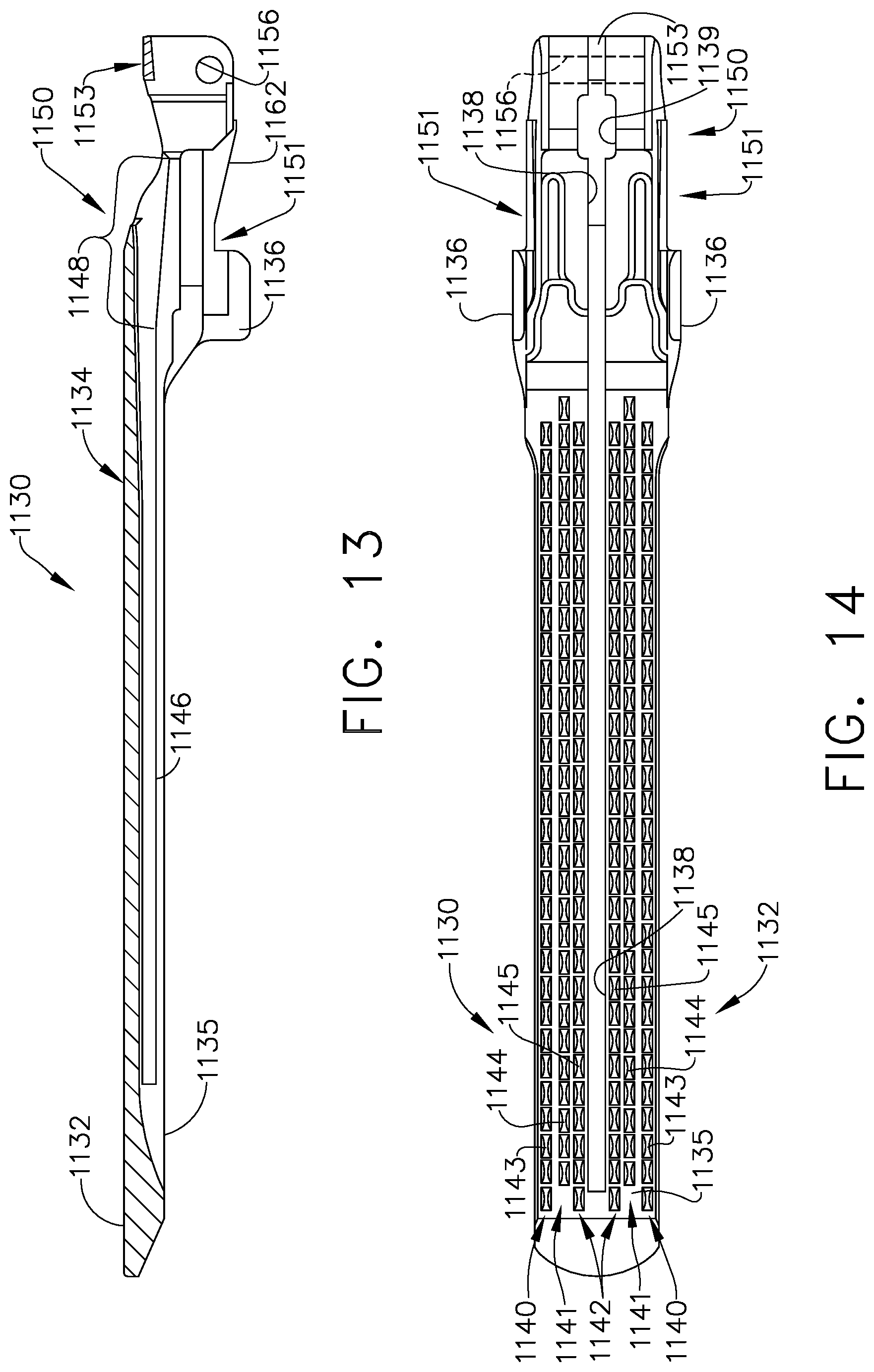
D00015

D00016

D00017

D00018

D00019

D00020

D00021

D00022
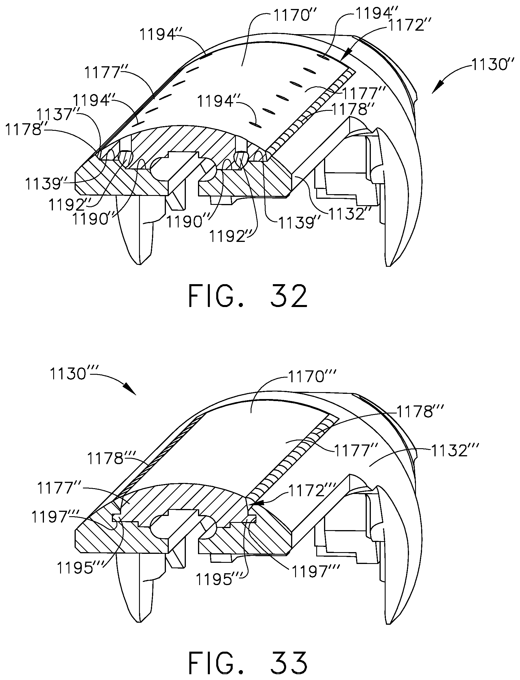
D00023
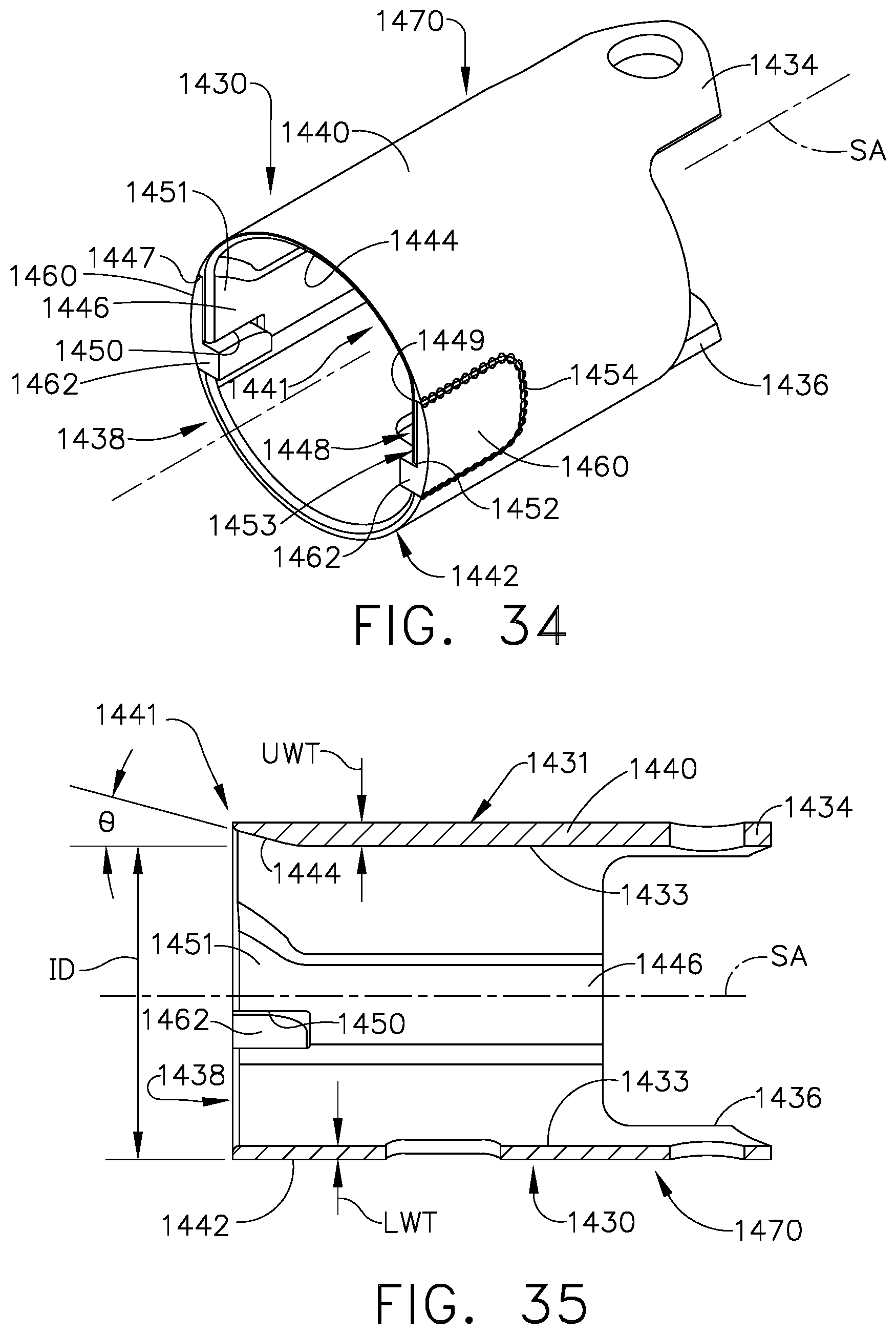
D00024

D00025

D00026

D00027

D00028

D00029

D00030
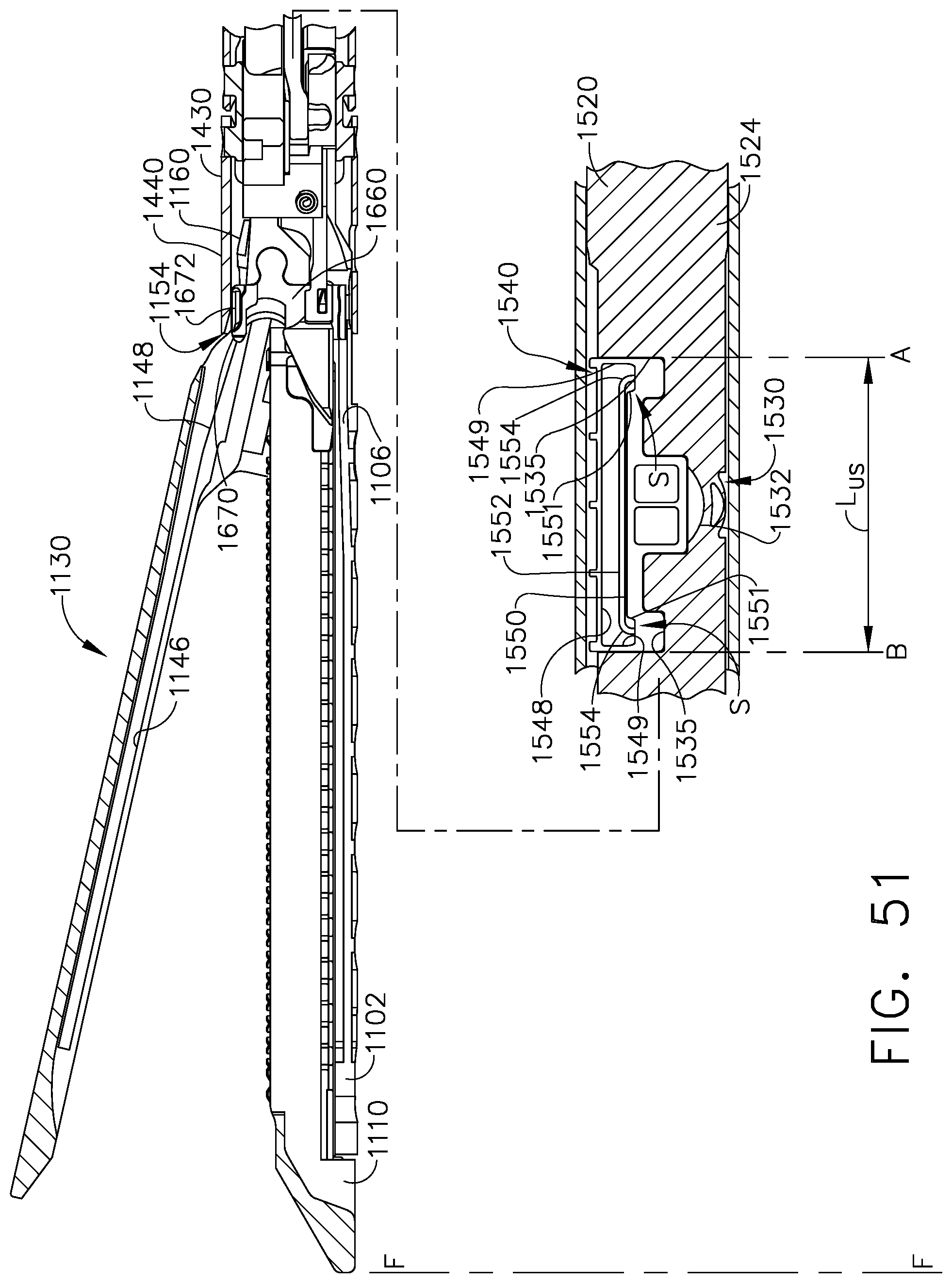
D00031

D00032

D00033

D00034

D00035

D00036

D00037

D00038

D00039

D00040
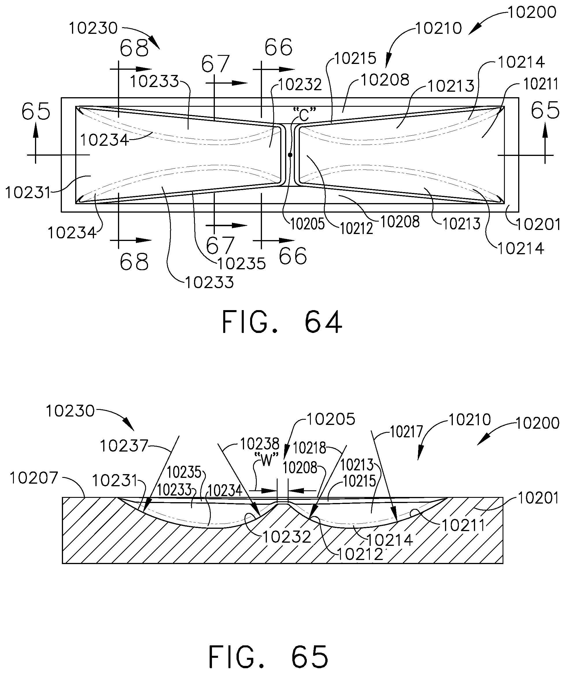
D00041

D00042

D00043

D00044

D00045

D00046

D00047

D00048

D00049

D00050

D00051
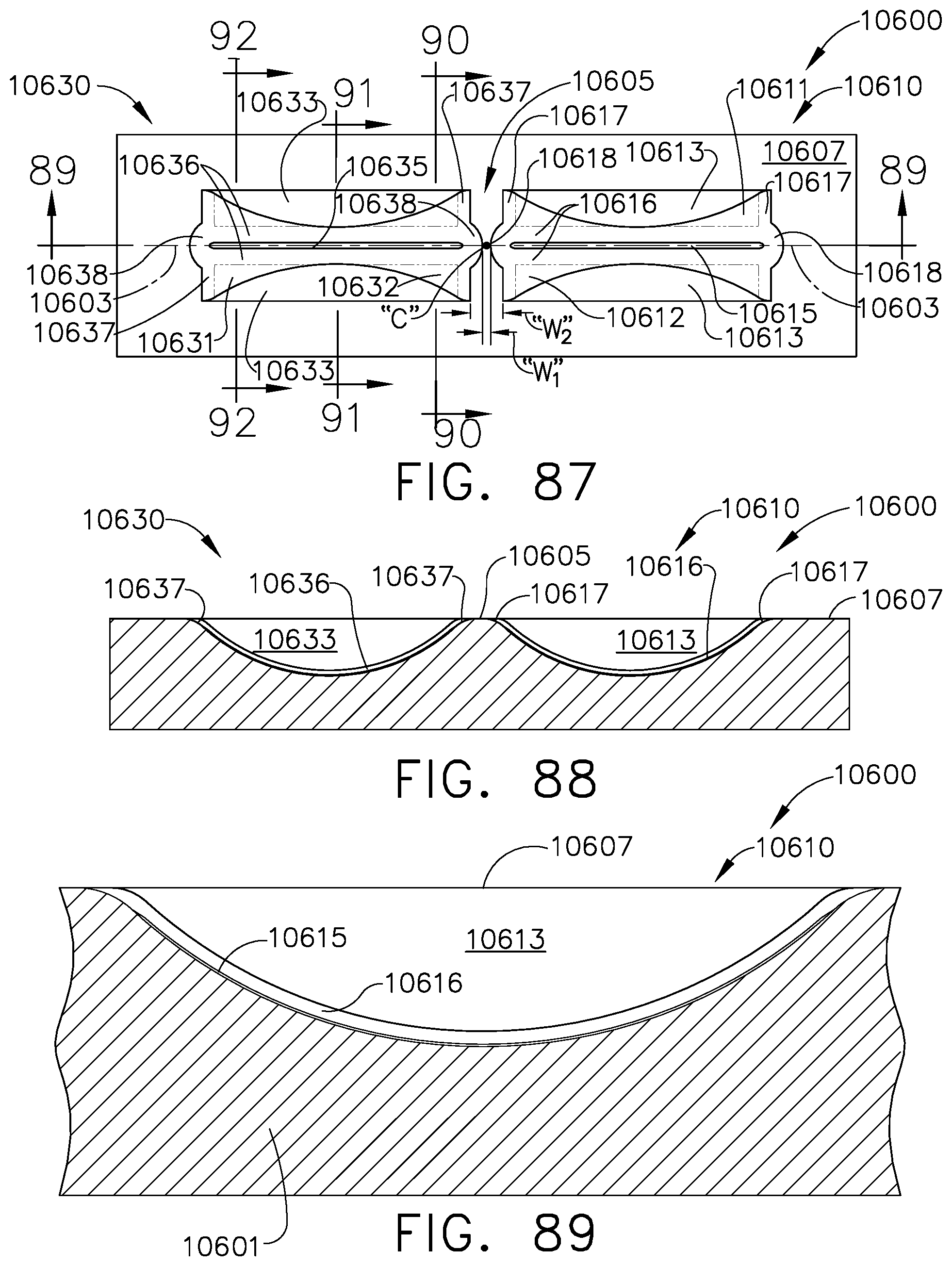
D00052

D00053
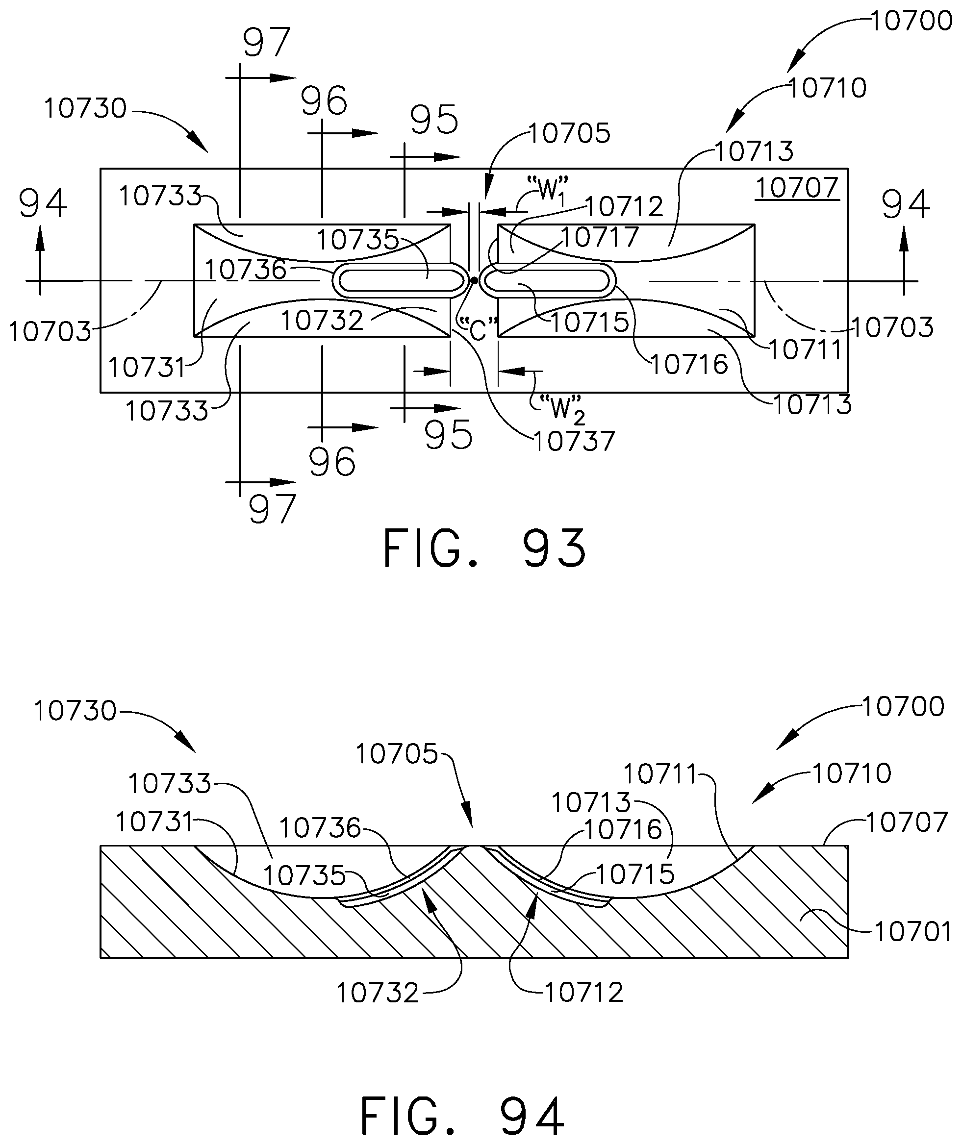
D00054

D00055

D00056

D00057

D00058

D00059

D00060

D00061
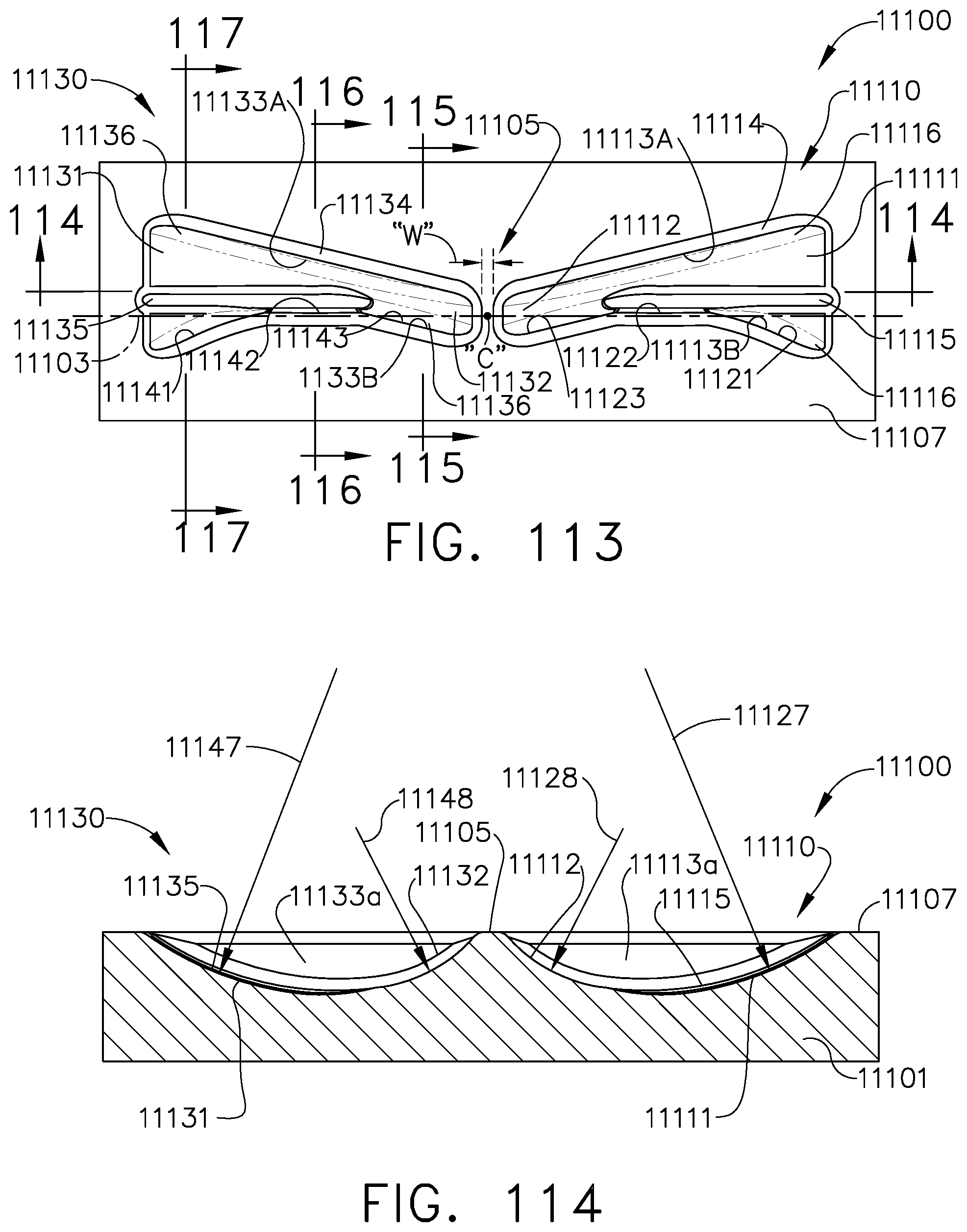
D00062

D00063

D00064

D00065

D00066

D00067
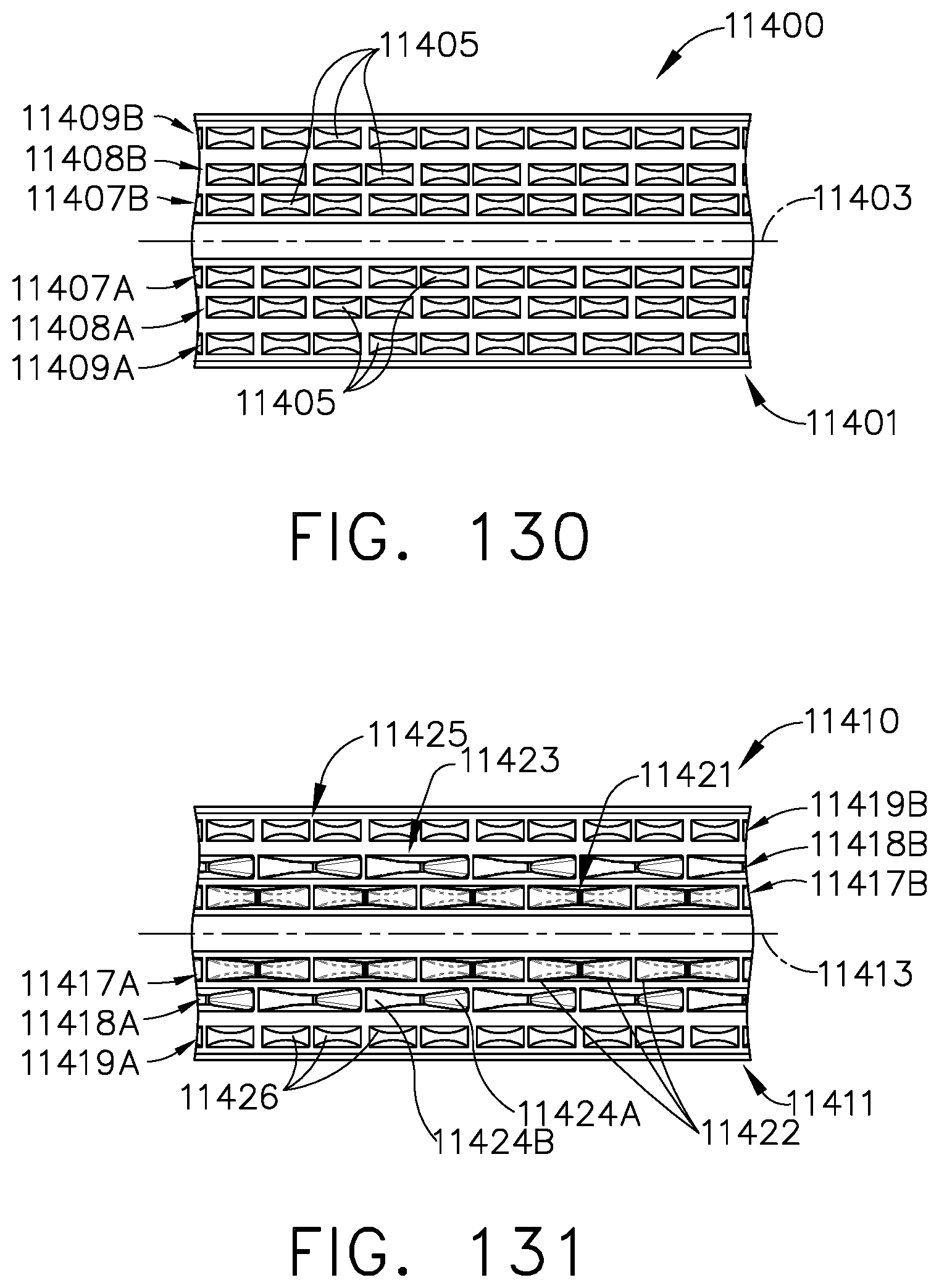
D00068
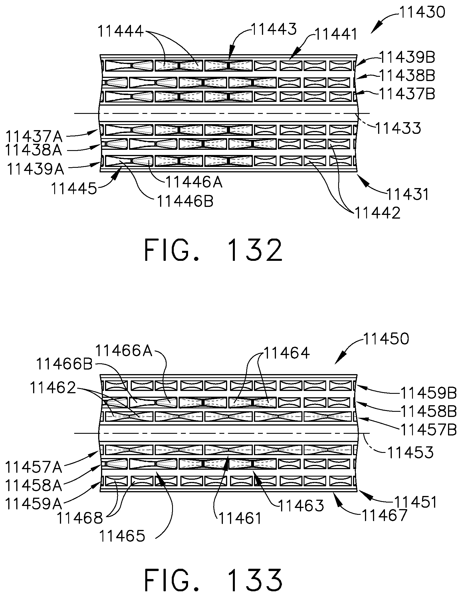
D00069

D00070

D00071

D00072

D00073

D00074
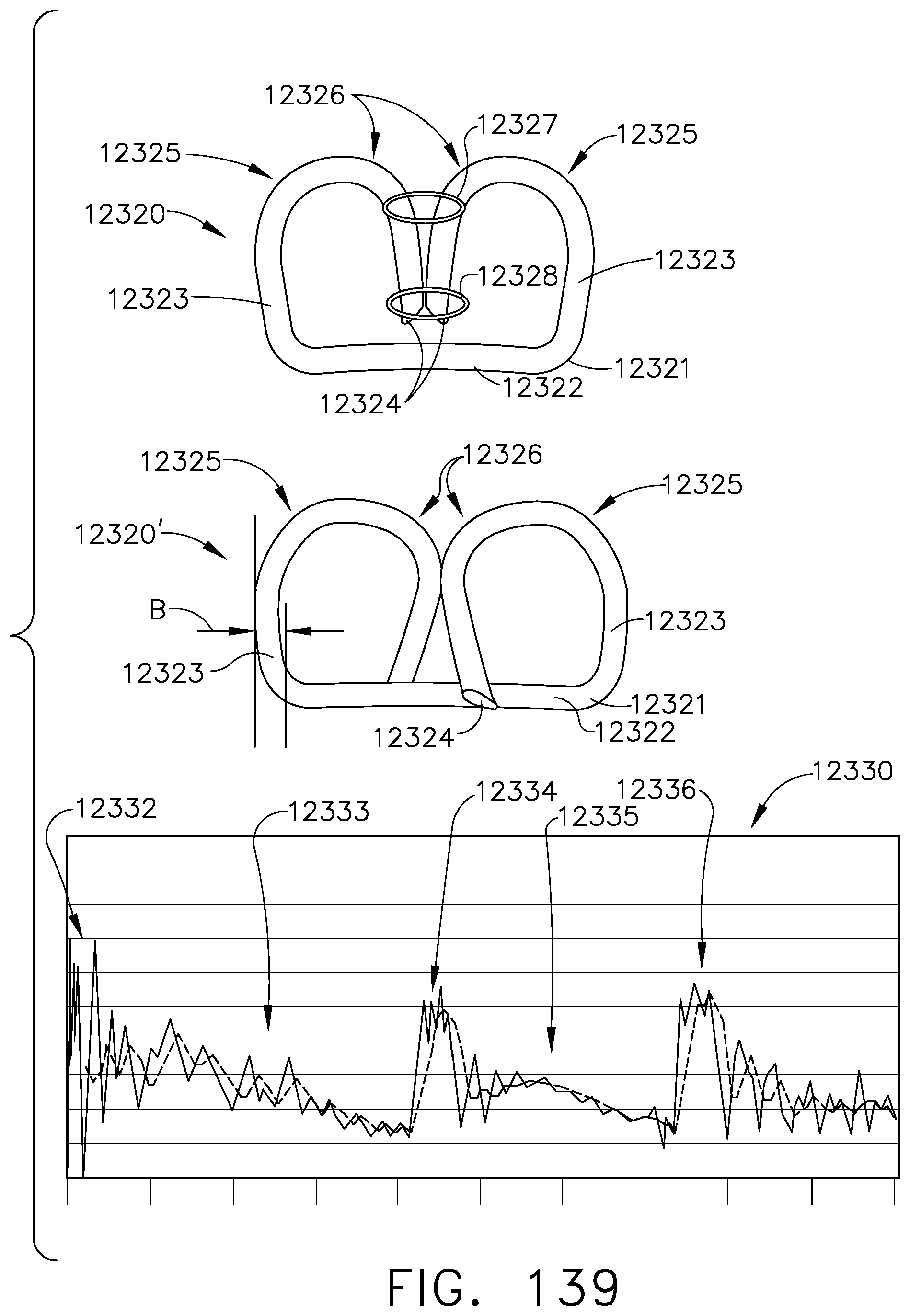
D00075

D00076

D00077

D00078

D00079

D00080

D00081

D00082

D00083
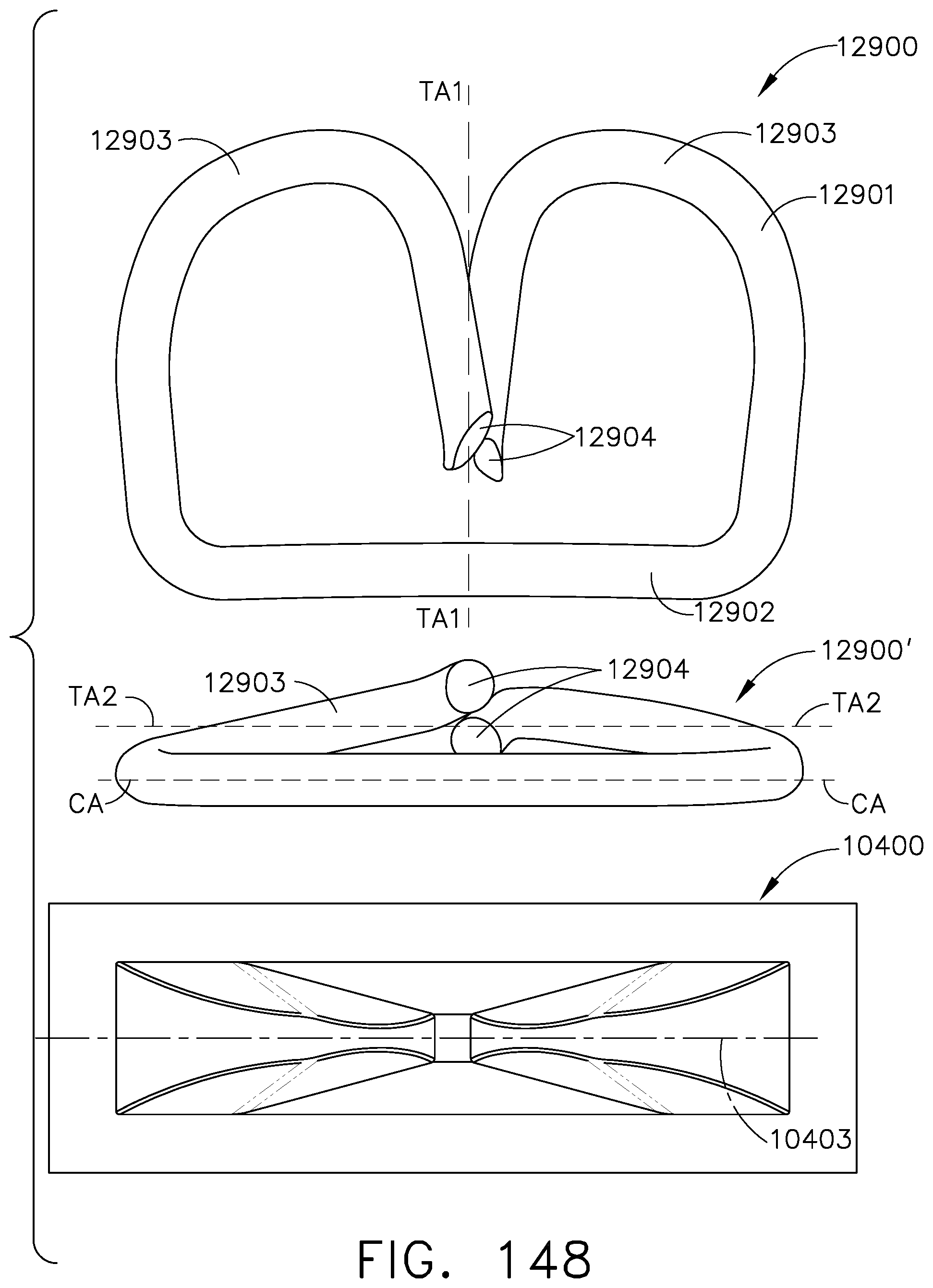
D00084

D00085
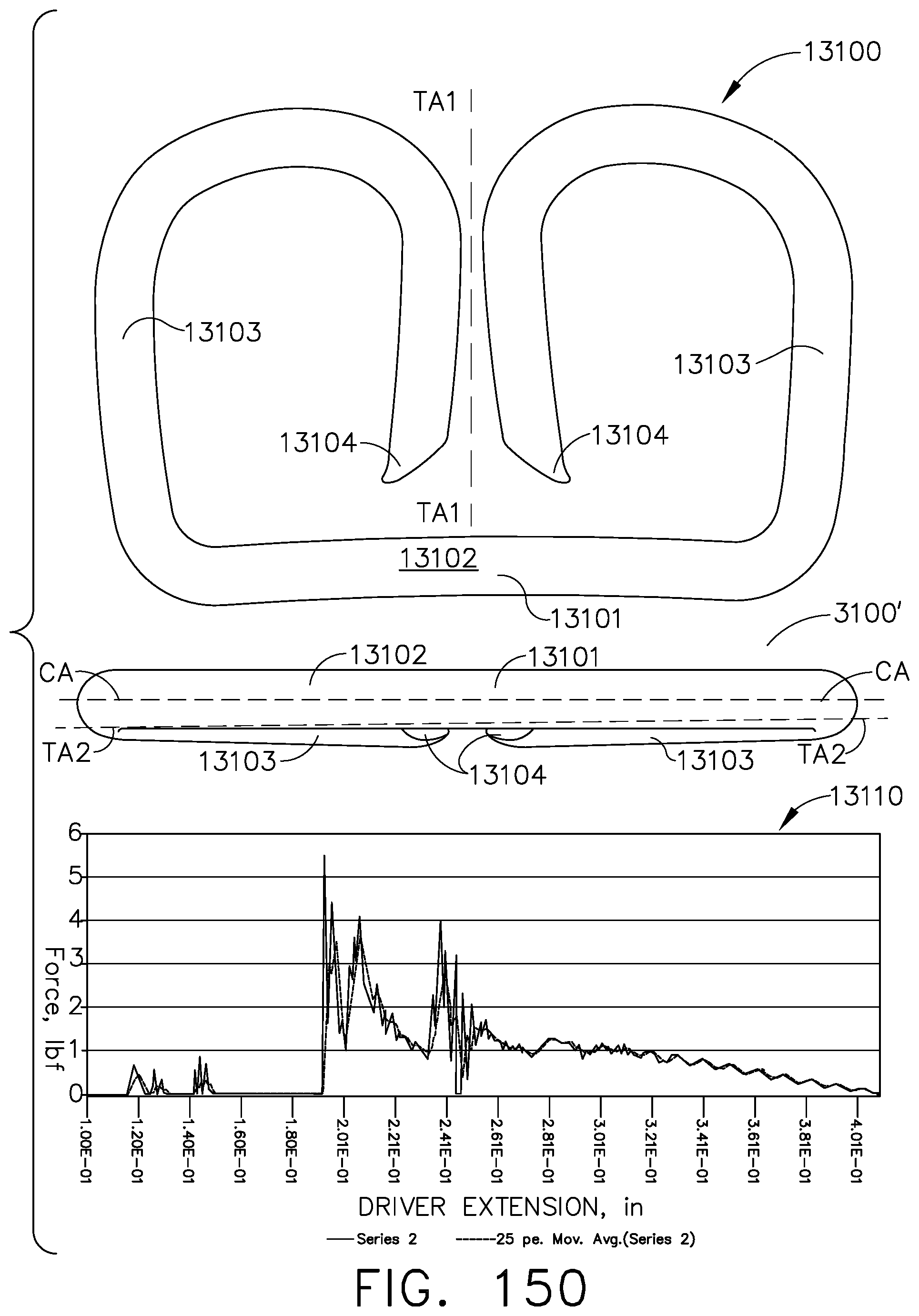
D00086

D00087

D00088

D00089

D00090

XML
uspto.report is an independent third-party trademark research tool that is not affiliated, endorsed, or sponsored by the United States Patent and Trademark Office (USPTO) or any other governmental organization. The information provided by uspto.report is based on publicly available data at the time of writing and is intended for informational purposes only.
While we strive to provide accurate and up-to-date information, we do not guarantee the accuracy, completeness, reliability, or suitability of the information displayed on this site. The use of this site is at your own risk. Any reliance you place on such information is therefore strictly at your own risk.
All official trademark data, including owner information, should be verified by visiting the official USPTO website at www.uspto.gov. This site is not intended to replace professional legal advice and should not be used as a substitute for consulting with a legal professional who is knowledgeable about trademark law.