Cartridge Assemblies For Surgical Staplers
Shelton, IV; Frederick E. ; et al.
U.S. patent application number 16/727160 was filed with the patent office on 2020-07-16 for cartridge assemblies for surgical staplers. The applicant listed for this patent is Ethicon LLC. Invention is credited to Jerome R. Morgan, Frederick E. Shelton, IV.
| Application Number | 20200222047 16/727160 |
| Document ID | / |
| Family ID | 54345608 |
| Filed Date | 2020-07-16 |


View All Diagrams
| United States Patent Application | 20200222047 |
| Kind Code | A1 |
| Shelton, IV; Frederick E. ; et al. | July 16, 2020 |
CARTRIDGE ASSEMBLIES FOR SURGICAL STAPLERS
Abstract
Surgical stapling devices are disclosed herein that improve on the disclosures of previous surgical stapling devices.
| Inventors: | Shelton, IV; Frederick E.; (Hillsboro, OH) ; Morgan; Jerome R.; (Cincinnati, OH) | ||||||||||
| Applicant: |
|
||||||||||
|---|---|---|---|---|---|---|---|---|---|---|---|
| Family ID: | 54345608 | ||||||||||
| Appl. No.: | 16/727160 | ||||||||||
| Filed: | December 26, 2019 |
Related U.S. Patent Documents
| Application Number | Filing Date | Patent Number | ||
|---|---|---|---|---|
| 14527384 | Oct 29, 2014 | 10517594 | ||
| 16727160 | ||||
| Current U.S. Class: | 1/1 |
| Current CPC Class: | A61B 2017/07242 20130101; A61B 2017/07235 20130101; A61B 2017/07271 20130101; A61B 2017/07278 20130101; A61B 2017/07228 20130101; A61B 17/07207 20130101; A61B 2017/07214 20130101; A61B 17/0644 20130101; A61B 2017/07257 20130101; A61B 2017/320044 20130101 |
| International Class: | A61B 17/072 20060101 A61B017/072 |
Claims
1. An end effector for a surgical stapling instrument, the end effector comprising: a staple cartridge, comprising: a cartridge body including a proximal end portion and a distal end portion; an elongate slot extending between the proximal end portion and the distal end portion; a tissue supporting portion, comprising: a first tissue supporting surface; a second tissue supporting surface, wherein the second tissue supporting surface is stepped up from the first tissue supporting surface; and a third tissue supporting surface, wherein the third tissue supporting surface is stepped up from the second tissue supporting surface; a plurality of first staple cavities arranged in a first row on a lateral side of the elongate slot, wherein the first row extends along the first tissue supporting surface; a plurality of second staple cavities arranged in a second row on the lateral side of the elongate slot, wherein the second row is closer to the elongate slot than the first row, and wherein the second row extends along the second tissue supporting surface; a plurality of third staple cavities arranged in a third row on the lateral side of the elongate slot, wherein the third row is closer to the elongate slot than the second row, and wherein the third row extends along the third tissue supporting surface; a set of staples, comprising: a first staple removably stored in the first row of staple cavities, wherein the first staple comprises a first unformed height; a second staple removably stored in the second row of staple cavities, wherein the second staple comprises a second unformed height smaller than the first unformed height; and a third staple removably stored in the third row of staple cavities, wherein the third staple comprises a third unformed height smaller than the second unformed height, wherein the set of staples are arranged in a first staggered arrangement, wherein the third staple is closer to the distal end portion than the second staple, and wherein the second staple is closer to the distal end portion than the first staple; and a staple pusher system movable to simultaneously deploy the set of staples, wherein the staple pusher system includes a plurality of independent pusher members, comprising: a first pusher member configured to lift the first staple; a second pusher member configured to lift the second staple; and a third pusher member configured to lift the third staple, wherein the plurality of pusher members are arranged in a second staggered arrangement corresponding to the first staggered arrangement, wherein the third pusher member is closer to the distal end portion than the second pusher member, wherein the second pusher member is closer to the distal end portion than the first pusher member, wherein the first pusher member is coupled to the second pusher member, and wherein the third pusher member is separated from the first pusher member and the second pusher member.
2. The end effector of claim 1, wherein the staple cartridge comprises a firing member movable to drive the plurality of pusher members to deploy the set of staples, and wherein the third pusher member is driven by the firing member faster than the first pusher member and the second pusher member.
3. The end effector of claim 2, wherein the third staple is fully-formed prior to the first staple and the second staple being fully-formed.
4. The end effector of claim 3, wherein the first staple and the second staple are fully-formed simultaneously.
5. The end effector of claim 2, wherein the staple pusher system comprises: a first camming portion attached to the first pusher member and the second pusher member; and a second camming portion attached to the third pusher member, wherein the second camming portion is independently movable from the first camming portion.
6. An end effector for a surgical stapling instrument, the end effector comprising: a staple cartridge, comprising: a cartridge body including a proximal end portion and a distal end portion; an elongate slot extending between the proximal end portion and the distal end portion; a tissue supporting portion, comprising: a first tissue supporting surface; a second tissue supporting surface, wherein the second tissue supporting surface is stepped up from the first tissue supporting surface; and a third tissue supporting surface, wherein the third tissue supporting surface is stepped up from the second tissue supporting surface; a plurality of first staple cavities arranged in a first row on a lateral side of the elongate slot, wherein the first row extends along the first tissue supporting surface; a plurality of second staple cavities arranged in a second row on the lateral side of the elongate slot, wherein the second row is closer to the elongate slot than the first row, and wherein the second row extends along the second tissue supporting surface; a plurality of third staple cavities arranged in a third row on the lateral side of the elongate slot, wherein the third row is closer to the elongate slot than the second row, and wherein the third row extends along the third tissue supporting surface; a set of staples, comprising: a first staple removably stored in the first row of staple cavities, wherein the first staple comprises a first unformed height; a second staple removably stored in the second row of staple cavities, wherein the second staple comprises a second unformed height smaller than the first unformed height; and a third staple removably stored in the third row of staple cavities, wherein the third staple comprises a third unformed height smaller than the second unformed height, wherein the first staple and the second staple are laterally aligned with each other, wherein the third staple is closer to the distal end portion than the first staple and the second staple, and wherein the set of staples are fully-formed simultaneously; and a staple pusher system movable to simultaneously deploy the set of staples, wherein the staple pusher system includes a plurality of independent pusher members, comprising: a first pusher member configured to lift the first staple; a second pusher member configured to lift the second staple; and a third pusher member configured to lift the third staple, wherein the first pusher member and the second pusher member are laterally aligned with each other, and wherein the third pusher member is closer to the distal end portion than the first pusher member and the second pusher member.
7. The end effector of claim 6, wherein the staple pusher system comprises: a first camming portion attached to the first pusher member and the second pusher member; and a second camming portion attached to the second pusher member and the third pusher member.
8. An end effector for a surgical stapling instrument, the end effector comprising: a staple cartridge, comprising: a cartridge body including a proximal end portion and a distal end portion; an elongate slot extending between the proximal end portion and the distal end portion; a tissue supporting portion, comprising: a first tissue supporting surface; a second tissue supporting surface, wherein the second tissue supporting surface is stepped up from the first tissue supporting surface; and a third tissue supporting surface, wherein the third tissue supporting surface is stepped up from the second tissue supporting surface; a plurality of first staple cavities arranged in a first row on a lateral side of the elongate slot, wherein the first row extends along the first tissue supporting surface; a plurality of second staple cavities arranged in a second row on the lateral side of the elongate slot, wherein the second row is closer to the elongate slot than the first row, and wherein the second row extends along the second tissue supporting surface; a plurality of third staple cavities arranged in a third row on the lateral side of the elongate slot, wherein the third row is closer to the elongate slot than the second row, and wherein the third row extends along the third tissue supporting surface; a set of staples, comprising: a first staple removably stored in the first row of staple cavities, wherein the first staple comprises a first unformed height; a second staple removably stored in the second row of staple cavities, wherein the second staple comprises a second unformed height smaller than the first unformed height; and a third staple removably stored in the third row of staple cavities, wherein the third staple comprises a third unformed height smaller than the second unformed height, wherein the second staple and the third staple are laterally aligned with each other, wherein the first staple is further away from the distal end portion than the second staple and the third staple, and wherein the set of staples are fully-formed simultaneously; and a staple pusher system movable simultaneously to deploy the set of staples, wherein the staple pusher system includes a plurality of independent pusher members, comprising: a first pusher member configured to lift the first staple; a second pusher member configured to lift the second staple; and a third pusher member configured to lift the third staple, wherein the second pusher member and the third pusher member are laterally aligned with each other, and wherein the first pusher member is further away from the distal end portion than the second pusher member and the third pusher member.
9. The end effector of claim 8, wherein the staple pusher system comprises: a first camming portion attached to the first pusher member and the second pusher member; and a second camming portion attached to the second pusher member and the third pusher member.
10-20. (canceled)
Description
CROSS-REFERENCE TO RELATED APPLICATION
[0001] This application is a divisional application claiming priority under 35 U.S.C. .sctn. 121 to U.S. patent application Ser. No. 14/527,384, entitled CARTRIDGE ASSEMBLIES FOR SURGICAL STAPLERS, filed Oct. 29, 2014, now U.S. Patent Application Publication No. 2016/0120544, the entire disclosure of which is hereby incorporated by reference herein.
BACKGROUND
[0002] The present invention relates to stapling instruments and, in various embodiments, to a surgical stapling instrument for producing one or more rows of staples.
[0003] A stapling instrument can include a pair of cooperating elongate jaw members, wherein each jaw member can be adapted to be inserted into a patient and positioned relative to tissue that is to be stapled and/or incised. In various embodiments, one of the jaw members can support a staple cartridge with at least two laterally spaced rows of staples contained therein, and the other jaw member can support an anvil with staple-forming pockets aligned with the rows of staples in the staple cartridge. Generally, the stapling instrument can further include a pusher bar and a knife blade which are slidable relative to the jaw members to sequentially eject the staples from the staple cartridge via camming surfaces on the pusher bar and/or camming surfaces on a wedge sled that is pushed by the pusher bar. In at least one embodiment, the camming surfaces can be configured to activate a plurality of staple drivers carried by the cartridge and associated with the staples in order to push the staples against the anvil and form laterally spaced rows of deformed staples in the tissue gripped between the jaw members. In at least one embodiment, the knife blade can trail the camming surfaces and cut the tissue along a line between the staple rows. Examples of such stapling instruments are disclosed in U.S. Pat. No. 7,794,475, entitled SURGICAL STAPLES HAVING COMPRESSIBLE OR CRUSHABLE MEMBERS FOR SECURING TISSUE THEREIN AND STAPLING INSTRUMENTS FOR DEPLOYING THE SAME, the entire disclosure of which is hereby incorporated by reference herein.
BRIEF DESCRIPTION OF THE DRAWINGS
[0004] Various features of the embodiments described herein are set forth with particularity in the appended claims. The various embodiments, however, both as to organization and methods of operation, together with advantages thereof, may be understood in accordance with the following description taken in conjunction with the accompanying drawings as follows:
[0005] FIG. 1 is a perspective view of a staple drive assembly showing an actuation sled and a staple pusher system in accordance with at least one embodiment;
[0006] FIG. 1A is a perspective view of a staple drive assembly showing an actuation sled and a staple pusher system in accordance with at least one embodiment;
[0007] FIG. 1B is a perspective view of a staple drive assembly showing an actuation sled and a staple pusher system in accordance with at least one embodiment;
[0008] FIG. 1C is a perspective view of a staple drive assembly showing an actuation sled and a staple pusher system in accordance with at least one embodiment;
[0009] FIG. 1D is a perspective view of a staple drive assembly showing an actuation sled and a staple pusher system in accordance with at least one embodiment;
[0010] FIG. 1E is a perspective view of a staple drive assembly showing an actuation sled and a staple pusher system in accordance with at least one embodiment;
[0011] FIG. 2 is a perspective view of a surgical stapling apparatus in accordance with at least one embodiment;
[0012] FIG. 2A is a side elevational view of an alternative end effector of the surgical stapling apparatus of FIG. 2 in accordance with at least one embodiment;
[0013] FIG. 2B is a side elevational view of the end effector FIG. 2A in a partially open configuration;
[0014] FIG. 2C is a perspective view of an end effector of the surgical stapling apparatus of FIG. 2 in accordance with at least one embodiment;
[0015] FIG. 2D is a cross sectional view of the end effector of FIG. 2C in a closed configuration in accordance with at least one embodiment;
[0016] FIG. 3 is an exploded perspective view of a staple cartridge, staples, staple pushers, and an actuation sled in accordance with at least one embodiment;
[0017] FIG. 3A is an exploded perspective view of a staple cartridge, staples, and staple pushers in accordance with at least one embodiment;
[0018] FIG. 3B is a side perspective view of staples and a staple pusher in accordance with at least one embodiment;
[0019] FIG. 3C is a side elevational view of a "V" shaped staple in accordance with at least one embodiment;
[0020] FIG. 3D is a side elevational view of a "U" shaped staple in accordance with at least one embodiment;
[0021] FIG. 3E is a perspective view of a "U" shaped staple positioned onto a staple pusher plate in accordance with at least one embodiment;
[0022] FIG. 3F is a perspective view of a "U" shaped staple positioned onto a staple pusher plate in accordance with at least one embodiment;
[0023] FIG. 3G is a partial cross-sectional view of a "U" shaped staple and the staple pusher plate before the "U" shaped staple is positioned onto the staple pusher plate;
[0024] FIG. 3H is a partial cross-sectional view of the "U" shaped staple and the staple pusher plate of FIG. 3G while the "U" shaped staple is positioned onto the staple pusher plate;
[0025] FIG. 3I is a partial perspective view of a staple deposited in a retention slot in accordance with at least one embodiment;
[0026] FIG. 3J is a partial cross-sectional view of along the line 3J-3J of FIG. 31;
[0027] FIG. 4 is a top plan view of the staple cartridge of FIG. 3 with the actuation sled in an initial position;
[0028] FIG. 5 is a side cross-sectional view of a proximal portion of the staple cartridge taken along section line 5-5 of FIG. 4;
[0029] FIG. 6 is a front perspective view of the staple pusher of FIG. 1;
[0030] FIG. 7 is a rear perspective view of the staple pusher of FIG. 1;
[0031] FIG. 8 is a top plan view of the staple pusher of FIG. 1;
[0032] FIG. 9 is a side cross-sectional view taken along section line 9-9 of FIG. 8;
[0033] FIG. 10 is a side cross-sectional view taken along section line 10-10 of FIG. 8;
[0034] FIG. 11 is a front perspective view of the actuation sled of FIG. 1;
[0035] FIG. 12 is a rear perspective view of the actuation sled of FIG. 1;
[0036] FIG. 13 is a top plan view of the actuation sled of FIG. 1;
[0037] FIG. 14 is a side cross-sectional view taken along section line 14-14 of FIG. 13;
[0038] FIG. 15 is a side cross-sectional view taken along section line 15-15 of FIG. 13;
[0039] FIG. 16 is a side cross-sectional view of the staple drive assembly of FIG. 1 showing the initial engagement between the cam members of the staple pusher of FIG. 6 and the cam wedges of the actuation sled as the actuation sled moves in the direction of arrow A;
[0040] FIG. 17 is a side cross-sectional view of the staple drive assembly of FIG. 1 showing the continued engagement between the cam members of the staple pusher of FIG. 6 and the cam wedges of the actuation sled as the actuation sled continues to move in the direction of arrow A; and
[0041] FIG. 18 is a top plan view taken along section line 18-18 in FIG. 17 of the staple drive assembly of FIG. 17.
[0042] Corresponding reference characters indicate corresponding parts throughout the several views. The exemplifications set out herein illustrate various embodiments of the invention, in one form, and such exemplifications are not to be construed as limiting the scope of the invention in any manner.
DETAILED DESCRIPTION
[0043] Applicant of the present application owns the following patent application which was filed on Oct. 29, 2014 and which is herein incorporated by reference in its entirety:
[0044] U.S. patent application Ser. No. 14/527,398, entitled STAPLE CARTRIDGES COMPRISING DRIVER ARRANGEMENTS, now U.S. Patent Application Publication No. 2016/0120545.
[0045] Numerous specific details are set forth to provide a thorough understanding of the overall structure, function, manufacture, and use of the embodiments as described in the specification and illustrated in the accompanying drawings. It will be understood by those skilled in the art, however, that the embodiments may be practiced without such specific details. In other instances, well-known operations, components, and elements have not been described in detail so as not to obscure the embodiments described in the specification. Those of ordinary skill in the art will understand that the embodiments described and illustrated herein are non-limiting examples, and thus it can be appreciated that the specific structural and functional details disclosed herein may be representative and illustrative. Variations and changes thereto may be made without departing from the scope of the claims.
[0046] The terms "comprise" (and any form of comprise, such as "comprises" and "comprising"), "have" (and any form of have, such as "has" and "having"), "include" (and any form of include, such as "includes" and "including") and "contain" (and any form of contain, such as "contains" and "containing") are open-ended linking verbs. As a result, a surgical system, device, or apparatus that "comprises," "has," "includes" or "contains" one or more elements possesses those one or more elements, but is not limited to possessing only those one or more elements. Likewise, an element of a system, device, or apparatus that "comprises," "has," "includes" or "contains" one or more features possesses those one or more features, but is not limited to possessing only those one or more features.
[0047] The terms "proximal" and "distal" are used herein with reference to a clinician manipulating the handle portion of the surgical instrument. The term "proximal" referring to the portion closest to the clinician and the term "distal" referring to the portion located away from the clinician. It will be further appreciated that, for convenience and clarity, spatial terms such as "vertical", "horizontal", "up", and "down" may be used herein with respect to the drawings. However, surgical instruments are used in many orientations and positions, and these terms are not intended to be limiting and/or absolute.
[0048] Various exemplary devices and methods are provided for performing laparoscopic and minimally invasive surgical procedures. However, the person of ordinary skill in the art will readily appreciate that the various methods and devices disclosed herein can be used in numerous surgical procedures and applications including, for example, in connection with open surgical procedures. As the present Detailed Description proceeds, those of ordinary skill in the art will further appreciate that the various instruments disclosed herein can be inserted into a body in any way, such as through a natural orifice, through an incision or puncture hole formed in tissue, etc. The working portions or end effector portions of the instruments can be inserted directly into a patient's body or can be inserted through an access device that has a working channel through which the end effector and elongated shaft of a surgical instrument can be advanced.
[0049] The present disclosure is directed toward a staple drive assembly for use in a staple cartridge. The staple drive assembly may also be used in a disposable loading unit and/or any other suitable device and can be configured to deploy numerous types of staples and/or fasteners. The staple drive assembly includes an actuation sled and at least one staple driver. The staple cartridge includes a tissue contacting and/or supporting surface having a number of staple cavities wherein each staple cavity is adapted for releasably receiving a staple. The staple cartridge may include a guide channel / knife slot extending from a proximal portion to a distal portion along its longitudinal axis. In one embodiment, the staple cartridge is adapted for use in a surgical stapler having a drive mechanism.
[0050] An example of a surgical stapler having a staple drive assembly is disclosed in U.S. Pat. No. 6,669,073, entitled SURGICAL STAPLING APPARATUS, which issued on Dec. 30, 2003, the entire disclosure of which is incorporated herein by reference. The disclosures of U.S. Pat. No. 7,866,528, entitled STAPLE DRIVE ASSEMBLY, filed Jan. 11, 2011 and U.S. Patent Application Publication No. 2013/0327810, entitled FASTENER CARTRIDGE ASSEMBLY COMPRISING A FIXED ANVIL AND A STAPLE DRIVER ARRANGEMENT, filed Aug. 15, 2013, now U.S. Pat. No. 9,839,427, are also hereby incorporated by reference herein in their entireties.
[0051] A staple drive assembly 100, in accordance with one embodiment of the present disclosure, is illustrated in FIG. 1. The staple drive assembly 100 includes an actuation sled 110 and at least one staple pusher arrangement or system 160. The actuation sled 110 includes a base 112, a first camming member 120, a second camming member 140, and a guide member 150. The first and second camming members 120 and 140 include respective first or leading cam wedges 122 and 142 and respective second or trailing cam wedges 124 and 144. In one embodiment, staple drive assembly 100 is adapted for use in a surgical stapler having at least two linear rows of staples such as an endoscopic or laparoscopic stapler.
[0052] Referring to FIG. 2, a surgical stapler 10 is shown. The surgical stapler 10 includes a trigger assembly 30, a body portion 12, a staple cartridge 40, and an anvil assembly 70. Trigger assembly 30 includes a pivotal trigger 32. Pivotal movement of the trigger 32 during an actuation sequence of the trigger 32 translates pivotal movement of the trigger 32 into linear movement of a drive mechanism (not shown). The drive mechanism is operatively coupled to an actuation sled in the staple cartridge 40 to translate linear movement of the drive mechanism to linear movement of the actuation sled. The surgical stapler 10 is movable such that a portion of body tissue (not shown) may be positioned between the anvil assembly 70 and the staple cartridge 40. Actuation of stapler 10 moves anvil assembly 70 towards staple cartridge 40 thereby grasping or retaining the portion of body tissue therebetween. In addition, once the portion of body tissue is grasped between the anvil assembly 70 and the staple cartridge 40, continued actuation of stapler 10 discharges staples 50 (FIG. 3) through the portion of body tissue and against the anvil assembly 70 to form completed staples 50.
[0053] A staple drive assembly such as, for example, the staple drive assembly 100 (FIG. 1), the staple drive assembly 200 (FIG. 1A), the staple drive assembly 300 (FIG. 1B), the staple drive assembly 400 (FIG. 1C), the staple drive assembly 700 (FIG. 1D), the staple drive assembly 800 (FIG. 1E) may be incorporated into the staple cartridge 40 of surgical stapler 10. Alternately, the staple drive assembly 100, 200, 300, 400, 700, and/or 800 may be incorporated into other known stapling devices including open-type surgical stapling devices and other endoscopic or laparoscopic surgical stapling devices, for example. While the present disclosure describes embodiments involving an actuation sled, it also will be appreciated that the design characteristics and function of the sled camming members may be incorporated directly into cam bars or firing wedges, which in turn are connected to the firing mechanism of the surgical stapling instrument.
[0054] FIG. 3 illustrates a staple cartridge 40' including the staple drive assembly 100. The staple cartridge 40' includes a plurality of fasteners or staples 50 and a corresponding number of staple pockets or retention slots 60. A tissue contacting and/or supporting surface 44 is defined by a top surface of the staple cartridge 40'. A guide channel 42 extends substantially the length of staple cartridge 40' and is adapted for slidably receiving guide member 150 of actuation sled 110 as shown in FIG. 4. In FIG. 4, sled 110 is shown positioned at the proximal end of the staple cartridge 40' with the guide member 150 disposed in the guide channel 42. The guide channel 42 cooperates with the guide member 150 for aligning and positioning the actuation sled 110 in the staple cartridge 40' as it translates longitudinally from a proximal end to a distal end of the staple cartridge 40'. Guide channel 42 may also facilitate passage of a knife blade (not shown) through the staple cartridge 40'. In various instances, a knife blade can be mounted to the guide member 150.
[0055] In FIG. 5, which is a cross-sectional view taken along line 5-5 of FIG. 4, the actuation sled 110 is shown disposed in the proximal end of staple cartridge 40' in a first or ready position, for example. In the ready position, the actuation sled 110 is capable of translating distally through the staple cartridge 40', in the direction indicated by arrow A, and sequentially engaging the staple pushers 160 (FIG. 3). The actuation sled 110 is translatable along a longitudinal axis of the staple cartridge 40' from its ready position to a second or end position located in a distal portion of the staple cartridge 40'.
[0056] As previously discussed, the staple pusher 160 includes prongs or pusher plates 166 that are laterally and longitudinally spaced apart as well as first and second cam members 162, 164 interposed between adjacent pusher plates 166. More specifically, as discussed hereinabove, in one embodiment of the present disclosure, each staple pusher 160 includes a plurality of independent pusher plates 166 that are substantially parallel to a longitudinal axis of staple cartridge 40' and parallel to a centerline CL of each staple pusher 160 (FIG. 8). Additionally, first and second cam members or portions162, 164 are also substantially parallel to centerline CL (FIG. 8).
[0057] Staple pusher 160, as viewed from left to right in FIG. 8 (i.e. distal to proximal), includes an inboard pusher plate 166 that is most distal along centerline CL. A middle pusher plate 166 is laterally spaced apart from inboard pusher plate 166 and is axially offset in the proximal direction from inboard pusher plate 166. An outboard pusher plate 166 is laterally spaced apart from middle pusher plate 166 and is axially offset in the proximal direction from middle pusher plate 166. Further still, first cam member 162 is disposed between inboard pusher plate 166 and middle pusher plate 166 while second cam member 164 is disposed between middle pusher plate 166 and outboard pusher plate 166. Configured thusly, staple pusher 160 has an arrangement where pusher plates 166 are longitudinally staggered from a distal portion of staple pusher 160 to a proximal portion of staple pusher 160 as seen in FIG. 8. An outboard pusher plate 166 is closer to a distal portion of a staple cartridge that incorporates the staple pusher 160 than a middle pusher plate 166 and the middle pusher plate 166 is closer to the distal portion of the staple cartridge than the inboard pusher plate 166, for example.
[0058] First and second cam members 162, 164 include respective first and second cam surfaces 162a, 162b, and 164a, 164b (FIGS. 9 and 10). At the intersection of first and second cam surfaces 162a, 162b and 164a, 164b are respective transition points 162c, 164c. A plane T (FIG. 10) extending through transition points 162c, 164c is parallel to respective tops 163, 165 of cam members 162, 164. In one embodiment, first cam surfaces 162a, 164a define a first engagement or receiving angle with respect to tops 163, 165 of respective first and second cam members 162, 164. Second cam surfaces 162b, 164b define a second engagement or receiving angle with respect to plane T. First and second receiving angles are complementary to respective first and second drive angles of camming members 120, 140 of actuation sled 110.
[0059] With reference to FIGS. 11-15, several views of one embodiment of actuation sled 110 are shown. First and second camming members 120, 140 each include a first or leading cam wedge 122, 142, respectively, that is laterally and longitudinally spaced apart from a second or trailing cam wedge 124, 144, respectively. The lateral and longitudinal offset distances of each pair of camming wedges substantially corresponds to the lateral and longitudinal offset distances between corresponding cam members 162, 164. First cam wedges 122, 142 are laterally and longitudinally spaced from second cam wedges 124, 144, respectively, by a substantially identical amount such that first and second camming members 120, 140 are symmetrical about a central longitudinal axis of actuation sled 110. Leading cam wedges 122, 142 include respective first and second drive faces 122a, 122b, 142a, and 142b. First drive faces 122a, 142a form first drive angles on camming members 120, 140 with respect to base 112 of actuation sled 110. At the intersection of first and second drive faces 122a, 142a and 122b, 142b are respective transition points 123, 143. A plane X extending through transition points 123, 143 is substantially parallel to base 112. Second drive faces 122b, 142b form respective second drive angles on camming members 120, 140 with respect to plane X. Plane X is also substantially parallel to tissue contacting surface 44 of staple cartridge 40'.
[0060] Similarly, trailing cam wedges 124, 144 include respective first and second drive faces 124a, 124b, 144a, and 144b. First drive faces 124a, 144a form first drive angles on camming members 120, 140 with respect to base 112 (FIG. 5) of actuation sled 110. At the intersection of first and second drive faces 124a, 124b and 144a, 144 b are respective transition points 125, 145. Plane X extends through transition points 125, 145 and is substantially parallel to base 112. Second drive faces 124b, 144b form respective second drive angles on camming members 120, 140 with respect to plane X.
[0061] Interaction between the actuation sled 110 and the staple pusher 160 of the staple drive assembly 100 is shown in FIGS. 16-18 and discussed in detail hereinafter. The interactions between actuation sleds of other staple drive assemblies described hereinafter and their corresponding staple pushers can be the same or, or at least similar, in many respects to the interaction between the actuation sled 110 and the staple pusher 160. Accordingly, for the sake of brevity, the detailed description of such interactions is omitted.
[0062] Initially, as illustrated in FIG. 16, actuation sled 110 translates distally through staple cartridge 40' in the direction indicated by arrow A (see also FIG. 5) causing first drive face 122a to slidably engage first cam surface 162a and urge staple pusher 160 from its first or rest position in a generally vertical direction as indicated by arrow B. Because the lateral and longitudinal offset distances of wedges 122, 124 correspond to the lateral and longitudinal offset distances between cam wedges 162, 164, first drive face 124a substantially simultaneously slidably engages first cam surface 164a thereby urging staple pusher 160 in a generally vertical direction as indicated by arrow B. Since cam surfaces 162a and 164a are longitudinally offset, staple pusher 160 is driven in a controlled and balanced manner and any tendency of staple pusher 160 to tilt or rotate counterclockwise (as viewed in FIGS. 16-17) is minimized as staple pusher 160 is driven through retainer slot 60. First drive faces 122a, 124a and respective first cam surfaces 162a, 164a have complementary angles that maximize translation of longitudinal motion of actuation sled 110 to vertical motion of staple pusher 160.
[0063] Referring now to FIG. 17, continued distal movement of actuation sled 110 further urges staple pusher 160 generally vertically to an intermediate position, such that second drive faces 122b, 124b slidably engage respective second cam surfaces 162b, 164b while first drive faces 122a, 124a substantially simultaneously disengage from respective first cam surfaces 162a, 164a. Similarly, second drive faces 122b, 124b and respective second cam surfaces 162b, 164b have complementary angles to maximize translation of longitudinal motion of actuation sled 110 to vertical motion of staple pusher 160. The corresponding lateral and longitudinal offset of second drive faces 122b, 124b and respective second cam surfaces 162b, 164b continue to control the advancement of staple pusher 160 so as to minimize any tendency of staple pusher 160 to tilt or rotate in a counterclockwise direction as viewed in FIGS. 16 and 17. Continuing distal movement of actuation sled 110 continues to urge staple pusher 160 vertically to its second or end position immediately prior to the disengagement between second drive faces 122b, 124b and respective second cam surfaces 162b, 164b.
[0064] Further to the above, longitudinal motion of actuation sled 110 in the direction indicated by arrow A results in first and second camming members 120, 140 slidably engaging staple pushers 160 as shown in FIGS. 16-18. Sliding engagement between leading cam wedges 122, 142 and first cam members 162 in cooperation with the substantially simultaneous engagement between trailing cam wedges 124, 144 and second cam members 164 improve the longitudinal stability of the staple pushers 160 during vertical motion as follows. Leading cam wedges 122, 142 are longitudinally spaced apart from trailing cam wedges 124, 144 by a predetermined amount. Since respective first and second cam members 162, 164 are longitudinally spaced apart by a comparable, but complementary amount, longitudinal movement of actuation sled 110 results in the substantially simultaneous, but offset engagement of leading cam wedges 122, 124 and trailing cam wedges 124, 144 with respective first and second cam members 162, 164 thereby transferring the longitudinal movement of actuation sled 110 to vertical movement of staple pusher 160 at longitudinally spaced apart impact points.
[0065] Referring to FIG. 3A, a staple cartridge 2140 includes a tissue contacting and/or supporting portion 2161. The tissue contacting portion 2161 includes three tissue contacting and/or supporting surfaces 2161a-2161c. Tissue contacting surfaces 2161a-2161c are planar, or at least substantially planar, structures that are substantially parallel to one another, but are not co-planar with one another. Said another way, the tissue contacting portion 2161 is stepped. A set of tissue contacting surfaces 2161a-2161c is disposed on each side of a knife channel 2148. The tissue contacting surfaces 2161c have a knife channel 2148 defined therebetween. The tissue contacting surfaces 2161c are co-planar with one another. The tissue contacting surfaces 2161a-2161c include different heights as measured from a datum such as the place including the top of the knife channel 2148, for example. Additionally, the tissue contacting surfaces 2161a on opposite sides of the knife channel 2148 are co-planar with one another. Similarly, the tissue contacting surfaces 2161b on opposite sides of the knife channel 2148 are co-planar with one another. Furthermore, the tissue contacting surfaces 2161c on opposite sides of the knife channel 2148 are co-planar with one another. Although the drawings show planar tissue contacting surfaces 2161a-2161c, the present disclosure envisions curved or angled tissue contacting surfaces as well as other kinds of tissue contacting surfaces having other shapes and structures.
[0066] A wall or any other suitable structure interconnects the tissue contacting surfaces 2161a and 2161b. Similarly, a suitable structure such as a wall interconnects the tissue contacting surfaces 2161b and 2161c. The walls or interconnecting structures may be oriented orthogonally with respect to the tissue contacting surfaces 2161a-2161c. The present disclosure, however, contemplates walls or interconnecting structures oriented in different directions such as angled, curved or other configurations.
[0067] In certain instances, referring to FIG. 3A, the tissue contacting surface 2161c has a height greater than the tissue contacting surface 2161b ; and the tissue contacting surface 2161b has a height greater than the tissue contacting surface 2161a. While tissue contacting surfaces 2161a-2161c are shown as decreasing in height between the first tissue contacting surface 2161a and the third tissue contacting surface 2161c, it is envisioned that the heights of each tissue contacting surface may vary depending on the particular surgical procedure. Other features of tissue contacting surfaces 2161a-2161c may also vary according to the circumstances.
[0068] Each tissue contacting surface 2161a-2161c includes a plurality of retention slots 2144 formed therein. Retention slots 2144 are disposed in a plurality of rows 2144a, 2144b, and 2144c that are located in tissue contacting surfaces 2161a, 2161b, and 2161c, respectively. The linear rows of retention slots 2144a-2144c are staggered along the longitudinal axis of staple cartridge 2140 as shown in FIG. 3A. Particularly, the distal most retention slots 2144 of rows 2144a, 2144c are closer to a distal end of the staple cartridge 2140 than the distal most retention slots 2144 of row 2144b. On the other hand, the most proximal retention slots 2144 of rows 2144b are closer to the proximal end of cartridge 2140 than the most proximal retention slots 2144 of rows 2144a and 2144c. Linear rows of retention slots 2144a-2144c having other suitable arrangements are within the scope of the present disclosure as long as they are capable of receiving surgical fasteners.
[0069] In certain instances, as illustrated in FIG. 3A, the retention slots of the row of retention slots 2144a are positioned at regular intervals along a first longitudinal axis. Spaces between adjacent retention slots of the row of retention slots 2144a can be referred to as staple gaps in the first longitudinal axis as tissue positioned over such spaces will not be stapled by staples ejected from the retention slots of the row of retention slots 2144a. The retention slots of the row of retention slots 2144b are also positioned at regular intervals along a second longitudinal axis. The retention slots of the row of retention slots 2144b are staggered with respect to the retention slots of the row of retention slots 2144a. The retention slots of the row of retention slots 2144b are positioned laterally with respect to the staple gaps in the row of retention slots 2144a. Spaces between adjacent retention slots of the row of retention slots 2144b can also be referred to as staple gaps in the second longitudinal axis as tissue positioned over such spaces will not be stapled by staples ejected from the retention slots of the row of retention slots 2144b. The retention slots of the row of retention slots 2144c are also positioned at regular intervals along a third longitudinal axis. The retention slots of the row of retention slots 2144c are staggered with respect to the retention slots of the row of retention slots 2144b. The retention slots of the row of retention slots 2144c are positioned laterally with respect to the staple gaps in the retention slots of the row of retention slots 2144b.
[0070] FIG. 3B illustrates an arrangement of the surgical fasteners 50a-50c in the staple cartridge 2140. Staple cartridge 2140 includes surgical fasteners or staples 50a, 50b, and 50c. Each staple 50a, 50b, and 50c includes a base 52a-52c. Legs 55a of the surgical fasteners 50a have a first leg length "A", legs 55b of the surgical fasteners 50b have a second leg length "B", and legs 55c of surgical fasteners 50c have a third leg length "C." In one embodiment, the first length "A" is greater than the second length "B." In turn, the second length "B" is greater than the third length "C." Surgical fasteners 50a-50c are configured to operate in conjunction with staple pusher 2160.
[0071] Surgical fasteners 50a-50c cooperate with staple pusher 2160 and sled 110 such that the longitudinal translation of sled 110 through staple cartridge 2140 urges pushers 2160 in a vertical direction to eject the surgical fasteners 50a-50c. As shown in FIG. 3B, the staple pusher 2160 includes pusher plates 2166a-2166c, each of which has a different vertical dimension. Pusher plate 2166c has the greatest vertical dimension and cooperates with the surgical fastener 50c, which has the smallest leg length. Pusher plate 2166a has the smallest vertical dimension and cooperates with the surgical fastener 50a, which has the largest leg length. Pusher plate 2166b has a vertical dimension greater than pusher plate 2166a, but less than pusher plate 2166c and cooperates with surgical fastener 50b, which has an intermediate leg length, between those of the surgical fasteners 50a and 50c. The surgical fasteners 50c are arranged adjacent the knife channel 2148. Surgical fasteners 50a are adjacent to an outer edge of the staple cartridge 2140, and surgical fasteners 50b are disposed therebetween. By providing the surgical fasteners 50a-50c and pusher plates 2160 with complementary heights, the various sized-staples are formed against the anvil of the stapler into the desired shape. It is also envisioned that other arrangements of pusher plates and surgical fasteners may be used.
[0072] In various instances, the staple cartridge 2140 may include a single planar tissue contacting surface and the anvil member may be provided with more than one tissue contacting surface so as to define more than one gap with respect to the tissue contacting surface of the staple cartridge. One or both of the staple cartridge and anvil member may have stepped surfaces, angled or sloped surfaces, or curved surfaces that are selected to correspond to staples having predetermined leg lengths. In certain embodiments, more than one tissue contacting surface is provided, on the staple cartridge, the anvil member, or both, with sloped surfaces extending therebetween. In certain embodiments, the staple pushers have heights corresponding to the different staple sizes. The anvil pockets of the anvil assembly, the staple pushers, and/or the actuation sled are arranged to form each of the different sized staples in the desired closed shapes.
[0073] In certain instances, staple cartridge 2140 includes at least one double staple pusher 2170, at least one triple staple pusher 2160 and at least one quadruple staple pusher 2180. As seen in FIG. 3A, double staple pusher 2170 has only two pusher plates 2176, triple staple pusher 2160 has three pusher plates 2166, and quadruple staple pusher 2180 has four pusher plates 2186. The staples and pushers are arranged in a pattern on a first side 2148a of knife channel 2148 and on a second side 2148b of knife channel 2148, so as to form three longitudinal rows of staples on each side of knife channel 2148.
[0074] In certain instances, the rows of staples 50a are positioned at regular intervals along a first longitudinal axis. Spaces between adjacent rows of staples 50a can be referred to as staple gaps in the first longitudinal axis as tissue positioned over such spaces will not be stapled by staples 50a. The rows of staples 50b are also positioned at regular intervals along a second longitudinal axis. The staples 50b are staggered with respect to the staples 50a. The staples 50b are positioned laterally with respect to the staple gaps in the row of staples 50a. Spaces between adjacent staples 50b can also be referred to as staple gaps in the second longitudinal axis as tissue positioned over such spaces will not be stapled by the staples 50b. The staples 50c are also positioned at regular intervals along a third longitudinal axis. The staples 50c are staggered with respect to the staples 50b. The staples 50c are positioned laterally with respect to the staple gaps in the row of staples 50b.
[0075] Double staple pushers 2170 are disposed at the proximal end of staple cartridge 2140 and are adapted to deploy the most proximal staples 50b and 50c through retention slots 2144 of rows 2144b and 2144c, respectively. One double staple pusher 2170 interacts with two most proximal staples 50b and 50c disposed in retention slots 2144 of rows 2144b and 2144c. Quadruple staple pushers 2180 are positioned in the distal end of staple cartridge 2140 and are configured to deploy four of the distal most staples 50a and 50c, including the staples which are deployed through the distal most retention slots 2144 of rows 2144c, 2144a. The quadruple staple pushers 2180 interact with another staple 50a in the outermost retention slots 2144 of rows 2144a, as well as a staple 50b in retention slots 2144 of rows 2144b. For each side 2148a, 2148b of the staple cartridge, one double staple pusher 2170 is disposed at a proximal end of the staple cartridge 2140 and one quadruple staple pusher 2180 at the distal end of the staple cartridge 2140. The pushers are arranged in a mirror-image of each other, in either side of the staple cartridge.
[0076] A plurality of triple staple pushers 2160 extend between double staple pushers 2170 and quadruple staple pushers 2180 in a longitudinal manner and are configured to deploy the staples 50a, 50b and 50c from retention slots 2144 of the innermost rows 2144c, middle rows 2144b, and outermost rows 2144a. One triple staple pusher 2160 interacts with one staple 50a disposed in retention slot 2144 of the outermost row 2144a, one staple 50b disposed in retention slot 2144 of rows 2144b, and one staple 50c disposed in retention slot 2144 of the innermost row 2144c. The pusher plates of the triple staple pushers 2160 have heights that correspond to the size of the staples, as discussed above.
[0077] Referring now to FIGS. 2A and 2B, an end effector 500 is depicted. The end effector 500 can be employed with the surgical instrument 10. For example, as illustrated in FIG. 2A, the end effector 500 may be coupled to and extend from the body portion 12. The end effector 500 may comprise a staple cartridge such as, for example, the stable cartridge 40 (FIG. 2), the stable cartridge 40' (FIG. 3), and/or the stable cartridge 2140 (FIG. 3A). In addition, the end effector 500 may include an anvil assembly such as, for example, the anvil assembly 70 (FIG. 2) and/or the anvil assembly 604 (FIG. 3C).
[0078] FIG. 2A depicts an end effector 500 comprising the stable cartridge 2140 and the anvil assembly 70, for example. In certain instances, the anvil assembly 70 can be movable toward the staple cartridge 2140 (FIG. 3A) to capture tissue therebetween in response to actuation of the trigger 32, for example. As illustrated in FIG. 2A, the end effector 500 includes a cartridge channel 506 which can extend distally from the body portion 12. The cartridge channel 506 can be configured to receive a staple cartridge such as the staple cartridge 2140, for example. In certain instances, the cartridge channel 506 is fixedly attached to the body portion 12. A proximal portion 508 of the cartridge channel 506 may extend, or substantially extend, along a longitudinal axis AA defined by the body portion 12, as illustrated in FIG. 2A. In certain instances, a distal portion 510 of the cartridge channel 506 may deviate from the longitudinal axis AA. The distal portion 510 may extend in a direction that intersects the longitudinal axis AA at an angle a, as illustrated in FIG. 2A, for example.
[0079] In certain instances, the angle a can be any angle selected from a range of about 5 degrees, for example, to about 90 degrees, for example. In certain instances, the angle a can be any angle selected from a range of about 20 degrees, for example, to about 80 degrees, for example. In certain instances, the angle .alpha. can be any angle selected from a range of about 30 degrees, for example, to about 50 degrees, for example. In at least one instance, the angle .alpha. can be about 45 degrees, for example.
[0080] Referring again to FIGS. 2A and 2B, the distal portion 510 of the cartridge channel 506 may include a hooking region 514 which can be comprise of a depression in the distal portion 510, for example. As illustrated in FIG. 2B, the hooking region 514 can be configured to capture anatomical structures such as, for example, a blood vessel. In certain instances, the distal portion 510 may comprise a pointed tip 512 which can facilitate positioning of a staple carriage such as the staple cartridge 2140 underneath tissue to be captured between the staple cartridge 2140 and the anvil assembly 70. The pointed tip 512 can be employed to atraumatically dissect connective tissue, for example, in order to provide a path for positioning the staple cartridge 2140 with respect to an anatomical structure. The anvil assembly 70 can then be moved to capture the anatomical structure between the staple cartridge 2140 and the anvil assembly 70. In certain instances, the depression is proximal to the pointed tip 512.
[0081] In certain instances, as illustrated in FIGS. 2A and 2B, the distal portion 510 may comprise a ramp portion 515. The ramp portion 515 may be configured to facilitate a transition of tissue caught in the depression of the distal portion 510 to a staple cartridge such as, for example, the staple cartridge 2140. As described herein, the staple cartridge 2140 may comprise stepped tissue contacting and/or supporting surfaces 2161a, 2161b, and 2161c. In such instances, the ramp portion 515 can be configured to facilitate the transition of tissue from the depression of the distal portion 510 to the stepped tissue contacting surfaces 2161a, 2161b, and 2161c. In at least one example, the ramp portion 515 may be split into three sub-ramps that each lead to one of the tissue contacting surfaces 2161a, 2161b, and 2161c, for example.
[0082] FIG. 3C illustrates a "V" shaped fastener 520. In certain instances, one or more of the fasteners 50a, 50b, and/or 50c may comprise "V" shapes which can be similar to the "V" shape" of the fastener 520 depicted in FIG. 3C. In certain instances, the staple cartridge 2140 may comprise a plurality of "V" shaped fasteners 50a, 50b, and 50c. The "V" shaped fasteners 50a, 50b, and 50c can be housed, or at least partially housed, within the retention slots 2144 of the staple cartridge 2140 for deployment into tissue captured between the staple cartridge 2140 and an anvil assembly such as, for example, the anvil assembly 70 (FIG. 2) and/or the anvil assembly 604 (FIG. 3C).
[0083] Referring to FIG. 3C, a "V" shaped staple 520 may be comprised of a base 522, a first leg 524, and a second leg 526. In certain instances, as illustrated in FIG. 3C, the legs 524 and 526 may extend from the base 522 in a plane intersecting the base 522. In certain instances, the first leg 524 and/or the second 526 can form an angle .beta. with the base 522. In certain instances, the angle .beta. can be greater than 90 degrees, for example.
[0084] FIG. 3D illustrates a "U" shaped fastener 528. In certain instances, one or more of the fasteners 50a, 50b, and/or 50c may comprise "U" shapes which can be similar to the "U" shape" of the fastener 528 depicted in FIG. 3D. In certain instances, the staple cartridge 2140 may comprise a plurality of "U" shaped fasteners 50a, 50b, and 50c. The "U" shaped fasteners 50a, 50b, and 50c can be housed, or at least partially housed, within the retention slots 2144 of the staple cartridge 2140 for deployment into tissue captured between the staple cartridge 2140 and an anvil assembly such as, for example, the anvil assembly 70 (FIG. 2) and/or the anvil assembly 604 (FIG. 3C).
[0085] Referring to FIG. 3D, a "U" shaped staple 528 may be comprised of a base 530, a first leg 532, and a second leg 534. In certain instances, as illustrated in FIG. 3D, the legs 532 and 534 may extend from the base 530 in a plane intersecting the base 530. In certain instances, the first leg 532 and/or the second 534 can form an angle .theta. with the base 530. In certain instances, the angle .theta. can be about 90 degrees, for example, as illustrated in FIG. 3D.
[0086] In various instances, one or more of the staple cartridges of the present disclosure such as, for example, the staple cartridge 40, the staple cartridge 40', and/or the staple cartridge 2140 can be equipped with retaining features configured to releasably secure "U" shaped staples such as, for example, the "U" shaped staples 50a-50c within their respective retention slots while a staple cartridge is being maneuvered for positioning relative to tissue. In at least one example, one or more of the staple pushers incorporated into the above-mentioned staple cartridges such as, for example, the staple pushers 160 (FIG. 1), the staple pushers 260 (FIG. 1A), the staple pushers 360 (FIG. 1B), the staple pushers 460 (FIG. 1C), the staple pushers 760 (FIG. 1D), the staple pushers 860 (FIG. 1E), and/or the staple pushers 2160 (FIG. 2B) can be modified to include retaining features, as described in greater detail hereinafter, for releasably securing "U" shaped staples within their respective retention slots.
[0087] FIG. 3E depicts a staple pusher 540 which includes a retaining feature 542 that can be employed to releasably secure a "U" shaped staple 528 within a retention slot of a staple cartridge such as, for example, the staple cartridge 40, the staple cartridge 40', and/or the staple cartridge 2140. As illustrated in FIG. 3E, in certain instances, a "U" shaped staple 528 can be releasably secured to the staple pusher 540 by positioning a base 530 of the "U" shaped staple between a retaining hook 544 of the retaining feature 542 and a pusher plate comprising a first pusher plate portion 546 and a second pusher plate portion 548, for example. In at least one example, the first pusher plate portion 546 and the second pusher plate portion 548 may reside on opposite ends of the staple pusher 540, as illustrated in FIG. 3E.
[0088] In certain instances, the first pusher plate portion 546 may comprise a channel configured to receive a first base portion 550 of the base 530. The leg 532 may extend from the first base portion 550. Furthermore, the second pusher plate portion 548 may comprise a channel configured to receive a second base portion 552 of the base 530. The leg 534 may extend from the second base portion 552. In certain instances, the retaining hook 544 may receive, or at least partially receive, an intermediate base portion 554 extending between the first base portion 550 and the second base portion 552, as illustrated in FIG. 3E.
[0089] In certain instances, a "U" shaped staple 528 can be loaded onto a staple pusher 540 by positioning the base 530 of the "U" shaped staple 528 between the retaining hook 544 and the first pusher plate portion 546 and the second pusher plate portion 548. To load the "U" shaped staple 528 onto a staple pusher 540, the base 530 can be pressed against a top end 558 of the retaining hook 544 which may cause a springing member 556 to be moved giving way to the base 530 to drop into a final position. In the final position, the first base portion 550 is received by the channel of the first pusher plate portion 546 and the second base portion 552 is received by the channel of the second pusher plate portion 548, as illustrated in FIG. 3E. In certain instances, the springing member 556 is permitted to spring the retaining hook 544 into locking engagement with the base 530 once the base 530 passes the top end 558 into the final position, as illustrated in FIG. 3E.
[0090] The reader will appreciate that the retaining hook 544 can maintain the base 530 in the final position while a staple cartridge carrying the "U" shaped staple 528 is maneuvered to a suitable position relative to tissue. Upon reaching the suitable position, the "U" shaped staple 528 can be ejected from the staple cartridge and formed by an anvil assembly such as, for example the anvil assembly 70 to bond the "U" shaped staple 528 to the tissue. The bond between the formed, or at least forming, "U" shaped staple 528 and the tissue can cause the "U" shaped staple 528 to be pulled free from the retaining hook 544 as the staple cartridge is removed from the stapled tissue, or vice versa. In other words, removing the staple cartridge from the stapled tissue, or vice versa, may cause the base 530 to press against the springing member 556 and move out of locking engagement with the retaining hook 544. Other releasing mechanisms for releasing the "U" shaped staple 528 from locking engagement with the retaining hook 544 are contemplated by the present disclosure.
[0091] In various instances, referring primarily to FIGS. 3F-3H, a "U" shaped staple 528 can be releasably secured to a staple pusher 560. Like the staple pusher 540, the staple pusher 560 can releasably secure a "U" shaped staple 528 within a retention slot of a staple cartridge such as, for example, the staple cartridge 40, the staple cartridge 40', and/or the staple cartridge 2140. In certain instances, the staple pusher 560 may include a pusher plate 562. As illustrated in FIG. 3G, the pusher plate 562 may comprise a channel 563. The channel 563 may define an opening 564 comprising a width d2, as illustrated in FIG. 3G.
[0092] In certain instances, the width d2 can be slightly smaller than a width d1 of the base 530 of the "U" shaped staple 528. To load the "U" shaped staple 528 onto the staple pusher 560, the base 530 may be pressed against the pusher plate 562. In certain instances, the base 530 may be forced through the slightly smaller opening 564. As illustrated in FIG. 3H, the resulting tight fit between the channel and the base 530 may allow the channel 563 to releasably retain at least a portion of the base 530. In certain instances, walls of the channel 563 can be deformed to accommodate the base 530. In at least one example, one or more of the walls of the channel 563 can be comprised of a deformable material which may deform under pressure from the base 530 to create a tight fit between the channel 563 and the base 530. In certain instances, one or more of the walls of the channel 563 can be comprised of one or more deformable soft metals, for example. In certain instances, one or more of the walls of the channel 563 can be comprised of one or more deformable plastics, for example.
[0093] In certain instances, the width d1 can be any width selected from a range of about 0.0050 inch, for example, to about 0.0100 inch, for example. In certain instances, the width d1 can be any width selected from a range of about 0.0060 inch, for example, to about 0.0090 inch, for example. In certain instances, the width d1 can be any width selected from a range of about 0.0070 inch, for example, to about 0.0080 inch, for example. In certain instances, the width d1 can be about 0.0079 inch, for example.
[0094] In certain instances, the width d2 can be any width selected from a range of about 0.0050 inch, for example, to about 0.0100 inch, for example. In certain instances, the width d2 can be any width selected from a range of about 0.0055 inch, for example, to about 0.0085 inch, for example. In certain instances, the width d2 can be any width selected from a range of about 0.0060 inch, for example, to about 0.0075 inch, for example. In certain instances, the width d2 can be about 0.0069 inch, for example.
[0095] In certain instances, the ratio of the width d2 to the width d1 can be any value selected from a range of about 0.70, for example, to about 0.95, for example. In certain instances, the ratio of the width d2 to the width d1 can be any value selected from a range of about 0.75, for example, to about 0.90, for example. In at least one example, the ratio of the width d2 to the width d1 is 0.87. In at least one example, the width d1 is 0.0079 inch and the width d2 is 0.0069.
[0096] In various instances, a staple cartridge of the present disclosure such as, for example, the staple cartridge 40, the staple cartridge 40', and/or the staple cartridge 2140 may comprise retention slots equipped with retention mechanisms configured to releasably secure staples such as, for example, the "U" shaped staple 528 while the staple cartridge is being maneuvered for positioning relative to tissue. For example, FIGS. 3I and 3J depict a retention slot 570 comprising a retention mechanism 571 which can be employed to releasably secure a "U" shaped staple 528.
[0097] In certain instances, referring to FIG. 31, the retention mechanism 571 can be configured to resist release of a "U" shaped staple 528 through an opening 572 of the retention slot 570. In certain instances, the opening 572 may comprise a first narrow end portion 574 and a second narrow end portion 576. As illustrated in FIG. 31, the first narrow end portion 574 and the second narrow end portion 578 can be located on opposite ends of the retention slot 570.
[0098] In at least one example, as illustrated in FIG. 3J, the first narrow end portion 574 comprises a first bendable seal 576 extending, or at least partially extending, across the opening 572 to create the first narrow end portion 574. Likewise, the second narrow end portion 578 may comprise a second bendable seal 580 extending, or at least partially extending, across the opening 572 to create the second narrow end portion 576.
[0099] In certain instances, as illustrated in FIG. 3J, the first bendable seal 576 may resist passage of the leg 532 therethrough. In certain instances, the second bendable seal 580 may resist passage of the leg 534 therethrough. To eject the "U" shaped staple 528, a staple pusher such as, for example, the staple pusher 160 (FIG. 1), the staple pusher 260 (FIG. 1A), the staple pusher 360 (FIG. 1B), the staple pusher 460 (FIG. 1C), the staple pusher 760 (FIG. 1D), the staple pusher 860 (FIG. 1E), and/or the staple pusher 2160 (FIG. 2B) may motivate the "U" shaped staple 528 to exit the retention slot 570. In such instances, the leg 532 and the leg 534 may be motivated to press against the first bendable seal 576 and the second bendable seal 580, respectively, to cause the first bendable seal 576 and the second bendable seal 580 to bend to give way for passage of the leg 532 and the leg 534, respectively.
[0100] In certain instances, the first bendable seal 576 and/or the second bendable seal 580 may comprise a plurality of bendable tabs 582. The tabs 582 may resist release of a staple such as, for example, the "U" shaped staple 528 from the retention slot 570. As illustrated in FIG. 3J, a tab 582 may extend across, or at least partially across, the opening 572, for example. As described above, to eject the "U" shaped staple 528, a staple pusher may motivate the "U" shaped staple 528 to exit the retention slot 570. In certain instances, the leg 532 and/or the leg 534 may be motivated to force open a passage between the tabs 582 by causing one or more of the tabs 582 to bend thereby permitting the release of the "U" shaped staple 528.
[0101] Referring now to FIGS. 2C and 2D, an end effector 600 is depicted. The end effector 600 is similar in many respects to the end effector 500 (FIG. 2A). Like the end effector 500, the end effector 600 can be employed with the surgical instrument 10 (FIG. 2). Also, like the end effector 500, the end effector 600 may comprise an anvil assembly 604 and a cartridge channel 601 which can be configured to receive a staple cartridge such as, for example, the stable cartridge 40 (FIG. 2), the stable cartridge 40' (FIG. 3), and/or the stable cartridge 2140 (FIG. 3A). Furthermore, like the cartridge channel 506 of the end effector 500, the cartridge channel 601 of the end effector 600 may be fixedly attached to the body portion 12 (FIG. 2) of the surgical instrument 10 and may comprise the distal portion 510 which may deviate from a longitudinal axis defined by the cartridge channel 601.
[0102] In certain instances, as illustrated in FIG. 2D, the end effector 600 comprises a staple cartridge 602 and an anvil assembly 604. The anvil assembly 604 is similar in many respects to the anvil assembly 70 (FIG. 2). For example, like the anvil assembly 70, the anvil assembly 604 can be movable toward a staple cartridge such as, for example, the staple cartridge 602 to capture tissue therebetween in response to actuation of the trigger 32, for example.
[0103] Referring again to FIG. 2D, the staple cartridge 602 is similar in many respects to the staple cartridge 2140. For example, like the staple cartridge 2140, the staple cartridge 602 comprises the tissue contacting portion 2161, the staple pusher plates 2166a-2166c, the retention slots 2144a-2144c, and the staples 50a-50c. As described above, the tissue contacting portion 2161 includes tissue contacting surfaces 2161a, 2161b, and 2161c which are stepped. Also as described above, the tissue contacting surfaces 2161a, 2161b, and 2161c include different heights as measured from the datum at the top of the knife channel 2148. In certain instances, as illustrated in FIG. 2D, the tissue contacting surface 2161c has a greater height than the tissue contacting surface 2161b, for example, and the tissue contacting surface 2161b has a greater height than the tissue contacting surface 2161a, for example.
[0104] Further to the above, the anvil assembly 604 may include a tissue contacting portion 608. The tissue contacting portion 608 includes tissue contacting surfaces 608a, 608b, and 608c. Like the tissue contacting surfaces 2161a-2161c, the tissue contacting surfaces 608a-608c are planar, or at least substantially planar, structures that are substantially parallel to one another, but are not co-planar with one another. Also like the tissue contacting surfaces 2161a-2161c, the tissue contacting surfaces 608a-608c are stepped. In certain instances, as illustrated in FIG. 3D, the stepped arrangement of the tissue contacting surfaces 2161a, 2161b, and 2161c can be a mirror image to the stepped arrangement of the tissue contacting surfaces 608a, 608b, and 608c, respectively.
[0105] In certain instances, a set of tissue contacting surfaces 608a-608c is disposed on each side of the knife channel 2148. The tissue contacting surfaces 608a-608c include different heights as measured from the datum at the top of the knife channel 2148, for example. Additionally, the tissue contacting surfaces 608a on opposite sides of the knife channel 2148 can be co-planar with one another. Similarly, the tissue contacting surfaces 608b on opposite sides of the knife channel 2148 can be co-planar with one another. Furthermore, the tissue contacting surfaces 608c on opposite sides of the knife channel 2148 can be co-planar with one another. Although the drawings show planar tissue contacting and/or supporting surfaces 608a-608c, the present disclosure envisions curved or angled tissue contacting surfaces as well as other kinds of tissue contacting surfaces having other shapes and structures.
[0106] A wall or any other suitable structure interconnects the tissue contacting surfaces 608a and 608b. Similarly, a suitable structure such as a wall interconnects the tissue contacting surfaces 608b and 608c. The walls or interconnecting structures may be oriented orthogonally with respect to the tissue contacting surfaces 608a-608c. The present disclosure, however, contemplates walls or interconnecting structures oriented in different directions such as angled, curved or other configurations.
[0107] In the embodiment illustrated in FIG. 2D, the end effector 600 is depicted in a fully approximated configuration. As illustrated in FIG. 2D, the tissue contacting surfaces 608a-608c of the anvil assembly 602 are stepped such that the most interior tissue contacting surface 608c is closest to the staple cartridge 602 while the most exterior tissue contacting surface 608a is furthest from the staple cartridge 602. Likewise the tissue contacting surfaces 2161a-2161c of the staple cartridge 602 are stepped such that the most interior tissue contacting surface 2161c is closest to the anvil assembly 604 while the most exterior tissue contacting surface 2161c is furthest from the staple cartridge.
[0108] The reader will appreciate that as tissue is compressed between the anvil assembly 604 and the staple cartridge 602, a tissue compression gradient can be created. The tissue captured between the tissue contacting surfaces 2161c and 608c may experience a greater compression than the tissue captured between the tissue contacting surfaces 2161b and 608b. Also, the tissue captured between the tissue contacting surfaces 2161b and 608b may experience a greater compression than the tissue captured between the tissue contacting surfaces 2161a and 608a. The resulting tissue compression gradient may cause fluid within the tissue captured between the anvil assembly 604 and the staple cartridge 602 to diffuse or flow outward in a direction away from the knife channel 2148.
[0109] Referring now to FIG. 1A, a staple drive assembly 200 is depicted. The staple drive assembly 200 is similar in many respects to the staple drive assembly 100 (FIG. 1). Like the staple drive assembly 100, the staple drive assembly 200 is adapted for use with a surgical stapler such as, for example, the surgical stapler 10 (FIG. 2). Also, like the staple drive assembly 100, the staple drive assembly 200 can be incorporated into the stable cartridge 40 (FIG. 2), the stable cartridge 40' (FIG. 3), the staple cartridge 602 (FIG. 2C), and/or the stable cartridge 2140 (FIG. 3A), for example.
[0110] As illustrated in FIG. 1A, the staple drive assembly 200 includes an actuation sled 210 and at least one staple pusher arrangement or system 260. The actuation sled 210 includes a base 212, a first camming member 220, a second camming member 240, and a guide member 250. The first camming member 220 and the second camming member 240 can be located on opposite sides of the guide member 250. The first and second camming members 220, 240 include respective first or leading cam wedges 222, 242 and respective second or trailing cam wedges 224, 244, for example.
[0111] The actuation sled 210 is translatable to motivate at least one staple pusher arrangement or system 260 to eject staples such as, for example, the staples 50a-50c, the staples 520, and/or the staples 528 from a staple cartridge into tissue captured by the surgical instrument 10. The staple pusher 260 is similar in many respects to the staple pusher 160. For example, like the staple pusher 160, the staple pusher 260 includes staggered pusher plates 266a-266c which are similar in many respects to the staggered pusher plates 166. Also, like the staple pusher 160, the staple pusher 260 comprises a camming member 164 which is configured to couple the middle pusher plate 266b and the outboard pusher plate 266c, as illustrated in FIG. 1A.
[0112] However, unlike the staple pusher 160, the staple pusher 260 lacks the camming member 162. Accordingly, the inboard pusher plate 266a of the pusher plate 260 can be moved independently relative to the middle and outboard pusher plates 266 which are coupled by the camming member 164. In certain instances, the inboard pusher plate 266a may comprise a separate camming member 262, as illustrated in FIG. 1A, which can be engaged with a leading cam wedge such as, for example, the cam wedge 222 as the actuation sled 210 is translated to motivate the at least one staple pusher arrangement or system 260 to eject staples.
[0113] In certain instances, as illustrated in FIG. 1A, the leading cam wedges 222, 242 may comprise steeper drive angles in comparison to the trailing cam wedges 224, 244, for example. In such instances, as the actuation sled 210 is advanced against the staple pusher 260, the camming member 262 may be elevated faster than the camming member 164. Accordingly, the inboard pusher plate 266a, which is coupled to the camming member 262, can be elevated faster than the outboard pusher plate 266c and middle pusher plate 266b, which are coupled to the camming member 164. A staple driven by the faster elevated inboard pusher plate 266a may be fully-formed faster than simultaneously ejected staples which are driven by the slower elevated outboard pusher plate 266c and middle pusher plate 266b, for example.
[0114] In certain instances, as illustrated in FIG. 1A, the leading cam wedges 222, 242 may terminate higher than the trailing cam wedges 224, 244, for example. Said another way, proximal ends of the leading cam wedges 222, 242 may comprise greater vertical heights than proximal ends of the trailing cam wedges 224, 244, for example. In such instances, as the actuation sled 210 is advanced against the staple pusher 260, the camming member 262 may be elevated higher than the camming member 164. Accordingly, the inboard pusher plate 266a, which is coupled to the camming member 262, can be elevated higher than the outboard pusher plate 266c and middle pusher plate 266b, which are coupled to the camming member 164. A staple driven by the higher elevated inboard pusher plate 266a may be compressed to a greater degree in a fully-formed configuration than similarly sized and simultaneously ejected staples that are driven by the lower elevated outboard pusher plate 266c and middle pusher plate 266b, for example.
[0115] In certain instances, the ratio of the drive angles of the trailing cam wedges 224, 244 to the drive angles of the leading cam wedges 222, 242, respectively, can be selected from a range of about 0.7, for example, to about 0.9, for example. In at least one example the ratio can be about 0.8, for example.
[0116] In certain instances, the ratio of the vertical heights of the proximal ends of the trailing cam wedges 224, 244 to the vertical heights of the proximal ends of the leading cam wedges 222, 242, respectively, can be selected from a range of about 0.7, for example, to about 0.9, for example. In at least one example the ratio can be about 0.8, for example.
[0117] In certain instances, as illustrated in FIG. 1A, the leading cam wedges 222, 242 may terminate prior to the trailing cam wedges 224, 244, for example. Said another way, the trailing cam wedges 224, 244 may extend proximally beyond the leading cam wedges 222, 242. In such instances, as the actuation sled 210 is advanced against a staple pusher 260, the camming member 164 of the staple pusher 260 may be driven by a trailing cam wedge for a longer period of time than the camming member 262 of the staple pusher 260 is driven by a leading cam wedge, for example. Accordingly, staples deployed by the longer driven middle pusher plate 266b and outboard pusher plate 266c can be fully-formed after a simultaneously ejected staple which is deployed by the shorter driven inboard pusher plate 266c is fully-formed, for example.
[0118] The reader will appreciate that the independent movement of the inboard pusher plate 266a from the middle pusher plate 266b and outboard pusher plate 266c in response to the advancement of the actuation sled 210 against the staple pusher 260 allows a staple driven by the inboard pusher plate 266a to be fully-formed faster and/or to a greater final compression than simultaneously ejected staples that are driven by the middle pusher plate 266b and outboard pusher plate 266c.
[0119] The reader will also appreciate that the time lag between the formation of a staple ejected by the inboard pusher plate 266a and staples ejected by the middle pusher plate 266b and the outboard pusher plate 266c may provide a greater opportunity for outward fluid diffusion through tissue receiving such staples. Furthermore, incorporation of the staple drive assembly 200 into a cartridge assembly 602 of the end effector 600 (FIG. 2C) may further increase the opportunity available for outward fluid diffusion by combining the faster ejection and/or complete formation of staples ejected by the inboard pusher plate 266a with the compression gradient generated by the anvil assembly 604 and the staple cartridge 602, for example.
[0120] Referring now to FIG. 1B, a staple drive assembly 300 is depicted. The staple drive assembly 300 is similar in many respects to the staple drive assembly 100 (FIG. 1). Like the staple drive assembly 100, the staple drive assembly 300 is adapted for use with a surgical stapler such as, for example, the surgical stapler 10. Also, like the staple drive assembly 100, the staple drive assembly 300 can be incorporated into the stable cartridge 40 (FIG. 2), the stable cartridge 40' (FIG. 3), the staple cartridge 602 (FIG. 3A) and/or the stable cartridge 2140 (FIG. 3A), for example. However, unlike the staple drive assembly 100, the staple drive assembly 300 is configured to simultaneously deploy three inversely staggered staples 50a-50c. The three inversely staggered staples 50a-50c are arranged such that the inner most staple 50c is in a proximal, or at least partially proximal, position to the middle staple 50b with respect to the distal portion of the staple cartridge and the middle staple 50b is in a proximal, or at least partially proximal, position to the outer most staple 50a with respect to the distal portion of the staple cartridge. Furthermore, the inner most staple 50c comprises a smaller fully-formed height than the middle staple 50b and the middle staple 50b comprises a smaller fully-formed height than the outer most staple 50a, for example.
[0121] As illustrated in FIG. 1B, the staple drive assembly 300 includes an actuation sled 310 and at least one staple pusher arrangement or system 360. The at least one staple pusher arrangement or system 360 includes inversely staggered pusher plates 366a-366c. The actuation sled 310 includes a base 312, a first camming member 320, a second camming member 340, and a guide member 350. The first camming member 320 and the second camming member 340 can be located on opposite sides of the guide member 350. The first and second camming members 320, 340 include respective first or leading cam wedges 322, 342 and respective second or trailing cam wedges 324, 344, for example.
[0122] Unlike the actuation sled 110 of the staple drive assembly 100, the actuation sled 310 of the staple drive assembly 300 comprises outward leading cam wedges and inward trailing cam wedges corresponding to the inversely staggered pusher plates 366a-366c. For example, as illustrated in FIG. 1B, the leading cam wedge 322 is laterally spaced further away from the guide member 350 than the trailing cam wedge 324 and the leading cam wedge 342 is laterally spaced further away from the guide member 350 than the trailing cam wedge 344.
[0123] Further to the above, as illustrated in FIG. 1B, the pusher plates 366a-366c of the staple pusher 360 of the staple drive assembly 300 are inversely staggered such that an outboard pusher plate 366c, which is furthest from the knife channel 2148, is closer to a distal portion of a staple cartridge that incorporates the staple pusher 360 than a middle pusher plate 366b and the middle pusher plate 366b is closer to the distal portion of the staple cartridge than the inboard pusher plate 366a, which is closest to the knife channel 2148, for example. Said another way, the inboard pusher plate 366a lags behind the middle pusher plate 366b and the middle pusher plate 366b lags behind the outboard pusher plate 366c, for example.
[0124] Further to the above, as illustrated in FIG. 1B, the inboard pusher plate 366a comprises a greater vertical height than the middle pusher plate 366b and the middle pusher plate 366b comprises a greater vertical height the outboard pusher plate 366c. The inboard pusher plate 366a deploys a first staple 50c comprising a first unformed height. The middle pusher plate 366b deploys a second staple 50b comprising a second unformed height greater than the first unformed height of the first staple 50c. The outboard pusher plate 366c deploys a third staple 50a comprising a third unformed height greater than the second unformed height of the second staple 50b, for example. Furthermore, the first staple 50c comprises a smaller fully-formed height than the second staple 50b and the second staple 50b comprises a smaller fully-formed height than the third staple 50a, for example. Like the inversely staggered pusher plates 366a-366c, the staples 50a, 50b, and 50c, which are simultaneously deployed by the pusher plates 366c, 366b, and 366a respectively, comprise an inversely staggered arrangement such that the third staple 50a is closer to a distal portion of a staple cartridge that incorporates the staple pusher 360 than the second staple 50b and the second staple 50b is closer to a distal portion of the staple cartridge than the first staple 50c.
[0125] Referring now to FIGS. 1C and 1D, staple drive assemblies 400 and 700 are depicted. The staple drive assemblies 400 (FIG. 1C) and 700 (FIG. 1D) are similar in many respects to the staple drive assembly 100 (FIG. 1). Like the staple drive assembly 100, the staple drive assemblies 400 and 700 are adapted for use with a surgical stapler such as, for example, the surgical stapler 10. Also, like the staple drive assembly 100, the staple drive assemblies 400 and 700 can be incorporated into the stable cartridge 40 (FIG. 2), the stable cartridge 40' (FIG. 3), the staple cartridge 602 (FIG. 2C), and/or the stable cartridge 2140 (FIG. 3A), for example.
[0126] As illustrated in FIG. 1C, the staple drive assembly 400 includes an actuation sled 410 and at least one staple pusher arrangement or system 460. The actuation sled 410 includes a base 412, a first camming member 420, a second camming member 440, and a guide member 450. The first camming member 420 and the second camming member 440 can be located on opposite sides of the guide member 450. The first and second camming members 420, 440 include respective first or leading cam wedges 422, 442 and respective second or trailing cam wedges 424, 444, for example.
[0127] The actuation sled 410 is translatable to motivate at least one staple pusher arrangement or system 460 to eject staples such as, for example, the staples 50a-50c, the staples 520, and/or the staples 528 from a staple cartridge into tissue captured by the surgical instrument 10. The staple pusher 460 is similar in many respects to the staple pusher 160 arrangement or system. For example, like the staple pusher 160, the staple pusher 460 comprises three pusher plates 466a-466c. Also, like the staple pusher 160, the staple pusher 460 comprises camming members or portions 162 and 164 which couple the pusher plates 466a-466c, as illustrated in FIG. 1C.
[0128] The pusher plates 466a-466c are similar in many respects to the pusher plates 166. For example, like the pusher plates 166, the pusher plates 466 are laterally spaced apart such that an inboard pusher plate 466a is closest to the knife channel 2148 and an outboard pusher plate 466c is furthest from the knife channel 2148, as illustrated in FIG. 1C. A middle pusher plate 466b is situated between the inboard pusher plate 466a and the outboard pusher plate 466c, for example.
[0129] Further to the above, as illustrated in FIG. 1C, the pusher plates 466a-466c of the staple pusher 460 of the staple drive assembly 400 are arranged such that the outboard pusher plate 466c and the middle pusher plate 466b are laterally aligned with each other. Said another way, the outboard pusher plate 466c and the middle pusher plates 466b are equidistant from a distal portion of a staple cartridge that incorporates the staple pusher 460, for example. In addition, the inboard pusher plate 466a is closer to the distal portion of the staple cartridge than the outboard pusher plate 466c and the middle pusher plates 466b, for example. In certain instances, the outboard pusher plate 466c and the middle pusher plate 466b equally lag in position proximally behind the inboard pusher plate 466, for example.
[0130] Further to the above, as illustrated in FIG. 1C, the inboard pusher plate 466a comprises a greater vertical height than the middle pusher plate 466b and, similarly, the middle pusher plate 466b comprises a greater height the outboard pusher plate 466c. The inboard pusher plate 466a deploys a first staple 50c comprising a first unformed height. The middle pusher plate 466b deploys a second staple 50b comprising a second unformed height greater than the first unformed height of the first staple 50c. The outboard pusher plate 466c deploys a third staple 50a comprising a third unformed height greater than the second unformed height of the second staple 50b, for example. Furthermore, the first staple 50c comprises a smaller fully-formed height than the second staple 50b and the second staple 50b comprises a smaller fully-formed height than the third staple 50a, for example. Like the pusher plates 466a-466c, the staples 50a, 50b, and 50c, which are simultaneously deployed by the pusher plates 466c, 466b, and 466a respectively, are arranged such that the third staple 50a and the second staple 50b equally lag in position proximally behind the first staple 50c, as illustrated in FIG. 1C.
[0131] In certain instances, the difference in formed height between the staples 50a-50c may create a compression gradient, as described above, that allows fluid diffusion in an outward direction away from the knife channel 2148. Furthermore, positioning the inboard pusher plate 466a slightly ahead in position relative to the middle pusher plate 466b and outboard pusher plate 466c may cause an inner row of staples 50c to be deployed slightly ahead of a middle row of staples 50b and an outer row of staples 50a. For example, the inner row of staples 50c can be deployed one staple ahead of the middle row of staples 50b and the outer row of staples 50a.
[0132] The lag in the deployment of the middle row of staples 50b and the outer row of staples 50a relative to the inner row of staples 50c may cause a lag in the application of tissue compression as the firing action of the staple pusher 460 moves from the inner to the outer staple rows. The lag in the application of tissue compression may provide additional time for the fluid diffusion through the tissue captured between the inner row of staples 50c and the middle row of staples 50b.
[0133] In certain instances, the lateral alignment of the middle pusher plate 466b and the outboard pusher plate 466c may cause laterally aligned staples 50b and staples 50a of a middle row of staples 50b and an outer row of staples 50a, respectively, to be simultaneously formed. In certain instances, the simultaneous deployment of the laterally aligned staples 50b and staples 50a can provide a better grip onto tissue portions, intended for the lesser compression, to ensure stability in the outer row of staples 50a and the middle row of staples 50b as the staple pusher 460 is translated distally.
[0134] Further to the above, the lateral alignment of the staples 50a and 50b may cause the staple gaps between the staples 50a of the row of staples 50a and the staple gaps between the staples 50b of the row of staples 50b to be laterally aligned. In certain instances, the lateral alignment described herein can be complete lateral alignment. In other instances, the lateral alignment described herein can be partial lateral alignment. In any event, the lateral alignment of the staples 50a and 50b may create, or at least substantially create, channels for fluid diffusion through the laterally aligned staple gaps of the rows of staples 50a and 50b. In certain instances, as described above, the staples 50c are staggered with respect to the laterally aligned staples 50a and 50b. In such instances, the staples 50c can be laterally positioned with respect to the staple gaps the row of staples 50a and the staple gaps of the row of staples 50b. Such a staggered arrangement of the staples 50c with respect to the laterally aligned staples 50a and 50b may ensure hemostasis along the stapled tissue.
[0135] As illustrated in FIG. 1D, the staple drive assembly 700 includes an actuation sled 710 and at least one staple pusher arrangement or system 760. The actuation sled 710 includes a base 712, a first camming member 720, a second camming member 740, and a guide member 750. The first camming member 720 and the second camming member 740 can be located on opposite sides of the guide member 750. The first and second camming members 720, 740 include respective first or leading cam wedges 722, 742 and respective second or trailing cam wedges 724, 744, for example.
[0136] The actuation sled 710 is translatable to motivate at least one staple pusher arrangement or system 760 to eject staples such as, for example, the staples 50a-50c, the staples 520, and/or the staples 528 from a staple cartridge into tissue captured by the surgical instrument 10. The staple pusher 760 is similar in many respects to the staple pusher 160. For example, like the staple pusher 160, the staple pusher 760 comprises three pusher plates 766a-766c. Also, like the staple pusher 160, the staple pusher 760 comprises the camming members or portions162 and 164 which are configured to couple the pusher plates 766a-766c, as illustrated in FIG. 1D.
[0137] The pusher plates 766a-766c are similar in many respects to the pusher plates 166. For example, like the pusher plates 166, the pusher plates 766a-766c are laterally spaced apart such that an inboard pusher plate 766a is closest to the knife channel 2148 and an outboard pusher plate 766c is furthest from the knife channel 2148, as illustrated in FIG. 1D. A middle pusher plate 766b is situated between the inboard pusher plate 766a and the outboard pusher plates 766c, for example.
[0138] Further to the above, as illustrated in FIG. 1D, the pusher plates 766a-766c of the staple pusher 760 of the staple drive assembly 700 are arranged such that the inboard pusher plate 766a and the middle pusher plate 766b are laterally aligned with each other. Said another way, the inboard pusher plate 766a and the middle pusher plate 766b are equidistant from a distal portion of a staple cartridge that incorporates the staple pusher 760, for example. In addition, the outboard pusher plate 766c is further away from the distal portion of the staple cartridge than the inboard pusher plate 766a and the middle pusher plate 766b, for example. In other words, the outboard pusher plate 766c lags in position proximally behind the inboard pusher plate 766a and the middle pusher plate 766b, for example. Said another way, the inboard pusher plate 766a and the middle pusher plate 766b are equally ahead in position distally relative to the outboard pusher plate 766c.
[0139] Further to the above, as illustrated in FIG. 1D, the inboard pusher plate 766a comprises a greater vertical height than the middle pusher plate 766b and the middle pusher plate 766b comprises a greater vertical height than the outboard pusher plate 766c. The inboard pusher plate 766a deploys a first staple 50c comprising a first unformed height. The middle pusher plate 766b deploys a second staple 50b comprising a second unformed height greater than the first unformed height of the first staple 50c. The outboard pusher plate 766c deploys a third staple 50a comprising a third unformed height greater than the second unformed height of the second staple 50b, for example. Furthermore, the first staple 50c comprises a smaller fully-formed height than the second staple 50b and the second staple 50b comprises a smaller fully-formed height than the third staple 50a, for example. Like the pusher plates 766a-766c, the staples 50a, 50b, and 50c, which are simultaneously deployed by the pusher plates 766c, 766b, and 766a respectively, are arranged such that the first staple 50c and the second staple 50b are equally ahead in position distally relative to the third staple 50a, as illustrated in FIG. 1D.
[0140] In certain instances, the difference in formed height between the staples 50a-50c may create a compression gradient, as described above, that allows fluid diffusion in an outward direction away from the knife channel 2148. Furthermore, positioning the outboard pusher plate 766c slightly behind in position relative to the middle pusher plate 766b and the inboard pusher plate 766a may cause an outer row of staples 50a to be deployed slightly after a middle row of staples 50b and an inner row of staples 50c. For example, the outer row of staples 50a can be deployed one staple behind the middle row of staples 50b and the inner row of staples 50c.
[0141] The lag in the deployment of the outer row of staples 50a relative to the middle row of staples 50b and the inner row of staples 50c may cause a lag in the application of tissue compression as the firing action of the staple pusher 460 moves from the inner to the outer staple rows. The lag in the application of tissue compression may provide additional time for the fluid diffusion through the captured tissue between the middle row of staples 50b and the outer row of staples 50a.
[0142] In certain instances, the lateral alignment of the middle pusher plate 766b and the inboard pusher plate 766a may cause laterally aligned staples 50b and staples 50c of a middle row of staples 50b and an inner row of staples 50c, respectively, to be simultaneously formed. In certain instances, the simultaneous deployment of the laterally aligned middle staples 50b and inner staples 50c can provide a better grip onto tissue portions captured by the inner row of staples 50c and the middle row of staples 50a as the staple pusher 460 is translated distally.
[0143] Further to the above, the lateral alignment of the staples 50c and 50b may cause the staple gaps between the staples 50c of the row of staples 50c and the staple gaps between the staples 50b of the row of staples 50b to be laterally aligned. In certain instances, the lateral alignment described herein can be complete lateral alignment. In other instances, the lateral alignment described herein can be partial lateral alignment. In any event, the lateral alignment of the staples 50c and 50b may create, or at least substantially create, channels for fluid diffusion through the laterally aligned staple gaps of the rows of staples 50c and 50b. In certain instances, as described above, the staples 50a are staggered with respect to the laterally aligned staples 50c and 50b. In such instances, the staples 50a can be laterally positioned with respect to the staple gaps the row of staples 50c and the staple gaps of the row of staples 50b. Such a staggered arrangement of the staples 50a with respect to the laterally aligned staples 50c and 50b may ensure hemostasis along the stapled tissue.
[0144] Referring now to FIG. 1E, a staple drive assembly 800 is depicted. The staple drive assembly 800 is similar in many respects to the staple drive assembly 100 (FIG. 1). Like the staple drive assembly 100, the staple drive assembly 800 is adapted for use with a surgical stapler such as, for example, the surgical stapler 10. Also, like the staple drive assembly 100, the staple drive assembly 800 can be incorporated into the stable cartridge 40 (FIG. 2), the stable cartridge 40' (FIG. 3), the staple cartridge 602 (FIG. 2C), and/or the stable cartridge 2140 (FIG. 3A), for example.
[0145] As illustrated in FIG. 1E, the staple drive assembly 800 includes an actuation sled 810 and at least one staple pusher arrangement or system 860. The actuation sled 810 includes a base 812, a first camming member 820, a second camming member 840, and a guide member 850. The first camming member 820 and the second camming member 840 can be located on opposite sides of the guide member 850. The first camming member 820 includes a first or leading cam wedge 822 and a second or trailing cam wedge 824. The second camming member 840 includes a first or leading cam wedge 842 and a second or trailing cam wedge 844. In certain instances, the first camming member 820 can be laterally out of alignment with the second camming member 840. In at least one example, as illustrated in FIG. 1E, the second camming member 840 lags in position proximally behind the first camming member 820 a distance "d1".
[0146] The actuation sled 810 is translatable to motivate a plurality of staple pushers 860 to eject staples such as, for example, the staples 50a-50c, the staples 520, and/or the staples 528 from a staple cartridge into tissue captured by the surgical instrument 10. In certain instances, the staple pushers 860 are arranged on opposite sides of the knife channel 2148. For example, a first staple pusher 860a can be positioned on a first side 2148a of the knife channel 2148 and a second staple pusher 860b can be positioned on a second side 2148b, opposite the first side 2148a, of the knife channel 2148. The first staple pusher 860a and the second staple pusher 860b can be equidistant from a distal portion of a staple cartridge that incorporates the staple pushers 860.
[0147] In certain instances, the lag between the first camming member 820 and the second camming member 840 causes the first camming member 820 to engage the first staple pusher 860a before the second camming member 840 engages the second staple pusher 860b. In such instances, the staples driven by the first camming member 820 are ejected, or at least partially ejected, before the staples driven by the second camming member 840. The reader will appreciate that the lag between the engagement of the first camming member 820 with the first staple pusher 860a and the engagement of the second camming member 840 with the second staple pusher 860b can depend, at least in part, on the distance "d1".
[0148] In certain instances, the displacement of the first camming member 820 out of alignment with the second camming member 840 may reduce the force required to eject the staples 50a-50c. As the actuation sled 810 is translated, the camming member 820 may engage the first staple pusher 860a and eject, or at least partially eject, the staples 50a-50c of the first staple pusher 860a before the camming member 840 engages the second staple pusher 860b, for example.
[0149] In certain instances, the staples 50a-50c of the second staple pusher 860b can be in a first phase of ejection while the staples 50a-50c of the first staple pusher 860a are in a second later phase of ejection. In certain instances, driving the staples 50a-50c through the first phase of ejection requires a lesser force than driving the staples 50a-50c through the second phase of ejection. For example, the first phase of ejection may comprise elevating the staples 50a-50c to penetrate tissue captured between an anvil assembly and a tissue cartridge and the second phase of ejection may comprise forming the staples 50a-50c against the anvil assembly.
[0150] In certain instances, the lag between the first camming member 820 and the second camming member 840 can be configured to cause the first camming member 820 to be engaged with the first staple pusher 866a in the second phase of ejection while the second camming member 840 is engaged with the second staple pusher 866b in the first phase of ejection. In at least one example, as the actuation sled 810 is translated, the first camming member 820 and the second camming member 840 may alternate between first phases of ejection and second phases of ejection. Accordingly, the force required to translate the actuation sled 820 can be the sum of the force required at a first phase of ejection and at second phase of ejection. The reader will appreciate that if the first camming member 820 and the second camming member 840 are aligned, the force required to translate the actuation sled 810 will be alternated between the total force required at two first phases of ejection and the total force required at two second phases of ejection.
[0151] Further to the above, the staple pusher 860 is similar in many respects to the staple pusher 160. For example, like the staple pusher 160, the staple pusher 860 includes staggered pusher plates 866a-866c which are similar in many respects to the staggered pusher plates 166. Also, like the staple pusher 160, the staple pusher 860 comprises the camming members 162 and 164 which are configured to couple the pusher plates 866a-866c, as illustrated in FIG. 1E.
[0152] The pusher plates 866a-866c are similar in many respects to the pusher plates 166. For example, like the pusher plates 166, the pusher plates 866a-866c are laterally spaced apart such that an inboard pusher plate 866a is closest to the knife channel 2148 and an outboard pusher plate 866c is furthest from the knife channel 2148, as illustrated in FIG. 1E. The middle pusher plate 866b is situated between the inboard pusher plate 866a and outboard pusher plates 866c, for example.
[0153] Further to the above, as illustrated in FIG. 1E, the inboard pusher plate 866a comprises a greater vertical height than the middle pusher plate 866b and the middle pusher plate 866b comprises a greater vertical height the outboard pusher plate 866c. The inboard pusher plate 866a deploys a first staple 50c comprising a first unformed height. The middle pusher plate 866b deploys a second staple 50b comprising a second unformed height greater than the first unformed height of the first staple 50c. The outboard pusher plate 866c deploys a third staple 50a comprising a third unformed height greater than the second unformed height of the second staple 50b, for example. Furthermore, the first staple 50c comprises a smaller fully-formed height than the second staple 50b and the second staple 50b comprises a smaller fully-formed height than the third staple 50a, for example.
[0154] The entire disclosures of:
[0155] U.S. Pat. No. 5,403,312, entitled ELECTROSURGICAL HEMOSTATIC DEVICE, which issued on Apr. 4, 1995;
[0156] U.S. Pat. No. 7,000,818, entitled SURGICAL STAPLING INSTRUMENT HAVING SEPARATE DISTINCT CLOSING AND FIRING SYSTEMS, which issued on Feb. 21, 2006;
[0157] U.S. Pat. No. 7,422,139, entitled MOTOR-DRIVEN SURGICAL CUTTING AND FASTENING INSTRUMENT WITH TACTILE POSITION FEEDBACK, which issued on Sep. 9, 2008;
[0158] U.S. Pat. No. 7,464,849, entitled ELECTRO-MECHANICAL SURGICAL INSTRUMENT WITH CLOSURE SYSTEM AND ANVIL ALIGNMENT COMPONENTS, which issued on Dec. 16, 2008;
[0159] U.S. Pat. No. 7,670,334, entitled SURGICAL INSTRUMENT HAVING AN ARTICULATING END EFFECTOR, which issued on Mar. 2, 2010;
[0160] U.S. Pat. No. 7,753,245, entitled SURGICAL STAPLING INSTRUMENTS, which issued on Jul. 13, 2010;
[0161] U.S. Pat. No. 8,393,514, entitled SELECTIVELY ORIENTABLE IMPLANTABLE FASTENER CARTRIDGE, which issued on Mar. 12, 2013;
[0162] U.S. patent application Ser. 11/343,803, entitled SURGICAL INSTRUMENT HAVING RECORDING CAPABILITIES, now U.S. Pat. No. 7,845,537;
[0163] U.S. patent application Ser. 12/031,573, entitled SURGICAL CUTTING AND FASTENING INSTRUMENT HAVING RF ELECTRODES, filed Feb. 14, 2008;
[0164] U.S. patent application Ser. 12/031,873, entitled END EFFECTORS FOR A SURGICAL CUTTING AND STAPLING INSTRUMENT, filed Feb. 15, 2008, now U.S. Pat. No. 7,980,443;
[0165] U.S. patent application Ser. 12/235,782, entitled MOTOR-DRIVEN SURGICAL CUTTING INSTRUMENT, now U.S. Pat. No. 8,210,411;
[0166] U.S. patent application Ser. 12/249,117, entitled POWERED SURGICAL CUTTING AND STAPLING APPARATUS WITH MANUALLY RETRACTABLE FIRING SYSTEM, now U.S. Pat. No. 8,608,045;
[0167] U.S. patent application Ser. 12/647,100, entitled MOTOR-DRIVEN SURGICAL CUTTING INSTRUMENT WITH ELECTRIC ACTUATOR DIRECTIONAL CONTROL ASSEMBLY, filed December 24, 2009, now U.S. Pat. No. 8,220,688;
[0168] U.S. patent application Ser. 12/893,461, entitled STAPLE CARTRIDGE, filed Sep. 29, 2012, now U.S. Pat. No. 8,733,613;
[0169] U.S. patent application Ser. 13/036,647, entitled SURGICAL STAPLING INSTRUMENT, filed Feb. 28, 2011, now U.S. Pat. No. 8,561,870;
[0170] U.S. patent application Ser. 13/118,241, entitled SURGICAL STAPLING INSTRUMENTS WITH ROTATABLE STAPLE DEPLOYMENT ARRANGEMENTS, now U.S. Pat. No. 9,072,535;
[0171] U.S. patent application Ser. 13/524,049, entitled ARTICULATABLE SURGICAL INSTRUMENT COMPRISING A FIRING DRIVE, filed on Jun. 15, 2012, now U.S. Pat. No. 9,101,358;
[0172] U.S. patent application Ser. 13/800,025, entitled STAPLE CARTRIDGE TISSUE THICKNESS SENSOR SYSTEM, filed on Mar. 13, 2013, now U.S. Pat. No. 9,345,481;
[0173] U.S. patent application Ser. 13/800,067, entitled STAPLE CARTRIDGE TISSUE THICKNESS SENSOR SYSTEM, filed on Mar. 13, 2013, now U.S. Patent Application Publication No. 2014/0263552;
[0174] U.S. Patent Application Publication No. 2007/0175955, entitled SURGICAL CUTTING AND FASTENING INSTRUMENT WITH CLOSURE TRIGGER LOCKING MECHANISM, filed Jan. 31, 2006; and
[0175] U.S. Patent Application Publication No. 2010/0264194, entitled SURGICAL STAPLING INSTRUMENT WITH AN ARTICULATABLE END EFFECTOR, filed Apr. 22, 2010, now U.S. Pat. No. 8,308,040, are hereby incorporated by reference herein.
[0176] Although the various embodiments of the devices have been described herein in connection with certain disclosed embodiments, many modifications and variations to those embodiments may be implemented. Also, where materials are disclosed for certain components, other materials may be used. Furthermore, according to various embodiments, a single component may be replaced by multiple components, and multiple components may be replaced by a single component, to perform a given function or functions. The foregoing description and following claims are intended to cover all such modification and variations.
[0177] The devices disclosed herein can be designed to be disposed of after a single use, or they can be designed to be used multiple times. In either case, however, the device can be reconditioned for reuse after at least one use. Reconditioning can include any combination of the steps of disassembly of the device, followed by cleaning or replacement of particular pieces, and subsequent reassembly. In particular, the device can be disassembled, and any number of the particular pieces or parts of the device can be selectively replaced or removed in any combination. Upon cleaning and/or replacement of particular parts, the device can be reassembled for subsequent use either at a reconditioning facility, or by a surgical team immediately prior to a surgical procedure. Those skilled in the art will appreciate that reconditioning of a device can utilize a variety of techniques for disassembly, cleaning/replacement, and reassembly. Use of such techniques, and the resulting reconditioned device, are all within the scope of the present application.
[0178] Preferably, the invention described herein will be processed before surgery. First, a new or used instrument is obtained and if necessary cleaned. The instrument can then be sterilized. In one sterilization technique, the instrument is placed in a closed and sealed container, such as a plastic or TYVEK bag. The container and instrument are then placed in a field of radiation that can penetrate the container, such as gamma radiation, x-rays, or high-energy electrons. The radiation kills bacteria on the instrument and in the container. The sterilized instrument can then be stored in the sterile container. The sealed container keeps the instrument sterile until it is opened in the medical facility.
[0179] While this invention has been described as having exemplary designs, the present invention may be further modified within the spirit and scope of the disclosure. This application is therefore intended to cover any variations, uses, or adaptations of the invention using its general principles. Further, this application is intended to cover such departures from the present disclosure as come within known or customary practice in the art to which this invention pertains.
[0180] Any patent, publication, or other disclosure material, in whole or in part, that is said to be incorporated by reference herein is incorporated herein only to the extent that the incorporated materials does not conflict with existing definitions, statements, or other disclosure material set forth in this disclosure. As such, and to the extent necessary, the disclosure as explicitly set forth herein supersedes any conflicting material incorporated herein by reference. Any material, or portion thereof, that is said to be incorporated by reference herein, but which conflicts with existing definitions, statements, or other disclosure material set forth herein will only be incorporated to the extent that no conflict arises between that incorporated material and the existing disclosure material.
* * * * *
D00000
D00001
D00002
D00003
D00004
D00005
D00006
D00007
D00008
D00009
D00010
D00011
D00012
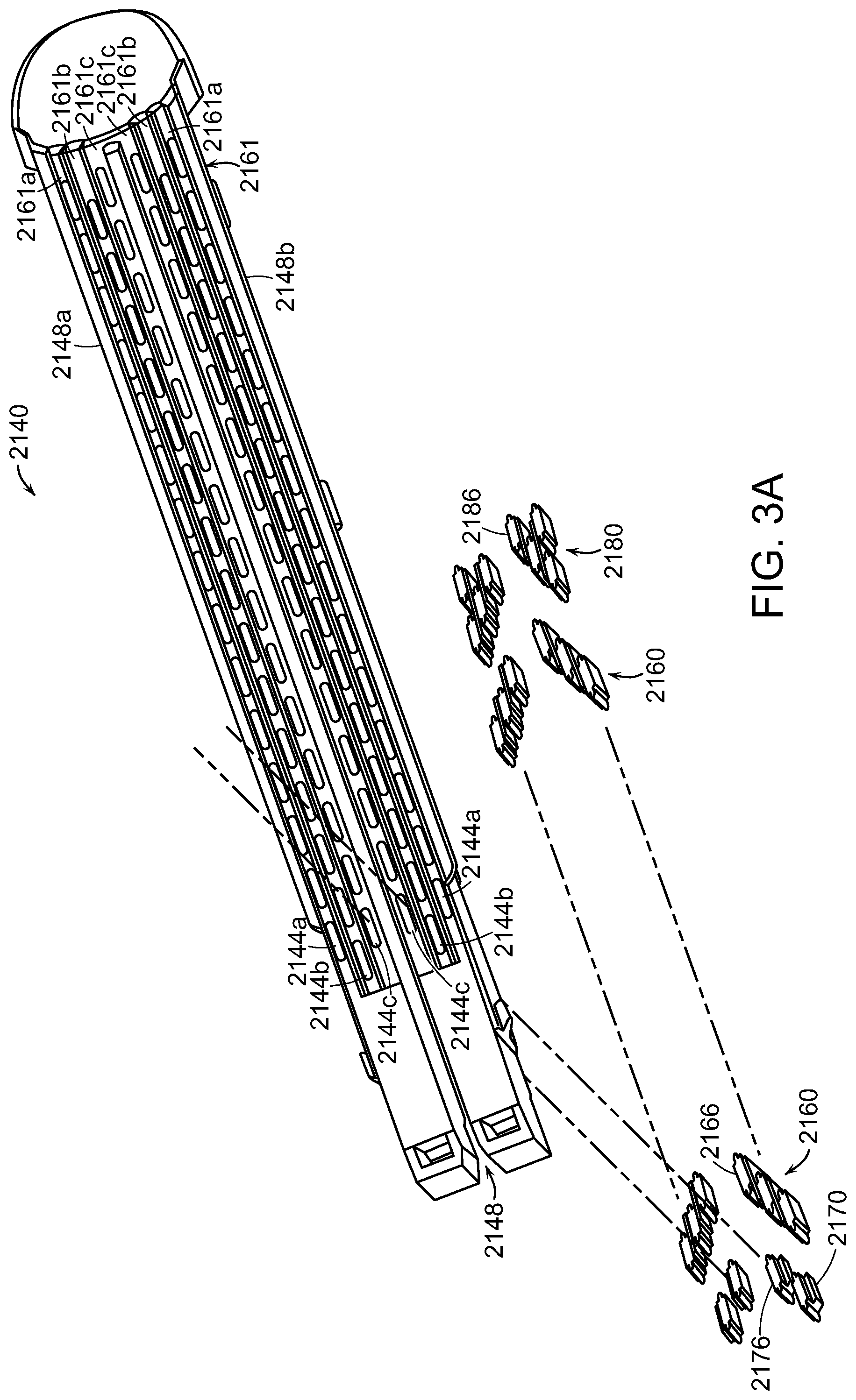
D00013

D00014

D00015

D00016

D00017

D00018

D00019

D00020

D00021

D00022

D00023

XML
uspto.report is an independent third-party trademark research tool that is not affiliated, endorsed, or sponsored by the United States Patent and Trademark Office (USPTO) or any other governmental organization. The information provided by uspto.report is based on publicly available data at the time of writing and is intended for informational purposes only.
While we strive to provide accurate and up-to-date information, we do not guarantee the accuracy, completeness, reliability, or suitability of the information displayed on this site. The use of this site is at your own risk. Any reliance you place on such information is therefore strictly at your own risk.
All official trademark data, including owner information, should be verified by visiting the official USPTO website at www.uspto.gov. This site is not intended to replace professional legal advice and should not be used as a substitute for consulting with a legal professional who is knowledgeable about trademark law.