Systems And Methods Of Initiating A Power Shutdown Mode For A Surgical Instrument
Leimbach; Richard L. ; et al.
U.S. patent application number 15/720829 was filed with the patent office on 2019-04-04 for systems and methods of initiating a power shutdown mode for a surgical instrument. The applicant listed for this patent is Ethicon LLC. Invention is credited to Gregory J. Bakos, Richard L. Leimbach, Raymond E. Parfett.
| Application Number | 20190099179 15/720829 |
| Document ID | / |
| Family ID | 63720612 |
| Filed Date | 2019-04-04 |


View All Diagrams
| United States Patent Application | 20190099179 |
| Kind Code | A1 |
| Leimbach; Richard L. ; et al. | April 4, 2019 |
SYSTEMS AND METHODS OF INITIATING A POWER SHUTDOWN MODE FOR A SURGICAL INSTRUMENT
Abstract
Various systems and methods of controlling a surgical instrument are disclosed. In one aspect, the surgical instrument includes an end effector that is pivotable between an unarticulated position and an articulated position, a knife bar movable between an unfired position and a fired position. The surgical instrument is configured to determine a firing state according to whether the knife bar is moving between the unfired position and the fired position, determine an articulation state according to whether the displacement member is moving between the first position and the second position, and then initiate a power shutdown mode according to the firing state and the articulation state.
| Inventors: | Leimbach; Richard L.; (Cincinnati, OH) ; Parfett; Raymond E.; (Loveland, OH) ; Bakos; Gregory J.; (Mason, OH) | ||||||||||
| Applicant: |
|
||||||||||
|---|---|---|---|---|---|---|---|---|---|---|---|
| Family ID: | 63720612 | ||||||||||
| Appl. No.: | 15/720829 | ||||||||||
| Filed: | September 29, 2017 |
| Current U.S. Class: | 1/1 |
| Current CPC Class: | A61B 2017/00017 20130101; A61B 2018/00708 20130101; A61B 2017/07271 20130101; A61B 17/07207 20130101; A61B 2017/00738 20130101; A61B 2017/00407 20130101; A61B 2017/00398 20130101; A61B 2017/00039 20130101; A61B 2017/00734 20130101; A61B 90/98 20160201; A61B 2017/07278 20130101; A61B 2018/1455 20130101; A61B 2017/2929 20130101; A61B 2090/034 20160201; A61B 2090/0811 20160201; A61B 2017/2927 20130101; A61B 18/1445 20130101; A61B 2017/00477 20130101; A61B 2090/0807 20160201; A61B 18/1442 20130101; A61B 2017/07257 20130101; A61B 2017/07285 20130101; A61B 2017/0046 20130101; A61B 2017/00123 20130101; A61B 34/25 20160201; A61B 90/06 20160201 |
| International Class: | A61B 17/072 20060101 A61B017/072; A61B 34/00 20060101 A61B034/00 |
Claims
1. A surgical instrument comprising: an end effector pivotable between an unarticulated position and an articulated position; a displacement member coupled to the end effector, the displacement member movable between a first position and a second position to drive the end effector between the unarticulated position and the articulated position; a knife bar movable between a unfired position and a fired position; a control circuit configured to: determine a firing state according to whether the knife bar is moving between the unfired position and the fired position; determine an articulation state according to whether the displacement member is moving between the first position and the second position; and initiate a power shutdown mode according to the firing state and the articulation state.
2. The surgical instrument of claim 1, wherein the control circuit is configured to not initiate the power shutdown mode unless the knife bar is in the unfired position.
3. The surgical instrument of claim 1, wherein the control circuit is configured to not initiate the power shutdown mode unless the displacement member is in the first position.
4. The surgical instrument of claim 1, further comprising: a firing trigger coupled to the knife bar, the firing trigger configured to drive the knife bar between the unfired position and the fired position; wherein the control circuit is configured to determine whether the knife bar is moving according to a position of the firing trigger.
5. The surgical instrument of claim 1, further comprising: a motor coupled to the knife bar, the motor configured to drive the knife bar between the unfired position and the fired position; wherein the control circuit is configured to determine whether the knife bar is moving according to a voltage of the motor.
6. The surgical instrument of claim 1, further comprising: a sensor configured to detect a position of the knife bar and provide a signal indicative thereof; wherein the control circuit is configured to determine whether the knife bar is moving according to the signal. The surgical instrument of claim 1, further comprising: a sensor configured to detect a position of the displacement member and provide a signal indicative thereof; wherein the control circuit is configured to determine whether the displacement member is moving according to the signal.
8. A surgical instrument comprising: an end effector pivotable from an articulation home position; a knife bar movable from a knife home position; and a control circuit configured to: determine whether the knife bar is moving; determine whether the end effector is moving; and initiate a power shutdown mode upon the knife bar and the end effector not moving.
9. The surgical instrument of claim 8, wherein the control circuit is configured to not initiate the power shutdown mode unless the knife bar is in the knife home position.
10. The surgical instrument of claim 8, wherein the control circuit is configured to not initiate the power shutdown mode unless the end effector is in the articulation home position.
11. The surgical instrument of claim 8, further comprising: a firing trigger coupled to the knife bar, the firing trigger configured to drive the knife bar from the knife home position; wherein the control circuit is configured to determine whether the knife bar is moving according to a position of the firing trigger.
12. The surgical instrument of claim 8, further comprising: a motor coupled to the knife bar, the motor configured to drive the knife bar from the knife home position; wherein the control circuit is configured to determine whether the knife bar is moving according to a voltage of the motor.
13. The surgical instrument of claim 8, further comprising: a sensor configured to detect a position of the knife bar and provide a signal indicative thereof; wherein the control circuit is configured to determine whether the knife bar is moving according to the signal.
14. The surgical instrument of claim 8, further comprising: a sensor configured to detect a position of the end effector and provide a signal indicative thereof; wherein the control circuit is configured to determine whether the end effector is moving according to the signal.
15. A method of controlling a surgical instrument comprising an end effector, a displacement member coupled to the end effector, the displacement member movable between a first position and a second position, and a knife bar movable between a unfired position and a fired position, the method comprising: determining a firing state according to whether the knife bar is moving between the unfired position and the fired position; determining an articulation state according to whether the displacement member is moving between the first position and the second position; and initiating a power shutdown mode according to the firing state and the articulation state.
16. The method of claim 15, wherein the power shutdown mode is not initiated unless the knife bar is in the unfired position.
17. The method of claim 15, wherein the power shutdown mode is not initiated unless the displacement member is in the first position.
18. The method of claim 15, further comprising determining whether the knife bar is moving according to a position of a firing trigger coupled to the knife bar.
19. The method of claim 15, further comprising determining whether the knife bar is moving according to a voltage of a motor coupled to the knife bar.
20. The method of claim 15, further comprising determining whether the knife bar is moving according to a sensor configured to detect a position of the knife bar.
21. The method of claim 15, further comprising determining whether the displacement member is moving according to a sensor configured to detect a position of the displacement member.
Description
TECHNICAL FIELD
[0001] The present disclosure relates to surgical instruments and, in various circumstances, to surgical stapling and cutting instruments that are designed to cut and staple tissue.
BACKGROUND
[0002] In a surgical stapling and cutting instrument it may be useful to control the display and other components of the instrument to provide alerts to the clinician using the instrument, power down the instrument, and take other such actions according to the operational state of the surgical instrument. The operational state of the surgical instrument (i.e., whether the instrument is cutting, stapling, clamping, articulating, or taking other such actions) can be detected by one or more sensors, which can be communicably coupled to a control circuit configured to execute various processes according to the states of the instrument detected by the sensors. In some situations, it may be useful to provide alerts to the clinician in order to alert the clinician as to errors experienced by the surgical instrument. In other situations, it may be useful to power down the instrument when the instrument has completed its surgical stapling and cutting operations. In still other situations, it may be useful to display the position of the knife during the course of a firing stroke thereof in order to allow a clinician to view the cutting progress.
SUMMARY
[0003] In one aspect, a surgical instrument comprising: an end effector pivotable between an unarticulated position and an articulated position; a displacement member coupled to the end effector, the displacement member movable between a first position and a second position to drive the end effector between the unarticulated position and the articulated position; a knife bar movable between a unfired position and a fired position; a control circuit configured to: determine a firing state according to whether the knife bar is moving between the unfired position and the fired position; determine an articulation state according to whether the displacement member is moving between the first position and the second position; and initiate a power shutdown mode according to the firing state and the articulation state.
[0004] In another aspect, a surgical instrument comprising: an end effector pivotable from an articulation home position; a knife bar movable from a knife home position; and a control circuit configured to: determine whether the knife bar is moving; determine whether the end effector is moving; and initiate a power shutdown mode upon the knife bar and the end effector not moving.
[0005] In another aspect, a method of controlling a surgical instrument comprising an end effector, a displacement member coupled to the end effector, the displacement member movable between a first position and a second position, and a knife bar movable between a unfired position and a fired position, the method comprising: determining a firing state according to whether the knife bar is moving between the unfired position and the fired position; determining an articulation state according to whether the displacement member is moving between the first position and the second position; and initiating a power shutdown mode according to the firing state and the articulation state.
FIGURES
[0006] The novel features of the aspects described herein are set forth with particularity in the appended claims. These aspects, however, both as to organization and methods of operation may be better understood by reference to the following description, taken in conjunction with the accompanying drawings.
[0007] FIG. 1 is a perspective view of a surgical instrument that has an interchangeable shaft assembly operably coupled thereto according to one aspect of this disclosure.
[0008] FIG. 2 is an exploded assembly view of a portion of the surgical instrument of FIG. 1 according to one aspect of this disclosure.
[0009] FIG. 3 is an exploded assembly view of portions of the interchangeable shaft assembly according to one aspect of this disclosure.
[0010] FIG. 4 is an exploded view of an end effector of the surgical instrument of FIG. 1 according to one aspect of this disclosure.
[0011] FIGS. 5A-5B is a block diagram of a control circuit of the surgical instrument of FIG. 1 spanning two drawing sheets according to one aspect of this disclosure.
[0012] FIG. 6 is a block diagram of the control circuit of the surgical instrument of FIG. 1 illustrating interfaces between the handle assembly, the power assembly, and the handle assembly and the interchangeable shaft assembly according to one aspect of this disclosure.
[0013] FIG. 7 illustrates a control circuit configured to control aspects of the surgical instrument of FIG. 1 according to one aspect of this disclosure.
[0014] FIG. 8 illustrates a combinational logic circuit configured to control aspects of the surgical instrument of FIG. 1 according to one aspect of this disclosure.
[0015] FIG. 9 illustrates a sequential logic circuit configured to control aspects of the surgical instrument of FIG. 1 according to one aspect of this disclosure.
[0016] FIG. 10 is a diagram of an absolute positioning system of the surgical instrument of FIG. 1 where the absolute positioning system comprises a controlled motor drive circuit arrangement comprising a sensor arrangement according to one aspect of this disclosure.
[0017] FIG. 11 is an exploded perspective view of the sensor arrangement for an absolute positioning system showing a control circuit board assembly and the relative alignment of the elements of the sensor arrangement according to one aspect of this disclosure.
[0018] FIG. 12 is a diagram of a position sensor comprising a magnetic rotary absolute positioning system according to one aspect of this disclosure.
[0019] FIG. 13 is a section view of an end effector of the surgical instrument of FIG. 1 showing a firing member stroke relative to tissue grasped within the end effector according to one aspect of this disclosure.
[0020] FIG. 14 illustrates a block diagram of a surgical instrument programmed to control distal translation of a displacement member according to one aspect of this disclosure.
[0021] FIG. 15 illustrates a diagram plotting two example displacement member strokes executed according to one aspect of this disclosure.
[0022] FIG. 16 is a partial perspective view of a portion of an end effector of a surgical instrument showing an elongate shaft assembly in an unarticulated orientation with portions thereof omitted for clarity, according to one aspect of this disclosure.
[0023] FIG. 17 is another perspective view of the end effector of FIG. 16 showing the elongate shaft assembly an unarticulated orientation, according to one aspect of this disclosure.
[0024] FIG. 18 is an exploded assembly perspective view of the end effector of FIG. 16 showing the elongate shaft assembly aspect, according to one aspect of this disclosure.
[0025] FIG. 19 is a top view of the end effector of FIG. 16 showing the elongate shaft assembly in an unarticulated orientation, according to one aspect of this disclosure.
[0026] FIG. 20 is another top view of the end effector of FIG. 16 showing the elongate shaft assembly in a first articulated orientation, according to one aspect of this disclosure.
[0027] FIG. 21 is another top view of the end effector of FIG. 16 showing the elongate shaft assembly in a second articulated orientatio16n, according to one aspect of this disclosure.
[0028] FIG. 22 is a perspective view of a surgical system including a handle assembly coupled to an interchangeable surgical tool assembly that is configured to be used in connection with conventional surgical staple/fastener cartridges and radio frequency (RF) cartridges according to one aspect of this disclosure.
[0029] FIG. 23 is an exploded perspective assembly view of the surgical system of FIG. 22 according to one aspect of this disclosure.
[0030] FIG. 24 is a top cross-sectional view of a portion of the interchangeable surgical tool assembly of FIG. 22 with the end effector thereof in an articulated position according to one aspect of this disclosure.
[0031] FIG. 25 is a perspective view of an onboard circuit board arrangement and RF generator plus configuration according to one aspect of this disclosure.
[0032] FIG. 26 illustrates a logic flow diagram of a process of determining when to initiate a low power shutdown of the surgical instrument according to one aspect of this disclosure.
[0033] FIG. 27 illustrates a front view of a display screen or portion thereof showing an image indicating that the surgical instrument is in a low power shutdown mode according to one aspect of this disclosure.
DESCRIPTION
[0034] Applicant of the present application owns the following patent applications that were filed concurrently herewith and which are each herein incorporated by reference in their respective entireties:
[0035] Attorney Docket No. END8312USNP/170177, entitled SYSTEMS AND METHODS FOR PROVIDING ALERTS ACCORDING TO THE OPERATIONAL STATE OF A SURGICAL INSTRUMENT, by inventors Richard L. Leimbach et al., filed Sep. 29, 2017.
[0036] Attorney Docket No. END8313USNP/170178, entitled SYSTEMS AND METHODS OF DISPLAYING A KNIFE POSITION FOR A SURGICAL INSTRUMENT, by inventors Richard L. Leimbach et al., filed Sep. 29, 2017.
[0037] Attorney Docket No. END8315USNP/170180, entitled SYSTEMS AND METHODS FOR LANGUAGE SELECTION OF A SURGICAL INSTRUMENT, by inventors Richard L. Leimbach et al., filed Sep. 29, 2017.
[0038] Attorney Docket No. END8316USDP/170181D, entitled DISPLAY SCREEN OR PORTION THEREOF WITH ANIMATED GRAPHICAL USER INTERFACE, by inventors Tony C. Siebel et al., filed Sep. 29, 2017.
[0039] Attorney Docket No. END8317USDP/170182D, entitled DISPLAY SCREEN OR PORTION THEREOF WITH ANIMATED GRAPHICAL USER INTERFACE, by inventors Tony C. Siebel et al., filed Sep. 29, 2017.
[0040] Attorney Docket No. END8318USDP/170183D, entitled DISPLAY SCREEN OR PORTION THEREOF WITH ANIMATED GRAPHICAL USER INTERFACE, by inventors Tony C. Siebel et al., filed Sep. 29, 2017.
[0041] Attorney Docket No. END8319USDP/170184D, entitled DISPLAY SCREEN OR PORTION THEREOF WITH ANIMATED GRAPHICAL USER INTERFACE, by inventors Tony C. Siebel et al., filed Sep. 29, 2017.
[0042] Attorney Docket No. END8320USNP/170176M, entitled SYSTEM AND METHODS FOR CONTROLLING A DISPLAY OF A SURGICAL INSTRUMENT, by inventors Richard L. Leimbach et al., filed Sep. 29, 2017.
[0043] Certain aspects are shown and described to provide an understanding of the structure, function, manufacture, and use of the disclosed devices and methods. Features shown or described in one example may be combined with features of other examples and modifications and variations are within the scope of this disclosure.
[0044] The terms "proximal" and "distal" are relative to a clinician manipulating the handle of the surgical instrument where "proximal" refers to the portion closer to the clinician and "distal" refers to the portion located further from the clinician. For expediency, spatial terms "vertical," "horizontal," "up," and "down" used with respect to the drawings are not intended to be limiting and/or absolute, because surgical instruments can used in many orientations and positions.
[0045] Example devices and methods are provided for performing laparoscopic and minimally invasive surgical procedures. Such devices and methods, however, can be used in other surgical procedures and applications including open surgical procedures, for example. The surgical instruments can be inserted into a through a natural orifice or through an incision or puncture hole formed in tissue. The working portions or end effector portions of the instruments can be inserted directly into the body or through an access device that has a working channel through which the end effector and elongated shaft of the surgical instrument can be advanced.
[0046] In some aspects, surgical instruments can include devices capable of performing cutting (as in, e.g., FIGS. 1 and 22), stapling (as in, e.g., FIG. 1), electrosurgical (as in, e.g., FIG. 22), and/or ultrasonic operations, as described in further detail below. Further detail regarding ultrasonic surgical instruments can be found in U.S. Pat. No. 6,283,981, entitled METHOD OF BALANCING ASYMMETRIC ULTRASONIC SURGICAL BLADES; U.S. Pat. No. 6,309,400, entitled CURVED ULTRASONIC WAVEGUIDE HAVING A TRAPEZOIDAL CROSS SECTION; and U.S. Pat. No. 6,436,115, entitled BALANCED ULTRASONIC WAVEGUIDE INCLUDING A PLURALITY OF BALANCE ASYMMETRIES, the entire disclosures of which are hereby incorporated herein by reference.
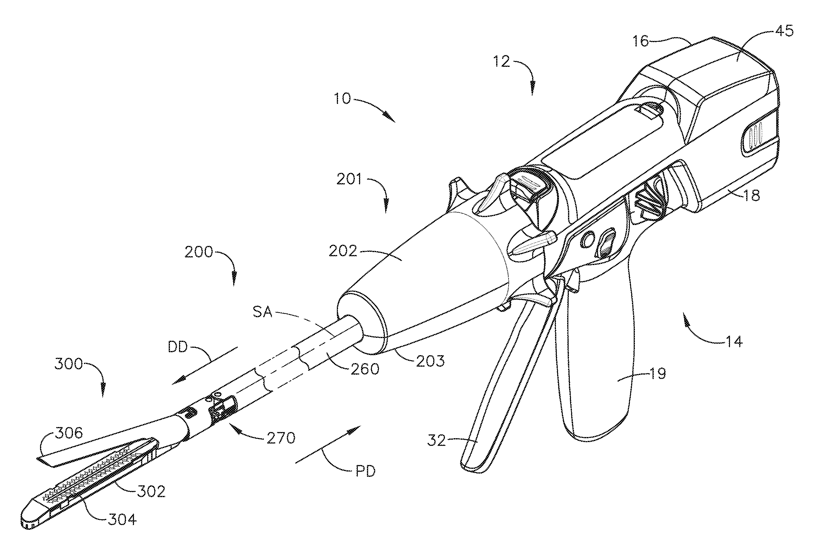
[0047] FIGS. 1-4 depict a motor-driven surgical instrument 10 for cutting and fastening that may or may not be reused. In the illustrated examples, the surgical instrument 10 includes a housing 12 that comprises a handle assembly 14 that is configured to be grasped, manipulated, and actuated by the clinician. The housing 12 is configured for operable attachment to an interchangeable shaft assembly 200 that has an end effector 300 operably coupled thereto that is configured to perform one or more surgical tasks or procedures. In accordance with the present disclosure, various forms of interchangeable shaft assemblies may be effectively employed in connection with robotically controlled surgical systems. The term "housing" may encompass a housing or similar portion of a robotic system that houses or otherwise operably supports at least one drive system configured to generate and apply at least one control motion that could be used to actuate interchangeable shaft assemblies. The term "frame" may refer to a portion of a handheld surgical instrument. The term "frame" also may represent a portion of a robotically controlled surgical instrument and/or a portion of the robotic system that may be used to operably control a surgical instrument. Interchangeable shaft assemblies may be employed with various robotic systems, instruments, components, and methods disclosed in U.S. Pat. No. 9,072,535, entitled SURGICAL STAPLING INSTRUMENTS WITH ROTATABLE STAPLE DEPLOYMENT ARRANGEMENTS, which is hereby incorporated herein by reference in its entirety.
[0048] FIG. 1 is a perspective view of a surgical instrument 10 that has an interchangeable shaft assembly 200 operably coupled thereto according to one aspect of this disclosure. The housing 12 includes an end effector 300 that comprises a surgical cutting and fastening device configured to operably support a surgical staple cartridge 304 therein. The housing 12 may be configured for use in connection with interchangeable shaft assemblies that include end effectors that are adapted to support different sizes and types of staple cartridges, have different shaft lengths, sizes, and types. The housing 12 may be employed with a variety of interchangeable shaft assemblies, including assemblies configured to apply other motions and forms of energy such as, radio frequency (RF) energy, ultrasonic energy, and/or motion to end effector arrangements adapted for use in connection with various surgical applications and procedures. The end effectors, shaft assemblies, handles, surgical instruments, and/or surgical instrument systems can utilize any suitable fastener, or fasteners, to fasten tissue. For instance, a fastener cartridge comprising a plurality of fasteners removably stored therein can be removably inserted into and/or attached to the end effector of a shaft assembly.
[0049] The handle assembly 14 may comprise a pair of interconnectable handle housing segments 16, 18 interconnected by screws, snap features, adhesive, etc. The handle housing segments 16, 18 cooperate to form a pistol grip portion 19 that can be gripped and manipulated by the clinician. The handle assembly 14 operably supports a plurality of drive systems configured to generate and apply control motions to corresponding portions of the interchangeable shaft assembly that is operably attached thereto. A display may be provided below a cover 45.
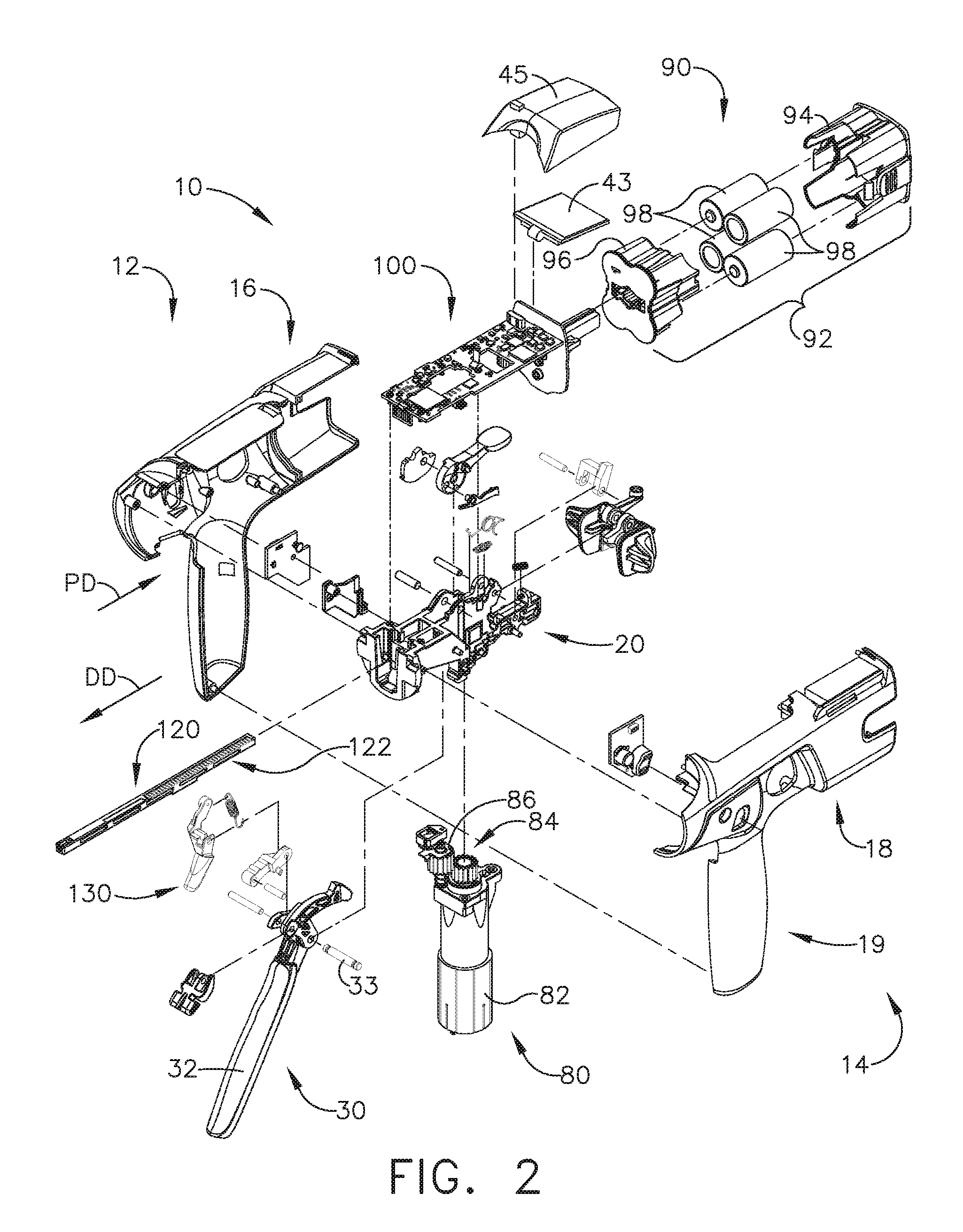
[0050] FIG. 2 is an exploded assembly view of a portion of the surgical instrument 10 of FIG. 1 according to one aspect of this disclosure. The handle assembly 14 may include a frame 20 that operably supports a plurality of drive systems. The frame 20 can operably support a closure drive system 30, which can apply closing and opening motions to the interchangeable shaft assembly 200. The closure drive system 30 may include an actuator such as a closure trigger 32 pivotally supported by the frame 20. The closure trigger 32 is pivotally coupled to the handle assembly 14 by a pivot pin 33 to enable the closure trigger 32 to be manipulated by a clinician. When the clinician grips the pistol grip portion 19 of the handle assembly 14, the closure trigger 32 can pivot from a starting or "unactuated" position to an "actuated" position and more particularly to a fully compressed or fully actuated position.
[0051] The handle assembly 14 and the frame 20 may operably support a firing drive system 80 configured to apply firing motions to corresponding portions of the interchangeable shaft assembly attached thereto. The firing drive system 80 may employ an electric motor 82 located in the pistol grip portion 19 of the handle assembly 14. The electric motor 82 may be a DC brushed motor having a maximum rotational speed of approximately 25,000 RPM, for example. In other arrangements, the motor may include a brushless motor, a cordless motor, a synchronous motor, a stepper motor, or any other suitable electric motor. The electric motor 82 may be powered by a power source 90 that may comprise a removable power pack 92. The removable power pack 92 may comprise a proximal housing portion 94 configured to attach to a distal housing portion 96. The proximal housing portion 94 and the distal housing portion 96 are configured to operably support a plurality of batteries 98 therein. Batteries 98 may each comprise, for example, a Lithium Ion (LI) or other suitable battery. The distal housing portion 96 is configured for removable operable attachment to a control circuit board 100, which is operably coupled to the electric motor 82. Several batteries 98 connected in series may power the surgical instrument 10. The power source 90 may be replaceable and/or rechargeable. A display 43, which is located below the cover 45, is electrically coupled to the control circuit board 100. The cover 45 may be removed to expose the display 43.
[0052] The electric motor 82 can include a rotatable shaft (not shown) that operably interfaces with a gear reducer assembly 84 mounted in meshing engagement with a with a set, or rack, of drive teeth 122 on a longitudinally movable drive member 120. The longitudinally movable drive member 120 has a rack of drive teeth 122 formed thereon for meshing engagement with a corresponding drive gear 86 of the gear reducer assembly 84.
[0053] In use, a voltage polarity provided by the power source 90 can operate the electric motor 82 in a clockwise direction wherein the voltage polarity applied to the electric motor by the battery can be reversed in order to operate the electric motor 82 in a counter-clockwise direction. When the electric motor 82 is rotated in one direction, the longitudinally movable drive member 120 will be axially driven in the distal direction "DD." When the electric motor 82 is driven in the opposite rotary direction, the longitudinally movable drive member 120 will be axially driven in a proximal direction "PD." The handle assembly 14 can include a switch that can be configured to reverse the polarity applied to the electric motor 82 by the power source 90. The handle assembly 14 may include a sensor configured to detect the position of the longitudinally movable drive member 120 and/or the direction in which the longitudinally movable drive member 120 is being moved.
[0054] Actuation of the electric motor 82 can be controlled by a firing trigger 130 that is pivotally supported on the handle assembly 14. The firing trigger 130 may be pivoted between an unactuated position and an actuated position.
[0055] Turning back to FIG. 1, the interchangeable shaft assembly 200 includes an end effector 300 comprising an elongated channel 302 configured to operably support a surgical staple cartridge 304 therein. The end effector 300 may include an anvil 306 that is pivotally supported relative to the elongated channel 302. The interchangeable shaft assembly 200 may include an articulation joint 270. Construction and operation of the end effector 300 and the articulation joint 270 are set forth in U.S. Patent Application Publication No. 2014/0263541, entitled ARTICULATABLE SURGICAL INSTRUMENT COMPRISING AN ARTICULATION LOCK, which is hereby incorporated herein by reference in its entirety. The interchangeable shaft assembly 200 may include a proximal housing or nozzle 201 comprised of nozzle portions 202, 203. The interchangeable shaft assembly 200 may include a closure tube 260 extending along a shaft axis SA that can be utilized to close and/or open the anvil 306 of the end effector 300.
[0056] Turning back to FIG. 1, the closure tube 260 is translated distally (direction "DD") to close the anvil 306, for example, in response to the actuation of the closure trigger 32 in the manner described in the aforementioned reference U.S. Patent Application Publication No. 2014/0263541. The anvil 306 is opened by proximally translating the closure tube 260. In the anvil-open position, the closure tube 260 is moved to its proximal position.
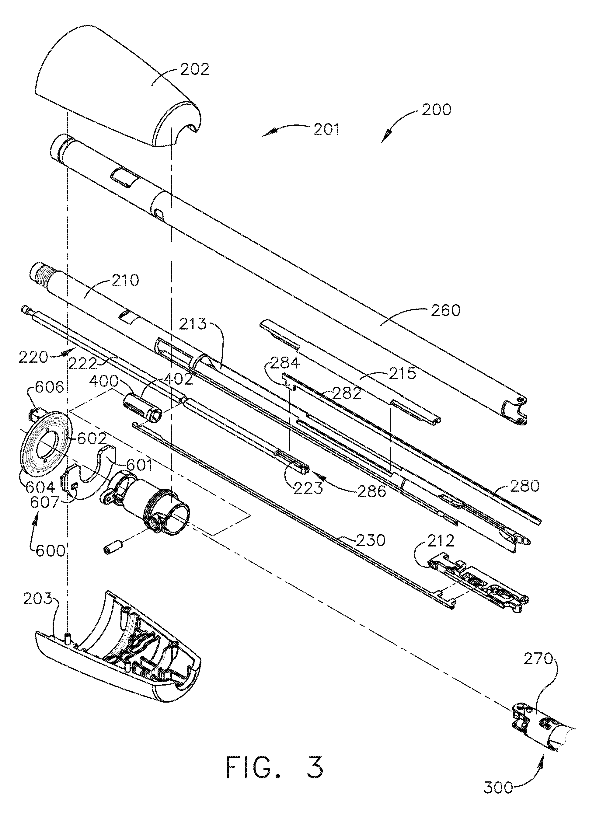
[0057] FIG. 3 is another exploded assembly view of portions of the interchangeable shaft assembly 200 according to one aspect of this disclosure. The interchangeable shaft assembly 200 may include a firing member 220 supported for axial travel within the spine 210. The firing member 220 includes an intermediate firing shaft 222 configured to attach to a distal cutting portion or knife bar 280. The intermediate firing shaft 222 may include a longitudinal slot 223 in a distal end configured to receive a tab 284 on the proximal end 282 of the knife bar 280. The longitudinal slot 223 and the proximal end 282 may be configured to permit relative movement there between and can comprise a slip joint 286. The slip joint 286 can permit the intermediate firing shaft 222 of the firing member 220 to articulate the end effector 300 about the articulation joint 270 without moving, or at least substantially moving, the knife bar 280. Once the end effector 300 has been suitably oriented, the intermediate firing shaft 222 can be advanced distally until a proximal sidewall of the longitudinal slot 223 contacts the tab 284 to advance the knife bar 280 and fire the staple cartridge positioned within the elongated channel 302. The spine 210 has an elongated opening or window 213 therein to facilitate assembly and insertion of the intermediate firing shaft 222 into the spine 210. Once the intermediate firing shaft 222 has been inserted therein, a top frame segment 215 may be engaged with the shaft frame 212 to enclose the intermediate firing shaft 222 and knife bar 280 therein. Operation of the firing member 220 may be found in U.S. Patent Application Publication No. 2014/0263541. A spine 210 can be configured to slidably support a firing member 220 and the closure tube 260 that extends around the spine 210. The spine 210 may slidably support an articulation driver 230.
[0058] The interchangeable shaft assembly 200 can include a clutch assembly 400 configured to selectively and releasably couple the articulation driver 230 to the firing member 220. The clutch assembly 400 includes a lock collar, or lock sleeve 402, positioned around the firing member 220 wherein the lock sleeve 402 can be rotated between an engaged position in which the lock sleeve 402 couples the articulation driver 230 to the firing member 220 and a disengaged position in which the articulation driver 230 is not operably coupled to the firing member 220. When the lock sleeve 402 is in the engaged position, distal movement of the firing member 220 can move the articulation driver 230 distally and, correspondingly, proximal movement of the firing member 220 can move the articulation driver 230 proximally. When the lock sleeve 402 is in the disengaged position, movement of the firing member 220 is not transmitted to the articulation driver 230 and, as a result, the firing member 220 can move independently of the articulation driver 230. The nozzle 201 may be employed to operably engage and disengage the articulation drive system with the firing drive system in the various manners described in U.S. Patent Application Publication No. 2014/0263541.
[0059] The interchangeable shaft assembly 200 can comprise a slip ring assembly 600 which can be configured to conduct electrical power to and/or from the end effector 300 and/or communicate signals to and/or from the end effector 300, for example. The slip ring assembly 600 can comprise a proximal connector flange 604 and a distal connector flange 601 positioned within a slot defined in the nozzle portions 202, 203. The proximal connector flange 604 can comprise a first face and the distal connector flange 601 can comprise a second face positioned adjacent to and movable relative to the first face. The distal connector flange 601 can rotate relative to the proximal connector flange 604 about the shaft axis SA-SA (FIG. 1). The proximal connector flange 604 can comprise a plurality of concentric, or at least substantially concentric, conductors 602 defined in the first face thereof. A connector 607 can be mounted on the proximal side of the distal connector flange 601 and may have a plurality of contacts wherein each contact corresponds to and is in electrical contact with one of the conductors 602. Such an arrangement permits relative rotation between the proximal connector flange 604 and the distal connector flange 601 while maintaining electrical contact there between. The proximal connector flange 604 can include an electrical connector 606 that can place the conductors 602 in signal communication with a shaft circuit board, for example. In at least one instance, a wiring harness comprising a plurality of conductors can extend between the electrical connector 606 and the shaft circuit board. The electrical connector 606 may extend proximally through a connector opening defined in the chassis mounting flange. Further details regarding slip ring assembly 600 may be found in U.S. Patent Application Publication No. 2014/0263541.
[0060] The interchangeable shaft assembly 200 can include a proximal portion fixably mounted to the handle assembly 14 and a distal portion that is rotatable about a longitudinal axis. The rotatable distal shaft portion can be rotated relative to the proximal portion about the slip ring assembly 600. The distal connector flange 601 of the slip ring assembly 600 can be positioned within the rotatable distal shaft portion.
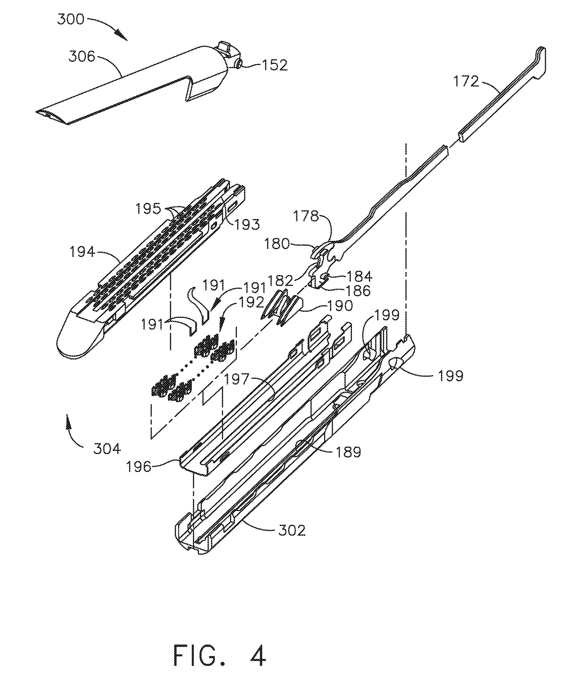
[0061] FIG. 4 is an exploded view of one aspect of an end effector 300 of the surgical instrument 10 of FIG. 1 according to one aspect of this disclosure. The end effector 300 may include the anvil 306 and the surgical staple cartridge 304. The anvil 306 may be coupled to an elongated channel 302. Apertures 199 can be defined in the elongated channel 302 to receive pins 152 extending from the anvil 306 to allow the anvil 306 to pivot from an open position to a closed position relative to the elongated channel 302 and surgical staple cartridge 304. A firing bar 172 is configured to longitudinally translate into the end effector 300. The firing bar 172 may be constructed from one solid section, or may include a laminate material comprising a stack of steel plates. The firing bar 172 comprises an I-beam 178 and a cutting edge 182 at a distal end thereof. A distally projecting end of the firing bar 172 can be attached to the I-beam 178 to assist in spacing the anvil 306 from a surgical staple cartridge 304 positioned in the elongated channel 302 when the anvil 306 is in a closed position. The I-beam 178 may include a sharpened cutting edge 182 to sever tissue as the I-beam 178 is advanced distally by the firing bar 172. In operation, the I-beam 178 may, or fire, the surgical staple cartridge 304. The surgical staple cartridge 304 can include a molded cartridge body 194 that holds a plurality of staples 191 resting upon staple drivers 192 within respective upwardly open staple cavities 195. A wedge sled 190 is driven distally by the I-beam 178, sliding upon a cartridge tray 196 of the surgical staple cartridge 304. The wedge sled 190 upwardly cams the staple drivers 192 to force out the staples 191 into deforming contact with the anvil 306 while the cutting edge 182 of the I-beam 178 severs clamped tissue.
[0062] The I-beam 178 can include upper pins 180 that engage the anvil 306 during firing. The I-beam 178 may include middle pins 184 and a bottom foot 186 to engage portions of the cartridge body 194, cartridge tray 196, and elongated channel 302. When a surgical staple cartridge 304 is positioned within the elongated channel 302, a slot 193 defined in the cartridge body 194 can be aligned with a longitudinal slot 197 defined in the cartridge tray 196 and a slot 189 defined in the elongated channel 302. In use, the I-beam 178 can slide through the aligned longitudinal slots 193, 197, and 189 wherein, as indicated in FIG. 4, the bottom foot 186 of the I-beam 178 can engage a groove running along the bottom surface of elongated channel 302 along the length of slot 189, the middle pins 184 can engage the top surfaces of cartridge tray 196 along the length of longitudinal slot 197, and the upper pins 180 can engage the anvil 306. The I-beam 178 can space, or limit the relative movement between, the anvil 306 and the surgical staple cartridge 304 as the firing bar 172 is advanced distally to fire the staples from the surgical staple cartridge 304 and/or incise the tissue captured between the anvil 306 and the surgical staple cartridge 304. The firing bar 172 and the I-beam 178 can be retracted proximally allowing the anvil 306 to be opened to release the two stapled and severed tissue portions.
[0063] FIGS. 5A-5B is a block diagram of a control circuit 700 of the surgical instrument 10 of FIG. 1 spanning two drawing sheets according to one aspect of this disclosure. Referring primarily to FIGS. 5A-5B, a handle assembly 702 may include a motor 714 which can be controlled by a motor driver 715 and can be employed by the firing system of the surgical instrument 10. In various forms, the motor 714 may be a DC brushed driving motor having a maximum rotational speed of approximately 25,000 RPM. In other arrangements, the motor 714 may include a brushless motor, a cordless motor, a synchronous motor, a stepper motor, or any other suitable electric motor. The motor driver 715 may comprise an H-bridge driver comprising field-effect transistors (FETs) 719, for example. The motor 714 can be powered by the power assembly 706 releasably mounted to the handle assembly 14 for supplying control power to the surgical instrument 10. The power assembly 706 may comprise a battery which may include a number of battery cells connected in series that can be used as the power source to power the surgical instrument 10. In certain circumstances, the battery cells of the power assembly 706 may be replaceable and/or rechargeable. In at least one example, the battery cells can be Lithium-Ion batteries which can be separably couplable to the power assembly 706.
[0064] The shaft assembly 704 may include a shaft assembly controller 722 which can communicate with a safety controller and power management controller 716 through an interface while the shaft assembly 704 and the power assembly 706 are coupled to the handle assembly 702. For example, the interface may comprise a first interface portion 725 which may include one or more electric connectors for coupling engagement with corresponding shaft assembly electric connectors and a second interface portion 727 which may include one or more electric connectors for coupling engagement with corresponding power assembly electric connectors to permit electrical communication between the shaft assembly controller 722 and the power management controller 716 while the shaft assembly 704 and the power assembly 706 are coupled to the handle assembly 702. One or more communication signals can be transmitted through the interface to communicate one or more of the power requirements of the attached interchangeable shaft assembly 704 to the power management controller 716. In response, the power management controller may modulate the power output of the battery of the power assembly 706, as described below in greater detail, in accordance with the power requirements of the attached shaft assembly 704. The connectors may comprise switches which can be activated after mechanical coupling engagement of the handle assembly 702 to the shaft assembly 704 and/or to the power assembly 706 to allow electrical communication between the shaft assembly controller 722 and the power management controller 716.
[0065] The interface can facilitate transmission of the one or more communication signals between the power management controller 716 and the shaft assembly controller 722 by routing such communication signals through a main controller 717 residing in the handle assembly 702, for example. In other circumstances, the interface can facilitate a direct line of communication between the power management controller 716 and the shaft assembly controller 722 through the handle assembly 702 while the shaft assembly 704 and the power assembly 706 are coupled to the handle assembly 702.
[0066] The main controller 717 may be any single core or multicore processor such as those known under the trade name ARM Cortex by Texas Instruments. In one aspect, the main controller 717 may be an LM4F230H5QR ARM Cortex-M4F Processor Core, available from Texas Instruments, for example, comprising on-chip memory of 256 KB single-cycle flash memory, or other non-volatile memory, up to 40 MHz, a prefetch buffer to improve performance above 40 MHz, a 32 KB single-cycle serial random access memory (SRAM), internal read-only memory (ROM) loaded with StellarisWare.RTM. software, 2 KB electrically erasable programmable read-only memory (EEPROM), one or more pulse width modulation (PWM) modules, one or more quadrature encoder inputs (QEI) analog, one or more 12-bit Analog-to-Digital Converters (ADC) with 12 analog input channels, details of which are available for the product datasheet.
[0067] The safety controller may be a safety controller platform comprising two controller-based families such as TMS570 and RM4x known under the trade name Hercules ARM Cortex R4, also by Texas Instruments. The safety controller may be configured specifically for IEC 61508 and ISO 26262 safety critical applications, among others, to provide advanced integrated safety features while delivering scalable performance, connectivity, and memory options.
[0068] The power assembly 706 may include a power management circuit which may comprise the power management controller 716, a power modulator 738, and a current sense circuit 736. The power management circuit can be configured to modulate power output of the battery based on the power requirements of the shaft assembly 704 while the shaft assembly 704 and the power assembly 706 are coupled to the handle assembly 702. The power management controller 716 can be programmed to control the power modulator 738 of the power output of the power assembly 706 and the current sense circuit 736 can be employed to monitor power output of the power assembly 706 to provide feedback to the power management controller 716 about the power output of the battery so that the power management controller 716 may adjust the power output of the power assembly 706 to maintain a desired output. The power management controller 716 and/or the shaft assembly controller 722 each may comprise one or more processors and/or memory units which may store a number of software modules.
[0069] The surgical instrument 10 (FIGS. 1-4) may comprise an output device 742 which may include devices for providing a sensory feedback to a user. Such devices may comprise, for example, visual feedback devices (e.g., an LCD display screen, LED indicators), audio feedback devices (e.g., a speaker, a buzzer) or tactile feedback devices (e.g., haptic actuators). In certain circumstances, the output device 742 may comprise a display 743 which may be included in the handle assembly 702. The shaft assembly controller 722 and/or the power management controller 716 can provide feedback to a user of the surgical instrument 10 through the output device 742. The interface can be configured to connect the shaft assembly controller 722 and/or the power management controller 716 to the output device 742. The output device 742 can instead be integrated with the power assembly 706. In such circumstances, communication between the output device 742 and the shaft assembly controller 722 may be accomplished through the interface while the shaft assembly 704 is coupled to the handle assembly 702.
[0070] The control circuit 700 comprises circuit segments configured to control operations of the powered surgical instrument 10. A safety controller segment (Segment 1) comprises a safety controller and the main controller 717 segment (Segment 2). The safety controller and/or the main controller 717 are configured to interact with one or more additional circuit segments such as an acceleration segment, a display segment, a shaft segment, an encoder segment, a motor segment, and a power segment. Each of the circuit segments may be coupled to the safety controller and/or the main controller 717. The main controller 717 is also coupled to a flash memory. The main controller 717 also comprises a serial communication interface. The main controller 717 comprises a plurality of inputs coupled to, for example, one or more circuit segments, a battery, and/or a plurality of switches. The segmented circuit may be implemented by any suitable circuit, such as, for example, a printed circuit board assembly (PCBA) within the powered surgical instrument 10. It should be understood that the term processor as used herein includes any microprocessor, processors, controller, controllers, or other basic computing device that incorporates the functions of a computer's central processing unit (CPU) on an integrated circuit or at most a few integrated circuits. The main controller 717 is a multipurpose, programmable device that accepts digital data as input, processes it according to instructions stored in its memory, and provides results as output. It is an example of sequential digital logic, as it has internal memory. The control circuit 700 can be configured to implement one or more of the processes described herein.
[0071] The acceleration segment (Segment 3) comprises an accelerometer. The accelerometer is configured to detect movement or acceleration of the powered surgical instrument 10. Input from the accelerometer may be used to transition to and from a sleep mode, identify an orientation of the powered surgical instrument, and/or identify when the surgical instrument has been dropped. In some examples, the acceleration segment is coupled to the safety controller and/or the main controller 717.
[0072] The display segment (Segment 4) comprises a display connector coupled to the main controller 717. The display connector couples the main controller 717 to a display through one or more integrated circuit drivers of the display. The integrated circuit drivers of the display may be integrated with the display and/or may be located separately from the display. The display may comprise any suitable display, such as, for example, an organic light-emitting diode (OLED) display, a liquid-crystal display (LCD), and/or any other suitable display. In some examples, the display segment is coupled to the safety controller.
[0073] The shaft segment (Segment 5) comprises controls for an interchangeable shaft assembly 200 (FIGS. 1 and 3) coupled to the surgical instrument 10 (FIGS. 1-4) and/or one or more controls for an end effector 300 coupled to the interchangeable shaft assembly 200. The shaft segment comprises a shaft connector configured to couple the main controller 717 to a shaft PCBA. The shaft PCBA comprises a low-power microcontroller with a ferroelectric random access memory (FRAM), an articulation switch, a shaft release Hall effect switch, and a shaft PCBA EEPROM. The shaft PCBA EEPROM comprises one or more parameters, routines, and/or programs specific to the interchangeable shaft assembly 200 and/or the shaft PCBA. The shaft PCBA may be coupled to the interchangeable shaft assembly 200 and/or integral with the surgical instrument 10. In some examples, the shaft segment comprises a second shaft EEPROM. The second shaft EEPROM comprises a plurality of algorithms, routines, parameters, and/or other data corresponding to one or more shaft assemblies 200 and/or end effectors 300 that may be interfaced with the powered surgical instrument 10.
[0074] The position encoder segment (Segment 6) comprises one or more magnetic angle rotary position encoders. The one or more magnetic angle rotary position encoders are configured to identify the rotational position of the motor 714, an interchangeable shaft assembly 200 (FIGS. 1 and 3), and/or an end effector 300 of the surgical instrument 10 (FIGS. 1-4). In some examples, the magnetic angle rotary position encoders may be coupled to the safety controller and/or the main controller 717.
[0075] The motor circuit segment (Segment 7) comprises a motor 714 configured to control movements of the powered surgical instrument 10 (FIGS. 1-4). The motor 714 is coupled to the main controller 717 by an H-bridge driver comprising one or more H-bridge field-effect transistors (FETs) and a motor controller. The H-bridge driver is also coupled to the safety controller. A motor current sensor is coupled in series with the motor to measure the current draw of the motor. The motor current sensor is in signal communication with the main controller 717 and/or the safety controller. In some examples, the motor 714 is coupled to a motor electromagnetic interference (EMI) filter.
[0076] The motor controller controls a first motor flag and a second motor flag to indicate the status and position of the motor 714 to the main controller 717. The main controller 717 provides a pulse-width modulation (PWM) high signal, a PWM low signal, a direction signal, a synchronize signal, and a motor reset signal to the motor controller through a buffer. The power segment is configured to provide a segment voltage to each of the circuit segments.
[0077] The power segment (Segment 8) comprises a battery coupled to the safety controller, the main controller 717, and additional circuit segments. The battery is coupled to the segmented circuit by a battery connector and a current sensor. The current sensor is configured to measure the total current draw of the segmented circuit. In some examples, one or more voltage converters are configured to provide predetermined voltage values to one or more circuit segments. For example, in some examples, the segmented circuit may comprise 3.3V voltage converters and/or 5V voltage converters. A boost converter is configured to provide a boost voltage up to a predetermined amount, such as, for example, up to 13V. The boost converter is configured to provide additional voltage and/or current during power intensive operations and prevent brownout or low-power conditions.
[0078] A plurality of switches are coupled to the safety controller and/or the main controller 717. The switches may be configured to control operations of the surgical instrument 10 (FIGS. 1-4), of the segmented circuit, and/or indicate a status of the surgical instrument 10. A bail-out door switch and Hall effect switch for bailout are configured to indicate the status of a bail-out door. A plurality of articulation switches, such as, for example, a left side articulation left switch, a left side articulation right switch, a left side articulation center switch, a right side articulation left switch, a right side articulation right switch, and a right side articulation center switch are configured to control articulation of an interchangeable shaft assembly 200 (FIGS. 1 and 3) and/or the end effector 300 (FIGS. 1 and 4). A left side reverse switch and a right side reverse switch are coupled to the main controller 717. The left side switches comprising the left side articulation left switch, the left side articulation right switch, the left side articulation center switch, and the left side reverse switch are coupled to the main controller 717 by a left flex connector. The right side switches comprising the right side articulation left switch, the right side articulation right switch, the right side articulation center switch, and the right side reverse switch are coupled to the main controller 717 by a right flex connector. A firing switch, a clamp release switch, and a shaft engaged switch are coupled to the main controller 717.
[0079] Any suitable mechanical, electromechanical, or solid state switches may be employed to implement the plurality of switches, in any combination. For example, the switches may be limit switches operated by the motion of components associated with the surgical instrument 10 (FIGS. 1-4) or the presence of an object. Such switches may be employed to control various functions associated with the surgical instrument 10. A limit switch is an electromechanical device that consists of an actuator mechanically linked to a set of contacts. When an object comes into contact with the actuator, the device operates the contacts to make or break an electrical connection. Limit switches are used in a variety of applications and environments because of their ruggedness, ease of installation, and reliability of operation. They can determine the presence or absence, passing, positioning, and end of travel of an object. In other implementations, the switches may be solid state switches that operate under the influence of a magnetic field such as Hall-effect devices, magneto-resistive (MR) devices, giant magneto-resistive (GMR) devices, magnetometers, among others. In other implementations, the switches may be solid state switches that operate under the influence of light, such as optical sensors, infrared sensors, ultraviolet sensors, among others. Still, the switches may be solid state devices such as transistors (e.g., FET, Junction-FET, metal-oxide semiconductor-FET (MOSFET), bipolar, and the like). Other switches may include wireless switches, ultrasonic switches, accelerometers, inertial sensors, among others.
[0080] FIG. 6 is another block diagram of the control circuit 700 of the surgical instrument of FIG. 1 illustrating interfaces between the handle assembly 702 and the power assembly 706 and between the handle assembly 702 and the interchangeable shaft assembly 704 according to one aspect of this disclosure. The handle assembly 702 may comprise a main controller 717, a shaft assembly connector 726 and a power assembly connector 730. The power assembly 706 may include a power assembly connector 732, a power management circuit 734 that may comprise the power management controller 716, a power modulator 738, and a current sense circuit 736. The power assembly connectors 730, 732 form an interface 727. The power management circuit 734 can be configured to modulate power output of the battery 707 based on the power requirements of the interchangeable shaft assembly 704 while the interchangeable shaft assembly 704 and the power assembly 706 are coupled to the handle assembly 702. The power management controller 716 can be programmed to control the power modulator 738 of the power output of the power assembly 706 and the current sense circuit 736 can be employed to monitor power output of the power assembly 706 to provide feedback to the power management controller 716 about the power output of the battery 707 so that the power management controller 716 may adjust the power output of the power assembly 706 to maintain a desired output. The shaft assembly 704 comprises a shaft assembly controller 722 coupled to a non-volatile memory 721 and shaft assembly connector 728 to electrically couple the shaft assembly 704 to the handle assembly 702. The shaft assembly connectors 726, 728 form interface 725. The main controller 717, the shaft assembly controller 722, and/or the power management controller 716 can be configured to implement one or more of the processes described herein.
[0081] The surgical instrument 10 (FIGS. 1-4) may comprise an output device 742 to a sensory feedback to a user. Such devices may comprise visual feedback devices (e.g., an LCD display screen, LED indicators), audio feedback devices (e.g., a speaker, a buzzer), or tactile feedback devices (e.g., haptic actuators). In certain circumstances, the output device 742 may comprise a display 743 that may be included in the handle assembly 702. The shaft assembly controller 722 and/or the power management controller 716 can provide feedback to a user of the surgical instrument 10 through the output device 742. The interface 727 can be configured to connect the shaft assembly controller 722 and/or the power management controller 716 to the output device 742. The output device 742 can be integrated with the power assembly 706. Communication between the output device 742 and the shaft assembly controller 722 may be accomplished through the interface 725 while the interchangeable shaft assembly 704 is coupled to the handle assembly 702. Having described a control circuit 700 (FIGS. 5A-5B and 6) for controlling the operation of the surgical instrument 10 (FIGS. 1-4), the disclosure now turns to various configurations of the surgical instrument 10 (FIGS. 1-4) and control circuit 700.
[0082] FIG. 7 illustrates a control circuit 800 configured to control aspects of the surgical instrument 10 (FIGS. 1-4) according to one aspect of this disclosure. The control circuit 800 can be configured to implement various processes described herein. The control circuit 800 may comprise a controller comprising one or more processors 802 (e.g., microprocessor, microcontroller) coupled to at least one memory circuit 804. The memory circuit 804 stores machine executable instructions that when executed by the processor 802, cause the processor 802 to execute machine instructions to implement various processes described herein. The processor 802 may be any one of a number of single or multi-core processors known in the art. The memory circuit 804 may comprise volatile and non-volatile storage media. The processor 802 may include an instruction processing unit 806 and an arithmetic unit 808. The instruction processing unit may be configured to receive instructions from the memory circuit 804.
[0083] FIG. 8 illustrates a combinational logic circuit 810 configured to control aspects of the surgical instrument 10 (FIGS. 1-4) according to one aspect of this disclosure. The combinational logic circuit 810 can be configured to implement various processes described herein. The circuit 810 may comprise a finite state machine comprising a combinational logic circuit 812 configured to receive data associated with the surgical instrument 10 at an input 814, process the data by the combinational logic 812, and provide an output 816.
[0084] FIG. 9 illustrates a sequential logic circuit 820 configured to control aspects of the surgical instrument 10 (FIGS. 1-4) according to one aspect of this disclosure. The sequential logic circuit 820 or the combinational logic circuit 822 can be configured to implement various processes described herein. The circuit 820 may comprise a finite state machine. The sequential logic circuit 820 may comprise a combinational logic circuit 822, at least one memory circuit 824, and a clock 829, for example. The at least one memory circuit 820 can store a current state of the finite state machine. In certain instances, the sequential logic circuit 820 may be synchronous or asynchronous. The combinational logic circuit 822 is configured to receive data associated with the surgical instrument 10 an input 826, process the data by the combinational logic circuit 822, and provide an output 828. In other aspects, the circuit may comprise a combination of the processor 802 and the finite state machine to implement various processes herein. In other aspects, the finite state machine may comprise a combination of the combinational logic circuit 810 and the sequential logic circuit 820.
[0085] Aspects may be implemented as an article of manufacture. The article of manufacture may include a computer readable storage medium arranged to store logic, instructions, and/or data for performing various operations of one or more aspects. For example, the article of manufacture may comprise a magnetic disk, optical disk, flash memory, or firmware containing computer program instructions suitable for execution by a general purpose processor or application specific processor.
[0086] FIG. 10 is a diagram of an absolute positioning system 1100 of the surgical instrument 10 (FIGS. 1-4) where the absolute positioning system 1100 comprises a controlled motor drive circuit arrangement comprising a sensor arrangement 1102 according to one aspect of this disclosure. The sensor arrangement 1102 for an absolute positioning system 1100 provides a unique position signal corresponding to the location of a displacement member 1111. Turning briefly to FIGS. 2-4, in one aspect the displacement member 1111 represents the longitudinally movable drive member 120 (FIG. 2) comprising a rack of drive teeth 122 for meshing engagement with a corresponding drive gear 86 of the gear reducer assembly 84. In other aspects, the displacement member 1111 represents the firing member 220 (FIG. 3), which could be adapted and configured to include a rack of drive teeth. In yet another aspect, the displacement member 1111 represents the firing bar 172 (FIG. 4) or the I-beam 178 (FIG. 4), each of which can be adapted and configured to include a rack of drive teeth. Accordingly, as used herein, the term displacement member is used generically to refer to any movable member of the surgical instrument 10 such as the drive member 120, the firing member 220, the firing bar 172, the I-beam 178, or any element that can be displaced. In one aspect, the longitudinally movable drive member 120 is coupled to the firing member 220, the firing bar 172, and the I-beam 178. Accordingly, the absolute positioning system 1100 can, in effect, track the linear displacement of the I-beam 178 by tracking the linear displacement of the longitudinally movable drive member 120. In various other aspects, the displacement member 1111 may be coupled to any sensor suitable for measuring linear displacement. Thus, the longitudinally movable drive member 120, the firing member 220, the firing bar 172, or the I-beam 178, or combinations, may be coupled to any suitable linear displacement sensor. Linear displacement sensors may include contact or non-contact displacement sensors. Linear displacement sensors may comprise linear variable differential transformers (LVDT), differential variable reluctance transducers (DVRT), a slide potentiometer, a magnetic sensing system comprising a movable magnet and a series of linearly arranged Hall effect sensors, a magnetic sensing system comprising a fixed magnet and a series of movable linearly arranged Hall effect sensors, an optical sensing system comprising a movable light source and a series of linearly arranged photo diodes or photo detectors, or an optical sensing system comprising a fixed light source and a series of movable linearly arranged photo diodes or photo detectors, or any combination thereof.
[0087] An electric motor 1120 can include a rotatable shaft 1116 that operably interfaces with a gear assembly 1114 that is mounted in meshing engagement with a set, or rack, of drive teeth on the displacement member 1111. A sensor element 1126 may be operably coupled to a gear assembly 1114 such that a single revolution of the sensor element 1126 corresponds to some linear longitudinal translation of the displacement member 1111. An arrangement of gearing and sensors can be connected to the linear actuator via a rack and pinion arrangement or a rotary actuator via a spur gear or other connection. A power source 1129 supplies power to the absolute positioning system 1100 and an output indicator 1128 may display the output of the absolute positioning system 1100. In FIG. 2, the displacement member 1111 represents the longitudinally movable drive member 120 comprising a rack of drive teeth 122 formed thereon for meshing engagement with a corresponding drive gear 86 of the gear reducer assembly 84. The displacement member 1111 represents the longitudinally movable firing member 220, firing bar 172, I-beam 178, or combinations thereof.
[0088] A single revolution of the sensor element 1126 associated with the position sensor 1112 is equivalent to a longitudinal linear displacement dl of the of the displacement member 1111, where dl is the longitudinal linear distance that the displacement member 1111 moves from point "a" to point "b" after a single revolution of the sensor element 1126 coupled to the displacement member 1111. The sensor arrangement 1102 may be connected via a gear reduction that results in the position sensor 1112 completing one or more revolutions for the full stroke of the displacement member 1111. The position sensor 1112 may complete multiple revolutions for the full stroke of the displacement member 1111.
[0089] A series of switches 1122a-1122n, where n is an integer greater than one, may be employed alone or in combination with gear reduction to provide a unique position signal for more than one revolution of the position sensor 1112. The state of the switches 1122a-1122n are fed back to a controller 1104 that applies logic to determine a unique position signal corresponding to the longitudinal linear displacement d1+d2+ . . . dn of the displacement member 1111. The output 1124 of the position sensor 1112 is provided to the controller 1104. The position sensor 1112 of the sensor arrangement 1102 may comprise a magnetic sensor, an analog rotary sensor like a potentiometer, an array of analog Hall-effect elements, which output a unique combination of position signals or values.
[0090] The absolute positioning system 1100 provides an absolute position of the displacement member 1111 upon power up of the instrument without retracting or advancing the displacement member 1111 to a reset (zero or home) position as may be required with conventional rotary encoders that merely count the number of steps forwards or backwards that the motor 1120 has taken to infer the position of a device actuator, drive bar, knife, and the like.
[0091] The controller 1104 may be programmed to perform various functions such as precise control over the speed and position of the knife and articulation systems. In one aspect, the controller 1104 includes a processor 1108 and a memory 1106. The electric motor 1120 may be a brushed DC motor with a gearbox and mechanical links to an articulation or knife system. In one aspect, a motor driver 1110 may be an A3941 available from Allegro Microsystems, Inc. Other motor drivers may be readily substituted for use in the absolute positioning system 1100. A more detailed description of the absolute positioning system 1100 is described in U.S. patent application Ser. No. 15/130,590, entitled SYSTEMS AND METHODS FOR CONTROLLING A SURGICAL STAPLING AND CUTTING INSTRUMENT, the entire disclosure of which is hereby incorporated herein by reference.
[0092] The controller 1104 may be programmed to provide precise control over the speed and position of the displacement member 1111 and articulation systems. The controller 1104 may be configured to compute a response in the software of the controller 1104. The computed response is compared to a measured response of the actual system to obtain an "observed" response, which is used for actual feedback decisions. The observed response is a favorable, tuned, value that balances the smooth, continuous nature of the simulated response with the measured response, which can detect outside influences on the system.
[0093] The absolute positioning system 1100 may comprise and/or be programmed to implement a feedback controller, such as a PID, state feedback, and adaptive controller. A power source 1129 converts the signal from the feedback controller into a physical input to the system, in this case voltage. Other examples include pulse width modulation (PWM) of the voltage, current, and force. Other sensor(s) 1118 may be provided to measure physical parameters of the physical system in addition to position measured by the position sensor 1112. In some aspects, the other sensor(s) 1118 can include sensor arrangements such as those described in U.S. Pat. No. 9,345,481, entitled STAPLE CARTRIDGE TISSUE THICKNESS SENSOR SYSTEM, which is hereby incorporated herein by reference in its entirety; U.S. Patent Application Publication No. 2014/0263552, entitled STAPLE CARTRIDGE TISSUE THICKNESS SENSOR SYSTEM, which is hereby incorporated herein by reference in its entirety; and U.S. patent application Ser. No. 15/628,175, entitled TECHNIQUES FOR ADAPTIVE CONTROL OF MOTOR VELOCITY OF A SURGICAL STAPLING AND CUTTING INSTRUMENT, which is hereby incorporated herein by reference in its entirety. In a digital signal processing system, absolute positioning system 1100 is coupled to a digital data acquisition system where the output of the absolute positioning system 1100 will have finite resolution and sampling frequency. The absolute positioning system 1100 may comprise a compare and combine circuit to combine a computed response with a measured response using algorithms such as weighted average and theoretical control loop that drives the computed response towards the measured response. The computed response of the physical system takes into account properties like mass, inertial, viscous friction, inductance resistance, etc., to predict what the states and outputs of the physical system will be by knowing the input. The controller 1104 may be a control circuit 700 (FIGS. 5A-5B).
[0094] The motor driver 1110 may be an A3941 available from Allegro Microsystems, Inc. The A3941 driver 1110 is a full-bridge controller for use with external N-channel power metal oxide semiconductor field effect transistors (MOSFETs) specifically designed for inductive loads, such as brush DC motors. The driver 1110 comprises a unique charge pump regulator provides full (>10 V) gate drive for battery voltages down to 7 V and allows the A3941 to operate with a reduced gate drive, down to 5.5 V. A bootstrap capacitor may be employed to provide the above-battery supply voltage required for N-channel MOSFETs. An internal charge pump for the high-side drive allows DC (100% duty cycle) operation. The full bridge can be driven in fast or slow decay modes using diode or synchronous rectification. In the slow decay mode, current recirculation can be through the high-side or the lowside FETs. The power FETs are protected from shoot-through by resistor adjustable dead time. Integrated diagnostics provide indication of undervoltage, overtemperature, and power bridge faults, and can be configured to protect the power MOSFETs under most short circuit conditions. Other motor drivers may be readily substituted for use in the absolute positioning system 1100.
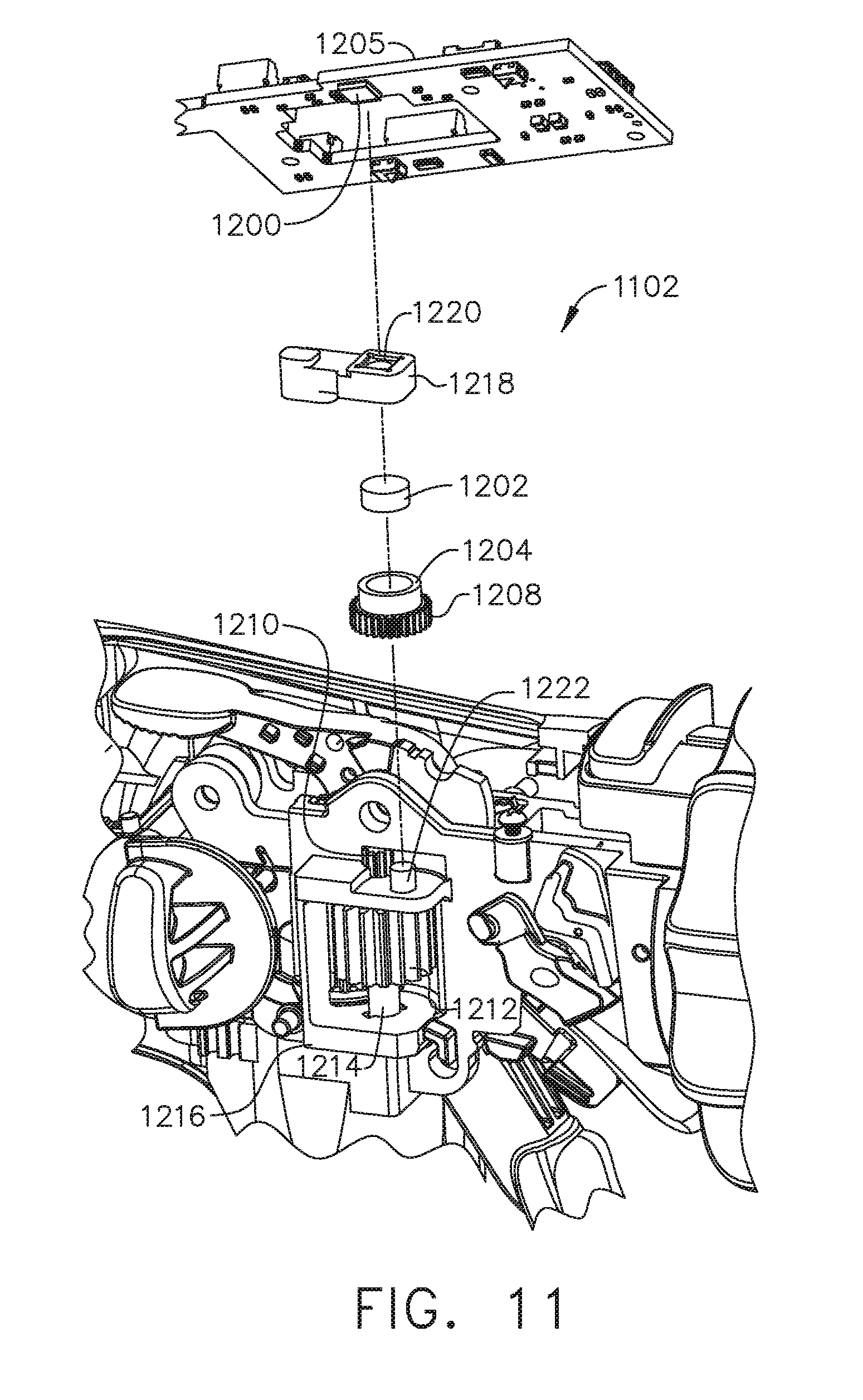
[0095] Having described a general architecture for implementing aspects of an absolute positioning system 1100 for a sensor arrangement 1102, the disclosure now turns to FIGS. 11 and 12 fora description of one aspect of a sensor arrangement 1102 for the absolute positioning system 1100. FIG. 11 is an exploded perspective view of the sensor arrangement 1102 for the absolute positioning system 1100 showing a circuit 1205 and the relative alignment of the elements of the sensor arrangement 1102, according to one aspect. The sensor arrangement 1102 for an absolute positioning system 1100 comprises a position sensor 1200, a magnet 1202 sensor element, a magnet holder 1204 that turns once every full stroke of the displacement member 1111, and a gear assembly 1206 to provide a gear reduction. With reference briefly to FIG. 2, the displacement member 1111 may represent the longitudinally movable drive member 120 comprising a rack of drive teeth 122 for meshing engagement with a corresponding drive gear 86 of the gear reducer assembly 84. Returning to FIG. 11, a structural element such as bracket 1216 is provided to support the gear assembly 1206, the magnet holder 1204, and the magnet 1202. The position sensor 1200 comprises magnetic sensing elements such as Hall elements and is placed in proximity to the magnet 1202. As the magnet 1202 rotates, the magnetic sensing elements of the position sensor 1200 determine the absolute angular position of the magnet 1202 over one revolution.
[0096] The sensor arrangement 1102 may comprise any number of magnetic sensing elements, such as, for example, magnetic sensors classified according to whether they measure the total magnetic field or the vector components of the magnetic field. The techniques used to produce both types of magnetic sensors encompass many aspects of physics and electronics. The technologies used for magnetic field sensing include search coil, fluxgate, optically pumped, nuclear precession, SQUID, Hall-effect, anisotropic magnetoresistance, giant magnetoresistance, magnetic tunnel junctions, giant magnetoimpedance, magnetostrictive/piezoelectric composites, magnetodiode, magnetotransistor, fiber optic, magnetooptic, and microelectromechanical systems-based magnetic sensors, among others.
[0097] A gear assembly comprises a first gear 1208 and a second gear 1210 in meshing engagement to provide a 3:1 gear ratio connection. A third gear 1212 rotates about a shaft 1214. The third gear 1212 is in meshing engagement with the displacement member 1111 (or 120 as shown in FIG. 2) and rotates in a first direction as the displacement member 1111 advances in a distal direction D and rotates in a second direction as the displacement member 1111 retracts in a proximal direction P. The second gear 1210 also rotates about the shaft 1214 and, therefore, rotation of the second gear 1210 about the shaft 1214 corresponds to the longitudinal translation of the displacement member 1111. Thus, one full stroke of the displacement member 1111 in either the distal or proximal directions D, P corresponds to three rotations of the second gear 1210 and a single rotation of the first gear 1208. Since the magnet holder 1204 is coupled to the first gear 1208, the magnet holder 1204 makes one full rotation with each full stroke of the displacement member 1111.
[0098] The position sensor 1200 is supported by a position sensor holder 1218 defining an aperture 1220 suitable to contain the position sensor 1200 in precise alignment with a magnet 1202 rotating below within the magnet holder 1204. The fixture is coupled to the bracket 1216 and to the circuit 1205 and remains stationary while the magnet 1202 rotates with the magnet holder 1204. A hub 1222 is provided to mate with the first gear 1208 and the magnet holder 1204. The second gear 1210 and third gear 1212 coupled to shaft 1214 also are shown.
[0099] FIG. 12 is a diagram of a position sensor 1200 for an absolute positioning system 1100 comprising a magnetic rotary absolute positioning system according to one aspect of this disclosure. The position sensor 1200 may be implemented as an AS5055EQFT single-chip magnetic rotary position sensor available from Austria Microsystems, AG. The position sensor 1200 is interfaced with the controller 1104 to provide an absolute positioning system 1100. The position sensor 1200 is a low-voltage and low-power component and includes four Hall-effect elements 1228A, 1228B, 1228C, 1228D in an area 1230 of the position sensor 1200 that is located above the magnet 1202 (FIGS. 15 and 16). A high resolution ADC 1232 and a smart power management controller 1238 are also provided on the chip. A CORDIC processor 1236 (for Coordinate Rotation Digital Computer), also known as the digit-by-digit method and Volder's algorithm, is provided to implement a simple and efficient algorithm to calculate hyperbolic and trigonometric functions that require only addition, subtraction, bitshift, and table lookup operations. The angle position, alarm bits, and magnetic field information are transmitted over a standard serial communication interface such as an SPI interface 1234 to the controller 1104. The position sensor 1200 provides 12 or 14 bits of resolution. The position sensor 1200 may be an AS5055 chip provided in a small QFN 16-pin 4.times.4.times.0.85 mm package.
[0100] The Hall-effect elements 1228A, 1228B, 1228C, 1228D are located directly above the rotating magnet 1202 (FIG. 11). The Hall-effect is a well-known effect and for expediency will not be described in detail herein, however, generally, the Hall-effect produces a voltage difference (the Hall voltage) across an electrical conductor transverse to an electric current in the conductor and a magnetic field perpendicular to the current. A Hall coefficient is defined as the ratio of the induced electric field to the product of the current density and the applied magnetic field. It is a characteristic of the material from which the conductor is made, since its value depends on the type, number, and properties of the charge carriers that constitute the current. In the AS5055 position sensor 1200, the Hall-effect elements 1228A, 1228B, 1228C, 1228D are capable producing a voltage signal that is indicative of the absolute position of the magnet 1202 in terms of the angle over a single revolution of the magnet 1202. This value of the angle, which is unique position signal, is calculated by the CORDIC processor 1236 is stored onboard the AS5055 position sensor 1200 in a register or memory. The value of the angle that is indicative of the position of the magnet 1202 over one revolution is provided to the controller 1104 in a variety of techniques, e.g., upon power up or upon request by the controller 1104.
[0101] The AS5055 position sensor 1200 requires only a few external components to operate when connected to the controller 1104. Six wires are needed for a simple application using a single power supply: two wires for power and four wires 1240 for the SPI interface 1234 with the controller 1104. A seventh connection can be added in order to send an interrupt to the controller 1104 to inform that a new valid angle can be read. Upon power-up, the AS5055 position sensor 1200 performs a full power-up sequence including one angle measurement. The completion of this cycle is indicated as an INT output 1242, and the angle value is stored in an internal register. Once this output is set, the AS5055 position sensor 1200 suspends to sleep mode. The controller 1104 can respond to the INT request at the INT output 1242 by reading the angle value from the AS5055 position sensor 1200 over the SPI interface 1234. Once the angle value is read by the controller 1104, the INT output 1242 is cleared again. Sending a "read angle" command by the SPI interface 1234 by the controller 1104 to the position sensor 1200 also automatically powers up the chip and starts another angle measurement. As soon as the controller 1104 has completed reading of the angle value, the INT output 1242 is cleared and a new result is stored in the angle register. The completion of the angle measurement is again indicated by setting the INT output 1242 and a corresponding flag in the status register.
[0102] Due to the measurement principle of the AS5055 position sensor 1200, only a single angle measurement is performed in very short time (.about.600 .mu.s) after each power-up sequence. As soon as the measurement of one angle is completed, the AS5055 position sensor 1200 suspends to power-down state. An on-chip filtering of the angle value by digital averaging is not implemented, as this would require more than one angle measurement and, consequently, a longer power-up time that is not desired in low-power applications. The angle jitter can be reduced by averaging of several angle samples in the controller 1104. For example, an averaging of four samples reduces the jitter by 6 dB (50%).
[0103] FIG. 13 is a section view of an end effector 2502 of the surgical instrument 10 (FIGS. 1-4) showing an I-beam 2514 firing stroke relative to tissue 2526 grasped within the end effector 2502 according to one aspect of this disclosure. The end effector 2502 is configured to operate with the surgical instrument 10 shown in FIGS. 1-4. The end effector 2502 comprises an anvil 2516 and an elongated channel 2503 with a staple cartridge 2518 positioned in the elongated channel 2503. A firing bar 2520 is translatable distally and proximally along a longitudinal axis 2515 of the end effector 2502. When the end effector 2502 is not articulated, the end effector 2502 is in line with the shaft of the instrument. An I-beam 2514 comprising a cutting edge 2509 is illustrated at a distal portion of the firing bar 2520. A wedge sled 2513 is positioned in the staple cartridge 2518. As the I-beam 2514 translates distally, the cutting edge 2509 contacts and may cut tissue 2526 positioned between the anvil 2516 and the staple cartridge 2518. Also, the I-beam 2514 contacts the wedge sled 2513 and pushes it distally, causing the wedge sled 2513 to contact staple drivers 2511. The staple drivers 2511 may be driven up into staples 2505, causing the staples 2505 to advance through tissue and into pockets 2507 defined in the anvil 2516, which shape the staples 2505.
[0104] An example I-beam 2514 firing stroke is illustrated by a chart 2529 aligned with the end effector 2502. Example tissue 2526 is also shown aligned with the end effector 2502. The firing member stroke may comprise a stroke begin position 2527 and a stroke end position 2528. During an I-beam 2514 firing stroke, the I-beam 2514 may be advanced distally from the stroke begin position 2527 to the stroke end position 2528. The I-beam 2514 is shown at one example location of a stroke begin position 2527. The I-beam 2514 firing member stroke chart 2529 illustrates five firing member stroke regions 2517, 2519, 2521, 2523, 2525. In a first firing stroke region 2517, the I-beam 2514 may begin to advance distally. In the first firing stroke region 2517, the I-beam 2514 may contact the wedge sled 2513 and begin to move it distally. While in the first region, however, the cutting edge 2509 may not contact tissue and the wedge sled 2513 may not contact a staple driver 2511. After static friction is overcome, the force to drive the I-beam 2514 in the first region 2517 may be substantially constant.
[0105] In the second firing member stroke region 2519, the cutting edge 2509 may begin to contact and cut tissue 2526. Also, the wedge sled 2513 may begin to contact staple drivers 2511 to drive staples 2505. Force to drive the I-beam 2514 may begin to ramp up. As shown, tissue encountered initially may be compressed and/or thinner because of the way that the anvil 2516 pivots relative to the staple cartridge 2518. In the third firing member stroke region 2521, the cutting edge 2509 may continuously contact and cut tissue 2526 and the wedge sled 2513 may repeatedly contact staple drivers 2511. Force to drive the I-beam 2514 may plateau in the third region 2521. By the fourth firing stroke region 2523, force to drive the I-beam 2514 may begin to decline. For example, tissue in the portion of the end effector 2502 corresponding to the fourth firing region 2523 may be less compressed than tissue closer to the pivot point of the anvil 2516, requiring less force to cut. Also, the cutting edge 2509 and wedge sled 2513 may reach the end of the tissue 2526 while in the fourth region 2523. When the I-beam 2514 reaches the fifth region 2525, the tissue 2526 may be completely severed. The wedge sled 2513 may contact one or more staple drivers 2511 at or near the end of the tissue. Force to advance the I-beam 2514 through the fifth region 2525 may be reduced and, in some examples, may be similar to the force to drive the I-beam 2514 in the first region 2517. At the conclusion of the firing member stroke, the I-beam 2514 may reach the stroke end position 2528. The positioning of firing member stroke regions 2517, 2519, 2521, 2523, 2525 in FIG. 18 is just one example. In some examples, different regions may begin at different positions along the end effector longitudinal axis 2515, for example, based on the positioning of tissue between the anvil 2516 and the staple cartridge 2518.
[0106] As discussed above and with reference now to FIGS. 10-13, the electric motor 1122 positioned within the handle assembly of the surgical instrument 10 (FIGS. 1-4) can be utilized to advance and/or retract the firing system of the shaft assembly, including the I-beam 2514, relative to the end effector 2502 of the shaft assembly in order to staple and/or incise tissue captured within the end effector 2502. The I-beam 2514 may be advanced or retracted at a desired speed, or within a range of desired speeds. The controller 1104 may be configured to control the speed of the I-beam 2514. The controller 1104 may be configured to predict the speed of the I-beam 2514 based on various parameters of the power supplied to the electric motor 1122, such as voltage and/or current, for example, and/or other operating parameters of the electric motor 1122 or external influences. The controller 1104 may be configured to predict the current speed of the I-beam 2514 based on the previous values of the current and/or voltage supplied to the electric motor 1122, and/or previous states of the system like velocity, acceleration, and/or position. The controller 1104 may be configured to sense the speed of the I-beam 2514 utilizing the absolute positioning sensor system described herein. The controller can be configured to compare the predicted speed of the I-beam 2514 and the sensed speed of the I-beam 2514 to determine whether the power to the electric motor 1122 should be increased in order to increase the speed of the I-beam 2514 and/or decreased in order to decrease the speed of the I-beam 2514. Further regarding surgical instruments 10 driven by an electric motor 1122 may be found in U.S. Pat. No. 8,210,411, entitled MOTOR-DRIVEN SURGICAL CUTTING INSTRUMENT, which is hereby incorporated herein by reference in its entirety. Further detail regarding surgical instruments 10 including sensor arrangements may be found in U.S. Pat. No. 7,845,537, entitled SURGICAL INSTRUMENT HAVING RECORDING CAPABILITIES, which is hereby incorporated herein by reference in its entirety.
[0107] Force acting on the I-beam 2514 may be determined using various techniques. The I-beam 2514 force may be determined by measuring the motor 2504 current, where the motor 2504 current is based on the load experienced by the I-beam 2514 as it advances distally. The I-beam 2514 force may be determined by positioning a strain gauge on the drive member 120 (FIG. 2), the firing member 220 (FIG. 2), I-beam 2514 (I-beam 178, FIG. 20), the firing bar 172 (FIG. 2), and/or on a proximal end of the cutting edge 2509. The I-beam 2514 force may be determined by monitoring the actual position of the I-beam 2514 moving at an expected velocity based on the current set velocity of the motor 2504 after a predetermined elapsed period T.sub.1 and comparing the actual position of the I-beam 2514 relative to the expected position of the I-beam 2514 based on the current set velocity of the motor 2504 at the end of the period T.sub.1. Thus, if the actual position of the I-beam 2514 is less than the expected position of the I-beam 2514, the force on the I-beam 2514 is greater than a nominal force. Conversely, if the actual position of the I-beam 2514 is greater than the expected position of the I-beam 2514, the force on the I-beam 2514 is less than the nominal force. The difference between the actual and expected positions of the I-beam 2514 is proportional to the deviation of the force on the I-beam 2514 from the nominal force. Such techniques are described in U.S. patent application Ser. No. 15/628,075, entitled SYSTEMS AND METHODS FOR CONTROLLING MOTOR VELOCITY OF A SURGICAL STAPLING AND CUTTING INSTRUMENT, which is hereby incorporated herein by reference in its entirety.
[0108] FIG. 14 illustrates a block diagram of a surgical instrument 2500 programmed to control distal translation of a displacement member according to one aspect of this disclosure. In one aspect, the surgical instrument 2500 is programmed to control distal translation of a displacement member 1111 such as the I-beam 2514. The surgical instrument 2500 comprises an end effector 2502 that may comprise an anvil 2516, an I-beam 2514 (including a sharp cutting edge 2509), and a removable staple cartridge 2518. The end effector 2502, anvil 2516, I-beam 2514, and staple cartridge 2518 may be configured as described herein, for example, with respect to FIGS. 1-13.
[0109] The position, movement, displacement, and/or translation of a liner displacement member 1111, such as the I-beam 2514, can be measured by the absolute positioning system 1100, sensor arrangement 1102, and position sensor 1200 as shown in FIGS. 10-12 and represented as position sensor 2534 in FIG. 14. Because the I-beam 2514 is coupled to the longitudinally movable drive member 120, the position of the I-beam 2514 can be determined by measuring the position of the longitudinally movable drive member 120 employing the position sensor 2534. Accordingly, in the following description, the position, displacement, and/or translation of the I-beam 2514 can be achieved by the position sensor 2534 as described herein. A control circuit 2510, such as the control circuit 700 described in FIGS. 5A and 5B, may be programmed to control the translation of the displacement member 1111, such as the I-beam 2514, as described in connection with FIGS. 10-12. The control circuit 2510, in some examples, may comprise one or more microcontrollers, microprocessors, or other suitable processors for executing instructions that cause the processor or processors to control the displacement member, e.g., the I-beam 2514, in the manner described. In one aspect, a timer/counter circuit 2531 provides an output signal, such as elapsed time or a digital count, to the control circuit 2510 to correlate the position of the I-beam 2514 as determined by the position sensor 2534 with the output of the timer/counter circuit 2531 such that the control circuit 2510 can determine the position of the I-beam 2514 at a specific time (t) relative to a starting position. The timer/counter circuit 2531 may be configured to measure elapsed time, count external evens, or time external events.
[0110] The control circuit 2510 may generate a motor set point signal 2522. The motor set point signal 2522 may be provided to a motor controller 2508. The motor controller 2508 may comprise one or more circuits configured to provide a motor drive signal 2524 to the motor 2504 to drive the motor 2504 as described herein. In some examples, the motor 2504 may be a brushed DC electric motor, such as the motor 82, 714, 1120 shown in FIGS. 1, 5B, 10. For example, the velocity of the motor 2504 may be proportional to the motor drive signal 2524. In some examples, the motor 2504 may be a brushless direct current (DC) electric motor and the motor drive signal 2524 may comprise a pulse-width-modulated (PWM) signal provided to one or more stator windings of the motor 2504. Also, in some examples, the motor controller 2508 may be omitted and the control circuit 2510 may generate the motor drive signal 2524 directly.
[0111] The motor 2504 may receive power from an energy source 2512. The energy source 2512 may be or include a battery, a super capacitor, or any other suitable energy source 2512. The motor 2504 may be mechanically coupled to the I-beam 2514 via a transmission 2506. The transmission 2506 may include one or more gears or other linkage components to couple the motor 2504 to the I-beam 2514. A position sensor 2534 may sense a position of the I-beam 2514. The position sensor 2534 may be or include any type of sensor that is capable of generating position data that indicates a position of the I-beam 2514. In some examples, the position sensor 2534 may include an encoder configured to provide a series of pulses to the control circuit 2510 as the I-beam 2514 translates distally and proximally. The control circuit 2510 may track the pulses to determine the position of the I-beam 2514. Other suitable position sensor may be used, including, for example, a proximity sensor. Other types of position sensors may provide other signals indicating motion of the I-beam 2514. Also, in some examples, the position sensor 2534 may be omitted. Where the motor 2504 is a stepper motor, the control circuit 2510 may track the position of the I-beam 2514 by aggregating the number and direction of steps that the motor 2504 has been instructed to execute. The position sensor 2534 may be located in the end effector 2502 or at any other portion of the instrument.
[0112] The control circuit 2510 may be in communication with one or more sensors 2538. The sensors 2538 may be positioned on the end effector 2502 and adapted to operate with the surgical instrument 2500 to measure the various derived parameters such as gap distance versus time, tissue compression versus time, and anvil strain versus time. The sensors 2538 may comprise a magnetic sensor, a magnetic field sensor, a strain gauge, a pressure sensor, a force sensor, an inductive sensor such as an eddy current sensor, a resistive sensor, a capacitive sensor, an optical sensor, and/or any other suitable sensor for measuring one or more parameters of the end effector 2502. The sensors 2538 may include one or more sensors.
[0113] The one or more sensors 2538 may comprise a strain gauge, such as a micro-strain gauge, configured to measure the magnitude of the strain in the anvil 2516 during a clamped condition. The strain gauge provides an electrical signal whose amplitude varies with the magnitude of the strain. The sensors 2538 may comprise a pressure sensor configured to detect a pressure generated by the presence of compressed tissue between the anvil 2516 and the staple cartridge 2518. The sensors 2538 may be configured to detect impedance of a tissue section located between the anvil 2516 and the staple cartridge 2518 that is indicative of the thickness and/or fullness of tissue located therebetween.
[0114] The sensors 2538 may be is configured to measure forces exerted on the anvil 2516 by the closure drive system 30. For example, one or more sensors 2538 can be at an interaction point between the closure tube 260 (FIG. 3) and the anvil 2516 to detect the closure forces applied by the closure tube 260 to the anvil 2516. The forces exerted on the anvil 2516 can be representative of the tissue compression experienced by the tissue section captured between the anvil 2516 and the staple cartridge 2518. The one or more sensors 2538 can be positioned at various interaction points along the closure drive system 30 (FIG. 2) to detect the closure forces applied to the anvil 2516 by the closure drive system 30. The one or more sensors 2538 may be sampled in real time during a clamping operation by a processor as described in FIGS. 5A-5B. The control circuit 2510 receives real-time sample measurements to provide analyze time based information and assess, in real time, closure forces applied to the anvil 2516.
[0115] A current sensor 2536 can be employed to measure the current drawn by the motor 2504. The force required to advance the I-beam 2514 corresponds to the current drawn by the motor 2504. The force is converted to a digital signal and provided to the control circuit 2510.
[0116] Using the physical properties of the instruments disclosed herein in connection with FIGS. 1-13, and with reference to FIG. 14, the control circuit 2510 can be configured to simulate the response of the actual system of the instrument in the software of the controller. A displacement member can be actuated to move an I-beam 2514 in the end effector 2502 at or near a target velocity. The surgical instrument 2500 can include a feedback controller, which can be one of any feedback controllers, including, but not limited to a PID, a State Feedback, LQR, and/or an Adaptive controller, for example. The surgical instrument 2500 can include a power source to convert the signal from the feedback controller into a physical input such as case voltage, pulse width modulated (PWM) voltage, frequency modulated voltage, current, torque, and/or force, for example.
[0117] The actual drive system of the surgical instrument 2500 is configured to drive the displacement member, cutting member, or I-beam 2514, by a brushed DC motor with gearbox and mechanical links to an articulation and/or knife system. Another example is the electric motor 2504 that operates the displacement member and the articulation driver, for example, of an interchangeable shaft assembly. An outside influence is an unmeasured, unpredictable influence of things like tissue, surrounding bodies and friction on the physical system. Such outside influence can be referred to as drag which acts in opposition to the electric motor 2504. The outside influence, such as drag, may cause the operation of the physical system to deviate from a desired operation of the physical system.
[0118] Before explaining aspects of the surgical instrument 2500 in detail, it should be noted that the example aspects are not limited in application or use to the details of construction and arrangement of parts illustrated in the accompanying drawings and description. The example aspects may be implemented or incorporated in other aspects, variations and modifications, and may be practiced or carried out in various ways. Further, unless otherwise indicated, the terms and expressions employed herein have been chosen for the purpose of describing the example aspects for the convenience of the reader and are not for the purpose of limitation thereof. Also, it will be appreciated that one or more of the following-described aspects, expressions of aspects and/or examples, can be combined with any one or more of the other following-described aspects, expressions of aspects and/or examples.
[0119] Various example aspects are directed to a surgical instrument 2500 comprising an end effector 2502 with motor-driven surgical stapling and cutting implements. For example, a motor 2504 may drive a displacement member distally and proximally along a longitudinal axis of the end effector 2502. The end effector 2502 may comprise a pivotable anvil 2516 and, when configured for use, a staple cartridge 2518 positioned opposite the anvil 2516. A clinician may grasp tissue between the anvil 2516 and the staple cartridge 2518, as described herein. When ready to use the instrument 2500, the clinician may provide a firing signal, for example by depressing a trigger of the instrument 2500. In response to the firing signal, the motor 2504 may drive the displacement member distally along the longitudinal axis of the end effector 2502 from a proximal stroke begin position to a stroke end position distal of the stroke begin position. As the displacement member translates distally, an I-beam 2514 with a cutting element positioned at a distal end, may cut the tissue between the staple cartridge 2518 and the anvil 2516.
[0120] In various examples, the surgical instrument 2500 may comprise a control circuit 2510 programmed to control the distal translation of the displacement member, such as the I-beam 2514, for example, based on one or more tissue conditions. The control circuit 2510 may be programmed to sense tissue conditions, such as thickness, either directly or indirectly, as described herein. The control circuit 2510 may be programmed to select a firing control program based on tissue conditions. A firing control program may describe the distal motion of the displacement member. Different firing control programs may be selected to better treat different tissue conditions. For example, when thicker tissue is present, the control circuit 2510 may be programmed to translate the displacement member at a lower velocity and/or with lower power. When thinner tissue is present, the control circuit 2510 may be programmed to translate the displacement member at a higher velocity and/or with higher power.
[0121] In some examples, the control circuit 2510 may initially operate the motor 2504 in an open loop configuration for a first open loop portion of a stroke of the displacement member. Based on a response of the instrument 2500 during the open loop portion of the stroke, the control circuit 2510 may select a firing control program. The response of the instrument may include, a translation distance of the displacement member during the open loop portion, a time elapsed during the open loop portion, energy provided to the motor 2504 during the open loop portion, a sum of pulse widths of a motor drive signal, etc. After the open loop portion, the control circuit 2510 may implement the selected firing control program for a second portion of the displacement member stroke. For example, during the closed loop portion of the stroke, the control circuit 2510 may modulate the motor 2504 based on translation data describing a position of the displacement member in a closed loop manner to translate the displacement member at a constant velocity.
[0122] FIG. 15 illustrates a diagram 2580 plotting two example displacement member strokes executed according to one aspect of this disclosure. The diagram 2580 comprises two axes. A horizontal axis 2584 indicates elapsed time. A vertical axis 2582 indicates the position of the I-beam 2514 between a stroke begin position 2586 and a stroke end position 2588. On the horizontal axis 2584, the control circuit 2510 may receive the firing signal and begin providing the initial motor setting at t.sub.0. The open loop portion of the displacement member stroke is an initial time period that may elapse between t.sub.0 and t.sub.1.
[0123] A first example 2592 shows a response of the surgical instrument 2500 when thick tissue is positioned between the anvil 2516 and the staple cartridge 2518. During the open loop portion of the displacement member stroke, e.g., the initial time period between t.sub.0 and t.sub.1, the I-beam 2514 may traverse from the stroke begin position 2586 to position 2594. The control circuit 2510 may determine that position 2594 corresponds to a firing control program that advances the I-beam 2514 at a selected constant velocity (V.sub.slow), indicated by the slope of the example 2592 after t.sub.1 (e.g., in the closed loop portion). The control circuit 2510 may drive I-beam 2514 to the velocity V.sub.slow by monitoring the position of I-beam 2514 and modulating the motor set point signal 2522 and/or motor drive signal 2524 to maintain V.sub.slow.
[0124] A second example 2590 shows a response of the surgical instrument 2500 when thin tissue is positioned between the anvil 2516 and the staple cartridge 2518. During the initial time period (e.g., the open loop period) between t.sub.0 and t.sub.1, the I-beam 2514 may traverse from the stroke begin position 2586 to position 2596. The control circuit may determine that position 2596 corresponds to a firing control program that advances the displacement member at a selected constant velocity (V.sub.fast). Because the tissue in example 2590 is thinner than the tissue in example 2592, it may provide less resistance to the motion of the I-beam 2514. As a result, the I-beam 2514 may traverse a larger portion of the stroke during the initial time period. Also, in some examples, thinner tissue (e.g., a larger portion of the displacement member stroke traversed during the initial time period) may correspond to higher displacement member velocities after the initial time period.
[0125] FIGS. 16-21 illustrate an end effector 2300 of a surgical instrument 2010 showing how the end effector 2300 may be articulated relative to the elongate shaft assembly 2200 about an articulation joint 2270 according to one aspect of this disclosure. FIG. 16 is a partial perspective view of a portion of the end effector 2300 showing an elongate shaft assembly 2200 in an unarticulated orientation with portions thereof omitted for clarity. FIG. 17 is a perspective view of the end effector 2300 of FIG. 16 showing the elongate shaft assembly 2200 in an unarticulated orientation. FIG. 18 is an exploded assembly perspective view of the end effector 2300 of FIG. 16 showing the elongate shaft assembly 2200. FIG. 19 is a top view of the end effector 2300 of FIG. 16 showing the elongate shaft assembly 2200 in an unarticulated orientation. FIG. 20 is a top view of the end effector 2300 of FIG. 16 showing the elongate shaft assembly 2200 in a first articulated orientation. FIG. 21 is a top view of the end effector 2300 of FIG. 16 showing the elongate shaft assembly 2200 in a second articulated orientation.
[0126] With reference now to FIGS. 16-21, the end effector 2300 is adapted to cut and staple tissue and includes a first jaw in the form of an elongated channel 2302 that is configured to operably support a surgical staple cartridge 2304 therein. The end effector 2300 further includes a second jaw in the form of an anvil 2310 that is supported on the elongated channel 2302 for movement relative thereto. The elongate shaft assembly 2200 includes an articulation system 2800 that employs an articulation lock 2810. The articulation lock 2810 can be configured and operated to selectively lock the surgical end effector 2300 in various articulated positions. Such arrangement enables the surgical end effector 2300 to be rotated, or articulated, relative to the shaft closure tube 260 when the articulation lock 2810 is in its unlocked state. Referring specifically to FIG. 18, the elongate shaft assembly 2200 includes a spine 210 that is configured to (1) slidably support a firing member 220 therein and, (2) slidably support the closure tube 260 (FIG. 16), which extends around the spine 210. The shaft closure tube 260 is attached to an end effector closure sleeve 272 that is pivotally attached to the closure tube 260 by a double pivot closure sleeve assembly 271.
[0127] The spine 210 also slidably supports a proximal articulation driver 230. The proximal articulation driver 230 has a distal end 231 that is configured to operably engage the articulation lock 2810. The articulation lock 2810 further comprises a shaft frame 2812 that is attached to the spine 210 in the various manners disclosed herein. The shaft frame 2812 is configured to movably support a proximal portion 2821 of a distal articulation driver 2820 therein. The distal articulation driver 2820 is movably supported within the elongate shaft assembly 2200 for selective longitudinal travel in a distal direction DD and a proximal direction PD along an articulation actuation axis AAA that is laterally offset and parallel to the shaft axis SA-SA in response to articulation control motions applied thereto.
[0128] In FIGS. 17 and 18, the shaft frame 2812 includes a distal end portion 2814 that has a pivot pin 2818 formed thereon. The pivot pin 2818 is adapted to be pivotally received within a pivot hole 2397 formed in pivot base portion 2395 of an end effector mounting assembly 2390. The end effector mounting assembly 2390 is attached to the proximal end 2303 of the elongated channel 2302 by a spring pin 2393 or equivalent. The pivot pin 2818 defines an articulation axis B-B transverse to the shaft axis SA-SA to facilitate pivotal travel (i.e., articulation) of the end effector 2300 about the articulation axis B-B relative to the shaft frame 2812.
[0129] As shown in FIG. 18, a link pin 2825 is formed on a distal end 2823 of the distal articulation driver 2820 and is configured to be received within a hole 2904 in a proximal end 2902 of a cross link 2900. The cross link 2900 extends transversely across the shaft axis SA-SA and includes a distal end portion 2906. A distal link hole 2908 is provided through the distal end portion 2906 of the cross link 2900 and is configured to pivotally receive therein a base pin 2398 extending from the bottom of the pivot base portion 2395 of the end effector mounting assembly 2390. The base pin 2398 defines a link axis LA that is parallel to the articulation axis B-B. FIGS. 17 and 20 illustrate the surgical end effector 2300 in an unarticulated position. The end effector axis EA is defined by the elongated channel 2302 is aligned with the shaft axis SA-SA. The term "aligned with" may mean "coaxially aligned" with the shaft axis SA-SA or parallel with the shaft axis SA-SA. Movement of the distal articulation driver 2820 in the proximal direction PD will cause the cross link 2900 to draw the surgical end effector 2300 in a clockwise CW direction about the articulation axis B-B as shown in FIG. 19. Movement of the distal articulation driver 2820 in the distal direction DD will cause the cross link 2900 to move the surgical end effector 2300 in the counterclockwise CCW direction about the articulation axis B-B as shown in FIG. 21. As shown in FIG. 21, the cross link 2900 has a curved shape that permits the cross link 2900 to curve around the pivot pin 2818 when the surgical end effector 2300 is articulated in that direction. When the surgical end effector 2300 is in a fully articulated position on either side of the shaft axis SA-SA, the articulation angle 2700 between the end effector axis EA and the shaft axis SA-SA is approximately sixty-five degrees (65.degree.). Thus, the range of articulation on either said of the shaft axis is from one degree (1.degree.) to sixty-five degrees (65.degree.).
[0130] FIG. 19 shows the articulation joint 2270 in a straight position, i.e., at a zero angle .theta..sub.0 relative to the longitudinal direction depicted as shaft axis SA, according to one aspect. FIG. 20 shows the articulation joint 2270 of FIG. 19 articulated in one direction at a first angle .theta..sub.1 defined between the shaft axis SA and the end effector axis EA, according to one aspect. FIG. 21 illustrates the articulation joint 2270 of FIG. 19 articulated in another direction at a second angle .theta..sub.2 defined between the shaft axis SA and the end effector axis EA.
[0131] The surgical end effector 2300 in FIGS. 16-21 comprises a surgical cutting and stapling device that employs a firing member 220 of the various types and configurations described herein. However, the surgical end effector 2300 may comprise other forms of surgical end effectors that do not cut and/or staple tissue. A middle support member 2950 is pivotally and slidably supported relative to the spine 210. In FIG. 18, the middle support member 2950 includes a slot 2952 that is adapted to receive therein a pin 2954 that protrudes from the spine 210. This enables the middle support member 2950 to pivot and translate relative to the pin 2954 when the surgical end effector 2300 is articulated. A pivot pin 2958 protrudes from the underside of the middle support member 2950 to be pivotally received within a corresponding pivot hole 2399 provided in the base portion 2395 of the end effector mounting assembly 2390. The middle support member 2950 further includes a slot 2960 for receiving a firing member 220 there through. The middle support member 2950 serves to provide lateral support to the firing member 220 as it flexes to accommodate articulation of the surgical end effector 2300.
[0132] The surgical instrument can additionally be configured to determine the angle at which the end effector 2300 is oriented. In various aspects, the position sensor 1112 of the sensor arrangement 1102 may comprise one or more magnetic sensors, analog rotary sensors (such as potentiometers), arrays of analog Hall effect sensors, which output a unique combination of position signals or values, among others, for example. In one aspect, the articulation joint 2270 of the aspect illustrated in FIGS. 16-21 can additionally comprise an articulation sensor arrangement that is configured to determine the angular position, i.e., articulation angle, of the end effector 2300 and provide a unique position signal corresponding thereto.
[0133] The articulation sensor arrangement can be similar to the sensor arrangement 1102 described above and illustrated in FIGS. 10-12. In this aspect, the articulation sensor arrangement can comprise a position sensor and a magnet that is operatively coupled to the articulation joint 2270 such that it rotates in a manner consistent with the rotation of the articulation joint 2270. The magnet can, for example, be coupled to the pivot pin 2818. The position sensor comprises one or more magnetic sensing elements, such as Hall effect sensors, and is placed in proximity to the magnet, either within or adjacent to the articulation joint 2270. Accordingly, as the magnet rotates, the magnetic sensing elements of the position sensor determine the magnet's absolute angular position. As the magnet is coupled to the articulation joint 2270, the angular position of the magnet with respect to the position sensor corresponds to the angular position of the end effector 2300. Therefore, the articulation sensor arrangement is able to determine the angular position of the end effector as the end effector articulates.
[0134] In another aspect, the surgical instrument is configured to determine the angle at which the end effector 2300 is positioned in an indirect manner by monitoring the absolute position of the articulation driver 230 (FIG. 3). As the position of the articulation driver 230 corresponds to the angle at which the end effector 2300 is oriented in a known manner, the absolute position of the articulation driver 230 can be tracked and then translated to the angular position of the end effector 2300. In this aspect, the surgical instrument comprises an articulation sensor arrangement that is configured to determine the absolute linear position of the articulation driver 230 and provide a unique position signal corresponding thereto. In some aspects, the articulation sensor arrangement or the controller operably coupled to the articulation sensor arrangement is configured additionally to translate or calculate the angular position of the end effector 2300 from the unique position signal.
[0135] The articulation sensor arrangement in this aspect can likewise be similar to the sensor arrangement 1102 described above and illustrated in FIGS. 10-12. In one aspect similar to the aspect illustrated in FIG. 10 with respect to the displacement member 1111, the articulation sensor arrangement comprises a position sensor and a magnet that turns once every full stroke of the longitudinally-movable articulation driver 230. The position sensor comprises one or more magnetic sensing elements, such as Hall effect sensors, and is placed in proximity to the magnet. Accordingly, as the magnet rotates, the magnetic sensing elements of the position sensor determine the absolute angular position of the magnet over one revolution.
[0136] In one aspect, a single revolution of a sensor element associated with the position sensor is equivalent to a longitudinal linear displacement dl of the of the longitudinally-movable articulation driver 230. In other words, dl is the longitudinal linear distance that the longitudinally-movable articulation driver 230 moves from point "a" to point "b" after a single revolution of a sensor element coupled to the longitudinally-movable articulation driver 230. The articulation sensor arrangement may be connected via a gear reduction that results in the position sensor completing only one revolution for the full stroke of the longitudinally-movable articulation driver 230. In other words, d1 can be equal to the full stroke of the articulation driver 230. The position sensor is configured to then transmit a unique position signal corresponding to the absolute position of the articulation driver 230 to the controller 1104, such as in those aspects depicted in FIG. 10 Upon receiving the unique position signal, the controller 1104 is then configured execute a logic to determine the angular position of the end effector corresponding to the linear position of the articulation driver 230 by, for example, querying a lookup table that returns the value of the pre-calculated angular position of the end effector 2300, calculating via an algorithm the angular position of the end effector 2300 utilizing the linear position of the articulation driver 230 as the input, or performing any other such method as is known in the field.
[0137] In various aspects, any number of magnetic sensing elements may be employed on the articulation sensor arrangement, such as, for example, magnetic sensors classified according to whether they measure the total magnetic field or the vector components of the magnetic field. The number of magnetic sensing elements utilized corresponds to the desired resolution to be sensed by the articulation sensor arrangement. In other words, the larger number of magnetic sensing elements used, the finer degree of articulation that can be sensed by the articulation sensor arrangement. The techniques used to produce both types of magnetic sensors encompass many aspects of physics and electronics. The technologies used for magnetic field sensing include search coil, fluxgate, optically pumped, nuclear precession, SQUID, Hall-effect, anisotropic magnetoresistance, giant magnetoresistance, magnetic tunnel junctions, giant magnetoimpedance, magnetostrictive/piezoelectric composites, magnetodiode, magnetotransistor, fiber optic, magnetooptic, and microelectromechanical systems-based magnetic sensors, among others.
[0138] In one aspect, the position sensor of the various aspects of the articulation sensor arrangement may be implemented in a manner similar to the positioning system illustrated in FIG. 12 for tracking the position of the displacement member 1111. In one such aspect, the articulation sensor arrangement may be implemented as an AS5055EQFT single-chip magnetic rotary position sensor available from Austria Microsystems, AG. The position sensor is interfaced with the controller to provide an absolute positioning system for determining the absolute angular position of the end effector 2300, either directly or indirectly. The position sensor is a low voltage and low power component and includes four Hall-effect elements 1228A, 1228B, 1228C, 1228D in an area 1230 of the position sensor 1200 that is located above the magnet 1202 (FIG. 11). A high resolution ADC 1232 and a smart power management controller 1238 are also provided on the chip. A CORDIC processor 1236 (for Coordinate Rotation Digital Computer), also known as the digit-by-digit method and Volder's algorithm, is provided to implement a simple and efficient algorithm to calculate hyperbolic and trigonometric functions that require only addition, subtraction, bitshift, and table lookup operations. The angle position, alarm bits and magnetic field information are transmitted over a standard serial communication interface such as an SPI interface 1234 to the controller 1104. The position sensor 1200 provides 12 or 14 bits of resolution. The position sensor 1200 may be an AS5055 chip provided in a small QFN 16-pin 4.times.4.times.0.85 mm package.
[0139] With reference to FIGS. 1-4 and 10-12, the position of the articulation joint 2270 and the position of the I-beam 178 (FIG. 4) can be determined with the absolute position feedback signal/value from the absolute positioning system 1100. In one aspect, the articulation angle can be determined based on the drive member 120 of the surgical instrument 10. As described above, the movement of the longitudinally movable drive member 120 (FIG. 2) can be tracked by the absolute positioning system 1100 wherein, when the articulation drive is operably coupled to the firing member 220 (FIG. 3) by the clutch assembly 400 (FIG. 3), for example, the absolute positioning system 1100 can, in effect, track the movement of the articulation system via the drive member 120. As a result of tracking the movement of the articulation system, the controller of the surgical instrument can track the articulation angle .theta. of the end effector 2300. In various circumstances, as a result, the articulation angle 6 can be determined as a function of longitudinal displacement of the drive member 120. Since the longitudinal displacement of the drive member 120 can be precisely determined based on the absolute position signal/value provided by the absolute positioning system 1100, the articulation angle .theta. can be determined as a function of longitudinal displacement.
[0140] In another aspect, the articulation angle .theta. can be determined by locating sensors at the articulation joint 2270. The sensors can be configured to sense rotation of the articulation joint 2270 using the absolute positioning system 1100 in a manner adapted to measure absolute rotation of the articulation joint 2270, rather than the longitudinal displacement of the drive member 120, as described above. For example, the sensor arrangement 1102 comprises a position sensor 1200, a magnet 1202, and a magnet holder 1204 adapted to sense rotation of the articulation joint 2270. The position sensor 1200 comprises one or more than one magnetic sensing elements such as Hall elements and is placed in proximity to the magnet 1202. The position sensor 1200 described in FIG. 12 can be adapted to measure the rotation angle of the articulation joint 2270. Accordingly, as the magnet 1202 rotates, the magnetic sensing elements of the position sensor 1200 determine the absolute angular position of the magnet 1202 located on the articulation joint 2270. This information is provided to the controller 1104 to calculate the articulation angle of the articulation joint 2270. Accordingly, the articulation angle of the end effector 2300 can be determined by the absolute positioning system 1100 adapted to measure absolute rotation of the articulation joint 2270.
[0141] In one aspect, the firing rate or velocity of the I-beam 178 may be varied as a function of end effector 2300 articulation angle to lower the force-to-fire on the firing drive system 80 and, in particular, the force-to-fire of the I-beam 178, among other components of the firing drive system 80 discussed herein. To adapt to the variable firing force of the I-beam 178 as a function of end effector 2300 articulation angle, a variable motor control voltage can be applied to the motor 82 to control the velocity of the motor 82. The velocity of the motor 82 may be controlled by comparing the I-beam 178 firing force to different maximum thresholds based on articulation angle of the end effector 2300. The velocity of the electric motor 82 can be varied by adjusting the voltage, current, pulse width modulation (PWM), or duty cycle (0-100%) applied to the motor 82, for example.
[0142] FIGS. 22 and 23 depict a motor-driven surgical instrument 10 that may be used to perform a variety of different surgical procedures. The surgical instrument 10 can comprise an end effector 3602, which can comprise one or more electrodes. The end effector 3602 can be positioned against tissue such that electrical current may be introduced into the tissue. The surgical instrument 10 can be configured for monopolar or bipolar operation. During monopolar operation, current may be introduced into the tissue by an active (or source) electrode on the end effector 3602 and returned through a return electrode. The return electrode may be a grounding pad and separately located on a patient's body. During bipolar operation, current may be introduced into and returned from the tissue by the active and return electrodes, respectively, of the end effector.
[0143] The end effector 3602 can comprise a first jaw 3604 and a second jaw member 3608. At least one of the jaw members 3604, 3608 may have at least one electrode. At least one of the jaw members 3604, 3608 may be moveable from a position spaced apart from the opposing jaw for receiving tissues to a position in which the space between the jaw members 3604, 3608 is less than that of the first position. This movement of the moveable jaw may compress the tissue held between. Heat generated by the current flow through the tissue in combination with the compression achieved by the jaw's movement may form hemostatic seals within the tissue and/or between tissues and, thus, may be particularly useful for sealing blood vessels, for example. The surgical instrument 10 may comprise a knife member 3628 that is extendable through the end effector 3602. The knife member 3628 may be movable relative to the tissue and the electrodes to transect the tissue.
[0144] The surgical instrument 10 may include mechanisms to clamp tissue together, such as a stapling device, and/or mechanisms to sever tissue, such as a tissue knife. The electrosurgical instrument 10 may include a shaft for placing the end effector 3602 proximate to tissue undergoing treatment. The shaft may be straight or curved, bendable or non-bendable. In an electrosurgical instrument 10 including a straight and bendable shaft, the shaft may have one or more articulation joints to permit controlled bending of the shaft. Such joints may permit a user of the electrosurgical instrument 10 to place the end effector in contact with tissue at an angle to the shaft when the tissue being treated is not readily accessible using an electrosurgical device having a straight, non-bending shaft.
[0145] Electrical energy applied by electrosurgical devices can be transmitted to the instrument by a generator 3400 in communication with the handle assembly 3500. The electrical energy may be in the form of radio frequency ("RF") energy. RF energy is a form of electrical energy that may be in the frequency range of 200 kilohertz (kHz) to 1 megahertz (MHz). In application, an electrosurgical instrument can transmit low frequency RF energy through tissue, which causes ionic agitation, or friction, in effect resistive heating, thereby increasing the temperature of the tissue. Because a sharp boundary is created between the affected tissue and the surrounding tissue, surgeons can operate with a high level of precision and control, without sacrificing un-targeted adjacent tissue. The low operating temperatures of RF energy is useful for removing, shrinking, or sculpting soft tissue while simultaneously sealing blood vessels. RF energy works particularly well on connective tissue, which is primarily comprised of collagen and shrinks when contacted by heat.
[0146] The RF energy may be in a frequency range described in EN 60601-2-2:2009+A11:2011, Definition 201.3.218--HIGH FREQUENCY. For example, the frequency in monopolar RF applications may be typically restricted to less than 5 MHz. However, in bipolar RF applications, the frequency can be almost anything. Frequencies above 200 kHz can be typically used for monopolar applications in order to avoid the unwanted stimulation of nerves and muscles that would result from the use of low frequency current. Lower frequencies may be used for bipolar applications if the risk analysis shows the possibility of neuromuscular stimulation has been mitigated to an acceptable level. Normally, frequencies above 5 MHz are not used in order to minimize the problems associated with high frequency leakage currents. Higher frequencies may, however, be used in the case of bipolar applications. It is generally recognized that 10 mA is the lower threshold of thermal effects on tissue.
[0147] In the illustrated arrangement, the surgical instrument 10 comprises an interchangeable surgical tool assembly 3600 that is operably coupled to a handle assembly 3500. In another surgical system aspect, the interchangeable surgical tool assembly 3600 may also be effectively employed with a tool drive assembly of a robotically controlled or automated surgical system. For example, the surgical tool assembly 3600 disclosed herein may be employed with various robotic systems, instruments, components and methods such as, but not limited to, those disclosed in U.S. Pat. No. 9,072,535, entitled SURGICAL STAPLING INSTRUMENTS WITH ROTATABLE STAPLE DEPLOYMENT ARRANGEMENTS, which is hereby incorporated herein by reference in its entirety.
[0148] In the illustrated aspect, the handle assembly 3500 may comprise a handle housing 3502 that includes a pistol grip portion that can be gripped and manipulated by the clinician. As will be briefly discussed below, the handle assembly 3500 operably supports a plurality of drive systems that are configured to generate and apply various control motions to corresponding portions of the interchangeable surgical tool assembly 3600. As shown in FIG. 22, the handle assembly 3500 may further include a handle frame 3506 that operably supports the plurality of drive systems. For example, the handle frame 3506 can operably support a "first" or closure drive system, generally designated as 3510, which may be employed to apply closing and opening motions to the interchangeable surgical tool assembly 3600. In at least one form, the closure drive system 3510 may include an actuator in the form of a closure trigger 3512 that is pivotally supported by the handle frame 3506. Such arrangement enables the closure trigger 3512 to be manipulated by a clinician such that when the clinician grips the pistol grip portion 504 of the handle assembly 3500, the closure trigger 3512 may be easily pivoted from a starting or "unactuated" position to an "actuated" position and more particularly to a fully compressed or fully actuated position. In use, to actuate the closure drive system 3510, the clinician depresses the closure trigger 3512 towards the pistol grip portion. As described in further detail in U.S. Patent Application Publication No. 2015/0272575, entitled SURGICAL INSTRUMENT COMPRISING A SENSOR SYSTEM, which is hereby incorporated herein by reference in its entirety, when the clinician fully depresses the closure trigger 3512 to attain the full closure stroke, the closure drive system 3510 is configured to lock the closure trigger 3512 into the fully depressed or fully actuated position. When the clinician desires to unlock the closure trigger 3512 to permit it to be biased to the unactuated position, the clinician simply activates a closure release button assembly 3518 which enables the closure trigger to return to unactuated position. The closure release button assembly 3518 may also be configured to interact with various sensors that communicate with a microcontroller in the handle assembly 3500 for tracking the position of the closure trigger 3512. Further details concerning the configuration and operation of the closure release button assembly 3518 may be found in U.S. Patent Application Publication No. 2015/0272575.
[0149] In at least one form, the handle assembly 3500 and the handle frame 3506 may operably support another drive system referred to herein as a firing drive system 3530 that is configured to apply firing motions to corresponding portions of the interchangeable surgical tool assembly that is attached thereto. As was described in detail in U.S. Patent Application Publication No. 2015/0272575, the firing drive system 3530 may employ an electric motor 3505 that is located in the pistol grip portion of the handle assembly 3500. In various forms, the motor 3505 may be a DC brushed driving motor having a maximum rotation of, approximately, 25,000 RPM, for example. In other arrangements, the motor 3505 may include a brushless motor, a cordless motor, a synchronous motor, a stepper motor, or any other suitable electric motor. The motor 3505 may be powered by a power source 3522 that in one form may comprise a removable power pack. The power pack may support a plurality of Lithium Ion ("LI") or other suitable batteries therein. A number of batteries may be connected in series may be used as the power source 3522 for the surgical instrument 10. In addition, the power source 3522 may be replaceable and/or rechargeable.
[0150] The electric motor 3505 is configured to axially drive a longitudinally movable drive member 3540 in a distal and proximal directions depending upon the polarity of the motor. For example, when the motor 3505 is driven in one rotary direction, the longitudinally movable drive member will be axially driven in a distal direction "DD." When the motor 3505 is driven in the opposite rotary direction, the longitudinally movable drive member 3540 will be axially driven in a proximal direction "PD." The handle assembly 3500 can include a switch 3513 which can be configured to reverse the polarity applied to the electric motor 3505 by the power source 3522 or otherwise control the motor 3505. The handle assembly 3500 can also include a sensor or sensors (not shown) that is configured to detect the position of the drive member and/or the direction in which the drive member is being moved. Actuation of the motor 3505 can be controlled by a firing trigger (not shown) that is adjacent to the closure trigger 3512 and pivotally supported on the handle assembly 3500. The firing trigger may be pivoted between an unactuated position and an actuated position. The firing trigger may be biased into the unactuated position by a spring or other biasing arrangement such that when the clinician releases the firing trigger, it may be pivoted or otherwise returned to the unactuated position by the spring or biasing arrangement. In at least one form, the firing trigger can be positioned "outboard" of the closure trigger 3512. As discussed in U.S. Patent Application Publication No. 2015/0272575, the handle assembly 3500 may be equipped with a firing trigger safety button (not shown) to prevent inadvertent actuation of the firing trigger. When the closure trigger 3512 is in the unactuated position, the safety button is contained in the handle assembly 3500 where the clinician cannot readily access it and move it between a safety position preventing actuation of the firing trigger and a firing position wherein the firing trigger may be fired. As the clinician depresses the closure trigger, the safety button and the firing trigger pivot down wherein they can then be manipulated by the clinician.
[0151] In at least one form, the longitudinally movable drive member 3540 may have a rack of teeth formed thereon for meshing engagement with a corresponding drive gear arrangement (not shown) that interfaces with the motor. Further details regarding those features may be found in U.S. Patent Application Publication No. 2015/0272575. In at least one arrangement, however, the longitudinally movable drive member is insulated to protect it from inadvertent RF energy. At least one form also includes a manually-actuatable "bailout" assembly that is configured to enable the clinician to manually retract the longitudinally movable drive member should the motor 3505 become disabled. The bailout assembly may include a lever or bailout handle assembly that is stored within the handle assembly 3500 under a releasable door 3550. The lever may be configured to be manually pivoted into ratcheting engagement with the teeth in the drive member. Thus, the clinician can manually retract the drive member 3540 by using the bailout handle assembly to ratchet the drive member in the proximal direction "PD." U.S. Pat. No. 8,608,045, entitled POWERED SURGICAL CUTTING AND STAPLING APPARATUS WITH MANUALLY RETRACTABLE FIRING SYSTEM, the entire disclosure of which is hereby incorporated herein by reference, discloses bailout arrangements and other components, arrangements and systems that may also be employed with any one of the various interchangeable surgical tool assemblies disclosed herein.
[0152] As shown in FIG. 22, in at least one arrangement, the interchangeable surgical tool assembly 3600 includes a tool frame assembly 3610 that comprises a tool chassis that operably supports a nozzle assembly 3612 thereon. As further discussed in detail in U.S. patent application Ser. No. 15/635,631, entitled SURGICAL INSTRUMENT WITH AXIALLY MOVABLE CLOSURE MEMBER, which is hereby incorporated herein by reference in its entirety, the tool chassis and nozzle assembly 3612 facilitate rotation of the surgical end effector 3602 about a shaft axis SA relative to the tool chassis. Such rotational travel is represented by arrow R in FIG. 22. The interchangeable surgical tool assembly 3600 includes a spine assembly 3630 (see FIGS. 3 and 24) that operably supports the proximal closure tube 3622 and is coupled to the surgical end effector 3602. In various circumstances, for ease of assembly, the spine assembly 3630 may be fabricated from an upper spine segment and a lower spine segment that are interconnected together by snap features, adhesive, welding, etc. In assembled form, the spine assembly 3630 includes a proximal end that is rotatably supported in the tool chassis. In one arrangement, for example, the proximal end of the spine assembly 3630 is attached to a spine bearing (not shown) that is configured to be supported within the tool chassis. Such arrangement facilitates rotatable attachment of the spine assembly 3630 to the tool chassis such that the spine assembly may be selectively rotated about a shaft axis SA relative to the tool chassis.
[0153] In the illustrated aspect, the interchangeable surgical tool assembly 3600 includes a surgical end effector 3602 that comprises a first jaw 3604 and a second jaw 3608. In one arrangement, the first jaw comprises an elongated channel 3614 that is configured to operably support a conventional (mechanical) surgical staple/fastener cartridge 304 (FIG. 4) or a radio frequency (RF) cartridge 3606 (FIGS. 22 and 23) therein. The second jaw 3608 comprises an anvil 3616 that is pivotally supported relative to the elongated channel 3614. The anvil 3616 may be selectively moved toward and away from a surgical cartridge supported in the elongated channel 3614 between open and closed positions by actuating the closure drive system 3510. In the illustrated arrangement, the anvil 3616 is pivotally supported on a proximal end portion of the elongated channel 3614 for selective pivotal travel about a pivot axis that is transverse to the shaft axis SA. Actuation of the closure drive system 3510 may result in the distal axial movement of a proximal closure member or proximal closure tube 3622 that is attached to an articulation connector 3618. Actuation of the proximal closure tube 3622 will result in the distal travel of the distal closure tube segment 3620 to ultimately apply a closing motion to the anvil 3616.
[0154] In at least one arrangement, RF energy is supplied to the surgical tool assembly 3600 by a conventional RF generator 3400 through a supply lead 3402. In at least one arrangement, the supply lead 3402 includes a male plug assembly 3406 that is configured to be plugged into corresponding female connectors 3410 that are attached to a segmented RF circuit 3656 on the an onboard circuit board 3654. See FIG. 25. Such arrangement facilitates rotational travel of the shaft and end effector 3602 about the shaft axis SA relative to the tool chassis by rotating the nozzle assembly 3612 without winding up the supply lead 3402 from the generator 3400. An onboard on/off power switch 3420 is supported on the latch assembly 3624 and tool chassis for turning the RF generator on and off. When the tool assembly 3600 is operably coupled to the handle assembly 3500 or robotic system, the onboard segmented RF circuit 3656 communicates with the microprocessor 3560 through the connectors 3668 and, in some arrangements, a housing connector (not shown). As shown in FIG. 22, the handle assembly 3500 may also include a display screen 3430 for viewing information about the progress of sealing, stapling, knife location, status of the cartridge, tissue, temperature, etc. As can also be seen FIG. 25, the slip ring assembly 3652 includes a proximal connector 3666 that interfaces with a distal connector 3658 that includes a flexible shaft circuit strip or assembly 3646 that may include a plurality of narrow electrical conductors 3662 for stapling related activities and wider electrical conductors 3664 used for RF purposes. As shown in FIGS. 24 and 25, the flexible shaft circuit strip 3646 is centrally supported between the laminated plates or bars 3636 that form the knife bar 3626. Such arrangement facilitates sufficient flexing of the knife bar 3626 and flexible shaft circuit strip 3646 during articulation of the end effector 3602 while remaining sufficiently stiff so as to enable the knife member 3628 to be distally advanced through the clamped tissue.
[0155] In at least one arrangement, the elongated channel 3614 includes a channel circuit 3642 supported in a recess that extends from the proximal end of the elongated channel 3614 to a distal location in the bottom portion of the elongated channel 3614. The channel circuit 3642 includes a proximal contact portion that contacts a distal contact portion 3644 of the flexible shaft circuit strip 3646 for electrical contact therewith. In at least one arrangement, the distal end of the channel circuit 3642 is received within a corresponding wall recess formed in one of the walls of the elongated channel 3614 and is folded over and attached to an upper edge of the elongated channel 3614 wall. A series of corresponding exposed contacts are provided in the distal end of the channel circuit 3642. Correspondingly, the cartridge 3606 can include a flexible cartridge circuit that is attached to a distal micro-chip and is affixed to the distal end portion of the body of the cartridge 3606. An end of the flexible cartridge circuit can be folded over the edge of the deck surface of the cartridge 3606 and includes exposed contacts configured to make electrical contact with the exposed contacts of the channel circuit 3642. Thus, when the RF cartridge 3606 is installed in the elongated channel 3614, the electrodes as well as the distal micro-chip of the RF cartridge 3606 are powered and communicate with the onboard circuit board 3654 through contact between the flexible cartridge circuit, the flexible channel circuit 3642, the flexible shaft circuit 3646, and the slip ring assembly 3652. Further details regarding the RF cartridges 3606 and the corresponding circuitry and sensor arrangements of the surgical instrument 10 that communicate and/or interact with the RF cartridges 3606 can be found in U.S. patent application Ser. No. 15/636,096, entitled SURGICAL SYSTEM COUPLABLE WITH STAPLE CARTRIDGE AND RADIO FREQUENCY CARTRIDGE, AND METHOD OF USING SAME, which is hereby incorporated herein by reference in its entirety.
[0156] FIG. 26 illustrates a logic flow diagram of a process 6000 of determining when to initiate a low power shutdown of the surgical instrument 10 (FIGS. 1, 22) as executed by the controller 1104 (FIG. 10) according to one aspect of this disclosure. In various aspects, the surgical instrument 10 can be configured to execute processes, such as process 6000, that are configured to monitor the various operational states of the surgical instrument 10 and then initiate a low power or power shutdown mode according to those determined operational states. Such functionality can be useful in order to, e.g., reduce the power drawn from the energy source 2512 (FIG. 14) when the process 6000 determines that the operational states of the surgical instrument 10 have been completed, which allows the surgical instrument 10 to generally conserve energy. In the following description of the process 4000, reference should also be made to FIGS. 3, 10, and 16-23. As used herein, the term "knife" can collectively refer to the knife bar 280 (also referred to as the firing bar 172), cutting edge 182, and other related components that are advanced distally to transect tissue.
[0157] Accordingly, the controller 1104 checks 6002 the knife state of the surgical instrument 10. The firing or knife state is an operational state of the surgical instrument 10 wherein the knife bar 280 is being translated to transect tissue captured at the end effector 2300. The controller 1104 can determine whether the knife bar 280 is being fired by, e.g., sensing the position of a component of the knife system via a position sensor 1112, detecting whether a voltage is being applied to the motor 1120, detecting the position of the firing trigger, detecting whether the closure drive system 3510 has been activated, detecting relative positions of the jaws 3604, 3608 (or the anvil 3616 and the cartridge 3606) of the end effector 2300, or by combinations thereof. In one general aspect, if the controller 1104 detects that the firing system for the knife has been activated and the end effector 2300 is clamped, then the process 5000 determines that the surgical instrument 10 is in a firing state.
[0158] The controller 1104 can detect that the firing system for the knife has been activated in a variety of different ways. In one aspect, the controller 1104 is configured to directly sense the translation of the knife bar 280. In this aspect, the displacement member 1111 tracked by the position sensor 1112 represents the knife bar 280. In other aspects, the controller 1104 is configured to indirectly sense the translation of the knife bar 280 by instead sensing the translation of a component that is coupled to the knife bar 280. In these aspects, the displacement member 1111 tracked by the position sensor 1112 represents the longitudinally movable drive member 120 (FIG. 2), the I-beam 178 (FIG. 4), or another component of the knife system or the firing drive system 80. In any of these aspects, when the position sensor 1112 detects that the displacement member 1111 is advancing from a first (i.e., proximal or home) position to a second (i.e., distal) position, the controller 1104 can thereby determine that the knife bar 280 is being fired. In another aspect, the controller 1104 can be communicably coupled to a current sensor 2536 (FIG. 14) that is configured to detect when the motor 2504 is drawing power from the energy source 2512. When the current sensor 2536 detects that the motor 2504 is drawing power (i.e., a voltage is being applied to the motor 2504), the controller 1104 can thereby determine that the knife bar 280 is being fired because the motor 2504 drives the knife bar 280 when a voltage is applied thereto. In yet another aspect, the other sensor(s) 1118 can include a firing trigger sensor configured to determine when the firing trigger (not shown) has been actuated. As the firing trigger causes the knife system to fire, detecting whether the firing trigger has been actuated thus serves as a proxy for determining the firing state of the surgical instrument 10. The firing trigger sensor can include, e.g., a position sensor configured to detect the position of the firing trigger relative to the handle assembly 3500. Various other aspects include combinations of the aforementioned sensor arrangements and/or various additional sensors configured to detect when the knife system or the firing drive system 80 is activated.
[0159] The controller 1104 can detect that the end effector 2300 is clamped in a variety of different ways. In one aspect, the other sensor(s) 1118 can include a closure trigger sensor configured to determine when the closure trigger 3512 has been actuated. As the closure trigger 3512 causes the closure drive system 3510 to be activated, detecting whether the closure trigger 3512 has been actuated thus serves as a proxy for determining whether the end effector 2300 is in a clamped or unclamped position. The closure trigger sensor can include, e.g., a position sensor configured to detect the position of the closure trigger 3512 relative to the handle assembly 3500. Other aspects can include a firing trigger sensor or a firing button sensor for detecting the actuation of the firing controls. The other sensor(s) 1118 can further include a closure drive system sensor configured to detect the activation of the closure drive system 3510. For example, the other sensor(s) 1118 can include a sensor configured to measure forces exerted on the anvil 3616 by the closure tube 3620 or a sensor configured to measure the relative position of the closure tube 3620 or another movable component of the closure drive system that translates between a first position and a second position to effect the closure of the end effector 2300. The other sensor(s) 1118 can further include a jaw sensor configured to determine whether the jaws 3604, 3608 of the end effector 2300 are in a clamped or unclamped position. For example, the other sensor(s) 1118 can include a sensor configured to detect a distance between the first jaw 3604 and the second jaw 3608, a pressure sensor disposed on at least one of the first jaw 3604 and/or the second jaw 3608 that is configured to detect when the end effector 2300 is clamped on an object (e.g., tissue), or an impedance sensor configured to detect impedance of tissue located between the first jaw 3604 and the second jaw 3608.
[0160] The process 6000 executed by the controller 1104 then determines 6004 whether the knife bar 280 is firing according to whether the process 6000 determined that the knife state is active or inactive. In one specific example, the surgical instrument 10 includes a firing trigger sensor, as described above, and a jaw sensor, as describe above. If the controller 1104 detects that the firing trigger has been actuated and that the jaws 3604, 3608 of the end effector 2300 are clamped via the aforementioned sensors, then the process 6000 determines 6004 that the surgical instrument 10 is in a firing state, i.e., the knife bar 280 is being advanced to transect tissue. Various other aspects can include the sensor arrangements described above either in isolation or in other combinations to determine whether the surgical instrument 10 is in a firing state. Further information regarding various sensor arrangements can be found in U.S. patent application Ser. No. 15/628,175, entitled TECHNIQUES FOR ADAPTIVE CONTROL OF MOTOR VELOCITY OF A SURGICAL STAPLING AND CUTTING INSTRUMENT, which is hereby incorporated herein by reference in its entirety.
[0161] If the knife bar 280 is firing, then the process 6000 continues along the YES branch and proceeds to determine 6006 whether the knife bar 280 is at the home position. The position of the knife bar 280 can be sensed directly or indirectly, as described above. Regardless of whether the displacement member 1111 represents the knife bar 280, the longitudinally movable drive member 120 (FIG. 2), or another such longitudinally movable component of the knife system or the firing drive system 80, the process 6000 can determine 6004 whether the knife bar 280 is at the home position by detecting the position of the displacement member 1111 relative to its initial position. Even if the displacement member 1111 does not directly represent the knife bar 280, the position of the displacement member 1111 corresponds to the position of the knife bar 280 because they are operably coupled together. In other words, translation of, e.g., the longitudinally movable drive member 120 causes a corresponding translation in the knife bar 280, as described above. Therefore, when the displacement 1111 is located at its first or unfired position, the knife bar 280 is likewise located at its unfired position. The controller 1104 can be configured to retrieve the home position of the displacement member 1111 from, e.g., the memory 1106, and then compare the current position of the displacement member 1111 to the retrieved home position of the displacement member 1111 to determine whether the displacement member 1111 is in the home position.
[0162] If the knife bar 280 is not located at its home position, then the process 6000 continues along the NO branch and proceeds to allow the knife bar 280 to continue 6008 transection (i.e., firing or cutting tissue). After allowing the knife bar 280 to continue 6008 transection, the process 6000 then loops back and re-determines 6006 whether the knife bar 280 is at the home position. In various aspects, the process 6000 can continue this loop continuously until it determines 6006 that the knife bar 280 is at the home position. The step of allowing the knife bar 280 to continue 6008 transection can include, e.g., a time delay prior to re-determining 6006 whether the knife bar 280 is located at the home position.
[0163] Once the process 6000 determines 6006 that the knife bar 280 is at the home position, the process 6000 proceeds along the YES branch and then checks 6010 the articulation state of the surgical instrument 10. In one aspect, the process 6000 likewise proceeds to check 6010 the articulation state of the surgical instrument 10 if the process 6000 proceeded along the NO branch from the step of determining 6004 whether the knife bar 280 was firing. In another aspect, the process 6000 determines 6006 whether the knife bar 280 is at the home position regardless of whether or not the knife bar 280 is firing, as determined 6004 by the process 6000. In this aspect, the process 6000 only proceeds to check 6010 the articulation state once the process 6000 determines 6006 that the knife bar 280 is at the home position. In other words, in this aspect the process 6000 only continues when the knife bar 280 is at the home position.
[0164] The articulation state corresponds to whether the end effector 2300 is articulating or is in a static position. When the end effector 2300 is articulating, it can be said to be in an active operational state. When the end effector 2300 is not articulating, it can be said to be in an inactive operational state. The controller 1104 can determine the articulation state by, e.g., sensing a position of a component in the articulation system 2800 via a position sensor 1112, sensing an angular position of the end effector 2300, or combinations thereof. In one aspect, the displacement member 1111 tracked by the position sensor 1112 represents the articulation driver 230 or another component of the articulation system 2800 or the firing drive system 80. In another aspect, the surgical instrument 10 can include an articulation sensor arrangement, which in turn can include a position sensor and a magnet that is operatively coupled to the articulation joint 2270 such that it rotates in a manner consistent with the rotation of the articulation joint 2270. As described above, as the magnet rotates, the magnetic sensing elements of the position sensor determine the magnet's absolute angular position, which then corresponds to the angular position (i.e., articulation position) of the end effector 2300.
[0165] After checking 6010 the articulation state of the surgical instrument 10, the process 6000 then determines 6012 whether the end effector 2300 is at the home position. In one aspect, the process 6000 determines whether the end effector 2300 is in the home position by determining the position of the displacement member 1111 (which may correspond to the longitudinally movable driver member 3540, the articulation driver 230, or another movable component in the articulation system 2800) relative to the proximal and distal limits between which the displacement member 1111 is translated. Because the articulation of the end effector 2300 is driven by the displacement member 1111, the limits of the translation range of the displacement member 1111 correspond to the limits of the articulation range of the end effector 2300. Thus, the proximal position of the displacement member 1111 corresponds to a first limit of the articulation range of the end effector 2300 and, accordingly, the distal position of the displacement member 1111 corresponds to a second limit of the articulation range of the end effector 2300. Therefore, the process 6000 executed by the controller 1104 can determine 6012 whether the end effector 2300 is at its home position according the position of the displacement member 1111 relative to the limits of the displacement member's 1111 translation range. The home position of the end effector 2300 can correspond to one of the limits of its articulation range, a midpoint between the limits of its articulation range, or any other position therebetween. In one aspect, the home position of the end effector 2300 corresponds to the position in its articulation range where the end effector 2300 is aligned with the longitudinal axis of the shaft of the surgical instrument 10. The proximal and distal positions of the displacement member 1111 can be, e.g., stored in the memory 1106 and retrieved by the controller 1104 to calculate the relative angular position of the end effector 2300. In another aspect, the process 4000 determines the relative articulation position of the end effector 2300 by directly detecting the angle at which the articulation joint 2270 and/or end effector 2300 is oriented by, e.g., an articulation sensor arrangement. The detected articulation angle of the end effector 2300 can be compared to the limits of its articulation range, which can be, e.g., stored in the memory 1106 and retrieved by the controller 1104 to calculate the relative position of the end effector 2300.
[0166] If the end effector 2300 is not located at its home position, then the process 6000 continues along the NO branch and proceeds to allow the end effector 2300 to continue 6014 articulating. After allowing the end effector 2300 to continue 6014 articulating, the process 6000 then loops back and re-determines 6012 whether the end effector 2300 is at the home position. In various aspects, the process 6000 can continue this loop continuously until it determines 6012 that the angular position of the end effector 2300 is the home position. The step of allowing the end effector 2300 to continue 6014 articulating can include, e.g., a time delay prior to re-determining 6012 whether the end effector 2300 is located at the home position.
[0167] If the process 6000 determines 6012 that the end effector 2300 is located at the home position, then the process 6000 continues along the YES branch and initiates 6016 a power shutdown mode. The power shutdown mode causes the controller 1104 to deactivate one or more processes that are being executed thereby and/or deactivate various components of the surgical instrument 10 that are drawing power from power sources (e.g., energy source 2512), such as the position sensor 1112, the other sensor(s) 1118, the display screen 3430 (FIG. 23), and the motor 2504 (FIG. 14). In one aspect depicted in FIG. 27, the controller 1104 causes the display screen 6030 to display an image 6032 to visually indicate to the clinician that the surgical instrument 10 has entered the power shutdown mode. The image 6032 can be displayed indefinitely or for only a set period of time. In sum, the process 6000 as executed by the controller 1104 causes the surgical instrument 10 to enter a low power mode or power shutdown mode when the process 6000 detects that the knife bar 280 and the end effector 2300 are both in their respective home positions. In one aspect, the process 6000 includes an additional step of waiting for a variable or predetermined period of time prior to initiating 6016 the power shutdown mode. In other words, in some aspects the process 6000 only initiates 6016 the low power mode if the knife and the end effector 2300 have been located in their respective home positions for a period of time exceeding a particular threshold duration.
[0168] In various aspects, the surgical instrument 10 is configured to reactivate to the full power mode from the power shutdown mode when a clinician inputs a command via a capacitive screen (e.g., display screen 3430) or when a motion sensor detects that the surgical instrument 10 is shaken or otherwise manipulated.
[0169] The functions or processes for controlling a surgical instrument to initiate a power shutdown mode according to the operational state of the surgical instrument described herein may be executed by any of the processing circuits described herein, such as the control circuit 700 described in connection with FIGS. 5A-6, the circuits 800, 810, 820 described in FIGS. 7-9, the controller 1104 described in connection with FIGS. 10 and 12, and/or the control circuit 2510 described in FIG. 14.
[0170] Aspects of the motorized surgical instrument may be practiced without the specific details disclosed herein. Some aspects have been shown as block diagrams rather than detail. Parts of this disclosure may be presented in terms of instructions that operate on data stored in a computer memory. An algorithm refers to a self-consistent sequence of steps leading to a desired result, where a "step" refers to a manipulation of physical quantities which may take the form of electrical or magnetic signals capable of being stored, transferred, combined, compared, and otherwise manipulated. These signals may be referred to as bits, values, elements, symbols, characters, terms, numbers. These and similar terms may be associated with the appropriate physical quantities and are merely convenient labels applied to these quantities.
[0171] Generally, aspects described herein which can be implemented, individually and/or collectively, by a wide range of hardware, software, firmware, or any combination thereof can be viewed as being composed of various types of "electrical circuitry." Consequently, "electrical circuitry" includes electrical circuitry having at least one discrete electrical circuit, electrical circuitry having at least one integrated circuit, electrical circuitry having at least one application specific integrated circuit, electrical circuitry forming a general purpose computing device configured by a computer program (e.g., a general purpose computer or processor configured by a computer program which at least partially carries out processes and/or devices described herein, electrical circuitry forming a memory device (e.g., forms of random access memory), and/or electrical circuitry forming a communications device (e.g., a modem, communications switch, or optical-electrical equipment). These aspects may be implemented in analog or digital form, or combinations thereof.
[0172] The foregoing description has set forth aspects of devices and/or processes via the use of block diagrams, flowcharts, and/or examples, which may contain one or more functions and/or operations. Each function and/or operation within such block diagrams, flowcharts, or examples can be implemented, individually and/or collectively, by a wide range of hardware, software, firmware, or virtually any combination thereof. In one aspect, several portions of the subject matter described herein may be implemented via Application Specific Integrated Circuits (ASICs), Field Programmable Gate Arrays (FPGAs), digital signal processors (DSPs), Programmable Logic Devices (PLDs), circuits, registers and/or software components, e.g., programs, subroutines, logic and/or combinations of hardware and software components. logic gates, or other integrated formats. Some aspects disclosed herein, in whole or in part, can be equivalently implemented in integrated circuits, as one or more computer programs running on one or more computers (e.g., as one or more programs running on one or more computer systems), as one or more programs running on one or more processors (e.g., as one or more programs running on one or more microprocessors), as firmware, or as virtually any combination thereof, and that designing the circuitry and/or writing the code for the software and or firmware would be well within the skill of one of skill in the art in light of this disclosure.
[0173] The mechanisms of the disclosed subject matter are capable of being distributed as a program product in a variety of forms, and that an illustrative aspect of the subject matter described herein applies regardless of the particular type of signal bearing medium used to actually carry out the distribution. Examples of a signal bearing medium include the following: a recordable type medium such as a floppy disk, a hard disk drive, a Compact Disc (CD), a Digital Video Disk (DVD), a digital tape, a computer memory, etc.; and a transmission type medium such as a digital and/or an analog communication medium (e.g., a fiber optic cable, a waveguide, a wired communications link, a wireless communication link (e.g., transmitter, receiver, transmission logic, reception logic, etc.).
[0174] The foregoing description of these aspects has been presented for purposes of illustration and description. It is not intended to be exhaustive or limiting to the precise form disclosed. Modifications or variations are possible in light of the above teachings. These aspects were chosen and described in order to illustrate principles and practical application to thereby enable one of ordinary skill in the art to utilize the aspects and with modifications as are suited to the particular use contemplated. It is intended that the claims submitted herewith define the overall scope.
[0175] Various aspects of the subject matter described herein are set out in the following numbered examples:
[0176] Example 1. A surgical instrument comprising: an end effector pivotable between an unarticulated position and an articulated position; a displacement member coupled to the end effector, the displacement member movable between a first position and a second position to drive the end effector between the unarticulated position and the articulated position; a knife bar movable between a unfired position and a fired position; a control circuit configured to: determine a firing state according to whether the knife bar is moving between the unfired position and the fired position; determine an articulation state according to whether the displacement member is moving between the first position and the second position; and initiate a power shutdown mode according to the firing state and the articulation state.
[0177] Example 2. The surgical instrument of Example 1, wherein the control circuit is configured to not initiate the power shutdown mode unless the knife bar is in the unfired position.
[0178] Example 3. The surgical instrument of Example 1 or Example 2, wherein the control circuit is configured to not initiate the power shutdown mode unless the displacement member is in the first position.
[0179] Example 4. The surgical instrument of at least one of Example 1 through Example 3, further comprising: a firing trigger coupled to the knife bar, the firing trigger configured to drive the knife bar between the unfired position and the fired position; wherein the control circuit is configured to determine whether the knife bar is moving according to a position of the firing trigger.
[0180] Example 5. The surgical instrument of at least one of Example 1 through Example 4, further comprising: a motor coupled to the knife bar, the motor configured to drive the knife bar between the unfired position and the fired position; wherein the control circuit is configured to determine whether the knife bar is moving according to a voltage of the motor.
[0181] Example 6. The surgical instrument of at least one of Example 1 through Example 5, further comprising: a sensor configured to detect a position of the knife bar and provide a signal indicative thereof; wherein the control circuit is configured to determine whether the knife bar is moving according to the signal.
[0182] Example 7. The surgical instrument of at least one of Example 1 through Example 6, further comprising: a sensor configured to detect a position of the displacement member and provide a signal indicative thereof; wherein the control circuit is configured to determine whether the displacement member is moving according to the signal.
[0183] Example 8. A surgical instrument comprising: an end effector pivotable from an articulation home position; a knife bar movable from a knife home position; and a control circuit configured to: determine whether the knife bar is moving; determine whether the end effector is moving; and initiate a power shutdown mode upon the knife bar and the end effector not moving.
[0184] Example 9. The surgical instrument of Example 8, wherein the control circuit is configured to not initiate the power shutdown mode unless the knife bar is in the knife home position.
[0185] Example 10. The surgical instrument of Example 8 or Example 9, wherein the control circuit is configured to not initiate the power shutdown mode unless the end effector is in the articulation home position.
[0186] Example 11. The surgical instrument of at least one of Example 8 through Example 10, further comprising: a firing trigger coupled to the knife bar, the firing trigger configured to drive the knife bar from the knife home position; wherein the control circuit is configured to determine whether the knife bar is moving according to a position of the firing trigger.
[0187] Example 12. The surgical instrument of at least one of Example 8 through Example 11, further comprising: a motor coupled to the knife bar, the motor configured to drive the knife bar from the knife home position; wherein the control circuit is configured to determine whether the knife bar is moving according to a voltage of the motor.
[0188] Example 13. The surgical instrument of at least one of Example 8 through Example 12, further comprising: a sensor configured to detect a position of the knife bar and provide a signal indicative thereof; wherein the control circuit is configured to determine whether the knife bar is moving according to the signal.
[0189] Example 14. The surgical instrument of at least one of Example 8 through Example 13, further comprising: a sensor configured to detect a position of the end effector and provide a signal indicative thereof; wherein the control circuit is configured to determine whether the end effector is moving according to the signal.
[0190] Example 15. A method of controlling a surgical instrument comprising an end effector, a displacement member coupled to the end effector, the displacement member movable between a first position and a second position, and a knife bar movable between a unfired position and a fired position, the method comprising: determining a firing state according to whether the knife bar is moving between the unfired position and the fired position; determining an articulation state according to whether the displacement member is moving between the first position and the second position; and initiating a power shutdown mode according to the firing state and the articulation state.
[0191] Example 16. The method of Example 15, wherein the power shutdown mode is not initiated unless the knife bar is in the unfired position.
[0192] Example 17. The method of Example 15 or Example 16, wherein the power shutdown mode is not initiated unless the displacement member is in the first position.
[0193] Example 18. The method of at least one of Example 15 through Example 17, further comprising determining whether the knife bar is moving according to a position of a firing trigger coupled to the knife bar.
[0194] Example 19. The method of at least one of Example 15 through Example 18, further comprising determining whether the knife bar is moving according to a voltage of a motor coupled to the knife bar.
[0195] Example 20. The method of at least one of Example 15 through Example 19, further comprising determining whether the knife bar is moving according to a sensor configured to detect a position of the knife bar.
[0196] Example 21. The method of at least one of Example 15 through Example 20, further comprising determining whether the displacement member is moving according to a sensor configured to detect a position of the displacement member.
* * * * *
D00000
D00001
D00002
D00003
D00004
D00005
D00006
D00007
D00008
D00009
D00010
D00011
D00012
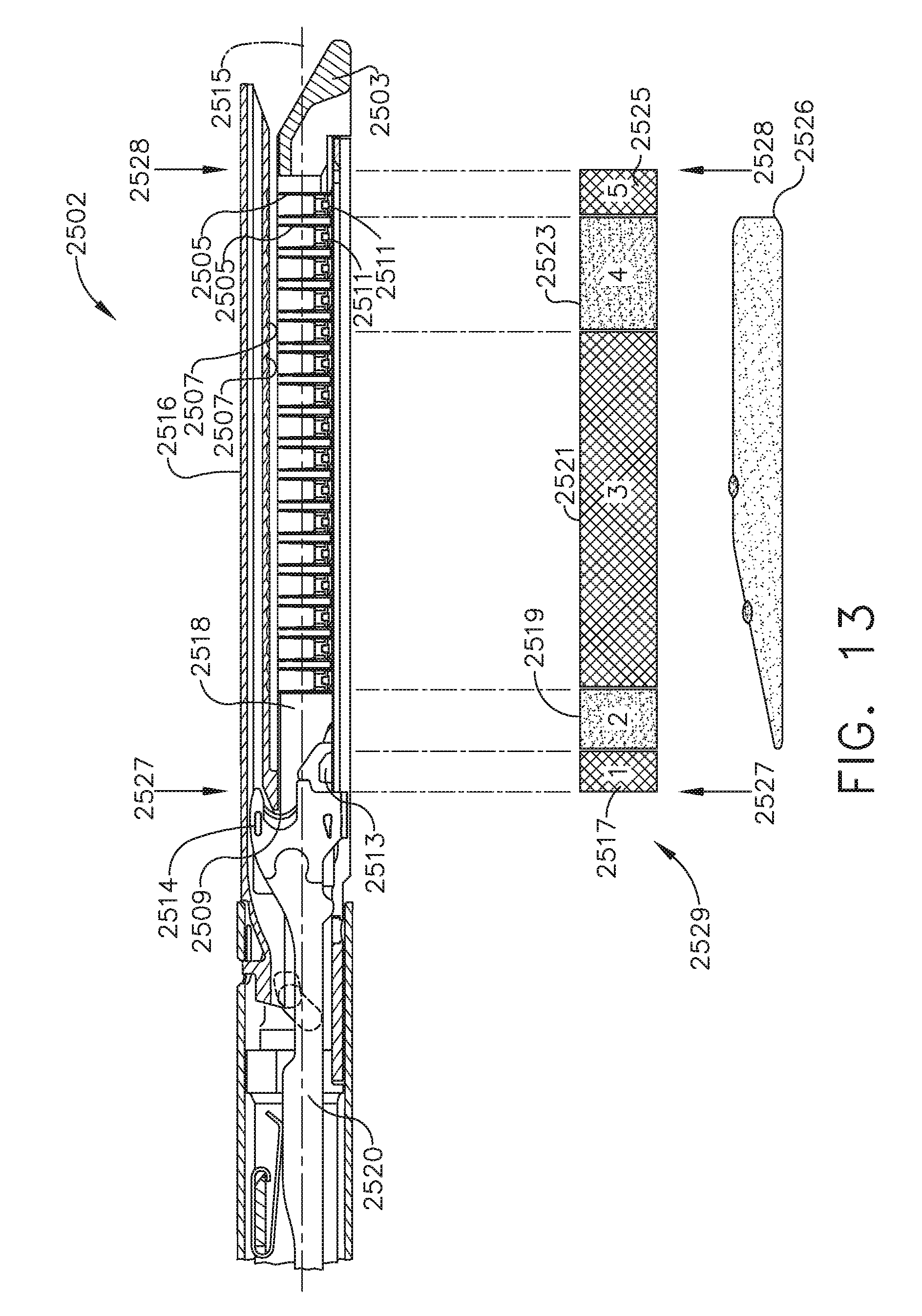
D00013
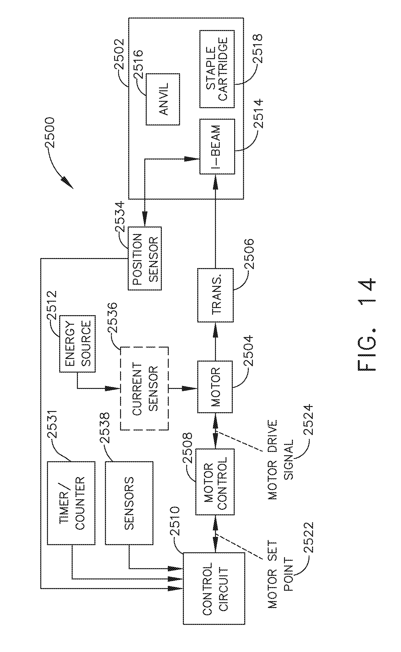
D00014

D00015

D00016

D00017
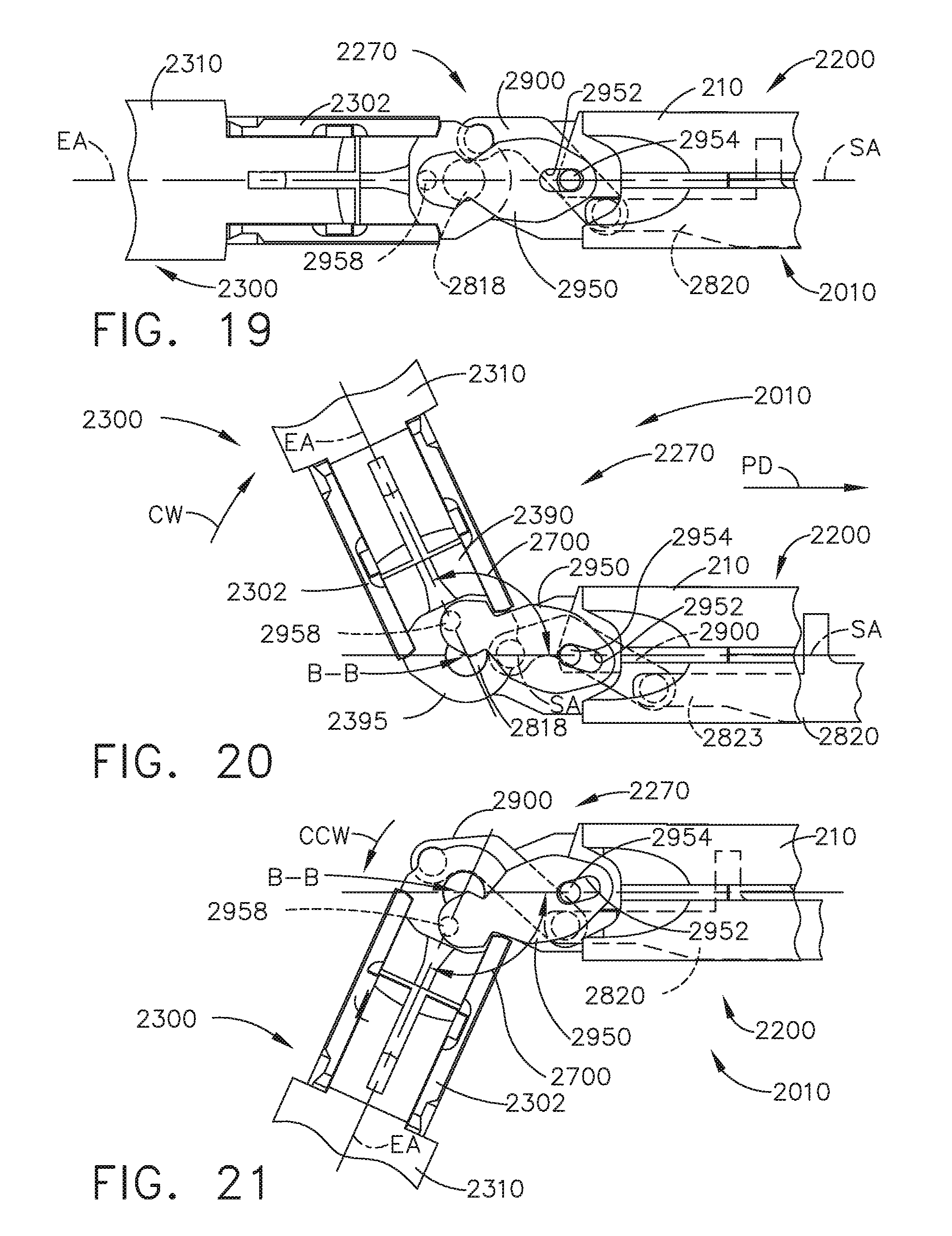
D00018
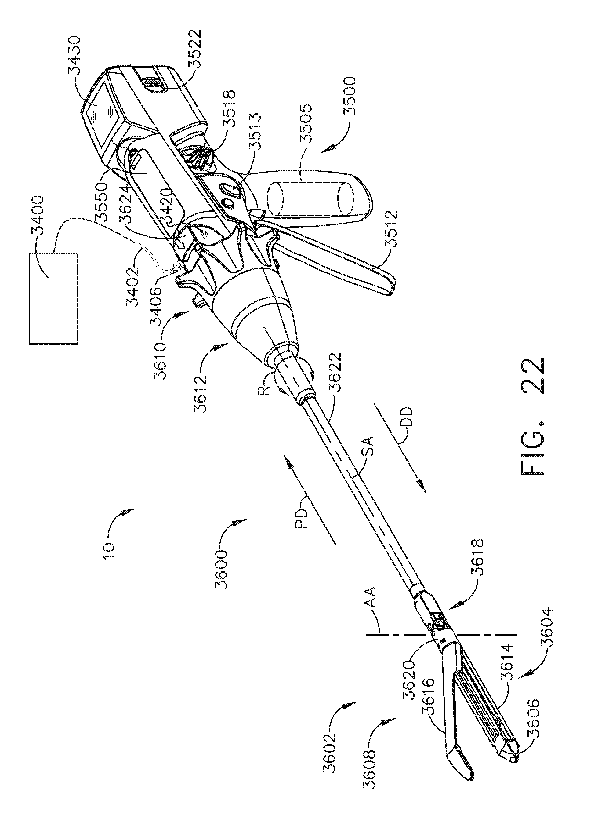
D00019
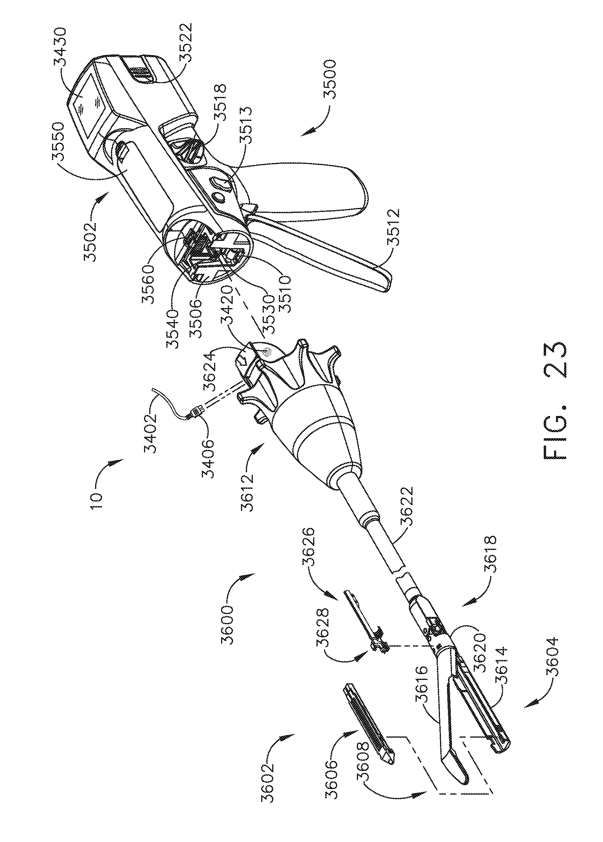
D00020
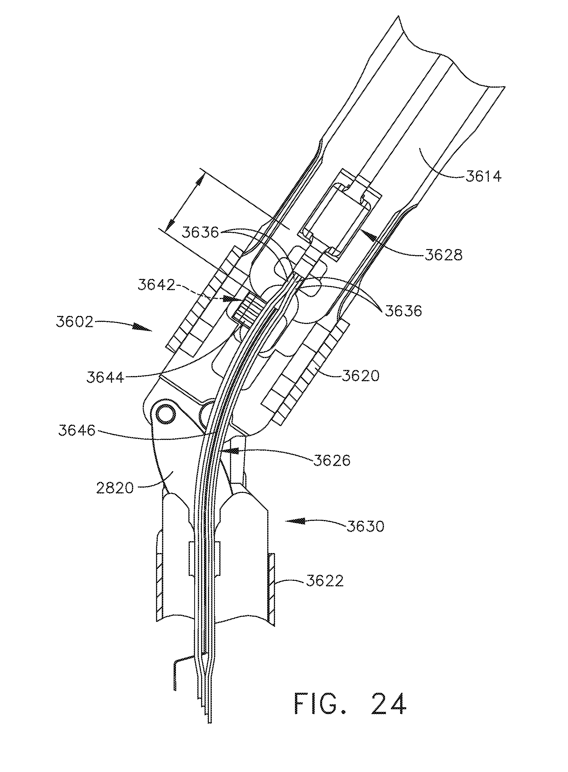
D00021
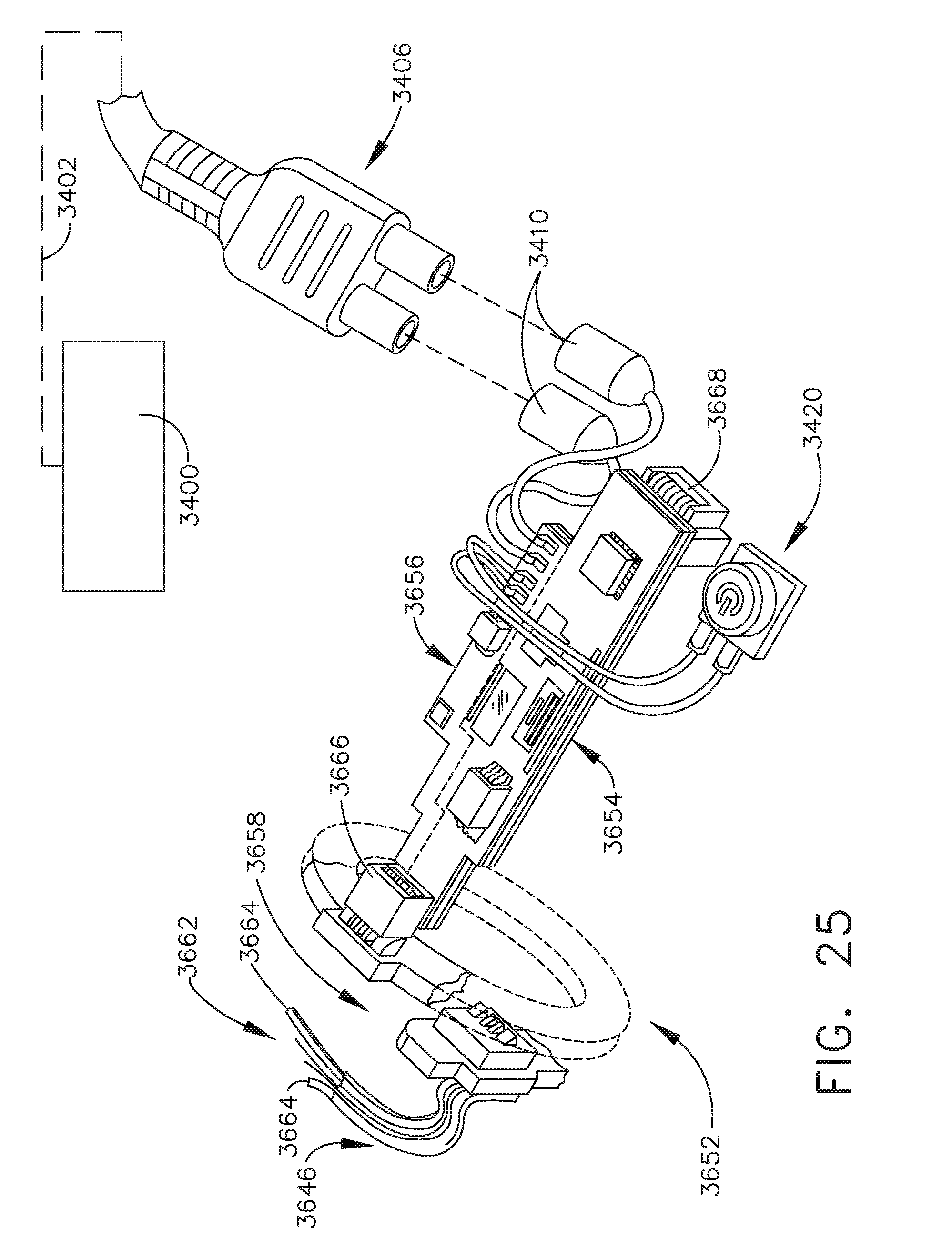
D00022
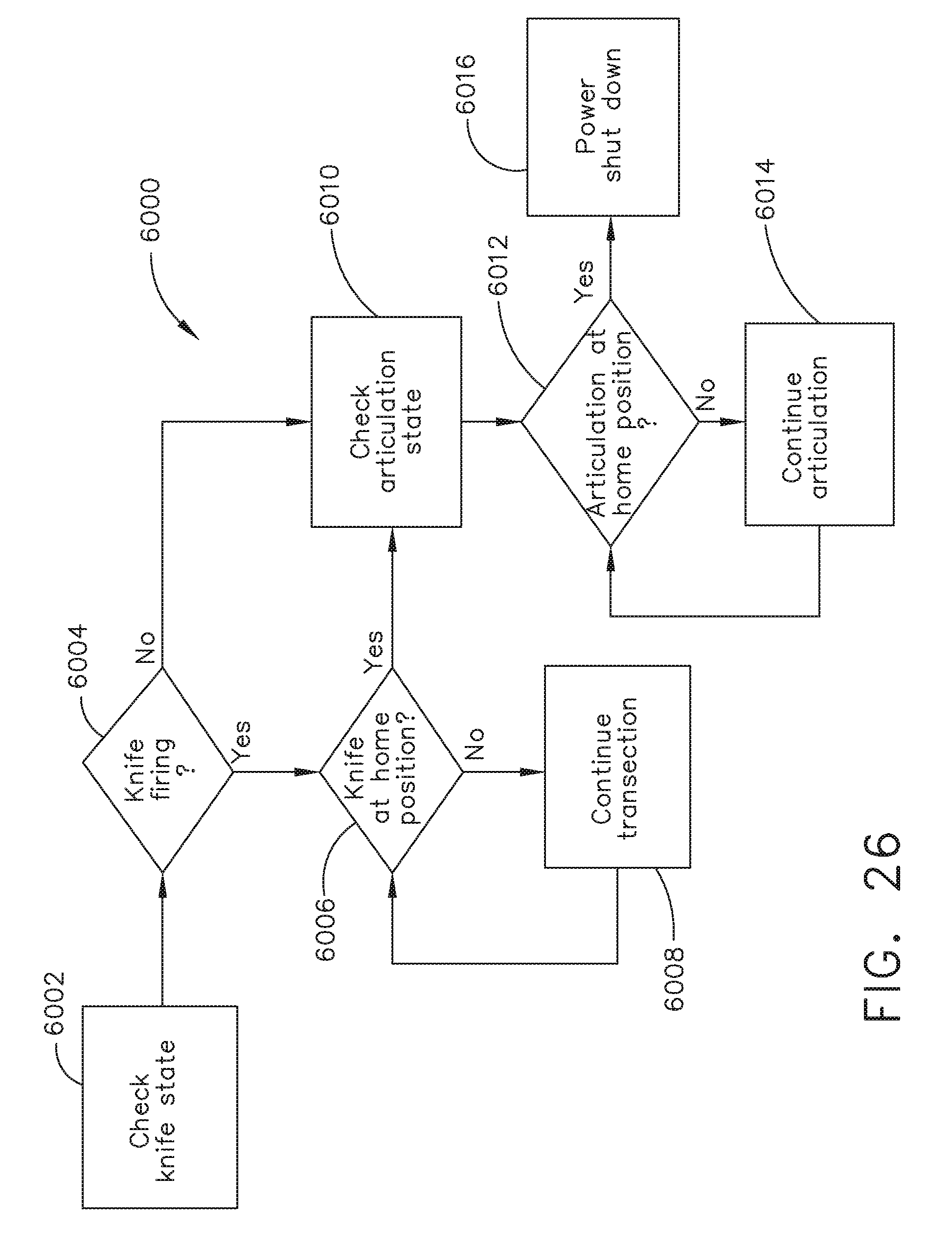
D00023
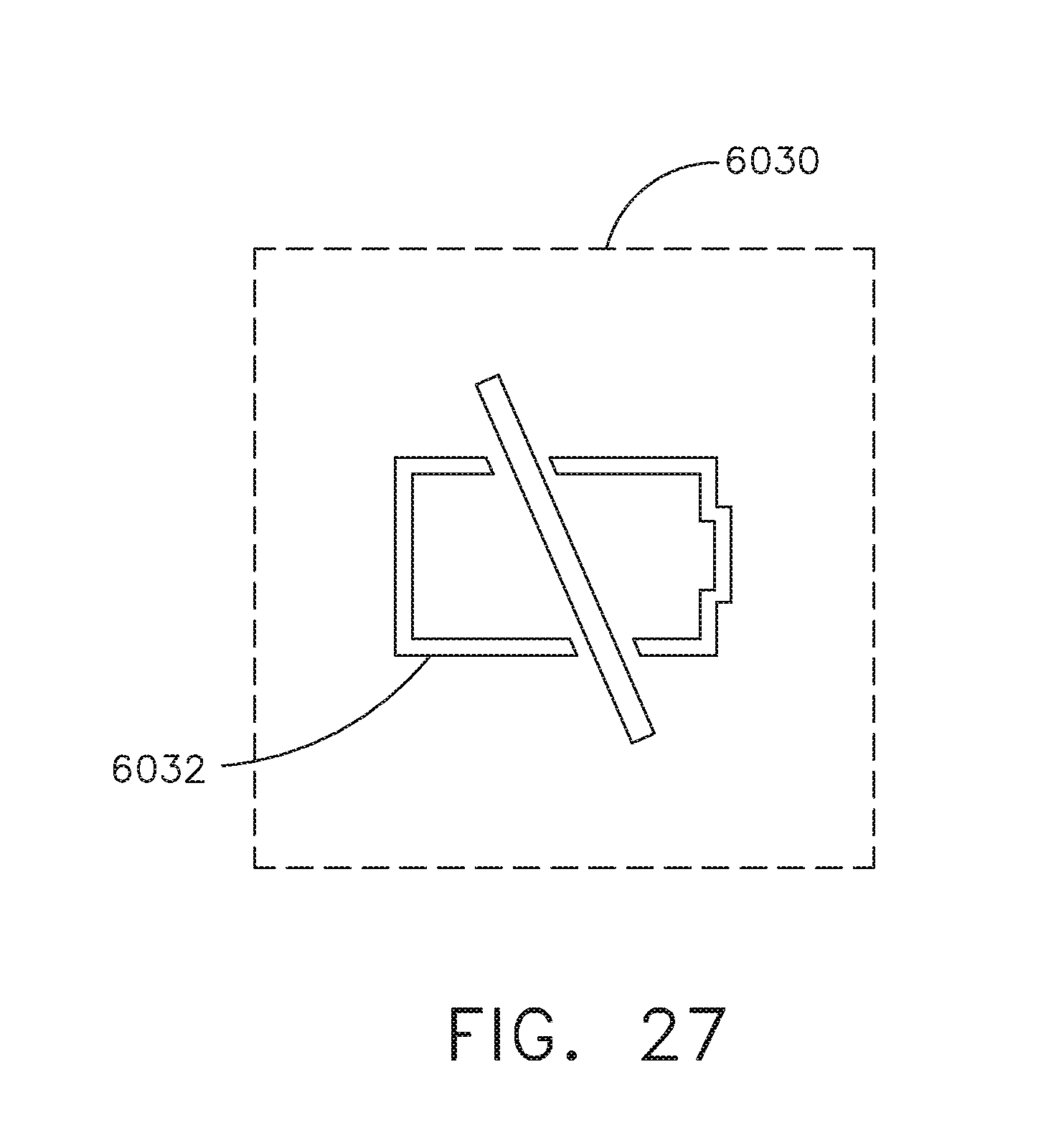
XML
uspto.report is an independent third-party trademark research tool that is not affiliated, endorsed, or sponsored by the United States Patent and Trademark Office (USPTO) or any other governmental organization. The information provided by uspto.report is based on publicly available data at the time of writing and is intended for informational purposes only.
While we strive to provide accurate and up-to-date information, we do not guarantee the accuracy, completeness, reliability, or suitability of the information displayed on this site. The use of this site is at your own risk. Any reliance you place on such information is therefore strictly at your own risk.
All official trademark data, including owner information, should be verified by visiting the official USPTO website at www.uspto.gov. This site is not intended to replace professional legal advice and should not be used as a substitute for consulting with a legal professional who is knowledgeable about trademark law.