Lockout disabling mechanism
Boudreaux Fe
U.S. patent number 10,194,976 [Application Number 14/468,037] was granted by the patent office on 2019-02-05 for lockout disabling mechanism. This patent grant is currently assigned to Ethicon LLC. The grantee listed for this patent is Ethicon Endo-Surgery, Inc.. Invention is credited to Chad P. Boudreaux.


View All Diagrams
| United States Patent | 10,194,976 |
| Boudreaux | February 5, 2019 |
Lockout disabling mechanism
Abstract
A surgical instrument is disclosed. The surgical instrument has a handle assembly. The handle assembly has a trigger operatively coupled to a firing plate, an energy button configured to deliver energy to at least one electrode, a lockout element operatively coupled to the energy button, the lockout element configured to prevent operation of the firing plate, and a lockout disabling mechanism configured to disable the lockout element, the lockout disabling mechanism operable between a first position and a second position. When the lockout disabling mechanism is located in the first position, the lockout element is enabled and can be unlocked by the energy button, and wherein when the lockout disabling mechanism is in the second position, the lockout element is disabled.
| Inventors: | Boudreaux; Chad P. (Cincinnati, OH) | ||||||||||
|---|---|---|---|---|---|---|---|---|---|---|---|
| Applicant: |
|
||||||||||
| Assignee: | Ethicon LLC (Guaynabo,
PR) |
||||||||||
| Family ID: | 55347268 | ||||||||||
| Appl. No.: | 14/468,037 | ||||||||||
| Filed: | August 25, 2014 |
Prior Publication Data
| Document Identifier | Publication Date | |
|---|---|---|
| US 20160051317 A1 | Feb 25, 2016 | |
| Current U.S. Class: | 1/1 |
| Current CPC Class: | A61B 18/1445 (20130101); H01H 9/286 (20130101); A61B 2017/00367 (20130101); A61B 2017/2923 (20130101); A61B 2090/0801 (20160201); H01H 9/06 (20130101); A61B 2018/00607 (20130101); A61B 2018/1455 (20130101); A61B 2090/08021 (20160201); H01H 2215/00 (20130101); H01H 2300/014 (20130101); A61B 2018/0091 (20130101); H01H 2239/03 (20130101) |
| Current International Class: | A61B 18/14 (20060101); H01H 9/28 (20060101); A61B 18/00 (20060101); A61B 90/00 (20160101); A61B 17/00 (20060101); A61B 17/29 (20060101) |
| Field of Search: | ;606/52 |
References Cited [Referenced By]
U.S. Patent Documents
| 2366274 | January 1945 | Luth et al. |
| 2458152 | January 1949 | Eakins |
| 2510693 | June 1950 | Green |
| 2867039 | January 1959 | Zach |
| 3166971 | January 1965 | Stoecker |
| 3525912 | August 1970 | Wallin |
| 3580841 | May 1971 | Cadotte et al. |
| 3703651 | November 1972 | Blowers |
| 3777760 | December 1973 | Essner |
| 4005714 | February 1977 | Hiltebrandt |
| 4034762 | July 1977 | Cosens et al. |
| 4058126 | November 1977 | Leveen |
| 4203430 | May 1980 | Takahashi |
| 4220154 | September 1980 | Semm |
| 4237441 | December 1980 | van Konynenburg et al. |
| 4281785 | August 1981 | Brooks |
| 4304987 | December 1981 | van Konynenburg |
| 4314559 | February 1982 | Allen |
| 4463759 | August 1984 | Garito et al. |
| 4492231 | January 1985 | Auth |
| 4535773 | August 1985 | Yoon |
| 4545926 | October 1985 | Fouts, Jr. et al. |
| 4550870 | November 1985 | Krumme et al. |
| 4582236 | April 1986 | Hirose |
| 4617927 | October 1986 | Manes |
| 4735603 | April 1988 | Goodson et al. |
| 4761871 | August 1988 | O'Connor et al. |
| 4830462 | May 1989 | Karny et al. |
| 4849133 | July 1989 | Yoshida et al. |
| 4860745 | August 1989 | Farin et al. |
| 4878493 | November 1989 | Pasternak et al. |
| 4880015 | November 1989 | Nierman |
| 4910389 | March 1990 | Sherman et al. |
| 4920978 | May 1990 | Colvin |
| 4936842 | June 1990 | D'Amelio et al. |
| 5020514 | June 1991 | Heckele |
| 5061269 | October 1991 | Muller |
| 5099840 | March 1992 | Goble et al. |
| 5104025 | April 1992 | Main et al. |
| 5106538 | April 1992 | Barma et al. |
| 5108383 | April 1992 | White |
| 5156633 | October 1992 | Smith |
| 5160334 | November 1992 | Billings et al. |
| 5190541 | March 1993 | Abele et al. |
| 5196007 | March 1993 | Ellman et al. |
| 5205459 | April 1993 | Brinkerhoff et al. |
| 5217460 | June 1993 | Knoepfler |
| 5234428 | August 1993 | Kaufman |
| 5258006 | November 1993 | Rydell et al. |
| 5285945 | February 1994 | Brinkerhoff et al. |
| 5290286 | March 1994 | Parins |
| 5309927 | May 1994 | Welch |
| 5312023 | May 1994 | Green et al. |
| 5318563 | June 1994 | Malis et al. |
| 5318564 | June 1994 | Eggers |
| 5318589 | June 1994 | Lichtman |
| 5326013 | July 1994 | Green et al. |
| 5330471 | July 1994 | Eggers |
| 5330502 | July 1994 | Hassler et al. |
| 5339723 | August 1994 | Huitema |
| 5342359 | August 1994 | Rydell |
| 5361583 | November 1994 | Huitema |
| 5383874 | January 1995 | Jackson et al. |
| 5387207 | February 1995 | Dyer et al. |
| 5389098 | February 1995 | Tsuruta et al. |
| 5395312 | March 1995 | Desai |
| 5395363 | March 1995 | Billings et al. |
| 5395364 | March 1995 | Anderhub et al. |
| 5396266 | March 1995 | Brimhall |
| 5396900 | March 1995 | Slater et al. |
| 5403312 | April 1995 | Yates et al. |
| 5417709 | May 1995 | Slater |
| 5428504 | June 1995 | Bhatla |
| 5429131 | July 1995 | Scheinman et al. |
| 5443463 | August 1995 | Stern et al. |
| 5445638 | August 1995 | Rydell et al. |
| 5451227 | September 1995 | Michaelson |
| 5456684 | October 1995 | Schmidt et al. |
| 5458598 | October 1995 | Feinberg et al. |
| 5465895 | November 1995 | Knodel et al. |
| 5472443 | December 1995 | Cordis et al. |
| 5476479 | December 1995 | Green et al. |
| 5478003 | December 1995 | Green et al. |
| 5480409 | January 1996 | Riza |
| 5484436 | January 1996 | Eggers et al. |
| 5486189 | January 1996 | Mudry et al. |
| 5496317 | March 1996 | Goble et al. |
| 5504650 | April 1996 | Katsui et al. |
| 5509922 | April 1996 | Aranyi et al. |
| 5511556 | April 1996 | DeSantis |
| 5520704 | May 1996 | Castro et al. |
| 5522839 | June 1996 | Pilling |
| 5531744 | July 1996 | Nardella et al. |
| 5540681 | July 1996 | Strul et al. |
| 5542916 | August 1996 | Hirsch et al. |
| 5558671 | September 1996 | Yates |
| 5563179 | October 1996 | Stone et al. |
| 5569164 | October 1996 | Lurz |
| 5571121 | November 1996 | Heifetz |
| 5573534 | November 1996 | Stone |
| 5584830 | December 1996 | Ladd et al. |
| 5599350 | February 1997 | Schulze et al. |
| 5607450 | March 1997 | Zvenyatsky et al. |
| 5611813 | March 1997 | Lichtman |
| 5618307 | April 1997 | Donlon et al. |
| 5624452 | April 1997 | Yates |
| 5632432 | May 1997 | Schulze et al. |
| 5647871 | July 1997 | Levine et al. |
| 5658281 | August 1997 | Heard |
| 5662667 | September 1997 | Knodel |
| 5665085 | September 1997 | Nardella |
| 5665100 | September 1997 | Yoon |
| 5674219 | October 1997 | Monson et al. |
| 5674220 | October 1997 | Fox et al. |
| 5688270 | November 1997 | Yates et al. |
| 5693051 | December 1997 | Schulze et al. |
| 5709680 | January 1998 | Yates et al. |
| 5711472 | January 1998 | Bryan |
| 5713896 | February 1998 | Nardella |
| 5716366 | February 1998 | Yates |
| 5720742 | February 1998 | Zacharias |
| 5720744 | February 1998 | Eggleston et al. |
| 5735848 | April 1998 | Yates et al. |
| 5743906 | April 1998 | Parins et al. |
| 5752973 | May 1998 | Kieturakis |
| 5755717 | May 1998 | Yates et al. |
| 5762255 | June 1998 | Chrisman et al. |
| 5779701 | July 1998 | McBrayer et al. |
| 5782834 | July 1998 | Lucey et al. |
| 5792135 | August 1998 | Madhani et al. |
| 5792138 | August 1998 | Shipp |
| 5796188 | August 1998 | Bays |
| 5797941 | August 1998 | Schulze et al. |
| 5800432 | September 1998 | Swanson |
| 5800449 | September 1998 | Wales |
| 5805140 | September 1998 | Rosenberg et al. |
| 5807393 | September 1998 | Williamson, IV et al. |
| 5810811 | September 1998 | Yates et al. |
| 5817033 | October 1998 | DeSantis et al. |
| 5817084 | October 1998 | Jensen |
| 5817093 | October 1998 | Williamson, IV et al. |
| 5827323 | October 1998 | Klieman |
| 5836909 | November 1998 | Cosmescu |
| 5836943 | November 1998 | Miller, III |
| 5836990 | November 1998 | Li |
| 5853412 | December 1998 | Mayenberger |
| 5876401 | March 1999 | Schulze et al. |
| 5878193 | March 1999 | Wang et al. |
| 5880668 | March 1999 | Hall |
| 5891142 | April 1999 | Eggers et al. |
| 5906625 | May 1999 | Bito et al. |
| 5910129 | June 1999 | Koblish et al. |
| 5921956 | July 1999 | Grinberg et al. |
| 5929846 | July 1999 | Rosenberg et al. |
| 5984938 | November 1999 | Yoon |
| 6003517 | December 1999 | Sheffield et al. |
| 6013052 | January 2000 | Durman et al. |
| 6024741 | February 2000 | Williamson, IV |
| 6024744 | February 2000 | Kese et al. |
| 6033399 | March 2000 | Gines |
| 6039734 | March 2000 | Goble |
| 6050996 | April 2000 | Schmaltz et al. |
| 6063098 | May 2000 | Houser et al. |
| 6068629 | May 2000 | Haissaguerre et al. |
| 6074389 | June 2000 | Levine et al. |
| 6091995 | July 2000 | Ingle et al. |
| 6099483 | August 2000 | Palmer et al. |
| 6099550 | August 2000 | Yoon |
| H1904 | October 2000 | Yates et al. |
| 6132368 | October 2000 | Cooper |
| 6144402 | November 2000 | Norsworthy et al. |
| 6152923 | November 2000 | Ryan |
| 6154198 | November 2000 | Rosenberg |
| 6162208 | December 2000 | Hipps |
| 6174309 | January 2001 | Wrublewski et al. |
| 6176857 | January 2001 | Ashley |
| 6190386 | February 2001 | Rydell |
| 6206876 | March 2001 | Levine et al. |
| 6228080 | May 2001 | Gines |
| 6231565 | May 2001 | Tovey et al. |
| 6259230 | July 2001 | Chou |
| 6277117 | August 2001 | Tetzlaff et al. |
| 6292700 | September 2001 | Morrison et al. |
| 6325799 | December 2001 | Goble |
| 6340878 | January 2002 | Oglesbee |
| 6364888 | April 2002 | Niemeyer et al. |
| 6387109 | May 2002 | Davison et al. |
| 6391026 | May 2002 | Hung et al. |
| 6398779 | June 2002 | Buysse et al. |
| 6409722 | June 2002 | Hoey et al. |
| H2037 | July 2002 | Yates et al. |
| 6419675 | July 2002 | Gallo, Sr. |
| 6430446 | August 2002 | Knowlton |
| 6443968 | September 2002 | Holthaus et al. |
| 6458128 | October 2002 | Schulze |
| 6464689 | October 2002 | Qin et al. |
| 6464702 | October 2002 | Schulze et al. |
| 6480796 | November 2002 | Wiener |
| 6491690 | December 2002 | Goble et al. |
| 6500112 | December 2002 | Khouri |
| 6500176 | December 2002 | Truckai et al. |
| 6503248 | January 2003 | Levine |
| 6511480 | January 2003 | Tetzlaff et al. |
| 6514252 | February 2003 | Nezhat et al. |
| 6517565 | February 2003 | Whitman et al. |
| 6531846 | March 2003 | Smith |
| 6533784 | March 2003 | Truckai et al. |
| 6537272 | March 2003 | Christopherson et al. |
| 6537291 | March 2003 | Friedman et al. |
| 6551309 | April 2003 | LePivert |
| 6554829 | April 2003 | Schulze et al. |
| 6558376 | May 2003 | Bishop |
| 6562037 | May 2003 | Paton et al. |
| 6572639 | June 2003 | Ingle et al. |
| 6575969 | June 2003 | Rittman, III et al. |
| 6582451 | June 2003 | Marucci et al. |
| 6584360 | June 2003 | Francischelli et al. |
| 6585735 | July 2003 | Frazier et al. |
| 6589200 | July 2003 | Schwemberger et al. |
| 6602252 | August 2003 | Mollenauer |
| 6610060 | August 2003 | Mulier et al. |
| 6619529 | September 2003 | Green et al. |
| 6620161 | September 2003 | Schulze et al. |
| 6622731 | September 2003 | Daniel et al. |
| 6623482 | September 2003 | Pendekanti et al. |
| 6635057 | October 2003 | Harano et al. |
| 6644532 | November 2003 | Green et al. |
| 6651669 | November 2003 | Burnside |
| 6656177 | December 2003 | Truckai et al. |
| 6656198 | December 2003 | Tsonton et al. |
| 6662127 | December 2003 | Wiener et al. |
| 6673248 | January 2004 | Chowdhury |
| 6679882 | January 2004 | Kornerup |
| 6682501 | January 2004 | Nelson et al. |
| 6695840 | February 2004 | Schulze |
| 6722552 | April 2004 | Fenton, Jr. |
| 6733498 | May 2004 | Paton et al. |
| 6746443 | June 2004 | Morley et al. |
| 6752815 | June 2004 | Beaupre |
| 6766202 | July 2004 | Underwood et al. |
| 6770072 | August 2004 | Truckai et al. |
| 6773409 | August 2004 | Truckai et al. |
| 6773435 | August 2004 | Schulze et al. |
| 6775575 | August 2004 | Bommannan et al. |
| 6783524 | August 2004 | Anderson et al. |
| 6789939 | September 2004 | Schrodinger et al. |
| 6796981 | September 2004 | Wham et al. |
| 6800085 | October 2004 | Selmon et al. |
| 6802843 | October 2004 | Truckai et al. |
| 6811842 | November 2004 | Ehrnsperger et al. |
| 6821273 | November 2004 | Mollenauer |
| 6835199 | December 2004 | McGuckin, Jr. et al. |
| 6840938 | January 2005 | Morley et al. |
| 6860880 | March 2005 | Treat et al. |
| 6877647 | April 2005 | Green et al. |
| 6893435 | May 2005 | Goble |
| 6905497 | June 2005 | Truckai et al. |
| 6908463 | June 2005 | Treat et al. |
| 6913579 | July 2005 | Truckai et al. |
| 6926716 | August 2005 | Baker et al. |
| 6929622 | August 2005 | Chian |
| 6929644 | August 2005 | Truckai et al. |
| 6953461 | October 2005 | McClurken et al. |
| 6977495 | December 2005 | Donofrio |
| 6994709 | February 2006 | Iida |
| 7000818 | February 2006 | Shelton, IV et al. |
| 7011657 | March 2006 | Truckai et al. |
| 7041102 | May 2006 | Truckai et al. |
| 7052496 | May 2006 | Yamauchi |
| 7055731 | June 2006 | Shelton, IV et al. |
| 7063699 | June 2006 | Hess et al. |
| 7066936 | June 2006 | Ryan |
| 7070597 | July 2006 | Truckai et al. |
| 7077853 | July 2006 | Kramer et al. |
| 7083618 | August 2006 | Couture et al. |
| 7083619 | August 2006 | Truckai et al. |
| 7087054 | August 2006 | Truckai et al. |
| 7094235 | August 2006 | Francischelli et al. |
| 7101371 | September 2006 | Dycus et al. |
| 7101372 | September 2006 | Dycus et al. |
| 7101373 | September 2006 | Dycus et al. |
| 7112201 | September 2006 | Truckai et al. |
| 7118570 | October 2006 | Tetzlaff et al. |
| 7125409 | October 2006 | Truckai et al. |
| 7131970 | November 2006 | Moses |
| 7137980 | November 2006 | Buysse et al. |
| 7143925 | December 2006 | Shelton, IV et al. |
| 7147138 | December 2006 | Shelton, IV |
| 7156846 | January 2007 | Dycus et al. |
| 7160296 | January 2007 | Pearson et al. |
| 7169146 | January 2007 | Truckai et al. |
| 7169156 | January 2007 | Hart |
| 7179271 | February 2007 | Friedman et al. |
| 7186253 | March 2007 | Truckai et al. |
| 7189233 | March 2007 | Truckai et al. |
| 7195631 | March 2007 | Dumbauld |
| 7207471 | April 2007 | Heinrich et al. |
| 7220951 | May 2007 | Truckai et al. |
| 7225964 | June 2007 | Mastri et al. |
| 7226448 | June 2007 | Bertolero et al. |
| 7232440 | June 2007 | Dumbauld et al. |
| 7235073 | June 2007 | Levine et al. |
| 7241294 | July 2007 | Reschke |
| 7251531 | July 2007 | Mosher et al. |
| 7252667 | August 2007 | Moses et al. |
| 7267677 | September 2007 | Johnson et al. |
| 7267685 | September 2007 | Butaric et al. |
| 7273483 | September 2007 | Wiener et al. |
| 7287682 | October 2007 | Ezzat et al. |
| 7300450 | November 2007 | Vleugels et al. |
| 7303557 | December 2007 | Wham et al. |
| 7307313 | December 2007 | Ohyanagi et al. |
| 7309849 | December 2007 | Truckai et al. |
| 7311709 | December 2007 | Truckai et al. |
| 7329257 | February 2008 | Kanehira et al. |
| 7354440 | April 2008 | Truckai et al. |
| 7357287 | April 2008 | Shelton, IV et al. |
| 7364577 | April 2008 | Wham et al. |
| 7367976 | May 2008 | Lawes et al. |
| 7371227 | May 2008 | Zeiner |
| RE40388 | June 2008 | Gines |
| 7381209 | June 2008 | Truckai et al. |
| 7384420 | June 2008 | Dycus et al. |
| 7396356 | July 2008 | Mollenauer |
| 7403224 | July 2008 | Fuller et al. |
| 7404508 | July 2008 | Smith et al. |
| 7407077 | August 2008 | Ortiz et al. |
| 7416101 | August 2008 | Shelton, IV et al. |
| 7422139 | September 2008 | Shelton, IV et al. |
| 7435582 | October 2008 | Zimmermann et al. |
| 7441684 | October 2008 | Shelton, IV et al. |
| 7442193 | October 2008 | Shields et al. |
| 7445621 | November 2008 | Dumbauld et al. |
| 7464846 | December 2008 | Shelton, IV et al. |
| 7473253 | January 2009 | Dycus et al. |
| 7488319 | February 2009 | Yates |
| 7491201 | February 2009 | Shields et al. |
| 7494501 | February 2009 | Ahlberg et al. |
| 7498080 | March 2009 | Tung et al. |
| 7506791 | March 2009 | Omaits et al. |
| 7510107 | March 2009 | Timm et al. |
| 7513025 | April 2009 | Fischer |
| 7517349 | April 2009 | Truckai et al. |
| 7524320 | April 2009 | Tierney et al. |
| 7540872 | June 2009 | Schechter et al. |
| 7543730 | June 2009 | Marczyk |
| 7550216 | June 2009 | Ofer et al. |
| 7553309 | June 2009 | Buysse et al. |
| 7559452 | July 2009 | Wales et al. |
| 7582086 | September 2009 | Privitera et al. |
| 7586289 | September 2009 | Andruk et al. |
| 7588176 | September 2009 | Timm et al. |
| 7594925 | September 2009 | Danek et al. |
| 7597693 | October 2009 | Garrison |
| 7604150 | October 2009 | Boudreaux |
| 7621930 | November 2009 | Houser |
| 7628791 | December 2009 | Garrison et al. |
| 7628792 | December 2009 | Guerra |
| 7632267 | December 2009 | Dahla |
| 7632269 | December 2009 | Truckai et al. |
| 7641653 | January 2010 | Dalla Betta et al. |
| 7641671 | January 2010 | Crainich |
| 7644848 | January 2010 | Swayze et al. |
| 7645277 | January 2010 | McClurken et al. |
| 7648499 | January 2010 | Orszulak et al. |
| 7658311 | February 2010 | Boudreaux |
| 7665647 | February 2010 | Shelton, IV et al. |
| 7666206 | February 2010 | Taniguchi et al. |
| 7670334 | March 2010 | Hueil et al. |
| 7691095 | April 2010 | Bednarek et al. |
| 7691098 | April 2010 | Wallace et al. |
| 7703459 | April 2010 | Saadat et al. |
| 7703653 | April 2010 | Shah et al. |
| 7708751 | May 2010 | Hughes et al. |
| 7717915 | May 2010 | Miyazawa |
| 7722527 | May 2010 | Bouchier et al. |
| 7722607 | May 2010 | Dumbauld et al. |
| 7726537 | June 2010 | Olson et al. |
| 7753904 | July 2010 | Shelton, IV et al. |
| 7753908 | July 2010 | Swanson |
| 7762445 | July 2010 | Heinrich et al. |
| 7766210 | August 2010 | Shelton, IV et al. |
| 7766910 | August 2010 | Hixson et al. |
| 7770775 | August 2010 | Shelton, IV et al. |
| 7775972 | August 2010 | Brock et al. |
| 7776037 | August 2010 | Odom |
| 7780651 | August 2010 | Madhani et al. |
| 7780663 | August 2010 | Yates et al. |
| 7784663 | August 2010 | Shelton, IV |
| 7789883 | September 2010 | Takashino et al. |
| 7793814 | September 2010 | Racenet et al. |
| 7803156 | September 2010 | Eder et al. |
| 7806891 | October 2010 | Nowlin et al. |
| 7810693 | October 2010 | Broehl et al. |
| 7815641 | October 2010 | Dodde et al. |
| 7819298 | October 2010 | Hall et al. |
| 7819299 | October 2010 | Sheltoin, IV et al. |
| 7819872 | October 2010 | Johnson et al. |
| 7824401 | November 2010 | Manzo et al. |
| 7832408 | November 2010 | Shelton, IV et al. |
| 7832612 | November 2010 | Baxter, III et al. |
| 7845537 | December 2010 | Shelton, IV et al. |
| 7846159 | December 2010 | Morrison et al. |
| 7846160 | December 2010 | Payne et al. |
| 7861906 | January 2011 | Doll et al. |
| 7879035 | February 2011 | Garrison et al. |
| 7879070 | February 2011 | Ortiz et al. |
| 7896875 | March 2011 | Heim et al. |
| 7901400 | March 2011 | Wham et al. |
| 7909220 | March 2011 | Viola |
| 7919184 | April 2011 | Mohapatra et al. |
| 7922061 | April 2011 | Shelton, IV et al. |
| 7922651 | April 2011 | Yamada et al. |
| 7931649 | April 2011 | Couture et al. |
| 7935114 | May 2011 | Takashino et al. |
| 7951165 | May 2011 | Golden et al. |
| 7955331 | June 2011 | Truckai et al. |
| 7963963 | June 2011 | Francischelli et al. |
| 7967602 | June 2011 | Lindquist |
| 7981113 | July 2011 | Truckai et al. |
| 7997278 | August 2011 | Utley et al. |
| 8020743 | September 2011 | Shelton, IV |
| 8038693 | October 2011 | Allen |
| 8056720 | November 2011 | Hawkes |
| 8058771 | November 2011 | Giordano et al. |
| 8061014 | November 2011 | Smith et al. |
| 8070036 | December 2011 | Knodel et al. |
| 8105323 | January 2012 | Buysse et al. |
| 8128624 | March 2012 | Couture et al. |
| 8136712 | March 2012 | Zingman |
| 8141762 | March 2012 | Bedi et al. |
| 8157145 | April 2012 | Shelton, IV et al. |
| 8197472 | June 2012 | Lau et al. |
| 8197479 | June 2012 | Olson et al. |
| 8197502 | June 2012 | Smith et al. |
| 8221415 | July 2012 | Francischelli |
| 8236020 | August 2012 | Smith et al. |
| 8241235 | August 2012 | Kahler et al. |
| 8241284 | August 2012 | Dycus et al. |
| 8246615 | August 2012 | Behnke |
| 8246618 | August 2012 | Bucciaglia et al. |
| 8251994 | August 2012 | McKenna et al. |
| 8262563 | September 2012 | Bakos et al. |
| 8267300 | September 2012 | Boudreaux |
| 8277446 | October 2012 | Heard |
| 8277447 | October 2012 | Garrison et al. |
| 8282669 | October 2012 | Gerber et al. |
| 8287528 | October 2012 | Wham et al. |
| 8292886 | October 2012 | Kerr et al. |
| 8298232 | October 2012 | Unger |
| 8303583 | November 2012 | Hosier et al. |
| 8323310 | December 2012 | Kingsley |
| 8333778 | December 2012 | Smith et al. |
| 8333779 | December 2012 | Smith et al. |
| 8334468 | December 2012 | Palmer et al. |
| 8338726 | December 2012 | Palmer et al. |
| 8357158 | January 2013 | McKenna et al. |
| 8372064 | February 2013 | Douglass et al. |
| 8372099 | February 2013 | Deville et al. |
| 8372101 | February 2013 | Smith et al. |
| 8377059 | February 2013 | Deville et al. |
| 8377085 | February 2013 | Smith et al. |
| 8397971 | March 2013 | Yates et al. |
| 8403948 | March 2013 | Deville et al. |
| 8403949 | March 2013 | Palmer et al. |
| 8403950 | March 2013 | Palmer et al. |
| 8414577 | April 2013 | Boudreaux et al. |
| 8418349 | April 2013 | Smith et al. |
| 8419757 | April 2013 | Smith et al. |
| 8419758 | April 2013 | Smith et al. |
| 8425545 | April 2013 | Smith et al. |
| 8430876 | April 2013 | Kappus et al. |
| 8435257 | May 2013 | Smith et al. |
| 8439939 | May 2013 | Deville et al. |
| 8444662 | May 2013 | Palmer et al. |
| 8444664 | May 2013 | Balanev et al. |
| 8453906 | June 2013 | Huang et al. |
| 8460288 | June 2013 | Tamai et al. |
| 8460292 | June 2013 | Truckai et al. |
| 8480703 | July 2013 | Nicholas et al. |
| 8485413 | July 2013 | Scheib et al. |
| 8486057 | July 2013 | Behnke, II |
| 8496682 | July 2013 | Guerra et al. |
| 8535311 | September 2013 | Schall |
| 8535340 | September 2013 | Allen |
| 8535341 | September 2013 | Allen |
| 8540128 | September 2013 | Shelton, IV et al. |
| 8562598 | October 2013 | Falkenstein et al. |
| 8562604 | October 2013 | Nishimura |
| 8568390 | October 2013 | Mueller |
| 8568412 | October 2013 | Brandt et al. |
| 8569997 | October 2013 | Lee |
| 8574231 | November 2013 | Boudreaux et al. |
| 8591506 | November 2013 | Wham et al. |
| D695407 | December 2013 | Price et al. |
| 8613383 | December 2013 | Beckman et al. |
| 8623011 | January 2014 | Spivey |
| 8623016 | January 2014 | Fischer |
| 8623027 | January 2014 | Price et al. |
| 8623044 | January 2014 | Timm et al. |
| 8628529 | January 2014 | Aldridge et al. |
| 8632461 | January 2014 | Glossop |
| 8638428 | January 2014 | Brown |
| 8647350 | February 2014 | Mohan et al. |
| 8663220 | March 2014 | Wiener et al. |
| 8663222 | March 2014 | Anderson et al. |
| 8684253 | April 2014 | Giordano et al. |
| 8685020 | April 2014 | Weizman et al. |
| 8696665 | April 2014 | Hunt et al. |
| 8702609 | April 2014 | Hadjicostis |
| 8702704 | April 2014 | Shelton, IV et al. |
| 8709035 | April 2014 | Johnson et al. |
| 8715270 | May 2014 | Weitzner et al. |
| 8715277 | May 2014 | Weizman |
| 8734443 | May 2014 | Hixson et al. |
| 8747238 | June 2014 | Shelton, IV et al. |
| 8747351 | June 2014 | Schultz |
| 8747404 | June 2014 | Boudreaux et al. |
| 8752264 | June 2014 | Ackley et al. |
| 8752749 | June 2014 | Moore et al. |
| 8753338 | June 2014 | Widenhouse et al. |
| 8764747 | July 2014 | Cummings et al. |
| 8790342 | July 2014 | Stulen et al. |
| 8795276 | August 2014 | Dietz et al. |
| 8795327 | August 2014 | Dietz et al. |
| 8827992 | September 2014 | Koss et al. |
| 8834466 | September 2014 | Cummings et al. |
| 8834518 | September 2014 | Faller et al. |
| 8845630 | September 2014 | Mehta et al. |
| 8888776 | November 2014 | Dietz et al. |
| 8888809 | November 2014 | Davison et al. |
| 8906016 | December 2014 | Boudreaux et al. |
| 8926607 | January 2015 | Norvell et al. |
| 8926608 | January 2015 | Bacher et al. |
| 8931682 | January 2015 | Timm et al. |
| 8939974 | January 2015 | Boudreaux et al. |
| 8951248 | February 2015 | Messerly et al. |
| 8956349 | February 2015 | Aldridge et al. |
| 8979843 | March 2015 | Timm et al. |
| 8979844 | March 2015 | White et al. |
| 8979890 | March 2015 | Boudreaux |
| 8986302 | March 2015 | Aldridge et al. |
| 8992422 | March 2015 | Spivey et al. |
| 9005199 | April 2015 | Beckman et al. |
| 9011437 | April 2015 | Woodruff et al. |
| 9028494 | May 2015 | Shelton, IV et al. |
| 9028519 | May 2015 | Yates et al. |
| 9044243 | June 2015 | Johnson et al. |
| 9044256 | June 2015 | Cadeddu et al. |
| 9055961 | June 2015 | Manzo et al. |
| 9060770 | June 2015 | Shelton, IV et al. |
| 9066723 | June 2015 | Beller et al. |
| 9072535 | July 2015 | Shelton, IV et al. |
| 9072536 | July 2015 | Shelton, IV et al. |
| 9101385 | August 2015 | Shelton, IV et al. |
| 9119657 | September 2015 | Shelton, IV et al. |
| 9125662 | September 2015 | Shelton, IV |
| 9149324 | October 2015 | Huang et al. |
| 9149325 | October 2015 | Worrell et al. |
| 9168085 | October 2015 | Juzkiw et al. |
| 9179912 | November 2015 | Yates et al. |
| 9192380 | November 2015 | (Tarinelli) Racenet et al. |
| 9192431 | November 2015 | Woodruff et al. |
| 9198714 | December 2015 | Worrell et al. |
| 9204879 | December 2015 | Shelton, IV |
| 9216050 | December 2015 | Condie et al. |
| 9226751 | January 2016 | Shelton, IV et al. |
| 9226767 | January 2016 | Stulen et al. |
| 9237891 | January 2016 | Shelton, IV |
| 9259265 | February 2016 | Harris et al. |
| 9265926 | February 2016 | Strobl et al. |
| 9277962 | March 2016 | Koss et al. |
| 9283027 | March 2016 | Monson et al. |
| 9283045 | March 2016 | Rhee et al. |
| 9295514 | March 2016 | Shelton, IV et al. |
| 9314292 | April 2016 | Trees et al. |
| 9326788 | May 2016 | Batross et al. |
| 9333025 | May 2016 | Monson et al. |
| 9351754 | May 2016 | Vakharia et al. |
| 9375232 | June 2016 | Hunt et al. |
| 9375267 | June 2016 | Kerr et al. |
| 9408660 | August 2016 | Strobl et al. |
| 9414880 | August 2016 | Monson et al. |
| 9421060 | August 2016 | Monson et al. |
| 9456863 | October 2016 | Moua |
| 9456864 | October 2016 | Witt et al. |
| 9510906 | December 2016 | Boudreaux et al. |
| 9522029 | December 2016 | Yates et al. |
| 2002/0022836 | February 2002 | Goble et al. |
| 2002/0049551 | April 2002 | Friedman et al. |
| 2002/0107517 | August 2002 | Witt et al. |
| 2002/0165541 | November 2002 | Whitman |
| 2003/0014053 | January 2003 | Nguyen et al. |
| 2003/0105474 | June 2003 | Bonutti |
| 2003/0109875 | June 2003 | Tetzlaff et al. |
| 2003/0114851 | June 2003 | Truckai et al. |
| 2003/0130693 | July 2003 | Levin et al. |
| 2003/0139741 | July 2003 | Goble et al. |
| 2003/0158548 | August 2003 | Phan et al. |
| 2003/0171747 | September 2003 | Kanehira et al. |
| 2003/0216722 | November 2003 | Swanson |
| 2003/0229344 | December 2003 | Dycus et al. |
| 2004/0019350 | January 2004 | O'Brien et al. |
| 2004/0054364 | March 2004 | Aranyi et al. |
| 2004/0092992 | May 2004 | Adams et al. |
| 2004/0138621 | July 2004 | Jahns et al. |
| 2004/0167508 | August 2004 | Wham et al. |
| 2004/0193148 | September 2004 | Wham et al. |
| 2004/0193150 | September 2004 | Sharkey et al. |
| 2004/0232196 | November 2004 | Shelton, IV et al. |
| 2004/0249374 | December 2004 | Tetzlaff et al. |
| 2004/0260273 | December 2004 | Wan |
| 2005/0015125 | January 2005 | Mioduski et al. |
| 2005/0033278 | February 2005 | McClurken et al. |
| 2005/0085809 | April 2005 | Mucko et al. |
| 2005/0090817 | April 2005 | Phan |
| 2005/0103819 | May 2005 | Racenet et al. |
| 2005/0113827 | May 2005 | Dumbauld |
| 2005/0131390 | June 2005 | Heinrich et al. |
| 2005/0165429 | July 2005 | Douglas et al. |
| 2005/0171522 | August 2005 | Christopherson |
| 2005/0203507 | September 2005 | Truckai et al. |
| 2005/0256405 | November 2005 | Makin et al. |
| 2005/0261581 | November 2005 | Hughes et al. |
| 2005/0267464 | December 2005 | Truckai et al. |
| 2006/0052778 | March 2006 | Chapman et al. |
| 2006/0058825 | March 2006 | Ogura et al. |
| 2006/0064086 | March 2006 | Odom |
| 2006/0069388 | March 2006 | Truckai et al. |
| 2006/0159731 | July 2006 | Shoshan |
| 2006/0270916 | November 2006 | Skwarek et al. |
| 2006/0293656 | December 2006 | Shadduck et al. |
| 2007/0027469 | February 2007 | Smith et al. |
| 2007/0073185 | March 2007 | Nakao |
| 2007/0073341 | March 2007 | Smith et al. |
| 2007/0106158 | May 2007 | Madan et al. |
| 2007/0106317 | May 2007 | Shelton, IV et al. |
| 2007/0118115 | May 2007 | Artale et al. |
| 2007/0146113 | June 2007 | Truckai et al. |
| 2007/0173803 | July 2007 | Wham et al. |
| 2007/0173811 | July 2007 | Couture et al. |
| 2007/0173813 | July 2007 | Odom |
| 2007/0175949 | August 2007 | Shelton, IV et al. |
| 2007/0185474 | August 2007 | Nahen |
| 2007/0191713 | August 2007 | Eichmann et al. |
| 2007/0191830 | August 2007 | Cromton, Jr. et al. |
| 2007/0203483 | August 2007 | Kim et al. |
| 2007/0208312 | September 2007 | Norton et al. |
| 2007/0208336 | September 2007 | Kim |
| 2007/0208340 | September 2007 | Ganz et al. |
| 2007/0232920 | October 2007 | Kowalski et al. |
| 2007/0232926 | October 2007 | Stulen et al. |
| 2007/0232927 | October 2007 | Madan et al. |
| 2007/0232928 | October 2007 | Wiener et al. |
| 2007/0236213 | October 2007 | Paden et al. |
| 2007/0239025 | October 2007 | Wiener et al. |
| 2007/0260242 | November 2007 | Dycus et al. |
| 2007/0265613 | November 2007 | Edelstein et al. |
| 2007/0265616 | November 2007 | Couture et al. |
| 2008/0015575 | January 2008 | Odom et al. |
| 2008/0071269 | March 2008 | Hilario et al. |
| 2008/0114355 | May 2008 | Whayne et al. |
| 2008/0147058 | June 2008 | Horrell et al. |
| 2008/0147062 | June 2008 | Truckai et al. |
| 2008/0167522 | July 2008 | Giordano et al. |
| 2008/0188755 | August 2008 | Hart |
| 2008/0188851 | August 2008 | Truckai et al. |
| 2008/0188912 | August 2008 | Stone et al. |
| 2008/0214967 | September 2008 | Aranyi et al. |
| 2008/0221565 | September 2008 | Eder et al. |
| 2008/0255642 | October 2008 | Zarins et al. |
| 2008/0262491 | October 2008 | Swoyer et al. |
| 2008/0269862 | October 2008 | Elmouelhi et al. |
| 2008/0281315 | November 2008 | Gines |
| 2008/0294158 | November 2008 | Pappone et al. |
| 2008/0300588 | December 2008 | Groth et al. |
| 2009/0012516 | January 2009 | Curtis et al. |
| 2009/0048589 | February 2009 | Takashino et al. |
| 2009/0076506 | March 2009 | Baker |
| 2009/0076534 | March 2009 | Shelton, IV et al. |
| 2009/0082766 | March 2009 | Unger et al. |
| 2009/0099582 | April 2009 | Isaacs et al. |
| 2009/0112229 | April 2009 | Omori et al. |
| 2009/0125026 | May 2009 | Rioux et al. |
| 2009/0125027 | May 2009 | Fischer |
| 2009/0131929 | May 2009 | Shimizu |
| 2009/0138003 | May 2009 | Deville et al. |
| 2009/0138006 | May 2009 | Bales et al. |
| 2009/0182322 | July 2009 | D'Amelio et al. |
| 2009/0182331 | July 2009 | D'Amelio et al. |
| 2009/0182332 | July 2009 | Long et al. |
| 2009/0206140 | August 2009 | Scheib et al. |
| 2009/0209979 | August 2009 | Yates et al. |
| 2009/0248002 | October 2009 | Takashino et al. |
| 2009/0248021 | October 2009 | McKenna |
| 2009/0254080 | October 2009 | Honda |
| 2009/0287205 | November 2009 | Ingle |
| 2009/0320268 | December 2009 | Cunningham et al. |
| 2009/0326530 | December 2009 | Orban, III et al. |
| 2010/0032470 | February 2010 | Hess et al. |
| 2010/0036370 | February 2010 | Mirel et al. |
| 2010/0036380 | February 2010 | Taylor et al. |
| 2010/0076433 | March 2010 | Taylor et al. |
| 2010/0081863 | April 2010 | Hess et al. |
| 2010/0081864 | April 2010 | Hess et al. |
| 2010/0081880 | April 2010 | Widenhouse et al. |
| 2010/0081881 | April 2010 | Murray et al. |
| 2010/0081882 | April 2010 | Hess et al. |
| 2010/0081883 | April 2010 | Murray et al. |
| 2010/0081995 | April 2010 | Widenhouse et al. |
| 2010/0094323 | April 2010 | Isaacs et al. |
| 2010/0168620 | July 2010 | Klimovitch et al. |
| 2010/0222752 | September 2010 | Collins, Jr. et al. |
| 2010/0237132 | September 2010 | Measamer et al. |
| 2010/0264194 | October 2010 | Huang et al. |
| 2010/0274278 | October 2010 | Fleenor et al. |
| 2011/0015627 | January 2011 | DiNardo et al. |
| 2011/0071525 | March 2011 | Dumbauld |
| 2011/0082486 | April 2011 | Messerly et al. |
| 2011/0087214 | April 2011 | Giordano et al. |
| 2011/0087215 | April 2011 | Aldridge et al. |
| 2011/0087216 | April 2011 | Aldridge et al. |
| 2011/0087217 | April 2011 | Yates et al. |
| 2011/0087220 | April 2011 | Felder et al. |
| 2011/0118754 | May 2011 | Dachs, II et al. |
| 2011/0155781 | June 2011 | Swensgard et al. |
| 2011/0224668 | September 2011 | Johnson et al. |
| 2011/0276049 | November 2011 | Gerhardt |
| 2011/0276057 | November 2011 | Conlon et al. |
| 2011/0278343 | November 2011 | Knodel et al. |
| 2011/0284014 | November 2011 | Cadeddu et al. |
| 2011/0288369 | November 2011 | Ginnebaugh |
| 2011/0290856 | December 2011 | Shelton, IV et al. |
| 2011/0295269 | December 2011 | Swensgard et al. |
| 2011/0295295 | December 2011 | Shelton, IV et al. |
| 2011/0301605 | December 2011 | Horner |
| 2011/0306967 | December 2011 | Payne et al. |
| 2011/0313415 | December 2011 | Fernandez et al. |
| 2012/0016413 | January 2012 | Timm et al. |
| 2012/0022519 | January 2012 | Huang et al. |
| 2012/0022526 | January 2012 | Aldridge et al. |
| 2012/0078139 | March 2012 | Aldridge et al. |
| 2012/0078243 | March 2012 | Worrell et al. |
| 2012/0078244 | March 2012 | Worrell et al. |
| 2012/0078247 | March 2012 | Worrell et al. |
| 2012/0078248 | March 2012 | Worrell et al. |
| 2012/0083783 | April 2012 | Davison et al. |
| 2012/0109186 | May 2012 | Parrott et al. |
| 2012/0116265 | May 2012 | Houser et al. |
| 2012/0116379 | May 2012 | Yates et al. |
| 2012/0116380 | May 2012 | Madan et al. |
| 2012/0116391 | May 2012 | Houser et al. |
| 2012/0130256 | May 2012 | Buysse et al. |
| 2012/0136353 | May 2012 | Romero |
| 2012/0138660 | June 2012 | Shelton, IV |
| 2012/0150170 | June 2012 | Buysse et al. |
| 2012/0150192 | June 2012 | Dachs, II et al. |
| 2012/0172859 | July 2012 | Condie et al. |
| 2012/0265196 | October 2012 | Turner et al. |
| 2012/0265241 | October 2012 | Hart et al. |
| 2012/0296371 | November 2012 | Kappus et al. |
| 2012/0323238 | December 2012 | Tyrrell et al. |
| 2013/0023925 | January 2013 | Mueller |
| 2013/0030428 | January 2013 | Worrell et al. |
| 2013/0030433 | January 2013 | Heard |
| 2013/0035685 | February 2013 | Fischer et al. |
| 2013/0079762 | March 2013 | Twomey et al. |
| 2013/0085496 | April 2013 | Unger et al. |
| 2013/0123776 | May 2013 | Monson et al. |
| 2013/0158659 | June 2013 | Bergs et al. |
| 2013/0158660 | June 2013 | Bergs et al. |
| 2013/0253256 | September 2013 | Griffith et al. |
| 2013/0253502 | September 2013 | Aronow et al. |
| 2013/0296843 | November 2013 | Boudreaux et al. |
| 2013/0338661 | December 2013 | Behnke, II |
| 2014/0001231 | January 2014 | Shelton, IV et al. |
| 2014/0001234 | January 2014 | Shelton, IV et al. |
| 2014/0001235 | January 2014 | Shelton, IV |
| 2014/0001236 | January 2014 | Shelton, IV et al. |
| 2014/0005640 | January 2014 | Shelton, IV et al. |
| 2014/0005653 | January 2014 | Shelton, IV et al. |
| 2014/0005678 | January 2014 | Shelton, IV et al. |
| 2014/0005680 | January 2014 | Shelton, IV et al. |
| 2014/0005681 | January 2014 | Gee et al. |
| 2014/0005693 | January 2014 | Shelton, IV et al. |
| 2014/0005694 | January 2014 | Shelton, IV et al. |
| 2014/0005695 | January 2014 | Shelton, IV |
| 2014/0005701 | January 2014 | Olson et al. |
| 2014/0005702 | January 2014 | Timm et al. |
| 2014/0005703 | January 2014 | Stulen et al. |
| 2014/0005705 | January 2014 | Weir et al. |
| 2014/0005718 | January 2014 | Shelton, IV et al. |
| 2014/0014544 | January 2014 | Bugnard et al. |
| 2014/0094801 | April 2014 | Boudreaux et al. |
| 2014/0180281 | June 2014 | Rusin |
| 2014/0194874 | July 2014 | Dietz et al. |
| 2014/0194875 | July 2014 | Reschke et al. |
| 2014/0194915 | July 2014 | Johnson et al. |
| 2014/0214019 | July 2014 | Baxter, III et al. |
| 2014/0228844 | August 2014 | Horlle et al. |
| 2014/0257284 | September 2014 | Artale |
| 2014/0303551 | October 2014 | Germain et al. |
| 2014/0316408 | October 2014 | Davison et al. |
| 2014/0330271 | November 2014 | Dietz et al. |
| 2014/0343550 | November 2014 | Faller et al. |
| 2015/0018826 | January 2015 | Boudreaux |
| 2015/0080876 | March 2015 | Worrell et al. |
| 2015/0080879 | March 2015 | Trees et al. |
| 2015/0080891 | March 2015 | Shelton, IV et al. |
| 2015/0133915 | May 2015 | Strobl et al. |
| 2015/0133929 | May 2015 | Evans et al. |
| 2015/0141981 | May 2015 | Price et al. |
| 2015/0190189 | July 2015 | Yates et al. |
| 2015/0196352 | July 2015 | Beckman et al. |
| 2015/0230853 | August 2015 | Johnson et al. |
| 2015/0230861 | August 2015 | Woloszko et al. |
| 2015/0265347 | September 2015 | Yates et al. |
| 2015/0272602 | October 2015 | Boudreaux et al. |
| 2015/0272657 | October 2015 | Yates et al. |
| 2015/0272659 | October 2015 | Boudreaux et al. |
| 2015/0272660 | October 2015 | Boudreaux et al. |
| 2015/0289925 | October 2015 | Voegele et al. |
| 2015/0297286 | October 2015 | Boudreaux et al. |
| 2016/0045248 | February 2016 | Unger et al. |
| 2016/0051315 | February 2016 | Boudreaux |
| 2016/0051316 | February 2016 | Boudreaux |
| 2016/0058492 | March 2016 | Yates et al. |
| 2016/0074108 | March 2016 | Woodruff et al. |
| 2016/0128762 | May 2016 | Harris et al. |
| 2016/0135875 | May 2016 | Strobl et al. |
| 2016/0157927 | June 2016 | Corbett et al. |
| 2016/0175024 | June 2016 | Yates et al. |
| 2016/0175028 | June 2016 | Trees et al. |
| 2016/0175029 | June 2016 | Witt et al. |
| 2016/0175030 | June 2016 | Boudreaux |
| 2016/0175031 | June 2016 | Boudreaux |
| 2016/0175032 | June 2016 | Yang |
| 2016/0199123 | July 2016 | Thomas et al. |
| 2016/0199125 | July 2016 | Jones |
| 2016/0228171 | August 2016 | Boudreaux |
| 2016/0270840 | September 2016 | Yates et al. |
| 2016/0270841 | September 2016 | Strobl et al. |
| 2016/0270842 | September 2016 | Strobl et al. |
| 2016/0270843 | September 2016 | Boudreaux et al. |
| 2016/0278848 | September 2016 | Boudreaux et al. |
| 2016/0296268 | October 2016 | Gee et al. |
| 2016/0296270 | October 2016 | Strobl et al. |
| 2016/0296271 | October 2016 | Danziger et al. |
| 2016/0302844 | October 2016 | Strobl et al. |
| 2016/0317215 | November 2016 | Worrell et al. |
| 2868227 | Feb 2007 | CN | |||
| 102834069 | Dec 2012 | CN | |||
| 4300307 | Jul 1994 | DE | |||
| 19608716 | Apr 1997 | DE | |||
| 29623113 | Oct 1997 | DE | |||
| 20004812 | Sep 2000 | DE | |||
| 10201569 | Jul 2003 | DE | |||
| 0340803 | Aug 1993 | EP | |||
| 0630612 | Dec 1994 | EP | |||
| 0705571 | Apr 1996 | EP | |||
| 0557806 | May 1998 | EP | |||
| 0640317 | Sep 1999 | EP | |||
| 0722696 | Dec 2002 | EP | |||
| 1293172 | Apr 2006 | EP | |||
| 0875209 | May 2006 | EP | |||
| 1704824 | Sep 2006 | EP | |||
| 1749479 | Feb 2007 | EP | |||
| 1767157 | Mar 2007 | EP | |||
| 1254637 | Aug 2007 | EP | |||
| 1878399 | Jan 2008 | EP | |||
| 1915953 | Apr 2008 | EP | |||
| 1532933 | May 2008 | EP | |||
| 1707143 | Jun 2008 | EP | |||
| 1943957 | Jul 2008 | EP | |||
| 1435852 | Dec 2008 | EP | |||
| 1849424 | Apr 2009 | EP | |||
| 2042117 | Apr 2009 | EP | |||
| 2060238 | May 2009 | EP | |||
| 1810625 | Aug 2009 | EP | |||
| 2090238 | Aug 2009 | EP | |||
| 2090256 | Aug 2009 | EP | |||
| 2092905 | Aug 2009 | EP | |||
| 2105104 | Sep 2009 | EP | |||
| 1747761 | Oct 2009 | EP | |||
| 1769766 | Feb 2010 | EP | |||
| 2151204 | Feb 2010 | EP | |||
| 2153791 | Feb 2010 | EP | |||
| 2243439 | Oct 2010 | EP | |||
| 1510178 | Jun 2011 | EP | |||
| 1728475 | Aug 2011 | EP | |||
| 2353518 | Aug 2011 | EP | |||
| 2529681 | Dec 2012 | EP | |||
| 1767164 | Jan 2013 | EP | |||
| 2316359 | Mar 2013 | EP | |||
| 2578172 | Apr 2013 | EP | |||
| 2508143 | Feb 2014 | EP | |||
| 2472216 | Feb 2011 | GB | |||
| H 08-229050 | Sep 1996 | JP | |||
| 2008-018226 | Jan 2008 | JP | |||
| 5714508 | May 2015 | JP | |||
| WO 81/03272 | Nov 1981 | WO | |||
| WO 93/07817 | Apr 1993 | WO | |||
| WO 93/22973 | Nov 1993 | WO | |||
| WO 95/10978 | Apr 1995 | WO | |||
| WO 96/35382 | Nov 1996 | WO | |||
| WO 97/10764 | Mar 1997 | WO | |||
| WO 98/00069 | Jan 1998 | WO | |||
| WO 98/40020 | Sep 1998 | WO | |||
| WO 98/57588 | Dec 1998 | WO | |||
| WO 99/23960 | May 1999 | WO | |||
| WO 99/40857 | Aug 1999 | WO | |||
| WO 99/40861 | Aug 1999 | WO | |||
| WO 00/24330 | May 2000 | WO | |||
| WO 00/24331 | May 2000 | WO | |||
| WO 00/25691 | May 2000 | WO | |||
| WO 01/28444 | Apr 2001 | WO | |||
| WO 02/062241 | Aug 2002 | WO | |||
| WO 02/080797 | Oct 2002 | WO | |||
| WO 03/001986 | Jan 2003 | WO | |||
| WO 03/013374 | Feb 2003 | WO | |||
| WO 03/020339 | Mar 2003 | WO | |||
| WO 03/028541 | Apr 2003 | WO | |||
| WO 03/030708 | Apr 2003 | WO | |||
| WO 03/068046 | Aug 2003 | WO | |||
| WO 2004/011037 | Feb 2004 | WO | |||
| WO 2004/032754 | Apr 2004 | WO | |||
| WO 2004/032762 | Apr 2004 | WO | |||
| WO 2004/032763 | Apr 2004 | WO | |||
| WO 2004/078051 | Sep 2004 | WO | |||
| WO 2004/112618 | Dec 2004 | WO | |||
| WO 2005/052959 | Jun 2005 | WO | |||
| WO 2006/021269 | Mar 2006 | WO | |||
| WO 2006/036706 | Apr 2006 | WO | |||
| WO 2006/055166 | May 2006 | WO | |||
| WO 2006/119139 | Nov 2006 | WO | |||
| WO 2008/020964 | Feb 2008 | WO | |||
| WO 2008/045348 | Apr 2008 | WO | |||
| WO 2008/099529 | Aug 2008 | WO | |||
| WO 2008/101356 | Aug 2008 | WO | |||
| WO 2009/022614 | Feb 2009 | WO | |||
| WO 2009/036818 | Mar 2009 | WO | |||
| WO 2009/039179 | Mar 2009 | WO | |||
| WO 2009/059741 | May 2009 | WO | |||
| WO 2009/082477 | Jul 2009 | WO | |||
| WO 2009/149234 | Dec 2009 | WO | |||
| WO 2010/017266 | Feb 2010 | WO | |||
| WO 2010/104755 | Sep 2010 | WO | |||
| WO 2011/008672 | Jan 2011 | WO | |||
| WO 2011/084768 | Jul 2011 | WO | |||
| WO 2011/089717 | Jul 2011 | WO | |||
| WO 2011/144911 | Nov 2011 | WO | |||
| WO 2012/044606 | Apr 2012 | WO | |||
| WO 2012/166510 | Dec 2012 | WO | |||
| WO 2013/034629 | Mar 2013 | WO | |||
| WO 2013/062978 | May 2013 | WO | |||
| WO 2013/102602 | Jul 2013 | WO | |||
| WO 2013/154157 | Oct 2013 | WO | |||
| WO 2015/197395 | Dec 2015 | WO | |||
Other References
|
Weir, C.E., "Rate of shrinkage of tendon collagen--heat, entropy and free energy of activation of the shrinkage of untreated tendon. Effect of acid salt, pickle, and tannage on the activation of tendon collagen." Journal of the American Leather Chemists Association, 44, pp. 108-140 (1949). cited by applicant . Hormann et al., "Reversible and irreversible denaturation of collagen fibers." Biochemistry, 10, pp. 932-937 (1971). cited by applicant . Henriques. F.C., "Studies in thermal injury V. The predictability and the significance of thermally induced rate processes leading to irreversible epidermal injury." Archives of Pathology, 434, pp. 489-502 (1947). cited by applicant . Arnoczky et al., "Thermal Modification of Conective Tissues: Basic Science Considerations and Clinical Implications," J. Am Acad Orthop Surg, vol. 8, No. 5, pp. 305-313 (Sep./Oct. 2000). cited by applicant . Chen et al., "Heat-induced changes in the mechanics of a collagenous tissue: pseudoelastic behavior at 37.degree. C.," Journal of Biomechanics, 31, pp. 211-216 (1998). cited by applicant . Chen et al., "Heat-Induced Changes in the Mechanics of a Collagenous Tissue: Isothermal Free Shrinkage," Transactions of the ASME, vol. 119, pp. 372-378 (Nov. 1997). cited by applicant . Chen et al., "Heat-Induced Changes in the Mechanics of a Collagenous Tissue: Isothermal, Isotonic Shrinkage," Transactions of the ASME, vol. 120, pp. 382-388 (Jun. 1998). cited by applicant . Chen et al., "Phenomenological Evolution Equations for Heat-Induced Shrinkage of a Collagenous Tissue," IEEE Transactions on Biomedical Engineering, vol. 45, No. 10, pp. 1234-1240 (Oct. 1998). cited by applicant . Harris et al., "Kinetics of Thermal Damage to a Collagenous Membrane Under Biaxial Isotonic Loading," IEEE Transactions on Biomedical Engineering, vol. 51, No. 2, pp. 371-379 (Feb. 2004). cited by applicant . Harris et al., "Altered Mechanical Behavior of Epicardium Due to Isothermal Heating Under Biaxial Isotonic Loads," Journal of Biomechanical Engineering, vol. 125, pp. 381-388 (Jun. 2003). cited by applicant . Hayashi et al., "The Effect of Thermal Heating on the Length and Histologic Properties of the Glenohumeral Joint Capsule," American Journal of Sports Medicine, vol. 25, Issue 1, 11 pages (Jan. 1997), URL: http://www.mdconsult.com/das/article/body/156183648-2/jorg=journal&source- =MI&sp=1 . . . , accessed Aug. 25, 2009. cited by applicant . Lee et al., "A multi-sample denaturation temperature tester for collagenous biomaterials," Med. Eng. Phy., vol. 17, No. 2, pp. 115-121 (Mar. 1995). cited by applicant . Moran et al., "Thermally Induced Shrinkage of Joint Capsule," Clinical Orthopaedics and Related Research, No. 281, pp. 248-255 (Dec. 2000). cited by applicant . Wall et al., "Thermal modification of collagen," J Shoulder Elbow Surg, No. 8, pp. 339-344 (Jul./Aug. 1999). cited by applicant . Wells et al., "Altered Mechanical Behavior of Epicardium Under Isothermal Biaxial Loading," Transactions of the ASME, Journal of Biomedical Engineering, vol. 126, pp. 492-497 (Aug. 2004). cited by applicant . Gibson, "Magnetic Refrigerator Successfully Tested," U.S. Department of Energy Research News, accessed online on Aug. 6, 2010 at http://www.eurekalert.org/features/doe/2001-11/dl-mrs062802.php (Nov. 1, 2001). cited by applicant . Humphrey, J.D., "Continuum Thermomechanics and the Clinical Treatment of Disease and Injury," Appl. Mech. Rev., vol. 56, No. 2 pp. 231-260 (Mar. 2003). cited by applicant . Kurt Gieck & Reiner Gieck, Engineering Formulas .sctn. Z.7 (7th ed. 1997). cited by applicant . National Semiconductors Temperature Sensor Handbook--http://www.national.com/appinfo/tempsensors/files/temphb.pdf; accessed online: Apr. 1, 2011. cited by applicant . Glaser and Subak-Sharpe, Integrated Circuit Engineering, Addison-Wesley Publishing, Reading, MA (1979). (book--not attached). cited by applicant . Wright, et al., "Time-Temperature Equivalence of Heat-Induced Changes in Cells and Proteins," Feb. 1998. ASME Journal of Biomechanical Engineering, vol. 120, pp. 22-26. cited by applicant . Covidien Brochure, [Value Analysis Brief], LigaSure Advance.TM. Pistol Grip, dated Rev. Apr. 2010 (7 pages). cited by applicant . Covidien Brochure, LigaSure Impact.TM. Instrument LF4318, dated Feb. 2013 (3 pages). cited by applicant . Covidien Brochure, LigaSure Atlas.TM. Hand Switching Instruments, dated Dec. 2008 (2 pages). cited by applicant . Covidien Brochure, The LigaSure.TM. 5 mm Blunt Tip Sealer/Divider Family, dated Apr. 2013 (2 pages). cited by applicant . Covidien Brochure, The LigaSure Precise.TM. Instrument, dated Mar. 2011 (2 pages). cited by applicant . Erbe Electrosurgery VIO.RTM. 200S, (2012), p. 7, 12 pages, accessed Mar. 31, 2014 at http://www.erbe-med.com/erbe/media/Marketingmaterialien/85140-170_ERBE_EN- _VIO_200_S__D027541. cited by applicant . Jang, J. et al. "Neuro-fuzzy and Soft Computing." Prentice Hall, 1997, pp. 13-89, 199-293, 335-393,453-496, 535-549. cited by applicant . Douglas, S.C. "Introduction to Adaptive Filter". Digital Signal Processing Handbook. Ed. Vijay K. Madisetti and Douglas B. Williams. Boca Raton: CRC Press LLC, 1999. cited by applicant . Sullivan, "Cost-Constrained Selection of Strand Diameter and Number in a Litz-Wire Transformer Winding," IEEE Transactions on Power Electronics, vol. 16, No. 2, Mar. 2001, pp. 281-288. cited by applicant . Sullivan, "Optimal Choice for Number of Strands in a Litz-Wire Transformer Winding," IEEE Transactions on Power Electronics, vol. 14, No. 2, Mar. 1999, pp. 283-291. cited by applicant . https://www.kjmagnetics.com/fieldcalculator.asp, retrieved Jul. 11, 2016, backdated to Nov. 11, 2011 via https://web.archive.org/web/20111116164447/http://www.kjmagnetics.com/fie- ldcalculator.asp. cited by applicant . Leonard I. Malis, M.D., "The Value of Irrigation During Bipolar Coagulation," 1989. cited by applicant . U.S Appl. No. 15/265,293, filed Sep. 14, 2016. cited by applicant . U.S. Appl. No. 15/258,570, filed Sep. 7, 2016. cited by applicant . U.S. Appl. No. 15/258,578, filed Sep. 7, 2016. cited by applicant . U.S. Appl. No. 15/258,586, filed Sep. 7, 2016. cited by applicant . U.S. Appl. No. 15/258,598, filed Sep. 7, 2016. cited by applicant. |
Primary Examiner: Hupczey, Jr.; Roland
Claims
The invention claimed is:
1. A surgical instrument, comprising: a handle assembly comprising: a trigger operatively coupled to a firing plate; an energy button configured to deliver energy to at least one electrode; a lockout element operatively coupled to the energy button, the lockout element configured to transition between an enabled position that prevents operation of the firing plate and a disabled position; and a lockout disabling mechanism configured to move relative to the lockout element between a first position and a second position, wherein when the lockout disabling mechanism is located in the first position, the lockout element can transition between the enabled position and the disabled position, and wherein when the lockout disabling mechanism moves to the second position, the lockout disabling mechanism engages the lockout element to hold the lockout element in the disabled position; wherein actuation of actuating the energy button transitions the lockout element from the enabled position to the disabled position when the lockout disabling mechanism is in the first position.
2. The surgical instrument of claim 1, wherein the lockout disabling mechanism comprises: a button slidably movable between the first position and the second position; a slider operatively coupled to the button, wherein the slider is slidably movable between the first position and the second position by the button; and a lever arm having a first end and a second end, the first end coupled to the slider and the second end coupled to the lockout element; wherein the lever arm disables the lockout element when the slider is slidably moved from the first position to the second position.
3. The surgical instrument of claim 2, wherein the lockout disabling mechanism comprises a lock arm operatively coupled to the lever arm and the lockout element.
4. The surgical instrument of claim 2, wherein the slider comprises a ramped wall portion to engage the first end of the lever arm.
5. The surgical instrument of claim 2, wherein the slider comprises a detent to provide tactile feedback when locking and unlocking the lockout disabling mechanism.
6. The surgical instrument of claim 5, wherein the detent is configured to maintain the slider in a locked position.
7. The surgical instrument of claim 1, wherein the lockout disabling mechanism comprises: a button rotatably movable between the first position and the second position; a rotator operatively coupled to the button, wherein the rotator is rotatably movable between the first position and the second position by the button; and a lever arm having a first end and a second end, the first end coupled to the rotator and the second end coupled to the lockout element; wherein the lever arm disables the lockout element when the rotator is rotatably moved from the first position to the second position.
8. The surgical instrument of claim 7, wherein the lockout disabling mechanism comprises a lock arm operatively coupled to the lever arm and the lockout element.
9. The surgical instrument of claim 1, wherein the lockout disabling mechanism is operable independently of the energy button.
10. The surgical instrument of claim 1, wherein the disabled position of the lockout element permits operation of the firing plate.
11. A surgical instrument, comprising: a handle assembly comprising: a trigger operatively coupled to a trigger plate and a firing plate; an energy button configured to deliver energy to at least one electrode; a lockout element operatively coupled to the energy button, the lockout element configured to transition between an enabled position that prevents operation of the firing plate and a disabled position; a lockout disabling mechanism configured to move relative to the lockout element between a first position and a second position, wherein when the lockout disabling mechanism is located in the first position, the lockout element can transition between the enabled position and the disabled position, and wherein when the lockout disabling mechanism moves to the second position, the lockout disabling mechanism engages the lockout element to hold the lockout element in the disabled position; wherein actuation of the energy button transitions the lockout element from the enabled position to the disabled position when the lockout disabling mechanism is in the first position; a shaft assembly comprising a proximal end and a distal end, wherein the shaft assembly is coupled to the handle assembly at the proximal end; and an end effector coupled to the distal end of the shaft assembly, the end effector comprising: a jaw assembly, comprising: a first jaw member; and a second jaw member, wherein rotation of the trigger plate transitions the jaw assembly between an open configuration and an approximated configuration by moving at least one of the first jaw member and the second jaw member relative to the other one of the first jaw member and the second jaw member; and a cutting member deployable in response to rotation of the firing plate.
12. The surgical instrument of claim 11, wherein the lockout disabling mechanism comprises: a button slidably movable between the first position and the second position; a slider operatively coupled to the button, wherein the slider is slidably movable between the first position and the second position by the button; and a lever arm having a first end and a second end, the first end coupled to the slider and the second end coupled to the lockout element; wherein the lever arm disables the lockout element when the slider is slidably moved from the first position to the second position.
13. The surgical instrument of claim 12, wherein the lockout disabling mechanism comprises a lock arm operatively coupled to the lever arm and the lockout element.
14. The surgical instrument of claim 12, wherein the slider comprises a ramped wall portion to engage the first end of the lever arm.
15. The surgical instrument of claim 12, wherein the slider comprises a detent to provide tactile feedback when locking and unlocking the lockout disabling mechanism.
16. The surgical instrument of claim 15, wherein the detent is configured to maintain the slider in a locked position.
17. The surgical instrument of claim 11, wherein the lockout disabling mechanism comprises: a button rotatably movable between the first position and the second position; a rotator operatively coupled to the button, wherein the rotator is rotatably movable between the first position and the second position by the button; and a lever arm having a first end and a second end, the first end coupled to the rotator and the second end coupled to the lockout element; wherein the lever arm disables the lockout element when the rotator is rotatably moved from the first position to the second position.
18. The surgical instrument of claim 17, wherein the lockout disabling mechanism comprises a lock arm operatively coupled to the lever arm and the lockout element.
19. The surgical instrument of claim 11, wherein the lockout disabling mechanism is operable independently of the energy button.
20. The surgical instrument of claim 11, wherein the disabled position of the lockout element permits operation of the firing plate.
21. A surgical instrument, comprising: an energy button; a lockout mechanism configured to transition between an enabled position that prevents a cutting element from being fired and a disabled position; and a lockout disabling mechanism configured to move relative to the lockout mechanism between a first position and a second position, wherein when the lockout disabling mechanism is located in the first position, the lockout mechanism can be transitioned between the enabled position and the disabled position, and wherein when the lockout disabling mechanism is moved to the second position, the lockout disabling mechanism engages the lockout mechanism to hold the lockout mechanism in the disabled position; wherein actuation of the energy button transitions the lockout mechanism from the enabled position to the disabled position when the lockout disabling mechanism is in the first position.
22. The surgical instrument of claim 21, wherein the lockout disabling mechanism comprises: a button slidably movable between the first position and the second position; a slider operatively coupled to the button, wherein the slider is slidably movable between the first position and the second position by the button; and a lever arm having a first end and a second end, the first end coupled to the slider and the second end coupled to the lockout mechanism; wherein the lever arm disables the lockout mechanism when the slider is slidably moved from the first position to the second position.
23. The surgical instrument of claim 22, wherein the lockout disabling mechanism comprises a lock arm operatively coupled to the lever arm and the lockout mechanism; wherein the slider comprises a ramped wall portion to engage the first end of the lever arm; wherein the slider comprises a detent to provide tactile feedback when locking and unlocking the lockout disabling mechanism; and wherein the detent is configured to maintain the slider in a locked position.
24. The surgical instrument of claim 21, wherein the lockout disabling mechanism comprises: a button rotatably movable between the first position and the second position; a rotator operatively coupled to the button, wherein the rotator is rotatably movable between the first position and the second position by the button; and a lever arm having a first end and a second end, the first end coupled to the rotator and the second end coupled to the lockout mechanism; wherein the lever arm disables the lockout mechanism when the rotator is rotatably moved from the first position to the second position.
25. The surgical instrument of claim 21, wherein the lockout disabling mechanism is operable independently of the energy button.
26. The surgical instrument of claim 21, wherein the disabled position of the lockout mechanism permits the cutting element to be fired.
Description
CROSS-REFERENCE TO RELATED APPLICATIONS
This application is related to U.S. patent application Ser. No. 14/467,883, titled "SIMULTANEOUS I-BEAM AND SPRING DRIVEN CAM JAW CLOSURE MECHANISM," filed Aug. 25, 2014 now U.S. Publication No. 2016/0051315 and U.S. patent application Ser. No. 14/467,990, titled "ELECTROSURGICAL ELECTRODE MECHANISM," filed Aug. 25, 2014 now U.S. Publication No. 2016/0051316; each of which is incorporated herein by reference in its entirety.
INTRODUCTION
The present disclosure is related generally to electrosurgical devices with various mechanisms for clamping and treating tissue. In particular, the present disclosure is related to electrosurgical devices with a knife lockout disabling feature.
Conventional electrosurgical devices have a knife lockout that prevents the user from firing the knife unless the energy is activated. The energy button and lockout button are the same component. This feature, however, prevents a user of a conventional electrosurgical device from turning off or otherwise disabling the knife lockout feature such that the device can be operated faster. Also, conventional electrosurgical devices make it difficult to unlock the knife when the fire trigger is forced to the closed position. Thus, when the knife eventually comes unlocked, the knife jumps forward due to the potential energy developed under the compressive forces. Such jump of the knife is undesirable. Accordingly, to provide flexibility to a user of a conventional electrosurgical device, the following disclosure describes various solutions for turning off the knife lockout.
While several devices have been made and used, it is believed that no one prior to the inventors has made or used the device described in the appended claims.
SUMMARY
In one embodiment, a surgical instrument is provided. The surgical instrument comprises a handle assembly. The handle assembly comprises a trigger operatively coupled to a firing plate; an energy button configured to deliver energy to at least one electrode; a lockout element operatively coupled to the energy button, the lockout element configured to prevent operation of the firing plate; and a lockout disabling mechanism configured to disable the lockout element, the lockout disabling mechanism operable between a first position and a second position, wherein when the lockout disabling mechanism is located in the first position, the lockout element is enabled and can be unlocked by the energy button, and wherein when the lockout disabling mechanism is in the second position, the lockout element is disabled.
In another embodiment, the lockout disabling mechanism of the surgical instrument comprises a button slidably movable between the first position and the second position; a slider operatively coupled to the button, wherein the slider is slidably movable between the first position and the second position by the button; and a lever arm having a first end and a second end, the first end coupled to the slider and the second end coupled to the lockout element. The lever arm disables the lockout element when the slider is slidably moved from the first position to the second position.
In various other embodiments, the lockout disabling mechanism of the surgical instrument comprises a lock arm operatively coupled to the lever arm and the lockout element. The slider of the surgical instrument comprises a ramped wall portion to engage the first end of the lever arm. The slider of the surgical instrument comprises a detent to provide tactile feedback when locking and unlocking the lockout disabling mechanism. The detent is configured to maintain the slider in the locked position.
In another embodiment, the lockout disabling mechanism of the surgical instrument comprises a button rotatably movable between the first position and the second position; a rotator operatively coupled to the button, wherein the rotator is rotatably movable between the first position and the second position by the button; and a lever arm having a first end and a second end, the first end coupled to the rotator and the second end coupled to the lockout element; wherein the lever arm disables the lockout element when the rotator is rotatably moved from the first position to the second position. The lockout disabling mechanism of the surgical instrument comprises a lock arm operatively coupled to the lever arm and the lockout element.
In one embodiment, a surgical instrument is provided. The surgical instrument comprises a handle assembly. The handle comprises a trigger operatively coupled to a trigger plate and a firing plate; an energy button configured to deliver energy to at least one electrode; a lockout element operatively coupled to the energy button, the lockout element configured to prevent operation of the firing plate; and a lockout disabling mechanism configured to disable the lockout element, the lockout disabling mechanism operable between a first position and a second position, wherein when the lockout disabling mechanism is located in the first position, the lockout element is enabled and can be unlocked by the energy button, and wherein when the lockout disabling mechanism is in the second position, the lockout element is disabled; a shaft assembly comprising a proximal end and a distal end, wherein the shaft assembly is coupled to the handle assembly at the proximal end; and an end effector coupled to the distal end of the shaft assembly. The end effector comprises a jaw assembly. The jaw assembly comprises a first jaw member; and a second jaw member, wherein rotation of the trigger plate transitions the jaw assembly between an open configuration and an approximated configuration by moving at least one of the first jaw member and the second jaw member relative to the other one of the first jaw member and the second jaw member; and a cutting member deployable in response to rotation of the firing plate.
In another embodiment, the lockout disabling mechanism of the surgical instrument comprises a button slidably movable between the first position and the second position; a slider operatively coupled to the button, wherein the slider is slidably movable between the first position and the second position by the button; and a lever arm having a first end and a second end, the first end coupled to the slider and the second end coupled to the lockout element; wherein the lever arm disables the lockout element when the slider is slidably moved from the first position to the second position.
In another embodiment, the lockout disabling mechanism of the surgical instrument comprises a lock arm operatively coupled to the lever arm and the lockout element. The slider of the surgical instrument comprises a ramped wall portion to engage the first end of the lever arm. The slider of the surgical instrument comprises a detent to provide tactile feedback when locking and unlocking the lockout disabling mechanism. The detent of the surgical instrument is configured to maintain the slider in the locked position.
In another embodiment, the lockout disabling mechanism surgical instrument comprises a button rotatably movable between the first position and the second position; a rotator operatively coupled to the button, wherein the rotator is rotatably movable between the first position and the second position by the button; and a lever arm having a first end and a second end, the first end coupled to the rotator and the second end coupled to the lockout element. The lever arm disables the lockout element when the rotator is rotatably moved from the first position to the second position. The lockout disabling mechanism of the surgical instrument comprises a lock arm operatively coupled to the lever arm and the lockout element.
In one embodiment, a surgical instrument is provided. The surgical instrument comprises an energy button; a lockout mechanism configured to prevent a cutting element from being fired unless the energy button is actuated; and a lockout disabling mechanism configured to disable the lockout mechanism, the lockout disabling mechanism is configured to operate between a first position and a second position, wherein when the lockout disabling mechanism is located in the first position, the lockout mechanism is enabled, and wherein when the lockout disabling mechanism is in the second position, the lockout mechanism is disabled.
In another embodiment, the lockout disabling mechanism of the surgical instrument comprises a button slidably movable between the first position and the second position; a slider operatively coupled to the button, wherein the slider is slidably movable between the first position and the second position by the button; and a lever arm having a first end and a second end, the first end coupled to the slider and the second end coupled to the lockout element. The lever arm disables the lockout element when the slider is slidably moved from the first position to the second position. The lockout disabling mechanism comprises a lock arm operatively coupled to the lever arm and the lockout element. The slider comprises a ramped wall portion to engage the first end of the lever arm. The slider comprises a detent to provide tactile feedback when locking and unlocking the lockout disabling mechanism. The detent is configured to maintain the slider in the locked position.
In another embodiment, the lockout disabling mechanism of the surgical instrument comprises a button rotatably movable between the first position and the second position; a rotator operatively coupled to the button, wherein the rotator is rotatably movable between the first position and the second position by the button; and a lever arm having a first end and a second end, the first end coupled to the rotator and the second end coupled to the lockout element. The lever arm disables the lockout element when the rotator is rotatably moved from the first position to the second position.
The foregoing summary is illustrative only and is not intended to be in any way limiting. In addition to the illustrative aspects, embodiments, and features described above, further aspects, embodiments, and features will become apparent by reference to the drawings and the following detailed description.
FIGURES
The novel features of the embodiments described herein are set forth with particularity in the appended claims. The embodiments, however, both as to organization and methods of operation may be better understood by reference to the following description, taken in conjunction with the accompanying drawings as follows.
FIG. 1 illustrates a surgical instrument comprising a knife lockout disabling mechanism, according to one embodiment.
FIG. 2 is a perspective view of a handle assembly of the surgical instrument illustrated in FIG. 1 with the left handle housing shroud and several sheaths in the shaft assembly removed, according to one embodiment.
FIG. 3 is a side elevation view of a handle assembly of a surgical instrument, similar to the surgical instrument shown in FIGS. 1 and 2, with the left handle housing shroud removed, according to one embodiment.
FIG. 4 is a side elevation view of the handle assembly of the surgical instrument shown in FIG. 3, according to one embodiment.
FIG. 5 is a perspective view of the handle assembly of the surgical instrument shown in FIG. 4, according to one embodiment.
FIG. 6A is a detailed view of a knife lockout disabling mechanism showing a slider, a lever arm, and a button, according to one embodiment.
FIG. 6B is a detailed view of a knife lockout disabling mechanism showing a slider, a lever arm, and a button, according to one embodiment.
FIG. 7 is an exploded view of a handle assembly with the right handle housing shroud and various mechanisms located within the handle assembly removed, according to one embodiment.
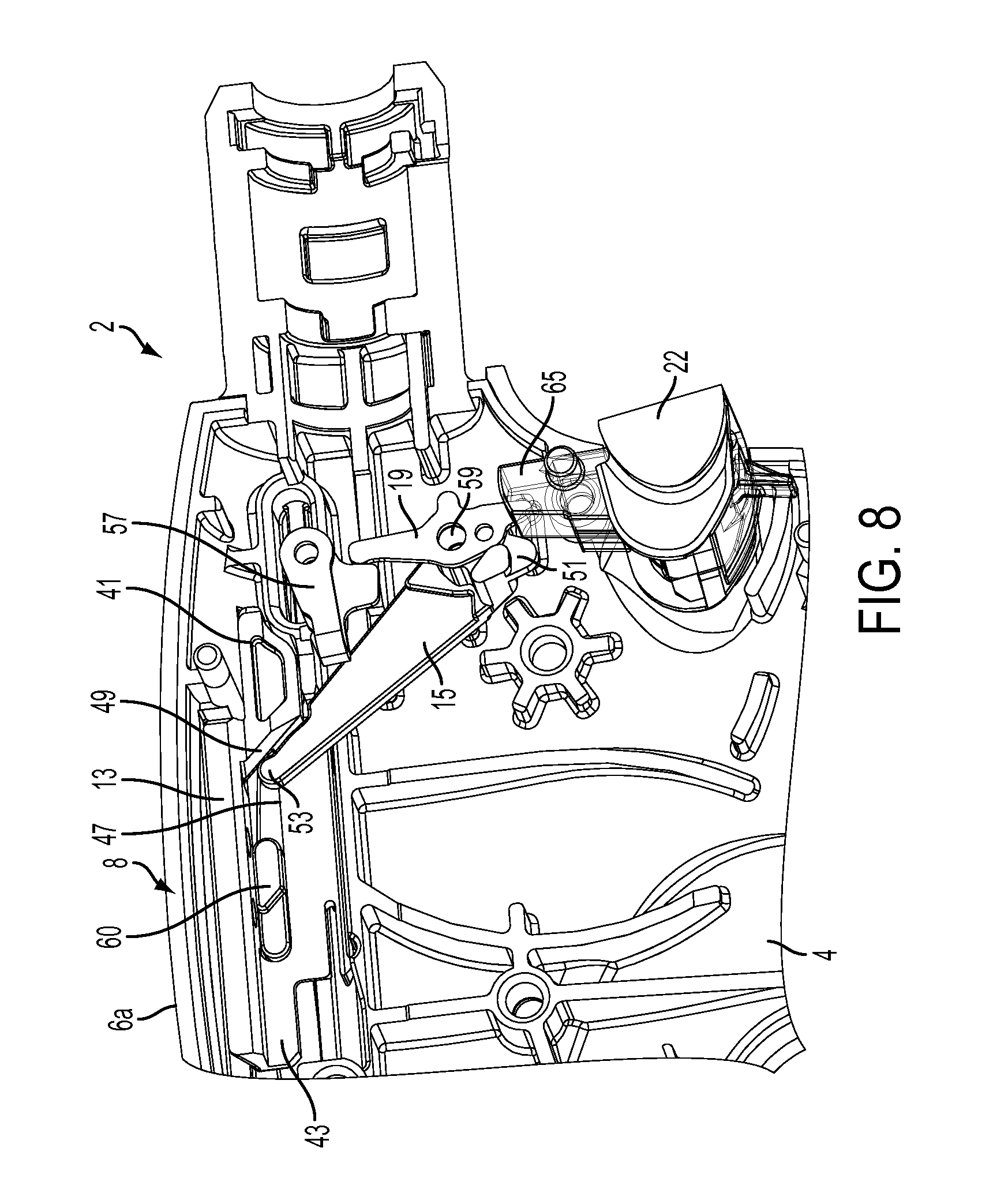
FIG. 8 is a perspective view of a handle assembly with the right handle housing shroud and various mechanisms located within the handle assembly removed, according to one embodiment.
FIG. 9 is a perspective view of a handle assembly with the right handle housing shroud and various mechanisms located within the handle assembly removed, according to one embodiment.
FIG. 10 is a side elevation view of a handle assembly of a surgical instrument, with the left handle housing shroud removed, according to one embodiment.
FIG. 11 is a perspective view of the handle assembly portion of the surgical instrument shown in FIG. 10, with the left handle housing shroud removed, according to one embodiment.
FIG. 12 is a detailed view of a knife lockout disabling mechanism showing a slider, a lever arm, and a button, according to one embodiment.
FIG. 13 is a side elevational view of a knife lockout disabling mechanism, according to one embodiment.
FIG. 14 is a side elevational view of the surgical instrument shown in FIG. 3 with the right handle housing shroud removed, according to one embodiment.
FIG. 15 is a perspective view of the surgical instrument shown in FIG. 3 with the right handle housing shroud removed, according to one embodiment.
FIG. 16 is a side elevational view of the rotary knife lockout disabling mechanism for a surgical instrument where the knife lockout element is enabled, according to one embodiment.
FIG. 17 is a side elevational view of the rotary knife lockout disabling mechanism for a surgical instrument where the knife lockout mechanism is disabled, according to one embodiment.
FIG. 18 is a side elevational view of the surgical instrument shown in FIGS. 1 and 2 with the left housing shroud removed, shaft assembly sheaths removed, the jaw fully open and the lockout defeat mechanism enabled, e.g., in the "ON" position, according to one embodiment.
FIG. 19 is a side elevational view of the surgical instrument shown in FIG. 18 with the right housing shroud removed, according to one embodiment.
FIG. 20 is a side elevational view of the surgical instrument shown in FIG. 19 with the firing plate removed, according to one embodiment.
FIG. 21 is a side elevational view of the surgical instrument shown in FIG. 20 with the lockout defeat mechanism slider removed, according to one embodiment.
FIG. 22 is a side elevational view of the surgical instrument shown in FIG. 20 with the toggle clamp and yoke removed, according to one embodiment.
FIG. 23 is a partial perspective view of the surgical instrument shown in FIG. 22, according to one embodiment.
FIG. 24 is a partial perspective view of the surgical instrument shown in FIG. 23 with the firing plate replaced, according to one embodiment.
FIG. 25 is a partial perspective view of the surgical instrument shown in FIG. 24 with the lockout defeat mechanism slider, lever arm, and lock arm removed, according to one embodiment.
FIG. 26 is a side elevational view of the surgical instrument shown in FIGS. 1 and 2 with the left housing shroud removed, shaft assembly sheaths removed, the jaw fully open and the lockout defeat mechanism disabled, e.g., in the "OFF" position, according to one embodiment.
FIG. 27 is a side elevational view of the surgical instrument shown in FIG. 26 with the right housing shroud removed, according to one embodiment.
FIG. 28 is a partial perspective view of the surgical instrument shown in FIG. 27 with the toggle clamp and yoke removed, according to one embodiment.
FIG. 29 is a side elevational view of the surgical instrument shown in FIGS. 1 and 2 with the left housing shroud removed, shaft assembly sheaths removed, the jaw fully closed, knife fully fired, and the lockout defeat mechanism enabled, e.g., in the "ON" position, according to one embodiment.
FIG. 30 is a side elevational view of the surgical instrument shown in FIG. 29 with the right housing shroud removed, according to one embodiment.
FIG. 31 is a side elevational view of the surgical instrument shown in FIG. 30 with the lockout defeat mechanism slider, lever arm, and firing plate removed, according to one embodiment.
FIG. 32 is a partial perspective view of the surgical instrument shown in FIG. 30, according to one embodiment.
FIG. 33 is a side elevational view of the surgical instrument shown in FIGS. 1 and 2 with the left housing shroud removed, shaft assembly sheaths removed, jaw fully closed, knife fully fired, and lockout defeat mechanism disabled, e.g., in the "OFF" position, according to one embodiment.
FIG. 34 is a side elevational view of the surgical instrument shown in FIG. 33 with the right housing shroud removed, according to one embodiment.
FIG. 35 is a partial perspective view of the surgical instrument shown in FIG. 34, according to one embodiment.
FIG. 36 is a side elevational view of the surgical instrument shown in FIGS. 1 and 2 with the left housing shroud removed, shaft assembly sheaths removed, jaw clamped, and the lockout defeat mechanism enabled, e.g., in the "ON" position, according to one embodiment.
FIG. 37 is a side elevational view of the surgical instrument shown in FIG. 36 with the right housing shroud removed, according to one embodiment.
FIG. 38 is a partial perspective view of the surgical instrument shown in FIG. 37, according to one embodiment.
FIG. 39 is a side elevational view of the surgical instrument shown in FIGS. 1 and 2 with the left housing shroud removed, shaft assembly sheaths removed, jaw clamped and the lockout defeat mechanism disabled, e.g., in the "OFF" position, according to one embodiment.
FIG. 40 is a side elevational view of the surgical instrument shown in FIG. 39 with the right housing shroud removed, according to one embodiment.
FIG. 41 is a partial perspective view of the surgical instrument shown in FIG. 40, according to one embodiment.
FIG. 42 is a side elevational view of the surgical instrument shown in FIGS. 1 and 2 with the left housing shroud removed, shaft assembly sheaths removed, jaw clamped and the energy button thrown to unlock the lockout mechanism, according to one embodiment.
FIG. 43 is a side elevational view of the surgical instrument shown in FIG. 42 with the right housing shroud removed, according to one embodiment.
FIG. 44 is a partial perspective view of the surgical instrument shown in FIG. 43, according to one embodiment.
FIG. 45 is an exploded view of the shaft assembly, end effector, yoke, and rack portions of the surgical instrument shown in FIGS. 1 and 2, according to one embodiment.
FIG. 46 is a perspective view of the shaft assembly, end effector, yoke, and rack shown in FIG. 45 in the assembled state, according to one embodiment.
FIG. 47 is a side view of an end effector portion of the surgical instrument shown in FIGS. 1 and 2 with the jaws open, according to one embodiment.
FIG. 48 is a side view of an end effector portion of the surgical instrument shown in FIGS. 1 and 2 showing an energy button located underneath the energy button housing to illustrate that the lock release mechanism also is the energy delivery element, according to one embodiment.
DESCRIPTION
In the following detailed description, reference is made to the accompanying drawings, which form a part hereof. In the drawings, similar symbols and reference characters typically identify similar components throughout the several views, unless context dictates otherwise. The illustrative embodiments described in the detailed description, drawings, and claims are not meant to be limiting. Other embodiments may be utilized, and other changes may be made, without departing from the scope of the subject matter presented here.
The following description of certain examples of the technology should not be used to limit its scope. Other examples, features, aspects, embodiments, and advantages of the technology will become apparent to those skilled in the art from the following description, which is by way of illustration, one of the best modes contemplated for carrying out the technology. As will be realized, the technology described herein is capable of other different and obvious aspects, all without departing from the technology. Accordingly, the drawings and descriptions should be regarded as illustrative in nature and not restrictive.
It is further understood that any one or more of the teachings, expressions, embodiments, examples, etc. described herein may be combined with any one or more of the other teachings, expressions, embodiments, examples, etc. that are described herein. The following-described teachings, expressions, embodiments, examples, etc. should therefore not be viewed in isolation relative to each other. Various suitable ways in which the teachings herein may be combined will be readily apparent to those of ordinary skill in the art in view of the teachings herein. Such modifications and variations are intended to be included within the scope of the claims.
Before explaining the various embodiments of the surgical devices having a knife lockout disabling mechanism in detail, it should be noted that the various embodiments disclosed herein are not limited in their application or use to the details of construction and arrangement of parts illustrated in the accompanying drawings and description. Rather, the disclosed embodiments may be positioned or incorporated in other embodiments, variations and modifications thereof, and may be practiced or carried out in various ways. Accordingly, embodiments of the surgical devices disclosed herein are illustrative in nature and are not meant to limit the scope or application thereof. Furthermore, unless otherwise indicated, the terms and expressions employed herein have been chosen for the purpose of describing the embodiments for the convenience of the reader and are not to limit the scope thereof. In addition, it should be understood that any one or more of the disclosed embodiments, expressions of embodiments, and/or examples thereof, can be combined with any one or more of the other disclosed embodiments, expressions of embodiments, and/or examples thereof, without limitation.
Also, in the following description, it is to be understood that terms such as front, back, inside, outside, top, bottom and the like are words of convenience and are not to be construed as limiting terms. Terminology used herein is not meant to be limiting insofar as devices described herein, or portions thereof, may be attached or utilized in other orientations. The various embodiments will be described in more detail with reference to the drawings.
In various embodiments, the present disclosure provides an electrosurgical instrument comprising a knife lockout disabling mechanism configured to disable or override the knife lockout mechanism of the electrosurgical instrument. In one embodiment, the knife lockout disabling mechanism comprises a slider, a lever arm, and a button operatively coupled to the slider. The button can be engaged by the user to slidably move the slider back (proximally) and forth (distally) between several positions. In one embodiment, the slider is configured to slidably move back and forth between two positions. The lever arm is configured to pivot around a lock arm and to push in or activate the energy button when rotated. In one embodiment, the lever arm is connected to a ramped (or pivoting) slider that forces the lever arm to rotate and force the lock arm to rotate to unlock, disable, or override the knife lockout mechanism of the electrosurgical instrument. In one embodiment, the slider includes features to lock the lever arm in place once it is activated. A spring may be coupled to the energy button to force the lever arm and the slider back to their start positions once the energy button is deactivated. In other words, in one embodiment, the slider is configured to be in the lock-off (lock defeated) or lock-on (lock undefeated) position and the spring is configured to force the slider back to its start position in the transition area.
In another embodiment, the knife lockout disabling mechanism of the electrosurgical instrument comprises a rotator, a lever arm, and a button operatively coupled to the rotator configured to disable, override, or otherwise turn off the knife lockout mechanism of the electrosurgical instrument. The button can be engaged by the user to rotate the rotator between various positions. In one embodiment, the rotator can be rotated between two positions. The rotator acts on the lever arm to engage a surface of the lockout mechanism and thereby defeat the lockout mechanism of the electrosurgical instrument.
The above knife lockout disabling mechanisms, as discussed in more detail below, provide several advantages over conventional electrosurgical devices with knife lockout mechanisms that cannot be disabled. For example, the lockout disabling mechanisms according to the present disclosure are configured to fit in a form factor of current electrosurgical instruments with only a change to one of the housing shrouds. The lockout disabling mechanism generally moves between two states (off or on). Thus, the button portion of the slider or rotator can move slidably or rotatably between the two positions or states but not in any intermediate positions between the two states. In one embodiment, the button can be retrofitted into some existing electrosurgical instruments and locks into place without requiring any additional or new components to lock it in position. The button can be configured to employ a spring that is already provided for the energy button, as described herein. Also, either the slider or rotator is operatively coupled to the energy button such that when the knife lockout disabling mechanism is activated, it moves the energy button inward to provide a visual and tactile clue that the knife lockout feature is turned off.
Turning now to the figures, FIG. 1 illustrates a surgical instrument 102 comprising a trigger assembly 107 and a lockout disabling mechanism 108. In this view, a first jaw member 116a of an end effector 110 is fully open and the knife lockout disabling mechanism 108 is located in the off position. The knife lockout disabling mechanism 108 is configured to clamp and fire an end effector 110 coupled to the surgical instrument 102. The surgical instrument 102 comprises a handle assembly 104, a shaft assembly 112, and the end effector 110. The shaft assembly 112 comprises a proximal end and a distal end. The proximal end of the shaft assembly 112 is coupled to the distal end of the handle assembly 104. The end effector 110 is coupled to the distal end of the shaft assembly 112. The handle assembly 104 comprises a pistol grip 118. The handle assembly 104 comprises a left handle housing shroud 106a and a right handle housing shroud 106b. The trigger assembly 107 comprises a trigger 109 actuatable towards the pistol grip 118. The knife lockout disabling mechanism 108 comprises a button 139, or knob, that is actuatable for adjusting or controlling the position of the knife lockout disabling mechanism 108 between first and second positions A and B (A=Distal and B=Proximal relative to the clinician) within a slot 111 formed in the left handle housing shroud 106a. A rotatable shaft knob 120 is configured to rotate the shaft assembly 112 with respect to the handle assembly 104. The handle assembly 104 further comprises an energy button 122 configured to provide electrosurgical energy to one or more electrodes in the end effector 110.
The knife lockout mechanism forces the user to first clamp (close the jaws 110), energize the electrodes, and then cut the tissue (fire the knife). The knife unlock feature contains the energy button 122 so that the energy button 122 has to be depressed before the knife can be released or that the single trigger can move the rack 136 forward. The single trigger 109 closes the jaws in the first .about.13 degrees of stroke. The single trigger 109 fires the knife in the last .about.29 degrees of stroke. The lockout is the stop in between the first stroke and the second stroke. As shown in FIG. 48, an energy button 166 is located underneath the energy button 122 housing to illustrate that the lock release mechanism also is the energy delivery element.
The shaft assembly 112 comprises a closure/jaw actuator, a firing/cutting member actuator, and an outer sheath. In some embodiments, the outer sheath comprises the closure actuator. The outer sheath comprises one or more contact electrodes on a distal end configured to interface with the end effector 110. The one or more contact electrodes are operatively coupled to the energy button 122 and an energy source (not shown).
The energy source may be suitable for therapeutic tissue treatment, tissue cauterization/sealing, as well as sub-therapeutic treatment and measurement. The energy button 122 controls the delivery of energy to the electrodes. As used throughout this disclosure, a button refers to a switch mechanism for controlling some aspect of a machine or a process. The buttons may be made out of a hard material such as usually plastic or metal. The surface may be formed or shaped to accommodate the human finger or hand, so as to be easily depressed or pushed. Buttons can be most often biased switches, even though many un-biased buttons (due to their physical nature) require a spring to return to their un-pushed state. Terms for the "pushing" of the button, may include press, depress, mash, and punch.
In some embodiments, an end effector 110 is coupled to the distal end of the shaft assembly 112. The end effector 110 comprises a first jaw member 116a and a second jaw member 116b. The first jaw member 116a is pivotally coupled to the second jaw member 116b. The first jaw member 116a is pivotally moveable with respect to the second jaw member 116b to grasp tissue therebetween. In some embodiments, the second jaw member 116b is fixed. In other embodiments, the first jaw member 116a and the second jaw member 116b are pivotally movable. The end effector 110 comprises at least one electrode. The electrode is configured to deliver energy. Energy delivered by the electrode may comprise, for example, radiofrequency (RF) energy, sub-therapeutic RF energy, ultrasonic energy, and/or other suitable forms of energy. In some embodiments, a cutting member (not shown) is receivable within a longitudinal slot defined by the first jaw member 116a and/or the second jaw member 116b. The cutting member is configured to cut tissue grasped between the first jaw member 116a and the second jaw member 116b. In some embodiments, the cutting member comprises an electrode for delivering energy, such as, for example, RF and/or ultrasonic energy.
In certain instances, as described above, the surgical instrument 102 may include an automatic energy lockout mechanism. The energy lockout mechanism can be associated with a closure mechanism of the surgical instrument 102. In certain instances, the energy lockout mechanism can be configured to permit energy delivery to the end effector 10 when the energy delivery button 122 is actuated if the jaw members 116a and 116b are in an open configuration. In certain instances, the energy lockout mechanism may be configured to deny energy delivery to the end effector 110 when the energy delivery button 122 is actuated if the jaw members 116a and 116b are in a closed configuration. In certain instances, the energy lockout mechanism automatically transitions from permitting the energy delivery to denying the energy delivery when the jaw members 116a and 116b are transitioned from the closed configuration to the open configuration, for example. In certain instances, the energy lockout mechanism automatically transitions from denying the energy delivery to permitting the energy delivery when the jaw members 116a and 116b are transitioned from the open configuration to the closed configuration, for example.
FIG. 2 is a perspective view of a handle assembly 104 of a surgical instrument 102 illustrated in FIG. 1, according to one embodiment, with the right housing shroud 106a and the outer and inner sheaths of the shaft assembly 112 removed to show some of the internal mechanisms. The left handle housing shroud 106b of the handle assembly 104 comprises the knife lockout disabling mechanism 108. The button 139 is located in the first "off" position A (A=distal relative to the clinician) within the slot 111 formed in the right handle housing shroud 106a. In the illustrated embodiment, position B (B=proximal relative to the clinician) corresponds to the second "on" position of the knife lockout disabling mechanism 108, where the knife lockout mechanism remains disabled until the button is switched back to position A. Accordingly, position A corresponds to the enabled state of the knife lockout mechanism and position B corresponds to the disabled state of the knife lockout mechanism. Stated differently, position A corresponds to the "off" state of the knife lockout disabling mechanism 108 and position B corresponds to the "on" state of the knife lockout disabling mechanism 108. When the knife lockout mechanism is in the disabled state, the energy button 122 may appear to be depressed to provide a visual indication to the clinician that the knife lockout mechanism has been disabled but without energizing the electrodes in the end effector 110 (FIG. 1). When the knife lockout mechanism is disabled, the knife may be fired at will without the need to apply electrosurgical energy to one or more electrodes in the end effector 110.
The trigger assembly 107 comprises the necessary components for closing the jaw members 116a, 116b and firing the cutting member or knife bands 174. The trigger assembly 107 comprises a trigger plate 124 and firing plate 128 operatively coupled to the trigger 109. Squeezing the trigger 109 in direction C towards the pistol grip 118 rotates the trigger plate 124 which operates the toggle clamp 145 to advance a yoke 132 and a closure actuator 129 distally to close the jaw members 116a, 116b of the end effector. Initial rotation of the trigger plate 124 also slightly rotates the firing plate 128. The firing plate 128 comprises a sector gear with a plurality of teeth 131 that engage and rotate a first pinion gear 133, which engages a second pinion gear 134 to advance a rack 136 (neither is shown in this view). A lock arm 157 (shown in FIGS. 22-24, 28, 32, 35, 38, 41, 44, for example) is operatively coupled to a lever arm 115, an unlock arm 119, and a lockout element 165. When the instrument 102 is in normal lockout mode, the lock arm 157 engages a notch 158 (shown in FIGS. 23-25, 38, 41, 44, and 45, for example) in the rack 136 to lock the rack 136 and prevent the rack 136 from moving distally (firing) no matter how hard the trigger 109 is squeezed.
The single trigger 109 closes the jaws in the first .about.13 degrees of stroke. The trigger plate 124 is configured to interface with the toggle clamp 145 during rotation of the trigger 109 from an initial position to a first rotation, which is .about.13 degrees of stroke, for example. The trigger plate 124 is operably coupled to the firing plate 128. In certain instances, the firing plate 128 may include a first slot 128a and a second slot 128b. The first slot 128a receives a drive pin 148 fixedly coupled to the trigger plate 124. The pin 148 slidably moves within the first slot 128a. Rotation of the trigger plate 124, while the pin 148 is slid ably received within the first slot 128a, drives rotation of the firing plate 128. The teeth 131 of the sector gear engage and rotate the first pinion 133, which in turn drives the second pinion 134, which drives the rack 136 distally to fire the cutting element, or knife, but only when the knife lockout is unlocked, released, or disabled.
The single trigger 109 fires the knife in the last .about.29 degrees of stroke. Rotation of the trigger plate 124 beyond a predetermined rotation such as, for example, the first rotation, causes rotation of the firing plate 128. Rotation of the firing plate 128 deploys a cutting member within the end effector 110. For example, in the illustrated embodiment, the firing plate 128 comprises a sector gear operably coupled to a rack 136 through the first and second pinions 133, 134. The firing plate 128 comprises a plurality of teeth 131 configured to interface with the first pinion 133. Rotation of the firing plate 128 rotates the first and second pinions 133, 134, to drive the rack 136 distally. Distal movement of the rack 136 drives the cutting member actuator distally, causing deployment of the cutting member (e.g., knife) within the end effector 110.
The lockout is the stop in between the first stroke and the second stroke. Turning back now to the description of the lockout disabling mechanism 108, when the slider 113 button 139 portion is in located in position A, the lock arm 157 can be released by pressing or actuating the energy button 122 to rotate the lockout element 165, which rotates the unlock arm 119 to release the lock arm 157. Once the lock arm 157 is released, the rack 136 is enabled to advance distally and fire the knife by squeezing the trigger 109 in direction C further towards the pistol grip 118. As the trigger 109 is squeezed, the firing plate 128 rotates and drives the first pinion gear 133, which drives the second pinion gear 134 to drive the rack 136.
When the slider 113 button 139 is located in position B, the slider 113 rotates the lever arm 115, which rotates the unlock arm 119 to release the lock arm 157. While the button 139 is in position B, the rack 136 can be fired without the need to press energy button 122 to rotate the lockout element 165. A detent may be provided to hold the button in either position A or B. These and other features are described in more detail hereinbelow.
The shaft assembly 112 comprises a closure/jaw actuator and a firing/cutting member actuator. The closure/jaw actuator comprises a yoke 132 and toggle clamp 145 assembly operatively coupled to a closure actuator 129 which acts on a closure spring 114 coupled to a spring-to-bar interface element 127 and a closure bar 142. In one instance the closure bar 142 is operatively coupled to the jaw members 116a, 116b via at least one linkage. The firing/cutting member actuator comprises a rack 136 operatively coupled to a firing bar 117, which is slidably received within the closure actuator 129 and the closure spring 114. The firing bar 117 is coupled to a knife pusher block 140 and a flexible I-beam knife band 174 comprising multiple flexible bands fastened together and a cutting element at the distal end. Advancing the rack 136 in the distal direction advances the cutting element band 174 distally through a channel or slot formed in the jaw members 116a, 116b.
FIG. 3 is a side elevation view of a handle assembly 4 of a surgical instrument 2 similar to the surgical instrument 102 shown in FIGS. 1 and 2, with the left handle housing shroud removed to expose various mechanisms located within the handle assembly 4 and the knife lockout mechanism enabled. The handle assembly 4 comprises a plurality of components for actuating the surgical instrument 2, such as, for example, mechanism for affecting the closure of the jaw members of the end effector, deploying a cutting member (e.g., knife) within the end effector, and/or delivering energy to one or more electrodes coupled to the end effector. The knife lockout disabling mechanism 8 is configured to disable the knife lockout mechanism of the end effector. The knife lockout disabling mechanism 8 comprises a slider 13, a lever arm 15, and a button 39 operatively coupled to the slider 13. An unlock arm 19 is actuated by the lever arm 15 as the slider 13 is slidably translated from the first position A to the second position B as indicated in FIG. 4. While the slider 13 translates in a proximal direction B, a ramped or angled wall 49 formed within a body 43 portion of the slider 13 engages or contacts one end 51 of the lever arm 15 causing the lever arm 15 to rotate in a first direction E about a pivot point 59. The rotating lever arm 15 pushes the unlock arm 19 causing the unlock arm 19 to rotate in the same first direction. One end of the unlock arm 19 rotates the knife lockout element 65 in a second, opposite, direction and the other end of the unlock arm 19 rotates the lock arm 57 (not shown in this view, but shown in FIGS. 8 and 9) to unlock or disable the knife lockout function.
FIG. 4 is a side elevation view of the handle assembly 4 of the surgical instrument 2 shown in FIG. 3, with the left handle housing shroud removed to expose various mechanisms located within the handle assembly 4 and the knife lockout mechanism disabled, according to one embodiment. As shown in FIG. 4, the slider 13 has been slidably translated to the proximal position as indicated by arrow D. The lever arm 15 and the unlock arm 19 have been rotated in a the direction indicated by arrow G by the other end 53 of the lever arm 15 and the knife lockout element 65 has been rotated in a second, opposite, direction. The unlock arm 19 acts on the lock arm 57 to disable the knife lockout function. The energy button 22 is operatively coupled to the unlock arm 19. Thus, the energy button 22 will be in a depressed state as indicated by arrow F when the knife lockout element 65 has been disabled.
FIG. 5 is a perspective view of the handle assembly 4 of the surgical instrument 2 shown in FIG. 4, with the left handle housing shroud removed to expose various mechanisms located within the handle assembly 4 and the knife lockout element 65 disabled, according to one embodiment. In various embodiments, the electrosurgical instrument 2 comprising a knife lockout disabling mechanism 8 configured to disable or override the knife lockout element 65 of the electrosurgical instrument 2. As shown win FIG. 5, the slider 13 has been slidably translated proximally in direction B to disable the knife lockout element 65 as described in connection with FIG. 4. The button 39 can be engaged by the clinician to slidably move the slider 13 back (proximally) and forth (distally) between several positions. In one embodiment, the slider 13 is configured to slidably move back and forth between the first and second positions A and B. The lever arm 15 is configured to pivot about the unlock arm 19 and to push in the energy button 22 when rotated. In one embodiment, the lever arm 15 is coupled to a ramped (or pivoting) slider 13 that forces the lever arm 15 to rotate in a first direction and force the unlock arm 19 to rotate in a second, opposite, direction. The unlock arm 19 rotates the lock arm 57 to unlock, disable, or override the knife lockout mechanism of the electrosurgical instrument 2. In one embodiment, the slider 13 includes features to lock the lever arm 15 in place once it is activated. A spring may be coupled to the energy button 22 to force the lever arm 15 and the slider 13 back to their start positions A or B once the energy button 22 is deactivated. In other words, in one embodiment, the slider 13 may be configured to be in the lock-OFF (lock defeated, disabled, etc.) or lock-ON (lock undefeated, enabled, etc.) position and the spring is configured to force the slider 13 back to its start position in the transition area. A longitudinal projection 41 extends distally from the body 43 of the slider 13.
Turning now to FIGS. 3-5, the knife lockout disabling mechanism 8 is coupled to one or more mechanisms for closing the jaw members of the end effector and deploying a cutting member (e.g., knife) therein. In one embodiment, when the trigger 9 is squeezed in direction C towards the pistol grip 18, the trigger 9 rotates the trigger plate 24 about a rotation point defined by a rotation pin 25a. Rotation of the trigger plate 24 to a first position causes a toggle clamp 45 to advance a yoke 32 and a closure actuator configured to transition the jaw members from an open position to a closed position. For example, in the illustrated embodiment, the toggle clamp 45 is operatively coupled to a yoke 32. The toggle clamp 45 is movably coupled to the trigger plate 24. Rotation of the trigger plate 24 also drives the yoke 32 distally. Distal movement of the yoke 32 compresses a closure spring 114, causing distal movement of the closure actuator. As previously discussed in connection with FIGS. 1 and 2, distal movement of the closure actuator compresses a closure spring. The closure spring is coupled to a closure bar via the spring-to-bar interface element. Accordingly, distal movement of the closure actuator causes the closure bar to pivotally move the first jaw member from an open position to a closed position with respect to the second jaw member, for example.
Rotation of the trigger plate 24 beyond a predetermined rotation such as, for example, the first rotation position, causes partial rotation of the firing plate 28. Rotation of the firing plate 28 deploys a cutting member within the end effector 10. For example, in the illustrated embodiment, the firing plate 28 comprises a sector gear operably coupled to a rack 36 through first and second pinions 33 and 34. The sector gear of the firing plate 28 comprises a plurality of teeth 31 configured to interface with the first pinion 33. The first pinion 33 drives the second pinion 34. Thus, rotation of the firing plate 28 rotates the pinions 33 and 34, driving the rack 36 distally. Distal movement of the rack 36 drives the cutting member actuator distally, causing deployment of the cutting member (e.g., knife) within the end effector 10. The rack 36, however, comprises at least one notch 58 configured to engage the lock arm 57. When the lock arm 57 engages the notch 58 in the rack 36, the rack 36 is prevented from firing distally. This is referred to as the lockout state. When the button 39 in position A, the energy button 22 must be depressed inwardly towards to pistol grip 18 to unlock the lock arm 57 and release the rack 36. A spring is provided behind the energy button 22 to balance out this force. When the button 39 in position B, the lockout mechanism is disabled by the lever arm 15 and the unlock arm 19 releasing the lock arm 57.
The trigger plate 24 is configured to interface with the toggle clamp 45 during rotation of the trigger 9 from an initial position to a first rotation position, for example. The trigger plate 24 is operably coupled to the firing plate 28. In certain instances, the firing plate 28 may include a first slot 28a and a second slot 28b. The first slot 28a receives a drive pin 48 coupled to the trigger plate 24. The drive pin 48 is slidably driven by the trigger plate 24 in the first slot 28a and drives the firing plate 28.
Rotation of the firing plate 28 by the drive pin 48 in the first slot 28a rotates the sector gear teeth 31, which engage and rotate the first pinion 33. The first pinion 33 rotates the second pinion 34. The second pinion 34 drives the rack 36 distally to fire the cutting element (e.g., knife), but only when the lock arm 57 is released or disabled from the notch 58 in the rack 32 either by locating the button 39 in position B or pressing the energy button 22 to release the lockout element 65.
FIG. 6 illustrates a detailed view of the knife lockout disabling mechanism 8 showing the slider 13, one end of the lever arm 15, and the button 39, according to one embodiment. The slider 13 comprises a body 43 defining a longitudinal slot 47 enabling the slider 13 to slidably translate in either direction A or B. In FIG. 6, the slider 13 is shown in the proximal position B, wherein the lock arm 57 is disabled allowing the rack 32 to move distally to drive the firing bar. A projection 41 extends longitudinally from the body 43 of the slider 13. At the distal end of the projection 41, a detent 21 feature provides tactile feedback to the clinician when locking and unlocking the knife lockout mechanism. The detent 21 feature also keeps the slider 13 in the unlocked position like a detent. An angled wall 49 (ramp) portion of the body 43 engages one end 51 of the lever arm 15.
FIG. 7 is an exploded view of the handle assembly 4 with the right handle housing shroud and various mechanisms located within the handle assembly 4 removed to more clearly show the components of the knife lockout disabling mechanism 8, according to one embodiment. As shown in FIG. 6, the slider 13 comprises a longitudinal slot 47 that is slidably movable over a longitudinal projection 60 formed on the left handle housing shroud 6a. The slot 11 provides an aperture for the button 39, operatively coupled to the slider 13, to slidably move between first and second positions (A and B). One end 53 of the lever arm 15 is pivotally mounted to a pivot point 27 formed on the left handle housing shroud 6a. Another end 51 of the lever arm 15 is received in a space 29 defined by the slider 13 body 43 and engages the ramp 49 when the slider is in position A.
FIGS. 8 and 9 are perspective views of the handle assembly 4 with the right handle housing shroud and various mechanisms located within the handle assembly 4 removed to more clearly show the components of the knife lockout disabling mechanism 8, according to one embodiment. As shown in FIG. 8, the knife lockout disabling mechanism 8 is in the locked state. The slider 13 is located in position A and one end of the lever arm 15 is abutting the ramp 49 wall formed in the slider 13 body 43. The ramp 49 engages one end 53 of the lever arm 15 to pivotally rotate the lever arm 15 as the slider 13 moves from position A, shown in FIG. 8, to position B, shown in FIG. 9. The lever arm 15 is configured to pivot the unlock arm 19 such that one end of the unlock arm 19 pushes in the energy button 22 when rotated as shown in FIG. 9 and the other end of the unlock arm 19 release the lock arm 57 to disable the knife lockout mechanism. As shown in FIG. 8, the lockout element 65 is shown in the locked position such that the lock arm 57 engages the notch 58 formed in the rack 32 to prevent the knife from firing. As shown in FIG. 9, when the unlock arm 19 is rotated in the second, opposite, direction, the lock arm 57 unlocks the knife lockout function to enable firing of the knife without actuating the energy button 22. Nevertheless, the energy button 22 is slightly pushed in to provide an indication that the lockout function has been disabled.
FIGS. 10-15 illustrate a knife lockout disabling mechanism according to another embodiment. FIG. 10 is a side elevation view of the handle assembly 104 of a surgical instrument 102, with the left handle housing shroud 106a removed to expose various mechanisms located within the handle assembly 104 and the knife lockout disabling mechanism 108 in the "off" position, according to one embodiment. The knife lockout disabling mechanism 108 comprises a slider 113, a button 139, and a lever arm 115. The slider 113 comprises a body 143 defining a longitudinal slot 147 wherein the slider 113 slidably translates in directions A and B by sliding the button 139. The slider 113 further comprises longitudinally extending projections 141, 163, where the second longitudinal projection 163 and the body 143 define a cutout portion 162. A ramped or angled wall 149 engages the end 153 of the lever arm 115. Thus, when the slider 113 moves from position A to position B, the ramp 149 engages the one end 153 of the lever arm 115 causing it to rotate in a first direction. The rotation of the lever arm 115 in the first direction causes one end of the unlock arm 119 to rotate in the same first direction to push on the knife lockout element 165 and the other end of the unlock arm 119 disengages the lock arm 157 (shown in FIGS. 22-24, 28, 32, 35, 38, 41, 44, for example) from the notch 158 (shown in FIGS. 23-25, 38, 41, 44, and 45, for example) in the rack 132. When the lock arm 57 is rotated out of the notch 58 it unlocks or disables the knife lockout function, thus enabling the cutting element to be fired by the rack 132.
As shown in FIG. 10, a slider 113 portion of the knife lockout disabling mechanism 108 has been slidably translated to a distal position by sliding the button 139 in the distal direction A. A lever arm 115 is configured to rotate in a first direction as indicated by arrow E when the slider 113 is slidably translated in the proximal direction B as indicated by arrow B. A unlock arm 119 is configured to rotate in the same first direction when one end 153 of the lever arm 115 pushes on the unlock arm 119 as the slider 113 is slidably translated in the proximal direction B. One end of the unlock arm 119 pushes on the knife lockout element 165 to cause it to rotate in an opposite second direction and the other end of the unlock arm 119 unlocks the lock arm 57 to disable the knife lockout function. The energy button 122 is operatively coupled to the unlock arm 119 and is shown in an undepressed state to show that the knife lockout mechanism is enabled.
FIG. 11 is a perspective view of the handle assembly 104 of the surgical instrument 102 shown in FIG. 10, with the left handle housing shroud 106a removed to expose various mechanisms located within the handle assembly 104 and the knife lockout mechanism disabled, according to one embodiment. In various embodiments, the electrosurgical instrument 102 comprising a knife lockout disabling mechanism 108 configured to disable or override the knife lockout mechanism of the electrosurgical instrument 102. As shown win FIG. 11, the slider 113 is still in the distal position A such that the knife lockout mechanism is enabled as described in connection with FIG. 10. The button 139 can be engaged by the clinician to slidably move the slider 113 back (proximally) and forth (distally) between several positions. In one embodiment, the slider 113 is configured to slidably move back and forth between the first and second positions A and B. The lever arm 115 is configured to pivot about the unlock arm 119 and to push in the energy button 122 when rotated. In one embodiment, the lever arm 115 is connected to a ramped (or pivoting) slider 113 that forces the lever arm 115 to rotate in a first direction and force the unlock arm 119 to rotate in a second, opposite, direction to unlock, disable, or override the knife lockout mechanism of the electrosurgical instrument 102. In one embodiment, the slider 113 includes features to lock the lever arm 115 in place once it is activated. A spring may be coupled to the energy button 122 to force the lever arm 115 and the slider 113 back to their start positions A or B once the energy button 122 is deactivated. In other words, in one embodiment, the slider 113 is configured to be in the lock-off (lock defeated) or lock-on (lock undefeated) position and the spring is configured to force the slider 113 back to its start position in the transition area. A longitudinal projection 141 extends distally from the body 143 of the slider 113.
FIGS. 12 and 6B are detailed views of the knife lockout disabling mechanism 108 showing the slider 113, one end of the lever arm 115, and the button 139, according to one embodiment. The slider 113 comprises a body 143 defining a first longitudinal slot 147 that enables the slider 113 to slidably translate proximally and distally. A projection 141 extends longitudinally from the body 143 of the slider 113. At the distal end of the projection 141, a detent 121 feature provides tactile feedback to the clinician when locking and unlocking the knife lockout mechanism. The detent 121 feature also keeps the slider 113 in the unlocked position. An angled or ramped wall 149 portion of the body 143 engages one end 151 of the lever arm 115. A second longitudinal slot 160 and a cutout portion 162 defined by the second longitudinal projection 163 and the body 143 are provided on a proximal end of the slider 113.
As shown more particularly in FIG. 6B, the detent 121 is provided to the lock defeat OFF position so that the slider 113 will stay in place even when the lockout button 139 is pushed in. The detent 121 prevents the slider 113 from moving backwards when the energy button 122 is pressed to defeat the lockout. When the energy button 122 is depressed to defeat the lockout mechanism, the lockout defeat lever arm 115 moves with the energy button 122 and could cause the slider 113 to move freely with gravity or if the device is jolted. The detent 121 prevents the slider 113 from moving freely with gravity or if the device is jolted when the energy button 122 is depressed to defeat the lockout mechanism.
FIG. 13 is a side elevation view of the knife lockout disabling mechanism 108, according to one embodiment. The slider 113 is shown in the distal position corresponding to an enabled knife lockout mechanism. The button 139 is employed to slidably translate the slider 113 proximally and distally along the first longitudinal slot 147. The one end 151 of the lever arm 115 is shown resting on the ramped wall 149 portion of the slider 113 body 143. As shown, the lever arm 115 includes a notched portion 164 and defines a detent 121 to provide tactile feedback to the user regarding the state of the knife lockout mechanism. The lever arm 115 is rotatably coupled the unlock arm 119, which is rotatably coupled to the energy button 122.
FIGS. 14 and 15 provide additional views of the knife lockout disabling mechanism 108. FIG. 14 is a side elevational view of the surgical instrument 102 with the right handle housing shroud removed to expose various mechanisms located within the handle assembly 104 and the knife lockout mechanism enabled, according to one embodiment. FIG. 15 is a perspective view of the surgical instrument 102 with the right handle housing shroud removed to expose various mechanisms located within the handle assembly 104 and the knife lockout mechanism enabled, according to one embodiment.
With reference now to FIGS. 1, 2, 10, 11, 14, and 15, the knife lockout disabling mechanism 108 is coupled to one or more mechanisms for closing the jaw members 116a, 116b of the end effector 10 and deploying a cutting member (e.g., knife) therein. In one embodiment, when the trigger 109 is squeezed in direction C towards the pistol grip 118, the trigger 109 rotates the trigger plate 124 about a rotation point defined by a rotation pin 125a. Rotation of the trigger plate 124 to a first position causes a toggle clamp 145 to advance a yoke 132 and a closure actuator 129 configured to transition the jaw members 116a, 116b from an open position to a closed position. For example, in the illustrated embodiment, the toggle clamp 145 is operatively coupled to a yoke 132. The toggle clamp 145 is movably coupled to the trigger plate 124. Rotation of the trigger plate 124 also drives the yoke 132 distally. Distal movement of the yoke 132 compresses a closure spring 114, causing distal movement of the closure actuator 129. As previously discussed in connection with FIG. 2, distal movement of the closure actuator 112 compresses the closure spring 114. The closure spring 114 is coupled to the closure bar 142 via the spring-to-bar interface element 119. Accordingly, distal movement of the closure actuator 129 causes the closure bar 142 to pivotally move the first jaw member 116a from an open position to a closed position with respect to the second jaw member 116b, for example.
Rotation of the trigger plate 124 beyond a predetermined rotation such as, for example, the first rotation position, causes partial rotation of the firing plate 128. Rotation of the firing plate 128 deploys a cutting member within the end effector 110. For example, in the illustrated embodiment, the firing plate 128 comprises a sector gear operably coupled to a rack 136 through first and second pinions 133 and 134. The sector gear of the firing plate 128 comprises a plurality of teeth 131 configured to interface with the first pinion 133. The first pinion 133 drives the second pinion 134. Thus, rotation of the firing plate 128 rotates the first and second pinions 133 and 134 and drives the rack 136 distally. Distal movement of the rack 136 drives the cutting member actuator distally, causing deployment of the cutting member (e.g., knife) within the end effector 110. The rack 136, however, comprises at least one notch 58 configured to engage the lock arm 157. When the lock arm 157 engages the notch 58 in the rack 136, the rack 136 is prevented from firing distally. This is referred to as the lockout state. When the button 139 in position A, the energy button 122 must be depressed inwardly towards to pistol grip 118 to unlock the lock arm 57 and release the rack 136. When the button 139 in position B, the lockout mechanism is disabled by the lever arm 115 and the unlock arm 119 releasing the lock arm 157.
The trigger plate 124 is configured to interface with the toggle clamp 145 during rotation of the trigger 109 from an initial position to a first rotation position, for example. The trigger plate 124 is operably coupled to the firing plate 128. In certain instances, the firing plate 128 may include a first slot 128a and a second slot 128b. The first slot 128a receives a drive pin 148 coupled to the trigger plate 124. The drive pin 148 is slidably driven by the trigger plate 124 in the first slot 128a and drives the firing plate 128.
Rotation of the firing plate 128 by the drive pin 148 in the first slot 128a rotates the sector gear teeth 131 to rotate the first pinion 133. The first pinion 133 rotates the second pinion 134. The second pinion 134 drives the rack 136 distally to fire the cutting element (e.g., knife), but only when the lock arm 157 is released or disabled from the notch 158 in the rack 132 either by locating the button 139 in position B or pressing the energy button 122 to release the lockout element 165.
FIGS. 16 and 17 are side elevational views of a rotary knife lockout disabling mechanism 208 for a surgical instrument, according to one embodiment. FIG. 16 is a side elevational view of the rotary knife lockout disabling mechanism 208 for a surgical instrument where the knife lockout element 265 is enabled, according to one embodiment. FIG. 17 is a side elevational view of the rotary knife lockout disabling mechanism 208 for a surgical instrument where the knife lockout mechanism is disabled, according to one embodiment. As shown in FIGS. 16 and 17, in another embodiment, the knife lockout disabling mechanism 208 of the electrosurgical instrument 202 comprises a rotator 213, a lever arm 215, and a button 239 operatively coupled to the rotator 213 and is configured to disable, override, or otherwise turn off the knife lockout element 265 of the electrosurgical instrument 202. The button 239 can be engaged by the clinician to rotate the rotator 213 about a pivot point 247 between various positions. In one embodiment, the rotator 213 can be rotated about the pivot point 247 between two positions. The rotator 213 acts on the lever arm 215, which rotates a lock arm 219. The lock arm 219 rotates about a pivot point 259 and engages a surface of the lockout element 265 to rotate the lockout element 265 and thereby defeat the lockout mechanism of the electrosurgical instrument 202.
As shown in FIG. 16, the rotator 213 is positioned such that it can push on one end of the lever arm 215 when the rotator 213 is rotated in a first direction about the pivot point 247. The lever arm 215 and the lock arm 219 rotate about the pivot point 259 where the lock arm 219 rotates the lockout element 265 to the position shown in FIG. 17 to disable the knife lockout function. When the lever arm 215 is rotated about the pivot point 259 in the first direction, the lock arm 219 also rotates about the pivot point 259 in the same direction. The lock arm 219 then pushes on the lockout element 265 causing it to rotate in the opposite direction to unlock the knife lockout element 265, as shown in FIG. 17.
The above described knife lockout disabling mechanisms 8, 108, 208 provide several advantages over conventional electrosurgical devices with knife lockout mechanisms that cannot be disabled. For example, the lockout disabling mechanisms 8, 108, 208 according to the present disclosure can be configured to fit in a form factor of current electrosurgical instruments with only a change to one of the housing shrouds 6a, 6b, 106a, 106b, 206a, 206b. The lockout disabling mechanism 8, 108, 208 generally moves between two states (off or on). Thus, the button portion of the slider 13, 113 can be slidably translated and the rotator 213 can move rotatably between the two positions or states but not in any intermediate positions between the two states. In one embodiment, the button 39, 139, 239 can be retrofitted into some existing electrosurgical instruments and locks into place without requiring any additional or new components to lock it in position. The button 39, 139, 239 can be configured to employ a spring that is already provided for the energy button 22, 122, 222 as described herein. Also, either the slider or rotator is operatively coupled to the energy button such that when the knife lockout disabling mechanism is activated, it moves the energy button 22, 122, 222 inward to provide a visual and tactile clue that the knife lockout feature is turned off.
FIGS. 18-44 illustrate additional views of the surgical instrument 102 with the jaw members 116a, 116b, cutting member, and lockout mechanism in various modes of operation, according to one embodiment.
FIGS. 18-25 illustrate the surgical instrument 102 shown in FIGS. 1 and 2 with the jaw 110 fully open and the lockout defeat mechanism 108 enabled, e.g., in the "ON" position. FIG. 18 is a side elevational view of the surgical instrument 102 shown in FIGS. 1 and 2 with the left housing 106a shroud removed, shaft assembly 112 sheaths removed, the jaw 110 fully open and the lockout defeat mechanism 108 enabled, e.g., in the "ON" position, according to one embodiment. Thus, the button 139 portion of the slider 113 is slidably moved proximally to locate it in the B position.
FIG. 19 is a side elevational view of the surgical instrument 102 shown in FIG. 18 with the right housing shroud 106b removed, according to one embodiment. The trigger 109 is located in the maximum distal position and the trigger plate 124 is engaged with the toggle clamp 145 and yoke 132, which are located in the maximum proximal position to set the jaws 110 in the fully open position. The slider 113 is set to the maximum proximal "B" position where the ramp 149 has rotated the lever arm 115. The lever arm 115 rotates the unlock arm 119 clockwise and the lockout element 165 counterclockwise to enable the lockout defeat mechanism 108. The lockout element 165 also depresses the energy button 122 to indicate that the lockout defeat mechanism 108 enabled in the "ON" position. This view also shows the position of the firing plate 128 sector gear meshed with the first pinion 133 prior to firing the cutting element. FIG. 20 is a side elevational view of the surgical instrument shown in FIG. 19 with the firing plate 128 removed, according to one embodiment. This view illustrates the position of the trigger 109 relative to the trigger plate 124, the toggle clamp 145, and the yoke 132. This view also shows the first pinion 133 meshed with the second pinion 134 which located behind the firing plate 128. FIG. 21 is a side elevational view of the surgical instrument 102 shown in FIG. 20 with the lockout defeat mechanism slider 113 removed, according to one embodiment, to better illustrate the position of the toggle clamp 145 when the jaws 110 are fully open. FIG. 22 is a side elevational view of the surgical instrument 102 shown in FIG. 20 with the toggle clamp 145 and the yoke 132 removed, according to one embodiment. This view shows the position of the rack 136 and the lock arm 157 relative to the position of the slider 113. In addition, this view shows the second pinion 134 meshed with the rack 136 when the cutting element has not yet been fired. FIG. 23 is a partial perspective view of the surgical instrument 102 shown in FIG. 22, according to one embodiment, which more clearly shows the lock arm 157 located in the notch 158 formed on top of the rack 136. When the unlock arm 119 is in the indicated position, as the toggle clamp 145 and yoke move in the distal direction, the unlock arm 119 acts on the lock arm 157 to disengage the lock arm 157 from the notch 158 in the rack 136 to defeat the lockout mechanism. Therefore, the rack 136 is able to advance distally when the firing plate 128 is rotated by the trigger 109. FIG. 24 is a partial perspective view of the surgical instrument shown in FIG. 23 with the firing plate 128 replaced, according to one embodiment, to show the relative position of the firing plate 128, the first and second pinions 133, 134 and the rack 136 prior to firing the cutting element. FIG. 25 is a partial perspective view of the surgical instrument 102 shown in FIG. 24 with the lockout defeat mechanism slider 113, lever arm 115, and lock arm 157 removed, according to one embodiment, to show the notch 158 or slot formed on top of the rack 136. As previously discussed, the lock arm 157 engages the notch 158 to prevent the rack 136 from advancing distally to fire the cutting element in response to the squeezing the trigger 109.
FIGS. 26-28 illustrate the surgical instrument 102 shown in FIGS. 1 and 2 with the jaw 110 fully open and the lockout defeat mechanism 108 disabled, e.g., in the "OFF" position. FIG. 26 is a side elevational view of the surgical instrument 102 shown in FIGS. 1 and 2 with the left housing shroud 106a removed, shaft assembly 112 sheaths removed, the jaw 110 fully open and the lockout defeat mechanism 108 disabled, e.g., in the "OFF" position, according to one embodiment. Thus, the button 139 portion of the slider 113 is slidably moved distally to locate it in the A position. FIG. 27 is a side elevational view of the surgical instrument 102 shown in FIG. 26 with the right housing shroud 106b removed, according to one embodiment. The trigger 109 is located in the maximum distal position and the trigger plate 124 is engaged with the toggle clamp 145 and yoke 132, which are located in the maximum proximal position to set the jaws 110 in the fully open position. The slider 113 is set to the maximum distal "A" position. The lever arm 115 holds the unlock arm 119 and the lockout element 165 in a substantially vertical position to disable the lockout defeat mechanism 108 and enable the lockout mechanism. This view also shows the position of the firing plate 128 sector gear meshed with the first pinion 133 prior to firing the cutting element. FIG. 28 is a partial perspective view of the surgical instrument 102 shown in FIG. 27 with the toggle clamp 145 and yoke 132 removed, according to one embodiment. As shown, the unlock arm 119 is located in a substantially vertical position. Accordingly, as the toggle clamp 145 and the yoke 132 slide distally, the lock arm 157 will not contact the unlock arm 119 and the lock arm 157 remains engaged with the notch 158 in the rack 136. In this configuration, the lockout mechanism is enabled and to fire the rack 136, the energy button 122 must be depressed to rotate the lockout element 165 counterclockwise to rotate the unlock arm 119 clockwise and in response rotate the lock arm 157 counterclockwise to disengage it from the notch 158 in the rack 136.
FIGS. 29-32 illustrate the surgical instrument 102 shown in FIGS. 1 and 2 with the jaw 110 fully closed, knife fully fired, and the lockout defeat mechanism 108 enabled, e.g., in the "ON" position. FIG. 29 is a side elevational view of the surgical instrument 102 shown in FIGS. 1 and 2 with the left housing shroud 106a removed, shaft assembly 112 sheaths removed, the jaw 110 fully closed, knife fully fired, and the lockout defeat mechanism 108 enabled, e.g., in the "ON" position, according to one embodiment. FIG. 30 is a side elevational view of the surgical instrument 102 shown in FIG. 29 with the right housing shroud 106b removed, according to one embodiment. As shown, the trigger 109 is squeezed fully proximally in direction C to straighten the toggle clamp 145 and advance the yoke 132 distally in direction H to push on the closure actuator and close the jaws 110. Further, the firing plate 128 is shown fully rotated in the counterclockwise to fully fire the knife. As previously discussed, the slider 113 has been slidably moved proximally in direction I to position B to rotate the lever arm 115 and the unlock arm 119 clockwise to rotate the lockout element 165 counterclockwise in response. When the slider 113 is located in position B, the unlock arm 119 will unlock, e.g., disengage, the lock arm 157 from the notch 158 to enable the rack 136 to move proximally in direction I in response to the firing plate 128 rotating counterclockwise while engaged to the first pinion 133. The first pinion 133 rotates clockwise and which in turn rotates the second pinion 134 counterclockwise to drive the rack 136 distally in direction H to drive the firing bar 117 and the knife distally in direction H. FIG. 31 is a side elevational view of the surgical instrument 102 shown in FIG. 30 with the lockout defeat mechanism slider 113, lever arm 119, and firing plate 128 removed, according to one embodiment, to show the position of trigger plate 124, toggle clamp 145, and yoke 132 when the jaws 110 are in the fully closed position. FIG. 32 is a partial perspective view of the surgical instrument 102 shown in FIG. 30, according to one embodiment. In this view, the unlock arm 119 is shown engaged with the lock arm 157 to release the lock arm 157 from the notch 158 in the rack 136 to enable the rack 136 to slide distally in direction H and fire the knife.
FIGS. 33-35 illustrate the surgical instrument 102 shown in FIGS. 1 and 2 with the jaw 110 fully closed, knife fully fired, and the lockout defeat mechanism 108 disabled, e.g., in the "OFF" position. FIG. 33 is a side elevational view of the surgical instrument shown in FIGS. 1 and 2 with the left housing shroud removed, shaft assembly sheaths removed, the jaw fully closed and the lockout defeat mechanism disabled in the "OFF" position, according to one embodiment. FIG. 34 is a side elevational view of the surgical instrument 102 shown in FIG. 33 with the right housing shroud 106b removed, according to one embodiment. Thus, the button 139 portion of the slider 113 is slidably moved distally to locate it in the A position. To fully close the jaw 110, the trigger 109 is squeezed in direction C to rotate the trigger plate 124 fully counterclockwise to straighten the toggle clamp 145 and advanced the yoke 132. To fully fire the knife while the lockout defeat mechanism 108 disabled, e.g., in the "OFF" position (in other words, the lockout mechanism is enabled) the energy button 122 must be depressed to rotate the lockout element 165 counterclockwise and rotate the unlock arm 119 clockwise to kick the lock arm 157 out of the notch 158 in the rack 136 and unlock the lockout mechanism. Once the lockout mechanism in unlocked, the trigger 109 can be fully squeezed in direction C to rotate the firing plate 128 counterclockwise. This rotates the first pinion 133 clockwise, the second pinion 134 counterclockwise, and the rack 136 is driven distally to fire the firing bar 117 distally in direction H to fire the knife 174 and the I-beam member 216. FIG. 35 is a partial perspective view of the surgical instrument 102 shown in FIG. 34, according to one embodiment. This view shows the energy button 122 depressed to rotate the lockout element 165 counterclockwise, which in turn rotates the unlock arm 119 clockwise to unlock the unlock arm 119 unlocking the lock arm 157 and enabling the rack 136 to fire the firing bar 117 and the knife.
FIGS. 36-38 illustrate the surgical instrument 102 shown in FIGS. 1 and 2 with the jaw 110 fully closed or clamped and the lockout defeat mechanism 108 enabled, e.g., in the "ON" position. FIG. 36 is a side elevational view of the surgical instrument 102 shown in FIGS. 1 and 2 with the left housing 106a shroud removed, shaft assembly 112 sheaths removed, the jaw 110 clamped and the lockout defeat mechanism 108 enabled, e.g., in the "ON" position, according to one embodiment. FIG. 37 is a side elevational view of the surgical instrument 102 shown in FIG. 36 with the right housing shroud 106b removed, according to one embodiment. In this view, the jaw 110 has been fully clamped but the knife has not yet been fired. Thus, the trigger plate 124 is fully rotated counterclockwise to straighten the toggle clamp 145 and drive the yoke 132 distally in direction H. Since the knife 174 has not been fired, the trigger 109 has not been fully squeezed and the firing plate 128 has not been rotated to actuate the rack 136. FIG. 38 is a partial perspective view of the surgical instrument 102 shown in FIG. 37, according to one embodiment. With the lockout defeat mechanism 108 enabled, e.g., in the "ON" position, when the jaw 110 is clamped, the lock arm 157 is unlocked by the unlock arm 119 when the toggle clamp 145 and the yoke 132 are advanced distally in direction H. As shown, the lock arm 157 has been disengaged from the notch 158 in the rack 136 to enable the rack 136 to drive the firing bar 117 and the knife without the need to first depress the energy button 122.
FIGS. 39-41 illustrate the surgical instrument 102 shown in FIGS. 1 and 2 with the jaw 110 fully closed clamped position and the lockout defeat mechanism 108 disabled, e.g., in the "OFF" position. FIG. 39 is a side elevational view of the surgical instrument 102 shown in FIGS. 1 and 2 with the left housing shroud 106a removed, shaft assembly 112 sheaths removed, the jaw 110 clamped and the lockout defeat mechanism 108 disabled, e.g., in the "OFF" position, according to one embodiment. FIG. 40 is a side elevational view of the surgical instrument 102 shown in FIG. 39 with the right housing shroud 106b removed, according to one embodiment. In this view, the jaw 110 has been fully clamped but the knife has not yet been fired. Thus, the trigger plate 124 is fully rotated counterclockwise to straighten the toggle clamp 145 and drive the yoke 132 distally in direction H. Since the knife has not been fired, the trigger 109 has not been fully squeezed and the firing plate 128 has not been rotated to actuate the rack 136. FIG. 41 is a partial perspective view of the surgical instrument 102 shown in FIG. 40, according to one embodiment. With the lockout defeat mechanism 108 disabled, e.g., in the "OFF" position, when the jaw 110 is clamped, the lock arm 157 is located in the notch 158 formed in the rack 136 to prevent the rack 136 from advancing distally in direction H. As shown, the energy button 122 has not been depressed to unlock the lockout mechanism, thus when the toggle clamp 145 and the yoke 132 are advanced distally in direction H, the unlock arm 116 is positioned substantially vertically relative to the lock arm 157 and cannot disengage it from the notch 158. As shown, the lock arm 157 is still engaged in the notch 158 formed of the rack 136 to disable the rack 136 from driving the firing bar 117 and the knife without first depressing the energy button 122 to unlock the lockout mechanism.
FIGS. 42-44 illustrate the surgical instrument 102 shown in FIGS. 1 and 2 with the jaw 110 clamped and the energy button 122 thrown to unlock the lockout mechanism. FIG. 42 is a side elevational view of the surgical instrument 102 shown in FIGS. 1 and 2 with the left housing shroud 106a removed, shaft assembly 112 sheaths removed, the jaw 110 clamped and the energy button 122 thrown to unlock the lockout mechanism, according to one embodiment. FIG. 43 is a side elevational view of the surgical instrument 102 shown in FIG. 42 with the right housing shroud 106b removed, according to one embodiment. As shown, the trigger plate 128 has been rotated counterclockwise by the trigger 109. The firing plate 128, however, has not been actuated. The energy button 122 has been thrown or depressed to unlock the lockout mechanism. FIG. 44 is a partial perspective view of the surgical instrument 102 shown in FIG. 43, according to one embodiment. As shown, the lock arm 157 has been disengaged from the notch 158 formed in the rack 136 to enable the rack to advance distally in direction H when the trigger 109 is fully squeezed in direction C to actuate the firing plate 128.
FIG. 45 is an exploded view of the shaft assembly 112, end effector 110, yoke 132, and rack 136 portions of the surgical instrument shown in FIGS. 1 and 2, according to one embodiment. FIG. 46 is a perspective view of the shaft assembly 112, end effector 110, yoke 132, and rack 136 in the assembled state according to one embodiment showing the functional components. With reference now to FIGS. 45-46, the shaft assembly 112 comprises an outer tube 100 which contains or houses the various functional components of the shaft assembly 112. An electrically insulative nonconductive tube 176 is slidably received within the outer tube 100. A clamp tube 161 is attached to the non conductive tube 176. The functional components of the shaft assembly 112 are slidably contained within the within the nonconductive tube 176 whereas the conductive elements 107a, 107b employed to supply electrical energy to the end effector 110 electrodes 135 are located outside the nonconductive tube 176. A closure actuator 129 is coupled to the distal end of the yoke 132. The closure actuator 129 comprises a proximal portion and a distal portion. The distal portion of the closure actuator 129 is sized to be received within a closure spring 114. The proximal portion of the closure actuator 129 is sized to compress the closure spring 114. The closure spring 114 is coupled to a closure bar 142 through a spring to bar interface element 127. The distal end 172 of the closure bar 142 is operatively coupled to the jaws 116a, 116b by a pin 180 and closure linkages 178a, 178b. The jaws 116a, 116b are pivotally coupled by a pin 182 and rotatable support structures 146a, 146b formed in the top jaw 116a. The closure actuator 129 is coupled to the distal end of the yoke 132, which is operatively coupled to the toggle clamp 145 (FIG. 10, for example). As previously described, the toggle clamp 145 is movably coupled to the trigger plate 124 (FIG. 10), for example. Rotation of the trigger plate 124 straightens the toggle clamp 145 to drive the yoke 132 distally. Distal movement of the yoke 132 causes distal movement of the closure actuator 129 to compress the closure spring 114 and drive the closure bar 142. Distal movement of the closure actuator 129 pivotally moves the first jaw member 116a from an open position to a closed position with respect to the second jaw member 116b, for example.
A firing bar 117 comprises a proximal end 117a and a distal end 117b. The proximal end 117a of the firing bar 117 is coupled to the distal end 130 of the rack 136. The rack 136 is received within the yoke 132. The firing bar 117 is received within the closure actuator 129, the spring to bar interface element 127, and the jaw open spring 138. The distal end 117b of the firing bar 117 is fixedly coupled to a knife pusher block 140, which is fixedly coupled to a cutting element 174 (knife). The cutting element 174 comprises flexible bands 174a, 174b, 174c, which are fastened by the knife pusher block 140 at the proximal end and by pins 144a, 144b at the distal end to form knife or cutting element having an I-beam configuration. As previously described, the teeth 131 of the sector gear of the firing plate 128 engage and rotate the pinions 133, 134, which drive the rack 136 distally. The rack 136 drives the firing bar 117, which in turn drives the flexible I-beam cutting element 174 when the lock arm 157 is disengaged from a notch 158 formed in the rack 136.
FIG. 47 is a side view of an end effector 110 portion of the surgical instrument 102 shown in FIGS. 1 and 2 with the jaws open, according to one embodiment. The closure bar 142 is operatively coupled to the proximal end of the top jaw 116a via the closure linkages 178a, 178b (not shown) and first and second pins 180a, 180b. The lower pin 180a is slidably movable within a slot 212. As the closure bar 142 moves distally in the direction indicated by arrow AA, the pin 180a slides in the slot 212 to and forces the second pin 180b to move upwardly in the direction indicated by arrow BB to force the top jaw 116a to rotate to a closed position as indicated by arrow CC. The top jaw 116a pivots about a pivot point defined by the fastener pin 182. The bottom jaw 116b comprises the electrode 135, which is electrically coupled to an energy source (e.g., an RF electrosurgical energy source). The flexible 1-beam band knife comprises a knife or cutting element 174. The cutting element 174 and the fastener pins 144a, 144b form an 1-beam member 216 that forces the jaws 116a, 116b shut when the cutting element 174 is fired by the rack 136 and firing bar 117, as previously described. The 1-beam member 216 advances distally on tracks 210a, 210b formed in the respective upper and lower jaws 116a, 116b to force the jaws 116a, 116b shut and compress the tissue located therebetween. A ramp 204 is defined at the proximal end of the top track 210a in the top jaw 116a. Accordingly, a predetermined force is required to advance the 1-beam member 216 over the ramp 204 before the 1-beam member 216 engages the top track 210a to close the jaws 116a, 116b as the 1-beam member 216 is advanced distally by the flexible 1-beam band 174. In the present view, the 1-beam member 216 is located behind the ramp 204 as the linkages 178a, 178b (not shown) close the jaws 116a, 116b.
It is worthy to note that any reference to "one aspect," "an aspect," "one embodiment," or "an embodiment" means that a particular feature, structure, or characteristic described in connection with the aspect is included in at least one aspect. Thus, appearances of the phrases "in one aspect," "in an aspect," "in one embodiment," or "in an embodiment" in various places throughout the specification are not necessarily all referring to the same aspect. Furthermore, the particular features, structures or characteristics may be combined in any suitable manner in one or more aspects.
Although various embodiments have been described herein, many modifications, variations, substitutions, changes, and equivalents to those embodiments may be implemented and will occur to those skilled in the art. Also, where materials are disclosed for certain components, other materials may be used. It is therefore to be understood that the foregoing description and the appended claims are intended to cover all such modifications and variations as falling within the scope of the disclosed embodiments. The following claims are intended to cover all such modification and variations.
Although various embodiments have been described herein, many modifications, variations, substitutions, changes, and equivalents to those embodiments may be implemented and will occur to those skilled in the art. Also, where materials are disclosed for certain components, other materials may be used. It is therefore to be understood that the foregoing description and the appended claims are intended to cover all such modifications and variations as falling within the scope of the disclosed embodiments. The following claims are intended to cover all such modification and variations.
* * * * *
References
-
mdconsult.com/das/article/body/156183648-2/jorg=journal&source=MI&sp=1
-
eurekalert.org/features/doe/2001-11/dl-mrs062802.php
-
national.com/appinfo/tempsensors/files/temphb.pdf
-
erbe-med.com/erbe/media/Marketingmaterialien/85140-170_ERBE_EN_VIO_200_S__D027541
-
kjmagnetics.com/fieldcalculator.asp
-
D00000
D00001
D00002
D00003
D00004
D00005
D00006
D00007
D00008
D00009
D00010
D00011
D00012

D00013

D00014

D00015

D00016
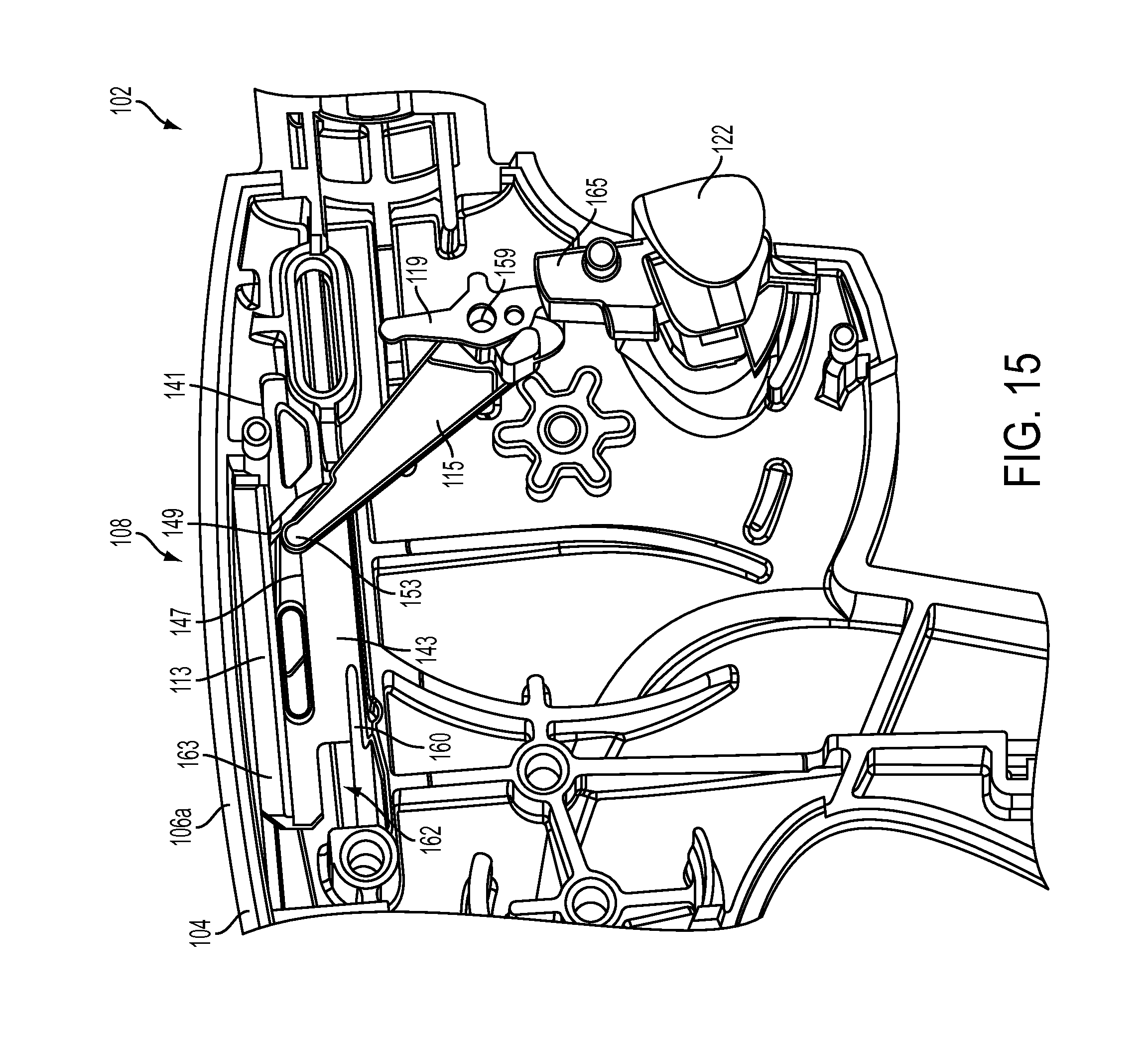
D00017

D00018

D00019

D00020

D00021

D00022

D00023

D00024
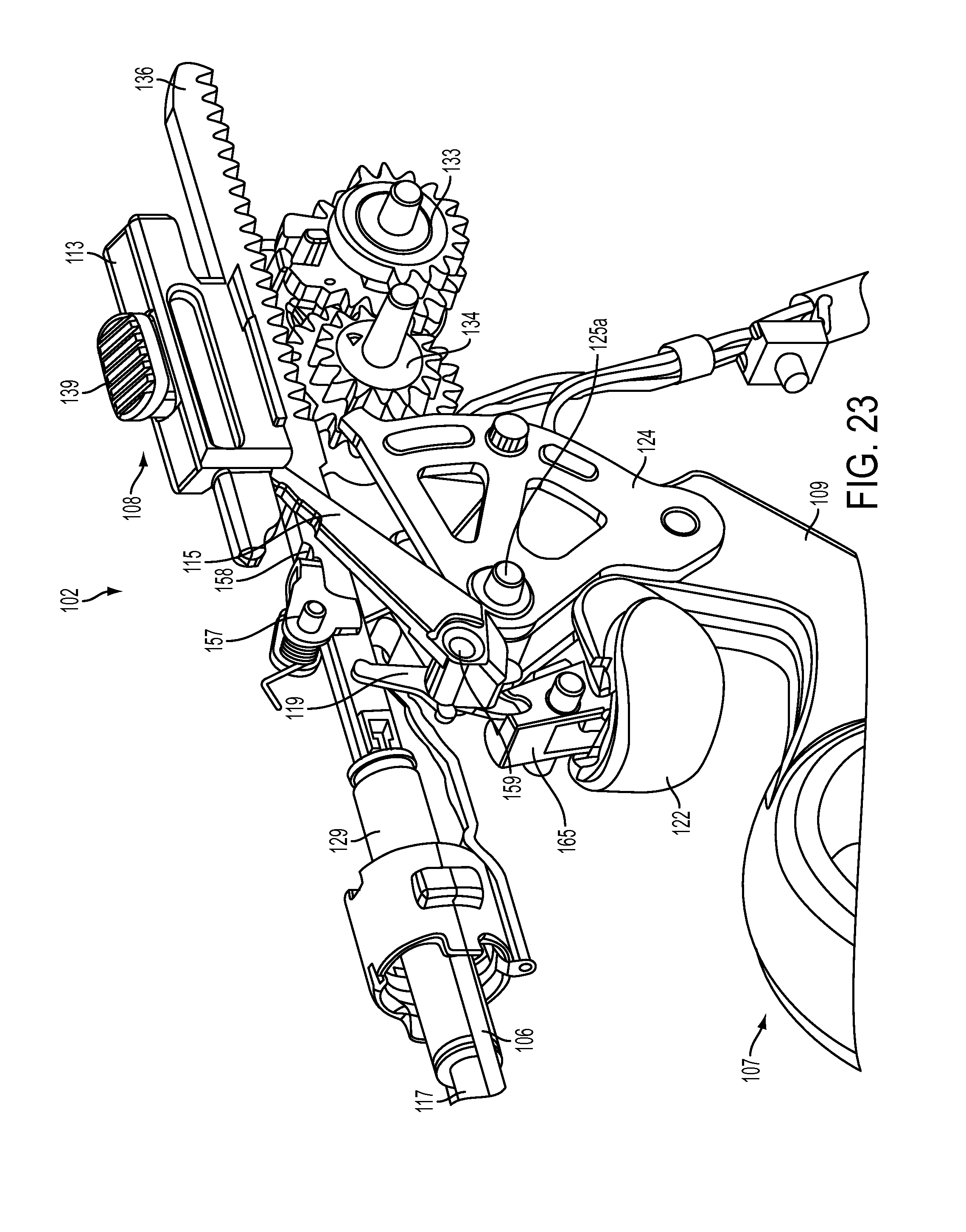
D00025

D00026

D00027

D00028

D00029

D00030

D00031

D00032

D00033

D00034

D00035

D00036

D00037

D00038

D00039

D00040

D00041

D00042

D00043

D00044

D00045
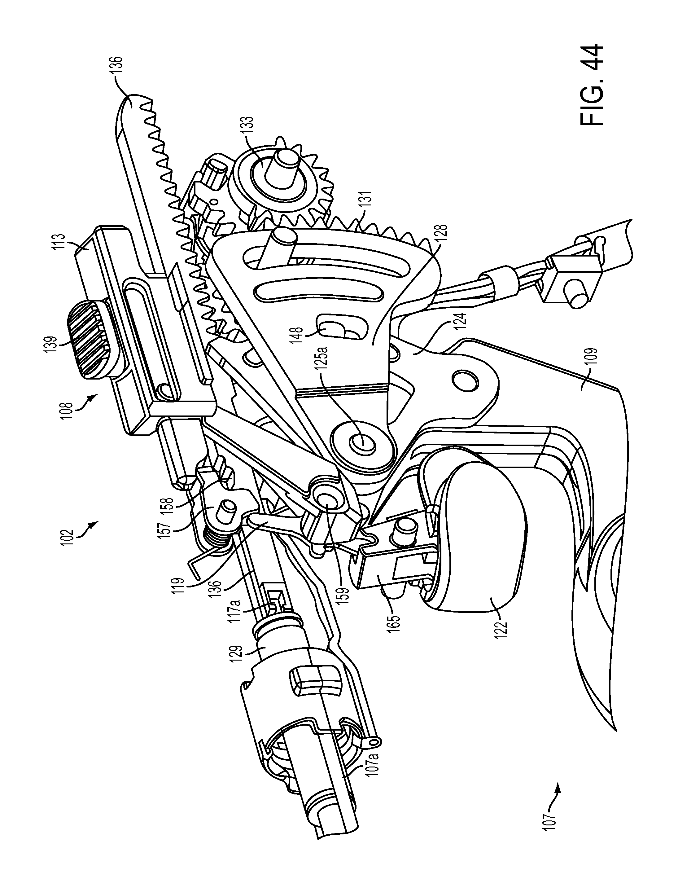
D00046

D00047

D00048

D00049

XML
uspto.report is an independent third-party trademark research tool that is not affiliated, endorsed, or sponsored by the United States Patent and Trademark Office (USPTO) or any other governmental organization. The information provided by uspto.report is based on publicly available data at the time of writing and is intended for informational purposes only.
While we strive to provide accurate and up-to-date information, we do not guarantee the accuracy, completeness, reliability, or suitability of the information displayed on this site. The use of this site is at your own risk. Any reliance you place on such information is therefore strictly at your own risk.
All official trademark data, including owner information, should be verified by visiting the official USPTO website at www.uspto.gov. This site is not intended to replace professional legal advice and should not be used as a substitute for consulting with a legal professional who is knowledgeable about trademark law.