Staple cartridge assembly without a bottom cover
Swayze , et al. Feb
U.S. patent number 10,213,203 [Application Number 14/836,036] was granted by the patent office on 2019-02-26 for staple cartridge assembly without a bottom cover. This patent grant is currently assigned to Ethicon LLC. The grantee listed for this patent is Ethicon Endo-Surgery, LLC. Invention is credited to Taylor W. Aronhalt, Chester O. Baxter, III, Jason L. Harris, Frederick E. Shelton, IV, Jeffrey S. Swayze, Michael J. Vendely.


View All Diagrams
| United States Patent | 10,213,203 |
| Swayze , et al. | February 26, 2019 |
Staple cartridge assembly without a bottom cover
Abstract
A staple cartridge is disclosed. The staple cartridge is insertable into and removable from a jaw of surgical stapling instrument. The staple cartridge comprises a cartridge body including staple cavities and staples removably stored in the staple cavities. Each of the staple cavities includes a bottom opening and a top opening. The staples include features configured to inhibit the staples from falling out of the bottom openings of the staple cavities. The staple cartridge further comprises a firing member configured to eject the staples from the staple cavities through the top openings of the staple cavities. The firing member further comprises one or more features configured to inhibit the firing member from falling out of the bottom of the cartridge body. In various instances, as a result, a cover extending around the bottom of the cartridge body may not be required.
| Inventors: | Swayze; Jeffrey S. (West Chester, OH), Shelton, IV; Frederick E. (Hillsboro, OH), Vendely; Michael J. (Lebanon, OH), Baxter, III; Chester O. (Loveland, OH), Harris; Jason L. (Lebanon, OH), Aronhalt; Taylor W. (Loveland, OH) | ||||||||||
|---|---|---|---|---|---|---|---|---|---|---|---|
| Applicant: |
|
||||||||||
| Assignee: | Ethicon LLC (Guaynabo,
PR) |
||||||||||
| Family ID: | 62234666 | ||||||||||
| Appl. No.: | 14/836,036 | ||||||||||
| Filed: | August 26, 2015 |
Prior Publication Data
| Document Identifier | Publication Date | |
|---|---|---|
| US 20170055997 A1 | Mar 2, 2017 | |
| Current U.S. Class: | 1/1 |
| Current CPC Class: | A61B 17/064 (20130101); A61B 17/1155 (20130101); A61L 31/10 (20130101); A61B 17/32 (20130101); A61L 31/022 (20130101); A61B 17/115 (20130101); A61B 17/105 (20130101); A61B 17/0469 (20130101); A61B 17/07292 (20130101); A61L 31/148 (20130101); A61B 17/068 (20130101); A61B 17/07207 (20130101); A61B 17/072 (20130101); A61B 17/0644 (20130101); A61B 17/00491 (20130101); A61B 2017/07228 (20130101); A61B 2017/00964 (20130101); A61B 2017/07214 (20130101); A61B 2017/07264 (20130101); A61B 17/0401 (20130101); A61B 2017/0464 (20130101); A61B 2017/0472 (20130101); A61B 2017/07221 (20130101); A61B 2017/07271 (20130101); A61B 2017/1142 (20130101); A61B 2017/00004 (20130101); A61B 2017/07242 (20130101); A61B 2017/2929 (20130101); A61B 2017/00889 (20130101); A61B 2017/07278 (20130101); A61B 2017/00526 (20130101); A61B 2090/037 (20160201); A61B 2090/08021 (20160201); A61B 2017/00831 (20130101); A61B 2090/038 (20160201); A61B 2017/320052 (20130101); A61B 2017/00398 (20130101); A61B 2017/06042 (20130101); A61B 2017/07235 (20130101); A61B 2017/00893 (20130101); A61B 2017/0645 (20130101) |
| Current International Class: | A61B 17/068 (20060101); A61B 17/10 (20060101); A61B 17/115 (20060101); A61B 17/064 (20060101); A61B 17/04 (20060101); A61B 17/072 (20060101); A61B 17/06 (20060101); A61B 17/11 (20060101); A61B 17/00 (20060101); A61B 90/00 (20160101) |
| Field of Search: | ;227/175.1,176.1 ;606/219 |
References Cited [Referenced By]
U.S. Patent Documents
| 66052 | June 1867 | Smith |
| 662587 | November 1900 | Blake |
| 670748 | March 1901 | Weddeler |
| 951393 | March 1910 | Hahn |
| 1306107 | June 1919 | Elliott |
| 1314601 | September 1919 | McCaskey |
| 1677337 | July 1928 | Grove |
| 1794907 | March 1931 | Kelly |
| 2037727 | April 1936 | La Chapelle |
| 2132295 | October 1938 | Hawkins |
| 2161632 | June 1939 | Nattenheimer |
| 2211117 | August 1940 | Hess |
| 2214870 | September 1940 | West |
| 2318379 | May 1943 | Davis et al. |
| 2441096 | May 1948 | Happe |
| 2475322 | July 1949 | Horton et al. |
| 2526902 | October 1950 | Rublee |
| 2578686 | December 1951 | Fish |
| 2674149 | April 1954 | Benson |
| 2711461 | June 1955 | Happe |
| 2804848 | September 1957 | O'Farrell et al. |
| 2808482 | October 1957 | Zanichkowsky et al. |
| 2853074 | September 1958 | Olson |
| 2959974 | November 1960 | Emrick |
| 3032769 | May 1962 | Palmer |
| 3060972 | October 1962 | Sheldon |
| 3075062 | January 1963 | Iaccarino |
| 3078465 | February 1963 | Bobrov |
| 3079606 | March 1963 | Bobrov et al. |
| 3166072 | January 1965 | Sullivan, Jr. |
| 3196869 | July 1965 | Scholl |
| 3204731 | September 1965 | Bent et al. |
| 3266494 | August 1966 | Brownrigg et al. |
| 3269630 | August 1966 | Fleischer |
| 3275211 | September 1966 | Hirsch et al. |
| 3317103 | May 1967 | Cullen et al. |
| 3499591 | March 1970 | Green |
| 3551987 | January 1971 | Wilkinson |
| 3583393 | June 1971 | Takahashi |
| 3662939 | May 1972 | Bryan |
| 3717294 | February 1973 | Green |
| 3799151 | March 1974 | Fukaumi et al. |
| RE28932 | August 1976 | Noiles et al. |
| 4060089 | November 1977 | Noiles |
| 4106446 | August 1978 | Yamada et al. |
| 4108211 | August 1978 | Tanaka |
| 4111206 | September 1978 | Vishnevsky et al. |
| 4129059 | December 1978 | Van Eck |
| 4169990 | October 1979 | Lerdman |
| 4180285 | December 1979 | Reneau |
| 4198734 | April 1980 | Brumlik |
| 4198982 | April 1980 | Fortner et al. |
| 4207898 | June 1980 | Becht |
| 4213562 | July 1980 | Garrett et al. |
| 4226242 | October 1980 | Jarvik |
| 4241861 | December 1980 | Fleischer |
| 4244372 | January 1981 | Kapitanov et al. |
| 4250436 | February 1981 | Weissman |
| 4261244 | April 1981 | Becht et al. |
| 4272002 | June 1981 | Moshofsky |
| 4272662 | June 1981 | Simpson |
| 4274304 | June 1981 | Curtiss |
| 4275813 | June 1981 | Noiles |
| 4289133 | September 1981 | Rothfuss |
| 4296654 | October 1981 | Mercer |
| 4304236 | December 1981 | Conta et al. |
| 4305539 | December 1981 | Korolkov et al. |
| 4312685 | January 1982 | Riedl |
| 4317451 | March 1982 | Cerwin et al. |
| 4319576 | March 1982 | Rothfuss |
| 4321002 | March 1982 | Froehlich |
| 4328839 | May 1982 | Lyons et al. |
| 4331277 | May 1982 | Green |
| 4340331 | July 1982 | Savino |
| 4347450 | August 1982 | Colligan |
| 4349028 | September 1982 | Green |
| 4353371 | October 1982 | Cosman |
| 4379457 | April 1983 | Gravener et al. |
| 4380312 | April 1983 | Landrus |
| 4382326 | May 1983 | Rabuse |
| 4383634 | May 1983 | Green |
| 4393728 | July 1983 | Larson et al. |
| 4396139 | August 1983 | Hall et al. |
| 4397311 | August 1983 | Kanshin et al. |
| 4402445 | September 1983 | Green |
| 4408692 | October 1983 | Sigel et al. |
| 4409057 | October 1983 | Molenda et al. |
| 4415112 | November 1983 | Green |
| 4416276 | November 1983 | Newton et al. |
| 4428376 | January 1984 | Mericle |
| 4429695 | February 1984 | Green |
| 4434796 | March 1984 | Karapetian et al. |
| 4438659 | March 1984 | Desplats |
| 4442964 | April 1984 | Becht |
| 4448194 | May 1984 | DiGiovanni et al. |
| 4451743 | May 1984 | Suzuki et al. |
| 4454887 | June 1984 | Kruger |
| 4467805 | August 1984 | Fukuda |
| 4473077 | September 1984 | Noiles et al. |
| 4475679 | October 1984 | Fleury, Jr. |
| 4485816 | December 1984 | Krumme |
| 4486928 | December 1984 | Tucker et al. |
| 4488523 | December 1984 | Shichman |
| 4489875 | December 1984 | Crawford et al. |
| 4499895 | February 1985 | Takayama |
| 4500024 | February 1985 | DiGiovanni et al. |
| 4505272 | March 1985 | Utyamyshev et al. |
| 4505273 | March 1985 | Braun et al. |
| 4505414 | March 1985 | Filipi |
| 4506671 | March 1985 | Green |
| 4520817 | June 1985 | Green |
| 4522327 | June 1985 | Korthoff et al. |
| 4526174 | July 1985 | Froehlich |
| 4527724 | July 1985 | Chow et al. |
| 4530453 | July 1985 | Green |
| 4531522 | July 1985 | Bedi et al. |
| 4532927 | August 1985 | Miksza, Jr. |
| 4548202 | October 1985 | Duncan |
| 4565109 | January 1986 | Tsay |
| 4565189 | January 1986 | Mabuchi |
| 4566620 | January 1986 | Green et al. |
| 4569469 | February 1986 | Mongeon et al. |
| 4571213 | February 1986 | Ishimoto |
| 4573468 | March 1986 | Conta et al. |
| 4573469 | March 1986 | Golden et al. |
| 4573622 | March 1986 | Green et al. |
| 4576167 | March 1986 | Noiles |
| 4580712 | April 1986 | Green |
| 4585153 | April 1986 | Failla et al. |
| 4589416 | May 1986 | Green |
| 4591085 | May 1986 | Di Giovanni |
| 4597753 | July 1986 | Turley |
| 4600037 | July 1986 | Hatten |
| 4604786 | August 1986 | Howie, Jr. |
| 4605001 | August 1986 | Rothfuss et al. |
| 4605004 | August 1986 | Di Giovanni et al. |
| 4606343 | August 1986 | Conta et al. |
| 4607638 | August 1986 | Crainich |
| 4608981 | September 1986 | Rothfuss et al. |
| 4610250 | September 1986 | Green |
| 4610383 | September 1986 | Rothfuss et al. |
| D286180 | October 1986 | Korthoff |
| D286441 | October 1986 | Korthoff et al. |
| D286442 | October 1986 | Korthoff et al. |
| 4619262 | October 1986 | Taylor |
| 4619391 | October 1986 | Sharkany et al. |
| 4628459 | December 1986 | Shinohara et al. |
| 4629107 | December 1986 | Fedotov et al. |
| 4632290 | December 1986 | Green et al. |
| 4633874 | January 1987 | Chow et al. |
| 4634419 | January 1987 | Kreizman et al. |
| 4641076 | February 1987 | Linden |
| 4643731 | February 1987 | Eckenhoff |
| 4646722 | March 1987 | Silverstein et al. |
| 4655222 | April 1987 | Florez et al. |
| 4662555 | May 1987 | Thornton |
| 4663874 | May 1987 | Sano et al. |
| 4664305 | May 1987 | Blake, III et al. |
| 4665916 | May 1987 | Green |
| 4667674 | May 1987 | Korthoff et al. |
| 4669647 | June 1987 | Storace |
| 4671445 | June 1987 | Barker et al. |
| 4676245 | June 1987 | Fukuda |
| 4684051 | August 1987 | Akopov et al. |
| 4693248 | September 1987 | Failla |
| 4700703 | October 1987 | Resnick et al. |
| 4708141 | November 1987 | Inoue et al. |
| 4709120 | November 1987 | Pearson |
| 4715520 | December 1987 | Roehr, Jr. et al. |
| 4719917 | January 1988 | Barrows et al. |
| 4727308 | February 1988 | Huljak et al. |
| 4728020 | March 1988 | Green et al. |
| 4728876 | March 1988 | Mongeon et al. |
| 4729260 | March 1988 | Dudden |
| 4730726 | March 1988 | Holzwarth |
| 4741336 | May 1988 | Failla et al. |
| 4743214 | May 1988 | Tai-Cheng |
| 4747820 | May 1988 | Hornlein et al. |
| 4750902 | June 1988 | Wuchinich et al. |
| 4752024 | June 1988 | Green et al. |
| 4754909 | July 1988 | Barker et al. |
| 4767044 | August 1988 | Green |
| D297764 | September 1988 | Hunt et al. |
| 4773420 | September 1988 | Green |
| 4777780 | October 1988 | Holzwarth |
| 4781186 | November 1988 | Simpson et al. |
| 4787387 | November 1988 | Burbank, III et al. |
| 4790225 | December 1988 | Moody et al. |
| 4802478 | February 1989 | Powell |
| 4805617 | February 1989 | Bedi et al. |
| 4805823 | February 1989 | Rothfuss |
| 4809695 | March 1989 | Gwathmey et al. |
| 4815460 | March 1989 | Porat et al. |
| 4817847 | April 1989 | Redtenbacher et al. |
| 4819853 | April 1989 | Green |
| 4821939 | April 1989 | Green |
| 4827911 | May 1989 | Broadwin et al. |
| 4830855 | May 1989 | Stewart |
| 4834720 | May 1989 | Blinkhorn |
| 4844068 | July 1989 | Arata et al. |
| 4848637 | July 1989 | Pruitt |
| 4865030 | September 1989 | Polyak |
| 4869414 | September 1989 | Green et al. |
| 4869415 | September 1989 | Fox |
| 4873977 | October 1989 | Avant et al. |
| 4874122 | October 1989 | Froelich et al. |
| 4880015 | November 1989 | Nierman |
| 4890613 | January 1990 | Golden et al. |
| 4892244 | January 1990 | Fox et al. |
| 4893622 | January 1990 | Green et al. |
| 4894051 | January 1990 | Shiber |
| 4896678 | January 1990 | Ogawa |
| 4900303 | February 1990 | Lemelson |
| 4903697 | February 1990 | Resnick et al. |
| 4915100 | April 1990 | Green |
| 4930503 | June 1990 | Pruitt |
| 4930674 | June 1990 | Barak |
| 4931047 | June 1990 | Broadwin et al. |
| 4932960 | June 1990 | Green et al. |
| 4938408 | July 1990 | Bedi et al. |
| 4941623 | July 1990 | Pruitt |
| 4944443 | July 1990 | Oddsen et al. |
| 4951860 | August 1990 | Peters et al. |
| 4955898 | September 1990 | Matsutani et al. |
| 4955959 | September 1990 | Tompkins et al. |
| 4965709 | October 1990 | Ngo |
| 4973274 | November 1990 | Hirukawa |
| 4978049 | December 1990 | Green |
| 4978333 | December 1990 | Broadwin et al. |
| 4986808 | January 1991 | Broadwin et al. |
| 4988334 | January 1991 | Hornlein et al. |
| 5002543 | March 1991 | Bradshaw et al. |
| 5002553 | March 1991 | Shiber |
| 5005754 | April 1991 | Van Overloop |
| 5009661 | April 1991 | Michelson |
| 5014899 | May 1991 | Presty et al. |
| 5015227 | May 1991 | Broadwin et al. |
| 5018515 | May 1991 | Gilman |
| 5018657 | May 1991 | Pedlick et al. |
| 5024671 | June 1991 | Tu et al. |
| 5027834 | July 1991 | Pruitt |
| 5031814 | July 1991 | Tompkins et al. |
| 5035040 | July 1991 | Kerrigan et al. |
| 5038109 | August 1991 | Goble et al. |
| 5040715 | August 1991 | Green et al. |
| 5042707 | August 1991 | Taheri |
| 5053047 | October 1991 | Yoon |
| 5061269 | October 1991 | Muller |
| 5062563 | November 1991 | Green et al. |
| 5065929 | November 1991 | Schulze et al. |
| 5071052 | December 1991 | Rodak et al. |
| 5071430 | December 1991 | de Salis et al. |
| 5074454 | December 1991 | Peters |
| 5079006 | January 1992 | Urquhart |
| 5080556 | January 1992 | Carreno |
| 5083695 | January 1992 | Foslien et al. |
| 5084057 | January 1992 | Green et al. |
| 5088979 | February 1992 | Filipi et al. |
| 5088997 | February 1992 | Delahuerga et al. |
| 5089009 | February 1992 | Green |
| 5094247 | March 1992 | Hernandez et al. |
| 5100420 | March 1992 | Green et al. |
| 5104025 | April 1992 | Main et al. |
| 5104397 | April 1992 | Vasconcelos et al. |
| 5106008 | April 1992 | Tompkins et al. |
| 5108368 | April 1992 | Hammerslag et al. |
| 5111987 | May 1992 | Moeinzadeh et al. |
| 5116349 | May 1992 | Aranyi |
| D327323 | June 1992 | Hunt |
| 5122156 | June 1992 | Granger et al. |
| 5129570 | July 1992 | Schulze et al. |
| 5137198 | August 1992 | Nobis et al. |
| 5139513 | August 1992 | Segato |
| 5141144 | August 1992 | Foslien et al. |
| 5142932 | September 1992 | Moya et al. |
| 5155941 | October 1992 | Takahashi et al. |
| 5156315 | October 1992 | Green et al. |
| 5156609 | October 1992 | Nakao et al. |
| 5156614 | October 1992 | Green et al. |
| 5158567 | October 1992 | Green |
| D330699 | November 1992 | Gill |
| 5163598 | November 1992 | Peters et al. |
| 5171247 | December 1992 | Hughett et al. |
| 5171249 | December 1992 | Stefanchik et al. |
| 5171253 | December 1992 | Klieman |
| 5188111 | February 1993 | Yates et al. |
| 5190517 | March 1993 | Zieve et al. |
| 5190544 | March 1993 | Chapman et al. |
| 5190560 | March 1993 | Woods et al. |
| 5192288 | March 1993 | Thompson et al. |
| 5195968 | March 1993 | Lundquist et al. |
| 5197648 | March 1993 | Gingold |
| 5197649 | March 1993 | Bessler et al. |
| 5197966 | March 1993 | Sommerkamp |
| 5200280 | April 1993 | Karasa |
| 5201746 | April 1993 | Shichman |
| 5205459 | April 1993 | Brinkerhoff et al. |
| 5207697 | May 1993 | Carusillo et al. |
| 5209747 | May 1993 | Knoepfler |
| 5211649 | May 1993 | Kohler et al. |
| 5211655 | May 1993 | Hasson |
| 5217457 | June 1993 | Delahuerga et al. |
| 5217478 | June 1993 | Rexroth |
| 5219111 | June 1993 | Bilotti et al. |
| 5221036 | June 1993 | Takase |
| 5221281 | June 1993 | Klicek |
| 5222963 | June 1993 | Brinkerhoff et al. |
| 5222975 | June 1993 | Crainich |
| 5222976 | June 1993 | Yoon |
| 5223675 | June 1993 | Taft |
| D338729 | August 1993 | Sprecklemeier et al. |
| 5234447 | August 1993 | Kaster et al. |
| 5236440 | August 1993 | Hlavacek |
| 5239981 | August 1993 | Anapliotis |
| 5240163 | August 1993 | Stein et al. |
| 5242457 | September 1993 | Akopov et al. |
| 5244462 | September 1993 | Delahuerga et al. |
| 5246156 | September 1993 | Rothfuss et al. |
| 5246443 | September 1993 | Mai |
| 5253793 | October 1993 | Green et al. |
| 5258009 | November 1993 | Conners |
| 5258012 | November 1993 | Luscombe et al. |
| 5259366 | November 1993 | Reydel et al. |
| 5260637 | November 1993 | Pizzi |
| 5263629 | November 1993 | Trumbull et al. |
| 5263973 | November 1993 | Cook |
| 5264218 | November 1993 | Rogozinski |
| 5268622 | December 1993 | Philipp |
| 5271543 | December 1993 | Grant et al. |
| 5271544 | December 1993 | Fox et al. |
| RE34519 | January 1994 | Fox et al. |
| 5275323 | January 1994 | Schulze et al. |
| 5275608 | January 1994 | Forman et al. |
| 5279416 | January 1994 | Malec et al. |
| 5281216 | January 1994 | Klicek |
| 5282806 | February 1994 | Haber et al. |
| 5282829 | February 1994 | Hermes |
| 5284128 | February 1994 | Hart |
| 5285945 | February 1994 | Brinkerhoff et al. |
| 5289963 | March 1994 | McGarry et al. |
| 5290271 | March 1994 | Jernberg |
| 5292053 | March 1994 | Bilotti et al. |
| 5297714 | March 1994 | Kramer |
| 5304204 | April 1994 | Bregen |
| D347474 | May 1994 | Olson |
| 5307976 | May 1994 | Olson et al. |
| 5309927 | May 1994 | Welch |
| 5312023 | May 1994 | Green et al. |
| 5312024 | May 1994 | Grant et al. |
| 5312329 | May 1994 | Beaty et al. |
| 5314424 | May 1994 | Nicholas |
| 5314445 | May 1994 | Heidmueller nee Degwitz et al. |
| 5314466 | May 1994 | Stern et al. |
| 5318221 | June 1994 | Green et al. |
| D348930 | July 1994 | Olson |
| 5329923 | July 1994 | Lundquist |
| 5330487 | July 1994 | Thornton et al. |
| 5330502 | July 1994 | Hassler et al. |
| 5332142 | July 1994 | Robinson et al. |
| 5333422 | August 1994 | Warren et al. |
| 5333772 | August 1994 | Rothfuss et al. |
| 5333773 | August 1994 | Main et al. |
| 5334183 | August 1994 | Wuchinich |
| 5336232 | August 1994 | Green et al. |
| 5339799 | August 1994 | Kami et al. |
| 5341724 | August 1994 | Vatel |
| 5341810 | August 1994 | Dardel |
| 5342381 | August 1994 | Tidemand |
| 5342395 | August 1994 | Jarrett et al. |
| 5342396 | August 1994 | Cook |
| 5344060 | September 1994 | Gravener et al. |
| 5344454 | September 1994 | Clarke et al. |
| 5346504 | September 1994 | Ortiz et al. |
| 5348259 | September 1994 | Blanco et al. |
| 5350388 | September 1994 | Epstein |
| 5350391 | September 1994 | Iacovelli |
| 5350400 | September 1994 | Esposito et al. |
| 5352229 | October 1994 | Goble et al. |
| 5352235 | October 1994 | Koros et al. |
| 5352238 | October 1994 | Green et al. |
| 5354303 | October 1994 | Spaeth et al. |
| 5356006 | October 1994 | Alpern et al. |
| 5358506 | October 1994 | Green et al. |
| 5358510 | October 1994 | Luscombe et al. |
| 5359231 | October 1994 | Flowers et al. |
| D352780 | November 1994 | Glaeser et al. |
| 5360305 | November 1994 | Kerrigan |
| 5360428 | November 1994 | Hutchinson, Jr. |
| 5364001 | November 1994 | Bryan |
| 5364003 | November 1994 | Williamson, IV |
| 5366133 | November 1994 | Geiste |
| 5366134 | November 1994 | Green et al. |
| 5366479 | November 1994 | McGarry et al. |
| 5368015 | November 1994 | Wilk |
| 5368592 | November 1994 | Stern et al. |
| 5370645 | December 1994 | Klicek et al. |
| 5372124 | December 1994 | Takayama et al. |
| 5372596 | December 1994 | Klicek et al. |
| 5372602 | December 1994 | Burke |
| 5374277 | December 1994 | Hassler |
| 5376095 | December 1994 | Ortiz |
| 5379933 | January 1995 | Green et al. |
| 5381649 | January 1995 | Webb |
| 5381782 | January 1995 | DeLaRama et al. |
| 5382247 | January 1995 | Cimino et al. |
| 5383880 | January 1995 | Hooven |
| 5383881 | January 1995 | Green et al. |
| 5383888 | January 1995 | Zvenyatsky et al. |
| 5383895 | January 1995 | Holmes et al. |
| 5389098 | February 1995 | Tsuruta et al. |
| 5389104 | February 1995 | Hahnen et al. |
| 5391180 | February 1995 | Tovey et al. |
| 5392979 | February 1995 | Green et al. |
| 5395030 | March 1995 | Kuramoto et al. |
| 5395033 | March 1995 | Byrne et al. |
| 5395034 | March 1995 | Allen et al. |
| 5395312 | March 1995 | Desai |
| 5395384 | March 1995 | Duthoit et al. |
| 5397046 | March 1995 | Savage et al. |
| 5397324 | March 1995 | Carroll et al. |
| 5403043 | April 1995 | Smet |
| 5403312 | April 1995 | Yates et al. |
| 5405072 | April 1995 | Zlock et al. |
| 5405073 | April 1995 | Porter |
| 5405344 | April 1995 | Williamson et al. |
| 5405360 | April 1995 | Tovey |
| 5407293 | April 1995 | Crainich |
| 5409498 | April 1995 | Braddock et al. |
| D357981 | May 1995 | Green et al. |
| 5411481 | May 1995 | Allen et al. |
| 5411508 | May 1995 | Bessler et al. |
| 5413107 | May 1995 | Oakley et al. |
| 5413267 | May 1995 | Solyntjes et al. |
| 5413268 | May 1995 | Green et al. |
| 5413272 | May 1995 | Green et al. |
| 5413573 | May 1995 | Koivukangas |
| 5415334 | May 1995 | Williamson et al. |
| 5415335 | May 1995 | Knodell, Jr. |
| 5417203 | May 1995 | Tovey et al. |
| 5417361 | May 1995 | Williamson, IV |
| 5421829 | June 1995 | Olichney et al. |
| 5422567 | June 1995 | Matsunaga |
| 5423471 | June 1995 | Mastri et al. |
| 5423809 | June 1995 | Klicek |
| 5425745 | June 1995 | Green et al. |
| 5431322 | July 1995 | Green et al. |
| 5431654 | July 1995 | Nic |
| 5431668 | July 1995 | Burbank, III et al. |
| 5433721 | July 1995 | Hooven et al. |
| 5437681 | August 1995 | Meade et al. |
| 5438302 | August 1995 | Goble |
| 5439155 | August 1995 | Viola |
| 5439156 | August 1995 | Grant et al. |
| 5439479 | August 1995 | Shichman et al. |
| 5441191 | August 1995 | Linden |
| 5441193 | August 1995 | Gravener |
| 5441483 | August 1995 | Avitall |
| 5441494 | August 1995 | Ortiz |
| 5444113 | August 1995 | Sinclair et al. |
| 5445155 | August 1995 | Sieben |
| 5445304 | August 1995 | Plyley et al. |
| 5445644 | August 1995 | Pietrafitta et al. |
| 5447417 | September 1995 | Kuhl et al. |
| 5447513 | September 1995 | Davison et al. |
| 5449355 | September 1995 | Rhum et al. |
| 5449365 | September 1995 | Green et al. |
| 5449370 | September 1995 | Vaitekunas |
| 5452836 | September 1995 | Huitema et al. |
| 5452837 | September 1995 | Williamson, IV et al. |
| 5454378 | October 1995 | Palmer et al. |
| 5454822 | October 1995 | Schob et al. |
| 5454827 | October 1995 | Aust et al. |
| 5456401 | October 1995 | Green et al. |
| 5458579 | October 1995 | Chodorow et al. |
| 5462215 | October 1995 | Viola et al. |
| 5464013 | November 1995 | Lemelson |
| 5464144 | November 1995 | Guy et al. |
| 5464300 | November 1995 | Crainich |
| 5465894 | November 1995 | Clark et al. |
| 5465895 | November 1995 | Knodel et al. |
| 5465896 | November 1995 | Allen et al. |
| 5466020 | November 1995 | Page et al. |
| 5467911 | November 1995 | Tsuruta et al. |
| 5468253 | November 1995 | Bezwada et al. |
| 5470006 | November 1995 | Rodak |
| 5470007 | November 1995 | Plyley et al. |
| 5470009 | November 1995 | Rodak |
| 5470010 | November 1995 | Rothfuss et al. |
| 5472132 | December 1995 | Savage et al. |
| 5472442 | December 1995 | Klicek |
| 5473204 | December 1995 | Temple |
| 5474057 | December 1995 | Makower et al. |
| 5474223 | December 1995 | Viola et al. |
| 5474566 | December 1995 | Alesi et al. |
| 5476206 | December 1995 | Green et al. |
| 5476479 | December 1995 | Green et al. |
| 5478003 | December 1995 | Green et al. |
| 5478354 | December 1995 | Tovey et al. |
| 5480089 | January 1996 | Blewett |
| 5480409 | January 1996 | Riza |
| 5482197 | January 1996 | Green et al. |
| 5484095 | January 1996 | Green et al. |
| 5484398 | January 1996 | Stoddard |
| 5484451 | January 1996 | Akopov et al. |
| 5485947 | January 1996 | Olson et al. |
| 5485952 | January 1996 | Fontayne |
| 5487499 | January 1996 | Sorrentino et al. |
| 5487500 | January 1996 | Knodel et al. |
| 5489058 | February 1996 | Plyley et al. |
| 5489256 | February 1996 | Adair |
| 5496312 | March 1996 | Klicek |
| 5496317 | March 1996 | Goble et al. |
| 5497933 | March 1996 | DeFonzo et al. |
| 5501654 | March 1996 | Failla et al. |
| 5503320 | April 1996 | Webster et al. |
| 5503635 | April 1996 | Sauer et al. |
| 5503638 | April 1996 | Cooper et al. |
| 5505363 | April 1996 | Green et al. |
| 5507426 | April 1996 | Young et al. |
| 5509596 | April 1996 | Green et al. |
| 5509916 | April 1996 | Taylor |
| 5511564 | April 1996 | Wilk |
| 5514129 | May 1996 | Smith |
| 5514157 | May 1996 | Nicholas et al. |
| 5518163 | May 1996 | Hooven |
| 5518164 | May 1996 | Hooven |
| 5520678 | May 1996 | Heckele et al. |
| 5520700 | May 1996 | Beyar et al. |
| 5522817 | June 1996 | Sander et al. |
| 5522831 | June 1996 | Sleister et al. |
| 5527320 | June 1996 | Carruthers et al. |
| 5529235 | June 1996 | Boiarski et al. |
| D372086 | July 1996 | Grasso et al. |
| 5531305 | July 1996 | Roberts et al. |
| 5531744 | July 1996 | Nardella et al. |
| 5533521 | July 1996 | Granger |
| 5533581 | July 1996 | Barth et al. |
| 5533661 | July 1996 | Main et al. |
| 5535934 | July 1996 | Boiarski et al. |
| 5535935 | July 1996 | Vidal et al. |
| 5535937 | July 1996 | Boiarski et al. |
| 5540375 | July 1996 | Bolanos et al. |
| 5541376 | July 1996 | Ladtkow et al. |
| 5542594 | August 1996 | McKean et al. |
| 5542949 | August 1996 | Yoon |
| 5543119 | August 1996 | Sutter et al. |
| 5547117 | August 1996 | Hamblin et al. |
| 5549621 | August 1996 | Bessler et al. |
| 5549627 | August 1996 | Kieturakis |
| 5549628 | August 1996 | Cooper et al. |
| 5549637 | August 1996 | Crainich |
| 5551622 | September 1996 | Yoon |
| 5553675 | September 1996 | Pitzen et al. |
| 5553765 | September 1996 | Knodel et al. |
| 5554148 | September 1996 | Aebischer et al. |
| 5554169 | September 1996 | Green et al. |
| 5556416 | September 1996 | Clark et al. |
| 5558665 | September 1996 | Kieturakis |
| 5558671 | September 1996 | Yates |
| 5560530 | October 1996 | Bolanos et al. |
| 5560532 | October 1996 | DeFonzo et al. |
| 5562239 | October 1996 | Boiarski et al. |
| 5562241 | October 1996 | Knodel et al. |
| 5562682 | October 1996 | Oberlin et al. |
| 5562690 | October 1996 | Green et al. |
| 5562701 | October 1996 | Huitema et al. |
| 5562702 | October 1996 | Huitema et al. |
| 5564615 | October 1996 | Bishop et al. |
| 5569161 | October 1996 | Ebling et al. |
| 5569270 | October 1996 | Weng |
| 5569284 | October 1996 | Young et al. |
| 5571090 | November 1996 | Sherts |
| 5571100 | November 1996 | Goble et al. |
| 5571116 | November 1996 | Bolanos et al. |
| 5571285 | November 1996 | Chow et al. |
| 5573543 | November 1996 | Akopov et al. |
| 5574431 | November 1996 | McKeown et al. |
| 5575054 | November 1996 | Klinzing et al. |
| 5575789 | November 1996 | Bell et al. |
| 5575799 | November 1996 | Bolanos et al. |
| 5575803 | November 1996 | Cooper et al. |
| 5575805 | November 1996 | Li |
| 5577654 | November 1996 | Bishop |
| 5579978 | December 1996 | Green et al. |
| 5580067 | December 1996 | Hamblin et al. |
| 5582611 | December 1996 | Tsuruta et al. |
| 5582617 | December 1996 | Klieman et al. |
| 5584425 | December 1996 | Savage et al. |
| 5586711 | December 1996 | Plyley et al. |
| 5588579 | December 1996 | Schnut et al. |
| 5588580 | December 1996 | Paul et al. |
| 5588581 | December 1996 | Conlon et al. |
| 5591170 | January 1997 | Spievack et al. |
| 5591187 | January 1997 | Dekel |
| 5597107 | January 1997 | Knodel et al. |
| 5599151 | February 1997 | Daum et al. |
| 5599279 | February 1997 | Slotman et al. |
| 5599344 | February 1997 | Paterson |
| 5599350 | February 1997 | Schulze et al. |
| 5599852 | February 1997 | Scopelianos et al. |
| 5601224 | February 1997 | Bishop et al. |
| 5603443 | February 1997 | Clark et al. |
| 5605272 | February 1997 | Witt et al. |
| 5605273 | February 1997 | Hamblin et al. |
| 5607094 | March 1997 | Clark et al. |
| 5607095 | March 1997 | Smith et al. |
| 5607433 | March 1997 | Polla et al. |
| 5607450 | March 1997 | Zvenyatsky et al. |
| 5609285 | March 1997 | Grant et al. |
| 5609601 | March 1997 | Kolesa et al. |
| 5611709 | March 1997 | McAnulty |
| 5613966 | March 1997 | Makower et al. |
| 5615820 | April 1997 | Viola |
| 5618294 | April 1997 | Aust et al. |
| 5618303 | April 1997 | Marlow et al. |
| 5618307 | April 1997 | Donlon et al. |
| 5619992 | April 1997 | Guthrie et al. |
| 5620289 | April 1997 | Curry |
| 5620452 | April 1997 | Yoon |
| 5624398 | April 1997 | Smith et al. |
| 5624452 | April 1997 | Yates |
| 5626587 | May 1997 | Bishop et al. |
| 5626595 | May 1997 | Sklar et al. |
| 5628446 | May 1997 | Geiste et al. |
| 5628743 | May 1997 | Cimino |
| 5628745 | May 1997 | Bek |
| 5630539 | May 1997 | Plyley et al. |
| 5630540 | May 1997 | Blewett |
| 5630541 | May 1997 | Williamson, IV et al. |
| 5630782 | May 1997 | Adair |
| 5632432 | May 1997 | Schulze et al. |
| 5632433 | May 1997 | Grant et al. |
| 5634584 | June 1997 | Okorocha et al. |
| 5636779 | June 1997 | Palmer |
| 5636780 | June 1997 | Green et al. |
| 5639008 | June 1997 | Gallagher et al. |
| D381077 | July 1997 | Hunt |
| 5643291 | July 1997 | Pier et al. |
| 5645209 | July 1997 | Green et al. |
| 5647526 | July 1997 | Green et al. |
| 5647869 | July 1997 | Goble et al. |
| 5649937 | July 1997 | Bito et al. |
| 5649956 | July 1997 | Jensen et al. |
| 5651491 | July 1997 | Heaton et al. |
| 5653373 | August 1997 | Green et al. |
| 5653374 | August 1997 | Young et al. |
| 5653677 | August 1997 | Okada et al. |
| 5653721 | August 1997 | Knodel et al. |
| 5655698 | August 1997 | Yoon |
| 5657921 | August 1997 | Young et al. |
| 5658238 | August 1997 | Suzuki et al. |
| 5658281 | August 1997 | Heard |
| 5658300 | August 1997 | Bito et al. |
| 5658307 | August 1997 | Exconde |
| 5662258 | September 1997 | Knodel et al. |
| 5662260 | September 1997 | Yoon |
| 5662662 | September 1997 | Bishop et al. |
| 5665085 | September 1997 | Nardella |
| 5667517 | September 1997 | Hooven |
| 5667526 | September 1997 | Levin |
| 5667527 | September 1997 | Cook |
| 5669544 | September 1997 | Schulze et al. |
| 5669904 | September 1997 | Platt, Jr. et al. |
| 5669907 | September 1997 | Platt, Jr. et al. |
| 5669918 | September 1997 | Balazs et al. |
| 5673840 | October 1997 | Schulze et al. |
| 5673841 | October 1997 | Schulze et al. |
| 5673842 | October 1997 | Bittner et al. |
| 5674286 | October 1997 | D'Alessio et al. |
| 5678748 | October 1997 | Plyley et al. |
| 5680981 | October 1997 | Mililli et al. |
| 5680982 | October 1997 | Schulze et al. |
| 5680983 | October 1997 | Plyley et al. |
| 5683349 | November 1997 | Makower et al. |
| 5685474 | November 1997 | Seeber |
| 5686090 | November 1997 | Schilder et al. |
| 5688270 | November 1997 | Yates et al. |
| 5690269 | November 1997 | Bolanos et al. |
| 5692668 | December 1997 | Schulze et al. |
| 5693020 | December 1997 | Rauh |
| 5693042 | December 1997 | Boiarski et al. |
| 5693051 | December 1997 | Schulze et al. |
| 5695494 | December 1997 | Becker |
| 5695502 | December 1997 | Pier et al. |
| 5695504 | December 1997 | Gifford, III et al. |
| 5695524 | December 1997 | Kelley et al. |
| 5697542 | December 1997 | Knodel et al. |
| 5697543 | December 1997 | Burdorff |
| 5697909 | December 1997 | Eggers et al. |
| 5697943 | December 1997 | Sauer et al. |
| 5700270 | December 1997 | Peyser et al. |
| 5702387 | December 1997 | Arts et al. |
| 5702408 | December 1997 | Wales et al. |
| 5702409 | December 1997 | Rayburn et al. |
| 5704087 | January 1998 | Strub |
| 5704534 | January 1998 | Huitema et al. |
| 5706997 | January 1998 | Green et al. |
| 5706998 | January 1998 | Plyley et al. |
| 5707392 | January 1998 | Kortenbach |
| 5709334 | January 1998 | Sorrentino et al. |
| 5709335 | January 1998 | Heck |
| 5709680 | January 1998 | Yates et al. |
| 5709706 | January 1998 | Kienzle et al. |
| 5711472 | January 1998 | Bryan |
| 5713128 | February 1998 | Schrenk et al. |
| 5713505 | February 1998 | Huitema |
| 5713895 | February 1998 | Lontine et al. |
| 5713896 | February 1998 | Nardella |
| 5713920 | February 1998 | Bezwada et al. |
| 5715987 | February 1998 | Kelley et al. |
| 5715988 | February 1998 | Palmer |
| 5716366 | February 1998 | Yates |
| 5718359 | February 1998 | Palmer et al. |
| 5718360 | February 1998 | Green et al. |
| 5718548 | February 1998 | Cotellessa |
| 5720744 | February 1998 | Eggleston et al. |
| D393067 | March 1998 | Geary et al. |
| 5725536 | March 1998 | Oberlin et al. |
| 5725554 | March 1998 | Simon et al. |
| 5728110 | March 1998 | Vidal et al. |
| 5728121 | March 1998 | Bimbo et al. |
| 5730758 | March 1998 | Allgeyer |
| 5732821 | March 1998 | Stone et al. |
| 5732871 | March 1998 | Clark et al. |
| 5732872 | March 1998 | Bolduc et al. |
| 5733308 | March 1998 | Daugherty et al. |
| 5735445 | April 1998 | Vidal et al. |
| 5735848 | April 1998 | Yates et al. |
| 5735874 | April 1998 | Measamer et al. |
| 5738474 | April 1998 | Blewett |
| 5738648 | April 1998 | Lands et al. |
| 5743456 | April 1998 | Jones et al. |
| 5747953 | May 1998 | Philipp |
| 5749889 | May 1998 | Bacich et al. |
| 5749893 | May 1998 | Vidal et al. |
| 5752644 | May 1998 | Bolanos et al. |
| 5752965 | May 1998 | Francis et al. |
| 5755717 | May 1998 | Yates et al. |
| 5758814 | June 1998 | Gallagher et al. |
| 5762255 | June 1998 | Chrisman et al. |
| 5762256 | June 1998 | Mastri et al. |
| 5766188 | June 1998 | Igaki |
| 5766205 | June 1998 | Zvenyatsky et al. |
| 5769892 | June 1998 | Kingwell |
| 5772379 | June 1998 | Evensen |
| 5772578 | June 1998 | Heimberger et al. |
| 5772659 | June 1998 | Becker et al. |
| 5776130 | July 1998 | Buysse et al. |
| 5778939 | July 1998 | Hok-Yin |
| 5779130 | July 1998 | Alesi et al. |
| 5779131 | July 1998 | Knodel et al. |
| 5779132 | July 1998 | Knodel et al. |
| 5782396 | July 1998 | Mastri et al. |
| 5782397 | July 1998 | Koukline |
| 5782749 | July 1998 | Riza |
| 5782859 | July 1998 | Nicholas et al. |
| 5784934 | July 1998 | Izumisawa |
| 5785232 | July 1998 | Vidal et al. |
| 5785647 | July 1998 | Tompkins et al. |
| 5787897 | August 1998 | Kieturakis |
| 5792135 | August 1998 | Madhani et al. |
| 5792165 | August 1998 | Klieman et al. |
| 5794834 | August 1998 | Hamblin et al. |
| 5796188 | August 1998 | Bays |
| 5797536 | August 1998 | Smith et al. |
| 5797537 | August 1998 | Oberlin et al. |
| 5797538 | August 1998 | Heaton et al. |
| 5797906 | August 1998 | Rhum et al. |
| 5797959 | August 1998 | Castro et al. |
| 5799857 | September 1998 | Robertson et al. |
| 5800379 | September 1998 | Edwards |
| 5800423 | September 1998 | Jensen |
| 5806676 | September 1998 | Wasgien |
| 5807376 | September 1998 | Viola et al. |
| 5807378 | September 1998 | Jensen et al. |
| 5807393 | September 1998 | Williamson, IV et al. |
| 5809441 | September 1998 | McKee |
| 5810721 | September 1998 | Mueller et al. |
| 5810811 | September 1998 | Yates et al. |
| 5810846 | September 1998 | Virnich et al. |
| 5810855 | September 1998 | Rayburn et al. |
| 5813813 | September 1998 | Daum et al. |
| 5814055 | September 1998 | Knodel et al. |
| 5814057 | September 1998 | Oi et al. |
| 5816471 | October 1998 | Plyley et al. |
| 5817084 | October 1998 | Jensen |
| 5817091 | October 1998 | Nardella et al. |
| 5817093 | October 1998 | Williamson, IV et al. |
| 5817109 | October 1998 | McGarry et al. |
| 5817119 | October 1998 | Klieman et al. |
| 5820009 | October 1998 | Melling et al. |
| 5823066 | October 1998 | Huitema et al. |
| 5826776 | October 1998 | Schulze et al. |
| 5827271 | October 1998 | Buysse et al. |
| 5827298 | October 1998 | Hart et al. |
| 5829662 | November 1998 | Allen et al. |
| 5833690 | November 1998 | Yates et al. |
| 5833695 | November 1998 | Yoon |
| 5833696 | November 1998 | Whitfield et al. |
| 5836503 | November 1998 | Ehrenfels et al. |
| 5836960 | November 1998 | Kolesa et al. |
| 5839639 | November 1998 | Sauer et al. |
| 5843021 | December 1998 | Edwards et al. |
| 5843096 | December 1998 | Igaki et al. |
| 5843097 | December 1998 | Mayenberger et al. |
| 5843122 | December 1998 | Riza |
| 5843132 | December 1998 | Ilvento |
| 5843169 | December 1998 | Taheri |
| 5846254 | December 1998 | Schulze et al. |
| 5849011 | December 1998 | Jones et al. |
| 5849023 | December 1998 | Mericle |
| 5855311 | January 1999 | Hamblin et al. |
| 5855583 | January 1999 | Wang et al. |
| 5860581 | January 1999 | Robertson et al. |
| 5860975 | January 1999 | Goble et al. |
| 5865361 | February 1999 | Milliman et al. |
| 5868760 | February 1999 | McGuckin, Jr. |
| 5871135 | February 1999 | Williamson, IV et al. |
| 5873885 | February 1999 | Weidenbenner |
| 5876401 | March 1999 | Schulze et al. |
| 5878193 | March 1999 | Wang et al. |
| 5878937 | March 1999 | Green et al. |
| 5878938 | March 1999 | Bittner et al. |
| 5891160 | April 1999 | Williamson, IV et al. |
| 5893506 | April 1999 | Powell |
| 5893835 | April 1999 | Witt et al. |
| 5893878 | April 1999 | Pierce |
| 5894979 | April 1999 | Powell |
| 5897552 | April 1999 | Edwards et al. |
| 5897562 | April 1999 | Bolanos et al. |
| 5899914 | May 1999 | Zirps et al. |
| 5901895 | May 1999 | Heaton et al. |
| 5902312 | May 1999 | Frater et al. |
| 5904647 | May 1999 | Ouchi |
| 5904693 | May 1999 | Dicesare et al. |
| 5904702 | May 1999 | Ek et al. |
| 5906625 | May 1999 | Bito et al. |
| 5908402 | June 1999 | Blythe |
| 5908427 | June 1999 | McKean et al. |
| 5911353 | June 1999 | Bolanos et al. |
| 5915616 | June 1999 | Viola et al. |
| 5916225 | June 1999 | Kugel |
| 5918791 | July 1999 | Sorrentino et al. |
| 5919198 | July 1999 | Graves, Jr. et al. |
| 5921956 | July 1999 | Grinberg et al. |
| 5928256 | July 1999 | Riza |
| 5931847 | August 1999 | Bittner et al. |
| 5931853 | August 1999 | McEwen et al. |
| 5937951 | August 1999 | Izuchukwu et al. |
| 5938667 | August 1999 | Peyser et al. |
| 5941442 | August 1999 | Geiste et al. |
| 5941890 | August 1999 | Voegele et al. |
| 5944172 | August 1999 | Hannula |
| 5944715 | August 1999 | Goble et al. |
| 5947984 | September 1999 | Whipple |
| 5948030 | September 1999 | Miller et al. |
| 5951516 | September 1999 | Bunyan |
| 5951552 | September 1999 | Long et al. |
| 5951574 | September 1999 | Stefanchik et al. |
| 5951581 | September 1999 | Saadat et al. |
| 5954259 | September 1999 | Viola et al. |
| 5964394 | October 1999 | Robertson |
| 5964774 | October 1999 | McKean et al. |
| 5971916 | October 1999 | Koren |
| 5973221 | October 1999 | Collyer et al. |
| D416089 | November 1999 | Barton et al. |
| 5984949 | November 1999 | Levin |
| 5988479 | November 1999 | Palmer |
| 5997528 | December 1999 | Bisch et al. |
| 5997552 | December 1999 | Person et al. |
| 6003517 | December 1999 | Sheffield et al. |
| 6004319 | December 1999 | Goble et al. |
| 6004335 | December 1999 | Vaitekunas et al. |
| 6010054 | January 2000 | Johnson et al. |
| 6010513 | January 2000 | Tormala et al. |
| 6012494 | January 2000 | Balazs |
| 6013076 | January 2000 | Goble et al. |
| 6015406 | January 2000 | Goble et al. |
| 6015417 | January 2000 | Reynolds, Jr. |
| 6017322 | January 2000 | Snoke et al. |
| 6017354 | January 2000 | Culp et al. |
| 6017356 | January 2000 | Frederick et al. |
| 6022352 | February 2000 | Vandewalle |
| 6024741 | February 2000 | Williamson, IV et al. |
| 6024748 | February 2000 | Manzo et al. |
| 6027501 | February 2000 | Goble et al. |
| 6032849 | March 2000 | Mastri et al. |
| 6033378 | March 2000 | Lundquist et al. |
| 6033399 | March 2000 | Gines |
| 6033427 | March 2000 | Lee |
| 6037724 | March 2000 | Buss et al. |
| 6039733 | March 2000 | Buysse et al. |
| 6039734 | March 2000 | Goble |
| 6042601 | March 2000 | Smith |
| 6045560 | April 2000 | McKean et al. |
| 6047861 | April 2000 | Vidal et al. |
| 6050472 | April 2000 | Shibata |
| 6050990 | April 2000 | Tankovich et al. |
| 6050996 | April 2000 | Schmaltz et al. |
| 6053390 | April 2000 | Green et al. |
| 6053922 | April 2000 | Krause et al. |
| RE36720 | May 2000 | Green et al. |
| 6056735 | May 2000 | Okada et al. |
| 6056746 | May 2000 | Goble et al. |
| 6062360 | May 2000 | Shields |
| 6063097 | May 2000 | Oi et al. |
| 6063098 | May 2000 | Houser et al. |
| 6065919 | May 2000 | Peck |
| 6066132 | May 2000 | Chen et al. |
| 6068627 | May 2000 | Orszulak et al. |
| 6071233 | June 2000 | Ishikawa et al. |
| 6074386 | June 2000 | Goble et al. |
| 6074401 | June 2000 | Gardiner et al. |
| 6077286 | June 2000 | Cuschieri et al. |
| 6079606 | June 2000 | Milliman et al. |
| 6080181 | June 2000 | Jensen et al. |
| 6082577 | July 2000 | Coates et al. |
| 6083191 | July 2000 | Rose |
| 6083234 | July 2000 | Nicholas et al. |
| 6083242 | July 2000 | Cook |
| 6086544 | July 2000 | Hibner et al. |
| 6086600 | July 2000 | Kortenbach |
| 6090106 | July 2000 | Goble et al. |
| 6093186 | July 2000 | Goble |
| 6099537 | August 2000 | Sugai et al. |
| 6099551 | August 2000 | Gabbay |
| 6102271 | August 2000 | Longo et al. |
| 6109500 | August 2000 | Alli et al. |
| 6117148 | September 2000 | Ravo et al. |
| 6117158 | September 2000 | Measamer et al. |
| 6119913 | September 2000 | Adams et al. |
| 6120433 | September 2000 | Mizuno et al. |
| 6123241 | September 2000 | Walter et al. |
| H001904 | October 2000 | Yates et al. |
| 6126058 | October 2000 | Adams et al. |
| 6126670 | October 2000 | Walker et al. |
| 6131789 | October 2000 | Schulze et al. |
| 6131790 | October 2000 | Piraka |
| 6132368 | October 2000 | Cooper |
| 6139546 | October 2000 | Koenig et al. |
| 6149660 | November 2000 | Laufer et al. |
| 6152935 | November 2000 | Kammerer et al. |
| 6155473 | December 2000 | Tompkins et al. |
| 6156056 | December 2000 | Kearns et al. |
| 6159146 | December 2000 | El Gazayerli |
| 6159200 | December 2000 | Verdura et al. |
| 6159224 | December 2000 | Yoon |
| 6162208 | December 2000 | Hipps |
| 6165175 | December 2000 | Wampler et al. |
| 6165184 | December 2000 | Verdura et al. |
| 6165188 | December 2000 | Saadat et al. |
| 6168605 | January 2001 | Measamer et al. |
| 6171305 | January 2001 | Sherman |
| 6171316 | January 2001 | Kovac et al. |
| 6171330 | January 2001 | Benchetrit |
| 6174308 | January 2001 | Goble et al. |
| 6174309 | January 2001 | Wrublewski et al. |
| 6179194 | January 2001 | Morton |
| 6179195 | January 2001 | Adams et al. |
| 6179776 | January 2001 | Adams et al. |
| 6179849 | January 2001 | Yencho et al. |
| 6181105 | January 2001 | Cutolo et al. |
| 6182673 | February 2001 | Kindermann et al. |
| 6187003 | February 2001 | Buysse et al. |
| 6190386 | February 2001 | Rydell |
| 6193129 | February 2001 | Bittner et al. |
| 6197042 | March 2001 | Ginn et al. |
| 6200330 | March 2001 | Benderev et al. |
| 6202914 | March 2001 | Geiste et al. |
| 6206897 | March 2001 | Jamiolkowski et al. |
| 6206904 | March 2001 | Ouchi |
| 6210403 | April 2001 | Klicek |
| 6213999 | April 2001 | Platt, Jr. et al. |
| 6214028 | April 2001 | Yoon et al. |
| 6220368 | April 2001 | Ark et al. |
| 6223100 | April 2001 | Green |
| 6223835 | May 2001 | Habedank et al. |
| 6224617 | May 2001 | Saadat et al. |
| 6228081 | May 2001 | Goble |
| 6228083 | May 2001 | Lands et al. |
| 6228084 | May 2001 | Kirwan, Jr. |
| 6231565 | May 2001 | Tovey et al. |
| 6234178 | May 2001 | Goble et al. |
| 6241139 | June 2001 | Milliman et al. |
| 6241140 | June 2001 | Adams et al. |
| 6241723 | June 2001 | Heim et al. |
| 6245084 | June 2001 | Mark et al. |
| 6248117 | June 2001 | Blatter |
| 6249076 | June 2001 | Madden et al. |
| 6250532 | June 2001 | Green et al. |
| 6258107 | July 2001 | Balazs et al. |
| 6261286 | July 2001 | Goble et al. |
| 6264086 | July 2001 | McGuckin, Jr. |
| 6264087 | July 2001 | Whitman |
| 6270508 | August 2001 | Klieman et al. |
| 6273876 | August 2001 | Klima et al. |
| 6273897 | August 2001 | Dalessandro et al. |
| 6277114 | August 2001 | Bullivant et al. |
| 6293942 | September 2001 | Goble et al. |
| 6296640 | October 2001 | Wampler et al. |
| 6302311 | October 2001 | Adams et al. |
| 6305891 | October 2001 | Burlingame |
| 6306134 | October 2001 | Goble et al. |
| 6306149 | October 2001 | Meade |
| 6309403 | October 2001 | Minor et al. |
| 6315184 | November 2001 | Whitman |
| 6320123 | November 2001 | Reimers |
| 6322494 | November 2001 | Bullivant et al. |
| 6324339 | November 2001 | Hudson et al. |
| 6325799 | December 2001 | Goble |
| 6325810 | December 2001 | Hamilton et al. |
| 6330965 | December 2001 | Milliman et al. |
| 6331181 | December 2001 | Tierney et al. |
| 6331761 | December 2001 | Kumar et al. |
| 6333029 | December 2001 | Vyakarnam et al. |
| 6334860 | January 2002 | Dorn |
| 6334861 | January 2002 | Chandler et al. |
| 6336926 | January 2002 | Goble |
| 6338737 | January 2002 | Toledano |
| 6343731 | February 2002 | Adams et al. |
| 6346077 | February 2002 | Taylor et al. |
| 6348061 | February 2002 | Whitman |
| 6352503 | March 2002 | Matsui et al. |
| 6352532 | March 2002 | Kramer et al. |
| 6355699 | March 2002 | Vyakarnam et al. |
| 6356072 | March 2002 | Chass |
| 6358224 | March 2002 | Tims et al. |
| 6364877 | April 2002 | Goble et al. |
| 6364888 | April 2002 | Niemeyer et al. |
| 6370981 | April 2002 | Watarai |
| 6373152 | April 2002 | Wang et al. |
| 6383201 | May 2002 | Dong |
| 6387113 | May 2002 | Hawkins et al. |
| 6387114 | May 2002 | Adams |
| 6391038 | May 2002 | Vargas et al. |
| 6398781 | June 2002 | Goble et al. |
| 6398797 | June 2002 | Bombard et al. |
| 6402766 | June 2002 | Bowman et al. |
| 6406440 | June 2002 | Stefanchik |
| 6406472 | June 2002 | Jensen |
| 6409724 | June 2002 | Penny et al. |
| H002037 | July 2002 | Yates et al. |
| 6413274 | July 2002 | Pedros |
| 6416486 | July 2002 | Wampler |
| 6416509 | July 2002 | Goble et al. |
| 6419695 | July 2002 | Gabbay |
| 6423079 | July 2002 | Blake, III |
| RE37814 | August 2002 | Allgeyer |
| 6428070 | August 2002 | Takanashi et al. |
| 6429611 | August 2002 | Li |
| 6436097 | August 2002 | Nardella |
| 6436107 | August 2002 | Wang et al. |
| 6436110 | August 2002 | Bowman et al. |
| 6436122 | August 2002 | Frank et al. |
| 6439439 | August 2002 | Rickard et al. |
| 6439446 | August 2002 | Perry et al. |
| 6440146 | August 2002 | Nicholas et al. |
| 6443973 | September 2002 | Whitman |
| 6447518 | September 2002 | Krause et al. |
| 6447864 | September 2002 | Johnson et al. |
| 6450391 | September 2002 | Kayan et al. |
| 6450989 | September 2002 | Dubrul et al. |
| 6454781 | September 2002 | Witt et al. |
| 6468275 | October 2002 | Wampler et al. |
| 6471106 | October 2002 | Reining |
| 6478210 | November 2002 | Adams et al. |
| 6482200 | November 2002 | Shippert |
| 6485490 | November 2002 | Wampler et al. |
| 6485503 | November 2002 | Jacobs et al. |
| 6485667 | November 2002 | Tan |
| 6488196 | December 2002 | Fenton, Jr. |
| 6488197 | December 2002 | Whitman |
| 6491201 | December 2002 | Whitman |
| 6491690 | December 2002 | Goble et al. |
| 6491701 | December 2002 | Tierney et al. |
| 6492785 | December 2002 | Kasten et al. |
| 6494896 | December 2002 | D'Alessio et al. |
| 6500176 | December 2002 | Truckai et al. |
| 6500194 | December 2002 | Benderev et al. |
| 6503257 | January 2003 | Grant et al. |
| 6503259 | January 2003 | Huxel et al. |
| 6505768 | January 2003 | Whitman |
| 6510854 | January 2003 | Goble |
| 6511468 | January 2003 | Cragg et al. |
| 6512360 | January 2003 | Goto et al. |
| 6517528 | February 2003 | Pantages et al. |
| 6517535 | February 2003 | Edwards |
| 6517565 | February 2003 | Whitman et al. |
| 6517566 | February 2003 | Hovland et al. |
| 6522101 | February 2003 | Malackowski |
| 6527782 | March 2003 | Hogg et al. |
| 6527785 | March 2003 | Sancoff et al. |
| 6533157 | March 2003 | Whitman |
| 6533784 | March 2003 | Truckai et al. |
| 6535764 | March 2003 | Imran et al. |
| 6543456 | April 2003 | Freeman |
| 6545384 | April 2003 | Pelrine et al. |
| 6547786 | April 2003 | Goble |
| 6550546 | April 2003 | Thurler et al. |
| 6551333 | April 2003 | Kuhns et al. |
| 6554861 | April 2003 | Knox et al. |
| 6555770 | April 2003 | Kawase |
| 6558378 | May 2003 | Sherman et al. |
| 6558379 | May 2003 | Batchelor et al. |
| 6565560 | May 2003 | Goble et al. |
| 6569085 | May 2003 | Kortenbach et al. |
| 6569171 | May 2003 | DeGuillebon et al. |
| 6578751 | June 2003 | Hartwick |
| 6582427 | June 2003 | Goble et al. |
| 6582441 | June 2003 | He et al. |
| 6583533 | June 2003 | Pelrine et al. |
| 6585144 | July 2003 | Adams et al. |
| 6588643 | July 2003 | Bolduc et al. |
| 6589164 | July 2003 | Flaherty |
| 6592538 | July 2003 | Hotchkiss et al. |
| 6592597 | July 2003 | Grant et al. |
| 6596296 | July 2003 | Nelson et al. |
| 6596304 | July 2003 | Bayon et al. |
| 6596432 | July 2003 | Kawakami et al. |
| D478665 | August 2003 | Isaacs et al. |
| D478986 | August 2003 | Johnston et al. |
| 6601749 | August 2003 | Sullivan et al. |
| 6602252 | August 2003 | Mollenauer |
| 6602262 | August 2003 | Griego et al. |
| 6605078 | August 2003 | Adams |
| 6605669 | August 2003 | Awokola et al. |
| 6607475 | August 2003 | Doyle et al. |
| 6613069 | September 2003 | Boyd et al. |
| 6616686 | September 2003 | Coleman et al. |
| 6619529 | September 2003 | Green et al. |
| 6620166 | September 2003 | Wenstrom, Jr. et al. |
| 6626834 | September 2003 | Dunne et al. |
| 6629630 | October 2003 | Adams |
| 6629974 | October 2003 | Penny et al. |
| 6629988 | October 2003 | Weadock |
| 6636412 | October 2003 | Smith |
| 6638108 | October 2003 | Tachi |
| 6638285 | October 2003 | Gabbay |
| 6638297 | October 2003 | Huitema |
| RE38335 | November 2003 | Aust et al. |
| 6641528 | November 2003 | Torii |
| 6644532 | November 2003 | Green et al. |
| 6645201 | November 2003 | Utley et al. |
| 6646307 | November 2003 | Yu et al. |
| 6648816 | November 2003 | Irion et al. |
| 6652595 | November 2003 | Nicolo |
| D484243 | December 2003 | Ryan et al. |
| D484595 | December 2003 | Ryan et al. |
| D484596 | December 2003 | Ryan et al. |
| 6656177 | December 2003 | Truckai et al. |
| 6656193 | December 2003 | Grant et al. |
| 6663623 | December 2003 | Oyama et al. |
| 6663641 | December 2003 | Kovac et al. |
| 6666854 | December 2003 | Lange |
| 6666875 | December 2003 | Sakurai et al. |
| 6667825 | December 2003 | Lu et al. |
| 6669073 | December 2003 | Milliman et al. |
| 6671185 | December 2003 | Duval |
| D484977 | January 2004 | Ryan et al. |
| 6676660 | January 2004 | Wampler et al. |
| 6679269 | January 2004 | Swanson |
| 6679410 | January 2004 | Wursch et al. |
| 6681978 | January 2004 | Geiste et al. |
| 6681979 | January 2004 | Whitman |
| 6682527 | January 2004 | Strul |
| 6682528 | January 2004 | Frazier et al. |
| 6685727 | February 2004 | Fisher et al. |
| 6689153 | February 2004 | Skiba |
| 6692507 | February 2004 | Pugsley et al. |
| 6695198 | February 2004 | Adams et al. |
| 6695199 | February 2004 | Whitman |
| 6698643 | March 2004 | Whitman |
| 6699235 | March 2004 | Wallace et al. |
| 6704210 | March 2004 | Myers |
| 6705503 | March 2004 | Pedicini et al. |
| 6709445 | March 2004 | Boebel et al. |
| 6712773 | March 2004 | Viola |
| 6716223 | April 2004 | Leopold et al. |
| 6716232 | April 2004 | Vidal et al. |
| 6716233 | April 2004 | Whitman |
| 6722552 | April 2004 | Fenton, Jr. |
| 6723087 | April 2004 | O'Neill et al. |
| 6723091 | April 2004 | Goble et al. |
| 6726697 | April 2004 | Nicholas et al. |
| 6729119 | May 2004 | Schnipke et al. |
| 6736825 | May 2004 | Blatter et al. |
| 6736854 | May 2004 | Vadurro et al. |
| 6740030 | May 2004 | Martone et al. |
| 6747121 | June 2004 | Gogolewski |
| 6749560 | June 2004 | Konstorum et al. |
| 6752768 | June 2004 | Burdorff et al. |
| 6752816 | June 2004 | Culp et al. |
| 6755195 | June 2004 | Lemke et al. |
| 6755338 | June 2004 | Hahnen et al. |
| 6758846 | July 2004 | Goble et al. |
| 6761685 | July 2004 | Adams et al. |
| 6762339 | July 2004 | Klun et al. |
| 6767352 | July 2004 | Field et al. |
| 6767356 | July 2004 | Kanner et al. |
| 6769590 | August 2004 | Vresh et al. |
| 6769594 | August 2004 | Orban, III |
| 6770027 | August 2004 | Banik et al. |
| 6770072 | August 2004 | Truckai et al. |
| 6773409 | August 2004 | Truckai et al. |
| 6773438 | August 2004 | Knodel et al. |
| 6777838 | August 2004 | Miekka et al. |
| 6780151 | August 2004 | Grabover et al. |
| 6780180 | August 2004 | Goble et al. |
| 6783524 | August 2004 | Anderson et al. |
| 6786382 | September 2004 | Hoffman |
| 6786864 | September 2004 | Matsuura et al. |
| 6786896 | September 2004 | Madhani et al. |
| 6790173 | September 2004 | Saadat et al. |
| 6793652 | September 2004 | Whitman et al. |
| 6793661 | September 2004 | Hamilton et al. |
| 6793663 | September 2004 | Kneifel et al. |
| 6802843 | October 2004 | Truckai et al. |
| 6805273 | October 2004 | Bilotti et al. |
| 6806808 | October 2004 | Watters et al. |
| 6808525 | October 2004 | Latterell et al. |
| 6814741 | November 2004 | Bowman et al. |
| 6817508 | November 2004 | Racenet et al. |
| 6817509 | November 2004 | Geiste et al. |
| 6817974 | November 2004 | Cooper et al. |
| 6818018 | November 2004 | Sawhney |
| 6820791 | November 2004 | Adams |
| 6821273 | November 2004 | Mollenauer |
| 6821282 | November 2004 | Perry et al. |
| 6821284 | November 2004 | Sturtz et al. |
| 6827246 | December 2004 | Sullivan et al. |
| 6827712 | December 2004 | Tovey et al. |
| 6827725 | December 2004 | Batchelor et al. |
| 6828902 | December 2004 | Casden |
| 6830174 | December 2004 | Hillstead et al. |
| 6831629 | December 2004 | Nishino et al. |
| 6832998 | December 2004 | Goble |
| 6834001 | December 2004 | Myono |
| 6835173 | December 2004 | Couvillon, Jr. |
| 6835199 | December 2004 | McGuckin, Jr. et al. |
| 6835336 | December 2004 | Watt |
| 6837846 | January 2005 | Jaffe et al. |
| 6838493 | January 2005 | Williams et al. |
| 6840423 | January 2005 | Adams et al. |
| 6843403 | January 2005 | Whitman |
| 6843789 | January 2005 | Goble |
| 6843793 | January 2005 | Brock et al. |
| 6846307 | January 2005 | Whitman et al. |
| 6846308 | January 2005 | Whitman et al. |
| 6846309 | January 2005 | Whitman et al. |
| 6849071 | February 2005 | Whitman et al. |
| 6850817 | February 2005 | Green |
| 6858005 | February 2005 | Ohline et al. |
| RE38708 | March 2005 | Bolanos et al. |
| D502994 | March 2005 | Blake, III |
| 6861142 | March 2005 | Wilkie et al. |
| 6863668 | March 2005 | Gillespie et al. |
| 6863694 | March 2005 | Boyce et al. |
| 6866178 | March 2005 | Adams et al. |
| 6866671 | March 2005 | Tierney et al. |
| 6867248 | March 2005 | Martin et al. |
| 6869435 | March 2005 | Blake, III |
| 6872214 | March 2005 | Sonnenschein et al. |
| 6874669 | April 2005 | Adams et al. |
| 6877647 | April 2005 | Green et al. |
| 6878106 | April 2005 | Herrmann |
| 6889116 | May 2005 | Jinno |
| 6893435 | May 2005 | Goble |
| 6899538 | May 2005 | Matoba |
| 6905057 | June 2005 | Swayze et al. |
| 6905497 | June 2005 | Truckai et al. |
| 6908472 | June 2005 | Wiener et al. |
| 6911033 | June 2005 | de Guillebon et al. |
| 6913579 | July 2005 | Truckai et al. |
| 6913608 | July 2005 | Liddicoat et al. |
| 6913613 | July 2005 | Schwarz et al. |
| 6921397 | July 2005 | Corcoran et al. |
| 6921412 | July 2005 | Black et al. |
| 6923093 | August 2005 | Ullah |
| 6923803 | August 2005 | Goble |
| 6926716 | August 2005 | Baker et al. |
| 6929641 | August 2005 | Goble et al. |
| 6929644 | August 2005 | Truckai et al. |
| 6931830 | August 2005 | Liao |
| 6932218 | August 2005 | Kosann et al. |
| 6932810 | August 2005 | Ryan |
| 6936042 | August 2005 | Wallace et al. |
| D509297 | September 2005 | Wells |
| D509589 | September 2005 | Wells |
| 6939358 | September 2005 | Palacios et al. |
| 6942662 | September 2005 | Goble et al. |
| 6942674 | September 2005 | Belef et al. |
| 6945444 | September 2005 | Gresham et al. |
| 6945981 | September 2005 | Donofrio et al. |
| 6953138 | October 2005 | Dworak et al. |
| 6953139 | October 2005 | Milliman et al. |
| 6958035 | October 2005 | Friedman et al. |
| 6959851 | November 2005 | Heinrich |
| 6959852 | November 2005 | Shelton, IV et al. |
| 6960107 | November 2005 | Schaub et al. |
| 6960163 | November 2005 | Ewers et al. |
| 6960220 | November 2005 | Marino et al. |
| 6964363 | November 2005 | Wales et al. |
| 6966907 | November 2005 | Goble |
| 6966909 | November 2005 | Marshall et al. |
| 6971988 | December 2005 | Orban, III |
| 6972199 | December 2005 | Lebouitz et al. |
| 6974462 | December 2005 | Sater |
| 6978921 | December 2005 | Shelton, IV et al. |
| 6978922 | December 2005 | Bilotti et al. |
| 6981628 | January 2006 | Wales |
| 6981941 | January 2006 | Whitman et al. |
| 6981978 | January 2006 | Gannoe |
| 6984203 | January 2006 | Tartaglia et al. |
| 6984231 | January 2006 | Goble et al. |
| 6986451 | January 2006 | Mastri et al. |
| 6988649 | January 2006 | Shelton, IV et al. |
| 6988650 | January 2006 | Schwemberger et al. |
| 6990731 | January 2006 | Haytayan |
| 6990796 | January 2006 | Schnipke et al. |
| 6994708 | February 2006 | Manzo |
| 6995729 | February 2006 | Govari et al. |
| 6997931 | February 2006 | Sauer et al. |
| 7000818 | February 2006 | Shelton, IV et al. |
| 7000819 | February 2006 | Swayze et al. |
| 7001380 | February 2006 | Goble |
| 7001408 | February 2006 | Knodel et al. |
| 7008435 | March 2006 | Cummins |
| 7009039 | March 2006 | Yayon et al. |
| 7011657 | March 2006 | Truckai et al. |
| 7018357 | March 2006 | Emmons |
| 7018390 | March 2006 | Turovskiy et al. |
| 7025743 | April 2006 | Mann et al. |
| 7029435 | April 2006 | Nakao |
| 7032798 | April 2006 | Whitman et al. |
| 7032799 | April 2006 | Viola et al. |
| 7033356 | April 2006 | Latterell et al. |
| 7036680 | May 2006 | Flannery |
| 7037344 | May 2006 | Kagan et al. |
| 7041102 | May 2006 | Truckai et al. |
| 7041868 | May 2006 | Greene et al. |
| 7043852 | May 2006 | Hayashida et al. |
| 7044352 | May 2006 | Shelton, IV et al. |
| 7044353 | May 2006 | Mastri et al. |
| 7048687 | May 2006 | Reuss et al. |
| 7048745 | May 2006 | Tierney et al. |
| 7052494 | May 2006 | Goble et al. |
| 7052499 | May 2006 | Steger et al. |
| 7055730 | June 2006 | Ehrenfels et al. |
| 7055731 | June 2006 | Shelton, IV et al. |
| 7056284 | June 2006 | Martone et al. |
| 7056330 | June 2006 | Gayton |
| 7059331 | June 2006 | Adams et al. |
| 7059508 | June 2006 | Shelton, IV et al. |
| 7063671 | June 2006 | Couvillon, Jr. |
| 7063712 | June 2006 | Vargas et al. |
| 7066879 | June 2006 | Fowler et al. |
| 7066944 | June 2006 | Laufer et al. |
| 7067038 | June 2006 | Trokhan et al. |
| 7070083 | July 2006 | Jankowski |
| 7070559 | July 2006 | Adams et al. |
| 7070597 | July 2006 | Truckai et al. |
| 7071287 | July 2006 | Rhine et al. |
| 7075770 | July 2006 | Smith |
| 7077856 | July 2006 | Whitman |
| 7080769 | July 2006 | Vresh et al. |
| 7081114 | July 2006 | Rashidi |
| 7083073 | August 2006 | Yoshie et al. |
| 7083075 | August 2006 | Swayze et al. |
| 7083571 | August 2006 | Wang et al. |
| 7083615 | August 2006 | Peterson et al. |
| 7083619 | August 2006 | Truckai et al. |
| 7083620 | August 2006 | Jahns et al. |
| 7087049 | August 2006 | Nowlin et al. |
| 7087054 | August 2006 | Truckai et al. |
| 7087071 | August 2006 | Nicholas et al. |
| 7090637 | August 2006 | Danitz et al. |
| 7090673 | August 2006 | Dycus et al. |
| 7090683 | August 2006 | Brock et al. |
| 7090684 | August 2006 | McGuckin, Jr. et al. |
| 7094202 | August 2006 | Nobis et al. |
| 7094247 | August 2006 | Monassevitch et al. |
| 7097089 | August 2006 | Marczyk |
| 7097644 | August 2006 | Long |
| 7097650 | August 2006 | Weller et al. |
| 7098794 | August 2006 | Lindsay et al. |
| 7100949 | September 2006 | Williams et al. |
| 7104741 | September 2006 | Krohn |
| 7108695 | September 2006 | Witt et al. |
| 7108701 | September 2006 | Evens et al. |
| 7108709 | September 2006 | Cummins |
| 7111768 | September 2006 | Cummins et al. |
| 7111769 | September 2006 | Wales et al. |
| 7112214 | September 2006 | Peterson et al. |
| RE39358 | October 2006 | Goble |
| 7114642 | October 2006 | Whitman |
| 7118582 | October 2006 | Wang et al. |
| 7121446 | October 2006 | Arad et al. |
| 7122028 | October 2006 | Looper et al. |
| 7125409 | October 2006 | Truckai et al. |
| 7126303 | October 2006 | Farritor et al. |
| 7128253 | October 2006 | Mastri et al. |
| 7128254 | October 2006 | Shelton, IV et al. |
| 7128748 | October 2006 | Mooradian et al. |
| 7131445 | November 2006 | Amoah |
| 7133601 | November 2006 | Phillips et al. |
| 7134587 | November 2006 | Schwemberger et al. |
| 7137981 | November 2006 | Long |
| 7140527 | November 2006 | Ehrenfels et al. |
| 7140528 | November 2006 | Shelton, IV |
| 7143923 | December 2006 | Shelton, IV et al. |
| 7143924 | December 2006 | Scirica et al. |
| 7143925 | December 2006 | Shelton, IV et al. |
| 7143926 | December 2006 | Shelton, IV et al. |
| 7147138 | December 2006 | Shelton, IV |
| 7147139 | December 2006 | Schwemberger et al. |
| 7147140 | December 2006 | Wukusick et al. |
| 7147637 | December 2006 | Goble |
| 7147650 | December 2006 | Lee |
| 7150748 | December 2006 | Ebbutt et al. |
| 7153300 | December 2006 | Goble |
| 7156863 | January 2007 | Sonnenschein et al. |
| 7159750 | January 2007 | Racenet et al. |
| 7160299 | January 2007 | Baily |
| 7161036 | January 2007 | Oikawa et al. |
| 7168604 | January 2007 | Milliman et al. |
| 7172104 | February 2007 | Scirica et al. |
| 7172593 | February 2007 | Trieu et al. |
| 7179223 | February 2007 | Motoki et al. |
| 7179267 | February 2007 | Nolan et al. |
| 7182239 | February 2007 | Myers |
| 7182763 | February 2007 | Nardella |
| 7183737 | February 2007 | Kitagawa |
| 7188758 | March 2007 | Viola et al. |
| 7189207 | March 2007 | Viola |
| 7195627 | March 2007 | Amoah et al. |
| 7199537 | April 2007 | Okamura et al. |
| 7202653 | April 2007 | Pai |
| 7204835 | April 2007 | Latterell et al. |
| 7207233 | April 2007 | Wadge |
| 7207471 | April 2007 | Heinrich et al. |
| 7207472 | April 2007 | Wukusick et al. |
| 7207556 | April 2007 | Saitoh et al. |
| 7208005 | April 2007 | Frecker et al. |
| 7210609 | May 2007 | Leiboff et al. |
| 7211081 | May 2007 | Goble |
| 7211084 | May 2007 | Goble et al. |
| 7211092 | May 2007 | Hughett |
| 7213736 | May 2007 | Wales et al. |
| 7214224 | May 2007 | Goble |
| 7214232 | May 2007 | Bowman et al. |
| 7217285 | May 2007 | Vargas et al. |
| 7220260 | May 2007 | Fleming et al. |
| 7220272 | May 2007 | Weadock |
| 7225963 | June 2007 | Scirica |
| 7225964 | June 2007 | Mastri et al. |
| 7234624 | June 2007 | Gresham et al. |
| 7235089 | June 2007 | McGuckin, Jr. |
| 7235302 | June 2007 | Jing et al. |
| 7237708 | July 2007 | Guy et al. |
| 7238195 | July 2007 | Viola |
| 7241288 | July 2007 | Braun |
| 7246734 | July 2007 | Shelton, IV |
| 7247161 | July 2007 | Johnston et al. |
| 7252660 | August 2007 | Kunz |
| 7255696 | August 2007 | Goble et al. |
| 7256695 | August 2007 | Hamel et al. |
| 7258262 | August 2007 | Mastri et al. |
| 7258546 | August 2007 | Beier et al. |
| 7260431 | August 2007 | Libbus et al. |
| 7265374 | September 2007 | Lee et al. |
| 7267679 | September 2007 | McGuckin, Jr. et al. |
| 7267682 | September 2007 | Bender et al. |
| 7273483 | September 2007 | Wiener et al. |
| 7278562 | October 2007 | Mastri et al. |
| 7278563 | October 2007 | Green |
| 7278949 | October 2007 | Bader |
| 7278994 | October 2007 | Goble |
| 7282048 | October 2007 | Goble et al. |
| 7286850 | October 2007 | Frielink et al. |
| 7287682 | October 2007 | Ezzat et al. |
| 7293685 | November 2007 | Ehrenfels et al. |
| 7295907 | November 2007 | Lu et al. |
| 7296722 | November 2007 | Ivanko |
| 7296724 | November 2007 | Green et al. |
| 7297149 | November 2007 | Vitali et al. |
| 7300373 | November 2007 | Jinno et al. |
| 7300450 | November 2007 | Vleugels et al. |
| 7303106 | December 2007 | Milliman et al. |
| 7303107 | December 2007 | Milliman et al. |
| 7303108 | December 2007 | Shelton, IV |
| 7303502 | December 2007 | Thompson |
| 7303556 | December 2007 | Metzger |
| 7306597 | December 2007 | Manzo |
| 7308998 | December 2007 | Mastri et al. |
| 7322975 | January 2008 | Goble et al. |
| 7322994 | January 2008 | Nicholas et al. |
| 7324572 | January 2008 | Chang |
| 7326203 | February 2008 | Papineau et al. |
| 7326213 | February 2008 | Benderev et al. |
| 7328828 | February 2008 | Ortiz et al. |
| 7328829 | February 2008 | Arad et al. |
| 7330004 | February 2008 | DeJonge et al. |
| 7331340 | February 2008 | Barney |
| 7334717 | February 2008 | Rethy et al. |
| 7334718 | February 2008 | McAlister et al. |
| 7335199 | February 2008 | Goble et al. |
| 7336048 | February 2008 | Lohr |
| 7336184 | February 2008 | Smith et al. |
| 7338513 | March 2008 | Lee et al. |
| 7341591 | March 2008 | Grinberg |
| 7343920 | March 2008 | Toby et al. |
| 7344532 | March 2008 | Goble et al. |
| 7348763 | March 2008 | Reinhart et al. |
| RE40237 | April 2008 | Bilotti et al. |
| 7351258 | April 2008 | Ricotta et al. |
| 7354447 | April 2008 | Shelton, IV et al. |
| 7354502 | April 2008 | Polat et al. |
| 7357287 | April 2008 | Shelton, IV et al. |
| 7357806 | April 2008 | Rivera et al. |
| 7361195 | April 2008 | Schwartz et al. |
| 7364060 | April 2008 | Milliman |
| 7364061 | April 2008 | Swayze et al. |
| 7377918 | May 2008 | Amoah |
| 7377928 | May 2008 | Zubik et al. |
| 7380695 | June 2008 | Doll et al. |
| 7380696 | June 2008 | Shelton, IV et al. |
| 7384417 | June 2008 | Cucin |
| 7386730 | June 2008 | Uchikubo |
| 7388217 | June 2008 | Buschbeck et al. |
| 7391173 | June 2008 | Schena |
| 7396356 | July 2008 | Mollenauer |
| 7397364 | July 2008 | Govari |
| 7398907 | July 2008 | Racenet et al. |
| 7398908 | July 2008 | Holsten et al. |
| 7400752 | July 2008 | Zacharias |
| 7401721 | July 2008 | Holsten et al. |
| 7404508 | July 2008 | Smith et al. |
| 7404509 | July 2008 | Ortiz et al. |
| 7404822 | July 2008 | Viart et al. |
| 7407074 | August 2008 | Ortiz et al. |
| 7407075 | August 2008 | Holsten et al. |
| 7407076 | August 2008 | Racenet et al. |
| 7407077 | August 2008 | Ortiz et al. |
| 7407078 | August 2008 | Shelton, IV et al. |
| 7410086 | August 2008 | Ortiz et al. |
| 7413563 | August 2008 | Corcoran et al. |
| 7416101 | August 2008 | Shelton, IV et al. |
| 7418078 | August 2008 | Blanz et al. |
| RE40514 | September 2008 | Mastri et al. |
| 7419080 | September 2008 | Smith et al. |
| 7419081 | September 2008 | Ehrenfels et al. |
| 7419495 | September 2008 | Menn et al. |
| 7422136 | September 2008 | Marczyk |
| 7422138 | September 2008 | Bilotti et al. |
| 7422139 | September 2008 | Shelton, IV et al. |
| 7424965 | September 2008 | Racenet et al. |
| 7427607 | September 2008 | Suzuki |
| 7431188 | October 2008 | Marczyk |
| 7431189 | October 2008 | Shelton, IV et al. |
| 7431694 | October 2008 | Stefanchik et al. |
| 7431730 | October 2008 | Viola |
| 7434715 | October 2008 | Shelton, IV et al. |
| 7434717 | October 2008 | Shelton, IV et al. |
| 7438209 | October 2008 | Hess et al. |
| 7438718 | October 2008 | Milliman et al. |
| 7439354 | October 2008 | Lenges et al. |
| 7441684 | October 2008 | Shelton, IV et al. |
| 7441685 | October 2008 | Boudreaux |
| 7442201 | October 2008 | Pugsley et al. |
| 7448525 | November 2008 | Shelton, IV et al. |
| 7451904 | November 2008 | Shelton, IV |
| 7455208 | November 2008 | Wales et al. |
| 7455676 | November 2008 | Holsten et al. |
| 7455682 | November 2008 | Viola |
| 7461767 | December 2008 | Viola et al. |
| 7462187 | December 2008 | Johnston et al. |
| 7464846 | December 2008 | Shelton, IV et al. |
| 7464847 | December 2008 | Viola et al. |
| 7464849 | December 2008 | Shelton, IV et al. |
| 7467740 | December 2008 | Shelton, IV et al. |
| 7467849 | December 2008 | Silverbrook et al. |
| 7472814 | January 2009 | Mastri et al. |
| 7472815 | January 2009 | Shelton, IV et al. |
| 7472816 | January 2009 | Holsten et al. |
| 7473253 | January 2009 | Dycus et al. |
| 7473263 | January 2009 | Johnston et al. |
| 7476237 | January 2009 | Taniguchi et al. |
| 7479608 | January 2009 | Smith |
| 7481347 | January 2009 | Roy |
| 7481348 | January 2009 | Marczyk |
| 7481349 | January 2009 | Holsten et al. |
| 7481824 | January 2009 | Boudreaux et al. |
| 7485133 | February 2009 | Cannon et al. |
| 7485142 | February 2009 | Milo |
| 7487899 | February 2009 | Shelton, IV et al. |
| 7490749 | February 2009 | Schall et al. |
| 7494039 | February 2009 | Racenet et al. |
| 7494499 | February 2009 | Nagase et al. |
| 7494501 | February 2009 | Ahlberg et al. |
| 7500979 | March 2009 | Hueil et al. |
| 7501198 | March 2009 | Barley et al. |
| 7503474 | March 2009 | Hillstead et al. |
| 7506790 | March 2009 | Shelton, IV |
| 7506791 | March 2009 | Omaits et al. |
| 7507202 | March 2009 | Schoellhorn |
| 7510107 | March 2009 | Timm et al. |
| 7510566 | March 2009 | Jacobs et al. |
| 7513408 | April 2009 | Shelton, IV et al. |
| 7517356 | April 2009 | Heinrich |
| 7524320 | April 2009 | Tierney et al. |
| 7530984 | May 2009 | Sonnenschein et al. |
| 7530985 | May 2009 | Takemoto et al. |
| 7533906 | May 2009 | Luettgen et al. |
| 7534259 | May 2009 | Lashinski et al. |
| 7546939 | June 2009 | Adams et al. |
| 7546940 | June 2009 | Milliman et al. |
| 7547312 | June 2009 | Bauman et al. |
| 7549563 | June 2009 | Mather et al. |
| 7549564 | June 2009 | Boudreaux |
| 7549998 | June 2009 | Braun |
| 7552854 | June 2009 | Wixey et al. |
| 7556185 | July 2009 | Viola |
| 7556186 | July 2009 | Milliman |
| 7556647 | July 2009 | Drews et al. |
| 7559449 | July 2009 | Viola |
| 7559450 | July 2009 | Wales et al. |
| 7559452 | July 2009 | Wales et al. |
| 7559937 | July 2009 | de la Torre et al. |
| 7563862 | July 2009 | Sieg et al. |
| 7565993 | July 2009 | Milliman et al. |
| 7566300 | July 2009 | Devierre et al. |
| 7567045 | July 2009 | Fristedt |
| 7568603 | August 2009 | Shelton, IV et al. |
| 7568604 | August 2009 | Ehrenfels et al. |
| 7568619 | August 2009 | Todd et al. |
| 7575144 | August 2009 | Ortiz et al. |
| 7588174 | September 2009 | Holsten et al. |
| 7588175 | September 2009 | Timm et al. |
| 7588176 | September 2009 | Timm et al. |
| 7588177 | September 2009 | Racenet |
| 7591783 | September 2009 | Boulais et al. |
| 7597229 | October 2009 | Boudreaux et al. |
| 7597230 | October 2009 | Racenet et al. |
| 7600663 | October 2009 | Green |
| 7604150 | October 2009 | Boudreaux |
| 7604151 | October 2009 | Hess et al. |
| 7607557 | October 2009 | Shelton, IV et al. |
| 7611038 | November 2009 | Racenet et al. |
| 7611474 | November 2009 | Hibner et al. |
| 7615003 | November 2009 | Stefanchik et al. |
| 7615067 | November 2009 | Lee et al. |
| 7617961 | November 2009 | Viola |
| D605762 | December 2009 | Nalagatla et al. |
| 7624902 | December 2009 | Marczyk et al. |
| 7624903 | December 2009 | Green et al. |
| 7625370 | December 2009 | Hart et al. |
| 7631793 | December 2009 | Rethy et al. |
| 7631794 | December 2009 | Rethy et al. |
| 7635074 | December 2009 | Olson et al. |
| 7637409 | December 2009 | Marczyk |
| 7637410 | December 2009 | Marczyk |
| 7638958 | December 2009 | Philipp et al. |
| 7641091 | January 2010 | Olson et al. |
| 7641092 | January 2010 | Kruszynski et al. |
| 7641093 | January 2010 | Doll et al. |
| 7641095 | January 2010 | Viola |
| 7644783 | January 2010 | Roberts et al. |
| 7644848 | January 2010 | Swayze et al. |
| 7645230 | January 2010 | Mikkaichi et al. |
| 7648457 | January 2010 | Stefanchik et al. |
| 7648519 | January 2010 | Lee et al. |
| 7651017 | January 2010 | Ortiz et al. |
| 7651498 | January 2010 | Shifrin et al. |
| 7654431 | February 2010 | Hueil et al. |
| 7655288 | February 2010 | Bauman et al. |
| 7656131 | February 2010 | Embrey et al. |
| 7658311 | February 2010 | Boudreaux |
| 7658312 | February 2010 | Vidal et al. |
| 7659219 | February 2010 | Biran et al. |
| 7662161 | February 2010 | Briganti et al. |
| 7665646 | February 2010 | Prommersberger |
| 7665647 | February 2010 | Shelton, IV et al. |
| 7669746 | March 2010 | Shelton, IV |
| 7669747 | March 2010 | Weisenburgh, II et al. |
| 7670334 | March 2010 | Hueil et al. |
| 7673780 | March 2010 | Shelton, IV et al. |
| 7673781 | March 2010 | Swayze et al. |
| 7673782 | March 2010 | Hess et al. |
| 7673783 | March 2010 | Morgan et al. |
| 7674253 | March 2010 | Fisher et al. |
| 7674255 | March 2010 | Braun |
| 7674263 | March 2010 | Ryan |
| 7674270 | March 2010 | Layer |
| 7682307 | March 2010 | Danitz et al. |
| 7682367 | March 2010 | Shah et al. |
| 7686201 | March 2010 | Csiky |
| 7686826 | March 2010 | Lee et al. |
| 7688028 | March 2010 | Phillips et al. |
| 7691098 | April 2010 | Wallace et al. |
| 7691106 | April 2010 | Schenberger et al. |
| 7694865 | April 2010 | Scirica |
| 7695485 | April 2010 | Whitman et al. |
| 7699204 | April 2010 | Viola |
| 7699835 | April 2010 | Lee et al. |
| 7699844 | April 2010 | Utley et al. |
| 7699846 | April 2010 | Ryan |
| 7699856 | April 2010 | Van Wyk et al. |
| 7699859 | April 2010 | Bombard et al. |
| 7699860 | April 2010 | Huitema et al. |
| 7703653 | April 2010 | Shah et al. |
| 7708180 | May 2010 | Murray et al. |
| 7708181 | May 2010 | Cole et al. |
| 7708758 | May 2010 | Lee et al. |
| 7714239 | May 2010 | Smith |
| 7717312 | May 2010 | Beetel |
| 7717313 | May 2010 | Criscuolo et al. |
| 7717846 | May 2010 | Zirps et al. |
| 7718180 | May 2010 | Karp |
| 7718556 | May 2010 | Matsuda et al. |
| 7721930 | May 2010 | McKenna et al. |
| 7721931 | May 2010 | Shelton, IV et al. |
| 7721933 | May 2010 | Ehrenfels et al. |
| 7721934 | May 2010 | Shelton, IV et al. |
| 7721936 | May 2010 | Shalton, IV et al. |
| 7722527 | May 2010 | Bouchier et al. |
| 7722607 | May 2010 | Dumbauld et al. |
| 7722610 | May 2010 | Viola et al. |
| 7726537 | June 2010 | Olson et al. |
| 7726538 | June 2010 | Holsten et al. |
| 7726539 | June 2010 | Holsten et al. |
| 7727954 | June 2010 | McKay |
| 7729742 | June 2010 | Govari |
| 7731072 | June 2010 | Timm et al. |
| 7731073 | June 2010 | Wixey et al. |
| 7731724 | June 2010 | Huitema et al. |
| 7735703 | June 2010 | Morgan et al. |
| 7736374 | June 2010 | Vaughan et al. |
| 7738971 | June 2010 | Swayze et al. |
| 7743960 | June 2010 | Whitman et al. |
| 7744624 | June 2010 | Bettuchi |
| 7744627 | June 2010 | Orban, III et al. |
| 7744628 | June 2010 | Viola |
| 7748587 | July 2010 | Haramiishi et al. |
| 7749204 | July 2010 | Dhanaraj et al. |
| 7751870 | July 2010 | Whitman |
| 7753245 | July 2010 | Boudreaux et al. |
| 7753904 | July 2010 | Shelton, IV et al. |
| 7758612 | July 2010 | Shipp |
| 7766207 | August 2010 | Mather et al. |
| 7766209 | August 2010 | Baxter, III et al. |
| 7766210 | August 2010 | Shelton, IV et al. |
| 7766821 | August 2010 | Brunnen et al. |
| 7766894 | August 2010 | Weitzner et al. |
| 7770773 | August 2010 | Whitman et al. |
| 7770774 | August 2010 | Mastri et al. |
| 7770775 | August 2010 | Shelton, IV et al. |
| 7770776 | August 2010 | Chen et al. |
| 7771396 | August 2010 | Stefanchik et al. |
| 7772720 | August 2010 | McGee et al. |
| 7776037 | August 2010 | Odom |
| 7776060 | August 2010 | Mooradian et al. |
| 7778004 | August 2010 | Nerheim et al. |
| 7780054 | August 2010 | Wales |
| 7780055 | August 2010 | Scirica et al. |
| 7780663 | August 2010 | Yates et al. |
| 7780685 | August 2010 | Hunt et al. |
| 7784662 | August 2010 | Wales et al. |
| 7784663 | August 2010 | Shelton, IV |
| 7789875 | September 2010 | Brock et al. |
| 7789883 | September 2010 | Takashino et al. |
| 7789889 | September 2010 | Zubik et al. |
| 7793812 | September 2010 | Moore et al. |
| 7794475 | September 2010 | Hess et al. |
| 7798386 | September 2010 | Schall et al. |
| 7799039 | September 2010 | Shelton, IV et al. |
| 7799044 | September 2010 | Johnston et al. |
| 7799965 | September 2010 | Patel et al. |
| 7803151 | September 2010 | Whitman |
| 7806871 | October 2010 | Li et al. |
| 7806891 | October 2010 | Nowlin et al. |
| 7810690 | October 2010 | Bilotti et al. |
| 7810691 | October 2010 | Boyden et al. |
| 7810692 | October 2010 | Hall et al. |
| 7810693 | October 2010 | Broehl et al. |
| 7815092 | October 2010 | Whitman et al. |
| 7815565 | October 2010 | Stefanchik et al. |
| 7819296 | October 2010 | Hueil et al. |
| 7819297 | October 2010 | Doll et al. |
| 7819298 | October 2010 | Hall et al. |
| 7819299 | October 2010 | Shelton, IV et al. |
| 7819884 | October 2010 | Lee et al. |
| 7819886 | October 2010 | Whitfield et al. |
| 7823592 | November 2010 | Bettuchi et al. |
| 7823760 | November 2010 | Zemlok et al. |
| 7824401 | November 2010 | Manzo et al. |
| 7824426 | November 2010 | Racenet et al. |
| 7828189 | November 2010 | Holsten et al. |
| 7828794 | November 2010 | Sartor |
| 7828808 | November 2010 | Hinman et al. |
| 7832408 | November 2010 | Shelton, IV et al. |
| 7832611 | November 2010 | Boyden et al. |
| 7832612 | November 2010 | Baxter, III et al. |
| 7833234 | November 2010 | Bailly et al. |
| 7836400 | November 2010 | May et al. |
| 7837079 | November 2010 | Holsten et al. |
| 7837080 | November 2010 | Schwemberger |
| 7837081 | November 2010 | Holsten et al. |
| 7837694 | November 2010 | Tethrake et al. |
| 7838789 | November 2010 | Stoffers et al. |
| 7841503 | November 2010 | Sonnenschein et al. |
| 7842025 | November 2010 | Coleman et al. |
| 7842028 | November 2010 | Lee |
| 7845533 | December 2010 | Marczyk et al. |
| 7845534 | December 2010 | Viola et al. |
| 7845535 | December 2010 | Scircia |
| 7845536 | December 2010 | Viola et al. |
| 7845537 | December 2010 | Shelton, IV et al. |
| 7846149 | December 2010 | Jankowski |
| 7850623 | December 2010 | Griffin et al. |
| 7850642 | December 2010 | Moll et al. |
| 7850982 | December 2010 | Stopek et al. |
| 7854736 | December 2010 | Ryan |
| 7857183 | December 2010 | Shelton, IV |
| 7857185 | December 2010 | Swayze et al. |
| 7857186 | December 2010 | Baxter, III et al. |
| 7857813 | December 2010 | Schmitz et al. |
| 7861906 | January 2011 | Doll et al. |
| 7862579 | January 2011 | Ortiz et al. |
| 7866525 | January 2011 | Scirica |
| 7866527 | January 2011 | Hall et al. |
| 7866528 | January 2011 | Olson et al. |
| 7870989 | January 2011 | Viola et al. |
| 7871418 | January 2011 | Thompson et al. |
| 7879070 | February 2011 | Ortiz et al. |
| 7883465 | February 2011 | Donofrio et al. |
| 7886951 | February 2011 | Hessler |
| 7886952 | February 2011 | Scirica et al. |
| 7887530 | February 2011 | Zemlok et al. |
| 7887535 | February 2011 | Lands et al. |
| 7887563 | February 2011 | Cummins |
| 7891531 | February 2011 | Ward |
| 7891532 | February 2011 | Mastri et al. |
| 7893586 | February 2011 | West et al. |
| 7896214 | March 2011 | Farascioni |
| 7896215 | March 2011 | Adams et al. |
| 7896877 | March 2011 | Hall et al. |
| 7896895 | March 2011 | Boudreaux et al. |
| 7900805 | March 2011 | Shelton, IV et al. |
| 7905380 | March 2011 | Shelton, IV et al. |
| 7905381 | March 2011 | Baxter, III et al. |
| 7905889 | March 2011 | Catanese, III et al. |
| 7905902 | March 2011 | Huitema et al. |
| 7909191 | March 2011 | Baker et al. |
| 7909220 | March 2011 | Viola |
| 7909221 | March 2011 | Viola et al. |
| 7913891 | March 2011 | Doll et al. |
| 7913893 | March 2011 | Mastri et al. |
| 7914543 | March 2011 | Roth et al. |
| 7914551 | March 2011 | Ortiz et al. |
| 7918230 | April 2011 | Whitman et al. |
| 7918376 | April 2011 | Knodel et al. |
| 7918377 | April 2011 | Measamer et al. |
| 7918848 | April 2011 | Lau et al. |
| 7918867 | April 2011 | Dana et al. |
| 7918873 | April 2011 | Cummins |
| 7922061 | April 2011 | Shelton, IV et al. |
| 7922063 | April 2011 | Zemlok et al. |
| 7922743 | April 2011 | Heinrich et al. |
| 7926691 | April 2011 | Viola et al. |
| 7927328 | April 2011 | Orszulak et al. |
| 7928281 | April 2011 | Augustine |
| 7931660 | April 2011 | Aranyi et al. |
| 7931695 | April 2011 | Ringeisen |
| 7934630 | May 2011 | Shelton, IV et al. |
| 7934631 | May 2011 | Balbierz et al. |
| 7935773 | May 2011 | Hadba et al. |
| 7938307 | May 2011 | Bettuchi |
| 7941865 | May 2011 | Seman, Jr. et al. |
| 7942301 | May 2011 | Sater |
| 7942303 | May 2011 | Shah |
| 7942890 | May 2011 | D'Agostino et al. |
| 7944175 | May 2011 | Mori et al. |
| 7946453 | May 2011 | Voegele et al. |
| 7950560 | May 2011 | Zemlok et al. |
| 7950561 | May 2011 | Aranyi |
| 7951071 | May 2011 | Whitman et al. |
| 7951166 | May 2011 | Orban, III et al. |
| 7954682 | June 2011 | Giordano et al. |
| 7954684 | June 2011 | Boudreaux |
| 7954686 | June 2011 | Baxter, III et al. |
| 7954687 | June 2011 | Zemlok et al. |
| 7954688 | June 2011 | Argentine et al. |
| 7955257 | June 2011 | Frasier et al. |
| 7959050 | June 2011 | Smith et al. |
| 7959051 | June 2011 | Smith et al. |
| 7959052 | June 2011 | Sonnenschein et al. |
| 7963432 | June 2011 | Knodel et al. |
| 7963433 | June 2011 | Whitman et al. |
| 7963963 | June 2011 | Francischelli et al. |
| 7963964 | June 2011 | Santilli et al. |
| 7966799 | June 2011 | Morgan et al. |
| 7967178 | June 2011 | Scirica et al. |
| 7967179 | June 2011 | Olson et al. |
| 7967180 | June 2011 | Scirica |
| 7967181 | June 2011 | Viola et al. |
| 7967839 | June 2011 | Flock et al. |
| 7972298 | July 2011 | Wallace et al. |
| 7980443 | July 2011 | Scheib et al. |
| 7988015 | August 2011 | Mason, II et al. |
| 7988026 | August 2011 | Knodel et al. |
| 7988027 | August 2011 | Olson et al. |
| 7988028 | August 2011 | Farascioni et al. |
| 7992757 | August 2011 | Wheeler et al. |
| 7993360 | August 2011 | Hacker et al. |
| 7997468 | August 2011 | Farascioni |
| 7997469 | August 2011 | Olson et al. |
| 8002696 | August 2011 | Suzuki |
| 8002784 | August 2011 | Jinno et al. |
| 8002785 | August 2011 | Weiss et al. |
| 8002795 | August 2011 | Beetel |
| 8006365 | August 2011 | Levin et al. |
| 8006885 | August 2011 | Marczyk |
| 8006889 | August 2011 | Adams et al. |
| 8007511 | August 2011 | Brock et al. |
| 8011550 | September 2011 | Aranyi et al. |
| 8011551 | September 2011 | Marczyk et al. |
| 8011553 | September 2011 | Mastri et al. |
| 8011555 | September 2011 | Tarinelli et al. |
| 8012170 | September 2011 | Whitman et al. |
| 8016176 | September 2011 | Kasvikis et al. |
| 8016177 | September 2011 | Bettuchi et al. |
| 8016178 | September 2011 | Olson et al. |
| 8016855 | September 2011 | Whitman et al. |
| 8016858 | September 2011 | Whitman |
| 8016881 | September 2011 | Furst |
| 8020742 | September 2011 | Marczyk |
| 8020743 | September 2011 | Shelton, IV |
| 8021375 | September 2011 | Aldrich et al. |
| 8025199 | September 2011 | Whitman et al. |
| 8028883 | October 2011 | Stopek |
| 8028884 | October 2011 | Sniffin et al. |
| 8028885 | October 2011 | Smith et al. |
| 8034077 | October 2011 | Smith et al. |
| 8034363 | October 2011 | Li et al. |
| 8037591 | October 2011 | Spivey et al. |
| 8038045 | October 2011 | Bettuchi et al. |
| 8038046 | October 2011 | Smith et al. |
| 8038686 | October 2011 | Huitema et al. |
| 8043207 | October 2011 | Adams |
| 8043328 | October 2011 | Hahnen et al. |
| 8047236 | November 2011 | Perry |
| 8048503 | November 2011 | Farnsworth et al. |
| 8056787 | November 2011 | Boudreaux et al. |
| 8056788 | November 2011 | Mastri et al. |
| 8056789 | November 2011 | White et al. |
| 8057508 | November 2011 | Shelton, IV |
| 8058771 | November 2011 | Giordano et al. |
| 8061576 | November 2011 | Cappola |
| 8062330 | November 2011 | Prommersberger et al. |
| 8066167 | November 2011 | Measamer et al. |
| 8066168 | November 2011 | Vidal et al. |
| D650074 | December 2011 | Hunt et al. |
| 8070033 | December 2011 | Milliman et al. |
| 8070035 | December 2011 | Holsten et al. |
| 8070743 | December 2011 | Kagan et al. |
| 8075571 | December 2011 | Vitali et al. |
| 8083118 | December 2011 | Milliman et al. |
| 8083119 | December 2011 | Prommersberger |
| 8083120 | December 2011 | Shelton, IV et al. |
| 8084001 | December 2011 | Burns et al. |
| 8085013 | December 2011 | Wei et al. |
| 8087563 | January 2012 | Milliman et al. |
| 8091756 | January 2012 | Viola |
| 8092443 | January 2012 | Bischoff |
| 8092932 | January 2012 | Phillips et al. |
| 8096458 | January 2012 | Hessler |
| 8097017 | January 2012 | Viola |
| 8100310 | January 2012 | Zemlok |
| 8100872 | January 2012 | Patel |
| 8102278 | January 2012 | Deck et al. |
| 8105350 | January 2012 | Lee et al. |
| 8108072 | January 2012 | Zhao et al. |
| 8109426 | February 2012 | Milliman et al. |
| 8110208 | February 2012 | Hen |
| 8113405 | February 2012 | Milliman |
| 8113410 | February 2012 | Hall et al. |
| 8114100 | February 2012 | Smith et al. |
| 8123103 | February 2012 | Milliman |
| 8123766 | February 2012 | Bauman et al. |
| 8123767 | February 2012 | Bauman et al. |
| 8127975 | March 2012 | Olson et al. |
| 8127976 | March 2012 | Scirica et al. |
| 8128624 | March 2012 | Couture et al. |
| 8128643 | March 2012 | Aranyi et al. |
| 8128645 | March 2012 | Sonnenschein et al. |
| 8132703 | March 2012 | Milliman et al. |
| 8132706 | March 2012 | Marczyk et al. |
| 8136712 | March 2012 | Zingman |
| 8136713 | March 2012 | Hathaway et al. |
| 8140417 | March 2012 | Shibata |
| 8141762 | March 2012 | Bedi et al. |
| 8141763 | March 2012 | Milliman |
| 8146790 | April 2012 | Milliman |
| 8147485 | April 2012 | Wham et al. |
| 8152041 | April 2012 | Kostrzewski |
| 8157145 | April 2012 | Shelton, IV et al. |
| 8157148 | April 2012 | Scirica |
| 8157151 | April 2012 | Ingmanson et al. |
| 8157152 | April 2012 | Holsten et al. |
| 8157153 | April 2012 | Shelton, IV et al. |
| 8157793 | April 2012 | Omori et al. |
| 8161977 | April 2012 | Shelton, IV et al. |
| 8162138 | April 2012 | Bettenhausen et al. |
| 8162197 | April 2012 | Mastri et al. |
| 8167185 | May 2012 | Shelton, IV et al. |
| 8167895 | May 2012 | D'Agostino et al. |
| 8167898 | May 2012 | Schaller et al. |
| 8170241 | May 2012 | Roe et al. |
| 8172120 | May 2012 | Boyden et al. |
| 8172122 | May 2012 | Kasvikis et al. |
| 8172124 | May 2012 | Shelton, IV et al. |
| 8177797 | May 2012 | Shimoji et al. |
| 8180458 | May 2012 | Kane et al. |
| 8181840 | May 2012 | Milliman |
| 8186555 | May 2012 | Shelton, IV et al. |
| 8186556 | May 2012 | Viola |
| 8186560 | May 2012 | Hess et al. |
| 8191752 | June 2012 | Scirica |
| 8192460 | June 2012 | Orban, III et al. |
| 8196795 | June 2012 | Moore et al. |
| 8196796 | June 2012 | Shelton, IV et al. |
| 8201720 | June 2012 | Hessler |
| 8201721 | June 2012 | Zemlok et al. |
| 8202549 | June 2012 | Stucky et al. |
| 8205779 | June 2012 | Ma et al. |
| 8205780 | June 2012 | Sorrentino et al. |
| 8205781 | June 2012 | Baxter, III et al. |
| 8206291 | June 2012 | Fischvogt et al. |
| 8210411 | July 2012 | Yates et al. |
| 8210414 | July 2012 | Bettuchi et al. |
| 8210415 | July 2012 | Ward |
| 8210416 | July 2012 | Milliman et al. |
| 8211125 | July 2012 | Spivey |
| 8214019 | July 2012 | Govari et al. |
| 8215531 | July 2012 | Shelton, IV et al. |
| 8215533 | July 2012 | Viola et al. |
| 8220468 | July 2012 | Cooper et al. |
| 8220688 | July 2012 | Laurent et al. |
| 8220690 | July 2012 | Hess et al. |
| 8221424 | July 2012 | Cha |
| 8225799 | July 2012 | Bettuchi |
| 8226715 | July 2012 | Hwang et al. |
| 8227946 | July 2012 | Kim |
| 8231040 | July 2012 | Zemlok et al. |
| 8231041 | July 2012 | Marczyk et al. |
| 8231042 | July 2012 | Hessler et al. |
| 8231043 | July 2012 | Tarinelli et al. |
| 8236010 | August 2012 | Ortiz et al. |
| 8241271 | August 2012 | Millman et al. |
| 8241308 | August 2012 | Kortenbach et al. |
| 8241322 | August 2012 | Whitman et al. |
| 8245594 | August 2012 | Rogers et al. |
| 8245898 | August 2012 | Smith et al. |
| 8245899 | August 2012 | Swensgard et al. |
| 8245900 | August 2012 | Scirica |
| 8245901 | August 2012 | Stopek |
| 8246637 | August 2012 | Viola et al. |
| 8256654 | September 2012 | Bettuchi et al. |
| 8256655 | September 2012 | Sniffin et al. |
| 8256656 | September 2012 | Milliman et al. |
| 8257251 | September 2012 | Shelton, IV et al. |
| 8257356 | September 2012 | Bleich et al. |
| 8257391 | September 2012 | Orban, III et al. |
| 8257634 | September 2012 | Scirica |
| 8262655 | September 2012 | Ghabrial et al. |
| 8267300 | September 2012 | Boudreaux |
| 8267924 | September 2012 | Zemlok et al. |
| 8267946 | September 2012 | Whitfield et al. |
| 8267951 | September 2012 | Whayne et al. |
| 8269121 | September 2012 | Smith |
| 8272553 | September 2012 | Mastri et al. |
| 8272554 | September 2012 | Whitman et al. |
| 8272918 | September 2012 | Lam |
| 8273404 | September 2012 | Dave et al. |
| 8276801 | October 2012 | Zemlok et al. |
| 8276802 | October 2012 | Kostrzewski |
| 8281973 | October 2012 | Wenchell et al. |
| 8281974 | October 2012 | Hessler et al. |
| 8285367 | October 2012 | Hyde et al. |
| 8286845 | October 2012 | Perry et al. |
| 8286846 | October 2012 | Smith et al. |
| 8287561 | October 2012 | Nunez et al. |
| 8292147 | October 2012 | Viola |
| 8292150 | October 2012 | Bryant |
| 8292151 | October 2012 | Viola |
| 8292152 | October 2012 | Milliman et al. |
| 8292155 | October 2012 | Shelton, IV et al. |
| 8292157 | October 2012 | Smith et al. |
| 8292888 | October 2012 | Whitman |
| 8298161 | October 2012 | Vargas |
| 8298677 | October 2012 | Wiesner et al. |
| 8302323 | November 2012 | Fortier et al. |
| 8308040 | November 2012 | Huang et al. |
| 8308042 | November 2012 | Aranyi |
| 8308046 | November 2012 | Prommersberger |
| 8308659 | November 2012 | Scheibe et al. |
| 8313496 | November 2012 | Sauer et al. |
| 8313509 | November 2012 | Kostrzewski |
| 8317070 | November 2012 | Hueil et al. |
| 8317071 | November 2012 | Knodel |
| 8317074 | November 2012 | Ortiz et al. |
| 8317790 | November 2012 | Bell et al. |
| 8319002 | November 2012 | Daniels et al. |
| 8322455 | December 2012 | Shelton, IV et al. |
| 8322589 | December 2012 | Boudreaux |
| 8322590 | December 2012 | Patel et al. |
| 8323314 | December 2012 | Blier |
| 8323789 | December 2012 | Rozhin et al. |
| 8328061 | December 2012 | Kasvikis |
| 8328062 | December 2012 | Viola |
| 8328063 | December 2012 | Milliman et al. |
| 8328064 | December 2012 | Racenet et al. |
| 8328802 | December 2012 | Deville et al. |
| 8328823 | December 2012 | Aranyi et al. |
| 8333313 | December 2012 | Boudreaux et al. |
| 8333691 | December 2012 | Schaaf |
| 8333764 | December 2012 | Francischelli et al. |
| 8336753 | December 2012 | Olson et al. |
| 8336754 | December 2012 | Cappola et al. |
| 8342377 | January 2013 | Milliman et al. |
| 8342378 | January 2013 | Marczyk et al. |
| 8342379 | January 2013 | Whitman et al. |
| 8348123 | January 2013 | Scirica et al. |
| 8348125 | January 2013 | Viola et al. |
| 8348126 | January 2013 | Olson et al. |
| 8348127 | January 2013 | Marczyk |
| 8348129 | January 2013 | Bedi et al. |
| 8348130 | January 2013 | Shah et al. |
| 8348131 | January 2013 | Omaits et al. |
| 8348972 | January 2013 | Soltz et al. |
| 8353437 | January 2013 | Boudreaux |
| 8353438 | January 2013 | Baxter, III et al. |
| 8353439 | January 2013 | Baxter, III et al. |
| 8356740 | January 2013 | Knodel |
| 8357144 | January 2013 | Whitman et al. |
| 8360296 | January 2013 | Zingman |
| 8360297 | January 2013 | Shelton, IV et al. |
| 8360298 | January 2013 | Farascioni et al. |
| 8360299 | January 2013 | Zemlok et al. |
| 8361501 | January 2013 | DiTizio et al. |
| 8365973 | February 2013 | White et al. |
| 8365975 | February 2013 | Manoux et al. |
| 8365976 | February 2013 | Hess et al. |
| 8366559 | February 2013 | Papenfuss et al. |
| 8366787 | February 2013 | Brown et al. |
| 8371491 | February 2013 | Huitema et al. |
| 8371492 | February 2013 | Aranyi et al. |
| 8371493 | February 2013 | Aranyi et al. |
| 8372094 | February 2013 | Bettuchi et al. |
| 8376865 | February 2013 | Forster et al. |
| 8377044 | February 2013 | Coe et al. |
| 8387848 | March 2013 | Johnson et al. |
| 8388633 | March 2013 | Rousseau et al. |
| 8393513 | March 2013 | Jankowski |
| 8393514 | March 2013 | Shelton, IV et al. |
| 8393516 | March 2013 | Kostrzewski |
| 8397971 | March 2013 | Yates et al. |
| 8397973 | March 2013 | Hausen |
| 8398673 | March 2013 | Hinchliffe et al. |
| 8403138 | March 2013 | Weisshaupt et al. |
| 8403198 | March 2013 | Sorrentino et al. |
| 8403945 | March 2013 | Whitfield et al. |
| 8403950 | March 2013 | Palmer et al. |
| 8408439 | April 2013 | Huang et al. |
| 8408442 | April 2013 | Racenet et al. |
| 8409079 | April 2013 | Okamoto et al. |
| 8409174 | April 2013 | Omori |
| 8409222 | April 2013 | Whitfield et al. |
| 8409223 | April 2013 | Sorrentino et al. |
| 8413870 | April 2013 | Pastorelli et al. |
| 8413871 | April 2013 | Racenet et al. |
| 8413872 | April 2013 | Patel |
| 8414577 | April 2013 | Boudreaux et al. |
| 8418908 | April 2013 | Beardsley |
| 8418909 | April 2013 | Kostrzewski |
| 8424737 | April 2013 | Scirica |
| 8424739 | April 2013 | Racenet et al. |
| 8424740 | April 2013 | Shelton, IV et al. |
| 8424741 | April 2013 | McGuckin, Jr. et al. |
| 8425600 | April 2013 | Maxwell |
| 8430292 | April 2013 | Patel et al. |
| 8430892 | April 2013 | Bindra et al. |
| 8430898 | April 2013 | Wiener et al. |
| 8439246 | May 2013 | Knodel |
| 8444036 | May 2013 | Shelton, IV |
| 8444549 | May 2013 | Viola et al. |
| 8453904 | June 2013 | Eskaros et al. |
| 8453906 | June 2013 | Huang et al. |
| 8453907 | June 2013 | Laurent et al. |
| 8453908 | June 2013 | Bedi et al. |
| 8453912 | June 2013 | Mastri et al. |
| 8453914 | June 2013 | Laurent et al. |
| 8454628 | June 2013 | Smith et al. |
| 8454640 | June 2013 | Johnston et al. |
| 8457757 | June 2013 | Cauller et al. |
| 8459520 | June 2013 | Giordano et al. |
| 8459525 | June 2013 | Yates et al. |
| 8464922 | June 2013 | Marczyk |
| 8464923 | June 2013 | Shelton, IV |
| 8464924 | June 2013 | Gresham et al. |
| 8464925 | June 2013 | Hull et al. |
| 8465502 | June 2013 | Zergiebel |
| 8469973 | June 2013 | Meade et al. |
| 8474677 | July 2013 | Woodard, Jr. et al. |
| 8475453 | July 2013 | Marczyk et al. |
| 8475474 | July 2013 | Bombard et al. |
| 8475491 | July 2013 | Milo |
| 8479969 | July 2013 | Shelton, IV |
| 8480703 | July 2013 | Nicholas et al. |
| 8485412 | July 2013 | Shelton, IV et al. |
| 8485413 | July 2013 | Scheib et al. |
| 8490853 | July 2013 | Criscuolo et al. |
| 8491603 | July 2013 | Yeung et al. |
| 8496156 | July 2013 | Sniffin et al. |
| 8496683 | July 2013 | Prommersberger et al. |
| 8499992 | August 2013 | Whitman et al. |
| 8499993 | August 2013 | Shelton, IV et al. |
| 8500762 | August 2013 | Sholev et al. |
| 8506557 | August 2013 | Zemlok et al. |
| 8506580 | August 2013 | Zergiebel et al. |
| 8506581 | August 2013 | Wingardner, III et al. |
| 8512359 | August 2013 | Whitman et al. |
| 8517239 | August 2013 | Scheib et al. |
| 8517241 | August 2013 | Nicholas et al. |
| 8517243 | August 2013 | Giordano et al. |
| 8517244 | August 2013 | Shelton, IV et al. |
| 8521273 | August 2013 | Kliman |
| 8523043 | September 2013 | Ullrich et al. |
| 8523881 | September 2013 | Cabiri et al. |
| 8523900 | September 2013 | Jinno et al. |
| 8529588 | September 2013 | Ahlberg et al. |
| 8529600 | September 2013 | Woodard, Jr. et al. |
| 8529819 | September 2013 | Ostapoff et al. |
| 8532747 | September 2013 | Nock et al. |
| 8534528 | September 2013 | Shelton, IV |
| 8535304 | September 2013 | Sklar et al. |
| 8540128 | September 2013 | Shelton, IV et al. |
| 8540129 | September 2013 | Baxter, III et al. |
| 8540130 | September 2013 | Moore et al. |
| 8540131 | September 2013 | Swayze |
| 8540133 | September 2013 | Bedi et al. |
| 8540733 | September 2013 | Whitman et al. |
| 8540735 | September 2013 | Mitelberg et al. |
| 8550984 | October 2013 | Takemoto |
| 8551076 | October 2013 | Duval et al. |
| 8556151 | October 2013 | Viola |
| 8556918 | October 2013 | Bauman et al. |
| 8556935 | October 2013 | Knodel et al. |
| 8561870 | October 2013 | Baxter, III et al. |
| 8561873 | October 2013 | Ingmanson et al. |
| 8567656 | October 2013 | Shelton, IV et al. |
| 8573459 | November 2013 | Smith et al. |
| 8573461 | November 2013 | Shelton, IV et al. |
| 8573462 | November 2013 | Smith et al. |
| 8573465 | November 2013 | Shelton, IV |
| 8574263 | November 2013 | Mueller |
| 8579176 | November 2013 | Smith et al. |
| 8579178 | November 2013 | Holsten et al. |
| 8579937 | November 2013 | Gresham |
| 8579938 | November 2013 | Heinrich et al. |
| 8584919 | November 2013 | Hueil et al. |
| 8585721 | November 2013 | Kirsch |
| 8590760 | November 2013 | Cummins et al. |
| 8590762 | November 2013 | Hess et al. |
| 8590764 | November 2013 | Hartwick et al. |
| 8602287 | December 2013 | Yates et al. |
| 8602288 | December 2013 | Shelton, IV et al. |
| 8603135 | December 2013 | Mueller |
| 8608043 | December 2013 | Scirica |
| 8608044 | December 2013 | Hueil et al. |
| 8608045 | December 2013 | Smith et al. |
| 8608046 | December 2013 | Laurent et al. |
| 8608745 | December 2013 | Guzman et al. |
| 8613383 | December 2013 | Beckman et al. |
| 8616431 | December 2013 | Timm et al. |
| 8622274 | January 2014 | Yates et al. |
| 8622275 | January 2014 | Baxter, III et al. |
| 8627993 | January 2014 | Smith et al. |
| 8627995 | January 2014 | Smith et al. |
| 8628518 | January 2014 | Blumenkranz et al. |
| 8631987 | January 2014 | Shelton, IV et al. |
| 8631992 | January 2014 | Hausen et al. |
| 8631993 | January 2014 | Kostrzewski |
| 8632462 | January 2014 | Yoo et al. |
| 8632525 | January 2014 | Kerr et al. |
| 8632535 | January 2014 | Shelton, IV et al. |
| 8632563 | January 2014 | Nagase et al. |
| 8636187 | January 2014 | Hueil et al. |
| 8636191 | January 2014 | Meagher |
| 8636193 | January 2014 | Whitman et al. |
| 8636736 | January 2014 | Yates et al. |
| 8636766 | January 2014 | Milliman et al. |
| 8640788 | February 2014 | Dachs, II et al. |
| 8646674 | February 2014 | Schulte et al. |
| 8647258 | February 2014 | Aranyi et al. |
| 8652120 | February 2014 | Giordano et al. |
| 8652151 | February 2014 | Lehman et al. |
| 8657174 | February 2014 | Yates et al. |
| 8657176 | February 2014 | Shelton, IV et al. |
| 8657177 | February 2014 | Scirica et al. |
| 8657178 | February 2014 | Hueil et al. |
| 8657814 | February 2014 | Werneth et al. |
| 8662370 | March 2014 | Takei |
| 8663192 | March 2014 | Hester et al. |
| 8664792 | March 2014 | Rebsdorf |
| 8668129 | March 2014 | Olson |
| 8668130 | March 2014 | Hess et al. |
| 8672206 | March 2014 | Aranyi et al. |
| 8672207 | March 2014 | Shelton, IV et al. |
| 8672208 | March 2014 | Hess et al. |
| 8672951 | March 2014 | Smith et al. |
| 8678263 | March 2014 | Viola |
| 8679093 | March 2014 | Farra |
| 8679137 | March 2014 | Bauman et al. |
| 8679154 | March 2014 | Smith et al. |
| 8679156 | March 2014 | Smith et al. |
| 8679454 | March 2014 | Guire et al. |
| 8684250 | April 2014 | Bettuchi et al. |
| 8684253 | April 2014 | Giordano et al. |
| 8685020 | April 2014 | Weizman et al. |
| 8695866 | April 2014 | Leimbach et al. |
| 8696665 | April 2014 | Hunt et al. |
| 8701958 | April 2014 | Shelton, IV et al. |
| 8701959 | April 2014 | Shah |
| 8708210 | April 2014 | Zemlok et al. |
| 8708211 | April 2014 | Zemlok et al. |
| 8708213 | April 2014 | Shelton, IV et al. |
| 8714429 | May 2014 | Demmy |
| 8720766 | May 2014 | Hess et al. |
| 8721630 | May 2014 | Ortiz et al. |
| 8721646 | May 2014 | Fox |
| 8721666 | May 2014 | Schroeder et al. |
| 8727197 | May 2014 | Hess et al. |
| 8728119 | May 2014 | Cummins |
| 8728120 | May 2014 | Blier |
| 8733612 | May 2014 | Ma |
| 8733613 | May 2014 | Huitema et al. |
| 8733614 | May 2014 | Ross et al. |
| 8734478 | May 2014 | Widenhouse et al. |
| D706927 | June 2014 | Cheney et al. |
| 8740034 | June 2014 | Morgan et al. |
| 8740037 | June 2014 | Shelton, IV et al. |
| 8740038 | June 2014 | Shelton, IV et al. |
| 8746529 | June 2014 | Shelton, IV et al. |
| 8746530 | June 2014 | Giordano et al. |
| 8746535 | June 2014 | Shelton, IV et al. |
| 8747238 | June 2014 | Shelton, IV et al. |
| 8752264 | June 2014 | Ackley et al. |
| 8752699 | June 2014 | Morgan et al. |
| 8752747 | June 2014 | Shelton, IV et al. |
| 8752749 | June 2014 | Moore et al. |
| 8757287 | June 2014 | Mak et al. |
| 8757465 | June 2014 | Woodard, Jr. et al. |
| 8758235 | June 2014 | Jaworek |
| 8758366 | June 2014 | McLean et al. |
| 8758391 | June 2014 | Swayze et al. |
| 8758438 | June 2014 | Boyce et al. |
| 8763875 | July 2014 | Morgan et al. |
| 8763877 | July 2014 | Schall et al. |
| 8763879 | July 2014 | Shelton, IV et al. |
| 8770458 | July 2014 | Scirica |
| 8770459 | July 2014 | Racenet et al. |
| 8770460 | July 2014 | Belzer |
| 8771169 | July 2014 | Whitman et al. |
| 8771312 | July 2014 | Knodel et al. |
| 8777004 | July 2014 | Shelton, IV et al. |
| 8783541 | July 2014 | Shelton, IV et al. |
| 8783542 | July 2014 | Riestenberg et al. |
| 8783543 | July 2014 | Shelton, IV et al. |
| 8784304 | July 2014 | Mikkaichi et al. |
| 8784404 | July 2014 | Doyle et al. |
| 8784415 | July 2014 | Malackowski et al. |
| 8789737 | July 2014 | Hodgkinson et al. |
| 8789739 | July 2014 | Swensgard |
| 8789740 | July 2014 | Baxter, III et al. |
| 8789741 | July 2014 | Baxter, III et al. |
| 8790684 | July 2014 | Dave et al. |
| 8794496 | August 2014 | Scirica |
| 8794497 | August 2014 | Zingman |
| 8795276 | August 2014 | Dietz et al. |
| 8800837 | August 2014 | Zemlok |
| 8800838 | August 2014 | Shelton, IV |
| 8800840 | August 2014 | Jankowski |
| 8800841 | August 2014 | Ellerhorst et al. |
| 8801732 | August 2014 | Harris et al. |
| 8801734 | August 2014 | Shelton, IV et al. |
| 8801735 | August 2014 | Shelton, IV et al. |
| 8801752 | August 2014 | Fortier et al. |
| 8806973 | August 2014 | Ross et al. |
| 8808294 | August 2014 | Fox et al. |
| 8808311 | August 2014 | Heinrich et al. |
| 8808325 | August 2014 | Hess et al. |
| 8814024 | August 2014 | Woodard, Jr. et al. |
| 8814025 | August 2014 | Miller et al. |
| 8820603 | September 2014 | Shelton, IV et al. |
| 8820605 | September 2014 | Shelton, IV |
| 8820606 | September 2014 | Hodgkinson |
| 8827133 | September 2014 | Shelton, IV et al. |
| 8827134 | September 2014 | Viola et al. |
| 8827903 | September 2014 | Shelton, IV et al. |
| 8833632 | September 2014 | Swensgard |
| 8834498 | September 2014 | Byrum et al. |
| 8840003 | September 2014 | Morgan et al. |
| 8840603 | September 2014 | Shelton, IV et al. |
| 8844789 | September 2014 | Shelton, IV et al. |
| 8851354 | October 2014 | Swensgard et al. |
| 8852185 | October 2014 | Twomey |
| 8852199 | October 2014 | Deslauriers et al. |
| 8857693 | October 2014 | Schuckmann et al. |
| 8857694 | October 2014 | Shelton, IV et al. |
| 8858538 | October 2014 | Belson et al. |
| 8858571 | October 2014 | Shelton, IV et al. |
| 8858590 | October 2014 | Shelton, IV et al. |
| 8864007 | October 2014 | Widenhouse et al. |
| 8864009 | October 2014 | Shelton, IV et al. |
| 8870049 | October 2014 | Amid et al. |
| 8870050 | October 2014 | Hodgkinson |
| 8870912 | October 2014 | Brisson et al. |
| 8875971 | November 2014 | Hall et al. |
| 8875972 | November 2014 | Weisenburgh, II et al. |
| 8876857 | November 2014 | Burbank |
| 8876858 | November 2014 | Braun |
| 8888792 | November 2014 | Harris et al. |
| 8893946 | November 2014 | Boudreaux et al. |
| 8893949 | November 2014 | Shelton, IV et al. |
| 8899463 | December 2014 | Schall et al. |
| 8899464 | December 2014 | Hueil et al. |
| 8899465 | December 2014 | Shelton, IV et al. |
| 8899466 | December 2014 | Baxter, III et al. |
| 8905977 | December 2014 | Shelton et al. |
| 8911426 | December 2014 | Coppeta et al. |
| 8911471 | December 2014 | Spivey et al. |
| 8920435 | December 2014 | Smith et al. |
| 8920438 | December 2014 | Aranyi et al. |
| 8920443 | December 2014 | Hiles et al. |
| 8920444 | December 2014 | Hiles et al. |
| 8925782 | January 2015 | Shelton, IV |
| 8925783 | January 2015 | Zemlok et al. |
| 8925788 | January 2015 | Hess et al. |
| 8926598 | January 2015 | Mollere et al. |
| 8931682 | January 2015 | Timm et al. |
| 8936614 | January 2015 | Allen, IV |
| 8939343 | January 2015 | Milliman et al. |
| 8939344 | January 2015 | Olson et al. |
| 8955732 | February 2015 | Zemlok et al. |
| 8956390 | February 2015 | Shah et al. |
| 8960519 | February 2015 | Whitman et al. |
| 8960520 | February 2015 | McCuen |
| 8960521 | February 2015 | Kostrzewski |
| 8967443 | March 2015 | McCuen |
| 8967446 | March 2015 | Beardsley et al. |
| 8967448 | March 2015 | Carter et al. |
| 8968276 | March 2015 | Zemlok et al. |
| 8968337 | March 2015 | Whitfield et al. |
| 8968355 | March 2015 | Malkowski et al. |
| 8968358 | March 2015 | Reschke |
| 8973803 | March 2015 | Hall et al. |
| 8973804 | March 2015 | Hess et al. |
| 8974440 | March 2015 | Farritor et al. |
| 8978954 | March 2015 | Shelton, IV et al. |
| 8978955 | March 2015 | Aronhalt et al. |
| 8978956 | March 2015 | Schall et al. |
| 8979890 | March 2015 | Boudreaux |
| 8982195 | March 2015 | Claus et al. |
| 8991676 | March 2015 | Hess et al. |
| 8991677 | March 2015 | Moore et al. |
| 8991678 | March 2015 | Wellman et al. |
| 8992422 | March 2015 | Spivey et al. |
| 8996165 | March 2015 | Wang et al. |
| 8998058 | April 2015 | Moore et al. |
| 8998059 | April 2015 | Smith et al. |
| 8998061 | April 2015 | Williams et al. |
| 9004339 | April 2015 | Park |
| 9005230 | April 2015 | Yates et al. |
| 9005243 | April 2015 | Stopek et al. |
| 9010608 | April 2015 | Casasanta, Jr. et al. |
| 9016540 | April 2015 | Whitman et al. |
| 9016541 | April 2015 | Viola et al. |
| 9016542 | April 2015 | Shelton, IV et al. |
| 9017331 | April 2015 | Fox |
| 9023014 | May 2015 | Chowaniec et al. |
| 9027817 | May 2015 | Milliman et al. |
| 9028494 | May 2015 | Shelton, IV et al. |
| 9028495 | May 2015 | Mueller et al. |
| 9028519 | May 2015 | Yates et al. |
| 9033203 | May 2015 | Woodard, Jr. et al. |
| 9033204 | May 2015 | Shelton, IV et al. |
| 9038881 | May 2015 | Schaller et al. |
| 9044227 | June 2015 | Shelton, IV et al. |
| 9044228 | June 2015 | Woodard, Jr. et al. |
| 9044229 | June 2015 | Scheib et al. |
| 9044230 | June 2015 | Morgan et al. |
| 9050083 | June 2015 | Yates et al. |
| 9050084 | June 2015 | Schmid et al. |
| 9050120 | June 2015 | Swarup et al. |
| 9055941 | June 2015 | Schmid et al. |
| 9055942 | June 2015 | Balbierz et al. |
| 9055943 | June 2015 | Zemlok et al. |
| 9055944 | June 2015 | Hodgkinson et al. |
| 9060770 | June 2015 | Shelton, IV et al. |
| 9060894 | June 2015 | Wubbeling |
| 9072515 | July 2015 | Hall et al. |
| 9072523 | July 2015 | Houser et al. |
| 9072535 | July 2015 | Shelton, IV et al. |
| 9072536 | July 2015 | Shelton, IV et al. |
| 9078653 | July 2015 | Leimbach et al. |
| 9084601 | July 2015 | Moore et al. |
| 9084602 | July 2015 | Gleiman |
| 9089326 | July 2015 | Krumanaker et al. |
| 9089330 | July 2015 | Widenhouse et al. |
| 9095339 | August 2015 | Moore et al. |
| 9095362 | August 2015 | Dachs, II et al. |
| 9096033 | August 2015 | Holop et al. |
| 9101358 | August 2015 | Kerr et al. |
| 9101385 | August 2015 | Shelton, IV et al. |
| 9107663 | August 2015 | Swensgard |
| 9110587 | August 2015 | Kim et al. |
| 9113862 | August 2015 | Morgan et al. |
| 9113864 | August 2015 | Morgan et al. |
| 9113865 | August 2015 | Shelton, IV et al. |
| 9113874 | August 2015 | Shelton, IV et al. |
| 9113880 | August 2015 | Zemlok et al. |
| 9113881 | August 2015 | Scirica |
| 9113883 | August 2015 | Aronhalt et al. |
| 9113884 | August 2015 | Shelton, IV et al. |
| 9119657 | September 2015 | Shelton, IV et al. |
| 9119898 | September 2015 | Bayon et al. |
| 9119957 | September 2015 | Gantz et al. |
| 9123286 | September 2015 | Park |
| 9125649 | September 2015 | Bruewer et al. |
| 9125654 | September 2015 | Aronhalt et al. |
| 9125662 | September 2015 | Shelton, IV |
| 9131940 | September 2015 | Huitema et al. |
| 9138225 | September 2015 | Huang et al. |
| 9138226 | September 2015 | Racenet et al. |
| 9149274 | October 2015 | Spivey et al. |
| 9149325 | October 2015 | Worrell et al. |
| 9168038 | October 2015 | Shelton, IV et al. |
| 9168039 | October 2015 | Knodel |
| 9179911 | November 2015 | Morgan et al. |
| 9179912 | November 2015 | Yates et al. |
| 9186046 | November 2015 | Ramamurthy et al. |
| 9186137 | November 2015 | Farascioni et al. |
| 9186140 | November 2015 | Hiles et al. |
| 9186143 | November 2015 | Timm et al. |
| 9192380 | November 2015 | (Tarinelli) Racenet et al. |
| 9192384 | November 2015 | Bettuchi |
| 9198661 | December 2015 | Swensgard |
| 9198662 | December 2015 | Barton et al. |
| 9204830 | December 2015 | Zand et al. |
| 9204877 | December 2015 | Whitman et al. |
| 9204878 | December 2015 | Hall et al. |
| 9204879 | December 2015 | Shelton, IV |
| 9204880 | December 2015 | Baxter, III et al. |
| 9204923 | December 2015 | Manzo et al. |
| 9211120 | December 2015 | Scheib et al. |
| 9211121 | December 2015 | Hall et al. |
| 9211122 | December 2015 | Hagerty et al. |
| 9216019 | December 2015 | Schmid et al. |
| 9216062 | December 2015 | Duque et al. |
| 9220500 | December 2015 | Swayze et al. |
| 9220501 | December 2015 | Baxter, III et al. |
| 9220502 | December 2015 | Zemlok et al. |
| 9226751 | January 2016 | Shelton, IV et al. |
| 9232941 | January 2016 | Mandakolathur Vasudevan et al. |
| 9232945 | January 2016 | Zingman |
| 9237891 | January 2016 | Shelton, IV |
| 9237892 | January 2016 | Hodgkinson |
| 9241714 | January 2016 | Timm et al. |
| 9265500 | February 2016 | Sorrentino et al. |
| 9271753 | March 2016 | Butler et al. |
| 9271799 | March 2016 | Shelton, IV et al. |
| 9272406 | March 2016 | Aronhalt et al. |
| 9277919 | March 2016 | Timmer et al. |
| 9277922 | March 2016 | Carter et al. |
| 9282962 | March 2016 | Schmid et al. |
| 9282963 | March 2016 | Bryant |
| 9282966 | March 2016 | Shelton, IV et al. |
| 9282974 | March 2016 | Shelton, IV |
| 9283054 | March 2016 | Morgan et al. |
| 9289206 | March 2016 | Hess et al. |
| 9289207 | March 2016 | Shelton, IV |
| 9289210 | March 2016 | Baxter, III et al. |
| 9289212 | March 2016 | Shelton, IV et al. |
| 9289225 | March 2016 | Shelton, IV et al. |
| 9289256 | March 2016 | Shelton, IV et al. |
| 9295464 | March 2016 | Shelton, IV et al. |
| 9295466 | March 2016 | Hodgkinson et al. |
| 9301752 | April 2016 | Mandakolathur Vasudevan et al. |
| 9301753 | April 2016 | Aldridge et al. |
| 9301755 | April 2016 | Shelton, IV et al. |
| 9301759 | April 2016 | Spivey et al. |
| 9307965 | April 2016 | Ming et al. |
| 9307986 | April 2016 | Hall et al. |
| 9307987 | April 2016 | Swensgard et al. |
| 9307988 | April 2016 | Shelton, IV |
| 9307989 | April 2016 | Shelton, IV et al. |
| 9307994 | April 2016 | Gresham et al. |
| 9308009 | April 2016 | Madan et al. |
| 9314246 | April 2016 | Shelton, IV et al. |
| 9314247 | April 2016 | Shelton, IV et al. |
| 9320518 | April 2016 | Henderson et al. |
| 9320520 | April 2016 | Shelton, IV et al. |
| 9320521 | April 2016 | Shelton, IV et al. |
| 9320523 | April 2016 | Shelton, IV et al. |
| 9326767 | May 2016 | Koch, Jr. et al. |
| 9326768 | May 2016 | Shelton, IV |
| 9326769 | May 2016 | Shelton, IV et al. |
| 9326770 | May 2016 | Shelton, IV et al. |
| 9326771 | May 2016 | Baxter, III et al. |
| 9332974 | May 2016 | Henderson et al. |
| 9332984 | May 2016 | Weaner et al. |
| 9332987 | May 2016 | Leimbach et al. |
| 9333082 | May 2016 | Wei et al. |
| 9345477 | May 2016 | Anim et al. |
| 9345481 | May 2016 | Hall et al. |
| 9351726 | May 2016 | Leimbach et al. |
| 9351727 | May 2016 | Leimbach et al. |
| 9351730 | May 2016 | Schmid et al. |
| 9351731 | May 2016 | Carter et al. |
| 9358003 | June 2016 | Hall et al. |
| 9358005 | June 2016 | Shelton, IV et al. |
| 9358015 | June 2016 | Sorrentino et al. |
| 9364219 | June 2016 | Olson et al. |
| 9364220 | June 2016 | Williams |
| 9364229 | June 2016 | D'Agostino et al. |
| 9364230 | June 2016 | Shelton, IV et al. |
| 9364233 | June 2016 | Alexander, III et al. |
| 9370358 | June 2016 | Shelton, IV et al. |
| 9370364 | June 2016 | Smith et al. |
| 9386983 | July 2016 | Swensgard et al. |
| 9386984 | July 2016 | Aronhalt et al. |
| 9386985 | July 2016 | Koch, Jr. et al. |
| 9386988 | July 2016 | Baxter, III et al. |
| 9393015 | July 2016 | Laurent et al. |
| 9393018 | July 2016 | Wang et al. |
| 9398911 | July 2016 | Auld |
| 9402604 | August 2016 | Williams et al. |
| 9402626 | August 2016 | Ortiz et al. |
| 9402628 | August 2016 | Beardsley |
| 9408604 | August 2016 | Shelton, IV et al. |
| 9408606 | August 2016 | Shelton, IV |
| 9408622 | August 2016 | Stulen et al. |
| 9414838 | August 2016 | Shelton, IV et al. |
| 9414880 | August 2016 | Monson et al. |
| 9421014 | August 2016 | Ingmanson et al. |
| 9427223 | August 2016 | Park et al. |
| 9433411 | September 2016 | Racenet et al. |
| 9433419 | September 2016 | Gonzalez et al. |
| 9433420 | September 2016 | Hodgkinson |
| 9439649 | September 2016 | Shelton, IV et al. |
| 9439651 | September 2016 | Smith et al. |
| 9445813 | September 2016 | Shelton, IV et al. |
| 9451956 | September 2016 | Balbierz et al. |
| 9451958 | September 2016 | Shelton, IV et al. |
| 9463260 | October 2016 | Stopek |
| 9468438 | October 2016 | Baber et al. |
| 9480476 | November 2016 | Aldridge et al. |
| 9480492 | November 2016 | Aranyi et al. |
| 9486213 | November 2016 | Altman et al. |
| 9486214 | November 2016 | Shelton, IV |
| 9492146 | November 2016 | Kostrzewski et al. |
| 9492167 | November 2016 | Shelton, IV et al. |
| 9492170 | November 2016 | Bear et al. |
| 9498215 | November 2016 | Duque et al. |
| 9498219 | November 2016 | Moore et al. |
| D775336 | December 2016 | Shelton, IV et al. |
| 9510827 | December 2016 | Kostrzewski |
| 9510828 | December 2016 | Yates et al. |
| 9510830 | December 2016 | Shelton, IV et al. |
| 9510846 | December 2016 | Sholev et al. |
| 9517063 | December 2016 | Swayze et al. |
| 9517068 | December 2016 | Shelton, IV et al. |
| 9522029 | December 2016 | Yates et al. |
| 9545258 | January 2017 | Smith et al. |
| 9549732 | January 2017 | Yates et al. |
| 9549735 | January 2017 | Shelton, IV et al. |
| 9554794 | January 2017 | Baber et al. |
| 9561032 | February 2017 | Shelton, IV et al. |
| 9561038 | February 2017 | Shelton, IV et al. |
| 9561045 | February 2017 | Hinman et al. |
| 9566061 | February 2017 | Aronhalt et al. |
| 9572574 | February 2017 | Shelton, IV et al. |
| 9572577 | February 2017 | Lloyd et al. |
| 9574644 | February 2017 | Parihar |
| 9585657 | March 2017 | Shelton, IV et al. |
| 9585658 | March 2017 | Shelton, IV |
| 9585660 | March 2017 | Laurent et al. |
| 9585662 | March 2017 | Shelton, IV et al. |
| 9585663 | March 2017 | Shelton, IV et al. |
| 9592050 | March 2017 | Schmid et al. |
| 9592052 | March 2017 | Shelton, IV |
| 9592053 | March 2017 | Shelton, IV et al. |
| 9592054 | March 2017 | Schmid et al. |
| 9597073 | March 2017 | Sorrentino et al. |
| 9597074 | March 2017 | Felder et al. |
| 9597075 | March 2017 | Shelton, IV et al. |
| 9597080 | March 2017 | Milliman et al. |
| 9603595 | March 2017 | Shelton, IV et al. |
| 9603598 | March 2017 | Shelton, IV et al. |
| 9603991 | March 2017 | Shelton, IV et al. |
| 9610080 | April 2017 | Whitfield et al. |
| 9615826 | April 2017 | Shelton, IV et al. |
| 9629623 | April 2017 | Lytle, IV et al. |
| 9629626 | April 2017 | Soltz et al. |
| 9629629 | April 2017 | Leimbach et al. |
| 9629814 | April 2017 | Widenhouse et al. |
| 9642620 | May 2017 | Baxter, III et al. |
| 9649110 | May 2017 | Parihar et al. |
| 9649111 | May 2017 | Shelton, IV et al. |
| 9655613 | May 2017 | Schaller |
| 9655614 | May 2017 | Swensgard et al. |
| 9655615 | May 2017 | Knodel et al. |
| 9655624 | May 2017 | Shelton, IV et al. |
| 9662110 | May 2017 | Huang et al. |
| 9662131 | May 2017 | Omori et al. |
| 9668729 | June 2017 | Williams et al. |
| 9668732 | June 2017 | Patel et al. |
| 9675344 | June 2017 | Combrowski et al. |
| 9675351 | June 2017 | Hodgkinson et al. |
| 9675355 | June 2017 | Shelton, IV et al. |
| 9675372 | June 2017 | Laurent et al. |
| 9675375 | June 2017 | Houser et al. |
| 9681870 | June 2017 | Baxter, III et al. |
| 9681873 | June 2017 | Smith et al. |
| 9687230 | June 2017 | Leimbach et al. |
| 9687231 | June 2017 | Baxter, III et al. |
| 9687232 | June 2017 | Shelton, IV et al. |
| 9687236 | June 2017 | Leimbach et al. |
| 9687237 | June 2017 | Schmid et al. |
| 9690362 | June 2017 | Leimbach et al. |
| 9693772 | July 2017 | Ingmanson et al. |
| 9693777 | July 2017 | Schellin et al. |
| 9700309 | July 2017 | Jaworek et al. |
| 9700310 | July 2017 | Morgan et al. |
| 9700317 | July 2017 | Aronhalt et al. |
| 9700319 | July 2017 | Motooka et al. |
| 9700321 | July 2017 | Shelton, IV et al. |
| 9706991 | July 2017 | Hess et al. |
| 9707043 | July 2017 | Bozung |
| 9724091 | August 2017 | Shelton, IV et al. |
| 9724092 | August 2017 | Baxter, III et al. |
| 9724094 | August 2017 | Baber et al. |
| 9724096 | August 2017 | Thompson et al. |
| 9724098 | August 2017 | Baxter, III et al. |
| 9730692 | August 2017 | Shelton, IV et al. |
| 9730695 | August 2017 | Leimbach et al. |
| 9730697 | August 2017 | Morgan et al. |
| 9733663 | August 2017 | Leimbach et al. |
| 9737301 | August 2017 | Baber et al. |
| 9737302 | August 2017 | Shelton, IV et al. |
| 9737303 | August 2017 | Shelton, IV et al. |
| 9737365 | August 2017 | Hegeman et al. |
| 9743928 | August 2017 | Shelton, IV et al. |
| 9743929 | August 2017 | Leimbach et al. |
| 9750498 | September 2017 | Timm et al. |
| 9750499 | September 2017 | Leimbach et al. |
| 9750501 | September 2017 | Shelton, IV et al. |
| 9750502 | September 2017 | Scirica et al. |
| 9757123 | September 2017 | Giordano et al. |
| 9757124 | September 2017 | Schellin et al. |
| 9757128 | September 2017 | Baber et al. |
| 9757130 | September 2017 | Shelton, IV |
| 9763662 | September 2017 | Shelton, IV et al. |
| 9770245 | September 2017 | Swayze et al. |
| 9775608 | October 2017 | Aronhalt et al. |
| 9775609 | October 2017 | Shelton, IV et al. |
| 9775613 | October 2017 | Shelton, IV et al. |
| 9775614 | October 2017 | Shelton, IV et al. |
| 9782169 | October 2017 | Kimsey et al. |
| 9788834 | October 2017 | Schmid et al. |
| 9788836 | October 2017 | Overmyer et al. |
| 9795379 | October 2017 | Leimbach et al. |
| 9795381 | October 2017 | Shelton, IV |
| 9795382 | October 2017 | Shelton, IV |
| 9795384 | October 2017 | Weaner et al. |
| 9801626 | October 2017 | Parihar et al. |
| 9801627 | October 2017 | Harris et al. |
| 9801628 | October 2017 | Harris et al. |
| 9801634 | October 2017 | Shelton, IV et al. |
| 9804618 | October 2017 | Leimbach et al. |
| 9808244 | November 2017 | Leimbach et al. |
| 9808246 | November 2017 | Shelton, IV et al. |
| 9808247 | November 2017 | Shelton, IV et al. |
| 9808249 | November 2017 | Shelton, IV |
| 9814460 | November 2017 | Kimsey et al. |
| 9814462 | November 2017 | Woodard, Jr. et al. |
| 9820738 | November 2017 | Lytle, IV et al. |
| 9820741 | November 2017 | Kostrzewski |
| 9826976 | November 2017 | Parihar et al. |
| 9826977 | November 2017 | Leimbach et al. |
| 9826978 | November 2017 | Shelton, IV et al. |
| 9833236 | December 2017 | Shelton, IV et al. |
| 9833238 | December 2017 | Baxter, III et al. |
| 9833241 | December 2017 | Huitema et al. |
| 9833242 | December 2017 | Baxter, III et al. |
| 9839420 | December 2017 | Shelton, IV et al. |
| 9839421 | December 2017 | Zerkle et al. |
| 9839422 | December 2017 | Schellin et al. |
| 9839423 | December 2017 | Vendely et al. |
| 9839425 | December 2017 | Zergiebel et al. |
| 9839427 | December 2017 | Swayze et al. |
| 9839428 | December 2017 | Baxter, III et al. |
| 9839429 | December 2017 | Weisenburgh, II et al. |
| 9839480 | December 2017 | Pribanic et al. |
| 9844368 | December 2017 | Boudreaux et al. |
| 9844369 | December 2017 | Huitema et al. |
| 9844372 | December 2017 | Shelton, IV et al. |
| 9844373 | December 2017 | Swayze et al. |
| 9844374 | December 2017 | Lytle, IV et al. |
| 9844375 | December 2017 | Overmyer et al. |
| 9844376 | December 2017 | Baxter, III et al. |
| 9844379 | December 2017 | Shelton, IV et al. |
| 9848873 | December 2017 | Shelton, IV |
| 9848875 | December 2017 | Aronhalt et al. |
| 9861359 | January 2018 | Shelton, IV et al. |
| 9861361 | January 2018 | Aronhalt et al. |
| 9867612 | January 2018 | Parihar et al. |
| 9867613 | January 2018 | Marczyk et al. |
| 9867618 | January 2018 | Hall et al. |
| 9868198 | January 2018 | Nicholas et al. |
| 9872682 | January 2018 | Hess et al. |
| 9872683 | January 2018 | Hopkins et al. |
| 9872684 | January 2018 | Hall et al. |
| 9877721 | January 2018 | Schellin et al. |
| 9883860 | February 2018 | Leimbach et al. |
| 9883861 | February 2018 | Shelton, IV et al. |
| 9884456 | February 2018 | Schellin et al. |
| 9888919 | February 2018 | Leimbach et al. |
| 9888924 | February 2018 | Ebersole et al. |
| 9889230 | February 2018 | Bennett et al. |
| 9895147 | February 2018 | Shelton, IV |
| 9895148 | February 2018 | Shelton, IV et al. |
| 9895813 | February 2018 | Blumenkranz et al. |
| 9901342 | February 2018 | Shelton, IV et al. |
| 9901343 | February 2018 | Vold et al. |
| 9907620 | March 2018 | Shelton, IV et al. |
| 9913642 | March 2018 | Leimbach et al. |
| 9913647 | March 2018 | Weisenburgh, II et al. |
| 9913648 | March 2018 | Shelton, IV et al. |
| 9913694 | March 2018 | Brisson |
| 9918704 | March 2018 | Shelton, IV et al. |
| 9918716 | March 2018 | Baxter, III et al. |
| 9918717 | March 2018 | Czernik |
| 9924942 | March 2018 | Swayze et al. |
| 9924944 | March 2018 | Shelton, IV et al. |
| 9924947 | March 2018 | Shelton, IV et al. |
| 9924961 | March 2018 | Shelton, IV et al. |
| 9931118 | April 2018 | Shelton, IV et al. |
| 9943309 | April 2018 | Shelton, IV et al. |
| 9943310 | April 2018 | Harris et al. |
| 9962158 | May 2018 | Hall et al. |
| 9962161 | May 2018 | Scheib et al. |
| 9968354 | May 2018 | Shelton, IV et al. |
| 9968355 | May 2018 | Shelton, IV et al. |
| 9968356 | May 2018 | Shelton, IV et al. |
| 9968397 | May 2018 | Taylor et al. |
| 9974529 | May 2018 | Shelton, IV et al. |
| 9974538 | May 2018 | Baxter, III et al. |
| 9980713 | May 2018 | Aronhalt et al. |
| 9980729 | May 2018 | Moore et al. |
| 9987000 | June 2018 | Shelton, IV et al. |
| 9987006 | June 2018 | Morgan et al. |
| 9987011 | June 2018 | Williams et al. |
| 9987095 | June 2018 | Chowaniec et al. |
| 9987099 | June 2018 | Chen et al. |
| 9993248 | June 2018 | Shelton, IV et al. |
| 9993258 | June 2018 | Shelton, IV et al. |
| 9999408 | June 2018 | Boudreaux et al. |
| 9999426 | June 2018 | Moore et al. |
| 9999431 | June 2018 | Shelton, IV et al. |
| 10004497 | June 2018 | Overmyer et al. |
| 10004498 | June 2018 | Morgan et al. |
| 10004501 | June 2018 | Shelton, IV et al. |
| 10004505 | June 2018 | Moore et al. |
| D822206 | July 2018 | Shelton, IV et al. |
| 10010322 | July 2018 | Shelton, IV et al. |
| 10010324 | July 2018 | Huitema et al. |
| 10013049 | July 2018 | Leimbach et al. |
| 10016199 | July 2018 | Baber et al. |
| 10028742 | July 2018 | Shelton, IV et al. |
| 10028743 | July 2018 | Shelton, IV et al. |
| 10028744 | July 2018 | Shelton, IV et al. |
| 10028761 | July 2018 | Leimbach et al. |
| D826405 | August 2018 | Shelton, IV et al. |
| 10039529 | August 2018 | Kerr et al. |
| 10045769 | August 2018 | Aronhalt et al. |
| 10045776 | August 2018 | Shelton, IV et al. |
| 10045779 | August 2018 | Savage et al. |
| 10045781 | August 2018 | Cropper et al. |
| 10052044 | August 2018 | Shelton, IV et al. |
| 10052099 | August 2018 | Morgan et al. |
| 10052100 | August 2018 | Morgan et al. |
| 10052104 | August 2018 | Shelton, IV et al. |
| 10058317 | August 2018 | Fan et al. |
| 10058327 | August 2018 | Weisenburgh, II et al. |
| 10058963 | August 2018 | Shelton, IV et al. |
| 10064621 | September 2018 | Kerr et al. |
| 10064624 | September 2018 | Shelton, IV et al. |
| 10064688 | September 2018 | Shelton, IV et al. |
| 2001/0025183 | September 2001 | Shahidi |
| 2002/0022836 | February 2002 | Goble et al. |
| 2002/0029036 | March 2002 | Goble et al. |
| 2002/0095175 | July 2002 | Brock et al. |
| 2002/0103494 | August 2002 | Pacey |
| 2002/0117534 | August 2002 | Green et al. |
| 2002/0127265 | September 2002 | Bowman et al. |
| 2002/0134811 | September 2002 | Napier et al. |
| 2002/0143340 | October 2002 | Kaneko |
| 2003/0078647 | April 2003 | Vallana et al. |
| 2003/0084983 | May 2003 | Rangachari et al. |
| 2003/0093103 | May 2003 | Malackowski et al. |
| 2003/0096158 | May 2003 | Takano et al. |
| 2003/0139741 | July 2003 | Goble et al. |
| 2003/0153908 | August 2003 | Goble et al. |
| 2003/0163085 | August 2003 | Tanner et al. |
| 2003/0181900 | September 2003 | Long |
| 2003/0195387 | October 2003 | Kortenbach et al. |
| 2003/0205029 | November 2003 | Chapolini et al. |
| 2003/0216732 | November 2003 | Truckai et al. |
| 2003/0236505 | December 2003 | Bonadio et al. |
| 2004/0006335 | January 2004 | Garrison |
| 2004/0006340 | January 2004 | Latterell et al. |
| 2004/0028502 | February 2004 | Cummins |
| 2004/0030333 | February 2004 | Goble |
| 2004/0034357 | February 2004 | Beane et al. |
| 2004/0044364 | March 2004 | DeVries et al. |
| 2004/0068161 | April 2004 | Couvillon |
| 2004/0068224 | April 2004 | Couvillon et al. |
| 2004/0068307 | April 2004 | Goble |
| 2004/0070369 | April 2004 | Sakakibara |
| 2004/0073222 | April 2004 | Koseki |
| 2004/0078037 | April 2004 | Batchelor et al. |
| 2004/0093024 | May 2004 | Lousararian et al. |
| 2004/0098040 | May 2004 | Taniguchi et al. |
| 2004/0101822 | May 2004 | Wiesner et al. |
| 2004/0102783 | May 2004 | Sutterlin et al. |
| 2004/0108357 | June 2004 | Milliman et al. |
| 2004/0110439 | June 2004 | Chaikof et al. |
| 2004/0115022 | June 2004 | Albertson et al. |
| 2004/0116952 | June 2004 | Sakurai et al. |
| 2004/0147909 | July 2004 | Johnston et al. |
| 2004/0164123 | August 2004 | Racenet et al. |
| 2004/0167572 | August 2004 | Roth et al. |
| 2004/0181219 | September 2004 | Goble et al. |
| 2004/0193189 | September 2004 | Kortenbach et al. |
| 2004/0199181 | October 2004 | Knodel et al. |
| 2004/0222268 | November 2004 | Bilotti et al. |
| 2004/0225186 | November 2004 | Horne et al. |
| 2004/0232201 | November 2004 | Wenchell et al. |
| 2004/0236352 | November 2004 | Wang et al. |
| 2004/0243147 | December 2004 | Lipow |
| 2004/0243151 | December 2004 | Demmy et al. |
| 2004/0243163 | December 2004 | Casiano et al. |
| 2004/0247415 | December 2004 | Mangone |
| 2004/0254566 | December 2004 | Plicchi et al. |
| 2004/0254590 | December 2004 | Hoffman et al. |
| 2004/0260315 | December 2004 | Dell et al. |
| 2004/0267310 | December 2004 | Racenet et al. |
| 2005/0010213 | January 2005 | Stad et al. |
| 2005/0032511 | February 2005 | Malone et al. |
| 2005/0033352 | February 2005 | Zepf et al. |
| 2005/0054946 | March 2005 | Krzyzanowski |
| 2005/0059997 | March 2005 | Bauman et al. |
| 2005/0070929 | March 2005 | Dalessandro et al. |
| 2005/0075561 | April 2005 | Golden |
| 2005/0085693 | April 2005 | Belson et al. |
| 2005/0090817 | April 2005 | Phan |
| 2005/0096683 | May 2005 | Ellins et al. |
| 2005/0124855 | June 2005 | Jaffe et al. |
| 2005/0125897 | June 2005 | Wyslucha et al. |
| 2005/0131173 | June 2005 | McDaniel et al. |
| 2005/0131211 | June 2005 | Bayley et al. |
| 2005/0131390 | June 2005 | Heinrich et al. |
| 2005/0131436 | June 2005 | Johnston et al. |
| 2005/0131457 | June 2005 | Douglas et al. |
| 2005/0137454 | June 2005 | Saadat et al. |
| 2005/0137455 | June 2005 | Ewers et al. |
| 2005/0143759 | June 2005 | Kelly |
| 2005/0143769 | June 2005 | White et al. |
| 2005/0154258 | July 2005 | Tartaglia et al. |
| 2005/0154406 | July 2005 | Bombard et al. |
| 2005/0165419 | July 2005 | Sauer et al. |
| 2005/0169974 | August 2005 | Tenerz et al. |
| 2005/0171522 | August 2005 | Christopherson |
| 2005/0177181 | August 2005 | Kagan et al. |
| 2005/0182298 | August 2005 | Ikeda et al. |
| 2005/0187545 | August 2005 | Hooven et al. |
| 2005/0203550 | September 2005 | Laufer et al. |
| 2005/0216055 | September 2005 | Scirica et al. |
| 2005/0228224 | October 2005 | Okada et al. |
| 2005/0240178 | October 2005 | Morley et al. |
| 2005/0245965 | November 2005 | Orban, III et al. |
| 2005/0246881 | November 2005 | Kelly et al. |
| 2005/0256452 | November 2005 | DeMarchi et al. |
| 2005/0261676 | November 2005 | Hall et al. |
| 2005/0263563 | December 2005 | Racenet et al. |
| 2005/0267455 | December 2005 | Eggers et al. |
| 2005/0283188 | December 2005 | Loshakove et al. |
| 2006/0008787 | January 2006 | Hayman et al. |
| 2006/0015009 | January 2006 | Jaffe et al. |
| 2006/0020258 | January 2006 | Strauss et al. |
| 2006/0020336 | January 2006 | Liddicoat |
| 2006/0025812 | February 2006 | Shelton |
| 2006/0041188 | February 2006 | Dirusso et al. |
| 2006/0047275 | March 2006 | Goble |
| 2006/0049229 | March 2006 | Milliman et al. |
| 2006/0052824 | March 2006 | Ransick et al. |
| 2006/0052825 | March 2006 | Ransick et al. |
| 2006/0064086 | March 2006 | Odom |
| 2006/0079735 | April 2006 | Martone et al. |
| 2006/0086032 | April 2006 | Valencic et al. |
| 2006/0087746 | April 2006 | Lipow |
| 2006/0089535 | April 2006 | Raz et al. |
| 2006/0100649 | May 2006 | Hart |
| 2006/0180634 | August 2006 | Shelton et al. |
| 2006/0185682 | August 2006 | Marczyk |
| 2006/0201989 | September 2006 | Ojeda |
| 2006/0212071 | September 2006 | Ginn et al. |
| 2006/0252993 | November 2006 | Freed et al. |
| 2006/0289602 | December 2006 | Wales et al. |
| 2006/0291981 | December 2006 | Viola et al. |
| 2007/0010838 | January 2007 | Shelton et al. |
| 2007/0026039 | February 2007 | Drumheller et al. |
| 2007/0026040 | February 2007 | Crawley et al. |
| 2007/0027468 | February 2007 | Wales et al. |
| 2007/0027551 | February 2007 | Farnsworth et al. |
| 2007/0049951 | March 2007 | Menn |
| 2007/0049966 | March 2007 | Bonadio et al. |
| 2007/0051375 | March 2007 | Milliman |
| 2007/0073341 | March 2007 | Smith et al. |
| 2007/0078484 | April 2007 | Talarico et al. |
| 2007/0084897 | April 2007 | Shelton et al. |
| 2007/0093869 | April 2007 | Bloom et al. |
| 2007/0102472 | May 2007 | Shelton |
| 2007/0106113 | May 2007 | Ravo |
| 2007/0106317 | May 2007 | Shelton et al. |
| 2007/0135686 | June 2007 | Pruitt et al. |
| 2007/0135803 | June 2007 | Belson |
| 2007/0155010 | July 2007 | Farnsworth et al. |
| 2007/0170225 | July 2007 | Shelton et al. |
| 2007/0173687 | July 2007 | Shima et al. |
| 2007/0173813 | July 2007 | Odom |
| 2007/0175950 | August 2007 | Shelton et al. |
| 2007/0175951 | August 2007 | Shelton et al. |
| 2007/0175955 | August 2007 | Shelton et al. |
| 2007/0190110 | August 2007 | Pameijer et al. |
| 2007/0191868 | August 2007 | Theroux et al. |
| 2007/0194079 | August 2007 | Hueil et al. |
| 2007/0194082 | August 2007 | Morgan et al. |
| 2007/0203510 | August 2007 | Bettuchi |
| 2007/0208359 | September 2007 | Hoffman |
| 2007/0213750 | September 2007 | Weadock |
| 2007/0225562 | September 2007 | Spivey et al. |
| 2007/0233163 | October 2007 | Bombard et al. |
| 2007/0243227 | October 2007 | Gertner |
| 2007/0244471 | October 2007 | Malackowski |
| 2007/0246505 | October 2007 | Pace-Floridia et al. |
| 2007/0275035 | November 2007 | Herman et al. |
| 2007/0276409 | November 2007 | Ortiz et al. |
| 2007/0279011 | December 2007 | Jones et al. |
| 2007/0286892 | December 2007 | Herzberg et al. |
| 2008/0003196 | January 2008 | Jonn et al. |
| 2008/0015598 | January 2008 | Prommersberger |
| 2008/0021278 | January 2008 | Leonard et al. |
| 2008/0029570 | February 2008 | Shelton et al. |
| 2008/0029573 | February 2008 | Shelton et al. |
| 2008/0029574 | February 2008 | Shelton et al. |
| 2008/0029575 | February 2008 | Shelton et al. |
| 2008/0029576 | February 2008 | Shelton |
| 2008/0030170 | February 2008 | Dacquay et al. |
| 2008/0051833 | February 2008 | Gramuglia et al. |
| 2008/0065153 | March 2008 | Allard et al. |
| 2008/0078802 | April 2008 | Hess et al. |
| 2008/0082114 | April 2008 | McKenna et al. |
| 2008/0082125 | April 2008 | Murray et al. |
| 2008/0082126 | April 2008 | Murray et al. |
| 2008/0085296 | April 2008 | Powell et al. |
| 2008/0086078 | April 2008 | Powell et al. |
| 2008/0091072 | April 2008 | Omori et al. |
| 2008/0128469 | June 2008 | Dalessandro et al. |
| 2008/0129253 | June 2008 | Shiue et al. |
| 2008/0140115 | June 2008 | Stopek |
| 2008/0154299 | June 2008 | Livneh |
| 2008/0169328 | July 2008 | Shelton |
| 2008/0169332 | July 2008 | Shelton et al. |
| 2008/0169333 | July 2008 | Shelton et al. |
| 2008/0172087 | July 2008 | Fuchs et al. |
| 2008/0183193 | July 2008 | Omori et al. |
| 2008/0190989 | August 2008 | Crews et al. |
| 2008/0197167 | August 2008 | Viola et al. |
| 2008/0200762 | August 2008 | Stokes et al. |
| 2008/0200835 | August 2008 | Monson et al. |
| 2008/0200933 | August 2008 | Bakos et al. |
| 2008/0255413 | October 2008 | Zemlok et al. |
| 2008/0262654 | October 2008 | Omori et al. |
| 2008/0287944 | November 2008 | Pearson et al. |
| 2008/0294179 | November 2008 | Balbierz et al. |
| 2008/0296346 | December 2008 | Shelton, IV et al. |
| 2008/0297287 | December 2008 | Shachar et al. |
| 2008/0308602 | December 2008 | Timm et al. |
| 2008/0308603 | December 2008 | Shelton et al. |
| 2008/0315829 | December 2008 | Jones et al. |
| 2009/0001121 | January 2009 | Hess et al. |
| 2009/0001130 | January 2009 | Hess et al. |
| 2009/0004455 | January 2009 | Gravagna et al. |
| 2009/0005809 | January 2009 | Hess et al. |
| 2009/0012534 | January 2009 | Madhani et al. |
| 2009/0020958 | January 2009 | Soul |
| 2009/0048589 | February 2009 | Takashino et al. |
| 2009/0076506 | March 2009 | Baker |
| 2009/0078736 | March 2009 | Van Lue |
| 2009/0081313 | March 2009 | Aghion et al. |
| 2009/0090763 | April 2009 | Zemlok et al. |
| 2009/0092651 | April 2009 | Shah et al. |
| 2009/0099579 | April 2009 | Nentwick et al. |
| 2009/0099876 | April 2009 | Whitman |
| 2009/0119011 | May 2009 | Kondo et al. |
| 2009/0143855 | June 2009 | Weber et al. |
| 2009/0149871 | June 2009 | Kagan et al. |
| 2009/0171147 | July 2009 | Lee et al. |
| 2009/0177201 | July 2009 | Soltz et al. |
| 2009/0177226 | July 2009 | Reinprecht et al. |
| 2009/0188964 | July 2009 | Orlov |
| 2009/0198272 | August 2009 | Kerver et al. |
| 2009/0204108 | August 2009 | Steffen |
| 2009/0206125 | August 2009 | Huitema et al. |
| 2009/0206126 | August 2009 | Huitema et al. |
| 2009/0206131 | August 2009 | Weisenburgh, II et al. |
| 2009/0206133 | August 2009 | Morgan et al. |
| 2009/0206137 | August 2009 | Hall et al. |
| 2009/0206139 | August 2009 | Hall et al. |
| 2009/0206141 | August 2009 | Huitema et al. |
| 2009/0206142 | August 2009 | Huitema et al. |
| 2009/0242610 | October 2009 | Shelton, IV et al. |
| 2009/0247901 | October 2009 | Zimmer |
| 2009/0255974 | October 2009 | Viola |
| 2009/0270895 | October 2009 | Churchill et al. |
| 2009/0292283 | November 2009 | Odom |
| 2009/0308907 | December 2009 | Nalagatla et al. |
| 2009/0318957 | December 2009 | Viola et al. |
| 2010/0016888 | January 2010 | Calabrese et al. |
| 2010/0023024 | January 2010 | Zeiner et al. |
| 2010/0023052 | January 2010 | Heinrich et al. |
| 2010/0036370 | February 2010 | Mirel et al. |
| 2010/0069942 | March 2010 | Shelton, IV |
| 2010/0076483 | March 2010 | Imuta |
| 2010/0076489 | March 2010 | Stopek et al. |
| 2010/0100124 | April 2010 | Calabrese et al. |
| 2010/0133316 | June 2010 | Lizee et al. |
| 2010/0133317 | June 2010 | Shelton, IV et al. |
| 2010/0145146 | June 2010 | Melder |
| 2010/0147921 | June 2010 | Olson |
| 2010/0147922 | June 2010 | Olson |
| 2010/0179022 | July 2010 | Shirokoshi |
| 2010/0191262 | July 2010 | Harris et al. |
| 2010/0193566 | August 2010 | Scheib et al. |
| 2010/0204717 | August 2010 | Knodel |
| 2010/0222901 | September 2010 | Swayze et al. |
| 2010/0249497 | September 2010 | Peine et al. |
| 2010/0267662 | October 2010 | Fielder et al. |
| 2010/0274160 | October 2010 | Yachi et al. |
| 2010/0292540 | November 2010 | Hess et al. |
| 2010/0298636 | November 2010 | Castro et al. |
| 2010/0312261 | December 2010 | Suzuki et al. |
| 2010/0331856 | December 2010 | Carlson et al. |
| 2011/0006101 | January 2011 | Hall et al. |
| 2011/0011916 | January 2011 | Levine |
| 2011/0022032 | January 2011 | Zemlok et al. |
| 2011/0024477 | February 2011 | Hall |
| 2011/0024478 | February 2011 | Shelton, IV |
| 2011/0036891 | February 2011 | Zemlok et al. |
| 2011/0046667 | February 2011 | Culligan et al. |
| 2011/0060363 | March 2011 | Hess et al. |
| 2011/0082538 | April 2011 | Dahlgren et al. |
| 2011/0087276 | April 2011 | Bedi et al. |
| 2011/0114697 | May 2011 | Baxter, III et al. |
| 2011/0121049 | May 2011 | Malinouskas et al. |
| 2011/0125176 | May 2011 | Yates et al. |
| 2011/0137340 | June 2011 | Cummins |
| 2011/0147433 | June 2011 | Shelton, IV et al. |
| 2011/0163146 | July 2011 | Ortiz et al. |
| 2011/0174861 | July 2011 | Shelton, IV et al. |
| 2011/0192882 | August 2011 | Hess et al. |
| 2011/0275901 | November 2011 | Shelton, IV |
| 2011/0276083 | November 2011 | Shelton, IV et al. |
| 2011/0278343 | November 2011 | Knodel et al. |
| 2011/0290856 | December 2011 | Shelton, IV et al. |
| 2011/0293690 | December 2011 | Griffin et al. |
| 2011/0295295 | December 2011 | Shelton, IV et al. |
| 2011/0313894 | December 2011 | Dye et al. |
| 2011/0315413 | December 2011 | Fisher et al. |
| 2012/0004636 | January 2012 | Lo |
| 2012/0016413 | January 2012 | Timm et al. |
| 2012/0029272 | February 2012 | Shelton, IV et al. |
| 2012/0074200 | March 2012 | Schmid et al. |
| 2012/0080336 | April 2012 | Shelton, IV et al. |
| 2012/0080340 | April 2012 | Shelton, IV et al. |
| 2012/0080344 | April 2012 | Shelton, IV |
| 2012/0080478 | April 2012 | Morgan et al. |
| 2012/0080497 | April 2012 | White et al. |
| 2012/0080498 | April 2012 | Shelton, IV et al. |
| 2012/0125792 | May 2012 | Cassivi |
| 2012/0130421 | May 2012 | Hafez et al. |
| 2012/0175398 | July 2012 | Sandborn et al. |
| 2012/0234895 | September 2012 | O'Connor et al. |
| 2012/0234897 | September 2012 | Shelton, IV et al. |
| 2012/0241493 | September 2012 | Baxter, III et al. |
| 2012/0248169 | October 2012 | Widenhouse et al. |
| 2012/0283707 | November 2012 | Giordano et al. |
| 2012/0289979 | November 2012 | Eskaros et al. |
| 2012/0292367 | November 2012 | Morgan et al. |
| 2012/0298722 | November 2012 | Hess et al. |
| 2013/0012983 | January 2013 | Kleyman |
| 2013/0020375 | January 2013 | Shelton, IV et al. |
| 2013/0020376 | January 2013 | Shelton, IV et al. |
| 2013/0023861 | January 2013 | Shelton, IV et al. |
| 2013/0026208 | January 2013 | Shelton, IV et al. |
| 2013/0026210 | January 2013 | Shelton, IV et al. |
| 2013/0030462 | January 2013 | Keating et al. |
| 2013/0087597 | April 2013 | Shelton, IV et al. |
| 2013/0098970 | April 2013 | Racenet et al. |
| 2013/0116669 | May 2013 | Shelton, IV et al. |
| 2013/0131651 | May 2013 | Strobl et al. |
| 2013/0153636 | June 2013 | Shelton, IV et al. |
| 2013/0153641 | June 2013 | Shelton, IV et al. |
| 2013/0172929 | July 2013 | Hess et al. |
| 2013/0175317 | July 2013 | Yates et al. |
| 2013/0181033 | July 2013 | Shelton, IV et al. |
| 2013/0181034 | July 2013 | Shelton, IV et al. |
| 2013/0214025 | August 2013 | Zemlok et al. |
| 2013/0214030 | August 2013 | Aronhalt et al. |
| 2013/0233906 | September 2013 | Hess et al. |
| 2013/0256373 | October 2013 | Schmid et al. |
| 2013/0256379 | October 2013 | Schmid et al. |
| 2013/0256380 | October 2013 | Schmid et al. |
| 2013/0261661 | October 2013 | Piraka |
| 2013/0270322 | October 2013 | Scheib et al. |
| 2013/0317305 | November 2013 | Stevenson et al. |
| 2013/0324981 | December 2013 | Smith et al. |
| 2013/0324982 | December 2013 | Smith et al. |
| 2013/0334280 | December 2013 | Krehel et al. |
| 2013/0334283 | December 2013 | Swayze et al. |
| 2013/0334284 | December 2013 | Swayze et al. |
| 2013/0334285 | December 2013 | Swayze et al. |
| 2013/0341374 | December 2013 | Shelton, IV et al. |
| 2014/0001231 | January 2014 | Shelton, IV et al. |
| 2014/0001234 | January 2014 | Shelton, IV et al. |
| 2014/0005640 | January 2014 | Shelton, IV et al. |
| 2014/0005678 | January 2014 | Shelton, IV et al. |
| 2014/0005702 | January 2014 | Timm et al. |
| 2014/0005718 | January 2014 | Shelton, IV et al. |
| 2014/0014705 | January 2014 | Baxter, III |
| 2014/0018832 | January 2014 | Shelton, IV |
| 2014/0048580 | February 2014 | Merchant et al. |
| 2014/0103098 | April 2014 | Choi et al. |
| 2014/0107640 | April 2014 | Yates et al. |
| 2014/0151433 | June 2014 | Shelton, IV et al. |
| 2014/0158747 | June 2014 | Measamer et al. |
| 2014/0166724 | June 2014 | Schellin et al. |
| 2014/0166725 | June 2014 | Schellin et al. |
| 2014/0166726 | June 2014 | Schellin et al. |
| 2014/0171966 | June 2014 | Giordano et al. |
| 2014/0175152 | June 2014 | Hess et al. |
| 2014/0224857 | August 2014 | Schmid |
| 2014/0243865 | August 2014 | Swayze et al. |
| 2014/0246475 | September 2014 | Hall et al. |
| 2014/0248167 | September 2014 | Sugimoto et al. |
| 2014/0249557 | September 2014 | Koch, Jr. et al. |
| 2014/0259591 | September 2014 | Shelton, IV et al. |
| 2014/0263541 | September 2014 | Leimbach et al. |
| 2014/0263552 | September 2014 | Hall et al. |
| 2014/0263554 | September 2014 | Leimbach et al. |
| 2014/0263558 | September 2014 | Hausen et al. |
| 2014/0284371 | September 2014 | Morgan et al. |
| 2014/0291378 | October 2014 | Shelton, IV et al. |
| 2014/0291379 | October 2014 | Schellin et al. |
| 2014/0291383 | October 2014 | Spivey et al. |
| 2014/0299648 | October 2014 | Shelton, IV et al. |
| 2014/0303645 | October 2014 | Morgan et al. |
| 2014/0305990 | October 2014 | Shelton, IV et al. |
| 2014/0305991 | October 2014 | Parihar et al. |
| 2014/0309666 | October 2014 | Shelton, IV et al. |
| 2014/0330161 | November 2014 | Swayze et al. |
| 2015/0008248 | January 2015 | Giordano et al. |
| 2015/0053737 | February 2015 | Leimbach et al. |
| 2015/0053742 | February 2015 | Shelton, IV et al. |
| 2015/0053743 | February 2015 | Yates et al. |
| 2015/0053746 | February 2015 | Shelton, IV et al. |
| 2015/0053748 | February 2015 | Yates et al. |
| 2015/0060518 | March 2015 | Shelton, IV et al. |
| 2015/0060519 | March 2015 | Shelton, IV et al. |
| 2015/0060520 | March 2015 | Shelton, IV et al. |
| 2015/0060521 | March 2015 | Weisenburgh, II et al. |
| 2015/0076207 | March 2015 | Boudreaux et al. |
| 2015/0076208 | March 2015 | Shelton, IV |
| 2015/0076209 | March 2015 | Shelton, IV et al. |
| 2015/0076210 | March 2015 | Shelton, IV et al. |
| 2015/0076212 | March 2015 | Shelton, IV |
| 2015/0080868 | March 2015 | Kerr |
| 2015/0083781 | March 2015 | Giordano et al. |
| 2015/0083782 | March 2015 | Scheib et al. |
| 2015/0090759 | April 2015 | Spivey et al. |
| 2015/0090760 | April 2015 | Giordano et al. |
| 2015/0090761 | April 2015 | Giordano et al. |
| 2015/0090762 | April 2015 | Giordano et al. |
| 2015/0090763 | April 2015 | Murray et al. |
| 2015/0108199 | April 2015 | Shelton, IV et al. |
| 2015/0144679 | May 2015 | Scirica et al. |
| 2015/0173744 | June 2015 | Shelton, IV et al. |
| 2015/0173749 | June 2015 | Shelton, IV et al. |
| 2015/0173756 | June 2015 | Baxter, III et al. |
| 2015/0173789 | June 2015 | Baxter, III et al. |
| 2015/0182220 | July 2015 | Yates et al. |
| 2015/0182222 | July 2015 | Swayze et al. |
| 2015/0196295 | July 2015 | Shelton, IV et al. |
| 2015/0196296 | July 2015 | Swayze et al. |
| 2015/0196299 | July 2015 | Swayze et al. |
| 2015/0196347 | July 2015 | Yates et al. |
| 2015/0196348 | July 2015 | Yates et al. |
| 2015/0201932 | July 2015 | Swayze et al. |
| 2015/0201936 | July 2015 | Swayze et al. |
| 2015/0201937 | July 2015 | Swayze et al. |
| 2015/0201938 | July 2015 | Swayze et al. |
| 2015/0201939 | July 2015 | Swayze et al. |
| 2015/0201940 | July 2015 | Swayze et al. |
| 2015/0201941 | July 2015 | Swayze et al. |
| 2015/0209031 | July 2015 | Shelton, IV et al. |
| 2015/0231409 | August 2015 | Racenet et al. |
| 2015/0265276 | September 2015 | Huitema et al. |
| 2015/0265357 | September 2015 | Shelton, IV et al. |
| 2015/0272557 | October 2015 | Overmyer et al. |
| 2015/0272571 | October 2015 | Leimbach et al. |
| 2015/0272580 | October 2015 | Leimbach et al. |
| 2015/0272582 | October 2015 | Leimbach et al. |
| 2015/0280384 | October 2015 | Leimbach et al. |
| 2015/0282810 | October 2015 | Shelton, IV et al. |
| 2015/0289873 | October 2015 | Shelton, IV et al. |
| 2015/0289874 | October 2015 | Leimbach et al. |
| 2015/0297199 | October 2015 | Nicholas et al. |
| 2015/0297210 | October 2015 | Widenhouse et al. |
| 2015/0297219 | October 2015 | Shelton, IV et al. |
| 2015/0297222 | October 2015 | Huitema et al. |
| 2015/0297223 | October 2015 | Huitema et al. |
| 2015/0297225 | October 2015 | Huitema et al. |
| 2015/0297228 | October 2015 | Huitema et al. |
| 2015/0297229 | October 2015 | Schellin et al. |
| 2015/0297232 | October 2015 | Huitema et al. |
| 2015/0297233 | October 2015 | Huitema et al. |
| 2015/0297234 | October 2015 | Schellin et al. |
| 2015/0297235 | October 2015 | Harris et al. |
| 2015/0297236 | October 2015 | Harris et al. |
| 2015/0313594 | November 2015 | Shelton, IV et al. |
| 2015/0327864 | November 2015 | Hodgkinson et al. |
| 2015/0335328 | November 2015 | Shelton, IV et al. |
| 2015/0342603 | December 2015 | Zergiebel et al. |
| 2015/0342607 | December 2015 | Shelton, IV et al. |
| 2015/0374368 | December 2015 | Swayze et al. |
| 2015/0374369 | December 2015 | Yates et al. |
| 2015/0374374 | December 2015 | Shelton, IV et al. |
| 2015/0374375 | December 2015 | Shelton, IV et al. |
| 2015/0374376 | December 2015 | Shelton, IV |
| 2015/0374377 | December 2015 | Shelton, IV |
| 2015/0374378 | December 2015 | Giordano et al. |
| 2015/0374379 | December 2015 | Shelton, IV |
| 2016/0000430 | January 2016 | Ming et al. |
| 2016/0000431 | January 2016 | Giordano et al. |
| 2016/0000437 | January 2016 | Giordano et al. |
| 2016/0000438 | January 2016 | Swayze et al. |
| 2016/0000442 | January 2016 | Shelton, IV |
| 2016/0000452 | January 2016 | Yates et al. |
| 2016/0000453 | January 2016 | Yates et al. |
| 2016/0000513 | January 2016 | Shelton, IV et al. |
| 2016/0007992 | January 2016 | Yates et al. |
| 2016/0008023 | January 2016 | Yates et al. |
| 2016/0015391 | January 2016 | Shelton, IV et al. |
| 2016/0051257 | February 2016 | Shelton, IV et al. |
| 2016/0058443 | March 2016 | Yates et al. |
| 2016/0066911 | March 2016 | Baber et al. |
| 2016/0066912 | March 2016 | Baber et al. |
| 2016/0066913 | March 2016 | Swayze et al. |
| 2016/0074040 | March 2016 | Widenhouse et al. |
| 2016/0089137 | March 2016 | Hess et al. |
| 2016/0089142 | March 2016 | Harris et al. |
| 2016/0089146 | March 2016 | Harris et al. |
| 2016/0089147 | March 2016 | Harris et al. |
| 2016/0089149 | March 2016 | Harris et al. |
| 2016/0100837 | April 2016 | Huang et al. |
| 2016/0106431 | April 2016 | Shelton, IV et al. |
| 2016/0113653 | April 2016 | Zingman |
| 2016/0120544 | May 2016 | Shelton, IV et al. |
| 2016/0120545 | May 2016 | Shelton, IV et al. |
| 2016/0166256 | June 2016 | Baxter, III et al. |
| 2016/0174969 | June 2016 | Kerr et al. |
| 2016/0174971 | June 2016 | Baxter, III et al. |
| 2016/0174972 | June 2016 | Shelton, IV et al. |
| 2016/0174974 | June 2016 | Schmid et al. |
| 2016/0174976 | June 2016 | Morgan et al. |
| 2016/0174984 | June 2016 | Smith et al. |
| 2016/0174985 | June 2016 | Baxter, III et al. |
| 2016/0183939 | June 2016 | Shelton, IV et al. |
| 2016/0183943 | June 2016 | Shelton, IV |
| 2016/0183944 | June 2016 | Swensgard et al. |
| 2016/0183945 | June 2016 | Shelton, IV et al. |
| 2016/0192916 | July 2016 | Shelton, IV et al. |
| 2016/0192917 | July 2016 | Shelton, IV et al. |
| 2016/0192918 | July 2016 | Shelton, IV et al. |
| 2016/0192929 | July 2016 | Schmid et al. |
| 2016/0192933 | July 2016 | Shelton, IV |
| 2016/0192936 | July 2016 | Leimbach et al. |
| 2016/0192996 | July 2016 | Spivey et al. |
| 2016/0199059 | July 2016 | Shelton, IV et al. |
| 2016/0199061 | July 2016 | Shelton, IV et al. |
| 2016/0199063 | July 2016 | Mandakolathur Vasudevan et al. |
| 2016/0199064 | July 2016 | Shelton, IV et al. |
| 2016/0199089 | July 2016 | Hess et al. |
| 2016/0199956 | July 2016 | Shelton, IV et al. |
| 2016/0206310 | July 2016 | Shelton, IV |
| 2016/0206314 | July 2016 | Scheib et al. |
| 2016/0220248 | August 2016 | Timm et al. |
| 2016/0220249 | August 2016 | Shelton, IV et al. |
| 2016/0220266 | August 2016 | Shelton, IV et al. |
| 2016/0220268 | August 2016 | Shelton, IV et al. |
| 2016/0235403 | August 2016 | Shelton, IV et al. |
| 2016/0235404 | August 2016 | Shelton, IV |
| 2016/0235405 | August 2016 | Shelton, IV et al. |
| 2016/0235406 | August 2016 | Shelton, IV et al. |
| 2016/0235408 | August 2016 | Shelton, IV et al. |
| 2016/0235409 | August 2016 | Shelton, IV et al. |
| 2016/0235494 | August 2016 | Shelton, IV et al. |
| 2016/0242775 | August 2016 | Shelton, IV et al. |
| 2016/0242776 | August 2016 | Shelton, IV et al. |
| 2016/0242777 | August 2016 | Shelton, IV et al. |
| 2016/0242781 | August 2016 | Shelton, IV et al. |
| 2016/0242782 | August 2016 | Shelton, IV et al. |
| 2016/0242783 | August 2016 | Shelton, IV et al. |
| 2016/0249909 | September 2016 | Shelton, IV et al. |
| 2016/0249910 | September 2016 | Shelton, IV et al. |
| 2016/0249911 | September 2016 | Timm et al. |
| 2016/0249915 | September 2016 | Beckman et al. |
| 2016/0249916 | September 2016 | Shelton, IV et al. |
| 2016/0249917 | September 2016 | Beckman et al. |
| 2016/0249918 | September 2016 | Shelton, IV et al. |
| 2016/0249922 | September 2016 | Morgan et al. |
| 2016/0249927 | September 2016 | Beckman et al. |
| 2016/0256071 | September 2016 | Shelton, IV et al. |
| 2016/0256154 | September 2016 | Shelton, IV et al. |
| 2016/0256156 | September 2016 | Shelton, IV et al. |
| 2016/0256160 | September 2016 | Shelton, IV et al. |
| 2016/0256161 | September 2016 | Overmyer et al. |
| 2016/0256185 | September 2016 | Shelton, IV et al. |
| 2016/0256229 | September 2016 | Morgan et al. |
| 2016/0262745 | September 2016 | Morgan et al. |
| 2016/0262746 | September 2016 | Shelton, IV et al. |
| 2016/0270780 | September 2016 | Hall et al. |
| 2016/0270789 | September 2016 | Gupta et al. |
| 2016/0287249 | October 2016 | Alexander, III et al. |
| 2016/0287250 | October 2016 | Shelton, IV et al. |
| 2016/0287251 | October 2016 | Shelton, IV et al. |
| 2016/0287253 | October 2016 | Shelton, IV et al. |
| 2016/0338702 | November 2016 | Eh Renfels et al. |
| 2016/0367255 | December 2016 | Wise et al. |
| 2017/0027571 | February 2017 | Nalagatla et al. |
| 2017/0027572 | February 2017 | Nalagatla et al. |
| 2017/0027573 | February 2017 | Nalagatla et al. |
| 2017/0027574 | February 2017 | Nalagatla et al. |
| 2017/0055996 | March 2017 | Baxter, III et al. |
| 2017/0055998 | March 2017 | Baxter, III et al. |
| 2017/0055999 | March 2017 | Baxter, III et al. |
| 2017/0056000 | March 2017 | Nalagatla et al. |
| 2017/0056001 | March 2017 | Shelton, IV et al. |
| 2017/0056002 | March 2017 | Nalagatla et al. |
| 2017/0056004 | March 2017 | Shelton, IV et al. |
| 2017/0056005 | March 2017 | Shelton, IV et al. |
| 2017/0056006 | March 2017 | Shelton, IV et al. |
| 2017/0056007 | March 2017 | Eckert et al. |
| 2017/0056008 | March 2017 | Shelton, IV et al. |
| 2017/0056011 | March 2017 | Harris et al. |
| 2017/0056012 | March 2017 | Harris et al. |
| 2017/0056013 | March 2017 | Harris et al. |
| 2017/0056014 | March 2017 | Harris et al. |
| 2017/0056015 | March 2017 | Harris et al. |
| 2017/0095250 | April 2017 | Kostrzewski et al. |
| 2017/0231633 | August 2017 | Marczyk et al. |
| 2017/0245856 | August 2017 | Baxter, III et al. |
| 2017/0245857 | August 2017 | Shelton, IV et al. |
| 2017/0367695 | December 2017 | Shelton, IV et al. |
| 2017/0367696 | December 2017 | Shelton, IV et al. |
| 2017/0367697 | December 2017 | Shelton, IV et al. |
| 2017/0367698 | December 2017 | Shelton, IV et al. |
| 2017/0367699 | December 2017 | Shelton, IV et al. |
| 2018/0103948 | April 2018 | Baxter, III et al. |
| 2018/0110513 | April 2018 | Baxter, III et al. |
| 2018/0110517 | April 2018 | Baxter, III et al. |
| 2018/0168585 | June 2018 | Shelton, IV et al. |
| 2018/0168586 | June 2018 | Shelton, IV et al. |
| 2018/0168600 | June 2018 | Shelton, IV et al. |
| 2018/0168617 | June 2018 | Shelton, IV et al. |
| 2018/0168643 | June 2018 | Shelton, IV et al. |
| 2018/0168647 | June 2018 | Shelton, IV et al. |
| 2018/0168648 | June 2018 | Shelton, IV et al. |
| 2018/0168650 | June 2018 | Shelton, IV et al. |
| 2008207624 | Mar 2009 | AU | |||
| 2010214687 | Sep 2010 | AU | |||
| 2011218702 | Jun 2013 | AU | |||
| 2012200178 | Jul 2013 | AU | |||
| 2458946 | Mar 2003 | CA | |||
| 2477181 | Apr 2004 | CA | |||
| 2512960 | Jan 2006 | CA | |||
| 2514274 | Jan 2006 | CA | |||
| 2639177 | Feb 2009 | CA | |||
| 2795323 | May 2014 | CA | |||
| 1163558 | Oct 1997 | CN | |||
| 2488482 | May 2002 | CN | |||
| 1523725 | Aug 2004 | CN | |||
| 1545154 | Nov 2004 | CN | |||
| 1634601 | Jul 2005 | CN | |||
| 2716900 | Aug 2005 | CN | |||
| 2738962 | Nov 2005 | CN | |||
| 1726874 | Feb 2006 | CN | |||
| 1868411 | Nov 2006 | CN | |||
| 1915180 | Feb 2007 | CN | |||
| 2868212 | Feb 2007 | CN | |||
| 1960679 | May 2007 | CN | |||
| 101011286 | Aug 2007 | CN | |||
| 101095621 | Jan 2008 | CN | |||
| 101111196 | Jan 2008 | CN | |||
| 101137402 | Mar 2008 | CN | |||
| 101507620 | Aug 2009 | CN | |||
| 101507622 | Aug 2009 | CN | |||
| 101507623 | Aug 2009 | CN | |||
| 101507625 | Aug 2009 | CN | |||
| 101507628 | Aug 2009 | CN | |||
| 101675898 | Mar 2010 | CN | |||
| 101683280 | Mar 2010 | CN | |||
| 101028205 | Jan 2011 | CN | |||
| 101934098 | Jan 2011 | CN | |||
| 201949071 | Aug 2011 | CN | |||
| 101336835 | Sep 2011 | CN | |||
| 102188270 | Sep 2011 | CN | |||
| 101779977 | Dec 2011 | CN | |||
| 101534723 | Jan 2012 | CN | |||
| 101310680 | Apr 2012 | CN | |||
| 202397539 | Aug 2012 | CN | |||
| 101317782 | Oct 2012 | CN | |||
| 101541251 | Nov 2012 | CN | |||
| 101507633 | Feb 2013 | CN | |||
| 101023879 | Mar 2013 | CN | |||
| 101327137 | Jun 2013 | CN | |||
| 101401736 | Jun 2013 | CN | |||
| 202982106 | Jun 2013 | CN | |||
| 101332110 | Jul 2013 | CN | |||
| 101683281 | Jan 2014 | CN | |||
| 103648408 | Mar 2014 | CN | |||
| 203777011 | Aug 2014 | CN | |||
| 273689 | May 1914 | DE | |||
| 1775926 | Jan 1972 | DE | |||
| 3036217 | Apr 1982 | DE | |||
| 3212828 | Nov 1982 | DE | |||
| 3210466 | Sep 1983 | DE | |||
| 3709067 | Sep 1988 | DE | |||
| 4228909 | Mar 1994 | DE | |||
| 9412228 | Sep 1994 | DE | |||
| 19509116 | Sep 1996 | DE | |||
| 19707373 | Feb 1998 | DE | |||
| 19851291 | Jan 2000 | DE | |||
| 19924311 | Nov 2000 | DE | |||
| 69328576 | Jan 2001 | DE | |||
| 20016423 | Feb 2001 | DE | |||
| 10052679 | May 2001 | DE | |||
| 20112837 | Oct 2001 | DE | |||
| 20121753 | Apr 2003 | DE | |||
| 10314827 | Apr 2004 | DE | |||
| 202004012389 | Sep 2004 | DE | |||
| 10314072 | Oct 2004 | DE | |||
| 202007003114 | Jun 2007 | DE | |||
| 0000756 | Feb 1979 | EP | |||
| 0122046 | Oct 1984 | EP | |||
| 0070230 | Apr 1985 | EP | |||
| 0156774 | Oct 1985 | EP | |||
| 0050554 | Jan 1986 | EP | |||
| 0033548 | May 1986 | EP | |||
| 0077262 | Aug 1986 | EP | |||
| 0129442 | Nov 1987 | EP | |||
| 0276104 | Jul 1988 | EP | |||
| 0178940 | Jan 1991 | EP | |||
| 0178941 | Jan 1991 | EP | |||
| 0169044 | Jun 1991 | EP | |||
| 0248844 | Jan 1993 | EP | |||
| 0539762 | May 1993 | EP | |||
| 0545029 | Jun 1993 | EP | |||
| 0548998 | Jun 1993 | EP | |||
| 0379721 | Sep 1993 | EP | |||
| 0277959 | Oct 1993 | EP | |||
| 0233940 | Nov 1993 | EP | |||
| 0261230 | Nov 1993 | EP | |||
| 0324636 | Mar 1994 | EP | |||
| 0591946 | Apr 1994 | EP | |||
| 0593920 | Apr 1994 | EP | |||
| 0594148 | Apr 1994 | EP | |||
| 0427949 | Jun 1994 | EP | |||
| 0523174 | Jun 1994 | EP | |||
| 0600182 | Jun 1994 | EP | |||
| 0310431 | Nov 1994 | EP | |||
| 0375302 | Nov 1994 | EP | |||
| 0376562 | Nov 1994 | EP | |||
| 0630612 | Dec 1994 | EP | |||
| 0630614 | Dec 1994 | EP | |||
| 0634144 | Jan 1995 | EP | |||
| 0639349 | Feb 1995 | EP | |||
| 0646356 | Apr 1995 | EP | |||
| 0646357 | Apr 1995 | EP | |||
| 0505036 | May 1995 | EP | |||
| 0653189 | May 1995 | EP | |||
| 0669104 | Aug 1995 | EP | |||
| 0387980 | Oct 1995 | EP | |||
| 0511470 | Oct 1995 | EP | |||
| 0674876 | Oct 1995 | EP | |||
| 0676173 | Oct 1995 | EP | |||
| 0679367 | Nov 1995 | EP | |||
| 0392547 | Dec 1995 | EP | |||
| 0685204 | Dec 1995 | EP | |||
| 0364216 | Jan 1996 | EP | |||
| 0699418 | Mar 1996 | EP | |||
| 0702937 | Mar 1996 | EP | |||
| 0488768 | Apr 1996 | EP | |||
| 0705571 | Apr 1996 | EP | |||
| 0528478 | May 1996 | EP | |||
| 0711611 | May 1996 | EP | |||
| 0541987 | Jul 1996 | EP | |||
| 0667119 | Jul 1996 | EP | |||
| 0737446 | Oct 1996 | EP | |||
| 0741996 | Nov 1996 | EP | |||
| 0748614 | Dec 1996 | EP | |||
| 0708618 | Mar 1997 | EP | |||
| 0770355 | May 1997 | EP | |||
| 0503662 | Jun 1997 | EP | |||
| 0447121 | Jul 1997 | EP | |||
| 0621009 | Jul 1997 | EP | |||
| 0625077 | Jul 1997 | EP | |||
| 0633749 | Aug 1997 | EP | |||
| 0710090 | Aug 1997 | EP | |||
| 0578425 | Sep 1997 | EP | |||
| 0623312 | Sep 1997 | EP | |||
| 0621006 | Oct 1997 | EP | |||
| 0625335 | Nov 1997 | EP | |||
| 0552423 | Jan 1998 | EP | |||
| 0592244 | Jan 1998 | EP | |||
| 0648476 | Jan 1998 | EP | |||
| 0649290 | Mar 1998 | EP | |||
| 0598618 | Sep 1998 | EP | |||
| 0678007 | Sep 1998 | EP | |||
| 0869104 | Oct 1998 | EP | |||
| 0603472 | Nov 1998 | EP | |||
| 0605351 | Nov 1998 | EP | |||
| 0878169 | Nov 1998 | EP | |||
| 0879742 | Nov 1998 | EP | |||
| 0695144 | Dec 1998 | EP | |||
| 0722296 | Dec 1998 | EP | |||
| 0760230 | Feb 1999 | EP | |||
| 0623316 | Mar 1999 | EP | |||
| 0650701 | Mar 1999 | EP | |||
| 0537572 | Jun 1999 | EP | |||
| 0923907 | Jun 1999 | EP | |||
| 0640317 | Sep 1999 | EP | |||
| 0843906 | Mar 2000 | EP | |||
| 0552050 | May 2000 | EP | |||
| 0833592 | May 2000 | EP | |||
| 0795298 | Jun 2000 | EP | |||
| 0832605 | Jun 2000 | EP | |||
| 0484677 | Jul 2000 | EP | |||
| 0830094 | Sep 2000 | EP | |||
| 1034747 | Sep 2000 | EP | |||
| 1034748 | Sep 2000 | EP | |||
| 0694290 | Nov 2000 | EP | |||
| 1050278 | Nov 2000 | EP | |||
| 1053719 | Nov 2000 | EP | |||
| 1053720 | Nov 2000 | EP | |||
| 1055399 | Nov 2000 | EP | |||
| 1055400 | Nov 2000 | EP | |||
| 1058177 | Dec 2000 | EP | |||
| 1080694 | Mar 2001 | EP | |||
| 1090592 | Apr 2001 | EP | |||
| 1095627 | May 2001 | EP | |||
| 0806914 | Sep 2001 | EP | |||
| 0768840 | Dec 2001 | EP | |||
| 0908152 | Jan 2002 | EP | |||
| 0717959 | Feb 2002 | EP | |||
| 0872213 | May 2002 | EP | |||
| 0862386 | Jun 2002 | EP | |||
| 0949886 | Sep 2002 | EP | |||
| 1238634 | Sep 2002 | EP | |||
| 0858295 | Dec 2002 | EP | |||
| 0656188 | Jan 2003 | EP | |||
| 0717960 | Feb 2003 | EP | |||
| 1284120 | Feb 2003 | EP | |||
| 1287788 | Mar 2003 | EP | |||
| 0717966 | Apr 2003 | EP | |||
| 0869742 | May 2003 | EP | |||
| 0829235 | Jun 2003 | EP | |||
| 0887046 | Jul 2003 | EP | |||
| 1323384 | Jul 2003 | EP | |||
| 0852480 | Aug 2003 | EP | |||
| 0891154 | Sep 2003 | EP | |||
| 0813843 | Oct 2003 | EP | |||
| 0873089 | Oct 2003 | EP | |||
| 0856326 | Nov 2003 | EP | |||
| 1374788 | Jan 2004 | EP | |||
| 0814712 | Feb 2004 | EP | |||
| 1402837 | Mar 2004 | EP | |||
| 0705570 | Apr 2004 | EP | |||
| 0959784 | Apr 2004 | EP | |||
| 1407719 | Apr 2004 | EP | |||
| 1411626 | Apr 2004 | EP | |||
| 1086713 | May 2004 | EP | |||
| 0996378 | Jun 2004 | EP | |||
| 1426012 | Jun 2004 | EP | |||
| 0833593 | Jul 2004 | EP | |||
| 1442694 | Aug 2004 | EP | |||
| 0888749 | Sep 2004 | EP | |||
| 0959786 | Sep 2004 | EP | |||
| 1453432 | Sep 2004 | EP | |||
| 1459695 | Sep 2004 | EP | |||
| 1254636 | Oct 2004 | EP | |||
| 1473819 | Nov 2004 | EP | |||
| 1477119 | Nov 2004 | EP | |||
| 1479345 | Nov 2004 | EP | |||
| 1479347 | Nov 2004 | EP | |||
| 1479348 | Nov 2004 | EP | |||
| 0754437 | Dec 2004 | EP | |||
| 1025807 | Dec 2004 | EP | |||
| 1001710 | Jan 2005 | EP | |||
| 1496805 | Jan 2005 | EP | |||
| 1256318 | Feb 2005 | EP | |||
| 1520521 | Apr 2005 | EP | |||
| 1520522 | Apr 2005 | EP | |||
| 1520523 | Apr 2005 | EP | |||
| 1520525 | Apr 2005 | EP | |||
| 1522264 | Apr 2005 | EP | |||
| 1523942 | Apr 2005 | EP | |||
| 1550408 | Jul 2005 | EP | |||
| 1557129 | Jul 2005 | EP | |||
| 1064883 | Aug 2005 | EP | |||
| 1067876 | Aug 2005 | EP | |||
| 0870473 | Sep 2005 | EP | |||
| 1157666 | Sep 2005 | EP | |||
| 0880338 | Oct 2005 | EP | |||
| 1158917 | Nov 2005 | EP | |||
| 1344498 | Nov 2005 | EP | |||
| 0906764 | Dec 2005 | EP | |||
| 1330989 | Dec 2005 | EP | |||
| 0771176 | Jan 2006 | EP | |||
| 1621138 | Feb 2006 | EP | |||
| 1621139 | Feb 2006 | EP | |||
| 1621141 | Feb 2006 | EP | |||
| 1621143 | Feb 2006 | EP | |||
| 1621145 | Feb 2006 | EP | |||
| 1621151 | Feb 2006 | EP | |||
| 1034746 | Mar 2006 | EP | |||
| 1201196 | Mar 2006 | EP | |||
| 1632191 | Mar 2006 | EP | |||
| 1647231 | Apr 2006 | EP | |||
| 1065981 | May 2006 | EP | |||
| 1082944 | May 2006 | EP | |||
| 1230899 | May 2006 | EP | |||
| 1652481 | May 2006 | EP | |||
| 1382303 | Jun 2006 | EP | |||
| 1253866 | Jul 2006 | EP | |||
| 1032318 | Aug 2006 | EP | |||
| 1045672 | Aug 2006 | EP | |||
| 1617768 | Aug 2006 | EP | |||
| 1693015 | Aug 2006 | EP | |||
| 1400214 | Sep 2006 | EP | |||
| 1702567 | Sep 2006 | EP | |||
| 1129665 | Nov 2006 | EP | |||
| 1400206 | Nov 2006 | EP | |||
| 1721568 | Nov 2006 | EP | |||
| 1256317 | Dec 2006 | EP | |||
| 1285633 | Dec 2006 | EP | |||
| 1728473 | Dec 2006 | EP | |||
| 1736105 | Dec 2006 | EP | |||
| 1011494 | Jan 2007 | EP | |||
| 1479346 | Jan 2007 | EP | |||
| 1484024 | Jan 2007 | EP | |||
| 1749485 | Feb 2007 | EP | |||
| 1754445 | Feb 2007 | EP | |||
| 1759812 | Mar 2007 | EP | |||
| 1767157 | Mar 2007 | EP | |||
| 1767163 | Mar 2007 | EP | |||
| 1563792 | Apr 2007 | EP | |||
| 1769756 | Apr 2007 | EP | |||
| 1769758 | Apr 2007 | EP | |||
| 1581128 | May 2007 | EP | |||
| 1780825 | May 2007 | EP | |||
| 1785097 | May 2007 | EP | |||
| 1790293 | May 2007 | EP | |||
| 1790294 | May 2007 | EP | |||
| 1563793 | Jun 2007 | EP | |||
| 1800610 | Jun 2007 | EP | |||
| 1300117 | Aug 2007 | EP | |||
| 1813199 | Aug 2007 | EP | |||
| 1813200 | Aug 2007 | EP | |||
| 1813201 | Aug 2007 | EP | |||
| 1813202 | Aug 2007 | EP | |||
| 1813203 | Aug 2007 | EP | |||
| 1813207 | Aug 2007 | EP | |||
| 1813209 | Aug 2007 | EP | |||
| 1815950 | Aug 2007 | EP | |||
| 1330991 | Sep 2007 | EP | |||
| 1837041 | Sep 2007 | EP | |||
| 0922435 | Oct 2007 | EP | |||
| 1487359 | Oct 2007 | EP | |||
| 1599146 | Oct 2007 | EP | |||
| 1839596 | Oct 2007 | EP | |||
| 1679096 | Nov 2007 | EP | |||
| 1857057 | Nov 2007 | EP | |||
| 1402821 | Dec 2007 | EP | |||
| 1872727 | Jan 2008 | EP | |||
| 1550410 | Feb 2008 | EP | |||
| 1671593 | Feb 2008 | EP | |||
| 1897502 | Mar 2008 | EP | |||
| 1611856 | Apr 2008 | EP | |||
| 1908417 | Apr 2008 | EP | |||
| 1917929 | May 2008 | EP | |||
| 1330201 | Jun 2008 | EP | |||
| 1702568 | Jul 2008 | EP | |||
| 1943955 | Jul 2008 | EP | |||
| 1943957 | Jul 2008 | EP | |||
| 1943959 | Jul 2008 | EP | |||
| 1943962 | Jul 2008 | EP | |||
| 1943964 | Jul 2008 | EP | |||
| 1943976 | Jul 2008 | EP | |||
| 1593337 | Aug 2008 | EP | |||
| 1970014 | Sep 2008 | EP | |||
| 1974678 | Oct 2008 | EP | |||
| 1980213 | Oct 2008 | EP | |||
| 1980214 | Oct 2008 | EP | |||
| 1759645 | Nov 2008 | EP | |||
| 1987780 | Nov 2008 | EP | |||
| 1990014 | Nov 2008 | EP | |||
| 1552795 | Dec 2008 | EP | |||
| 1693008 | Dec 2008 | EP | |||
| 1759640 | Dec 2008 | EP | |||
| 1997439 | Dec 2008 | EP | |||
| 2000101 | Dec 2008 | EP | |||
| 2000102 | Dec 2008 | EP | |||
| 2005894 | Dec 2008 | EP | |||
| 2005897 | Dec 2008 | EP | |||
| 2005901 | Dec 2008 | EP | |||
| 2008595 | Dec 2008 | EP | |||
| 1736104 | Mar 2009 | EP | |||
| 1749486 | Mar 2009 | EP | |||
| 1782743 | Mar 2009 | EP | |||
| 2039302 | Mar 2009 | EP | |||
| 2039308 | Mar 2009 | EP | |||
| 2039316 | Mar 2009 | EP | |||
| 1721576 | Apr 2009 | EP | |||
| 1733686 | Apr 2009 | EP | |||
| 2044890 | Apr 2009 | EP | |||
| 2055243 | May 2009 | EP | |||
| 1550409 | Jun 2009 | EP | |||
| 1550413 | Jun 2009 | EP | |||
| 1719461 | Jun 2009 | EP | |||
| 1834594 | Jun 2009 | EP | |||
| 1709911 | Jul 2009 | EP | |||
| 2077093 | Jul 2009 | EP | |||
| 1745748 | Aug 2009 | EP | |||
| 2090231 | Aug 2009 | EP | |||
| 2090237 | Aug 2009 | EP | |||
| 2090241 | Aug 2009 | EP | |||
| 2090245 | Aug 2009 | EP | |||
| 2090254 | Aug 2009 | EP | |||
| 2090256 | Aug 2009 | EP | |||
| 2095777 | Sep 2009 | EP | |||
| 2098170 | Sep 2009 | EP | |||
| 2110082 | Oct 2009 | EP | |||
| 2110083 | Oct 2009 | EP | |||
| 2110084 | Oct 2009 | EP | |||
| 2111803 | Oct 2009 | EP | |||
| 1813208 | Nov 2009 | EP | |||
| 1908426 | Nov 2009 | EP | |||
| 2116195 | Nov 2009 | EP | |||
| 2116197 | Nov 2009 | EP | |||
| 1607050 | Dec 2009 | EP | |||
| 1762190 | Dec 2009 | EP | |||
| 1815804 | Dec 2009 | EP | |||
| 1875870 | Dec 2009 | EP | |||
| 1878395 | Jan 2010 | EP | |||
| 2151204 | Feb 2010 | EP | |||
| 1813211 | Mar 2010 | EP | |||
| 2165656 | Mar 2010 | EP | |||
| 2165660 | Mar 2010 | EP | |||
| 2165664 | Mar 2010 | EP | |||
| 1566150 | Apr 2010 | EP | |||
| 1813206 | Apr 2010 | EP | |||
| 2184014 | May 2010 | EP | |||
| 1769754 | Jun 2010 | EP | |||
| 1854416 | Jun 2010 | EP | |||
| 1911408 | Jun 2010 | EP | |||
| 2198787 | Jun 2010 | EP | |||
| 1647286 | Sep 2010 | EP | |||
| 1825821 | Sep 2010 | EP | |||
| 1535565 | Oct 2010 | EP | |||
| 1702570 | Oct 2010 | EP | |||
| 1785098 | Oct 2010 | EP | |||
| 2005896 | Oct 2010 | EP | |||
| 2030578 | Nov 2010 | EP | |||
| 2036505 | Nov 2010 | EP | |||
| 2245993 | Nov 2010 | EP | |||
| 2253280 | Nov 2010 | EP | |||
| 1627605 | Dec 2010 | EP | |||
| 2027811 | Dec 2010 | EP | |||
| 2130498 | Dec 2010 | EP | |||
| 2263568 | Dec 2010 | EP | |||
| 1994890 | Jan 2011 | EP | |||
| 2005900 | Jan 2011 | EP | |||
| 2283780 | Feb 2011 | EP | |||
| 2286738 | Feb 2011 | EP | |||
| 1690502 | Mar 2011 | EP | |||
| 1884201 | Mar 2011 | EP | |||
| 2292153 | Mar 2011 | EP | |||
| 1769755 | Apr 2011 | EP | |||
| 2090240 | Apr 2011 | EP | |||
| 2305135 | Apr 2011 | EP | |||
| 2308388 | Apr 2011 | EP | |||
| 2314254 | Apr 2011 | EP | |||
| 2316345 | May 2011 | EP | |||
| 2316366 | May 2011 | EP | |||
| 1813205 | Jun 2011 | EP | |||
| 2090243 | Jun 2011 | EP | |||
| 2329773 | Jun 2011 | EP | |||
| 2090239 | Jul 2011 | EP | |||
| 2340771 | Jul 2011 | EP | |||
| 1728475 | Aug 2011 | EP | |||
| 2353545 | Aug 2011 | EP | |||
| 2361562 | Aug 2011 | EP | |||
| 1936253 | Oct 2011 | EP | |||
| 1836986 | Nov 2011 | EP | |||
| 1908414 | Nov 2011 | EP | |||
| 2153781 | Nov 2011 | EP | |||
| 2389928 | Nov 2011 | EP | |||
| 1847225 | Dec 2011 | EP | |||
| 2397079 | Dec 2011 | EP | |||
| 2399538 | Dec 2011 | EP | |||
| 1785102 | Jan 2012 | EP | |||
| 2415416 | Feb 2012 | EP | |||
| 2090253 | Mar 2012 | EP | |||
| 2430986 | Mar 2012 | EP | |||
| 2444008 | Apr 2012 | EP | |||
| 1347638 | May 2012 | EP | |||
| 2446834 | May 2012 | EP | |||
| 2455007 | May 2012 | EP | |||
| 2457519 | May 2012 | EP | |||
| 2462878 | Jun 2012 | EP | |||
| 2462880 | Jun 2012 | EP | |||
| 1813204 | Jul 2012 | EP | |||
| 2189121 | Jul 2012 | EP | |||
| 2248475 | Jul 2012 | EP | |||
| 2005895 | Aug 2012 | EP | |||
| 2090248 | Aug 2012 | EP | |||
| 2481359 | Aug 2012 | EP | |||
| 2486860 | Aug 2012 | EP | |||
| 2486862 | Aug 2012 | EP | |||
| 1908412 | Sep 2012 | EP | |||
| 1935351 | Sep 2012 | EP | |||
| 2497431 | Sep 2012 | EP | |||
| 1550412 | Oct 2012 | EP | |||
| 1616549 | Oct 2012 | EP | |||
| 2030579 | Oct 2012 | EP | |||
| 2090252 | Oct 2012 | EP | |||
| 2517637 | Oct 2012 | EP | |||
| 2517638 | Oct 2012 | EP | |||
| 2517642 | Oct 2012 | EP | |||
| 2517645 | Oct 2012 | EP | |||
| 2517649 | Oct 2012 | EP | |||
| 2517651 | Oct 2012 | EP | |||
| 2526877 | Nov 2012 | EP | |||
| 2526883 | Nov 2012 | EP | |||
| 2191778 | Dec 2012 | EP | |||
| 1884206 | Mar 2013 | EP | |||
| 2090238 | Apr 2013 | EP | |||
| 1806103 | May 2013 | EP | |||
| 2586380 | May 2013 | EP | |||
| 1982657 | Jul 2013 | EP | |||
| 2614782 | Jul 2013 | EP | |||
| 2090234 | Sep 2013 | EP | |||
| 2633830 | Sep 2013 | EP | |||
| 2090244 | Oct 2013 | EP | |||
| 2644124 | Oct 2013 | EP | |||
| 2644209 | Oct 2013 | EP | |||
| 2649948 | Oct 2013 | EP | |||
| 2649949 | Oct 2013 | EP | |||
| 2700367 | Feb 2014 | EP | |||
| 2713902 | Apr 2014 | EP | |||
| 1772105 | May 2014 | EP | |||
| 2759267 | Jul 2014 | EP | |||
| 2777528 | Sep 2014 | EP | |||
| 2777538 | Sep 2014 | EP | |||
| 2446835 | Jan 2015 | EP | |||
| 2891460 | Jul 2015 | EP | |||
| 2923660 | Sep 2015 | EP | |||
| 2371296 | Aug 2016 | EP | |||
| 2116192 | Mar 2017 | EP | |||
| 3135208 | Mar 2017 | EP | |||
| 3005956 | Sep 2017 | EP | |||
| 2396594 | Feb 2013 | ES | |||
| 459743 | Nov 1913 | FR | |||
| 999646 | Feb 1952 | FR | |||
| 1112936 | Mar 1956 | FR | |||
| 2598905 | Nov 1987 | FR | |||
| 2765794 | Jan 1999 | FR | |||
| 2815842 | May 2002 | FR | |||
| 939929 | Oct 1963 | GB | |||
| 1210522 | Oct 1970 | GB | |||
| 1217159 | Dec 1970 | GB | |||
| 1339394 | Dec 1973 | GB | |||
| 2024012 | Jan 1980 | GB | |||
| 2109241 | Jun 1983 | GB | |||
| 2272159 | May 1994 | GB | |||
| 2284242 | May 1995 | GB | |||
| 2286435 | Aug 1995 | GB | |||
| 2336214 | Oct 1999 | GB | |||
| 2425903 | Nov 2006 | GB | |||
| 2423199 | May 2009 | GB | |||
| 930100110 | Nov 1993 | GR | |||
| S4711908 | May 1972 | JP | |||
| S5033988 | Apr 1975 | JP | |||
| S56112235 | Sep 1981 | JP | |||
| S58500053 | Jan 1983 | JP | |||
| S58501360 | Aug 1983 | JP | |||
| S59174920 | Oct 1984 | JP | |||
| S60100955 | Jun 1985 | JP | |||
| S60212152 | Oct 1985 | JP | |||
| S6198249 | May 1986 | JP | |||
| S61502036 | Sep 1986 | JP | |||
| S62170011 | Oct 1987 | JP | |||
| S6359764 | Mar 1988 | JP | |||
| S63147449 | Jun 1988 | JP | |||
| S63203149 | Aug 1988 | JP | |||
| H02279149 | Nov 1990 | JP | |||
| H0312126 | Jan 1991 | JP | |||
| H04215747 | Aug 1992 | JP | |||
| H04131860 | Dec 1992 | JP | |||
| H0584252 | Apr 1993 | JP | |||
| H05123325 | May 1993 | JP | |||
| H05212039 | Aug 1993 | JP | |||
| H067357 | Jan 1994 | JP | |||
| H0630945 | Feb 1994 | JP | |||
| H0654857 | Mar 1994 | JP | |||
| H0663054 | Mar 1994 | JP | |||
| H0626812 | Apr 1994 | JP | |||
| H06121798 | May 1994 | JP | |||
| H06125913 | May 1994 | JP | |||
| H06197901 | Jul 1994 | JP | |||
| H06237937 | Aug 1994 | JP | |||
| H06327684 | Nov 1994 | JP | |||
| H079622 | Feb 1995 | JP | |||
| H0731623 | Feb 1995 | JP | |||
| H0747070 | Feb 1995 | JP | |||
| H0751273 | Feb 1995 | JP | |||
| H07124166 | May 1995 | JP | |||
| H07163574 | Jun 1995 | JP | |||
| H07171163 | Jul 1995 | JP | |||
| H07255735 | Oct 1995 | JP | |||
| H07285089 | Oct 1995 | JP | |||
| H0833641 | Feb 1996 | JP | |||
| H0833642 | Feb 1996 | JP | |||
| H08164141 | Jun 1996 | JP | |||
| H08182684 | Jul 1996 | JP | |||
| H08507708 | Aug 1996 | JP | |||
| H08229050 | Sep 1996 | JP | |||
| H08336540 | Dec 1996 | JP | |||
| H08336544 | Dec 1996 | JP | |||
| H09501081 | Feb 1997 | JP | |||
| H09501577 | Feb 1997 | JP | |||
| H09164144 | Jun 1997 | JP | |||
| H10113352 | May 1998 | JP | |||
| H10118090 | May 1998 | JP | |||
| H10512469 | Dec 1998 | JP | |||
| 2000014632 | Jan 2000 | JP | |||
| 2000033071 | Feb 2000 | JP | |||
| 2000112002 | Apr 2000 | JP | |||
| 2000166932 | Jun 2000 | JP | |||
| 2000171730 | Jun 2000 | JP | |||
| 2000287987 | Oct 2000 | JP | |||
| 2000325303 | Nov 2000 | JP | |||
| 2001046384 | Feb 2001 | JP | |||
| 2001087272 | Apr 2001 | JP | |||
| 2001514541 | Sep 2001 | JP | |||
| 2001276091 | Oct 2001 | JP | |||
| 2001286477 | Oct 2001 | JP | |||
| 2001517473 | Oct 2001 | JP | |||
| 2002051974 | Feb 2002 | JP | |||
| 2002085415 | Mar 2002 | JP | |||
| 2002143078 | May 2002 | JP | |||
| 2002204801 | Jul 2002 | JP | |||
| 2002528161 | Sep 2002 | JP | |||
| 2002314298 | Oct 2002 | JP | |||
| 2002369820 | Dec 2002 | JP | |||
| 2003000603 | Jan 2003 | JP | |||
| 2003500153 | Jan 2003 | JP | |||
| 2003504104 | Feb 2003 | JP | |||
| 2003135473 | May 2003 | JP | |||
| 2003148903 | May 2003 | JP | |||
| 2003164066 | Jun 2003 | JP | |||
| 2003521301 | Jul 2003 | JP | |||
| 2003523251 | Aug 2003 | JP | |||
| 2003523254 | Aug 2003 | JP | |||
| 2003300416 | Oct 2003 | JP | |||
| 2004147701 | May 2004 | JP | |||
| 2004162035 | Jun 2004 | JP | |||
| 2004229976 | Aug 2004 | JP | |||
| 2004524076 | Aug 2004 | JP | |||
| 2004531280 | Oct 2004 | JP | |||
| 2004532084 | Oct 2004 | JP | |||
| 2004532676 | Oct 2004 | JP | |||
| 2004329624 | Nov 2004 | JP | |||
| 2004337617 | Dec 2004 | JP | |||
| 2004344662 | Dec 2004 | JP | |||
| 2004344663 | Dec 2004 | JP | |||
| 2005013573 | Jan 2005 | JP | |||
| 2005028147 | Feb 2005 | JP | |||
| 2005028148 | Feb 2005 | JP | |||
| 2005028149 | Feb 2005 | JP | |||
| 2005505309 | Feb 2005 | JP | |||
| 2005505322 | Feb 2005 | JP | |||
| 2005505334 | Feb 2005 | JP | |||
| 2005080702 | Mar 2005 | JP | |||
| 2005103280 | Apr 2005 | JP | |||
| 2005103281 | Apr 2005 | JP | |||
| 2005103293 | Apr 2005 | JP | |||
| 2005511131 | Apr 2005 | JP | |||
| 2005511137 | Apr 2005 | JP | |||
| 2005131163 | May 2005 | JP | |||
| 2005131164 | May 2005 | JP | |||
| 2005131173 | May 2005 | JP | |||
| 2005131211 | May 2005 | JP | |||
| 2005131212 | May 2005 | JP | |||
| 2005137423 | Jun 2005 | JP | |||
| 2005137919 | Jun 2005 | JP | |||
| 2005144183 | Jun 2005 | JP | |||
| 2005152416 | Jun 2005 | JP | |||
| 2005516714 | Jun 2005 | JP | |||
| 2005521109 | Jul 2005 | JP | |||
| 2005523105 | Aug 2005 | JP | |||
| 2005524474 | Aug 2005 | JP | |||
| 2005296412 | Oct 2005 | JP | |||
| 2005328882 | Dec 2005 | JP | |||
| 2005335432 | Dec 2005 | JP | |||
| 2005342267 | Dec 2005 | JP | |||
| 2006034975 | Feb 2006 | JP | |||
| 2006034977 | Feb 2006 | JP | |||
| 2006034978 | Feb 2006 | JP | |||
| 2006034980 | Feb 2006 | JP | |||
| 2006506106 | Feb 2006 | JP | |||
| 2006510879 | Mar 2006 | JP | |||
| 2006187649 | Jul 2006 | JP | |||
| 2006218297 | Aug 2006 | JP | |||
| 2006223872 | Aug 2006 | JP | |||
| 2006281405 | Oct 2006 | JP | |||
| 2006289064 | Oct 2006 | JP | |||
| 2006334412 | Dec 2006 | JP | |||
| 2006334417 | Dec 2006 | JP | |||
| 2006346445 | Dec 2006 | JP | |||
| 2007000634 | Jan 2007 | JP | |||
| 2007050253 | Mar 2007 | JP | |||
| 2007061628 | Mar 2007 | JP | |||
| 3906843 | Apr 2007 | JP | |||
| 2007083051 | Apr 2007 | JP | |||
| 2007098130 | Apr 2007 | JP | |||
| 2007105481 | Apr 2007 | JP | |||
| 2007117725 | May 2007 | JP | |||
| 2007130471 | May 2007 | JP | |||
| 2007130479 | May 2007 | JP | |||
| 3934161 | Jun 2007 | JP | |||
| 2007203049 | Aug 2007 | JP | |||
| 2007203051 | Aug 2007 | JP | |||
| 2007203055 | Aug 2007 | JP | |||
| 2007203057 | Aug 2007 | JP | |||
| 2007524435 | Aug 2007 | JP | |||
| 2007222615 | Sep 2007 | JP | |||
| 2007229448 | Sep 2007 | JP | |||
| 4001860 | Oct 2007 | JP | |||
| 2007252916 | Oct 2007 | JP | |||
| 2007307373 | Nov 2007 | JP | |||
| 2007325922 | Dec 2007 | JP | |||
| 2008068073 | Mar 2008 | JP | |||
| 2008206967 | Sep 2008 | JP | |||
| 2008212637 | Sep 2008 | JP | |||
| 2008212638 | Sep 2008 | JP | |||
| 2008220956 | Sep 2008 | JP | |||
| 2008237881 | Oct 2008 | JP | |||
| 2008259860 | Oct 2008 | JP | |||
| 2008264535 | Nov 2008 | JP | |||
| 2008283459 | Nov 2008 | JP | |||
| 2009006137 | Jan 2009 | JP | |||
| 2009502351 | Jan 2009 | JP | |||
| 2009502352 | Jan 2009 | JP | |||
| 2009022742 | Feb 2009 | JP | |||
| 2009506799 | Feb 2009 | JP | |||
| 2009507526 | Feb 2009 | JP | |||
| 2009072599 | Apr 2009 | JP | |||
| 2009090113 | Apr 2009 | JP | |||
| 2009106752 | May 2009 | JP | |||
| 2009189836 | Aug 2009 | JP | |||
| 2009189837 | Aug 2009 | JP | |||
| 2009189838 | Aug 2009 | JP | |||
| 2009201998 | Sep 2009 | JP | |||
| 2009536082 | Oct 2009 | JP | |||
| 2009261944 | Nov 2009 | JP | |||
| 2009268908 | Nov 2009 | JP | |||
| 2009539420 | Nov 2009 | JP | |||
| 2009291604 | Dec 2009 | JP | |||
| 2010504808 | Feb 2010 | JP | |||
| 2010504809 | Feb 2010 | JP | |||
| 2010504846 | Feb 2010 | JP | |||
| 2010505524 | Feb 2010 | JP | |||
| 2010069310 | Apr 2010 | JP | |||
| 2010075695 | Apr 2010 | JP | |||
| 2010088876 | Apr 2010 | JP | |||
| 2010098844 | Apr 2010 | JP | |||
| 4461008 | May 2010 | JP | |||
| 4549018 | Sep 2010 | JP | |||
| 2010214166 | Sep 2010 | JP | |||
| 2010540192 | Dec 2010 | JP | |||
| 4783373 | Sep 2011 | JP | |||
| 2011524199 | Sep 2011 | JP | |||
| 5140421 | Feb 2013 | JP | |||
| 5162595 | Mar 2013 | JP | |||
| 2013128791 | Jul 2013 | JP | |||
| 5333899 | Nov 2013 | JP | |||
| 20110003229 | Jan 2011 | KR | |||
| 2008830 | Mar 1994 | RU | |||
| 2052979 | Jan 1996 | RU | |||
| 2098025 | Dec 1997 | RU | |||
| 2141279 | Nov 1999 | RU | |||
| 2144791 | Jan 2000 | RU | |||
| 2181566 | Apr 2002 | RU | |||
| 2187249 | Aug 2002 | RU | |||
| 2189091 | Sep 2002 | RU | |||
| 32984 | Oct 2003 | RU | |||
| 2225170 | Mar 2004 | RU | |||
| 42750 | Dec 2004 | RU | |||
| 61114 | Feb 2007 | RU | |||
| 189517 | Jan 1967 | SU | |||
| 328636 | Sep 1972 | SU | |||
| 674747 | Jul 1979 | SU | |||
| 886900 | Dec 1981 | SU | |||
| 1009439 | Apr 1983 | SU | |||
| 1022703 | Jun 1983 | SU | |||
| 1333319 | Aug 1987 | SU | |||
| 1377053 | Feb 1988 | SU | |||
| 1509051 | Sep 1989 | SU | |||
| 1561964 | May 1990 | SU | |||
| 1708312 | Jan 1992 | SU | |||
| 1722476 | Mar 1992 | SU | |||
| 1752361 | Aug 1992 | SU | |||
| 1814161 | May 1993 | SU | |||
| WO-8202824 | Sep 1982 | WO | |||
| WO-8602254 | Apr 1986 | WO | |||
| WO-9115157 | Oct 1991 | WO | |||
| WO-9220295 | Nov 1992 | WO | |||
| WO-9221300 | Dec 1992 | WO | |||
| WO-9308755 | May 1993 | WO | |||
| WO-9313718 | Jul 1993 | WO | |||
| WO-9314690 | Aug 1993 | WO | |||
| WO-9315648 | Aug 1993 | WO | |||
| WO-9315850 | Aug 1993 | WO | |||
| WO-9319681 | Oct 1993 | WO | |||
| WO-9400060 | Jan 1994 | WO | |||
| WO-9411057 | May 1994 | WO | |||
| WO-9412108 | Jun 1994 | WO | |||
| WO-9417737 | Aug 1994 | WO | |||
| WO-9418893 | Sep 1994 | WO | |||
| WO-9420030 | Sep 1994 | WO | |||
| WO-9422378 | Oct 1994 | WO | |||
| WO-9423659 | Oct 1994 | WO | |||
| WO-9424943 | Nov 1994 | WO | |||
| WO-9424947 | Nov 1994 | WO | |||
| WO-9502369 | Jan 1995 | WO | |||
| WO-9503743 | Feb 1995 | WO | |||
| WO-9506817 | Mar 1995 | WO | |||
| WO-9509576 | Apr 1995 | WO | |||
| WO-9509577 | Apr 1995 | WO | |||
| WO-9514436 | Jun 1995 | WO | |||
| WO-9517855 | Jul 1995 | WO | |||
| WO-9518383 | Jul 1995 | WO | |||
| WO-9518572 | Jul 1995 | WO | |||
| WO-9519739 | Jul 1995 | WO | |||
| WO-9520360 | Aug 1995 | WO | |||
| WO-9523557 | Sep 1995 | WO | |||
| WO-9524865 | Sep 1995 | WO | |||
| WO-9525471 | Sep 1995 | WO | |||
| WO-9526562 | Oct 1995 | WO | |||
| WO-9529639 | Nov 1995 | WO | |||
| WO-9604858 | Feb 1996 | WO | |||
| WO-9618344 | Jun 1996 | WO | |||
| WO-9619151 | Jun 1996 | WO | |||
| WO-9619152 | Jun 1996 | WO | |||
| WO-9620652 | Jul 1996 | WO | |||
| WO-9621119 | Jul 1996 | WO | |||
| WO-9622055 | Jul 1996 | WO | |||
| WO-9623448 | Aug 1996 | WO | |||
| WO-9624301 | Aug 1996 | WO | |||
| WO-9627337 | Sep 1996 | WO | |||
| WO-9631155 | Oct 1996 | WO | |||
| WO-9635464 | Nov 1996 | WO | |||
| WO-9639085 | Dec 1996 | WO | |||
| WO-9639086 | Dec 1996 | WO | |||
| WO-9639087 | Dec 1996 | WO | |||
| WO-9639088 | Dec 1996 | WO | |||
| WO-9639089 | Dec 1996 | WO | |||
| WO-9700646 | Jan 1997 | WO | |||
| WO-9700647 | Jan 1997 | WO | |||
| WO-9701989 | Jan 1997 | WO | |||
| WO-9706582 | Feb 1997 | WO | |||
| WO-9710763 | Mar 1997 | WO | |||
| WO-9710764 | Mar 1997 | WO | |||
| WO-9711648 | Apr 1997 | WO | |||
| WO-9711649 | Apr 1997 | WO | |||
| WO-9715237 | May 1997 | WO | |||
| WO-9724073 | Jul 1997 | WO | |||
| WO-9724993 | Jul 1997 | WO | |||
| WO-9730644 | Aug 1997 | WO | |||
| WO-9734533 | Sep 1997 | WO | |||
| WO-9737598 | Oct 1997 | WO | |||
| WO-9739688 | Oct 1997 | WO | |||
| WO-9801080 | Jan 1998 | WO | |||
| WO-9817180 | Apr 1998 | WO | |||
| WO-9822154 | May 1998 | WO | |||
| WO-9827880 | Jul 1998 | WO | |||
| WO-9830153 | Jul 1998 | WO | |||
| WO-9847436 | Oct 1998 | WO | |||
| WO-9858589 | Dec 1998 | WO | |||
| WO-9902090 | Jan 1999 | WO | |||
| WO-9903407 | Jan 1999 | WO | |||
| WO-9903408 | Jan 1999 | WO | |||
| WO-9903409 | Jan 1999 | WO | |||
| WO-9912483 | Mar 1999 | WO | |||
| WO-9912487 | Mar 1999 | WO | |||
| WO-9912488 | Mar 1999 | WO | |||
| WO-9915086 | Apr 1999 | WO | |||
| WO-9915091 | Apr 1999 | WO | |||
| WO-9923933 | May 1999 | WO | |||
| WO-9923959 | May 1999 | WO | |||
| WO-9925261 | May 1999 | WO | |||
| WO-9929244 | Jun 1999 | WO | |||
| WO-9934744 | Jul 1999 | WO | |||
| WO-9945849 | Sep 1999 | WO | |||
| WO-9948430 | Sep 1999 | WO | |||
| WO-9951158 | Oct 1999 | WO | |||
| WO-0024322 | May 2000 | WO | |||
| WO-0024330 | May 2000 | WO | |||
| WO-0041638 | Jul 2000 | WO | |||
| WO-0048506 | Aug 2000 | WO | |||
| WO-0053112 | Sep 2000 | WO | |||
| WO-0054653 | Sep 2000 | WO | |||
| WO-0057796 | Oct 2000 | WO | |||
| WO-0064365 | Nov 2000 | WO | |||
| WO-0072762 | Dec 2000 | WO | |||
| WO-0072765 | Dec 2000 | WO | |||
| WO-0078222 | Dec 2000 | WO | |||
| WO-0103587 | Jan 2001 | WO | |||
| WO-0105702 | Jan 2001 | WO | |||
| WO-0110482 | Feb 2001 | WO | |||
| WO-0135845 | May 2001 | WO | |||
| WO-0154594 | Aug 2001 | WO | |||
| WO-0158371 | Aug 2001 | WO | |||
| WO-0162158 | Aug 2001 | WO | |||
| WO-0162161 | Aug 2001 | WO | |||
| WO-0162162 | Aug 2001 | WO | |||
| WO-0162163 | Aug 2001 | WO | |||
| WO-0162164 | Aug 2001 | WO | |||
| WO-0162169 | Aug 2001 | WO | |||
| WO-0178605 | Oct 2001 | WO | |||
| WO-0180757 | Nov 2001 | WO | |||
| WO-0191646 | Dec 2001 | WO | |||
| WO-0200121 | Jan 2002 | WO | |||
| WO-0207608 | Jan 2002 | WO | |||
| WO-0207618 | Jan 2002 | WO | |||
| WO-0217799 | Mar 2002 | WO | |||
| WO-0219920 | Mar 2002 | WO | |||
| WO-0219932 | Mar 2002 | WO | |||
| WO-0226143 | Apr 2002 | WO | |||
| WO-0230297 | Apr 2002 | WO | |||
| WO-0232322 | Apr 2002 | WO | |||
| WO-0236028 | May 2002 | WO | |||
| WO-0243571 | Jun 2002 | WO | |||
| WO-02058568 | Aug 2002 | WO | |||
| WO-02060328 | Aug 2002 | WO | |||
| WO-02065933 | Aug 2002 | WO | |||
| WO-02067785 | Sep 2002 | WO | |||
| WO-02080781 | Oct 2002 | WO | |||
| WO-02085218 | Oct 2002 | WO | |||
| WO-02087586 | Nov 2002 | WO | |||
| WO-02098302 | Dec 2002 | WO | |||
| WO-03000138 | Jan 2003 | WO | |||
| WO-03001329 | Jan 2003 | WO | |||
| WO-03001986 | Jan 2003 | WO | |||
| WO-03013363 | Feb 2003 | WO | |||
| WO-03013372 | Feb 2003 | WO | |||
| WO-03015604 | Feb 2003 | WO | |||
| WO-03020106 | Mar 2003 | WO | |||
| WO-03020139 | Mar 2003 | WO | |||
| WO-03024339 | Mar 2003 | WO | |||
| WO-03030743 | Apr 2003 | WO | |||
| WO-03037193 | May 2003 | WO | |||
| WO-03055402 | Jul 2003 | WO | |||
| WO-03057048 | Jul 2003 | WO | |||
| WO-03057058 | Jul 2003 | WO | |||
| WO-03063694 | Aug 2003 | WO | |||
| WO-03077769 | Sep 2003 | WO | |||
| WO-03079911 | Oct 2003 | WO | |||
| WO-03082126 | Oct 2003 | WO | |||
| WO-03086206 | Oct 2003 | WO | |||
| WO-03088845 | Oct 2003 | WO | |||
| WO-03047436 | Nov 2003 | WO | |||
| WO-03090630 | Nov 2003 | WO | |||
| WO-03094743 | Nov 2003 | WO | |||
| WO-03094745 | Nov 2003 | WO | |||
| WO-03094746 | Nov 2003 | WO | |||
| WO-03094747 | Nov 2003 | WO | |||
| WO-03101313 | Dec 2003 | WO | |||
| WO-03105698 | Dec 2003 | WO | |||
| WO-03105702 | Dec 2003 | WO | |||
| WO-2004004578 | Jan 2004 | WO | |||
| WO-2004006980 | Jan 2004 | WO | |||
| WO-2004011037 | Feb 2004 | WO | |||
| WO-2004014238 | Feb 2004 | WO | |||
| WO-03079909 | Mar 2004 | WO | |||
| WO-2004019769 | Mar 2004 | WO | |||
| WO-2004019803 | Mar 2004 | WO | |||
| WO-2004021868 | Mar 2004 | WO | |||
| WO-2004028585 | Apr 2004 | WO | |||
| WO-2004030554 | Apr 2004 | WO | |||
| WO-2004032754 | Apr 2004 | WO | |||
| WO-2004032760 | Apr 2004 | WO | |||
| WO-2004032762 | Apr 2004 | WO | |||
| WO-2004032763 | Apr 2004 | WO | |||
| WO-2004032783 | Apr 2004 | WO | |||
| WO-2004034875 | Apr 2004 | WO | |||
| WO-2004047626 | Jun 2004 | WO | |||
| WO-2004047653 | Jun 2004 | WO | |||
| WO-2004049956 | Jun 2004 | WO | |||
| WO-2004050971 | Jun 2004 | WO | |||
| WO-2004052426 | Jun 2004 | WO | |||
| WO-2004056276 | Jul 2004 | WO | |||
| WO-2004056277 | Jul 2004 | WO | |||
| WO-2004058079 | Jul 2004 | WO | |||
| WO-2004062516 | Jul 2004 | WO | |||
| WO-2004064600 | Aug 2004 | WO | |||
| WO-2004078050 | Sep 2004 | WO | |||
| WO-2004078051 | Sep 2004 | WO | |||
| WO-2004078236 | Sep 2004 | WO | |||
| WO-2004086987 | Oct 2004 | WO | |||
| WO-2004096015 | Nov 2004 | WO | |||
| WO-2004096057 | Nov 2004 | WO | |||
| WO-2004103157 | Dec 2004 | WO | |||
| WO-2004105593 | Dec 2004 | WO | |||
| WO-2004105621 | Dec 2004 | WO | |||
| WO-2004112618 | Dec 2004 | WO | |||
| WO-2004112652 | Dec 2004 | WO | |||
| WO-2005027983 | Mar 2005 | WO | |||
| WO-2005037329 | Apr 2005 | WO | |||
| WO-2005042041 | May 2005 | WO | |||
| WO-2005044078 | May 2005 | WO | |||
| WO-2005055846 | Jun 2005 | WO | |||
| WO-2005072634 | Aug 2005 | WO | |||
| WO-2005078892 | Aug 2005 | WO | |||
| WO-2005079675 | Sep 2005 | WO | |||
| WO-2005087128 | Sep 2005 | WO | |||
| WO-2005096954 | Oct 2005 | WO | |||
| WO-2005112806 | Dec 2005 | WO | |||
| WO-2005112808 | Dec 2005 | WO | |||
| WO-2005115251 | Dec 2005 | WO | |||
| WO-2005115253 | Dec 2005 | WO | |||
| WO-2005117735 | Dec 2005 | WO | |||
| WO-2005122936 | Dec 2005 | WO | |||
| WO-2006023486 | Mar 2006 | WO | |||
| WO-2006023578 | Mar 2006 | WO | |||
| WO-2006027014 | Mar 2006 | WO | |||
| WO-2006028314 | Mar 2006 | WO | |||
| WO-2006044490 | Apr 2006 | WO | |||
| WO-2006044581 | Apr 2006 | WO | |||
| WO-2006044810 | Apr 2006 | WO | |||
| WO-2006049852 | May 2006 | WO | |||
| WO-2006051252 | May 2006 | WO | |||
| WO-2006059067 | Jun 2006 | WO | |||
| WO-2006083748 | Aug 2006 | WO | |||
| WO-2006085389 | Aug 2006 | WO | |||
| WO-2006092563 | Sep 2006 | WO | |||
| WO-2006092565 | Sep 2006 | WO | |||
| WO-2006115958 | Nov 2006 | WO | |||
| WO-2006125940 | Nov 2006 | WO | |||
| WO-2006132992 | Dec 2006 | WO | |||
| WO-2007002180 | Jan 2007 | WO | |||
| WO-2007016290 | Feb 2007 | WO | |||
| WO-2007018898 | Feb 2007 | WO | |||
| WO-2007059233 | May 2007 | WO | |||
| WO-2007074430 | Jul 2007 | WO | |||
| WO-2007089603 | Aug 2007 | WO | |||
| WO-2007098220 | Aug 2007 | WO | |||
| WO-2007121579 | Nov 2007 | WO | |||
| WO-2007129121 | Nov 2007 | WO | |||
| WO-2007131110 | Nov 2007 | WO | |||
| WO-2007137304 | Nov 2007 | WO | |||
| WO-2007139734 | Dec 2007 | WO | |||
| WO-2007142625 | Dec 2007 | WO | |||
| WO-2007145825 | Dec 2007 | WO | |||
| WO-2007146987 | Dec 2007 | WO | |||
| WO-2007147439 | Dec 2007 | WO | |||
| WO-2008020964 | Feb 2008 | WO | |||
| WO-2008021969 | Feb 2008 | WO | |||
| WO-2008039237 | Apr 2008 | WO | |||
| WO-2008039249 | Apr 2008 | WO | |||
| WO-2008039270 | Apr 2008 | WO | |||
| WO-2008045383 | Apr 2008 | WO | |||
| WO-2008057281 | May 2008 | WO | |||
| WO-2008070763 | Jun 2008 | WO | |||
| WO-2008089404 | Jul 2008 | WO | |||
| WO-2008101080 | Aug 2008 | WO | |||
| WO-2008101228 | Aug 2008 | WO | |||
| WO-2008103797 | Aug 2008 | WO | |||
| WO-2008109125 | Sep 2008 | WO | |||
| WO-2008112912 | Sep 2008 | WO | |||
| WO-2008118728 | Oct 2008 | WO | |||
| WO-2008124748 | Oct 2008 | WO | |||
| WO-2009005969 | Jan 2009 | WO | |||
| WO-2009022614 | Feb 2009 | WO | |||
| WO-2009023851 | Feb 2009 | WO | |||
| WO-2009033057 | Mar 2009 | WO | |||
| WO-2009039506 | Mar 2009 | WO | |||
| WO-2009046394 | Apr 2009 | WO | |||
| WO-2009067649 | May 2009 | WO | |||
| WO-2009091497 | Jul 2009 | WO | |||
| WO-2009120944 | Oct 2009 | WO | |||
| WO-2009137761 | Nov 2009 | WO | |||
| WO-2009143092 | Nov 2009 | WO | |||
| WO-2009143331 | Nov 2009 | WO | |||
| WO-2009150650 | Dec 2009 | WO | |||
| WO-2009152307 | Dec 2009 | WO | |||
| WO-2010028332 | Mar 2010 | WO | |||
| WO-2010030434 | Mar 2010 | WO | |||
| WO-2010045425 | Apr 2010 | WO | |||
| WO-2010050771 | May 2010 | WO | |||
| WO-2010054404 | May 2010 | WO | |||
| WO-2010056714 | May 2010 | WO | |||
| WO-2010063795 | Jun 2010 | WO | |||
| WO-2010090940 | Aug 2010 | WO | |||
| WO-2010093333 | Aug 2010 | WO | |||
| WO-2010098871 | Sep 2010 | WO | |||
| WO-2011008672 | Jan 2011 | WO | |||
| WO-2011013103 | Feb 2011 | WO | |||
| WO-2011044343 | Apr 2011 | WO | |||
| WO-2011060311 | May 2011 | WO | |||
| WO-2012006306 | Jan 2012 | WO | |||
| WO-2012/013577 | Feb 2012 | WO | |||
| WO-2012021671 | Feb 2012 | WO | |||
| WO-2012040438 | Mar 2012 | WO | |||
| WO-2012044551 | Apr 2012 | WO | |||
| WO-2012044554 | Apr 2012 | WO | |||
| WO-2012044597 | Apr 2012 | WO | |||
| WO-2012044606 | Apr 2012 | WO | |||
| WO-2012044820 | Apr 2012 | WO | |||
| WO-2012044844 | Apr 2012 | WO | |||
| WO-2012044853 | Apr 2012 | WO | |||
| WO-2012058213 | May 2012 | WO | |||
| WO-2012068156 | May 2012 | WO | |||
| WO-2012127462 | Sep 2012 | WO | |||
| WO-2012135705 | Oct 2012 | WO | |||
| WO-2012143913 | Oct 2012 | WO | |||
| WO-2012148667 | Nov 2012 | WO | |||
| WO-2012148703 | Nov 2012 | WO | |||
| WO-2012160163 | Nov 2012 | WO | |||
| WO-2012166503 | Dec 2012 | WO | |||
| WO-2013009699 | Jan 2013 | WO | |||
| WO-2013016633 | Jan 2013 | WO | |||
| WO-2013036409 | Mar 2013 | WO | |||
| WO-2013043707 | Mar 2013 | WO | |||
| WO-2013043717 | Mar 2013 | WO | |||
| WO-2013043721 | Mar 2013 | WO | |||
| WO-2013062978 | May 2013 | WO | |||
| WO-2013148762 | Oct 2013 | WO | |||
| WO-2013167427 | Nov 2013 | WO | |||
| WO-2014004199 | Jan 2014 | WO | |||
| WO-2014004294 | Jan 2014 | WO | |||
| WO-2016/057225 | Apr 2016 | WO | |||
Other References
|
"Biomedical Coatings," Fort Wayne Metals, Research Products Corporation, obtained online at www.fwmetals.com on Jun. 21, 2010 (1 page). cited by applicant . "Indian Standard: Automotive Vehicles--Brakes and Braking Systems (IS 11852-1:2001)", Mar. 1, 2001. cited by applicant . Allegro MicroSystems, LLC, Automotive Full Bridge MOSFET Driver, A3941-DS, Rev. 5, 21 pages, http://www.allegromicro.com/.about./media/Files/Datasheets/A3941-Datashee- t.ashx?la=en. cited by applicant . Anonymous: "Stamping (metalworking)--Wikipedia," Jun. 6, 2016, Retrieved from the Internet: URL: https://en.wikipedia.org/w/index.php?title-Stamping_(metalworking)&oldid=- 723906245 [retrieved on May 15, 2018]. cited by applicant . ASTM procedure D2240-00, "Standard Test Method for Rubber Property-Durometer Hardness," (Published Aug. 2000). cited by applicant . ASTM procedure D2240-05, "Standard Test Method for Rubber Property-Durometer Hardness," (Published Apr. 2010). cited by applicant . B.R. Coolman, DVM, MS et al., "Comparison of Skin Staples With Sutures for Anastomosis of the Small Intestine in Dogs," Abstract; http://www.blackwell-synergy.com/doi/abs/10.1053/jvet.2000.7539?cookieSet- =1&journalCode=vsu which redirects to http://www3.interscience.wiley.com/journal/119040681/abstract?CRETRY=1&SR- ETRY=0; [online] accessed: Sep. 22, 2008 (2 pages). cited by applicant . Brar et al., "Investigation of the mechanical and degradation properties of Mg--Sr and Mg--Zn--Sr alloys for use as potential biodegradable implant materials," J. Mech. Behavior of Biomed. Mater. 7 (2012) pp. 87-95. cited by applicant . Breedveld et al., "A New, Easily Miniaturized Sterrable Endoscope," IEEE Engineering in Medicine and Biology Magazine (Nov./Dec. 2005). cited by applicant . Byrne et al., "Molecular Imprinting Within Hydrogels," Advanced Drug Delivery Reviews, 54 (2002) pp. 149-161. cited by applicant . C.C. Thompson et al., "Peroral Endoscopic Reduction of Dilated Gastrojejunal Anastomosis After Roux-en-Y Gastric Bypass: A Possible New Option for Patients with Weight Regain," Surg Endosc (2006) vol. 20., pp. 1744-1748. cited by applicant . Chen et al., "Elastomeric Biomaterials for Tissue Engineering," Progress in Polymer Science 38 (2013), pp. 584-671. cited by applicant . Covidien "iDrive.TM. Ultra Powered Stapling System, A Guide for Surgeons," (6 pages). cited by applicant . Covidien "iDrive.TM. Ultra Powered Stapling System, Cleaning and Sterilization Guide," (2 pages). cited by applicant . Covidien Brochure "iDrive.TM. Ultra Powered Stapling System," (6 pages). cited by applicant . Covidien Brochure, "Endo GIA.TM. Curved Tip Reload with Tri-Staple.TM. Technology," (2012), 2 pages. cited by applicant . Covidien Brochure, "Endo GIA.TM. Reloads with Tri-Staple.TM. Technology and Endo GIA.TM. Ultra Universal Staplers," (2010), 2 pages. cited by applicant . Covidien Brochure, "Endo GIA.TM. Reloads with Tri-Staple.TM. Technology," (2010), 1 page. cited by applicant . Covidien Brochure, "Endo GIA.TM. Reloads with Tri-Staple.TM. Technology," (2010), 2 pages. cited by applicant . Covidien Brochure, "Endo GIA.TM. Black Reload with Tri-Staple.TM. Technology," (2012), 2 pages. cited by applicant . Covidien Brochure, "Endo GIA.TM. Ultra Universal Stapler," (2010), 2 pages. cited by applicant . Covidien iDrive.TM. Ultra in Service Reference Card, "iDrive.TM. Ultra Powered Stapling Device," (4 pages). cited by applicant . Covidien iDrive.TM. Ultra Powered Stapling System ibrochure, "The Power of iDrive.TM. Ultra Powered Stapling System and Tri-Staple.TM. Technology," (23 pages). cited by applicant . D. Tuite, Ed., "Get the Lowdown on Ultracapacitors," Nov. 15, 2007; [online] URL: http://electronicdesign.com/Articles/Print.cfm?ArticleID-17465, accessed Jan. 15, 2008 (5 pages). cited by applicant . Datasheet for Panasonic TK Relays Ultra Low Profile 2 A Polarized Relay, Copyright Matsushita Electric Works, Ltd. (Known of at least as early as Aug. 17, 2010), 5 pages. cited by applicant . Disclosed Anonymously, "Motor-Driven Surgical Stapler Improvements," Research Disclosure Database No. 526041, Published: Feb. 2008. cited by applicant . Ebara, "Carbohydrate-Derived Hydrogels and Microgels," Engineered Carbohydrate-Based Materials for Biomedical Applications: Polymers, Surfaes, Dendrimers, Nanoparticles, and Hydrogels, Edited by Ravin Narain, 2011, pp. 337-345. cited by applicant . Erdmann et al., "Evaluation of the Soft Tissue Biocompatibility of MgCa0.8 and Surgical Steel 316L in Vivo: A Comparative Study in Rabbits," Biomed. Eng. OnLine 2010 9:63 (17 pages). cited by applicant . Fast, Versatile Blackfin Processors Handle Advanced RFID Reader Applications; Analog Dialogue: vol. 40--Sep. 2006; http://www.analog.com/library/analogDialogue/archives/40-09/rfid.pdf; Wayback Machine to Feb. 15, 2012. cited by applicant . Hoffman, "Hydrogels for Biomedical Applications," Advanced Drug Delivery Reviews, 43 (2002) pp. 3-12. cited by applicant . Hoffman, "Hydrogels for Biomedical Applications," Advanced Drug Delivery Reviews, 54 (2002) pp. 3-12. cited by applicant . http://ninpgan.net/publications/51-100/89.pdf; 2004, Ning Pan, On Uniqueness of Fibrous Materials, Design & Nature II. Eds: Colins, M. and Brebbia, C. WIT Press, Boston, 493-504. cited by applicant . Jeong et al., "Thermosensitive Sol-Gel Reversible Hydrogels," Advanced Drug Delivery Reviews, 54 (2002) pp. 37-51. cited by applicant . Matsuda, "Thermodynamics of Formation of Porous Polymeric Membrane from Solutions," Polymer Journal, vol. 23, No. 5, pp. 435-444 (1991). cited by applicant . Miyata et al., "Biomolecule-Sensitive Hydrogels," Advanced Drug Delivery Reviews, 54 (2002) pp. 79-98. cited by applicant . Pellicer et al. "On the biodegradability, mechanical behavior, and cytocompatibility of amorphous Mg72Zn23Ca5 and crystalline Mg70Zn23Ca5Pd2 alloys as temporary implant materials," J Biomed Mater Res Part A, 2013:101A:502-517. cited by applicant . Peppas, "Physiologically Responsive Hydrogels," Journal of Bioactive and Compatible Polymers, vol. 6 (Jul. 1991) pp. 241-246. cited by applicant . Peppas, Editor "Hydrogels in Medicine and Pharmacy," vol. I, Fundamentals, CRC Press, 1986. cited by applicant . Pitt et al., "Attachment of Hyaluronan to Metallic Surfaces," J. Biomed. Mater. Res. 68A: pp. 95-106, 2004. cited by applicant . Qiu et al., "Environment-Sensitive Hydrogels for Drug Delivery," Advanced Drug Delivery Reviews, 53 (2001) pp. 321-339. cited by applicant . Schellhammer et al., "Poly-Lactic-Acid for Coating of Endovascular Stents: Preliminary Results in Canine Experimental Av-Fistulae," Mat.-wiss. u. Werkstofftech., 32, pp. 193-199 (2001). cited by applicant . Seils et al., Covidien Summary: Clinical Study "UCONN Biodynamics: Final Report on Results," (2 pages). cited by applicant . Serial Communication Protocol; Michael Lemmon Feb. 1, 2009; http://www3.nd.edu/.about.lemmon/courses/ee224/web-manual/web-manual/lab1- 2/node2.html; Wayback Machine to Apr. 29, 2012. cited by applicant . Solorio et al., "Gelatin Microspheres Crosslinked with Genipin for Local Delivery of Growth Factors," J. Tissue Eng. Regen. Med. (2010), 4(7): pp. 514-523. cited by applicant . The Sodem Aseptic Battery Transfer Kit, Sodem Systems, 2000, 3 pages. cited by applicant . Van Meer et al., "A Disposable Plastic Compact Wrist for Smart Minimally Invasive Surgical Tools," LAAS/CNRS (Aug. 2005). cited by applicant . Yan et al, Comparison of the effects of Mg--6Zn and Ti--3Al--2.5V alloys on TGF-.beta./TNF-.alpha./VEGF/b-FGF in the healing of the intestinal track in vivo, Biomed. Mater. 9 (2014), 11 pages. cited by applicant . Yan et al., "Comparison of the effects of Mg--6Zn and titanium on intestinal tract in vivo," J Mater Sci: Mater Med (2013), 11 pages. cited by applicant . Young, "Microcellular foams via phase separation," Journal of Vacuum Science & Technology A 4(3), (May/Jun. 1986). cited by applicant. |
Primary Examiner: Lopez; Michelle
Claims
What is claimed is:
1. A staple cartridge assembly for use with a surgical stapler, wherein said staple cartridge assembly comprises: a cartridge body, comprising: a proximal end; a distal end; a deck; a longitudinal slot defined in said deck extending from said proximal end toward said distal end; and staple cavities, wherein said staple cavities are arranged in longitudinal rows, and wherein each said staple cavity comprises: a top opening defined in said deck; a bottom opening; a proximal end; a distal end; and a staple cavity sidewall extending between said proximal end and said distal end; and staples removably stored in said staple cavities, wherein each said staple comprises: a proximal leg; a distal leg; a base extending between said proximal leg and said distal leg; and a retention projection extending from said base, wherein said retention projections of said staples are engaged with said staple cavity sidewalls to prevent said staples from falling out of said bottom openings of said staple cavities.
2. The staple cartridge assembly of claim 1, further comprising a sled movable from said proximal end toward said distal end to eject said staples through said top openings of said staple cavities.
3. The staple cartridge assembly of claim 2, wherein said cartridge body further comprises: a bottom surface defined opposite said deck; a longitudinal channel defined in said bottom surface, wherein at least a portion of said sled is slidably positioned in said longitudinal channel; and a retention portion configured to prevent said sled from falling out of said longitudinal channel through said bottom surface.
4. The staple cartridge assembly of claim 3, wherein said staple cartridge assembly does not comprise a cover extending around said bottom surface of said cartridge body.
5. The staple cartridge assembly of claim 4, wherein said cartridge body comprises at least one snap-fit feature configured to directly engage the surgical stapler.
6. The staple cartridge assembly of claim 1, wherein each said staple is stamped from a sheet of material, wherein said proximal leg, said distal leg, and said base of each said staple are formed in a staple plane, and wherein said retention projection extends laterally from said staple plane.
7. A staple cartridge assembly for use with a surgical stapler, wherein said staple cartridge assembly comprises: a cartridge body, comprising: a proximal end; a distal end; a deck; a longitudinal slot defined in said deck extending from said proximal end toward said distal end; and staple cavities, wherein said staple cavities are arranged in longitudinal rows, and wherein each said staple cavity comprises: a top opening defined in said deck; a bottom opening; a proximal end; a distal end; and a staple cavity sidewall extending between said proximal end and said distal end; and staples removably stored in said staple cavities, wherein each said staple comprises: a proximal leg; a distal leg; a base extending between said proximal leg and said distal leg; and a retention projection extending from said base, wherein said retention projections of said staples are engaged with said staple cavity sidewalls to prevent said staples from falling out of said bottom openings of said staple cavities, wherein said staple cartridge assemble further comprises a sled movable from said proximal end toward said distal end to eject said staples through said top openings of said staple cavities, wherein said cartridge body further comprises: a bottom surface defined opposite said deck; a longitudinal channel defined in said bottom surface, wherein at least a portion of said sled is slidably positioned in said longitudinal channel; and a retention portion configured to prevent said sled from falling out of said longitudinal channel through said bottom surface, wherein said sled is movable between a proximal position and a distal position during a firing stroke, wherein said retention portion is engaged with said sled when said sled is in said proximal position, and wherein said retention portion is not engaged with said sled when said sled is in said distal position.
8. A staple cartridge assembly for use with a surgical stapler, wherein said staple cartridge assembly comprises: a cartridge body, comprising: a proximal end; a distal end; a deck; a longitudinal slot defined in said deck extending from said proximal end toward said distal end; and staple cavities, wherein said staple cavities are arranged in longitudinal rows, and wherein each said staple cavity comprises: a top opening defined in said deck; a bottom opening; a proximal end; a distal end; and a staple cavity sidewall extending between said proximal end and said distal end; and staples removably stored in said staple cavities, wherein each said staple comprises: a proximal leg; a distal leg; a base extending between said proximal leg and said distal leg; and a retention projection extending from said base, wherein said retention projections of said staples are engaged with said staple cavity sidewalls to prevent said staples from falling out of said bottom openings of said staple cavities, wherein said staple cartridge assembly further comprises a sled movable from said proximal end toward said distal end to eject said staples through said top openings of said staple cavities, wherein said cartridge body further comprises: a bottom surface defined opposite said deck; a longitudinal channel defined in said bottom surface, wherein at least a portion of said sled is slidably positioned in said longitudinal channel; and a retention portion configured to prevent said sled from falling out of said longitudinal channel through said bottom surface, wherein said sled directly engages said staples, and wherein said staple cartridge assembly does not comprise drivers positioned intermediate said sled and said staples.
9. A replaceable staple cartridge assembly for use with a surgical stapler, wherein said replaceable staple cartridge assembly comprises: a cartridge body, comprising: a proximal end; a distal end; a deck; a bottom portion; a longitudinal slot defined in said deck extending from said proximal end toward said distal end; a longitudinal channel defined in said bottom portion; and staple cavities, wherein each said staple cavity comprises a top opening defined in said deck and a bottom opening defined in said bottom portion; staples removably stored in said staple cavities; a sled slidably positioned in said longitudinal channel, wherein said sled is movable from said proximal end toward said distal end to eject said staples through said top openings of said staple cavities; and a retention portion configured to prevent said sled from falling out of said longitudinal channel through said bottom portion.
10. The replaceable staple cartridge assembly of claim 9, wherein said replaceable staple cartridge assembly does not comprise a cover extending around said bottom portion of said cartridge body.
11. A staple cartridge assembly for use with a surgical stapler, wherein said staple cartridge assembly comprises: a cartridge body, comprising: a proximal end; a distal end; a deck; a bottom portion; a longitudinal slot defined in said deck extending from said proximal end toward said distal end; a longitudinal channel defined in said bottom portion; and staple cavities, wherein each said staple cavity comprises a top opening defined in said deck and a bottom opening defined in said bottom portion; staples removably stored in said staple cavities; a sled slidably positioned in said longitudinal channel, wherein said sled is movable from said proximal end toward said distal end to eject said staples through said top openings of said staple cavities; and a retention portion configured to prevent said sled from falling out of said longitudinal channel through said bottom portion, wherein said sled is movable between a proximal position and a distal position during a firing stroke, wherein said retention portion is engaged with said sled when said sled is in said proximal position, and wherein said retention portion is not engaged with said sled when said sled is in said distal position.
12. A staple cartridge assembly for use with a surgical stapler, wherein said staple cartridge assembly comprises: a cartridge body, comprising: a proximal end; a distal end; a deck; a bottom portion; a longitudinal slot defined in said deck extending from said proximal end toward said distal end; a longitudinal channel defined in said bottom portion; and staple cavities, wherein each said staple cavity comprises a top opening defined in said deck and a bottom opening defined in said bottom portion; staples removably stored in said staple cavities; a sled slidably positioned in said longitudinal channel, wherein said sled is movable from said proximal end toward said distal end to eject said staples through said top openings of said staple cavities; and a retention portion configured to prevent said sled from falling out of said longitudinal channel through said bottom portion, wherein said sled directly engages said staples, and wherein said staple cartridge assembly does not comprise drivers positioned intermediate said sled and said staples.
13. A replaceable staple cartridge assembly for use with a surgical stapler, wherein the surgical stapler includes a jaw configured to receive said replaceable staple cartridge assembly, and wherein said replaceable staple cartridge assembly comprises: a cartridge body, comprising: a proximal end; a distal end; a deck; a bottom portion, wherein said replaceable staple cartridge assembly does not comprise an enclosure extending around said bottom portion; a longitudinal slot defined in said deck extending from said proximal end toward said distal end; a longitudinal channel defined in said bottom portion; and staple cavities, wherein each said staple cavity comprises a top opening defined in said deck and a bottom opening defined in said bottom portion; staples removably stored in said staple cavities; a sled slidably positioned in said longitudinal channel, wherein said sled is movable from said proximal end toward said distal end to eject said staples through said top openings of said staple cavities during a firing stroke; and means for preventing said sled from falling out of said longitudinal channel through said bottom portion.
14. A staple cartridge assembly for use with a surgical stapler, wherein the surgical stapler includes a jaw configured to receive said staple cartridge assembly, and wherein said staple cartridge assembly comprises: a cartridge body, comprising: a proximal end; a distal end; a deck; a bottom portion, wherein said staple cartridge assembly does not comprise an enclosure extending around said bottom portion; a longitudinal slot defined in said deck extending from said proximal end toward said distal end; a longitudinal channel defined in said bottom portion; and staple cavities, wherein each said staple cavity comprises a top opening defined in said deck and a bottom opening defined in said bottom portion; staples removably stored in said staple cavities; a sled slidably positioned in said longitudinal channel, wherein said sled is movable from said proximal end toward said distal end to eject said staples through said top openings of said staple cavities during a firing stroke; and means for preventing said sled from falling out of said longitudinal channel through said bottom portion, wherein said sled directly engages said staples during said firing stroke.
15. The staple cartridge assembly of claim 14, further comprising means for preventing said staples from falling out of said staple cavities through said bottom openings.
16. A replaceable staple cartridge assembly for use with a surgical stapler, wherein the surgical stapler includes a jaw configured to receive said replaceable staple cartridge assembly, and wherein said replaceable staple cartridge assembly comprises: a cartridge body, comprising: a proximal end; a distal end; a deck; a bottom portion, wherein said replaceable staple cartridge assembly does not comprise an enclosure extending around said bottom portion; and staple cavities, wherein each said staple cavity comprises a top opening defined in said deck and a bottom opening defined in said bottom portion; and staples removably stored in said staple cavities, wherein said cartridge body includes shelves integrally formed with said cartridge body that prevent said staples from falling out of said staple cavities through said bottom openings.
Description
BACKGROUND
The present invention relates to surgical instruments and, in various embodiments, to surgical stapling and cutting instruments and staple cartridges for use therewith.
A stapling instrument can include a pair of cooperating elongate jaw members, wherein each jaw member can be adapted to be inserted into a patient and positioned relative to tissue that is to be stapled and/or incised. In various embodiments, one of the jaw members can support a staple cartridge with at least two laterally spaced rows of staples contained therein, and the other jaw member can support an anvil with staple-forming pockets aligned with the rows of staples in the staple cartridge. Generally, the stapling instrument can further include a pusher bar and a knife blade which are slidable relative to the jaw members to sequentially eject the staples from the staple cartridge via camming surfaces on the pusher bar and/or camming surfaces on a wedge sled that is pushed by the pusher bar. In at least one embodiment, the camming surfaces can be configured to activate a plurality of staple drivers carried by the cartridge and associated with the staples in order to push the staples against the anvil and form laterally spaced rows of deformed staples in the tissue gripped between the jaw members. In at least one embodiment, the knife blade can trail the camming surfaces and cut the tissue along a line between the staple rows.
The foregoing discussion is intended only to illustrate various aspects of the related art in the field of the invention at the time, and should not be taken as a disavowal of claim scope.
BRIEF DESCRIPTION OF THE DRAWINGS
Various features of the embodiments described herein are set forth with particularity in the appended claims. The various embodiments, however, both as to organization and methods of operation, together with advantages thereof, may be understood in accordance with the following description taken in conjunction with the accompanying drawings as follows:
FIG. 1 is a perspective view of a staple for use with a surgical stapling instrument in accordance with at least one embodiment;
FIG. 2 is a side elevation view of the staple of FIG. 1;
FIG. 3 is a top view of the staple of FIG. 1;
FIG. 4 is a cross-sectional view of the staple of FIG. 1 taken along line 4-4 in FIG. 3;
FIG. 5 is a perspective view of a staple for use with a surgical stapling instrument in accordance with at least one embodiment;
FIG. 6 is a side elevation view of the staple of FIG. 5;
FIG. 7 is a side elevation view of a staple for use with surgical stapling instrument in accordance with at least one embodiment;
FIG. 8 is a side elevation view of the staple of FIG. 7 in a formed configuration;
FIG. 9 is a top view of the staple of FIG. 7 in the formed configuration of FIG. 8;
FIG. 10 is a side elevation view of the staple of FIG. 7 in a formed configuration and a partial cross-sectional view of an anvil of a surgical stapling instrument;
FIG. 11 is a perspective view of a staple for use with a surgical stapling instrument in accordance with at least one embodiment;
FIGS. 11A-11C are cross-sections of portions of the staple of FIG. 11;
FIG. 12 is a perspective view of a staple for use with a surgical stapling instrument in accordance with at least one embodiment;
FIG. 13 is a side elevation view of a staple for use with a surgical stapling instrument in accordance with at least one embodiment;
FIG. 14 is a partial top view of a formed staple configuration comprising a plurality of staples in accordance with at least one embodiment;
FIG. 15 is a perspective view of a staple for use with a surgical stapling instrument in accordance with at least one embodiment;
FIG. 16 is a partial cross-sectional view of an anvil illustrating a portion of the staple of FIG. 15 being formed from an unformed configuration to a formed configuration;
FIG. 17 is an elevation view of the staple of FIG. 15 in a formed configuration;
FIG. 18 includes side views of multiple staple tips in accordance with at least one embodiment;
FIG. 19 is a bottom view of a staple in accordance with at least one embodiment and forming pockets of an anvil according to a first arrangement;
FIG. 20 is partial cross-sectional view of an anvil pocket of FIG. 19 taken along line 20-20 in FIG. 19;
FIG. 21 is a bottom view of the staple and the forming pockets of FIG. 19 according to a second arrangement;
FIG. 22 is a bottom view of the staple and the forming pockets of FIG. 19 according to a third arrangement;
FIG. 23 is a bottom view of the staple of FIG. 19 and forming pockets in accordance with at least one embodiment;
FIG. 24 is a partial cross-sectional view of an anvil pocket of FIG. 23 taken along line 24-24 in FIG. 23;
FIG. 25 is a bottom view of the staple of FIG. 19 and forming pockets in accordance with at least one embodiment;
FIG. 26 is a bottom view of the staple of FIG. 19 and forming pockets in accordance with at least one embodiment;
FIG. 27 is a partial perspective view of a staple leg in accordance with at least one embodiment;
FIG. 27A is a partial cross-sectional end view of the staple leg of FIG. 27;
FIG. 27B is a partial longitudinal cross-section of the staple leg of FIG. 27;
FIG. 28 is a perspective view of a portion of a staple strip manufactured with progressive die stamping;
FIG. 28A is a partial cross-sectional view of the portion of the staple strip of FIG. 28 taken along line 28A-28A in FIG. 28;
FIG. 28B is a partial cross-sectional view of the portion of the staple strip of FIG. 28 taken along line 28B-28B in FIG. 28;
FIG. 28C is a partial perspective view of a sled configured to engage the staple strip of FIG. 28;
FIG. 29 is a perspective view of a portion of a staple strip manufactured with progressive die stamping in accordance with at least one embodiment;
FIG. 30 is a bottom perspective view of the staple strip of FIG. 29;
FIG. 31 is a partial cross-sectional view of a staple cartridge and staples in accordance with at least one embodiment;
FIG. 32 is a perspective view of a staple cartridge assembly in accordance with at least one embodiment;
FIG. 33 is a top plan view of the staple cartridge assembly of FIG. 32;
FIG. 34 is a detail view of a distal end of the staple cartridge assembly of FIG. 32;
FIG. 35 is a partial cross-sectional perspective view of a staple cartridge assembly in accordance with at least one embodiment illustrating staples being ejected from the staple cartridge assembly by a firing member;
FIG. 36 is a partial exploded view of the staple cartridge assembly of FIG. 35;
FIG. 37 is a partial cross-sectional view of the staple cartridge assembly of FIG. 35 illustrating a staple being deformed against an anvil by the firing member;
FIG. 38 is a partial plan view of a staple positioned in a staple cavity of the staple cartridge assembly of FIG. 35;
FIG. 39 is a partial perspective view of a staple being lifted by the firing member of the staple cartridge of FIG. 35;
FIG. 40 is a bottom perspective view of the staple of FIG. 39;
FIG. 41 is a diagram illustrating the staple of FIG. 39 in a level position;
FIG. 42 is a diagram illustrating the staple of FIG. 39 in a crooked position;
FIG. 43 is a cross-sectional plan view of a staple cavity configured to guide a staple in accordance with at least one embodiment;
FIG. 44 is a cross-sectional perspective view of a staple cartridge assembly positioned in a jaw of a surgical stapling instrument in accordance with at least one embodiment illustrating a firing member positioned in a cartridge body of the staple cartridge assembly;
FIG. 45 is a partial cross-sectional perspective view of the staple cartridge assembly of FIG. 44 illustrating a retention feature configured to hold the firing member in the cartridge body when the staple cartridge assembly is not positioned in the jaw of the surgical stapling instrument;
FIG. 46 is a partial cross-sectional exploded view of the staple cartridge assembly of FIG. 44;
FIG. 47 is a partial cross-sectional end view of the staple cartridge assembly of FIG. 44;
FIG. 48 is a partial cross-sectional perspective view of the staple cartridge assembly of FIG. 44 illustrating a retention feature configured to releasably hold the staple cartridge assembly in the jaw of the surgical stapling instrument;
FIG. 49 is a partial plan view of a staple positioned in a staple cavity of a staple cartridge assembly in accordance with at least one embodiment;
FIG. 50 is a detail view of a retention feature configured to releasably hold the staple in the staple cartridge assembly of FIG. 49;
FIG. 51 is a partial cross-sectional elevational view of a staple cartridge assembly in accordance with at least one embodiment;
FIG. 52 is a perspective view of a staple in accordance with at least one embodiment;
FIG. 53 is a bottom perspective view of the staple of FIG. 52;
FIG. 54 is a front elevational view of the staple of FIG. 52;
FIG. 55 is a side elevational view of the staple of FIG. 52;
FIG. 56 is a bottom view of the staple of FIG. 52;
FIG. 57 is a perspective view of a firing member of a staple cartridge assembly in accordance with at least one embodiment comprising alignment channels;
FIG. 58 is a diagram illustrating the firing member of FIG. 57 and a staple positioned in a staple cavity of a staple cartridge assembly;
FIG. 59 is a diagram illustrating the firing member of FIG. 57 aligning the staple of FIG. 58 within the staple cavity of FIG. 58;
FIG. 60 is a perspective view of the firing member of FIG. 57 and staples arranged in two longitudinal rows;
FIG. 61 is a partial cross-sectional view of an alignment channel of the firing member of FIG. 57 and a portion of the staple of FIG. 58;
FIG. 62 is a partial cross-sectional perspective view of the staple cartridge assembly of FIG. 58;
FIG. 63 is a partial exploded view of the staple cartridge assembly of FIG. 58;
FIG. 64 is a partial bottom cross-sectional perspective view of the staple cartridge assembly of FIG. 58;
FIG. 65 is a partial perspective view of projections extending from a deck surface of a staple cartridge assembly in accordance with at least one alternative embodiment;
FIG. 66 is a partial perspective view of projections extending from a deck surface of a staple cartridge assembly in accordance with at least one alternative embodiment;
FIG. 67 is a bottom perspective view of a cartridge body of a staple cartridge assembly;
FIG. 68 is a bottom view of the cartridge body of FIG. 67;
FIG. 69 is a bottom perspective view of the cartridge body of the staple cartridge assembly of FIG. 32;
FIG. 70 is a bottom view of the cartridge body of FIG. 32;
FIG. 71 is a diagram illustrating the cartridge body of FIG. 67 to an alternative embodiment of a cartridge body;
FIG. 72 is a partial top plan view of a staple cartridge assembly in accordance with at least one embodiment;
FIG. 73 is a partial perspective view of the staple cartridge of FIG. 32;
FIG. 74 is a cross-sectional view of the staple cartridge of FIG. 32 and the anvil of FIG. 37 illustrating certain staples in an unfired position and certain staples in a fired position;
FIG. 75 illustrates the staples of the staple cartridge of FIG. 32 deformed to three different heights;
FIG. 76 illustrates the staples of the staple cartridge of FIG. 32 implanted in the tissue of a patient;
FIG. 77 illustrates a staple of the staple cartridge of FIG. 32 being deformed;
FIG. 78 is a perspective view of a staple in accordance with at least one embodiment;
FIG. 79 is a cross-sectional view of the staple of FIG. 78;
FIG. 80 is a perspective view of a staple assembly in accordance with at least one embodiment;
FIG. 81 is an elevational view of the staple assembly of FIG. 80;
FIG. 82 is a perspective view of an implantable staple adjunct;
FIG. 83 is a cross-sectional view of the staple adjunct of FIG. 82;
FIG. 84 is a partial perspective view of a staple assembly including the staple adjunct of FIG. 82;
FIG. 85 illustrates the staple assembly of FIG. 84 implanted into tissue;
FIG. 86 is a perspective view of a staple in accordance with at least one embodiment illustrated in a deformed configuration;
FIG. 87 is a plan view of a circular cartridge body comprising a plurality of the staple assemblies of FIG. 84 in accordance with at least one embodiment;
FIG. 88 illustrates the spacing of the staples of FIG. 35 in unstretched tissue;
FIG. 89 illustrates the spacing of the staples of FIG. 35 in stretched tissue;
FIG. 90 is a perspective view of a staple in accordance with at least one embodiment;
FIG. 91 illustrates the staple of FIG. 90 implanted into tissue;
FIG. 92 illustrates the staple of FIG. 90 after being partially dissolved;
FIG. 93 is a cross-sectional perspective view of a portion of a circular surgical stapler in accordance with at least one embodiment;
FIG. 94 is a partial cross-sectional perspective view of the circular surgical stapler of FIG. 93;
FIG. 95 is a partial perspective view of the circular surgical stapler of FIG. 93;
FIG. 96 is a partial exploded perspective view of a circular surgical stapler in accordance with at least one embodiment;
FIG. 97 is a partial perspective view of the circular surgical stapler of FIG. 96 illustrating staples in a preloaded position;
FIG. 98 is a partial perspective view of the circular surgical stapler of FIG. 96;
FIG. 99 is an end view of a circular surgical stapling configuration in accordance with at least one embodiment;
FIG. 100 is an end view of a circular surgical stapling configuration in accordance with at least one embodiment;
FIG. 101 is partial cross-sectional view of a colon stapled with a circular stapling instrument disclosed herein;
FIG. 102 is a partial perspective view of a curved stapler in accordance with at least one embodiment;
FIG. 103 is a partial exploded view of the curved stapler of FIG. 102;
FIG. 104 is a partial perspective view of the curved stapler of FIG. 102;
FIG. 105 is a partial perspective view of a curved stapler in accordance with at least one embodiment; and
FIG. 106 is a partial perspective view of the curved stapler of FIG. 105.
Corresponding reference characters indicate corresponding parts throughout the several views. The exemplifications set out herein illustrate various embodiments of the invention, in one form, and such exemplifications are not to be construed as limiting the scope of the invention in any manner.
DETAILED DESCRIPTION
The Applicant of the present application owns the following U.S. Patent Applications that were filed on even date herewith and which are each herein incorporated by reference in their respective entireties: U.S. patent application Ser. No. 14/836,324, entitled SURGICAL STAPLES FOR MINIMIZING STAPLE ROLL, now U.S. Patent Application Publication No. 2017/0056005; U.S. patent application Ser. No. 14/836,020, entitled SURGICAL STAPLES COMPRISING FEATURES FOR IMPROVED FASTENING OF TISSUE, now U.S. Patent Application Publication No. 2017/0055996; U.S. patent application Ser. No. 14/836,411, entitled SURGICAL STAPLES COMPRISING HARDNESS VARIATIONS FOR IMPROVED FASTENING OF TISSUE, now U.S. Patent Application Publication No. 2017/0056008; U.S. patent application Ser. No. 14/836,058, entitled SURGICAL STAPLE STRIPS FOR PERMITTING VARYING STAPLE PROPERTIES AND ENABLING EASY CARTRIDGE LOADING, now U.S. Patent Application Publication No. 2017/0055998; U.S. patent application Ser. No. 14/836,110, entitled SURGICAL STAPLING CONFIGURATIONS FOR CURVED AND CIRCULAR STAPLING INSTRUMENTS, now U.S. Patent Application Publication No. 2017/0056000; U.S. patent application Ser. No. 14/836,077, entitled STAPLE CARTRIDGE ASSEMBLY COMPRISING STAPLE CAVITIES FOR PROVIDING BETTER STAPLE GUIDANCE, now U.S. Patent Application Publication No. 2017/0055999; U.S. patent application Ser. No. 14/836,225, entitled STAPLE CARTRIDGE ASSEMBLY INCLUDING STAPLE GUIDES, now U.S. Patent Application Publication No. 2017/0056003; U.S. patent application Ser. No. 14/836,351, entitled STAPLE CARTRIDGE ASSEMBLY COMPRISING STAPLE ALIGNMENT FEATURES ON A FIRING MEMBER, now U.S. Patent Application Publication No. 2017/0056006; U.S. patent application Ser. No. 14/836,163, entitled STAPLE CARTRIDGE ASSEMBLY COMPRISING VARIOUS TISSUE COMPRESSION GAPS AND STAPLE FORMING GAPS, now U.S. Patent Application Publication No. 2017/0056002; U.S. patent application Ser. No. 14/836,294, entitled STAPLES CONFIGURED TO SUPPORT AN IMPLANTABLE ADJUNCT, now U.S. Patent Application Publication No. 2017/0056004; U.S. patent application Ser. No. 14/836,375, entitled STAPLES COMPRISING A COVER, now U.S. Patent Application Publication No. 2017/0056007; and U.S. patent application Ser. No. 14/836,137, entitled STAPLE CARTRIDGE ASSEMBLY INCLUDING FEATURES FOR CONTROLLING THE ROTATION OF STAPLES WHEN BEING EJECTED THEREFROM, now U.S. Patent Application Publication No. 2017/0056001.
Applicant of the present application also owns the following patent applications that were filed on Dec. 23, 2013 and which are each incorporated by reference herein in their respective entireties: U.S. patent application Ser. No. 14/138,554, entitled SURGICAL INSTRUMENTS WITH ARTICULATABLE SHAFT ARRANGEMENTS; U.S. patent application Ser. No. 14/138,465, entitled SURGICAL STAPLES AND STAPLE CARTRIDGES; U.S. patent application Ser. No. 14/138,474, entitled ARTICULATABLE SURGICAL INSTRUMENTS WITH SEPARATE AND DISTINCT CLOSING AND FIRING SYSTEMS; U.S. patent application Ser. No. 14/138,485 entitled SURGICAL CUTTING AND STAPLING INSTRUMENTS WITH INDEPENDENT JAW CONTROL FEATURES; U.S. patent application Ser. No. 14/138,475, entitled SURGICAL STAPLES AND STAPLE CARTRIDGES; U.S. patent application Ser. No. 14/138,481, entitled SURGICAL STAPLES AND METHODS FOR MAKING THE SAME; U.S. patent application Ser. No. 14/138,489 entitled SURGICAL STAPLES, STAPLE CARTRIDGES AND SURGICAL END EFFECTORS; U.S. Design patent application Ser. No. 29/477,488, entitled SURGICAL FASTENER; U.S. patent application Ser. No. 14/138,505 entitled FASTENER CARTRIDGE COMPRISING AN EXTENDABLE FIRING MEMBER; U.S. patent application Ser. No. 14/138,518 entitled FASTENER CARTRIDGE COMPRISING A FIRING MEMBER CONFIGURED TO DIRECTLY ENGAGE AND EJECT FASTENERS FROM THE FASTENER CARTRIDGE; U.S. patent application Ser. No. 14/138,530 entitled FASTENER CARTRIDGE COMPRISING A FIRING MEMBER INCLUDING FASTENER TRANSFER SURFACES; U.S. patent application Ser. No. 14/138,507, entitled MODULAR SURGICAL INSTRUMENTS; U.S. patent application Ser. No. 14/138,497, entitled SURGICAL CUTTING AND STAPLING INSTRUMENTS WITH ARTICULATABLE END EFFECTORS; and U.S. patent application Ser. No. 14/138,516, entitled SURGICAL CUTTING AND STAPLING METHODS.
Numerous specific details are set forth to provide a thorough understanding of the overall structure, function, manufacture, and use of the embodiments as described in the specification and illustrated in the accompanying drawings. Well-known operations, components, and elements have not been described in detail so as not to obscure the embodiments described in the specification. The reader will understand that the embodiments described and illustrated herein are non-limiting examples, and thus it can be appreciated that the specific structural and functional details disclosed herein may be representative and illustrative. Variations and changes thereto may be made without departing from the scope of the claims.
The terms "comprise" (and any form of comprise, such as "comprises" and "comprising"), "have" (and any form of have, such as "has" and "having"), "include" (and any form of include, such as "includes" and "including") and "contain" (and any form of contain, such as "contains" and "containing") are open-ended linking verbs. As a result, a surgical system, device, or apparatus that "comprises," "has," "includes" or "contains" one or more elements possesses those one or more elements, but is not limited to possessing only those one or more elements. Likewise, an element of a system, device, or apparatus that "comprises," "has," "includes" or "contains" one or more features possesses those one or more features, but is not limited to possessing only those one or more features.
The terms "proximal" and "distal" are used herein with reference to a clinician manipulating the handle portion of the surgical instrument. The term "proximal" referring to the portion closest to the clinician and the term "distal" referring to the portion located away from the clinician. It will be further appreciated that, for convenience and clarity, spatial terms such as "vertical", "horizontal", "up", and "down" may be used herein with respect to the drawings. However, surgical instruments are used in many orientations and positions, and these terms are not intended to be limiting and/or absolute.
Various exemplary devices and methods are provided for performing laparoscopic and minimally invasive surgical procedures. However, the reader will readily appreciate that the various methods and devices disclosed herein can be used in numerous surgical procedures and applications including, for example, in connection with open surgical procedures. As the present Detailed Description proceeds, the reader will further appreciate that the various instruments disclosed herein can be inserted into a body in any way, such as through a natural orifice, through an incision or puncture hole formed in tissue, etc. The working portions or end effector portions of the instruments can be inserted directly into a patient's body or can be inserted through an access device that has a working channel through which the end effector and elongated shaft of a surgical instrument can be advanced.
A staple, or fastener, disclosed herein is configured for use with a surgical stapling instrument. Discussed in greater detail below, the staple is removably stored in a staple cavity of a staple cartridge. The staple cartridge comprises a sled configured to receive a firing actuation from the surgical stapling instrument which imparts a force on the staple to eject the staple from the staple cavity. When the staple is ejected, or driven, out of the staple cavity by the sled, the staple undergoes a deformation process where the staple forms into a fired configuration from an unfired configuration. The staple forms into the fired configuration when the staple contacts corresponding forming pockets of an anvil of the surgical stapling instrument.
Various staples disclosed herein comprise a flat-formed staple which can be cut and/or stamped from a sheet of material, for example. The sheet of material can be metallic and can comprise stainless steel and/or titanium, for example. In at least one instance, outlines can be traced, etched, and/or cut into the sheet of material which are machined and/or laser cut to form the staples into a manufactured shape.
The staples comprise a pair of staple legs and a staple base portion, or crown, from which the staple legs extend. Each staple leg comprises a staple tip, or piercing portion, which is configured to pierce the tissue and contact a corresponding forming pocket of the anvil of the surgical stapling instrument. The staple legs are configured to change shape to achieve a formed configuration to fasten the tissue. The staple base portion defines a first plane and the staple legs define a second plane which is laterally offset from but at least substantially parallel to the first plane. Embodiments are envisioned where the first and second planes are not parallel.
The flat-formed staple 100 depicted in FIGS. 1-4 comprises a proximal staple leg 110, a distal staple leg 120, and a staple base portion 130. The staple 100 further comprises vertical transition portions, or bends, 118, 128 and lateral transition portions, or bends, 116, 126. The vertical transition portions 118, 128 bend, or extend, the legs 110, 120 vertically, or upward, from the staple base portion 130. The lateral transition portions 116, 126 extend the staple legs 110, 120 laterally outward, or at least substantially perpendicularly with respect to the staple base portion 130. The staple legs 110, 120 define a first plane and the staple base portion 130 defines a second plane. Together, the vertical transition portions 118, 128 and the lateral transition portions 116, 126 permit the staple legs 110, 120 to be laterally offset and parallel with respect to the staple base portion 130. Stated another way, the first plane is offset from and at least substantially parallel to the second plane. In FIGS. 1-4, the first plane is offset in the negative Y direction. Other staples may be used in conjunction with a plurality of staples 100 where the other staples comprise a first plane which is offset in the positive Y direction. The use of both types of staples permits staple rows to be nested, or interwoven, where staple legs of neighboring rows may be at least substantially aligned and/or share a common longitudinal axis. In various instances, the staple rows can be nested to provide denser staple rows.
The proximal staple leg 110 and the distal staple leg 120 comprise staple tips 112, 122 and corners 114, 124, respectively. The tips 112, 122 are configured to pierce tissue and contact a forming pocket of an anvil of a surgical stapling instrument. The tips 112, 122 contact the anvil when the staple 100 receives a driving force to eject the staple 100 from a corresponding staple cavity in the staple cartridge. The tips 112, 122 and/or legs 110, 120 of the staple 100 will then begin forming from an unfired configuration to a fired configuration. The proximal staple leg 120 further comprises a leading engagement foot 117 comprising a chamfered surface, or edge, 119. As the sled contacts the staple 100 upon the sled's distal translation, a feature of the sled can engage the leading engagement foot 117 to aid in preventing longitudinal staple roll, or rotation, for example. The engagement foot 117 can comprise a push point that is configured to be pushed on to load the staple 100 into a staple cartridge.
Since the staple 100 is a flat-formed staple, the staple legs 110, 120, tips 112, 122, and/or other portions of the staple 100 can be further developed, or worked, after being stamped from a flat, or at least substantially flat, stock. Further developing the staple 100 can provide specific properties creating and/or altering preferential bending planes, toughness, and/or elasticity, for example. Traditional wire-formed staples comprise desirable properties advantageous for surgical fastening and can be implemented with the staple 100. Methods for constructing the corners 114, 124 and/or tips 112, 122, for example, may include any suitable process including cold working, for example. A specific process may include coining by working the corners 114, 124 into a rounded, angled, oblique, and/or parabolic profile, for example. The staple tips 112, 122 can also be worked using similar methods to provide an adequate tip configured to pierce tissue and form against a corresponding forming pocket of the anvil.
The staple base portion 130 comprises an inclined drive surface 132, a final drive surface 131, and a distal wall 133. In various embodiments, the staple 100 is supported in a staple cartridge by a pan where the final drive surface 131 is configured to rest on the pan. In various other embodiments where a staple cartridge is pan-less, the final drive surface does not rest on a pan, rather, the final drive surface comprises an initial position residing above a bottom surface of the pan-less staple cartridge. This would allow a bottom surface of the sled and the bottom surface of the pan-less staple cartridge to be at least substantially flush as the sled translates through the cartridge. The drive surface 132 of each staple base portion 130 is configured to receive the driving force F.sub.s from the sled of the surgical stapling instrument. When the sled translates distally through the staple cartridge, the sled contacts the drive surface 132 to lift the staple 100 out of the cartridge and, in addition, contact the final drive surface 131 to form the staple 100 into its fired configuration.
The distal wall 133 acts as a distal-most wall of the staple base portion 130 and is positioned proximal of the distal staple leg 120 resulting in a lack of any portion of the staple base portion 130 underneath the distal staple leg 120. Having a greater amount of mass in the base portion 130 of the staple 100 increases the ability of the staple 100 to resist rotational motion caused by the moment M.sub.s applied by the sled. Increasing the moment of inertia of the staple base portion 130 increases the ability to resist rotational motion. As a result, a greater torque, or larger moment, would be required to cause longitudinal staple roll.
The staple base portion 130 further comprises a top surface, or compression surface, 136 comprising a proximal surface 139, an intermediate surface 138, and a distal surface 137. The proximal surface 139 is angled, or slanted, upward toward the proximal leg 110. The distal surface 137 is angled, or slanted, upward toward the distal leg 120. The intermediate surface 138 is at least substantially parallel to the final drive surface 131. This valley-like configuration limits the stress concentration of tissue captured near the transition portions 118, 128, 116, 126 where the legs 110, 120 extend from the staple base portion 130. In various embodiments, these surfaces 137, 138, 139 can be curved to create a concave surface. In traditional staples, when formed, the connections where the legs meet the staple base produce locations responsible for highly localized tissue stress. This is especially true in the event that such a traditional staple buckles, or is crushed, or flattened, rather than formed into a true "B" configuration.
In various embodiments, the dynamics of the staple 100 are predictable when ejected from a staple cartridge. As the staple 100 is ejected from its corresponding staple cavity, a driving force F.sub.S from the sled generates a moment M.sub.s. One preventive measure for preventing staple roll includes increasing the moment of inertia of the staple 100, discussed above, which is configured to prevent, as illustrated in FIG. 2, longitudinal roll, or rotation of the staple. In the event that the staple 100 rolls longitudinally in the distal direction, or, in other words, rotates counterclockwise about the Y axis, outer, longitudinal staple leg surfaces 115, 125 of the staple 100 will contact the guide surfaces, or sidewalls, of the staple cartridge. This contact produces corresponding reaction forces F.sub.C1 and F.sub.C2. More particularly, as the staple 100 is driven out of the staple cavity and rotated about the Y axis, the wall 115 of the proximal staple leg 110 contacts a proximal sidewall of the staple cartridge producing a reaction force F.sub.C2 which acts upon the staple leg 110 below the center of mass. The wall 125 of the distal staple leg 120 contacts a distal sidewall of the staple cartridge producing a reaction force F.sub.C1 which acts upon the staple leg 120 above the center of mass. Both reaction forces, F.sub.C1 and F.sub.C2, contribute to a reactional moment M.sub.RC to counteract, or balance, the applied moment M.sub.s acting on the staple 100. The reaction forces discussed herein may be distributed loads acting upon a surface area of each of the staple legs 110, 120.
The moment of inertia of the staple 100 is also configured to prevent, as illustrated in FIG. 4, lateral roll, or rotation of the staple 100. The staple base portion 130 comprises a notch 134 defined in the top surface 136 on a side of the staple base portion 130 closest to the legs 110, 120. The notch 134 contributes to the predictability of the dynamics of the staple 100 before formation and upon formation when ejected from the staple cartridge. For example, referring primarily to FIG. 4, the notch 134 is configured to induce rotation of the staple 100 toward a particular cavity sidewall. In the event that the staple 100 rolls laterally, or, in other words, rotates in the direction of the applied moment M.sub.S, outer, lateral staple leg walls 111, 121 of the staple 100 will contact the guide surfaces, or sidewalls, of the staple cartridge producing corresponding reaction forces F.sub.C1 and F.sub.C2. For example, as the staple 100 is driven out of the staple cavity and rotated in the direction of the applied moment M.sub.S, the walls 111, 121 of the staple legs 110, 120 contact a corresponding sidewall of the staple cartridge producing a reaction force F.sub.C1 which act upon the staple legs 110, 120 above the center of mass. An outer lateral wall 135 of the staple base portion 130 contacts another corresponding sidewall of the staple cartridge producing a reaction force F.sub.C2 which acts upon the staple base portion 130 below the center of mass. Reaction forces F.sub.C1 and F.sub.C2 produce a reactional moment M.sub.RC to counteract, or balance, the applied moment M.sub.S acting on the staple 100 from the sled. The reaction forces discussed herein may be distributed loads acting upon a surface area of each of the staple legs 110, 120 and the staple base portion 130. In various embodiments, the staple 100 is encouraged to roll laterally in the direction of the applied moment M.sub.S to control which walls of the staple cavity are going to be contacted for staple guidance as the staple 100 is ejected from the staple's 100 corresponding staple cavity.
FIGS. 5 and 6 illustrate a wire-formed staple 200 comprising staple legs 210 and a staple base portion 230. The staple legs 210 are offset and bent at a substantially ninety degree angle from the staple base portion 230. The staple legs 210 reside in a first plane which is at least substantially perpendicular to a second plane defined by the staple base portion 230 and the bend portions 220 of the staple legs 210.
FIGS. 7-10 illustrate a staple 300 comprising a proximal staple leg 310, a distal staple leg 320, and a staple base portion, or crown, 330 having a drive surface 332. The staple legs 310, 320 extend from the staple base portion 330 and each staple leg 310, 320 comprises a laterally outward bend portion and an upward bend portion. The laterally outward bend portions of the staple legs bend the staple legs laterally outward with respect to the staple base portion. The upward bend portions of the staple legs bend the staple legs vertically with respect to the staple base portion. The staple 300 comprises a first zone 331 comprising a first hardness, second zones 311, 321 comprising a second hardness, and third zones 312, 322 comprising a third hardness. Embodiments are envisioned where the staple 300 comprises more or less zones than depicted. Varying certain properties, such as the hardness, of different portions of the staple 300 can provide greater control and predictability when forming the staple against corresponding forming pockets such as forming pockets 341 of anvil 340, for example. The first hardness of the first zone 331 may be greater than that of the second hardness of the second zones 311, 321. In many instances, it is desirable to have ductile staple legs 310, 320 capable of permanently changing shape without fracture or, in other words, having staple legs 310, 320 with a high plasticity, while having a staple base portion 330 that supports the staple legs 310, 320 and comprises a hardness greater than the staple legs 310, 320, for example. A greater hardness would increase the staple base portion's 330 ability to resist deformation upon the application of an external and/or internal force, such as a force from the staple legs upon being compressed against the anvil, for example.
Metal working different portions of the staples disclosed herein can comprise several advantages. One of these advantages may include being able to prevent crushing, or buckling, of the staple legs during formation and, instead, encourage the staple legs to deform in a desired configuration as a result of the contact with the corresponding forming pockets.
The staple 300 may be formed into any desired formation. In an unformed configuration, the staple legs 310, 320 define a first plane P.sub.1 and the staple base portion 330 defines a second plane P.sub.2. Shown in FIGS. 9 and 10 is an example of a formation of the staple 300 in which the staple legs 310, 320 are formed laterally toward the second plane P.sub.2. Variations in hardness of certain zones and/or portions of the staple 300 can be responsible for providing directional encouragement when contacting the forming pockets 341. Embodiments are envisioned where the staple legs 310, 320 are formed in a direction laterally away from the second plane P.sub.2.
FIGS. 11-11C depict a staple 400 comprising staple legs 410 and a staple base portion 430 formed from a flat sheet of material. The staple base portion 430 comprises a rectangular cross-sectional profile 431 and the staple legs comprise a round cross-sectional profile 411. Having round staple legs 410 that extend from a staple base portion 430 having the rectangular cross-sectional profile 431 can provide a staple base portion and staple legs with no preferential bending planes. The staple 400 comprises bend portions 420 where the staple legs 410 extend from the staple base portion 430. The bend portions 420 comprise a substantially square cross-sectional profile 421. The square profile 421 and the rectangular profile 431 of the bend portions 420 and the staple base portion 430, respectively, provide a stiff connection and backbone to the round staple legs 410. The round staple legs 410 eliminate preferential bending planes that staple legs with a square, rectangular, or any shape with vertices or a non-uniform shape, cross-sections could have.
FIG. 12 depicts a staple 500 in accordance with at least one embodiment comprising a proximal staple leg 510, a distal staple leg 520, and a staple base portion 530 from which the staple legs 510, 520 extend. The proximal staple leg 510 is bent laterally outward from the staple base portion 530 in a first direction. The distal staple leg 520 is bent laterally outward from the staple base portion in a second direction. The first direction is opposite the second direction. The staple base portion 530 defines a first plane and the staple legs 510, 520 define a second plane which intersects the first plane. One advantage of having the staple legs 510, 520 bent in opposite directions can help prevent lateral roll by counteracting the applied sled moment on each side of the staple base portion 530. This results in an S-shaped configuration and requires complimentary forming pockets.
A staple 600 is depicted in FIG. 13 comprising a proximal leg 610, a distal leg 620, and a staple base portion 630 having a drive surface 632. The distal leg 620 is longer than the proximal leg 610 resulting in an offset contact timing of the tips 611, 621 of the staple legs 610, 620 against the forming pockets of the anvil. In various embodiments, the distal leg may comprise a tip that comprises an initial pre-bent configuration to aid in the forming process when initially contacting the anvil. This pre-formed tip 621 would require less compressive force than the staple tip 611 to begin deformation against the anvil. Having the longer staple leg, in this case the distal staple leg 620, contact the anvil before the shorter, or proximal, staple leg, 610 may require the staple tip 621 of the longer leg 620 to have, to a certain degree, a pre-formed tip before the tip 611 is deformed.
FIG. 14 illustrates an arrangement 700 of formed staples 711, 721. The staples 711 are arranged in a first row 710 and the staples 721 are arranged in a second row 720 which is adjacent to the first row 710. The staples 711, 712 may be similar to that of the staple 600 illustrated in FIG. 13 discussed above. The staples 711 comprise laterally opposing legs 713, 715. The staples 721 comprise laterally opposing legs 723, 725. The laterally opposing legs 713, 715 each comprise tips configured to contact forming pockets of an anvil at contact points 713c, 715c, respectively. The laterally opposing legs 723, 725 also each comprise tips configured to contact forming pockets of an anvil at contact points 723c, 725c, respectively. The laterally opposing legs 713, 715 each form inwardly toward the staple base portion from which they extend. The laterally opposing legs 723, 725 also each form inwardly toward the staple base portion from which they extend.
The staple rows 710, 720 are interwoven such that the contact points 723c, 713c are in substantial alignment. Such an arrangement allows for a more densely arranged staple row configuration in a staple cartridge and/or a more densely arranged forming pocket configuration on an anvil. Also, intersecting purchase planes may provide for a higher quality purchase and a larger area of purchase coverage in the tissue. The intersecting purchase planes may guarantee that anything captured between the staple rows and the forming pockets is guaranteed to be adequately fastened. This can help when stapling smaller vessels and/or not easily visible vessels that, in conventional staple arrangements, may navigate staple row separations resulting in less than adequate fastening.
FIGS. 15-17 depict a staple 800 comprising staple legs 810, 820 and a staple base portion 830 having a drive surface 832. The staple legs 810, 820 comprise tips 842 configured to contact forming pockets of an anvil, such as forming pocket 861 of the anvil 860, for example. The staple tips 842 comprise a piercing tip, or portion, 842T, a curling surface 842S, and a concave cutout portion 842C. The piercing tip 842T is configured to pierce the tissue T upon ejection from the staple cartridge and, once in contact with the forming pocket 861 of the anvil 860, deform within the forming pocket 861. Deformation of the staple tip 842 is encouraged into a certain formation by utilizing the predictable deformability of the concave cutout portion 842C. The curling surface 842S of the staple tip 842 is configured to curl, or deform, from a piercing position 812A, to an intermediate formed position 812B, and to a non-piercing position 812C. Once the staple tip 842 has deformed completely, the piercing tip 842T is shielded, or isolated, from the tissue T by the curling surface 842S. This prevents further piercing of the tissue T after the tip 842 pierces the tissue upon ejection. This arrangement also prevents further injury and/or unwanted irritation that a piercing tip that is exposed after the initial piercing could possibly inflict Preventing further piercing of the tissue T after the legs are formed also lessens the chance of the staple 800 being pulled through the tissue T. The curling surface 842S acts as a shield configured to shield the piercing tip 842T from the tissue T.
FIG. 18 depicts multiple examples of different types of staple tips 871, 872, 873, 874, and 875 that can be employed with any suitable surgical staple such as the staples disclosed herein. Staple tip 871 comprises a triangular shape with an at least substantially flat face. Staple tip 872 comprises a face with a varying contour. Staple tip 873 comprises a rocket-like shape. Staple tip 874 comprises a nub-like profile. The nub-like profile may be substantially dull, for example. Staple tip 875 comprises a pencil-sharpened profile.
In various embodiments, the staple tips disclosed herein may comprise a material different than that of the staple to which the staple tip is connected in order to make deforming in the fashion desired easier, however, the staple tip material can still be strong enough to prevent unfolding of the staple tip after fastening tissue.
Surgical staples can be encouraged to form into a desired configuration by changing the shape, size, configuration, and/or other aspects of the forming pockets configured to form the staples. FIG. 19 depicts forming pockets 911, 921 configured to form a staple 900. The staple 900 comprises staple legs 901, 902, staple tips 910, 920, and a staple base 930, wherein the staples legs 901, 902 extend from the staple base 930. The staple 900 is configured to contact and form against the corresponding forming pockets 911, 921. The forming pocket 911 comprises a forming channel surface 917 configured to receive a corresponding tip 910 and encourage the tip 910 to form in a direction P1. Shown in FIG. 20, the forming pocket 911 comprises lateral valley-like surfaces 915 and longitudinal valley-like surfaces 913 configured to funnel, or catch, the tip 910 of the staple in the event of minor misalignment upon contact. The staple 900, staple leg 901, and/or staple tip 910 may be driven off target with respect to the forming channel surface 917 upon ejection from the cartridge. The valley-like surfaces permit longitudinal and lateral roll of the staple. Although illustrated as concave surfaces, the valley surfaces may be convex or flat, for example.
The forming pocket 921 comprises a forming channel surface 927 configured to receive a corresponding tip 920 of the staple 900 and encourage the tip 920 to form in a direction D1. The direction D1 is opposite the direction P1 and, as shown in FIG. 19, illustrates an instance in which the staple legs are formed toward each other and at least substantially parallel to the staple base 930. Other embodiments are envisioned where the directions D1, P1 direct the corresponding staple legs in opposite directions but outward with respect to each other. The forming pocket 921 further comprises lateral valley-like surfaces 925 and longitudinal valley like surfaces 923 configured to funnel, or catch, the tip 920 of the staple 900 in the event of minor misalignment upon contact. The staple 900, staple leg 902, and/or staple tip 920 may be driven off target with respect to the forming channel surface 927 upon ejection from the cartridge.
In various embodiments, the longitudinal valley-like surfaces may comprise two separate valley surfaces. The two separate valley surfaces may comprise an initial valley surface nearest the intended point of contact for the corresponding staple tip. The initial valley surface may comprise a larger range of misalignment protection than the other of the separate valley surfaces. The initial valley surface may comprise a larger width and/or height than the other of the separate valley surfaces, for example.
FIG. 21 depicts another arrangement of the staple pockets 911, 921 discussed above. However, the staple pockets 911, 921 in the illustrated arrangement are configured to direct the staple tips inward toward the staple base 130. The leg 901 and tip 910 are configured to be formed in direction P2. The leg 902 and tip 920 are configured to be formed in direction D2. The directions P2, D2 are transverse. Other embodiments are envisioned where the directions P2, D2 direct the corresponding staple legs and tips away from the staple base, or outward.
FIG. 22 depicts yet another arrangement of the staple pockets 911, 921 discussed above. The staple pockets 911, 921 in the illustrated arrangement are configured to form the corresponding staple legs 901, 902 and tips 910, 920 in opposite directions where one of the staple legs 902 is directed toward the staple base 930 and one of the staple legs 901 is directed away from the staple base 930. The leg 901 and tip 910 are configured to form in direction P3. The leg 902 and tip 920 are configured to form in direction D3. The directions P3, D3 are at least substantially parallel. Other embodiments are envisioned where the directions P3, D3 are not parallel.
FIGS. 23 and 24 depict another embodiment of forming pockets comprising forming pockets 1011, 1021 configured to deform the staple 900. The forming pockets 1011, 1021 comprise an ear-like shape providing nested pockets. This type of arrangement can save space on the staple forming surface of an anvil to allow for more staple pockets and, as a result, more staples in a staple cartridge in a lesser amount of space. The forming pocket 1011 comprises a forming channel surface 1017 configured to receive the corresponding tip 910 and encourage the tip 910 to form in a curved direction P4. Shown in FIG. 24, the forming pocket 1011 comprises a first valley-like, curved surface 1015A and a second valley-like, curved surface 1015B configured to funnel, or catch, the tip 910 of the staple in the event of minor misalignment during contact. The staple 900, staple leg 901, and/or staple tip 910 may be driven off target with respect to the forming channel surface 917 upon ejection from its staple cavity. The valley-like surfaces permit some longitudinal and lateral roll of the staple. Although illustrated as concave surfaces, the valley surfaces may be convex or flat, for example.
The forming pocket 1021 comprises a forming channel surface 1027 configured to receive the corresponding tip 920 of the staple 900 and encourage the tip 920 to form in a direction D4. FIG. 23 illustrates an instance in which the staple legs 901, 902 are formed toward each other with one staple leg 901 formed away from the staple base 930 and one staple leg 902 formed toward the staple base 930. Other embodiments are envisioned where the directions P4, D4 direct the corresponding staple legs 901, 902 in opposite directions but outward with respect to each other. The forming pocket 1021 comprises a first valley-like, curved surface 1025A and a second valley-like, curved surface 1025B configured to funnel, or catch, the tip 920 of the staple 900 in the event of minor misalignment before and/or during contact.
FIG. 25 depicts yet another embodiment of forming pockets comprising anvil forming pockets 1111, 1121 configured to deform corresponding staple legs 901, 902 and tips 910, 920 toward the staple base 930. The forming pockets 1111, 1121 are trapezoidal in shape and can be nested with other similar forming pockets using less space on a forming surface of an anvil. The forming pockets 1111, 1121 are configured to form the staple legs 901, 902 and tips 910, 920 in directions P5, D5, respectively.
FIG. 26 depicts yet another embodiment of forming pockets comprising anvil forming pockets 1211, 1221 configured to deform corresponding staple legs 901, 902 and tips 910, 920 in directions P6, D6, respectively. The forming pockets 1111, 1121 are triangular in shape and can be nested with each other comprising an even more compact forming pocket arrangement on an anvil of a surgical stapling instrument.
Referring now to FIGS. 27-27B, a staple leg 1300 is depicted. The staple leg 1300 comprises a substantially round staple tip with a substantially square staple leg and a staple leg body portion 1301. The staple leg 1300 comprises hardened corners formed using a coining process, for example, where the corners 1303A, 1303B, 1303C, and 1303D were rounded in order to create preferential bending planes. Stated another way, the staple leg 1300 comprises a cross-sectional profile configured to encourage the staple leg 1300 to bend in a certain direction due to the corner hardening upon contact with an anvil. The corners 1303A, 1303B, 1303C, and 1303D may vary in hardness from one corner to the next, or, may comprise two corners with a first hardness and the other two corners with a second hardness. The corners 1303A, 1303B, 1303C, and 1303D may be coined to provide different radial profiles on the same staple leg. For example, the corner 1303A comprises a radial profile with a radius R.sub.A greater than the radius R.sub.B of the radial profile of corner 1303B shown in FIG. 27B.
Portions of the staples disclosed herein may be hardened at various times of the manufacturing process with any suitable means. For example, hardening process may include bronzing, chemical vapor deposition, physical vapor deposition, laser surface treatment, thermal oxidation, ion nitriding, and/or solid state diffusion, for example. Other portions of the staples may be prevented from being hardened by these processes. Other portions of the staples may be locally annealed, such as the staple tips, for example. Increasing hardness in certain areas can increase the force required to unform the staples after the staples have assumed a fired configuration.
FIGS. 28-28C depict a staple 1400 and a sled 1460 in accordance with at least one embodiment. The staple 1400 comprises staple legs 1410, 1420, a staple base portion 1430 from which the staple legs 1410, 1420 extend, a drive surface 1432, and a bottom surface 1431. The staple legs 1410, 1420 extend from the staple base portion 1430 in a plane which is a parallel and offset with respect to a plane defined by the staple base portion 1430. The staple 1400 is made with progressive die stamping utilizing a base strip 1450 and a connector portion 1451. Although only a single staple 1400 is shown, a plurality of staples 1400 are attached to the base strip 1450. The connector portion 1451 connects the staple 1400, specifically the staple base portion 1430, to the base strip 1450. The connector portion 1451 comprises a discontinuity, or notch, 1453 configured to permit the staples 1400 to detach from the strip 1450. In at least one instance, the sled 1460 comprises release portions, or striking portions, 1461. The release portions 1461 of the sled 1460 are configured to engage the discontinuities 1453, or connector portions 1451, to separate, break, and/or shear, the staples 1400 from the base strip 1450 and permit the staples to be ejected from their staple cavities by the sled 1460.
Embodiments are envisioned where the base strip 1450 comprises alignment features such as holes, for example, which engage corresponding alignment features on a staple cartridge. Such alignment features may comprise protrusions, for example, that align with the alignment features of the base strip 1450. In various instances, a person loading the staples into the cartridge could align the staples with the staple cavities and/or align the alignment features before pushing the staples into the staple cavities. Certain embodiments are envisioned in which the staple cartridge comprises engagement features configured to engage the discontinuities 1453 when the strip assemblies are loaded into the staple cartridge. The engagement features allow the staples 1400 to be separated from the strip 1450 when the staples 1400 are loaded into a staple cartridge instead of when the staples 1400 are fired. Manufacturing staples using progressive die stamping can permit staples to have different crown sizes, shapes, and/or configurations as well as staple leg sizes, shapes, and/or configurations. Another advantage of using progressive die stamping technology may include the ability to alter the spacing of the rows of staples in which the staples are aligned.
FIGS. 29 and 30 depict another embodiment of a strip 1500 of staples 1501 made with progressive die stamping. The strip 1500 of staples 1501 comprises a base strip 1550, a connector portion 1551, and staples 1501. Each staple 1501 comprises, one, a staple base portion 1530 comprising a bottom surface 1531 and, two, staple legs 1510 extending from the staple base portion 1530. The connector portion 1551 attaches the bottom surface 1531 of the staple base portion 1530 to the base strip 1550. The staple legs are bent up from the staple base portion 1530 such that the legs 1510 reside in a plane which is offset and at least substantially parallel to a plane defined by the staple base portion 1530. In the illustrated embodiment, the staple legs 1510 are bent in a direction opposite to that of the connector portion 1551. Bending the legs 1510 and the connector portions 1551 in this manner can permit a more dense staple row arrangement. The connector portions 1551 can comprise a discontinuity enabling the staples 1501 to be released from the base strip 1550 upon loading the staples 1501 into a staple cartridge and/or firing the staples 1501 from the staple cartridge as discussed in the previous embodiment.
FIG. 31 depicts a plurality of staples 1601 and a cross-sectional view of a portion of a staple cartridge 1650 in accordance with at least one embodiment. The staples 1601 are removably stored within corresponding staple cavities 1651 of the staple cartridge 1650. The staple cartridge 1650 comprises a deck surface 1653 and staple leg supports 1655. The staples 1601 comprise, one, staple legs 1610 which each comprise a staple tip 1611 and, two, a staple base portion 1630 from which the staple legs 1610 extend. Each staple 1601 comprises a pre-load configuration, a loaded configuration, and a fired configuration where the staple 1601 is ejected from the staple cartridge 1650 and formed against corresponding forming pockets of an anvil. The staple legs 1610 are bent outwardly with respect to the staple base portions 1630 in the pre-load configuration. The staple legs 1610 are biased against sidewalls of the corresponding staple cavity 1651 in the loaded configuration and define a first distance X between the tips 1611 of the staple legs 1610. In the pre-load configuration, the distance between the staple tips 1611 of the staple legs 1610 is greater than X. This biasing force helps support the staples 1601 in the staple cartridge 1650.
A staple cartridge 2000 is illustrated in FIGS. 32-34. The staple cartridge assembly 2000 comprises a cartridge body 2010. The cartridge body 2010 is positionable in and removable from a jaw of a surgical stapling instrument. As a result, the staple cartridge 2000 is replaceable; however, other embodiments are envisioned in which the staple cartridge 2000 is not replaceable. The cartridge body 2010 comprises a proximal end 2011, a distal end 2012, and a deck 2014 extending between the proximal end 2011 and the distal end 2012. The deck 2014 is configured to support the tissue of a patient when the tissue is compressed against the deck 2014.
The cartridge body 2010 further comprises a plurality of staple cavities 2020 defined therein. The staple cavities 2020 are arranged in six longitudinal rows extending between the proximal end 2011 and the distal end 2012; however, any suitable arrangement of staple cavities 2020 can be utilized. A staple, such as staple 2130 (FIG. 40), for example, is removably stored in each staple cavity 2020. As discussed in greater detail below, the staples are ejected from the staple cavities 2020 by a firing member when the firing member is moved from the proximal end 2011 of the cartridge body 2010 toward the distal end 2012.
Further to the above, the staples are moved from an unfired position to a fired position by the firing member. The firing member lifts the staples toward an anvil, such as anvil 2190 (FIG. 37), for example, to deform the staples between an unfired, undeformed configuration and a fired, deformed configuration. The cartridge body 2010 further comprises a longitudinal slot 2013 defined therein. The slot 2013 is configured to receive the staple firing member and/or a tissue cutting member therein when the staples are ejected from the staple cavities 2020.
In various embodiments, further to the above, the staples do not protrude above the deck 2014 until they are moved toward the anvil by the firing member. Such embodiments may frequently utilize small staples. In other embodiments, the legs of the staples protrude above the deck 2014 when the staples are in their unfired positions. In at least one such embodiment, the cartridge body 2010 further comprises projections 2050 extending from the deck 2014. The projections 2050 extend the staple cavities 2020 above the deck 2014 and guide the staples toward the anvil when the staples are being ejected from the staple cartridge 2000. In such embodiments, the staples may not extend above the projections 2050 until they are moved toward the anvil by the firing member.
Referring primarily to FIG. 34, the projections 2050 do not extend around the entirety of the staple cavities 2020. A first projection 2050 is positioned adjacent a first end of each cavity 2020 and a second projection 2050 is positioned adjacent a second end of each cavity 2020. Each first projection 2050 extends around a first staple leg guide 2022 of a staple cavity 2020 and each second projection 2050 extends around a second staple leg guide 2023 of the staple cavity 2020. Each first projection 2050 provides a proximal bracket which can control and guide the proximal leg of a staple and each second projection 2050 provides a distal bracket which can control and guide the distal leg of the staple. The first projection 2050 of each staple cavity 2020 is not symmetrical with respect to the first end of the staple cavity 2020 and does not extend around the entirety of the first end of the cavity 2020. Similarly, the second projection 2050 of each staple cavity 2020 is not symmetrical with respect to the second end of the staple cavity 2020 and does not extend around the entirety of the second end of the cavity 2020. The first projection 2050 and the second projection 2050 comprise mirror images of one another and are symmetrically arranged with respect to the center of each staple cavity 2020; however, any suitable arrangement of projections could be utilized.
As illustrated in FIGS. 32-34, the cartridge body 2010 comprises steps 2014' and steps 2014'' which extend upwardly from the deck 2014. More specifically, the steps 2014' extend upwardly from the deck 2014 and the steps 2014'' extend upwardly from the steps 2014'. As a result, the steps 2014'' may apply a larger compressive pressure to the tissue than the steps 2014' and, similarly, the steps 2014' may apply a larger compressive pressure to the tissue than the deck 2014. The steps 2014' and 2014'' comprise staggered longitudinal plateaus; however, the steps 2014' and 2014'' may comprise any suitable configuration. Moreover, further to the above, the projections 2050 extending from the steps 2014'' extend above the projections 2050 extending from the steps 2014' and, similarly, the projections 2050 extending from the steps 2014' extend above the projections 2050 extending from the deck 2014. Stated another way, the projections 2050 extending from the deck 2014, the steps 2014', and the steps 2014'' are staggered.
A staple cartridge 2100 is illustrated in FIGS. 35-38. The staple cartridge assembly 2100 comprises a cartridge body 2110 and is similar to the staple cartridge assembly 2000 and/or the other staple cartridges disclosed herein in many respects. The cartridge body 2110 comprises a deck 2114, a plurality of staple cavities 2120a, and a plurality of staple cavities 2120b. The staple cavities 2120a are similar to the staple cavities 2120b in many respects. For instance, the staple cavities 2120a and 2120b both comprise a central slot 2121 having a proximal end and a distal end, a proximal staple leg guide 2122 extending laterally from the proximal end of the central slot 2121, and a distal staple leg guide 2123 extending laterally from the distal end of the central slot 2121. That said, the staple cavities 2120a and the staple cavities 2120b are oriented in different directions. More particularly, the staple leg guides 2122, 2123 of the staple cavities 2120a extend toward the staple cavities 2120b and, similarly, the staple leg guides 2122, 2123 of the staple cavities 2120b extend toward the staple cavities 2120a; however, any suitable arrangement can be utilized.
A staple 2130a is positioned in each staple cavity 2120a and a staple 2130b is positioned in each staple cavity 2120b. The staples 2130a and the staples 2130b are similar in many respects. For instance, each staple 2130a comprises a base, or crown, 2131, a proximal leg 2132 extending from a proximal end of the base 2131, and a distal leg 2133 extending from a distal end of the base 2131. That said, the staples 2130a, 2130b are adapted in a manner to fit within the staple cavities 2120a, 2120b, respectively. For example, when the staples 2130a are positioned in the staple cavities 2120a and the staples 2130b are positioned in the staple cavities 2120b, the legs 2132, 2133 of the staples 2130a extend toward the staples 2130b and the legs 2132, 2133 of the staples 2130b extend toward the staples 2130a; however, other arrangements are possible.
Further to the above, the proximal legs 2132 of the staples 2130a, 2130b are positioned within the staple leg guides 2122 when the staples 2130a, 2130b are stored in the staple cavities 2120a, 2120b, respectively. Similarly, the distal legs 2133 of the staples 2130a, 2130b are positioned within the staple leg guides 2123 when the staples 2130a, 2130b are stored in the staple cavities 2120a, 2120b, respectively. Moreover, the bases 2131 of the staples 2130a, 2130b are positioned in the central slots 2121 of the staple cavities 2120 when the staples 2130a, 2130b are stored in the staple cavities 2120a, 2120b, respectively. Referring primarily to FIG. 35, the tips of the staple legs 2132, 2133 extend above the deck 2114 of the cartridge body 2110 when the staples 2130a, 2130b are in their unfired positions. That said, the tips of the staple legs 2132 are at least partially surrounded by proximal projections 2152 extending from the deck 2114 and the tips of the staple legs 2133 are at least partially surrounded by distal projections 2153 extending from the deck 2114. The proximal projections 2152 extend around the proximal staple leg guides 2122, but they do not extend around the proximal ends of the central slots 2121. Similarly, the distal projections 2153 extend around the distal staple leg guides 2123, but they do not extend around the distal ends of the central slots 2121.
Turning now to FIG. 38, each proximal projection 2152 comprises a first portion 2154 which extends around a proximal side of the proximal guide slot 2122 and a second portion 2155 which extends around a lateral side of the proximal guide slot 2122. The proximal projection 2152 does not extend around a distal side of the proximal guide slot 2122; however, it is envisioned that the proximal projection 2152 can extend around the distal side of the proximal guide slot in alternative embodiments. Similarly, each distal projection 2153 comprises a first portion which extends around a distal side of the distal guide slot 2123 and a second portion which extends around a lateral side of the distal guide slot 2123. The distal projection 2153 does not extend around a proximal side of the distal guide slot 2123; however, it is envisioned that the distal projection 2153 can extend around the proximal side of the distal guide slot in alternative embodiments. In any event, the arrangement depicted in FIG. 38 protects the staple legs 2132, 2133 when the staples 2130a, 2130b are in their unfired positions and, in addition, guide the staples 2130a, 2130b as the staples are being fired. Such an arrangement also appropriately controls the flow of tissue relative to the deck 2114 of the cartridge body 2110.
Referring again to FIG. 38, the staple cavities 2120a and the staples 2130a are sized and configured such that clearance gaps are provided between the staples 2130a and the staple cavities 2120a. For example, a clearance gap 2156 is present between the proximal leg 2132 of a staple 2130b and the proximal sidewall of the proximal guide slot 2122 and, similarly, a clearance gap 2158 is present between the proximal leg 2132 of the staple 2130b and the distal sidewall of the proximal guide slot 2122. In addition, a clearance gap 2157 is present between the lateral side of the proximal leg 2132 and the lateral sidewall of the proximal guide slot 2122. Similar gaps can be found between the distal leg 2133 and the distal guide slot 2123. Lateral clearance gaps 2126, 2127 can also be provided between the base 2131 of the staple 2130b and the lateral sides of the central slot 2121. Such clearance gaps may be transient and the staple may contact one or more of the sidewalls nonetheless.
A staple cartridge 2200 is illustrated in FIG. 43. The staple cartridge 2200 is similar to the staple cartridges 2000, 2100 and the other staple cartridges disclosed herein in many respects. The staple cartridge 2200 comprises a cartridge body 2210 including staple cavities 2220 defined therein. Each of the staple cavities 2220 has a staple, such as staple 2130, for example, removably stored therein. Each staple cavity 2220 comprises a first guide slot 2222 configured to guide the leg 2132 of the staple 2130, a second guide slot 2223 configured to guide the leg 2133 of the staple 2130, and a central slot 2221. The guide slots 2222 and 2223 extend laterally from the central slot 2221 and the central slot 2221 includes an intermediate guide 2225 configured to guide the base 2131 of the staple 2130. The first guide slot 2222 is sized and configured such that the staple leg 2132 is closely received in a corner of the first guide slot 2222. Similarly, the second guide slot 2223 is sized and configured such that the staple leg 2133 is closely received in a corner of the second guide slot 2223. The intermediate guide 2225 is sized and configured to limit the lateral movement of the staple 2130 within the staple cavity 2220. Moreover, the intermediate guide 2225 is sized and configured to hold the staple legs 2132 and 2133 in the staple leg guide slots 2222 and 2223, respectively.
As discussed above, the intermediate guide 2225 is sized and configured to hold the staple legs 2132 and 2133 against the sidewalls of the guide slots 2222 and 2223, respectively. Such an arrangement creates lateral reaction forces, indicated as force vectors LT in FIG. 43, between the lateral sidewalls of the cavity 2220 and the staple 2130. Such lateral reaction forces generate friction forces between the sidewalls of the cavity 2220 and the staple 2130 when the staple 2130 is ejected from the cavity 2220. It should be understood that friction forces are a function of the surface area in which they are applied and, as such, the intermediate guide 2225 does not extend along the entire length of the central slot 2221. That said, the intermediate guide 2225 has a longitudinal length which is sufficient to control the orientation of the staple 2130 within the cavity 2220. Moreover, the intermediate guide 2225 has a sufficient vertical length sufficient to control the orientation of the staple 2130 during the firing stroke of the staple 2130. In at least one instance, the guide 2225 extends along the entire vertical depth of the cavity 2220.
The intermediate guide 2225 is flat and is configured to interface with a flat surface defined on the lateral side of the base 2131 of the staple 2130; however, any suitable arrangement could be utilized. In certain alternative embodiments, the intermediate guide 2225 comprises a resilient biasing member configured to apply a lateral biasing force to the base 2131 of the staple 2130, for example. In at least one instance, the resilient biasing member could comprise a cantilever spring, for example.
The staple cavity 2220 does not include a lateral guide positioned opposite the lateral intermediate guide 2225. In fact, a clearance gap 2229 is present between a lateral sidewall 2228 and the staple 2130.
Further to the above, referring again to FIG. 43, the staple 2130 is not positioned in the ends of the central slot 2221. More particularly, the central slot 2221 of the cavity 2220 comprises a proximal end 2226 and a distal end 2227 and the staple 2130 does not extend into either the proximal end 2226 or the distal end 2227. Rather, clearance gaps are present between the ends 2226, 2227 and the staple 2130. Such clearance gaps extend between the ends 2226, 2227 and the intermediate guide 2225. As a result, the ends 2226, 2227 of the staple cavity 2220 do not control the longitudinal position of the staple 2130. Instead, the staple leg guides 2222, 2223 control the longitudinal position of the staple 2130. In fact, the legs 2132 and 2133 of the staple 2130 can be biased inwardly by the staple leg guides 2222 and 2223, respectively. Such an arrangement creates longitudinal reaction forces, indicated as force vectors LG in FIG. 43.
As a result of the above, the staple cavity 2220 comprises three control points, or positions, in which the staple cavity 2220 controls the orientation of the staple 2130. These control points comprise discrete control positions with clearance gaps defined therebetween. Stated another way, the guides 2222, 2223, and 2225 triangulate the control of the staple 2130. Alternative embodiments are envisioned which comprise more than three control points. In any event, the control points provided by the staple leg guides 2222 and 2223 are defined in a first control plane. An intermediate control point provided by the intermediate guide 2225 is defined in a second control plane. The first control plane and the second control plane are parallel; however, alternative embodiments are envisioned in which the first control plane and the second control plane are not parallel. Moreover, the first control plane is aligned with, or adjacent to, the staple legs 2132 and 2133 of the staple 2130 and the second control plane is aligned with, or adjacent to, the base 2131 of the staple 2130.
A staple cartridge 2700 is illustrated in FIG. 65. The staple cartridge 2700 comprises a cartridge body 2710 which includes a deck 2714 and a plurality of staple cavities 2220 defined in the deck 2714. Similar to the cartridge body 2110, the cartridge body 2710 includes projections 2752 and 2753 which extend above the deck 2714. The projections 2752 at least partially surround the staple leg guides 2222 of the staple cavities 2220 and the projections 2753 at least partially surround the staple leg guides 2223 of the staple cavities 2220. Similar to projections 2152, 2153, the projections 2752, 2753 each include an outside portion 2754 and a lateral portion 2755. The outside portions 2754 are positioned longitudinally with respect to the staple leg guides 2222 and 2223 while the lateral portions 2755 are positioned laterally with respect to the staple leg guides 2222 and 2223. Unlike the projections 2152, 2153, the projections 2752, 2753 each include an inner portion 2756 which are positioned longitudinally with respect to the staple leg guides 2222 and 2223. The inner portions 2756 are connected to the lateral portions 2755 and the lateral portions 2755 are connected to the outside portions 2754. Similar to the above, the projections 2752, 2753 extend the staple cavities 2220 above the deck 2714.
A staple cartridge 2800 is illustrated in FIG. 66. The staple cartridge 2800 comprises a cartridge body 2810 which includes a deck 2814 and a plurality of staple cavities 2220 defined in the deck 2814. Similar to the cartridge body 2110, the cartridge body 2810 includes projections 2152, 2153 which extend above the deck 2114. As outlined above, the projections 2152 at least partially surround the staple leg guides 2222 of the staple cavities 2220 and the projections 2753 at least partially surround the staple leg guides 2223 of the staple cavities 2220. Moreover, the cartridge body 2810 includes inner projections 2856 which are positioned longitudinally with respect to the staple leg guides 2222 and 2223. The inner projections 2856 are not connected to the projections 2152, 2153.
Referring again to FIG. 35, the staples 2130 are driven between unfired positions and fired positions by a firing member, such as sled 2140, for example. The sled 2140 comprises wedges 2145 which are configured to directly engage the staples 2130 and lift the staples 2130 toward an anvil, such as anvil 2190, for example, as illustrated in FIG. 37. The sled 2140 comprises a wedge 2145 for each longitudinal row of staples 2130; however, the sled 2140 may have any suitable number of wedges 2145. Each wedge 2145 comprises an angled drive surface 2141 which slides under the staples 2130 as the sled 2140 is advanced from the proximal end of the staple cartridge 2100 toward the distal end of the staple cartridge 2100. The base 2131 of each staple 2130 comprises an angled drive surface 2135 which is directly contacted by a drive surface 2141. Stated another way, each staple 2130 comprises its own integrally-formed driver having a drive surface 2135. The staples 2130 are comprised of metal and, as a result, the integrally-formed driver is also comprised of metal. That said, the staples disclosed herein can be comprised of any suitable material.
Further to the above, each drive surface 2141 comprises an initial, or distal, portion 2142, a second, or intermediate, portion 2143, and a third, or apex, portion 2144. The initial portion 2142 extends at a first angle and provides an initial contact point for the sled 2140 against a staple 2130 as the sled 2140 is moved distally. As the initial portion 2142 slides under the staple 2130, the staple 2130 is lifted upwardly within the staple cavity 2120. As the sled 2140 continues to move distally, the intermediate portion 2143 comes into contact with the staple 2130. The intermediate portion 2143 extends at a second angle which is different than the first angle. The first angle can be steeper than the second angle when it is desirable for there to be a quick initial upward displacement of the staple 2130 whereas the first angle can be shallower than the second angle when it is desirable to a provide a gradual initial upward displacement of the staple 2130. In either event, the staple 2130 contacts the anvil 2190 while the staple 2130 is being lifted upwardly by the intermediate portion 2143, as illustrated in FIG. 37; however, alternative embodiments are envisioned in which the staple 2130 contacts the anvil 2190 when the staple 2130 is being lifted upwardly by the initial portion 2142. In either event, the proximal leg 2132 of the staple 2130 contacts a proximal forming pocket 2192 defined in the anvil 2190 and the distal leg 2133 contacts a distal forming pocket 2193 defined in the anvil 2190. The forming pockets 2192 and 2193 are configured to bend the legs 2132 and 2133 inwardly to deform the staple 2130 and capture the tissue of a patient within the staple 2130. The apex 2144 of the drive surface 2141 slides under the staple 2130 to finish the forming process. The apex 2144 can comprise a peak of the drive surface 2141, a flat surface, and/or a surface which extends at a third angle which is different than the first angle and/or the second angle.
In various instances, each drive surface 2141 can comprise a portion which trails, or is positioned proximal to, the apex 2144 of the drive surface 2141. Such a trailing portion can be lower than the apex 2144, for example. Moreover, such a trailing portion can provide for a gradual decrease in forming pressure in the staples 2130, for example.
Turning now to FIG. 39, the staple 2130 further includes a foot 2134 which extends downwardly from the proximal leg 2132. When the staple 2130 is in its proper orientation in its staple cavity 2120, as illustrated in FIG. 41, the foot 2134 is not contacted by the sled 2140. In such instances, an alignment plateau 2146 of the sled 2140 passes under the foot 2134. When the staple 2130 is not in its proper orientation in its staple cavity 2120, as illustrated in FIG. 42, the sled 2140 can contact the staple 2130 and re-orient the staple 2130. For the purpose of comparison, an improperly oriented staple 2130 and a properly oriented staple 2130' are both illustrated in FIG. 42. The sled 2140 comprises an angled alignment ramp 2148 which is configured to contact the foot 2134 and rotate the staple 2130 into is proper orientation. After the alignment ramp 2148 has properly oriented the staple 2130, the alignment plateau 2146 can slide underneath the foot 2134. As can be appreciated from FIG. 39, the alignment ramp 2148, the alignment plateau 2146, and the foot 2134 are arranged in an alignment plane which is aligned with the forming plane of the legs 2132 and 2133 of the staple 2130. The alignment plane is adjacent to a lifting plane which includes the forming surface 2141 of the sled 2140 and the base 2131 of the staple 2130.
A staple cartridge assembly 2300 is illustrated in FIGS. 44-48. The staple cartridge assembly 2300 is similar to the staple cartridge 2000, 2100, 2200, and the other staple cartridges disclosed herein in many respects. The staple cartridge 2300 comprises a cartridge body 2310 and sleds 2340 which are configured to eject staples removably stored in the cartridge body 2310. Similar to sled 2140, sleds 2340 comprise staple forming ramps 2145. The ramps 2145 are slidably positioned in longitudinal slots 2115 defined in the cartridge body 2110 which are aligned with the lifting portions, or planes, of the staples. Notably, as discussed in greater detail below, the slots 2115 have an open end defined in the bottom 2316 of the cartridge body 2310.
Further to the above, the staple cartridge assembly 2300 does not include a cover extending around the bottom 2316 of the cartridge body 2310. Referring primarily to FIG. 48, the cartridge body 2310 is directly positioned against the jaw 2180 of the stapling instrument. In embodiments where a staple cartridge is not readily removable from the jaw of a stapling instrument and not readily replaceable with another staple cartridge, the absence of a bottom cover is not necessarily problematic as the jaw 2180 can prevent the staples from falling out of the bottom of the staple cavities 2120 and/or the sleds 2340 from falling out of the bottom of the longitudinal slots 2115. The staple cartridge assembly 2300 is, however, replaceable and, even though it does not include a bottom cover, the staple cartridge assembly 2300 includes features which keep the staples and the sleds 2340 from falling out of the bottom 2316 of the cartridge body 2310, which are described in greater detail further below. Such features could be adapted to any of the staple cartridges disclosed herein.
Referring primarily to FIGS. 45-47, the cartridge body 2310 includes retention features configured to hold the sleds 2340 therein. For example, the cartridge body 2310 includes proximal retention features 2317 which are configured to hold the sleds 2340 in the longitudinal slots 2115 when the sleds 2340 are in their proximal, or unfired, positions. The sleds 2340 are in their unfired positions when the staple cartridge assembly 2300 is inserted, or loaded, into the jaw 2180 and, as a result, the proximal retention features 2317 retain the sleds 2340 in the cartridge body 2310 when the cartridge assembly 2300 is being handled by a clinician. Each retention feature 2317 includes an angled surface 2318 and a shoulder 2319. Each sled 2340 includes a corresponding recess 2348 configured to receive an angled surface 2318 and, in addition, a corresponding shoulder 2349 which can be aligned with and/or contact a shoulder 2319 of the retention feature 2317. When the sleds 2340 are inserted into the slots 2115, referring to FIG. 46, the ramps 2145 and/or the sidewalls of the cartridge 2310 can flex to permit the sleds 2340 to slide relative to the angled surfaces and then resiliently snap back to their original positions once the shoulders 2349 of the sleds 2340 have become aligned with the shoulders 2319 of the cartridge body 2310, as illustrated in FIG. 45. The retention features 2317 are also configured to prevent the sleds 2340 from sliding proximally out of the longitudinal slots 2115.
As a result of the above, the proximal retention features 2317 prevent the sleds 2340 from falling out of the cartridge body 2310 when a clinician is handling the staple cartridge assembly 2300. When the sleds 2340 are advanced distally to fire the staples, the sleds 2340 are no longer aligned with the proximal retention features 2317. At such point, however, the staple cartridge assembly 2300 is already in the jaw 2180 and sled retention features are no longer needed. That said, the cartridge body 2310 can include additional retention features which can hold the sleds 2340 in the cartridge body 2310 regardless of the position of the sleds 2340. Such retention features could be configured to hold the sleds 2340 in the cartridge body 2310 when the sleds 2340 are in their distal, or fully fired, positions, for example.
Further to the above, the staples of the staple cartridges disclosed herein can include one or more features configured to hold the staples in the staple cavities of the staple cartridge. Turning now to FIGS. 49 and 50, a staple 2330 includes a base 2331 and one or more staple legs 2332 extending from the base 2331. The staple 2330 is removably stored in a staple cavity 2320 in the cartridge body 2310, for example. The base 2331 comprises a protrusion 2338 extending therefrom which is engaged with a sidewall of the staple cavity 2320. The interaction between the protrusion 2338 and the staple cavity sidewall keeps the staple 2330 from falling out of the bottom 2316 of the cartridge body 2310. The interaction between the protrusion 2338 and the staple cavity sidewall comprises an interference fit; however, such an interference fit does not prevent the sleds 2340 from ejecting the staples 2330 from the staple cavities 2320. The protrusion 2338 can be formed in the base 2331 during a stamping process, for example. The stamping process can form the protrusion 2338 by creating a dent 2337 in the opposite side of the base 2331. The staple cavity 2320 includes a vertical groove 2328 which is aligned with the protrusion 2338. The groove 2328 increases the contact area between the sidewall of the staple cavity 2320 and the protrusion 2338. In addition, the groove 2328 can control the orientation of the staple 2330 within the staple cavity 2320. Alternative embodiments are envisioned which do not comprise the groove 2328.
In addition to or in lieu of the above, the staples stored in the staple cartridges disclosed herein can include staple legs which are resiliently engaged with the sidewalls of their staple cavities. Turning now to FIG. 51, a staple 2430 can include a base 2431 and staple legs 2432 and 2433 extending from the base 2431. The staples 2430 are similar to the staples 2130, 2330, and/or the other staples disclosed herein in many respects. A staple cartridge body 2410, for example, can include a plurality of staple cavities 2120 defined therein and a staple 2430 positioned in each staple cavity 2120. FIG. 51 depicts a staple 2430 positioned inside a cavity 2120 and a staple 2430 positioned outside a staple cavity 2120 of the cartridge body 2430. When the staples 2430 are not positioned in the staple cavities 2120, the staple legs 2432, 2433 do not extend in parallel directions; rather, they extend outwardly away from each other. When the staples 2430 are positioned in the staple cavities 2120, they are flexed inwardly by the sidewalls of the staple cavities 2120. Stated another way, the staple legs 2432, 2433 are resiliently biased against the sidewalls of the staple cavities and, owing to this biased engagement, the staples 2430 are inhibited from falling out of the bottom 2436 of the cartridge body 2410. As illustrated in FIG. 51, the distance between the staple legs 2432, 2433 when the staples 2130 are positioned in the staple cavities 2120 is X while the distance between the staple legs 2432, 2433 when the staples 2130 are not positioned in the staple cavities is larger than X.
In various embodiments, a cartridge body can include one or more shoulders which are configured to keep the staples stored therein from falling out of the bottom of the cartridge body. The shoulders can at least partially extend underneath the staples.
In certain embodiments, the cartridge body of a staple cartridge assembly can be comprised of plastic and can be formed during an injection molding process, for example. The injection mold can include two halves which are movable toward and away from each other. The interface between the injection mold halves is often called a parting line and it is frequent that flashing, or seepage of the plastic between the mold halves, can occur at the parting line. In at least one embodiment, the parting line of an injection mold can be defined at the interfaces between the deck of the staple cartridge and the staple cavities defined in the deck. As a result of the above, plastic flashing can occur around the perimeter of the staple cavities. Such flashing can releasably hold the staples in the staple cartridge.
Referring again to FIG. 48, the cartridge body 2310 is configured to directly engage the jaw 2180. The jaw 2180 comprises one or more retention shoulders 2315 defined therein. The cartridge body 2310 comprises corresponding retention shoulders 2187 which co-operate with the retention shoulders 2315 to releasably retain the cartridge body 2310 in the jaw 2180. The cartridge body 2310 and/or the jaw 2180 further comprise ramp surfaces 2314 which are configured to facilitate the insertion of the cartridge body 2310 into the jaw 2180. As a result of the above, the cartridge body 2310 can have a snap-fit relationship with the jaw 2180. The snap-fit relationship can be overcome by prying the cartridge body 2310 out of the jaw 2180 such that the staple cartridge assembly 2300 can be replaced.
A staple 2530 is illustrated in FIGS. 52-56. The staple 2530 is similar to the staples 2130, 2330, 2340, and/or the other staples disclosed herein in many respects. The staple 2530 comprises a base 2531 and legs 2532 and 2533 extending from the base 2531. The staple 2530 also includes a projection 2538 extending upwardly from the base 2531. The projection 2538 is aligned with the staple driving plane which includes the base 2531 and is not aligned with tissue capture plane including the staple legs 2532 and 2533. The projections 2538 can compress the tissue outside of the staple capture plane.
A staple cartridge assembly 2600 is illustrated in FIGS. 57-64. The staple cartridge 2600 comprises a cartridge body 2610 including a plurality of staple cavities 2220 defined therein. The staple cartridge 2600 further comprises a staple 2530 positioned in each staple cavity 2220 and sleds 2640 configured to eject the staples 2530 from the staple cavities 2220. The sleds 2640 are similar to the sleds 2140 in many respects. Each sled 2640 comprises a plurality of ramps 2645 wherein each ramp 2645 comprises a drive surface 2641 configured to slide under the staples 2530 and lift the staples 2530 within the staple cavities 2220. Each drive surface 2641 includes an inclined surface 2643 bounded by lateral sidewalls 2649 which define a guide channel that aligns the staples 2530 with respect to the drive surfaces 2641 and/or the staple cavities 2220. The guide channel is configured to receive the bases 2531 of the staples 2530 between the sidewalls 2649 and orient the staples 2530 laterally as the sled 2640 is advanced distally. Such lateral re-alignment is apparent upon comparing FIGS. 58 and 59. Referring again to FIGS. 52-56, each staple 2530 comprises a guide feature 2139 defined on the bases 2531 thereof. The guide feature 2139 of each staple 2530 comprises a curved end, for example, which is configured to interact with the lateral sidewalls 2649 of the guide channels and adjust the lateral position of the staples 2530. In various other embodiments, the guide features 2139 can comprise any suitable configuration.
In addition to or in lieu of the above, referring primarily to FIG. 60, the sleds 2640 comprise guide channels 2646 which are configured to receive the downwardly depending feet 2134 of the staples 2530 and orient the staples 2530 with respect to the drive surfaces 2641 and/or the staple cavities 2220. Each guide channel 2646 comprises a ramp portion 2648 and lateral sidewalls. The guide channels 2646 are configured to receive the bases 2531 of the staples 2530 between the sidewalls of the channels 2646 and orient the staples 2530 laterally as the sled 2640 is advanced distally. Referring primarily to FIG. 61, each foot 2134 comprises lead-in, or beveled, surfaces 2137 which are configured to interact with the sidewalls of the channels 2646 to guide the staples 2530 into the channels 2646. That said, the feet 2134 can comprise any suitable geometry which facilitates the entry of the staples 2530 into the channels 2646. The reader should appreciate that, as the staples 2530 are driven upwardly within the staple cavities 2220 by the drive surfaces 2641, the feet 2134 of the staples 2530 lift out of the channels 2646. By the time that the staples 2530 are being formed by the apexes 2644 of the drive surfaces 2641, the feet 2134 are no longer positioned in the channels 2646.
Referring primarily to FIGS. 58, 59, and 64, the channels 2646 can also align the sleds 2640 with respect to the cartridge body 2610. More particularly, the cartridge body 2610 further comprises longitudinal rails 2616 extending downwardly into the channels 2646. The rails 2616 are closely received in the channels 2646 to limit or prevent lateral movement between the sleds 2640 and the cartridge body 2610 while permit the longitudinal movement of the sleds 2640 needed to fire the staples 2530 as outlined above. The foot 2134 of each staple 2530 is configured to properly orient the staple 2530 within its staple cavity 2220 in the event that the staple 2530 is misoriented within the staple cavity 2220.
The arrangements disclosed herein allow for a staple cartridge to be more compact than previous staple cartridges. Among other things, the staple cartridges disclosed herein that do not utilize staple drivers between the firing member and the staples, i.e., driverless staple cartridges, allow the staple cartridges to have a shorter overall height. Similarly, the staple cartridges that do not include a bottom cover also allow the staple cartridges to have a shorter overall height. Driverless staple cartridges can also allow smaller staple cavities to be utilized. Turning now to FIGS. 67 and 68, a cartridge body 2910 includes staple cavities 2920 and a longitudinal slot 2013 defined therein. FIGS. 67 and 68 show the bottom 2916 of the cartridge body 2910 and the bottom openings of the staple cavities 2920. The reader should appreciate that the staple cavities 2920 are sized and configured to receive staple drivers for driving the staples out of the cartridge body 2910. Turning now to FIGS. 69 and 70 which depicts the bottom 2016 of the cartridge body 2010, the staple cavities 2020 of the cartridge body 2010 are smaller than the staple cavities 2920. As the reader will recall, drivers are not positioned in the staple cavities 2020 and, as a result, the size of the staple cavities 2020 can be reduced. FIG. 71 compares the bottom 2916 of the cartridge body 2910 to the bottom 3016 of an alternative embodiment of a cartridge body 3010. As can be seen in FIG. 71, the cartridge body 3010 includes longitudinal rows of staple cavities 3020 which are much narrower than the longitudinal rows of staple cavities 2920. In various instances, such narrower staple cavities can permit the center lines of the longitudinal rows of staple cavities to be closer to one another. Turning now to FIG. 72, a staple cartridge body 3110 includes longitudinal rows of staple cavities 3120a, 3120b, and 3120c defined in a deck 3114 of the cartridge body 3110 which are positioned closer together than would be permitted in embodiments which use staple drivers to lift the staples within the cartridge body.
The various embodiments of the staple cartridge assemblies disclosed herein can have any suitable number of staples and/or any suitable size of staples. In certain instances, all of the staples stored in the staple cartridge assembly 2000 (FIG. 73) have the same, or at least substantially the same, size. Referring to FIG. 77, each staple 2130 in the staple cartridge 2000 comprises an unformed, or unfired, overall height H1 defined between the bottom of the base 2131 and the tips of the staple legs 2132, 2133. Similarly, each staple 2130 comprises a tissue capture area defined between the top of the base 2131 and the tips of the staple legs 2132, 2133 which has the same height H2 when the staples 2130 are in their unformed height.
In contrast to the above, a first group of staples stored in the staple cartridge 2000 can have a first unformed height H1 and a second group of staples can have a second unformed height H1 which is different than the first unformed height H1. Also in contrast to the above, a first group of staples stored in the staple cartridge 2000 can have a first tissue capture height H2 and a second group of staples can have a second tissue capture height H2 which is different than the first tissue capture height H2.
The first group of staples can be positioned in a first longitudinal row of staple cavities 2120 while the second group of staples can be positioned in a second longitudinal row of staple cavities 2120. In at least one instance, the first row of staple cavities 2120 can be adjacent the knife slot 2013 in the step 2014'' of the cartridge body 2010 while the second row of staple cavities 2120 can be adjacent the first row of staple cavities 2120 in the step 2014' of the cartridge body 2010. In at least one such instance, the first unformed height H1 is shorter than the second unformed height H1, for example.
Further to the above, a third group of staples stored in the staple cartridge 2000 can have a third unformed height H1 which is different than the first unformed height H1 and/or the second unformed height H1. The third group of staples can be positioned in a third longitudinal row of staple cavities 2120. In at least one instance, the third row of staple cavities 2120 can be adjacent the second row of staple cavities 2120 in the deck 2014 of the cartridge body 2010. In at least one such instance, the second unformed height H1 is shorter than the third unformed height H1, for example. In addition to or in lieu of the above, the third group of staples can have a third tissue capture height H2 which is larger than the second tissue capture height H2.
In various embodiments, the first group of staples, the second group of staples, and/or the third group of staples can be deformed to the same overall formed height. Alternatively, the first group of staples can be deformed to a first formed height, the second group of staples can be deformed to a second formed height, and/or the third group of staples can be deformed to a third formed height. In such instances, the first group of staples can apply a larger pressure to the tissue than the second group of staples and, similarly, the second group of staples can apply a larger pressure to the tissue than the third group of staples.
Turning now to FIGS. 74-76, staples having the same unformed height can be deformed to different formed heights. For example, a first longitudinal row of staples, represented by staples 2130'', can be deformed to a first formed height, a second longitudinal row of staples, represented by staples 2130', can be deformed to a second formed height, and/or a third row of staples, represented by staples 2130, can be deformed to a third formed height. The first formed height is shorter than the second formed height, and the second formed height is shorter than the third formed height, for example. In such instances, the first group of staples can apply a larger pressure to the tissue than the second group of staples and, similarly, the second group of staples can apply a larger pressure to the third group of staples.
A staple 3230 is illustrated in FIGS. 78 and 79. The staple 3230 comprises a base, or crown, 3231, a first leg 3232 extending from the base 3231, and a second leg 3233 extending from the base 3231. Similar to the base 2131 of the staple 2130, the base 3231 of the staple 3230 includes an inclined drive surface defined in a drive plane. Unlike staple 2130, however, the first leg 3232 and the second leg 3233 define a staple forming plane which is transverse to, or non-parallel to, the drive plane.
The staple 3230 further includes a platform 3238 extending from the base 3231. The platform 3238 is integrally formed with the base 3231 and has been folded over such that the platform 3238 extends laterally from the base 3231. The platform 3238 is not directly connected to the legs 3232, 3233. Instead, gaps 3237 are present between the platform 3238 and the legs 3232, 3233. In various other embodiments, the platform 3238 is directly connected to the first leg 3232 and/or the second leg 3233. The platform 3238 extends in a plane, i.e., a support plane, which is transverse to the drive plane and the staple forming plane; however, the platform 3238 can extend in any suitable direction. The platform 3238 is flat, or at least substantially flat; however, the platform 3238 can comprise any suitable shape.
In certain embodiments, the platforms 3238 of the staples 3230 can contact the tissue being stapled when the staples 3230 are implanted into the tissue. The wider platform 3238 can reduce the possibility of the staples 3230 tearing through the tissue.
In various embodiments, a staple cartridge assembly comprises a cartridge body including a deck and staple cavities defined in the deck. The staple cartridge assembly further comprises staples 3230 removably stored in the staple cavities and, in addition, an implantable layer positioned over the deck. The implantable layer can comprise any suitable adjunct such as a tissue thickness compensator and/or a buttress material, for example. A tissue thickness compensator can compensate for variations in the thickness of the tissue being stapled. The implantable layer can be comprised of a woven material and/or a non-woven material, for example.
Further to the above, the platforms 3238 of the staples 3230 can abut the layer when the staples 3230 are implanted into the tissue. In such instances, the platforms 3238 support the layer. Similar to the above, the platforms 3238 can also reduce the possibility of the staples 3230 tearing through the layer. The platforms 3238 of the staples 3230 and the layer can form a co-operative system which distributes the forces, stresses, and/or strains being applied to the tissue over a larger area.
The staple 3230 is formed from a flat sheet of material utilizing a stamping process. During the stamping process, material is removed from the sheet to create the general shape of the staple 3230. The first leg 3232 is bent in a first direction and the second leg 3233 is bent in a second direction; however, both the first leg 3232 and the second leg 3233 can be bent in any suitable direction by a die utilizing a single line of action. The platform 3238 is bent in the same direction as the first leg 3232 during the stamping process, and/or a different stamping process. In certain instances, the platform 3238 can be created utilizing the same single line of action that creates the legs 3232 and 3233. In other instances, the platform 3238 can be created utilizing a second line of action which is transverse or orthogonal to the first line of action.
Turning now to FIG. 86, a staple 3630 comprises a base, or crown, 3631, and legs 3632 and 3633 extending from the base 3631. Similar to the staple 3230, the staple 3630 further comprises a platform 3638 extending from the base 3631. The reader should appreciate that the platform 3238 of the staple 3230 and the platform 3638 of the staple 3630 can increase the moment of inertia, or stiffness, of the staples. The staple 3630 comprises a relief, or flex, slot 3637 in the base 3631 which decreases the stiffness of the staple 3630, for example. Additionally, or alternatively, a relief slot could be provided in the platform 3638. In any event, more than one relief slot could be utilized to provide the desired stiffness of the staple 3630. Moreover, such relief slots could be adapted to any of the staples disclosed herein.
In addition to or in lieu of the above, turning now to FIGS. 80 and 81, a staple assembly 3330 comprises a staple 3230 and an implantable adjunct 3370 attached to the staple 3230. The adjunct 3370 comprises a first end including a first aperture 3372 configured to receive the first leg 3232 of the staple 3230 and a second aperture 3373 configured to receive the second leg 3233. As a result, the adjunct 3370 is tethered to the staple legs 3232, 3233 and the movement of the adjunct 3370 relative to the staple 3230 is constrained.
Further to the above, the adjunct 3370 comprises a resilient portion 3371 which extends over the platform 3238 of the staple 3230. A gap 3377 is present between the resilient portion 3371 of the adjunct 3370 and the platform 3238 of the staple 3230 when the staple assembly 3330 is stored in a staple cartridge. When the staple assembly 3330 is ejected from the staple cartridge, the staple legs 3232, 3233 of the staples 3230 penetrate the tissue being stapled and the resilient portion 3371 of the adjunct 3370 comes into contact with the tissue. The resilient portion 3371 is configured to flex, deflect, and/or displace downwardly toward the platform 3238 when the adjunct 3370 comes into contact with the tissue. The resilient portion 3371 can apply a biasing force to the tissue when the tissue is captured within the staple 3230. The movement of the resilient portion 3371 is at least partially constrained by the platform 3238.
In addition to or in lieu of the above, turning now to FIG. 84, a staple assembly 3430 comprises a staple 3630 and an implantable adjunct 3470 attached to the staple 3230. The adjunct 3470 comprises a first end including a first aperture 3472 configured to receive the first leg 3632 of the staple 3630 and a second aperture 3473 configured to receive the second leg 3633. As a result, the adjunct 3470 is tethered to the staple legs 3632, 3633 and the movement of the adjunct 3470 relative to the staple 3630 is constrained.
Further to the above, the adjunct 3470 comprises a resilient portion 3471 which extends over the platform 3638 of the staple 3630. Very little, if any, gap is present between the resilient portion 3471 of the adjunct 3470 and the platform 3638 of the staple 3630 when the staple assembly 3430 is stored in a staple cartridge. When the staple assembly 3430 is ejected from the staple cartridge, the staple legs 3632, 3633 of the staple 3630 penetrate the tissue being stapled and the resilient portion 3471 of the adjunct 3470 comes into contact with the tissue. Referring to FIG. 85, the resilient portion 3471 is configured to flex, deflect, and/or displace downwardly toward the platform 3638 when the adjunct 3470 comes into contact with the tissue. The resilient portion 3471 can apply a biasing force to the tissue when the tissue is captured within the staple 3630. The movement of the resilient portion 3471 is at least partially constrained by the platform 3638.
Referring primarily to FIGS. 82 and 83, the resilient portion 3471 of the adjunct 3470 comprises an enclosure. The enclosure is sealed and includes at least one material therein. In various instances, the material comprises a medicament. The medicament is released from the enclosure when the enclosure is ruptured. The enclosure can rupture when the staple assembly 3430 is implanted in the tissue or after a period of time. The adjunct 3470 is comprised of any suitable biocompatible material and, when the biocompatible material comprises a bioabsorbable material, the adjunct 3470 can be absorbed in situ. After a sufficient amount of the adjunct 3470 has been absorbed, the medicament can be released from the adjunct 3470. In various alternative embodiments, an adjunct comprises two separate enclosures. In at least one such embodiment, a first enclosure can contain a first medicament and a second enclosure can contain a second medicament. The first medicament can mix with the second medicament when the enclosures have been ruptured.
Further to the above, the material in the chamber of the resilient portion 3471 can be selected for its mechanical properties such as its elasticity, for example, and can provide the resilient portion 3471 with desirable properties to apply a sufficient biasing force to the tissue. In at least one instance, it may be desirable for the resilient portion 3471 to have mechanical properties which closely resemble that of patient tissue. In other instances, it may be desirable for the resilient portion 3471 to have a stiffness less than the stiffness of patient tissue, for example. Such embodiments may provide a suitable constriction of blood flow within the tissue. In some instances, it may be desirable for the resilient portion 3471 to have a stiffness which is less than the stiffness of the base 3631 but greater than the stiffness of the patient tissue, for example. Such embodiments may provide strain relief to the tissue.
The adjuncts 3370, 3470 can be comprised of a woven material and/or a non-woven material. In at least one instance, the adjuncts 3370, 3470 comprise shells which are comprised of a woven material and/or a non-woven material. The adjuncts 3370, 3470 can be comprised of PGA and/or PLA, for example. In at least one instance, the adjuncts 3370, 3470 comprise shells which are comprised of PGA and/or PLA, for example.
The adjuncts 3370, 3470 are configured to be attached to a single staple. Stated another way, each adjunct 3370, 3470 are only attached to one staple. Such adjuncts can be referred to as pledgets. Alternative embodiments are envisioned in which two or more staples are connected by an adjunct.
Turning now to FIGS. 88 and 89, the various staples disclosed herein, such as staples 2130, for example, can be implanted into the tissue of a patient in longitudinal rows. Two longitudinal rows of staples 2130 are depicted in FIGS. 88 and 89. In various instances, the tissue may stretch in various directions, such as longitudinally, for example. The longitudinal stretch of tissue T is depicted in FIG. 89. As can be seen in FIG. 89, the rows of staples 2130 can stretch along with the tissue T. In such instances, the gaps between the staples 2130 can increase. This gap increase is readily apparent when comparing the unstretched gap distance X1 (FIG. 88) to the stretched gap distance X2 (FIG. 89). The staples 2130 in a third longitudinal row can be positioned and arranged such that they are aligned with or co-extensive with the gaps whether or not the gaps are stretched (X2) or unstretched (X1). Such concepts could be readily adapted to circular and/or curved staple rows, for example.
Turning now to FIG. 87, a circular cartridge body 3510, for example, can utilize the staple assemblies 3430. The cartridge body 3510 comprises a plurality of staple cavities 3520 arranged in circular, concentric rows. As illustrated in FIG. 87, each staple cavity includes a staple assembly 3430 positioned therein; however, any suitable staple could be utilized.
The staples disclosed herein can be comprised of any suitable material. In various instances, the staples are comprised of stainless steel and/or titanium, for example. In certain instances, the staples disclosed herein are comprised of magnesium. The entire disclosures of COMPARISON OF THE EFFECTS OF Mg-6Zn AND Ti-3Al-2.5V ALLOYS ON TGF-.beta./TNF-.alpha./VEGF/b-FGF IN THE HEALING OF THE INTESTINAL TRACT IN VIVO, Biomed. Mater. 9 (2014) 025011, by Yan et al.; COMPARISON OF THE EFFECTS OF Mg-6Zn AND TITANIUM ON INTESTINAL TRACT IN VIVO, J. Mater. Sci.: Mater. Med., by Yan et al. which published online on Mar. 20, 2013; EVALUATION OF THE SOFT TISSUE BIOCOMPATIBILITY OF MgCa0.8 AND SURGICAL STEEL 316L IN VIVO: A COMPARATIVE STUDY IN RABBITS, Biomed Eng. OnLine 2010 9:63, by Erdmann et al.; INVESTIGATION OF THE MECHANICAL AND DEGRADATION PROPERTIES OF Mg--Sr AND Mg--Zn--Sr ALLOYS FOR USE AS POTENTIAL BIODEGRADABLE IMPLANT MATERIALS, J. Mech. Behavior of Biomed. Mat. 7 (2012) 87-95, by Brar et al.; Mg--Zr--Sr ALLOYS AS BIODEGRADABLE IMPLANT MATERIALS, Acta Biomaterialia 8 (2012) 3177-3188, by Li et al.; ON THE BIODEGRADABILITY, MECHANICAL BEHAVIOR, AND CYTOCOMPATABILITY OF AMORPHOUS Mg.sub.72Zn.sub.23Ca.sub.3 AND CRYSTALLINE Mg.sub.70Zn.sub.23CaPd.sub.2 ALLOYS AS TEMPORARY IMPLANT MATERIALS, Soc. Biomat., by Pellicer et al., which published online on Aug. 28, 2012, are incorporated by reference herein. In at least one instance, the staples are comprised of a magnesium alloy including zinc and/or silver, for example. Staples including alloys of magnesium and zinc increase the healing performance of tissue. Staples including silver provide anti-microbial benefits. Staples including all three alloys provide a synergistic dynamic.
Staples comprised of magnesium, including those comprised of a magnesium alloy, can be treated to improve the hardness of the staples. In various instances, a magnesium nitride coating is applied to the magnesium staples. The magnesium nitride coating is applied the entirety of the magnesium staples in certain instances while, in other instances, the magnesium nitride coating is applied to only portions of the magnesium staples. For instance, it may be desirable to coat only the staple legs and/or the tips of the staple legs in magnesium nitride as the staple legs need to have a sufficient hardness to penetrate the tissue. In at least one such instance, a mask can be applied to the remainder of the magnesium staple when the magnesium nitride coating is applied to the staple legs. The magnesium nitride coating can be created by introducing the magnesium staples to a nitrogen-rich environment at an elevated temperature and/or pressure, for example.
In addition to or in lieu of the above, one or more surfaces of the magnesium staples can include a coating including carbon.
In addition to or in lieu of the above, other surface hardening techniques could be utilized. For example, the magnesium staples could be hardened using a laser hardening process and/or a plasma discharge hardening process. In at least one instance, a KERONITE ceramic surface treatment, by Keronite International, can be applied to the staples.
As discussed above, certain portions of the magnesium staples may undergo a hardening process while other portions of the magnesium staples may not undergo a hardening process. In some instances, certain portions of the magnesium staples can be hardened to a first hardness while other portions of the magnesium staples can be hardened to a second hardness which is different than the first hardness. The portions of the magnesium staples having a lower hardness will elude magnesium, zinc, and/or silver ions, for example, faster than the portions of the magnesium staples having a higher hardness.
In addition to or in lieu of the above, magnesium staples, including those comprised of a magnesium alloy, can be at least partially covered in a coating including silver. In at least one instance, the silver coating can include ionized silver, for example. In certain instances, an electroplating process can be utilized to apply the silver coating to the magnesium staples. In various instances, the entirety of the magnesium staples are covered in a silver coating. In at least one instance, a portion, or portions, of the magnesium staples are masked during the electroplating process such that the masked portions are not coated, or at least substantially coated, in silver.
In addition to or in lieu of the above, the staples disclosed herein can be coated, or at least partially coated, in an anti-microbial coating. Such a coating can comprise triclosan, for example. In at least one instance, the triclosan is mixed in an absorbable polymer coating. In certain instances, the coating can comprise LAE intermixed with sodium stearate, for example. The entire disclosure of WO 2012013577 A1, entitled COMPOSITION FOR COATING MEDICAL DEVICES CONTAINING LAE AND A POLYCATIONIC AMPHOTERIC POLYMER, by Gaffar et al., is incorporated by reference herein.
Turning now to FIGS. 90-92, a staple 3730 comprises a metal frame and a coating 3739 on less than the entirety of the metal frame. The metal frame includes the staple 2130 and is comprised of magnesium and/or a magnesium alloy, for example. The coating 3739 includes a bioabsorbable polymer, however, the coating 3739 can comprise any suitable material. The coating 3739 extends around the legs 2132, 2133 of the metal frame 2130. More specifically, the coating 3739 spirals around each of the legs 2132, 2133; however, any suitable arrangement of the coating 3739 could be utilized. The coating 3739 also covers the transitions, or corners, between the legs 2132, 2133 and the base, or crown, 2131 of the metal frame 2130. The coating 3739 could also cover a portion of the base 2131. In various instances, the coating 3739 can be strategically applied to areas of the metal frame 2130 that are inherently susceptible to faster bioabsorption, such as the bends, edges, and/or corners of the metal frame 2130, for example. In any event, a portion of the metal frame 2130 is covered by the coating 3739 while a portion of the metal frame 2130 is exposed.
The magnesium, or magnesium alloy, metal frame 2130 is bioabsorbable. Referring primarily to FIG. 91, the portions of the metal frame 2130 that are not covered by the coating 3739 are directly exposed to the body when implanted, and, thus, immediately subjected to the body's natural absorption process. The portions of the metal frame 2130 that are covered by the coating 3739 are not directly exposed to the body, at least not initially, when implanted. The coating 3739 protects, or at least somewhat protects, the portions of the metal frame 2130 that it covers and delays the bioabsorption of such portions. Over time, referring primarily to FIG. 92, the unprotected portions of the metal frame 2130 will bioabsorb, leaving behind the portions of the metal frame 2130 that are protected by the coating 3739. The coating 3739 can substantially encapsulate the portions of the metal frame 2130 that it covers, at least until the coating 3739 itself is bioabsorbed and/or until the metal frame 2130 has sufficiently broken apart. At such point, the portions of the metal frame 2130 that the coating 3739 once protected are exposed and can be bioabsorbed by the body.
The bioabsorbable polymer of the coating 3739 can be comprised of PGA and/or PLA, for example; however, the coating 3739 can be comprised of any suitable material including, but not limited to, bioabsorbable polymers and non-bioabsorbable polymers. In certain instances, the coating 3739 comprises a non cross-linked polymer, for example. Such a polymer can cause the coating 3739 to swell and encapsulate any sharp edges of the metal frame 2130 that are created when the metal frame 2130 deteriorates.
In various embodiments, the coating 3739 can be arranged in a grid, mesh, and/or lattice arrangement on the metal frame 2130 In such an embodiment, the metal frame 2130 can be exposed in the openings in the grid which can allow the metal frame 2130 to be bioabsorbed in such openings. As the metal frame 2130 begins to deteriorate, the latticed coating 3739 can act as a net or cage and hold the fragments of the metal frame 2130 together, for example, at least until the coating 3739 is bioabsorbed.
The coating 3739 can be applied to the metal frame 2130 in any suitable manner. In at least one instance, the coating 3739 can be sprayed onto the metal frame 2130 such that the coating 3739 is applied in a random manner which creates random openings through which the metal frame 2130 can be bioabsorbed. In certain other instances, the coating 3739 can be applied to the metal frame 2130 in a pattern. In at least one such instance, the pattern can include a dot-matrix pattern having islands of coating surrounded by exposed portions of the metal frame 2130.
In certain alternative embodiments, a staple can include two or more coatings. In at least one such instance, a first coating can be bioabsorbed at a first rate and a second coating can be bioabsorbed at a second rate to expose different portions of the metal frame 2130 at different times during the healing process, for example. Such staples can still have uncovered portions; however, it is contemplated that every portion of a staple could be covered by at least one or more coatings.
The therapeutic benefits provided by the materials disclosed herein are a function of the surface area of the staples that is exposed to the patient's body. Staples having a larger surface area may deliver such therapeutic benefits faster than staples having a smaller surface area. That said, staples having a smaller surface area may provide such therapeutic benefits over a longer period of time. Nonetheless, the surface area of the staples disclosed herein can be increased by introducing apertures into the staples. For instance, one or more apertures, or through holes, can be created in the base, or crown, 2131 of the staple 2130, for example. The through holes can permit tissue to grow through the staple 2130 and improve the assimilation of the staple 2130 into the body.
In at least one embodiment, further to the above, the coating 3739 is not positioned in the apertures as the coating 3739 would reduce the available surface absorption area of the staple 2130. However, if delaying the bioabsorption of these staple portions is desired, the apertures in the staple 2130 could be filled, or at least partially filled, with the coating 3739. As discussed above, the coating 3739 can be configured to delay the absorption of the underlying metal frame; however, any suitable coating could be utilized. For example, a coating on the metal frame could encourage tissue ingrowth into the structure of the staple. In at least one such instance, the coating comprises small micropillars that create a porous and/or prickly interaction with the tissue.
In various embodiments, further to the above, a suture, or string, can extend through the apertures defined in the staples. Such a suture can tether the staples together. In various instances, the suture is threaded through the apertures while the staples are positioned in the staple cartridge. In other instances, the suture is threaded through the apertures after the staples have been implanted into the tissue. In at least one embodiment, the suture is positioned in a groove defined in the deck of the staple cartridge and the staples each comprise a slot or hook defined therein which is configured to catch the suture as the staples are being deployed. In any event, the suture can be pulled to gather the stapled tissue together, such as in a purse-string tissue gathering technique, for example.
In various embodiments, the staples disclosed herein can comprise barbs. In at least one instance, barbs are defined on the staple leg such that the barbs engage a layer that is implanted with the tissue. Such barbs can reduce relative movement between the layer and the staples. In certain embodiments, barbs are defined on the base of the staple. Such barbs can grip a layer of tissue positioned adjacent the implanted staples.
A circular surgical stapler 5000 is depicted in FIGS. 93-95. The circular surgical stapler 5000 comprises a frame assembly 5020 comprising an attachment portion 5021 configured to operably couple an anvil to the circular surgical stapler 5000. The circular surgical stapler 5000 further comprises a knife member 5040 configured to incise tissue captured by the circular surgical stapler 5000, a surgical staple cartridge 5010 which removably stores a plurality of staples 5051 therein, and a pusher assembly, or driver, 5030 configured to eject the staples 5051 out of the staple cartridge 5010. The surgical staple cartridge 5010 comprises a cartridge deck 5013 and a plurality of staple cavities 5011 defined in the cartridge deck 5013 which removably store the staples 5051. The staples 5051 are similar to the staples discussed in greater detail herein, however, any suitable staple may be used. The staples 5051 comprise staple legs in a plane which is offset from a plane defined by the staple base portion.
Referring primarily to FIG. 95, the staple cavities 5011 of the staple cartridge 5010 comprise an inner row of staple cavities 5011A, an intermediate row of staple cavities 5011B, and an outer row of staple cavities 5011C. Staple row spacing may can include any suitable spacing; however, nested rows may be closer together than non-nested rows. The intermediate row of staple cavities 5011B is positioned radially outward with respect to the inner row of staple cavities 5011A. The outer row of staple cavities 5011C is positioned radially outward with respect to the intermediate row of staple cavities 5011B. The staple cavities 5011A in the inner row comprise an orientation which orients the staple legs of the staples 5051 stored therein such that the staple legs extend radially outward with respect to the staple base. The intermediate row of staple cavities 5011B and the outer row of staple cavities 5011C comprise an orientation which orients the staple legs of the staples 5051 stored therein such that the staple legs extend radially inward with respect to the staple bases.
The staple cavities 5011A in the inner row define a plurality of first gaps therebetween having a distance A. The intermediate row of staple cavities 5011B define a plurality of second gaps with a distance B. The outer row of staple cavities 5011C define a plurality of third gaps with a distance C. The distance A is less than the distances B and C. The distance B is greater than the distance A but less than the distance C. The distance C is greater than the distances A and B. The cavities 5011 are arranged such that the first gaps comprise a distance which is greater than the distances of the second gaps and/or the third gaps. The cavities 5011 are arranged such that the third gaps comprise a distance which is less than the distances of the first gaps and/or the second gaps. Embodiments are envisioned where there are no gaps associated with one or more rows of staple cavities.
The intermediate row of staple cavities 5011B are arranged such that the cavities 5011B overlap the first gaps defined by the inner row of staple cavities 5011A in order to compensate for the lack of tissue ligation in the first gaps. The outer row of staple cavities 5011C are arranged such that the cavities 5011C overlap the second gaps defined by the intermediate row of staple cavities 5011B in order to compensate for the lack of tissue ligation in the second gaps. Overlapping these fastening gaps with such an arrangement increases the ligation ability of the circular surgical stapler 5000. This arrangement also permits the fastened tissue to flex upon fastening. Conventional arrangements utilize greater quantities of staples in the intermediate and/or outer rows in order to increase ligation efficiency; however, such conventional arrangements can limit tissue flexibility after fastening.
FIGS. 96-98 illustrate a circular surgical stapler 5100 in accordance with at least one embodiment. The circular surgical stapler 5100 comprises a frame assembly 5120 comprising an attachment portion configured to operably couple an anvil to the circular surgical stapler 5100. The circular surgical stapler 5100 further comprises a knife member 5140 configured to incise tissue captured by the circular surgical stapler 5100, a surgical staple cartridge 5110 which removably stores a plurality of staples 5151 therein, and a pusher assembly, or driver, 5130 configured to eject the staples 5151 out of the staple cartridge 5110. The pusher assembly 5130 comprises an inner row of staple drivers 5130A, an intermediate row of staple drivers 5130B, and an outer row of staple drivers 5130C. The surgical staple cartridge 5110 comprises a cartridge deck 5113 and a plurality of staple cavities 5111 defined in the cartridge deck 5113 which removably store the staples 5151 therein. The surgical staple cartridge 5110 further comprises a plurality of deck features, or staple supports, or guides, 5115 configured to support, guide, and/or control the staples 5151 when the staples 5151 are ejected from the staple cartridge 5110. The deck features, or cavity extenders, 5115 can have a multitude of purposes such as aiding in the gripping of tissue intermediate the anvil and the staple cartridge 5110 and/or storing, releasing, and delivering a medicament to tissue captured with the stapler 5100, for example.
The staple cavities 5111 of the staple cartridge 5110 are similar to the staple cavities 5011 in many respects. The staple cavities 5111 comprise an inner row of staple cavities 5111A, an intermediate row of staple cavities 5111B, and an outer row of staple cavities 5111C. The deck features 5115 comprise a plurality of first deck features 5115A, a plurality of second deck features 5115B, and a plurality of third deck features 5115C. Each first deck feature 5115A comprises an intermediate portion 5116 and two outer portions 5117 to define a T-configuration. The intermediate portion 5116 sits between two staple cavities 5111A and extends from the deck 5113 to guide and/or support neighboring staple legs. The outer portions 5117 branch off of the intermediate portion 5116 in at least substantially opposite directions and extend from the deck 5113 to guide and/or support a portion of a staple base. Combining deck features for more than one cavity in such a manner can save space on the cartridge deck 5113.
Each second deck feature 5115B and each third deck feature 5115C comprise an intermediate portion 5118 and two outer portions 5119 to define a cavity-surrounding configuration. The intermediate portion 5118 extends from the deck 5113 to guide and/or support staple bases of staples removably stored in the intermediate row of staple cavities 5111B and the outer row of staple cavities 5111C. The two outer portions 5119 branch off from the intermediate portion 5118 to support the staple legs that extend from the staple base that the intermediate portion 5118 is guiding and/or supporting.
FIG. 99 illustrates a circular stapling configuration 5200 for use with a circular surgical stapler in accordance with at least one embodiment. The circular stapling configuration 5200 is an arrangement of staples employable with a circular staple cartridge. A circular staple cartridge employing the circular stapling configuration 5200 comprises corresponding staple cavities to removably store the staples discussed herein. The circular stapling configuration 5200 comprises a plurality of staples 5210 comprising an inner row of staples 5213, an intermediate row of staples 5215, and an outer row of staples 5217. Each staple 5213 is orientated such that its staple legs face outward toward the outer row of staples 5217. Each staple 5215 is orientated such that its staple legs face inward toward the inner row of staples 5113. Each staple 5217 is orientated such that its staple legs face outward away from the inner row of staples 5213 and the intermediate row of staples 5215. Each staple row may reside a certain distance from each other staple row and/or the cutting member to better control blood flow and/or predict tissue behavior at certain points within the stapled tissue.
The outer row of staples 5217 comprise different characteristics than the inner and/or intermediate row of staples 5213, 5215. For example, in various instances, the outer row of staples 5217 are formed into a larger "B" formation resulting in a greater capture volume and/or taller staple forming height to alleviate high tissue compression near the outer row of staples 5217. A larger B formation may also improve blood flow toward the inner rows. In various instances, the outer row of staples 5217 comprise a greater resistance to unfolding by utilizing a larger staple crown, staple leg widths, and/or staple leg thicknesses.
The quantity of staples used in each row of staples can vary in a circular and/or linear surgical staple cartridge. The outer row of staples 5217 comprise a first quantity, the intermediate row of staples 5215 comprise a second quantity, and the inner row of staples 5213 comprise a third quantity. FIG. 99 illustrates a scenario where the first quantity is equal to the second quantity, but, greater than the third quantity. In various embodiments, the first quantity, the second quantity, and the third quantity are different. In various embodiments, the first quantity is greater than the second quantity and the second quantity is greater than the third quantity.
Varying staple crown widths between staple rows can provide an effective and/or efficient stapling arrangement. For example, each outer row staple 5217 comprises a staple crown having a width that is greater than the crown width of each inner row staple 5213 and each intermediate row staple 5215. The staple crown of each outer row staple 5217 is bent laterally in order have a larger crown width staple while maintaining the compact circular stapling arrangement. Some embodiments are envisioned where the crown of each outer row staple 5217 is curved. One advantage of bending or curving the crown of the outer row staples 5217 can include being able to nest the outer row staples 5217 closer to the intermediate row staples 5215 and the inner row staples 5213, for example. Each outer row staple 5217 spans a plurality of gaps defined between the inner row staples 5213 and/or the intermediate row staples 5215. Each intermediate row staple 5215 spans, overlaps, or covers each gap defined between the inner row of staples 5213.
In various embodiments the gaps defined by the inner row staples 5213 can be varied based on the radial position of the row of inner staples. For example, a row of inner staples having a diameter much less than the diameter of the intestine being stapled may comprise much larger gaps between the inner row staples to provide radial flexibility, and/or expansion. A row of inner staples having a diameter less than, but closer to, the diameter of the intestine being stapled may comprise smaller gaps between the inner row staples because, in this instance, vast expansion and/or flexibility may not be necessary.
FIG. 100 illustrates a circular stapling configuration 5300 for use with a circular surgical stapler in accordance with at least one embodiment. The circular stapling configuration 5300 is an arrangement of staples employable with a circular staple cartridge. A circular staple cartridge employing the circular stapling configuration 5300 comprises corresponding staple cavities to removably store the staples discussed herein. The circular stapling configuration 5300 comprises a plurality of staples 5310 comprising inner row staples 5313A, 5313B, intermediate row staples 5315C, 5315D, and outer row staples 5317E, 5317F. Each staple 5313A, 5313B is orientated such that the staple legs thereof face outward toward the outer row staples 5317E, 5317F. Each staple 5315C, 5315D is orientated such that the staple legs thereof face inward toward the inner row staples 5313A, 5313B. Each staple 5317E, 5317F is orientated such that the staple legs thereof face outward away from the inner row staples 5313A, 5313B and the intermediate row staples 5315C, 5315D. Embodiments are envisioned where various staples within the same row face opposite directions. Embodiments are envisioned where every staple in every row faces the same direction. Embodiments are envisioned where the inner row staples face inward, the intermediate row staples face outward, and the outer row staples face inward, for example.
Varying staple crown widths between and within staple rows can also provide a an effective and/or efficient stapling arrangement. For example, the inner row staples 5313A, 5313B each comprise a different crown width, the intermediate row staples 5315C, 5315D each comprise a different crown width, and the outer row staples 5317E, 5317F each comprise a different crown width. In various embodiments, the crown widths of each staple 5313A, 5313B, 5315C, 5315D, 5317E, and 5317F are all different. Embodiments are envisioned where crown widths of certain staples in one row are equal to crown widths of certain staples in another row. The inner row staples define a stretch zone labeled SZ. The stretch zone SZ can comprise a gap defined between the staples 5313A, for example. The stretch zone SZ permits the stapled tissue to flex.
The circular surgical staplers, circular staple cartridges, and/or circular stapling configurations may be employed in a colectomy procedure, for example. FIG. 101 illustrates an example of a part of a colectomy procedure where two portions of intestine are joined providing a new pathway, or passage, 5400 for the digestive system. One portion of intestine T.sub.1 comprises an inner wall 5410 and a second portion of intestine T.sub.2 comprises an inner wall 5420. The intestine portions T.sub.1 and T.sub.2 are stapled with inner staples 5401, intermediate staples 5403, and outer staples 5405. The intestine portions T.sub.1 and T.sub.2 are incised creating a new passage P-P for digestive material to pass. The incision creates cut portions 5411 and 5421 of the intestine portions T.sub.1 and T.sub.2. The change in diameter between the inner walls 5410, 5420 of the intestine portions T.sub.1 and T.sub.2 and the cut portions 5411, 5421 can, in some cases, constrict, or narrow, the passage P-P making it difficult for digestive material to pass. It can be desirable to have flexibility of the staple portion starting with the inner staples 5401. One method for providing flexibility utilizes staple gaps defined between staples in the various rows in which the staples are arranged. Another method for providing flexibility utilizes larger sized staples with larger staple crowns. In various instances, gaps between the staples and staple rows permit flexibility of the stapled portion allowing digestive material to pass more easily. In various instances, different size staples permit tissue flexibility.
FIGS. 102-104 depict a curved stapling instrument 5500 in accordance with at least one embodiment configured to capture, incise, and staple tissue. The curved stapling instrument 5500 comprises a frame assembly 5510, a staple cartridge 5520, and an anvil 5530. Upon receiving a first actuation force, the staple cartridge 5520 is driven toward the anvil 5530 to capture tissue therebetween. The curved stapling instrument 5500 further comprises a knife assembly 5540 comprising a cutting member 5541 configured to incise the tissue captured between the staple cartridge 5520 and the anvil 5530. The staple cartridge 5520 comprises a deck 5527 comprising a cutting slot 5521 configured to receive the cutting member 5541, a plurality of staple cavities 5523A and 5523B, and a plurality of staples 5560 removably stored within the staple cavities 5523A, 5523B. The curved stapling instrument 5500 further comprises a driver assembly 5550 comprising a plurality of staple drivers 5551 configured to drive the staples 5560 toward the anvil 5530 upon the application of a second actuation force. The second actuation force is responsible for lifting the driver assembly 5550 and the knife assembly 5540 vertically relative to the curved stapling instrument 5500 in order to incise and staple the tissue.
The staple cartridge 5520 further comprises a plurality of deck features 5525 extending from the deck 5527. Embodiments are envisioned where the deck features 5525 are separate portions configured to be attached to the deck 5527. The deck features 5525 can be extensions of the staple cavities 5523A, 5523B in order to support, guide, and/or control the staples 5560 while loading the staples 5560 into the cartridge 5520, while housing, or supporting, the staples 5560 before ejecting the staples 5560, and/or while ejecting the staples 5560 from the cartridge 5520. A single deck feature 5525 supports two different staple legs of neighboring staples. The deck features 5525 can comprise multiple support walls configured to support one or more sides, faces, and/or edges of each staple leg. Embodiments are envisioned where the deck features 5525 on the outer staple rows, rows furthest from the slot, only correlate with every other staple cavity in each outer row. Staple features may increase in density the closer to the incision the staple features are positioned.
FIGS. 105 and 106 depict a curved stapling instrument 5600 in accordance with at least one embodiment configured to capture, incise, and staple tissue. The curved stapling instrument 5600 comprises a frame assembly 5610, a staple cartridge 5620, and an anvil 5630. Upon receiving a first actuation force, the staple cartridge 5620 is driven toward the anvil 5630 to capture tissue therebetween. The curved stapling instrument 5600 further comprises a knife assembly comprising a cutting member configured to incise the tissue captured between the staple cartridge 5620 and the anvil 5630. The staple cartridge 5620 comprises a deck 5627 comprising a cutting slot 5621 configured to receive the cutting member, a plurality of staple cavities 5623, and a plurality of staples 5660 removably stored within the staple cavities 5623. The curved stapling instrument 5600 further comprises a driver assembly 5650 comprising a plurality of staple drivers 5651 configured to drive the staples 5660 toward the anvil 5630 upon the application of a second actuation force. The second actuation force is responsible for lifting the driver assembly 5650 and the knife assembly vertically relative to the curved stapling instrument 5600 in order to incise and staple the tissue.
The staple cartridge 5620 further comprises a plurality of deck features 5625 extending from the deck 5627. Embodiments are envisioned where the deck features 5625 are separate portions configured to be attached to the deck 5627. The deck features 5625 can be extensions of the staple cavities 5623 in order to support, guide, and/or control the staples 5660 while loading the staples 5660 into the cartridge 5620, while housing, or supporting, the staples 5660 before ejecting the staples 5660, and/or while ejecting the staples 5660 from the cartridge 5620. The deck features 5625 can comprise multiple support walls configured to support one or more sides, faces, and/or edges of each staple leg. The deck features 5625 extend from at least one of the staple leg walls and at least one of the staple base walls of the staple cavities.
The staple drivers 5651 comprise a flat profile which is at least substantially the same as the bottom profile of the staples 5660. Having similar, or the same, profiles permits an adequate force distribution by the staple drivers 5651 over the staple base portions of the staples 5660. When being formed against the anvil 5630, the similar profiles between the drivers 5651 and the staples 5660 prevents the staples 5660 becoming misaligned.
EXAMPLES
Example 1
A staple cartridge assembly for use with a surgical stapler, wherein the staple cartridge assembly comprises a cartridge body including a proximal end, a distal end, a deck, a longitudinal slot defined in the deck extending from the proximal end toward the distal end and staple cavities, wherein the staple cavities are arranged in longitudinal rows. Each staple cavity comprises a top opening defined in the deck, a bottom opening, a proximal end, a distal end, and a staple cavity sidewall extending between the proximal end and the distal end. The staple cartridge assembly further comprises staples removably stored in the staple cavities, wherein each staple comprises a proximal leg, a distal leg, a base extending between the proximal leg and the distal leg, and a retention projection extending from the base, wherein the retention projections of the staples are engaged with the staple cavity sidewalls to prevent the staples from falling out of the bottom openings of the staple cavities.
Example 2
The staple cartridge assembly of Example 1, further comprising a sled movable from the proximal end toward the distal end to eject the staples through the top openings of the staple cavities.
Example 3
The staple cartridge assembly of Example 2, wherein the cartridge body further comprises a bottom surface defined opposite the deck, a longitudinal channel defined in the bottom surface, wherein at least a portion of the sled is slidably positioned in the longitudinal channel, and a retention portion configured to prevent the sled from falling out of the longitudinal channel through the bottom surface.
Example 4
The staple cartridge assembly of Example 3, wherein the sled is movable between a proximal position and a distal position during a firing stroke, wherein the retention portion is engaged with the sled when the sled is in the proximal position, and wherein the retention portion is not engaged with the sled when the sled is in the distal position.
Example 5
The staple cartridge assembly of Examples 1, 2, 3, or 4, wherein the staple cartridge assembly does not comprise a cover extending around the bottom surface of the cartridge body.
Example 6
The staple cartridge assembly of Examples 1, 2, 3, 4, or 5, wherein the cartridge body comprises at least one snap-fit feature configured to directly engage the surgical stapler.
Example 7
The staple cartridge assembly of Examples 3, 4, or 5, wherein the sled directly engages the staples, and wherein the staple cartridge assembly does not comprise drivers positioned intermediate the sled and the staples.
Example 8
The staple cartridge assembly of Examples 1, 2, 3, 4, 5, 6, or 7, wherein each staple is stamped from a sheet of material, wherein the proximal leg, the distal leg, and the base of each the staple are formed in a staple plane, and wherein the retention projection extends laterally from the staple plane.
Example 9
A staple cartridge assembly for use with a surgical stapler, wherein the staple cartridge assembly comprises a cartridge body including a proximal end, a distal end, a deck, a bottom portion, a longitudinal slot defined in the deck extending from the proximal end toward the distal end, a longitudinal channel defined in the bottom portion, and staple cavities, wherein each staple cavity comprises a top opening defined in the deck and a bottom opening defined in the bottom portion. The staple cartridge assembly further comprises staples removably stored in the staple cavities, a sled slidably positioned in the longitudinal channel, wherein the sled is movable from the proximal end toward the distal end to eject the staples through the top openings of the staple cavities, and a retention portion configured to prevent the sled from falling out of the longitudinal channel through the bottom portion.
Example 10
The staple cartridge assembly of Example 9, wherein the sled is movable between a proximal position and a distal position during a firing stroke, wherein the retention portion is engaged with the sled when the sled is in the proximal position, and wherein the retention portion is not engaged with the sled when the sled is in the distal position.
Example 11
The staple cartridge assembly of Examples 9 or 10, wherein the staple cartridge assembly does not comprise a cover extending around the bottom portion of the cartridge body.
Example 12
The staple cartridge assembly of Examples 9, 10, or 11, wherein the sled directly engages the staples, and wherein the staple cartridge assembly does not comprise drivers positioned intermediate the sled and the staples.
Example 13
A staple cartridge assembly for use with a surgical stapler, wherein the surgical stapler includes a jaw configured to receive the staple cartridge assembly, and wherein the staple cartridge assembly comprises a cartridge body including a proximal end, a distal end, a deck, a bottom portion, wherein the staple cartridge assembly does not comprise an enclosure extending around the bottom portion, a longitudinal slot defined in the deck extending from the proximal end toward the distal end, a longitudinal channel defined in the bottom portion, and staple cavities, wherein each the staple cavity comprises a top opening defined in the deck and a bottom opening defined in the bottom portion. The staple cartridge assembly further comprises staples removably stored in the staple cavities, a sled slidably positioned in the longitudinal channel, wherein the sled is movable from the proximal end toward the distal end to eject the staples through the top openings of the staple cavities during a firing stroke, and means for preventing the sled from falling out of the longitudinal channel through the bottom portion.
Example 14
The staple cartridge assembly of Example 13, wherein the sled directly engages the staples during the firing stroke.
Example 15
The staple cartridge assembly of Examples 13 or 14, further comprising means for preventing the staples from falling out of the staple cavities through the bottom openings.
Example 16
A staple cartridge assembly for use with a surgical stapler, wherein the surgical stapler includes a jaw configured to receive the staple cartridge assembly, and wherein the staple cartridge assembly comprises a cartridge body including a proximal end, a distal end, a deck, a bottom portion, wherein the staple cartridge assembly does not comprise an enclosure extending around the bottom portion, and staple cavities, wherein each the staple cavity comprises a top opening defined in the deck and a bottom opening defined in the bottom portion. The staple cartridge assembly further comprises staples removably stored in the staple cavities, wherein the cartridge body includes shelves integrally formed with the cartridge body that prevent the staples from falling out of the staple cavities through the bottom openings.
Example 17
A staple cartridge assembly for use with a surgical stapler, wherein the staple cartridge assembly comprises a cartridge body including a proximal end, a distal end, a deck, a longitudinal slot defined in the deck extending from the proximal end toward the distal end, and a staple cavity. The staple cavity comprises a top opening defined in the deck, a bottom opening, a proximal guide, a distal guide, a sidewall extending between the proximal guide and the distal guide, and an intermediate guide extending inwardly from the sidewall. The staple cartridge assembly further comprises a staple removably stored in the staple cavity including a proximal leg positioned within the proximal guide, a distal leg positioned within the distal guide, and a base extending between the proximal leg and the distal leg, wherein the intermediate guide is positioned to guide the base and hold the proximal leg in the proximal guide and the distal leg in the distal guide.
Example 18
The staple cartridge assembly of Example 17, wherein the staple cavity further comprises a proximal cavity end proximal to the proximal guide and a distal cavity end distal to the distal guide.
Example 19
The staple cartridge assembly of Example 18, wherein the staple is not positioned in the proximal cavity end and the distal cavity end.
Example 20
The staple cartridge assembly of Examples 18 or 19, wherein a first clearance gap is present between the staple base, the intermediate guide, and the distal cavity end, and wherein a second clearance gap is present between the staple base, the intermediate guide, and the proximal cavity end.
Example 21
The staple cartridge assembly of Examples 17, 18, 19, or 20, wherein the base comprises a flat guide surface interfaced with the intermediate guide.
Example 22
The staple cartridge assembly of Examples 17, 18, 19, 20, or 21, wherein the cartridge body further comprises a plurality of the staple cavities, and wherein the staple cartridge assembly further comprises a plurality of the staples positioned in the staple cavities.
Example 23
The staple cartridge assembly of Examples 17, 18, 19, 20, 21, or 22, wherein the proximal guide, the distal guide, and the intermediate guide triangulate the control of the staple as the staple is ejected from the staple cavity.
Example 24
The staple cartridge assembly of Examples 17, 18, 19, 20, 21, 22 or 23, wherein the proximal guide and the distal guide extend above the deck.
Example 25
The staple cartridge assembly of Examples 17, 18, 19, 20, 21, 22, 23, or 24, wherein the intermediate guide extends above the deck.
Example 26
The staple cartridge assembly of Examples 17, 18, 19, 20, 21, 22, 23, 24, or 25, wherein the proximal leg and the distal leg of the staple define a leg plane, wherein the base comprises a drive surface in a drive plane, and wherein the drive plane is offset from the leg plane.
Example 27
The staple cartridge assembly of Examples 17, 18, 19, 20, 21, 22, 23, 24, 25, or 26, wherein the proximal leg and the distal leg are pinched toward each other by the proximal guide and the distal guide.
Example 28
The staple cartridge assembly of Examples 17, 18, 19, 20, 21, 22, 23, 24, 25, 26, or 27, wherein the intermediate guide comprises a resilient biasing member engaged with the base configured to push the proximal leg into the proximal guide and the distal leg into the distal guide.
Example 29
The staple cartridge assembly of Examples 17, 18, 19, 20, 21, 22, 23, 24, 25, 26, 27, or 28, wherein the intermediate guide is positioned closer to the distal guide than the proximal guide.
Example 30
The staple cartridge assembly of Examples 17, 18, 19, 20, 21, 22, 23, 24, 25, 26, 27, or 28, wherein the intermediate guide is positioned equidistant between the distal guide and the proximal guide.
Example 31
A staple cartridge assembly for use with a surgical stapler, wherein the staple cartridge assembly comprises a cartridge body including a proximal end, a distal end, a deck, a longitudinal slot defined in the deck extending from the proximal end toward the distal end, and a staple cavity. The staple cavity comprises a top opening defined in the deck, a bottom opening, a proximal guide, a distal guide, and a sidewall extending between the proximal guide and the distal guide. The staple cartridge assembly further comprises a staple removably stored in the staple cavity including a proximal leg positioned within the proximal guide, a distal leg positioned within the distal guide, wherein the proximal leg and the distal leg define a leg plane, and wherein the proximal leg and the distal leg are pinched toward each other by the proximal guide and the distal guide, and a base extending between the proximal leg and the distal leg, wherein the base comprises a drive surface in a drive plane, and wherein the drive plane is offset from the leg plane.
Example 32
The staple cartridge assembly of Example 31, wherein the leg plane is parallel to the drive plane.
Example 33
The staple cartridge assembly of Examples 31 or 32, wherein the cartridge body further comprises a plurality of the staple cavities, and wherein the staple cartridge assembly further comprises a plurality of the staples positioned in the staple cavities.
Example 34
A staple cartridge assembly for use with a surgical stapler, wherein the staple cartridge assembly comprises a cartridge body including a proximal end, a distal end, a deck, a longitudinal slot defined in the deck extending from the proximal end toward the distal end, and a staple cavity. The staple cavity comprises a top opening defined in the deck, a bottom opening, a proximal guide, a distal guide, a sidewall extending between the proximal guide and the distal end guide, and an intermediate guide extending inwardly from the staple cavity sidewall. The staple cartridge assembly further comprises a staple removably stored in the staple cavity including a proximal leg positioned within the proximal guide, a distal leg positioned within the distal guide, and a base extending between the proximal leg and the distal leg, wherein the proximal guide, the distal guide, and the intermediate guide triangulate the control of the staple as the staple is ejected from the staple cavity.
Example 35
The staple cartridge assembly of Example 34, wherein the cartridge body further comprises a plurality of the staple cavities, and wherein the staple cartridge assembly further comprises a plurality of the staples positioned in the staple cavities.
Example 36
A staple cartridge assembly for use with a surgical stapler, wherein the staple cartridge assembly comprises a cartridge body including a proximal cartridge end, a distal cartridge end, a deck, a longitudinal knife slot defined in the deck extending from the proximal cartridge end toward the distal cartridge end, and a staple cavity. The staple cavity comprises a top opening defined in the deck, a proximal cavity end, a distal cavity end, a proximal guide, a distal guide, wherein the proximal guide and the distal guide extend above the deck, and a cavity slot extending between the proximal cavity end and the distal cavity end, wherein the proximal guide and the distal guide extend laterally with respect to the cavity slot. The staple cartridge assembly further comprises a staple removably stored in the staple cavity including a proximal leg positioned within the proximal guide, a distal leg positioned within the distal guide, and a base extending between the proximal leg and the distal leg, wherein the base is positioned in the cavity slot.
Example 37
The staple cartridge assembly of Example 36, wherein the proximal guide and the distal guide extend toward the knife slot.
Example 38
The staple cartridge assembly of Example 36, wherein the proximal guide and the distal guide extend away from the knife slot.
Example 39
The staple cartridge assembly of Examples 36, 37, or 38, wherein the proximal guide comprises a proximal bracket.
Example 40
The staple cartridge assembly of Example 39, wherein the proximal bracket does not extend around the proximal cavity end.
Example 41
The staple cartridge assembly of Examples 39 or 40, wherein the cavity slot is defined by a longitudinal axis, and wherein the proximal bracket is not aligned with the longitudinal axis.
Example 42
The staple cartridge assembly of Examples 36, 37, 38, 39, 40, or 41, wherein the distal guide comprises a distal bracket.
Example 43
The staple cartridge assembly of Example 42, wherein the distal bracket does not extend around the distal cavity end.
Example 44
The staple cartridge assembly of Examples 42 or 43, wherein the cavity slot is defined by a longitudinal axis, and wherein the distal bracket is not aligned with the longitudinal axis.
Example 45
The staple cartridge assembly of Examples 36, 37, 38, 39, 40, 41, 42, 43, or 44, wherein the proximal leg and the distal leg define a staple leg plane, wherein the base comprises a drive surface in a drive plane offset from the staple leg plane, wherein the proximal guide and the distal guide are aligned with the staple plane, and wherein the proximal guide and the distal guide are not aligned with the drive plane.
Example 46
The staple cartridge assembly of Examples 36, 37, 38, 39, 40, 41, 42, 43, or 44, wherein the proximal leg and the distal leg define a staple leg plane, wherein the base comprises a drive surface in a drive plane offset from the staple leg plane, and wherein the proximal guide and the distal guide define a bracket plane aligned with the staple leg plane.
Example 47
The staple cartridge assembly of Examples 36, 37, 38, 39, 40, 41, 42, 43, 44, 45, or 46, wherein the cartridge body further comprises a plurality of the staple cavities, and wherein the staple cartridge assembly further comprises a plurality of the staples positioned in the staple cavities.
Example 48
The staple cartridge assembly of Examples 36, 37, 38, 39, 40, 41, 42, 43, 44, 45, 46, or 47, wherein a portion of the proximal guide that extends above the deck comprises a staple cavity extender, and wherein a portion of the distal guide that extends above the deck comprises a staple cavity extender
Example 49
A staple cartridge assembly for use with a surgical stapler, wherein the staple cartridge assembly comprises a cartridge body including a proximal cartridge end, a distal cartridge end, a deck, and a staple cavity. The staple cavity includes a proximal cavity end, a distal cavity end, a proximal guide extending above and below the deck, a distal guide extending above and below the deck, and a connecting slot extending between the proximal cavity end and the distal cavity end, wherein the proximal guide and the distal guide extend laterally with respect to the connecting slot. The staple cartridge assembly further comprises a staple removably stored in the staple cavity comprising a proximal leg positioned within the proximal guide, a distal leg positioned within the distal guide, and a base extending between the proximal leg and the distal leg, wherein the base is positioned in the cavity slot.
Example 50
The staple cartridge assembly of Example 49, wherein the cartridge body further comprises a plurality of the staple cavities, and wherein the staple cartridge assembly further comprises a plurality of the staples positioned in the staple cavities.
Example 51
The staple cartridge assembly of Examples 49 or 50, wherein the portion of the proximal guide that extends above the deck comprises a staple cavity extender, and wherein the portion of the distal guide that extends above the deck comprises a staple cavity extender
Example 52
A fastener cartridge assembly for use with a surgical fastening instrument, wherein the fastener cartridge assembly comprises a cartridge body comprising a proximal cartridge end, a distal cartridge end, a deck, and a fastener pocket. The fastener pocket comprises a proximal pocket end, a distal pocket end, a proximal guide, a distal guide, a proximal pocket extender, wherein the proximal pocket extender extends above the deck, a distal pocket extender, wherein the proximal pocket extender extends above the deck, and a pocket opening extending between the proximal pocket end and the distal pocket end, wherein the proximal guide and the distal guide extend laterally with respect to the pocket opening. The fastener cartridge assembly further comprises a fastener removably stored in the fastener pocket comprising a proximal leg positioned within the proximal guide, a distal leg positioned within the distal guide, and a base extending between the proximal leg and the distal leg, wherein the base is positioned in the pocket opening.
Example 53
The fastener cartridge assembly of Example 52, wherein the cartridge body further comprises a plurality of the fastener pockets, and wherein the fastener cartridge assembly further comprises a plurality of the fasteners positioned in the fastener pockets.
Example 54
A staple cartridge assembly for use with a surgical instrument, the staple cartridge assembly comprising a cartridge body including a proximal end, a distal end, a deck, and staple cavities defined in the deck. The staple cartridge assembly further comprises staples removably positioned in the staple cavities and a firing member comprising a channel aligned with the staples, wherein the channel comprises a first lateral sidewall and a second lateral sidewall, and wherein the channel is configured to receive the staples between the first lateral sidewall and the second lateral sidewall.
Example 55
The staple cartridge assembly of Example 54, wherein the channel is defined on an inclined surface of the firing member.
Example 56
The staple cartridge assembly of Examples 54 or 55, wherein the channel comprises a ramp portion configured to lift the staples within the staple cavities during a firing stroke of the firing member and an apex portion configured to form the staples against an anvil of the surgical instrument to a final formed height.
Example 57
The staple cartridge assembly of Example 56, wherein the channel comprises a trailing portion positioned proximally with respect to the apex portion, and wherein the apex portion is positioned above the trailing portion.
Example 58
The staple cartridge assembly of Examples 54, 55, 56, or 57, wherein the firing member comprises a sled including a plurality of wedges, and wherein the channel is defined on one of the wedges.
Example 59
The staple cartridge assembly of Examples 54, 55, 56, 57, or 58, wherein the firing member further comprises a ramp configured to initially lift the staples within the staple cavities and guide the staples into the channel.
Example 60
The staple cartridge assembly of Examples 54, 55, 56, 57, 58, or 59, wherein the channel comprises a mouth portion and a longitudinal portion, wherein the mouth portion provides a lead-in to the longitudinal portion, and wherein the mouth portion is wider than the longitudinal portion.
Example 61
The staple cartridge assembly of Examples 54, 55, 56, 57, 58, 59, or 60, wherein the staples are received within the channel without a staple driver positioned between the staples and the channel.
Example 62
The staple cartridge assembly of Examples 54, 55, 56, 57, 58, 59, 60, or 61, wherein the first lateral sidewall is parallel to the second lateral sidewall.
Example 63
The staple cartridge assembly of Examples 54, 55, 56, 57, 58, 59, 60, or 61, wherein the first lateral sidewall is not parallel to the second lateral sidewall.
Example 64
The staple cartridge assembly of Examples 54, 55, 56, 57, 58, 59, 60, or 61, wherein the first lateral sidewall and the second lateral are angled with respect to each other to create a staple entry lead-in.
Example 65
The staple cartridge assembly of Examples 54, 55, 56, 57, 58, 59, 60, 61, 62, 63, or 64, wherein the channel comprises a first channel, and wherein the firing member further comprises a second channel configured to receive the staples.
Example 66
The staple cartridge assembly of Example 65, wherein each staple comprises a drive portion configured to enter the first channel, and a forming portion configured to enter the second channel.
Example 67
The staple cartridge assembly of Examples 65 or 66, wherein the first channel extends at an angle relative to the second channel.
Example 68
The staple cartridge assembly of Examples 65, 66, or 67, wherein the first channel and the second channel are parallel to one another in a first region and non-parallel to one another in a second region.
Example 69
The staple cartridge assembly of Examples 65, 66, 67, or 68, wherein the second channel is configured to receive the staples before the first channel as the firing member is advanced toward the distal end.
Example 70
A staple cartridge assembly for use with a surgical instrument, the staple cartridge assembly comprising a cartridge body comprising a deck and staple cavities defined in the deck, staples removably positioned in the staple cavities, and a firing member comprising a ramp configured to directly engage the staples and a rail extending from the ramp configured to orient the staples relative to the ramp.
Example 71
The staple cartridge assembly of Example 70, wherein the rail comprises a first rail, and wherein the firing member further comprises a second rail extending from the ramp configured to orient the staples relative to the ramp.
Example 72
The staple cartridge assembly of Example 71, wherein the first rail is parallel to the second rail.
Example 73
A staple cartridge assembly for use with a surgical stapling instrument including an anvil, wherein the anvil includes forming pockets, and wherein the staple cartridge assembly comprises a cartridge body comprising a proximal end, a distal end, a deck, and staple cavities defined in the deck. The staple cartridge assembly comprises staples removably positioned in the staple cavities, wherein each staple comprises a staple driving portion and a staple forming portion, and a firing member comprising a first guide channel aligned with the staple driving portions of the staples and a second guide channel aligned with the staple forming portions of the staples, wherein the first guide channel and the second guide channel are configured to co-operatively align the staples with the staple forming pockets of the anvil when the firing member is moved toward the distal end.
Example 74
A staple cartridge assembly comprising a cartridge body including a deck, a first longitudinal row of staple cavities, and a second longitudinal row of staple cavities. The staple cartridge assembly further comprises a plurality of first staples, wherein each first staple is removably stored in the first longitudinal row of staple cavities, and wherein each first staple comprises a unitary structure including a first base including a first drive surface and a first staple leg extending from the first base and including a first tip, wherein a first unformed distance is defined between the first drive surface and the first tip, a plurality of second staples, wherein each second staple is removably stored in the second longitudinal row of staple cavities, and wherein each second staple comprises a unitary structure including a second base including a second drive surface and a second staple leg extending from the second base and including a second tip, wherein a second unformed distance is defined between the second drive surface and the second tip which is different than the first unformed distance, and a firing member configured to directly engage the first staples and the second staples.
Example 75
The staple cartridge assembly of Example 74, wherein the first staples and the second staples are formed from a sheet of metal.
Example 76
The staple cartridge assembly of Examples 74 or 75, wherein each first base includes a first tissue supporting surface, wherein a first tissue capture distance is defined between the first tissue supporting surface and the first tip, wherein each second base includes a second tissue supporting surface, wherein a second tissue capture distance is defined between the second tissue supporting surface and the second tip, and wherein the first tissue capture distance is different than the second tissue capture distance.
Example 77
The staple cartridge assembly of Examples 74, 75, or 76, wherein the deck comprises a first deck height along the first longitudinal row of staple cavities and a second deck height along second the longitudinal row of staple cavities which is different than the first deck height.
Example 78
The staple cartridge assembly of Example 77, wherein the cartridge body further comprises a longitudinal slot configured to receive a cutting member, wherein the first longitudinal row of staple cavities is adjacent the longitudinal slot, wherein the second longitudinal row of staple cavities is adjacent the first longitudinal row of staple cavities, and wherein the second deck height is shorter than the first deck height.
Example 79
The staple cartridge assembly of Examples 74, 75, 76, 77, or 78, wherein the cartridge body further comprises a longitudinal slot configured to receive a cutting member, wherein the first longitudinal row of staple cavities is adjacent the longitudinal slot, and wherein the second longitudinal row of staple cavities is adjacent the first longitudinal row of staple cavities.
Example 80
The staple cartridge assembly of Examples 74, 75, 76, 77, 78, or 79, wherein the first unformed distance is shorter than the second unformed distance.
Example 81
The staple cartridge assembly of Examples 74, 75, 76, 77, 78, 79, or 80, further comprising an anvil configured to deform the staples.
Example 82
The staple cartridge assembly of Example 81, wherein the anvil is configured to deform the first staples to a first deformed height and the second staples to a second deformed height which is different than the first deformed height.
Example 83
The staple cartridge assembly of Examples 81 or 82, wherein the cartridge body is movable toward the anvil to clamp tissue between the anvil and the deck of the cartridge body.
Example 84
The staple cartridge assembly of Examples 81, 82, or 83, wherein the anvil is movable toward the cartridge body to clamp tissue between the anvil and the deck of the cartridge body.
Example 85
The staple cartridge assembly of Examples 74, 75, 76, 77, 78, 79, 80, 81, 82, 83, or 84, further comprising staple cavity extenders extending from the deck.
Example 86
The staple cartridge assembly of Examples 74, 75, 76, 77, 78, 79, 80, 81, 82, 83, 84, or 85, further comprising an implantable layer positioned over the deck.
Example 87
A staple cartridge assembly comprising a cartridge body comprising a deck, a first longitudinal row of staple cavities, and a second longitudinal row of staple cavities. The staple cartridge assembly further comprises a plurality of first staples, wherein each first staple is removably stored in the first longitudinal row of staple cavities, and wherein each first staple comprises a unitary structure including a first base including a first drive surface and a first tissue supporting surface and a first staple leg extending from the first base including a first tip, wherein a first tissue capture distance is defined between the first tissue supporting surface and the first tip, a plurality of second staples, wherein each second staple is removably stored in the second longitudinal row of staple cavities, and wherein each second staple comprises a unitary structure including a second base including a second drive surface and a second tissue supporting surface and a second staple leg extending from the second base including a second tip, wherein a second tissue capture distance is defined between the second tissue supporting surface and the second tip which is different than the first tissue capture distance, and a firing member configured to directly engage the first staples and the second staples.
Example 88
The staple cartridge assembly of Example 87, wherein the deck comprises a first deck height along the first longitudinal row of staple cavities and a second deck height along second the longitudinal row of staple cavities which is different than the first deck height.
Example 89
The staple cartridge assembly of Example 88, wherein the cartridge body further comprises a longitudinal slot configured to receive a cutting member, wherein the first longitudinal row of staple cavities is adjacent the longitudinal slot, wherein the second longitudinal row of staple cavities is adjacent the first longitudinal row of staple cavities, and wherein the second deck height is shorter than the first deck height.
Example 90
The staple cartridge assembly of Examples 87, 88, or 89, further comprising an anvil configured to deform the staples.
Example 91
The staple cartridge assembly of Example 90, wherein the anvil is configured to deform the first staples to a first deformed height and the second staples to a second deformed height which is different than the first deformed height.
Example 92
The staple cartridge assembly of Examples 90 or 91, wherein the cartridge body is movable toward the anvil to clamp tissue between the anvil and the deck of the cartridge body.
Example 93
A staple cartridge assembly comprising a cartridge body comprising a first longitudinal row of staple cavities and a second longitudinal row of staple cavities, a plurality of first staples removably stored in the first longitudinal row of staple cavities, wherein each first staple is comprised of stamped metal and includes an integrally-formed metal driver, a plurality of second staples removably stored in the second longitudinal row of staple cavities, wherein each second staple is comprised of stamped metal and includes an integrally-formed metal driver, and means for forming the first staples to a first deformed height and the second staples to a second deformed height, wherein the first deformed height is different than the second deformed height.
Example 94
A staple cartridge assembly comprising a staple cartridge body including a deck and staple cavities defined in the deck, staples removable stored in the staple cavities, wherein each staple comprises a base, a leg extending from the base, and a platform extending laterally from the base, and an implantable layer positioned over the deck, wherein the platforms of the staples are configured to abut the layer when the staples are implanted into the tissue of a patient.
Example 95
The staple cartridge assembly of Example 94, wherein each staple is stamped from a sheet of material, wherein the base defines a base plane, and wherein the platform is folded out of the base plane.
Example 96
The staple cartridge assembly of Examples 94 or 95, wherein the implantable layer comprises a woven material.
Example 97
The staple cartridge assembly of Examples 94, 95, or 96, wherein the implantable layer comprises a non-woven material.
Example 98
The staple cartridge assembly of Examples 94, 95, 96, or 97, further comprising a retention member extending from the leg adjacent the base, wherein the retention member is configured to engage the implantable layer when staples are implanted into the tissue of a patient.
Example 99
The staple cartridge assembly of Examples 94, 95, 96, 97, or 98, wherein the platform is flat.
Example 100
The staple cartridge assembly of Examples 94, 95, 96, 97 98, or 99, wherein the platform is not directly attached to the leg.
Example 101
A staple cartridge assembly comprising a staple cartridge body including a deck and staple cavities defined in the deck, staples removable stored in the staple cavities, wherein each staple comprises a crown, a first leg and a second leg extending from the crown, and a platform extending laterally from the crown, and an implantable layer positioned over the deck, wherein the platforms of the staples are configured to support the layer when the staples are implanted into the tissue of a patient.
Example 102
The staple cartridge assembly of Example 101, wherein each staple is stamped from a sheet of material, wherein the crown defines a crown plane, and wherein the platform is folded out of the crown plane.
Example 103
The staple cartridge assembly of Examples 101 or 102, wherein the implantable layer comprises a woven material.
Example 104
The staple cartridge assembly of Examples 101, 102, or 103, wherein the implantable layer comprises a non-woven material.
Example 105
The staple cartridge assembly of Examples 101, 102, 103, or 104, further comprising a retention member extending from the leg adjacent the crown, wherein the retention member is configured to engage the implantable layer when staples are implanted into the tissue of a patient.
Example 106
The staple cartridge assembly of Examples 101, 102, 103, 104, or 105, wherein the platform is flat.
Example 107
The staple cartridge assembly of Examples 101, 102, 103, 104, 105, or 106, wherein each staple comprises a compliant adjunct positioned adjacent the crown.
Example 108
The staple cartridge assembly of Example 107, wherein the compliant adjunct extends between the first leg and the second leg.
Example 109
The staple cartridge assembly of Examples 107 or 108, wherein the compliant adjunct is attached to the first leg and the second leg.
Example 110
The staple cartridge assembly of Examples 107, 108, or 109, wherein the compliant adjunct comprises a first aperture and a second aperture, wherein the first leg extends through the first aperture, and wherein the second leg extends through the second aperture.
Example 111
The staple cartridge assembly of Examples 107, 108, 109, or 110, wherein the compliant adjunct comprises a cavity and at least one medicament positioned in the cavity.
Example 112
The staple cartridge assembly of Examples 107, 108, 109, 110, or 111, wherein the compliant adjunct comprises a compressible enclosure.
Example 113
A staple cartridge assembly comprising a staple cartridge body including a deck and staple cavities defined in the deck, and staples removably stored in the staple cavities, wherein each staple comprises a crown, a first leg and a second leg extending from the crown, a platform extending laterally from the crown, and a compliant adjunct positioned adjacent the crown.
Example 114
The staple cartridge assembly of Example 113, wherein the compliant adjunct extends between the first leg and the second leg.
Example 115
The staple cartridge assembly of Examples 113 or 114, wherein the compliant adjunct is attached to the first leg and the second leg.
Example 116
The staple cartridge assembly of Examples 113, 114, or 115, wherein the compliant adjunct comprises a first aperture and a second aperture, wherein the first leg extends through the first aperture, and wherein the second leg extends through the second aperture.
Example 117
The staple cartridge assembly of Examples 113, 114, 115, or 116, wherein the compliant adjunct comprises a cavity and at least one medicament positioned in the cavity.
Example 118
The staple cartridge assembly of Examples 113, 114, 115, 116, or 117, wherein the compliant adjunct comprises a compressible enclosure.
Example 119
A staple cartridge assembly comprising a cartridge body including a deck and a plurality of staple cavities defined in the deck, and a plurality of staples stored in the staple cavities, wherein each staple comprises a first portion comprised of an alloy including zinc and magnesium and a second portion comprised of an absorbable polymer, wherein the second portion is disposed on the first portion, and wherein the second portion covers less than the entirety of the first portion.
Example 120
The staple cartridge assembly of Example 119, wherein the first portion comprises a base and a staple leg extending from the base, and wherein the second portion extends around the staple leg in a spiral pattern.
Example 121
The staple cartridge assembly of Examples 119 or 120, wherein the second portion is coated on the first portion in a dot-matrix pattern.
Example 122
The staple cartridge assembly of Examples 119, 120, or 121, wherein the first portion comprises a base and a staple leg extending from the base, wherein a corner is defined between the base and the staple leg, and wherein the second portion covers the corner.
Example 123
The staple cartridge assembly of Examples 119, 120, 121, or 122, wherein the absorbable polymer comprises a non-crosslinked polymer.
Example 124
The staple cartridge assembly of Examples 119, 120, 121, 122, or 123, wherein the second portion is coated on the first portion in a mesh pattern.
Example 125
The staple cartridge assembly of Examples 119, 120, 121, 122, 123, or 124, wherein the first portion comprises a base and a staple leg extending from the base, wherein the staple leg comprises a tissue penetrating tip, and wherein the staple further comprises magnesium nitride disposed on the tip.
Example 126
The staple cartridge assembly of Examples 119, 120, 121, 122, 123, 124, or 125, wherein the staple further comprises a coating of ionized silver on at least part of the first portion that is not coated by the second portion.
Example 127
The staple cartridge assembly of Examples 119, 120, 121, 122, 123, 124, 125, or 126, further comprising at least one aperture in the first portion.
Example 128
A staple cartridge assembly comprising a cartridge body including a deck and a plurality of staple cavities defined in the deck and a plurality of staples stored in the staple cavities, wherein each staple comprises a metal frame comprised of a magnesium alloy and an absorbable polymer coated on the metal frame, wherein the absorbable polymer does not cover every portion of the metal frame.
Example 129
A staple cartridge assembly comprising a cartridge body including a deck and a plurality of staple cavities defined in the deck, and a plurality of staples stored in the staple cavities, wherein each staple comprises a metal frame comprised of a magnesium alloy, wherein the metal frame comprises a base and a leg extending from the base, and wherein the leg comprises a tissue penetrating tip, and a magnesium nitride coating on the tip.
Example 130
The staple cartridge assembly of Example 129, wherein each staple further comprises an absorbable polymer coated on the metal frame, and wherein the absorbable polymer does not cover every portion of the metal frame.
Example 131
The staple cartridge assembly of Examples 129 or 130, wherein each staple further comprises a coating comprising silver on at least a portion of the metal frame.
Example 132
A staple cartridge assembly comprising a cartridge body including a deck and a plurality of staple cavities defined in the deck, and a plurality of staples stored in the staple cavities, wherein each staple comprises a metal frame comprised of a magnesium alloy, wherein the metal frame comprises a base and a leg extending from the base, and wherein the leg comprises a tissue penetrating tip, and a coating comprising silver on at least a portion of the metal frame.
Example 133
The staple cartridge assembly of Example 132, wherein each staple further comprises an absorbable polymer coated on the metal frame, and wherein the absorbable polymer does not cover every portion of the metal frame.
Example 134
The staple cartridge assembly of Examples 132 or 133, further comprising a magnesium nitride coating on the tip.
Example 135
A staple cartridge assembly comprising a cartridge body including a deck and a plurality of staple cavities defined in the deck, and a plurality of staples stored in the staple cavities, wherein each staple comprises a metal frame comprised of a magnesium alloy, wherein the metal frame comprises a base and a leg extending from the base, and wherein the leg comprises tissue penetrating tip, and an aperture defined in the metal frame.
Example 136
The staple cartridge assembly of Example 135, wherein each staple further comprises an absorbable polymer coated on the metal frame, and wherein the absorbable polymer does not cover every portion of the metal frame.
Example 137
The staple cartridge assembly of Example 135, wherein each staple further comprises an absorbable polymer coated on the metal frame, and wherein the absorbable polymer is not positioned in the aperture.
Example 138
The staple cartridge assembly of Example 135, wherein each staple further comprises an absorbable polymer coated on the metal frame, and wherein the absorbable polymer is positioned in the aperture.
Example 139
The staple cartridge assembly of Example 135, wherein each staple further comprises an absorbable polymer coated on the metal frame, and wherein the aperture is filled with the absorbable polymer.
Example 140
A staple cartridge assembly for stapling tissue comprising a cartridge body including a proximal end, a distal end, and a plurality of staple cavities, a plurality of staples positioned in the staple cavities, wherein each staple comprises a base a leg extending from the base, wherein the leg comprises a tip configured to penetrate the tissue, and a foot extending from the base, and a firing member configured to eject the staples from the staple cavities, wherein the firing member is configured to contact the foot of any staple that is misoriented within its staple cavity prior to ejecting the misoriented staple from its staple cavity.
Example 141
The staple cartridge assembly of Example 140, wherein the firing member comprises a firing ramp configured to contact the bases of the staples to drive the staples out of the staple cavities and an alignment ramp configured to contact the feet of the staples if the staples are misoriented.
Example 142
The staple cartridge assembly of Examples 140 or 141, wherein the firing member further comprises a firing channel aligned with the firing ramp, wherein the firing channel is configured to receive the bases of the staples, and an alignment channel aligned with the alignment ramp, wherein the alignment channel is configured to receive the feet of the staples once the staples are properly oriented.
Example 143
The staple cartridge assembly of Examples 141 or 142, wherein the alignment ramp extends distally with respect to the firing ramp such that the alignment ramp can contact the feet of the staples before the firing ramp contacts the bases of the staples.
Example 144
The staple cartridge assembly of Examples 140, 141, 142, or 143, wherein the foot of the staple is positioned proximally with respect to the base of the staple.
Example 145
The staple cartridge assembly of Examples 140, 141, 142, 143, or 144, wherein the firing member is not configured to contact the feet of the staples if the staples are properly oriented within the staple cavities.
Example 146
A staple cartridge assembly for stapling tissue comprising a cartridge body comprising a proximal end and a distal end, and a plurality of staple cavities, wherein each staple cavity comprises a top opening, a proximal wall, and a distal wall. The staple cartridge assembly further comprises a firing member and a plurality of staples positioned in the staple cavities, wherein each staple comprises a base, a proximal leg extending from the base, a distal leg extending from the base, and center of mass defined in the base, wherein the distal wall provides a distal reaction force to the staple above the center of mass and the proximal wall provides a proximal reaction force to the staple below the center of mass wherein the staple is lifted toward the top opening by the firing member. The staple cartridge assembly further comprises a firing member configured to eject the staples from the staple cavities, wherein the firing member is configured to contact the foot of any staple that is misoriented within its staple cavity prior to ejecting the misoriented staple from its staple cavity.
Example 147
The staple cartridge assembly of Example 146, wherein the base defines a drive plane, and wherein the proximal leg and the distal leg are not in the drive plane.
Example 148
The staple cartridge assembly of Examples 146 or 147, wherein the proximal leg and the distal leg are offset laterally from the center of mass of the staple.
Example 149
The staple cartridge assembly of Examples 146, 147, or 148, wherein the distal wall applies the distal reaction force to the distal leg and the proximal wall applies the proximal reaction force to the proximal leg.
Example 150
The staple cartridge assembly of Example 147, wherein the proximal leg extends to a first side of the drive plane and the distal leg extends to a second side of the drive plane.
Example 151
The staple cartridge assembly of Examples 146, 147, 148, 149, or 150, wherein the base comprises a notch defined therein configured to shift the center of mass of the staple toward a side of the staple cavity.
Example 152
A staple cartridge assembly for stapling tissue comprising a cartridge body including a proximal end, a distal end, and a plurality of staple cavities. The staple cartridge assembly further comprises a plurality of staples positioned in the staple cavities, wherein each staple comprises a base defining a drive plane and a leg extending from the base, wherein the leg extends to a side of the drive plane, a firing member configured to eject the staples from the staple cavities, and means for reducing the rotation of the staples within the staple cavities when the firing member is driving the staples out of the staple cavities.
Example 153
A surgical staple cartridge for use with a surgical stapling instrument, the surgical staple cartridge comprising a cartridge body, a plurality of staple cavities, and a plurality of staples removably stored in the staple cavities, wherein each staple comprises a staple base portion which defines a first plane, a center of mass located within the staple base portion, a first staple leg extending from the staple base portion, and a second staple leg extending from the staple base portion, wherein the first staple leg and the second staple leg define a second plane which is offset and at least substantially parallel to the first plane.
Example 154
The surgical staple cartridge of Example 153, wherein the first staple leg and the second staple leg are configured to form toward the staple base portion.
Example 155
The surgical staple cartridge of Examples 153 or 154, wherein the staple base portion comprises a compression surface comprising a contour configured to limit tissue compression.
Example 156
The surgical staple cartridge of Examples 153, 154, or 155, wherein the staple base portion comprises a bottom surface, and wherein the first staple leg further comprises an engagement foot elevated above the bottom surface.
Example 157
The surgical staple cartridge of Examples 153, 154, 155, or 156, wherein the staple base portion comprises an inner wall and a top surface, wherein the inner wall and the top surface comprise a cutout configured to cause the staple base portion to lean toward the staple legs.
Example 158
The surgical staple cartridge of Examples 153, 154, 155, 156, or 157, wherein the first staple leg extends higher than the second staple leg.
Example 159
The surgical staple cartridge of Examples 153, 154, 155, 156, 157, or 158, wherein the staple base portion comprises a rectangular cross-sectional profile.
Example 160
The surgical staple cartridge of Examples 153, 154, 155, 156, 157, 158, or 159, wherein the first staple leg and the second staple leg comprise a substantially round cross-sectional profile.
Example 161
The surgical staple cartridge of Examples 153, 154, 155, 156, 157, 158, 159, or 160, wherein the first staple leg and the second staple leg comprise coined corners.
Example 162
The surgical staple cartridge of Examples 153, 154, 155, 156, 157, 158, 159, 160, or 161, wherein the first staple leg is proximal the second staple leg, wherein the staple base portion comprises a distal wall, and wherein the distal wall is proximal to the second staple leg.
Example 163
The surgical staple cartridge of Examples 153, 154, 155, 156, 157, 158, 159, 160, 161, or 162, wherein the first staple leg comprises a first height and the second staple leg comprises a second height different than the first height.
Example 164
The surgical staple cartridge of Examples 153, 154, 155, 156, 157, 158, 159, 160, 161, 162, or 163, wherein the first staple leg and the second staple leg each comprise a staple tip configured to form against corresponding forming pockets of an anvil, wherein the corresponding forming pockets comprise a valley and a forming surface, and wherein the valley is configured to funnel the staple tips toward the forming surface.
Example 165
The surgical staple cartridge of Examples 153, 154, 155, 156, 157, 158, 159, 160, 161, 162, 163, or 164, wherein the first staple leg and the second staple leg are configured to form against corresponding forming pockets, wherein the corresponding forming pockets are configured to form the first staple leg in a first direction and the second staple leg in a second direction, and wherein the first direction is opposite and at least substantially parallel to the second direction.
Example 166
The surgical staple cartridge of Example 165, wherein the first direction points away from the staple base portion, and wherein the second direction points toward the staple base portion.
Example 167
The surgical staple cartridge of Examples 153, 154, 155, 156, 157, 158, 159, 160, 161, 162, 163, 164, 165, or 166, wherein the first staple leg and the second staple leg are configured to form against corresponding forming pockets, wherein the corresponding forming pockets are configured to form the first staple leg in a first curved direction and the second staple leg in a second curved direction.
Example 168
A surgical staple comprising a staple base portion defining a first plane, a first staple leg extending at least substantially perpendicular from the staple base portion, and a second staple leg extending at least substantially perpendicular from the staple base portion, wherein the first staple leg and the second staple leg define a second plane, wherein the first plane and the second plane intersect.
Example 169
A surgical staple cartridge comprising a plurality of the surgical staple of Examples 152, 153, 154, 155, 156, 157, 158, 159, 160, 161, 162, 163, 164, 165, 166, 167, or 168, wherein the surgical staples are arranged in a plurality of woven rows.
Example 170
The surgical staple of Examples 168 or 169, wherein the staple is configured to form into an S-shape configuration.
Example 171
A surgical staple comprising a staple base portion comprising a bottom surface which defines a bottom plane, a center of mass located within the staple base portion, and a first staple leg and a second staple leg extending from the staple base portion and defining a staple leg plane which is offset and at least substantially parallel to the staple base portion, wherein the first staple leg comprises an engagement foot elevated above the bottom plane.
Example 172
The surgical staple of Example 171, wherein the engagement foot is laterally offset with respect to the staple base portion.
Example 173
A surgical staple cartridge for use with a surgical stapler including an anvil to staple tissue, wherein the anvil comprises a plurality of forming pockets, the surgical staple cartridge comprising a cartridge body, a plurality of staple cavities, and a plurality of staples removably stored within the staple cavities, wherein each staple comprises a base and a staple leg extending from the base, wherein the staple leg comprises a staple tip comprising a piercing portion, wherein the piercing portion is configured to puncture tissue and deform against the forming pocket of the anvil, and wherein the piercing portion is configured to deform into a nested configuration such that the piercing tip is isolated from the tissue.
Example 174
The surgical staple cartridge of Example 173, wherein the nested configuration comprises a hook configuration configured to prevent the surgical staple from pulling through the tissue.
Example 175
The surgical staple cartridge of Examples 173 or 174, wherein the staple tip further comprises a cutout portion configured to receive the piercing portion when the piercing portion is deformed.
Example 176
The surgical staple cartridge of Example 175, wherein the cutout portion is concave.
Example 177
The surgical staple cartridge of Examples 175 or 176, wherein each staple comprises another staple leg extending from the base, wherein the another staple leg comprises another staple tip comprising another cutout portion, and wherein the cutout portion and the another cutout portion face each other.
Example 178
The surgical staple cartridge of Examples 173, 174, 175, 176, or 177, wherein the staple tip further comprises a curling surface configured to ride against a corresponding forming pocket of the anvil.
Example 179
The surgical staple cartridge of Examples 173, 174, 175, 176, 177, or 178, wherein each staple comprises another staple leg, wherein the staple leg and the another staple leg define a first plane, wherein the staple base defines a second plane, and wherein the first plane and the second plane are laterally offset from each other.
Example 180
A surgical staple for use with a surgical stapler including an anvil, wherein the anvil comprises a forming pocket, the surgical staple comprising a staple base portion and a staple leg extending from the staple base portion, wherein the staple leg comprises a staple tip, and wherein the staple tip comprises a piercing tip configured to contact the forming pocket to deform the staple leg and a cutout portion, wherein the piercing tip is configured to curl in toward the cutout portion upon contact with the forming pocket such that the staple tip assumes a non-piercing configuration.
Example 181
The surgical staple of Example 180, wherein the non-piercing configuration comprises a hook configuration configured to prevent the surgical staple from pulling through the tissue.
Example 182
The surgical staple of Examples 180 or 181, wherein the cutout portion is configured to receive the piercing tip when the staple tip is deformed.
Example 183
The surgical staple of Examples 180, 181, or 182, wherein the cutout portion is concave.
Example 184
The surgical staple of Examples 180, 181, 182, or 183, wherein the staple tip further comprises a deformable surface configured to form against the forming pocket of the anvil.
Example 185
A surgical staple cartridge for use with a surgical stapler including an anvil, the surgical staple cartridge comprising a cartridge body, a plurality of staple cavities, and a plurality of flat-formed staples removably stored within the staple cavities, wherein each staple comprises a staple base portion and a staple leg extending from the base portion, wherein the staple leg comprises a staple tip comprising a rounded profile and a piercing portion.
Example 186
The surgical staple cartridge of Example 185, wherein the rounded profile is attained by a cold working process.
Example 187
The surgical staple cartridge of Examples 185 or 186, wherein the staple tip comprises a coined portion.
Example 188
The surgical staple cartridge of Examples 185, 186, or 187, wherein the staple tip further comprises a deformable surface configured to form against a forming pocket of the anvil.
Example 189
The surgical staple cartridge of Examples 185, 186, 187, or 188, wherein the staple tip comprises a first hardness, and wherein the staple leg comprises a second hardness different than the first hardness.
Example 190
The surgical staple cartridge of Example 189, wherein the first hardness is greater than the second hardness.
Example 191
A surgical staple cartridge for use with a surgical stapling instrument, the surgical staple cartridge comprising a cartridge body, a plurality of staple cavities, and a plurality of staples removably stored within the staple cavities, wherein each staple comprises a staple base and a pair of staple legs extending from the staple base, wherein each staple leg comprises a staple tip, wherein the staple legs comprise a first zone comprising a first hardness, and wherein the staple tips comprise a second zone comprising a second hardness which is different than the first hardness.
Example 192
The surgical staple cartridge of Example 191, wherein the second hardness is greater than the first hardness.
Example 193
The surgical staple cartridge of Example 191, wherein the second hardness is less than the first hardness.
Example 194
The surgical staple cartridge of Examples 191, 192, or 193, wherein the staple base comprises a third zone comprising a third hardness different than the first hardness and the second hardness.
Example 195
The surgical staple cartridge of Examples 191, 192, 193, or 194, wherein the staple legs comprise corner portions that are coined to the first hardness.
Example 196
The surgical staple cartridge of Example 195, wherein the corner portions provide a preferential bending plane.
Example 197
The surgical staple cartridge of Examples 191, 192, 193, 194, 195, or 196, wherein the first zone comprises a first ductility, and wherein the second zone comprises a second ductility which is less than the first ductility.
Example 198
A surgical staple cartridge for use with a surgical stapling instrument, the surgical staple cartridge comprising a cartridge body, a plurality of staple cavities, and a plurality of staples removably stored within the staple cavities, wherein each staple comprises a staple base, a pair of staple legs extending from the staple base, a first zone comprising a first hardness, and a second zone comprising a second hardness which is different that the first hardness.
Example 199
The surgical staple cartridge of Example 198, wherein the first zone is hardened using a first method and the second zone is hardened using a second method different than the first method.
Example 200
The surgical staple cartridge of Example 198, wherein only one of the first zone and the second zone is hardened by a hardening method.
Example 201
The surgical staple cartridge of Examples 198, 199, or 200, wherein each staple further comprises bend portions intermediate the staple legs and the staple base, and wherein the bend portions comprise the first zone and the staple base comprises the second zone.
Example 202
The surgical staple cartridge of Examples 198, 199, 200, or 201, wherein the staple base comprises the first zone and the staple legs comprise the second zone.
Example 203
The surgical staple cartridge of Examples 198, 199, 200, 201, or 202, wherein the staple legs are not hardened and the staple base is hardened such that the staple legs are encouraged to assume a formed configuration and such that the staple base is configured to avoid plastic deformation.
Example 204
The surgical staple cartridge of Examples 198, 199, 200, 201, 202, or 203, wherein each staple leg comprises a transition portion extending from the staple base and a vertical leg portion extending from the transition portion, and wherein the staple base comprises the first zone and the vertical leg portion comprises the second zone.
Example 205
A surgical staple configured to be removably stored within a surgical staple cartridge in an unfired configuration, the surgical staple comprising a non-uniform hardness profile, wherein the staple comprises a first zone having a first hardness and a second zone having a second hardness, wherein the first zone is hardened to the first hardness when the staple is in a pre-load configuration, and wherein the second zone is hardened to the second hardness when the staple is in the pre-load configuration.
Example 206
A surgical staple cartridge for use with a surgical stapling instrument, the surgical staple cartridge comprising a cartridge body, a plurality of staple cavities, and a plurality of staples removably stored within the staple cavities, wherein each staple comprises a staple base, wherein the staple base defines a first zone comprising a first hardness, a plurality of bend portions extending from the staple base, wherein the bend portions define a second zone comprising a second hardness, and staple legs extending from the bend portions, wherein each staple leg defines a third zone comprising a third hardness different than the first hardness.
Example 207
The surgical staple cartridge of Example 206, wherein the first hardness is greater than the third hardness.
Example 208
The surgical staple cartridge of Example 206, wherein the first hardness is greater than the second hardness and the third hardness.
Example 209
The surgical staple cartridge of Examples 206, 207, or 208, wherein each staple leg comprises a staple tip defining a fourth zone comprising a fourth hardness which is less than the third hardness.
Example 210
A surgical staple cartridge for use with a surgical stapling instrument, the surgical staple cartridge comprising a sled, a cartridge body, a plurality of staple cavities, and a strip of staples removably stored within the staple cavities, wherein the strip of staples comprises a plurality of staples, a strip, and a plurality of connector portions joining the staples to the strip, wherein the connector portions are configured to release the staples from the strip.
Example 211
The surgical staple cartridge of Example 210, wherein each connector portion comprises a discontinuity configured to encourage the separation of the staples from the strip.
Example 212
The surgical staple cartridge of Example 210, wherein each connector portion comprises a discontinuity configured to encourage the separation of the staple from the strip when the strip of staples is loaded into the cartridge body.
Example 213
The surgical staple cartridge of Examples 210 or 211, wherein the sled is configured to separate the plurality of staples from the strip by breaking the connector portions when the sled is translated through the staple cartridge.
Example 214
The surgical staple cartridge of Examples 210, 211, 212, or 213, wherein each staple comprises a pair of outwardly biasing staple legs configured to engage the cartridge body and hold the strip of staples in the surgical staple cartridge.
Example 215
The surgical staple cartridge of Examples 210, 211, 212, 213, or 214, wherein the cartridge body comprises a bottom, and wherein the strip of staples is configured to be loaded into the bottom of the cartridge body.
Example 216
The surgical staple cartridge of Examples 210, 211, 212, 213, 214, or 215, wherein the plurality of staples are arranged in a first row and a second row, and wherein the strip is joined to the staples in the first row and the second row.
Example 217
The surgical staple cartridge of Examples 210, 211, 212, 213, 214, 215, or 216, wherein the plurality of staples comprises a first group of staples having a first configuration and a second group of staples having a second configuration different than the first configuration.
Example 218
The surgical staple cartridge of Examples 210, 211, 212, 213, 214, 215, 216, or 217, wherein the connector portion comprises a peened portion.
Example 219
The surgical staple cartridge of Examples 210, 211, 212, 213, 214, 215, 216, 217, or 218, wherein the sled comprises striking portions configured to break the connector portions.
Example 220
The surgical staple cartridge of Examples 210, 211, 212, 213, 214, 215, 216, 217, 218, or 219, wherein the staples comprise a chamfered surface configured to engage the sled when the sled is translated through the cartridge body.
Example 221
The surgical staple cartridge of Examples 210, 211, 212, 213, 214, 215, 216, 217, 218, 219, or 220, wherein the strip comprise alignment features configured to engage corresponding alignment features on the cartridge body.
Example 222
A surgical staple cartridge for use with a surgical stapling instrument, the surgical staple cartridge comprising a cartridge body, a plurality of staple cavities, and a strip of staples removably stored within the cartridge body, the strip of staples comprising a plurality of staples, a strip, and a plurality of connector portions joining the staples to the strip, wherein the connector portions are engageable to release the staples from the strip, and wherein the staples, the strip, and the connector portions are metal.
Example 223
The surgical staple cartridge of Example 222, wherein the plurality of staples comprises a first plurality of staples comprising a first crown width and a second plurality of staples comprising a second crown width which is different than the first crown width.
Example 224
The surgical staple cartridge of Examples 222 or 223, wherein the plurality of staples comprises a first group of staples comprising staple legs defining a first height and a second group of staples comprising staple legs defining a second height different than the first height.
Example 225
The surgical staple cartridge of Example 222, wherein the strip of staples comprises a uniform composition.
Example 226
The surgical staple cartridge of Examples 222, 223, 224, or 225, wherein the strip comprises alignment features configured to engage corresponding alignment features on the cartridge body.
Example 227
The surgical staple cartridge of Example 222, 223, 224, 225, or 226, further comprising a second strip of staples comprising a plurality of second staples, a second strip, and a plurality of second connector portions joining the second staples to the second strip, wherein the plurality of staples are arranged in a plurality of rows defining a first row spacing, wherein the plurality of second staples are arranged in a plurality of second rows defining a second row spacing, and wherein the first row spacing and the second row spacing are different.
Example 228
A metal strip of surgical staples configured for use with a surgical staple cartridge, the metal strip of surgical staples comprising a plurality of staples, a ribbon, and a plurality of connector portions joining the staples to the ribbon.
Example 229
The metal strip of surgical staples of Example 228, wherein the connector portions comprise a discontinuity notch.
Example 230
A surgical staple cartridge for use with a circular stapler, the surgical staple cartridge comprising a cartridge body, a plurality of staple cavities defined in the cartridge body, and a plurality of staples removably stored within the staple cavities, the plurality of staples comprising an inner row of staples comprising a quantity of first staples, wherein each first staple comprises a first staple crown defining a first staple crown width, an intermediate row of staples positioned radially outward with respect to the inner row of staples, wherein the intermediate row of staples comprises a quantity of second staples, and wherein each second staple comprises a second staple crown defining a second staple crown width, and an outer row of staples positioned radially outward with respect to the intermediate row of staples, wherein the outer row of staples comprises a quantity of third staples, wherein each third staple comprises a third staple crown defining a third staple crown width, and wherein one of the first staple crown width, the second staple crown width, and the third staple crown width is different than another of the first staple crown width, the second staple crown width, and the third staple crown width.
Example 231
The surgical staple cartridge of Example 230, wherein the inner row of staples defines a plurality of first gaps between the first staples, and wherein the second staples of the intermediate row of staples overlap the first gaps.
Example 232
The surgical staple cartridge of Example 231, wherein the intermediate row of staples defines a plurality of second gaps between the second staples, wherein the second gaps are larger than the first gaps, and wherein the third staples of the outer row of staples overlap the second gaps.
Example 233
The surgical staple cartridge of Examples 231 or 232, wherein the third staples of the outer row of staples also overlap the first gaps.
Example 234
The surgical staple cartridge of Example 230, wherein the inner row of staples defines a plurality of first gaps between the first staples, wherein the intermediate row of staples defines a plurality of second gaps between the second staples, wherein the second staples overlap the first gaps, and wherein the first gaps and the second gaps are at least substantially equal.
Example 235
The surgical staple cartridge of Example 230, wherein the inner row of staples defines a plurality of first gaps between the first staples, wherein the intermediate row of staples defines a plurality of second gaps between the second staples, wherein each first gap defines a first distance, and wherein each second gap defines a second distance which is less than the first distance.
Example 236
The surgical staple cartridge of Examples 230, 231, 232, 233, 234, or 235, wherein the first staple crown width is less than the second staple crown width.
Example 237
The surgical staple cartridge of Examples 230, 231, 232, 233, 234, or 235, wherein the first staple crown width is at least substantially equal to the second staple crown width.
Example 238
The surgical staple cartridge of Examples 230, 231, 232, 233, 234, 235, 236, or 237, wherein the third staple crown width is greater than the first staple crown width and the second staple crown width.
Example 239
A surgical staple cartridge for use with a circular stapler, the surgical staple cartridge comprising a cartridge body, a plurality of staple cavities defined in the cartridge body, and a plurality of staples removably stored within the staple cavities, the plurality of staples comprising an inner row of staples comprising a first quantity of first staples, wherein each first staple comprises a first staple crown defining a first staple crown width, an intermediate row of staples positioned radially outward with respect to the inner row of staples, wherein the intermediate row of staples comprises a second quantity of second staples, and wherein each second staple comprises a second staple crown defining a second staple crown width, and an outer row of staples positioned radially outward with respect to the intermediate row of staples, wherein the outer row of staples comprises a third quantity of third staples, wherein each third staple comprises a third staple crown defining a third staple crown width, wherein one of the first staple crown width, the second staple crown width, and the third staple crown width is different than another of the first staple crown width, the second staple crown width, and the third staple crown width, and wherein one of the first quantity, the second quantity, and the third quantity is different than another of the first quantity, the second quantity, and the third quantity.
Example 240
The surgical staple cartridge of Example 239, wherein the second quantity is less than the first quantity.
Example 241
The surgical staple cartridge of Examples 239 or 240, wherein the second quantity is less than the third quantity.
Example 242
The surgical staple cartridge of Examples 239, 240, or 241, wherein the plurality of staple cavities comprises a plurality of non-uniform cavity extenders.
Example 243
The surgical staple cartridge of Examples 239, 240, 241, or 242, wherein each first staple of the inner row of staples comprises a pair of staple legs extending radially outward from each first staple crown.
Example 244
The surgical staple cartridge of Examples 239, 240, 241, 242, or 243, wherein each second staple of the intermediate row of staples comprises a pair of staple legs extending radially inward from each second staple crown.
Example 245
The surgical staple cartridge of Examples 239, 240, 241, 242, 243, or 244, wherein each third staple of the outer row of staples comprises a pair of staple legs extending radially inward from each third staple crown.
Example 246
A surgical staple cartridge for use with a surgical stapler, the surgical staple cartridge comprising a cartridge body, a plurality of staple cavities defined in the cartridge body, and a plurality of staples removably stored within the staple cavities, the plurality of staples comprising an inner row of staples comprising a first quantity of first staples, wherein each first staple comprises a first staple crown defining a first staple crown width, an intermediate row of staples positioned outward with respect to the inner row of staples, wherein the intermediate row of staples comprises a second quantity of second staples, and wherein each second staple comprises a second staple crown defining a second staple crown width, and an outer row of staples positioned outward with respect to the intermediate row of staples, wherein the outer row of staples comprises a third quantity of third staples, wherein each third staple comprises a third staple crown defining a third staple crown width, and wherein one of the first staple crown width, the second staple crown width, and the third staple crown width is different than another of the first staple crown width, the second staple crown width, and the third staple crown width.
Example 247
The surgical staple cartridge of Example 246, wherein one of the first quantity, the second quantity, and the third quantity is different than another of the first quantity, the second quantity, and the third quantity.
Example 248
The surgical staple cartridge of Example 246, wherein the first quantity and the second quantity are equal.
Example 249
The surgical staple cartridge of Examples 246, 247, or 248, wherein the inner row of staples defines a plurality of first gaps between the first staples, wherein the intermediate row of staples defines a plurality of second gaps between the second staples, wherein each first gap defines a first distance, and wherein each second gap defines a second distance which is less than the first distance.
The entire disclosures of:
U.S. Pat. No. 5,403,312, entitled ELECTROSURGICAL HEMOSTATIC DEVICE, which issued on Apr. 4, 1995;
U.S. Pat. No. 7,000,818, entitled SURGICAL STAPLING INSTRUMENT HAVING SEPARATE DISTINCT CLOSING AND FIRING SYSTEMS, which issued on Feb. 21, 2006;
U.S. Pat. No. 7,422,139, entitled MOTOR-DRIVEN SURGICAL CUTTING AND FASTENING INSTRUMENT WITH TACTILE POSITION FEEDBACK, which issued on Sep. 9, 2008;
U.S. Pat. No. 7,464,849, entitled ELECTRO-MECHANICAL SURGICAL INSTRUMENT WITH CLOSURE SYSTEM AND ANVIL ALIGNMENT COMPONENTS, which issued on Dec. 16, 2008;
U.S. Pat. No. 7,670,334, entitled SURGICAL INSTRUMENT HAVING AN ARTICULATING END EFFECTOR, which issued on Mar. 2, 2010;
U.S. Pat. No. 7,753,245, entitled SURGICAL STAPLING INSTRUMENTS, which issued on Jul. 13, 2010;
U.S. Pat. No. 8,393,514, entitled SELECTIVELY ORIENTABLE IMPLANTABLE FASTENER CARTRIDGE, which issued on Mar. 12, 2013;
U.S. patent application Ser. No. 11/343,803, entitled SURGICAL INSTRUMENT HAVING RECORDING CAPABILITIES; now U.S. Pat. No. 7,845,537;
U.S. patent application Ser. No. 12/031,573, entitled SURGICAL CUTTING AND FASTENING INSTRUMENT HAVING RF ELECTRODES, filed Feb. 14, 2008;
U.S. patent application Ser. No. 12/031,873, entitled END EFFECTORS FOR A SURGICAL CUTTING AND STAPLING INSTRUMENT, filed Feb. 15, 2008, now U.S. Pat. No. 7,980,443;
U.S. patent application Ser. No. 12/235,782, entitled MOTOR-DRIVEN SURGICAL CUTTING INSTRUMENT, now U.S. Pat. No. 8,210,411;
U.S. patent application Ser. No. 12/249,117, entitled POWERED SURGICAL CUTTING AND STAPLING APPARATUS WITH MANUALLY RETRACTABLE FIRING SYSTEM, now U.S. Pat. No. 8,608,045;
U.S. patent application Ser. No. 12/647,100, entitled MOTOR-DRIVEN SURGICAL CUTTING INSTRUMENT WITH ELECTRIC ACTUATOR DIRECTIONAL CONTROL ASSEMBLY, filed Dec. 24, 2009; now U.S. Pat. No. 8,220,688;
U.S. patent application Ser. No. 12/893,461, entitled STAPLE CARTRIDGE, filed Sep. 29, 2012, now U.S. Pat. No. 8,733,613;
U.S. patent application Ser. No. 13/036,647, entitled SURGICAL STAPLING INSTRUMENT, filed Feb. 28, 2011, now U.S. Pat. No. 8,561,870;
U.S. patent application Ser. No. 13/118,241, entitled SURGICAL STAPLING INSTRUMENTS WITH ROTATABLE STAPLE DEPLOYMENT ARRANGEMENTS, now U.S. Pat. No. 9,072,535;
U.S. patent application Ser. No. 13/524,049, entitled ARTICULATABLE SURGICAL INSTRUMENT COMPRISING A FIRING DRIVE, filed on Jun. 15, 2012; now U.S. Pat. No. 9,101,358;
U.S. patent application Ser. No. 13/800,025, entitled STAPLE CARTRIDGE TISSUE THICKNESS SENSOR SYSTEM, filed on Mar. 13, 2013, now U.S. Patent Application Publication No. 2014/0263551;
U.S. patent application Ser. No. 13/800,067, entitled STAPLE CARTRIDGE TISSUE THICKNESS SENSOR SYSTEM, filed on Mar. 13, 2013, now U.S. Patent Application Publication No. 2014/0263552;
U.S. Patent Application Publication No. 2007/0175955, entitled SURGICAL CUTTING AND FASTENING INSTRUMENT WITH CLOSURE TRIGGER LOCKING MECHANISM, filed Jan. 31, 2006; and
U.S. Patent Application Publication No. 2010/0264194, entitled SURGICAL STAPLING INSTRUMENT WITH AN ARTICULATABLE END EFFECTOR, filed Apr. 22, 2010, now U.S. Pat. No. 8,308,040, are hereby incorporated by reference herein.
Although the various embodiments of the devices have been described herein in connection with certain disclosed embodiments, many modifications and variations to those embodiments may be implemented. Also, where materials are disclosed for certain components, other materials may be used. Furthermore, according to various embodiments, a single component may be replaced by multiple components, and multiple components may be replaced by a single component, to perform a given function or functions. The foregoing description and following claims are intended to cover all such modification and variations.
The devices disclosed herein can be designed to be disposed of after a single use, or they can be designed to be used multiple times. In either case, however, the device can be reconditioned for reuse after at least one use. Reconditioning can include any combination of the steps of disassembly of the device, followed by cleaning or replacement of particular pieces, and subsequent reassembly. In particular, the device can be disassembled, and any number of the particular pieces or parts of the device can be selectively replaced or removed in any combination. Upon cleaning and/or replacement of particular parts, the device can be reassembled for subsequent use either at a reconditioning facility, or by a surgical team immediately prior to a surgical procedure. Those skilled in the art will appreciate that reconditioning of a device can utilize a variety of techniques for disassembly, cleaning/replacement, and reassembly. Use of such techniques, and the resulting reconditioned device, are all within the scope of the present application.
By way of example only, aspects described herein may be processed before surgery. First, a new or used instrument may be obtained and when necessary cleaned. The instrument may then be sterilized. In one sterilization technique, the instrument is placed in a closed and sealed container, such as a plastic or TYVEK bag. The container and instrument may then be placed in a field of radiation that can penetrate the container, such as gamma radiation, x-rays, or high-energy electrons. The radiation may kill bacteria on the instrument and in the container. The sterilized instrument may then be stored in the sterile container. The sealed container may keep the instrument sterile until it is opened in a medical facility. A device also may be sterilized using any other technique known in the art, including but not limited to beta or gamma radiation, ethylene oxide, plasma peroxide, or steam.
While this invention has been described as having exemplary designs, the present invention may be further modified within the spirit and scope of the disclosure. This application is therefore intended to cover any variations, uses, or adaptations of the invention using its general principles.
Any patent, publication, or other disclosure material, in whole or in part, that is said to be incorporated by reference herein is incorporated herein only to the extent that the incorporated materials does not conflict with existing definitions, statements, or other disclosure material set forth in this disclosure. As such, and to the extent necessary, the disclosure as explicitly set forth herein supersedes any conflicting material incorporated herein by reference. Any material, or portion thereof, that is said to be incorporated by reference herein, but which conflicts with existing definitions, statements, or other disclosure material set forth herein will only be incorporated to the extent that no conflict arises between that incorporated material and the existing disclosure material.
* * * * *
References
-
fwmetals.com
-
allegromicro.com/.about./media/Files/Datasheets/A3941-Datasheet.ashx?la=en
-
en.wikipedia.org/w/index.php?title-Stamping
-
blackwell-synergy.com/doi/abs/10.1053/jvet.2000.7539?cookieSet=1&journalCode=vsuwhichredirectsto
-
www3.interscience.wiley.com/journal/119040681/abstract?CRETRY=1&SRETRY=0
-
electronicdesign.com/Articles/Print.cfm?ArticleID-17465
-
analog.com/library/analogDialogue/archives/40-09/rfid.pdf
-
ninpgan.net/publications/51-100/89.pdf
-
www3.nd.edu/.about.lemmon/courses/ee224/web-manual/web-manual/lab12/node2.html
D00000
D00001
D00002
D00003
D00004
D00005
D00006
D00007
D00008
D00009
D00010
D00011
D00012

D00013

D00014

D00015

D00016

D00017
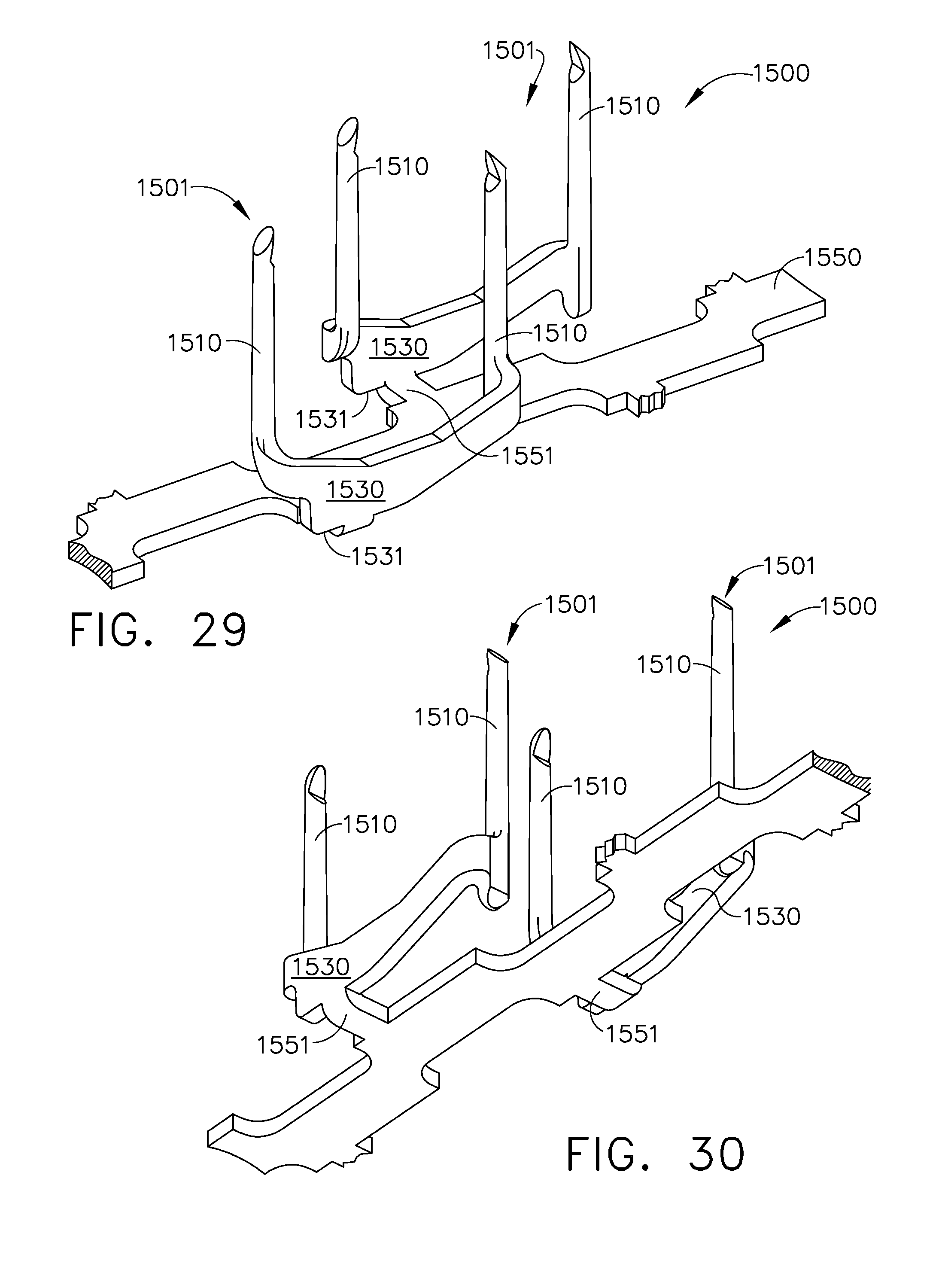
D00018

D00019

D00020

D00021

D00022

D00023

D00024

D00025

D00026

D00027

D00028
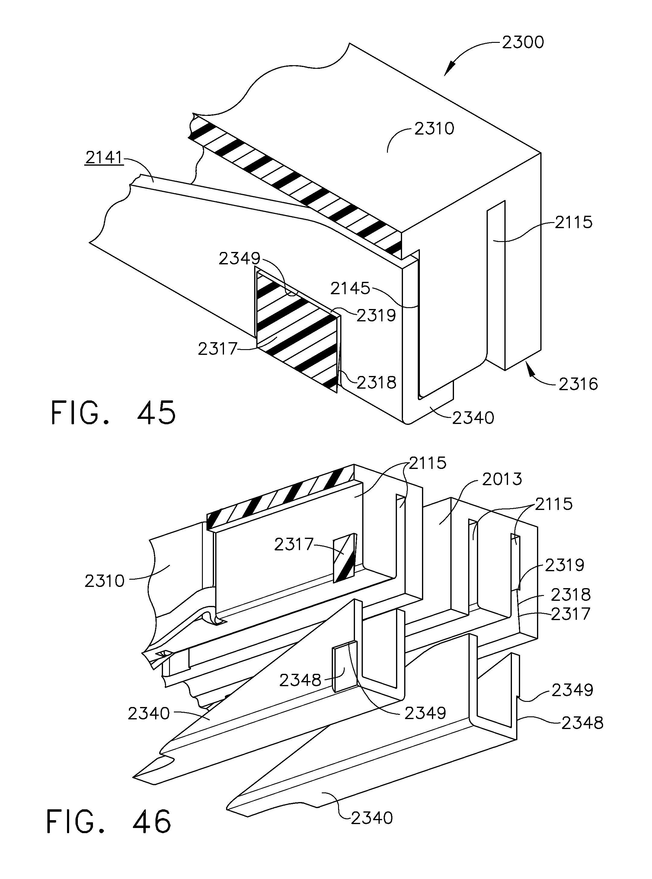
D00029
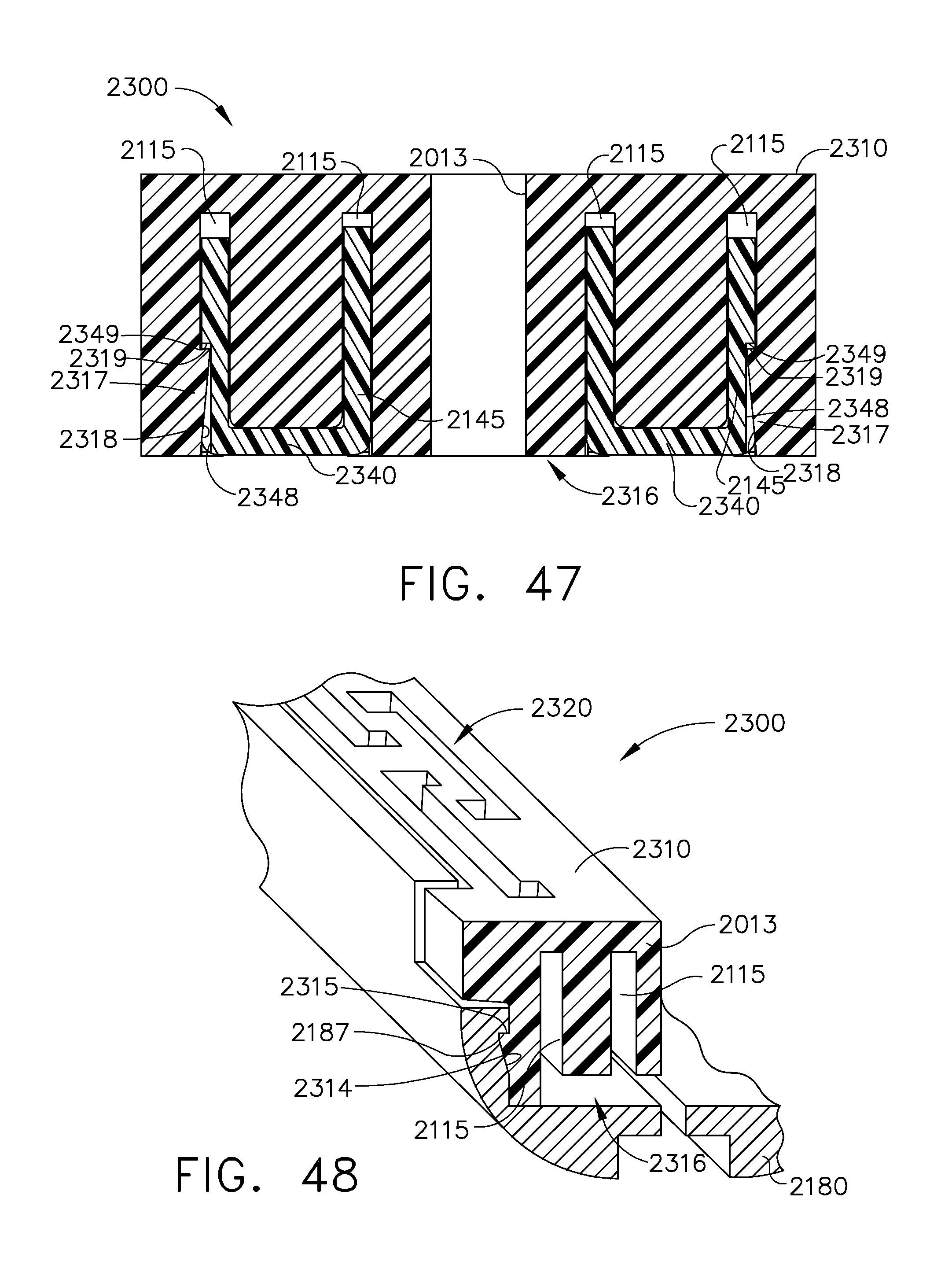
D00030

D00031
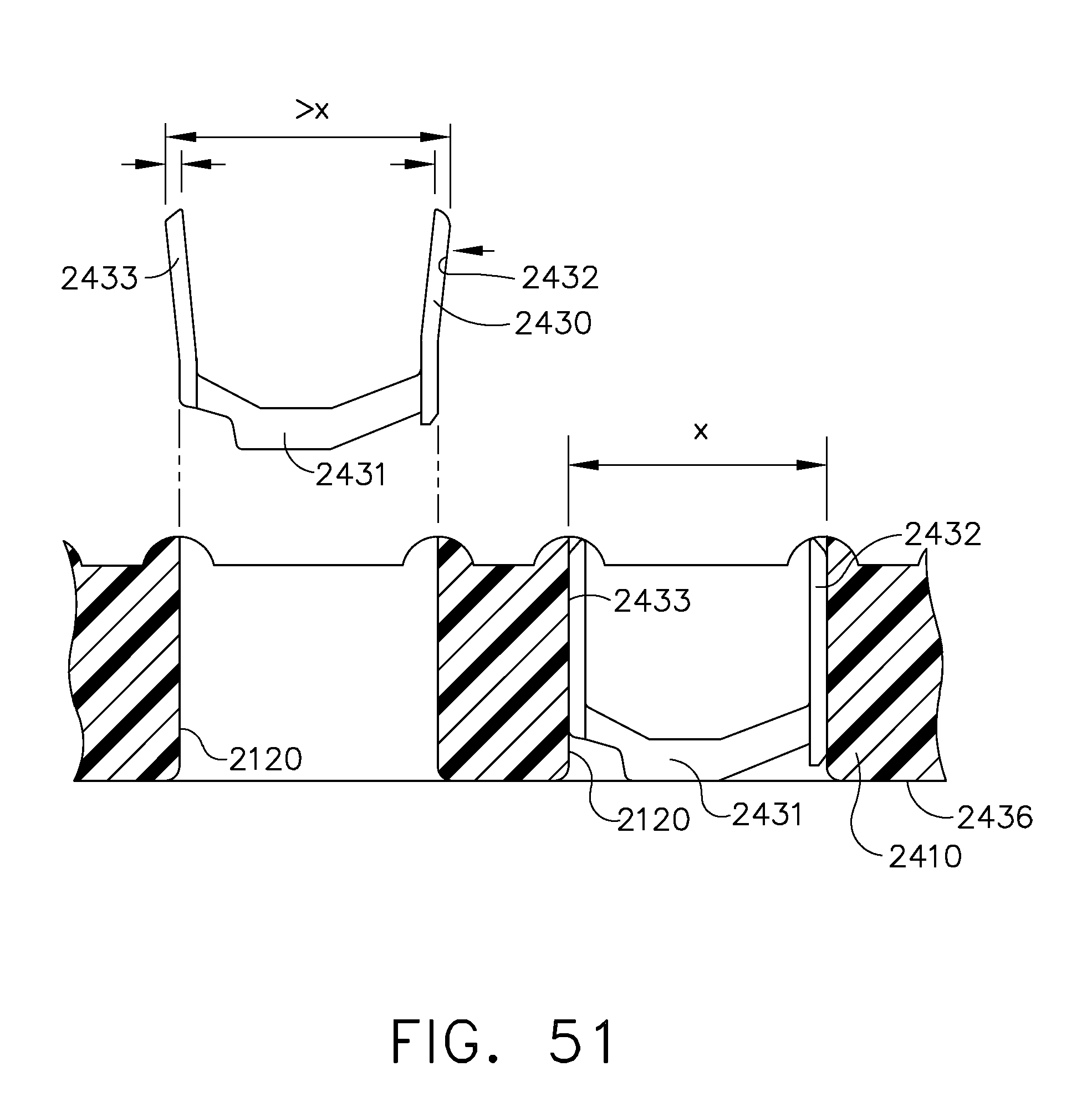
D00032

D00033

D00034
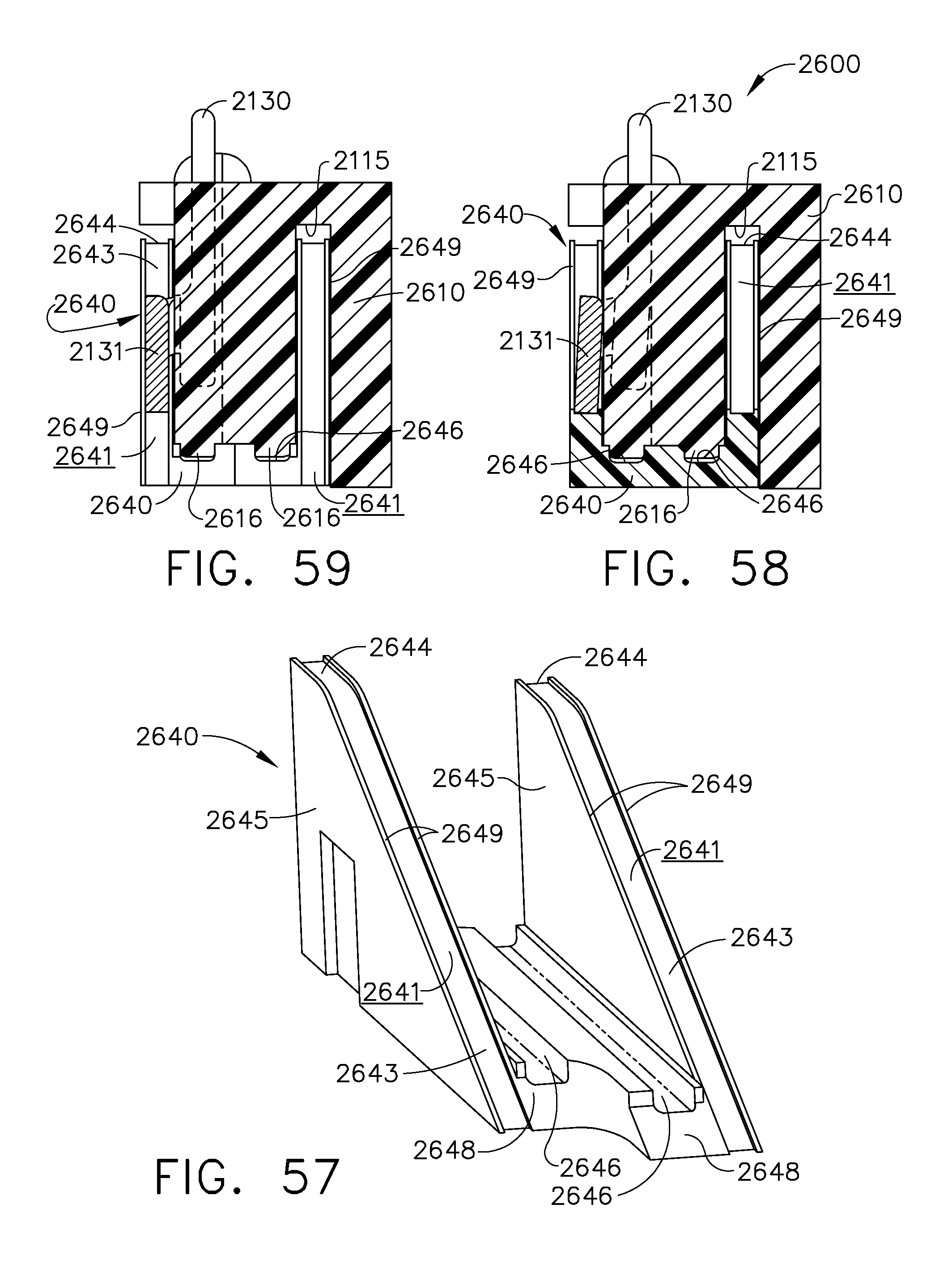
D00035
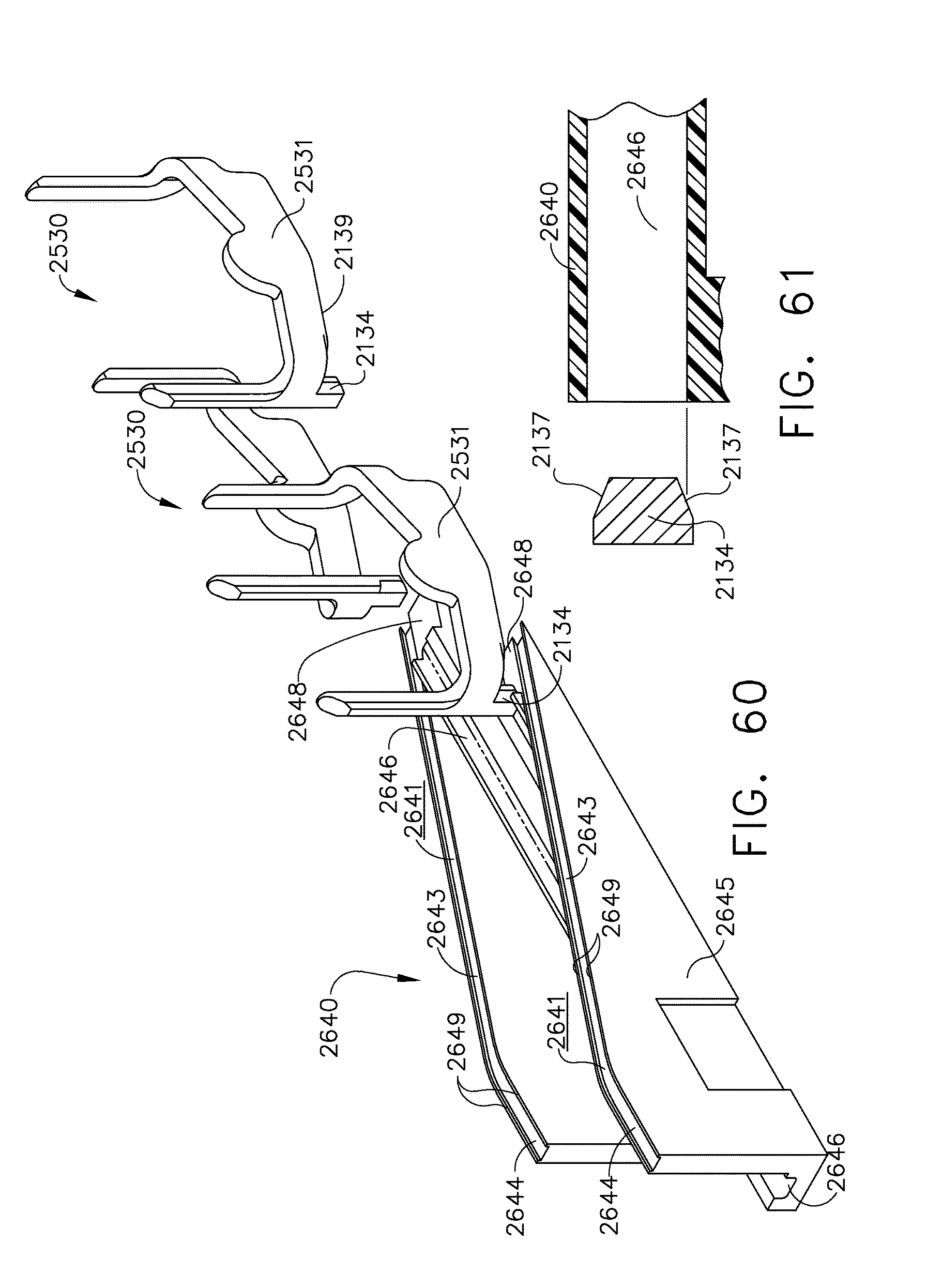
D00036
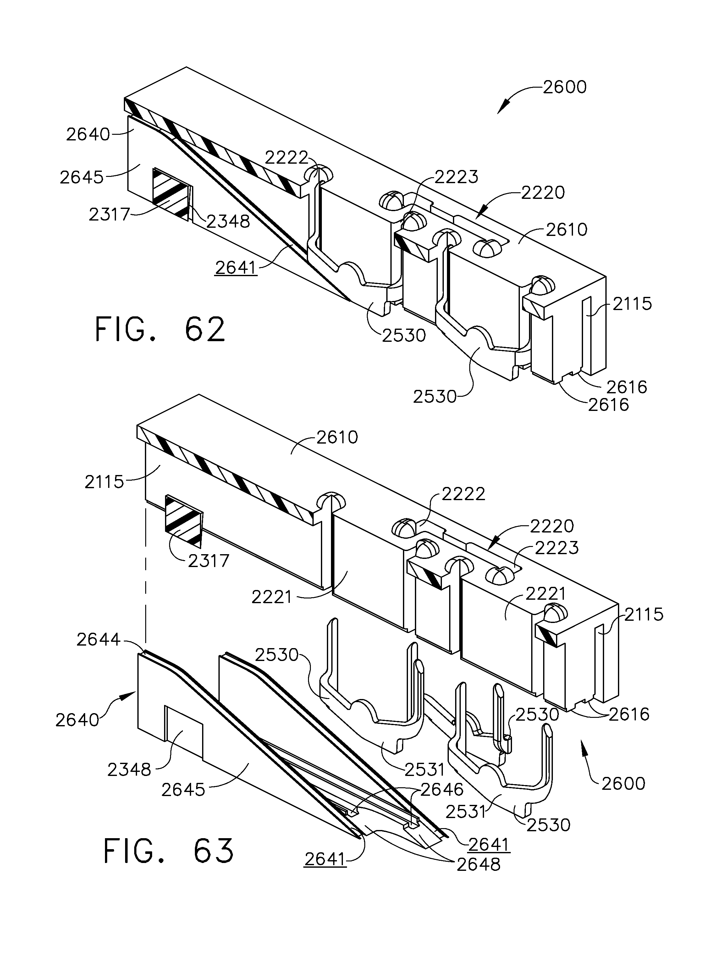
D00037

D00038

D00039
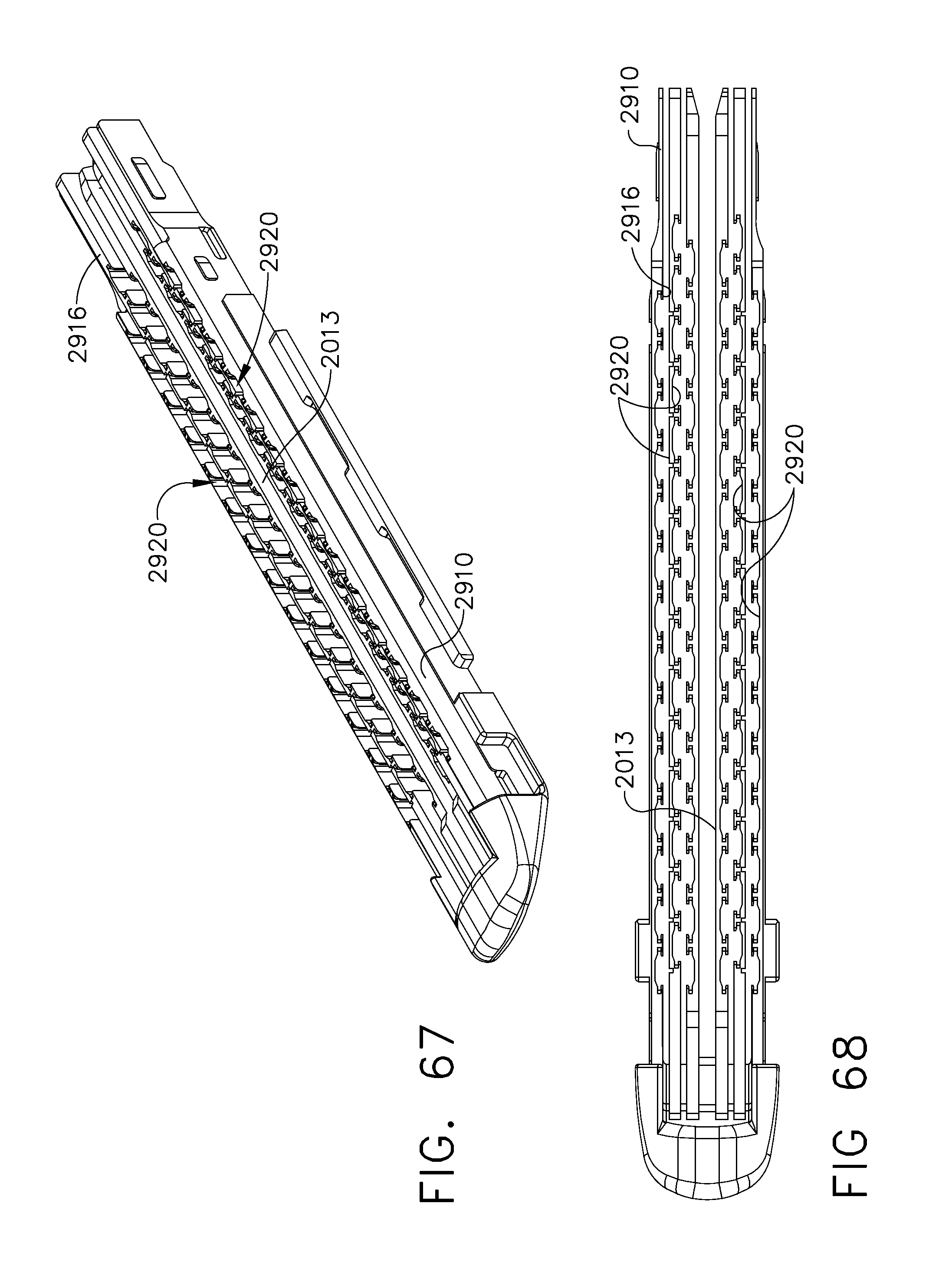
D00040

D00041
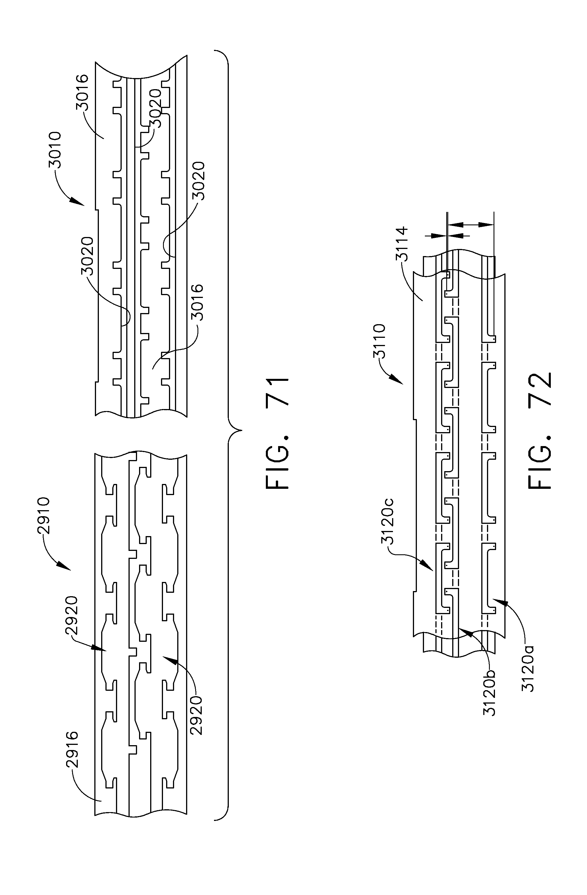
D00042

D00043

D00044
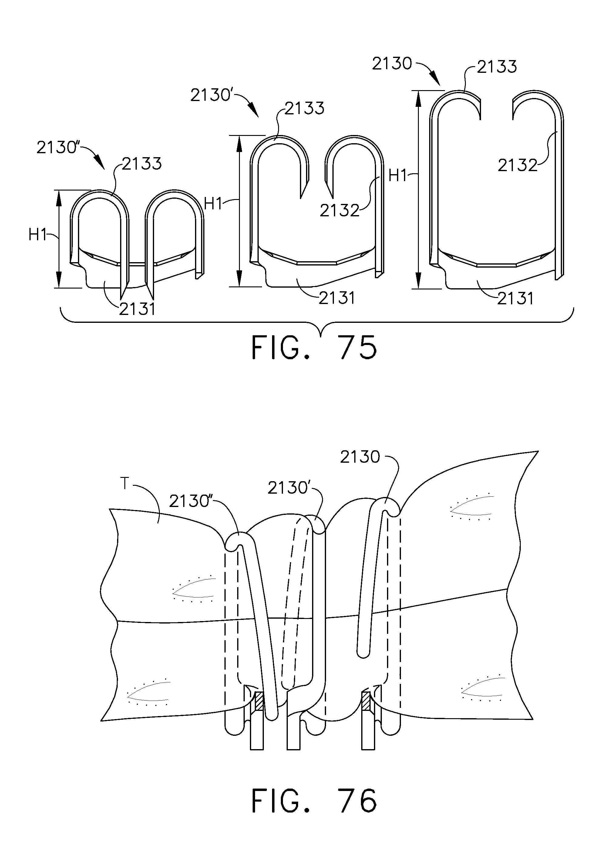
D00045

D00046

D00047
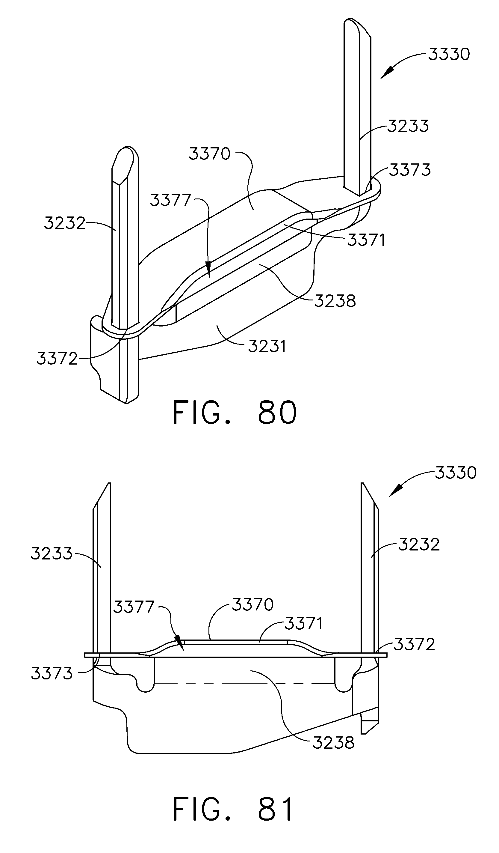
D00048
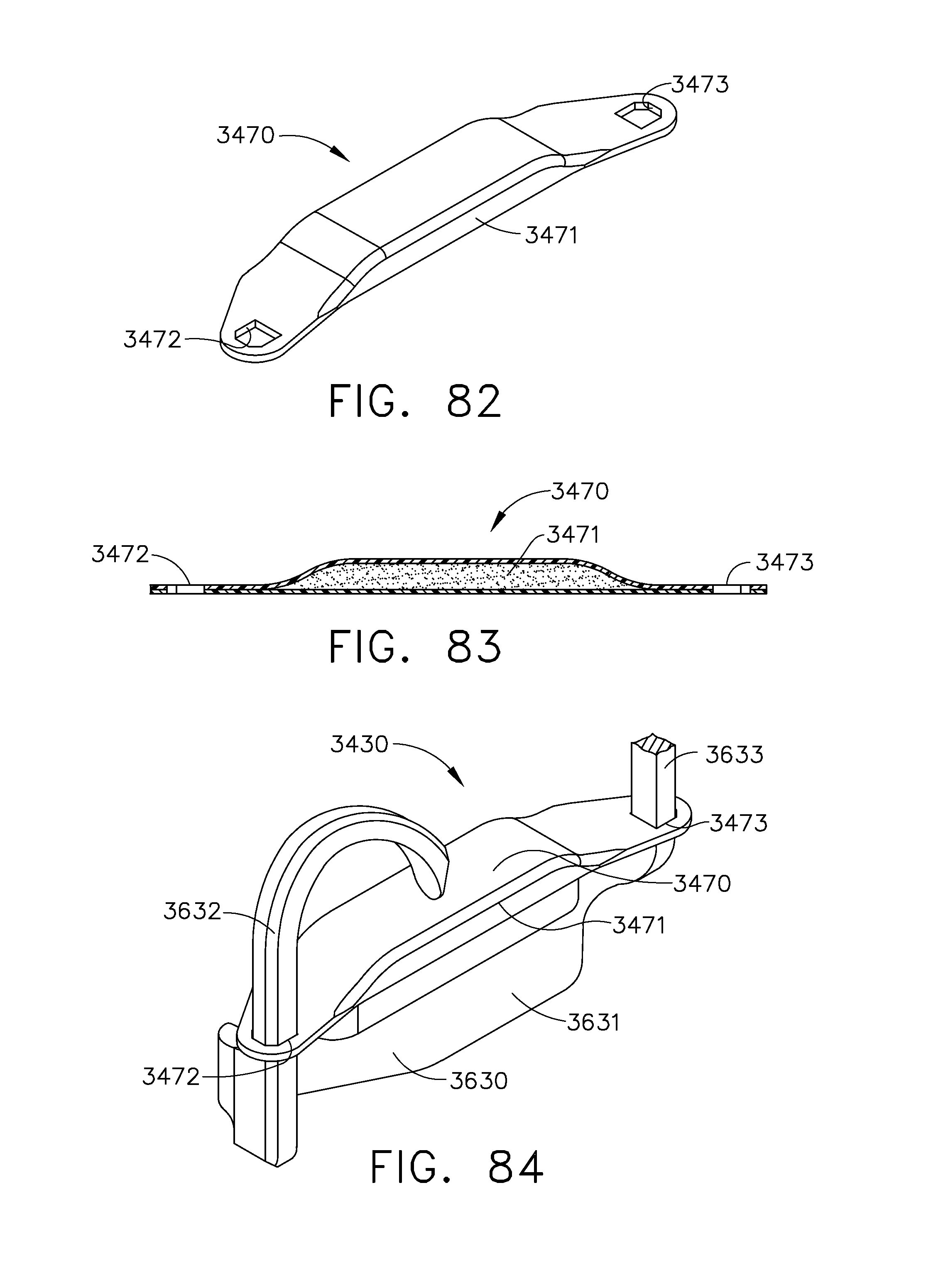
D00049

D00050

D00051

D00052

D00053

D00054

D00055

D00056
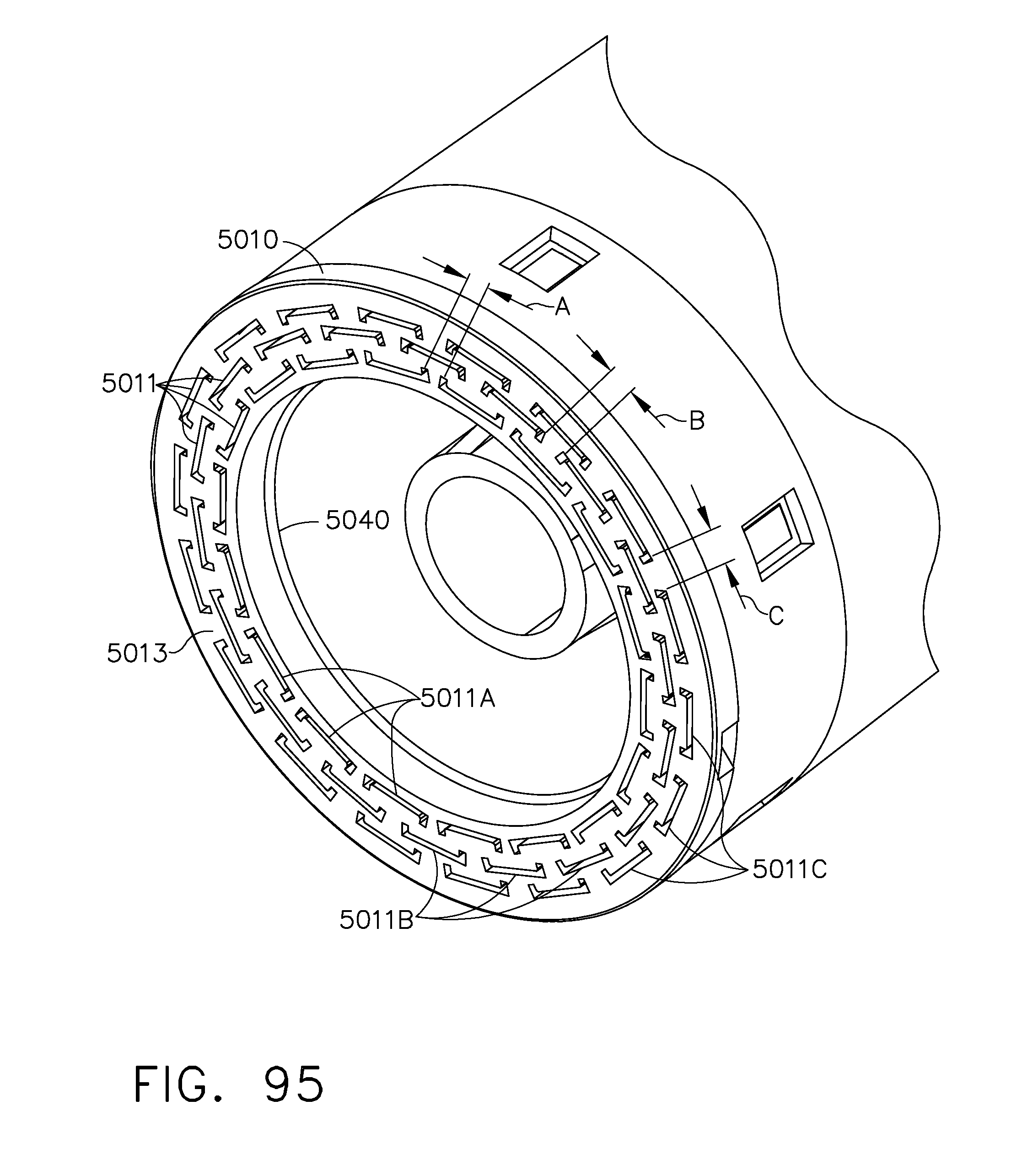
D00057
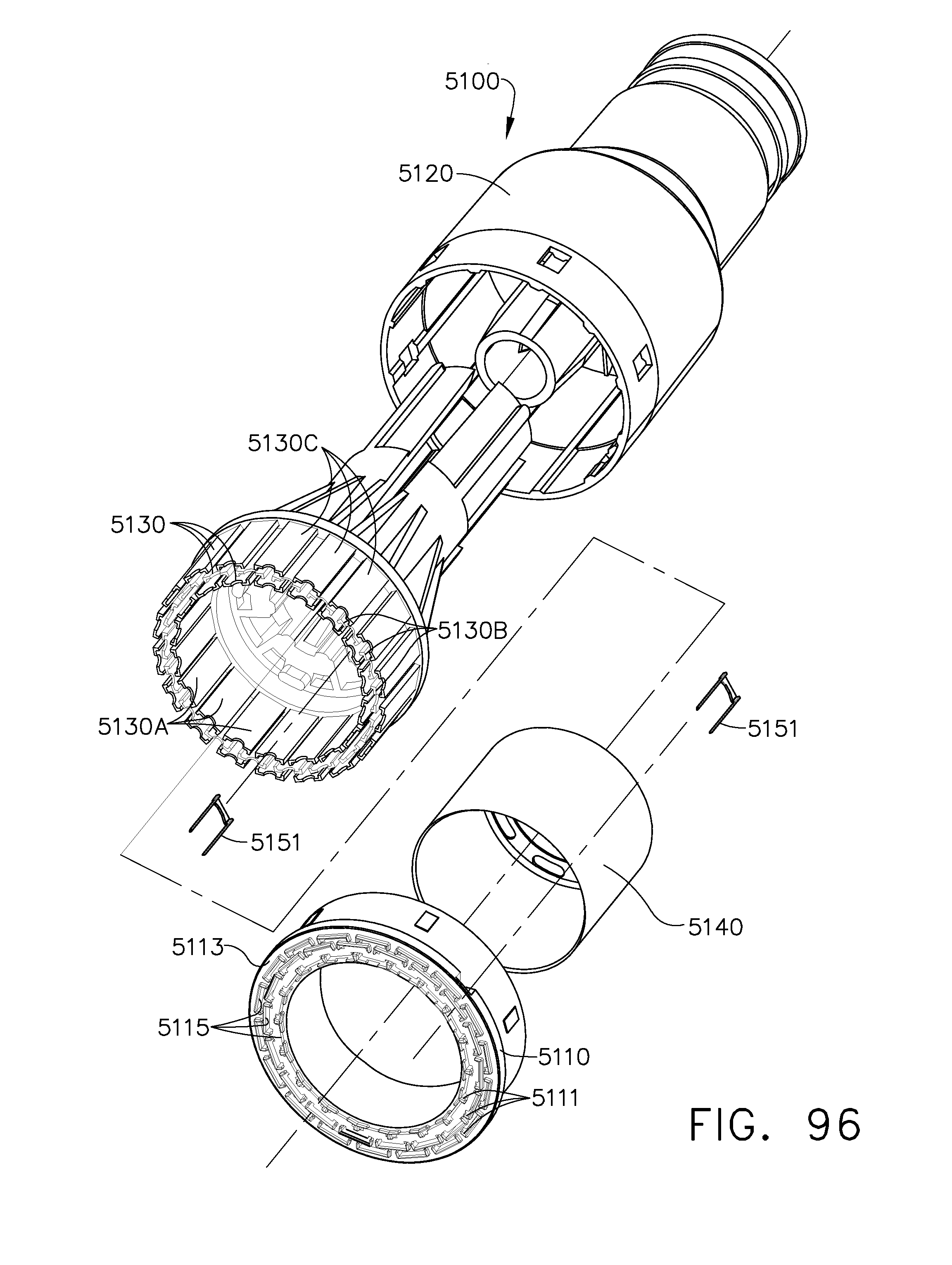
D00058
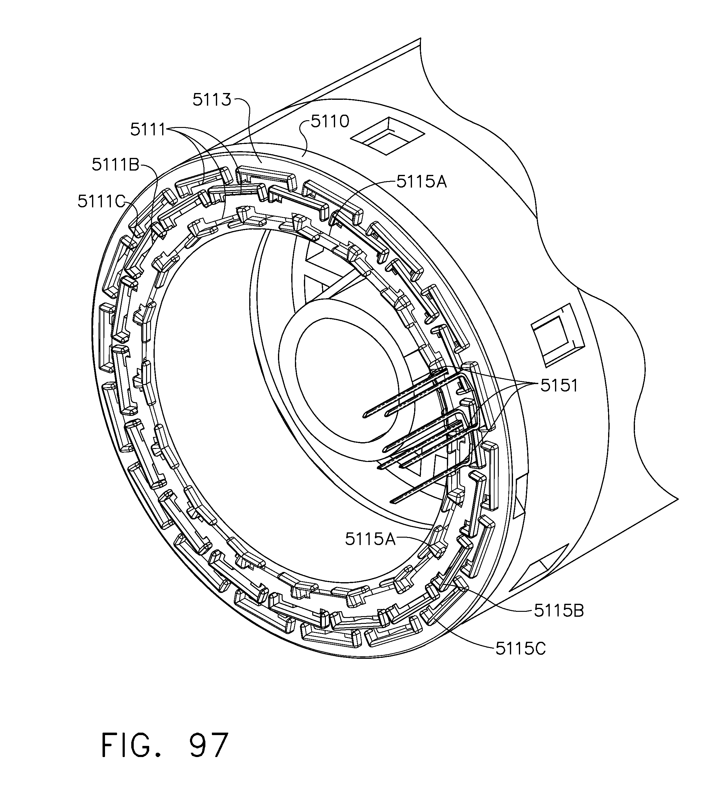
D00059
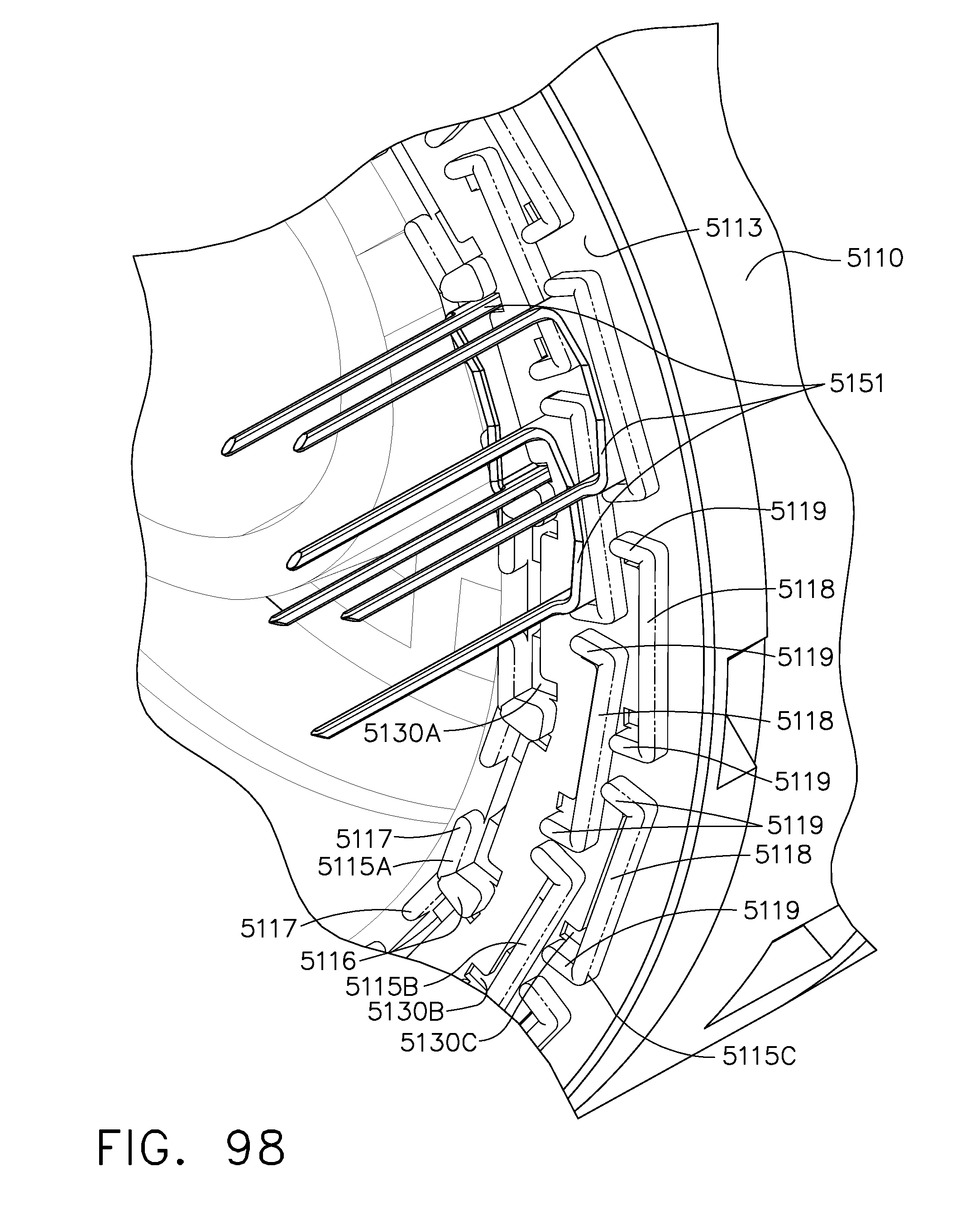
D00060

D00061

D00062

D00063

D00064

D00065

D00066

XML
uspto.report is an independent third-party trademark research tool that is not affiliated, endorsed, or sponsored by the United States Patent and Trademark Office (USPTO) or any other governmental organization. The information provided by uspto.report is based on publicly available data at the time of writing and is intended for informational purposes only.
While we strive to provide accurate and up-to-date information, we do not guarantee the accuracy, completeness, reliability, or suitability of the information displayed on this site. The use of this site is at your own risk. Any reliance you place on such information is therefore strictly at your own risk.
All official trademark data, including owner information, should be verified by visiting the official USPTO website at www.uspto.gov. This site is not intended to replace professional legal advice and should not be used as a substitute for consulting with a legal professional who is knowledgeable about trademark law.