Gear train assemblies for robotic surgical systems
Rockrohr
U.S. patent number 10,220,522 [Application Number 15/102,908] was granted by the patent office on 2019-03-05 for gear train assemblies for robotic surgical systems. This patent grant is currently assigned to Covidien LP. The grantee listed for this patent is Covidien LP. Invention is credited to Brian Rockrohr.


| United States Patent | 10,220,522 |
| Rockrohr | March 5, 2019 |
Gear train assemblies for robotic surgical systems
Abstract
An end effector for use and connection to a robot arm of a robotic surgical system, wherein the end effector is controlled and/or articulated by at least one cable extending from a respective motor of a control device of the robot surgical system, is provided. The end effector includes at least one gear train that transmits forces from the at least one motor of the control device to at least one of the proximal bracket of the wrist assembly, the distal bracket of the wrist assembly and the jaw assembly. The gear train enables at least one of a pivoting of the distal hub assembly relative to the proximal hub; a rotation of the distal bracket relative to the proximal bracket; and an opening/closing of the jaw assembly.
| Inventors: | Rockrohr; Brian (Waterbury, CT) | ||||||||||
|---|---|---|---|---|---|---|---|---|---|---|---|
| Applicant: |
|
||||||||||
| Assignee: | Covidien LP (Mansfield,
MA) |
||||||||||
| Family ID: | 53371671 | ||||||||||
| Appl. No.: | 15/102,908 | ||||||||||
| Filed: | October 23, 2014 | ||||||||||
| PCT Filed: | October 23, 2014 | ||||||||||
| PCT No.: | PCT/US2014/061863 | ||||||||||
| 371(c)(1),(2),(4) Date: | June 09, 2016 | ||||||||||
| PCT Pub. No.: | WO2015/088655 | ||||||||||
| PCT Pub. Date: | June 18, 2015 |
Prior Publication Data
| Document Identifier | Publication Date | |
|---|---|---|
| US 20160303745 A1 | Oct 20, 2016 | |
Related U.S. Patent Documents
| Application Number | Filing Date | Patent Number | Issue Date | ||
|---|---|---|---|---|---|
| 61914979 | Dec 12, 2013 | ||||
| Current U.S. Class: | 1/1 |
| Current CPC Class: | A61B 34/71 (20160201); B25J 9/102 (20130101); B25J 17/0258 (20130101); B25J 15/0213 (20130101); A61B 34/30 (20160201); A61B 17/00234 (20130101); A61B 2017/2932 (20130101); A61B 2017/2929 (20130101); A61B 17/29 (20130101); A61B 2017/2943 (20130101); A61B 2017/00323 (20130101); A61B 2017/2927 (20130101) |
| Current International Class: | A61B 17/29 (20060101); A61B 34/00 (20160101); B25J 17/02 (20060101); B25J 9/10 (20060101); B25J 15/02 (20060101); A61B 34/30 (20160101); A61B 17/00 (20060101) |
| Field of Search: | ;606/1,34,51,130,169 |
References Cited [Referenced By]
U.S. Patent Documents
| 2777340 | January 1957 | Hettwer et al. |
| 2957353 | October 1960 | Babacz |
| 3111328 | November 1963 | Di Rito et al. |
| 3695058 | October 1972 | Keith, Jr. |
| 3734515 | May 1973 | Dudek |
| 3759336 | September 1973 | Marcovitz et al. |
| 4162399 | July 1979 | Hudson |
| 4606343 | August 1986 | Conta et al. |
| 4683772 | August 1987 | Colimitra |
| 4705038 | November 1987 | Sjostrom et al. |
| 4722685 | February 1988 | de Estrada et al. |
| 4823807 | April 1989 | Russell et al. |
| 4862759 | September 1989 | Trevelyan |
| 4874181 | October 1989 | Hsu |
| 5129118 | July 1992 | Walmesley |
| 5129570 | July 1992 | Schulze et al. |
| 5152744 | October 1992 | Krause et al. |
| 5301061 | April 1994 | Nakada et al. |
| 5312023 | May 1994 | Green et al. |
| 5326013 | July 1994 | Green et al. |
| 5350355 | September 1994 | Sklar |
| 5383874 | January 1995 | Jackson et al. |
| 5383880 | January 1995 | Hooven |
| 5389098 | February 1995 | Tsuruta et al. |
| 5395033 | March 1995 | Byrne et al. |
| 5400267 | March 1995 | Denen et al. |
| 5411508 | May 1995 | Bessler et al. |
| 5413267 | May 1995 | Solyntjes et al. |
| 5427087 | June 1995 | Ito et al. |
| 5433721 | July 1995 | Hooven et al. |
| 5467911 | November 1995 | Tsuruta et al. |
| 5476379 | December 1995 | Disel |
| 5487499 | January 1996 | Sorrentino et al. |
| 5518163 | May 1996 | Hooven |
| 5518164 | May 1996 | Hooven |
| 5526822 | June 1996 | Burbank et al. |
| 5529235 | June 1996 | Boiarski et al. |
| 5535934 | July 1996 | Boiarski et al. |
| 5535937 | July 1996 | Boiarski et al. |
| 5540375 | July 1996 | Bolanos et al. |
| 5540706 | July 1996 | Aust et al. |
| 5542594 | August 1996 | McKean et al. |
| 5549637 | August 1996 | Crainich |
| 5553675 | September 1996 | Pitzen et al. |
| 5562239 | October 1996 | Boiarski et al. |
| 5564615 | October 1996 | Bishop et al. |
| 5609560 | March 1997 | Ichikawa et al. |
| 5626587 | May 1997 | Bishop et al. |
| 5632432 | May 1997 | Schulze et al. |
| 5645209 | July 1997 | Green et al. |
| 5647526 | July 1997 | Green et al. |
| 5653374 | August 1997 | Young et al. |
| 5658300 | August 1997 | Bito et al. |
| 5662662 | September 1997 | Bishop et al. |
| 5667517 | September 1997 | Hooven |
| 5693042 | December 1997 | Boiarski et al. |
| 5704534 | January 1998 | Huitema et al. |
| 5713505 | February 1998 | Huitema |
| 5762603 | June 1998 | Thompson |
| 5779130 | July 1998 | Alesi et al. |
| 5782396 | July 1998 | Mastri et al. |
| 5782397 | July 1998 | Koukline |
| 5784542 | July 1998 | Ohm et al. |
| 5792573 | August 1998 | Pitzen et al. |
| 5797536 | August 1998 | Smith et al. |
| 5797900 | August 1998 | Madhani |
| 5820009 | October 1998 | Melling et al. |
| 5863159 | January 1999 | Lasko |
| 5908427 | June 1999 | McKean et al. |
| 5954259 | September 1999 | Viola et al. |
| 5964774 | October 1999 | McKean et al. |
| 5993454 | November 1999 | Longo |
| 6010054 | January 2000 | Johnson et al. |
| 6017354 | January 2000 | Culp et al. |
| 6032849 | March 2000 | Mastri et al. |
| 6045560 | April 2000 | McKean et al. |
| 6090123 | July 2000 | Culp et al. |
| 6126651 | October 2000 | Mayer |
| 6129547 | October 2000 | Cise et al. |
| 6165169 | December 2000 | Panescu et al. |
| 6239732 | May 2001 | Cusey |
| 6241139 | June 2001 | Milliman et al. |
| 6264086 | July 2001 | McGuckin, Jr. |
| 6264087 | July 2001 | Whitman |
| 6302311 | October 2001 | Adams et al. |
| 6315184 | November 2001 | Whitman |
| 6321855 | November 2001 | Barnes |
| 6329778 | December 2001 | Culp et al. |
| 6343731 | February 2002 | Adams et al. |
| 6348061 | February 2002 | Whitman |
| 6368324 | April 2002 | Dinger et al. |
| 6371909 | April 2002 | Hoeg et al. |
| 6434507 | August 2002 | Clayton et al. |
| 6443973 | September 2002 | Whitman |
| 6461372 | October 2002 | Jensen et al. |
| 6488197 | December 2002 | Whitman |
| 6491201 | December 2002 | Whitman |
| 6533157 | March 2003 | Whitman |
| 6537280 | March 2003 | Dinger et al. |
| 6554844 | April 2003 | Lee et al. |
| 6610066 | August 2003 | Dinger et al. |
| 6611793 | August 2003 | Burnside et al. |
| 6645218 | November 2003 | Cassidy et al. |
| 6654999 | December 2003 | Stoddard et al. |
| 6698643 | March 2004 | Whitman |
| 6699177 | March 2004 | Wang et al. |
| 6716233 | April 2004 | Whitman |
| 6743240 | June 2004 | Smith et al. |
| 6783533 | August 2004 | Green et al. |
| 6792390 | September 2004 | Burnside et al. |
| 6793652 | September 2004 | Whitman et al. |
| 6817508 | November 2004 | Racenet et al. |
| 6830174 | December 2004 | Hillstead et al. |
| 6846308 | January 2005 | Whitman et al. |
| 6846309 | January 2005 | Whitman et al. |
| 6849071 | February 2005 | Whitman et al. |
| 6860892 | March 2005 | Tanaka et al. |
| 6899538 | May 2005 | Matoba |
| 6905057 | June 2005 | Swayze et al. |
| 6959852 | November 2005 | Shelton, IV et al. |
| 6964363 | November 2005 | Wales et al. |
| 6981628 | January 2006 | Wales |
| 6981941 | January 2006 | Whitman et al. |
| 6986451 | January 2006 | Mastri et al. |
| 6988649 | January 2006 | Shelton, IV et al. |
| 7032798 | April 2006 | Whitman et al. |
| RE39152 | June 2006 | Aust et al. |
| 7055731 | June 2006 | Shelton, IV et al. |
| 7059508 | June 2006 | Shelton, IV et al. |
| 7077856 | July 2006 | Whitman |
| 7111769 | September 2006 | Wales et al. |
| 7122029 | October 2006 | Koop et al. |
| 7140528 | November 2006 | Shelton, IV |
| 7141049 | November 2006 | Stern et al. |
| 7143923 | December 2006 | Shelton, IV et al. |
| 7143925 | December 2006 | Shelton, IV et al. |
| 7143926 | December 2006 | Shelton, IV et al. |
| 7147138 | December 2006 | Shelton, IV |
| 7172104 | February 2007 | Scirica et al. |
| 7225964 | June 2007 | Mastri et al. |
| 7238021 | July 2007 | Johnson |
| 7246734 | July 2007 | Shelton, IV |
| 7252660 | August 2007 | Kunz |
| 7328828 | February 2008 | Ortiz et al. |
| 7364061 | April 2008 | Swayze et al. |
| 7380695 | June 2008 | Doll et al. |
| 7380696 | June 2008 | Shelton, IV et al. |
| 7404508 | July 2008 | Smith et al. |
| 7407078 | August 2008 | Shelton, IV et al. |
| 7416101 | August 2008 | Shelton, IV et al. |
| 7419080 | September 2008 | Smith et al. |
| 7422139 | September 2008 | Shelton, IV et al. |
| 7422592 | September 2008 | Morley |
| 7431189 | October 2008 | Shelton, IV et al. |
| 7441684 | October 2008 | Shelton, IV et al. |
| 7448525 | November 2008 | Shelton, IV et al. |
| 7464846 | December 2008 | Shelton, IV et al. |
| 7464847 | December 2008 | Viola et al. |
| 7464849 | December 2008 | Shelton, IV et al. |
| 7481347 | January 2009 | Roy |
| 7481824 | January 2009 | Boudreaux et al. |
| 7487899 | February 2009 | Shelton, IV et al. |
| 7549564 | June 2009 | Boudreaux |
| 7565993 | July 2009 | Milliman et al. |
| 7568603 | August 2009 | Shelton, IV et al. |
| 7575144 | August 2009 | Ortiz et al. |
| 7588175 | September 2009 | Timm et al. |
| 7588176 | September 2009 | Timm et al. |
| 7637409 | December 2009 | Marczyk |
| 7641093 | January 2010 | Doll et al. |
| 7644848 | January 2010 | Swayze et al. |
| 7670334 | March 2010 | Hueil et al. |
| 7673780 | March 2010 | Shelton, IV et al. |
| 7699835 | April 2010 | Lee et al. |
| 7721931 | May 2010 | Shelton, IV et al. |
| 7738971 | June 2010 | Swayze et al. |
| 7740159 | June 2010 | Shelton, IV et al. |
| 7743960 | June 2010 | Whitman et al. |
| 7758613 | July 2010 | Whitman |
| 7766210 | August 2010 | Shelton, IV et al. |
| 7770773 | August 2010 | Whitman et al. |
| 7770775 | August 2010 | Shelton, IV et al. |
| 7793812 | September 2010 | Moore et al. |
| 7799039 | September 2010 | Shelton, IV et al. |
| 7802712 | September 2010 | Milliman et al. |
| 7803151 | September 2010 | Whitman |
| 7822458 | October 2010 | Webster, III et al. |
| 7845534 | December 2010 | Viola et al. |
| 7845537 | December 2010 | Shelton, IV et al. |
| 7857185 | December 2010 | Swayze et al. |
| 7870989 | January 2011 | Viola et al. |
| 7900805 | March 2011 | Shelton, IV et al. |
| 7905897 | March 2011 | Whitman et al. |
| 7918230 | April 2011 | Whitman et al. |
| 7922061 | April 2011 | Shelton, IV et al. |
| 7922719 | April 2011 | Ralph et al. |
| 7947034 | May 2011 | Whitman |
| 7951071 | May 2011 | Whitman et al. |
| 7954682 | June 2011 | Giordano et al. |
| 7959051 | June 2011 | Smith et al. |
| 7963433 | June 2011 | Whitman et al. |
| 7967178 | June 2011 | Scirica et al. |
| 7967179 | June 2011 | Olson et al. |
| 7992758 | August 2011 | Whitman et al. |
| 8011550 | September 2011 | Aranyi et al. |
| 8016178 | September 2011 | Olson et al. |
| 8016855 | September 2011 | Whitman et al. |
| 8020743 | September 2011 | Shelton, IV |
| 8025199 | September 2011 | Whitman et al. |
| 8035487 | October 2011 | Malackowski |
| 8052024 | November 2011 | Viola et al. |
| 8074859 | December 2011 | Kostrzewski |
| 8092451 | January 2012 | Schechter et al. |
| 8114118 | February 2012 | Knodel et al. |
| 8127975 | March 2012 | Olson et al. |
| 8132705 | March 2012 | Viola et al. |
| 8152516 | April 2012 | Harvey et al. |
| 8157150 | April 2012 | Viola et al. |
| 8157151 | April 2012 | Ingmanson et al. |
| 8182494 | May 2012 | Yencho et al. |
| 8186555 | May 2012 | Shelton, IV et al. |
| 8186587 | May 2012 | Zmood et al. |
| 8220367 | July 2012 | Hsu |
| 8235273 | August 2012 | Olson et al. |
| 8237388 | August 2012 | Jinno et al. |
| 8241322 | August 2012 | Whitman et al. |
| 8272554 | September 2012 | Whitman et al. |
| 8292150 | October 2012 | Bryant |
| 8292888 | October 2012 | Whitman |
| 8342379 | January 2013 | Whitman et al. |
| 8348130 | January 2013 | Shah et al. |
| 8348855 | January 2013 | Hillely et al. |
| 8353440 | January 2013 | Whitman et al. |
| 8357144 | January 2013 | Whitman et al. |
| 8365633 | February 2013 | Simaan et al. |
| 8365972 | February 2013 | Aranyi et al. |
| 8371492 | February 2013 | Aranyi et al. |
| 8372057 | February 2013 | Cude et al. |
| 8391957 | March 2013 | Carlson et al. |
| 8403926 | March 2013 | Nobis et al. |
| 8418904 | April 2013 | Wenchell et al. |
| 8424739 | April 2013 | Racenet et al. |
| 8454585 | June 2013 | Whitman |
| 8505802 | August 2013 | Viola et al. |
| 8517241 | August 2013 | Nicholas et al. |
| 8523043 | September 2013 | Ullrich et al. |
| 8551076 | October 2013 | Duval et al. |
| 8561871 | October 2013 | Rajappa et al. |
| 8561874 | October 2013 | Scirica |
| 8602287 | December 2013 | Yates et al. |
| 8623000 | January 2014 | Humayun et al. |
| 8627995 | January 2014 | Smith et al. |
| 8632463 | January 2014 | Drinan et al. |
| 8636766 | January 2014 | Milliman et al. |
| 8647258 | February 2014 | Aranyi et al. |
| 8652121 | February 2014 | Quick et al. |
| 8657174 | February 2014 | Yates et al. |
| 8657177 | February 2014 | Scirica et al. |
| 8672206 | March 2014 | Aranyi et al. |
| 8696552 | April 2014 | Whitman |
| 8708213 | April 2014 | Shelton, IV et al. |
| 8715306 | May 2014 | Faller et al. |
| 8758391 | June 2014 | Swayze et al. |
| 8806973 | August 2014 | Ross et al. |
| 8808311 | August 2014 | Heinrich et al. |
| 8820605 | September 2014 | Shelton, IV |
| 8851355 | October 2014 | Aranyi et al. |
| 8858571 | October 2014 | Shelton, IV et al. |
| 8875972 | November 2014 | Weisenburgh, II et al. |
| 8888762 | November 2014 | Whitman |
| 8893946 | November 2014 | Boudreaux et al. |
| 8899462 | December 2014 | Kostrzewski et al. |
| 8905289 | December 2014 | Patel et al. |
| 8919630 | December 2014 | Milliman |
| 8931680 | January 2015 | Milliman |
| 8939344 | January 2015 | Olson et al. |
| 8950646 | February 2015 | Viola |
| 8960519 | February 2015 | Whitman et al. |
| 8961396 | February 2015 | Azarbarzin et al. |
| 8967443 | March 2015 | McCuen |
| 8968276 | March 2015 | Zemlok et al. |
| 8968337 | March 2015 | Whitfield et al. |
| 8992422 | March 2015 | Spivey et al. |
| 9016545 | April 2015 | Aranyi et al. |
| 9023014 | May 2015 | Chowaniec et al. |
| 9033868 | May 2015 | Whitman et al. |
| 9055943 | June 2015 | Zemlok et al. |
| 9064653 | June 2015 | Prest et al. |
| 9072515 | July 2015 | Hall et al. |
| 9113847 | August 2015 | Whitman et al. |
| 9113875 | August 2015 | Viola et al. |
| 9113876 | August 2015 | Zemlok et al. |
| 9113899 | August 2015 | Garrison et al. |
| 9216013 | December 2015 | Scirica et al. |
| 9241712 | January 2016 | Zemlok et al. |
| 9282961 | March 2016 | Whitman et al. |
| 9282963 | March 2016 | Bryant |
| 9295522 | March 2016 | Kostrzewski |
| 9307986 | April 2016 | Hall et al. |
| 2001/0031975 | October 2001 | Whitman et al. |
| 2002/0040217 | April 2002 | Jinno |
| 2002/0049454 | April 2002 | Whitman et al. |
| 2002/0165541 | November 2002 | Whitman |
| 2003/0038938 | February 2003 | Jung et al. |
| 2003/0165794 | September 2003 | Matoba |
| 2004/0034369 | February 2004 | Sauer et al. |
| 2004/0111012 | June 2004 | Whitman |
| 2004/0133189 | July 2004 | Sakurai |
| 2004/0153124 | August 2004 | Whitman |
| 2004/0176751 | September 2004 | Weitzner et al. |
| 2004/0193146 | September 2004 | Lee et al. |
| 2005/0125027 | June 2005 | Knodel et al. |
| 2005/0131442 | June 2005 | Yachia et al. |
| 2006/0142656 | June 2006 | Malackowski et al. |
| 2006/0142740 | June 2006 | Sherman et al. |
| 2006/0142744 | June 2006 | Boutoussov |
| 2006/0259073 | November 2006 | Miyamoto et al. |
| 2006/0278680 | December 2006 | Viola et al. |
| 2006/0284730 | December 2006 | Schmid et al. |
| 2007/0023476 | February 2007 | Whitman et al. |
| 2007/0023477 | February 2007 | Whitman et al. |
| 2007/0029363 | February 2007 | Popov |
| 2007/0084897 | April 2007 | Shelton et al. |
| 2007/0102472 | May 2007 | Shelton |
| 2007/0152014 | July 2007 | Gillum et al. |
| 2007/0175947 | August 2007 | Ortiz et al. |
| 2007/0175949 | August 2007 | Shelton et al. |
| 2007/0175950 | August 2007 | Shelton et al. |
| 2007/0175951 | August 2007 | Shelton et al. |
| 2007/0175955 | August 2007 | Shelton et al. |
| 2007/0175961 | August 2007 | Shelton et al. |
| 2007/0270784 | November 2007 | Smith et al. |
| 2008/0029570 | February 2008 | Shelton et al. |
| 2008/0029573 | February 2008 | Shelton et al. |
| 2008/0029574 | February 2008 | Shelton et al. |
| 2008/0029575 | February 2008 | Shelton et al. |
| 2008/0039256 | February 2008 | Jinno et al. |
| 2008/0058801 | March 2008 | Taylor et al. |
| 2008/0109012 | May 2008 | Falco et al. |
| 2008/0110958 | May 2008 | McKenna et al. |
| 2008/0147089 | June 2008 | Loh et al. |
| 2008/0167736 | July 2008 | Swayze et al. |
| 2008/0185419 | August 2008 | Smith et al. |
| 2008/0188841 | August 2008 | Tomasello et al. |
| 2008/0197167 | August 2008 | Viola et al. |
| 2008/0208195 | August 2008 | Shores et al. |
| 2008/0237296 | October 2008 | Boudreaux et al. |
| 2008/0245175 | October 2008 | Jinno et al. |
| 2008/0251561 | October 2008 | Eades et al. |
| 2008/0255413 | October 2008 | Zemlok et al. |
| 2008/0255607 | October 2008 | Zemlok |
| 2008/0262654 | October 2008 | Omori et al. |
| 2008/0308603 | December 2008 | Shelton et al. |
| 2009/0012533 | January 2009 | Barbagli et al. |
| 2009/0090763 | April 2009 | Zemlok et al. |
| 2009/0099876 | April 2009 | Whitman |
| 2009/0138006 | May 2009 | Bales et al. |
| 2009/0171147 | July 2009 | Lee et al. |
| 2009/0182193 | July 2009 | Whitman et al. |
| 2009/0209946 | August 2009 | Swayze et al. |
| 2009/0209990 | August 2009 | Yates et al. |
| 2009/0254094 | October 2009 | Knapp et al. |
| 2009/0299141 | December 2009 | Downey et al. |
| 2010/0016852 | January 2010 | Manzo et al. |
| 2010/0016853 | January 2010 | Burbank |
| 2010/0023022 | January 2010 | Zeiner et al. |
| 2010/0069942 | March 2010 | Shelton, IV |
| 2010/0193568 | August 2010 | Scheib et al. |
| 2010/0211053 | August 2010 | Ross et al. |
| 2010/0225073 | September 2010 | Porter et al. |
| 2011/0071508 | March 2011 | Duval et al. |
| 2011/0077673 | March 2011 | Grubac et al. |
| 2011/0121049 | May 2011 | Malinouskas et al. |
| 2011/0125138 | May 2011 | Malinouskas et al. |
| 2011/0139851 | June 2011 | McCuen |
| 2011/0155783 | June 2011 | Rajappa et al. |
| 2011/0155786 | June 2011 | Shelton, IV |
| 2011/0172648 | July 2011 | Jeong |
| 2011/0174009 | July 2011 | Iizuka et al. |
| 2011/0174099 | July 2011 | Ross et al. |
| 2011/0184245 | July 2011 | Xia et al. |
| 2011/0204119 | August 2011 | McCuen |
| 2011/0218522 | September 2011 | Whitman |
| 2011/0276057 | November 2011 | Conlon et al. |
| 2011/0290854 | December 2011 | Timm et al. |
| 2011/0295242 | December 2011 | Spivey et al. |
| 2011/0295269 | December 2011 | Swensgard et al. |
| 2012/0000962 | January 2012 | Racenet et al. |
| 2012/0010616 | January 2012 | Huang et al. |
| 2012/0074199 | March 2012 | Olson et al. |
| 2012/0080475 | April 2012 | Smith et al. |
| 2012/0080485 | April 2012 | Woodard, Jr. et al. |
| 2012/0089131 | April 2012 | Zemlok et al. |
| 2012/0104071 | May 2012 | Bryant |
| 2012/0116368 | May 2012 | Viola |
| 2012/0116416 | May 2012 | Neff et al. |
| 2012/0143002 | June 2012 | Aranyi et al. |
| 2012/0168485 | July 2012 | Marczyk et al. |
| 2012/0172924 | July 2012 | Allen, IV |
| 2012/0199630 | August 2012 | Shelton |
| 2012/0211542 | August 2012 | Racenet |
| 2012/0223121 | September 2012 | Viola et al. |
| 2012/0245428 | September 2012 | Smith et al. |
| 2012/0253329 | October 2012 | Zemlok et al. |
| 2012/0310220 | December 2012 | Malkowski et al. |
| 2012/0323226 | December 2012 | Chowaniec et al. |
| 2012/0330285 | December 2012 | Hartoumbekis et al. |
| 2013/0020376 | January 2013 | Shelton, IV et al. |
| 2013/0032629 | February 2013 | Viola |
| 2013/0093149 | April 2013 | Saur et al. |
| 2013/0131695 | May 2013 | Scarfogliero et al. |
| 2013/0158542 | June 2013 | Manzo et al. |
| 2013/0181035 | July 2013 | Milliman |
| 2013/0184704 | July 2013 | Beardsley et al. |
| 2013/0214025 | August 2013 | Zemlok et al. |
| 2013/0274722 | October 2013 | Kostrzewski et al. |
| 2013/0282052 | October 2013 | Aranyi et al. |
| 2013/0292451 | November 2013 | Viola et al. |
| 2013/0313304 | November 2013 | Shelton, IV et al. |
| 2013/0317486 | November 2013 | Nicholas et al. |
| 2013/0319706 | December 2013 | Nicholas et al. |
| 2013/0324978 | December 2013 | Nicholas et al. |
| 2013/0324979 | December 2013 | Nicholas et al. |
| 2013/0334281 | December 2013 | Williams |
| 2014/0012236 | January 2014 | Williams et al. |
| 2014/0012237 | January 2014 | Pribanic et al. |
| 2014/0012289 | January 2014 | Snow et al. |
| 2014/0025046 | January 2014 | Williams et al. |
| 2014/0110455 | April 2014 | Ingmanson et al. |
| 2014/0207125 | July 2014 | Applegate et al. |
| 2014/0207182 | July 2014 | Zergiebel et al. |
| 2014/0207185 | July 2014 | Goble et al. |
| 2014/0236174 | August 2014 | Williams et al. |
| 2014/0276932 | September 2014 | Williams et al. |
| 2014/0299647 | October 2014 | Scirica et al. |
| 2014/0303668 | October 2014 | Nicholas et al. |
| 2014/0358129 | December 2014 | Zergiebel et al. |
| 2014/0361068 | December 2014 | Aranyi et al. |
| 2014/0365235 | December 2014 | DeBoer et al. |
| 2014/0373652 | December 2014 | Zergiebel et al. |
| 2015/0014392 | January 2015 | Williams et al. |
| 2015/0048144 | February 2015 | Whitman |
| 2015/0076205 | March 2015 | Zergiebel |
| 2015/0080912 | March 2015 | Sapre |
| 2015/0112381 | April 2015 | Richard |
| 2015/0122870 | May 2015 | Zemlok et al. |
| 2015/0133224 | May 2015 | Whitman et al. |
| 2015/0150547 | June 2015 | Ingmanson et al. |
| 2015/0150574 | June 2015 | Richard et al. |
| 2015/0157320 | June 2015 | Zergiebel et al. |
| 2015/0157321 | June 2015 | Zergiebel et al. |
| 2015/0164502 | June 2015 | Richard et al. |
| 2015/0201931 | July 2015 | Zergiebel et al. |
| 2015/0272577 | October 2015 | Zemlok et al. |
| 2015/0297199 | October 2015 | Nicholas et al. |
| 2015/0303996 | October 2015 | Calderoni |
| 2015/0320420 | November 2015 | Penna et al. |
| 2015/0327850 | November 2015 | Kostrzewski |
| 2015/0342601 | December 2015 | Williams et al. |
| 2015/0342603 | December 2015 | Zergiebel et al. |
| 2015/0374366 | December 2015 | Zergiebel et al. |
| 2015/0374370 | December 2015 | Zergiebel et al. |
| 2015/0374371 | December 2015 | Richard et al. |
| 2015/0374372 | December 2015 | Zergiebel et al. |
| 2015/0374449 | December 2015 | Chowaniec et al. |
| 2015/0380187 | December 2015 | Zergiebel et al. |
| 2016/0095585 | April 2016 | Zergiebel et al. |
| 2016/0095596 | April 2016 | Scirica et al. |
| 2016/0106406 | April 2016 | Cabrera et al. |
| 2016/0113648 | April 2016 | Zergiebel et al. |
| 2016/0113649 | April 2016 | Zergiebel et al. |
| 2451558 | Jan 2003 | CA | |||
| 1547454 | Nov 2004 | CN | |||
| 1957854 | May 2007 | CN | |||
| 101495046 | Jul 2009 | CN | |||
| 102247182 | Nov 2011 | CN | |||
| 102008053842 | May 2010 | DE | |||
| 0443576 | Aug 1991 | EP | |||
| 0705571 | Apr 1996 | EP | |||
| 1563793 | Aug 2005 | EP | |||
| 1769754 | Apr 2007 | EP | |||
| 2316345 | May 2011 | EP | |||
| 2668910 | Dec 2013 | EP | |||
| 2333509 | Feb 2010 | ES | |||
| 2005-125075 | May 2005 | JP | |||
| 20120022521 | Mar 2012 | KR | |||
| 2011/108840 | Sep 2011 | WO | |||
| 2012/040984 | Apr 2012 | WO | |||
Other References
|
Chinese Second Office Action corresponding to counterpart Patent Appln. CN 2014800674869 dated Aug. 1, 2018. cited by applicant . Extended European Search Report corresponding to counterpart International Application No. EP 14 18 4882.0 dated May 12, 2015. cited by applicant . Canadian Office Action corresponding to counterpart International Application No. CA 2640399 dated May 7, 2015. cited by applicant . Japanese Office Action corresponding to counterpart International Application No. JP 2011-197365 dated Mar. 23, 2015. cited by applicant . Japanese Office Action corresponding to counterpart International Application No. JP 2011-084092 dated May 20, 2015. cited by applicant . Japanese Office Action corresponding to counterpart International Application No. JP 2014-148482 dated Jun. 2, 2015. cited by applicant . Extended European Search Report corresponding to counterpart International Application No. EP 14 18 9358.6 dated Jul. 8, 2015. cited by applicant . Extended European Search Report corresponding to counterpart International Application No. EP 14 19 6148.2 dated Apr. 23, 2015. cited by applicant . Partial European Search Report corresponding to counterpart International Application No. EP 14 19 6704.2 dated May 11,2015. cited by applicant . Australian Office Action corresponding to counterpart International Application No. AU 2010241367 dated Aug. 20, 2015. cited by applicant . Partial European Search Report corresponding to counterpart International Application No. EP 14 19 9783.3 dated Sep. 3, 2015. cited by applicant . Extended European Search Report corresponding to counterpart International Application No. EP 15 16 9962.6 dated Sep. 14, 2015. cited by applicant . Extended European Search Report corresponding to International Application No. EP 15 15 1076.5 dated Apr. 22, 2015. cited by applicant . Japanese Office Action corresponding to International Application No. JP 2011-084092 dated Jan. 14, 2016. cited by applicant . Extended European Search Report corresponding to International Application No. EP 12 19 7970.2 dated Jan. 28, 2016. cited by applicant . Chinese Office Action corresponding to International Application No. CN 201210560638.1 dated Oct. 21, 2015. cited by applicant . European Office Action corresponding to International Application No. EP 14 15 9056.2 dated Oct. 26, 2015. cited by applicant . Australian Examination Report No. 1 corresponding to International Application No. AU 2015200153 dated Dec. 11, 2015. cited by applicant . Australian Examination Report No. 1 corresponding to International Application No. AU 2014204542 dated Jan. 7, 2016. cited by applicant . Chinese Office Action corresponding to International Application No. CN 201310125449.6 dated Feb. 3, 2016. cited by applicant . Extended European Search Report corresponding to International Application No. EP 15 19 0245.9 dated Jan. 28, 2016. cited by applicant . Extended European Search Report corresponding to International Application No. EP 15 16 7793.7 dated Apr. 5, 2016. cited by applicant . European Office Action corresponding to International Application No. EP 14 18 4882.0 dated Apr. 25, 2016. cited by applicant . Extended European Search Report corresponding to International Application No. EP 14 19 6704.2 dated Sep. 24, 2015. cited by applicant . International Search Report and Written Opinion corresponding to Intl Appin. No. PCT/US2015/051837, dated Dec. 21, 2015. cited by applicant . Extended European Search Report corresponding to International Application No. EP 14 19 7563.1 dated Aug. 5, 2015. cited by applicant . Partial European Search Report corresponding to International Application No. EP 15 19 0643.5 dated Feb. 26, 2016. cited by applicant . Extended European Search Report corresponding to International Application No. EP 15 16 6899.3 dated Feb. 3, 2016. cited by applicant . Extended European Search Report corresponding to International Application No. EP 14 19 9783.3 dated Dec. 22, 2015. cited by applicant . Extended European Search Report corresponding to International Application No. EP 15 17 3807.7 dated Nov. 24, 2015. cited by applicant . Extended European Search Report corresponding to International Application No. EP 15 19 0760.7 dated Apr. 1, 2016. cited by applicant . Extended European Search Report corresponding to International Application No. EP 15 17 3803.6 dated Nov. 24, 2015. cited by applicant . Extended European Search Report corresponding to International Application No. EP 15 17 3804.4 dated Nov. 24, 2015. cited by applicant . Extended European Search Report corresponding to International Application No. EP 15 18 8539.9 dated Feb. 17, 2016. cited by applicant . Extended European Search Report corresponding to International Application No. EP 15 17 3910.9 dated Nov. 13, 2015. cited by applicant . European Office Action corresponding to International Application No. EP 14 15 2236.7 dated Aug. 11, 2015. cited by applicant . Extended European Search Report corresponding to International Application No. EP 15 18 4915.5 dated Jan. 5, 2016. cited by applicant . Chinese Office Action corresponding to counterpart Int'l Appln. No. CN 201310369318.2 dated Jun. 28, 2016. cited by applicant . Chinese Office Action (with English translation), dated Jul. 4, 2016, corresponding to Chinese Patent Application No. 2015101559718; 23 total pages. cited by applicant . European Search Report EP 15 156 035.6 dated Aug. 10, 2016. cited by applicant . International Search Report for (PCT/US2014/061863) date of completion is Jan. 21, 2015 (4 pages). cited by applicant . Chinese First Office Action corresponding to counterpart Chinese Patent Appln. No. CN 2014800674869 dated Jan. 24, 2018. cited by applicant . Extended European Search Report corresponding to counterpart EP Application No. 14 87 0110.5 dated Mar. 20, 2018. cited by applicant. |
Primary Examiner: Bui; Vy
Parent Case Text
CROSS-REFERENCE TO RELATED APPLICATIONS
This application is a U.S. National Stage application filed under 35 U.S.C. .sctn. 371(a) of International Patent Application No. PCT/US2014/061863, filed Oct. 23, 2014, which claims the benefit to U.S. Provisional Patent Application No. 61/914,979, filed Dec. 12, 2013, the entire disclosure of each of which is incorporated by reference herein.
Claims
What is claimed is:
1. An end effector connectable to a robot arm of a robotic surgical system and actuated by at least one motor of a control device of the robot surgical system, the end effector comprising: a wrist assembly including: a proximal hub defining a respective longitudinal axis; and a distal hub assembly defining a respective longitudinal axis, the distal hub assembly includes: a proximal bracket pivotally connected to the proximal hub; and a distal bracket pivotally connected to the proximal bracket, the distal bracket being rotatable relative to the proximal bracket along the longitudinal axis of the distal hub assembly; and a jaw assembly including a pair of jaws pivotally supported on the distal bracket, each jaw including: a proximal portion pivotally connected to the distal bracket; and a distal portion extending distally of the proximal portion thereof; and at least one gear train supported in the wrist assembly, wherein the at last one gear train transmits forces from the at least one motor of the control device to at least one of the proximal bracket of the wrist assembly, the distal bracket of the wrist assembly and the jaw assembly; the at least one gear train enabling at least one of: a pivoting of the distal hub assembly relative to the proximal hub; a rotation of the distal bracket relative to the proximal bracket; and an opening or closing of the jaw assembly.
2. The end effector according to claim 1, wherein the at least one gear train includes a first gear train comprising: a first gear rotatably supported in the proximal hub, the first gear of the proximal hub being in operative communication with at least one motor of the control system; and a first gear non-rotatably supported on the proximal bracket of the distal hub assembly, wherein the first gear of the proximal bracket defines a rotation axis that is co-axial with a pivot axis of the distal hub assembly relative to the proximal hub, wherein the first gear of the proximal bracket is in meshing engagement with the first gear of the proximal hub.
3. The end effector according to claim 2, wherein the at least one gear train includes a second gear train comprising: a second gear rotatably supported in the proximal hub, the second gear of the proximal hub being in operative communication with at least one motor of the control system, the first gear and the second gear of the proximal hub being concentric; a second gear rotatably supported in the proximal bracket of the distal hub assembly, wherein the first gear and the second gear of the proximal bracket are concentric; and a further second gear rotatably supported in the proximal bracket of the distal hub assembly, wherein the further second gear defines a rotation axis that is co-axial with the longitudinal axis of the distal hub assembly, the further second gear being non-rotatably supported on a stem extending from the distal bracket, wherein the further second gear of the proximal bracket is in meshing engagement with the second gear of the proximal bracket, and wherein the second gear of the proximal bracket is in meshing engagement with the second gear of the proximal hub.
4. The end effector according to claim 3, wherein the at least one gear train includes a third gear train comprising: a third gear rotatably supported in the proximal hub, the third gear of the proximal hub being in operative communication with at least one motor of the control system, the first, second and third gears of the proximal hub being concentric with one another; a third gear rotatably supported in the proximal bracket of the distal hub assembly, wherein the first, second and third gears of the proximal bracket are concentric with one another; and a further third gear rotatably supported in the proximal bracket of the distal hub assembly, wherein the further third gear is co-axial and concentric with the further second gear of the proximal bracket, the further third gear being non-rotatably supported on a stem extending from a gear rotatably supported in the distal bracket, wherein the further third gear of the proximal bracket is in meshing engagement with the third gear of the proximal bracket, and wherein the third gear of the proximal bracket is in meshing engagement with the third gear of the proximal hub.
5. The end effector according to claim 4, wherein the at least one gear train includes a gear rotatably supported in the distal bracket of the distal hub assembly, the gear of the distal bracket being keyed to the further third gear of the proximal bracket, and wherein the proximal portion of each jaw is in meshing engagement with the gear of the distal bracket.
6. The end effector according to claim 4, wherein the first gear that is rotatably supported in the proximal hub defines a first diameter; wherein the second gear that is rotatably supported in the proximal hub defines a second diameter smaller than the first diameter; and wherein the third gear that is rotatably supported in the proximal hub defines a third diameter that is smaller than the second diameter.
7. The end effector according to claim 4, wherein the first gear that is non-rotatably supported on the proximal bracket defines a first diameter; wherein the second gear that is rotatably supported on the proximal bracket defines a second diameter smaller than the first diameter; and wherein the third gear that is rotatably supported on the proximal bracket defines a third diameter that is smaller than the second diameter.
8. The end effector according to claim 4, wherein the further second gear that is rotatably supported on the proximal bracket defines a diameter; and wherein the further third gear that is rotatably supported in the proximal bracket defines a diameter that is smaller than the diameter of the further second gear.
9. The end effector according to claim 7, wherein the proximal bracket is U-shaped including a pair of spaced apart upright supports extending in a proximal direction that are interconnected by a backspan, and wherein the first gear that is non-rotatably supported on the proximal bracket and the second and third gears that are rotatably supported on the proximal bracket are supported on one of the proximally extending upright supports of the proximal bracket.
10. The end effector according to claim 9, wherein the further second gear and the further third gear, that are rotatably supported on the proximal bracket, are supported on the backspan of the proximal bracket.
11. The end effector according to claim 4, further comprising: a first drive tube extending through the proximal hub and supporting the first gear on a distal end thereof, the first drive tube defining a lumen therethrough; a second drive tube extending through the proximal hub and through the lumen of the first drive tube, the second drive tube supporting the second gear on a distal end thereof, the second drive tube defining a lumen therethrough; and a third drive tube extending through the proximal hub and through the lumen of the second drive tube, the third drive tube supporting the third gear on a distal end thereof.
12. The end effector according to claim 11, wherein the first gear that is rotatably supported in the proximal hub defines a first diameter; wherein the second gear that is rotatably supported in the proximal hub defines a second diameter smaller than the first diameter; and wherein the third gear that is rotatably supported in the proximal hub defines a third diameter that is smaller than the second diameter.
13. An end effector connectable to a robot arm of a robotic surgical system, wherein the end effector is actuated by at least one motor of a control device of the robot surgical system, the end effector comprising: a wrist assembly including: a proximal hub defining a respective longitudinal axis; and a distal hub assembly including: a proximal bracket pivotally connected to the proximal hub, the proximal bracket defining a longitudinal axis, the proximal bracket being pivotable about a first pivot axis that extends transversely to the longitudinal axis of the proximal hub; and a distal bracket pivotally connected to the proximal bracket, the distal bracket defining a longitudinal axis, the distal bracket being pivotable about a second pivot axis that extends transversely to the longitudinal axis of the proximal hub and transversely to the first pivot axis; and a jaw assembly including a pair of jaws pivotally supported on the distal bracket, each jaw including: a proximal portion pivotally connected to the distal bracket; and a distal portion extending distally of the proximal portion thereof; and at least one gear train supported in the wrist assembly, wherein the at last one gear train transmits forces from the at least one motor of the control device to at least one of the proximal bracket of the wrist assembly, the distal bracket of the wrist assembly and the jaw assembly; the at least one gear train enabling at least one of: a pivoting of the proximal bracket relative to the proximal hub; a pivoting of the distal bracket relative to the proximal bracket; and an opening or closing of the jaw assembly.
14. The end effector according to claim 13, wherein the at least one gear train includes a first gear train comprising: a first gear rotatably supported in the proximal hub, the first gear of the proximal hub being in operative communication with at least one motor of the control system; and a first gear non-rotatably supported on the proximal bracket of the distal hub assembly, wherein the first gear of the proximal bracket defines a rotation axis that is co-axial with the first pivot axis, wherein the first gear of the proximal bracket is in meshing engagement with the first gear of the proximal hub.
15. The end effector according to claim 14, wherein the at least one gear train includes a second gear train comprising: a second gear rotatably supported in the proximal hub, the second gear of the proximal hub being in operative communication with at least one motor of the control system, the first gear and the second gear of the proximal hub being concentric; a second gear rotatably supported in the proximal bracket and along the first pivot axis, wherein the first gear and the second gear of the proximal bracket are concentric; and a proximal second gear rotatably supported in the proximal bracket of the distal hub assembly and along the longitudinal axis of the proximal bracket; a distal second gear rotatably supported in the proximal bracket of the distal hub assembly and along the longitudinal axis of the proximal bracket, wherein the proximal second gear and the distal second gear are non-rotatably supported on a common shaft; and a second gear non-rotatably supported on the distal bracket of the distal hub assembly, wherein the second gear of the distal bracket defines a rotation axis that is co-axial with the second pivot axis, wherein the second gear of the distal bracket is in meshing engagement with the distal second gear of the proximal hub.
16. The end effector according to claim 15, wherein the at least one gear train includes a third gear train comprising: a third gear rotatably supported in the proximal hub, the third gear of the proximal hub being in operative communication with at least one motor of the control system, the first, second and third gears of the proximal hub being concentric with one another; a proximal third gear rotatably supported in the proximal bracket of the distal hub assembly and along the longitudinal axis of the proximal bracket; a distal third gear rotatably supported in the proximal bracket of the distal hub assembly and along the longitudinal axis of the proximal bracket, wherein the proximal third gear and the distal third gear of the proximal bracket are non-rotatably supported on a common shaft; a third gear rotatably supported on the distal bracket of the distal hub assembly, wherein the third gear of the distal bracket defines a rotation axis that is co-axial with the second pivot axis, wherein the third gear of the distal bracket is in meshing engagement with the distal third gear of the proximal bracket; a proximal third gear rotatably supported in the distal bracket of the distal hub assembly and along the longitudinal axis of the distal bracket, the proximal third gear that is supported in the distal bracket is in meshing engagement with the third gear rotatably supported on the second pivot axis of the distal bracket; and a distal third gear rotatably supported in the distal bracket of the distal hub assembly and along the longitudinal axis of the distal bracket, wherein the proximal third gear and the distal third gear of the distal bracket are non-rotatably supported on a common shaft; wherein the proximal portion of each jaw is in meshing engagement with the distal third gear rotatably supported in the distal bracket.
17. The end effector according to claim 16, wherein the first gear that is rotatably supported in the proximal hub defines a first diameter; wherein the second gear that is rotatably supported in the proximal hub defines a second diameter smaller than the first diameter; and wherein the third gear that is rotatably supported in the proximal hub defines a third diameter that is smaller than the second diameter.
18. The end effector according to claim 17, wherein the first gear that is non-rotatably supported on the proximal bracket defines a first diameter; wherein the second gear that is rotatably supported on the first pivot axis of the proximal bracket defines a second diameter smaller than the first diameter; and wherein the third gear that is rotatably supported on the first pivot axis of the proximal bracket defines a third diameter that is smaller than the second diameter.
19. The end effector according to claim 18, wherein the proximal second gear that is rotatably supported in the proximal bracket defines a diameter; and wherein the proximal third gear that is rotatably supported in the proximal bracket defines a diameter that is smaller than the diameter of the proximal second gear that is rotatably supported in the proximal bracket of the distal hub assembly.
20. The end effector according to claim 19, wherein the second gear that is non-rotatably supported on the distal bracket defines a diameter; and wherein the third gear that is rotatably supported on the distal bracket defines a diameter that is smaller that the diameter of the second gear that is non-rotatably supported on the distal bracket.
Description
BACKGROUND
Robotic surgical systems have been used in minimally invasive medical procedures. Some robotic surgical systems included a console supporting a robot arm, and at least one end effector such as forceps or a grasping tool that is mounted to the robot arm via a wrist assembly. During a medical procedure, the end effector and the wrist assembly were inserted into a small incision (via a cannula) or a natural orifice of a patient to position the end effector at a work site within the body of the patient.
Cables were extended from the robot console, through the robot arm, and connected to the wrist assembly and/or end effector. In some instances, the cables were actuated by means of motors that were controlled by a processing system including a user interface for a surgeon or clinician to be able to control the robotic surgical system including the robot arm, the wrist assembly and/or the end effector.
In some instances, the wrist assembly provided three degrees of freedom for movement of the end effector through the use of three cables or cable pairs, one for each degree of freedom. For example, for grasping or cutting end effectors the wrist assembly provided the three degrees of freedom by allowing changes to a pitch, a yaw, and an opening and closing of the end effector.
As demand for smaller surgical tools increased, device manufacturers developed surgical tools such as grasping and cutting tools having smaller cross-sectional areas. These smaller cross-sectional areas reduced the total force that could be applied between two jaws at the end of the tools. Additionally, the use of three cables or cable pairs to provide three degrees of motion required a minimum cross-sectional area to implement and limit the ability to further reduce the cross sectional area of these tools. Finally, the force that was applied was not customizable to provide varying forces depending on the position of the jaws in relation to each other as the jaws are opened and closed.
There is a need for surgical tools having relatively small cross-sectional areas and relatively shorter lengths that are able to provide high forces between end effector jaws, including customizable forces that vary depending on the position of the jaws in relation to each other.
SUMMARY
Jaws at the end of surgical robotics tools, such as forceps or scissor cutting tools, may be driven by a cable/tube and gear system. In some instances, the cable/tube and gear system may be driven directly so at least one cable/tube controls a pitch, at least one cable/tube controls a yaw, and at least one cable/tube opens and closes the jaws.
End effectors, including wrist assemblies and jaw assemblies, may be used with and actuated by robotic surgical systems. In some instances, an end effector may be controlled and/or articulated by at least one cable/tube extending from a respective motor of a control device of the robot surgical system.
According to one aspect of the present disclosure, an end effector for use and connection to a robot arm of a robotic surgical system is provided, wherein the end effector is controlled and/or articulated by at least one motor of a control device of the robot surgical system. The end effector comprises a wrist assembly including a proximal hub defining a respective longitudinal axis; and a distal hub assembly defining a respective longitudinal axis. The distal hub assembly includes a proximal bracket pivotally connected to the proximal hub; and a distal bracket pivotally connected to the proximal bracket, the distal bracket being rotatable relative to the proximal bracket along the longitudinal axis of the distal hub assembly.
The end effector further includes a jaw assembly including a pair of jaws pivotally supported on the distal bracket. Each jaw includes a proximal portion pivotally connected to the distal bracket; and a distal portion extending distally of the proximal portion thereof.
The end effector also includes at least one gear train supported in the wrist assembly. The at last one gear train transmits forces from the at least one motor of the control device to at least one of the proximal bracket of the wrist assembly, the distal bracket of the wrist assembly and the jaw assembly. The gear train enables at least one of a pivoting of the distal hub assembly relative to the proximal hub; a rotation of the distal bracket relative to the proximal bracket; and an opening/closing of the jaw assembly.
The at least one gear train may include a first gear train comprising a first gear rotatably supported in the proximal hub, the first gear of the proximal hub being in operative communication with at least one motor of the control system; and a first gear non-rotatably supported on the proximal bracket of the distal hub assembly. The first gear of the proximal bracket may define a rotation axis that is co-axial with a pivot axis of the distal hub assembly relative to the proximal hub. The first gear of the proximal bracket may be in meshing engagement with the first gear of the proximal hub.
The at least one gear train may include a second gear train comprising a second gear rotatably supported in the proximal hub, the second gear of the proximal hub being in operative communication with at least one motor of the control system, the first gear and the second gear of the proximal hub being concentric; a second gear rotatably supported in the proximal bracket of the distal hub assembly, wherein the first gear and the second gear of the proximal bracket are concentric; and a further second gear rotatably supported in the proximal bracket of the distal hub assembly, wherein the further second gear defines a rotation axis that is co-axial with the longitudinal axis of the distal hub assembly, the further second gear being non-rotatably supported on a stem extending from the distal bracket.
The further second gear of the proximal bracket may be in meshing engagement with the second gear of the proximal bracket. The second gear of the proximal bracket may be in meshing engagement with the second gear of the proximal hub.
The at least one gear train may include a third gear train comprising a third gear rotatably supported in the proximal hub, the third gear of the proximal hub being in operative communication with at least one motor of the control system, the first, second and third gears of the proximal hub being concentric with one another; a third gear rotatably supported in the proximal bracket of the distal hub assembly, wherein the first, second and third gears of the proximal bracket are concentric with one another; and a further third gear rotatably supported in the proximal bracket of the distal hub assembly, wherein the further third gear is co-axial and concentric with the further second gear of the proximal bracket, the further third gear being non-rotatably supported on a stem extending from a gear rotatably supported in the distal bracket.
The further third gear of the proximal bracket may be in meshing engagement with the third gear of the proximal bracket. The third gear of the proximal bracket may be in meshing engagement with the third gear of the proximal hub.
The at least one gear train may include a gear rotatably supported in the distal bracket of the distal hub assembly. The gear of the distal bracket may be keyed to the further third gear of the proximal bracket. The proximal portion of each jaw may be in meshing engagement with the gear of the distal bracket.
The first gear that is rotatably supported in the proximal hub may define a first diameter. The second gear that is rotatably supported in the proximal hub may define a second diameter smaller than the first diameter. The third gear that is rotatably supported in the proximal hub may define a third diameter that is smaller than the second diameter.
The first gear that is non-rotatably supported on the proximal bracket may define a first diameter. The second gear that is rotatably supported on the proximal bracket may define a second diameter smaller than the first diameter. The third gear that is rotatably supported on the proximal bracket may define a third diameter that is smaller than the second diameter.
The further second gear that is rotatably supported on the proximal bracket may define a diameter. The further third gear that is rotatably supported in the proximal bracket may define a diameter that is smaller than the diameter of the further second gear.
The proximal bracket may be U-shaped including a pair of spaced apart upright supports extending in a proximal direction that are interconnected by a backspan. The first gear that is non-rotatably supported on the proximal bracket and the second and third gears that are rotatably supported on the proximal bracket may be supported on one of the proximally extending upright supports of the proximal bracket.
The further second gear and the further third gear, that are rotatably supported on the proximal bracket, may be supported on the backspan of the proximal bracket.
The end effector may further comprise a first drive tube extending through the proximal hub and supporting the first gear on a distal end thereof, the first drive tube defining a lumen therethrough; a second drive tube extending through the proximal hub and through the lumen of the first drive tube, the second drive tube supporting the second gear on a distal end thereof, the second drive tube defining a lumen therethrough; and a third drive tube extending through the proximal hub and through the lumen of the second drive tube, the third drive tube supporting the third gear on a distal end thereof.
The first gear that is rotatably supported in the proximal hub may define a first diameter. The second gear that is rotatably supported in the proximal hub may define a second diameter smaller than the first diameter. The third gear that is rotatably supported in the proximal hub may define a third diameter that is smaller than the second diameter.
According to another aspect of the present disclosure, an end effector for use and connection to a robot arm of a robotic surgical system is provided, wherein the end effector is controlled and/or articulated by at least one motor of a control device of the robot surgical system. The end effector comprises a wrist assembly including a proximal hub defining a respective longitudinal axis; and a distal hub assembly.
The distal assembly includes a proximal bracket pivotally connected to the proximal hub, wherein the proximal bracket defines a longitudinal axis, and wherein the proximal bracket is pivotable about a first pivot axis that extends transversely to the longitudinal axis of the proximal hub. The distal assembly further includes a distal bracket pivotally connected to the proximal bracket, wherein the distal bracket defines a longitudinal axis, and wherein the distal bracket is pivotable about a second pivot axis that extends transversely to the longitudinal axis of the proximal hub and transversely to the first pivot axis.
The end effector comprises a jaw assembly including a pair of jaws pivotally supported on the distal bracket. Each jaw includes a proximal portion pivotally connected to the distal bracket; and a distal portion extending distally of the proximal portion thereof.
The end effector further includes at least one gear train supported in the wrist assembly, wherein the at last one gear train transmits forces from the at least one motor of the control device to at least one of the proximal bracket of the wrist assembly, the distal bracket of the wrist assembly and the jaw assembly. The gear train enabling at least one of a pivoting of the proximal bracket relative to the proximal hub; a pivoting of the distal bracket relative to the proximal bracket; and an opening/closing of the jaw assembly.
The at least one gear train may include a first gear train comprising a first gear rotatably supported in the proximal hub, the first gear of the proximal hub being in operative communication with at least one motor of the control system; and a first gear non-rotatably supported on the proximal bracket of the distal hub assembly. The first gear of the proximal bracket may define a rotation axis that is co-axial with the first pivot axis. The first gear of the proximal bracket may be in meshing engagement with the first gear of the proximal hub.
The at least one gear train may include a second gear train comprising a second gear rotatably supported in the proximal hub, wherein the second gear of the proximal hub is in operative communication with at least one motor of the control system, and wherein the first gear and the second gear of the proximal hub may be concentric. The second gear train may include a second gear rotatably supported in the proximal bracket and along the first pivot axis, wherein the first gear and the second gear of the proximal bracket may be concentric.
The second gear train may further include a proximal second gear rotatably supported in the proximal bracket of the distal hub assembly and along the longitudinal axis of the proximal bracket; a distal second gear rotatably supported in the proximal bracket of the distal hub assembly and along the longitudinal axis of the proximal bracket, wherein the proximal second gear and the distal second gear may be non-rotatably supported on a common shaft; and a second gear non-rotatably supported on the distal bracket of the distal hub assembly, wherein the second gear of the distal bracket defines a rotation axis that is co-axial with the second pivot axis, wherein the second gear of the distal bracket may be in meshing engagement with the distal second gear of the proximal hub.
The at least one gear train may include a third gear train comprising a third gear rotatably supported in the proximal hub. The third gear of the proximal hub may be in operative communication with at least one motor of the control system. The first, second and third gears of the proximal hub may be concentric with one another.
The third gear train may also include a proximal third gear rotatably supported in the proximal bracket of the distal hub assembly and along the longitudinal axis of the proximal bracket; a distal third gear rotatably supported in the proximal bracket of the distal hub assembly and along the longitudinal axis of the proximal bracket, wherein the proximal third gear and the distal third gear of the proximal bracket may be non-rotatably supported on a common shaft; a third gear rotatably supported on the distal bracket of the distal hub assembly, wherein the third gear of the distal bracket defines a rotation axis that is co-axial with the second pivot axis, wherein the third gear of the distal bracket may be in meshing engagement with the distal third gear of the proximal bracket; a proximal third gear rotatably supported in the distal bracket of the distal hub assembly and along the longitudinal axis of the distal bracket, the proximal third gear that is supported in the distal bracket may be in meshing engagement with the third gear rotatably supported on the second pivot axis of the distal bracket; and a distal third gear rotatably supported in the distal bracket of the distal hub assembly and along the longitudinal axis of the distal bracket, wherein the proximal third gear and the distal third gear of the distal bracket may be non-rotatably supported on a common shaft.
The proximal portion of each jaw may be in meshing engagement with the distal third gear rotatably supported in the distal bracket.
The first gear that is rotatably supported in the proximal hub may define a first diameter. The second gear that is rotatably supported in the proximal hub may define a second diameter smaller than the first diameter. The third gear that is rotatably supported in the proximal hub may define a third diameter that is smaller than the second diameter.
The first gear that is non-rotatably supported on the proximal bracket may define a first diameter. The second gear that is rotatably supported on the first pivot axis of the proximal bracket may define a second diameter smaller than the first diameter. The third gear that is rotatably supported on the first pivot axis of the proximal bracket may define a third diameter that is smaller than the second diameter.
The proximal second gear that is rotatably supported in the proximal bracket may define a diameter. The proximal third gear that is rotatably supported in the proximal bracket may define a diameter that is smaller than the diameter of the proximal second gear that is rotatably supported in the proximal bracket of the distal hub assembly.
The second gear that is non-rotatably supported on the distal bracket may define a diameter. The third gear that is rotatably supported on the distal bracket may define a diameter that is smaller that the diameter of the second gear that is non-rotatably supported on the distal bracket.
Further details and aspects of exemplary embodiments of the present disclosure are described in more detail below with reference to the appended figures.
BRIEF DESCRIPTION OF THE DRAWINGS
Embodiments of the present disclosure are described herein with reference to the accompanying drawings, wherein:
FIG. 1A is a schematic illustration of a medical work station and operating console in accordance with the present disclosure;
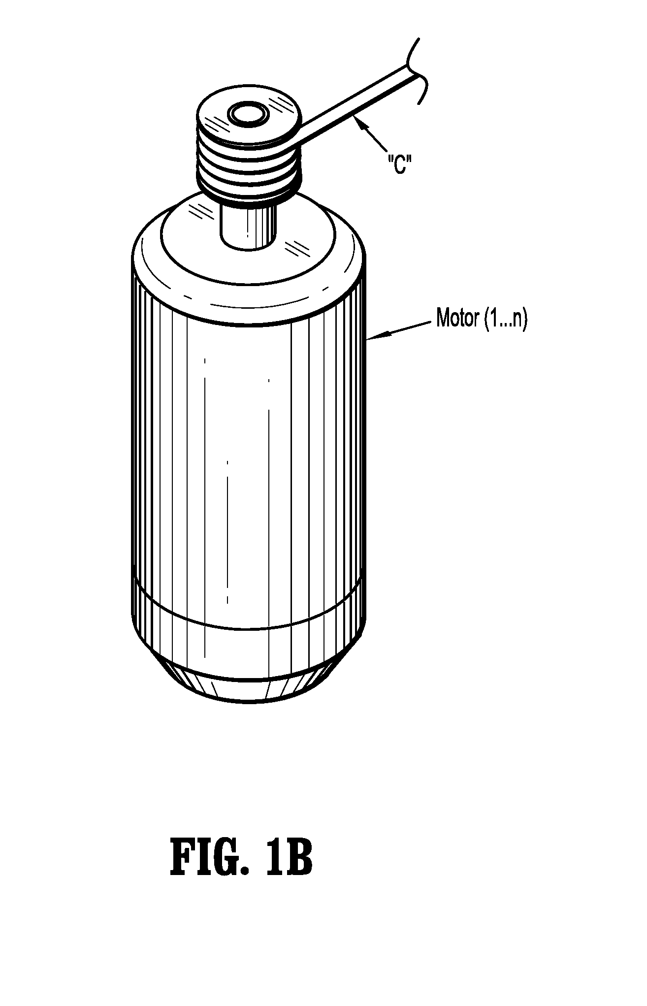
FIG. 1B is a schematic, perspective view of a motor of a control device of the medical work station of FIG. 1A;
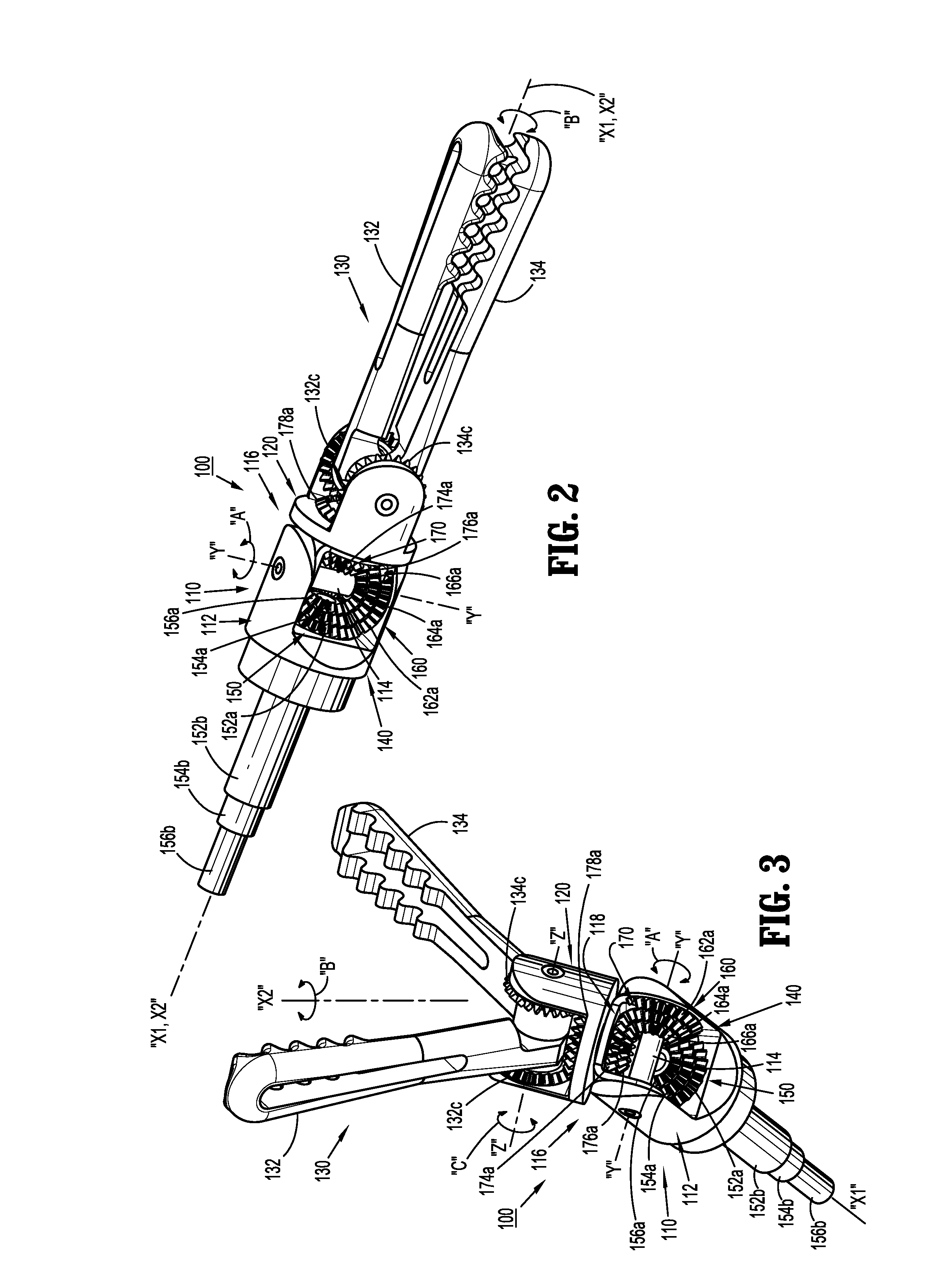
FIG. 2 is a perspective view of an end effector, according to an embodiment of the present disclosure, for use in the medical work station of FIG. 1A, illustrating a jaw assembly thereof in a non-articulated and a closed condition;
FIG. 3 is a perspective view of the end effector of FIG. 2 illustrating the jaw assembly thereof in an articulated and an open condition;
FIG. 4 is a perspective view, with parts separated, of the end effector of FIGS. 2 and 3;
FIG. 5 is a perspective view of an end effector, according to another embodiment of the present disclosure, for use in the medical work station of FIG. 1A, illustrating a jaw assembly thereof in a non-articulated and a closed condition;
FIG. 6 is a perspective view of the end effector of FIG. 5 illustrating the jaw assembly thereof in an articulated and an open condition;
FIG. 7 is a perspective view, with parts separated, of the end effector of FIGS. 5 and 6;
FIG. 8 is a perspective view of an end effector, according to another embodiment of the present disclosure, for use in the medical work station of FIG. 1A, illustrating a jaw assembly thereof in a non-articulated and a closed condition;
FIG. 9 is a perspective view of the end effector of FIG. 8 illustrating the jaw assembly thereof in an articulated and an open condition; and
FIG. 10 is a perspective view, with parts separated, of the end effector of FIGS. 8 and 9.
DETAILED DESCRIPTION
Embodiments of the presently disclosed jaw assemblies and/or wrist assemblies are described in detail with reference to the drawings, in which like reference numerals designate identical or corresponding elements in each of the several views. As used herein the term "distal" refers to that portion of the jaw assembly and/or wrist assembly, that is farther from the user, while the term "proximal" refers to that portion of the jaw assembly and/or wrist assembly that is closer to the user.
Referring initially to FIGS. 1A and 1B, a medical work station is shown generally as work station 1 and generally includes a plurality of robot arms 2, 3; a control device 4; and an operating console 5 coupled with control device 4. Operating console 5 includes a display device 6, which is set up in particular to display three-dimensional images; and manual input devices 7, 8, by means of which a person (not shown), for example a surgeon, is able to telemanipulate robot arms 2, 3 in a first operating mode, as known in principle to a person skilled in the art.
Each of the robot arms 2, 3 includes a plurality of members, which are connected through joints, and an attaching device 9, 11, to which may be attached, for example, a surgical tool "ST" supporting an end effector 100, in accordance with any one of several embodiments disclosed herein, as will be described in greater detail below.
Robot arms 2, 3 may be driven by electric drives (not shown) that are connected to control device 4. Control device 4 (e.g., a computer) is set up to activate the drives, in particular by means of a computer program, in such a way that robot arms 2, 3, their attaching devices 9, 11 and thus the surgical tool (including end effector 100) execute a desired movement according to a movement defined by means of manual input devices 7, 8. Control device 4 may also be set up in such a way that it regulates the movement of robot arms 2, 3 and/or of the drives.
Medical work station 1 is configured for use on a patient 13 lying on a patient table 12 to be treated in a minimally invasive manner by means of end effector 100. Medical work station 1 may also include more than two robot arms 2, 3, the additional robot arms likewise being connected to control device 4 and being telemanipulatable by means of operating console 5. A medical instrument or surgical tool (including an end effector 100) may also be attached to the additional robot arm.
Reference may be made to U.S. Patent Publication No. 2012/0116416, filed on Nov. 3, 2011, entitled "Medical Workstation," the entire content of which is incorporated herein by reference, for a detailed discussion of the construction and operation of medical work station 1.
Control device 4 may control a plurality of motors (Motor 1 . . . n) with each motor configured to wind-up or let out a length of a cable "C" (FIG. 1B) extending through each robot arm to end effector 100 of the surgical tool, or to rotate a gear or a drive shaft (not shown). In use, as cables "C" are wound-up and let out, cables "C", gears or drive shafts may effect operation and/or movement of each end effector of the surgical tool. It is contemplated that control device 4 coordinates the activation of the various motors (Motor 1 . . . n) to coordinate a winding-up or letting out a length of a respective cable "C" in order to coordinate an operation and/or movement of a respective end effector. Although FIG. 1B shows a single cable "C" that is wound up or let out by a single motor, in some instances two or more cables or two ends of a single cable may be wound up or let out by a single motor. For example, in some instances, two cables or cable ends may be coupled in opposite directions to a single motor so that as the motor is activated in a first direction, one of the cables winds up while the other cable lets out. Other cable configurations may be used in different embodiments.
Turning now to FIGS. 2-4, an end effector for connection to robot arms 2, 3 and for manipulation by control device 4, is generally designated as 100. End effector 100 includes a wrist assembly 110, and a jaw assembly 130 pivotally connected to wrist assembly 110. Wrist assembly 110 includes a proximal hub 112, in the form of a distally extending clevis, defining a first longitudinal axis "X1-X1." Proximal hub 112 defines a first pivot axis "Y-Y" that is oriented orthogonal to the first longitudinal axis "X1-X1." In an embodiment, first pivot axis "Y-Y" may extend through the first longitudinal axis "X1-X1." Proximal hub 112, being in the form of a clevis, includes a pair of spaced apart, opposed upright supports 112a, 112b through which first pivot axis "Y-Y" extends.
Wrist assembly 110 further includes a distal hub assembly 116 pivotally connected to upright supports 112a, 112b of proximal hub 112. Distal hub assembly 116 includes a proximal U-shaped bracket 118 having a pair of spaced apart, opposed, proximally extending, upright supports 118a, 118b interconnected by a backspan 118c. Upright supports 118a, 118b of proximal U-shaped bracket 118 are pivotally connected to respective upright supports 112a, 112b of proximal hub 112, via a pivot pin 114. Pivot pin 114 is disposed along first pivot axis "Y-Y".
Distal hub assembly 116 further includes a distal U-shaped bracket 120 having a pair of spaced apart, opposed, distally extending, upright supports 120a, 120b interconnected by a backspan 120c. Upright supports 120a, 120b of distal U-shaped bracket 120 define a second pivot axis "Z-Z" therebetween. Backspan 120c of distal U-shaped bracket 120 is pivotally connected to backspan 118c of proximal U-shaped bracket 118, about a second longitudinal axis "X2-X2." Second pivot axis "Z-Z" is oriented orthogonal to the first longitudinal axis "X1-X1." In an embodiment, when the first longitudinal axis "X1-X1" is parallel with the second longitudinal axis "X2-X2" (i.e., end effector 100 is in an axially aligned orientation), second pivot axis "Z-Z" may extend through first longitudinal axis "X1-X1."
With continued reference to FIGS. 2-4, as mentioned above, end effector 100 includes a jaw assembly 130 that is pivotally supported on a pivot pin 136 extending between upright supports 120a, 120b of distal U-shaped bracket 120 and along second pivot axis "B-B". Jaw assembly 130 includes a pair of jaws 132, 134 pivotally connected to upright supports 120a, 120b of distal U-shaped bracket 120. Specifically, each jaw 132, 134 includes a respective proximal end 132a, 134a pivotally connected to upright supports 120a, 120b of distal U-shaped bracket 120, via pivot pin 136; and a respective distal end 132b, 134b. Each distal end 132b, 134b of the pair of jaws 132, 134 defines a grip or toothed portion in juxtaposed relation to one another.
In accordance with the present disclosure and the present embodiment, end effector 100 includes a gear system 140 configured and adapted to transfer/transmit rotational forces generated by motors (Motor 1 . . . n) of control device 4 into an articulation of wrist assembly 110 along first pivot axis "Y-Y", a rotation of jaw assembly 130 along second longitudinal axis "X2-X2", and an opening/closing of jaw assembly 130.
Gear system 140 includes a first gear assembly 150 rotatably supported in proximal hub 112 of wrist assembly 110. First gear assembly 150 includes a first or outer bevel gear 152a supported on a distal end of a first or outer drive tube 152b. Outer bevel gear 152a defines a first or relatively large diameter. Outer drive tube 152b defines a lumen therethrough having a longitudinal axis that is coaxial or parallel with the first longitudinal axis "X1-X1". A proximal end of outer drive tube 152a may be acted upon, either directly or indirectly, by a respective motor (Motor 1 . . . n) of control device 4 so as to be rotated about the longitudinal axis thereof.
First gear assembly 150 also includes a second or intermediate bevel gear 154a supported on a distal end of a second or intermediate drive tube 154b. Intermediate bevel gear 154a defines a second or relatively intermediate diameter that is smaller than the diameter of outer bevel gear 152a. Intermediate drive tube 154b defines a lumen therethrough having a longitudinal axis that is coaxial or parallel with the first longitudinal axis "X1-X1". Intermediate drive tube 154b is sized and dimensioned to be rotatably disposed within the lumen of outer drive tube 152b. A proximal end of intermediate drive tube 154a may be acted upon, either directly or indirectly, by a respective motor (Motor 1 . . . n) of control device 4 so as to be rotated about the longitudinal axis thereof.
First gear assembly 150 further also includes a third or inner bevel gear 156a supported on a distal end of a third or inner drive tube 156b. Inner bevel gear 156a defines a third or relatively small diameter that is smaller than the diameter of intermediate bevel gear 154a. Inner drive tube 156b defines a lumen therethrough having a longitudinal axis that is coaxial or parallel with the first longitudinal axis "X1-X1". Inner drive tube 156b is sized and dimensioned to be rotatably disposed within the lumen of intermediate drive tube 154b. A proximal end of inner drive tube 156a may be acted upon, either directly or indirectly, by a respective motor (Motor 1 . . . n) of control device 4 so as to be rotated about the longitudinal axis thereof.
As illustrated in FIGS. 2-4, bevel gears 152a, 154a, and 156a of first gear assembly 150 are arranged in a stacked and concentric configuration, wherein intermediate bevel gear 154a is stacked or disposed distal of and concentric with outer bevel gear 152a, and inner bevel gear 156a is stacked or disposed distal of and concentric with intermediate bevel gear 154a.
Gear system 140 includes a second gear assembly 160 rotatably supported in/on proximal U-shaped bracket 118 of distal hub assembly 116, and rotatably supported on pivot pin 114. Specifically, second gear assembly 160 includes a first or outer bevel gear 162a non-rotatably supported on or integrally formed in one of upright supports 118a, 118b of proximal U-shaped bracket 118. Outer bevel gear 162a of second gear assembly 160 defines a first or relatively large diameter. Outer bevel gear 162a of second gear assembly 160 is in meshing engagement with outer bevel gear 152a of first gear assembly 150.
Second gear assembly 160 also includes a second or intermediate bevel gear 164a rotatably supported on pivot pin 114. Intermediate bevel gear 164a of second gear assembly 160 defines a second or intermediate diameter. Intermediate bevel gear 164a of second gear assembly 160 is in meshing engagement with intermediate bevel gear 154a of first gear assembly 150.
Second gear assembly 160 further includes a third or inner bevel gear 166a rotatably supported on pivot pin 114. Inner bevel gear 166a of second gear assembly 160 defines a third or small diameter. Inner bevel gear 166a of second gear assembly 160 is in meshing engagement with inner bevel gear 156a of first gear assembly 150.
Bevel gears 162a, 164a, and 166a of second gear assembly 160 are arranged in a stacked and concentric configuration, wherein intermediate bevel gear 164a is stacked or disposed atop and concentric with outer bevel gear 162a, and inner bevel gear 166a is stacked atop and concentric with intermediate bevel gear 164a.
Gear system 140 includes a third gear assembly 170 rotatably supported in/on proximal U-shaped bracket 118 of distal hub assembly 116, specifically on backspan 118c of proximal U-shaped bracket 118, between upright supports 118a, 118b. Third gear assembly 170 includes an intermediate bevel gear 174a keyed to or non-rotatably supported on a stem 120d extending from backspan 120c of distal U-shaped bracket 120 that extends through backspan 118c of proximal U-shaped bracket 118. Intermediate bevel gear 174a is axially disposed along second longitudinal axis "X2-X2". Intermediate bevel gear 174a of third gear assembly 170 defines an intermediate diameter. Intermediate bevel gear 174a of third gear assembly 170 is in meshing engagement with intermediate bevel gear 164a of second gear assembly 160.
Third gear assembly 170 further includes an inner bevel gear 176a keyed to or non-rotatably supported on a stem 178b extending from a jaw bevel gear 178a rotatably disposed between upright supports 120a, 120b of distal U-shaped bracket 120. Stem 178b extends through backspan 120c of distal U-shaped bracket 120, through backspan 118c of proximal U-shaped bracket 118, and through intermediate bevel gear 174a of third gear assembly 170. Inner bevel gear 176a is axially disposed along second longitudinal axis "X2-X2". Inner bevel gear 176a of third gear assembly 170 defines a small diameter. Inner bevel gear 176a of third gear assembly 170 is in meshing engagement with inner bevel gear 166a of second gear assembly 160.
Bevel gears 174a and 176a of third gear assembly 170 are arranged in a stacked and concentric configuration, wherein inner bevel gear 176a is stacked or disposed proximal of and concentric with intermediate bevel gear 174a.
As illustrated in FIGS. 2-4, proximal end 132a of jaw 132 defines or non-rotatably supports a bevel gear 132c, and proximal end 134a of jaw 134 defines or non-rotatably supports a bevel gear 134c. Each bevel gear 132c, 134c is in meshing engagement with jaw bevel gear 178a.
In accordance with the present disclosure, a first gear train is defined which includes outer bevel gear 152a of first gear assembly 150, and outer bevel gear 162a of second gear assembly 160. Also, a second gear train is defined which includes intermediate bevel gear 154a of first gear assembly 150, intermediate bevel gear 164a of second gear assembly 160, and intermediate bevel gear 174a of third gear assembly 170. Further, a third gear train is defined which includes inner bevel gear 156a of first gear assembly 150, inner bevel gear 166a of second gear assembly 160, inner bevel gear 176a of third gear assembly 170, jaw bevel gear 178, and bevel gears 132c, 134c of jaws 132, 134.
In operation, when the first gear train is actuated, end effector 100 is pivoted or articulated about first pivot axis "Y-Y". Specifically, in operation, rotation of outer tube 152b results in rotation of outer bevel gear 152a of first gear assembly 150, which results in rotation of outer bevel gear 162a of second gear assembly 160 to rotate proximal U-shaped bracket 118 of distal hub assembly 116 about first pivot axis "Y-Y" and thus pivot jaws 132, 134 about first pivot axis "Y-Y", as indicated by arrow "A".
Also in operation, when the second gear train is actuated, end effector 100 is rotated along second longitudinal axis "X2-X2". Specifically, in operation, rotation of intermediate tube 154b results in rotation of intermediate bevel gear 154a of first gear assembly 150, which results in rotation of intermediate bevel gear 164a of second gear assembly 160, which results in rotation of intermediate bevel gear 174a of third gear assembly 170 to rotate distal U-shaped bracket 120 of distal hub assembly 116 about second longitudinal axis "X2-X2" and thus rotate jaws 132, 134 about second longitudinal axis "X2-X2", as indicated by arrow "B".
Additionally, in operation, when the third gear train is actuated, end effector 100 actuated to open/close jaws 132, 134. Specifically, in operation, rotation of inner tube 156b results in rotation of inner bevel gear 156a of first gear assembly 150, which results in rotation of inner bevel gear 166a of second gear assembly 160, which results in rotation of inner bevel gear 176a of third gear assembly 170, which results in rotation of jaw bevel gear 178a, and which results in opposed rotations of bevel gears 132c, 134c of jaws 132, 134 about second pivot axis "Z", as indicated by arrow "C", resulting in an opening or closing of jaws 132, 134.
Turning now to FIGS. 5-7, an end effector for connection to robot arms 2, 3 and for manipulation by control device 4, in accordance with another embodiment of the present disclosure, is generally designated as 200.
End effector 200 includes a wrist assembly 210, and a jaw assembly 230 pivotally connected to wrist assembly 210. Wrist assembly 210 includes a proximal hub 212, in the form of a distally extending clevis, defining a first longitudinal axis "X1-X1." Proximal hub 212 defines a first pivot axis "Y-Y" that is oriented orthogonal to the first longitudinal axis "X1-X1." In an embodiment, first pivot axis "Y-Y" may extend through the first longitudinal axis "X1-X1." Proximal hub 212, being in the form of a clevis, includes a pair of spaced apart, opposed upright supports 212a, 212b through which first pivot axis "Y-Y" extends.
Wrist assembly 210 further includes a distal hub assembly 216 pivotally connected to upright supports 212a, 212b of proximal hub 212. Distal hub assembly 216 includes a proximal bracket 218 having a pair of spaced apart, opposed, proximally extending, upright supports 218a, 218b interconnected by a backspan 218c, and a pair of spaced apart, opposed, distally extending, upright supports 218d, 218e interconnected by backspan 218c. Proximal upright supports 218a, 218b of proximal bracket 218 are pivotally connected to respective upright supports 212a, 212b of proximal hub 212, via a first pivot pin 214a. First pivot pin 214a defines a first pivot axis "Y-Y".
Distal hub assembly 216 further includes a distal bracket 220 having a pair of spaced apart, opposed, proximally extending, upright supports 220a, 220b interconnected by a backspan 220c, and a pair of spaced apart, opposed, distally extending, upright supports 220d, 220e interconnected by backspan 220c. Proximal upright supports 220a, 220b of distal bracket 220 are pivotally connected to respective upright supports 218d, 218e of proximal bracket 218, via a second pivot pin 214b. Second pivot pin 214b defines a second pivot axis "W-W". Distal bracket 220 defines a second longitudinal axis "X2-X2." Second pivot axis "W-B" is oriented orthogonal to the first longitudinal axis "X1-X1."
With continued reference to FIGS. 5-7, as mentioned above, end effector 200 includes a jaw assembly 230 that is pivotally supported on a third pivot pin 214c extending between upright supports 220d, 220e of distal bracket 220 and along a third pivot axis "Z-Z". Jaw assembly 230 includes a pair of jaws 232, 234 pivotally connected to upright supports 220d, 220e of distal bracket 220. Specifically, each jaw 232, 234 includes a respective proximal end 232a, 234a pivotally connected to upright supports 220d, 220e of distal bracket 220, via third pivot pin 214c; and a respective distal end 232b, 234b. Each distal end 232b, 234b of the pair of jaws 232, 234 defines a grip or toothed portion in juxtaposed relation to one another.
In accordance with the present disclosure and the present embodiment, end effector 200 includes a gear system 240 (FIG. 6) configured and adapted to transfer/transmit rotational forces generated by motors (Motor 1 . . . n) of control device 4 into an articulation of wrist assembly 210 along first pivot axis "Y-Y", an articulation of wrist assembly 210 along second pivot axis "W-W", and an opening/closing of jaw assembly 230.
Gear system 240 includes a first gear assembly 250 rotatably supported in proximal hub 212 of wrist assembly 210. First gear assembly 250 includes a first or outer bevel gear 252a supported on a distal end of a first or outer drive tube 252b. Outer bevel gear 252a defines a first or relatively large diameter. Outer drive tube 252b defines a lumen therethrough having a longitudinal axis that is coaxial or parallel with the first longitudinal axis "X1-X1". A proximal end of outer drive tube 252a may be acted upon, either directly or indirectly, by a respective motor (Motor 1 . . . n) of control device 4 so as to be rotated about the longitudinal axis thereof.
First gear assembly 250 also includes a second or intermediate bevel gear 254a supported on a distal end of a second or intermediate drive tube 254b. Intermediate bevel gear 254a defines a second or relatively intermediate diameter that is smaller than the diameter of outer bevel gear 252a. Intermediate drive tube 254b defines a lumen therethrough having a longitudinal axis that is coaxial or parallel with the first longitudinal axis "X1-X1". Intermediate drive tube 254b is sized and dimensioned to be rotatably disposed within the lumen of outer drive tube 252b. A proximal end of intermediate drive tube 254a may be acted upon, either directly or indirectly, by a respective motor (Motor 1 . . . n) of control device 4 so as to be rotated about the longitudinal axis thereof.
First gear assembly 250 further also includes a third or inner bevel gear 256a supported on a distal end of a third or inner drive tube 256b. Inner bevel gear 256a defines a third or relatively small diameter that is smaller than the diameter of intermediate bevel gear 254a. Inner drive tube 256b defines a lumen therethrough having a longitudinal axis that is coaxial or parallel with the first longitudinal axis "X1-X1". Inner drive tube 256b is sized and dimensioned to be rotatably disposed within the lumen of intermediate drive tube 254b. A proximal end of inner drive tube 256a may be acted upon, either directly or indirectly, by a respective motor (Motor 1 . . . n) of control device 4 so as to be rotated about the longitudinal axis thereof.
As illustrated in FIGS. 5-7, bevel gears 252a, 254a, and 256a of first gear assembly 250 are arranged in a stacked and concentric configuration, wherein intermediate bevel gear 254a is stacked or disposed distal of and concentric with outer bevel gear 252a, and inner bevel gear 256a is stacked or disposed distal of and concentric with intermediate bevel gear 254a.
Gear system 240 includes a second gear assembly 260 rotatably supported in/on proximal bracket 218 of distal hub assembly 216, and rotatably supported on first pivot pin 214a. Specifically, second gear assembly 260 includes a first or outer bevel gear 262a non-rotatably supported on or integrally formed in one of proximal upright supports 218a, 218b of proximal bracket 218. Outer bevel gear 262a of second gear assembly 260 defines a first or relatively large diameter. Outer bevel gear 262a of second gear assembly 260 is in meshing engagement with outer bevel gear 252a of first gear assembly 250.
Second gear assembly 260 also includes a second or intermediate bevel gear 264a rotatably supported on first pivot pin 214a. Intermediate bevel gear 264a of second gear assembly 260 defines a second or intermediate diameter. Intermediate bevel gear 264a of second gear assembly 260 is in meshing engagement with intermediate bevel gear 254a of first gear assembly 250.
Second gear assembly 260 further includes a third or inner bevel gear 266a rotatably supported on first pivot pin 214a. Inner bevel gear 266a of second gear assembly 260 defines a third or small diameter. Inner bevel gear 266a of second gear assembly 260 is in meshing engagement with inner bevel gear 256a of first gear assembly 250.
Bevel gears 262a, 264a, and 266a of second gear assembly 260 are arranged in a stacked and concentric configuration, wherein intermediate bevel gear 264a is stacked or disposed atop and concentric with outer bevel gear 262a, and inner bevel gear 266a is stacked atop and concentric with intermediate bevel gear 264a.
Gear system 240 includes a third gear assembly 270 rotatably supported in/on proximal bracket 218 of distal hub assembly 216, specifically on backspan 218c of proximal bracket 218, between upright supports 218a, 218b and between upright supports 218d, 218e. Third gear assembly 270 includes a proximal intermediate bevel gear 274a keyed to or non-rotatably supported on a stem 274c, that extends through backspan 218c, and which non-rotatably supports a distal intermediate bevel gear 274b.
Proximal and distal intermediate bevel gears 274a, 274b are axially disposed along second longitudinal axis "X2-X2". Proximal and distal intermediate bevel gears 274a, 274b of third gear assembly 270 each define an intermediate diameter. Proximal intermediate bevel gear 274a of third gear assembly 270 is in meshing engagement with intermediate bevel gear 264a of second gear assembly 260.
Third gear assembly 270 further includes a proximal inner bevel gear 276a keyed to or non-rotatably supported on a stem 276c, that extends through stem 274c and through backspan 218c, and which non-rotatably supports a distal inner bevel gear 276b. Proximal and distal inner bevel gears 276a, 276b are axially disposed along second longitudinal axis "X2-X2". Proximal and distal inner bevel gears 276a, 276b of third gear assembly 270 each define a small diameter. Proximal inner bevel gear 276a of third gear assembly 270 is in meshing engagement with inner bevel gear 266a of second gear assembly 260.
Proximal bevel gears 274a and 276a of third gear assembly 270 are arranged in a stacked and concentric configuration, wherein proximal inner bevel gear 276a is stacked or disposed proximal of and concentric with proximal intermediate bevel gear 274a, and wherein distal inner bevel gear 276b is stacked or disposed distal of and concentric with distal intermediate bevel gear 274b.
Gear system 240 additionally includes a fourth gear assembly 280 rotatably supported in/on proximal bracket 218 of distal hub assembly 216, and rotatably supported on second pivot pin 214b. Specifically, fourth gear assembly 280 includes an intermediate bevel gear 284a rotatably supported on second pivot pin 214b, between distal upright supports 218d, 218e of proximal bracket 218. Specifically, intermediate bevel gear 284a of fourth gear assembly 280 is non-rotatably connected to one of distal upright supports 218d, 218e of proximal bracket 218 or is integrally formed therewith. Intermediate bevel gear 284a of fourth gear assembly 280 defines an intermediate diameter. Intermediate bevel gear 284a of fourth gear assembly 280 is in meshing engagement with distal intermediate bevel gear 274b of third gear assembly 270.
Fourth gear assembly 280 further includes an inner bevel gear 286a rotatably supported on second pivot pin 214b. Inner bevel gear 286a of fourth gear assembly 280 defines a small diameter. Inner bevel gear 286a of fourth gear assembly 280 is in meshing engagement with inner bevel gear 276b of third gear assembly 270.
Bevel gears 284a and 286a of fourth gear assembly 280 are arranged in a stacked and concentric configuration, wherein inner bevel gear 286a is stacked atop and concentric with intermediate bevel gear 284a.
Gear system 240 includes a fifth gear assembly 290 rotatably supported in/on distal bracket 220 of distal hub assembly 216, specifically on backspan 220c of distal bracket 220, between upright supports 220a, 220b and between upright supports 220d, 220e. Fifth gear assembly 290 includes a proximal inner bevel gear 296a keyed to or non-rotatably supported on a stem 296c, that extends through backspan 220c, and which non-rotatably supports a distal inner bevel gear 296b that is disposed distal of backspan 220c of distal bracket 220. Proximal and distal inner bevel gears 296a, 296b are axially disposed along second longitudinal axis "X2-X2". Proximal and distal inner bevel gears 296a, 296b of fifth gear assembly 290 each define a small diameter. Proximal inner bevel gear 296a of fifth gear assembly 290 is in meshing engagement with inner bevel gear 286a of fourth gear assembly 280.
As illustrated in FIGS. 5-7, proximal end 232a of jaw 232 defines or non-rotatably supports a bevel gear 232c, and proximal end 234a of jaw 234 defines or non-rotatably supports a bevel gear 234c. Each bevel gear 232c, 234c is in meshing engagement with distal inner bevel gear 296b of fifth gear assembly 290.
In accordance with the present disclosure, a first gear train is defined which includes outer bevel gear 252a of first gear assembly 250, and outer bevel gear 262a of second gear assembly 260. Also, a second gear train is defined which includes intermediate bevel gear 254a of first gear assembly 250, intermediate bevel gear 264a of second gear assembly 260, intermediate proximal bevel gear 274a and intermediate distal bevel gear 274b of third gear assembly 270, and intermediate bevel gear 284a of fourth gear assembly 280. Further, a third gear train is defined which includes inner bevel gear 256a of first gear assembly 250, inner bevel gear 266a of second gear assembly 260, inner proximal bevel gear 276a and inner distal bevel gear 276b of third gear assembly 270, inner bevel gear 286a of fourth gear assembly 280, inner proximal bevel gear 296a and inner distal bevel gear 296b of fifth gear assembly 290, and bevel gears 232c, 234c of jaws 232, 234.
In operation, when the first gear train is actuated, end effector 200 is pivoted or articulated about first pivot axis "Y-Y". Specifically, in operation, rotation of outer tube 252b results in rotation of outer bevel gear 252a of first gear assembly 250, which results in rotation of outer bevel gear 262a of second gear assembly 260 to rotate proximal bracket 218 of distal hub assembly 216 about first pivot axis "Y-Y" and thus pivot jaws 232, 234 about first pivot axis "Y-Y", as indicated by arrow "A".
Also in operation, when the second gear train is actuated, end effector 200 is pivoted or articulated about second pivot axis "W-W". Specifically, in operation, rotation of intermediate tube 254b results in rotation of intermediate bevel gear 254a of first gear assembly 250, which results in rotation of intermediate bevel gear 264a of second gear assembly 260, which results in rotation of intermediate proximal bevel gear 274a and distal bevel gear 274b of third gear assembly 270, which results in rotation of intermediate bevel gear 284a of fourth gear assembly 280 to rotate distal bracket 220 of distal hub assembly 216 about second pivot axis "W-W" and thus rotate jaws 232, 234 about second pivot axis "W-W", as indicated by arrow "B".
Additionally, in operation, when the third gear train is actuated, end effector 200 actuated to open/close jaws 232, 234. Specifically, in operation, rotation of inner tube 256b results in rotation of inner bevel gear 256a of first gear assembly 250, which results in rotation of inner bevel gear 266a of second gear assembly 260, which results in rotation of inner proximal bevel gear 276a and inner distal bevel gear 276b of third gear assembly 270, which results in rotation of inner bevel gear 286a of fourth gear assembly 280, which results in rotation of inner proximal bevel gear 296a and distal bevel gear 296b of fifth gear assembly 290, and which results in opposed rotations of bevel gears 232c, 234c of jaws 232, 234 about third pivot axis "Z", as indicated by arrow "C", resulting in an opening or closing of jaws 232, 234.
Turning now to FIGS. 8-10, an end effector for connection to robot arms 2, 3 and for manipulation by control device 4, in accordance with another embodiment of the present disclosure, is generally designated as 300. End effector 300 includes a wrist assembly 310, and a jaw assembly 330 pivotally connected to wrist assembly 310. Wrist assembly 310 includes a proximal hub 312, in the form of a distally extending clevis, defining a first longitudinal axis "X1-X1." Proximal hub 312 defines a first pivot axis "Y-Y" that is oriented orthogonal to the first longitudinal axis "X1-X1." In an embodiment, first pivot axis "Y-Y" may extend through the first longitudinal axis "X1-X1." Proximal hub 312, being in the form of a clevis, includes a pair of spaced apart, opposed upright supports 312a, 312b through which first pivot axis "Y-Y" extends.
Wrist assembly 310 further includes a distal hub assembly 316 pivotally connected to upright supports 312a, 312b of proximal hub 312. Distal hub assembly 316 includes a proximal U-shaped bracket 318 having a pair of spaced apart, opposed, proximally extending, upright supports 318a, 318b interconnected by a backspan 318c. Upright supports 318a, 318b of proximal U-shaped bracket 318 are pivotally connected to respective upright supports 312a, 312b of proximal hub 312, via a pivot pin (not shown) disposed along first pivot axis "Y-Y".
Distal hub assembly 316 further includes a distal U-shaped bracket 320 having a pair of spaced apart, opposed, distally extending, upright supports 320a, 320b interconnected by a backspan 320c. Upright supports 320a, 320b of distal U-shaped bracket 320 define a second pivot axis "Z-Z" therebetween. Backspan 320c of distal U-shaped bracket 320 is pivotally connected to backspan 318c of proximal U-shaped bracket 318, about a second longitudinal axis "X2-X2." Second pivot axis "Z-Z" is oriented orthogonal to the first longitudinal axis "X1-X1."
With continued reference to FIGS. 8-10, as mentioned above, end effector 300 includes a jaw assembly 330 that is pivotally supported on a pivot pin 336 extending between upright supports 320a, 320b of distal U-shaped bracket 320 and along second pivot axis "B-B". Jaw assembly 330 includes a pair of jaws 332, 334 pivotally connected to upright supports 320a, 320b of distal U-shaped bracket 320. Specifically, each jaw 332, 334 includes a respective proximal end 332a, 334a pivotally connected to upright supports 320a, 320b of distal U-shaped bracket 320, via pivot pin 336; and a respective distal end 332b, 334b. Each distal end 332b, 334b of the pair of jaws 332, 334 defines a grip or toothed portion in juxtaposed relation to one another.
In accordance with the present disclosure and the present embodiment, end effector 300 includes a gear system 340 configured and adapted to transfer/transmit rotational forces generated by motors (Motor 1 . . . n) of control device 4 into an articulation of wrist assembly 310 along first pivot axis "Y-Y", a rotation of jaw assembly 330 along second longitudinal axis "X2-X2", and an opening/closing of jaw assembly 330.
Gear system 340 includes a bevel gear 352a supported on a distal end of an outer drive tube 352b. Outer drive tube 352b defines a lumen therethrough having a longitudinal axis that is coaxial or parallel with the first longitudinal axis "X1-X1". A proximal end of outer drive tube 352a may be acted upon, either directly or indirectly, by a respective motor (Motor 1 . . . n) of control device 4 so as to be rotated about the longitudinal axis thereof.
Gear system 340 further includes a first bevel gear 362a rotatably supported on upright support 318a of proximal U-shaped bracket 318, and a second bevel gear 362b rotatably supported on one of upright supports 318b of proximal U-shaped bracket 318. First and second bevel gears 362a, 362b are in meshing engagement with bevel gear 352a.
Gear system 340 also includes a first bevel gear 372a keyed to or non-rotatably supported on a stem 372c extending a second bevel gear 372b, wherein stem 372c extends through backspan 320c of distal U-shaped bracket 320 and through backspan 318c of proximal U-shaped bracket 318. First and second bevel gears 372a, 372b are axially disposed along second longitudinal axis "X2-X2". First bevel gear 372a is in meshing engagement with first and second bevel gears 362a, 362b.
As illustrated in FIGS. 8-10, proximal end 332a of jaw 332 defines or non-rotatably supports a bevel gear 332c, and proximal end 334a of jaw 334 defines or non-rotatably supports a bevel gear 334c. Each bevel gear 332c, 334c is in meshing engagement with second bevel gear 372b.
In accordance with the present disclosure, a gear train is defined which includes bevel gear 352a, and first and second bevel gears 362a, 362b, first and second bevel gears 372a, 372b, and bevel gears 332c, 334c of jaws 332, 334. In operation, when the gear train of end effector 300 is actuated, end effector 300 actuated to open/close jaws 332, 334. Specifically, in operation, rotation of tube 352b results in rotation of bevel gear 352a, which results in rotation of first and second bevel gears 362a, 362b, which results in rotation of first and second bevel gears 372a, 372b, which results in opposed rotations of bevel gears 332c, 334c of jaws 332, 334 about second pivot axis "Z", as indicated by arrow "C", resulting in an opening or closing of jaws 332, 334.
While bevel gears have been shown and described for incorporation into the end effectors herein described, it is contemplated and within the scope of the present disclosure that other types of gears may be used, individually or in combination with one another, such as, for example, spur gears, crown gears, worm gears, sprockets, and the like.
With reference to FIGS. 8-10, a single first cable 322 is at least partially wrapped around a cam plate or spool 326 and secured to at least one point thereof, or that the single first cable 322 may be wrapped at least once around spool 326, in the manner of a capistan. Single first cable 322 may include proximal ends that extend through robot arm 2 or 3 and operatively associated with a respective first motor and second motor (not shown) of control device 4. While a single first cable 322 is shown and described, it is contemplated that a first pair of cables (not shown) including respective distal ends may be secured to opposed sides of spool 326, or wrapped at least 180.degree. around spool 326 and secured thereto, and including respective proximal ends extending through robot arm 2 or 3 and operatively associated with a respective first motor and second motor (not shown) of control device 4.
A single second cable 324 is at least partially wrapped around spool 326 and secured to at least one point thereof, or that the single second cable 324 may be wrapped at least once around spool 326, in the manner of a capistan. Single second cable 324 may include proximal ends that extend through robot arm 2 or 3 and operatively associated with a respective first motor and second motor (not shown) of control device 4. While a single second cable 324 is shown and described, it is contemplated that a first pair of cables (not shown) including respective distal ends may be secured to opposed sides of spool 326, or wrapped at least 180.degree. around spool 326 and secured thereto, and including respective proximal ends extending through robot arm 2 or 3 and operatively associated with a respective first motor and second motor (not shown) of control device 4.
Spool 326 is rotatably supported along first pivot axis "Y-Y" and between upright supports 312a, 312b of proximal hub 312.
In operation, as one proximal end of first cable 322 or second cable 324 is drawn in by a corresponding motor, an other opposite end of first cable 322 or second cable 324 is let out. In so doing, jaw assembly 330 may be pivoted about first pivot axis "Y-Y", in the direction of arrow "A".
In accordance with the present disclosure, end effectors that are compact in design, and yet may transmit relatively large forces or achieve a relatively large range of motion of pivoting and rotation, are contemplated and described. The gear trains disclosed herein enable transmission of relatively high loads, and may be accomplished with tight tolerances. Additionally, relatively high precision of control of movement of the end effectors is achieved.
It will be understood that various modifications may be made to the embodiments disclosed herein. For example, while the cam pulleys disclosed herein have been shown and described as being connected to the proximal ends of the jaws, it is contemplated and within the scope of the present disclosure, for the cam pulley to be operatively connected with the distal portion of the jaws. Therefore, the above description should not be construed as limiting, but merely as exemplifications of various embodiments. Those skilled in the art will envision other modifications within the scope and spirit of the claims appended thereto.
* * * * *
D00000
D00001
D00002
D00003
D00004
D00005
D00006
D00007
D00008
XML
uspto.report is an independent third-party trademark research tool that is not affiliated, endorsed, or sponsored by the United States Patent and Trademark Office (USPTO) or any other governmental organization. The information provided by uspto.report is based on publicly available data at the time of writing and is intended for informational purposes only.
While we strive to provide accurate and up-to-date information, we do not guarantee the accuracy, completeness, reliability, or suitability of the information displayed on this site. The use of this site is at your own risk. Any reliance you place on such information is therefore strictly at your own risk.
All official trademark data, including owner information, should be verified by visiting the official USPTO website at www.uspto.gov. This site is not intended to replace professional legal advice and should not be used as a substitute for consulting with a legal professional who is knowledgeable about trademark law.