Interchangeable surgical tool assembly with a surgical end effector that is selectively rotatable about a shaft axis
Shelton, IV , et al. Sept
U.S. patent number 10,413,293 [Application Number 15/089,296] was granted by the patent office on 2019-09-17 for interchangeable surgical tool assembly with a surgical end effector that is selectively rotatable about a shaft axis. This patent grant is currently assigned to Ethicon LLC. The grantee listed for this patent is Ethicon Endo-Surgery, LLC. Invention is credited to Jason L. Harris, Adam D. Hensel, Frederick E. Shelton, IV.


View All Diagrams
| United States Patent | 10,413,293 |
| Shelton, IV , et al. | September 17, 2019 |
Interchangeable surgical tool assembly with a surgical end effector that is selectively rotatable about a shaft axis
Abstract
A surgical instrument is disclosed. In one form, the surgical instrument comprises an elongate shaft assembly and an end effector that is configured for selective rotation relative to the axis of the elongate shaft assembly. The surgical instrument can include a rotary locking system for locking the surgical end effector in rotary orientations about the shaft axis upon application of axial locking and axial unlocking motions to the rotary locking system. The surgical instrument may further comprise a rotary drive system that is configured to apply rotary control motions to a firing member as well as to apply rotary positioning motions to the surgical end effector.
| Inventors: | Shelton, IV; Frederick E. (Hillsboro, OH), Harris; Jason L. (Lebanon, OH), Hensel; Adam D. (Cincinnati, OH) | ||||||||||
|---|---|---|---|---|---|---|---|---|---|---|---|
| Applicant: |
|
||||||||||
| Assignee: | Ethicon LLC (Guaynabo,
PR) |
||||||||||
| Family ID: | 62235074 | ||||||||||
| Appl. No.: | 15/089,296 | ||||||||||
| Filed: | April 1, 2016 |
Prior Publication Data
| Document Identifier | Publication Date | |
|---|---|---|
| US 20170281168 A1 | Oct 5, 2017 | |
| Current U.S. Class: | 1/1 |
| Current CPC Class: | A61B 17/07207 (20130101); A61B 17/072 (20130101); A61B 17/0686 (20130101); A61B 2017/291 (20130101); A61B 2017/00734 (20130101); A61B 2017/2927 (20130101); A61B 2017/2912 (20130101); A61B 2017/00123 (20130101); A61B 2017/0042 (20130101); A61B 2017/00464 (20130101); A61B 2017/07271 (20130101); A61B 2017/2925 (20130101); A61B 2017/2932 (20130101); A61B 2017/00017 (20130101); A61B 2017/07278 (20130101); A61B 2090/034 (20160201); A61B 2017/00398 (20130101); A61B 2017/0046 (20130101); A61B 2017/2922 (20130101); A61B 2017/2929 (20130101); A61B 2017/2923 (20130101); A61B 2017/293 (20130101); A61B 2017/07228 (20130101); A61B 2017/07257 (20130101); A61B 2017/00407 (20130101); A61B 2017/00424 (20130101); A61B 2017/07285 (20130101); A61B 2017/00115 (20130101); A61B 2017/00367 (20130101) |
| Current International Class: | A61B 17/072 (20060101); A61B 17/068 (20060101); A61B 17/00 (20060101); A61B 17/29 (20060101); A61B 90/00 (20160101) |
| Field of Search: | ;227/175.1,174.1 |
References Cited [Referenced By]
U.S. Patent Documents
| 2224882 | December 1940 | Peck |
| 2742955 | April 1956 | Dominguez |
| 2853074 | September 1958 | Olson |
| 3080564 | March 1963 | Strekopitov et al. |
| 3166072 | January 1965 | Sullivan, Jr. |
| 3266494 | August 1966 | Brownrigg et al. |
| 3359978 | December 1967 | Smith, Jr. |
| 3490675 | January 1970 | Green et al. |
| 3494533 | February 1970 | Green et al. |
| 3551987 | January 1971 | Wilkinson |
| 3643851 | February 1972 | Green et al. |
| 3662939 | May 1972 | Bryan |
| 3717294 | February 1973 | Green |
| 3744495 | July 1973 | Johnson |
| 3746002 | July 1973 | Haller |
| 3819100 | June 1974 | Noiles et al. |
| 3863639 | February 1975 | Kleaveland |
| RE28932 | August 1976 | Noiles et al. |
| 4111206 | September 1978 | Vishnevsky et al. |
| 4190042 | February 1980 | Sinnreich |
| 4198982 | April 1980 | Fortner et al. |
| 4207898 | June 1980 | Becht |
| 4272002 | June 1981 | Moshofsky |
| 4274398 | June 1981 | Scott, Jr. |
| 4304236 | December 1981 | Conta et al. |
| 4331277 | May 1982 | Green |
| 4383634 | May 1983 | Green |
| 4396139 | August 1983 | Hall et al. |
| 4402445 | September 1983 | Green |
| 4408692 | October 1983 | Sigel et al. |
| 4415112 | November 1983 | Green |
| 4417890 | November 1983 | Dennehey et al. |
| 4429695 | February 1984 | Green |
| 4473077 | September 1984 | Noiles et al. |
| 4475679 | October 1984 | Fleury, Jr. |
| 4489875 | December 1984 | Crawford et al. |
| 4500024 | February 1985 | DiGiovanni et al. |
| 4505272 | March 1985 | Utyamyshev et al. |
| 4505273 | March 1985 | Braun et al. |
| 4505414 | March 1985 | Filipi |
| 4506671 | March 1985 | Green |
| 4522327 | June 1985 | Korthoff et al. |
| 4527724 | July 1985 | Chow et al. |
| 4530453 | July 1985 | Green |
| 4566620 | January 1986 | Green et al. |
| 4573468 | March 1986 | Conta et al. |
| 4573622 | March 1986 | Green et al. |
| 4580712 | April 1986 | Green |
| 4585153 | April 1986 | Failla et al. |
| 4605004 | August 1986 | Di Giovanni et al. |
| 4610383 | September 1986 | Rothfuss et al. |
| 4619262 | October 1986 | Taylor |
| 4619391 | October 1986 | Sharkany et al. |
| 4629107 | December 1986 | Fedotov et al. |
| 4632290 | December 1986 | Green et al. |
| 4654028 | March 1987 | Suma |
| 4655222 | April 1987 | Florez et al. |
| 4662555 | May 1987 | Thornton |
| 4664305 | May 1987 | Blake, III et al. |
| 4669647 | June 1987 | Storace |
| 4671445 | June 1987 | Barker et al. |
| 4684051 | August 1987 | Akopov et al. |
| 4700703 | October 1987 | Resnick et al. |
| 4715520 | December 1987 | Roehr, Jr. et al. |
| 4728020 | March 1988 | Green et al. |
| 4744363 | May 1988 | Hasson |
| 4752024 | June 1988 | Green et al. |
| 4754909 | July 1988 | Barker et al. |
| 4767044 | August 1988 | Green |
| 4773420 | September 1988 | Green |
| 4805823 | February 1989 | Rothfuss |
| 4809695 | March 1989 | Gwathmey et al. |
| 4817847 | April 1989 | Redtenbacher et al. |
| 4819853 | April 1989 | Green |
| 4821939 | April 1989 | Green |
| 4844068 | July 1989 | Arata et al. |
| 4848637 | July 1989 | Pruitt |
| 4869414 | September 1989 | Green et al. |
| 4869415 | September 1989 | Fox |
| 4873977 | October 1989 | Avant et al. |
| 4893622 | January 1990 | Green et al. |
| 4903697 | February 1990 | Resnick et al. |
| 4909789 | March 1990 | Taguchi et al. |
| 4921479 | May 1990 | Grayzel |
| 4930674 | June 1990 | Barak |
| 4941623 | July 1990 | Pruitt |
| 4944443 | July 1990 | Oddsen et al. |
| 4973302 | November 1990 | Armour et al. |
| 4984564 | January 1991 | Yuen |
| 5002553 | March 1991 | Shiber |
| 5014899 | May 1991 | Presty et al. |
| 5027834 | July 1991 | Pruitt |
| 5065929 | November 1991 | Schulze et al. |
| 5071430 | December 1991 | de Salis et al. |
| 5074454 | December 1991 | Peters |
| 5080088 | January 1992 | LeVahn |
| 5082005 | January 1992 | Kaldany |
| 5084057 | January 1992 | Green et al. |
| 5104025 | April 1992 | Main et al. |
| 5104397 | April 1992 | Vasconcelos et al. |
| 5108368 | April 1992 | Hammerslag et al. |
| 5116349 | May 1992 | Aranyi |
| 5119983 | June 1992 | Green et al. |
| 5122156 | June 1992 | Granger et al. |
| 5129570 | July 1992 | Schulze et al. |
| 5137198 | August 1992 | Nobis et al. |
| 5139513 | August 1992 | Segato |
| 5141144 | August 1992 | Foslien et al. |
| 5156609 | October 1992 | Nakao et al. |
| 5158567 | October 1992 | Green |
| 5171247 | December 1992 | Hughett et al. |
| 5171249 | December 1992 | Stefanchik et al. |
| 5195505 | March 1993 | Josefsen |
| 5197649 | March 1993 | Bessler et al. |
| 5205459 | April 1993 | Brinkerhoff et al. |
| 5211649 | May 1993 | Kohler et al. |
| 5211655 | May 1993 | Hasson |
| 5221036 | June 1993 | Takase |
| 5222945 | June 1993 | Basnight |
| 5222963 | June 1993 | Brinkerhoff et al. |
| 5222975 | June 1993 | Crainich |
| 5234447 | August 1993 | Kaster et al. |
| 5236440 | August 1993 | Hlavacek |
| 5239981 | August 1993 | Anapliotis |
| 5258009 | November 1993 | Conners |
| 5263937 | November 1993 | Shipp |
| 5271543 | December 1993 | Grant et al. |
| 5275322 | January 1994 | Brinkerhoff et al. |
| 5282806 | February 1994 | Haber et al. |
| 5282829 | February 1994 | Hermes |
| 5285945 | February 1994 | Brinkerhoff et al. |
| 5304204 | April 1994 | Bregen |
| 5309896 | May 1994 | Moll et al. |
| 5309927 | May 1994 | Welch |
| 5312023 | May 1994 | Green et al. |
| 5314445 | May 1994 | Heidmueller nee Degwitz et al. |
| 5330502 | July 1994 | Hassler et al. |
| 5333772 | August 1994 | Rothfuss et al. |
| 5336232 | August 1994 | Green et al. |
| 5342385 | August 1994 | Norelli et al. |
| 5342395 | August 1994 | Jarrett et al. |
| 5342396 | August 1994 | Cook |
| 5346115 | September 1994 | Perouse et al. |
| 5350400 | September 1994 | Esposito et al. |
| 5354250 | October 1994 | Christensen |
| 5354303 | October 1994 | Spaeth et al. |
| 5358506 | October 1994 | Green et al. |
| 5366479 | November 1994 | McGarry et al. |
| 5374277 | December 1994 | Hassler |
| 5375588 | December 1994 | Yoon |
| 5383880 | January 1995 | Hooven |
| 5383888 | January 1995 | Zvenyatsky et al. |
| 5383895 | January 1995 | Holmes et al. |
| 5391180 | February 1995 | Tovey et al. |
| 5395030 | March 1995 | Kuramoto et al. |
| 5395033 | March 1995 | Byrne et al. |
| 5395384 | March 1995 | Duthoit et al. |
| 5397324 | March 1995 | Carroll et al. |
| 5403312 | April 1995 | Yates et al. |
| 5404870 | April 1995 | Brinkerhoff et al. |
| 5405072 | April 1995 | Zlock et al. |
| 5405073 | April 1995 | Porter |
| 5405344 | April 1995 | Williamson et al. |
| 5405360 | April 1995 | Tovey |
| 5411508 | May 1995 | Bessler et al. |
| 5413272 | May 1995 | Green et al. |
| 5413573 | May 1995 | Koivukangas |
| 5415334 | May 1995 | Williamson et al. |
| 5417361 | May 1995 | Williamson, IV |
| 5419766 | May 1995 | Chang et al. |
| 5425745 | June 1995 | Green et al. |
| 5433721 | July 1995 | Hooven et al. |
| 5441494 | August 1995 | Ortiz |
| 5445644 | August 1995 | Pietrafitta et al. |
| 5449365 | September 1995 | Green et al. |
| 5452837 | September 1995 | Williamson, IV et al. |
| 5465894 | November 1995 | Clark et al. |
| 5474057 | December 1995 | Makower et al. |
| 5474566 | December 1995 | Alesi et al. |
| 5476479 | December 1995 | Green et al. |
| 5478354 | December 1995 | Tovey et al. |
| 5480089 | January 1996 | Blewett |
| 5480409 | January 1996 | Riza |
| 5482197 | January 1996 | Green et al. |
| 5483952 | January 1996 | Aranyi |
| 5484095 | January 1996 | Green et al. |
| 5484451 | January 1996 | Akopov et al. |
| 5485947 | January 1996 | Olson et al. |
| 5485952 | January 1996 | Fontayne |
| 5487499 | January 1996 | Sorrentino et al. |
| 5487500 | January 1996 | Knodel et al. |
| 5489058 | February 1996 | Plyley et al. |
| 5490819 | February 1996 | Nicholas et al. |
| 5497933 | March 1996 | DeFonzo et al. |
| 5503320 | April 1996 | Webster et al. |
| 5503635 | April 1996 | Sauer et al. |
| 5505363 | April 1996 | Green et al. |
| 5507426 | April 1996 | Young et al. |
| 5509596 | April 1996 | Green et al. |
| 5511564 | April 1996 | Wilk |
| 5514157 | May 1996 | Nicholas et al. |
| 5518163 | May 1996 | Hooven |
| 5518164 | May 1996 | Hooven |
| 5520609 | May 1996 | Moll et al. |
| 5520678 | May 1996 | Heckele et al. |
| 5520700 | May 1996 | Beyar et al. |
| 5527264 | June 1996 | Moll et al. |
| 5529235 | June 1996 | Boiarski et al. |
| 5531856 | July 1996 | Moll et al. |
| 5533661 | July 1996 | Main et al. |
| 5535934 | July 1996 | Boiarski et al. |
| 5535935 | July 1996 | Vidal et al. |
| 5535937 | July 1996 | Boiarski et al. |
| 5540375 | July 1996 | Bolanos et al. |
| 5542594 | August 1996 | McKean et al. |
| 5547117 | August 1996 | Hamblin et al. |
| 5549621 | August 1996 | Bessler et al. |
| 5549637 | August 1996 | Crainich |
| 5551622 | September 1996 | Yoon |
| 5553765 | September 1996 | Knodel et al. |
| 5554169 | September 1996 | Green et al. |
| 5556416 | September 1996 | Clark et al. |
| 5558665 | September 1996 | Kieturakis |
| 5560530 | October 1996 | Bolanos et al. |
| 5560532 | October 1996 | DeFonzo et al. |
| 5562239 | October 1996 | Boiarski et al. |
| 5562241 | October 1996 | Knodel et al. |
| 5562682 | October 1996 | Oberlin et al. |
| 5562690 | October 1996 | Green et al. |
| 5562701 | October 1996 | Huitema et al. |
| 5562702 | October 1996 | Huitema et al. |
| 5564615 | October 1996 | Bishop et al. |
| 5571116 | November 1996 | Bolanos et al. |
| 5571285 | November 1996 | Chow et al. |
| 5575799 | November 1996 | Bolanos et al. |
| 5575803 | November 1996 | Cooper et al. |
| 5575805 | November 1996 | Li |
| 5577654 | November 1996 | Bishop |
| 5579978 | December 1996 | Green et al. |
| 5580067 | December 1996 | Hamblin et al. |
| 5584425 | December 1996 | Savage et al. |
| 5586711 | December 1996 | Plyley et al. |
| 5588579 | December 1996 | Schnut et al. |
| 5588580 | December 1996 | Paul et al. |
| 5588581 | December 1996 | Conlon et al. |
| 5597107 | January 1997 | Knodel et al. |
| 5601224 | February 1997 | Bishop et al. |
| 5603443 | February 1997 | Clark et al. |
| 5605272 | February 1997 | Witt et al. |
| 5605273 | February 1997 | Hamblin et al. |
| 5607094 | March 1997 | Clark et al. |
| 5607095 | March 1997 | Smith et al. |
| 5607450 | March 1997 | Zvenyatsky et al. |
| 5609285 | March 1997 | Grant et al. |
| 5613937 | March 1997 | Garrison et al. |
| 5615820 | April 1997 | Viola |
| 5618303 | April 1997 | Marlow et al. |
| 5618307 | April 1997 | Donlon et al. |
| 5620452 | April 1997 | Yoon |
| 5624452 | April 1997 | Yates |
| 5628446 | May 1997 | Geiste et al. |
| 5628743 | May 1997 | Cimino |
| 5630539 | May 1997 | Plyley et al. |
| 5630540 | May 1997 | Blewett |
| 5632432 | May 1997 | Schulze et al. |
| 5632433 | May 1997 | Grant et al. |
| 5634584 | June 1997 | Okorocha et al. |
| 5636779 | June 1997 | Palmer |
| 5636780 | June 1997 | Green et al. |
| 5639008 | June 1997 | Gallagher et al. |
| 5645209 | July 1997 | Green et al. |
| 5647526 | July 1997 | Green et al. |
| 5649937 | July 1997 | Bito et al. |
| 5651491 | July 1997 | Heaton et al. |
| 5651762 | July 1997 | Bridges |
| 5653373 | August 1997 | Green et al. |
| 5653374 | August 1997 | Young et al. |
| 5653721 | August 1997 | Knodel et al. |
| 5655698 | August 1997 | Yoon |
| 5657921 | August 1997 | Young et al. |
| 5662258 | September 1997 | Knodel et al. |
| 5662260 | September 1997 | Yoon |
| 5667517 | September 1997 | Hooven |
| 5667526 | September 1997 | Levin |
| 5667527 | September 1997 | Cook |
| 5669544 | September 1997 | Schulze et al. |
| 5669918 | September 1997 | Balazs et al. |
| 5673840 | October 1997 | Schulze et al. |
| 5673841 | October 1997 | Schulze et al. |
| 5680981 | October 1997 | Mililli et al. |
| 5680982 | October 1997 | Schulze et al. |
| 5680983 | October 1997 | Plyley et al. |
| 5681341 | October 1997 | Lunsford et al. |
| 5683349 | November 1997 | Makower et al. |
| 5685474 | November 1997 | Seeber |
| 5685826 | November 1997 | Bonutti |
| 5688270 | November 1997 | Yates et al. |
| 5690269 | November 1997 | Bolanos et al. |
| 5692668 | December 1997 | Schulze et al. |
| 5693042 | December 1997 | Boiarski et al. |
| 5695504 | December 1997 | Gifford, III et al. |
| 5695524 | December 1997 | Kelley et al. |
| 5697543 | December 1997 | Burdorff |
| 5697943 | December 1997 | Sauer et al. |
| 5700270 | December 1997 | Peyser et al. |
| 5702408 | December 1997 | Wales et al. |
| 5702409 | December 1997 | Rayburn et al. |
| 5704534 | January 1998 | Huitema et al. |
| 5706997 | January 1998 | Green et al. |
| 5706998 | January 1998 | Plyley et al. |
| 5707392 | January 1998 | Kortenbach |
| 5709334 | January 1998 | Sorrentino et al. |
| 5709680 | January 1998 | Yates et al. |
| 5709706 | January 1998 | Kienzle et al. |
| 5711472 | January 1998 | Bryan |
| 5713505 | February 1998 | Huitema |
| 5715987 | February 1998 | Kelley et al. |
| 5716366 | February 1998 | Yates |
| 5718359 | February 1998 | Palmer et al. |
| 5718360 | February 1998 | Green et al. |
| 5725536 | March 1998 | Oberlin et al. |
| 5725554 | March 1998 | Simon et al. |
| 5728121 | March 1998 | Bimbo et al. |
| 5730758 | March 1998 | Allgeyer |
| 5732871 | March 1998 | Clark et al. |
| 5732872 | March 1998 | Bolduc et al. |
| 5735874 | April 1998 | Measamer et al. |
| 5738629 | April 1998 | Moll et al. |
| 5741271 | April 1998 | Nakao et al. |
| 5743456 | April 1998 | Jones et al. |
| 5749889 | May 1998 | Bacich et al. |
| 5749893 | May 1998 | Vidal et al. |
| 5752644 | May 1998 | Bolanos et al. |
| 5752965 | May 1998 | Francis et al. |
| 5752970 | May 1998 | Yoon |
| 5758814 | June 1998 | Gallagher et al. |
| 5762255 | June 1998 | Chrisman et al. |
| 5762256 | June 1998 | Mastri et al. |
| 5766188 | June 1998 | Igaki |
| 5766205 | June 1998 | Zvenyatsky et al. |
| 5769892 | June 1998 | Kingwell |
| 5779130 | July 1998 | Alesi et al. |
| 5779131 | July 1998 | Knodel et al. |
| 5779132 | July 1998 | Knodel et al. |
| 5782396 | July 1998 | Mastri et al. |
| 5782397 | July 1998 | Koukline |
| 5782859 | July 1998 | Nicholas et al. |
| 5785232 | July 1998 | Vidal et al. |
| 5785647 | July 1998 | Tompkins et al. |
| 5787897 | August 1998 | Kieturakis |
| 5792135 | August 1998 | Madhani et al. |
| 5794834 | August 1998 | Hamblin et al. |
| 5797536 | August 1998 | Smith et al. |
| 5797537 | August 1998 | Oberlin et al. |
| 5797538 | August 1998 | Heaton et al. |
| 5797959 | August 1998 | Castro et al. |
| 5799857 | September 1998 | Robertson et al. |
| 5807376 | September 1998 | Viola et al. |
| 5807378 | September 1998 | Jensen et al. |
| 5810721 | September 1998 | Mueller et al. |
| 5810811 | September 1998 | Yates et al. |
| 5810855 | September 1998 | Rayburn et al. |
| 5814055 | September 1998 | Knodel et al. |
| 5814057 | September 1998 | Oi et al. |
| 5817084 | October 1998 | Jensen |
| 5817093 | October 1998 | Williamson, IV et al. |
| 5820009 | October 1998 | Melling et al. |
| 5826776 | October 1998 | Schulze et al. |
| 5827298 | October 1998 | Hart et al. |
| 5829662 | November 1998 | Allen et al. |
| 5833695 | November 1998 | Yoon |
| 5836503 | November 1998 | Ehrenfels et al. |
| 5839369 | November 1998 | Chatterjee et al. |
| 5839639 | November 1998 | Sauer et al. |
| 5843096 | December 1998 | Igaki et al. |
| 5855311 | January 1999 | Hamblin et al. |
| 5855583 | January 1999 | Wang et al. |
| 5860581 | January 1999 | Robertson et al. |
| 5865361 | February 1999 | Milliman et al. |
| 5868760 | February 1999 | McGuckin, Jr. |
| 5871135 | February 1999 | Williamson, IV et al. |
| 5876401 | March 1999 | Schulze et al. |
| 5878937 | March 1999 | Green et al. |
| 5893506 | April 1999 | Powell |
| 5894979 | April 1999 | Powell |
| 5897562 | April 1999 | Bolanos et al. |
| 5901895 | May 1999 | Heaton et al. |
| 5902312 | May 1999 | Frater et al. |
| 5906577 | May 1999 | Beane et al. |
| 5906625 | May 1999 | Bito et al. |
| 5908427 | June 1999 | McKean et al. |
| 5911353 | June 1999 | Bolanos et al. |
| 5915616 | June 1999 | Viola et al. |
| 5918791 | July 1999 | Sorrentino et al. |
| 5919198 | July 1999 | Graves, Jr. et al. |
| 5931853 | August 1999 | McEwen et al. |
| 5937951 | August 1999 | Izuchukwu et al. |
| 5938667 | August 1999 | Peyser et al. |
| 5941442 | August 1999 | Geiste et al. |
| 5947984 | September 1999 | Whipple |
| 5951576 | September 1999 | Wakabayashi |
| 5954259 | September 1999 | Viola et al. |
| 5964774 | October 1999 | McKean et al. |
| 5997528 | December 1999 | Bisch et al. |
| 5997552 | December 1999 | Person et al. |
| 6003517 | December 1999 | Sheffield et al. |
| 6010054 | January 2000 | Johnson et al. |
| 6017356 | January 2000 | Frederick et al. |
| 6024741 | February 2000 | Williamson, IV et al. |
| 6024748 | February 2000 | Manzo et al. |
| 6032849 | March 2000 | Mastri et al. |
| 6045560 | April 2000 | McKean et al. |
| 6050472 | April 2000 | Shibata |
| 6053390 | April 2000 | Green et al. |
| RE36720 | May 2000 | Green et al. |
| 6056735 | May 2000 | Okada et al. |
| 6063025 | May 2000 | Bridges et al. |
| 6063097 | May 2000 | Oi et al. |
| 6066132 | May 2000 | Chen et al. |
| 6074401 | June 2000 | Gardiner et al. |
| 6079606 | June 2000 | Milliman et al. |
| 6083234 | July 2000 | Nicholas et al. |
| 6083241 | July 2000 | Longo et al. |
| 6083242 | July 2000 | Cook |
| 6086600 | July 2000 | Kortenbach |
| 6099551 | August 2000 | Gabbay |
| 6102271 | August 2000 | Longo et al. |
| 6109500 | August 2000 | Alli et al. |
| 6117148 | September 2000 | Ravo et al. |
| 6117158 | September 2000 | Measamer et al. |
| 6119913 | September 2000 | Adams et al. |
| H1904 | October 2000 | Yates et al. |
| 6126058 | October 2000 | Adams et al. |
| 6131790 | October 2000 | Piraka |
| 6142933 | November 2000 | Longo et al. |
| 6155473 | December 2000 | Tompkins et al. |
| 6159146 | December 2000 | El Gazayerli |
| 6159200 | December 2000 | Verdura et al. |
| 6162208 | December 2000 | Hipps |
| 6165188 | December 2000 | Saadat et al. |
| 6171330 | January 2001 | Benchetrit |
| 6174318 | January 2001 | Bates et al. |
| 6179195 | January 2001 | Adams et al. |
| 6193129 | February 2001 | Bittner et al. |
| 6202914 | March 2001 | Geiste et al. |
| 6214020 | April 2001 | Mulhauser et al. |
| 6214028 | April 2001 | Yoon et al. |
| 6216698 | April 2001 | Regula |
| 6221007 | April 2001 | Green |
| 6231565 | May 2001 | Tovey et al. |
| 6234178 | May 2001 | Goble et al. |
| 6241139 | June 2001 | Milliman et al. |
| 6241140 | June 2001 | Adams et al. |
| 6241723 | June 2001 | Heim et al. |
| 6248117 | June 2001 | Blatter |
| 6250532 | June 2001 | Green et al. |
| 6254534 | July 2001 | Butler et al. |
| 6258107 | July 2001 | Balazs et al. |
| 6264086 | July 2001 | McGuckin, Jr. |
| 6264087 | July 2001 | Whitman |
| 6267772 | July 2001 | Mulhauser et al. |
| 6273897 | August 2001 | Dalessandro et al. |
| 6293927 | September 2001 | McGuckin, Jr. |
| 6302311 | October 2001 | Adams et al. |
| 6309403 | October 2001 | Minor et al. |
| 6315184 | November 2001 | Whitman |
| 6325810 | December 2001 | Hamilton et al. |
| 6330965 | December 2001 | Milliman et al. |
| 6331181 | December 2001 | Tierney et al. |
| 6338737 | January 2002 | Toledano |
| 6343731 | February 2002 | Adams et al. |
| 6346077 | February 2002 | Taylor et al. |
| 6352503 | March 2002 | Matsui et al. |
| 6364888 | April 2002 | Niemeyer et al. |
| 6387113 | May 2002 | Hawkins et al. |
| 6391038 | May 2002 | Vargas et al. |
| 6398797 | June 2002 | Bombard et al. |
| 6402766 | June 2002 | Bowman et al. |
| 6402780 | June 2002 | Williamson, IV et al. |
| RE37814 | August 2002 | Allgeyer |
| 6436107 | August 2002 | Wang et al. |
| 6436110 | August 2002 | Bowman et al. |
| 6436122 | August 2002 | Frank et al. |
| 6439446 | August 2002 | Perry et al. |
| 6440146 | August 2002 | Nicholas et al. |
| 6443973 | September 2002 | Whitman |
| 6447523 | September 2002 | Middleman et al. |
| 6450391 | September 2002 | Kayan et al. |
| 6458077 | October 2002 | Boebel et al. |
| 6478210 | November 2002 | Adams et al. |
| 6488196 | December 2002 | Fenton, Jr. |
| 6488197 | December 2002 | Whitman |
| 6491201 | December 2002 | Whitman |
| 6491701 | December 2002 | Tierney et al. |
| 6494885 | December 2002 | Dhindsa |
| 6503257 | January 2003 | Grant et al. |
| 6503259 | January 2003 | Huxel et al. |
| 6505768 | January 2003 | Whitman |
| 6510854 | January 2003 | Goble |
| 6517528 | February 2003 | Pantages et al. |
| 6517565 | February 2003 | Whitman et al. |
| 6517566 | February 2003 | Hovland et al. |
| 6533157 | March 2003 | Whitman |
| 6543456 | April 2003 | Freeman |
| 6551333 | April 2003 | Kuhns et al. |
| 6569171 | May 2003 | DeGuillebon et al. |
| 6578751 | June 2003 | Hartwick |
| 6582364 | June 2003 | Butler et al. |
| 6585144 | July 2003 | Adams et al. |
| 6588643 | July 2003 | Bolduc et al. |
| 6592597 | July 2003 | Grant et al. |
| 6601749 | August 2003 | Sullivan et al. |
| 6605078 | August 2003 | Adams |
| 6616686 | September 2003 | Coleman et al. |
| 6619529 | September 2003 | Green et al. |
| 6629630 | October 2003 | Adams |
| 6629988 | October 2003 | Weadock |
| 6638285 | October 2003 | Gabbay |
| 6638297 | October 2003 | Huitema |
| 6644532 | November 2003 | Green et al. |
| 6645201 | November 2003 | Utley et al. |
| 6648901 | November 2003 | Fleischman et al. |
| 6656193 | December 2003 | Grant et al. |
| 6666854 | December 2003 | Lange |
| 6669073 | December 2003 | Milliman et al. |
| 6681978 | January 2004 | Geiste et al. |
| 6681979 | January 2004 | Whitman |
| 6682528 | January 2004 | Frazier et al. |
| 6692507 | February 2004 | Pugsley et al. |
| 6695198 | February 2004 | Adams et al. |
| 6695199 | February 2004 | Whitman |
| 6698643 | March 2004 | Whitman |
| 6699235 | March 2004 | Wallace et al. |
| 6716232 | April 2004 | Vidal et al. |
| 6716233 | April 2004 | Whitman |
| 6722552 | April 2004 | Fenton, Jr. |
| 6723087 | April 2004 | O'Neill et al. |
| 6726697 | April 2004 | Nicholas et al. |
| 6736825 | May 2004 | Blatter et al. |
| 6749600 | June 2004 | Levy |
| 6752816 | June 2004 | Culp et al. |
| 6755338 | June 2004 | Hahnen et al. |
| 6769590 | August 2004 | Vresh et al. |
| 6769594 | August 2004 | Orban, III |
| 6773438 | August 2004 | Knodel et al. |
| 6780151 | August 2004 | Grabover et al. |
| 6786382 | September 2004 | Hoffman |
| 6786896 | September 2004 | Madhani et al. |
| 6793652 | September 2004 | Whitman et al. |
| 6805273 | October 2004 | Bilotti et al. |
| 6817508 | November 2004 | Racenet et al. |
| 6817509 | November 2004 | Geiste et al. |
| 6820791 | November 2004 | Adams |
| 6821284 | November 2004 | Sturtz et al. |
| 6827246 | December 2004 | Sullivan et al. |
| 6827712 | December 2004 | Tovey et al. |
| 6830174 | December 2004 | Hillstead et al. |
| 6835199 | December 2004 | McGuckin, Jr. et al. |
| 6840423 | January 2005 | Adams et al. |
| 6843403 | January 2005 | Whitman |
| 6846307 | January 2005 | Whitman et al. |
| 6846308 | January 2005 | Whitman et al. |
| 6846309 | January 2005 | Whitman et al. |
| 6849071 | February 2005 | Whitman et al. |
| RE38708 | March 2005 | Bolanos et al. |
| 6866178 | March 2005 | Adams et al. |
| 6866671 | March 2005 | Tierney et al. |
| 6872214 | March 2005 | Sonnenschein et al. |
| 6874669 | April 2005 | Adams et al. |
| 6877647 | April 2005 | Green et al. |
| 6905057 | June 2005 | Swayze et al. |
| 6913608 | July 2005 | Liddicoat et al. |
| 6913613 | July 2005 | Schwarz et al. |
| 6936042 | August 2005 | Wallace et al. |
| 6939358 | September 2005 | Palacios et al. |
| 6945444 | September 2005 | Gresham et al. |
| 6953138 | October 2005 | Dworak et al. |
| 6953139 | October 2005 | Milliman et al. |
| 6959851 | November 2005 | Heinrich |
| 6959852 | November 2005 | Shelton, IV et al. |
| 6960220 | November 2005 | Marino et al. |
| 6964363 | November 2005 | Wales et al. |
| 6971988 | December 2005 | Orban, III |
| 6978921 | December 2005 | Shelton, IV et al. |
| 6978922 | December 2005 | Bilotti et al. |
| 6981628 | January 2006 | Wales |
| 6981978 | January 2006 | Gannoe |
| 6986451 | January 2006 | Mastri et al. |
| 6988649 | January 2006 | Shelton, IV et al. |
| 6988650 | January 2006 | Schwemberger et al. |
| 6997931 | February 2006 | Sauer et al. |
| 7000818 | February 2006 | Shelton, IV et al. |
| 7000819 | February 2006 | Swayze et al. |
| 7001408 | February 2006 | Knodel et al. |
| 7008435 | March 2006 | Cummins |
| 7032798 | April 2006 | Whitman et al. |
| 7032799 | April 2006 | Viola et al. |
| 7037314 | May 2006 | Armstrong |
| 7044352 | May 2006 | Shelton, IV et al. |
| 7044353 | May 2006 | Mastri et al. |
| 7052454 | May 2006 | Taylor |
| 7055731 | June 2006 | Shelton, IV et al. |
| 7056330 | June 2006 | Gayton |
| 7059331 | June 2006 | Adams et al. |
| 7059508 | June 2006 | Shelton, IV et al. |
| 7063712 | June 2006 | Vargas et al. |
| 7066944 | June 2006 | Laufer et al. |
| 7070083 | July 2006 | Jankowski |
| 7077856 | July 2006 | Whitman |
| 7080769 | July 2006 | Vresh et al. |
| 7083075 | August 2006 | Swayze et al. |
| 7083626 | August 2006 | Hart et al. |
| 7087071 | August 2006 | Nicholas et al. |
| 7090673 | August 2006 | Dycus et al. |
| 7090683 | August 2006 | Brock et al. |
| 7090684 | August 2006 | McGuckin, Jr. et al. |
| 7094247 | August 2006 | Monassevitch et al. |
| 7097089 | August 2006 | Marczyk |
| 7108701 | September 2006 | Evens et al. |
| 7108709 | September 2006 | Cummins |
| 7111769 | September 2006 | Wales et al. |
| 7114642 | October 2006 | Whitman |
| 7118582 | October 2006 | Wang et al. |
| 7121446 | October 2006 | Arad et al. |
| 7122028 | October 2006 | Looper et al. |
| 7128253 | October 2006 | Mastri et al. |
| 7128254 | October 2006 | Shelton, IV et al. |
| 7128748 | October 2006 | Mooradian et al. |
| 7131445 | November 2006 | Amoah |
| 7134587 | November 2006 | Schwemberger et al. |
| 7140527 | November 2006 | Ehrenfels et al. |
| 7143923 | December 2006 | Shelton, IV et al. |
| 7143924 | December 2006 | Scirica et al. |
| 7143925 | December 2006 | Shelton, IV et al. |
| 7143926 | December 2006 | Shelton, IV et al. |
| 7147138 | December 2006 | Shelton, IV |
| 7147139 | December 2006 | Schwemberger et al. |
| 7147650 | December 2006 | Lee |
| 7156863 | January 2007 | Sonnenschein et al. |
| 7159750 | January 2007 | Racenet et al. |
| 7160299 | January 2007 | Baily |
| 7168604 | January 2007 | Milliman et al. |
| 7172104 | February 2007 | Scirica et al. |
| 7179267 | February 2007 | Nolan et al. |
| 7182239 | February 2007 | Myers |
| 7188758 | March 2007 | Viola et al. |
| 7207471 | April 2007 | Heinrich et al. |
| 7207472 | April 2007 | Wukusick et al. |
| 7208005 | April 2007 | Frecker et al. |
| 7210609 | May 2007 | Leiboff et al. |
| 7213736 | May 2007 | Wales et al. |
| 7220272 | May 2007 | Weadock |
| 7225963 | June 2007 | Scirica |
| 7225964 | June 2007 | Mastri et al. |
| 7229408 | June 2007 | Douglas et al. |
| 7234624 | June 2007 | Gresham et al. |
| 7235089 | June 2007 | McGuckin, Jr. |
| 7237708 | July 2007 | Guy et al. |
| 7238195 | July 2007 | Viola |
| 7241288 | July 2007 | Braun |
| 7246734 | July 2007 | Shelton, IV |
| 7252660 | August 2007 | Kunz |
| 7258262 | August 2007 | Mastri et al. |
| 7267679 | September 2007 | McGuckin, Jr. et al. |
| 7278562 | October 2007 | Mastri et al. |
| 7278563 | October 2007 | Green |
| 7296722 | November 2007 | Ivanko |
| 7296724 | November 2007 | Green et al. |
| 7297149 | November 2007 | Vitali et al. |
| 7300450 | November 2007 | Vleugels et al. |
| 7303106 | December 2007 | Milliman et al. |
| 7303107 | December 2007 | Milliman et al. |
| 7303108 | December 2007 | Shelton, IV |
| 7308998 | December 2007 | Mastri et al. |
| 7328828 | February 2008 | Ortiz et al. |
| 7328829 | February 2008 | Arad et al. |
| 7334717 | February 2008 | Rethy et al. |
| 7334718 | February 2008 | McAlister et al. |
| 7338505 | March 2008 | Belson |
| 7338513 | March 2008 | Lee et al. |
| 7343920 | March 2008 | Toby et al. |
| RE40237 | April 2008 | Bilotti et al. |
| 7354447 | April 2008 | Shelton, IV et al. |
| 7357287 | April 2008 | Shelton, IV et al. |
| 7364060 | April 2008 | Milliman |
| 7364061 | April 2008 | Swayze et al. |
| 7377928 | May 2008 | Zubik et al. |
| 7380695 | June 2008 | Doll et al. |
| 7380696 | June 2008 | Shelton, IV et al. |
| 7396356 | July 2008 | Mollenauer |
| 7398907 | July 2008 | Racenet et al. |
| 7398908 | July 2008 | Holsten et al. |
| 7401721 | July 2008 | Holsten et al. |
| 7404508 | July 2008 | Smith et al. |
| 7404509 | July 2008 | Ortiz et al. |
| 7404822 | July 2008 | Viart et al. |
| 7407074 | August 2008 | Ortiz et al. |
| 7407075 | August 2008 | Holsten et al. |
| 7407076 | August 2008 | Racenet et al. |
| 7407077 | August 2008 | Ortiz et al. |
| 7407078 | August 2008 | Shelton, IV et al. |
| 7410086 | August 2008 | Ortiz et al. |
| 7416101 | August 2008 | Shelton, IV et al. |
| RE40514 | September 2008 | Mastri et al. |
| 7419080 | September 2008 | Smith et al. |
| 7419081 | September 2008 | Ehrenfels et al. |
| 7422136 | September 2008 | Marczyk |
| 7422139 | September 2008 | Shelton, IV et al. |
| 7424965 | September 2008 | Racenet et al. |
| 7431188 | October 2008 | Marczyk |
| 7431189 | October 2008 | Shelton, IV et al. |
| 7431730 | October 2008 | Viola |
| 7434715 | October 2008 | Shelton, IV et al. |
| 7434717 | October 2008 | Shelton, IV et al. |
| 7438209 | October 2008 | Hess et al. |
| 7438718 | October 2008 | Milliman et al. |
| 7441684 | October 2008 | Shelton, IV et al. |
| 7441685 | October 2008 | Boudreaux |
| 7442201 | October 2008 | Pugsley et al. |
| 7448525 | November 2008 | Shelton, IV et al. |
| 7455208 | November 2008 | Wales et al. |
| 7455676 | November 2008 | Holsten et al. |
| 7455682 | November 2008 | Viola |
| 7461767 | December 2008 | Viola et al. |
| 7464846 | December 2008 | Shelton, IV et al. |
| 7464847 | December 2008 | Viola et al. |
| 7464849 | December 2008 | Shelton, IV et al. |
| 7467740 | December 2008 | Shelton, IV et al. |
| 7472814 | January 2009 | Mastri et al. |
| 7472815 | January 2009 | Shelton, IV et al. |
| 7472816 | January 2009 | Holsten et al. |
| 7473221 | January 2009 | Ewers et al. |
| 7481347 | January 2009 | Roy |
| 7481348 | January 2009 | Marczyk |
| 7481349 | January 2009 | Holsten et al. |
| 7481824 | January 2009 | Boudreaux et al. |
| 7487899 | February 2009 | Shelton, IV et al. |
| 7490749 | February 2009 | Schall et al. |
| 7491232 | February 2009 | Bolduc et al. |
| 7494039 | February 2009 | Racenet et al. |
| 7494499 | February 2009 | Nagase et al. |
| 7500979 | March 2009 | Hueil et al. |
| 7503474 | March 2009 | Hillstead et al. |
| 7506790 | March 2009 | Shelton, IV |
| 7506791 | March 2009 | Omaits et al. |
| 7510107 | March 2009 | Timm et al. |
| 7513408 | April 2009 | Shelton, IV et al. |
| 7517356 | April 2009 | Heinrich |
| 7524320 | April 2009 | Tierney et al. |
| 7527632 | May 2009 | Houghton et al. |
| 7530984 | May 2009 | Sonnenschein et al. |
| 7546939 | June 2009 | Adams et al. |
| 7546940 | June 2009 | Milliman et al. |
| 7547312 | June 2009 | Bauman et al. |
| 7549563 | June 2009 | Mather et al. |
| 7549564 | June 2009 | Boudreaux |
| 7549998 | June 2009 | Braun |
| 7556185 | July 2009 | Viola |
| 7556186 | July 2009 | Milliman |
| 7556647 | July 2009 | Drews et al. |
| 7559449 | July 2009 | Viola |
| 7559450 | July 2009 | Wales et al. |
| 7559452 | July 2009 | Wales et al. |
| 7565993 | July 2009 | Milliman et al. |
| 7568603 | August 2009 | Shelton, IV et al. |
| 7568604 | August 2009 | Ehrenfels et al. |
| 7575144 | August 2009 | Ortiz et al. |
| 7588174 | September 2009 | Holsten et al. |
| 7588175 | September 2009 | Timm et al. |
| 7588176 | September 2009 | Timm et al. |
| 7588177 | September 2009 | Racenet |
| 7597229 | October 2009 | Boudreaux et al. |
| 7597230 | October 2009 | Racenet et al. |
| 7600663 | October 2009 | Green |
| 7604150 | October 2009 | Boudreaux |
| 7604151 | October 2009 | Hess et al. |
| 7607557 | October 2009 | Shelton, IV et al. |
| 7611038 | November 2009 | Racenet et al. |
| 7624902 | December 2009 | Marczyk et al. |
| 7624903 | December 2009 | Green et al. |
| 7631793 | December 2009 | Rethy et al. |
| 7631794 | December 2009 | Rethy et al. |
| 7635074 | December 2009 | Olson et al. |
| 7637409 | December 2009 | Marczyk |
| 7641091 | January 2010 | Olson et al. |
| 7641092 | January 2010 | Kruszynski et al. |
| 7641095 | January 2010 | Viola |
| 7644848 | January 2010 | Swayze et al. |
| 7648519 | January 2010 | Lee et al. |
| 7651017 | January 2010 | Ortiz et al. |
| 7654431 | February 2010 | Hueil et al. |
| 7658311 | February 2010 | Boudreaux |
| 7658312 | February 2010 | Vidal et al. |
| 7662161 | February 2010 | Briganti et al. |
| 7665646 | February 2010 | Prommersberger |
| 7665647 | February 2010 | Shelton, IV et al. |
| 7669746 | March 2010 | Shelton, IV |
| 7669747 | March 2010 | Weisenburgh, II et al. |
| 7670334 | March 2010 | Hueil et al. |
| 7673780 | March 2010 | Shelton, IV et al. |
| 7673781 | March 2010 | Swayze et al. |
| 7673782 | March 2010 | Hess et al. |
| 7673783 | March 2010 | Morgan et al. |
| 7674255 | March 2010 | Braun |
| 7682686 | March 2010 | Curro et al. |
| 7686201 | March 2010 | Csiky |
| 7686826 | March 2010 | Lee et al. |
| 7691098 | April 2010 | Wallace et al. |
| 7694864 | April 2010 | Okada et al. |
| 7694865 | April 2010 | Scirica |
| 7699204 | April 2010 | Viola |
| 7699844 | April 2010 | Utley et al. |
| 7699859 | April 2010 | Bombard et al. |
| 7703653 | April 2010 | Shah et al. |
| 7708180 | May 2010 | Murray et al. |
| 7708181 | May 2010 | Cole et al. |
| 7708758 | May 2010 | Lee et al. |
| 7717312 | May 2010 | Beetel |
| 7717313 | May 2010 | Criscuolo et al. |
| 7717873 | May 2010 | Swick |
| 7721930 | May 2010 | McKenna et al. |
| 7721931 | May 2010 | Shelton, IV et al. |
| 7721933 | May 2010 | Ehrenfels et al. |
| 7721934 | May 2010 | Shelton, IV et al. |
| 7721936 | May 2010 | Shalton, IV et al. |
| 7726537 | June 2010 | Olson et al. |
| 7726538 | June 2010 | Holsten et al. |
| 7731072 | June 2010 | Timm et al. |
| 7735703 | June 2010 | Morgan et al. |
| 7736306 | June 2010 | Brustad et al. |
| 7738971 | June 2010 | Swayze et al. |
| 7740159 | June 2010 | Shelton, IV et al. |
| 7743960 | June 2010 | Whitman et al. |
| 7744624 | June 2010 | Bettuchi |
| 7744627 | June 2010 | Orban, III et al. |
| 7744628 | June 2010 | Viola |
| 7753245 | July 2010 | Boudreaux et al. |
| 7753904 | July 2010 | Shelton, IV et al. |
| 7758612 | July 2010 | Shipp |
| 7766207 | August 2010 | Mather et al. |
| 7766209 | August 2010 | Baxter, III et al. |
| 7766210 | August 2010 | Shelton, IV et al. |
| 7766821 | August 2010 | Brunnen et al. |
| 7770773 | August 2010 | Whitman et al. |
| 7770774 | August 2010 | Mastri et al. |
| 7770775 | August 2010 | Shelton, IV et al. |
| 7770776 | August 2010 | Chen et al. |
| 7776060 | August 2010 | Mooradian et al. |
| 7780054 | August 2010 | Wales |
| 7780055 | August 2010 | Scirica et al. |
| 7780685 | August 2010 | Hunt et al. |
| 7784662 | August 2010 | Wales et al. |
| 7784663 | August 2010 | Shelton, IV |
| 7789889 | September 2010 | Zubik et al. |
| 7793812 | September 2010 | Moore et al. |
| 7794475 | September 2010 | Hess et al. |
| 7798386 | September 2010 | Schall et al. |
| 7799039 | September 2010 | Shelton, IV et al. |
| 7803151 | September 2010 | Whitman |
| 7806891 | October 2010 | Nowlin et al. |
| 7810690 | October 2010 | Bilotti et al. |
| 7810691 | October 2010 | Boyden et al. |
| 7810692 | October 2010 | Hall et al. |
| 7810693 | October 2010 | Broehl et al. |
| 7815092 | October 2010 | Whitman et al. |
| 7819296 | October 2010 | Hueil et al. |
| 7819297 | October 2010 | Doll et al. |
| 7819298 | October 2010 | Hall et al. |
| 7819299 | October 2010 | Shelton, IV et al. |
| 7823592 | November 2010 | Bettuchi et al. |
| 7824426 | November 2010 | Racenet et al. |
| 7828189 | November 2010 | Holsten et al. |
| 7828808 | November 2010 | Hinman et al. |
| 7832408 | November 2010 | Shelton, IV et al. |
| 7832611 | November 2010 | Boyden et al. |
| 7832612 | November 2010 | Baxter, III et al. |
| 7833234 | November 2010 | Bailly et al. |
| 7837079 | November 2010 | Holsten et al. |
| 7837080 | November 2010 | Schwemberger |
| 7837081 | November 2010 | Holsten et al. |
| 7837694 | November 2010 | Tethrake et al. |
| 7842028 | November 2010 | Lee |
| 7845533 | December 2010 | Marczyk et al. |
| 7845534 | December 2010 | Viola et al. |
| 7845535 | December 2010 | Scircia |
| 7845536 | December 2010 | Viola et al. |
| 7845537 | December 2010 | Shelton, IV et al. |
| 7846149 | December 2010 | Jankowski |
| 7857183 | December 2010 | Shelton, IV |
| 7857185 | December 2010 | Swayze et al. |
| 7857186 | December 2010 | Baxter, III et al. |
| 7861906 | January 2011 | Doll et al. |
| 7862502 | January 2011 | Pool et al. |
| 7866525 | January 2011 | Scirica |
| 7866527 | January 2011 | Hall et al. |
| 7870989 | January 2011 | Viola et al. |
| 7871418 | January 2011 | Thompson et al. |
| 7879070 | February 2011 | Ortiz et al. |
| 7883461 | February 2011 | Albrecht et al. |
| 7886952 | February 2011 | Scirica et al. |
| 7891531 | February 2011 | Ward |
| 7891532 | February 2011 | Mastri et al. |
| 7896214 | March 2011 | Farascioni |
| 7896215 | March 2011 | Adams et al. |
| 7896897 | March 2011 | Gresham et al. |
| 7900805 | March 2011 | Shelton, IV et al. |
| 7905380 | March 2011 | Shelton, IV et al. |
| 7905381 | March 2011 | Baxter, III et al. |
| 7905889 | March 2011 | Catanese, III et al. |
| 7905902 | March 2011 | Huitema et al. |
| 7909220 | March 2011 | Viola |
| 7909221 | March 2011 | Viola et al. |
| 7913891 | March 2011 | Doll et al. |
| 7913893 | March 2011 | Mastri et al. |
| 7914543 | March 2011 | Roth et al. |
| 7918230 | April 2011 | Whitman |
| 7918376 | April 2011 | Knodel et al. |
| 7918377 | April 2011 | Measamer et al. |
| 7922061 | April 2011 | Shelton, IV et al. |
| 7922063 | April 2011 | Zemlok et al. |
| 7922743 | April 2011 | Heinrich et al. |
| 7926691 | April 2011 | Viola et al. |
| 7931877 | April 2011 | Steffens et al. |
| 7934630 | May 2011 | Shelton, IV et al. |
| 7934631 | May 2011 | Balbierz et al. |
| 7938307 | May 2011 | Bettuchi |
| 7942303 | May 2011 | Shah |
| 7942890 | May 2011 | D'Agostino et al. |
| 7950560 | May 2011 | Zemlok et al. |
| 7950561 | May 2011 | Aranyi |
| 7951071 | May 2011 | Whitman et al. |
| 7954682 | June 2011 | Giordano et al. |
| 7954684 | June 2011 | Boudreaux |
| 7954686 | June 2011 | Baxter, III et al. |
| 7954687 | June 2011 | Zemlok et al. |
| 7955253 | June 2011 | Ewers et al. |
| 7955257 | June 2011 | Frasier et al. |
| 7959050 | June 2011 | Smith et al. |
| 7959051 | June 2011 | Smith et al. |
| 7963432 | June 2011 | Knodel et al. |
| 7963433 | June 2011 | Whitman et al. |
| 7966799 | June 2011 | Morgan et al. |
| 7967180 | June 2011 | Scirica |
| 7967181 | June 2011 | Viola et al. |
| 7967791 | June 2011 | Franer et al. |
| 7980443 | July 2011 | Scheib et al. |
| 7981132 | July 2011 | Dubrul et al. |
| 7988026 | August 2011 | Knodel et al. |
| 7988027 | August 2011 | Olson et al. |
| 7988028 | August 2011 | Farascioni et al. |
| 7992757 | August 2011 | Wheeler et al. |
| 7997469 | August 2011 | Olson et al. |
| 8002696 | August 2011 | Suzuki |
| 8002795 | August 2011 | Beetel |
| 8006885 | August 2011 | Marczyk |
| 8006889 | August 2011 | Adams et al. |
| 8011550 | September 2011 | Aranyi et al. |
| 8011551 | September 2011 | Marczyk et al. |
| 8011553 | September 2011 | Mastri et al. |
| 8011555 | September 2011 | Tarinelli et al. |
| 8016176 | September 2011 | Kasvikis et al. |
| 8016177 | September 2011 | Bettuchi et al. |
| 8016178 | September 2011 | Olson et al. |
| 8016855 | September 2011 | Whitman et al. |
| 8016858 | September 2011 | Whitman |
| 8020742 | September 2011 | Marczyk |
| 8020743 | September 2011 | Shelton, IV |
| 8021389 | September 2011 | Molz, IV |
| 8025199 | September 2011 | Whitman et al. |
| 8028883 | October 2011 | Stopek |
| 8028884 | October 2011 | Sniffin et al. |
| 8028885 | October 2011 | Smith et al. |
| 8034077 | October 2011 | Smith et al. |
| 8038045 | October 2011 | Bettuchi et al. |
| 8038046 | October 2011 | Smith et al. |
| 8043207 | October 2011 | Adams |
| 8043328 | October 2011 | Hahnen et al. |
| 8056787 | November 2011 | Boudreaux et al. |
| 8056788 | November 2011 | Mastri et al. |
| 8061558 | November 2011 | Jordan et al. |
| 8062330 | November 2011 | Prommersberger et al. |
| 8066167 | November 2011 | Measamer et al. |
| 8066168 | November 2011 | Vidal et al. |
| D650074 | December 2011 | Hunt et al. |
| 8075476 | December 2011 | Vargas |
| 8083118 | December 2011 | Milliman et al. |
| 8083119 | December 2011 | Prommersberger |
| 8083120 | December 2011 | Shelton, IV et al. |
| 8091756 | January 2012 | Viola |
| 8096457 | January 2012 | Manoux et al. |
| 8097017 | January 2012 | Viola |
| 8100310 | January 2012 | Zemlok |
| 8105350 | January 2012 | Lee et al. |
| 8109426 | February 2012 | Milliman et al. |
| 8113405 | February 2012 | Milliman |
| 8113410 | February 2012 | Hall et al. |
| 8114100 | February 2012 | Smith et al. |
| 8123103 | February 2012 | Milliman |
| 8123767 | February 2012 | Bauman et al. |
| 8127975 | March 2012 | Olson et al. |
| 8128559 | March 2012 | Minnelli |
| 8128645 | March 2012 | Sonnenschein et al. |
| 8132703 | March 2012 | Milliman et al. |
| 8132706 | March 2012 | Marczyk et al. |
| 8136712 | March 2012 | Zingman |
| 8136713 | March 2012 | Hathaway et al. |
| 8141762 | March 2012 | Bedi et al. |
| 8141763 | March 2012 | Milliman |
| 8146790 | April 2012 | Milliman |
| 8147456 | April 2012 | Fisher et al. |
| 8152041 | April 2012 | Kostrzewski |
| 8152773 | April 2012 | Albrecht et al. |
| 8157145 | April 2012 | Shelton, IV et al. |
| 8157148 | April 2012 | Scirica |
| 8157152 | April 2012 | Holsten et al. |
| 8157153 | April 2012 | Shelton, IV et al. |
| 8161977 | April 2012 | Shelton, IV et al. |
| 8162197 | April 2012 | Mastri et al. |
| 8167185 | May 2012 | Shelton, IV et al. |
| 8167895 | May 2012 | D'Agostino et al. |
| 8172120 | May 2012 | Boyden et al. |
| 8172122 | May 2012 | Kasvikis et al. |
| 8172124 | May 2012 | Shelton, IV et al. |
| 8177797 | May 2012 | Shimoji et al. |
| 8186555 | May 2012 | Shelton, IV et al. |
| 8186560 | May 2012 | Hess et al. |
| 8191752 | June 2012 | Scirica |
| 8196795 | June 2012 | Moore et al. |
| 8196796 | June 2012 | Shelton, IV et al. |
| 8201721 | June 2012 | Zemlok et al. |
| 8205780 | June 2012 | Sorrentino et al. |
| 8205781 | June 2012 | Baxter, III et al. |
| 8210411 | July 2012 | Yates et al. |
| 8210414 | July 2012 | Bettuchi et al. |
| 8210415 | July 2012 | Ward |
| 8210416 | July 2012 | Milliman et al. |
| 8211125 | July 2012 | Spivey |
| 8215531 | July 2012 | Shelton, IV et al. |
| 8215533 | July 2012 | Viola et al. |
| 8220688 | July 2012 | Laurent et al. |
| 8220690 | July 2012 | Hess et al. |
| 8225799 | July 2012 | Bettuchi |
| 8226553 | July 2012 | Shelton, IV et al. |
| 8231040 | July 2012 | Zemlok et al. |
| 8231042 | July 2012 | Hessler et al. |
| 8231043 | July 2012 | Tarinelli et al. |
| 8236010 | August 2012 | Ortiz et al. |
| 8241271 | August 2012 | Millman et al. |
| 8241308 | August 2012 | Kortenbach et al. |
| 8241322 | August 2012 | Whitman et al. |
| 8245898 | August 2012 | Smith et al. |
| 8245899 | August 2012 | Swensgard et al. |
| 8245900 | August 2012 | Scirica |
| 8245901 | August 2012 | Stopek |
| 8256654 | September 2012 | Bettuchi et al. |
| 8256655 | September 2012 | Sniffin et al. |
| 8257251 | September 2012 | Shelton, IV et al. |
| 8267300 | September 2012 | Boudreaux |
| 8272553 | September 2012 | Mastri et al. |
| 8276801 | October 2012 | Zemlok et al. |
| 8276802 | October 2012 | Kostrzewski |
| 8281973 | October 2012 | Wenchell et al. |
| 8286845 | October 2012 | Perry et al. |
| 8286846 | October 2012 | Smith et al. |
| 8287561 | October 2012 | Nunez et al. |
| 8292151 | October 2012 | Viola |
| 8292155 | October 2012 | Shelton, IV et al. |
| 8292157 | October 2012 | Smith et al. |
| 8292888 | October 2012 | Whitman |
| 8298189 | October 2012 | Fisher et al. |
| 8308040 | November 2012 | Huang et al. |
| 8308042 | November 2012 | Aranyi |
| 8308046 | November 2012 | Prommersberger |
| 8308638 | November 2012 | Hart |
| 8313496 | November 2012 | Sauer et al. |
| 8317070 | November 2012 | Hueil et al. |
| 8317071 | November 2012 | Knodel |
| 8317074 | November 2012 | Ortiz et al. |
| 8322455 | December 2012 | Shelton, IV et al. |
| 8322589 | December 2012 | Boudreaux |
| 8322590 | December 2012 | Patel et al. |
| 8328062 | December 2012 | Viola |
| 8328063 | December 2012 | Milliman et al. |
| 8328064 | December 2012 | Racenet et al. |
| 8333313 | December 2012 | Boudreaux et al. |
| 8333691 | December 2012 | Schaaf |
| 8336753 | December 2012 | Olson et al. |
| 8337517 | December 2012 | Van Dalen |
| 8348123 | January 2013 | Scirica et al. |
| 8348127 | January 2013 | Marczyk |
| 8348129 | January 2013 | Bedi et al. |
| 8348131 | January 2013 | Omaits et al. |
| 8348837 | January 2013 | Wenchell |
| 8348972 | January 2013 | Soltz et al. |
| 8353437 | January 2013 | Boudreaux |
| 8353438 | January 2013 | Baxter, III et al. |
| 8353439 | January 2013 | Baxter, III et al. |
| 8357144 | January 2013 | Whitman et al. |
| 8360296 | January 2013 | Zingman |
| 8360297 | January 2013 | Shelton, IV et al. |
| 8360298 | January 2013 | Farascioni et al. |
| 8360299 | January 2013 | Zemlok et al. |
| 8365973 | February 2013 | White et al. |
| 8365976 | February 2013 | Hess et al. |
| 8371491 | February 2013 | Huitema et al. |
| 8371492 | February 2013 | Aranyi et al. |
| 8371493 | February 2013 | Aranyi et al. |
| 8372094 | February 2013 | Bettuchi et al. |
| 8393513 | March 2013 | Jankowski |
| 8393514 | March 2013 | Shelton, IV et al. |
| 8397971 | March 2013 | Yates et al. |
| 8398669 | March 2013 | Kim |
| 8403198 | March 2013 | Sorrentino et al. |
| 8408439 | April 2013 | Huang et al. |
| 8408442 | April 2013 | Racenet et al. |
| 8409079 | April 2013 | Okamoto et al. |
| 8413870 | April 2013 | Pastorelli et al. |
| 8413871 | April 2013 | Racenet et al. |
| 8413872 | April 2013 | Patel |
| 8414577 | April 2013 | Boudreaux et al. |
| 8424737 | April 2013 | Scirica |
| 8424740 | April 2013 | Shelton, IV et al. |
| 8424741 | April 2013 | McGuckin, Jr. et al. |
| 8439246 | May 2013 | Knodel |
| 8444036 | May 2013 | Shelton, IV |
| 8453904 | June 2013 | Eskaros et al. |
| 8453907 | June 2013 | Laurent et al. |
| 8453908 | June 2013 | Bedi et al. |
| 8453912 | June 2013 | Mastri et al. |
| 8453914 | June 2013 | Laurent et al. |
| 8459520 | June 2013 | Giordano et al. |
| 8459525 | June 2013 | Yates et al. |
| 8464922 | June 2013 | Marczyk |
| 8464923 | June 2013 | Shelton, IV |
| 8464924 | June 2013 | Gresham et al. |
| 8464925 | June 2013 | Hull et al. |
| 8465515 | June 2013 | Drew et al. |
| 8474677 | July 2013 | Woodard, Jr. et al. |
| 8475457 | July 2013 | Shano |
| 8479967 | July 2013 | Marczyk |
| 8479969 | July 2013 | Shelton, IV |
| 8485412 | July 2013 | Shelton, IV et al. |
| 8485413 | July 2013 | Scheib et al. |
| 8485970 | July 2013 | Widenhouse et al. |
| 8490853 | July 2013 | Criscuolo et al. |
| 8491603 | July 2013 | Yeung et al. |
| 8496156 | July 2013 | Sniffin et al. |
| 8499993 | August 2013 | Shelton, IV et al. |
| 8517239 | August 2013 | Scheib et al. |
| 8517241 | August 2013 | Nicholas et al. |
| 8517243 | August 2013 | Giordano et al. |
| 8517244 | August 2013 | Shelton, IV et al. |
| 8517931 | August 2013 | Minnelli et al. |
| 8523043 | September 2013 | Ullrich et al. |
| 8523881 | September 2013 | Cabiri et al. |
| 8529600 | September 2013 | Woodard, Jr. et al. |
| 8534528 | September 2013 | Shelton, IV |
| 8540128 | September 2013 | Shelton, IV et al. |
| 8540129 | September 2013 | Baxter, III et al. |
| 8540130 | September 2013 | Moore et al. |
| 8540131 | September 2013 | Swayze |
| 8540133 | September 2013 | Bedi et al. |
| 8540733 | September 2013 | Whitman et al. |
| 8556151 | October 2013 | Viola |
| 8556918 | October 2013 | Bauman et al. |
| 8561870 | October 2013 | Baxter, III et al. |
| 8561873 | October 2013 | Ingmanson et al. |
| 8567656 | October 2013 | Shelton, IV et al. |
| 8573459 | November 2013 | Smith et al. |
| 8573461 | November 2013 | Shelton, IV et al. |
| 8573462 | November 2013 | Smith et al. |
| 8573465 | November 2013 | Shelton, IV |
| 8579176 | November 2013 | Smith et al. |
| 8579178 | November 2013 | Holsten et al. |
| 8579937 | November 2013 | Gresham |
| 8584919 | November 2013 | Hueil et al. |
| 8590760 | November 2013 | Cummins et al. |
| 8590762 | November 2013 | Hess et al. |
| 8590764 | November 2013 | Hartwick et al. |
| 8602287 | December 2013 | Yates et al. |
| 8602288 | December 2013 | Shelton, IV et al. |
| 8603089 | December 2013 | Viola |
| 8608043 | December 2013 | Scirica |
| 8608044 | December 2013 | Hueil et al. |
| 8608045 | December 2013 | Smith et al. |
| 8608046 | December 2013 | Laurent et al. |
| 8616431 | December 2013 | Timm et al. |
| 8622274 | January 2014 | Yates et al. |
| 8622275 | January 2014 | Baxter, III et al. |
| 8627993 | January 2014 | Smith et al. |
| 8627995 | January 2014 | Smith et al. |
| 8631987 | January 2014 | Shelton, IV et al. |
| 8631993 | January 2014 | Kostrzewski |
| 8632462 | January 2014 | Yoo et al. |
| 8632525 | January 2014 | Kerr et al. |
| 8632535 | January 2014 | Shelton, IV et al. |
| 8632563 | January 2014 | Nagase et al. |
| 8636187 | January 2014 | Hueil et al. |
| 8636191 | January 2014 | Meagher |
| 8636736 | January 2014 | Yates et al. |
| 8640788 | February 2014 | Dachs, II et al. |
| 8640940 | February 2014 | Ohdaira |
| 8652120 | February 2014 | Giordano et al. |
| 8657174 | February 2014 | Yates et al. |
| 8657176 | February 2014 | Shelton, IV et al. |
| 8657178 | February 2014 | Hueil et al. |
| 8668129 | March 2014 | Olson |
| 8668130 | March 2014 | Hess et al. |
| 8672206 | March 2014 | Aranyi et al. |
| 8672207 | March 2014 | Shelton, IV et al. |
| 8672208 | March 2014 | Hess et al. |
| 8672839 | March 2014 | Ewers et al. |
| 8672951 | March 2014 | Smith et al. |
| 8679154 | March 2014 | Smith et al. |
| 8679156 | March 2014 | Smith et al. |
| 8684253 | April 2014 | Giordano et al. |
| 8695866 | April 2014 | Leimbach et al. |
| 8701958 | April 2014 | Shelton, IV et al. |
| 8701959 | April 2014 | Shah |
| 8708210 | April 2014 | Zemlok et al. |
| 8708213 | April 2014 | Shelton, IV et al. |
| 8714429 | May 2014 | Demmy |
| 8720766 | May 2014 | Hess et al. |
| 8721630 | May 2014 | Ortiz et al. |
| 8727197 | May 2014 | Hess et al. |
| 8727961 | May 2014 | Ziv |
| 8733612 | May 2014 | Ma |
| 8733613 | May 2014 | Huitema et al. |
| 8734336 | May 2014 | Bonadio et al. |
| 8734478 | May 2014 | Widenhouse et al. |
| 8740034 | June 2014 | Morgan et al. |
| 8740037 | June 2014 | Shelton, IV et al. |
| 8740038 | June 2014 | Shelton, IV et al. |
| 8746529 | June 2014 | Shelton, IV et al. |
| 8746530 | June 2014 | Giordano et al. |
| 8746535 | June 2014 | Shelton, IV et al. |
| 8747238 | June 2014 | Shelton, IV et al. |
| 8752699 | June 2014 | Morgan et al. |
| 8752747 | June 2014 | Shelton, IV et al. |
| 8752749 | June 2014 | Moore et al. |
| 8757465 | June 2014 | Woodard, Jr. et al. |
| 8758235 | June 2014 | Jaworek |
| 8758391 | June 2014 | Swayze et al. |
| 8763875 | July 2014 | Morgan et al. |
| 8763877 | July 2014 | Schall et al. |
| 8763879 | July 2014 | Shelton, IV et al. |
| 8764773 | July 2014 | Harari et al. |
| 8770458 | July 2014 | Scirica |
| 8770459 | July 2014 | Racenet et al. |
| 8770460 | July 2014 | Belzer |
| 8777004 | July 2014 | Shelton, IV et al. |
| 8783541 | July 2014 | Shelton, IV et al. |
| 8783542 | July 2014 | Riestenberg et al. |
| 8783543 | July 2014 | Shelton, IV et al. |
| 8784304 | July 2014 | Mikkaichi et al. |
| 8789739 | July 2014 | Swensgard |
| 8789740 | July 2014 | Baxter, III et al. |
| 8789741 | July 2014 | Baxter, III et al. |
| 8794497 | August 2014 | Zingman |
| 8800838 | August 2014 | Shelton, IV |
| 8800840 | August 2014 | Jankowski |
| 8800841 | August 2014 | Ellerhorst et al. |
| 8801734 | August 2014 | Shelton, IV et al. |
| 8801735 | August 2014 | Shelton, IV et al. |
| 8808325 | August 2014 | Hess et al. |
| 8814024 | August 2014 | Woodard, Jr. et al. |
| 8814788 | August 2014 | Gan |
| 8820603 | September 2014 | Shelton, IV et al. |
| 8820605 | September 2014 | Shelton, IV |
| 8827133 | September 2014 | Shelton, IV et al. |
| 8827134 | September 2014 | Viola et al. |
| 8827903 | September 2014 | Shelton, IV et al. |
| 8833632 | September 2014 | Swensgard |
| 8834464 | September 2014 | Stewart et al. |
| 8840003 | September 2014 | Morgan et al. |
| 8840603 | September 2014 | Shelton, IV et al. |
| 8844789 | September 2014 | Shelton, IV et al. |
| 8851354 | October 2014 | Swensgard et al. |
| 8857693 | October 2014 | Schuckmann et al. |
| 8857694 | October 2014 | Shelton, IV et al. |
| 8858538 | October 2014 | Belson et al. |
| 8858571 | October 2014 | Shelton, IV et al. |
| 8858590 | October 2014 | Shelton, IV et al. |
| 8864007 | October 2014 | Widenhouse et al. |
| 8864009 | October 2014 | Shelton, IV et al. |
| 8875971 | November 2014 | Hall et al. |
| 8875972 | November 2014 | Weisenburgh, II et al. |
| 8876857 | November 2014 | Burbank |
| 8888695 | November 2014 | Piskun et al. |
| 8893946 | November 2014 | Boudreaux et al. |
| 8893949 | November 2014 | Shelton, IV et al. |
| 8899463 | December 2014 | Schall et al. |
| 8899465 | December 2014 | Shelton, IV et al. |
| 8899466 | December 2014 | Baxter, III et al. |
| 8905977 | December 2014 | Shelton et al. |
| 8911471 | December 2014 | Spivey et al. |
| 8920435 | December 2014 | Smith et al. |
| 8925782 | January 2015 | Shelton, IV |
| 8925788 | January 2015 | Hess et al. |
| 8926506 | January 2015 | Widenhouse et al. |
| 8926598 | January 2015 | Mollere et al. |
| 8931682 | January 2015 | Timm et al. |
| 8956390 | February 2015 | Shah et al. |
| 8960519 | February 2015 | Whitman et al. |
| 8967448 | March 2015 | Carter et al. |
| 8973803 | March 2015 | Hall et al. |
| 8973804 | March 2015 | Hess et al. |
| 8974440 | March 2015 | Farritor et al. |
| 8978954 | March 2015 | Shelton, IV et al. |
| 8978955 | March 2015 | Aronhalt et al. |
| 8978956 | March 2015 | Schall et al. |
| 8991676 | March 2015 | Hess et al. |
| 8991677 | March 2015 | Moore et al. |
| 8992422 | March 2015 | Spivey et al. |
| 8998058 | April 2015 | Moore et al. |
| 9005230 | April 2015 | Yates et al. |
| 9005243 | April 2015 | Stopek et al. |
| 9016541 | April 2015 | Viola et al. |
| 9016542 | April 2015 | Shelton, IV et al. |
| 9028494 | May 2015 | Shelton, IV et al. |
| 9028519 | May 2015 | Yates et al. |
| 9033203 | May 2015 | Woodard, Jr. et al. |
| 9033204 | May 2015 | Shelton, IV et al. |
| 9044227 | June 2015 | Shelton, IV et al. |
| 9044228 | June 2015 | Woodard, Jr. et al. |
| 9044229 | June 2015 | Scheib et al. |
| 9044230 | June 2015 | Morgan et al. |
| 9050083 | June 2015 | Yates et al. |
| 9050084 | June 2015 | Schmid et al. |
| 9050120 | June 2015 | Swarup et al. |
| 9055941 | June 2015 | Schmid et al. |
| 9055942 | June 2015 | Balbierz et al. |
| 9055945 | June 2015 | Miksza et al. |
| 9060770 | June 2015 | Shelton, IV et al. |
| 9072515 | July 2015 | Hall et al. |
| 9072523 | July 2015 | Houser et al. |
| 9072535 | July 2015 | Shelton, IV et al. |
| 9072536 | July 2015 | Shelton, IV et al. |
| 9078653 | July 2015 | Leimbach et al. |
| 9084601 | July 2015 | Moore et al. |
| 9084602 | July 2015 | Gleiman |
| 9089326 | July 2015 | Krumanaker et al. |
| 9089330 | July 2015 | Widenhouse et al. |
| 9095339 | August 2015 | Moore et al. |
| 9095362 | August 2015 | Dachs, II et al. |
| 9101358 | August 2015 | Kerr et al. |
| 9101385 | August 2015 | Shelton, IV et al. |
| 9107663 | August 2015 | Swensgard |
| 9113862 | August 2015 | Morgan et al. |
| 9113864 | August 2015 | Morgan et al. |
| 9113865 | August 2015 | Shelton, IV et al. |
| 9113874 | August 2015 | Shelton, IV et al. |
| 9113880 | August 2015 | Zemlok et al. |
| 9113883 | August 2015 | Aronhalt et al. |
| 9113884 | August 2015 | Shelton, IV et al. |
| 9119657 | September 2015 | Shelton, IV et al. |
| 9119957 | September 2015 | Gantz et al. |
| 9125654 | September 2015 | Aronhalt et al. |
| 9125662 | September 2015 | Shelton, IV |
| 9131835 | September 2015 | Widenhouse et al. |
| 9131940 | September 2015 | Huitema et al. |
| 9138225 | September 2015 | Huang et al. |
| 9149274 | October 2015 | Spivey et al. |
| 9168038 | October 2015 | Shelton, IV et al. |
| 9173978 | November 2015 | Kelly et al. |
| 9179911 | November 2015 | Morgan et al. |
| 9179912 | November 2015 | Yates et al. |
| 9186143 | November 2015 | Timm et al. |
| 9186148 | November 2015 | Felder et al. |
| 9198661 | December 2015 | Swensgard |
| 9198662 | December 2015 | Barton et al. |
| 9204830 | December 2015 | Zand et al. |
| 9204879 | December 2015 | Shelton, IV |
| 9204880 | December 2015 | Baxter, III et al. |
| 9211120 | December 2015 | Scheib et al. |
| 9211122 | December 2015 | Hagerty et al. |
| 9216019 | December 2015 | Schmid et al. |
| 9220500 | December 2015 | Swayze et al. |
| 9220501 | December 2015 | Baxter, III et al. |
| 9226751 | January 2016 | Shelton, IV et al. |
| 9232941 | January 2016 | Mandakolathur Vasudevan et al. |
| 9232945 | January 2016 | Zingman |
| 9237891 | January 2016 | Shelton, IV |
| 9241714 | January 2016 | Timm et al. |
| 9271753 | March 2016 | Butler et al. |
| 9271799 | March 2016 | Shelton, IV et al. |
| 9272406 | March 2016 | Aronhalt et al. |
| 9277919 | March 2016 | Timmer et al. |
| 9282962 | March 2016 | Schmid et al. |
| 9282963 | March 2016 | Bryant |
| 9282966 | March 2016 | Shelton, IV et al. |
| 9282974 | March 2016 | Shelton, IV |
| 9289210 | March 2016 | Baxter, III et al. |
| 9289212 | March 2016 | Shelton, IV et al. |
| 9289225 | March 2016 | Shelton, IV et al. |
| 9289256 | March 2016 | Shelton, IV et al. |
| 9295463 | March 2016 | Viola et al. |
| 9295464 | March 2016 | Shelton, IV et al. |
| 9301752 | April 2016 | Mandakolathur Vasudevan et al. |
| 9301753 | April 2016 | Aldridge et al. |
| 9301755 | April 2016 | Shelton, IV et al. |
| 9301759 | April 2016 | Spivey et al. |
| 9307965 | April 2016 | Ming et al. |
| 9307986 | April 2016 | Hall et al. |
| 9307988 | April 2016 | Shelton, IV |
| 9307989 | April 2016 | Shelton, IV et al. |
| 9307994 | April 2016 | Gresham et al. |
| 9314246 | April 2016 | Shelton, IV et al. |
| 9314247 | April 2016 | Shelton, IV et al. |
| 9320518 | April 2016 | Henderson et al. |
| 9320521 | April 2016 | Shelton, IV et al. |
| 9320523 | April 2016 | Shelton, IV et al. |
| 9326767 | May 2016 | Koch, Jr. et al. |
| 9326768 | May 2016 | Shelton, IV |
| 9326769 | May 2016 | Shelton, IV et al. |
| 9326770 | May 2016 | Shelton, IV et al. |
| 9326771 | May 2016 | Baxter, III et al. |
| 9326812 | May 2016 | Waaler et al. |
| 9332974 | May 2016 | Henderson et al. |
| 9332984 | May 2016 | Weaner et al. |
| 9332987 | May 2016 | Leimbach et al. |
| 9333082 | May 2016 | Wei et al. |
| 9345477 | May 2016 | Anim et al. |
| 9345481 | May 2016 | Hall et al. |
| 9351726 | May 2016 | Leimbach et al. |
| 9351727 | May 2016 | Leimbach et al. |
| 9351730 | May 2016 | Schmid et al. |
| 9351734 | May 2016 | Prior |
| 9358003 | June 2016 | Hall et al. |
| 9358005 | June 2016 | Shelton, IV et al. |
| 9364217 | June 2016 | Kostrzewski et al. |
| 9364219 | June 2016 | Olson et al. |
| 9364230 | June 2016 | Shelton, IV et al. |
| 9364233 | June 2016 | Alexander, III et al. |
| 9370358 | June 2016 | Shelton, IV et al. |
| 9370364 | June 2016 | Smith et al. |
| 9386983 | July 2016 | Swensgard et al. |
| 9386984 | July 2016 | Aronhalt et al. |
| 9386985 | July 2016 | Koch, Jr. et al. |
| 9386988 | July 2016 | Baxter, III et al. |
| 9393015 | July 2016 | Laurent et al. |
| 9398911 | July 2016 | Auld |
| 9402626 | August 2016 | Ortiz et al. |
| 9408604 | August 2016 | Shelton, IV et al. |
| 9408606 | August 2016 | Shelton, IV |
| 9414838 | August 2016 | Shelton, IV et al. |
| 9427223 | August 2016 | Park et al. |
| 9433419 | September 2016 | Gonzalez et al. |
| 9439649 | September 2016 | Shelton, IV et al. |
| 9439651 | September 2016 | Smith et al. |
| 9451958 | September 2016 | Shelton, IV et al. |
| 9451980 | September 2016 | Alfieri |
| 9463260 | October 2016 | Stopek |
| 9468438 | October 2016 | Baber et al. |
| 9474519 | October 2016 | Brustad et al. |
| 9480476 | November 2016 | Aldridge et al. |
| 9486132 | November 2016 | Green |
| 9486200 | November 2016 | Melsheimer et al. |
| 9486213 | November 2016 | Altman et al. |
| 9486214 | November 2016 | Shelton, IV |
| 9492154 | November 2016 | Melsheimer et al. |
| 9492167 | November 2016 | Shelton, IV et al. |
| 9492170 | November 2016 | Bear et al. |
| 9498219 | November 2016 | Moore et al. |
| 9517063 | December 2016 | Swayze et al. |
| 9517068 | December 2016 | Shelton, IV et al. |
| 9521996 | December 2016 | Armstrong |
| 9522029 | December 2016 | Yates et al. |
| 9549732 | January 2017 | Yates et al. |
| 9554794 | January 2017 | Baber et al. |
| 9561032 | February 2017 | Shelton, IV et al. |
| 9561038 | February 2017 | Shelton, IV et al. |
| 9561045 | February 2017 | Hinman et al. |
| 9566061 | February 2017 | Aronhalt et al. |
| 9572573 | February 2017 | Scheib et al. |
| 9572574 | February 2017 | Shelton, IV et al. |
| 9572577 | February 2017 | Lloyd et al. |
| 9585550 | March 2017 | Abel et al. |
| 9585657 | March 2017 | Shelton, IV et al. |
| 9585660 | March 2017 | Laurent et al. |
| 9592050 | March 2017 | Schmid et al. |
| 9592052 | March 2017 | Shelton, IV |
| 9592053 | March 2017 | Shelton, IV et al. |
| 9597075 | March 2017 | Shelton, IV et al. |
| 9597080 | March 2017 | Milliman et al. |
| 9603595 | March 2017 | Shelton, IV et al. |
| 9603598 | March 2017 | Shelton, IV et al. |
| 9603991 | March 2017 | Shelton, IV et al. |
| 9615826 | April 2017 | Shelton, IV et al. |
| 9615892 | April 2017 | Piferi et al. |
| 9629623 | April 2017 | Lytle, IV et al. |
| 9629626 | April 2017 | Soltz et al. |
| 9629629 | April 2017 | Leimbach et al. |
| 9629631 | April 2017 | Nicholas et al. |
| 9629814 | April 2017 | Widenhouse et al. |
| 9636112 | May 2017 | Penna et al. |
| 9649110 | May 2017 | Parihar et al. |
| 9649111 | May 2017 | Shelton, IV et al. |
| 9655614 | May 2017 | Swensgard et al. |
| 9655624 | May 2017 | Shelton, IV et al. |
| 9662131 | May 2017 | Omori et al. |
| 9675355 | June 2017 | Shelton, IV et al. |
| 9675372 | June 2017 | Laurent et al. |
| 9675375 | June 2017 | Houser et al. |
| 9681873 | June 2017 | Smith et al. |
| 9687230 | June 2017 | Leimbach et al. |
| 9687231 | June 2017 | Baxter, III et al. |
| 9687236 | June 2017 | Leimbach et al. |
| 9690362 | June 2017 | Leimbach et al. |
| 9693777 | July 2017 | Schellin et al. |
| 9700309 | July 2017 | Jaworek et al. |
| 9700317 | July 2017 | Aronhalt et al. |
| 9700321 | July 2017 | Shelton, IV et al. |
| 9700326 | July 2017 | Morriss et al. |
| 9706991 | July 2017 | Hess et al. |
| 9724091 | August 2017 | Shelton, IV et al. |
| 9724094 | August 2017 | Baber et al. |
| 9724100 | August 2017 | Scheib et al. |
| 9730692 | August 2017 | Shelton, IV et al. |
| 9733663 | August 2017 | Leimbach et al. |
| 9737301 | August 2017 | Baber et al. |
| 9737335 | August 2017 | Butler et al. |
| 9743928 | August 2017 | Shelton, IV et al. |
| 9743929 | August 2017 | Leimbach et al. |
| 9750499 | September 2017 | Leimbach et al. |
| 9750502 | September 2017 | Scirica et al. |
| 9750503 | September 2017 | Milliman |
| 9757123 | September 2017 | Giordano et al. |
| 9757124 | September 2017 | Schellin et al. |
| 9757128 | September 2017 | Baber et al. |
| 9757130 | September 2017 | Shelton, IV |
| 9757133 | September 2017 | Latimer et al. |
| 9770245 | September 2017 | Swayze et al. |
| 9775608 | October 2017 | Aronhalt et al. |
| 9775613 | October 2017 | Shelton, IV et al. |
| 9782169 | October 2017 | Kimsey et al. |
| 9788834 | October 2017 | Schmid et al. |
| 9788836 | October 2017 | Overmyer et al. |
| 9795382 | October 2017 | Shelton, IV |
| 9795384 | October 2017 | Weaner et al. |
| 9801626 | October 2017 | Parihar et al. |
| 9804618 | October 2017 | Leimbach et al. |
| 9808244 | November 2017 | Leimbach et al. |
| 9808246 | November 2017 | Shelton, IV et al. |
| 9808247 | November 2017 | Shelton, IV et al. |
| 9814460 | November 2017 | Kimsey et al. |
| 9820738 | November 2017 | Lytle, IV et al. |
| 9826976 | November 2017 | Parihar et al. |
| 9826977 | November 2017 | Leimbach et al. |
| 9833236 | December 2017 | Shelton, IV et al. |
| 9833241 | December 2017 | Huitema et al. |
| 9839420 | December 2017 | Shelton, IV et al. |
| 9839421 | December 2017 | Zerkle et al. |
| 9839422 | December 2017 | Schellin et al. |
| 9839423 | December 2017 | Vendely et al. |
| 9839427 | December 2017 | Swayze et al. |
| 9839428 | December 2017 | Baxter, III et al. |
| 9844368 | December 2017 | Boudreaux et al. |
| 9844369 | December 2017 | Huitema et al. |
| 9844372 | December 2017 | Shelton, IV et al. |
| 9844373 | December 2017 | Swayze et al. |
| 9844374 | December 2017 | Lytle, IV et al. |
| 9844375 | December 2017 | Overmyer et al. |
| 9848873 | December 2017 | Shelton, IV |
| 9848875 | December 2017 | Aronhalt et al. |
| 9861359 | January 2018 | Shelton, IV et al. |
| 9861361 | January 2018 | Aronhalt et al. |
| 9861382 | January 2018 | Smith et al. |
| 9867612 | January 2018 | Parihar et al. |
| 9867618 | January 2018 | Hall et al. |
| 9872684 | January 2018 | Hall et al. |
| 9877721 | January 2018 | Schellin et al. |
| 9877722 | January 2018 | Schellin et al. |
| 9883860 | February 2018 | Leimbach et al. |
| 9883861 | February 2018 | Shelton, IV et al. |
| 9884456 | February 2018 | Schellin et al. |
| 9888919 | February 2018 | Leimbach et al. |
| 9888924 | February 2018 | Ebersole et al. |
| 9895148 | February 2018 | Shelton, IV et al. |
| 9901342 | February 2018 | Shelton, IV et al. |
| 9907600 | March 2018 | Stulen et al. |
| 9913642 | March 2018 | Leimbach et al. |
| 9913646 | March 2018 | Shelton, IV |
| 9918704 | March 2018 | Shelton, IV et al. |
| 9924961 | March 2018 | Shelton, IV et al. |
| 9931118 | April 2018 | Shelton, IV et al. |
| 9943309 | April 2018 | Shelton, IV et al. |
| 9968355 | May 2018 | Shelton, IV et al. |
| 9974529 | May 2018 | Shelton, IV et al. |
| 9980713 | May 2018 | Aronhalt et al. |
| 9987000 | June 2018 | Shelton, IV et al. |
| 9993248 | June 2018 | Shelton, IV et al. |
| 9993258 | June 2018 | Shelton, IV et al. |
| 9999408 | June 2018 | Boudreaux et al. |
| 10004497 | June 2018 | Overmyer et al. |
| 10004498 | June 2018 | Morgan et al. |
| 10004501 | June 2018 | Shelton, IV et al. |
| 10010322 | July 2018 | Shelton, IV et al. |
| 10010324 | July 2018 | Huitema et al. |
| 10013049 | July 2018 | Leimbach et al. |
| 10016199 | July 2018 | Baber et al. |
| 10028761 | July 2018 | Leimbach et al. |
| 10039529 | August 2018 | Kerr et al. |
| 10045769 | August 2018 | Aronhalt et al. |
| 10045776 | August 2018 | Shelton, IV et al. |
| 10045779 | August 2018 | Savage et al. |
| 10052044 | August 2018 | Shelton, IV et al. |
| 10052099 | August 2018 | Morgan et al. |
| 10052100 | August 2018 | Morgan et al. |
| 10052102 | August 2018 | Baxter, III et al. |
| 10058963 | August 2018 | Shelton, IV et al. |
| 10064621 | September 2018 | Kerr et al. |
| 10071452 | September 2018 | Shelton, IV et al. |
| 10085748 | October 2018 | Morgan et al. |
| 2001/0025183 | September 2001 | Shahidi |
| 2002/0095175 | July 2002 | Brock et al. |
| 2002/0103494 | August 2002 | Pacey |
| 2002/0117534 | August 2002 | Green et al. |
| 2003/0190584 | October 2003 | Heasley |
| 2004/0054353 | March 2004 | Taylor |
| 2004/0098040 | May 2004 | Taniguchi et al. |
| 2004/0108357 | June 2004 | Milliman et al. |
| 2004/0147909 | July 2004 | Johnston et al. |
| 2004/0158230 | August 2004 | Hunn et al. |
| 2004/0158261 | August 2004 | Vu |
| 2004/0164123 | August 2004 | Racenet et al. |
| 2004/0167572 | August 2004 | Roth et al. |
| 2004/0193189 | September 2004 | Kortenbach et al. |
| 2004/0199181 | October 2004 | Knodel et al. |
| 2004/0222268 | November 2004 | Bilotti et al. |
| 2004/0232201 | November 2004 | Wenchell et al. |
| 2004/0236352 | November 2004 | Wang et al. |
| 2004/0243147 | December 2004 | Lipow |
| 2004/0243151 | December 2004 | Demmy et al. |
| 2004/0254566 | December 2004 | Plicchi et al. |
| 2004/0260315 | December 2004 | Dell et al. |
| 2004/0267310 | December 2004 | Racenet et al. |
| 2005/0033226 | February 2005 | Kim |
| 2005/0051163 | March 2005 | Deem et al. |
| 2005/0059997 | March 2005 | Bauman et al. |
| 2005/0070929 | March 2005 | Dalessandro et al. |
| 2005/0085693 | April 2005 | Belson et al. |
| 2005/0131390 | June 2005 | Heinrich et al. |
| 2005/0131457 | June 2005 | Douglas et al. |
| 2005/0143756 | June 2005 | Jankowski |
| 2005/0143759 | June 2005 | Kelly |
| 2005/0154406 | July 2005 | Bombard et al. |
| 2005/0177181 | August 2005 | Kagan et al. |
| 2005/0182298 | August 2005 | Ikeda et al. |
| 2005/0184121 | August 2005 | Heinrich |
| 2005/0203550 | September 2005 | Laufer et al. |
| 2005/0216055 | September 2005 | Scirica et al. |
| 2005/0236459 | October 2005 | Gresham |
| 2005/0245965 | November 2005 | Orban, III et al. |
| 2005/0246881 | November 2005 | Kelly et al. |
| 2005/0256452 | November 2005 | DeMarchi et al. |
| 2005/0263563 | December 2005 | Racenet et al. |
| 2005/0283188 | December 2005 | Loshakove et al. |
| 2006/0020258 | January 2006 | Strauss et al. |
| 2006/0025812 | February 2006 | Shelton |
| 2006/0041188 | February 2006 | Dirusso et al. |
| 2006/0049229 | March 2006 | Milliman et al. |
| 2006/0052669 | March 2006 | Hart |
| 2006/0052825 | March 2006 | Ransick et al. |
| 2006/0100643 | May 2006 | Laufer et al. |
| 2006/0149306 | July 2006 | Hart et al. |
| 2006/0161050 | July 2006 | Butler et al. |
| 2006/0161185 | July 2006 | Saadat et al. |
| 2006/0173470 | August 2006 | Oray et al. |
| 2006/0180634 | August 2006 | Shelton et al. |
| 2006/0185682 | August 2006 | Marczyk |
| 2006/0201989 | September 2006 | Ojeda |
| 2006/0211919 | September 2006 | Wilk |
| 2006/0235368 | October 2006 | Oz |
| 2006/0241651 | October 2006 | Wilk |
| 2006/0252993 | November 2006 | Freed et al. |
| 2006/0258904 | November 2006 | Stefanchik et al. |
| 2006/0259073 | November 2006 | Miyamoto et al. |
| 2006/0271102 | November 2006 | Bosshard et al. |
| 2006/0289602 | December 2006 | Wales et al. |
| 2007/0027468 | February 2007 | Wales et al. |
| 2007/0043387 | February 2007 | Vargas et al. |
| 2007/0073341 | March 2007 | Smith et al. |
| 2007/0078484 | April 2007 | Talarico et al. |
| 2007/0080188 | April 2007 | Spence et al. |
| 2007/0084897 | April 2007 | Shelton et al. |
| 2007/0093869 | April 2007 | Bloom et al. |
| 2007/0102472 | May 2007 | Shelton |
| 2007/0106317 | May 2007 | Shelton et al. |
| 2007/0135803 | June 2007 | Belson |
| 2007/0170225 | July 2007 | Shelton et al. |
| 2007/0173687 | July 2007 | Shima et al. |
| 2007/0173813 | July 2007 | Odom |
| 2007/0175950 | August 2007 | Shelton et al. |
| 2007/0175951 | August 2007 | Shelton et al. |
| 2007/0175955 | August 2007 | Shelton et al. |
| 2007/0194079 | August 2007 | Hueil et al. |
| 2007/0194082 | August 2007 | Morgan et al. |
| 2007/0203510 | August 2007 | Bettuchi |
| 2007/0208359 | September 2007 | Hoffman |
| 2007/0225562 | September 2007 | Spivey et al. |
| 2007/0244471 | October 2007 | Malackowski |
| 2007/0246505 | October 2007 | Pace-Floridia et al. |
| 2007/0276409 | November 2007 | Ortiz et al. |
| 2008/0029570 | February 2008 | Shelton et al. |
| 2008/0029573 | February 2008 | Shelton et al. |
| 2008/0029574 | February 2008 | Shelton et al. |
| 2008/0029575 | February 2008 | Shelton et al. |
| 2008/0078802 | April 2008 | Hess et al. |
| 2008/0082114 | April 2008 | McKenna et al. |
| 2008/0082125 | April 2008 | Murray et al. |
| 2008/0082126 | April 2008 | Murray et al. |
| 2008/0140115 | June 2008 | Stopek |
| 2008/0154299 | June 2008 | Livneh |
| 2008/0154335 | June 2008 | Thrope et al. |
| 2008/0169328 | July 2008 | Shelton |
| 2008/0169332 | July 2008 | Shelton et al. |
| 2008/0169333 | July 2008 | Shelton et al. |
| 2008/0172087 | July 2008 | Fuchs et al. |
| 2008/0183193 | July 2008 | Omori et al. |
| 2008/0190989 | August 2008 | Crews et al. |
| 2008/0197167 | August 2008 | Viola et al. |
| 2008/0200933 | August 2008 | Bakos et al. |
| 2008/0242939 | October 2008 | Johnston |
| 2008/0255413 | October 2008 | Zemlok et al. |
| 2008/0262654 | October 2008 | Omori et al. |
| 2008/0294179 | November 2008 | Balbierz et al. |
| 2008/0296346 | December 2008 | Shelton, IV et al. |
| 2008/0308602 | December 2008 | Timm et al. |
| 2008/0308603 | December 2008 | Shelton et al. |
| 2009/0001121 | January 2009 | Hess et al. |
| 2009/0001130 | January 2009 | Hess et al. |
| 2009/0005809 | January 2009 | Hess et al. |
| 2009/0012534 | January 2009 | Madhani et al. |
| 2009/0078736 | March 2009 | Van Lue |
| 2009/0090763 | April 2009 | Zemlok et al. |
| 2009/0149871 | June 2009 | Kagan et al. |
| 2009/0188964 | July 2009 | Orlov |
| 2009/0198272 | August 2009 | Kerver et al. |
| 2009/0204108 | August 2009 | Steffen |
| 2009/0206125 | August 2009 | Huitema et al. |
| 2009/0206126 | August 2009 | Huitema et al. |
| 2009/0206131 | August 2009 | Weisenburgh, II et al. |
| 2009/0206133 | August 2009 | Morgan et al. |
| 2009/0206137 | August 2009 | Hall et al. |
| 2009/0206139 | August 2009 | Hall et al. |
| 2009/0206141 | August 2009 | Huitema et al. |
| 2009/0206142 | August 2009 | Huitema et al. |
| 2009/0242610 | October 2009 | Shelton, IV et al. |
| 2009/0255974 | October 2009 | Viola |
| 2009/0292283 | November 2009 | Odom |
| 2009/0308907 | December 2009 | Nalagatla et al. |
| 2010/0069942 | March 2010 | Shelton, IV |
| 2010/0133317 | June 2010 | Shelton, IV et al. |
| 2010/0147921 | June 2010 | Olson |
| 2010/0147922 | June 2010 | Olson |
| 2010/0193566 | August 2010 | Scheib et al. |
| 2010/0222901 | September 2010 | Swayze et al. |
| 2010/0292540 | November 2010 | Hess et al. |
| 2010/0312261 | December 2010 | Suzuki et al. |
| 2011/0006101 | January 2011 | Hall et al. |
| 2011/0011916 | January 2011 | Levine |
| 2011/0022032 | January 2011 | Zemlok et al. |
| 2011/0024477 | February 2011 | Hall |
| 2011/0024478 | February 2011 | Shelton, IV |
| 2011/0036891 | February 2011 | Zemlok et al. |
| 2011/0060363 | March 2011 | Hess et al. |
| 2011/0071356 | March 2011 | Edwards |
| 2011/0087276 | April 2011 | Bedi et al. |
| 2011/0114697 | May 2011 | Baxter, III et al. |
| 2011/0118706 | May 2011 | Gingras et al. |
| 2011/0125176 | May 2011 | Yates et al. |
| 2011/0147433 | June 2011 | Shelton, IV et al. |
| 2011/0163146 | July 2011 | Ortiz et al. |
| 2011/0172495 | July 2011 | Armstrong |
| 2011/0174861 | July 2011 | Shelton, IV et al. |
| 2011/0192882 | August 2011 | Hess et al. |
| 2011/0275901 | November 2011 | Shelton, IV |
| 2011/0276083 | November 2011 | Shelton, IV et al. |
| 2011/0278343 | November 2011 | Knodel et al. |
| 2011/0290856 | December 2011 | Shelton, IV et al. |
| 2011/0295295 | December 2011 | Shelton, IV et al. |
| 2012/0029272 | February 2012 | Shelton, IV et al. |
| 2012/0074200 | March 2012 | Schmid et al. |
| 2012/0080336 | April 2012 | Shelton, IV et al. |
| 2012/0080340 | April 2012 | Shelton, IV et al. |
| 2012/0080344 | April 2012 | Shelton, IV |
| 2012/0080478 | April 2012 | Morgan et al. |
| 2012/0080498 | April 2012 | Shelton, IV et al. |
| 2012/0175398 | July 2012 | Sandborn et al. |
| 2012/0199602 | August 2012 | Jordan et al. |
| 2012/0234895 | September 2012 | O'Connor et al. |
| 2012/0234897 | September 2012 | Shelton, IV et al. |
| 2012/0241493 | September 2012 | Baxter, III et al. |
| 2012/0248169 | October 2012 | Widenhouse et al. |
| 2012/0283707 | November 2012 | Giordano et al. |
| 2012/0289979 | November 2012 | Eskaros et al. |
| 2012/0292367 | November 2012 | Morgan et al. |
| 2012/0298722 | November 2012 | Hess et al. |
| 2013/0020375 | January 2013 | Shelton, IV et al. |
| 2013/0020376 | January 2013 | Shelton, IV et al. |
| 2013/0023861 | January 2013 | Shelton, IV et al. |
| 2013/0026208 | January 2013 | Shelton, IV et al. |
| 2013/0026209 | January 2013 | Mozdzierz et al. |
| 2013/0026210 | January 2013 | Shelton, IV et al. |
| 2013/0030253 | January 2013 | Titus |
| 2013/0085339 | April 2013 | Jaworek et al. |
| 2013/0087597 | April 2013 | Shelton, IV et al. |
| 2013/0098970 | April 2013 | Racenet et al. |
| 2013/0116669 | May 2013 | Shelton, IV et al. |
| 2013/0153636 | June 2013 | Shelton, IV et al. |
| 2013/0153641 | June 2013 | Shelton, IV et al. |
| 2013/0172929 | July 2013 | Hess et al. |
| 2013/0175317 | July 2013 | Yates et al. |
| 2013/0181033 | July 2013 | Shelton, IV et al. |
| 2013/0181034 | July 2013 | Shelton, IV et al. |
| 2013/0214030 | August 2013 | Aronhalt et al. |
| 2013/0231667 | September 2013 | Taylor et al. |
| 2013/0233906 | September 2013 | Hess et al. |
| 2013/0256373 | October 2013 | Schmid et al. |
| 2013/0256379 | October 2013 | Schmid et al. |
| 2013/0256380 | October 2013 | Schmid et al. |
| 2013/0270322 | October 2013 | Scheib et al. |
| 2013/0324981 | December 2013 | Smith et al. |
| 2013/0324982 | December 2013 | Smith et al. |
| 2013/0331867 | December 2013 | Reeser et al. |
| 2013/0334283 | December 2013 | Swayze et al. |
| 2013/0334284 | December 2013 | Swayze et al. |
| 2013/0334285 | December 2013 | Swayze et al. |
| 2013/0341374 | December 2013 | Shelton, IV et al. |
| 2014/0001231 | January 2014 | Shelton, IV et al. |
| 2014/0001234 | January 2014 | Shelton, IV et al. |
| 2014/0005640 | January 2014 | Shelton, IV et al. |
| 2014/0005678 | January 2014 | Shelton, IV et al. |
| 2014/0005718 | January 2014 | Shelton, IV et al. |
| 2014/0014704 | January 2014 | Onukuri et al. |
| 2014/0014705 | January 2014 | Baxter, III |
| 2014/0107640 | April 2014 | Yates et al. |
| 2014/0151433 | June 2014 | Shelton, IV et al. |
| 2014/0166724 | June 2014 | Schellin et al. |
| 2014/0166725 | June 2014 | Schellin et al. |
| 2014/0166726 | June 2014 | Schellin et al. |
| 2014/0171966 | June 2014 | Giordano et al. |
| 2014/0175152 | June 2014 | Hess et al. |
| 2014/0200561 | July 2014 | Ingmanson et al. |
| 2014/0224857 | August 2014 | Schmid |
| 2014/0243865 | August 2014 | Swayze et al. |
| 2014/0246475 | September 2014 | Hall et al. |
| 2014/0249557 | September 2014 | Koch, Jr. et al. |
| 2014/0263541 | September 2014 | Leimbach et al. |
| 2014/0263552 | September 2014 | Hall et al. |
| 2014/0263554 | September 2014 | Leimbach et al. |
| 2014/0284371 | September 2014 | Morgan et al. |
| 2014/0291378 | October 2014 | Shelton, IV et al. |
| 2014/0291379 | October 2014 | Schellin et al. |
| 2014/0291383 | October 2014 | Spivey et al. |
| 2014/0299648 | October 2014 | Shelton, IV et al. |
| 2014/0303645 | October 2014 | Morgan et al. |
| 2014/0305990 | October 2014 | Shelton, IV et al. |
| 2014/0305991 | October 2014 | Parihar et al. |
| 2014/0309666 | October 2014 | Shelton, IV et al. |
| 2015/0053737 | February 2015 | Leimbach et al. |
| 2015/0265276 | September 2015 | Huitema et al. |
| 2015/0265357 | September 2015 | Shelton, IV et al. |
| 2015/0272557 | October 2015 | Overmyer et al. |
| 2015/0272571 | October 2015 | Leimbach et al. |
| 2015/0272580 | October 2015 | Leimbach et al. |
| 2015/0272582 | October 2015 | Leimbach et al. |
| 2015/0280384 | October 2015 | Leimbach et al. |
| 2015/0282810 | October 2015 | Shelton, IV et al. |
| 2015/0289873 | October 2015 | Shelton, IV et al. |
| 2015/0289874 | October 2015 | Leimbach et al. |
| 2015/0297210 | October 2015 | Widenhouse et al. |
| 2015/0297219 | October 2015 | Shelton, IV et al. |
| 2015/0297222 | October 2015 | Huitema et al. |
| 2015/0297223 | October 2015 | Huitema et al. |
| 2015/0297225 | October 2015 | Huitema et al. |
| 2015/0297228 | October 2015 | Huitema et al. |
| 2015/0297229 | October 2015 | Schellin et al. |
| 2015/0297232 | October 2015 | Huitema et al. |
| 2015/0297233 | October 2015 | Huitema et al. |
| 2015/0297234 | October 2015 | Schellin et al. |
| 2015/0297235 | October 2015 | Harris et al. |
| 2015/0297236 | October 2015 | Harris et al. |
| 2015/0313594 | November 2015 | Shelton, IV et al. |
| 2015/0351758 | December 2015 | Shelton, IV et al. |
| 2016/0066911 | March 2016 | Baber et al. |
| 2016/0066912 | March 2016 | Baber et al. |
| 2016/0066913 | March 2016 | Swayze et al. |
| 2016/0089146 | March 2016 | Harris et al. |
| 2016/0113653 | April 2016 | Zingman |
| 2016/0120544 | May 2016 | Shelton, IV et al. |
| 2016/0135796 | May 2016 | Hundertmark et al. |
| 2016/0143637 | May 2016 | Nering et al. |
| 2016/0174969 | June 2016 | Kerr et al. |
| 2016/0174971 | June 2016 | Baxter, III et al. |
| 2016/0174972 | June 2016 | Shelton, IV et al. |
| 2016/0249909 | September 2016 | Shelton, IV et al. |
| 2016/0249910 | September 2016 | Shelton, IV et al. |
| 2016/0249915 | September 2016 | Beckman et al. |
| 2016/0249916 | September 2016 | Shelton, IV et al. |
| 2016/0249917 | September 2016 | Beckman et al. |
| 2016/0249918 | September 2016 | Shelton, IV et al. |
| 2016/0249927 | September 2016 | Beckman et al. |
| 2016/0256071 | September 2016 | Shelton, IV et al. |
| 2016/0256154 | September 2016 | Shelton, IV et al. |
| 2016/0256160 | September 2016 | Shelton, IV et al. |
| 2016/0256161 | September 2016 | Overmyer et al. |
| 2016/0256185 | September 2016 | Shelton, IV et al. |
| 2016/0278775 | September 2016 | Shelton, IV et al. |
| 2016/0278778 | September 2016 | Shelton, IV et al. |
| 2016/0367245 | December 2016 | Wise et al. |
| 2016/0367246 | December 2016 | Baxter, III et al. |
| 2016/0367254 | December 2016 | Baxter, III et al. |
| 2016/0367255 | December 2016 | Wise et al. |
| 2016/0367256 | December 2016 | Hensel et al. |
| 2017/0007229 | January 2017 | Widenhouse et al. |
| 2017/0027571 | February 2017 | Nalagatla et al. |
| 2017/0027572 | February 2017 | Nalagatla et al. |
| 2017/0027573 | February 2017 | Nalagatla et al. |
| 2017/0027574 | February 2017 | Nalagatla et al. |
| 2017/0055986 | March 2017 | Harris et al. |
| 2017/0056000 | March 2017 | Nalagatla et al. |
| 2017/0119386 | May 2017 | Scheib et al. |
| 2017/0119387 | May 2017 | Dalessandro et al. |
| 2017/0119389 | May 2017 | Turner et al. |
| 2017/0119390 | May 2017 | Schellin et al. |
| 2017/0119392 | May 2017 | Shelton, IV et al. |
| 2017/0189018 | July 2017 | Harris et al. |
| 2017/0189019 | July 2017 | Harris et al. |
| 2017/0189020 | July 2017 | Harris et al. |
| 2017/0224330 | August 2017 | Worthington et al. |
| 2017/0224331 | August 2017 | Worthington et al. |
| 2017/0224332 | August 2017 | Hunter et al. |
| 2017/0224333 | August 2017 | Hunter et al. |
| 2017/0224334 | August 2017 | Worthington et al. |
| 2017/0224335 | August 2017 | Weaner et al. |
| 2017/0224336 | August 2017 | Hunter et al. |
| 2017/0224342 | August 2017 | Worthington et al. |
| 2017/0224343 | August 2017 | Baxter, III et al. |
| 2017/0231623 | August 2017 | Shelton, IV et al. |
| 2017/0231626 | August 2017 | Shelton, IV et al. |
| 2017/0231627 | August 2017 | Shelton, IV et al. |
| 2017/0231628 | August 2017 | Shelton, IV et al. |
| 2017/0258540 | September 2017 | Blatt |
| 2017/0281155 | October 2017 | Shelton, IV et al. |
| 2017/0281161 | October 2017 | Shelton, IV et al. |
| 2017/0281162 | October 2017 | Shelton, IV et al. |
| 2017/0281163 | October 2017 | Shelton, IV et al. |
| 2017/0281164 | October 2017 | Harris et al. |
| 2017/0281165 | October 2017 | Harris et al. |
| 2017/0281166 | October 2017 | Morgan et al. |
| 2017/0281167 | October 2017 | Shelton, IV et al. |
| 2017/0281169 | October 2017 | Harris et al. |
| 2017/0281170 | October 2017 | Shelton, IV et al. |
| 2017/0281171 | October 2017 | Shelton, IV et al. |
| 2017/0281172 | October 2017 | Shelton, IV et al. |
| 2017/0281173 | October 2017 | Shelton, IV et al. |
| 2017/0281174 | October 2017 | Harris et al. |
| 2017/0281177 | October 2017 | Harris et al. |
| 2017/0281178 | October 2017 | Shelton, IV et al. |
| 2017/0281179 | October 2017 | Shelton, IV et al. |
| 2017/0281180 | October 2017 | Morgan et al. |
| 2017/0281183 | October 2017 | Miller et al. |
| 2017/0281184 | October 2017 | Shelton, IV et al. |
| 2017/0281185 | October 2017 | Miller et al. |
| 2017/0281186 | October 2017 | Shelton, IV et al. |
| 2017/0281187 | October 2017 | Shelton, IV et al. |
| 2017/0281188 | October 2017 | Shelton, IV et al. |
| 2017/0281189 | October 2017 | Nalagatla et al. |
| 2008207624 | Mar 2009 | AU | |||
| 2010214687 | Sep 2010 | AU | |||
| 2012200178 | Jul 2013 | AU | |||
| 2458946 | Mar 2003 | CA | |||
| 2477181 | Apr 2004 | CA | |||
| 2512960 | Jan 2006 | CA | |||
| 2514274 | Jan 2006 | CA | |||
| 2639177 | Feb 2009 | CA | |||
| 1163558 | Oct 1997 | CN | |||
| 2488482 | May 2002 | CN | |||
| 1523725 | Aug 2004 | CN | |||
| 1545154 | Nov 2004 | CN | |||
| 2686539 | Mar 2005 | CN | |||
| 1634601 | Jul 2005 | CN | |||
| 2716900 | Aug 2005 | CN | |||
| 2738962 | Nov 2005 | CN | |||
| 1726874 | Feb 2006 | CN | |||
| 1868411 | Nov 2006 | CN | |||
| 1915180 | Feb 2007 | CN | |||
| 2868212 | Feb 2007 | CN | |||
| 1960679 | May 2007 | CN | |||
| 101011286 | Aug 2007 | CN | |||
| 101095621 | Jan 2008 | CN | |||
| 101675898 | Mar 2010 | CN | |||
| 101683280 | Mar 2010 | CN | |||
| 102188270 | Sep 2011 | CN | |||
| 101534723 | Jan 2012 | CN | |||
| 202313540 | Jul 2012 | CN | |||
| 101541251 | Nov 2012 | CN | |||
| 101507633 | Feb 2013 | CN | |||
| 101023879 | Mar 2013 | CN | |||
| 101401736 | Jun 2013 | CN | |||
| 273689 | May 1914 | DE | |||
| 1775926 | Jan 1972 | DE | |||
| 3036217 | Apr 1982 | DE | |||
| 3212828 | Nov 1982 | DE | |||
| 3210466 | Sep 1983 | DE | |||
| 3709067 | Sep 1988 | DE | |||
| 9412228 | Sep 1994 | DE | |||
| 19509116 | Sep 1996 | DE | |||
| 19851291 | Jan 2000 | DE | |||
| 19924311 | Nov 2000 | DE | |||
| 69328576 | Jan 2001 | DE | |||
| 20016423 | Feb 2001 | DE | |||
| 10052679 | May 2001 | DE | |||
| 20112837 | Oct 2001 | DE | |||
| 20121753 | Apr 2003 | DE | |||
| 10314827 | Apr 2004 | DE | |||
| 10314072 | Oct 2004 | DE | |||
| 202007003114 | Jun 2007 | DE | |||
| 0000756 | Feb 1979 | EP | |||
| 0122046 | Oct 1984 | EP | |||
| 0070230 | Apr 1985 | EP | |||
| 0156774 | Oct 1985 | EP | |||
| 0033548 | May 1986 | EP | |||
| 0077262 | Aug 1986 | EP | |||
| 0129442 | Nov 1987 | EP | |||
| 0276104 | Jul 1988 | EP | |||
| 0178940 | Jan 1991 | EP | |||
| 0178941 | Jan 1991 | EP | |||
| 0169044 | Jun 1991 | EP | |||
| 0248844 | Jan 1993 | EP | |||
| 0539762 | May 1993 | EP | |||
| 0545029 | Jun 1993 | EP | |||
| 0548998 | Jun 1993 | EP | |||
| 0379721 | Sep 1993 | EP | |||
| 0277959 | Oct 1993 | EP | |||
| 0233940 | Nov 1993 | EP | |||
| 0261230 | Nov 1993 | EP | |||
| 0324636 | Mar 1994 | EP | |||
| 0591946 | Apr 1994 | EP | |||
| 0593920 | Apr 1994 | EP | |||
| 0594148 | Apr 1994 | EP | |||
| 0427949 | Jun 1994 | EP | |||
| 0523174 | Jun 1994 | EP | |||
| 0600182 | Jun 1994 | EP | |||
| 0310431 | Nov 1994 | EP | |||
| 0375302 | Nov 1994 | EP | |||
| 0376562 | Nov 1994 | EP | |||
| 0630612 | Dec 1994 | EP | |||
| 0630614 | Dec 1994 | EP | |||
| 0634144 | Jan 1995 | EP | |||
| 0639349 | Feb 1995 | EP | |||
| 0646356 | Apr 1995 | EP | |||
| 0646357 | Apr 1995 | EP | |||
| 0505036 | May 1995 | EP | |||
| 0653189 | May 1995 | EP | |||
| 0669104 | Aug 1995 | EP | |||
| 0387980 | Oct 1995 | EP | |||
| 0511470 | Oct 1995 | EP | |||
| 0674876 | Oct 1995 | EP | |||
| 0676173 | Oct 1995 | EP | |||
| 0679367 | Nov 1995 | EP | |||
| 0392547 | Dec 1995 | EP | |||
| 0685204 | Dec 1995 | EP | |||
| 0364216 | Jan 1996 | EP | |||
| 0699418 | Mar 1996 | EP | |||
| 0702937 | Mar 1996 | EP | |||
| 0488768 | Apr 1996 | EP | |||
| 0705571 | Apr 1996 | EP | |||
| 0528478 | May 1996 | EP | |||
| 0711611 | May 1996 | EP | |||
| 0541987 | Jul 1996 | EP | |||
| 0667119 | Jul 1996 | EP | |||
| 0737446 | Oct 1996 | EP | |||
| 0741996 | Nov 1996 | EP | |||
| 0748614 | Dec 1996 | EP | |||
| 0708618 | Mar 1997 | EP | |||
| 0770355 | May 1997 | EP | |||
| 0503662 | Jun 1997 | EP | |||
| 0447121 | Jul 1997 | EP | |||
| 0621009 | Jul 1997 | EP | |||
| 0625077 | Jul 1997 | EP | |||
| 0633749 | Aug 1997 | EP | |||
| 0710090 | Aug 1997 | EP | |||
| 0578425 | Sep 1997 | EP | |||
| 0625335 | Nov 1997 | EP | |||
| 0552423 | Jan 1998 | EP | |||
| 0592244 | Jan 1998 | EP | |||
| 0648476 | Jan 1998 | EP | |||
| 0649290 | Mar 1998 | EP | |||
| 0598618 | Sep 1998 | EP | |||
| 0678007 | Sep 1998 | EP | |||
| 0869104 | Oct 1998 | EP | |||
| 0603472 | Nov 1998 | EP | |||
| 0605351 | Nov 1998 | EP | |||
| 0878169 | Nov 1998 | EP | |||
| 0879742 | Nov 1998 | EP | |||
| 0695144 | Dec 1998 | EP | |||
| 0722296 | Dec 1998 | EP | |||
| 0760230 | Feb 1999 | EP | |||
| 0623316 | Mar 1999 | EP | |||
| 0650701 | Mar 1999 | EP | |||
| 0537572 | Jun 1999 | EP | |||
| 0923907 | Jun 1999 | EP | |||
| 0640317 | Sep 1999 | EP | |||
| 0843906 | Mar 2000 | EP | |||
| 0552050 | May 2000 | EP | |||
| 0833592 | May 2000 | EP | |||
| 0832605 | Jun 2000 | EP | |||
| 0484677 | Jul 2000 | EP | |||
| 0830094 | Sep 2000 | EP | |||
| 1034747 | Sep 2000 | EP | |||
| 1034748 | Sep 2000 | EP | |||
| 0694290 | Nov 2000 | EP | |||
| 1050278 | Nov 2000 | EP | |||
| 1053719 | Nov 2000 | EP | |||
| 1053720 | Nov 2000 | EP | |||
| 1055399 | Nov 2000 | EP | |||
| 1055400 | Nov 2000 | EP | |||
| 1058177 | Dec 2000 | EP | |||
| 1080694 | Mar 2001 | EP | |||
| 1090592 | Apr 2001 | EP | |||
| 1095627 | May 2001 | EP | |||
| 0806914 | Sep 2001 | EP | |||
| 0768840 | Dec 2001 | EP | |||
| 0908152 | Jan 2002 | EP | |||
| 0717959 | Feb 2002 | EP | |||
| 0872213 | May 2002 | EP | |||
| 0862386 | Jun 2002 | EP | |||
| 0949886 | Sep 2002 | EP | |||
| 1238634 | Sep 2002 | EP | |||
| 0858295 | Dec 2002 | EP | |||
| 0656188 | Jan 2003 | EP | |||
| 0717960 | Feb 2003 | EP | |||
| 1284120 | Feb 2003 | EP | |||
| 1287788 | Mar 2003 | EP | |||
| 0717966 | Apr 2003 | EP | |||
| 0869742 | May 2003 | EP | |||
| 0829235 | Jun 2003 | EP | |||
| 0887046 | Jul 2003 | EP | |||
| 1323384 | Jul 2003 | EP | |||
| 0852480 | Aug 2003 | EP | |||
| 0891154 | Sep 2003 | EP | |||
| 0813843 | Oct 2003 | EP | |||
| 0873089 | Oct 2003 | EP | |||
| 0856326 | Nov 2003 | EP | |||
| 1374788 | Jan 2004 | EP | |||
| 0814712 | Feb 2004 | EP | |||
| 1402837 | Mar 2004 | EP | |||
| 0705570 | Apr 2004 | EP | |||
| 0959784 | Apr 2004 | EP | |||
| 1407719 | Apr 2004 | EP | |||
| 1086713 | May 2004 | EP | |||
| 0996378 | Jun 2004 | EP | |||
| 1426012 | Jun 2004 | EP | |||
| 0833593 | Jul 2004 | EP | |||
| 1442694 | Aug 2004 | EP | |||
| 0888749 | Sep 2004 | EP | |||
| 0959786 | Sep 2004 | EP | |||
| 1459695 | Sep 2004 | EP | |||
| 1254636 | Oct 2004 | EP | |||
| 1473819 | Nov 2004 | EP | |||
| 1477119 | Nov 2004 | EP | |||
| 1479345 | Nov 2004 | EP | |||
| 1479347 | Nov 2004 | EP | |||
| 1479348 | Nov 2004 | EP | |||
| 0754437 | Dec 2004 | EP | |||
| 1025807 | Dec 2004 | EP | |||
| 1001710 | Jan 2005 | EP | |||
| 1496805 | Jan 2005 | EP | |||
| 1256318 | Feb 2005 | EP | |||
| 1520521 | Apr 2005 | EP | |||
| 1520522 | Apr 2005 | EP | |||
| 1520523 | Apr 2005 | EP | |||
| 1520525 | Apr 2005 | EP | |||
| 1522264 | Apr 2005 | EP | |||
| 1523942 | Apr 2005 | EP | |||
| 1550408 | Jul 2005 | EP | |||
| 1557129 | Jul 2005 | EP | |||
| 1064883 | Aug 2005 | EP | |||
| 1067876 | Aug 2005 | EP | |||
| 0870473 | Sep 2005 | EP | |||
| 1157666 | Sep 2005 | EP | |||
| 0880338 | Oct 2005 | EP | |||
| 1158917 | Nov 2005 | EP | |||
| 1344498 | Nov 2005 | EP | |||
| 0906764 | Dec 2005 | EP | |||
| 1330989 | Dec 2005 | EP | |||
| 0771176 | Jan 2006 | EP | |||
| 1621138 | Feb 2006 | EP | |||
| 1621139 | Feb 2006 | EP | |||
| 1621141 | Feb 2006 | EP | |||
| 1621145 | Feb 2006 | EP | |||
| 1621151 | Feb 2006 | EP | |||
| 1034746 | Mar 2006 | EP | |||
| 1201196 | Mar 2006 | EP | |||
| 1632191 | Mar 2006 | EP | |||
| 1647231 | Apr 2006 | EP | |||
| 1065981 | May 2006 | EP | |||
| 1082944 | May 2006 | EP | |||
| 1230899 | May 2006 | EP | |||
| 1652481 | May 2006 | EP | |||
| 1382303 | Jun 2006 | EP | |||
| 1253866 | Jul 2006 | EP | |||
| 1032318 | Aug 2006 | EP | |||
| 1045672 | Aug 2006 | EP | |||
| 1617768 | Aug 2006 | EP | |||
| 1693015 | Aug 2006 | EP | |||
| 1400214 | Sep 2006 | EP | |||
| 1702567 | Sep 2006 | EP | |||
| 1129665 | Nov 2006 | EP | |||
| 1400206 | Nov 2006 | EP | |||
| 1721568 | Nov 2006 | EP | |||
| 1256317 | Dec 2006 | EP | |||
| 1285633 | Dec 2006 | EP | |||
| 1728473 | Dec 2006 | EP | |||
| 1736105 | Dec 2006 | EP | |||
| 1011494 | Jan 2007 | EP | |||
| 1479346 | Jan 2007 | EP | |||
| 1484024 | Jan 2007 | EP | |||
| 1749485 | Feb 2007 | EP | |||
| 1754445 | Feb 2007 | EP | |||
| 1759812 | Mar 2007 | EP | |||
| 1767157 | Mar 2007 | EP | |||
| 1767163 | Mar 2007 | EP | |||
| 1563792 | Apr 2007 | EP | |||
| 1769756 | Apr 2007 | EP | |||
| 1769758 | Apr 2007 | EP | |||
| 1581128 | May 2007 | EP | |||
| 1780825 | May 2007 | EP | |||
| 1785097 | May 2007 | EP | |||
| 1790293 | May 2007 | EP | |||
| 1790294 | May 2007 | EP | |||
| 1563793 | Jun 2007 | EP | |||
| 1800610 | Jun 2007 | EP | |||
| 1300117 | Aug 2007 | EP | |||
| 1813199 | Aug 2007 | EP | |||
| 1813200 | Aug 2007 | EP | |||
| 1813201 | Aug 2007 | EP | |||
| 1813202 | Aug 2007 | EP | |||
| 1813203 | Aug 2007 | EP | |||
| 1813207 | Aug 2007 | EP | |||
| 1813209 | Aug 2007 | EP | |||
| 1815950 | Aug 2007 | EP | |||
| 1330991 | Sep 2007 | EP | |||
| 1837041 | Sep 2007 | EP | |||
| 0922435 | Oct 2007 | EP | |||
| 1487359 | Oct 2007 | EP | |||
| 1599146 | Oct 2007 | EP | |||
| 1839596 | Oct 2007 | EP | |||
| 1679096 | Nov 2007 | EP | |||
| 1857057 | Nov 2007 | EP | |||
| 1402821 | Dec 2007 | EP | |||
| 1872727 | Jan 2008 | EP | |||
| 1550410 | Feb 2008 | EP | |||
| 1671593 | Feb 2008 | EP | |||
| 1897502 | Mar 2008 | EP | |||
| 1611856 | Apr 2008 | EP | |||
| 1908417 | Apr 2008 | EP | |||
| 1917929 | May 2008 | EP | |||
| 1330201 | Jun 2008 | EP | |||
| 1702568 | Jul 2008 | EP | |||
| 1943955 | Jul 2008 | EP | |||
| 1943957 | Jul 2008 | EP | |||
| 1943959 | Jul 2008 | EP | |||
| 1943962 | Jul 2008 | EP | |||
| 1943964 | Jul 2008 | EP | |||
| 1943976 | Jul 2008 | EP | |||
| 1593337 | Aug 2008 | EP | |||
| 1970014 | Sep 2008 | EP | |||
| 1974678 | Oct 2008 | EP | |||
| 1980213 | Oct 2008 | EP | |||
| 1759645 | Nov 2008 | EP | |||
| 1987780 | Nov 2008 | EP | |||
| 1987780 | Nov 2008 | EP | |||
| 1990014 | Nov 2008 | EP | |||
| 1552795 | Dec 2008 | EP | |||
| 1693008 | Dec 2008 | EP | |||
| 1759640 | Dec 2008 | EP | |||
| 1997439 | Dec 2008 | EP | |||
| 2000102 | Dec 2008 | EP | |||
| 2005894 | Dec 2008 | EP | |||
| 2005901 | Dec 2008 | EP | |||
| 2008595 | Dec 2008 | EP | |||
| 1736104 | Mar 2009 | EP | |||
| 1749486 | Mar 2009 | EP | |||
| 1782743 | Mar 2009 | EP | |||
| 2039302 | Mar 2009 | EP | |||
| 2039308 | Mar 2009 | EP | |||
| 2039316 | Mar 2009 | EP | |||
| 1721576 | Apr 2009 | EP | |||
| 1733686 | Apr 2009 | EP | |||
| 2044890 | Apr 2009 | EP | |||
| 2055243 | May 2009 | EP | |||
| 1550409 | Jun 2009 | EP | |||
| 1550413 | Jun 2009 | EP | |||
| 1719461 | Jun 2009 | EP | |||
| 1834594 | Jun 2009 | EP | |||
| 1709911 | Jul 2009 | EP | |||
| 2077093 | Jul 2009 | EP | |||
| 1745748 | Aug 2009 | EP | |||
| 2090231 | Aug 2009 | EP | |||
| 2090237 | Aug 2009 | EP | |||
| 2090241 | Aug 2009 | EP | |||
| 2090245 | Aug 2009 | EP | |||
| 2090254 | Aug 2009 | EP | |||
| 2090256 | Aug 2009 | EP | |||
| 2095777 | Sep 2009 | EP | |||
| 2098170 | Sep 2009 | EP | |||
| 2110082 | Oct 2009 | EP | |||
| 2110083 | Oct 2009 | EP | |||
| 2110084 | Oct 2009 | EP | |||
| 2111803 | Oct 2009 | EP | |||
| 1813208 | Nov 2009 | EP | |||
| 1908426 | Nov 2009 | EP | |||
| 2116195 | Nov 2009 | EP | |||
| 2116197 | Nov 2009 | EP | |||
| 1607050 | Dec 2009 | EP | |||
| 1762190 | Dec 2009 | EP | |||
| 1815804 | Dec 2009 | EP | |||
| 1875870 | Dec 2009 | EP | |||
| 1878395 | Jan 2010 | EP | |||
| 2151204 | Feb 2010 | EP | |||
| 1813211 | Mar 2010 | EP | |||
| 2165656 | Mar 2010 | EP | |||
| 2165660 | Mar 2010 | EP | |||
| 1566150 | Apr 2010 | EP | |||
| 1813206 | Apr 2010 | EP | |||
| 1769754 | Jun 2010 | EP | |||
| 1854416 | Jun 2010 | EP | |||
| 1911408 | Jun 2010 | EP | |||
| 2198787 | Jun 2010 | EP | |||
| 1647286 | Sep 2010 | EP | |||
| 1825821 | Sep 2010 | EP | |||
| 1535565 | Oct 2010 | EP | |||
| 1702570 | Oct 2010 | EP | |||
| 1785098 | Oct 2010 | EP | |||
| 2005896 | Oct 2010 | EP | |||
| 2030578 | Nov 2010 | EP | |||
| 2036505 | Nov 2010 | EP | |||
| 2245993 | Nov 2010 | EP | |||
| 2253280 | Nov 2010 | EP | |||
| 1627605 | Dec 2010 | EP | |||
| 2027811 | Dec 2010 | EP | |||
| 2130498 | Dec 2010 | EP | |||
| 2263568 | Dec 2010 | EP | |||
| 1994890 | Jan 2011 | EP | |||
| 2005900 | Jan 2011 | EP | |||
| 2283780 | Feb 2011 | EP | |||
| 2286738 | Feb 2011 | EP | |||
| 1690502 | Mar 2011 | EP | |||
| 2292153 | Mar 2011 | EP | |||
| 1769755 | Apr 2011 | EP | |||
| 2090240 | Apr 2011 | EP | |||
| 2305135 | Apr 2011 | EP | |||
| 2308388 | Apr 2011 | EP | |||
| 2314254 | Apr 2011 | EP | |||
| 2316345 | May 2011 | EP | |||
| 2316366 | May 2011 | EP | |||
| 1813205 | Jun 2011 | EP | |||
| 2090243 | Jun 2011 | EP | |||
| 2329773 | Jun 2011 | EP | |||
| 2090239 | Jul 2011 | EP | |||
| 2340771 | Jul 2011 | EP | |||
| 1728475 | Aug 2011 | EP | |||
| 2353545 | Aug 2011 | EP | |||
| 2361562 | Aug 2011 | EP | |||
| 1836986 | Nov 2011 | EP | |||
| 1908414 | Nov 2011 | EP | |||
| 2153781 | Nov 2011 | EP | |||
| 2389928 | Nov 2011 | EP | |||
| 1847225 | Dec 2011 | EP | |||
| 2399538 | Dec 2011 | EP | |||
| 1785102 | Jan 2012 | EP | |||
| 2090253 | Mar 2012 | EP | |||
| 2430986 | Mar 2012 | EP | |||
| 2446834 | May 2012 | EP | |||
| 2455007 | May 2012 | EP | |||
| 2457519 | May 2012 | EP | |||
| 2462878 | Jun 2012 | EP | |||
| 2462880 | Jun 2012 | EP | |||
| 1813204 | Jul 2012 | EP | |||
| 2189121 | Jul 2012 | EP | |||
| 2248475 | Jul 2012 | EP | |||
| 2005895 | Aug 2012 | EP | |||
| 2090248 | Aug 2012 | EP | |||
| 2481359 | Aug 2012 | EP | |||
| 2486862 | Aug 2012 | EP | |||
| 1908412 | Sep 2012 | EP | |||
| 1935351 | Sep 2012 | EP | |||
| 2497431 | Sep 2012 | EP | |||
| 1550412 | Oct 2012 | EP | |||
| 1616549 | Oct 2012 | EP | |||
| 2030579 | Oct 2012 | EP | |||
| 2090252 | Oct 2012 | EP | |||
| 2517637 | Oct 2012 | EP | |||
| 2517638 | Oct 2012 | EP | |||
| 2517642 | Oct 2012 | EP | |||
| 2517645 | Oct 2012 | EP | |||
| 2517649 | Oct 2012 | EP | |||
| 2517651 | Oct 2012 | EP | |||
| 2526877 | Nov 2012 | EP | |||
| 1884206 | Mar 2013 | EP | |||
| 2090238 | Apr 2013 | EP | |||
| 1806103 | May 2013 | EP | |||
| 1982657 | Jul 2013 | EP | |||
| 2614782 | Jul 2013 | EP | |||
| 2090234 | Sep 2013 | EP | |||
| 2633830 | Sep 2013 | EP | |||
| 2090244 | Oct 2013 | EP | |||
| 2644124 | Oct 2013 | EP | |||
| 2644209 | Oct 2013 | EP | |||
| 2649948 | Oct 2013 | EP | |||
| 2649949 | Oct 2013 | EP | |||
| 2700367 | Feb 2014 | EP | |||
| 1772105 | May 2014 | EP | |||
| 2759267 | Jul 2014 | EP | |||
| 2777539 | Sep 2014 | EP | |||
| 2446835 | Jan 2015 | EP | |||
| 2396594 | Feb 2013 | ES | |||
| 459743 | Nov 1913 | FR | |||
| 999646 | Feb 1952 | FR | |||
| 1112936 | Mar 1956 | FR | |||
| 2598905 | Nov 1987 | FR | |||
| 2765794 | Jan 1999 | FR | |||
| 2815842 | May 2002 | FR | |||
| 939929 | Oct 1963 | GB | |||
| 1210522 | Oct 1970 | GB | |||
| 1217159 | Dec 1970 | GB | |||
| 1339394 | Dec 1973 | GB | |||
| 2024012 | Jan 1980 | GB | |||
| 2109241 | Jun 1983 | GB | |||
| 2272159 | May 1994 | GB | |||
| 2284242 | May 1995 | GB | |||
| 2286435 | Aug 1995 | GB | |||
| 2336214 | Oct 1999 | GB | |||
| 2425903 | Nov 2006 | GB | |||
| 2423199 | May 2009 | GB | |||
| 930100110 | Nov 1993 | GR | |||
| S4711908 | May 1972 | JP | |||
| S5033988 | Apr 1975 | JP | |||
| S56112235 | Sep 1981 | JP | |||
| S58500053 | Jan 1983 | JP | |||
| S58501360 | Aug 1983 | JP | |||
| S59174920 | Oct 1984 | JP | |||
| S60100955 | Jun 1985 | JP | |||
| S60212152 | Oct 1985 | JP | |||
| S6198249 | May 1986 | JP | |||
| S61502036 | Sep 1986 | JP | |||
| S62170011 | Oct 1987 | JP | |||
| S6359764 | Mar 1988 | JP | |||
| S63147449 | Jun 1988 | JP | |||
| S63203149 | Aug 1988 | JP | |||
| H02279149 | Nov 1990 | JP | |||
| H0312126 | Jan 1991 | JP | |||
| H04215747 | Aug 1992 | JP | |||
| H04131860 | Dec 1992 | JP | |||
| H0584252 | Apr 1993 | JP | |||
| H05123325 | May 1993 | JP | |||
| H05212039 | Aug 1993 | JP | |||
| H067357 | Jan 1994 | JP | |||
| H0630945 | Feb 1994 | JP | |||
| H0654857 | Mar 1994 | JP | |||
| H0626812 | Apr 1994 | JP | |||
| H06121798 | May 1994 | JP | |||
| H06125913 | May 1994 | JP | |||
| H06197901 | Jul 1994 | JP | |||
| H06237937 | Aug 1994 | JP | |||
| H06327684 | Nov 1994 | JP | |||
| H0731623 | Feb 1995 | JP | |||
| H0747070 | Feb 1995 | JP | |||
| H0751273 | Feb 1995 | JP | |||
| H07124166 | May 1995 | JP | |||
| H07163574 | Jun 1995 | JP | |||
| H07171163 | Jul 1995 | JP | |||
| H07255735 | Oct 1995 | JP | |||
| H07285089 | Oct 1995 | JP | |||
| H0833641 | Feb 1996 | JP | |||
| H0833642 | Feb 1996 | JP | |||
| H08164141 | Jun 1996 | JP | |||
| H08182684 | Jul 1996 | JP | |||
| H08507708 | Aug 1996 | JP | |||
| H08229050 | Sep 1996 | JP | |||
| H08336540 | Dec 1996 | JP | |||
| H08336544 | Dec 1996 | JP | |||
| H09501081 | Feb 1997 | JP | |||
| H09501577 | Feb 1997 | JP | |||
| H09164144 | Jun 1997 | JP | |||
| H10113352 | May 1998 | JP | |||
| H10118090 | May 1998 | JP | |||
| H10512469 | Dec 1998 | JP | |||
| 2000014632 | Jan 2000 | JP | |||
| 2000033071 | Feb 2000 | JP | |||
| 2000112002 | Apr 2000 | JP | |||
| 2000166932 | Jun 2000 | JP | |||
| 2000171730 | Jun 2000 | JP | |||
| 2000287987 | Oct 2000 | JP | |||
| 2000325303 | Nov 2000 | JP | |||
| 2001046384 | Feb 2001 | JP | |||
| 2001087272 | Apr 2001 | JP | |||
| 2001514541 | Sep 2001 | JP | |||
| 2001276091 | Oct 2001 | JP | |||
| 2001286477 | Oct 2001 | JP | |||
| 2001517473 | Oct 2001 | JP | |||
| 2002051974 | Feb 2002 | JP | |||
| 2002085415 | Mar 2002 | JP | |||
| 2002143078 | May 2002 | JP | |||
| 2002204801 | Jul 2002 | JP | |||
| 2002528161 | Sep 2002 | JP | |||
| 2002314298 | Oct 2002 | JP | |||
| 2002369820 | Dec 2002 | JP | |||
| 2003000603 | Jan 2003 | JP | |||
| 2003500153 | Jan 2003 | JP | |||
| 2003504104 | Feb 2003 | JP | |||
| 2003135473 | May 2003 | JP | |||
| 2003148903 | May 2003 | JP | |||
| 2003164066 | Jun 2003 | JP | |||
| 2003521301 | Jul 2003 | JP | |||
| 2003523251 | Aug 2003 | JP | |||
| 2003523254 | Aug 2003 | JP | |||
| 2004147701 | May 2004 | JP | |||
| 2004162035 | Jun 2004 | JP | |||
| 2004229976 | Aug 2004 | JP | |||
| 2004524076 | Aug 2004 | JP | |||
| 2004531280 | Oct 2004 | JP | |||
| 2004532084 | Oct 2004 | JP | |||
| 2004532676 | Oct 2004 | JP | |||
| 2004329624 | Nov 2004 | JP | |||
| 2004337617 | Dec 2004 | JP | |||
| 2004344662 | Dec 2004 | JP | |||
| 2004344663 | Dec 2004 | JP | |||
| 2005028147 | Feb 2005 | JP | |||
| 2005028148 | Feb 2005 | JP | |||
| 2005028149 | Feb 2005 | JP | |||
| 2005505309 | Feb 2005 | JP | |||
| 2005505322 | Feb 2005 | JP | |||
| 2005505334 | Feb 2005 | JP | |||
| 2005080702 | Mar 2005 | JP | |||
| 2005103280 | Apr 2005 | JP | |||
| 2005103281 | Apr 2005 | JP | |||
| 2005103293 | Apr 2005 | JP | |||
| 2005511131 | Apr 2005 | JP | |||
| 2005511137 | Apr 2005 | JP | |||
| 2005131163 | May 2005 | JP | |||
| 2005131164 | May 2005 | JP | |||
| 2005131173 | May 2005 | JP | |||
| 2005131211 | May 2005 | JP | |||
| 2005131212 | May 2005 | JP | |||
| 2005137423 | Jun 2005 | JP | |||
| 2005137919 | Jun 2005 | JP | |||
| 2005144183 | Jun 2005 | JP | |||
| 2005152416 | Jun 2005 | JP | |||
| 2005516714 | Jun 2005 | JP | |||
| 2005521109 | Jul 2005 | JP | |||
| 2005523105 | Aug 2005 | JP | |||
| 2005524474 | Aug 2005 | JP | |||
| 2005296412 | Oct 2005 | JP | |||
| 2005328882 | Dec 2005 | JP | |||
| 2005335432 | Dec 2005 | JP | |||
| 2005342267 | Dec 2005 | JP | |||
| 2006034975 | Feb 2006 | JP | |||
| 2006034977 | Feb 2006 | JP | |||
| 2006034978 | Feb 2006 | JP | |||
| 2006034980 | Feb 2006 | JP | |||
| 2006506106 | Feb 2006 | JP | |||
| 2006510879 | Mar 2006 | JP | |||
| 2006187649 | Jul 2006 | JP | |||
| 2006218297 | Aug 2006 | JP | |||
| 2006223872 | Aug 2006 | JP | |||
| 2006281405 | Oct 2006 | JP | |||
| 2006289064 | Oct 2006 | JP | |||
| 2006334412 | Dec 2006 | JP | |||
| 2006334417 | Dec 2006 | JP | |||
| 2006346445 | Dec 2006 | JP | |||
| 2007050253 | Mar 2007 | JP | |||
| 2007061628 | Mar 2007 | JP | |||
| 3906843 | Apr 2007 | JP | |||
| 2007083051 | Apr 2007 | JP | |||
| 2007098130 | Apr 2007 | JP | |||
| 2007105481 | Apr 2007 | JP | |||
| 2007117725 | May 2007 | JP | |||
| 2007130471 | May 2007 | JP | |||
| 3934161 | Jun 2007 | JP | |||
| 2007203049 | Aug 2007 | JP | |||
| 2007203051 | Aug 2007 | JP | |||
| 2007203057 | Aug 2007 | JP | |||
| 2007209751 | Aug 2007 | JP | |||
| 2007524435 | Aug 2007 | JP | |||
| 2007222615 | Sep 2007 | JP | |||
| 2007229448 | Sep 2007 | JP | |||
| 4001860 | Oct 2007 | JP | |||
| 2007325922 | Dec 2007 | JP | |||
| 2008068073 | Mar 2008 | JP | |||
| 2008206967 | Sep 2008 | JP | |||
| 2008212637 | Sep 2008 | JP | |||
| 2008212638 | Sep 2008 | JP | |||
| 2008220956 | Sep 2008 | JP | |||
| 2008259860 | Oct 2008 | JP | |||
| 2008264535 | Nov 2008 | JP | |||
| 2008283459 | Nov 2008 | JP | |||
| 2009502351 | Jan 2009 | JP | |||
| 2009506799 | Feb 2009 | JP | |||
| 2009507526 | Feb 2009 | JP | |||
| 2009072599 | Apr 2009 | JP | |||
| 2009090113 | Apr 2009 | JP | |||
| 2009106752 | May 2009 | JP | |||
| 2009189836 | Aug 2009 | JP | |||
| 2009189837 | Aug 2009 | JP | |||
| 2009189838 | Aug 2009 | JP | |||
| 2009536082 | Oct 2009 | JP | |||
| 2009261944 | Nov 2009 | JP | |||
| 2009539420 | Nov 2009 | JP | |||
| 2009291604 | Dec 2009 | JP | |||
| 2010504808 | Feb 2010 | JP | |||
| 2010504809 | Feb 2010 | JP | |||
| 2010504846 | Feb 2010 | JP | |||
| 2010505524 | Feb 2010 | JP | |||
| 2010069310 | Apr 2010 | JP | |||
| 2010088876 | Apr 2010 | JP | |||
| 2010098844 | Apr 2010 | JP | |||
| 4461008 | May 2010 | JP | |||
| 4549018 | Sep 2010 | JP | |||
| 2010540192 | Dec 2010 | JP | |||
| 4783373 | Sep 2011 | JP | |||
| 5140421 | Feb 2013 | JP | |||
| 5162595 | Mar 2013 | JP | |||
| 2013128791 | Jul 2013 | JP | |||
| 5333899 | Nov 2013 | JP | |||
| 20110003229 | Jan 2011 | KR | |||
| 1814161 | May 1993 | RU | |||
| 2008830 | Mar 1994 | RU | |||
| 2052979 | Jan 1996 | RU | |||
| 2098025 | Dec 1997 | RU | |||
| 2141279 | Nov 1999 | RU | |||
| 2144791 | Jan 2000 | RU | |||
| 2181566 | Apr 2002 | RU | |||
| 2187249 | Aug 2002 | RU | |||
| 2189091 | Sep 2002 | RU | |||
| 32984 | Oct 2003 | RU | |||
| 2225170 | Mar 2004 | RU | |||
| 42750 | Dec 2004 | RU | |||
| 61114 | Feb 2007 | RU | |||
| 189517 | Jan 1967 | SU | |||
| 328636 | Sep 1972 | SU | |||
| 674747 | Jul 1979 | SU | |||
| 886900 | Dec 1981 | SU | |||
| 1009439 | Apr 1983 | SU | |||
| 1022703 | Jun 1983 | SU | |||
| 1333319 | Aug 1987 | SU | |||
| 1377053 | Feb 1988 | SU | |||
| 1509051 | Sep 1989 | SU | |||
| 1561964 | May 1990 | SU | |||
| 1708312 | Jan 1992 | SU | |||
| 1722476 | Mar 1992 | SU | |||
| 1752361 | Aug 1992 | SU | |||
| 1814161 | May 1993 | SU | |||
| WO-8202824 | Sep 1982 | WO | |||
| WO-8602254 | Apr 1986 | WO | |||
| WO-9115157 | Oct 1991 | WO | |||
| WO-9220295 | Nov 1992 | WO | |||
| WO-9221300 | Dec 1992 | WO | |||
| WO-9308755 | May 1993 | WO | |||
| WO-9313718 | Jul 1993 | WO | |||
| WO-9314690 | Aug 1993 | WO | |||
| WO-9315648 | Aug 1993 | WO | |||
| WO-9315850 | Aug 1993 | WO | |||
| WO-9319681 | Oct 1993 | WO | |||
| WO-9400060 | Jan 1994 | WO | |||
| WO-9411057 | May 1994 | WO | |||
| WO-9412108 | Jun 1994 | WO | |||
| WO-9418893 | Sep 1994 | WO | |||
| WO-9420030 | Sep 1994 | WO | |||
| WO-9422378 | Oct 1994 | WO | |||
| WO-9423659 | Oct 1994 | WO | |||
| WO-9424943 | Nov 1994 | WO | |||
| WO-9424947 | Nov 1994 | WO | |||
| WO-9502369 | Jan 1995 | WO | |||
| WO-9503743 | Feb 1995 | WO | |||
| WO-9506817 | Mar 1995 | WO | |||
| WO-9509576 | Apr 1995 | WO | |||
| WO-9509577 | Apr 1995 | WO | |||
| WO-9514436 | Jun 1995 | WO | |||
| WO-9517855 | Jul 1995 | WO | |||
| WO-9518383 | Jul 1995 | WO | |||
| WO-9518572 | Jul 1995 | WO | |||
| WO-9519739 | Jul 1995 | WO | |||
| WO-9520360 | Aug 1995 | WO | |||
| WO-9523557 | Sep 1995 | WO | |||
| WO-9524865 | Sep 1995 | WO | |||
| WO-9525471 | Sep 1995 | WO | |||
| WO-9526562 | Oct 1995 | WO | |||
| WO-9529639 | Nov 1995 | WO | |||
| WO-9604858 | Feb 1996 | WO | |||
| WO-9618344 | Jun 1996 | WO | |||
| WO-9619151 | Jun 1996 | WO | |||
| WO-9619152 | Jun 1996 | WO | |||
| WO-9620652 | Jul 1996 | WO | |||
| WO-9621119 | Jul 1996 | WO | |||
| WO-9622055 | Jul 1996 | WO | |||
| WO-9623448 | Aug 1996 | WO | |||
| WO-9624301 | Aug 1996 | WO | |||
| WO-9627337 | Sep 1996 | WO | |||
| WO-9631155 | Oct 1996 | WO | |||
| WO-9635464 | Nov 1996 | WO | |||
| WO-9639085 | Dec 1996 | WO | |||
| WO-9639086 | Dec 1996 | WO | |||
| WO-9639087 | Dec 1996 | WO | |||
| WO-9639088 | Dec 1996 | WO | |||
| WO-9639089 | Dec 1996 | WO | |||
| WO-9700646 | Jan 1997 | WO | |||
| WO-9700647 | Jan 1997 | WO | |||
| WO-9701989 | Jan 1997 | WO | |||
| WO-9706582 | Feb 1997 | WO | |||
| WO-9710763 | Mar 1997 | WO | |||
| WO-9710764 | Mar 1997 | WO | |||
| WO-9711648 | Apr 1997 | WO | |||
| WO-9711649 | Apr 1997 | WO | |||
| WO-9715237 | May 1997 | WO | |||
| WO-9724073 | Jul 1997 | WO | |||
| WO-9724993 | Jul 1997 | WO | |||
| WO-9730644 | Aug 1997 | WO | |||
| WO-9734533 | Sep 1997 | WO | |||
| WO-9737598 | Oct 1997 | WO | |||
| WO-9739688 | Oct 1997 | WO | |||
| WO-9801080 | Jan 1998 | WO | |||
| WO-9817180 | Apr 1998 | WO | |||
| WO-9822154 | May 1998 | WO | |||
| WO-9827880 | Jul 1998 | WO | |||
| WO-9830153 | Jul 1998 | WO | |||
| WO-9847436 | Oct 1998 | WO | |||
| WO-9858589 | Dec 1998 | WO | |||
| WO-9902090 | Jan 1999 | WO | |||
| WO-9903407 | Jan 1999 | WO | |||
| WO-9903408 | Jan 1999 | WO | |||
| WO-9903409 | Jan 1999 | WO | |||
| WO-9912483 | Mar 1999 | WO | |||
| WO-9912487 | Mar 1999 | WO | |||
| WO-9912488 | Mar 1999 | WO | |||
| WO-9915086 | Apr 1999 | WO | |||
| WO-9915091 | Apr 1999 | WO | |||
| WO-9923933 | May 1999 | WO | |||
| WO-9923959 | May 1999 | WO | |||
| WO-9925261 | May 1999 | WO | |||
| WO-9929244 | Jun 1999 | WO | |||
| WO-9934744 | Jul 1999 | WO | |||
| WO-9945849 | Sep 1999 | WO | |||
| WO-9948430 | Sep 1999 | WO | |||
| WO-9951158 | Oct 1999 | WO | |||
| WO-0024322 | May 2000 | WO | |||
| WO-0024330 | May 2000 | WO | |||
| WO-0041638 | Jul 2000 | WO | |||
| WO-0048506 | Aug 2000 | WO | |||
| WO-0053112 | Sep 2000 | WO | |||
| WO-0054653 | Sep 2000 | WO | |||
| WO-0057796 | Oct 2000 | WO | |||
| WO-0064365 | Nov 2000 | WO | |||
| WO-0072762 | Dec 2000 | WO | |||
| WO-0072765 | Dec 2000 | WO | |||
| WO-0078222 | Dec 2000 | WO | |||
| WO-0103587 | Jan 2001 | WO | |||
| WO-0105702 | Jan 2001 | WO | |||
| WO-0110482 | Feb 2001 | WO | |||
| WO-0135845 | May 2001 | WO | |||
| WO-0154594 | Aug 2001 | WO | |||
| WO-0158371 | Aug 2001 | WO | |||
| WO-0162158 | Aug 2001 | WO | |||
| WO-0162161 | Aug 2001 | WO | |||
| WO-0162162 | Aug 2001 | WO | |||
| WO-0162163 | Aug 2001 | WO | |||
| WO-0162164 | Aug 2001 | WO | |||
| WO-0162169 | Aug 2001 | WO | |||
| WO-0178605 | Oct 2001 | WO | |||
| WO-0180757 | Nov 2001 | WO | |||
| WO-0191646 | Dec 2001 | WO | |||
| WO-0200121 | Jan 2002 | WO | |||
| WO-0207608 | Jan 2002 | WO | |||
| WO-0207618 | Jan 2002 | WO | |||
| WO-0217799 | Mar 2002 | WO | |||
| WO-0219920 | Mar 2002 | WO | |||
| WO-0219932 | Mar 2002 | WO | |||
| WO-0226143 | Apr 2002 | WO | |||
| WO-0230297 | Apr 2002 | WO | |||
| WO-0232322 | Apr 2002 | WO | |||
| WO-0236028 | May 2002 | WO | |||
| WO-0243571 | Jun 2002 | WO | |||
| WO-02058568 | Aug 2002 | WO | |||
| WO-02060328 | Aug 2002 | WO | |||
| WO-02065933 | Aug 2002 | WO | |||
| WO-02067785 | Sep 2002 | WO | |||
| WO-02080781 | Oct 2002 | WO | |||
| WO-02085218 | Oct 2002 | WO | |||
| WO-02087586 | Nov 2002 | WO | |||
| WO-02098302 | Dec 2002 | WO | |||
| WO-03000138 | Jan 2003 | WO | |||
| WO-03001329 | Jan 2003 | WO | |||
| WO-03001986 | Jan 2003 | WO | |||
| WO-03013363 | Feb 2003 | WO | |||
| WO-03013372 | Feb 2003 | WO | |||
| WO-03015604 | Feb 2003 | WO | |||
| WO-03020106 | Mar 2003 | WO | |||
| WO-03020139 | Mar 2003 | WO | |||
| WO-03024339 | Mar 2003 | WO | |||
| WO-03030743 | Apr 2003 | WO | |||
| WO-03037193 | May 2003 | WO | |||
| WO-03055402 | Jul 2003 | WO | |||
| WO-03057048 | Jul 2003 | WO | |||
| WO-03057058 | Jul 2003 | WO | |||
| WO-03063694 | Aug 2003 | WO | |||
| WO-03077769 | Sep 2003 | WO | |||
| WO-03079911 | Oct 2003 | WO | |||
| WO-03082126 | Oct 2003 | WO | |||
| WO-03086206 | Oct 2003 | WO | |||
| WO-03088845 | Oct 2003 | WO | |||
| WO-03047436 | Nov 2003 | WO | |||
| WO-03090630 | Nov 2003 | WO | |||
| WO-03094743 | Nov 2003 | WO | |||
| WO-03094745 | Nov 2003 | WO | |||
| WO-03094746 | Nov 2003 | WO | |||
| WO-03094747 | Nov 2003 | WO | |||
| WO-03101313 | Dec 2003 | WO | |||
| WO-03105698 | Dec 2003 | WO | |||
| WO-03105702 | Dec 2003 | WO | |||
| WO-2004006980 | Jan 2004 | WO | |||
| WO-2004011037 | Feb 2004 | WO | |||
| WO-2004014238 | Feb 2004 | WO | |||
| WO-03079909 | Mar 2004 | WO | |||
| WO-2004019769 | Mar 2004 | WO | |||
| WO-2004019803 | Mar 2004 | WO | |||
| WO-2004021868 | Mar 2004 | WO | |||
| WO-2004028585 | Apr 2004 | WO | |||
| WO-2004030554 | Apr 2004 | WO | |||
| WO-2004032754 | Apr 2004 | WO | |||
| WO-2004032760 | Apr 2004 | WO | |||
| WO-2004032762 | Apr 2004 | WO | |||
| WO-2004032763 | Apr 2004 | WO | |||
| WO-2004032783 | Apr 2004 | WO | |||
| WO-2004034875 | Apr 2004 | WO | |||
| WO-2004047626 | Jun 2004 | WO | |||
| WO-2004047653 | Jun 2004 | WO | |||
| WO-2004049956 | Jun 2004 | WO | |||
| WO-2004050971 | Jun 2004 | WO | |||
| WO-2004052426 | Jun 2004 | WO | |||
| WO-2004056276 | Jul 2004 | WO | |||
| WO-2004056277 | Jul 2004 | WO | |||
| WO-2004062516 | Jul 2004 | WO | |||
| WO-2004064600 | Aug 2004 | WO | |||
| WO-2004078050 | Sep 2004 | WO | |||
| WO-2004078051 | Sep 2004 | WO | |||
| WO-2004078236 | Sep 2004 | WO | |||
| WO-2004086987 | Oct 2004 | WO | |||
| WO-2004096015 | Nov 2004 | WO | |||
| WO-2004096057 | Nov 2004 | WO | |||
| WO-2004103157 | Dec 2004 | WO | |||
| WO-2004105593 | Dec 2004 | WO | |||
| WO-2004105621 | Dec 2004 | WO | |||
| WO-2004112618 | Dec 2004 | WO | |||
| WO-2004112652 | Dec 2004 | WO | |||
| WO-2005027983 | Mar 2005 | WO | |||
| WO-2005037329 | Apr 2005 | WO | |||
| WO-2005042041 | May 2005 | WO | |||
| WO-2005044078 | May 2005 | WO | |||
| WO-2005055846 | Jun 2005 | WO | |||
| WO-2005072634 | Aug 2005 | WO | |||
| WO-2005078892 | Aug 2005 | WO | |||
| WO-2005079675 | Sep 2005 | WO | |||
| WO-2005087128 | Sep 2005 | WO | |||
| WO-2005096954 | Oct 2005 | WO | |||
| WO-2005112806 | Dec 2005 | WO | |||
| WO-2005112808 | Dec 2005 | WO | |||
| WO-2005115251 | Dec 2005 | WO | |||
| WO-2005115253 | Dec 2005 | WO | |||
| WO-2005117735 | Dec 2005 | WO | |||
| WO-2005122936 | Dec 2005 | WO | |||
| WO-2006023486 | Mar 2006 | WO | |||
| WO-2006023578 | Mar 2006 | WO | |||
| WO-2006027014 | Mar 2006 | WO | |||
| WO-2006028314 | Mar 2006 | WO | |||
| WO-2006044490 | Apr 2006 | WO | |||
| WO-2006044581 | Apr 2006 | WO | |||
| WO-2006044810 | Apr 2006 | WO | |||
| WO-2006049852 | May 2006 | WO | |||
| WO-2006051252 | May 2006 | WO | |||
| WO-2006059067 | Jun 2006 | WO | |||
| WO-2006083748 | Aug 2006 | WO | |||
| WO-2006085389 | Aug 2006 | WO | |||
| WO-2006092563 | Sep 2006 | WO | |||
| WO-2006092565 | Sep 2006 | WO | |||
| WO-2006115958 | Nov 2006 | WO | |||
| WO-2006125940 | Nov 2006 | WO | |||
| WO-2006132992 | Dec 2006 | WO | |||
| WO-2007002180 | Jan 2007 | WO | |||
| WO-2007016290 | Feb 2007 | WO | |||
| WO-2007018898 | Feb 2007 | WO | |||
| WO-2007059233 | May 2007 | WO | |||
| WO-2007074430 | Jul 2007 | WO | |||
| WO-2007089603 | Aug 2007 | WO | |||
| WO-2007098220 | Aug 2007 | WO | |||
| WO-2007121579 | Nov 2007 | WO | |||
| WO-2007131110 | Nov 2007 | WO | |||
| WO-2007137304 | Nov 2007 | WO | |||
| WO-2007139734 | Dec 2007 | WO | |||
| WO-2007142625 | Dec 2007 | WO | |||
| WO-2007145825 | Dec 2007 | WO | |||
| WO-2007146987 | Dec 2007 | WO | |||
| WO-2007147439 | Dec 2007 | WO | |||
| WO-2008020964 | Feb 2008 | WO | |||
| WO-2008021969 | Feb 2008 | WO | |||
| WO-2008039249 | Apr 2008 | WO | |||
| WO-2008039270 | Apr 2008 | WO | |||
| WO-2008045383 | Apr 2008 | WO | |||
| WO-2008057281 | May 2008 | WO | |||
| WO-2008070763 | Jun 2008 | WO | |||
| WO-2008089404 | Jul 2008 | WO | |||
| WO-2008101080 | Aug 2008 | WO | |||
| WO-2008101228 | Aug 2008 | WO | |||
| WO-2008103797 | Aug 2008 | WO | |||
| WO-2008109125 | Sep 2008 | WO | |||
| WO-2008124748 | Oct 2008 | WO | |||
| WO-2009022614 | Feb 2009 | WO | |||
| WO-2009023851 | Feb 2009 | WO | |||
| WO-2009033057 | Mar 2009 | WO | |||
| WO-2009039506 | Mar 2009 | WO | |||
| WO-2009046394 | Apr 2009 | WO | |||
| WO-2009067649 | May 2009 | WO | |||
| WO-2009091497 | Jul 2009 | WO | |||
| WO-2009120944 | Oct 2009 | WO | |||
| WO-2009137761 | Nov 2009 | WO | |||
| WO-2009143092 | Nov 2009 | WO | |||
| WO-2009143331 | Nov 2009 | WO | |||
| WO-2009150650 | Dec 2009 | WO | |||
| WO-2010028332 | Mar 2010 | WO | |||
| WO-2010030434 | Mar 2010 | WO | |||
| WO-2010050771 | May 2010 | WO | |||
| WO-2010054404 | May 2010 | WO | |||
| WO-2010063795 | Jun 2010 | WO | |||
| WO-2010093333 | Aug 2010 | WO | |||
| WO-2010098871 | Sep 2010 | WO | |||
| WO-2011008672 | Jan 2011 | WO | |||
| WO-2011013103 | Feb 2011 | WO | |||
| WO-2011044343 | Apr 2011 | WO | |||
| WO-2011060311 | May 2011 | WO | |||
| WO-2012006306 | Jan 2012 | WO | |||
| WO-2012021671 | Feb 2012 | WO | |||
| WO-2012040438 | Mar 2012 | WO | |||
| WO-2012044551 | Apr 2012 | WO | |||
| WO-2012044554 | Apr 2012 | WO | |||
| WO-2012044597 | Apr 2012 | WO | |||
| WO-2012044606 | Apr 2012 | WO | |||
| WO-2012044820 | Apr 2012 | WO | |||
| WO-2012044844 | Apr 2012 | WO | |||
| WO-2012044853 | Apr 2012 | WO | |||
| WO-2012058213 | May 2012 | WO | |||
| WO-2012068156 | May 2012 | WO | |||
| WO-2012127462 | Sep 2012 | WO | |||
| WO-2012143913 | Oct 2012 | WO | |||
| WO-2012148667 | Nov 2012 | WO | |||
| WO-2012148703 | Nov 2012 | WO | |||
| WO-2012160163 | Nov 2012 | WO | |||
| WO-2013009699 | Jan 2013 | WO | |||
| WO-2013036409 | Mar 2013 | WO | |||
| WO-2013043707 | Mar 2013 | WO | |||
| WO-2013043717 | Mar 2013 | WO | |||
| WO-2013043721 | Mar 2013 | WO | |||
| WO-2013062978 | May 2013 | WO | |||
| WO-2013/087092 | Jun 2013 | WO | |||
| WO-2013148762 | Oct 2013 | WO | |||
| WO-2013167427 | Nov 2013 | WO | |||
| WO-2014004199 | Jan 2014 | WO | |||
Other References
|
Disclosed Anonymously, "Motor-Driven Surgical Stapler Improvements," Research Disclosure Database No. 526041, Published: Feb. 2008. cited by applicant . B.R. Coolman, DVM, MS et al., "Comparison of Skin Staples With Sutures for Anastomosis of the Small Intestine in Dogs," Abstract; http://www.blackwell-synergy.com/doi/abs/10.1053/jvet.2000.7539?cookieSet- =1&journalCode=vsu which redirects to http://www3.interscience.wiley.com/journa1/119040681/abstract?CRETRY=1&SR- ETRY=0; [online] accessed: Sep. 22, 2008 (2 pages). cited by applicant . "Biomedical Coatings," Fort Wayne Metals, Research Products Corporation, obtained online at www.fwmetals.com on Jun. 21, 2010 (1 page). cited by applicant . Van Meer et al., "A Disposable Plastic Compact Wrist for Smart Minimally Invasive Surgical Tools," LAAS/CNRS (Aug. 2005). cited by applicant . Breedveld et al., "A New, Easily Miniaturized Sterrable Endoscope," IEEE Engineering in Medicine and Biology Magazine (Nov./Dec. 2005). cited by applicant . D. Tuite, Ed., "Get the Lowdown on Ultracapacitors," Nov. 15, 2007; [online] URL: http://electronicdesign.com/Articles/Print.cfm?ArticleID=17465, accessed Jan. 15, 2008 (5 pages). cited by applicant . Datasheet for Panasonic TK Relays Ultra Low Profile 2 A Polarized Relay, Copyright Matsushita Electric Works, Ltd. (Known of at least as early as Aug. 17, 2010), 5 pages. cited by applicant . ASTM procedure D2240-00, "Standard Test Method for Rubber Property-Durometer Hardness," (Published Aug. 2000). cited by applicant . ASTM procedure D2240-05, "Standard Test Method for Rubber Property-Durometer Hardness," (Published Apr. 2010). cited by applicant . Covidien Brochure, "Endo GIA.TM. Reloads with Tri-Staple.TM. Technology," (2010), 1 page. cited by applicant . Covidien Brochure, "Endo GIA.TM. Reloads with Tri-Staple.TM. Technology and Endo GIA.TM. Ultra Universal Staplers," (2010), 2 pages. cited by applicant . Covidien Brochure, "Endo GIA.TM. Black Reload with Tri-Staple.TM. Technology," (2012), 2 pages. cited by applicant . Covidien Brochure, "Endo GIA.TM. Curved Tip Reload with Tri-Staple.TM. Technology," (2012), 2 pages. cited by applicant . Covidien Brochure, "Endo GIA.TM. Reloads with Tri-Staple.TM. Technology," (2010), 2 pages. cited by applicant . Covidien Brochure, "Endo GIA.TM. Ultra Universal Stapler," (2010), 2 pages. cited by applicant . Miyata et al., "Biomolecule-Sensitive Hydrogels," Advanced Drug Delivery Reviews, 54 (2002) pp. 79-98. cited by applicant . Jeong et al., "Thermosensitive Sol-Gel Reversible Hydrogels," Advanced Drug Delivery Reviews, 54 (2002) pp. 37-51. cited by applicant . Byrne et al., "Molecular Imprinting Within Hydrogels," Advanced Drug Delivery Reviews, 54 (2002) pp. 149-161. cited by applicant . Qiu et al., "Environment-Sensitive Hydrogels for Drug Delivery," Advanced Drug Delivery Reviews, 53 (2001) pp. 321-339. cited by applicant . Hoffman, "Hydrogels for Biomedical Applications," Advanced Drug Delivery Reviews, 43 (2002) pp. 3-12. cited by applicant . Hoffman, "Hydrogels for Biomedical Applications," Advanced Drug Delivery Reviews, 54 (2002) pp. 3-12. cited by applicant . Peppas, "Physiologically Responsive Hydrogels," Journal of Bioactive and Compatible Polymers, vol. 6 (Jul. 1991) pp. 241-246. cited by applicant . Ebara, "Carbohydrate-Derived Hydrogels and Microgels," Engineered Carbohydrate-Based Materials for Biomedical Applications: Polymers, Surfaes, Dendrimers, Nanoparticles, and Hydrogels, Edited by Ravin Narain, 2011, pp. 337-345. cited by applicant . Peppas, Editor "Hydrogels in Medicine and Pharmacy," vol. I, Fundamentals, CRC Press, 1986. cited by applicant . Matsuda, "Thermodynamics of Formation of Porous Polymeric Membrane from Solutions," Polymer Journal, vol. 23, No. 5, pp. 435-444 (1991). cited by applicant . Young, "Microcellular foams via phase separation," Journal of Vacuum Science & Technology A 4(3), (May/Jun. 1986). cited by applicant . C.C. Thompson et al., "Peroral Endoscopic Reduction of Dilated Gastrojejunal Anastomosis After Roux-en-Y Gastric Bypass: A Possible New Option for Patients with Weight Regain," Surg Endosc (2006) vol. 20., pp. 1744-1748. cited by applicant . The Sodem Aseptic Battery Transfer Kit, Sodem Systems, 2000, 3 pages. cited by applicant . Chen et al., "Elastomeric Biomaterials for Tissue Engineering," Progress in Polymer Science 38 (2013), pp. 584-671. cited by applicant . Pitt et al., "Attachment of Hyaluronan to Metallic Surfaces," J. Biomed. Mater. Res. 68A: pp. 95-106, 2004. cited by applicant . Schellhammer et al., "Poly-Lactic-Acid for Coating of Endovascular Stents: Preliminary Results in Canine Experimental Av-Fistulae," Mat.-wiss. u. Werkstofftech., 32, pp. 193-199 (2001). cited by applicant . Solorio et al., "Gelatin Microspheres Crosslinked with Genipin for Local Delivery of Growth Factors," J. Tissue Eng. Regen. Med. (2010), 4(7): pp. 514-523. cited by applicant . http://ninpgan.net/publications/51-100/89.pdf; 2004, Ning Pan, On Uniqueness of Fibrous Materials, Design & Nature II. Eds: Colins, M. and Brebbia, C. WIT Press, Boston, 493-504. cited by applicant . Covidien iDrive.TM. Ultra in Service Reference Card, "iDrive.TM. Ultra Powered Stapling Device," (4 pages). cited by applicant . Covidien iDrive.TM. Ultra Powered Stapling System ibrochure, "The Power of iDrive.TM. Ultra Powered Stapling System and Tri-Staple.TM. Technology," (23 pages). cited by applicant . Seils et al., Covidien Summary: Clinical Study "UCONN Biodynamics: Final Report on Results," (2 pages). cited by applicant . Covidien "iDrive.TM. Ultra Powered Stapling System, A Guide for Surgeons," (6 pages). cited by applicant . Covidien "iDrive.TM. Ultra Powered Stapling System, Cleaning and Sterilization Guide," (2 pages). cited by applicant . Covidien Brochure "iDrive.TM. Ultra Powered Stapling System," (6 pages). cited by applicant . "Indian Standard: Automotive Vehicles--Brakes and Braking Systems (IS 11852-1:2001)", Mar. 1, 2001. cited by applicant . European Search Report for Application No. 17164421.4, dated Aug. 17, 2017 (8 pages). cited by applicant . International Search Report for Application No. PCT/US2017/024513, dated May 23, 2017 (5 pages). cited by applicant . International Preliminary Report on Patentability for Application No. PCT/US2017/024513, dated Oct. 2, 2018 (6 pages). cited by applicant. |
Primary Examiner: Lopez; Michelle
Claims
What is claimed is:
1. A surgical instrument, comprising: an elongate shaft assembly defining a shaft axis; a surgical end effector operably coupled to said elongate shaft assembly by a mounting fixture configured to permit said surgical end effector to selectively rotate about said shaft axis upon application of at least one rotary positioning motion thereto, said surgical end effector comprising a firing member configured for selective axial movement therein in response to an application of at least one rotary control motion thereto; an end effector rotary locking system interfacing with said surgical end effector and configured to lock said surgical end effector in rotary orientations about said shaft axis upon application of an axial locking motion to said end effector rotary locking system and to unlock said surgical end effector for selective rotation about said shaft axis upon application of an axial unlocking motion to said end effector rotary locking system, said end effector rotary locking system comprising a rotation locking disc coupled to said surgical end effector for rotational travel therewith upon said application of said at least one rotary positioning motion to said surgical end effector, said rotation locking disc further configured to frictionally engage said mounting fixture to prevent rotation of said surgical end effector about said shaft axis upon application of said axial locking motion to said end effector rotary locking system; and a rotary drive system configured to apply said at least one rotary control motion to said firing member, said rotary drive system configured to apply at least one said rotary positioning motion to said surgical end effector when said end effector rotary locking system is in an unlocked configuration to position said surgical end effector in a selected one of said rotary orientations about said shaft axis.
2. The surgical instrument of claim 1, wherein said elongate shaft assembly further comprises an articulation joint operably coupling said surgical end effector to said elongate shaft assembly to facilitate selective articulation of said surgical end effector about an articulation axis that is transverse to said shaft axis upon application of articulation motions thereto.
3. The surgical instrument of claim 1, wherein said rotation locking disc comprises a plurality of locking detents radially arranged thereon wherein each of said locking detents corresponds to one of said rotary orientations and wherein said end effector rotary locking system further comprises a lock member supported for selective movement into locking engagement with a corresponding one of said locking detents upon said application of said axial locking motion thereto.
4. The surgical instrument of claim 3, wherein said end effector rotary locking system further comprises an axially movable locking control rod configured to apply said axial locking motion to said lock member.
5. The surgical instrument of claim 4, wherein said lock member comprises: a locking gear assembly rotatably supported in meshing engagement with a gear rack on said locking control rod; a lock gear supported in meshing engagement with said locking gear assembly; and a lock lug formed on said lock gear for selective locking engagement with said corresponding one of said locking detents.
6. The surgical instrument of claim 5, wherein when said lock lug is in locking engagement with said corresponding one of said locking detents, said rotation locking disc frictionally engages said mounting fixture to prevent rotation of said surgical end effector about said shaft axis.
7. A surgical instrument, comprising: an elongate shaft assembly defining a shaft axis; a surgical end effector operably interfacing with said elongate shaft assembly for selective rotation relative to said elongate shaft assembly about said shaft axis upon application of at least one rotary positioning motion thereto, said surgical end effector comprising a firing member configured for selective axial movement therein in response to an application of at least one rotary control motion thereto; an articulation joint operably coupling said surgical end effector to said elongate shaft assembly to facilitate selective articulation of said surgical end effector about an articulation axis that is transverse to said shaft axis upon application of articulation motions thereto, said articulation joint comprising: an articulation shaft coupled to said elongate shaft assembly, said articulation shaft defining said articulation axis; and a mounting fixture pivotally iournaled on said articulation shaft for selective articulation about said articulation axis, said mounting fixture operably interfacing with said surgical end effector to permit said surgical end effector to selectively rotate about said shaft axis upon application of said at least one rotary positioning motion thereto; an end effector rotary locking system interfacing with said surgical end effector and being configured to lock said surgical end effector in rotary orientations about said shaft axis upon application of an axial locking motion to said end effector rotary locking system and to unlock said surgical end effector for selective rotation about said shaft axis upon application of an axial unlocking motion to said end effector rotary locking system, said end effector rotary locking system comprising a rotation locking disc coupled to said surgical end effector for rotational travel therewith upon said application of said at least one rotary positioning motion to said surgical end effector, said rotation locking disc further configured to frictionally engage said mounting fixture to prevent rotation of said surgical end effector about said shaft axis upon application of said axial locking motion to said end effector rotary locking system; and a rotary drive system configured to apply said at least one rotary control motion to said firing member, said rotary drive system configured to apply said at least one rotary positioning motion to said surgical end effector when said end effector rotary locking system is in an unlocked configuration to position said surgical end effector in a selected one of said rotary orientations about said shaft axis.
8. The surgical instrument of claim 7, wherein said elongate shaft assembly further comprising an articulation drive shaft configured to apply articulation motions to said mounting fixture upon application of rotary articulation drive motions to said articulation drive shaft.
9. The surgical instrument of claim 8, wherein said rotary drive system comprises: a distal power shaft operably supported by said surgical end effector and configured to apply said at least one rotary control motion to said firing member and said at least one rotary positioning motion to said surgical end effector when said end effector rotary locking system is in said unlocked configuration; and a proximal rotary drive shaft in operable engagement with said distal power shaft.
10. A surgical cutting and fastening instrument, comprising: an elongate shaft assembly defining a shaft axis; a surgical end effector comprising: an elongate channel configured to operably support a surgical staple cartridge therein, wherein said elongate channel is operably coupled to said elongate shaft assembly by a mounting fixture configured to permit said elongate channel to selectively rotate about said shaft axis upon application of at least one rotary positioning motion thereto; an anvil supported relative to said elongate channel for selective movement between open and closed positions relative to said elongate channel; and a cutting member configured for selective axial movement through said elongate channel and said anvil when said anvil is in said closed position in response to an application of at least one rotary control motion thereto and wherein said surgical cutting and fastening instrument further comprises: an end effector rotary locking system interfacing with said elongate channel and said elongate shaft assembly and being configured to lock said elongate channel in rotary orientations about said shaft axis upon application of an axial locking motion to said end effector rotary locking system and to unlock said elongate channel for selective rotation about said shaft axis upon application of an axial unlocking motion to said end effector rotary locking system, said end effector rotary locking system comprising a rotation locking disc coupled to said elongate channel for rotational travel therewith upon said application of said at least one rotary positioning motion to said elongate channel, said rotation locking disc further configured to frictionally engage said mounting fixture to prevent rotation of said surgical end effector about said shaft axis upon application of said axial locking motion to said end effector rotary locking system; and a rotary drive system configured to apply said at least one rotary control motion to said cutting member, said rotary drive system configured to apply said at least one rotary positioning motion to said elongate channel when said end effector rotary locking system is in an unlocked configuration to position said surgical end effector in a selected one of said rotary orientations about said shaft axis.
11. The surgical cutting and fastening instrument of claim 10, wherein said rotary drive system comprises: a distal power shaft operably supported by said surgical end effector and configured to apply said at least one rotary control motion to said cutting member and said at least one rotary positioning motion to said elongate channel when said end effector rotary locking system is in said unlocked configuration; and a proximal rotary drive shaft in operable engagement with said distal power shaft.
12. The surgical cutting and fastening instrument of claim 11, wherein said rotary drive system further comprises an anvil drive shaft rotatably supported in said anvil and in operable engagement with said distal power shaft, said proximal rotary drive shaft in operable engagement with said cutting member for axially driving said cutting member through said elongate channel and said anvil.
13. The surgical cutting and fastening instrument of claim 11 further comprising: an articulation joint operably coupled to said elongate shaft assembly and said mounting fixture to facilitate selective articulation of said surgical end effector about an articulation axis that is transverse to said shaft axis and rotation of said surgical end effector about said shaft axis distal to said articulation joint; and an articulation drive shaft configured to apply articulation motions to said mounting fixture upon application of rotary articulation drive motions to said articulation drive shaft.
14. The surgical cutting and fastening instrument of claim 13, wherein said proximal rotary drive shaft is coaxially aligned on said shaft axis and wherein said articulation drive shaft comprises an articulation drive shaft axis that is offset from said shaft axis.
15. The surgical cutting and fasting instrument of claim 10, further comprising an articulation joint operably coupled to said elongate shaft assembly and said mounting fixture to facilitate selective articulation of said surgical end effector about an articulation axis that is transverse to said shaft axis and rotation of said surgical end effector about said shaft axis distal to said articulation joint.
Description
BACKGROUND
The present invention relates to surgical instruments and, in various arrangements, to surgical stapling and cutting instruments and staple cartridges for use therewith that are designed to staple and cut tissue.
BRIEF DESCRIPTION OF THE DRAWINGS
Various features of the embodiments described herein, together with advantages thereof, may be understood in accordance with the following description taken in conjunction with the accompanying drawings as follows:
FIG. 1 is a perspective view of a surgical instrument including an interchangeable surgical tool assembly in accordance with at least one embodiment;
FIG. 2 is another perspective view of a handle assembly of the surgical instrument of FIG. 1, with a portion of the handle housing omitted to expose components housed therein;
FIG. 3 is an exploded assembly view of portions of the handle assembly of the surgical instrument of FIGS. 1 and 2;
FIG. 4 is a cross-sectional perspective view of the handle assembly of FIGS. 2 and 3;
FIG. 5 is a partial cross-sectional side view of the handle assembly of FIGS. 2-4 with a grip portion of the handle assembly shown in solid lines in one position relative to a primary housing portion and in phantom lines in another position relative to the primary housing portion of the handle assembly;
FIG. 6 is an end cross-sectional view of the handle assembly of FIGS. 2-5 taken along line 6-6 in FIG. 5;
FIG. 7 is another end cross-sectional view of the handle assembly of FIGS. 2-6 taken along line 7-7 in FIG. 5;
FIG. 8 is another end cross-sectional view of the handle assembly of FIGS. 2-7 showing a shifter gear in meshing engagement with a drive gear on a rotary drive socket;
FIG. 9 is another end cross-sectional view of the handle assembly of FIGS. 2-8 showing the position of a shifter solenoid when the shifter gear is in meshing engagement with the drive gear on the rotary drive socket;
FIG. 10 is another perspective view of the handle assembly of FIGS. 2-9 with certain portions thereof shown in cross-section and with an access panel portion thereof shown in phantom;
FIG. 11 is a top view of the handle assembly of FIGS. 2-11 with a bailout system shown in an actuatable position;
FIG. 12 is a perspective view of a bailout handle of the bailout system depicted in FIGS. 2-11;
FIG. 13 is an exploded assembly view of portions of the bailout handle of FIG. 12 with portions thereof shown in cross-section;
FIG. 14 is a cross-sectional elevation view of the handle assembly of FIG. 11;
FIG. 15 is a perspective view of the handle assembly of FIGS. 2-11 and a tool attachment module portion of the interchangeable surgical tool assembly of FIG. 1;
FIG. 16 is a partial cross-sectional perspective view of the tool attachment module portion of FIG. 15;
FIG. 17 is an exploded assembly view of portions of the interchangeable surgical tool assembly of FIG. 16;
FIG. 18 is an exploded assembly view of the tool attachment module of FIG. 16;
FIG. 19 is a perspective view of one form of a shaft coupler release assembly;
FIG. 20 is a side cross-sectional view of the tool attachment module of FIGS. 16 and 18 being aligned for installation on a tool mounting portion of the handle assembly of FIG. 1;
FIG. 21 is another side cross-sectional view of the tool attachment module of FIG. 20 being initially inserted into tool mounting portion of the handle assembly of FIG. 1;
FIG. 22 is another side cross-sectional view of the tool attachment module of FIGS. 20 and 21 attached to the tool mounting portion of the handle assembly of FIG. 1;
FIG. 23 is a perspective view of the interchangeable surgical tool assembly of FIG. 1;
FIG. 24 is a cross-sectional perspective view the interchangeable surgical tool assembly of FIG. 23;
FIG. 25 is a perspective view of a surgical end effector portion of the interchangeable surgical tool assembly of FIG. 23;
FIG. 26 is a cross-sectional perspective view of the surgical end effector of FIG. 25;
FIG. 27 is an exploded assembly view of the surgical end effector of FIG. 25;
FIG. 28 is a partial rear cross-sectional view of the surgical end effector of FIG. 25;
FIG. 29 is a cross-sectional perspective view of a firing member or cutting member in accordance with at least one embodiment;
FIG. 30 is a cross-sectional elevational view of an articulation joint in accordance with at least one embodiment;
FIG. 31 is a cross-sectional view of the surgical end effector of FIG. 25 with the firing member of FIG. 29 in a firing position;
FIG. 32 is another cross-sectional view of the surgical end effector of FIG. 25 with the firing member FIG. 29 in an ending position;
FIG. 33 is another cross-sectional view of a portion of the surgical end effector of FIG. 25 with an anvil assembly in an open position;
FIG. 34 is another cross-sectional view of a portion of the surgical end effector of FIG. 25 with the firing member of FIG. 29 in a pre-firing position;
FIG. 35 is another cross-sectional view of a portion of the surgical end effector of FIG. 34 wherein the firing member has been returned to a starting position to thereby urge the internally threaded closure nut into threaded engagement with the closure thread segment on the distal power shaft;
FIG. 36 is a perspective view of a bearing spring in accordance with at least one embodiment;
FIG. 37 is an exploded assembly view of the articulation joint of FIG. 30;
FIG. 38 is a top view of the articulation joint of FIG. 30 with the surgical end effector of FIG. 25 in an unarticulated orientation;
FIG. 39 is another top view of the articulation joint of FIG. 30 with the surgical end effector in a maximum articulated orientation;
FIG. 40 is a perspective view of a portion of the elongate shaft assembly of FIG. 23 showing the articulation joint of FIG. 30 and portions of a surgical end effector rotary locking system embodiment;
FIG. 40A is a partial exploded perspective view of an articulation joint and end effector illustrating one arrangement for facilitating the supply of electrical signals to the end effector around the articulation joint in accordance with at least one embodiment;
FIG. 40B is a side elevational view of the articulation joint and end effector of FIG. 40A with some components thereof shown in cross-section;
FIG. 41 is a partial cross-sectional perspective view of the surgical end effector rotary locking system of FIG. 40 in an unlocked orientation;
FIG. 42 is another partial cross-sectional perspective view of the surgical end effector rotary locking system of FIGS. 40 and 41 in an unlocked orientation;
FIG. 43 is a top view of the surgical end effector rotary locking system of FIGS. 40-42 in a locked orientation; and
FIG. 44 is a top view of the surgical end effector rotary locking system of FIGS. 40-43 in an unlocked orientation.
Corresponding reference characters indicate corresponding parts throughout the several views. The exemplifications set out herein illustrate various embodiments of the invention, in one form, and such exemplifications are not to be construed as limiting the scope of the invention in any manner.
DETAILED DESCRIPTION
Applicant of the present application owns the following patent applications that were filed on Apr. 1, 2016 and which are each herein incorporated by reference in their respective entireties:
U.S. patent application Ser. No. 15/089,325, entitled METHOD FOR OPERATING A SURGICAL STAPLING SYSTEM; now U.S. Patent Application Publication No. 2017/0281171;
U.S. patent application Ser. No. 15/089,321, entitled MODULAR SURGICAL STAPLING SYSTEM COMPRISING A DISPLAY; now U.S. Patent Application Publication No. 2017/0281163;
U.S. patent application Ser. No. 15/089,326, entitled SURGICAL STAPLING SYSTEM COMPRISING A DISPLAY INCLUDING A RE-ORIENTABLE DISPLAY FIELD; now U.S. Patent Application Publication No. 2017/0281172;
U.S. patent application Ser. No. 15/089,263, entitled SURGICAL INSTRUMENT HANDLE ASSEMBLY WITH RECONFIGURABLE GRIP PORTION; now U.S. Patent Application Publication No. 2017/0281165;
U.S. patent application Ser. No. 15/089,262, entitled ROTARY POWERED SURGICAL INSTRUMENT WITH MANUALLY ACTUATABLE BAILOUT SYSTEM; now U.S. Patent Application Publication No. 2017/0281161;
U.S. patent application Ser. No. 15/089,277, entitled SURGICAL CUTTING AND STAPLING END EFFECTOR WITH ANVIL CONCENTRIC DRIVE MEMBER; now U.S. Patent Application Publication No. 2017/0281166;
U.S. patent application Ser. No. 15/089,283, entitled CLOSURE SYSTEM ARRANGEMENTS FOR SURGICAL CUTTING AND STAPLING DEVICES WITH SEPARATE AND DISTINCT FIRING SHAFTS; now U.S. Patent Application Publication No. 2017/0281167;
U.S. patent application Ser. No. 15/089,258, entitled SURGICAL STAPLING SYSTEM COMPRISING A SHIFTABLE TRANSMISSION; now U.S. Patent Application Publication No. 2017/0281178;
U.S. patent application Ser. No. 15/089,278, entitled SURGICAL STAPLING SYSTEM CONFIGURED TO PROVIDE SELECTIVE CUTTING OF TISSUE; now U.S. Patent Application Publication No. 2017/0281162;
U.S. patent application Ser. No. 15/089,284, entitled SURGICAL STAPLING SYSTEM COMPRISING A CONTOURABLE SHAFT; now U.S. Patent Application Publication No. 2017/0281186;
U.S. patent application Ser. No. 15/089,295, entitled SURGICAL STAPLING SYSTEM COMPRISING A TISSUE COMPRESSION LOCKOUT; now U.S. Patent Application Publication No. 2017/0281187;
U.S. patent application Ser. No. 15/089,300, entitled SURGICAL STAPLING SYSTEM COMPRISING AN UNCLAMPING LOCKOUT; now U.S. Patent Application Publication No. 2017/0281179;
U.S. patent application Ser. No. 15/089,196, entitled SURGICAL STAPLING SYSTEM COMPRISING A JAW CLOSURE LOCKOUT; now U.S. Patent Application Serial No. 2017/0281183;
U.S. patent application Ser. No. 15/089,203, entitled SURGICAL STAPLING SYSTEM COMPRISING A JAW ATTACHMENT LOCKOUT; now U.S. Patent Application Publication No. 2017/0281184;
U.S. patent application Ser. No. 15/089,210, entitled SURGICAL STAPLING SYSTEM COMPRISING A SPENT CARTRIDGE LOCKOUT; now U.S. Patent Application Publication No. 2017/0281185;
U.S. patent application Ser. No. 15/089,324, entitled SURGICAL INSTRUMENT COMPRISING A SHIFTING MECHANISM; now U.S. Patent Application Publication No. 2017/0281170;
U.S. patent application Ser. No. 15/089,335, entitled SURGICAL STAPLING INSTRUMENT COMPRISING MULTIPLE LOCKOUTS; now U.S. Patent Application Publication No. 2017/0281155;
U.S. patent application Ser. No. 15/089,339, entitled SURGICAL STAPLING INSTRUMENT; now U.S. Patent Application Publication No. 2017/0281173;
U.S. patent application Ser. No. 15/089,253 entitled SURGICAL STAPLING SYSTEM CONFIGURED TO APPLY ANNULAR ROWS OF STAPLES HAVING DIFFERENT HEIGHTS; now U.S. Patent Application Publication No. 2017/0281177;
U.S. patent application Ser. No. 15/089,304, entitled SURGICAL STAPLING SYSTEM COMPRISING A GROOVED FORMING POCKET; now U.S. Patent Application Publication No. 2017/0281188;
U.S. patent application Ser. No. 15/089,331, entitled ANVIL MODIFICATION MEMBERS FOR SURGICAL STAPLERS; now U.S. Patent Application Publication No. 2017/0281180;
U.S. patent application Ser. No. 15/089,336, entitled STAPLE CARTRIDGES WITH ATRAUMATIC FEATURES; now U.S. Patent Application Publication No. 2017/0281164;
U.S. patent application Ser. No. 15/089,312, entitled CIRCULAR STAPLING SYSTEM COMPRISING AN INCISABLE TISSUE SUPPORT; now U.S. Patent Application Publication No. 2017/0281189;
U.S. patent application Ser. No. 15/089,309, entitled CIRCULAR STAPLING SYSTEM COMPRISING ROTARY FIRING SYSTEM; now U.S. Patent Application Publication No. 2017/0281169; and
U.S. patent application Ser. No. 15/089,349, entitled CIRCULAR STAPLING SYSTEM COMPRISING LOAD CONTROL; now U.S. Patent Application Publication No. 2017/0281174.
The Applicant of the present application also owns the U.S. Patent Applications identified below which were filed on Dec. 31, 2015 which are each herein incorporated by reference in their respective entirety:
U.S. patent application Ser. No. 14/984,488, entitled MECHANISMS FOR COMPENSATING FOR BATTERY PACK FAILURE IN POWERED SURGICAL INSTRUMENTS;
U.S. patent application Ser. No. 14/984,525, entitled MECHANISMS FOR COMPENSATING FOR DRIVETRAIN FAILURE IN POWERED SURGICAL INSTRUMENTS; and
U.S. patent application Ser. No. 14/984,552, entitled SURGICAL INSTRUMENTS WITH SEPARABLE MOTORS AND MOTOR CONTROL CIRCUITS.
The Applicant of the present application also owns the U.S. Patent Applications identified below which were filed on Feb. 9, 2016 which are each herein incorporated by reference in their respective entirety:
U.S. patent application Ser. No. 15/019,220, entitled SURGICAL INSTRUMENT WITH ARTICULATING AND AXIALLY TRANSLATABLE END EFFECTOR;
U.S. patent application Ser. No. 15/019,228, entitled SURGICAL INSTRUMENTS WITH MULTIPLE LINK ARTICULATION ARRANGEMENTS;
U.S. patent application Ser. No. 15/019,196, entitled SURGICAL INSTRUMENT ARTICULATION MECHANISM WITH SLOTTED SECONDARY CONSTRAINT;
U.S. patent application Ser. No. 15/019,206, entitled SURGICAL INSTRUMENTS WITH AN END EFFECTOR THAT IS HIGHLY ARTICULATABLE RELATIVE TO AN ELONGATE SHAFT ASSEMBLY;
U.S. patent application Ser. No. 15/019,215, entitled SURGICAL INSTRUMENTS WITH NON-SYMMETRICAL ARTICULATION ARRANGEMENTS;
U.S. patent application Ser. No. 15/019,227, entitled ARTICULATABLE SURGICAL INSTRUMENTS WITH SINGLE ARTICULATION LINK ARRANGEMENTS;
U.S. patent application Ser. No. 15/019,235, entitled SURGICAL INSTRUMENTS WITH TENSIONING ARRANGEMENTS FOR CABLE DRIVEN ARTICULATION SYSTEMS;
U.S. patent application Ser. No. 15/019,230, entitled ARTICULATABLE SURGICAL INSTRUMENTS WITH OFF-AXIS FIRING BEAM ARRANGEMENTS; and
U.S. patent application Ser. No. 15/019,245, entitled SURGICAL INSTRUMENTS WITH CLOSURE STROKE REDUCTION ARRANGEMENTS.
The Applicant of the present application also owns the U.S. Patent Applications identified below which were filed on Feb. 12, 2016 which are each herein incorporated by reference in their respective entirety:
U.S. patent application Ser. No. 15/043,254, entitled MECHANISMS FOR COMPENSATING FOR DRIVETRAIN FAILURE IN POWERED SURGICAL INSTRUMENTS;
U.S. patent application Ser. No. 15/043,259, entitled MECHANISMS FOR COMPENSATING FOR DRIVETRAIN FAILURE IN POWERED SURGICAL INSTRUMENTS;
U.S. patent application Ser. No. 15/043,275, entitled MECHANISMS FOR COMPENSATING FOR DRIVETRAIN FAILURE IN POWERED SURGICAL INSTRUMENTS; and
U.S. patent application Ser. No. 15/043,289, entitled MECHANISMS FOR COMPENSATING FOR DRIVETRAIN FAILURE IN POWERED SURGICAL INSTRUMENTS.
Applicant of the present application owns the following patent applications that were filed on Jun. 18, 2015 and which are each herein incorporated by reference in their respective entireties:
U.S. patent application Ser. No. 14/742,925, entitled SURGICAL END EFFECTORS WITH POSITIVE JAW OPENING ARRANGEMENTS;
U.S. patent application Ser. No. 14/742,941, entitled SURGICAL END EFFECTORS WITH DUAL CAM ACTUATED JAW CLOSING FEATURES;
U.S. patent application Ser. No. 14/742,914, entitled MOVABLE FIRING BEAM SUPPORT ARRANGEMENTS FOR ARTICULATABLE SURGICAL INSTRUMENTS;
U.S. patent application Ser. No. 14/742,900, entitled ARTICULATABLE SURGICAL INSTRUMENTS WITH COMPOSITE FIRING BEAM STRUCTURES WITH CENTER FIRING SUPPORT MEMBER FOR ARTICULATION SUPPORT;
U.S. patent application Ser. No. 14/742,885, entitled DUAL ARTICULATION DRIVE SYSTEM ARRANGEMENTS FOR ARTICULATABLE SURGICAL INSTRUMENTS; and
U.S. patent application Ser. No. 14/742,876, entitled PUSH/PULL ARTICULATION DRIVE SYSTEMS FOR ARTICULATABLE SURGICAL INSTRUMENTS.
Applicant of the present application owns the following patent applications that were filed on Mar. 6, 2015 and which are each herein incorporated by reference in their respective entireties:
U.S. patent application Ser. No. 14/640,746, entitled POWERED SURGICAL INSTRUMENT;
U.S. patent application Ser. No. 14/640,795, entitled MULTIPLE LEVEL THRESHOLDS TO MODIFY OPERATION OF POWERED SURGICAL INSTRUMENTS;
U.S. patent application Ser. No. 14/640,832, entitled ADAPTIVE TISSUE COMPRESSION TECHNIQUES TO ADJUST CLOSURE RATES FOR MULTIPLE TISSUE TYPES;
U.S. patent application Ser. No. 14/640,935, entitled OVERLAID MULTI SENSOR RADIO FREQUENCY (RF) ELECTRODE SYSTEM TO MEASURE TISSUE COMPRESSION;
U.S. patent application Ser. No. 14/640,831, entitled MONITORING SPEED CONTROL AND PRECISION INCREMENTING OF MOTOR FOR POWERED SURGICAL INSTRUMENTS;
U.S. patent application Ser. No. 14/640,859, entitled TIME DEPENDENT EVALUATION OF SENSOR DATA TO DETERMINE STABILITY, CREEP, AND VISCOELASTIC ELEMENTS OF MEASURES;
U.S. patent application Ser. No. 14/640,817, entitled INTERACTIVE FEEDBACK SYSTEM FOR POWERED SURGICAL INSTRUMENTS;
U.S. patent application Ser. No. 14/640,844, entitled CONTROL TECHNIQUES AND SUB-PROCESSOR CONTAINED WITHIN MODULAR SHAFT WITH SELECT CONTROL PROCESSING FROM HANDLE;
U.S. patent application Ser. No. 14/640,837, entitled SMART SENSORS WITH LOCAL SIGNAL PROCESSING;
U.S. patent application Ser. No. 14/640,765, entitled SYSTEM FOR DETECTING THE MIS-INSERTION OF A STAPLE CARTRIDGE INTO A SURGICAL STAPLER;
U.S. patent application Ser. No. 14/640,799, entitled SIGNAL AND POWER COMMUNICATION SYSTEM POSITIONED ON A ROTATABLE SHAFT; and
U.S. patent application Ser. No. 14/640,780, entitled SURGICAL INSTRUMENT COMPRISING A LOCKABLE BATTERY HOUSING.
Applicant of the present application owns the following patent applications that were filed on Feb. 27, 2015, and which are each herein incorporated by reference in their respective entireties:
U.S. patent application Ser. No. 14/633,576, entitled SURGICAL INSTRUMENT SYSTEM COMPRISING AN INSPECTION STATION;
U.S. patent application Ser. No. 14/633,546, entitled SURGICAL APPARATUS CONFIGURED TO ASSESS WHETHER A PERFORMANCE PARAMETER OF THE SURGICAL APPARATUS IS WITHIN AN ACCEPTABLE PERFORMANCE BAND;
U.S. patent application Ser. No. 14/633,560, entitled SURGICAL CHARGING SYSTEM THAT CHARGES AND/OR CONDITIONS ONE OR MORE BATTERIES;
U.S. patent application Ser. No. 14/633,566, entitled CHARGING SYSTEM THAT ENABLES EMERGENCY RESOLUTIONS FOR CHARGING A BATTERY;
U.S. patent application Ser. No. 14/633,555, entitled SYSTEM FOR MONITORING WHETHER A SURGICAL INSTRUMENT NEEDS TO BE SERVICED;
U.S. patent application Ser. No. 14/633,542, entitled REINFORCED BATTERY FOR A SURGICAL INSTRUMENT;
U.S. patent application Ser. No. 14/633,548, entitled POWER ADAPTER FOR A SURGICAL INSTRUMENT;
U.S. patent application Ser. No. 14/633,526, entitled ADAPTABLE SURGICAL INSTRUMENT HANDLE;
U.S. patent application Ser. No. 14/633,541, entitled MODULAR STAPLING ASSEMBLY; and
U.S. patent application Ser. No. 14/633,562, entitled SURGICAL APPARATUS CONFIGURED TO TRACK AN END-OF-LIFE PARAMETER.
Applicant of the present application owns the following patent applications that were filed on Dec. 18, 2014 and which are each herein incorporated by reference in their respective entireties:
U.S. patent application Ser. No. 14/574,478, entitled SURGICAL INSTRUMENT SYSTEMS COMPRISING AN ARTICULATABLE END EFFECTOR AND MEANS FOR ADJUSTING THE FIRING STROKE OF A FIRING;
U.S. patent application Ser. No. 14/574,483, entitled SURGICAL INSTRUMENT ASSEMBLY COMPRISING LOCKABLE SYSTEMS;
U.S. patent application Ser. No. 14/575,139, entitled DRIVE ARRANGEMENTS FOR ARTICULATABLE SURGICAL INSTRUMENTS;
U.S. patent application Ser. No. 14/575,148, entitled LOCKING ARRANGEMENTS FOR DETACHABLE SHAFT ASSEMBLIES WITH ARTICULATABLE SURGICAL END EFFECTORS;
U.S. patent application Ser. No. 14/575,130, entitled SURGICAL INSTRUMENT WITH AN ANVIL THAT IS SELECTIVELY MOVABLE ABOUT A DISCRETE NON-MOVABLE AXIS RELATIVE TO A STAPLE CARTRIDGE;
U.S. patent application Ser. No. 14/575,143, entitled SURGICAL INSTRUMENTS WITH IMPROVED CLOSURE ARRANGEMENTS;
U.S. patent application Ser. No. 14/575,117, entitled SURGICAL INSTRUMENTS WITH ARTICULATABLE END EFFECTORS AND MOVABLE FIRING BEAM SUPPORT ARRANGEMENTS;
U.S. patent application Ser. No. 14/575,154, entitled SURGICAL INSTRUMENTS WITH ARTICULATABLE END EFFECTORS AND IMPROVED FIRING BEAM SUPPORT ARRANGEMENTS;
U.S. patent application Ser. No. 14/574,493, entitled SURGICAL INSTRUMENT ASSEMBLY COMPRISING A FLEXIBLE ARTICULATION SYSTEM; and
U.S. patent application Ser. No. 14/574,500, entitled SURGICAL INSTRUMENT ASSEMBLY COMPRISING A LOCKABLE ARTICULATION SYSTEM.
Applicant of the present application owns the following patent applications that were filed on Mar. 1, 2013 and which are each herein incorporated by reference in their respective entireties:
U.S. patent application Ser. No. 13/782,295, entitled ARTICULATABLE SURGICAL INSTRUMENTS WITH CONDUCTIVE PATHWAYS FOR SIGNAL COMMUNICATION, now U.S. Patent Application Publication No. 2014/0246471;
U.S. patent application Ser. No. 13/782,323, entitled ROTARY POWERED ARTICULATION JOINTS FOR SURGICAL INSTRUMENTS, now U.S. Patent Application Publication No. 2014/0246472;
U.S. patent application Ser. No. 13/782,338, entitled THUMBWHEEL SWITCH ARRANGEMENTS FOR SURGICAL INSTRUMENTS, now U.S. Patent Application Publication No. 2014/0249557;
U.S. patent application Ser. No. 13/782,499, entitled ELECTROMECHANICAL SURGICAL DEVICE WITH SIGNAL RELAY ARRANGEMENT, now U.S. Patent Application Publication No. 2014/0246474;
U.S. patent application Ser. No. 13/782,460, entitled MULTIPLE PROCESSOR MOTOR CONTROL FOR MODULAR SURGICAL INSTRUMENTS, now U.S. Patent Application Publication No. 2014/0246478;
U.S. patent application Ser. No. 13/782,358, entitled JOYSTICK SWITCH ASSEMBLIES FOR SURGICAL INSTRUMENTS, now U.S. Patent Application Publication No. 2014/0246477;
U.S. patent application Ser. No. 13/782,481, entitled SENSOR STRAIGHTENED END EFFECTOR DURING REMOVAL THROUGH TROCAR, now U.S. Patent Application Publication No. 2014/0246479;
U.S. patent application Ser. No. 13/782,518, entitled CONTROL METHODS FOR SURGICAL INSTRUMENTS WITH REMOVABLE IMPLEMENT PORTIONS, now U.S. Patent Application Publication No. 2014/0246475;
U.S. patent application Ser. No. 13/782,375, entitled ROTARY POWERED SURGICAL INSTRUMENTS WITH MULTIPLE DEGREES OF FREEDOM, now U.S. Patent Application Publication No. 2014/0246473; and
U.S. patent application Ser. No. 13/782,536, entitled SURGICAL INSTRUMENT SOFT STOP, now U.S. Patent Application Publication No. 2014/0246476.
Applicant of the present application also owns the following patent applications that were filed on Mar. 14, 2013 and which are each herein incorporated by reference in their respective entireties:
U.S. patent application Ser. No. 13/803,097, entitled ARTICULATABLE SURGICAL INSTRUMENT COMPRISING A FIRING DRIVE, now U.S. Patent Application Publication No. 2014/0263542;
U.S. patent application Ser. No. 13/803,193, entitled CONTROL ARRANGEMENTS FOR A DRIVE MEMBER OF A SURGICAL INSTRUMENT, now U.S. Patent Application Publication No. 2014/0263537;
U.S. patent application Ser. No. 13/803,053, entitled INTERCHANGEABLE SHAFT ASSEMBLIES FOR USE WITH A SURGICAL INSTRUMENT, now U.S. Patent Application Publication No. 2014/0263564;
U.S. patent application Ser. No. 13/803,086, entitled ARTICULATABLE SURGICAL INSTRUMENT COMPRISING AN ARTICULATION LOCK, now U.S. Patent Application Publication No. 2014/0263541;
U.S. patent application Ser. No. 13/803,210, entitled SENSOR ARRANGEMENTS FOR ABSOLUTE POSITIONING SYSTEM FOR SURGICAL INSTRUMENTS, now U.S. Patent Application Publication No. 2014/0263538;
U.S. patent application Ser. No. 13/803,148, entitled MULTI-FUNCTION MOTOR FOR A SURGICAL INSTRUMENT, now U.S. Patent Application Publication No. 2014/0263554;
U.S. patent application Ser. No. 13/803,066, entitled DRIVE SYSTEM LOCKOUT ARRANGEMENTS FOR MODULAR SURGICAL INSTRUMENTS, now U.S. Patent Application Publication No. 2014/0263565;
U.S. patent application Ser. No. 13/803,117, entitled ARTICULATION CONTROL SYSTEM FOR ARTICULATABLE SURGICAL INSTRUMENTS, now U.S. Patent Application Publication No. 2014/0263553;
U.S. patent application Ser. No. 13/803,130, entitled DRIVE TRAIN CONTROL ARRANGEMENTS FOR MODULAR SURGICAL INSTRUMENTS, now U.S. Patent Application Publication No. 2014/0263543; and
U.S. patent application Ser. No. 13/803,159, entitled METHOD AND SYSTEM FOR OPERATING A SURGICAL INSTRUMENT, now U.S. Patent Application Publication No. 2014/0277017.
Applicant of the present application also owns the following patent application that was filed on Mar. 7, 2014 and is herein incorporated by reference in its entirety:
U.S. patent application Ser. No. 14/200,111, entitled CONTROL SYSTEMS FOR SURGICAL INSTRUMENTS, now U.S. Patent Application Publication No. 2014/0263539.
Applicant of the present application also owns the following patent applications that were filed on Mar. 26, 2014 and are each herein incorporated by reference in their respective entireties:
U.S. patent application Ser. No. 14/226,106, entitled POWER MANAGEMENT CONTROL SYSTEMS FOR SURGICAL INSTRUMENTS, now U.S. Patent Application Publication No. 2015/0272582;
U.S. patent application Ser. No. 14/226,099, entitled STERILIZATION VERIFICATION CIRCUIT, now U.S. Patent Application Publication No. 2015/0272581;
U.S. patent application Ser. No. 14/226,094, entitled VERIFICATION OF NUMBER OF BATTERY EXCHANGES/PROCEDURE COUNT, now U.S. Patent Application Publication No. 2015/0272580;
U.S. patent application Ser. No. 14/226,117, entitled POWER MANAGEMENT THROUGH SLEEP OPTIONS OF SEGMENTED CIRCUIT AND WAKE UP CONTROL, now U.S. Patent Application Publication No. 2015/0272574;
U.S. patent application Ser. No. 14/226,075, entitled MODULAR POWERED SURGICAL INSTRUMENT WITH DETACHABLE SHAFT ASSEMBLIES, now U.S. Patent Application Publication No. 2015/0272579;
U.S. patent application Ser. No. 14/226,093, entitled FEEDBACK ALGORITHMS FOR MANUAL BAILOUT SYSTEMS FOR SURGICAL INSTRUMENTS, now U.S. Patent Application Publication No. 2015/0272569;
U.S. patent application Ser. No. 14/226,116, entitled SURGICAL INSTRUMENT UTILIZING SENSOR ADAPTATION, now U.S. Patent Application Publication No. 2015/0272571;
U.S. patent application Ser. No. 14/226,071, entitled SURGICAL INSTRUMENT CONTROL CIRCUIT HAVING A SAFETY PROCESSOR, now U.S. Patent Application Publication No. 2015/0272578;
U.S. patent application Ser. No. 14/226,097, entitled SURGICAL INSTRUMENT COMPRISING INTERACTIVE SYSTEMS, now U.S. Patent Application Publication No. 2015/0272570;
U.S. patent application Ser. No. 14/226,126, entitled INTERFACE SYSTEMS FOR USE WITH SURGICAL INSTRUMENTS, now U.S. Patent Application Publication No. 2015/0272572;
U.S. patent application Ser. No. 14/226,133, entitled MODULAR SURGICAL INSTRUMENT SYSTEM, now U.S. Patent Application Publication No. 2015/0272557;
U.S. patent application Ser. No. 14/226,081, entitled SYSTEMS AND METHODS FOR CONTROLLING A SEGMENTED CIRCUIT, now U.S. Patent Application Publication No. 2015/0277471;
U.S. patent application Ser. No. 14/226,076, entitled POWER MANAGEMENT THROUGH SEGMENTED CIRCUIT AND VARIABLE VOLTAGE PROTECTION, now U.S. Patent Application Publication No. 2015/0280424;
U.S. patent application Ser. No. 14/226,111, entitled SURGICAL STAPLING INSTRUMENT SYSTEM, now U.S. Patent Application Publication No. 2015/0272583; and
U.S. patent application Ser. No. 14/226,125, entitled SURGICAL INSTRUMENT COMPRISING A ROTATABLE SHAFT, now U.S. Patent Application Publication No. 2015/0280384.
Applicant of the present application also owns the following patent applications that were filed on Sep. 5, 2014 and which are each herein incorporated by reference in their respective entireties:
U.S. patent application Ser. No. 14/479,103, entitled CIRCUITRY AND SENSORS FOR POWERED MEDICAL DEVICE, now U.S. Patent Application Publication No. 2016/0066912;
U.S. patent application Ser. No. 14/479,119, entitled ADJUNCT WITH INTEGRATED SENSORS TO QUANTIFY TISSUE COMPRESSION, now U.S. Patent Application Publication No. 2016/0066914;
U.S. patent application Ser. No. 14/478,908, entitled MONITORING DEVICE DEGRADATION BASED ON COMPONENT EVALUATION, now U.S. Patent Application Publication No. 2016/0066910;
U.S. patent application Ser. No. 14/478,895, entitled MULTIPLE SENSORS WITH ONE SENSOR AFFECTING A SECOND SENSOR'S OUTPUT OR INTERPRETATION, now U.S. Patent Application Publication No. 2016/0066909;
U.S. patent application Ser. No. 14/479,110, entitled USE OF POLARITY OF HALL MAGNET DETECTION TO DETECT MISLOADED CARTRIDGE, now U.S. Patent Application Publication No. 2016/0066915;
U.S. patent application Ser. No. 14/479,098, entitled SMART CARTRIDGE WAKE UP OPERATION AND DATA RETENTION, now U.S. Patent Application Publication No. 2016/0066911;
U.S. patent application Ser. No. 14/479,115, entitled MULTIPLE MOTOR CONTROL FOR POWERED MEDICAL DEVICE, now U.S. Patent Application Publication No. 2016/0066916; and
U.S. patent application Ser. No. 14/479,108, entitled LOCAL DISPLAY OF TISSUE PARAMETER STABILIZATION, now U.S. Patent Application Publication No. 2016/0066913.
Applicant of the present application also owns the following patent applications that were filed on Apr. 9, 2014 and which are each herein incorporated by reference in their respective entireties:
U.S. patent application Ser. No. 14/248,590, entitled MOTOR DRIVEN SURGICAL INSTRUMENTS WITH LOCKABLE DUAL DRIVE SHAFTS, now U.S. Patent Application Publication No. 2014/0305987;
U.S. patent application Ser. No. 14/248,581, entitled SURGICAL INSTRUMENT COMPRISING A CLOSING DRIVE AND A FIRING DRIVE OPERATED FROM THE SAME ROTATABLE OUTPUT, now U.S. Patent Application Publication No. 2014/0305989;
U.S. patent application Ser. No. 14/248,595, entitled SURGICAL INSTRUMENT SHAFT INCLUDING SWITCHES FOR CONTROLLING THE OPERATION OF THE SURGICAL INSTRUMENT, now U.S. Patent Application Publication No. 2014/0305988;
U.S. patent application Ser. No. 14/248,588, entitled POWERED LINEAR SURGICAL STAPLER, now U.S. Patent Application Publication No. 2014/0309666;
U.S. patent application Ser. No. 14/248,591, entitled TRANSMISSION ARRANGEMENT FOR A SURGICAL INSTRUMENT, now U.S. Patent Application Publication No. 2014/0305991;
U.S. patent application Ser. No. 14/248,584, entitled MODULAR MOTOR DRIVEN SURGICAL INSTRUMENTS WITH ALIGNMENT FEATURES FOR ALIGNING ROTARY DRIVE SHAFTS WITH SURGICAL END EFFECTOR SHAFTS, now U.S. Patent Application Publication No. 2014/0305994;
U.S. patent application Ser. No. 14/248,587, entitled POWERED SURGICAL STAPLER, now U.S. Patent Application Publication No. 2014/0309665;
U.S. patent application Ser. No. 14/248,586, entitled DRIVE SYSTEM DECOUPLING ARRANGEMENT FOR A SURGICAL INSTRUMENT, now U.S. Patent Application Publication No. 2014/0305990; and
U.S. patent application Ser. No. 14/248,607, entitled MODULAR MOTOR DRIVEN SURGICAL INSTRUMENTS WITH STATUS INDICATION ARRANGEMENTS, now U.S. Patent Application Publication No. 2014/0305992.
Applicant of the present application also owns the following patent applications that were filed on Apr. 16, 2013 and which are each herein incorporated by reference in their respective entireties:
U.S. Provisional Patent Application Ser. No. 61/812,365, entitled SURGICAL INSTRUMENT WITH MULTIPLE FUNCTIONS PERFORMED BY A SINGLE MOTOR;
U.S. Provisional Patent Application Ser. No. 61/812,376, entitled LINEAR CUTTER WITH POWER;
U.S. Provisional Patent Application Ser. No. 61/812,382, entitled LINEAR CUTTER WITH MOTOR AND PISTOL GRIP;
U.S. Provisional Patent Application Ser. No. 61/812,385, entitled SURGICAL INSTRUMENT HANDLE WITH MULTIPLE ACTUATION MOTORS AND MOTOR CONTROL; and
U.S. Provisional Patent Application Ser. No. 61/812,372, entitled SURGICAL INSTRUMENT WITH MULTIPLE FUNCTIONS PERFORMED BY A SINGLE MOTOR.
Numerous specific details are set forth to provide a thorough understanding of the overall structure, function, manufacture, and use of the embodiments as described in the specification and illustrated in the accompanying drawings. Well-known operations, components, and elements have not been described in detail so as not to obscure the embodiments described in the specification. The reader will understand that the embodiments described and illustrated herein are non-limiting examples, and thus it can be appreciated that the specific structural and functional details disclosed herein may be representative and illustrative. Variations and changes thereto may be made without departing from the scope of the claims.
The terms "comprise" (and any form of comprise, such as "comprises" and "comprising"), "have" (and any form of have, such as "has" and "having"), "include" (and any form of include, such as "includes" and "including") and "contain" (and any form of contain, such as "contains" and "containing") are open-ended linking verbs. As a result, a surgical system, device, or apparatus that "comprises," "has," "includes" or "contains" one or more elements possesses those one or more elements, but is not limited to possessing only those one or more elements. Likewise, an element of a system, device, or apparatus that "comprises," "has," "includes" or "contains" one or more features possesses those one or more features, but is not limited to possessing only those one or more features.
The terms "proximal" and "distal" are used herein with reference to a clinician manipulating the handle portion of the surgical instrument. The term "proximal" refers to the portion closest to the clinician and the term "distal" refers to the portion located away from the clinician. It will be further appreciated that, for convenience and clarity, spatial terms such as "vertical", "horizontal", "up", and "down" may be used herein with respect to the drawings. However, surgical instruments are used in many orientations and positions, and these terms are not intended to be limiting and/or absolute.
Various exemplary devices and methods are provided for performing laparoscopic and minimally invasive surgical procedures. However, the reader will readily appreciate that the various methods and devices disclosed herein can be used in numerous surgical procedures and applications including, for example, in connection with open surgical procedures. As the present Detailed Description proceeds, the reader will further appreciate that the various instruments disclosed herein can be inserted into a body in any way, such as through a natural orifice, through an incision or puncture hole formed in tissue, etc. The working portions or end effector portions of the instruments can be inserted directly into a patient's body or can be inserted through an access device that has a working channel through which the end effector and elongate shaft of a surgical instrument can be advanced.
A surgical stapling system can comprise a shaft and an end effector extending from the shaft. The end effector comprises a first jaw and a second jaw. The first jaw comprises a staple cartridge. The staple cartridge is insertable into and removable from the first jaw; however, other embodiments are envisioned in which a staple cartridge is not removable from, or at least readily replaceable from, the first jaw. The second jaw comprises an anvil configured to deform staples ejected from the staple cartridge. The second jaw is pivotable relative to the first jaw about a closure axis; however, other embodiments are envisioned in which first jaw is pivotable relative to the second jaw. The surgical stapling system further comprises an articulation joint configured to permit the end effector to be rotated, or articulated, relative to the shaft. The end effector is rotatable about an articulation axis extending through the articulation joint. Other embodiments are envisioned which do not include an articulation joint.
The staple cartridge comprises a cartridge body. The cartridge body includes a proximal end, a distal end, and a deck extending between the proximal end and the distal end. In use, the staple cartridge is positioned on a first side of the tissue to be stapled and the anvil is positioned on a second side of the tissue. The anvil is moved toward the staple cartridge to compress and clamp the tissue against the deck. Thereafter, staples removably stored in the cartridge body can be deployed into the tissue. The cartridge body includes staple cavities defined therein wherein staples are removably stored in the staple cavities. The staple cavities are arranged in six longitudinal rows. Three rows of staple cavities are positioned on a first side of a longitudinal slot and three rows of staple cavities are positioned on a second side of the longitudinal slot. Other arrangements of staple cavities and staples may be possible.
The staples are supported by staple drivers in the cartridge body. The drivers are movable between a first, or unfired position, and a second, or fired, position to eject the staples from the staple cavities. The drivers are retained in the cartridge body by a retainer which extends around the bottom of the cartridge body and includes resilient members configured to grip the cartridge body and hold the retainer to the cartridge body. The drivers are movable between their unfired positions and their fired positions by a sled. The sled is movable between a proximal position adjacent the proximal end and a distal position adjacent the distal end. The sled comprises a plurality of ramped surfaces configured to slide under the drivers and lift the drivers, and the staples supported thereon, toward the anvil.
Further to the above, the sled is moved distally by a firing member. The firing member is configured to contact the sled and push the sled toward the distal end. The longitudinal slot defined in the cartridge body is configured to receive the firing member. The anvil also includes a slot configured to receive the firing member. The firing member further comprises a first cam which engages the first jaw and a second cam which engages the second jaw. As the firing member is advanced distally, the first cam and the second cam can control the distance, or tissue gap, between the deck of the staple cartridge and the anvil. The firing member also comprises a knife configured to incise the tissue captured intermediate the staple cartridge and the anvil. It is desirable for the knife to be positioned at least partially proximal to the ramped surfaces such that the staples are ejected ahead of the knife.
Handle Assembly
FIG. 1 depicts a motor-driven surgical system 10 that may be used to perform a variety of different surgical procedures. In the illustrated embodiment, the motor driven surgical system 10 comprises a selectively reconfigurable housing or handle assembly 20 that is attached to one form of an interchangeable surgical tool assembly 1000. For example, the system 10 that is depicted in FIG. 1 includes an interchangeable surgical tool assembly 1000 that comprises a surgical cutting and fastening instrument which may be referred to as an endocutter. As will be discussed in further detail below, the interchangeable surgical tool assemblies may include end effectors that are adapted to support different sizes and types of staple cartridges and, have different shaft lengths, sizes, and types, etc. Such arrangements, for example, may utilize any suitable fastener, or fasteners, to fasten tissue. For instance, a fastener cartridge comprising a plurality of fasteners removably stored therein can be removably inserted into and/or attached to the end effector of a surgical tool assembly. Other surgical tool assemblies may be interchangeably employed with the handle assembly 20. For example, the interchangeable surgical tool assembly 1000 may be detached from the handle assembly 20 and replaced with a different surgical tool assembly that is configured to perform other surgical procedures. In other arrangements, the surgical tool assembly may not be interchangeable with other surgical tool assemblies and essentially comprise a dedicated shaft that is non-removably affixed or coupled to the handle assembly 20, for example. The surgical tool assemblies may also be referred to as elongate shaft assemblies. The surgical tool assemblies may be reusable or, in other configurations, the surgical tool assemblies may be designed to be disposed of after a single use.
As the present Detailed Description proceeds, it will be understood that the various forms of interchangeable surgical tool assemblies disclosed herein may also be effectively employed in connection with robotically-controlled surgical systems. Thus, the terms "housing" and "housing assembly" may also encompass a housing or similar portion of a robotic system that houses or otherwise operably supports at least one drive system that is configured to generate and apply at least one control motion which could be used to actuate the elongate shaft assemblies disclosed herein and their respective equivalents. The term "frame" may refer to a portion of a handheld surgical instrument. The term "frame" may also represent a portion of a robotically controlled surgical instrument and/or a portion of the robotic system that may be used to operably control a surgical instrument. For example, the surgical tool assemblies disclosed herein may be employed with various robotic systems, instruments, components and methods such as, but not limited to, those disclosed in U.S. patent application Ser. No. 13/118,241, entitled SURGICAL STAPLING INSTRUMENTS WITH ROTATABLE STAPLE DEPLOYMENT ARRANGEMENTS, now U.S. Patent Application Publication No. 2012/0298719 which is hereby incorporated by reference herein in its entirety.
Referring now to FIGS. 1 and 2, the housing assembly or handle assembly 20 comprises a primary housing portion 30 that may be formed from a pair of housing segments 40, 70 that may be fabricated from plastic, polymer materials, metal, etc. and be joined together by an appropriate fastener arrangement such as, for example, adhesive, screws, press-fit features, snap-fit features, latches, etc. As will be discussed in further detail below, the primary housing portion 30 operably supports a plurality of drive systems therein that are configured to generate and apply various control motions to corresponding portions of the interchangeable surgical tool assembly that is operably attached thereto. The handle assembly 20 further comprises a grip portion 100 that is movably coupled to the primary housing portion 30 and is configured to be gripped and manipulated by the clinician in various positions relative to the primary housing portion 30. The grip portion 100 may be fabricated from a pair of grip segments 110, 120 that may be fabricated from plastic, polymer materials, metal, etc. and are joined together by an appropriate fastener arrangement such as, for example, adhesive, screws, press-fit features, snap-fit features, latches, etc. for assembly and maintenance purposes.
As can be seen in FIG. 2, the grip portion 100 comprises a grip housing 130 that defines a hollow cavity 132 that is configured to operably support a drive motor and gearbox which will be discussed in further detail below. The upper portion 134 of the grip housing 130 is configured to extend through an opening 80 in the primary housing portion 30 and be pivotally journaled on a pivot shaft 180. The pivot shaft 180 defines a pivot axis designated as "PA". See FIG. 3. For reference purposes, the handle assembly 20 defines a handle axis designated as "HA" that may be parallel to the shaft axis "SA" of the elongate shaft assembly of the interchangeable surgical tool that is operably attached to the handle assembly 20. The pivot axis PA is transverse to the handle axis HA. See FIG. 1. Such arrangement enables the grip portion 100 to be pivoted relative to the primary housing portion 30 about the pivot axis PA to a position that is best suited for the type of interchangeable surgical tool assembly that is coupled to the handle assembly 20. The grip housing 130 defines a grip axis, generally designated as "GA". See FIG. 2. When the interchangeable surgical tool assembly that is coupled to the handle assembly 20 comprises an endocutter for example, the clinician might want to position the grip portion 100 relative to the primary housing portion 30 such that the grip axis GA is perpendicular or approximately perpendicular (angle "H1") to the handle axis HA (referred to herein as a "first grip position"). See FIG. 5. However, if the handle assembly 20 is being used to control an interchangeable surgical tool assembly that comprises a circular stapler for example, the clinician may wish to pivot the grip portion 100 relative to the primary housing portion 30 to a position wherein the grip axis GA is at a forty-five degree or approximately forty-five degree angle or other suitable acute angle (angle "H2") relative to the handle axis HA. This position is referred to herein as a "second grip position". FIG. 5 illustrates the grip portion 100 in phantom lines in the second grip position.
Referring now to FIGS. 3-5, the handle assembly 20 also includes a grip locking system, generally designated as 150, for selectively locking the grip portion 100 in the desired orientation relative to the primary housing portion 30. In one arrangement, the grip locking system 150 comprises an arcuate series 152 of pointed teeth 154. The teeth 154 are spaced from each other and form a locking groove 156 therebetween. Each locking groove 156 corresponds to a particular angular locking position for the grip portion 100. For example, in at least one arrangement, the teeth 154 and locking grooves or "locking locations" 156 are arranged to permit the grip portion 100 to be locked at 10-15 degree intervals between the first grip position and the second grip position. The arrangement may employ two stop positions which are tailored to the type of instrument (shaft arrangement) employed. For example, for an endocutter shaft arrangement, it may be approximately around ninety degrees to the shaft and for a circular stapler arrangement, the angle may be approximately forty-five degrees to the shaft while being swept forward towards the surgeon. The grip locking system 150 further includes a locking button 160 that has a locking portion that is configured to lockingly engage the locking grooves 156. For example, the locking button 160 is pivotally mounted in the primary handle portion 30 on a pivot pin 131 to permit the locking button 160 to pivot into engagement with a corresponding locking groove 156. A locking spring 164 serves to bias the locking button 160 into an engaged or locked position with the corresponding locking groove 156. The locking portion and the teeth configurations serve to enable the teeth 154 to slide past the locking portion when the clinician depresses the locking button 160. Thus, to adjust the angular position of the grip portion 100 relative to the primary housing portion 30, the clinician depresses the locking button 160 and then pivots the grip portion 100 to the desired angular position. Once the grip portion 100 has been moved to the desired position, the clinician releases the locking button 160. The locking spring 164 will then bias the locking button 160 toward the series of teeth 154 so that the locking portion enters the corresponding locking groove 156 to retain the grip portion 100 in that position during use.
Drive Systems
The handle assembly 20 operably supports a first rotary drive system 300, a second rotary drive system 320 and a third axial drive system 400. The rotary drive systems 300, 320 are each powered by a motor 200 that is operably supported in the grip portion 100. As can be seen in FIG. 2, for example, the motor 200 is supported within the cavity 132 in the grip portion 100 and has a gear box assembly 202 that has an output drive shaft 204 protruding therefrom. In various forms, the motor 200 may be a DC brushed driving motor having a maximum rotation of, approximately, 25,000 RPM, for example. In other arrangements, the motor may include a brushless motor, a cordless motor, a synchronous motor, a stepper motor, or any other suitable electric motor. The motor 200 may be powered by a power source 210 that, in one form, may comprise a removable power pack 212. The power source 210 may comprise, for example, anyone of the various power source arrangements disclosed in further detail in U.S. Patent Application Publication No. 2015/0272575 and entitled SURGICAL INSTRUMENT COMPRISING A SENSOR SYSTEM, the entire disclosure of which is hereby incorporated by reference herein. In the illustrated arrangement, for example, the power pack 212 may comprise a proximal housing portion 214 that is configured for attachment to a distal housing portion 216. The proximal housing portion 214 and the distal housing portion 216 are configured to operably support a plurality of batteries 218 therein. Batteries 218 may each comprise, for example, a Lithium Ion ("LI") or other suitable battery. The distal housing portion 216 is configured for removable operable attachment to a handle circuit board assembly 220 which is also operably coupled to the motor 200. The handle circuit board assembly 220 may also be generally referred to herein as the "control system or CPU 224". A number of batteries 218 may be connected in series may be used as the power source for the handle assembly 20. In addition, the power source 210 may be replaceable and/or rechargeable. In other embodiments, the surgical instrument 10 may be powered by alternating current (AC) for example. The motor 200 may be controlled by a rocker switch 206 that is mounted to the grip portion 100.
As outlined above, the motor 200 is operably coupled to a gear box assembly 202 that includes an output drive shaft 204. Attached to the output drive shaft 204 is a driver bevel gear 230. The motor 200, the gear box assembly 202, the output drive shaft 204 and the driver bevel gear 230 may also be collectively referred to herein as a "motor assembly 231". The driver bevel gear 230 interfaces with a driven bevel gear 234 that is attached to a system drive shaft 232 as well as a pivot bevel gear 238 that is journaled on the pivot shaft 180. The driven bevel gear 234 is axially movable on the system drive shaft 232 between an engaged position wherein the driven bevel gear 234 is in meshing engagement with the driver bevel gear 230 (FIG. 5) and a disengaged position wherein the driven bevel gear 234 is out of meshing engagement with the drive bevel gear 230 (FIG. 14). A drive system spring 235 is journaled between the driven bevel gear 234 and a proximal end flange 236 that is formed on a proximal portion of the system drive shaft 232. See FIGS. 4 and 14. The drive system spring 235 serves to bias the driven bevel gear 234 out of meshing engagement with the driver bevel gear 230 as will be discussed in further detail below. The pivot bevel gear 238 facilitates pivotal travel of the output drive shaft 204 and driver bevel gear 230 with the grip portion 100 relative to the primary handle portion 30.
In the illustrated example, the system drive shaft 232 interfaces with a rotary drive selector system, generally designated as 240. In at least one form, for example, the rotary drive selector system 240 comprises a shifter gear 250 that is selectively movable between the first rotary drive system 300 and the second rotary drive system 320. As can be seen in FIGS. 6-9, for example, the drive selector system 240 comprises a shifter mounting plate 242 that is non-movably mounted within primary handle portion 30. For example, the shifter mounting plate 242 may be frictionally retained between mounting lugs (not shown) formed in the housing segments 40, 70 or be otherwise retained therein by screws, adhesive, etc. Still referring to FIGS. 6-9, the system drive shaft 232 extends through a hole in the shifter mounting plate 242 and has the central, or system, drive gear 237 non-rotatably attached thereto. For example the central drive gear 237 may be attached to the system drive shaft 232 by a keyway arrangement 233. See FIGS. 6-9. In other arrangements, the system drive shaft 232 may be rotatably supported in the shifter mounting plate 242 by a corresponding bearing (not shown) that is mounted thereto. In any event, rotation of the system drive shaft 232 will result in rotation of the central drive gear 234.
As can be seen in FIG. 3, the first drive system 300 includes a first drive socket 302 that is rotatably supported in a distal wall 32 formed in the primary handle portion 30. The first drive socket 302 may comprise a first body portion 304 that has a splined socket formed therein. A first driven gear 306 is formed on or is non-movably attached to the first body portion 304. The first body portion 304 may be rotatably supported in a corresponding hole or passage provided the distal wall 32 or it may be rotatably supported in a corresponding bearing (not shown) that is mounted in the distal wall 32. Similarly, the second rotary drive system 320 includes a second drive socket 322 that is also rotatably supported in the distal wall 32 of the primary handle portion 30. The second drive socket 322 may comprise a second body portion 324 that has a splined socket formed therein. A second driven gear 326 is formed on or is non-rotatably mounted to the second body portion 324. The second body portion 324 may be rotatably supported in a corresponding hole or passage provided the distal wall 32 or it may be rotatably supported in a corresponding bearing (not shown) that is mounted in the distal wall 32. The first and second drive sockets 302, 322 are spaced from each other on each lateral side of the handle axis HA. See FIG. 4, for example.
As indicated above, in the illustrated example, the rotary drive selector system 240 includes a shifter gear 250. As can be seen in FIGS. 6-9, the shifter gear 250 is rotatably mounted on an idler shaft 252 that is movably supported in an arcuate slot 244 in the shifter mounting plate 242. The shifter gear 250 is mounted so as to freely rotate on the idler shaft 252 and remain in meshing engagement with the central drive gear 234. The idler shaft 252 is coupled to an end of a shaft 262 of a shifter solenoid 260. The shifter solenoid 260 is pinned or otherwise mounted with the primary handle housing 30 such that when the shifter solenoid 260 is actuated, the shifter gear 250 is moved into meshing engagement with one of the first driven gear 306 or the second driven gear 326. For example, in one arrangement, when the solenoid shaft is 262 is retracted (FIGS. 6 and 7), the shifter gear 250 is in meshing engagement with the central drive gear 234 and the first driven gear 306 such that actuation of the motor 200 will result in rotation of the first drive socket 302. As can be seen in FIGS. 6 and 7, a shifter spring 266 may be employed to bias the shifter gear 250 into that first actuation position. Thus, should power be lost to the surgical instrument 10, the shifter spring 266 will automatically bias the shifter gear 250 into the first position. When the shifter gear 250 is in that position, subsequent actuation of the motor 200 will result in rotation of the first drive socket 302 of the first rotary drive system 300. When the shifter solenoid is actuated, the shifter gear 250 is moved into meshing engagement with the second driven gear 326 on the second drive socket 322. Thereafter, actuation of the motor 200 will result in actuation or rotation of the second drive socket 322 of the second rotary drive system 320.
Bailout System
As will be discussed in further detail below, the first and second rotary drive systems 300, 320 may be used to power various component portions of the interchangeable surgical tool assembly that is coupled thereto. As indicated above, in at least one arrangement, if during the actuation of the interchangeable surgical tool assembly, power was lost to the motor, the shifter spring 266 will bias the shifter gear 250 to the first position. Depending upon which component portion of the interchangeable surgical tool assembly was being operated, it may be necessary to reverse the application of the rotary drive motion to the first drive system 300 to enable the interchangeable surgical tool assembly to be removed from the patient. The handle assembly 20 of the illustrated example employs a manually actuatable "bailout" system, generally designated as 330, for manually applying a rotary drive motion to the first rotary drive system 300 in the above described scenario, for example.
Referring now to FIGS. 3, 10 and 11, the illustrated bailout system 330 comprises a bailout drive train 332 that includes a planetary gear assembly 334. In at least one form, the planetary gear assembly 334 includes a planetary gear housing 336 that houses a planetary gear arrangement (not shown) that includes a planetary bevel gear 338. The planetary gear assembly 334 includes a bailout drive shaft 340 that is operably coupled to the planetary gear arrangement within the planetary gear housing 336. Rotation of the planetary bevel gear 338 rotates the planetary gear arrangement which ultimately rotates the bailout drive shaft 340. A bailout drive gear 342 is journaled on the bailout drive shaft 340 so that the bailout drive gear 342 can move axially on the bailout drive shaft 340, yet rotate therewith. The bailout drive gear 342 is movable between a spring stop flange 344 that is formed on the bailout drive shaft 340 and a shaft end stop 346 that is formed on the distal end of the bailout drive shaft 340. A bailout shaft spring 348 is journaled on the bailout drive shaft 340 between the bailout drive gear 342 and the spring stop flange 344. The bailout shaft spring 348 biases the bailout drive gear 342 distally on the bailout drive shaft 340. When the bailout drive gear 342 is in its distal-most position on the bail out drive shaft 340, it is in meshing engagement with a bailout driven gear 350 that is non-rotatably mounted to the system drive shaft 232. See FIG. 14.
Referring now to FIGS. 12 and 13, the bailout system 330 includes a bailout actuator assembly or bailout handle assembly 360 that facilitates the manual application of a bailout drive motion to the bailout drive train 332. As can be seen in those Figures, the bailout handle assembly 360 includes a bailout bevel gear assembly 362 that comprises a bailout bevel gear 364 and a ratchet gear 366. The bailout handle assembly 360 further includes a bailout handle 370 that is movably coupled to the bailout bevel gear assembly 362 by a pivot yoke 372 that is pivotally mounted on the ratchet gear 366. The bailout handle 370 is pivotally coupled to the pivot yoke 372 by a pin 374 for selective pivotal travel between a stored position "SP" and an actuation position "AP". See FIG. 12. A handle spring 376 is employed to bias the bailout handle 370 into the actuation position AP. In at least one arrangement, the angle between the axis SP representing the stored position and the axis AP representing the actuation position may be approximately thirty degrees, for example. See FIG. 13. As can also be seen in FIG. 13, the bailout handle assembly 360 further includes a ratchet pawl 378 that is rotatably mounted in a cavity or hole 377 in the pivot yoke 372. The ratchet pawl 378 is configured to meshingly engage the ratchet gear 366 when rotated in an actuation direction "AD" and then rotate out of meshing engagement when rotated in the opposite direction. A ratchet spring 384 and ball member 386 are movably supported in a cavity 379 in the pivot yoke 372 and serve to lockingly engage detents 380, 382 in the ratchet pawl 378 as the bailout handle 370 is actuated (ratcheted).
Referring now to FIGS. 3 and 10, the bailout system 330 further includes a bailout access panel 390 that is maneuverable between an open position and a closed position. In the illustrated arrangement, the bailout access panel 390 is configured to be removably coupled to the housing segment 70 of the primary housing portion 30. Thus, in at least that embodiment, when the bailout access panel 390 is removed or detached from the primary housing portion 30, it is said to be in an "open" position and when the bailout access panel 390 is attached to the primary housing portion 30 as illustrated, it is said to be in a "closed" position. Other embodiments are contemplated, however, wherein the access panel is movably coupled to the primary housing portion such that when the access panel is in the open position, it remains attached thereto. For example, in such embodiments, the access panel may be pivotally attached to the primary housing portion or slidably attached to the primary housing portion and be maneuverable between an open position and a closed position. In the illustrated example, the bailout access panel 390 is configured to snappingly engage corresponding portions of the housing segment 70 to removably retain it in a "closed" position. Other forms of mechanical fasteners such as screws, pins, etc. could also be used.
Regardless of whether the bailout access panel 390 is detachable from the primary housing portion 30 or it remains movably attached to the primary housing portion 30, the bailout access panel 390 includes a drive system locking member or yoke 392 and a bailout locking member or yoke 396 that each protrudes out from the backside thereof or are otherwise formed thereon. The drive system locking yoke 392 includes a drive shaft notch 394 that is configured to receive a portion of the system drive shaft 232 therein when the bailout access panel 390 is installed in the primary housing portion 30 (i.e., the bailout access panel is in the "closed" position). When the bailout access panel 390 is positioned or installed in the closed position, the drive system locking yoke 392 serves to bias the driven bevel gear 234 into meshing engagement with the driver bevel gear 230 (against the bias of the drive system spring 235). In addition, the bailout locking yoke 396 includes a bailout drive shaft notch 397 that is configured to receive a portion of the bailout drive shaft 340 therein when the bailout access panel 390 is installed or positioned in the closed position. As can be seen in FIGS. 5 and 10, the bailout locking yoke 396 also serves to bias the bailout drive gear 342 out of meshing engagement with the bailout driven gear 350 (against the bias of the bailout shaft spring 348). Thus, the bailout locking yoke 396 prevents the bailout drive gear 342 from interfering with rotation of the system drive shaft 232 when the bailout access panel 390 is installed or in the closed position. In addition, the bailout locking yoke 396 includes a handle notch 398 for engaging the bailout handle 370 and retaining it in the stored position SP.
FIGS. 4, 5 and 10 illustrate the configurations of the drive system components and the bailout system components when the bailout access panel 390 is installed or is in the closed position. As can be seen in those Figures, the drive system locking member 392 biases the driven bevel gear 234 into meshing engagement with the driver bevel gear 230. Thus, when the bailout access panel 390 is installed or is in the closed position, actuation of the motor 200 will result in the rotation of the driver bevel gear 230 and ultimately the system drive shaft 232. Also, when in that position, the bailout locking yoke 396 serves to bias the bailout drive gear 342 out of meshing engagement with the bailout driven gear 350 on the system drive shaft 232. Thus, when the bailout access panel 390 is installed or is in the closed position, the drive system is actuatable by the motor 200 and the bailout system 330 is disconnected or prevented from applying any actuation motion to the system drive shaft 232. To activate the bailout system 330, the clinician first removes the bailout access panel 390 or otherwise moves the bailout access panel 390 to the open position. This action removes the drive system locking member 392 from engagement with the driven bevel gear 234 which thereby permits the drive system spring 235 to bias the driven bevel gear 234 out of meshing engagement with the driver bevel gear 230. In addition, removal of the bailout access panel 390 or movement of the bailout access panel to an open position also results in the disengagement of the bailout locking yoke 396 with the bailout drive gear 342 which thereby permits the bailout shaft spring 348 to bias the bailout drive gear 342 into meshing engagement with the bailout driven gear 350 on the system drive shaft 232. Thus, rotation of the bailout drive gear 342 will result in rotation of the bailout driven gear 350 and the system drive shaft 232. Removal of the bailout access panel 390 or otherwise movement of the bailout access panel 390 to an open position also permits the handle spring 376 to bias the bailout handle 370 into the actuation position shown in FIGS. 11 and 14. When in that position, the clinician can manually ratchet the bailout handle 370 in the ratchet directions RD which results in the rotation of the of the ratchet bevel gear 364 (in a clockwise direction in FIG. 14, for example) which ultimately results in the application of a retraction rotary motion to the system drive shaft 232 through the bailout drive train 332. The clinician may ratchet the bailout handle 370 a number of times until the system drive shaft 232 has been sufficiently rotated a number of times to retract a component of the surgical end effector portion of the surgical tool assembly that is attached to the handle assembly 20. Once the bailout system 330 has been sufficiently manually actuated, the clinician may then replace the bailout access panel 390 (i.e., return the bailout access panel 390 to the closed position) to thereby cause the drive system locking member 392 to bias the driven bevel gear 234 into meshing engagement with the driver bevel gear 230 and the bailout locking yoke 396 to bias the bailout drive gear 342 out of meshing engagement with the bailout driven gear 350. As was discussed above, should power be lost or interrupted, the shifter spring 266 will bias the shifter solenoid 260 into the first actuation position. As such, actuation of the bailout system 330 will result in the application of reversing or retraction motions to the first rotary drive system 300.
As discussed above, a surgical stapling instrument can comprise a manually-actuated bailout system configured to retract a staple firing drive, for example. In many instances, the bailout system may need to be operated and/or cranked more than one time to fully retract the staple firing drive. In such instances, the user of the stapling instrument may lose track of how many times they have cranked the bailout and/or otherwise become confused as to how much further the firing drive needs to be retracted. Various embodiments are envisioned in which the stapling instrument comprises a system configured to detect the position of a firing member of the firing drive, determine the distance in which the firing member needs to be retracted, and display that distance to the user of the surgical instrument.
In at least one embodiment, a surgical stapling instrument comprises one or more sensors configured to detect the position of the firing member. In at least one instance, the sensors comprise Hall Effect sensors, for example, and can be positioned in a shaft and/or end effector of the stapling instrument. The sensors are in signal communication with a controller of the surgical stapling instrument which is, in turn, in signal communication with a display on the surgical stapling instrument. The controller comprises a microprocessor configured to compare the actual position of the firing member to a datum, or reference, position--which comprises a fully retracted position of the firing member--and calculate the distance, i.e., the remaining distance, between the actual position of the firing member and the reference position.
Further to the above, the display comprises an electronic display, for example, and the controller is configured to display the remaining distance on the electronic display in any suitable manner. In at least one instance, the controller displays a progress bar on the display. In such instances, an empty progress bar can represent that the firing member is at the end of its firing stroke and a full progress bar can represent that the firing member has been fully retracted, for example. In at least one instance, 0% can represent that the firing member is at the end of its firing stroke and 100% can represent that the firing member has been fully retracted, for example. In certain instances, the controller is configured to display how many actuations of the bailout mechanism are required to retract the firing member to its fully retracted position on the display.
Further to the above, the actuation of the bailout mechanism can operably disconnect a battery, or power source, of the surgical stapling instrument from an electric motor of the firing drive. In at least one embodiment, the actuation of the bailout mechanism flips a switch which electrically decouples the battery from the electric motor. Such a system would prevent the electric motor from resisting the manual retraction of the firing member.
The illustrated handle assembly 20 also supports a third axial drive system that is generally designated as 400. As can be seen in FIGS. 3 and 4, the third axial drive system 400, in at least one form, comprises a solenoid 402 that has a third drive actuator member or rod 410 protruding therefrom. The distal end 412 of the third drive actuator member 410 has a third drive cradle or socket 414 formed therein for receiving a corresponding portion of a drive system component of an interchangeable surgical tool assembly that is operably attached thereto. The solenoid 402 is wired to or otherwise communicates with the handle circuit board assembly 220 and the control system or CPU 224. In at least one arrangement, the solenoid 402 is "spring loaded" such that when the solenoid 402 is unactuated, the spring component thereof biases the third drive actuator 410 back to an unactuated starting position.
As indicated above, the reconfigurable handle assembly 20 may be advantageously employed to actuate a variety of different interchangeable surgical tool assemblies. To that end, the handle assembly 20 includes a tool mounting portion that is generally designated as 500 for operably coupling an interchangeable surgical tool assembly thereto. In the illustrated example, the tool mounting portion 500 includes two inwardly facing dovetail receiving slots 502 that are configured to engage corresponding portions of a tool attachment module portion of the interchangeable surgical tool assembly. Each dovetail receiving slot 502 may be tapered or, stated another way, be somewhat V-shaped. The dovetail receiving slots 502 are configured to releasably receive corresponding tapered attachment or lug portions that are formed on a portion of the tool attachment nozzle portion of the interchangeable surgical tool assembly. Each interchangeable surgical tool assembly may also be equipped with a latching system that is configured to releasable engage corresponding retention pockets 504 that are formed in the tool mounting portion 500 of the handle assembly 20.
The various interchangeable surgical tool assemblies may have a "primary" rotary drive system that is configured to be operably coupled to or interface with the first rotary drive system 310 as well as a "secondary" rotary drive system that is configured to be operably coupled to or interface with the second rotary drive system 320. The primary and secondary rotary drive systems may be configured to provide various rotary motions to portions of the particular type of surgical end effector that comprises a portion of the interchangeable surgical tool assembly. To facilitate operable coupling of the primary rotary drive system to the first rotary drive system and the secondary drive system to the second rotary drive system 320, the tool mounting portion 500 of the handle assembly 20 also includes a pair of insertion ramps 506 that are configured to bias portions of the primary and secondary rotary drive systems of the interchangeable surgical tool assembly distally during the coupling process so as to facilitate alignment and operable coupling of the primary rotary drive system to the first rotary drive system 300 on the handle assembly 20 and the secondary rotary drive system to the second rotary drive system 320 on the handle assembly 20.
The interchangeable surgical tool assembly may also include a "tertiary" axial drive system for applying axial motion(s) to corresponding portions of the surgical end effector of the interchangeable surgical tool assembly. To facilitate operable coupling of the tertiary axial drive system to the third axial drive system 400 on the handle assembly 20, the third drive actuator member 410 is provided with a socket 414 that is configured to operably receive a lug or other portion of the tertiary axial drive system therein.
Interchangeable Surgical Tool Assembly
FIG. 15 illustrates use of an interchangeable surgical tool assembly 1000 that may be used in connection with the handle assembly 20. As can be seen in that Figure, for example, the interchangeable surgical tool assembly 1000 includes a tool attachment module 1010 that is configured for operable and removable attachment to the tool mounting portion 500 of the handle assembly 20. The tool attachment module 1010 in the illustrated arrangement includes a nozzle frame 1020. In the illustrated arrangement, the interchangeable surgical tool assembly 1000 includes a primary rotary drive system 1100 and a secondary rotary drive system 1200. The primary rotary drive system 1100 is configured to operably interface with the first rotary drive system 300 on the handle assembly 20 and apply rotary firing motions to the surgical end effector 1500 attached thereto as will be discussed in further detail below. The secondary rotary drive system 1200 is configured to operably interface with the second rotary drive system 320 on the handle assembly 20 and apply articulation control motions to an articulation system 1700. The articulation system 1700 couples the surgical end effector 1500 to an elongate shaft assembly 1400 that is coupled to the nozzle frame 1020. The interchangeable surgical tool assembly 1000 further includes a tertiary drive system 1300 that is configured to operably interface with the third axial drive system 400 in the handle assembly 20. The tertiary axial drive system 1300 of the surgical tool assembly comprises a tertiary actuation shaft 1302 that has a shaft attachment lug 1306 formed on the proximal end 1304 thereof. As will be discussed in further detail below, when the interchangeable surgical tool assembly 1000 is coupled to the handle assembly 20, the shaft attachment lug 1306 is received in the shaft attachment socket 414 on the distal end 412 of the third drive actuator member 410.
Still referring to FIG. 15, the reader will observe that the tool mounting portion 500 of the handle assembly 20 includes two inwardly facing dovetail receiving slots 502. Each dovetail receiving slot 502 may be tapered or, stated another way, be somewhat V-shaped. The dovetail receiving slots 502 are configured to releasably receive corresponding tapered attachment or lug portions 1022 formed on the nozzle frame 1020. Turning next to FIG. 18, in at least one form, the tool attachment module 1010 is removably latched to the tool mounting portion 500 of the handle assembly 20 by a latching system generally designated as 1030. In the illustrated embodiment, the latching system 1030 comprises a lock yoke 1032 that includes a pair of inwardly extending pivot pins 1034 (only one is shown in FIG. 18) that are received in corresponding pivot holes (not shown) in the nozzle frame 1020. Such arrangement serves to pivotally or movably couple the lock yoke 1032 to the nozzle frame 1020. The lock yoke 1032 further includes a pair of retention lugs or hook formations 1036 (only one can be seen in FIG. 18) that are configured to be hookingly or otherwise retainingly received in corresponding retention pockets 504 that are formed in the tool mounting portion 500 of the handle assembly 20. The lock yoke 1032 may be pivoted out of retaining engagement by applying an unlocking motion (represented by arrow 1041 in FIGS. 18, 20 and 21) to a release button 1038 that is attached to the lock yoke 1032. A lock yoke spring 1040 is received on a spring lug 1039 that is formed on the lock yoke 1032 and a spring mounting lug 1021 that is formed on the nozzle frame 1020. The lock yoke spring 1040 serves to bias the lock yoke 1032 into the locked position.
The latching system 1030 of the illustrated example further comprises a shaft coupler release assembly 1031 for releasably engaging the primary rotary drive system 1100 to the first rotary drive system 300 as well as the secondary rotary drive system 1200 to the second rotary drive system 320 on the handle assembly 20. Referring now to FIGS. 18 and 19, the primary rotary drive system 1100 includes a primary drive key 1102 that is configured to be axially received within the first drive socket 302 of the first rotary drive system 300. The primary drive key 1102 is slidably received on a primary transfer shaft 1104 that is rotatably supported by a bulkhead 1023 that is formed in the nozzle frame 1020. The primary drive key 1102 also movably extends through a hole 1025 in another bulkhead 1024 that is formed in the nozzle frame 1020. See FIG. 18. The primary transfer shaft 1104 is splined so that the primary drive key 1102 is free to axially move on the primary transfer shaft 1104 but not rotate relative thereto such that rotation of the primary drive key 1102 results in rotation of the primary transfer shaft 1104. As can be further seen in FIG. 18, the primary drive key 1102 includes an attachment flange 1106 that is received within a cavity 1044 in a coupler release tab 1042. Thus, the primary drive key 1102 and the coupler release tab 1042 move as a unit. A primary transfer spring 1108 is journaled on the primary transfer shaft 1104 and extends between the bulkhead 1023 and the coupler release tab 1042 to bias the coupler release tab 1042 and the primary drive key 1102 in the proximal direction "PD" on the primary transfer shaft 1104.
Still referring to FIGS. 18 and 19, the secondary rotary drive system 1200 includes a secondary drive key 1202 that is configured to be axially received within the second drive socket 322 of the second rotary drive system 320. The secondary drive key 1202 is slidably received on a secondary transfer shaft 1204 that is rotatably supported by the bulkhead 1023. The secondary drive key 1202 also movably extends through a hole 1026 in bulkhead 1024. The secondary transfer shaft 1204 is splined so that the secondary drive key 1202 is free to axially move on the secondary transfer shaft 1204 but not rotate relative thereto such that rotation of the secondary drive key 1202 results in rotation of the secondary transfer shaft 1204. The secondary drive key 1202 includes an attachment flange (not shown) that is received within a cavity (not shown) in the coupler release tab 1042. Thus, the secondary drive key 1202 and the coupler release tab 1042 move as a unit. A secondary transfer spring 1208 is journaled on the secondary transfer shaft 1204 and extends between the bulkhead 1023 and the coupler release tab 1042 to bias the coupler release tab 1042 and the secondary drive key 1202 in the proximal direction PD on the secondary transfer shaft 1204. As can be seen in FIG. 18, the coupler release tab 1042 is formed with two upstanding actuator portions 1046 that correspond to inwardly extending coupler release tabs 1048 formed on the lock yoke 1032.
Operation of the latching system 1030 may be understood from reference to FIGS. 20-22. FIG. 20 illustrates the beginning of the coupling process wherein the interchangeable surgical tool assembly 1000 is moved in the installation direction "ID" relative to the handle assembly 20. To commence the installation process, the clinician aligns the tapered attachment lugs 1022 on the nozzle frame 1020 with their corresponding dovetail slot 502 on the tool mounting portion 500 of the handle assembly 20 and moves the interchangeable surgical tool assembly 1000 in the insertion direction ID relative to the handle assembly 20. Insertion and movement of the tapered attachment lugs 1022 in their respective dovetail slot 502 serves to align the shaft attachment lug 1306 on the tertiary actuation shaft 1302 with the shaft attachment socket 414 on the distal end 412 of the third drive actuator member 410. Likewise, the primary drive key 1102 and the secondary drive key 1202 are each aligned for contact with corresponding insertion ramps 506 that are formed on the tool mounting portion 500 of the handle assembly 20.
FIG. 21 illustrates contact between the primary drive key 1102 and the corresponding insertion ramp 506 with it being understood that the secondary drive key 1202 would be in a similar position with its corresponding insertion ramp 506. As can be seen in that Figure, the primary drive key 1102 has contacted the insertion ramp 506 and continued advancement of the interchangeable surgical tool assembly 1000 in the installation direction ID causes the insertion ramp 506 to bias the primary drive key 1102 in the distal direction DD on the primary transfer shaft 1104. The secondary drive key 1202 would similarly move in the distal direction DD on the secondary transfer shaft 1204. This movement may be further achieved by pushing the release button 1038 in the direction represented by arrow 1041 which causes the lock yoke 1032 to contact the coupler release tab 1042 and move it in the distal direction DD against the biasing force of the first and second transfer springs 1108, 1208. The clinician may maintain the pressure on the release button 1038 so that once the primary drive key 1102 and secondary drive key 1202 clear their corresponding insertion ramps 506, the primary drive key 1102 and secondary drive key 1202 can move into alignment with the corresponding first and second drive sockets 302, 322, respectively. When the tapered attachment lugs 1022 are seated in their respective dovetail slots 502, the primary drive key 1102 is axially aligned with the first drive socket 302 and the secondary drive key 1202 is axially aligned with the second drive socket 322, such that when the clinician releases the release button 1038, the primary drive key 1102 enters the first drive socket 302 and the secondary drive key 1202 enters the second drive socket 322. See FIG. 22. Thus, rotation of the first drive socket 302 will result in rotation of the primary drive key 1102 and the primary transfer shaft 1104 and rotation of the second drive socket 322 will result in rotation of the secondary drive key 1202 and the secondary transfer shaft 1204. In addition, the shaft attachment lug 1306 is received within the shaft attachment socket 414 on the distal end 412 of the third drive actuator member 410. Thus, axial movement of the third drive actuator member 410 will result in the axial movement of the tertiary actuation shaft 1302. As can also be seen in FIGS. 20-22, the interchangeable surgical tool assembly 1000 further includes an onboard "tool" circuit board 1060 that has a connector portion 1062 that is configured to mate with a corresponding connector 222 on the handle circuit board 220. When the tool circuit board 1060 is coupled to the handle circuit board 220, the tool circuit board provides an identification signal to the control system or CPU 224 so that the control system or CPU 224 can select the appropriate control actions for the type of interchangeable surgical tool assembly that is being employed.
End Effectors
The interchangeable surgical tool assembly 1000 includes a surgical end effector 1500 that is configured to cut and fasten tissue. As can be seen in FIGS. 23 and 24, the surgical end effector 1500 is operably coupled to an elongate shaft assembly 1400 by an articulation joint 1702. As will be discussed in further detail below, the elongate shaft assembly 1400 is operably coupled to the tool attachment module 1010 and comprises portions of the primary rotary drive system 1100, the secondary rotary drive system 1200 and the tertiary axial drive system 1300. Referring now to FIGS. 25-28, the surgical end effector 1500 includes an elongate channel 1520 that is configured to operably support a surgical staple cartridge 1550 therein. The surgical staple cartridge 1550 may comprise a compressible or implantable staple cartridge that has a body portion 1552 that consists of a compressible hemostat material such as, for example, oxidized regenerated cellulose ("ORC") or a bio-absorbable foam in which lines of unformed metal staples or other forms of fasteners are supported. In at least some embodiments, in order to prevent the staple from being affected and the hemostat material from being activated during the introduction and positioning process, the entire cartridge may be coated and/or wrapped in a biodegradable film such as a polydioxanon film, sold under the trademark PDS.RTM., a polyglycerol sebacate (PGS) film, and/or other biodegradable films formed from PGA (polyglycolic acid), PCL (polycaprolactone), PLA or PLLA (polylactic acid), PHA (polyhydroxyalkanoate), PGCL (poliglecaprone 25) and/or a composite of PGA, PCL, PLA, PDS, for example, that would be impermeable until ruptured. Varieties of different implantable cartridge arrangements are known and may be employed. For example, various implantable/compressible cartridge arrangements are disclosed in further detail in many of the patent applications and patents that have been incorporated by reference herein in their respective entireties. In the illustrated example, the cartridge body portion 1552 of surgical staple cartridge 1550 is sized to be removably supported within the elongate channel 1520.
The elongate channel 1520 and surgical staple cartridge 1550 installed therein may also be referred to herein a "first jaw" 1502. The surgical end effector 1500 also includes a second jaw 1504 in the form of an anvil assembly 1560 that is supported for movable travel relative to the first jaw. Stated another way, the first and second jaws 1502 and 1504 may be configured for movable travel relative to each other between open positions and closed positions. In the illustrated arrangement, the anvil assembly 1560 comprises an anvil body portion or anvil frame 1562. The anvil frame 1562 includes a proximal anvil portion 1570 that has a pair of trunnion pins 1572 extending laterally therefrom. The trunnion pins 1572 are movably received in pivot slots 1526 that are formed in corresponding upstanding walls 1524 of a channel mounting portion 1522 of the elongate channel 1520. See FIGS. 27 and 28. The anvil frame 1562, in at least one form, includes a pair of downwardly extending tissue stops 1564 that serve to limit the distance in which the target tissue may extend proximally between the first and second jaws 1502, 1504 so that when the target tissue is severed, the fasteners are properly positioned to fasten the cut tissue. When the first and second jaws 1502, 1504 are in the closed position, the tissue stops 1564 are outside of the upstanding walls 1524 of the channel mounting portion 1522 and the proximal anvil portion 1570 is located between the upstanding walls 1524. See FIG. 28.
Anvil Concentric Drive Member
The anvil assembly 1560 operably supports an anvil concentric drive member 1600 for operably driving a firing member 1620 through the end effector 1500. The anvil concentric drive member 1600 may, for example, be centrally disposed within the anvil frame 1562 and substantially extend the length thereof. The anvil concentric drive member 1600 in the illustrated embodiment comprises an anvil drive shaft 1610 that includes a distal bearing lug 1611 and a proximal bearing lug 1612. The distal bearing lug 1611 is rotatably housed in a distal bearing housing 1580 that is supported in a bearing pocket in the anvil frame 1562. The proximal bearing lug 1612 is rotatably supported in the anvil assembly 1560 by a floating bearing housing 1582 that is movably supported in a bearing pocket 1574 that is formed in the proximal anvil portion 1570. See FIG. 27. The proximal and distal bearing housing arrangements may serve to prevent or at least minimize an occurrence of compressive forces on the anvil drive shaft 1610 which might otherwise cause the anvil drive shaft 1610 to buckle under high force conditions. The anvil drive shaft 1610 further includes a driven firing gear 1614, a proximal threaded or helix section 1616 and a distal threaded or helix section 1618. In the illustrated arrangement, the proximal threaded section 1616 has a first length "FL" and the distal threaded section 1618 has a distal length "DL" that is greater than the first length FL. In at least one arrangement, for example, the first length FL may be approximately 3-5 threads per inch using only one acme thread lead and the distal length DL may be approximately 9-15 threads per inch with 2-4 acme thread leads for more power. However, the proximal threaded section 1616 and the distal threaded section 1618 may have other lengths. See FIG. 31. As can be seen in FIG. 26, the pitch of the distal threaded section 1618 is greater than the pitch of the proximal threaded section 1616. Stated another way, the lead of the distal threaded section 1618 is greater than the lead of the proximal threaded section 1616. In one arrangement, the lead of the distal threaded section 1618 may be approximately twice as large as the lead of the proximal threaded section 1616. As can also be seen in FIG. 31, a dead space 1617 may be provided between the proximal threaded section 1616 and the distal threaded section 1618. In at least one example, the anvil drive shaft 1610 may be fabricated in one piece from extruded gear stock.
To facilitate assembly of the various anvil components, the anvil assembly 1560 includes an anvil cap 1563 that may be attached to the anvil frame 1562 by welding, snap features, etc. In addition, the anvil assembly 1560 includes a pair of anvil plates or staple forming plates 1568 that may contain various patterns of staple forming pockets or forming pockets on the bottom surfaces thereof that correspond to the staple arrangements in the surgical staple cartridge 1550 that is supported in the elongate channel 1520. The staple forming plates 1568 may be made of a metal or similar material and be welded to or otherwise attached to the anvil frame 1562. In other arrangements, a single anvil plate that has a slot therein to accommodate a firing member may also be employed. Such anvil plate or combination of plates may serve to improve the overall stiffness of the anvil assembly. The anvil plate(s) may be flat and have the staple forming pockets or forming pockets "coined" therein, for example.
FIG. 29 illustrates one form of a firing member 1620 that includes a body portion 1622 that has a knife nut portion 1624 formed thereon or otherwise attached thereto. The knife nut portion 1624 is configured to be received on the anvil drive shaft 1610. A distal thread nodule 1626 and a proximal thread nodule 1628 that are configured to engage the proximal threaded section 1616 and the distal threaded section 1618 are formed in the knife nut portion 1624. The distal thread nodule 1626 is spaced from the proximal thread nodule 1628 relative to the length of the dead space 1617 such that when the knife nut portion 1624 spans across the dead space 1617, the distal thread nodule 1626 is in threaded engagement with the distal threaded section 1618 and the proximal thread nodule 1628 is in threaded engagement with the proximal threaded section 1616. In addition, an anvil engaging tab 1630 protrudes laterally from opposite lateral portions of the knife nut 1624 and is oriented to engage the corresponding staple forming plate 1568 that are attached to the anvil frame 1562. The firing member 1620 further includes a channel engaging tab 1632 that protrudes from each lateral side of the body portion 1622 to engage portions of the elongate channel 1520 as will be discussed in further detail below. The firing member 1620 also includes a tissue cutting surface 1634.
Rotation of the anvil drive shaft 1610 in a first rotary direction will result in the axial movement of the firing member 1620 from a starting position (FIG. 35) to an ending position (FIG. 32). Similarly, rotation of the anvil drive shaft 1610 in a second rotary direction will result in the axial retraction of the firing member 1620 from the ending position back to the starting position. The anvil drive shaft 1610 ultimately obtains rotary motion from a proximal drive shaft 1120 that operably interfaces with the primary transfer shaft 1104. Referring again to FIGS. 16-18, a proximal drive gear 1110 is mounted to the primary transfer shaft 1104 and is supported in meshing engagement with a power driven gear 1122 that is mounted to a proximal end of the proximal drive shaft 1120. The proximal drive shaft 1120 is rotatably supported within a power shaft support tube 1124 and has a power bevel gear 1126 attached to its distal end. See FIG. 30. As indicated above, the illustrated interchangeable surgical tool assembly 1000 includes an articulation joint 1702 that facilitates articulation of the surgical end effector 1500. In at least one embodiment as illustrated in FIG. 30, the articulation joint 1702 comprises an articulation shaft 1704 that is mounted to a distal end of an outer spine tube 1402 of the elongate shaft assembly. In particular, the outer spine tube 1402 includes a pair of distally protruding pivot tabs 1404, 1406 that are attached to the corresponding ends of the articulation shaft 1704 such that the articulation shaft 1704 defines an articulation axis "A-A" that is transverse to a shaft axis "SA-SA" defined by the elongate shaft assembly 1400.
Still referring to FIG. 30, the power bevel gear 1126 is in meshing engagement with a centrally disposed power transfer gear 1128 that is rotatably journaled on the articulation shaft 1704. The primary rotary drive system 1100 of the illustrated embodiment further includes a distal power shaft 1130 that has a distal driven gear 1132 attached to the proximal end thereof by a screw or other fastener 1133. The distal power shaft 1130 may also be referred to herein as a rotary output drive shaft. The distal driven gear 1132 is in meshing engagement with the centrally disposed power transfer gear 1128. Turning next to FIGS. 31 and 32, a distal drive gear 1134 is attached to the distal end of the distal power shaft 1130. The distal drive gear 1134 is configured for meshing engagement with the driven firing gear 1614 on the anvil drive shaft 1610 when the anvil assembly 1560 is in the closed position as shown in FIGS. 31 and 32. The anvil drive shaft 1610 is said to be "separate and distinct" from the distal power shaft 1130. That is, at least in the illustrated arrangement for example, the anvil drive shaft 1610 is not coaxially aligned with the distal power shaft 1130 and does not form a part of the distal power shaft 1130. In addition, the anvil drive shaft 1610 is movable relative to the distal power shaft 1130, for example, when the anvil assembly 1560 is moved between open and closed positions. FIG. 31 illustrates the anvil assembly 1560 in a closed position and the firing member 1620 in a pre-firing position. As can be seen in that Figure, the distal thread nodule 1626 in the knife nut 1624 of the firing member 1620 is engaged with the distal threaded portion 1618 such that rotation of the anvil drive shaft 1610 drives (fires) the firing member 1620 to the end position illustrated in FIG. 32. Further details regarding the operation of the firing member 1620 are provided below.
Opening and Closing Systems
In the illustrated arrangement, the anvil assembly 1560 is closed by distally advancing a closure tube 1410 that is a portion of the elongate shaft assembly 1400. As can be seen in FIGS. 27 and 31-35, the closure tube 1410 includes an internally threaded closure nut 1412 that is configured for threaded engagement with a closure thread segment 1136 that is formed on the distal power shaft 1130. FIG. 33 illustrates the anvil assembly 1560 in an open position. As was discussed above, the proximal bearing lug 1612 is rotatably supported in the anvil assembly 1560 by a floating bearing housing 1582 that is movably supported in a bearing pocket 1574 in the proximal anvil portion 1570. A bearing spring 1584 is journaled on the distal power shaft 1130 and is configured to apply a biasing force to the bearing housing 1582 during opening and closing of the anvil assembly 1560. Such biasing force serves to urge the anvil assembly 1560 into the open position. In at least one arrangement, the bearing spring 1584 comprises an assembly of plates 1586 fabricated from, for example, 17-4, 416 or 304 stainless steel that are laminated together by a more annealed stainless steel material and which have a hole 1588 for receiving the distal power shaft 1130 therethrough. See FIG. 36.
As indicated above, the anvil trunnion pins 1572 are received in vertically oriented pivot slots 1526 that are formed in the upstanding walls 1524 of the elongate channel 1520 to afford the anvil assembly 1560 with the ability to move vertically relative to the elongate channel 1520 as well as relative to the surgical staple cartridge 1550 supported therein. Such movement of the anvil assembly 1560 relative to the elongate channel 1520 may serve to accommodate different thicknesses of tissue that is clamped therebetween. To that end, in the illustrated example, the surgical end effector 1500 also includes an anvil spring assembly 1590 for managing the magnitude of the tissue gap between the staple forming plates 1568 and the upper surface of the surgical staple cartridge 1550. As can be most particularly seen in FIG. 27, the anvil spring assembly 1590 in the illustrated example includes a bearing mount 1592 that is mounted between the upstanding walls 1524 of the elongate channel 1520. As can be seen in FIGS. 27 and 33, the bearing mount 1592 has a somewhat U-shaped bearing cavity 1594 therein that is configured to operably receive therein a shaft bearing 1138 as well as a bearing stop flange 1140 that is formed on or otherwise attached to the distal power shaft 1130. Such arrangement serves to rotatably support the distal power shaft 1130 within the proximal end portion or channel mounting portion 1522 of the elongate channel 1520. Two spring tabs 1596 extend from the bearing mount 1592 and are oriented to apply a downward biasing force to the proximal anvil portion 1570. See FIG. 32. Such biasing force serves to bias the proximal anvil portion 1570 downward such that the anvil trunnion pins 1572 are biased downward within their corresponding vertical pivot slots 1526 and enable the anvil assembly 1560 to vertically move to accommodate different thicknesses of tissue. As the anvil assembly 1560 is closed, the target tissue that is captured between the anvil assembly 1560 and the surgical staple cartridge 1550 will result in the compression of the cartridge body 1552 and the staples or fasteners supported therein will be pressed through the tissue into forming contact with the staple forming plates 1568 on the underside of anvil assembly 1560. Depending upon the arrangement of staples of fasteners in the staple cartridge 1550, the staples may be formed in several discreet lines through the staple cartridge body and the clamped tissue. For example, there may be a total of six lines of staples (three lines of staple on each side of a central area through which the firing member 1620 may pass). In at least one arrangement, for example, the staples in one line may be offset or staggered from the staples in adjacent lines.
As can be seen in FIG. 33 when the anvil assembly 1560 is in the open position, the closure thread segment 1136 on the distal power shaft 1130 remains in threaded engagement with the closure nut 1412. When in the open position, the firing member 1620 is located in its proximal-most or starting position on the proximal threaded portion 1616 of the anvil drive shaft 1610. As can be seen in FIG. 33, when in that proximal starting position, the channel engagement tabs 1632 on the firing member are able to clear the channel ledges 1528 formed in the elongate channel 1520 to enable the firing member 1620 to pivot with the anvil assembly 1560 to the open position. When in that position (which may also be referred to as a "fully open position"), the driver firing gear 1614 may remain in contact with the distal drive gear 1134, but it is not in meshing engagement therewith. Thus, rotation of the distal power shaft 1130 will not result in rotation of the anvil drive shaft 1610.
To commence the closing process, the distal power shaft 1130 is rotated in a first rotary direction. This initial rotation of the distal power shaft 1130 causes the closure tube 1410 to move in the distal direction DD by virtue of the threaded engagement between the closure thread segment 1136 on the distal power shaft 1130 and the internally threaded closure nut 1412. As the closure tube 1410 moves distally, a closure tab 1414 that is formed on the distal end of the closure tube 1410 contacts the proximal anvil portion 1570 and moves into camming contact therewith to cause the anvil assembly 1560 to pivot to an initial closed position. Further rotation of the distal power shaft 1130 will result in the distal movement of the closure tube 1410 until the closure tube reaches a "fully closed" position wherein the internally threaded closure nut 1412 has threadably disengaged from the closure thread segment 1136. When in that position, for example, the internally threaded closure nut 1412 is distal to the closure thread segment 1136 and further rotation of the distal power shaft 1130 in the first rotary direction will not affect movement of the closure tube 1410. A closure spring 1416 serves to bias the closure tube 1410 distally to retain the internally threaded closure nut 1412 out of threaded engagement with the closure thread segment 1136.
Once the anvil assembly 1560 has been moved to the closed position, the driven firing gear 1614 on the anvil drive shaft 1610 will now be in meshing engagement with the distal drive gear 1134 on the distal power shaft 1130. Further rotation of the distal power shaft 1130 in the first rotary direction will thereby result in the rotation of the anvil drive shaft 1610 and cause the firing member 1620 to move distally on the proximal threaded portion 1616. Continued rotation of the anvil drive shaft 1610 in the first rotary direction will result in the distal movement of the firing member 1620. FIG. 34 illustrates the position of the firing member 1620 just prior to engagement between the distal thread nodule 1626 and the distal threaded portion 1618 of the firing drive shaft. FIG. 31 illustrates the position of the firing member 1620 after the distal thread nodule 1626 has initially threadably engaged the distal threaded portion 1618 of the anvil drive shaft 1610. When in that position, the anvil engaging tabs 1630 on the firing member 1620 have engaged the corresponding staple forming plates 1568 that are attached to the anvil frame 1562 and the channel engaging tabs 1632 have engaged the corresponding ledges 1528 on the elongate channel 1520 to maintain a desired spacing between the anvil assembly 1560 and the elongate channel 1520.
Continued rotation of the distal power shaft 1130 in the first rotary direction causes the anvil drive shaft 1610 to also rotate. Now that the distal thread nodule 1626 has engaged the distal threaded portion 1618 of the anvil drive shaft 1610, the firing member 1620 will move at a "firing speed" that is faster than a "pre-firing speed" that the firing member 1620 moves when threadably engaged with the proximal threaded portion 1616 of the anvil drive shaft 1610. This speed difference is due to the differences in the thread leads of the proximal and distal threaded portions 1616, 1618. As the firing member 1620 moves distally through the end effector 1500, the tissue cutting surface 1634 passes between the staple forming plates 1568 and cuts through the tissue that has been clamped between the anvil assembly 1560 and the surgical staple cartridge 1550. Thus, the tissue is first stapled when the anvil assembly 1560 is moved to the fully closed position. The tissue is thereafter cut when the firing member is distally advanced through the end effector 1500. Thus, the staple forming process may "separate and distinct" from the tissue cutting process.
FIG. 32 illustrates the position of the firing member 1620 at the end firing position or near the end firing position. Once the firing member 1620 has reached the end firing position which may, for example, be determined by sensors, encoders, etc.--not shown, the distal power shaft 1130 may be rotated in a second rotary direction or "retraction direction" which also causes the anvil drive shaft 1610 to rotate in the opposite direction. Rotation of the anvil drive shaft 1610 in the second rotary direction will cause the firing member 1620 to move proximally to the position shown in FIG. 35. As can be seen in FIG. 35, the closure tube 1410 is fitted with a closure tube reset spring 1418 that extends distally from a lug 1413 on the closure nut 1412. The firing member 1620 is formed with a proximally extending reset tab 1636 that is configured to contact and apply a proximal compression force to the closure tube reset spring 1418 when the firing member 1620 returns to the starting position. Such proximal compression force serves to urge the closure tube 1410 and, more particularly, the internally threaded closure nut 1412 against the closure thread segment 1136 on the distal power shaft 1130 so that the closure nut threads threadably re-engage the closure thread segment 1136 on the distal power shaft 1130. As the distal power shaft 1130 continues to rotate in the second rotary direction, the interaction between the closure thread segment 1136 and the closure nut 1412 causes the closure tube 1410 to move proximally so that the closure tab 1414 moves out of camming contact with the proximal anvil portion 1570 to thereby permit the bearing spring 1584 to urge the anvil assembly 1560 to the open position (FIG. 33). The tissue contained between the anvil assembly 1560 and the elongate channel 1520 may also serve to urge the anvil assembly 1560 to the open position wherein the tissue may be removed therefrom.
Articulation System
As indicated above, the illustrated example includes an articulation system 1700 that facilitates articulation of the surgical end effector 1500 about the articulation axis AA that is transverse to the shaft axis SA. In the illustrated example, the surgical end effector 1500 is also capable of being selectively rotated about the shaft axis SA distal to the articulation joint 1702 as represented by arrow 1703 in FIG. 24. In the illustrated example, the articulation system 1700 is actuated by the second rotary drive system 320 in the handle assembly 20. As was discussed above, the interchangeable surgical tool assembly 1000 includes a secondary rotary drive system 1220 that is configured to operably interface with a second rotary drive system 320 on the handle assembly. In the illustrated arrangement, the secondary rotary drive 1220 comprises a portion of the articulation system 1700. In the illustrated example, the articulation system 1700 comprises an articulation drive shaft 1706 that is rotatably supported on the power shaft support tube 1124. As indicated above, the proximal drive shaft 1120 rotatably extends through the power shaft support tube 1124. In the illustrated arrangement, the proximal drive shaft 1120 is coaxially aligned on the shaft axis SA. The power shaft support tube 1124 is configured such that the articulation drive shaft 1706 is not coaxially aligned on the shaft axis SA. Stated another way, the articulation drive shaft 1706 has an articulation drive shaft axis "ADA" that is offset from the shaft axis SA when the articulation drive shaft 1706 is mounted on the power shaft support tube 1124. See FIG. 30. Such arrangement facilitates the formation of a relatively compact nested gear arrangement in the vicinity of the articulation joint 1702 as can be seen in FIG. 38-42. In the illustrated arrangement for example, a proximal articulation driven gear 1708 is mounted to the proximal end of the articulation drive shaft 1706. See FIG. 19. The proximal articulation driven gear 1708 is arranged in meshing engagement with a secondary drive gear 1206 that is mounted to a distal end of the secondary transfer shaft 1204. Rotation of the secondary transfer shaft 1204 and the secondary drive gear 1206 will result in the rotation of the proximal articulation driven gear 1708 as well as of the articulation drive shaft 1706. A distal articulation drive gear 1710 is attached to the distal end of the articulation drive shaft 1706. The distal articulation drive gear 1710 is supported in meshing engagement with a channel articulation gear 1538 that is formed on a channel mounting fixture 1530.
More specifically and with reference to FIGS. 30 and 37, in the illustrated example, the channel mounting fixture 1530 comprises a disc-like body portion 1532 that has a lower shaft attachment tab 1534 and an upper shaft attachment tab 1536 formed thereon. The articulation shaft 1704 extends through corresponding holes in the lower and upper shaft attachment tabs 1536, 1534 to be attached to the pivot tabs 1404, 1406 in the outer spine tube 1402. Such arrangement serves to permit the channel mounting fixture 1530 to rotate about the articulation axis AA relative to the outer shaft spine tube 1402. The channel articulation gear 1538 is formed on the lower shaft attachment tab 1534 and is retained in meshing engagement with distal articulation drive gear 1710. Referring now to FIG. 27, in the illustrated example, the channel mounting portion 1522 of the elongate channel 1520 includes an upstanding proximal wall 1523 that has a mounting hub 1525 proximally protruding therefrom. A shaft hole 1527 extends through the mounting hub 1525 and upstanding proximal wall 1523 that is configured to permit the distal power shaft 1130 to extend therethrough. In the illustrated example, the channel mounting fixture 1530 is frictionally mounted on the mounting hub 1525 to complete the coupling of the end effector 1500 to the articulation joint 1702. See FIG. 30.
FIGS. 30, 38 and 39 best illustrate operation of the articulation joint 1702. Rotation of the articulation drive shaft 1704 in a first rotary direction by the second rotary drive system 320 will result in rotation or articulation of the surgical end effector 1500 in an articulation angle 1711 (FIG. 39) relative to the shaft axis SA. In at least one example, the articulation angle 1711 may be between 0.degree.-90.degree., for example. Rotation of the articulation drive shaft 1704 in an opposite rotary direction will result in the articulation of the surgical end effector 1500 in an opposite articulation direction. Once the surgical end effector 1500 has been articulated to the desired orientation, power to the second rotary drive system 320 (and ultimately to the secondary rotary drive system 1200) is discontinued. The friction between the components (i.e., gears) of the secondary rotary drive system 1200, as well as the components (i.e., gears) of the articulation system 1700, serves to retain the surgical end effector 1500 in the articulated orientation. In alternative arrangements, however, gears 306 and 326 may be locked in place. For example, when gear 252 engages these gears, the shifting mechanism that engages gear 252 with gear 306 can disengage the lock. This can be accomplished with a simple cam surface that disengages the locking means when the gear 252 moves to engage.
End Effector Rotation
The illustrated interchangeable surgical tool assembly 1000 is configured to employ the primary rotary drive system 1100 to selectively rotate the surgical end effector 1500 about the shaft axis SA. In addition, in the illustrated example, the tertiary axial drive system 1300 is configured to selectively lock the surgical end effector 1500 in the desired rotary orientation. As can be seen in FIGS. 37 and 42, for example, the elongate shaft assembly 1400 includes an elongate shaft support tube 1420 that extends from the tool mounting portion 1010 to just proximal of the articulation joint 1702. The elongate shaft support tube 1420 includes an "off-axis" passageway 1422 for rotatably supporting the articulation drive shaft 1706 therethrough. The elongate shaft support tube 1420 further includes a distal end 1424 that has a gear cavity 1426 and a gear axle 1428 formed therein for accommodating a locking gear assembly 1430 therein. See FIG. 37. The locking gear assembly 1430 includes drive gear 1432 that is received within the gear cavity 1426 in the elongate shaft support tube 1420. In addition, the locking gear assembly 1430 has a smaller driven gear 1434 attached thereto. As was briefly discussed above, the tertiary axial drive system 1300 includes a tertiary actuation shaft 1302 that is also referred to herein as a locking control rod 1302. The locking control rod 1302 has a shaft attachment lug 1306 formed on the proximal end 1304 thereof. When the interchangeable surgical tool assembly 1000 is coupled to the handle assembly 20, the shaft attachment lug 1306 is received in the shaft attachment socket 414 on the distal end 412 of the third drive actuator member 410. Thus, actuation of the third axial drive 400 will result in the axial movement of the locking control rod 1302. In the illustrated arrangement, the axially movable locking control rod 1302 has a gear rack 1308 formed in its distal end that is configured for meshing engagement with the driven gear 1434. Axial movement of the locking control rod 1302 will result in rotation of the locking gear assembly 1430 in a first rotary direction about the gear axle 1428 and axial movement of the locking control rod 1302 in the proximal direction will result in rotation of the locking gear assembly 1430 in a second rotary direction.
In the illustrated example, the tertiary drive system 1300 is configured to operably interface with an end effector rotary locking system 1310. In at least one embodiment, the end effector rotary locking system 1310 comprises a rotation locking disc 1320 that includes a disc-like body 1322 that has a hollow mounting stem 1324 protruding therefrom. As can be seen in FIG. 30, the mounting stem 1324 extends through the shaft hole 1527 in the mounting hub 1525. The distal end of the mounting stem 1324 includes an annular groove 1326 that is configured to receive an inwardly extending fastener flange 1598 that is formed on the bearing housing 1592 of the anvil spring assembly 1590. The proximal-facing surface of the disc-like body 1322 of the rotation locking disc 1320 has a plurality of lock detents 1328 radially arranged thereon. The lock detents 1328 are arranged to be frictionally engaged by a lock member that, in at least one form comprises a lock lug 1332 that is formed on a lock gear 1330 that is journaled on the articulation shaft 1704. See FIGS. 43 and 44. As can be seen in those Figures, the lock gear 1330 is supported in meshing engagement with drive gear 1432 of the locking gear assembly 1430. Actuation of the tertiary actuation shaft 1302 by the tertiary drive system 1300 will result in rotation of the locking gear assembly 1430. Actuation of the locking gear assembly 1430 will result in the rotation of the lock gear 1330 about the articulation shaft 1704. When the lock lug 1332 on the lock gear 1330 is in engagement with a lock detent 1328, the rotation locking disc 1320, as well as the end effector 1500, is prevented from rotating about the shaft axis SA. For example, the lock lug 1332 frictionally engages the corresponding lock detent 1328 and serves to urge the rotation locking disc 1320 into further frictional engagement with the body portion 1532 of the channel mounting fixture 1530. Such frictional engagement between those two components serves to prevent the locking disc 1320 as well as the elongate channel 1520 from rotating about the shaft axis SA. FIG. 43 illustrates the lock lug 1332 in locking engagement with one of the lock detents 1328 and FIG. 44 illustrates the lock lug 1332 in an unlocked orientation whereby the locking disc 1320 is free to rotate about the shaft axis SA.
In the illustrated embodiment of the interchangeable surgical tool assembly 1000, rotation of the end effector 1500 about the shaft axis SA is controlled by a remote rotation dial 1340 that is rotatably supported on the nozzle frame 1020. The remote rotation dial 1340 operably interfaces with a rheostat mounting assembly 1350 that is mounted within the nozzle frame 1020. As can be seen in FIG. 23, for example, the remote rotation dial 1340 includes a plurality of scallops 1341 around its perimeter and is accessible on both sides of the nozzle frame 1020. Such arrangement may enable the user to engage and rotate the remote rotation dial 1340 with a finger of the same hand that is gripping the handle assembly 20 or the remote rotation dial may be engaged with the user's other hand as well. Referring to FIGS. 18, 20 and 21, the rheostat mounting assembly 1350 includes a hollow mounting hub 1352 that has an annular groove 1354 for receiving a corresponding mounting bulkhead 1028 that is formed in the nozzle frame 1020. In at least one arrangement, the mounting hub 1352 includes an annular retention detent 1356 that is configured to retain the remote rotation dial 1340 on the hollow mounting hub 1352 while permitting the remote rotation dial 1340 to rotate relative thereto. The rheostat mounting assembly 1350 includes a radially extending flange portion 1358 that supports a collection of stationary contacts 1360 thereon. See FIG. 18. The flange portion 1358 is received within a rheostat cavity 1342 in the remote rotation dial 1340. A rotary contact assembly 1344 is mounted within the rheostat cavity 1342 and is configured to interface with the stationary contacts 1360 as the remote rotation dial 1340 is rotated on the rheostat mounting assembly 1350. The rheostat mounting assembly is wired to or is otherwise in communication with the tool circuit board 1060.
In at least one arrangement, rotation of the surgical end effector 1500 about the shaft axis SA is commenced by rotating the remote rotation dial 1340. In at least one arrangement, the control system or CPU 224 is configured to rotate the surgical end effector 1500 in the same rotary direction as the remote rotation dial 1340 is rotated. Initial rotation of the remote rotation dial 1340 will cause the control system or CPU 224 in the handle assembly 20 to activate the third axial drive system 400 in the handle assembly 20. In particular, the control system or CPU 224 actuates the solenoid 402 which results in the axial movement of the third actuator member 410. Axial movement of the third actuator member 410 results in the axial movement of the tertiary actuation shaft or locking control rod 1302 which is operably coupled thereto. Axial movement of the locking control rod 1302 results in the rotation of the locking gear assembly 1430. Rotation of the locking gear assembly 1430 will cause the lock gear 1330 to rotate to the unlocked position (FIG. 44). The control system or CPU 224 will then activate the first rotary drive system 300. The reader will appreciate that because the lock lug 1332 has rotated out of engagement with the corresponding lock detent 1328 on the rotation locking disc 1320 that the rotation locking disc 1320 is now capable of rotating about the shaft axis SA. However, friction between the rotation locking disc 1320 and the mounting hub 1525 on the channel mounting portion 1522 may temporarily prevent the surgical end effector 1500 from rotating.
Actuation of the first rotary drive system 300 will result in the application of rotary drive motion to the first drive socket 302 because the shifter solenoid 260 has not been actuated and shifter spring 166 has biased the shifter gear 250 into meshing engagement with the first driven gear 306 on the first drive socket 302. See FIGS. 6 and 7. Rotation of the first drive socket 302 will result in rotation of the primary transfer shaft 1104 which is in operable engagement with the first drive socket 302. Rotation of the primary transfer shaft 1104 will result in the rotation of the proximal drive gear 1110 that is attached to the primary transfer shaft 1104. Because the proximal drive gear 1110 is in meshing engagement with the power driven gear 1122 that is attached to the proximal drive shaft 1120, the proximal drive shaft 1120 is also rotated. See FIG. 19.
Referring now to FIG. 30, rotation of the proximal drive shaft 1120 will ultimately result in the rotation of the distal driven gear 1132 that is attached to the distal power shaft 1130. Rotation of the distal driven gear 1132 will result in rotation of the distal power shaft 1130. The friction between the distal power shaft 1130 and the rotation locking disc 1320, as well as the friction between the bearing housing 1592 and the distal power shaft 1130 and the rotation locking disc 1320, as well as the friction between the closure nut 1412 of the closure tube 1410 and the closure thread segment 1136 on the distal power shaft 1130 in total ("second amount of friction") is greater than the friction between the mounting hub portion 1525 of the elongate channel 1520 and the channel mounting fixture 1530, as well as the friction between the rotation locking disc 1320 and the channel mounting fixture 1530 in total ("first amount of friction") so as to permit the elongate channel 1520 and closure tube 1410 to rotate with the distal power shaft 1130 relative to the channel mounting fixture 1530 about the shaft axis SA. In one arrangement, for example, the rotary position of the remote rotation dial 1340 will, through the control system or CPU 224, determine the rotary position of the distal power shaft 1130 and ultimately the surgical end effector 1500. Once the user has positioned the surgical end effector 1500 in the desired rotary position about the shaft axis SA and has discontinued rotation of the remote rotation dial 1340, the control system or CPU 224 will discontinue power to the first rotary drive system 300 as well as to the third axial drive system 400. In at least one embodiment, the solenoid 402 is "spring loaded" such that upon deactivation, the spring component thereof will bias the third drive actuator member 410 distally which will result in the proximal movement of the locking control rod 1302. Such axial movement of the locking control rod 1302 will result in the rotation of the lock gear 1330 to thereby bring the lock lug 1332 into retaining engagement with the corresponding lock detent 1328 on the rotation locking disc 1320 and thereby lock the surgical end effector 1500 into that rotary orientation. Thus, should power be lost to the handle assembly 20 and, more particularly to the third drive system 400, the solenoid spring will cause the end effector rotary locking system 1310 to move to the locked orientation to thereby prevent rotation of the surgical end effector 1500 relative to the elongate shaft assembly 1400. As can be appreciated from the foregoing discussion, when the interchangeable surgical tool assembly 1000 is operably coupled to the handle assembly 20, the third axial drive system 400 is employed to unlock the end effector locking system 1310 and the first rotary drive system 300 is employed to rotate the surgical end effector 1500 relative to the elongate shaft assembly 1400. The reader will appreciate that such rotation of the surgical end effector 1500 is completely distal to the articulation joint 1702. Thus, the outer spine tube 1402, as well as the articulation joint 1702, remain stationary during the rotation process.
One general method of operating and controlling the surgical instrument 10 will now be described. FIG. 1 illustrates the surgical instrument 10 after the interchangeable surgical tool assembly 1000 has been operably attached to the handle assembly 20. As indicated above, coupling the tool attachment module portion 1010 of the interchangeable surgical tool assembly 1000 to the tool attachment portion 500 of the handle assembly 20 causes the tool circuit board 1060 to be coupled to or otherwise communicate with the handle circuit board 220 that comprises the control system or CPU 224. Once connected or in communication with the control system or CPU 224, the tool circuit board 1060 may provide specific software to the control system or CPU 224 that is unique to that particular interchangeable surgical tool assembly. The clinician may also position the grip portion 100 of the handle assembly 20 in the desired position relative to the primary housing portion 30 that may be best suited for the type of interchangeable surgical tool assembly being used.
As can be seen in FIG. 3, the illustrated handle assembly 20 includes right and left control button assemblies 270R, 270L that interface with the control system or CPU 224. In one exemplary arrangement, each control button assembly 270R, 270L includes a first button 272, a second button 274 and a third button 276 that each interface with the control system or CPU 224. It will be understood that in at least one embodiment, the control button 272 on the right control button assembly 270R may perform the same control function as the control button 272 on the left control button assembly 270L. Similarly, the control button 274 on the right control button assembly 270R may perform the same control function as the control button 274 on the left control button assembly 270L. Likewise, the control button 276 on the right control button assembly 270R may perform the same control function as the control button 276 on the left control button assembly 270L. Such arrangements enable the clinician to control the surgical instrument from both sides of the handle assembly 20. In at least one arrangement, the control buttons 272, 274, 276 comprise "Hall Effect" sensors or linear sensors so actuation of the buttons can indicate the intensity of the user's request as well as the speed desired, for example.
In one arrangement, the first and second control buttons 272, 274 may be used to control operation of the articulation system 1700. For example, the control button 272 may be used to initiate articulation of the surgical end effector 1500 about the articulation axis AA to the right (arrow "R" in FIG. 1). Upon actuation of the first control button 272, the control system or CPU 224 activates the shifter solenoid 260 of the rotary drive selector system 240 to move the shifter gear 250 into meshing engagement with the second driven gear 326 on the second drive socket 322. Thereafter, the control system 224 or CPU actuates the motor 200 to apply rotary motion to the second rotary drive system 320 in the rotary direction necessary to cause the articulation system 1700 to articulate the surgical end effector to the right (arrow R). In one arrangement, the amount of depression or actuation force applied to the control button, may dictate the speed at which the motor rotates. In addition, or in the alterative, the clinician may also depress the rocker switch 206 to affect the motor rotation speed. Once the surgical end effector 1500 has been articulated to the desired position, the user discontinues actuation of the first control button 270 (and the rocker switch 206). Once the control button 270 has been deactivated, the control system or CPU 224 deactivates the shifter solenoid 260. The spring component of the shifter solenoid 260 moves the shifter gear 250 into meshing engagement with the first driven gear 306 on the first drive socket 302. Thus, further actuation of the motor 200 will result in actuation of the first rotary drive 300. Actuation of the second control button 274 will operate in the same manner, but will result in rotation of the motor 200 so as to cause the articulation system 1700 to articulate the surgical end effector 1500 to the left (arrow L in FIG. 1).
As was discussed above, the surgical end effector 1500 may also be rotated about the shaft axis relative to the articulation joint 1702. To commence rotation of the surgical end effector 1500, the clinician rotates the remote rotational dial 1340 in the rotary direction in which he or she intends the surgical end effector 1500 to rotate. Rotation of the remote rotation dial 1340 causes the control system or CPU 224 to actuate the third axial drive system 400. In particular, the solenoid 402 is actuated to axially move the third drive actuator member 410 and the locking control rod 1302 in the proximal direction. As the locking control rod 1302 moves proximally, the gear rack 1308 causes the locking gear assembly 1430 to rotate the lock gear 1330 so as to disengage the lock lug 1332 from the corresponding lock detent 1328 in the rotation locking disc 1320. See FIGS. 41 and 42. The control system or CPU retains the solenoid 402 in that actuated orientation and then activates the motor 200 to apply rotary motion to the first rotary drive system 300 in the direction necessary to rotate the surgical end effector 1500 in the desired rotary direction. Actuation of the first rotary drive system 300 will result in rotation of the distal drive shaft 1130 which will result in rotation of the surgical end effector 1500 about the shaft axis SA. Once the surgical end effector 1500 has been rotated to the desired position, rotation of the remote rotation dial 1340 by the clinician is discontinued. Thereafter, the control system or CPU 224 will deactivate the motor 200 as well as the solenoid 402. The spring component of the solenoid 402 will then bias the third drive actuator member 410 and the locking control rod 1302 in the distal position to thereby cause the lock gear 1330 to rotate in an opposite direction so as to cause the lock lug 1332 to engage the corresponding lock detent 1328 in the rotation locking disc 1320. The surgical end effector 1500 is locked in that rotary position.
In at least one arrangement, the third buttons 276 may comprise a "home state" button that communicates with the control system or CPU 224 to return the surgical end effector 1500 to a home state wherein the surgical end effector is unarticulated and also rotated back to an in initial rotary orientation. For example, when the third button 276 is actuated, the CPU may unlock the end effector rotary locking system 1310 by actuating the solenoid 402 to cause the lock lug 1332 to disengage from the rotation locking disc 1320 and then actuate the first rotary drive system 300 to cause the surgical end effector to rotate back to a starting rotary position. Thereafter, the solenoid 402 is de-actuated to cause the lock lug 1332 to re-engage the rotation locking disc to lock the surgical end effector 1500 in that rotary orientation. The control system or CPU 224 may then actuate the shifter solenoid 260 to bring the shifter gear 250 into meshing engagement with the second driven gear 326 on the second drive socket 322. After the second rotary drive system 320 is ready for actuation, the control system or CPU 224 may then actuate the motor 200 to return the surgical end effector 1500 to the unarticulated position.
Once the surgical end effector 1500 has been rotated and/or articulated into a desired configuration, discontinuing actuation of the articulation system 1700 as well discontinuing rotation of the remote rotation dial 1340 will result in the motor 200 being operably engaged with the first rotary drive system 300 in the manner discussed herein. The clinician may then manipulate the surgical end effector 1500 so as to position the target tissue between the anvil assembly 1560 and the surgical staple cartridge 1550. The clinician may commence the closing and firing processes by actuating the rocker switch 206. Actuation of the rocker switch 206 will cause the control system or CPU 224 to actuate the motor 200 to cause the motor to apply a rotary control motion in a first rotary direction to the first rotary drive system 300. Rotation of the first rotary drive system 300 will cause the distal power shaft 1130 to rotate and commence the closing process in the manner described above. Once the anvil assembly 1560 is fully closed, the control system or CPU 224 may stop the motor 200 and provide the clinician with an indication (sound, vibration, notice on a display screen, etc.) that the anvil is fully closed. This may happen regardless of whether the rocker switch 206 remains actuated or not. Then, when the clinician desires for the firing member to cut the target tissue which was stapled during the closing process, the clinician may then re-actuate the rocker switch 206 to start the motor and cause the firing member to be distally driven through the end effector in the above-described manner. The rocker switch 206 may be configured such that the speed in which the motor rotates is proportional to the distance that the rocker switch is depressed or otherwise actuated. In other arrangements, the control system or CPU 224 may not stop the motor between the closure and firing sequences. Various forms of sensors and/or encoders may be employed to monitor the position of the firing member during the firing process. Once the firing member has reach the ending position, the rotary direction of the motor is reversed by the control system or CPU 224 until the firing member as returned to the starting position wherein the anvil assembly 1560 is biased to the open position in the above described manner.
FIGS. 40A and 40B illustrate one example arrangement for supplying electrical signals from the circuit board 1060 in the tool attachment module portion 1010 to the end effector attached thereto while enabling the end effector to be selectively articulated and rotated in the various manners described herein. As can be seen in those Figures, conductors (wires) 1401A, 1401B extend along the exterior of the outer spine tube 1402 of the elongate shaft assembly. The conductors 1401A, 1401B extend from the tool attachment module 1010 along the spine tube 1402 and enter a hole 1531 in the channel mounting fixture 1530. To accommodate articulation of the end effector about the articulation joint 1702, a loop 1403 may be provided in the conductors 1401A, 1401B to provide a sufficient amount of slack therein. Conductor 1401A extends into the channel mounting fixture 1530 and has a proximally-facing contact 1405A attached thereto. Similarly, conductor 1401B extends into the channel mounting fixture 1530 and has a proximally-facing contact 1405B attached thereto. These contacts 1405A, 1405B correspond to conductive tracks 1325A, 1325B, respectively that are mounted on the distal surface 1323 of the disc-like body 1322 of the rotation locking disc 1320. When assembled together, contact 1405A is in rotational electrical contact with track 1325A and contact 1405B is in rotational electrical contact with track 1325B. Such arrangement permits relative rotation of the channel mounting fixture 1530 and the rotation locking disc 1320 while facilitating electrical contact between the conductors 1401A, 1401B and the tracks 1325A, 1325B. End effector wires 1327A, 1327B are attached to the tracks 1325A, 1325B, respectively and extend through the hollow mounting stem 1324 of the rotation locking disc 1320. The end effector wires 1327A, 1327B may then be attached to sensors, lights, etc. in the end effector. Such arrangement serves to supply electrical power to the end effector from the tool attachment module 1010 while facilitating articulation and rotation of the end effector.
Many of the surgical instrument systems described herein are motivated by an electric motor; however, the surgical instrument systems described herein can be motivated in any suitable manner. In various instances, the surgical instrument systems described herein can be motivated by a manually-operated trigger, for example. In certain instances, the motors disclosed herein may comprise a portion or portions of a robotically controlled system. Moreover, any of the end effectors and/or tool assemblies disclosed herein can be utilized with a robotic surgical instrument system. U.S. patent application Ser. No. 13/118,241, entitled SURGICAL STAPLING INSTRUMENTS WITH ROTATABLE STAPLE DEPLOYMENT ARRANGEMENTS, now U.S. Patent Application Publication No. 2012/0298719, for example, discloses several examples of a robotic surgical instrument system in greater detail.
The surgical instrument systems described herein have been described in connection with the deployment and deformation of staples; however, the embodiments described herein are not so limited. Various embodiments are envisioned which deploy fasteners other than staples, such as clamps or tacks, for example. Moreover, various embodiments are envisioned which utilize any suitable means for sealing tissue. For instance, an end effector in accordance with various embodiments can comprise electrodes configured to heat and seal the tissue. Also, for instance, an end effector in accordance with certain embodiments can apply vibrational energy to seal the tissue.
The entire disclosures of:
U.S. Pat. No. 5,403,312, entitled ELECTROSURGICAL HEMOSTATIC DEVICE, which issued on Apr. 4, 1995;
U.S. Pat. No. 7,000,818, entitled SURGICAL STAPLING INSTRUMENT HAVING SEPARATE DISTINCT CLOSING AND FIRING SYSTEMS, which issued on Feb. 21, 2006;
U.S. Pat. No. 7,422,139, entitled MOTOR-DRIVEN SURGICAL CUTTING AND FASTENING INSTRUMENT WITH TACTILE POSITION FEEDBACK, which issued on Sep. 9, 2008;
U.S. Pat. No. 7,464,849, entitled ELECTRO-MECHANICAL SURGICAL INSTRUMENT WITH CLOSURE SYSTEM AND ANVIL ALIGNMENT COMPONENTS, which issued on Dec. 16, 2008;
U.S. Pat. No. 7,670,334, entitled SURGICAL INSTRUMENT HAVING AN ARTICULATING END EFFECTOR, which issued on Mar. 2, 2010;
U.S. Pat. No. 7,753,245, entitled SURGICAL STAPLING INSTRUMENTS, which issued on Jul. 13, 2010;
U.S. Pat. No. 8,393,514, entitled SELECTIVELY ORIENTABLE IMPLANTABLE FASTENER CARTRIDGE, which issued on Mar. 12, 2013;
U.S. patent application Ser. No. 11/343,803, entitled SURGICAL INSTRUMENT HAVING RECORDING CAPABILITIES; now U.S. Pat. No. 7,845,537;
U.S. patent application Ser. No. 12/031,573, entitled SURGICAL CUTTING AND FASTENING INSTRUMENT HAVING RF ELECTRODES, filed Feb. 14, 2008;
U.S. patent application Ser. No. 12/031,873, entitled END EFFECTORS FOR A SURGICAL CUTTING AND STAPLING INSTRUMENT, filed Feb. 15, 2008, now U.S. Pat. No. 7,980,443;
U.S. patent application Ser. No. 12/235,782, entitled MOTOR-DRIVEN SURGICAL CUTTING INSTRUMENT, now U.S. Pat. No. 8,210,411;
U.S. patent application Ser. No. 12/249,117, entitled POWERED SURGICAL CUTTING AND STAPLING APPARATUS WITH MANUALLY RETRACTABLE FIRING SYSTEM, now U.S. Pat. No. 8,608,045;
U.S. patent application Ser. No. 12/647,100, entitled MOTOR-DRIVEN SURGICAL CUTTING INSTRUMENT WITH ELECTRIC ACTUATOR DIRECTIONAL CONTROL ASSEMBLY, filed Dec. 24, 2009; now U.S. Pat. No. 8,220,688;
U.S. patent application Ser. No. 12/893,461, entitled STAPLE CARTRIDGE, filed Sep. 29, 2012, now U.S. Pat. No. 8,733,613;
U.S. patent application Ser. No. 13/036,647, entitled SURGICAL STAPLING INSTRUMENT, filed Feb. 28, 2011, now U.S. Pat. No. 8,561,870;
U.S. patent application Ser. No. 13/118,241, entitled SURGICAL STAPLING INSTRUMENTS WITH ROTATABLE STAPLE DEPLOYMENT ARRANGEMENTS, now U.S. Pat. No. 9,072,535;
U.S. patent application Ser. No. 13/524,049, entitled ARTICULATABLE SURGICAL INSTRUMENT COMPRISING A FIRING DRIVE, filed on Jun. 15, 2012; now U.S. Pat. No. 9,101,358;
U.S. patent application Ser. No. 13/800,025, entitled STAPLE CARTRIDGE TISSUE THICKNESS SENSOR SYSTEM, filed on Mar. 13, 2013, now U.S. Patent Application Publication No. 2014/0263551;
U.S. patent application Ser. No. 13/800,067, entitled STAPLE CARTRIDGE TISSUE THICKNESS SENSOR SYSTEM, filed on Mar. 13, 2013, now U.S. Patent Application Publication No. 2014/0263552;
U.S. Patent Application Publication No. 2007/0175955, entitled SURGICAL CUTTING AND FASTENING INSTRUMENT WITH CLOSURE TRIGGER LOCKING MECHANISM, filed Jan. 31, 2006; and
U.S. Patent Application Publication No. 2010/0264194, entitled SURGICAL STAPLING INSTRUMENT WITH AN ARTICULATABLE END EFFECTOR, filed Apr. 22, 2010, now U.S. Pat. No. 8,308,040, are hereby incorporated by reference herein.
Although various devices have been described herein in connection with certain embodiments, modifications and variations to those embodiments may be implemented. Also, where materials are disclosed for certain components, other materials may be used. Furthermore, according to various embodiments, a single component may be replaced by multiple components, and multiple components may be replaced by a single component, to perform a given function or functions. The foregoing description and following claims are intended to cover all such modification and variations.
The devices disclosed herein can be designed to be disposed of after a single use, or they can be designed to be used multiple times. In either case, however, a device can be reconditioned for reuse after at least one use. Reconditioning can include any combination of the steps including, but not limited to, the disassembly of the device, followed by cleaning or replacement of particular pieces of the device, and subsequent reassembly of the device. In particular, a reconditioning facility and/or surgical team can disassemble a device and, after cleaning and/or replacing particular parts of the device, the device can be reassembled for subsequent use. Those skilled in the art will appreciate that reconditioning of a device can utilize a variety of techniques for disassembly, cleaning/replacement, and reassembly. Use of such techniques, and the resulting reconditioned device, are all within the scope of the present application.
The devices disclosed herein may be processed before surgery. First, a new or used instrument may be obtained and, when necessary, cleaned. The instrument may then be sterilized. In one sterilization technique, the instrument is placed in a closed and sealed container, such as a plastic or TYVEK bag. The container and instrument may then be placed in a field of radiation that can penetrate the container, such as gamma radiation, x-rays, and/or high-energy electrons. The radiation may kill bacteria on the instrument and in the container. The sterilized instrument may then be stored in the sterile container. The sealed container may keep the instrument sterile until it is opened in a medical facility. A device may also be sterilized using any other technique known in the art, including but not limited to beta radiation, gamma radiation, ethylene oxide, plasma peroxide, and/or steam.
While this invention has been described as having exemplary designs, the present invention may be further modified within the spirit and scope of the disclosure. This application is therefore intended to cover any variations, uses, or adaptations of the invention using its general principles.
Any patent, publication, or other disclosure material, in whole or in part, that is said to be incorporated by reference herein is incorporated herein only to the extent that the incorporated materials do not conflict with existing definitions, statements, or other disclosure material set forth in this disclosure. As such, and to the extent necessary, the disclosure as explicitly set forth herein supersedes any conflicting material incorporated herein by reference. Any material, or portion thereof, that is said to be incorporated by reference herein, but which conflicts with existing definitions, statements, or other disclosure material set forth herein will only be incorporated to the extent that no conflict arises between that incorporated material and the existing disclosure material.
* * * * *
References
D00000
D00001
D00002
D00003
D00004
D00005
D00006
D00007
D00008
D00009
D00010
D00011
D00012

D00013

D00014

D00015

D00016

D00017

D00018
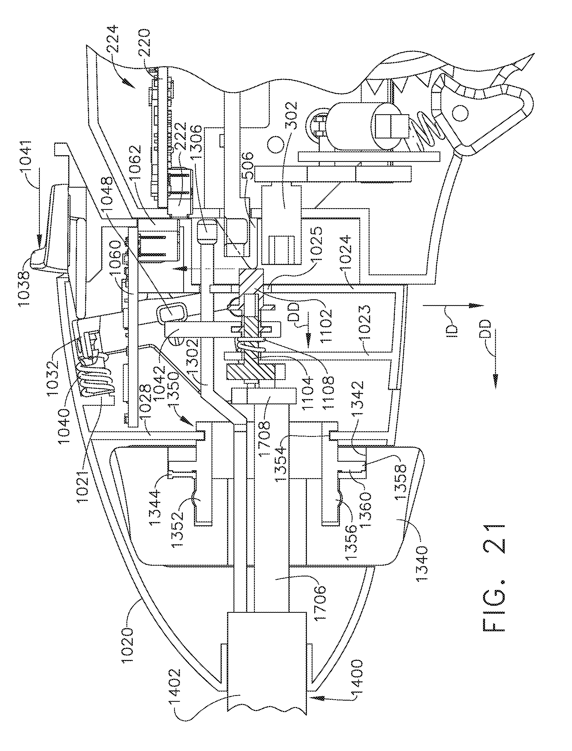
D00019

D00020
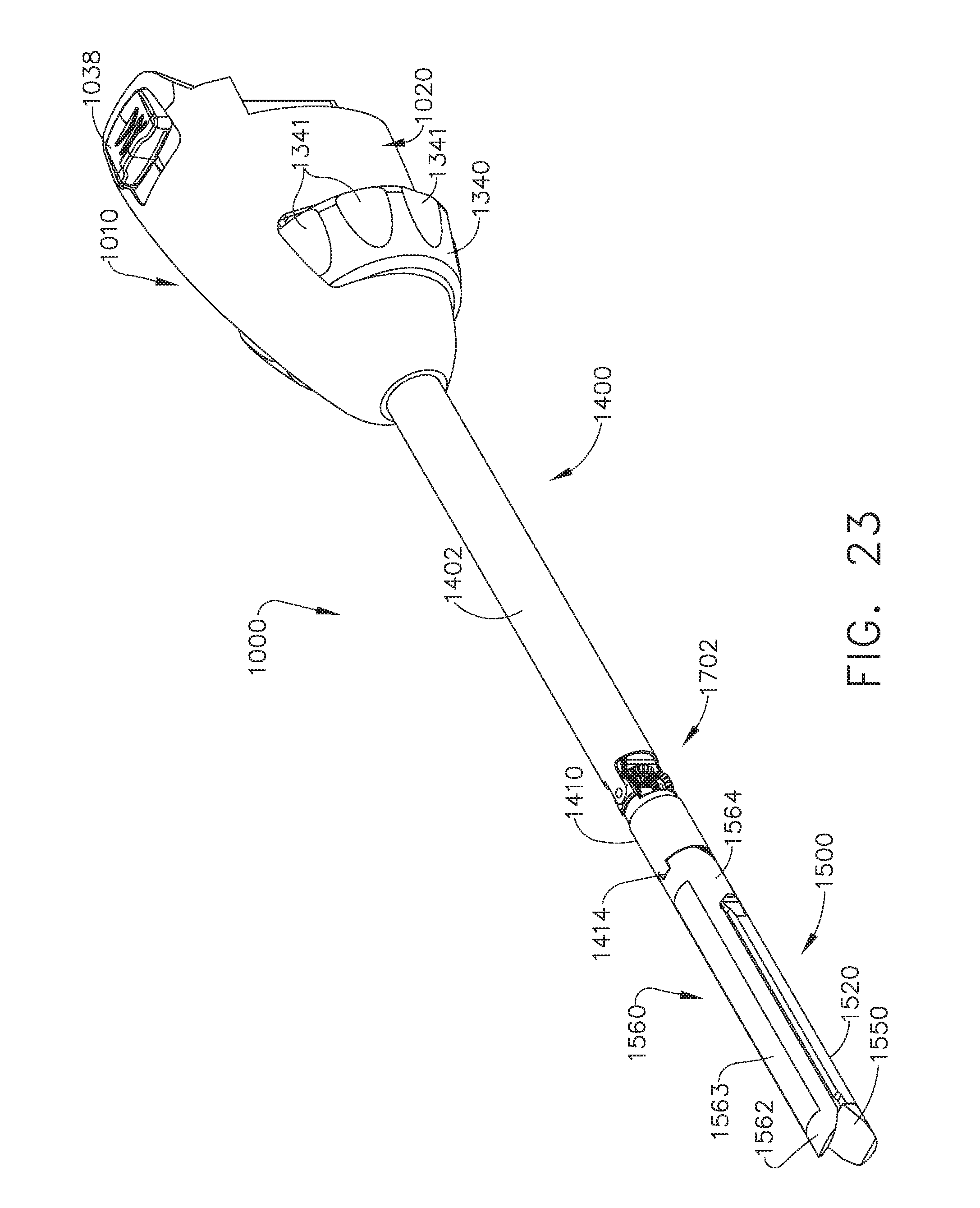
D00021

D00022

D00023

D00024

D00025
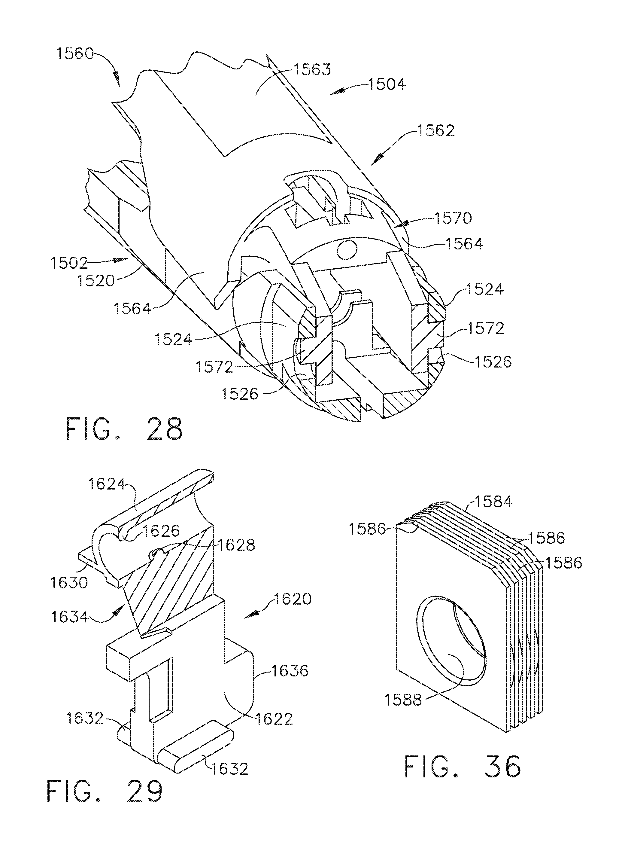
D00026

D00027
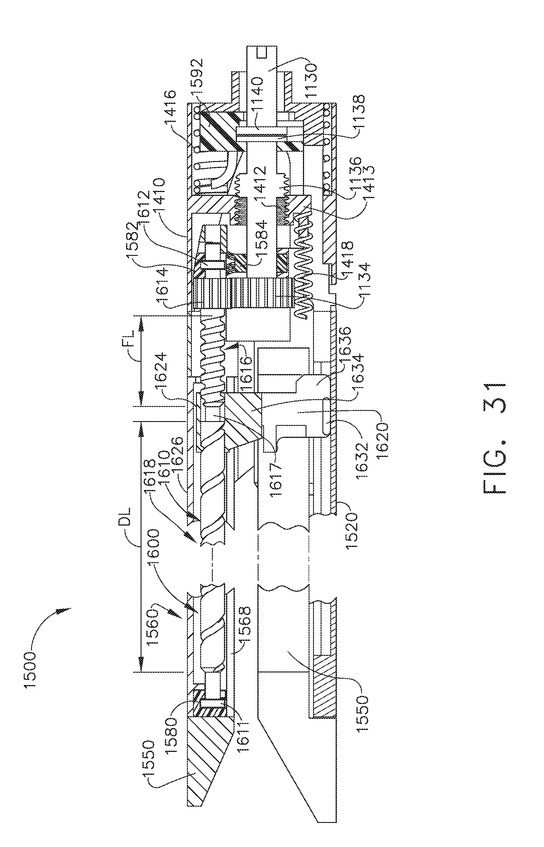
D00028

D00029

D00030

D00031

D00032

D00033

D00034

D00035

D00036

XML
uspto.report is an independent third-party trademark research tool that is not affiliated, endorsed, or sponsored by the United States Patent and Trademark Office (USPTO) or any other governmental organization. The information provided by uspto.report is based on publicly available data at the time of writing and is intended for informational purposes only.
While we strive to provide accurate and up-to-date information, we do not guarantee the accuracy, completeness, reliability, or suitability of the information displayed on this site. The use of this site is at your own risk. Any reliance you place on such information is therefore strictly at your own risk.
All official trademark data, including owner information, should be verified by visiting the official USPTO website at www.uspto.gov. This site is not intended to replace professional legal advice and should not be used as a substitute for consulting with a legal professional who is knowledgeable about trademark law.