Articulatable surgical instruments with conductive pathways for signal communication
Jaworek , et al.
U.S. patent number 10,226,249 [Application Number 15/274,939] was granted by the patent office on 2019-03-12 for articulatable surgical instruments with conductive pathways for signal communication. This patent grant is currently assigned to ETHICON LLC. The grantee listed for this patent is Ethicon, LLC. Invention is credited to Michael D. Auld, Daniel L. Baber, Gary S. Jaworek, John S. Kimsey, Robert L. Koch, Jr., Richard L. Leimbach, Daniel J. Ulrich.


View All Diagrams
| United States Patent | 10,226,249 |
| Jaworek , et al. | March 12, 2019 |
Articulatable surgical instruments with conductive pathways for signal communication
Abstract
A cover for an articulation joint that is supported in an elongate shaft assembly of a surgical instrument that is operably coupled to a surgical end effector that includes at least one end effector conductor therein. The cover includes at least one electrically conductive pathway that extends from the distal end of the cover to form an electrically conductive pathway from the end effector conductor to a shaft conductor on the elongate shaft assembly while facilitating operation of the articulation joint. Various conductor arrangements facilitating the passage of electrical current between an end effector to a control system across the articulation joint are also disclosed.
| Inventors: | Jaworek; Gary S. (Cincinnati, OH), Koch, Jr.; Robert L. (Cincinnati, OH), Auld; Michael D. (Blue Ash, OH), Kimsey; John S. (Florence, KY), Baber; Daniel L. (West Chester, OH), Leimbach; Richard L. (Cincinnati, OH), Ulrich; Daniel J. (Hamilton, OH) | ||||||||||
|---|---|---|---|---|---|---|---|---|---|---|---|
| Applicant: |
|
||||||||||
| Assignee: | ETHICON LLC (Guaynabo,
PR) |
||||||||||
| Family ID: | 55950132 | ||||||||||
| Appl. No.: | 15/274,939 | ||||||||||
| Filed: | September 23, 2016 |
Prior Publication Data
| Document Identifier | Publication Date | |
|---|---|---|
| US 20170007254 A1 | Jan 12, 2017 | |
Related U.S. Patent Documents
| Application Number | Filing Date | Patent Number | Issue Date | ||
|---|---|---|---|---|---|
| 13782295 | Mar 1, 2013 | 9700309 | |||
| Current U.S. Class: | 1/1 |
| Current CPC Class: | A61B 17/320068 (20130101); A61B 17/07207 (20130101); A61B 18/1442 (20130101); A61B 18/1445 (20130101); A61B 90/98 (20160201); A61B 2017/00734 (20130101); A61B 2017/00017 (20130101); A61B 2017/0046 (20130101); A61B 17/3423 (20130101); A61B 2090/0811 (20160201); A61B 2018/1455 (20130101); A61B 2090/064 (20160201); A61B 2017/00106 (20130101); A61B 2017/00221 (20130101); A61B 2017/00464 (20130101); A61B 2017/07271 (20130101); A61B 2090/033 (20160201); A61B 2017/2927 (20130101); A61B 2017/00039 (20130101); A61B 2017/00022 (20130101); A61B 2017/00123 (20130101); A61B 2034/742 (20160201); A61B 2018/0063 (20130101); A61B 2018/00619 (20130101); A61B 2017/07278 (20130101); A61B 2017/00398 (20130101) |
| Current International Class: | A61B 17/072 (20060101); A61B 17/00 (20060101); A61B 17/32 (20060101); A61B 18/14 (20060101); A61B 34/00 (20160101); A61B 17/34 (20060101); A61B 18/00 (20060101); A61B 90/00 (20160101); A61B 90/98 (20160101); A61B 17/29 (20060101) |
References Cited [Referenced By]
U.S. Patent Documents
| 66052 | June 1867 | Smith |
| 662587 | November 1900 | Blake |
| 670748 | March 1901 | Weddeler |
| 719487 | February 1903 | Minor |
| 804229 | November 1905 | Hutchinson |
| 951393 | March 1910 | Hahn |
| 1306107 | June 1919 | Elliott |
| 1314601 | September 1919 | McCaskey |
| 1677337 | July 1928 | Grove |
| 1794907 | March 1931 | Kelly |
| 1849427 | March 1932 | Hook |
| 1944116 | January 1934 | Stratman |
| 1954048 | April 1934 | Jeffrey et al. |
| 2037727 | April 1936 | La Chapelle |
| 2132295 | October 1938 | Hawkins |
| 2161632 | June 1939 | Nattenheimer |
| 2211117 | August 1940 | Hess |
| 2214870 | September 1940 | West |
| 2224882 | December 1940 | Peck |
| 2318379 | May 1943 | Davis et al. |
| 2329440 | September 1943 | La Place |
| 2441096 | May 1948 | Happe |
| 2448741 | September 1948 | Scott et al. |
| 2450527 | October 1948 | Smith |
| 2526902 | October 1950 | Rublee |
| 2527256 | October 1950 | Jackson |
| 2578686 | December 1951 | Fish |
| 2638901 | May 1953 | Sugarbaker |
| 2674149 | April 1954 | Benson |
| 2711461 | June 1955 | Happe |
| 2742955 | April 1956 | Dominguez |
| 2804848 | September 1957 | O'Farrell et al. |
| 2808482 | October 1957 | Zanichkowsky et al. |
| 2853074 | September 1958 | Olson |
| 2887004 | May 1959 | Stewart |
| 2957353 | October 1960 | Lewis |
| 2959974 | November 1960 | Emrick |
| 3032769 | May 1962 | Palmer |
| 3060972 | October 1962 | Sheldon |
| 3075062 | January 1963 | Iaccarino |
| 3078465 | February 1963 | Bobrov |
| 3079606 | March 1963 | Bobrov et al. |
| 3080564 | March 1963 | Strekopitov et al. |
| 3166072 | January 1965 | Sullivan, Jr. |
| 3180236 | April 1965 | Beckett |
| 3196869 | July 1965 | Scholl |
| 3204731 | September 1965 | Bent et al. |
| 3266494 | August 1966 | Brownrigg et al. |
| 3269630 | August 1966 | Fleischer |
| 3269631 | August 1966 | Takaro |
| 3275211 | September 1966 | Hirsch et al. |
| 3317103 | May 1967 | Cullen et al. |
| 3317105 | May 1967 | Astafjev et al. |
| 3357296 | December 1967 | Lefever |
| 3359978 | December 1967 | Smith, Jr. |
| 3480193 | November 1969 | Ralston |
| 3490675 | January 1970 | Green et al. |
| 3494533 | February 1970 | Green et al. |
| 3499591 | March 1970 | Green |
| 3503396 | March 1970 | Pierie et al. |
| 3509629 | May 1970 | Kidokoro |
| 3551987 | January 1971 | Wilkinson |
| 3568675 | March 1971 | Harvey |
| 3572159 | March 1971 | Tschanz |
| 3583393 | June 1971 | Takahashi |
| 3589589 | June 1971 | Akopov |
| 3598943 | August 1971 | Barrett |
| 3608549 | September 1971 | Merrill |
| 3618842 | November 1971 | Bryan |
| 3638652 | February 1972 | Kelley |
| 3640317 | February 1972 | Panfili |
| 3643851 | February 1972 | Green et al. |
| 3650453 | March 1972 | Smith, Jr. |
| 3661666 | May 1972 | Foster et al. |
| 3662939 | May 1972 | Bryan |
| 3688966 | September 1972 | Perkins et al. |
| 3695646 | October 1972 | Mommsen |
| 3709221 | January 1973 | Riely |
| 3717294 | February 1973 | Green |
| 3734207 | May 1973 | Fishbein |
| 3740994 | June 1973 | De Carlo, Jr. |
| 3744495 | July 1973 | Johnson |
| 3746002 | July 1973 | Haller |
| 3747603 | July 1973 | Adler |
| 3751902 | August 1973 | Kingsbury et al. |
| 3752161 | August 1973 | Bent |
| 3799151 | March 1974 | Fukaumi et al. |
| 3808452 | April 1974 | Hutchinson |
| 3815476 | June 1974 | Green et al. |
| 3819100 | June 1974 | Noiles et al. |
| 3821919 | July 1974 | Knohl |
| 3836171 | September 1974 | Hayashi et al. |
| 3837555 | September 1974 | Green |
| 3841474 | October 1974 | Maier |
| 3851196 | November 1974 | Hinds |
| 3863639 | February 1975 | Kleaveland |
| 3883624 | May 1975 | McKenzie et al. |
| 3885491 | May 1975 | Curtis |
| 3892228 | July 1975 | Mitsui |
| 3894174 | July 1975 | Cartun |
| 3902247 | September 1975 | Fleer et al. |
| 3940844 | March 1976 | Colby et al. |
| 3944163 | March 1976 | Hayashi et al. |
| 3950686 | April 1976 | Randall |
| 3952747 | April 1976 | Kimmell, Jr. |
| 3955581 | May 1976 | Spasiano et al. |
| 3959879 | June 1976 | Sellers |
| RE28932 | August 1976 | Noiles et al. |
| 3972734 | August 1976 | King |
| 3981051 | September 1976 | Brumlik |
| 4025216 | May 1977 | Hives |
| 4027746 | June 1977 | Kine |
| 4034143 | July 1977 | Sweet |
| 4054108 | October 1977 | Gill |
| 4060089 | November 1977 | Noiles |
| 4066133 | January 1978 | Voss |
| 4100820 | July 1978 | Evett |
| 4106446 | August 1978 | Yamada et al. |
| 4108211 | August 1978 | Tanaka |
| 4111206 | September 1978 | Vishnevsky et al. |
| 4127227 | November 1978 | Green |
| 4129059 | December 1978 | Van Eck |
| 4135517 | January 1979 | Reale |
| 4154122 | May 1979 | Severin |
| 4169990 | October 1979 | Lerdman |
| 4180285 | December 1979 | Reneau |
| 4185701 | January 1980 | Boys |
| 4190042 | February 1980 | Sinnreich |
| 4198734 | April 1980 | Brumlik |
| 4198982 | April 1980 | Fortner et al. |
| 4207898 | June 1980 | Becht |
| 4213562 | July 1980 | Garrett et al. |
| 4226242 | October 1980 | Jarvik |
| 4239431 | December 1980 | Davini |
| 4241861 | December 1980 | Fleischer |
| 4244372 | January 1981 | Kapitanov et al. |
| 4250436 | February 1981 | Weissman |
| 4261244 | April 1981 | Becht et al. |
| 4272002 | June 1981 | Moshofsky |
| 4272662 | June 1981 | Simpson |
| 4274304 | June 1981 | Curtiss |
| 4274398 | June 1981 | Scott, Jr. |
| 4275813 | June 1981 | Noiles |
| 4278091 | July 1981 | Borzone |
| 4289131 | September 1981 | Mueller |
| 4289133 | September 1981 | Rothfuss |
| 4290542 | September 1981 | Fedotov et al. |
| D261356 | October 1981 | Robinson |
| 4296654 | October 1981 | Mercer |
| 4296881 | October 1981 | Lee |
| 4304236 | December 1981 | Conta et al. |
| 4305539 | December 1981 | Korolkov et al. |
| 4312363 | January 1982 | Rothfuss et al. |
| 4312685 | January 1982 | Riedl |
| 4317451 | March 1982 | Cerwin et al. |
| 4319576 | March 1982 | Rothfuss |
| 4321002 | March 1982 | Froehlich |
| 4321746 | March 1982 | Grinage |
| 4328839 | May 1982 | Lyons et al. |
| 4331277 | May 1982 | Green |
| 4340331 | July 1982 | Savino |
| 4347450 | August 1982 | Colligan |
| 4349028 | September 1982 | Green |
| 4350151 | September 1982 | Scott |
| 4353371 | October 1982 | Cosman |
| 4357940 | November 1982 | Muller |
| 4361057 | November 1982 | Kochera |
| 4366544 | December 1982 | Shima et al. |
| 4373147 | February 1983 | Carlson, Jr. |
| 4376380 | March 1983 | Burgess |
| 4379457 | April 1983 | Gravener et al. |
| 4380312 | April 1983 | Landrus |
| 4382326 | May 1983 | Rabuse |
| 4383634 | May 1983 | Green |
| 4393728 | July 1983 | Larson et al. |
| 4396139 | August 1983 | Hall et al. |
| 4397311 | August 1983 | Kanshin et al. |
| 4402445 | September 1983 | Green |
| 4406621 | September 1983 | Bailey |
| 4408692 | October 1983 | Sigel et al. |
| 4409057 | October 1983 | Molenda et al. |
| 4415112 | November 1983 | Green |
| 4416276 | November 1983 | Newton et al. |
| 4417890 | November 1983 | Dennehey et al. |
| 4423456 | December 1983 | Zaidenweber |
| 4428376 | January 1984 | Mericle |
| 4429695 | February 1984 | Green |
| 4430997 | February 1984 | DiGiovanni et al. |
| 4434796 | March 1984 | Karapetian et al. |
| 4438659 | March 1984 | Desplats |
| 4442964 | April 1984 | Becht |
| 4448194 | May 1984 | DiGiovanni et al. |
| 4451743 | May 1984 | Suzuki et al. |
| 4452376 | June 1984 | Klieman et al. |
| 4454887 | June 1984 | Kruger |
| 4461305 | July 1984 | Cibley |
| 4467805 | August 1984 | Fukuda |
| 4469481 | September 1984 | Kobayashi |
| 4470414 | September 1984 | Imagawa et al. |
| 4471780 | September 1984 | Menges et al. |
| 4471781 | September 1984 | Di Giovanni et al. |
| 4473077 | September 1984 | Noiles et al. |
| 4475679 | October 1984 | Fleury, Jr. |
| 4478220 | October 1984 | Di Giovanni et al. |
| 4480641 | November 1984 | Failla et al. |
| 4485816 | December 1984 | Krumme |
| 4485817 | December 1984 | Swiggett |
| 4486928 | December 1984 | Tucker et al. |
| 4488523 | December 1984 | Shichman |
| 4489875 | December 1984 | Crawford et al. |
| 4493983 | January 1985 | Taggert |
| 4499895 | February 1985 | Takayama |
| 4500024 | February 1985 | DiGiovanni et al. |
| 4503842 | March 1985 | Takayama |
| 4505272 | March 1985 | Utyamyshev et al. |
| 4505273 | March 1985 | Braun et al. |
| 4505414 | March 1985 | Filipi |
| 4506671 | March 1985 | Green |
| 4512038 | April 1985 | Alexander et al. |
| 4520817 | June 1985 | Green |
| 4522327 | June 1985 | Korthoff et al. |
| 4526174 | July 1985 | Froehlich |
| 4527724 | July 1985 | Chow et al. |
| 4530357 | July 1985 | Pawloski et al. |
| 4530453 | July 1985 | Green |
| 4531522 | July 1985 | Bedi et al. |
| 4532927 | August 1985 | Miksza, Jr. |
| 4540202 | September 1985 | Amphoux et al. |
| 4548202 | October 1985 | Duncan |
| 4556058 | December 1985 | Green |
| 4560915 | December 1985 | Soultanian |
| 4565109 | January 1986 | Tsay |
| 4565189 | January 1986 | Mabuchi |
| 4566620 | January 1986 | Green et al. |
| 4569346 | February 1986 | Poirier |
| 4569469 | February 1986 | Mongeon et al. |
| 4571213 | February 1986 | Ishimoto |
| 4573468 | March 1986 | Conta et al. |
| 4573469 | March 1986 | Golden et al. |
| 4573622 | March 1986 | Green et al. |
| 4576165 | March 1986 | Green et al. |
| 4576167 | March 1986 | Noiles |
| 4580712 | April 1986 | Green |
| 4585153 | April 1986 | Failla et al. |
| 4586501 | May 1986 | Claracq |
| 4586502 | May 1986 | Bedi et al. |
| 4589416 | May 1986 | Green |
| 4589870 | May 1986 | Citrin et al. |
| 4591085 | May 1986 | Di Giovanni |
| RE32214 | July 1986 | Schramm |
| 4597753 | July 1986 | Turley |
| 4600037 | July 1986 | Hatten |
| 4604786 | August 1986 | Howie, Jr. |
| 4605001 | August 1986 | Rothfuss et al. |
| 4605004 | August 1986 | Di Giovanni et al. |
| 4606343 | August 1986 | Conta et al. |
| 4607638 | August 1986 | Crainich |
| 4608981 | September 1986 | Rothfuss et al. |
| 4610250 | September 1986 | Green |
| 4610383 | September 1986 | Rothfuss et al. |
| 4612933 | September 1986 | Brinkerhoff et al. |
| D286180 | October 1986 | Korthoff |
| D286442 | October 1986 | Korthoff et al. |
| 4617914 | October 1986 | Ueda |
| 4619262 | October 1986 | Taylor |
| 4619391 | October 1986 | Sharkany et al. |
| D287278 | December 1986 | Spreckelmeier |
| 4628459 | December 1986 | Shinohara et al. |
| 4629107 | December 1986 | Fedotov et al. |
| 4632290 | December 1986 | Green et al. |
| 4633861 | January 1987 | Chow et al. |
| 4633874 | January 1987 | Chow et al. |
| 4634419 | January 1987 | Kreizman et al. |
| 4635638 | January 1987 | Weintraub et al. |
| 4641076 | February 1987 | Linden |
| 4642618 | February 1987 | Johnson et al. |
| 4643173 | February 1987 | Bell et al. |
| 4643731 | February 1987 | Eckenhoff |
| 4646722 | March 1987 | Silverstein et al. |
| 4646745 | March 1987 | Noiles |
| 4652820 | March 1987 | Maresca |
| 4654028 | March 1987 | Suma |
| 4655222 | April 1987 | Florez et al. |
| 4662555 | May 1987 | Thornton |
| 4663874 | May 1987 | Sano et al. |
| 4664305 | May 1987 | Blake, III et al. |
| 4665916 | May 1987 | Green |
| 4667674 | May 1987 | Korthoff et al. |
| 4669647 | June 1987 | Storace |
| 4671278 | June 1987 | Chin |
| 4671280 | June 1987 | Dorband et al. |
| 4671445 | June 1987 | Barker et al. |
| 4672964 | June 1987 | Dee et al. |
| 4675944 | June 1987 | Wells |
| 4676245 | June 1987 | Fukuda |
| 4679460 | July 1987 | Yoshigai |
| 4679719 | July 1987 | Kramer |
| 4684051 | August 1987 | Akopov et al. |
| 4688555 | August 1987 | Wardle |
| 4691703 | September 1987 | Auth et al. |
| 4693248 | September 1987 | Failla |
| 4698579 | October 1987 | Richter et al. |
| 4700703 | October 1987 | Resnick et al. |
| 4705038 | November 1987 | Sjostrom et al. |
| 4708141 | November 1987 | Inoue et al. |
| 4709120 | November 1987 | Pearson |
| 4715520 | December 1987 | Roehr, Jr. et al. |
| 4719917 | January 1988 | Barrows et al. |
| 4721099 | January 1988 | Chikama |
| 4724840 | February 1988 | McVay et al. |
| 4727308 | February 1988 | Huljak et al. |
| 4728020 | March 1988 | Green et al. |
| 4728876 | March 1988 | Mongeon et al. |
| 4729260 | March 1988 | Dudden |
| 4730726 | March 1988 | Holzwarth |
| 4741336 | May 1988 | Failla et al. |
| 4743214 | May 1988 | Tai-Cheng |
| 4744363 | May 1988 | Hasson |
| 4747820 | May 1988 | Hornlein et al. |
| 4750902 | June 1988 | Wuchinich et al. |
| 4752024 | June 1988 | Green et al. |
| 4754909 | July 1988 | Barker et al. |
| 4763669 | August 1988 | Jaeger |
| 4767044 | August 1988 | Green |
| 4773420 | September 1988 | Green |
| 4777780 | October 1988 | Holzwarth |
| 4781186 | November 1988 | Simpson et al. |
| 4784137 | November 1988 | Kulik et al. |
| 4787387 | November 1988 | Burbank, III et al. |
| 4790225 | December 1988 | Moody et al. |
| 4790314 | December 1988 | Weaver |
| 4805617 | February 1989 | Bedi et al. |
| 4805823 | February 1989 | Rothfuss |
| 4807628 | February 1989 | Peters et al. |
| 4809695 | March 1989 | Gwathmey et al. |
| 4815460 | March 1989 | Porat et al. |
| 4817643 | April 1989 | Olson |
| 4817847 | April 1989 | Redtenbacher et al. |
| 4819853 | April 1989 | Green |
| 4821939 | April 1989 | Green |
| 4827911 | May 1989 | Broadwin et al. |
| 4828542 | May 1989 | Hermann |
| 4828944 | May 1989 | Yabe et al. |
| 4830855 | May 1989 | Stewart |
| 4833937 | May 1989 | Nagano |
| 4834720 | May 1989 | Blinkhorn |
| 4838859 | June 1989 | Strassmann |
| 4844068 | July 1989 | Arata et al. |
| 4848637 | July 1989 | Pruitt |
| 4856078 | August 1989 | Konopka |
| 4860644 | August 1989 | Kohl et al. |
| 4862891 | September 1989 | Smith |
| 4863423 | September 1989 | Wallace |
| 4865030 | September 1989 | Polyak |
| 4868530 | September 1989 | Ahs |
| 4869414 | September 1989 | Green et al. |
| 4869415 | September 1989 | Fox |
| 4873977 | October 1989 | Avant et al. |
| 4875486 | October 1989 | Rapoport et al. |
| 4880015 | November 1989 | Nierman |
| 4890613 | January 1990 | Golden et al. |
| 4892244 | January 1990 | Fox et al. |
| 4893622 | January 1990 | Green et al. |
| 4894051 | January 1990 | Shiber |
| 4896584 | January 1990 | Stoll et al. |
| 4896678 | January 1990 | Ogawa |
| 4900303 | February 1990 | Lemelson |
| 4903697 | February 1990 | Resnick et al. |
| 4909789 | March 1990 | Taguchi et al. |
| 4915100 | April 1990 | Green |
| 4919679 | April 1990 | Averill et al. |
| 4921479 | May 1990 | Grayzel |
| 4925082 | May 1990 | Kim |
| 4928699 | May 1990 | Sasai |
| 4930503 | June 1990 | Pruitt |
| 4930674 | June 1990 | Barak |
| 4931047 | June 1990 | Broadwin et al. |
| 4931737 | June 1990 | Hishiki |
| 4932960 | June 1990 | Green et al. |
| 4933843 | June 1990 | Scheller et al. |
| D309350 | July 1990 | Sutherland et al. |
| 4938408 | July 1990 | Bedi et al. |
| 4941623 | July 1990 | Pruitt |
| 4943182 | July 1990 | Hoblingre |
| 4944443 | July 1990 | Oddsen et al. |
| 4946067 | August 1990 | Kelsall |
| 4948327 | August 1990 | Crupi, Jr. |
| 4949707 | August 1990 | LeVahn et al. |
| 4951860 | August 1990 | Peters et al. |
| 4951861 | August 1990 | Schulze et al. |
| 4955959 | September 1990 | Tompkins et al. |
| 4957212 | September 1990 | Duck et al. |
| 4962877 | October 1990 | Hervas |
| 4964559 | October 1990 | Deniega et al. |
| 4965709 | October 1990 | Ngo |
| 4973274 | November 1990 | Hirukawa |
| 4973302 | November 1990 | Armour et al. |
| 4978049 | December 1990 | Green |
| 4978333 | December 1990 | Broadwin et al. |
| 4979952 | December 1990 | Kubota et al. |
| 4984564 | January 1991 | Yuen |
| 4986808 | January 1991 | Broadwin et al. |
| 4987049 | January 1991 | Komamura et al. |
| 4988334 | January 1991 | Hornlein et al. |
| 4995877 | February 1991 | Ams et al. |
| 4995959 | February 1991 | Metzner |
| 4996975 | March 1991 | Nakamura |
| 5002543 | March 1991 | Bradshaw et al. |
| 5002553 | March 1991 | Shiber |
| 5005754 | April 1991 | Van Overloop |
| 5009661 | April 1991 | Michelson |
| 5012411 | April 1991 | Policastro et al. |
| 5014898 | May 1991 | Heidrich |
| 5014899 | May 1991 | Presty et al. |
| 5015227 | May 1991 | Broadwin et al. |
| 5018515 | May 1991 | Gilman |
| 5018657 | May 1991 | Pedlick et al. |
| 5024652 | June 1991 | Dumenek et al. |
| 5024671 | June 1991 | Tu et al. |
| 5027834 | July 1991 | Pruitt |
| 5030226 | July 1991 | Green et al. |
| 5031814 | July 1991 | Tompkins et al. |
| 5035040 | July 1991 | Kerrigan et al. |
| 5038109 | August 1991 | Goble et al. |
| 5040715 | August 1991 | Green et al. |
| 5042707 | August 1991 | Taheri |
| 5061269 | October 1991 | Muller |
| 5062491 | November 1991 | Takeshima et al. |
| 5062563 | November 1991 | Green et al. |
| 5065929 | November 1991 | Schulze et al. |
| 5071052 | December 1991 | Rodak et al. |
| 5071430 | December 1991 | de Salis et al. |
| 5074454 | December 1991 | Peters |
| 5077506 | December 1991 | Krause |
| 5079006 | January 1992 | Urquhart |
| 5080556 | January 1992 | Carreno |
| 5083695 | January 1992 | Foslien et al. |
| 5084057 | January 1992 | Green et al. |
| 5088979 | February 1992 | Filipi et al. |
| 5088997 | February 1992 | Delahuerga et al. |
| 5089606 | February 1992 | Cole et al. |
| 5094247 | March 1992 | Hernandez et al. |
| 5098004 | March 1992 | Kerrigan |
| 5098360 | March 1992 | Hirota |
| 5100042 | March 1992 | Gravener et al. |
| 5100420 | March 1992 | Green et al. |
| 5104025 | April 1992 | Main et al. |
| 5104397 | April 1992 | Vasconcelos et al. |
| 5104400 | April 1992 | Berguer et al. |
| 5106008 | April 1992 | Tompkins et al. |
| 5108368 | April 1992 | Hammerslag et al. |
| 5109722 | May 1992 | Hufnagle et al. |
| 5111987 | May 1992 | Moeinzadeh et al. |
| 5116349 | May 1992 | Aranyi |
| D327323 | June 1992 | Hunt |
| 5119009 | June 1992 | McCaleb et al. |
| 5122156 | June 1992 | Granger et al. |
| 5124990 | June 1992 | Williamson |
| 5129570 | July 1992 | Schulze et al. |
| 5137198 | August 1992 | Nobis et al. |
| 5139513 | August 1992 | Segato |
| 5141144 | August 1992 | Foslien et al. |
| 5142932 | September 1992 | Moya et al. |
| 5155941 | October 1992 | Takahashi et al. |
| 5156315 | October 1992 | Green et al. |
| 5156609 | October 1992 | Nakao et al. |
| 5156614 | October 1992 | Green et al. |
| 5158567 | October 1992 | Green |
| D330699 | November 1992 | Gill |
| 5163598 | November 1992 | Peters et al. |
| 5168605 | December 1992 | Bartlett |
| 5170925 | December 1992 | Madden et al. |
| 5171247 | December 1992 | Hughett et al. |
| 5171249 | December 1992 | Stefanchik et al. |
| 5171253 | December 1992 | Klieman |
| 5173133 | December 1992 | Morin et al. |
| 5176677 | January 1993 | Wuchinich |
| 5176688 | January 1993 | Narayan et al. |
| 5187422 | February 1993 | Izenbaard et al. |
| 5188102 | February 1993 | Idemoto et al. |
| 5188111 | February 1993 | Yates et al. |
| 5190517 | March 1993 | Zieve et al. |
| 5190544 | March 1993 | Chapman et al. |
| 5190560 | March 1993 | Woods et al. |
| 5192288 | March 1993 | Thompson et al. |
| 5195505 | March 1993 | Josefsen |
| 5195968 | March 1993 | Lundquist et al. |
| 5197648 | March 1993 | Gingold |
| 5197649 | March 1993 | Bessler et al. |
| 5197966 | March 1993 | Sommerkamp |
| 5197970 | March 1993 | Green et al. |
| 5200280 | April 1993 | Karasa |
| 5201750 | April 1993 | Hocherl et al. |
| 5205459 | April 1993 | Brinkerhoff et al. |
| 5207697 | May 1993 | Carusillo et al. |
| 5209747 | May 1993 | Knoepfler |
| 5209756 | May 1993 | Seedhom et al. |
| 5211649 | May 1993 | Kohler et al. |
| 5211655 | May 1993 | Hasson |
| 5217457 | June 1993 | Delahuerga et al. |
| 5217478 | June 1993 | Rexroth |
| 5219111 | June 1993 | Bilotti et al. |
| 5220269 | June 1993 | Chen et al. |
| 5221036 | June 1993 | Takase |
| 5221281 | June 1993 | Klicek |
| 5222945 | June 1993 | Basnight |
| 5222963 | June 1993 | Brinkerhoff et al. |
| 5222975 | June 1993 | Crainich |
| 5222976 | June 1993 | Yoon |
| 5223675 | June 1993 | Taft |
| D338729 | August 1993 | Sprecklemeier et al. |
| 5234447 | August 1993 | Kaster et al. |
| 5236424 | August 1993 | Imran |
| 5236440 | August 1993 | Hlavacek |
| 5239981 | August 1993 | Anapliotis |
| 5240163 | August 1993 | Stein et al. |
| 5242457 | September 1993 | Akopov et al. |
| 5244462 | September 1993 | Delahuerga et al. |
| 5246156 | September 1993 | Rothfuss et al. |
| 5246443 | September 1993 | Mai |
| 5253793 | October 1993 | Green et al. |
| 5258007 | November 1993 | Spetzler et al. |
| 5258008 | November 1993 | Wilk |
| 5258009 | November 1993 | Conners |
| 5258010 | November 1993 | Green et al. |
| 5258012 | November 1993 | Luscombe et al. |
| 5259366 | November 1993 | Reydel et al. |
| 5259835 | November 1993 | Clark et al. |
| 5260637 | November 1993 | Pizzi |
| 5261877 | November 1993 | Fine et al. |
| 5261922 | November 1993 | Hood |
| 5263629 | November 1993 | Trumbull et al. |
| 5263937 | November 1993 | Shipp |
| 5263973 | November 1993 | Cook |
| 5264218 | November 1993 | Rogozinski |
| 5268622 | December 1993 | Philipp |
| 5271543 | December 1993 | Grant et al. |
| 5271544 | December 1993 | Fox et al. |
| RE34519 | January 1994 | Fox et al. |
| 5275322 | January 1994 | Brinkerhoff et al. |
| 5275323 | January 1994 | Schulze et al. |
| 5275608 | January 1994 | Forman et al. |
| 5279416 | January 1994 | Malec et al. |
| 5281216 | January 1994 | Klicek |
| 5282806 | February 1994 | Haber et al. |
| 5282829 | February 1994 | Hermes |
| 5284128 | February 1994 | Hart |
| 5285381 | February 1994 | Iskarous et al. |
| 5285945 | February 1994 | Brinkerhoff et al. |
| 5286253 | February 1994 | Fucci |
| 5289963 | March 1994 | McGarry et al. |
| 5290271 | March 1994 | Jernberg |
| 5290310 | March 1994 | Makower et al. |
| 5292053 | March 1994 | Bilotti et al. |
| 5297714 | March 1994 | Kramer |
| 5304204 | April 1994 | Bregen |
| D347474 | May 1994 | Olson |
| 5307976 | May 1994 | Olson et al. |
| 5308576 | May 1994 | Green et al. |
| 5309387 | May 1994 | Mori et al. |
| 5309927 | May 1994 | Welch |
| 5312023 | May 1994 | Green et al. |
| 5312024 | May 1994 | Grant et al. |
| 5312329 | May 1994 | Beaty et al. |
| 5313935 | May 1994 | Kortenbach et al. |
| 5313967 | May 1994 | Lieber et al. |
| 5314424 | May 1994 | Nicholas |
| 5314445 | May 1994 | Heidmueller nee Degwitz et al. |
| 5314466 | May 1994 | Stern et al. |
| 5318221 | June 1994 | Green et al. |
| 5320627 | June 1994 | Sorensen et al. |
| D348930 | July 1994 | Olson |
| 5326013 | July 1994 | Green et al. |
| 5329923 | July 1994 | Lundquist |
| 5330487 | July 1994 | Thornton et al. |
| 5330502 | July 1994 | Hassler et al. |
| 5331971 | July 1994 | Bales et al. |
| 5332142 | July 1994 | Robinson et al. |
| 5333422 | August 1994 | Warren et al. |
| 5333772 | August 1994 | Rothfuss et al. |
| 5333773 | August 1994 | Main et al. |
| 5334183 | August 1994 | Wuchinich |
| 5336130 | August 1994 | Ray |
| 5336229 | August 1994 | Noda |
| 5336232 | August 1994 | Green et al. |
| 5339799 | August 1994 | Kami et al. |
| 5341724 | August 1994 | Vatel |
| 5341807 | August 1994 | Nardella |
| 5341810 | August 1994 | Dardel |
| 5342380 | August 1994 | Hood |
| 5342381 | August 1994 | Tidemand |
| 5342385 | August 1994 | Norelli et al. |
| 5342395 | August 1994 | Jarrett et al. |
| 5342396 | August 1994 | Cook |
| 5343382 | August 1994 | Hale et al. |
| 5343391 | August 1994 | Mushabac |
| 5344059 | September 1994 | Green et al. |
| 5344060 | September 1994 | Gravener et al. |
| 5344454 | September 1994 | Clarke et al. |
| 5346504 | September 1994 | Ortiz et al. |
| 5348259 | September 1994 | Blanco et al. |
| 5350355 | September 1994 | Sklar |
| 5350388 | September 1994 | Epstein |
| 5350391 | September 1994 | Iacovelli |
| 5350400 | September 1994 | Esposito et al. |
| 5352229 | October 1994 | Goble et al. |
| 5352235 | October 1994 | Koros et al. |
| 5352238 | October 1994 | Green et al. |
| 5354250 | October 1994 | Christensen |
| 5354303 | October 1994 | Spaeth et al. |
| 5356006 | October 1994 | Alpern et al. |
| 5356064 | October 1994 | Green et al. |
| 5358506 | October 1994 | Green et al. |
| 5358510 | October 1994 | Luscombe et al. |
| 5359231 | October 1994 | Flowers et al. |
| D352780 | November 1994 | Glaeser et al. |
| 5359993 | November 1994 | Slater et al. |
| 5360305 | November 1994 | Kerrigan |
| 5360428 | November 1994 | Hutchinson, Jr. |
| 5364001 | November 1994 | Bryan |
| 5364002 | November 1994 | Green et al. |
| 5364003 | November 1994 | Williamson, IV |
| 5366133 | November 1994 | Geiste |
| 5366134 | November 1994 | Green et al. |
| 5366479 | November 1994 | McGarry et al. |
| 5368015 | November 1994 | Wilk |
| 5368592 | November 1994 | Stern et al. |
| 5369565 | November 1994 | Chen et al. |
| 5370645 | December 1994 | Klicek et al. |
| 5372124 | December 1994 | Takayama et al. |
| 5372596 | December 1994 | Klicek et al. |
| 5372602 | December 1994 | Burke |
| 5374277 | December 1994 | Hassler |
| 5375588 | December 1994 | Yoon |
| 5376095 | December 1994 | Ortiz |
| 5379933 | January 1995 | Green et al. |
| 5381649 | January 1995 | Webb |
| 5381782 | January 1995 | DeLaRama et al. |
| 5381943 | January 1995 | Allen et al. |
| 5382247 | January 1995 | Cimino et al. |
| 5383880 | January 1995 | Hooven |
| 5383881 | January 1995 | Green et al. |
| 5383882 | January 1995 | Buess et al. |
| 5383888 | January 1995 | Zvenyatsky et al. |
| 5383895 | January 1995 | Holmes et al. |
| 5388568 | February 1995 | van der Heide |
| 5389098 | February 1995 | Tsuruta et al. |
| 5389102 | February 1995 | Green et al. |
| 5389104 | February 1995 | Hahnen et al. |
| 5391180 | February 1995 | Tovey et al. |
| 5392979 | February 1995 | Green et al. |
| 5395030 | March 1995 | Kuramoto et al. |
| 5395033 | March 1995 | Byrne et al. |
| 5395034 | March 1995 | Allen et al. |
| 5395312 | March 1995 | Desai |
| 5395384 | March 1995 | Duthoit et al. |
| 5397046 | March 1995 | Savage et al. |
| 5397324 | March 1995 | Carroll et al. |
| 5400267 | March 1995 | Denen et al. |
| 5403276 | April 1995 | Schechter et al. |
| 5403312 | April 1995 | Yates et al. |
| 5404106 | April 1995 | Matsuda |
| 5404870 | April 1995 | Brinkerhoff et al. |
| 5405072 | April 1995 | Zlock et al. |
| 5405073 | April 1995 | Porter |
| 5405344 | April 1995 | Williamson et al. |
| 5405360 | April 1995 | Tovey |
| 5407293 | April 1995 | Crainich |
| 5408409 | April 1995 | Glassman et al. |
| 5409498 | April 1995 | Braddock et al. |
| D357981 | May 1995 | Green et al. |
| 5411481 | May 1995 | Allen et al. |
| 5411508 | May 1995 | Bessler et al. |
| 5413107 | May 1995 | Oakley et al. |
| 5413267 | May 1995 | Solyntjes et al. |
| 5413268 | May 1995 | Green et al. |
| 5413272 | May 1995 | Green et al. |
| 5413573 | May 1995 | Koivukangas |
| 5415334 | May 1995 | Williamson et al. |
| 5415335 | May 1995 | Knodell, Jr. |
| 5417203 | May 1995 | Tovey et al. |
| 5417361 | May 1995 | Williamson, IV |
| 5419766 | May 1995 | Chang et al. |
| 5421829 | June 1995 | Olichney et al. |
| 5422567 | June 1995 | Matsunaga |
| 5423471 | June 1995 | Mastri et al. |
| 5423809 | June 1995 | Klicek |
| 5423835 | June 1995 | Green et al. |
| 5425745 | June 1995 | Green et al. |
| 5427298 | June 1995 | Tegtmeier |
| 5431322 | July 1995 | Green et al. |
| 5431323 | July 1995 | Smith et al. |
| 5431654 | July 1995 | Nic |
| 5431668 | July 1995 | Burbank, III et al. |
| 5433721 | July 1995 | Hooven et al. |
| 5437681 | August 1995 | Meade et al. |
| 5438302 | August 1995 | Goble |
| 5439155 | August 1995 | Viola |
| 5439156 | August 1995 | Grant et al. |
| 5439479 | August 1995 | Shichman et al. |
| 5441191 | August 1995 | Linden |
| 5441193 | August 1995 | Gravener |
| 5441483 | August 1995 | Avitall |
| 5441494 | August 1995 | Ortiz |
| 5443197 | August 1995 | Malis et al. |
| 5443463 | August 1995 | Stern et al. |
| 5444113 | August 1995 | Sinclair et al. |
| 5445155 | August 1995 | Sieben |
| 5445304 | August 1995 | Plyley et al. |
| 5445644 | August 1995 | Pietrafitta et al. |
| 5447265 | September 1995 | Vidal et al. |
| 5447417 | September 1995 | Kuhl et al. |
| 5447513 | September 1995 | Davison et al. |
| 5449355 | September 1995 | Rhum et al. |
| 5449365 | September 1995 | Green et al. |
| 5449370 | September 1995 | Vaitekunas |
| 5452836 | September 1995 | Huitema et al. |
| 5452837 | September 1995 | Williamson, IV et al. |
| 5454378 | October 1995 | Palmer et al. |
| 5454822 | October 1995 | Schob et al. |
| 5454827 | October 1995 | Aust et al. |
| 5456401 | October 1995 | Green et al. |
| 5458279 | October 1995 | Plyley |
| 5458579 | October 1995 | Chodorow et al. |
| 5462215 | October 1995 | Viola et al. |
| 5464013 | November 1995 | Lemelson |
| 5464144 | November 1995 | Guy et al. |
| 5464300 | November 1995 | Crainich |
| 5465819 | November 1995 | Weilant et al. |
| 5465894 | November 1995 | Clark et al. |
| 5465895 | November 1995 | Knodel et al. |
| 5465896 | November 1995 | Allen et al. |
| 5466020 | November 1995 | Page et al. |
| 5467911 | November 1995 | Tsuruta et al. |
| 5468253 | November 1995 | Bezwada et al. |
| 5470006 | November 1995 | Rodak |
| 5470007 | November 1995 | Plyley et al. |
| 5470008 | November 1995 | Rodak |
| 5470009 | November 1995 | Rodak |
| 5470010 | November 1995 | Rothfuss et al. |
| 5471129 | November 1995 | Mann |
| 5472132 | December 1995 | Savage et al. |
| 5472442 | December 1995 | Klicek |
| 5473204 | December 1995 | Temple |
| 5474057 | December 1995 | Makower et al. |
| 5474223 | December 1995 | Viola et al. |
| 5474566 | December 1995 | Alesi et al. |
| 5476206 | December 1995 | Green et al. |
| 5476479 | December 1995 | Green et al. |
| 5476481 | December 1995 | Schondorf |
| 5478003 | December 1995 | Green et al. |
| 5478354 | December 1995 | Tovey et al. |
| 5480089 | January 1996 | Blewett |
| 5480409 | January 1996 | Riza |
| 5482197 | January 1996 | Green et al. |
| 5483952 | January 1996 | Aranyi |
| 5484095 | January 1996 | Green et al. |
| 5484398 | January 1996 | Stoddard |
| 5484451 | January 1996 | Akopov et al. |
| 5485947 | January 1996 | Olson et al. |
| 5485952 | January 1996 | Fontayne |
| 5487499 | January 1996 | Sorrentino et al. |
| 5487500 | January 1996 | Knodel et al. |
| 5489058 | February 1996 | Plyley et al. |
| 5489256 | February 1996 | Adair |
| 5489290 | February 1996 | Furnish |
| 5490819 | February 1996 | Nicholas et al. |
| 5492671 | February 1996 | Krafft |
| 5496312 | March 1996 | Klicek |
| 5496317 | March 1996 | Goble et al. |
| 5497933 | March 1996 | DeFonzo et al. |
| 5501654 | March 1996 | Failla et al. |
| 5503320 | April 1996 | Webster et al. |
| 5503635 | April 1996 | Sauer et al. |
| 5503638 | April 1996 | Cooper et al. |
| 5505363 | April 1996 | Green et al. |
| 5507426 | April 1996 | Young et al. |
| 5509596 | April 1996 | Green et al. |
| 5509916 | April 1996 | Taylor |
| 5511564 | April 1996 | Wilk |
| 5514129 | May 1996 | Smith |
| 5514149 | May 1996 | Green et al. |
| 5514157 | May 1996 | Nicholas et al. |
| 5518163 | May 1996 | Hooven |
| 5518164 | May 1996 | Hooven |
| 5520609 | May 1996 | Moll et al. |
| 5520634 | May 1996 | Fox et al. |
| 5520678 | May 1996 | Heckele et al. |
| 5520700 | May 1996 | Beyar et al. |
| 5522817 | June 1996 | Sander et al. |
| 5522831 | June 1996 | Sleister et al. |
| 5527264 | June 1996 | Moll et al. |
| 5527320 | June 1996 | Carruthers et al. |
| 5529235 | June 1996 | Boiarski et al. |
| D372086 | July 1996 | Grasso et al. |
| 5531305 | July 1996 | Roberts et al. |
| 5531744 | July 1996 | Nardella et al. |
| 5531856 | July 1996 | Moll et al. |
| 5533521 | July 1996 | Granger |
| 5533581 | July 1996 | Barth et al. |
| 5533661 | July 1996 | Main et al. |
| 5535934 | July 1996 | Boiarski et al. |
| 5535935 | July 1996 | Vidal et al. |
| 5535937 | July 1996 | Boiarski et al. |
| 5540375 | July 1996 | Bolanos et al. |
| 5540705 | July 1996 | Meade et al. |
| 5541376 | July 1996 | Ladtkow et al. |
| 5541489 | July 1996 | Dunstan |
| 5542594 | August 1996 | McKean et al. |
| 5542949 | August 1996 | Yoon |
| 5543119 | August 1996 | Sutter et al. |
| 5543695 | August 1996 | Culp et al. |
| 5544802 | August 1996 | Crainich |
| 5547117 | August 1996 | Hamblin et al. |
| 5549583 | August 1996 | Sanford et al. |
| 5549621 | August 1996 | Bessler et al. |
| 5549627 | August 1996 | Kieturakis |
| 5549628 | August 1996 | Cooper et al. |
| 5549637 | August 1996 | Crainich |
| 5551622 | September 1996 | Yoon |
| 5553624 | September 1996 | Francese et al. |
| 5553675 | September 1996 | Pitzen et al. |
| 5553765 | September 1996 | Knodel et al. |
| 5554148 | September 1996 | Aebischer et al. |
| 5554169 | September 1996 | Green et al. |
| 5556020 | September 1996 | Hou |
| 5556416 | September 1996 | Clark et al. |
| 5558533 | September 1996 | Hashizawa et al. |
| 5558665 | September 1996 | Kieturakis |
| 5558671 | September 1996 | Yates |
| 5560530 | October 1996 | Bolanos et al. |
| 5560532 | October 1996 | DeFonzo et al. |
| 5561881 | October 1996 | Klinger et al. |
| 5562239 | October 1996 | Boiarski et al. |
| 5562241 | October 1996 | Knodel et al. |
| 5562682 | October 1996 | Oberlin et al. |
| 5562690 | October 1996 | Green et al. |
| 5562701 | October 1996 | Huitema et al. |
| 5562702 | October 1996 | Huitema et al. |
| 5563481 | October 1996 | Krause |
| 5564615 | October 1996 | Bishop et al. |
| 5569161 | October 1996 | Ebling et al. |
| 5569270 | October 1996 | Weng |
| 5569284 | October 1996 | Young et al. |
| 5571090 | November 1996 | Sherts |
| 5571100 | November 1996 | Goble et al. |
| 5571116 | November 1996 | Bolanos et al. |
| 5571285 | November 1996 | Chow et al. |
| 5571488 | November 1996 | Beerstecher et al. |
| 5573169 | November 1996 | Green et al. |
| 5573543 | November 1996 | Akopov et al. |
| 5574431 | November 1996 | McKeown et al. |
| 5575054 | November 1996 | Klinzing et al. |
| 5575789 | November 1996 | Bell et al. |
| 5575799 | November 1996 | Bolanos et al. |
| 5575803 | November 1996 | Cooper et al. |
| 5575805 | November 1996 | Li |
| 5577654 | November 1996 | Bishop |
| 5578052 | November 1996 | Koros et al. |
| 5579978 | December 1996 | Green et al. |
| 5580067 | December 1996 | Hamblin et al. |
| 5582611 | December 1996 | Tsuruta et al. |
| 5582617 | December 1996 | Klieman et al. |
| 5583114 | December 1996 | Barrows et al. |
| 5584425 | December 1996 | Savage et al. |
| 5586711 | December 1996 | Plyley et al. |
| 5588579 | December 1996 | Schnut et al. |
| 5588580 | December 1996 | Paul et al. |
| 5588581 | December 1996 | Conlon et al. |
| 5591170 | January 1997 | Spievack et al. |
| 5591187 | January 1997 | Dekel |
| 5597107 | January 1997 | Knodel et al. |
| 5599151 | February 1997 | Daum et al. |
| 5599279 | February 1997 | Slotman et al. |
| 5599344 | February 1997 | Paterson |
| 5599350 | February 1997 | Schulze et al. |
| 5599852 | February 1997 | Scopelianos et al. |
| 5601224 | February 1997 | Bishop et al. |
| 5601573 | February 1997 | Fogelberg et al. |
| 5601604 | February 1997 | Vincent |
| 5602449 | February 1997 | Krause et al. |
| 5603443 | February 1997 | Clark et al. |
| 5605272 | February 1997 | Witt et al. |
| 5605273 | February 1997 | Hamblin et al. |
| 5607094 | March 1997 | Clark et al. |
| 5607095 | March 1997 | Smith et al. |
| 5607433 | March 1997 | Polla et al. |
| 5607450 | March 1997 | Zvenyatsky et al. |
| 5607474 | March 1997 | Athanasiou et al. |
| 5609285 | March 1997 | Grant et al. |
| 5609601 | March 1997 | Kolesa et al. |
| 5611709 | March 1997 | McAnulty |
| 5613499 | March 1997 | Palmer et al. |
| 5613937 | March 1997 | Garrison et al. |
| 5613966 | March 1997 | Makower et al. |
| 5614887 | March 1997 | Buchbinder |
| 5615820 | April 1997 | Viola |
| 5618294 | April 1997 | Aust et al. |
| 5618303 | April 1997 | Marlow et al. |
| 5618307 | April 1997 | Donlon et al. |
| 5619992 | April 1997 | Guthrie et al. |
| 5620289 | April 1997 | Curry |
| 5620326 | April 1997 | Younker |
| 5620452 | April 1997 | Yoon |
| 5624398 | April 1997 | Smith et al. |
| 5624452 | April 1997 | Yates |
| 5626587 | May 1997 | Bishop et al. |
| 5626595 | May 1997 | Sklar et al. |
| 5628446 | May 1997 | Geiste et al. |
| 5628743 | May 1997 | Cimino |
| 5628745 | May 1997 | Bek |
| 5630539 | May 1997 | Plyley et al. |
| 5630540 | May 1997 | Blewett |
| 5630541 | May 1997 | Williamson, IV et al. |
| 5630782 | May 1997 | Adair |
| 5632432 | May 1997 | Schulze et al. |
| 5632433 | May 1997 | Grant et al. |
| 5633374 | May 1997 | Humphrey et al. |
| 5634584 | June 1997 | Okorocha et al. |
| 5636779 | June 1997 | Palmer |
| 5636780 | June 1997 | Green et al. |
| 5639008 | June 1997 | Gallagher et al. |
| D381077 | July 1997 | Hunt |
| 5643291 | July 1997 | Pier et al. |
| 5643294 | July 1997 | Tovey et al. |
| 5643319 | July 1997 | Green et al. |
| 5645209 | July 1997 | Green et al. |
| 5647526 | July 1997 | Green et al. |
| 5647869 | July 1997 | Goble et al. |
| 5649937 | July 1997 | Bito et al. |
| 5649956 | July 1997 | Jensen et al. |
| 5651491 | July 1997 | Heaton et al. |
| 5651762 | July 1997 | Bridges |
| 5651821 | July 1997 | Uchida |
| 5653373 | August 1997 | Green et al. |
| 5653374 | August 1997 | Young et al. |
| 5653677 | August 1997 | Okada et al. |
| 5653721 | August 1997 | Knodel et al. |
| 5655698 | August 1997 | Yoon |
| 5657417 | August 1997 | Di Troia |
| 5657429 | August 1997 | Wang et al. |
| 5657921 | August 1997 | Young et al. |
| 5658238 | August 1997 | Suzuki |
| 5658281 | August 1997 | Heard |
| 5658298 | August 1997 | Vincent et al. |
| 5658300 | August 1997 | Bito et al. |
| 5658307 | August 1997 | Exconde |
| 5662258 | September 1997 | Knodel et al. |
| 5662260 | September 1997 | Yoon |
| 5662662 | September 1997 | Bishop et al. |
| 5662667 | September 1997 | Knodel |
| 5665085 | September 1997 | Nardella |
| 5667517 | September 1997 | Hooven |
| 5667526 | September 1997 | Levin |
| 5667527 | September 1997 | Cook |
| 5669544 | September 1997 | Schulze et al. |
| 5669904 | September 1997 | Platt, Jr. et al. |
| 5669907 | September 1997 | Platt, Jr. et al. |
| 5669918 | September 1997 | Balazs et al. |
| 5673840 | October 1997 | Schulze et al. |
| 5673841 | October 1997 | Schulze et al. |
| 5673842 | October 1997 | Bittner et al. |
| 5674286 | October 1997 | D'Alessio et al. |
| 5678748 | October 1997 | Plyley et al. |
| 5680981 | October 1997 | Mililli et al. |
| 5680982 | October 1997 | Schulze et al. |
| 5680983 | October 1997 | Plyley et al. |
| 5681341 | October 1997 | Lunsford et al. |
| 5683349 | November 1997 | Makower et al. |
| 5685474 | November 1997 | Seeber |
| 5686090 | November 1997 | Schilder et al. |
| 5688270 | November 1997 | Yates et al. |
| 5690269 | November 1997 | Bolanos et al. |
| 5692668 | December 1997 | Schulze et al. |
| 5693020 | December 1997 | Rauh |
| 5693042 | December 1997 | Boiarski et al. |
| 5693051 | December 1997 | Schulze et al. |
| 5695494 | December 1997 | Becker |
| 5695502 | December 1997 | Pier et al. |
| 5695504 | December 1997 | Gifford, III et al. |
| 5695524 | December 1997 | Kelley et al. |
| 5697542 | December 1997 | Knodel et al. |
| 5697543 | December 1997 | Burdorff |
| 5697909 | December 1997 | Eggers et al. |
| 5697943 | December 1997 | Sauer et al. |
| 5700270 | December 1997 | Peyser et al. |
| 5700276 | December 1997 | Benecke |
| 5702387 | December 1997 | Arts et al. |
| 5702408 | December 1997 | Wales et al. |
| 5702409 | December 1997 | Rayburn et al. |
| 5704087 | January 1998 | Strub |
| 5704534 | January 1998 | Huitema et al. |
| 5706997 | January 1998 | Green et al. |
| 5706998 | January 1998 | Plyley et al. |
| 5707392 | January 1998 | Kortenbach |
| 5709334 | January 1998 | Sorrentino et al. |
| 5709680 | January 1998 | Yates et al. |
| 5709706 | January 1998 | Kienzle et al. |
| 5711472 | January 1998 | Bryan |
| 5712460 | January 1998 | Carr et al. |
| 5713128 | February 1998 | Schrenk et al. |
| 5713505 | February 1998 | Huitema |
| 5713895 | February 1998 | Lontine et al. |
| 5713896 | February 1998 | Nardella |
| 5713920 | February 1998 | Bezwada et al. |
| 5715604 | February 1998 | Lanzoni |
| 5715987 | February 1998 | Kelley et al. |
| 5715988 | February 1998 | Palmer |
| 5716366 | February 1998 | Yates |
| 5718359 | February 1998 | Palmer et al. |
| 5718360 | February 1998 | Green et al. |
| 5718548 | February 1998 | Cotellessa |
| 5718714 | February 1998 | Livneh |
| 5720744 | February 1998 | Eggleston et al. |
| D393067 | March 1998 | Geary et al. |
| 5724025 | March 1998 | Tavori |
| 5725536 | March 1998 | Oberlin et al. |
| 5725554 | March 1998 | Simon et al. |
| 5728110 | March 1998 | Vidal et al. |
| 5728113 | March 1998 | Sherts |
| 5728121 | March 1998 | Bimbo et al. |
| 5730758 | March 1998 | Allgeyer |
| 5732821 | March 1998 | Stone et al. |
| 5732871 | March 1998 | Clark et al. |
| 5732872 | March 1998 | Bolduc et al. |
| 5733308 | March 1998 | Daugherty et al. |
| 5735445 | April 1998 | Vidal et al. |
| 5735848 | April 1998 | Yates et al. |
| 5735874 | April 1998 | Measamer et al. |
| 5738474 | April 1998 | Blewett |
| 5738629 | April 1998 | Moll et al. |
| 5738648 | April 1998 | Lands et al. |
| 5741271 | April 1998 | Nakao et al. |
| 5743456 | April 1998 | Jones et al. |
| 5747953 | May 1998 | Philipp |
| 5749889 | May 1998 | Bacich et al. |
| 5749893 | May 1998 | Vidal et al. |
| 5749968 | May 1998 | Melanson et al. |
| 5752644 | May 1998 | Bolanos et al. |
| 5752965 | May 1998 | Francis et al. |
| 5752970 | May 1998 | Yoon |
| 5755717 | May 1998 | Yates et al. |
| 5758814 | June 1998 | Gallagher et al. |
| 5762255 | June 1998 | Chrisman et al. |
| 5762256 | June 1998 | Mastri et al. |
| 5766188 | June 1998 | Igaki |
| 5766205 | June 1998 | Zvenyatsky et al. |
| 5769303 | June 1998 | Knodel et al. |
| 5769748 | June 1998 | Eyerly et al. |
| 5769791 | June 1998 | Benaron et al. |
| 5769892 | June 1998 | Kingwell |
| 5772379 | June 1998 | Evensen |
| 5772578 | June 1998 | Heimberger et al. |
| 5772659 | June 1998 | Becker et al. |
| 5776130 | July 1998 | Buysse et al. |
| 5778939 | July 1998 | Hok-Yin |
| 5779130 | July 1998 | Alesi et al. |
| 5779131 | July 1998 | Knodel et al. |
| 5779132 | July 1998 | Knodel et al. |
| 5782396 | July 1998 | Mastri et al. |
| 5782397 | July 1998 | Koukline |
| 5782748 | July 1998 | Palmer et al. |
| 5782749 | July 1998 | Riza |
| 5782859 | July 1998 | Nicholas et al. |
| 5784934 | July 1998 | Izumisawa |
| 5785232 | July 1998 | Vidal et al. |
| 5785647 | July 1998 | Tompkins et al. |
| 5787897 | August 1998 | Kieturakis |
| 5791231 | August 1998 | Cohn et al. |
| 5792135 | August 1998 | Madhani et al. |
| 5792162 | August 1998 | Jolly et al. |
| 5792165 | August 1998 | Klieman et al. |
| 5794834 | August 1998 | Hamblin et al. |
| 5796188 | August 1998 | Bays |
| 5797536 | August 1998 | Smith et al. |
| 5797537 | August 1998 | Oberlin et al. |
| 5797538 | August 1998 | Heaton et al. |
| 5797637 | August 1998 | Ervin |
| 5797906 | August 1998 | Rhum et al. |
| 5797927 | August 1998 | Yoon |
| 5797941 | August 1998 | Schulze et al. |
| 5797959 | August 1998 | Castro et al. |
| 5799857 | September 1998 | Robertson et al. |
| 5800379 | September 1998 | Edwards |
| 5800423 | September 1998 | Jensen |
| 5804726 | September 1998 | Geib et al. |
| 5804936 | September 1998 | Brodsky et al. |
| 5806676 | September 1998 | Wasgien |
| 5807376 | September 1998 | Viola et al. |
| 5807378 | September 1998 | Jensen et al. |
| 5807393 | September 1998 | Williamson, IV et al. |
| 5809441 | September 1998 | McKee |
| 5810721 | September 1998 | Mueller et al. |
| 5810811 | September 1998 | Yates et al. |
| 5810846 | September 1998 | Virnich et al. |
| 5810855 | September 1998 | Rayburn et al. |
| 5813813 | September 1998 | Daum et al. |
| 5814055 | September 1998 | Knodel et al. |
| 5814057 | September 1998 | Oi et al. |
| 5816471 | October 1998 | Plyley et al. |
| 5817084 | October 1998 | Jensen |
| 5817091 | October 1998 | Nardella et al. |
| 5817093 | October 1998 | Williamson, IV et al. |
| 5817109 | October 1998 | McGarry et al. |
| 5817119 | October 1998 | Klieman et al. |
| 5820009 | October 1998 | Melling et al. |
| 5823066 | October 1998 | Huitema et al. |
| 5824333 | October 1998 | Scopelianos et al. |
| 5826776 | October 1998 | Schulze et al. |
| 5827271 | October 1998 | Buysse et al. |
| 5827298 | October 1998 | Hart et al. |
| 5829662 | November 1998 | Allen et al. |
| 5830598 | November 1998 | Patterson |
| 5833690 | November 1998 | Yates et al. |
| 5833695 | November 1998 | Yoon |
| 5833696 | November 1998 | Whitfield et al. |
| 5836503 | November 1998 | Ehrenfels et al. |
| 5836960 | November 1998 | Kolesa et al. |
| 5839369 | November 1998 | Chatterjee et al. |
| 5839639 | November 1998 | Sauer et al. |
| 5843021 | December 1998 | Edwards et al. |
| 5843096 | December 1998 | Igaki et al. |
| 5843097 | December 1998 | Mayenberger et al. |
| 5843122 | December 1998 | Riza |
| 5843132 | December 1998 | Ilvento |
| 5843169 | December 1998 | Taheri |
| 5846254 | December 1998 | Schulze et al. |
| 5847566 | December 1998 | Marritt et al. |
| 5849011 | December 1998 | Jones et al. |
| 5849020 | December 1998 | Long et al. |
| 5849023 | December 1998 | Mericle |
| 5851179 | December 1998 | Ritson et al. |
| 5853366 | December 1998 | Dowlatshahi |
| 5855311 | January 1999 | Hamblin et al. |
| 5855583 | January 1999 | Wang et al. |
| 5860581 | January 1999 | Robertson et al. |
| 5860975 | January 1999 | Goble et al. |
| 5865361 | February 1999 | Milliman et al. |
| 5865638 | February 1999 | Trafton |
| 5868361 | February 1999 | Rinderer |
| 5868760 | February 1999 | McGuckin, Jr. |
| 5868790 | February 1999 | Vincent et al. |
| 5871135 | February 1999 | Williamson, IV et al. |
| 5873885 | February 1999 | Weidenbenner |
| 5876401 | March 1999 | Schulze et al. |
| 5878193 | March 1999 | Wang et al. |
| 5878607 | March 1999 | Nunes et al. |
| 5878937 | March 1999 | Green et al. |
| 5878938 | March 1999 | Bittner et al. |
| 5881777 | March 1999 | Bassi et al. |
| 5891094 | April 1999 | Masterson et al. |
| 5891160 | April 1999 | Williamson, IV et al. |
| 5891558 | April 1999 | Bell et al. |
| 5893506 | April 1999 | Powell |
| 5893835 | April 1999 | Witt et al. |
| 5893878 | April 1999 | Pierce |
| 5894979 | April 1999 | Powell |
| 5897552 | April 1999 | Edwards et al. |
| 5897562 | April 1999 | Bolanos et al. |
| 5899824 | May 1999 | Kurtz et al. |
| 5899914 | May 1999 | Zirps et al. |
| 5901895 | May 1999 | Heaton et al. |
| 5902312 | May 1999 | Frater et al. |
| 5903117 | May 1999 | Gregory |
| 5904647 | May 1999 | Ouchi |
| 5904693 | May 1999 | Dicesare et al. |
| 5904702 | May 1999 | Ek et al. |
| 5906577 | May 1999 | Beane et al. |
| 5906625 | May 1999 | Bito et al. |
| 5907211 | May 1999 | Hall et al. |
| 5908402 | June 1999 | Blythe |
| 5908427 | June 1999 | McKean et al. |
| 5909062 | June 1999 | Krietzman |
| 5911353 | June 1999 | Bolanos et al. |
| 5915616 | June 1999 | Viola et al. |
| 5916225 | June 1999 | Kugel |
| 5918791 | July 1999 | Sorrentino et al. |
| 5919198 | July 1999 | Graves, Jr. et al. |
| 5921956 | July 1999 | Grinberg et al. |
| 5924864 | July 1999 | Loge et al. |
| 5928137 | July 1999 | Green |
| 5928256 | July 1999 | Riza |
| 5931847 | August 1999 | Bittner et al. |
| 5931853 | August 1999 | McEwen et al. |
| 5937951 | August 1999 | Izuchukwu et al. |
| 5938667 | August 1999 | Peyser et al. |
| 5941442 | August 1999 | Geiste et al. |
| 5941890 | August 1999 | Voegele et al. |
| 5944172 | August 1999 | Hannula |
| 5944715 | August 1999 | Goble et al. |
| 5946978 | September 1999 | Yamashita |
| 5947984 | September 1999 | Whipple |
| 5947996 | September 1999 | Logeman |
| 5948030 | September 1999 | Miller et al. |
| 5948429 | September 1999 | Bell et al. |
| 5951301 | September 1999 | Younker |
| 5951516 | September 1999 | Bunyan |
| 5951552 | September 1999 | Long et al. |
| 5951574 | September 1999 | Stefanchik et al. |
| 5951581 | September 1999 | Saadat et al. |
| 5954259 | September 1999 | Viola et al. |
| 5964394 | October 1999 | Robertson |
| 5964774 | October 1999 | McKean et al. |
| 5971916 | October 1999 | Koren |
| 5973221 | October 1999 | Collyer et al. |
| D416089 | November 1999 | Barton et al. |
| 5976122 | November 1999 | Madhani et al. |
| 5977746 | November 1999 | Hershberger et al. |
| 5984949 | November 1999 | Levin |
| 5988479 | November 1999 | Palmer |
| 5990379 | November 1999 | Gregory |
| 5993466 | November 1999 | Yoon |
| 5997528 | December 1999 | Bisch et al. |
| 5997552 | December 1999 | Person et al. |
| 6001108 | December 1999 | Wang et al. |
| 6003517 | December 1999 | Sheffield et al. |
| 6004319 | December 1999 | Goble et al. |
| 6004335 | December 1999 | Vaitekunas et al. |
| 6007521 | December 1999 | Bidwell et al. |
| 6010054 | January 2000 | Johnson et al. |
| 6010513 | January 2000 | Tormala et al. |
| 6010520 | January 2000 | Pattison |
| 6012494 | January 2000 | Balazs |
| 6013076 | January 2000 | Goble et al. |
| 6015406 | January 2000 | Goble et al. |
| 6015417 | January 2000 | Reynolds, Jr. |
| 6017322 | January 2000 | Snoke et al. |
| 6017354 | January 2000 | Culp et al. |
| 6017356 | January 2000 | Frederick et al. |
| 6018227 | January 2000 | Kumar et al. |
| 6019745 | February 2000 | Gray |
| 6022352 | February 2000 | Vandewalle |
| 6023641 | February 2000 | Thompson |
| 6024708 | February 2000 | Bales et al. |
| 6024741 | February 2000 | Williamson, IV et al. |
| 6024748 | February 2000 | Manzo et al. |
| 6024750 | February 2000 | Mastri et al. |
| 6024764 | February 2000 | Schroeppel |
| 6027501 | February 2000 | Goble et al. |
| 6030384 | February 2000 | Nezhat |
| 6032849 | March 2000 | Mastri et al. |
| 6033105 | March 2000 | Barker et al. |
| 6033378 | March 2000 | Lundquist et al. |
| 6033399 | March 2000 | Gines |
| 6033427 | March 2000 | Lee |
| 6036667 | March 2000 | Manna et al. |
| 6037724 | March 2000 | Buss et al. |
| 6037927 | March 2000 | Rosenberg |
| 6039733 | March 2000 | Buysse et al. |
| 6039734 | March 2000 | Goble |
| 6042601 | March 2000 | Smith |
| 6042607 | March 2000 | Williamson, IV et al. |
| 6043626 | March 2000 | Snyder et al. |
| 6045560 | April 2000 | McKean et al. |
| 6047861 | April 2000 | Vidal et al. |
| 6049145 | April 2000 | Austin et al. |
| 6050172 | April 2000 | Corves et al. |
| 6050472 | April 2000 | Shibata |
| 6050989 | April 2000 | Fox et al. |
| 6050990 | April 2000 | Tankovich et al. |
| 6050996 | April 2000 | Schmaltz et al. |
| 6053390 | April 2000 | Green et al. |
| 6053899 | April 2000 | Slanda et al. |
| 6053922 | April 2000 | Krause et al. |
| RE36720 | May 2000 | Green et al. |
| 6056735 | May 2000 | Okada et al. |
| 6056746 | May 2000 | Goble et al. |
| 6059806 | May 2000 | Hoegerle |
| 6062360 | May 2000 | Shields |
| 6063025 | May 2000 | Bridges et al. |
| 6063050 | May 2000 | Manna et al. |
| 6063095 | May 2000 | Wang et al. |
| 6063097 | May 2000 | Oi et al. |
| 6063098 | May 2000 | Houser et al. |
| 6065679 | May 2000 | Levie et al. |
| 6065919 | May 2000 | Peck |
| 6066132 | May 2000 | Chen et al. |
| 6066151 | May 2000 | Miyawaki et al. |
| 6068627 | May 2000 | Orszulak et al. |
| 6071233 | June 2000 | Ishikawa et al. |
| 6074386 | June 2000 | Goble et al. |
| 6074401 | June 2000 | Gardiner et al. |
| 6077280 | June 2000 | Fossum |
| 6077286 | June 2000 | Cuschieri et al. |
| 6077290 | June 2000 | Marini |
| 6079606 | June 2000 | Milliman et al. |
| 6080181 | June 2000 | Jensen et al. |
| 6082577 | July 2000 | Coates et al. |
| 6083191 | July 2000 | Rose |
| 6083223 | July 2000 | Baker |
| 6083234 | July 2000 | Nicholas et al. |
| 6083242 | July 2000 | Cook |
| 6086544 | July 2000 | Hibner et al. |
| 6086600 | July 2000 | Kortenbach |
| 6090106 | July 2000 | Goble et al. |
| 6093186 | July 2000 | Goble |
| 6099537 | August 2000 | Sugai et al. |
| 6099551 | August 2000 | Gabbay |
| 6102271 | August 2000 | Longo et al. |
| 6104304 | August 2000 | Clark et al. |
| 6106511 | August 2000 | Jensen |
| 6109500 | August 2000 | Alli et al. |
| 6110187 | August 2000 | Donlon |
| 6113618 | September 2000 | Nic |
| 6117148 | September 2000 | Ravo et al. |
| 6117158 | September 2000 | Measamer et al. |
| 6119913 | September 2000 | Adams et al. |
| 6120433 | September 2000 | Mizuno et al. |
| 6120462 | September 2000 | Hibner et al. |
| 6123241 | September 2000 | Walter et al. |
| 6123701 | September 2000 | Nezhat |
| H001904 | October 2000 | Yates et al. |
| 6126058 | October 2000 | Adams et al. |
| 6126359 | October 2000 | Dittrich et al. |
| 6126670 | October 2000 | Walker et al. |
| 6131789 | October 2000 | Schulze et al. |
| 6131790 | October 2000 | Piraka |
| 6132368 | October 2000 | Cooper |
| 6139546 | October 2000 | Koenig et al. |
| 6142149 | November 2000 | Steen |
| 6142933 | November 2000 | Longo et al. |
| 6147135 | November 2000 | Yuan et al. |
| 6149660 | November 2000 | Laufer et al. |
| 6151323 | November 2000 | O'Connell et al. |
| 6152935 | November 2000 | Kammerer et al. |
| 6155473 | December 2000 | Tompkins et al. |
| 6156056 | December 2000 | Kearns et al. |
| 6157169 | December 2000 | Lee |
| 6159146 | December 2000 | El Gazayerli |
| 6159200 | December 2000 | Verdura et al. |
| 6159224 | December 2000 | Yoon |
| 6162208 | December 2000 | Hipps |
| 6162220 | December 2000 | Nezhat |
| 6162537 | December 2000 | Martin et al. |
| 6165175 | December 2000 | Wampler et al. |
| 6165184 | December 2000 | Verdura et al. |
| 6165188 | December 2000 | Saadat et al. |
| 6167185 | December 2000 | Smiley et al. |
| 6168605 | January 2001 | Measamer et al. |
| 6171305 | January 2001 | Sherman |
| 6171316 | January 2001 | Kovac et al. |
| 6171330 | January 2001 | Benchetrit |
| 6173074 | January 2001 | Russo |
| 6174308 | January 2001 | Goble et al. |
| 6174309 | January 2001 | Wrublewski et al. |
| 6174318 | January 2001 | Bates et al. |
| 6175290 | January 2001 | Forsythe et al. |
| 6179195 | January 2001 | Adams et al. |
| 6179776 | January 2001 | Adams et al. |
| 6181105 | January 2001 | Cutolo et al. |
| 6182673 | February 2001 | Kindermann et al. |
| 6185356 | February 2001 | Parker et al. |
| 6186142 | February 2001 | Schmidt et al. |
| 6187003 | February 2001 | Buysse et al. |
| 6190386 | February 2001 | Rydell |
| 6193129 | February 2001 | Bittner et al. |
| 6197042 | March 2001 | Ginn et al. |
| 6200330 | March 2001 | Benderev et al. |
| 6202914 | March 2001 | Geiste et al. |
| 6206894 | March 2001 | Thompson et al. |
| 6206897 | March 2001 | Jamiolkowski et al. |
| 6206904 | March 2001 | Ouchi |
| 6209414 | April 2001 | Uneme |
| 6210403 | April 2001 | Klicek |
| 6213999 | April 2001 | Platt, Jr. et al. |
| 6214028 | April 2001 | Yoon et al. |
| 6220368 | April 2001 | Ark et al. |
| 6221007 | April 2001 | Green |
| 6221023 | April 2001 | Matsuba et al. |
| 6223100 | April 2001 | Green |
| 6223835 | May 2001 | Habedank et al. |
| 6224617 | May 2001 | Saadat et al. |
| 6228080 | May 2001 | Gines |
| 6228081 | May 2001 | Goble |
| 6228083 | May 2001 | Lands et al. |
| 6228084 | May 2001 | Kirwan, Jr. |
| 6228089 | May 2001 | Wahrburg |
| 6228098 | May 2001 | Kayan et al. |
| 6231565 | May 2001 | Tovey et al. |
| 6234178 | May 2001 | Goble et al. |
| 6237604 | May 2001 | Burnside et al. |
| 6238384 | May 2001 | Peer |
| 6241139 | June 2001 | Milliman et al. |
| 6241140 | June 2001 | Adams et al. |
| 6241723 | June 2001 | Heim et al. |
| 6245084 | June 2001 | Mark et al. |
| 6248116 | June 2001 | Chevillon et al. |
| 6248117 | June 2001 | Blatter |
| 6249076 | June 2001 | Madden et al. |
| 6249105 | June 2001 | Andrews et al. |
| 6250532 | June 2001 | Green et al. |
| 6251485 | June 2001 | Harris et al. |
| 6254534 | July 2001 | Butler et al. |
| 6254619 | July 2001 | Garabet et al. |
| 6254642 | July 2001 | Taylor |
| 6258107 | July 2001 | Balazs et al. |
| 6261286 | July 2001 | Goble et al. |
| 6264086 | July 2001 | McGuckin, Jr. |
| 6264087 | July 2001 | Whitman |
| 6264617 | July 2001 | Bales et al. |
| 6270508 | August 2001 | Klieman et al. |
| 6270916 | August 2001 | Sink et al. |
| 6273876 | August 2001 | Klima et al. |
| 6273897 | August 2001 | Dalessandro et al. |
| 6277114 | August 2001 | Bullivant et al. |
| 6280407 | August 2001 | Manna et al. |
| 6293927 | September 2001 | McGuckin, Jr. |
| 6293942 | September 2001 | Goble et al. |
| 6296640 | October 2001 | Wampler et al. |
| 6302311 | October 2001 | Adams et al. |
| 6302743 | October 2001 | Chiu et al. |
| 6305891 | October 2001 | Burlingame |
| 6306134 | October 2001 | Goble et al. |
| 6306149 | October 2001 | Meade |
| 6306424 | October 2001 | Vyakarnam et al. |
| 6309397 | October 2001 | Julian et al. |
| 6309403 | October 2001 | Minor et al. |
| 6312435 | November 2001 | Wallace et al. |
| 6315184 | November 2001 | Whitman |
| 6319510 | November 2001 | Yates |
| 6320123 | November 2001 | Reimers |
| 6322494 | November 2001 | Bullivant et al. |
| 6324339 | November 2001 | Hudson et al. |
| 6325799 | December 2001 | Goble |
| 6325805 | December 2001 | Ogilvie et al. |
| 6325810 | December 2001 | Hamilton et al. |
| 6328498 | December 2001 | Mersch |
| 6330965 | December 2001 | Milliman et al. |
| 6331181 | December 2001 | Tierney et al. |
| 6331761 | December 2001 | Kumar et al. |
| 6333029 | December 2001 | Vyakarnam et al. |
| 6334860 | January 2002 | Dorn |
| 6334861 | January 2002 | Chandler et al. |
| 6336926 | January 2002 | Goble |
| 6338737 | January 2002 | Toledano |
| 6343731 | February 2002 | Adams et al. |
| 6346077 | February 2002 | Taylor et al. |
| 6348061 | February 2002 | Whitman |
| D454951 | March 2002 | Bon |
| 6352503 | March 2002 | Matsui et al. |
| 6352532 | March 2002 | Kramer et al. |
| 6355699 | March 2002 | Vyakarnam et al. |
| 6356072 | March 2002 | Chass |
| 6358224 | March 2002 | Tims et al. |
| 6358263 | March 2002 | Mark et al. |
| 6364877 | April 2002 | Goble et al. |
| 6364888 | April 2002 | Niemeyer et al. |
| 6370981 | April 2002 | Watarai |
| 6371114 | April 2002 | Schmidt et al. |
| 6373152 | April 2002 | Wang et al. |
| 6377011 | April 2002 | Ben-Ur |
| 6383201 | May 2002 | Dong |
| 6387092 | May 2002 | Burnside et al. |
| 6387113 | May 2002 | Hawkins et al. |
| 6387114 | May 2002 | Adams |
| 6391038 | May 2002 | Vargas et al. |
| 6392854 | May 2002 | O'Gorman |
| 6398779 | June 2002 | Buysse et al. |
| 6398781 | June 2002 | Goble et al. |
| 6398797 | June 2002 | Bombard et al. |
| 6402766 | June 2002 | Bowman et al. |
| 6406440 | June 2002 | Stefanchik |
| 6406472 | June 2002 | Jensen |
| 6409724 | June 2002 | Penny et al. |
| H002037 | July 2002 | Yates et al. |
| 6412639 | July 2002 | Hickey |
| 6413274 | July 2002 | Pedros |
| 6416486 | July 2002 | Wampler |
| 6416509 | July 2002 | Goble et al. |
| 6419695 | July 2002 | Gabbay |
| 6423079 | July 2002 | Blake, III |
| RE37814 | August 2002 | Allgeyer |
| 6428070 | August 2002 | Takanashi et al. |
| 6428487 | August 2002 | Burdorff et al. |
| 6429611 | August 2002 | Li |
| 6430298 | August 2002 | Kettl et al. |
| 6432065 | August 2002 | Burdorff et al. |
| 6436097 | August 2002 | Nardella |
| 6436107 | August 2002 | Wang et al. |
| 6436110 | August 2002 | Bowman et al. |
| 6436122 | August 2002 | Frank et al. |
| 6439439 | August 2002 | Rickard et al. |
| 6439446 | August 2002 | Perry et al. |
| 6440146 | August 2002 | Nicholas et al. |
| 6441577 | August 2002 | Blumenkranz et al. |
| D462758 | September 2002 | Epstein et al. |
| 6443973 | September 2002 | Whitman |
| 6445530 | September 2002 | Baker |
| 6447518 | September 2002 | Krause et al. |
| 6447523 | September 2002 | Middleman et al. |
| 6447864 | September 2002 | Johnson et al. |
| 6450391 | September 2002 | Kayan et al. |
| 6450989 | September 2002 | Dubrul et al. |
| 6454781 | September 2002 | Witt et al. |
| 6458077 | October 2002 | Boebel et al. |
| 6458147 | October 2002 | Cruise et al. |
| 6460627 | October 2002 | Below et al. |
| 6468275 | October 2002 | Wampler et al. |
| 6468286 | October 2002 | Mastri et al. |
| 6471106 | October 2002 | Reining |
| 6471659 | October 2002 | Eggers et al. |
| 6478210 | November 2002 | Adams et al. |
| 6482200 | November 2002 | Shippert |
| 6482217 | November 2002 | Pintor et al. |
| 6485490 | November 2002 | Wampler et al. |
| 6485503 | November 2002 | Jacobs et al. |
| 6485667 | November 2002 | Tan |
| 6486286 | November 2002 | McGall et al. |
| 6488196 | December 2002 | Fenton, Jr. |
| 6488197 | December 2002 | Whitman |
| 6488659 | December 2002 | Rosenman |
| 6491201 | December 2002 | Whitman |
| 6491690 | December 2002 | Goble et al. |
| 6491701 | December 2002 | Tierney et al. |
| 6492785 | December 2002 | Kasten et al. |
| 6494885 | December 2002 | Dhindsa |
| 6494896 | December 2002 | D'Alessio et al. |
| 6498480 | December 2002 | Manara |
| 6500176 | December 2002 | Truckai et al. |
| 6500194 | December 2002 | Benderev et al. |
| 6503139 | January 2003 | Coral |
| 6503257 | January 2003 | Grant et al. |
| 6503259 | January 2003 | Huxel et al. |
| 6505768 | January 2003 | Whitman |
| 6510854 | January 2003 | Goble |
| 6511468 | January 2003 | Cragg et al. |
| 6512360 | January 2003 | Goto et al. |
| 6514252 | February 2003 | Nezhat et al. |
| 6516073 | February 2003 | Schulz et al. |
| 6517528 | February 2003 | Pantages et al. |
| 6517535 | February 2003 | Edwards |
| 6517565 | February 2003 | Whitman et al. |
| 6517566 | February 2003 | Hovland et al. |
| 6520971 | February 2003 | Perry et al. |
| 6520972 | February 2003 | Peters |
| 6522101 | February 2003 | Malackowski |
| 6524180 | February 2003 | Simms et al. |
| 6527782 | March 2003 | Hogg et al. |
| 6527785 | March 2003 | Sancoff et al. |
| 6532958 | March 2003 | Buan et al. |
| 6533157 | March 2003 | Whitman |
| 6533723 | March 2003 | Lockery et al. |
| 6533784 | March 2003 | Truckai et al. |
| 6535764 | March 2003 | Imran et al. |
| 6539816 | April 2003 | Kogiso et al. |
| 6543456 | April 2003 | Freeman |
| 6545384 | April 2003 | Pelrine et al. |
| 6547786 | April 2003 | Goble |
| 6550546 | April 2003 | Thurler et al. |
| 6551333 | April 2003 | Kuhns et al. |
| 6554861 | April 2003 | Knox et al. |
| 6555770 | April 2003 | Kawase |
| 6558378 | May 2003 | Sherman et al. |
| 6558379 | May 2003 | Batchelor et al. |
| 6558429 | May 2003 | Taylor |
| 6561187 | May 2003 | Schmidt et al. |
| 6565560 | May 2003 | Goble et al. |
| 6566619 | May 2003 | Gillman et al. |
| 6569085 | May 2003 | Kortenbach et al. |
| 6569171 | May 2003 | DeGuillebon et al. |
| 6578751 | June 2003 | Hartwick |
| 6582364 | June 2003 | Butler et al. |
| 6582427 | June 2003 | Goble et al. |
| 6582441 | June 2003 | He et al. |
| 6583533 | June 2003 | Pelrine et al. |
| 6585144 | July 2003 | Adams et al. |
| 6585664 | July 2003 | Burdorff et al. |
| 6587750 | July 2003 | Gerbi et al. |
| 6588643 | July 2003 | Bolduc et al. |
| 6588931 | July 2003 | Betzner et al. |
| 6589118 | July 2003 | Soma et al. |
| 6589164 | July 2003 | Flaherty |
| 6592538 | July 2003 | Hotchkiss et al. |
| 6592597 | July 2003 | Grant et al. |
| 6594552 | July 2003 | Nowlin et al. |
| 6596296 | July 2003 | Nelson et al. |
| 6596304 | July 2003 | Bayon et al. |
| 6596432 | July 2003 | Kawakami et al. |
| 6599323 | July 2003 | Melican et al. |
| D478665 | August 2003 | Isaacs et al. |
| D478986 | August 2003 | Johnston et al. |
| 6601749 | August 2003 | Sullivan et al. |
| 6602252 | August 2003 | Mollenauer |
| 6602262 | August 2003 | Griego et al. |
| 6603050 | August 2003 | Heaton |
| 6605078 | August 2003 | Adams |
| 6605669 | August 2003 | Awokola et al. |
| 6605911 | August 2003 | Klesing |
| 6607475 | August 2003 | Doyle et al. |
| 6611793 | August 2003 | Burnside et al. |
| 6613069 | September 2003 | Boyd et al. |
| 6616686 | September 2003 | Coleman et al. |
| 6619529 | September 2003 | Green et al. |
| 6620111 | September 2003 | Stephens et al. |
| 6620166 | September 2003 | Wenstrom, Jr. et al. |
| 6625517 | September 2003 | Bogdanov et al. |
| 6626834 | September 2003 | Dunne et al. |
| 6629630 | October 2003 | Adams |
| 6629974 | October 2003 | Penny et al. |
| 6629988 | October 2003 | Weadock |
| 6635838 | October 2003 | Kornelson |
| 6636412 | October 2003 | Smith |
| 6638108 | October 2003 | Tachi |
| 6638285 | October 2003 | Gabbay |
| 6638297 | October 2003 | Huitema |
| RE38335 | November 2003 | Aust et al. |
| 6641528 | November 2003 | Torii |
| 6644532 | November 2003 | Green et al. |
| 6645201 | November 2003 | Utley et al. |
| 6646307 | November 2003 | Yu et al. |
| 6648816 | November 2003 | Irion et al. |
| 6648901 | November 2003 | Fleischman et al. |
| 6652595 | November 2003 | Nicolo |
| D484243 | December 2003 | Ryan et al. |
| D484595 | December 2003 | Ryan et al. |
| D484596 | December 2003 | Ryan et al. |
| 6656177 | December 2003 | Truckai et al. |
| 6656193 | December 2003 | Grant et al. |
| 6659940 | December 2003 | Adler |
| 6663623 | December 2003 | Oyama et al. |
| 6663641 | December 2003 | Kovac et al. |
| 6666854 | December 2003 | Lange |
| 6666875 | December 2003 | Sakurai et al. |
| 6667825 | December 2003 | Lu et al. |
| 6669073 | December 2003 | Milliman et al. |
| 6670806 | December 2003 | Wendt et al. |
| 6671185 | December 2003 | Duval |
| D484977 | January 2004 | Ryan et al. |
| 6676660 | January 2004 | Wampler et al. |
| 6677687 | January 2004 | Ho et al. |
| 6679269 | January 2004 | Swanson |
| 6679410 | January 2004 | Wursch et al. |
| 6681978 | January 2004 | Geiste et al. |
| 6681979 | January 2004 | Whitman |
| 6682527 | January 2004 | Strul |
| 6682528 | January 2004 | Frazier et al. |
| 6682544 | January 2004 | Mastri et al. |
| 6685698 | February 2004 | Morley et al. |
| 6685727 | February 2004 | Fisher et al. |
| 6689153 | February 2004 | Skiba |
| 6692507 | February 2004 | Pugsley et al. |
| 6692692 | February 2004 | Stetzel |
| 6695198 | February 2004 | Adams et al. |
| 6695199 | February 2004 | Whitman |
| 6695774 | February 2004 | Hale et al. |
| 6696814 | February 2004 | Henderson et al. |
| 6697048 | February 2004 | Rosenberg et al. |
| 6698643 | March 2004 | Whitman |
| 6699177 | March 2004 | Wang et al. |
| 6699214 | March 2004 | Gellman |
| 6699235 | March 2004 | Wallace et al. |
| 6704210 | March 2004 | Myers |
| 6705503 | March 2004 | Pedicini et al. |
| 6709445 | March 2004 | Boebel et al. |
| 6712773 | March 2004 | Viola |
| 6716223 | April 2004 | Leopold et al. |
| 6716232 | April 2004 | Vidal et al. |
| 6716233 | April 2004 | Whitman |
| 6720734 | April 2004 | Norris |
| 6722550 | April 2004 | Ricordi et al. |
| 6722552 | April 2004 | Fenton, Jr. |
| 6723087 | April 2004 | O'Neill et al. |
| 6723091 | April 2004 | Goble et al. |
| 6723109 | April 2004 | Solingen |
| 6726697 | April 2004 | Nicholas et al. |
| 6726706 | April 2004 | Dominguez |
| 6729119 | May 2004 | Schnipke et al. |
| 6736825 | May 2004 | Blatter et al. |
| 6736854 | May 2004 | Vadurro et al. |
| 6740030 | May 2004 | Martone et al. |
| 6743230 | June 2004 | Lutze et al. |
| 6744385 | June 2004 | Kazuya et al. |
| 6747121 | June 2004 | Gogolewski |
| 6747300 | June 2004 | Nadd et al. |
| 6749560 | June 2004 | Konstorum et al. |
| 6749600 | June 2004 | Levy |
| 6752768 | June 2004 | Burdorff et al. |
| 6752816 | June 2004 | Culp et al. |
| 6754959 | June 2004 | Guiette, III et al. |
| 6755195 | June 2004 | Lemke et al. |
| 6755338 | June 2004 | Hahnen et al. |
| 6755843 | June 2004 | Chung et al. |
| 6756705 | June 2004 | Pulford, Jr. |
| 6758846 | July 2004 | Goble et al. |
| 6761685 | July 2004 | Adams et al. |
| 6762339 | July 2004 | Klun et al. |
| 6764445 | July 2004 | Ramans et al. |
| 6766957 | July 2004 | Matsuura et al. |
| 6767352 | July 2004 | Field et al. |
| 6767356 | July 2004 | Kanner et al. |
| 6769590 | August 2004 | Vresh et al. |
| 6769594 | August 2004 | Orban, III |
| 6770027 | August 2004 | Banik et al. |
| 6770070 | August 2004 | Balbierz |
| 6770072 | August 2004 | Truckai et al. |
| 6773409 | August 2004 | Truckai et al. |
| 6773438 | August 2004 | Knodel et al. |
| 6775575 | August 2004 | Bommannan et al. |
| 6777838 | August 2004 | Miekka et al. |
| 6780151 | August 2004 | Grabover et al. |
| 6780180 | August 2004 | Goble et al. |
| 6783524 | August 2004 | Anderson et al. |
| 6786382 | September 2004 | Hoffman |
| 6786864 | September 2004 | Matsuura et al. |
| 6786896 | September 2004 | Madhani et al. |
| 6788018 | September 2004 | Blumenkranz |
| 6790173 | September 2004 | Saadat et al. |
| 6793652 | September 2004 | Whitman et al. |
| 6793661 | September 2004 | Hamilton et al. |
| 6793663 | September 2004 | Kneifel et al. |
| 6793669 | September 2004 | Nakamura et al. |
| 6796921 | September 2004 | Buck et al. |
| 6802822 | October 2004 | Dodge |
| 6802843 | October 2004 | Truckai et al. |
| 6802844 | October 2004 | Ferree |
| 6805273 | October 2004 | Bilotti et al. |
| 6806808 | October 2004 | Watters et al. |
| 6808525 | October 2004 | Latterell et al. |
| 6810359 | October 2004 | Sakaguchi |
| 6814741 | November 2004 | Bowman et al. |
| 6817508 | November 2004 | Racenet et al. |
| 6817509 | November 2004 | Geiste et al. |
| 6817974 | November 2004 | Cooper et al. |
| 6818018 | November 2004 | Sawhney |
| 6820791 | November 2004 | Adams |
| 6821273 | November 2004 | Mollenauer |
| 6821282 | November 2004 | Perry et al. |
| 6821284 | November 2004 | Sturtz et al. |
| 6827246 | December 2004 | Sullivan et al. |
| 6827712 | December 2004 | Tovey et al. |
| 6827725 | December 2004 | Batchelor et al. |
| 6828902 | December 2004 | Casden |
| 6830174 | December 2004 | Hillstead et al. |
| 6831629 | December 2004 | Nishino et al. |
| 6832998 | December 2004 | Goble |
| 6834001 | December 2004 | Myono |
| 6835173 | December 2004 | Couvillon, Jr. |
| 6835199 | December 2004 | McGuckin, Jr. et al. |
| 6835336 | December 2004 | Watt |
| 6836611 | December 2004 | Popovic et al. |
| 6837846 | January 2005 | Jaffe et al. |
| 6837883 | January 2005 | Moll et al. |
| 6838493 | January 2005 | Williams et al. |
| 6840423 | January 2005 | Adams et al. |
| 6841967 | January 2005 | Kim et al. |
| 6843403 | January 2005 | Whitman |
| 6843789 | January 2005 | Goble |
| 6843793 | January 2005 | Brock et al. |
| 6846308 | January 2005 | Whitman et al. |
| 6846309 | January 2005 | Whitman et al. |
| 6849071 | February 2005 | Whitman et al. |
| 6850817 | February 2005 | Green |
| 6852122 | February 2005 | Rush |
| 6852330 | February 2005 | Bowman et al. |
| 6853879 | February 2005 | Sunaoshi |
| 6858005 | February 2005 | Ohline et al. |
| 6859882 | February 2005 | Fung |
| RE38708 | March 2005 | Bolanos et al. |
| D502994 | March 2005 | Blake Ill |
| 6861142 | March 2005 | Wilkie et al. |
| 6861954 | March 2005 | Levin |
| 6863668 | March 2005 | Gillespie et al. |
| 6863694 | March 2005 | Boyce et al. |
| 6866178 | March 2005 | Adams et al. |
| 6866671 | March 2005 | Tierney et al. |
| 6867248 | March 2005 | Martin et al. |
| 6869430 | March 2005 | Balbierz et al. |
| 6869435 | March 2005 | Blake, III |
| 6872214 | March 2005 | Sonnenschein et al. |
| 6874669 | April 2005 | Adams et al. |
| 6877647 | April 2005 | Green et al. |
| 6878106 | April 2005 | Herrmann |
| 6884392 | April 2005 | Malkin et al. |
| 6884428 | April 2005 | Binette et al. |
| 6887710 | May 2005 | Call et al. |
| 6889116 | May 2005 | Jinno |
| 6893435 | May 2005 | Goble |
| 6899538 | May 2005 | Matoba |
| 6899593 | May 2005 | Moeller et al. |
| 6905057 | June 2005 | Swayze et al. |
| 6905497 | June 2005 | Truckai et al. |
| 6905498 | June 2005 | Hooven |
| 6908472 | June 2005 | Wiener et al. |
| 6911033 | June 2005 | de Guillebon et al. |
| 6911916 | June 2005 | Wang et al. |
| 6913579 | July 2005 | Truckai et al. |
| 6913608 | July 2005 | Liddicoat et al. |
| 6913613 | July 2005 | Schwarz et al. |
| 6921397 | July 2005 | Corcoran et al. |
| 6921412 | July 2005 | Black et al. |
| 6923093 | August 2005 | Ullah |
| 6923803 | August 2005 | Goble |
| 6923819 | August 2005 | Meade et al. |
| 6926716 | August 2005 | Baker et al. |
| 6928902 | August 2005 | Eyssallenne |
| 6929641 | August 2005 | Goble et al. |
| 6929644 | August 2005 | Truckai et al. |
| 6931830 | August 2005 | Liao |
| 6932218 | August 2005 | Kosann et al. |
| 6932810 | August 2005 | Ryan |
| 6936042 | August 2005 | Wallace et al. |
| 6936948 | August 2005 | Bell et al. |
| D509297 | September 2005 | Wells |
| D509589 | September 2005 | Wells |
| 6939358 | September 2005 | Palacios et al. |
| 6942662 | September 2005 | Goble et al. |
| 6942674 | September 2005 | Belef et al. |
| 6945444 | September 2005 | Gresham et al. |
| 6945981 | September 2005 | Donofrio et al. |
| 6951562 | October 2005 | Zwirnmann |
| 6953138 | October 2005 | Dworak et al. |
| 6953139 | October 2005 | Milliman et al. |
| 6953461 | October 2005 | McClurken et al. |
| 6958035 | October 2005 | Friedman et al. |
| 6959851 | November 2005 | Heinrich |
| 6959852 | November 2005 | Shelton, IV et al. |
| 6960107 | November 2005 | Schaub et al. |
| 6960163 | November 2005 | Ewers et al. |
| 6960220 | November 2005 | Marino et al. |
| 6962587 | November 2005 | Johnson et al. |
| 6963792 | November 2005 | Green |
| 6964363 | November 2005 | Wales et al. |
| 6966907 | November 2005 | Goble |
| 6966909 | November 2005 | Marshall et al. |
| 6968908 | November 2005 | Tokunaga et al. |
| 6969385 | November 2005 | Moreyra |
| 6969395 | November 2005 | Eskuri |
| 6971988 | December 2005 | Orban, III |
| 6972199 | December 2005 | Lebouitz et al. |
| 6974435 | December 2005 | Daw et al. |
| 6974462 | December 2005 | Sater |
| 6978921 | December 2005 | Shelton, IV et al. |
| 6978922 | December 2005 | Bilotti et al. |
| 6981628 | January 2006 | Wales |
| 6981941 | January 2006 | Whitman et al. |
| 6981978 | January 2006 | Gannoe |
| 6984203 | January 2006 | Tartaglia et al. |
| 6984231 | January 2006 | Goble et al. |
| 6986451 | January 2006 | Mastri et al. |
| 6988649 | January 2006 | Shelton, IV et al. |
| 6988650 | January 2006 | Schwemberger et al. |
| 6989034 | January 2006 | Hammer et al. |
| 6990731 | January 2006 | Haytayan |
| 6990796 | January 2006 | Schnipke et al. |
| 6993200 | January 2006 | Tastl et al. |
| 6993413 | January 2006 | Sunaoshi |
| 6994708 | February 2006 | Manzo |
| 6995729 | February 2006 | Govari et al. |
| 6996433 | February 2006 | Burbank et al. |
| 6997931 | February 2006 | Sauer et al. |
| 6997935 | February 2006 | Anderson et al. |
| 6998736 | February 2006 | Lee et al. |
| 6998816 | February 2006 | Wieck et al. |
| 7000818 | February 2006 | Shelton, IV et al. |
| 7000819 | February 2006 | Swayze et al. |
| 7000911 | February 2006 | McCormick et al. |
| 7001380 | February 2006 | Goble |
| 7001408 | February 2006 | Knodel et al. |
| 7004174 | February 2006 | Eggers et al. |
| 7007176 | February 2006 | Goodfellow et al. |
| 7008433 | March 2006 | Voellmicke et al. |
| 7008435 | March 2006 | Cummins |
| 7009039 | March 2006 | Yayon et al. |
| 7011657 | March 2006 | Truckai et al. |
| 7014640 | March 2006 | Kemppainen et al. |
| 7018357 | March 2006 | Emmons |
| 7018390 | March 2006 | Turovskiy et al. |
| 7021669 | April 2006 | Lindermeir et al. |
| 7023159 | April 2006 | Gorti et al. |
| 7025064 | April 2006 | Wang et al. |
| 7025732 | April 2006 | Thompson et al. |
| 7025743 | April 2006 | Mann et al. |
| 7025775 | April 2006 | Gadberry et al. |
| 7028570 | April 2006 | Ohta et al. |
| 7029435 | April 2006 | Nakao |
| 7029439 | April 2006 | Roberts et al. |
| 7030904 | April 2006 | Adair et al. |
| 7032798 | April 2006 | Whitman et al. |
| 7032799 | April 2006 | Viola et al. |
| 7033356 | April 2006 | Latterell et al. |
| 7035716 | April 2006 | Harris et al. |
| 7035762 | April 2006 | Menard et al. |
| 7036680 | May 2006 | Flannery |
| 7037314 | May 2006 | Armstrong |
| 7037344 | May 2006 | Kagan et al. |
| 7041088 | May 2006 | Nawrocki et al. |
| 7041102 | May 2006 | Truckai et al. |
| 7041868 | May 2006 | Greene et al. |
| 7043852 | May 2006 | Hayashida et al. |
| 7044350 | May 2006 | Kameyama et al. |
| 7044352 | May 2006 | Shelton, IV et al. |
| 7044353 | May 2006 | Mastri et al. |
| 7046082 | May 2006 | Komiya et al. |
| 7048687 | May 2006 | Reuss et al. |
| 7048745 | May 2006 | Tierney et al. |
| 7052454 | May 2006 | Taylor |
| 7052494 | May 2006 | Goble et al. |
| 7052499 | May 2006 | Steger et al. |
| 7055730 | June 2006 | Ehrenfels et al. |
| 7055731 | June 2006 | Shelton, IV et al. |
| 7056284 | June 2006 | Martone et al. |
| 7056330 | June 2006 | Gayton |
| 7059331 | June 2006 | Adams et al. |
| 7059508 | June 2006 | Shelton, IV et al. |
| 7063671 | June 2006 | Couvillon, Jr. |
| 7063712 | June 2006 | Vargas et al. |
| 7064509 | June 2006 | Fu et al. |
| 7066879 | June 2006 | Fowler et al. |
| 7066944 | June 2006 | Laufer et al. |
| 7067038 | June 2006 | Trokhan et al. |
| 7070083 | July 2006 | Jankowski |
| 7070559 | July 2006 | Adams et al. |
| 7070597 | July 2006 | Truckai et al. |
| 7071287 | July 2006 | Rhine et al. |
| 7075770 | July 2006 | Smith |
| 7077856 | July 2006 | Whitman |
| 7080769 | July 2006 | Vresh et al. |
| 7081114 | July 2006 | Rashidi |
| 7083073 | August 2006 | Yoshie et al. |
| 7083075 | August 2006 | Swayze et al. |
| 7083571 | August 2006 | Wang et al. |
| 7083615 | August 2006 | Peterson et al. |
| 7083619 | August 2006 | Truckai et al. |
| 7083620 | August 2006 | Jahns et al. |
| 7083626 | August 2006 | Hart et al. |
| 7087049 | August 2006 | Nowlin et al. |
| 7087054 | August 2006 | Truckai et al. |
| 7087071 | August 2006 | Nicholas et al. |
| 7090637 | August 2006 | Danitz et al. |
| 7090673 | August 2006 | Dycus et al. |
| 7090683 | August 2006 | Brock et al. |
| 7090684 | August 2006 | McGuckin, Jr. et al. |
| 7091412 | August 2006 | Wang et al. |
| 7094202 | August 2006 | Nobis et al. |
| 7094247 | August 2006 | Monassevitch et al. |
| 7094916 | August 2006 | DeLuca et al. |
| 7096972 | August 2006 | Orozco, Jr. |
| 7097089 | August 2006 | Marczyk |
| 7097644 | August 2006 | Long |
| 7097650 | August 2006 | Weller et al. |
| 7098794 | August 2006 | Lindsay et al. |
| 7100949 | September 2006 | Williams et al. |
| 7101187 | September 2006 | Deconinck et al. |
| 7101394 | September 2006 | Hamm et al. |
| 7104741 | September 2006 | Krohn |
| 7108695 | September 2006 | Witt et al. |
| 7108701 | September 2006 | Evens et al. |
| 7108709 | September 2006 | Cummins |
| 7111768 | September 2006 | Cummins et al. |
| 7111769 | September 2006 | Wales et al. |
| 7112214 | September 2006 | Peterson et al. |
| RE39358 | October 2006 | Goble |
| 7114642 | October 2006 | Whitman |
| 7116100 | October 2006 | Mock et al. |
| 7118020 | October 2006 | Lee et al. |
| 7118528 | October 2006 | Piskun |
| 7118563 | October 2006 | Weckwerth et al. |
| 7118582 | October 2006 | Wang et al. |
| 7119534 | October 2006 | Butzmann |
| 7121446 | October 2006 | Arad et al. |
| 7122028 | October 2006 | Looper et al. |
| 7125403 | October 2006 | Julian et al. |
| 7125409 | October 2006 | Truckai et al. |
| 7126303 | October 2006 | Farritor et al. |
| 7126879 | October 2006 | Snyder |
| 7128253 | October 2006 | Mastri et al. |
| 7128254 | October 2006 | Shelton, IV et al. |
| 7128748 | October 2006 | Mooradian et al. |
| 7131445 | November 2006 | Amoah |
| 7133601 | November 2006 | Phillips et al. |
| 7134587 | November 2006 | Schwemberger et al. |
| 7135027 | November 2006 | Delmotte |
| 7137980 | November 2006 | Buysse et al. |
| 7137981 | November 2006 | Long |
| 7139016 | November 2006 | Squilla et al. |
| 7140527 | November 2006 | Ehrenfels et al. |
| 7140528 | November 2006 | Shelton, IV |
| 7141055 | November 2006 | Abrams et al. |
| 7143923 | December 2006 | Shelton, IV et al. |
| 7143924 | December 2006 | Scirica et al. |
| 7143925 | December 2006 | Shelton, IV et al. |
| 7143926 | December 2006 | Shelton, IV et al. |
| 7146191 | December 2006 | Kerner et al. |
| 7147138 | December 2006 | Shelton, IV |
| 7147139 | December 2006 | Schwemberger et al. |
| 7147140 | December 2006 | Wukusick et al. |
| 7147637 | December 2006 | Goble |
| 7147648 | December 2006 | Lin |
| 7147650 | December 2006 | Lee |
| 7150748 | December 2006 | Ebbutt et al. |
| 7153300 | December 2006 | Goble |
| 7155316 | December 2006 | Sutherland et al. |
| 7156863 | January 2007 | Sonnenschein et al. |
| 7159750 | January 2007 | Racenet et al. |
| 7160296 | January 2007 | Pearson et al. |
| 7160299 | January 2007 | Baily |
| 7161036 | January 2007 | Oikawa et al. |
| 7161580 | January 2007 | Bailey et al. |
| 7163563 | January 2007 | Schwartz et al. |
| 7166133 | January 2007 | Evans et al. |
| 7168604 | January 2007 | Milliman et al. |
| 7170910 | January 2007 | Chen et al. |
| 7171279 | January 2007 | Buckingham et al. |
| 7172104 | February 2007 | Scirica et al. |
| 7172593 | February 2007 | Trieu et al. |
| 7172615 | February 2007 | Morriss et al. |
| 7174636 | February 2007 | Lowe |
| 7179223 | February 2007 | Motoki et al. |
| 7179267 | February 2007 | Nolan et al. |
| 7182239 | February 2007 | Myers |
| 7182763 | February 2007 | Nardella |
| 7183737 | February 2007 | Kitagawa |
| 7187960 | March 2007 | Abreu |
| 7188758 | March 2007 | Viola et al. |
| 7189207 | March 2007 | Viola |
| 7190147 | March 2007 | Gileff et al. |
| 7195627 | March 2007 | Amoah et al. |
| D541418 | April 2007 | Schechter et al. |
| 7199537 | April 2007 | Okamura et al. |
| 7202576 | April 2007 | Dechene et al. |
| 7202653 | April 2007 | Pai |
| 7204404 | April 2007 | Nguyen et al. |
| 7204835 | April 2007 | Latterell et al. |
| 7207233 | April 2007 | Wadge |
| 7207471 | April 2007 | Heinrich et al. |
| 7207472 | April 2007 | Wukusick et al. |
| 7207556 | April 2007 | Saitoh et al. |
| 7208005 | April 2007 | Frecker et al. |
| 7210609 | May 2007 | Leiboff et al. |
| 7211081 | May 2007 | Goble |
| 7211084 | May 2007 | Goble et al. |
| 7211092 | May 2007 | Hughett |
| 7211979 | May 2007 | Khatib et al. |
| 7213736 | May 2007 | Wales et al. |
| 7214224 | May 2007 | Goble |
| 7215517 | May 2007 | Takamatsu |
| 7217285 | May 2007 | Vargas et al. |
| 7220260 | May 2007 | Fleming et al. |
| 7220272 | May 2007 | Weadock |
| 7225959 | June 2007 | Patton et al. |
| 7225963 | June 2007 | Scirica |
| 7225964 | June 2007 | Mastri et al. |
| 7226450 | June 2007 | Athanasiou et al. |
| 7229408 | June 2007 | Douglas et al. |
| 7234624 | June 2007 | Gresham et al. |
| 7235072 | June 2007 | Sartor et al. |
| 7235089 | June 2007 | McGuckin, Jr. |
| 7235302 | June 2007 | Jing et al. |
| 7237708 | July 2007 | Guy et al. |
| 7238195 | July 2007 | Viola |
| 7238901 | July 2007 | Kim et al. |
| 7239657 | July 2007 | Gunnarsson |
| 7241288 | July 2007 | Braun |
| 7241289 | July 2007 | Braun |
| 7246734 | July 2007 | Shelton, IV |
| 7247161 | July 2007 | Johnston et al. |
| 7249267 | July 2007 | Chapuis |
| 7252641 | August 2007 | Thompson et al. |
| 7252660 | August 2007 | Kunz |
| 7255012 | August 2007 | Hedtke |
| 7255696 | August 2007 | Goble et al. |
| 7256695 | August 2007 | Hamel et al. |
| 7258262 | August 2007 | Mastri et al. |
| 7258546 | August 2007 | Beier et al. |
| 7260431 | August 2007 | Libbus et al. |
| 7265374 | September 2007 | Lee et al. |
| 7267677 | September 2007 | Johnson et al. |
| 7267679 | September 2007 | McGuckin, Jr. et al. |
| 7272002 | September 2007 | Drapeau |
| 7273483 | September 2007 | Wiener et al. |
| 7275674 | October 2007 | Racenet et al. |
| 7276044 | October 2007 | Ferry et al. |
| 7276068 | October 2007 | Johnson et al. |
| 7278562 | October 2007 | Mastri et al. |
| 7278563 | October 2007 | Green |
| 7278949 | October 2007 | Bader |
| 7278994 | October 2007 | Goble |
| 7282048 | October 2007 | Goble et al. |
| 7286850 | October 2007 | Frielink et al. |
| 7287682 | October 2007 | Ezzat et al. |
| 7289139 | October 2007 | Amling et al. |
| 7293685 | November 2007 | Ehrenfels et al. |
| 7295893 | November 2007 | Sunaoshi |
| 7295907 | November 2007 | Lu et al. |
| 7296722 | November 2007 | Ivanko |
| 7296724 | November 2007 | Green et al. |
| 7297149 | November 2007 | Vitali et al. |
| 7300373 | November 2007 | Jinno et al. |
| 7300450 | November 2007 | Vleugels et al. |
| 7303106 | December 2007 | Milliman et al. |
| 7303107 | December 2007 | Milliman et al. |
| 7303108 | December 2007 | Shelton, IV |
| 7303502 | December 2007 | Thompson |
| 7303556 | December 2007 | Metzger |
| 7306597 | December 2007 | Manzo |
| 7308998 | December 2007 | Mastri et al. |
| 7311238 | December 2007 | Liu |
| 7313430 | December 2007 | Urquhart et al. |
| 7314473 | January 2008 | Jinno et al. |
| 7322859 | January 2008 | Evans |
| 7322975 | January 2008 | Goble et al. |
| 7322994 | January 2008 | Nicholas et al. |
| 7324572 | January 2008 | Chang |
| 7326203 | February 2008 | Papineau et al. |
| 7326213 | February 2008 | Benderev et al. |
| 7328828 | February 2008 | Ortiz et al. |
| 7328829 | February 2008 | Arad et al. |
| 7330004 | February 2008 | DeJonge et al. |
| 7331340 | February 2008 | Barney |
| 7331343 | February 2008 | Schmidt et al. |
| 7331969 | February 2008 | Inganas et al. |
| 7334717 | February 2008 | Rethy et al. |
| 7334718 | February 2008 | McAlister et al. |
| 7335199 | February 2008 | Goble et al. |
| 7336045 | February 2008 | Clermonts |
| 7336048 | February 2008 | Lohr |
| 7336184 | February 2008 | Smith et al. |
| 7337774 | March 2008 | Webb |
| 7338505 | March 2008 | Belson |
| 7338513 | March 2008 | Lee et al. |
| 7341591 | March 2008 | Grinberg |
| 7343920 | March 2008 | Toby et al. |
| 7344532 | March 2008 | Goble et al. |
| 7344533 | March 2008 | Pearson et al. |
| 7346344 | March 2008 | Fontaine |
| 7346406 | March 2008 | Brotto et al. |
| 7348763 | March 2008 | Reinhart et al. |
| 7348875 | March 2008 | Hughes et al. |
| RE40237 | April 2008 | Bilotti et al. |
| 7351258 | April 2008 | Ricotta et al. |
| 7354447 | April 2008 | Shelton, IV et al. |
| 7354502 | April 2008 | Polat et al. |
| 7357287 | April 2008 | Shelton, IV et al. |
| 7357806 | April 2008 | Rivera et al. |
| 7361168 | April 2008 | Makower et al. |
| 7361195 | April 2008 | Schwartz et al. |
| 7364060 | April 2008 | Milliman |
| 7364061 | April 2008 | Swayze et al. |
| 7368124 | May 2008 | Chun et al. |
| 7371210 | May 2008 | Brock et al. |
| 7371403 | May 2008 | McCarthy et al. |
| 7377918 | May 2008 | Amoah |
| 7377928 | May 2008 | Zubik et al. |
| 7380695 | June 2008 | Doll et al. |
| 7380696 | June 2008 | Shelton, IV et al. |
| 7384403 | June 2008 | Sherman |
| 7384417 | June 2008 | Cucin |
| 7386365 | June 2008 | Nixon |
| 7386730 | June 2008 | Uchikubo |
| 7388217 | June 2008 | Buschbeck et al. |
| 7388484 | June 2008 | Hsu |
| 7391173 | June 2008 | Schena |
| 7394190 | July 2008 | Huang |
| 7396356 | July 2008 | Mollenauer |
| 7397364 | July 2008 | Govari |
| 7398707 | July 2008 | Morley et al. |
| 7398907 | July 2008 | Racenet et al. |
| 7398908 | July 2008 | Holsten et al. |
| 7400107 | July 2008 | Schneider et al. |
| 7400752 | July 2008 | Zacharias |
| 7401000 | July 2008 | Nakamura |
| 7401721 | July 2008 | Holsten et al. |
| 7404449 | July 2008 | Bermingham et al. |
| 7404508 | July 2008 | Smith et al. |
| 7404509 | July 2008 | Ortiz et al. |
| 7404822 | July 2008 | Viart et al. |
| 7407074 | August 2008 | Ortiz et al. |
| 7407075 | August 2008 | Holsten et al. |
| 7407076 | August 2008 | Racenet et al. |
| 7407077 | August 2008 | Ortiz et al. |
| 7407078 | August 2008 | Shelton, IV et al. |
| 7408310 | August 2008 | Hong et al. |
| 7410085 | August 2008 | Wolf et al. |
| 7410086 | August 2008 | Ortiz et al. |
| 7410483 | August 2008 | Danitz et al. |
| 7413563 | August 2008 | Corcoran et al. |
| 7416101 | August 2008 | Shelton, IV et al. |
| 7418078 | August 2008 | Blanz et al. |
| RE40514 | September 2008 | Mastri et al. |
| 7419080 | September 2008 | Smith et al. |
| 7419081 | September 2008 | Ehrenfels et al. |
| 7419321 | September 2008 | Tereschouk |
| 7419495 | September 2008 | Menn et al. |
| 7422136 | September 2008 | Marczyk |
| 7422138 | September 2008 | Bilotti et al. |
| 7422139 | September 2008 | Shelton, IV et al. |
| 7424965 | September 2008 | Racenet et al. |
| 7427607 | September 2008 | Suzuki |
| D578644 | October 2008 | Shumer et al. |
| 7431188 | October 2008 | Marczyk |
| 7431189 | October 2008 | Shelton, IV et al. |
| 7431694 | October 2008 | Stefanchik et al. |
| 7431730 | October 2008 | Viola |
| 7434715 | October 2008 | Shelton, IV et al. |
| 7434717 | October 2008 | Shelton, IV et al. |
| 7435249 | October 2008 | Buysse et al. |
| 7438209 | October 2008 | Hess et al. |
| 7438718 | October 2008 | Milliman et al. |
| 7439354 | October 2008 | Lenges et al. |
| 7441684 | October 2008 | Shelton, IV et al. |
| 7441685 | October 2008 | Boudreaux |
| 7442201 | October 2008 | Pugsley et al. |
| 7443547 | October 2008 | Moreno et al. |
| 7448525 | November 2008 | Shelton, IV et al. |
| 7451904 | November 2008 | Shelton, IV |
| 7455208 | November 2008 | Wales et al. |
| 7455676 | November 2008 | Holsten et al. |
| 7455682 | November 2008 | Viola |
| 7461767 | December 2008 | Viola et al. |
| 7462187 | December 2008 | Johnston et al. |
| 7464845 | December 2008 | Chou |
| 7464846 | December 2008 | Shelton, IV et al. |
| 7464847 | December 2008 | Viola et al. |
| 7464849 | December 2008 | Shelton, IV et al. |
| 7467740 | December 2008 | Shelton, IV et al. |
| 7467849 | December 2008 | Silverbrook et al. |
| 7472814 | January 2009 | Mastri et al. |
| 7472815 | January 2009 | Shelton, IV et al. |
| 7472816 | January 2009 | Holsten et al. |
| 7473221 | January 2009 | Ewers et al. |
| 7473253 | January 2009 | Dycus et al. |
| 7473263 | January 2009 | Johnston et al. |
| 7476237 | January 2009 | Taniguchi et al. |
| 7479608 | January 2009 | Smith |
| 7481347 | January 2009 | Roy |
| 7481348 | January 2009 | Marczyk |
| 7481349 | January 2009 | Holsten et al. |
| 7481824 | January 2009 | Boudreaux et al. |
| 7485124 | February 2009 | Kuhns et al. |
| 7485133 | February 2009 | Cannon et al. |
| 7485142 | February 2009 | Milo |
| 7487899 | February 2009 | Shelton, IV et al. |
| 7489055 | February 2009 | Jeong et al. |
| 7490749 | February 2009 | Schall et al. |
| 7491232 | February 2009 | Bolduc et al. |
| 7494039 | February 2009 | Racenet et al. |
| 7494499 | February 2009 | Nagase et al. |
| 7494501 | February 2009 | Ahlberg et al. |
| 7500979 | March 2009 | Hueil et al. |
| 7501198 | March 2009 | Barley et al. |
| 7503474 | March 2009 | Hillstead et al. |
| 7506790 | March 2009 | Shelton, IV |
| 7506791 | March 2009 | Omaits et al. |
| 7507202 | March 2009 | Schoellhorn |
| 7510107 | March 2009 | Timm et al. |
| 7510534 | March 2009 | Burdorff et al. |
| 7510566 | March 2009 | Jacobs et al. |
| 7513407 | April 2009 | Chang |
| 7513408 | April 2009 | Shelton, IV et al. |
| 7517356 | April 2009 | Heinrich |
| 7524320 | April 2009 | Tierney et al. |
| 7527632 | May 2009 | Houghton et al. |
| 7530984 | May 2009 | Sonnenschein et al. |
| 7530985 | May 2009 | Takemoto et al. |
| 7533906 | May 2009 | Luettgen et al. |
| 7534259 | May 2009 | Lashinski et al. |
| 7540867 | June 2009 | Jinno et al. |
| 7542807 | June 2009 | Bertolero et al. |
| 7546939 | June 2009 | Adams et al. |
| 7546940 | June 2009 | Milliman et al. |
| 7547312 | June 2009 | Bauman et al. |
| 7549563 | June 2009 | Mather et al. |
| 7549564 | June 2009 | Boudreaux |
| 7549998 | June 2009 | Braun |
| 7552854 | June 2009 | Wixey et al. |
| 7553173 | June 2009 | Kowalick |
| 7553275 | June 2009 | Padget et al. |
| 7554343 | June 2009 | Bromfield |
| 7556185 | July 2009 | Viola |
| 7556186 | July 2009 | Milliman |
| 7556647 | July 2009 | Drews et al. |
| 7559449 | July 2009 | Viola |
| 7559450 | July 2009 | Wales et al. |
| 7559452 | July 2009 | Wales et al. |
| 7559937 | July 2009 | de la Torre et al. |
| 7562910 | July 2009 | Kertesz et al. |
| 7563269 | July 2009 | Hashiguchi |
| 7563862 | July 2009 | Sieg et al. |
| 7565993 | July 2009 | Milliman et al. |
| 7566300 | July 2009 | Devierre et al. |
| 7567045 | July 2009 | Fristedt |
| 7568603 | August 2009 | Shelton, IV et al. |
| 7568604 | August 2009 | Ehrenfels et al. |
| 7568619 | August 2009 | Todd et al. |
| 7575144 | August 2009 | Ortiz et al. |
| 7578825 | August 2009 | Huebner |
| 7583063 | September 2009 | Dooley |
| 7586289 | September 2009 | Andruk et al. |
| 7588174 | September 2009 | Holsten et al. |
| 7588175 | September 2009 | Timm et al. |
| 7588176 | September 2009 | Timm et al. |
| 7588177 | September 2009 | Racenet |
| 7591783 | September 2009 | Boulais et al. |
| 7591818 | September 2009 | Bertolero et al. |
| 7597229 | October 2009 | Boudreaux et al. |
| 7597230 | October 2009 | Racenet et al. |
| 7597693 | October 2009 | Garrison |
| 7597699 | October 2009 | Rogers |
| 7598972 | October 2009 | Tomita |
| 7600663 | October 2009 | Green |
| 7604150 | October 2009 | Boudreaux |
| 7604151 | October 2009 | Hess et al. |
| 7604668 | October 2009 | Farnsworth et al. |
| 7607557 | October 2009 | Shelton, IV et al. |
| 7611038 | November 2009 | Racenet et al. |
| 7611474 | November 2009 | Hibner et al. |
| 7615003 | November 2009 | Stefanchik et al. |
| 7615067 | November 2009 | Lee et al. |
| 7617961 | November 2009 | Viola |
| 7624902 | December 2009 | Marczyk et al. |
| 7624903 | December 2009 | Green et al. |
| 7625370 | December 2009 | Hart et al. |
| 7630841 | December 2009 | Comisky et al. |
| 7631793 | December 2009 | Rethy et al. |
| 7631794 | December 2009 | Rethy et al. |
| 7635074 | December 2009 | Olson et al. |
| 7637409 | December 2009 | Marczyk |
| 7637410 | December 2009 | Marczyk |
| 7638958 | December 2009 | Philipp et al. |
| 7641091 | January 2010 | Olson et al. |
| 7641092 | January 2010 | Kruszynski et al. |
| 7641093 | January 2010 | Doll et al. |
| 7641095 | January 2010 | Viola |
| 7644783 | January 2010 | Roberts et al. |
| 7644848 | January 2010 | Swayze et al. |
| 7645230 | January 2010 | Mikkaichi et al. |
| 7648457 | January 2010 | Stefanchik et al. |
| 7648519 | January 2010 | Lee et al. |
| 7650185 | January 2010 | Maile et al. |
| 7651017 | January 2010 | Ortiz et al. |
| 7651498 | January 2010 | Shifrin et al. |
| 7654431 | February 2010 | Hueil et al. |
| 7655004 | February 2010 | Long |
| 7655288 | February 2010 | Bauman et al. |
| 7655584 | February 2010 | Biran et al. |
| 7656131 | February 2010 | Embrey et al. |
| 7658311 | February 2010 | Boudreaux |
| 7658312 | February 2010 | Vidal et al. |
| 7658705 | February 2010 | Melvin et al. |
| 7659219 | February 2010 | Biran et al. |
| 7662161 | February 2010 | Briganti et al. |
| 7665646 | February 2010 | Prommersberger |
| 7665647 | February 2010 | Shelton, IV et al. |
| 7669746 | March 2010 | Shelton, IV |
| 7669747 | March 2010 | Weisenburgh, II et al. |
| 7670334 | March 2010 | Hueil et al. |
| 7673780 | March 2010 | Shelton, IV et al. |
| 7673781 | March 2010 | Swayze et al. |
| 7673782 | March 2010 | Hess et al. |
| 7673783 | March 2010 | Morgan et al. |
| 7674253 | March 2010 | Fisher et al. |
| 7674255 | March 2010 | Braun |
| 7674263 | March 2010 | Ryan |
| 7674270 | March 2010 | Layer |
| 7682307 | March 2010 | Danitz et al. |
| 7682367 | March 2010 | Shah et al. |
| 7682686 | March 2010 | Curro et al. |
| 7686201 | March 2010 | Csiky |
| 7686804 | March 2010 | Johnson et al. |
| 7686826 | March 2010 | Lee et al. |
| 7688028 | March 2010 | Phillips et al. |
| 7691098 | April 2010 | Wallace et al. |
| 7691103 | April 2010 | Fernandez et al. |
| 7691106 | April 2010 | Schenberger et al. |
| 7694864 | April 2010 | Okada et al. |
| 7694865 | April 2010 | Scirica |
| 7695485 | April 2010 | Whitman et al. |
| 7699204 | April 2010 | Viola |
| 7699835 | April 2010 | Lee et al. |
| 7699844 | April 2010 | Utley et al. |
| 7699846 | April 2010 | Ryan |
| 7699856 | April 2010 | Van Wyk et al. |
| 7699859 | April 2010 | Bombard et al. |
| 7699860 | April 2010 | Huitema et al. |
| 7703653 | April 2010 | Shah et al. |
| 7708180 | May 2010 | Murray et al. |
| 7708181 | May 2010 | Cole et al. |
| 7708182 | May 2010 | Viola |
| 7708758 | May 2010 | Lee et al. |
| 7712182 | May 2010 | Zeiler et al. |
| 7713190 | May 2010 | Brock et al. |
| 7714239 | May 2010 | Smith |
| 7714334 | May 2010 | Lin |
| 7717312 | May 2010 | Beetel |
| 7717313 | May 2010 | Criscuolo et al. |
| 7717846 | May 2010 | Zirps et al. |
| 7717873 | May 2010 | Swick |
| 7717915 | May 2010 | Miyazawa |
| 7718180 | May 2010 | Karp |
| 7718556 | May 2010 | Matsuda et al. |
| 7721930 | May 2010 | McKenna et al. |
| 7721931 | May 2010 | Shelton, IV et al. |
| 7721933 | May 2010 | Ehrenfels et al. |
| 7721934 | May 2010 | Shelton, IV et al. |
| 7721936 | May 2010 | Shalton, IV et al. |
| 7722527 | May 2010 | Bouchier et al. |
| 7722607 | May 2010 | Dumbauld et al. |
| 7722610 | May 2010 | Viola et al. |
| 7725214 | May 2010 | Diolaiti |
| 7726537 | June 2010 | Olson et al. |
| 7726538 | June 2010 | Holsten et al. |
| 7726539 | June 2010 | Holsten et al. |
| 7727954 | June 2010 | McKay |
| 7728553 | June 2010 | Carrier et al. |
| 7729742 | June 2010 | Govari |
| 7731072 | June 2010 | Timm et al. |
| 7731073 | June 2010 | Wixey et al. |
| 7731724 | June 2010 | Huitema et al. |
| 7735703 | June 2010 | Morgan et al. |
| 7736306 | June 2010 | Brustad et al. |
| 7736374 | June 2010 | Vaughan et al. |
| 7738971 | June 2010 | Swayze et al. |
| 7740159 | June 2010 | Shelton, IV et al. |
| 7742036 | June 2010 | Grant et al. |
| 7743960 | June 2010 | Whitman et al. |
| 7744624 | June 2010 | Bettuchi |
| 7744627 | June 2010 | Orban, III et al. |
| 7744628 | June 2010 | Viola |
| 7747146 | June 2010 | Milano et al. |
| 7748587 | July 2010 | Haramiishi et al. |
| 7748632 | July 2010 | Coleman et al. |
| 7749204 | July 2010 | Dhanaraj et al. |
| 7751870 | July 2010 | Whitman |
| 7753245 | July 2010 | Boudreaux et al. |
| 7753246 | July 2010 | Scirica |
| 7753904 | July 2010 | Shelton, IV et al. |
| 7757924 | July 2010 | Gerbi et al. |
| 7758612 | July 2010 | Shipp |
| 7762462 | July 2010 | Gelbman |
| 7762998 | July 2010 | Birk et al. |
| 7766207 | August 2010 | Mather et al. |
| 7766209 | August 2010 | Baxter, III et al. |
| 7766210 | August 2010 | Shelton, IV et al. |
| 7766821 | August 2010 | Brunnen et al. |
| 7766894 | August 2010 | Weitzner et al. |
| 7770658 | August 2010 | Ito et al. |
| 7770773 | August 2010 | Whitman et al. |
| 7770774 | August 2010 | Mastri et al. |
| 7770775 | August 2010 | Shelton, IV et al. |
| 7770776 | August 2010 | Chen et al. |
| 7771396 | August 2010 | Stefanchik et al. |
| 7772720 | August 2010 | McGee et al. |
| 7772725 | August 2010 | Siman-Tov |
| 7775972 | August 2010 | Brock et al. |
| 7776037 | August 2010 | Odom |
| 7776060 | August 2010 | Mooradian et al. |
| 7776065 | August 2010 | Griffiths et al. |
| 7778004 | August 2010 | Nerheim et al. |
| 7780054 | August 2010 | Wales |
| 7780055 | August 2010 | Scirica et al. |
| 7780309 | August 2010 | McMillan et al. |
| 7780663 | August 2010 | Yates et al. |
| 7780685 | August 2010 | Hunt et al. |
| 7784662 | August 2010 | Wales et al. |
| 7784663 | August 2010 | Shelton, IV |
| 7787256 | August 2010 | Chan et al. |
| 7789283 | September 2010 | Shah |
| 7789875 | September 2010 | Brock et al. |
| 7789883 | September 2010 | Takashino et al. |
| 7789889 | September 2010 | Zubik et al. |
| 7793812 | September 2010 | Moore et al. |
| 7794475 | September 2010 | Hess et al. |
| 7798386 | September 2010 | Schall et al. |
| 7799039 | September 2010 | Shelton, IV et al. |
| 7799044 | September 2010 | Johnston et al. |
| 7799965 | September 2010 | Patel et al. |
| 7803151 | September 2010 | Whitman |
| 7806871 | October 2010 | Li et al. |
| 7806891 | October 2010 | Nowlin et al. |
| 7810690 | October 2010 | Bilotti et al. |
| 7810691 | October 2010 | Boyden et al. |
| 7810692 | October 2010 | Hall et al. |
| 7810693 | October 2010 | Broehl et al. |
| 7811275 | October 2010 | Birk et al. |
| 7814816 | October 2010 | Alberti et al. |
| 7815092 | October 2010 | Whitman et al. |
| 7815565 | October 2010 | Stefanchik et al. |
| 7815662 | October 2010 | Spivey et al. |
| 7819296 | October 2010 | Hueil et al. |
| 7819297 | October 2010 | Doll et al. |
| 7819298 | October 2010 | Hall et al. |
| 7819299 | October 2010 | Shelton, IV et al. |
| 7819799 | October 2010 | Merril et al. |
| 7819884 | October 2010 | Lee et al. |
| 7819886 | October 2010 | Whitfield et al. |
| 7823592 | November 2010 | Bettuchi et al. |
| 7823760 | November 2010 | Zemlok et al. |
| 7824401 | November 2010 | Manzo et al. |
| 7824422 | November 2010 | Benchetrit |
| 7824426 | November 2010 | Racenet et al. |
| 7828189 | November 2010 | Holsten et al. |
| 7828794 | November 2010 | Sartor |
| 7828808 | November 2010 | Hinman et al. |
| 7831292 | November 2010 | Quaid et al. |
| 7832408 | November 2010 | Shelton, IV et al. |
| 7832611 | November 2010 | Boyden et al. |
| 7832612 | November 2010 | Baxter, III et al. |
| 7833234 | November 2010 | Bailly et al. |
| 7835823 | November 2010 | Sillman et al. |
| 7836400 | November 2010 | May et al. |
| 7837079 | November 2010 | Holsten et al. |
| 7837080 | November 2010 | Schwemberger |
| 7837081 | November 2010 | Holsten et al. |
| 7837425 | November 2010 | Saeki et al. |
| 7837694 | November 2010 | Tethrake et al. |
| 7838789 | November 2010 | Stoffers et al. |
| 7839109 | November 2010 | Carmen, Jr. et al. |
| 7841503 | November 2010 | Sonnenschein et al. |
| 7842025 | November 2010 | Coleman et al. |
| 7842028 | November 2010 | Lee |
| 7843158 | November 2010 | Prisco |
| 7845533 | December 2010 | Marczyk et al. |
| 7845534 | December 2010 | Viola et al. |
| 7845535 | December 2010 | Scircia |
| 7845536 | December 2010 | Viola et al. |
| 7845537 | December 2010 | Shelton, IV et al. |
| 7846085 | December 2010 | Silverman et al. |
| 7846149 | December 2010 | Jankowski |
| 7848066 | December 2010 | Yanagishima |
| 7850623 | December 2010 | Griffin et al. |
| 7850642 | December 2010 | Moll et al. |
| 7850982 | December 2010 | Stopek et al. |
| 7854735 | December 2010 | Houser et al. |
| 7854736 | December 2010 | Ryan |
| 7857183 | December 2010 | Shelton, IV |
| 7857184 | December 2010 | Viola |
| 7857185 | December 2010 | Swayze et al. |
| 7857186 | December 2010 | Baxter, III et al. |
| 7857813 | December 2010 | Schmitz et al. |
| 7861906 | January 2011 | Doll et al. |
| 7862502 | January 2011 | Pool et al. |
| 7862546 | January 2011 | Conlon et al. |
| 7862579 | January 2011 | Ortiz et al. |
| 7866525 | January 2011 | Scirica |
| 7866527 | January 2011 | Hall et al. |
| 7866528 | January 2011 | Olson et al. |
| 7870989 | January 2011 | Viola et al. |
| 7871418 | January 2011 | Thompson et al. |
| 7871440 | January 2011 | Schwartz et al. |
| 7875055 | January 2011 | Cichocki, Jr. |
| 7879063 | February 2011 | Khosravi |
| 7879070 | February 2011 | Ortiz et al. |
| 7883461 | February 2011 | Albrecht et al. |
| 7883465 | February 2011 | Donofrio et al. |
| 7886951 | February 2011 | Hessler |
| 7886952 | February 2011 | Scirica et al. |
| 7887530 | February 2011 | Zemlok et al. |
| 7887535 | February 2011 | Lands et al. |
| 7887536 | February 2011 | Johnson et al. |
| 7887563 | February 2011 | Cummins |
| 7891531 | February 2011 | Ward |
| 7891532 | February 2011 | Mastri et al. |
| 7892200 | February 2011 | Birk et al. |
| 7892245 | February 2011 | Liddicoat et al. |
| 7893586 | February 2011 | West et al. |
| 7896214 | March 2011 | Farascioni |
| 7896215 | March 2011 | Adams et al. |
| 7896869 | March 2011 | DiSilvestro et al. |
| 7896877 | March 2011 | Hall et al. |
| 7896895 | March 2011 | Boudreaux et al. |
| 7896897 | March 2011 | Gresham et al. |
| 7898198 | March 2011 | Murphree |
| 7900805 | March 2011 | Shelton, IV et al. |
| 7900806 | March 2011 | Chen et al. |
| 7901381 | March 2011 | Birk et al. |
| 7905380 | March 2011 | Shelton, IV et al. |
| 7905381 | March 2011 | Baxter, III et al. |
| 7905881 | March 2011 | Masuda et al. |
| 7905889 | March 2011 | Catanese, III et al. |
| 7905902 | March 2011 | Huitema et al. |
| 7909039 | March 2011 | Hur |
| 7909191 | March 2011 | Baker et al. |
| 7909220 | March 2011 | Viola |
| 7909221 | March 2011 | Viola et al. |
| 7909224 | March 2011 | Prommersberger |
| 7913891 | March 2011 | Doll et al. |
| 7913893 | March 2011 | Mastri et al. |
| 7914543 | March 2011 | Roth et al. |
| 7914551 | March 2011 | Ortiz et al. |
| 7918230 | April 2011 | Whitman et al. |
| 7918376 | April 2011 | Knodel et al. |
| 7918377 | April 2011 | Measamer et al. |
| 7918845 | April 2011 | Saadat et al. |
| 7918848 | April 2011 | Lau et al. |
| 7918861 | April 2011 | Brock et al. |
| 7918867 | April 2011 | Dana et al. |
| 7922061 | April 2011 | Shelton, IV et al. |
| 7922063 | April 2011 | Zemlok et al. |
| 7922743 | April 2011 | Heinrich et al. |
| 7923144 | April 2011 | Kohn et al. |
| 7926691 | April 2011 | Viola et al. |
| 7927328 | April 2011 | Orszulak et al. |
| 7928281 | April 2011 | Augustine |
| 7930040 | April 2011 | Kelsch et al. |
| 7930065 | April 2011 | Larkin et al. |
| 7931660 | April 2011 | Aranyi et al. |
| 7931695 | April 2011 | Ringeisen |
| 7931877 | April 2011 | Steffens et al. |
| 7934630 | May 2011 | Shelton, IV et al. |
| 7934631 | May 2011 | Balbierz et al. |
| 7935773 | May 2011 | Hadba et al. |
| 7938307 | May 2011 | Bettuchi |
| 7941865 | May 2011 | Seman, Jr. et al. |
| 7942303 | May 2011 | Shah |
| 7942890 | May 2011 | D'Agostino et al. |
| 7944175 | May 2011 | Mori et al. |
| 7945792 | May 2011 | Cherpantier |
| 7945798 | May 2011 | Carlson et al. |
| 7946453 | May 2011 | Voegele et al. |
| 7947011 | May 2011 | Birk et al. |
| 7950560 | May 2011 | Zemlok et al. |
| 7950561 | May 2011 | Aranyi |
| 7951071 | May 2011 | Whitman et al. |
| 7951166 | May 2011 | Orban, III et al. |
| 7954682 | June 2011 | Giordano et al. |
| 7954684 | June 2011 | Boudreaux |
| 7954685 | June 2011 | Viola |
| 7954686 | June 2011 | Baxter, III et al. |
| 7954687 | June 2011 | Zemlok et al. |
| 7955253 | June 2011 | Ewers et al. |
| 7955257 | June 2011 | Frasier et al. |
| 7955322 | June 2011 | Devengenzo et al. |
| 7955327 | June 2011 | Sartor et al. |
| 7955380 | June 2011 | Chu et al. |
| 7959050 | June 2011 | Smith et al. |
| 7959051 | June 2011 | Smith et al. |
| 7959052 | June 2011 | Sonnenschein et al. |
| 7963432 | June 2011 | Knodel et al. |
| 7963433 | June 2011 | Whitman et al. |
| 7963913 | June 2011 | Devengenzo et al. |
| 7963963 | June 2011 | Francischelli et al. |
| 7963964 | June 2011 | Santilli et al. |
| 7964206 | June 2011 | Suokas et al. |
| 7966236 | June 2011 | Noriega et al. |
| 7966799 | June 2011 | Morgan et al. |
| 7967178 | June 2011 | Scirica et al. |
| 7967179 | June 2011 | Olson et al. |
| 7967180 | June 2011 | Scirica |
| 7967181 | June 2011 | Viola et al. |
| 7967791 | June 2011 | Franer et al. |
| 7967839 | June 2011 | Flock et al. |
| 7972298 | July 2011 | Wallace et al. |
| 7972315 | July 2011 | Birk et al. |
| 7976213 | July 2011 | Bertolotti et al. |
| 7976563 | July 2011 | Summerer |
| 7979137 | July 2011 | Tracey et al. |
| 7980443 | July 2011 | Scheib et al. |
| 7981132 | July 2011 | Dubrul et al. |
| 7987405 | July 2011 | Turner et al. |
| 7988015 | August 2011 | Mason, II et al. |
| 7988026 | August 2011 | Knodel et al. |
| 7988027 | August 2011 | Olson et al. |
| 7988028 | August 2011 | Farascioni et al. |
| 7988779 | August 2011 | Disalvo et al. |
| 7992757 | August 2011 | Wheeler et al. |
| 7993360 | August 2011 | Hacker et al. |
| 7994670 | August 2011 | Ji |
| 7997054 | August 2011 | Bertsch et al. |
| 7997468 | August 2011 | Farascioni |
| 7997469 | August 2011 | Olson et al. |
| 8002696 | August 2011 | Suzuki |
| 8002784 | August 2011 | Jinno et al. |
| 8002785 | August 2011 | Weiss et al. |
| 8002795 | August 2011 | Beetel |
| 8006365 | August 2011 | Levin et al. |
| 8006885 | August 2011 | Marczyk |
| 8006889 | August 2011 | Adams et al. |
| 8007370 | August 2011 | Hirsch et al. |
| 8007465 | August 2011 | Birk et al. |
| 8007479 | August 2011 | Birk et al. |
| 8007511 | August 2011 | Brock et al. |
| 8007513 | August 2011 | Nalagatla et al. |
| 8011550 | September 2011 | Aranyi et al. |
| 8011551 | September 2011 | Marczyk et al. |
| 8011553 | September 2011 | Mastri et al. |
| 8011555 | September 2011 | Tarinelli et al. |
| 8012170 | September 2011 | Whitman et al. |
| 8016176 | September 2011 | Kasvikis et al. |
| 8016177 | September 2011 | Bettuchi et al. |
| 8016178 | September 2011 | Olson et al. |
| 8016849 | September 2011 | Wenchell |
| 8016855 | September 2011 | Whitman et al. |
| 8016858 | September 2011 | Whitman |
| 8016881 | September 2011 | Furst |
| 8020742 | September 2011 | Marczyk |
| 8020743 | September 2011 | Shelton, IV |
| 8021375 | September 2011 | Aldrich et al. |
| 8025199 | September 2011 | Whitman et al. |
| 8028882 | October 2011 | Viola |
| 8028883 | October 2011 | Stopek |
| 8028884 | October 2011 | Sniffin et al. |
| 8028885 | October 2011 | Smith et al. |
| 8029510 | October 2011 | Hoegerle |
| 8031069 | October 2011 | Cohn et al. |
| 8033438 | October 2011 | Scirica |
| 8033439 | October 2011 | Racenet et al. |
| 8033440 | October 2011 | Wenchell et al. |
| 8034077 | October 2011 | Smith et al. |
| 8034337 | October 2011 | Simard |
| 8034363 | October 2011 | Li et al. |
| 8035487 | October 2011 | Malackowski |
| 8037591 | October 2011 | Spivey et al. |
| 8038045 | October 2011 | Bettuchi et al. |
| 8038046 | October 2011 | Smith et al. |
| 8038686 | October 2011 | Huitema et al. |
| 8043207 | October 2011 | Adams |
| 8043328 | October 2011 | Hahnen et al. |
| 8044536 | October 2011 | Nguyen et al. |
| 8047236 | November 2011 | Perry |
| 8048503 | November 2011 | Farnsworth et al. |
| 8052636 | November 2011 | Moll et al. |
| 8056787 | November 2011 | Boudreaux et al. |
| 8056788 | November 2011 | Mastri et al. |
| 8056789 | November 2011 | White et al. |
| 8057508 | November 2011 | Shelton, IV |
| 8058771 | November 2011 | Giordano et al. |
| 8060250 | November 2011 | Reiland et al. |
| 8061014 | November 2011 | Smith et al. |
| 8061576 | November 2011 | Cappola |
| 8062236 | November 2011 | Soltz |
| 8062330 | November 2011 | Prommersberger et al. |
| 8063619 | November 2011 | Zhu et al. |
| 8066158 | November 2011 | Vogel et al. |
| 8066166 | November 2011 | Demmy et al. |
| 8066167 | November 2011 | Measamer et al. |
| 8066168 | November 2011 | Vidal et al. |
| 8066720 | November 2011 | Knodel et al. |
| D650074 | December 2011 | Hunt et al. |
| 8070033 | December 2011 | Milliman et al. |
| 8070035 | December 2011 | Holsten et al. |
| 8070743 | December 2011 | Kagan et al. |
| 8074858 | December 2011 | Marczyk |
| 8074861 | December 2011 | Ehrenfels et al. |
| 8075476 | December 2011 | Vargas |
| 8075571 | December 2011 | Vitali et al. |
| 8079950 | December 2011 | Stern et al. |
| 8079989 | December 2011 | Birk et al. |
| 8080004 | December 2011 | Downey et al. |
| 8083118 | December 2011 | Milliman et al. |
| 8083119 | December 2011 | Prommersberger |
| 8083120 | December 2011 | Shelton, IV et al. |
| 8084001 | December 2011 | Burns et al. |
| 8084969 | December 2011 | David et al. |
| 8085013 | December 2011 | Wei et al. |
| 8087563 | January 2012 | Milliman et al. |
| 8089509 | January 2012 | Chatenever et al. |
| 8091753 | January 2012 | Viola |
| 8091756 | January 2012 | Viola |
| 8092443 | January 2012 | Bischoff |
| 8092932 | January 2012 | Phillips et al. |
| 8093572 | January 2012 | Kuduvalli |
| 8096458 | January 2012 | Hessler |
| 8097017 | January 2012 | Viola |
| 8100310 | January 2012 | Zemlok |
| 8100824 | January 2012 | Hegeman et al. |
| 8100872 | January 2012 | Patel |
| 8102278 | January 2012 | Deck et al. |
| 8105350 | January 2012 | Lee et al. |
| 8107925 | January 2012 | Natsuno et al. |
| 8108033 | January 2012 | Drew et al. |
| 8108072 | January 2012 | Zhao et al. |
| 8109426 | February 2012 | Milliman et al. |
| 8110208 | February 2012 | Hen |
| 8113405 | February 2012 | Milliman |
| 8113408 | February 2012 | Wenchell et al. |
| 8113410 | February 2012 | Hall et al. |
| 8114100 | February 2012 | Smith et al. |
| 8118206 | February 2012 | Zand et al. |
| 8118207 | February 2012 | Racenet et al. |
| 8120301 | February 2012 | Goldberg et al. |
| 8122128 | February 2012 | Burke, II et al. |
| 8123103 | February 2012 | Milliman |
| 8123523 | February 2012 | Carron et al. |
| 8123766 | February 2012 | Bauman et al. |
| 8123767 | February 2012 | Bauman et al. |
| 8125168 | February 2012 | Johnson et al. |
| 8127975 | March 2012 | Olson et al. |
| 8127976 | March 2012 | Scirica et al. |
| 8128624 | March 2012 | Couture et al. |
| 8128643 | March 2012 | Aranyi et al. |
| 8128645 | March 2012 | Sonnenschein et al. |
| 8128662 | March 2012 | Altarac et al. |
| 8132703 | March 2012 | Milliman et al. |
| 8132706 | March 2012 | Marczyk et al. |
| 8134306 | March 2012 | Drader et al. |
| 8136712 | March 2012 | Zingman |
| 8136713 | March 2012 | Hathaway et al. |
| 8137339 | March 2012 | Jinno et al. |
| 8140417 | March 2012 | Shibata |
| 8141762 | March 2012 | Bedi et al. |
| 8141763 | March 2012 | Milliman |
| 8142200 | March 2012 | Crunkilton et al. |
| 8142425 | March 2012 | Eggers |
| 8142461 | March 2012 | Houser et al. |
| 8142515 | March 2012 | Therin et al. |
| 8143520 | March 2012 | Cutler |
| 8146790 | April 2012 | Milliman |
| 8147421 | April 2012 | Farquhar et al. |
| 8147456 | April 2012 | Fisher et al. |
| 8147485 | April 2012 | Wham et al. |
| 8152041 | April 2012 | Kostrzewski |
| 8152756 | April 2012 | Webster et al. |
| 8154239 | April 2012 | Katsuki et al. |
| 8157145 | April 2012 | Shelton, IV et al. |
| 8157148 | April 2012 | Scirica |
| 8157151 | April 2012 | Ingmanson et al. |
| 8157152 | April 2012 | Holsten et al. |
| 8157153 | April 2012 | Shelton, IV et al. |
| 8157793 | April 2012 | Omori et al. |
| 8161977 | April 2012 | Shelton, IV et al. |
| 8162138 | April 2012 | Bettenhausen et al. |
| 8162197 | April 2012 | Mastri et al. |
| 8162668 | April 2012 | Toly |
| 8162933 | April 2012 | Francischelli et al. |
| 8162965 | April 2012 | Reschke et al. |
| 8167185 | May 2012 | Shelton, IV et al. |
| 8167622 | May 2012 | Zhou |
| 8167895 | May 2012 | D'Agostino et al. |
| 8167898 | May 2012 | Schaller et al. |
| 8170241 | May 2012 | Roe et al. |
| 8172004 | May 2012 | Ho |
| 8172120 | May 2012 | Boyden et al. |
| 8172122 | May 2012 | Kasvikis et al. |
| 8172124 | May 2012 | Shelton, IV et al. |
| 8177776 | May 2012 | Humayun et al. |
| 8177797 | May 2012 | Shimoji et al. |
| 8179705 | May 2012 | Chapuis |
| 8180458 | May 2012 | Kane et al. |
| 8181839 | May 2012 | Beetel |
| 8181840 | May 2012 | Milliman |
| 8182422 | May 2012 | Bayer et al. |
| 8183807 | May 2012 | Tsai et al. |
| 8186555 | May 2012 | Shelton, IV et al. |
| 8186556 | May 2012 | Viola |
| 8186558 | May 2012 | Sapienza |
| 8186560 | May 2012 | Hess et al. |
| 8191752 | June 2012 | Scirica |
| 8192460 | June 2012 | Orban, III et al. |
| 8192651 | June 2012 | Young et al. |
| 8196795 | June 2012 | Moore et al. |
| 8196796 | June 2012 | Shelton, IV et al. |
| 8197501 | June 2012 | Shadeck et al. |
| 8197502 | June 2012 | Smith et al. |
| 8197837 | June 2012 | Jamiolkowski et al. |
| 8201720 | June 2012 | Hessler |
| 8201721 | June 2012 | Zemlok et al. |
| 8202549 | June 2012 | Stucky et al. |
| 8205779 | June 2012 | Ma et al. |
| 8205780 | June 2012 | Sorrentino et al. |
| 8205781 | June 2012 | Baxter, III et al. |
| 8210411 | July 2012 | Yates et al. |
| 8210414 | July 2012 | Bettuchi et al. |
| 8210415 | July 2012 | Ward |
| 8210416 | July 2012 | Milliman et al. |
| 8210721 | July 2012 | Chen et al. |
| 8211125 | July 2012 | Spivey |
| 8214019 | July 2012 | Govari et al. |
| 8215531 | July 2012 | Shelton, IV et al. |
| 8215532 | July 2012 | Marczyk |
| 8215533 | July 2012 | Viola et al. |
| 8220468 | July 2012 | Cooper et al. |
| 8220688 | July 2012 | Laurent et al. |
| 8220690 | July 2012 | Hess et al. |
| 8221424 | July 2012 | Cha |
| 8225799 | July 2012 | Bettuchi |
| 8225979 | July 2012 | Farascioni et al. |
| 8226553 | July 2012 | Shelton, IV et al. |
| 8226635 | July 2012 | Petrie et al. |
| 8226675 | July 2012 | Houser et al. |
| 8226715 | July 2012 | Hwang et al. |
| 8227946 | July 2012 | Kim |
| 8228048 | July 2012 | Spencer |
| 8229549 | July 2012 | Whitman et al. |
| 8231040 | July 2012 | Zemlok et al. |
| 8231041 | July 2012 | Marczyk et al. |
| 8231042 | July 2012 | Hessler et al. |
| 8231043 | July 2012 | Tarinelli et al. |
| 8235272 | August 2012 | Nicholas et al. |
| 8236010 | August 2012 | Ortiz et al. |
| 8236020 | August 2012 | Smith et al. |
| 8237388 | August 2012 | Jinno et al. |
| 8240537 | August 2012 | Marczyk |
| 8241271 | August 2012 | Millman et al. |
| 8241284 | August 2012 | Dycus et al. |
| 8241308 | August 2012 | Kortenbach et al. |
| 8241322 | August 2012 | Whitman et al. |
| 8245594 | August 2012 | Rogers et al. |
| 8245898 | August 2012 | Smith et al. |
| 8245899 | August 2012 | Swensgard et al. |
| 8245900 | August 2012 | Scirica |
| 8245901 | August 2012 | Stopek |
| 8246608 | August 2012 | Omori et al. |
| 8246637 | August 2012 | Viola et al. |
| 8256654 | September 2012 | Bettuchi et al. |
| 8256655 | September 2012 | Sniffin et al. |
| 8256656 | September 2012 | Milliman et al. |
| 8257251 | September 2012 | Shelton, IV et al. |
| 8257356 | September 2012 | Bleich et al. |
| 8257386 | September 2012 | Lee et al. |
| 8257391 | September 2012 | Orban, III et al. |
| 8257634 | September 2012 | Scirica |
| 8258745 | September 2012 | Smith et al. |
| 8262655 | September 2012 | Ghabrial et al. |
| 8267300 | September 2012 | Boudreaux |
| 8267924 | September 2012 | Zemlok et al. |
| 8267946 | September 2012 | Whitfield et al. |
| 8267951 | September 2012 | Whayne et al. |
| 8269121 | September 2012 | Smith |
| 8272553 | September 2012 | Mastri et al. |
| 8272554 | September 2012 | Whitman et al. |
| 8272918 | September 2012 | Lam |
| 8273404 | September 2012 | Dave et al. |
| 8276801 | October 2012 | Zemlok et al. |
| 8276802 | October 2012 | Kostrzewski |
| 8277473 | October 2012 | Sunaoshi et al. |
| 8281446 | October 2012 | Moskovich |
| 8281973 | October 2012 | Wenchell et al. |
| 8281974 | October 2012 | Hessler et al. |
| 8282654 | October 2012 | Ferrari et al. |
| 8285367 | October 2012 | Hyde et al. |
| 8286723 | October 2012 | Puzio et al. |
| 8286845 | October 2012 | Perry et al. |
| 8286846 | October 2012 | Smith et al. |
| 8287522 | October 2012 | Moses et al. |
| 8287561 | October 2012 | Nunez et al. |
| 8292147 | October 2012 | Viola |
| 8292150 | October 2012 | Bryant |
| 8292151 | October 2012 | Viola |
| 8292152 | October 2012 | Milliman et al. |
| 8292155 | October 2012 | Shelton, IV et al. |
| 8292157 | October 2012 | Smith et al. |
| 8292888 | October 2012 | Whitman |
| 8298161 | October 2012 | Vargas |
| 8298189 | October 2012 | Fisher et al. |
| 8298677 | October 2012 | Wiesner et al. |
| 8302323 | November 2012 | Fortier et al. |
| 8308040 | November 2012 | Huang et al. |
| 8308042 | November 2012 | Aranyi |
| 8308043 | November 2012 | Bindra et al. |
| 8308046 | November 2012 | Prommersberger |
| 8308659 | November 2012 | Scheibe et al. |
| 8308725 | November 2012 | Bell et al. |
| 8310188 | November 2012 | Nakai |
| 8313496 | November 2012 | Sauer et al. |
| 8313509 | November 2012 | Kostrzewski |
| 8317070 | November 2012 | Hueil et al. |
| 8317071 | November 2012 | Knodel |
| 8317074 | November 2012 | Ortiz et al. |
| 8317744 | November 2012 | Kirschenman |
| 8317790 | November 2012 | Bell et al. |
| 8319002 | November 2012 | Daniels et al. |
| 8322455 | December 2012 | Shelton, IV et al. |
| 8322589 | December 2012 | Boudreaux |
| 8322590 | December 2012 | Patel et al. |
| 8322901 | December 2012 | Michelotti |
| 8323789 | December 2012 | Rozhin et al. |
| 8328061 | December 2012 | Kasvikis |
| 8328062 | December 2012 | Viola |
| 8328063 | December 2012 | Milliman et al. |
| 8328064 | December 2012 | Racenet et al. |
| 8328802 | December 2012 | Deville et al. |
| 8328823 | December 2012 | Aranyi et al. |
| 8333313 | December 2012 | Boudreaux et al. |
| 8333691 | December 2012 | Schaaf |
| 8333764 | December 2012 | Francischelli et al. |
| 8333779 | December 2012 | Smith et al. |
| 8334468 | December 2012 | Palmer et al. |
| 8336753 | December 2012 | Olson et al. |
| 8336754 | December 2012 | Cappola et al. |
| 8342377 | January 2013 | Milliman et al. |
| 8342378 | January 2013 | Marczyk et al. |
| 8342379 | January 2013 | Whitman et al. |
| 8343150 | January 2013 | Artale |
| 8347978 | January 2013 | Forster et al. |
| 8348123 | January 2013 | Scirica et al. |
| 8348124 | January 2013 | Scirica |
| 8348125 | January 2013 | Viola et al. |
| 8348126 | January 2013 | Olson et al. |
| 8348127 | January 2013 | Marczyk |
| 8348129 | January 2013 | Bedi et al. |
| 8348130 | January 2013 | Shah et al. |
| 8348131 | January 2013 | Omaits et al. |
| 8348837 | January 2013 | Wenchell |
| 8348959 | January 2013 | Wolford et al. |
| 8348972 | January 2013 | Soltz et al. |
| 8349987 | January 2013 | Kapiamba et al. |
| 8353437 | January 2013 | Boudreaux |
| 8353438 | January 2013 | Baxter, III et al. |
| 8353439 | January 2013 | Baxter, III et al. |
| 8356740 | January 2013 | Knodel |
| 8357144 | January 2013 | Whitman et al. |
| 8357161 | January 2013 | Mueller |
| 8360296 | January 2013 | Zingman |
| 8360297 | January 2013 | Shelton, IV et al. |
| 8360298 | January 2013 | Farascioni et al. |
| 8360299 | January 2013 | Zemlok et al. |
| 8361501 | January 2013 | DiTizio et al. |
| 8365973 | February 2013 | White et al. |
| 8365975 | February 2013 | Manoux et al. |
| 8365976 | February 2013 | Hess et al. |
| 8366559 | February 2013 | Papenfuss et al. |
| 8366787 | February 2013 | Brown et al. |
| 8371393 | February 2013 | Higuchi et al. |
| 8371491 | February 2013 | Huitema et al. |
| 8371492 | February 2013 | Aranyi et al. |
| 8371493 | February 2013 | Aranyi et al. |
| 8371494 | February 2013 | Racenet et al. |
| 8372094 | February 2013 | Bettuchi et al. |
| 8376865 | February 2013 | Forster et al. |
| 8377029 | February 2013 | Nagao et al. |
| 8377044 | February 2013 | Coe et al. |
| 8382773 | February 2013 | Whitfield et al. |
| 8382790 | February 2013 | Uenohara et al. |
| 8387848 | March 2013 | Johnson et al. |
| 8388633 | March 2013 | Rousseau et al. |
| 8389588 | March 2013 | Ringeisen et al. |
| 8393513 | March 2013 | Jankowski |
| 8393514 | March 2013 | Shelton, IV et al. |
| 8393516 | March 2013 | Kostrzewski |
| 8397971 | March 2013 | Yates et al. |
| 8397973 | March 2013 | Hausen |
| 8398633 | March 2013 | Mueller |
| 8398669 | March 2013 | Kim |
| 8398673 | March 2013 | Hinchliffe et al. |
| 8400851 | March 2013 | Byun |
| 8403138 | March 2013 | Weisshaupt et al. |
| 8403198 | March 2013 | Sorrentino et al. |
| 8403832 | March 2013 | Cunningham et al. |
| 8403945 | March 2013 | Whitfield et al. |
| 8403946 | March 2013 | Whitfield et al. |
| 8403950 | March 2013 | Palmer et al. |
| 8408439 | April 2013 | Huang et al. |
| 8408442 | April 2013 | Racenet et al. |
| 8409079 | April 2013 | Okamoto et al. |
| 8409174 | April 2013 | Omori |
| 8409175 | April 2013 | Lee et al. |
| 8409222 | April 2013 | Whitfield et al. |
| 8409223 | April 2013 | Sorrentino et al. |
| 8411500 | April 2013 | Gapihan et al. |
| 8413870 | April 2013 | Pastorelli et al. |
| 8413871 | April 2013 | Racenet et al. |
| 8413872 | April 2013 | Patel |
| 8414577 | April 2013 | Boudreaux et al. |
| 8418073 | April 2013 | Mohr et al. |
| 8418906 | April 2013 | Farascioni et al. |
| 8418908 | April 2013 | Beardsley |
| 8418909 | April 2013 | Kostrzewski |
| 8419717 | April 2013 | Diolaiti et al. |
| 8419747 | April 2013 | Hinman et al. |
| 8419754 | April 2013 | Laby et al. |
| 8423182 | April 2013 | Robinson et al. |
| 8424737 | April 2013 | Scirica |
| 8424739 | April 2013 | Racenet et al. |
| 8424740 | April 2013 | Shelton, IV et al. |
| 8424741 | April 2013 | McGuckin, Jr. et al. |
| 8425600 | April 2013 | Maxwell |
| 8427430 | April 2013 | Lee et al. |
| 8430292 | April 2013 | Patel et al. |
| 8430892 | April 2013 | Bindra et al. |
| 8430898 | April 2013 | Wiener et al. |
| 8435257 | May 2013 | Smith et al. |
| 8439246 | May 2013 | Knodel |
| 8444036 | May 2013 | Shelton, IV |
| 8444037 | May 2013 | Nicholas et al. |
| 8444549 | May 2013 | Viola et al. |
| 8453904 | June 2013 | Eskaros et al. |
| 8453906 | June 2013 | Huang et al. |
| 8453907 | June 2013 | Laurent et al. |
| 8453908 | June 2013 | Bedi et al. |
| 8453912 | June 2013 | Mastri et al. |
| 8453914 | June 2013 | Laurent et al. |
| 8454495 | June 2013 | Kawano et al. |
| 8454628 | June 2013 | Smith et al. |
| 8454640 | June 2013 | Johnston et al. |
| 8457757 | June 2013 | Cauller et al. |
| 8459520 | June 2013 | Giordano et al. |
| 8459521 | June 2013 | Zemlok et al. |
| 8459525 | June 2013 | Yates et al. |
| 8464922 | June 2013 | Marczyk |
| 8464923 | June 2013 | Shelton, IV |
| 8464924 | June 2013 | Gresham et al. |
| 8464925 | June 2013 | Hull et al. |
| 8465475 | June 2013 | Isbell, Jr. |
| 8465502 | June 2013 | Zergiebel |
| 8465515 | June 2013 | Drew et al. |
| 8469946 | June 2013 | Sugita |
| 8469973 | June 2013 | Meade et al. |
| 8470355 | June 2013 | Skalla et al. |
| 8474677 | July 2013 | Woodard, Jr. et al. |
| 8475453 | July 2013 | Marczyk et al. |
| 8475454 | July 2013 | Alshemari |
| 8475474 | July 2013 | Bombard et al. |
| 8479968 | July 2013 | Hodgkinson et al. |
| 8479969 | July 2013 | Shelton, IV |
| 8480703 | July 2013 | Nicholas et al. |
| 8485412 | July 2013 | Shelton, IV et al. |
| 8485413 | July 2013 | Scheib et al. |
| 8485970 | July 2013 | Widenhouse et al. |
| 8487199 | July 2013 | Palmer et al. |
| 8490853 | July 2013 | Criscuolo et al. |
| 8491581 | July 2013 | Deville et al. |
| 8491603 | July 2013 | Yeung et al. |
| 8496154 | July 2013 | Marczyk et al. |
| 8496156 | July 2013 | Sniffin et al. |
| 8496683 | July 2013 | Prommersberger et al. |
| 8499992 | August 2013 | Whitman et al. |
| 8499993 | August 2013 | Shelton, IV et al. |
| 8500762 | August 2013 | Sholev et al. |
| 8502091 | August 2013 | Palmer et al. |
| 8505799 | August 2013 | Viola et al. |
| 8505801 | August 2013 | Ehrenfels et al. |
| 8506555 | August 2013 | Ruiz Morales |
| 8506557 | August 2013 | Zemlok et al. |
| 8506580 | August 2013 | Zergiebel et al. |
| 8506581 | August 2013 | Wingardner, III et al. |
| 8511308 | August 2013 | Hecox et al. |
| 8512359 | August 2013 | Whitman et al. |
| 8512402 | August 2013 | Marczyk et al. |
| 8517239 | August 2013 | Scheib et al. |
| 8517241 | August 2013 | Nicholas et al. |
| 8517243 | August 2013 | Giordano et al. |
| 8517244 | August 2013 | Shelton, IV et al. |
| 8521273 | August 2013 | Kliman |
| 8523043 | September 2013 | Ullrich et al. |
| 8523881 | September 2013 | Cabiri et al. |
| 8523900 | September 2013 | Jinno et al. |
| 8529588 | September 2013 | Ahlberg et al. |
| 8529600 | September 2013 | Woodard, Jr. et al. |
| 8529819 | September 2013 | Ostapoff et al. |
| 8532747 | September 2013 | Nock et al. |
| 8534528 | September 2013 | Shelton, IV |
| 8535304 | September 2013 | Sklar et al. |
| 8535340 | September 2013 | Allen |
| 8540128 | September 2013 | Shelton, IV et al. |
| 8540129 | September 2013 | Baxter, III et al. |
| 8540130 | September 2013 | Moore et al. |
| 8540131 | September 2013 | Swayze |
| 8540133 | September 2013 | Bedi et al. |
| 8540733 | September 2013 | Whitman et al. |
| 8540735 | September 2013 | Mitelberg et al. |
| 8550984 | October 2013 | Takemoto |
| 8551076 | October 2013 | Duval et al. |
| 8555660 | October 2013 | Takenaka et al. |
| 8556151 | October 2013 | Viola |
| 8556918 | October 2013 | Bauman et al. |
| 8556935 | October 2013 | Knodel et al. |
| 8560147 | October 2013 | Taylor et al. |
| 8561617 | October 2013 | Lindh et al. |
| 8561870 | October 2013 | Baxter, III et al. |
| 8561871 | October 2013 | Rajappa et al. |
| 8561873 | October 2013 | Ingmanson et al. |
| 8562598 | October 2013 | Falkenstein et al. |
| 8567656 | October 2013 | Shelton, IV et al. |
| 8568416 | October 2013 | Schmitz et al. |
| 8568425 | October 2013 | Ross et al. |
| 8573459 | November 2013 | Smith et al. |
| 8573461 | November 2013 | Shelton, IV et al. |
| 8573462 | November 2013 | Smith et al. |
| 8573465 | November 2013 | Shelton, IV |
| 8574199 | November 2013 | von Bulow et al. |
| 8574263 | November 2013 | Mueller |
| 8575880 | November 2013 | Grantz |
| 8579176 | November 2013 | Smith et al. |
| 8579178 | November 2013 | Holsten et al. |
| 8579897 | November 2013 | Vakharia et al. |
| 8579937 | November 2013 | Gresham |
| 8584919 | November 2013 | Hueil et al. |
| 8584920 | November 2013 | Hodgkinson |
| 8584921 | November 2013 | Scirica |
| 8585583 | November 2013 | Sakaguchi et al. |
| 8585721 | November 2013 | Kirsch |
| 8590760 | November 2013 | Cummins et al. |
| 8590762 | November 2013 | Hess et al. |
| 8590764 | November 2013 | Hartwick et al. |
| 8596515 | December 2013 | Okoniewski |
| 8597745 | December 2013 | Farnsworth et al. |
| 8599450 | December 2013 | Kubo et al. |
| 8602287 | December 2013 | Yates et al. |
| 8602288 | December 2013 | Shelton, IV et al. |
| 8603077 | December 2013 | Cooper et al. |
| 8603089 | December 2013 | Viola |
| 8603110 | December 2013 | Maruyama et al. |
| 8603135 | December 2013 | Mueller |
| 8608043 | December 2013 | Scirica |
| 8608044 | December 2013 | Hueil et al. |
| 8608045 | December 2013 | Smith et al. |
| 8608046 | December 2013 | Laurent et al. |
| 8608745 | December 2013 | Guzman et al. |
| 8613383 | December 2013 | Beckman et al. |
| 8616427 | December 2013 | Viola |
| 8616431 | December 2013 | Timm et al. |
| 8622274 | January 2014 | Yates et al. |
| 8622275 | January 2014 | Baxter, III et al. |
| 8627993 | January 2014 | Smith et al. |
| 8627995 | January 2014 | Smith et al. |
| 8628518 | January 2014 | Blumenkranz et al. |
| 8628545 | January 2014 | Cabrera et al. |
| 8631987 | January 2014 | Shelton, IV et al. |
| 8631992 | January 2014 | Hausen et al. |
| 8631993 | January 2014 | Kostrzewski |
| 8632462 | January 2014 | Yoo et al. |
| 8632525 | January 2014 | Kerr et al. |
| 8632535 | January 2014 | Shelton, IV et al. |
| 8632563 | January 2014 | Nagase et al. |
| 8636187 | January 2014 | Hueil et al. |
| 8636191 | January 2014 | Meagher |
| 8636193 | January 2014 | Whitman et al. |
| 8636736 | January 2014 | Yates et al. |
| 8636766 | January 2014 | Milliman et al. |
| 8639936 | January 2014 | Hu et al. |
| 8640788 | February 2014 | Dachs, II et al. |
| 8646674 | February 2014 | Schulte et al. |
| 8647258 | February 2014 | Aranyi et al. |
| 8652120 | February 2014 | Giordano et al. |
| 8652151 | February 2014 | Lehman et al. |
| 8657174 | February 2014 | Yates et al. |
| 8657175 | February 2014 | Sonnenschein et al. |
| 8657176 | February 2014 | Shelton, IV et al. |
| 8657177 | February 2014 | Scirica et al. |
| 8657178 | February 2014 | Hueil et al. |
| 8657482 | February 2014 | Malackowski et al. |
| 8657808 | February 2014 | McPherson et al. |
| 8657814 | February 2014 | Werneth et al. |
| 8657821 | February 2014 | Palermo |
| 8662370 | March 2014 | Takei |
| 8663106 | March 2014 | Stivoric et al. |
| 8663192 | March 2014 | Hester et al. |
| 8663245 | March 2014 | Francischelli et al. |
| 8663262 | March 2014 | Smith et al. |
| 8663270 | March 2014 | Donnigan et al. |
| 8664792 | March 2014 | Rebsdorf |
| 8668129 | March 2014 | Olson |
| 8668130 | March 2014 | Hess et al. |
| 8672206 | March 2014 | Aranyi et al. |
| 8672207 | March 2014 | Shelton, IV et al. |
| 8672208 | March 2014 | Hess et al. |
| 8672922 | March 2014 | Loh et al. |
| 8672935 | March 2014 | Okada et al. |
| 8672951 | March 2014 | Smith et al. |
| 8673210 | March 2014 | Deshays |
| 8675820 | March 2014 | Baic et al. |
| 8678263 | March 2014 | Viola |
| 8679093 | March 2014 | Farra |
| 8679098 | March 2014 | Hart |
| 8679137 | March 2014 | Bauman et al. |
| 8679154 | March 2014 | Smith et al. |
| 8679156 | March 2014 | Smith et al. |
| 8679454 | March 2014 | Guire et al. |
| 8684248 | April 2014 | Milliman |
| 8684249 | April 2014 | Racenet et al. |
| 8684250 | April 2014 | Bettuchi et al. |
| 8684253 | April 2014 | Giordano et al. |
| 8684962 | April 2014 | Kirschenman et al. |
| 8685004 | April 2014 | Zemlock et al. |
| 8685020 | April 2014 | Weizman et al. |
| 8695866 | April 2014 | Leimbach et al. |
| 8696665 | April 2014 | Hunt et al. |
| 8701958 | April 2014 | Shelton, IV et al. |
| 8701959 | April 2014 | Shah |
| 8708210 | April 2014 | Zemlok et al. |
| 8708211 | April 2014 | Zemlok et al. |
| 8708213 | April 2014 | Shelton, IV et al. |
| 8714352 | May 2014 | Farascioni et al. |
| 8714429 | May 2014 | Demmy |
| 8714430 | May 2014 | Natarajan et al. |
| 8715256 | May 2014 | Greener |
| 8715302 | May 2014 | Ibrahim et al. |
| 8720766 | May 2014 | Hess et al. |
| 8721630 | May 2014 | Ortiz et al. |
| 8721666 | May 2014 | Schroeder et al. |
| 8727197 | May 2014 | Hess et al. |
| 8727199 | May 2014 | Wenchell |
| 8727200 | May 2014 | Roy |
| 8727961 | May 2014 | Ziv |
| 8728099 | May 2014 | Cohn et al. |
| 8728119 | May 2014 | Cummins |
| 8733470 | May 2014 | Matthias et al. |
| 8733612 | May 2014 | Ma |
| 8733613 | May 2014 | Huitema et al. |
| 8733614 | May 2014 | Ross et al. |
| 8734336 | May 2014 | Bonadio et al. |
| 8734359 | May 2014 | Ibanez et al. |
| 8734478 | May 2014 | Widenhouse et al. |
| 8739033 | May 2014 | Rosenberg |
| 8739417 | June 2014 | Tokunaga et al. |
| 8740034 | June 2014 | Morgan et al. |
| 8740037 | June 2014 | Shelton, IV et al. |
| 8740038 | June 2014 | Shelton, IV et al. |
| 8740987 | June 2014 | Geremakis et al. |
| 8746529 | June 2014 | Shelton, IV et al. |
| 8746530 | June 2014 | Giordano et al. |
| 8746533 | June 2014 | Whitman et al. |
| 8746535 | June 2014 | Shelton, IV et al. |
| 8747238 | June 2014 | Shelton, IV et al. |
| 8747441 | June 2014 | Konieczynski et al. |
| 8752264 | June 2014 | Ackley et al. |
| 8752699 | June 2014 | Morgan et al. |
| 8752747 | June 2014 | Shelton, IV et al. |
| 8752748 | June 2014 | Whitman et al. |
| 8752749 | June 2014 | Moore et al. |
| 8757287 | June 2014 | Mak et al. |
| 8757465 | June 2014 | Woodard, Jr. et al. |
| 8758235 | June 2014 | Jaworek |
| 8758366 | June 2014 | McLean et al. |
| 8758391 | June 2014 | Swayze et al. |
| 8758438 | June 2014 | Boyce et al. |
| 8763875 | July 2014 | Morgan et al. |
| 8763877 | July 2014 | Schall et al. |
| 8763879 | July 2014 | Shelton, IV et al. |
| 8764732 | July 2014 | Hartwell |
| 8770458 | July 2014 | Scirica |
| 8770459 | July 2014 | Racenet et al. |
| 8770460 | July 2014 | Belzer |
| 8771169 | July 2014 | Whitman et al. |
| 8777004 | July 2014 | Shelton, IV et al. |
| 8777082 | July 2014 | Scirica |
| 8777083 | July 2014 | Racenet et al. |
| 8777898 | July 2014 | Suon et al. |
| 8783541 | July 2014 | Shelton, IV et al. |
| 8783542 | July 2014 | Riestenberg et al. |
| 8783543 | July 2014 | Shelton, IV et al. |
| 8784304 | July 2014 | Mikkaichi et al. |
| 8784404 | July 2014 | Doyle et al. |
| 8784415 | July 2014 | Malackowski et al. |
| 8789737 | July 2014 | Hodgkinson et al. |
| 8789739 | July 2014 | Swensgard |
| 8789740 | July 2014 | Baxter, III et al. |
| 8789741 | July 2014 | Baxter, III et al. |
| 8790658 | July 2014 | Cigarini et al. |
| 8790684 | July 2014 | Dave et al. |
| 8794496 | August 2014 | Scirica |
| 8794497 | August 2014 | Zingman |
| 8795276 | August 2014 | Dietz et al. |
| 8795308 | August 2014 | Valin |
| 8795324 | August 2014 | Kawai et al. |
| 8800681 | August 2014 | Rousson et al. |
| 8800837 | August 2014 | Zemlok |
| 8800838 | August 2014 | Shelton, IV |
| 8800839 | August 2014 | Beetel |
| 8800840 | August 2014 | Jankowski |
| 8800841 | August 2014 | Ellerhorst et al. |
| 8801734 | August 2014 | Shelton, IV et al. |
| 8801735 | August 2014 | Shelton, IV et al. |
| 8801752 | August 2014 | Fortier et al. |
| 8806973 | August 2014 | Ross et al. |
| 8807414 | August 2014 | Ross et al. |
| 8808161 | August 2014 | Gregg et al. |
| 8808274 | August 2014 | Hartwell |
| 8808294 | August 2014 | Fox et al. |
| 8808308 | August 2014 | Boukhny et al. |
| 8808311 | August 2014 | Heinrich et al. |
| 8808325 | August 2014 | Hess et al. |
| 8810197 | August 2014 | Juergens |
| 8811017 | August 2014 | Fujii et al. |
| 8813866 | August 2014 | Suzuki |
| 8814024 | August 2014 | Woodard, Jr. et al. |
| 8814025 | August 2014 | Miller et al. |
| 8820603 | September 2014 | Shelton, IV et al. |
| 8820605 | September 2014 | Shelton, IV |
| 8820606 | September 2014 | Hodgkinson |
| 8820607 | September 2014 | Marczyk |
| 8822934 | September 2014 | Sayeh et al. |
| 8825164 | September 2014 | Tweden et al. |
| 8827133 | September 2014 | Shelton, IV et al. |
| 8827134 | September 2014 | Viola et al. |
| 8827903 | September 2014 | Shelton, IV et al. |
| 8833219 | September 2014 | Pierce |
| 8833630 | September 2014 | Milliman |
| 8833632 | September 2014 | Swensgard |
| 8834498 | September 2014 | Byrum et al. |
| 8840003 | September 2014 | Morgan et al. |
| 8840603 | September 2014 | Shelton, IV et al. |
| 8840609 | September 2014 | Stuebe |
| 8844789 | September 2014 | Shelton, IV et al. |
| 8851215 | October 2014 | Goto |
| 8851354 | October 2014 | Swensgard et al. |
| 8852185 | October 2014 | Twomey |
| 8852199 | October 2014 | Deslauriers et al. |
| 8857693 | October 2014 | Schuckmann et al. |
| 8857694 | October 2014 | Shelton, IV et al. |
| 8858538 | October 2014 | Belson et al. |
| 8858590 | October 2014 | Shelton, IV et al. |
| 8864007 | October 2014 | Widenhouse et al. |
| 8864009 | October 2014 | Shelton, IV et al. |
| 8864010 | October 2014 | Williams |
| 8870050 | October 2014 | Hodgkinson |
| 8870912 | October 2014 | Brisson et al. |
| 8875971 | November 2014 | Hall et al. |
| 8875972 | November 2014 | Weisenburgh, II et al. |
| 8876857 | November 2014 | Burbank |
| 8876858 | November 2014 | Braun |
| 8887979 | November 2014 | Mastri et al. |
| 8888688 | November 2014 | Julian et al. |
| 8888695 | November 2014 | Piskun et al. |
| 8888792 | November 2014 | Harris et al. |
| 8888809 | November 2014 | Davison et al. |
| 8893946 | November 2014 | Boudreaux et al. |
| 8893949 | November 2014 | Shelton, IV et al. |
| 8894647 | November 2014 | Beardsley et al. |
| 8894654 | November 2014 | Anderson |
| 8899460 | December 2014 | Wojcicki |
| 8899461 | December 2014 | Farascioni |
| 8899463 | December 2014 | Schall et al. |
| 8899464 | December 2014 | Hueil et al. |
| 8899465 | December 2014 | Shelton, IV et al. |
| 8899466 | December 2014 | Baxter, III et al. |
| 8905287 | December 2014 | Racenet et al. |
| 8905977 | December 2014 | Shelton et al. |
| 8910846 | December 2014 | Viola |
| 8911426 | December 2014 | Coppeta et al. |
| 8911448 | December 2014 | Stein |
| 8911460 | December 2014 | Neurohr et al. |
| 8911471 | December 2014 | Spivey et al. |
| 8920433 | December 2014 | Barrier et al. |
| 8920435 | December 2014 | Smith et al. |
| 8920438 | December 2014 | Aranyi et al. |
| 8920443 | December 2014 | Hiles et al. |
| 8920444 | December 2014 | Hiles et al. |
| 8922163 | December 2014 | Macdonald |
| 8925782 | January 2015 | Shelton, IV |
| 8925783 | January 2015 | Zemlok et al. |
| 8925788 | January 2015 | Hess et al. |
| 8926506 | January 2015 | Widenhouse et al. |
| 8926598 | January 2015 | Mollere et al. |
| 8931576 | January 2015 | Iwata |
| 8931679 | January 2015 | Kostrzewski |
| 8931680 | January 2015 | Milliman |
| 8931682 | January 2015 | Timm et al. |
| 8936614 | January 2015 | Allen, IV |
| 8939343 | January 2015 | Milliman et al. |
| 8939344 | January 2015 | Olson et al. |
| 8945163 | February 2015 | Voegele et al. |
| 8955732 | February 2015 | Zemlok et al. |
| 8956342 | February 2015 | Russo et al. |
| 8956390 | February 2015 | Shah et al. |
| 8958860 | February 2015 | Banerjee et al. |
| 8960519 | February 2015 | Whitman et al. |
| 8960520 | February 2015 | McCuen |
| 8960521 | February 2015 | Kostrzewski |
| 8961504 | February 2015 | Hoarau et al. |
| 8963714 | February 2015 | Medhal et al. |
| 8967443 | March 2015 | McCuen |
| 8967444 | March 2015 | Beetel |
| 8967446 | March 2015 | Beardsley et al. |
| 8967448 | March 2015 | Carter et al. |
| 8968276 | March 2015 | Zemlok et al. |
| 8968337 | March 2015 | Whitfield et al. |
| 8968340 | March 2015 | Chowaniec et al. |
| 8968355 | March 2015 | Malkowski et al. |
| 8968358 | March 2015 | Reschke |
| 8970507 | March 2015 | Holbein et al. |
| 8973803 | March 2015 | Hall et al. |
| 8973804 | March 2015 | Hess et al. |
| 8974440 | March 2015 | Farritor et al. |
| 8978954 | March 2015 | Shelton, IV et al. |
| 8978955 | March 2015 | Aronhalt et al. |
| 8978956 | March 2015 | Schall et al. |
| 8979843 | March 2015 | Timm et al. |
| 8979890 | March 2015 | Boudreaux |
| 8982195 | March 2015 | Claus et al. |
| 8991676 | March 2015 | Hess et al. |
| 8991677 | March 2015 | Moore et al. |
| 8991678 | March 2015 | Wellman et al. |
| 8992042 | March 2015 | Eichenholz |
| 8992422 | March 2015 | Spivey et al. |
| 8992565 | March 2015 | Brisson et al. |
| 8996165 | March 2015 | Wang et al. |
| 8998058 | April 2015 | Moore et al. |
| 8998059 | April 2015 | Smith et al. |
| 8998061 | April 2015 | Williams et al. |
| 9002518 | April 2015 | Manzo et al. |
| 9004339 | April 2015 | Park |
| 9005230 | April 2015 | Yates et al. |
| 9005238 | April 2015 | DeSantis et al. |
| 9005243 | April 2015 | Stopek et al. |
| 9010606 | April 2015 | Aranyi et al. |
| 9010608 | April 2015 | Casasanta, Jr. et al. |
| 9011439 | April 2015 | Shalaby et al. |
| 9011471 | April 2015 | Timm et al. |
| 9016539 | April 2015 | Kostrzewski et al. |
| 9016540 | April 2015 | Whitman et al. |
| 9016541 | April 2015 | Viola et al. |
| 9016542 | April 2015 | Shelton, IV et al. |
| 9016545 | April 2015 | Aranyi et al. |
| 9017331 | April 2015 | Fox |
| 9017355 | April 2015 | Smith et al. |
| 9017369 | April 2015 | Renger et al. |
| 9017371 | April 2015 | Whitman et al. |
| 9021684 | May 2015 | Lenker et al. |
| 9023014 | May 2015 | Chowaniec et al. |
| 9023071 | May 2015 | Miller et al. |
| 9027817 | May 2015 | Milliman et al. |
| 9028494 | May 2015 | Shelton, IV et al. |
| 9028495 | May 2015 | Mueller et al. |
| 9028519 | May 2015 | Yates et al. |
| 9033203 | May 2015 | Woodard, Jr. et al. |
| 9033204 | May 2015 | Shelton, IV et al. |
| 9034505 | May 2015 | Detry et al. |
| 9038881 | May 2015 | Schaller et al. |
| 9039690 | May 2015 | Kersten et al. |
| 9039694 | May 2015 | Ross et al. |
| 9039720 | May 2015 | Madan |
| 9043027 | May 2015 | Durant et al. |
| 9044227 | June 2015 | Shelton, IV et al. |
| 9044228 | June 2015 | Woodard, Jr. et al. |
| 9044229 | June 2015 | Scheib et al. |
| 9044230 | June 2015 | Morgan et al. |
| 9050083 | June 2015 | Yates et al. |
| 9050084 | June 2015 | Schmid et al. |
| 9050100 | June 2015 | Yates et al. |
| 9050120 | June 2015 | Swarup et al. |
| 9050123 | June 2015 | Krause et al. |
| 9055941 | June 2015 | Schmid et al. |
| 9055942 | June 2015 | Balbierz et al. |
| 9055943 | June 2015 | Zemlok et al. |
| 9055944 | June 2015 | Hodgkinson et al. |
| 9055961 | June 2015 | Manzo et al. |
| 9060776 | June 2015 | Yates et al. |
| 9060894 | June 2015 | Wubbeling |
| 9061392 | June 2015 | Forgues et al. |
| 9072515 | July 2015 | Hall et al. |
| 9072523 | July 2015 | Houser et al. |
| 9072535 | July 2015 | Shelton, IV et al. |
| 9072536 | July 2015 | Shelton, IV et al. |
| 9078653 | July 2015 | Leimbach et al. |
| 9084601 | July 2015 | Moore et al. |
| 9084602 | July 2015 | Gleiman |
| 9086875 | July 2015 | Harrat et al. |
| 9089326 | July 2015 | Krumanaker et al. |
| 9089330 | July 2015 | Widenhouse et al. |
| 9089352 | July 2015 | Jeong |
| 9091588 | July 2015 | Lefler |
| 9095339 | August 2015 | Moore et al. |
| 9095346 | August 2015 | Houser et al. |
| 9095362 | August 2015 | Dachs, II et al. |
| 9096033 | August 2015 | Holop et al. |
| 9099863 | August 2015 | Smith et al. |
| 9101358 | August 2015 | Kerr et al. |
| 9101385 | August 2015 | Shelton, IV et al. |
| 9107663 | August 2015 | Swensgard |
| 9107690 | August 2015 | Bales, Jr. et al. |
| 9110587 | August 2015 | Kim et al. |
| 9113862 | August 2015 | Morgan et al. |
| 9113864 | August 2015 | Morgan et al. |
| 9113865 | August 2015 | Shelton, IV et al. |
| 9113873 | August 2015 | Marczyk et al. |
| 9113874 | August 2015 | Shelton, IV et al. |
| 9113876 | August 2015 | Zemlok et al. |
| 9113880 | August 2015 | Zemlok et al. |
| 9113881 | August 2015 | Scirica |
| 9113883 | August 2015 | Aronhalt et al. |
| 9113884 | August 2015 | Shelton, IV et al. |
| 9113887 | August 2015 | Behnke, II et al. |
| 9119657 | September 2015 | Shelton, IV et al. |
| 9119898 | September 2015 | Bayon et al. |
| 9119957 | September 2015 | Gantz et al. |
| 9123286 | September 2015 | Park |
| 9124097 | September 2015 | Cruz |
| 9125654 | September 2015 | Aronhalt et al. |
| 9125662 | September 2015 | Shelton, IV |
| 9126317 | September 2015 | Lawton et al. |
| 9131835 | September 2015 | Widenhouse et al. |
| 9131940 | September 2015 | Huitema et al. |
| 9131950 | September 2015 | Matthew |
| 9131957 | September 2015 | Skarbnik et al. |
| 9138225 | September 2015 | Huang et al. |
| 9138226 | September 2015 | Racenet et al. |
| 9144455 | September 2015 | Kennedy et al. |
| 9149274 | October 2015 | Spivey et al. |
| 9149324 | October 2015 | Huang et al. |
| 9149325 | October 2015 | Worrell et al. |
| 9153994 | October 2015 | Wood et al. |
| 9161753 | October 2015 | Prior |
| 9161803 | October 2015 | Yates et al. |
| 9168038 | October 2015 | Shelton, IV et al. |
| 9168039 | October 2015 | Knodel |
| 9168054 | October 2015 | Turner et al. |
| 9168144 | October 2015 | Rivin et al. |
| 9179911 | November 2015 | Morgan et al. |
| 9179912 | November 2015 | Yates et al. |
| 9182244 | November 2015 | Luke et al. |
| 9186046 | November 2015 | Ramamurthy et al. |
| 9186137 | November 2015 | Farascioni et al. |
| 9186140 | November 2015 | Hiles et al. |
| 9186142 | November 2015 | Fanelli et al. |
| 9186143 | November 2015 | Timm et al. |
| 9186148 | November 2015 | Felder et al. |
| 9186221 | November 2015 | Burbank |
| 9192380 | November 2015 | (Tarinelli) Racenet et al. |
| 9192384 | November 2015 | Bettuchi |
| 9192430 | November 2015 | Rachlin et al. |
| 9192434 | November 2015 | Twomey et al. |
| 9193045 | November 2015 | Saur et al. |
| 9198642 | December 2015 | Storz |
| 9198644 | December 2015 | Balek et al. |
| 9198661 | December 2015 | Swensgard |
| 9198662 | December 2015 | Barton et al. |
| 9198683 | December 2015 | Friedman et al. |
| 9204830 | December 2015 | Zand et al. |
| 9204877 | December 2015 | Whitman et al. |
| 9204878 | December 2015 | Hall et al. |
| 9204879 | December 2015 | Shelton, IV |
| 9204880 | December 2015 | Baxter, III et al. |
| 9204923 | December 2015 | Manzo et al. |
| 9204924 | December 2015 | Marczyk et al. |
| 9211120 | December 2015 | Scheib et al. |
| 9211121 | December 2015 | Hall et al. |
| 9211122 | December 2015 | Hagerty et al. |
| 9216013 | December 2015 | Scirica et al. |
| 9216019 | December 2015 | Schmid et al. |
| 9216020 | December 2015 | Zhang et al. |
| 9216030 | December 2015 | Fan et al. |
| 9216062 | December 2015 | Duque et al. |
| 9220500 | December 2015 | Swayze et al. |
| 9220501 | December 2015 | Baxter, III et al. |
| 9220502 | December 2015 | Zemlok et al. |
| 9220508 | December 2015 | Dannaher |
| 9220559 | December 2015 | Worrell et al. |
| 9220570 | December 2015 | Kim et al. |
| 9226750 | January 2016 | Weir et al. |
| 9226751 | January 2016 | Shelton, IV et al. |
| 9226767 | January 2016 | Stulen et al. |
| 9232941 | January 2016 | Mandakolathur Vasudevan et al. |
| 9232945 | January 2016 | Zingman |
| 9232979 | January 2016 | Parihar et al. |
| 9233610 | January 2016 | Kim et al. |
| 9237891 | January 2016 | Shelton, IV |
| 9237892 | January 2016 | Hodgkinson |
| 9237895 | January 2016 | McCarthy et al. |
| 9237921 | January 2016 | Messerly et al. |
| 9240740 | January 2016 | Zeng et al. |
| 9241714 | January 2016 | Timm et al. |
| 9241716 | January 2016 | Whitman |
| 9241731 | January 2016 | Boudreaux et al. |
| 9259274 | February 2016 | Prisco |
| 9261172 | February 2016 | Solomon et al. |
| 9265500 | February 2016 | Sorrentino et al. |
| 9265516 | February 2016 | Casey et al. |
| 9265585 | February 2016 | Wingardner et al. |
| 9271727 | March 2016 | McGuckin, Jr. et al. |
| 9271753 | March 2016 | Butler et al. |
| 9271799 | March 2016 | Shelton, IV et al. |
| 9272406 | March 2016 | Aronhalt et al. |
| 9277919 | March 2016 | Timmer et al. |
| 9277922 | March 2016 | Carter et al. |
| 9282962 | March 2016 | Schmid et al. |
| 9282963 | March 2016 | Bryant |
| 9282966 | March 2016 | Shelton, IV et al. |
| 9282974 | March 2016 | Shelton, IV |
| 9283028 | March 2016 | Johnson |
| 9283045 | March 2016 | Rhee et al. |
| 9283054 | March 2016 | Morgan et al. |
| 9289206 | March 2016 | Hess et al. |
| 9289207 | March 2016 | Shelton, IV |
| 9289210 | March 2016 | Baxter et al. |
| 9289211 | March 2016 | Williams et al. |
| 9289212 | March 2016 | Shelton, IV et al. |
| 9289225 | March 2016 | Shelton, IV et al. |
| 9289256 | March 2016 | Shelton, IV et al. |
| 9293757 | March 2016 | Toussaint et al. |
| 9295464 | March 2016 | Shelton, IV et al. |
| 9295465 | March 2016 | Farascioni |
| 9295466 | March 2016 | Hodgkinson et al. |
| 9295468 | March 2016 | Heinrich et al. |
| 9295514 | March 2016 | Shelton, IV et al. |
| 9295522 | March 2016 | Kostrzewski |
| 9295784 | March 2016 | Eggert et al. |
| 9301691 | April 2016 | Hufnagel et al. |
| 9301752 | April 2016 | Mandakolathur Vasudevan et al. |
| 9301753 | April 2016 | Aldridge et al. |
| 9301755 | April 2016 | Shelton, IV et al. |
| 9301759 | April 2016 | Spivey et al. |
| 9307965 | April 2016 | Ming et al. |
| 9307986 | April 2016 | Hall et al. |
| 9307987 | April 2016 | Swensgard et al. |
| 9307988 | April 2016 | Shelton, IV |
| 9307989 | April 2016 | Shelton, IV et al. |
| 9307994 | April 2016 | Gresham et al. |
| 9308009 | April 2016 | Madan et al. |
| 9308011 | April 2016 | Chao et al. |
| 9314246 | April 2016 | Shelton, IV et al. |
| 9314247 | April 2016 | Shelton, IV et al. |
| 9314261 | April 2016 | Bales, Jr. et al. |
| 9314908 | April 2016 | Tanimoto et al. |
| 9320518 | April 2016 | Henderson et al. |
| 9320520 | April 2016 | Shelton, IV et al. |
| 9320521 | April 2016 | Shelton, IV et al. |
| 9320523 | April 2016 | Shelton, IV et al. |
| 9326767 | May 2016 | Koch, Jr. et al. |
| 9326768 | May 2016 | Shelton, IV |
| 9326769 | May 2016 | Shelton, IV et al. |
| 9326770 | May 2016 | Shelton, IV et al. |
| 9326771 | May 2016 | Baxter, III et al. |
| 9326788 | May 2016 | Batross et al. |
| 9326812 | May 2016 | Waaler et al. |
| 9332890 | May 2016 | Ozawa |
| 9332974 | May 2016 | Henderson et al. |
| 9332984 | May 2016 | Weaner et al. |
| 9332987 | May 2016 | Leimbach et al. |
| 9333040 | May 2016 | Shellenberger et al. |
| 9333082 | May 2016 | Wei et al. |
| 9339226 | May 2016 | van der Walt et al. |
| 9345477 | May 2016 | Anim et al. |
| 9345480 | May 2016 | Hessler et al. |
| 9345481 | May 2016 | Hall et al. |
| 9351726 | May 2016 | Leimbach et al. |
| 9351727 | May 2016 | Leimbach et al. |
| 9351728 | May 2016 | Sniffin et al. |
| 9351730 | May 2016 | Schmid et al. |
| 9351731 | May 2016 | Carter et al. |
| 9351732 | May 2016 | Hodgkinson |
| 9358003 | June 2016 | Hall et al. |
| 9358005 | June 2016 | Shelton, IV et al. |
| 9358015 | June 2016 | Sorrentino et al. |
| 9358031 | June 2016 | Manzo |
| 9364217 | June 2016 | Kostrzewski et al. |
| 9364219 | June 2016 | Olson et al. |
| 9364220 | June 2016 | Williams |
| 9364226 | June 2016 | Zemlok et al. |
| 9364229 | June 2016 | D'Agostino et al. |
| 9364230 | June 2016 | Shelton, IV et al. |
| 9364231 | June 2016 | Wenchell |
| 9364233 | June 2016 | Alexander, III et al. |
| 9364279 | June 2016 | Houser et al. |
| 9368991 | June 2016 | Qahouq |
| 9370341 | June 2016 | Ceniccola et al. |
| 9370358 | June 2016 | Shelton, IV et al. |
| 9370364 | June 2016 | Smith et al. |
| 9375206 | June 2016 | Vidal et al. |
| 9375255 | June 2016 | Houser et al. |
| 9381058 | July 2016 | Houser et al. |
| 9386983 | July 2016 | Swensgard et al. |
| 9386984 | July 2016 | Aronhalt et al. |
| 9386985 | July 2016 | Koch, Jr. et al. |
| 9386988 | July 2016 | Baxter, III et al. |
| 9387003 | July 2016 | Kaercher et al. |
| 9393015 | July 2016 | Laurent et al. |
| 9393017 | July 2016 | Flanagan et al. |
| 9393018 | July 2016 | Wang et al. |
| 9398911 | July 2016 | Auld |
| 9402604 | August 2016 | Williams et al. |
| 9402626 | August 2016 | Ortiz et al. |
| 9402627 | August 2016 | Stevenson et al. |
| 9408604 | August 2016 | Shelton, IV et al. |
| 9408606 | August 2016 | Shelton, IV |
| 9408622 | August 2016 | Stulen et al. |
| 9414838 | August 2016 | Shelton, IV et al. |
| 9414849 | August 2016 | Nagashimada |
| 9414880 | August 2016 | Monson et al. |
| 9420967 | August 2016 | Zand et al. |
| 9421003 | August 2016 | Williams et al. |
| 9421014 | August 2016 | Ingmanson et al. |
| 9421030 | August 2016 | Cole et al. |
| 9421060 | August 2016 | Monson et al. |
| 9427223 | August 2016 | Park et al. |
| 9427231 | August 2016 | Racenet et al. |
| 9433411 | September 2016 | Racenet et al. |
| 9433419 | September 2016 | Gonzalez et al. |
| 9433420 | September 2016 | Hodgkinson |
| 9439649 | September 2016 | Shelton, IV et al. |
| 9439650 | September 2016 | McGuckin, Jr. et al. |
| 9439651 | September 2016 | Smith et al. |
| 9445808 | September 2016 | Woodard, Jr. et al. |
| 9445813 | September 2016 | Shelton, IV et al. |
| 9451958 | September 2016 | Shelton, IV et al. |
| 9461340 | October 2016 | Li et al. |
| 9463040 | October 2016 | Jeong et al. |
| 9463260 | October 2016 | Stopek |
| 9468438 | October 2016 | Baber et al. |
| 9468447 | October 2016 | Aman et al. |
| 9470297 | October 2016 | Aranyi et al. |
| 9471969 | October 2016 | Zeng et al. |
| 9474506 | October 2016 | Magnin et al. |
| 9474523 | October 2016 | Meade et al. |
| 9474540 | October 2016 | Stokes et al. |
| 9475180 | October 2016 | Eshleman et al. |
| 9480476 | November 2016 | Aldridge et al. |
| 9480492 | November 2016 | Aranyi et al. |
| 9483095 | November 2016 | Tran et al. |
| 9486186 | November 2016 | Fiebig et al. |
| 9486213 | November 2016 | Altman et al. |
| 9486214 | November 2016 | Shelton, IV |
| 9486302 | November 2016 | Boey et al. |
| 9488197 | November 2016 | Wi |
| 9492146 | November 2016 | Kostrzewski et al. |
| 9492167 | November 2016 | Shelton, IV et al. |
| 9492170 | November 2016 | Bear et al. |
| 9492189 | November 2016 | Williams et al. |
| 9492192 | November 2016 | To et al. |
| 9498213 | November 2016 | Marczyk et al. |
| 9498219 | November 2016 | Moore et al. |
| 9504521 | November 2016 | Deutmeyer et al. |
| D775336 | December 2016 | Shelton, IV et al. |
| 9510828 | December 2016 | Yates et al. |
| 9510830 | December 2016 | Shelton, IV et al. |
| 9510846 | December 2016 | Sholev et al. |
| 9510895 | December 2016 | Houser et al. |
| 9510925 | December 2016 | Hotter et al. |
| 9517063 | December 2016 | Swayze et al. |
| 9517068 | December 2016 | Shelton, IV et al. |
| 9521996 | December 2016 | Armstrong |
| 9522029 | December 2016 | Yates et al. |
| 9526481 | December 2016 | Storz et al. |
| 9526499 | December 2016 | Kostrzewski et al. |
| 9526564 | December 2016 | Rusin |
| 9532783 | January 2017 | Swayze et al. |
| 9545258 | January 2017 | Smith et al. |
| 9549732 | January 2017 | Yates et al. |
| 9549735 | January 2017 | Shelton, IV et al. |
| 9554794 | January 2017 | Baber et al. |
| 9554796 | January 2017 | Kostrzewski |
| 9554812 | January 2017 | Inkpen et al. |
| 9559624 | January 2017 | Philipp |
| 9561031 | February 2017 | Heinrich et al. |
| 9561032 | February 2017 | Shelton, IV et al. |
| 9561038 | February 2017 | Shelton, IV et al. |
| 9561045 | February 2017 | Hinman et al. |
| 9566061 | February 2017 | Aronhalt et al. |
| 9566067 | February 2017 | Milliman et al. |
| 9572574 | February 2017 | Shelton, IV et al. |
| 9572577 | February 2017 | Lloyd et al. |
| 9572592 | February 2017 | Price et al. |
| 9574644 | February 2017 | Parihar |
| 9585550 | March 2017 | Abel et al. |
| 9585657 | March 2017 | Shelton, IV et al. |
| 9585658 | March 2017 | Shelton, IV |
| 9585659 | March 2017 | Viola et al. |
| 9585660 | March 2017 | Laurent et al. |
| 9585662 | March 2017 | Shelton, IV et al. |
| 9585663 | March 2017 | Shelton, IV et al. |
| 9592050 | March 2017 | Schmid et al. |
| 9592052 | March 2017 | Shelton, IV |
| 9592053 | March 2017 | Shelton, IV et al. |
| 9592054 | March 2017 | Schmid et al. |
| 9597073 | March 2017 | Sorrentino et al. |
| 9597075 | March 2017 | Shelton, IV et al. |
| 9597080 | March 2017 | Milliman et al. |
| 9597104 | March 2017 | Nicholas et al. |
| 9597143 | March 2017 | Madan et al. |
| 9603595 | March 2017 | Shelton, IV et al. |
| 9603598 | March 2017 | Shelton, IV et al. |
| 9603991 | March 2017 | Shelton, IV et al. |
| 9610080 | April 2017 | Whitfield et al. |
| 9615826 | April 2017 | Shelton, IV et al. |
| 9629623 | April 2017 | Lytle, IV et al. |
| 9629626 | April 2017 | Soltz et al. |
| 9629629 | April 2017 | Leimbach et al. |
| 9629652 | April 2017 | Mumaw et al. |
| 9629814 | April 2017 | Widenhouse et al. |
| 9642620 | May 2017 | Baxter, III et al. |
| 9649096 | May 2017 | Sholev |
| 9649110 | May 2017 | Parihar et al. |
| 9649111 | May 2017 | Shelton, IV et al. |
| 9655613 | May 2017 | Schaller |
| 9655614 | May 2017 | Swensgard et al. |
| 9655615 | May 2017 | Knodel et al. |
| 9655624 | May 2017 | Shelton, IV et al. |
| 9662108 | May 2017 | Williams |
| 9662110 | May 2017 | Huang et al. |
| 9662116 | May 2017 | Smith et al. |
| 9662131 | May 2017 | Omori et al. |
| 9668729 | June 2017 | Williams et al. |
| 9668732 | June 2017 | Patel et al. |
| 9675344 | June 2017 | Combrowski et al. |
| 9675351 | June 2017 | Hodgkinson et al. |
| 9675355 | June 2017 | Shelton, IV et al. |
| 9675372 | June 2017 | Laurent et al. |
| 9675375 | June 2017 | Houser et al. |
| 9675405 | June 2017 | Trees et al. |
| 9681870 | June 2017 | Baxter, III et al. |
| 9681873 | June 2017 | Smith et al. |
| 9681884 | June 2017 | Clem et al. |
| 9687230 | June 2017 | Leimbach et al. |
| 9687231 | June 2017 | Baxter, III et al. |
| 9687232 | June 2017 | Shelton, IV et al. |
| 9687233 | June 2017 | Fernandez et al. |
| 9687236 | June 2017 | Leimbach et al. |
| 9687237 | June 2017 | Schmid et al. |
| 9687253 | June 2017 | Detry et al. |
| 9689466 | June 2017 | Kanai et al. |
| 9690362 | June 2017 | Leimbach et al. |
| 9693772 | July 2017 | Ingmanson et al. |
| 9693774 | July 2017 | Gettinger et al. |
| 9693777 | July 2017 | Schellin et al. |
| 9700309 | July 2017 | Jaworek et al. |
| 9700310 | July 2017 | Morgan et al. |
| 9700317 | July 2017 | Aronhalt et al. |
| 9700318 | July 2017 | Scirica et al. |
| 9700319 | July 2017 | Motooka et al. |
| 9700321 | July 2017 | Shelton, IV et al. |
| 9706981 | July 2017 | Nicholas et al. |
| 9706991 | July 2017 | Hess et al. |
| 9706993 | July 2017 | Hessler et al. |
| 9707026 | July 2017 | Malackowski et al. |
| 9707043 | July 2017 | Bozung |
| 9707684 | July 2017 | Ruiz Morales et al. |
| 9713468 | July 2017 | Harris et al. |
| 9713470 | July 2017 | Scirica et al. |
| 9724091 | August 2017 | Shelton, IV et al. |
| 9724092 | August 2017 | Baxter, III et al. |
| 9724094 | August 2017 | Baber et al. |
| 9724096 | August 2017 | Thompson et al. |
| 9724098 | August 2017 | Baxter, III et al. |
| 9724163 | August 2017 | Orban |
| 9730692 | August 2017 | Shelton, IV et al. |
| 9730695 | August 2017 | Leimbach et al. |
| 9730697 | August 2017 | Morgan et al. |
| 9730717 | August 2017 | Katsuki et al. |
| 9731410 | August 2017 | Hirabayashi et al. |
| 9733663 | August 2017 | Leimbach et al. |
| 9737297 | August 2017 | Racenet et al. |
| 9737301 | August 2017 | Baber et al. |
| 9737302 | August 2017 | Shelton, IV et al. |
| 9737303 | August 2017 | Shelton, IV et al. |
| 9737365 | August 2017 | Hegeman et al. |
| 9743927 | August 2017 | Whitman |
| 9743928 | August 2017 | Shelton, IV et al. |
| 9743929 | August 2017 | Leimbach et al. |
| 9750498 | September 2017 | Timm et al. |
| 9750499 | September 2017 | Leimbach et al. |
| 9750501 | September 2017 | Shelton, IV et al. |
| 9750639 | September 2017 | Barnes et al. |
| 9757123 | September 2017 | Giordano et al. |
| 9757124 | September 2017 | Schellin et al. |
| 9757126 | September 2017 | Cappola |
| 9757128 | September 2017 | Baber et al. |
| 9757129 | September 2017 | Williams |
| 9757130 | September 2017 | Shelton, IV |
| 9763662 | September 2017 | Shelton, IV et al. |
| 9770245 | September 2017 | Swayze et al. |
| 9775608 | October 2017 | Aronhalt et al. |
| 9775609 | October 2017 | Shelton, IV et al. |
| 9775610 | October 2017 | Nicholas et al. |
| 9775611 | October 2017 | Kostrzewski |
| 9775613 | October 2017 | Shelton, IV et al. |
| 9775614 | October 2017 | Shelton, IV et al. |
| 9782169 | October 2017 | Kimsey et al. |
| 9782170 | October 2017 | Zemlok et al. |
| 9782214 | October 2017 | Houser et al. |
| 9788834 | October 2017 | Schmid et al. |
| 9788836 | October 2017 | Overmyer et al. |
| 9788851 | October 2017 | Dannaher et al. |
| 9795379 | October 2017 | Leimbach et al. |
| 9795381 | October 2017 | Shelton, IV |
| 9795382 | October 2017 | Shelton, IV |
| 9795383 | October 2017 | Aldridge et al. |
| 9795384 | October 2017 | Weaner et al. |
| 9797486 | October 2017 | Zergiebel et al. |
| 9801626 | October 2017 | Parihar et al. |
| 9801627 | October 2017 | Harris et al. |
| 9801628 | October 2017 | Harris et al. |
| 9801634 | October 2017 | Shelton, IV et al. |
| 9802033 | October 2017 | Hibner et al. |
| 9804618 | October 2017 | Leimbach et al. |
| 9808244 | November 2017 | Leimbach et al. |
| 9808246 | November 2017 | Shelton, IV et al. |
| 9808247 | November 2017 | Shelton, IV et al. |
| 9808249 | November 2017 | Shelton, IV |
| 9814460 | November 2017 | Kimsey et al. |
| 9814462 | November 2017 | Woodard, Jr. et al. |
| 9820738 | November 2017 | Lytle, IV et al. |
| 9820741 | November 2017 | Kostrzewski |
| 9820768 | November 2017 | Gee et al. |
| 9825455 | November 2017 | Sandhu et al. |
| 9826976 | November 2017 | Parihar et al. |
| 9826977 | November 2017 | Leimbach et al. |
| 9826978 | November 2017 | Shelton, IV et al. |
| 9829698 | November 2017 | Haraguchi et al. |
| 9833236 | December 2017 | Shelton, IV et al. |
| 9833238 | December 2017 | Baxter, III et al. |
| 9833239 | December 2017 | Yates et al. |
| 9833241 | December 2017 | Huitema et al. |
| 9833242 | December 2017 | Baxter, III et al. |
| 9839420 | December 2017 | Shelton, IV et al. |
| 9839421 | December 2017 | Zerkle et al. |
| 9839422 | December 2017 | Schellin et al. |
| 9839423 | December 2017 | Vendely et al. |
| 9839427 | December 2017 | Swayze et al. |
| 9839428 | December 2017 | Baxter, III et al. |
| 9839429 | December 2017 | Weisenburgh, II et al. |
| 9839480 | December 2017 | Pribanic et al. |
| 9844368 | December 2017 | Boudreaux et al. |
| 9844369 | December 2017 | Huitema et al. |
| 9844372 | December 2017 | Shelton, IV et al. |
| 9844373 | December 2017 | Swayze et al. |
| 9844374 | December 2017 | Lytle, IV et al. |
| 9844375 | December 2017 | Overmyer et al. |
| 9844376 | December 2017 | Baxter, III et al. |
| 9844379 | December 2017 | Shelton, IV et al. |
| 9848873 | December 2017 | Shelton, IV |
| 9848875 | December 2017 | Aronhalt et al. |
| 9855662 | January 2018 | Ruiz Morales et al. |
| 9861261 | January 2018 | Shahinian |
| 9861359 | January 2018 | Shelton, IV et al. |
| 9861361 | January 2018 | Aronhalt et al. |
| 9861382 | January 2018 | Smith et al. |
| 9867612 | January 2018 | Parihar et al. |
| 9867618 | January 2018 | Hall et al. |
| 9868198 | January 2018 | Nicholas et al. |
| 9872682 | January 2018 | Hess et al. |
| 9872683 | January 2018 | Hopkins et al. |
| 9872684 | January 2018 | Hall et al. |
| 9877721 | January 2018 | Schellin et al. |
| 9877723 | January 2018 | Hall et al. |
| 9883860 | February 2018 | Leimbach et al. |
| 9883861 | February 2018 | Shelton, IV et al. |
| 9884456 | February 2018 | Schellin et al. |
| 9888919 | February 2018 | Leimbach et al. |
| 9888924 | February 2018 | Ebersole et al. |
| 9889230 | February 2018 | Bennett et al. |
| 9895147 | February 2018 | Shelton, IV |
| 9895148 | February 2018 | Shelton, IV et al. |
| 9895813 | February 2018 | Blumenkranz et al. |
| 9901341 | February 2018 | Kostrzewski |
| 9901342 | February 2018 | Shelton, IV et al. |
| 9901344 | February 2018 | Moore et al. |
| 9901345 | February 2018 | Moore et al. |
| 9901346 | February 2018 | Moore et al. |
| 9907456 | March 2018 | Miyoshi |
| 9907553 | March 2018 | Cole et al. |
| 9907620 | March 2018 | Shelton, IV et al. |
| 9913642 | March 2018 | Leimbach et al. |
| 9913644 | March 2018 | McCuen |
| 9913646 | March 2018 | Shelton, IV |
| 9913647 | March 2018 | Weisenburgh, II et al. |
| 9913648 | March 2018 | Shelton, IV et al. |
| 9913694 | March 2018 | Brisson |
| 9918704 | March 2018 | Shelton, IV et al. |
| 9918715 | March 2018 | Menn |
| 9918716 | March 2018 | Baxter, III et al. |
| 9924942 | March 2018 | Swayze et al. |
| 9924944 | March 2018 | Shelton, IV et al. |
| 9924945 | March 2018 | Zheng et al. |
| 9924946 | March 2018 | Vendely et al. |
| 9924947 | March 2018 | Shelton, IV et al. |
| 9924961 | March 2018 | Shelton, IV et al. |
| 9931116 | April 2018 | Racenet et al. |
| 9931118 | April 2018 | Shelton, IV et al. |
| 9936954 | April 2018 | Shelton, IV et al. |
| 9943309 | April 2018 | Shelton, IV et al. |
| 9943310 | April 2018 | Harris et al. |
| 9943312 | April 2018 | Posada et al. |
| 9955965 | May 2018 | Chen et al. |
| 9955966 | May 2018 | Zergiebel |
| 9962158 | May 2018 | Hall et al. |
| 9962159 | May 2018 | Heinrich et al. |
| 9962161 | May 2018 | Scheib et al. |
| 9968354 | May 2018 | Shelton, IV et al. |
| 9968355 | May 2018 | Shelton, IV et al. |
| 9968356 | May 2018 | Shelton, IV et al. |
| 9968397 | May 2018 | Taylor et al. |
| 9974529 | May 2018 | Shelton, IV et al. |
| 9974538 | May 2018 | Baxter, III et al. |
| 9974539 | May 2018 | Yates et al. |
| 9980713 | May 2018 | Aronhalt et al. |
| 9980729 | May 2018 | Moore et al. |
| 9987000 | June 2018 | Shelton, IV et al. |
| 9987003 | June 2018 | Timm et al. |
| 9987006 | June 2018 | Morgan et al. |
| 9993248 | June 2018 | Shelton, IV et al. |
| 9993258 | June 2018 | Shelton, IV et al. |
| 9999408 | June 2018 | Boudreaux et al. |
| 9999426 | June 2018 | Moore et al. |
| 9999431 | June 2018 | Shelton, IV et al. |
| 10004497 | June 2018 | Overmyer et al. |
| 10004498 | June 2018 | Morgan et al. |
| 10004500 | June 2018 | Shelton, IV et al. |
| 10004501 | June 2018 | Shelton, IV et al. |
| 10004505 | June 2018 | Moore et al. |
| 10004506 | June 2018 | Shelton, IV et al. |
| 10010322 | July 2018 | Shelton, IV et al. |
| 10010324 | July 2018 | Huitema et al. |
| 10013049 | July 2018 | Leimbach et al. |
| 10016199 | July 2018 | Baber et al. |
| 10028742 | July 2018 | Shelton, IV et al. |
| 10028743 | July 2018 | Shelton, IV et al. |
| 10028744 | July 2018 | Shelton, IV et al. |
| 10028761 | July 2018 | Leimbach et al. |
| 10039440 | August 2018 | Fenech et al. |
| 10039529 | August 2018 | Kerr et al. |
| 10041822 | August 2018 | Zemlok |
| 10045769 | August 2018 | Aronhalt et al. |
| 10045776 | August 2018 | Shelton, IV et al. |
| 10045778 | August 2018 | Yates et al. |
| 10045779 | August 2018 | Savage et al. |
| 10045781 | August 2018 | Cropper et al. |
| 10052044 | August 2018 | Shelton, IV et al. |
| 10052099 | August 2018 | Morgan et al. |
| 10052100 | August 2018 | Morgan et al. |
| 10052102 | August 2018 | Baxter, III et al. |
| 10052104 | August 2018 | Shelton, IV et al. |
| 10052164 | August 2018 | Overmyer |
| 10058317 | August 2018 | Fan et al. |
| 10058327 | August 2018 | Weisenburgh, II et al. |
| 10058963 | August 2018 | Shelton, IV et al. |
| 10064620 | September 2018 | Gettinger et al. |
| 10064621 | September 2018 | Kerr et al. |
| 10064624 | September 2018 | Shelton, IV et al. |
| 10064688 | September 2018 | Shelton, IV et al. |
| 2001/0000531 | April 2001 | Casscells et al. |
| 2001/0025183 | September 2001 | Shahidi |
| 2002/0014510 | February 2002 | Richter et al. |
| 2002/0022836 | February 2002 | Goble et al. |
| 2002/0022861 | February 2002 | Jacobs et al. |
| 2002/0029032 | March 2002 | Arkin |
| 2002/0029036 | March 2002 | Goble et al. |
| 2002/0042620 | April 2002 | Julian et al. |
| 2002/0091374 | July 2002 | Cooper |
| 2002/0095175 | July 2002 | Brock et al. |
| 2002/0103494 | August 2002 | Pacey |
| 2002/0117534 | August 2002 | Green et al. |
| 2002/0127265 | September 2002 | Bowman et al. |
| 2002/0128633 | September 2002 | Brock et al. |
| 2002/0134811 | September 2002 | Napier et al. |
| 2002/0135474 | September 2002 | Sylliassen |
| 2002/0143340 | October 2002 | Kaneko |
| 2002/0158593 | October 2002 | Henderson et al. |
| 2002/0185514 | December 2002 | Adams et al. |
| 2002/0188170 | December 2002 | Santamore et al. |
| 2002/0188287 | December 2002 | Zvuloni et al. |
| 2003/0009193 | January 2003 | Corsaro |
| 2003/0050628 | March 2003 | Whitman |
| 2003/0066858 | April 2003 | Holgersson |
| 2003/0078647 | April 2003 | Vallana et al. |
| 2003/0083648 | May 2003 | Wang et al. |
| 2003/0084983 | May 2003 | Rangachari et al. |
| 2003/0093103 | May 2003 | Malackowski et al. |
| 2003/0094356 | May 2003 | Waldron |
| 2003/0096158 | May 2003 | Takano et al. |
| 2003/0114851 | June 2003 | Truckai et al. |
| 2003/0139741 | July 2003 | Goble et al. |
| 2003/0153908 | August 2003 | Goble et al. |
| 2003/0153968 | August 2003 | Geis et al. |
| 2003/0163085 | August 2003 | Tanner et al. |
| 2003/0181900 | September 2003 | Long |
| 2003/0190584 | October 2003 | Heasley |
| 2003/0195387 | October 2003 | Kortenbach et al. |
| 2003/0205029 | November 2003 | Chapolini et al. |
| 2003/0216732 | November 2003 | Truckai et al. |
| 2003/0236505 | December 2003 | Bonadio et al. |
| 2004/0006335 | January 2004 | Garrison |
| 2004/0006340 | January 2004 | Latterell et al. |
| 2004/0007608 | January 2004 | Ehrenfels et al. |
| 2004/0024457 | February 2004 | Boyce et al. |
| 2004/0028502 | February 2004 | Cummins |
| 2004/0030333 | February 2004 | Goble |
| 2004/0034357 | February 2004 | Beane et al. |
| 2004/0044364 | March 2004 | DeVries et al. |
| 2004/0049121 | March 2004 | Yaron |
| 2004/0049172 | March 2004 | Root et al. |
| 2004/0059362 | March 2004 | Knodel et al. |
| 2004/0068161 | April 2004 | Couvillon |
| 2004/0068224 | April 2004 | Couvillon et al. |
| 2004/0068307 | April 2004 | Goble |
| 2004/0070369 | April 2004 | Sakakibara |
| 2004/0073222 | April 2004 | Koseki |
| 2004/0078037 | April 2004 | Batchelor et al. |
| 2004/0085180 | May 2004 | Juang |
| 2004/0093024 | May 2004 | Lousararian et al. |
| 2004/0098040 | May 2004 | Taniguchi et al. |
| 2004/0101822 | May 2004 | Wiesner et al. |
| 2004/0102783 | May 2004 | Sutterlin et al. |
| 2004/0108357 | June 2004 | Milliman et al. |
| 2004/0110439 | June 2004 | Chaikof et al. |
| 2004/0115022 | June 2004 | Albertson et al. |
| 2004/0116952 | June 2004 | Sakurai et al. |
| 2004/0122423 | June 2004 | Dycus et al. |
| 2004/0133095 | July 2004 | Dunki-Jacobs et al. |
| 2004/0143297 | July 2004 | Ramsey |
| 2004/0147909 | July 2004 | Johnston et al. |
| 2004/0153100 | August 2004 | Ahlberg et al. |
| 2004/0158261 | August 2004 | Vu |
| 2004/0164123 | August 2004 | Racenet et al. |
| 2004/0167572 | August 2004 | Roth et al. |
| 2004/0181219 | September 2004 | Goble et al. |
| 2004/0193189 | September 2004 | Kortenbach et al. |
| 2004/0197367 | October 2004 | Rezania et al. |
| 2004/0199181 | October 2004 | Knodel et al. |
| 2004/0204735 | October 2004 | Shiroff et al. |
| 2004/0222268 | November 2004 | Bilotti et al. |
| 2004/0225186 | November 2004 | Horne et al. |
| 2004/0232201 | November 2004 | Wenchell et al. |
| 2004/0236352 | November 2004 | Wang et al. |
| 2004/0243147 | December 2004 | Lipow |
| 2004/0243151 | December 2004 | Demmy et al. |
| 2004/0243163 | December 2004 | Casiano et al. |
| 2004/0247415 | December 2004 | Mangone |
| 2004/0249366 | December 2004 | Kunz |
| 2004/0254455 | December 2004 | Iddan |
| 2004/0254566 | December 2004 | Plicchi et al. |
| 2004/0254590 | December 2004 | Hoffman et al. |
| 2004/0260315 | December 2004 | Deli et al. |
| 2004/0267310 | December 2004 | Racenet et al. |
| 2005/0010158 | January 2005 | Brugger et al. |
| 2005/0010213 | January 2005 | Stad et al. |
| 2005/0021078 | January 2005 | Vleugels et al. |
| 2005/0032511 | February 2005 | Malone et al. |
| 2005/0033352 | February 2005 | Zepf et al. |
| 2005/0051163 | March 2005 | Deem et al. |
| 2005/0054946 | March 2005 | Krzyzanowski |
| 2005/0057225 | March 2005 | Marquet |
| 2005/0058890 | March 2005 | Brazell et al. |
| 2005/0059997 | March 2005 | Bauman et al. |
| 2005/0070929 | March 2005 | Dalessandro et al. |
| 2005/0075561 | April 2005 | Golden |
| 2005/0080342 | April 2005 | Gilreath et al. |
| 2005/0085693 | April 2005 | Belson et al. |
| 2005/0090817 | April 2005 | Phan |
| 2005/0096683 | May 2005 | Ellins et al. |
| 2005/0116673 | June 2005 | Carl et al. |
| 2005/0124855 | June 2005 | Jaffe et al. |
| 2005/0125897 | June 2005 | Wyslucha et al. |
| 2005/0130682 | June 2005 | Takara et al. |
| 2005/0131173 | June 2005 | McDaniel et al. |
| 2005/0131211 | June 2005 | Bayley et al. |
| 2005/0131390 | June 2005 | Heinrich et al. |
| 2005/0131436 | June 2005 | Johnston et al. |
| 2005/0131457 | June 2005 | Douglas et al. |
| 2005/0137454 | June 2005 | Saadat et al. |
| 2005/0137455 | June 2005 | Ewers et al. |
| 2005/0139636 | June 2005 | Schwemberger et al. |
| 2005/0143759 | June 2005 | Kelly |
| 2005/0143769 | June 2005 | White et al. |
| 2005/0145671 | July 2005 | Viola |
| 2005/0150928 | July 2005 | Kameyama et al. |
| 2005/0154258 | July 2005 | Tartaglia et al. |
| 2005/0154406 | July 2005 | Bombard et al. |
| 2005/0159778 | July 2005 | Heinrich et al. |
| 2005/0165419 | July 2005 | Sauer et al. |
| 2005/0169974 | August 2005 | Tenerz et al. |
| 2005/0171522 | August 2005 | Christopherson |
| 2005/0177181 | August 2005 | Kagan et al. |
| 2005/0177249 | August 2005 | Kladakis et al. |
| 2005/0182298 | August 2005 | Ikeda et al. |
| 2005/0184121 | August 2005 | Heinrich |
| 2005/0186240 | August 2005 | Ringeisen et al. |
| 2005/0187545 | August 2005 | Hooven et al. |
| 2005/0203550 | September 2005 | Laufer et al. |
| 2005/0209614 | September 2005 | Fenter et al. |
| 2005/0216055 | September 2005 | Scirica et al. |
| 2005/0222587 | October 2005 | Jinno et al. |
| 2005/0222611 | October 2005 | Weitkamp |
| 2005/0222616 | October 2005 | Rethy et al. |
| 2005/0222665 | October 2005 | Aranyi |
| 2005/0228224 | October 2005 | Okada et al. |
| 2005/0228446 | October 2005 | Mooradian et al. |
| 2005/0230453 | October 2005 | Viola |
| 2005/0240178 | October 2005 | Morley et al. |
| 2005/0245965 | November 2005 | Orban, III et al. |
| 2005/0251063 | November 2005 | Basude |
| 2005/0256452 | November 2005 | DeMarchi et al. |
| 2005/0261676 | November 2005 | Hall et al. |
| 2005/0263563 | December 2005 | Racenet et al. |
| 2005/0267455 | December 2005 | Eggers et al. |
| 2005/0274034 | December 2005 | Hayashida et al. |
| 2005/0283188 | December 2005 | Loshakove et al. |
| 2006/0008787 | January 2006 | Hayman et al. |
| 2006/0015009 | January 2006 | Jaffe et al. |
| 2006/0020258 | January 2006 | Strauss et al. |
| 2006/0020336 | January 2006 | Liddicoat |
| 2006/0025812 | February 2006 | Shelton |
| 2006/0041188 | February 2006 | Dirusso et al. |
| 2006/0047275 | March 2006 | Goble |
| 2006/0049229 | March 2006 | Milliman et al. |
| 2006/0052824 | March 2006 | Ransick et al. |
| 2006/0052825 | March 2006 | Ransick et al. |
| 2006/0064086 | March 2006 | Odom |
| 2006/0079735 | April 2006 | Martone et al. |
| 2006/0079879 | April 2006 | Faller et al. |
| 2006/0086032 | April 2006 | Valencic et al. |
| 2006/0087746 | April 2006 | Lipow |
| 2006/0089535 | April 2006 | Raz et al. |
| 2006/0100643 | May 2006 | Laufer et al. |
| 2006/0100649 | May 2006 | Hart |
| 2006/0111711 | May 2006 | Goble |
| 2006/0111723 | May 2006 | Chapolini et al. |
| 2006/0116634 | June 2006 | Shachar |
| 2006/0142772 | June 2006 | Ralph et al. |
| 2006/0161050 | July 2006 | Butler et al. |
| 2006/0161185 | July 2006 | Saadat et al. |
| 2006/0167471 | July 2006 | Phillips |
| 2006/0173470 | August 2006 | Oray et al. |
| 2006/0176031 | August 2006 | Forman et al. |
| 2006/0178556 | August 2006 | Hasser et al. |
| 2006/0180633 | August 2006 | Emmons |
| 2006/0180634 | August 2006 | Shelton et al. |
| 2006/0185682 | August 2006 | Marczyk |
| 2006/0199999 | September 2006 | Ikeda et al. |
| 2006/0201989 | September 2006 | Ojeda |
| 2006/0206100 | September 2006 | Eskridge et al. |
| 2006/0217729 | September 2006 | Eskridge et al. |
| 2006/0235368 | October 2006 | Oz |
| 2006/0244460 | November 2006 | Weaver |
| 2006/0252990 | November 2006 | Kubach |
| 2006/0252993 | November 2006 | Freed et al. |
| 2006/0258904 | November 2006 | Stefanchik et al. |
| 2006/0259073 | November 2006 | Miyamoto et al. |
| 2006/0264831 | November 2006 | Skwarek et al. |
| 2006/0264929 | November 2006 | Goble et al. |
| 2006/0271042 | November 2006 | Latterell et al. |
| 2006/0271102 | November 2006 | Bosshard et al. |
| 2006/0282064 | December 2006 | Shimizu et al. |
| 2006/0284730 | December 2006 | Schmid et al. |
| 2006/0287576 | December 2006 | Tsuji et al. |
| 2006/0289602 | December 2006 | Wales et al. |
| 2006/0291981 | December 2006 | Viola et al. |
| 2007/0010702 | January 2007 | Wang et al. |
| 2007/0010838 | January 2007 | Shelton et al. |
| 2007/0026039 | February 2007 | Drumheller et al. |
| 2007/0026040 | February 2007 | Crawley et al. |
| 2007/0027468 | February 2007 | Wales et al. |
| 2007/0027551 | February 2007 | Farnsworth et al. |
| 2007/0043387 | February 2007 | Vargas et al. |
| 2007/0049951 | March 2007 | Menn |
| 2007/0049966 | March 2007 | Bonadio et al. |
| 2007/0051375 | March 2007 | Milliman |
| 2007/0055228 | March 2007 | Berg et al. |
| 2007/0073341 | March 2007 | Smith et al. |
| 2007/0073389 | March 2007 | Bolduc et al. |
| 2007/0078328 | April 2007 | Ozaki et al. |
| 2007/0078484 | April 2007 | Talarico et al. |
| 2007/0084897 | April 2007 | Shelton et al. |
| 2007/0090788 | April 2007 | Hansford et al. |
| 2007/0093869 | April 2007 | Bloom et al. |
| 2007/0102472 | May 2007 | Shelton |
| 2007/0106113 | May 2007 | Ravo |
| 2007/0106317 | May 2007 | Shelton et al. |
| 2007/0134251 | June 2007 | Ashkenazi et al. |
| 2007/0135686 | June 2007 | Pruitt et al. |
| 2007/0135803 | June 2007 | Belson |
| 2007/0155010 | July 2007 | Farnsworth et al. |
| 2007/0170225 | July 2007 | Shelton et al. |
| 2007/0173687 | July 2007 | Shima et al. |
| 2007/0173813 | July 2007 | Odom |
| 2007/0175950 | August 2007 | Shelton et al. |
| 2007/0175951 | August 2007 | Shelton et al. |
| 2007/0175955 | August 2007 | Shelton et al. |
| 2007/0179477 | August 2007 | Danger |
| 2007/0185545 | August 2007 | Duke |
| 2007/0190110 | August 2007 | Pameijer et al. |
| 2007/0191868 | August 2007 | Theroux et al. |
| 2007/0194079 | August 2007 | Hueil et al. |
| 2007/0194082 | August 2007 | Morgan et al. |
| 2007/0197954 | August 2007 | Keenan |
| 2007/0198039 | August 2007 | Jones et al. |
| 2007/0203510 | August 2007 | Bettuchi |
| 2007/0208375 | September 2007 | Nishizawa et al. |
| 2007/0213750 | September 2007 | Weadock |
| 2007/0225562 | September 2007 | Spivey et al. |
| 2007/0233163 | October 2007 | Bombard et al. |
| 2007/0243227 | October 2007 | Gertner |
| 2007/0244471 | October 2007 | Malackowski |
| 2007/0246505 | October 2007 | Pace-Floridia et al. |
| 2007/0275035 | November 2007 | Herman et al. |
| 2007/0276409 | November 2007 | Ortiz et al. |
| 2007/0279011 | December 2007 | Jones et al. |
| 2007/0286892 | December 2007 | Herzberg et al. |
| 2007/0296286 | December 2007 | Avenell |
| 2008/0003196 | January 2008 | Jonn et al. |
| 2008/0015598 | January 2008 | Prommersberger |
| 2008/0021486 | January 2008 | Oyola et al. |
| 2008/0029570 | February 2008 | Shelton et al. |
| 2008/0029573 | February 2008 | Shelton et al. |
| 2008/0029574 | February 2008 | Shelton et al. |
| 2008/0029575 | February 2008 | Shelton et al. |
| 2008/0030170 | February 2008 | Dacquay et al. |
| 2008/0042861 | February 2008 | Dacquay et al. |
| 2008/0051833 | February 2008 | Gramuglia et al. |
| 2008/0064921 | March 2008 | Larkin et al. |
| 2008/0065153 | March 2008 | Allard et al. |
| 2008/0071328 | March 2008 | Haubrich et al. |
| 2008/0078802 | April 2008 | Hess et al. |
| 2008/0082114 | April 2008 | McKenna et al. |
| 2008/0082125 | April 2008 | Murray et al. |
| 2008/0082126 | April 2008 | Murray et al. |
| 2008/0083807 | April 2008 | Beardsley et al. |
| 2008/0085296 | April 2008 | Powell et al. |
| 2008/0086078 | April 2008 | Powell et al. |
| 2008/0091072 | April 2008 | Omori et al. |
| 2008/0108443 | May 2008 | Jinno et al. |
| 2008/0114250 | May 2008 | Urbano et al. |
| 2008/0125749 | May 2008 | Olson |
| 2008/0128469 | June 2008 | Dalessandro et al. |
| 2008/0129253 | June 2008 | Shiue et al. |
| 2008/0135600 | June 2008 | Hiranuma et al. |
| 2008/0140115 | June 2008 | Stopek |
| 2008/0140159 | June 2008 | Bornhoft et al. |
| 2008/0154299 | June 2008 | Livneh |
| 2008/0154335 | June 2008 | Thrope et al. |
| 2008/0169328 | July 2008 | Shelton |
| 2008/0169332 | July 2008 | Shelton et al. |
| 2008/0169333 | July 2008 | Shelton et al. |
| 2008/0172087 | July 2008 | Fuchs et al. |
| 2008/0183193 | July 2008 | Omori et al. |
| 2008/0190989 | August 2008 | Crews et al. |
| 2008/0196419 | August 2008 | Dube |
| 2008/0197167 | August 2008 | Viola et al. |
| 2008/0200755 | August 2008 | Bakos |
| 2008/0200762 | August 2008 | Stokes et al. |
| 2008/0200835 | August 2008 | Monson et al. |
| 2008/0200911 | August 2008 | Long |
| 2008/0200933 | August 2008 | Bakos et al. |
| 2008/0200934 | August 2008 | Fox |
| 2008/0234709 | September 2008 | Houser |
| 2008/0242939 | October 2008 | Johnston |
| 2008/0249536 | October 2008 | Stahler et al. |
| 2008/0249608 | October 2008 | Dave |
| 2008/0255413 | October 2008 | Zemlok et al. |
| 2008/0262654 | October 2008 | Omori |
| 2008/0269596 | October 2008 | Revie et al. |
| 2008/0281171 | November 2008 | Fennell et al. |
| 2008/0287944 | November 2008 | Pearson et al. |
| 2008/0293910 | November 2008 | Kapiamba et al. |
| 2008/0294179 | November 2008 | Balbierz et al. |
| 2008/0296346 | December 2008 | Shelton, IV et al. |
| 2008/0297287 | December 2008 | Shachar et al. |
| 2008/0308602 | December 2008 | Timm et al. |
| 2008/0308603 | December 2008 | Shelton et al. |
| 2008/0312687 | December 2008 | Blier |
| 2008/0315829 | December 2008 | Jones et al. |
| 2009/0001121 | January 2009 | Hess et al. |
| 2009/0001130 | January 2009 | Hess et al. |
| 2009/0004455 | January 2009 | Gravagna et al. |
| 2009/0005809 | January 2009 | Hess et al. |
| 2009/0012534 | January 2009 | Madhani et al. |
| 2009/0015195 | January 2009 | Loth-Krausser |
| 2009/0020958 | January 2009 | Soul |
| 2009/0048583 | February 2009 | Williams et al. |
| 2009/0048589 | February 2009 | Takashino et al. |
| 2009/0076506 | March 2009 | Baker |
| 2009/0078736 | March 2009 | Van Lue |
| 2009/0081313 | March 2009 | Aghion et al. |
| 2009/0088659 | April 2009 | Graham et al. |
| 2009/0090763 | April 2009 | Zemlok et al. |
| 2009/0092651 | April 2009 | Shah et al. |
| 2009/0099579 | April 2009 | Nentwick et al. |
| 2009/0099876 | April 2009 | Whitman |
| 2009/0119011 | May 2009 | Kondo et al. |
| 2009/0143855 | June 2009 | Weber et al. |
| 2009/0149871 | June 2009 | Kagan et al. |
| 2009/0171147 | July 2009 | Lee et al. |
| 2009/0177226 | July 2009 | Reinprecht et al. |
| 2009/0181290 | July 2009 | Baldwin et al. |
| 2009/0188964 | July 2009 | Orlov |
| 2009/0198272 | August 2009 | Kerver et al. |
| 2009/0204108 | August 2009 | Steffen |
| 2009/0204109 | August 2009 | Grove et al. |
| 2009/0206125 | August 2009 | Huitema et al. |
| 2009/0206126 | August 2009 | Huitema et al. |
| 2009/0206131 | August 2009 | Weisenburgh, II et al. |
| 2009/0206133 | August 2009 | Morgan et al. |
| 2009/0206137 | August 2009 | Hall et al. |
| 2009/0206139 | August 2009 | Hall et al. |
| 2009/0206141 | August 2009 | Huitema et al. |
| 2009/0206142 | August 2009 | Huitema et al. |
| 2009/0221993 | September 2009 | Sohi et al. |
| 2009/0234273 | September 2009 | Intoccia et al. |
| 2009/0242610 | October 2009 | Shelton, IV et al. |
| 2009/0247368 | October 2009 | Chiang |
| 2009/0247901 | October 2009 | Zimmer |
| 2009/0248041 | October 2009 | Williams et al. |
| 2009/0253959 | October 2009 | Yoshie et al. |
| 2009/0255974 | October 2009 | Viola |
| 2009/0262078 | October 2009 | Pizzi |
| 2009/0270895 | October 2009 | Churchill et al. |
| 2009/0290016 | November 2009 | Suda |
| 2009/0292283 | November 2009 | Odom |
| 2009/0306639 | December 2009 | Nevo et al. |
| 2009/0308907 | December 2009 | Nalagatla et al. |
| 2010/0016888 | January 2010 | Calabrese et al. |
| 2010/0023024 | January 2010 | Zeiner et al. |
| 2010/0030233 | February 2010 | Whitman et al. |
| 2010/0036370 | February 2010 | Mirel et al. |
| 2010/0065604 | March 2010 | Weng |
| 2010/0069942 | March 2010 | Shelton, IV |
| 2010/0076483 | March 2010 | Imuta |
| 2010/0076489 | March 2010 | Stopek et al. |
| 2010/0081883 | April 2010 | Murray et al. |
| 2010/0094340 | April 2010 | Stopek et al. |
| 2010/0100124 | April 2010 | Calabrese et al. |
| 2010/0116519 | May 2010 | Gareis |
| 2010/0122339 | May 2010 | Boccacci |
| 2010/0133317 | June 2010 | Shelton, IV et al. |
| 2010/0145146 | June 2010 | Melder |
| 2010/0147921 | June 2010 | Olson |
| 2010/0147922 | June 2010 | Olson |
| 2010/0179022 | July 2010 | Shirokoshi |
| 2010/0179382 | July 2010 | Shelton, IV |
| 2010/0180711 | July 2010 | Kilibarda et al. |
| 2010/0191262 | July 2010 | Harris et al. |
| 2010/0191292 | July 2010 | DeMeo et al. |
| 2010/0193566 | August 2010 | Scheib et al. |
| 2010/0204717 | August 2010 | Knodel |
| 2010/0222901 | September 2010 | Swayze et al. |
| 2010/0228283 | September 2010 | Jinno |
| 2010/0249497 | September 2010 | Peine |
| 2010/0256675 | October 2010 | Romans |
| 2010/0258327 | October 2010 | Esenwein et al. |
| 2010/0267662 | October 2010 | Fielder et al. |
| 2010/0274160 | October 2010 | Yachi et al. |
| 2010/0292540 | November 2010 | Hess et al. |
| 2010/0298636 | November 2010 | Castro et al. |
| 2010/0312261 | December 2010 | Suzuki et al. |
| 2010/0318085 | December 2010 | Austin et al. |
| 2010/0331856 | December 2010 | Carlson et al. |
| 2011/0006101 | January 2011 | Hall et al. |
| 2011/0011916 | January 2011 | Levine |
| 2011/0016960 | January 2011 | Debrailly |
| 2011/0021871 | January 2011 | Berkelaar |
| 2011/0022032 | January 2011 | Zemlok et al. |
| 2011/0024477 | February 2011 | Hall |
| 2011/0024478 | February 2011 | Shelton, IV |
| 2011/0025311 | February 2011 | Chauvin et al. |
| 2011/0034910 | February 2011 | Ross et al. |
| 2011/0036891 | February 2011 | Zemlok et al. |
| 2011/0046643 | February 2011 | Milad |
| 2011/0046667 | February 2011 | Culligan et al. |
| 2011/0060363 | March 2011 | Hess et al. |
| 2011/0066156 | March 2011 | McGahan et al. |
| 2011/0082538 | April 2011 | Dahlgren et al. |
| 2011/0087276 | April 2011 | Bedi et al. |
| 2011/0087278 | April 2011 | Viola et al. |
| 2011/0088921 | April 2011 | Forgues et al. |
| 2011/0095064 | April 2011 | Taylor et al. |
| 2011/0101069 | May 2011 | Bombard et al. |
| 2011/0101794 | May 2011 | Schroeder et al. |
| 2011/0112517 | May 2011 | Peine et al. |
| 2011/0112530 | May 2011 | Keller |
| 2011/0114697 | May 2011 | Baxter, III et al. |
| 2011/0121049 | May 2011 | Malinouskas et al. |
| 2011/0125138 | May 2011 | Malinouskas et al. |
| 2011/0125176 | May 2011 | Yates et al. |
| 2011/0127945 | June 2011 | Yoneda |
| 2011/0129706 | June 2011 | Takahashi et al. |
| 2011/0144764 | June 2011 | Bagga et al. |
| 2011/0147433 | June 2011 | Shelton, IV et al. |
| 2011/0163146 | July 2011 | Ortiz et al. |
| 2011/0172495 | July 2011 | Armstrong |
| 2011/0174861 | July 2011 | Shelton, IV et al. |
| 2011/0192882 | August 2011 | Hess et al. |
| 2011/0199225 | August 2011 | Touchberry et al. |
| 2011/0218400 | September 2011 | Ma et al. |
| 2011/0218550 | September 2011 | Ma |
| 2011/0230713 | September 2011 | Kleemann et al. |
| 2011/0238044 | September 2011 | Main et al. |
| 2011/0241597 | October 2011 | Zhu et al. |
| 2011/0275901 | November 2011 | Shelton, IV |
| 2011/0276083 | November 2011 | Shelton, IV et al. |
| 2011/0278343 | November 2011 | Knodel et al. |
| 2011/0279268 | November 2011 | Konishi et al. |
| 2011/0290853 | December 2011 | Shelton, IV |
| 2011/0290856 | December 2011 | Shelton, IV et al. |
| 2011/0293690 | December 2011 | Griffin et al. |
| 2011/0295295 | December 2011 | Shelton, IV et al. |
| 2011/0313894 | December 2011 | Dye et al. |
| 2011/0315413 | December 2011 | Fisher et al. |
| 2012/0004636 | January 2012 | Lo |
| 2012/0016239 | January 2012 | Barthe et al. |
| 2012/0016413 | January 2012 | Timm et al. |
| 2012/0016467 | January 2012 | Chen et al. |
| 2012/0029272 | February 2012 | Shelton, IV et al. |
| 2012/0033360 | February 2012 | Hsu |
| 2012/0059286 | March 2012 | Hastings et al. |
| 2012/0064483 | March 2012 | Lint et al. |
| 2012/0074200 | March 2012 | Schmid et al. |
| 2012/0078071 | March 2012 | Bohm et al. |
| 2012/0078139 | March 2012 | Aldridge et al. |
| 2012/0078244 | March 2012 | Worrell et al. |
| 2012/0080336 | April 2012 | Shelton, IV et al. |
| 2012/0080340 | April 2012 | Shelton, IV et al. |
| 2012/0080344 | April 2012 | Shelton, IV |
| 2012/0080478 | April 2012 | Morgan et al. |
| 2012/0080498 | April 2012 | Shelton, IV et al. |
| 2012/0086276 | April 2012 | Sawyers |
| 2012/0095458 | April 2012 | Cybulski et al. |
| 2012/0109186 | May 2012 | Parrott et al. |
| 2012/0116261 | May 2012 | Mumaw et al. |
| 2012/0116265 | May 2012 | Houser et al. |
| 2012/0116266 | May 2012 | Houser et al. |
| 2012/0118595 | May 2012 | Pellenc |
| 2012/0123203 | May 2012 | Riva |
| 2012/0125792 | May 2012 | Cassivi |
| 2012/0132286 | May 2012 | Lim et al. |
| 2012/0171539 | July 2012 | Rejman et al. |
| 2012/0175398 | July 2012 | Sandborn et al. |
| 2012/0197272 | August 2012 | Oray et al. |
| 2012/0211542 | August 2012 | Racenet |
| 2012/0221018 | August 2012 | Bastia |
| 2012/0223121 | September 2012 | Viola et al. |
| 2012/0234895 | September 2012 | O'Connor et al. |
| 2012/0234897 | September 2012 | Shelton, IV et al. |
| 2012/0239068 | September 2012 | Morris et al. |
| 2012/0241493 | September 2012 | Baxter, III et al. |
| 2012/0248169 | October 2012 | Widenhouse et al. |
| 2012/0251861 | October 2012 | Liang et al. |
| 2012/0253328 | October 2012 | Cunningham et al. |
| 2012/0283707 | November 2012 | Giordano et al. |
| 2012/0289979 | November 2012 | Eskaros et al. |
| 2012/0292367 | November 2012 | Morgan et al. |
| 2012/0298722 | November 2012 | Hess et al. |
| 2012/0303002 | November 2012 | Chowaniec et al. |
| 2013/0006227 | January 2013 | Takashino |
| 2013/0012959 | January 2013 | Jinno |
| 2013/0012983 | January 2013 | Kleyman |
| 2013/0018400 | January 2013 | Milton et al. |
| 2013/0020375 | January 2013 | Shelton, IV et al. |
| 2013/0020376 | January 2013 | Shelton, IV et al. |
| 2013/0023861 | January 2013 | Shelton, IV et al. |
| 2013/0023910 | January 2013 | Solomon et al. |
| 2013/0026208 | January 2013 | Shelton, IV et al. |
| 2013/0026210 | January 2013 | Shelton, IV et al. |
| 2013/0030462 | January 2013 | Keating et al. |
| 2013/0068816 | March 2013 | Mandakolathur Vasudevan et al. |
| 2013/0087597 | April 2013 | Shelton, IV et al. |
| 2013/0090534 | April 2013 | Burns et al. |
| 2013/0096568 | April 2013 | Justis |
| 2013/0096574 | April 2013 | Kang |
| 2013/0098970 | April 2013 | Racenet et al. |
| 2013/0105552 | May 2013 | Weir et al. |
| 2013/0116669 | May 2013 | Shelton, IV et al. |
| 2013/0123783 | May 2013 | Marczyk |
| 2013/0123816 | May 2013 | Hodgkinson et al. |
| 2013/0126202 | May 2013 | Oomori et al. |
| 2013/0131476 | May 2013 | Siu et al. |
| 2013/0131651 | May 2013 | Strobl et al. |
| 2013/0136969 | May 2013 | Yasui et al. |
| 2013/0153636 | June 2013 | Shelton, IV et al. |
| 2013/0153641 | June 2013 | Shelton, IV et al. |
| 2013/0158390 | June 2013 | Tan et al. |
| 2013/0162198 | June 2013 | Yokota et al. |
| 2013/0172929 | July 2013 | Hess et al. |
| 2013/0175317 | July 2013 | Yates et al. |
| 2013/0181033 | July 2013 | Shelton, IV et al. |
| 2013/0181034 | July 2013 | Shelton, IV et al. |
| 2013/0214025 | August 2013 | Zemlok et al. |
| 2013/0214030 | August 2013 | Aronhalt et al. |
| 2013/0233906 | September 2013 | Hess et al. |
| 2013/0238021 | September 2013 | Gross et al. |
| 2013/0248578 | September 2013 | Arteaga Gonzalez |
| 2013/0253480 | September 2013 | Kimball et al. |
| 2013/0256373 | October 2013 | Schmid et al. |
| 2013/0256379 | October 2013 | Schmid et al. |
| 2013/0256380 | October 2013 | Schmid et al. |
| 2013/0270322 | October 2013 | Scheib et al. |
| 2013/0277410 | October 2013 | Fernandez et al. |
| 2013/0317753 | November 2013 | Kamen et al. |
| 2013/0324981 | December 2013 | Smith et al. |
| 2013/0324982 | December 2013 | Smith et al. |
| 2013/0327552 | December 2013 | Lovelass et al. |
| 2013/0333910 | December 2013 | Tanimoto et al. |
| 2013/0334280 | December 2013 | Krehel et al. |
| 2013/0334283 | December 2013 | Swayze et al. |
| 2013/0334284 | December 2013 | Swayze et al. |
| 2013/0334285 | December 2013 | Swayze et al. |
| 2013/0341374 | December 2013 | Shelton, IV et al. |
| 2014/0001231 | January 2014 | Shelton, IV et al. |
| 2014/0001234 | January 2014 | Shelton, IV et al. |
| 2014/0005640 | January 2014 | Shelton, IV et al. |
| 2014/0005678 | January 2014 | Shelton, IV et al. |
| 2014/0005702 | January 2014 | Timm et al. |
| 2014/0005718 | January 2014 | Shelton, IV et al. |
| 2014/0012289 | January 2014 | Snow et al. |
| 2014/0012299 | January 2014 | Stoddard et al. |
| 2014/0014705 | January 2014 | Baxter, III |
| 2014/0018832 | January 2014 | Shelton, IV |
| 2014/0039549 | February 2014 | Belsky et al. |
| 2014/0048580 | February 2014 | Merchant et al. |
| 2014/0081176 | March 2014 | Hassan |
| 2014/0100558 | April 2014 | Schmitz et al. |
| 2014/0107640 | April 2014 | Yates et al. |
| 2014/0110456 | April 2014 | Taylor |
| 2014/0114327 | April 2014 | Boudreaux et al. |
| 2014/0131418 | May 2014 | Kostrzewski |
| 2014/0151433 | June 2014 | Shelton, IV et al. |
| 2014/0158747 | June 2014 | Measamer et al. |
| 2014/0166724 | June 2014 | Schellin et al. |
| 2014/0166725 | June 2014 | Schellin et al. |
| 2014/0166726 | June 2014 | Schellin et al. |
| 2014/0171966 | June 2014 | Giordano et al. |
| 2014/0175147 | June 2014 | Manoux et al. |
| 2014/0175150 | June 2014 | Shelton, IV et al. |
| 2014/0175152 | June 2014 | Hess et al. |
| 2014/0188159 | July 2014 | Steege |
| 2014/0200561 | July 2014 | Ingmanson et al. |
| 2014/0207125 | July 2014 | Applegate et al. |
| 2014/0224857 | August 2014 | Schmid |
| 2014/0228867 | August 2014 | Thomas et al. |
| 2014/0230595 | August 2014 | Butt et al. |
| 2014/0239037 | August 2014 | Boudreaux et al. |
| 2014/0243865 | August 2014 | Swayze et al. |
| 2014/0246475 | September 2014 | Hall et al. |
| 2014/0248167 | September 2014 | Sugimoto et al. |
| 2014/0249557 | September 2014 | Koch, Jr. et al. |
| 2014/0249573 | September 2014 | Arav |
| 2014/0259591 | September 2014 | Shelton, IV et al. |
| 2014/0263541 | September 2014 | Leimbach et al. |
| 2014/0263552 | September 2014 | Hall et al. |
| 2014/0263554 | September 2014 | Leimbach et al. |
| 2014/0263558 | September 2014 | Hausen et al. |
| 2014/0276730 | September 2014 | Boudreaux et al. |
| 2014/0284371 | September 2014 | Morgan et al. |
| 2014/0288460 | September 2014 | Ouyang et al. |
| 2014/0291378 | October 2014 | Shelton, IV et al. |
| 2014/0291379 | October 2014 | Schellin et al. |
| 2014/0291383 | October 2014 | Spivey et al. |
| 2014/0299648 | October 2014 | Shelton, IV et al. |
| 2014/0303645 | October 2014 | Morgan et al. |
| 2014/0303660 | October 2014 | Boyden et al. |
| 2014/0305990 | October 2014 | Shelton, IV et al. |
| 2014/0305991 | October 2014 | Parihar et al. |
| 2014/0309666 | October 2014 | Shelton, IV et al. |
| 2014/0330161 | November 2014 | Swayze et al. |
| 2014/0367445 | December 2014 | Ingmanson et al. |
| 2014/0367446 | December 2014 | Ingmanson et al. |
| 2014/0378950 | December 2014 | Chiu |
| 2015/0002089 | January 2015 | Rejman et al. |
| 2015/0008248 | January 2015 | Giordano et al. |
| 2015/0053737 | February 2015 | Leimbach et al. |
| 2015/0053742 | February 2015 | Shelton, IV et al. |
| 2015/0053743 | February 2015 | Yates et al. |
| 2015/0053746 | February 2015 | Shelton, IV et al. |
| 2015/0053748 | February 2015 | Yates et al. |
| 2015/0060518 | March 2015 | Shelton, IV et al. |
| 2015/0060519 | March 2015 | Shelton, IV et al. |
| 2015/0060520 | March 2015 | Shelton, IV et al. |
| 2015/0060521 | March 2015 | Weisenburgh, II et al. |
| 2015/0066000 | March 2015 | An et al. |
| 2015/0076207 | March 2015 | Boudreaux et al. |
| 2015/0076208 | March 2015 | Shelton, IV |
| 2015/0076209 | March 2015 | Shelton, IV et al. |
| 2015/0076210 | March 2015 | Shelton, IV et al. |
| 2015/0076212 | March 2015 | Shelton, IV |
| 2015/0080868 | March 2015 | Kerr |
| 2015/0083781 | March 2015 | Giordano et al. |
| 2015/0083782 | March 2015 | Scheib et al. |
| 2015/0090759 | April 2015 | Spivey et al. |
| 2015/0090760 | April 2015 | Giordano et al. |
| 2015/0090761 | April 2015 | Giordano et al. |
| 2015/0090762 | April 2015 | Giordano et al. |
| 2015/0090763 | April 2015 | Murray et al. |
| 2015/0108199 | April 2015 | Shelton, IV et al. |
| 2015/0122870 | May 2015 | Zemlok et al. |
| 2015/0148830 | May 2015 | Stulen et al. |
| 2015/0150554 | June 2015 | Soltz |
| 2015/0150620 | June 2015 | Miyamoto et al. |
| 2015/0150636 | June 2015 | Hagn et al. |
| 2015/0173744 | June 2015 | Shelton, IV et al. |
| 2015/0173749 | June 2015 | Shelton, IV et al. |
| 2015/0173756 | June 2015 | Baxter, III et al. |
| 2015/0173789 | June 2015 | Baxter, III et al. |
| 2015/0182220 | July 2015 | Yates et al. |
| 2015/0182222 | July 2015 | Swayze et al. |
| 2015/0196295 | July 2015 | Shelton, IV et al. |
| 2015/0196296 | July 2015 | Swayze et al. |
| 2015/0196299 | July 2015 | Swayze et al. |
| 2015/0196347 | July 2015 | Yates et al. |
| 2015/0196348 | July 2015 | Yates et al. |
| 2015/0201932 | July 2015 | Swayze et al. |
| 2015/0201936 | July 2015 | Swayze et al. |
| 2015/0201937 | July 2015 | Swayze et al. |
| 2015/0201938 | July 2015 | Swayze et al. |
| 2015/0201939 | July 2015 | Swayze et al. |
| 2015/0201940 | July 2015 | Swayze et al. |
| 2015/0201941 | July 2015 | Swayze et al. |
| 2015/0209031 | July 2015 | Shelton, IV et al. |
| 2015/0222212 | August 2015 | Iwata |
| 2015/0231409 | August 2015 | Racenet et al. |
| 2015/0245835 | September 2015 | Racenet et al. |
| 2015/0265276 | September 2015 | Huitema et al. |
| 2015/0265357 | September 2015 | Shelton, IV et al. |
| 2015/0272557 | October 2015 | Overmyer et al. |
| 2015/0272571 | October 2015 | Leimbach et al. |
| 2015/0272580 | October 2015 | Leimbach et al. |
| 2015/0272582 | October 2015 | Leimbach et al. |
| 2015/0280384 | October 2015 | Leimbach et al. |
| 2015/0282810 | October 2015 | Shelton, IV et al. |
| 2015/0289873 | October 2015 | Shelton, IV et al. |
| 2015/0289874 | October 2015 | Leimbach et al. |
| 2015/0297200 | October 2015 | Fitzsimmons et al. |
| 2015/0297210 | October 2015 | Widenhouse et al. |
| 2015/0297219 | October 2015 | Shelton, IV et al. |
| 2015/0297222 | October 2015 | Huitema et al. |
| 2015/0297223 | October 2015 | Huitema et al. |
| 2015/0297225 | October 2015 | Huitema et al. |
| 2015/0297228 | October 2015 | Huitema et al. |
| 2015/0297229 | October 2015 | Schellin et al. |
| 2015/0297232 | October 2015 | Huitema et al. |
| 2015/0297233 | October 2015 | Huitema et al. |
| 2015/0297234 | October 2015 | Schellin et al. |
| 2015/0297235 | October 2015 | Harris et al. |
| 2015/0297236 | October 2015 | Harris et al. |
| 2015/0303417 | October 2015 | Koeder et al. |
| 2015/0305729 | October 2015 | Fitzsimmons et al. |
| 2015/0313594 | November 2015 | Shelton, IV et al. |
| 2015/0324317 | November 2015 | Collins et al. |
| 2015/0327864 | November 2015 | Hodgkinson et al. |
| 2015/0335328 | November 2015 | Shelton, IV et al. |
| 2015/0342607 | December 2015 | Shelton, IV et al. |
| 2015/0351758 | December 2015 | Shelton, IV et al. |
| 2015/0351762 | December 2015 | Vendely et al. |
| 2015/0352699 | December 2015 | Sakai et al. |
| 2015/0372265 | December 2015 | Morisaku et al. |
| 2015/0374361 | December 2015 | Gettinger et al. |
| 2015/0374363 | December 2015 | Laurent, IV et al. |
| 2015/0374368 | December 2015 | Swayze et al. |
| 2015/0374369 | December 2015 | Yates et al. |
| 2015/0374371 | December 2015 | Richard et al. |
| 2015/0374374 | December 2015 | Shelton, IV et al. |
| 2015/0374375 | December 2015 | Shelton, IV et al. |
| 2015/0374376 | December 2015 | Shelton, IV |
| 2015/0374377 | December 2015 | Shelton, IV |
| 2015/0374378 | December 2015 | Giordano et al. |
| 2015/0374379 | December 2015 | Shelton, IV |
| 2015/0380187 | December 2015 | Zergiebel et al. |
| 2016/0000430 | January 2016 | Ming et al. |
| 2016/0000431 | January 2016 | Giordano et al. |
| 2016/0000437 | January 2016 | Giordano et al. |
| 2016/0000438 | January 2016 | Swayze et al. |
| 2016/0000442 | January 2016 | Shelton, IV |
| 2016/0000452 | January 2016 | Yates et al. |
| 2016/0000453 | January 2016 | Yates et al. |
| 2016/0000513 | January 2016 | Shelton, IV et al. |
| 2016/0007992 | January 2016 | Yates et al. |
| 2016/0008023 | January 2016 | Yates et al. |
| 2016/0015391 | January 2016 | Shelton, IV et al. |
| 2016/0023342 | January 2016 | Koenig et al. |
| 2016/0030042 | February 2016 | Heinrich et al. |
| 2016/0030103 | February 2016 | Manwaring et al. |
| 2016/0051257 | February 2016 | Shelton, IV et al. |
| 2016/0058443 | March 2016 | Yates et al. |
| 2016/0066911 | March 2016 | Baber et al. |
| 2016/0066912 | March 2016 | Baber et al. |
| 2016/0066913 | March 2016 | Swayze et al. |
| 2016/0069449 | March 2016 | Kanai et al. |
| 2016/0073909 | March 2016 | Zand et al. |
| 2016/0074040 | March 2016 | Widenhouse et al. |
| 2016/0082161 | March 2016 | Zilberman et al. |
| 2016/0089137 | March 2016 | Hess et al. |
| 2016/0089142 | March 2016 | Harris et al. |
| 2016/0089146 | March 2016 | Harris et al. |
| 2016/0089147 | March 2016 | Harris et al. |
| 2016/0089149 | March 2016 | Harris et al. |
| 2016/0089198 | March 2016 | Arya et al. |
| 2016/0095585 | April 2016 | Zergiebel et al. |
| 2016/0100837 | April 2016 | Huang et al. |
| 2016/0106431 | April 2016 | Shelton, IV et al. |
| 2016/0113653 | April 2016 | Zingman |
| 2016/0120544 | May 2016 | Shelton, IV et al. |
| 2016/0120545 | May 2016 | Shelton, IV et al. |
| 2016/0135663 | May 2016 | Isoda et al. |
| 2016/0166256 | June 2016 | Baxter, III et al. |
| 2016/0166308 | June 2016 | Manwaring et al. |
| 2016/0174969 | June 2016 | Kerr et al. |
| 2016/0174971 | June 2016 | Baxter, III et al. |
| 2016/0174972 | June 2016 | Shelton, IV et al. |
| 2016/0174974 | June 2016 | Schmid et al. |
| 2016/0174976 | June 2016 | Morgan et al. |
| 2016/0174984 | June 2016 | Smith et al. |
| 2016/0174985 | June 2016 | Baxter, III et al. |
| 2016/0183939 | June 2016 | Shelton, IV et al. |
| 2016/0183943 | June 2016 | Shelton, IV |
| 2016/0183944 | June 2016 | Swensgard et al. |
| 2016/0183945 | June 2016 | Shelton, IV et al. |
| 2016/0192916 | July 2016 | Shelton, IV et al. |
| 2016/0192917 | July 2016 | Shelton, IV et al. |
| 2016/0192918 | July 2016 | Shelton, IV et al. |
| 2016/0192929 | July 2016 | Schmid et al. |
| 2016/0192933 | July 2016 | Shelton, IV |
| 2016/0192936 | July 2016 | Leimbach et al. |
| 2016/0192977 | July 2016 | Manwaring et al. |
| 2016/0192996 | July 2016 | Spivey et al. |
| 2016/0199059 | July 2016 | Shelton, IV et al. |
| 2016/0199061 | July 2016 | Shelton, IV et al. |
| 2016/0199063 | July 2016 | Mandakolathur Vasudevan et al. |
| 2016/0199064 | July 2016 | Shelton, IV et al. |
| 2016/0199089 | July 2016 | Hess et al. |
| 2016/0199956 | July 2016 | Shelton, IV et al. |
| 2016/0206310 | July 2016 | Shelton, IV |
| 2016/0206314 | July 2016 | Scheib et al. |
| 2016/0220248 | August 2016 | Timm et al. |
| 2016/0220249 | August 2016 | Shelton, IV et al. |
| 2016/0220266 | August 2016 | Shelton, IV et al. |
| 2016/0220268 | August 2016 | Shelton, IV et al. |
| 2016/0235403 | August 2016 | Shelton, IV et al. |
| 2016/0235404 | August 2016 | Shelton, IV |
| 2016/0235405 | August 2016 | Shelton, IV et al. |
| 2016/0235406 | August 2016 | Shelton, IV et al. |
| 2016/0235408 | August 2016 | Shelton, IV et al. |
| 2016/0235409 | August 2016 | Shelton, IV et al. |
| 2016/0235494 | August 2016 | Shelton, IV et al. |
| 2016/0242775 | August 2016 | Shelton, IV et al. |
| 2016/0242776 | August 2016 | Shelton, IV et al. |
| 2016/0242777 | August 2016 | Shelton, IV et al. |
| 2016/0242781 | August 2016 | Shelton, IV et al. |
| 2016/0242782 | August 2016 | Shelton, IV et al. |
| 2016/0242783 | August 2016 | Shelton, IV et al. |
| 2016/0249909 | September 2016 | Shelton, IV et al. |
| 2016/0249910 | September 2016 | Shelton, IV et al. |
| 2016/0249911 | September 2016 | Timm et al. |
| 2016/0249915 | September 2016 | Beckman et al. |
| 2016/0249916 | September 2016 | Shelton, IV et al. |
| 2016/0249917 | September 2016 | Beckman et al. |
| 2016/0249918 | September 2016 | Shelton, IV et al. |
| 2016/0249922 | September 2016 | Morgan et al. |
| 2016/0249927 | September 2016 | Beckman et al. |
| 2016/0256071 | September 2016 | Shelton, IV et al. |
| 2016/0256154 | September 2016 | Shelton, IV et al. |
| 2016/0256156 | September 2016 | Shelton, IV et al. |
| 2016/0256159 | September 2016 | Pinjala et al. |
| 2016/0256160 | September 2016 | Shelton, IV et al. |
| 2016/0256161 | September 2016 | Overmyer et al. |
| 2016/0256185 | September 2016 | Shelton, IV et al. |
| 2016/0256229 | September 2016 | Morgan et al. |
| 2016/0262745 | September 2016 | Morgan et al. |
| 2016/0262746 | September 2016 | Shelton, IV et al. |
| 2016/0270780 | September 2016 | Hall et al. |
| 2016/0278765 | September 2016 | Shelton, IV et al. |
| 2016/0278775 | September 2016 | Shelton, IV et al. |
| 2016/0287249 | October 2016 | Alexander, III et al. |
| 2016/0287250 | October 2016 | Shelton, IV et al. |
| 2016/0287251 | October 2016 | Shelton, IV et al. |
| 2016/0287253 | October 2016 | Shelton, IV et al. |
| 2016/0310143 | October 2016 | Bettuchi |
| 2016/0331375 | November 2016 | Shelton, IV et al. |
| 2016/0345976 | December 2016 | Gonzalez et al. |
| 2016/0346034 | December 2016 | Arya et al. |
| 2016/0354085 | December 2016 | Shelton, IV et al. |
| 2016/0367122 | December 2016 | Ichimura et al. |
| 2016/0367245 | December 2016 | Wise et al. |
| 2016/0367246 | December 2016 | Baxter, III et al. |
| 2016/0367247 | December 2016 | Weaner et al. |
| 2016/0367254 | December 2016 | Baxter, III et al. |
| 2016/0367255 | December 2016 | Wise et al. |
| 2016/0367256 | December 2016 | Hensel et al. |
| 2016/0374675 | December 2016 | Shelton, IV et al. |
| 2017/0000485 | January 2017 | Shelton, IV et al. |
| 2017/0007236 | January 2017 | Shelton, IV et al. |
| 2017/0007237 | January 2017 | Yates et al. |
| 2017/0007238 | January 2017 | Yates et al. |
| 2017/0007239 | January 2017 | Shelton, IV |
| 2017/0007241 | January 2017 | Shelton, IV et al. |
| 2017/0007242 | January 2017 | Shelton, IV et al. |
| 2017/0007243 | January 2017 | Shelton, IV et al. |
| 2017/0007244 | January 2017 | Shelton, IV et al. |
| 2017/0007245 | January 2017 | Shelton, IV et al. |
| 2017/0007246 | January 2017 | Shelton, IV et al. |
| 2017/0007247 | January 2017 | Shelton, IV et al. |
| 2017/0007248 | January 2017 | Shelton, IV et al. |
| 2017/0007249 | January 2017 | Shelton, IV et al. |
| 2017/0007250 | January 2017 | Shelton, IV et al. |
| 2017/0007251 | January 2017 | Yates et al. |
| 2017/0007255 | January 2017 | Jaworek et al. |
| 2017/0007338 | January 2017 | Swensgard et al. |
| 2017/0007340 | January 2017 | Swensgard et al. |
| 2017/0007341 | January 2017 | Swensgard et al. |
| 2017/0007347 | January 2017 | Jaworek et al. |
| 2017/0014125 | January 2017 | Shelton, IV et al. |
| 2017/0014129 | January 2017 | Shelton, IV et al. |
| 2017/0049444 | February 2017 | Schellin et al. |
| 2017/0049447 | February 2017 | Barton et al. |
| 2017/0049448 | February 2017 | Widenhouse et al. |
| 2017/0055986 | March 2017 | Harris et al. |
| 2017/0055996 | March 2017 | Baxter, III et al. |
| 2017/0055997 | March 2017 | Swayze et al. |
| 2017/0055998 | March 2017 | Baxter, III et al. |
| 2017/0055999 | March 2017 | Baxter, III et al. |
| 2017/0056000 | March 2017 | Nalagatla et al. |
| 2017/0056001 | March 2017 | Shelton, IV et al. |
| 2017/0056002 | March 2017 | Nalagatla et al. |
| 2017/0056004 | March 2017 | Shelton, IV et al. |
| 2017/0056005 | March 2017 | Shelton, IV et al. |
| 2017/0056006 | March 2017 | Shelton, IV et al. |
| 2017/0056007 | March 2017 | Eckert et al. |
| 2017/0079640 | March 2017 | Overmyer et al. |
| 2017/0079641 | March 2017 | Overmyer et al. |
| 2017/0079642 | March 2017 | Overmyer et al. |
| 2017/0079643 | March 2017 | Yates et al. |
| 2017/0079644 | March 2017 | Overmyer et al. |
| 2017/0079647 | March 2017 | Yates et al. |
| 2017/0079650 | March 2017 | Yates et al. |
| 2017/0086823 | March 2017 | Leimbach et al. |
| 2017/0086827 | March 2017 | Vendely et al. |
| 2017/0086829 | March 2017 | Vendely et al. |
| 2017/0086830 | March 2017 | Yates et al. |
| 2017/0086831 | March 2017 | Shelton, IV et al. |
| 2017/0086832 | March 2017 | Harris et al. |
| 2017/0086835 | March 2017 | Harris et al. |
| 2017/0086836 | March 2017 | Harris et al. |
| 2017/0086837 | March 2017 | Vendely et al. |
| 2017/0086838 | March 2017 | Harris et al. |
| 2017/0086839 | March 2017 | Vendely et al. |
| 2017/0086840 | March 2017 | Harris et al. |
| 2017/0086841 | March 2017 | Vendely et al. |
| 2017/0086842 | March 2017 | Shelton, IV et al. |
| 2017/0086843 | March 2017 | Vendely et al. |
| 2017/0086844 | March 2017 | Vendely et al. |
| 2017/0086845 | March 2017 | Vendely et al. |
| 2017/0086936 | March 2017 | Shelton, IV et al. |
| 2017/0119390 | May 2017 | Schellin et al. |
| 2017/0119397 | May 2017 | Harris et al. |
| 2017/0128149 | May 2017 | Heinrich et al. |
| 2017/0135695 | May 2017 | Shelton, IV et al. |
| 2017/0135697 | May 2017 | Mozdzierz et al. |
| 2017/0150983 | June 2017 | Ingmanson et al. |
| 2017/0172672 | June 2017 | Bailey et al. |
| 2017/0182211 | June 2017 | Raxworthy et al. |
| 2017/0189018 | July 2017 | Harris et al. |
| 2017/0189019 | July 2017 | Harris et al. |
| 2017/0189020 | July 2017 | Harris et al. |
| 2017/0196558 | July 2017 | Morgan et al. |
| 2017/0196560 | July 2017 | Leimbach et al. |
| 2017/0196561 | July 2017 | Shelton, IV et al. |
| 2017/0196562 | July 2017 | Shelton, IV et al. |
| 2017/0196637 | July 2017 | Shelton, IV et al. |
| 2017/0196649 | July 2017 | Yates et al. |
| 2017/0202596 | July 2017 | Shelton, IV et al. |
| 2017/0209145 | July 2017 | Swayze et al. |
| 2017/0209146 | July 2017 | Yates et al. |
| 2017/0209226 | July 2017 | Overmyer et al. |
| 2017/0215881 | August 2017 | Shelton, IV et al. |
| 2017/0224330 | August 2017 | Worthington et al. |
| 2017/0224331 | August 2017 | Worthington et al. |
| 2017/0224332 | August 2017 | Hunter et al. |
| 2017/0224333 | August 2017 | Hunter et al. |
| 2017/0224334 | August 2017 | Worthington et al. |
| 2017/0224335 | August 2017 | Weaner et al. |
| 2017/0224336 | August 2017 | Hunter et al. |
| 2017/0224339 | August 2017 | Huang et al. |
| 2017/0224342 | August 2017 | Worthington et al. |
| 2017/0224343 | August 2017 | Baxter, III et al. |
| 2017/0231623 | August 2017 | Shelton, IV et al. |
| 2017/0231626 | August 2017 | Shelton, IV et al. |
| 2017/0231627 | August 2017 | Shelton, IV et al. |
| 2017/0231628 | August 2017 | Shelton, IV et al. |
| 2017/0238928 | August 2017 | Morgan et al. |
| 2017/0238929 | August 2017 | Yates et al. |
| 2017/0245952 | August 2017 | Shelton, IV et al. |
| 2017/0245953 | August 2017 | Shelton, IV et al. |
| 2017/0249431 | August 2017 | Shelton, IV et al. |
| 2017/0258469 | September 2017 | Shelton, IV et al. |
| 2017/0265856 | September 2017 | Shelton, IV et al. |
| 2017/0281167 | October 2017 | Shelton, IV et al. |
| 2017/0281180 | October 2017 | Morgan et al. |
| 2017/0290585 | October 2017 | Shelton, IV et al. |
| 2017/0296169 | October 2017 | Yates et al. |
| 2017/0296170 | October 2017 | Shelton, IV et al. |
| 2017/0296171 | October 2017 | Shelton, IV et al. |
| 2017/0296172 | October 2017 | Harris et al. |
| 2017/0296173 | October 2017 | Shelton, IV et al. |
| 2017/0296177 | October 2017 | Harris et al. |
| 2017/0296178 | October 2017 | Miller et al. |
| 2017/0296179 | October 2017 | Shelton, IV et al. |
| 2017/0296180 | October 2017 | Harris et al. |
| 2017/0296183 | October 2017 | Shelton, IV et al. |
| 2017/0296184 | October 2017 | Harris et al. |
| 2017/0296185 | October 2017 | Swensgard et al. |
| 2017/0296189 | October 2017 | Vendely et al. |
| 2017/0296190 | October 2017 | Aronhalt et al. |
| 2017/0296191 | October 2017 | Shelton, IV et al. |
| 2017/0296213 | October 2017 | Swensgard et al. |
| 2017/0311944 | November 2017 | Morgan et al. |
| 2017/0311949 | November 2017 | Shelton, IV |
| 2017/0311950 | November 2017 | Shelton, IV et al. |
| 2017/0312040 | November 2017 | Giordano et al. |
| 2017/0312041 | November 2017 | Giordano et al. |
| 2017/0312042 | November 2017 | Giordano et al. |
| 2017/0319201 | November 2017 | Morgan et al. |
| 2017/0319207 | November 2017 | Shelton, IV et al. |
| 2017/0319209 | November 2017 | Morgan et al. |
| 2017/0319777 | November 2017 | Shelton, IV et al. |
| 2017/0333034 | November 2017 | Morgan et al. |
| 2017/0333035 | November 2017 | Morgan et al. |
| 2017/0333070 | November 2017 | Laurent et al. |
| 2017/0348043 | December 2017 | Wang et al. |
| 2017/0360442 | December 2017 | Shelton, IV et al. |
| 2017/0367700 | December 2017 | Leimbach et al. |
| 2017/0367991 | December 2017 | Widenhouse et al. |
| 2018/0000483 | January 2018 | Leimbach et al. |
| 2018/0000545 | January 2018 | Giordano et al. |
| 2018/0008269 | January 2018 | Moore et al. |
| 2018/0008270 | January 2018 | Moore et al. |
| 2018/0008271 | January 2018 | Moore et al. |
| 2018/0008356 | January 2018 | Giordano et al. |
| 2018/0008357 | January 2018 | Giordano et al. |
| 2018/0028184 | February 2018 | Shelton, IV et al. |
| 2018/0028185 | February 2018 | Shelton, IV et al. |
| 2018/0042611 | February 2018 | Swayze et al. |
| 2018/0049824 | February 2018 | Harris et al. |
| 2018/0049883 | February 2018 | Moskowitz et al. |
| 2018/0055510 | March 2018 | Schmid et al. |
| 2018/0055513 | March 2018 | Shelton, IV et al. |
| 2018/0055524 | March 2018 | Shelton, IV et al. |
| 2018/0055525 | March 2018 | Shelton, IV et al. |
| 2018/0055526 | March 2018 | Shelton, IV et al. |
| 2018/0064437 | March 2018 | Yates et al. |
| 2018/0064440 | March 2018 | Shelton, IV et al. |
| 2018/0064441 | March 2018 | Shelton, IV et al. |
| 2018/0064442 | March 2018 | Shelton, IV et al. |
| 2018/0064443 | March 2018 | Shelton, IV et al. |
| 2018/0070939 | March 2018 | Giordano et al. |
| 2018/0070942 | March 2018 | Shelton, IV et al. |
| 2018/0070946 | March 2018 | Shelton, IV et al. |
| 2018/0074535 | March 2018 | Shelton, IV et al. |
| 2018/0078248 | March 2018 | Swayze et al. |
| 2018/0085116 | March 2018 | Yates et al. |
| 2018/0085117 | March 2018 | Shelton, IV et al. |
| 2018/0085123 | March 2018 | Shelton, IV et al. |
| 2018/0095487 | April 2018 | Leimbach et al. |
| 2018/0103952 | April 2018 | Aronhalt et al. |
| 2018/0103953 | April 2018 | Shelton, IV et al. |
| 2018/0103955 | April 2018 | Shelton, IV et al. |
| 2018/0110516 | April 2018 | Baxter, III et al. |
| 2018/0110518 | April 2018 | Overmyer et al. |
| 2018/0110519 | April 2018 | Lytle, IV et al. |
| 2018/0110520 | April 2018 | Shelton, IV et al. |
| 2018/0110521 | April 2018 | Shelton, IV et al. |
| 2018/0110522 | April 2018 | Shelton, IV et al. |
| 2018/0110523 | April 2018 | Shelton, IV |
| 2018/0110574 | April 2018 | Shelton, IV et al. |
| 2018/0110575 | April 2018 | Shelton, IV et al. |
| 2018/0116658 | May 2018 | Aronhalt, IV et al. |
| 2018/0116662 | May 2018 | Shelton, IV et al. |
| 2018/0116665 | May 2018 | Hall et al. |
| 2018/0125481 | May 2018 | Yates et al. |
| 2018/0125488 | May 2018 | Morgan et al. |
| 2018/0125489 | May 2018 | Leimbach et al. |
| 2018/0125590 | May 2018 | Giordano et al. |
| 2018/0126504 | May 2018 | Shelton, IV et al. |
| 2018/0132845 | May 2018 | Schmid et al. |
| 2018/0132850 | May 2018 | Leimbach et al. |
| 2018/0132851 | May 2018 | Hall et al. |
| 2018/0132952 | May 2018 | Spivey et al. |
| 2018/0133856 | May 2018 | Shelton, IV et al. |
| 2018/0140299 | May 2018 | Weaner et al. |
| 2018/0140368 | May 2018 | Shelton, IV et al. |
| 2018/0146960 | May 2018 | Shelton, IV et al. |
| 2018/0153542 | June 2018 | Shelton, IV et al. |
| 2018/0161034 | June 2018 | Scheib et al. |
| 2018/0168575 | June 2018 | Simms et al. |
| 2018/0168576 | June 2018 | Hunter et al. |
| 2018/0168577 | June 2018 | Aronhalt et al. |
| 2018/0168578 | June 2018 | Aronhalt et al. |
| 2018/0168579 | June 2018 | Aronhalt et al. |
| 2018/0168580 | June 2018 | Hunter et al. |
| 2018/0168581 | June 2018 | Hunter et al. |
| 2018/0168582 | June 2018 | Swayze et al. |
| 2018/0168583 | June 2018 | Hunter et al. |
| 2018/0168584 | June 2018 | Harris et al. |
| 2018/0168589 | June 2018 | Swayze et al. |
| 2018/0168590 | June 2018 | Overmyer et al. |
| 2018/0168591 | June 2018 | Swayze et al. |
| 2018/0168592 | June 2018 | Overmyer et al. |
| 2018/0168593 | June 2018 | Overmyer et al. |
| 2018/0168594 | June 2018 | Shelton, IV et al. |
| 2018/0168595 | June 2018 | Overmyer et al. |
| 2018/0168596 | June 2018 | Beckman et al. |
| 2018/0168597 | June 2018 | Fanelli et al. |
| 2018/0168598 | June 2018 | Shelton, IV et al. |
| 2018/0168599 | June 2018 | Bakos et al. |
| 2018/0168600 | June 2018 | Shelton, IV et al. |
| 2018/0168601 | June 2018 | Bakos et al. |
| 2018/0168602 | June 2018 | Bakos et al. |
| 2018/0168603 | June 2018 | Morgan et al. |
| 2018/0168604 | June 2018 | Shelton, IV et al. |
| 2018/0168605 | June 2018 | Baber et al. |
| 2018/0168606 | June 2018 | Shelton, IV et al. |
| 2018/0168607 | June 2018 | Shelton, IV et al. |
| 2018/0168608 | June 2018 | Shelton, IV et al. |
| 2018/0168609 | June 2018 | Fanelli et al. |
| 2018/0168610 | June 2018 | Shelton, IV et al. |
| 2018/0168611 | June 2018 | Shelton, IV et al. |
| 2018/0168612 | June 2018 | Shelton, IV et al. |
| 2018/0168613 | June 2018 | Shelton, IV et al. |
| 2018/0168614 | June 2018 | Shelton, IV et al. |
| 2018/0168615 | June 2018 | Shelton, IV et al. |
| 2018/0168618 | June 2018 | Scott et al. |
| 2018/0168619 | June 2018 | Scott et al. |
| 2018/0168620 | June 2018 | Huang et al. |
| 2018/0168621 | June 2018 | Shelton, IV et al. |
| 2018/0168622 | June 2018 | Shelton, IV et al. |
| 2018/0168623 | June 2018 | Simms et al. |
| 2018/0168624 | June 2018 | Shelton, IV et al. |
| 2018/0168625 | June 2018 | Posada et al. |
| 2018/0168626 | June 2018 | Shelton, IV et al. |
| 2018/0168627 | June 2018 | Weaner et al. |
| 2018/0168628 | June 2018 | Hunter et al. |
| 2018/0168629 | June 2018 | Shelton, IV et al. |
| 2018/0168630 | June 2018 | Shelton, IV et al. |
| 2018/0168631 | June 2018 | Harris et al. |
| 2018/0168632 | June 2018 | Harris et al. |
| 2018/0168633 | June 2018 | Shelton, IV et al. |
| 2018/0168634 | June 2018 | Harris et al. |
| 2018/0168635 | June 2018 | Shelton, IV et al. |
| 2018/0168636 | June 2018 | Shelton, IV et al. |
| 2018/0168637 | June 2018 | Harris et al. |
| 2018/0168638 | June 2018 | Harris et al. |
| 2018/0168639 | June 2018 | Shelton, IV et al. |
| 2018/0168640 | June 2018 | Shelton, IV et al. |
| 2018/0168641 | June 2018 | Harris et al. |
| 2018/0168642 | June 2018 | Shelton, IV et al. |
| 2018/0168644 | June 2018 | Shelton, IV et al. |
| 2018/0168645 | June 2018 | Shelton, IV et al. |
| 2018/0168646 | June 2018 | Shelton, IV et al. |
| 2018/0168649 | June 2018 | Shelton, IV et al. |
| 2018/0168651 | June 2018 | Shelton, IV et al. |
| 2018/0206843 | July 2018 | Yates et al. |
| 2008207624 | Mar 2009 | AU | |||
| 2010214687 | Sep 2010 | AU | |||
| 2011218702 | Jun 2013 | AU | |||
| 2012200178 | Jul 2013 | AU | |||
| 1015829 | Aug 1977 | CA | |||
| 1125615 | Jun 1982 | CA | |||
| 2458946 | Mar 2003 | CA | |||
| 2477181 | Apr 2004 | CA | |||
| 2512960 | Jan 2006 | CA | |||
| 2514274 | Jan 2006 | CA | |||
| 2639177 | Feb 2009 | CA | |||
| 2576347 | Aug 2015 | CA | |||
| 86100996 | Sep 1986 | CN | |||
| 1163558 | Oct 1997 | CN | |||
| 2488482 | May 2002 | CN | |||
| 1424891 | Jun 2003 | CN | |||
| 1523725 | Aug 2004 | CN | |||
| 1545154 | Nov 2004 | CN | |||
| 1634601 | Jul 2005 | CN | |||
| 1636525 | Jul 2005 | CN | |||
| 1636526 | Jul 2005 | CN | |||
| 2716900 | Aug 2005 | CN | |||
| 2738962 | Nov 2005 | CN | |||
| 1726874 | Feb 2006 | CN | |||
| 1726878 | Feb 2006 | CN | |||
| 1868411 | Nov 2006 | CN | |||
| 1915180 | Feb 2007 | CN | |||
| 2868212 | Feb 2007 | CN | |||
| 1960679 | May 2007 | CN | |||
| 101011286 | Aug 2007 | CN | |||
| 200942099 | Sep 2007 | CN | |||
| 200991269 | Dec 2007 | CN | |||
| 101095621 | Jan 2008 | CN | |||
| 101111196 | Jan 2008 | CN | |||
| 201001747 | Jan 2008 | CN | |||
| 101137402 | Mar 2008 | CN | |||
| 101143105 | Mar 2008 | CN | |||
| 201029899 | Mar 2008 | CN | |||
| 101224122 | Jul 2008 | CN | |||
| 101224124 | Jul 2008 | CN | |||
| 101254126 | Sep 2008 | CN | |||
| 101507620 | Aug 2009 | CN | |||
| 101507622 | Aug 2009 | CN | |||
| 101507623 | Aug 2009 | CN | |||
| 101507625 | Aug 2009 | CN | |||
| 101507628 | Aug 2009 | CN | |||
| 101534724 | Sep 2009 | CN | |||
| 101626731 | Jan 2010 | CN | |||
| 101669833 | Mar 2010 | CN | |||
| 101675898 | Mar 2010 | CN | |||
| 101683280 | Mar 2010 | CN | |||
| 101721236 | Jun 2010 | CN | |||
| 101801284 | Aug 2010 | CN | |||
| 101828940 | Sep 2010 | CN | |||
| 101868203 | Oct 2010 | CN | |||
| 101873834 | Oct 2010 | CN | |||
| 101073509 | Dec 2010 | CN | |||
| 101912285 | Dec 2010 | CN | |||
| 101028205 | Jan 2011 | CN | |||
| 101933824 | Jan 2011 | CN | |||
| 101934098 | Jan 2011 | CN | |||
| 201719298 | Jan 2011 | CN | |||
| 102038531 | May 2011 | CN | |||
| 102038532 | May 2011 | CN | |||
| 101534722 | Jun 2011 | CN | |||
| 201879759 | Jun 2011 | CN | |||
| 101361666 | Aug 2011 | CN | |||
| 201949071 | Aug 2011 | CN | |||
| 101224119 | Sep 2011 | CN | |||
| 101336835 | Sep 2011 | CN | |||
| 102188270 | Sep 2011 | CN | |||
| 101779977 | Dec 2011 | CN | |||
| 101534723 | Jan 2012 | CN | |||
| 101310680 | Apr 2012 | CN | |||
| 101912284 | Jul 2012 | CN | |||
| 202397539 | Aug 2012 | CN | |||
| 202426586 | Sep 2012 | CN | |||
| 101317782 | Oct 2012 | CN | |||
| 202489990 | Oct 2012 | CN | |||
| 101507639 | Nov 2012 | CN | |||
| 101541251 | Nov 2012 | CN | |||
| 102835977 | Dec 2012 | CN | |||
| 101507633 | Feb 2013 | CN | |||
| 101023879 | Mar 2013 | CN | |||
| 101507624 | Mar 2013 | CN | |||
| 101327137 | Jun 2013 | CN | |||
| 101401736 | Jun 2013 | CN | |||
| 101332110 | Jul 2013 | CN | |||
| 101683281 | Jan 2014 | CN | |||
| 103648408 | Mar 2014 | CN | |||
| 203564285 | Apr 2014 | CN | |||
| 203564287 | Apr 2014 | CN | |||
| 203597997 | May 2014 | CN | |||
| 103908313 | Jul 2014 | CN | |||
| 203736251 | Jul 2014 | CN | |||
| 102783741 | Oct 2014 | CN | |||
| 102973300 | Oct 2014 | CN | |||
| 102793571 | Dec 2014 | CN | |||
| 104337556 | Feb 2015 | CN | |||
| 102166129 | Mar 2015 | CN | |||
| 102469995 | Mar 2015 | CN | |||
| 102113902 | Apr 2015 | CN | |||
| 102247177 | Feb 2016 | CN | |||
| 103750872 | May 2016 | CN | |||
| 273689 | May 1914 | DE | |||
| 1775926 | Jan 1972 | DE | |||
| 3036217 | Apr 1982 | DE | |||
| 3212828 | Nov 1982 | DE | |||
| 3210466 | Sep 1983 | DE | |||
| 3709067 | Sep 1988 | DE | |||
| 4228909 | Mar 1994 | DE | |||
| 9412228 | Sep 1994 | DE | |||
| 19509116 | Sep 1996 | DE | |||
| 19534043 | Mar 1997 | DE | |||
| 19707373 | Feb 1998 | DE | |||
| 19851291 | Jan 2000 | DE | |||
| 19924311 | Nov 2000 | DE | |||
| 69328576 | Jan 2001 | DE | |||
| 20016423 | Feb 2001 | DE | |||
| 19941859 | Mar 2001 | DE | |||
| 10052679 | May 2001 | DE | |||
| 20112837 | Oct 2001 | DE | |||
| 20121753 | Apr 2003 | DE | |||
| 10314827 | Apr 2004 | DE | |||
| 202004012389 | Sep 2004 | DE | |||
| 10314072 | Oct 2004 | DE | |||
| 202007003114 | Jun 2007 | DE | |||
| 102010013150 | Sep 2011 | DE | |||
| 0000756 | Feb 1979 | EP | |||
| 0033633 | Aug 1981 | EP | |||
| 0122046 | Oct 1984 | EP | |||
| 0070230 | Apr 1985 | EP | |||
| 0156774 | Oct 1985 | EP | |||
| 0072754 | Apr 1986 | EP | |||
| 0033548 | May 1986 | EP | |||
| 0077262 | Aug 1986 | EP | |||
| 0189807 | Aug 1986 | EP | |||
| 0212278 | Mar 1987 | EP | |||
| 0129442 | Nov 1987 | EP | |||
| 0255631 | Feb 1988 | EP | |||
| 0276104 | Jul 1988 | EP | |||
| 0178940 | Jan 1991 | EP | |||
| 0178941 | Jan 1991 | EP | |||
| 0169044 | Jun 1991 | EP | |||
| 0248844 | Jan 1993 | EP | |||
| 0539762 | May 1993 | EP | |||
| 0541950 | May 1993 | EP | |||
| 0545029 | Jun 1993 | EP | |||
| 0548998 | Jun 1993 | EP | |||
| 0379721 | Sep 1993 | EP | |||
| 0277959 | Oct 1993 | EP | |||
| 0233940 | Nov 1993 | EP | |||
| 0261230 | Nov 1993 | EP | |||
| 0324636 | Mar 1994 | EP | |||
| 0591946 | Apr 1994 | EP | |||
| 0593920 | Apr 1994 | EP | |||
| 0594148 | Apr 1994 | EP | |||
| 0427949 | Jun 1994 | EP | |||
| 0523174 | Jun 1994 | EP | |||
| 0600182 | Jun 1994 | EP | |||
| 0310431 | Nov 1994 | EP | |||
| 0375302 | Nov 1994 | EP | |||
| 0376562 | Nov 1994 | EP | |||
| 0623311 | Nov 1994 | EP | |||
| 0630612 | Dec 1994 | EP | |||
| 0630614 | Dec 1994 | EP | |||
| 0634144 | Jan 1995 | EP | |||
| 0639349 | Feb 1995 | EP | |||
| 0646356 | Apr 1995 | EP | |||
| 0646357 | Apr 1995 | EP | |||
| 0505036 | May 1995 | EP | |||
| 0653189 | May 1995 | EP | |||
| 0669104 | Aug 1995 | EP | |||
| 0387980 | Oct 1995 | EP | |||
| 0511470 | Oct 1995 | EP | |||
| 0674876 | Oct 1995 | EP | |||
| 0676173 | Oct 1995 | EP | |||
| 0679367 | Nov 1995 | EP | |||
| 0392547 | Dec 1995 | EP | |||
| 0685204 | Dec 1995 | EP | |||
| 0686374 | Dec 1995 | EP | |||
| 0364216 | Jan 1996 | EP | |||
| 0699418 | Mar 1996 | EP | |||
| 0702937 | Mar 1996 | EP | |||
| 0488768 | Apr 1996 | EP | |||
| 0705571 | Apr 1996 | EP | |||
| 0528478 | May 1996 | EP | |||
| 0711611 | May 1996 | EP | |||
| 0541987 | Jul 1996 | EP | |||
| 0667119 | Jul 1996 | EP | |||
| 0737446 | Oct 1996 | EP | |||
| 0741996 | Nov 1996 | EP | |||
| 0748614 | Dec 1996 | EP | |||
| 0708618 | Mar 1997 | EP | |||
| 0770355 | May 1997 | EP | |||
| 0503662 | Jun 1997 | EP | |||
| 0447121 | Jul 1997 | EP | |||
| 0621009 | Jul 1997 | EP | |||
| 0625077 | Jul 1997 | EP | |||
| 0633749 | Aug 1997 | EP | |||
| 0710090 | Aug 1997 | EP | |||
| 0578425 | Sep 1997 | EP | |||
| 0623312 | Sep 1997 | EP | |||
| 0621006 | Oct 1997 | EP | |||
| 0625335 | Nov 1997 | EP | |||
| 0552423 | Jan 1998 | EP | |||
| 0592244 | Jan 1998 | EP | |||
| 0648476 | Jan 1998 | EP | |||
| 0649290 | Mar 1998 | EP | |||
| 0598618 | Sep 1998 | EP | |||
| 0678007 | Sep 1998 | EP | |||
| 0869104 | Oct 1998 | EP | |||
| 0603472 | Nov 1998 | EP | |||
| 0605351 | Nov 1998 | EP | |||
| 0878169 | Nov 1998 | EP | |||
| 0879742 | Nov 1998 | EP | |||
| 0695144 | Dec 1998 | EP | |||
| 0722296 | Dec 1998 | EP | |||
| 0760230 | Feb 1999 | EP | |||
| 0623316 | Mar 1999 | EP | |||
| 0650701 | Mar 1999 | EP | |||
| 0537572 | Jun 1999 | EP | |||
| 0923907 | Jun 1999 | EP | |||
| 0640317 | Sep 1999 | EP | |||
| 0843906 | Mar 2000 | EP | |||
| 0552050 | May 2000 | EP | |||
| 0833592 | May 2000 | EP | |||
| 0832605 | Jun 2000 | EP | |||
| 0484677 | Jul 2000 | EP | |||
| 0830094 | Sep 2000 | EP | |||
| 1034747 | Sep 2000 | EP | |||
| 1034748 | Sep 2000 | EP | |||
| 0726632 | Oct 2000 | EP | |||
| 0694290 | Nov 2000 | EP | |||
| 1050278 | Nov 2000 | EP | |||
| 1053719 | Nov 2000 | EP | |||
| 1053720 | Nov 2000 | EP | |||
| 1055399 | Nov 2000 | EP | |||
| 1055400 | Nov 2000 | EP | |||
| 1058177 | Dec 2000 | EP | |||
| 1080694 | Mar 2001 | EP | |||
| 1090592 | Apr 2001 | EP | |||
| 1095627 | May 2001 | EP | |||
| 0806914 | Sep 2001 | EP | |||
| 0768840 | Dec 2001 | EP | |||
| 0908152 | Jan 2002 | EP | |||
| 0717959 | Feb 2002 | EP | |||
| 0872213 | May 2002 | EP | |||
| 0862386 | Jun 2002 | EP | |||
| 0949886 | Sep 2002 | EP | |||
| 1238634 | Sep 2002 | EP | |||
| 0858295 | Dec 2002 | EP | |||
| 0656188 | Jan 2003 | EP | |||
| 0717960 | Feb 2003 | EP | |||
| 1284120 | Feb 2003 | EP | |||
| 1287788 | Mar 2003 | EP | |||
| 0717966 | Apr 2003 | EP | |||
| 0717967 | May 2003 | EP | |||
| 0869742 | May 2003 | EP | |||
| 0829235 | Jun 2003 | EP | |||
| 0887046 | Jul 2003 | EP | |||
| 1323384 | Jul 2003 | EP | |||
| 0852480 | Aug 2003 | EP | |||
| 0891154 | Sep 2003 | EP | |||
| 0813843 | Oct 2003 | EP | |||
| 0873089 | Oct 2003 | EP | |||
| 0856326 | Nov 2003 | EP | |||
| 1374788 | Jan 2004 | EP | |||
| 0814712 | Feb 2004 | EP | |||
| 1402837 | Mar 2004 | EP | |||
| 0705570 | Apr 2004 | EP | |||
| 0959784 | Apr 2004 | EP | |||
| 1407719 | Apr 2004 | EP | |||
| 1411626 | Apr 2004 | EP | |||
| 1086713 | May 2004 | EP | |||
| 0996378 | Jun 2004 | EP | |||
| 1426012 | Jun 2004 | EP | |||
| 0833593 | Jul 2004 | EP | |||
| 1442694 | Aug 2004 | EP | |||
| 0888749 | Sep 2004 | EP | |||
| 0959786 | Sep 2004 | EP | |||
| 1453432 | Sep 2004 | EP | |||
| 1459695 | Sep 2004 | EP | |||
| 1254636 | Oct 2004 | EP | |||
| 1473819 | Nov 2004 | EP | |||
| 1477119 | Nov 2004 | EP | |||
| 1479345 | Nov 2004 | EP | |||
| 1479347 | Nov 2004 | EP | |||
| 1479348 | Nov 2004 | EP | |||
| 0754437 | Dec 2004 | EP | |||
| 1025807 | Dec 2004 | EP | |||
| 1001710 | Jan 2005 | EP | |||
| 1496805 | Jan 2005 | EP | |||
| 1256318 | Feb 2005 | EP | |||
| 1520521 | Apr 2005 | EP | |||
| 1520522 | Apr 2005 | EP | |||
| 1520523 | Apr 2005 | EP | |||
| 1520525 | Apr 2005 | EP | |||
| 1522264 | Apr 2005 | EP | |||
| 1523942 | Apr 2005 | EP | |||
| 1550408 | Jul 2005 | EP | |||
| 1557129 | Jul 2005 | EP | |||
| 1064883 | Aug 2005 | EP | |||
| 1067876 | Aug 2005 | EP | |||
| 0870473 | Sep 2005 | EP | |||
| 1157666 | Sep 2005 | EP | |||
| 0880338 | Oct 2005 | EP | |||
| 1158917 | Nov 2005 | EP | |||
| 1344498 | Nov 2005 | EP | |||
| 0906764 | Dec 2005 | EP | |||
| 1330989 | Dec 2005 | EP | |||
| 0771176 | Jan 2006 | EP | |||
| 1621138 | Feb 2006 | EP | |||
| 1621139 | Feb 2006 | EP | |||
| 1621141 | Feb 2006 | EP | |||
| 1621143 | Feb 2006 | EP | |||
| 1621145 | Feb 2006 | EP | |||
| 1621151 | Feb 2006 | EP | |||
| 1034746 | Mar 2006 | EP | |||
| 1201196 | Mar 2006 | EP | |||
| 1632191 | Mar 2006 | EP | |||
| 1647231 | Apr 2006 | EP | |||
| 1065981 | May 2006 | EP | |||
| 1082944 | May 2006 | EP | |||
| 1230899 | May 2006 | EP | |||
| 1652481 | May 2006 | EP | |||
| 1382303 | Jun 2006 | EP | |||
| 1253866 | Jul 2006 | EP | |||
| 1676539 | Jul 2006 | EP | |||
| 1032318 | Aug 2006 | EP | |||
| 1045672 | Aug 2006 | EP | |||
| 1617768 | Aug 2006 | EP | |||
| 1693015 | Aug 2006 | EP | |||
| 1400214 | Sep 2006 | EP | |||
| 1702567 | Sep 2006 | EP | |||
| 1129665 | Nov 2006 | EP | |||
| 1400206 | Nov 2006 | EP | |||
| 1721568 | Nov 2006 | EP | |||
| 1723914 | Nov 2006 | EP | |||
| 1256317 | Dec 2006 | EP | |||
| 1285633 | Dec 2006 | EP | |||
| 1728473 | Dec 2006 | EP | |||
| 1736105 | Dec 2006 | EP | |||
| 1011494 | Jan 2007 | EP | |||
| 1479346 | Jan 2007 | EP | |||
| 1484024 | Jan 2007 | EP | |||
| 1749485 | Feb 2007 | EP | |||
| 1754445 | Feb 2007 | EP | |||
| 1759812 | Mar 2007 | EP | |||
| 1767157 | Mar 2007 | EP | |||
| 1767163 | Mar 2007 | EP | |||
| 1563792 | Apr 2007 | EP | |||
| 1769756 | Apr 2007 | EP | |||
| 1769758 | Apr 2007 | EP | |||
| 1581128 | May 2007 | EP | |||
| 1780825 | May 2007 | EP | |||
| 1785097 | May 2007 | EP | |||
| 1790293 | May 2007 | EP | |||
| 1790294 | May 2007 | EP | |||
| 1563793 | Jun 2007 | EP | |||
| 1791473 | Jun 2007 | EP | |||
| 1800610 | Jun 2007 | EP | |||
| 1300117 | Aug 2007 | EP | |||
| 1813199 | Aug 2007 | EP | |||
| 1813200 | Aug 2007 | EP | |||
| 1813201 | Aug 2007 | EP | |||
| 1813202 | Aug 2007 | EP | |||
| 1813203 | Aug 2007 | EP | |||
| 1813207 | Aug 2007 | EP | |||
| 1813209 | Aug 2007 | EP | |||
| 1815950 | Aug 2007 | EP | |||
| 1330991 | Sep 2007 | EP | |||
| 1837041 | Sep 2007 | EP | |||
| 0922435 | Oct 2007 | EP | |||
| 1487359 | Oct 2007 | EP | |||
| 1599146 | Oct 2007 | EP | |||
| 1839596 | Oct 2007 | EP | |||
| 1679096 | Nov 2007 | EP | |||
| 1857057 | Nov 2007 | EP | |||
| 1402821 | Dec 2007 | EP | |||
| 1872727 | Jan 2008 | EP | |||
| 1550410 | Feb 2008 | EP | |||
| 1671593 | Feb 2008 | EP | |||
| 1897502 | Mar 2008 | EP | |||
| 1611856 | Apr 2008 | EP | |||
| 1908417 | Apr 2008 | EP | |||
| 1917929 | May 2008 | EP | |||
| 1330201 | Jun 2008 | EP | |||
| 1702568 | Jul 2008 | EP | |||
| 1943955 | Jul 2008 | EP | |||
| 1943957 | Jul 2008 | EP | |||
| 1943959 | Jul 2008 | EP | |||
| 1943962 | Jul 2008 | EP | |||
| 1943964 | Jul 2008 | EP | |||
| 1943976 | Jul 2008 | EP | |||
| 1593337 | Aug 2008 | EP | |||
| 1970014 | Sep 2008 | EP | |||
| 1974678 | Oct 2008 | EP | |||
| 1980213 | Oct 2008 | EP | |||
| 1980214 | Oct 2008 | EP | |||
| 1759645 | Nov 2008 | EP | |||
| 1987780 | Nov 2008 | EP | |||
| 1990014 | Nov 2008 | EP | |||
| 1992296 | Nov 2008 | EP | |||
| 1552795 | Dec 2008 | EP | |||
| 1693008 | Dec 2008 | EP | |||
| 1759640 | Dec 2008 | EP | |||
| 1997439 | Dec 2008 | EP | |||
| 2000101 | Dec 2008 | EP | |||
| 2000102 | Dec 2008 | EP | |||
| 2005894 | Dec 2008 | EP | |||
| 2005897 | Dec 2008 | EP | |||
| 2005901 | Dec 2008 | EP | |||
| 2008595 | Dec 2008 | EP | |||
| 2025293 | Feb 2009 | EP | |||
| 1736104 | Mar 2009 | EP | |||
| 1749486 | Mar 2009 | EP | |||
| 1782743 | Mar 2009 | EP | |||
| 2039302 | Mar 2009 | EP | |||
| 2039308 | Mar 2009 | EP | |||
| 2039316 | Mar 2009 | EP | |||
| 1721576 | Apr 2009 | EP | |||
| 1733686 | Apr 2009 | EP | |||
| 2044890 | Apr 2009 | EP | |||
| 2055243 | May 2009 | EP | |||
| 1550409 | Jun 2009 | EP | |||
| 1550413 | Jun 2009 | EP | |||
| 1719461 | Jun 2009 | EP | |||
| 1834594 | Jun 2009 | EP | |||
| 1709911 | Jul 2009 | EP | |||
| 2077093 | Jul 2009 | EP | |||
| 1745748 | Aug 2009 | EP | |||
| 2090231 | Aug 2009 | EP | |||
| 2090237 | Aug 2009 | EP | |||
| 2090241 | Aug 2009 | EP | |||
| 2090245 | Aug 2009 | EP | |||
| 2090254 | Aug 2009 | EP | |||
| 2090256 | Aug 2009 | EP | |||
| 2095777 | Sep 2009 | EP | |||
| 2098170 | Sep 2009 | EP | |||
| 2100562 | Sep 2009 | EP | |||
| 2110082 | Oct 2009 | EP | |||
| 2110083 | Oct 2009 | EP | |||
| 2110084 | Oct 2009 | EP | |||
| 2111803 | Oct 2009 | EP | |||
| 1813208 | Nov 2009 | EP | |||
| 1908426 | Nov 2009 | EP | |||
| 2116195 | Nov 2009 | EP | |||
| 2116197 | Nov 2009 | EP | |||
| 1607050 | Dec 2009 | EP | |||
| 1762190 | Dec 2009 | EP | |||
| 1815804 | Dec 2009 | EP | |||
| 1875870 | Dec 2009 | EP | |||
| 1878395 | Jan 2010 | EP | |||
| 2151204 | Feb 2010 | EP | |||
| 1813211 | Mar 2010 | EP | |||
| 2165654 | Mar 2010 | EP | |||
| 2165656 | Mar 2010 | EP | |||
| 2165660 | Mar 2010 | EP | |||
| 2165663 | Mar 2010 | EP | |||
| 2165664 | Mar 2010 | EP | |||
| 1566150 | Apr 2010 | EP | |||
| 1813206 | Apr 2010 | EP | |||
| 2184014 | May 2010 | EP | |||
| 1769754 | Jun 2010 | EP | |||
| 1854416 | Jun 2010 | EP | |||
| 1911408 | Jun 2010 | EP | |||
| 2198787 | Jun 2010 | EP | |||
| 2214610 | Aug 2010 | EP | |||
| 2218409 | Aug 2010 | EP | |||
| 1647286 | Sep 2010 | EP | |||
| 1825821 | Sep 2010 | EP | |||
| 1535565 | Oct 2010 | EP | |||
| 1702570 | Oct 2010 | EP | |||
| 1785098 | Oct 2010 | EP | |||
| 2005896 | Oct 2010 | EP | |||
| 2030578 | Nov 2010 | EP | |||
| 2036505 | Nov 2010 | EP | |||
| 2245993 | Nov 2010 | EP | |||
| 2245994 | Nov 2010 | EP | |||
| 2253280 | Nov 2010 | EP | |||
| 1627605 | Dec 2010 | EP | |||
| 2027811 | Dec 2010 | EP | |||
| 2130498 | Dec 2010 | EP | |||
| 2258282 | Dec 2010 | EP | |||
| 2263568 | Dec 2010 | EP | |||
| 1994890 | Jan 2011 | EP | |||
| 2005900 | Jan 2011 | EP | |||
| 2277667 | Jan 2011 | EP | |||
| 2283780 | Feb 2011 | EP | |||
| 2286738 | Feb 2011 | EP | |||
| 1494595 | Mar 2011 | EP | |||
| 1690502 | Mar 2011 | EP | |||
| 1884201 | Mar 2011 | EP | |||
| 2292153 | Mar 2011 | EP | |||
| 1769755 | Apr 2011 | EP | |||
| 2090240 | Apr 2011 | EP | |||
| 2305135 | Apr 2011 | EP | |||
| 2308388 | Apr 2011 | EP | |||
| 2314254 | Apr 2011 | EP | |||
| 2316345 | May 2011 | EP | |||
| 2316366 | May 2011 | EP | |||
| 2319443 | May 2011 | EP | |||
| 2324776 | May 2011 | EP | |||
| 1813205 | Jun 2011 | EP | |||
| 2042107 | Jun 2011 | EP | |||
| 2090243 | Jun 2011 | EP | |||
| 2329773 | Jun 2011 | EP | |||
| 2090239 | Jul 2011 | EP | |||
| 2340771 | Jul 2011 | EP | |||
| 1728475 | Aug 2011 | EP | |||
| 2353545 | Aug 2011 | EP | |||
| 2361562 | Aug 2011 | EP | |||
| 2377472 | Oct 2011 | EP | |||
| 1836986 | Nov 2011 | EP | |||
| 1908414 | Nov 2011 | EP | |||
| 2153781 | Nov 2011 | EP | |||
| 2387943 | Nov 2011 | EP | |||
| 2389928 | Nov 2011 | EP | |||
| 1847225 | Dec 2011 | EP | |||
| 2397079 | Dec 2011 | EP | |||
| 2399538 | Dec 2011 | EP | |||
| 1785102 | Jan 2012 | EP | |||
| 1316290 | Feb 2012 | EP | |||
| 1962711 | Feb 2012 | EP | |||
| 2415416 | Feb 2012 | EP | |||
| 2090253 | Mar 2012 | EP | |||
| 2430986 | Mar 2012 | EP | |||
| 1347638 | May 2012 | EP | |||
| 1943956 | May 2012 | EP | |||
| 2446834 | May 2012 | EP | |||
| 2455007 | May 2012 | EP | |||
| 2457519 | May 2012 | EP | |||
| 2462878 | Jun 2012 | EP | |||
| 2462880 | Jun 2012 | EP | |||
| 1813204 | Jul 2012 | EP | |||
| 2189121 | Jul 2012 | EP | |||
| 2248475 | Jul 2012 | EP | |||
| 2478845 | Jul 2012 | EP | |||
| 2005895 | Aug 2012 | EP | |||
| 2090248 | Aug 2012 | EP | |||
| 2481359 | Aug 2012 | EP | |||
| 2484304 | Aug 2012 | EP | |||
| 2486860 | Aug 2012 | EP | |||
| 2486862 | Aug 2012 | EP | |||
| 2486868 | Aug 2012 | EP | |||
| 1908412 | Sep 2012 | EP | |||
| 1935351 | Sep 2012 | EP | |||
| 2497431 | Sep 2012 | EP | |||
| 1550412 | Oct 2012 | EP | |||
| 1616549 | Oct 2012 | EP | |||
| 2030579 | Oct 2012 | EP | |||
| 2090252 | Oct 2012 | EP | |||
| 2517637 | Oct 2012 | EP | |||
| 2517638 | Oct 2012 | EP | |||
| 2517642 | Oct 2012 | EP | |||
| 2517645 | Oct 2012 | EP | |||
| 2517649 | Oct 2012 | EP | |||
| 2517651 | Oct 2012 | EP | |||
| 2526877 | Nov 2012 | EP | |||
| 2526883 | Nov 2012 | EP | |||
| 1884206 | Mar 2013 | EP | |||
| 2286735 | Mar 2013 | EP | |||
| 2090238 | Apr 2013 | EP | |||
| 1806103 | May 2013 | EP | |||
| 2586380 | May 2013 | EP | |||
| 2586383 | May 2013 | EP | |||
| 2606812 | Jun 2013 | EP | |||
| 2606834 | Jun 2013 | EP | |||
| 1982657 | Jul 2013 | EP | |||
| 2614782 | Jul 2013 | EP | |||
| 2617369 | Jul 2013 | EP | |||
| 2620117 | Jul 2013 | EP | |||
| 2090234 | Sep 2013 | EP | |||
| 2633830 | Sep 2013 | EP | |||
| 2090244 | Oct 2013 | EP | |||
| 2644124 | Oct 2013 | EP | |||
| 2644209 | Oct 2013 | EP | |||
| 2649948 | Oct 2013 | EP | |||
| 2649949 | Oct 2013 | EP | |||
| 1997438 | Nov 2013 | EP | |||
| 2684529 | Jan 2014 | EP | |||
| 2687164 | Jan 2014 | EP | |||
| 2700367 | Feb 2014 | EP | |||
| 2713902 | Apr 2014 | EP | |||
| 1772105 | May 2014 | EP | |||
| 2743042 | Jun 2014 | EP | |||
| 2759267 | Jul 2014 | EP | |||
| 2764826 | Aug 2014 | EP | |||
| 2764827 | Aug 2014 | EP | |||
| 2767243 | Aug 2014 | EP | |||
| 2772206 | Sep 2014 | EP | |||
| 2772209 | Sep 2014 | EP | |||
| 2777520 | Sep 2014 | EP | |||
| 2777524 | Sep 2014 | EP | |||
| 2777528 | Sep 2014 | EP | |||
| 2777537 | Sep 2014 | EP | |||
| 2777538 | Sep 2014 | EP | |||
| 2786714 | Oct 2014 | EP | |||
| 2792313 | Oct 2014 | EP | |||
| 2803324 | Nov 2014 | EP | |||
| 2815704 | Dec 2014 | EP | |||
| 2446835 | Jan 2015 | EP | |||
| 2845545 | Mar 2015 | EP | |||
| 1943960 | Apr 2015 | EP | |||
| 2090255 | Apr 2015 | EP | |||
| 2853220 | Apr 2015 | EP | |||
| 2923647 | Sep 2015 | EP | |||
| 2923653 | Sep 2015 | EP | |||
| 2923660 | Sep 2015 | EP | |||
| 2932913 | Oct 2015 | EP | |||
| 2944270 | Nov 2015 | EP | |||
| 1774914 | Dec 2015 | EP | |||
| 2090235 | Apr 2016 | EP | |||
| 2823773 | Apr 2016 | EP | |||
| 2131750 | May 2016 | EP | |||
| 2298220 | Jun 2016 | EP | |||
| 2510891 | Jun 2016 | EP | |||
| 1915957 | Aug 2016 | EP | |||
| 2296559 | Aug 2016 | EP | |||
| 2586379 | Aug 2016 | EP | |||
| 2777533 | Oct 2016 | EP | |||
| 2364651 | Nov 2016 | EP | |||
| 2116192 | Mar 2017 | EP | |||
| 2789299 | May 2017 | EP | |||
| 2311386 | Jun 2017 | EP | |||
| 2839787 | Jun 2017 | EP | |||
| 2745782 | Oct 2017 | EP | |||
| 2396594 | Feb 2013 | ES | |||
| 459743 | Nov 1913 | FR | |||
| 999646 | Feb 1952 | FR | |||
| 1112936 | Mar 1956 | FR | |||
| 2452275 | Apr 1983 | FR | |||
| 2598905 | Nov 1987 | FR | |||
| 2689749 | Jul 1994 | FR | |||
| 2765794 | Jan 1999 | FR | |||
| 2815842 | May 2002 | FR | |||
| 939929 | Oct 1963 | GB | |||
| 1210522 | Oct 1970 | GB | |||
| 1217159 | Dec 1970 | GB | |||
| 1339394 | Dec 1973 | GB | |||
| 2024012 | Jan 1980 | GB | |||
| 2109241 | Jun 1983 | GB | |||
| 2090534 | Jun 1984 | GB | |||
| 2272159 | May 1994 | GB | |||
| 2284242 | May 1995 | GB | |||
| 2286435 | Aug 1995 | GB | |||
| 2336214 | Oct 1999 | GB | |||
| 2425903 | Nov 2006 | GB | |||
| 2426391 | Nov 2006 | GB | |||
| 2423199 | May 2009 | GB | |||
| 2509523 | Jul 2014 | GB | |||
| 930100110 | Nov 1993 | GR | |||
| S4711908 | May 1972 | JP | |||
| S5033988 | Apr 1975 | JP | |||
| S56112235 | Sep 1981 | JP | |||
| S58500053 | Jan 1983 | JP | |||
| S58501360 | Aug 1983 | JP | |||
| S59174920 | Oct 1984 | JP | |||
| S60100955 | Jun 1985 | JP | |||
| S60212152 | Oct 1985 | JP | |||
| S6198249 | May 1986 | JP | |||
| S61502036 | Sep 1986 | JP | |||
| S62170011 | Oct 1987 | JP | |||
| S6359764 | Mar 1988 | JP | |||
| S63147449 | Jun 1988 | JP | |||
| S63203149 | Aug 1988 | JP | |||
| H0129503 | Jun 1989 | JP | |||
| H02279149 | Nov 1990 | JP | |||
| H0312126 | Jan 1991 | JP | |||
| H0318354 | Jan 1991 | JP | |||
| H0378514 | Aug 1991 | JP | |||
| H0385009 | Aug 1991 | JP | |||
| H04215747 | Aug 1992 | JP | |||
| H04131860 | Dec 1992 | JP | |||
| H0584252 | Apr 1993 | JP | |||
| H05123325 | May 1993 | JP | |||
| H05212039 | Aug 1993 | JP | |||
| H 05226945 | Sep 1993 | JP | |||
| H067357 | Jan 1994 | JP | |||
| H0630945 | Feb 1994 | JP | |||
| H0654857 | Mar 1994 | JP | |||
| H0663054 | Mar 1994 | JP | |||
| H0626812 | Apr 1994 | JP | |||
| H06121798 | May 1994 | JP | |||
| H06125913 | May 1994 | JP | |||
| H06197901 | Jul 1994 | JP | |||
| H06237937 | Aug 1994 | JP | |||
| H06327684 | Nov 1994 | JP | |||
| H079622 | Feb 1995 | JP | |||
| H0731623 | Feb 1995 | JP | |||
| H0747070 | Feb 1995 | JP | |||
| H0751273 | Feb 1995 | JP | |||
| H07124166 | May 1995 | JP | |||
| H07163573 | Jun 1995 | JP | |||
| H07163574 | Jun 1995 | JP | |||
| H08164141 | Jun 1995 | JP | |||
| H07171163 | Jul 1995 | JP | |||
| H07255735 | Oct 1995 | JP | |||
| H07285089 | Oct 1995 | JP | |||
| H07299074 | Nov 1995 | JP | |||
| H0833641 | Feb 1996 | JP | |||
| H0833642 | Feb 1996 | JP | |||
| H08173437 | Jul 1996 | JP | |||
| H08182684 | Jul 1996 | JP | |||
| H08215201 | Aug 1996 | JP | |||
| H08507708 | Aug 1996 | JP | |||
| H08229050 | Sep 1996 | JP | |||
| H08289895 | Nov 1996 | JP | |||
| H08336540 | Dec 1996 | JP | |||
| H08336544 | Dec 1996 | JP | |||
| H09501081 | Feb 1997 | JP | |||
| H09501577 | Feb 1997 | JP | |||
| H09164144 | Jun 1997 | JP | |||
| H09-323068 | Dec 1997 | JP | |||
| H10113352 | May 1998 | JP | |||
| H10118090 | May 1998 | JP | |||
| H10-200699 | Jul 1998 | JP | |||
| H 10296660 | Nov 1998 | JP | |||
| H10512465 | Dec 1998 | JP | |||
| H10512469 | Dec 1998 | JP | |||
| 2000014632 | Jan 2000 | JP | |||
| 2000033071 | Feb 2000 | JP | |||
| 2000112002 | Apr 2000 | JP | |||
| 3056672 | Jun 2000 | JP | |||
| 2000166932 | Jun 2000 | JP | |||
| 2000171730 | Jun 2000 | JP | |||
| 2000287987 | Oct 2000 | JP | |||
| 2000325303 | Nov 2000 | JP | |||
| 2001037763 | Feb 2001 | JP | |||
| 2001046384 | Feb 2001 | JP | |||
| 2001087272 | Apr 2001 | JP | |||
| 2001514541 | Sep 2001 | JP | |||
| 2001276091 | Oct 2001 | JP | |||
| 2001286477 | Oct 2001 | JP | |||
| 2001517473 | Oct 2001 | JP | |||
| 2002051974 | Feb 2002 | JP | |||
| 2002085415 | Mar 2002 | JP | |||
| 2002143078 | May 2002 | JP | |||
| 2002204801 | Jul 2002 | JP | |||
| 2002528161 | Sep 2002 | JP | |||
| 2002314298 | Oct 2002 | JP | |||
| 2002369820 | Dec 2002 | JP | |||
| 2002542186 | Dec 2002 | JP | |||
| 2003000603 | Jan 2003 | JP | |||
| 2003500153 | Jan 2003 | JP | |||
| 2003504104 | Feb 2003 | JP | |||
| 2003135473 | May 2003 | JP | |||
| 2003148903 | May 2003 | JP | |||
| 2003164066 | Jun 2003 | JP | |||
| 2003521301 | Jul 2003 | JP | |||
| 2003521304 | Jul 2003 | JP | |||
| 2003523251 | Aug 2003 | JP | |||
| 2003523254 | Aug 2003 | JP | |||
| 2003524431 | Aug 2003 | JP | |||
| 3442423 | Sep 2003 | JP | |||
| 2003300416 | Oct 2003 | JP | |||
| 2004147701 | May 2004 | JP | |||
| 2004162035 | Jun 2004 | JP | |||
| 2004229976 | Aug 2004 | JP | |||
| 2004524076 | Aug 2004 | JP | |||
| 2004531280 | Oct 2004 | JP | |||
| 2004532084 | Oct 2004 | JP | |||
| 2004532676 | Oct 2004 | JP | |||
| 2004-535217 | Nov 2004 | JP | |||
| 2004329624 | Nov 2004 | JP | |||
| 2004337617 | Dec 2004 | JP | |||
| 2004344662 | Dec 2004 | JP | |||
| 2004344663 | Dec 2004 | JP | |||
| 2005013573 | Jan 2005 | JP | |||
| 2005028147 | Feb 2005 | JP | |||
| 2005028148 | Feb 2005 | JP | |||
| 2005028149 | Feb 2005 | JP | |||
| 2005505309 | Feb 2005 | JP | |||
| 2005505322 | Feb 2005 | JP | |||
| 2005505334 | Feb 2005 | JP | |||
| 2005080702 | Mar 2005 | JP | |||
| 2005103280 | Apr 2005 | JP | |||
| 2005103281 | Apr 2005 | JP | |||
| 2005103293 | Apr 2005 | JP | |||
| 2005511131 | Apr 2005 | JP | |||
| 2005511137 | Apr 2005 | JP | |||
| 2005131163 | May 2005 | JP | |||
| 2005131164 | May 2005 | JP | |||
| 2005131173 | May 2005 | JP | |||
| 2005131211 | May 2005 | JP | |||
| 2005131212 | May 2005 | JP | |||
| 2005137423 | Jun 2005 | JP | |||
| 2005137919 | Jun 2005 | JP | |||
| 2005144183 | Jun 2005 | JP | |||
| 2005152416 | Jun 2005 | JP | |||
| 2005516714 | Jun 2005 | JP | |||
| 2005187954 | Jul 2005 | JP | |||
| 2005521109 | Jul 2005 | JP | |||
| 2005523105 | Aug 2005 | JP | |||
| 2005524474 | Aug 2005 | JP | |||
| 2005296412 | Oct 2005 | JP | |||
| 2005529675 | Oct 2005 | JP | |||
| 2005529677 | Oct 2005 | JP | |||
| 2005328882 | Dec 2005 | JP | |||
| 2005335432 | Dec 2005 | JP | |||
| 2005342267 | Dec 2005 | JP | |||
| 2006034975 | Feb 2006 | JP | |||
| 2006034977 | Feb 2006 | JP | |||
| 2006034978 | Feb 2006 | JP | |||
| 2006034980 | Feb 2006 | JP | |||
| 2006043451 | Feb 2006 | JP | |||
| 2006506106 | Feb 2006 | JP | |||
| 2006510879 | Mar 2006 | JP | |||
| 3791856 | Jun 2006 | JP | |||
| 2006187649 | Jul 2006 | JP | |||
| 2006218228 | Aug 2006 | JP | |||
| 2006218297 | Aug 2006 | JP | |||
| 2006223872 | Aug 2006 | JP | |||
| 2006281405 | Oct 2006 | JP | |||
| 2006289064 | Oct 2006 | JP | |||
| 2006334412 | Dec 2006 | JP | |||
| 2006334417 | Dec 2006 | JP | |||
| 2006346445 | Dec 2006 | JP | |||
| 2007000634 | Jan 2007 | JP | |||
| 2007050253 | Mar 2007 | JP | |||
| 2007061628 | Mar 2007 | JP | |||
| 3906843 | Apr 2007 | JP | |||
| 2007083051 | Apr 2007 | JP | |||
| 2007098130 | Apr 2007 | JP | |||
| 2007105481 | Apr 2007 | JP | |||
| 2007117725 | May 2007 | JP | |||
| 2007130471 | May 2007 | JP | |||
| 2007130479 | May 2007 | JP | |||
| 3934161 | Jun 2007 | JP | |||
| 2007203047 | Aug 2007 | JP | |||
| 2007203049 | Aug 2007 | JP | |||
| 2007203051 | Aug 2007 | JP | |||
| 2007203055 | Aug 2007 | JP | |||
| 2007203057 | Aug 2007 | JP | |||
| 2007524435 | Aug 2007 | JP | |||
| 2007222615 | Sep 2007 | JP | |||
| 2007229448 | Sep 2007 | JP | |||
| 2007526026 | Sep 2007 | JP | |||
| 4001860 | Oct 2007 | JP | |||
| 2007252916 | Oct 2007 | JP | |||
| 2007307373 | Nov 2007 | JP | |||
| 2007325922 | Dec 2007 | JP | |||
| 2008068073 | Mar 2008 | JP | |||
| 2008510515 | Apr 2008 | JP | |||
| 2008516669 | May 2008 | JP | |||
| 2008528203 | Jul 2008 | JP | |||
| 2008-220032 | Sep 2008 | JP | |||
| 2008206967 | Sep 2008 | JP | |||
| 2008212637 | Sep 2008 | JP | |||
| 2008212638 | Sep 2008 | JP | |||
| 2008212640 | Sep 2008 | JP | |||
| 2008220956 | Sep 2008 | JP | |||
| 2008237881 | Oct 2008 | JP | |||
| 2008259860 | Oct 2008 | JP | |||
| 2008264535 | Nov 2008 | JP | |||
| 2008283459 | Nov 2008 | JP | |||
| 2008307393 | Dec 2008 | JP | |||
| 2009000531 | Jan 2009 | JP | |||
| 2009006137 | Jan 2009 | JP | |||
| 2009502351 | Jan 2009 | JP | |||
| 2009502352 | Jan 2009 | JP | |||
| 2009022742 | Feb 2009 | JP | |||
| 2009506799 | Feb 2009 | JP | |||
| 2009507526 | Feb 2009 | JP | |||
| 2009072595 | Apr 2009 | JP | |||
| 2009072599 | Apr 2009 | JP | |||
| 2009090113 | Apr 2009 | JP | |||
| 2009106752 | May 2009 | JP | |||
| 2009189821 | Aug 2009 | JP | |||
| 2009189823 | Aug 2009 | JP | |||
| 2009189836 | Aug 2009 | JP | |||
| 2009189837 | Aug 2009 | JP | |||
| 2009189838 | Aug 2009 | JP | |||
| 2009189846 | Aug 2009 | JP | |||
| 2009189847 | Aug 2009 | JP | |||
| 2009201998 | Sep 2009 | JP | |||
| 2009207260 | Sep 2009 | JP | |||
| 2009226028 | Oct 2009 | JP | |||
| 2009536082 | Oct 2009 | JP | |||
| 2009261944 | Nov 2009 | JP | |||
| 2009268908 | Nov 2009 | JP | |||
| 2009538684 | Nov 2009 | JP | |||
| 2009539420 | Nov 2009 | JP | |||
| 2009291604 | Dec 2009 | JP | |||
| 2010504808 | Feb 2010 | JP | |||
| 2010504809 | Feb 2010 | JP | |||
| 2010504813 | Feb 2010 | JP | |||
| 2010504846 | Feb 2010 | JP | |||
| 2010505524 | Feb 2010 | JP | |||
| 2010069307 | Apr 2010 | JP | |||
| 2010069310 | Apr 2010 | JP | |||
| 2010075694 | Apr 2010 | JP | |||
| 2010075695 | Apr 2010 | JP | |||
| 2010088876 | Apr 2010 | JP | |||
| 2010094514 | Apr 2010 | JP | |||
| 2010098844 | Apr 2010 | JP | |||
| 4461008 | May 2010 | JP | |||
| 2010-520025 | Jun 2010 | JP | |||
| 2010-148879 | Jul 2010 | JP | |||
| 2010142636 | Jul 2010 | JP | |||
| 4549018 | Sep 2010 | JP | |||
| 2010214166 | Sep 2010 | JP | |||
| 2010-240429 | Oct 2010 | JP | |||
| 2010240411 | Oct 2010 | JP | |||
| 2010246948 | Nov 2010 | JP | |||
| 2010-540041 | Dec 2010 | JP | |||
| 2010279690 | Dec 2010 | JP | |||
| 2010540192 | Dec 2010 | JP | |||
| 2011005260 | Jan 2011 | JP | |||
| 2011504391 | Feb 2011 | JP | |||
| 2011509786 | Mar 2011 | JP | |||
| 2011072574 | Apr 2011 | JP | |||
| 2011072797 | Apr 2011 | JP | |||
| 2011078763 | Apr 2011 | JP | |||
| 2011-115594 | Jun 2011 | JP | |||
| 2011-520564 | Jul 2011 | JP | |||
| 4722849 | Jul 2011 | JP | |||
| 4783373 | Sep 2011 | JP | |||
| 2011524199 | Sep 2011 | JP | |||
| 2011251156 | Dec 2011 | JP | |||
| 2012040398 | Mar 2012 | JP | |||
| 2012507356 | Mar 2012 | JP | |||
| 2012517289 | Aug 2012 | JP | |||
| 5140421 | Feb 2013 | JP | |||
| 5162595 | Mar 2013 | JP | |||
| 2013517891 | May 2013 | JP | |||
| 2013526342 | Jun 2013 | JP | |||
| 2013128791 | Jul 2013 | JP | |||
| 5333899 | Nov 2013 | JP | |||
| 2016-512057 | Apr 2016 | JP | |||
| 20100110134 | Oct 2010 | KR | |||
| 20110003229 | Jan 2011 | KR | |||
| 1814161 | May 1993 | RU | |||
| 2008830 | Mar 1994 | RU | |||
| 2052979 | Jan 1996 | RU | |||
| 2066128 | Sep 1996 | RU | |||
| 2098025 | Dec 1997 | RU | |||
| 2141279 | Nov 1999 | RU | |||
| 2144791 | Jan 2000 | RU | |||
| 2161450 | Jan 2001 | RU | |||
| 2181566 | Apr 2002 | RU | |||
| 2187249 | Aug 2002 | RU | |||
| 2189091 | Sep 2002 | RU | |||
| 32984 | Oct 2003 | RU | |||
| 2225170 | Mar 2004 | RU | |||
| 42750 | Dec 2004 | RU | |||
| 61114 | Feb 2007 | RU | |||
| 2007103563 | Aug 2008 | RU | |||
| 189517 | Jan 1967 | SU | |||
| 328636 | Sep 1972 | SU | |||
| 511939 | Apr 1976 | SU | |||
| 674747 | Jul 1979 | SU | |||
| 728848 | Apr 1980 | SU | |||
| 886900 | Dec 1981 | SU | |||
| 1009439 | Apr 1983 | SU | |||
| 1022703 | Jun 1983 | SU | |||
| 1271497 | Nov 1986 | SU | |||
| 1333319 | Aug 1987 | SU | |||
| 1377052 | Feb 1988 | SU | |||
| 1377053 | Feb 1988 | SU | |||
| 1443874 | Dec 1988 | SU | |||
| 1509051 | Sep 1989 | SU | |||
| 1561964 | May 1990 | SU | |||
| 1708312 | Jan 1992 | SU | |||
| 1722476 | Mar 1992 | SU | |||
| 1752361 | Aug 1992 | SU | |||
| 1814161 | May 1993 | SU | |||
| WO-8202824 | Sep 1982 | WO | |||
| WO-8602254 | Apr 1986 | WO | |||
| WO-9115157 | Oct 1991 | WO | |||
| WO-9220295 | Nov 1992 | WO | |||
| WO-9221300 | Dec 1992 | WO | |||
| WO-9308755 | May 1993 | WO | |||
| WO-9313718 | Jul 1993 | WO | |||
| WO-9314690 | Aug 1993 | WO | |||
| WO-9315648 | Aug 1993 | WO | |||
| WO-9315850 | Aug 1993 | WO | |||
| WO-9319681 | Oct 1993 | WO | |||
| WO-9400060 | Jan 1994 | WO | |||
| WO-9411057 | May 1994 | WO | |||
| WO-94/14129 | Jun 1994 | WO | |||
| WO-9412108 | Jun 1994 | WO | |||
| WO-9417737 | Aug 1994 | WO | |||
| WO-9418893 | Sep 1994 | WO | |||
| WO-9420030 | Sep 1994 | WO | |||
| WO-9422378 | Oct 1994 | WO | |||
| WO-9423659 | Oct 1994 | WO | |||
| WO-9424943 | Nov 1994 | WO | |||
| WO-9424947 | Nov 1994 | WO | |||
| WO-9502369 | Jan 1995 | WO | |||
| WO-9503743 | Feb 1995 | WO | |||
| WO-9506817 | Mar 1995 | WO | |||
| WO-9509576 | Apr 1995 | WO | |||
| WO-9509577 | Apr 1995 | WO | |||
| WO-9514436 | Jun 1995 | WO | |||
| WO-9517855 | Jul 1995 | WO | |||
| WO-9518383 | Jul 1995 | WO | |||
| WO-9518572 | Jul 1995 | WO | |||
| WO-9519739 | Jul 1995 | WO | |||
| WO-9520360 | Aug 1995 | WO | |||
| WO-9523557 | Sep 1995 | WO | |||
| WO-9524865 | Sep 1995 | WO | |||
| WO-9525471 | Sep 1995 | WO | |||
| WO-9526562 | Oct 1995 | WO | |||
| WO-9529639 | Nov 1995 | WO | |||
| WO-9604858 | Feb 1996 | WO | |||
| WO-9618344 | Jun 1996 | WO | |||
| WO-9619151 | Jun 1996 | WO | |||
| WO-9619152 | Jun 1996 | WO | |||
| WO-9620652 | Jul 1996 | WO | |||
| WO-9621119 | Jul 1996 | WO | |||
| WO-9622055 | Jul 1996 | WO | |||
| WO-9623448 | Aug 1996 | WO | |||
| WO-9624301 | Aug 1996 | WO | |||
| WO-9627337 | Sep 1996 | WO | |||
| WO-9631155 | Oct 1996 | WO | |||
| WO-9635464 | Nov 1996 | WO | |||
| WO-9639085 | Dec 1996 | WO | |||
| WO-9639086 | Dec 1996 | WO | |||
| WO-9639087 | Dec 1996 | WO | |||
| WO-9639088 | Dec 1996 | WO | |||
| WO-9639089 | Dec 1996 | WO | |||
| WO-9700646 | Jan 1997 | WO | |||
| WO-9700647 | Jan 1997 | WO | |||
| WO-9701989 | Jan 1997 | WO | |||
| WO-9706582 | Feb 1997 | WO | |||
| WO-9710763 | Mar 1997 | WO | |||
| WO-9710764 | Mar 1997 | WO | |||
| WO-9711648 | Apr 1997 | WO | |||
| WO-9711649 | Apr 1997 | WO | |||
| WO-9715237 | May 1997 | WO | |||
| WO-9724073 | Jul 1997 | WO | |||
| WO-9724993 | Jul 1997 | WO | |||
| WO-9730644 | Aug 1997 | WO | |||
| WO-9730659 | Aug 1997 | WO | |||
| WO-9734533 | Sep 1997 | WO | |||
| WO-9737598 | Oct 1997 | WO | |||
| WO-9739688 | Oct 1997 | WO | |||
| WO-9741767 | Nov 1997 | WO | |||
| WO-9801080 | Jan 1998 | WO | |||
| WO-9817180 | Apr 1998 | WO | |||
| WO-9822154 | May 1998 | WO | |||
| WO-9827880 | Jul 1998 | WO | |||
| WO-9830153 | Jul 1998 | WO | |||
| WO-9847436 | Oct 1998 | WO | |||
| WO-9858589 | Dec 1998 | WO | |||
| WO-9902090 | Jan 1999 | WO | |||
| WO-9903407 | Jan 1999 | WO | |||
| WO-9903408 | Jan 1999 | WO | |||
| WO-9903409 | Jan 1999 | WO | |||
| WO-9912483 | Mar 1999 | WO | |||
| WO-9912487 | Mar 1999 | WO | |||
| WO-9912488 | Mar 1999 | WO | |||
| WO-9915086 | Apr 1999 | WO | |||
| WO-9915091 | Apr 1999 | WO | |||
| WO-9923933 | May 1999 | WO | |||
| WO-9923959 | May 1999 | WO | |||
| WO-9925261 | May 1999 | WO | |||
| WO-9929244 | Jun 1999 | WO | |||
| WO-9934744 | Jul 1999 | WO | |||
| WO-9945849 | Sep 1999 | WO | |||
| WO-9948430 | Sep 1999 | WO | |||
| WO-9951158 | Oct 1999 | WO | |||
| WO-0024322 | May 2000 | WO | |||
| WO-0024330 | May 2000 | WO | |||
| WO-0033755 | Jun 2000 | WO | |||
| WO-0041638 | Jul 2000 | WO | |||
| WO-0048506 | Aug 2000 | WO | |||
| WO-0053112 | Sep 2000 | WO | |||
| WO-0054653 | Sep 2000 | WO | |||
| WO-0057796 | Oct 2000 | WO | |||
| WO-0064365 | Nov 2000 | WO | |||
| WO-0072762 | Dec 2000 | WO | |||
| WO-0072765 | Dec 2000 | WO | |||
| WO-0078222 | Dec 2000 | WO | |||
| WO-0103587 | Jan 2001 | WO | |||
| WO-0105702 | Jan 2001 | WO | |||
| WO-0110482 | Feb 2001 | WO | |||
| WO-0135845 | May 2001 | WO | |||
| WO-0154594 | Aug 2001 | WO | |||
| WO-0158371 | Aug 2001 | WO | |||
| WO-0162158 | Aug 2001 | WO | |||
| WO-0162161 | Aug 2001 | WO | |||
| WO-0162162 | Aug 2001 | WO | |||
| WO-0162163 | Aug 2001 | WO | |||
| WO-0162164 | Aug 2001 | WO | |||
| WO-0162169 | Aug 2001 | WO | |||
| WO-0178605 | Oct 2001 | WO | |||
| WO-0180757 | Nov 2001 | WO | |||
| WO-0191646 | Dec 2001 | WO | |||
| WO-0200121 | Jan 2002 | WO | |||
| WO-0207608 | Jan 2002 | WO | |||
| WO-0207618 | Jan 2002 | WO | |||
| WO-0217799 | Mar 2002 | WO | |||
| WO-0219920 | Mar 2002 | WO | |||
| WO-0219932 | Mar 2002 | WO | |||
| WO-0226143 | Apr 2002 | WO | |||
| WO-0230297 | Apr 2002 | WO | |||
| WO-0232322 | Apr 2002 | WO | |||
| WO-0236028 | May 2002 | WO | |||
| WO-0243571 | Jun 2002 | WO | |||
| WO-02058568 | Aug 2002 | WO | |||
| WO-02060328 | Aug 2002 | WO | |||
| WO-02065933 | Aug 2002 | WO | |||
| WO-02067785 | Sep 2002 | WO | |||
| WO-02080781 | Oct 2002 | WO | |||
| WO-02085218 | Oct 2002 | WO | |||
| WO-02087586 | Nov 2002 | WO | |||
| WO-02098302 | Dec 2002 | WO | |||
| WO-03000138 | Jan 2003 | WO | |||
| WO-03001329 | Jan 2003 | WO | |||
| WO-03001986 | Jan 2003 | WO | |||
| WO-03013363 | Feb 2003 | WO | |||
| WO-03013372 | Feb 2003 | WO | |||
| WO-03015604 | Feb 2003 | WO | |||
| WO-03020106 | Mar 2003 | WO | |||
| WO-03020139 | Mar 2003 | WO | |||
| WO-03024339 | Mar 2003 | WO | |||
| WO-03030743 | Apr 2003 | WO | |||
| WO-03037193 | May 2003 | WO | |||
| WO-03055402 | Jul 2003 | WO | |||
| WO-03057048 | Jul 2003 | WO | |||
| WO-03057058 | Jul 2003 | WO | |||
| WO-03063694 | Aug 2003 | WO | |||
| WO-03077769 | Sep 2003 | WO | |||
| WO-03079911 | Oct 2003 | WO | |||
| WO-03082126 | Oct 2003 | WO | |||
| WO-03086206 | Oct 2003 | WO | |||
| WO-03088845 | Oct 2003 | WO | |||
| WO-03047436 | Nov 2003 | WO | |||
| WO-03090630 | Nov 2003 | WO | |||
| WO-03094743 | Nov 2003 | WO | |||
| WO-03094745 | Nov 2003 | WO | |||
| WO-03094746 | Nov 2003 | WO | |||
| WO-03094747 | Nov 2003 | WO | |||
| WO-03101313 | Dec 2003 | WO | |||
| WO-03105698 | Dec 2003 | WO | |||
| WO-03105702 | Dec 2003 | WO | |||
| WO-2004004578 | Jan 2004 | WO | |||
| WO-2004006980 | Jan 2004 | WO | |||
| WO-2004011037 | Feb 2004 | WO | |||
| WO-2004014238 | Feb 2004 | WO | |||
| WO-03079909 | Mar 2004 | WO | |||
| WO-2004019769 | Mar 2004 | WO | |||
| WO-2004019803 | Mar 2004 | WO | |||
| WO-2004021868 | Mar 2004 | WO | |||
| WO-2004028585 | Apr 2004 | WO | |||
| WO-2004030554 | Apr 2004 | WO | |||
| WO-2004032754 | Apr 2004 | WO | |||
| WO-2004032760 | Apr 2004 | WO | |||
| WO-2004032762 | Apr 2004 | WO | |||
| WO-2004032763 | Apr 2004 | WO | |||
| WO-2004032783 | Apr 2004 | WO | |||
| WO-2004034875 | Apr 2004 | WO | |||
| WO-2004047626 | Jun 2004 | WO | |||
| WO-2004047653 | Jun 2004 | WO | |||
| WO-2004049956 | Jun 2004 | WO | |||
| WO-2004050971 | Jun 2004 | WO | |||
| WO-2004052426 | Jun 2004 | WO | |||
| WO-2004056276 | Jul 2004 | WO | |||
| WO-2004056277 | Jul 2004 | WO | |||
| WO-2004062516 | Jul 2004 | WO | |||
| WO-2004064600 | Aug 2004 | WO | |||
| WO-2004078050 | Sep 2004 | WO | |||
| WO-2004078051 | Sep 2004 | WO | |||
| WO-2004078236 | Sep 2004 | WO | |||
| WO-2004086987 | Oct 2004 | WO | |||
| WO-2004096015 | Nov 2004 | WO | |||
| WO-2004096057 | Nov 2004 | WO | |||
| WO-2004103157 | Dec 2004 | WO | |||
| WO-2004105593 | Dec 2004 | WO | |||
| WO-2004105621 | Dec 2004 | WO | |||
| WO-2004112618 | Dec 2004 | WO | |||
| WO-2004112652 | Dec 2004 | WO | |||
| WO-2005027983 | Mar 2005 | WO | |||
| WO-2005037329 | Apr 2005 | WO | |||
| WO-2005042041 | May 2005 | WO | |||
| WO-2005044078 | May 2005 | WO | |||
| WO-2005048809 | Jun 2005 | WO | |||
| WO-2005055846 | Jun 2005 | WO | |||
| WO-2005072634 | Aug 2005 | WO | |||
| WO-2005078892 | Aug 2005 | WO | |||
| WO-2005079675 | Sep 2005 | WO | |||
| WO-2005087128 | Sep 2005 | WO | |||
| WO-2005096954 | Oct 2005 | WO | |||
| WO-2005110243 | Nov 2005 | WO | |||
| WO-2005112806 | Dec 2005 | WO | |||
| WO-2005112808 | Dec 2005 | WO | |||
| WO-2005115251 | Dec 2005 | WO | |||
| WO-2005115253 | Dec 2005 | WO | |||
| WO-2005117735 | Dec 2005 | WO | |||
| WO-2005122936 | Dec 2005 | WO | |||
| WO-2006/026520 | Mar 2006 | WO | |||
| WO-2006023486 | Mar 2006 | WO | |||
| WO-2006023578 | Mar 2006 | WO | |||
| WO-2006027014 | Mar 2006 | WO | |||
| WO-2006028314 | Mar 2006 | WO | |||
| WO-2006044490 | Apr 2006 | WO | |||
| WO-2006044581 | Apr 2006 | WO | |||
| WO-2006044810 | Apr 2006 | WO | |||
| WO-2006049852 | May 2006 | WO | |||
| WO-2006050360 | May 2006 | WO | |||
| WO-2006051252 | May 2006 | WO | |||
| WO-2006/057702 | Jun 2006 | WO | |||
| WO-2006059067 | Jun 2006 | WO | |||
| WO-2006/073581 | Jul 2006 | WO | |||
| WO-2006083748 | Aug 2006 | WO | |||
| WO-2006085389 | Aug 2006 | WO | |||
| WO-2006092563 | Sep 2006 | WO | |||
| WO-2006092565 | Sep 2006 | WO | |||
| WO-2006115958 | Nov 2006 | WO | |||
| WO-2006125940 | Nov 2006 | WO | |||
| WO-2006132992 | Dec 2006 | WO | |||
| WO-2007002180 | Jan 2007 | WO | |||
| WO-2007014355 | Feb 2007 | WO | |||
| WO-2007016290 | Feb 2007 | WO | |||
| WO-2007018898 | Feb 2007 | WO | |||
| WO-2007034161 | Mar 2007 | WO | |||
| WO-2007051000 | May 2007 | WO | |||
| WO-2007059233 | May 2007 | WO | |||
| WO-2007074430 | Jul 2007 | WO | |||
| WO-2007089603 | Aug 2007 | WO | |||
| WO-2007098220 | Aug 2007 | WO | |||
| WO-2007121579 | Nov 2007 | WO | |||
| WO-2007129121 | Nov 2007 | WO | |||
| WO-2007131110 | Nov 2007 | WO | |||
| WO-2007137304 | Nov 2007 | WO | |||
| WO-2007139734 | Dec 2007 | WO | |||
| WO-2007142625 | Dec 2007 | WO | |||
| WO-2007145825 | Dec 2007 | WO | |||
| WO-2007146987 | Dec 2007 | WO | |||
| WO-2007147439 | Dec 2007 | WO | |||
| WO-2008020964 | Feb 2008 | WO | |||
| WO-2008021687 | Feb 2008 | WO | |||
| WO-2008021969 | Feb 2008 | WO | |||
| WO-2008027972 | Mar 2008 | WO | |||
| WO-2008039237 | Apr 2008 | WO | |||
| WO-2008039249 | Apr 2008 | WO | |||
| WO-2008039270 | Apr 2008 | WO | |||
| WO-2008045383 | Apr 2008 | WO | |||
| WO-2008/061566 | May 2008 | WO | |||
| WO-2008057281 | May 2008 | WO | |||
| WO-2008070763 | Jun 2008 | WO | |||
| WO-2008080148 | Jul 2008 | WO | |||
| WO-2008089404 | Jul 2008 | WO | |||
| WO-2008101080 | Aug 2008 | WO | |||
| WO-2008101228 | Aug 2008 | WO | |||
| WO-2008103797 | Aug 2008 | WO | |||
| WO-2008109123 | Sep 2008 | WO | |||
| WO-2008109125 | Sep 2008 | WO | |||
| WO-2008112912 | Sep 2008 | WO | |||
| WO-2008118728 | Oct 2008 | WO | |||
| WO-2008118928 | Oct 2008 | WO | |||
| WO-2008124748 | Oct 2008 | WO | |||
| WO-2008131357 | Oct 2008 | WO | |||
| WO-2009005969 | Jan 2009 | WO | |||
| WO-2009022614 | Feb 2009 | WO | |||
| WO-2009023851 | Feb 2009 | WO | |||
| WO-2009033057 | Mar 2009 | WO | |||
| WO-2009039506 | Mar 2009 | WO | |||
| WO-2009046394 | Apr 2009 | WO | |||
| WO-2009066105 | May 2009 | WO | |||
| WO-2009067649 | May 2009 | WO | |||
| WO-2009091497 | Jul 2009 | WO | |||
| WO-2009120944 | Oct 2009 | WO | |||
| WO-2009137761 | Nov 2009 | WO | |||
| WO-2009143092 | Nov 2009 | WO | |||
| WO-2009143331 | Nov 2009 | WO | |||
| WO-2009150650 | Dec 2009 | WO | |||
| WO-2009152307 | Dec 2009 | WO | |||
| WO-2010028332 | Mar 2010 | WO | |||
| WO-2010030434 | Mar 2010 | WO | |||
| WO-2010045425 | Apr 2010 | WO | |||
| WO-2010050771 | May 2010 | WO | |||
| WO-2010054404 | May 2010 | WO | |||
| WO-2010056714 | May 2010 | WO | |||
| WO-2010063795 | Jun 2010 | WO | |||
| WO-2010090940 | Aug 2010 | WO | |||
| WO-2010093333 | Aug 2010 | WO | |||
| WO-2010098871 | Sep 2010 | WO | |||
| WO-2011008672 | Jan 2011 | WO | |||
| WO-2011013103 | Feb 2011 | WO | |||
| WO-2011044343 | Apr 2011 | WO | |||
| WO-2011056458 | May 2011 | WO | |||
| WO-2011060311 | May 2011 | WO | |||
| WO-2011084969 | Jul 2011 | WO | |||
| WO-2011127137 | Oct 2011 | WO | |||
| WO-2012006306 | Jan 2012 | WO | |||
| WO-2012009431 | Jan 2012 | WO | |||
| WO-2012/013577 | Feb 2012 | WO | |||
| WO-2012021671 | Feb 2012 | WO | |||
| WO-2012040438 | Mar 2012 | WO | |||
| WO-2012044551 | Apr 2012 | WO | |||
| WO-2012044554 | Apr 2012 | WO | |||
| WO-2012044597 | Apr 2012 | WO | |||
| WO-2012044606 | Apr 2012 | WO | |||
| WO-2012044820 | Apr 2012 | WO | |||
| WO-2012044844 | Apr 2012 | WO | |||
| WO-2012044853 | Apr 2012 | WO | |||
| WO-2012044854 | Apr 2012 | WO | |||
| WO-2012058213 | May 2012 | WO | |||
| WO-2012068156 | May 2012 | WO | |||
| WO-2012109760 | Aug 2012 | WO | |||
| WO-2012127462 | Sep 2012 | WO | |||
| WO-2012135705 | Oct 2012 | WO | |||
| WO-2012143913 | Oct 2012 | WO | |||
| WO-2012148667 | Nov 2012 | WO | |||
| WO-2012148668 | Nov 2012 | WO | |||
| WO-2012148703 | Nov 2012 | WO | |||
| WO-2012160163 | Nov 2012 | WO | |||
| WO-2012166503 | Dec 2012 | WO | |||
| WO-2013009252 | Jan 2013 | WO | |||
| WO-2013009699 | Jan 2013 | WO | |||
| WO-2013023114 | Feb 2013 | WO | |||
| WO-2013036409 | Mar 2013 | WO | |||
| WO-2013043707 | Mar 2013 | WO | |||
| WO-2013043717 | Mar 2013 | WO | |||
| WO-2013043721 | Mar 2013 | WO | |||
| WO-2013062978 | May 2013 | WO | |||
| WO-2013116869 | Aug 2013 | WO | |||
| WO-2013148762 | Oct 2013 | WO | |||
| WO-2013167427 | Nov 2013 | WO | |||
| WO-2013188130 | Dec 2013 | WO | |||
| WO-2014/008289 | Jan 2014 | WO | |||
| WO-2014004199 | Jan 2014 | WO | |||
| WO-2014004294 | Jan 2014 | WO | |||
| WO-2014/113438 | Jul 2014 | WO | |||
| WO-2014/134034 | Sep 2014 | WO | |||
| WO-2014/172213 | Oct 2014 | WO | |||
| WO-2014158882 | Oct 2014 | WO | |||
| WO-2015/032797 | Mar 2015 | WO | |||
| WO-2015/148136 | Oct 2015 | WO | |||
| WO-2015148141 | Oct 2015 | WO | |||
| WO-2015153642 | Oct 2015 | WO | |||
Other References
|
"Biomedical Coatings," Fort Wayne Metals, Research Products Corporation, obtained online at www.fwmetals.com on Jun. 21,2010 (1 page). cited by applicant . "Indian Standard: Automotive Vehicles--Brakes and Braking Systems (IS 11852-1:2001)", Mar. 1, 2001. cited by applicant . Allegro MicroSystems, LLC, Automotive Full Bridge MOSFET Driver, A3941-DS, Rev. 5, 21 pages, http://www.allegromicro.com/.about./media/Files/Datasheets/A3941-Datashee- t.ashx?la=en. cited by applicant . Anonymous, Analog Devices Wiki, Chapter 11: The Current Mirror, Aug. 20, 2017, 22 pages. https://wiki.analog.com/university/courses/electronics/text/chapter-11?re- v=1503222341. cited by applicant . Anonymous: "Sense & Control Application Note Current Sensing Using Linear Hall Sensors," Feb. 3, 2009, pp. 1-18. Retrieved from the Internet: URL: http://www.infineon.com/dgdl/Current_Sensing_Rev.1.1.pdf?fileId=db3a30433- 2d040720132d939503e5f17 [retrieved on Oct. 18, 2016]. cited by applicant . ASTM procedure D2240-00, "Standard Test Method for Rubber Property-Durometer Hardness," (Published Aug. 2000). cited by applicant . ASTM procedure D2240-05, "Standard Test Method for Rubber Property-Durometer Hardness," (Published Apr. 2010). cited by applicant . B.R. Coolman, DVM, MS et al., "Comparison of Skin Staples With Sutures for Anastomosis of the Small Intestine in Dogs," Abstract; http://www.blackwell-synergy.com/doi/abs/10.1053/jvet.2000.7539?cookieSet- =1&journalCode=vsu which redirects to http://www3.interscience.wiley.com/journa1/119040681/abstract?CRETRY=1&SR- ETRY=0; [online] accessed: Sep. 22, 2008 (2 pages). cited by applicant . Brar et al., "Investigation of the mechanical and degradation properties of Mg--Sr and Mg--Zn--Sr alloys for use as potential biodegradable implant materials," J. Mech. Behavior of Biomed. Mater. 7 (2012) pp. 87-95. cited by applicant . Breedveld et al., "A New, Easily Miniaturized Sterrable Endoscope," IEEE Engineering in Medicine and Biology Magazine (Nov./Dec. 2005). cited by applicant . Byrne et al., "Molecular Imprinting Within Hydrogels," Advanced Drug Delivery Reviews, 54 (2002) pp. 149-161. cited by applicant . C.C. Thompson et al., "Peroral Endoscopic Reduction of Dilated Gastrojejunal Anastomosis After Roux-en-Y Gastric Bypass: A Possible New Option for Patients with Weight Regain," Surg Endosc (2006) vol. 20., pp. 1744-1748. cited by applicant . Chen et al., "Elastomeric Biomaterials for Tissue Engineering," Progress in Polymer Science 38 (2013), pp. 584-671. cited by applicant . Covidien "iDrive.TM. Ultra Powered Stapling System, A Guide for Surgeons," (6 pages). cited by applicant . Covidien "iDrive.TM. Ultra Powered Stapling System, Cleaning and Sterilization Guide," (2 pages). cited by applicant . Covidien Brochure "iDrive.TM. Ultra Powered Stapling System," (6 pages). cited by applicant . Covidien Brochure, "Endo GIA.TM. Curved Tip Reload with Tri-Staple.TM. Technology," (2012), 2 pages. cited by applicant . Covidien Brochure, "Endo GIA.TM. Reloads with Tri-Staple.TM. Technology and Endo GIA.TM. Ultra Universal Staplers," (2010), 2 pages. cited by applicant . Covidien Brochure, "Endo GIA.TM. Reloads with Tri-Staple.TM. Technology," (2010), 1 page. cited by applicant . Covidien Brochure, "Endo GIA.TM. Reloads with Tri-Staple.TM. Technology," (2010), 2 pages. cited by applicant . Covidien Brochure, "Endo GIA.TM. Black Reload with Tri-Staple.TM. Technology," (2012), 2 pages. cited by applicant . Covidien Brochure, "Endo GIA.TM. Ultra Universal Stapler," (2010), 2 pages. cited by applicant . Covidien iDrive.TM. Ultra in Service Reference Card, "iDrive.TM. Ultra Powered Stapling Device," (4 pages). cited by applicant . Covidien iDriveT.TM. Ultra Powered Stapling System ibrochure, "The Power of iDrive.TM. Ultra Powered Stapling System and Tri-Staple.TM. Technology," (23 pages). cited by applicant . Cuper et al., "The Use of Near-Infrared Light for Safe and Effective Visualization of Subsurface Blood Vessels to Facilitate Blood Withdrawal in Children," Medical Engineering & Physics, vol. 35, No. 4, pp. 433-440 (2013). cited by applicant . D. Tuite, Ed., "Get the Lowdown on Ultracapacitors," Nov. 15, 2007; [online] URL: http://electronicdesign.com/Articles/Print.cfm?ArticleID=17465, accessed Jan. 15, 2008 (5 pages). cited by applicant . Data Sheet of LM4F230H5QR, 2007. cited by applicant . Datasheet for Panasonic TK Relays Ultra Low Profile 2 a Polarized Relay, Copyright Matsushita Electric Works, Ltd. (Known of at least as early as Aug. 17, 2010), 5 pages. cited by applicant . Disclosed Anonymously, "Motor-Driven Surgical Stapler Improvements," Research Disclosure Database No. 526041, Published: Feb. 2008. cited by applicant . Ebara, "Carbohydrate-Derived Hydrogels and Microgels," Engineered Carbohydrate-Based Materials for Biomedical Applications: Polymers, Surfaes, Dendrimers, Nanoparticles, and Hydrogels, Edited by Ravin Narain, 2011, pp. 337-345. cited by applicant . Fast, Versatile Blackfin Processors Handle Advanced RFID Reader Applications; Analog Dialogue: vol. 40--Sep. 2006; http://www.analog.com/library/analogDialogue/archives/40-09/rfid.pdf; Wayback Machine to Feb. 15, 2012. cited by applicant . Hoffman, "Hydrogels for Biomedical Applications," Advanced Drug Delivery Reviews, 43 (2002) pp. 3-12. cited by applicant . Hoffman, "Hydrogels for Biomedical Applications," Advanced Drug Delivery Reviews, 54 (2002) pp. 3-12. cited by applicant . http://ninpgan.net/publications/51-100/89.pdf; 2004, Ning Pan, On Uniqueness of Fibrous Materials, Design & Nature II. Eds: Colins, M. and Brebbia, C. WIT Press, Boston, 493-504. cited by applicant . Jeong et al., "Thermosensitive Sol-Gel Reversible Hydrogels," Advanced Drug Delivery Reviews, 54 (2002) pp. 37-51. cited by applicant . Lyon et al. "The Relationship Between Current Load and Temperature for Quasi-Steady State and Transient Conditions," SPIE--International Society for Optical Engineering. Proceedings, vol. 4020, (pp. 62-70), Mar. 30, 2000. cited by applicant . Matsuda, "Thermodynamics of Formation of Porous Polymeric Membrane from Solutions," Polymer Journal, vol. 23, No. 5, pp. 435-444 (1991). cited by applicant . Miyata et al., "Biomolecule-Sensitive Hydrogels," Advanced Drug Delivery Reviews, 54 (2002) pp. 79-98. cited by applicant . Mouser Electronics, "LM317 3-Terminal Adjustable Regulator with Overcurrent/Overtemperature Self Protection", Sep. 30, 2016 (Sep. 30, 2016), XP0555246104, Retrieved from the Internet: URL: http://www.mouser.com/ds/2/405/lm317m-440423.pdf, pp. 1-9. cited by applicant . Mouser Electronics, "LM317M 3-Terminal Adjustable Regulator with Overcurrent/Overtemperature Self Protection", Mar. 31, 2014 (Mar. 31, 2014), XP0555246104, Retrieved from the Internet: URL: http://www.mouser.com/ds/2/405/lm317m-440423.pdf, pp. 1-8. cited by applicant . Patrick J. Sweeney: "RFID for Dummies", Mar. 11, 2010, pp. 365-365, XP055150775, ISBN: 978-1-11-805447-5, Retrieved from the Internet: URL: books.google.de/books?isbn=1118054474 [retrieved on Nov. 4, 2014] --book not attached. cited by applicant . Pellicer et al. "On the biodegradability, mechanical behavior, and cytocompatibility of amorphous Mg72Zn23Ca5 and crystalline Mg70Zn23Ca5Pd2 alloys as temporary implant materials," J Biomed Mater Res Part A ,2013:101A:502-517. cited by applicant . Peppas, "Physiologically Responsive Hydrogels," Journal of Bioactive and Compatible Polymers, vol. 6 (Jul. 1991) pp. 241-246. cited by applicant . Peppas, Editor "Hydrogels in Medicine and Pharmacy," vol. I, Fundamentals, CRC Press, 1986. cited by applicant . Pitt et al., "Attachment of Hyaluronan to Metallic Surfaces," J. Biomed. Mater. Res. 68A: pp. 95-106, 2004. cited by applicant . Qiu et al., "Environment-Sensitive Hydrogels for Drug Delivery," Advanced Drug Delivery Reviews, 53 (2001) pp. 321-339. cited by applicant . Schellhammer et al., "Poly-Lactic-Acid for Coating of Endovascular Stents: Preliminary Results in Canine Experimental Av-Fistulae," Mat.-wiss. u. Werkstofftech., 32, pp. 193-199 (2001). cited by applicant . Seils et al., Covidien Summary: Clinical Study "UCONN Biodynamics: Final Report on Results," (2 pages). cited by applicant . Serial Communication Protocol; Michael Lemmon Feb. 1, 2009; http://www3.nd.edu/.about.lemmon/courses/ee224/web-manual/web-manual/lab1- 2/node2.html; Wayback Machine to Apr. 29, 2012. cited by applicant . Solorio et al., "Gelatin Microspheres Crosslinked with Genipin for Local Delivery of Growth Factors," J. Tissue Eng. Regen. Med. (2010), 4(7): pp. 514-523. cited by applicant . The Sodem Aseptic Battery Transfer Kit, Sodem Systems, 2000, 3 pages. cited by applicant . Van Meer et al., "A Disposable Plastic Compact Wrist for Smart Minimally Invasive Surgical Tools," LAAS/CNRS (Aug. 2005). cited by applicant . Yan et al, Comparison of the effects of Mg--6Zn and Ti--3Al-2.5V alloys on TGF-.beta./TNF-.alpha./VEGF/b-FGF in the healing of the intestinal track in vivo, Biomed. Mater. 9 (2014), 11 pages. cited by applicant . Yan et al., "Comparison of the effects of Mg--6Zn and titanium on intestinal tract in vivo," J Mater Sci: Mater Med (2013), 11 pages. cited by applicant . Young, "Microcellular foams via phase separation," Journal of Vacuum Science & Technology A 4(3), (May/Jun. 1986). cited by applicant. |
Primary Examiner: Desai; Hemant M
Assistant Examiner: Iman; Tanzim
Parent Case Text
CROSS-REFERENCE TO RELATED APPLICATIONS
This application is a continuation application claiming priority under 35 U.S.C. .sctn. 120 to U.S. patent application Ser. No. 13/782,295, entitled ARTICULATABLE SURGICAL INSTRUMENTS WITH CONDUCTIVE PATHWAYS FOR SIGNAL COMMUNICATION, filed Mar. 1, 2013, now U.S. Patent Application Publication No. 2014/0246471, the entire disclosure of which is hereby incorporated by reference herein.
Claims
What is claimed is:
1. A surgical instrument, comprising: a handle assembly comprising a proximal portion and a distal portion detachably connected to the proximal portion; a modular shaft assembly detachably connected to the handle assembly, wherein the modular shaft assembly comprises an articulation joint; at least one electrical shaft conductor positioned within the modular shaft assembly; an end effector connected to the modular shaft assembly; a coupler assembly configured to be detachably coupled to the end effector and form an electrically conductive coupler pathway from an end effector conductor in the end effector to the articulation joint; an articulation joint conductor contacting the electrically conductive coupler pathway and traversing the articulation joint to contact the at least one electrical shaft conductor to form an electrically-conductive path therebetween, wherein the coupler assembly comprises a locking assembly configured to releasably lock the end effector to the coupler assembly, and wherein the locking assembly forms the electrically conductive coupler pathway from the end effector conductor to the articulation joint conductor; a motor housing assembly removably supported within the proximal portion of the handle assembly, wherein the motor housing assembly comprises: a plurality of electric motors; and a motor support configured to support the plurality of electric motors, wherein the motor support is configured to hold a first one of the electric motors and a second one of the electric motors parallel to one another relative to a longitudinal axis of the modular shaft assembly; a battery electrically couplable to the electric motors, wherein the battery is positioned within the proximal portion of the handle assembly; a control system electrically connected to the battery, wherein the control system is positioned within the proximal portion of the handle assembly and is configured to control operation of the plurality of electric motors; and a visual display in signal communication with the control system.
2. The surgical instrument of claim 1, wherein the end effector comprises a rotatable end effector.
3. The surgical instrument of claim 1, wherein the end effector is detachably connected to the modular shaft assembly.
4. The surgical instrument of claim 1, wherein the motor housing assembly is positioned within the proximal portion of the handle assembly.
5. The surgical instrument of claim 1, wherein the plurality of electric motors are positioned within the proximal portion of the handle assembly.
6. The surgical instrument of claim 1, wherein the motor support is further configured to hold a third one of the electric motors parallel to at least one of the first one of the electric motors and the second one of the electric motors.
7. The surgical instrument of claim 1, wherein the control system comprises a plurality of control circuits corresponding to the plurality of electric motors.
8. The surgical instrument of claim 1, wherein the visual display comprises a light emitting diode.
9. A surgical instrument, comprising: a handle assembly; a modular shaft assembly detachably connected to the handle assembly, wherein the modular shaft assembly comprises an articulation joint and a rotatable end effector; at least one electrical shaft conductor positioned within the modular shaft assembly; a coupler assembly configured to be detachably coupled to the rotatable end effector and form an electrically conductive coupler pathway from an end effector conductor in the rotatable end effector to the articulation joint; an articulation joint conductor contacting the electrically conductive coupler pathway and traversing the articulation joint to contact the at least one electrical shaft conductor to form an electrically-conductive path therebetween, wherein the coupler assembly comprises a locking assembly configured to releasably lock the rotatable end effector to the coupler assembly, and wherein the locking assembly forms the electrically conductive coupler pathway from the end effector conductor to the articulation joint conductor; a motor housing assembly removably supported within the handle assembly, wherein the motor housing assembly comprises: a plurality of electric motors; and a motor support configured to support the plurality of electric motors, wherein the motor support is configured to hold a first one of the electric motors and a second one of the electric motors parallel to one another relative to a longitudinal axis of the modular shaft assembly; a power source electrically couplable to each of the electric motors, wherein the power source is positioned within the handle assembly; a control system electrically connected to the power source, wherein the control system is positioned within the handle assembly and is configured to control operation of the plurality of electric motors; and a visual display in signal communication with the control system.
10. The surgical instrument of claim 9, wherein the handle assembly comprises a first portion and a second portion detachably connected to the first portion.
11. The surgical instrument of claim 9, wherein the motor support is further configured to hold a third one of the electric motors parallel to at least one of the first one of the electric motors and the second one of the electric motors.
12. The surgical instrument of claim 9, wherein the power source comprises a battery.
13. The surgical instrument of claim 9, wherein the control system comprises a plurality of control circuits corresponding to the plurality of electric motors.
14. A surgical instrument, comprising: a handle assembly comprising a first portion and a second portion detachably connected to the first portion; a modular shaft assembly detachably connected to the handle assembly; an end effector; an articulation joint configured to operably couple the end effector to the modular shaft assembly; a coupler assembly configured to be detachably coupled to the end effector and form an electrically conductive coupler pathway from an end effector conductor in the end effector to the articulation joint; an articulation joint conductor contacting the electrically conductive coupler pathway and traversing the articulation joint to contact an electrical shaft conductor in the modular shaft assembly to form an electrically-conductive path therebetween, wherein the coupler assembly comprises a locking assembly configured to releasably lock the end effector to the coupler assembly, and wherein the locking assembly forms the electrically conductive coupler pathway from the end effector conductor to the articulation joint conductor; a motor housing assembly removably insertable into the first portion of the handle assembly, wherein the motor housing assembly comprises: a plurality of electric motors; and a motor support configured to support the electric motors; a battery electrically couplable to the electric motors, wherein the battery is positioned within the handle assembly; a control system electrically connected to the battery, wherein the control system is positioned within the handle assembly and is configured to control operation of the electric motors; and a visual display in signal communication with the control system.
15. The surgical instrument of claim 14, wherein the motor support is further configured to hold: a first one and a second one of the electric motors parallel to one other relative to a longitudinal axis of the modular shaft assembly; and a third one of the electric motors, wherein the third one of the electric motors is parallel to at least one of the first one of the electric motors and the second one of the electric motors.
16. The surgical instrument of claim 14, wherein the control system comprises a plurality of control circuits corresponding to the plurality of electric motors.
Description
FIELD OF THE INVENTION
The present invention relates to surgical instruments and, in various arrangements, to surgical cutting and stapling instruments and staple cartridges therefor that are designed to cut and staple tissue.
BACKGROUND
Surgical staplers are often used to deploy staples into soft tissue to reduce or eliminate bleeding from the soft tissue, especially as the tissue is being transected, for example. Surgical staplers, such as an endocutter, for example, can comprise an end effector which can be moved, or articulated, with respect to an elongate shaft assembly. End effectors are often configured to secure soft tissue between first and second jaw members where the first jaw member often includes a staple cartridge which is configured to removably store staples therein and the second jaw member often includes an anvil. Such surgical staplers can include a closing system for pivoting the anvil relative to the staple cartridge.
Surgical staplers, as outlined above, can be configured to pivot the anvil of the end effector relative to the staple cartridge in order to capture soft tissue therebetween. In various circumstances, the anvil can be configured to apply a clamping force to the soft tissue in order to hold the soft tissue tightly between the anvil and the staple cartridge. If a surgeon is unsatisfied with the position of the end effector, however, the surgeon must typically activate a release mechanism on the surgical stapler to pivot the anvil into an open position and then reposition the end effector. Thereafter, staples are typically deployed from the staple cartridge by a driver which traverses a channel in the staple cartridge and causes the staples to be deformed against the anvil and secure layers of the soft tissue together. Often, as known in the art, the staples are deployed in several staple lines, or rows, in order to more reliably secure the layers of tissue together. The end effector may also include a cutting member, such as a knife, for example, which is advanced between two rows of the staples to resect the soft tissue after the layers of the soft tissue have been stapled together.
Such surgical staplers and effectors may be sized and configured to be inserted into a body cavity through a trocar or other access opening. The end effector is typically coupled to an elongate shaft that is sized to pass through the trocar or opening. The elongate shaft assembly is often operably coupled to a handle that supports control systems and/or triggers for controlling the operation of the end effector. To facilitate proper location and orientation of the end effector within the body, many surgical instruments are configured to facilitate articulation of the end effector relative to a portion of the elongate shaft.
The foregoing discussion is intended only to illustrate various aspects of the related art in the field of the invention at the time, and should not be taken as a disavowal of claim scope.
BRIEF DESCRIPTION OF THE DRAWINGS
The features and advantages of this invention, and the manner of attaining them, will become more apparent and the invention itself will be better understood by reference to the following description of embodiments of the invention taken in conjunction with the accompanying drawings, wherein:
FIG. 1 is a perspective view of a surgical stapling instrument of one form of the present invention;
FIG. 2 is another perspective view of the surgical instrument of FIG. 1 with a portion of the handle housing removed;
FIG. 3 is an exploded assembly view of one effector arrangement of the present invention;
FIG. 4 is a partial cross-sectional view of a portion of the end effector and the elongate shaft assembly of the surgical instrument of FIGS. 1 and 2 with the anvil assembly in an open position;
FIG. 5 is another partial cross-sectional view of the end effector and elongate shaft assembly of FIG. 4 with the anvil assembly in a closed position prior to firing;
FIG. 6 is another partial cross-sectional view of the end effector and elongate shaft assembly of FIGS. 4 and 5 after the tissue cutting member has been advanced to a distal-most position within the end effector;
FIG. 7 is a perspective view of a coupler assembly arrangement of the present invention;
FIG. 8 is an exploded assembly view of the coupler assembly of FIG. 7;
FIG. 9 is a perspective view of the proximal end of the end effector and the distal end of the elongate shaft assembly and coupler assembly attached thereto;
FIG. 10 is an elevational view of the proximal end of the end effector of FIG. 9;
FIG. 11 is an elevational view of the distal end of the coupler assembly of FIG. 9;
FIG. 12 is a perspective assembly view of a portion of the end effector and elongate shaft assembly prior to coupling the end effector thereto;
FIG. 13 is another perspective view of a portion of an end effector and elongate shaft assembly arrangement after the end effector has been initially engaged with a coupler assembly portion of the elongate shaft assembly;
FIG. 14 is another perspective view of the components depicted in FIG. 13 after the end effector has been coupled to the coupler assembly portion of the elongate shaft assembly;
FIG. 15 is a perspective view of an articulation control arrangement of the present invention;
FIG. 16 is a perspective view of a portion of an articulation shaft segment arrangement;
FIG. 17 is an exploded perspective view of an articulation joint arrangement of the present invention;
FIG. 18 is a perspective view of the articulation joint arrangement of FIG. 17;
FIG. 19 is a top view of the articulation joint arrangement of FIGS. 17 and 18;
FIG. 20 is a cross-sectional view of the components illustrated in FIG. 19;
FIG. 21 is another cross-sectional view of the articulation joint of FIGS. 19 and 20;
FIG. 22 is another cross-sectional view of the articulation joint of FIG. 21 in an articulated configuration;
FIG. 23 is a perspective view of a firing system arrangement of the present invention;
FIG. 24 is a perspective view of an end effector rotation system arrangement of the present invention;
FIG. 25 is a perspective view of a portion of an articulation joint and coupler assembly of the present invention;
FIG. 26 is a perspective view of a shaft rotation system arrangement of the present invention;
FIG. 27 is an exploded perspective view of the surgical instrument of FIGS. 1 and 2;
FIG. 28 is an exploded perspective view of a detachable drive mount arrangement of the present invention;
FIG. 28A is an end elevational view of a portion of the detachable drive mount arrangement of FIG. 28 attached to a motor mounting assembly arrangement;
FIG. 28B is a perspective view of a portion of the detachable drive mount arrangement and motor mounting assembly arrangement of FIG. 28A;
FIG. 29 is a cross-sectional view of a portion of a handle assembly arrangement;
FIG. 30 is an exploded assembly view of a detachable drive mount and motor mounting assembly within the handle housing portions;
FIG. 31 is an exploded assembly view of a motor mounting assembly arrangement;
FIG. 32 is another an exploded cross-sectional assembly view of the detachable drive mount and motor mounting assembly within the handle housing portions;
FIG. 33 is a side elevational view of a portion of the handle assembly with various components omitted for clarity;
FIG. 34 is a bottom perspective view of a switch arrangement of the present invention;
FIG. 35 is an exploded assembly view of the switch arrangement of FIG. 34;
FIG. 36 is a cross-sectional view of portion of the switch arrangement of FIGS. 34 and 35 mounted with the handle assembly wherein the joy stick control portion is in an unactuated position;
FIG. 37 is another cross-sectional view of the switch arrangement of FIG. 36 with the joy stick control portion in an actuated position;
FIG. 38 is a side cross-sectional view of the switch arrangement of FIG. 36;
FIG. 39 is a side cross-sectional view of the switch arrangement of FIG. 37;
FIG. 40 is a side elevational view of the switch arrangement of FIGS. 34-39;
FIG. 41 is a front elevational view of the switch arrangement of FIGS. 34-40;
FIG. 42 is another exploded assembly view of the switch arrangement of FIGS. 34-41;
FIG. 43 is a rear elevational view of a thumbwheel paddle control assembly arrangement in an actuated position;
FIG. 44 is another rear elevational view of the thumbwheel paddle control assembly arrangement in another actuated position;
FIG. 45 is another partial cross-sectional view of an end effector and elongate shaft assembly arrangement;
FIG. 46 is an enlarged cross-sectional view of a portion of an articulation joint arrangement and coupler assembly arrangement with an end effector coupled thereto;
FIG. 47 is a perspective view of a portion of the handle assembly arrangement with a portion of the handle housing removed;
FIG. 48 is an enlarged perspective view of a portion of a handle assembly illustrating a conductor coupling arrangement;
FIG. 49 is an exploded perspective view of a portion of another coupler assembly arrangement and articulation joint arrangement;
FIG. 50 is a perspective view of another articulation joint arrangement of the present invention;
FIG. 51 is an exploded assembly view of the articulation joint arrangement of FIG. 50;
FIG. 52 is a cross-sectional view of the articulation joint arrangement of FIGS. 50 and 51;
FIG. 53 is another cross-sectional perspective view of the articulation joint arrangement of FIGS. 50-52;
FIG. 54 is a perspective view of another articulation joint arrangement of the present invention;
FIG. 55 is an exploded assembly view of the articulation joint arrangement of FIG. 54;
FIG. 56 is a partial cross-sectional view of the articulation joint arrangement of FIGS. 54 and 55;
FIG. 57 is another partial cross-sectional view of the articulation joint arrangement of FIGS. 54-56;
FIG. 58 is another partial perspective cross-sectional view of the articulation joint arrangement of FIGS. 54-57;
FIG. 59 is another partial perspective cross-sectional view of the articulation joint arrangement of FIGS. 54-58 with the joint in an articulated orientation;
FIG. 60 is another partial perspective cross-sectional view of the articulation joint arrangement of FIGS. 54-59 with the joint in another articulated orientation;
FIG. 61 is a perspective view of another articulation joint arrangement of the present invention;
FIG. 62 is another perspective view of the articulation joint arrangement of FIG. 60 in an articulated orientation;
FIG. 63 is an exploded assembly view of the articulation joint of FIGS. 61 and 62;
FIG. 64 is a cross-sectional view of the articulation joint arrangement of FIGS. 61-63;
FIG. 65 is another cross-sectional perspective view of the articulation joint arrangement of FIGS. 61-64;
FIG. 66 is another cross-sectional perspective view of the articulation joint arrangement of FIGS. 61-65 with the articulation joint in an articulated orientation;
FIG. 67 is a perspective view of another motor mounting assembly arrangement of the present invention;
FIG. 68 is a front elevational view of the motor mounting assembly arrangement of FIG. 67;
FIG. 69 is an exploded assembly view of the motor mounting assembly arrangement of FIGS. 67 and 68;
FIG. 70 shows a perspective view of some forms of an electrosurgical end effector for use with the surgical instrument;
FIG. 71 shows a perspective view of some forms of the end effector of FIG. 70 with the jaws closed and the distal end of an axially movable member in a partially advanced position;
FIG. 72 is a perspective view of some forms of the axially moveable member of the end effector of FIG. 70;
FIG. 73 is a section view of some forms of the end effector of FIG. 70;
FIG. 74-75 illustrates one form of an ultrasonic end effector for use with the surgical instrument;
FIGS. 76-77 show additional views of one form of the axially movable member of the end effector of FIG. 74;
FIG. 78 illustrates one form of a linear staple end effector that may be used with the surgical instrument;
FIG. 79 illustrates one form of a circular staple end effector that may be used with the surgical instrument;
FIG. 80 illustrates several example power cords for use with the surgical instrument;
FIG. 81 illustrates several example shafts that can be used with the surgical instrument;
FIG. 82 is a block diagram of the handle assembly of the surgical instrument showing various control elements;
FIG. 83 illustrates one form of various end effector implement portions comprising circuits as described herein;
FIG. 84 is a block diagram showing one form of a control configuration to be implemented by the control circuit to control the surgical instrument;
FIG. 85 is a flowchart showing one example form of a process flow for implementing the control algorithm of FIG. 84;
FIG. 86 is a block diagram showing another form of a control configuration to be implemented by the control circuit to control the surgical instrument;
FIG. 87 is a flowchart showing one example form of a process flow for implementing the control algorithm of FIG. 86;
FIG. 88 illustrates one form of a surgical instrument comprising a relay station in the handle;
FIG. 89 illustrates one form of an end effector with a sensor module configured to transmit a signal disposed therein;
FIG. 90 is a block diagram showing one form of a sensor module;
FIG. 91 is a block diagram showing one form of a relay station;
FIG. 92 is a block diagram showing one form of a relay station configured to convert a received low-power signal;
FIG. 93 is a flow chart of one form of a method for relaying a signal indicative of a condition at an end effector;
FIG. 94 illustrates a distal portion of an instrument comprising a mechanical stop as illustrated in FIG. 1 according to certain aspects described herein;
FIG. 95 is a diagram of a system adaptable for use with an electromechanical stop comprising a power source, a control system, and a drive motor according to according to certain aspects described herein;
FIG. 96 is a graphical illustration depicting change in current over time associated with an instrument comprising an electromechanical stop without a soft stop according to certain aspects described herein;
FIG. 97 illustrates a distal portion of an instrument equipped with a mechanical stop comprising a soft stop wherein the drive member is actuated to a position prior to contact with the soft stop at a second position of an end of stroke according to certain aspects described herein;
FIG. 98 illustrates the instrument shown in FIG. 97 wherein the drive member is actuated through the first position of the end of stroke to the second position of the end of stroke according to certain aspects described herein;
FIG. 99 is a graphical illustration depicting change in current over time associated with an instrument comprising an electromechanical stop with a soft stop according to certain aspects described herein;
FIG. 100 is a perspective view of an alternative motor mounting assembly that employs a gear driven drive mount assembly;
FIG. 101 is another perspective view of the motor mounting assembly of FIG. 100 with the distal shaft housing omitted for clarity;
FIG. 102 is another perspective view of the motor mounting assembly of FIGS. 100 and 101;
FIG. 103 is a cross-sectional view of the motor mounting assembly of FIGS. 100-102;
FIG. 104 is a top view of the motor mounting assembly of FIGS. 100-103;
FIG. 105 illustrates one form of a surgical instrument comprising a sensor-straightened end effector in an articulated state;
FIG. 106 illustrates the surgical instrument of FIG. 105 in a straightened state;
FIG. 107 illustrates one form of a sensor-straightened end effector inserted into a surgical overtube;
FIG. 108 illustrates one form of a sensor-straightened end effector inserted into a surgical overtube in an articulated state;
FIG. 109 illustrates one form of a sensor-straightened end effector in an articulated state;
FIG. 110 illustrates one form of the sensor-straightened end effector of FIG. 109 in a straightened state;
FIG. 111 illustrates one form of a magnetic ring for use with a sensor-straightened end effector;
FIG. 112 illustrates one form of a sensor-straightened end effector comprising a magnetic sensor;
FIG. 113 illustrates one form of a magnetic reed sensor;
FIG. 114 illustrates one form of a modular motor control platform;
FIG. 115 illustrates one form of a modular motor control platform comprising multiple motor-controller pairs;
FIG. 116 illustrates one form of a modular motor control platform comprising a master controller and a slave controller; and
FIG. 117 illustrates one form of a control process implementable by a multiple-motor controlled surgical instrument.
DETAILED DESCRIPTION
Applicant of the present application also owns the following patent applications that were filed on Mar. 1, 2013 and which are each herein incorporated by reference in their respective entireties:
U.S. patent application Ser. No. 13/782,375, entitled ROTARY POWERED SURGICAL INSTRUMENTS WITH MULTIPLE DEGREES OF FREEDOM, now U.S. Pat. No. 9,398,911;
U.S. patent application Ser. No. 13/782,323, entitled ROTARY POWERED ARTICULATION JOINTS FOR SURGICAL INSTRUMENTS, now U.S. Patent Application Publication No. 2014/0246472;
U.S. patent application Ser. No. 13/782,338, entitled THUMBWHEEL SWITCH ARRANGEMENTS FOR SURGICAL INSTRUMENTS, now U.S. Patent Application Publication No. 2014/0249557;
U.S. patent application Ser. No. 13/782,358, entitled JOYSTICK SWITCH ASSEMBLIES FOR SURGICAL INSTRUMENTS, now U.S. Pat. No. 9,326,767;
U.S. patent application Ser. No. 13/782,536, entitled SURGICAL INSTRUMENT SOFT STOP, now U.S. Pat. No. 9,307,986;
U.S. patent application Ser. No. 13/782,499, entitled ELECTROMECHANICAL SURGICAL DEVICE WITH SIGNAL RELAY ARRANGEMENT, now U.S. Pat. No. 9,358,003;
U.S. patent application Ser. No. 13/782,481, entitled SENSOR STRAIGHTENED END EFFECTOR DURING REMOVAL THROUGH TROCAR, now U.S. Patent Application Publication No. 2014/0246479;
U.S. patent application Ser. No. 13/782,460, entitled MULTIPLE PROCESSOR MOTOR CONTROL FOR MODULAR SURGICAL INSTRUMENTS, now U.S. Patent Application Publication No. 2014/0246478; and
U.S. patent application Ser. No. 13/782,518, entitled CONTROL METHODS FOR SURGICAL INSTRUMENTS WITH REMOVABLE IMPLEMENT PORTIONS, now U.S. Patent Application Publication No. 2014/0246475.
Certain exemplary embodiments will now be described to provide an overall understanding of the principles of the structure, function, manufacture, and use of the devices and methods disclosed herein. One or more examples of these embodiments are illustrated in the accompanying drawings. Those of ordinary skill in the art will understand that the devices and methods specifically described herein and illustrated in the accompanying drawings are non-limiting exemplary embodiments and that the scope of the various embodiments of the present invention is defined solely by the claims. The features illustrated or described in connection with one exemplary embodiment may be combined with the features of other embodiments. Such modifications and variations are intended to be included within the scope of the present invention.
The terms "comprise" (and any form of comprise, such as "comprises" and "comprising"), "have" (and any form of have, such as "has" and "having"), "include" (and any form of include, such as "includes" and "including") and "contain" (and any form of contain, such as "contains" and "containing") are open-ended linking verbs. As a result, a surgical system, device, or apparatus that "comprises," "has," "includes" or "contains" one or more elements possesses those one or more elements, but is not limited to possessing only those one or more elements. Likewise, an element of a system, device, or apparatus that "comprises," "has," "includes" or "contains" one or more features possesses those one or more features, but is not limited to possessing only those one or more features.
The terms "proximal" and "distal" are used herein with reference to a clinician manipulating the handle portion of the surgical instrument. The term "proximal" referring to the portion closest to the clinician and the term "distal" referring to the portion located away from the clinician. It will be further appreciated that, for convenience and clarity, spatial terms such as "vertical", "horizontal", "up", and "down" may be used herein with respect to the drawings. However, surgical instruments are used in many orientations and positions, and these terms are not intended to be limiting and/or absolute.
Various exemplary devices and methods are provided for performing laparoscopic and minimally invasive surgical procedures. However, the person of ordinary skill in the art will readily appreciate that the various methods and devices disclosed herein can be used in numerous surgical procedures and applications including, for example, in connection with open surgical procedures. As the present Detailed Description proceeds, those of ordinary skill in the art will further appreciate that the various instruments disclosed herein can be inserted into a body in any way, such as through a natural orifice, through an incision or puncture hole formed in tissue, etc. The working portions or end effector portions of the instruments can be inserted directly into a patient's body or can be inserted through an access device that has a working channel through which the end effector and elongate shaft of a surgical instrument can be advanced.
Turning to the Drawings wherein like numerals denote like components throughout the several views, FIGS. 1-3 depict a surgical instrument 10 that is capable of applying rotary actuation motions to an implement portion 100 operably coupled thereto. As will be discussed in further detail below, the instrument 10 may be effectively employed with a variety of different implements that may be interchangeably coupled to the instrument 10. The arrangement of FIGS. 1 and 2, for example, is shown coupled to an end effector 102 that is configured to cut and staple tissue. However, other implement arrangements may also be operated by the instrument 10.
End Effector
The end effector 102 depicted in FIGS. 1-6 includes an elongate channel member 110 that may be configured to operably and removably support a staple cartridge 130. The staple cartridge 130 may include an upper surface or cartridge deck 132 that includes a plurality of staple pockets 134 that are arranged in lines in a staggered fashion on each side of an elongate slot 136. See FIG. 3. A plurality of surgical staples 140 are supported on corresponding staple drivers 138 that are operably supported within the staple pockets 134. As can also be seen in FIG. 3, in one form, the end effector 102 includes an end base 150 that is configured to be coupled to a proximal end of the staple cartridge 130 and seated within a proximal end of the elongate channel 110. For example, the end base 150 may be formed with distally-extending latch tabs 152 that are configured to be received in corresponding latch slots 142 in the cartridge deck 132. In addition, the end base 150 may be provided with laterally-extending attachment lugs 154 for attaching the end base 150 to the elongate channel 110. For example, the attachment lugs 154 may be configured to be received in corresponding attachment holes 112 in the elongate channel 110.
In one form, the end base 150 includes a centrally disposed slot 156 that is configured to support a tissue cutting member 160 and sled 170. The tissue cutting member 160 may include a body portion 162 that has a tissue cutting portion 164 thereon or otherwise attached thereto. The body portion 162 may be threadably journaled on an end effector drive screw 180 that is rotatably mounted within the elongate channel 110. The sled 170 is supported for axial travel relative to the end effector drive screw 180 and may be configured to interface with the body portion 162 of the tissue cutting member 160. As the tissue cutting member 160 is driven distally, the sled 170 is driven distally by the tissue cutting member 160. As the sled 170 is driven distally, the wedges 172 formed thereon serve to advance the drivers 138 upward within the staple cartridge 130.
The end effector 102 may further include an anvil assembly 190 that is supported for selective movement relative to the staple cartridge 130. In at least one form, the anvil assembly 190 may comprise a first anvil portion 192 that is coupled to a rear anvil portion 194 and a top anvil portion 196. The rear anvil portion 194 may have a pair of laterally protruding trunnions 198 that are configured to be received in corresponding trunnions holes or cavities 114 in the elongate channel 110 to facilitate movable or pivotal travel of the anvil assembly 190 relative to the elongate channel 110 and the staple cartridge 130 supported therein.
The tissue cutting member 160 may be provided with a pair of laterally-protruding actuator tabs 166 that are configured to be slidably received within slots 199 in the anvil assembly 190. In addition, the tissue cutting member 160 may further have a foot 168 that is sized to engage a bottom portion of the elongate channel 110 such that, as the tissue cutting member 160 is driven distally, the tabs 166 and foot 168 cause the anvil assembly 190 to move to a closed position. The tabs 166 and foot 168 may serve to space the anvil assembly 190 relative to the staple cartridge 130 at a desired spacing as the tissue is cut and stapled. The first anvil portion 192 may have a staple forming underside 193 thereon to form the surgical staples 140 as they are driven into contact therewith. FIG. 4 illustrates the position of the anvil assembly 190 and the cutting member 160 when the anvil assembly 190 is in an open position. FIG. 5 illustrates the position of the anvil assembly 190 and the cutting member 160 after the anvil assembly 190 has been closed, but before the tissue cutting member 160 has been advanced distally or "fired". FIG. 6 illustrates the position of the tissue cutting member 160 after it has been advanced to its distal-most position within the staple cartridge 130.
The end effector drive screw 180 may be rotatably supported within the elongate channel 110. In one form, for example, the end effector drive screw 180 may have a proximal end 182 that is coupled to a drive shaft attachment member 184 that is configured to interface with a coupler assembly 200. The drive shaft attachment member 184 may be configured to be attached to the proximal end 182 of the end effector drive screw 180. For example, the drive shaft attachment member 184 may have a hexagonally-shaped protrusion 186 extending therefrom that is adapted to be non-rotatably received in a correspond hexagonal socket that comprises a portion of a firing system generally designated as 500. Rotation of the end effector drive screw 180 in a first direction causes the tissue cutting member 160 to move in the distal direction. In various forms, the staple cartridge 130 may be fitted with a pair of bumpers 174 that that serve to cushion the sled 170 as it reaches its distal-most position within the elongate channel 110. The bumpers 174 may each have a spring 176 to provide the bumper with a desired amount of cushion.
End Effector Coupler Assembly
Various forms of implements 100 may be operably coupled to the surgical instrument 10 by means of a coupler assembly 200. One form of coupler assembly 200 is shown in FIGS. 7-14. The coupler assembly 200 may include a coupler housing segment 202 that is configured to operably support a drive gear assembly collectively designated as 220. In at least one form, the drive gear assembly 220 includes an input gear 222, a transfer gear 228, and an output gear 232. See FIG. 8. The input gear 222 is mounted to or formed on an input shaft 224 that is rotatably supported by first and second bulkhead members 204, 206. The input shaft 224 has a proximal end 226 that is configured to mate with a distal firing shaft segment 510 that comprises a portion of a unique and novel firing system 500 which will be described in further detail below. For example, the proximal end 226 may be configured with a hexagonal cross-sectional shape for non-rotatable insertion into a hexagonal-shaped socket 512 formed in a distal end of a distal firing shaft segment 510. The transfer gear 228 may be mounted to or formed on a transfer shaft 230 that is rotatably supported by the baffle members 204, 206. The output gear 232 may be mounted to or formed on an output drive shaft 234 that is rotatably supported by the baffle members 204, 206. For assembly purposes, the distal end 236 of the output drive shaft 234 may be configured to be non-rotatably attached to an output socket 238 that protrudes distally out through a distal end cap 210. In one arrangement, the distal end cap 210 may be attached to the coupler housing 202 by fasteners 208 or any other suitable fastener arrangements. The output socket 238 may be pinned to the distal end 236 of the output drive shaft 234. The output socket 238 may be configured to non-rotatably mate with the drive shaft attachment member 184. For example, the output socket 238 may be configured with a hexagonal shape so that it can mate with the hexagonal protrusion 186 on the drive shaft attachment member 184. In addition, to facilitate operable attachment of the implement 100 to the coupler assembly 200, an attachment lug 212 may be formed or attached to the end cap 210.
One arrangement of the coupler assembly 200 may further include a locking assembly generally designated as 240. In at least one form, the locking assembly 240 includes a spring-biased locking member or pin 242 that is movably supported in a locking slot 214 formed in the coupler housing segment 202. The locking pin 242 may be configured to axially move within the locking slot 214 such that its locking end 244 protrudes out through a hole 211 in the end cap 210. See FIG. 8. A locking spring 246 is journaled on the locking pin 242 to bias the locking pin 242 within the locking slot 214 in the distal direction "DD". An actuator arm 248 may be formed on or attached to the locking pin 242 to enable the user to apply an unlocking motion to the locking pin 242 in the proximal direction "PD".
As can be seen in FIGS. 3, 9, and 10, the elongate channel 110 of the end effector 102 may have a proximal end wall 116 that has a coupling opening 118 formed therein for receipt of the attachment lug 212 therein. In one arrangement, for example, the attachment lug 212 may include a neck portion 213 that has a mushroomed attachment head 215 formed thereon. The coupling opening 118 may have a first circular portion 120 sized to enable the attachment head 215 to be inserted therein. The coupling opening 118 may further have a narrow slot 122 formed therein that is sized to enable the neck 213 to be received therein. The proximal end wall 116 may further have a locking hole 124 for receiving the distal end 244 of the locking pin 242 therein.
One method of attaching an end effector 102 to the coupling assembly 200 of the surgical instrument 10 may be understood from reference to FIGS. 12-14. For example, to attach the end effector 102 to the coupling assembly 200, the user may align the hexagonal protrusion 186 on the drive shaft attachment member 184 with the hexagonal output socket 238. Likewise, the mushroom head 215 may be aligned with the circular opening portion 120 of the coupling opening 118 as illustrated in FIGS. 9 and 12. The user may then axially insert the protrusion 186 into the socket 238 and the attachment head 215 into the coupling opening 118 as shown in FIG. 13. Thereafter, the user may rotate the end effector 102 (represented by arrow "R" in FIG. 14) to cause the neck 213 to enter the slot 122 and enable the distal end 244 of the locking pin 242 to snap into the locking hole 124 to prevent further relative rotation between the end effector 102 and the coupling assembly 200. Such arrangement serves to operably couple the end effector 102 to the surgical instrument 10.
To detach the end effector 102 from the coupling assembly 200, the user may apply an unlocking motion to the actuator arm 248 to bias the locking pin the proximal direction "PD". Such movement of the locking pin 242 causes the distal end 244 of the locking pin 242 to move out of the locking hole 124 in the end wall 116 of the elongate channel 110. The user is then free to rotate the end effector 102 relative to the coupling assembly in an opposite direction to move the neck portion 213 of the attachment button 212 out of the slot 122 to enable the attachment head 215 to be axially pulled out of the coupling opening 118 in the end effector 102 to thereby detach the end effector 102 from the coupling assembly 200. As can be appreciated from above, the coupling assembly 200 provides a unique and novel arrangement for operably coupling a surgical implement 100 that is operable through application of rotary drive motion(s) to the surgical instrument 10. In particular, the coupling assembly 200 enables a variety of different surgical implements 100 or end effectors 102 to be operably coupled to the elongate shaft assembly 30 of the surgical instrument 10.
Articulation System
As can be seen in FIGS. 1 and 2, the elongate shaft assembly 30 may define a shaft axis A-A. In at least one form, the elongate shaft assembly 30 may include an articulation system 300 for selectively articulating the end effector 102 about an articulation axis B-B that is substantially transverse to the shaft axis A-A. One form of articulation system 300 is shown in FIGS. 15 and 16. As can be seen in those Figures, the articulation system 300 may include a powered articulation joint 310. In at least one arrangement, the articulation joint 310 includes a distal joint portion or a distal clevis 312 that is rotatably supported on a proximally-extending hub portion 203 of the coupler housing segment 202 by a distal housing bearing 314. See FIG. 20. The distal clevis 312 may be pivotally attached to a proximal joint portion or proximal clevis 330 by an articulation pin 332 that defines articulation axis B-B. See FIG. 18. The distal clevis 312 may include a distally-protruding attachment hub 316 that is sized to be received within the proximal end of the coupler housing segment 202. The attachment hub 316 may have an annular groove 318 therein that is configured to receive attachment pins 320 therein. See FIG. 8. The attachment pins 320 serve to attach the coupler housing segment 202 to the distal clevis 312 such that the coupler housing segment 202 may rotate relative to the distal clevis 312 about the shaft axis A-A. As can be seen in FIG. 20, the distal firing shaft segment 510 extends through the hub portion 203 of the coupler housing segment 202 and is rotatably supported relative thereto by a distal firing shaft bearing 322 mounted within the hub portion 203.
To facilitate the application of a rotary drive or firing motion to the end effector 102, as well as to facilitate rotation of the end effector 102 relative to the elongate shaft 30 about the shaft axis A-A while maintaining the ability to articulate the end effector 102 relative to the elongate shaft assembly 30 about articulation axis B-B, the articulation joint 310 may include a unique and novel "nested" gear assembly, generally designated as 350 and which is located within a gear area 351 between the distal clevis 312 and the proximal clevis 330. See FIGS. 18-20. In at least one form, for example, the nested gear assembly 350 may include an inner drive shaft gear train or "first gear train" 360 that is "nested" with an outer end effector gear train or "second gear train" 380. As used herein, the term "nested" may mean that no portion of the first gear train 360 extends radially outward beyond any portion of the second gear train 380. Such unique and novel gear arrangement is compact and facilitates the transfer of rotary control motions to the end effector while also enabling the distal clevis portion to pivot relative to the proximal clevis portion. As will be discussed in further detail below, the inner drive shaft gear train 360 facilitates the application of rotary drive or firing motions from a proximal firing shaft segment 520 to the distal firing shaft segment 510 through the articulation joint 310. Likewise, the outer end effector gear train 380 facilitates the application of rotary control motions to the coupler assembly 200 from an end effector rotation system 550 as will be discussed in further detail below.
In at least one form, for example, the inner drive shaft gear train 360 may include a a distal drive shaft bevel gear 362 that may be attached to the proximal end of the distal firing shaft segment 510 by a screw 364. See FIG. 17. The inner drive shaft gear train 360 may also include a proximal drive shaft bevel gear 366 that is attached to the proximal firing shaft segment 520 by a screw 368. See FIG. 20. In addition, the inner drive shaft gear train 360 may further include a drive shaft transfer gear 370 that is mounted on a transfer gear bearing 374 that is mounted on a transverse gear shaft 372. See FIG. 17. Such inner drive shaft gear train 360 may facilitate the transfer of rotary drive motions from the proximal firing shaft segment 520 through the articulation joint 310 to the distal firing shaft segment 510.
As indicated above, the nested gear assembly 350 also includes an outer end effector gear train 380 that facilitates the application of rotary control motions to the coupler assembly 200 from the end effector rotation system 550 through the articulation joint 310. In at least one form, the outer end effector gear train 380 may, for example, include an output bevel gear 382 that is non-rotatably (e.g., keyed) onto the proximally-extending hub portion 203 of the coupler housing segment 202. The outer end effector gear train 380 may further include an input bevel gear 384 that is non-rotatably attached (e.g., keyed onto) to a proximal rotation shaft segment 552 of the end effector rotation system 550. In addition, the outer end effector gear train 380 may further include a rotation shaft transfer gear 388 that is mounted on an outer transfer gear bearing 386 that is supported on the transversely-extending articulation pin 332. See FIG. 17. Articulation pin 332 extends through the hollow transverse gear shaft 372 and serves to pin the distal clevis 312 to the proximal clevis 330 for articulation about the transverse articulation axis B-B. The articulation shaft 332 may be retained in position by spring clips 334. The unique and novel articulation joint 310 and nested gear assembly 350 facilitate the transfer of various control motions from the handle assembly 20 through the elongate shaft assembly 30 to the end effector 102 while enabling the end effector 102 to rotate about the elongate shaft axis A-A and articulate about the articulation axis B-B.
Articulation of the end effector 102 about the articulation axis B-B relative to the elongate shaft assembly 30 may be accomplished by an articulation control system 400. In various forms, the articulation control system 400 may include an articulation control motor 402 that is operably supported in the handle assembly 20. See FIG. 15. The articulation control motor 402 may be coupled to an articulation drive assembly 410 that is operably supported on a detachable drive mount 700 that is removably supported in the handle assembly 20 as will be discussed in further detail below. In at least one form, the articulation drive assembly 410 may include a proximal articulation drive shaft segment 412 that is rotatably supported in a shaft housing assembly 710 of the detachable drive mount 700. See FIGS. 27 and 28. For example, the proximal articulation drive shaft segment 412 may be rotatably supported within a distal shaft housing portion 712 by articulation bearings 414. In addition, the proximal articulation drive shaft segment 412 may be rotatably supported in a proximal shaft housing portion 714 by bearings 415. See FIG. 28. The articulation control system 400 may further comprise a proximal articulation shaft segment 420 that is rotatably driven about the shaft axis A-A by the articulation control motor 402. As can also be seen in FIG. 15, the articulation drive assembly 410 may also include a pair of articulation drive pulleys 416, 417 that serve to drive articulation drive belt 418. Thus, actuation of the articulation control motor 402 may result in the rotation of the proximal articulation shaft segment 420 about the shaft axis A-A. See FIG. 15.
As can be seen in FIGS. 15 and 16, the proximal articulation shaft segment 420 has a threaded portion 422 that is adapted to threadably mate with an articulation drive link 424. Rotation of the distal articulation drive shaft segment 420 in a first direction may axially drive the articulation drive link 424 in the distal direction "DD" and rotation of the distal articulation drive shaft segment 420 in an opposite or second direction may cause the articulation drive link 424 to move axially in the proximal direction "PD". The articulation drive link 424 may be pinned to an articulation bar 426 by a pin 428. The articulation bar 426 may, in turn, be pinned to the distal clevis 312 by pin 429. See FIG. 17. Thus, when the clinician wishes to articulate the end effector 102 or implement 100 about the articulation axis B-B relative to the elongate shaft assembly 30, the clinician actuates the articulation control motor 402 to cause the articulation control motor 402 to rotate the proximal articulation shaft segment 420 to thereby actuate the articulation bar 426 in the desired direction to pivot the distal clevis 312 (and end effector 102 attached thereto) in the desired direction. See FIGS. 21 and 22.
Firing System
As indicated above, the end effector 102 may be operated by rotary controlled motions applied to the end effector drive screw 180 by a firing system 500 which includes the distal firing shaft segment 510 and the proximal firing shaft segment 520. See FIG. 23. The proximal firing shaft segment 520 comprises a portion of the elongate shaft assembly 30 and may be rotatably supported within a hollow proximal rotation shaft segment 552 by a distal bearing sleeve 522. See FIG. 20. Referring again to FIG. 23, in at least one form, the firing system 500 includes a firing motor 530 that is operably supported in the handle assembly 20. A proximal end of the proximal firing shaft segment 520 may be rotatably supported within the detachable drive mount 700 and be configured to be coupled to the firing motor 530 in a manner discussed in further detail below. As can be seen in FIG. 29, the proximal end of the proximal firing shaft segment 520 may be rotatably supported in a thrust bearing 524 mounted with the distal bulkhead plate 722 of the drive mount bulkhead assembly 720. Actuation of the firing motor 530 will ultimately result in the rotation of the end effector drive screw 180 to apply the rotary control motion to the end effector 102.
End Effector Rotation System
In various forms, the surgical instrument 10 may also include an end effector rotation system or "distal roll system" 550 for selectively rotating the end effector 102 relative to the elongate shaft assembly 30 about the shaft axis A-A. The end effector rotation system 550 may include the proximal rotation shaft segment 552 which also comprises a portion of the elongate shaft assembly 30. As can be seen in FIG. 20, the proximal rotation shaft segment 552 may be rotatably supported within the proximal clevis 330 by a distal bearing 554 and a proximal bearing 556. In addition, the proximal rotation shaft segment 552 may be rotatably supported within the proximal articulation shaft segment 420 by a distal bearing sleeve 558 and a proximal bearing 559. See FIGS. 20 and 30. The proximal end of the proximal rotation shaft segment 552 may also be rotatably supported within a drive mount bulkhead assembly 720 by a proximal bearing 555 as can be seen in FIG. 30.
In at least one form, the end effector rotation system 550 may include an end effector rotation or "distal roll" motor 560 that is operably supported in the handle assembly 20. See FIG. 24. The end effector rotation motor 560 may be coupled to a rotation drive assembly 570 that is operably supported on the detachable drive mount 700. In at least one form, the rotation drive assembly 570 includes a proximal rotation drive shaft segment 572 that is rotatably supported in the shaft housing assembly 710 of the detachable drive mount 700. See FIG. 27. For example, the proximal rotation drive shaft segment 572 may be rotatably supported within the distal shaft housing portion 712 by bearings 576. In addition, the proximal rotation drive shaft segment 572 is rotatably supported in the proximal housing portion 714 by bearing 577. See FIG. 28. As can be seen in FIGS. 24 and 28, the rotation drive assembly 570 may also include a pair of rotation drive pulleys 574, 575 that serve to drive a rotation drive belt 578. Thus, actuation of the end effector rotation motor 560 will result in the rotation of the proximal rotation shaft segment 552 about the shaft axis A-A. Rotation of the proximal rotation shaft segment 552 results in rotation of the coupler assembly 200 and ultimately of the end effector 102 coupled thereto.
Shaft Rotation System
Various forms of the surgical instrument 10 may also include a shaft rotation system generally designated as 600. The shaft rotation system may also be referred to herein as the "proximal roll system". In at least one form, the shaft rotation system 600 includes a proximal outer shaft segment 602 that also comprises a portion of the elongate shaft assembly 30. The proximal outer shaft segment 602 has a distal end 604 that is non-rotatably coupled to the proximal clevis 330. As can be seen in FIGS. 19 and 26, the distal end 604 has a clearance notch 606 therein for permitting actuation of the articulation bar 426 relative thereto. The shaft rotation system 600 may include a shaft rotation or "proximal roll" motor 610 that is operably supported in the handle assembly 20. The shaft rotation motor 610 may be coupled to a shaft drive assembly 620 that is operably supported on the detachable drive mount 700. In at least one form, the shaft drive assembly 620 includes a proximal drive shaft segment 622 that is rotatably supported in the distal shaft housing portion 712 of the detachable drive mount 700 by bearings 624. See FIG. 28. In addition, the proximal drive shaft segment 622 is rotatably supported in the proximal drive shaft housing portion 714 by bearing 626. As can be seen in FIGS. 26 and 28, the shaft drive assembly 620 may also include a pair of rotation drive pulleys 630, 632 that serve to drive a shaft drive belt 634. The drive pulley 632 is non-rotatably attached to the proximal drive shaft segment 602 such that rotation of the drive pulley 632 results in rotation of the proximal drive shaft segment 602 and the end effector 102 attached thereto about the shaft axis A-A. As can be further seen in FIGS. 28 and 30, the proximal drive shaft segment 602 is rotatably supported within the distal shaft housing portion 712 by a pair of sleeve bearings 607 and 608.
The unique and novel articulation system arrangements of the present invention afford multiple degrees of freedom to the end effector while facilitating the application of rotary control motions thereto. For example, in connection with some surgical operations, positioning of the end effector into a position that is coplanar with the target tissue may be necessary. Various arrangements of the present invention offer at least three degrees of freedom to an end effector while meeting size limitations often encountered when performing surgical procedures laparoscopically, for example.
Various forms of the present surgical instrument facilitate improved user dexterity, precision, and efficiency in positioning the end effector relative to the target tissue. For example, conventional shaft articulation joints commonly used for power transmission frequently employ universal joints(s), hinged vertebral and flexurally compliant couplings. All of those methods may tend to suffer from performance limitations including limits in bend radius and excessive length characteristics. Various forms of the unique and novel elongate shaft assemblies and drive systems disclosed herein, for example, allow the distance between the articulation axis and the end effector to be minimized when compared to other conventional articulation arrangements. The elongate shaft assemblies and articulation joint arrangements disclosed herein facilitate transfer of at least one rotary control motion to the end effector while also affording multiple degrees of freedom to the end effector to enable the end effector to be precisely positioned relative to the target tissue.
After the end effector 102 or implement 100 has been used, it may be detached from the coupler assembly 200 of the surgical instrument 10 and either disposed of or separately reprocessed and sterilized utilizing appropriate sterilization methods. The surgical instrument 10 may be used multiple times in connection with fresh end effectors/implements. Depending upon the particular application, it may be desirable for the surgical instrument 10 to be resterilized. For example, the instrument 10 may be resterilized before it is used to complete another surgical procedure.
Surgical instruments must be sterile prior to use. One popular method for sterilizing medical devices involves exposing the device to wet steam at a desired temperature for a desired time period. Such sterilization procedures, while effective, are generally ill-suited for sterilizing surgical instruments that employ electrical components due to the high temperatures generated when using steam sterilization methods. Such devices are commonly sterilized by exposing them to a gas such as, for example, Ethylene Oxide.
Various forms of the surgical instrument 10 may be sterilized utilizing conventional sterilization methods. In at least one form, for example, the elongated shaft assembly 30 may be fabricated from components and materials that may be effectively sterilized utilizing methods that employ relatively high sterilization temperatures. It may be desirable, however, to use sterilization methods that have lower operating temperatures when sterilizing the handle assembly, for example, to avoid possibly damaging the electrical components. Thus, it may be desirable to sterilize the handle assembly 20, which houses various electrical components, apart from the elongate shaft assembly 30. To facilitate use of such separate sterilization procedures, the elongate shaft assembly 30, in at least one form, is detachable from the handle assembly 20.
Detachable Drive Mount Assembly
More specifically and with reference to FIG. 28, the detachable drive mount assembly 700 is operably supported within a portion of the handle assembly 20. In one form, for example, the detachable drive mount assembly 700 may be mounted within distal handle housing segments 21 and 22 that may be interconnected by means of snap features, screws or other fastener arrangements. The distal handle housing segments 21 and 22 when coupled together may be referred to herein as a "distal handle housing portion" or "housing" 25. The detachable drive mount assembly 700 may, for example, include a shaft housing assembly 710 that comprises a distal shaft housing 712 and a proximal shaft housing 714. The detachable drive mount assembly 700 may further comprise a drive mount bulkhead assembly 720 that includes a distal bulkhead plate 722 and a proximal coupler bulkhead plate 724. As was described above, in at least one form, the detachable drive mount assembly 700 may operably support the articulation drive assembly 410, the proximal end of the proximal firing shaft segment 520, the rotation drive assembly 570, and the shaft drive assembly 620. To facilitate quick coupling of the firing shaft segment 520, the articulation drive assembly 410, the rotation drive assembly 570, and the shaft drive assembly 620 to the firing motor 530, the articulation control motor 402, the end effector rotation motor 560 and the shaft rotation motor 610, respectively, a unique and novel coupler arrangement may be employed.
Motor Mounting Assembly
In at least one form, for example, the detachable drive mount assembly 700 may be configured to be removably coupled to a motor mounting assembly generally designated as 750. The motor mounting assembly 750 may be supported within handle housing segments 23 and 24 that are couplable together by snap features, screws, etc. and serve to form a pistol grip portion 26 of the handle assembly 20. See FIG. 1. The handle housing segments 23 and 24, when coupled together, may be referred to herein as a "proximal handle housing portion" or "housing" 28. Referring to FIGS. 29-32, the motor mounting assembly 750 may comprise a motor mount 752 that is removably supported within the handle housing segments 23 and 24. In at least one form, for example, the motor mount 752 may have a bottom plate 754 and a vertically extending motor bulkhead assembly 756. The bottom plate 754 may have a fastener tab 758 formed thereon that is configured to retainingly mate to be received with a bottom plate portion 730 of the detachable drive mount 700. In addition, a right locator pin 772 and a left locator pin 774 are mounted in the motor bulkhead assembly 756 and protrude distally therethrough in corresponding right and left socket tubes 716, 718 formed in the proximal shaft housing portion 714. See FIG. 32.
In at least one configuration, the detachable drive mount assembly 700 may be removably coupled to the motor mounting assembly 750 by releasable latch arrangements 760. As can be seen in FIG. 31, for example, a releasable latch arrangement 760 may be located on each lateral side of the motor mounting assembly 750. Each releasable latch arrangement 760 may include a latch arm 762 that is pivotally attached to the motor bulkhead assembly 756 by a corresponding pin 764. Each latch arm 762 may protrude out through a corresponding fastener lug 766 formed on the distal side of the motor bulkhead assembly 756. The fastener lugs 766 may be configured to be slidably received within corresponding receiver members 726 that protrude proximally from the proximal coupler bulkhead plate 724. See FIGS. 30 and 32. When the drive mount assembly 700 is brought into mating engagement with the motor mounting assembly 750, the fastener lugs 766 are slid into the corresponding receiver members 726 such that the latch arms 762 retainingly engage a latch portion 728 of the corresponding receiver member 726. Each latch arm 762 has a corresponding latch spring 768 associated therewith to bias the latch arm 762 into retaining engagement with the corresponding latch portion 728 to retain the detachable drive mount assembly 700 coupled to the motor mounting assembly 750. In addition, in at least one form, each latch arrangement 760 further includes a release button 770 that is movably coupled to the motor bulkhead 756 and is oriented for selective contact therewith. Each release button 770 may include a release spring 771 that biases the button 770 out of contact with its corresponding latch arm 762. When the clinician desires to detach the detachable drive mount assembly 700 from the motor mounting assembly 750, the clinician simply pushes each button 770 inwardly to bias the latch arms 762 out of retaining engagement with the latch portions 728 on the receiver members 726 and then pulls the detachable drive mount assembly 700 out of mating engagement with the motor mounting assembly 750. Other releasable latch arrangements may be employed to releasably couple the detachable drive mount assembly 700 may be removably coupled to the motor mounting assembly 750.
At least one form of the surgical instrument 10 may also employ coupler assemblies for coupling the control motors to their respective drive assemblies that are operably supported mounted on the detachable drive mount 700. More specifically and with reference to FIGS. 28-32, a coupler assembly 780 is employed to removably couple the articulation drive assembly 410 to the articulation control motor 402. The coupler assembly 780 may include a proximal coupler portion 782 that is operably coupled to the drive shaft 404 of articulation control motor 402. In addition, the coupler assembly 780 may further include a distal coupler portion 784 that is attached to the proximal articulation drive shaft 412. See FIGS. 28 and 32. Each distal coupler portion 784 may have a plurality of (three are shown) coupler protrusions 786 that are designed to non-rotatably seat with corresponding scalloped areas 788 formed in the proximal coupler portion 782. See FIG. 30. Similarly, another distal coupler portion 784 may be attached to the proximal rotation drive shaft 572 of the rotation drive assembly 570 and a corresponding proximal coupler portion 782 is attached to the rotation motor drive shaft 562. In addition, another distal coupler portion 784 may be attached to the proximal firing shaft segment 520 and a corresponding proximal coupler portion 782 is attached to the firing motor drive shaft 532. Still another distal coupler portion 784 may be attached to the proximal drive shaft segment 622 of the shaft drive assembly 620 and a corresponding proximal coupler portion 782 is attached to the drive shaft 612 of the shaft rotation motor 610. Such coupler assemblies 780 facilitate coupling of the control motors to their respective drive assemblies regardless of the positions of the drive shafts and the motor shafts.
The various forms of the unique and novel handle assembly arrangement described above enable the elongate shaft assembly 30 to be easily detached from the remaining portion of the handle assembly 20 that houses the motors 402, 530, 560 and 610 and the various electrical components comprising a control system, generally designated as 800. As such, the elongate shaft assembly 30 and the detachable drive mount portion 700 may be sterilized apart from the remaining portion of handle assembly housing the motors and control system which may be damaged utilizing sterilization methods that employ high temperatures. Such unique and novel detachable drive mount arrangement may also be employed in connection with arrangements wherein the drive system (motors and control components) comprise a portion of a robotic system that may or may not be hand held.
Gear Driven Drive Mount Arrangement
FIGS. 100-103 illustrate an alternative drive mount 5700 that employs a collection of gear drives for transmitting drive motions from the motors to their respective shafts. As can be seen in FIG. 100, the drive mount 5700 may include a distal shaft housing assembly 5710 that includes a distal shaft housing 5712 that operably supports a plurality of gear train arrangements.
The distal shaft housing 5712 is configured to be removably mounted to the proximal coupler bulkhead plate 5724 that has a pair of mounting sockets 5725 for receiving corresponding mounting lugs 5713 protruding from the distal shaft housing 5712 as can be seen in FIG. 100. As in the above described arrangements, the shaft of the firing or transection motor 530 is directly coupled to the proximal firing shaft segment 5520 by a coupler assembly 5780 as can be seen in FIG. 103. The proximal rotational shaft segment 5552 of the end effector rotation system 550 is rotated by a gear train, generally depicted as 5565. In at least one form, for example, the gear train 5565 includes a driven gear 5566 that is attached to the proximal rotational shaft segment 5552 and is supported in meshing engagement with a drive gear 5567. As can be most particularly seen in FIG. 103, the drive gear 5567 is mounted to a spur shaft 5568 that is rotatably supported in the distal shaft housing 5712. The spur shaft 5568 is coupled to the shaft of the end effector rotation or distal roll motor 560 by a coupler assembly 5780.
The proximal articulation shaft segment 5420 is rotated by a gear train, generally depicted as 5430. In at least one form, for example, the gear train 5430 includes a driven gear 5432 that is attached to the proximal articulation shaft segment 5420 and is supported in meshing engagement with a drive gear 5434. As can be most particularly seen in FIG. 102, the drive gear 5434 is mounted to a spur shaft 5436 that is rotatably supported in the distal shaft housing 5712. The spur shaft 5436 is coupled to the shaft of the articulation control motor 402 by a coupler assembly 5780.
The proximal outer shaft segment 5602 is rotated by a gear train, generally depicted as 5640. In at least one form, for example, the gear train 5640 includes a driven gear 5642 that is attached to the proximal outer shaft segment 5602 and is supported in meshing engagement with a compound bevel gear 5644 that is rotatably supported within the distal shaft housing 5712. The compound bevel gear 5644 is in meshing engagement with a drive bevel gear assembly 5646 that is mounted to a spur shaft 5648 that is also rotatably supported in the distal shaft housing 5712. The spur shaft 5648 is coupled to the shaft of the shaft rotation or proximal roll motor 610 by a coupler assembly 5780. See FIG. 101. The alternative drive mount 5700 motors and gear trains may be used to power and control the surgical instrument in the manners herein described.
Power and Control Systems
In various forms, the surgical instrument 10 may employ a control system generally designated as 800 for controlling the various motors employed by the instrument. The motors 402, 530, 560 and 610 and their related control components may also be referred to herein as a "drive system", generally designated as 398. In one form, the drive system 398 serves to "electrically generate" a plurality of control motions. The term "electrically generate" refers to the use of electrical signals to actuate a motor or other electrically powered device and may be distinguished from control motions that are manually or otherwise mechanically generated without the use of electrical current. In one form, the drive system 398 may be operably supported within a handle assembly that may be held in the hand or hands of the clinician. In other forms, however, the drive system 398 may comprise a part of and/or be operated by and/or be supported by a robotic system.
In one form, the motors 402, 530, 560 and 610 and their related control components may receive power from a battery 802 that is housed within the pistol grip portion 26 of the handle assembly 20. In other arrangements, the battery may be supported by a robotic system, for example. In other embodiments, however, the handle assembly 20 may have a power cord (not shown) protruding therefrom for supplying power from another source electrical power. In still other arrangements, the motors and electrical components may receive power and control signals from a robotic system. The control system 800 may comprise various control system components that may include, for example, a distal circuit board 810 that is supported on the detachable drive mount 700. The distal circuit board 810 may include electrical connectors 812 and/or electrical components that can be sterilized utilizing conventional steam sterilization techniques as well as by other lower temperature sterilization methods. The control system 800 may further include a proximal circuit board 820 that is supported in the portion of the handle assembly 20 formed by the handle housings segments 23 and 24. The proximal circuit board 820 is configured to be electrically coupled to the distal circuit board 810 when the detachable drive mount 700 has been coupled to the motor mounting assembly 750.
Various forms of the surgical instrument 10 may employ a unique and novel control switch arrangement 830 that may be operably housed within or supported by the pistol grip portion 26 of the handle assembly 20. For example, in at least one form, the control switch arrangement 830 may include a unique and novel joystick control 840 that enables the user to maximize functional control of various aspects of the surgical instrument 10 through a single interface. More specifically and with reference to FIGS. 33-39, one form of joystick control 840 may include a joystick control rod 842 that is operably attached to a joystick switch assembly 850 that is movably housed within a switch housing assembly 844. The switch housing assembly 844 may be mounted within the pistol grip portion 26 of the handle assembly 20. In at least one form, for example, the switch housing assembly 844 may include a housing body 846 and a rear housing plate 848. As can be most particularly seen in FIGS. 35-39, a joystick printed circuit board 852 may be operably supported on the joystick switch assembly 850 by a rear mounting plate 854. The rear mounting plate 854 may be configured to move as a unit with the joystick switch assembly 850 and joystick printed circuit board 852 within the switch housing 844. A joystick spring 856 may be supported between the rear housing plate 848 and the rear mounting plate 854 to bias the joystick switch assembly 850 and joystick control rod 842 in the forward or distal direction. See FIGS. 36 and 38.
The joystick control 840 may be electrically coupled to the proximal circuit board 820 and battery 802 of the control system 800 through various connector cables 864 for providing control power to the various motors 402, 530, 560, and 610 of the surgical instrument 10. For example, by rocking or otherwise actuating the joystick control rod 842, the user may control the articulation control motor 402 and/or the distal roll motor 560 and/or the proximal roll motor 610.
The joystick control switch assembly 850 may be referred to herein as a "first switch" for controlling one or more of the motors of the drive system. The joystick control 840 may further include a first sensor 860 which may comprise, for example, a magnet, that may be mounted to the joystick printed circuit board 852 for movable travel therewith. In addition, a second or stationary sensor 862 may be mounted within the rear housing plate 848. The second sensor 862 may comprise, for example, a "hall effect" sensor or similar sensing device. In at least one arrangement for example, the sensor 862 may be configured to communicate with the firing motor 530. The first and second sensors, 860, 862 may be referred to herein as a "second switch" generally designated as 858. The above-described arrangement allows the joystick switch assembly 850 to axially move in and out when the user depresses the joystick control rod 842. By leveraging the in and out motion of the entire joystick switch assembly 850, in at least one form, the design essentially consists of a switch within a switch. In an unactuated position, the joystick spring 856 biases the joystick switch assembly 850 in the forward (distal) direction. When the clinician pushes the joystick 842 inwardly (proximally), the first sensor 860 is moved closer to the second sensor 862. Moving the first sensor 860 closer to the second sensor 862 may result in the actuation of the so-called second switch 858 which may result in the actuation of the transection or firing motor 530.
When performing a procedure using an end effector 102, the clinician may wish to open and close the anvil assembly 190 to manipulate the target tissue into a desired position without transecting or cutting the tissue. In one form, as the clinician initially depresses the joystick control rod 842, the second switch 858 causes the firing motor 530 to be activated to thereby cause the tissue cutting member 160 to start to move distally. In various forms, the tissue cutting member 160 is arranged within the end effector 102 such that initial movement of the tissue cutting member 160 in the distal direction causes the anvil assembly 190 to close (i.e., pivot toward the staple cartridge 130 without cutting the tissue or firing the surgical staples). When the clinician releases the joystick control rod 842, the joystick spring 856 will bias the joystick assembly 850 distally to thereby move the first sensor 860 away from the second sensor 862. Movement of the sensor 860 away from the second sensor 862 may reduce the rotational speed of the firing motor 530 until the firing motor 530 is eventually stopped or deactivated. In at least one form, this second switch arrangement 858 may be configured such that the rotational speed of the firing motor 530 is directly proportional to the speed at which the user depresses the joystick control rod 842.
Once the clinician has positioned and captured the desired tissue within the end effector 102, the end effector 102 may be actuated or "fired" by fully depressing the joystick control rod 842. In various forms, the joystick switch assembly 850 may also have a third compression switch 866 integrally formed therein and which also communicates with the control system 800. Full depression of the joystick control rod 842 may result in the activation of the third switch 866. In at least one form, when the third switch 866 is activated, the firing motor 530 will remain activated even when the clinician releases the joystick control rod 842. After the firing stroke has been completed (i.e., the tissue cutting member 160 has been driven to its distal-most position in the end effector 102), the user may again fully depress the joystick control rod 842 to release the third switch 866 and thereby return control of the firing motor 530 to the second switch 858. Thus, if the clinician releases the joystick control rod 842 after completely depressing it for the second time, the joystick spring 856 will bias the joystick switch assembly 850 to the starting position. The control system 800 will cause the firing motor 530 to rotate in an opposite direction until the tissue cutting member 160 has been returned to its starting position whereby the anvil assembly 190 is once again moved to an open position to enable the end effector 102 to release the transected tissue.
In various forms, the control switch arrangement 830 may also employ a unique and novel thumbwheel control assembly 870. As can be seen in FIG. 42, the thumbwheel control assembly 870 may be rotatably mounted on a distally protruding hub portion 845 of the switch housing assembly 844 such that the thumbwheel control assembly 870 is pivotable about a switch axis SA-SA. Such position conveniently places a thumbwheel actuator member 872 of the thumbwheel control assembly 870 in a position wherein the clinician can pivot it with a thumb and/or index finger while grasping the pistol grip portion 26 of the handle assembly 20. The thumbwheel actuator member 872 may be attached to a thumbwheel collar 874 that is received on the hub portion 845 and may be rotatably retained in position by a mounting flange 27 formed by the handle segments 23 and 24. A left sensor (magnet) 876 and a right sensor (magnet) 878 are mounted to the thumbwheel collar 874 as shown in FIG. 41. The sensors 876 and 878 may have opposing polarities. A stationary sensor 880 may be mounted to the switch housing assembly 844 such that it is centrally disposed between the left sensor 876 and the right sensor 878. The stationary sensor 880 may comprise, for example, a "hall effect" sensor and be coupled to the proximal circuit board 820 of the control system 800 for controlling one of the control motors. For example, the thumbwheel control assembly 870 may be used to control, for example, the proximal roll or shaft rotation motor 610. In other arrangements, the thumbwheel control assembly 870 may be used to control the distal roll motor 560 to rotate the end effector about the shaft axis relative to the elongate shaft assembly. A pair of centering springs 882 may be employed to bias the thumbwheel collar 874 into a central or neutral position. When the thumbwheel collar 874 is in the neutral position as shown in FIG. 41, the shaft rotation or proximal roll motor 610 (or distal roll motor 560--whichever the case may be) is deactivated.
As the user pivots the thumbwheel actuator 872 in a clockwise direction to a position shown in FIG. 43, the control system 800 may cause the shaft rotation motor 610 to rotate the elongate shaft assembly 30 about the shaft axis A-A in a clockwise direction. Likewise, when the user pivots the thumbwheel actuator 872 in a counterclockwise direction to the position shown in FIG. 44, the control system 800 may cause the shaft rotation motor 610 to rotate the elongate shaft assembly 30 in the counterclockwise direction about the shaft axis A-A. Stated another way, as the user pivots the thumbwheel actuator 872 clockwise or counterclockwise, the stationary sensor 880 controls the rotational direction of the elongate shaft assembly 30 based upon the proximity of the left and right sensors 876, 878 in relationship to the stationary sensor 880. The response of the stationary sensor 880 can be configured so that, as the user increases rotation of the thumbwheel actuator 872, the relative speed that the motor 610 rotates the elongate shaft assembly 30 increases. As can be seen in FIGS. 41-44, a stop lug 847 may be formed on the switch housing assembly 844 to cooperate with a notch 875 in the thumbwheel collar to prevent contact between the movable sensors 876, 878 and the stationary sensor 880. Those of ordinary skill in the art will understand that the thumbwheel control assembly 870 may be used to control any of the other motors of the surgical instrument 10. Similarly, the joy stick control 840 may be configured to control any one or more of the motors in the surgical instrument 10. The unique and novel thumbwheel control assembly arrangements disclosed herein enable the user to have functional control through rotation of an ergonomic thumbwheel actuator interface. In alternative forms, the movable sensors 876, 878, may comprise hall effector sensors that each communicate with the motor. The stationary sensor 880 may comprise a magnet.
In various forms, each of the motors of the surgical instrument 10 may be provided with a corresponding encoder that communicates with a microprocessor chip on the proximal circuit board 820. For example, the articulation control motor 402 may have an encoder 404 operably coupled thereto that communicates with the proximal circuit board 820. The firing or transection motor 530 may have an encoder 534 operably coupled thereto that communicates with the proximal circuit board 820. The end effector rotation or distal roll motor 560 may have an encoder 564 operably coupled thereto that communicates with the proximal circuit board 820. The shaft rotation or proximal roll motor 610 may have an encoder 614 operably coupled thereto that communicates with the proximal circuit board 820. The encoders may serve to provide the corresponding microprocessor chips with feedback regarding the number of rotations and direction of rotation for each of the motors. In some forms, in addition to the encoders, the rotation drive assembly 570 may employ sensor arrangements to track the rotation of the various shaft segments. For example, as can be seen in FIGS. 15, 28, and 29, the articulation drive pulley 417 may have a first articulation sensor 419 mounted thereto that is adapted to be detected by a second articulation sensor 421 which may comprise, for example, a hall effect sensor, that is mounted to the distal circuit board 810. The first and second articulation sensors 419, 421 serve to provide an additional means of feedback for tracking the rotatable position of the proximal articulation shaft 420. Likewise, the distal roll pulley 575 of the rotation drive assembly 570 may have a first distal roll sensor 580 mounted thereto that is adapted to be detected by a second distal roll sensor 582 that is mounted to the distal circuit board 810. See FIGS. 24, 28, and 29. The first and second distal roll sensors 580, 582 serve to provide an additional means of feedback for tracking the rotatable position of the proximal rotation shaft segment 552. In addition, the pulley 632 of the proximal roll drive assembly 620 may have a first proximal roll sensor 634 that is adapted to be detected by a second proximal roll sensor 636 mounted to the distal circuit board 810. See FIGS. 26, 28, and 29. The first and second proximal roll sensors 634, 636 serve to provide an additional means of feedback for tracking the rotatable position of the proximal outer shaft segment 602.
Conductive Pathways from End Effector to Handle Assembly
As discussed herein, various forms of the surgical instrument 10 may be effectively employed with a variety of different end effectors or surgical implements that require or employ rotary or other motions for end effector/implement operation/manipulation. For example, one form of the end effector 102 requires rotary control motions to open and close the anvil assembly 190, drive the surgical staples and transect tissue. One form of the end effector 102 may also be equipped with a distal sensor arrangement for sensing a degree or amount of closure attained by the anvil assembly 190 relative to the surgical staple cartridge 130. For example, the anvil assembly 190 may include a first anvil sensor 890 that is mounted in the distal end thereof. See FIG. 3. The anvil sensor 890 may comprise, for example, a hall effector sensor that is configured to detect a second staple cartridge sensor (magnet) 892 mounted in the distal end of the surgical staple cartridge 130. In at least one form, the first anvil sensor 890 may communicate with at least one an end effector conductor 894 that is mounted on the anvil assembly 190 as shown. In one form for example, the end effector conductor 894 comprises a flat metal strip that has a flexible hook 896 formed on the proximal end thereof. As generally used herein, the terms "conductor" or "conductive" refer to a member or component that is capable of conducting electricity therethrough. A conductor, for example, may comprise wire or wires, flexible conductive strips or metal traces, multi-channel conductive ribbon cable, etc. As used herein, the terms "electrically contacts" and "electrically communicates with" means that the components are configured to pass electrical current or signals therebetween.
Referring now to FIGS. 45 and 46, it can be seen that the flexible hook 896 may be oriented for contact with the distal end 244 of the locking pin 242. The locking pin 242 may, for example, be constructed from electrical conductive material and be coated with an insulative coating (e.g., polymer, etc.) to electrically insulate the locking pin 242 from the coupler housing segment 202 but have an exposed tip configured to make electrical contact with the hook 896. In addition, the locking spring 246 may also be fabricated from an electrical conductive material (e.g., metal). The locking spring 246 may be attached (e.g., soldered, etc.) to the locking pin 242 such that the locking pin 242 and locking spring 246 form an electrically conductive coupler pathway for conducting electrical current through the coupler assembly 200. The locking spring 246 may also be coated with an insulative coating to electrically insulate it from the coupler housing segment 202. The locking pin 242 and the locking spring 246 may be collectively referred to herein as a "locking pin assembly" 249. The locking spring 246 may terminate in a proximal end 247 that is configured for slidable electrical contact with a proximal conductor assembly 250 that is mounted to the distal clevis 312 of the articulation joint 310.
As can be seen in FIG. 8, one form of proximal conductor assembly 250 may include conductor wire/wires/trace 252 and an annular electrical conductor in the form of, for example, a conductive washer 254. As can be seen in FIG. 46, the conductor 252 communicates with a proximal conductor portion 256 that protrudes out through the distal clevis 312 to communicate with an articulation joint conductor 258 supported by a flexible joint cover 900 that extends over the articulation joint 310. In at least one form, the joint cover 900 includes a hollow body 902 that has an open proximal end 904 and an open distal end 906 and a joint receiving passage 908 extending therebetween. The hollow body 902 may contain a plurality of ribs 910 and be fabricated from a polymer or similar non-electrically-conductive material that is omni-directionally stretchable to accommodate movement of the articulation joint components. However, the joint cover 900 could also be fabricated from other suitable materials and arrangements such as flexible micro-cut tubing, etc. The articulation joint conductor 258 may comprise for example, a conductive ribbon cable, wire, wires, trace, etc. As can be further seen in FIG. 46, a proximal end of the articulation joint conductor 258 is electrically coupled to a shaft conductor 260 on the proximal outer shaft segment 602.
Referring now to FIGS. 47 and 48, in at least one form, the proximal end of the shaft conductor 260 may be oriented for sliding contact with an annular conductor ring 262 that is mounted in the handle assembly 20. Such arrangement may enable electrical current to flow between the shaft conductor 260 and the conductor ring 262 as the elongate shaft assembly 30 is rotated about the shaft axis A-A relative to the handle assembly 20. As can be further seen in FIGS. 47 and 48, a conductor 264 is coupled to the conductor ring 262 and extends proximally through the handle housing 20. The conductor 264 may comprise a wire or other suitable electrical conductor and have a proximal end 266 that is configured to flexibly contact the tip of the left locator pin 774. In particular, for example, the proximal end 266 may extend through the wall of the left locator socket 718 such that when the left locator pin 774 is inserted therein, the proximal end portion 266 of the conductor 264 makes contact with the left locator pin 774. In at least one form, the left locator pin 774 is fabricated from electrically conductive material (metal) such that when the proximal end 266 of the conductor 264 makes contact therewith, electrical current can flow between those components. In addition, an attachment conductor 776 serves to electrically couple the left locator pin 774 to the proximal circuit board assembly 820 to facilitate transfer of electrical current therebetween.
The above-described arrangement facilitates the passage of electrical current between the end effector or surgical implement that has been attached to the elongate shaft assembly 30 of the surgical instrument 10 and the control system components located in the handle assembly 20 of the surgical instrument 10. This conductive pathway is maintained while also maintaining the ability to rotate the end effector relative to the elongate shaft assembly, articulate the end effector relative to the elongate shaft assembly and rotate the end effector and elongate shaft assembly as a unit. The joint cover 900 may provide an electrical communication path between the elongate shaft and the end effector. The joint cover 900 may contain an electrical flex strip, wire, trace, etc. to conduct more than one signal for electrical communication. Thus, a plurality of different sensors or electrical components may be employed in the end effector to provide various forms of feedback to the user. For example, sensors may be employed determine the number of use cycles, track the progress of the cutting instrument within the end effector during firing, provide feedback to the control system to automatically control the various motors in the handle assembly, etc.
FIG. 49 illustrates an alternative articulation joint 310' that is configured to permit the passage of electrical current or signals therethrough. In this form, a distal electrical joint conductor 270 is provided through the distal clevis 312' to contact a distal metal washer 272 embedded therein as shown. The proximal clevis 330' may have a proximal metal washer 274 mounted thereto for rotational contact with the distal metal washer 272 when the distal clevis 312' is coupled to the proximal clevis 330'' in the manner described above. The proximal metal washer 274 may be curved or beveled to maintain sliding contact between the washers 272, 274. A proximal electrical joint conductor 276 in the form of, for example, a contactor strip, wire or trace is attached to the washer 274 and is configured for electrical contact with the shaft conductor 260 on the proximal outer shaft segment 602. Thus, such arrangement facilitates the passage of electrical current/signals from the end effector 102 through the locking pin 242, locking spring 242 (i.e., the locking pin assembly 249), conductor ring 252, distal electrical joint conductor 270, washers 272, 274 and the proximal electrical joint conductor 276 to the shaft conductor 260.
Alternative Articulation Joint Arrangements
Another form of articulation joint 1000 is shown in FIGS. 50-53. Such articulation joint 1000 can facilitate the articulation and rotation of an end effector or surgical implement coupled thereto relative to the shaft axis A-A of the elongate shaft to which the articulation joint 1000 is attached. The articulation joint may also facilitate such movement of the end effector or surgical implement while also providing a rotary control motion to the end effector/implement for actuation or manipulation thereof. The articulation joint 1000 may be coupled to an elongate shaft assembly that is similar in construction to the elongate shaft assembly 30 described above or it may be coupled to other suitable shaft assemblies. The elongate shaft assembly may be coupled to a handle assembly that houses a plurality of motors. One motor may be used to apply control motions to a flexible cable member 1010 that extends through the elongate shaft assembly and which is operably coupled to the articulation joint 1000. For example, the flexible cable 1010 may be attached to a sheave or pulley assembly that is operably attached to or communicates with the shaft of a corresponding motor such that operation of the motor causes the cable 1010 to be actuated. The handle assembly may also include a firing motor that is operably attached to a proximal firing shaft 1030 that extends through the elongate shaft assembly to interface with the articulation joint 1000 as will be discussed in further detail below. The handle assembly may also include a motor that operably interfaces with an end effector or distal roll shaft 1040 that transmits a rotary control motion to the articulation joint 1000 which may be used to rotate the end effector or surgical implement about the shaft axis A-A relative to the elongate shaft. The handle assembly may also include a proximal roll motor that is employed to rotate the elongate shaft assembly about the shaft axis A-A in the manner described above.
In at least one form, the articulation joint 1000 may include a proximal clevis assembly 1020 that is attached to or formed on the end of the elongate shaft assembly. In the arrangement shown in FIGS. 50-53, the proximal clevis assembly 1020 is formed on a distal end of the elongate shaft assembly 30'. As can be seen in those Figures, the proximal clevis assembly 1020 has a distal end wall 1022 and a pair of spaced clevis arms 1024, 1026. The proximal clevis 1020 is configured to be pivotally coupled to a distal clevis 1050 by a pivot shaft 1051 which serves to define articulation axis B-B. Articulation axis B-B may be substantially transverse to shaft axis A-A.
The distal clevis 1050 has a socket 1052 formed thereon and a pair of distal clevis arms 1054, 1056. The pivot shaft 1051 extends centrally through the clevis arms 1024, 1054, 1056, and 1026 as shown in FIG. 53. The clevis arm 1054 may have a cable pulley 1058 formed thereon to which the flexible cable 1010 is attached. Thus, rotation of the cable 1010 by its corresponding motor will result in rotation of the distal clevis 1050 relative to the proximal clevis 1020 about the articulation axis B-B.
In various forms, the articulation joint 1000 may further include a rotatable mounting hub 1060 that is rotatably received within the socket 1052. The mounting hub 1060 may have a ring gear 1062 attached thereto that is adapted for meshing engagement with a distal roll pinion gear 1064. The distal roll pinion gear 1064 is attached to a pinion shaft 1066 that is rotatably supported in an end wall 1053 of the distal clevis 1050. The pinion shaft 1066 has a distal roll output gear 1068 attached thereto. The distal roll output gear 1068 is supported in meshing engagement with distal roll transfer gear 1070 that is rotatably journaled on the pivot shaft 1051 and is in meshing engagement with a distal roll input gear 1072. The distal roll input gear 1072 is mounted to the distal roll shaft 1040. The distal roll output gear 1068, the distal roll transfer gear 1070 and the distal roll input gear 1072 are referred to herein as the "distal roll gear train", generally designated as 1069. The distal roll transfer gear 1070 is "free-wheeling" on the pivot shaft 1051 such that rotation of the distal roll shaft 1040 ultimately results in the rotation of the of the distal roll pinion gear 1064 without rotating the pivot shaft 1051. Rotation of the distal roll pinion gear 1064 within the ring gear 1062 results in the rotation of the mounting hub 1060 about the shaft axis A-A. In various forms, an end effector or surgical implement may be directly coupled to the mounting hub 1060 such that rotation of the mounting hub 1060 results in rotation of the end effector/implement. For example, the mounting hub 1060 may be formed with a hub socket 1061 that is sized to retainingly receive a portion of the end effector/implement therein. In alternative arrangements, the mounting hub 1060 may comprise an integral part of the end effector or the end effector may be attached to the mounting hub 1060 by other fastener arrangements. For example, the mounting hub 1060 may be attached to a coupling assembly of the type and construction described above and then the end effector/implement may be detachably attached to the coupling assembly.
The articulation joint 1000 may also facilitate transfer of a rotary control motion through the joint 1000 to the end effector/implement attached thereto. As can be seen in FIGS. 52 and 53, a distal end of the proximal firing shaft 1030 is rotatably supported by the distal end wall 1022 of the proximal clevis assembly 1020 and has an input firing gear 1080 attached thereto. The input firing gear 1080 is in meshing engagement with a firing transfer gear 1082 that is journaled on the pivot shaft 1051. The firing transfer gear 1082 is in meshing engagement with a firing output gear 1084 that is mounted on a firing output shaft 1090 that is mounted in the end wall 1053 of the distal clevis 1050. The firing output shaft 1090 may be configured for driving engagement with a corresponding drive member or shaft on the end effector/implement. For example, the distal end 1092 of the firing output shaft 1090 may be formed with a hexagonal shape so that it may be received in a corresponding hexagonal socket formed in a mounting flange 1094 that may be configured to be attached to the drive shaft of the end effector/implement. The firing input gear 1080, the firing transfer gear 1082, and the firing output gear 1084 are referred to herein as the "firing shaft gear train", generally designated as 1081. The firing transfer gear 1082 is "free-wheeling" on the pivot shaft 1051 such that rotation of the proximal firing shaft 1030 ultimately results in the rotation of the of the firing output shaft 1090 without rotating the pivot shaft 1051. The distal roll gear train 1069 and the firing shaft gear train 1081 are essentially "nested" together facilitate articulation of the end effector/implement relative to the elongate shaft assembly while facilitating the transfer of rotary control motions to the end effector and while facilitating the rotation of the end effector about the shaft axis A-A.
FIGS. 54-60 illustrate another alternative articulation joint arrangement 1100. In at least one form, the articulation joint 1100 may include a proximal clevis 1110, a central clevis 1130 and a distal clevis 1150. The articulation joint 1100 may be configured to facilitate the articulation of an end effector or surgical implement coupled thereto about two different articulation axes B-B and C-C that are substantially transverse to each other as well as to the shaft axis A-A of an elongate shaft assembly 30'' to which it is attached. For example, the articulation joint 1100 may be configured such that the central clevis 1130 may be pivoted about the first articulation axis B-B relative to the first clevis 1110 and the distal clevis 1150 may be selectively pivoted about a second articulation axis C-C relative to the central clevis 1130. The articulation joint 1100 may also facilitate such articulation of the end effector or surgical implement while also providing a rotary control motion to the end effector/implement for actuation or manipulation thereof.
The articulation joint 1100 may be coupled to an elongate shaft assembly that is similar in construction to the elongate shaft assembly 30 described above or it may be coupled to other suitable shaft assemblies. In one arrangement, the proximal clevis 1110 is integrally formed with the outer tube of the elongate shaft assembly 30''. As can be seen in FIGS. 54-60, the proximal clevis 1110 has an upper proximal clevis arm 1112 and a lower proximal clevis arm 1114. The central clevis 1130 also has an upper central clevis arm 1132 and a lower central clevis arm 1134. The upper proximal clevis arm is pivotally coupled to the upper central clevis arm 1132 by a proximal pivot pin 1116. The proximal pivot pin 1116 also pivotally couples the lower proximal clevis arm 1114 to the lower central clevis arm 1134. The proximal pivot pin 1116 serves to define the first articulation axis B-B.
Also in at least one arrangement, the central clevis 1130 has a right central clevis arm 1136 and a left central clevis arm 1138. The distal clevis 1150 has a right distal clevis arm 1152 and a left distal clevis arm 1154. The right central clevis arm 1136 is pivotally coupled to the right distal clevis arm 1152 by a distal pivot pin 1156. The left central clevis arm 1138 is pivotally coupled to the left distal clevis arm 1154 by the distal pivot pin 1156. The distal pivot pin 1156 defines the second articulation axis C-C. In one arrangement, the distal pivot pin 1156 is non-pivotally attached to the right and left distal clevis arms 1152, 1154 such that the distal pivot pin 1156 rotates with the distal clevis 1150 relative to the central clevis 1130.
The elongate shaft assembly 30'' may be coupled to a handle assembly that houses a plurality of motors. One motor may be used to apply control motions to a first flexible cable member 1170 that extends through the elongate shaft assembly 30'' and which is operably coupled to the articulation joint 1100. For example, the first flexible cable 1170 may be attached to a first sheave or pulley assembly that is operably attached to or communicates with the shaft of a corresponding motor such that operation of the motor causes the first cable 1170 to be actuated.
In one arrangement, the first flexible cable 1170 may be employed to selectively pivot the central clevis 1130 relative to the proximal clevis 1110 about the first articulation axis B-B. In such arrangement, for example, the first cable 1170 extends around a first pulley or sheave 1180 that is attached to the central clevis 1130. For example, the first pulley 1180 is attached to the upper central clevis arm 1132 and pivotally journaled on the proximal pivot pin 1116. Actuation of the first cable 1170 will cause the central clevis 1130 to pivot relative to the proximal clevis 1110 about the first articulation axis B-B.
The articulation joint 1100 may also employ a second flexible cable 1190 that is received on a sheave or pulley assembly that is operably attached to or communicates with the shaft of a corresponding motor within the handle assembly such that operation of the motor causes the second cable 1190 to be actuated. The second cable 1190 may be employed to selectively pivot the distal clevis 1150 relative to the central clevis 1130 about the second articulation axis C-C. In such arrangement, for example, the second cable 1190 extends around a second pulley or sheave 1158 that is non-rotatably attached to the distal pivot pin 1156. Actuation of the second cable 1190 will result in the rotation of the distal pivot pin 1156 and the distal clevis 1150 attached thereto about the second articulation axis C-C relative to the central clevis 1130.
The articulation joint 1100 may also facilitate transfer of a rotary control motion through the joint 1100 to the end effector/implement attached thereto. A proximal rotary firing shaft 1200 may extend through the elongate shaft assembly 30'' and be operably coupled to a firing motor in the handle assembly for applying a rotary firing motion thereto. In one arrangement, the proximal firing shaft 1200 may be hollow such that the second cable 1190 may extend therethrough. The proximal firing shaft 1200 may operably interface with a proximal firing gear train 1210 operably supported in the articulation joint 1100. For example, in one arrangement, the first firing gear train 1210 may include a proximal input firing gear 1212 that is attached to the proximal firing shaft 1200. The proximal input firing gear 1212 is oriented in meshing engagement with a proximal firing transfer gear 1214 that is journaled on the proximal pivot shaft 1116 such that it can freely rotate thereon. The proximal firing transfer gear 1214 is oriented in meshing engagement with a proximal firing output gear 1216 that is coupled to a central firing shaft 1218 that rotatably passes through a central web 1131 of the central clevis 1130.
The articulation joint 1100 may further include a distal firing gear train 1220 that cooperates with the proximal firing gear train 1210 to transfer the rotary firing or control motion through the articulation joint 1100. The distal firing gear train 1220 may include a distal firing input gear 1222 that is mounted to the central firing shaft 1216. The distal firing input gear 1222 is in meshing engagement with a distal firing transfer gear 1224 that is rotatably mounted to the distal pivot pin 1156 such that it may freely rotate thereon. The distal firing transfer gear 1224 is in meshing engagement with a distal firing output gear 1226 that is rotatably supported within the distal clevis 1150. The distal firing output gear 1226 may be configured for driving engagement with a corresponding drive member or shaft on the end effector/implement.
Another form of articulation joint 1300 is shown in FIGS. 61-66. Such articulation joint 1300 can facilitate the articulation and rotation of an end effector or surgical implement coupled thereto relative to the shaft axis A-A of the elongate shaft to which the articulation joint 1300 is attached. The articulation joint may also facilitate such movement of the end effector or surgical implement while also providing a rotary control motion to the end effector/implement for actuation or manipulation thereof. The articulation joint 1300 may be coupled to an elongate shaft assembly that is similar in construction to the elongate shaft assembly 30 described above or it may be coupled to other suitable shaft assemblies. The elongate shaft assembly may be coupled to a handle assembly that houses a plurality of motors. One motor may be used to apply control motions to a flexible cable 1310 that extends through the elongate shaft assembly and which is operably coupled to the articulation joint 1300. For example, the flexible cable 1310 may be attached to a sheave or pulley assembly that is operably attached to or communicates with the shaft of a corresponding motor such that operation of the motor causes the cable 1310 to be actuated. The handle assembly may also include a firing motor that is operably attached to a proximal firing shaft 1330 that extends through the elongate shaft assembly to interface with the articulation joint 1300 as will be discussed in further detail below. The handle assembly may also include a motor that operably interfaces with a flexible distal roll shaft 1340 that transmits a rotary control motion to the articulation joint 1300 which may be used to rotate the end effector or surgical implement about the shaft axis A-A relative to the elongate shaft. The handle assembly may also include a proximal roll motor that is employed to rotate the elongate shaft assembly about the shaft axis A-A in the manner described above.
In at least one form, the articulation joint 1300 may include a proximal clevis assembly 1320 that is attached to or formed on the end of the elongate shaft assembly. In the arrangement shown in FIGS. 61-66, the proximal clevis assembly 1320 is formed on a distal end of an outer tube forming a portion of the elongate shaft assembly 30''. As can be seen in those Figures, the proximal clevis assembly 1320 has a distal end wall 1322 and a pair of spaced clevis arms 1324, 1326. The proximal clevis 1320 is configured to be pivotally coupled to a distal clevis 1350 by an upper pivot shaft 1351 and a lower pivot shaft 1353 which serve to define articulation axis B-B. Articulation axis B-B is substantially transverse to shaft axis A-A.
The distal clevis 1350 has a socket 1352 formed thereon and a pair of distal clevis arms 1354, 1356. The upper pivot shaft 1351 extends centrally through the clevis arms 1324 and 1354. The lower pivot shaft 1353 extends through the clevis arms 1356, and 1026 as shown in FIG. 64. The clevis arm 1356 further has a cable pulley 1358 formed thereon or attached thereto. The flexible cable 1310 is attached to the cable pulley 1358 such that actuation of the cable 1310 will result in articulation of the distal clevis 1350 about the articulation axis B-B relative to the proximal clevis 1320.
In various forms, the articulation joint 1300 may further include a rotatable mounting hub 1360 that is rotatably received within the socket 1052. The mounting hub 1060 may have a driven gear 1362 attached thereto that is adapted for meshing engagement with a distal roll pinion gear 1364. The distal roll pinion gear 1364 is attached to a pinion shaft 1366 that is rotatably supported in an end wall 1355 of the distal clevis 1350. In at least one arrangement, the distal roll pinion gear 1364 is operated by the flexible distal roll shaft 1340 that extends through a proximal support shaft 1342 extending through the elongate shaft assembly 30''. In various forms, an end effector or surgical implement may be directly coupled to the mounting hub 1360 such that rotation of the mounting hub 1360 results in rotation of the end effector/implement. For example, the mounting hub 1360 may be formed with a hub socket 1361 that is sized to retainingly receive a portion of the end effector/implement therein. In alternative arrangements, the mounting hub 1360 may comprise an integral part of the end effector or the end effector may be attached to the mounting hub 1360 by other fastener arrangements. For example, the mounting hub 1360 may be attached to a coupling assembly of the type and construction described above and then the end effector/implement may be detachably attached to the coupling assembly.
The articulation joint 1300 may also facilitate transfer of a rotary control motion through the joint 1300 to the end effector/implement attached thereto. As can be seen in FIGS. 63 and 64, a distal end of the proximal firing shaft 1330 is rotatably supported by the distal end wall 1322 of the proximal clevis assembly 1320 and has a firing input gear 1380 attached thereto. The firing input gear 1380 is in meshing engagement with a firing transfer gear 1382 that is journaled on the lower pivot shaft 1353. The firing transfer gear 1382 is in meshing engagement with a firing output gear 1384 that is mounted on a firing output shaft 1390 that extends through the end wall 1355 of the distal clevis 1350 and the end wall 1370 of the mounting hub 1360. The firing output shaft 1390 may be configured for driving engagement with a corresponding drive member or shaft on the end effector/implement. For example, the distal end 1392 of the firing output shaft 1390 may be formed with a hexagonal shape so that it may be received in a corresponding hexagonal socket formed in a mounting flange 1394 that may be configured to be attached to the drive shaft of the end effector/implement. The firing input gear 1380, the firing transfer gear 1382, and the firing output gear 1384 are referred to herein as the firing shaft gear train, generally designated as 1381. The firing transfer gear 1382 is "free-wheeling" on the lower pivot shaft 1353 such that rotation of the proximal firing shaft 1330 ultimately results in the rotation of the of the firing output shaft 1390 without rotating the lower pivot shaft 1353. The distal roll gear train 1369 and the firing shaft gear train 1381 facilitate articulation of the end effector/implement relative to the elongate shaft assembly while facilitating the transfer of rotary control motions to the end effector and while facilitating the rotation of the end effector about the shaft axis A-A.
Alternative Motor Mounting Assemblies
FIGS. 67-69 illustrate an alternative motor mounting assembly generally designated as 1750. The motor mounting assembly 1750 may be supported within handle housing segments 23 and 24 that are couplable together by snap features, screws, etc. and serve to form a pistol grip portion 26 of the handle assembly 20. In at least one form, the motor mounting assembly 1750 may comprise a motor housing 1752 that is removably supported within the handle housing segments 23 and 24. In at least one form, for example, the motor housing 1752 has a motor bulkhead assembly 1756 attached thereto. The motor housing 1752 serves to support motors 402, 530, 560 and 610. Each motor has its own circuit control board 1780 attached thereto for controlling the operation of each motor in the various manner described herein.
In some forms, the implement portion 100 may comprise an electrosurgical end effector that utilizes electrical energy to treat tissue. Example electrosurgical end effectors and associated instruments are described in U.S. patent application Ser. No. 13/536,393, entitled SURGICAL END EFFECTOR JAW AND ELECTRODE CONFIGURATIONS, now U.S. Patent Application Publication No. 2014/0005640, and U.S. patent application Ser. No. 13/536,417, entitled ELECTRODE CONNECTIONS FOR ROTARY DRIVEN SURGICAL TOOLS, now U.S. Pat. No. 9,101,385, both of which are incorporated by reference herein in their entireties. FIGS. 70-73 illustrate an example end effector 3156 making up an alternate implement portion 100. The end effector 3156 may be adapted for capturing and transecting tissue and for the contemporaneously welding the captured tissue with controlled application of energy (e.g., radio frequency (RF) energy). The first jaw 3160A and the second jaw 3160B may close to thereby capture or engage tissue about a longitudinal axis 3194 defined by an axially moveable member 3182. The first jaw 3160A and second jaw 3160B may also apply compression to the tissue.
FIG. 70 shows a perspective view of some forms of an electrosurgical end effector 3156 for use with the surgical instrument 10. FIG. 70 shows the end effector 3156 with the jaws 3160A, 3160B open. FIG. 71 shows a perspective view of some forms of the end effector 3156 with the jaws 3160A, 3160B closed. As noted above, the end effector 3156 may comprise the upper first jaw 3160A and the lower second jaw 3160B, which may be straight or curved. The first jaw 3160A and the second jaw 3160B may each comprise an elongate slot or channel 3162A and 3162B (FIG. 70), respectively, disposed outwardly along their respective middle portions. Further, the first jaw 3160A and second jaw 3160B may each have tissue-gripping elements, such as teeth 3198, disposed on the inner portions of first jaw 3160A and second jaw 3160B. The first jaw 3160A may comprise an upper first jaw body 3200A with an upper first outward-facing surface 3202A and an upper first energy delivery surface 3204A. The second jaw 3160B may comprise a lower second jaw body 3200B with a lower second outward-facing surface 3202B and a lower second energy delivery surface 3204B. The first energy delivery surface 3204A and the second energy delivery surface 3204B may both extend in a "U" shape about the distal end of the end effector 3156. It will be appreciated that the end effector 3156 may be rotatable and articulatable in a manner similar to that described herein with respect to the end effector 102.
FIG. 72 shows one form of an axially movable member 3182 of the end effector 3156. The axially movable member 3182 is driven by a threaded drive shaft 3151. (FIG. 70) A proximal end of the threaded drive shaft 3151 may be configured to be non-rotatably coupled to the output socket 238 and thereby receive rotational motion provided by the motor 530. The axially movable member 3182 may comprise a threaded nut 3153 for receiving the threaded drive shaft 3151 such that rotation of the threaded drive shaft 3151 causes the axially movable member 3182 to translate distally and proximally along the axis 3194. (FIG. 72) The axially moveable member 3182 may comprise one or several pieces, but in any event, may be movable or translatable with respect to the elongate shaft 158 and/or the jaws 3160A, 3160B. Also, in at least some forms, the axially moveable member 3182 may be made of 17-4 precipitation hardened stainless steel. The distal end of axially moveable member 3182 may comprise a flanged "I"-beam configured to slide within the channels 3162A and 3162B in jaws 3160A and 3160B. The axially moveable member 3182 may slide within the channels 3162A, 3162B to open and close first jaw 3160A and second jaw 3160B. The distal end of the axially moveable member 3182 may also comprise an upper flange or "c"-shaped portion 3182A and a lower flange or "c"-shaped portion 3182B. The flanges 3182A and 3182B respectively define inner cam surfaces 3206A and 3206B for engaging outward facing surfaces of first jaw 3160A and second jaw 3160B. The opening-closing of jaws 3160A and 3160B can apply very high compressive forces on tissue using cam mechanisms which may include movable "I-beam" axially moveable member 3182 and the outward facing surfaces 3208A, 3208B of jaws 3160A, 3160B.
More specifically, referring now to FIGS. 70-72, collectively, the inner cam surfaces 3206A and 3206B of the distal end of axially moveable member 3182 may be adapted to slidably engage the first outward-facing surface 3208A and the second outward-facing surface 3208B of the first jaw 3160A and the second jaw 3160B, respectively. The channel 3162A within first jaw 3160A and the channel 3162B within the second jaw 3160B may be sized and configured to accommodate the movement of the axially moveable member 3182, which may comprise a tissue-cutting element 3210, for example, comprising a sharp distal edge. FIG. 71, for example, shows the distal end of the axially moveable member 3182 advanced at least partially through channels 3162A and 3162B (FIG. 70). The advancement of the axially moveable member 3182 may close the end effector 3156 from the open configuration shown in FIG. 70. In the closed position shown by FIG. 71, the upper first jaw 3160A and lower second jaw 3160B define a gap or dimension D between the first energy delivery surface 3204A and second energy delivery surface 3204B of first jaw 3160A and second jaw 3160B, respectively. In various forms, dimension D can equal from about 0.0005'' to about 0.040'', for example, and in some forms, between about 0.001'' to about 0.010'', for example. Also, the edges of the first energy delivery surface 3204A and the second energy delivery surface 3204B may be rounded to prevent the dissection of tissue.
FIG. 73 is a section view of some forms of the end effector 3156. The engagement, or tissue-contacting, surface 3204B of the lower jaw 3160B is adapted to deliver energy to tissue, at least in part, through a conductive-resistive matrix, such as a variable resistive positive temperature coefficient (PTC) body. At least one of the upper and lower jaws 3160A, 3160B may carry at least one electrode 3212 configured to deliver the energy from a generator 3164 to the captured tissue. The engagement, or tissue-contacting, surface 3204A of upper jaw 3160A may carry a similar conductive-resistive matrix (e.g., a PTC material), or in some forms the surface may be a conductive electrode or an insulative layer, for example. Alternatively, the engagement surfaces of the jaws can carry any of the energy delivery components disclosed in U.S. Pat. No. 6,929,644, filed Oct. 22, 2001, entitled ELECTROSURGICAL JAW STRUCTURE FOR CONTROLLED ENERGY DELIVERY, the entire disclosure of which is incorporated herein by reference.
The first energy delivery surface 3204A and the second energy delivery surface 3204B may each be in electrical communication with the generator 3164. The generator 3164 is connected to the end effector 3156 via a suitable transmission medium such as conductors 3172, 3174. In some forms, the generator 3164 is coupled to a controller, such as a control unit 3168, for example. In various forms, the control unit 3168 may be formed integrally with the generator 3164 or may be provided as a separate circuit module or device electrically coupled to the generator 3164 (shown in phantom to illustrate this option). The generator 3164 may be implemented as an external piece of equipment and/or may be implemented integral to the surgical instrument 10.
The first energy delivery surface 3204A and the second energy delivery surface 3204B may be configured to contact tissue and deliver electrosurgical energy to captured tissue which are adapted to seal or weld the tissue. The control unit 3168 regulates the electrical energy delivered by electrical generator 3164 which in turn delivers electrosurgical energy to the first energy delivery surface 3204A and the second energy delivery surface 3204B. The control unit 3168 may regulate the power generated by the generator 3164 during activation.
As mentioned above, the electrosurgical energy delivered by electrical generator 3164 and regulated, or otherwise controlled, by the control unit 3168 may comprise radio frequency (RF) energy, or other suitable forms of electrical energy. Further, the opposing first and second energy delivery surfaces 3204A and 3204B may carry variable resistive positive temperature coefficient (PTC) bodies that are in electrical communication with the generator 3164 and the control unit 3168. Additional details regarding electrosurgical end effectors, jaw closing mechanisms, and electrosurgical energy-delivery surfaces are described in the following U.S. patents and published patent applications: U.S. Pat. Nos. 7,087,054; 7,083,619; 7,070,597; 7,041,102; 7,011,657; 6,929,644; 6,926,716; 6,913,579; 6,905,497; 6,802,843; 6,770,072; 6,656,177; 6,533,784; and 6,500,176; and U.S. Patent Application Publication Nos. 2010/0036370 and 2009/0076506, all of which are incorporated herein in their entirety by reference and made a part of this specification.
A suitable generator 3164 is available as model number GEN11, from Ethicon Endo-Surgery, Inc., Cincinnati, Ohio. Also, in some forms, the generator 3164 may be implemented as an electrosurgery unit (ESU) capable of supplying power sufficient to perform bipolar electrosurgery using radio frequency (RF) energy. In some forms, the ESU can be a bipolar ERBE ICC 350 sold by ERBE USA, Inc. of Marietta, Ga. In some forms, such as for bipolar electrosurgery applications, a surgical instrument having an active electrode and a return electrode can be utilized, wherein the active electrode and the return electrode can be positioned against, adjacent to and/or in electrical communication with, the tissue to be treated such that current can flow from the active electrode, through the positive temperature coefficient (PTC) bodies and to the return electrode through the tissue. Thus, in various forms, the surgical instrument 10 utilizing the end effector 3156 creates a supply path and a return path, wherein the captured tissue being treated completes, or closes, the circuit. In some forms, the generator 3164 may be a monopolar RF ESU and the surgical instrument 10 may utilize comprise a monopolar end effector in which one or more active electrodes are integrated. For such a system, the generator 3164 may utilize a return pad in intimate contact with the patient at a location remote from the operative site and/or other suitable return path. The return pad may be connected via a cable to the generator 3164.
During operation of electrosurgical instrument 150, the user generally grasps tissue, supplies energy to the captured tissue to form a weld or a seal, and then drives a tissue-cutting element 3210 at the distal end of the axially moveable member 3182 through the captured tissue. According to various forms, the translation of the axial movement of the axially moveable member 3182 may be paced, or otherwise controlled, to aid in driving the axially moveable member 3182 at a suitable rate of travel. By controlling the rate of the travel, the likelihood that the captured tissue has been properly and functionally sealed prior to transection with the cutting element 3210 is increased.
In some forms, the implement portion 100 may comprise an ultrasonic end effector that utilizes harmonic or ultrasonic energy to treat tissue. FIG. 74 illustrates one form of an ultrasonic end effector 3026 for use with the surgical instrument 10. The end effector assembly 3026 comprises a clamp arm assembly 3064 and a blade 3066 to form the jaws of the clamping mechanism. The blade 3066 may be an ultrasonically actuatable blade acoustically coupled to an ultrasonic transducer 3016 positioned within the end effector 3026. Examples of small sized transducers and end effectors comprising transducers are provided in co-pending U.S. patent application Ser. No. 13/538,601, entitled ULTRASONIC SURGICAL INSTRUMENTS WITH DISTALLY POSITIONED TRANSDUCERS, now U.S. Patent Application Publication No. 2014/0005702, and U.S. Patent Application Publication No. 2009/0036912, entitled ULTRASONIC SURGICAL INSTRUMENTS, now U.S. Pat. No. 8,430,898. The transducer 3016 may be acoustically coupled (e.g., directly or indirectly mechanically coupled) to the blade 3066 via a waveguide 3078.
A tubular actuating member 3058 may move the clamp arm assembly 3064 to an open position in direction 3062A wherein the clamp arm assembly 3064 and the blade 3066 are disposed in spaced relation relative to one another and to a clamped or closed position in direction 3062B wherein the clamp arm assembly 3064 and the blade 3066 cooperate to grasp tissue therebetween. The distal end of the tubular reciprocating tubular actuating member 3058 is mechanically engaged to the end effector assembly 3026. In the illustrated form, the distal end of the tubular reciprocating tubular actuating member 3058 is mechanically engaged to the clamp arm assembly 3064, which is pivotable about the pivot point 3070, to open and close the clamp arm assembly 3064. For example, in the illustrated form, the clamp arm assembly 3064 is movable from an open position to a closed position in direction 3062B about a pivot point 3070 when the reciprocating tubular actuating member 3058 is retracted proximally. The clamp arm assembly 3064 is movable from a closed position to an open position in direction 3062A about the pivot point 3070 when the reciprocating tubular actuating member 3058 is translated distally. (FIG. 75)
The tubular actuating member 3058 may be translated proximally and distally due to rotation of a threaded drive shaft 3001. A proximal end of the threaded drive shaft 3001 may be configured to be non-rotatably coupled to the output socket 238 and thereby receive rotational motion provided by the motor 530. The tubular actuating member 3058 may comprise a threaded nut 3059 for receiving the threaded drive shaft 3001 such that rotation of the threaded drive shaft 3001 causes the tubular actuating member 3058 to translate distally and proximally. FIGS. 76-77 show additional view of one form of the axially movable member 3058 and tubular nut 3059. In some forms, the tubular actuating member 3058 defines a cavity 3003. The waveguide 3078 and/or a portion of the blade 3066 may extend through the cavity 3003, as illustrated in FIG. 74.
In one example form, the distal end of the ultrasonic transmission waveguide 3078 may be coupled to the proximal end of the blade 3066 by an internal threaded connection, preferably at or near an antinode. It is contemplated that the blade 3066 may be attached to the ultrasonic transmission waveguide 3078 by any suitable means, such as a welded joint or the like. Although the blade 3066 may be detachable from the ultrasonic transmission waveguide 3078, it is also contemplated that the single element end effector (e.g., the blade 3066) and the ultrasonic transmission waveguide 3078 may be formed as a single unitary piece.
The ultrasonic transducer 3016, which is known as a "Langevin stack", generally oscillates in response to an electric signal provided by a generator 3005 (FIG. 74). For example, the transducer 3016 may comprise a plurality of piezoelectric elements or other elements for converting an electrical signal from the generator 3005 to mechanical energy that results in primarily a standing acoustic wave of longitudinal vibratory motion of the ultrasonic transducer 3016 and the blade 3066 portion of the end effector assembly 3026 at ultrasonic frequencies. The ultrasonic transducer 3016 may, but need not, have a length equal to an integral number of one-half system wavelengths (n.lamda./2; where "n" is any positive integer; e.g., n=1, 2, 3 . . . ) in length. A suitable vibrational frequency range for the transducer 3016 and blade 3066 may be about 20 Hz to 32 kHz and a well-suited vibrational frequency range may be about 30-10 kHz. A suitable operational vibrational frequency may be approximately 55.5 kHz, for example.
The generator 3005 may be any suitable type of generator located internal to or external from the surgical instrument 10. A suitable generator is available as model number GEN11, from Ethicon Endo-Surgery, Inc., Cincinnati, Ohio. When the transducer 3016 is energized, a vibratory motion standing wave is generated through the waveguide 3078 and blade 3066. The end effector 3026 is designed to operate at a resonance such that an acoustic standing wave pattern of predetermined amplitude is produced. The amplitude of the vibratory motion at any point along the transducer 3016, waveguide 3078 and blade 3066 depends upon the location along those components at which the vibratory motion is measured. A minimum or zero crossing in the vibratory motion standing wave is generally referred to as a node (i.e., where motion is minimal), and a local absolute value maximum or peak in the standing wave is generally referred to as an anti-node (e.g., where local motion is maximal). The distance between an anti-node and its nearest node is one-quarter wavelength (.lamda./4).
In one example form, the blade 3066 may have a length substantially equal to an integral multiple of one-half system wavelengths (n.lamda./2). A distal end of the blade 3066 may be disposed near an antinode in order to provide the maximum longitudinal excursion of the distal end. When the transducer assembly is energized, the distal end of the blade 3066 may be configured to move in the range of, for example, approximately 10 to 500 microns peak-to-peak, and preferably in the range of about 30 to 64 microns at a predetermined vibrational frequency of 55 kHz, for example.
In one example form, the blade 3066 may be coupled to the ultrasonic transmission waveguide 3078. The blade 3066 and the ultrasonic transmission waveguide 3078 as illustrated are formed as a single unit construction from a material suitable for transmission of ultrasonic energy. Examples of such materials include Ti6Al4V (an alloy of Titanium including Aluminum and Vanadium), Aluminum, Stainless Steel, or other suitable materials. Alternately, the blade 3066 may be separable (and of differing composition) from the ultrasonic transmission waveguide 3078, and coupled by, for example, a stud, weld, glue, quick connect, or other suitable known methods. The length of the ultrasonic transmission waveguide 3078 may be substantially equal to an integral number of one-half wavelengths (n.lamda./2), for example. The ultrasonic transmission waveguide 3078 may be preferably fabricated from a solid core shaft constructed out of material suitable to propagate ultrasonic energy efficiently, such as the titanium alloy discussed above (i.e., Ti6Al4V) or any suitable aluminum alloy, or other alloys, for example.
In some forms, the surgical instrument 10 may also be utilized with other stapler-type end effectors. For example, FIG. 78 illustrates one form of a linear staple end effector 3500 that may be used with the surgical instrument 10. The end effector 3500 comprises an anvil portion 3502 and a translatable staple channel 3514. The translatable staple channel 3514 is translatable in the distal and proximal directions, as indicated by arrow 3516. A threaded drive shaft 3506 may be coupled to the output socket 238, for example, as described herein above to receive rotational motion provided by the motor 530. The threaded drive shaft 3506 may be coupled to a threaded nut 3508 fixedly coupled to the staple channel 3514 such that rotation of the threaded drive shaft 3506 causes translation of the staple channel 3514 in the directions indicated by arrow 3516. The nut 3508 may also be coupled to a driver 3510, which may, in turn, contact a staple cartridge 3512. As it translates distally, the driver 3510 may push staples from the staple cartridge 3512 against the anvil 3502, thus driving the staples through any tissue positioned between the staple channel 3514 and the anvil 3502.
Also, in some forms, the surgical instrument may be utilized with a circular staple end effector. FIG. 79 illustrates one form of a circular staple end effector 3520 that may be used with the surgical instrument 10. The end effector 3520 comprises an anvil 3522 and a staple portion 3524. A threaded drive shaft 3530 extends from the anvil 3522 through the staple portion 3524. The threaded drive shaft 3530 may be coupled to the output socket 238, for example, as described herein above to receive rotational motion provided by the motor 530. A threaded nut 3532 may be coupled to the staple portion 3524 such that rotation of the threaded drive shaft 3530 alternately translates the staple portion 3524 distally and proximally as indicated by arrow 3534. The threaded shaft may also be coupled to a driver 3528 such that distal motion of the staple portion 3524 pushes the driver 3528 distally into a staple cartridge 3526 to drive staples from the cartridge 3526 into any tissue positioned between the anvil 3522 and the staple portion 3524. In some embodiments, the end effector 3520 may also comprise a knife or cutting implement 3535 for cutting tissue prior to stapling.
In addition to different end effectors, it will be appreciated that other implement portions may be interchangeable with respect to the surgical instrument 10. For example, some forms of the surgical instrument 10 utilize different power cords. FIG. 80 illustrates several example power cords 3540, 3542, 3544 for use with the surgical instrument. Each of the power cords 3540, 3542, 3544 comprises a socket 3546 for coupling to the surgical instrument 10. The power cords 3540, 3542, 3544 may be utilized to connect the surgical instrument 10 to various power sources. For example power cords 3540 and 3542 comprise sockets 3550, 3552 to be received by generators, such as the model number GEN11 generator, from Ethicon Endo-Surgery, Inc., in Cincinnati, Ohio. Such a generator may provide power to the instrument 10 and/or may provide a signal to drive an electrosurgical and/or ultrasonic end effector. Power cord 3544 comprises a plug 3548 that may be plugged into a wall socket to provide power to the instrument 10 (e.g., in lieu of the battery 802).
In some forms, the surgical instrument may also comprise interchangeable implement portions that include different shafts. FIG. 81 illustrates several example shafts 3554, 3556, 3558 that can be used with the surgical instrument 10. Each shaft 3554, 3556, 3558 comprises a detachable drive mount portion 700', 700'', 700''' similar to the detachable drive mount portion 700 that may be received by the instrument 10 as described herein above. Each shaft 3554, 3556, 3558 also comprises a coupler assembly 3557 for receiving an end effector similar to the coupler assembly 200 described herein above. In some embodiments, different shafts are configured to receive different types of end effectors at the coupler assembly 3557. The shafts 3554, 3556, 3558 may each comprise different characteristics including, for example, different lengths, the presence or absence of articulation, passive or active articulation, different degrees of articulation, different diameters, different curvatures, etc. For example, the shaft 3554 defines a curve 3559 off the center axis of the shaft. The shaft 3558 defines an articulation joint 3560 that may be articulated in a manner similar to that described herein above with respect to the articulation joint 310.
It will be appreciated that different kinds of implement portions 100 (e.g., power cords, shafts, end effectors, etc.) require the various motors and other components of the surgical instrument 10 to operate in different ways. For example, powered end effectors, such as the electrosurgical end effector 3156 and ultrasonic end effector 3026, require an energy signal for powering electrodes and/or ultrasonic blades. Different end effectors may also require different motion of the various motors 402, 560, 530, 610 for actuation, including, for example, the actuation of different motors, the provision of different amounts of torque, etc. In various forms, the implement portions 100 may provide the surgical instrument 10 with control parameters.
FIG. 82 is a block diagram of the handle assembly 20 of the surgical instrument 10 showing various control elements. The control elements shown in FIG. 82 are configured to receive control parameters from various implement portions and control the surgical instrument 10 based on the received control parameters and based on one or more input control signals received from the clinician (e.g., via the joystick control 840 or other suitable actuation device). The control elements may comprise a control circuit 3702 for controlling the surgical instrument 10. In various forms, the control circuit 3702 may execute a control algorithm for operating the surgical instrument 10 including any installed implement portions. In some forms, the control circuit 3702 is implemented on the proximal circuit board 820 described herein above. The control circuit 3702 comprises a microprocessor 3706 and associated memory and/or data storage 3708. In some forms the control circuit 3702 may also comprise a generator circuit 3704 for providing a power signal to an ultrasonic and/or electrosurgical device. The generator circuit 3704 may operate as a stand-alone component or in conjunction with an external generator.
FIG. 82 also shows motors 3714, which may correspond to the motors 402, 560, 530, 610 described above. A battery 3713 may correspond to the battery 802 described herein above. Input to the control circuit 3702 may be provided by the joystick control 840 or other suitable actuation device. The various surgical implement portions 100 described herein may be coupled to the handle 20 at respective sockets 3710, 3712. The socket 3712 may receive a shaft, such as the shafts 3554, 3556, 3558. For example, the socket 3712 may receive a shaft in a manner similar to the way that the handle 20 receives the detachable derive mount 700 as described herein above. The socket 3710 may be configured to receive a cord socket, such as the sockets 3546 described herein above.
The control circuit 3702, in conjunction with various other control elements such as the sockets 3710, 3712, may receive control parameters from various installed implement portions. Control parameters may comprise, for example, data describing properties of the implement portions, data describing algorithms for operating the instrument 10 with the implement portions installed, etc. Sockets 3710, 3712 may mechanically and communicatively couple to the various implement portions. For example, various implement portions may comprise circuits 3720 for storing control parameters. Such circuits 3720 are shown in conjunction with the power cords 3540, 3542, 3544 in FIGS. 80 and 81 and in conjunction with the shafts 3554, 3556 3558 of FIG. 81. Also, FIG. 83 illustrates one form of various end effector implement portions 3730, 3732, 3734, 3736, 3738 comprising circuits 3720 as described herein. The circuits 3720 may comprise one or more data storage components for storing control parameters for provision to the control circuit 3702. Such data storage components can include any suitable type of memory device (e.g., electrically erasable programmable read only memory (EEPROM), digital register, any other type of memory, etc.). Memory devices may also include coils or other hardware components configured to modulate predetermined control parameters, for example, in response to a radio frequency identification (RFID) interrogation signal. In some forms, the circuits 3720 make a direct wired connection to the control circuit 3702, for example, via respective sockets 3710, 3712. Accordingly, the control circuit 3702 may directly communicate with the various circuits 3720 to receive control parameters.
In some forms, the circuits 3720 comprise passive or active RFID devices. The handle 20 may comprise one or more antennas 3716, 3718, which may be positioned at or near the respective sockets 3710, 3712. Utilizing the antennas 3716, 3718, the control circuit 3702 may interrogate the circuits 3720 on installed implement portions to retrieve the control parameters. In some forms, the control circuit 3702 is programmed to interrogate the various implement portions upon start-up and/or upon an indication that an implement portion has been installed and/or removed. In response the control circuit 3702 may receive a reflected signal from the RFID device. The reflected signal may indicate the relevant control parameters. In some forms, the circuits 3720 may comprise active RFID devices that transmit the data describing their associated implement portions, for example, upon installation.
As illustrated in FIG. 81, some shaft forms may comprise antennas 3719 at distal portions. The antennas 3719 may be in communication with the control circuit 3702 via conductors (not shown) extending through the respective shafts allowing the control circuit 3702 to interrogate RFID device circuits 3720 on end effectors, such as end effectors 3730, 3732, 3734, 3736, 3738. In some forms, antennas 3718 positioned in the handle may receive and transmit sufficient power so as to interrogate an RFID device circuit 3720 on an end effector without the requiring a separate antenna 379 in the shaft. In some arrangements, the circuits 3720 may be configured to make a wired connection to the control circuit 3702. For example, antennas 3716, 3718, 3719 may be omitted.
FIG. 84 is a block diagram showing one form of a control configuration 3800 to be implemented by the control circuit 3702 to control the surgical instrument 10. According to the configuration 3800, the control circuit 3702 is programmed with a control algorithm 3802. The control algorithm 3802 receives control parameters from installed implement portions in the form of input variables 3801. The input variables 3801 may describe properties of installed implement portion. The control algorithm 3802 also receives one or more input control signals 3818 (e.g., from the joystick control 840, a robotic system, or other suitable actuation device operated by a clinician). Based on the input variables 3801, the control algorithm 3802 may operate the surgical instrument 10 by translating the one or more input control signals 3818 to an output motor control signal 3814 for controlling the motors 3714 and an optional output energy control signal 3816 for controlling an ultrasonic and/or electrosurgical end effector. It will be appreciated that not all forms of the surgical instrument 10 need receive input variables from all of the listed implement portions. For example, some forms of the surgical instrument comprise a single shaft and/or a fixed end effector. Also, some forms of the surgical instrument (or configurations thereof) may omit a power cord.
The control algorithm 3802 may implement a plurality of functional modules 3804, 3806, 3810, 3812 related to different aspects of the surgical instrument 10. A firing module 3804 may translate the one or more input control signals 3818 to one or more output motor control signals 3814 for controlling the respective motors 3714 to fire the instrument 10. An articulation module 3806 may translate the one or more input control signals 3818 to one or more output motor control signals 3814 for articulating the shaft of the instrument 10. The power module 3812 may route power to the various components of the surgical instrument 10, as required by an installed power cord. For forms of the instrument 10 utilizing energy at the end effector (e.g., ultrasonic and/or electrosurgical instruments), an energy module 3810 may translate the one or more input control signals 3818 into output energy signals 3816 to be provided to the end effector. The energy signals 3816 may be produced by the generator 3704 and/or by an external generator (not shown in FIG. 84) and may be provided to a transducer 3016 and/or energy delivery surfaces 3204A, 3204B at the end effector.
The various modules 3804, 3806, 3810, 3812 of the control algorithm 3802 may utilize control parameters in the form of input variables 3801 to translate the one or more input control signals 3818 into output signals 3814, 3816. For example, input variables 3801 received from different implement portions may affect the control algorithm 3802 in different ways. Input variables 3801 received from power cord, such as 3540, 3542, 3544 may include, for example, a cord type, whether the cord is connected to an external object such as a generator or power socket, the identity of the external object to which the cord is connected, etc. One type of power cord, such as cord 3544, may be configured to receive power from an external power socket, such as a wall outlet. When the control circuit 3702 determines that a cord of this type is installed (e.g., at socket 3710), the power module 3812 may be programmed to configured the control circuit 3702 to power the motors 3714 and/or energy elements from power provided through the installed cord implement. Power provided through the installed cord implement may be used in addition to or instead of power provided by the battery 3713.
Another type of cord, such as 3540 and 3542, may be configured to communicate with an external generator. The power module 3812 and/or energy module 3810 may configured the control circuit 3702 to power the energy element based on an energy signal received via the installed power cord. In addition, the energy module 3810 may configure the control circuit 3702 to provide input to the generator via the installed power cord. Such input may include, for example, an input control signal 3818 indicating that the clinician has requested energy. In some forms, the input variables 3801 received from the power cord may also indicate a type of generator that the power cords is configured to (and/or is) coupled to. Example generators may include stand-alone electrosurgical generators, stand-alone ultrasonic generators, combined electrosurgical/ultrasonic generators, etc. In some forms, the input variables 3801 received from the cord may also indicate a type of generator with which the cord is configured to couple. In some forms, the type of generator indicated may affect the operation of the control algorithm 3802. For example, different generator types may have different control interfaces and expect different forms of instructions from the surgical instrument 10 and/or provide outputs in different forms.
When the shaft, such as one of shafts 3554, 3556, 3558, is a removable implement portion, input variables 3801 received from the shaft may indicate various properties of the shaft. Such properties may include, for example, a length of the shaft, a position and degree of curvature of the shaft (if any), parameters describing an articulation joint of the shaft (if any), etc. The length of the shaft and the position and degree of curvature of the shaft may be utilized, for example, by the firing module 3804 and/or by the articulation module 3806 of the control algorithm 3802 to determine torque requirements and/or tolerances. The parameters describing the articulation joint of the shaft may indicate, or allow the articulation module 3806 to derive, various motor motions required to articulate the shaft in different directions. In some embodiments, the input variables 3801 may also indicate a degree of allowable articulation, which the articulation module 3806 may translate into a maximum allowable motor movement. In some forms, input variables 3801 received from the shaft may also indicate whether the installed shaft supports shaft rotation and/or end effector rotation. Such variables 3801 may be utilized by the control algorithm 3802 to derive which motor or motors 3714 are to be actuated for shaft and/or end effector rotation, the torque and number of rotations indicated for each motor 3714, etc.
Input variables 3801 received from end effector implement portions may be of different forms based on the type of end effector used. For example, endocutters and other stapler end effectors, such as the end effector 102 described herein above, may provide variable values indicating the length of the end effector (e.g., 45 mm or 60 mm staple line), whether the anvil and elongate channel are straight or curved, the motor 3714 to which a drive shaft, such as drive shaft 180, is coupled, etc. Such input variables 3801 may be utilized by the firing module 3804 to translate input control signals 3818 requesting firing of the instrument 10 to output motor control signals 3814. For example, the length, curvature, etc. of the end effector may determine the motor 3714 to be activated, the amount of force or torque required to be provided, the number of motor rotations required to fire, etc. Similarly, input variables 3818 received from linear or circular stapler end effectors, such as 3500 and 3520, may be utilized by the firing algorithm 3804 to determine the motor 3714 to be actuated to fire, the amount of force or torque required to be provide in response to different levels of the input control signal 3818 related to firing, the number of motor rotations required to fire, etc.
When the end effector is an energy end effector, such as the electrosurgical end effector 3156 or the ultrasonic end effector 3026, the received input variables 3801 may describe information relating to the closure motion of the end effector, as well as information describing the energy elements including, for example, the timing of energy provision in the context of the firing stroke. The information describing the closure motion may be utilized, for example, by the firing module 3804 to determine which motor or motors 3714 are to be actuated for firing and/or retraction, the torque and number of rotations indicated for each motor 3714, etc. Information describing the energy elements may be utilized, for example, by the energy module 3810 to generate the output energy signal 3816. For example, the energy module 3810 may determine what type of output energy signal 3816 is required (e.g., voltage, current, etc.), whether the signal can be generated by an internal generator 3704, whether there are any lock-outs to be implemented with the signal. Example lock-outs may prevent the firing motion from taking place unless energy is being provided and/or may prevent energy from being provided unless the firing motion is taking place. In some embodiments, the energy module 3810 may also derive the timing of the output energy signal 3816 in the context of the instrument's firing stroke. For example, referring to the electrosurgical end effector 3156, the energy module 3810 may derive how long the energy delivery surfaces 3204A, 3204B should be activated before the tissue cutting element 3210 is advanced.
FIG. 85 is a flowchart showing one example form of a process flow 3600 for implementing the control algorithm 3802 with the control circuit 3702. At 3602, the control circuit 3702 may receive an indication of the presence of an implement portion (e.g., a power cord, shaft, end effector, etc.). The indication may be generated automatically upon installation of the implement portion. For example, in forms where the implement portion comprises an active RFID, the indication of the presence of the implement portion may be provided by the active RFID. Also, in some embodiments, the socket 3710, 3712 by which the implement portion is connected to the instrument 10 may comprise a switch that indicates the presence of the implement portion. At 3604, the control circuit 3702 may interrogate the implement portion for input variables 3801. When the implement portion comprises a passive RFID device, the interrogation may comprise illuminating the RFID device with a radio frequency signal. When the implement portion is in wired communication with control circuit, 3702, the interrogation may comprise sending a request to a memory device associated with the implement portion.
At 3606, the control circuit 3702 may receive input variables 3801 from the implement portion. The input variables 3801 may be received in any suitable manner. For example, when the implement portion comprises a passive RFID device, the input variables 3801 may be derived by demodulating a return signal from the RFID device. When there is a wired connection between the implement portion and the circuit 3702, the input variables 3801 may be received directly from a memory device at the implement portion, etc. At 3608, the control circuit 3702 may apply the input variables 3801 to the control algorithm 3802, for example, as described herein above. This may have the effect of configuring the pre-existing algorithm 3802 to operate the instrument 10 with whatever implement portion or portions are installed.
FIG. 86 is a block diagram showing another form of a control configuration 3900 to be implemented by the control circuit 3702 to control the surgical instrument 10. In the configuration 3900, the control parameters received from the various implement portions comprise algorithms for controlling the respective implement portions. The control circuit 3702 implements a shell control algorithm 3902 comprising an operating system 3904. The operating system 3904 is programmed to interrogate installed implement portions to receive control parameters, in the form of implement algorithms 3906. Each implement algorithm 3906 may describe a manner of translating input control signals 3908 into output motor control signals 3910 and output energy signals 3912. Upon receiving the implement algorithms 3906, the operating system 3904 may execute the algorithms 3906 to operate the instrument 10.
In some embodiments, the operating system 3904 may also reconcile the various algorithms 3906. For example, an implement algorithm 3906 received from an energy end effector may take different configurations based on whether the instrument is in communication with an external generator, or utilizing the internal generator 3704. Accordingly, the operating system 3904 may configure an implement algorithm 3906 for an energy end effector based on whether an implement algorithm 3906 has been received from a corresponding power cord configured to couple with an external generator. Also, in some forms, the tolerances and/or number of rotations necessary for firing an end effector may depend on the configuration of the shaft. Accordingly, the operating system 3904 may be configured to modify the implement algorithm 3906 received from an end effector based on a corresponding implement algorithm 3906 received from a shaft.
FIG. 87 is a flowchart showing one example form of a process flow 3400 for implementing the control algorithm 3902 utilizing the control circuit 3702. At 3402, the control circuit 3702 may execute the operating system 3904. The operating system 3904 may program the control circuit 3702 to take various other actions described herein with respect to the control configuration 3900. At 3404, the control circuit 3702 may interrogate one or more implement portions installed with the surgical instrument 10, for example, as described herein. At 3406, the control circuit 3702 may receive implement algorithms 3906, as described herein. At 3408, the control circuit 3702 may apply the received algorithms 3906 to operate the surgical instrument. Applying the received algorithms 3906 may include, for example, reconciling the algorithms 3906, as described herein above.
FIGS. 88 and 89 illustrate one form of a surgical instrument 4010 comprising a sensing module 4004 located in the end effector 4002. In some forms, the surgical instrument 4010 may be similar to the surgical instrument 10 and the end effector 4002 may be similar to the end effector 102 described above. The sensing module 4004 may be configured to measure one or more conditions at the end effector 4002. For example, in one arrangement, the sensing module 4004 may comprise a tissue-thickness sensing module that senses the thickness of tissue clamped in the end effector 4002 between the staple cartridge 130 and the anvil assembly 190. The sensing module 4004 may be configured to generate a wireless signal indicative of the one or more measured conditions at the end effector 4002. According to one arrangement shown in FIG. 89, the sensing module 4004 may be located at a distal end of the end effector 4002, such that the sensing module 4004 is out of the way of the staples of the staple cartridge 130 when the staples are fired. In various forms, the sensing module 4004 may comprise a sensor, a radio module, and a power source. See FIG. 90. The sensor may be disposed in the distal end of the end effector 4002 (as shown in FIG. 89), at the powered articulation joint 310, or any other suitable portion of the implement portion 100.
In various arrangements, the sensor may comprise any suitable sensor for detecting one or more conditions at the end effector 4002. For example, and without limitation, a sensor located at the distal end of the end effector 4002 may comprise a tissue thickness sensor such as a Hall Effect Sensor or a reed switch sensor, an optical sensor, a magneto-inductive sensor, a force sensor, a pressure sensor, a piezo-resistive film sensor, an ultrasonic sensor, an eddy current sensor, an accelerometer, a pulse oximetry sensor, a temperature sensor, a sensor configured to detect an electrical characteristic of a tissue path (such as capacitance or resistance), or any combination thereof. As another example, and without limitation, a sensor located at the powered articulation joint 310 may comprise a potentiometer, a capacitive sensor (slide potentiometer), piezo-resistive film sensor, a pressure sensor, or any other suitable sensor type. In some arrangements, the sensing module 4004 may comprise a plurality of sensors located in multiple locations in the end effector 4002. The sensing module 4004 may further comprise one or more visual markers to provide a visual indication, such as through a video feed, to a user of the current condition at the end effector 4002.
The sensing module 4004 may comprise a radio module configured to generate and transmit a wireless signal indicative of the measured condition at the end effector 4002. See FIG. 90. The radio module may comprise an antenna configured to transmit the wireless signal at a first frequency. The transmission power of the sensing module 4004 may be limited by the size of the antenna and the power source locatable in the sensing module 4004. The size of the end effector 4002 may reduce the available space for placing an antenna or a power source powerful enough to transmit a signal from the sensing module 4004 to a remote location, such as, for example, a video monitor 4014. Due to the constrained size of the antenna and the low power delivered by the power source to the sensing module 4004, the sensing module 4004 may produce a low-power signal 4006 capable of transmission over short distances. For example, in some forms the sensing module 4004 may transmit a signal from the end effector 4002 to the relay station 4008 located proximally from the end effector 4002. For example, the relay station 4008 may be located at the handle 4020 of the instrument 4010, in the shaft 4030 (e.g., a proximal portion of the shaft 4030), and/or in an implantable device positioned on or within the patient.
The relay station 4008 may be configured to receive the low-power signal 4006 from the sensing module 4004. The low-power signal 4006 is limited by the size of the antenna and the power source that may be located in the end effector 4002 as part of the sensing module 4004. The relay station 4008 may be configured to receive the low-power signal 4006 and retransmit the received signal as a high-power signal 4012. The high-power signal 4012 may be transmitted to remote network or device, such as a video monitor 4014 configured to display a graphical representation of the measured condition at the end effector 4002. Although the sensing module 4004 and the relay station 4008 have generally been described in relation to the surgical instrument 4010, those skilled in the art will recognize that the sensing module 4004 and relay station 4008 arrangement may be used with any suitable surgical system, such as, for example, a robotic surgical system. For example, the relay station 4008 may be positioned in a shaft and/or instrument portion of the robotic surgical instrument. A suitable robotic surgical system is described in U.S. patent application Ser. No. 13/538,700, entitled SURGICAL INSTRUMENTS WITH ARTICULATING SHAFTS, now U.S. Pat. No. 9,408,622, which is herein incorporated by reference in its entirety.
In some forms, the video monitor 4014 may comprise a stand-alone unit for displaying the measured condition at the end effector 4002, a standard viewing monitor for use in endoscopic, laparoscopic, or open surgery, or any other suitable monitor. The displayed graphical representation may be displayed overtop of a video feed or other information displayed on the video monitor. In some forms, the high-power signal 4012 may interrupt the video monitor 4014 display and may cause the video monitor to display only the graphical representation of the measured condition at the end effector 4002. A receiver module 4015 may be interfaced with the video monitor 4014 to allow the video monitor 4014 to receive the high-power signal 4012 from the relay station 4008. In some arrangements, the receiver module 4015 may be formed integrally with the video monitor 4014. The high-power signal 4012 may be transmitted wirelessly, through a wired connection, or both. The high-power signal 4012 may be received by a wide-area network (WAN), a local-area network (LAN), or any other suitable network or device.
In some forms, the video monitor 4014 may display images based on data contained in the received high-power signal 4012. For example, the clinician may see real-time data regarding the thickness of the clamped tissue throughout a procedure involving the surgical instrument 4010. The video monitor 4014 may comprise a monitor, such as a cathode ray tube (CRT) monitor, a plasma monitor, a liquid-crystal display (LCD) monitor, or any other suitable visual display monitor. The video monitor 4014 may display a graphical representation of the condition at the end effector 4002 based on the data contained in the received high-power signal 4012. The video monitor 4014 may display the condition at the end effector 4002 in any suitable manner, such as, for example, overlaying a graphical representation of the condition at the end effector over a video feed or other data displayed on the video monitor 4014. In some forms, the video monitor 4014 may be configured to display only data received from the high-power signal 4012. Similarly, the high-powered signal 4012 may be received by a computer system (not shown). The computer system may comprise a radio-frequency module (such as, for example, receiver module 4015) for communication with the relay station 4008. The computer system may store the data from the high-power signal 4012 in a memory unit (e.g., a ROM or hard disk drive) and may process the data with a processor.
In some forms, the relay station 4008 amplifies the power of the low-power signal 4006 to a high-power signal 4012 but does not otherwise alter the low-power signal 4006. The relay station 4008 may be configured to retransmit the high-power signal 4012 to a remote network or device. In some arrangements, the relay station 4008 may alter or process the received low-power signal 4006 before retransmitting the high-power signal 4012. The relay station 4008 may be configured to convert the received signal from a first frequency transmitted by the sensing module 4004 into a second frequency receivable by a remote network or device, such as the video monitor 4014. For example, in one arrangement, the sensing module 4004 may transmit the low-power signal 4006 using a first frequency comprising a human-tissue permeable frequency. A human-tissue permeable frequency may comprise a frequency configured to pass through human tissue with minimal attenuation of the signal. For example, a frequency may be chosen outside of a water absorption band to limit the attenuation of the signal by human tissue (which may comprise a high percentage of water). For example, the sensing module 4004 may use the Medical Implant Communication Service (MICS) frequency band (402-405 MHz), a suitable industrial, scientific, and medical (ISM) radio band (such as 433 MHz center frequency or 915 MHz center frequency), a near field communication band (13.56 MHz), a Bluetooth communication band (2.4 GHz), an ultrasonic frequency, or any other suitable, human-tissue permeable frequency or frequency band. The relay station 4008 may receive the low-power signal 4006 in the first frequency. The relay station 4008 may convert the low-power signal 4006 from the first frequency to a second frequency that is suitable for transmission through air over long ranges. The relay station 4008 may use any suitable frequency to transmit the high-power signal 4012, such as, for example, a Wi-Fi frequency (2.4 GHz or 5 GHz).
In some forms, the relay station 4008 may convert the received low-power signal 4006 from a first communication protocol to a second communication protocol prior to transmission of the high-power signal 4012. For example, the sensing module 4004 may transmit the low-power signal 4006 using a first communication protocol, such as, for example, a near field communication (NFC) protocol, a Bluetooth communication protocol, a proprietary communication protocol, or any other suitable communication protocol. The relay station 4008 may receive the low-power signal 4006 using the first communication protocol. The relay station 4008 may comprise a protocol conversion module to convert the received signal from the first communication protocol to a second communication protocol, such as, for example, TCP/IP, UDP, or any other suitable communication protocol.
FIG. 90 is a block diagram showing a sensing module 4104, which represents an example arrangement of the sensing module 4004 described herein above. The sensing module 4104 may comprise a sensor 4116, a controller 4118, a radio module 4124, and a power source 4126. The controller 4118 may comprise a processor unit 4120 and a memory unit 4122. The sensor 4116 may be disposed in the distal end of the end effector 4002 (as shown in FIG. 89), at articulation joint 310, or any other suitable portion of the implement portion 100. In various forms, the sensor 4116 may comprise any suitable sensor for detecting one or more conditions at the end effector.
In some arrangements, the sensor 4116 may comprise a tissue thickness sensor, such as, for example, a Hall Effect sensor. The tissue thickness sensor may detect the thickness of tissue clamped in the end effector 4002 based on a magnetic field generated by a magnet 4042 located, for example, at a distal end of the anvil assembly 190. See FIG. 89. When the clinician closes the anvil assembly 190, the magnet 4042 rotates downwardly closer to the sensing module 4004, thereby varying the magnetic field detected by the sensing module 4004 as the anvil assembly 190 rotates into the closed (or clamped) position. The strength of the magnetic field from the magnet 4042 sensed by the sensing module 4004 is indicative of the distance between the channel 130 and the anvil assembly 190, which is indicative of the thickness of the tissue clamped between the channel 130 and the anvil assembly 190 when the end effector 4002 is in the closed (or clamped) position.
The sensing module 4104 may be configured to generate a wireless signal indicative of the measured condition at the end effector. The wireless signal may be generated by the radio module 4124. In some forms, the transmission power of the radio module 4124 is limited by the size of an antenna included in the radio module 4124 and the size of a power source 4126 located in the sensing module 4104. The size of the end effector 4002 may reduce the available space for placing an antenna or a power source 4126 powerful enough to transmit a signal from the sensor 4116 to a remote location, such as, for example, a video monitor 4014. Due to the limitations on the antenna and the low power delivered by the power source 4126, the radio module 4124 may only produce a low-power signal 4006 capable of transmission over short distances, such as the distance to the proximal end of the shaft 4030. For example, in one form, the radio module 4124 may transmit the low-power signal 4006 from the end effector 4002 to the handle 4020 of the surgical instrument 4010. In some arrangements, a power source 4126 capable of delivering higher power levels may generate a low-power signal 4006 to prolong operation of the surgical instrument 4010.
The memory unit 4122 of the controller 4118 may comprise one or more solid state read only memory (ROM) and/or random access memory (RAM) units. In various arrangements, the processor 4120 and the memory unit(s) 4122 may be integrated into a single integrated circuit (IC), or multiple ICs. The ROM memory unit(s) may comprise flash memory. The ROM memory unit(s) may store code instructions to be executed by the processor 4120 of the controller 4118. In addition, the ROM memory unit(s) 4122 may store data indicative of the cartridge type of the cartridge 130. That is, for example, the ROM memory unit(s) 4122 may store data indicating the model type of the staple cartridge 130. In some arrangements, a controller in the handle 4020 of the surgical instrument 4010 may utilize the condition information and model type of the staple cartridge 130 to detect proper operation of the surgical instrument 4010. For example, the sensing module 4004 may be configured to measure tissue thickness. The tissue thickness information and the cartridge model type may be used to determine if the tissue clamped in the end effector 4002 is too thick or too thin, based on the specified tissue thickness range for the particular staple cartridge 130. The radio module 4124 may be a low power, 2-way radio module that communicates wirelessly, using a wireless data communication protocol, with the relay station 4008 in the handle 4020 of the surgical instrument 4010. The radio module 4124 may comprise any suitable antenna for transmission of the low-power signal 4006. For example, the radio module 4124 may comprise a dipole antenna, a half-wave dipole antenna, a monopole antenna, a near field communication antenna, or any other suitable antenna for transmission of the low-power signal 4006. The size of the antenna, and therefore the available transmission power and frequencies, may be limited by the size of the end effector 4002.
According to various forms, the radio module 4124 may communicate with the relay station 4008 using a human-tissue permeable frequency. For example, the communications between the radio module 4124 and the relay station 4008 may use the Medical Implant Communication Service (MICS) frequency band (402-405 MHz), a suitable industrial, scientific, and medical (ISM) radio band (such as 433 MHz center frequency or 915 MHz center frequency), a Near Field communication band (13.56 MHz), a Bluetooth communication band (2.4 GHz), an ultrasonic frequency, or any other suitable, human-tissue-permeable frequency or frequency band. The power source 4126 may comprise a suitable battery cell for powering the components of the sensing module 4004, such as a Lithium-ion battery or some other suitable battery cell.
In some forms, the components of the sensing module 4104 may be located in the end effector 4002, on the shaft 4030, or in any other suitable location of the surgical instrument 4010. For example, the sensor 4116 may be located in the distal end of the end effector 4002. The controller 4118, the radio module 4124, and the power source 4126 may be located on the shaft 4030. One or more wires may connect the sensor 4116 to the controller 4118, the radio module 4124, and the power source 4126. In some forms, the functions of the end effector 4002 and the shaft 4030 may limit the placement of the sensing module 4104. For example, in the illustrated form, the end effector 4002 is articulatable and rotatable through the powered articulation joint 310. Placing wires over the powered articulation joint 310 may result in twisting or crimping of the wires and may interfere with the operation of the powered articulation joint 310. The placement of the sensing module 4004 components may be limited to a location distal of the powered articulation joint 310 to prevent operational issues of the articulation joint 310 or of the sensing module 4004.
In some arrangements, the sensing module 4104 may comprise an analog to digital convertor (ADC) 4123. The sensor 4116 may generate an analog signal representative of a condition at the end effector 4002. Transmission of the signal representative of a condition at the end effector 4002 wirelessly may require conversion of the analog signal to a digital signal. The analog signal produced by the sensor 4116 may be converted into a digital signal by the ADC 4123 prior to the generation and transmission of the low-power signal 4006. The ADC 4123 may be included in the controller 4118 or may comprise a separate controller, such as, for example, a microprocessor, a programmable gate-array, or any other suitable ADC circuit.
FIG. 91 is a block diagram showing a relay station 4208, which represents one example arrangement of the relay station 4008 described herein above. The relay station 4208 may be located proximal to the shaft, such as, for example, in close proximity with a battery 4226, and spaced away from the sensing module 4004 in the end effector 4002 by, for example, the shaft 4030. For example, the relay station 4208 may be located in the handle 4020 of the surgical instrument 4010. As such, the relay station 4208 may receive a wireless signal from the sensing module 4004. The relay station 4208 may comprise a releasable module that may be selectively interfaced with the handle 4020 of the surgical instrument 4002.
As shown in FIG. 91, the relay station 4208 may comprise a radio module 4228 and an amplification module 4230. In some arrangements, the radio module 4228 is configured to receive the low-power signal 4006. The low-power signal 4006 may be transmitted from the sensing module 4004 and is indicative of a condition at the end effector 4002. The radio module 4228 of the relay station 4208 receives the low-power signal 4006 and provides the low-power signal 4006 to an amplification module 4230. The amplification module 4230 may amplify the low-power signal 4006 to a high-power signal 4012 suitable for transmission over a longer range than the low-power signal 4006. After amplifying the received low-power signal 4006 to the high-power signal 4012, the amplification module 4230 may provide the high-power signal 4012 to the radio module 4228 for transmission to a remote network or device, such as, for example, the video monitor 4014. The amplification module 4230 may comprise any suitable amplification circuit, for example, a transistor, an operational amplifier (op-amp), a fully differential amplifier, or any other suitable signal amplifier.
FIG. 92 is a block diagram showing a relay station 4308, which represents another example arrangement of the relay station 4008 described herein above. In the illustrated form, the relay station 4308 comprises a radio module 4328, an amplification module 4330, and a processing module 4336. The amplification module 4330 may amplify the received low-power signal 4006 prior to processing by the processing module 4336, after the processing module 4336 has processed the received low-power signal 4006, or both prior to and after processing by the processing module 4336. The radio module 4328 may comprise a receiver module 4332 and a transmitter module 4334. In some forms, the receiver module 4332 and the transmitter module 4334 may be combined into a signal transceiver module (not shown). The receiver module 4332 may be configured to receive the low-power signal 4006 from the sensing module 4004. The receiver module 4332 may provide the received low-power signal 4006 to the processing module 4336.
In the illustrated arrangement, the processing module 4336 comprises a frequency conversion module 4338 and a protocol conversion module 4340. The frequency conversion module 4338 may be configured to convert the received low-power signal 4006 from a first frequency to a second frequency. For example, the sensing module 4004 may transmit the low-power signal 4006 using a first frequency that is suitable for transmission through human tissue, such as a MICS or an ISM frequency. The receiver module 4332 may receive the low-power signal 4006 in the first frequency. The frequency conversion module 4338 may convert the low-power signal 4006 from the first frequency to a second frequency that is suitable for transmission through air over long ranges. The frequency conversion module 4338 may convert the received low-power signal 4006 into any suitable frequency for transmission of the high-power signal, such as, for example, a Wi-Fi frequency (2.4 GHz or 5 GHz frequencies).
The protocol conversion module 4340 may be configured to convert the received signal from a first communication protocol to a second communication protocol. For example, the sensing module 4004 may transmit the low-power signal 4006 using a first communication protocol, such as, for example, a near field communication (NFC) protocol, a Bluetooth communication protocol, a proprietary communication protocol, or any other suitable communication protocol. The relay station 4308 may receive the low-power signal 4006 using the first communication protocol. The relay station 4308 may comprise a protocol conversion module 4340 to convert the received low-power signal 4006 from the first communication protocol to a second communication protocol, such as, for example, a TCP/IP protocol, a Bluetooth protocol, or any other suitable communication protocol. The processing module 4336, including the frequency conversion module 4338 and the protocol conversion module 4340, may comprise one or more microprocessors, programmable gate-arrays, integrated circuits, or any other suitable controller or any combination thereof.
In some forms, the frequency conversion module 4338 and/or the protocol conversion module 4340 may be programmable. Networks, video monitors, or other receiving equipment may be configured to receive signals at a specific frequency and in a specific protocol. For example, a local-area network (LAN) may be configured to receive a wireless signal using the 802.11 wireless standard, requiring a transmission at a frequency of 2.4 GHz or 5 GHz and using a TCP/IP communication protocol. A user may select the 802.11 wireless communication standard from a plurality of communication standards stored by the relay station 4308. A memory module may be included in the relay station 4308 to store the plurality of communication standards. A user may select a communication standard for the high-power signal 4012 from the plurality of communication standards stored by the memory module. For example, a user may select the 802.11 communication standard as the communication standard for the transmission of the high-power signal 4012. When a communication standard is selected by a user, the frequency conversion module 4338 or the protocol conversion module 4340 may be programmed by the memory module to convert the received low-power signal 4006 into the selected communication standard by converting the frequency or communication protocol of the received low-power signal 4006. In some arrangements, the relay station 4308 may automatically detect the proper frequency and communication protocol for receiving the low-power signal 4006 or transmitting the high-power signal 4012. For example, the relay station 4308 may detect a hospital wireless communication network. The relay station 4308 may automatically program the frequency conversion module 4338 and protocol conversion module 4340 to convert the received low-power signal 4006 into the proper frequency and protocol for communication of the high-power signal 4012 to the hospital wireless communication network.
In the illustrated form, the processing module 4336 may provide the processed signal to an amplification module 4330 for amplification of the processed signal to a high-power signal 4012 prior to transmission. The amplification module 4330 may amplify the processed signal to a suitable level for transmission by a transmission module 4334. The amplification module 4330 may comprise any suitable amplification circuit, for example, a transistor, an operational amplifier (op-amp), a fully differential amplifier, or any other suitable electronic amplifier. The amplification module 4330 may comprise a battery (not shown) or may be connected to a power source 4326 located within the handle 4020 of the surgical instrument 4010. The amplification module 4330 may be programmable to provide one or more amplification levels in response to the selection of a specific communication type.
The amplification module 4330 may provide the high-power signal 4012 to the transmission module 4334 for transmission. Although the radio module 4328, the processing module 4336, and the amplification module 4330 are shown as separate modules, those skilled in the art will recognize that any or all of the illustrated modules may be combined into a signal integrated circuit or multiple integrated circuits.
FIG. 93 illustrates one embodiment of a method for relaying a signal indicative of a condition at an end effector 4400. The method 4400 may comprise generating 4402, by a sensing module (e.g., the sensing module 4004 described herein), a signal indicative of a condition at an end effector, such as end effector 4002. The signal may represent any measurable condition at the end effector 4002, such as, for example, the thickness of tissue clamped in the end effector 4002. The sensing module may generate the signal using a sensor, such as, for example, the sensor 4116 of the sensing module 4104 shown in FIG. 90. The method 4400 may further comprise, transmitting 4404, by a radio module the generated signal as a low-power signal. For example, the radio module 4124 shown in FIG. 90 may transmit a low-power signal 4006. In practice, the transmission power of the radio module may be limited by the size of the antenna and power source that may be disposed in the end effector 4002. Given the limited space, the transmission power of the radio module may be limited to a low-power signal 4006. The low-power signal 4006 may be transmitted using the radio module at a power-level that allows the low-power signal 4006 to be received by a relay station 4008 in the handle 4020 of the surgical instrument 4010.
The method for relaying the signal indicative of a condition at an end effector 4400 may further comprise receiving 4406 the low-power signal by a relay station, such as, for example, relay station 4008. After receiving the low-power signal, the relay station may convert 4408 the low-power signal to a high-power signal, such as, for example, the high-power signal 4012. The conversion of low-power signal to high-power signal may comprise amplification of the low-power signal by an amplification module, such as the amplification module 4230 shown in FIG. 91. Conversion of the low-power signal to high-power signal may also comprise converting the communication standard of the low-power signal to a communication standard suitable for transmission of the high-power signal. For example, the method 4400 may comprise converting 4408, using a processing module, the received low-power signal from a first frequency to a second frequency.
After converting 4408 the low-power signal to the high-power signal, the method 4400 may further comprise transmitting 4410, by the relay station, the high-power signal to a remote location, such as, for example, an operating room viewing screen or a hospital network. The high-power signal may be received 4412 by the viewing screen, which may display a graphical representation of the condition at the end effector to a user. In some arrangements, the method may comprise, selecting, by a user, a frequency and/or a communication protocol for the high-power signal prior to the conversion of the low-power signal. The frequency and the communication protocol may be selected from a plurality of frequencies stored in a memory module of the relay station.
Electromechanical Soft Stop
In various forms, the surgical instrument may employ a mechanical stop adapted to stop or decelerate a motor driven element at or near an end of a drive stroke. According to various forms, the mechanical stop may comprise a hard stop structured to abruptly terminate movement of the motor driven element and/or a soft stop structured to decelerate the motor driven element at or near an end of stroke. As described in more detail below, in certain forms, such instruments may include an electromechanical stop comprising the mechanical stop and a control system configured to measure and/or monitor current provided to a motor used to drive the motor driven element. In one form, the control system is configured to terminate power to the motor or otherwise disengage the drive motion of the motor driven element upon determining the occurrence of a current meeting predetermined parameters.
It is to be appreciated that for brevity and ease of understanding the various aspects of the mechanical and electromechanical stops described herein are generally described with respect to surgical instruments and associated drive members comprising cutting and fastening devices. However, those having skill in the art will appreciate that the present disclosure is not so limited and that the various mechanical stops and related electromechanical features disclosed herein may find use in a variety of other devices known to the art. For example, while additional uses will become more apparent below, various mechanical stops disclosed herein may be employed in any device comprising an electrically controlled motor and/or control or drive system, for example, as well as non-endoscopic surgical instruments, such as laparoscopic instruments. Referring again to FIGS. 1-6, which illustrate an electromechanical surgical instrument 10 equipped with one form of a mechanical stop according to one aspect. The handle assembly 20 is operatively coupled to the elongate shaft assembly 30, a distal portion of which is operatively attached to the end effector 102. The end effector 102 comprises a proximal end 103 and a distal end 104. As described above, the elongate channel member 110 may be configured to operably and removably support the staple cartridge 130, and the anvil assembly 190 may be selectively movable relative to the staple cartridge 130 between an open position (see FIG. 4) and an open position (see FIG. 6) to capture tissue therebetween.
In certain forms, the instrument 10 comprises a drive member, which may be any portion or component of the instrument 10 that is movable by action of a motor. In various forms, the drive member may include the elongate shaft assembly 30, the end effector 102, or one or more portions or components thereof, such as the sled 170 or tissue cutting member 160, the body portion 162 of which may be threadably journaled on the end effector drive screw 180 such that it is rotatably mounted within the elongate channel 110. As described above, the sled 170 may be supported for axial travel relative to the end effector drive screw 180 and may be configured to interface with the body portion 162 of the tissue cutting member 160. The end effector drive screw 180 may be rotatably supported within the elongate channel 110 as described above. Rotation of the end effector drive screw 180 in a first direction causes the tissue cutting member 160 to move in the distal direction through a drive stroke. As the tissue cutting member 160 is driven distally through the drive stroke, the sled 170 is driven distally by the tissue cutting member 160. In various forms, the staple cartridge 130 may be fitted with a mechanical stop comprising a soft stop. According to one aspect, the soft stop comprises one or more bumpers 174 to cushion the sled 170 as it reaches its end of stroke near the distal-most position within the elongate channel 110. The bumpers 174 may each be associated with a resistance member 175, such a spring 176, to provide the bumper with a desired amount of cushion.
As described in greater detail above, the sled 170 and tissue cutting member 160 are movable through a drive stoke along shaft axis A-A extending between the proximal end 103 of the end effector 102 and the distal end 104 of the end effector 102 to simultaneously cut and fasten tissue. While the illustrated end effector 102 is configured to operate as an endocutter for clamping, severing and stapling tissue, in other aspects, different types of end effectors may be used, such as end effectors for other types of surgical devices, such as graspers, cutters, staplers, clip appliers, access devices, drug/gene therapy devices, ultrasound, RF or laser devices, etc.
Referring to FIG. 94, which illustrates the distal end 104 of the end effector 102 shown in FIGS. 1-6, a drive member 158 comprising the sled 170 and cutting member 160 is movable through a drive stroke defined along the shaft axis A-A between a proximal home position and a distal end of stroke position. In one aspect, the end of stroke position is defined between a first and second position S.sub.1, S.sub.2 (see FIGS. 97 and 78). In various forms, at least one of the home position and the end of stroke includes a mechanical stop, such as a hard stop or soft stop, which may physically impede, e.g., block or limit, additional longitudinal movement beyond a respective stop position. In one form, both the home position and the end of stroke comprise a mechanical stop. As illustrated, the drive member 158 is distally disposed prior to or adjacent to the end of stroke.
As described above, the surgical instrument 10 may employ a control system for controlling one or more motors and related drive components as described above. FIG. 95 is a diagram depicting one form of a system comprising a control system 1400, drive motor 1402, and power source 1404 for use with a surgical instrument employing an electromechanical stop, which may include a mechanical soft or hard stop according to various aspects. The surgical system comprises a power source 1404 operatively coupled to the drive motor 1402 via the control system 1400. The power source 1404 may be configured to supply electric power to the drive motor 1402 to drive a drive member, such as drive member 158. In certain aspects, the power source 1404 may comprise any convenient source of power such as a battery, a/c outlet, generator, or the like. The control system 1400 may comprise various modules or circuits and may be operative to control various system components, e.g., the drive member 158, power source 1404, ora user interface. The control system 1400 may be configured to control, monitor, or measure various instrument 10 operations, signals, inputs, outputs, or parameters, for example.
In various forms, the control system 1400 may be similar to control system 800 described above. For example, in various aspects, the control system 1400 may be configured to "electrically generate" a plurality of control motions. The term "electrically generate" refers to the use of electrical signals to actuate or otherwise control a motor 1402, for example motors 402, 530, 560, and 610, or other electrically powered device and may be distinguished from control motions that are manually or mechanically generated without the use of electrical current. For example, the control system 1400 may electrically generate a control motion, such as a rotary control motion, comprising delivering power to the drive motor, which may be in response to a user instruction, such as an electrical signal given to the control system via actuation of an actuator, such a drive or firing trigger associated with the handle assembly 20. In certain aspects, the control system 1400 may electrically generate a rotary control motion comprising termination of power delivery to the drive motor 1402, which may be in response to a user or biasing mechanism returning the actuator or firing trigger to an open position. In at least one aspect, the control system 1400 may electrically generate a rotary control motion comprising termination or reduction of power delivery to the drive motor 1402 due to a measured electrical parameter reaching a predetermined value. For example, the control system 1400 may terminate power delivery to the drive motor 1402 when measured current reaches a predetermined threshold.
Referring generally to FIG. 1 and FIGS. 94 and 95, in various forms, the surgical instrument 10 comprises a handle assembly 20 equipped with a user interface configured to transmit an actuation signal from the user, e.g., a clinician, to the control system 1400 to electrically generate a control motion with respect to the elongate shaft assembly 30, the end effector 102, or the drive member 158. For example, in certain aspects, the user interface comprises a trigger assembly comprising an actuator or trigger operative to provide an input signal to the control system 1400 to control a supply of power to the drive motor 1402, such as firing motor 530 (see FIG. 23). The assembly may comprise a closure trigger for closing and/or locking the anvil assembly 190 and a firing trigger for actuating the end effector 102, e.g., driving the drive member 158 through the drive stroke. In operation, the closure trigger may be actuated first, thereby bringing the anvil assembly 190 to the closed position, e.g., capturing tissue between the staple cartridge 130 and the anvil assembly 190. Once the clinician is satisfied with the positioning of the end effector 102, the clinician may draw back the closure trigger to its fully closed, locked position. The firing trigger may then be actuated from an open position to a closed position to actuate the drive member 158 through the drive stroke. In various aspects, the firing trigger may return to the open position when the clinician removes pressure or may be mechanically resettable to the open position via operative connection to the actuation of the drive member 158 or a separate mechanism. In one aspect, the firing trigger may be a multi-position trigger whereby once the drive member 158 has reached a position at or near the end of stroke, the firing trigger may be actuated from a second open position to a second closed position to actuate the drive member 158 proximally toward the home position. In some such aspects, the first and second open and closed positions may be substantially the same. Depending on the desired configuration, in certain aspects, a release button or latch may be configured to release the closure trigger from the locked position. As explained in more detail below, following actuation of the firing trigger from the open position to the closed position, the firing trigger may be operatively disengaged, e.g., actuation of the firing trigger may provide an initial actuation input signal that may be routed to the control system 1400 to instruct the control system 1400 to initiate actuation of the drive member 158. In certain configurations, absent a user override feature, actuation of the drive member 158 will terminate at or near the end of stroke by action initiated by the control system, e.g., disengaging or interrupting power delivery to drive motor, even when the firing trigger is in the closed position.
In one form, the trigger assembly comprises a joystick control, which may be similar to the joystick control 840 described above. For example, as shown in FIGS. 33-39, the joystick control may beneficially enable the user to maximize functional control of various aspects of the surgical instrument 10 through a single interface. In one aspect, the joystick control rod 842 may be operably attached to the joystick switch assembly 850 that is movably housed within the switch housing assembly 844 such that the switch housing assembly 844 is mounted within the pistol grip 26 of the handle assembly 20. The switch housing assembly 844 may include a biasing member 856 to bias the joystick switch assembly 850 and the joystick control rod 842 in a desired position when not subject to external positioning, for example, by a user. The joystick control 840 may be electrically coupled to the control system 1400 to provide control instructions to the control system 1400. For example, manipulation of the joy stick control rod 842, such as depressing or directional movement, may allow the user may control various control movements associated with the surgical instrument 10, which may include actuation of the drive member 158.
As described above, various forms of the surgical instrument 10 comprise one or more electrically operated or powered motors, such as motors 402, 530, 560, and 610. The one or more motors may, for example, be located in a portion of the handle assembly 20 or elongate shaft assembly 30 of the instrument 10 and be operative to drive the drive member 158 between the home position and the end of stroke. In one form, the motor may include a brushless motor, a cordless motor, a synchronous motor, a stepper motor, or any other suitable electric motor. In certain arrangements, the motor may operate in a rotary or linear actuation mode, e.g., a linear actuator, and may include a transmission coupling between the drive motor 1402 and drive member 158 to convert rotary motion of the drive motor 1402 to linear motion or to couple rotary motion between multiple components. In various forms, a transmission coupling comprising one or more gears or interlocking elements such as belts or pulleys is operative to transmit rotary motion from the drive motor 1400 to one or more segments of the elongate shaft assembly 30 to actuate the end effector 102. For example, rotation of the end effector drive screw 180 in a first direction causes the drive member 158 to move in a first direction, e.g., a distal direction, along shaft axis A-A. In various aspects, rotation of the end effector drive screw 180 in a second direction, opposite of the first, causes the drive member 158 to move in a second direction, e.g., a proximal direction, along shaft axis A-A. In one aspect, the drive motor 1400 drives the drive member 158 distally toward the end of stroke and is reversible to drive the drive member 158 proximally toward the home position. For example, the drive motor 1402 may be reversible, by, for example, reversing the polarity of the voltage supply, thereby producing reverse rotation or motion of the motor and, hence, reverse movement of the drive member 158. As such, the drive member 158 may be moved between positions along the drive stroke in both proximal and distal directions by conventional methods, or methods such as those disclosed in U.S. patent application Ser. No. 12/235,782, entitled MOTOR-DRIVEN SURGICAL CUTTING INSTRUMENT, now U.S. Pat. No. 8,210,411, which is incorporated herein by reference in its entirety. Notably, although the instruments 10 described herein generally refer to handheld instruments comprising a handle, in various forms, instruments 10 comprising mechanical stops, that may operate as part of an electromechanical stop, may be adapted for use in robotic or similar devices used by robotic systems.
In certain aspects, the surgical instrument 10 comprises a reversible motor and includes a proximal mechanical stop and a distal mechanical stop. In various aspects, as described above, actuating the firing trigger signals actuation of the drive member 158 through the drive stroke. When the drive member 158 reaches the end of the drive stroke, for example, when a cutting member 160 reaches the distal end of its cutting stroke, an end of stroke or direction switch, for example, may be switched to a closed position, reversing the polarity of the voltage applied to the motor 1402 to thereby reverse the direction of rotation of the motor 1402. Such a switch may be associated with the control system 1400 and may be in addition to or in the alternative to termination of power delivery to the drive motor 1402. Notably, however, in other aspects a manual return switch may be provided to reverse the motor 1402 and return the drive member 158 to its original or home position.
A mechanical stop is disposed at or near the end of stroke and is structured to increase resistance to movement of the drive member 158 through the end of stroke. The mechanical stop includes a soft stop comprising a pair of bumpers 174 each operatively coupled to a resistance member 175. The bumpers 174 are configured to contact the drive member 158 at or near the end of stroke. For example, the bumpers 174 shown in FIG. 94 are structured to contact a contact surface 173 of at least one wedge 172. In various aspects, the bumpers 174 may be dimensioned to complement a dimension of the contact surface 173. For example, in at least on aspect, the bumpers 174 may be dimensioned to present an angled surface substantially equivalent to the contact surface 173. In this way, stability of the contact between the bumpers 174 and the wedges 172 may be increased and the force applied to the contact surface 173 may be distributed along a larger structural area of the wedges 174. Similarly, in one aspect, the bumpers 174 comprise a flexible, such as an elastic or cushion surface to receive the contact surface 173 and reduce component breakdown. In one form, the resistance members 175 each comprise a spring 176 positioned between a bumper 174 and a hard stop 178 to provide resistance and deceleration of the drive member 158 at or near the end of stroke 158.
It will be appreciated that various aspects of surgical instruments 10 may be fitted with multiple bumpers 174 and resistance members 175 and that bumpers 174 and resistance members 175 may be structured to contact other portions of the drive member 158. For example, the instrument 10 may comprise an additional stop, which may be in addition to or instead of the above hard stop 178 and/or the soft stop arrangements. Thus, in one form, referring to FIG. 94, the drive screw 180 may be fitted with a stop that may include a soft stop comprising a bumper 290 associated with a resistance member 291 positioned along the drive stroke and opposed to a contact surface 292 of the drive member 158. In one form, the resistance member 291 comprises an elastomeric material that may be compressible between the bumper 292 and a hard stop 294 to absorb the longitudinal force of the drive member 158. In certain aspects, multiple soft stops may be configured to contact the drive member 158 at different predetermined positions. For example, in one form, the drive member 158 contacts bumper 290 before bumpers 174, for example, to provide a more identifiable current spike, e.g., to produce a current spike comprising two distinct current spike components, the magnitude and/or temporal separation of which may be used to increase assurance of an occurrence of a current spike.
In various forms, resistance members 175 comprise a compressible portion that may or may not be associated with a hard stop 178. For example, in one aspect a resistance member 175 may be housed between the hard stop 178 and the bumper 174 and may include a compressible portion, such as a spring 176, elastomeric material, such as a polymer, foam, or gel. In operation, the bumper 174 may be accelerated toward the compressible portion upon contact with the drive member 158 whereby the compressible portion compresses by a given degree. In various aspects, the resistance member 175 may comprise a deceleration portion, such as a brake. In one aspect the deceleration member comprises a compressible cell, such as a hydraulic pneumatic cell through which contact with the drive member 158 may compress a piston positioned within the cell to impart an increase in pressure configured to decelerate or brake the drive member 158. In certain aspects, the soft stop may be structured to apply a smooth or gradual resistance and/or deceleration with respect to time and/or distance. For example one or more coiled springs having the same or different compressibility properties may be structured or arranged to precisely control deceleration or braking of the deceleration member, e.g., in a gradual or stepped manner. In one form, the soft stop may be structured to apply a progressive resistance to the distal motion of the drive member 158.
In various forms, a soft stop includes a biasing member configured to bias the contact member away from the hard stop. It will be appreciated that, in some aspects, the biasing member may be the same or share similar components with the resistance members 175. Thus, in some forms, a biasing member may be structured to compress between the bumper 174 and the hard stop 178 by the longitudinal actuation force of the drive member 158 and thereafter return to a precompressed state upon removal of the force. In certain aspects, the biasing member may be actuatable, movable, and/or compressible to counter the actuation motion of the drive member 158. Notably, compressing or otherwise countering a bias associated with the resistance members 175 may result in an energy transfer that may, at least temporarily, be stored or retained by the soft stop in a potential energy position. In one aspect, the resistance members 175 may be maintained in a potential energy position by a latch, hook, or obstruction, for example, which may prevent one or more resistance members 175 from returning to a precompressed state. Beneficially, the stored energy may be released, for example, by the user and/or the control system 1400 whereby at least a portion of the stored energy is applied to return the drive member 158 to the home position.
In various aspects, resistance members 175 may comprise additional configurations. For example, in one aspect, one or more magnets, such as permanent magnets, may be positioned to repel an opposed permanent magnet associated with the drive member 158. For example, one or more magnets may be rotatable or movable to adjust the size of repulsive magnetic fields opposing longitudinal movement. Various other aspects may employ coil magnets electrically coupled to the control system for activation before or after successful deceleration of the drive member 158. Additional resistance members 175 may comprise reciprocating structures including arrangements implementing pulleys and/or gears, for example.
In various aspects, a mechanical stop comprising a soft stop may or may not be associated with a hard stop 178. For example, in some forms the soft stop includes a hard stop 178, while in other forms the soft stop does not include a hard stop or the hard stop 178 may operate as an auxiliary stop. In some forms, the soft stop may comprise a spring loaded hard stop 178 to provide a gradual and/or progressive resistance to the drive stroke or deceleration of the drive member 158. For example, the soft stop may be configured to gradually decrease the velocity of the drive member 158 by providing resistance to the proximal or distal force applied to the drive member 158 by the drive motor 1402 or present in the inertia of the system. In at least one form, the magnitude of resistance provided by the soft stop to counter or decelerate the actuation or drive motion may be selectively adjustable. For example, the instrument 10 may be fitted with one or more soft stops that may be selectively slid or rotated to multiple positions along the drive stroke. As such, a user may customize the position of a soft stop for a particular application. In one form, an electrochemical device comprising a soft stop may include an adjustable dial to adjust the resistance provided by the soft stop along the end of stroke. In some such forms, adjusting the dial may simultaneously adjust the longitudinal distance encompassed by the soft stop and, hence, the end of stoke, as well as threshold values associated with determining a current spike, as explained in more detail below. In one form, a warning signal may be provided to the user when a manual setting is set beyond a predetermined mechanical tolerance.
Referring again to FIG. 95, in various forms, the control system 1400 is configured to formulate and/or respond to feedback information that may, at least in part, be derived from information measured by the control system 1400 or obtained from other system components. For example, in one aspect, the control system 1400 may be configured to initiate power delivery to system components in response to an input signal, such as an instruction provided by a user. In certain aspects, the control system 1400 may generate or provide information, such as a warning or instrument state, to a user via the user interface, such as a visual or audio display. Signals or inputs generated by the control system 1400 may be, for example, in response to other signals or inputs provided by a user, instrument components, or may be a function of one or more measurements associated with the instrument 10. In certain aspects, the control system 1400 may be configured to monitor or receive various measurements and thereafter interpret, calculate, and/or decode the information and respond in a predetermined way.
In one aspect, the control system 1400 includes or may be selectively associated with a semiconductor, computer chip, or memory. As stated above, inputs provided to or from the control system 1400, such as those supplied by the user or produced by the control system 1400 in response to instructions, signals, or measured parameters may be analog or digital. Accordingly, in some forms, the control system 1400 may be configured to send or receive analog or digital inputs or signals to or from instrument components. In various aspects, the control system 1400 may use software that may employ one or more algorithms to further formulate input signals to control and monitor instrument components. Such formulated input signals may be a function of criteria measured and/or calculated by the control system 1400 or, in some instances, provided to the control system 1400 by another instrument component, a user, or a separate system in operative communication with the control system 1400. For example, the control system 1400 may respond by activating or deactivating the drive motor 1402, terminating, initiating power to the drive motor 1402 or to additional system components, or by providing instructions or additional inputs for these or other operations. In various aspects, the control system 1400 may comprise circuitry, for example transistors or switches, configured to monitor electrical parameters associated with the operation of the instrument 10. For example, control system circuitry may be configured to activate or deactivate the drive motor 1402 or open or close a power delivery path to the drive motor 1402 when electrical parameters associated with operation of the instrument 10 reach a threshold value, e.g., a current spike, as determined by the circuitry configuration.
In certain forms, surgical instruments 10 and systems employing a mechanical stop may operate in an open loop. For example, in one form, the instruments may operate without assistance from a position feedback device configured to provide the control system 1400 with information regarding how the instrument 10 is responding to inputs, such that the control system 1400 may modify output. In various aspects, as introduced above, the control system 1400 may monitor power delivery to a drive motor 1402 to determine end of stroke position of the drive member 158. That is, for example, the control system 1400 through various voltage monitory techniques from which current, namely current spikes, may be determined, may, at least in part, be ascertained using a mechanical stop. For example, a control system 1400 may monitor voltage to determine current with respect to power delivery to a drive motor 1402 and, hence, the drive member 158, as described above. Resistance to the drive stroke increases torque on the drive motor 1402 resulting in detectable current spikes with respect to the power delivered to the drive motor 1402. Thus, a large current spike may be measured by the control system 1400 when the drive member 158 contacts a mechanical stop at which time the control system 1400 may respond by terminating power delivery to the drive motor 1402. Hence, the mechanical stop provides the physical force to decelerate the drive member 158 and produce the current spike that may be ascertained by the control system 1400 to initiate disengagement of the drive motor 1400.
As introduced above, in certain aspects, the control system 1400 is configured to control various operations of the instrument 10. For example, in certain aspects, the control system 1400 comprises a control circuit 1406 operatively coupled to a drive circuit 1408. The drive circuit 1408 may be configured to deliver power from the power source 1404 to the drive motor 1402 to drive the drive member 158. The control circuit 1406 may be configured to control the delivery of power to the drive circuit 1408. Hence, the control circuit 1406 may be configured to control the drive motor 1402 via control over power delivery to the drive circuit 1408. The control circuit 1406 may be further configured to monitor, e.g., sample or measure, the power delivered to the drive motor 1402. For example, the control circuit 1406 may sample input/output voltage and/or current at one or more points of the drive circuit 1408 through which the drive motor 1402 receives power to actuate the drive member 158. In various aspects, the control circuit 1406 may include or be coupled to the drive circuit 1408 through which it may monitor input/output voltage, for example across a resistor coupled to a current path associated with the drive circuit 1408, for example. As those skilled in the art will appreciate, the above description is just one manner of measuring and/or monitoring current supplied to the drive motor 1402 and will further recognize that current may similarly be measured and/or monitored by alternate methods known in the art, and, therefore, such methods are within the scope of the present disclosure. In some forms, when the control circuit 1406 detects a spike in the current supplied to the drive motor 1402, the control system 1400 terminates energy delivery to the drive motor 1402 through the drive circuit 1408. In various aspects, the control system 1400 may also disengage operative coupling, e.g., transmission, between the drive motor 1402 and the drive member 158, at least momentarily, in response to a measured current spike.
In certain configurations, when electromechanical stops comprise a hard stop designed to abruptly terminate the drive stroke, the instrument 10 may be susceptible to mechanical failure due to, for example, time lag between detection of the current spike and subsequent relief from the actuation force provided by the drive motor 1402. Additionally, due to the inertia of the system, for example, the drive member 158 may also continue to be actuated or driven after reaching the end of stroke, despite termination of power delivery to the drive motor 1402. In some instances, the delay in relieving the drive member 158 of the actuation force may drive the drive member 158, drive motor 1402, drive screw 180, or other transmission coupling to mechanical failure.
FIG. 96 is a graphical illustration depicting current over time of an instrument 10 employing a electromechanical stop comprising a hard stop 178 without a soft stop. The current between time A, corresponding to a position of the drive member 158 proximal to the end of stroke, and time B, corresponding to a position of the drive member 158 upon contact with the hard stop 178 at an end of stroke, is relatively low or steady. However, at time B, the current spikes, representing contact between the drive member 158 and the hard stop that is positioned at the end of stroke. Due to a time lag between detection of the current spike sometime after time B and termination of power delivery to the drive motor 1402, the drive motor 1402 continues to drive the drive member 158, although unsuccessfully, against the hard stop 178 until time C, when power delivery to the drive member 158 is terminated. Although not shown, the inertia of the system may also continue to actuate the drive member 158 against the hard stop 178 for a period of time after time C.
As stated above, while providing the convenience of open loop operation, surgical instruments operating as depicted in FIG. 96 may be susceptible to mechanical failure due to, for example, the time lag between detection of the current spike and subsequent relief from the actuation motion. According to various forms, referring to FIGS. 97 and 98, the instruments 10 disclosed herein may comprise electromechanical stops comprising a soft stop structure to contact and decelerate the drive member 158 prior to reaching the end of stroke to induce an identifiable current spike, thereby increasing the amount of time the control system 1400 has to detect and respond to the current spike. The surgical instrument 10 includes various features similar to those illustrated in FIGS. 1 and 70; thus, like features are identified using like numeric identifiers and, for brevity, will not be described again. The instrument 10 includes an electromechanical stop comprising a soft stop to oppose movement of a drive member 158 at or near the end of the drive stroke or segment thereof, such as at a proximal home position or a distal end of stroke extending between a first soft stop position S.sub.1 and a second soft stop position S.sub.2 along the shaft axis A-A. The electromechanical stop further comprises a hard stop 178 disposed at position H. The soft stop comprises a bumper 174 and a resistance member 175 disposed at or near the end of stroke, e.g., at least partially within the first soft stop position S.sub.1 and second soft stop position S.sub.2. The bumper 174 and resistance member 175 function to provide resistance to the drive member 158 within the end of stroke defined between the first soft stop position S.sub.1 and second soft stop position S.sub.2. In various forms, the bumper 174 and resistance member 175 may also function to decelerate the drive member 158 from the first soft stop position S.sub.1 to the second soft stop position S.sub.2. In certain forms, a soft stop may be positioned in any preferred location where it is desirable to provide resistance to or begin decelerating the drive member 158.
FIG. 97 depicts the drive member 158 in the process of extending through the drive stroke at a position proximal to the first soft stop position S.sub.1. FIG. 98 depicts the drive member 158 after fully extending through the drive stroke beyond the first soft stop position S.sub.1 of the end of stroke such that it is positioned at a second soft stop position S.sub.2 of the end of stroke. Accordingly, the soft stop is positioned to contact the drive member 158 at the first soft stop position S.sub.1 and thereafter compress distally toward the second soft stop position S.sub.2 due to compressive interaction with the hard stop at position H. Accordingly, the second soft stop position S.sub.2 may effectively comprise a hard stop position H* with respect to the drive member and the extreme distal terminus of the end of stroke. In various aspects, the drive member 158 may completely or appreciably decelerate prior to reaching the hard stop position H* at the second soft stop position S.sub.2. Thus, in such aspects, a hard stop, if present, may comprise a redundant or safety feature.
Resistance to the actuation motion provided by the mechanical stop, which may be accompanied by a decelerating or braking force, may be gradual, progressive, or stepped with respect to distance and/or time, for example. That is, in some aspects, a soft stop presents a path of increased resistance between a first soft stop position S.sub.1 and the second soft stop position S.sub.2. Notably, the end of stroke does not necessarily imply that the functional operation of the drive member continues throughout the entire end of stroke, e.g., to the second soft stop position S.sub.2. For example, in one form, the end of stroke is positioned at or slightly proximal to the distal most staple. In another form, the position of initial contact with the soft stop, e.g., at the first soft stop position S.sub.1, is distal to the distal most staple. That is, the drive member 158 may not contact or experience significant resistance to longitudinal movement through the drive stroke until the distal most staple has been ejected, at which time increased resistance and/or deceleration may take place. In this way, movement of the drive member will not be prematurely limited by action of the control system 1400.
FIG. 99 is a graphical illustration depicting current over time of an instrument 10 employing an electromechanical stop comprising a soft stop according to various aspects. The current between time A*, corresponding to a position of the drive member 158 proximal to the end of stroke, and time B.sup.*.sub.0, corresponding to a position of the drive member 158 upon contact with the soft stop, for example at a bumper 174, the current is relatively low or steady. However, following time B.sup.*.sub.0 the current gradually begins to spike representing increasing resistance to the longitudinal motion of the drive member. In various aspects, the gradual increase in resistance may advantageously increase the time in which the current spike occurs, for example between times B.sup.*.sub.0 and B.sup.*.sub.2, effectively slowing down response time to give the control system 1400 time to react, thus minimizing the adverse effects of the time lag explained above with respect to FIG. 96. In certain aspects, the control system 1400 may monitor voltage and measure current supplied to the drive motor 1402, as described above. The control system 1400 may be configured to respond in a predetermined way to changes in current. For example, upon reaching a threshold current, for example at time B.sup.*.sub.1, the control system 1400 may terminate power supply to the drive motor 1402. In one configuration, the threshold current may comprise a time component. For example, the threshold current may include a current differential over a specific period of time. In certain configurations, a current spike may comprise one of multiple predetermined current thresholds, each defined by a ratio of a current differential over a time period. As can be seen in FIG. 99, the gradual increase in resistance may also advantageously reduce impact loading on the end effector 102 upon contact with a hard stop at time B.sup.*.sub.2 as well as reduce the time period B.sup.*.sub.2 to C* in which the drive motor 1402 continues to actuate the drive member 158 against the hard stop 178 after distal movement has ceased.
In certain aspects, the control system 1400 may determine that a predetermined current threshold as measured by an increase or slope of current over time, for example, has been achieved and may thereafter terminate a power input signal provided to drive motor 1402. For example, in one configuration, the control system 1400 may monitor current and thereby terminate power delivery to the drive motor 1402 when a magnitude of the current increases a predetermined amount over a given period of time. In various aspects, these or other values, such as threshold values, may be adjusted by a user such as manually or by accessing onboard protocol via an administrative link, such as through a computer. In at least one configuration, the drive circuit 1408 or control circuit 1406 comprises a variable resistor such that a user may vary the current supplied to the drive motor 1402 by varying the extent of actuation with respect to the trigger. For example, the rotation of the firing motor 530 may be proportional to the pressure or movement a user applies to the actuator or trigger. In one form the control circuit 1406 may communicate with the drive circuit 1408 such that threshold values may be raised or desensitized.
In certain configurations, a plurality of sensors or electrical components may be employed in the end effector 102 to provide various forms of feedback to the user. In one aspect, sensors may provide feedback to the control system 1400 to automatically control the various motors associated with the instrument. For example, in one aspect the surgical instrument comprises multiple motors, such as motors 402, 530, 560, and/or 610, that are actuatable by one or more control systems, such as control systems 800 and 1400, to electrically generate control motions. The control systems may be configured to operatively control the motors and receive positional feedback from a plurality of sensors configured to monitor positional information. In certain aspects, the control systems may use the positional information to electrically generate altered or modulated control motions via control of power delivery to one or more motors or may provide various positional information to the user, for example. In various aspects, the control systems may be operable in a hybrid open/closed loop system. For example, the control system 1400 may be configured to operate the drive motor 1402, such as firing motor 530 in an open loop as described herein while also operating various other motors, such as shaft rotation motor 610, for example, in a closed loop. In one aspect, the control system 1400 may be configured such that the user may selectively choose which motors the control system 1400 may operate in a closed or open loop to, for example, customize the various operations of the instrument 10 as may be desired.
It will be appreciated that one or more inputs may be provided by a user which may or may not be subject to evaluation by the control system 1400. For example, the control system 1400 may include an override mode in which one or more inputs provided to the control system 1400 by one or more users or other control systems in communication with the control system 1400 may be forwarded and/or provided to the instrument 10. For example, when the drive member 158 is in the home position, the control system 1400 may lockout, prevent, or ignore instructions to couple delivery of power to the drive motor 1402 or otherwise engage the drive motor 1402 to electrically generate the actuation motion of the drive member 158. In at least one aspect, lockout occurs or is the default state or condition of the system until the occurrence of one or more events, such as closure of the anvil 190 or adequate mechanical or electrical feedback, such as, for example, latching of components, user initiated override, change in measured parameter at, near, or along the path or drive member.
In various aspects, one or more mechanical stops including soft stop assemblies according to the present disclosure may be provided in a kit. The kit may have specific application to one or more select devices or may be universal or modifiable for universal application to a number of devices. For example, a soft stop assembly kit may contain a replacement deceleration member, such as resistance members and/or contact members, such as bumpers. In one form, a kit includes replacement or aftermarket bushings that may be used as or be insertable within a housing dimensioned to support a resistance member in order to increase the resistance provided by the soft stop at one or more locations along the drive stroke. In various forms, shims may be provided to adjust clearance between a stop and the body of the device. In some aspects, the contact member may include a permanent or temporary, such as replaceable, modifiable, or upgradable, contact guard structured to be disposed between the drive member and the bumper, the resistance member, and/or the hard stop. The contact guard may be formed from an elastic or other material that is at least partially compressible when contacted by the accelerated mass of the drive member or impacted upon the soft or hard stop. One aspect of a guard may be a polymer that may slip, slide, snap, or be molded onto a portion, such as a contact surface of the drive member 158. In another aspect, a guard may be fitted or fittable onto a face of the bumper 174. In yet other aspects, the bumper 174 may comprise a contact configured to contact and at least partially absorb the force of the accelerated mass of the drive member 158 to prevent or partially limit the extent of physical damage or mechanical failure to the drive member 158, drive motor 1402, drive screw 180, or associated components.
In some forms, removing a surgical instrument, such as the surgical instrument 10 shown in FIGS. 1 and 2, from a patient may be difficult, as the end effector 102 may be in an articulated or rotated position, preventing the end effector 102 from passing through a trocar or other access point into a patient. A clinician may be unaware of the current articulation state of the end effector 102, such as, for example, articulated along the articulation axis B-B, and may attempt to remove the surgical instrument 10 without first straightening the end effector 102. In various forms, a surgical instrument may be configured such that its end effector is straightened based on input from a sensor (e.g., the instrument may have a sensor-straightened end effector). In this way, the clinician may ensure that end effector 102 is straight with respect to the articulation axis B-B prior to removing the end effector 102 from a patient, such as, for example, through a trocar. In various forms, a sensor may be configured to trigger a powered straightening event as the end effector is removed from the patient.
FIG. 105 illustrates one form of a surgical instrument 5810 comprising a sensor-straightened end effector 5802. A sensor 5826a, 5826b may detect a gross proximal motion of the surgical instrument 5810. The gross proximal motion may indicate that the surgical instrument 5810 is being removed from the patient, such as through a trocar or an overtube. A minimum threshold proximal motion may be set to prevent the end effector 5802 from straightening due to a slight proximal adjustment of the surgical instrument 5810 during treatment. In various forms, when the gross proximal motion of the surgical instrument 5810 exceeds a minimum threshold, the sensor 5826a, 5826b may send a signal to a motor, such as, for example, the articulation control motor 402, to cause the motor to straighten the end effector 5802.
In some forms, the sensor 5826a, 5826b may be located in the shaft 5831, the end effector 5802, the handle 5820, or any other suitable location to detect a gross proximal movement of the surgical instrument 5810. In various forms, the sensor 5826a, 5826b may comprise any suitable sensor for detecting movement of the surgical instrument 5810. For example, the sensor 5826a, 5826b may comprise a sensor configured to measure acceleration, such as an accelerometer. When the accelerometer detects acceleration in a proximal direction above a predetermined threshold, the accelerometer may send a signal to the articulation control motor 402 to activate a straightening process. As another example, the sensor 5826a, 5826b may comprise a proximity sensor, such as a magnetic sensor, a Hall Effect sensor, a reed switch sensor, or any other suitable proximity sensor. In various forms, the proximity sensor may be configured to measure the proximity of the sensor 5826a, 5826b to a fixed point, such as a trocar 5858 or an overtube 5960. As the surgical instrument 5810 is withdrawn in a proximal direction, the proximity between the sensor 5826a, 5826b and the fixed point may decrease, causing the sensor 5826a, 5826b to send a signal to the articulation control motor 402 to activate a powered straightening process of the end effector 5802. In various forms, multiple sensors may be included to provide a redundant check for the straightening process.
In one form, a first sensor 5826a and a second sensor 5826b may be disposed on the surgical instrument 5810. The first sensor 5826a may be located on a proximal portion of the shaft 5831 and the second sensor 5826b may be located on a distal portion of the shaft 5831. Those skilled in the art will recognize that the first and second sensors 5826a, 5826b may be located in any suitable portion of the surgical instrument 5810 such as, for example, the handle 5820, a detachable surgical module, the shaft 5831, or the sensor-straightened end effector 5802. In some forms, the first sensor 5826a may comprise an accelerometer configured to detect a gross proximal movement of the surgical instrument 5810. In some forms, the second sensor 5826b may comprise a proximity sensor configured to detect a distance between the second sensor 5826b and a fixed point, such as, for example, the trocar 5858. In the illustrated form, the trocar 5858 comprises a plurality of magnets 5822. The plurality of magnets 5822 may generate a constant magnetic field. The second sensor 5826b may be configured to detect an increase in intensity of the magnetic field, indicating movement of the second sensor 5826b, and therefore the sensor-straightened end effector 5802, towards the trocar 5858.
In one form, the first sensor 5826a and the second sensor 5826b may be configured to activate a powered straightening process of the sensor-straightened end effector 5802. In operation, the first sensor 5826a may detect a gross proximal movement of the surgical instrument 5810 by detecting a proximal acceleration above a predetermined threshold. The first sensor 5826a may send a first signal to the articulation control motor 402 to activate the powered straightening process. In some forms, the second sensor 5826b may also detect the gross proximal movement of the end effector by detecting a change in the magnetic field intensity between the sensor 5826b and a fixed point, such as the trocar 5858. The second sensor 5826b may send a second signal to the articulation control motor 402 to activate the powered straightening process.
As shown in FIG. 105, the sensor-straightened end effector 5802 has been articulated at the articulation axis B-B (shown in FIG. 1). The sensor-straightened end effector 5802 may be coupled to a shaft 5831. An operator may move the surgical instrument 5810 in a proximal direction, causing the shaft 5831 and the sensor-straightened end effector 5802 to move in a proximal direction. The proximal movement may be detected by a first sensor 5826a. The first sensor 5826a may comprise an accelerometer. The first sensor 5826a may send a signal to an articulation control motor, such as, for example, the articulation control motor 402 to activate a powered straightening process. The proximal movement may also be detected by a second sensor 5826b. The second sensor 5826b may comprise a magnetic proximity sensor, such as, for example, a Hall Effect sensor or a reed switch sensor. The second sensor 5826b may send a signal to the articulation control motor 402 to activate the powered straightening process. The second sensor 5826b may send the signal to the articulation control motor 402 independent of the first sensor 5826a.
As the clinician removes the surgical instrument 5810 from the trocar 5858, the powered straightening process straightens the sensor-straightened end effector 5802. After the powered straightening process has completed, the sensor-straightened end effector 5802 is in a straight configuration, as shown in FIG. 106. The straightened sensor-straightened end effector 5802 may be withdrawn through the trocar 5858 without damaging the patient or the trocar 5858 and without the clinician needing to manually straighten the sensor-straightened end effector 5802. In some forms, the surgical instrument 5810 may provide a feedback signal to the user to indicate the activation or progress of a powered straightening process. For example, in some forms, a light-emitting diode (LED) may be located on the handle 5820. The LED may be illuminated during the powered straightening process to provide the user with a visual indication that the powered straightening process is occurring.
In some forms, the first and second sensors 5826a, 5826b may function as redundant checks on the straightening process. For example, in some forms, both the first and second sensors 5826a, 5826b may provide a signal to the articulation control motor 402 to activate the straightening process. A signal from either the first sensor 5826a or the second sensor 5826b may cause the articulation control motor 402 to straighten the sensor-straightened end effector 5802. In some forms, the powered straightening process may not execute until a signal has been received from both the first sensor 5826a and the second sensor 5826b. In some forms, either the first sensor 5826a or the second sensor 5826b may independently activate the powered straightening process but the process may be aborted if a signal is not received from both the first and second sensors 5826a, 5826b within a predetermined time limit. For example, the powered straightening process may be initiated by a signal from the first sensor 5826a. If a signal is not received from the second sensor 5826b within a predetermined time limit, the powered straightening process may be aborted by the surgical instrument 5810.
In some forms, the surgical instrument 5810 may comprise a stop sensor. The stop sensor may detect contact between the sensor-straightened end effector 5802 and a tissue section during the straightening process. If the stop sensor detects contact between the sensor-straightened end effector 5802 and a tissue section, the stop sensor may send a signal to the articulation control motor 402 to deactivate the straightening process to prevent damage to the patient. In some forms, when the stop sensor determines that the sensor-straightened end effector 5802 is no longer in contact with a tissue portion, the stop sensor may send a signal to the articulation control motor 402 to continue the straightening process. In some forms, the stop sensor may send a signal to the operator, for example through a feedback device, to notify the user that the sensor-straightened end effector 5802 has contacted a tissue section and that the straightening process has been deactivated. The stop sensor may comprise, for example, a pressure sensor disposed on the sensor-straightened end effector 5802.
FIGS. 107 and 108 illustrate one form of a sensor-straightened end effector 5902. In some forms, the sensor-straightened end effector 5902 may be inserted into a patient through an overtube 5960. The overtube 5960 may comprise a magnetic ring 5922 located on the distal end of the overtube 5960. A first sensor 5926a and a second sensor 5926b may be configured to detect movement of the sensor-straightened end effector 5902 when the shaft 5931 is withdrawn from the overtube 5960. In some forms, the first sensor 5926a may comprise an accelerometer and the second sensor 5926b may comprise a magnetic proximity sensor. The second sensor 5926b may detect a change in a magnetic field strength as the second sensor 5926b is moved in a proximal direction towards the magnetic ring 5922. As the second sensor 5926b approaches the magnetic ring 5922, the second sensor 5926b may generate a signal to initiate a powered straightening process of the end effector 5902. The second sensor 5926b may comprise any suitable sensor for sensing a changing magnetic field, such as, for example, a reed switch sensor or a Hall Effect sensor. As discussed above, the first sensor 5926a and the second sensor 5926b may provide a redundant check for the powered straightening process. Those skilled in the art will recognize that in some forms, only the first sensor 5926a or the second sensor 5926b may be included. In some forms, additional sensors may be included to detect a gross proximal movement of the surgical instrument 5910.
FIGS. 109 and 110 illustrate one form of a sensor-straightened end effector 6002 transitioning from an articulated state to a straightened state during removal from a trocar 6058. In FIG. 109, the sensor-straightened end effector 6002 is in an articulated position with respect to the shaft 6031. A clinician may begin to withdraw the sensor-straightened end effector 6002 through the trocar 6058 in a proximal direction, as indicated by arrow `A.` The proximal movement may be detected by a first sensor 6026a, a second sensor 6026b, or both the first and second sensors 6026a, 6026b. The first sensor 6026a may comprise an accelerometer configured to detect a gross proximal movement of the shaft 6031, The second sensor 6026b may comprise a magnetic sensor configured to detect a change in a magnetic field between the second sensor 6026b and a fixed point, such as, for example, the trocar 6058, The trocar 6058 may comprise a magnet 6022 to generate a magnetic field. As the shaft 6031 is withdrawn through the trocar 6058, the strength of the magnetic field detected by the magnetic sensor 6026b will change proportionally to the distance between the magnetic sensor 6026b and the magnet 6022, The first sensor 6026a or the second sensor 6026b may generate a signal to the articulation control motor 402 to activate a powered straightening process to straighten the sensor-straightened end effector 6002 with respect to the shaft 6831.
After the powered straightening process has completed, the sensor-straightened end effector 6002 is in a straight state as shown in FIG. 110. In the straight state, the sensor-straightened end effector 6002 may be withdrawn through the trocar 6058 without damaging the patient, the trocar 6058, and without the clinician needing to manually straighten the end effector 6002. In some forms, a clinician may be able to override the powered straightening process and maintain the sensor-straightened end effector 6002 in an articulated state during removal from the trocar 6058.
FIG. 111 illustrates one form of a magnetic ring 6121 that may be attached to a trocar 5858, 6058 or an overtube 5960. The magnetic ring 6121 may comprise a plurality of magnets 6122 that may generate a magnetic field. The magnetic field may be detected by a magnetic sensor disposed on a surgical instrument, such as, for example, the second sensor 6026b. The magnetic sensor 6026b may be configured to maintain a sensor-straightened end effector, such as end effector 6002, in a straightened state when the magnetic sensor detects the magnetic field generated by the magnetic ring 6121. For example, in one form, the magnetic sensor 6026b may be configured to generate a lockout signal that prevents articulation of an end effector if the magnetic sensor 6026b detects a magnetic field above a predetermined threshold. The predetermined threshold may be determined based on the strength of the magnetic field generated by the magnetic ring 6121 at a specific distance corresponding to the articulation axis B-B being located outside of the trocar 5858 or the overtube 5960. In some forms, the magnetic sensor 6026b may activate a powered straightening process when the detected magnetic field strength exceeds the predetermined threshold and may generate a lockout signal to prevent articulation of the sensor-straightened end effector 6002 until the detected magnetic field strength drops below the predetermined threshold.
FIGS. 112 and 113 illustrate one form of a magnetic sensor 6226 comprising a reed switch sensor. A reed switch may comprise an electrical switch 6250 operated by an applied magnetic field. A pair of contacts may be disposed on ferrous metal reeds in a hermetically sealed glass envelope. The contacts may be normally open, closing when a magnetic field is present, or normally closed and opening when a magnetic field is applied.
With reference now to FIGS. 105 and 106, a method for controlling a sensor straightened end effector is disclosed. Although the method for controlling a sensor straightened end effector is described herein with reference to FIGS. 105 and 106, those skilled in the art will recognize that the method may be used with any of the forms of the sensor-straightened end effector disclosed herein, such as, for example, the forms illustrated in FIGS. 107-113, In one form, the method may comprise detecting, by a first sensor 5826a, a gross proximal movement of a surgical instrument 5810. The surgical instrument 5810 may comprise a sensor-straightened end effector 5802. A clinician may articulate the sensor-straightened end effector 5802 during treatment. Once the treatment is complete, the clinician may begin to withdraw the surgical instrument 5810 from the patient, moving the surgical instrument 5810 in a proximal direction. The proximal movement of the surgical instrument 5810 may be detected by the first sensor 5826a. In some forms, the first sensor 5826a may comprise an accelerometer configured to detect a gross proximal movement of the surgical instrument 5810. The method may further comprise generating, by the first sensor 5826a, a signal indicating that a gross proximal movement has been detected. The signal may be transmitted by the first sensor 5826a to a controller for the articulation control motor 402, such as, for example, a control circuit such as the control circuit 3702 shown in FIG. 82. Additional motor controllers are provided and described with respect to FIGS. 84, 114-116, etc. The method may further comprise receiving, by the articulation control motor 402, the signal from the first sensor 5826a and activating, by the articulation control motor 402, a powered straightening process to straighten the angle of articulation of the sensor-straightened end effector 5802 in response to the received signal. The powered straightening process may return the sensor-straightened end effector 5802 to a zero articulation state.
In some forms, the method may further comprise detecting, by a second sensor 5826b, the gross proximal movement of the surgical instrument 5810. In some forms, the second sensor 5826b may comprise a magnetic proximity sensor, such as, for example, a Hall Effect sensor or a reed switch sensor. The second sensor 5826b may be configured to detect the distance between the second sensor 5826b and a fixed point, such as a trocar 5858 or an overtube 5960. The method for controlling a sensor-straightened end effector 5802 may further comprise generating, by the second sensor 5826b, a signal indicating that the gross proximal movement has been detected. The second signal may be transmitted to the articulation control motor 402. The method may further comprise receiving, by the articulation control motor 402, the second signal and activating, by the articulation control motor 402, the powered straightening process to straighten the angle of articulation of the sensor-straightened end effector 5802. In some forms, the second sensor 5826b may generate the second signal independent of the first sensor 5826a.
In some forms, the first and second sensors 5826a, 5826b may function as redundant checks on the straightening process. For example, in some forms, both the first and second sensors 5826a, 5826b may provide a signal to the articulation control motor 402 to activate the straightening process. A signal from either the first sensor 5826a or the second sensor 5826b may cause the articulation control motor 402 to straighten the sensor-straightened end effector 5802. In some forms, the powered straightening process may not execute until both a signal has been received from both the first and the second sensors 5826a, 5826b. In some forms, either the first sensor 5826a or the second sensor 5826b may independently activate the powered straightening process but the process may be aborted if a signal is not received from both the first and second sensors 5826a, 5826b within a predetermined time limit. For example, the powered straightening process may be initiated by a signal from the first sensor 5826a. If a signal is not received from the second sensor 5826b within a predetermined time limit, the powered straightening process may be aborted by the surgical instrument 5810.
In one form, various surgical instruments may utilize a modular motor control platform. For example, the modular control platform may be implemented by the control circuit 3702. FIG. 114 shows one form of a modular motor control platform 6300 comprising a master controller 6306, one or more motor-controller pairs 6309a-6309c. The platform 6300 may control one or more motors 6318a, 6318b, 6318c. The motors 6318a, 6318b, 6318c may be any motors utilized in a surgical instrument. For example, in some forms one or more of the motors 6318a, 6318b, 6318c may correspond to one or more of the articulation motor 402, the firing motor 530, the end effector rotation motor 560 and/or the shaft rotation motor 610.
In various forms, the respective controllers 6306, 6309a-6309c may be implemented utilizing one or more processors (e.g., processors implemented on the control circuit 3702). The modular motor control platform 6300 may be suitable to control a motor controlled surgical instrument, such as, for example, the surgical instrument 10 illustrated in FIGS. 1 and 2. In various forms, the master controller 6306 may be mounted on the distal circuit board 810 or the proximal circuit board 820. A first motor controller 6314a is operatively coupled to a first motor 6318a to provide one or more control signals to the first motor 6318a. A second motor controller 6314b may be operatively coupled to the second motor 6318b and a third motor controller 6314c may be operatively coupled to the third motor 6318c. The motor controllers 6314a-6314c are in electrical communication with the master controller 6306. The master controller 6306 provides control signals to the motor controllers 6314a-6314c based on a main control process for controlling one or more functions of the end effector 6302. The main control process may be a predefined process, a user-defined process, or a device generated process.
In one form, the main control process may define one or more surgical procedures performable by the surgical instrument 10 comprising one or more functions of the shaft 30 and the end effector 102. For example, in one form, the main control process may define a cutting and sealing operation of the surgical instrument 10. The cutting and sealing operation may comprise multiple functions of the surgical instrument 10, such as, for example, a clamping function, a stapling function, a cutting function, and an unclamping function. A user may indicate the initiation of a cutting and sealing operation in any suitable manner, such as, for example pressing a button or switch on the handle 20. Those skilled in the art will appreciate that any suitable input method may be used to activate one or more functions of the surgical instrument 10.
In one form, when the clinician indicates initiation of the cutting and sealing operation, such as, for example, by pressing a button on the handle 20, the master controller 6306 may generate a series of control signals and provide the control signals to one or more motor controllers 6314a-6314c. For example, at time t.sub.0, a cutting and sealing operation may be initiated. The master controller 6306 may generate a first control signal indicating that a clamping function should be performed. The first control signal may be transmitted to a first motor controller 6314a coupled to a first motor 6318a configured to control a clamping motion of the end effector 6302. The first motor controller 6314a may, in turn, provide one or more signals to the first motor 6318a, activating the first motor 6318a to pivot the anvil assembly 190 of the end effector 102 to clamp tissue located between the anvil assembly 190 and the cartridge 130. The master controller 6306 may poll the first motor controller 6314a for a status signal until the first motor controller 6314a indicates the clamping operation has completed. At time t.sub.1, the first motor controller 6314a may provide a signal to the master controller 6306 indicating the clamping function has completed.
At time t.sub.2, a second control signal may be transmitted from the master controller 6306 indicating that a stapling and cutting operating should be performed. The second control signal may be sent to a second motor controller 6314b coupled to a second motor 6318b. The second motor 6318b may be configured to control proximal and distal movement of the cutting portion 164 and/or the sled 170 disposed within the end effector 102. A stapling and cutting operation control signal may result in the second motor controller 6314b activating the second motor 6318b to advance the cutting portion 164 and/or the sled 170 in a distal direction causing the staple cartridge 130 to fire and the cutting portion 164 to cut tissue clamped by the anvil assembly 190, as discussed in more detail above. At time t.sub.3, the cutting portion 164 reaches a distal-most point and the second motor controller 6314b may provide a signal to the master controller 6306 indicating that the stapling and cutting operation has completed. The second motor controller 6314b may automatically generate a control signal for the second motor 6318b to reverse the direction of the cutting portion 164 until the cutting portion 164 has been fully retracted.
After receiving the signal from the second motor controller 6314b at time t.sub.3, the master controller 6306 may provide a third control signal to the first motor controller 6314a indicating that a release function should be performed. The first motor controller 6314a may generate a control signal for the first motor 6318a to cause the first motor 6318a to reverse the earlier clamping operation and to unclamp the anvil assembly 190. The release function may be performed by the first motor controller 6314a and first motor 6318a simultaneously with the reversing of the second motor 6318b to retract the cutting portion 164 to its starting position. The use of a master controller 6306 and individual motor controllers 6314a, 6314b allows the surgical instrument 10 to perform multiple operations simultaneously without over stressing any of the individual controllers 6306, 6314a, 6314b.
The motor controllers 6314a-6314c may comprise one or more independent processes for monitoring and controlling surgical operations, such as, for example, movement of a motor. In some forms, the motor controllers 6314a-6314c may be configured to operate one or more control feedback loop mechanisms. For example, in some forms, the motor controllers 6314a-6314c may be configured as closed loop controllers, such as single-input-single-output (SISO) or multiple-input-multiple-output (MIMO) controllers. In some forms, the motor controllers 6314a-6314c may operate as proportional-integral-derivative (PID) controllers. A PID controller may operate a control loop using three tuning terms, a proportional gain term, an integral gain term, and a derivative gain term. A PID controller may comprise a control process configured to measure a specified variable and compare the measured value of the specified variable to an expected value or set-point of the specified variable. The PID controller may adjust a control variable based on the difference between the measured valued and the expected value of the specified variable. In some forms, the motor controllers 6314a-6314c may comprise a PID velocity controller. For example, a first motor controller 6314a may measure a specified variable, such as the position of a motor 6314a. The first motor controller 6314a may adjust a control variable, such as the speed of the motor 6314a, based on the difference between the measured position of the motor 6314a and a set-point or expected position of the motor 6314a.
In some forms, the motor controllers 6314a-6314c may be configured as fault detection controllers. A fault detection controller may operate a fault detection process. In some forms, the fault detection controller may operate a direct pattern recognition fault process comprising monitoring one or more sensors configured to directly indicate a fault, which may be referred to as signal processing based fault detection. In some forms, a sensor value provided by a sensor is compared to an expected value of the sensor derived from a model of the surgical process controlled by the fault detection controller, which may be referred to as model-based fault detection. Those skilled in the art will recognize that a combination of signal processing and model-based fault detection may be employed by a motor controller.
In some forms, the motor controllers 6314a-6314c may be configured as current/force limiting controllers. A current/force limiting controller may be configured to limit a measured value, such as the current delivered to a motor or the force exerted by a motor, to a predetermined value. For example, in one form, a first motor controller 6314a may be configured to limit the force exerted during a clamping operation to a predetermined value. A force sensor may monitor the force provided by a first motor 6318a configured to control a clamping operation of a surgical instrument. When the force value measured by the force sensor matches the predetermined value, the first motor controller 6314a may cease operation of the first motor 6318a. In some forms, a motor controller 6314a-6314c may be configured to monitor the current delivered to a motor 6318a-6318c. The current drawn by the motor 6318a-6318c may be indicative of one or more functions of the motor 6318a-6318c, such as the speed of the motor or the force exerted by the motor during a surgical operation. If the current drawn by the motor 6318a-6318c exceeds a predetermined threshold, the motor controller 6314a-6314c may cease operation of the motor to prevent damage to a patient and to the surgical instrument.
In some forms, the motor controllers 6314a-6314c may provide independent verification of the main control process executed by the master controller 6306. For example, the motor controllers 6314a-6314c may verify that the action requested by the master controller 6306 is a valid action prior to execution of the requested action. In some forms, the motor controller 6314a-6314c may use state information to verify that the requested action is valid. For example, in one form, a first motor controller 6314a may receive an instruction from the master controller 6306 to perform a cutting and stapling operation. The first motor controller 6314a may check the current state of the surgical instrument, such as, for example, checking whether the anvil assembly 190 is in a clamped position. If the state information matches a valid state for executing a cutting and stapling operation, the first motor controller 6314a may perform the cutting and stapling operation. However, if the state information does not match a valid state for cutting and stapling, the first motor controller 6314a may indicate a fault in the master controller 6306 or the main control process. Those skilled in the art will recognize that the motor controllers 6314a-6314c may comprise one or more control processes and one or more types of control processes.
FIG. 115 illustrates one form of a modular motor control platform 6400 comprising a master controller 6406 and four motor-controller pairs 6409a-6409d. The modular motor control platform 6400 may also be implemented by the control circuit 3702 described herein above, for example, utilizing one or more processors. The modular motor control platform 6400 may be configured to control various motors. For example, a distal roll motor 6418a may operate in a manner similar to that described herein with respect to the end effector rotation motor 560. An articulation motor 6418b may operate in a manner similar to that described herein with respect to the articulation motor 402. A proximal roll motor 6418c may operate in a manner similar to that described herein with respect to the shaft rotation motor 610. A transaction motor 6418d may operate in a manner similar to that described herein with respect to the firing motor 530.
The master controller 6406 may be electrically coupled to one or more motor controllers 6414a-6414d. The master controller 6406 may be coupled to the one or more motor controllers 6414a-6414d through a wired or wireless connection. In some forms, the motors 6418a-6418d may comprise associated motor encoders 6416a-6416d configured to provide a signal indicative of the position of the motor shaft. In some forms, the motor encoders 6416a-6416d may be omitted. In one form, the master controller 6406 may be configured to communicate with any number of motor controllers 6414a-6414d, such as, for example, one to ten motor controllers. In some forms, the master controller 6406 may be configured to communicate with one or more additional peripheral controllers (not shown) wherein the peripheral controllers are configured to control one or more non-motorized surgical functions, such as, for example, ultrasonic functions, electrosurgical functions, or any other suitable function of the surgical instrument.
In one form, the master controller 6406 may synchronously communicate with the motor controllers 6414a-6414d. The communications from the master controller 6406 may include, for example, providing instructions to execute a specific sub-routine or function of the motor controllers 6414a-6414d, querying the motor controllers 6414a-6414d for a status update, and receiving feedback information from the motor controllers 6414a-6414d. Synchronous communication may be direct communication between the master controller 6406 and the motor controllers 6414a-6414d where the communications are time synchronized. For example, in the form illustrated in FIG. 115, the master controller 6406 may communicate with each of the motor controllers 6414a-6414d during predefined time windows. In another form, a token may be passed between the motor controllers 6414a-6414d to allow the motor controller 6414a-6414d currently holding the token to communicate with the master controller 6406 during a predetermined time period.
In one form, the master controller 6406 may execute a main control process. The main control process may monitor user inputs, execute operations of the surgical instrument 10, provide feedback to a user, or perform any other functions of the surgical instrument 10. For example, in one form, a master controller 6406 may execute a main control process comprising a cutting and sealing operation. In some forms, the main control process may provide control signals to each of the motor controllers 6414a-6414d. Execution of the individual functions of the motors 6418a-6418d may be controlled by the motor controllers 6414a-6414d. In some forms, the master control process may activate or deactivate one or more of the motors 6418-6418d based on the attachment or removal of a module surgical component, such as a modular shaft 30 or implement portion 100. The master controller 6406 may provide control signals to the motor controllers 6414a-6414d and may receive status signals from the motor controllers 6414a-6414d. The status signals may include, for example, a function completion signal, a fault signal, an idle signal, or a feedback signal.
In some forms, the function signal may indicate the operation or completion status of a function performable by the motor-controller pairs 6409a-6409d. For example, the function signal may indicate that a clamping operation is occurring or has been completed. The function signal may also indicate the success of the operation, such as, for example, indicating the amount of force applied by the tissue clamped during the clamping operation. A motor controller 6414a-6414d may generate a fault signal if the motor controller 6414a-6414d detects an error in an associated motor 6418a-6418d or in the completion of a surgical operation. The fault signal may cause the master controller 6406 to generate a fault signal to the operator, such as, for example, a visual indicator or an audible indicator. The fault signal may also cause the master controller 6406 to send control signals to the motor controllers 6414a-6414d to stop any currently executing functions.
An idle signal may be provided by the motor controllers 6414a-6414d to the master controller 6406 to indicate that an associated motor 6418a-6418d is idle and may be utilized to perform an associated function of the surgical instrument 10. In one form, an idle signal may indicate that a function has been performed by a motor 6418a-6418d. For example, in one form, a first motor controller 6414a may receive a control signal from the master controller 6406 to perform a clamping operation. The first motor controller 6414a may convert the control signal from the master controller 6406 into one or more control signals for the motor 6418a. Once the motor 6418a has performed the indicated function, the motor controller 6414a may transmit an idle signal to the master controller 6406, indicating that the motor 6418a has completed the requested function.
In various forms, a feedback signal may be provided by the motor controllers 6414a-6414d to the master controller 6406. The master controller 6406 may have one or more associated feedback devices (not shown) to provide feedback to an operator. The feedback signals received from the motor controllers 6414a-6414d may be converted to control signals for the feedback devices by the master controller 6406. In some forms, the motor controllers 6414a-6414d may provide feedback signals directly to a feedback device.
In some forms, the synchronous communication between the master controller 6406 and the motor controllers 6414a-6414d may be interrupted by an override signal. The override signal may cause the master controller 6406 to cease synchronous communication and to communicate with the motor controller 6414a generating the override signal. In various forms, the override signal may be generated by a motor controller 6414a as the result of a failure of a motor, an input signal from the user, or based on a predetermined threshold in one or more feedback signals. The override signal may cause the master controller 6406 to send a signal to each of the motor controllers 6414a-6414d to cease all operation of the motors 6418a-6418d until the condition that caused the generation of the override signal has been resolved. In one form, the master controller 6406 may generate a signal for a feedback device to notify the operator of the override signal.
FIG. 116 illustrates one form of a dual-controller modular motor control platform 6500. The platform 6500 may also be implemented by the control circuit 3702, as described herein. The dual-controller modular motor control platform 6500 comprises a master controller 6506, a slave controller 6507, and four motor-controller pairs 6509a-6509d. The modular motor control platform 6400 may be configured to control motors 6518a, 6518b, 6518c, 6518c. For example, a distal roll motor 6518a may operate in a manner similar to that described herein with respect to the end effector rotation motor 560. An articulation motor 6518b may operate in a manner similar to that described herein with respect to the articulation motor 402. A proximal roll motor 6518c may operate in a manner similar to that described herein with respect to the shaft rotation motor 610. A transaction motor 6518d may operate in a manner similar to that described herein with respect to the firing motor 530.
The modular motor control platform 6500 may be configured to control the articulation motor 402, the firing motor 530, the end effector rotation or "distal roll" motor 560, and the shaft rotation or "proximal roll" motor 610. The master controller 6506 and the slave controller 6507 may each be associated with a subset of the available motor controllers. For example, in the illustrated form, the master controller 6506 is associated with the first and second motor controllers 6514a-6514b and the slave controller 6507 is associated with the third and fourth motor controllers 6514c-6514d. The master controller 6506 and the slave controller 6507 may be in electrical communication. In some forms, the slave controller 6507 may located on the distal circuit board 810 or the proximal circuit board 820. The slave controller 6507 may reduce the load on the master controller 6506 by reducing the number of motor controllers 6514a-6514d that the master controller 6506 must communicate with and control. The master controller 6506 and the slave controller 6507 may receive one or more controller inputs 6508.
In one form, the master controller 6506 may provide control signals directly to a first motor controller 6514a and a second motor controller 6514b. The master controller 6506 may also provide control signals to the slave controller 6507. The slave controller may provide control signals to a third motor controller 6514c and a fourth motor controller 6514d. By reducing the number of motor controllers 6514a-6514d that the master controller 6506 must query and control, the dual-controller modular motor control platform 6500 may increase response times or dedicate additional processing load of the master controller 6506 to other tasks. In one form, the master controller 6506 may execute a main control process and the slave controller 6507 may execute a slave control process to generate one or more signals for the motor controllers 6514a-6514d based on input from the master controller 6506. In one form, the slave controller 6507 may receive controller inputs from one or more user controls, such as, for example, a clamping button or a firing switch. In one form, the master controller 6506 may communicate with one or more slave controllers 6507 and may not provide any control signals directly to the motor controllers 6514a-6514d.
In one form, additional slave controllers 6507 may be added to the system to control additional motor controllers or surgical modules. In one form, the slave controller 6507 may only be utilized when a predefined threshold of motor controllers is required. For example, in the form shown in FIG. 116, four motor controllers 6514a-6514d are connected to the dual-controller modular motor control platform 6500. The master controller 6506 and the slave controller 6507 are each associated with two motor controllers 6514a-6514d. Deactivation of one or more motors, such as, for example, by replacing the shaft 30 with a different shaft requiring only to motors for articulation, may result in deactivation of the slave controller 6507, as the additional processing power of the slave controller 6507 is not required to reduce processing load on the master controller 6506. In some forms, deactivation of one or more motor controllers 6514a-6514d may result in the remaining motor controllers being assigned to an idle slave controller 6507. For example, deactivation of the third and fourth motors 6514c, 6514d would result in the slave controller 6507 being idle. The second motor controller 6514b may be disconnected from the master controller 6506 and connected to the slave controller 6507 to lessen the processing load of the master controller 6506. One or more load balancing processes may be executed as part of the main control process to ensure optimized distribution of control between the master controller 6506 and one or more slave controllers 6507.
Referring now back to FIGS. 114-116, a method for controlling a modular surgical instrument 10 comprising multiple motor controllers may be disclosed. Although the method for controlling a modular surgical instrument 10 is discussed with respect to FIGS. 114-116, those skilled in the art will recognize that the method may be employed with respect to any embodiment of the surgical instrument, or the various control platforms described herein. The method may comprise generating, by a master controller 6506, a main control process comprising one or more control signals. The method may further comprise transmitting, from the master controller 6506 to one or more motor controllers 6514a-6514d, the generated control signals. The motor controllers 6514a-6514d may receive the transmitted control signals. In some forms, the subset of the control signals received by a first motor controller 6514a may comprise the control signals transmitted by the master controller 6506 during a specific time period in which the master controller 6506 and the first motor controller 6514a are in synchronous communication. The method may further comprise controlling, by the motor controllers 6514a-6514d, one or more associated motors 6518a-6518d based on the control signals received from the master controller 6506.
In some forms, the method may comprise transmitting, by the master controller 6506, one or more control signals to a slave controller 6507. The slave controller 6507 may be in electrical communication with one or more motor controllers 6514a-6514d. The slave controller 6507 may execute a slave control process comprising generating one or more motor control signals based on input received from the master controller 6506. The slave control process may further comprise transmitting, by the slave controller 6507, the motor control signals to one or more electrically coupled motor controllers 6514a-6514d. The method may further comprise controlling, by the motor controllers 6514a-6514d, one or more associated motors in response to the received motor control signals. In various forms, a subset of the generated motor control signals may be synchronously transmitted to each of the motor controllers 6514a-6514d during a predetermined time period.
FIG. 117 illustrates one form of a main control process 6600 that may be executed by a master controller, such as, for example, the master controllers shown in FIGS. 114-116 or any other suitable master controller. In one form, the surgical instrument 10 may comprise four motors, such as, for example the articulation motor 402, the firing motor 530, the end effector rotation or "distal roll" motor 560, and the shaft rotation or "proximal roll" motor 610 and a joystick 842. The surgical instrument 10 may be configured to perform a distal rotation function, a grasping function, a clamping function, and a firing function. The surgical instrument 10 may comprise one or more buttons for controlling the various operations of the surgical instrument 10, such as, for example a home button, an unload button, a grasping button, a clamping button, ora fire button. The surgical instrument 10 may further comprise a light-emitting diode (LED) to provide visual feedback to a user regarding the operation of the surgical instrument 10.
In some forms, when the surgical instrument 10 is activated, the master controller 6406 places the device into a default mode. In the illustrated main control process 6600, the default mode is the articulation state 6602. The articulation state 6602 may comprise activation of three of the four available motors. The activated motors may control the rotation of the shaft 30 (e.g., the shaft rotation motor 610), the end effector 102 (e.g., the end effector rotation motor 560), and/or the articulation of the end effector 102 (e.g., the articulation motor 410). In the default articulation mode, the joystick 842 may be active. In the articulation state 6602, the joystick 842 may be used to control the articulation or rotation of the shaft 30 and the end effector 102. The distal rotation function may be active (or available) while the grasping, clamping, and firing functions are unavailable. The home button may also be activated in the default state. The LED may be green to indicate the surgical instrument 10 is in a state during which the surgical instrument 10 may be safely moved.
A user may press the home button 6604 causing the surgical instrument 10 to return to a home state 6606, e.g., a starting state in which the end effector 102 is straightened with respect to the shaft 30 and the shaft 30 and end effector 102 are returned to a zero rotation state. The home state 6606 may be useful for moving from one operation to another or may allow a user to quickly reorient the surgical instrument 10 during operation. Once the home state 6606 has been reached, the master control process 6600 may return 6605 to the default articulation state 6602.
In one form, the end effector 102, illustrated in FIGS. 1 and 2, may be releasably connected to the shaft 30 to allow different implements to be attached to the shaft 30. The shaft 30 may be releasably connected to the handle 20 to allow various shafts to be attached to the surgical instrument 10. In one form, the master controller 6406 may sense the ejection 6608 of an end effector 102 or a shaft 30 from the surgical instrument 10 and may disable operation of the surgical instrument 10 until a new shaft or implement portion has been attached to the surgical instrument 10 and the surgical instrument 10 has been returned to a home state 6606. After the master control process 6600 has detected a new end effector 102 and has returned to the home state 6606, the master control process 6600 may enter the default state 6602.
In one form, the surgical instrument 10 may have an end effector 102 attached. The end effector 102 may be configured to perform a grasping function. The grasping function may comprise grasping an area of tissue between the anvil assembly 190 and the cartridge 130 of the end effector 102. The surgical instrument 10 may comprise a grasping button to activate a grasping function. When a user presses 6614 the grasping button, the surgical instrument 10 may enter a grasping mode 6616, locking out movement of the end effector 102, such as rotation or articulation with respect to the shaft 30. The grasping mode 6616 may activate a fourth motor (e.g., the firing motor 530) to cause a portion of the end effector 102 to grasp a tissue section, such as, for example, moving the anvil assembly 190 from an open position to a closed position. A clamping button may be activated when the surgical instrument 10 enters a grasping state.
In some forms, a clinician may press 6620 a clamping button, causing the surgical instrument 10 to enter a clamp mode 6622. In the clamp mode 6622, the surgical instrument 10 may lock out the fourth motor to prevent release of the tissue section during a subsequent operation. The clamp mode 6622 may activate a fire button located on the handle 20. Once the surgical instrument 10 has entered the clamp mode 6622, the master controller 6406 may change the LED to blue to indicate to the clinician that tissue has been clamped in the anvil assembly 190 and that the surgical instrument 10 may be fired to cause a stapling and cutting operation.
A clinician may press 6626 a fire button to cause the surgical instrument 10 to enter a fire mode 6628. In the fire mode 6628, the surgical instrument 10 may deactivate the motors configured to control movement of the surgical instrument 10, such as, for example, motors 1-3. The fire mode 6628 may activate the fourth motor which may be configurable to control a stapling and cutting operation as described above. The fire button may be held down, causing the master controller 6406 to generate control signals for the motor controller associated with the fourth motor to activate the stapling and cutting operation, causing a cutting portion 164 and/or a sled 170 to advance within a staple cartridge 130 located in the end effector 102. During the firing sequence, the LED may be set to red by the master controller 6406 to alert the clinician that the surgical instrument 10 is firing. A "fired tag" may be set to true by the master controller 6406, indicating that the surgical instrument has been fired and may not be fired again. The master controller 6406 or the motor controller associated with the fourth motor may automatically retract the cutting portion 164 when the cutting portion 164 has reached the distal end of the end effector 102. Once the cutting portion 164 has completed the reverse stroke and returned to its starting position, the master control process 6600 may return 6630 to the clamp state 6622.
A clinician may deactivate 6624 the clamp state 6622 by pressing the clamp button. The master control process 6600 will generate one or more control signals to return to the grasping state 6616 when the clamping state 6622 is deactivated. The clinician may then release 6618 the grasping state 6616 and transition into the articulation state 6602, or any other suitable default state. Those skilled in the art will recognize that the master control process 6600 may be modified to accommodate any surgical operation or function performable by the surgical instrument 10 or any attached surgical module. In some forms, the master control process 6600 may be automatically configured based on the attached shafts, end effectors, or power modules.
In accordance with one general form, there is provided a surgical instrument comprising a handle assembly that is configured to simultaneously and independently electrically generate at least two discrete rotary control motions. The surgical instrument may further include an elongate shaft assembly that operably interfaces with the handle assembly for independently and simultaneously receiving and transmitting the at least two discrete rotary control motions to an end effector operably coupled to the elongate shaft assembly.
In accordance with another general form, there is provided a surgical instrument that comprises a handle assembly that is configured to simultaneously and independently generate at least three discrete rotary control motions. The surgical instrument may further include an elongate shaft assembly that operably interfaces with the handle assembly for independently and simultaneously receiving and transmitting the at least three discrete rotary control motions to an end effector operably coupled to the elongate shaft assembly.
In accordance with another general form, there is provided a surgical instrument that comprises a drive system that is configured to electrically generate a plurality of discrete rotary control motions. The surgical instrument may further include an elongate shaft assembly that is operably coupled to the drive system for receiving a first rotary control motion therefrom for rotating the elongate shaft assembly about a shaft axis. The elongate shaft assembly may be configured to receive and transmit a second rotary control motion from the drive system to a surgical end effector that is operably coupled to the elongate shaft assembly to cause the surgical end effector to rotate about the shaft axis relative to the elongate shaft assembly. The elongate shaft assembly may be further configured to receive and transmit a third rotary control motion from the drive system to an articulation joint that communicates with the elongate shaft assembly and the surgical end effector to articulate the surgical end effector about an articulation axis that is substantially transverse to the shaft axis.
In accordance with still another general form, there is provided an articulation joint for a surgical instrument that includes an elongate shaft assembly and a drive system that is configured to generate and apply a plurality of rotary control motions to the elongate shaft assembly. In at least one form, the articulation joint comprises a proximal joint portion that is coupled to the elongate shaft assembly and a distal joint portion that is movably coupled to the proximal joint portion and is configured to interface with a surgical end effector. A first gear train may operably interface with a proximal firing shaft portion of the elongate shaft assembly. A distal firing shaft may operably interface with the surgical end effector for transmitting a rotary firing motion from the proximal firing shaft to the surgical end effector while facilitating articulation of the distal joint portion relative to the proximal joint portion. A second gear train may operably interface with a proximal rotation shaft portion of the elongate shaft assembly for transmitting a distal rotational control motion to the surgical end effector to cause the surgical end effector to rotate relative to the elongate shaft assembly while facilitating articulation of the distal joint portion relative to the proximal joint portion.
In accordance with another general form, there is provided an articulation joint for a surgical instrument that has an elongate shaft assembly and a drive system that is configured to generate and apply a plurality of rotary control motions to the elongate shaft assembly. In at least one form, the articulation joint includes a proximal clevis that is coupled to the elongate shaft assembly and a distal clevis that is pivotally pinned to the proximal clevis for selective pivotal travel relative thereto about an articulation axis that is substantially transverse to a shaft axis that is defined by the elongate shaft assembly. A first gear train may be supported in a gear area defined between the proximal and distal clevises such that no portion of the first gear train extends radially outwardly beyond any portion of the articulation joint. The first gear train may operably interface with a proximal firing shaft portion of the elongate shaft assembly. A distal firing shaft may operably interface with the surgical end effector for transmitting a rotary firing motion from the proximal firing shaft to the surgical end effector while facilitating pivotal travel of the distal clevis relative to the proximal clevis. A second gear train may be supported in the gear area such that no portion of the first gear train extends radially outwardly beyond any portion of the articulation joint. The second gear train may operably interface with a proximal rotation shaft portion of the elongate shaft assembly for transmitting a distal rotational control motion to the surgical end effector to cause the surgical end effector to rotate relative to the elongate shaft assembly while facilitating articulation of the distal clevis relative to the proximal clevis.
In accordance with another general form, there is provided a surgical instrument that includes a drive system that is configured to generate a plurality of rotary control motions. An elongate shaft assembly operably interfaces with the drive system and may comprise an outer shaft segment that operably interfaces with the drive system to receive distal rotational control motions therefrom. An articulation shaft may operably interface with the drive system to receive rotary articulation motions therefrom. The elongate shaft assembly may further include a proximal firing shaft segment that operably interfaces with the drive system to receive rotary firing motions therefrom. The surgical instrument may further include an articulation joint that may include a proximal clevis that is coupled to the elongate shaft assembly and a distal clevis that is pivotally pinned to the proximal clevis for selective pivotal travel relative thereto about an articulation axis that is substantially transverse to a shaft axis defined by the elongate shaft assembly. A coupling assembly may rotatably interface with the distal clevis and be configured for attachment to a surgical end effector. A distal firing shaft segment may be operably supported by the coupling assembly and be configured to interface with a drive shaft portion of the surgical end effector. A first gear train may operably interface with the proximal firing shaft segment and the distal firing shaft segment for transmitting the rotary firing motions from the proximal firing shaft segment to the distal firing shaft segment while enabling the distal clevis to be selectively pivoted relative to the proximal clevis. A second gear train may operably interface with a proximal rotation shaft for transmitting the distal rotational control motions to the coupling assembly while enabling the distal clevis to be selectively pivoted relative to the proximal clevis. An articulation drive link may interface with the articulation shaft and the distal clevis and be constrained to move axially relative to the articulation joint in response to applications of the rotary articulation motions to the articulation shaft.
In accordance with yet another general form, there is provided a cover for an articulation joint that is supported in an elongate shaft assembly of a surgical instrument that is operably coupled to a surgical end effector that has at least one end effector conductor therein. In at least one form, the cover comprises a non electrically-conductive hollow body that has an open distal end and an open proximal end and a joint-receiving passage that extends therebetween for receiving the articulation joint therein. The hollow body is configured to permit portions of the articulation joint to be selectively articulated relative to each other while substantially enclosing the portions within the hollow body. At least one electrically conductive pathway extends from the distal end of the hollow body to the proximal end of the hollow body. Each of the at least one electrically conductive pathways has a distal end portion that is configured to electrically contact a corresponding end effector conductor when the end effector has been coupled to the elongate shaft assembly and a proximal end portion that is configured to electrically contact a corresponding shaft conductor in the elongate shaft assembly.
In accordance with another general form, there is provided a surgical instrument that includes an elongate shaft assembly that has at least one electrical shaft conductor therein and an articulation joint. In at least one form, the articulation joint includes a proximal joint portion that is coupled to the elongate shaft assembly. A distal joint portion is movably coupled to the proximal joint portion for selective articulation relative thereto. A coupler assembly is rotatably coupled to the distal joint portion for selective rotation relative thereto. The coupler assembly may be configured to be detachably coupled to the surgical end effector and form an electrically conductive coupler pathway from an end effector conductor in the end effector to the articulation joint. The surgical instrument may further include an articulation joint conductor that contacts the conductive coupler pathway and traverses the articulation joint to contact the corresponding shaft conductor to form an electrically-conductive path therebetween.
In accordance with another general form, there is provided a surgical instrument that includes a control system that contains at least one electrical control component. The surgical instrument further includes an elongate shaft assembly that has an a electrical shaft conductor that operably communicates with at least one of the electrical control components. The surgical instrument may further include an articulation joint that includes a proximal clevis that is coupled to the elongate shaft assembly. A distal clevis is pivotally coupled to the proximal clevis for selective pivotal travel relative thereto. The surgical instrument may further include a coupler assembly that is coupled to the distal clevis and a surgical end effector that is releasably coupled to the coupler assembly. The surgical end effector may include an end effector conductor that is arranged for electrical contact with an electrically conductive coupler pathway formed in the coupler assembly when the surgical end effector has been coupled to the coupler assembly. An articulation joint conductor may traverse the articulation joint and be in electrical contact with the conductive pathway through the coupler assembly and the shaft conductor.
In accordance with yet another general form, there is provided a surgical instrument that includes a handle assembly that has an elongate shaft assembly operably coupled thereto and configured for operably attachment to a surgical end effector. A motor is supported by the handle assembly and is configured to apply a rotary motion to one of the elongate shaft or the surgical end effector coupled thereto. A thumbwheel control assembly is operably supported on the handle assembly and communicates with the motor such that when an actuator portion of the thumbwheel control assembly is pivoted in a first direction, the motor applies a rotary motion to one of the elongate shaft assembly and end effector in the first direction and when the actuator portion is pivoted in a second direction, the motor applies the rotary motion to one of the elongate shaft assembly and end effector in the second direction.
In accordance with another general form, there is provided a surgical instrument that includes a handle assembly that has an elongate shaft assembly rotatably coupled thereto and is configured for operably attachment to a surgical end effector. A motor is supported by the handle assembly and is configured to apply a rotary motion to the elongate shaft assembly for selective rotation about a shaft axis. The surgical instrument further includes a thumbwheel control assembly that includes a thumbwheel actuator member that is pivotally supported relative to the handle assembly. A first magnet is supported on the thumbwheel actuator member and a second magnet is supported on the thumbwheel actuator member. A stationary sensor is centrally disposed between the first and second magnets when the thumbwheel actuator member is in an unactuated position. The stationary sensor communicates with the motor such that when the thumbwheel actuator is pivoted in a first direction, the motor applies a rotary motion to the elongate shaft assembly in the first direction and when the thumbwheel actuator member is pivoted in a second direction, the motor applies the rotary motion to the elongate shaft assembly in the second direction.
In accordance with another general form, there is provided a surgical instrument that includes a handle assembly that has an elongate shaft assembly rotatably coupled thereto and configured for operably attachment to a surgical end effector such that the end effector may be selectively rotated about a shaft axis relative to the elongate shaft assembly. A motor is supported by the handle assembly and is configured to apply a rotary motion to the end effector or coupler portion of the elongate shaft assembly to which the end effector is coupled for selective rotation thereof about the shaft axis. The surgical instrument further includes a thumbwheel control assembly that includes a thumbwheel actuator member that is pivotally supported relative to the handle assembly. First and second magnets are supported on the thumbwheel actuator member. A stationary sensor is centrally disposed between the first and second magnets when the thumbwheel actuator member is in an unactuated position. The stationary sensor communicates with the motor such that when the thumbwheel actuator is pivoted in a first direction, the motor applies a rotary motion to the end effector or coupler position in the first direction and when the thumbwheel actuator member is pivoted in a second direction, the motor applies the rotary motion to the end effector or coupler portion in the second direction.
In accordance with yet another general form, there is provided a surgical instrument that includes a housing that supports a plurality of motors. The surgical instrument further includes a joystick control assembly that includes a first switch assembly that is movably supported by the housing and includes a joystick that is movably mounted thereto such that pivotal movement of the joystick relative to the first switch assembly causes at least one corresponding control signal to be sent to at least one of the motors communicating therewith. The joystick assembly further includes a second switch assembly that comprises a first sensor and a second sensor that is movable with the first switch assembly such that movement of the second sensor relative to the first sensor causes at least one other control signal to be sent to another one of the motors communicating therewith.
In accordance with another general form, there is provided a surgical instrument that includes a handle assembly that has an elongate shaft assembly rotatably supported relative thereto. A proximal roll motor is supported by the handle assembly and is configured to apply proximal rotary motions to the elongate shaft assembly to cause the elongate shaft assembly to rotate relative to the handle assembly about a shaft axis. A surgical end effector is operably coupled to the elongate shaft assembly and is configured to perform a surgical procedure upon application of at least one firing motion thereto. A firing motor is supported by the handle assembly and is configured to apply firing motions to a portion of the elongate shaft assembly for transfer to the surgical end effector. The surgical instrument further includes a joystick control assembly that comprises a first switch assembly that is movably supported by the handle assembly and includes a joystick that is movably mounted thereto such that pivotal movement of the joystick relative to the first switch assembly causes at least one corresponding control signal to be sent to the proximal roll motor. The joystick control assembly further includes a second switch assembly that comprises a first sensor and a second sensor that is movable with the first switch assembly such that movement of the second sensor relative to the first sensor causes at least one other control signal to be sent to the firing motor.
In accordance with another general form, there is provided a surgical instrument that includes a handle assembly that has an elongate shaft assembly rotatably supported relative thereto. The surgical instrument further includes an articulation joint that comprises a proximal joint portion that is coupled to the elongate shaft assembly and a distal joint portion that is movably coupled to the proximal joint portion. An articulation motor is supported by the handle assembly and is configured to apply articulation motions to the articulation joint to cause the distal joint portion to move relative to the proximal joint portion. A surgical end effector is operably coupled to the elongate shaft assembly and is configured to perform a surgical procedure upon application of at least one firing motion thereto. A firing motor is supported by the handle assembly and is configured to apply firing motions to a portion of the elongate shaft assembly for transfer to the surgical end effector. The surgical instrument further includes a joystick control assembly that comprises a first switch assembly that is movably supported by the handle assembly and includes a joystick that is movably mounted thereto such that pivotal movement of the joystick relative to the first switch assembly causes at least one corresponding control signal to be sent to the articulation motor. The joystick assembly further includes a second switch assembly that comprises a first sensor and a second sensor that is movable with the first switch assembly such that movement of the second sensor relative to the first sensor causes at least one other control signal to be sent to the firing motor.
In accordance with another general form, there is provided a surgical instrument for acting on tissue. The instrument comprises at least one processor and operatively associate memory, at least one motor in communication with the processor and at least one actuation device. The processor is programmed to receive from a removable implement portion a first variable describing the removable implement. The processor is also programmed to apply the first variable to an instrument control algorithm. Further, the processor is programmed to receive an input control signal from the actuation device and control the at least one motor to operate the surgical instrument in conjunction with the removable implement in accordance with the instrument control algorithm considering the input control signal.
In accordance with an additional general form, the processor may be programmed to receive from a removable implement an implement control algorithm describing operation of the surgical instrument in conjunction with the removable implement. The processor may also be programmed to receive an input control signal from the actuation device and control the at least one motor to operate the surgical instrument in conjunction with the removable implement in accordance with the implement control algorithm considering the input control signal.
In accordance with another general form, a surgical instrument configured to relay a low-power signal from an end effector to a remote device may be disclosed. The surgical instrument may comprise a handle, a shaft extending distally from the handle, and an end effector attached to the distal end of the shaft. A sensor may be disposed in the end effector. The sensor may generate a signal indicative of a condition at the end effector. A transmitter may be located in the end effector. The transmitter may transmit the signal from the sensor at a first power level. The signal may be received by a relay station located in the handle of the surgical instrument. The relay station is configured to amplify and retransmit the signal at a second power level, wherein the second power level is higher than the first power level.
In accordance with an additional general form, a relay station for relaying a signal from an end effector of a surgical instrument to a remote device may be disclosed. The relay station comprises a receiver configured to receive a signal from a sensor disposed in an end effector. The signal is transmitted at a first power level. The relay station further comprises an amplifier configured to amplify the signal to a second power level. A transmitter is configured to transmit the signal at the second power level. The second power level is higher than the first power level.
In accordance with a general form, a method for relaying a signal received from a sensing module in an end effector may be disclosed. The method comprises generating, by a sensor, a first signal indicative of a condition at a surgical end effector. The sensor is located in the end effector. The method further comprises transmitting, using a transmitter, the first signal at a first power level and receiving the transmitted signal, using a receiver, at a relay station. The first signal is amplified by the relay station using an amplifier to a high-power signal comprising a second power level. The second power level is greater than the first power level. The high-power signal is transmitted, using the relay station, at the second power level. The high-power signal is received by a remote device, such as a video monitor. The video monitor displays a graphical representation of the condition at the surgical end effector.
Some portions of the above are presented in terms of methods and symbolic representations of operations on data bits within a computer memory. These descriptions and representations are the means used by those skilled in the art to most effectively convey the substance of their work to others skilled in the art. A method is here, and generally, conceived to be a self-consistent sequence of actions (instructions) leading to a desired result. The actions are those requiring physical manipulations of physical quantities. Usually, though not necessarily, these quantities take the form of electrical, magnetic or optical signals capable of being stored, transferred, combined, compared and otherwise manipulated. It is convenient, at times, principally for reasons of common usage, to refer to these signals as bits, values, elements, symbols, characters, terms, numbers, or the like. Furthermore, it is also convenient, at times, to refer to certain arrangements of actions requiring physical manipulations of physical quantities as modules or code devices, without loss of generality.
Certain aspects of the present invention include process steps and instructions described herein in the form of a method. It should be noted that the process steps and instructions of the present invention can be embodied in software, firmware or hardware, and when embodied in software, can be downloaded to reside on and be operated from different platforms used by a variety of operating systems.
The present invention also relates to an apparatus for performing the operations herein. This apparatus may be specially constructed for the required purposes, or it may comprise a general-purpose computer selectively activated or reconfigured by a computer program stored in the computer. Such a computer program may be stored in a computer readable storage medium, such as, but not limited to, any type of disk including floppy disks, optical disks, CD-ROMs, magnetic-optical disks, read-only memories (ROMs), random access memories (RAMs), EPROMs, EEPROMs, magnetic or optical cards, application specific integrated circuits (ASICs), or any type of media suitable for storing electronic instructions, and each coupled to a computer system bus. Furthermore, the computers and computer systems referred to in the specification may include a single processor or may be architectures employing multiple processor designs for increased computing capability.
The methods and displays presented herein are not inherently related to any particular computer or other apparatus. Various general-purpose systems may also be used with programs in accordance with the teachings herein, or it may prove convenient to construct more specialized apparatus to perform the required method actions. The required structure for a variety of these systems will appear from the above description. In addition, the present invention is not described with reference to any particular programming language. It will be appreciated that a variety of programming languages may be used to implement the teachings of the present invention as described herein, and any references above to specific languages are provided for disclosure of enablement and best mode of the present invention.
In various forms, a surgical instrument configured to relay a low-power signal from an end effector to a remote device is disclosed. The surgical instrument may comprise a handle, a shaft extending distally from the handle, and an end effector attached to the distal end of the shaft. A sensor may be disposed in the end effector. The sensor may generate a signal indicative of a condition at the end effector. A transmitter may be located in the end effector. The transmitter may transmit the signal from the sensor at a first power level. The signal may be received by a relay station located in the handle of the surgical instrument. The relay station is configured to amplify and retransmit the signal at a second power level, wherein the second power level is higher than the first power level.
In various forms, a relay station for relaying a signal from an end effector of a surgical instrument to a remote device is disclosed. The relay station comprises a receiver configured to receive a signal from a sensor disposed in an end effector. The signal is transmitted at a first power level. The relay station further comprises an amplifier configured to amplify the signal to a second power level. A transmitter is configured to transmit the signal at the second power level. The second power level is higher than the first power level.
In various forms, a method for relaying a signal received from a sensing module in an end effector is disclosed. The method comprises generating, by a sensor, a first signal indicative of a condition at a surgical end effector. The sensor is located in the end effector. The method further comprises transmitting, using a transmitter, the first signal at a first power level and receiving the transmitted signal, using a receiver, at a relay station. The first signal is amplified by the relay station using an amplifier to a high-power signal comprising a second power level. The second power level is greater than the first power level. The high-power signal is transmitted, using the relay station, at the second power level. The high-power signal is received by a remote device, such as a video monitor. The video monitor displays a graphical representation of the condition at the surgical end effector.
In various forms, a sensor-straightened end effector is disclosed. The sensor-straightened end effector may comprise an end effector coupled to a shaft at an articulation point. The end effector may be articulable at an angle with respect to the shaft. A sensor may be disposed on the sensor-straightened end effector, such as on the shaft or on the end effector. The sensor is configured to detect a gross proximal movement of the surgical instrument. When detecting a gross proximal movement, the sensor may generate a signal to control a motor to straighten the end effector with respect to the shaft.
In various forms, a surgical instrument comprising a sensor-straightened end effector is disclosed. The surgical instrument may comprise a handle. A shaft may extend distally from the handle. A motor may be disposed within the handle for controlling an articulation of the surgical instrument. An articulating end effector is disposed at the distal end of the shaft. A sensor may be disposed in the handle, the shaft, or the end effector. The sensor may be configured to detect a gross proximal movement of the surgical instrument. When the sensor detects the gross proximal movement, the sensor may activate a powered straightening process, causing the motor to straighten the articulated end effector. In some forms, multiple sensors may provide redundant checks for the straightening process.
In various forms, a method for operating a surgical instrument comprising a sensor straightened end effector is disclosed. The method may comprise detecting, by a first sensor, a proximal movement of the surgical instrument. The first sensor may be located in any suitable section of the surgical instrument, such as the handle, shaft, or end effector. The first sensor may be an accelerometer, a magnetic sensor, or any other suitable sensor type. The sensor may generate a signal indicating that a gross proximal movement has been detected. The method may further comprise receiving, by a motor, the generated signal from the first sensor. The motor may straighten an angle of articulation of the motor-controlled articulating end effector in response to the received signal. A second sensor may generate a second signal to provide a redundant check.
In various forms, the present disclosure is directed towards a motor-driven surgical instrument comprising a modular motor control platform. A master controller may execute a main control process for controlling one or more operations of the surgical instrument. A first motor controller and a second motor controller may be operatively coupled to the master controller. The first motor controller may have an associated first motor and the second motor controller may have an associated second motor. The main control process may generate control signals for the first and second motor controllers. The first and second motor controllers may operate the first and second motors in response to the control signals. In some forms, the modular motor control system may comprise a slave controller configured to control one or more of the motor controllers based on one or more control signals received by the slave controller from the master controller.
In various forms, a modular motor control system may comprise one or more motor controllers each having an associated motor. The one or more motor controllers may be in communication with a master controller. The master controller may be configured to provide control signals to the motor controllers as part of a main control process. The motor controllers may control the associated motors in response to the received control signals. In some forms, the one or more motor controllers and the associated motors may be located within a handle adapted to receive a modular shaft, a modular end effector, and a modular power supply. The handle may provide an interface between the motors and the modular shaft and end effector.
In various forms, a surgical instrument may include a modular motor control system. The surgical instrument may comprise a master controller. The surgical instrument may be configured to receive modular surgical components, such as a modular shaft and implement portion. The surgical instrument may have one or more motors and associated motor controllers mounted therein. The motor controllers may be operatively coupled to the motors. The motors may be configured to control one or more movements of an attached shaft or implement portion. The master controller and the motor controllers may be in electrical communication. The master controller may be configured to provide one or more control signals to the motor controllers as part of the main control process. The motor controllers may control the motors in response to the received control signals.
In various forms, a method for controlling a motor-driven surgical instrument is disclosed. The method may comprise generating, by a master controller, one or more control signals. A first control signal may be transmitted to a first motor controller configured to control a first motor. The first motor controller may operate the first motor in response to the first control signal received from the master controller. A second control signal may be transmitted to a second motor controller configured to a control a second motor. The second motor controller may operate the second motor in response to the second control signal received from the master controller. In some forms, the second control signal may be generated by a slave controller.
In accordance with one general form, there is provided a surgical instrument comprising a drive motor and a drive member that is movable by the drive motor through a drive stroke between a home position and an end of stroke position. The end of stroke position extends between a first position and a second position. A mechanical stop may be disposed at or near the end of stroke position and may be structured to increase resistance to the movement of the drive member through the drive stroke from the first position to the second position. The mechanical stop may comprise a bumper and a resistance member. The bumper may be movable from the first position to the second position and be configured to contact the drive member at the first position. The resistance member may be operatively coupled to the bumper and configured to increase resistance to movement of the drive member from the first position to the second position. The resistance member may be configured to decelerate the drive member prior to the drive member actuating to the second position. In one form, the resistance member is structured to be compressible to progressively increase the resistance to the movement of the drive member between the first position and the second position. The resistance member may in one form comprise a spring. The bumpers may comprise contact surfaces that are dimensioned to complement a dimension of a drive member surface contacted at the first position.
In one form, a control system is configured to detect a current spike associated with the increased resistance to the movement of the drive member. The control system may monitor voltage associated with the delivery of power to the drive motor to detect the current spike. The current spike may comprise a predetermined threshold current. The predetermined threshold current may comprise at least one predetermined threshold current differential over at least one defined time period. When the control system detects the current spike, delivery of power to the drive motor may be interrupted. In one form, the mechanical stop may further comprise a hard stop that may prevent movement of the drive member beyond the second position.
In accordance with one general form, there is provided a mechanical stop for use in a surgical instrument to produce a detectable current spike associated with an electromechanical stop. For example, the mechanical stop may be disposed at or near an end of stroke associated with a drive stroke of a drive member. The end of stroke may extend between a first position and a second position. The mechanical stop may comprise one or more bumpers and one or more resistance members. The bumpers may be movable from the first position to the second position and may be configured to contact the drive member at the first position. The resistance members may be operatively coupled to the bumpers and configured to increase resistance to movement of the drive member from the first position to the second position to produce the current spike. The resistance members may be configured to decelerate the drive member prior to the drive member actuating to the second position. One or more of the resistance members may be structured to be compressible to progressively increase the resistance to the movement of the drive member between the first position and the second position. One or more resistance members may also be structured to be compressible and may comprise at least one spring. The bumpers may comprise contact surfaces that are dimensioned to complement a dimension of a drive member surface that is contacted at the first position. The current spike associated with the increased resistance may be detectable by a control system associated with the electromechanical surgical instrument. The control system may be configured to monitor voltage associated with power delivery to a drive motor and to interrupt the delivery of power to the drive motor when the current spike comprises at least one predetermined threshold current. At least one threshold current may comprise a current differential over at least one defined time period. In one form, the mechanical stop further comprises a hard stop for preventing movement of the drive member beyond the second position.
The devices disclosed herein can be designed to be disposed of after a single use, or they can be designed to be used multiple times. In either case, however, the device can be reconditioned for reuse after at least one use. Reconditioning can include any combination of the steps of disassembly of the device, followed by cleaning or replacement of particular pieces, and subsequent reassembly. In particular, the device can be disassembled, and any number of the particular pieces or parts of the device can be selectively replaced or removed in any combination. Upon cleaning and/or replacement of particular parts, the device can be reassembled for subsequent use either at a reconditioning facility, or by a surgical team immediately prior to a surgical procedure. Those skilled in the art will appreciate that reconditioning of a device can utilize a variety of techniques for disassembly, cleaning/replacement, and reassembly. Use of such techniques, and the resulting reconditioned device, are all within the scope of the present application.
Preferably, the invention described herein will be processed before surgery. First, a new or used instrument is obtained and if necessary cleaned. The instrument can then be sterilized. In one sterilization technique, the instrument is placed in a closed and sealed container, such as a plastic or TYVEK bag. The container and instrument are then placed in a field of radiation that can penetrate the container, such as gamma radiation, x-rays, or high-energy electrons. The radiation kills bacteria on the instrument and in the container. The sterilized instrument can then be stored in the sterile container. The sealed container keeps the instrument sterile until it is opened in the medical facility.
Any patent, publication, or other disclosure material, in whole or in part, that is said to be incorporated by reference herein is incorporated herein only to the extent that the incorporated materials does not conflict with existing definitions, statements, or other disclosure material set forth in this disclosure. As such, and to the extent necessary, the disclosure as explicitly set forth herein supersedes any conflicting material incorporated herein by reference. Any material, or portion thereof, that is said to be incorporated by reference herein, but which conflicts with existing definitions, statements, or other disclosure material set forth herein will only be incorporated to the extent that no conflict arises between that incorporated material and the existing disclosure material.
While this invention has been described as having exemplary designs, the present invention may be further modified within the spirit and scope of the disclosure. This application is therefore intended to cover any variations, uses, or adaptations of the invention using its general principles. Further, this application is intended to cover such departures from the present disclosure as come within known or customary practice in the art to which this invention pertains.
* * * * *
References
-
fwmetals.com
-
allegromicro.com/.about./media/Files/Datasheets/A3941-Datasheet.ashx?la=en
-
wiki.analog.com/university/courses/electronics/text/chapter-11?rev=1503222341
-
infineon.com/dgdl/Current_Sensing_Rev.1.1.pdf?fileId=db3a304332d040720132d939503e5f17
-
blackwell-synergy.com/doi/abs/10.1053/jvet.2000.7539?cookieSet=1&journalCode=vsuwhichredirectsto
-
www3.interscience.wiley.com/journa1/119040681/abstract?CRETRY=1&SRETRY=0
-
electronicdesign.com/Articles/Print.cfm?ArticleID=17465
-
analog.com/library/analogDialogue/archives/40-09/rfid.pdf
-
ninpgan.net/publications/51-100/89.pdf
-
mouser.com/ds/2/405/lm317m-440423.pdf
-
www3.nd.edu/.about.lemmon/courses/ee224/web-manual/web-manual/lab12/node2.html
D00000
D00001
D00002
D00003
D00004
D00005
D00006
D00007
D00008
D00009
D00010
D00011
D00012

D00013

D00014

D00015

D00016

D00017
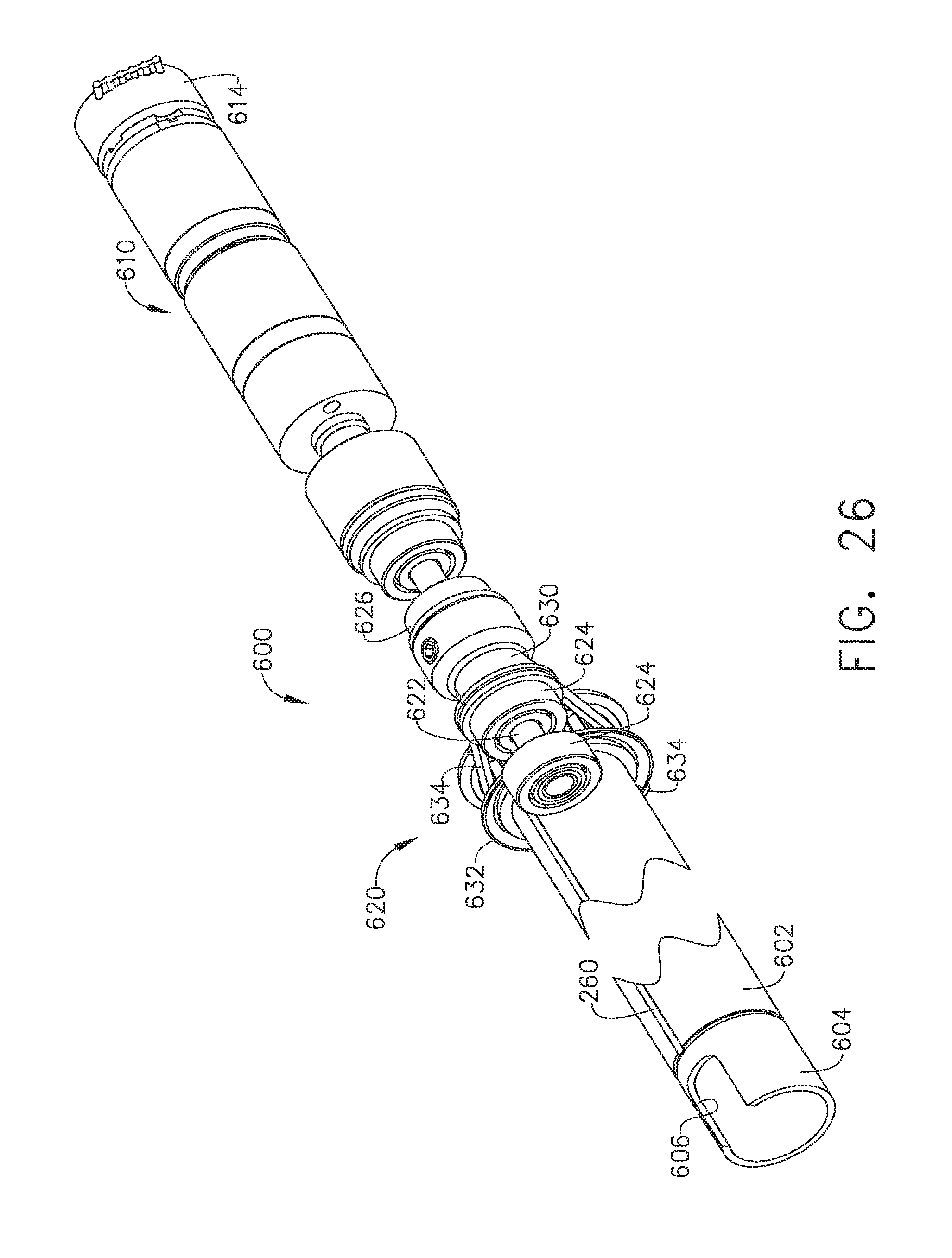
D00018

D00019

D00020

D00021

D00022

D00023

D00024

D00025

D00026

D00027

D00028

D00029
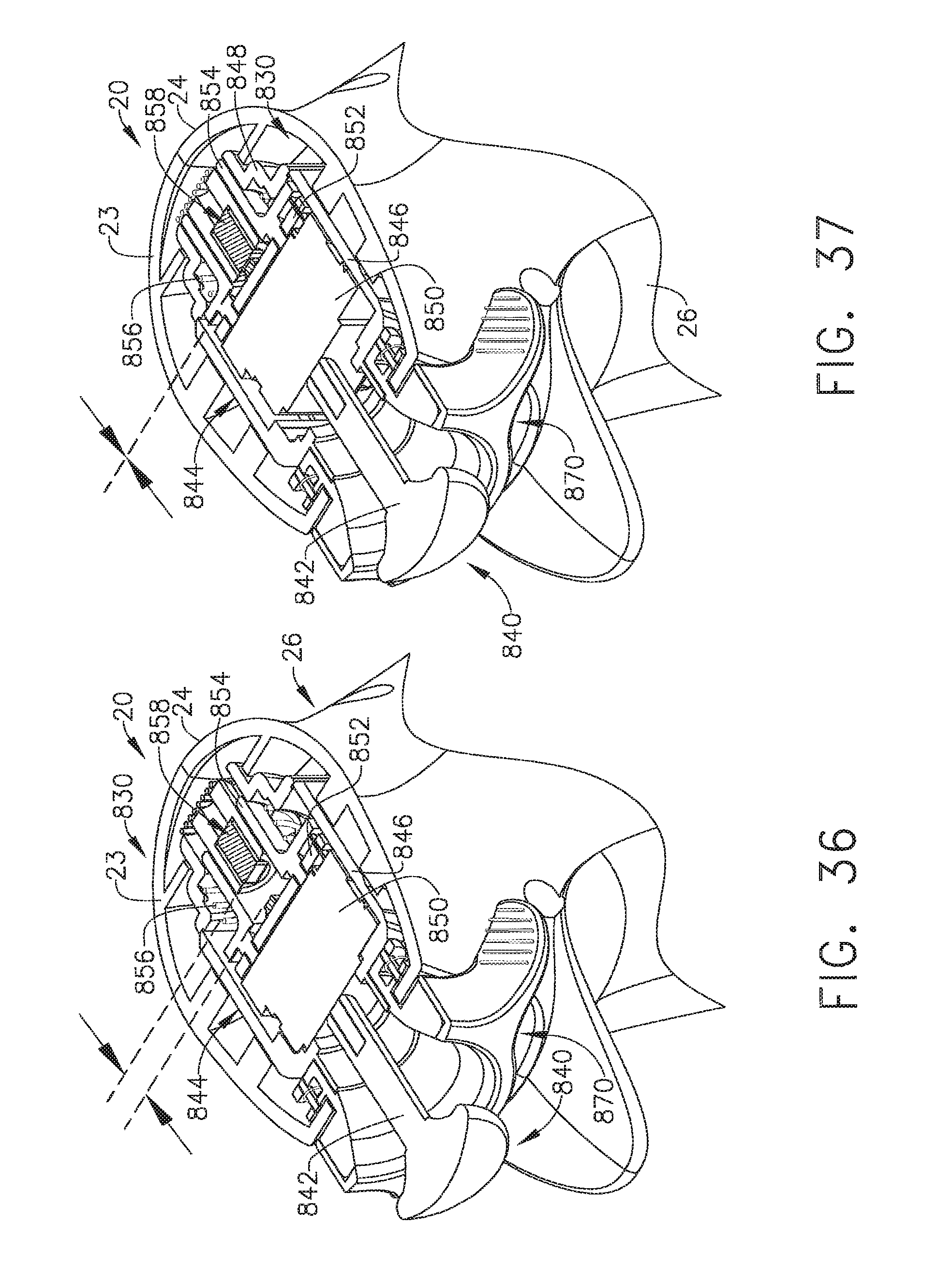
D00030

D00031

D00032

D00033

D00034

D00035

D00036

D00037

D00038

D00039

D00040

D00041

D00042

D00043

D00044

D00045

D00046

D00047

D00048

D00049
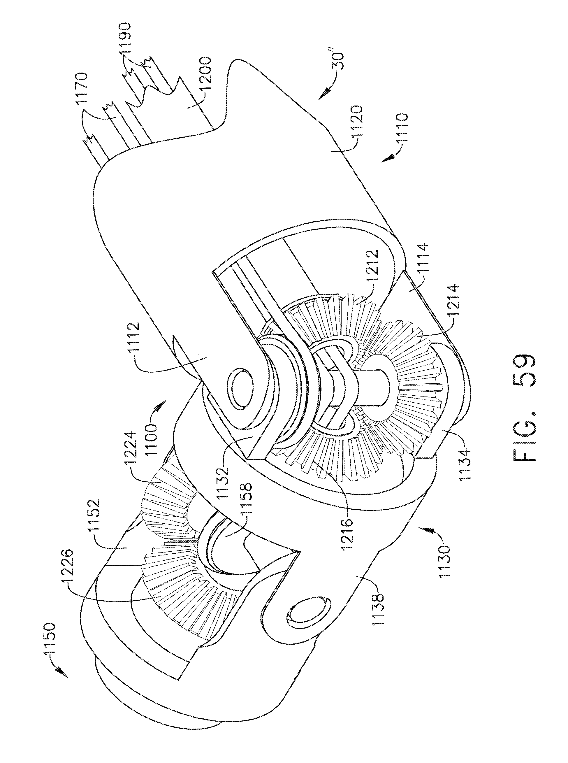
D00050

D00051

D00052

D00053

D00054

D00055

D00056

D00057

D00058

D00059

D00060

D00061

D00062

D00063

D00064
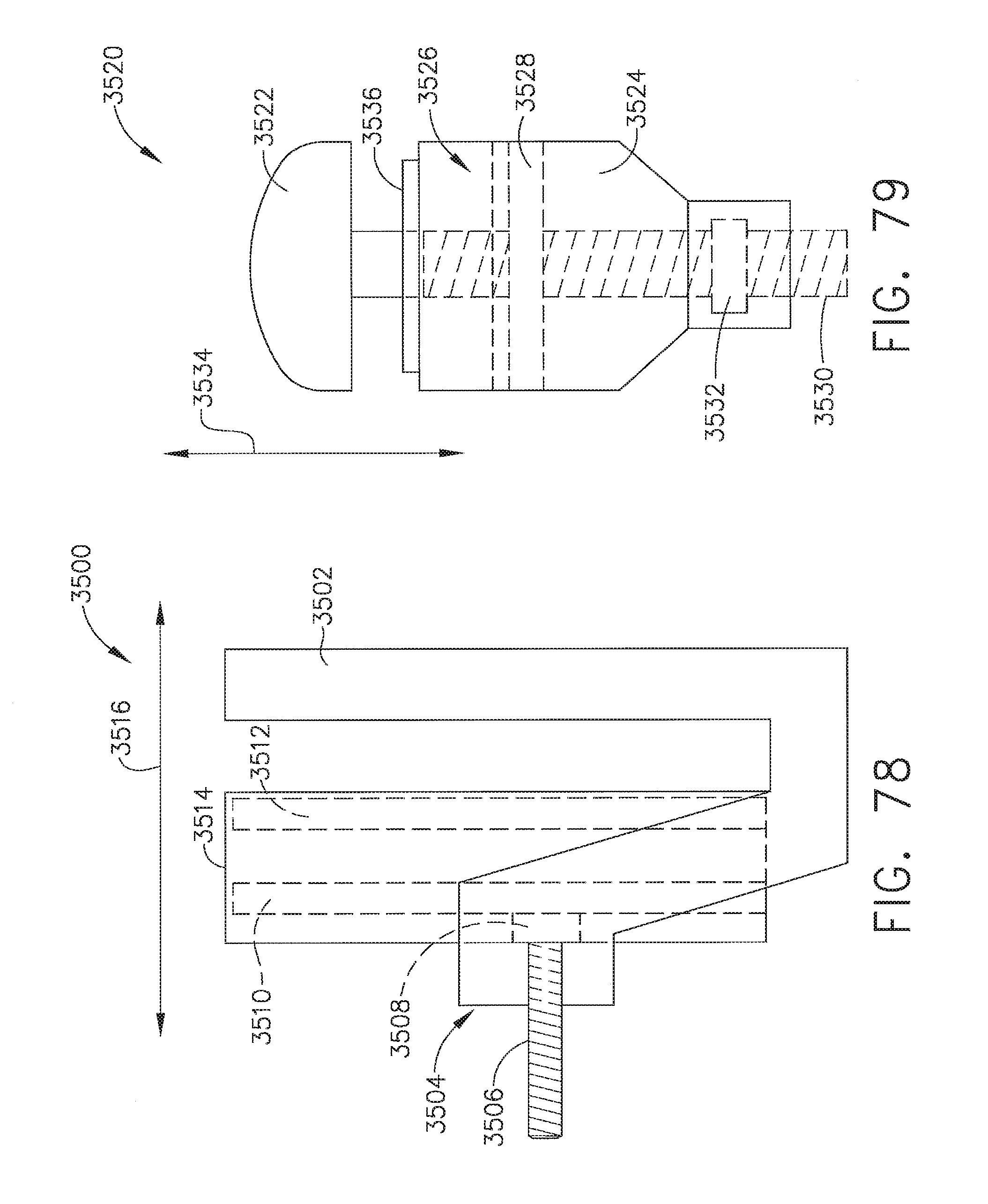
D00065

D00066

D00067
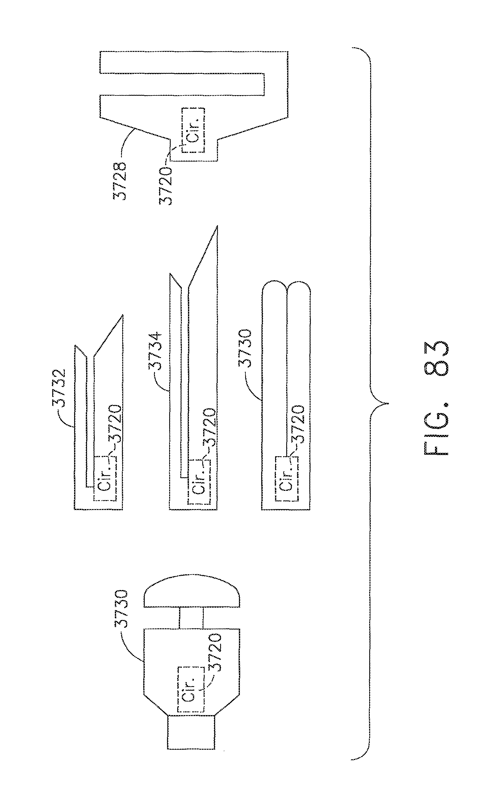
D00068

D00069

D00070

D00071

D00072

D00073

D00074

D00075

D00076

D00077

D00078

D00079

D00080
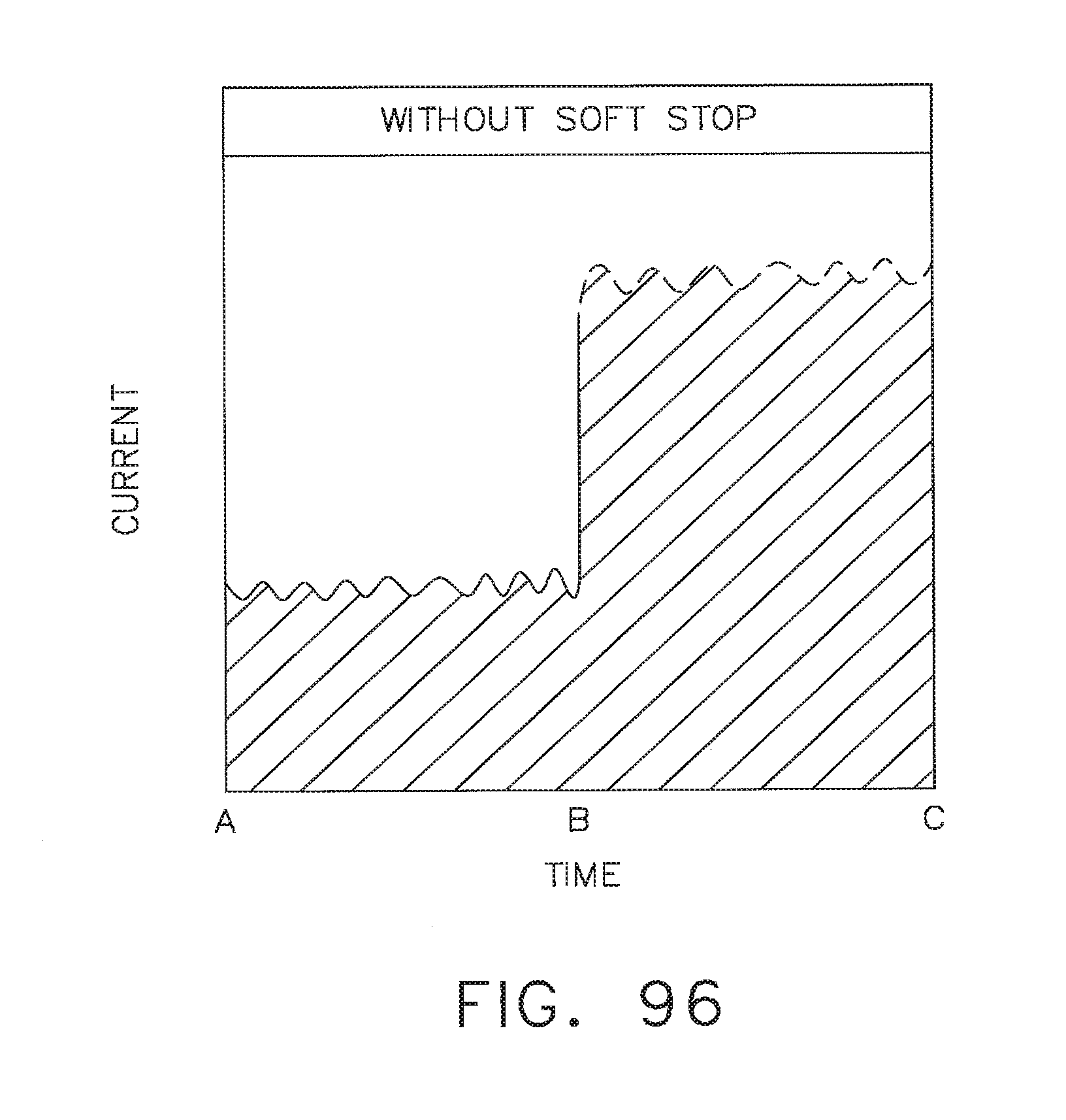
D00081

D00082

D00083

D00084

D00085

D00086

D00087

D00088

D00089

D00090

D00091

D00092

D00093

D00094
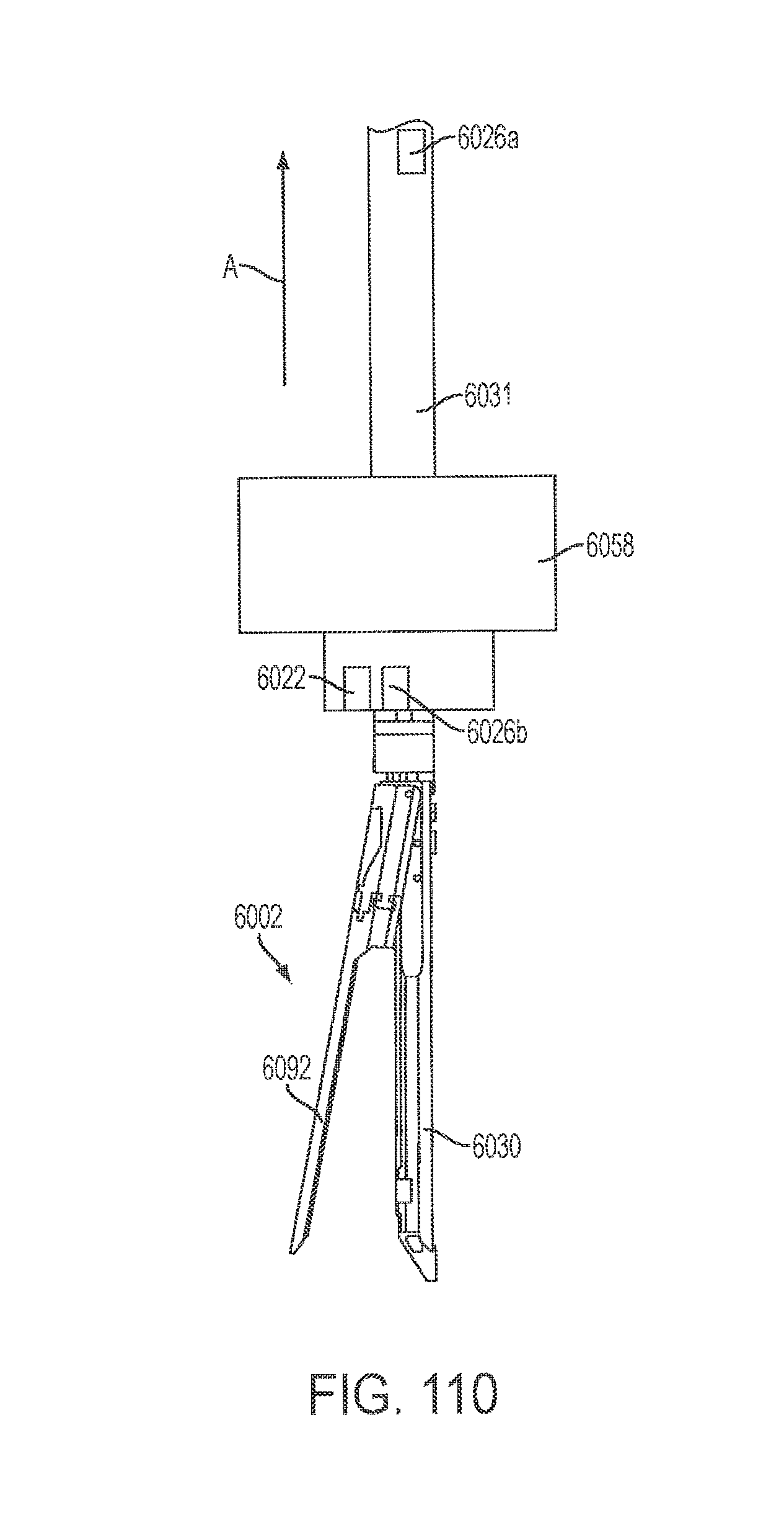
D00095

D00096

D00097
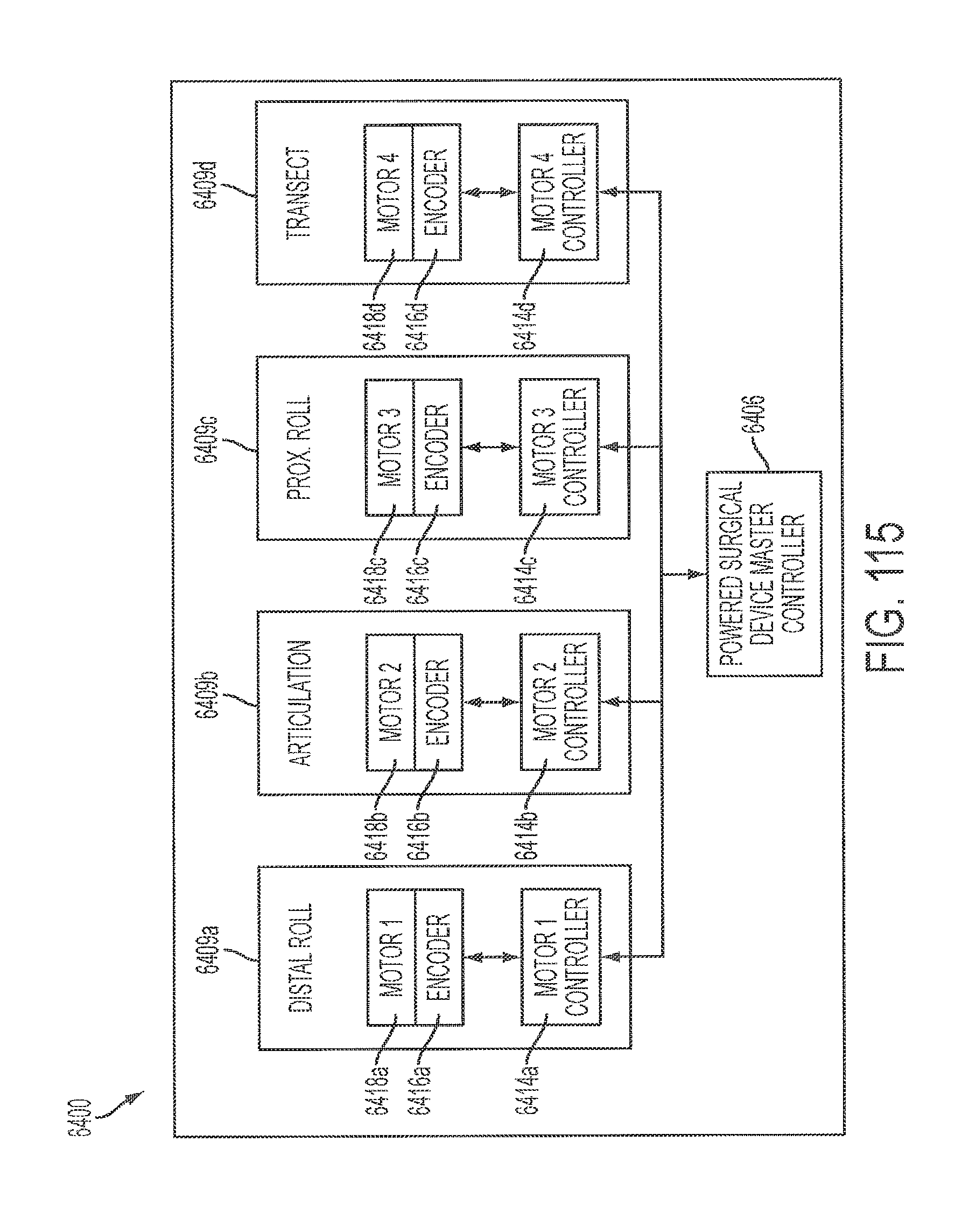
D00098

D00099

XML
uspto.report is an independent third-party trademark research tool that is not affiliated, endorsed, or sponsored by the United States Patent and Trademark Office (USPTO) or any other governmental organization. The information provided by uspto.report is based on publicly available data at the time of writing and is intended for informational purposes only.
While we strive to provide accurate and up-to-date information, we do not guarantee the accuracy, completeness, reliability, or suitability of the information displayed on this site. The use of this site is at your own risk. Any reliance you place on such information is therefore strictly at your own risk.
All official trademark data, including owner information, should be verified by visiting the official USPTO website at www.uspto.gov. This site is not intended to replace professional legal advice and should not be used as a substitute for consulting with a legal professional who is knowledgeable about trademark law.