Adapters With End Effector Position Sensing And Control Arrangements For Use In Connection With Electromechanical Surgical Instr
Shelton, IV; Frederick E. ; et al.
U.S. patent application number 15/843567 was filed with the patent office on 2019-06-20 for adapters with end effector position sensing and control arrangements for use in connection with electromechanical surgical instr. The applicant listed for this patent is Ethicon LLC. Invention is credited to Jason L. Harris, Frederick E. Shelton, IV, Michael J. Vendely, Sarah A. Worthington.
| Application Number | 20190183500 15/843567 |
| Document ID | / |
| Family ID | 64665677 |
| Filed Date | 2019-06-20 |


View All Diagrams
| United States Patent Application | 20190183500 |
| Kind Code | A1 |
| Shelton, IV; Frederick E. ; et al. | June 20, 2019 |
ADAPTERS WITH END EFFECTOR POSITION SENSING AND CONTROL ARRANGEMENTS FOR USE IN CONNECTION WITH ELECTROMECHANICAL SURGICAL INSTRUMENTS
Abstract
An adapter for use with an electromechanical surgical instrument. The adapter includes a shaft assembly and a surgical end effector that is selectively articulatable and rotatable relative to the shaft assembly through a range of articulated and rotated positions. The adapter includes sensing and control arrangements for monitoring and maintaining the end effector in articulated and/or rotated positions.
| Inventors: | Shelton, IV; Frederick E.; (Hillsboro, OH) ; Worthington; Sarah A.; (Angola, IN) ; Harris; Jason L.; (Lebanon, OH) ; Vendely; Michael J.; (Lebanon, OH) | ||||||||||
| Applicant: |
|
||||||||||
|---|---|---|---|---|---|---|---|---|---|---|---|
| Family ID: | 64665677 | ||||||||||
| Appl. No.: | 15/843567 | ||||||||||
| Filed: | December 15, 2017 |
| Current U.S. Class: | 1/1 |
| Current CPC Class: | H01M 2220/30 20130101; A61B 2090/067 20160201; A61B 2017/2948 20130101; A61B 2017/07285 20130101; A61B 2017/00477 20130101; H01M 10/425 20130101; A61B 2017/0023 20130101; A61B 2017/07257 20130101; A61B 90/06 20160201; A61B 2017/00734 20130101; A61B 2017/00407 20130101; A61B 2090/0813 20160201; A61B 2017/00398 20130101; A61B 2017/2927 20130101; A61B 2017/0046 20130101; A61B 2017/00473 20130101; H01M 2/1055 20130101; A61B 2090/0811 20160201; A61B 2017/07278 20130101; A61B 2017/07271 20130101; A61B 2017/00017 20130101; A61B 2090/034 20160201; A61B 17/07207 20130101 |
| International Class: | A61B 17/072 20060101 A61B017/072; A61B 90/00 20060101 A61B090/00 |
Claims
1. An adapter for use with an electromechanical surgical instrument, said adapter comprising: an adapter housing assembly configured to be operably coupled to the electromechanical surgical instrument; a shaft assembly defining a longitudinal axis between a proximal end and a distal end thereof, said proximal end operably coupled to said adapter housing assembly; a surgical end effector operably coupled to said distal end of said shaft assembly for selective articulation relative to said shaft assembly; and an articulation control system, comprising: a rotary drive shaft configured to operably interface with a source of rotary drive motions in the electromechanical surgical instrument when said adapter housing assembly is operably coupled thereto; an articulation driver arrangement operably interfacing with said rotary drive shaft and said surgical end effector and comprising an articulation member configured to move axially in response to rotation of said rotary drive shaft to articulate said surgical end effector through a range of articulated orientations; and means for monitoring an axial position of said articulation member during rotation of said rotary drive member and communicating a signal corresponding to said axial position to the electromechanical surgical instrument when said adapter housing assembly is operably coupled thereto.
2. The adapter of claim 1, wherein said articulation member is configured to move axially between a beginning axial position and an ending axial position in response to rotation of said rotary drive shaft and wherein said means for monitoring is configured to monitor said axial position of said articulation member between said beginning axial position and said ending axial position.
3. The adapter of claim 2, wherein said means for monitoring comprises an articulation sensor assembly configured to communicate with the electromechanical surgical instrument when said adapter housing assembly is operably coupled thereto, said articulation sensor assembly comprising: a first articulation sensor corresponding to said beginning axial position; and a second articulation sensor corresponding to said ending axial position, said first and second articulation sensors configured to detect said axial position of said articulation member between said beginning axial position and said ending axial position and generate said signal corresponding to said axial position of said articulation member and communicate said signal to the electromechanical surgical instrument.
4. The adapter of claim 3, wherein a portion of said articulation member is operably supported in an axially movable articulation bearing housing that is in threaded engagement with said rotary drive shaft and configured to move between said beginning axial position and said ending axial position in response to rotation of said rotary drive shaft and wherein said first and second articulation sensors are configured to sense a position of an articulation magnet supported by said articulation bearing housing.
5. The adapter of claim 2, wherein when a portion of said articulation member is in a neutral axial position located between said beginning axial position and said ending axial position, said surgical end effector is axially aligned with said longitudinal axis in an unarticulated position.
6. The adapter of claim 5, further comprising means for determining when said portion of said articulation member is in said neutral axial position.
7. The adapter of claim 6, wherein said portion of said articulation member is operably supported in an axially movable articulation bearing housing that is in threaded engagement with said rotary drive shaft and configured to move between said beginning axial position and said ending axial position in response to rotation of said rotary drive shaft and wherein said means for determining when said portion of said articulation member is in said neutral axial position comprises a neutral switch member configured to detect said bearing housing when said bearing housing is in said neutral axial position and send a corresponding signal to the electromechanical instrument.
8. The adapter of claim 7, wherein the source of rotary drive motions comprises an electrical powered articulation motor in the electromechanical surgical instrument and wherein said rotary drive shaft is configured to operably interface with an output shaft of the electrically powered articulation motor such that operation of the electrical powered articulation motor at a an electrical current level to move said portion of said articulation member between said beginning axial position and said ending axial position and wherein said means for determining when said portion of said articulation member is in said neutral axial position comprises means for altering said level of electrical current when said portion of said articulation member is in said neutral position.
9. The adapter of claim 8, wherein said portion of said articulation member is operably supported in an axially movable articulation bearing housing that is in threaded engagement with a threaded portion of said rotary drive shaft and is configured to move between said beginning axial position and said ending axial position in response to rotation of said rotary drive shaft, and wherein said means for altering said level of electrical current when said portion of said articulation member is in said neutral position comprises a rotational resistance generator on said rotary drive shaft configured to increase rotational resistance between said rotary drive shaft and said articulation bearing housing when said articulation bearing housing is in said neutral position to thereby increase said level of electrical current drawn by the electrical powered articulation motor.
10. The adapter of claim 9, wherein said rotational resistance generator comprises an O-ring on said threaded portion of said rotary drive shaft.
11. The adapter of claim 6, wherein said portion of said articulation member is operably supported in an axially movable articulation bearing housing that is in threaded engagement with said rotary drive shaft and is configured to move between said beginning axial position and said ending axial position in response to rotation of said rotary drive shaft and wherein the source of rotary drive motions comprises an electrical powered articulation motor in the electromechanical surgical instrument and wherein said rotary drive shaft is configured to operably interface with an output shaft of the electrically powered articulation motor such that when the electrical powered articulation motor draws a level of electrical current, the articulation motor causes said rotary drive shaft to move said portion of said articulation member between said beginning axial position and said ending axial position and wherein said means for determining when said portion of said articulation member is in said neutral axial position comprises a thread arrangement on said rotary drive shaft that is configured to reduce the level of electrical current drawn by the electrically powered articulation motor when said bearing housing is in said neutral axial position.
12. The adapter of claim 11, wherein said thread arrangement comprises a plurality of threads in threaded engagement with said bearing housing to move said bearing housing between said beginning and ending axial positions and configured such that a lesser number of said plurality of threads are in threaded engagement with said bearing housing when said bearing housing is in said neutral position so as to reduce the level of electrical current drawn by the electrically powered articulation motor.
13. The adapter of claim 6, wherein said portion of said articulation member is operably supported in an axially movable articulation housing that is in threaded engagement with a thread arrangement of said rotary drive shaft and is configured to move between said beginning axial position and said ending axial position in response to rotation of said rotary drive shaft, said thread arrangement comprising: a first thread segment configured to threadably engage said articulation housing; and a second thread segment spaced from said first thread segment by a central segment having a configuration that differs from said first and second thread segments and wherein said means for determining when said portion of said articulation member is in said neutral axial position comprises a sensor assembly configured to interact with said central segment and generate a signal indicative of an axial position of said movable articulation housing.
14. The adapter of claim 13, wherein said central segment is not threaded.
15. The adapter of claim 1, wherein said adapter housing assembly comprises: a drive coupler portion configured to be operably coupled to the electromechanical surgical instrument; and an outer knob housing coupled to said shaft assembly and rotatably supported on said drive coupler portion for selective rotation relative thereto about said longitudinal axis and wherein said adapter further comprises: a rotary drive system configured to operably interface with another source of rotary drive motions in the electromechanical surgical instrument when said drive coupler portion is operably coupled thereto, said rotary drive system configured to selectively rotate said outer knob housing about said longitudinal axis; and means for monitoring a rotary position of said outer knob housing during operation of said rotary drive system and communicating another signal corresponding to said rotary position to the electromechanical surgical instrument when said drive coupler portion is operably coupled thereto.
16. The adapter of claim 15, wherein said rotary drive system comprises another rotary drive shaft arrangement configured to operably interface with the another source of rotary drive motions in the electromechanical surgical instrument, said another rotary drive shaft arrangement in meshing engagement with said outer knob housing such that rotation of said another rotary drive shaft rotates said outer knob housing and wherein said means for monitoring a rotary position of said outer knob housing comprises a sensor arrangement configured to detect at least one magnet supported by said outer knob housing.
17. An adapter for use with an electromechanical surgical instrument, said adapter comprising: a shaft assembly defining a longitudinal axis between a proximal end and a distal end thereof; a surgical end effector operably coupled to said distal end of said shaft assembly; an adapter housing assembly comprising: a drive coupler portion configured to be operably coupled to the electromechanical surgical instrument; and an outer knob housing coupled to said shaft assembly and rotatably supported on said drive coupler portion for selective rotation relative thereto about said longitudinal axis and wherein said adapter further comprises: a rotary drive system configured to operably interface with a source of rotary drive motions in the electromechanical surgical instrument when said drive coupler portion is operably coupled thereto and said rotary drive system configured to selectively rotate said outer knob housing about said longitudinal axis; and means for monitoring a rotary position of said outer knob housing about said longitudinal axis during operation of said rotary drive system and communicating a signal corresponding to said rotary position to the electromechanical surgical instrument.
18. The adapter of claim 17, wherein said rotary drive system comprises a rotary drive shaft arrangement configured to operably interface with the source of rotary drive motions in the electromechanical surgical instrument, said rotary drive shaft arrangement in meshing engagement with said outer knob housing such that rotation of said rotary drive shaft rotates said outer knob housing and wherein said means for monitoring a rotary position of said outer knob housing comprises a sensor arrangement configured to detect at least one magnet supported by said outer knob housing.
19. An adapter for use with an electromechanical surgical instrument, said adapter comprising: an adapter housing assembly configured to be operably coupled to the electromechanical surgical instrument; a shaft assembly defining a longitudinal axis between a proximal end and a distal end thereof, said proximal end operably coupled to said adapter housing assembly; a surgical loading unit operably coupled to said distal end of said shaft assembly for selective articulation relative to said shaft assembly, said surgical loading unit comprising: a staple cartridge assembly; an anvil assembly; and a dynamic clamping assembly axially movable in said surgical loading unit in response to a firing drive motion applied thereto to clamp said anvil assembly and staple cartridge assembly onto tissue and cut the clamped tissue and fire staples from the staple cartridge assembly and wherein said adapter further comprises: a first rotary drive shaft assembly configured to operably interface with a first source of rotary drive motions in the electromechanical surgical instrument and said dynamic clamping assembly to apply said firing drive motion thereto; and an articulation control system, comprising: a second rotary drive shaft configured to operably interface with a second source of rotary drive motions in the electromechanical surgical instrument when said adapter housing assembly is operably coupled thereto; an articulation driver arrangement operably interfacing with said second rotary drive shaft and said surgical loading unit and comprising an articulation member configured to move axially in response to rotation of said second rotary drive shaft to articulate said surgical loading unit through a range of articulated orientations; and means for monitoring an axial position of said articulation member during rotation of said second rotary drive member and communicating a signal corresponding to said axial position to the electromechanical surgical instrument when said adapter housing is operably coupled thereto.
20. The adapter of claim 19, wherein said adapter housing comprises: a drive coupler portion configured to be operably coupled to the electromechanical surgical instrument; and an outer knob housing coupled to said shaft assembly and rotatably supported on said drive coupler portion for selective rotation relative thereto about said longitudinal axis and wherein said adapter further comprises: a rotary drive system configured to operably interface with a third source of rotary drive motions in the electromechanical surgical instrument when said drive coupler portion is operably coupled thereto and configured to selectively rotate said outer knob housing about said longitudinal axis; and means for monitoring a rotary position of said outer knob housing during operation of said rotary drive system and communicating another signal corresponding to said rotary position to the electromechanical surgical instrument when said drive coupler portion is operably coupled thereto.
Description
BACKGROUND
[0001] The present invention relates to surgical instruments and, in various arrangements, to surgical stapling and cutting instruments and staple cartridges for use therewith that are designed to staple and cut tissue.
BRIEF DESCRIPTION OF THE DRAWINGS
[0002] Various features of the embodiments described herein, together with advantages thereof, may be understood in accordance with the following description taken in conjunction with the accompanying drawings as follows:
[0003] FIG. 1 is a perspective view of an electromechanical surgical system;
[0004] FIG. 2 is a perspective view of a distal end of an electromechanical surgical instrument portion of the surgical system of FIG. 1;
[0005] FIG. 3 is an exploded assembly view of an outer shell feature and the electromechanical surgical instrument of FIG. 2;
[0006] FIG. 4 is a rear perspective view of a portion of the electromechanical surgical instrument of FIG. 2;
[0007] FIG. 5 is a partial exploded assembly view of a portion of an adapter and the electromechanical surgical instrument of the surgical system of FIG. 1;
[0008] FIG. 6 is an exploded assembly view of a portion of the adapter of FIG. 5;
[0009] FIG. 7 is a cross-sectional perspective view of a portion of an articulation assembly of an adapter;
[0010] FIG. 8 is a perspective view of the articulation assembly of FIG. 7;
[0011] FIG. 9 is another perspective view of the articulation assembly of FIG. 8;
[0012] FIG. 10 is an exploded assembly view of a loading unit employed in the electromechanical surgical system of FIG. 1;
[0013] FIG. 11 is a perspective view of an alternative adapter embodiment;
[0014] FIG. 12 is a side elevational view of a portion of a loading unit of the adapter of FIG. 11 with the jaws thereof in an open position;
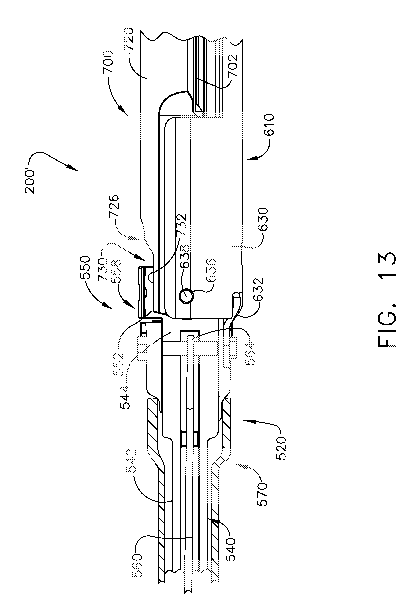
[0015] FIG. 13 is another side elevational view of a portion of the loading unit of FIG. 11 with portions thereof shown in cross-section and the jaws thereof in a closed position;
[0016] FIG. 14 is a bottom view of a portion of the loading unit of FIG. 13 with portions thereof shown in cross-section;
[0017] FIG. 15 is a perspective view of a portion of the loading unit of FIG. 14 with a portion of the outer tube shown in phantom lines;
[0018] FIG. 16 is a cross-sectional view of a proximal portion of another adapter employing various seal arrangements therein;
[0019] FIG. 17 is an end cross-sectional view of a portion of the adapter of FIG. 16;
[0020] FIG. 18 is a side elevation al view of another adapter;
[0021] FIG. 19 is a cross-sectional view of a portion of the adapter of FIG. 18;
[0022] FIG. 20 is a rear perspective view of portions of another adapter;
[0023] FIG. 21 is a cross-sectional view of another adapter;
[0024] FIG. 22 is a top view of a loading unit of an adapter with the tool assembly thereof in an unarticulated position;
[0025] FIG. 23 is another top view of the loading unit of FIG. 22 with the tool assembly in a first articulated position;
[0026] FIG. 24 is another top view of the loading unit of FIGS. 22 and 23 with the tool assembly in a second articulated position;
[0027] FIG. 25 is a perspective view of a portion of an adapter;
[0028] FIG. 26 is a perspective view of another portion of an adapter;
[0029] FIG. 27 is a partial cross-sectional perspective view of an articulation system and sensor assembly embodiment of an adapter in an unarticulated (neutral) position;
[0030] FIG. 28 is another perspective view of the articulation system and sensor assembly of FIG. 27 in a first articulated position;
[0031] FIG. 29 is another perspective view of the articulation system and sensor assembly of FIGS. 27 and 28 in a second articulated position;
[0032] FIG. 30 is a partial cross-sectional view a portion of an alternative proximal drive shaft and bearing housing of an alternative articulation system in an unarticulated (neutral) position;
[0033] FIG. 31 is another partial cross-sectional view the portion of an alternative proximal drive shaft and bearing housing of the alternative articulation system of FIG. 30 in an articulated position;
[0034] FIG. 32 is a partial cross-sectional view a portion of an alternative proximal drive shaft and bearing housing of an alternative articulation system in an unarticulated (neutral) position;
[0035] FIG. 33 is another partial cross-sectional view the portion of an alternative proximal drive shaft and bearing housing of the alternative articulation system of FIG. 32 in an articulated position;
[0036] FIG. 34 is a partial cross-sectional perspective view of another articulation system and sensor assembly embodiment of an adapter in an unarticulated (neutral) position;
[0037] FIG. 35 is a partial cross-sectional side view of the articulation system and sensor assembly embodiment of an adapter of FIG. 34 in the unarticulated (neutral) position;
[0038] FIG. 36 is another partial cross-sectional side view of the articulation system and sensor assembly embodiment of an adapter of FIGS. 34 and 35 in an articulated position;
[0039] FIG. 37 is another partial cross-sectional side view of the articulation system and sensor assembly embodiment of an adapter of FIGS. 34-36 in another articulated position; and
[0040] FIG. 38 is a perspective view of portions of an articulation system and sensor system and a shaft rotation system and sensor arrangement of another adapter.
[0041] Corresponding reference characters indicate corresponding parts throughout the several views. The exemplifications set out herein illustrate various embodiments of the invention, in one form, and such exemplifications are not to be construed as limiting the scope of the invention in any manner.
DETAILED DESCRIPTION
[0042] Applicant of the present application owns the following U.S. Patent Applications that were filed on even date herewith and which are each herein incorporated by reference in their respective entireties: [0043] U.S. patent application Ser. No. ______, entitled SEALED ADAPTERS FOR USE WITH ELECTROMECHANICAL SURGICAL INSTRUMENTS; Attorney Docket No. END8286USNP/170227; [0044] U.S. patent application Ser. No. ______, entitled END EFFECTORS WITH POSITIVE JAW OPENING FEATURES FOR USE WITH ADAPTERS FOR ELECTROMECHANICAL SURGICAL INSTRUMENTS; Attorney Docket No. END8277USNP/170219; [0045] U.S. patent application Ser. No. ______, entitled SURGICAL END EFFECTORS WITH CLAMPING ASSEMBLIES CONFIGURED TO INCREASE JAW APERTURE RANGES; Attorney Docket No. END8278USNP/170220; [0046] U.S. patent application Ser. No. ______, entitled SURGICAL END EFFECTORS WITH PIVOTAL JAWS CONFIGURED TO TOUCH AT THEIR RESPECTIVE DISTAL ENDS WHEN FULLY CLOSED; Attorney Docket No. END8283USNP/170223; [0047] U.S. patent application Ser. No. ______, entitled SURGICAL END EFFECTORS WITH JAW STIFFENER ARRANGEMENTS CONFIGURED TO PERMIT MONITORING OF FIRING MEMBER; Attorney Docket No. END8282USNP/170221; [0048] U.S. patent application Ser. No. ______, entitled DYNAMIC CLAMPING ASSEMBLIES WITH IMPROVED WEAR CHARACTERISTICS FOR USE IN CONNECTION WITH ELECTROMECHANICAL SURGICAL INSTRUMENTS; Attorney Docket No. END8279USNP/170222; [0049] U.S. patent application Ser. No. ______, entitled ADAPTERS WITH FIRING STROKE SENSING ARRANGEMENTS FOR USE IN CONNECTION WITH ELECTROMECHANICAL SURGICAL INSTRUMENTS; Attorney Docket No. END8287USNP/170229; [0050] U.S. patent application Ser. No. ______, entitled ADAPTERS WITH CONTROL SYSTEMS FOR CONTROLLING MULTIPLE MOTORS OF AN ELECTROMECHANICAL SURGICAL INSTRUMENT; Attorney Docket No. END8284USNP/170224; [0051] U.S. patent application Ser. No. ______, entitled HANDHELD ELECTROMECHANICAL SURGICAL INSTRUMENTS WITH IMPROVED MOTOR CONTROL ARRANGEMENTS FOR POSITIONING COMPONENTS OF AN ADAPTER COUPLED THERETO; Attorney Docket No. END8285USNP/170225; [0052] U.S. patent application Ser. No. ______, entitled SYSTEMS AND METHODS OF CONTROLLING A CLAMPING MEMBER FIRING RATE OF A SURGICAL INSTRUMENT; Attorney Docket No. END8280USNP/170226; [0053] U.S. patent application Ser. No. ______, entitled SYSTEMS AND METHODS OF CONTROLLING A CLAMPING MEMBER; Attorney Docket No. END8335USNP/170231; and [0054] U.S. patent application Ser. No. ______, entitled METHODS OF OPERATING SURGICAL END EFFECTORS; Attorney Docket No. END8298USNP/170218M.
[0055] Numerous specific details are set forth to provide a thorough understanding of the overall structure, function, manufacture, and use of the embodiments as described in the specification and illustrated in the accompanying drawings. Well-known operations, components, and elements have not been described in detail so as not to obscure the embodiments described in the specification. The reader will understand that the embodiments described and illustrated herein are non-limiting examples, and thus it can be appreciated that the specific structural and functional details disclosed herein may be representative and illustrative. Variations and changes thereto may be made without departing from the scope of the claims.
[0056] The terms "comprise" (and any form of comprise, such as "comprises" and "comprising"), "have" (and any form of have, such as "has" and "having"), "include" (and any form of include, such as "includes" and "including") and "contain" (and any form of contain, such as "contains" and "containing") are open-ended linking verbs. As a result, a surgical system, device, or apparatus that "comprises," "has," "includes" or "contains" one or more elements possesses those one or more elements, but is not limited to possessing only those one or more elements. Likewise, an element of a system, device, or apparatus that "comprises," "has," "includes" or "contains" one or more features possesses those one or more features, but is not limited to possessing only those one or more features.
[0057] The terms "proximal" and "distal" are used herein with reference to a clinician manipulating the handle portion of the surgical instrument. The term "proximal" refers to the portion closest to the clinician and the term "distal" refers to the portion located away from the clinician. It will be further appreciated that, for convenience and clarity, spatial terms such as "vertical", "horizontal", "up", and "down" may be used herein with respect to the drawings. However, surgical instruments are used in many orientations and positions, and these terms are not intended to be limiting and/or absolute.
[0058] Various exemplary devices and methods are provided for performing laparoscopic and minimally invasive surgical procedures. However, the reader will readily appreciate that the various methods and devices disclosed herein can be used in numerous surgical procedures and applications including, for example, in connection with open surgical procedures. As the present Detailed Description proceeds, the reader will further appreciate that the various instruments disclosed herein can be inserted into a body in any way, such as through a natural orifice, through an incision or puncture hole formed in tissue, etc. The working portions or end effector portions of the instruments can be inserted directly into a patient's body or can be inserted through an access device that has a working channel through which the end effector and elongate shaft of a surgical instrument can be advanced.
[0059] A surgical stapling system can comprise a shaft and an end effector extending from the shaft. The end effector comprises a first jaw and a second jaw. The first jaw comprises a staple cartridge. The staple cartridge is insertable into and removable from the first jaw; however, other embodiments are envisioned in which a staple cartridge is not removable from, or at least readily replaceable from, the first jaw. The second jaw comprises an anvil configured to deform staples ejected from the staple cartridge. The second jaw is pivotable relative to the first jaw about a closure axis; however, other embodiments are envisioned in which the first jaw is pivotable relative to the second jaw. The surgical stapling system further comprises an articulation joint configured to permit the end effector to be rotated, or articulated, relative to the shaft. The end effector is rotatable about an articulation axis extending through the articulation joint. Other embodiments are envisioned which do not include an articulation joint.
[0060] The staple cartridge comprises a cartridge body. The cartridge body includes a proximal end, a distal end, and a deck extending between the proximal end and the distal end. In use, the staple cartridge is positioned on a first side of the tissue to be stapled and the anvil is positioned on a second side of the tissue. The anvil is moved toward the staple cartridge to compress and clamp the tissue against the deck. Thereafter, staples removably stored in the cartridge body can be deployed into the tissue. The cartridge body includes staple cavities defined therein wherein staples are removably stored in the staple cavities. The staple cavities are arranged in six longitudinal rows. Three rows of staple cavities are positioned on a first side of a longitudinal slot and three rows of staple cavities are positioned on a second side of the longitudinal slot. Other arrangements of staple cavities and staples may be possible.
[0061] The staples are supported by staple drivers in the cartridge body. The drivers are movable between a first, or unfired position, and a second, or fired, position to eject the staples from the staple cavities. The drivers are retained in the cartridge body by a retainer which extends around the bottom of the cartridge body and includes resilient members configured to grip the cartridge body and hold the retainer to the cartridge body. The drivers are movable between their unfired positions and their fired positions by a sled. The sled is movable between a proximal position adjacent the proximal end and a distal position adjacent the distal end. The sled comprises a plurality of ramped surfaces configured to slide under the drivers and lift the drivers, and the staples supported thereon, toward the anvil.
[0062] Further to the above, the sled is moved distally by a firing member. The firing member is configured to contact the sled and push the sled toward the distal end. The longitudinal slot defined in the cartridge body is configured to receive the firing member. The anvil also includes a slot configured to receive the firing member. The firing member further comprises a first cam which engages the first jaw and a second cam which engages the second jaw. As the firing member is advanced distally, the first cam and the second cam can control the distance, or tissue gap, between the deck of the staple cartridge and the anvil. The firing member also comprises a knife configured to incise the tissue captured intermediate the staple cartridge and the anvil. It is desirable for the knife to be positioned at least partially proximal to the ramped surfaces such that the staples are ejected ahead of the knife.
[0063] FIG. 1 depicts a motor-driven (electromechanical) surgical system 1 that may be used to perform a variety of different surgical procedures. As can be seen in that Figure, one example of the surgical system 1 includes a powered handheld electromechanical surgical instrument 100 that is configured for selective attachment thereto of a plurality of different surgical tool implements (referred to herein as "adapters") that are each configured for actuation and manipulation by the powered handheld electromechanical surgical instrument. As illustrated in FIG. 1, the handheld surgical instrument 100 is configured for selective connection with an adapter 200, and, in turn, adapter 200 is configured for selective connection with end effectors that comprise a single use loading unit ("SULU") or a disposable loading unit ("DLU") or a multiple use loading unit ("MULU"). In another surgical system embodiment, various forms of adapter 200 may also be effectively employed with a tool drive assembly of a robotically controlled or automated surgical system. For example, the surgical tool assemblies disclosed herein may be employed with various robotic systems, instruments, components and methods such as, but not limited to, those disclosed in U.S. Pat. No. 9,072,535, entitled SURGICAL STAPLING INSTRUMENTS WITH ROTATABLE STAPLE DEPLOYMENT ARRANGEMENTS, which is hereby incorporated by reference herein in its entirety.
[0064] As illustrated in FIGS. 1 and 2, surgical instrument 100 includes a power-pack 101 and an outer shell housing 10 that is configured to selectively receive and substantially encase the power-pack 101. The power pack 101 may also be referred to herein as handle assembly 101. One form of surgical instrument 100, for example, is disclosed in International Publication No. WO 2016/057225 A1, International Application No. PCT/US2015/051837, entitled HANDHELD ELECTROMECHANICAL SURGICAL SYSTEM, the entire disclosure of which is hereby incorporated by reference herein. Various features of surgical instrument 100 will not be disclosed herein beyond what is necessary to understand the various features of the inventions disclosed herein with it being understood that further details may be gleaned from reference to WO 2016/057225 A1 and other references incorporated by reference herein.
[0065] As illustrated in FIG. 3, outer shell housing 10 includes a distal half-section 10a and a proximal half-section 10b that is pivotably connected to distal half-section 10a by a hinge 16 located along an upper edge of distal half-section 10a and proximal half-section 10b. When joined, distal and proximal half-sections 10a, 10b define a shell cavity 10c therein in which the power-pack 101 is selectively situated. Each of distal and proximal half-sections 10a, 10b includes a respective upper shell portion 12a, 12b, and a respective lower shell portion 14a, 14b. Lower shell portions 14a, 14b define a snap closure feature 18 for selectively securing the lower shell portions 14a, 14b to one another and for maintaining shell housing 10 in a closed condition. Distal half-section 10a of shell housing 10 defines a connecting portion 20 that is configured to accept a corresponding drive coupling assembly 210 of adapter 200 (see FIG. 5). Specifically, distal half-section 10a of shell housing 10 has a recess that receives a portion of drive coupling assembly 210 of adapter 200 when adapter 200 is mated to surgical instrument 100.
[0066] Connecting portion 20 of distal half-section 10a defines a pair of axially extending guide rails 21a, 21b that project radially inward from inner side surfaces thereof as shown in FIG. 5. Guide rails 21a, 21b assist in rotationally orienting adapter 200 relative to surgical instrument 100 when adapter 200 is mated to surgical instrument 100. Connecting portion 20 of distal half-section 10a defines three apertures 22a, 22b, 22c that are formed in a distally facing surface thereof and which are arranged in a common plane or line with one another. Connecting portion 20 of distal half-section 10a also defines an elongate slot 24 also formed in the distally facing surface thereof. Connecting portion 20 of distal half-section 10a further defines a female connecting feature 26 (see FIG. 2) formed in a surface thereof. Female connecting feature 26 selectively engages with a male connecting feature of adapter 200.
[0067] Distal half-section 10a of shell housing 10 supports a distal facing toggle control button 30. The toggle control button 30 is capable of being actuated in a left, right, up and down direction upon application of a corresponding force thereto or a depressive force thereto. Distal half-section 10a of shell housing 10 supports a right-side pair of control buttons 32a, 32b (see FIG. 3); and a left-side pair of control button 34a, 34b (see FIG. 2). The right-side control buttons 32a, 32b and the left-side control buttons 34a, 34b are capable of being actuated upon application of a corresponding force thereto or a depressive force thereto. Proximal half-section 10b of shell housing 10 supports a right-side control button 36a (see FIG. 3) and a left-side control button 36b (see FIG. 2). Right-side control button 36a and left-side control button 36b are capable of being actuated upon application of a corresponding force thereto or a depressive force thereto.
[0068] Shell housing 10 includes a sterile barrier plate assembly 60 selectively supported in distal half-section 10a. Specifically, the sterile barrier plate assembly 60 is disposed behind connecting portion 20 of distal half-section 10a and within shell cavity 10c of shell housing 10. The plate assembly 60 includes a plate 62 rotatably supporting three coupling shafts 64a, 64b, 64c (see FIGS. 3 and 5). Each coupling shaft 64a, 64b, 64c extends from opposed sides of plate 62 and has a tri-lobe transverse cross-sectional profile. Each coupling shaft 64a, 64b, 64c extends through the respective apertures 22a, 22b, 22c of connecting portion 20 of distal half-section 10a when the sterile barrier plate assembly 60 is disposed within shell cavity 10c of shell housing 10. The plate assembly 60 further includes an electrical pass-through connector 66 supported on plate 62. Pass-through connector 66 extends from opposed sides of plate 62. Pass-through connector 66 defines a plurality of contact paths each including an electrical conduit for extending an electrical connection across plate 62. When the plate assembly 60 is disposed within shell cavity 10c of shell housing 10, distal ends of coupling shaft 64a, 64b, 64c and a distal end of pass-through connector 66 are disposed or situated within connecting portion 20 of distal half-section 10a of shell housing 10, and are configured to electrically and/or mechanically engage respective corresponding features of adapter 200.
[0069] Referring to FIGS. 3 and 4, the power-pack or the handle assembly 101 includes an inner handle housing 110 having a lower housing portion 104 and an upper housing portion 108 extending from and/or supported on lower housing portion 104. Lower housing portion 104 and upper housing portion 108 are separated into a distal half section 110a and a proximal half-section 110b connectable to distal half-section 110a by a plurality of fasteners. When joined, distal and proximal half-sections 110a, 110b define the inner handle housing 110 having an inner housing cavity 110c therein in which a power-pack core assembly 106 is situated. Power-pack core assembly 106 is configured to control the various operations of surgical instrument 100.
[0070] Distal half-section 110a of inner handle housing 110 supports a distal toggle control interface 130 that is in operative registration with the distal toggle control button 30 of shell housing 10. In use, when the power-pack 101 is disposed within shell housing 10, actuation of the toggle control button 30 exerts a force on toggle control interface 130. Distal half-section 110a of inner handle housing 110 also supports a right-side pair of control interfaces (not shown), and a left-side pair of control interfaces 132a, 132b. In use, when the power-pack 101 is disposed within shell housing 10, actuation of one of the right-side pair of control buttons or the left-side pair of control button of distal half-section 10a of shell housing 10 exerts a force on a respective one of the right-side pair of control interfaces 132a, 132b or the left-side pair of control interfaces 132a, 132b of distal half-section 110a of inner handle housing 110.
[0071] With reference to FIGS. 1-5, inner handle housing 110 provides a housing in which power-pack core assembly 106 is situated. Power-pack core assembly 106 includes a battery circuit 140, a controller circuit board 142 and a rechargeable battery 144 configured to supply power to any of the electrical components of surgical instrument 100. Controller circuit board 142 includes a motor controller circuit board 142a, a main controller circuit board 142b, and a first ribbon cable 142c interconnecting motor controller circuit board 142a and main controller circuit board 142b. Power-pack core assembly 106 further includes a display screen 146 supported on main controller circuit board 142b. Display screen 146 is visible through a clear or transparent window 110d (see FIG. 3) provided in proximal half-section 110b of inner handle housing 110. It is contemplated that at least a portion of inner handle housing 110 may be fabricated from a transparent rigid plastic or the like. It is further contemplated that shell housing 10 may either include a window formed therein (in visual registration with display screen 146 and with window 110d of proximal half-section 110b of inner handle housing 110, and/or shell housing 10 may be fabricated from a transparent rigid plastic or the like.
[0072] Power-pack core assembly 106 further includes a first motor 152, a second motor 154, and a third motor 156 that are supported by motor bracket 148 and are each electrically connected to controller circuit board 142 and battery 144. Motors 152, 154, 156 are disposed between motor controller circuit board 142a and main controller circuit board 142b. Each motor 152, 154, 156 includes a respective motor shaft 152a, 154a, 156a extending therefrom. Each motor shaft 152a, 154a, 156a has a tri-lobe transverse cross-sectional profile for transmitting rotative forces or torque. Each motor 152, 154, 156 is controlled by a respective motor controller. Rotation of motor shafts 152a, 154a, 156a by respective motors 152, 154, 156 function to drive shafts and/or gear components of adapter 200 in order to perform the various operations of surgical instrument 100. In particular, motors 152, 154, 156 of power-pack core assembly 106 are configured to drive shafts and/or gear components of adapter 200.
[0073] As illustrated in FIGS. 1 and 5, surgical instrument 100 is configured for selective connection with adapter 200, and, in turn, adapter 200 is configured for selective connection with end effector 500. Adapter 200 includes an outer knob housing 202 and an outer tube 206 that extends from a distal end of knob housing 202. Knob housing 202 and outer tube 206 are configured and dimensioned to house the components of adapter assembly 200. Outer tube 206 is dimensioned for endoscopic insertion, in particular, that outer tube is passable through a typical trocar port, cannula or the like. Knob housing 202 is dimensioned to not enter the trocar port, cannula of the like. Knob housing 202 is configured and adapted to connect to connecting portion 20 of the outer shell housing 10 of surgical instrument 100.
[0074] Adapter 200 is configured to convert a rotation of either of first or second coupling shafts 64a, 64b of surgical instrument 100 into axial translation useful for operating a drive assembly 540 and an articulation link 560 of end effector 500, as illustrated in FIG. 10 and as will be described in greater detail below. As illustrated in FIG. 6, adapter 200 includes the proximal inner housing assembly 204 that rotatably supports a first rotatable proximal drive shaft 212, a second rotatable proximal drive shaft 214, and a third rotatable proximal drive shaft 216 therein. Each proximal drive shaft 212, 214, 216 functions as a rotation receiving member to receive rotational forces from respective coupling shafts 64a, 64b and 64c of surgical instrument 100. In addition, the drive coupling assembly 210 of adapter 200 is also configured to rotatably support first, second and third connector sleeves 218, 220 and 222, respectively, arranged in a common plane or line with one another. Each connector sleeve 218, 220, 222 is configured to mate with respective first, second and third coupling shafts 64a, 64b, 64c of surgical instrument 100, as described above. Each connector sleeves 218, 222, 220 is further configured to mate with a proximal end of respective first, second, and third proximal drive shafts 212, 214, 216 of adapter 200.
[0075] Drive coupling assembly 210 of adapter 200 also includes a first, a second, and a third biasing member 224, 226, and 228 disposed distally of respective first, second, and third connector sleeves 218, 220, 222. Each biasing members 224, 226, and 228 is disposed about respective first, second, and third rotatable proximal drive shaft 212, 214, and 216. Biasing members 224, 226, and 228 act on respective connector sleeves 218, 222, and 220 to help maintain connector sleeves 218, 222. and 220 engaged with the distal end of respective coupling shafts 64a, 64b, and 64c of surgical instrument 100 when adapter 200 is connected to surgical instrument 100.
[0076] Also in the illustrated arrangement, adapter 200 includes first, second, and third drive converting assemblies 240, 250, 260, respectively, that are each disposed within inner housing assembly 204 and outer tube 206. Each drive converting assembly 240, 250, 260 is configured and adapted to transmit or convert a rotation of a first, second, and third coupling shafts 64a, 64b, and 64c of surgical instrument 100 into axial translation of an articulation driver or bar 258 of adapter 200, to effectuate articulation of end effector 500; a rotation of a ring gear 266 of adapter 200, to effectuate rotation of adapter 200; or axial translation of a distal drive member 248 of adapter 200 to effectuate closing, opening, and firing of end effector 500.
[0077] Still referring to FIG. 6, first force/rotation transmitting/converting assembly 240 includes first rotatable proximal drive shaft 212, which, as described above, is rotatably supported within inner housing assembly 204. First rotatable proximal drive shaft 212 includes a non-circular or shaped proximal end portion configured for connection with first connector sleeve 218 which is connected to respective first coupling shaft 64a of surgical instrument 100. First rotatable proximal drive shaft 212 includes a threaded distal end portion 212b. First force/rotation transmitting/converting assembly 240 further includes a drive coupling nut 244 that threadably engages the threaded distal end portion 212b of first rotatable proximal drive shaft 212, and which is slidably disposed within outer tube 206. Drive coupling nut 244 is slidably keyed within proximal core tube portion of outer tube 206 so as to be prevented from rotation as first rotatable proximal drive shaft 212 is rotated. In this manner, as the first rotatable proximal drive shaft 212 is rotated, drive coupling nut 244 is translated along threaded distal end portion 212b of first rotatable proximal drive shaft 212 and, in turn, through and/or along outer tube 206.
[0078] First force/rotation transmitting/converting assembly 240 further includes a distal drive member 248 that is mechanically engaged with drive coupling nut 244, such that axial movement of drive coupling nut 244 results in a corresponding amount of axial movement of distal drive member 248. The distal end portion of distal drive member 248 supports a connection member 247 configured and dimensioned for selective engagement with an engagement member 546 of a drive assembly 540 of end effector 500 (FIG. 10). Drive coupling nut 244 and/or distal drive member 248 function as a force transmitting member to components of end effector 500. In operation, as first rotatable proximal drive shaft 212 is rotated, as a result of the rotation of first coupling shaft 64a of surgical instrument 100, drive coupling nut 244 is translated axially along first rotatable proximal drive shaft 212. As drive coupling nut 244 is translated axially along first rotatable proximal drive shaft 212, distal drive member 248 is translated axially relative to outer tube 206. As distal drive member 248 is translated axially, with connection member 247 connected thereto and engaged with a hollow drive member 548 attached to drive assembly 540 of end effector 500 (FIG. 10), distal drive member 248 causes concomitant axial translation of drive assembly 540 of end effector 500 to effectuate a closure of a tool assembly portion 600 of the end effector 500 and a firing of various components within the tool assembly.
[0079] Still referring to FIG. 6, second drive converting assembly 250 of adapter 200 includes second proximal drive shaft 214 that is rotatably supported within inner housing assembly 204. Second rotatable proximal drive shaft 214 includes a non-circular or shaped proximal end portion configured for connection with second coupling shaft 64c of surgical instrument 100. Second rotatable proximal drive shaft 214 further includes a threaded distal end portion 214a configured to threadably engage an articulation bearing housing 253 of an articulation bearing assembly 252. Referring to FIGS. 6-9, the articulation bearing housing 253 supports an articulation bearing 255 that has an inner race 257 that is independently rotatable relative to an outer race 259. Articulation bearing housing 253 has a non-circular outer profile, for example tear-dropped shaped, that is slidably and non-rotatably disposed within a complementary bore (not shown) of inner housing hub 204a. Second drive converting assembly 250 of adapter 200 further includes articulation bar 258 that has a proximal portion that is secured to inner race 257 of articulation bearing 255. A distal portion of articulation bar 258 includes a slot 258a therein, which is configured to accept a hook 562 the articulation link 560 (FIG. 10) of end effector 500. Articulation bar 258 functions as a force transmitting member to components of end effector 500. In the illustrated arrangement and as further discussed in WO 2016/057225 A1, articulation bearing assembly 252 is both rotatable and longitudinally translatable and is configured to permit free, unimpeded rotational movement of end effector 500 when its first and second jaw members 610, 700 are in an approximated position and/or when jaw members 610, 700 are articulated.
[0080] In operation, as second proximal drive shaft 214 is rotated, the articulation bearing assembly 252 is axially translated along threaded distal end portion 214a of second proximal drive shaft 214, which in turn, causes articulation bar 258 to be axially translated relative to outer tube 206. As articulation bar 258 is translated axially, articulation bar 258, being coupled to articulation link 560 of end effector 500, causes concomitant axial translation of articulation link 560 of end effector 500 to effectuate an articulation of tool assembly 600. Articulation bar 258 is secured to inner race 257 of articulation bearing 253 and is thus free to rotate about the longitudinal axis relative to outer race 259 of articulation bearing 253.
[0081] As illustrated in FIG. 6, adapter 200 includes a third drive converting assembly 260 that is supported in inner housing assembly 204. Third drive converting assembly 260 includes rotation ring gear 266 that is fixedly supported in and connected to outer knob housing 202. Ring gear 266 defines an internal array of gear teeth 266a and includes a pair of diametrically opposed, radially extending protrusions 266b. Protrusions 266b are configured to be disposed within recesses defined in outer knob housing 202, such that rotation of ring gear 266 results in rotation of outer knob housing 202, and vice a versa. Third drive converting assembly 260 further includes third rotatable proximal drive shaft 216 which, as described above, is rotatably supported within inner housing assembly 204. Third rotatable proximal drive shaft 216 includes a non-circular or shaped proximal end portion that is configured for connection with third connector 220. Third rotatable proximal drive shaft 216 includes a spur gear 216 keyed to a distal end thereof. A reversing spur gear 264 inter-engages spur gear 216a of third rotatable proximal drive shaft 216 to gear teeth 266a of ring gear 266. In operation, as third rotatable proximal drive shaft 216 is rotated, due to a rotation of the third coupling shaft 64b of surgical instrument 100, spur gear 216a of third rotatable proximal drive shaft 216 engages reversing gear 264 causing reversing gear 264 to rotate. As reversing gear 264 rotates, ring gear 266 also rotates thereby causing outer knob housing 202 to rotate. Rotation of the outer knob housing 202 causes the outer tube 206 to rotate about longitudinal axis of adapter 200. As outer tube 206 is rotated, end effector 500 that is connected to a distal end portion of adapter 200, is also rotated about a longitudinal axis of adapter 200.
[0082] Adapter 200 further includes an attachment/detachment button 272 (FIG. 5) that is supported on a stem 273 (FIG. 6) that projects from drive coupling assembly 210 of adapter 200. The attachment/detachment button 272 is biased by a biasing member (not shown) that is disposed within or around stem 273, to an un-actuated condition. Button 272 includes a lip or ledge that is configured to snap behind a corresponding lip or ledge of connecting portion 20 of the surgical instrument 100. As also discussed in WO 2016/057225 A1, the adapter 200 may further include a lock mechanism 280 for fixing the axial position of distal drive member 248. As can be seen in FIG. 21, for example, lock mechanism 280 includes a button 282 that is slidably supported on outer knob housing 202. Lock button 282 is connected to an actuation bar (not shown) that extends longitudinally through outer tube 206. Actuation bar moves upon a movement of lock button 282. In operation, in order to lock the position and/or orientation of distal drive member 248, a user moves lock button 282 from a distal position to a proximal position, thereby causing the lock out (not shown) to move proximally such that a distal face of the lock out moves out of contact with camming member 288, which causes camming member 288 to cam into recess 249 of distal drive member 248. In this manner, distal drive member 248 is prevented from distal and/or proximal movement. When lock button 282 is moved from the proximal position to the distal position, the distal end of actuation bar moves distally into the lock out (not shown), against the bias of a biasing member (not shown), to force camming member 288 out of recess 249, thereby allowing unimpeded axial translation and radial movement of distal drive member 248.
[0083] Returning again to FIG. 6, adapter 200 includes an electrical assembly 290 supported on and in outer knob housing 202 and inner housing assembly 204. Electrical assembly 290 includes a plurality of electrical contact blades 292, supported on a circuit board 294, for electrical connection to pass-through connector of plate assembly of shell housing 10 of surgical instrument 100. Electrical assembly 290 serves to allow for calibration and communication information (i.e., life-cycle information, system information, force information) to pass to the circuit board of surgical instrument 100 via an electrical receptacle portion of the power-pack core assembly 106 of surgical instrument 100. Electrical assembly 290 further includes a strain gauge 296 that is electrically connected to circuit board 294. Strain gauge 296 is mounted within the inner housing assembly 204 to restrict rotation of the strain gauge 296 relative thereto. First rotatable proximal drive shaft 212 extends through strain gauge 296 to enable the strain gauge 296 to provide a closed-loop feedback to a firing/clamping load exhibited by first rotatable proximal drive shaft 212. Electrical assembly 290 also includes a slip ring 298 that is non-rotatably and slidably disposed along drive coupling nut 244 of outer tube 206. Slip ring 298 is in electrical connection with circuit board 294 and serves to permit rotation of first rotatable proximal drive shaft 212 and axial translation of drive coupling nut 244 while still maintaining electrical contact of slip ring 298 with at least another electrical component within adapter 200, and while permitting the other electrical components to rotate about first rotatable proximal drive shaft 212 and drive coupling nut 244.
[0084] Still referring to FIG. 6, inner housing assembly 204 includes a hub 205 that has a distally oriented annular wall 207 that defines a substantially circular outer profile. Hub 205 includes a substantially tear-drop shaped inner recess or bore that is shaped and dimensioned to slidably receive articulation bearing assembly 252 therewithin. Inner housing assembly 204 further includes a ring plate 254 that is secured to a distal face of distally oriented annular wall 207 of hub 204a. Ring plate 254 defines an aperture 254a therethrough that is sized and formed therein so as to be aligned with second proximal drive shaft 214 and to rotatably receive a distal tip thereof. In this manner, the distal tip of the second proximal drive shaft 214 is supported and prevented from moving radially away from a longitudinal rotational axis of second proximal drive shaft 214 as second proximal drive shaft 214 is rotated to axially translate articulation bearing assembly 252.
[0085] Turning next to FIG. 10, in one example, the end effector 500 may be configured for a single use ("disposable loading unit--DLU") and be similar to those DLU's disclosed in U.S. Patent Application Publication No. 2010/0301097, entitled LOADING UNIT HAVING DRIVE ASSEMBLY LOCKING MECHANISM, now U.S. Pat. No. 9,795,384, U.S. Patent Application Publication No. 2012/0217284, entitled LOCKING MECHANISM FOR USE WITH LOADING UNITS, now U.S. Pat. No. 8,292,158, and U.S. Patent Application Publication No. 2015/0374371, entitled ADAPTER ASSEMBLIES FOR INTERCONNECTING SURGICAL LOADING UNITS AND HANDLE ASSEMBLIES, the entire disclosures of each such references being hereby incorporated by reference herein. It is also contemplated that the end effector 500 may be configured for multiple uses (MULU) such as those end effectors disclosed in U.S. Patent Application Publication No. 2017/0095250, entitled MULTI-USE LOADING UNIT, the entire disclosure of which is hereby incorporated by reference herein.
[0086] The depicted surgical instrument 100 fires staples, but it may be adapted to fire any other suitable fastener such as clips and two-part fasteners. In the illustrated arrangement, the end effector 500 comprises a loading unit 510. The loading unit 510 comprises a proximal body portion 520 and a tool assembly 600. Tool assembly 600 includes a pair of jaw members including a first jaw member 610 that comprises an anvil assembly 612 and a second jaw member 700 that comprises a cartridge assembly 701. One jaw member is pivotal in relation to the other to enable the clamping of tissue between the jaw members. The cartridge assembly 701 is movable in relation to anvil assembly 612 and is movable between an open or unclamped position and a closed or approximated position. However, the anvil assembly 612, or both the cartridge assembly 701 and the anvil assembly 612, can be movable.
[0087] The cartridge assembly 701 has a cartridge body 702 and in some instances a support plate 710 that are attached to a channel 720 by a snap-fit connection, a detent, latch, or by another type of connection. The cartridge assembly 701 includes fasteners or staples 704 that are movably supported in a plurality of laterally spaced staple retention slots 706, which are configured as openings in a tissue contacting surface 708. Each slot 706 is configured to receive a fastener or staple therein. Cartridge body 702 also defines a plurality of cam wedge slots which accommodate staple pushers 709 and which are open on the bottom (i.e., away from tissue-contacting surface) to allow an actuation sled 712 to pass longitudinally therethrough. The cartridge assembly 701 is removable from channel 720 after the staples have been fired from cartridge body 702. Another removable cartridge assembly is capable of being loaded onto channel 720, such that surgical instrument 100 can be actuated again to fire additional fasteners or staples. Further details concerning the cartridge assembly may be found, for example, in U.S. Patent Application Publication No. 2017/0095250 as well as various other references that have been incorporated by reference herein.
[0088] Cartridge assembly 701 is pivotal in relation to anvil assembly 612 and is movable between an open or unclamped position and a closed or clamped position for insertion through a cannula of a trocar. Proximal body portion 520 includes at least a drive assembly 540 and an articulation link 560. In one arrangement, drive assembly 540 includes a flexible drive beam 542 that has a distal end 544 and a proximal engagement section 546. A proximal end of the engagement section 546 includes diametrically opposed inwardly extending fingers 547 that engage a hollow drive member 548 to fixedly secure drive member 548 to the proximal end of beam 542. Drive member 548 defines a proximal porthole which receives connection member 247 of drive tube 246 of first drive converting assembly 240 of adapter 200 when the end effector 500 is attached to the distal end of the adapter 200.
[0089] End effector 500 further includes a housing assembly 530 that comprises an outer housing 532 and an inner housing 534 that is disposed within outer housing 532. First and second lugs 536 are each disposed on an outer surface of a proximal end 533 of outer housing 532 and are configured to operably engage the distal end of the adapter 200 as discussed in further detail in WO 2016/057225 A1.
[0090] With reference to FIG. 10, for example, anvil assembly 612 includes an anvil cover 630 and an anvil plate 620, which includes a plurality of staple forming depressions. Anvil plate 620 is secured to an underside of anvil cover 630. When tool assembly 600 is in the approximated position, staple forming depressions are positioned in juxtaposed alignment with staple receiving slots of the cartridge assembly 701.
[0091] The tool assembly 600 includes a mounting assembly 800 that comprises an upper mounting portion 810 and a lower mounting portion 812. A mounting tail 632 protrudes proximally from a proximal end 631 of the anvil cover 630. A centrally-located pivot member 814 extends from each upper and lower mounting portions 810 and 812 through openings 822 that are formed in coupling members 820. In at least one arrangement, the pivot member 814 of the upper mounting portion 810 also extends through an opening 634 in the mounting tail 632 as well. Coupling members 820 each include an interlocking proximal portion 824 that is configured to be received in corresponding grooves formed in distal ends of the outer housing 532 and inner housing 534. Proximal body portion 520 of end effector 500 includes articulation link 560 that has a hooked proximal end 562. The articulation link 560 is dimensioned to be slidably positioned within a slot in the inner housing. A pair of H-block assemblies 830 are positioned adjacent the distal end of the outer housing 532 and adjacent the distal end 544 of axial drive assembly 540 to prevent outward buckling and bulging of the flexible drive beam 542 during articulation and firing of surgical stapling apparatus 10. Each H-block assembly 830 includes a flexible body 832 which includes a proximal end fixedly secured to the distal end of the outer housing 532 and a distal end that is fixedly secured to mounting assembly 800. In one arrangement, a distal end 564 of the articulation link is pivotally pinned to the right H block assembly 830. Axial movement of the articulation link 560 will cause the tool assembly to articulate relative to the body portion 520.
[0092] FIGS. 11-15 illustrate an adapter 200' that is substantially identical to adapter 200 described above, except for the differences noted below. As can be seen in FIG. 11, the adapter 200' includes an outer tube 206 that has a proximal end portion 910 that has a first diameter "FD" and is mounted within the outer knob housing 202. The proximal end portion 910 may be coupled to the inner housing assembly 204 or otherwise supported therein in the manners discussed in further detail in WO 2016/057225 A1 for example. The proximal end portion 910 extends proximally from a central tube portion 912 that has a second diameter "SD". In the illustrated embodiment, an end effector 500 is coupled to a distal end 914 of a shaft assembly 203 or outer tube 206. The outer tube 206 defines a longitudinal axis LA that extends between the proximal end portion 910 and the distal end 914 as can be seen in FIG. 11. As can be seen in FIGS. 10 and 11, an outer sleeve 570 of the proximal body portion 520 of the end effector 500 has a distal end portion 572 and a proximal end portion 574. The proximal end portion 574 has a diameter SD' that is approximately equal to the second diameter SD of the central tube portion 912. The distal end portion 572 has a third diameter "TD". In one arrangement, FD and TD are approximately equal and greater than SD. Other arrangements are contemplated wherein FD and TD are not equal, but each are greater than SD. However, it is preferable that for most cases FD and TD are dimensioned for endoscopic insertion through a typical trocar port, cannula or the like. In at least one arrangement (FIG. 11), the outer sleeve 570 is formed with a flat or scalloped side 576 to facilitate improved access within the patient while effectively accommodating the various drive and articulation components of the adapter 200'. In addition, by providing the central tube portion 912 with a reduced diameter may afford the adapter 200' with improved thoracic in-between rib access.
[0093] In at least one arrangement, channel 720, which may be machined or made of sheet metal, includes a pair of proximal holes 722 (FIG. 10) that are configured to align with a pair of corresponding holes 636 in the anvil cover 630 to receive corresponding pins or bosses 638 (FIG. 12) to facilitate a pivotal relationship between anvil assembly 612 and cartridge assembly 701. In the illustrated example, a dynamic clamping assembly 550 is attached to or formed at the distal end 544 of the flexible drive beam 542. The dynamic clamping assembly 550 includes a vertical body portion 552 that has a tissue cutting surface 554 formed thereon or attached thereto. See FIG. 10, for example. An anvil engagement feature 556 is formed on one end of the body portion 552 and comprises an anvil engagement tab 557 that protrudes from each lateral side of the body portion 552. Similarly, a channel engagement feature 558 is formed on the other end of the of the body portion 552 and comprises a channel engagement tab 559 that protrudes from each lateral side of the body portion 552. See FIG. 15.
[0094] As indicated above, the anvil assembly 612 includes an anvil plate 620. The anvil plate 620 includes an elongate slot 622 that is configured to accommodate the body portion 552 of the dynamic clamping assembly 550 as the dynamic clamping assembly 550 is axially advanced during the firing process. The elongate slot 622 is defined between two anvil plate ledges 624 that extend along each lateral side of the elongate slot 622. See FIG. 10. As the dynamic clamping assembly 550 is distally advanced, the anvil engagement tabs 557 slidably engage the anvil plate ledges 624 to retain the anvil assembly 612 clamped onto the target tissue. Similarly, during the firing operation, the body portion 552 of the dynamic clamping assembly 550 extends through a central slot in the channel 720 and the channel engagement tabs 559 slidably engage channel ledges 725 extending along each side of the central channel slot to retain the cartridge assembly 701 clamped onto the target tissue.
[0095] Turning to FIGS. 13 and 15, the channel 720 defines a docking area generally designated as 730 that is configured to accommodate the dynamic clamping assembly 550 when it is in its proximal most position referred to herein as an unfired or starting position. In particular, the docking area 730 is partially defined by planar docking surfaces 732 that provides clearance between the channel engagement tabs 559 on the dynamic clamping assembly 550 to enable the cartridge assembly 701 to pivot to a fully opened position. A ramped or camming surface 726 extends from a distal end of each of the docking surfaces 732. Ramped surface 726 is engaged by the dynamic clamping assembly 550 in order to move the anvil assembly 612 and the cartridge assembly 701 with respect to one another. Similar camming surface could be provided on the anvil assembly 612 in other embodiments. It is envisioned that ramped surfaces 726 may also facilitate the alignment and/or engagement between channel 720 and support plate 620 and/or cartridge body 702. As the drive assembly 540 is distally advanced (fired), the channel engagement tabs 559 on the dynamic clamping assembly 550 engage the corresponding ramped surfaces 726 to apply a closing motion to the cartridge assembly 701 thus closing the cartridge assembly 701 and the anvil assembly 612. Further distal translation of the dynamic clamping assembly 550 causes the actuation sled 712 to move distally through cartridge body 702, which causes cam wedges 713 of actuation sled 712 to sequentially engage staple pushers 709 to move staple pushers 709 vertically within staple retention slots 706 and eject staples 704 into staple forming depressions of anvil plate 620. Subsequent to the ejection of staples 704 from retention slots 706 (and into tissue), the cutting edge 554 of the dynamic clamping assembly 550 severs the stapled tissue as the tissue cutting edge 554 on the vertical body portion 552 of the dynamic clamping assembly 550 travels distally through a central slot 703 of cartridge body 702. After staples 704 have been ejected from cartridge body 702 and a user wishes to use the same instrument 10 to fire additional staples 704 (or another type of fastener or knife), the user can remove the loading unit 510 from the adapter 200' and replace it with another fresh or unspent loading unit. In an alternative arrangement, the user may simply remove the spent cartridge body 702 and replace it with a fresh unspent or unfired cartridge body 702.
[0096] During use of conventional adapters, debris and body fluids can migrate into the outer tube of the adapter and detrimentally hamper the operation of the adapter articulation and firing drive systems. In egregious cases, such debris and fluids infiltrate into the inner housing assembly of the adapter which may cause the electrical components supported therein to short out and malfunction. Further, due to limited access to the interior of the outer tube of the adapter, such debris and fluids are difficult to remove therefrom which can prevent or reduce the ability to reuse the adapter.
[0097] Turning to FIGS. 16 and 17, in one arrangement, at least one first seal 230 is provided between the proximal inner housing assembly 204 and the first rotatable proximal drive shaft 212 to prevent fluid/debris infiltration within and proximal to the proximal inner housing assembly 204. In addition, at least one second seal 232 is provided between the articulation bar 258 and the outer tube 206 to prevent fluid/debris from passing therebetween to enter the proximal inner housing assembly 204. At least one third housing seal 233 may be provided around a hub 205 of the proximal inner housing 204 to establish a seal between the hub 205 and the outer knob housing 202. The first, second, and third seals 230, 232, 233 may comprise, for example, flexible O-rings manufactured from rubber or other suitable material.
[0098] In other arrangements, it may be desirable for the first and second seals 230, 232 to be located in the adapter 200 distal to the electronic components housed within the outer knob housing 202. For example, to prevent fluids/debris from fouling/shorting the slip ring assembly 298, it is desirable establish seals between the various moving components of the adapter 200 that are operably supported within the outer tube 206 in a location or locations that are each distal to the slip ring assembly 298, for example. The seals 230, 232 may be supported in the wall of the outer tube and/or in mounting member 234 or other separate mounting member/bushing/housing supported within the outer tube 206 and configured to facilitate axial movement of the distal drive member 248 as well as the articulation bar 258 while establishing a fluid-tight seal between the bushing and/or outer tube and the distal drive member 248 and the articulation bar 258. See FIGS. 18 and 20. In the embodiment illustrated in FIG. 19 for example, the first seal 230 may additionally have wiper features 231 that also slidably engage the distal drive member 248 to prevent fluid/debris D from infiltrating in the proximal direction PD into the proximal inner housing assembly 204. In at least one arrangement to enable debris and fluids that have collected in the outer tube 206 distal to the first and second seals 230, 232, at least two flushing ports 236, 238 are provided within the outer tube 206. See e.g., FIGS. 18 and 20. The axially spaced flushing ports 236, 238 are located distal to the first and second seals 230, 232. A flushing solution (e.g., cleaning fluid, saline fluid, air, etc.) may be entered into one or more port(s) to force the errant debris and fluid out of one or more other port(s).
[0099] As discussed above, in one example, the surgical end effector 500 comprises a loading unit 510 that is configured to be operably coupled to a distal end of a shaft assembly of an adapter. As can be seen in FIGS. 22-24, in one arrangement the loading unit 510 comprises a proximal body portion 520 and a tool assembly 600 that is configured to be articulated relative to the proximal body portion 520. When the proximal body portion 520 is coupled to the shaft assembly, the proximal body portion 520 is axially aligned with a longitudinal axis LA that is defined by the shaft assembly of the adapter. When the tool assembly 600 is in an unarticulated position (FIG. 22), an axis TA of the tool assembly 600 is aligned with the longitudinal axis LA of the adapter shaft assembly, for example. The tool assembly 600 may also be articulated to a first side (FIG. 23) wherein the tool axis TA is transverse to the longitudinal axis LA as well as to a second side (FIG. 24) wherein the tool axis TA is transverse to the longitudinal axis LA. During some articulation motions, an articulation bar 258 of the adapter may encounter significant resistive forces. Sensing the resisting forces on the articulation frame or articulation bar 258 which is interconnected to an articulation link 560 of the DLU or MLU via a strain gauge or other deflection oriented circuit would enable the control circuit for the articulation motor to back drive the articulation motor when the force exceeds a predetermined threshold. Such action would remove some or all of the resistance provided to the articulation frame via the drive member of the adapter and thereby prevent internal drive damage and/or minimize collateral tissue damage. FIG. 26 illustrates use of multi-axis strain gauges 310, 312 on the outer tube assembly 206. The multi-axis strain gauges 310, 312 are connected to the circuit board 294 located within the inner housing assembly 204 (shown in FIG. 6). The strain gauges may, in the alternative, be mounted on the articulation bar 258. In at least one arrangement, for example, the strain goes negative as the force on the articulation bar 258 increases. Such arrangement may be particularly useful when the user intended to straighten the tool assembly (FIG. 22) to pull it back through a trocar, but failed to get the tool assembly 600 fully straightened. In such case, the end effector may become jammed within the trocar cannula and/or result in high loading of the articulation frame or articulation bar 258 and drive shaft 214. This condition might be completely mitigated if the articulation system could sense this condition via load on the articulation bar 258 or drive screw 214 and longitudinally adjust the position of the articulation bar 258 by energizing the articulation motor of the surgical instrument 100 to which the adapter is attached until the bending forces are below the predetermined threshold.
[0100] Articulation of the end effector 500 or, more particularly, the articulation of the tool assembly 600 of the end effector 500 is controlled by rotating the second proximal drive shaft 214 that is in threaded engagement with the articulation bearing assembly 252 as was discussed above. See FIGS. 6-9. The second drive converting assembly 250 of adapter 200 further includes articulation bar 258 that has a proximal portion that is secured to inner race 257 of articulation bearing 255. See FIG. 7. A distal portion of articulation bar 258 includes a slot 258a therein, which is configured to accept a hook 562 of the articulation link 560 (FIG. 10) of end effector 500. Articulation bar 258 functions as a force transmitting member to components of end effector 500. In the illustrated arrangement and as further discussed in WO 2016/057225 A1, articulation bearing assembly 252 is both rotatable and longitudinally translatable and is configured to permit free, unimpeded rotational movement of the tool assembly 600 of the end effector 500 when its jaw members 610, 700 are in an approximated position and/or when jaw members 610, 700 are articulated.
[0101] In operation, as second proximal drive shaft 214 is rotated due to a rotation of second connector sleeve 222, as a result of the rotation of the second coupling shaft 64c of surgical instrument 100, articulation bearing assembly 252 is translated axially along threaded distal end portion 214a of second proximal drive shaft 214. This axial translation of the articulation bearing assembly 252 causes the articulation bar 258 to be axially translated relative to outer tube 206. As articulation bar 258 is translated axially, it causes concomitant axial translation of articulation link 560 of end effector 500 to effectuate an articulation of tool assembly 600. Articulation bar 258 is secured to inner race 257 of articulation bearing 253 and is thus free to rotate about the longitudinal axis relative to outer race 259 of articulation bearing 253.
[0102] It may be desirable to control the articulation of the end effector and to monitor the articulated position thereof during a surgical procedure. FIGS. 27-29 illustrate an improved articulation control system or second drive converting assembly 3250. The second drive converting assembly 3250 in many aspects is identical to the second drive converting assembly 250 described above, except for the specific differences discussed below. As can be seen in FIG. 27, the second drive converting assembly 3250 includes second proximal drive shaft 3214 that is rotatably supported within inner housing assembly 204 (shown in FIG. 6). Second rotatable proximal drive shaft 3214 includes a non-circular or shaped proximal end portion 3215 that is configured for connection with second coupling shaft 64c of surgical instrument 100. Second rotatable proximal drive shaft 3214 further includes a threaded distal end portion 3214a that is configured to threadably engage an articulation bearing housing 3253 of an articulation bearing assembly 3252. Housing 3253 supports an articulation bearing 255 that has an inner race 257 that is independently rotatable relative to an outer race 259. Articulation bearing housing 3253 has a non-circular outer profile, for example tear-dropped shaped, that is slidably and non-rotatably disposed within a complementary bore (not shown) of inner housing hub 204a (FIG. 6). Second drive converting assembly 3250 further includes articulation bar 3258 that has a proximal portion that is secured to inner race 257 of articulation bearing 255. A distal portion of articulation bar 3258 includes a slot 3258a therein, which is configured to accept a hook 562 of the articulation link 560 (FIG. 10) of end effector 500. Articulation bar 3258 functions as a force transmitting member to components of end effector 500.
[0103] In the illustrated arrangement, the articulation bearing housing 3253 is in threaded engagement with the threaded distal end portion 3214a of the second rotatable proximal drive shaft 3214. The bearing housing 3253 may also be referred to herein as an articulation driver arrangement. In at least one example, the bearing housing or articulation driver arrangement 3252 is configured to move axially in two directions from a central or neutral position (FIG. 27) to a proximal axial position (FIG. 28) and to a distal axial position (FIG. 29). When the bearing housing 3253 is in the central or neutral position, the tool assembly 600 is axially aligned with the proximal body portion 520 such that the tool assembly axis TA is aligned with the longitudinal axis LA (FIG. 22). Stated another way, the tool assembly or surgical end effector is unarticulated. The tool assembly 600 is oriented in the unarticulated position initially to facilitate insertion of the end effector through a trocar cannula. When the second rotatable proximal drive shaft 3214 is rotated in a first rotary direction, the bearing housing 3252 is driven in a proximal axial direction from the neutral position. As the bearing housing 3252 moves in the proximal direction PD, the tool assembly 600 articulates in a first articulation direction AD.sub.1 until the bearing housing 3252 reaches the proximal axial position (FIG. 28) at which point the tool assembly 600 is fully articulated in the articulation direction AD.sub.1 shown in FIG. 23, for example. When the second rotatable proximal drive shaft 3214 is rotated in a second rotary direction (opposite the first rotary direction), the bearing housing 3253 is driven in a distal direction DD from the neutral position. As the bearing housing 3253 moves in the distal direction DD, the tool assembly 600 articulates in a second articulation direction AD.sub.2 until the bearing housing 3253 reaches the distal axial position (FIG. 29) at which point the tool assembly 600 is fully articulated in the articulation direction AD.sub.2 shown in FIG. 24, for example.
[0104] As discussed above, to insert the surgical end effector into the patient through a cannula of a trocar, the tool assembly may need to be in the unarticulated position and it may need to be returned to the unarticulated position to enable the surgical end effector to be removed from the patient through the trocar cannula after the procedure is completed. Thus, the articulation control system may need to be able to precisely control the axial position of the bearing housing to ensure that the tool assembly is precisely aligned with the proximal housing to avoid possible jamming of the end effector with the trocar cannula. In one example, an articulation sensor assembly, generally indicated as 3300 is employed to communicate with a motor controller circuit board 142a (FIG. 4), or other controller arrangement of the electromechanical surgical instrument 100 to which the adapter is operably coupled. In the illustrated example, the articulation sensor assembly 3300 comprises a proximal sensor 3310 and a distal sensor 3320 that are mounted to a sensor bracket 3302. In addition, the bearing housing 3253 includes a sensor magnet 3330 as can be seen in FIG. 27. The proximal and distal sensors 3310, 3320 may comprise conventional Hall sensors and be wired to the adapter circuit board 294 (FIG. 6) for ultimate electrical communication with the motor controller circuit board 142a in the electromechanical surgical instrument 100 (FIG. 4). The sensors 3310, 3320 serve to detect the position of the sensor magnet 3330 so as to monitor when the bearing housing 3253 nears the neutral position and reaches the neutral position and convey that information back to the motor controller circuit board. Such arrangement enables a motor controller algorithm to vary the speed of the articulation motor as it approaches the neutral position to allow the user to stop near the neutral position without the system intentionally pausing at that predetermined position.
[0105] In addition to the above described articulation sensor assembly, an O-ring 3340 or similar feature is located on the threaded portion 3214a of the second rotatable proximal drive shaft 3214 in place of or over some of the threads of the threaded portion 3214a. In such an arrangement, a spike in the articulation motor current (e.g., motor 156--FIG. 4) will occur when the O-ring 3340 encounters a threaded portion 3350 of the bearing housing 3253. This current spike will occur when the O-ring 3340 encounters the threads 3350 to increase rotary resistance or friction when entering from a proximal direction or a distal direction of travel and is used to determine the distance that the bearing housing 3253 is from the neutral position. Once a spike in motor current is detected, an algorithm controlling the articulation motor 156 sets the drive screw rotary position to zero and the articulation motor 156 then rotates the drive screw 3214 in the proper rotary direction to drive the bearing housing 3253 axially to reach the neutral position. In alternative arrangements of the O-ring, select threads of the threaded portion 3214a may be removed or omitted or intentionally damaged or altered to alter the rotational resistance/friction and thus alter the amount of motor current drawn by the articulation motor to facilitate control of the articulation motor in the above-described manner.
[0106] FIGS. 30 and 31 depict an alternative proximal drive shaft 3414 that may be employed to axially advance the bearing housing 3253 and detect the position of the bearing housing 3253 as the drive shaft 3414 is rotated in the first and second rotary directions. As can be seen in FIGS. 30 and 31, the proximal drive shaft 3414 is formed with a proximal set of threads 3420, a distal set of threads 3430 and a center thread 3440. The center thread 3440 is centrally located between the proximal set of threads 3420 and the distal set of threads 3430 and is separated therefrom by unthreaded portions 3450. Threads 3420, 3430, 3440 are configured to threadably engage internal threads 3350 formed in the bearing housing 3253. FIG. 30 illustrates the bearing housing 3253 in the neutral position. As can be seen in FIG. 30, the least mount of threads (including the threads of the proximal thread segment 3420, the distal thread segment 3430 and the center thread 3430) are in threaded contact with the threads 3350 of the bearing housing 3253 and will thus result in the lowest amount of current drawn by the articulation motor. FIG. 31 illustrates the bearing housing 3253 being moved in the proximal direction with all of the threads of the proximal thread segment 3420 in threaded engagement with the threads in the bearing housing 3253 which will cause the articulation motor 156 to experience a higher amount of current. Such higher current will also be experienced when the bearing housing 3253 is driven in the distal direction DD. By monitoring when the current is at its lowest magnitude or is approaching the lowest magnitude, an algorithm controlling the articulation motor 156 may be used to slow down and stop the articulation motor 156 in the various manners described herein.
[0107] FIGS. 32 and 33 depict an alternative proximal drive shaft 3514 and switch arrangement 3550 that may be employed to detect when the bearing housing 3253 approaches and reaches the neutral position as the drive shaft 3514 is rotated in the first and second rotary directions. As can be seen in FIGS. 32 and 33, the proximal drive shaft 3514 is formed with a proximal set of threads 3520 and a distal set of threads 3530 that are separated by an unthreaded central portion 3540 that has a diameter that decreases or tapers from each end so that it is smallest in its center. Threads 3520, 3530 are configured to threadably engage internal threads 3350 formed in the bearing housing 3253. In this arrangement, the switch arrangement 3550 comprises a radially movable switch plunger 3552 that is supported in the bearing housing 3253 and is biased into contact the drive shaft 3514 by a biasing member such as a spring 3554. The switch plunger 3552 includes contacts 3556 that are configured to operably interface with contacts 3558 in the bearing housing 3253. FIG. 32 illustrates the bearing housing 3253 in the neutral position. As can be seen in that FIG. 32, the switch plunger 3552 is in contact with approximately the center of the unthreaded central portion 3540 of the drive shaft 3514 such that the contacts 3556 are in contact with the contacts 3558. Contacts 3556/3558 communicate with the motor control circuit in the surgical instrument 100 through the circuit board 294 to indicate that the bearing housing 3253 is in the neutral position. FIG. 33 illustrates the bearing housing 3253 being moved in the proximal direction PD with all of the threads of the proximal thread segment 3520 in threaded engagement with the threads in the bearing housing 3253 and the switch plunger 3552 in contact with the proximal thread segment 3520 which moves the contacts 3556 away from contacts 3558 as shown. This condition will also occur when the bearing housing 3253 is moved in the distal direction. Such arrangements may be employed to control the articulation motor in the above-described manners.
[0108] FIGS. 34-37 depict an alternative switch arrangement 3650 for detecting when the bearing housing 3553 is in the neutral position. In this arrangement for example, the switch arrangement 3650 is supported in the inner housing 204 and includes a radially movable switch plunger 3652. As can be seen in FIGS. 34-37, the bearing housing 3553 is formed with an activator detent 3555 that is configured to interact with the switch plunger 3652. The switch plunger 3652 interacts with a leaf spring 3654 that is configured to engage a contact 3658 in the inner housing 204. FIG. 35 illustrates the bearing housing 3553 in a neutral position. When in that position, the switch plunger 3652 has biased the leaf spring 3654 into contact with the contact 3658 to complete a circuit to inform the motor controller circuit through the circuit board 294 that the bearing housing 3553 is in the neutral position. FIG. 36 illustrates the bearing housing 3553 in a position that is proximal to the neutral position such that the detent 3555 on the bearing housing 3553 is proximal to the center of the switch plunger 3652 to enable the spring 3654 to move out of contact with the contact 3658. FIG. 37 illustrates the bearing housing 3553 in a position distal to the neutral position such that the detent 3555 on the bearing housing 3553 is distal to the center of the switch plunger 3652 to enable the leaf spring 3654 to move out of contact with the contact 3658. Such arrangements may be employed to control the articulation motor 158 in the above-described manners.
[0109] As described above, in at least some examples, the adapter 200 employs a proximal rotary drive shaft 216 that is ultimately rotated by a corresponding motor in the surgical instrument 100 to rotate the shaft assembly about the longitudinal axis LA. During a procedure, it may be desirable for the clinician to know the exact rotary position of the shaft assembly for adjustment purposes and resetting purposes. One arrangement, for example, could employ an optical detector arrangement for detecting incremental etched or printed markings on the outer shaft tube 206, for example. Such markings may be provided completely around a proximal end portion of the outer tube 206 that allow for detection and indication of multiple 360 increments. Longitudinal marks may correlate with a ring advancing feature that moves one increment distal for each full 360.degree. rotation.
[0110] FIG. 38 illustrates another rotational detection system 3750 that may be employed to detect and control the rotation of the shaft assembly about the longitudinal axis LA. As can be seen in that Figure, the rotational detection system 3750 includes a pair of rotational sensors 3752, 3754 that are configured to sense the position of a sensor magnet 3756 in one of the opposed, radially extending protrusions 266b. The sensors 3752, 3754 are below the centerline of the adapter. In another arrangement, one rotational sensor is employed and a sensor magnet is mounted in each of the protrusions 266b. The magnets are oriented so their polarities are different. Due to the different polarities, a single sensor is able to detect the positions of both magnets ensuring unique tracking of each magnet and proper determination of position. This information is transmitted to the motor controller circuit in the surgical instrument 100 through circuit board 294 and contacts 292. A control algorithm may be employed to control the second motor 154 such that the rotation of the shaft assembly may be limited to rotate through a certain range or stop at a certain point or to bring the rotations induced within the last use back to a zero position. In other examples, multiple 360.degree. rotation overall limiting features which allow the shaft to turn a predetermined number of 360.degree. rotations before instructing the user to counter rotate. In other arrangements, the system may automatically cause the motor to counter rotate the shaft assembly after the first closure cycle after the cartridge is reloaded or the DLU is replaced.
EXAMPLES
Example 1
[0111] An adapter for use with an electromechanical surgical instrument. In at least one example, the adapter comprises an adapter housing assembly that is configured to be operably coupled to the electromechanical surgical instrument. A shaft assembly defines a longitudinal axis that extends between a proximal end and a distal end thereof. The proximal end is operably coupled to the adapter housing assembly. A surgical end effector is operably coupled to the distal end of the shaft assembly for selective articulation relative to the shaft assembly. The adapter further comprises an articulation control system that includes a rotary drive shaft that is configured to operably interface with a source of rotary drive motions in the electromechanical surgical instrument when the adapter housing assembly is operably coupled thereto. An articulation driver arrangement operably interfaces with the rotary drive shaft and the surgical end effector. The articulation driver arrangement comprises an articulation member that is configured to move axially in response to rotation of the rotary drive shaft to articulate the surgical end effector through a range of articulated orientations. The articulation control system further comprises means for monitoring an axial position of the articulation member during rotation of the rotary drive member. The means is also configured to communicate a signal corresponding to the axial position of the articulation member to the electromechanical surgical instrument when the adapter housing assembly is operably coupled thereto.
Example 2
[0112] The adapter of Example 1, wherein the articulation member is configured to move axially between a beginning axial position and an ending axial position in response to rotation of the rotary drive shaft. The means for monitoring is configured to monitor the axial position of the articulation member between the beginning axial position and the ending axial position.
Example 3
[0113] The adapter of Example 2, wherein the means for monitoring comprises an articulation sensor assembly that is configured to communicate with the electromechanical surgical instrument when the adapter housing assembly is operably coupled thereto. In at least one example, the articulation sensor assembly comprises a first articulation sensor that corresponds to the beginning axial position and a second articulation sensor that corresponds to the ending axial position. The first and second articulation sensors are configured to detect the axial position of the articulation member between the beginning axial position and the ending axial position and generate the signal that corresponds to the axial position of the articulation member and communicate the signal to the electromechanical surgical instrument.
Example 4
[0114] The adapter of Example 3, wherein a portion of the articulation member is operably supported in an axially movable articulation bearing housing that is in threaded engagement with the rotary drive shaft and is configured to move between the beginning axial position and the ending axial position in response to rotation of the rotary drive shaft. The first and second articulation sensors are configured to sense a position of an articulation magnet that is supported by the articulation bearing housing.
Example 5
[0115] The adapter of Examples 2, 3 or 4, wherein when a portion of the articulation member is in a neutral axial position located between the beginning axial position and the ending axial position, the surgical end effector is axially aligned with the longitudinal axis in an unarticulated position.
Example 6
[0116] The adapter of Example 5, further comprising means for determining when the portion of the articulation member is in the neutral axial position.
Example 7
[0117] The adapter of Example 6, wherein the portion of the articulation member is operably supported in an axially movable articulation bearing housing that is in threaded engagement with the rotary drive shaft and is configured to move between the beginning axial position and the ending axial position in response to rotation of the rotary drive shaft. The means for determining when the portion of the articulation member is in the neutral axial position comprises a neutral switch member that is configured to detect the bearing housing when the bearing housing is in the neutral axial position and send a corresponding signal to the electromechanical instrument.
Example 8
[0118] The adapter of Examples 6 or 7, wherein the source of rotary drive motions comprises an electrical powered articulation motor in the electromechanical surgical instrument. The rotary drive shaft is configured to operably interface with an output shaft of the electrically powered articulation motor such that operation of the electrical powered articulation motor at a an electrical current level is sufficient to move the portion of the articulation member between the beginning axial position and the ending axial position. The means for determining when the portion of the articulation member is in the neutral axial position comprises means for altering the level of electrical current when the portion of the articulation member is in the neutral position.
Example 9
[0119] The adapter of Example 8, wherein the portion of the articulation member is operably supported in an axially movable articulation bearing housing that is in threaded engagement with a threaded portion of the rotary drive shaft and is configured to move between the beginning axial position and the ending axial position in response to rotation of the rotary drive shaft. The means for altering the level of electrical current when the portion of the articulation member is in the neutral position comprises a rotational resistance generator on the rotary drive shaft that is configured to increase rotational resistance between the rotary drive shaft and the articulation bearing housing when the articulation bearing housing is in the neutral position to thereby increase the level of electrical current drawn by the electrical powered articulation motor.
Example 10
[0120] The adapter of Example 9, wherein the rotational resistance generator comprises an O-ring on the threaded portion of the rotary drive shaft.
Example 11
[0121] The adapter of Example 6, wherein the portion of the articulation member is operably supported in an axially movable articulation bearing housing that is in threaded engagement with the rotary drive shaft and is configured to move between the beginning axial position and the ending axial position in response to rotation of the rotary drive shaft. The source of rotary drive motions comprises an electrical powered articulation motor in the electromechanical surgical instrument. The rotary drive shaft is configured to operably interface with an output shaft of the electrically powered articulation motor such that when the electrical powered articulation motor draws a level of electrical current, the articulation motor causes the rotary drive shaft to move said portion of said articulation member between the beginning axial position and the ending axial position. The means for determining when the portion of the articulation member is in the neutral axial position comprises a thread arrangement on the rotary drive shaft that is configured to reduce the level of electrical current drawn by the electrically powered articulation motor when the bearing housing is in the neutral axial position.
Example 12
[0122] The adapter of Example 11, wherein the thread arrangement comprises a plurality of threads in threaded engagement with the bearing housing for moving the bearing housing between said beginning and ending axial positions. The plurality of threads are configured such that a lesser number of threads are in threaded engagement with the bearing housing when the bearing housing is in the neutral position so as to reduce the level of electrical current drawn by the electrically powered articulation motor.
Example 13
[0123] The adapter of Example 6, wherein the portion of the articulation member is operably supported in an axially movable articulation housing that is in threaded engagement with a thread arrangement of the rotary drive shaft and is configured to move between the beginning axial position and the ending axial position in response to rotation of the rotary drive shaft. The thread arrangement comprises a first thread segment that is configured to threadably engage the articulation housing and a second thread segment that is spaced from the first thread segment by a central segment that has a configuration that differs from the first and second thread segments. The means for determining when the portion of the articulation member is in the neutral axial position comprises a sensor assembly that is configured to interact with the central segment and generate a signal that is indicative of an axial position of the movable articulation housing.
Example 14
[0124] The adapter of Example 13, wherein the central segment is not threaded.
Example 15
[0125] The adapter of Examples 1, 2, 3, 4, 5, 6, 7, 8, 9, 10, 11, 12, 13 or 14, wherein the adapter housing assembly comprises a drive coupler portion that is configured to be operably coupled to the electromechanical surgical instrument. An outer knob housing is coupled to the shaft assembly and is rotatably supported on the drive coupler portion for selective rotation relative thereto about the longitudinal axis. The adapter further comprises a rotary drive system that is configured to operably interface with another source of rotary drive motions in the electromechanical surgical instrument when the drive coupler portion is operably coupled thereto. The rotary drive system is configured to selectively rotate the outer knob housing about the longitudinal axis. The adapter further comprises means for monitoring a rotary position of the outer knob housing during operation of the rotary drive system and communicating another signal corresponding to the rotary position of the outer knob housing to the electromechanical surgical instrument when the drive coupler portion is operably coupled thereto.
Example 16
[0126] The adapter of Example 15, wherein the rotary drive system comprises another rotary drive shaft arrangement that is configured to operably interface with another source of rotary drive motions in the electromechanical surgical instrument. The other rotary drive shaft arrangement is in meshing engagement with the outer knob housing such that rotation of the other rotary drive shaft rotates the outer knob housing. The means for monitoring a rotary position of the outer knob housing comprises a sensor arrangement that is configured to detect at least one magnet that is supported by the outer knob housing.
Example 17
[0127] An adapter for use with an electromechanical surgical instrument. In at least one example, the adapter comprises a shaft assembly that defines a longitudinal axis that extends between a proximal end and a distal end thereof. A surgical end effector is operably coupled to the distal end of the shaft assembly. The adapter further comprises an adapter housing assembly that includes a drive coupler portion that is configured to be operably coupled to the electromechanical surgical instrument. An outer knob housing is coupled to the shaft assembly and is rotatably supported on the drive coupler portion for selective rotation relative thereto about the longitudinal axis. The adapter further comprises a rotary drive system that is configured to operably interface with a source of rotary drive motions in the electromechanical surgical instrument when the drive coupler portion is operably coupled thereto. The rotary drive system is configured to selectively rotate the outer knob housing about the longitudinal axis. The adapter also comprises means for monitoring a rotary position of the outer knob housing about the longitudinal axis during operation of the rotary drive system and communicating a signal corresponding to the rotary position to the electromechanical surgical instrument.
Example 18
[0128] The adapter of Example 17, wherein the rotary drive system comprises a rotary drive shaft arrangement that is configured to operably interface with the source of rotary drive motions in the electromechanical surgical instrument. The rotary drive shaft arrangement is in meshing engagement with the outer knob housing such that rotation of the rotary drive shaft rotates the outer knob housing. The means for monitoring a rotary position of the outer knob housing comprises a sensor arrangement that is configured to detect at least one magnet that is supported by the outer knob housing.
Example 19
[0129] An adapter for use with an electromechanical surgical instrument. In at least one example, the adapter comprises an adapter housing assembly that is configured to be operably coupled to the electromechanical surgical instrument. A shaft assembly defines a longitudinal axis that extends between a proximal end and a distal end thereof. The proximal end is operably coupled to the adapter housing assembly. A surgical loading unit is operably coupled to the distal end of the shaft assembly for selective articulation relative to the shaft assembly. The surgical loading unit comprises a staple cartridge assembly and an anvil assembly. A dynamic clamping assembly is axially movable in the surgical loading unit in response to a firing drive motion applied thereto to clamp the anvil assembly and staple cartridge assembly onto tissue and cut the clamped tissue and fire staples from the staple cartridge assembly. The adapter further comprises a first rotary drive shaft assembly that is configured to operably interface with a first source of rotary drive motions in the electromechanical surgical instrument and the dynamic clamping assembly to apply the firing drive motion thereto. The adapter further comprises an articulation control system that includes a second rotary drive shaft that is configured to operably interface with a second source of rotary drive motions in the electromechanical surgical instrument when the adapter housing assembly is operably coupled thereto. An articulation driver arrangement operably interfaces with the second rotary drive shaft and the surgical loading unit and comprises an articulation member that is configured to move axially in response to rotation of the second rotary drive shaft to articulate the surgical loading unit through a range of articulated orientations. The adapter further comprises means for monitoring an axial position of the articulation member during rotation of the second rotary drive member and communicating a signal corresponding to the axial position to the electromechanical surgical instrument when the adapter housing is operably coupled thereto.
Example 20
[0130] The adapter of Example 19, wherein the adapter housing comprises a drive coupler portion that is configured to be operably coupled to the electromechanical surgical instrument. An outer knob housing is coupled to the shaft assembly and is rotatably supported on the drive coupler portion for selective rotation relative thereto about the longitudinal axis. The adapter further comprises a rotary drive system that is configured to operably interface with a third source of rotary drive motions in the electromechanical surgical instrument when the drive coupler portion is operably coupled thereto and is configured to selectively rotate the outer knob housing about the longitudinal axis. The adapter further comprised means for monitoring a rotary position of the outer knob housing during operation of the rotary drive system and communicating another signal corresponding to the rotary position to the electromechanical surgical instrument when the drive coupler portion is operably coupled thereto.
[0131] Many of the surgical instrument systems described herein are motivated by an electric motor; however, the surgical instrument systems described herein can be motivated in any suitable manner. In various instances, the surgical instrument systems described herein can be motivated by a manually-operated trigger, for example. In certain instances, the motors disclosed herein may comprise a portion or portions of a robotically controlled system. Moreover, any of the end effectors and/or tool assemblies disclosed herein can be utilized with a robotic surgical instrument system. U.S. patent application Ser. No. 13/118,241, entitled SURGICAL STAPLING INSTRUMENTS WITH ROTATABLE STAPLE DEPLOYMENT ARRANGEMENTS, now U.S. Pat. No. 9,072,535, for example, discloses several examples of a robotic surgical instrument system in greater detail.
[0132] The surgical instrument systems described herein have been described in connection with the deployment and deformation of staples; however, the embodiments described herein are not so limited. Various embodiments are envisioned which deploy fasteners other than staples, such as clamps or tacks, for example. Moreover, various embodiments are envisioned which utilize any suitable means for sealing tissue. For instance, an end effector in accordance with various embodiments can comprise electrodes configured to heat and seal the tissue. Also, for instance, an end effector in accordance with certain embodiments can apply vibrational energy to seal the tissue.
[0133] Although various devices have been described herein in connection with certain embodiments, modifications and variations to those embodiments may be implemented. Particular features, structures, or characteristics may be combined in any suitable manner in one or more embodiments. Thus, the particular features, structures, or characteristics illustrated or described in connection with one embodiment may be combined in whole or in part, with the features, structures or characteristics of one ore more other embodiments without limitation. Also, where materials are disclosed for certain components, other materials may be used. Furthermore, according to various embodiments, a single component may be replaced by multiple components, and multiple components may be replaced by a single component, to perform a given function or functions. The foregoing description and following claims are intended to cover all such modification and variations.
[0134] The devices disclosed herein can be designed to be disposed of after a single use, or they can be designed to be used multiple times. In either case, however, a device can be reconditioned for reuse after at least one use. Reconditioning can include any combination of the steps including, but not limited to, the disassembly of the device, followed by cleaning or replacement of particular pieces of the device, and subsequent reassembly of the device. In particular, a reconditioning facility and/or surgical team can disassemble a device and, after cleaning and/or replacing particular parts of the device, the device can be reassembled for subsequent use. Those skilled in the art will appreciate that reconditioning of a device can utilize a variety of techniques for disassembly, cleaning/replacement, and reassembly. Use of such techniques, and the resulting reconditioned device, are all within the scope of the present application.
[0135] The devices disclosed herein may be processed before surgery. First, a new or used instrument may be obtained and, when necessary, cleaned. The instrument may then be sterilized. In one sterilization technique, the instrument is placed in a closed and sealed container, such as a plastic or TYVEK bag. The container and instrument may then be placed in a field of radiation that can penetrate the container, such as gamma radiation, x-rays, and/or high-energy electrons. The radiation may kill bacteria on the instrument and in the container. The sterilized instrument may then be stored in the sterile container. The sealed container may keep the instrument sterile until it is opened in a medical facility. A device may also be sterilized using any other technique known in the art, including but not limited to beta radiation, gamma radiation, ethylene oxide, plasma peroxide, and/or steam.
[0136] While this invention has been described as having exemplary designs, the present invention may be further modified within the spirit and scope of the disclosure. This application is therefore intended to cover any variations, uses, or adaptations of the invention using its general principles.
* * * * *
D00000
D00001
D00002
D00003
D00004
D00005
D00006
D00007
D00008
D00009
D00010
D00011
D00012

D00013

D00014

D00015

D00016

D00017

D00018

D00019

D00020

D00021

D00022

D00023

D00024

D00025

D00026

D00027

XML
uspto.report is an independent third-party trademark research tool that is not affiliated, endorsed, or sponsored by the United States Patent and Trademark Office (USPTO) or any other governmental organization. The information provided by uspto.report is based on publicly available data at the time of writing and is intended for informational purposes only.
While we strive to provide accurate and up-to-date information, we do not guarantee the accuracy, completeness, reliability, or suitability of the information displayed on this site. The use of this site is at your own risk. Any reliance you place on such information is therefore strictly at your own risk.
All official trademark data, including owner information, should be verified by visiting the official USPTO website at www.uspto.gov. This site is not intended to replace professional legal advice and should not be used as a substitute for consulting with a legal professional who is knowledgeable about trademark law.