Mechanisms For Compensating For Drivetrain Failure In Powered Surgical Instruments
Harris; Jason L. ; et al.
U.S. patent application number 16/379865 was filed with the patent office on 2019-10-03 for mechanisms for compensating for drivetrain failure in powered surgical instruments. The applicant listed for this patent is Ethicon LLC. Invention is credited to Jason L. Harris, Frederick E. Shelton, IV.
| Application Number | 20190298348 16/379865 |
| Document ID | / |
| Family ID | 57629445 |
| Filed Date | 2019-10-03 |


View All Diagrams
| United States Patent Application | 20190298348 |
| Kind Code | A1 |
| Harris; Jason L. ; et al. | October 3, 2019 |
MECHANISMS FOR COMPENSATING FOR DRIVETRAIN FAILURE IN POWERED SURGICAL INSTRUMENTS
Abstract
A surgical instrument includes an end effector, a drivetrain configured to transmit at least one motion to the end effector, and an electric motor operably coupled to the firing drivetrain, wherein the electric motor is configured to generate a mechanical output to motivate the drivetrain to transmit the at least one motion to the end effector. The surgical instrument further includes a controller that has a processor and a memory storing program instructions, which when executed by the processor, cause the processor to activate a safe mode in response to an acute failure of the drivetrain and activate a bailout mode in response to a catastrophic failure of the drivetrain.
| Inventors: | Harris; Jason L.; (Lebanon, OH) ; Shelton, IV; Frederick E.; (Hillsboro, OH) | ||||||||||
| Applicant: |
|
||||||||||
|---|---|---|---|---|---|---|---|---|---|---|---|
| Family ID: | 57629445 | ||||||||||
| Appl. No.: | 16/379865 | ||||||||||
| Filed: | April 10, 2019 |
Related U.S. Patent Documents
| Application Number | Filing Date | Patent Number | ||
|---|---|---|---|---|
| 14984525 | Dec 30, 2015 | 10368865 | ||
| 16379865 | ||||
| Current U.S. Class: | 1/1 |
| Current CPC Class: | A61B 2017/00181 20130101; A61B 2017/07257 20130101; A61B 2017/00473 20130101; A61B 2017/00039 20130101; A61B 2017/00084 20130101; A61B 2017/00137 20130101; A61B 17/072 20130101; A61B 2017/2927 20130101; A61B 2017/00725 20130101; A61B 17/07207 20130101; A61B 2017/00075 20130101; A61B 2090/0809 20160201; A61B 2017/0046 20130101; A61B 2017/00398 20130101; A61B 2017/00123 20130101; A61B 2017/00199 20130101; A61B 2017/00017 20130101; A61B 2017/00734 20130101; A61B 2017/07271 20130101; A61B 2090/065 20160201 |
| International Class: | A61B 17/072 20060101 A61B017/072 |
Claims
1. A surgical instrument, comprising: a jaw assembly, comprising: a staple cartridge including a plurality of staples; and an anvil, wherein at least one of the staple cartridge and the anvil is movable relative to the other one of the staple cartridge and the anvil to capture tissue therebetween; a drivetrain configured to transmit at least one motion to the jaw assembly; an electric motor operably coupled to the drivetrain, wherein the electric motor is configured to generate a mechanical output to motivate the drivetrain to transmit the at least one motion to the jaw assembly; and a controller, comprising: a processor; and a memory storing program instructions, which when executed by the processor, cause the processor to: activate a safe mode in response to an acute failure of the drivetrain; and activate a bailout mode in response to a catastrophic failure of the drivetrain.
2. The surgical instrument of claim 1, wherein the program instructions, when executed by the processor in response to the acute failure, cause the processor to modulate the mechanical output of the electric motor.
3. The surgical instrument of claim 2, wherein the modulation of the mechanical output of the electric motor comprises slowing the mechanical output.
4. The surgical instrument of claim 1, further comprising a power source configured to generate a motor input voltage.
5. The surgical instrument of claim 4, wherein the program instructions, when executed by the processor in response to the acute failure, cause the processor to modulate the motor input voltage.
6. The surgical instrument of claim 5, wherein the modulation of the motor input voltage comprises delivering the motor input voltage in pulses.
7. The surgical instrument of claim 5, wherein the modulation of the motor input voltage comprises reducing the motor input voltage.
8. The surgical instrument of claim 1, wherein the program instructions, when executed by the processor in response to the catastrophic failure, cause the processor to disable the electric motor.
9. The surgical instrument of claim 8, further comprising at least one feedback element, and wherein the program instructions, when executed by the processor in response to the catastrophic failure, cause the processor to employ the at least one feedback element to provide bailout instructions.
10. The surgical instrument of claim 1, wherein the drivetrain is a firing drivetrain configured to cause deployment of the plurality of staples into the captured tissue during a firing sequence.
11. A surgical instrument, comprising: an end effector; a drivetrain configured to transmit at least one motion to the end effector; an electric motor operably coupled to the firing drivetrain, wherein the electric motor is configured to generate a mechanical output to motivate the drivetrain to transmit the at least one motion to the end effector; and a controller, comprising: a processor; and a memory storing program instructions, which when executed by the processor, cause the processor to: activate a safe mode in response to an acute failure of the drivetrain; and activate a bailout mode in response to a catastrophic failure of the drivetrain.
12. The surgical instrument of claim 11, wherein the program instructions, when executed by the processor in response to the acute failure, cause the processor to modulate the mechanical output of the electric motor.
13. The surgical instrument of claim 12, wherein the modulation of the mechanical output of the electric motor comprises slowing the mechanical output.
14. The surgical instrument of claim 11, further comprising a power source configured to generate a motor input voltage.
15. The surgical instrument of claim 14, wherein the program instructions, when executed by the processor in response to the acute failure, cause the processor to modulate the motor input voltage.
16. The surgical instrument of claim 15, wherein the modulation of the motor input voltage comprises delivering the motor input voltage in pulses.
17. The surgical instrument of claim 15, wherein the modulation of the motor input voltage comprises reducing the motor input voltage.
18. The surgical instrument of claim 11, wherein the program instructions, when executed by the processor in response to the catastrophic failure, cause the processor to disable the electric motor.
19. The surgical instrument of claim 18, further comprising at least one feedback element, and wherein the program instructions, when executed by the processor in response to the catastrophic failure, cause the processor to employ the at least one feedback element to provide bailout instructions.
20. A surgical instrument, comprising: an end effector; a drivetrain configured to transmit at least one motion to the end effector; an electric motor operably coupled to the firing drivetrain, wherein the electric motor is configured to generate a mechanical output to motivate the drivetrain to transmit the at least one motion to the end effector; at least one feedback element; and a control circuit, comprising: a plurality of sensors; a processor; and a memory storing program instructions, which when executed by the processor in response to an acute failure of the drivetrain, cause the processor to: modulate a mechanical output of the electric motor; employ the at least one feedback element to issue at least one alert; and bypass input from a subset of the plurality of sensors.
21. (canceled)
Description
CROSS-REFERENCE TO RELATED APPLICATIONS
[0001] This application is a continuation application claiming priority under 35 U.S.C. .sctn. 120 to U.S. patent application Ser. No. 14/984,525, titled MECHANISMS FOR COMPENSATING FOR DRIVETRAIN FAILURE IN POWERED SURGICAL INSTRUMENTS, filed Dec. 30, 2015, now U.S. Patent Application Publication No. 2017/0189019, the entire disclosure of which is incorporated by reference herein.
[0002] This application is also related to commonly-owned U.S. patent application Ser. No. 14/984,488, and titled MECHANISMS FOR COMPENSATING FOR BATTERY PACK FAILURE IN POWERED SURGICAL INSTRUMENTS, now U.S. Patent Application Publication No. 2017/0189018 and U.S. patent application Ser. No. 14/984,552, and titled SURGICAL INSTRUMENTS WITH SEPARABLE MOTORS AND MOTOR CONTROL CIRCUITS, now U.S. Patent Application Publication No. 2017/0189020, filed Dec. 30, 2015, each of which is incorporated herein by reference in its entirety.
BACKGROUND
[0003] The present invention relates to surgical instruments and, in various arrangements, to surgical stapling and cutting instruments and staple cartridges for use therewith that are designed to staple and cut tissue.
BRIEF DESCRIPTION OF THE DRAWINGS
[0004] The features of the various aspects are set forth with particularity in the appended claims. The various aspects, however, both as to organization and methods of operation, together with advantages thereof, may best be understood by reference to the following description, taken in conjunction with the accompanying drawings as follows:
[0005] FIG. 1 is a perspective, disassembled view of an electromechanical surgical system including a surgical instrument, an adapter, and an end effector, according to the present disclosure;
[0006] FIG. 2 is a perspective view of the surgical instrument of FIG. 1, according to at least one aspect of the present disclosure;
[0007] FIG. 3 is perspective, exploded view of the surgical instrument of FIG. 1, according to at least one aspect of the present disclosure;
[0008] FIG. 4 is a perspective view of a battery of the surgical instrument of FIG. 1, according to at least one aspect of the present disclosure;
[0009] FIG. 5 is a top, partially-disassembled view of the surgical instrument of FIG. 1, according to at least one aspect of the present disclosure;
[0010] FIG. 6 is a front, perspective view of the surgical instrument of FIG. 1 with the adapter separated therefrom, according to at least one aspect of the present disclosure;
[0011] FIG. 7 is a side, cross-sectional view of the surgical instrument of FIG. 1, as taken through 7-7 of FIG. 2, according to at least one aspect of the present disclosure;
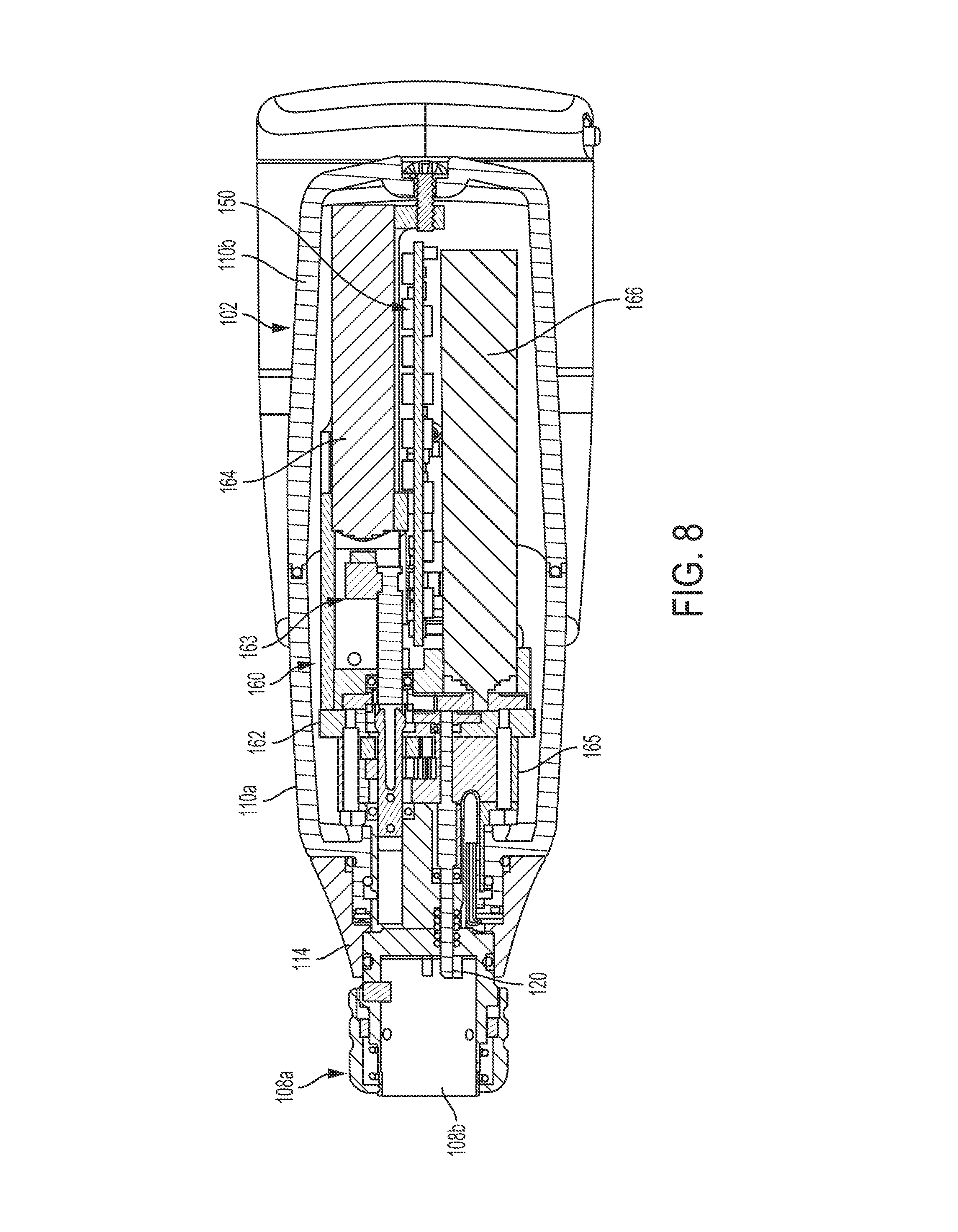
[0012] FIG. 8 is a top, cross-sectional view of the surgical instrument of FIG. 1, as taken through 8-8 of FIG. 2, according to at least one aspect of the present disclosure;
[0013] FIG. 9 is a perspective, exploded view of a end effector of FIG. 1, according to at least one aspect of the present disclosure;
[0014] FIG. 10A is a top view of a locking member, according to at least one aspect of the present disclosure;
[0015] FIG. 10B is a perspective view of the locking member of FIG. 10A, according to at least one aspect of the present disclosure;
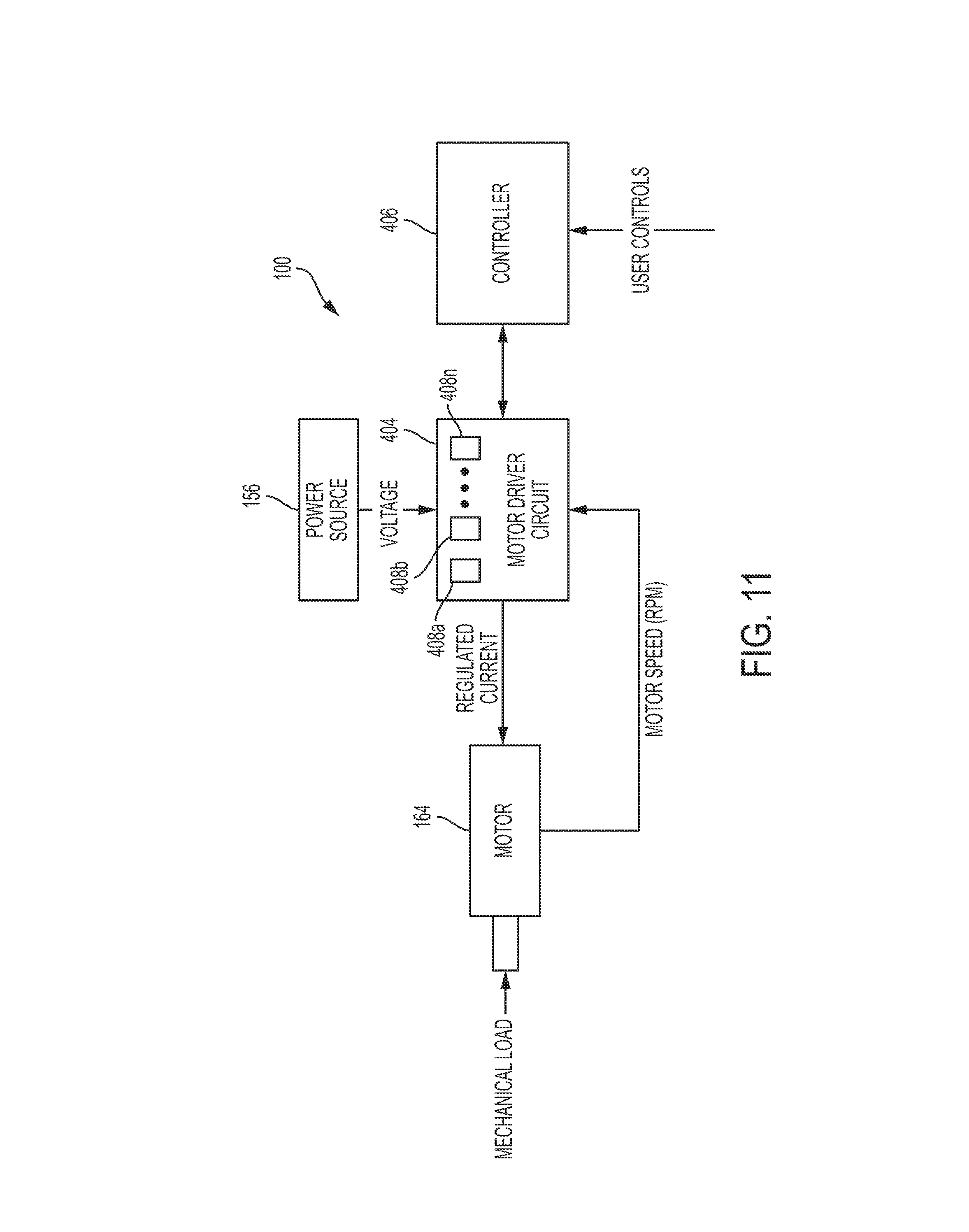
[0016] FIG. 11 is a schematic diagram of the surgical instrument of FIG. 1, according to at least one aspect of the present disclosure;
[0017] FIG. 12 is a perspective view, with parts separated, of an electromechanical surgical system, according to at least one aspect of the present disclosure;
[0018] FIG. 13 is a rear, perspective view of a shaft assembly and a powered surgical instrument, of the electromechanical surgical system of FIG. 12, illustrating a connection therebetween, according to at least aspect of the present disclosure;
[0019] FIG. 14 is a perspective view, with parts separated, of the shaft assembly of FIG. 13, according to at least aspect of the present disclosure;
[0020] FIG. 15 is a perspective view, with parts separated of a transmission housing of the shaft assembly of FIG. 13, according to at least aspect of the present disclosure;
[0021] FIG. 16 is a perspective view of a first gear train system that is supported in the transmission housing of FIG. 15, according to at least aspect of the present disclosure;
[0022] FIG. 17 is a perspective view of a second gear train system that is supported in the transmission housing of FIG. 15, according to at least aspect of the present disclosure;
[0023] FIG. 18 is a perspective view of a third drive shaft that is supported in the transmission housing of FIG. 15, according to at least aspect of the present disclosure;
[0024] FIG. 19 is a perspective view of a surgical instrument, according to at least one aspect of the present disclosure;
[0025] FIG. 19A is a top view of the surgical instrument of FIG. 19, according to at least one aspect of the present disclosure;
[0026] FIG. 20 is a circuit diagram of various components of the surgical instrument of FIG. 20, according to at least one aspect of the present disclosure;
[0027] FIG. 21 is logic diagram including steps for responding to drivetrain failures of the surgical instrument of FIG. 19, according to at least one aspect of the present disclosure;
[0028] FIG. 22 is a logic diagram of a safe mode of the surgical instrument of FIG. 19, according to at least one aspect of the present disclosure;
[0029] FIG. 22A is logic diagram including steps for responding to drivetrain failures of the surgical instrument of FIG. 19, according to at least one aspect of the present disclosure;
[0030] FIG. 23 is graph outlining a motor modulation in the safe mode of FIG. 22, according to at least one aspect of the present disclosure;
[0031] FIG. 23A is graph outlining a motor modulation in the safe mode of FIG. 22, according to at least one aspect of the present disclosure;
[0032] FIG. 24 is logic diagram including steps for responding to drivetrain failures of the surgical instrument of FIG. 19, according to at least one aspect of the present disclosure; and
[0033] FIG. 25 is a logic diagram of a bailout mode of the surgical instrument of FIG. 19, according to at least one aspect of the present disclosure.
DESCRIPTION
[0034] Before explaining various forms of mechanisms for compensating for drivetrain failure in powered surgical instruments in detail, it should be noted that the illustrative forms are not limited in application or use to the details of construction and arrangement of parts illustrated in the accompanying drawings and description. The illustrative forms may be implemented or incorporated in other forms, variations and modifications, and may be practiced or carried out in various ways. Further, unless otherwise indicated, the terms and expressions employed herein have been chosen for the purpose of describing the illustrative forms for the convenience of the reader and are not for the purpose of limitation thereof.
[0035] Further, it is understood that any one or more of the following-described forms, expressions of forms, examples, can be combined with any one or more of the other following-described forms, expressions of forms, and examples.
[0036] Various forms are directed to mechanisms for compensating for drivetrain failure in powered surgical instruments. In one form, the mechanisms for compensating for drivetrain failure in powered surgical instruments may be configured for use in open surgical procedures, but has applications in other types of surgery, such as laparoscopic, endoscopic, and robotic-assisted procedures.
[0037] FIGS. 1-18 depict various aspects of a surgical system that is generally designated as 10, and is in the form of a powered hand held electromechanical instrument configured for selective attachment thereto of a plurality of different end effectors that are each configured for actuation and manipulation by the powered hand held electromechanical surgical instrument. The aspects of FIGS. 1-18 are disclosed in U.S. Patent Application Publication No. 2014/0110453, filed Oct. 23, 2012, and titled SURGICAL INSTRUMENT WITH RAPID POST EVENT DETECTION, now U.S. Pat. No. 9,265,585, U.S. Patent Application Publication No. 2013/0282052, filed Jun. 19, 2013, and titled APPARATUS FOR ENDOSCOPIC PROCEDURES, now U.S. Pat. No. 9,480,492, and U.S. Patent Application Publication No. 2013/0274722, filed May 10, 2013, and titled APPARATUS FOR ENDOSCOPIC PROCEDURES, now U.S. Pat. No. 9,492,146.
[0038] Referring to FIGS. 1-3, a surgical instrument 100 is configured for selective connection with an adapter 200, and, in turn, adapter 200 is configured for selective connection with an end effector or single use loading unit or reload 300. As illustrated in FIGS. 1-3, the surgical instrument 100 includes a handle housing 102 having a lower housing portion 104, an intermediate housing portion 106 extending from and/or supported on lower housing portion 104, and an upper housing portion 108 extending from and/or supported on intermediate housing portion 106. Intermediate housing portion 106 and upper housing portion 108 are separated into a distal half-section 110a that is integrally formed with and extending from the lower portion 104, and a proximal half-section 110b connectable to distal half-section 110a by a plurality of fasteners. When joined, distal and proximal half-sections 110a, 110b define a handle housing 102 having a cavity 102a therein in which a circuit board 150 and a drive mechanism 160 is situated.
[0039] Distal and proximal half-sections 110a, 110b are divided along a plane that traverses a longitudinal axis "X" of upper housing portion 108, as seen in FIGS. 2 and 3. Handle housing 102 includes a gasket 112 extending completely around a rim of distal half-section and/or proximal half-section 110a, 110b and being interposed between distal half-section 110a and proximal half-section 110b. Gasket 112 seals the perimeter of distal half-section 110a and proximal half-section 110b. Gasket 112 functions to establish an air-tight seal between distal half-section 110a and proximal half-section 110b such that circuit board 150 and drive mechanism 160 are protected from sterilization and/or cleaning procedures.
[0040] In this manner, the cavity 102a of handle housing 102 is sealed along the perimeter of distal half-section 110a and proximal half-section 110b yet is configured to enable easier, more efficient assembly of circuit board 150 and a drive mechanism 160 in handle housing 102.
[0041] Intermediate housing portion 106 of handle housing 102 provides a housing in which circuit board 150 is situated. Circuit board 150 is configured to control the various operations of surgical instrument 100.
[0042] Lower housing portion 104 of surgical instrument 100 defines an aperture (not shown) formed in an upper surface thereof and which is located beneath or within intermediate housing portion 106. The aperture of lower housing portion 104 provides a passage through which wires 152 pass to electrically interconnect electrical components (a battery 156, as illustrated in FIG. 4, a circuit board 154, as illustrated in FIG. 3, etc.) situated in lower housing portion 104 with electrical components (circuit board 150, drive mechanism 160, etc.) situated in intermediate housing portion 106 and/or upper housing portion 108.
[0043] Handle housing 102 includes a gasket 103 disposed within the aperture of lower housing portion 104 (not shown) thereby plugging or sealing the aperture of lower housing portion 104 while allowing wires 152 to pass therethrough. Gasket 103 functions to establish an air-tight seal between lower housing portion 106 and intermediate housing portion 108 such that circuit board 150 and drive mechanism 160 are protected from sterilization and/or cleaning procedures.
[0044] As shown, lower housing portion 104 of handle housing 102 provides a housing in which a rechargeable battery 156, is removably situated. Battery 156 is configured to supply power to any of the electrical components of surgical instrument 100. Lower housing portion 104 defines a cavity (not shown) into which battery 156 is inserted. Lower housing portion 104 includes a door 105 pivotally connected thereto for closing cavity of lower housing portion 104 and retaining battery 156 therein.
[0045] With reference to FIGS. 3 and 5, distal half-section 110a of upper housing portion 108 defines a nose or connecting portion 108a. A nose cone 114 is supported on nose portion 108a of upper housing portion 108. Nose cone 114 is fabricated from a transparent material. A feedback indicator such as, for example, an illumination member 116 is disposed within nose cone 114 such that illumination member 116 is visible therethrough. Illumination member 116 is may be a light emitting diode printed circuit board (LED PCB). Illumination member 116 is configured to illuminate multiple colors with a specific color pattern being associated with a unique discrete event.
[0046] Upper housing portion 108 of handle housing 102 provides a housing in which drive mechanism 160 is situated. As illustrated in FIG. 5, drive mechanism 160 is configured to drive shafts and/or gear components in order to perform the various operations of surgical instrument 100. In particular, drive mechanism 160 is configured to drive shafts and/or gear components in order to selectively move tool assembly 304 of end effector 300 (see FIGS. 1 and 9) relative to proximal body portion 302 of end effector 300, to rotate end effector 300 about a longitudinal axis "X" (see FIG. 2) relative to handle housing 102, to move anvil assembly 306 relative to cartridge assembly 308 of end effector 300, and/or to fire a stapling and cutting cartridge within cartridge assembly 308 of end effector 300.
[0047] The drive mechanism 160 includes a selector gearbox assembly 162 that is located immediately proximal relative to adapter 200. Proximal to the selector gearbox assembly 162 is a function selection module 163 having a first motor 164 that functions to selectively move gear elements within the selector gearbox assembly 162 into engagement with an input drive component 165 having a second motor 166.
[0048] As illustrated in FIGS. 1-4, and as mentioned above, distal half-section 110a of upper housing portion 108 defines a connecting portion 108a configured to accept a corresponding drive coupling assembly 210 of adapter 200.
[0049] As illustrated in FIGS. 6-8, connecting portion 108a of surgical instrument 100 has a cylindrical recess 108b that receives a drive coupling assembly 210 of adapter 200 when adapter 200 is mated to surgical instrument 100. Connecting portion 108a houses three rotatable drive connectors 118, 120, 122.
[0050] When adapter 200 is mated to surgical instrument 100, each of rotatable drive connectors 118, 120, 122 of surgical instrument 100 couples with a corresponding rotatable connector sleeve 218, 220, 222 of adapter 200 as shown in FIG. 6. In this regard, the interface between corresponding first drive connector 118 and first connector sleeve 218, the interface between corresponding second drive connector 120 and second connector sleeve 220, and the interface between corresponding third drive connector 122 and third connector sleeve 222 are keyed such that rotation of each of drive connectors 118, 120, 122 of surgical instrument 100 causes a corresponding rotation of the corresponding connector sleeve 218, 220, 222 of adapter 200.
[0051] The mating of drive connectors 118, 120, 122 of surgical instrument 100 with connector sleeves 218, 220, 222 of adapter 200 allows rotational forces to be independently transmitted via each of the three respective connector interfaces. The drive connectors 118, 120, 122 of surgical instrument 100 are configured to be independently rotated by drive mechanism 160. In this regard, the function selection module 163 of drive mechanism 160 selects which drive connector or connectors 118, 120, 122 of surgical instrument 100 is to be driven by the input drive component 165 of drive mechanism 160.
[0052] Since each of drive connectors 118, 120, 122 of surgical instrument 100 has a keyed and/or substantially non-rotatable interface with respective connector sleeves 218, 220, 222 of adapter 200, when adapter 200 is coupled to surgical instrument 100, rotational force(s) are selectively transferred from drive mechanism 160 of surgical instrument 100 to adapter 200.
[0053] The selective rotation of drive connector(s) 118, 120 and/or 122 of surgical instrument 100 allows surgical instrument 100 to selectively actuate different functions of end effector 300. Selective and independent rotation of first drive connector 118 of surgical instrument 100 corresponds to the selective and independent opening and closing of tool assembly 304 of end effector 300, and driving of a stapling/cutting component of tool assembly 304 of end effector 300. Also, the selective and independent rotation of second drive connector 120 of surgical instrument 100 corresponds to the selective and independent articulation of tool assembly 304 of end effector 300 transverse to longitudinal axis "X" (see FIG. 2). Additionally, the selective and independent rotation of third drive connector 122 of surgical instrument 100 corresponds to the selective and independent rotation of end effector 300 about longitudinal axis "X" (see FIG. 2) relative to handle housing 102 of surgical instrument 100.
[0054] As mentioned above and as illustrated in FIGS. 5 and 8, drive mechanism 160 includes a selector gearbox assembly 162; and a function selection module 163, located proximal to the selector gearbox assembly 162, that functions to selectively move gear elements within the selector gearbox assembly 162 into engagement with second motor 166. Thus, drive mechanism 160 selectively drives one of drive connectors 118, 120, 122 of surgical instrument 100 at a given time.
[0055] As illustrated in FIGS. 1-3, handle housing 102 supports a control assembly 107 on a distal surface or side of intermediate housing portion 108. The control assembly 107 is a fully-functional mechanical subassembly that can be assembled and tested separately from the rest of the instrument 100 prior to coupling thereto.
[0056] Control assembly 107, in cooperation with intermediate housing portion 108, supports a pair of finger-actuated control buttons 124, 126 and a pair rocker devices 128, 130 within a housing 107a. The control buttons 124, 126 are coupled to extension shafts 125, 127 respectively. In particular, control assembly 107 defines an upper aperture 124a for slidably receiving the extension shaft 125, and a lower aperture 126a for slidably receiving the extension shaft 127.
[0057] The control assembly 107 and its components (e.g., control buttons 124, 126 and rocker devices 128, 130) my be formed from low friction, self-lubricating, lubricious plastics or materials or coatings covering the moving components to reduce actuation forces, key component wear, elimination of galling, smooth consistent actuation, improved component and assembly reliability and reduced clearances for a tighter fit and feel consistency. This includes the use of plastic materials in the bushings, rocker journals, plunger bushings, spring pockets, retaining rings and slider components. Molding the components in plastic also provides net-shape or mesh-shaped components with all of these performance attributes. Plastic components eliminate corrosion and bi-metal anodic reactions under electrolytic conditions such as autoclaving, steam sterilizations and cleaning Press fits with lubricious plastics and materials also eliminate clearances with minimal strain or functional penalties on the components when compared to similar metal components.
[0058] Suitable materials for forming the components of the control assembly 107 include, but are not limited to, polyamines, polyphenylene sulfides, polyphthalamides, polyphenylsulfones, polyether ketones, polytetrafluoroethylenes, and combinations thereof. These components may be used in the presence or absence of lubricants and may also include additives for reduced wear and frictional forces.
[0059] Reference may be made to a U.S. patent application Ser. No. 13/331,047, now U.S. Pat. No. 8,968,276, the entire contents of which are incorporated by reference herein, for a detailed discussion of the construction and operation of the surgical instrument 100.
[0060] The surgical instrument 100 includes a firing assembly configured to deploy or eject a plurality of staples into tissue captured by the end effector 300. The firing assembly comprises a drive assembly 360, as illustrated in FIG. 9. The drive assembly 360 includes a flexible drive beam 364 having a distal end which is secured to a dynamic clamping member 365, and a proximal engagement section 368. Engagement section 368 includes a stepped portion defining a shoulder 370. A proximal end of engagement section 368 includes diametrically opposed inwardly extending fingers 372. Fingers 372 engage a hollow drive member 374 to fixedly secure drive member 374 to the proximal end of beam 364. Drive member 374 defines a proximal porthole 376a which receives a connection member of drive tube 246 (FIG. 1) of adapter 200 when end effector 300 is attached to distal coupling 230 of adapter 200.
[0061] When drive assembly 360 is advanced distally within tool assembly 304, an upper beam 365a of clamping member 365 moves within a channel defined between anvil plate 312 and anvil cover 310 and a lower beam 365b moves over the exterior surface of carrier 316 to close tool assembly 304 and fire staples therefrom.
[0062] Proximal body portion 302 of end effector 300 includes a sheath or outer tube 301 enclosing an upper housing portion 301a and a lower housing portion 301b. The housing portions 301a and 301b enclose an articulation link 366 having a hooked proximal end 366a which extends from a proximal end of end effector 300. Hooked proximal end 366a of articulation link 366 engages a coupling hook (not shown) of adapter 200 when end effector 300 is secured to distal housing 232 of adapter 200. When drive bar 258 of adapter 200 is advanced or retracted as described above, articulation link 366 of end effector 300 is advanced or retracted within end effector 300 to pivot tool assembly 304 in relation to a distal end of proximal body portion 302.
[0063] As illustrated in FIG. 9 above, cartridge assembly 308 of tool assembly 304 includes a staple cartridge 305 supportable in carrier 316. The cartridge can be permanently installed in the end effector 300 or can be arranged so as to be removable and replaceable. Staple cartridge 305 defines a central longitudinal slot 305a, and three linear rows of staple retention slots 305b positioned on each side of longitudinal slot 305a. Each of staple retention slots 305b receives a single staple 307 and a portion of a staple pusher 309. During operation of instrument 100, drive assembly 360 abuts an actuation sled and pushes actuation sled through cartridge 305. As the actuation sled moves through cartridge 305, cam wedges of the actuation sled sequentially engage staple pushers 309 to move staple pushers 309 vertically within staple retention slots 305b and sequentially eject staples 307 therefrom for formation against anvil plate 312.
[0064] The hollow drive member 374 includes a lockout mechanism 373 that prevents a firing of previously fired end effectors 300. The lockout mechanism 373 includes a locking member 371 pivotally coupled within a distal porthole 376b via a pin 377, such that locking member 371 is pivotal about pin 377 relative to drive member 374.
[0065] With reference to FIGS. 10A and 10B, locking member 371 defines a channel 379 formed between elongate glides 381 and 383. Web 385 joins a portion of the upper surfaces of glides 381 and 383. Web 385 is configured and dimensioned to fit within the porthole 376b of the drive member 374. Horizontal ledges 389 and 391 extend from glides 381 and 383 respectively. As best shown in FIG. 9, a spring 393 is disposed within the drive member 374 and engages horizontal ledge 389 and/or horizontal ledge 391 to bias locking member 371 downward.
[0066] In operation, the locking member 371 is initially disposed in its pre-fired position at the proximal end of the housing portions 301a and 301b with horizontal ledge 389 and 391 resting on top of projections 303a, 303b formed in the sidewalls of housing portion 301b. In this position, locking member 371 is held up and out of alignment with a projection 303c formed in the bottom surface of housing portion 301b, distal of the projection 303a, 303b, and web 385 is in longitudinal juxtaposition with shoulder 370 defined in drive beam 364. This configuration permits the anvil 306 to be opened and repositioned onto the tissue to be stapled until the surgeon is satisfied with the position without activating locking member 371 to disable the disposable end effector 300.
[0067] Upon distal movement of the drive beam 364 by the drive tube 246, locking member 371 rides off of projections 303a, 303b and is biased into engagement with housing portion 301b by the spring 393, distal of projection 303c. Locking member 371 remains in this configuration throughout firing of the apparatus.
[0068] Upon retraction of the drive beam 364, after at least a partial firing, locking member 371 passes under projections 303a, 303b and rides over projection 303c of housing portion 301b until the distal-most portion of locking member 371 is proximal to projection 303c. The spring 393 biases locking member 371 into juxtaposed alignment with projection 303c, effectively disabling the disposable end effector. If an attempt is made to reactuate the apparatus, loaded with the existing end effector 300, the locking member 371 will abut projection 303c of housing portion 301b and will inhibit distal movement of the drive beam 364.
[0069] Another aspect of the instrument 100 is shown in FIG. 11. The instrument 100 includes the motor 164. The motor 164 may be any electrical motor configured to actuate one or more drives (e.g., rotatable drive connectors 118, 120, 122 of FIG. 6). The motor 164 is coupled to the battery 156, which may be a DC battery (e.g., rechargeable lead-based, nickel-based, lithium-ion based, battery etc.), an AC/DC transformer, or any other power source suitable for providing electrical energy to the motor 164.
[0070] The battery 156 and the motor 164 are coupled to a motor driver circuit 404 disposed on the circuit board 154 which controls the operation of the motor 164 including the flow of electrical energy from the battery 156 to the motor 164. The driver circuit 404 includes a plurality of sensors 408a, 408b, . . . 408n configured to measure operational states of the motor 164 and the battery 156. The sensors 408a-n may include voltage sensors, current sensors, temperature sensors, pressure sensors, telemetry sensors, optical sensors, and combinations thereof. The sensors 408a-408n may measure voltage, current, and other electrical properties of the electrical energy supplied by the battery 156. The sensors 408a-408n may also measure rotational speed as revolutions per minute (RPM), torque, temperature, current draw, and other operational properties of the motor 164. RPM may be determined by measuring the rotation of the motor 164. Position of various drive shafts (e.g., rotatable drive connectors 118, 120, 122 of FIG. 6) may be determined by using various linear sensors disposed in or in proximity to the shafts or extrapolated from the RPM measurements. In aspects, torque may be calculated based on the regulated current draw of the motor 164 at a constant RPM. In further aspects, the driver circuit 404 and/or the controller 406 may measure time and process the above-described values as a function thereof, including integration and/or differentiation, e.g., to determine rate of change of the measured values and the like.
[0071] The driver circuit 404 is also coupled to a controller 406, which may be any suitable logic control circuit adapted to perform the calculations and/or operate according to a set of instructions. The controller 406 may include a central processing unit operably connected to a memory which may include transitory type memory (e.g., RAM) and/or non-transitory type memory (e.g., flash media, disk media, etc.). The controller 406 includes a plurality of inputs and outputs for interfacing with the driver circuit 404. In particular, the controller 406 receives measured sensor signals from the driver circuit 404 regarding operational status of the motor 164 and the battery 156 and, in turn, outputs control signals to the driver circuit 404 to control the operation of the motor 164 based on the sensor readings and specific algorithm instructions. The controller 406 is also configured to accept a plurality of user inputs from a user interface (e.g., switches, buttons, touch screen, etc. of the control assembly 107 coupled to the controller 406). A removable memory card or chip may be provided, or data can be downloaded wirelessly.
[0072] Referring to FIG. 12-18, a surgical system 10' is depicted. The surgical system 10' is similar in many respects to the surgical system 10. For example, the surgical system 10' includes the surgical instrument 100. Upper housing portion 108 of instrument housing 102 defines a nose or connecting portion 108a configured to accept a corresponding shaft coupling assembly 514 of a transmission housing 512 of a shaft assembly 500 that is similar in many respects to the shaft assembly 200.
[0073] The shaft assembly 500 has a force transmitting assembly for interconnecting the at least one drive member of the surgical instrument to at least one rotation receiving member of the end effector. The force transmitting assembly has a first end that is connectable to the at least one rotatable drive member and a second end that is connectable to the at least one rotation receiving member of the end effector. When shaft assembly 500 is mated to surgical instrument 100, each of rotatable drive members or connectors 118, 120, 122 of surgical instrument 100 couples with a corresponding rotatable connector sleeve 518, 520, 522 of shaft assembly 500 (see FIGS. 13 and 15). In this regard, the interface between corresponding first drive member or connector 118 and first connector sleeve 518, the interface between corresponding second drive member or connector 120 and second connector sleeve 520, and the interface between corresponding third drive member or connector 122 and third connector sleeve 522 are keyed such that rotation of each of drive members or connectors 118, 120, 122 of surgical instrument 100 causes a corresponding rotation of the corresponding connector sleeve 518, 520, 522 of shaft assembly 500.
[0074] The selective rotation of drive member(s) or connector(s) 118, 120 and/or 122 of surgical instrument 100 allows surgical instrument 100 to selectively actuate different functions of an end effector 400.
[0075] Referring to FIGS. 12 and 14, the shaft assembly 500 includes an elongate, substantially rigid, outer tubular body 510 having a proximal end 510a and a distal end 510b and a transmission housing 212 connected to proximal end 210a of tubular body 510 and being configured for selective connection to surgical instrument 100. In addition, the shaft assembly 500 further includes an articulating neck assembly 530 connected to distal end 510b of elongate body portion 510.
[0076] Transmission housing 512 is configured to house a pair of gear train systems therein for varying a speed/force of rotation (e.g., increase or decrease) of first, second and/or third rotatable drive members or connectors 118, 120, and/or 122 of surgical instrument 100 before transmission of such rotational speed/force to the end effector 501. As seen in FIG. 15, transmission housing 512 and shaft coupling assembly 514 rotatably support a first proximal or input drive shaft 524a, a second proximal or input drive shaft 526a, and a third drive shaft 528.
[0077] Shaft drive coupling assembly 514 includes a first, a second and a third biasing member 518a, 520a and 522a disposed distally of respective first, second and third connector sleeves 518, 520, 522. Each of biasing members 518a, 520a and 522a is disposed about respective first proximal drive shaft 524a, second proximal drive shaft 526a, and third drive shaft 228. Biasing members 518a, 520a and 522a act on respective connector sleeves 518, 520 and 522 to help maintain connector sleeves 218, 220 and 222 engaged with the distal end of respective drive rotatable drive members or connectors 118, 120, 122 of surgical instrument 100 when shaft assembly 500 is connected to surgical instrument 100.
[0078] Shaft assembly 500 includes a first and a second gear train system 540, 550, respectively, disposed within transmission housing 512 and tubular body 510, and adjacent coupling assembly 514. As mentioned above, each gear train system 540, 550 is configured and adapted to vary a speed/force of rotation (e.g., increase or decrease) of first and second rotatable drive connectors 118 and 120 of surgical instrument 100 before transmission of such rotational speed/force to end effector 501.
[0079] As illustrated in FIGS. 15 and 16, first gear train system 540 includes first input drive shaft 524a, and a first input drive shaft spur gear 542a keyed to first input drive shaft 524a. First gear train system 540 also includes a first transmission shaft 544 rotatably supported in transmission housing 512, a first input transmission spur gear 544 a keyed to first transmission shaft 544 and engaged with first input drive shaft spur gear 542a, and a first output transmission spur gear 544b keyed to first transmission shaft 544. First gear train system 540 further includes a first output drive shaft 546a rotatably supported in transmission housing 512 and tubular body 510, and a first output drive shaft spur gear 546b keyed to first output drive shaft 546a and engaged with first output transmission spur gear 544b.
[0080] In at least one instance, the first input drive shaft spur gear 542a includes 10 teeth; first input transmission spur gear 544a includes 18 teeth; first output transmission spur gear 544b includes 13 teeth; and first output drive shaft spur gear 546b includes 15 teeth. As so configured, an input rotation of first input drive shaft 524a is converted to an output rotation of first output drive shaft 546a by a ratio of 1:2.08.
[0081] In operation, as first input drive shaft spur gear 542a is rotated, due to a rotation of first connector sleeve 558 and first input drive shaft 524a, as a result of the rotation of the first respective drive connector 118 of surgical instrument 100, first input drive shaft spur gear 542a engages first input transmission spur gear 544a causing first input transmission spur gear 544a to rotate. As first input transmission spur gear 544a rotates, first transmission shaft 544 is rotated and thus causes first output drive shaft spur gear 546b, that is keyed to first transmission shaft 544, to rotate. As first output drive shaft spur gear 546b rotates, since first output drive shaft spur gear 546b is engaged therewith, first output drive shaft spur gear 546b is also rotated. As first output drive shaft spur gear 546b rotates, since first output drive shaft spur gear 546b is keyed to first output drive shaft 546a, first output drive shaft 546a is rotated.
[0082] The shaft assembly 500, including the first gear system 540, functions to transmit operative forces from surgical instrument 100 to end effector 501 in order to operate, actuate and/or fire end effector 501.
[0083] As illustrated in FIGS. 15 and 17, second gear train system 550 includes second input drive shaft 526a, and a second input drive shaft spur gear 552a keyed to second input drive shaft 526a. Second gear train system 550 also includes a first transmission shaft 554 rotatably supported in transmission housing 512, a first input transmission spur gear 554a keyed to first transmission shaft 554 and engaged with second input drive shaft spur gear 552a, and a first output transmission spur gear 554b keyed to first transmission shaft 554.
[0084] Second gear train system 550 further includes a second transmission shaft 556 rotatably supported in transmission housing 512, a second input transmission spur gear 556a keyed to second transmission shaft 556 and engaged with first output transmission spur gear 554b that is keyed to first transmission shaft 554, and a second output transmission spur gear 556b keyed to second transmission shaft 556.
[0085] Second gear train system 550 additionally includes a second output drive shaft 558a rotatably supported in transmission housing 512 and tubular body 510, and a second output drive shaft spur gear 558b keyed to second output drive shaft 558a and engaged with second output transmission spur gear 556b.
[0086] In at least one instance, the second input drive shaft spur gear 552a includes 10 teeth; first input transmission spur gear 554a includes 20 teeth; first output transmission spur gear 554b includes 10 teeth; second input transmission spur gear 556a includes 20 teeth; second output transmission spur gear 556b includes 10 teeth; and second output drive shaft spur gear 558b includes 15 teeth. As so configured, an input rotation of second input drive shaft 526a is converted to an output rotation of second output drive shaft 558a by a ratio of 1:6.
[0087] In operation, as second input drive shaft spur gear 552a is rotated, due to a rotation of second connector sleeve 560 and second input drive shaft 526a, as a result of the rotation of the second respective drive connector 120 of surgical instrument 100, second input drive shaft spur gear 552a engages first input transmission spur gear 554a causing first input transmission spur gear 554a to rotate. As first input transmission spur gear 554a rotates, first transmission shaft 554 is rotated and thus causes first output transmission spur gear 554b, that is keyed to first transmission shaft 554, to rotate. As first output transmission spur gear 554b rotates, since second input transmission spur gear 556a is engaged therewith, second input transmission spur gear 556a is also rotated. As second input transmission spur gear 556a rotates, second transmission shaft 256 is rotated and thus causes second output transmission spur gear 256b, that is keyed to second transmission shaft 556, to rotate. As second output transmission spur gear 556b rotates, since second output drive shaft spur gear 558b is engaged therewith, second output drive shaft spur gear 558b is rotated. As second output drive shaft spur gear 558b rotates, since second output drive shaft spur gear 558b is keyed to second output drive shaft 558a, second output drive shaft 558a is rotated.
[0088] The shaft assembly 500, including second gear train system 550, functions to transmit operative forces from surgical instrument 100 to end effector 501 in order rotate shaft assembly 500 and/or end effector 501 relative to surgical instrument 100.
[0089] As illustrated in FIGS. 15 and 18, the transmission housing 512 and shaft coupling assembly 514 rotatably support a third drive shaft 528. Third drive shaft 528 includes a proximal end 528a configured to support third connector sleeve 522, and a distal end 528b extending to and operatively connected to an articulation assembly 570.
[0090] As illustrated in FIG. 14, elongate, outer tubular body 510 of shaft assembly 500 includes a first half section 511 a and a second half section 511b defining at least three longitudinally extending channels through outer tubular body 510 when half sections 511a, 511b are mated with one another. The channels are configured and dimensioned to rotatably receive and support first output drive shaft 546a, second output drive shaft 558a, and third drive shaft 528 as first output drive shaft 546a, second output drive shaft 558a, and third drive shaft 528 extend from transmission housing 512 to articulating neck assembly 530. Each of first output drive shaft 546a, second output drive shaft 558a, and third drive shaft 528 are elongate and sufficiently rigid to transmit rotational forces from transmission housing 520 to articulating neck assembly 530.
[0091] Turning to FIG. 14, the shaft assembly 500 further includes an articulating neck assembly 530. The articulating neck assembly 530 includes a proximal neck housing 532, a plurality of links 534 connected to and extending in series from proximal neck housing 532; and a distal neck housing 536 connected to and extending from a distal-most link of the plurality of links 534. It is contemplated that, in any of the aspects disclosed herein, that the shaft assembly may have a single link or pivot member for allowing the articulation of the end effector. It is contemplated that, in any of the aspects disclosed herein, that the distal neck housing can be incorporated with the distal most link.
[0092] The entire disclosures of:
[0093] U.S. Patent Application Publication No. 2014/0110453, filed Oct. 23, 2012, and titled SURGICAL INSTRUMENT WITH RAPID POST EVENT DETECTION, now U.S. Pat. No. 9,265,585;
[0094] U.S. Patent Application Publication No. 2013/0282052, filed Jun. 19, 2013, and titled APPARATUS FOR ENDOSCOPIC PROCEDURES, now U.S. Pat. No. 9,480,492; and
[0095] U.S. Patent Application Publication No. 2013/0274722, filed May 10, 2013, and titled APPARATUS FOR ENDOSCOPIC PROCEDURES, now U.S. Pat. No. 9,492,146, are hereby incorporated by reference herein.
[0096] Referring to FIGS. 19-20, a surgical instrument 10 is depicted. The surgical instrument 10 is similar in many respects to the surgical instrument 100. For example, the surgical instrument 10 is configured for selective connection with the end effector or single use loading unit or reload 300 via the adapter 200. Also, the surgical instrument 10 includes a handle housing 102 that includes a lower housing portion 104, an intermediate housing portion 106, and an upper housing portion 108.
[0097] Like the surgical instrument 100, the surgical instrument 10 includes a drive mechanism 160 which is configured to drive shafts and/or gear components in order to perform the various operations of surgical instrument 10. In at least one instance, the drive mechanism 160 includes a rotation drivetrain 12 (See FIG. 20) configured to rotate end effector 300 about a longitudinal axis "X" (see FIG. 2) relative to handle housing 102. The drive mechanism 160 further includes a closure drivetrain 14 (See FIG. 20) configured to move the anvil assembly 306 relative to the cartridge assembly 308 of the end effector 300 to capture tissue therebetween. In addition, the drive mechanism 160 includes a firing drivetrain 16 (See FIG. 20) configured to fire a stapling and cutting cartridge within the cartridge assembly 308 of the end effector 300.
[0098] As described above, referring primarily to FIGS. 7, 8, and 20, the drive mechanism 160 includes a selector gearbox assembly 162 that can be located immediately proximal relative to adapter 200. Proximal to the selector gearbox assembly 162 is the function selection module 163 which includes the first motor 164 that functions to selectively move gear elements within the selector gearbox assembly 162 to selectively position one of the drivetrains 12, 14, and 16 into engagement with the input drive component 165 of the second motor 166.
[0099] Referring to FIG. 20, the motors 164 and 166 are coupled to motor control circuits 18 and 18', respectively, which are configured to control the operation of the motors 164 and 66 including the flow of electrical energy from a power source 156 to the motors 164 and 166. The power source 156 may be a DC battery (e.g., rechargeable lead-based, nickel-based, lithium-ion based, battery etc.), an AC/DC transformer, or any other power source suitable for providing electrical energy to the surgical instrument 10.
[0100] The surgical instrument 10 further includes a microcontroller 20 ("controller"). In certain instances, the controller 20 may include a microprocessor 36 ("processor") and one or more computer readable mediums or memory units 38 ("memory"). In certain instances, the memory 38 may store various program instructions, which when executed may cause the processor 36 to perform a plurality of functions and/or calculations described herein. The power source 156 can be configured to supply power to the controller 20, for example.
[0101] The processor 36 can be in communication with the motor control circuit 18. In addition, the memory 38 may store program instructions, which when executed by the processor 36 in response to a user input 34, may cause the motor control circuit 18 to motivate the motor 164 to generate at least one rotational motion to selectively move gear elements within the selector gearbox assembly 162 to selectively position one of the drivetrains 12, 14, and 16 into engagement with the input drive component 165 of the second motor 166. Furthermore, the processor 36 can be in communication with the motor control circuit 18'. The memory 38 may also store program instructions, which when executed by the processor 36 in response to a user input 34, may cause the motor control circuit 18' to motivate the motor 166 to generate at least one rotational motion to drive the drivetrain engaged with the input drive component 165 of the second motor 166, for example.
[0102] The controller 20 and/or other controllers of the present disclosure may be implemented using integrated and/or discrete hardware elements, software elements, and/or a combination of both. Examples of integrated hardware elements may include processors, microprocessors, microcontrollers, integrated circuits, ASICs, PLDs, DSPs, FPGAs, logic gates, registers, semiconductor devices, chips, microchips, chip sets, microcontrollers, SoC, and/or SIP. Examples of discrete hardware elements may include circuits and/or circuit elements such as logic gates, field effect transistors, bipolar transistors, resistors, capacitors, inductors, and/or relays. In certain instances, the controller 20 may include a hybrid circuit comprising discrete and integrated circuit elements or components on one or more substrates, for example.
[0103] In certain instances, the controller 20 and/or other controllers of the present disclosure may be an LM 4F230H5QR, available from Texas Instruments, for example. In certain instances, the Texas Instruments LM4F230H5QR is an ARM Cortex-M4F Processor Core comprising on-chip memory of 256 KB single-cycle flash memory, or other non-volatile memory, up to 40 MHz, a prefetch buffer to improve performance above 40 MHz, a 32 KB single-cycle SRAM, internal ROM loaded with StellarisWare.RTM. software, 2 KB EEPROM, one or more PWM modules, one or more QEI analog, one or more 12-bit ADC with 12 analog input channels, among other features that are readily available. Other microcontrollers may be readily substituted for use with the present disclosure. Accordingly, the present disclosure should not be limited in this context.
[0104] In various instances, one or more of the various steps described herein can be performed by a finite state machine comprising either a combinational logic circuit or a sequential logic circuit, where either the combinational logic circuit or the sequential logic circuit is coupled to at least one memory circuit. The at least one memory circuit stores a current state of the finite state machine. The combinational or sequential logic circuit is configured to cause the finite state machine to the steps. The sequential logic circuit may be synchronous or asynchronous. In other instances, one or more of the various steps described herein can be performed by a circuit that includes a combination of the processor 36 and the finite state machine, for example.
[0105] Referring again to FIG. 20, the surgical instrument 10 further includes a drivetrain failure detection module 40. The processor 36 can be in communication with or otherwise control the module 40. The module 40 can be embodied as various means, such as circuitry, hardware, a computer program product comprising a computer readable medium (for example, the memory 38) storing computer readable program instructions that are executable by a processing device (for example, the processor 36), or some combination thereof. In some aspects, the processor 36 can include, or otherwise control the module 40.
[0106] Referring to FIG. 20, the module 40 may include one or more sensors (not shown) which can be configured to detect an acute drivetrain failure in one or more of the drivetrains 12, 14, and 16.
[0107] Referring to FIG. 20, the module 40 can be configured to detect an acute failure in an active drivetrain of the surgical instrument 10. The term "active" as used herein in connection with the drivetrains 12, 14, and 16 refers to a selected drivetrain that is engaged with the input drive component 165 and is driven by the second motor 166. The term "acute failure" as used herein refers to a failure that can cause one or more of the drivetrains 12, 14, and 16, for example, to operate at less than optimal performance levels. One example of an acute drivetrain failure may involve a tooth damage to one or more of the gears of an active drivetrain and/or or excessive slop in the active drivetrain.
[0108] In the event of an acute drivetrain failure, the active drivetrain may still be operated to complete a surgical step or to reset the surgical instrument 10; however, certain precautionary and/or safety steps can be taken, as described below in greater detail, to avoid or minimize additional damage to the active drivetrain and/or other components of the surgical instrument 10. Alternatively, in the event of a catastrophic failure, the active drivetrain is rendered inoperable, and certain bailout steps are taken to ensure, among other things, a safe detachment of the surgical instrument 10 from the tissue being treated.
[0109] Referring again to FIG. 21, a logic diagram 21 represents possible operations that can be implemented by the surgical instrument 10 in response to active drivetrain failures. The memory 38 may include program instructions, which when executed by the processor 36, may cause the processor 36 to employ the module 40 to continuously detect 23 active drivetrain failures. The memory 38 may include program instructions, which when executed by the processor 36, may cause the processor 36 to respond to a detected acute drivetrain failure by activating a safe mode 22 of operation, for example. In addition, the memory 38 may include program instructions, which when executed by the processor 36, may cause the processor 36 to respond to a detected catastrophic drivetrain failure by activating a recovery or bailout mode 22. If no drivetrain failures are detected, the processor 36 may permit the surgical instrument 10 to continue 27 with normal operations until an active drivetrain failure is detected.
[0110] Referring to FIG. 22, the safe mode 22 may include one or more steps such as, for example, a motor modulation step 26 which can be employed by the processor 36 to limit the speed of an active drivetrain. For example, if the firing drivetrain 16 is being actively driven by the motor 166 during a firing sequence, a detection of an acute drivetrain failure by the module 40 may cause the processor 36 to communicate to the motor drive circuit 18' instructions to cause the mechanical output of the motor 166 to be reduced. A reduction in the mechanical output of the motor 166 reduces the speed of the active drivetrain 16 which ensures safe completion of the firing sequence and/or resetting of the active drivetrain 16 to an original or starting position.
[0111] Likewise, if the closure drivetrain 14 is being actively driven by the motor 166 during a closure motion to capture tissue by the end effector 300, a detection of an acute drivetrain failure by the module 40 may cause the processor 36 to communicate to the motor drive circuit 18' instructions to cause the mechanical output of motor 166 to be reduced. A reduction in the mechanical output of the motor 166 reduces the speed of the active drivetrain 14 which ensures safe completion of the closure motion and/or resetting of the active drivetrain 14 to an original or starting position. Also, if the rotation drivetrain 12 is being actively driven by the motor 166, a detection of an acute drivetrain failure by the module 40 may cause the processor 36 to communicate to the motor drive circuit 18' instructions to cause the mechanical output of motor 166 to be reduced. A reduction in the mechanical output of the motor 166 reduces the speed of the active drivetrain 12 which ensures safe completion of the rotation and/or resetting of the active drivetrain 12 to an original or starting position.
[0112] Referring to FIG. 23, the motor modulation step 26 can be implemented by program instructions stored in the memory 38 which, when executed by the processor 36, may cause the processor 36 to communicate with the motor drive circuit 18', for example, to modulate a motor input voltage (Vm) of the motor 166, for example, to reduce a speed of an active drivetrain operably coupled to the motor 166. In at least one instance, as illustrated in FIG. 23, the motor modulation 26 may comprise delivering the motor input voltage (Vm) in pulses that are spaced apart from one another by time periods (t.sub.1) with no or zero motor input voltage (Vm). Alternatively, as illustrated in FIG. 23A, the motor modulation 26 may comprise a reduction in the motor input voltage (Vm) from a first voltage (V1) to a second voltage (V2). Delivering the motor input voltage (Vm) sparingly reduces the mechanical output of the motor 166 which, in turn, reduces or limits the speed of the active drivetrain. Reducing the speed of the active drivetrain, as described above, can slow the rotation of the drivetrain around the damaged section and/or limit the force of engagement with a tooth that follows a damaged or missing tooth.
[0113] The motor input voltage (Vm) pulses may each comprise a time period (t.sub.2). In at least one instance, a ratio of a time period (t.sub.2) to a time period (t.sub.1) can be any value selected from a range of about 1/100 to about 1, for example. In at least one instance, a ratio of a time period (t.sub.2) to a time period (t.sub.1) can be any value selected from a range of about 1/20 to about 1/80, for example. In at least one instance, a ratio of a time period (t.sub.2) to a time period (t.sub.1) can be any value selected from a range of about 1/30 to about 1/60, for example. Other values of the ratio of a time period (t.sub.2) to a time period (t.sub.1) are contemplated by the present disclosure.
[0114] Referring to FIG. 22A, in certain instances, a different or dedicated motor modulation 26 can be implemented for each of the drivetrains 12, 14, and/or 16. A logic diagram 41 represents possible operations that can be implemented by the surgical instrument 10 in such instances. As described above, the memory 38 may include program instructions, which when executed by the processor 36, may cause the processor 36 to employ the module 40 to continuously detect 23 active drivetrain failures. The memory 38 may also include program instructions, which when executed by the processor 36, may cause the processor 36 to respond to a detected 27 acute drivetrain failure by implementing one of a firing drivetrain modulation algorithm 43, a closure drivetrain modulation algorithm 45, and a rotation drivetrain modulation algorithm 49 depending on the type or nature of the active drivetrain when the acute failure is detected. The firing drivetrain modulation algorithm 43, the closure drivetrain modulation algorithm 45, and/or the rotation drivetrain modulation algorithm 49 can be stored in the memory 38, for example.
[0115] Referring again to FIG. 22, the safe mode 22 may also include a sensor bypass step 28. The surgical instrument 10 may include a variety of sensors such as, for example, closed loop sensors that are configured to provide various data to the processor 36 regarding the operation of the surgical instrument 10. In the event of an acute drivetrain failure, the data provided by such sensors may not be accurate. In response, the memory 38 may include program instructions which, when executed by the processor 36, may cause the processor 36 to respond to a detected acute drivetrain failure by bypassing input from such sensors and/or deactivating or pausing functions that are triggered in response to the input from such sensors.
[0116] The memory 38 may include a sensor bypass database of a subset of sensors that are to be deactivated or ignored in the event of an acute drivetrain failure. In at least one instance, the processor 36 may utilize the sensor bypass database to implement the sensor bypass step in the event of an acute drivetrain failure.
[0117] The safe mode 22 may also include a step 29 of alerting a user of the surgical instrument 10 that an acute drivetrain failure has been detected, and that the surgical instrument 10 will continue to run in the safe mode 22 which may limit or reduce the functions available to the user, for example. The processor 36 may employ a feedback system 35 to issue such alerts to the user of the surgical instrument 10. The feedback system 35 may include one or more feedback elements 34 and/or one or more user input elements 37, for example. In certain instances, the feedback system 35 may comprise one or more visual feedback elements including display screens, backlights, and/or LEDs, for example. In certain instances, the feedback system 35 may comprise one or more audio feedback systems such as speakers and/or buzzers, for example. In certain instances, the feedback system 35 may comprise one or more haptic feedback systems, for example. In certain instances, the feedback system 35 may comprise combinations of visual, audio, and/or haptic feedback systems, for example.
[0118] Referring to FIG. 24, a logic diagram 21', which is similar in many respects to the logic diagram 21, represents possible operations that can be implemented by the surgical instrument 10 in response to active drivetrain failures. In at least one instance, as illustrated in FIG. 24, operating the surgical instrument 10 in the safe mode 22 can be conditioned on obtaining an approval from a user of the surgical instrument 10, as illustrated in FIG. 24. The motor 166, for example, can be suspended 33 after an acute drivetrain failure is detected. The memory 38 may include program instructions, which when executed by the processor 36, may cause the processor 36 to suspend operation of an active drivetrain, in response to an acute drivetrain failure, by suspending operation of the motor 166, for example. The motor 166 can be stopped and/or disabled by disconnecting the power source 156 from the motor 166, for example. In various instances, a motor override circuit can be employed by the processor 36 to stop power delivery to the motor 166, for example.
[0119] After disabling the motor 166, the processor 36 can solicit an approval from the user to proceed in the safe mode 22 via one or more of the feedback elements 37. The operator's decision can be communicated to the processor 36 via the user input 34. If the operator chooses to proceed in the safe mode 22, the processor 36 can reactivate the damaged drivetrain, by reactivating power transmission to the motor 166, and proceed in the safe mode 22. Alternatively, if the operator chooses not to proceed in the safe mode 22, the processor 36 may activate the bailout mode 24.
[0120] Referring again to FIG. 22, the safe mode 22 may also include a service request step 42 for initiating a service request in the event of an acute failure of an active drivetrain. The memory 38 may include program instructions, which when executed by the processor 36, may cause the processor 36 to respond to a detected acute drivetrain failure by initiating a service request. The request can be communicated, through any suitable mode of communication, to a servicing unit which can be in the form of an external server, for example.
[0121] In at least one instance, a wireless mode of communication can be employed to initiate the service request. The wireless mode of communication can include one or more of Dedicated Short Range Communication (DSRC), Bluetooth, WFi, ZigBee, Radio Frequency Identification (RFID) and Near Field Communication (NFC).
[0122] The service request communication may also include any saved data in connection with the detected drivetrain failure such as, for example, the time and date of the failure, the type of the active drivetrain, and/or the surgical step during which the failure occurred. Furthermore, the feedback system 35 may include one or more visual feedback elements such as, for example, the screen 46 which can be employed to provide an interactive walkthrough of serviceability options and/or rebuild steps, for example.
[0123] Referring again to FIG. 22, the safe mode 22 may also include a limited functionality step 44. The memory 38 may include program instructions, which when executed by the processor 36, may cause the processor 36 to respond to a detected acute drivetrain failure by limiting the functions of the surgical instrument 10 that are available to the user. In at least one instance, processor 36 can limit the available functions to ones that reset or return the surgical instrument 10 to an original or starting position. For example, in the event an acute failure is detected in the firing drivetrain 16, the processor 36 can be configured to suspend further advancement of the firing drivetrain 16, and only allow retraction of the firing drivetrain 16 to an original or starting position. Likewise, in the event an acute failure is detected in the closure drivetrain 14 during a closure motion of the end effector 300, the processor 36 can be configured to suspend further advancement of the closure drivetrain 14, and only allow retraction of the closure drivetrain 14 to an original or starting position thereby releasing any captured tissue. Otherwise, functions that are not affected by the detected failure may still remain available.
[0124] In the event a catastrophic drivetrain failure rather than an acute drivetrain failure is detected, a bailout mode 24 can be activated. The memory 38 may include program instructions, which when executed by the processor 36, may cause the processor 36 to respond to an acute drivetrain failure by activating the bailout mode 24. In at least one instance, as illustrated in FIG. 25, the bailout mode 24 may include a mechanical bailout step 46. In the event of a catastrophic failure of an active drivetrain such as, for example, the firing drivetrain 16, the processor 36 may suspend the firing drivetrain 16 by stopping the motor 166. In addition, the processor 36 may employ one or more of the feedback elements 37 to alert 29 the user as to the detected failure and provide instructions to the user of the surgical instrument 10 to mechanically complete the firing sequence and/or reset the firing drivetrain 16.
[0125] In the event of a catastrophic failure of an active closure drivetrain 14, the processor 36 may suspend the closure drivetrain 14 by stopping the motor 166. In addition, the processor 36 may employ one or more of the feedback elements 37 to provide instructions to the user of the surgical instrument 10 to mechanically complete the closure motion and/or reset the closure drivetrain 14.
[0126] Referring to FIG. 19, the surgical instrument 10 can include a bailout door 13 which can be opened using a bailout handle 47. The bailout door 13 can be opened by a user of the surgical instrument 10 to access a bailout assembly which can be employed to mechanically complete a firing sequence, for example, and/or reset a firing drivetrain 16 of the surgical instrument 10. U.S. patent application Ser. No. 14/226,142, titled SURGICAL INSTRUMENT COMPRISING A SENSOR SYSTEM, and filed Mar. 26, 2014, now U.S. Pat. No. 9,913,642, and U.S. Patent Application Publication No. 2010/0089970, now U.S. Pat. No. 8,608,045, disclose bailout arrangements and other components, arrangements and systems that may also be employed with the various instruments disclosed herein. U.S. patent application Ser. No. 14/226,142, titled SURGICAL INSTRUMENT COMPRISING A SENSOR SYSTEM, and filed Mar. 26, 2014, now U.S. Pat. No. 9,913,642, is hereby incorporated by reference in its entirety. Also, U.S. patent application Ser. No. 12/249,117, titled POWERED SURGICAL CUTTING AND STAPLING APPARATUS WITH MANUALLY RETRACTABLE FIRING SYSTEM, now U.S. Pat. No. 8,608,045, is hereby incorporated by reference in its entirety.
[0127] Referring again to FIG. 25, the bailout mode 24 may further include of one or more of the steps described above in connection with the safe mode 22. For example, the bailout mode 24 may include a sensor bypass step 28. The memory 38 may include program instructions which, when executed by the processor 36, may cause the processor 36 to respond to a catastrophic drivetrain failure by bypassing input from various sensors and/or deactivating or pausing functions that are triggered in response to input from such sensors.
[0128] The memory 38 may include a sensor bypass database of a subset of sensors that are to be deactivated or ignored in the event of a catastrophic drivetrain failure. In at least one instance, the processor 36 may utilize the sensor bypass database to implement the sensor bypass step in the event of a catastrophic drivetrain failure. The bailout mode 24 may also include a service request step 42 for initiating a service request in the event of a catastrophic failure of an active drivetrain.
[0129] While various details have been set forth in the foregoing description, it will be appreciated that the various aspects of the mechanisms for compensating for drivetrain failure in powered surgical instruments may be practiced without these specific details. For example, for conciseness and clarity selected aspects have been shown in block diagram form rather than in detail. Some portions of the detailed descriptions provided herein may be presented in terms of instructions that operate on data that is stored in a computer memory. Such descriptions and representations are used by those skilled in the art to describe and convey the substance of their work to others skilled in the art. In general, an algorithm refers to a self-consistent sequence of steps leading to a desired result, where a "step" refers to a manipulation of physical quantities which may, though need not necessarily, take the form of electrical or magnetic signals capable of being stored, transferred, combined, compared, and otherwise manipulated. It is common usage to refer to these signals as bits, values, elements, symbols, characters, terms, numbers, or the like. These and similar terms may be associated with the appropriate physical quantities and are merely convenient labels applied to these quantities.
[0130] Unless specifically stated otherwise as apparent from the foregoing discussion, it is appreciated that, throughout the foregoing description, discussions using terms such as "processing" or "computing" or "calculating" or "determining" or "displaying" or the like, refer to the action and processes of a computer system, or similar electronic computing device, that manipulates and transforms data represented as physical (electronic) quantities within the computer system's registers and memories into other data similarly represented as physical quantities within the computer system memories or registers or other such information storage, transmission or display devices.
[0131] It is worthy to note that any reference to "one aspect" or "an aspect," means that a particular feature, structure, or characteristic described in connection with the aspect is included in at least one aspect. Thus, appearances of the phrases "in one aspect" or "in an aspect" in various places throughout the specification are not necessarily all referring to the same aspect. Furthermore, the particular features, structures or characteristics may be combined in any suitable manner in one or more aspects.
[0132] Although various aspects have been described herein, many modifications, variations, substitutions, changes, and equivalents to those aspects may be implemented and will occur to those skilled in the art. Also, where materials are disclosed for certain components, other materials may be used. It is therefore to be understood that the foregoing description and the appended claims are intended to cover all such modifications and variations as falling within the scope of the disclosed aspects. The following claims are intended to cover all such modification and variations.
[0133] Some or all of the aspects described herein may generally comprise technologies for mechanisms for compensating for drivetrain failure in powered surgical instruments, or otherwise according to technologies described herein. In a general sense, those skilled in the art will recognize that the various aspects described herein which can be implemented, individually and/or collectively, by a wide range of hardware, software, firmware, or any combination thereof can be viewed as being composed of various types of "electrical circuitry." Consequently, as used herein "electrical circuitry" includes, but is not limited to, electrical circuitry having at least one discrete electrical circuit, electrical circuitry having at least one integrated circuit, electrical circuitry having at least one application specific integrated circuit, electrical circuitry forming a general purpose computing device configured by a computer program (e.g., a general purpose computer configured by a computer program which at least partially carries out processes and/or devices described herein, or a microprocessor configured by a computer program which at least partially carries out processes and/or devices described herein), electrical circuitry forming a memory device (e.g., forms of random access memory), and/or electrical circuitry forming a communications device (e.g., a modem, communications switch, or optical-electrical equipment). Those having skill in the art will recognize that the subject matter described herein may be implemented in an analog or digital fashion or some combination thereof.
[0134] The foregoing detailed description has set forth various aspects of the devices and/or processes via the use of block diagrams, flowcharts, and/or examples. Insofar as such block diagrams, flowcharts, and/or examples contain one or more functions and/or operations, it will be understood by those within the art that each function and/or operation within such block diagrams, flowcharts, or examples can be implemented, individually and/or collectively, by a wide range of hardware, software, firmware, or virtually any combination thereof. In one aspect, several portions of the subject matter described herein may be implemented via Application Specific Integrated Circuits (ASICs), Field Programmable Gate Arrays (FPGAs), digital signal processors (DSPs), or other integrated formats. Those skilled in the art will recognize, however, that some aspects of the aspects disclosed herein, in whole or in part, can be equivalently implemented in integrated circuits, as one or more computer programs running on one or more computers (e.g., as one or more programs running on one or more computer systems), as one or more programs running on one or more processors (e.g., as one or more programs running on one or more microprocessors), as firmware, or as virtually any combination thereof, and that designing the circuitry and/or writing the code for the software and or firmware would be well within the skill of one of skill in the art in light of this disclosure. In addition, those skilled in the art will appreciate that the mechanisms of the subject matter described herein are capable of being distributed as a program product in a variety of forms, and that an illustrative aspect of the subject matter described herein applies regardless of the particular type of signal bearing medium used to actually carry out the distribution. Examples of a signal bearing medium include, but are not limited to, the following: a recordable type medium such as a floppy disk, a hard disk drive, a Compact Disc (CD), a Digital Video Disk (DVD), a digital tape, a computer memory, etc.; and a transmission type medium such as a digital and/or an analog communication medium (e.g., a fiber optic cable, a waveguide, a wired communications link, a wireless communication link (e.g., transmitter, receiver, transmission logic, reception logic, etc.), etc.).
[0135] All of the above-mentioned U.S. patents, U.S. patent application publications, U.S. patent applications, foreign patents, foreign patent applications, non-patent publications referred to in this specification and/or listed in any Application Data Sheet, or any other disclosure material are incorporated herein by reference, to the extent not inconsistent herewith. As such, and to the extent necessary, the disclosure as explicitly set forth herein supersedes any conflicting material incorporated herein by reference. Any material, or portion thereof, that is said to be incorporated by reference herein, but which conflicts with existing definitions, statements, or other disclosure material set forth herein will only be incorporated to the extent that no conflict arises between that incorporated material and the existing disclosure material.
[0136] One skilled in the art will recognize that the herein described components (e.g., operations), devices, objects, and the discussion accompanying them are used as examples for the sake of conceptual clarity and that various configuration modifications are contemplated. Consequently, as used herein, the specific exemplars set forth and the accompanying discussion are intended to be representative of their more general classes. In general, use of any specific exemplar is intended to be representative of its class, and the non-inclusion of specific components (e.g., operations), devices, and objects should not be taken limiting.
[0137] With respect to the use of substantially any plural and/or singular terms herein, those having skill in the art can translate from the plural to the singular and/or from the singular to the plural as is appropriate to the context and/or application. The various singular/plural permutations are not expressly set forth herein for sake of clarity.
[0138] The herein described subject matter sometimes illustrates different components contained within, or connected with, different other components. It is to be understood that such depicted architectures are merely exemplary, and that in fact many other architectures may be implemented which achieve the same functionality. In a conceptual sense, any arrangement of components to achieve the same functionality is effectively "associated" such that the desired functionality is achieved. Hence, any two components herein combined to achieve a particular functionality can be seen as "associated with" each other such that the desired functionality is achieved, irrespective of architectures or intermedial components. Likewise, any two components so associated can also be viewed as being "operably connected," or "operably coupled," to each other to achieve the desired functionality, and any two components capable of being so associated can also be viewed as being "operably couplable," to each other to achieve the desired functionality. Specific examples of operably couplable include but are not limited to physically mateable and/or physically interacting components, and/or wirelessly interactable, and/or wirelessly interacting components, and/or logically interacting, and/or logically interactable components.
[0139] Some aspects may be described using the expression "coupled" and "connected" along with their derivatives. It should be understood that these terms are not intended as synonyms for each other. For example, some aspects may be described using the term "connected" to indicate that two or more elements are in direct physical or electrical contact with each other. In another example, some aspects may be described using the term "coupled" to indicate that two or more elements are in direct physical or electrical contact. The term "coupled," however, also may mean that two or more elements are not in direct contact with each other, but yet still co-operate or interact with each other.
[0140] In some instances, one or more components may be referred to herein as "configured to," "configurable to," "operable/operative to," "adapted/adaptable," "able to," "conformable/conformed to," etc. Those skilled in the art will recognize that "configured to" can generally encompass active-state components and/or inactive-state components and/or standby-state components, unless context requires otherwise.
[0141] While particular aspects of the subject matter described herein have been shown and described, it will be apparent to those skilled in the art that, based upon the teachings herein, changes and modifications may be made without departing from the subject matter described herein and its broader aspects and, therefore, the appended claims are to encompass within their scope all such changes and modifications as are within the true spirit and scope of the subject matter described herein. It will be understood by those within the art that, in general, terms used herein, and especially in the appended claims (e.g., bodies of the appended claims) are generally intended as "open" terms (e.g., the term "including" should be interpreted as "including but not limited to," the term "having" should be interpreted as "having at least," the term "includes" should be interpreted as "includes but is not limited to," etc.). It will be further understood by those within the art that if a specific number of an introduced claim recitation is intended, such an intent will be explicitly recited in the claim, and in the absence of such recitation no such intent is present. For example, as an aid to understanding, the following appended claims may contain usage of the introductory phrases "at least one" and "one or more" to introduce claim recitations. However, the use of such phrases should not be construed to imply that the introduction of a claim recitation by the indefinite articles "a" or "an" limits any particular claim containing such introduced claim recitation to claims containing only one such recitation, even when the same claim includes the introductory phrases "one or more" or "at least one" and indefinite articles such as "a" or "an" (e.g., "a" and/or "an" should typically be interpreted to mean "at least one" or "one or more"); the same holds true for the use of definite articles used to introduce claim recitations.
[0142] In addition, even if a specific number of an introduced claim recitation is explicitly recited, those skilled in the art will recognize that such recitation should typically be interpreted to mean at least the recited number (e.g., the bare recitation of "two recitations," without other modifiers, typically means at least two recitations, or two or more recitations). Furthermore, in those instances where a convention analogous to "at least one of A, B, and C, etc." is used, in general such a construction is intended in the sense one having skill in the art would understand the convention (e.g., "a system having at least one of A, B, and C" would include but not be limited to systems that have A alone, B alone, C alone, A and B together, A and C together, B and C together, and/or A, B, and C together, etc.). In those instances where a convention analogous to "at least one of A, B, or C, etc." is used, in general such a construction is intended in the sense one having skill in the art would understand the convention (e.g., "a system having at least one of A, B, or C" would include but not be limited to systems that have A alone, B alone, C alone, A and B together, A and C together, B and C together, and/or A, B, and C together, etc.). It will be further understood by those within the art that typically a disjunctive word and/or phrase presenting two or more alternative terms, whether in the description, claims, or drawings, should be understood to contemplate the possibilities of including one of the terms, either of the terms, or both terms unless context dictates otherwise. For example, the phrase "A or B" will be typically understood to include the possibilities of "A" or "B" or "A and B."
[0143] With respect to the appended claims, those skilled in the art will appreciate that recited operations therein may generally be performed in any order. Also, although various operational flows are presented in a sequence(s), it should be understood that the various operations may be performed in other orders than those which are illustrated, or may be performed concurrently. Examples of such alternate orderings may include overlapping, interleaved, interrupted, reordered, incremental, preparatory, supplemental, simultaneous, reverse, or other variant orderings, unless context dictates otherwise. Furthermore, terms like "responsive to," "related to," or other past-tense adjectives are generally not intended to exclude such variants, unless context dictates otherwise.
[0144] In certain cases, use of a system or method may occur in a territory even if components are located outside the territory. For example, in a distributed computing context, use of a distributed computing system may occur in a territory even though parts of the system may be located outside of the territory (e.g., relay, server, processor, signal-bearing medium, transmitting computer, receiving computer, etc. located outside the territory).
[0145] A sale of a system or method may likewise occur in a territory even if components of the system or method are located and/or used outside the territory. Further, implementation of at least part of a system for performing a method in one territory does not preclude use of the system in another territory.
[0146] Although various aspects have been described herein, many modifications, variations, substitutions, changes, and equivalents to those aspects may be implemented and will occur to those skilled in the art. Also, where materials are disclosed for certain components, other materials may be used. It is therefore to be understood that the foregoing description and the appended claims are intended to cover all such modifications and variations as falling within the scope of the disclosed aspects. The following claims are intended to cover all such modification and variations.
[0147] In summary, numerous benefits have been described which result from employing the concepts described herein. The foregoing description of the one or more aspects has been presented for purposes of illustration and description. It is not intended to be exhaustive or limiting to the precise form disclosed. Modifications or variations are possible in light of the above teachings. The one or more aspects were chosen and described in order to illustrate principles and practical application to thereby enable one of ordinary skill in the art to utilize the various aspects and with various modifications as are suited to the particular use contemplated. It is intended that the claims submitted herewith define the overall scope.
[0148] Various aspects of the subject matter described herein are set out in the following numbered clauses:
[0149] 1. A surgical instrument, comprising: a jaw assembly, comprising: a staple cartridge including a plurality of staples; and an anvil, wherein at least one of the staple cartridge and the anvil is movable relative to the other one of the staple cartridge and the anvil to capture tissue therebetween; a drivetrain configured to transmit at least one motion to the jaw assembly; an electric motor operably coupled to the drivetrain, wherein the electric motor is configured to generate a mechanical output to motivate the drivetrain to transmit the at least one motion to the jaw assembly; and a controller, comprising: a processor; and a memory storing program instructions, which when executed by the processor, cause the processor to: activate a safe mode in response to an acute failure of the drivetrain; and activate a bailout mode in response to a catastrophic failure of the drivetrain.
[0150] 2. The surgical instrument of Clause 1, wherein the program instructions, when executed by the processor in response to the acute failure, cause the processor to modulate the mechanical output of the electric motor.
[0151] 3. The surgical instrument of any one of Clauses 1-2, wherein the modulation of the mechanical output of the electric motor comprises slowing the mechanical output.
[0152] 4. The surgical instrument of any one of Clauses 1-3, further comprising a power source configured to generate a motor input voltage.
[0153] 5. The surgical instrument of Clause 4, wherein the program instructions, when executed by the processor in response to the acute failure, cause the processor to modulate the motor input voltage.
[0154] 6. The surgical instrument of Clause 5, wherein the modulation of the motor input voltage comprises delivering the motor input voltage in pulses.
[0155] 7. The surgical instrument of Clause 5, wherein the modulation of the motor input voltage comprises reducing the motor input voltage.
[0156] 8. The surgical instrument of any one of Clauses 1-7, wherein the program instructions, when executed by the processor in response to the catastrophic failure, cause the processor to disable the electric motor.
[0157] 9. The surgical instrument of Clause 8, further comprising at least one feedback element, and wherein the program instructions, when executed by the processor in response to the catastrophic failure, cause the processor to employ the at least one feedback element to provide bailout instructions.
[0158] 10. The surgical instrument of any one of Clauses 1-9, wherein the drivetrain is a firing drivetrain configured to cause deployment of the plurality of staples into the captured tissue during a firing sequence.
[0159] 11. A surgical instrument, comprising: an end effector; a drivetrain configured to transmit at least one motion to the end effector; an electric motor operably coupled to the firing drivetrain, wherein the electric motor is configured to generate a mechanical output to motivate the drivetrain to transmit the at least one motion to the end effector; and a controller, comprising: a processor; and a memory storing program instructions, which when executed by the processor, cause the processor to: activate a safe mode in response to an acute failure of the drivetrain; and activate a bailout mode in response to a catastrophic failure of the drivetrain.
[0160] 12. The surgical instrument of Clause 11, wherein the program instructions, when executed by the processor in response to the acute failure, cause the processor to modulate the mechanical output of the electric motor.
[0161] 13. The surgical instrument of any one of Clauses 11-12, wherein the modulation of the mechanical output of the electric motor comprises slowing the mechanical output.
[0162] 14. The surgical instrument of any one of Clauses 11-13, further comprising a power source configured to generate a motor input voltage.
[0163] 15. The surgical instrument of Clause 14, wherein the program instructions, when executed by the processor in response to the acute failure, cause the processor to modulate the motor input voltage.
[0164] 16. The surgical instrument of Clause 15, wherein the modulation of the motor input voltage comprises delivering the motor input voltage in pulses.
[0165] 17. The surgical instrument of Clause 15, wherein the modulation of the motor input voltage comprises reducing the motor input voltage.
[0166] 18. The surgical instrument of any one of Clauses 11-17, wherein the program instructions, when executed by the processor in response to the catastrophic failure, cause the processor to disable the electric motor.
[0167] 19. The surgical instrument of Clause 18, further comprising at least one feedback element, and wherein the program instructions, when executed by the processor in response to the catastrophic failure, cause the processor to employ the at least one feedback element to provide bailout instructions.
[0168] 20. A surgical instrument, comprising: an end effector; a drivetrain configured to transmit at least one motion to the end effector; an electric motor operably coupled to the firing drivetrain, wherein the electric motor is configured to generate a mechanical output to motivate the drivetrain to transmit the at least one motion to the end effector; at least one feedback element; and a control circuit, comprising: a plurality of sensors; a processor; and a memory storing program instructions, which when executed by the processor in response to an acute failure of the drivetrain, cause the processor to: modulate a mechanical output of the electric motor; employ the at least one feedback element to issue at least one alert; and bypass input from a subset of the plurality of sensors.
[0169] 21. The surgical instrument of Clause 20, wherein the at least one alert comprises a service request.
* * * * *
D00000
D00001
D00002
D00003
D00004
D00005
D00006
D00007
D00008
D00009
D00010
D00011
D00012

D00013

D00014

D00015

D00016

D00017

D00018

D00019

D00020

D00021

D00022

D00023

D00024

D00025
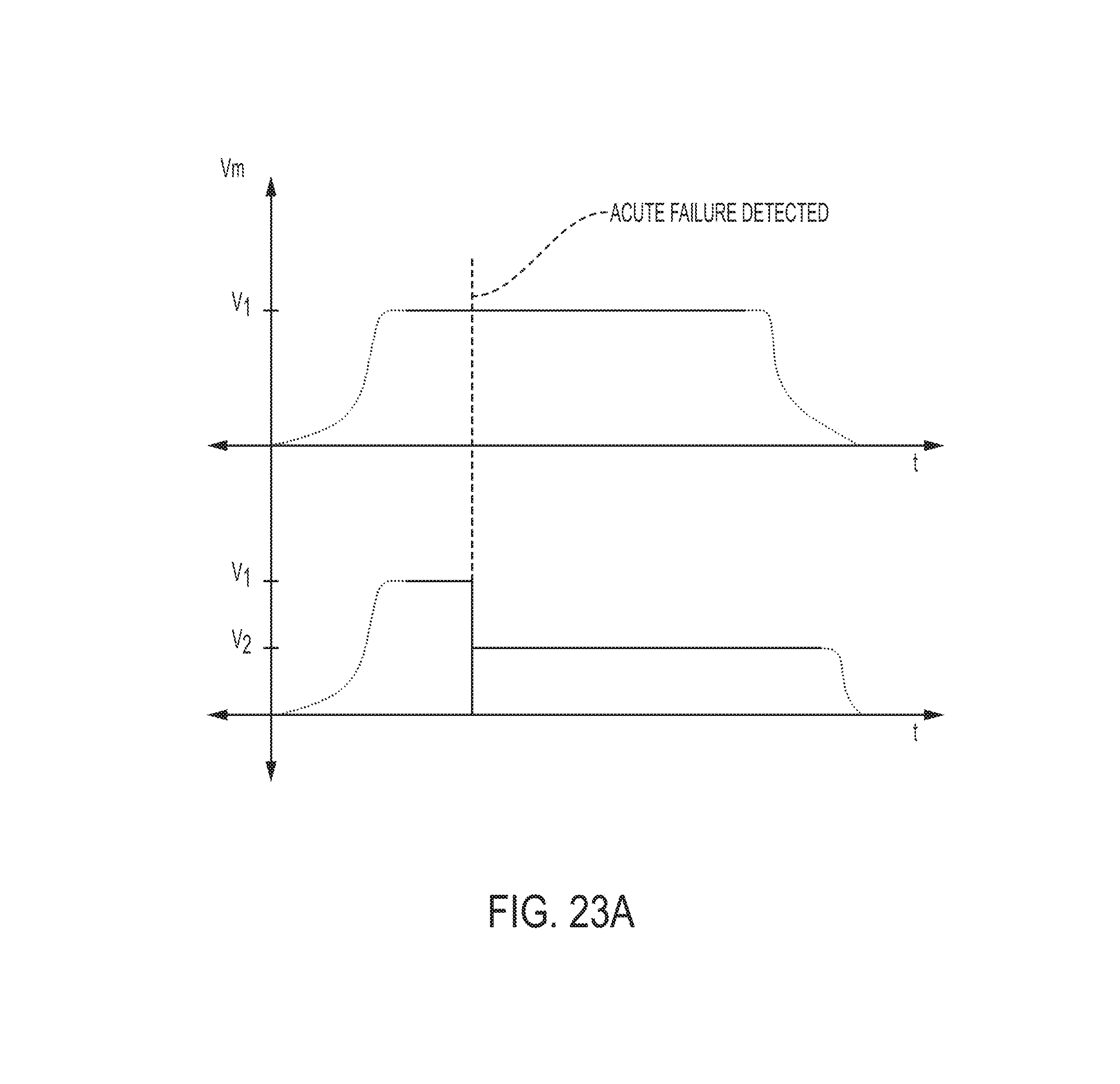
D00026

D00027
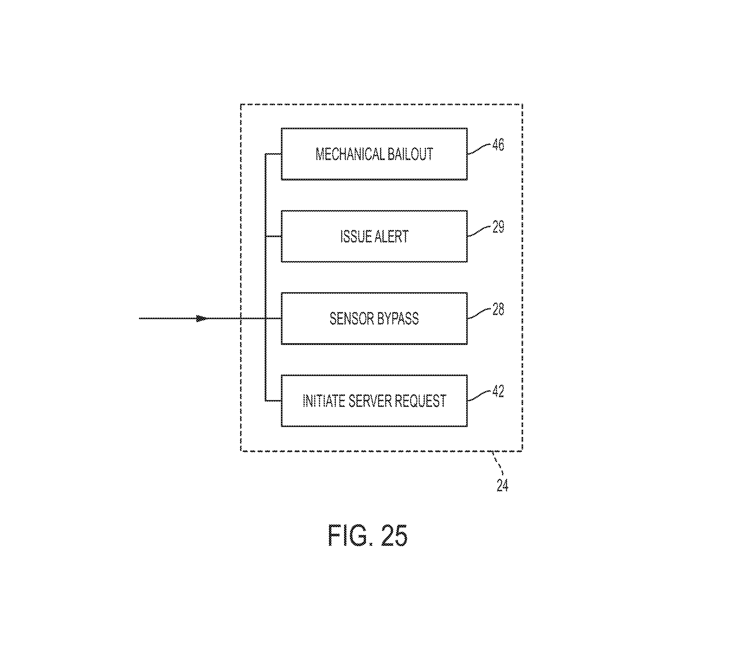
XML
uspto.report is an independent third-party trademark research tool that is not affiliated, endorsed, or sponsored by the United States Patent and Trademark Office (USPTO) or any other governmental organization. The information provided by uspto.report is based on publicly available data at the time of writing and is intended for informational purposes only.
While we strive to provide accurate and up-to-date information, we do not guarantee the accuracy, completeness, reliability, or suitability of the information displayed on this site. The use of this site is at your own risk. Any reliance you place on such information is therefore strictly at your own risk.
All official trademark data, including owner information, should be verified by visiting the official USPTO website at www.uspto.gov. This site is not intended to replace professional legal advice and should not be used as a substitute for consulting with a legal professional who is knowledgeable about trademark law.