Endoscopic reposable surgical clip applier
Yi , et al. March 2, 2
U.S. patent number 10,932,793 [Application Number 16/063,711] was granted by the patent office on 2021-03-02 for endoscopic reposable surgical clip applier. This patent grant is currently assigned to COVIDIEN LP. The grantee listed for this patent is Covidien LP. Invention is credited to Lin Chen, Shunhong Xu, Peng Yi, Kun Zhao.


View All Diagrams
| United States Patent | 10,932,793 |
| Yi , et al. | March 2, 2021 |
Endoscopic reposable surgical clip applier
Abstract
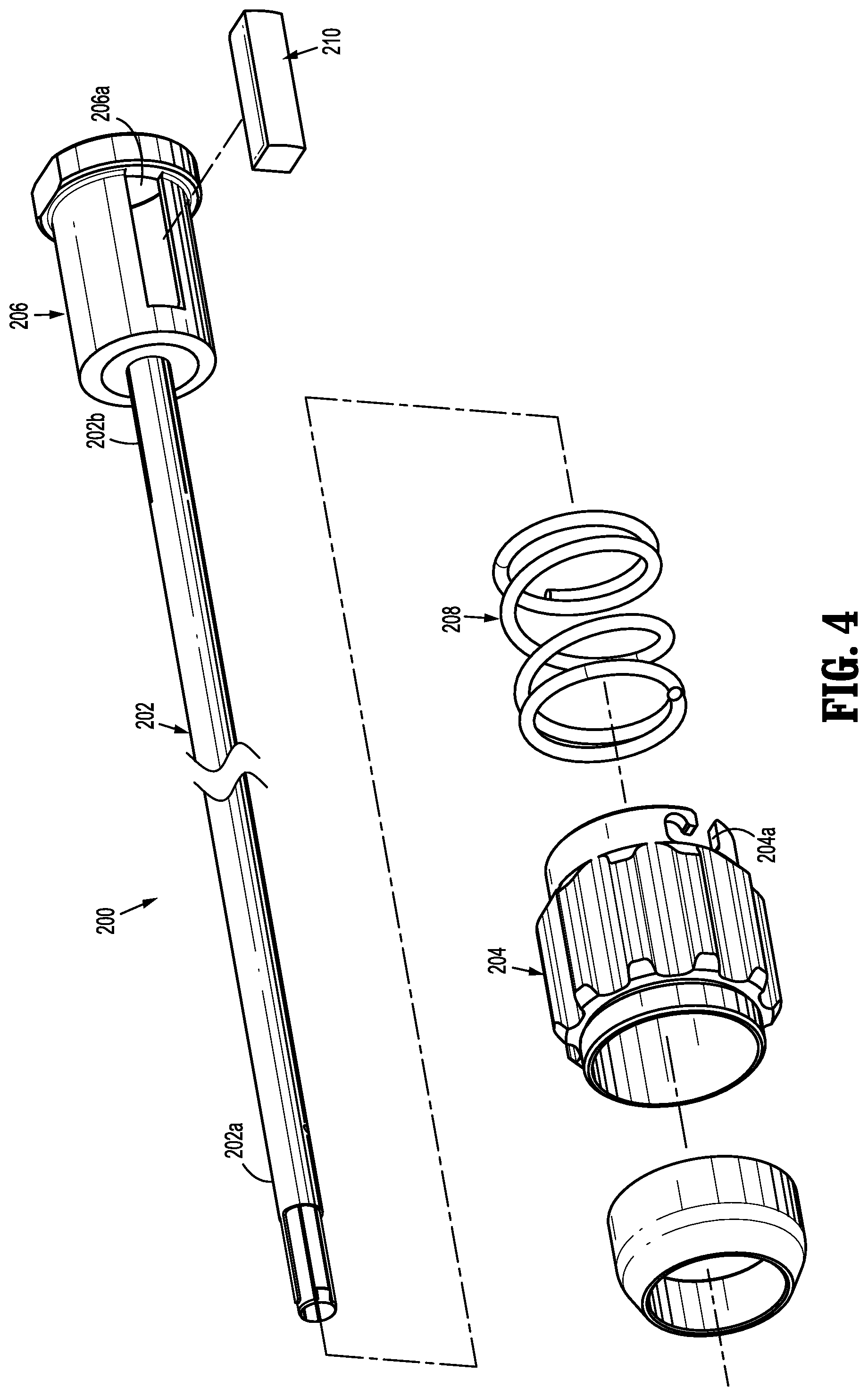
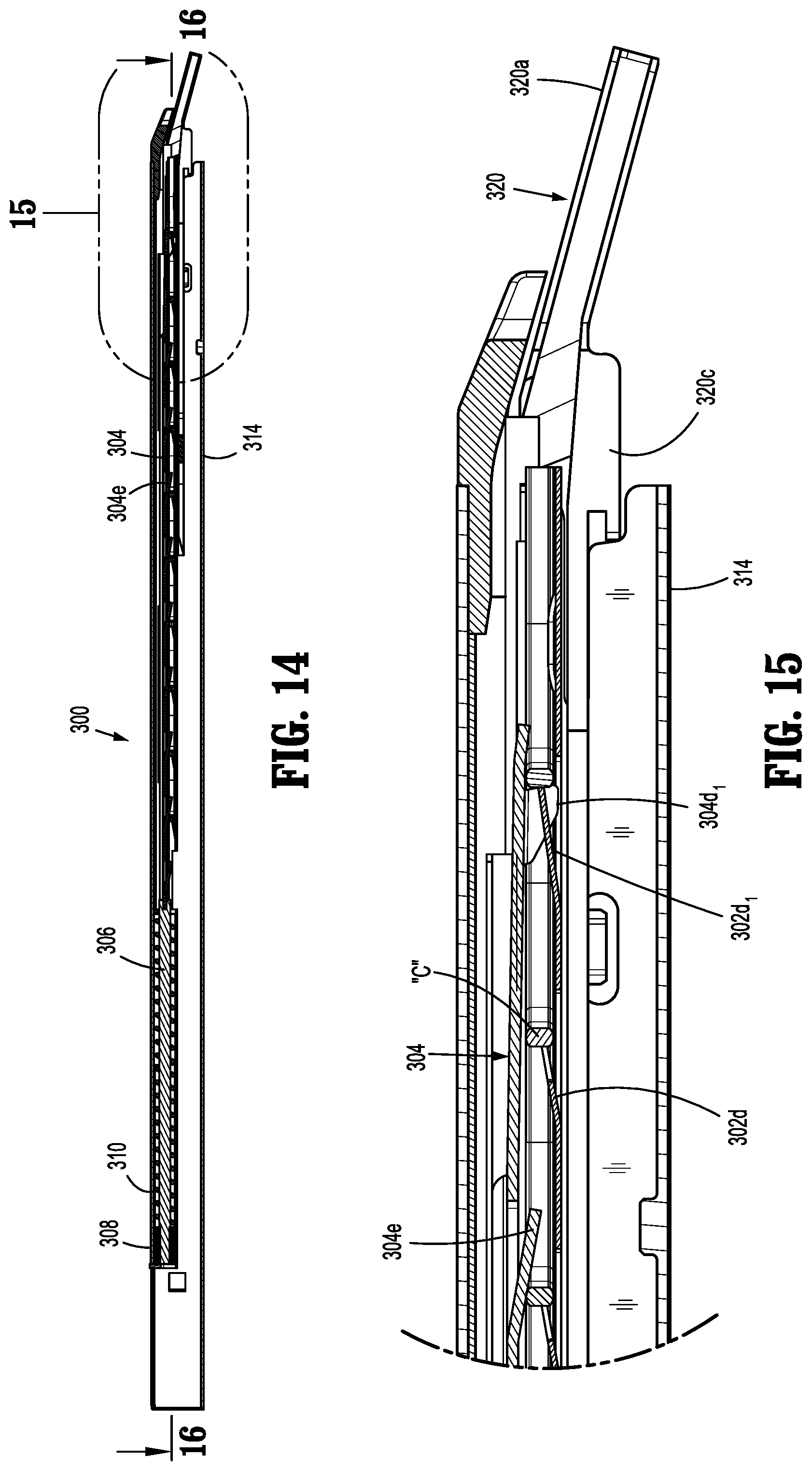
A reposable surgical clip applier (100) includes a handle assembly (110) having a housing, a trigger (114) and a drive assembly (120), the drive assembly (120) including a drive rod (122). The reposable surgical clip applier (100) further includes an outer tube assembly (200) disposed on a distal end of the housing and extending distally therefrom, and a clip cartridge assembly (300) selectively connectable to the distal end of the outer tube assembly (200). The clip cartridge assembly (300) includes an outer tube (314) and a pair of jaws (320a) fixedly supported in a distal end thereof, a first jaw pusher (130) in selective engagement with the distal end (122b) of the drive rod (122), a second jaw pusher (132) in selective engagement with the first jaw pusher (130) on a proximal end and the pair of jaws (320a) on a second end, and a plurality of surgical clips (C) disposed within the outer tube (314). A method of assembling a reposable surgical clip applier (100) is also provided.
| Inventors: | Yi; Peng (Shanghai, CN), Zhao; Kun (Shanghai, CN), Xu; Shunhong (Shanghai, CN), Chen; Lin (Shanghai, CN) | ||||||||||
|---|---|---|---|---|---|---|---|---|---|---|---|
| Applicant: |
|
||||||||||
| Assignee: | COVIDIEN LP (Mansfield,
MA) |
||||||||||
| Family ID: | 1000005391704 | ||||||||||
| Appl. No.: | 16/063,711 | ||||||||||
| Filed: | January 11, 2016 | ||||||||||
| PCT Filed: | January 11, 2016 | ||||||||||
| PCT No.: | PCT/CN2016/070571 | ||||||||||
| 371(c)(1),(2),(4) Date: | June 19, 2018 | ||||||||||
| PCT Pub. No.: | WO2017/120734 | ||||||||||
| PCT Pub. Date: | July 20, 2017 |
Prior Publication Data
| Document Identifier | Publication Date | |
|---|---|---|
| US 20200261095 A1 | Aug 20, 2020 | |
| Current U.S. Class: | 1/1 |
| Current CPC Class: | A61B 17/1285 (20130101); A61B 2017/00367 (20130101); A61B 34/35 (20160201); A61B 2017/0023 (20130101) |
| Current International Class: | A61B 17/128 (20060101); A61B 34/35 (20160101); A61B 17/00 (20060101) |
References Cited [Referenced By]
U.S. Patent Documents
| 3120230 | February 1964 | Skold |
| 3363628 | January 1968 | Wood |
| 3638847 | February 1972 | Noiles et al. |
| 3675688 | July 1972 | Bryan et al. |
| 3735762 | May 1973 | Bryan et al. |
| 3867944 | February 1975 | Samuels |
| 4226242 | October 1980 | Jarvik |
| 4242902 | January 1981 | Green |
| 4296751 | October 1981 | Blake, III et al. |
| 4372316 | February 1983 | Blake, III et al. |
| 4408603 | October 1983 | Blake, III et al. |
| 4412539 | November 1983 | Jarvik |
| 4418694 | December 1983 | Beroff et al. |
| 4471780 | September 1984 | Menges et al. |
| 4480640 | November 1984 | Becht |
| 4480641 | November 1984 | Failla et al. |
| 4487204 | December 1984 | Hrouda |
| 4487205 | December 1984 | Di Giovanni et al. |
| 4491133 | January 1985 | Menges et al. |
| 4492232 | January 1985 | Green |
| 4498476 | February 1985 | Cerwin et al. |
| 4500024 | February 1985 | Digiovanni et al. |
| 4509518 | April 1985 | McGarry et al. |
| 4512345 | April 1985 | Green |
| 4522207 | June 1985 | Klieman et al. |
| 4532925 | August 1985 | Blake, III |
| 4534351 | August 1985 | Rothfuss et al. |
| 4545377 | October 1985 | Cerwin et al. |
| 4549544 | October 1985 | Favaron |
| 4556058 | December 1985 | Green |
| 4557263 | December 1985 | Green |
| 4562839 | January 1986 | Blake, III et al. |
| 4572183 | February 1986 | Juska |
| 4576165 | March 1986 | Green et al. |
| 4576166 | March 1986 | Montgomery et al. |
| 4590937 | May 1986 | Deniega |
| 4598711 | July 1986 | Deniega |
| 4602631 | July 1986 | Funatsu |
| 4611595 | September 1986 | Klieman et al. |
| 4612932 | September 1986 | Caspar et al. |
| 4616650 | October 1986 | Green et al. |
| 4616651 | October 1986 | Golden |
| 4624254 | November 1986 | McGarry et al. |
| 4637395 | January 1987 | Caspar et al. |
| 4646740 | March 1987 | Peters et al. |
| 4647504 | March 1987 | Kimimura et al. |
| 4658822 | April 1987 | Kees, Jr. |
| 4660558 | April 1987 | Kees, Jr. |
| 4662373 | May 1987 | Montgomery et al. |
| 4662374 | May 1987 | Blake, III |
| 4671278 | June 1987 | Chin |
| 4671282 | June 1987 | Tretbar |
| 4674504 | June 1987 | Klieman et al. |
| 4681107 | July 1987 | Kees, Jr. |
| 4696396 | September 1987 | Samuels |
| 4702247 | October 1987 | Blake, III et al. |
| 4706668 | November 1987 | Backer |
| 4712549 | December 1987 | Peters et al. |
| 4726372 | February 1988 | Perlin |
| 4733666 | March 1988 | Mercer, Jr. |
| 4759364 | July 1988 | Boebel |
| 4765335 | August 1988 | Schmidt et al. |
| 4777949 | October 1988 | Perlin |
| 4796625 | January 1989 | Kees, Jr. |
| 4799481 | January 1989 | Transue et al. |
| 4815466 | March 1989 | Perlin |
| 4821721 | April 1989 | Chin et al. |
| 4822348 | April 1989 | Casey |
| 4834096 | May 1989 | Oh et al. |
| 4850355 | July 1989 | Brooks et al. |
| 4854317 | August 1989 | Braun |
| 4856517 | August 1989 | Collins et al. |
| 4929239 | May 1990 | Braun |
| 4931058 | June 1990 | Cooper |
| 4934364 | June 1990 | Green |
| 4957500 | September 1990 | Liang et al. |
| 4966603 | October 1990 | Focelle et al. |
| 4967949 | November 1990 | Sandhaus |
| 4983176 | January 1991 | Cushman et al. |
| 4988355 | January 1991 | Leveen et al. |
| 5002552 | March 1991 | Casey |
| 5026379 | June 1991 | Yoon |
| 5030224 | July 1991 | Wright et al. |
| 5030226 | July 1991 | Green et al. |
| 5032127 | July 1991 | Frazee et al. |
| 5035692 | July 1991 | Lyon et al. |
| 5047038 | September 1991 | Peters et al. |
| 5049152 | September 1991 | Simon et al. |
| 5049153 | September 1991 | Nakao et al. |
| 5053045 | October 1991 | Schmidt et al. |
| 5059202 | October 1991 | Liang et al. |
| 5062563 | November 1991 | Green et al. |
| 5062846 | November 1991 | Oh et al. |
| 5078731 | January 1992 | Hayhurst |
| 5084057 | January 1992 | Green et al. |
| 5100416 | March 1992 | Oh et al. |
| 5100420 | March 1992 | Green et al. |
| 5104394 | April 1992 | Knoepfler |
| 5104395 | April 1992 | Thornton et al. |
| 5112343 | May 1992 | Thornton |
| 5122150 | June 1992 | Puig |
| 5127915 | July 1992 | Mattson |
| 5129885 | July 1992 | Green et al. |
| 5156608 | October 1992 | Troidl et al. |
| 5160339 | November 1992 | Chen et al. |
| 5163945 | November 1992 | Ortiz et al. |
| 5171247 | December 1992 | Hughett et al. |
| 5171249 | December 1992 | Stefanchik et al. |
| 5171250 | December 1992 | Yoon |
| 5171251 | December 1992 | Bregen et al. |
| 5171252 | December 1992 | Friedland |
| 5171253 | December 1992 | Klieman |
| 5192288 | March 1993 | Thompson et al. |
| 5197970 | March 1993 | Green et al. |
| 5199566 | April 1993 | Ortiz et al. |
| 5201746 | April 1993 | Shichman |
| 5201900 | April 1993 | Nardella |
| 5207691 | May 1993 | Nardella |
| 5207692 | May 1993 | Kraus et al. |
| 5217473 | June 1993 | Yoon |
| 5219353 | June 1993 | Garvey, III et al. |
| 5246450 | September 1993 | Thornton et al. |
| 5269792 | December 1993 | Kovac et al. |
| 5281228 | January 1994 | Wolfson |
| 5282807 | February 1994 | Knoepfler |
| 5282808 | February 1994 | Kovac et al. |
| 5282832 | February 1994 | Toso et al. |
| 5289963 | March 1994 | McGarry et al. |
| 5290299 | March 1994 | Fain et al. |
| 5300081 | April 1994 | Young et al. |
| 5304183 | April 1994 | Gourlay et al. |
| 5306280 | April 1994 | Bregen et al. |
| 5306283 | April 1994 | Conners |
| 5312426 | May 1994 | Segawa et al. |
| 5330442 | July 1994 | Green et al. |
| 5330487 | July 1994 | Thornton et al. |
| 5340360 | August 1994 | Stefanchik |
| 5342373 | August 1994 | Stefanchik et al. |
| 5354304 | October 1994 | Allen et al. |
| 5354306 | October 1994 | Garvey, III et al. |
| 5356064 | October 1994 | Green et al. |
| 5359993 | November 1994 | Slater et al. |
| 5366458 | November 1994 | Korthoff et al. |
| 5366459 | November 1994 | Yoon |
| 5368600 | November 1994 | Failla et al. |
| 5381943 | January 1995 | Allen et al. |
| 5382253 | January 1995 | Hogendijk |
| 5382254 | January 1995 | McGarry et al. |
| 5382255 | January 1995 | Castro et al. |
| 5383880 | January 1995 | Hooven |
| 5383881 | January 1995 | Green et al. |
| 5395375 | March 1995 | Turkel et al. |
| 5395381 | March 1995 | Green et al. |
| 5403327 | April 1995 | Thornton et al. |
| 5409498 | April 1995 | Braddock et al. |
| 5413584 | May 1995 | Schulze |
| 5423835 | June 1995 | Green et al. |
| 5425740 | June 1995 | Hutchinson, Jr. |
| 5431667 | July 1995 | Thompson et al. |
| 5431668 | July 1995 | Burbank, III et al. |
| 5431669 | July 1995 | Thompson et al. |
| 5439468 | August 1995 | Schulze et al. |
| 5441509 | August 1995 | Vidal et al. |
| 5447513 | September 1995 | Davison et al. |
| 5448042 | September 1995 | Robinson et al. |
| 5449365 | September 1995 | Green et al. |
| 5462555 | October 1995 | Bolanos et al. |
| 5462558 | October 1995 | Kolesa et al. |
| 5464416 | November 1995 | Steckel |
| 5474566 | December 1995 | Alesi |
| 5474567 | December 1995 | Stefanchik et al. |
| 5474572 | December 1995 | Hayhurst |
| 5487499 | January 1996 | Sorrentino et al. |
| 5487746 | January 1996 | Yu et al. |
| 5501693 | March 1996 | Gravener |
| 5509920 | April 1996 | Phillips et al. |
| 5514149 | May 1996 | Green et al. |
| 5520701 | May 1996 | Lerch |
| 5527318 | June 1996 | McGarry |
| 5527319 | June 1996 | Green et al. |
| 5527320 | June 1996 | Carruthers et al. |
| 5542949 | August 1996 | Yoon |
| 5547474 | August 1996 | Kloeckl et al. |
| 5562655 | October 1996 | Mittelstadt et al. |
| 5569274 | October 1996 | Rapacki et al. |
| 5571121 | November 1996 | Heifetz |
| 5575802 | November 1996 | McQuilkin et al. |
| 5582615 | December 1996 | Foshee et al. |
| 5584840 | December 1996 | Ramsey et al. |
| 5591178 | January 1997 | Green et al. |
| 5593414 | January 1997 | Shipp et al. |
| 5593421 | January 1997 | Bauer |
| 5601573 | February 1997 | Fogelberg et al. |
| 5601574 | February 1997 | Stefanchik et al. |
| 5607436 | March 1997 | Pratt et al. |
| 5618291 | April 1997 | Thompson et al. |
| 5618306 | April 1997 | Roth et al. |
| 5620452 | April 1997 | Yoon |
| 5626585 | May 1997 | Mittelstadt et al. |
| 5626586 | May 1997 | Pistl et al. |
| 5626587 | May 1997 | Bishop et al. |
| 5626592 | May 1997 | Phillips et al. |
| RE35525 | June 1997 | Stefanchik et al. |
| 5634930 | June 1997 | Thornton et al. |
| 5643291 | July 1997 | Pier et al. |
| 5645551 | July 1997 | Green et al. |
| 5645553 | July 1997 | Kolesa et al. |
| 5649937 | July 1997 | Bito et al. |
| 5653720 | August 1997 | Johnson et al. |
| 5662662 | September 1997 | Bishop et al. |
| 5662676 | September 1997 | Koninckx |
| 5662679 | September 1997 | Voss et al. |
| 5665097 | September 1997 | Baker et al. |
| 5676676 | October 1997 | Porter |
| 5681330 | October 1997 | Hughett et al. |
| 5683405 | November 1997 | Yacoubian et al. |
| 5695502 | December 1997 | Pier et al. |
| 5695505 | December 1997 | Yoon |
| 5697938 | December 1997 | Jensen et al. |
| 5697942 | December 1997 | Palti |
| 5700270 | December 1997 | Peyser et al. |
| 5700271 | December 1997 | Whitfield et al. |
| 5702048 | December 1997 | Eberlin |
| 5709706 | January 1998 | Kienzle et al. |
| 5713911 | February 1998 | Racenet et al. |
| 5713912 | February 1998 | Porter |
| 5720756 | February 1998 | Green et al. |
| 5722982 | March 1998 | Ferreira et al. |
| 5725537 | March 1998 | Green et al. |
| 5725538 | March 1998 | Green et al. |
| 5725542 | March 1998 | Yoon |
| 5733295 | March 1998 | Back et al. |
| 5743310 | April 1998 | Moran |
| 5749881 | May 1998 | Sackier et al. |
| 5755726 | May 1998 | Pratt et al. |
| 5766189 | June 1998 | Matsuno |
| 5769857 | June 1998 | Reztzov et al. |
| 5772673 | June 1998 | Cuny et al. |
| 5776146 | July 1998 | Sackier et al. |
| 5776147 | July 1998 | Dolendo |
| 5779718 | July 1998 | Green et al. |
| 5779720 | July 1998 | Walder-Utz et al. |
| 5782844 | July 1998 | Yoon et al. |
| 5788698 | August 1998 | Savornin |
| 5792149 | August 1998 | Sherts et al. |
| 5792150 | August 1998 | Pratt et al. |
| 5797922 | August 1998 | Hessel et al. |
| 5809075 | September 1998 | Townshend |
| 5810853 | September 1998 | Yoon |
| 5817116 | October 1998 | Takahashi et al. |
| 5827306 | October 1998 | Yoon |
| 5827323 | October 1998 | Klieman et al. |
| 5833695 | November 1998 | Yoon |
| 5833696 | November 1998 | Whitfield et al. |
| 5833700 | November 1998 | Fogelberg et al. |
| 5835199 | November 1998 | Phillips et al. |
| 5843097 | December 1998 | Mayenberger et al. |
| 5843101 | December 1998 | Fry |
| 5846255 | December 1998 | Casey |
| 5849019 | December 1998 | Yoon |
| 5858018 | January 1999 | Shipp et al. |
| 5861005 | January 1999 | Kontos |
| 5868759 | February 1999 | Peyser et al. |
| 5868761 | February 1999 | Nicholas et al. |
| 5876410 | March 1999 | Petillo |
| 5895394 | April 1999 | Kienzle et al. |
| 5897565 | April 1999 | Foster |
| 5904693 | May 1999 | Dicesare et al. |
| 5906625 | May 1999 | Bito et al. |
| 5913862 | June 1999 | Ramsey et al. |
| 5913876 | June 1999 | Taylor et al. |
| 5918791 | July 1999 | Sorrentino et al. |
| 5921991 | July 1999 | Whitehead et al. |
| 5921996 | July 1999 | Sherman |
| 5921997 | July 1999 | Fogelberg et al. |
| 5928251 | July 1999 | Aranyi et al. |
| 5938667 | August 1999 | Peyser et al. |
| 5951574 | September 1999 | Stefanchik et al. |
| 5972003 | October 1999 | Rousseau et al. |
| 5976159 | November 1999 | Bolduc et al. |
| 5993465 | November 1999 | Shipp et al. |
| 6004335 | December 1999 | Vaitekunas et al. |
| 6009551 | December 1999 | Sheynblat |
| 6017358 | January 2000 | Yoon et al. |
| 6044971 | April 2000 | Esposito et al. |
| 6045560 | April 2000 | McKean et al. |
| 6053908 | April 2000 | Crainich et al. |
| RE36720 | May 2000 | Green et al. |
| 6059799 | May 2000 | Aranyi et al. |
| 6099536 | August 2000 | Petillo |
| 6099537 | August 2000 | Sugai et al. |
| 6139555 | October 2000 | Hart et al. |
| 6210418 | April 2001 | Storz et al. |
| 6217590 | April 2001 | Levinson |
| 6228097 | May 2001 | Levinson et al. |
| 6241740 | June 2001 | Davis et al. |
| 6258105 | July 2001 | Hart et al. |
| 6261302 | July 2001 | Voegele et al. |
| 6273898 | August 2001 | Kienzle et al. |
| 6277131 | August 2001 | Kalikow |
| 6306149 | October 2001 | Meade |
| 6318619 | November 2001 | Lee |
| 6322571 | November 2001 | Adams |
| 6350269 | February 2002 | Shipp et al. |
| 6352541 | March 2002 | Kienzle et al. |
| 6391035 | May 2002 | Appleby et al. |
| 6423079 | July 2002 | Blake, III |
| 6428548 | August 2002 | Durgin |
| 6440144 | August 2002 | Bacher |
| 6461363 | October 2002 | Gadberry et al. |
| 6464710 | October 2002 | Foster |
| 6494886 | December 2002 | Wilk et al. |
| 6517536 | February 2003 | Hooven et al. |
| 6520972 | February 2003 | Peters |
| 6527786 | March 2003 | Davis et al. |
| 6537289 | March 2003 | Kayan |
| 6546935 | April 2003 | Hooven |
| 6551333 | April 2003 | Kuhns et al. |
| 6562051 | May 2003 | Bolduc et al. |
| 6569171 | May 2003 | DeGuillebon et al. |
| 6579304 | June 2003 | Hart et al. |
| 6599298 | July 2003 | Forster et al. |
| 6602252 | August 2003 | Mollenauer |
| 6607540 | August 2003 | Shipp |
| 6613060 | September 2003 | Adams et al. |
| 6626916 | September 2003 | Yeung et al. |
| 6626922 | September 2003 | Hart et al. |
| 6648898 | November 2003 | Baxter |
| 6652538 | November 2003 | Kayan et al. |
| 6652539 | November 2003 | Shipp et al. |
| 6656193 | December 2003 | Grant et al. |
| 6673083 | January 2004 | Kayan et al. |
| 6676659 | January 2004 | Hutchins et al. |
| 6679894 | January 2004 | Damarati |
| RE38445 | February 2004 | Pistl et al. |
| 6695854 | February 2004 | Kayan et al. |
| 6706057 | March 2004 | Bidoia et al. |
| 6716226 | April 2004 | Sixto, Jr. et al. |
| 6723109 | April 2004 | Solingen |
| 6733514 | May 2004 | Miser |
| 6743240 | June 2004 | Smith et al. |
| 6743241 | June 2004 | Kerr |
| 6773438 | August 2004 | Knodel et al. |
| 6773440 | August 2004 | Gannoe et al. |
| 6776783 | August 2004 | Frantzen et al. |
| 6776784 | August 2004 | Ginn |
| 6780195 | August 2004 | Porat |
| 6793663 | September 2004 | Kneifel et al. |
| 6793664 | September 2004 | Mazzocchi et al. |
| 6802848 | October 2004 | Anderson et al. |
| 6814742 | November 2004 | Kimura et al. |
| 6818009 | November 2004 | Hart et al. |
| 6821273 | November 2004 | Mollenauer |
| 6821284 | November 2004 | Sturtz et al. |
| 6821285 | November 2004 | Laufer et al. |
| 6824547 | November 2004 | Wilson, Jr. et al. |
| 6824548 | November 2004 | Smith et al. |
| 6835199 | December 2004 | McGuckin, Jr. et al. |
| 6835200 | December 2004 | Laufer et al. |
| 6837893 | January 2005 | Miller |
| 6837894 | January 2005 | Pugsley, Jr. et al. |
| 6837895 | January 2005 | Mayenberger |
| 6840945 | January 2005 | Manetakis et al. |
| 6843794 | January 2005 | Sixto, Jr. et al. |
| 6849078 | February 2005 | Durgin et al. |
| 6849079 | February 2005 | Blake, III et al. |
| 6853879 | February 2005 | Sunaoshi |
| 6869435 | March 2005 | Blake, III |
| 6869436 | March 2005 | Wendlandt |
| 6889116 | May 2005 | Jinno |
| 6896676 | May 2005 | Zubok et al. |
| 6896682 | May 2005 | McClellan et al. |
| 6896684 | May 2005 | Monassevitch et al. |
| 6905503 | June 2005 | Gifford, III et al. |
| 6911032 | June 2005 | Jugenheimer et al. |
| 6911033 | June 2005 | de Guillebon et al. |
| 6913607 | July 2005 | Ainsworth et al. |
| 6916327 | July 2005 | Northrup, III et al. |
| 6916332 | July 2005 | Adams |
| 6923818 | August 2005 | Muramatsu et al. |
| 6939356 | September 2005 | Debbas |
| 6942674 | September 2005 | Belef et al. |
| 6942676 | September 2005 | Buelna |
| 6945978 | September 2005 | Hyde |
| 6945979 | September 2005 | Kortenbach et al. |
| 6949107 | September 2005 | McGuckin, Jr. et al. |
| 6953465 | October 2005 | Dieck et al. |
| 6955643 | October 2005 | Gellman et al. |
| 6959852 | November 2005 | Shelton, IV et al. |
| 6960218 | November 2005 | Rennich |
| 6960221 | November 2005 | Ho et al. |
| 6962594 | November 2005 | Thevenet |
| 6963792 | November 2005 | Green |
| 6964363 | November 2005 | Wales et al. |
| 6964668 | November 2005 | Modesitt et al. |
| 6966875 | November 2005 | Longobardi |
| 6966917 | November 2005 | Suyker et al. |
| 6966919 | November 2005 | Sixto, Jr. et al. |
| 6969391 | November 2005 | Gazzani |
| 6972023 | December 2005 | Whayne et al. |
| 6972027 | December 2005 | Fallin et al. |
| 6973770 | December 2005 | Schnipke et al. |
| 6974462 | December 2005 | Sater |
| 6974466 | December 2005 | Ahmed et al. |
| 6974475 | December 2005 | Wall |
| 6981505 | January 2006 | Krause et al. |
| 6981628 | January 2006 | Wales |
| 6991635 | January 2006 | Takamoto et al. |
| 6997929 | February 2006 | Manzi et al. |
| 7001399 | February 2006 | Damarati |
| 7037315 | May 2006 | Sancoff et al. |
| 7041119 | May 2006 | Green |
| 7052504 | May 2006 | Hughett |
| 7056330 | June 2006 | Gayton |
| 7070602 | July 2006 | Smith et al. |
| 7108700 | September 2006 | Chan |
| 7108703 | September 2006 | Danitz et al. |
| 7141056 | November 2006 | Manetakis |
| 7144402 | December 2006 | Kuester, III |
| 7175648 | February 2007 | Nakao |
| 7179265 | February 2007 | Manetakis et al. |
| 7207997 | April 2007 | Shipp et al. |
| 7211091 | May 2007 | Fowler et al. |
| 7211092 | May 2007 | Hughett |
| 7213736 | May 2007 | Wales et al. |
| 7214230 | May 2007 | Brock et al. |
| 7214232 | May 2007 | Bowman et al. |
| 7223271 | May 2007 | Muramatsu et al. |
| 7223272 | May 2007 | Francese et al. |
| 7232445 | June 2007 | Kortenbach et al. |
| 7238191 | July 2007 | Bachmann |
| 7261724 | August 2007 | Molitor et al. |
| 7261725 | August 2007 | Binmoeller |
| 7264625 | September 2007 | Buncke |
| 7288098 | October 2007 | Huitema et al. |
| 7297149 | November 2007 | Vitali et al. |
| 7312188 | December 2007 | Kiso |
| 7316693 | January 2008 | Viola |
| 7316696 | January 2008 | Wilson, Jr. et al. |
| 7322995 | January 2008 | Buckman et al. |
| 7326223 | February 2008 | Wilson, Jr. |
| 7329266 | February 2008 | Royse et al. |
| 7331968 | February 2008 | Arp et al. |
| 7338503 | March 2008 | Rosenberg et al. |
| 7357805 | April 2008 | Masuda et al. |
| 7367939 | May 2008 | Smith et al. |
| 7407074 | August 2008 | Ortiz et al. |
| 7419495 | September 2008 | Menn et al. |
| 7422137 | September 2008 | Manzo |
| 7431724 | October 2008 | Manetakis et al. |
| 7452327 | November 2008 | Durgin et al. |
| 7485124 | February 2009 | Kuhns et al. |
| 7488335 | February 2009 | Sgro |
| 7510562 | March 2009 | Lindsay |
| 7552853 | June 2009 | Mas et al. |
| 7559937 | July 2009 | de la Torre et al. |
| 7572266 | August 2009 | Young et al. |
| 7578827 | August 2009 | Gadberry et al. |
| 7582095 | September 2009 | Shipp et al. |
| 7585304 | September 2009 | Hughett |
| 7615058 | November 2009 | Sixto, Jr. et al. |
| 7615060 | November 2009 | Stokes et al. |
| 7621926 | November 2009 | Wixey et al. |
| 7637917 | December 2009 | Whitfield et al. |
| 7644848 | January 2010 | Swayze et al. |
| 7686820 | March 2010 | Huitema et al. |
| 7695482 | April 2010 | Viola |
| 7717926 | May 2010 | Whitfield et al. |
| 7727247 | June 2010 | Kimura et al. |
| 7727248 | June 2010 | Smith et al. |
| 7731724 | June 2010 | Huitema et al. |
| 7731725 | June 2010 | Gadberry et al. |
| 7736388 | June 2010 | Goldfarb et al. |
| 7740639 | June 2010 | Hummel et al. |
| 7740641 | June 2010 | Huitema |
| 7744623 | June 2010 | Anderson |
| 7752853 | July 2010 | Singh et al. |
| 7753250 | July 2010 | Clauson et al. |
| 7766207 | August 2010 | Mather et al. |
| 7766925 | August 2010 | Stokes et al. |
| 7770773 | August 2010 | Whitman et al. |
| 7776058 | August 2010 | Rosenberg et al. |
| 7780688 | August 2010 | Sakakine et al. |
| 7793813 | September 2010 | Bettuchi |
| 7806903 | October 2010 | Shibata et al. |
| 7819886 | October 2010 | Whitfield et al. |
| 7823592 | November 2010 | Bettuchi et al. |
| 7857828 | December 2010 | Jabba et al. |
| 7871416 | January 2011 | Phillips |
| 7875029 | January 2011 | Hausen |
| 7887553 | February 2011 | Lehman et al. |
| 7887554 | February 2011 | Stokes et al. |
| 7892244 | February 2011 | Monassevitch et al. |
| 7896895 | March 2011 | Boudreaux et al. |
| 7901420 | March 2011 | Dunn |
| 7905890 | March 2011 | Whitfield et al. |
| 7914544 | March 2011 | Nguyen et al. |
| 7914551 | March 2011 | Ortiz et al. |
| 7942890 | May 2011 | D'Agostino et al. |
| 7947052 | May 2011 | Baxter, III et al. |
| 7954682 | June 2011 | Giordano et al. |
| 7963433 | June 2011 | Whitman et al. |
| 7967831 | June 2011 | Rosenberg et al. |
| 7988027 | August 2011 | Olson et al. |
| 7998155 | August 2011 | Manzo |
| 8011550 | September 2011 | Aranyi et al. |
| 8011555 | September 2011 | Tarinelli et al. |
| 8016178 | September 2011 | Olson et al. |
| 8021375 | September 2011 | Aldrich et al. |
| 8021378 | September 2011 | Sixto, Jr. et al. |
| 8038686 | October 2011 | Huiterna et al. |
| 8048088 | November 2011 | Green et al. |
| 8056565 | November 2011 | Zergiebel |
| 8062310 | November 2011 | Shibata et al. |
| 8062311 | November 2011 | Litscher et al. |
| 8062314 | November 2011 | Sixto, Jr. et al. |
| 8066720 | November 2011 | Knodel et al. |
| 8066721 | November 2011 | Kortenbach et al. |
| 8066722 | November 2011 | Miyagi et al. |
| 8070760 | December 2011 | Fujita |
| 8074857 | December 2011 | Peterson et al. |
| 8075571 | December 2011 | Vitali et al. |
| 8080021 | December 2011 | Griego |
| 8083668 | December 2011 | Durgin et al. |
| 8088061 | January 2012 | Wells et al. |
| 8091755 | January 2012 | Kayan et al. |
| 8100926 | January 2012 | Filshie et al. |
| 8128643 | March 2012 | Aranyi et al. |
| 8133240 | March 2012 | Damarati |
| 8137368 | March 2012 | Kayan et al. |
| 8142451 | March 2012 | Boulnois et al. |
| 8157145 | April 2012 | Shelton, IV et al. |
| 8157149 | April 2012 | Olson et al. |
| 8157151 | April 2012 | Ingmanson et al. |
| 8172859 | May 2012 | Matsuno et al. |
| 8172870 | May 2012 | Shipp |
| 8177797 | May 2012 | Shimoji et al. |
| 8182529 | May 2012 | Gordon et al. |
| 8187290 | May 2012 | Buckman et al. |
| 8192449 | June 2012 | Maier et al. |
| 8211119 | July 2012 | Palmer et al. |
| 8211120 | July 2012 | Itoh |
| 8211124 | July 2012 | Ainsworth et al. |
| 8216255 | July 2012 | Smith et al. |
| 8216257 | July 2012 | Huitema et al. |
| 8236012 | August 2012 | Molitor et al. |
| 8241322 | August 2012 | Whitman et al. |
| 8246634 | August 2012 | Huitema et al. |
| 8246635 | August 2012 | Huitema |
| 8262678 | September 2012 | Matsuoka et al. |
| 8262679 | September 2012 | Nguyen |
| 8267944 | September 2012 | Sorrentino et al. |
| 8267945 | September 2012 | Nguyen et al. |
| 8267946 | September 2012 | Whitfield et al. |
| 8272554 | September 2012 | Whitman et al. |
| 8282655 | October 2012 | Whitfield et al. |
| 8287559 | October 2012 | Barker et al. |
| 8308743 | November 2012 | Matsuno et al. |
| 8313497 | November 2012 | Walberg et al. |
| 8328822 | December 2012 | Huitema et al. |
| 8336556 | December 2012 | Zergiebel |
| 8348130 | January 2013 | Shah et al. |
| 8357171 | January 2013 | Whitfield et al. |
| 8366709 | February 2013 | Schechter et al. |
| 8366726 | February 2013 | Dennis |
| 8371491 | February 2013 | Huitema et al. |
| 8372095 | February 2013 | Viola |
| 8382773 | February 2013 | Whitfield et al. |
| 8398655 | March 2013 | Cheng et al. |
| 8403138 | March 2013 | Weisshaupt et al. |
| 8403945 | March 2013 | Whitfield et al. |
| 8403946 | March 2013 | Whitfield et al. |
| 8408442 | April 2013 | Racenet et al. |
| 8409222 | April 2013 | Whitfield et al. |
| 8409223 | April 2013 | Sorrentino et al. |
| 8419752 | April 2013 | Sorrentino et al. |
| 8430892 | April 2013 | Bindra et al. |
| 8444660 | May 2013 | Adams et al. |
| 8465460 | June 2013 | Yodfat et al. |
| 8465502 | June 2013 | Zergiebel |
| 8475473 | July 2013 | Vandenbroek et al. |
| 8480688 | July 2013 | Boulnois et al. |
| 8486091 | July 2013 | Sorrentino et al. |
| 8491608 | July 2013 | Sorrentino et al. |
| 8496673 | July 2013 | Nguyen et al. |
| 8506580 | August 2013 | Zergiebel et al. |
| 8512357 | August 2013 | Viola |
| 8518055 | August 2013 | Cardinale et al. |
| 8523882 | September 2013 | Huitema et al. |
| 8529585 | September 2013 | Jacobs et al. |
| 8529586 | September 2013 | Rosenberg et al. |
| 8529588 | September 2013 | Ahlberg et al. |
| 8545486 | October 2013 | Malkowski |
| 8545519 | October 2013 | Aguirre et al. |
| 8556920 | October 2013 | Huitema et al. |
| 8568430 | October 2013 | Shipp |
| 8579918 | November 2013 | Whitfield et al. |
| 8585716 | November 2013 | Roskopf et al. |
| 8585717 | November 2013 | Sorrentino et al. |
| 8603109 | December 2013 | Aranyi et al. |
| 8623044 | January 2014 | Timm et al. |
| 8628547 | January 2014 | Weller et al. |
| 8632520 | January 2014 | Otley |
| 8636191 | January 2014 | Meagher |
| 8652151 | February 2014 | Lehman et al. |
| 8652152 | February 2014 | Aranyi et al. |
| 8663247 | March 2014 | Menn et al. |
| 8685048 | April 2014 | Adams et al. |
| 8690899 | April 2014 | Kogiso et al. |
| 8708210 | April 2014 | Zemlok et al. |
| 8708213 | April 2014 | Shelton, IV et al. |
| 8709027 | April 2014 | Adams et al. |
| 8715299 | May 2014 | Menn et al. |
| 8720766 | May 2014 | Hess et al. |
| 8734469 | May 2014 | Pribanic et al. |
| 8747423 | June 2014 | Whitfield et al. |
| 8753356 | June 2014 | Vitali et al. |
| 8758392 | June 2014 | Crainich |
| 8771169 | July 2014 | Whitman et al. |
| 8795302 | August 2014 | Wild |
| 8808310 | August 2014 | Jones et al. |
| 8814884 | August 2014 | Whitfield et al. |
| 8821516 | September 2014 | Huitema |
| 8839954 | September 2014 | Disch |
| 8845659 | September 2014 | Whitfield et al. |
| 8894665 | November 2014 | Sorrentino et al. |
| 8894666 | November 2014 | Schulz et al. |
| 8900253 | December 2014 | Aranyi et al. |
| 8915930 | December 2014 | Huitema et al. |
| 8915931 | December 2014 | Boudreaux et al. |
| 8939974 | January 2015 | Boudreaux et al. |
| 8945151 | February 2015 | Salas |
| 8950646 | February 2015 | Viola |
| 8968337 | March 2015 | Whitfield et al. |
| 8968342 | March 2015 | Wingardner, III et al. |
| 8973804 | March 2015 | Hess et al. |
| 8986343 | March 2015 | Bourque et al. |
| 8998935 | April 2015 | Hart |
| 9011464 | April 2015 | Zammataro |
| 9011465 | April 2015 | Whitfield et al. |
| 9028511 | May 2015 | Weller et al. |
| 9060779 | June 2015 | Martinez |
| 9084604 | July 2015 | Litscher et al. |
| 9089334 | July 2015 | Sorrentino et al. |
| 9113892 | August 2015 | Malkowski et al. |
| 9113893 | August 2015 | Sorrentino et al. |
| 9119629 | September 2015 | Cardinale et al. |
| 9186136 | November 2015 | Malkowski et al. |
| 9186153 | November 2015 | Zammataro |
| 9208429 | December 2015 | Thornton et al. |
| 9220507 | December 2015 | Patel |
| 9226825 | January 2016 | Starksen et al. |
| 9232947 | January 2016 | Brenner et al. |
| 9265486 | February 2016 | Hughett, Sr. et al. |
| 9271737 | March 2016 | Castro et al. |
| 9282972 | March 2016 | Patel |
| 9282973 | March 2016 | Hughett, Sr. et al. |
| 9358011 | June 2016 | Sorrentino et al. |
| 9364216 | June 2016 | Rockrohr et al. |
| 9364240 | June 2016 | Whitfield et al. |
| 9370400 | June 2016 | Parihar |
| 9393024 | July 2016 | Whitfield et al. |
| 9408610 | August 2016 | Hartournbekis |
| 9414844 | August 2016 | Zergiebel et al. |
| 9433411 | September 2016 | Racenet et al. |
| 9433422 | September 2016 | Crainich et al. |
| 9439654 | September 2016 | Sorrentino et al. |
| 9445810 | September 2016 | Cappola |
| 9445820 | September 2016 | Whiting |
| 9456824 | October 2016 | Willett et al. |
| 9468444 | October 2016 | Menn et al. |
| 9480477 | November 2016 | Aranyi et al. |
| 9480480 | November 2016 | Santilli et al. |
| 9486225 | November 2016 | Michler et al. |
| 9498227 | November 2016 | Zergiebel et al. |
| 9504472 | November 2016 | Kamler |
| 9517064 | December 2016 | Sarradon |
| 9526501 | December 2016 | Malkowski |
| 9526565 | December 2016 | Strobl |
| 9532787 | January 2017 | Zammataro |
| 9545254 | January 2017 | Sorrentino et al. |
| 9549741 | January 2017 | Zergiebel |
| 9561038 | February 2017 | Shelton, IV et al. |
| 9566066 | February 2017 | Kasvikis |
| 9597089 | March 2017 | Menn |
| 9642627 | May 2017 | Zammataro |
| 9681877 | June 2017 | Blake, III et al. |
| 9687247 | June 2017 | Aranyi et al. |
| 9700324 | July 2017 | Mazzucco et al. |
| 9717504 | August 2017 | Huitema |
| 9717505 | August 2017 | Whitfield et al. |
| 9724163 | August 2017 | Orban |
| 9737310 | August 2017 | Whitfield et al. |
| 9750500 | September 2017 | Malkowski |
| 9763668 | September 2017 | Whitfield et al. |
| 9763669 | September 2017 | Griego |
| 9775623 | October 2017 | Zammataro et al. |
| 9775624 | October 2017 | Rockrohr et al. |
| 9782164 | October 2017 | Mumaw et al. |
| 9782181 | October 2017 | Vitali et al. |
| 9808257 | November 2017 | Armenteros et al. |
| 9848886 | December 2017 | Malkowski et al. |
| 9855043 | January 2018 | Malkowski |
| 9883866 | February 2018 | Roundy et al. |
| 9931124 | April 2018 | Gokharu |
| 9968361 | May 2018 | Aranyi et al. |
| 9968362 | May 2018 | Malkowski et al. |
| 10004502 | June 2018 | Malkowski et al. |
| 10136939 | November 2018 | Minnelli et al. |
| 10159484 | December 2018 | Sorrentino et al. |
| 10159491 | December 2018 | Gokharu |
| 10159492 | December 2018 | Zammataro |
| 10166027 | January 2019 | Aranyi et al. |
| 10231732 | March 2019 | Racenet et al. |
| 10231735 | March 2019 | Sorrentino et al. |
| 10231738 | March 2019 | Sorrentino et al. |
| 10258346 | April 2019 | Zergiebel et al. |
| 10271854 | April 2019 | Whitfield et al. |
| 10292712 | May 2019 | Shankarsetty |
| 10349936 | July 2019 | Rockrohr et al. |
| 10349950 | July 2019 | Aranyi |
| 10357250 | July 2019 | Zammataro |
| 10363045 | July 2019 | Whitfield et al. |
| 10368876 | August 2019 | Bhatnagar et al. |
| 10390831 | August 2019 | Holsten et al. |
| 10426489 | October 2019 | Baril |
| 2002/0123742 | September 2002 | Baxter et al. |
| 2003/0014060 | January 2003 | Wilson et al. |
| 2003/0114867 | June 2003 | Bolduc et al. |
| 2003/0208231 | November 2003 | Williamson et al. |
| 2003/0229360 | December 2003 | Gayton |
| 2004/0097970 | May 2004 | Hughett |
| 2004/0097971 | May 2004 | Hughett |
| 2004/0133215 | July 2004 | Baxter |
| 2004/0138681 | July 2004 | Pier |
| 2004/0167545 | August 2004 | Sadler et al. |
| 2004/0176783 | September 2004 | Edoga et al. |
| 2004/0176784 | September 2004 | Okada |
| 2004/0193213 | September 2004 | Aranyi et al. |
| 2004/0230198 | November 2004 | Manzi et al. |
| 2004/0232197 | November 2004 | Shelton et al. |
| 2005/0010242 | January 2005 | Lindsay |
| 2005/0090837 | April 2005 | Sixto et al. |
| 2005/0096670 | May 2005 | Wellman et al. |
| 2005/0096671 | May 2005 | Wellman et al. |
| 2005/0107810 | May 2005 | Morales et al. |
| 2005/0107811 | May 2005 | Starksen et al. |
| 2005/0107871 | May 2005 | Realyvasquez et al. |
| 2005/0125010 | June 2005 | Smith et al. |
| 2005/0149068 | July 2005 | Williams et al. |
| 2005/0149069 | July 2005 | Bertolero et al. |
| 2005/0171560 | August 2005 | Hughett |
| 2005/0175703 | August 2005 | Hunter et al. |
| 2005/0177176 | August 2005 | Gerbi et al. |
| 2005/0216036 | September 2005 | Nakao |
| 2005/0216056 | September 2005 | Valdevit et al. |
| 2005/0222665 | October 2005 | Aranyi |
| 2005/0228416 | October 2005 | Burbank et al. |
| 2005/0234478 | October 2005 | Wixey et al. |
| 2005/0256529 | November 2005 | Yawata et al. |
| 2005/0267495 | December 2005 | Ginn et al. |
| 2005/0273122 | December 2005 | Theroux et al. |
| 2005/0277956 | December 2005 | Francese et al. |
| 2005/0277958 | December 2005 | Levinson |
| 2005/0288689 | December 2005 | Kammerer et al. |
| 2006/0000867 | January 2006 | Shelton et al. |
| 2006/0004388 | January 2006 | Whayne et al. |
| 2006/0009789 | January 2006 | Gambale et al. |
| 2006/0009790 | January 2006 | Blake et al. |
| 2006/0009792 | January 2006 | Baker et al. |
| 2006/0020271 | January 2006 | Stewart et al. |
| 2006/0079115 | April 2006 | Aranyi |
| 2006/0085015 | April 2006 | Whitfield et al. |
| 2006/0085021 | April 2006 | Wenzler |
| 2006/0100649 | May 2006 | Hart |
| 2006/0124485 | June 2006 | Kennedy |
| 2006/0163312 | July 2006 | Viola et al. |
| 2006/0173470 | August 2006 | Oray et al. |
| 2006/0190013 | August 2006 | Menn |
| 2006/0217749 | September 2006 | Wilson et al. |
| 2006/0224165 | October 2006 | Surti et al. |
| 2006/0224170 | October 2006 | Duff |
| 2006/0235439 | October 2006 | Molitor et al. |
| 2006/0241655 | October 2006 | Viola |
| 2006/0259045 | November 2006 | Damarati |
| 2006/0259049 | November 2006 | Harada et al. |
| 2007/0021766 | January 2007 | Belagali et al. |
| 2007/0038233 | February 2007 | Martinez et al. |
| 2007/0049947 | March 2007 | Menn et al. |
| 2007/0049949 | March 2007 | Manetakis |
| 2007/0049950 | March 2007 | Theroux et al. |
| 2007/0049951 | March 2007 | Menn |
| 2007/0083218 | April 2007 | Morris |
| 2007/0093790 | April 2007 | Downey et al. |
| 2007/0112365 | May 2007 | Hilal et al. |
| 2007/0118161 | May 2007 | Kennedy et al. |
| 2007/0118174 | May 2007 | Chu |
| 2007/0173866 | July 2007 | Sorrentino et al. |
| 2007/0185504 | August 2007 | Manetakis et al. |
| 2007/0191868 | August 2007 | Theroux et al. |
| 2007/0203510 | August 2007 | Bettuchi |
| 2007/0276417 | November 2007 | Mendes, Jr. et al. |
| 2007/0282355 | December 2007 | Brown et al. |
| 2007/0288039 | December 2007 | Aranyi et al. |
| 2007/0293875 | December 2007 | Soetikno et al. |
| 2008/0004636 | January 2008 | Walberg et al. |
| 2008/0045981 | February 2008 | Margolin et al. |
| 2008/0051808 | February 2008 | Rivera et al. |
| 2008/0103510 | May 2008 | Taylor et al. |
| 2008/0147092 | June 2008 | Rogge et al. |
| 2008/0167665 | July 2008 | Arp et al. |
| 2008/0228199 | September 2008 | Cropper et al. |
| 2008/0255413 | October 2008 | Zemlok et al. |
| 2008/0255589 | October 2008 | Blakeney et al. |
| 2008/0306492 | December 2008 | Shibata et al. |
| 2008/0306493 | December 2008 | Shibata et al. |
| 2008/0312670 | December 2008 | Lutze et al. |
| 2009/0088783 | April 2009 | Kennedy et al. |
| 2009/0182193 | July 2009 | Whitman et al. |
| 2009/0204115 | August 2009 | Dees, Jr. et al. |
| 2009/0209946 | August 2009 | Swayze et al. |
| 2009/0228023 | September 2009 | Cui |
| 2009/0261142 | October 2009 | Milliman et al. |
| 2009/0264904 | October 2009 | Aldrich et al. |
| 2009/0312775 | December 2009 | Gilkey et al. |
| 2009/0326558 | December 2009 | Cui et al. |
| 2010/0057102 | March 2010 | Sorrentino et al. |
| 2010/0089970 | April 2010 | Smith et al. |
| 2010/0274264 | October 2010 | Schulz et al. |
| 2010/0318103 | December 2010 | Cheng et al. |
| 2010/0331862 | December 2010 | Monassevitch et al. |
| 2011/0054498 | March 2011 | Monassevitch et al. |
| 2011/0087220 | April 2011 | Felder et al. |
| 2011/0087268 | April 2011 | Livneh |
| 2011/0144662 | June 2011 | McLawhorn et al. |
| 2011/0208211 | August 2011 | Whitfield et al. |
| 2011/0208212 | August 2011 | Lergiebel et al. |
| 2011/0218554 | September 2011 | Cheng et al. |
| 2011/0224700 | September 2011 | Schmidt et al. |
| 2011/0295290 | December 2011 | Whitfield |
| 2011/0313437 | December 2011 | Yeh |
| 2012/0022526 | January 2012 | Aldridge et al. |
| 2012/0029533 | February 2012 | Whitfield et al. |
| 2012/0046671 | February 2012 | Matsuoka et al. |
| 2012/0048759 | March 2012 | Disch et al. |
| 2012/0053402 | March 2012 | Conlon et al. |
| 2012/0226291 | September 2012 | Malizia et al. |
| 2012/0253298 | October 2012 | Henderson et al. |
| 2012/0265220 | October 2012 | Menn |
| 2012/0330326 | December 2012 | Creston et al. |
| 2013/0041379 | February 2013 | Bodor et al. |
| 2013/0131697 | May 2013 | Hartournbekis |
| 2013/0165951 | June 2013 | Blake, III |
| 2013/0172909 | July 2013 | Harris |
| 2013/0172910 | July 2013 | Malkowski |
| 2013/0175320 | July 2013 | Mandakolathur Vasudevan et al. |
| 2013/0226200 | August 2013 | Kappel et al. |
| 2013/0253540 | September 2013 | Castro et al. |
| 2013/0325040 | December 2013 | Lammataro |
| 2013/0325057 | December 2013 | Larson et al. |
| 2014/0074143 | March 2014 | Fitzgerald et al. |
| 2014/0188159 | July 2014 | Steege |
| 2014/0263565 | September 2014 | Lytle, IV et al. |
| 2014/0276970 | September 2014 | Messerly et al. |
| 2014/0324074 | October 2014 | Crainich et al. |
| 2014/0371728 | December 2014 | Vaughn |
| 2015/0032131 | January 2015 | Sorrentino et al. |
| 2015/0196298 | July 2015 | Menn et al. |
| 2015/0201953 | July 2015 | Strobl et al. |
| 2015/0265282 | September 2015 | Miles et al. |
| 2015/0313452 | November 2015 | Hasser et al. |
| 2015/0314451 | November 2015 | Nixon |
| 2016/0004956 | January 2016 | Reynolds et al. |
| 2016/0030044 | February 2016 | Zammataro |
| 2016/0113655 | April 2016 | Holsten |
| 2016/0151071 | June 2016 | Tokarz et al. |
| 2016/0213377 | July 2016 | Shankarsetty |
| 2016/0242767 | August 2016 | Kasvikis |
| 2016/0242789 | August 2016 | Sorrentino et al. |
| 2016/0256157 | September 2016 | Rockrohr et al. |
| 2016/0256158 | September 2016 | Whitfield et al. |
| 2016/0262764 | September 2016 | Gokharu |
| 2016/0296236 | October 2016 | Whitfield et al. |
| 2016/0338695 | November 2016 | Hartournbekis |
| 2016/0338699 | November 2016 | Sorrentino et al. |
| 2017/0027581 | February 2017 | Zergiebel et al. |
| 2017/0049449 | February 2017 | Aranyi et al. |
| 2017/0065277 | March 2017 | Malkowski |
| 2017/0065281 | March 2017 | Zammataro |
| 2017/0086846 | March 2017 | Sorrentino et al. |
| 2017/0086850 | March 2017 | Zergiebel |
| 2017/0128071 | May 2017 | Holsten et al. |
| 2017/0172780 | June 2017 | Murthy Aravalli |
| 2017/0202567 | July 2017 | Griffiths et al. |
| 2017/0238936 | August 2017 | Mujawar |
| 2017/0245921 | August 2017 | Joseph et al. |
| 2017/0252042 | September 2017 | Kethman et al. |
| 2017/0258472 | September 2017 | Aranyi et al. |
| 2017/0290587 | October 2017 | Schober et al. |
| 2017/0325814 | November 2017 | Malkowski |
| 2017/0340325 | November 2017 | Baril et al. |
| 2017/0340331 | November 2017 | Hu et al. |
| 2017/0340332 | November 2017 | Whitfield et al. |
| 2017/0360449 | December 2017 | Rockrohr et al. |
| 2018/0008276 | January 2018 | Bhatnagar et al. |
| 2018/0008277 | January 2018 | Baril |
| 2018/0021041 | January 2018 | Zhang et al. |
| 2018/0070952 | March 2018 | Malkowski et al. |
| 2018/0116671 | May 2018 | Prior |
| 2018/0116673 | May 2018 | Baril et al. |
| 2018/0116674 | May 2018 | Baril |
| 2018/0116675 | May 2018 | Baril |
| 2018/0116676 | May 2018 | Williams |
| 2018/0168660 | June 2018 | Gokharu |
| 2018/0214156 | August 2018 | Baril et al. |
| 2018/0221028 | August 2018 | Williams |
| 2018/0228492 | August 2018 | Aranyi et al. |
| 2018/0228567 | August 2018 | Baril et al. |
| 2018/0235632 | August 2018 | Mujawar et al. |
| 2018/0235633 | August 2018 | Baril et al. |
| 2018/0235637 | August 2018 | Xu et al. |
| 2018/0242977 | August 2018 | Tan et al. |
| 2018/0263624 | September 2018 | Malkowski et al. |
| 2018/0271526 | September 2018 | Zammataro |
| 2018/0317927 | November 2018 | Cai et al. |
| 2018/0317928 | November 2018 | P V R |
| 2018/0325519 | November 2018 | Baril et al. |
| 2019/0000449 | January 2019 | Baril et al. |
| 2019/0000482 | January 2019 | Hu et al. |
| 2019/0000584 | January 2019 | Baril |
| 2019/0021738 | January 2019 | Hartoumbekis |
| 2019/0038375 | February 2019 | Baril et al. |
| 2019/0046202 | February 2019 | Baril et al. |
| 2019/0046203 | February 2019 | Baril et al. |
| 2019/0046207 | February 2019 | Czemik et al. |
| 2019/0046208 | February 2019 | Baril et al. |
| 2019/0053806 | February 2019 | Zhang et al. |
| 2019/0053808 | February 2019 | Baril et al. |
| 2019/0059904 | February 2019 | Zammataro |
| 2019/0076147 | March 2019 | Baril et al. |
| 2019/0076148 | March 2019 | Baril et al. |
| 2019/0076149 | March 2019 | Baril et al. |
| 2019/0076150 | March 2019 | Gokharu |
| 2019/0076210 | March 2019 | Baril et al. |
| 2019/0133583 | May 2019 | Baril et al. |
| 2019/0133584 | May 2019 | Baril et al. |
| 2019/0133593 | May 2019 | P V R |
| 2019/0133594 | May 2019 | Dinino et al. |
| 2019/0133595 | May 2019 | Baril et al. |
| 2019/0150935 | May 2019 | Raikar et al. |
| 2019/0175176 | June 2019 | Zammataro |
| 2019/0175187 | June 2019 | P V R |
| 2019/0175188 | June 2019 | P V R |
| 2019/0175189 | June 2019 | P V R |
| 2019/0192139 | June 2019 | Rockrohr et al. |
| 2019/0209177 | July 2019 | Whitfield et al. |
| 2019/0216464 | July 2019 | Baril et al. |
| 2019/0239893 | August 2019 | Shankarsetty |
| 2013254887 | Nov 2013 | AU | |||
| 1163889 | Mar 1984 | CA | |||
| 202699217 | Jan 2013 | CN | |||
| 103251441 | Aug 2013 | CN | |||
| 104605911 | Feb 2017 | CN | |||
| 29520789 | Jun 1996 | DE | |||
| 202005001664 | May 2005 | DE | |||
| 202007003398 | Jun 2007 | DE | |||
| 202009006113 | Jul 2009 | DE | |||
| 0000756 | Feb 1979 | EP | |||
| 0406724 | Jan 1991 | EP | |||
| 0514139 | Nov 1992 | EP | |||
| 0576835 | Jan 1994 | EP | |||
| 0732078 | Sep 1996 | EP | |||
| 0769274 | Apr 1997 | EP | |||
| 1769757 | Apr 2007 | EP | |||
| 2158851 | Mar 2010 | EP | |||
| 2361562 | Aug 2011 | EP | |||
| 2412318 | Feb 2012 | EP | |||
| 3132756 | Feb 2017 | EP | |||
| 2073022 | Oct 1981 | GB | |||
| 2003033361 | Feb 2003 | JP | |||
| 2006054858 | Feb 2006 | JP | |||
| 2006154230 | Jun 2006 | JP | |||
| 2006277221 | Oct 2006 | JP | |||
| 2008017876 | Jan 2008 | JP | |||
| 2009215693 | Sep 2009 | JP | |||
| 2011186812 | Sep 2011 | JP | |||
| 2013166982 | Aug 2013 | JP | |||
| 903763 | Apr 1990 | WO | |||
| 0042922 | Jul 2000 | WO | |||
| 0166001 | Sep 2001 | WO | |||
| 0167965 | Sep 2001 | WO | |||
| 2016192096 | Dec 2016 | WO | |||
| 2016192718 | Dec 2016 | WO | |||
| 2016197350 | Dec 2016 | WO | |||
| 2016206015 | Dec 2016 | WO | |||
| 2017084000 | May 2017 | WO | |||
| 2017146138 | Aug 2017 | WO | |||
Other References
|
European Office Action corresponding to EP 12 152 989.5 dated May 4, 2015. cited by applicant . Australian Office Action corresponding to AU 2009212759 dated May 7, 2015. cited by applicant . Chinese Office Action corresponding to Int'l Appln No. CN 201210212642.9 dated Jun. 3, 2015. cited by applicant . European Office Action corresponding to Int'l Appln No. EP 04 719 757.9 dated Jun. 12, 2015. cited by applicant . European Office Action corresponding to Int'l Appln No. EP 13 166 382.5 dated Jun. 19, 2015. cited by applicant . Japanese Office Action corresponding to Int'l Application No. JP 2010-226908 dated Jun. 26, 2015. cited by applicant . Extended European Search Report corresponding to Int'l Application No. EP 15 15 5024.1 dated Jul. 17, 2015. cited by applicant . Extended European Search Report corresponding to Int'l Application No. EP 14 19 2026.4 dated Jul. 17, 2015. cited by applicant . Japanese Office Action corresponding to Int'l Application No. JP 2011-160126 dated Aug. 10, 2015. cited by applicant . Extended European Search Report corresponding to Int'l Application No. EP 14 15 0321.9 dated Sep. 23, 2015. cited by applicant . Extended European Search Report corresponding to Int'l Application No. EP 11 25 0675.3 dated Oct. 7, 2015. cited by applicant . Extended European Search Report corresponding to Int'l Application No. EP 11 25 0674.6 dated Oct. 7, 2015. cited by applicant . Extended European Search Report corresponding to Int'l Application No. EP 12 19 3447.5 dated Oct. 19, 2015. cited by applicant . Canadian Office Action corresponding to Int'l Application No. CA 2,675,875 dated Oct. 26, 2015. cited by applicant . Japanese Office Action corresponding to Int'l Application No. JP 2015-005629 dated Oct. 28, 2015. cited by applicant . Japanese Office Action corresponding to Int'l Application No. JP 2014-245081 dated Oct. 28, 2015. cited by applicant . Canadian Office Action corresponding to Int'l Application No. CA 2,675,921 dated Oct. 30, 2015. cited by applicant . Chinese Office Action corresponding to Int'l Application No. CN 201210555570.8 dated Nov. 2, 2015. cited by applicant . Canadian Office Action corresponding to In'tl Application No. CA 2,676,309 dated Nov. 3, 2015. cited by applicant . Canadian Office Action corresponding to Int'l Application No. CA 2,676,211 dated Nov. 24, 2015. cited by applicant . Canadian Office Action corresponding to Int'l Application No. CA 2,676,547 dated Nov. 25, 2015. cited by applicant . Extended European Search Report corresponding to Int'l Application No. EP 15 17 3809.3 dated Nov. 25, 2015. cited by applicant . Chinese Office Action corresponding to Int'l Application No. CN 201210586814.9 dated Dec. 2, 2015. cited by applicant . Extended European Search Report corresponding to Int'l Application No. EP 12 17 2940.4 dated Dec. 14, 2015. cited by applicant . Chinese First Office Action corresponding to Int'l Appln. No. CN 201210586826.1 dated Dec. 30, 2015. cited by applicant . Extended European Search Report corresponding to Int'l Appln. No. EP 15 18 5362.9 dated Feb. 12, 2016. cited by applicant . Extended European Search Report corresponding to Int'l Appln. No. EP 12 19 7813.4 dated Mar. 7, 2016. cited by applicant . Canadian Office Action corresponding to Int'l Appln. No. CA 2,676,465 dated Mar. 8, 2016. cited by applicant . Japanese Office Action corresponding to Int'l Appln. No. JP 2014-245081 dated Mar. 18, 2016. cited by applicant . Japanese Office Action corresponding to Int'l Appln. No. JP 2015-005629 dated Mar. 18, 2016. cited by applicant . Extended European Search Report corresponding to Int'l Appln. No. EP 15 19 3549.1 dated Mar. 22, 2016. cited by applicant . International Search Report and Written Opinion corresponding to Int'l Appln. No. PCT/CN2015/082199 dated Mar. 31, 2016. cited by applicant . Extended European Search Report corresponding to Int'l Appln. No. EP 15 19 7251.0 dated Apr. 8, 2016. cited by applicant . Extended European Search Report corresponding to Int'l Appln. No. EP 16 15 0739.7 dated May 17, 2016. cited by applicant . Canadian Office Action corresponding to Int'l Appln. No. CA 2,716,672 dated May 31, 2016. cited by applicant . Canadian Office Action corresponding to Int'l Appln. No. CA 2,717,448 dated May 31, 2016. cited by applicant . Canadian Office Action corresponding to Int'l Appln. No. CA 2,721,951 dated Jun. 1, 2016. cited by applicant . Partial European Search Report corresponding to Int'l Appln. No. EP 16 15 0287.7 dated Jun. 16, 2016. cited by applicant . Chinese Second Office Action corresponding to Int'l Appln. No. CN 201210555570.8 dated Jun. 20, 2016. cited by applicant . Chinese First Office Action corresponding to Chinese Appln. No. CN 201410076318.8 dated Jan. 23, 2017. cited by applicant . Extended European Search Report corresponding to European Appln. No. EP 16 18 3184.7 dated Jan. 24, 2017. cited by applicant . Japanese Office Action corresponding to Japanese Appln. No. JP 2016-097807 dated Feb. 14, 2017. cited by applicant . European Office Action corresponding to European Appln. No. EP 12 19 3447.5 dated Apr. 4, 2017. cited by applicant . Chinese First Office Action corresponding to Chinese Appln. No. CN 201410008877.5 dated Apr. 6, 2017. cited by applicant . Extended European Search Report corresponding to European Appln. No. EP 17 15 3714.5 dated May 11, 2017. cited by applicant . Extended European Search Report corresponding to European Appln. No. EP 17 15 8519.3 dated May 19, 2017. cited by applicant . Extended European Search Report corresponding to European Appln. No. EP 17 15 7606.9 dated May 22, 2017. cited by applicant . European Office Action corresponding to European Appln. No. EP 11 25 0674.6 dated May 23, 2017. cited by applicant . Canadian Office Action corresponding to Canadian Appln. No. CA 2,743,402 dated May 30, 2017. cited by applicant . European Office Action corresponding to European Appln. No. EP 16 15 9324.9 dated Aug. 7, 2017. cited by applicant . Extended European Search Report corresponding to Patent Application EP 18154617.7 dated Jun. 25, 2018. cited by applicant . Extended European Search Report corresponding to Patent Application EP 18155158.1 dated Jun. 28, 2018. cited by applicant . Extended European Search Report corresponding to Patent Application EP 15877428.1 dated Jul. 2, 2018. cited by applicant . Extended European Search Report corresponding to Patent Application EP 18157789.1 dated Jul. 5, 2018. cited by applicant . Canadian Office Action corresponding to Patent Application CA 2,972,444 dated Aug. 9, 2018. cited by applicant . Extended European Search Report corresponding to Patent Application EP 18156458.4 dated Sep. 3, 2018. cited by applicant . Extended European Search Report corresponding to Patent Application EP 18171682.0 dated Sep. 18, 2018. cited by applicant . Extended European Search Report corresponding to Patent Application EP 15878354.8 dated Sep. 19, 2018. cited by applicant . Extended European Search Report corresponding to Patent Application EP 18183394.8 dated Sep. 28, 2018. cited by applicant . Extended European Search Report corresponding to Patent Application EP 18163041.9 dated Sep. 28, 2018. cited by applicant . Extended European Search Report corresponding to Patent Application EP 18170524.5 dated Oct. 1, 2018. cited by applicant . Japanese Office Action corresponding to Patent Application JP 2017-536546 dated Oct. 15, 2018. cited by applicant . Extended European Search Report corresponding to Patent Application EP 18187640.0 dated Nov. 30, 2018. cited by applicant . Extended European Search Report corresponding to Patent Application EP 18187690.5 dated Nov. 30, 2018. cited by applicant . Chinese First Office Action corresponding to Patent Application CN 201510696298.9 dated Dec. 3, 2018. cited by applicant . Extended European Search Report corresponding to Patent Application EP 18158143.0 dated Dec. 5, 2018. cited by applicant . International Search Report corresponding to Int'l Patent Appln. PCT/US2018/050316 dated Dec. 31, 2018. cited by applicant . International Search Report corresponding to Int'l Patent Appln. PCT/US2018/050336 dated Jan. 7, 2019. cited by applicant . International Search Report corresponding to Int'l Patent Appln. PCT/US2018/050325 dated Jan. 7, 2019. cited by applicant . International Search Report corresponding to Int'l Patent Appln. PCT/US2018/045306 dated Jan. 16, 2019. cited by applicant . International Search Report corresponding to Int'l Patent Appln. PCT/US2018/050349 dated Jan. 21, 2019. cited by applicant . International Search Report corresponding to Int'l Patent Appln. PCT/US2018/045725 dated Jan. 28, 2019. cited by applicant . Extended European Search Report corresponding to European Patent Application EP 18208630.6 dated Feb. 12, 2019. cited by applicant . International Search Report corresponding to Int'l Patent Appln. PCT/US2018/057910 dated Feb. 22, 2019. cited by applicant . International Search Report corresponding to Int'l Patent Appln. PCT/US2018/057922 dated Feb. 22, 2019. cited by applicant . International Search Report corresponding to Int'l Patent Appln. PCT/US2018/058078 dated Feb. 22, 2019. cited by applicant . International Search Report corresponding to Int'l Patent Appln. PCT/US2018/058603 dated Feb. 22, 2019. cited by applicant . International Search Report corresponding to Int'l Patent Appln. PCT/US2018/057221 dated Mar. 11, 2019. cited by applicant . Extended European Search Report corresponding to European Patent Application EP 18212043.6 dated Apr. 24, 2019. cited by applicant . Extended European Search Report corresponding to European Patent Application EP 18211565.9 dated Apr. 26, 2019. cited by applicant . Extended European Search Report corresponding to European Patent Application EP 18211921.4 dated Apr. 30, 2019. cited by applicant . Chinese First Office Action corresponding to Chinese Patent Application CN 201510868226.8 dated May 29, 2019. cited by applicant . Extended European Search Report corresponding to European Patent Application EP 15905685.2 dated May 29, 2019. cited by applicant . European Office Action corresponding to European Patent Application EP 17157606.9 dated Jul. 2, 2019. cited by applicant . Extended European Search Report corresponding to European Patent Application EP 15908025.8 dated Jul. 2, 2019. cited by applicant . Extended European Search Report corresponding to European Patent Application EP 18212054.3 dated Jul. 3, 2019. cited by applicant . Japanese Office Action dated Oct. 17, 2019 corresponding to counterpart Patent Application JP 2018-534822. cited by applicant . Extended European Search Report dated Oct. 31, 2019 corresponding to counterpart Patent Application EP 16884297.9. cited by applicant . Chinese First Office Action dated Jul. 28, 2020 corresponding to counterpart Patent Application CN 201680078525.4. cited by applicant . International Search Report for PCT/CN2016/070571 date of completion is Sep. 6, 2016 (2 pages). cited by applicant . Chinese First Office Action corresponding to Chinese Appln. No. CN 2014104295806 dated Aug. 31, 2017. cited by applicant . Extended European Search Report corresponding to European Appln. No. EP 17 17 3508.7 dated Sep. 29, 2017. cited by applicant . Chinese Second Office Action corresponding to Chinese Appln. No. CN 201410076318.8 dated Oct. 10, 2017. cited by applicant . Extended European Search Report corresponding to European Appln. No. Ep 17 18 0570.8 dated Dec. 6, 2017. cited by applicant . Partial Supplementary European Search Report dated Jul. 30, 2019 issued in corresponding EP Appln. No. 16884297.9. cited by applicant . The extended European Search Report corresponding to European Application No. EP 07 25 3905.9, completed Jan. 29, 2008; dated Feb. 7, 2008; (7 Pages). cited by applicant . International Search Report corresponding to International Application No. PCT-US08-58185, completed Sep. 4, 2008; dated Sep. 9, 2008; (2 Pages). cited by applicant . The International Search Report corresponding to International Application No. PCT-US08-59859, completed Sep. 14, 2008; dated Sep. 18, 2008; (2 Pages). cited by applicant . The extended European Search Report corresponding to European Application No. EP 07 25 3807.7, completed Nov. 7, 2008; dated Nov. 26, 2008; (11 Pages). cited by applicant . The extended European Search Report corresponding to European Application No. EP 09 25 2049.3, completed Dec. 11, 2009; dated Jan. 12, 2010; (3 Pages). cited by applicant . The extended European Search Report corresponding to European Application No. EP 09 25 2050.1, completed Dec. 23, 2009; dated Jan. 21, 2010; (3 Pages). cited by applicant . The extended European Search Report corresponding to European Application No. EP 09 25 2051.9, completed Dec. 21, 2009; dated Jan. 28, 2010; (3 Pages). cited by applicant . The extended European Search Report corresponding to European Application No. EP 09 25 2052.7, ,completed Nov. 16, 2009; dated Nov. 24, 2009; (3 Pages). cited by applicant . The extended European Search Report corresponding to European Application No. EP 09 25 2053.5, completed Nov. 24, 2009; dated Dec. 1, 2009; (3 Pages). cited by applicant . The extended European Search Report corresponding to European Application No. EP 09 25 2054.3, completed Jan. 7, 2010; dated Jan. 22, 2010; (3 Pages). cited by applicant . The extended European Search Report corresponding to European Application No. EP 09 25 2056.8, completed Jan. 8, 2010; dated Feb. 5, 2010; (3 Pages). cited by applicant . The extended European Search Report corresponding to European Application No. EP 10 25 0497.4, completed May 4, 2010; dated May 12, 2010; (6 Pages). cited by applicant . The extended European Search Report corresponding to European Application No. EP 10 25 2079.8, completed Mar. 8, 2011; dated Mar. 17, 2011; (3 Pages). cited by applicant . The European Search Report corresponding to European Application No. EP 05 81 0218.7, completed Apr. 18, 2011; dated May 20, 2011; (3 pages). cited by applicant . The European Search Report corresponding to European Application No. EP 05 80 7612.6, completed May 2, 2011; dated May 20, 2011; (3 pages). cited by applicant . The extended European Search Report corresponding to European Application No. EP 10 25 1737.2, completed May 9, 2011; dated May 20, 2011; (4 pages). cited by applicant . The extended European Search Report corresponding to European Application No. EP 11 25 0214.1, completed May 25, 2011; dated Jun. 1, 2011; (3 Pages). cited by applicant . The extended European Search Report corresponding to European Application No. EP 11 00 2681.2, completed May 31, 2011; dated Jun. 10, 2011; (3 Pages). cited by applicant . The European Search Report corresponding to European Application No. EP 05 80 26865, completed Jan. 9, 2012; dated Jan. 18, 2012; (3 Pages). cited by applicant . The extended European Search Report corresponding to European Application No. EP 12 15 1313.9, completed Mar. 20, 2012 and dated Apr. 12, 2012; (5 Pages). cited by applicant . The extended European Search Report corresponding to European Application No. EP 12 16 1291.5, completed Apr. 24, 2012 and dated May 4, 2012; (5 Pages). cited by applicant . The extended European Search Report corresponding to European Application No. EP 12 16 5891.8, completed Jun. 12, 2012 and dated Jun. 20, 2012; (6 Pages). cited by applicant . The extended European Search Report corresponding to European Application No. EP 12 16 2288.0, completed Jun. 4, 2012 and dated Jul. 7, 2012; (6 Pages). cited by applicant . The extended European Search Report corresponding to European Application No. EP 12 16 4955.2, completed Aug. 23, 2012 and dated Sep. 4, 2012; (5 Pages). cited by applicant . The extended European Search Report corresponding to European Application No. EP 11 25 0754.6, completed Oct. 22, 2012 and dated Oct. 31, 2012; (6 Pages). cited by applicant . The extended European Search Report corresponding to European Application No. EP 12 18 6401.1, completed Nov. 22, 2012 and dated Nov. 30, 2012; (7 Pages). cited by applicant . The extended European Search Report corresponding to European Application No. EP 12 18 6448.2, completed Nov. 28, 2012 and dated Dec. 10, 2012; (6 Pages). cited by applicant . The extended European Search Report corresponding to European Application No. EP 12 19 1706.6, completed Dec. 19, 2012 and dated Jan. 8, 2013; (6 Pages). cited by applicant . The Extended European Search Report corresponding to EP 12 19 8745.7, completed Mar. 19, 2013 and dated Apr. 11, 2013; (8 Pages). cited by applicant . The Extended European Search Report corresponding to EP 12 15 2989.5, completed Apr. 9, 2013 and dated Apr. 18, 2013; (9 Pages). cited by applicant . The Extended European Search Report corresponding to EP 08 73 2820.9, completed Jul. 2, 2013 and dated Jul. 9, 2013; (10 Pages). cited by applicant . The Extended European Search Report corresponding to EP 13 17 2008.8, completed Aug. 14, 2013 and dated Aug. 28, 2013; (8 Pages). cited by applicant . The Extended European Search Report corresponding to EP 13 16 6382.5, completed Nov. 19, 2013 and dated Nov. 28, 2013; (8 Pages). cited by applicant . The Extended European Search Report corresponding to EP 11 25 0194.5, completed Nov. 25, 2013 and dated Dec. 3, 2013; (8 Pages). cited by applicant . The Extended European Search Report corresponding to EP 10 25 1798.4, completed Dec. 12, 2013 and dated Jan. 2, 2014; (9 Pages). cited by applicant . "Salute II Disposable Fixation Device", Technique Guide--Laparoscopic and Open Inguinal and Ventral Hernia Repair; Davol, A Bard Company, 2006; (7 Pages). cited by applicant . The Extended European Search Report corresponding to EP 10 25 2112.7, completed Jul. 29, 2014 and dated Aug. 5, 2014; (8 pp). cited by applicant . The Extended European Search Report corresponding to EP 14 15 1673.2, completed Apr. 25, 2014 and dated May 8, 2014; (8 pp). cited by applicant . Japanese Office Action corresponding to JP 2011-160130 dated Dec. 1, 2014. cited by applicant . Chinese Office Action corresponding to CN 201210015011.8 dated Jan. 4, 2015. cited by applicant . Japanese Office Action corresponding to JP 2011-160126 dated Jan. 9, 2015. cited by applicant . Japanese Office Action corresponding to JP 2011-184521 dated Jan. 15, 2015. cited by applicant . Extended European Search Report corresponding to 14 18 2236.1 dated Jan. 20, 2015. cited by applicant . Chinese Office Action corresponding to CN 201110201736.1 dated Feb. 9, 2015. cited by applicant . Extended European Search Report corresponding to EP 14 16 1540.1 dated Feb. 27, 2015. cited by applicant . Australian Office Action corresponding to AU 2010226985 dated Mar. 31, 2015. cited by applicant . Australian Office Action corresponding to AU 2013211526 dated Apr. 6, 2015. cited by applicant . Australian Office Action corresponding to AU 2011211463 dated Apr. 13, 2015. cited by applicant . Australian Office Action corresponding to AU 2013254887 dated Apr. 14, 2015. cited by applicant . Japanese Office Action corresponding to JP 2013-225272 dated May 1, 2015. cited by applicant. |
Primary Examiner: Ulsh; George J
Claims
What is claimed is:
1. A reposable surgical clip applier, comprising: a handle assembly including a housing, a fixed handle, a trigger, and a drive assembly removably supported within the housing and operatively actuatable by the trigger, the drive assembly including a drive rod having a proximal end and a distal end, wherein the distal end of the drive rod defines a tab extending therefrom; an outer tube assembly disposed on a distal end of the housing and extending distally therefrom; and a clip cartridge assembly selectively connectable to a distal end of the outer tube assembly, the clip cartridge assembly including: an outer tube; a pair of jaws fixedly supported in a distal end of the outer tube; a first jaw pusher in selective engagement with the distal end of the drive rod; a second jaw pusher, wherein a proximal end of the second jaw pusher is in selective engagement with the first jaw pusher and a distal end of the second jaw pusher is in selective engagement with the pair of jaws, wherein a proximal end of the first jaw pusher includes a pocket defined therein, the pocket configured to selectively engage the tab of the drive rod, wherein when a pair of tabs of the first jaw pusher are received within a corresponding pair of windows of the outer tube, the pocket of the first jaw pusher is permitted to receive the tab of the drive rod; and a plurality of surgical clips disposed within the outer tube.
2. The reposable surgical clip applier according to claim 1, wherein the outer tube of the clip cartridge assembly further includes the pair of windows defined therein, the pair of windows configured to receive the corresponding pair of tabs extending from each side of the first jaw pusher.
3. The reposable surgical clip applier according to claim 1, wherein actuation of the trigger causes distal movement of the drive rod and the first jaw pusher, wherein continued actuation of the trigger causes a distal end of the first jaw pusher to abut a proximal surface of the second jaw pusher, thereby urging the second jaw pusher in a distal direction.
4. The reposable surgical clip applier of claim 1, wherein the housing of the handle assembly includes a barrel housing having the fixed handle extending therefrom, the barrel housing defining a bore therethrough, an open proximal end, and an open distal end; and wherein the trigger is pivotally supported on and extends from the barrel housing, the trigger including an actuating end extending into the bore of the barrel housing.
5. The reposable surgical clip applier of claim 4, further including an end cap including a bore defined therein, the end cap configured to be received within the open proximal end of the bore of the housing.
6. The reposable surgical clip applier of claim 5, wherein the drive rod includes an elongate extension extending from the proximal end of the drive rod and extending in a proximal direction therefrom, the elongate extension configured to be slidably received within the bore of the threaded cap.
7. The reposable surgical clip applier according to claim 4, wherein the trigger of the handle assembly includes an actuating end, wherein the actuating end of the trigger is disposed proximal of the drive rod and is in operative contact with the drive rod.
8. The reposable surgical clip applier according to claim 7, wherein the trigger of the handle assembly is pivotable to a position wherein the actuating end of the trigger is not within the bore of the barrel housing.
9. The reposable surgical clip applier according to claim 8, wherein, when the actuating end of the trigger is not within the bore of the barrel housing, the distal end of the drive assembly is insertable into the open proximal end of the barrel housing and advanceable through the barrel housing and at least partially through the outer tube assembly.
10. The reposable surgical clip applier according to claim 4, wherein the outer tube assembly includes a knob supporting the outer tube of the clip cartridge assembly, wherein the barrel housing of the handle assembly and the knob of the outer tube assembly are selectively connectable to one another via a bayonet-type connection.
11. The reposable surgical clip applier according to claim 1, wherein a proximal end of the clip cartridge assembly is selectively connectable to the outer tube assembly via a snap-fit connection.
12. A reposable surgical clip applier, comprising: a handle assembly including a housing, a fixed handle, a trigger, and a drive assembly removably supported within the housing and operatively actuatable by the trigger, the drive assembly including a drive rod having a proximal end and a distal end; an outer tube assembly disposed on a distal end of the housing and extending distally therefrom; and a clip cartridge assembly selectively connectable to a distal end of the outer tube assembly, the clip cartridge assembly including: an outer tube; a pair of jaws fixedly supported in a distal end of the outer tube; a first jaw pusher in selective engagement with the distal end of the drive rod, wherein the first jaw pusher includes a barb defined on a distal end thereof; a second jaw pusher, wherein a proximal end of the second jaw pusher is in selective engagement with the first jaw pusher and a distal end of the second jaw pusher is in selective engagement with the pair of jaws, wherein the second jaw pusher includes a barb defined on the proximal end thereof, the barb of the first jaw pusher configured to engage the barb of the second jaw pusher as the first jaw pusher travels in a proximal direction; and a plurality of surgical clips disposed within the outer tube.
Description
CROSS-REFERENCE TO RELATED APPLICATIONS
This application is a National Stage Application of PCT/CN2016/070571 under 35 USC .sctn. 371 (a), the disclosure of the above-identified application is hereby incorporated by reference in its entirety.
BACKGROUND
Technical Field
This disclosure relates to surgical clip appliers. More particularly, the present disclosure relates to endoscopic reposable surgical clip appliers having a reusable handle assembly, a reusable shaft assembly, and a disposable clip cartridge assembly.
Description of Related Art
Endoscopic staplers and clip appliers are known in the art and are used for a number of distinct and useful surgical procedures. In the case of a laparoscopic surgical procedure, access to the interior of an abdomen is achieved through narrow tubes or cannulas inserted through a small entrance incision in the skin. Minimally invasive procedures performed elsewhere in the body are often generally referred to as endoscopic procedures. Typically, a tube or cannula device is extended into the patient's body through the entrance incision to provide an access port. The port allows the surgeon to insert a number of different surgical instruments therethrough using a trocar and for performing surgical procedures far removed from the incision.
During a majority of these procedures, the surgeon must often terminate the flow of blood or another fluid through one or more vessels. The surgeon will often apply a surgical clip to a blood vessel or another duct to prevent the flow of body fluids therethrough during the procedure. An endoscopic clip applier is known in the art for applying a single clip during an entry to the body cavity. Such clips are typically fabricated from a biocompatible material and are usually compressed over a vessel. Once applied to the vessel, the compressed clip terminates the flow of fluid therethrough.
Endoscopic clip appliers that are able to apply multiple clips in endoscopic or laparoscopic procedures during a single entry into the body cavity are described in commonly-assigned U.S. Pat. Nos. 5,084,057 and 5,100,420 to Green et al., which are both incorporated by reference in their entirety. Another multiple endoscopic clip applier is disclosed in commonly-assigned U.S. Pat. No. 5,607,436 by Pratt et al., the contents of which are also hereby incorporated by reference herein in its entirety. These devices are typically, though not necessarily, used during a single surgical procedure. U.S. Pat. No. 5,695,502 to Pier et al., the disclosure of which is hereby incorporated by reference herein, discloses a resterilizable surgical clip applier. The clip applier advances and forms multiple clips during a single insertion into the body cavity. This resterilizable clip applier is configured to receive and cooperate with an interchangeable clip magazine so as to advance and form multiple clips during a single entry into a body cavity.
During endoscopic or laparoscopic procedures it may be desirable and/or necessary to use different size surgical clips depending on the underlying tissue or vessels to be ligated. In order to reduce overall costs of a surgical clip applier, it is desirable for a single surgical clip applier to be loadable with and capable of firing different size surgical clips as needed.
Accordingly, a need exists for endoscopic surgical clip appliers that include reusable handle assemblies, reusable shaft assemblies, and disposable clip cartridge assemblies, with each clip cartridge assembly being loaded with a particularly sized clip (e.g., relatively small, relatively medium, or relatively large).
SUMMARY
The present disclosure relates to reposable endoscopic surgical clip appliers.
According to an aspect of the present disclosure, a reposable surgical clip applier is provided and includes a handle assembly, an outer tube assembly, and a clip cartridge assembly. The handle assembly includes a fixed handle, a trigger, and a drive assembly removably supported within the housing and operatively actuatable by the trigger. The drive assembly includes a drive rod having a proximal end and a distal end.
The outer tube assembly is disposed on a distal end of the housing and extends distally therefrom.
The clip cartridge assembly is selectively connectable to the distal end of the outer tube assembly and includes an outer tube, a pair of jaws fixedly supported in a distal end of the outer tube, a first jaw pusher in selective engagement with the distal end of the drive rod, a second jaw pusher, and a plurality of surgical clips disposed within the outer tube. A proximal end of the second jaw pusher is in selective engagement with the first jaw pusher and a distal end of the second jaw pusher is in selective engagement with the pair of jaws.
The distal end of the drive rod may define a tab extending therefrom.
The proximal end of the first jaw pusher may include a pocket defined therein configured to selectively engage the tab of the drive rod.
The outer tube of the clip cartridge assembly may further include a pair of windows defined therein configured to receive a corresponding pair of tabs extending from each side of the first jaw pusher. The pair of tabs of the first jaw pusher may be received within the corresponding pair of windows of the outer tube. The pocket of the first jaw pusher may be permitted to receive the tab of the drive rod.
Actuation of the trigger may cause distal movement of the drive rod and the first jaw pusher. Continued actuation of the trigger may cause a distal end of the first jaw pusher to abut a proximal surface of the second jaw pusher, thereby urging the second jaw pusher in a distal direction.
The second jaw pusher may include a barb defined on a proximal end thereof.
The first jaw pusher may include a barb defined on a distal end thereof. The barb of the first jaw pusher may be configured to engage the barb of the second jaw pusher as the first jaw pusher travels in a proximal direction.
The housing of the handle assembly may be a hollow barrel housing having the fixed handle extending therefrom. The barrel housing may define a bore therethrough, an open proximal end, and an open distal end. The trigger may be pivotally supported on and extend from the barrel housing. The trigger may include an actuating end extending into the bore of the barrel housing.
The reposable surgical clip applier may further include an end cap including a bore defined therein. The end cap may be configured to be received within the open proximal end of the bore of the housing.
The drive rod may include an elongate extension extending from a proximal end thereof and extending in a proximal direction therefrom. The elongate extension may be configured to be slidably received within the bore of the threaded cap.
The trigger of the handle assembly may include an actuating end disposed proximal of the drive rod and in operative contact with the drive rod.
The trigger of the handle assembly may be pivotable to a position wherein the actuating end of the trigger is not within the bore of the barrel housing.
In use, when the actuating end of the trigger is not within the bore of the barrel housing, the distal end of the drive assembly may be insertable into the proximal end of the barrel housing and advanceable through the barrel housing and through the outer tube assembly.
The outer tube assembly may include a knob supporting the outer tube thereof. The barrel housing of the handle assembly and the knob of the outer tube assembly may be selectively connectable to one another via a bayonet-type connection.
A proximal end of the clip cartridge assembly may be selectively connectable to the outer tube assembly via a snap-fit connection.
According to another aspect of the present disclosure, a method of assembling a reposable surgical clip applier is provided and includes advancing a drive assembly within a handle assembly that includes a housing, a fixed handle, and a trigger. The method further includes advancing a distal end of an outer tube disposed on a distal end of the handle assembly within an outer tube of a cartridge assembly. The method also includes advancing a tab disposed on a distal end of a drive rod of the drive assembly within a pocket defined within a proximal end of the first jaw pusher disposed within the outer tube of the cartridge assembly. The method further includes advancing an end cap over an elongate extension disposed on a proximal end of the drive rod and advancing the end cap within a bore defined within a proximal end of the housing of the handle assembly. In use, advancing the end cap within the bore urges the drive rod in a distal direction such that distal movement of the drive rod in turn urges the first jaw pusher in a distal direction, thereby capturing the tab of the drive rod within the pocket of the first jaw pusher such that the drive rod and the jaw member may be advanced or retreated in unison.
In use, advancing the distal end of an outer tube of a handle assembly within an outer tube of the cartridge assembly may include advancing the distal end of the outer tube of the handle assembly within the outer tube of the cartridge assembly until the cartridge assembly is frictionally retained within the outer tube of the handle assembly.
In use, continuing to advance the distal end of the outer tube of the handle assembly may include advancing the outer tube of the handle assembly within the outer tube of the cartridge assembly until the cartridge assembly is retained within the outer tube of the handle assembly by means of a snap-fit connection.
In use, advancing the end cap within a bore defined within a proximal end of the housing of the handle assembly may cause pair of tabs disposed on each side of the first jaw pusher to become dislodged from a corresponding pair of windows disposed in the outer tube of the cartridge assembly, thereby causing the pocket of the first jaw member to retain the tab of the drive rod therein.
The method may further include rotating the trigger such that an actuating end of the trigger is not within the bore of the housing assembly before advancing the drive assembly therein.
BRIEF DESCRIPTION OF THE DRAWINGS
A particular embodiment of a surgical clip applier is disclosed herein with reference to the drawings wherein:
FIG. 1 is a top, front, perspective view, of a reposable endoscopic surgical clip applier, according to the present disclosure;
FIG. 2 is a rear, perspective view, with parts separated, of the reposable endoscopic surgical clip applier of FIG. 1;
FIG. 3 is a perspective view, with parts separated, of a handle assembly of the reposable endoscopic surgical clip applier of FIGS. 1 and 2;
FIG. 4 is a perspective view, with parts separated, of an outer tube assembly of the reposable endoscopic surgical clip applier of FIGS. 1 and 2;
FIG. 5 is a perspective view of a main shaft assembly of the handle assembly of FIGS. 1 and 2;
FIG. 6 is a perspective view, with parts separated, of the main shaft assembly of FIG. 5;
FIG. 7 is a rear, perspective view of a disposable clip cartridge assembly according to an embodiment of the present disclosure;
FIG. 8 is a perspective view, with parts separated, of the disposable clip cartridge assembly of FIG. 7;
FIG. 9 is a perspective view of the disposable clip cartridge assembly of FIGS. 7 and 8, with an outer tube thereof removed;
FIG. 10 is an enlarged view of the indicated area of detail of FIG. 9;
FIG. 11 is a perspective view of the indicated area of detail of FIG. 9;
FIG. 12 is a bottom, perspective view of the disposable clip cartridge assembly of FIGS. 7-11, with an outer tube and cartridge clip tray thereof removed;
FIG. 13 is an enlarged view of the indicated area of detail of FIG. 12;
FIG. 14 is a cross-sectional view of the disposable clip cartridge assembly of FIGS. 7-13, as taken along section line 14-14 of FIG. 7;
FIG. 15 is an enlarged view of the indicated area of detail of FIG. 14;
FIG. 16 is a cross-sectional view of the disposable clip cartridge assembly of FIGS. 7-15, as taken along section line 16-16 of FIG. 14, with a clip pusher bar thereof removed;
FIG. 17 is an enlarged view of the indicated area of detail of FIG. 16;
FIG. 18 is a cross-sectional view of the handle assembly illustrating an insertion of a main shaft assembly into the handle assembly;
FIG. 19 is a perspective view of the reposable endoscopic surgical clip applier illustrating a connection of the disposable clip cartridge assembly of FIGS. 7-16 to the main shaft assembly of the handle assembly;
FIG. 20 is an enlarged view of the indicated area of detail of FIG. 19;
FIG. 20A is a cross-sectional view of the disposable clip cartridge assembly of FIG. 20, as taken along section line 20A-20A of FIG. 20;
FIG. 20B is a top view of a pusher bar of the disposable clip cartridge assembly of FIG. 20;
FIG. 21 is a longitudinal cross-sectional view of the reposable endoscopic surgical clip applier of FIG. 1, shown in an unactuated condition, and with the disposable clip cartridge assembly removed therefrom;
FIG. 22 is an enlarged view of the indicated area of detail of FIG. 21;
FIG. 23 is a cross-sectional view as taken along section line 23-23 of FIG. 22;
FIG. 24 is a cross-sectional view as taken along section line 24-24 of FIG. 23;
FIG. 25 is an enlarged view of the indicated area of detail of FIG. 21;
FIG. 26 is an enlarged view of the indicated area of detail of FIG. 25;
FIG. 27 is a longitudinal cross-sectional view of the disposable clip cartridge assembly, shown connected to the outer tube assembly of the reposable endoscopic surgical clip applier;
FIG. 28 is an enlarged view of the indicated area of detail of FIG. 27;
FIG. 28A is bottom, perspective view of the distal end of the disposable clip cartridge assembly;
FIG. 29 is an enlarged, perspective view of the indicated area of detail of FIG. 1, illustrating a connection of the disposable clip cartridge assembly to the outer tube assembly of the reposable endoscopic surgical clip applier;
FIG. 30 is a longitudinal cross-sectional view of the handle assembly of the reposable endoscopic surgical clip applier of FIG. 1, illustrating an actuation or squeezing of a trigger thereof;
FIGS. 31-33 are side, cross-sectional, elevational views of the disposable clip cartridge assembly and the outer tube assembly of the reposable endoscopic surgical clip applier, illustrating an actuation of the main shaft during the squeezing of the trigger;
FIGS. 34 and 35 are side, cross-sectional, elevational views the disposable clip cartridge assembly, illustrating an actuation of the cartridge clip pusher bar;
FIG. 36 is a cross-sectional, elevational view of an overload protection assembly of the reposable endoscopic surgical clip applier;
FIGS. 37-39 are top, cross-sectional, views of the disposable clip cartridge assembly and the outer tube assembly of the reposable endoscopic surgical clip applier, illustrating selective attachment of the main drive rod and the pusher bar;
FIGS. 40-42 are top, cross-sectional, views of the disposable clip cartridge assembly and the outer tube assembly of the reposable endoscopic surgical clip applier, illustrating selective removal of the main drive rod and the pusher bar; and
FIG. 43 is a schematic illustration of a robotic surgical system configured for use in accordance with the present disclosure.
DETAILED DESCRIPTION OF EMBODIMENTS
Embodiments of reposable surgical clip appliers, in accordance with the present disclosure, will now be described in detail with reference to the drawing figures wherein like reference numerals identify similar or identical structural elements. As shown in the drawings and described throughout the following description, as is traditional when referring to relative positioning on a surgical instrument, the term "proximal" refers to the end of the apparatus which is closer to the user and the term "distal" refers to the end of the apparatus which is further away from the user.
Referring initially to FIGS. 1-3, a surgical clip applier in accordance with an embodiment of the present disclosure is generally designated as 100. Surgical clip applier 100 includes a handle assembly 110, an elongated outer tube assembly 200 projecting from or extending from handle assembly 110, and a clip cartridge assembly 300 that can be removably and selectively mounted on a distal end of outer tube assembly 200. As will be described in greater detail below, a plurality of surgical clips "C" (FIG. 8) is loaded into clip cartridge assembly 300. Also, as will be described in greater detail below, in operation, as handle assembly 110 is actuated, a single surgical clip "C" is fired and formed around a vessel to be ligated.
Handle assembly 110, as shown in FIGS. 1-3, includes a fixed handle 112 and a squeezable trigger 114 pivotally attached to fixed handle 112 at pivot shaft 116. Squeezable trigger 114 includes a proximal actuating end 114a, which extends proximally beyond pivot shaft 116, and which extends into a bore 118a of a barrel 118 supported on fixed handle 112.
A barrel 118 is supported on fixed handle 112 and is configured to receive a proximal end of outer tube assembly 200. Barrel 118 defines a lumen or bore 118a therethrough. A threaded end cap 119 closes a proximal end of barrel 118. A nose 118b of barrel 118 includes a pair of diametrically opposed nubs 118c projecting radially therefrom, and which are configured and dimensioned to slidably engage a respective pair of oppositely disposed J-shaped notches 204a of an outer collar or knob 204 of outer tube assembly 200, in the manner of a bayonet-like connection, to secure outer tube assembly 200 to handle assembly 110.
With reference to FIGS. 2, 5, and 6, handle assembly 110 supports and/or includes a main drive assembly or advancing mechanism 120 removably supported within bore 118b of barrel 118 or removably connected to barrel 118. Main drive assembly 120 includes a main drive rod 122 having a proximal end 122a and a distal end 122b. Proximal end 122a of main drive rod 122 supports a flange 122c thereon, and a biasing member 124 (e.g., a return compression spring) is disposed on main drive rod 122 and distal of flange 122c, to urge main drive rod 122 to a proximal-most position. An elongate extension 122d extends from flange 122c in a proximal direction and is configured to be received within a bore 119a defined within threaded end cap 119 (FIG. 18). Distal end 122b of main drive rod 122 includes a ball shaped tab 122f disposed thereon and extending distally therefrom.
Main drive rod 122 pivotally supports a rocker 126 thereon via a pivot pin 127. Rocker 126 includes a proximal end 126a, and a distal end 126b. Distal end 126b has an enlarged head or piston configuration. A biasing member 128 (e.g., leaf spring) is supported on drive rod 122 and is configured to act on proximal end 126a of rocker 126. A cam ramp 126c (FIG. 26) is provided on or in a surface of rocker 126, and which is adjacent an outer tube 202 of outer tube assembly 200.
With reference to FIGS. 1, 2, 4, and 19, outer tube assembly 200 includes a hollow outer tube 202 having a proximal end 202a and a distal end 202b, and an outer collar or knob 204.
A proximal end of outer collar or knob 204 includes two oppositely disposed J-shaped notches 204a formed therein and being configured and dimensioned to selectively receive respective nubs 118c of barrel 118 of handle assembly 110, for selectively securing outer tube assembly 200 to handle assembly 110.
Outer tube assembly 200 further includes an inner collar 206 that is configured and dimensioned for disposition within outer collar 204. Inner collar 206 is mechanically secured to proximal end 202a of outer tube 202 using any suitable means, such as welding, adhesives, friction fit, or the like.
Outer tube assembly 200 also includes a biasing member 208 interposed between outer collar 204 and inner collar 206.
Inner collar 206 further includes a longitudinally extending slot or window 206a formed in a side thereof. A lock block 210 is provided for selective insertion into longitudinal slot or window 206a of inner collar 206. In use, when lock block 210 is inserted in slot or window 206a of inner collar 206, lock block 210 seats against or contacts a flat surface 122e of main drive rod 122 (see FIGS. 6, 23, and 24), thereby enabling rotation in a first direction and inhibiting or preventing main drive rod 122 from rotating in a second, opposite direction, when disposed within outer tube 202 of outer tube assembly 200.
Handle assembly 110, as well as outer tube assembly 200, may be made from a biocompatible material, such as, for example, a high grade surgical stainless steel, from titanium, or from a high strength autoclavable polymer, thermoplastic or the like.
With reference to FIG. 18, assembly of handle assembly 110, main drive assembly 120, and outer tube assembly 200 is described. Outer collar or knob 204 of outer tube assembly 200 is connected to nose 118b of barrel 118 of handle assembly 110 by aligning an open end of the J-shaped notches 204a of outer collar or knob 204 with nubs 118c of barrel 118 of handle assembly 110, approximating outer tube assembly 200 and handle assembly 110 until nubs 118c are fully received in the J-shaped notches 204a, and then rotating outer tube assembly 200 relative to handle assembly 110 to advance nubs 118c radially around the J-shaped notches 204a, e.g., in the manner of a bayonet-type connection.
With outer tube assembly 200 connected to handle assembly 110, and with end cap 119 removed from barrel 118, trigger 114 is moved or pivoted about pivot shaft 116 until actuating end 114a of trigger 114 does not obstruct bore 118a of barrel 118. With trigger 114 so positioned, distal end 122b (FIG. 2) of main drive rod 122 is inserted into bore 118a of barrel 118 via an open proximal end of barrel 118. Main drive assembly 120 is advanced through bore 118a of barrel 118 and through outer tube assembly 200 until flange 122c of main drive assembly 120 is positioned within bore 118a of barrel 118. With flange 122c of main drive assembly 120 positioned within bore 118a of barrel 118, trigger 114 is moved or pivoted about pivot shaft 116 until actuating end 114a of trigger 114 is once again disposed with in bore 118a of barrel 118 and disposed adjacent to and in contact with flange 122c of main drive assembly 120. The end cap 119 may then be advanced over elongate extension 122d such that elongate extension 122d nests within bore 119a. With elongate extension 122d nested within bore 119a, end cap 119 is further advanced thereover and re-connected to barrel 118 to secure main drive assembly 120 and actuating end 114a of trigger 114 to barrel 118 of handle assembly 110. As will be discussed in further detail hereinbelow, end cap 119 may be advanced into and out of bore 118a of barrel 118 to facilitate attachment and removal of clip cartridge assembly 300. In this manner, elongate extension 122d remains in slidable engagement with bore 119a and maintains main drive assembly 120 in alignment with outer tube assembly 200 as end cap 119 is advanced or withdrawn within bore 118a or barrel 118.
Turning now to FIGS. 1, 2, and 7-17, clip cartridge assembly 300 of surgical clip applier 100 is shown. Clip cartridge assembly 300 is configured to be selectively loadable or connectable to distal end of outer tube assembly 200, and to be actuated upon an actuation of trigger 114 of handle assembly 110 to fire and form surgical clips "C" loaded therein onto underlying tissue and/or vessels. Each clip cartridge assembly 300 may be loaded with a particularly sized set of surgical clips (e.g., relatively small surgical clips, relatively medium surgical clips, or relatively large surgical clips).
Clip cartridge assembly 300 includes a clip tray 302 including base wall 302a and a pair of spaced apart lower side walls or rails 302b.sub.1 supported on base wall 302a. Base wall 302a and lower rails 302b.sub.1 define a clip channel 302c.sub.1 (FIG. 11). Clip channel 302c.sub.1 is configured and dimensioned to slidably support a plurality of surgical clip "C" therein. Clip tray 302 further includes at least a pair of spaced apart upper side walls or rails 302b.sub.2 supported on lower side walls 302b.sub.1. Lower rails 302b.sub.1 and upper rails 302b.sub.2 define a pusher bar channel 302c.sub.2 (FIG. 11). Pusher bar channel 302c.sub.2 is configured and dimensioned to slidably support a cartridge clip pusher bar 304 therein.
Clip tray 302 includes a linear array of distally extending resilient, deflectable fingers 302d (FIGS. 13, 15, and 17) projecting up from base wall 302a and into lower clip channel 302c.sub.1 at a location between side rails 302b. A distal-most deflectable finger 302d.sub.1 forms a single, rectangular finger configured to engage a backspan or crown of the distal-most clip "C1" and nest between the spaced apart prongs 304d.sub.1, 304d.sub.2 (FIG. 13) of cartridge clip pusher bar 304, as discussed below. A pair of channels 302f (FIG. 17) are disposed or formed on either side of the distal-most finger 302d.sub.1 and are configured to selectively receive engage each of the spaced apart prongs 304d.sub.1, 304d.sub.2 of clip pusher bar 304 when all of the surgical clips "C" have been formed, as will be discussed in further detail below. Each of the remaining proximal deflectable fingers 302d define a V-shaped configuration adapted to engage opposing proximal sides of a backspan of each remaining clip of the stack of surgical clips "C", as illustrated in FIGS. 12, 13, 16 and 17.
As shown in FIGS. 11 and 17, clip tray 302 further includes a pair of spaced apart, distally extending resilient deflectable prongs 302e projecting up from the proximal end of base wall 302a and into lower clip channel 302c.sub.1 at a location between side rails 302.sub.1. Each of the prongs 302e is spaced apart such that they are in slidable engagement with a surface of a respective leg of the distal-most clip "C1". Prongs 302e are dimensioned to engage the legs of the distal-most clip "C1" and frictionally press the distal-most clip "C1" against each side rail 302b.sub.1, such that prongs 302e help to prevent the distal-most clip "C1", proximal to the distal-most clip "C1", from advancing distally past prongs 302e when the distal-most clip "C1" is being loaded into a pair of jaws 320. The biasing force provided by the prongs 302e is overcome when the distal-most clip "C1" is urged distally by the cartridge clip pusher bar 304, and once the distal-most clip "C1" has been loaded into the pair of jaws 320, each of the prongs 302e returns to their initial position to prevent the next clip "C" from advancing any further.
Clip cartridge assembly 300 includes, as shown in FIGS. 8-15, a cartridge clip pusher bar 304 slidably disposed between and within the pair of spaced apart upper side walls or rails 302b.sub.2 (FIG. 11) of clip tray 302. Cartridge clip pusher bar 304 includes a proximal end 304a engagable with or by a distal end of a cartridge pusher rod or shaft 306, as will be described in greater detail below. Cartridge clip pusher bar 304 further includes a distal end portion 304b defining a pusher 304d configured to engage a distal-most clip "C1" of a stack of surgical clips "C" for loading the distal-most clip "C1" into the pair of jaws 320 of clip cartridge assembly 300. Pusher 304d includes, as described above, a pair of spaced apart prongs 304d.sub.1, 304d.sub.2 configured to engage a backspan of the distal-most clip "C1", as illustrated in FIGS. 11 and 15.
As illustrated in FIGS. 8, 14, and 15, cartridge clip pusher bar 304 further includes a linear array of distally extending resilient, deflectable fingers 304e, with each finger 304e defining a rectangular profile including a distal shoulder formed at a distal end thereof. In use, when cartridge clip pusher bar 304 overlays or is disposed between the pair of spaced apart upper rails 302b.sub.2 of clip tray 302, each of the deflectable fingers 302d of clip tray 302 is disposed axially between each deflectable finger 304e of cartridge clip pusher bar 304, such that each of deflectable fingers 302d, 304e are arranged in a tandem configuration when the clip pusher bar 304 is in a proximal position relative to clip tray 302. Additionally, when cartridge clip pusher bar 304 overlays or is disposed between the pair of spaced apart upper rails 302b.sub.2 of clip tray 302, each deflectable finger 304e of cartridge clip pusher bar 304 extends across clip channel 302c.sub.1 of clip tray 302 such that the distal shoulders of deflectable fingers 304e are in registration with the stack of surgical clips "C".
In use, the V-shaped configuration of the proximal deflectable fingers 302d of clip tray 302 permits each proximal deflectable finger 304e of the cartridge clip pusher bar 304 to nest within the V-shape of the proximal deflectable fingers 302d such that the distal shoulders of deflectable fingers 304e engage a backspan of each of the remaining surgical clips of the stack of surgical clips "C" as the cartridge clip pusher bar 304 is driven distally.
As shown in FIG. 8, and 12-17, clip cartridge assembly 300 further includes a stack of surgical clips "C" interposed between clip tray 302 and cartridge clip pusher bar 304. The stack of surgical clips "C" is supported on or loaded in clip tray 302 such that a crown or backspan of each surgical clip "C" is disposed distal of a respective deflectable finger 302d of clip tray 302. Further, when cartridge clip pusher bar 304 is in a proximal position relative to clip tray 302, each deflectable finger 304e of cartridge clip pusher bar 304 is also disposed proximal of the crown or backspan of a respective clip of the stack of surgical clips "C" as discussed above.
Clip cartridge assembly 300 may be loaded with 10 surgical clips "C", or, in embodiments, clip cartridge assembly 300 may be loaded with any number of surgical clips C''. Surgical clips "C" may be fabricated from materials know by those skilled in the art, including and not limited to stainless steel, titanium, or other metal alloys. In an embodiment it is contemplated that at least a final surgical clip of the stack of surgical clips "C" may be dyed a particular color to indicate to the user when a final surgical clip of clip cartridge assembly 300 is loaded into the pair of jaws 320.
Once all of the surgical clips "C" are loaded into the clip tray 302 and cartridge clip pusher bar 304 is placed adjacent thereto, a channel cover 307 (FIG. 8), configured and adapted for connection and support on clip tray 302, may be snapped into engagement with lower rails 302b.sub.1 of clip tray 302.
With reference to FIGS. 8-10, 14, and 16, clip cartridge assembly 300 includes a cartridge pusher rod or shaft 306 slidably supported within clip tray 302. Cartridge pusher rod 306 includes a distal end connected to proximal end 304a of cartridge clip pusher bar 304, and a proximal end fixedly connected to a drive sled 308 with drive sled 308 being slidably supported within clip tray 302.
Clip cartridge assembly 300 includes a biasing member 310 disposed about cartridge pusher rod 306 and interposed between a distal stop block 312a and drive sled 308. A proximal stop block 312b is provided near proximal end of clip tray 302 to limit movement of drive sled 308. The distal end of cartridge pusher rod 306 extends distally past distal stop block 312a for engagement with the proximal end of cartridge clip pusher bar 304.
In operation, as will be described in greater detail below, as trigger 114 of handle assembly 110 is actuated, trigger 114 effects actuation of main drive rod 122 and rocker 126 of main drive assembly 120 to move rocker 126 in an axially distal direction. As main drive assembly 120 is moved in a distal direction distal end 126b of rocker 126 engages, abuts or acts on drive sled 308 to move drive sled 308 in a distal direction. As drive sled 308 is moved in a distal direction, drive sled 308 acts on cartridge clip pusher bar 304 to distally advance cartridge clip pusher bar 304, and effectuates compression of biasing member 310 to a biased condition.
Continuing with FIGS. 8-10, 14, and 16, clip cartridge assembly 300 includes a jaw blade 320 fixedly supported adjacent clip tray 302, within a lumen 314a of an outer tube 314 of clip cartridge assembly 300. Jaw blade 320 includes a pair of jaws 320a projecting from or extending distally from within outer tube 314, and a proximal stem 320b extending proximally into lumen 314a of outer tube 314. Jaw blade 320 is fabricated from a resilient material, such as, for example, stainless steel, and is formed such that the pair of jaws 320a thereof is spaced apart from one another or is biased apart from one another.
Each jaw 320a includes a cam tooth or wedge 320c projecting therefrom and configured to be engaged by V-shaped cam groove 132e provided at distal end 132b of second jaw pusher 132 (FIGS. 28A and 34) when main drive rod 122 of main drive assembly 120 is advanced distally. In operation, as main drive rod 122 is advanced distally, main drive rod 122 urges a first jaw pusher 130 distally until a distal end 130b of first jaw pusher 130 contacts a proximal surface 132d of a second jaw pusher 132. In this manner, first jaw pusher 130 and second jaw pusher 132 are initially disposed apart from one another such that a gap exists therebetweeen. Thereafter, both first and second jaw pushers 130, 132 are advanced distally such that the V-shaped cam groove 132e of second jaw pusher 132 engages cam teeth 320c of the pair of jaws 320a thereby resulting in a closure or approximation of the pair of jaws 320a. In this manner, first jaw pusher 130 may be advanced distally without causing the pair of jaws 320a to approximate.
Jaw blade 320 defines a channel between the pair of jaws 320a for receipt of a surgical clip "C" therein, when jaw blade 320 is an in un-approximated condition.
As briefly mentioned above, and as shown in FIGS. 7 and 8, clip cartridge assembly 300 includes an outer tube 314 defining a lumen 314a therethrough. Outer tube 314 is configured and dimensioned to operatively house clip tray 302, clip cartridge pusher 304, cover 307, clip pusher rod 306, drive sled 308, biasing member 310, jaw blade 320, and the stack of surgical clips "C" therewithin. A proximal end 314b of outer tube 314 defines a distally extending groove or channel 314c formed therein.
Generally, in operation, as main drive rod 122 of handle assembly 110 is distally advanced, due to an actuation of trigger 114, main drive rod 122 advances rocker 126 to act on drive sled 308 of cartridge assembly 300 to move drive sled 308 in a distal direction. As drive sled 308 is moved in a distal direction, drive sled 308 acts on cartridge pusher rod 306, and in turn, cartridge clip pusher bar 304 to distally advance cartridge clip pusher bar 304 by an amount or distance "X" (e.g., about 12 mm), and effectuates compression of biasing member 310 to a biased condition.
As cartridge clip pusher bar 304 of clip cartridge assembly 300 is moved in a distal direction, the spaced apart prongs 304d.sub.1, 304d.sub.2 of pusher 304d of cartridge clip pusher bar 304 engages the backspan of distal-most clip "C1" and pushes distal-most clip "C1" distally, by the amount or distance "X", out of clip cartridge assembly 300 and into the pair of jaws 320a.
As mentioned above, the distal movement of the distal-most clip "C1" compresses each of the spaced apart prongs 302e of the clip tray 302, thereby permitting the distal-most clip "C1" to be loaded within the pair of jaws 320a, as described above. Once the distal-most clip "C1" is loaded into the pair of jaws 320a, the prongs 302e return to their initial position and prevent the clips "C", proximal to the distal-most clip "C1", from advancing further distally.
Additionally, and simultaneously with a distal movement of the distal-most clip "C1", as cartridge clip pusher bar 304 of clip cartridge assembly 300 moves in a distal direction, the distal shoulder of each finger 304e of cartridge clip pusher bar 304 abuts against a respective backspan of a respective surgical clip of the remaining surgical clips "C" to also urge the remaining surgical clips "C" in a distal direction, by the amount or distance "X". In so doing, fingers 302d of the clip tray 302 are deflected, permitting each of the remaining surgical clips "C" to advance distally to replace each respective surgical clip of the stack of surgical clips "C". Once distal advancement of cartridge clip pusher bar 304 is completed, distal advancement of the stack of surgical clips "C" is also completed. Once the clips of the remaining stack of surgical clips "C" has distally advanced beyond respective fingers 302d of clip tray 302, fingers 302d of clip tray 302 spring back or return to their original position, thereby preventing each surgical clip "C" from any movement thereafter in a proximal direction.
Cartridge clip pusher bar 304 distally advances the remaining surgical clips "C" until each remaining surgical clip "C" is advanced distally, by the amount or distance "X", past a next adjacent resilient, deflectable finger 302d of clip tray 302.
Following movement of cartridge clip pusher bar 304, by the amount or distance "X", to load the distal-most clip "C1" into the pair of jaws 320a, a release or reversing feature 220, e.g., a nub or pin provided in outer tube 202 of outer tube assembly 200 is engaged or contacted by cam ramp 126c (FIG. 26) of rocker 126, to thus disengage piston 126b of rocker 126 from drive sled 308, to effectuate a reversal of the direction of travel of clip cartridge pusher bar 304, from the distal direction to a proximal direction. The actuation of rocker 126 by reversing feature 220 of outer tube 202 causes the distally directed forces acting on cartridge clip pusher bar 304 to be removed, and thus biasing member 310 is free to re-expand. As biasing member 310 is free to re-expand, biasing member 310 urges or moves drive sled 308 proximally to thereby withdraw cartridge clip pusher bar 304 proximally.
As cartridge clip pusher bar 304 is moved in a proximal direction, a proximal surface of fingers 304e thereof abut against a distal surface of the backspans of the remaining surgical clips "C" to also urge the remaining surgical clips "C" in a proximal direction. Fingers 304e of cartridge clip pusher bar 304 proximally retract the remaining surgical clips "C" until each remaining surgical clip "C" is retracted, by an amount or distance less than "X" (e.g., "X Y"), into contact with a respective distal tip of a respective resilient, deflectable finger 302d of clip tray 302, which blocks or stops further proximal retraction of the remaining surgical clips "C", while cartridge clip pusher bar 304 continues to move proximally to the proximal-most position thereof, e.g., an amount or distal "X".
As cartridge clip pusher bar 304 continues to be drawn proximally, concurrently, the spaced apart prongs 304d.sub.1, 304d.sub.2 of pusher 304d and fingers 304e of cartridge clip pusher bar 304 are deflected up and over each of the remaining surgical clips "C" until cartridge clip pusher bar 304 returns to a proximal-most position.
When clip cartridge assembly 300 is loaded with at least one clip "C", and when cartridge clip pusher bar 304 is in a proximal-most position, a nose 304g (FIG. 28) disposed on a distal-most end of cartridge clip pusher bar 304 is biased towards, and is supported by, an upper surface of a backspan of the distal-most surgical clip "C1", preventing each of the spaced apart prongs 304d.sub.1, 304d.sub.2 of pusher 304d from engaging or entering the pair of channels 302f of clip tray 302.
Turning now to FIGS. 19, 20, and 37-39, with outer tube assembly 200 connected to handle assembly 110, and with main drive assembly 120 loaded into handle assembly and outer tube assembly 200, as described above, clip cartridge assembly 300 may be selectively connected to a distal end of main drive assembly 120 and to a distal end of outer tube assembly 200.
Generally, with reference to FIGS. 37-39, with clip cartridge assembly 300 fully assembled, the distal end of main drive assembly 120 is inserted into proximal end 314b of outer tube 314 of clip cartridge assembly 300, and clip cartridge assembly 300 is approximated toward handle assembly 110 until an alignment rib 202c provided on proximal end 202a of outer tube 202 of outer tube assembly 200 aligns with and enters channel 314c (See FIG. 29) of outer tube 314 of clip cartridge assembly 300. At this point, first jaw pusher 130 is in a proximal most position such that a pair of tabs 134 extending laterally from the outer sides of the proximal end 130a of first jaw pusher 130 extend into respective windows 316 (See FIG. 39) defined within outer tube 314 of clip cartridge assembly 300. In this manner, the proximal end 130a of first jaw pusher 130 may expand to a spaced apart condition capable of accepting ball shaped tab 122f of main drive rod 122 within a pocket 136 defined within first jaw pusher 130. Thereafter, clip cartridge assembly 300 may be frictionally retained on or secured to outer tube assembly 200 by a snap-fit connection, or some other connecting arrangement known by one of skill in the art, for example, such as by detents, lips, or wings. In one exemplary embodiment, tabs 202d project from outer sides of outer tube 202 of outer tube assembly 200 and extend into respective windows 314d formed in outer tube 314 of clip cartridge assembly 300 such that clip cartridge assembly 300 is detachably secured to outer tube assembly 200 and to handle assembly 110.
At this point, threaded end cap 119 is advanced within bore 118a of barrel 118 such that elongate extension 122d of main drive rod 122 abuts an interior surface of bore 119a such that main drive rod 122 is urged distally (FIG. 38). In this manner, as main drive rod 122 is urged distally, first jaw pusher 130 is likewise urged distally such that the pair of tabs 134 are dislodged from windows 316 of outer tube 314 (FIG. 39). As the pair of tabs 134 are dislodged from windows 316, each of the respective pair of tabs contact in inner surface (not shown) of outer tube 314, thereby causing the proximal end 130a of first jaw pusher 130 to compress to an approximated position and capturing ball shaped tab 122f therein. In this manner, both the main drive rod 122 and first jaw pusher 130 act in unison, such that as main drive rod is advanced or retracted, first jaw pusher 130 is likewise advanced or retracted. In order to remove clip cartridge assembly 300 from outer tube assembly 200, the above noted procedure may be conducted in a reverse manner, as illustrated in FIGS. 40-42.
With continued reference to FIGS. 1-20B and 37-42, and with additional specific reference to FIGS. 21-36, an exemplary mode of operation of clip applier 100 is shown and described. As shown in FIGS. 27-29, clip applier 100 is illustrated with clip cartridge assembly 300 connected to distal end of outer tube assembly 200 and to distal end of main drive assembly 120 (as described above).
With reference to FIG. 30, when trigger 114 is squeezed or pivoted in the clockwise direction about pivot shaft 116, actuating end 114a of trigger 114 engages the proximal end of main drive rod 122 of handle assembly 110 thereby urging main drive rod 122 distally against the biasing force of return compression spring 124. As trigger 114 is squeezed, actuating end 114a of trigger 114 also compresses return compression spring 124. As main drive rod 122 of handle assembly 110 is distally advanced, due to an actuation of trigger 114, main drive rod 122 advances rocker 126 to act on drive sled 308 of cartridge assembly 300 to move drive sled 308 in a distal direction and to move cartridge clip pusher bar 304 in a distal direction, as described above.
As cartridge clip pusher bar 304 is moved in a distal direction, pusher 304d thereof engages the backspan of distal-most clip "C1" and pushes distal-most clip "C1" distally, out of clip cartridge assembly 300 and into the pair of jaws 320a.
Additionally, and simultaneously with a distal movement of the distal-most clip "C1", as cartridge clip pusher bar 304 of clip cartridge assembly 300 moves in a distal direction, the remaining surgical clips "C", main drive rod 122, and first jaw pusher 130 are also being moved in a distal direction. Following loading of distal-most clip "C1" into the pair of jaws 320a, as shown in FIGS. 32 and 33, cam ramp 126c of rocker 126 abuts or engages release or reversing feature 220 of outer tube assembly 200, to pivot rocker 126 about pivot pin 127, thereby disengaging piston 126b of rocker 126 from drive sled 308, to effectuate a reversal of the direction of travel of clip cartridge pusher bar 304, from the distal direction to a proximal direction.
As cartridge clip pusher bar 304 is moved in a proximal direction, cartridge clip pusher bar 304 acts on the backspans of the remaining surgical clips "C" to also urge the remaining surgical clips "C" in a proximal direction. Specifically, fingers 304e of cartridge clip pusher bar 304 proximally retract the remaining surgical clips "C" until each remaining surgical clip "C" is retracted into contact with a respective distal tip of a respective resilient, deflectable finger 302d of clip tray 302, which blocks or stops further proximal retraction of the remaining surgical clips "C", while cartridge clip pusher bar 304 continues to move proximally to the proximal-most position thereof.
With cartridge clip pusher bar 304 returned to the proximal-most position thereof, continued squeezing of trigger 114 continues to advance main drive rod 122 in a distal direction along with first jaw pusher 130. As trigger 114 is squeezed further, first jaw pusher 130 abuts second jaw pusher 132 and urges second jaw pusher 132 in a distal direction. Trigger 114 is squeezed further such that main drive rod 122, first jaw pusher 130, and second jaw pusher reach a distal-most position thereof (e.g., total distal advancement of about 17 mm), until the V-shaped cam groove 132e of second jaw pusher 132 engages cam teeth 320c of the pair of jaws 320a to close the pair of jaws 320a, and form the distal-most clip "C1" loaded therewith.
Following formation of the distal-most clip "C1", trigger 114 may be released, whereby return compression spring 124 is permitted to re-expand to act on flange 122c and move main drive rod 122 and first and second jaw pushers 130, 132 in a proximal direction until each of main drive rod 122, first jaw pusher 130, and second jaw pusher 132 are returned to a proximal-most position thereof. In this manner, with reference to FIGS. 34 and 35, as first jaw pusher 130 is returned to a proximal position, a barb 130c disposed on a distal end 130b thereof engages a corresponding barb 132c disposed on a proximal end 132a of second pusher bar 132. Barb 132c is disposed on second jaw pusher 132 in a manner such that a gap exists between barb 132c and proximal surface 132d, thereby allowing first jaw pusher 130 to travel in a proximal and distal direction without affecting movement of second jaw pusher 132.
When main drive rod 122 is returned to the proximal-most position thereof, cam ramp 126c of rocker 126 is moved proximally of release or reversing feature 220 of outer tube assembly 200, whereby biasing member leaf spring 128, acting on proximal end 126a of rocker 126 pivots rocker 126 such that piston 126b of rocker is brought back into axial registration with drive sled 308 of clip cartridge assembly 300.
Additionally, as main drive rod 122, and therefore, first jaw pusher 130 and second jaw pusher 132 are returned to a proximal-most position thereof, the V-shaped cam groove 132e of second jaw pusher 132 is withdrawn from and engages cam teeth 320c of the pair of jaws 320a thereby allowing the pair of jaws 320a to open as a result of their own resilient bias.
The operations described above can be repeated, as required, until all of the surgical clips "C" have been formed.
Surgical clip applier 100 may be provided with a lockout mechanism, wherein surgical clip applier 100 cannot be actuated once all of the surgical clips "C" have been fired. By way of example only, one such lockout mechanism may include spaced apart prongs 304d.sub.1, 304d.sub.2 of pusher 304d entering into and engaging the pair of channels 302f of clip tray 302 (FIG. 28A) once the final clip of the stack of clips "C" is formed and cartridge clip pusher bar 304 is retracted to the proximal-most position. Once the spaced apart prongs 304d.sub.1, 304d.sub.2 of pusher 304d are engaged with or disposed within the pair of channels 302f of clip tray 302, any distal movement of the cartridge clip pusher bar 304, e.g., upon an actuation of trigger 114, as described above, is inhibited.
In use, surgical clip applier 100, as mentioned above, is capable of loading different surgical clip cartridge assemblies 300 on outer tube assembly 200. Specifically, clip applier 100 may be loaded with a surgical clip cartridge assembly 300 that is loaded with a stack of surgical clips "C" having a first size, or a surgical clip cartridge assembly 300 that is loaded with a stack of surgical clips "C" having a second size different than the first size.
In this manner, the user or surgeon may load a surgical clip cartridge assembly 300, loaded with a particular size of surgical clips, depending on the particular surgical procedure to be performed. Additionally, during a surgical procedure, if the need arises to use a different sized surgical clip, the user or surgeon may eject or unload the surgical clip cartridge assembly 300 that is loaded onto outer tube assembly 200 and then load a new surgical clip cartridge assembly 300 (having a different sized stack of surgical clips loaded therein as compared to the unloaded surgical clip cartridge assembly 300) onto outer tube assembly 200.
Additionally, in accordance with the present disclosure, handle assembly 110 and outer tube assembly 200 may be reused following proper cleaning, sterilizing, autoclaving and the like, and clip cartridge assembly 300 is disposed following a complete and/or partial use thereof.
Also in accordance with the present disclosure, it is further contemplated that a surgical kit may be provided including a surgical clip applier 100 and a plurality of clip cartridge assemblies 300 including at least a first set of clip cartridge assemblies loaded with a stack of surgical clips having a first size and a second set of clip cartridge assemblies loaded with a stack of surgical clips having a second size different than the first size. The kit may include instructions for the assembly or surgical clip applier 100, the use of surgical clip applier 100, and the processing of surgical clip applier assembly 100 following use, a surgical clip applier 100 including a single handle assembly 110, a single outer tube assembly 200, a single clip cartridge assembly 300, and a package, container or box configured to retain the same.
Surgical instruments such as the clip appliers described herein may also be configured to work with robotic surgical systems and what is commonly referred to as "Telesurgery." Such systems employ various robotic elements to assist the surgeon and allow remote operation (or partial remote operation) of surgical instrumentation. Various robotic arms, gears, cams, pulleys, electric and mechanical motors, etc. may be employed for this purpose and may be designed with a robotic surgical system to assist the surgeon during the course of an operation or treatment. Such robotic systems may include remotely steerable systems, automatically flexible surgical systems, remotely flexible surgical systems, remotely articulating surgical systems, wireless surgical systems, modular or selectively configurable remotely operated surgical systems, etc.
The robotic surgical systems may be employed with one or more consoles that are next to the operating theater or located in a remote location. In this instance, one team of surgeons or nurses may prep the patient for surgery and configure the robotic surgical system with one or more of the instruments disclosed herein while another surgeon (or group of surgeons) remotely control the instruments via the robotic surgical system. As can be appreciated, a highly skilled surgeon may perform multiple operations in multiple locations without leaving his/her remote console which can be both economically advantageous and a benefit to the patient or a series of patients.
The robotic arms of the surgical system are typically coupled to a pair of master handles by a controller. The handles can be moved by the surgeon to produce a corresponding movement of the working ends of any type of surgical instrument (e.g., end effectors, graspers, knifes, scissors, etc.) which may complement the use of one or more of the embodiments described herein. The movement of the master handles may be scaled so that the working ends have a corresponding movement that is different, smaller or larger, than the movement performed by the operating hands of the surgeon. The scale factor or gearing ratio may be adjustable so that the operator can control the resolution of the working ends of the surgical instrument(s).
The master handles may include various sensors to provide feedback to the surgeon relating to various tissue parameters or conditions, e.g., tissue resistance due to manipulation, cutting or otherwise treating, pressure by the instrument onto the tissue, tissue temperature, tissue impedance, etc. As can be appreciated, such sensors provide the surgeon with enhanced tactile feedback simulating actual operating conditions. The master handles may also include a variety of different actuators for delicate tissue manipulation or treatment further enhancing the surgeon's ability to mimic actual operating conditions.
Referring to FIG. 43, a medical work station is shown generally as work station 1000 and generally may include a plurality of robot arms 1002, 1003; a control device 1004; and an operating console 1005 coupled with control device 1004. Operating console 1005 may include a display device 1006, which may be set up in particular to display three-dimensional images; and manual input devices 1007, 1008, by means of which a person (not shown), for example a surgeon, may be able to telemanipulate robot arms 1002, 1003 in a first operating mode.
Each of the robot arms 1002, 1003 may include a plurality of members, which are connected through joints, and an attaching device 1009, 1011, to which may be attached, for example, a surgical tool "ST" supporting an end effector 1100, in accordance with any one of several embodiments disclosed herein, as will be described in greater detail below.
Robot arms 1002, 1003 may be driven by electric drives (not shown) that are connected to control device 1004. Control device 1004 (e.g., a computer) may be set up to activate the drives, in particular by means of a computer program, in such a way that robot arms 1002, 1003, their attaching devices 1009, 1011 and thus the surgical tool (including end effector 1100) execute a desired movement according to a movement defined by means of manual input devices 1007, 1008. Control device 1004 may also be set up in such a way that it regulates the movement of robot arms 1002, 1003 and/or of the drives.
Medical work station 1000 may be configured for use on a patient 1013 lying on a patient table 1012 to be treated in a minimally invasive manner by means of end effector 1100. Medical work station 1000 may also include more than two robot arms 1002, 1003, the additional robot arms likewise being connected to control device 1004 and being telemanipulatable by means of operating console 1005. A medical instrument or surgical tool (including an end effector 1100) may also be attached to the additional robot arm. Medical work station 1000 may include a database 1014, in particular coupled to with control device 1004, in which are stored, for example, pre-operative data from patient/living being 1013 and/or anatomical atlases.
Reference is made herein to U.S. Patent Publication No. 2012/0116416, filed on Nov. 3, 2011, entitled "Medical Workstation," the entire content of which is incorporated herein by reference, for a more detailed discussion of the construction and operation of an exemplary robotic surgical system.
It is contemplated, and within the scope of the present disclosure, that other endoscopic assemblies, including a pair of jaws having a unique and diverse closure stroke length thereof, may be provided with a drive assembly, similar to any of the drive assemblies described herein, for accommodating and adapting the closure stroke length for the pair of jaws thereof to the constant trigger stroke length.
Accordingly, various endoscopic assemblies, constructed in accordance with the principles of the present disclosure, may be provided which are also capable of firing or forming or closing surgical clips of various sizes, materials, and configurations, across multiple platforms for multiple different manufactures.
It should be understood that the foregoing description is only illustrative of the present disclosure. Various alternatives and modifications can be devised by those skilled in the art without departing from the disclosure. Accordingly, the present disclosure is intended to embrace all such alternatives, modifications and variances. The embodiments described with reference to the attached drawing figures are presented only to demonstrate certain examples of the disclosure. Other elements, steps, methods and techniques that are insubstantially different from those described above and/or in the appended claims are also intended to be within the scope of the disclosure.
* * * * *
D00000
D00001
D00002
D00003
D00004
D00005
D00006
D00007
D00008
D00009
D00010
D00011
D00012

D00013

D00014

D00015

D00016

D00017

D00018

D00019

D00020

D00021

D00022
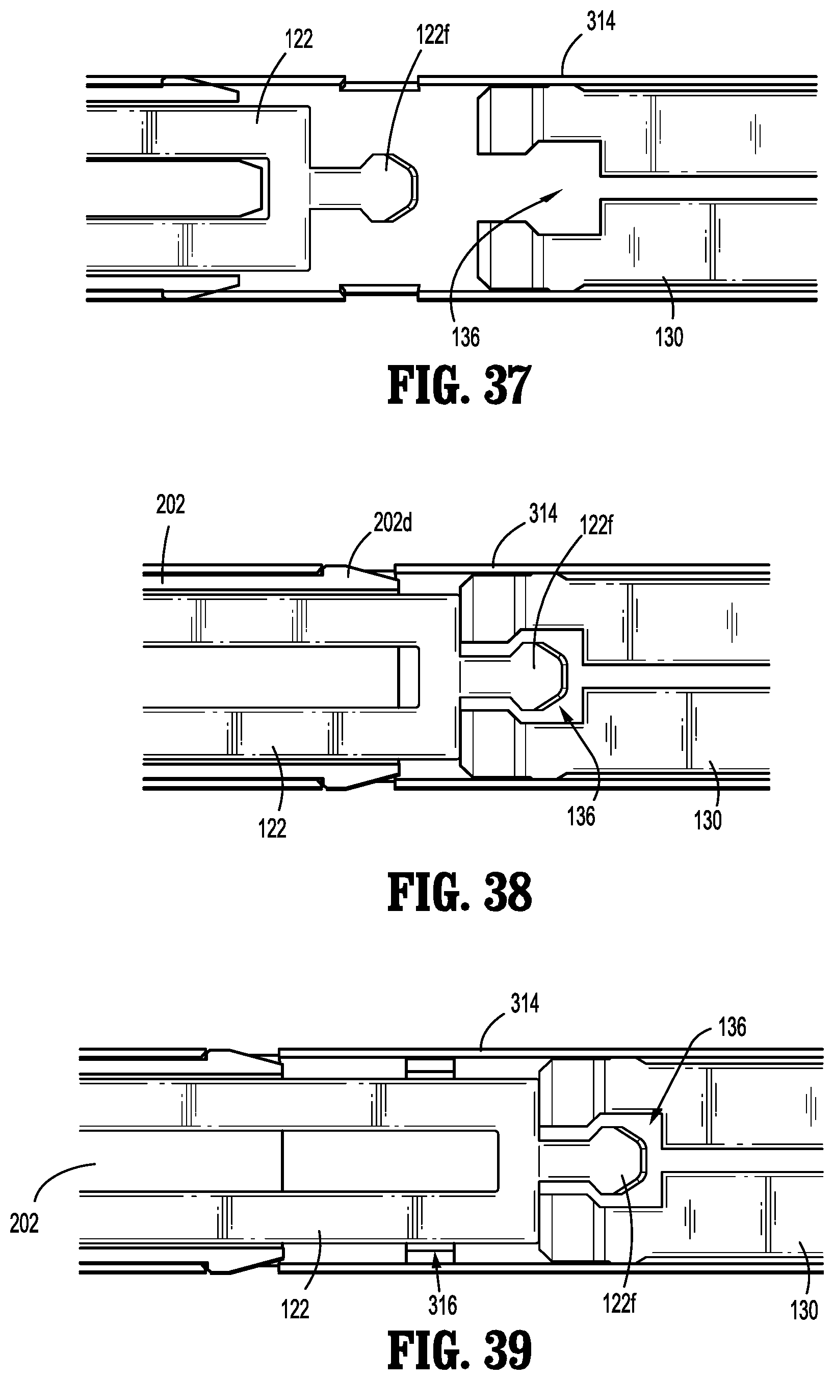
D00023

D00024

XML
uspto.report is an independent third-party trademark research tool that is not affiliated, endorsed, or sponsored by the United States Patent and Trademark Office (USPTO) or any other governmental organization. The information provided by uspto.report is based on publicly available data at the time of writing and is intended for informational purposes only.
While we strive to provide accurate and up-to-date information, we do not guarantee the accuracy, completeness, reliability, or suitability of the information displayed on this site. The use of this site is at your own risk. Any reliance you place on such information is therefore strictly at your own risk.
All official trademark data, including owner information, should be verified by visiting the official USPTO website at www.uspto.gov. This site is not intended to replace professional legal advice and should not be used as a substitute for consulting with a legal professional who is knowledgeable about trademark law.