Endoscopic Surgical Clip Applier
Baril; Jacob C. ; et al.
U.S. patent application number 16/042227 was filed with the patent office on 2019-03-14 for endoscopic surgical clip applier. The applicant listed for this patent is Covidien LP. Invention is credited to Jacob C. Baril, Brian J. Creston, Roman Czernik, Thomas A. Zammataro.
| Application Number | 20190076149 16/042227 |
| Document ID | / |
| Family ID | 65630122 |
| Filed Date | 2019-03-14 |


| United States Patent Application | 20190076149 |
| Kind Code | A1 |
| Baril; Jacob C. ; et al. | March 14, 2019 |
ENDOSCOPIC SURGICAL CLIP APPLIER
Abstract
A shaft assembly of an apparatus for applying surgical clips to body tissue includes a pair of jaws movable between a spaced-apart position and an approximated position, an elongated spindle, a shaft, a slidable member, and a pusher bar fixed to the slidable member. The slidable member is movable through longitudinally-extending channels of the spindle and the shaft. The pusher bar is configured to load a distal-most surgical clip into the pair of jaws during distal movement of the slidable member, via distal movement of the spindle, and remain in a distally advanced position during approximation of the pair of jaws.
| Inventors: | Baril; Jacob C.; (Norwalk, CT) ; Creston; Brian J.; (West Haven, CT) ; Czernik; Roman; (Trumbull, CT) ; Zammataro; Thomas A.; (Hamden, CT) | ||||||||||
| Applicant: |
|
||||||||||
|---|---|---|---|---|---|---|---|---|---|---|---|
| Family ID: | 65630122 | ||||||||||
| Appl. No.: | 16/042227 | ||||||||||
| Filed: | July 23, 2018 |
Related U.S. Patent Documents
| Application Number | Filing Date | Patent Number | ||
|---|---|---|---|---|
| 62557908 | Sep 13, 2017 | |||
| Current U.S. Class: | 1/1 |
| Current CPC Class: | A61B 2017/0046 20130101; A61B 17/1285 20130101 |
| International Class: | A61B 17/128 20060101 A61B017/128 |
Claims
1. An apparatus for application of surgical clips to body tissue, the apparatus comprising: a handle assembly; and a shaft assembly selectively connectable to the handle assembly and actuatable upon actuation of the handle assembly, the shaft assembly including: a pair of jaws movable between a spaced-apart position and an approximated position; an elongated spindle having a proximal portion configured to be coupled to an actuator of the handle assembly, and a distal portion operably coupled to the pair of jaws to selectively approximate the pair of jaws during distal movement of the spindle, the spindle defining a longitudinally-extending channel having a first portion, and a second portion extending at a non-zero angle relative to the first portion; a first shaft disposed alongside the spindle and defining a longitudinally-extending channel having a first portion, and a second portion extending at a non-zero angle relative to the first portion of the channel of the first shaft; a slidable member extending through each of the channels of the spindle and the first shaft, wherein a first distal movement of the spindle relative to the first shaft moves the slidable member with the spindle and through the first portion of the channel of the first shaft, and a second distal movement of the spindle relative to the first shaft moves the slidable member with the spindle and into the second portion of the channel of the first shaft and the first portion of the channel of the spindle, such that a third distal movement of the spindle relative to the first shaft moves the spindle distally relative to the slidable member; and a pusher bar having a proximal portion fixedly coupled to the slidable member, and a distal portion configured to load a distal-most surgical clip into the pair of jaws during distal movement of the slidable member, via the first distal movement of the spindle, and remain in a distally advanced position during approximation of the pair of jaws.
2. The apparatus according to claim 1, wherein the first portion of the channel of each of the spindle and the first shaft has a linear configuration and extends parallel to a longitudinal axis defined by the spindle, and the second portion of the channel of each of the spindle and the first shaft extends at a non-parallel angle relative to the longitudinal axis of the spindle.
3. The apparatus according to claim 1, wherein the shaft assembly further includes a second shaft disposed on an opposite side of the proximal portion of the spindle as the first shaft and being fixedly coupled to the first shaft, the second shaft defining a longitudinally-extending channel in mirrored relation with the channel of the first shaft, wherein the slidable member has a first end portion movably disposed within the channel of the first shaft, and a second end portion movably disposed within the channel of the second shaft.
4. The apparatus according to claim 1, wherein the first portion of the channel of the spindle defines a first plane, and the first portion of the channel of the first shaft defines a second plane offset from the first plane of the first portion of the channel of the spindle.
5. The apparatus according to claim 4, wherein at least a distal region of the second portion of the channel of the first shaft is coplanar with the first plane of the first portion of the channel of the spindle.
6. The apparatus according to claim 1, wherein the second portion of the channel of the spindle has a proximal limit defined by a proximal wall, the proximal wall configured to contact the slidable member during the first distal movement of the spindle to distally move the slidable member relative to the first shaft.
7. The apparatus according to claim 6, wherein the second portion of the channel of the spindle has a distal limit defined by a distal wall, the distal wall configured to contact the slidable member during proximal movement of the spindle relative to the first shaft.
8. The apparatus according to claim 1, wherein the first shaft includes a ramped inner surface that defines the second portion of the channel of the first shaft, the ramped inner surface being configured to move the slidable member upwardly from the second portion of the channel of the spindle into the first portion of the channel of the spindle during the second distal movement of the spindle.
9. The apparatus according to claim 1, wherein the slidable member is axially restrained within the second portion of the channel of the first shaft during the third distal movement of the spindle, such that the pusher bar is axially fixed relative to the pair of jaws during the third distal movement of the spindle.
10. The apparatus according to claim 9, wherein the slidable member rides within the first portion of the channel of the spindle during the third distal movement of the spindle.
11. A shaft assembly of an apparatus for applying surgical clips to body tissue, the shaft assembly comprising: a pair of jaws movable between a spaced-apart position and an approximated position; an elongated spindle having a proximal portion configured to be coupled to an actuator of the handle assembly, and a distal portion operably coupled to the pair of jaws to selectively approximate the pair of jaws during distal advancement of the spindle, the spindle defining a longitudinally-extending channel having a first portion, and a second portion extending at a non-zero angle relative to the first portion; a first shaft disposed alongside the spindle and defining a longitudinally-extending channel having a first portion, and a second portion extending at a non-zero angle relative to the first portion of the channel of the first shaft; a slidable member extending through each of the channels of the spindle and the first shaft, wherein a first distal movement of the spindle relative to the first shaft moves the slidable member with the spindle and through the first portion of the channel of the first shaft, and a second distal movement of the spindle relative to the first shaft moves the slidable member with the spindle and into the second portion of the channel of the first shaft and the first portion of the channel of the spindle, such that a third distal movement of the spindle relative to the first shaft moves the spindle distally relative to the slidable member; and a pusher bar having a proximal portion fixedly coupled to the slidable member, and a distal portion configured to load a distal-most surgical clip into the pair of jaws during distal movement of the slidable member, via the first distal movement of the spindle, and remain in a distally advanced position during approximation of the pair of jaws.
12. The shaft assembly according to claim 11, wherein the first portion of the channel of each of the spindle and the first shaft has a linear configuration and extends parallel to a longitudinal axis defined by the spindle, and the second portion of the channel of each of the spindle and the first shaft extends at a non-parallel angle relative to the longitudinal axis of the spindle.
13. The shaft assembly according to claim 11, further comprising a second shaft disposed on an opposite side of the proximal portion of the spindle as the first shaft and being fixedly coupled to the first shaft, the second shaft defining a longitudinally-extending channel in mirrored relation with the channel of the first shaft, wherein the slidable member has a first end portion movably disposed within the channel of the first shaft, and a second end portion movably disposed within the channel of the second shaft.
14. The shaft assembly according to claim 11, wherein the first portion of the channel of the spindle defines a first plane, and the first portion of the channel of the first shaft defines a second plane offset from the first plane of the first portion of the channel of the spindle.
15. The shaft assembly according to claim 14, wherein at least a distal region of the second portion of the channel of the first shaft is coplanar with the first plane of the first portion of the channel of the spindle.
16. The shaft assembly according to claim 11, wherein the second portion of the channel of the spindle has a proximal limit defined by a proximal wall, the proximal wall configured to contact the slidable member during the first distal movement of the spindle to distally move the slidable member relative to the first shaft.
17. The shaft assembly according to claim 16, wherein the second portion of the channel of the spindle has a distal limit defined by a distal wall, the distal wall configured to contact the slidable member during proximal movement of the spindle relative to the first shaft.
18. The shaft assembly according to claim 11, wherein the first shaft includes a ramped inner surface that defines the second portion of the channel of the first shaft, the ramped inner surface being configured to move the slidable member upwardly from the second portion of the channel of the spindle into the first portion of the channel of the spindle during the second distal movement of the spindle.
19. The shaft assembly according to claim 11, wherein the slidable member is axially restrained within the second portion of the channel of the first shaft during the third distal movement of the spindle, such that the pusher bar is axially fixed relative to the pair of jaws during the third distal movement of the spindle.
20. The shaft assembly according to claim 19, wherein the slidable member rides within the first portion of the channel of the spindle during the third distal movement of the spindle.
Description
CROSS-REFERENCE TO RELATED APPLICATIONS
[0001] This application claims the benefit of and priority to U.S. Provisional Patent Application No. 62/557,908 filed Sep. 12, 2017, the entire disclosure of which is incorporated by reference herein.
BACKGROUND
Technical Field
[0002] The present application relates generally to surgical clip appliers. More particularly, the present disclosure relates to endoscopic surgical clip appliers having a clip pusher bar that maintains a surgical clip between jaws of the surgical clip applier during clip formation.
Description of Related Art
[0003] Endoscopic surgical staplers and surgical clip appliers are known in the art and are used for a number of distinct and useful surgical procedures. In the case of a laparoscopic surgical procedure, access to the interior of an abdomen is achieved through narrow tubes or cannulas inserted through a small entrance incision in the skin. Minimally invasive procedures performed elsewhere in the body are often generally referred to as endoscopic procedures. Typically, a tube or cannula device is extended into the patient's body through the entrance incision to provide an access port. The port allows the surgeon to insert a number of different surgical instruments therethrough using a trocar and for performing surgical procedures far removed from the incision.
[0004] During a majority of these procedures, the surgeon must often terminate the flow of blood or another fluid through one or more vessels. The surgeon will often use a particular endoscopic surgical clip applier to apply a surgical clip to a blood vessel or another duct to prevent the flow of body fluids therethrough during the procedure.
[0005] Endoscopic surgical clip appliers having various sizes (e.g., diameters) that are configured to apply a variety of diverse surgical clips are known in the art, and which are capable of applying a single or multiple surgical clips during an entry to the body cavity. Such surgical clips are typically fabricated from a biocompatible material and are usually compressed over a vessel. Once applied to the vessel, the compressed surgical clip terminates the flow of fluid therethrough.
[0006] Endoscopic surgical clip appliers that are able to apply multiple clips in endoscopic or laparoscopic procedures during a single entry into the body cavity are described in commonly-assigned U.S. Pat. Nos. 5,084,057 and 5,100,420, which are both incorporated by reference herein in their entirety. Another multiple endoscopic surgical clip applier is disclosed in commonly-assigned U.S. Pat. No. 5,607,436, the contents of which are also hereby incorporated by reference herein in its entirety. These devices are typically, though not necessarily, used during a single surgical procedure. U.S. Pat. No. 5,695,502, the disclosure of which is hereby incorporated by reference herein, discloses a resterilizable endoscopic surgical clip applier. The endoscopic surgical clip applier advances and forms multiple clips during a single insertion into the body cavity. This resterilizable endoscopic surgical clip applier is configured to receive and cooperate with an interchangeable clip magazine so as to advance and form multiple clips during a single entry into a body cavity.
[0007] Sometimes prior to or during formation of the clip, the clip may be prematurely dislocated from between the jaws of the clip applier by, for example, the vessel being closed. Accordingly, a need exists for a clip applier having an improved mechanism that prevents clip dislocation during use.
SUMMARY
[0008] Accordingly, the present application provides an apparatus for application of surgical clips to body tissue. The apparatus includes a handle assembly and a shaft assembly selectively connectable to the handle assembly and actuatable upon actuation of the handle assembly. The shaft assembly includes a pair of jaws movable between a spaced-apart position and an approximated position, an elongated spindle, a first shaft disposed alongside the spindle, a slidable member, and a pusher bar having a proximal portion fixed to the slidable member. The spindle has a proximal portion configured to be coupled to an actuator of the handle assembly, and a distal portion operably coupled to the pair of jaws to selectively approximate the pair of jaws during distal movement of the spindle. The spindle defines a longitudinally-extending channel having a first portion, and a second portion extending at a non-zero angle relative to the first portion. The first shaft defines a longitudinally-extending channel having a first portion, and a second portion extending at a non-zero angle relative to the first portion of the channel of the first shaft. The slidable member extends through each of the channels, and a first distal movement of the spindle relative to the first shaft moves the slidable member with the spindle and through the first portion of the channel of the first shaft. A second distal movement of the spindle relative to the first shaft moves the slidable member with the spindle and into the second portion of the channel of the first shaft and the first portion of the channel of the spindle. A third distal movement of the spindle relative to the first shaft moves the spindle distally relative to the slidable member. The pusher bar has a distal portion configured to load a distal-most surgical clip into the pair of jaws during distal movement of the slidable member, via the first distal movement of the spindle, and remain in a distally advanced position during approximation of the pair of jaws.
[0009] In embodiments, the first portion of the channel of each of the spindle and the first shaft may have a linear configuration and extend parallel to a longitudinal axis defined by the spindle, and the second portion of the channel of each of the spindle and the first shaft may extend at a non-parallel angle relative to the longitudinal axis of the spindle.
[0010] It is contemplated that the shaft assembly may further include a second shaft disposed on an opposite side of the proximal portion of the spindle as the first shaft. The second shaft may be fixedly coupled to the first shaft and define a longitudinally-extending channel in mirrored relation with the channel of the first shaft. The slidable member may have a first end portion movably disposed within the channel of the first shaft, and a second end portion movably disposed within the channel of the second shaft.
[0011] It is envisioned that the first portion of the channel of the spindle may define a first plane, and the first portion of the channel of the first shaft may define a second plane offset from the first plane of the first portion of the channel of the spindle. A distal region of the second portion of the channel of the first shaft may be coplanar with the first plane of the first portion of the channel of the spindle.
[0012] In embodiments, the second portion of the channel of the spindle may have a proximal limit defined by a proximal wall. The proximal wall may be configured to contact the slidable member during the first distal movement of the spindle to distally move the slidable member relative to the first shaft.
[0013] It is contemplated that the second portion of the channel of the spindle may have a distal limit defined by a distal wall. The distal wall may be configured to contact the slidable member during proximal movement of the spindle relative to the first shaft.
[0014] It is envisioned that the first shaft may include a ramped inner surface that defines the second portion of the channel of the first shaft. The ramped inner surface may be configured to move the slidable member upwardly from the second portion of the channel of the spindle into the first portion of the channel of the spindle during the second distal movement of the spindle.
[0015] In embodiments, the slidable member may be axially restrained within the second portion of the channel of the first shaft during the third distal movement of the spindle, such that the pusher bar is axially fixed relative to the pair of jaws during the third distal movement of the spindle.
[0016] It is contemplated that the slidable member may ride within the first portion of the channel of the spindle during the third distal movement of the spindle.
[0017] In another aspect of the present disclosure, a shaft assembly of an apparatus for applying surgical clips to body tissue is provided. The shaft assembly includes a pair of jaws movable between a spaced-apart position and an approximated position, an elongated spindle, a first shaft disposed alongside the spindle, a slidable member, and a pusher bar having a proximal portion fixed to the slidable member. The spindle has a proximal portion configured to be coupled to an actuator, and a distal portion operably coupled to the pair of jaws to selectively approximate the pair of jaws during distal movement of the spindle. The spindle defines a longitudinally-extending channel having a first portion, and a second portion extending at a non-zero angle relative to the first portion. The first shaft defines a longitudinally-extending channel having a first portion, and a second portion extending at a non-zero angle relative to the first portion of the channel of the first shaft. The slidable member extends through each of the channels, and a first distal movement of the spindle relative to the first shaft moves the slidable member with the spindle and through the first portion of the channel of the first shaft. A second distal movement of the spindle relative to the first shaft moves the slidable member with the spindle and into the second portion of the channel of the first shaft and the first portion of the channel of the spindle. A third distal movement of the spindle relative to the first shaft moves the spindle distally relative to the slidable member. The pusher bar has a distal portion configured to load a distal-most surgical clip into the pair of jaws during distal movement of the slidable member, via the first distal movement of the spindle, and remain in a distally advanced position during approximation of the pair of jaws.
BRIEF DESCRIPTION OF THE DRAWINGS
[0018] A particular embodiment of a surgical clip applier is disclosed herein with reference to the drawings wherein:
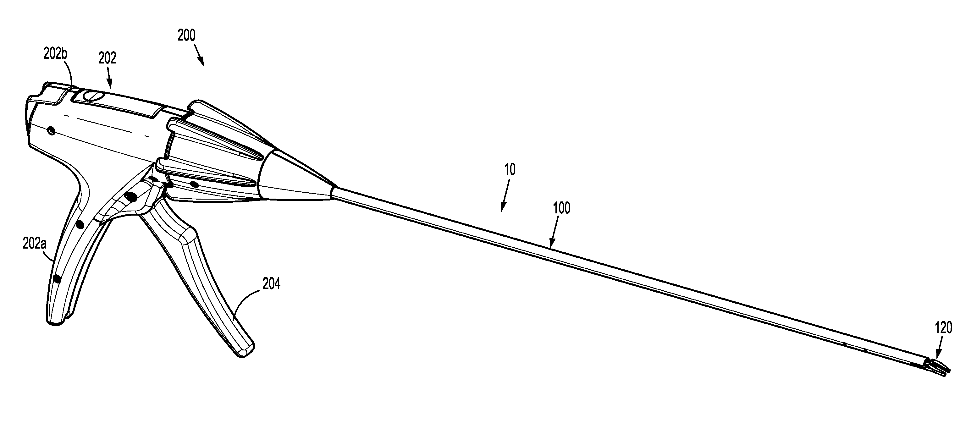
[0019] FIG. 1 is a perspective view of a reposable endoscopic surgical clip applier including a reusable handle assembly and a shaft assembly connected thereto;
[0020] FIG. 2 is a perspective view of the handle assembly of FIG. 1 with at least a housing half-section removed therefrom;
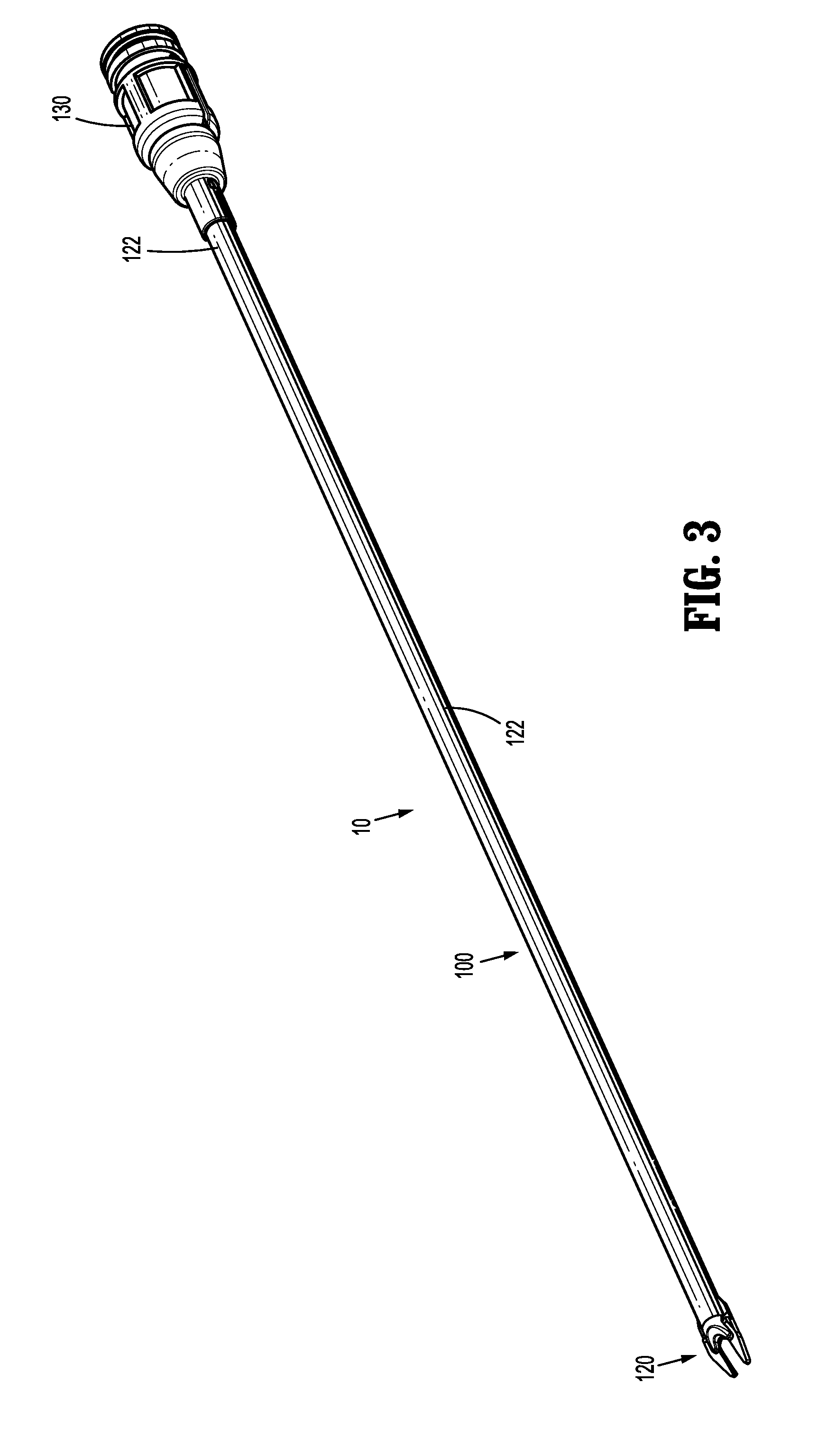
[0021] FIG. 3 is a perspective view of the shaft assembly of the endoscopic surgical clip applier of FIG. 1;
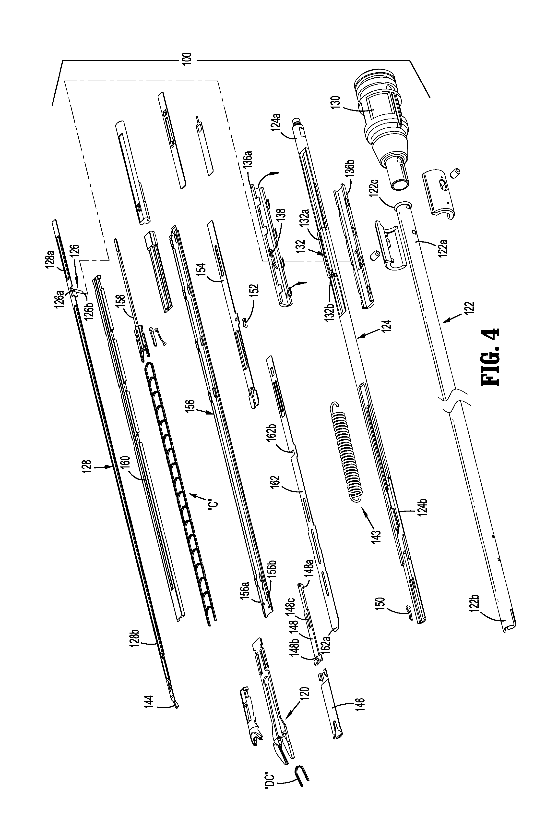
[0022] FIG. 4 is a perspective view, with parts separated, of the shaft assembly of FIG. 3;
[0023] FIG. 5A is a perspective view of a proximal portion of a spindle and left and right shafts of the shaft assembly of FIG. 3;
[0024] FIG. 5B is a perspective view, with a left shaft shown in phantom, of a proximal portion of the spindle and a slidable member of the shaft assembly of FIG. 3;
[0025] FIG. 6 is a perspective view, with parts separated, of the spindle, the slidable member, and left and right shafts of the shaft assembly of FIG. 5B;
[0026] FIG. 7 is a side view of the proximal portion of the spindle and the slidable member of FIG. 5B, illustrating the spindle in a first, starting position;
[0027] FIG. 8 is a side view of the proximal portion of the spindle and the slidable member of FIG. 5B, illustrating the spindle in a second, staple loading position;
[0028] FIG. 9 is a side view of the proximal portion of the spindle and the slidable member of FIG. 5B, illustrating the spindle in a third, stapling forming position;
[0029] FIG. 10 is a side view of the proximal portion of the spindle and the slidable member of FIG. 5B, illustrating the spindle in a retracting position;
[0030] FIG. 11 is a side view of the proximal portion of the spindle and the slidable member of FIG. 5B, illustrating the spindle in a reset position;
[0031] FIG. 12 is an enlarged view, with an outer tube removed, of a distal portion of the shaft assembly of FIG. 3; and
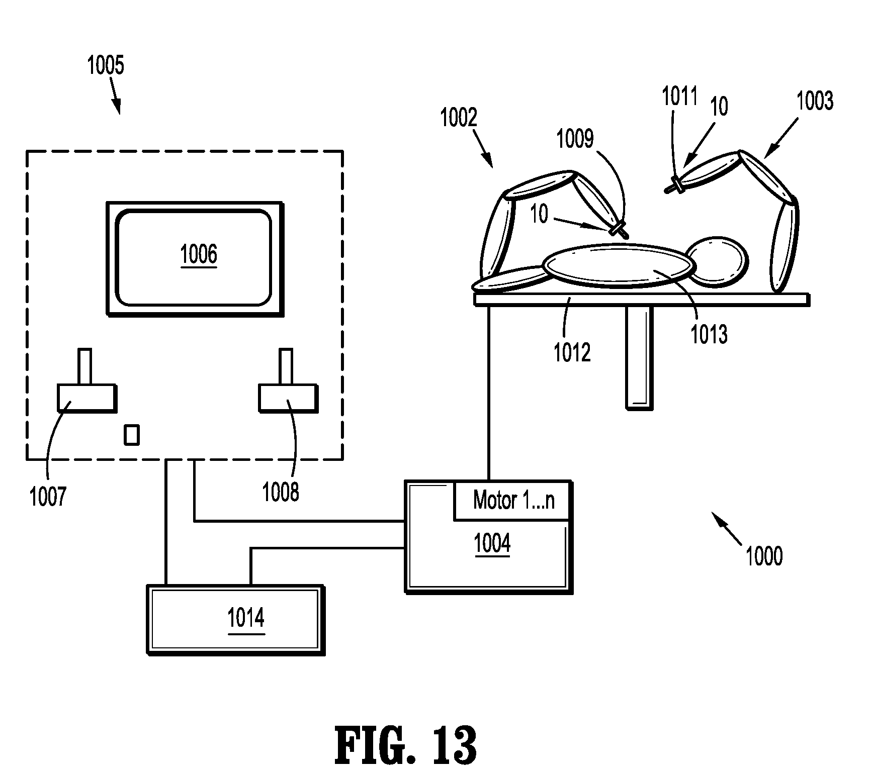
[0032] FIG. 13 is a schematic illustration of a robotic surgical system configured for use in accordance with the present disclosure.
DETAILED DESCRIPTION
[0033] Embodiments of endoscopic surgical clip appliers and shaft assemblies thereof, in accordance with the present disclosure, will now be described in detail with reference to the drawing figures wherein like reference numerals identify similar or identical structural elements. As shown in the drawings and described throughout the following description, as is traditional when referring to relative positioning on a surgical instrument, the term "proximal" refers to the end of the apparatus which is closer to the user and the term "distal" refers to the end of the apparatus which is further away from the user.
[0034] With reference to FIGS. 1 and 2, an apparatus for application of surgical clips to body tissue is illustrated and designated 10. The apparatus or surgical clip applier 10 generally includes a reusable handle assembly 200 and a disposable shaft assembly 100 operably coupled to the handle assembly 200. The handle assembly 200 includes a housing 202 having a first or right side half-section 202a and a second or left side half-section 202b. Housing 202 of handle assembly 200 further includes or defines a nose 202c dimensioned for receipt of a hub 130 of shaft assembly 100. Housing 202 of handle assembly 200 may be formed of a suitable plastic or thermoplastic material. It is further contemplated that housing 202 of handle assembly 200 may be fabricated from stainless steel of the like.
[0035] Handle assembly 200 includes a trigger 204 pivotably supported between right side half-section 202a and left side half-section 202b of housing 202. Trigger 204 is biased by a biasing member (not explicitly shown) to bias or urge trigger 204 to the un-actuated condition. Trigger 204 includes a drive arm 204b extending therefrom. Drive arm 204b may be integrally formed therewith or may be separately and fixedly secured to trigger 204. Drive arm 204b may define a curved, radiused or filleted upper distal surface.
[0036] Handle assembly 200 further includes a drive plunger 220 operatively connected to trigger 204. Drive plunger 220 defines a proximally extending trigger slot 220b formed in a proximal portion thereof for operatively receiving drive arm 204b of trigger 204. Trigger slot 220b defines a distal surface or wall 220c against which a distal surface of drive arm 204b of trigger 204 contacts in order to distally advance drive plunger 220 during an actuation of trigger 204. Drive plunger 220 has a distal end operably coupled to a proximal end of a spindle 124 (FIG. 5) of shaft assembly 100 to effect axial movement of the spindle 124 upon actuation of the trigger 204 of handle assembly 200.
[0037] For a more detailed description of the components and operation of the handle assembly 200 of clip applier 10, reference may be made to, for example, U.S. Patent Application Publication No. 2017/0128071, the entire contents of which being incorporated by reference herein.
[0038] With reference to FIGS. 3 and 4, the shaft assembly 100 of the clip applier 10 is operably coupled to the handle assembly 200 (FIGS. 1 and 2) for actuation by the handle assembly 200. The shaft assembly 100 stores a stack of surgical clips "C" therein and has a pair of jaws 120 configured to form, in seriatim, the surgical clips "C" received from a pusher bar 128 of the shaft assembly 120 upon actuation of the handle assembly 200. The shaft assembly 100 includes an elongated outer member or outer tube 122, an elongated spindle or inner shaft 124 axially movable within the outer tube 122 for actuating the clip applier 10, and a slidable member 126 movably coupled to the spindle 124 for axially translating the pusher bar 128 to load and hold the surgical clips "C" in the jaws 120 during clip formation, as will be described.
[0039] The outer tube 122 of the shaft assembly 100 has a proximal portion 122a supported and secured to a hub 130, and a distal portion 122b supporting the jaws 120. The hub 130 may be configured to be coupled to the handle assembly 200 (FIGS. 1 and 2) or an actuator of a robotic system 1000 (FIG. 13). The outer tube 122 defines a lumen 122c extending longitudinally therethrough dimensioned for slidable receipt of the spindle 124.
[0040] With reference to FIGS. 4-11, the spindle or inner shaft 124 of the shaft assembly 100 is slidably supported within the lumen 122c of the outer tube 122 and has a generally elongated configuration. The spindle 124 includes a proximal portion 124a, and a distal portion 124b configured to selectively actuate the pair of jaws 120 during distal advancement of the spindle 124. The proximal portion 124a of the spindle 124 may define a hook, an enlarged head or other translational force coupling feature configured to be coupled to an actuator (e.g., the drive plunger 220 of the handle assembly 200 or an actuator of the robotic surgical system 1000).
[0041] The proximal portion 124a of the spindle 124 defines an elongate channel 132 extending longitudinally along the spindle 124. The channel 132 of the spindle 124 is dimensioned for slidable receipt of the slidable member 126, and has a first portion or proximal portion 132a and a second portion or distal portion 132b extending at a non-zero angle relative to the first portion 132a. The first portion 132a of the channel 132 has a linear configuration and extends parallel to a longitudinal axis "X" defined by the spindle 126. The second portion 132b of the channel 132 extends from the first portion 132a of the channel 132 perpendicularly relative to the longitudinal axis "X" of the spindle 126. In some embodiments, the second portion 132b of the channel 132 may extend at any suitable angle relative to the longitudinal axis "X." In embodiments, the second portion 132b of the channel 132 may be a notch extending laterally from the first portion 132a of the channel 132.
[0042] The proximal portion 124a of the spindle 124 has an inner surface 134 that defines the elongate channel 132. The inner surface 134 has a proximal wall 134a that defines a proximal limit of the second portion 132b of the channel 132, and a distal wall 134b that defines a distal limit of the second portion 132b of the channel 132. The second portion 132b of the channel 132 is dimensioned for receipt of the slidable member 126 during a first distal advancement of the spindle 124. The proximal wall 134a of the inner surface 134 is configured to push or urge the slidable member 126 distally therewith as the spindle 126 moves distally, and the distal wall 134b of the inner surface 134 is configured to push or urge the slidable member 126 proximally as the spindle 124 moves proximally, as will be described in greater detail.
[0043] With continued reference to FIGS. 4-11, the shaft assembly 100 further includes a pair of longitudinal half-sections or shafts 136a, 136b disposed on opposite sides of the proximal portion 124a of the spindle 124. The shafts 136a, 136b, when assembled, together may form a unitary tubular member that surrounds the proximal portion 124a of the spindle 124. The shafts 136a, 136b are fixed within the outer tube 122 of the shaft assembly 100, such that the shafts 136a, 136b remain axially fixed relative to the outer tube 122 during distal and proximal movement of the spindle 124 relative to the outer tube 122.
[0044] The first shaft 136a defines an elongate channel 138 extending longitudinally along the first shaft 136a and which is disposed adjacent the channel 132 of the spindle 124. The second shaft 136b also defines an elongate channel (not explicitly shown), similar to the channel 138 of the first shaft 136a. The channels 138 of the first and second shafts 136a, 136b are in mirrored relation to one another. The channel 138 of the first shaft 136a is dimensioned for slidable receipt of a first end portion 126a of the slidable member 126, whereas the channel of the second shaft 136b is dimensioned for slidable receipt of a second end portion 126b of the slidable member 126. Since the channels 138 of the first and second shafts 136a, 136b are in mirrored relation to one another, only the channel 138 of the first shaft 132 will be described in further detail herein.
[0045] The channel 138 of the first shaft 136a has a first portion or proximal portion 138a and a second portion or distal portion 138b extending at a non-zero angle relative to the first portion 138a. The first portion 138a of the channel 138 has a linear configuration and extends parallel to the longitudinal axis "X" defined by the spindle 124. The first portion 138a of the channel 138 of the first shaft 136a defines a plane that is offset (e.g., disposed above or below) a plane defined by the first portion 132a of the channel 132 of the spindle 124. The second portion 138b of the channel 138 bends or extends upwardly from the first portion 138a of the channel 138, and in some embodiments downwardly from the first portion 138a of the channel 138. In some embodiments, the second portion 138b of the channel 138 may bend or extend relative to the first portion 138a of the channel 138 and may have a linear configuration. In some embodiments, the second portion 138b of the channel 138 may have a curved configuration.
[0046] The second portion 138b of the channel 138 has a distal region 138c that is coplanar with the first portion 132a of the channel 132 of the spindle 124. In this way, when the slidable member 126 is disposed within the first portion 132a of the channel 132 of the spindle 124, the slidable member 126 is simultaneously disposed within the second portion 138b of the channel 138 of the shafts 136a, 136b. Similarly, when the slidable member 126 is disposed within the second portion 132b of the channel 132 of the spindle 124, the slidable member 126 is simultaneously disposed with the first portion 138a of the channel 138 of the shafts 136a, 136b.
[0047] With reference to FIG. 6, the first shaft 136a has an inner surface 140 that defines the elongate channel 138. The inner surface 140 has a ramped portion 140a that partially defines the second portion 138b of the channel 138 of the first shaft 136a. The ramped portion 140a extends upwardly from the first portion 138a of the channel 138 of the first shaft 136a and is configured to urge or cam the slidable member 126 upwardly into the distal region 138c of the second portion 138b of the channel 138 of the first shaft 136a as the slidable member 126 is moved distally by the proximal wall 134a of the spindle 124. As the ramped portion 140a cams the slidable member 126 upwardly into the distal region 138c of the channel 138 of the first shaft 136a, the slidable member 126 is also moved from the second portion 132b of the channel 132 of the spindle 124 into the first portion 132a of the channel 132 of the spindle 124.
[0048] The slidable member 126 of the shaft assembly 100 may be configured as a pin or bar having a first end portion 126a slidably disposed within the channel 138 of the first shaft 136a, an intermediate portion extending through the channel 132 of the spindle 124, and a second end portion 126b slidably disposed within the channel (not explicitly shown) of the second shaft 136b. As briefly mentioned above, when the slidable member 126 is simultaneously disposed within both the first portion 138a of the channel 138 of the shafts 136a, 136b and the second portion 132b of the channel 132 of the spindle 124, the slidable member 126 is axially movable relative to the shafts 136a, 136b in response to axial movement of the spindle 124 via the proximal and distal walls 134a, 134b of the spindle 124. In contrast, when the slidable member 126 is simultaneously disposed within both the second portion 138b of the channel 138 of the shafts 136a, 136b and the first portion 132a of the channel 132 of the spindle 124, the slidable member 126 is axially restrained within the second portion 138b of the channel 138 of the shafts 136a, 136b during axial movement of the spindle 124, whereby the slidable member 126 rides within the first portion 132a of the channel 132 of the spindle 124.
[0049] The shaft assembly 100 may include a fixed pin or rod 142 and a biasing member, such as, for example, an extension spring 143 (FIG. 4). The extension spring 143 has a proximal loop, and a distal loop having the sliding member 126 extending therethrough. The fixed pin 142 extends through a longitudinally-extending slot 133 defined by the proximal portion 124a of the spindle 124 and through the proximal loop of the extension spring 143. The slot 133 is disposed proximally of the channel 132 of the spindle 124. The fixed pin 142 has a first end portion fixed to the first shaft 136a, and a second end portion fixed to the second shaft 136b, such that the fixed pin 142 rides within the slot 133 of the spindle 124 during axial movement of the spindle 124. The proximal loop of the extension spring 143 is fixed to the fixed pin 142, and the distal loop of the extension spring 143 is fixed to the slidable member 126. As such, the extension spring 143 exerts a proximally-oriented force on the slidable member 126 to urge the slidable member 126, and in turn the pusher bar 128, toward a retracted position.
[0050] With reference to FIGS. 4 and 12, the pusher bar 128 of the shaft assembly 100 has a proximal portion 128a, and a distal portion 128b for loading a distal-most surgical clip "DC" of the stack of surgical clips "C" between the jaws 120. The proximal portion 128a of the pusher bar 128 is fixed to the slidable member 126 so that the pusher bar 128 moves axially with axial movement of the slidable member 126. The proximal portion 128a of the pusher bar 128 may be fixed to the slidable member 126 via any suitable fastening engagement, such as, for example, various fasteners, adhesives, snap-fit engagements, or the like. Since the proximal portion 128a of the pusher bar 128 is fixed to the slidable member 126, axial movement of the slidable member 126 results in a corresponding axial movement of the pusher bar 128.
[0051] The distal portion 128b of the pusher bar 128 defines a pusher 144 configured to position the distal-most surgical clip "DC" between the pair of jaws 120 as the slidable member 126 is advanced toward a distal position, as shown in FIG. 9. The pusher 144 has a narrow profile for allowing the pair of jaws 120 to move to an approximated position while the pusher 144 is disposed therebetween. For example, the pusher 144 may have a width that is less than a horizontal distance the pair of jaws 120 are spaced from one another after completing a clip formation.
[0052] With continued reference to FIG. 4, additional components of the shaft assembly 100 responsible for effecting formation of the surgical clips "C" will be described. The distal portion 124b of the spindle 124 is operatively connected to a jaw cam closure wedge 146 via a slider joint 148. The jaw cam closure wedge 146 is selectively actuatable by the spindle 124 to engage camming features of the pair of jaws 120 to close the pair of jaws 120 and form a surgical clip "C" loaded therewithin. The slider joint 148 supports a latch member 150 for selective engagement with the spindle 124. The latch member 150 may be cammed in a direction toward the spindle 124 during actuation or translation of the spindle 124. In particular, during distal actuation of the spindle 124, at a predetermined distance, the latch member 150 is mechanically forced or cammed into and engaged with a slot in the spindle 124. This engagement of the latch member 150 in the slot of the spindle 124 allows the slider joint 148 to move together with the jaw cam closure wedge 146. The jaw cam closure wedge 146 thus can engage the relevant surfaces of the pair of jaws 120 to close the pair of jaws 120.
[0053] The slider joint 148 is connected, at a proximal portion 148a thereof, to a passageway formed in the distal portion 124b of the spindle 124. A distal portion 148b of the slider joint 148 defines a substantially T-shaped profile, wherein the distal portion 148b thereof is connected to the jaw cam closure wedge 146. The latch member 150 functions as a linkage and is disposed to move through an aperture 148c in the slider joint 148 to link with another fixed member and prevent the slider joint 148 from advancing the jaw cam closure wedge 146, and thus preventing the camming of the jaw cam closure wedge 146 from camming the pair of jaws 120 to a closed condition during an initial actuation of the clip applier 10. The distal portion 124b of the spindle 124 is provided with a camming feature configured to move a cam link 152 (pivotably connected to a filler component 154) in a perpendicular manner relative to a longitudinal axis of the spindle 124 during a distal advancement of the spindle 124.
[0054] The shaft assembly 100 further includes a clip channel 156 received within the outer tube 122. The clip channel 156 slidably retains the stack of surgical clips "C" therein for application, in seriatim, to the desired tissue or vessel. A clip follower 158 is provided and slidably disposed within the clip channel 156 at a location proximal of the stack of surgical clips "C." A spring (not shown) is provided to spring-bias the clip follower 158, and in turn, the stack of surgical clips "C", distally. A clip channel cover 160 is provided that overlies the clip channel 156 to retain and guide the clip follower 158, the spring, and the stack of surgical clips "C" in the clip channel 156.
[0055] The shaft assembly 100 further includes a wedge plate 162 that is biased to a proximal position by a wedge plate spring (not shown). The wedge plate 162 is a flat bar shaped member having a number of windows formed therein. The wedge plate 162 has a distal-most position wherein a tip or nose of the wedge plate 162 is inserted between the pair of jaws 120 to maintain the pair of jaws 120 in an open condition for loading of the distal-most surgical clip "DC" therein. The wedge plate 162 has a proximal-most position, maintained by the wedge plate spring, wherein the tip or nose of the wedge plate 162 is retracted from between the pair of jaws 120.
[0056] The wedge plate 162 defines a "U" or "C" shaped aperture or notch 162b in a side edge thereof. The C-shaped aperture or notch 162b of the wedge plate 162 selectively engages the cam link 152 supported on the filler plate 154. The cam link 152 selectively engages a surface of C-shaped aperture or notch 162b of the wedge plate 162 to retain the wedge plate 162 in a distal-most position such that a distal tip 162a of the wedge plate 162 is maintained inserted between the pair of jaws 120 to maintain the pair of jaws 120 splayed apart.
[0057] The filler component 154 of the shaft assembly 100 is interposed between the clip channel 156 and the wedge plate 162, at a location proximal of the pair of jaws 120. The filler component 154 pivotably supports the cam link 152 that is engagable with the wedge plate 162. During a distal advancement of the spindle 124, a camming feature of the spindle 124 engages a cam link boss of the cam link 152 to thereby move the cam link 152 out of engagement with the wedge plate 162 and permit the wedge plate 162 to return to the proximal-most position as a result of the spring.
[0058] It is contemplated that the clip applier 10 may be configured to close, fire, or form surgical clips similar to those shown and described in U.S. Patent Application Publication No. 2017/0128071, and U.S. Pat. Nos. 7,819,886 or 7,905,890, the entire contents of each of which are incorporated herein by reference.
[0059] In operation, the clip applier 10 is actuated to effect a stapling function thereof. In particular, the handle assembly 200 (FIGS. 1 and 2) or a control 1004 of a robotic assembly 1000 (FIG. 13) is actuated to advance the spindle 124 of the shaft assembly 100 in a distal direction within and relative to the outer tube 122. As shown in FIG. 7, when the clip applier 10 is in an initial, un-actuated state, the slidable member 126 of the shaft assembly 100 is disposed in the second portion or notch 132b of the channel 132 of the spindle 124 and the first portion 138a of the channel 138 of each of the first and second shafts 136a, 136b.
[0060] During a first distal movement of the spindle 124, in the direction indicated by arrow "A" in FIG. 7, the proximal wall 134a of the spindle 124 urges the slidable member 126 distally and through the first portion 138a of the channel 138 of each of the first and second shafts 136a, 136b. Since the pusher bar 128 is fixed to the slidable member 126, the pusher bar 128 also moves distally, whereby the pusher 144 (FIG. 12) of the distal portion 128b of the pusher bar 128 carries or pushes the distal-most surgical clip "DC" of the surgical clips "C" through the clip channel 156 in a distal direction until the distal-most surgical clip "DC" is disposed proximate the pair of jaws 120, signifying the conclusion of the first distal movement of the spindle 124, slidable member 126, and pusher bar 128.
[0061] After completion of the first distal movement of the spindle 124, the spindle 124 undergoes a second distal advancement or movement, via actuation of the handle assembly 200 or the control 1004 (FIG. 13), during which the slidable member 126 engages the ramped portion 140a of each of the first and second shafts 136a, 136b, as shown in FIG. 8. As the slidable member 126 engages the ramped portion 140a, the slidable member 126 is cammed or moved upwardly and into both the distal region 138c of the channel 138 of each of the first and second shafts 136a, 136b and the first portion 132a of the channel 132 of the spindle 124, as shown in FIG. 9.
[0062] Upon the slidable member 126 entering the distal region 138c of the channel 138 of the first and second shafts 136a, 136b, the pusher 144 (FIG. 12) of the pusher bar 128 positions the distal-most clip "DC" between the pair of jaws 120. With the slidable member 126 captured within both the distal region 138c of the channel 138 of the first and second shafts 136a, 136b and the first portion 132a of the channel 132 of the spindle 124, a third distal movement of the spindle 124 does not result in axial movement of the slidable member 126. As such, while the spindle 124 moves distally acting on the jaw cam closure wedge 146 to approximate the jaws 120 to form the distal-most surgical clip "DC," the pusher 144 of the pusher bar 128 remains engaged with the distal-most surgical clip "DC" due to the slidable member 126 being axially restrained within both the distal region 138c of the channel 138 of the first and second shafts 136a, 136b and the first portion 132a of the channel 132 of the spindle 124.
[0063] To reset the clip applier 10, the spindle 124 is retracted proximally, in the direction indicated by arrow "B" in FIG. 10, within the outer tube 122 and out of engagement with the jaws 120 to allow the jaws 120 to expand (due to their own spring bias) to their open configuration. Proximal movement of the spindle 124 relative to the slidable member 126 and the pusher bar 128 is continued until the distal wall 134b of the proximal portion 124a of the spindle 124 contacts the slidable member 126, as shown in FIG. 10. As such, a continued proximal retraction of the spindle 124 results in the slidable member 126 and the attached pusher bar 128 moving downwardly and proximally along the ramped portion 140a of the first and second shafts 136a, 136b, and positioning the slidable member 126 in both the second portion 132b of the channel 132 of the spindle 124 and the first portion 138a of the channel 138 of each of the shafts 136a, 136b. Upon moving the slidable member 126 proximally, the pusher 144 of the pusher bar 128 is removed from between the jaws 120, resetting the clip applier 10. In addition, the biasing member that interconnects the slidable member 126 and the fixed pin 142 assists in retracting the slidable member 126.
[0064] It is contemplated, and within the scope of the present disclosure, that other endoscopic assemblies, including a pair of jaws having a unique and diverse closure stroke length thereof, may be provided with a drive assembly, similar to any of the drive assemblies described herein, for accommodating and adapting the closure stroke length for the pair of jaws thereof to the constant trigger stroke length.
[0065] Accordingly, various endoscopic assemblies, constructed in accordance with the principles of the present disclosure, may be provided which are also capable of firing or forming or closing surgical clips of various sizes, materials, and configurations, across multiple platforms for multiple different manufactures.
[0066] Surgical instruments such as the clip appliers described herein may also be configured to work with robotic surgical systems and what is commonly referred to as "Telesurgery." Such systems employ various robotic elements to assist the surgeon and allow remote operation (or partial remote operation) of surgical instrumentation. Various robotic arms, gears, cams, pulleys, electric and mechanical motors, etc. may be employed for this purpose and may be designed with a robotic surgical system to assist the surgeon during the course of an operation or treatment. Such robotic systems may include remotely steerable systems, automatically flexible surgical systems, remotely flexible surgical systems, remotely articulating surgical systems, wireless surgical systems, modular or selectively configurable remotely operated surgical systems, etc.
[0067] The robotic surgical systems may be employed with one or more consoles that are next to the operating theater or located in a remote location. In this instance, one team of surgeons or nurses may prep the patient for surgery and configure the robotic surgical system with one or more of the instruments disclosed herein while another surgeon (or group of surgeons) remotely controls the instruments via the robotic surgical system. As can be appreciated, a highly skilled surgeon may perform multiple operations in multiple locations without leaving his/her remote console which can be both economically advantageous and a benefit to the patient or a series of patients.
[0068] The robotic arms of the surgical system are typically coupled to a pair of master handles by a controller. The handles can be moved by the surgeon to produce a corresponding movement of the working ends of any type of surgical instrument (e.g., end effectors, graspers, knifes, scissors, etc.) which may complement the use of one or more of the embodiments described herein. The movement of the master handles may be scaled so that the working ends have a corresponding movement that is different, smaller or larger, than the movement performed by the operating hands of the surgeon. The scale factor or gearing ratio may be adjustable so that the operator can control the resolution of the working ends of the surgical instrument(s).
[0069] The master handles may include various sensors to provide feedback to the surgeon relating to various tissue parameters or conditions, e.g., tissue resistance due to manipulation, cutting or otherwise treating, pressure by the instrument onto the tissue, tissue temperature, tissue impedance, etc. As can be appreciated, such sensors provide the surgeon with enhanced tactile feedback simulating actual operating conditions. The master handles may also include a variety of different actuators for delicate tissue manipulation or treatment further enhancing the surgeon's ability to mimic actual operating conditions.
[0070] Referring to FIG. 12, a medical work station is shown generally as robotic system or work station 1000 and generally may include a plurality of robot arms 1002, 1003; a control device 1004; and an operating console 1005 coupled with control device 1004. Operating console 1005 may include a display device 1006, which may be set up in particular to display three-dimensional images; and manual input devices 1007, 1008, by means of which a person (not shown), for example a surgeon, may be able to telemanipulate robot arms 1002, 1003 in a first operating mode.
[0071] Each of the robot arms 1002, 1003 may include a plurality of members, which are connected through joints, and an attaching device 1009, 1011, to which may be attached, for example, the shaft assembly 100 of FIGS. 1-11, in accordance with any one of several embodiments disclosed herein, as will be described in greater detail below.
[0072] Robot arms 1002, 1003 may be driven by electric drives (not shown) that are connected to control device 1004. Control device 1004 (e.g., a computer) may be set up to activate the drives, in particular by means of a computer program, in such a way that robot arms 1002, 1003, their attaching devices 1009, 1011 and thus the shaft assembly 100, execute a desired movement according to a movement defined by means of manual input devices 1007, 1008. Control device 1004 may also be set up in such a way that it regulates the movement of robot arms 1002, 1003 and/or of the drives.
[0073] Medical work station 1000 may be configured for use on a patient 1013 lying on a patient table 1012 to be treated in a minimally invasive manner by means of the shaft assembly 100. Medical work station 1000 may also include more than two robot arms 1002, 1003, the additional robot arms likewise being connected to control device 1004 and being telemanipulatable by means of operating console 1005. A surgical end effector, such as, for example, the shaft assembly 100 (FIGS. 1-11), may also be attached to the additional robot arm. Medical work station 1000 may include a database 1014, in particular coupled to with control device 1004, in which are stored, for example, pre-operative data from patient/living being 1013 and/or anatomical atlases.
[0074] Reference is made herein to U.S. Pat. No. 8,828,023, the entire content of which is incorporated herein by reference, for a more detailed description of the construction and operation of an exemplary robotic surgical system.
[0075] It should be understood that the foregoing description is only illustrative of the present disclosure. Various alternatives and modifications can be devised by those skilled in the art without departing from the disclosure. Accordingly, the present disclosure is intended to embrace all such alternatives, modifications and variances. The embodiments described with reference to the attached drawing figures are presented only to demonstrate certain examples of the disclosure. Other elements, steps, methods and techniques that are insubstantially different from those described above and/or in the appended claims are also intended to be within the scope of the disclosure.
* * * * *
D00000
D00001
D00002
D00003
D00004
D00005
D00006
D00007
D00008
D00009
D00010
XML
uspto.report is an independent third-party trademark research tool that is not affiliated, endorsed, or sponsored by the United States Patent and Trademark Office (USPTO) or any other governmental organization. The information provided by uspto.report is based on publicly available data at the time of writing and is intended for informational purposes only.
While we strive to provide accurate and up-to-date information, we do not guarantee the accuracy, completeness, reliability, or suitability of the information displayed on this site. The use of this site is at your own risk. Any reliance you place on such information is therefore strictly at your own risk.
All official trademark data, including owner information, should be verified by visiting the official USPTO website at www.uspto.gov. This site is not intended to replace professional legal advice and should not be used as a substitute for consulting with a legal professional who is knowledgeable about trademark law.