Endoscopic Surgical Clip Applier And Clip Applying Systems
Raikar; Anirudh ; et al.
U.S. patent application number 16/308864 was filed with the patent office on 2019-05-23 for endoscopic surgical clip applier and clip applying systems. The applicant listed for this patent is Covidien LP. Invention is credited to Longsheng Cai, Anirudh Raikar, Yuandong Tan, Kun Zhao.
| Application Number | 20190150935 16/308864 |
| Document ID | / |
| Family ID | 61161696 |
| Filed Date | 2019-05-23 |
| United States Patent Application | 20190150935 |
| Kind Code | A1 |
| Raikar; Anirudh ; et al. | May 23, 2019 |
ENDOSCOPIC SURGICAL CLIP APPLIER AND CLIP APPLYING SYSTEMS
Abstract
An endoscopic surgical clip applier (10) includes a handle assembly (100) configured to releasably engage at least two different endoscopic assemblies (200,300). The handle assembly (100) is configured to transition from a non-ratcheting use condition to a ratcheting use condition when an endoscopic assembly (200,300) configured for ratcheting use is engaged with the handle assembly (100). The handle assembly (100) is maintained in the non-ratcheting use condition when an endoscopic assembly (200,300) configured for non-ratcheting use is engaged with the handle assembly (100). Endoscopic assemblies (200,300) for use with the handle assembly are also provided.
| Inventors: | Raikar; Anirudh; (Shanghai, CN) ; Cai; Longsheng; (Shanghai, CN) ; Zhao; Kun; (Shanghai, CN) ; Tan; Yuandong; (Shanghai, CN) | ||||||||||
| Applicant: |
|
||||||||||
|---|---|---|---|---|---|---|---|---|---|---|---|
| Family ID: | 61161696 | ||||||||||
| Appl. No.: | 16/308864 | ||||||||||
| Filed: | August 11, 2016 | ||||||||||
| PCT Filed: | August 11, 2016 | ||||||||||
| PCT NO: | PCT/CN2016/094599 | ||||||||||
| 371 Date: | December 11, 2018 |
| Current U.S. Class: | 1/1 |
| Current CPC Class: | A61B 2017/00464 20130101; A61B 2017/00473 20130101; A61B 2017/0046 20130101; A61B 2017/00407 20130101; A61B 17/1285 20130101; A61B 2017/2912 20130101; A61B 2017/00477 20130101; A61B 2090/034 20160201 |
| International Class: | A61B 17/128 20060101 A61B017/128 |
Claims
1. A handle assembly of a surgical clip applier configured to releasably engage at least two different endoscopic assemblies, the handle assembly comprising: a housing defining a body portion and a fixed handle portion extending from the body portion; a trigger pivotably connected to the housing and movable relative to the fixed handle portion between an un-actuated position and an actuated position; a drive bar slidably supported within the body portion of the housing and operably coupled to the trigger such that movement of the trigger from the un-actuated position towards the actuated position translates the drive bar distally through the body portion of the housing, the drive bar including a ratchet rack disposed thereon; a ratchet engagement assembly disposed within the body portion of the housing and including an inner sleeve selectively slidable between a distal position and a proximal position; and a ratchet mechanism disposed within the body portion of the housing, the ratchet mechanism including: a pin; a cam disc pivotably supported on the pin, the cam disc defining a first stop surface; and a pawl disc pivotably supported on the pin adjacent the cam disc, the pawl disc defining a ratchet pawl and being operably coupled to the cam disc, wherein, the inner sleeve is configured to contact the first stop surface of the cam disc upon sliding of the inner sleeve from the distal position to the proximal position and urge the cam disc and the pawl disc to rotate about the pin from a non-ratcheting use orientation to a ratcheting use orientation, wherein: in the non-ratcheting use orientation, the ratchet pawl is positioned to inhibit operable engagement thereof with the ratchet rack upon distal translation of the drive bar; and in the ratcheting use orientation, the ratchet pawl is positioned to operably engage the ratchet rack upon distal translation of the drive bar.
2. The handle assembly according to claim 1, wherein the ratchet engagement assembly further includes a collar fixedly disposed within the body portion of the housing, and wherein the inner sleeve is slidably disposed within the collar.
3. The handle assembly according to claim 2, wherein the ratchet engagement assembly further includes a biasing member interdisposed between the collar and the inner sleeve and configured to bias the inner sleeve towards the distal position.
4. The handle assembly according to claim 1, wherein the ratchet engagement assembly is configured such that, upon engagement of an endoscopic assembly of a first type within the body portion of the housing, the endoscopic assembly of the first type urges the inner sleeve to slide from the distal position to the proximal position.
5. The handle assembly according to claim 4, wherein the ratchet engagement assembly is further configured such that, upon engagement of an endoscopic assembly of a second type within the body portion of the housing, the inner sleeve is maintained in the distal position.
6. The handle assembly according to claim 1, wherein the ratchet mechanism further includes a first biasing member operably coupling the cam disc and the pawl disc.
7. The handle assembly according to claim 6, wherein the first biasing member is a torsion spring including a body pivotably disposed about the pin, a first leg engaged with the cam disc, and a second leg engaged with the pawl disc.
8. The handle assembly according to claim 7, wherein the torsion spring is configured to enable the pawl disc to rotate together with the cam disc between the non-ratcheting use orientation and the ratcheting use orientation, and to permit the pawl disc to rotate relative to the cam disc to operably engage the ratchet rack upon distal translation of the drive bar.
9. The handle assembly according to claim 1, wherein the cam disc defines a second stop surface, the second stop surface configured to abut a shelf defined within the body portion of the housing to inhibit rotation of the cam disc beyond the ratcheting use orientation.
10. The handle assembly according to claim 1, further comprising a latch assembly operably supported on the body portion of the housing, the latch assembly including a lever latch configured to releasably engage an endoscopic assembly inserted into the body portion of the housing.
11. The handle assembly according to claim 10, wherein the lever latch includes a distal engagement tooth configured to engage the endoscopic assembly inserted into the body portion of the housing.
12. The handle assembly according to claim 11, wherein the lever latch includes a proximal manipulation portion configured for manual manipulation to disengage the distal engagement tooth from the endoscopic assembly to permit removal of the endoscopic assembly from the body portion of the housing.
13. A surgical clip applying system, comprising: a handle assembly, including: a housing; a trigger operably associated with the housing and movable relative thereto between an un-actuated position and an actuated position; a drive bar slidably supported within the housing and operably coupled to the trigger such that movement of the trigger from the un-actuated position towards the actuated position translates the drive bar through the housing, the drive bar including a ratchet rack disposed thereon; a sleeve slidably disposed within the housing; and a ratchet mechanism disposed within the housing, the ratchet mechanism including a cam disc defining a first stop surface and a pawl disc defining a ratchet pawl and being operably coupled to the cam disc; and a first endoscopic assembly configured for ratcheting use, the first endoscopic assembly including a first proximal hub insertable into and releasably engagable within the housing, wherein, upon insertion of the first proximal hub into the housing, the first proximal hub urges the sleeve to contact the first stop surface of the cam disc and urge the cam disc and the pawl disc to rotate from a non-ratcheting use orientation, wherein the ratchet pawl is positioned to inhibit operable engagement thereof with the ratchet rack, and a ratcheting use orientation, wherein the ratchet pawl is positioned to operably engage the ratchet rack.
14. The clip applying system according to claim 13, further comprising: a second endoscopic assembly configured for non-ratcheting use, the second endoscopic assembly including a second proximal hub insertable into and releasably engagable within the housing, wherein, upon insertion of the second proximal hub into the housing, the sleeve is maintained in its initial position such that the cam disc and the pawl disc are maintained in the non-ratcheting use orientation.
15. The clip applying system according to claim 13, wherein the first proximal hub includes a body and a push-block extending proximally from the body, the push-block configured to urge the sleeve from a first position to a second position to thereby rotate the cam disc and the pawl disc from the non-ratcheting use orientation to the ratcheting use orientation.
16. The clip applying system according to claim 15, wherein the second proximal hub is devoid of a push-block such that, upon insertion of the second proximal hub into the housing, the sleeve is maintained in its initial position such that the cam disc and the pawl disc are maintained in the non-ratcheting use orientation.
17. The clip applying system according to claim 13, wherein the ratchet mechanism further includes a torsion spring operably coupling the cam disc and the pawl disc, the torsion spring including a body, a first leg engaged with the cam disc, and a second leg engaged with the pawl disc.
18. The clip applying system according to claim 17, wherein the torsion spring is configured to enable the pawl disc to rotate together with the cam disc between the non-ratcheting use orientation and the ratcheting use orientation, and to permit the pawl disc to rotate relative to the cam disc to operably engage the ratchet rack upon distal translation of the drive bar.
19. The clip applying system according to claim 13, wherein the cam disc defines a second stop surface, the second stop surface configured to abut a shelf defined within the housing to inhibit rotation of the cam disc beyond the ratcheting use orientation.
Description
BACKGROUND
Technical Field
[0001] The present disclosure relates to surgical clip appliers and clip applying systems. More particularly, the present disclosure relates to endoscopic surgical clip appliers having handle assemblies configured for use with various different endoscopic assemblies, and systems incorporating the same.
Description of Related Art
[0002] Endoscopic surgical clip appliers are known in the art and are used for a number of distinct and useful surgical procedures. In the case of a laparoscopic surgical procedure, access to the interior of an abdomen is achieved through narrow tubes or cannulas inserted through a small entrance incision in the skin. Minimally invasive procedures performed elsewhere in the body are often generally referred to as endoscopic procedures.
[0003] Endoscopic surgical clip appliers having various sizes (e.g., diameters), that are configured to apply a variety of diverse surgical clips, are also known in the art, and are capable of applying a single or multiple surgical clips during an entry to the body cavity. Such surgical clips are typically fabricated from a biocompatible material and are usually compressed over a vessel. Once applied to the vessel, the compressed surgical clip terminates the flow of fluid therethrough.
[0004] During endoscopic or laparoscopic procedures it may be desirable and/or necessary to use different size surgical clips or different configured surgical clips depending on the underlying tissue or vessels to be ligated. In order to reduce overall costs of an endoscopic surgical clip applier, it is desirable for a single endoscopic surgical clip applier capable of receiving and firing different size surgical clips as needed.
[0005] Accordingly, a need exists for endoscopic surgical clip appliers and systems that include handle assemblies configured for use with various different endoscopic assemblies having different clips loaded therein and/or configured for performing various different surgical tasks.
SUMMARY
[0006] As detailed herein and shown in the drawing figures, as is traditional when referring to relative positioning on a surgical instrument, the term "proximal" refers to the end of the apparatus or component thereof which is closer to the user and the term "distal" refers to the end of the apparatus or component thereof which is further away from the user. Further, to the extent consistent, any or all of the aspects and features detailed herein may be used in conjunction with any or all of the other aspects and features detailed herein.
[0007] Provided in accordance with aspects of the present disclosure is handle assembly of a surgical clip applier configured to releasably engage at least two different endoscopic assemblies. The handle assembly includes a housing, a trigger, a drive bar, a ratchet engagement assembly, and a ratchet mechanism. The housing defines a body portion and a fixed handle portion extending from the body portion. The trigger is pivotably connected to the housing and movable relative to the fixed handle portion of the housing between an un-actuated position and an actuated position. The drive bar is slidably supported within the body portion of the housing and operably coupled to the trigger such that movement of the trigger from the un-actuated position towards the actuated position translates the drive bar distally through the body portion of the housing. The drive bar also includes a ratchet rack disposed thereon. The ratchet engagement assembly is disposed within the body portion of the housing and includes an inner sleeve selectively slidable between a distal position and a proximal position.
[0008] The ratchet mechanism is disposed within the body portion of the housing and includes a pin, a cam disc, and a pawl disc. The cam disc is pivotably supported on the pin and defines a first stop surface. The pawl disc is pivotably supported on the pin adjacent the cam disc. The pawl disc defines a ratchet pawl and is operably coupled to the cam disc.
[0009] The inner sleeve is configured to contact the first stop surface of the cam disc upon sliding of the inner sleeve from the distal position to the proximal position. Upon contacting the first stop surface, the inner sleeve urges the cam disc and the pawl disc to rotate about the pin from a non-ratcheting use orientation to a ratcheting use orientation. In the non-ratcheting use orientation, the ratchet pawl is positioned to inhibit operable engagement thereof with the ratchet rack upon distal translation of the drive bar. In the ratcheting use orientation, the ratchet pawl is positioned to operably engage the ratchet rack upon distal translation of the drive bar.
[0010] The ratchet engagement assembly may further include a collar fixedly disposed within the body portion of the housing. In such configurations, the inner sleeve may be slidably disposed within the collar. The ratchet engagement assembly may additionally include a biasing member interdisposed between the collar and the inner sleeve and configured to bias the inner sleeve towards the distal position.
[0011] The ratchet engagement assembly may be configured such that, upon engagement of an endoscopic assembly of a first type within the body portion of the housing, the endoscopic assembly of the first type urges the inner sleeve to slide from the distal position to the proximal position. Additionally or alternatively, the ratchet engagement assembly may be configured such that, upon engagement of an endoscopic assembly of a second type within the body portion of the housing, the inner sleeve is maintained in the distal position.
[0012] The ratchet mechanism may further include a first biasing member operably coupling the cam disc and the pawl disc. The first biasing member may be a torsion spring including a body pivotably disposed about the pin, a first leg engaged with the cam disc, and a second leg engaged with the pawl disc. Further, the torsion spring may be configured to enable the pawl disc to rotate together with the cam disc between the non-ratcheting use orientation and the ratcheting use orientation, and to permit the pawl disc to rotate relative to the cam disc to operably engage the ratchet rack upon distal translation of the drive bar. The ratchet mechanism may additionally or alternatively include a second biasing member configured to bias the cam disc and the pawl disc towards the non-ratcheting use orientation.
[0013] The cam disc may define a second stop surface that is configured to abut a shelf defined within the body portion of the housing to inhibit rotation of the cam disc beyond the ratcheting use orientation.
[0014] The handle assembly may further include a latch assembly operably supported on the body portion of the housing. The latch assembly may include a lever latch configured to releasably engage an endoscopic assembly inserted into the body portion of the housing.
[0015] The lever latch may include a distal engagement tooth configured to engage the endoscopic assembly inserted into the body portion of the housing. Additionally or alternatively, the lever latch may include a proximal manipulation portion configured for manual manipulation to disengage the distal engagement tooth from the endoscopic assembly to permit removal of the endoscopic assembly from the body portion of the housing.
[0016] Also provided in accordance with aspects of the present disclosure is a surgical clip applying system including a handle assembly and a first endoscopic assembly. The handle assembly includes a housing, a trigger operably associated with the housing and movable relative thereto between an un-actuated position and an actuated position, a drive bar, a sleeve slidably disposed within the housing, and a ratchet mechanism. The drive bar is slidably supported within the housing and operably coupled to the trigger such that movement of the trigger from the un-actuated position towards the actuated position translates the drive bar through the housing. The drive bar further includes a ratchet rack disposed thereon.
[0017] The ratchet mechanism is disposed within the housing and includes a cam disc defining a first stop surface and a pawl disc. The pawl disc defines a ratchet pawl and is operably coupled to the cam disc.
[0018] The first endoscopic assembly is configured for ratcheting use and includes a first proximal hub insertable into and releasably engagable within the housing of the handle assembly. Upon such insertion, the first proximal hub urges the sleeve to contact the first stop surface of the cam disc and urge the cam disc and the pawl disc to rotate from a non-ratcheting use orientation, wherein the ratchet pawl is positioned to inhibit operable engagement thereof with the ratchet rack, and a ratcheting use orientation, wherein the ratchet pawl is positioned to operably engage the ratchet rack.
[0019] The clip applying system may further include a second endoscopic assembly configured for non-ratcheting use. The second endoscopic assembly may include a second proximal hub insertable into and releasably engagable within the housing. Upon insertion of the second proximal hub into the housing, the sleeve is maintained in its initial position such that the cam disc and the pawl disc are maintained in the non-ratcheting use orientation.
[0020] The first proximal hub of the first endoscopic assembly may include a body and a push-block extending proximally from the body. The push-block is configured to urge the sleeve from a first position to a second position to thereby rotate the cam disc and the pawl disc from the non-ratcheting use orientation to the ratcheting use orientation.
[0021] The second proximal hub of the second endoscopic assembly may be devoid of a push-block such that, upon insertion of the second proximal hub into the housing, the sleeve is maintained in its initial position such that the cam disc and the pawl disc are maintained in the non-ratcheting use orientation.
[0022] The ratchet mechanism may further include a torsion spring operably coupling the cam disc and the pawl disc. More specifically, the torsion spring may include a body, a first leg engaged with the cam disc, and a second leg engaged with the pawl disc. The torsion spring may further be configured to enable the pawl disc to rotate together with the cam disc between the non-ratcheting use orientation and the ratcheting use orientation, and to permit the pawl disc to rotate relative to the cam disc to operably engage the ratchet rack upon distal translation of the drive bar. The ratchet mechanism may additionally or alternatively include a compression spring configured to bias the cam disc and the pawl disc towards the non-ratcheting use orientation.
[0023] The cam disc of the ratchet mechanism of the handle assembly may define a second stop surface configured to abut a shelf defined within the housing to inhibit rotation of the cam disc beyond the ratcheting use orientation.
BRIEF DESCRIPTION OF THE DRAWINGS
[0024] Aspects and features of the presently-disclosed endoscopic surgical clip applier are described in detail with reference to the drawing figures wherein like reference numerals identify similar or identical structural elements and:
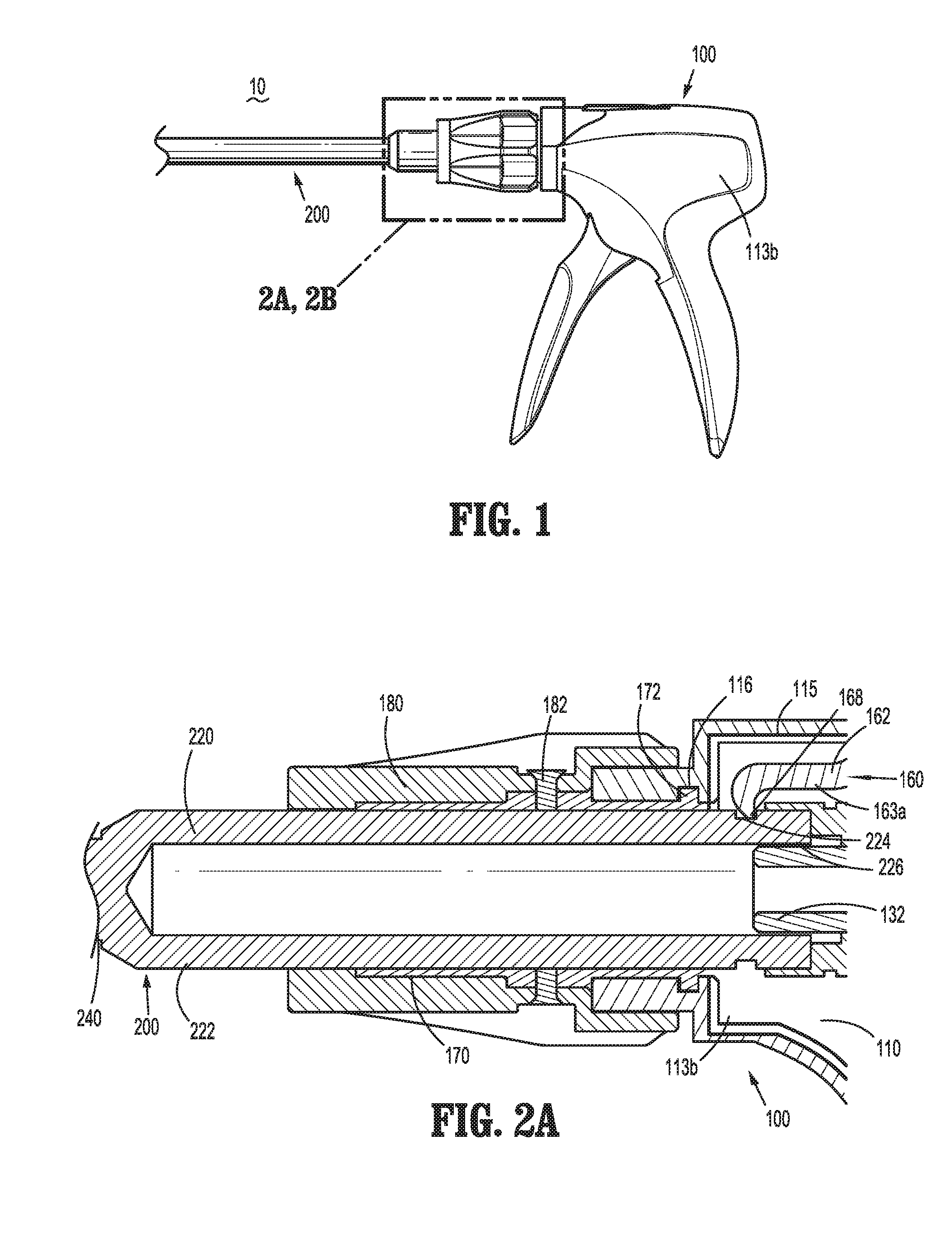
[0025] FIG. 1 is a side view of an endoscopic surgical clip applier provided in accordance with the present disclosure including a handle assembly having an endoscopic assembly engaged therewith;
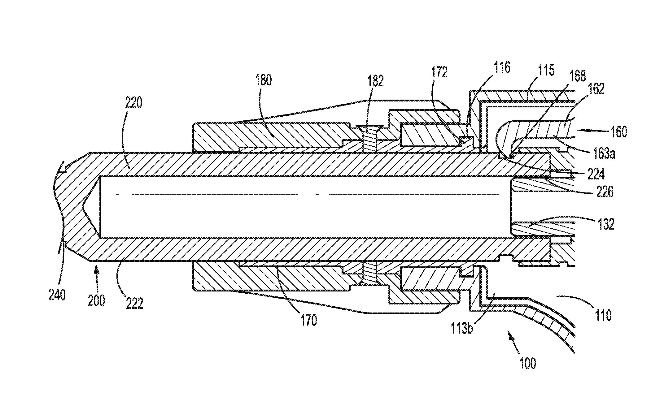
[0026] FIG. 2A is side, longitudinal, cross-sectional view of the area of detail indicated in FIG. 1;
[0027] FIG. 2B is a front, perspective view of the area of detail indicated in FIG. 1;
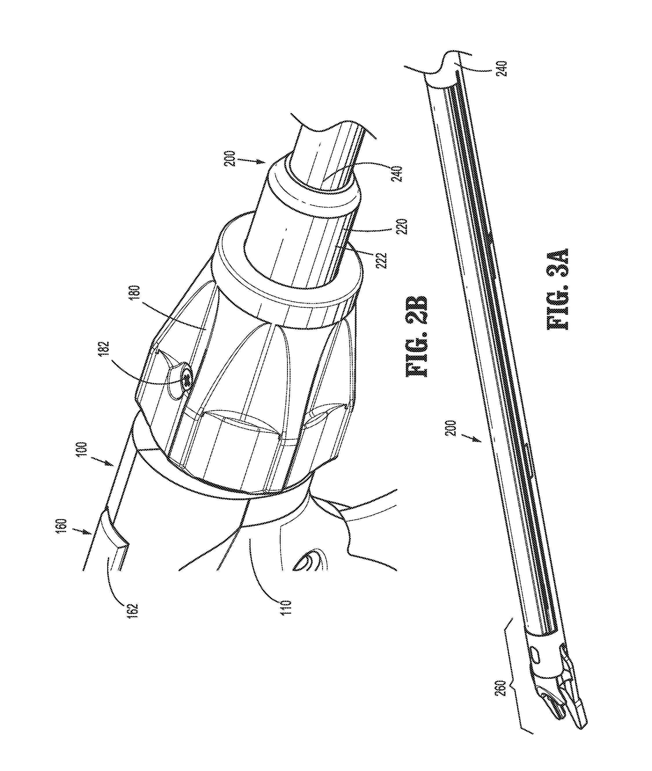
[0028] FIG. 3A is a side, perspective view of the distal end of the endoscopic assembly of FIG. 1;
[0029] FIG. 3B is a side, longitudinal, cross-sectional view of a proximal portion of an outer shaft of the endoscopic assembly of FIG. 1;
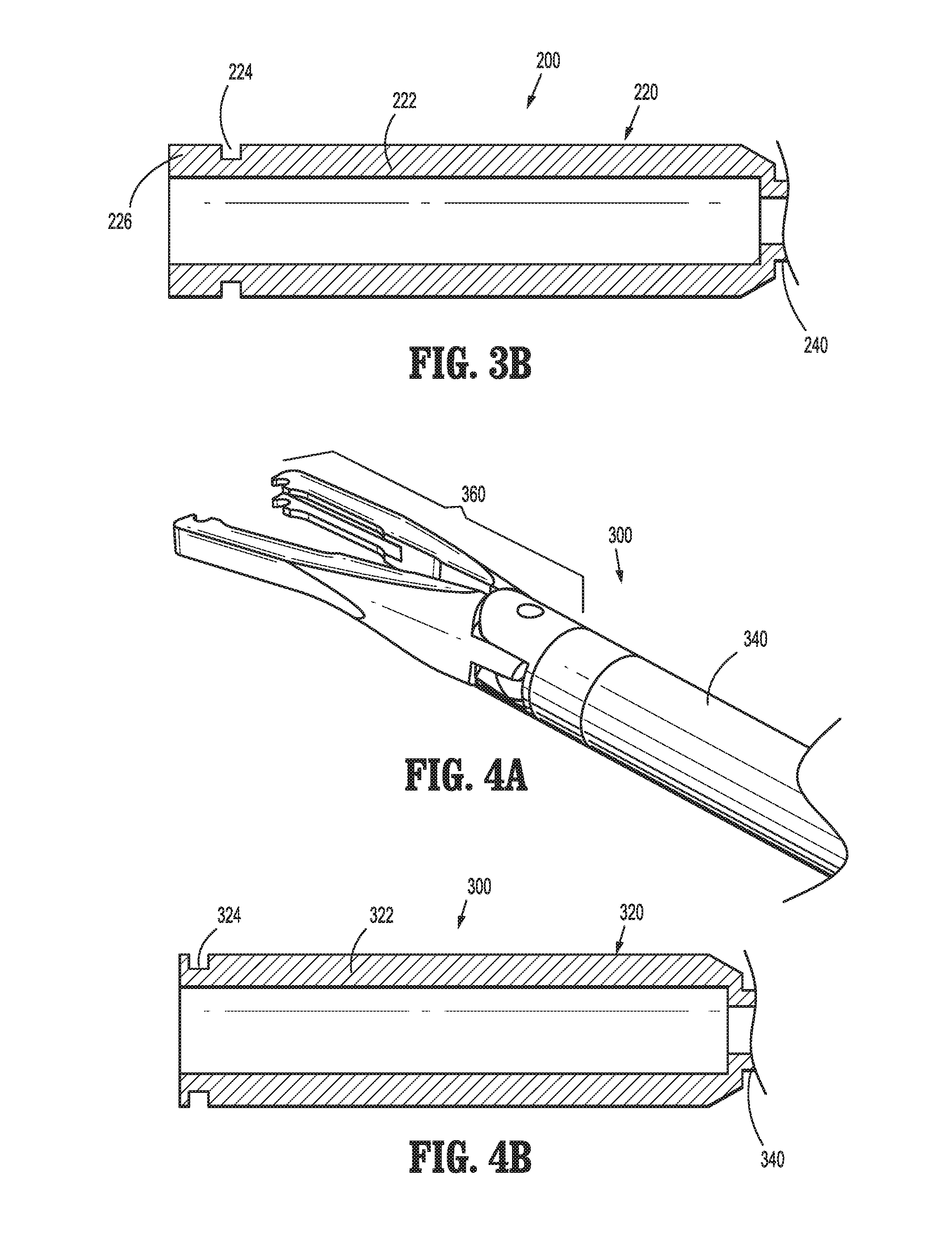
[0030] FIG. 4A is a side, perspective view of a distal end of another endoscopic assembly configured for use with the endoscopic clip applier of FIG. 1;
[0031] FIG. 4B is a side, longitudinal, cross-sectional view of a proximal portion of an outer shaft of the endoscopic assembly of FIG. 4A;
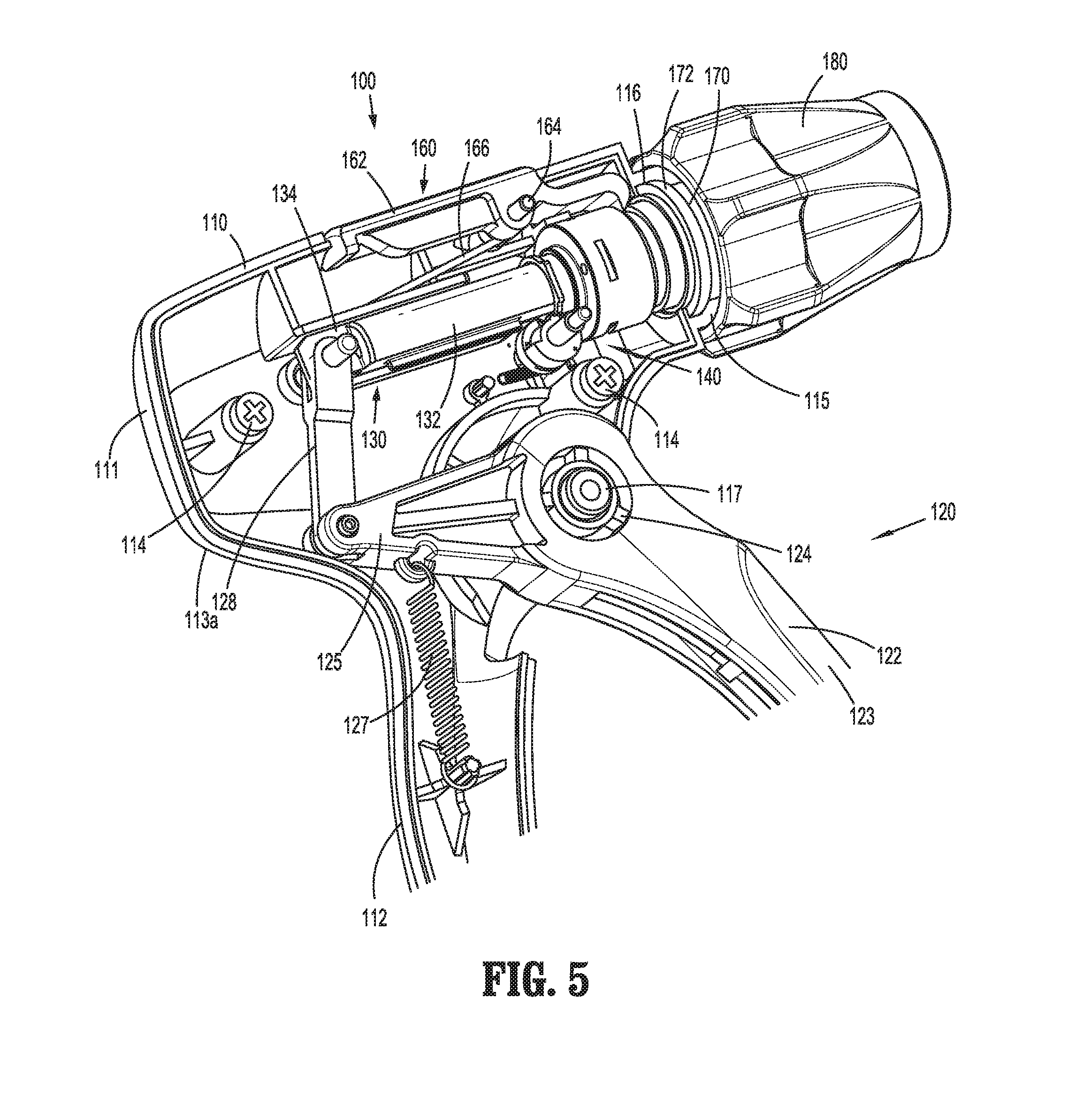
[0032] FIG. 5 is a rear, perspective view of the handle assembly of FIG. 1, with a portion of the housing removed to illustrate the internal components therein;
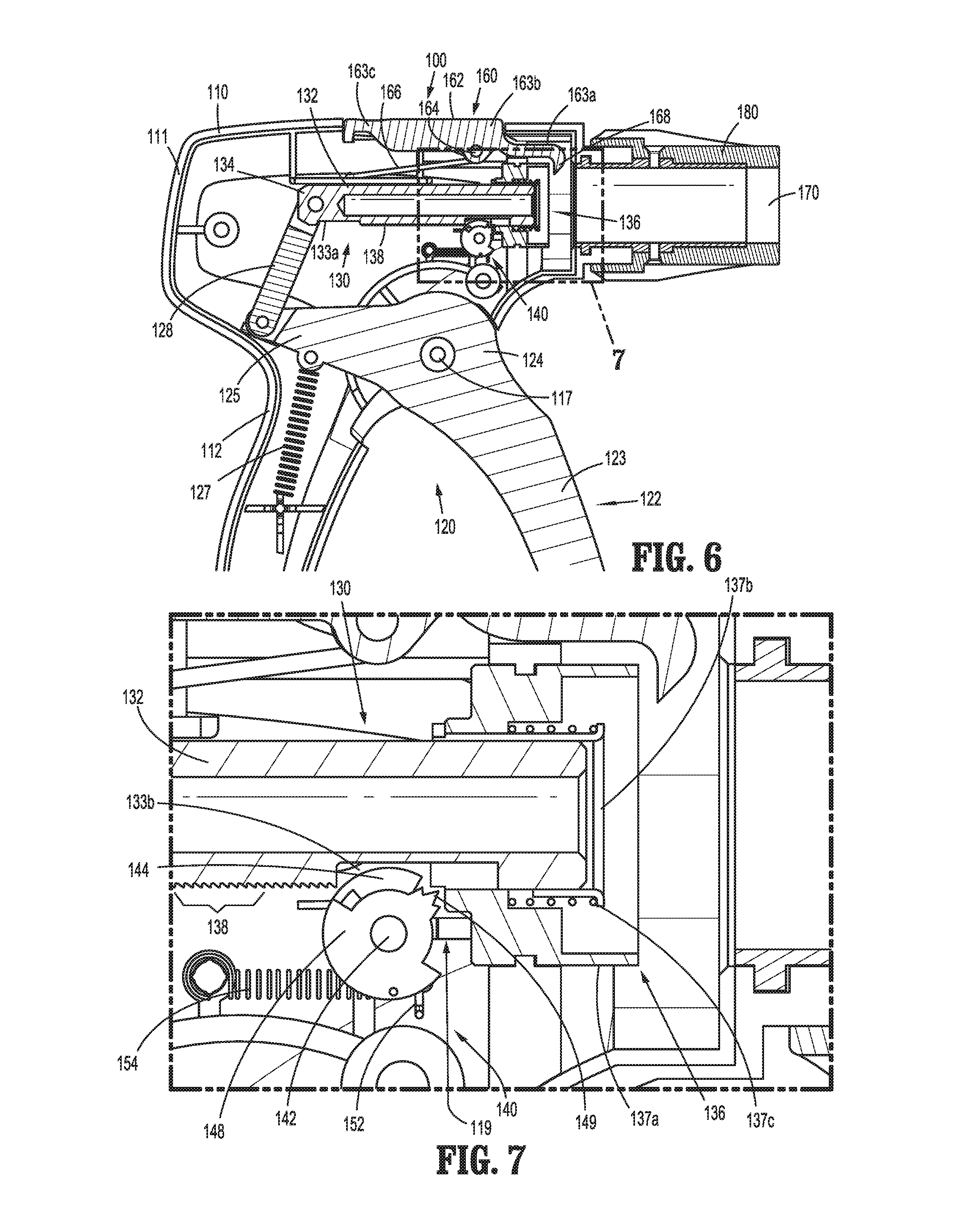
[0033] FIG. 6 is a side, longitudinal, cross-sectional view of the handle assembly of FIG. 1;
[0034] FIG. 7 is an enlarged, side, longitudinal, cross-sectional view of the area of detail indicated as "7" in FIG. 6;
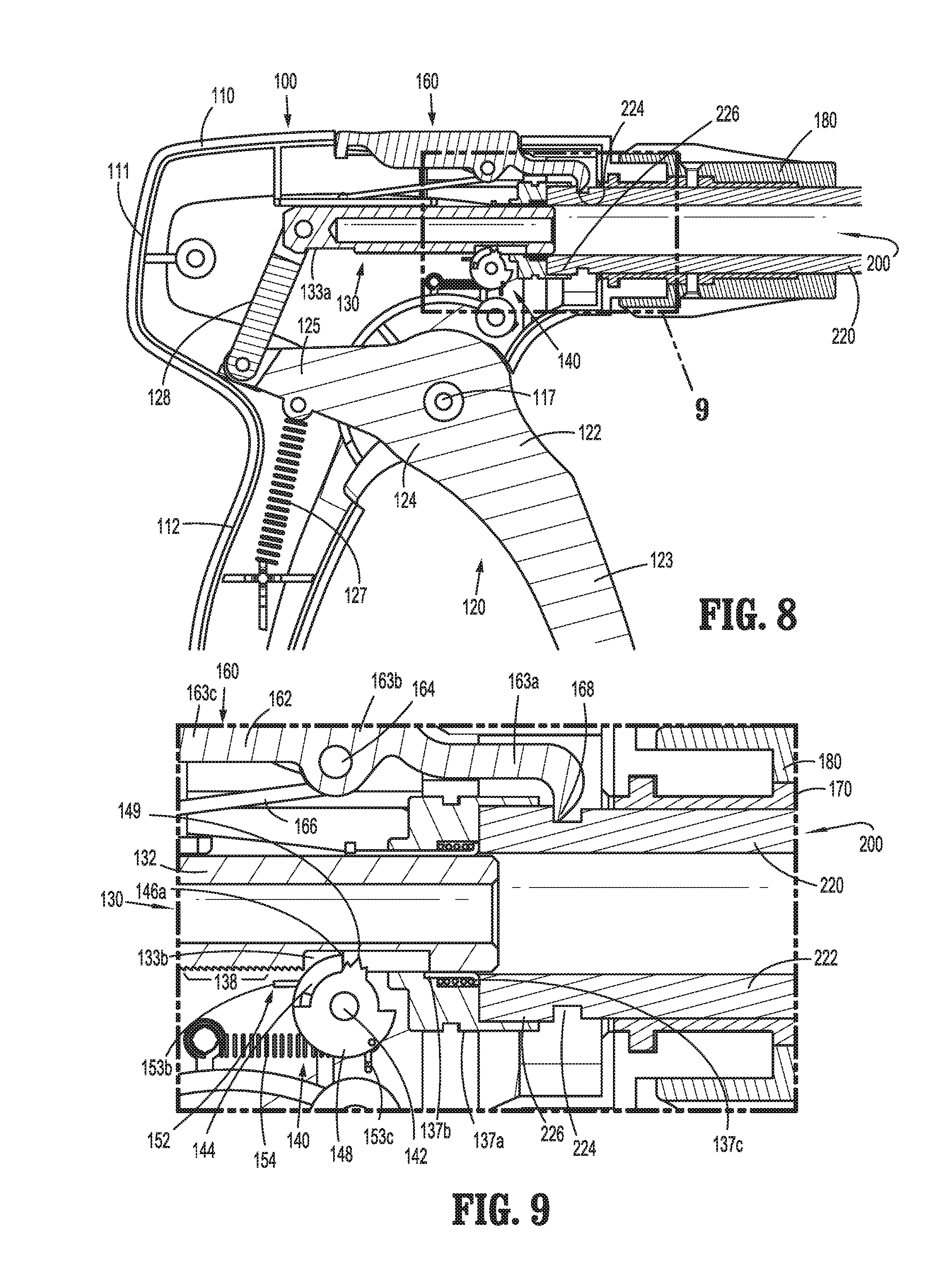
[0035] FIG. 8 is a side, longitudinal, cross-sectional view of the handle assembly of FIG. 1 including the endoscopic assembly of FIGS. 3A and 3B engaged therein, wherein a trigger of the handle assembly is disposed in an un-actuated position;
[0036] FIG. 9 is an enlarged, side, longitudinal, cross-sectional view of the area of detail indicated as "9" in FIG. 8;
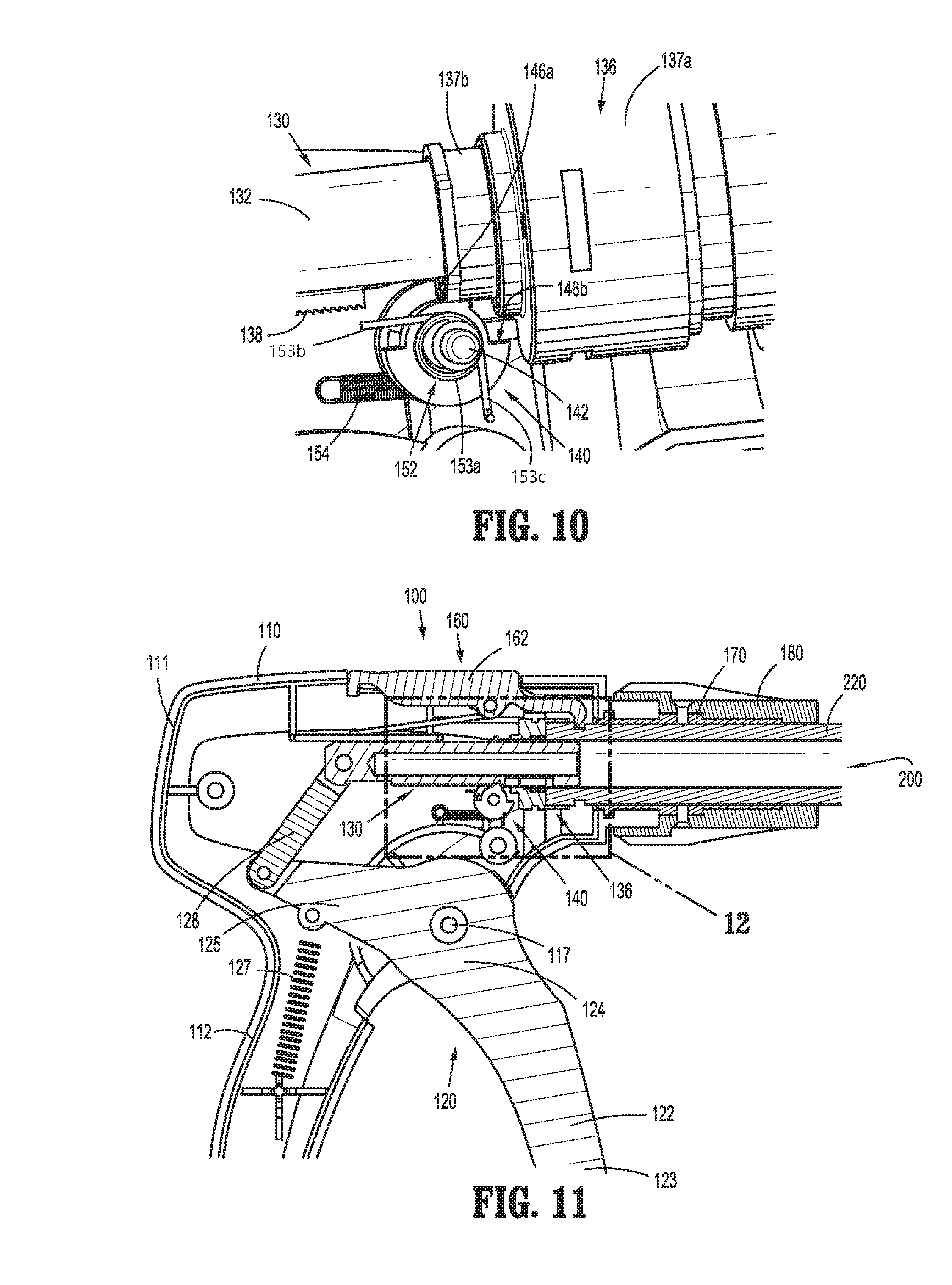
[0037] FIG. 10 is a side, perspective view of a portion of the endoscopic surgical clip applier of FIG. 1 illustrating the endoscopic assembly engaged within the handle assembly with the handle assembly disposed in a ratcheting-use condition;
[0038] FIG. 11 is a side, longitudinal, cross-sectional view of the handle assembly of FIG. 1 including the endoscopic assembly of FIG. FIGS. 3A and 3B engaged therein, wherein the trigger is disposed between the un-actuated position and an actuated position;
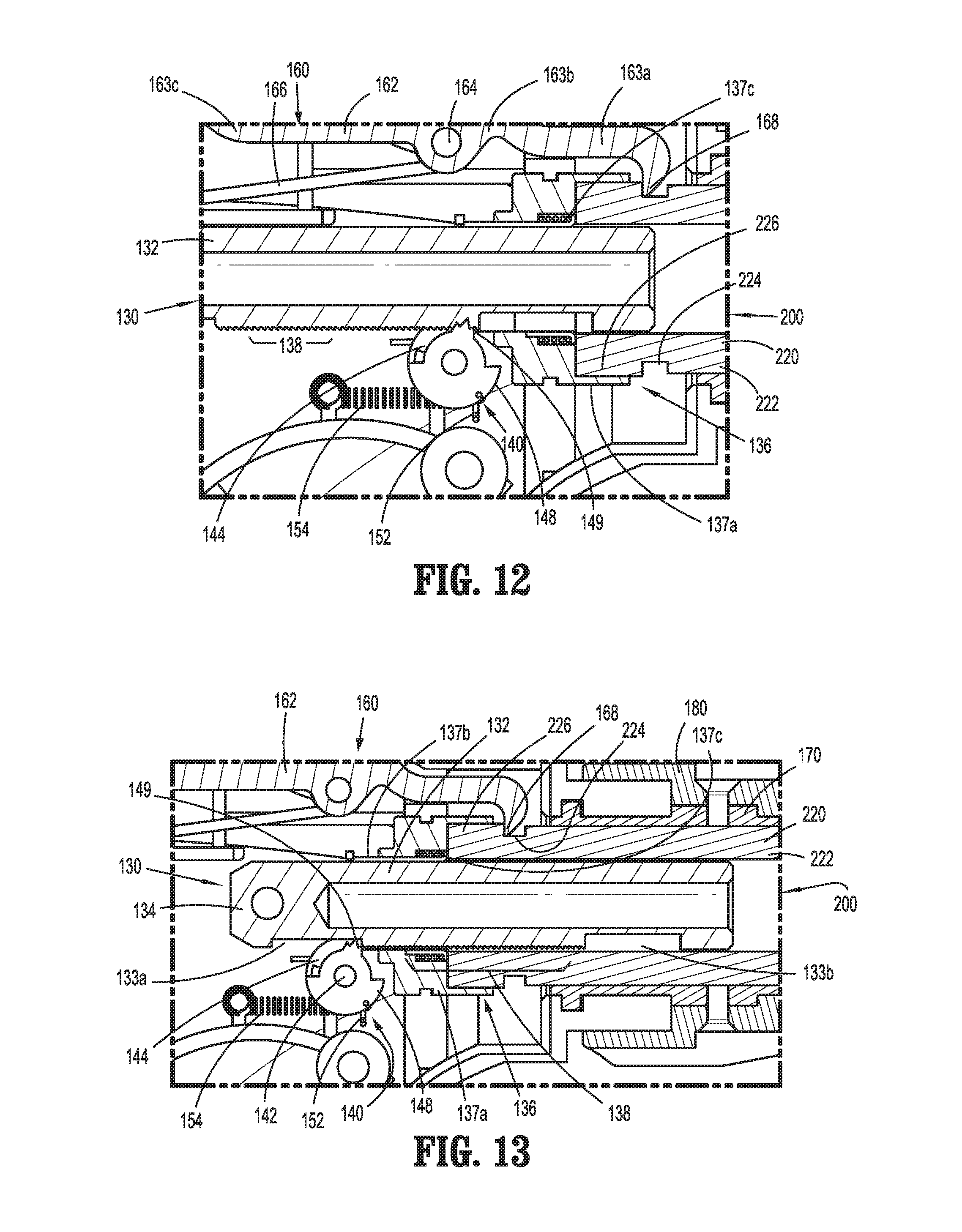
[0039] FIG. 12 is an enlarged, side, longitudinal, cross-sectional view of the area of detail indicated as "12" in FIG. 11; and
[0040] FIG. 13 is an enlarged, side, longitudinal, cross-sectional view of the portion of the handle assembly of FIG. 1 including the endoscopic assembly of FIG. FIGS. 3A and 3B engaged therein as illustrated in FIG. 12, wherein a drive assembly of the handle assembly is disposed in a distal-most position.
DETAILED DESCRIPTION
[0041] Turning to FIGS. 1, 2A, and 2B, an endoscopic surgical clip applier provided in accordance with the present disclosure is identified by reference numeral 10. Surgical clip applier 10 generally includes a handle assembly 100 and a plurality of endoscopic assemblies 200, 300 (FIGS. 4A and 4B) selectively connectable to and extendable distally from handle assembly 100. Handle assembly 100 is advantageously configured to operate each of endoscopic assemblies 200, 300 upon connection thereto, and may be configured as a sterilizable, reusable component such that handle assembly 100 may be repeatedly used with different and/or additional endoscopic assemblies 200, 300 during the course of one or more surgical procedures. The endoscopic assemblies 200, 300 may be configured as single-use disposable components, limited-use disposable components, or reusable components, depending upon a particular purpose and/or the configuration of the particular endoscopic assembly. In either configuration, the need for multiple handle assemblies 100 is obviated and, instead, the surgeon need only select an appropriate endoscopic assembly 200, 300 and connect that endoscopic assembly to handle assembly 100 in preparation for use.
[0042] With additional reference to FIGS. 3A-4B, handle assembly 100, more specifically, is configured for both ratcheting use, e.g., in connection with endoscopic assembly 200 (FIGS. 1 and 2A-3B), and non-ratcheting use, e.g., in connection with endoscopic assembly 300 (FIGS. 4A and 4B). Referring to FIGS. 1, 3A, and 3B, endoscopic assembly 200 is configured for ratcheting use and generally includes a proximal hub 220, an elongated shaft 240 extending distally from proximal hub 220, an end effector assembly 260 disposed on a distal end portion of elongated shaft 240, and an inner drive assembly (not shown) operably coupled between handle assembly 100 and end effector assembly 260 when endoscopic assembly 200 is engaged with handle assembly 100 to enable the sequential firing and forming of at least one surgical clip (not shown) about tissue. Proximal hub 220 includes a body 222 having an annular channel 224 defined therein on a proximal end portion thereof Proximal hub 220 further includes a push-block or relatively longer extension 226 that extends proximally from body 222. These features of proximal hub 220 are described in greater detail below. A more-detailed description of end effector assembly 260 and the inner drive assembly (not shown) of endoscopic assembly 200 are provided in International Application No. PCT/CN2015/091603, filed on Oct. 10, 2015, the entire content of which is hereby incorporated herein by reference. Further, it is contemplated that endoscopic assembly 200 may be configured to close, fire or form surgical clips similar to those shown and described in U.S. Pat. Nos. 7,819,886 or 7,905,890, the entire content of each of which is incorporated herein by reference.
[0043] Referring to FIGS. 4A-4B, endoscopic assembly 300 is configured for non-ratcheting use and generally includes a proximal hub 320, an elongated shaft 340 extending distally from proximal hub 320, an end effector assembly 360 disposed on a distal end portion of elongated shaft 340, and an inner drive assembly (not shown) operably coupled between handle assembly 100 and end effector assembly 360 when endoscopic assembly 300 is engaged with handle assembly 100 to enable grasping and/or manipulation of tissue, retrieval of a surgical clip, and firing and forming the surgical clip about tissue. Proximal hub 320 includes a body 322 having an annular channel 324 defined therein on a proximal end portion thereof Notably, and in contrast to proximal hub 220 of endoscopic assembly 200 (FIG. 3B), body 322 of proximal hub 320 defines the proximal-most portion of proximal hub 320; proximal hub 320 does not include a push-block that extends proximally from body 322, or, alternatively, proximal hub 320 includes a push-block that is relatively shorter as compared to push-block 226 of endoscopic assembly 200. A more-detailed description of end effector assembly 360 and the inner drive assembly (not shown) of endoscopic assembly 300 are also provided in International Application No. PCT/CN2015/091603, previously incorporated herein by reference. It is contemplated that endoscopic assembly 300 be configured to close, fire or form surgical clips similar to those shown and described in U.S. Pat. No. 4,834,096, the entire content of which is incorporated herein by reference.
[0044] Although exemplary endoscopic assemblies 200, 300 configured for ratcheting and non-ratcheting use, respectively, are detailed above, it is contemplated that various other endoscopic assemblies for performing various different surgical tasks and/or having various different configurations suitable for ratcheting or non-ratcheting use may likewise be utilized with handle assembly 100. More specifically, it is contemplated and within the scope of the present disclosure that other endoscopic assemblies including a pair of jaws having a unique and diverse closure stroke length thereof, may be provided for use with handle assembly 100 for ratcheting use or non-ratcheting use, similarly as detailed above with respect to endoscopic assemblies 200, 300. Such a configuration accommodates various different endoscopic assemblies having different configurations and/or different closure stroke lengths while providing a constant actuation stroke length of trigger 122 of trigger assembly 120 of handle assembly 100. Accordingly, various endoscopic assemblies, constructed in accordance with the principles of the present disclosure, may be provided which are also capable of firing or forming or closing surgical clips of various sizes, materials, and configurations, across multiple platforms for multiple different manufactures.
[0045] With reference to FIGS. 1, 2A, 2B, and 5, handle assembly 100 generally includes a housing 110, a trigger assembly 120 pivotably coupled to housing 110, a drive assembly 130 operably coupled to trigger assembly 120, a ratchet mechanism 140 selectively operably associated with drive assembly 130, a latch assembly 160 configured to releasably latch an endoscopic assembly 200, 300 (FIGS. 2-2B and 3A-3B, respectively) in engagement with handle assembly 100, a receiver tube 170 extending distally from housing 110 and configured to receive the proximal hub 220, 320 of the endoscopic assembly 200, 300 (FIGS. 1-3B and 4A-4B, respectively) inserted into handle assembly 100, and a rotation knob 180 disposed about receiver tube 170.
[0046] Handle assembly 100 is detailed below in connection with endoscopic assembly 200. Similarities in the engagement and use of handle assembly 100 with a non-ratcheting endoscopic assembly, e.g., endoscopic assembly 300 (FIGS. 3A and 3B), and with ratcheting endoscopic assembly 200 will not be described in detail below for purposes of brevity. Differences therebetween will be noted hereinbelow where applicable.
[0047] Housing 110 of handle assembly 100 defines a body portion 111 and a fixed handle portion 112 extending downwardly from body portion 111. Housing 110 is formed from first and second housing components or halves 113a, 113b secured to one another via a plurality of screws 114, although first and second housing components 113a, 113b may alternatively be secured in any other suitable manner, e.g., ultrasonic welding, gluing, other mechanical engagement, etc. Housing 110 is configured to house the internal working components of handle assembly 100. Body portion 111 includes a distal nose 115 defining an annular slot 116 on the interior thereof. More specifically, first and second housing components 113a, 113b each define a semi-annular slot portion such that, when first and second housing components 113a, 113b cooperate to form housing 110, annular slot 116 is formed. Receiver tube 170 of handle assembly 100 includes an annular rim 172 disposed thereabout on a proximal end portion thereof. Annular rim 172 is captured within annular slot 116 defined within distal nose 115 of housing 110, e.g., upon engagement of first and second housing components 113a, 113b with one another. Annular rim 172 is captured within annular slot 116 to rotatably engage receiver tube 170 with housing 110. Rotation knob 180 of handle assembly 100 is engaged about receiver tube 170, e.g., via a pair of opposed engagement pins 182, in fixed rotational orientation relative thereto such that rotation of rotation knob 180 relative to housing 110 effects similar rotation of receiver tube 170 relative to housing 110.
[0048] Body portion 111 of housing 110 further incudes an internal pivot post 117 extending transversely between housing components 113a, 113b (from either or both of housing components 113a, 113b), as detailed below. Fixed handle portion 112 of housing 110 is configured to facilitate grasping of handle assembly 100 and manipulation thereof and is monolithically formed with body portion 111, although other configurations are also contemplated.
[0049] Referring to FIGS. 1, 5, and 6, trigger assembly 120 generally includes a trigger 122, a biasing member 127, and a linkage 128. Trigger 122 includes a grasping portion 123, an intermediate pivot portion 124, and a proximal extension portion 125. Grasping portion 123 of trigger 122 extends downwardly from body portion 111 of housing 110 in opposed relation relative to fixed handle portion 112 of housing 110. Grasping portion 123 is configured to facilitate grasping and manipulation of trigger 122. Intermediate pivot portion 124 of trigger 122 is at least partially disposed within housing 110 and is pivotably supported on pivot post 117 of housing 110 so as to enable pivoting of trigger 122 about pivot post 117 and relative to housing 110, e.g., between an un-actuated position, wherein grasping portion 123 of trigger 122 is spaced-apart relative to fixed handle portion 112, and an actuated position, wherein grasping portion 123 of trigger 122 is approximated relative to fixed handle portion 112.
[0050] Proximal extension portion 125 of trigger 122 of trigger assembly 120 is disposed on an opposite side of intermediate pivot portion 124 and, thus, pivot post 117, as compared to grasping portion 123 of trigger 122. As such, pivoting of grasping portion 123 proximally, e.g., towards the actuated position, urges proximal extension portion 125 distally. Proximal extension portion 125 is pivotably coupled to the proximal end of linkage 128. Biasing member 127 is secured at either end and extends between proximal extension portion 125 and a support disposed within fixed handle portion 112 of housing 110. Pivoting of grasping portion 123 towards the actuated position elongates biasing member 127 storing energy therein such that, upon release of grasping portion 123, grasping portion 123 is returned towards the un-actuated position under the bias of biasing member 127. Although illustrated as an extension coil spring, biasing member 127 may define any suitable configuration for biasing grasping portion 123 of trigger 122 towards the un-actuated position.
[0051] As noted above, linkage 128 is coupled at its proximal end to proximal extension portion 125 of trigger 122. Linkage 128 is also pivotably coupled, at its distal end, to proximal extension 134, which extends distally from drive bar 132 of drive assembly 130. As a result of this configuration, pivoting of grasping portion 123 of trigger 122 towards the actuated position urges proximal extension portion 125 of trigger distally which, in turn, urges linkage 128 distally.
[0052] With additional reference to FIGS. 7 and 10, drive assembly 130 of handle assembly 100 includes drive bar 132, proximal extension 134, a ratchet engagement assembly 136, and a ratchet rack 138. Drive bar 132 extends in a generally longitudinal direction. As noted above, proximal extension 134 extends proximally from drive bar 132 and serves to pivotably couple drive bar 132 with linkage 128. Ratchet engagement assembly 136 includes a distal collar 137a that is fixedly mounted within body portion 111 of housing 110, an inner sleeve 137b slidably disposed within distal collar 137a, and a biasing member 137c positioned within distal collar 137a and configured to bias inner sleeve 137b distally relative to distal collar 137a. Biasing member 137c may be configured as a coil compression spring, although other configurations are also contemplated. Ratchet rack 138 extends in a generally longitudinal direction, similar to drive bar 132, and is defined on or engaged with drive bar 132 on an underside thereof Drive bar 132 defines proximal and distal recesses 133a, 133b, respectively, disposed adjacent the respective proximal and distal ends of drive bar 132.
[0053] With reference to FIGS. 6-10, ratchet mechanism 140 of handle assembly 100, as noted above, is selectively operably associated with drive assembly 130 to enable use of handle assembly 100 in either a ratcheting condition or a non-ratcheting condition. Ratchet mechanism 140 includes a pin 142, a cam disc 144, a pawl disc 148, and first and second biasing members 152, 154. Pin 142 is engaged within body portion 111 of housing 110 and extends transversely within body portion 111 of housing 110. Cam disc 144 is rotatably mounted about pin 142 and defines a cut-out forming first and second oppositely-facing stop surfaces 146a, 146b (FIG. 10) on cam disc 144, as detailed below.
[0054] Pawl disc 148 is rotatably mounted about pin 142 adjacent cam disc 144. Pawl disc 148 includes a ratchet pawl 149 extending therefrom that is configured to operably engage ratchet rack 138 of drive assembly 130 to permit incremental advancement of drive bar 132 through and relative to body portion 111 of housing 110, as detailed below. Pawl disc 148 is rotatable, in connection with cam disc 144, between a non-ratcheting use orientation, wherein ratchet pawl 149 is inhibited from engaging ratchet rack 138 upon advancement of drive bar 132, and a ratcheting-use orientation, wherein ratchet pawl 149 is operably positioned to incrementally engage ratchet rack 138 upon distal advancement of drive bar 132.
[0055] With reference to FIG. 10, first biasing member 152 is configured as a torsion spring having a base 153a and first and second legs 153b, 153c extending from base 153a. Base 153a is rotatably mounted about pin 142, first leg 153b is engaged with cam disc 144, and second leg 153c is engaged with pawl disc 148. As a result of this configuration, first biasing member 152 serves to operably couple cam disc 144 and pawl disc 148 with one another. More specifically, first biasing member 152 biases pawl disc 148 to rotate together with cam disc 144 about pin 142 in the absence of sufficient external influence to overcome the bias. As detailed below, this configuration enables rotation of pawl disc 148 about pin 142 from the non-ratcheting use orientation to the ratcheting use orientation in response to rotation of cam disc 144 upon engagement of an endoscopic assembly configured for ratcheting use, e.g., endoscopic assembly 200 (FIGS. 3A and 3B), with handle assembly 100. However, the bias of first biasing member 152 may be overcome in response to application of sufficient external influence thereto, thus permitting relative rotation between pawl disc 148 and cam disc 144. As also detailed below, this configuration enables rotation of pawl disc 148 about pin 142 and relative to cam disc 144 during actuation to enable incremental engagement of ratchet pawl 149 with ratchet rack 138 and to permit return of drive bar 132 after a complete actuation.
[0056] Second biasing member 154 of ratchet assembly 140 extends, e.g., longitudinally, within body portion 111 of housing 110. The proximal end of second biasing member 154 is fixed within body portion 111 of housing 110, while the distal end of second biasing member 154 is engaged with cam disc 144. The distal end of second biasing member 154 may alternatively be engaged with pawl disc 148. Second biasing member 154 is configured as an extension coil spring and, as such, biases cam disc 144 and pawl disc 148 towards the non-ratcheting use condition of ratchet mechanism 140, wherein ratchet pawl 149 is oriented to enable engagement thereof with ratchet rack 138.
[0057] Referring to FIGS. 1, 5, 8, and 9, latch assembly 160 includes a latch lever 162, a pivot pin 164, and a biasing member 166. Latch lever 162 is at least partially disposed within a cut-out defined without housing 110 of handle assembly 100 to enable manual manipulation thereof and defines a distal engagement section 163a, an intermediate section 163b, and a proximal manipulatable section 163c. Distal engagement section 163a of latch lever 162 includes an engagement tooth 168 extending therefrom. Engagement tooth 168 is configured to engage an endoscopic assembly inserted into handle assembly 100. With respect to endoscopic assembly 200, for example, upon insertion of proximal hub 220 of endoscopic assembly 200 into handle assembly 100, engagement tooth 168 is configured for engagement within annular channel 224 of proximal hub 220 to lock endoscopic assembly 200 in engagement within handle assembly 100.
[0058] Pivot pin 164 of latch assembly 160 pivotably couples intermediate section 163b of lever latch 162 with housing 110 of handle assembly 100 such that urging of proximal manipulation section 163c of lever latch 162 in a first direction, e.g., downwardly into housing 110, urges distal engagement section 163a of lever latch 162 in a second, opposite direction e.g., upwardly out of engagement with annular channel 224 of proximal hub 220 endoscopic assembly 200. Biasing member 166 is configured as a torsion spring, although other configurations are also contemplated, and is positioned to bias proximal manipulation section 163c of lever latch 162 upwardly, thereby biasing distal engagement section 163a downwardly towards an engaged position. Proximal manipulation section 163c of lever latch 162 is selectively depressible, against the bias of biasing member 166, to urge distal engagement section 163a upwardly towards a disengaged position.
[0059] Referring to FIGS. 5-10, insertion and engagement of endoscopic assembly 200 within handle assembly 100 (FIG. 1) is detailed. Initially, prior to insertion of endoscopic assembly 200, as illustrated in FIGS. 6 and 7, trigger 122 is disposed in the un-actuated position under the bias of biasing member 127, drive bar 132 is disposed in a proximal-most position, and cam disc 144 and pawl disc 148 are oriented in the non-ratcheting use orientation under the bias of second biasing member 154. Further, at this point, and lever latch 162 is disposed in the engaged position under the bias of biasing member 166.
[0060] In order to engage endoscopic assembly 200 within handle assembly 100, as illustrated in FIGS. 8-10, proximal hub 220 of endoscopic assembly 200 is inserted into rotation knob 180 of handle assembly 100 and slid proximally through rotation knob 180, receiver tube 170, and into housing 110. As proximal hub 220 initially enters housing 110, proximal hub 220 receives the distal end of drive bar 132 of drive assembly 130. Further, push-block 226 of proximal hub 220 enters distal collar 137a of drive assembly 130 and abuts the distal end of inner sleeve 137b of drive assembly 130.
[0061] Upon further insertion of proximal hub 220 into housing 110 and distal collar 137a, push-block 226 of proximal hub 220 urges sleeve 137b proximally against the bias of biasing member 137c. As sleeve 137b is urged proximally, the proximal end of sleeve 137b is urged into contact with first stop surface 146a of cam disc 144 of ratchet assembly 140 to urge cam disc 144 to rotate in a counter-clockwise direction, according to the orientation of FIGS. 7 and 9, from the non-ratcheting use orientation (FIG. 7) to the ratcheting use orientation (FIG. 9). More specifically, cam disc 144 is rotated until second stop surface 146b contacts shelf 119 defined within body portion 111 of housing 110. The abutment of second stop surface 146b with shelf 119 inhibits further rotation of cam disc 144 and, thus, further proximal insertion of proximal hub 220 of endoscopic assembly 200 into handle assembly 100. Due to the operable coupling of pawl disc 148 with cam disc 144 via first biasing member 152, as detailed above, rotation of cam disc 144 urges pawl disc 148 to rotate from the non-ratcheting use orientation (FIG. 7) to the ratcheting use orientation (FIG. 9) such that ratchet pawl 149 is operably positioned to engage ratchet rack 138 of drive assembly 130 upon distal advancement of drive bar 132.
[0062] Simultaneously or in close temporal relation with the rotation of cam disc 144 and pawl disc 148 to the ratcheting use orientation in response to further insertion of proximal hub 220 into housing 110, engagement tooth 168 of latch assembly 160 is cammed over the proximal end of proximal hub 220 and into engagement within annular channel 224 of proximal hub 220 to lock endoscopic assembly 200 in engagement within handle assembly 100.
[0063] Referring to FIGS. 3B, 4B, 7, and 9, as noted above, push-block 226 of proximal hub 220 of endoscopic assembly 200 urges sleeve 137b proximally to thereby rotate cam disc 144 and pawl disc 148 to the ratcheting use orientation (FIG. 9). In embodiments where the endoscopic assembly, utilized with handle assembly 100, is configured for non-ratcheting use, e.g., as with endoscopic assembly 300, since the endoscopic assembly is devoid of a push-block, cam disc 144 and pawl disc 148 remain disposed in the non-ratcheting use orientation (FIG. 7) under the bias of second biasing member 154 upon engagement of the non-ratcheting endoscopic assembly with handle assembly 100. Non-ratcheting endoscopic assemblies such as endoscopic assembly 300 are releasably locked in engagement within handle assembly 100 via latch assembly 160, similarly as detailed above with respect to the engagement of endoscopic assembly 200 within handle assembly 100.
[0064] Referring to FIGS. 8, 9, and 11-13, in use, with endoscopic assembly 200 engaged within handle assembly 100, as detailed above, pawl disc 148 is disposed in the ratcheting use orientation. Initially, trigger 122 is disposed in the un-actuated position and, as such, ratchet pawl 149 extends at least partially into distal recess 133b of drive bar 132. In order to fire surgical clip applier 10 (FIG. 1), grasping portion 123 of trigger 122 is pivoted towards fixed handle portion 112 of housing 110 to urge linkage 128 distally which, in turn, urges drive bar 132 distally through housing 110 and proximal hub 220 to drive the inner drive assembly (not shown) of endoscopic assembly 200 distally.
[0065] As drive bar 132 is translated distally, as shown in FIGS. 11 and 12, ratchet pawl 149 incrementally engages ratchet rack 138, inhibiting proximal return of drive bar 132. Pawl disc 148 is permitted to oscillate relative to cam disc 144, thus permitting ratchet pawl 149 to incrementally engage the teeth of ratchet rack 138 as drive bar 132 is advanced distally. This oscillatory movement of pawl disc 148 is permitted due to the operable coupling of pawl disc 148 and cam disc 144 via first biasing member 152, as detailed above.
[0066] With ratchet pawl 149 engaged with ratchet rack 138, drive bar 132 is inhibited from returning proximally and, thus, trigger 122 is inhibited from returning towards the un-actuated position until a full actuation of trigger 122 has been completed and ratchet pawl 149 has cleared ratchet rack 138 and entered proximal recess 133a of drive bar 132 (FIG. 13). During actuation, distal translation of drive bar 132 drives the inner drive assembly (not shown) of endoscopic assembly 200 to fire and form a surgical clip (not shown) from end effector assembly 360 (FIG. 3A) about tissue. Ratchet mechanism 140, in the ratcheting use condition, enables incremental firing of endoscopic assembly 200, as detailed above.
[0067] Upon full actuation of trigger 122, e.g., upon reaching the actuated position of trigger 122, ratchet pawl 149 clears ratchet rack 138 and enters proximal recess 133a of drive bar 132. Once ratchet pawl 149 has cleared ratchet rack 138, trigger 122 may be released and returned to the un-actuated position under the bias of biasing member 127, thereby returning drive bar 132 proximally. As drive bar 132 is returned proximally ratchet pawl 149 cams over the ratchet teeth of ratchet rack 138 without engaging the ratchet teeth. Thus, free return of drive bar 132 to its proximal-most position may be achieved. Upon return of trigger 122 to the un-actuated position, the above-detailed use of surgical clip applier 10 may be repeated to fire and form additional surgical clips (not shown).
[0068] Referring momentarily to FIGS. 1 and 4A-5, the use of endoscopic assembly 300 with handle assembly 100 is similar to that detailed above with respect to endoscopic assembly 200 except that, with pawl disc 148 maintained in the non-ratcheting use orientation (due to non-ratcheting endoscopic assemblies not including a push-block), ratchet pawl 149 is inhibited from engaging ratchet rack 138. Accordingly, during use of endoscopic assembly 300, trigger 122 may be freely pivoted between the un-actuated and actuated positions, and may be returned towards the un-actuated at any point during the actuation stroke.
[0069] Turning back to FIGS. 6-9, in order to disengage endoscopic assembly 200 from handle assembly 10, e.g., for cleaning and/or sterilization, or to replace endoscopic assembly 200 with another endoscopic assembly, proximal manipulation section 163c of lever latch 162 of latch assembly 160 is depressed inwardly into housing 110, against the bias of biasing member 166, to urge distal engagement section 163a of lever latch 162 upwardly and out of engagement within annular channel 224 of proximal hub 220 of endoscopic assembly 200. With distal engagement section 163a of lever latch 162 disposed in this disengaged position, proximal hub 220 of endoscopic assembly 200 may be withdrawn distally from handle assembly 100. Upon withdrawal of endoscopic assembly 200 from handle assembly 100, cam disc 144 and pawl disc 148 of ratchet mechanism 140 are returned to the non-ratcheting use orientation under the bias of second biasing member 154.
[0070] In accordance with the present disclosure, it is contemplated that a surgical system or kit (not shown) may be provided which includes a handle assembly 100, at least one endoscopic assembly 200, at least one endoscopic assembly 300, and instructions for using the same. It is further contemplated that a plurality of handle assemblies may be provided in the surgical system or kit. It is additionally contemplated that the surgical system or kit may include additional endoscopic assemblies, not shown or described herein, which are different from endoscopic assemblies 200 or 300, and which are configured to connection to and operation by handle assembly 100. It is still further contemplated that the surgical system or kit may include at least one cartridge of surgical clips or fasteners (not shown) for use with any of the endoscopic assemblies disclosed herein.
[0071] It should be understood that the foregoing description is only illustrative of the present disclosure. Various alternatives and modifications can be devised by those skilled in the art without departing from the disclosure. Accordingly, the present disclosure is intended to embrace all such alternatives, modifications and variances. The embodiments described with reference to the attached drawing figures are presented only to demonstrate certain examples of the disclosure. Other elements, steps, methods and techniques that are insubstantially different from those described above and/or in the appended claims are also intended to be within the scope of the disclosure.
* * * * *
D00000
D00001
D00002
D00003
D00004
D00005
D00006
D00007
D00008
XML
uspto.report is an independent third-party trademark research tool that is not affiliated, endorsed, or sponsored by the United States Patent and Trademark Office (USPTO) or any other governmental organization. The information provided by uspto.report is based on publicly available data at the time of writing and is intended for informational purposes only.
While we strive to provide accurate and up-to-date information, we do not guarantee the accuracy, completeness, reliability, or suitability of the information displayed on this site. The use of this site is at your own risk. Any reliance you place on such information is therefore strictly at your own risk.
All official trademark data, including owner information, should be verified by visiting the official USPTO website at www.uspto.gov. This site is not intended to replace professional legal advice and should not be used as a substitute for consulting with a legal professional who is knowledgeable about trademark law.