Modular Surgical Clip Cartridge
Dinino; Matthew A. ; et al.
U.S. patent application number 16/120571 was filed with the patent office on 2019-05-09 for modular surgical clip cartridge. The applicant listed for this patent is Covidien LP. Invention is credited to Jacob C. Baril, Brandon L. Calavan, Matthew A. Dinino, Roy J. Pilletere, Justin Thomas.
| Application Number | 20190133594 16/120571 |
| Document ID | / |
| Family ID | 66326559 |
| Filed Date | 2019-05-09 |


| United States Patent Application | 20190133594 |
| Kind Code | A1 |
| Dinino; Matthew A. ; et al. | May 9, 2019 |
MODULAR SURGICAL CLIP CARTRIDGE
Abstract
A modular clip cartridge includes a body portion having a first wall and a second wall. The first wall defines a first protuberance, a second protuberance symmetrically opposed to the first protuberance, and a first mating feature disposed between the first and second protuberances. The second wall defines a first recess, a second recess symmetrically opposed to the first recess, and a second mating feature disposed between the first and second recesses. At least one clip compartment is defined in the body portion and configured to releasably retain at least one surgical clip therein. One of the first and second mating features of the modular clip cartridge is configured to selectively engage one of a first and a second mating feature of another modular clip cartridge to selectively connect the first modular clip cartridge and another modular clip cartridge into a unitary arrangement to define a modular surgical clip pack.
| Inventors: | Dinino; Matthew A.; (Newington, CT) ; Calavan; Brandon L.; (Windsor, CT) ; Baril; Jacob C.; (Norwalk, CT) ; Pilletere; Roy J.; (North Haven, CT) ; Thomas; Justin; (New Haven, CT) | ||||||||||
| Applicant: |
|
||||||||||
|---|---|---|---|---|---|---|---|---|---|---|---|
| Family ID: | 66326559 | ||||||||||
| Appl. No.: | 16/120571 | ||||||||||
| Filed: | September 4, 2018 |
Related U.S. Patent Documents
| Application Number | Filing Date | Patent Number | ||
|---|---|---|---|---|
| 62581134 | Nov 3, 2017 | |||
| Current U.S. Class: | 1/1 |
| Current CPC Class: | A61B 2017/00477 20130101; A61B 17/1222 20130101 |
| International Class: | A61B 17/122 20060101 A61B017/122 |
Claims
1. A modular surgical clip pack, comprising: a first modular clip cartridge and a second modular clip cartridge, each modular clip cartridge including: a body portion including: a first wall defining a first protuberance, a second protuberance symmetrically opposed to the first protuberance, and a first mating feature disposed between the first and second protuberances; and a second wall defining a first recess, a second recess symmetrically opposed to the first recess, and a second mating feature disposed between the first and second recesses; at least one clip compartment defined in the body portion configured to releasably retain at least one surgical clip therein; and wherein one of the first mating feature and the second mating feature of the first modular clip cartridge is configured to selectively engage one of the first mating feature and the second mating feature of the second modular clip cartridge to selectively connect the first and second modular clip cartridges into a unitary arrangement to define the modular surgical clip pack, wherein the first and second protuberances of one of the first and second modular clip cartridges is configured to selectively engage with the first and second recesses of one of the first and second modular clip cartridges to lock the first and second modular clip cartridges into the unitary arrangement.
2. The modular surgical clip pack of claim 1, wherein the first mating feature includes a rail formed on the first wall and the second mating feature includes a slot formed in the second wall, wherein one of the slot or the rail of the first modular clip cartridge is configured to slidably engage one of the slot or the rail of the second modular clip cartridge to selectively connect the first and second modular clip cartridges into the unitary arrangement and define the modular surgical clip pack.
3. The modular surgical clip pack of claim 2, wherein the rail extends between a top end of the first wall to a bottom end of the first wall, and wherein the slot extends from a top end of the second wall to a bottom end of the second wall.
4. The modular surgical clip pack of claim 3, wherein the rail is disposed on a central portion of the first wall, and the slot is disposed on a central portion of the second wall.
5. The modular surgical clip pack of claim 1, wherein the first and second protuberances of one of the first and second modular clip cartridges and the first and second recesses of one of the first and second modular clip cartridges are snap-fit connectable to each other.
6. The modular surgical clip pack of claim 1, wherein each of the first and second protuberances defines a circular cross-sectional shape.
7. The modular surgical clip pack of claim 1, wherein the body portion includes a third wall and a fourth wall, the third and fourth walls being parallel relative to each other, the third and fourth walls extending between and interconnecting the first and second walls to define at least one of a rectangular and a cube shape of each modular surgical clip cartridge.
8. The modular surgical clip pack of claim 7, wherein each wall defines an inner surface and an outer surface, and wherein the at least one clip compartment is defined by the inner surface of at least one of the first, second, third, and fourth walls.
9. The modular surgical clip pack of claim 8, wherein the at least one clip compartment includes a pair of wall dividers that are parallel to the first and second walls and extend between and interconnect the third and fourth walls, the pair of wall dividers defining three separate clip compartments in the at least one clip compartment, each of the three separate clip compartments containing the at least one surgical clip therein.
10. The modular surgical clip pack of claim 1, wherein the at least one surgical clip includes at least one of a metallic clip or a polymeric clip.
11. The modular surgical clip pack of claim 1, wherein the at least one clip compartment is configured to receive a surgical instrument for removing the at least one surgical clip therefrom.
12. The modular surgical clip pack of claim 11, wherein the surgical instrument is selected from the group consisting of forceps, graspers, and a surgical clip applier.
13. A modular clip cartridge, comprising: a body portion including: a first wall defining a first protuberance, a second protuberance symmetrically opposed to the first protuberance, and a first mating feature disposed between the first and second protuberances; and a second wall defining a first recess, a second recess symmetrically opposed to the first recess, and a second mating feature disposed between the first and second recesses; and at least one clip compartment defined in the body portion, the at least one clip compartment configured to releasably retain at least one surgical clip therein; and wherein one of the first mating feature and the second mating feature of the modular clip cartridge is configured to selectively engage one of a first mating feature and a second mating feature of another modular clip cartridge to selectively connect the first modular clip cartridge and another modular clip cartridge into a unitary arrangement to define a modular surgical clip pack.
14. The modular clip cartridge of claim 13, wherein the first and second protuberances of the modular clip cartridge are configured to selectively engage with first and second recesses of another modular clip cartridge, and wherein the first and second recesses of the modular clip cartridge are configured to selectively receive first and second protuberances of another modular clip cartridge to lock the modular clip cartridge into a unitary arrangement with at least one other modular clip cartridge.
15. The modular clip cartridge of claim 13, wherein the body portion includes a third wall and a fourth wall, the third and fourth walls being parallel relative to each other, the third and fourth walls extending between and interconnecting the first and second walls to define at least one of a rectangular and a cube shape of the modular surgical clip cartridge.
16. The modular clip cartridge of claim 15, wherein each wall defines an inner surface and an outer surface, and wherein the at least one clip compartment is defined by the inner surface of at least one of the first, second, third, and fourth walls.
17. The modular clip cartridge of claim 16, wherein the at least one clip compartment includes a pair of wall dividers that are parallel to the first and second walls and extend between and interconnect the third and fourth walls, the pair of wall dividers defining three separate clip compartments in the at least one clip compartment, each of the three separate clip compartments containing the at least one surgical clip therein.
18. The modular clip cartridge of claim 13, wherein each of the first and second protuberances defines a circular cross-sectional shape.
19. The modular clip cartridge of claim 13, wherein the first mating feature includes a rail formed on the first wall and the second mating feature includes a slot formed in the second wall.
20. The modular clip cartridge of claim 19, wherein the rail is disposed on a central portion of the first wall between the first and second protuberances, and the slot is disposed on a central portion of the second wall between the first and second recesses.
Description
CROSS-REFERENCE TO RELATED APPLICATION
[0001] This application claims the benefit of and priority to U.S. Provisional Patent Application No. 62/581,134 filed Nov. 3, 2017, the entire disclosure of which is incorporated by reference herein.
BACKGROUND
1. Technical Field
[0002] The present disclosure relates to surgical clip cartridges, and more particularly, to modular surgical clip cartridges.
2. Background of Related Art
[0003] Surgical clips are used in a variety of surgical procedures. For example, a surgical clip may be applied to a blood vessel during a procedure to prevent the flow of fluids therethrough. Prior to use, some types of surgical clips are maintained in a clip cartridge to keep the surgical clips secure and/or protected until such time when the surgical clips are needed for a procedure. Typically, the clip cartridge is manufactured and assembled having a set number of surgical clips (e.g., 6 per cartridge) therein. It is often the case that surgical procedures require more, or less, surgical clips than are disposed within a single clip cartridge.
[0004] Accordingly, a need exists for a modular clip cartridge that can be assembled to contain a variable amount of surgical clips.
SUMMARY
[0005] According to an aspect of the present disclosure, a modular surgical clip pack is provided, including a first modular clip cartridge and a second modular clip cartridge. Each modular clip cartridge includes a body portion having a first wall and a second wall. The first wall defines a first protuberance, a second protuberance symmetrically opposed to the first protuberance, and a first mating feature disposed between the first and second protuberances. The second wall defines a first recess, a second recess symmetrically opposed to the first recess, and a second mating feature disposed between the first and second recesses. At least one clip compartment is defined in the body portion and is configured to releasably retain at least one surgical clip therein.
[0006] One of the first mating feature and the second mating feature of the first modular clip cartridge is configured to selectively engage one of the first mating feature and the second mating feature of the second modular clip cartridge to selectively connect the first and second modular clip cartridges into a unitary arrangement to define the modular surgical clip pack.
[0007] The first and second protuberances of one of the first and second modular clip cartridges is configured to selectively engage with the first and second recesses of one of the first and second modular clip cartridges to lock the first and second modular clip cartridges into the unitary arrangement.
[0008] In embodiments, the first mating feature includes a rail formed on the first wall and the second mating feature includes a slot formed in the second wall. One of the slot or the rail of the first modular clip cartridge is configured to slidably engage one of the slot or the rail of the second modular clip cartridge to selectively connect the first and second modular clip cartridges into the unitary arrangement and define the modular surgical clip pack.
[0009] In some embodiments, the rail extends between a top end of the first wall to a bottom end of the first wall, and the slot extends from a top end of the second wall to a bottom end of the second wall.
[0010] In certain embodiments, the rail is disposed on a central portion of the first wall, and the slot is disposed on a central portion of the second wall.
[0011] In embodiments, the first and second protuberances of one of the first and second modular clip cartridges and the first and second recesses of one of the first and second modular clip cartridges are snap-fit connectable to each other.
[0012] In some embodiments, each of the first and second protuberances defines a circular cross-sectional shape.
[0013] In certain embodiments, the body portion includes a third wall and a fourth wall. The third and fourth walls are parallel relative to each other and extend between and interconnect the first and second walls to define at least one of a rectangular and a cube shape of each modular surgical clip cartridge.
[0014] In embodiments, each wall defines an inner surface and an outer surface. The at least one clip compartment is defined by the inner surface of at least one of the first, second, third, and fourth walls.
[0015] In some embodiments, the at least one clip compartment includes a pair of wall dividers that are parallel to the first and second walls and extend between and interconnect the third and fourth walls. The pair of wall dividers define three separate clip compartments in the at least one clip compartment. Each of the three separate clip compartments contain the at least one surgical clip therein.
[0016] In certain embodiments, the at least one surgical clip includes at least one of a metallic clip or a polymeric clip.
[0017] In embodiments, the at least one clip compartment is configured to receive a surgical instrument for removing the at least one surgical clip therefrom.
[0018] In some embodiments, the surgical instrument is selected from the group consisting of forceps, graspers, and a surgical clip applier.
[0019] According to another aspect of the present disclosure, a modular clip cartridge is provided, including a body portion having a first wall and a second wall. The first wall defines a first protuberance, a second protuberance symmetrically opposed to the first protuberance, and a first mating feature disposed between the first and second protuberances. The second wall defines a first recess, a second recess symmetrically opposed to the first recess, and a second mating feature disposed between the first and second recesses. At least one clip compartment is defined in the body portion and configured to releasably retain at least one surgical clip therein.
[0020] One of the first mating feature and the second mating feature of the modular clip cartridge is configured to selectively engage one of a first mating feature and a second mating feature of another modular clip cartridge to selectively connect the first modular clip cartridge and another modular clip cartridge into a unitary arrangement to define a modular surgical clip pack.
[0021] In embodiments, the first and second protuberances of the modular clip cartridge are configured to selectively engage with first and second recesses of another modular clip cartridge. The first and second recesses of the modular clip cartridge are configured to selectively receive first and second protuberances of another modular clip cartridge to lock the modular clip cartridge into a unitary arrangement with at least one other modular clip cartridge.
[0022] In some embodiments, the body portion includes a third wall and a fourth wall that are parallel relative to each other. The third and fourth walls extend between and interconnect the first and second walls to define at least one of a rectangular and a cube shape of the modular surgical clip cartridge.
[0023] In certain embodiments, each wall defines an inner surface and an outer surface. The at least one clip compartment is defined by the inner surface of at least one of the first, second, third, and fourth walls.
[0024] In embodiments, the at least one clip compartment includes a pair of wall dividers that are parallel to the first and second walls and extend between and interconnect the third and fourth walls. The pair of wall dividers define three separate clip compartments in the at least one clip compartment. Each of the three separate clip compartments contain the at least one surgical clip therein.
[0025] In some embodiments, each of the first and second protuberances defines a circular cross-sectional shape.
[0026] In certain embodiments, the first mating feature includes a rail formed on the first wall and the second mating feature includes a slot formed in the second wall.
[0027] In embodiments, the rail is disposed on a central portion of the first wall between the first and second protuberances, and the slot is disposed on a central portion of the second wall between the first and second recesses.
BRIEF DESCRIPTION OF THE DRAWINGS
[0028] Objects and features of the present disclosure will become apparent to those of ordinary skill in the art when descriptions thereof are read with reference to the accompanying drawings, of which:
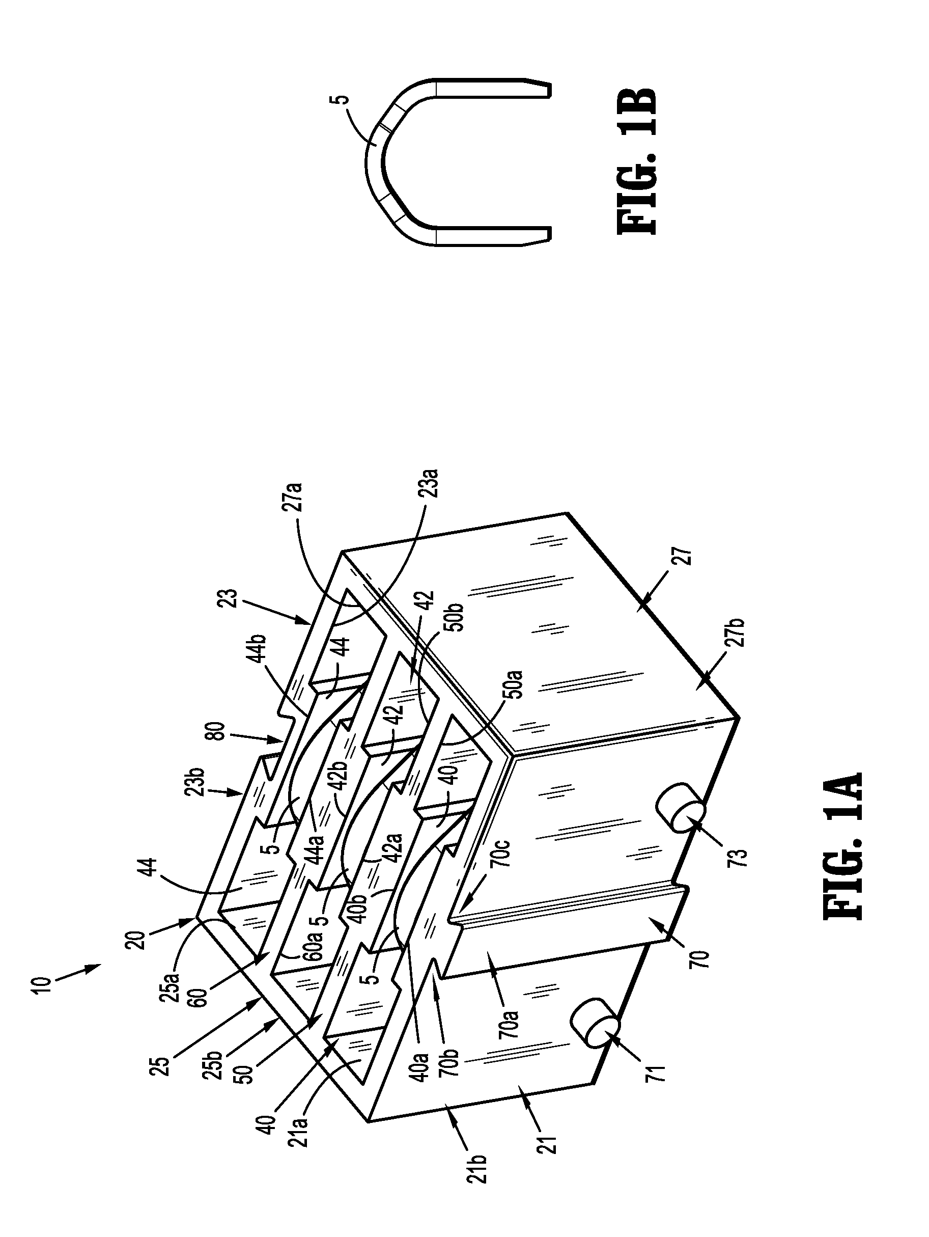
[0029] FIG. 1A is a perspective view of a modular surgical clip cartridge in accordance with the present disclosure;
[0030] FIG. 1B is a perspective view of a surgical clip for use with the modular surgical clip cartridge of FIG. 1A;
[0031] FIG. 2 is another perspective view of the modular surgical clip cartridge of FIG. 1A;
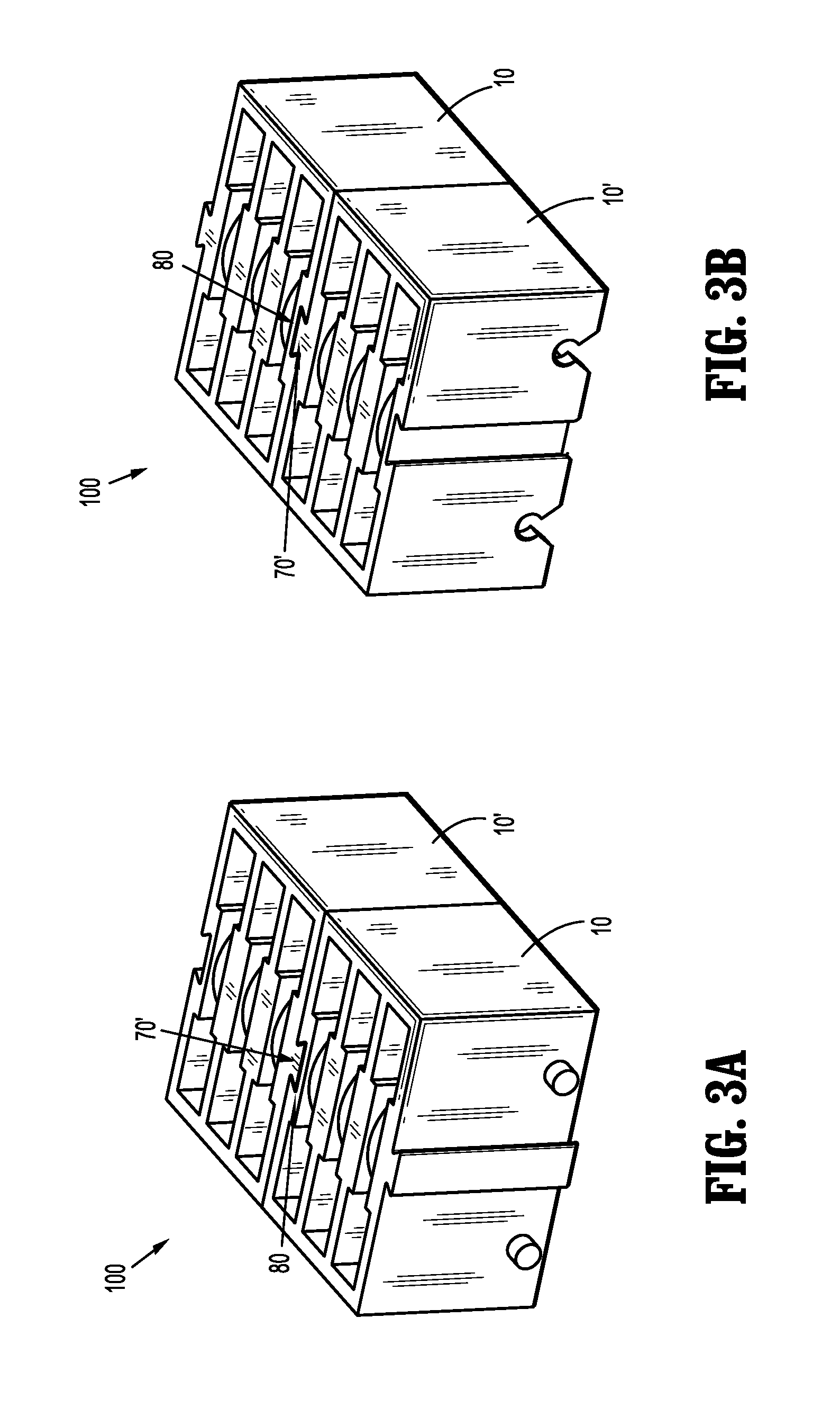
[0032] FIG. 3A is a perspective view of two modular surgical clip cartridges selectively connected to one another define a modular clip pack; and
[0033] FIG. 3B is another perspective view of the modular clip pack of FIG. 3A.
DETAILED DESCRIPTION
[0034] Embodiments of modular surgical clip cartridges, in accordance with the present disclosure, will now be described in detail with reference to the drawing figures wherein like reference numerals identify similar or identical structural elements. Aspects and features of the modular surgical clip cartridges depicted herein, not germane to the understanding of the present disclosure, are omitted to avoid obscuring the aspects and features of the present disclosure in unnecessary detail.
[0035] The present disclosure is directed to modular surgical clip cartridges configured to create clip packs retaining surgical clips of varying quantities. Specifically, the modular clip cartridges described herein are configured to selectively connect with one another, into a unitary arrangement, to define a modular clip pack. Any number of modular surgical clip cartridges can be connected with one another to form modular clip packs to define a variable number of surgical clip quantities. The modular clip cartridges can be, e.g., shipped and packed individually, and then assembled into modular clip packs as needed, enabling end users greater flexibility in planning surgical procedures, while reducing the overall costs of manufacture thereof.
[0036] Referring initially to FIGS. 1A, 1B, and 2, a modular clip cartridge in accordance with the present disclosure is shown and generally designated as 10. Modular clip cartridge 10 includes a body portion 20 generally defining respective first, second, third, and fourth walls 21, 23, 25, 27 and a plurality of clip compartments 40, 42, 44. Each clip compartment 40, 42, 44 is configured to releasably retain a surgical clip 5 therein.
[0037] First and second walls 21, 23 of body portion 20 (e.g., top and bottom walls) are parallel relative to each other. Likewise, third and fourth walls 25, 27 of body portion 20 (e.g., sidewalls) are parallel and spaced apart relative to each other, and extend between and interconnect first and second walls 21, 23. First wall 21 defines respective inner and outer surfaces 21a, 21b, second wall 23 defines respective inner and outer surfaces 23a, 23b, third wall 25 defines respective inner and outer surfaces 25a, 25b, and fourth wall 27 defines respective inner and outer surfaces 27a, 27b. Respective first, second, third, and fourth walls 21, 23, 25, 27 of body portion 20 collectively define a rectangular or cube shape of modular clip cartridge 10, although any other suitable shape or configuration (e.g., circular, trapezoidal, triangular, etc.) of modular clip cartridge 10 is contemplated.
[0038] Body portion 20 defines a first wall divider 50 and a second wall divider 60, extending between and interconnecting third and fourth walls 25, 27 to define individual clip compartments 40, 42, 44. First wall divider 50 defines respective lower and upper surfaces 50a, 50b. Likewise, second wall divider 60 defines respective lower and upper surfaces 60a, 60b. First and second wall dividers 50, 60 may be oriented parallel to first and second walls 21, 23 of body portion 20. Although modular clip cartridge 10 is shown as having two wall dividers 50, 60 to define three individual clip compartments 40, 42, 44 within body portion 20, it is contemplated that modular clip cartridge 10 may have any number of clip compartments (e.g., one, two, four, five, six, seven, etc.) for retaining any number of surgical clips 5 therein.
[0039] Clip compartment 40 defines a ledge or side edge 40a extending from inner surface 21a of first wall 21, and defines a ledge or side edge 40b extending from upper surface 50a of first wall divider 50 towards side edge 40a. Ledges or side edges 40a, 40b of clip compartment 40 define a reduced width, central portion 40c of clip compartment 40. Likewise, clip compartment 42 defines a ledge or side edge 42a extending from lower surface 50b of first wall divider 50, and defines a ledge or side edge 42b extending from lower surface 60a of second wall divider 60 toward side edge 42a. Ledges or side edges 42a, 42b define a reduced width, central portion 42c of clip compartment 42. In addition, clip compartment 44 defines a ledge or side edge 44a extending from lower surface 60b of first wall divider 60, and defines a ledge or side edge 44b extending from inner surface 23a second wall 23 toward side edge 44a. Ledges or side edges 44a, 44b define a reduced width, central portion 44c of clip compartment 44. As such, reduced width, central portions 40c, 42c, 44c of respective clip compartments 40, 42, 44 define clip compartments 40, 42, 44 having a substantially dog-bone shaped transverse cross-section profile. In embodiments, reduced width, central portions 40c, 42c, 44c may frictionally engage with surgical clips 5 to releasably retain surgical clips 5 therein.
[0040] Outer surface 21b of first wall 21 defines a first mating feature or rail 70 extending therefrom. Rail 70 extends from a top end of outer surface 21b of first wall 21 to a bottom end of outer surface 21b of first wall 21. Rail 70 may be located along a central portion or center line of outer surface 21b of first wall 21. Rail 70 is defined by a flat face 70a, and two inwardly extending side edges or undercuts 70b, 70c that terminate into outer surface 21b of first wall 21 (e.g., in the form of a dove tail). Although rail 70 is shown as having a trapezoidal, transverse cross-sectional shape, rail 70 can be configured with any suitable shape, size, or configuration (e.g., rectangular, triangular, semi-circular, etc.).
[0041] Outer surface 21b of first wall 21 further defines first and second protuberances or bosses 71, 73 extending therefrom. First protuberance 71 may be disposed on a first side of rail 70, while second protuberance 73 may be disposed on a second side of rail 70. Protuberances 71, 73 may be disposed on a lower end portion of outer surface 21b of first wall 21 (e.g., adjacent an end or edge thereof) and may be symmetrically opposed to each other. Protuberances 71, 73 are shown as having a circular, transverse cross-sectional shape, but any suitable shape is contemplated, such as, e.g., triangular, spherical, rectangular, trapezoidal, or the like. Modular clip cartridge 10 may include one, or more than the two protuberances 71, 73 shown in FIG. 1A.
[0042] Outer surface 23b of second wall 23 defines a second mating feature or slot 80 therein having a shape complementary to that of rail 70. Slot 80 is configured to slidably receive a rail 70' of a second modular clip cartridge 10' to selectively connect first modular clip cartridge 10 to another, e.g., second modular clip cartridge 10' to define a modular clip pack 100 (FIGS. 3A and 3B), as will be more fully described below. Slot 80 may extend from a top end or edge of outer surface 23b of second wall 23 to a bottom end of outer surface 23b of second wall 23.
[0043] Second wall 23 further defines first and second recesses 81, 83 therein having a shape complementary to that of first and second protuberances 71, 73 of first wall 21. Recesses 81, 83 are configured to frictionally engage with protuberances 71', 73' (not explicitly shown) of second modular clip cartridge 10' (FIGS. 3A and 3B) to at least temporally lock first modular clip cartridge 10 to another, e.g., second modular clip cartridge 10', as will be more fully described below. First recess 81 may be formed into a first side of second wall 23, while second recess 83 may be formed into a second side of second wall 23. Recesses 81, 83 may be defined through a bottom end portion of second wall 23. First and second recesses 81, 83 may be symmetrically opposed to each other. Recesses 81, 83 are shown as having a substantially keyhole like shape or configuration, but any suitable shape of recesses 81, 83 is contemplated.
[0044] In use, with reference to FIGS. 3A and 3B, slot 80 of first modular clip cartridge 10 slidably engages rail 70' of a second modular clip cartridge 10' to selectively connect first and second modular clip cartridges 10, 10' into a unitary arrangement and define a modular surgical clip pack 100. Specifically, with slot 80 of first modular clip cartridge 10 and rail 70' of second modular clip cartridge at least initially slidably engaged with each other, continued movement of slot 80 and rail 70' of respective first and second modular clip cartridges 10, 10' along each other causes first and second modular clip cartridges 10, 10' to fully join together into a unitary arrangement. As such, slot 80 and rail 70' of first and second modular clip cartridges 10, 10' function as a "tongue-and-groove" arrangement to form modular surgical clip pack 100.
[0045] In addition, in use, continued movement of slot 80 and rail 70' of respective first and second modular clip cartridges 10, 10' towards each other causes recesses 81, 83 of first modular clip cartridge 10 and protuberances 71, 73 of second modular clip cartridge 10' to frictionally engage with each other (not explicitly shown), causing first modular clip cartridge 10 and second modular clip cartridge 10' to at least temporarily lock into a unitary arrangement, e.g., into modular surgical clip pack 100. In embodiments, recesses 81, 83 of first modular clip cartridge 10 may have any type of connection with protuberances 71', 73' of second modular clip cartridge 10', such as for example, snap-fit, compression-fit, frictional-fit, or the like.
[0046] To disassemble modular clip pack 100, modular clip cartridge 10 is moved (e.g., slid) relative to second modular clip cartridge 10' such that recesses 81, 83 of modular clip cartridge 10 disengage from respective protuberances 71, 73 of second modular clip cartridge 10'. As such, modular clip pack 100 can be assembled and disassembled as needed.
[0047] Thus, advantageously, first and second modular clip cartridges 10, 10' can be, e.g., shipped and packed individually, and then assembled (or disassembled) into modular clip packs 100 as needed, enabling end users greater flexibility in planning surgical procedures, while reducing the overall cost of manufacture thereof.
[0048] Although two clip cartridges are shown as connected in FIGS. 3A and 3B of the present disclosure, it should be appreciated that any number of clip cartridges 10 may be connected with each other to define modular clip pack 100. In embodiments, rail 70, slot 80, protuberances 71, 73, and recesses 81, 83 may be formed onto and/or into any and/or all surfaces of modular clip cartridge 10 (e.g., third wall 25, fourth wall 27, etc.), such that modular clip cartridge 10 can be adjoined with other modular clip cartridges at additional points of connectivity, enabling end users with more flexibility. Additionally, although rail 70 is shown as being on the same surface as protuberances 71, 73, and slot 80 is shown as being on the same surface as recesses 81, 83, it should be appreciated that rail 70 may be formed on the same surface as recesses 81, 83, slot 80 may be formed on same surface as protuberances 71, 73, etc.
[0049] In embodiments, modular clip cartridge 10 may be formed from any suitable material, such as from plastics, polymers, ceramics, metals, and/or the like. Clip compartments 40 may be configured to receive any type of surgical clip 5 with any type of geometry, such as, for example, the surgical clips described in commonly assigned U.S. Pat. No. 5,501,693 to Gravener, the entire contents of which is hereby incorporated by reference. Surgical clips 5 may include at least one of a metallic or polymeric material. In embodiments, clip compartments 40 of modular clip cartridge 10 may be configured to receive jaws of a surgical instrument for removing surgical clips therefrom. Such surgical instruments may include, but are not limited to, forceps, graspers, surgical clip appliers, etc.
[0050] Persons skilled in the art will understand that the structures and methods specifically described herein and shown in the accompanying figures are non-limiting exemplary embodiments, and that the description, disclosure, and figures should be construed merely as exemplary of particular embodiments. It is to be understood, therefore, that the present disclosure is not limited to the precise embodiments described, and that various other changes and modifications may be effected by one skilled in the art without departing from the scope or spirit of the disclosure. Additionally, the elements and features shown or described in connection with certain embodiments may be combined with the elements and features of certain other embodiments without departing from the scope of the present disclosure, and that such modifications and variations are also included within the scope of the present disclosure. Accordingly, the subject matter of the present disclosure is not limited by what has been particularly shown and described.
* * * * *
D00000
D00001
D00002
D00003
XML
uspto.report is an independent third-party trademark research tool that is not affiliated, endorsed, or sponsored by the United States Patent and Trademark Office (USPTO) or any other governmental organization. The information provided by uspto.report is based on publicly available data at the time of writing and is intended for informational purposes only.
While we strive to provide accurate and up-to-date information, we do not guarantee the accuracy, completeness, reliability, or suitability of the information displayed on this site. The use of this site is at your own risk. Any reliance you place on such information is therefore strictly at your own risk.
All official trademark data, including owner information, should be verified by visiting the official USPTO website at www.uspto.gov. This site is not intended to replace professional legal advice and should not be used as a substitute for consulting with a legal professional who is knowledgeable about trademark law.