Endoscopic Reposable Surgical Clip Applier
Gokharu; Rajkumar
U.S. patent application number 16/185537 was filed with the patent office on 2019-03-14 for endoscopic reposable surgical clip applier. The applicant listed for this patent is Covidien LP. Invention is credited to Rajkumar Gokharu.
| Application Number | 20190076150 16/185537 |
| Document ID | / |
| Family ID | 55524196 |
| Filed Date | 2019-03-14 |
| United States Patent Application | 20190076150 |
| Kind Code | A1 |
| Gokharu; Rajkumar | March 14, 2019 |
ENDOSCOPIC REPOSABLE SURGICAL CLIP APPLIER
Abstract
A surgical clip applier is provided and includes a handle assembly and an endoscopic assembly selectively connectable to a housing of the handle assembly. The handle assembly includes a housing, a trigger pivotally supported on and extending from the housing, and a drive assembly supported within the housing and operatively actuatable by the trigger. The endoscopic assembly includes a shaft assembly extending from the housing, the shaft assembly including an outer tube and a pair of jaws supported in and extending from a distal end of the outer tube.
| Inventors: | Gokharu; Rajkumar; (Hyderabad, IN) | ||||||||||
| Applicant: |
|
||||||||||
|---|---|---|---|---|---|---|---|---|---|---|---|
| Family ID: | 55524196 | ||||||||||
| Appl. No.: | 16/185537 | ||||||||||
| Filed: | November 9, 2018 |
Related U.S. Patent Documents
| Application Number | Filing Date | Patent Number | ||
|---|---|---|---|---|
| 15001633 | Jan 20, 2016 | 10159491 | ||
| 16185537 | ||||
| 62130724 | Mar 10, 2015 | |||
| Current U.S. Class: | 1/1 |
| Current CPC Class: | A61B 17/1285 20130101; A61B 2017/0046 20130101; A61B 17/105 20130101; A61B 2017/2922 20130101; A61B 17/1222 20130101; A61B 2017/12004 20130101 |
| International Class: | A61B 17/128 20060101 A61B017/128; A61B 17/122 20060101 A61B017/122; A61B 17/10 20060101 A61B017/10 |
Claims
1. A drive assembly for a surgical clip applier, comprising: a clip pusher bar including a flange at a proximal end thereof and configured for distal translation to advance a surgical clip; and a toggle distal of the flange of the clip pusher bar, the toggle actuatable between a first position and a second position and configured to limit the distal translation of the clip pusher bar when the toggle is in the first position.
2. The drive assembly for the surgical clip applier of claim 1, further comprising a linkage and a push rod engagable by the linkage to actuate the toggle between the first position and the second position.
3. The drive assembly for the surgical clip applier of claim 2, further comprising a housing, the clip pusher bar, toggle, linkage and push rod all positioned within the housing.
4. The drive assembly for the surgical clip applier of claim 3, further comprising a trigger pivotally supported on and extending from the housing, the linkage connected to the trigger.
5. The drive assembly for the surgical clip applier of claim 4, wherein the toggle is spring loaded and includes a bias such that the toggle abuts the flange in the first position.
6. The drive assembly for the surgical clip applier of claim 1, wherein in the second position, there is a clearance between the toggle and the flange such that the clip pusher bar is able to translate distally to locate the flange distal to the toggle.
7. The drive assembly for the surgical clip applier of claim 5, further comprising a biasing member acting on the clip pusher bar to urge the clip pusher bar in a distal direction.
8. The drive assembly for the surgical clip applier of claim 7, wherein a force exerted by the bias of the toggle is greater than a force exerted by the biasing member acting on the clip pusher bar such that the biasing member is unable to push the flange past the toggle when the toggle is in the first position.
9. The drive assembly for the surgical clip applier of claim 8, wherein the linkage is slidably supported in the housing and is connected to the trigger.
10. The drive assembly for the surgical clip applier of claim 8, further comprising a guide block slidably supported in the housing, the guide block operatively connected to the trigger; wherein the clip pusher bar is slidably supported in the guide block.
11. The drive assembly for the surgical clip applier of claim 10, wherein when the toggle is in the second position, the biasing member acts on the clip pusher bar to urge the clip pusher bar distally until the flange thereof abuts the guide block.
12. The drive assembly for the surgical clip applier of claim 10, wherein the linkage includes a first end and a second end, the first end of the linkage being pivotably connected to the trigger and the second end of the linkage being pivotably connected to the guide block such that actuation of the trigger translates the guide block proximally.
13. The drive assembly for the surgical clip applier of claim 12, wherein the first end of the linkage and the trigger are slidably coupled to a slot defined in the housing such that upon actuation of the trigger, the first end of the linkage rides along the slot.
14. The drive assembly for the surgical clip applier of claim 13, wherein as the first end of the linkage rides along the slot, the linkage exerts a force on the push rod such that the push rod translates proximally to exert a force on the toggle to actuate the toggle from the first position to the second position.
15. The drive assembly for the surgical clip applier of claim 14, wherein in the second position, the biasing member acts on the clip pusher bar to urge the clip pusher bar distally until the flange thereof abuts the guide block.
16. A handle assembly for a surgical clip applier, the handle assembly comprising: a housing; a trigger pivotally supported on and extending from the housing; and a drive assembly supported within the housing and operatively actuatable by the trigger, the drive assembly including: a distal linkage slidably supported in the housing, the distal linkage including a first end and a second end, the second end of the distal linkage connected to the trigger; a proximal linkage slidably supported in the housing, the proximal linkage including a first end and a second end, the first end of the proximal linkage connected to the trigger; a jaw pusher slidably supported in the housing, the jaw pusher operatively connected to the trigger; a guide block slidably supported in the housing, the guide block operatively connected to the trigger; a clip pusher bar including a flange at a proximal end thereof and configured for distal translation to advance a surgical clip; a toggle distal of the flange of the clip pusher bar, the toggle actuatable between a first position and a second position and configured to limit the distal translation of the clip pusher bar when the toggle is in the first position; and a push rod supported in the housing, the push rod engagable by at least one of the proximal linkage and the distal linkage to actuate the toggle between the first position and the second position.
17. The handle assembly according to claim 16, wherein the drive assembly further includes a trigger return spring acting on the trigger to urge the trigger to an unactuated position.
18. The handle assembly according to claim 17, wherein in the second position, the biasing member acts on the clip pusher bar to urge the clip pusher bar distally until the flange thereof abuts the guide block.
19. The handle assembly according to claim 18, wherein when the trigger is actuated, the proximal linkage simultaneously engages the push rod and the guide block such that the toggle is in the second position and the guide block drives the abutting flange proximally past the toggle.
20. A surgical clip applier, comprising: an endoscopic assembly including: a shaft assembly including an outer tube; a plurality of surgical clips; and a pair of jaws supported in and extending from a distal end of the outer tube; and a handle assembly including: a housing supporting a proximal end of the endoscopic assembly; a trigger pivotally supported on and extending from the housing; and a drive assembly supported within the housing and operatively actuatable by the trigger, the drive assembly including: a distal linkage slidably supported in the housing, the distal linkage including a first end and a second end, the second end of the distal linkage connected to the trigger; a proximal linkage slidably supported in the housing, the proximal linkage including a first end and a second end, the first end of the proximal linkage connected to the trigger; a jaw pusher slidably supported in the housing, the jaw pusher operatively connected to the trigger; a guide block slidably supported in the housing, the guide block operatively connected to the trigger; a clip pusher bar including a flange at a proximal end thereof and configured for distal translation to advance a distal-most clip of the plurality of surgical clips; a toggle distal of the flange of the clip pusher bar, the toggle actuatable between a first position and a second position and configured to limit the distal translation of the clip pusher bar when the toggle is in the first position; and a push rod supported in the housing, the push rod engagable by at least one of the proximal linkage and the distal linkage to actuate the toggle between the first position and the second position.
Description
CROSS-REFERENCE TO RELATED APPLICATIONS
[0001] This application is a divisional of U.S. patent application Ser. No. 15/001,633 filed Jan. 20, 2016, which claims the benefit of and priority to U.S. Provisional Patent Application No. 62/130,724 filed Mar. 10, 2015, the entire disclosure of which is incorporated by reference herein.
BACKGROUND
Technical Field
[0002] The present disclosure relates to surgical clip appliers. More particularly, the present disclosure relates to endoscopic reposable surgical clip appliers having a reusable handle assembly, a reusable shaft assembly, and a disposable clip cartridge assembly.
Description of Related Art
[0003] Endoscopic staplers and clip appliers are known in the art and are used for a number of distinct and useful surgical procedures. In the case of a laparoscopic surgical procedure, access to the interior of an abdomen is achieved through narrow tubes or cannulas inserted through a small entrance incision in the skin. Minimally invasive procedures performed elsewhere in the body are often generally referred to as endoscopic procedures. Typically, a tube or cannula device is extended into the patient's body through the entrance incision to provide an access port. The port allows the surgeon to insert a number of different surgical instruments therethrough using a trocar and for performing surgical procedures far removed from the incision.
[0004] During a majority of these procedures, the surgeon must often terminate the flow of blood or another fluid through one or more vessels. The surgeon will often apply a surgical clip to a blood vessel or another duct to prevent the flow of body fluids therethrough during the procedure. An endoscopic clip applier is known in the art for applying a single clip during an entry to the body cavity. Such clips are typically fabricated from a biocompatible material and are usually compressed over a vessel. Once applied to the vessel, the compressed clip terminates the flow of fluid therethrough.
[0005] Endoscopic clip appliers that are able to apply multiple clips in endoscopic or laparoscopic procedures during a single entry into the body cavity are described in commonly-assigned U.S. Pat. Nos. 5,084,057 and 5,100,420 to Green et al., which are both incorporated by reference in their entirety. Another multiple endoscopic clip applier is disclosed in commonly-assigned U.S. Pat. No. 5,607,436 by Pratt et al., the contents of which is also hereby incorporated by reference herein in its entirety. These devices are typically, though not necessarily, used during a single surgical procedure. U.S. Pat. No. 5,695,502 to Pier et al., the disclosure of which is hereby incorporated by reference herein, discloses a resterilizable surgical clip applier. The clip applier advances and forms multiple clips during a single insertion into the body cavity. This resterilizable clip applier is configured to receive and cooperate with an interchangeable clip magazine so as to advance and form multiple clips during a single entry into a body cavity.
[0006] During endoscopic or laparoscopic procedures it may be desirable and/or necessary to use different size surgical clips depending on the underlying tissue or vessels to be ligated. In order to reduce overall costs of a surgical clip applier, it is desirable for a single surgical clip applier to be loadable with and capable of firing different size surgical clips as needed.
[0007] Accordingly, a need exists for endoscopic surgical clip appliers that include reusable handle assemblies, reusable shaft assemblies, and disposable clip cartridge assemblies, with each clip cartridge assembly being loaded with a particularly sized clip (e.g., small, medium, or large).
SUMMARY
[0008] According to an aspect of the present disclosure, a surgical clip applier is provided and includes a handle assembly and an endoscopic assembly selectively connectable to a housing of the handle assembly. The handle assembly includes a housing; a trigger pivotally supported on and extending from the housing; and a drive assembly supported within the housing and operatively actuatable by the trigger. The drive assembly includes at least one linkage connected to the trigger, the at least one linkage slidably supported in the housing; a guide block slidably supported in the housing, the guide block operatively connected to the trigger; a clip pusher bar slidably supported in the guide block, the clip pusher bar including a flange at a proximal end thereof; a toggle supported in the housing and located distal of the flange of the clip pusher bar, the toggle actuatable between a first position and a second position, wherein the toggle is configured to limit the distal translation of the clip pusher bar when the toggle is in the first position; and a push rod supported in the housing, the push rod engageable by the at least one linkage to actuate the toggle between the first position and the second position. The endoscopic assembly includes a shaft assembly extending from the housing, the shaft assembly including an outer tube; and a pair of jaws supported in and extending from a distal end of the outer tube, wherein when the toggle of the handle assembly in the second position, the pair of jaws are free to form a surgical clip on tissue.
[0009] The at least one linkage may include a first end and a second end, the first end of the linkage being pivotably connected to the trigger and the second end of the linkage being pivotably connected to the guide block such that actuation of the trigger translates the guide block proximally.
[0010] The first end of the at least one linkage and the trigger may be slidably coupled to a slot defined in the housing such that upon actuation of the trigger, the first end of the at least one linkage rides along the slot.
[0011] In use, as the first end of the at least one linkage rides along the slot, the at least one linkage may exert a force on the push rod such that the push rod translates proximally to exert a force on the toggle to actuate the toggle from the first position to the second position.
[0012] The toggle may be spring loaded and may include a bias such that the toggle abuts the flange in the first position.
[0013] In use, in the second position, there may be a clearance between the toggle and the flange such that the clip pusher bar is able to translate distally to locate the flange distal to the toggle.
[0014] The drive assembly may further include a biasing member acting on the clip pusher bar to urge the clip pusher bar in a distal direction.
[0015] In use, a force exerted by the bias of the toggle may be greater than a force exerted by the biasing member acting on the clip pusher bar such that the biasing member is unable to push the flange past the toggle when the toggle is in the first position.
[0016] The drive assembly may further include a trigger return spring acting on the trigger to urge the trigger to an unactuated position.
[0017] In use, in the second position, the biasing member may act on the clip pusher bar to urge the clip pusher bar distally until the flange thereof abuts the guide block.
[0018] In use, when the trigger is actuated, the at least one linkage may simultaneously engage the push rod and the guide block such that the toggle is in the second position and the guide block drives the abutting flange proximally past the toggle.
[0019] According to another aspect of the present disclosure, a surgical clip applier is provided and includes a handle assembly and an endoscopic assembly selectively connectable to a housing of the handle assembly. The handle assembly includes a housing; a trigger pivotally supported on and extending from the housing; and a drive assembly supported within the housing and operatively actuatable by the trigger. The drive assembly includes a distal linkage slidably supported in the housing, the distal linkage including a first end and a second end, the second end of the distal linkage connected to the trigger; a proximal linkage slidably supported in the housing, the proximal linkage including a first end and a second end, the first end of the proximal linkage connected to the trigger; a jaw pusher slidably supported in the housing, the jaw pusher operatively connected to the trigger; a guide block slidably supported in the housing, the guide block operatively connected to the trigger; a clip pusher bar slidably supported in the guide block, the clip pusher bar including a flange at a proximal end thereof; a toggle supported in the housing and located distal of the flange of the clip pusher bar, the toggle actuatable between a first position and a second position, wherein the toggle is configured to limit the distal translation of the clip pusher bar when the toggle is in the first position; and a push rod supported in the housing, the push rod engageable by at least one of the proximal linkage and the distal linkage to actuate the toggle between the first position and the second position.
[0020] The endoscopic assembly includes a shaft assembly extending from the housing, the shaft assembly including an outer tube; and a pair of jaws supported in and extending from a distal end of the outer tube, wherein when the toggle of the handle assembly in the second position, the pair of jaws are free to form a surgical clip on tissue.
[0021] In some embodiments, the distal linkage, the proximal linkage, and the trigger are slidably coupled to a slot defined in the housing such that upon actuation of the trigger, the distal linkage, the proximal linkage, and the trigger ride along a channel defined within the slot.
[0022] In use, actuation of the trigger may translate the jaw pusher distally and translates the guide block proximally.
[0023] In use, as the proximal linkage rides along the slot, the proximal linkage may exert a force on the push rod such that the push rod translates proximally to exert a force on the toggle to actuate the toggle from the first position to the second position.
[0024] According to another aspect of the present disclosure, a drive mechanism for a surgical clip applier is provided and includes a clip pusher bar and a toggle. The clip pusher bar includes a flange at a proximal end thereof and is configured for distal translation to advance a surgical clip.
[0025] In some embodiments, the drive mechanism further includes a linkage and a push rod engageable by the linkage to actuate the toggle between the first position and the second position.
[0026] The drive mechanism may further include a housing. The clip pusher bar, toggle, linkage, and push rod may all be positioned within the housing.
[0027] The drive mechanism may further include a trigger pivotally supported on and extending from the housing, and with the linkage connected to the trigger.
BRIEF DESCRIPTION OF THE DRAWINGS
[0028] A particular embodiment of a surgical clip applier is disclosed herein with reference to the drawings wherein:
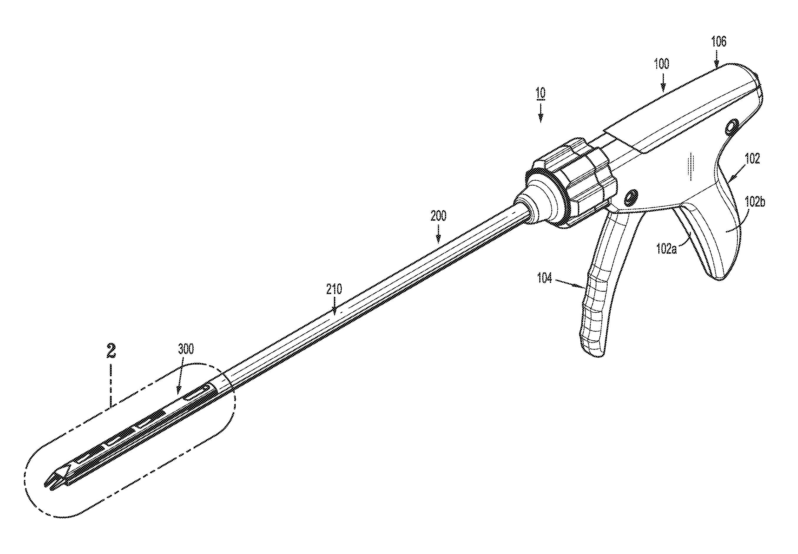
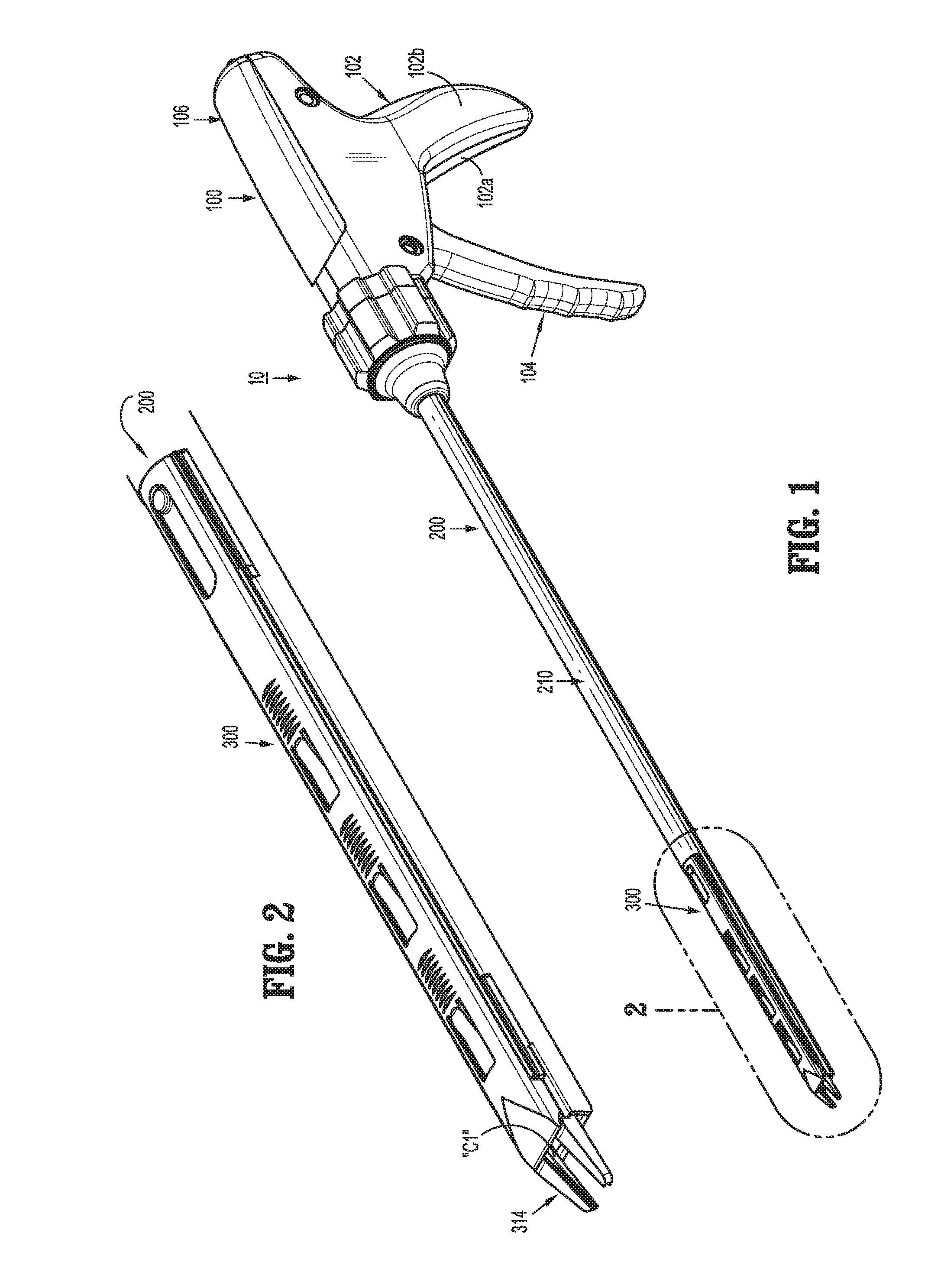
[0029] FIG. 1 is a perspective view of a reposable endoscopic surgical clip applier, according to the present disclosure;
[0030] FIG. 2 is an enlarged view of the indicated area of detail of FIG. 1;
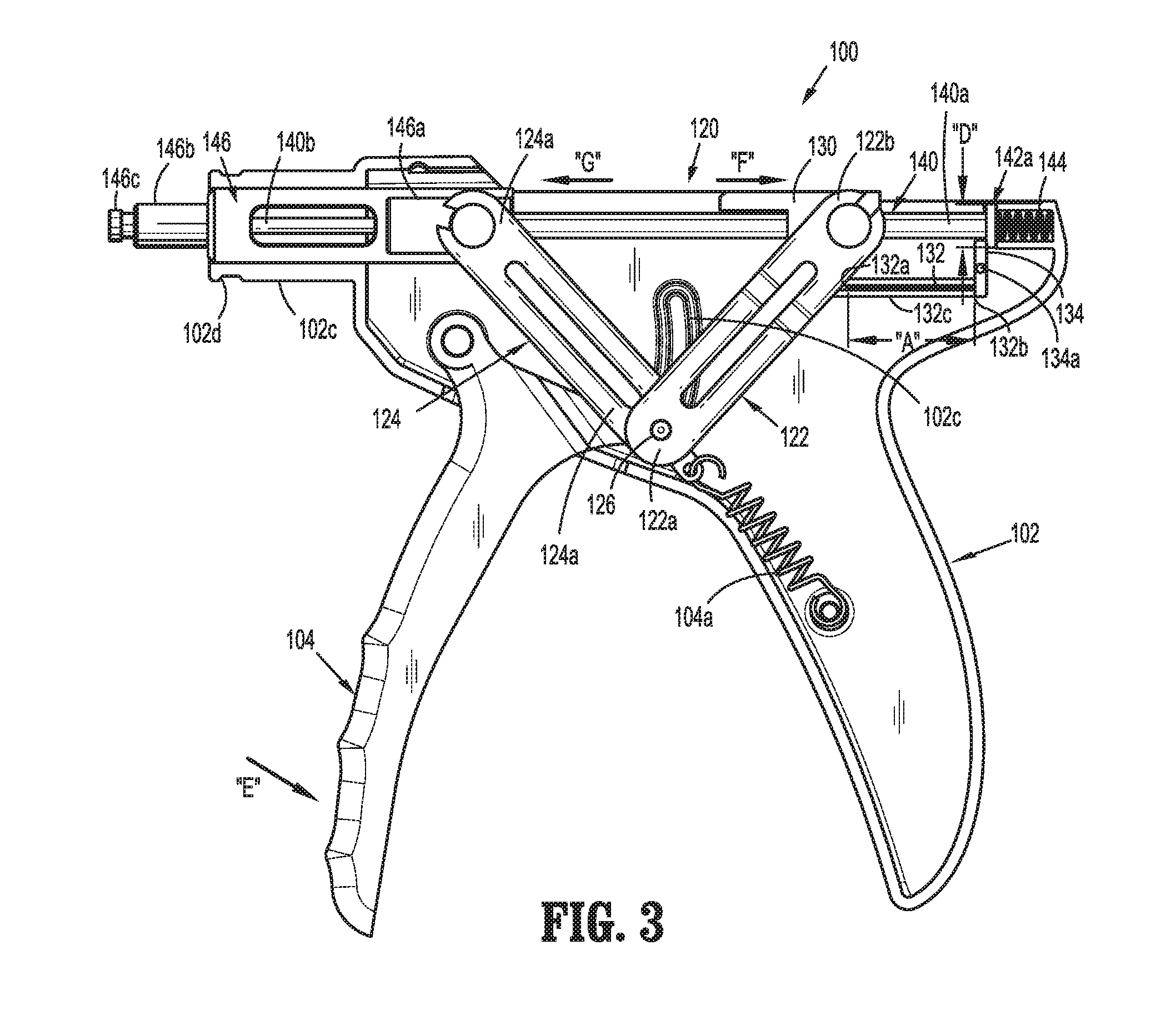
[0031] FIG. 3 is a side, elevational view of a handle assembly of the surgical clip applier of FIG. 1, with a housing half-section removed therefrom;
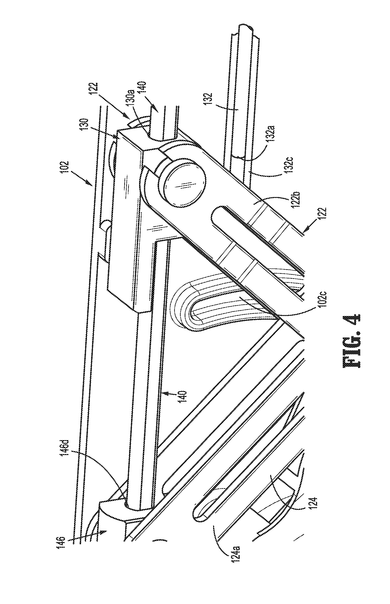
[0032] FIG. 4 is an enlarged, perspective view of a drive assembly of the handle assembly of FIG. 3;
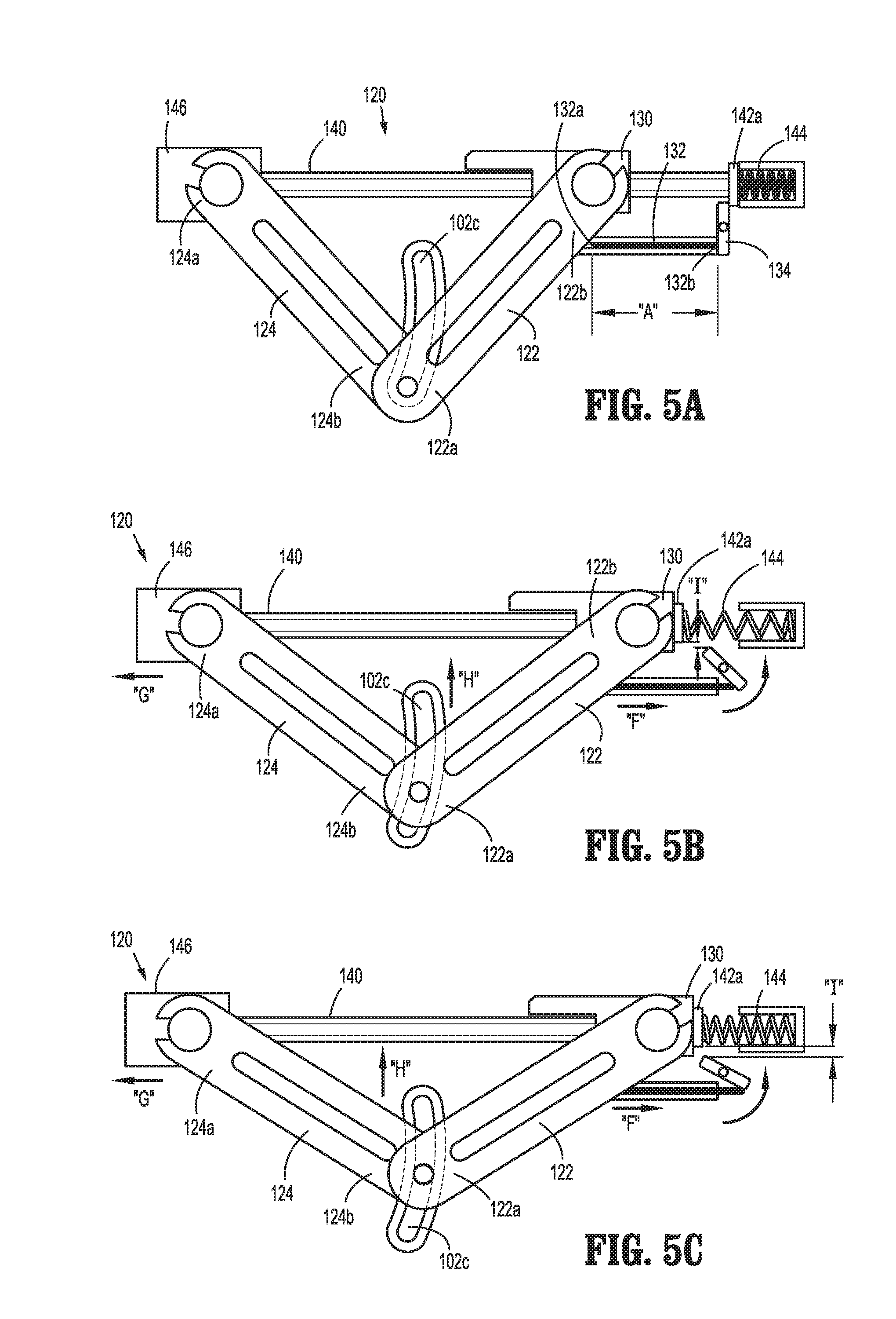
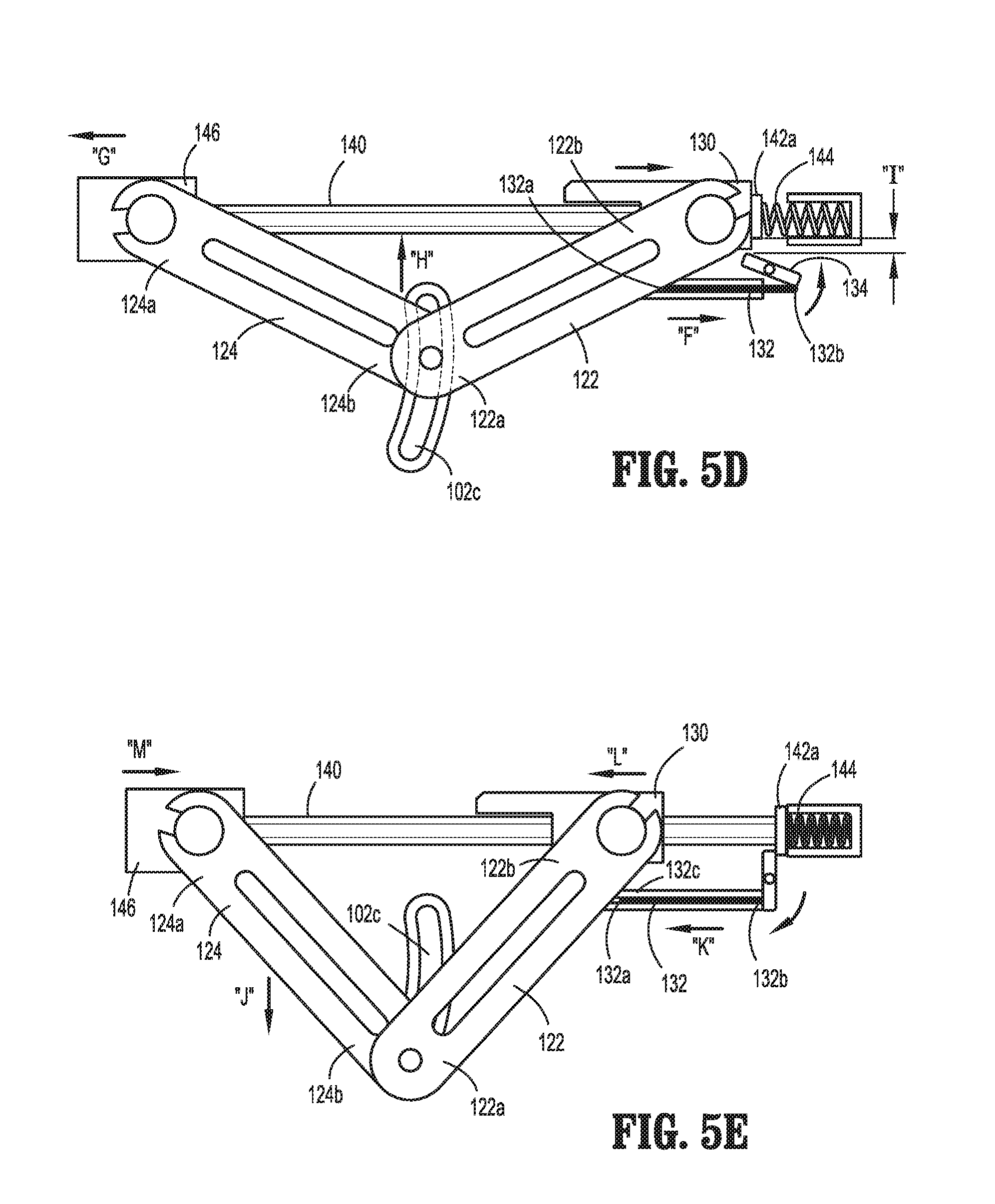
[0033] FIGS. 5A-5E are schematic elevational views of the drive assembly illustrated in FIGS. 3 and 4, illustrating an actuation of a trigger of the surgical clip applier;
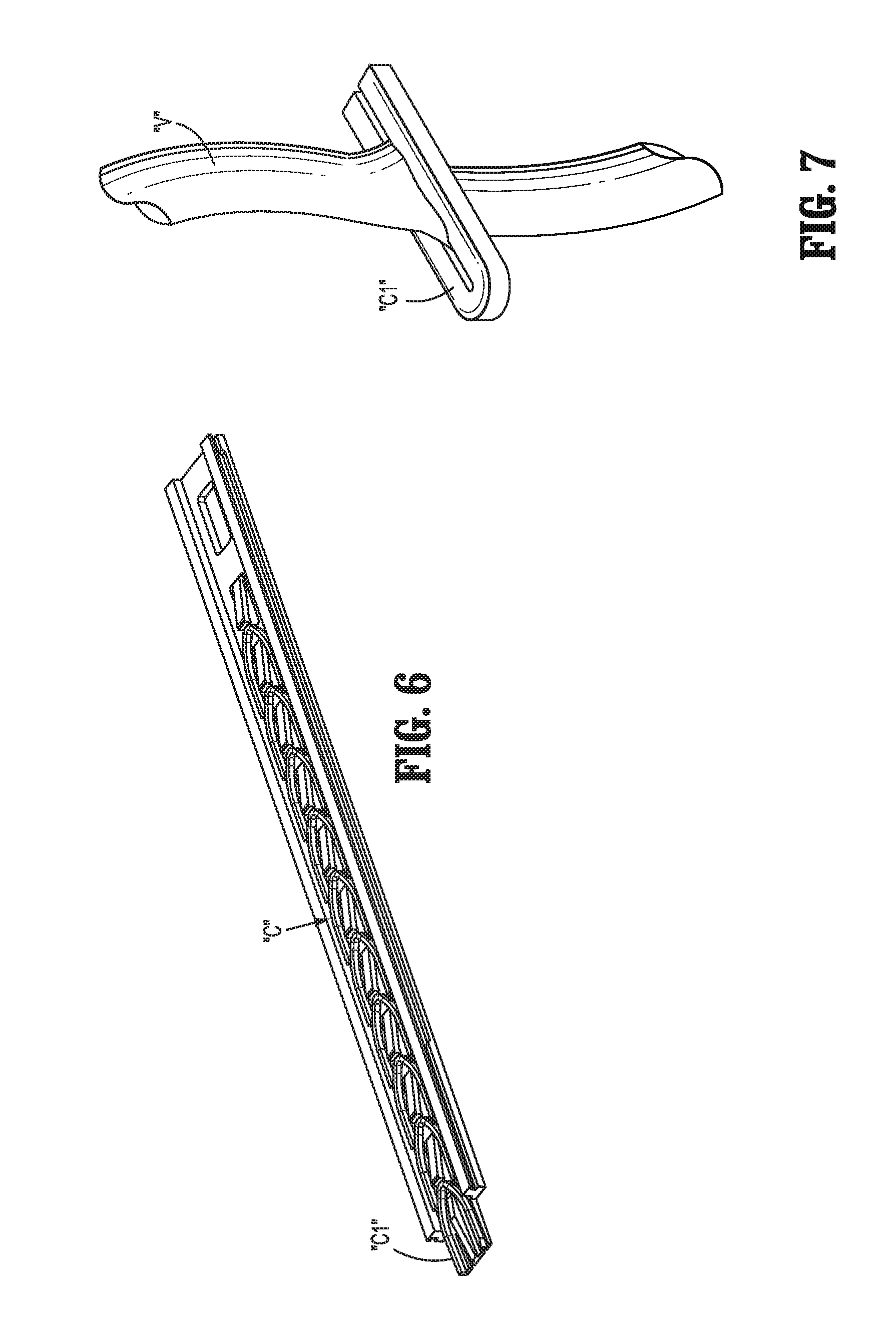
[0034] FIG. 6 is a perspective view of the clip cartridge tray of the surgical clip applier illustrating the plurality of surgical clips loaded therein; and
[0035] FIG. 7 is a perspective view of a surgical clip formed on a vessel.
DETAILED DESCRIPTION OF EMBODIMENTS
[0036] Embodiments of reposable endoscopic surgical clip appliers, in accordance with the present disclosure, will now be described in detail with reference to the drawing figures wherein like reference numerals identify similar or identical structural elements. As shown in the drawings and described throughout the following description, as is traditional when referring to relative positioning on a surgical instrument, the term "proximal" refers to the end of the apparatus which is closer to the user and the term "distal" refers to the end of the apparatus which is further away from the user.
[0037] Referring now to FIGS. 1-6, an endoscopic surgical clip applier in accordance with an embodiment of the present disclosure is generally designated as 10. Surgical clip applier 10 generally includes a handle assembly 100, an endoscopic assembly 200 including a shaft assembly 210 extending distally from handle assembly 100; and at least one surgical clip cartridge assembly 300 selectively loadable into shaft assembly 210 of endoscopic assembly 200. In embodiments, it is contemplated that shaft 210 may be integrally formed with handle assembly 100. In alternative embodiments, it is contemplated that shaft 210 may be selectively connectable to handle assembly 100.
[0038] Briefly, shaft assembly 210 of endoscopic assembly 200 may have various outer diameters such as, for example, about 5 mm or about 10 mm, depending on intended use. Further, shaft assembly 210 may have various relatively elongated or shortened lengths depending on intended use, such as, for example, in bariatric surgery. In one embodiment, in bariatric surgery, shaft assembly 210 may have a length of between about 30 cm and about 40 cm. However one skilled in the art should appreciate that shaft assembly 210 may have any suitable length and the present disclosure is not limited to any of the above identified lengths.
[0039] In accordance with the present disclosure, each surgical clip cartridge assembly 300 may be loaded with a plurality of surgical clips "C" (see FIG. 6). The plurality of surgical clips "C" may be particularly sized (e.g., small surgical clips, medium surgical clips, or large surgical clips). Each surgical clip cartridge assembly 300 is configured to be selectively loaded into shaft assembly 210 of endoscopic assembly 200, and to be actuated by handle assembly 100 to fire and form the plurality of surgical clips "C" loaded therein onto underlying tissue and/or vessels "V" (see FIG. 7).
[0040] Referring now to FIGS. 1 and 3, handle assembly 100 of surgical clip applier 10 is shown. Handle assembly 100 includes a housing 102 having a first or right side half-section 102a and a second or left side half-section 102b. Handle assembly 100 includes a trigger 104 pivotably supported between right side half-section 102a and left side half-section 102b of housing 102. Trigger 104 is biased by a trigger return spring 104a (e.g., a spring) to an unactuated condition.
[0041] Housing 102 of handle assembly 100 may be formed of a suitable plastic or thermoplastic material. Handle assembly 100 includes a removable cover 106 or the like which provides access to a drive assembly 120 of clip applier 10. Housing 102 of handle assembly 100 further includes, as seen in FIG. 3, a nose 102c defining an annular flange 102d.
[0042] Handle assembly 100 includes a drive assembly 120 operatively connected to trigger 104. Specifically, drive assembly 120 includes a proximal linkage 122, and a distal linkage 124. Though it is not shown in the figures, it is contemplated that in some embodiments, there may be a pair of proximal linkages 122 and a pair of distal linkages 124. Proximal linkage 122 includes a distal coupling portion 122a pivotally connected to trigger 104, and a proximal coupling portion 122b pivotally connected to a guide block 130. As shown in FIG. 4, guide block 130 defines a longitudinally extending passage 130a therethrough.
[0043] Distal linkage 124 includes a distal coupling portion 124a pivotally connected to a jaw pusher 146, and a proximal coupling portion 124b pivotally connected to trigger 104. A pin 126 pivotally connects proximal linkage 122 and distal linkage 124 to trigger 104. Pin 126 is also slidably disposed within opposed arcuate channels or slots 102c formed in opposed handle half-sections 102a, 102b. In this manner, as trigger 104 is actuated, pin 126 rides along opposed arcuate channels 102c (see FIGS. 3-5E), and causes opposed proximal coupling portion 122b of proximal linkage 122 and distal coupling portion 124a of distal linkage 124 to separate from one another.
[0044] Drive assembly 120 further includes a push rod 132 having a distal end 132a and a proximal end 132b and supported within a push rod channel 132c defined in housing 102. Push rod 132 is configured to translate longitudinally within push rod channel 132c and engage a toggle 134. Toggle 134 is spring loaded with a bias for clockwise rotation (or rotation in a first direction) about a pivot point 134a. As will be discussed in further detail below, as trigger 104 is actuated, proximal linkage 122 exerts a force on push rod 132 driving push rod 132 in a proximal direction. Push rod 132 in turn exerts a force on toggle 134 causing toggle 134 to rotate counter-clockwise (e.g., in a second direction opposite the first direction) about pivot point 134a. As shown in FIGS. 3-5E, push rod 132 includes a length "A." It is contemplated that length "A" of push rod 132 is configured to control the distance that push rod 132 has to travel prior to engaging toggle 134 and may be chosen accordingly.
[0045] With continued reference to FIGS. 3-5E, drive assembly 120 includes a clip pusher bar 140 slidably supported within and through housing 102 of handle assembly 100. Clip pusher bar 140 includes a flange 142a supported on a proximal end 140a thereof, and a clip pusher coupling tip (not shown) formed at a distal end 140b thereof. Flange 142a has a diameter "D" such that flange 142a abuts toggle 134 in the starting position. Accordingly, distal translation of clip pusher bar 140 is prevented by toggle 134 when toggle 134 is in the starting position shown in FIG. 3. Clip pusher bar 140 is dimensioned such that when trigger 104 is actuated, clip pusher coupling tip projects from nose 102c of housing 102 of handle assembly 100.
[0046] A biasing member 144 (e.g., a compression spring) is interposed between housing 102 of handle assembly 100 and flange 142a of clip pusher bar 140. Biasing member 144 acts on clip pusher bar 140 to bias or urge clip pusher bar 140 in a distal direction. It is contemplated that the clockwise spring bias of toggle 134 produces a greater force than the distal spring bias of biasing member 144. Accordingly, clip pusher bar 140 is unable to translate distally past toggle 134 when trigger 104 is not actuated.
[0047] Drive assembly 120 further includes a jaw pusher 146 slidably supported within housing 102 of handle assembly 100. Jaw pusher 146 includes a proximal end 146a pivotally connected to distal coupling portion 124a of distal linkage 124, and a jaw pusher coupling tip 146c formed at a distal end 146b thereof. Jaw pusher 146 defines a lumen 146d therethrough for receipt of and slidable passage of clip pusher bar 140 therein. Jaw pusher 146 is dimensioned such that jaw pusher coupling tip 146c thereof projects from nose 102c of housing 102 of handle assembly 100.
[0048] With continued reference to FIGS. 1-4, and with additional specific reference to FIGS. 5A-7, a firing stroke of surgical clip applier 10 is shown and described below. With surgical clip cartridge assembly 300 loaded in endoscopic assembly 200, as trigger 104 of handle assembly 100 is actuated to a fully actuated position, a distal-most clip "C1" of the plurality of surgical clips "C" is loaded into and formed by a pair of jaws 214 of endoscopic assembly 200.
[0049] In particular, FIG. 5A illustrates drive assembly 120 prior to actuation of trigger 104 and FIGS. 5B-5E details the incremental actuation of drive assembly 120 as surgical clip applier 10 is fired. As trigger 104 is actuated in the direction of arrow "E (see FIG. 3)," trigger 104 acts on proximal linkage 122 to move proximal coupling portion 122b of proximal linkage 122 in a proximal direction (as indicated by arrow "F" of FIG. 3), and acts on distal linkage 124 to move distal coupling portion 124a of distal linkage 124 in a distal direction (as indicated by arrow "G" of FIG. 3). Further, distal coupling portion 122a of proximal linkage 122 and proximal coupling portion 124b of distal linkage 124 are moved along opposed arcuate channels 102c in the direction indicated by arrow "H."
[0050] As proximal coupling portion 122b is moved in the direction of arrow "F," proximal linkage 122 engages distal end 132a of push rod 132. In turn, push rod 132 translates along push rod channel 132c to exert a rotation force on toggle 134 in a counter-clock wise (e.g., second) direction. As shown in FIG. 5B, the counter-clock wise rotation of toggle 134 creates a clearance "I" which is sufficient for flange 142a to clear toggle 134 thereby allowing biasing member 144 to expand and drive clip pusher bar 140 distally until flange 142a of clip pusher bar 140 abuts against guide block 130.
[0051] As clip pusher bar 140 of handle assembly 100 is moved in a distal direction, clip pusher bar 140 engages endoscopic assembly 200, which in turn, acts on cartridge assembly 300 to load the distal-most surgical clip "C1" into the pair of jaws 214.
[0052] Once flange 142a of clip pusher bar 140 is abutting guide block 130 and as trigger 104 is actuated further in the direction given by arrow "E," proximal linkage 122 continues to move guide block 130 in a proximal direction, and guide block 130 acts on flange 142a of clip pusher bar 140 to urge clip pusher bar 140 in a proximal direction. Simultaneously, as shown in FIG. 5C, proximal linkage 122 maintains contact with distal end 132a of push rod 132 such that push rod 132 maintains contact with toggle 134. This in turn maintains clearance "I" between toggle 134 and flange 142a such that guide block 130 is able to urge clip pusher bar 140 proximally until flange 142a clears toggle 134 (see FIG. 5D) and is located proximal to toggle 134.
[0053] As clip pusher bar 140 is moved in a proximal direction, clip pusher bar 140 engages endoscopic assembly 200, which in turn engages surgical clip cartridge assembly 300 to urge the remaining plurality of surgical clips "C" in a proximal direction. Surgical clip cartridge assembly 300 proximally retracts the remaining plurality of surgical clips "C" until each remaining clip of the plurality of surgical clips "C" is retracted.
[0054] As mentioned above, the actuation of trigger 104 in the direction of arrow "E," also acts on distal linkage 124 to move distal coupling portion 124a of distal linkage 124 in a distal direction (as indicated by arrow "G" of FIG. 3). As distal coupling portion 124a of distal linkage 124 is moved in a distal direction, distal coupling portion 124a urges jaw pusher 146 in a distal direction. With jaw pusher 146 connected to endoscopic assembly 200, as jaw pusher 146 is moved in the distal direction indicated by arrow "G," the pair of jaws 214 approximate to the closed position.
[0055] With the distal-most surgical clip "C1" loaded in the pair of jaws 214, as the pair of jaws 214 approximate to the closed position, distal-most surgical clip "C1" is formed therebetween, for example, on a vessel "V" or the like, as shown in FIG. 7.
[0056] With distal-most surgical clip "C1" formed, trigger 104 may be released and returned to an unactuated position either by or with the assistance of trigger return spring 104a (see FIG. 3). As trigger 104 is returned to an unactuated position, trigger 104 acts on proximal linkage 122 to move guide block 130 in a distal direction, and acts on distal linkage 124 to move jaw pusher 146 in a proximal direction.
[0057] In particular, as shown in FIG. 5E, when trigger 104 is released, distal coupling portion 122a and proximal coupling portion 124b move along opposed arcuate channels 102c in the direction indicated by arrow "J." Simultaneously, proximal coupling portion 122b moves distally in the direction indicated by arrow "L" and distal coupling portion 124a moves proximally in the direction indicated by arrow "M." As distal coupling portion 122a moves in the direction indicated by arrow "J" and proximal coupling portion 122b moves in the direction indicated by arrow "L," proximal linkage 122 loses contact with distal end 132a of push rod 132. As a result, the bias of toggle 134 rotates toggle 134 clockwise to return toggle 134 to its starting position and exerts a force on push rod 132 in the direction indicated by "K." At this stage, clearance "I" between toggle 134 and flange 142a no longer exists. Accordingly, flange 142a of clip pusher 140 is unable to advance distally past toggle 134, thereby resetting clip applier 10 for another firing.
[0058] In use, surgical clip applier 10, as mentioned above, is capable of loading different surgical clip cartridge assemblies 300 in endoscopic assembly 200. Specifically, endoscopic assembly 200 may be loaded with a surgical clip cartridge assembly 300 that is loaded with the plurality of surgical clips "C" having a first size, or endoscopic assembly 200 may be loaded with a surgical clip cartridge assembly 300 that is loaded with the plurality of surgical clips "C" having a second size different than the first size.
[0059] In this manner, the user or surgeon may load a surgical clip cartridge assembly 300, loaded with a particular size of surgical clips, depending on the particular surgical procedure to be performed. Additionally, during a surgical procedure, if the need arises to use a different sized surgical clip, the user or surgeon may eject or unload the surgical clip cartridge assembly 300 that is loaded in endoscopic assembly 200 and then load a new surgical clip cartridge assembly 300 (having a different sized plurality of surgical clips loaded therein as compared to the unloaded surgical clip cartridge assembly 300) into endoscopic assembly 200.
[0060] In accordance with the present disclosure, it is contemplated that surgical clip applier 10 includes a reusable and sterilizable handle assembly 100 that may be used for multiple surgical procedures; a reusable and sterilizable endoscopic assembly 200 that may also be used for multiple surgical procedures; and a disposable, single use clip cartridge assembly 300 (e.g., wherein the clip cartridge assembly 300 is disposed of when unloaded from endoscopic assembly 200). It is contemplated that endoscopic assembly 200 may be disposed of following the particular surgical procedure and not reused or sterilized.
[0061] Also in accordance with the present disclosure, it is further contemplated that a surgical kit may be provided including a single handle assembly 100, a single endoscopic assembly 200, and a plurality of clip cartridge assemblies 300 including at least a first set of clip cartridge assemblies loaded with a plurality of surgical clips having a first size and a second set of clip cartridge assemblies loaded with a plurality of surgical clips having a second size different than the first size. The kit may include instructions for the assembly or surgical clip applier 10, the use of surgical clip applier 10, and the processing of surgical clip applier assembly 10 following use.
[0062] It should be understood that the foregoing description is only illustrative of the present disclosure. Various alternatives and modifications can be devised by those skilled in the art without departing from the disclosure. Accordingly, the present disclosure is intended to embrace all such alternatives, modifications and variances. The embodiments described with reference to the attached drawing figures are presented only to demonstrate certain examples of the disclosure. Other elements, steps, methods and techniques that are insubstantially different from those described above and/or in the appended claims are also intended to be within the scope of the disclosure.
* * * * *
D00000
D00001
D00002
D00003
D00004
D00005
D00006
XML
uspto.report is an independent third-party trademark research tool that is not affiliated, endorsed, or sponsored by the United States Patent and Trademark Office (USPTO) or any other governmental organization. The information provided by uspto.report is based on publicly available data at the time of writing and is intended for informational purposes only.
While we strive to provide accurate and up-to-date information, we do not guarantee the accuracy, completeness, reliability, or suitability of the information displayed on this site. The use of this site is at your own risk. Any reliance you place on such information is therefore strictly at your own risk.
All official trademark data, including owner information, should be verified by visiting the official USPTO website at www.uspto.gov. This site is not intended to replace professional legal advice and should not be used as a substitute for consulting with a legal professional who is knowledgeable about trademark law.