Rotation Knob Assemblies And Surgical Instruments Including The Same
Baril; Jacob C. ; et al.
U.S. patent application number 16/120598 was filed with the patent office on 2019-05-09 for rotation knob assemblies and surgical instruments including the same. The applicant listed for this patent is Covidien LP. Invention is credited to Jacob C. Baril, Matthew A. Dinino.
| Application Number | 20190133584 16/120598 |
| Document ID | / |
| Family ID | 66326475 |
| Filed Date | 2019-05-09 |


| United States Patent Application | 20190133584 |
| Kind Code | A1 |
| Baril; Jacob C. ; et al. | May 9, 2019 |
ROTATION KNOB ASSEMBLIES AND SURGICAL INSTRUMENTS INCLUDING THE SAME
Abstract
A rotation knob assembly, handle assembly including the same, and surgical instrument including the same are disclosed. The rotation knob assembly includes an outer knob defining a lumen and at least one groove configured to receive an indexing protrusion of an elongated assembly to rotationally fix the elongated assembly relative to the outer knob. An inner collar is disposed within a proximal lumen portion of the outer knob and rotatably engaged therewith. A plurality of ball bearing assemblies protrude radially inwardly into the proximal lumen portion of the outer knob. Each ball bearing assembly includes a head and a ball bearing captured within the head. Each ball bearing is received within a waist of the inner collar such that, upon rotation of the outer knob relative to the inner collar, the ball bearings roll about a floor of the waist of the inner collar.
| Inventors: | Baril; Jacob C.; (Norwalk, CT) ; Dinino; Matthew A.; (Newington, CT) | ||||||||||
| Applicant: |
|
||||||||||
|---|---|---|---|---|---|---|---|---|---|---|---|
| Family ID: | 66326475 | ||||||||||
| Appl. No.: | 16/120598 | ||||||||||
| Filed: | September 4, 2018 |
Related U.S. Patent Documents
| Application Number | Filing Date | Patent Number | ||
|---|---|---|---|---|
| 62581144 | Nov 3, 2017 | |||
| Current U.S. Class: | 1/1 |
| Current CPC Class: | A61B 17/10 20130101; A61B 17/1285 20130101; A61B 2017/00477 20130101; A61B 2017/00407 20130101; A61B 2017/00464 20130101; A61B 2017/00367 20130101; A61B 2017/00469 20130101; A61B 2017/2922 20130101 |
| International Class: | A61B 17/10 20060101 A61B017/10 |
Claims
1. A rotation knob assembly for a surgical instrument, the rotation knob assembly comprising: an outer knob including a body defining a lumen extending longitudinally therethrough, the lumen including a proximal lumen portion and a distal lumen portion, the body defining a plurality of grooves disposed on an interior surface thereof surrounding the distal lumen portion, at least one groove of the plurality of grooves configured to receive a corresponding indexing protrusion of an elongated assembly inserted into the distal lumen portion to rotationally fix the elongated assembly relative to the outer knob; an inner collar disposed within the proximal lumen portion of the outer knob and rotatably engaged with the outer knob, the inner collar defining a waist including a floor recessed from an exterior annular surface of the inner collar; and a plurality of ball bearing assemblies protruding radially inwardly into the proximal lumen portion of the outer knob, each ball bearing assembly of the plurality of ball bearing assemblies including a head and a ball bearing captured within the head, each ball bearing received within the waist of the inner collar such that, upon rotation of the outer knob relative to the inner collar, the ball bearings roll about the floor of the waist of the inner collar.
2. The rotation knob assembly according to claim 1, wherein: the body of the outer knob defines a plurality of transverse apertures arranged annularly about and communicating with the proximal lumen portion, and each ball bearing assembly of the plurality of ball bearing assemblies includes a post extending from the head, each post received within one of the transverse apertures of the plurality of transverse apertures
3. The rotation knob assembly according to claim 1, wherein the outer knob is formed from a polymeric material and the inner collar is formed from a metal.
4. The rotation knob assembly according to claim 1, wherein the floor of the waist defines a smooth surface such that the ball bearings are continuously rolled about the floor.
5. The rotation knob assembly according to claim 1, wherein the floor of the waist includes a plurality of ramped segments angled relative to one another to define steps therebetween such that the ball bearings are rolled about the floor between a plurality of discrete positions.
6. The rotation knob assembly according to claim 5, wherein at least one of audible or tactile feedback is provided as the ball bearings roll about the floor.
7. A handle assembly of a surgical instrument, comprising: a housing defining a body portion, a fixed handle portion depending from the body portion, and a distal nose extending distally from the body portion; a drive assembly disposed within the housing; a trigger pivotably connected to the housing and operably associated with the drive assembly, the trigger movable relative to the fixed handle portion of the housing from an un-actuated position to an actuated position to actuate the drive assembly; and a rotation knob assembly extending distally from the distal nose of the housing, the rotation knob assembly including: an outer knob including a body defining a lumen extending longitudinally therethrough, the lumen including a proximal lumen portion and a distal lumen portion, the body defining a plurality of grooves disposed on an interior surface thereof surrounding the distal lumen portion, at least one groove of the plurality of grooves configured to receive a corresponding indexing protrusion of an elongated assembly inserted through the rotation knob assembly and into the distal nose of the housing to rotationally fix the elongated assembly relative to the outer knob; an inner collar engaged with the distal nose of the housing in fixed rotational orientation relative to the housing, the inner collar disposed within the proximal lumen portion of the outer knob and rotatably engaged with the outer knob, the inner collar defining a waist including a floor recessed from an exterior annular surface of the inner collar; and a plurality of ball bearing assemblies protruding radially inwardly into the proximal lumen portion of the outer knob, each ball bearing assembly of the plurality of ball bearing assemblies including a head and a ball bearing captured within the head, each ball bearing received within the waist of the inner collar such that, upon rotation of the outer knob relative to the inner collar and the housing, the ball bearings roll about the floor of the waist of the inner collar.
8. The handle assembly according to claim 7, wherein: the body of the outer knob defines a plurality of transverse apertures arranged annularly about and communicating with the proximal lumen portion, and each ball bearing assembly of the plurality of ball bearing assemblies includes a post extending from the head, each post received within one of the transverse apertures of the plurality of transverse apertures
9. The handle assembly according to claim 7, wherein the outer knob is formed from a polymeric material and the inner collar is formed from a metal.
10. The handle assembly according to claim 7, wherein the floor of the waist defines a smooth surface such that the ball bearings are continuously rolled about the floor.
11. The handle assembly according to claim 7, wherein the floor of the waist includes a plurality of ramped segments angled relative to one another to define steps therebetween such that the ball bearings are rolled about the floor between a plurality of discrete positions.
12. The handle assembly according to claim 11, wherein at least one of audible or tactile feedback is provided as the ball bearings roll about the floor.
13. The handle assembly according to claim 7, wherein the distal nose of the housing defines an annular recess and wherein the inner collar includes an annular protrusion configured for receipt within the annular recess to engage the inner collar with the distal nose.
14. The handle assembly according to claim 7, further comprising a latch assembly operably associated with the housing, wherein the latch assembly is configured to releasably engage an elongated assembly inserted through the rotation knob assembly and into the distal nose of the housing.
15. A surgical instrument, comprising: a handle assembly; and an elongated assembly extending distally from the handle assembly and supporting an end effector assembly at a distal end portion thereof, the elongated assembly including an indexing protrusion disposed towards a proximal end portion thereof; wherein the handle assembly includes: a housing defining a body portion, a fixed handle portion depending from the body portion, and a distal nose extending distally from the body portion; a drive assembly disposed within the housing; a trigger pivotably connected to the housing and operably associated with the drive assembly, the trigger movable relative to the fixed handle portion of the housing from an un-actuated position to an actuated position to actuate the drive assembly; and a rotation knob assembly extending distally from the distal nose of the housing and disposed about the elongated assembly, the rotation knob assembly including: an outer knob including a body defining a lumen extending longitudinally therethrough, the lumen including a proximal lumen portion and a distal lumen portion, the body defining a plurality of grooves disposed on an interior surface thereof surrounding the distal lumen portion, one groove of the plurality of grooves configured to receive the indexing protrusion of the elongated assembly to rotationally fix the elongated assembly relative to the outer knob; an inner collar engaged with the distal nose of the housing in fixed rotational orientation relative to the housing, the inner collar disposed within the proximal lumen portion of the outer knob and rotatably engaged with the outer knob, the inner collar defining a waist including a floor recessed from an exterior annular surface of the inner collar; and a plurality of ball bearing assemblies protruding radially inwardly into the proximal lumen portion of the outer knob, each ball bearing assembly of the plurality of ball bearing assemblies including a head and a ball bearing captured within the head, each ball bearing received within the waist of the inner collar such that, upon rotation of the outer knob relative to the inner collar and the housing, the ball bearings roll about the floor of the waist of the inner collar.
16. The surgical instrument according to claim 15, wherein: the body of the outer knob defines a plurality of transverse apertures arranged annularly about and communicating with the proximal lumen portion, and each ball bearing assembly of the plurality of ball bearing assemblies includes a post extending from the head, each post received within one of the transverse apertures of the plurality of transverse apertures.
17. The surgical instrument according to claim 15, wherein the floor of the waist defines a smooth surface such that the ball bearings are continuously rolled about the floor.
18. The surgical instrument according to claim 15, wherein the floor of the waist includes a plurality of ramped segments angled relative to one another to define steps therebetween such that the ball bearings are rolled about the floor between a plurality of discrete positions.
19. The surgical instrument according to claim 15, further comprising a latch assembly operably associated with the housing, wherein the latch assembly is configured to releasably engage the elongated assembly with the housing.
20. The surgical instrument according to claim 15, wherein the end effector is configured to fire and form at least one surgical clip about tissue in response to actuation of the drive assembly.
Description
CROSS-REFERENCE TO RELATED APPLICATION
[0001] This application claims the benefit of and priority to U.S. Provisional Patent Application No. 62/581,144 filed Jun. 28, 2018, the entire disclosure of which is incorporated by reference herein.
BACKGROUND
Technical Field
[0002] The present disclosure relates to surgical instruments such as, for example, surgical clip appliers. More particularly, the present disclosure relates to rotation knob assemblies for surgical clip appliers and surgical clip appliers including the same.
Description of Related Art
[0003] Surgical clip appliers are known in the art and are used for a number of distinct and useful surgical procedures. In the case of a laparoscopic surgical procedure, access to the interior of an abdomen is achieved through narrow tubes or cannulas inserted through a small entrance incision in the skin. Minimally invasive procedures performed elsewhere in the body are often generally referred to as endoscopic procedures.
[0004] Endoscopic surgical clip appliers having various sizes (e.g., diameters), that are configured to apply a variety of diverse surgical clips, are also known in the art, and are capable of applying a single or multiple surgical clips during an entry to the body cavity. Such surgical clips are typically fabricated from a biocompatible material and are usually compressed over tissue. Once applied to tissue, the compressed surgical clip terminates the flow of fluid therethrough.
SUMMARY
[0005] As detailed herein and shown in the drawing figures, as is traditional when referring to relative positioning on a surgical instrument, the term "proximal" refers to the end of the apparatus or component thereof which is closer to the user and the term "distal" refers to the end of the apparatus or component thereof which is further away from the user. Further, to the extent consistent, any or all of the aspects and features detailed herein may be used in conjunction with any or all of the other aspects and features detailed herein.
[0006] Provided in accordance with aspects of the present disclosure is a rotation knob assembly for a surgical instrument. The rotation knob assembly includes an outer knob, an inner collar, and a plurality of ball bearing assemblies.
[0007] The outer knob includes a body defining a lumen extending longitudinally therethrough. The lumen includes a proximal lumen portion and a distal lumen portion. The body defines a plurality of grooves disposed on an interior surface thereof surrounding the distal lumen portion. One or more of the grooves is configured to receive a corresponding indexing protrusion of an elongated assembly inserted into the distal lumen portion to rotationally fix the elongated assembly relative to the outer knob.
[0008] The inner collar is disposed within the proximal lumen portion of the outer knob and rotatably engaged with the outer knob. The inner collar defines a waist including a floor recessed from an exterior annular surface of the inner collar.
[0009] Each of the ball bearing assemblies protrudes radially inwardly into the proximal lumen portion of the outer knob. Each ball bearing assembly includes a head and a ball bearing captured within the head. Each ball bearing is received within the waist of the inner collar such that, upon rotation of the outer knob relative to the inner collar, the ball bearings roll about the floor of the waist of the inner collar.
[0010] In an aspect of the present disclosure, the body of the outer knob defines a plurality of transverse apertures arranged annularly about and communicating with the proximal lumen portion. In such aspects, each ball bearing assembly includes a post extending from the head. Each post is received within one of the transverse apertures of the plurality of transverse apertures.
[0011] In another aspect of the present disclosure, the outer knob is formed from a polymeric material and the inner collar is formed from a metal.
[0012] In yet another aspect of the present disclosure, the floor of the waist defines a smooth surface such that the ball bearings are continuously rolled about the floor.
[0013] In still another aspect of the present disclosure, the floor of the waist includes a plurality of ramped segments angled relative to one another to define steps therebetween such that the ball bearings are rolled about the floor between a plurality of discrete positions. In such aspects, audible and/or tactile feedback may be provided as the ball bearings roll about the floor.
[0014] A handle assembly of a surgical instrument provided in accordance with aspects of the present disclosure includes a housing, a drive assembly, a trigger, and a rotation knob assembly. The housing defines a body portion, a fixed handle portion depending from the body portion, and a distal nose extending distally from the body portion. The drive assembly is disposed within the housing and the trigger is pivotably connected to the housing and operably associated with the drive assembly such that movement of the trigger relative to the fixed handle portion of the housing from an un-actuated position to an actuated position actuates the drive assembly. The rotation knob assembly extends distally from the distal nose of the housing and may include any of the features of the rotation knob assembly detailed above or otherwise herein. The inner collar of the rotation knob assembly is engaged with the distal nose of the housing in fixed rotational orientation relative to the housing.
[0015] In an aspect of the present disclosure, the distal nose of the housing defines an annular recess and the inner collar of the rotation knob assembly includes an annular protrusion configured for receipt within the annular recess to engage the inner collar with the distal nose.
[0016] In another aspect of the present disclosure, a latch assembly is operably associated with the housing. The latch assembly is configured to releasably engage an elongated assembly inserted through the rotation knob assembly and into the distal nose of the housing.
[0017] A surgical instrument provided in accordance with aspects of the present disclosure includes a handle assembly and an elongated assembly extending distally from the handle assembly. The elongated assembly supports an end effector assembly at a distal end portion thereof and includes an indexing protrusion disposed towards a proximal end portion thereof. The handle assembly of the surgical instrument may include any of the features detailed above or otherwise herein. The elongated assembly extends through the rotation knob assembly and the indexing protrusion thereof is received within the groove of the outer knob to rotationally fix the elongated assembly relative to the outer knob.
[0018] In an aspect of the present disclosure, the end effector of the elongated assembly is configured to fire and form at least one surgical clip about tissue in response to actuation of the drive assembly.
BRIEF DESCRIPTION OF THE DRAWINGS
[0019] Aspects and features of the presently-disclosed rotation knob assemblies for surgical clip appliers and surgical clip appliers including the same are described in detail with reference to the drawing figures wherein like reference numerals identify similar or identical structural elements and:
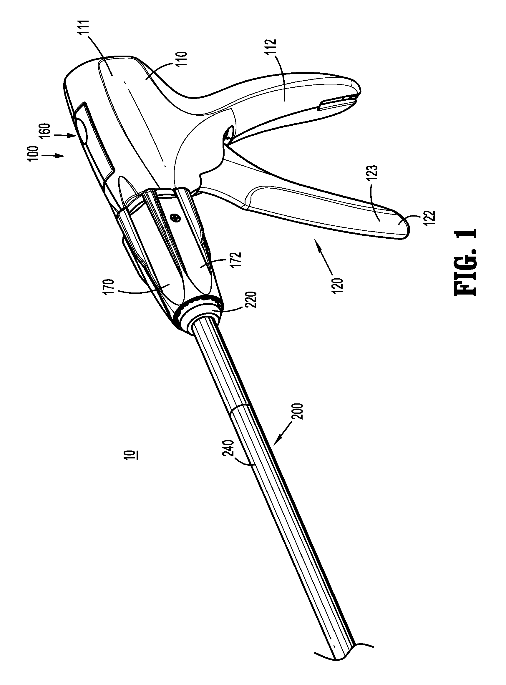
[0020] FIG. 1 is a front, perspective view of a surgical clip applier provided in accordance with the present disclosure including a handle assembly having an elongated assembly engaged therewith;
[0021] FIG. 2 is front, perspective view of the surgical clip applier of FIG. 1 with the elongated assembly removed from the handle assembly;
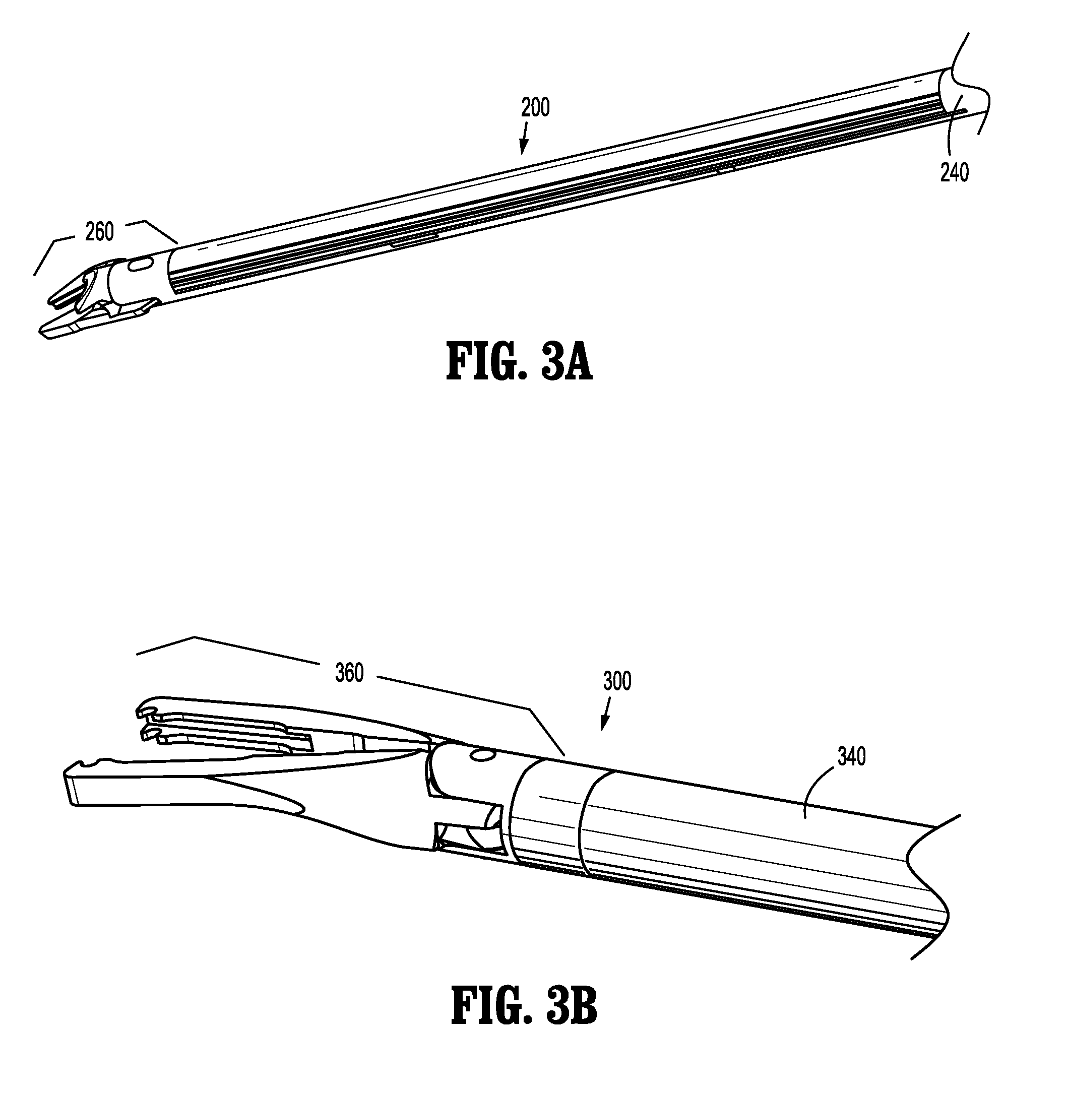
[0022] FIG. 3A is a side, perspective view of a distal end portion of the elongated assembly of FIGS. 1 and 2;
[0023] FIG. 3B is a side, perspective view of a distal end portion of another elongated assembly configured for use with the surgical clip applier of FIG. 1;
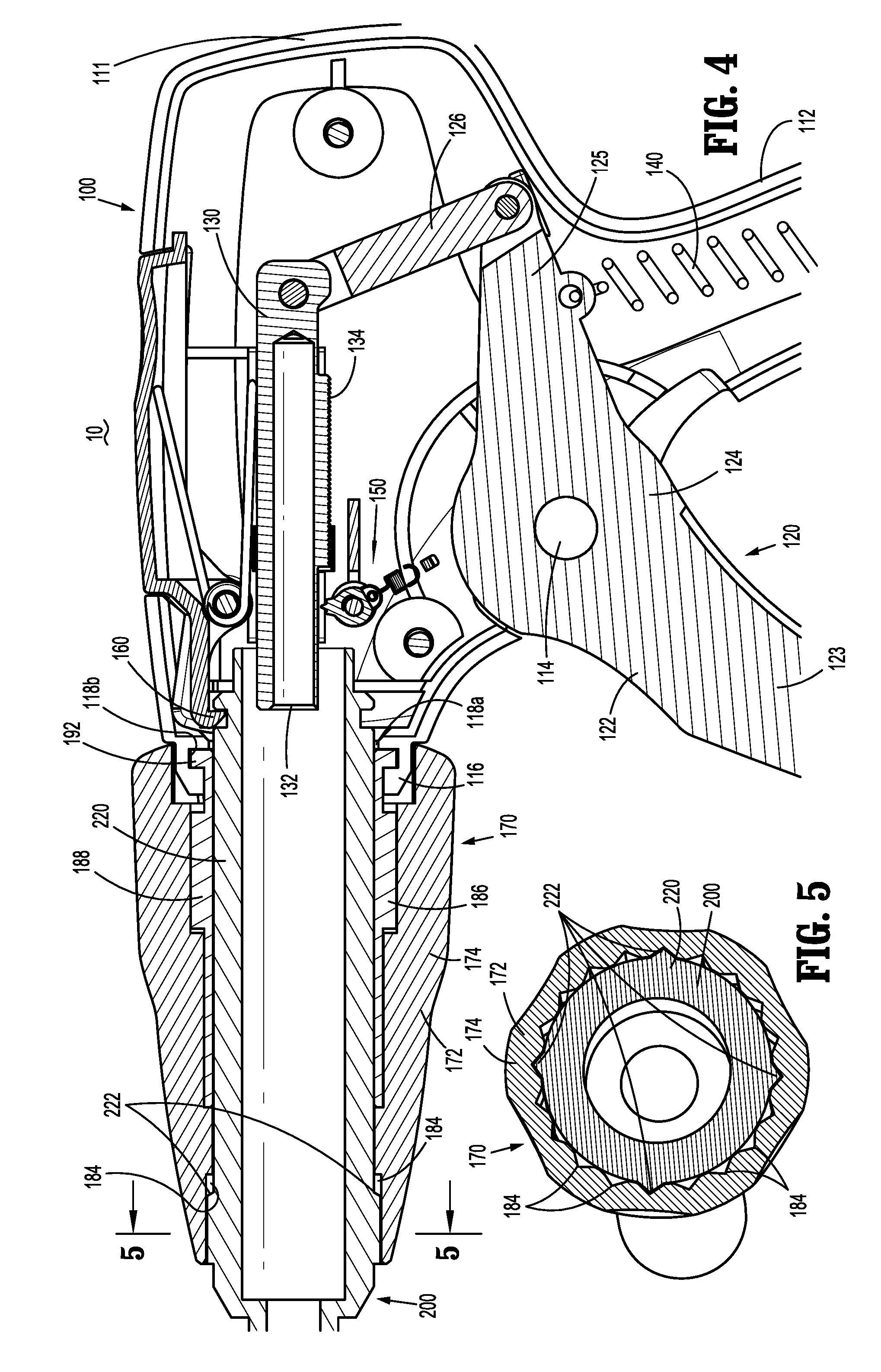
[0024] FIG. 4 is an enlarged, longitudinal, cross-sectional view of a portion of the handle assembly of the surgical clip applier of FIG. 1 including the elongated assembly of FIG. 1 engaged therewith;
[0025] FIG. 5 is an enlarged, transverse, cross-sectional view taken across section line "5-5" in FIG. 4;
[0026] FIG. 6 is an exploded, perspective view of a rotation knob assembly of the handle assembly of the surgical clip applier of FIG. 1;
[0027] FIG. 7A is a side, longitudinal, cross-sectional view of the rotation knob assembly of FIG. 6;
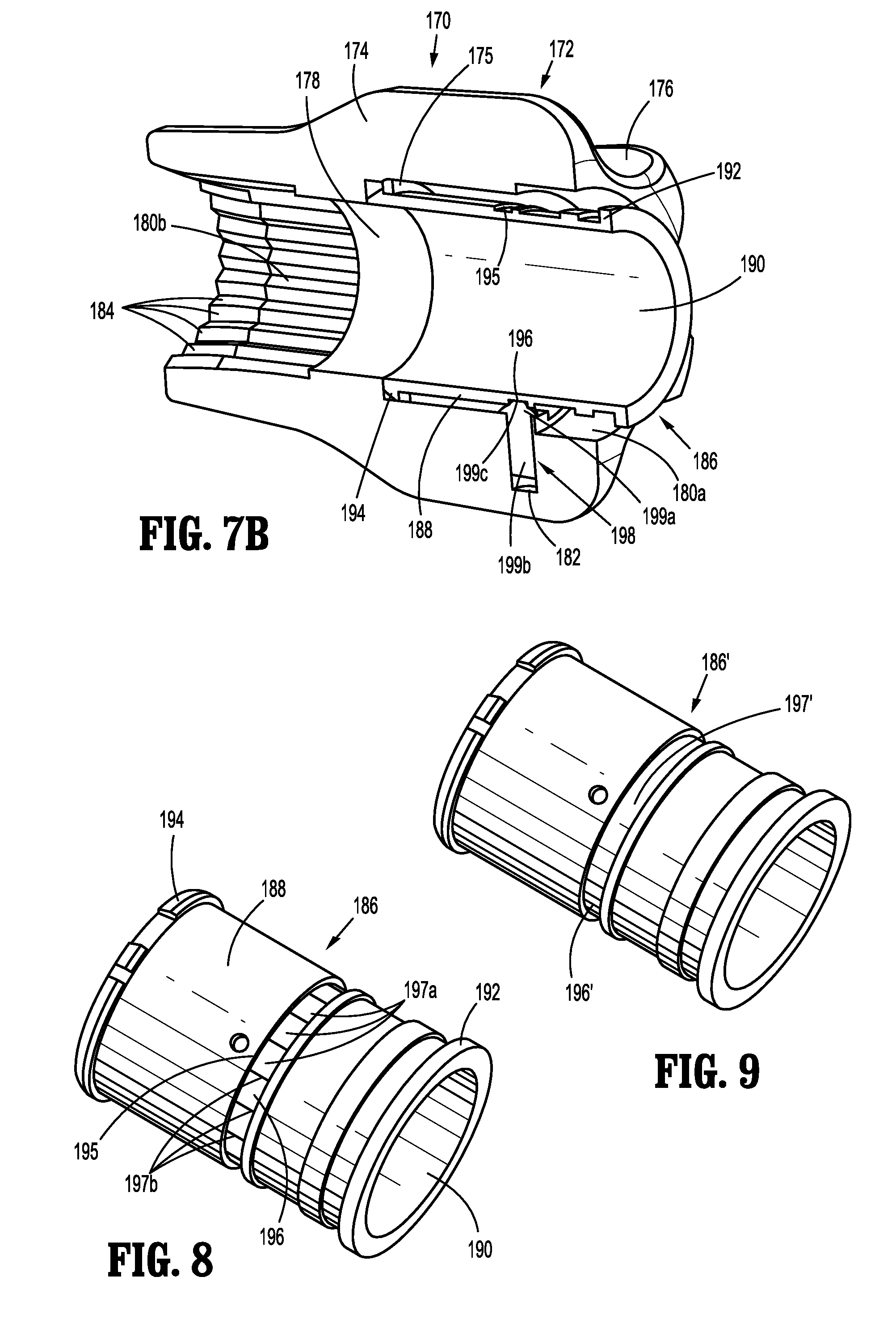
[0028] FIG. 7B is a perspective, longitudinal, cross-sectional view of the rotation knob assembly of FIG. 6;
[0029] FIG. 8 is a perspective view of an inner collar of the rotation knob assembly of FIG. 6; and
[0030] FIG. 9 is a perspective view of another inner collar configured for use with the rotation knob assembly of FIG. 6.
DETAILED DESCRIPTION
[0031] The present disclosure provides rotation knob assemblies for surgical instruments and surgical instruments including the same. Although detailed herein as incorporated into a surgical clip applier, the rotation knob assemblies of the present disclosure may alternatively be incorporated into any suitable surgical instrument.
[0032] Turning to FIGS. 1-2, a surgical clip applier embodying the aspects and features of the present disclosure is shown generally identified by reference numeral 10. Surgical clip applier 10 generally includes a handle assembly 100 and a plurality of elongated assemblies 200, 300 (FIG. 3B) selectively connectable to handle assembly 100. Handle assembly 100 is configured to operate each of the plurality of elongated assemblies 200, 300 (FIG. 3B) upon connection thereto, and may be configured as a sterilizable, reusable component such that handle assembly 100 may be repeatedly used with different and/or additional elongated assemblies 200, 300 (FIG. 3B) during the course of one or more surgical procedures. The elongated assemblies 200, 300 (FIG. 3B) may be configured as single-use disposable components, limited-use disposable components, or reusable components, depending upon a particular purpose and/or the configuration of the particular elongated assembly. In either configuration, the need for multiple handle assemblies 100 is obviated and, instead, the surgeon need only select an appropriate elongated assembly 200, 300 (FIG. 3B) and connect that elongated assembly to handle assembly 100 in preparation for use.
[0033] Handle assembly 100 generally includes a housing 110, an actuation mechanism 120 operably associated with housing 110, a ratchet mechanism 150 (FIG. 4) operably disposed within housing 110, a latch assembly 160 operably associated with housing 110, and a rotation knob assembly 170 operably coupled to a distal portion of housing 110. Housing 110 supports and/or encloses the operating components of handle assembly 100 and is detailed below. Actuation mechanism 120, detailed below, is configured to enable selective firing of one or more surgical clips (not shown) from the end effector of the attached elongated assembly. Rotation knob assembly 170 enables the selective rotation of the attached elongated assembly relative to housing 110, and is also detailed below.
[0034] Ratchet mechanical 150 enables ratcheting advancement of drive bar 130 (FIG. 4) of actuation mechanism 120, when an elongated assembly configured for ratcheting actuation is connected to handle assembly 100. Latch assembly 160 is configured to facilitate releasable locking engagement of the elongated assembly with handle assembly 100. Details of a suitable ratchet mechanism 150 and/or latch assembly 160 can be found in International Application No. PCT/CN2016/096666, filed on Aug. 26, 2016, the entire contents of which is hereby incorporated herein by reference. Alternatively or additionally, ratchet mechanism 150 and/or latch assembly 160 may be configured as detailed in International Application No. PCT/CN2016/071178, filed on Jan. 18, 2016, the entire contents of which is also hereby incorporated herein by reference.
[0035] With additional reference to FIGS. 3A and 3B, as noted above, handle assembly 100 is configured for use with different elongated assemblies such as, for example, elongated assembly 200 (FIGS. 1-3A) and elongated assembly 300 (FIG. 3B). Handle assembly 100, more specifically, is configured for both ratcheting use, e.g., in connection with elongated assembly 200 (FIGS. 1-3A), and non-ratcheting use, e.g., in connection with elongated assembly 300 (FIG. 3B). Elongated assemblies 200, 300 are described briefly below. A more detailed discussion of elongated assemblies, e.g., elongated assemblies 200, 300, configured for use with handle assembly 100 can be found in International Application Nos. PCT/CN2016/096666 and/or PCT/CN2016/071178, previously incorporated by reference herein in their entireties, and additionally or alternatively as in International Application No. PCT/CN2015/091603, filed on Oct. 10, 2015, the entire contents of which is likewise hereby incorporated herein by reference.
[0036] Referring to FIGS. 1-3A, elongated assembly 200 is configured for ratcheting use and generally includes a proximal hub 220, an elongated shaft 240 extending distally from proximal hub 220, an end effector assembly 260 disposed towards a distal end portion of elongated shaft 240, and an inner drive assembly (not shown) operably coupled between handle assembly 100 and end effector assembly 260 when elongated assembly 200 is engaged with handle assembly 100 to enable the sequential firing of at least one surgical clip (not shown) about tissue. End effector assembly 260 of elongated assembly 200 may be configured to fire surgical clips similar to those shown and described in U.S. Pat. No. 7,819,886 or 7,905,890, the entire contents of each of which is hereby incorporated herein by reference.
[0037] Proximal hub 220 of elongated assembly 200 defines a plurality of indexing protrusions 222 annularly disposed thereabout towards a distal end portion thereof. Indexing protrusions 222, as detailed below, are configured for slidable receipt within longitudinally-extending grooves 184 defined within outer knob 172 of rotation knob assembly 170 to rotationally fix proximal hub 220 of elongated assembly 200 relative to rotation knob assembly 170 upon insertion of proximal hub 220 therethrough (see also FIG. 5). As such, in use, rotation of outer knob 172 of rotation knob assembly 170 relative to housing 110 effects corresponding rotation of elongated assembly 200 relative to housing 110.
[0038] Referring to FIG. 3B, in conjunction with FIGS. 1 and 2, elongated assembly 300 is configured for non-ratcheting use and generally includes a proximal hub (not shown), an elongated shaft 340 extending distally from the proximal hub, an end effector assembly 360 disposed towards a distal end portion of elongated shaft 340, and an inner drive assembly (not shown) operably coupled between handle assembly 100 and end effector assembly 360 when elongated assembly 300 is engaged with handle assembly 100 to enable grasping and/or manipulation of tissue, retrieval of a surgical clip, and firing of the surgical clip about tissue. It is contemplated that end effector assembly 360 of elongated assembly 300 may be configured to fire surgical clips similar to those shown and described in U.S. Pat. No. 4,834,096, the entire contents of which is hereby incorporated herein by reference.
[0039] The proximal hub (not shown) of elongated assembly 300 includes indexing protrusions similarly as detailed above with respect to proxy hub 220 of elongated assembly 200 (see FIG. 2) such that elongated assembly 300 is rotationally fix relative to rotation knob assembly 170 upon insertion of proximal hub 220 therethrough to enable rotation of elongated assembly 300 relative to housing 110 in response to rotation of outer knob 172 of rotation knob assembly 170 relative to housing 110.
[0040] Referring generally to FIGS. 1-3B, although exemplary elongated assemblies 200, 300 configured for ratcheting and non-ratcheting use, respectively, are detailed above, it is contemplated that various other elongated assemblies for performing various different surgical tasks and/or having various different configurations suitable for ratcheting or non-ratcheting use may likewise be utilized with handle assembly 100.
[0041] Turning to FIGS. 1, 2, and 4, housing 110 of handle assembly 100 may be formed from first and second housing halves that cooperate to define a body portion 111 and a fixed handle portion 112 depending from body portion 111. Body portion 111 of housing 110 includes an internal pivot post 114 extending transversely within body portion 111, and a distal nose 116 defining a distal opening 118 therethrough. A proximal end portion of a proximal hub of an elongated assembly, e.g., proximal hub 220 of elongated assembly 200 (FIGS. 1-3A) or the proximal hub (not shown) of elongated assembly 300 (FIG. 3B), is configured to extend at least partially through distal opening 118a of distal nose 116 of housing 110 when the elongated assembly 200 or 300 is engaged with handle assembly 100 (see FIG. 4). Distal nose 116 of body portion 111 of housing 110 further includes an annular recess 118b defined on an interior surface thereof surrounding distal opening 118a. Annular recess 118b is configured to receive annular protrusion 192 of inner collar 186 of rotation knob assembly 170 to fixedly engage rotation knob assembly 170 with distal nose 116 of body portion 111 of housing 110. To this end, annular recess 118b and/or annular protrusion 192 of inner collar 186 may include keying features or other suitable features or materials (not shown) to facilitate rotationally-locked engagement between inner collar 186 and distal nose 116 of housing 110.
[0042] Actuation mechanism 120 is operably supported by housing 110 and includes a trigger 122, a linkage 126, a drive bar 130, and a biasing member 140. Trigger 122 includes a grasping portion 123, an intermediate pivot portion 124, and a proximal extension 125. Grasping portion 123 of trigger 122 extends downwardly from body portion 111 of housing 110 in opposed relation relative to fixed handle portion 112 of housing 110. Grasping portion 123 is configured to facilitate grasping and manipulation of trigger 122. Intermediate pivot portion 124 of trigger 122 is at least partially disposed within housing 110 and defines a pivot aperture configured to receive pivot post 114 of housing 110 so as to enable pivoting of trigger 122 about pivot post 114 and relative to housing 110, e.g., between an un-actuated position, wherein grasping portion 123 of trigger 122 is spaced-apart relative to fixed handle portion 112, and an actuated position, wherein grasping portion 123 of trigger 122 is approximated relative to fixed handle portion 112.
[0043] Proximal extension 125 of trigger 122 is disposed on an opposite side of intermediate pivot portion 124 and, thus, pivot post 114, as compared to grasping portion 123 of trigger 122. As such, pivoting of grasping portion 123 to rotate in one direction, e.g., proximally towards fixed handle portion 112, pivots proximal extension 125 to rotate in the opposite direction, e.g., distally. Proximal extension 125 of trigger 122 is pivotably coupled to the proximal end of linkage 126. Biasing member 140 is secured at either end and extends between proximal extension portion 125 of trigger 122 and a support (not shown) disposed within fixed handle portion 112 of housing 110. Pivoting of grasping portion 123 towards the actuated position elongates biasing member 140 storing energy therein such that, upon release of grasping portion 123, grasping portion 123 is returned towards the un-actuated position under the bias of biasing member 140. Although illustrated as an extension coil spring, biasing member 140 may define any suitable configuration for biasing grasping portion 123 of trigger 122 towards the un-actuated position.
[0044] As noted above, linkage 126 is coupled at its proximal end to proximal extension portion 125 of trigger 122. Linkage 126 is also pivotably coupled at its distal end to a proximal end of drive bar 130. As a result of this configuration, pivoting of grasping portion 123 of trigger 122 towards the actuated position urges proximal extension portion 125 of trigger 122 distally which, in turn, urges linkage 126 distally to, in turn, urge drive bar 130 distally.
[0045] Drive bar 130 is slidable through body portion 111 of housing 110, in response to actuation of trigger 122, to urge a distal end portion 132 of drive bar 130 into contact with a proximal actuator of an inner drive assembly (not shown) of an elongated assembly, e.g., elongated assembly 200 (FIGS. 1-3A) or elongated assembly 300 (FIG. 3B), engaged with handle assembly 100 to fire a surgical clip supported at the end effector assembly of the elongated assembly. Drive bar 130, more specifically, is slidable from an un-actuated, proximal position, corresponding to the un-actuated position of grasping portion 123 of trigger 122, to an actuated, distal position, corresponding to the actuated position of grasping portion 123 of trigger 122, in order to urge the proximal actuator of the inner drive assembly (not shown) of the elongated assembly distally to fire a surgical clip supported at the end effector assembly of the elongated assembly.
[0046] Drive bar 130 may further include a ratchet rack 134 extending along at least a portion of an underside surface thereof. Ratchet rack 134 is configured to selectively interface with ratchet mechanism 150 to enable advancement of drive bar 130 in either a ratcheting condition or a non-ratcheting condition. Ratchet rack 134 and ratchet mechanism 150, as noted above, may be configured similarly as described in, for example, International Application No. PCT/CN2016/096666 or International Application No. PCT/CN2016/071178, each of which was previously incorporated by reference herein.
[0047] With reference to FIGS. 4-8, as noted above, rotation knob assembly 170 is rotatably coupled to distal nose 116 of body portion 111 of housing 110 and is configured to receive the proximal hub of the elongated assembly, e.g., proximal hub 220 of elongated assembly 200, coupled to handle assembly 100 in fixed rotational engagement therewith to enable selective rotation of elongated assembly 200 relative to housing 110 upon rotation of outer knob 172 of rotation knob assembly 170 relative to housing 110. Rotation knob assembly 170 includes outer knob 172, an inner collar 186, and a plurality, e.g., three, ball bearing assemblies 198.
[0048] Referring to FIGS. 4-7B, outer knob 172 of rotation knob assembly 170 may be formed from a polymeric material, e.g., a biocompatible, sterilizable plastic, or other suitable material, and includes a body 174 defining a cone shaped-configuration tapering in diameter from a proximal end portion to a distal end portion thereof, although other suitable configurations are also contemplated. Body 174 defines a plurality of flutes 176 arranged radially about body 174 to facilitate grasping or gripping body 174 at any rotational orientation to enable rotation thereof.
[0049] Body 174 of outer knob 172 of rotation knob assembly 170 further includes a longitudinally-extending lumen 178 defined therethrough. Longitudinally-extending lumen 178 includes a proximal portion 180a and a distal portion 180b, which may define equal or different diameters, e.g., proximal portion 180a may define a larger diameter as compared to distal portion 180b. Proximal portion 180a of lumen 178 communicates with the proximal opening of body 174 of outer knob 172. A plurality, e.g., three, transverse apertures 182 equally-spaced annularly about body 174 of outer knob 172 are defined through body 174 of outer knob 172 and communicate with proximal portion 180a of lumen 178. Each transverse aperture 182 is configured to receive one of the ball bearing assemblies 198 as detailed below.
[0050] Distal portion 180b of lumen 178 communicates with the distal opening of body 174 of outer knob 172 at the distal end thereof and with proximal portion 180a of lumen 178 at the proximal end thereof. Body 174 includes a plurality of longitudinally-extending grooves 184 arranged annularly on an interior surface thereof and disposed about at least a portion of distal portion 180b of lumen 178. As noted above, grooves 184 are configured to slidably receive indexing protrusions 222 of proximal hub 220 of elongated assembly 200 (see FIGS. 2 and 5) to rotationally fix proximal hub 220 relative to outer knob 172 upon insertion of proximal hub 220 into handle assembly 100.
[0051] Inner collar 186 of rotation knob assembly 180 may be formed from a metal, e.g., stainless steel, or other suitable material, and includes a body 188 defining a longitudinally-extending lumen 190 therethrough. Inner collar 186 further includes an annular protrusion 192 disposed about the proximal end portion thereof, a distal head 194 disposed about the distal end portion thereof, and a waist or channel 195 defined annularly within an exterior surface of inner collar 186 and disposed between annular protrusion 192 and distal head 194. Annular protrusion 192, as noted above, is configured for receipt within annular recess 118b of distal nose 116 of housing 110 (see FIG. 4) to fixedly engage inner collar 186 with distal nose 116 of body portion 111 of housing 110, e.g., upon engagement of the housing halves forming housing 110 with one another.
[0052] Inner collar 186 is configured to accept body 174 of outer knob 172 thereabout such that inner collar 186 is received within proximal portion 180a of lumen 178 of body 174 of outer knob 172 through the proximal opening thereof. Distal head 194 of inner collar 186 defines a chamfered distally-facing edge such that, upon receipt of inner collar 186 within proximal portion 188a of lumen 178, distal head 194 is cammed over an internal annular rib 175 disposed on an internal surface of body 174 of outer knob 172 about proximal portion 180a of lumen 178 to longitudinally fix inner collar 186 within outer knob 172 while still permitting relative rotation therebetween. Distal head 194 may be sectioned, e.g., distal head 194 need not extend about the full annular periphery of inner collar 186, to facilitate the above-detailed engagement of inner collar 186 within outer knob 172.
[0053] Waist 195 of inner collar 186 includes a recessed floor 196 that is recessed relative to the exterior surface of inner collar 186. Upon rotatable engagement of outer knob 172 about inner collar 186, as detailed above, recessed floor 196 of waist 195 is aligned with each of transverse apertures 182 defined within outer knob 172.
[0054] With reference to FIG. 8, in embodiments, recessed floor 196 may include a plurality of ramped segments 197a (or an annular array of concavities/recesses) angled relative to one another to define steps 197b therebetween, thus defining a ratchet-like configuration. Alternatively, in other embodiments, with reference to FIG. 9, an inner collar 186' may be provided whereby recessed floor 196' defines a smooth surface 197'. Inner collar 186' may otherwise be similar to inner collar 186 (FIG. 8).
[0055] Referring again to FIGS. 6-7B, each ball bearing assembly 198 (e.g., spring ball bearing assembly) includes a head 199a, a post 199b extending from the respective head 199a thereof, and a ball bearing 199c captured within the respective head 199a thereof such that a portion of the ball bearing 199c protrudes from the head 199a and is rotatable relative thereto. Posts 199b of ball bearing assemblies 198 are configured for receipt within transverse apertures 182 defined through body 174 of outer knob 172, with ball bearing assemblies 198 oriented such that heads 199a and ball bearings 199c protrude radially inwardly into proximal portion 180a of lumen 178 of body 174 of outer knob 172. Ball bearing assemblies 198 may each further include a biasing member (not shown) disposed therein and configured to bias ball bearings 199c to protrude outwardly from heads 199a.
[0056] As noted above, upon rotatable engagement of outer knob 172 about inner collar 186, as detailed above, recessed floor 196 of waist 195 of inner collar 186 is aligned with each of transverse apertures 182 defined within outer knob 172. More specifically, since ball bearing assemblies 198 are engaged within transverse apertures 182, upon rotatable engagement of outer knob 172 about inner collar 186 (with ball bearing assemblies 198 already installed), ball bearings 199c protrude into waist 195 into abutment with recessed floor 196. The receipt of ball bearings 199c within waist 195 guides rotation of outer knob 172 relative to inner collar 186, enabling ball bearings 199c to roll about recessed floor 196 with minimal friction, thus providing ease of rotation for the user.
[0057] In embodiments where recessed floor 196 defines a ratchet-like or stepped configuration (FIGS. 6 and 8), outer knob 172 is rotatable about inner collar 186 in a plurality of discrete increments, with each discrete position corresponding to positioning of ball bearings 199c adjacent steps 197b of recessed floor 196. The particular increment depends upon the lengths of ramped segments 197a of recessed floor 196. Further, audible and/or tactile feedback, in the form of a "click" may be provided in such embodiments. On the other hand, in embodiments where inner collar 186' is provided with a smooth surface 197' (see FIG. 9), outer knob 172 may be rotated continuously through an infinite number of positions.
[0058] Referring generally to FIGS. 1, 2, 4, and 6, insertion and engagement of an elongated assembly, e.g., elongated assembly 200, with handle assembly 100 and use of the same are described.
[0059] In order to engage elongated assembly 200 with handle assembly 100, proximal hub 220 of elongated assembly 200 is inserted through the distal opening of outer knob 172 of rotation knob assembly 170, distal portion 180b of lumen 178 of outer knob 172, lumen 190 of inner collar 186 of rotation knob assembly 170, and into distal nose 116 of housing 110, wherein latch assembly 160 cams over the proximal end of proximal hub 220 and into engagement therewith to thereby rotatably engage proximal hub 220 relative to housing 110 and, thus, relative to inner collar 186. Upon insertion of proximal hub 220 through rotation knob assembly 170, as noted above, indexing protrusions 222 of proximal hub 220 are received within longitudinally-extending grooves 184 of outer knob 172 to rotationally fix proximal hub 220 relative to outer knob 172 (see FIG. 5).
[0060] With elongated assembly 200 engaged with handle assembly 100 as detailed above, handle assembly 100 may be manipulated and/or outer knob 172 rotated to position end effector 260 (FIG. 3A) of elongated assembly 200 about tissue to be treated. Once end effector 260 is positioned as desired, trigger 122 is pivoted towards fixed handle portion 112 of housing 110 to urge linkage 126 distally which, in turn, urges drive bar 130 distally through housing 110 to drive the proximal actuator of the inner drive assembly (not shown) of elongated assembly 200 distally through elongated assembly 200 to fire and form a surgical clip from end effector assembly 260 (FIG. 3A) about tissue. The above may be repeated to fire and form several surgical clips about tissue, as necessary.
[0061] In order to disengage elongated assembly 200 from handle assembly 100, e.g., for cleaning and/or sterilization, or to replace elongated assembly 200 with another endoscopic assembly, latch assembly 160 is depressed inwardly into housing 110 to disengage proximal hub 220 of elongated assembly 200, thus enabling proximal hub 220 to be withdrawn distally from housing 110 and rotation knob assembly 170.
[0062] It should be understood that the foregoing description is only illustrative of the present disclosure. Various alternatives and modifications can be devised by those skilled in the art without departing from the disclosure. Accordingly, the present disclosure is intended to embrace all such alternatives, modifications and variances. The embodiments described with reference to the attached drawing figures are presented only to demonstrate certain examples of the disclosure. Other elements, steps, methods and techniques that are insubstantially different from those described above and/or in the appended claims are also intended to be within the scope of the disclosure.
* * * * *
D00000
D00001
D00002
D00003
D00004
D00005
D00006
XML
uspto.report is an independent third-party trademark research tool that is not affiliated, endorsed, or sponsored by the United States Patent and Trademark Office (USPTO) or any other governmental organization. The information provided by uspto.report is based on publicly available data at the time of writing and is intended for informational purposes only.
While we strive to provide accurate and up-to-date information, we do not guarantee the accuracy, completeness, reliability, or suitability of the information displayed on this site. The use of this site is at your own risk. Any reliance you place on such information is therefore strictly at your own risk.
All official trademark data, including owner information, should be verified by visiting the official USPTO website at www.uspto.gov. This site is not intended to replace professional legal advice and should not be used as a substitute for consulting with a legal professional who is knowledgeable about trademark law.