Surgical Clip Applier
Hartoumbekis; Elias
U.S. patent application number 16/142031 was filed with the patent office on 2019-01-24 for surgical clip applier. The applicant listed for this patent is Covidien LP. Invention is credited to Elias Hartoumbekis.
| Application Number | 20190021738 16/142031 |
| Document ID | / |
| Family ID | 47594292 |
| Filed Date | 2019-01-24 |

View All Diagrams
| United States Patent Application | 20190021738 |
| Kind Code | A1 |
| Hartoumbekis; Elias | January 24, 2019 |
SURGICAL CLIP APPLIER
Abstract
The present application relates to surgical clip appliers having a plurality of clips for applying the clips to body tissues and vessels during surgical procedures and their methods of use and specifically to a reusable counter mechanism for use with a surgical clip applier. The surgical clip applier includes a housing, at least one handle pivotably connected to the housing, a channel assembly extending distally from the housing, a plurality of clips loaded in the channel assembly, a drive channel translatably supported in the housing and the channel assembly and being translatable upon actuation of the at least one handle, and a reusable counter mechanism removably insertable into a counter slot extending into the housing and engagable with the drive channel. The counter mechanism is configured display indicia corresponding to a quantity of clips and to update the indicia upon translation of the drive channel.
| Inventors: | Hartoumbekis; Elias; (New Haven, CT) | ||||||||||
| Applicant: |
|
||||||||||
|---|---|---|---|---|---|---|---|---|---|---|---|
| Family ID: | 47594292 | ||||||||||
| Appl. No.: | 16/142031 | ||||||||||
| Filed: | September 26, 2018 |
Related U.S. Patent Documents
| Application Number | Filing Date | Patent Number | ||
|---|---|---|---|---|
| 13666317 | Nov 1, 2012 | |||
| 16142031 | ||||
| 61561994 | Nov 21, 2011 | |||
| Current U.S. Class: | 1/1 |
| Current CPC Class: | A61B 17/1285 20130101; A61B 2090/0803 20160201 |
| International Class: | A61B 17/128 20060101 A61B017/128 |
Claims
1-9. (canceled)
10. A method of preparing a surgical clip applier for a surgical procedure, the method comprising the steps of: determining when a reusable counter mechanism is necessary for the surgical procedure; inserting the counter mechanism into a counter slot of the clip applier to engage a drive bar of the clip applier when the counter mechanism is determined to be necessary; performing the surgical procedure; and removing the counter mechanism from the counter slot of clip applier after the surgical procedure is complete.
11. The method according to claim 10, the method further including the step of removing a plug from the counter slot of the clip applier prior to the step of inserting the counter mechanism.
12. The method according to claim 10, further including the step of resetting the counter mechanism to an initial state prior to the step of inserting the counter mechanism.
13. The method according to claim 10, wherein the step of determining when a counter mechanism is necessary includes choosing between one of a digital counter, an analog counter, and no counter.
14. The method according to claim 10, wherein the step of inserting the counter mechanism includes inserting the counter mechanism into the counter slot until the counter mechanism is secured in the counter slot by a snap-fit mechanism and the step of removing the counter mechanism includes releasing the snap-fit mechanism.
15. A method of preparing a surgical clip applier for a surgical procedure, the method comprising the steps of: making a determination, by a surgeon, in the operating room, when a reusable counter mechanism is necessary for the surgical procedure; inserting the counter mechanism into a counter slot of the clip applier to engage a drive bar of the clip applier when the surgeon determines that the counter mechanism is necessary; performing the surgical procedure; and removing the counter mechanism from the counter slot of clip applier after the surgical procedure is complete.
16. The method according to claim 15, the method further including the step of removing a plug from the counter slot of the clip applier prior to the step of inserting the counter mechanism.
17. The method according to claim 15, further including the step of resetting the counter mechanism to an initial state prior to the step of inserting the counter mechanism.
18. The method according to claim 17, wherein the step of resetting the counter occurs in the operating room.
19. The method according to claim 15, wherein the step of making a determination by a surgeon includes the surgeon choosing between one of a digital counter, an analog counter, and no counter.
20. The method according to claim 15, wherein the step of inserting the counter mechanism includes inserting the counter mechanism into the counter slot until the counter mechanism is secured in the counter slot by a snap-fit mechanism and the step of removing the counter mechanism includes releasing the snap-fit mechanism.
Description
CROSS REFERENCE TO RELATED APPLICATION
[0001] The present application is a Divisional Application of U.S. patent application Ser. No. 13/666,317, filed on Nov. 1, 2012, which claims the benefit of and priority to U.S. Provisional Application Ser. No. 61/561,994, filed on Nov. 21, 2011, the entire contents of which are incorporated herein by reference.
BACKGROUND
1. Technical Field
[0002] The present application relates to surgical clip appliers having a plurality of clips for applying the clips to body tissues and vessels during surgical procedures and their methods of use. More specifically the present application relates to a reusable counter mechanism for use with a surgical clip applier.
2. Discussion of Related Art
[0003] Surgical clip appliers are known in the art and have increased in popularity among surgeons by offering an alternative to conventional suturing of body tissues and vessels. Typical instruments are disclosed in U.S. Pat. No. 5,030,226 to Green et al. and U.S. Pat. No. 5,431,668 to Burbank, III et al. These instruments generally provide a plurality of clips which are stored in the instrument and which are fed sequentially to the jaw mechanism at the distal end of the instrument upon opening and closing of the handles at the proximal end of the instrument. As the handles are closed, the jaws close to deform a clip positioned between the jaw members, and as the jaws are opened to release the deformed clip, a new clip is fed from the series to a position between the jaws. This process is repeated until all the clips in the series of clips have been used.
[0004] A need exists for a user of the clip applier to know how many clips remain in the clip applier, how many clips have been fired and/or when a final clip of the plurality of clips has been fired.
SUMMARY
[0005] The present application relates to surgical clip appliers having a plurality of clips for applying the clips to body tissues and vessels during surgical procedures and their methods of use. More specifically the present application relates to a reusable counter mechanism for use with a surgical clip applier.
[0006] In an aspect of the present disclosure, a surgical clip applier includes a housing, at least one handle pivotably connected to the housing, a channel assembly extending distally from the housing, a plurality of clips loaded in the channel assembly, a drive channel translatably supported in the housing and the channel assembly and being translatable upon actuation of the at least one handle, and a reusable counter mechanism removably insertable into a counter slot extending into the housing and engagable with the drive channel. The counter mechanism is configured to display indicia corresponding to a quantity of clips and to change the indicia upon translation of the drive channel.
[0007] In an aspect of the present disclosure, the counter mechanism is a digital counter. The drive channel may include a nub and the counter mechanism may include a contact. The nub is configured to engage the contact during translation of the drive channel to cause the contact to complete a circuit with the counter mechanism. The counter mechanism may includes a battery and the battery may be rechargeable.
[0008] In an aspect of the present disclosure, the counter mechanism is an analog counter. The counter mechanism may include a counter dial rotatably supported in the housing and including the indicia thereon and a counter clutch operatively connected to the counter dial such that rotation of the counter clutch in a first direction results in rotation of the counter dial in a first direction, and rotation of the counter clutch in a second direction results in no rotation of the counter dial. The drive channel may define an angled slot therein, and the counter clutch may include a clutch pin extending from a surface thereof and slidably engagable with the angled slot of the drive channel when the counter mechanism is inserted into the counter slot of the housing. Translation of the drive channel causes the clutch pin to be cammed by the angled slot to rotate the counter clutch in the first and second directions respectively.
[0009] In an aspect of the present disclosure, the counter mechanism is securable in the counter slot by a snap-fit mechanism.
[0010] In an aspect of the present disclosure, a method of preparing a surgical clip applier for a surgical procedure includes the steps of: determining when a reusable counter mechanism is necessary for the surgical procedure; inserting the counter mechanism into a counter slot of the clip applier to engage a drive bar of the clip applier when the counter mechanism is determined to be necessary; performing the surgical procedure; and removing the counter mechanism from the counter slot of clip applier after the surgical procedure is complete.
[0011] In an aspect of the present disclosure, the method includes the step of removing a plug from the counter slot of the clip applier prior to the step of inserting the counter mechanism.
[0012] In an aspect of the present disclosure, the method includes the step of resetting the counter mechanism to an initial state prior to the step of inserting the counter mechanism.
[0013] In an aspect of the present disclosure, the step of determining when a counter mechanism is necessary includes choosing between one of a digital counter, an analog counter, and no counter.
[0014] In an aspect of the present disclosure, the step of inserting the counter mechanism includes inserting the counter mechanism into the counter slot until the counter mechanism is secured in the counter slot by a snap-fit mechanism and the step of removing the counter mechanism includes releasing the snap-fit mechanism.
[0015] In an aspect of the present disclosure, a method of preparing a surgical clip applier for a surgical procedure includes the steps of: making a determination, by a surgeon, in the operating room, when a reusable counter mechanism is necessary for the surgical procedure; inserting the counter mechanism into a counter slot of the clip applier to engage a drive bar of the clip applier when the surgeon determines that the counter mechanism is necessary; performing the surgical procedure; and removing the counter mechanism from the counter slot of clip applier after the surgical procedure is complete.
[0016] In an aspect of the present disclosure, the method includes the step of removing a plug from the counter slot of the clip applier prior to the step of inserting the counter mechanism.
[0017] In an aspect of the present disclosure, the method includes the step of resetting the counter mechanism to an initial state prior to the step of inserting the counter mechanism. The step of resetting the counter may occur in the operating room.
[0018] In an aspect of the present disclosure, the step of making a determination by a surgeon includes the surgeon choosing between one of a digital counter, an analog counter, and no counter.
[0019] In an aspect of the present disclosure, the step of inserting the counter mechanism includes inserting the counter mechanism into the counter slot until the counter mechanism is secured in the counter slot by a snap-fit mechanism and the step of removing the counter mechanism includes releasing the snap-fit mechanism.
[0020] Although described separately, the above aspects may be combinable with any other aspect of the present disclosure.
BRIEF DESCRIPTION OF THE DRAWINGS
[0021] The present clip applier will be more fully appreciated as the same becomes better understood from the following detailed description when considered in connection with the following drawings, in which:
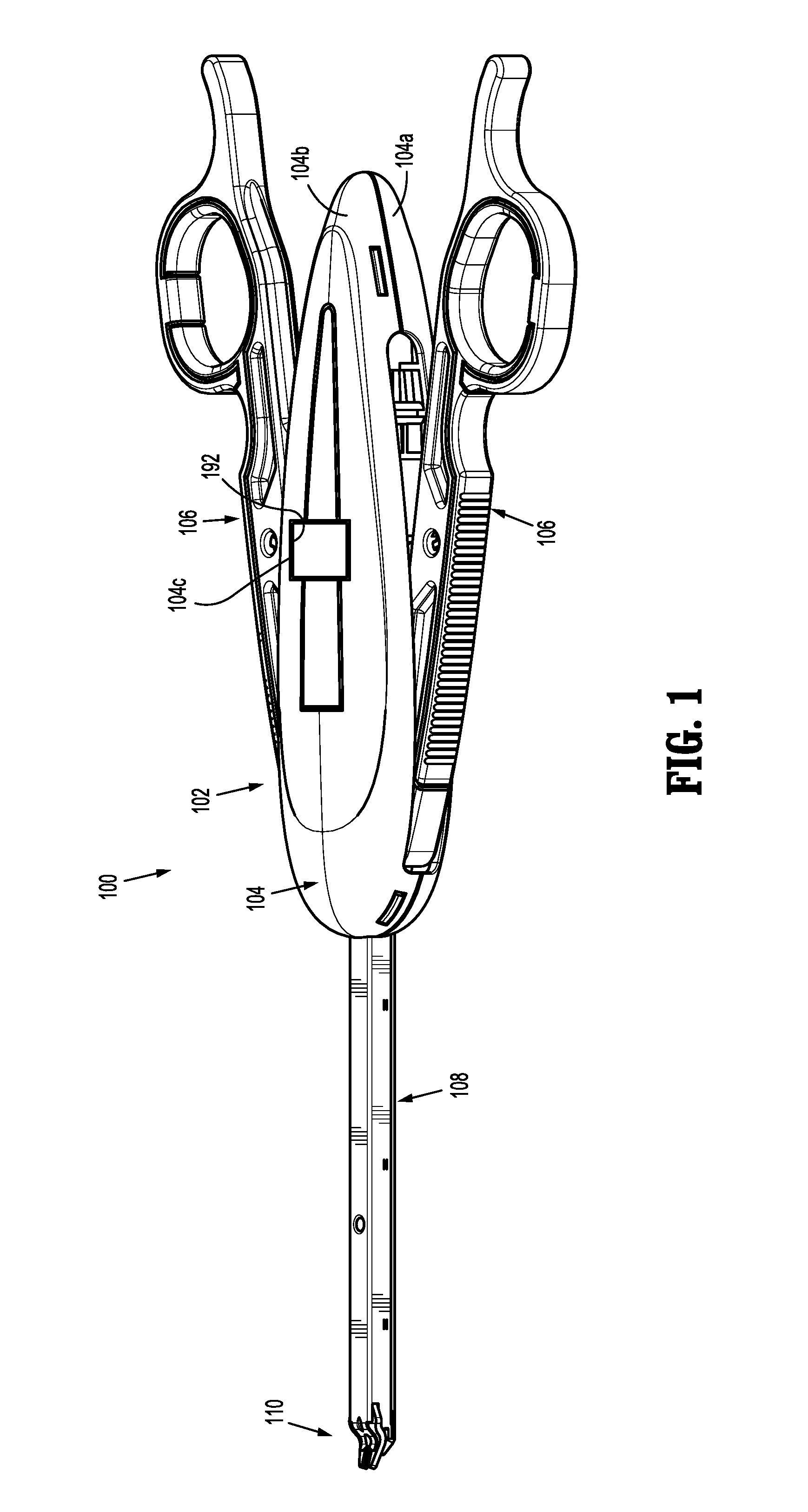
[0022] FIG. 1 is a perspective view of a surgical clip applier according to an embodiment of the present disclosure;
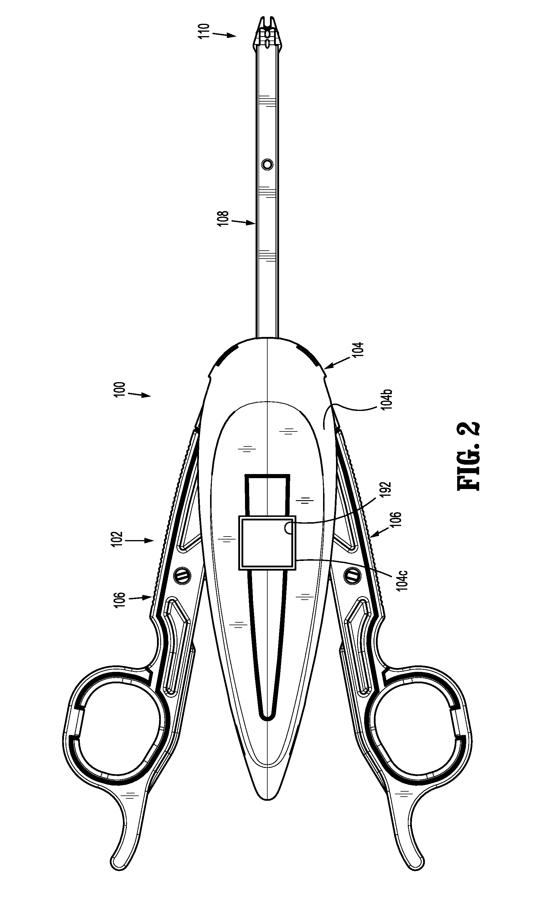
[0023] FIG. 2 is a top, plan view of the surgical clip applier of FIG. 1;
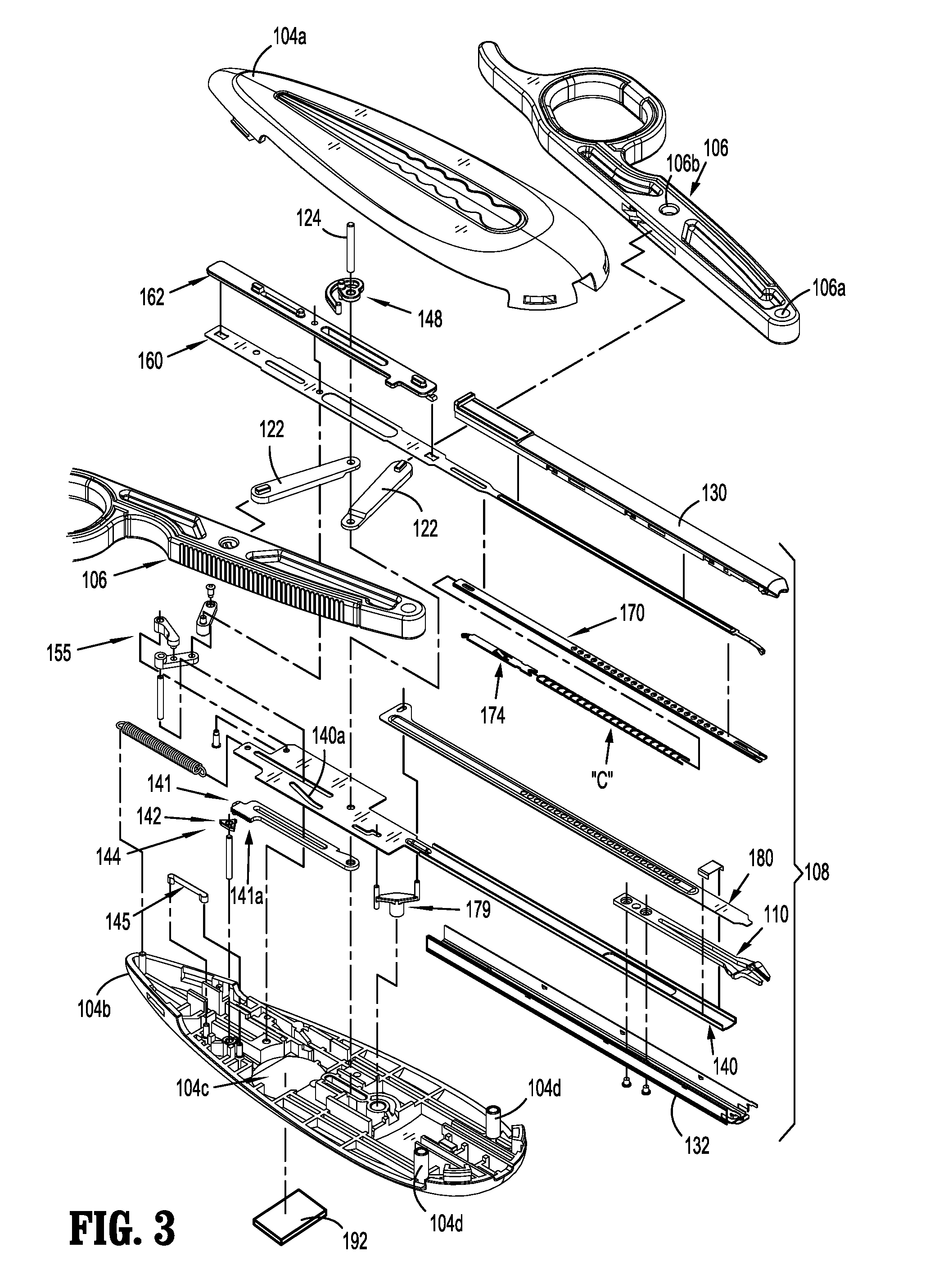
[0024] FIG. 3 an exploded perspective view of the surgical clip applier of FIGS. 1-2;
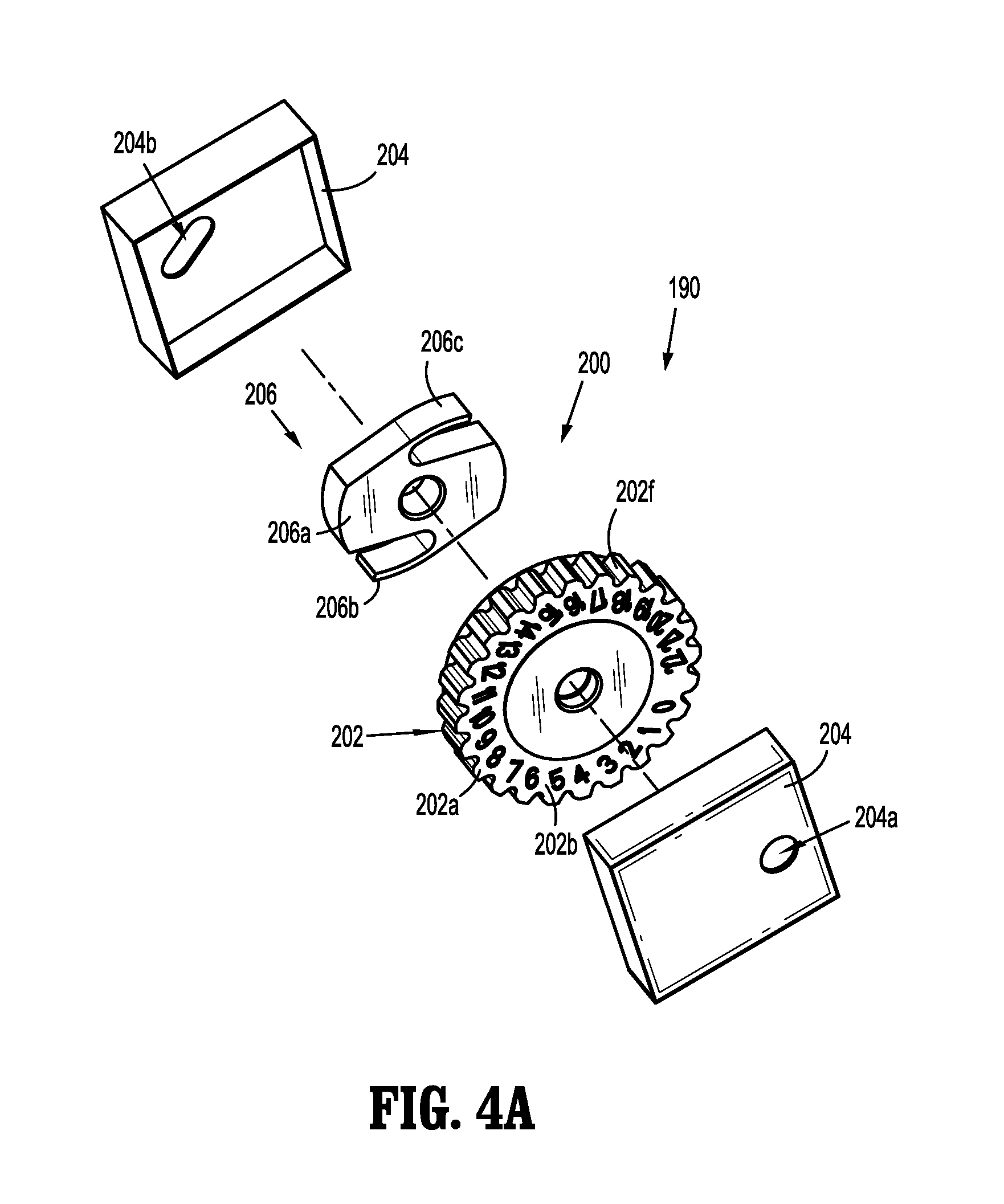
[0025] FIG. 4A is a front, perspective view of a re-usable mechanical counter insertable into the surgical clip applier of FIGS. 1 and 2;
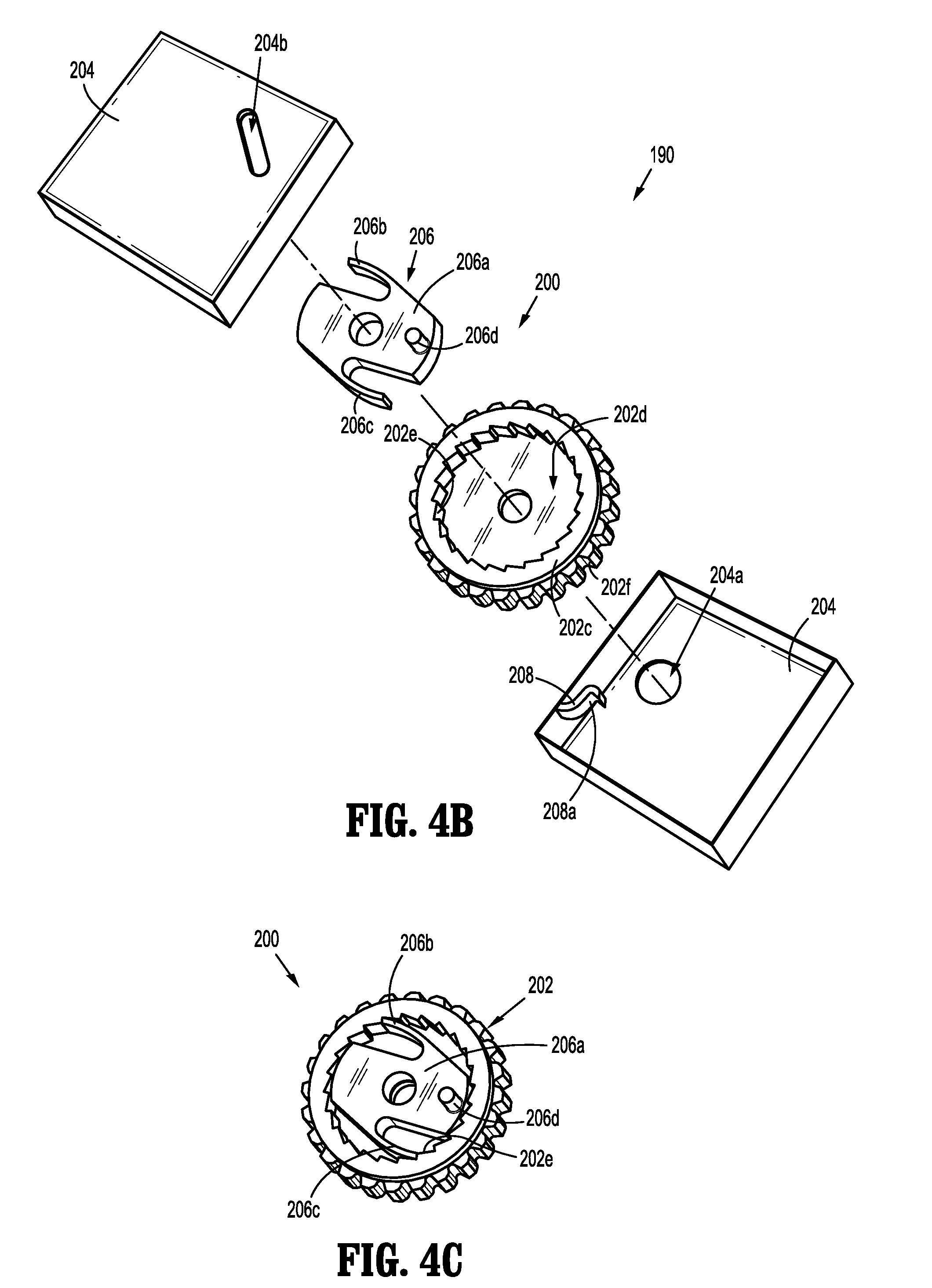
[0026] FIG. 4B is a rear, perspective view of the re-usable mechanical counter of FIG. 4A;
[0027] FIG. 4C is a perspective view of the re-usable mechanical counter of FIGS. 4A-4B, illustrating the clutch inserted into the bore of the counter dial;
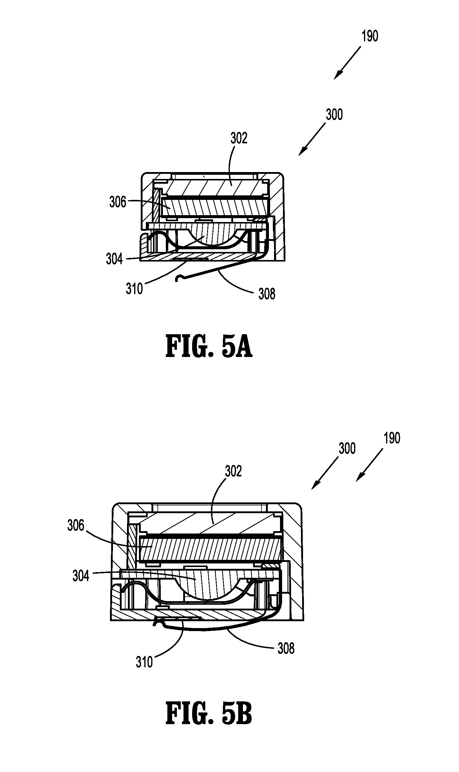
[0028] FIG. 5A is a side, cross-sectional view of a re-usable digital counter insertable into the surgical clip applier of FIGS. 1 and 2;
[0029] FIG. 5B is a side, cross-sectional view of a re-usable digital counter of FIG. 5A, illustrating the contact engaging the contact plate;
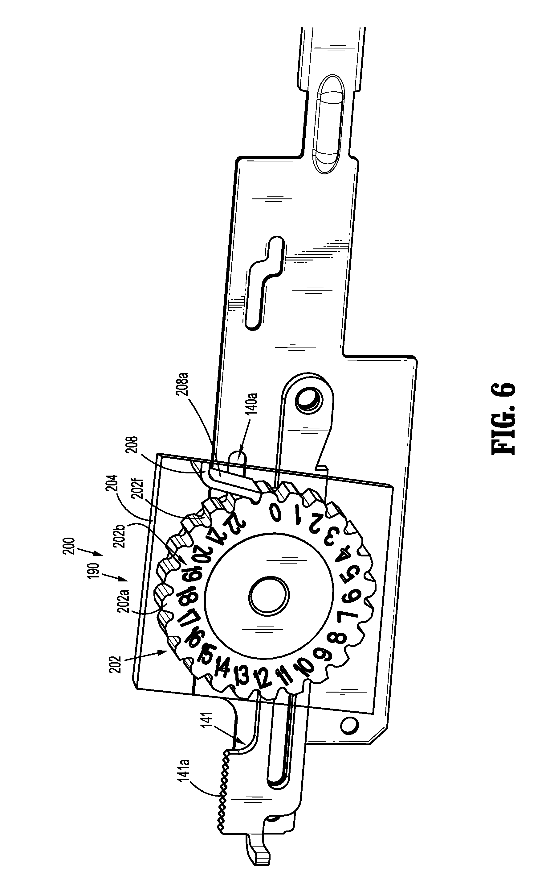
[0030] FIG. 6 is a perspective view of the mechanical counter of FIG. 4A engaging a drive member of the clip applier of FIGS. 1 and 2;
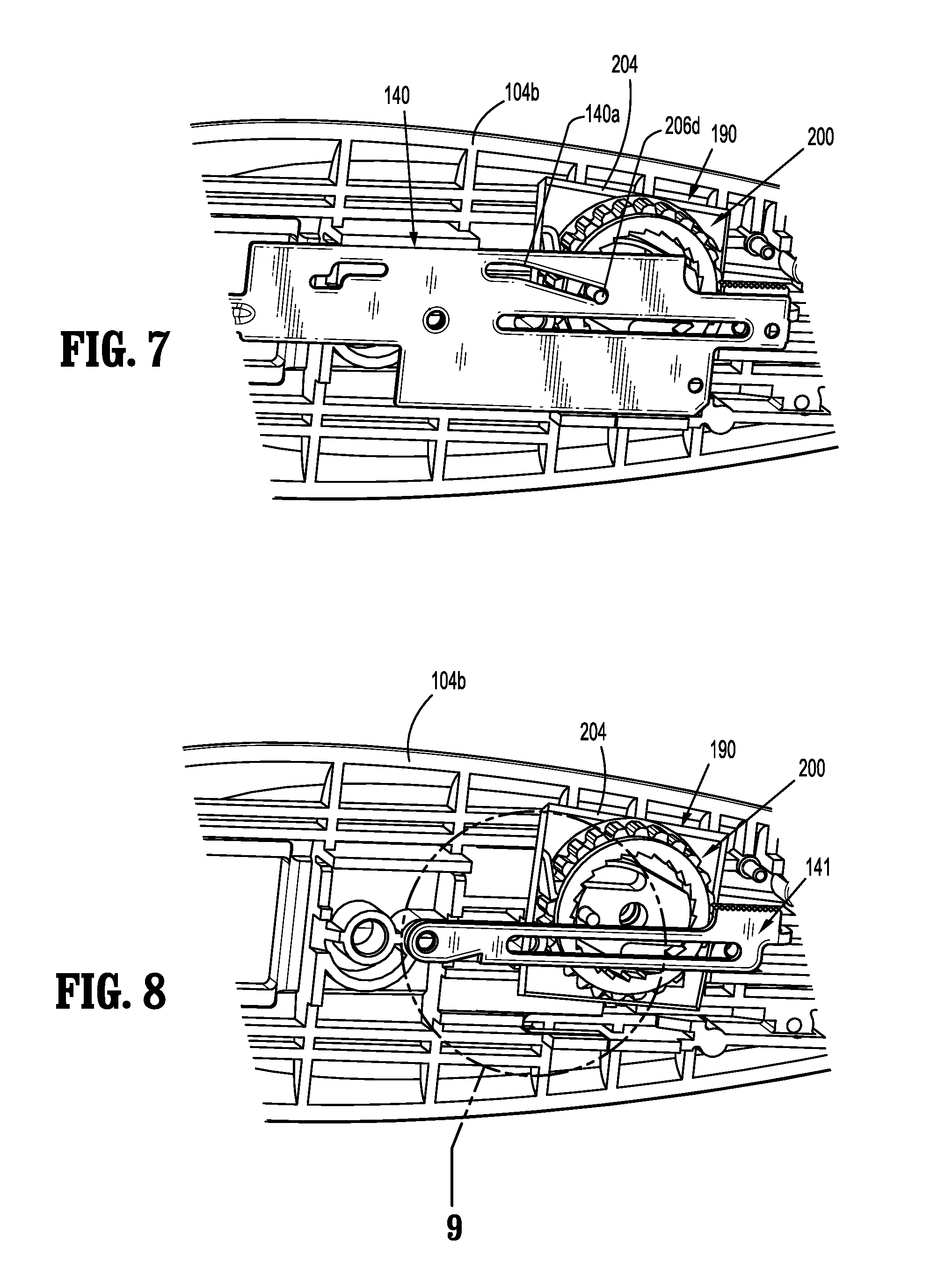
[0031] FIG. 7 is a perspective view of a handle assembly with a housing half-section removed therefrom and illustrating the mechanical counter engaged with a drive channel;
[0032] FIG. 8 is a perspective view of a handle assembly with a housing half-section and drive channel removed therefrom and illustrating the mechanical counter engaged with a ratchet;
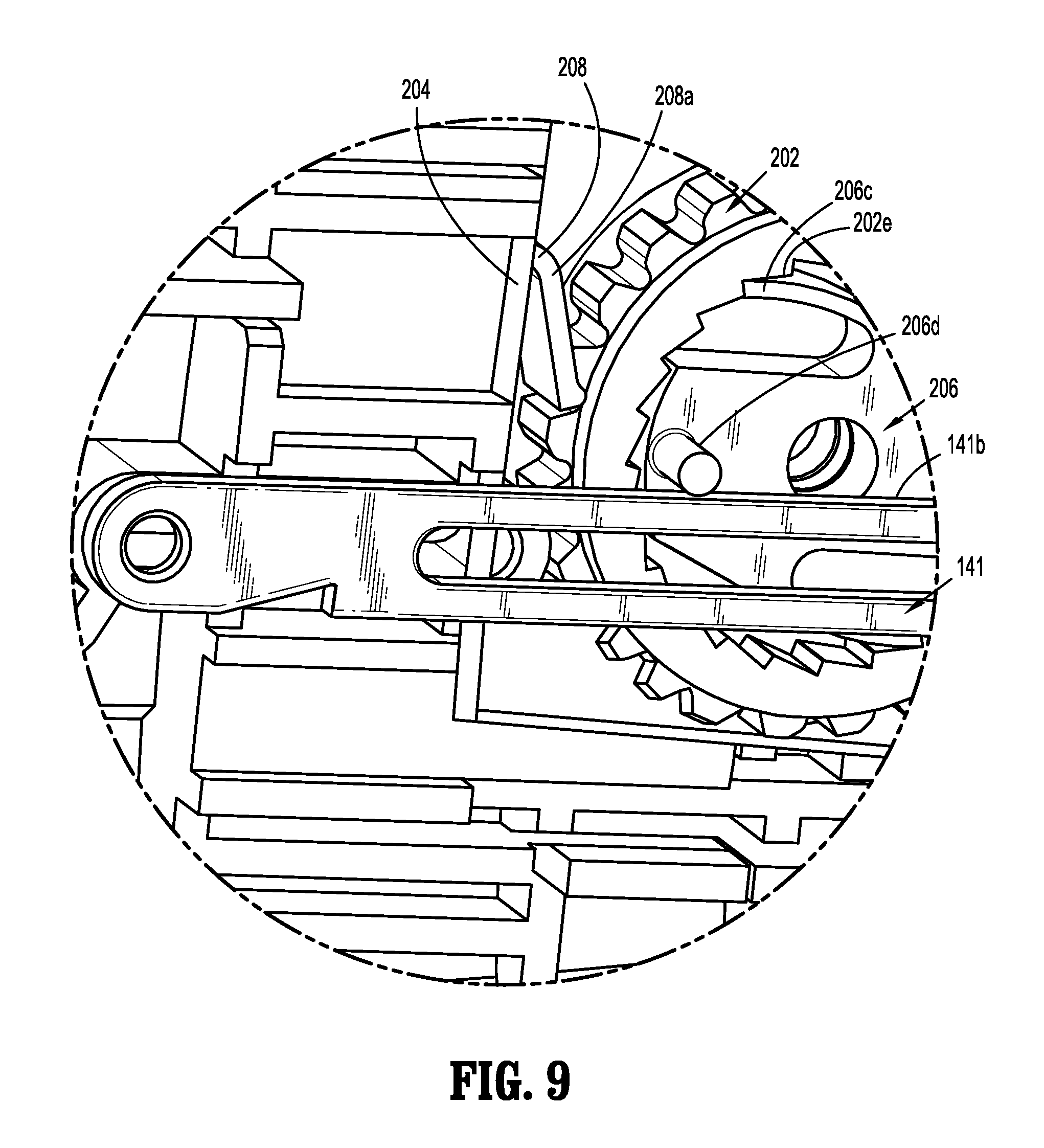
[0033] FIG. 9 is an enlarged view of the indicated area of detail of FIG. 8;
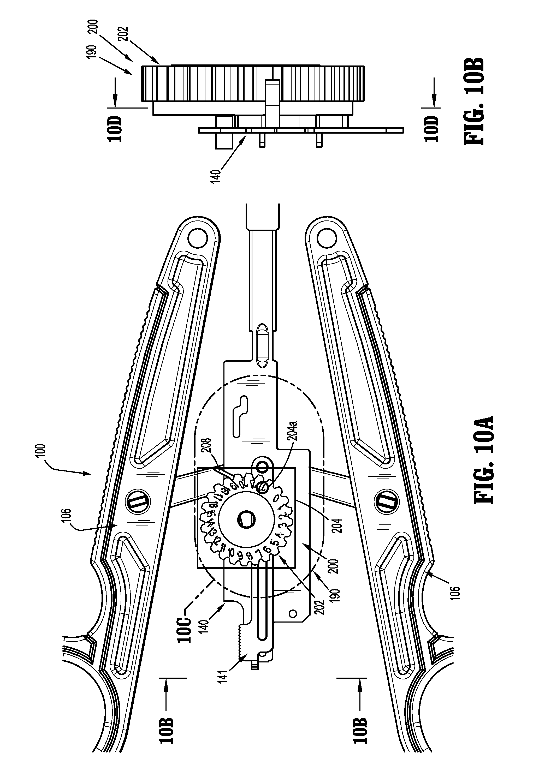
[0034] FIG. 10A is a top plan, schematic illustration of the mechanical counter operatively connected to the drive channel when the clip applier is in an original unactuated position;
[0035] FIG. 10B is a side view of the mechanical counter as viewed along 10B-10B of FIG. 10A;
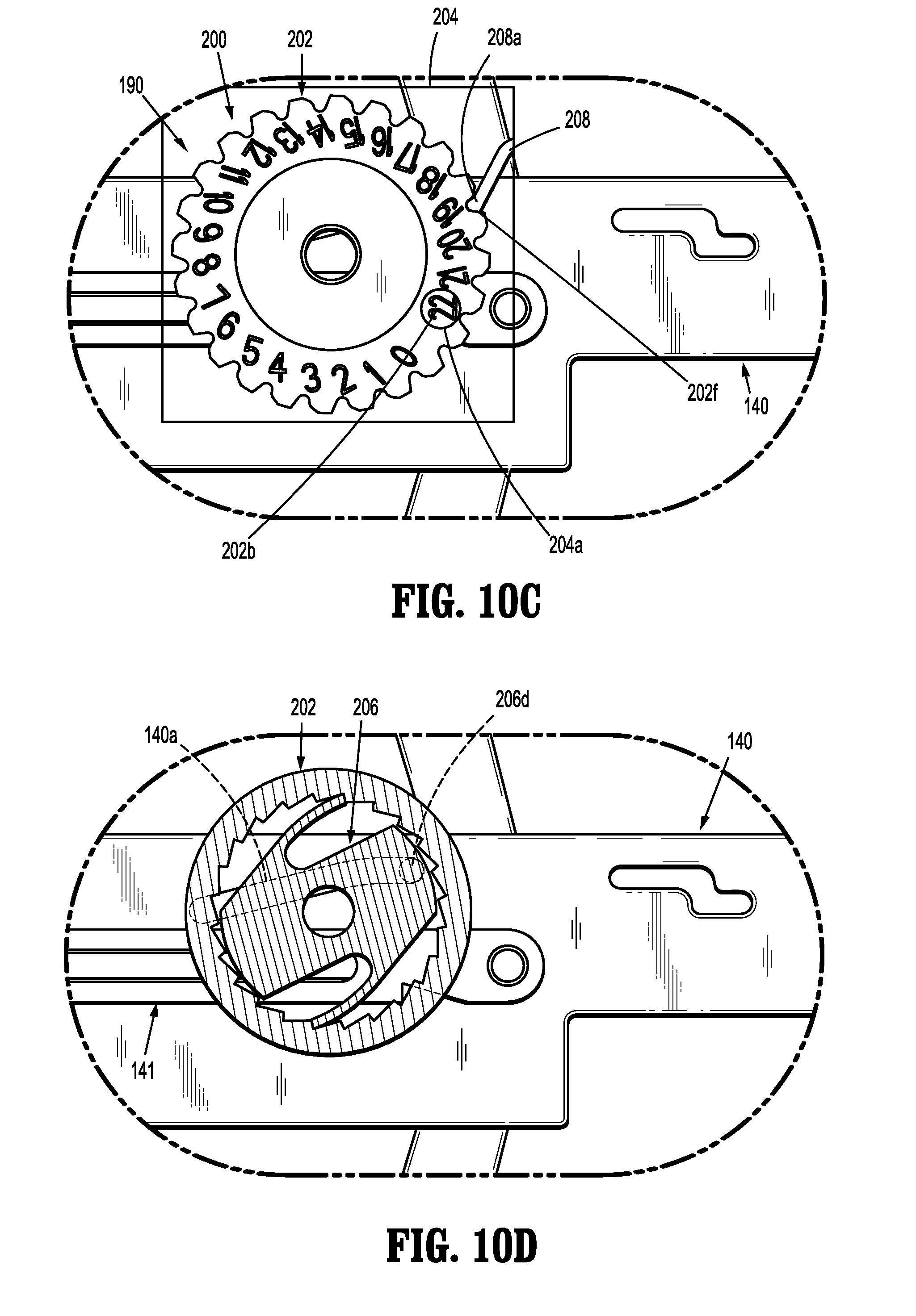
[0036] FIG. 10C is an enlarged view of the indicated area of detail of FIG. 10A;
[0037] FIG. 10D is a cross-sectional view of the mechanical counter as taken along 10D-10D of FIG. 10B;
[0038] FIG. 11A is a top plan, schematic illustration of the mechanical counter operatively connected to the drive channel when the clip applier is initially actuated;
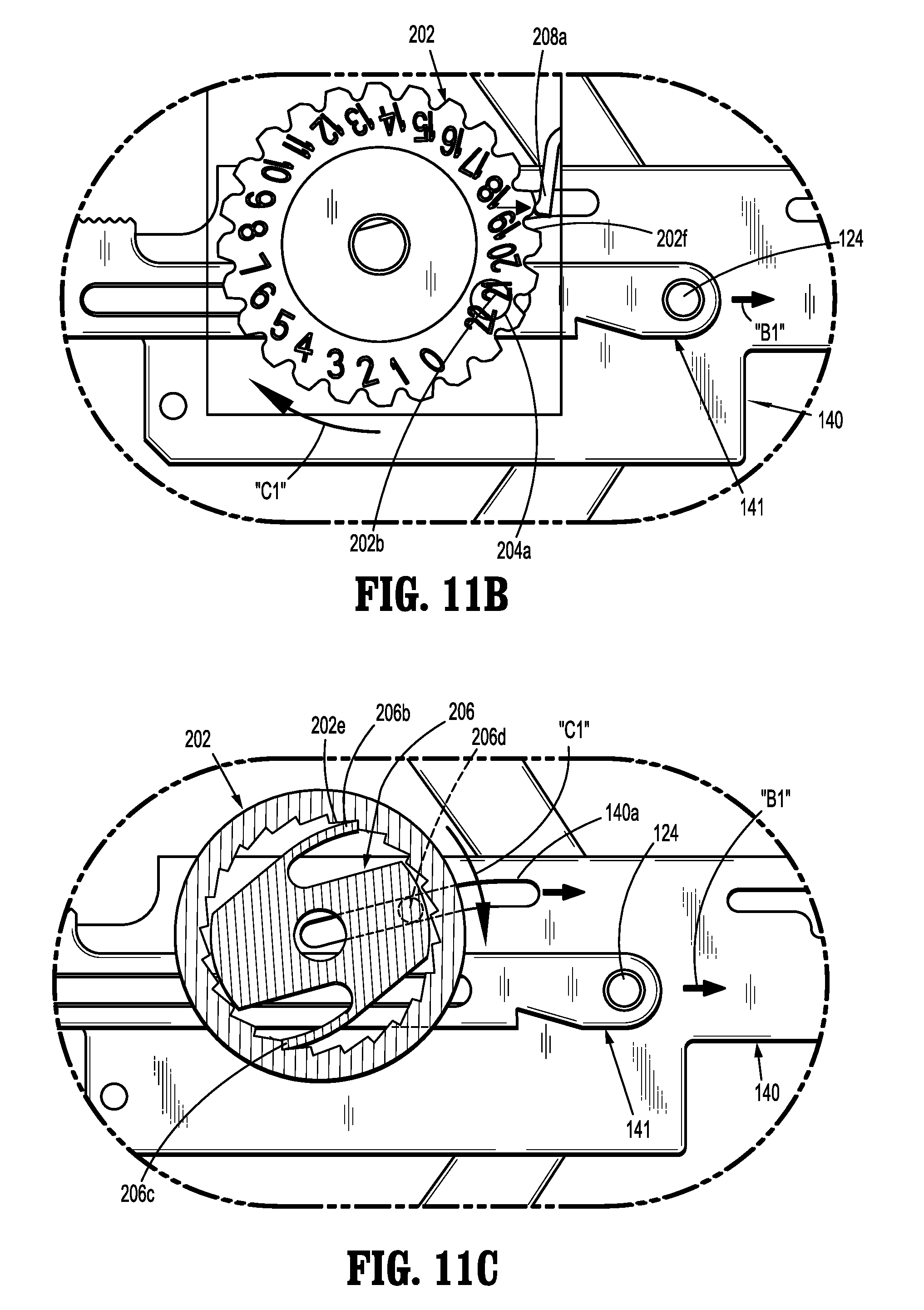
[0039] FIG. 11B is an enlarged view of the indicated area of detail of FIG. 11A;
[0040] FIG. 11C is a cross-sectional view of the mechanical counter as taken along 10D-10D of FIG. 10B, during the initial actuation of the clip applier;
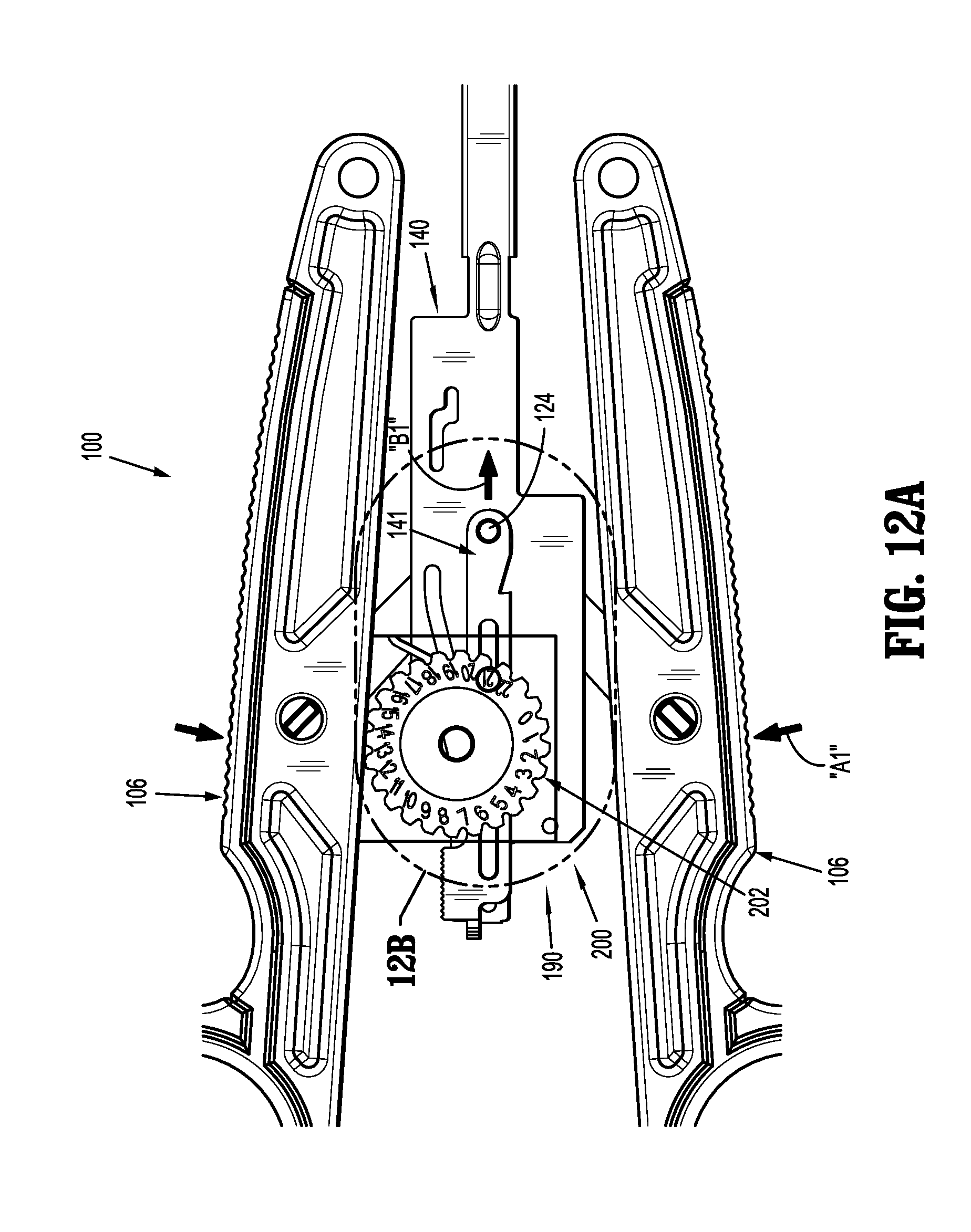
[0041] FIG. 12A is a top plan, schematic illustration of the mechanical counter operatively connected to the drive channel when the clip applier is fully actuated;
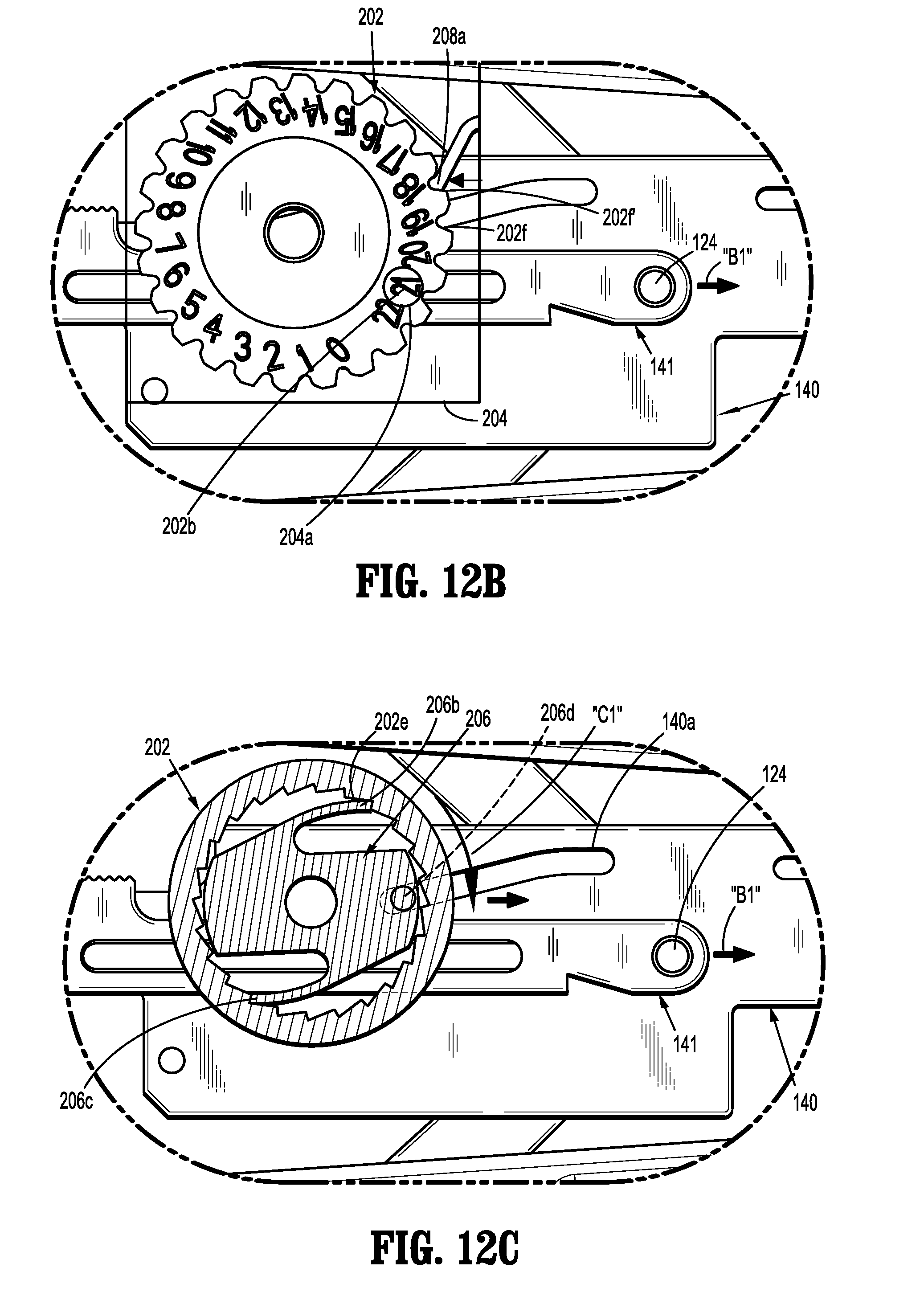
[0042] FIG. 12B is an enlarged view of the indicated area of detail of FIG. 12A;
[0043] FIG. 12C is a cross-sectional view of the mechanical counter as taken along 10D-10D of FIG. 10B, following the full actuation of the clip applier;
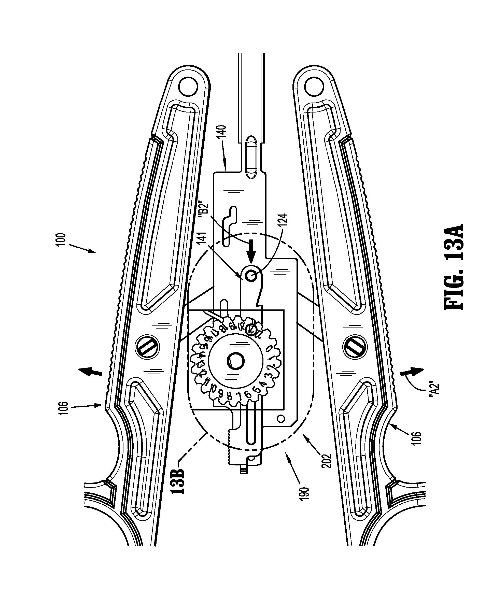
[0044] FIG. 13A is a top plan, schematic illustration of the mechanical counter operatively connected to the drive channel when the clip applier is released after full actuation;
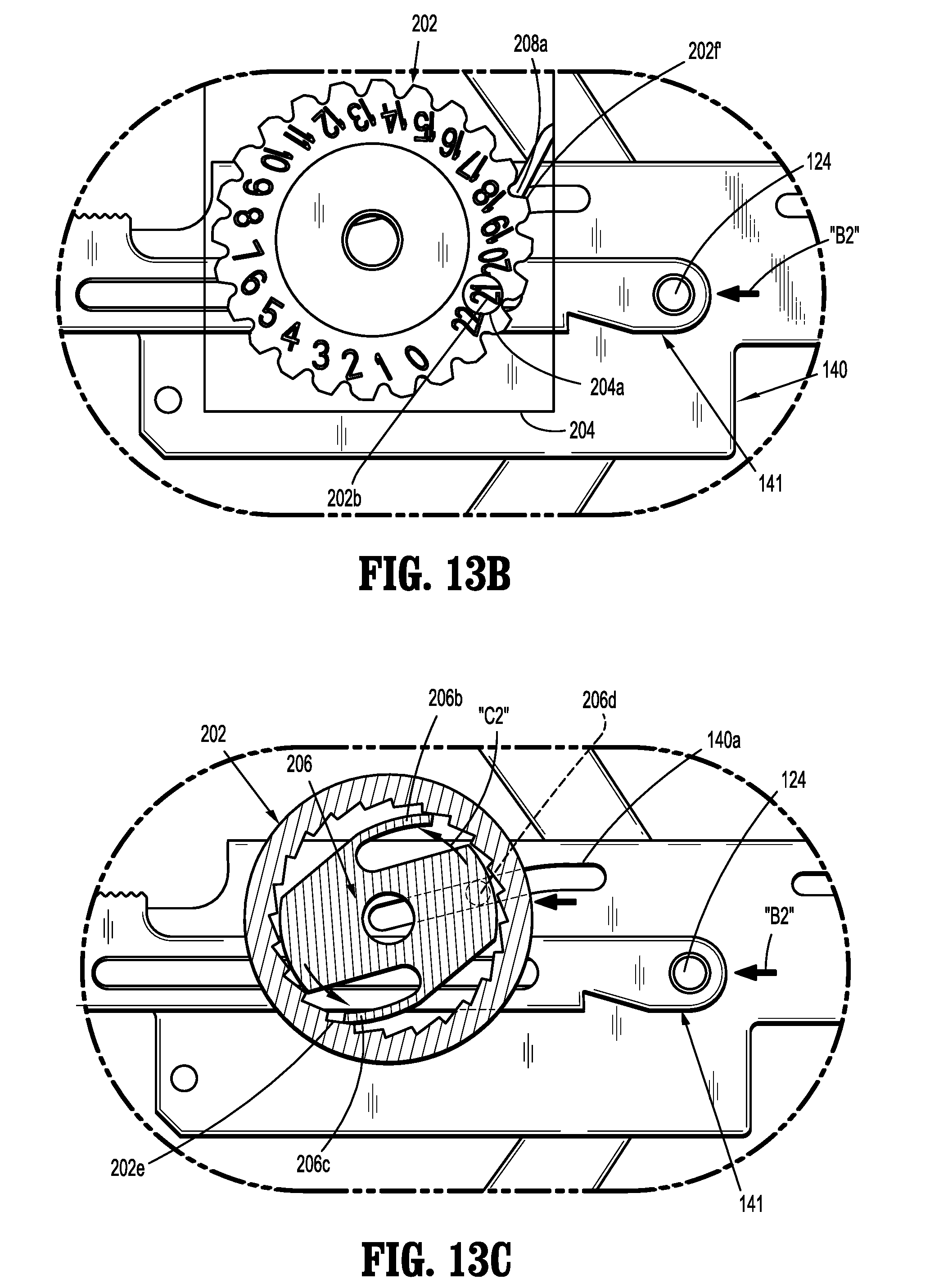
[0045] FIG. 13B is an enlarged view of the indicated area of detail of FIG. 13A;
[0046] FIG. 13C is a cross-sectional view of the mechanical counter as taken along 10D-10D of FIG. 10B, during a release of the clip applier following full actuation;
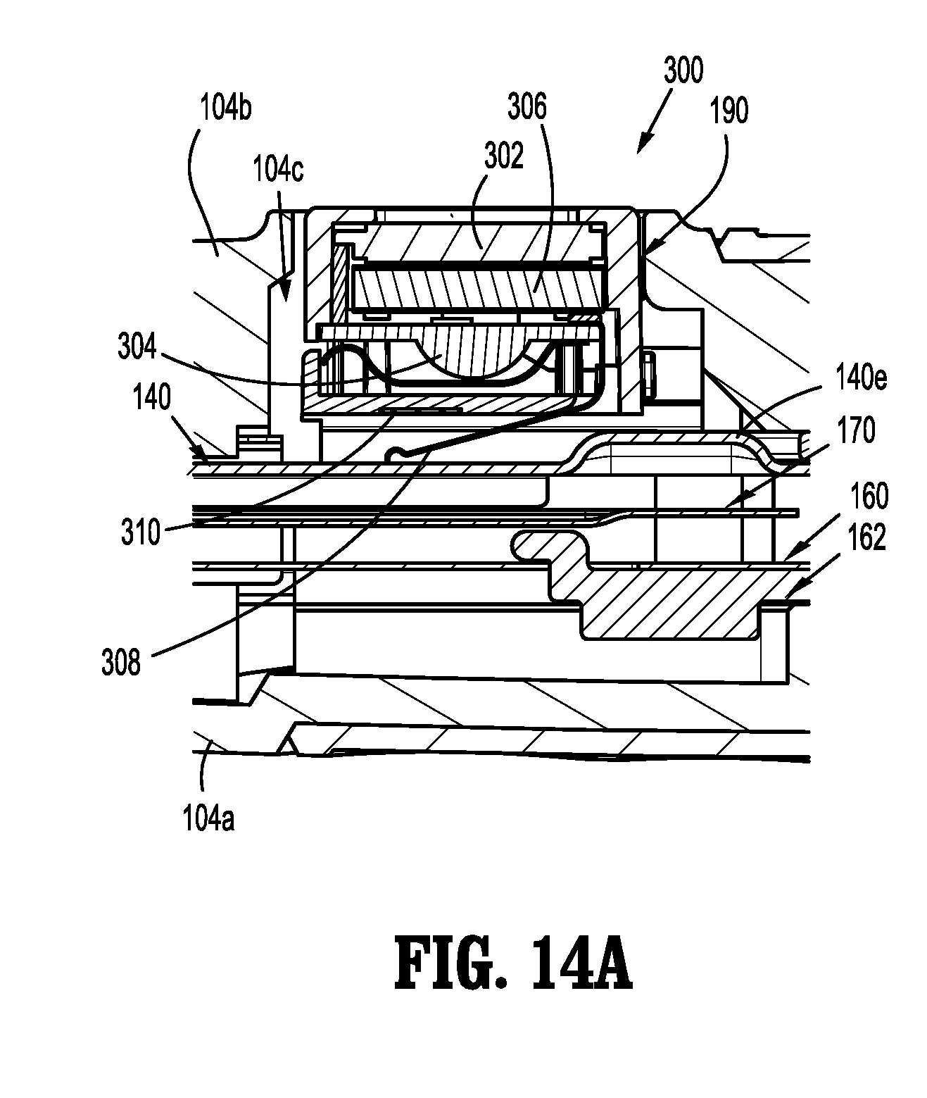
[0047] FIG. 14A is a side, cross-sectional view of the digital counter inserted into the clip applier when the drive channel is in an original unactuated position; and
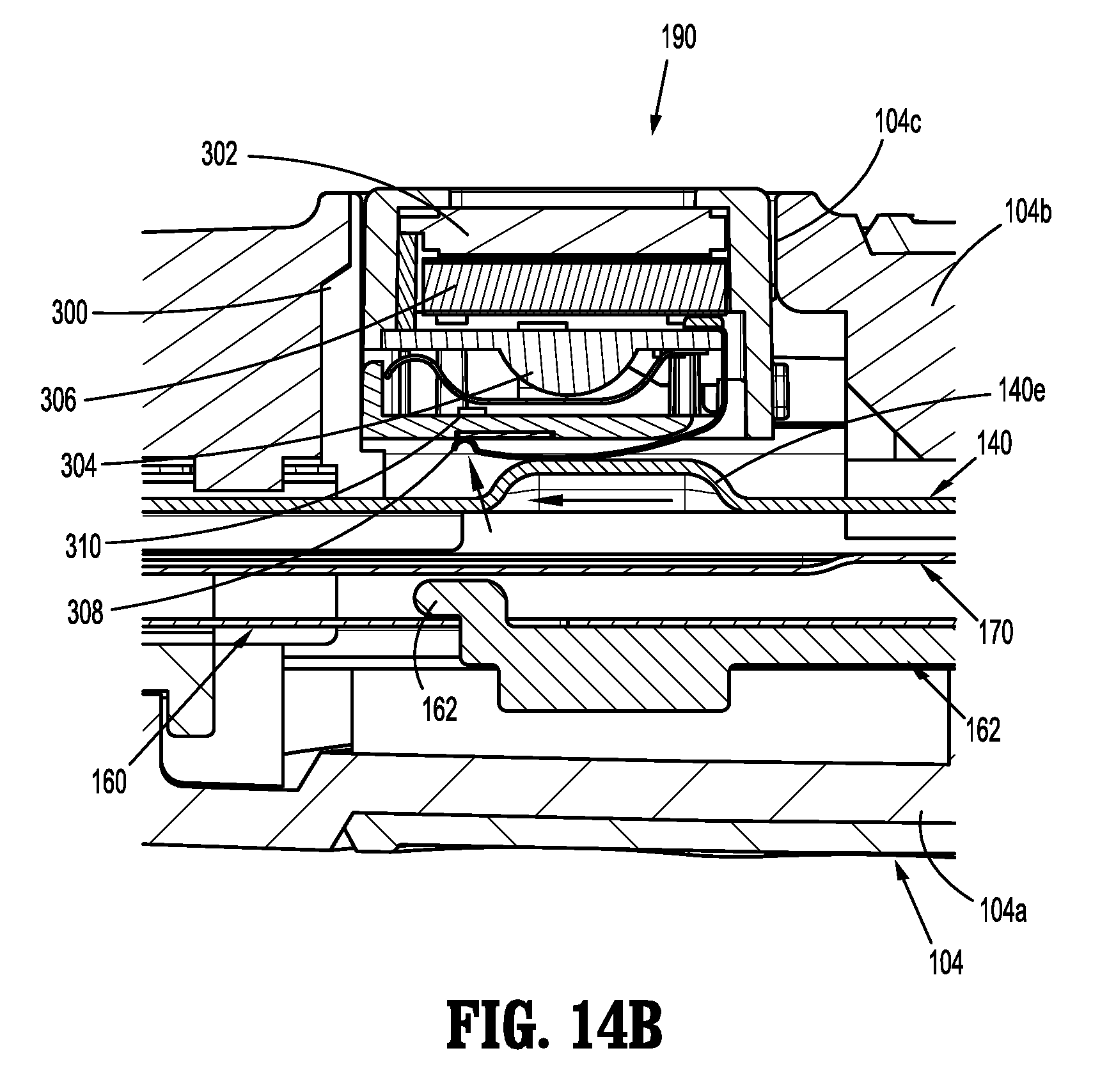
[0048] FIG. 14B is a side, cross-sectional view of the digital counter when the clip applier has been actuated and the nub of the drive channel is engaged with the contact of the digital counter to complete a circuit.
DETAILED DESCRIPTION OF EMBODIMENTS
[0049] Embodiments of surgical clip appliers in accordance with the present disclosure will now be described in detail with reference to the drawing figures wherein like reference numerals identify similar or identical structural elements. As shown in the drawings and described throughout the following description, as is traditional when referring to relative positioning on a surgical instrument, the term "proximal" refers to the end of the apparatus which is closer to the user and the term "distal" refers to the end of the apparatus which is further away from the user.
[0050] Referring now to FIGS. 1-3, a surgical clip applier in accordance with an embodiment of the present disclosure is generally designated as 100. Surgical clip applier 100 may be disposable and generally includes a handle assembly 102 including a housing 104 having an upper housing half 104a and lower housing half 104b. Handle assembly 102 further includes a pair of handles 106 pivotably secured to housing 104 and extending outwardly therefrom. A channel assembly 108 is fixedly secured to housing 104 and extends outwardly therefrom, terminating in a jaw assembly 110.
[0051] As seen in FIGS. 1-3, housing halves 104a and 104b of clip applier 100 fit together by snap fit engagement with one another. Housing 104 defines a counter slot 104c formed in lower housing half 104b for receiving a counter mechanism 190, as will be discussed in greater detail below. Counter slot 104c may initially include a removable plug 192 received therein.
[0052] As seen in FIG. 3, handles 106 are secured to housing 104 by handle pivot posts 104d extending from lower housing half 104b and into respective apertures 106a formed in handles 106. Handle assembly 102 includes a link member 122 pivotally connected to each handle 106 at a pivot point 106b formed in a respective handle 106. A distal end of each link member 122 is pivotally connected to a pivot point formed in a drive channel 140 via a drive pin 124. Each end of drive pin 124 is slidably received in an elongate channel formed in a respective upper and lower housing half 104a, 104b. In use, as will be described in greater detail below, as handles 106 are squeezed, link members 122 push drive channel 140 distally via drive pin 124.
[0053] Channel assembly 108 includes a channel or cartridge cover 130 and an outer or lower channel 132 each having a proximal end retained in housing assembly 102, between upper and lower housing halves 104a, 104b.
[0054] As seen in FIG. 3, clip applier 100 includes a clip pusher bar 160 slidably disposed beneath cartridge cover 130, a stabilizer 162 configured to overlie and engage pusher bar 160, a motion multiplier system 155 supported in housing 104, a clip carrier 170 disposed within channel assembly 108 and beneath pusher bar 160, a stack of surgical clips "C" loaded and/or retained within clip carrier 170 in a manner so as to slide therewithin and/or therealong, a clip follower 174 slidably disposed within clip carrier 170 and positioned behind the stack of surgical clips "C," a wedge plate 180 slidably disposed within handle assembly 102 and channel assembly 108, a wedge plate pivot arm 179 pivotally supported in lower housing half 104b of housing 104 for transmitting translation of drive channel 140 to translation of wedge plate 180, a drive channel 140 reciprocally supported in and extending between housing 104 of handle assembly 102 and channel assembly 108, an audible/tactile indicator 148 connected to drive channel 140 via drive pin 124, and a jaw assembly 110 (FIG. 1) mounted on or at a distal end of channel assembly 108 and actuatable by handles 106 of handle assembly 102.
[0055] Clip applier 100 also includes a ratchet rack member 141 slidably disposed in lower housing half 104b. Rack member 141 is pinned to drive pin 124 such that translation of drive pin 124 relative to housing 104 results in concomitant translation of rack member 141. Rack member 141 includes ratchet teeth 141a formed along an edge thereof and are configured and adapted to engage with a ratchet pawl 142 supported in housing 104. Rack member 141 and pawl 142 define a ratchet mechanism 144.
[0056] In use, as drive channel 140 is moved axially by drive pin 124, rack member 141 is also moved. Rack teeth 141a of rack member 141 has a length which allows pawl 142 to reverse and advance back over rack member 141 when rack member 141 changes between proximal and distal movement as drive channel 140 reaches a proximal-most or distal-most position.
[0057] Pawl 142 is pivotally connected to lower housing half 104b by a pawl pin at a location wherein pawl 142 is in substantial operative engagement with rack member 141. Pawl 142 is engageable with rack member 141 to restrict longitudinal movement of rack member 141 and, in turn, drive channel 140. Ratchet mechanism 144 further includes a pawl spring 145 configured and positioned to bias pawl 142 into operative association with rack member 141. Pawl spring 145 functions to maintain the teeth of pawl 142 in engagement with the teeth 141a of rack member 141, as well as to maintain pawl 142 in a rotated or canted position.
[0058] Reference may be made to U.S. patent application Ser. No. 12/540,475 filed on Aug. 13, 2009, entitled "Surgical Clip Applier;" now U.S. Pat. No. 8,465,502, U.S. patent application Ser. No. 12/539,006, filed on Aug. 11, 2009, entitled "Surgical Clip Applier and Method of Assembly;" now U.S. Pat. No. 8,056,565, U.S. patent application Ser. No. 12/939,296, filed on Nov. 4, 2010, entitled "Surgical Clip Applier", now U.S. Pat. No. 9,186,136, and U.S. patent application Ser. No. 12/943,045, filed on Nov. 10, 2010, entitled "Surgical Clip Applier", now U.S. Pat. No. 8,545,486, the entire contents of each of which being incorporated herein by reference, for a detailed discussion of the structure, operation, and method of assembly of various components surgical clip applier 100.
[0059] In accordance with the present disclosure, clip applier 100 is configured to receive a counter mechanism 190 in counter slot 104c. Counter mechanism 190 may be a mechanical or analog counter 200, as seen in FIGS. 4A-4C, 6-9, 10A-10D, 11A-11C, 12A-12C and 13A-13C, or may be a digital counter 300 as seen in FIGS. 5A-5B and 14A-14B.
[0060] Referring now to FIGS. 4A-4C, mechanical counter 200 is insertable into counter slot 104c and includes a counter dial 202 rotatably disposed within a counter housing 204, a counter clutch 206 operatively connected to counter dial 202 and configured to permit uni-directional rotation of counter dial 202, and a latch member 208 (FIG. 4B) configured to engage counter dial 202. Counter dial 202 includes a first face 202a disposed adjacent a window 204a formed in counter housing 204. First face 202a includes a plurality of indicia 202b, in the form of sequential numbers disposed thereof and substantially around a radial periphery thereof. Indicia 202b may correspond to the number of clips that are loaded in clip applier 100, may correspond to the number of clips that have been used in a surgical procedure, or may correspond to the number of clips to be used during a surgical procedure. The surgeon may reset or pre-set mechanical counter 200 by rotating counter dial 202 prior to inserting the counter mechanism 190 into the counter slot 104c. By way of example only, indicia 202b may be numerals from "0-22." Indicia 202b are located on first face 202a so as to be in registration with window 204a formed in counter housing 204. Counter dial 202 includes a second face 202c, opposite first face 202b, and defining a bore 202d therein. Bore 202d includes a radial array of uni-directional teeth 202e formed therein. Counter dial 202 further includes a first or outer rim defining a plurality of grooves 202f formed around an outer periphery thereof, and a second or inner rim formed in an outer periphery thereof.
[0061] With continued reference to FIGS. 4A-4C, counter clutch 206 is concentrically and rotatably nested in bore 202d of counter dial 202. Counter clutch 206 of mechanical counter 200 includes a body portion 206a configured and dimensioned for rotatable disposition in bore 202d of counter dial 202. Counter clutch 206 includes a pair of opposed resilient fingers 206b, 206c extending substantially tangentially from body portion 206a. Resilient fingers 206b, 206c extend from body portion 206a by an amount sufficient so as to resiliently engage uni-directional teeth 202e of dial 202. Counter clutch 206 includes a clutch pin 206d extending from body portion 206a and projecting out of bore 202d of counter dial 202. Clutch pin 206d extends through a clutch slot 204b of counter housing 204.
[0062] As seen in FIG. 4B, latch member 208 of mechanical counter 200 is secured to an inner wall of counter housing 204. Latch member 208 includes a resilient finger 208a configured to contact and selectively engage grooves 202f formed around the outer periphery of counter dial 202.
[0063] As seen in FIGS. 3 and 6-9, drive channel 140 defines an angled slot 140a formed therein at a location so as to slidably receive clutch pin 206d extending from body portion 206a of counter clutch 206. Angled slot 140a of drive channel 140 extends in a direction away from a longitudinal axis of clip applier 100 from a proximal to a distal direction. Rack member 141 is disposed in housing 104 such that clutch pin 206d of counter clutch 206 rides along or contacts a side edge 141b thereof.
[0064] Referring now to FIGS. 5A, 5B, 14A and 14B, digital counter 300 is insertable into counter slot 104c and includes a display 302, a processor 304, and an energy source 306 in the form of a battery or the like. Display 302 is a liquid crystal display that displays one or more operating parameters of clip applier 100 to the surgeon. The operating parameter displayed may be an amount or number of remaining clips, a number of clips that have been used, a position parameter, a surgical time of usage, or any other parameter of the procedure. Energy source 306 may be rechargeable and/or replaceable where, for example, energy source 306 may be recharged or replaced between uses of digital counter 300.
[0065] As seen in FIGS. 14A and 14B, digital counter 300 is actuated by nub 140e formed in drive channel 140. In use, as drive channel 140 is translated axially, nub 140e thereof engages a contact 308 of digital counter 300 causing contact 308 to engage a contact pad 310 of digital counter 300 to complete a circuit with energy source 306 and trigger processor 304 to perform a function (e.g., updating the number appearing on display 302 by a given increment or decrement value). It is contemplated that digital counter 300 may be dimensioned for insertion into counter slot 104a such that contact 308 is suitably aligned with nub 140e. Counter slot 104c and digital counter 300 may be configured and dimensioned such that digital counter 300 is insertable into counter slot 104c in only one orientation.
[0066] For a more detailed discussion of a similar mechanical counter, please refer to commonly owned U.S. patent application Ser. No. 12/943,045, mentioned above. For a more detailed discussion of a similar digital counter, please refer to commonly owned U.S. patent application Ser. Nos. 12/540,475 and 12/539,006, mentioned above.
[0067] Turning now to FIGS. 10A-10D, 11A-11C, 12A-12C, 13A-13C and 14A-14B, the operation of clip applier 100 is provided. Prior to any initial squeezing of handles 106 of clip applier 100, with clip applier 100 loaded with clips "C," drive channel 140 is located at a proximal-most position, as seen in FIG. 10A. According to the present disclosure, prior to any use of clip applier 100, the surgeon determines whether to include a counter mechanism 190 in clip applier 100, and "if so" which type of counter mechanism (e.g., analog/mechanical or digital) to include. For example, if the surgical procedure requires the use of only a few clips, such as one or two clips, the surgeon may not wish to include any counter and would instead leave plug 192 in place in counter slot 104c. On the other hand, if the surgical procedure requires the use of a larger number of clips, some or all of clip applier 100's capacity for example, the surgeon may wish to utilize one of counter mechanisms 190. When choosing between mechanical counter 200 and digital counter 300 the surgeon may consider a number of factors including, for example, whether additional functionality is required (e.g., digital counter 300 may, for example, allow the surgeon to switch display 302 between clips remaining and clips fired or may provide the surgeon with additional information related to the surgery such as, for example, elapsed time, etc.), ease of use, cost of maintenance, etc.
[0068] Mechanical counter 200, digital counter 300 and surgical clip applier 100 may each be re-usable or disposable.
[0069] If the surgeon chooses mechanical counter 200, the surgeon resets mechanical counter 200 to an initial state, for example, with the indicia 202d visible in window 204a displaying the number of clips "C" loaded into the clip applier, displaying the numeral "0" if mechanical counter 200 will increment during use, or displaying the total number of clips "C" to be used in the surgical operation or the total number of clips "C" available, if mechanical counter 200 will decrement during use.
[0070] For example, the surgeon may reset the mechanical counter 200 by actuating the clutch pin 206d of the counter clutch 206 until the desired number is visible through window 204a. As seen in FIG. 10A, for example, in the present instance, the clip applier 100 is fully loaded with twenty-two (22) clips, and the indicia 202d visible through window 204a formed in counter housing 204 is the numeral "22", as seen in FIG. 10C. Also, as seen in FIG. 10C, resilient finger 208a of latch member 208 is engaged in a groove 202f formed around the outer periphery of counter dial 202.
[0071] The surgeon then inserts mechanical counter 200 into counter slot 104c such that clutch pin 206d is inserted into angled slot 140a, as seen in FIG. 7. It is contemplated that mechanical counter 200 may include identification on its counter housing 204 of the proper orientation for insertion into counter slot 104c of housing 104 or that mechanical counter 200 may be dimensioned in relation to counter slot 104c such that only one orientation is possible for insertion.
[0072] As seen in FIG. 10D, prior to any squeezing of handles 106, clutch pin 206d of counter clutch 206 is disposed at a distal end of angled slot 140a of drive channel 140.
[0073] As seen in FIGS. 11A-11C, during an initial squeeze of handles 106, as indicated by arrow "A1," drive pin 124 translates drive channel 140 and rack member 141 in a distal direction, as indicated by arrow "B1." As drive channel 140 is translated in a distal direction, angled slot 140a of drive channel 140 is moved in a distal direction relative to clutch pin 206d of counter clutch 206, clutch pin 206d is cammed through angled slot 140a of drive channel 140 causing counter clutch 206 to rotate in the direction of arrow "C1." As counter clutch 206 is rotated in the direction of arrow "C1," as seen in FIG. 11C, resilient fingers 206b, 206c thereof engage uni-directional teeth 202e of dial 202, thereby causing dial 202 to also rotate in the direction of arrow "C1."
[0074] As dial 202 is rotated in the direction of arrow "C1," as seen in FIG. 11B, indicia 202b is moved relative to window 204a formed in counter housing 204, thereby beginning to increment or decrement mechanical counter 200. Additionally, as dial 202 is rotated in the direction of arrow "C1," resilient finger 208a of latch member 208 begins to disengage the groove 202f formed around the outer periphery of counter dial 202.
[0075] As seen in FIGS. 12A-12C, during a final or complete squeeze of handles 106, as indicated by arrow "A1," drive pin 124 further translates drive channel 140 and rack member 141 in a distal direction, as indicated by arrow "B1." As drive channel 140 is further translated in a distal direction, angled slot 140a of drive channel 140 is further moved in a distal direction relative to clutch pin 206d of counter clutch 206, clutch pin 206d is further cammed through angled slot 140a of drive channel 140 causing counter clutch 206 to further rotate in the direction of arrow "C1." As counter clutch 206 is further rotated in the direction of arrow "C1," as seen in FIG. 12C, resilient fingers 206b, 206c continue to cause dial 202 to rotate in the direction of arrow "C1."
[0076] As dial 202 is further rotated in the direction of arrow "C1," as seen in FIG. 12B, indicia 202b of numeral "22" is completely moved out of view of window 204a formed in counter housing 204 and new numeral "21" is moved into view of window 204a, thereby fully being decremented. As discussed above, other numerals, such as, for example, the numeral "0" may initially be visible through window 204a and, for example, mechanical counter 200 may increment from the numeral "0" to the numeral "1" instead of being decremented. This change of numeral coincides with a formation and/or firing/ejection/release of a clip from clip applier 100. In this manner, the user is shown the number of clips remaining in clip applier 100, the number of clips used during the procedure, or the number of clips remaining to be used. Additionally, as dial 202 is further rotated in the direction of arrow "C1," resilient finger 208a of latch member 208 moves into engagement in a groove 202f' adjacent to groove 202f formed around the outer periphery of counter dial 202.
[0077] Turning now to FIGS. 13A-13C, during an opening of handles 106, as indicated by arrow "A2," drive pin 124 translates drive channel 140 and rack member 141 in a proximal direction, as indicated by arrow "B2." As drive channel 140 is translated in a proximal direction, angled slot 140a of drive channel 140 is moved in a proximal direction relative to clutch pin 206d of counter clutch 206, clutch pin 206d is cammed through angled slot 140a of drive channel 140 causing counter clutch 206 to rotate in the direction of arrow "C2," opposite to "C1." As counter clutch 206 is rotated in the direction of arrow "C2," as seen in FIG. 13C, resilient fingers 206b, 206c are caused to deflect and snap over uni-directional teeth 202e of dial 202. As seen in FIG. 13B, any frictional forces tending to cause dial 202 to also rotate in the direction of arrow "C2" are negated by the engagement of resilient finger 208a of latch member 208 in groove 202f' formed around the outer periphery of counter dial 202, thereby maintaining the rotational orientation of dial 202.
[0078] With dial 202 being held or maintained in this rotational orientation, the new indicia 202b of numeral "21" if decrementing from numeral "22", or numeral "1" if incrementing from the numeral "0", is maintained in view in window 204a.
[0079] When drive channel 140 has been moved back to the fully proximal position, resilient fingers 206b, 206c of counter clutch 206 are re-set in engagement with adjacent uni-directional teeth 202e of dial 202. Additionally, as dial 202 is further rotated in the direction of arrow "C1," resilient finger 208a of latch member 208 moves into engagement in a groove 202f adjacent to groove 202f formed around the outer periphery of counter dial 202.
[0080] The surgeon may continue to actuate handles 106 until the final clip "C" is fired with the indicia 202b visible through window 204a either incrementing or decrementing to inform the surgeon of the number of clips "C" that have been used or the number of clips "C" remaining to be used or. Once the final clip "C" has been fired, a lockout mechanism (not shown) may be used to prevent further actuation of handles 106, prevent jaw assembly 110 from closing, and prevent clip applier 100 from being fired. A suitable lockout mechanism can be found, for example, in U.S. patent application Ser. Nos. 12/540,475, 12/539,006, and 12/943,045, mentioned above.
[0081] If the surgeon chooses digital counter 300, the surgeon resets digital counter 300 to an initial state, for example, with the display 302 displaying the number of clips "C" loaded into the clip applier, displaying the numeral "0", or the number of clips "C" to be used in the surgical operation.
[0082] The surgeon then inserts digital counter 300 into counter slot 104c such that contact 308 is axially aligned with nub 140e of drive bar 140, as seen in FIG. 14a. During actuation of handles 106, as described above, drive bar translates distally and nub 140e engages contact 308 and drives contact 308 to engage contact plate 310 (FIG. 14b). Engagement of contact 308 with contact plate 310 completes a circuit with energy source 306 and triggers processor 304 to perform a function. As described above, processor 304 may, for example, increment the numeral displayed on display 302, decrement the numeral displayed on display 302, or perform other functions required by the surgeon. Digital counter 300 may also be manipulated by the surgeon to display one or more pieces of information at the same time such as, for example, the remaining number of clips "C", the number of clips "C" fired, the elapsed time, etc. The numeral displayed on display 302 may be changed when contact 308 engages contact plate 310 or alternatively may be change when contact 308 disengages from contact plate 310, such as when drive bar 140 translates proximally due to opening of handles 106 at the end of the firing process.
[0083] After the surgical procedure is complete, counter mechanism 190 may be removed from clip applier 100 and sanitized/stored for re-use. For example, energy source 306 of digital counter 300 may be replaced or be recharged and digital counter 300 may be inserted into a docking or recharging station (not shown) for recharging.
[0084] It should be understood that the foregoing description is only illustrative of the present disclosure. Various alternatives and modifications can be devised by those skilled in the art without departing from the disclosure. Accordingly, the present disclosure is intended to embrace all such alternatives, modifications and variances. The embodiments described with reference to the attached drawing figures are presented only to demonstrate certain examples of the disclosure. Other elements, steps, methods and techniques that are insubstantially different from those described above and/or in the appended claims are also intended to be within the scope of the disclosure.
* * * * *
D00000
D00001
D00002
D00003
D00004
D00005
D00006
D00007
D00008
D00009
D00010
D00011
D00012

D00013
D00014
D00015
D00016
D00017
D00018
D00019
XML
uspto.report is an independent third-party trademark research tool that is not affiliated, endorsed, or sponsored by the United States Patent and Trademark Office (USPTO) or any other governmental organization. The information provided by uspto.report is based on publicly available data at the time of writing and is intended for informational purposes only.
While we strive to provide accurate and up-to-date information, we do not guarantee the accuracy, completeness, reliability, or suitability of the information displayed on this site. The use of this site is at your own risk. Any reliance you place on such information is therefore strictly at your own risk.
All official trademark data, including owner information, should be verified by visiting the official USPTO website at www.uspto.gov. This site is not intended to replace professional legal advice and should not be used as a substitute for consulting with a legal professional who is knowledgeable about trademark law.