Reposable Multi-fire Surgical Clip Applier
P V R; Mohan
U.S. patent application number 16/142108 was filed with the patent office on 2019-06-13 for reposable multi-fire surgical clip applier. The applicant listed for this patent is Covidien LP. Invention is credited to Mohan P V R.
| Application Number | 20190175187 16/142108 |
| Document ID | / |
| Family ID | 64665009 |
| Filed Date | 2019-06-13 |
View All Diagrams
| United States Patent Application | 20190175187 |
| Kind Code | A1 |
| P V R; Mohan | June 13, 2019 |
REPOSABLE MULTI-FIRE SURGICAL CLIP APPLIER
Abstract
A reposable surgical clip applier includes a handle assembly, a shaft assembly releasably engagable with the handle assembly, and a clip cartridge assembly releasably engagable within the shaft assembly. The handle assembly includes a proximal drive member and a proximal pusher bar movable through the proximal drive member. When the reposable surgical clip applier is assembled, the proximal drive member of the handle assembly is positioned proximally adjacent an inner drive assembly of the shaft assembly such that movement of handle(s) of the handle assembly towards an approximated position actuates a jaw assembly of the shaft assembly. When the reposable surgical clip applier is assembled, the proximal pusher of the handle assembly is positioned proximally adjacent a distal pusher of the clip cartridge assembly such that movement of the handle(s) towards a spaced-apart position loads a distal-most surgical clip from the clip cartridge assembly into the jaw assembly.
| Inventors: | P V R; Mohan; (Hyderabad, IN) | ||||||||||
| Applicant: |
|
||||||||||
|---|---|---|---|---|---|---|---|---|---|---|---|
| Family ID: | 64665009 | ||||||||||
| Appl. No.: | 16/142108 | ||||||||||
| Filed: | September 26, 2018 |
Related U.S. Patent Documents
| Application Number | Filing Date | Patent Number | ||
|---|---|---|---|---|
| 62598420 | Dec 13, 2017 | |||
| Current U.S. Class: | 1/1 |
| Current CPC Class: | A61B 17/1285 20130101; A61B 2017/2919 20130101; A61B 34/35 20160201; A61B 17/105 20130101; A61B 2017/00407 20130101; A61B 2017/2911 20130101; A61B 17/2909 20130101; A61B 2017/00477 20130101; A61B 2017/0023 20130101 |
| International Class: | A61B 17/128 20060101 A61B017/128; A61B 34/35 20060101 A61B034/35 |
Claims
1. A reposable surgical clip applier, comprising: a handle assembly, including: a housing; at least one handle movable relative to the housing between a spaced-apart position and an approximated position; and an inner actuation assembly disposed within the housing, the inner actuation assembly including a proximal drive member and a proximal pusher bar movable through the proximal drive member, the inner actuation assembly operably coupled to the at least one handle such that movement of the at least one handle towards the approximated position moves the proximal drive member distally about the proximal pusher bar and moves the proximal pusher bar proximally about and through the proximal drive member, and such that movement of the at least one handle towards the spaced-apart position moves the proximal drive member proximally about the proximal pusher bar and moves the proximal pusher bar distally about and through the proximal drive member; a shaft assembly releasably engagable with the handle assembly, the shaft assembly including: an outer tube; a jaw assembly supported at a distal end portion of the outer tube; and an inner drive assembly slidably disposed within the outer tube and operably coupled to the jaw assembly such that distal movement of the inner drive assembly through the outer tube actuates the jaw assembly; and a clip cartridge assembly releasably engagable within the shaft assembly, the clip cartridge assembly retaining a stack of surgical clips therein and including a distal pusher operably coupled to a distal-most surgical clip of the stack of surgical clips such that distal movement of the distal pusher loads the distal-most surgical clip into the jaw assembly when the clip cartridge assembly is releasably engaged within the shaft assembly, wherein, when the shaft assembly is releasably engaged with the handle assembly and the clip cartridge assembly is releasably engaged within the shaft assembly: the proximal drive member is positioned proximally adjacent the inner drive assembly such that movement of the at least one handle towards the approximated position actuates the jaw assembly, and the proximal pusher bar is positioned proximally adjacent the distal pusher such that movement of the at least one handle towards the spaced-apart position loads the distal-most surgical clip into the jaw assembly.
2. The reposable surgical clip applier according to claim 1, wherein the clip cartridge assembly further includes a biasing member configured to bias the distal pusher proximally.
3. The reposable surgical clip applier according to claim 2, wherein the clip cartridge assembly further includes a cartridge housing having a support base configured to support at least a portion of the distal pusher, the support base including a distal bridge portion and a proximal bridge portion, wherein the biasing member of the cartridge assembly is operably coupled to the distal pusher and to the proximal bridge portion to bias the distal pusher proximally.
4. The reposable surgical clip applier according to claim 3, wherein the clip cartridge assembly further includes a clip carrier including a pair of engagement flanges, and wherein the cartridge housing includes a pair of internal grooves extending longitudinally along at least a portion of a length of the cartridge housing, the pair of internal grooves configured to laterally receive the pair of engagement flanges, respectively, to inhibit axial movement of the clip carrier relative to the cartridge housing.
5. The reposable surgical clip applier according to claim 4, wherein the clip cartridge assembly further includes a carrier lock disposed proximally adjacent a proximal end portion of the clip carrier, the carrier lock including a pair of opposing arms configured to biasingly engage a pair of opposing internal walls of the cartridge housing, wherein the carrier lock is configured to inhibit proximal movement of the clip carrier relative to the cartridge housing beyond the carrier lock.
6. The reposable surgical clip applier according to claim 1, wherein the shaft assembly further includes a biasing member configured to bias the inner drive assembly proximally.
7. The reposable surgical clip applier according to claim 1, wherein the outer tube of the shaft assembly defines an elongated cut-out, and wherein the clip cartridge assembly is removably insertable into the elongated cut-out to releasably engage the clip cartridge assembly within the shaft assembly.
8. The reposable surgical clip applier according to claim 7, wherein the clip cartridge assembly includes a slider movable between an unlocked position and a locked position to releasably lock the clip cartridge assembly within the elongated cut-out.
9. The reposable surgical clip applier according to claim 8, wherein the slider is releasably retainable in each of the locked and unlocked positions.
10. The reposable surgical clip applier according to claim 1, wherein the housing of the handle assembly includes a distal mouth defining a central passageway and a protrusion extending inwardly into the central passageway, and wherein the shaft assembly includes a tubular proximal segment defining a slot configured to receive the protrusion upon insertion of the tubular proximal segment into the distal mouth to releasably engage the shaft assembly with the handle assembly.
11. The reposable surgical clip applier according to claim 1, wherein the handle assembly includes a pair of handles pivotably coupled to the housing and extending from opposed sides thereof
12. The reposable surgical clip applier according to claim 11, wherein the handle assembly further includes a linkage assembly configured to pivotably couple the pair of handles to the inner actuation assembly, the linkage assembly having a first link arm configured to operably couple a first handle of the pair of handles to the proximal drive member and a second link arm configured to operably couple a second handle of the pair of handles to the proximal pusher bar, wherein upon movement of the pair of handles towards the approximated position, the first link arm is configured to move the proximal drive member distally and the second link arm is configured to move the proximal pusher bar proximally, and wherein upon movement of the pair of handles towards the spaced-apart position, the first link arm is configured to move the proximal drive member proximally and the second link arm is configured to move the proximal pusher bar distally.
13. The reposable surgical clip applier according to claim 12, wherein the linkage assembly further includes a third link arm configured to operably couple the second handle of the pair of handles to the proximal drive member and a fourth link arm configured to operably couple the first handle of the pair of handles to the proximal pusher bar.
14. The reposable surgical clip applier according to claim 13, wherein the linkage assembly is configured to move the proximal drive member concurrently with the proximal pusher bar upon movement of the pair of handles.
15. A reposable surgical clip applier, comprising: a handle assembly, including: a housing; a first handle and a second handle movable relative to the housing between a spaced-apart position and an approximated position; an inner actuation assembly disposed within the housing, the inner actuation assembly including a proximal drive member defining a lumen and a proximal pusher bar slidably disposed within the lumen of the proximal drive member and movable in relation to the proximal drive member; and a linkage assembly configured to pivotably couple the first handle and the second handle to the inner actuation assembly, the linkage assembly including: a first link arm configured to operably couple the first handle to the proximal drive member; and a second link arm configured to operably couple the second handle to the proximal pusher bar, wherein upon movement of the first handle and the second handle towards the approximated position, the first link arm is configured to move the proximal drive member distally about the proximal pusher bar and the second link arm is configured to move the proximal pusher bar proximally through the proximal drive member, concurrently with movement of the proximal drive member, and wherein upon movement of the first handle and the second handle towards the spaced-apart position, the first link arm is configured to move the proximal drive member proximally about the proximal pusher bar and the second link arm is configured to move the proximal pusher bar distally through the proximal drive member, concurrently with movement of the proximal drive member.
16. The reposable surgical clip applier according to claim 15, further including a shaft assembly releasably engagable with the handle assembly, the shaft assembly including an outer tube and a jaw assembly supported at a distal end portion of the outer tube, the jaw assembly configured to move between a first position and a second position.
17. The reposable surgical clip applier according to claim 16, further including a clip cartridge assembly releasably engagable within the shaft assembly, the clip cartridge assembly retaining a stack of surgical clips therein, wherein, when the shaft assembly is releasably engaged with the handle assembly and the clip cartridge assembly is releasably engaged within the shaft assembly: upon movement of the first handle and the second handle towards the approximated position, the proximal drive member is configured to move distally to move the jaw assembly from the first position to the second position, and upon movement of the first handle and the second handle towards the spaced-apart position, the proximal pusher bar is configured to move distally to load a distal-most surgical clip of the stack of surgical clips into the jaw assembly.
18. The reposable surgical clip applier according to claim 17, wherein the shaft assembly further includes an inner drive assembly slidably disposed within the outer tube and operably coupled to the jaw assembly such that distal movement of the inner drive assembly through the outer tube actuates the jaw assembly.
19. The reposable surgical clip applier according to claim 18, wherein the clip cartridge assembly further includes a distal pusher operably coupled to the distal-most surgical clip of the stack of surgical clips such that distal movement of the distal pusher loads the distal-most surgical clip into the jaw assembly when the clip cartridge assembly is releasably engaged within the shaft assembly.
20. The reposable surgical clip applier according to claim 18, wherein when the shaft assembly is releasably engaged with the handle assembly and the clip cartridge assembly is releasably engaged within the shaft assembly: the proximal drive member is positioned proximally adjacent the inner drive assembly such that movement of the first handle and the second handle towards the approximated position is configured to move the proximal drive member to move the inner drive assembly distally through the outer tube, and the proximal pusher bar is positioned proximally adjacent the distal pusher such that movement of the first handle and the second handle towards the spaced-apart position is configured to move the proximal pusher bar to move the distal pusher distally to load the distal-most surgical clip into the jaw assembly.
Description
CROSS-REFERENCE TO RELATED APPLICATION
[0001] This application claims the benefit of and priority to U.S. Provisional Patent Application No. 62/598,420 filed Dec. 13, 2017, the entire disclosure of which is incorporated by reference herein.
BACKGROUND
Technical Field
[0002] The present disclosure relates to surgical clip appliers and, more particularly, to a reposable multi-fire surgical clip applier including a handle assembly, a shaft assembly, and a clip cartridge assembly that are configured for selective disassembly to facilitate disposal of any disposable component(s) and reprocessing of any reusable component(s) for further use.
Discussion of Related Art
[0003] Various staplers and clip appliers are known in the art and used for a number of distinct and useful surgical procedures. Clip appliers that are able to apply multiple clips during a single entry into a body cavity, for example, are described in commonly-assigned U.S. Pat. Nos. 5,084,057 and 5,100,420 to Green et al., the entire contents of which are incorporated herein by reference. Another multiple clip applier is disclosed in commonly-assigned U.S. Pat. No. 5,607,436 by Pratt et al., the entire contents of which is also hereby incorporated herein by reference. U.S. Pat. No. 5,695,502 to Pier et al., the entire contents of which is hereby incorporated herein by reference, discloses a resterilizable surgical clip applier that is configured to receive and cooperate with an interchangeable clip magazine so as to advance and form multiple clips during a single entry into a body cavity.
SUMMARY
[0004] The present disclosure relates to a reposable multi-fire surgical clip applier including a handle assembly, a shaft assembly, and a clip cartridge assembly that are configured for selective disassembly to facilitate disposal of any disposable component(s) and reprocessing of any reusable component(s) for further use.
[0005] A reposable surgical clip applier provided in accordance with aspects of the present disclosure includes a handle assembly, a shaft assembly releasably engagable with the handle assembly, and a clip cartridge assembly releasably engagable within the shaft assembly.
[0006] The handle assembly includes a housing, at least one handle movable relative to the housing between a spaced-apart position and an approximated position, and an inner actuation assembly disposed within the housing. The inner actuation assembly includes a proximal drive member and a proximal pusher bar movable through the proximal drive member. The inner actuation assembly is operably coupled to the at least one handle such that movement of the at least one handle towards the approximated position moves the proximal drive member distally about the proximal pusher bar and moves the proximal pusher bar proximally about and through the proximal drive member, and such that movement of the at least one handle towards the spaced-apart position moves the proximal drive member proximally about the proximal pusher bar and moves the proximal pusher bar distally about and through the proximal drive member.
[0007] The shaft assembly includes an outer tube, a jaw assembly supported at a distal end portion of the outer tube, and an inner drive slidably disposed within the outer tube and operably coupled to the jaw assembly such that distal movement of the inner drive through the outer tube actuates the jaw assembly.
[0008] The clip cartridge assembly retains a stack of surgical clips therein and includes a distal pusher operably coupled to a distal-most surgical clip of the stack of surgical clips such that distal movement of the distal pusher loads the distal-most surgical clip into the jaw assembly when the clip cartridge assembly is releasably engaged within the shaft assembly.
[0009] When the shaft assembly is releasably engaged with the handle assembly and the clip cartridge assembly is releasably engaged within the shaft assembly, the proximal drive member is positioned proximally adjacent the inner drive assembly such that movement of the at least one handle towards the approximated position actuates the jaw assembly, and the proximal pusher bar is positioned proximally adjacent the distal pusher such that movement of the at least one handle towards the spaced-apart position loads the distal-most surgical clip into the jaw assembly.
[0010] In one aspect of the present disclosure, the clip cartridge assembly further includes a biasing member configured to bias the distal pusher proximally.
[0011] In embodiments of the present disclosure, the clip cartridge assembly further includes a cartridge housing having a support base configured to support at least a portion of the distal pusher. In such embodiments, the support base includes a distal bridge portion and a proximal bridge portion, wherein the biasing member of the cartridge assembly is operably coupled to the distal pusher and to the proximal bridge portion to bias the distal pusher proximally.
[0012] In another aspect of the present disclosure, the clip cartridge assembly further includes a clip carrier including a pair of engagement flanges. In such aspects, the cartridge housing includes a pair of internal grooves extending longitudinally along at least a portion of a length of the cartridge housing. In such aspects, the pair of internal grooves may be configured to laterally receive the pair of engagement flanges, respectively, to inhibit axial movement of the clip carrier relative to the cartridge housing.
[0013] In still another aspect of the present disclosure, the clip cartridge assembly further includes a carrier lock disposed proximally adjacent a proximal end portion of the clip carrier. In such aspects, the carrier lock includes a pair of opposing arms configured to biasingly engage a pair of opposing internal walls of the cartridge housing, wherein the carrier lock is configured to inhibit proximal movement of the clip carrier relative to the cartridge housing beyond the carrier lock.
[0014] In embodiments of the present disclosure, the shaft assembly further includes a biasing member configured to bias the inner drive assembly proximally.
[0015] In aspects of the present disclosure, the outer tube of the shaft assembly defines an elongated cut-out. In such aspects, the clip cartridge assembly may be removably insertable into the elongated cut-out to releasably engage the clip cartridge assembly within the shaft assembly.
[0016] In another aspect of the present disclosure, the clip cartridge assembly includes a slider movable between an unlocked position and a locked position to releasably lock the clip cartridge assembly within the elongated cut-out.
[0017] In embodiments of the present disclosure, the slider is releasably retainable in each of the locked and unlocked positions.
[0018] In another aspect of the present disclosure, the housing of the handle assembly includes a distal mouth defining a central passageway and a protrusion extending inwardly into the central passageway. In such aspects, the shaft assembly includes a tubular proximal segment defining a slot configured to receive the protrusion upon insertion of the tubular proximal segment into the distal mouth to releasably engage the shaft assembly with the handle assembly.
[0019] In yet another aspect of the present disclosure, the handle assembly includes a pair of handles pivotably coupled to the housing and extending from opposed sides thereof.
[0020] In aspects of the present disclosure, the handle assembly further includes a linkage assembly configured to pivotably couple the pair of handles to the inner actuation assembly. In such aspects, the linkage assembly includes a first link arm configured to operably couple a first handle of the pair of handles to the proximal drive member and a second link arm configured to operably couple a second handle of the pair of handles to the proximal pusher bar. In such aspects, upon movement of the pair of handles towards the approximated position, the first link arm is configured to move the proximal drive member distally and the second link arm is configured to move the proximal pusher bar proximally. In such aspects, upon movement of the pair of handles towards the spaced-apart position, the first link arm is configured to move the proximal drive member proximally and the second link arm is configured to move the proximal pusher bar distally.
[0021] In embodiments of the present disclosure, linkage assembly further includes a third link arm configured to operably couple the second handle of the pair of handles to the proximal drive member and a fourth link arm configured to operably couple the first handle of the pair of handles to the proximal pusher bar.
[0022] In another aspect of the present disclosure, the linkage assembly is configured to move the proximal drive member concurrently with the proximal pusher bar upon movement of the pair of handles.
[0023] A reposable surgical clip applier provided in accordance with another aspect of the present disclosure includes a handle assembly. The handle assembly includes a housing, a first and a second handle movable relative to the housing between a spaced-apart position and an approximated position, an inner actuation assembly disposed within the housing, and a linkage assembly configured to pivotably couple the first handle and the second handle to the inner actuation assembly.
[0024] The inner actuation assembly includes a proximal drive member defining a lumen and a proximal pusher bar slidably disposed within the lumen of the proximal drive member and movable in relation to the proximal drive member.
[0025] The linkage assembly includes a first link arm configured to operably couple the first handle to the proximal drive member, and a second link arm configured to operably couple the second handle to the proximal pusher bar.
[0026] When the first handle and the second handle are moved towards the approximated position, the first link arm is configured to move the proximal drive member distally about the proximal pusher bar and the second link arm is configured to move the proximal pusher bar proximally through the proximal drive member, concurrently with movement of the proximal drive member.
[0027] When the first handle and the second handle are moved towards the spaced-apart position, the first link arm is configured to move the proximal drive member proximally about the proximal pusher bar and the second link arm is configured to move the proximal pusher bar distally through the proximal drive member, concurrently with movement of the proximal drive member.
[0028] In one aspect of the present disclosure, the reposable surgical clip applier further includes a shaft assembly releasably engagable with the handle assembly. In such aspects, the shaft assembly includes an outer tube and a jaw assembly supported at a distal end portion of the outer tube, the jaw assembly configured to move between a first position and a second position.
[0029] In embodiments of the present disclosure, the reposable surgical clip applier further includes a clip cartridge assembly releasably engagable within the shaft assembly. In such embodiments, the clip cartridge assembly may retain a stack of surgical clips therein. In such embodiments, when the shaft assembly is releasably engaged with the handle assembly and the clip cartridge assembly is releasably engaged within the shaft assembly, upon movement of the first handle and the second handle towards the approximated position, the proximal drive member is configured to move distally to move the jaw assembly from the first position to the second position, and upon movement of the first handle and the second handle towards the spaced-apart position, the proximal pusher bar is configured to move distally to load a distal-most surgical clip of the stack of surgical clips into the jaw assembly.
[0030] In yet another aspect of the present disclosure, the shaft assembly further includes an inner drive assembly slidably disposed within the outer tube and operably coupled to the jaw assembly. In such aspects, distal movement of the inner drive assembly through the outer tube actuates the jaw assembly.
[0031] In another aspect of the present disclosure, the clip cartridge assembly further includes a distal pusher operably coupled to the distal-most surgical clip of the stack of surgical clips. In such aspects, distal movement of the distal pusher loads the distal-most surgical clip into the jaw assembly when the clip cartridge assembly is releasably engaged within the shaft assembly.
[0032] In another embodiment of the present disclosure, when the shaft assembly is releasably engaged with the handle assembly and the clip cartridge assembly is releasably engaged within the shaft assembly, the proximal drive member is positioned proximally adjacent the inner drive assembly such that movement of the first handle and the second handle towards the approximated position is configured to move the proximal drive member to move the inner drive assembly distally through the outer tube, and the proximal pusher bar is positioned proximally adjacent the distal pusher such that movement of the first handle and the second handle towards the spaced-apart position is configured to move the proximal pusher bar to move the distal pusher distally to load the distal-most surgical clip into the jaw assembly.
BRIEF DESCRIPTION OF THE DRAWINGS
[0033] Aspects and features of a reposable multi-fire surgical clip applier are provided in accordance with the present disclosure with reference to the drawings wherein:
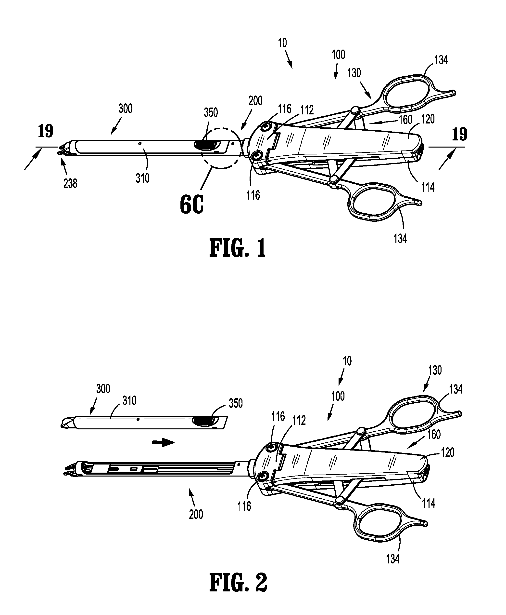
[0034] FIG. 1 is a top, perspective view of a reposable multi-fire surgical clip applier provided in accordance with the present disclosure, shown in an assembled condition with a door of a handle assembly thereof closed;
[0035] FIG. 2 is a top, perspective view of the surgical clip applier of FIG. 1, shown in a partially disassembled condition;
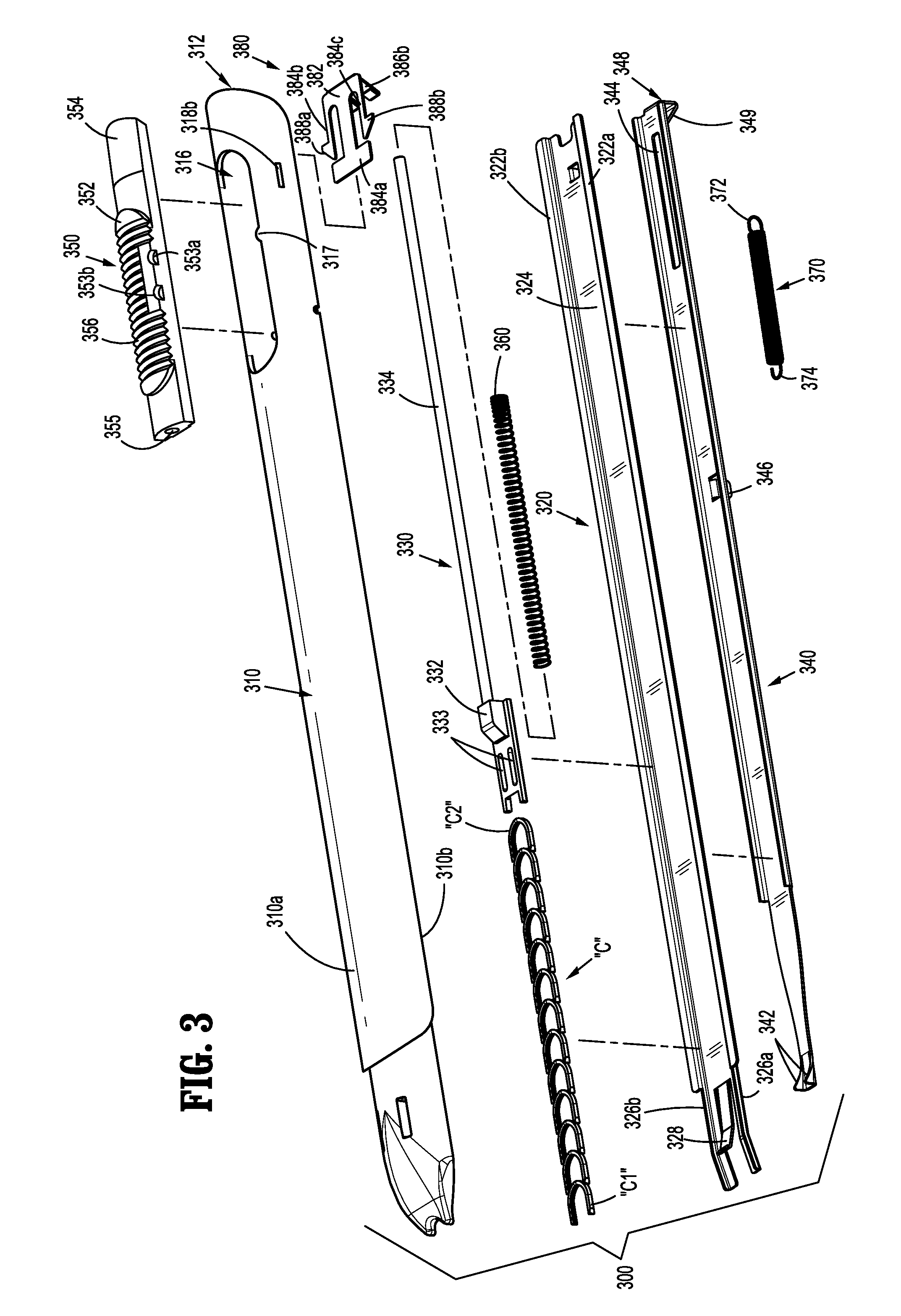
[0036] FIG. 3 is a front, perspective view, with parts separated, of a clip cartridge assembly of the surgical clip applier of FIG. 1;
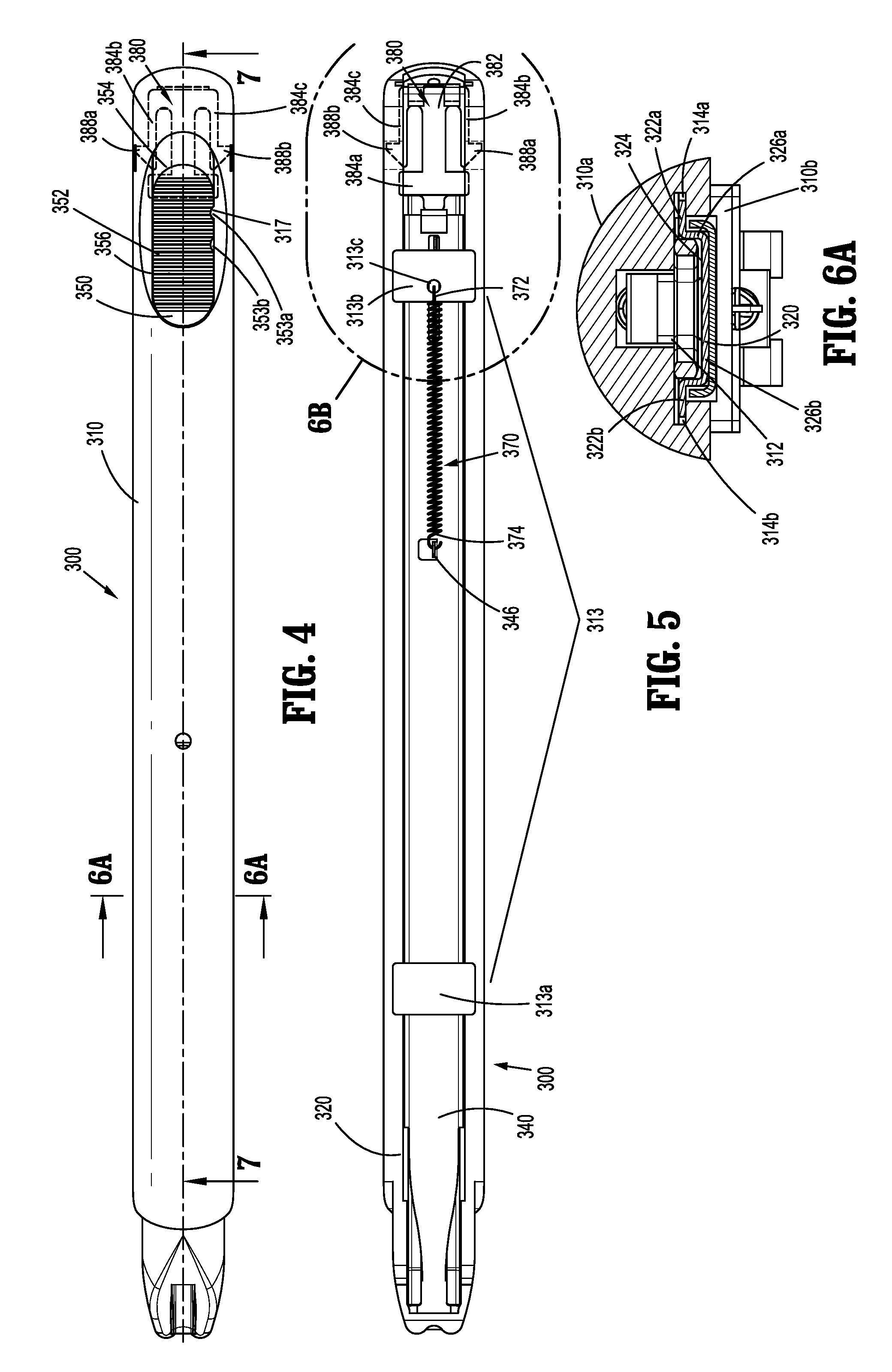
[0037] FIG. 4 is a top view of the clip cartridge assembly of the surgical clip applier of FIG. 3;
[0038] FIG. 5 is a bottom view of the clip cartridge assembly of FIG. 4;
[0039] FIG. 6A is a cross-sectional view taken across section line "6A-6A" in FIG. 4;
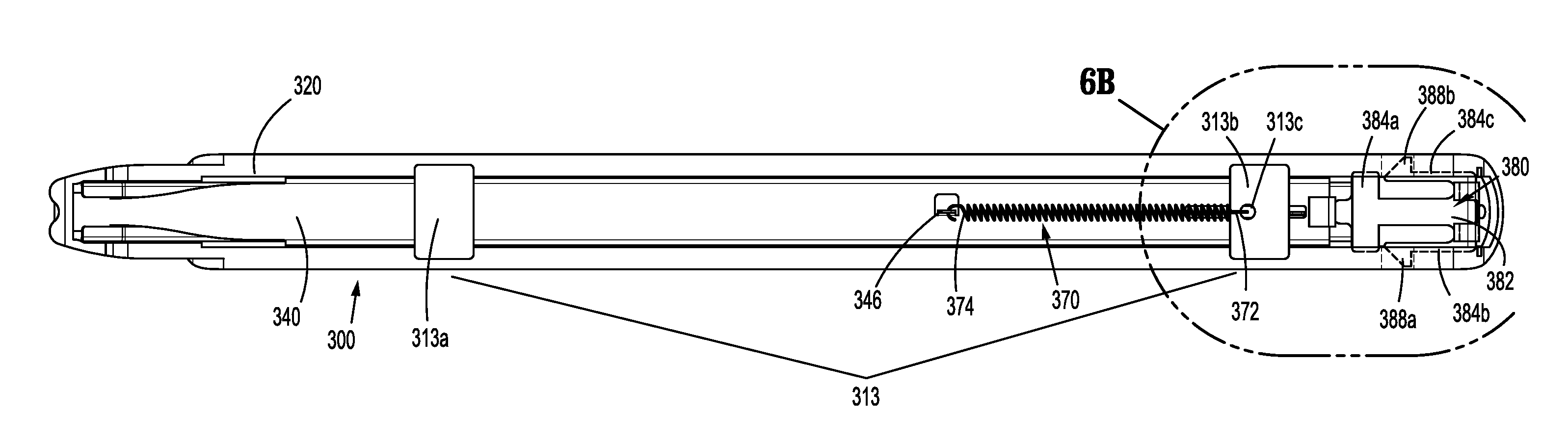
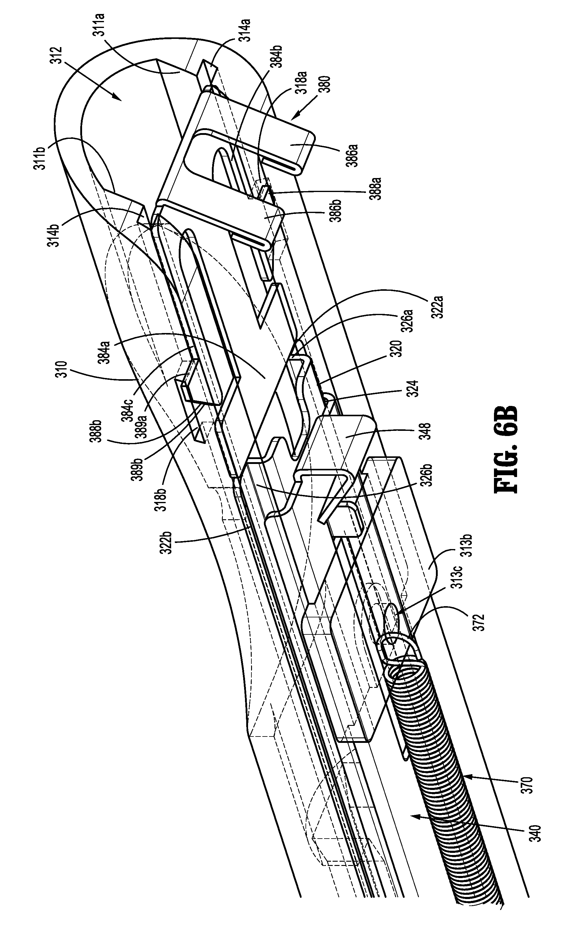
[0040] FIG. 6B is a bottom, perspective view of the area of detail indicated as "6B" in FIG. 5;
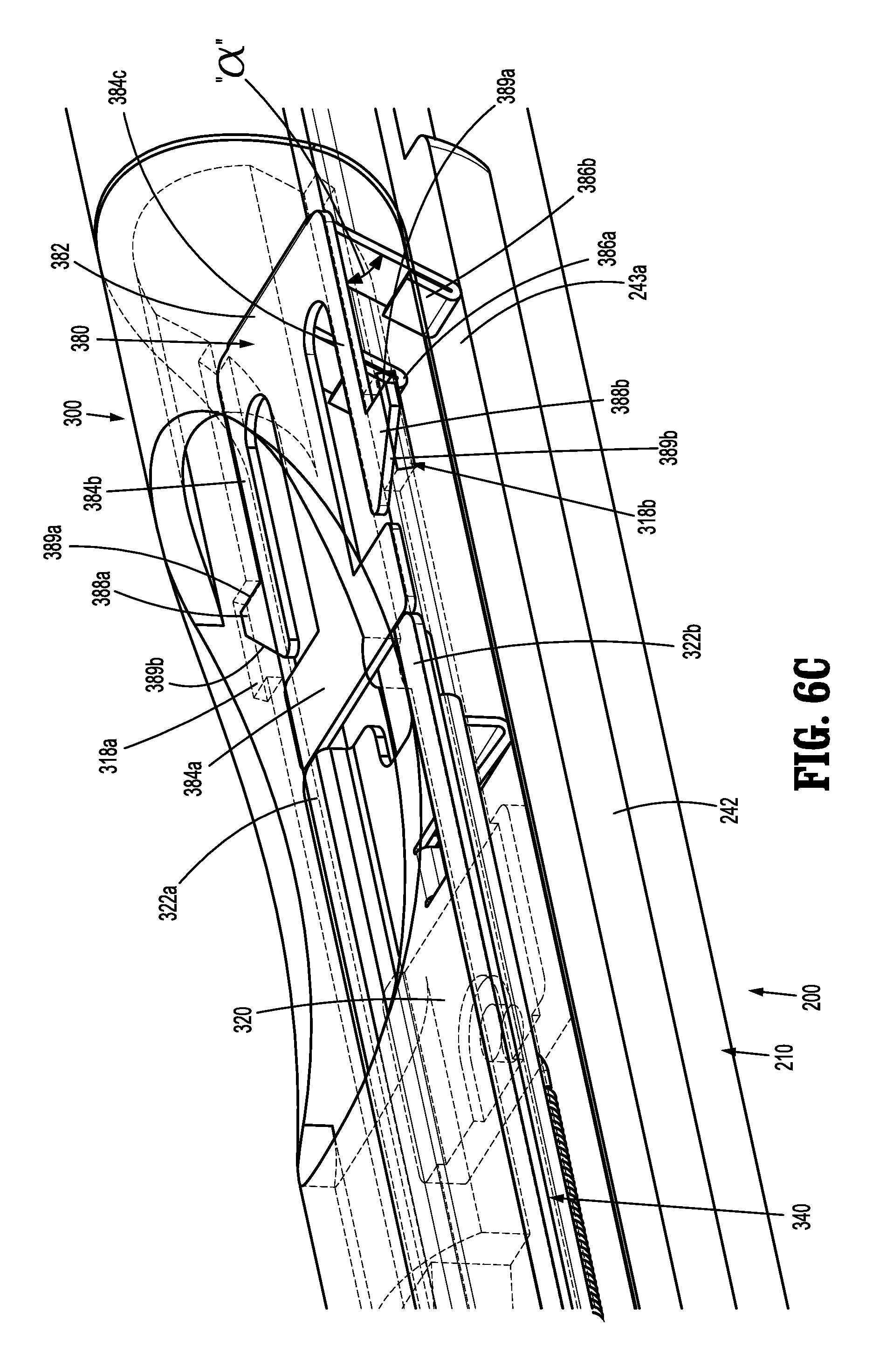
[0041] FIG. 6C is a top, perspective view of the area of detail indicated as "6C" in FIG. 1;
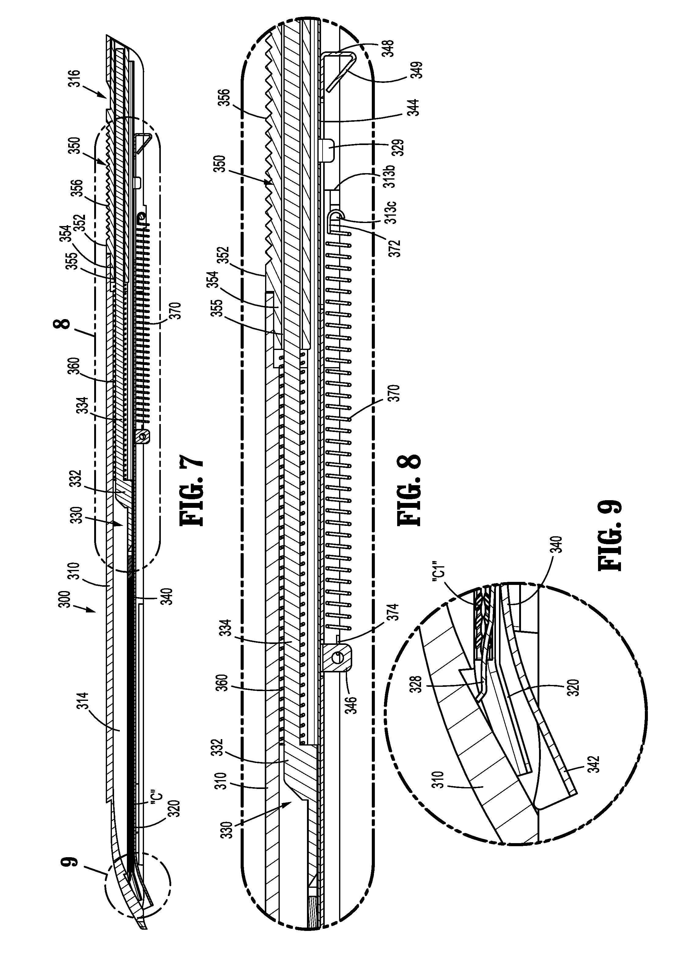
[0042] FIG. 7 is a longitudinal, cross-sectional view taken across section line "7-7" of FIG. 4;
[0043] FIG. 8 is an enlarged, longitudinal, cross-sectional view of the area of detail indicated as "8" in FIG. 7;
[0044] FIG. 9 is an enlarged, longitudinal, cross-sectional view of the area of detail indicated as "9" in FIG. 7;
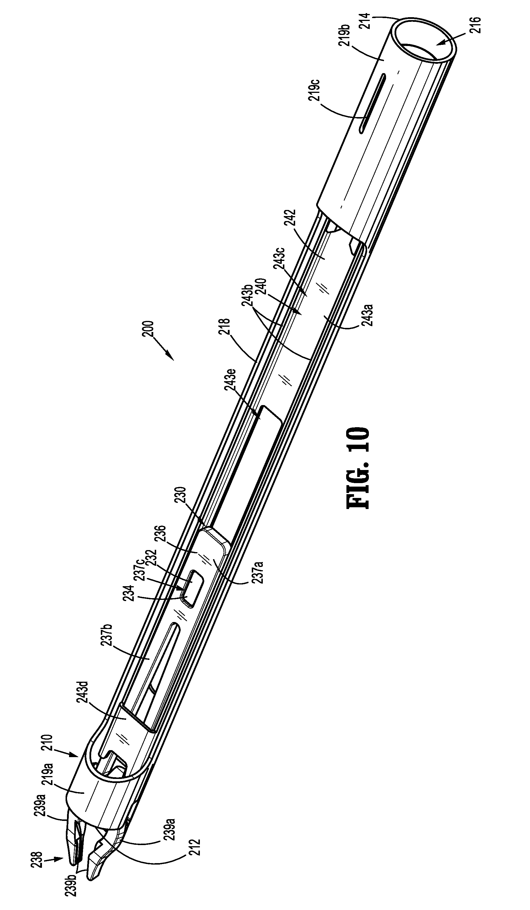
[0045] FIG. 10 is a top, perspective view of a shaft assembly of the surgical clip applier of FIG. 1;
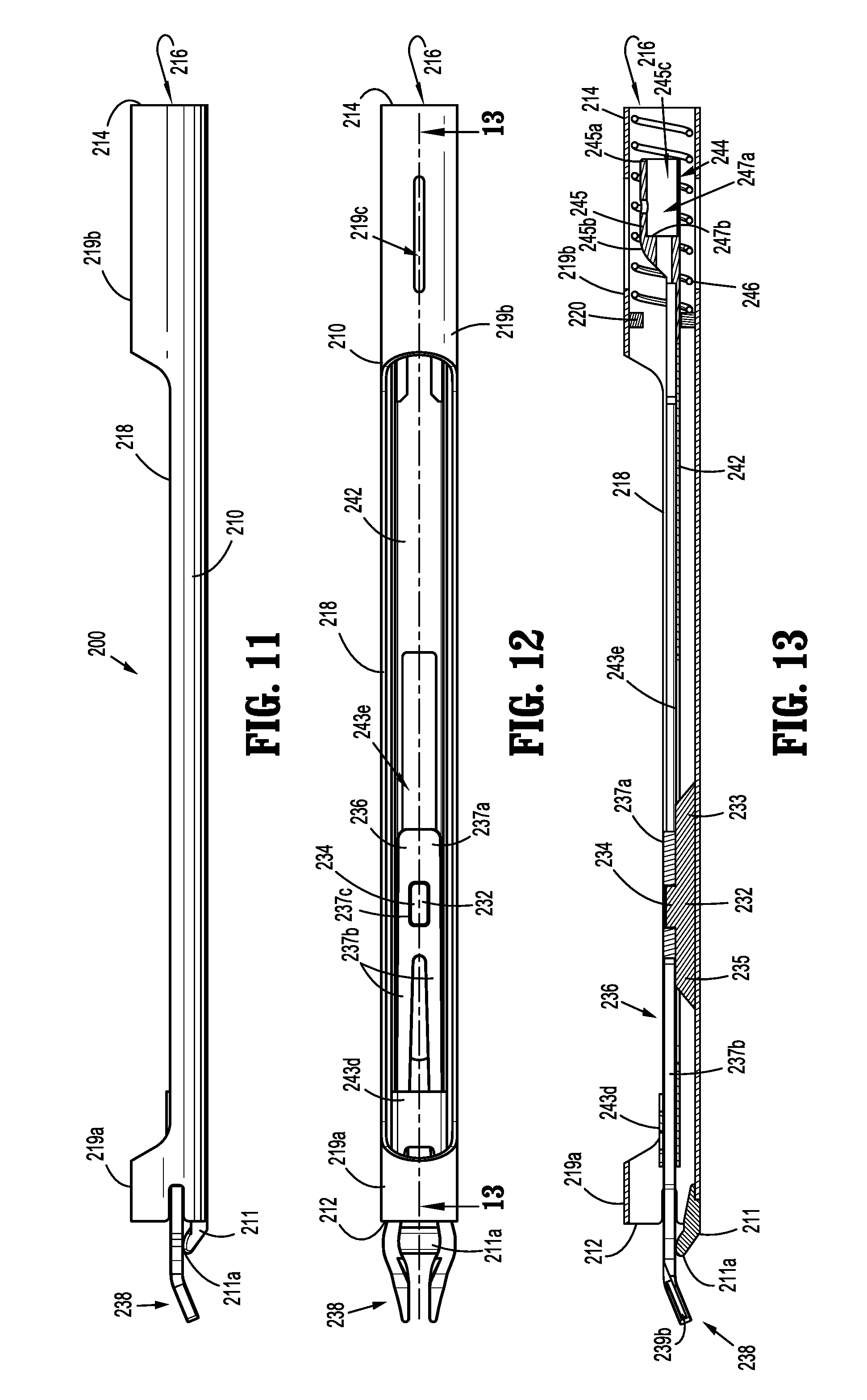
[0046] FIG. 11 is a side view of the shaft assembly of FIG. 10;
[0047] FIG. 12 is a top view of the shaft assembly of FIG. 10;
[0048] FIG. 13 is a longitudinal, cross-sectional view taken across section line "13-13" of FIG. 12;
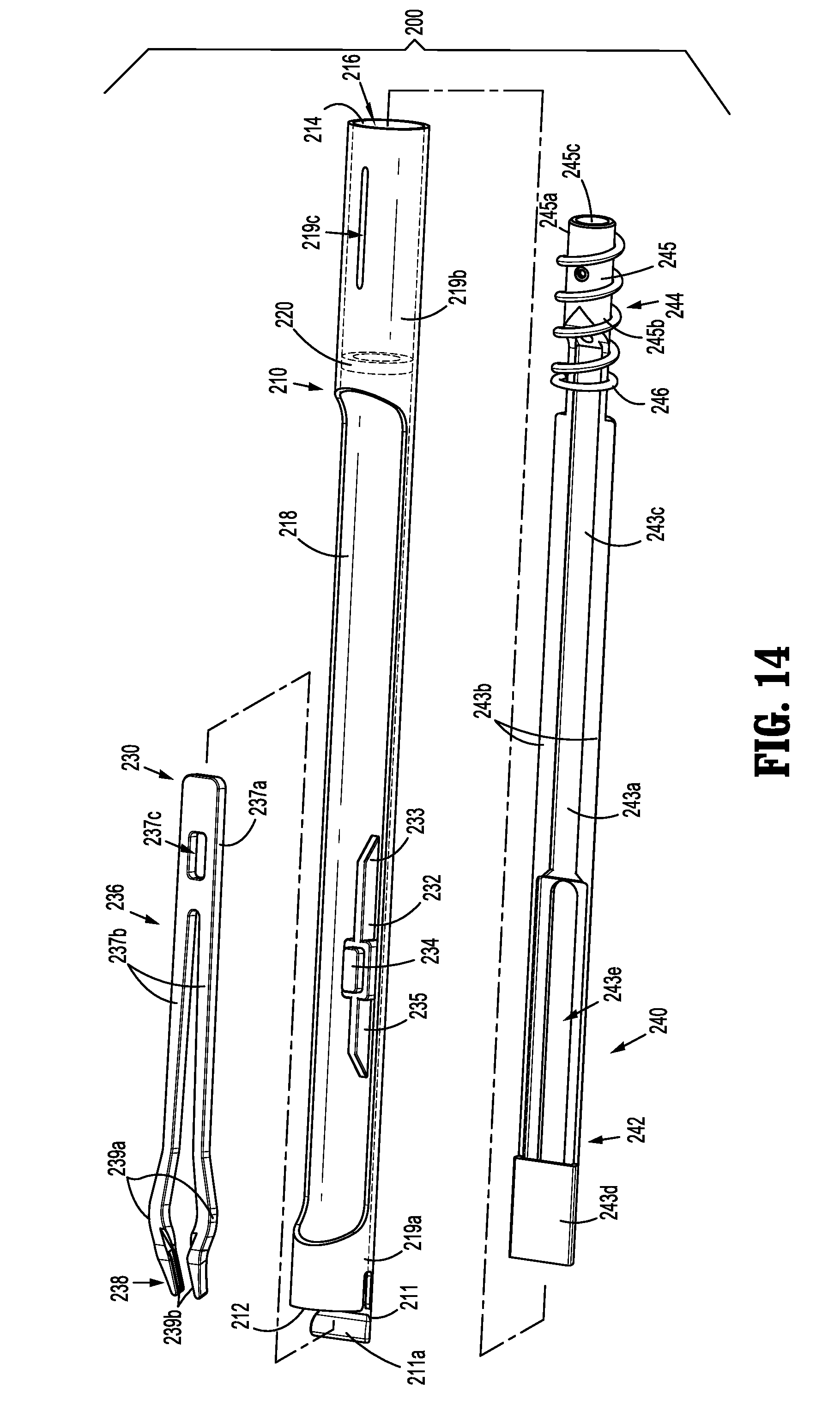
[0049] FIG. 14 is a top, perspective view, with parts partially separated, of the shaft assembly of FIG. 13;
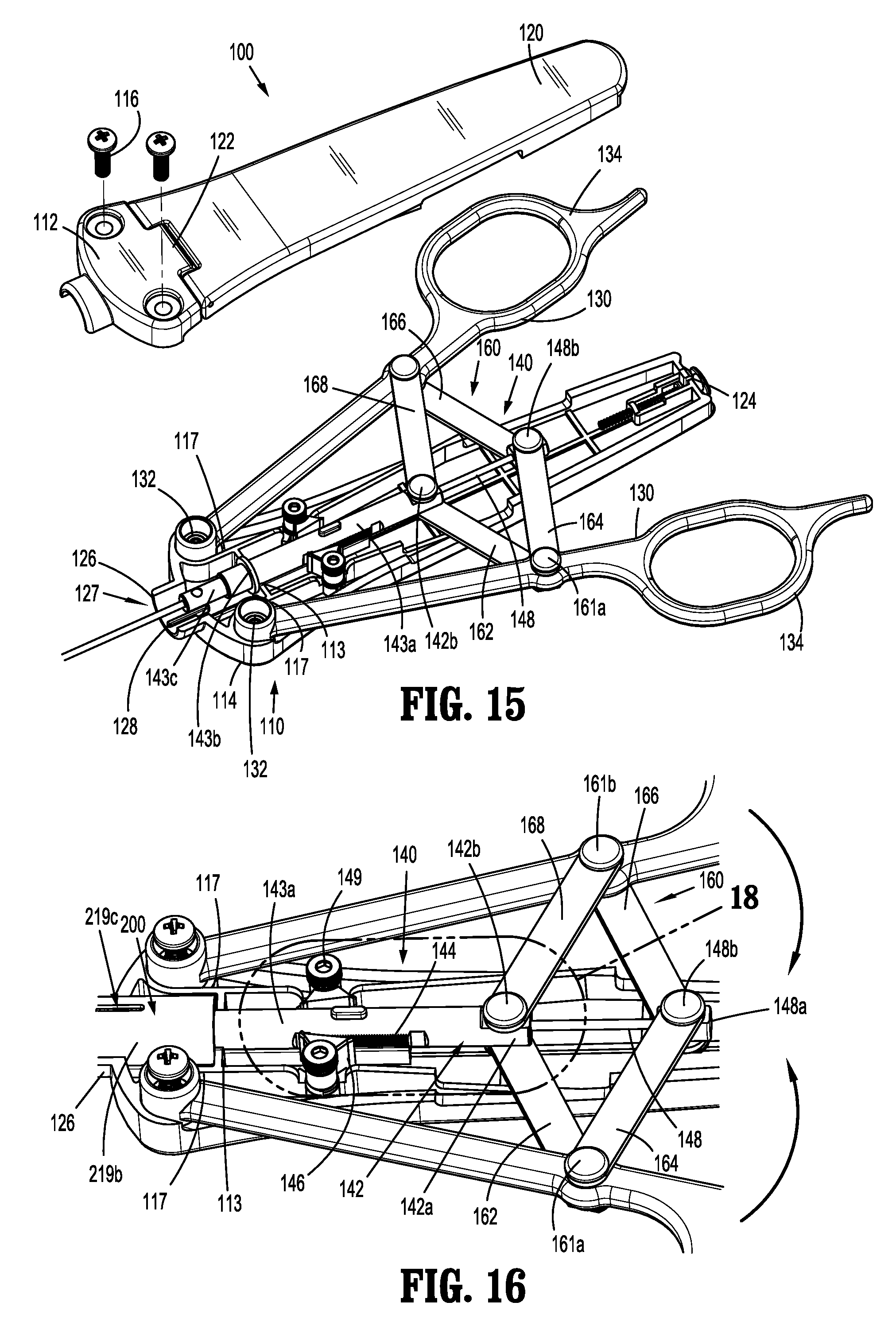
[0050] FIG. 15 is a top, perspective view, with parts partially separated, of the handle assembly of FIG. 1;
[0051] FIG. 16 is a top, perspective view of a handle assembly of the surgical clip applier of FIG. 1, with a housing section removed to illustrate the internal components therein;
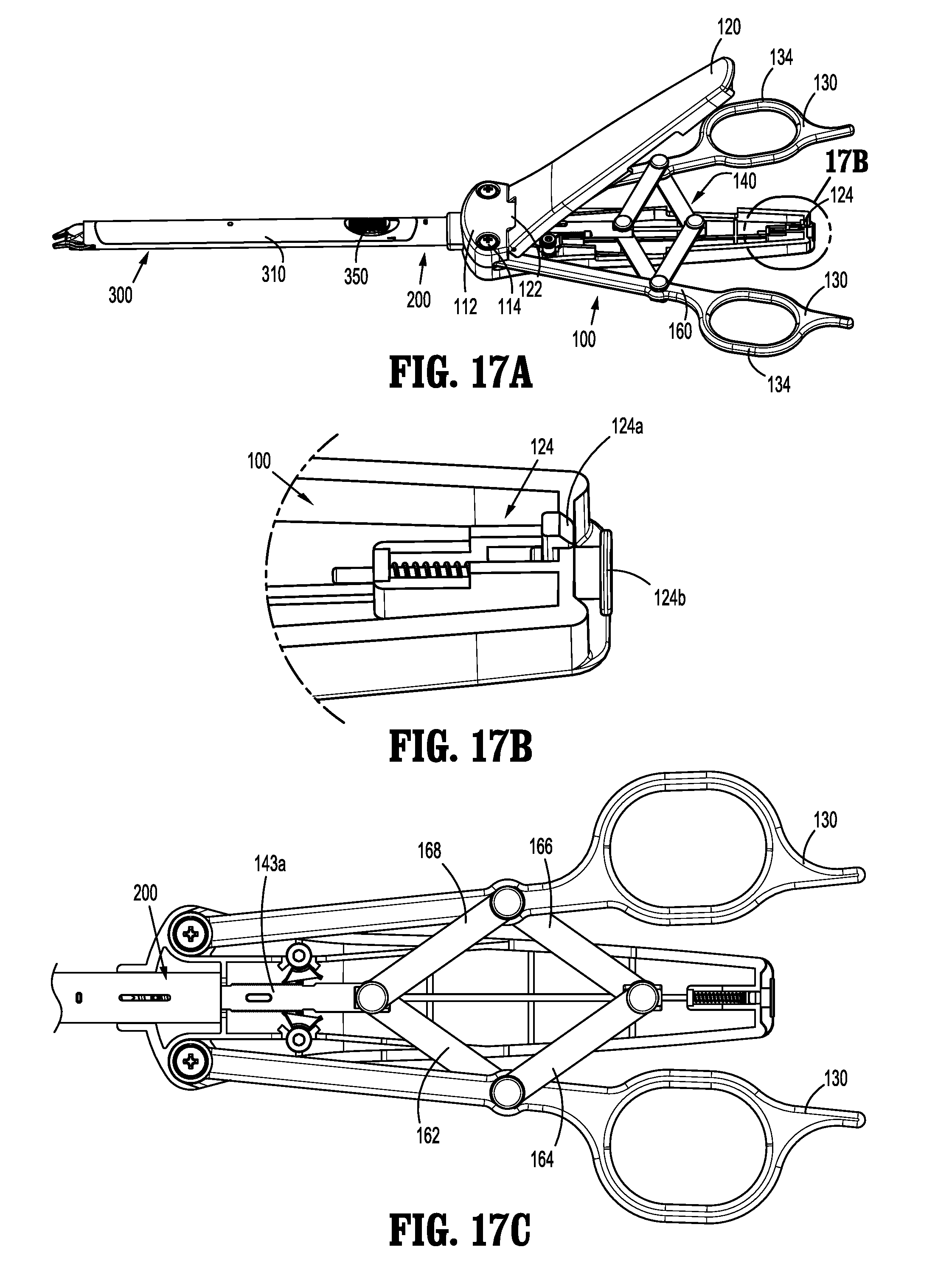
[0052] FIG. 17A is a top, perspective view of the surgical clip applier of FIG. 1, shown in an assembled condition with the door of the handle assembly open;
[0053] FIG. 17B is an enlarged, top, perspective view of the area of detail indicated as "17B" in FIG. 17A;
[0054] FIG. 17C is a top view of the surgical clip applier of FIG. 1, with the handle assembly thereof in an approximated position;
[0055] FIG. 18 is an enlarged, top, perspective view of the area of detail indicated as "18" in FIG. 16;
[0056] FIG. 19 is a longitudinal, cross-sectional view taken across section line "19-19" of
[0057] FIG. 1;
[0058] FIGS. 20 and 21 are top, perspective views illustrating engagement of the clip cartridge assembly of FIG. 3 with the shaft assembly of FIG. 10;
[0059] FIG. 22 is a top view of a distal portion of the surgical clip applier of FIG. 1;
[0060] FIG. 23 is an enlarged, front, perspective view of a distal end portion of the surgical clip applier of FIG. 1 with components shown in phantom to illustrate internal features of the surgical clip applier; and
[0061] FIG. 24 is a schematic illustration of a robotic surgical system configured for use in accordance with the present disclosure.
DETAILED DESCRIPTION OF EMBODIMENTS
[0062] A reposable multi-fire surgical clip applier in accordance with the present disclosure is described in detail below with reference to the drawing figures wherein like reference numerals identify similar or identical structural elements. As shown in the drawings and described throughout the following description, as is traditional when referring to relative positioning on a surgical instrument, the term "proximal" refers to the end portion of the apparatus or component thereof which is closer to the user and the term "distal" refers to the end portion of the apparatus or component thereof which is further away from the user.
[0063] Referring now to FIGS. 1 and 2, a surgical clip applier in accordance with an embodiment of the present disclosure is generally designated as 10. Surgical clip applier 10 includes a handle assembly 100, a shaft assembly 200 extending distally from handle assembly 100, and a clip cartridge assembly 300 mounted within shaft assembly 200. Shaft assembly 200 is removably and selectively engagable with handle assembly 100 and clip cartridge assembly 300 is removably and selectively mountable within shaft assembly 200. Handle assembly 100 and shaft assembly 200 may be configured as sterilizable, reusable components, while clip cartridge assembly 300 may be configured as a single-procedure-use component. As described in detail below, a stack of surgical clips "C" (FIG. 3) is loaded into clip cartridge assembly 300 such that, in operation, each actuation of handle assembly 100 actuates cooperating drive components of handle assembly 100, shaft assembly 200, and cartridge assembly 300 to fire and form a single surgical clip from the stack of surgical clips "C" (FIG. 3) around a vessel or other tissue to ligate the vessel or other tissue.
[0064] Referring to FIGS. 3-9, clip cartridge assembly 300 includes a cartridge cover or housing 310, a clip carrier 320, a clip follower 330, a distal pusher 340, a slider 350, a first biasing member 360, a second biasing member 370, a carrier lock 380, and a stack of surgical clips "C."
[0065] With reference to FIGS. 3, 6A, and 6B, cartridge housing 310 includes an upper housing portion 310a, a lower housing portion 310b, and an internal cavity 312 extending along a length of the cartridge housing 310 between a distal end portion and a proximal end portion thereof. Cartridge housing 310 may be formed at least partially from a transparent material, such as, for example, a transparent plastic, to enable visualization into internal cavity 312 thereof. Cartridge housing 310 includes a pair of internal grooves 314a, 314b extending longitudinally along at least a portion of the length of the cartridge housing 310, on opposing internal walls 311a, 311b thereof. The pair of internal grooves 314a, 314b are configured to retain clip carrier 320 and carrier lock 380 when clip carrier 320 and carrier lock 380 are disposed within internal cavity 312 of cartridge housing 310, as will be detailed below. Internal cavity 312 of cartridge housing 310 is also configured to receive at least a portion of clip follower 330, distal pusher 340, slider 350, first biasing member 360, second biasing member 370, and the stack of surgical clips "C" therein.
[0066] With reference to FIGS. 3-6A, upper housing portion 310a of cartridge housing 310 includes a window 316 formed therein and configured to slidably receive a cap portion 352 of slider 350. Cartridge housing 310 includes a protrusion 317 extending transversely into proximal window 316 from a side thereof. Cap portion 352 of slider 350 defines a more-proximally positioned recess 353a defined on a side thereof and a more-distally positioned recess 353b defined on the same side thereof. More-proximally positioned recess 353a is configured to receive protrusion 317 of cartridge housing 310 to releasably retain slider 350 in a distal position relative to cartridge housing 310. Upon sufficient proximal urging of cap portion 352 of slider 350 relative to cartridge housing 310, protrusion 317 of cartridge housing 310 is dislodged from more-proximally positioned recess 353a of cap portion 352 of slider 350, enabling slider 350 to slide proximally through window 316. Once slider 350 is slid sufficiently proximally, protrusion 317 is engaged within more-distally positioned recess 353b of cap portion 354 of slider 350 to thereby releasably retain slider 350 in a proximal position relative to cartridge housing 310. The proximal and distal positions of slider 350 are described in detail hereinbelow.
[0067] With continued reference to FIGS. 3-6A, lower housing portion 310b of cartridge housing 310 includes a support base 313 configured to enclose and support at least a portion of distal pusher 340 when distal pusher is disposed within internal cavity 312 of cartridge housing 310 (FIG. 5). Support base 313 includes a first or distal bridge portion 313a and a second or proximal bridge portion 313b extending between and coupled to lateral sides of cartridge housing 310. In embodiments, the first and second bridge portions 313a, 313b are longitudinally spaced apart and at least a portion of distal pusher 340 is disposed thereon. Second bridge portion 313b includes an aperture or slot 313c configured to receive a proximal end portion 372 of second biasing member 370 thus fixing proximal end portion 372 of second biasing member 370 relative to cartridge housing 310, as will be further detailed below. In embodiments, lower housing portion 310b of cartridge housing 310 may include more than two bridge portions or may be entirely enclosed.
[0068] With reference to FIGS. 3, 6A, and 6B, clip carrier 320 of clip cartridge assembly 300 includes a floor 324 and a pair of side walls 326a, 326b extending longitudinally along the opposed sides of floor 324 such that clip carrier 320 defines a generally U-shaped configuration. Clip carrier 320 includes a pair of engagement flanges 322a, 322b configured to engage the pair of internal grooves 314a, 314b of opposing internal walls 311a, 311b, respectively, of cartridge housing 310. Specifically, the pair engagement flanges 322a, 322b extend laterally from the pair of side walls 326a, 326b, respectively, and are disposed within the pair of internal grooves 314a, 314b of cartridge housing 310 to prevent axial movement of clip carrier 320 relative to cartridge housing 310.
[0069] As illustrated in FIGS. 6B and 6C, carrier lock 380 includes a body 382 having a central arm 384a, a pair of side arms 384b, 384c disposed on opposing lateral sides of central arm 384a and outwardly biased therefrom, and a pair of legs 386a, 386b folded below and under a proximal end portion of body 382. Each side arm 384b, 384c includes a tang 388a, 388b, respectively, extending outwardly therefrom. Internal cavity 312 of cartridge housing 310 is configured to receive carrier lock 380 such that the pair of side arms 384b, 384c are slidably disposed within internal grooves 314a, 314b, respectively, of cartridge housing 310. Cartridge housing 310 includes a pair of slots 318a, 318b extending through opposing internal walls 311a, 311b. The pair of slots 318a, 318b are positioned and configured to receive the pair of tangs 388a, 388b extending outwardly from the pair of side arms 384b, 384c, respectively, to releasably retain carrier lock 380 within internal cavity 312 of cartridge housing 310.
[0070] Each of the pair of tangs 388a, 388b includes a proximal portion 389a that is substantially parallel relative to a respective proximal portion of the pair of slots 318a, 318b and a distal portion 389b that is angled relative to a respective distal portion of the pair of slots 318a, 318b. It is contemplated that during proximal movement of carrier lock 380 relative to cartridge housing 310, the parallel relationship between each of the proximal portions 389a of the pair of tangs 388a, 388b and the respective proximal portions of the pair of slots 318a, 318b will result in an abutting engagement to prevent inadvertent release of the pair of tangs 388a, 388b of carrier lock 380 from within the pair of slots 318a, 318b of internal cavity 312 of cartridge housing 310. Further, it is contemplated that during distal movement of carrier lock 380 relative to cartridge housing 310, the angled relationship between each of the distal portions 389b of the pair of tangs 388a, 388b and the respective distal portions of the pair of slots 318a, 318b will result in a camming engagement to enable release of the pair of tangs 388a, 388b of carrier lock 380 from within the pair of slots 318a, 318b of internal cavity 312 of cartridge housing 310.
[0071] With continued reference to FIG. 6B, when clip carrier 320 is disposed within cartridge housing 310, as described above, carrier lock 380 is configured for positioning proximally adjacent a proximal end portion of clip carrier 320 such that central arm 384a of carrier lock 380 is disposed in abutting relation therewith. In this position, since carrier lock 380 is slidably retained within internal cavity 312 via engagement between the pair of tangs 388a, 388b and the pair of slots 318a, 318b, clip carrier 320 is inhibited from moving proximally beyond central arm 384a of carrier lock 380. In this manner, clip carrier 320 is retained within internal cavity 312 of cartridge housing 310.
[0072] With additional reference to FIG. 6C, the pair of legs 386a, 386b of carrier lock 380 is folded below and under the proximal end portion of body 382 to define an angle ".alpha." therebetween. In embodiments, angle ".alpha." is less than 90 degrees. This effectively forms a four-bar linkage mechanism providing for easier cleaning and sterilization, all in a more robust design having fewer parts. When cartridge assembly 300 is disposed within shaft assembly 200, as will be detailed below, the pair of legs 386a, 386b of carrier lock 380 is configured to be supported by a base 243a of a distal drive bar 242 of shaft assembly 200.
[0073] With additional reference to FIGS. 7-9, clip carrier 320 further includes a resilient central tang 328 extending upwardly from floor 322 towards a distal end portion of clip carrier 320. Resilient central tang 328 is configured to engage a backspan of a distal-most surgical clip "C1" of the stack of surgical clips "C" to retain the stack of surgical clips "C" within clip carrier 320. Clip carrier 320 further includes a leg 329 depending from an underside of floor 322 adjacent a proximal end portion thereof
[0074] With reference to FIGS. 3 and 8, clip follower 330 of clip cartridge assembly 300 includes a distal sled 332 slidably disposed within clip carrier 320 proximally of the stack of surgical clips "C." Distal sled 332 of clip follower 330, more specifically, is configured for positioning proximally adjacent a proximal-most clip "C2" of the stack of surgical clips "C" in abutting relation therewith. Distal sled 332 further defines a pair of slots 333 therethrough, as detailed below. Clip follower 330 further includes an elongated rod 334 extending proximally from distal sled 332. Elongated rod 334 defines a fixed distal end engaged to distal sled 332 and a free proximal end that is slidably disposed within a lumen 355 defined within base portion 354 of slider 350. First biasing member 360 is disposed about elongated rod 334 of clip follower 330 between distal sled 332 and base portion 354 of slider 350 so as to bias distal sled 332 distally into and against the proximal-most clip "C2" of the stack of surgical clips "C," thereby biasing the stack of surgical clips "C" distally. In embodiments, first biasing member 360 may take the form of a coil spring, a constant force spring, a power spring, or another suitable biasing element.
[0075] With reference to FIGS. 3, 5, and 8, distal pusher 340 of clip cartridge assembly 300 is slidably disposed about an underside of clip carrier 320, opposite clip follower 330. Distal pusher 340 includes a pair of pusher flanges 342 at a distal end portion thereof that are configured to urge the distal-most surgical clip "C1" of the stack of surgical clips "C" distally over resilient central tang 328 of clip carrier 320 and distally from clip cartridge assembly 300 into jaws 238 (FIG. 10). Distal pusher 340 further includes a proximal slot 344 defined therethrough adjacent a proximal end portion thereof that is configured to slidably receive leg 329 of clip carrier 320 to maintain distal pusher 340 and clip carrier 320 in alignment with one another while permitting distal pusher 340 to slide longitudinally relative to clip carrier 320. Specifically, distal pusher 340 is permitted to slide longitudinally relative to clip carrier 320 until a position where leg 329 of clip carrier 320 abuts a proximal end portion or a distal end portion of proximal slot 344 of distal pusher 340.
[0076] Distal pusher 340 also includes a flange or tab 346 depending from an underside thereof at an intermediate portion of distal pusher 340. Tab 346 is configured to receive a distal end portion 374 of second biasing member 370 such that the distal end portion 374 of second biasing member 370 is fixed relative to distal pusher 340. With distal end portion 374 of second biasing member 370 fixed relative to distal pusher 340, and with proximal end portion 372 thereof fixed relative to cartridge housing 310 (via slot 313c of second bridge portion 313b, as noted above), second biasing member 370 serves to bias distal pusher 340 proximally relative to cartridge housing 310 and, thus, clip carrier 320 and the stack of surgical clips "C."
[0077] Distal pusher 340 additionally includes a proximally-facing pusher surface 348 disposed at the proximal end portion thereof. Proximally-facing pusher surface 348 may be part of a proximal extension 349 that is monolithically formed with distal pusher 340 and folded below and under the proximal end portion thereof to define proximally-facing pusher surface 348.
[0078] Referring to FIGS. 3, 7, and 8, slider 350 of clip cartridge assembly 300 includes a base portion 354 and a cap portion 352 disposed on base portion 354. Cap portion 352, as detailed above, is configured for slidable receipt within window 316 of cartridge housing 310 and is releasably engagable therein in either a proximal position or a distal position. In the distal position, base portion 354 of slider 350 does not extend proximally beyond the proximal end portion of cartridge housing 310. In the proximal position, base portion 354 extends proximally beyond the proximal end portion of cartridge housing 310. As detailed below, movement of slider 350 between the distal and proximal position enables selective locking and unlocking of clip cartridge assembly 300 within shaft assembly 200 (FIG. 1).
[0079] Base portion 354 of slider 350, as noted above, defines a lumen 355 extending longitudinally therethrough. Lumen 355 is configured to slidably receive elongated rod 334 of clip follower 330, as shown in FIGS. 7 and 8. Cap portion 352 of slider 350 may define a textured, such as, for example, grooved, upper surface 356 to facilitate gripping cap portion 352 of slider 350 to slide slider 350 between the proximal and distal positions.
[0080] Continuing with reference to FIG. 3, the stack of surgical clips "C," as detailed above, is supported within clip carrier 320 with the clips thereof arranged in tip-to-tail orientation. Each of the surgical clips of the stack of surgical clips "C" includes a pair of legs interconnected by a backspan. In some embodiments, the stack of surgical clips "C" includes a lockout clip "LC" (FIG. 22) positioned proximally of the proximal-most clip "C2". The lockout clip "LC" is formed as a solid disc and may be distinctively marked and/or colored. Providing the lockout clip "LC" in this manner enables the user to visually determine or at least estimate the number of surgical clips remaining by viewing the position of the lockout clip "LC" through cartridge housing 310. The lockout clip "LC," if loaded into jaws 238 (FIG. 23), also serves as a lockout, as detailed below.
[0081] Referring to FIGS. 10-14, shaft assembly 200 includes an outer tube 210, an inner stop ring 220, a jaw assembly 230, and an inner drive assembly 240. Outer tube 210 includes an open distal end portion 212, an open proximal end portion 214, a lumen 216 extending between and communicating with the open distal and proximal end portions, 212, 214, respectively, and an elongated cut-out 218 defined through a side wall of outer tube 210 and communicating with lumen 216 therethrough. Outer tube 210 further includes a jaws support member 211 extending distally from open distal end portion 212. In embodiments, jaws support member 211 extends distally from a lower portion of outer tube 210 and towards an upper portion of outer tube 210 to define a support surface 211a. Elongated cut-out 218 is spaced-apart from open distal end portion 212 of outer tube 210 such that outer tube 210 defines a tubular distal segment 219a disposed distally of elongated cut-out 218. Elongated cut-out 218 is also spaced-apart from open proximal end portion 214 of outer tube 210 such that outer tube defines a tubular proximal segment 219b disposed proximally of elongated cut-out 218. Tubular proximal segment 219b includes a recess or slot 219c configured to engage handle assembly 100 (FIG. 19) to selectively couple shaft assembly 200 and handle assembly 100, as detailed below. Inner stop ring 220 is disposed within tubular proximal segment 219b of outer tube 210 and is fixedly engaged therein in any suitable manner, such as, for example, welding. In embodiments, tubular distal segment 219a of outer tube 210 may include indicia "I" (FIG. 22) configured to enable the user to visually determine or at least estimate the number of surgical clips remaining by viewing the position of the lockout clip "LC" through cartridge housing 310.
[0082] Jaw assembly 230 includes a stationary base 232 and a jaws component 236. Stationary base 232 is affixed within outer tube 210 to an interior surface thereof, via welding or other suitable methods. Stationary base 232 includes a proximal base portion 233, a central block 234, and a distal base portion 235. Jaws component 236 includes a proximal hub 237a, a bifurcated neck 237b, and a pair of jaws 238, one of which is attached to the free distal end of each of the bifurcated portions of bifurcated neck 237b. Proximal hub 237a of jaws component 236 defines a slot 237c configured to receive central block 234 of stationary base 232 to engage and fixedly maintain jaws component 236 within outer tube 210. With jaws component 236 engaged about stationary base 232 in this manner, jaws 238 extend distally from open distal end 212 of outer tube 210.
[0083] Jaws 238 of jaw assembly 230 are biased apart from one another via bifurcated neck 237b. Jaws 238 define outwardly-facing cam surfaces 239a and inwardly-facing channels 239b. A distal drive bar 242 of inner drive assembly 240 is configured to engage cam surfaces 239a of jaws 238 and urge jaws 238 towards one another, as detailed below. Inwardly-facing channels 239b of jaws 238 are configured to receive the legs of a surgical clip from the stack of surgical clips "C" therein to retain the surgical clip within the jaws 238 during formation thereof, as also detailed below.
[0084] Continuing with reference to FIGS. 10-14, inner drive assembly 240 of shaft assembly 200 includes a distal drive bar 242, a proximal drive plunger 244, and a drive biasing member 246. Distal drive bar 242 includes base 243a and a pair of side walls 243b extending longitudinally along opposing sides of a base 243a so as to define an inner channel 243c extending longitudinally along distal drive bar 242.
[0085] Distal drive bar 242 of inner drive assembly 240 further includes a boxed distal end portion 243d and a slot 243e defined through base 243a towards the boxed distal end portion 243d thereof. Distal drive bar 242 is slidably disposed within lumen 216 of outer tube 210. Slot 243e of distal drive bar 242 is configured to slidably receive stationary base 232 of jaw assembly 230 therethrough to enable distal drive bar 242 to slide within outer tube 210 and about stationary base 232. Boxed distal end portion 243d of distal drive bar 242 is configured for positioning about bifurcated neck 237b of jaw assembly 230. Upon distal advancement of distal drive bar 242, as detailed below, boxed distal end portion 243d of distal drive bar 242 is advanced distally about jaws component 236 to cam about cam surfaces 239a of jaws 238 to thereby urge jaws 238 towards one another.
[0086] Proximal drive plunger 244 includes a hub 245 having a proximal end portion 245a and a distal end portion 245b. Distal end portion 245b of hub 245 is engaged with a proximal end portion of inner channel 243c of distal drive bar 242. Drive biasing member 246 of inner drive assembly 240 is disposed about hub 245 of proximal drive plunger 244, extending between inner ring stop 220 to a position proximally beyond proximal end portion 245a of hub 245 to engage a feature of handle assembly 100 (FIG. 19), as will be detailed below, so as to bias proximal drive plunger 244 and, thus, distal drive bar 242, proximally. Hub 245 of proximal drive plunger 244 includes hub channel or lumen 247a extending along at least a length thereof and an inner hub wall 247b disposed in communication with hub lumen 247a. Hub 245 of proximal drive plunger 244 further defines an aperture 245c therethrough (FIG. 14). Aperture 245c of hub 245 is disposed to be in communication with hub lumen 247a and extends through inner hub wall 247b.
[0087] Jaws component 236 and inner drive assembly 240 are removable from outer tube 210 to facilitate reprocessing of the various components thereof for reuse. In order to insert jaws component 236 and inner drive assembly 240 into operable engagement with outer tube 210 and one another, jaws component 236, led by proximal hub 237a thereof, is inserted proximally through open distal end 212 of outer tube 210 until slot 237c of jaws component 236 is aligned above central block 234 of stationary base 232. Inner drive assembly 240, led by boxed distal end portion 243d of distal drive bar 242, is inserted distally through open proximal end 214 of outer tube 210 and slid distally about jaws component 236 until boxed distal end portion 243d of distal drive bar 242 is disposed about bifurcated neck 237b of jaws component 236, such that proximal hub 237a of jaws component 236 is disposed above slot 243e of base 243a of distal drive bar 242, and such that a distal end portion of drive biasing member 246 is urged against inner ring stop 225 within outer tube 210.
[0088] Once inner drive assembly 240 and jaws component 236 have been positioned as detailed above, proximal hub 237a of jaws component 236 may be engaged with stationary base 232 through slot 243e of base 243a of distal drive bar 242. More specifically, proximal hub 237a of jaws component 236 is urged towards central block 234 of stationary base 232 such that central block 234 is received within slot 237c of jaws component 236. With jaws component 236 engaged with stationary base 232 in this manner, stationary base 232 extends at least partially through slot 243e of base 243a of distal drive bar 242 and boxed distal end portion 243d of distal drive bar 242 is disposed about bifurcated neck 237b of jaws component 236. Thus, outer tube 210, jaws component 236, and inner drive assembly 240 are operably engaged with one another. Disengagement and removal of jaws component 236 and inner drive assembly 240 from outer tube 210 are effected in the opposite manner of the above-detailed insertion and engagement.
[0089] Referring to FIGS. 1, 2, and 15-17B, handle assembly 100 includes a housing 110, a pair of handles 130, and an inner actuation assembly 140. Housing 110 includes an upper housing portion 112 and lower housing portion 114 secured to one another by a plurality of screws 116, although other suitable engagements are also contemplated. Each housing portion 112, 114 further defines a pivot recess 117. One of the housing portions of housing 110, such as, for example, upper housing portion 112 includes a door 120 extending proximally from upper housing portion 112 and configured to selectively provide access to an opening or cavity 118 of housing 110. Door 120 is coupled to upper housing portion 112 via a hinge 122 to enable door 120 to pivot between a closed position (FIG. 1), covering opening 118, and an open position (FIG. 17), exposing opening 118. In embodiments, door 120 is shaped and dimensioned to correspond to a shape and dimension of lower housing portion 114 such that in the open position, a substantial portion of an interior of housing 110 is accessible via opening 118.
[0090] Housing 110 includes a latch 124 that enables releasable latching of door 120 in the closed position. As illustrated in FIG. 17B, latch 124 includes a spring-loaded locking member 124a and an actuator 124b. Spring-loaded locking member 124a is biased to engage door 120 to selectively maintain door 120 in the closed position. Actuator 124b is configured to selectively engage the spring-loaded locking member 124a to a position where the spring-loaded locking member 124a is disengaged from door 120 to move door 120 to the open position (FIG. 17). In the open position of door 120, access to the interior of housing 110 is provided to facilitate reprocessing of handle assembly 100 for reuse.
[0091] With reference to FIGS. 15 and 16, housing 110 further includes an open distal mouth 126 configured to receive a proximal end portion of shaft assembly 200 therethrough to releasably engage shaft assembly 200 with handle assembly 100, as detailed below. Open distal mouth 126 is formed from cooperating mouth portions of upper housing portion 112 and lower housing portion 114 and defines a central passageway 127. At least one of the upper and lower housing portions 112, 114 includes a protrusion 128 (FIGS. 15 and 19) extending radially inwardly into central passageway 127. Protrusion 128 is configured to releasably engage slot 219c (FIG. 16) of tubular proximal segment 219b of shaft assembly 200 to releasably engage shaft assembly 200 with handle assembly 100, as detailed below.
[0092] Handles 130 of handle assembly 100 are pivotably coupled to housing 110 and extend outwardly from opposing sides thereof. Handles 130, more specifically, each include a pivot post 132 at the distal end portion thereof and a finger loop 134 at the proximal end portion thereof. Pivot posts 132 are pivotably coupled to housing 110 to enable pivoting of handles 130 relative to housing 110 between a spaced-apart position and an approximated position. Finger loops 134 facilitate manipulation of handles 130 to pivot handles 130 between the spaced-apart and approximated positions.
[0093] Referring to FIGS. 15, 16, and 19, inner actuation assembly 140 includes a proximal drive member such as, for example, an outer drive tube 142, a ratchet assembly including a ratchet rack 144 and a pair of ratchet pawls 146, and a proximal pusher bar 148. Outer drive tube 142 is slidably disposed within housing 110. Outer drive tube 142 includes a body portion 143a, a collar 143b disposed towards a distal end portion of body portion 143a, and a neck portion 143c extending distally from the distal end portion of body portion 143a. Collar 143b protrudes radially from body portion 143b and includes an outer diameter "D1" that is greater than an outer diameter "D2" of body portion 143a. Outer diameter "D2" of body portion 143a is greater than an outer diameter "D3" of neck portion 143c. In operation, outer drive tube 142 is provided within housing 110 such that collar 143b of outer drive tube 142 is disposed adjacent an interior feature 113 within housing 110. Upon movement of outer drive tube 142, collar 143b is configured to proximally engage and abut interior feature 113 to define a proximal-most position of outer drive tube 142. Outer drive tube 142 further defines a lumen 143d (FIG. 19) extending longitudinally therethrough. In operation, proximal pusher bar 148 extends through lumen 143d of outer drive tube 142 in slidably relation relative thereto, and distally from outer drive tube 142, as detailed below.
[0094] With additional reference to FIG. 18, ratchet rack 144 is fixedly supported on outer drive tube 142 towards a proximal end portion of body portion 143a and defines first and second sets of teeth 145 extending along opposed sides thereof. The first and second sets of teeth 145 are configured to engage the first and second ratchet pawls 146, respectively. Ratchet pawls 146 are pivotably supported within housing 110 on either side of ratchet rack 144 via pivot members 149 and are operably positioned relative to the sets of teeth 145 of ratchet rack 144 to provide ratchet functionality to inner actuation assembly 140, as detailed below. As illustrated in phantom in FIG. 18, a biasing member 147 is provided to bias ratchet pawls 146 towards a neutral position.
[0095] Referring to FIGS. 15 and 16, handle assembly 100 further includes a linkage assembly 160 configured to pivotably couple handles 130 to inner actuation assembly 140. Linkage assembly 160 includes a first link arm 162, a second link arm 164, a third link arm 166, and a fourth link arm 168. Each of the first and second link arms 162, 164 are pivotably coupled at a first end portion thereof to an intermediate portion of one of the handles 130 via a first pivot boss 161a and each of the third and fourth link arms 166, 168 are pivotably coupled at a first end portion thereof to an intermediate portion of the other of the handles 130 via a second pivot boss 16 lb. Each of the first and fourth link arms 162, 168 are internally pivotably coupled at a second end portion thereof to a proximal end portion 142a of outer drive tube 142 via a first pivot pin 142b and each of the second and third link arms 164, 166 are internally pivotably coupled at a second end portion thereof to a proximal end portion 148a of proximal pusher bar 148 via a second pivot pin 148b. In embodiments, first, second, third, and fourth link arms 162, 164, 166, and 168 are disposed such that each of the intermediate portions of handles 130, proximal end portion 142a of outer drive tube 142, and proximal end portion 148a of proximal pusher bar 148 are sandwiched between respective portions of first, second, third, and fourth link arms 162, 164, 166, and 168 as described above.
[0096] Referring to FIGS. 16 and 18, in operation, with handles 130 disposed in the spaced-apart position relative to housing 110, outer drive tube 142 is disposed in the proximal-most position, while proximal pusher bar 148 is disposed in a distal-most position. As handles 130 are pivoted towards housing 110, towards the approximated position, first and fourth link arms 162, 168 urge outer drive tube 142 distally, and second and third link arms 164, 166 pull proximal pusher bar 148 proximally. It is contemplated that as handles 130 are pivoted towards the approximated position, linkage assembly 160 is configured to move outer drive tube 142 concurrently with proximal pusher bar 148. With handles 130 disposed in the approximated position relative to housing 110, outer drive tube 142 is disposed in a distal-most position, while proximal pusher bar 148 is disposed in a proximal-most position.
[0097] During the above-noted pivoting of handles 130 towards the approximated position, ratchet pawls 144 interact with ratchet rack 146 to provide an audible click and/or a tactile vibration, indicating that handles 130 are being moved through an actuation stroke. Further, upon handles 130 reaching the approximated position, ratchet pawls 146 clear ratchet rack 144, flip orientation to enable return of handles 130, and provide an end-of-stroke audible click and/or tactile vibration.
[0098] Upon release or return of handles 130 towards the spaced-apart position relative to housing 110, handles 130 move first and fourth link arms 162, 168 to pull outer drive tube 142 proximally, and move second and third link arms 164, 166 to urge proximal pusher bar 148 distally. It is contemplated that as handles 130 are pivoted towards the spaced-apart position, linkage assembly 160 is configured to move outer drive tube 142 concurrently with proximal pusher bar 148. With handles 130 disposed in the spaced-apart position relative to housing 110, outer drive tube 142 is disposed in the proximal-most position, while proximal pusher bar 148 is disposed in the distal-most position.
[0099] During the above-noted return of handles 130 towards the spaced-apart position, ratchet pawls 144 interact with ratchet rack 146 to provide an audible click and/or a tactile vibration, indicating that handles 130 are being moved through a return stroke. Further, upon handles 130 reaching the spaced-apart position, ratchet pawls 144 clear ratchet rack 146, flip orientation to permit subsequent actuation of handles 130, and provide an end-of-return audible click and/or tactile vibration.
[0100] Turning now to FIGS. 1 and 19-21, in order to assemble surgical clip applier 10 for use, handle assembly 100, shaft assembly 200, and clip cartridge assembly 300, if not pre-assembled, are individually assembled, as detailed above. Thereafter, shaft assembly 200 is engaged with handle assembly 100, as detailed below.
[0101] With reference to FIGS. 12, 13, and 19, in order to engage shaft assembly 200 with handle assembly 100, the proximal end portion of shaft assembly 200 is inserted proximally into open distal mouth 126 of housing 110. More specifically, shaft assembly 200 is moved proximally relative to handle assembly 100 such that tubular proximal segment 219b of shaft assembly 200 is inserted proximally into central passageway 127 until protrusion 128 is received within slot 219c of tubular proximal segment 219b of shaft assembly 200 to thereby releasably engage shaft assembly 200 with handle assembly 100. In embodiments, if housing 110 is preassembled, the plurality of screws 116 may be removed or loosened to space apart upper housing portion 112 and lower housing portion 114 such that slot 219c of tubular proximal segment 219b may be aligned with protrusion 128. Once protrusion 128 is received within slot 219c of tubular proximal segment 219b, upper housing portion 112 and lower housing portion 114 may be secured to one another by the plurality of screws 116.
[0102] During the above-noted insertion of the proximal end portion of shaft assembly 200 into open distal mouth 126 of housing 110, outer drive tube 142 and proximal pusher bar 148 disposed within lumen 143d of outer drive tube 142, are received within and extends through aperture 245c of hub 245 of proximal drive plunger 244 of inner drive assembly 240 of shaft assembly 200. When shaft assembly 200 engages with handle assembly 100 as detailed above, neck portion 143c of outer drive tube 142 is positioned proximally adjacent inner hub wall 247b of hub 245 of proximal drive plunger 244 and a distal end portion of body 143a is positioned proximally adjacent proximal end portion 245a of hub 245. Further, biasing member 246 of inner drive assembly 240 is disposed about hub 245, extending between inner ring stop 220 and collar 143b of outer drive tube 142. In embodiments, shaft assembly 200 may include a lock screw 248 extending through hub 245 and configured to fix neck portion 143c of outer drive tube 142 within hub lumen 247a to couple distal drive bar 242 and outer drive tube 142. Once shaft assembly 200 is engaged with handle assembly 100, clip cartridge assembly 300 may be engaged within shaft assembly 200, as detailed below.
[0103] Referring to FIGS. 20 and 21, to engage clip cartridge assembly 300 within shaft assembly 200, slider 350 of clip cartridge assembly 300, if not already in the distal position, is moved to the distal position, wherein base portion 354 of slider 350 does not extend proximally beyond the proximal end portion of cartridge housing 310 and wherein more-proximally positioned recess 353a of cap portion 352 of slider 350 is engaged within protrusion 317 of cartridge housing 310 to retain slider 350 in the distal position.
[0104] With reference to FIG. 20, with slider 350 in the distal position, clip cartridge assembly 300 is inserted through elongated cut-out 218 of outer tube 210 of shaft assembly 200 and distally relative to outer tube 210 such that the distal end portion of cartridge housing 310 ducks under tubular distal segment 219a of outer tube 210 and extends through the portion of lumen 216 defined by tubular distal segment 219a of outer tube 210. Following the positioning of the distal end potion of cartridge housing 310 in this manner, the remainder of clip cartridge assembly 300 is inserted through elongated cut-out 218 to be seated within lumen 216 of outer tube 210.
[0105] Referring to FIGS. 4, 5, and 21, once clip cartridge assembly 300 is fully seated within lumen 216 of outer tube 210 with the distal end portion of cartridge housing 310 extending through tubular distal segment 219a of outer tube 210, slider 350 is urged proximally such that protrusion 317 of cartridge housing 310 is dislodged from more-proximally positioned recess 353a of cap portion 352 of slider 350, slider 350 is slid proximally through window 316, and protrusion 317 is engaged within more-distally positioned recess 353b of cap portion 352 of slider 350 to retain slider 350 in the proximal position.
[0106] In the proximal position of slider 350, base portion 354 of slider 350 extends proximally beyond the proximal end portion of cartridge housing 310 and into tubular proximal segment 219b of outer tube 210. Thus, with base portion 354 of slider 350 extending into tubular proximal segment 219b of outer tube 210 and the distal end portion of cartridge housing 310 extending through tubular distal segment 219a of outer tube 210, clip cartridge assembly 300 is locked in engagement within shaft assembly 200. Disengagement and removal of clip cartridge assembly 300 is effected in the opposite manner as the insertion and engagement detailed above.
[0107] With additional reference to FIG. 17C, handles 130 of handle assembly 100 are moved to and maintained in the approximated position during the above-noted insertion of clip cartridge assembly 300 into shaft assembly 200, although handles 130 need not be maintained in the approximated position during movement of slider 350 to lock clip cartridge assembly 300 within shaft assembly 200.
[0108] By maintaining handles 130 of handle assembly 100 in the approximated position during insertion of clip cartridge assembly 300 into shaft assembly 200, proximal pusher bar 148 is disposed in a proximal-most position such that, proximal pusher bar 148 does not interfere with the insertion of clip cartridge assembly 300 into shaft assembly 200. Rather, proximal pusher bar 148, in the proximal-most position thereof, is maintained proximally of proximally-facing pusher surface 348 of distal pusher 340 of clip cartridge assembly 300.
[0109] Referring to FIGS. 1, 3, 7-9, 13, 19, and 22, once clip cartridge assembly 300 is disposed within shaft assembly 200, handles 130 may be released or returned towards the spaced-apart position such that proximal pusher plate 148 is moved distally through lumen 143d of outer drive tube 142 and towards the distal-most position of proximal pusher plate 148. As proximal pusher bar 148 is moved distally, the distal end portion of proximal pusher bar 148 is urged into proximally-facing pusher surface 348 of distal pusher 340 to thereby urge distal pusher 340 distally. As distal pusher 340 is moved distally, pusher flanges 342 thereof engage a backspan of a distal-most surgical clip "C1" of the stack of surgical clips "C" and urge the distal-most surgical clip "C1" distally over resilient central tang 328 of clip carrier 320 and distally from clip cartridge assembly 300 into inwardly-facing channels 239b of jaws 238. Thus, surgical clip applier 10 is loaded with a surgical clip within jaws 238 and ready for use (FIG. 9). As the distal-most clip of the stack of surgical clips "C" is loaded into jaws 238, sled 332 of clip follower 330, under the bias of first biasing member 360, urges the remaining clips, in the stack of surgical clips "C", distally such that each clip takes the position previously occupied by its distally-adjacent clip.
[0110] In use, with general reference to FIGS. 1, 13, 19, and 23, surgical clip applier 10 is manipulated such that a vessel (or other tissue), to be ligated, is disposed between jaws 238. Once this position has been achieved, handles 130 are moved from the spaced-apart position towards the approximated position. As detailed above, as handles 130 are moved towards the approximated position, outer drive tube 142 is urged distally. As outer drive tube 142 is urged distally, proximal drive plunger 244, which is coupled to outer drive tube 142 via lock screw 248, is in turn moved distally against the bias of drive biasing member 246 to thereby urge distal drive bar 242 distally. As distal drive bar 242 is advanced distally, boxed distal end portion 243d of distal drive bar 242 is advanced distally to cam about cam surfaces 239a of jaws 238, thereby urging jaws 238 towards one another to form the surgical clip loaded therein about the vessel (or other tissue).
[0111] Once the surgical clip is formed about the vessel (or other tissue), as indicated by the end-of-stroke indication provided by ratchet 144 and pawls 146, handles 130 may be released or returned towards the spaced-apart position such that the next distal-most surgical clip "C1" of the stack of surgical clips "C" is loaded into jaws 238 for subsequent firing. The above-detailed use of surgical clip applier 10 may be repeated to fire a plurality of surgical clips from the stack of surgical clips "C" until only the lockout clip "LC" remains.
[0112] Referring to FIGS. 1, 22, and 23, once the proximal-most clip "C2", the surgical clip disposed distally adjacent the lockout clip "LC," has been fired and handles 130 are released or returned towards the spaced-apart position, distal pusher 340 is moved distally such that pusher flanges 342 thereof engage a proximally-facing edge of the lockout clip "LC" and urges the lockout clip "LC" distally from clip cartridge assembly 300 into inwardly-facing channels 239b of jaws 238. Since the lockout clip "LC" is formed as a solid disc, jaws 238 are inhibited from being moved towards one another when the lockout clip "LC" is disposed therebetween. Thus, actuation of handles 130 is inhibited. Further, with no clips remaining in clip cartridge assembly 300, sled 332 of clip follower 330 is moved to the distal end portion of clip carrier 320 under the bias of first biasing member 360. As a result of this configuration, as pusher flanges 342 are moved proximally in response to the release or return of handles 130 towards the spaced-apart position, pusher flanges 342 are engaged within slots 333 of sled 332 of clip follower 330 to further inhibit subsequent actuation of handles 130. Thus, clip-less firing of surgical clip applier 10 is inhibited.
[0113] The present disclosure contemplates that surgical clip applier 10 be capable of loading different surgical clip cartridge assemblies 300 within shaft assembly 200. Specifically, surgical clip applier 10 may be loaded with a clip cartridge assembly 300 having a stack of surgical clips "C" of a particular size and/or configuration. For example, depending upon a particular purpose, a first clip cartridge assembly 300 having a stack of surgical clips "C" of a first size or a second clip cartridge assembly 300 having a stack of surgical clips "C" of a second size different than the first size may be loaded into shaft assembly 200. Additionally, during a surgical procedure, if the need arises to use a different size and/or configuration of surgical clip, the user may remove the clip cartridge assembly 300 being used in favor of a different clip cartridge assembly 300.
[0114] The present disclosure further contemplates a surgical kit including one handle assembly 100, one shaft assembly 200, and one or more clip cartridge assemblies 300 (similar or different from one another). The kit may also include instructions for the assembly of surgical clip applier 10, the use of surgical clip applier 10, and/or the reprocessing of reusable components of surgical clip applier 10 following use. A package, container, or box may also be provided.
[0115] Surgical instruments such as the clip applier(s), or components thereof, described herein may also be configured to work with robotic surgical systems and what is commonly referred to as "Telesurgery." Such systems employ various robotic elements to assist the surgeon and allow remote operation (or partial remote operation) of surgical instrumentation. Various robotic arms, gears, cams, pulleys, electric and mechanical motors, etc. may be employed for this purpose and may be designed with a robotic surgical system to assist the surgeon during the course of an operation or treatment. Such robotic systems may include remotely steerable systems, automatically flexible surgical systems, remotely flexible surgical systems, remotely articulating surgical systems, wireless surgical systems, modular or selectively configurable remotely operated surgical systems, etc.
[0116] The robotic surgical systems may be employed with one or more consoles that are next to the operating theater or located in a remote location. In this instance, one team of surgeons or nurses may prep the patient for surgery and configure the robotic surgical system with one or more of the instruments disclosed herein while another surgeon (or group of surgeons) remotely control the instruments via the robotic surgical system. As can be appreciated, a highly skilled surgeon may perform multiple operations in multiple locations without leaving his/her remote console which can be both economically advantageous and a benefit to the patient or a series of patients.
[0117] The robotic arms of the surgical system are typically coupled to a pair of master handles by a controller. The handles can be moved by the surgeon to produce a corresponding movement of the working ends of any type of surgical instrument (e.g., end effectors, graspers, knifes, scissors, etc.) which may complement the use of one or more of the embodiments described herein. The movement of the master handles may be scaled so that the working ends have a corresponding movement that is different, smaller or larger, than the movement performed by the operating hands of the surgeon. The scale factor or gearing ratio may be adjustable so that the operator can control the resolution of the working ends of the surgical instrument(s).
[0118] The master handles may include various sensors to provide feedback to the surgeon relating to various tissue parameters or conditions, e.g., tissue resistance due to manipulation, cutting or otherwise treating, pressure by the instrument onto the tissue, tissue temperature, tissue impedance, etc. As can be appreciated, such sensors provide the surgeon with enhanced tactile feedback simulating actual operating conditions. The master handles may also include a variety of different actuators for delicate tissue manipulation or treatment further enhancing the surgeon's ability to mimic actual operating conditions.
[0119] Referring to FIG. 24, a medical work station is shown generally as work station 1000 and generally may include a plurality of robot arms 1002, 1003; a control device 1004; and an operating console 1005 coupled with control device 1004. Operating console 1005 may include a display device 1006, which may be set up in particular to display three-dimensional images; and manual input devices 1007, 1008, by means of which a person (not shown), for example a surgeon, may be able to telemanipulate robot arms 1002, 1003 in a first operating mode.
[0120] Each of the robot arms 1002, 1003 may include a plurality of members, which are connected through joints, and an attaching device 1009, 1011, to which may be attached, for example, a surgical tool "ST" supporting an end effector 1100, in accordance with any one of several embodiments disclosed herein, as will be described in greater detail below.
[0121] Robot arms 1002, 1003 may be driven by electric drives (not shown) that are connected to control device 1004. Control device 1004 (e.g., a computer) may be set up to activate the drives, in particular by means of a computer program, in such a way that robot arms 1002, 1003, their attaching devices 1009, 1011 and thus the surgical tool (including end effector 1100) execute a desired movement according to a movement defined by means of manual input devices 1007, 1008. Control device 1004 may also be set up in such a way that it regulates the movement of robot arms 1002, 1003 and/or of the drives.
[0122] Medical work station 1000 may be configured for use on a patient 1013 lying on a patient table 1012 to be treated in a minimally invasive manner by means of end effector 1100. Medical work station 1000 may also include more than two robot arms 1002, 1003, the additional robot arms likewise being connected to control device 1004 and being telemanipulatable by means of operating console 1005. A medical instrument or surgical tool (including an end effector 1100) may also be attached to the additional robot arm. Medical work station 1000 may include a database 1014, in particular coupled to with control device 1004, in which are stored, for example, pre-operative data from patient/living being 1013 and/or anatomical atlases.
[0123] Reference is made herein to U.S. Patent No. 8,828,023, the entire content of which is incorporated herein by reference, for a more detailed discussion of the construction and operation of an exemplary robotic surgical system.
[0124] It should be understood that the foregoing description is only illustrative of the present disclosure. Various alternatives and modifications can be devised by those skilled in the art without departing from the disclosure. Accordingly, the present disclosure is intended to embrace all such alternatives, modifications and variances. The embodiments described with reference to the attached drawing figures are presented only to demonstrate certain examples of the disclosure. Other elements, steps, methods and techniques that are insubstantially different from those described above and/or in the appended claims are also intended to be within the scope of the disclosure.
* * * * *
D00000
D00001
D00002
D00003
D00004
D00005
D00006
D00007
D00008
D00009
D00010
D00011
D00012

D00013

D00014
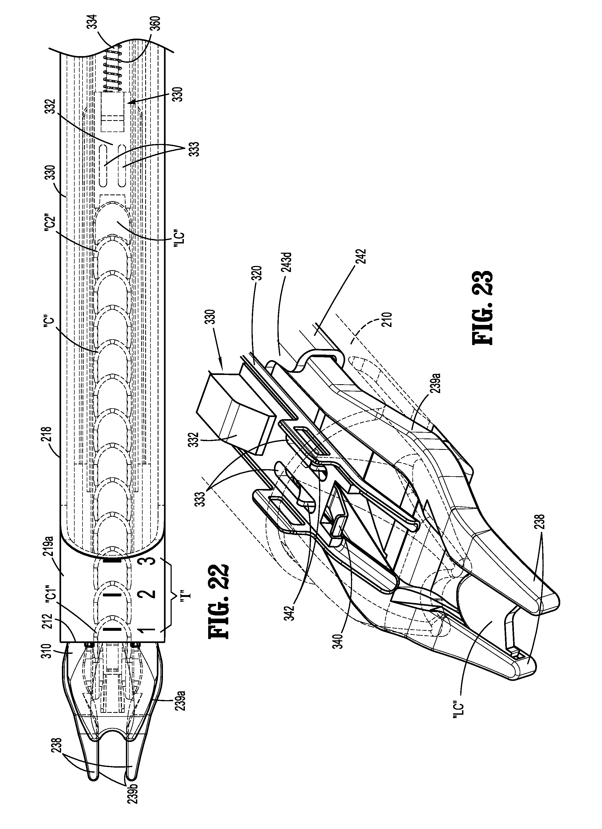
D00015
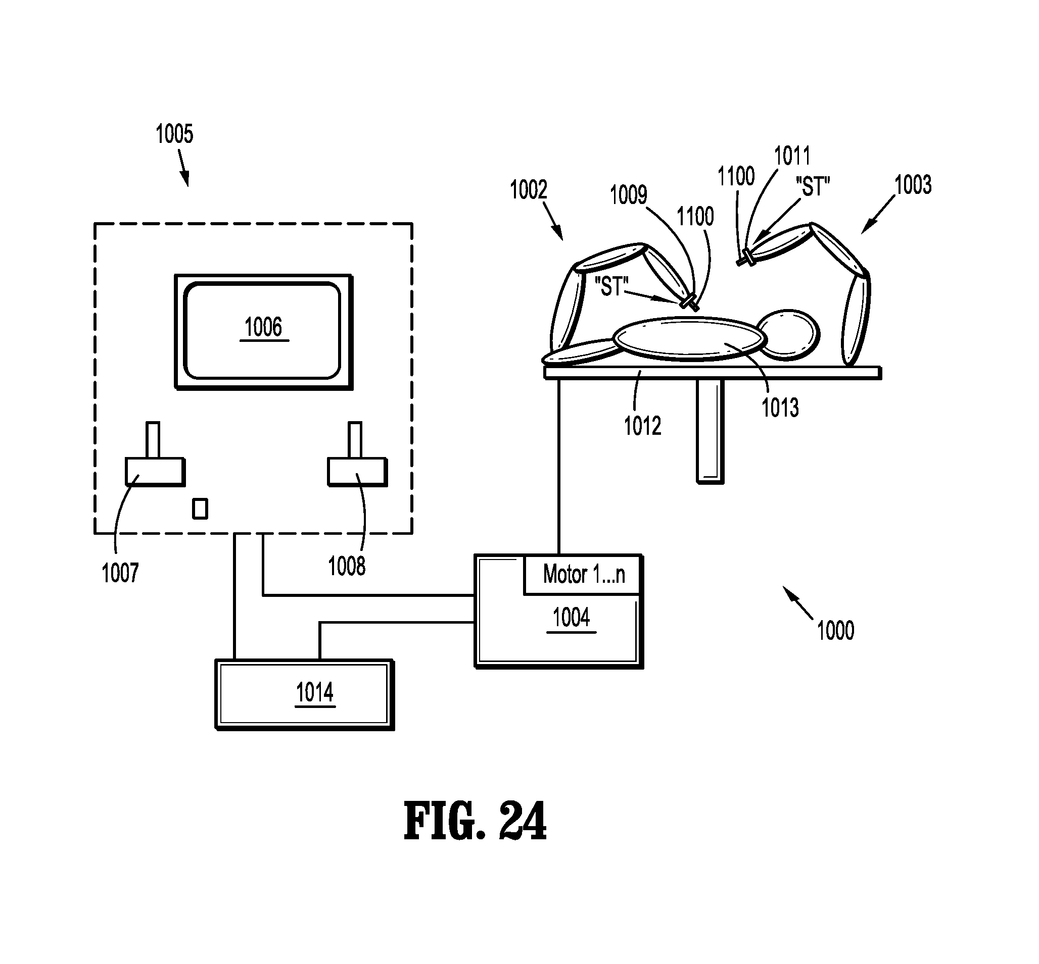
XML
uspto.report is an independent third-party trademark research tool that is not affiliated, endorsed, or sponsored by the United States Patent and Trademark Office (USPTO) or any other governmental organization. The information provided by uspto.report is based on publicly available data at the time of writing and is intended for informational purposes only.
While we strive to provide accurate and up-to-date information, we do not guarantee the accuracy, completeness, reliability, or suitability of the information displayed on this site. The use of this site is at your own risk. Any reliance you place on such information is therefore strictly at your own risk.
All official trademark data, including owner information, should be verified by visiting the official USPTO website at www.uspto.gov. This site is not intended to replace professional legal advice and should not be used as a substitute for consulting with a legal professional who is knowledgeable about trademark law.