Apparatus for applying surgical clips
Aranyi , et al. July 16, 2
U.S. patent number 10,349,950 [Application Number 15/606,020] was granted by the patent office on 2019-07-16 for apparatus for applying surgical clips. This patent grant is currently assigned to Covidien LP. The grantee listed for this patent is Covidien LP. Invention is credited to Ernest Aranyi, Greg Sorrentino, Kenneth H. Whitfield.

View All Diagrams
| United States Patent | 10,349,950 |
| Aranyi , et al. | July 16, 2019 |
Apparatus for applying surgical clips
Abstract
A clip applying apparatus is described for applying clips seriatim to tissue. The apparatus includes a lockout member for limiting distal movement of the camming member after the proximal-most clip has been applied to tissue. In one embodiment, the apparatus includes a jaw locking member for preventing approximation of the jaw members of the apparatus. In one embodiment, a latch assembly is provided to releasably engage a clip pusher of the apparatus to the camming member of the apparatus.
| Inventors: | Aranyi; Ernest (Easton, CT), Whitfield; Kenneth H. (North Haven, CT), Sorrentino; Greg (Wallingford, CT) | ||||||||||
|---|---|---|---|---|---|---|---|---|---|---|---|
| Applicant: |
|
||||||||||
| Assignee: | Covidien LP (Mansfield,
MA) |
||||||||||
| Family ID: | 36148943 | ||||||||||
| Appl. No.: | 15/606,020 | ||||||||||
| Filed: | May 26, 2017 |
Prior Publication Data
| Document Identifier | Publication Date | |
|---|---|---|
| US 20170258472 A1 | Sep 14, 2017 | |
Related U.S. Patent Documents
| Application Number | Filing Date | Patent Number | Issue Date | ||
|---|---|---|---|---|---|
| 14551546 | Nov 24, 2014 | 9687247 | |||
| 11245866 | Dec 30, 2014 | 8920438 | |||
| 60617017 | Oct 8, 2004 | ||||
| Current U.S. Class: | 1/1 |
| Current CPC Class: | A61B 17/1285 (20130101); A61B 17/128 (20130101); A61B 17/12 (20130101); A61B 2017/2837 (20130101); A61B 2017/12004 (20130101); A61B 2017/00407 (20130101) |
| Current International Class: | A61B 17/128 (20060101); A61B 17/12 (20060101); A61B 17/00 (20060101); A61B 17/28 (20060101) |
References Cited [Referenced By]
U.S. Patent Documents
| 3120230 | February 1964 | Skold |
| 3363628 | January 1968 | Wood |
| 3638847 | February 1972 | Noiles et al. |
| 3675688 | July 1972 | Bryan et al. |
| 3735762 | May 1973 | Bryan et al. |
| 3867944 | February 1975 | Samuels |
| 4242902 | January 1981 | Green |
| 4296751 | October 1981 | Blake, III et al. |
| 4372316 | February 1983 | Blake, III et al. |
| 4408603 | October 1983 | Blake, III et al. |
| 4412539 | November 1983 | Jarvik |
| 4418694 | December 1983 | Beroff et al. |
| 4430997 | February 1984 | DiGiovanni et al. |
| 4449531 | May 1984 | Cerwin et al. |
| 4471780 | September 1984 | Menges et al. |
| 4478220 | October 1984 | Di Giovanni et al. |
| 4480640 | November 1984 | Becht |
| 4480641 | November 1984 | Failla et al. |
| 4487204 | December 1984 | Hrouda |
| 4487205 | December 1984 | Di Giovanni et al. |
| 4491133 | January 1985 | Menges et al. |
| 4492232 | January 1985 | Green |
| 4498476 | February 1985 | Cerwin et al. |
| 4500024 | February 1985 | DiGiovanni et al. |
| 4509518 | April 1985 | McGarry et al. |
| 4512345 | April 1985 | Green |
| 4522207 | June 1985 | Klieman et al. |
| 4532925 | August 1985 | Blake, III |
| 4534351 | August 1985 | Rothfuss et al. |
| 4545377 | October 1985 | Cerwin et al. |
| 4549544 | October 1985 | Favaron |
| 4556058 | December 1985 | Green |
| 4557263 | December 1985 | Green |
| 4562839 | January 1986 | Blake, III et al. |
| 4572183 | February 1986 | Juska |
| 4576165 | March 1986 | Green et al. |
| 4576166 | March 1986 | Montgomery et al. |
| 4590937 | May 1986 | Deniega |
| 4592498 | June 1986 | Braun et al. |
| 4598711 | July 1986 | Deniega |
| 4602631 | July 1986 | Funatsu |
| 4611595 | September 1986 | Klieman et al. |
| 4612932 | September 1986 | Caspar et al. |
| 4616650 | October 1986 | Green et al. |
| 4616651 | October 1986 | Golden |
| 4624254 | November 1986 | McGarry et al. |
| 4637395 | January 1987 | Caspar et al. |
| 4646740 | March 1987 | Peters et al. |
| 4647504 | March 1987 | Kimimura et al. |
| 4658822 | April 1987 | Kees, Jr. |
| 4660558 | April 1987 | Kees, Jr. |
| 4662373 | May 1987 | Montgomery et al. |
| 4662374 | May 1987 | Blake, III |
| 4671278 | June 1987 | Chin |
| 4671282 | June 1987 | Tretbar |
| 4674504 | June 1987 | Klieman et al. |
| 4681107 | July 1987 | Kees, Jr. |
| 4696396 | September 1987 | Samuels |
| 4702247 | October 1987 | Blake, III et al. |
| 4706668 | November 1987 | Backer |
| 4712549 | December 1987 | Peters et al. |
| 4733666 | March 1988 | Mercer, Jr. |
| 4759364 | July 1988 | Boebel |
| 4765335 | August 1988 | Schmidt et al. |
| 4777949 | October 1988 | Perlin |
| 4796625 | January 1989 | Kees, Jr. |
| 4799481 | January 1989 | Transue et al. |
| 4815466 | March 1989 | Perlin |
| 4821721 | April 1989 | Chin et al. |
| 4822348 | April 1989 | Casey |
| 4834096 | May 1989 | Oh et al. |
| 4850355 | July 1989 | Brooks et al. |
| 4854317 | August 1989 | Braun |
| 4856517 | August 1989 | Collins et al. |
| 4929239 | May 1990 | Braun |
| 4931058 | June 1990 | Cooper |
| 4934364 | June 1990 | Green |
| 4951860 | August 1990 | Peters et al. |
| 4957500 | September 1990 | Liang et al. |
| 4966603 | October 1990 | Focelle et al. |
| 4967949 | November 1990 | Sandhaus |
| 4983176 | January 1991 | Cushman et al. |
| 4988355 | January 1991 | Leveen et al. |
| 5002552 | March 1991 | Casey |
| 5026379 | June 1991 | Yoon |
| 5030224 | July 1991 | Wright et al. |
| 5030226 | July 1991 | Green |
| 5032127 | July 1991 | Frazee et al. |
| 5035692 | July 1991 | Lyon et al. |
| 5047038 | September 1991 | Peters et al. |
| 5049152 | September 1991 | Simon et al. |
| 5049153 | September 1991 | Nakao et al. |
| 5053045 | October 1991 | Schmidt et al. |
| 5059202 | October 1991 | Liang et al. |
| 5062563 | November 1991 | Green et al. |
| 5062846 | November 1991 | Oh et al. |
| 5078731 | January 1992 | Hayhurst |
| 5084057 | January 1992 | Green et al. |
| 5100416 | March 1992 | Oh et al. |
| 5100420 | March 1992 | Green et al. |
| 5104394 | April 1992 | Knoepfler |
| 5104395 | April 1992 | Thornton et al. |
| 5112343 | May 1992 | Thornton |
| 5122150 | June 1992 | Puig |
| 5127915 | July 1992 | Mattson |
| 5129885 | July 1992 | Green et al. |
| 5156608 | October 1992 | Troidl et al. |
| 5160339 | November 1992 | Chen et al. |
| 5163945 | November 1992 | Ortiz et al. |
| 5171247 | December 1992 | Hughett et al. |
| 5171249 | December 1992 | Stefanchik et al. |
| 5171250 | December 1992 | Yoon |
| 5171251 | December 1992 | Bregen et al. |
| 5171252 | December 1992 | Friedland |
| 5171253 | December 1992 | Klieman |
| 5192288 | March 1993 | Thompson et al. |
| 5197970 | March 1993 | Green |
| 5199566 | April 1993 | Ortiz et al. |
| 5201746 | April 1993 | Shichman |
| 5201900 | April 1993 | Nardella |
| 5207691 | May 1993 | Nardella |
| 5207692 | May 1993 | Kraus et al. |
| 5217473 | June 1993 | Yoon |
| 5219353 | June 1993 | Garvey, III et al. |
| 5246450 | September 1993 | Thornton et al. |
| 5269792 | December 1993 | Kovac et al. |
| 5281228 | January 1994 | Wolfson |
| 5282807 | February 1994 | Knoepfler |
| 5282808 | February 1994 | Kovac et al. |
| 5282832 | February 1994 | Toso et al. |
| 5289963 | March 1994 | McGarry et al. |
| 5290299 | March 1994 | Fain et al. |
| 5300081 | April 1994 | Young et al. |
| 5304183 | April 1994 | Gourlay et al. |
| 5306280 | April 1994 | Bregen et al. |
| 5306283 | April 1994 | Conners |
| 5312426 | May 1994 | Segawa et al. |
| 5330442 | July 1994 | Green et al. |
| 5330487 | July 1994 | Thornton et al. |
| 5340360 | August 1994 | Stefanchik |
| 5342373 | August 1994 | Stefanchik et al. |
| 5354304 | October 1994 | Allen et al. |
| 5354306 | October 1994 | Garvey, III et al. |
| 5356064 | October 1994 | Green et al. |
| 5366458 | November 1994 | Korthoff et al. |
| 5366459 | November 1994 | Yoon |
| 5368600 | November 1994 | Failla et al. |
| 5381943 | January 1995 | Allen et al. |
| 5382253 | January 1995 | Hogendijk |
| 5382254 | January 1995 | McGarry et al. |
| 5382255 | January 1995 | Castro et al. |
| 5383880 | January 1995 | Hooven |
| 5383881 | January 1995 | Green et al. |
| 5395375 | March 1995 | Turkel et al. |
| 5395381 | March 1995 | Green et al. |
| 5403327 | April 1995 | Thornton et al. |
| 5409498 | April 1995 | Braddock et al. |
| 5413584 | May 1995 | Schulze |
| 5423835 | June 1995 | Green et al. |
| 5425740 | June 1995 | Hutchinson, Jr. |
| 5431667 | July 1995 | Thompson et al. |
| 5431668 | July 1995 | Burbank, III et al. |
| 5431669 | July 1995 | Thompson et al. |
| 5439468 | August 1995 | Schulze et al. |
| 5441509 | August 1995 | Vidal et al. |
| 5447513 | September 1995 | Davison et al. |
| 5449365 | September 1995 | Green et al. |
| 5462555 | October 1995 | Bolanos et al. |
| 5462558 | October 1995 | Kolesa et al. |
| 5464416 | November 1995 | Steckel |
| 5474566 | December 1995 | Alesi et al. |
| 5474567 | December 1995 | Stefanchik et al. |
| 5474572 | December 1995 | Hayhurst |
| 5487499 | January 1996 | Sorrentino et al. |
| 5487746 | January 1996 | Yu et al. |
| 5501693 | March 1996 | Gravener |
| 5509920 | April 1996 | Phillips et al. |
| 5514149 | May 1996 | Green et al. |
| 5520701 | May 1996 | Lerch |
| 5527318 | June 1996 | McGarry |
| 5527319 | June 1996 | Green et al. |
| 5527320 | June 1996 | Carruthers et al. |
| 5542949 | August 1996 | Yoon |
| 5547474 | August 1996 | Kloeckl et al. |
| 5569274 | October 1996 | Rapacki et al. |
| 5571121 | November 1996 | Heifetz |
| 5575802 | November 1996 | McQuilkin et al. |
| 5582615 | December 1996 | Foshee et al. |
| 5584840 | December 1996 | Ramsey et al. |
| 5591178 | January 1997 | Green et al. |
| 5593414 | January 1997 | Shipp et al. |
| 5593421 | January 1997 | Bauer |
| 5601573 | February 1997 | Fogelberg et al. |
| 5601574 | February 1997 | Stefanchik et al. |
| 5607436 | March 1997 | Pratt et al. |
| 5618291 | April 1997 | Thompson et al. |
| 5618306 | April 1997 | Roth et al. |
| 5620452 | April 1997 | Yoon |
| 5626585 | May 1997 | Mittelstadt et al. |
| 5626586 | May 1997 | Pistl et al. |
| 5626587 | May 1997 | Bishop et al. |
| 5626592 | May 1997 | Phillips et al. |
| RE35525 | June 1997 | Stefanchik et al. |
| 5634930 | June 1997 | Thornton et al. |
| 5643291 | July 1997 | Pier et al. |
| 5645551 | July 1997 | Green et al. |
| 5645553 | July 1997 | Kolesa et al. |
| 5649937 | July 1997 | Bito et al. |
| 5653720 | August 1997 | Johnson et al. |
| 5662662 | September 1997 | Bishop et al. |
| 5662676 | September 1997 | Koninckx |
| 5662679 | September 1997 | Voss et al. |
| 5665097 | September 1997 | Baker et al. |
| 5676676 | October 1997 | Porter |
| 5681330 | October 1997 | Hughett et al. |
| 5683405 | November 1997 | Yacoubian et al. |
| 5695502 | December 1997 | Pier et al. |
| 5695505 | December 1997 | Yoon |
| 5697938 | December 1997 | Jensen et al. |
| 5697942 | December 1997 | Palti |
| 5700270 | December 1997 | Peyser |
| 5700271 | December 1997 | Whitfield et al. |
| 5702048 | December 1997 | Eberlin |
| 5709706 | January 1998 | Kienzle et al. |
| 5713911 | February 1998 | Racenet et al. |
| 5713912 | February 1998 | Porter |
| 5720756 | February 1998 | Green et al. |
| 5722982 | March 1998 | Ferreira et al. |
| 5725537 | March 1998 | Green et al. |
| 5725538 | March 1998 | Green et al. |
| 5725542 | March 1998 | Yoon |
| 5733295 | March 1998 | Back et al. |
| 5749881 | May 1998 | Sackier et al. |
| 5755726 | May 1998 | Pratt et al. |
| 5766189 | June 1998 | Matsuno |
| 5769857 | June 1998 | Reztzov et al. |
| 5772673 | June 1998 | Cuny |
| 5776146 | July 1998 | Sackier et al. |
| 5776147 | July 1998 | Dolendo |
| 5779718 | July 1998 | Green et al. |
| 5779720 | July 1998 | Walder-Utz et al. |
| 5782844 | July 1998 | Yoon et al. |
| 5788698 | August 1998 | Savornin |
| 5792149 | August 1998 | Sherts et al. |
| 5792150 | August 1998 | Pratt et al. |
| 5797922 | August 1998 | Hessel et al. |
| 5810853 | September 1998 | Yoon |
| 5817116 | October 1998 | Takahashi et al. |
| 5827279 | October 1998 | Hughett et al. |
| 5827306 | October 1998 | Yoon |
| 5827323 | October 1998 | Klieman et al. |
| 5833695 | November 1998 | Yoon |
| 5833696 | November 1998 | Whitfield |
| 5833700 | November 1998 | Fogelberg et al. |
| 5835199 | November 1998 | Phillips et al. |
| 5843097 | December 1998 | Mayenberger et al. |
| 5843101 | December 1998 | Fry |
| 5846255 | December 1998 | Casey |
| 5849019 | December 1998 | Yoon |
| 5858018 | January 1999 | Shipp et al. |
| 5861005 | January 1999 | Kontos |
| 5868759 | February 1999 | Peyser et al. |
| 5868761 | February 1999 | Nicholas et al. |
| 5876410 | March 1999 | Petillo |
| 5895394 | April 1999 | Kienzle et al. |
| 5897565 | April 1999 | Foster |
| 5904693 | May 1999 | Dicesare et al. |
| 5906625 | May 1999 | Bito et al. |
| 5913862 | June 1999 | Ramsey et al. |
| 5913876 | June 1999 | Taylor et al. |
| 5918791 | July 1999 | Sorrentino et al. |
| 5921996 | July 1999 | Sherman |
| 5921997 | July 1999 | Fogelberg et al. |
| 5928251 | July 1999 | Aranyi et al. |
| 5938667 | August 1999 | Peyser |
| 5951574 | September 1999 | Stefanchik et al. |
| 5972003 | October 1999 | Rousseau et al. |
| 5976159 | November 1999 | Bolduc et al. |
| 5993465 | November 1999 | Shipp et al. |
| 6004335 | December 1999 | Vaitekunas et al. |
| 6009551 | December 1999 | Sheynblat |
| 6017358 | January 2000 | Yoon et al. |
| 6053908 | April 2000 | Crainich et al. |
| RE36720 | May 2000 | Green et al. |
| 6059799 | May 2000 | Aranyi |
| 6099536 | August 2000 | Petillo |
| 6099537 | August 2000 | Sugai et al. |
| 6139555 | October 2000 | Hart et al. |
| 6210418 | April 2001 | Storz et al. |
| 6217590 | April 2001 | Levinson |
| 6228097 | May 2001 | Levinson et al. |
| 6241740 | June 2001 | Davis et al. |
| 6258105 | July 2001 | Hart et al. |
| 6261302 | July 2001 | Voegele et al. |
| 6273898 | August 2001 | Kienzle et al. |
| 6277131 | August 2001 | Kalikow |
| 6306149 | October 2001 | Meade |
| 6318619 | November 2001 | Lee |
| 6322571 | November 2001 | Adams |
| 6350269 | February 2002 | Shipp et al. |
| 6352541 | March 2002 | Kienzle et al. |
| 6391035 | May 2002 | Appleby et al. |
| 6423079 | July 2002 | Blake, III |
| 6428548 | August 2002 | Durgin et al. |
| 6440144 | August 2002 | Bacher |
| 6461363 | October 2002 | Gadberry et al. |
| 6464710 | October 2002 | Foster |
| 6494886 | December 2002 | Wilk et al. |
| 6517536 | February 2003 | Hooven et al. |
| 6520972 | February 2003 | Peters |
| 6527786 | March 2003 | Davis et al. |
| 6537289 | March 2003 | Kayan et al. |
| 6546935 | April 2003 | Hooven |
| 6551333 | April 2003 | Kuhns et al. |
| 6562051 | May 2003 | Bolduc et al. |
| 6569171 | May 2003 | DeGuillebon et al. |
| 6579304 | June 2003 | Hart et al. |
| 6599298 | July 2003 | Forster et al. |
| 6602252 | August 2003 | Mollenauer |
| 6607540 | August 2003 | Shipp |
| 6613060 | September 2003 | Adams et al. |
| 6626916 | September 2003 | Yeung et al. |
| 6626922 | September 2003 | Hart et al. |
| 6648898 | November 2003 | Baxter |
| 6652538 | November 2003 | Kayan et al. |
| 6652539 | November 2003 | Shipp et al. |
| 6656193 | December 2003 | Grant et al. |
| 6673083 | January 2004 | Kayan et al. |
| 6676659 | January 2004 | Hutchins et al. |
| 6679894 | January 2004 | Damarati |
| RE38445 | February 2004 | Pistl et al. |
| 6695854 | February 2004 | Kayan et al. |
| 6706057 | March 2004 | Bidoia et al. |
| 6716226 | April 2004 | Sixto, Jr. et al. |
| 6723109 | April 2004 | Solingen |
| 6743240 | June 2004 | Smith et al. |
| 6773438 | August 2004 | Knodel et al. |
| 6773440 | August 2004 | Gannoe et al. |
| 6776783 | August 2004 | Frantzen et al. |
| 6776784 | August 2004 | Ginn |
| 6780195 | August 2004 | Porat |
| 6793663 | September 2004 | Kneifel et al. |
| 6793664 | September 2004 | Mazzocchi et al. |
| 6802848 | October 2004 | Anderson et al. |
| 6814742 | November 2004 | Kimura et al. |
| 6818009 | November 2004 | Hart et al. |
| 6821273 | November 2004 | Mollenauer |
| 6821284 | November 2004 | Sturtz et al. |
| 6824547 | November 2004 | Wilson, Jr. et al. |
| 6824548 | November 2004 | Smith et al. |
| 6835199 | December 2004 | McGuckin, Jr. et al. |
| 6835200 | December 2004 | Laufer et al. |
| 6837893 | January 2005 | Miller |
| 6837894 | January 2005 | Pugsley, Jr. et al. |
| 6837895 | January 2005 | Mayenberger |
| 6840945 | January 2005 | Manetakis et al. |
| 6843794 | January 2005 | Sixto, Jr. et al. |
| 6849078 | February 2005 | Durgin et al. |
| 6849079 | February 2005 | Blake, III et al. |
| 6853879 | February 2005 | Sunaoshi |
| 6869435 | March 2005 | Blake, III |
| 6869436 | March 2005 | Wendlandt |
| 6889116 | May 2005 | Jinno |
| 6896682 | May 2005 | McClellan et al. |
| 6905503 | June 2005 | Gifford, III et al. |
| 6911032 | June 2005 | Jugenheimer et al. |
| 6911033 | June 2005 | de Guillebon et al. |
| 6913607 | July 2005 | Ainsworth et al. |
| 6916327 | July 2005 | Northrup, III et al. |
| 6923818 | August 2005 | Muramatsu et al. |
| 6939356 | September 2005 | Debbas |
| 6942674 | September 2005 | Belef et al. |
| 6942676 | September 2005 | Buelna |
| 6945978 | September 2005 | Hyde |
| 6945979 | September 2005 | Kortenbach et al. |
| 6949107 | September 2005 | McGuckin, Jr. et al. |
| 6953465 | October 2005 | Dieck et al. |
| 6955643 | October 2005 | Gellman et al. |
| 6959852 | November 2005 | Shelton, IV et al. |
| 6960218 | November 2005 | Rennich |
| 6960221 | November 2005 | Ho et al. |
| 6962594 | November 2005 | Thevenet |
| 6963792 | November 2005 | Green |
| 6964363 | November 2005 | Wales et al. |
| 6964668 | November 2005 | Modesitt et al. |
| 6966875 | November 2005 | Longobardi |
| 6966917 | November 2005 | Suyker et al. |
| 6966919 | November 2005 | Sixto, Jr. et al. |
| 6969391 | November 2005 | Gazzani |
| 6972023 | December 2005 | Whayne et al. |
| 6972027 | December 2005 | Fallin et al. |
| 6973770 | December 2005 | Schnipke et al. |
| 6974462 | December 2005 | Sater |
| 6974466 | December 2005 | Ahmed et al. |
| 6974475 | December 2005 | Wall |
| 6981505 | January 2006 | Krause et al. |
| 6981628 | January 2006 | Wales |
| 6991635 | January 2006 | Takamoto et al. |
| 7052504 | May 2006 | Hughett |
| 7056330 | June 2006 | Gayton |
| 7108703 | September 2006 | Danitz et al. |
| 7144402 | December 2006 | Kuester, III |
| 7175648 | February 2007 | Nakao |
| 7179265 | February 2007 | Manetakis et al. |
| 7207997 | April 2007 | Shipp et al. |
| 7211091 | May 2007 | Fowler et al. |
| 7211092 | May 2007 | Hughett |
| 7214230 | May 2007 | Brock et al. |
| 7214232 | May 2007 | Bowman et al. |
| 7223271 | May 2007 | Muramatsu et al. |
| 7232445 | June 2007 | Kortenbach et al. |
| 7261724 | August 2007 | Molitor et al. |
| 7261725 | August 2007 | Binmoeller |
| 7264625 | September 2007 | Buncke |
| 7288098 | October 2007 | Huitema et al. |
| 7297149 | November 2007 | Vitali et al. |
| 7316693 | January 2008 | Viola |
| 7316696 | January 2008 | Wilson, Jr. et al. |
| 7326223 | February 2008 | Wilson, Jr. |
| 7329266 | February 2008 | Royse et al. |
| 7331968 | February 2008 | Arp et al. |
| 7338503 | March 2008 | Rosenberg et al. |
| 7357805 | April 2008 | Masuda et al. |
| 7431724 | October 2008 | Manetakis |
| 7510562 | March 2009 | Lindsay |
| 7552853 | June 2009 | Mas et al. |
| 7637917 | December 2009 | Whitfield et al. |
| 7644848 | January 2010 | Swayze |
| 7686820 | March 2010 | Huitema et al. |
| 7695482 | April 2010 | Viola |
| 7717926 | May 2010 | Whitfield et al. |
| 7727248 | June 2010 | Smith et al. |
| 7731724 | June 2010 | Huitema et al. |
| 7740641 | June 2010 | Huitema |
| 7752853 | July 2010 | Singh et al. |
| 7753250 | July 2010 | Clauson et al. |
| 7766207 | August 2010 | Mather et al. |
| 7819886 | October 2010 | Whitfield et al. |
| 7887553 | February 2011 | Lehman et al. |
| 7905890 | March 2011 | Whitfield et al. |
| 7942885 | May 2011 | Sixto, Jr. et al. |
| 7952060 | May 2011 | Watanabe et al. |
| 7963433 | June 2011 | Whitman et al. |
| 7988027 | August 2011 | Olson et al. |
| 8011550 | September 2011 | Aranyi et al. |
| 8011555 | September 2011 | Tarinelli et al. |
| 8016178 | September 2011 | Olson et al. |
| 8021375 | September 2011 | Aldrich et al. |
| 8021378 | September 2011 | Sixto, Jr. et al. |
| 8038686 | October 2011 | Huitema et al. |
| 8056565 | November 2011 | Zergiebel |
| 8062310 | November 2011 | Shibata et al. |
| 8066720 | November 2011 | Knodel et al. |
| 8066721 | November 2011 | Kortenbach et al. |
| 8066722 | November 2011 | Miyagi et al. |
| 8070760 | December 2011 | Fujita |
| 8075571 | December 2011 | Vitali et al. |
| 8080021 | December 2011 | Griego |
| 8083668 | December 2011 | Durgin et al. |
| 8088061 | January 2012 | Wells et al. |
| 8091755 | January 2012 | Kayan et al. |
| 8100926 | January 2012 | Filshie et al. |
| 8128643 | March 2012 | Aranyi et al. |
| 8133240 | March 2012 | Damarati |
| 8142451 | March 2012 | Boulnois et al. |
| 8157145 | April 2012 | Shelton, IV et al. |
| 8157149 | April 2012 | Olson et al. |
| 8157151 | April 2012 | Ingmanson et al. |
| 8172859 | May 2012 | Matsuno et al. |
| 8172870 | May 2012 | Shipp |
| 8187290 | May 2012 | Buckman et al. |
| 8211120 | July 2012 | Itoh |
| 8211124 | July 2012 | Ainsworth et al. |
| 8216255 | July 2012 | Smith et al. |
| 8216257 | July 2012 | Huitema et al. |
| 8236012 | August 2012 | Molitor et al. |
| 8246634 | August 2012 | Huitema et al. |
| 8246635 | August 2012 | Huitema |
| 8262678 | September 2012 | Matsuoka et al. |
| 8262679 | September 2012 | Nguyen |
| 8267944 | September 2012 | Sorrentino et al. |
| 8267945 | September 2012 | Nguyen et al. |
| 8267946 | September 2012 | Whitfield et al. |
| 8272554 | September 2012 | Whitman et al. |
| 8282655 | October 2012 | Whitfield et al. |
| 8308743 | November 2012 | Matsuno et al. |
| 8328822 | December 2012 | Huitema et al. |
| 8336556 | December 2012 | Zergiebel |
| 8348130 | January 2013 | Shah et al. |
| 8357171 | January 2013 | Whitfield et al. |
| 8366709 | February 2013 | Schechter et al. |
| 8366726 | February 2013 | Dennis |
| 8371491 | February 2013 | Huitema et al. |
| 8372095 | February 2013 | Viola |
| 8382773 | February 2013 | Whitfield et al. |
| 8398655 | March 2013 | Cheng et al. |
| 8403945 | March 2013 | Whitfield et al. |
| 8403946 | March 2013 | Whitfield et al. |
| 8408442 | April 2013 | Racenet et al. |
| 8409222 | April 2013 | Whitfield et al. |
| 8409223 | April 2013 | Sorrentino et al. |
| 8419752 | April 2013 | Sorrentino et al. |
| 8430892 | April 2013 | Bindra et al. |
| 8444660 | May 2013 | Adams et al. |
| 8465460 | June 2013 | Yodfat et al. |
| 8465502 | June 2013 | Zergiebel |
| 8475473 | July 2013 | Vandenbroek et al. |
| 8480688 | July 2013 | Boulnois et al. |
| 8486091 | July 2013 | Sorrentino et al. |
| 8491608 | July 2013 | Sorrentino et al. |
| 8496673 | July 2013 | Nguyen et al. |
| 8506580 | August 2013 | Zergiebel et al. |
| 8512357 | August 2013 | Viola |
| 8518055 | August 2013 | Cardinale et al. |
| 8523882 | September 2013 | Huitema et al. |
| 8529585 | September 2013 | Jacobs et al. |
| 8529586 | September 2013 | Rosenberg et al. |
| 8529588 | September 2013 | Ahlberg et al. |
| 8545486 | October 2013 | Malkowski |
| 8556920 | October 2013 | Huitema et al. |
| 8568430 | October 2013 | Shipp |
| 8579918 | November 2013 | Whitfield et al. |
| 8585717 | November 2013 | Sorrentino et al. |
| 8603109 | December 2013 | Aranyi et al. |
| 8652151 | February 2014 | Lehman et al. |
| 8652152 | February 2014 | Aranyi et al. |
| 8663247 | March 2014 | Menn et al. |
| 8685048 | April 2014 | Adams et al. |
| 8690899 | April 2014 | Kogiso et al. |
| 8708213 | April 2014 | Shelton, IV et al. |
| 8709027 | April 2014 | Adams et al. |
| 8715299 | May 2014 | Menn et al. |
| 8720766 | May 2014 | Hess et al. |
| 8734469 | May 2014 | Pribanic et al. |
| 8747423 | June 2014 | Whitfield et al. |
| 8753356 | June 2014 | Vitali et al. |
| 8814884 | August 2014 | Whitfield et al. |
| 8821516 | September 2014 | Huitema |
| 8839954 | September 2014 | Disch |
| 8845659 | September 2014 | Whitfield et al. |
| 8894665 | November 2014 | Sorrentino et al. |
| 8894666 | November 2014 | Schulz et al. |
| 8900253 | December 2014 | Aranyi et al. |
| 8915930 | December 2014 | Huitema et al. |
| 8920438 | December 2014 | Aranyi et al. |
| 8939974 | January 2015 | Boudreaux et al. |
| 8950646 | February 2015 | Viola |
| 8961542 | February 2015 | Whitfield et al. |
| 8968337 | March 2015 | Whitfield et al. |
| 8968342 | March 2015 | Wingardner, III et al. |
| 8973804 | March 2015 | Hess et al. |
| 9011464 | April 2015 | Zammataro |
| 9011465 | April 2015 | Whitfield et al. |
| 9089334 | July 2015 | Sorrentino et al. |
| 9113892 | August 2015 | Malkowski et al. |
| 9113893 | August 2015 | Sorrentino et al. |
| 9119629 | September 2015 | Cardinale et al. |
| 9186136 | November 2015 | Malkowski et al. |
| 9186153 | November 2015 | Zammataro |
| 9208429 | December 2015 | Thornton et al. |
| 9220507 | December 2015 | Patel et al. |
| 9282961 | March 2016 | Whitman et al. |
| 9326776 | May 2016 | Gadberry et al. |
| 9358011 | June 2016 | Sorrentino et al. |
| 9358015 | June 2016 | Sorrentino et al. |
| 9364216 | June 2016 | Rockrohr et al. |
| 9364239 | June 2016 | Malkowski |
| 9364240 | June 2016 | Whitfield et al. |
| 9370400 | June 2016 | Parihar |
| 9393024 | July 2016 | Whitfield et al. |
| 9398917 | July 2016 | Whitfield et al. |
| 9408610 | August 2016 | Hartoumbekis |
| 9414844 | August 2016 | Zergiebel et al. |
| 9433411 | September 2016 | Racenet et al. |
| 9439654 | September 2016 | Sorrentino et al. |
| 9480477 | November 2016 | Aranyi et al. |
| 9498227 | November 2016 | Zergiebel et al. |
| 9526501 | December 2016 | Malkowski |
| 9532787 | January 2017 | Zammataro |
| 9545254 | January 2017 | Sorrentino et al. |
| 9549741 | January 2017 | Zergiebel |
| 9642627 | May 2017 | Zammataro |
| 9687247 | June 2017 | Aranyi et al. |
| 9717505 | August 2017 | Whitfield et al. |
| 9737310 | August 2017 | Whitfield et al. |
| 9750500 | September 2017 | Malkowski |
| 9763668 | September 2017 | Whitfield et al. |
| 9775623 | October 2017 | Zammataro et al. |
| 9775624 | October 2017 | Rockrohr et al. |
| 9848886 | December 2017 | Malkowski et al. |
| 9855043 | January 2018 | Malkowski |
| 9931124 | April 2018 | Gokharu |
| 9968361 | May 2018 | Aranyi et al. |
| 9968362 | May 2018 | Malkowski et al. |
| 10004502 | June 2018 | Malkowski et al. |
| 10159484 | December 2018 | Sorrentino et al. |
| 10159491 | December 2018 | Gokharu |
| 10159492 | December 2018 | Zammataro |
| 10166027 | January 2019 | Aranyi et al. |
| 2001/0047178 | November 2001 | Peters |
| 2002/0040226 | April 2002 | Laufer et al. |
| 2002/0068947 | June 2002 | Kuhns et al. |
| 2002/0082618 | June 2002 | Shipp et al. |
| 2002/0087169 | July 2002 | Brock et al. |
| 2002/0087170 | July 2002 | Kuhns et al. |
| 2002/0099388 | July 2002 | Mayenberger |
| 2002/0120279 | August 2002 | Deguillebon et al. |
| 2002/0128668 | September 2002 | Manetakis |
| 2002/0177859 | November 2002 | Monassevitch et al. |
| 2002/0198537 | December 2002 | Smith et al. |
| 2002/0198538 | December 2002 | Kortenbach et al. |
| 2002/0198539 | December 2002 | Sixto et al. |
| 2002/0198540 | December 2002 | Smith et al. |
| 2002/0198541 | December 2002 | Smith et al. |
| 2003/0014060 | January 2003 | Wilson et al. |
| 2003/0018345 | January 2003 | Green |
| 2003/0023249 | January 2003 | Manetakis |
| 2003/0040759 | February 2003 | de Guillebon et al. |
| 2003/0105476 | June 2003 | Sancoff et al. |
| 2003/0114867 | June 2003 | Bolduc et al. |
| 2003/0135224 | July 2003 | Blake |
| 2003/0167063 | September 2003 | Kerr |
| 2003/0208231 | November 2003 | Williamson et al. |
| 2003/0220657 | November 2003 | Adams |
| 2003/0225423 | December 2003 | Huitema |
| 2003/0229360 | December 2003 | Gayton |
| 2003/0233105 | December 2003 | Gayton |
| 2004/0010272 | January 2004 | Manetakis et al. |
| 2004/0044352 | March 2004 | Fowler et al. |
| 2004/0097970 | May 2004 | Hughett |
| 2004/0097971 | May 2004 | Hughett |
| 2004/0097972 | May 2004 | Shipp et al. |
| 2004/0106936 | June 2004 | Shipp et al. |
| 2004/0133215 | July 2004 | Baxter |
| 2004/0138681 | July 2004 | Pier |
| 2004/0153100 | August 2004 | Ahlberg et al. |
| 2004/0158266 | August 2004 | Damarati |
| 2004/0162567 | August 2004 | Adams |
| 2004/0167545 | August 2004 | Sadler et al. |
| 2004/0176776 | September 2004 | Zubok et al. |
| 2004/0176783 | September 2004 | Edoga et al. |
| 2004/0176784 | September 2004 | Okada |
| 2004/0193213 | September 2004 | Aranyi et al. |
| 2004/0232197 | November 2004 | Shelton et al. |
| 2005/0010242 | January 2005 | Lindsay |
| 2005/0080440 | April 2005 | Durgin et al. |
| 2005/0090837 | April 2005 | Sixto et al. |
| 2005/0090838 | April 2005 | Sixto et al. |
| 2005/0096670 | May 2005 | Wellman et al. |
| 2005/0096671 | May 2005 | Wellman et al. |
| 2005/0096672 | May 2005 | Manetakis et al. |
| 2005/0101975 | May 2005 | Nguyen et al. |
| 2005/0107807 | May 2005 | Nakao |
| 2005/0107809 | May 2005 | Litscher et al. |
| 2005/0107810 | May 2005 | Morales et al. |
| 2005/0107811 | May 2005 | Starksen et al. |
| 2005/0107812 | May 2005 | Starksen et al. |
| 2005/0107871 | May 2005 | Realyvasquez et al. |
| 2005/0113847 | May 2005 | Gadberry et al. |
| 2005/0119671 | June 2005 | Reydel et al. |
| 2005/0119673 | June 2005 | Gordon et al. |
| 2005/0119677 | June 2005 | Shipp |
| 2005/0125010 | June 2005 | Smith et al. |
| 2005/0143767 | June 2005 | Kimura et al. |
| 2005/0149063 | July 2005 | Young et al. |
| 2005/0149064 | July 2005 | Peterson et al. |
| 2005/0149068 | July 2005 | Williams et al. |
| 2005/0149069 | July 2005 | Bertolero et al. |
| 2005/0165415 | July 2005 | Wales |
| 2005/0165418 | July 2005 | Chan |
| 2005/0171560 | August 2005 | Hughett |
| 2005/0175703 | August 2005 | Hunter et al. |
| 2005/0177176 | August 2005 | Gerbi et al. |
| 2005/0203547 | September 2005 | Weller et al. |
| 2005/0203548 | September 2005 | Weller et al. |
| 2005/0216036 | September 2005 | Nakao |
| 2005/0216056 | September 2005 | Valdevit et al. |
| 2005/0222588 | October 2005 | Vandenbroek et al. |
| 2005/0222590 | October 2005 | Gadberry et al. |
| 2005/0222665 | October 2005 | Aranyi |
| 2005/0228411 | October 2005 | Manzo |
| 2005/0228416 | October 2005 | Burbank et al. |
| 2005/0234478 | October 2005 | Wixey et al. |
| 2005/0251183 | November 2005 | Buckman et al. |
| 2005/0251184 | November 2005 | Anderson |
| 2005/0256529 | November 2005 | Yawata et al. |
| 2005/0267495 | December 2005 | Ginn et al. |
| 2005/0273122 | December 2005 | Theroux et al. |
| 2005/0277951 | December 2005 | Smith et al. |
| 2005/0277952 | December 2005 | Arp et al. |
| 2005/0277953 | December 2005 | Francese et al. |
| 2005/0277954 | December 2005 | Smith et al. |
| 2005/0277955 | December 2005 | Palmer et al. |
| 2005/0277956 | December 2005 | Francese et al. |
| 2005/0277958 | December 2005 | Levinson |
| 2005/0288689 | December 2005 | Kammerer et al. |
| 2005/0288690 | December 2005 | Bourque et al. |
| 2006/0000867 | January 2006 | Shelton et al. |
| 2006/0004388 | January 2006 | Whayne et al. |
| 2006/0004390 | January 2006 | Rosenberg et al. |
| 2006/0009789 | January 2006 | Gambale et al. |
| 2006/0009790 | January 2006 | Blake et al. |
| 2006/0009792 | January 2006 | Baker et al. |
| 2006/0020270 | January 2006 | Jabba et al. |
| 2006/0020271 | January 2006 | Stewart et al. |
| 2006/0047305 | March 2006 | Ortiz et al. |
| 2006/0047306 | March 2006 | Ortiz et al. |
| 2006/0064117 | March 2006 | Aranyi et al. |
| 2006/0079115 | April 2006 | Aranyi et al. |
| 2006/0079913 | April 2006 | Whitfield et al. |
| 2006/0085015 | April 2006 | Whitfield et al. |
| 2006/0100649 | May 2006 | Hart |
| 2006/0111731 | May 2006 | Manzo |
| 2006/0129170 | June 2006 | Royce et al. |
| 2006/0135992 | June 2006 | Bettuchi et al. |
| 2006/0163312 | July 2006 | Viola et al. |
| 2006/0173470 | August 2006 | Oray et al. |
| 2006/0178683 | August 2006 | Shimoji et al. |
| 2006/0184182 | August 2006 | Aranyi et al. |
| 2006/0190013 | August 2006 | Menn |
| 2006/0195125 | August 2006 | Sakakine et al. |
| 2006/0200179 | September 2006 | Barker et al. |
| 2006/0212050 | September 2006 | D'Agostino et al. |
| 2006/0217749 | September 2006 | Wilson et al. |
| 2006/0224165 | October 2006 | Surti et al. |
| 2006/0224170 | October 2006 | Duff |
| 2006/0235437 | October 2006 | Vitali et al. |
| 2006/0235438 | October 2006 | Huitema et al. |
| 2006/0235439 | October 2006 | Molitor et al. |
| 2006/0235440 | October 2006 | Huitema et al. |
| 2006/0235441 | October 2006 | Huitema et al. |
| 2006/0235442 | October 2006 | Huitema |
| 2006/0235443 | October 2006 | Huitema et al. |
| 2006/0235444 | October 2006 | Huitema et al. |
| 2006/0241655 | October 2006 | Viola |
| 2006/0259045 | November 2006 | Damarati |
| 2006/0259049 | November 2006 | Harada et al. |
| 2006/0264987 | November 2006 | Sgro |
| 2006/0271072 | November 2006 | Hummel et al. |
| 2007/0016228 | January 2007 | Salas |
| 2007/0021761 | January 2007 | Phillips |
| 2007/0021766 | January 2007 | Belagali et al. |
| 2007/0023476 | February 2007 | Whitman et al. |
| 2007/0023477 | February 2007 | Whitman et al. |
| 2007/0027458 | February 2007 | Sixto, Jr. et al. |
| 2007/0034669 | February 2007 | de la Torre et al. |
| 2007/0038233 | February 2007 | Martinez et al. |
| 2007/0049947 | March 2007 | Menn et al. |
| 2007/0049948 | March 2007 | Menn et al. |
| 2007/0049949 | March 2007 | Manetakis |
| 2007/0049950 | March 2007 | Theroux et al. |
| 2007/0049951 | March 2007 | Menn |
| 2007/0049953 | March 2007 | Shimoji et al. |
| 2007/0066981 | March 2007 | Meagher |
| 2007/0073314 | March 2007 | Gadberry et al. |
| 2007/0083218 | April 2007 | Morris |
| 2007/0093790 | April 2007 | Downey et al. |
| 2007/0093856 | April 2007 | Whitfield et al. |
| 2007/0106314 | May 2007 | Dunn |
| 2007/0112365 | May 2007 | Hilal et al. |
| 2007/0118155 | May 2007 | Goldfarb et al. |
| 2007/0118161 | May 2007 | Kennedy et al. |
| 2007/0118163 | May 2007 | Boudreaux et al. |
| 2007/0118174 | May 2007 | Chu |
| 2007/0123916 | May 2007 | Maier et al. |
| 2007/0142848 | June 2007 | Ainsworth et al. |
| 2007/0142851 | June 2007 | Sixto et al. |
| 2007/0149988 | June 2007 | Michler et al. |
| 2007/0149989 | June 2007 | Santilli et al. |
| 2007/0162060 | July 2007 | Wild |
| 2007/0173866 | July 2007 | Sorrentino et al. |
| 2007/0175949 | August 2007 | Shelton et al. |
| 2007/0185504 | August 2007 | Manetakis et al. |
| 2007/0191868 | August 2007 | Theroux et al. |
| 2007/0203509 | August 2007 | Bettuchi |
| 2007/0203510 | August 2007 | Bettuchi |
| 2007/0213747 | September 2007 | Monassevitch et al. |
| 2007/0250080 | October 2007 | Jones et al. |
| 2007/0265640 | November 2007 | Kortenbach et al. |
| 2007/0276417 | November 2007 | Mendes, Jr. et al. |
| 2007/0282355 | December 2007 | Brown et al. |
| 2007/0288039 | December 2007 | Aranyi et al. |
| 2007/0293875 | December 2007 | Soetikno et al. |
| 2008/0004636 | January 2008 | Walberg et al. |
| 2008/0004637 | January 2008 | Klassen et al. |
| 2008/0004639 | January 2008 | Huitema et al. |
| 2008/0015615 | January 2008 | Molitor et al. |
| 2008/0027465 | January 2008 | Vitali et al. |
| 2008/0027466 | January 2008 | Vitali et al. |
| 2008/0045981 | February 2008 | Margolin et al. |
| 2008/0051808 | February 2008 | Rivera et al. |
| 2008/0065118 | March 2008 | Damarati |
| 2008/0083813 | April 2008 | Zemlok et al. |
| 2008/0103510 | May 2008 | Taylor et al. |
| 2008/0147092 | June 2008 | Rogge et al. |
| 2008/0147093 | June 2008 | Roskopf et al. |
| 2008/0154287 | June 2008 | Rosenberg et al. |
| 2008/0167665 | July 2008 | Arp et al. |
| 2008/0167671 | July 2008 | Giordano et al. |
| 2008/0228199 | September 2008 | Cropper et al. |
| 2008/0243145 | October 2008 | Whitfield et al. |
| 2008/0255413 | October 2008 | Zemlok et al. |
| 2008/0255589 | October 2008 | Blakeney et al. |
| 2008/0306492 | December 2008 | Shibata et al. |
| 2008/0306493 | December 2008 | Shibata et al. |
| 2008/0312665 | December 2008 | Shibata et al. |
| 2008/0312670 | December 2008 | Lutze et al. |
| 2008/0319456 | December 2008 | Hart et al. |
| 2009/0076533 | March 2009 | Kayan et al. |
| 2009/0088777 | April 2009 | Miyagi et al. |
| 2009/0088783 | April 2009 | Kennedy et al. |
| 2009/0171380 | July 2009 | Whiting |
| 2009/0182193 | July 2009 | Whitman et al. |
| 2009/0209946 | August 2009 | Swayze et al. |
| 2009/0222003 | September 2009 | Otley |
| 2009/0228023 | September 2009 | Cui |
| 2009/0228024 | September 2009 | Whitfield et al. |
| 2009/0264904 | October 2009 | Aldrich et al. |
| 2009/0299382 | December 2009 | Zergiebel |
| 2009/0326558 | December 2009 | Cui et al. |
| 2010/0049216 | February 2010 | Zergiebel |
| 2010/0057105 | March 2010 | Sorrentino et al. |
| 2010/0057107 | March 2010 | Sorrentino et al. |
| 2010/0069935 | March 2010 | Crainich |
| 2010/0274262 | October 2010 | Schulz et al. |
| 2010/0274264 | October 2010 | Schulz et al. |
| 2010/0318103 | December 2010 | Cheng et al. |
| 2011/0054498 | March 2011 | Monassevitch et al. |
| 2011/0082474 | April 2011 | Bindra et al. |
| 2011/0087241 | April 2011 | Nguyen |
| 2011/0087243 | April 2011 | Nguyen et al. |
| 2011/0112552 | May 2011 | Lehman et al. |
| 2011/0137323 | June 2011 | Malkowski et al. |
| 2011/0137324 | June 2011 | Boudreaux et al. |
| 2011/0144662 | June 2011 | McLawhorn et al. |
| 2011/0144665 | June 2011 | Malkowski |
| 2011/0190791 | August 2011 | Jacobs et al. |
| 2011/0208211 | August 2011 | Whitfield et al. |
| 2011/0208212 | August 2011 | Zergiebel et al. |
| 2011/0218553 | September 2011 | Huitema et al. |
| 2011/0218554 | September 2011 | Cheng et al. |
| 2011/0218555 | September 2011 | Huitema |
| 2011/0218556 | September 2011 | Nguyen et al. |
| 2011/0224696 | September 2011 | Huitema et al. |
| 2011/0224700 | September 2011 | Schmidt et al. |
| 2011/0224701 | September 2011 | Menn |
| 2011/0230900 | September 2011 | Sarradon |
| 2011/0245847 | October 2011 | Menn et al. |
| 2011/0245848 | October 2011 | Rosenberg et al. |
| 2011/0251608 | October 2011 | Timm et al. |
| 2011/0295290 | December 2011 | Whitfield |
| 2011/0313437 | December 2011 | Yeh |
| 2012/0029534 | February 2012 | Whitfield et al. |
| 2012/0041455 | February 2012 | Martinez |
| 2012/0046671 | February 2012 | Matsuoka et al. |
| 2012/0048759 | March 2012 | Disch et al. |
| 2012/0053402 | March 2012 | Conlon et al. |
| 2012/0059394 | March 2012 | Brenner et al. |
| 2012/0065647 | March 2012 | Litscher et al. |
| 2012/0109158 | May 2012 | Zammataro |
| 2012/0116420 | May 2012 | Sorrentino et al. |
| 2012/0197269 | August 2012 | Zammataro |
| 2012/0226291 | September 2012 | Malizia et al. |
| 2012/0253298 | October 2012 | Henderson et al. |
| 2012/0265220 | October 2012 | Menn |
| 2012/0277765 | November 2012 | Zammataro et al. |
| 2012/0330326 | December 2012 | Creston et al. |
| 2013/0110135 | May 2013 | Whitfield et al. |
| 2013/0131697 | May 2013 | Hartoumbekis |
| 2013/0165951 | June 2013 | Blake, III |
| 2013/0165952 | June 2013 | Whitfield et al. |
| 2013/0172909 | July 2013 | Harris |
| 2013/0172910 | July 2013 | Malkowski |
| 2013/0172911 | July 2013 | Rockrohr et al. |
| 2013/0172912 | July 2013 | Whitfield et al. |
| 2013/0175320 | July 2013 | Mandakolathur Vasudevan et al. |
| 2013/0226200 | August 2013 | Kappel et al. |
| 2013/0253540 | September 2013 | Castro et al. |
| 2013/0253541 | September 2013 | Zergiebel |
| 2013/0274767 | October 2013 | Sorrentino et al. |
| 2013/0289583 | October 2013 | Zergiebel et al. |
| 2013/0296891 | November 2013 | Hartoumbekis |
| 2013/0296892 | November 2013 | Sorrentino et al. |
| 2013/0310849 | November 2013 | Malkowski |
| 2013/0325040 | December 2013 | Zammataro |
| 2014/0005693 | January 2014 | Shelton, IV et al. |
| 2014/0039526 | February 2014 | Malkowski |
| 2014/0052157 | February 2014 | Whitfield et al. |
| 2014/0058412 | February 2014 | Aranyi et al. |
| 2014/0074143 | March 2014 | Fitzgerald et al. |
| 2014/0194903 | July 2014 | Malkowski et al. |
| 2014/0207156 | July 2014 | Malkowski |
| 2014/0263565 | September 2014 | Lytle, IV et al. |
| 2014/0276970 | September 2014 | Messerly et al. |
| 2014/0296879 | October 2014 | Menn et al. |
| 2014/0316441 | October 2014 | Zergiebel et al. |
| 2014/0330291 | November 2014 | Whitfield et al. |
| 2015/0005790 | January 2015 | Whitfield et al. |
| 2015/0032131 | January 2015 | Sorrentino et al. |
| 2015/0045816 | February 2015 | Aranyi et al. |
| 2015/0066057 | March 2015 | Rockrohr et al. |
| 2015/0080916 | March 2015 | Aranyi et al. |
| 2015/0127022 | May 2015 | Whitfield et al. |
| 2015/0164511 | June 2015 | Whitfield et al. |
| 2015/0190138 | July 2015 | Whitfield et al. |
| 2015/0190139 | July 2015 | Zammataro |
| 2015/0282808 | October 2015 | Sorrentino et al. |
| 2015/0351771 | December 2015 | Malkowski et al. |
| 2015/0351772 | December 2015 | Malkowski et al. |
| 2016/0030044 | February 2016 | Zammataro |
| 2016/0030045 | February 2016 | Malkowski et al. |
| 2016/0113655 | April 2016 | Holsten |
| 2016/0151071 | June 2016 | Tokarz et al. |
| 2016/0192940 | July 2016 | Gokharu |
| 2016/0213377 | July 2016 | Shankarsetty |
| 2016/0242767 | August 2016 | Kasvikis |
| 2016/0242789 | August 2016 | Sorrentino et al. |
| 2016/0256157 | September 2016 | Rockrohr et al. |
| 2016/0256158 | September 2016 | Whitfield et al. |
| 2016/0262764 | September 2016 | Gokharu |
| 2016/0296236 | October 2016 | Whitfield et al. |
| 2016/0338695 | November 2016 | Hartoumbekis |
| 2016/0338699 | November 2016 | Sorrentino et al. |
| 2017/0027581 | February 2017 | Zergiebel et al. |
| 2017/0049449 | February 2017 | Aranyi et al. |
| 2017/0065277 | March 2017 | Malkowski |
| 2017/0065281 | March 2017 | Zammataro |
| 2017/0086846 | March 2017 | Sorrentino et al. |
| 2017/0086850 | March 2017 | Zergiebel |
| 2017/0128071 | May 2017 | Holsten et al. |
| 2017/0172780 | June 2017 | Murthy Aravalli |
| 2017/0238936 | August 2017 | Mujawar |
| 2017/0258472 | September 2017 | Aranyi et al. |
| 2017/0325814 | November 2017 | Malkowski |
| 2017/0340325 | November 2017 | Baril et al. |
| 2017/0340331 | November 2017 | Hu et al. |
| 2017/0340332 | November 2017 | Whitfield et al. |
| 2017/0360449 | December 2017 | Rockrohr et al. |
| 2018/0008276 | January 2018 | Bhatnagar et al. |
| 2018/0008277 | January 2018 | Baril |
| 2018/0070952 | March 2018 | Malkowski et al. |
| 2018/0116671 | May 2018 | Prior |
| 2018/0116673 | May 2018 | Baril et al. |
| 2018/0116674 | May 2018 | Baril |
| 2018/0116675 | May 2018 | Baril |
| 2018/0116676 | May 2018 | Williams |
| 2018/0168660 | June 2018 | Gokharu |
| 2018/0214156 | August 2018 | Baril et al. |
| 2018/0221028 | August 2018 | Williams |
| 2018/0228492 | August 2018 | Aranyi et al. |
| 2018/0228567 | August 2018 | Baril et al. |
| 2018/0235632 | August 2018 | Mujawar et al. |
| 2018/0235633 | August 2018 | Baril et al. |
| 2018/0235637 | August 2018 | Xu et al. |
| 2018/0242977 | August 2018 | Tan et al. |
| 2018/0263624 | September 2018 | Malkowski et al. |
| 2018/0271526 | September 2018 | Zammataro |
| 2018/0317927 | November 2018 | Cai et al. |
| 2018/0317928 | November 2018 | P V R |
| 2018/0325519 | November 2018 | Baril et al. |
| 2019/0000449 | January 2019 | Baril et al. |
| 2019/0000482 | January 2019 | Hu et al. |
| 2019/0000584 | January 2019 | Baril |
| 2010200641 | Oct 2010 | AU | |||
| 2013254887 | Nov 2013 | AU | |||
| 1163889 | Mar 1984 | CA | |||
| 2740831 | Apr 2010 | CA | |||
| 1994236 | Jul 2007 | CN | |||
| 101401737 | Apr 2009 | CN | |||
| 101530340 | Sep 2009 | CN | |||
| 100571640 | Dec 2009 | CN | |||
| 101658437 | Mar 2010 | CN | |||
| 101664329 | Mar 2010 | CN | |||
| 101664331 | Mar 2010 | CN | |||
| 201683954 | Dec 2010 | CN | |||
| 103083059 | May 2013 | CN | |||
| 103181809 | Jul 2013 | CN | |||
| 103181810 | Jul 2013 | CN | |||
| 104487006 | Apr 2015 | CN | |||
| 104605911 | Feb 2017 | CN | |||
| 202007003398 | Jun 2007 | DE | |||
| 20 2009 006113 | Jul 2009 | DE | |||
| 0000756 | Feb 1979 | EP | |||
| 0073655 | Mar 1983 | EP | |||
| 0085931 | Aug 1983 | EP | |||
| 0086721 | Aug 1983 | EP | |||
| 0089737 | Sep 1983 | EP | |||
| 0092300 | Oct 1983 | EP | |||
| 0324166 | Jul 1989 | EP | |||
| 0392750 | Oct 1990 | EP | |||
| 0406724 | Jan 1991 | EP | |||
| 0409569 | Jan 1991 | EP | |||
| 0 510 826 | Oct 1992 | EP | |||
| 0514139 | Mar 1993 | EP | |||
| 0569223 | Nov 1993 | EP | |||
| 0594003 | Apr 1994 | EP | |||
| 0598529 | May 1994 | EP | |||
| 0622049 | Nov 1994 | EP | |||
| 0685204 | Dec 1995 | EP | |||
| 0732078 | Sep 1996 | EP | |||
| 0755655 | Jan 1997 | EP | |||
| 0760230 | Mar 1997 | EP | |||
| 0769274 | Apr 1997 | EP | |||
| 0769275 | Apr 1997 | EP | |||
| 0 793 944 | Sep 1997 | EP | |||
| 0834286 | Apr 1998 | EP | |||
| 1317906 | Jun 2003 | EP | |||
| 1468653 | Oct 2004 | EP | |||
| 1609427 | Dec 2005 | EP | |||
| 1712187 | Oct 2006 | EP | |||
| 1712191 | Oct 2006 | EP | |||
| 1757236 | Feb 2007 | EP | |||
| 1813199 | Aug 2007 | EP | |||
| 1813207 | Aug 2007 | EP | |||
| 1894531 | Mar 2008 | EP | |||
| 1908423 | Apr 2008 | EP | |||
| 1913881 | Apr 2008 | EP | |||
| 1939231 | Jul 2008 | EP | |||
| 2000102 | Dec 2008 | EP | |||
| 2140817 | Jan 2010 | EP | |||
| 2229895 | Sep 2010 | EP | |||
| 2 263 570 | Dec 2010 | EP | |||
| 2332471 | Jun 2011 | EP | |||
| 2412318 | Feb 2012 | EP | |||
| 2412319 | Feb 2012 | EP | |||
| 2 752 165 | Jul 2014 | EP | |||
| 1134832 | Nov 1968 | GB | |||
| 2073022 | Oct 1981 | GB | |||
| 2 132 899 | Jul 1984 | GB | |||
| 10118083 | May 1998 | JP | |||
| 2003033361 | Feb 2003 | JP | |||
| 2006501954 | Jan 2006 | JP | |||
| 2006154230 | Jun 2006 | JP | |||
| 2006209948 | Aug 2006 | JP | |||
| 2006277221 | Oct 2006 | JP | |||
| 2007250843 | Sep 2007 | JP | |||
| 2008017876 | Jan 2008 | JP | |||
| 2008047498 | Feb 2008 | JP | |||
| 2008055165 | Mar 2008 | JP | |||
| 2008515550 | May 2008 | JP | |||
| 2009198991 | Sep 2009 | JP | |||
| 5499386 | May 2014 | JP | |||
| 0042922 | Jul 2000 | WO | |||
| 01/65997 | Sep 2001 | WO | |||
| 2001-66001 | Sep 2001 | WO | |||
| 2001-67965 | Sep 2001 | WO | |||
| 2003-086207 | Oct 2003 | WO | |||
| 2003-092473 | Nov 2003 | WO | |||
| 2004032762 | Apr 2004 | WO | |||
| 2005091457 | Sep 2005 | WO | |||
| 2006042076 | Apr 2006 | WO | |||
| 2006042084 | Apr 2006 | WO | |||
| 2006042110 | Apr 2006 | WO | |||
| 2006042141 | Apr 2006 | WO | |||
| 2006135479 | Dec 2006 | WO | |||
| 2008118928 | Oct 2008 | WO | |||
| 2008127968 | Oct 2008 | WO | |||
| 2016192096 | Dec 2016 | WO | |||
| 2016192718 | Dec 2016 | WO | |||
| 2016197350 | Dec 2016 | WO | |||
| 2016206015 | Dec 2016 | WO | |||
Other References
|
Chinese First Office Action corresponding to Chinese Appln. No. CN 201410076318.8 dated Jan. 23, 2017. cited by applicant . Extended European Search Report corresponding to European Appln. No. EP 16 18 3184.7 dated Jan. 24, 2017. cited by applicant . Japanese Office Action corresponding to Japanese Appln. No. JP 2016-097807 dated Feb. 14, 2017. cited by applicant . European Office Action corresponding to European Appln. No. EP 12 19 3447.5 dated Apr. 4, 2017. cited by applicant . Chinese First Office Action corresponding to Chinese Appln. No. CN 201410008877.5 dated Apr. 6, 2017. cited by applicant . Extended European Search Report corresponding to European Appln. No. EP 17 15 3714.5 dated May 11, 2017. cited by applicant . Extended European Search Report corresponding to European Appln. No. EP 17 15 8519.3 dated May 19, 2017. cited by applicant . Extended European Search Report corresponding to European Appln. No. EP 17 15 7606.9 dated May 22, 2017. cited by applicant . European Office Action corresponding to European Appln. No. EP 11 25 0674.6 dated May 23, 2017. cited by applicant . Canadian Office Action corresponding to Canadian Appln. No. CA 2,743,402 dated May 30, 2017. cited by applicant . Chinese First Office Action corresponding to Int'l Appln. No. CN 201510205737.1 dated Nov. 1, 2016. cited by applicant . European Office Action corresponding to Int'l Appln. No. EP 08 73 2820.9 dated Nov. 3, 2016. cited by applicant . Extended European Search Report corresponding to Int'l Appln. No. EP 16 18 5465.8 dated Dec. 21, 2016. cited by applicant . Extended European Search Report corresponding to Int'l Appln. No. EP 16 18 4652.2 dated Jan. 4, 2017. cited by applicant . Chinese First Office Action corresponding to Int'l Appln. No. CN 201510419902.3 dated Jan. 4, 2017. cited by applicant . European Office Action corresponding to European Appln. No. EP 16 15 9324.9 dated Aug. 7, 2017. cited by applicant . Chinese First Office Action corresponding to Chinese Appln. No. CN 2014104295806 dated Aug. 31, 2017. cited by applicant . Extended European Search Report corresponding to European Appln. No. EP 17 17 3508.7 dated Sep. 29, 2017. cited by applicant . Chinese Second Office Action corresponding to Chinese Appln. No. CN 201410076318.8 dated Oct. 10, 2017. cited by applicant . Extended European Search Report corresponding to European Appln. No. EP 17 18 0570.8 dated Dec. 6, 2017. cited by applicant . Japanese Office Action corresponding to counterpart Int'l Application No. JP 2014-245081 dated Oct. 28, 2015. cited by applicant . Canadian Office Action corresponding to counterpart Int'l Application No. CA 2,675,921 dated Oct. 30, 2015. cited by applicant . Chinese Office Action corresponding to counterpart Int'l Application No. CN 201210555570.8 dated Nov. 2, 2015. cited by applicant . Canadian Office Action corresponding to counterpart Int'l Application No. CA 2,676,309 dated Nov. 3, 2015. cited by applicant . Canadian Office Action corresponding to counterpart Int'l Application No. CA 2,676,211 dated Nov. 24, 2015. cited by applicant . Canadian Office Action corresponding to counterpart Int'l Application No. CA 2,676,547 dated Nov. 25, 2015. cited by applicant . Extended European Search Report corresponding to counterpart Int'l Application No. EP 15 17 3809.3 dated Nov. 25, 2015. cited by applicant . Chinese Office Action corresponding to counterpart Int'l Application No. CN 201210586814.9 dated Dec. 2, 2015. cited by applicant . Extended European Search Report corresponding to counterpart Int'l Application No. EP 12 17 2940.4 dated Dec. 14, 2015. cited by applicant . European Search Report for EP 14192026 dated Jul. 17, 2015. cited by applicant . Chinese First Office Action corresponding to counterpart Int'l Appln. No. CN 201210586826.1 dated Dec. 30, 2015. cited by applicant . Extended European Search Report corresponding to counterpart Int'l Appln. No. EP 15 19 1313.4 dated Feb. 1, 2016. cited by applicant . Extended European Search Report corresponding to counterpart Int'l Appln. No. EP 15 18 5362.9 dated Feb. 12, 2016. cited by applicant . Extended European Search Report corresponding to counterpart Int'l Appln. No. EP 12 19 7813.4 dated Mar. 7, 2016. cited by applicant . Canadian Office Action corresponding to counterpart Int'l Appln. No. CA 2,676,465 dated Mar. 8, 2016. cited by applicant . Japanese Office Action corresponding to counterpart Int'l Appln. No. JP 2014-245081 dated Mar. 18, 2016. cited by applicant . Japanese Office Action corresponding to counterpart Int'l Appln. No. JP 2015-005629 dated Mar. 18, 2016. cited by applicant . Extended European Search Report corresponding to counterpart Int'l Appln. No. EP 15 19 3549.1 dated Mar. 22, 2016. cited by applicant . International Search Report and Written Opinion corresponding to counterpart Int'l Appln. No. PCT/CN2015/082199 dated Mar. 31, 2016. cited by applicant . Extended European Search Report corresponding to counterpart Int'l Appln. No. EP 15 19 7251.0 dated Apr. 8, 2016. cited by applicant . Extended European Search Report corresponding to counterpart Int'l Appln. No. EP 16 15 0739.7 dated May 17, 2016. cited by applicant . Canadian Office Action corresponding to counterpart Int'l Appln. No. CA 2,716,672 dated May 31, 2016. cited by applicant . Canadian Office Action corresponding to counterpart Int'l Appln. No. CA 2,717,448 dated May 31, 2016. cited by applicant . Canadian Office Action corresponding to counterpart Int'l Appln. No. CA 2,721,951 dated Jun. 1, 2016. cited by applicant . Partial European Search Report corresponding to counterpart Int'l Appln. No. EP 16 15 0287.7 dated Jun. 16, 2016. cited by applicant . Chinese Second Office Action corresponding to counterpart Int'l Appln. No. CN 201210555570.8 dated Jun. 20, 2016. cited by applicant . International Search Report & Written Opinion corresponding to Int'l Appln. No. PCT/CN2015/091603 dated Jul. 8, 2016. cited by applicant . Japanese Office Action corresponding to JP 2011-160130 dated Dec. 1, 2014. cited by applicant . Chinese Office Action corresponding to CN 201210015011.8 dated Jan. 4, 2015. cited by applicant . Japanese Office Action corresponding to JP 2011-160126 dated Jan. 9, 2015. cited by applicant . Japanese Office Action corresponding to JP 2011-184521 dated Jan. 15, 2015. cited by applicant . Extended European Search Report corresponding to 14 18 2236.1 dated Jan. 20, 2015. cited by applicant . Chinese Office Action corresponding to CN 201110201736.1 dated Feb. 9, 2015. cited by applicant . Extended European Search Report corresponding to EP 14 16 1540.1 dated Feb. 27, 2015. cited by applicant . Australian Office Action corresponding to AU 2010226985 dated Mar. 31, 2015. cited by applicant . Australian Office Action corresponding to AU 2013211526 dated Apr. 6, 2015. cited by applicant . Australian Office Action corresponding to AU 2011211463 dated Apr. 13, 2015. cited by applicant . Australian Office Action corresponding to AU 2013254887 dated Apr. 14, 2015. cited by applicant . Japanese Office Action corresponding to JP 2013-225272 dated May 1, 2015. cited by applicant . European Office Action corresponding to EP 12 152 989.5 dated May 4, 2015. cited by applicant . Australian Office Action corresponding to AU 2009212759 dated May 7, 2015. cited by applicant . Japanese Office Action corresponding to JP 2013-229070 dated May 8, 2015. cited by applicant . Japanese Office Action corresponding to JP 2013-229996 dated May 8, 2015. cited by applicant . Japanese Office Action corresponding to JP 2014-190735 dated May 27, 2015; no English translation attached--unavailable. cited by applicant . Chinese Second Office Action corresponding to Int'l Appln. No. CN 201210586814.9 dated Jul. 18, 2016. cited by applicant . Chinese First Office Action corresponding to Int'l Appln. No. CN 201510093591.6 dated Jul. 25, 2016. cited by applicant . International Search Report & Written Opinion corresponding to Int'l Appln. No. PCT/CN2015/094172 dated Aug. 4, 2016. cited by applicant . Canadian Office Action corresponding to Int'l Appln. No. CA 2,728,538 dated Sep. 6, 2016. cited by applicant . Chinese Second Office Action corresponding to Int'l Appln. No. CN 201210586826.1 dated Sep. 14, 2016. cited by applicant . Extended European Search Report corresponding to Int'l Appln. No. EP 16 15 0287.7 dated Oct. 4, 2016. cited by applicant . The extended European Search Report corresponding to European Application No. EP 07 25 3905.9, completed Jan. 29, 2008; dated Feb. 7, 2008; (7 Pages). cited by applicant . International Search Report corresponding to International Application No. PCT-US08-58185, completed Sep. 4, 2008; dated Sep. 9, 2008; (2 Pages). cited by applicant . The International Search Report corresponding to International Application No. PCT-US08-59859, completed Sep. 14, 2008; dated Sep. 18, 2008; (2 Pages). cited by applicant . The extended European Search Report corresponding to European Application No. EP 07 25 3807.7, completed Nov. 1, 2008; dated Nov. 26, 2008; (11 Pages). cited by applicant . The extended European Search Report corresponding to European Application No. EP 09 25 2049.3, completed Dec. 11, 2009; dated Jan. 12, 2010; (3 Pages). cited by applicant . The extended European Search Report corresponding to European Application No. EP 09 25 2050.1, completed Dec. 23, 2009; dated Jan. 21, 2010; (3 Pages). cited by applicant . The extended European Search Report corresponding to European Application No. EP 09 25 2051.9, completed Dec. 21, 2009; dated Jan. 28, 2010; (3 Pages). cited by applicant . The extended European Search Report corresponding to European Application No. EP 09 25 2052.7, completed Nov. 16, 2009; dated Nov. 24, 2009; (3 Pages). cited by applicant . The extended European Search Report corresponding to European Application No. EP 09 25 2053.5, completed Nov. 24, 2009; dated Dec. 1, 2009; (3 Pages). cited by applicant . The extended European Search Report corresponding to European Application No. EP 09 25 2054.3, completed Jan. 1, 2010; dated Jan. 22, 2010; (3 Pages). cited by applicant . The extended European Search Report corresponding to European Application No. EP 09 25 2056.8, completed Jan. 3, 2010; dated Feb. 5, 2010; (3 Pages). cited by applicant . The extended European Search Report corresponding to European Application No. EP 10 25 0497.4, completed May 4, 2010; dated May 12, 2010; (6 Pages). cited by applicant . The extended European Search Report corresponding to European Application No. EP 10 25 2079.8, completed Mar. 3, 2011; dated Mar. 17, 2011; (3 Pages). cited by applicant . The European Search Report corresponding to European Application No. EP 05 81 0218.7, completed Apr. 18, 2011; dated May 20, 2011; (3 Pages). cited by applicant . The European Search Report corresponding to European Application No. EP 05 80 7612.6, completed May 2, 2011; dated May 20, 2011; (3 pages). cited by applicant . The extended European Search Report corresponding to European Application No. EP 10 25 1737.2, completed May 9, 2011; dated May 20, 2011; (4 pages). cited by applicant . The extended European Search Report corresponding to European Application No. EP 11 25 0214.1, completed May 25, 2011; dated Jun. 1, 2011; (3 Pages). cited by applicant . The extended European Search Report corresponding to European Application No. EP 11 00 2681.2, completed May 31, 2011; dated Jun. 10, 2011; (3 Pages). cited by applicant . The European Search Report corresponding to European Application No. EP 05 80 2686.5, completed Jan. 9, 2012; dated Jan. 18, 2012; (3 Pages). cited by applicant . The extended European Search Report corresponding to European Application No. EP 12 15 1313.9, completed Mar. 20, 2012 and dated Apr. 12, 2012; (5 Pages). cited by applicant . The extended European Search Report corresponding to European Application No. EP 12 16 1291.5, completed Apr. 24, 2012 and dated May 4, 2012; (5 Pages). cited by applicant . The extended European Search Report corresponding to European Application No. EP 12 16 5891.8, completed Jun. 12, 2012 and dated Jun. 20, 2012; (6 Pages). cited by applicant . The extended European Search Report corresponding to European Application No. EP 12 16 2288.0, completed Jun. 4, 2012 and dated Jul. 7, 2012; (6 Pages). cited by applicant . The extended European Search Report corresponding to European Application No. EP 12 16 4955.2, completed Aug. 23, 2012 and dated Sep. 4, 2012; (5 Pages). cited by applicant . The extended European Search Report corresponding to European Application No. EP 11 25 0754.6, completed Oct. 22, 2012 and dated Oct. 31, 2012; (6 Pages). cited by applicant . The extended European Search Report corresponding to European Application No. EP 12 18 6401.1, completed Nov. 22, 2012 and dated Nov. 30, 2012; (7 Pages). cited by applicant . The extended European Search Report corresponding to European Application No. EP 12 18 6448.2, completed Nov. 28, 2012 and dated Dec. 10, 2012; (6 Pages). cited by applicant . The extended European Search Report corresponding to European Application No. EP 12 19 1706.6, completed Dec. 19, 2012 and dated Jan. 8, 2013; (6 Pages). cited by applicant . The Extended European Search Report corresponding to EP 12 19 8745.7, completed Mar. 19, 2013 and dated Apr. 11, 2013; (8 Pages). cited by applicant . The Extended European Search Report corresponding to EP 12 15 2989.5, completed Apr. 9, 2013 and dated Apr. 18, 2013; (9 Pages). cited by applicant . The Extended European Search Report corresponding to EP 08 73 2820.9, completed Jul. 2, 2013 and dated Jul. 9, 2013; (10 Pages). cited by applicant . The Extended European Search Report corresponding to EP 13 17 2008.8, completed Aug. 14, 2013 and dated Aug. 28, 2013; (8 Pages). cited by applicant . The Extended European Search Report corresponding to EP 13 16 6382.5, completed Nov. 19, 2013 and dated Nov. 28, 2013; (8 Pages). cited by applicant . The Extended European Search Report corresponding to EP 11 25 0194.5, completed Nov. 25, 2013 and dated Dec. 3, 2013; (8 Pages). cited by applicant . The Extended European Search Report corresponding to EP 10 25 1798.4, completed Dec. 12, 2013 and dated Jan. 2, 2014; (9 Pages). cited by applicant . "Salute II Disposable Fixation Device", Technique Guide--Laparoscopic and Open Inguinal and Ventral Hernia Repair; Davol, A Bard Company, 2006; (7 Pages). cited by applicant . The Extended European Search Report corresponding to EP 10 25 2112.7, completed Jul. 29, 2014 and dated Aug. 5, 2014; (8 pp). cited by applicant . The Extended European Search Report corresponding to EP 14 15 1673.2, completed Apr. 25, 2014 and dated May 3, 2014; (8 pp). cited by applicant . Chinese Office Action corresponding to counterpart Int'l Appln No. CN 201210212642.9 dated Jun. 3, 2015. cited by applicant . European Office Action corresponding to counterpart Int'l Appln No. EP 04 719 757.9 dated Jun. 12, 2015. cited by applicant . European Office Action corresponding to counterpart Int'l Appln No. EP 13 166 382.5 dated Jun. 19, 2015. cited by applicant . Japanese Office Action corresponding to counterpart Int'l Application No. JP 2010-226908 dated Jun. 26, 2015. cited by applicant . Extended European Search Report corresponding to counterpart Int'l Application No. EP 15 15 5024.1 dated Jul. 17, 2015. cited by applicant . Japanese Office Action corresponding to counterpart Int'l Application No. JP 2011-160126 dated Aug. 10, 2015. cited by applicant . Extended European Search Report corresponding to counterpart Int'l Application No. EP 14 15 0321.9 dated Sep. 23, 2015. cited by applicant . Extended European Search Report corresponding to counterpart Int'l Application No. EP 11 25 0675.3 dated Oct. 7, 2015. cited by applicant . Extended European Search Report corresponding to counterpart Int'l Application No. EP 11 25 0674.6 dated Oct. 7, 2015. cited by applicant . Extended European Search Report corresponding to counterpart Int'l Application No. EP 12 19 3447.5 dated Oct. 19, 2015. cited by applicant . Canadian Office Action corresponding to counterpart Int'l Application No. CA 2,675,875 dated Oct. 26, 2015. cited by applicant . Japanese Office Action corresponding to counterpart Int'l Application No. JP 2015-005629 dated Oct. 28, 2015. cited by applicant . Extended European Search Report corresponding to Patent Application EP 18154617.7 dated Jun. 25, 2018. cited by applicant . Extended European Search Report corresponding to Patent Application EP 18155158.1 dated Jun. 28, 2018. cited by applicant . European Search Report corresponding to Patent Application EP 15877428.1 dated Jul. 2, 2018. cited by applicant . European Search Report corresponding to Patent Application EP 18157789.1 dated Jul. 5, 2018. cited by applicant . Office Action corresponding to Patent Application CA 2,972,444 dated Aug. 9, 2018. cited by applicant . European Search Report corresponding to Patent Application EP 18156458.4 dated Sep. 3, 2018. cited by applicant . European Search Report corresponding to Patent Application EP 18171682.0 dated Sep. 18, 2018. cited by applicant . European Search Report corresponding to Patent Application EP 15878354.8 dated Sep. 19, 2018. cited by applicant . European Search Report corresponding to Patent Application EP 18183394.8 dated Sep. 28, 2018. cited by applicant . Extended European Search Report corresponding to Patent Application EP 18163041.9 dated Sep. 28, 2018. cited by applicant . Extended European Search Report corresponding to Patent Application EP 18170524.5 dated Oct. 1, 2018. cited by applicant . Japanese Office Action corresponding to Patent Application JP 2017-536546 dated Oct. 15, 2018. cited by applicant . Extended European Search Report corresponding to Patent Application EP 18187640.0 dated Nov. 30, 2018. cited by applicant . Extended European Search Report corresponding to Patent Application EP 18187690.5 dated Nov. 30, 2018. cited by applicant . Chinese First Office Action corresponding to Patent Application CN 201510696298.9 dated Dec. 3, 2018. cited by applicant . Extended European Search Report corresponding to Patent Application EP 18158143.0 dated Dec. 5, 2018. cited by applicant. |
Primary Examiner: Dang; Phong Son H
Parent Case Text
CROSS REFERENCE TO RELATED APPLICATIONS
This application is a continuation of U.S. application Ser. No. 14/551,546, filed Nov. 24, 2014, which is a continuation of U.S. application Ser. No. 11/245,866, filed Oct. 7, 2005, now U.S. Pat. No. 8,920,438, which claims the benefit of U.S. Provisional application Ser. No. 60/617,017, filed Oct. 8, 2004, the entire contents of each of which are incorporated herein by reference.
Claims
What is claimed is:
1. An apparatus for applying surgical clips, comprising: a body portion supporting a clip stack, the clip stack including a distal-most clip; jaw members; a clip pusher supported by the body portion and positioned to advance the distal-most clip between the jaw members; a camming member positioned to move along the body portion between a retracted position and an advanced position to selectively approximate the jaw members, the camming member supporting an abutment; wherein the camming member defines a cutout and the abutment is supported within the cutout and a latch assembly supported on the clip pusher, the latch assembly including a latch member pivotable relative to the clip pusher between a first position and a second portion to selectively engage the abutment.
2. The apparatus according to claim 1, wherein the latch assembly further includes a biasing member that is configured to urge the latch member away from the clip pusher.
3. The apparatus according to claim 1, further including a latch cam supported on the body portion, the latch cam positioned to engage the latch member after the clip pusher advances the distal-most clip of the clip stack between the jaw members to disengage the latch member from the abutment.
4. The apparatus according to claim 3, wherein the body portion includes a housing body and a housing cover, the latch cam supported on the housing cover.
5. The apparatus according to claim 3, wherein the at least one moveable handle includes a pair of handles, each handle of the pair of handles is operably connected to the yoke by the at least one link.
6. The apparatus according to claim 1, wherein movement of the camming member from the retracted position to the advanced position causes the abutment to engage the latch member to move the latch member and the clip pusher distally.
7. The apparatus according to claim 1, wherein the abutment includes at least one projection that is received within the cutout to secure the abutment to the camming member.
8. The apparatus according to claim 1, wherein the abutment is integrally formed with the camming member.
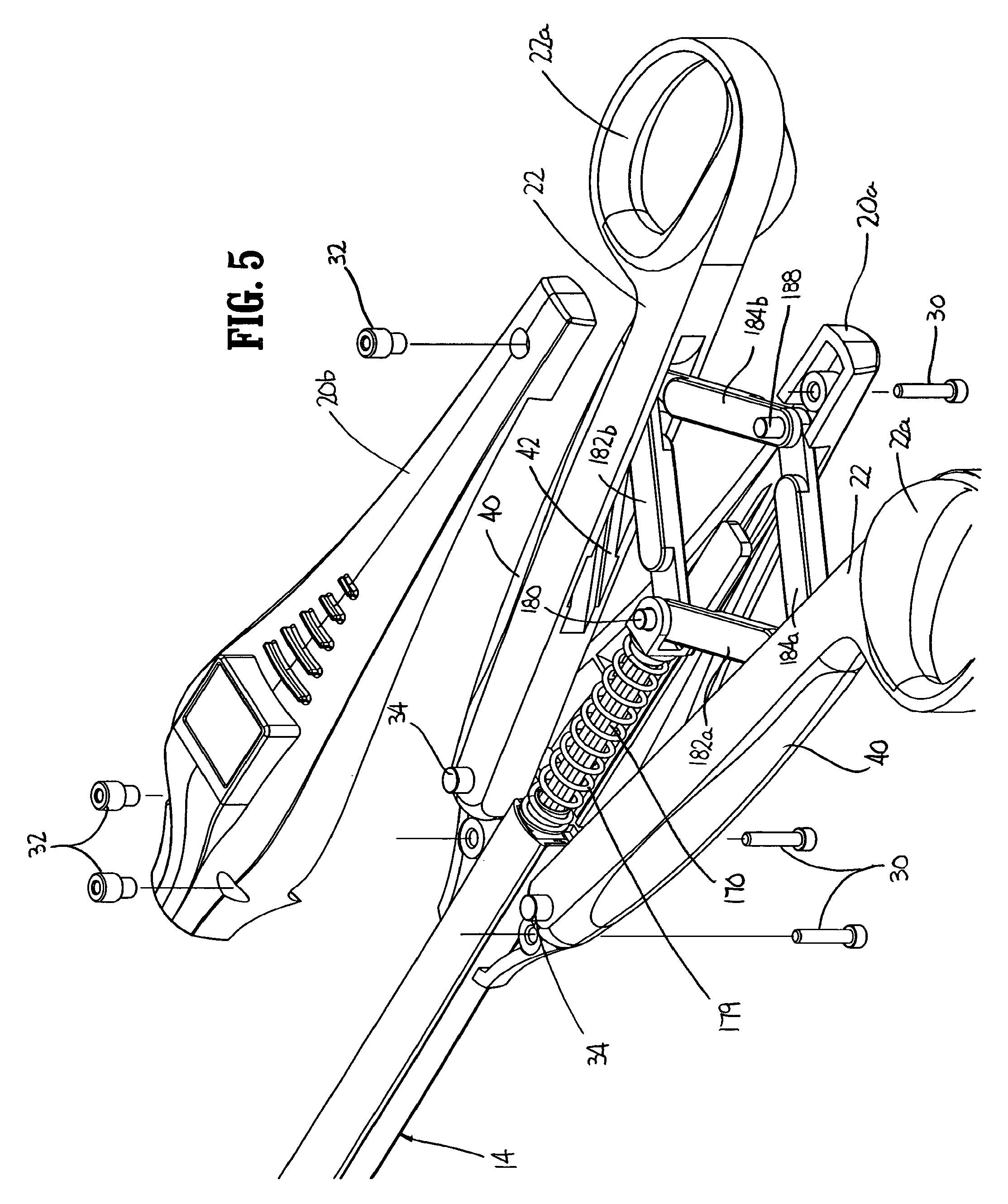
9. The apparatus of claim 1, further comprising at least one movable handle, wherein the camming member is operably connected to the at least one movable handle such that movement of the at least one movable handle through an actuation stroke effectuates movement of the camming member between the retracted position and the advanced position.
10. The apparatus according to claim 9, further comprising a yoke connected to the camming member, the at least one moveable handle operably connected to the yoke by at least one link such that movement of the at least one moveable handle through an actuation stroke effectuates advancement of the yoke and the camming member.
Description
TECHNICAL FIELD
This present disclosure relates generally to an apparatus for applying surgical clips to tissue. More specifically, the present disclosure relates to an apparatus for applying a series of clips to tissue seriatim.
BACKGROUND
Surgical procedures frequently require ligation of blood vessels, severed tissues and/or other organs to control or stop bleeding. Clip applying apparatus for quickly applying a surgical clip about tissue are well known. Such clip applying apparatus include single clip applicators and multiple clip applicators. In single clip applicators, a new clip is loaded into the apparatus after application of each clip. Multiple clip applicators include a series of clips which can be sequentially applied to tissue during the course of a surgical procedure. Because surgical procedures usually require the use of a multiplicity of surgical clips, multiple clip applicators are generally preferred.
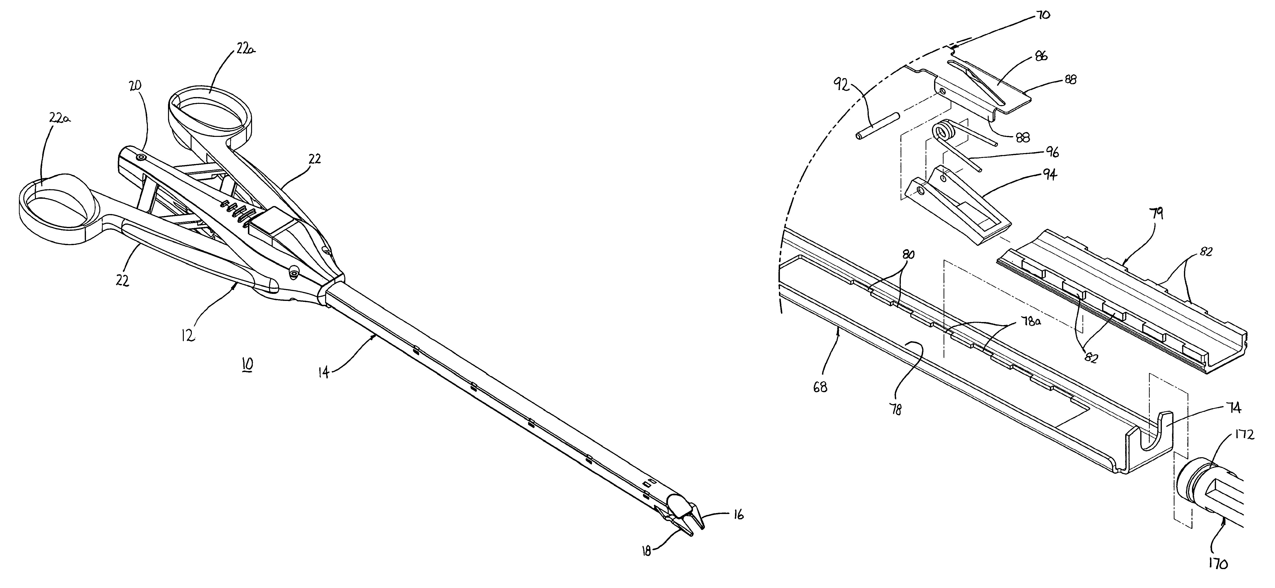
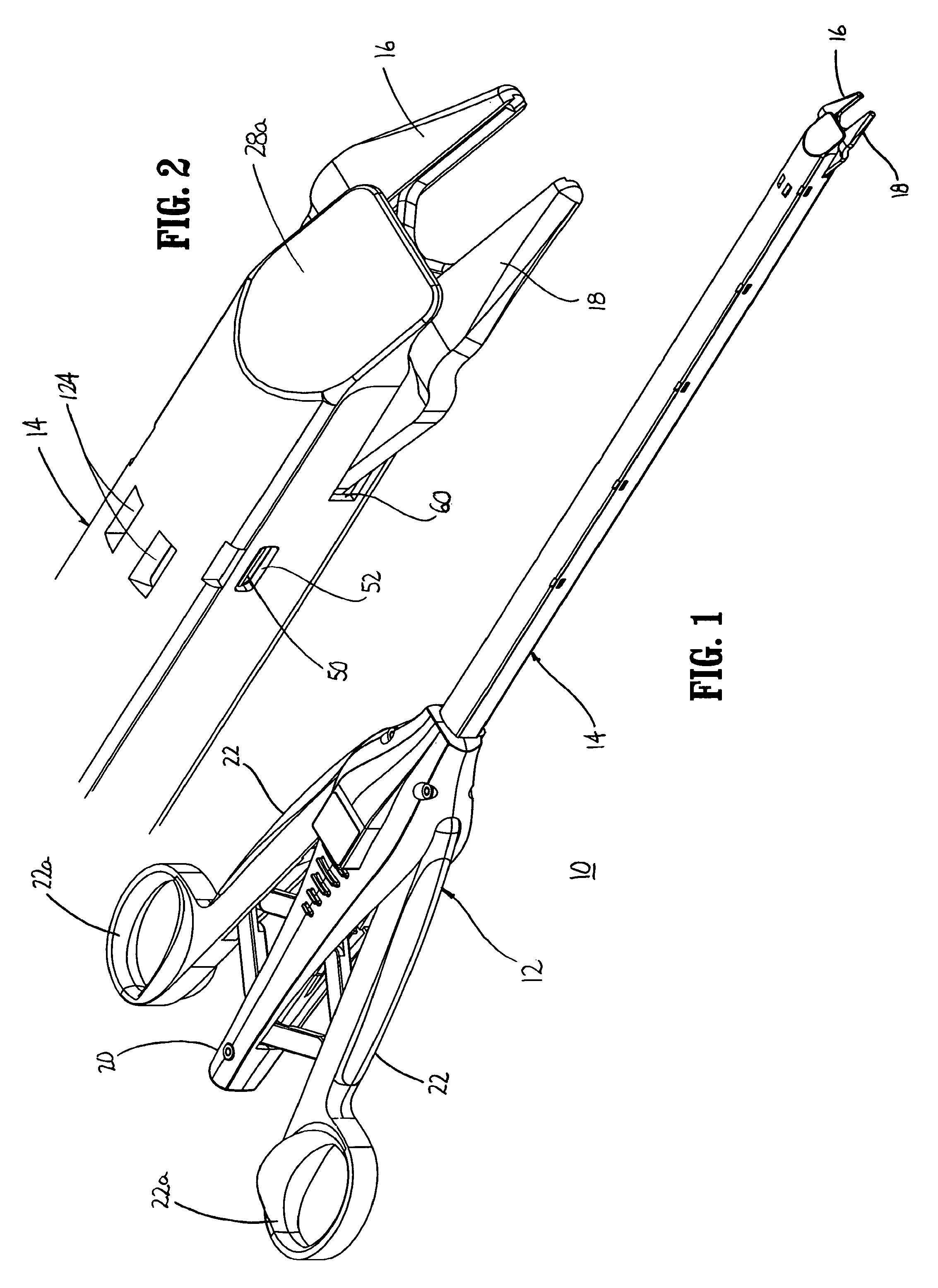
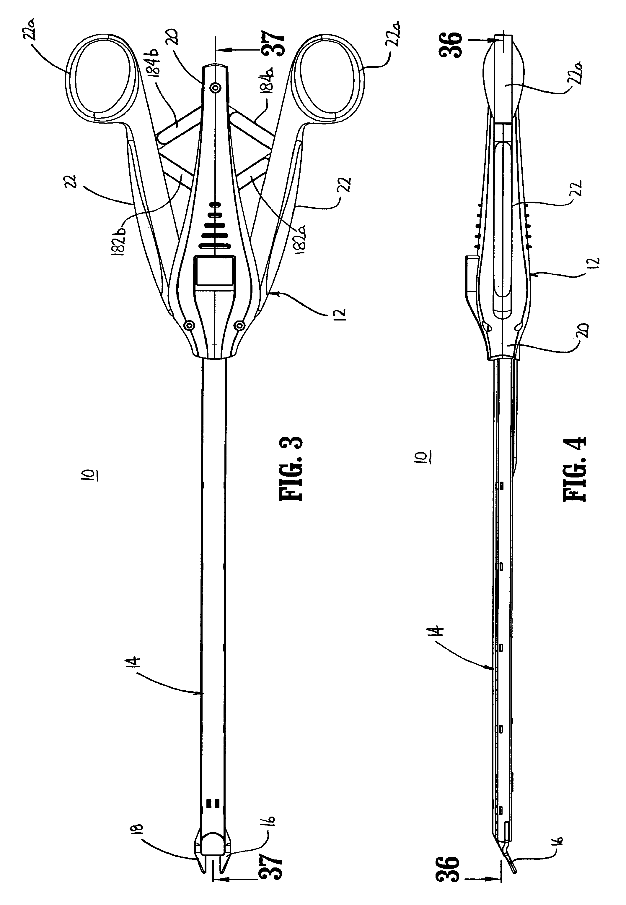
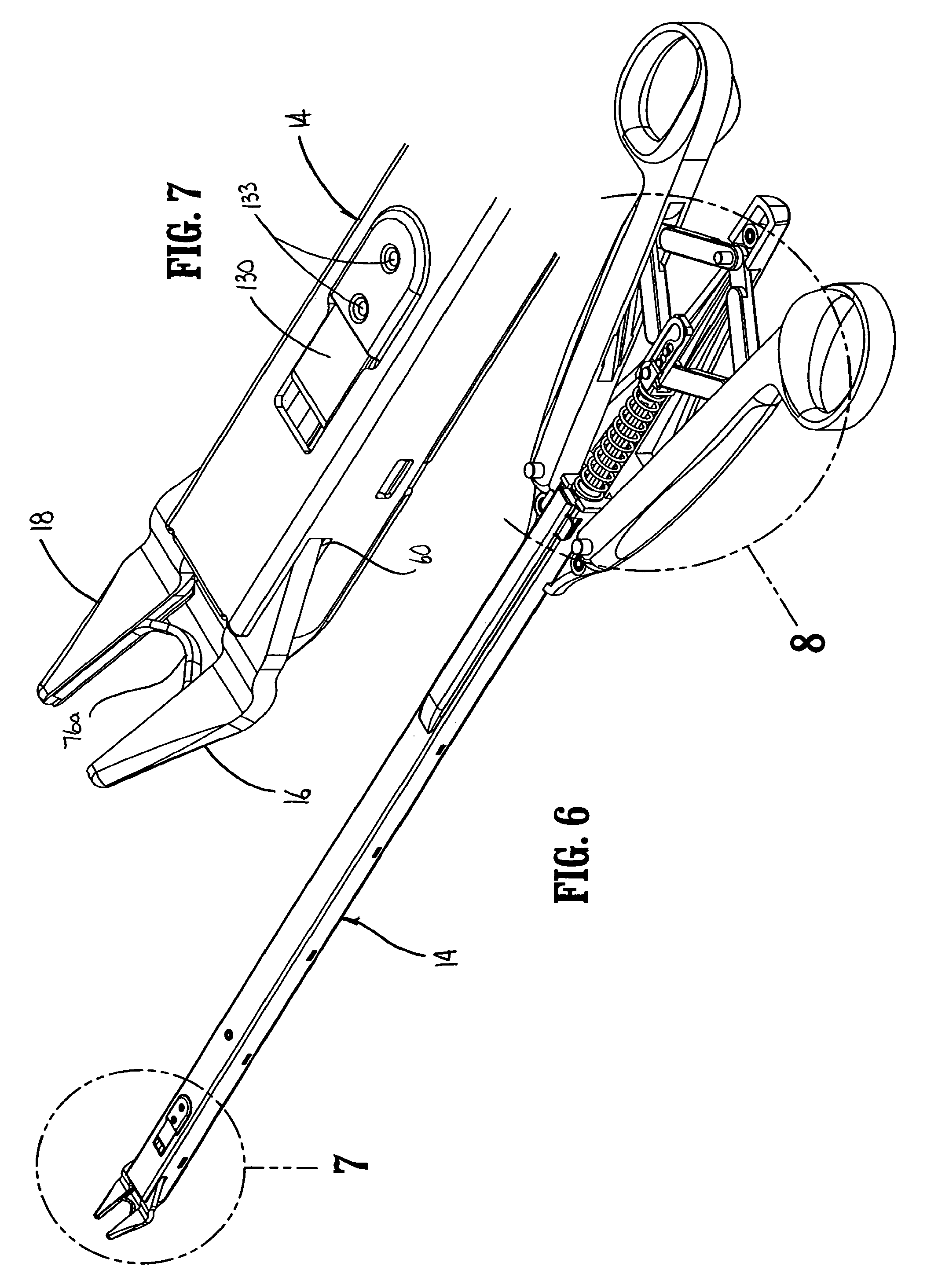
Typically, clip applying apparatus include a handle mechanism, an elongated body portion, and a clip crimping assembly, e.g., a jaw or pair of jaws. Such clip applying apparatus are configured for endoscopic or open surgical procedures. Although known clip applying apparatus for sequentially advancing individual clips have provided good results, a continuing need exists for a clip applying apparatus which is less complex and provides effective hemostasis.
SUMMARY
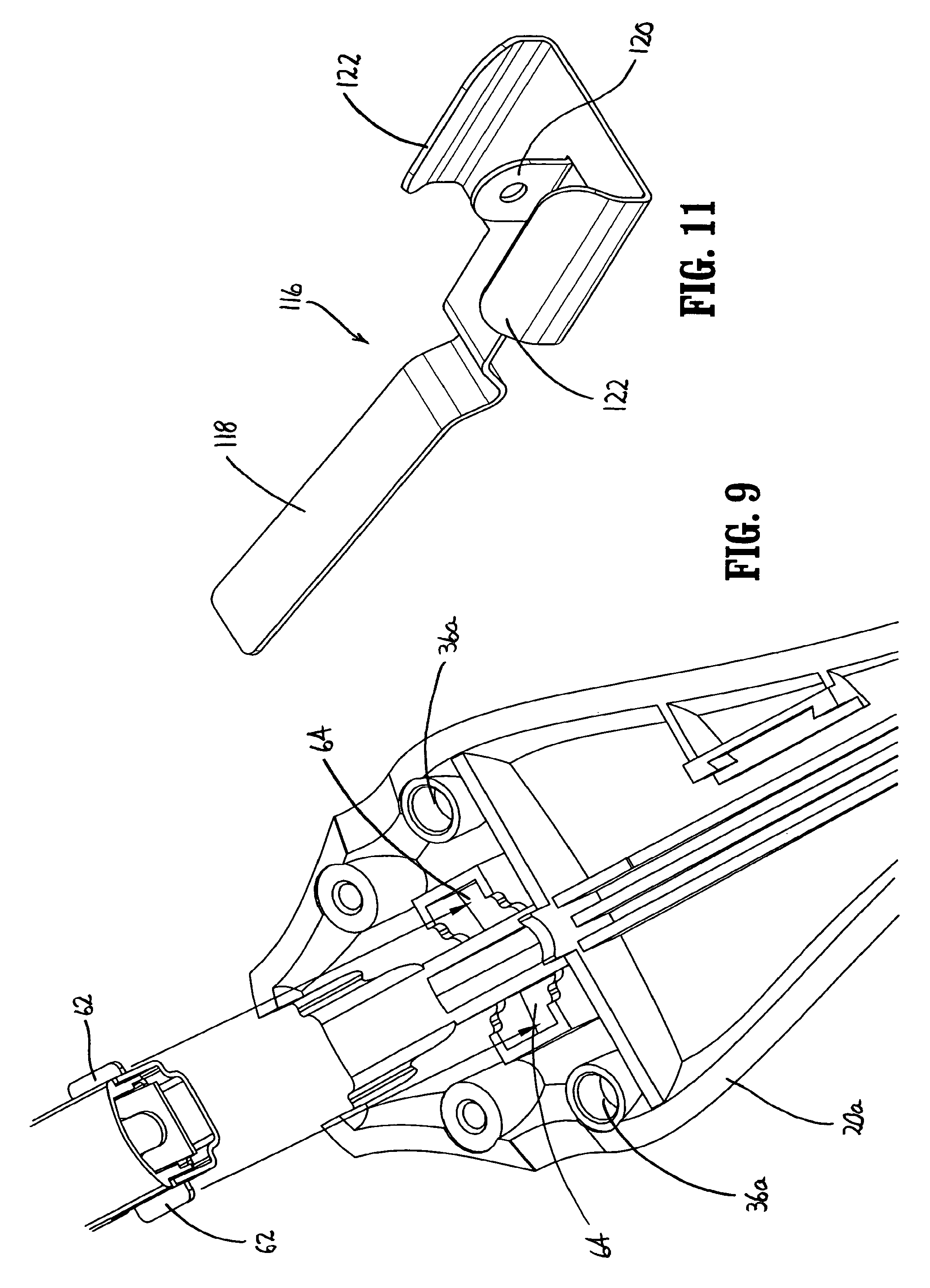
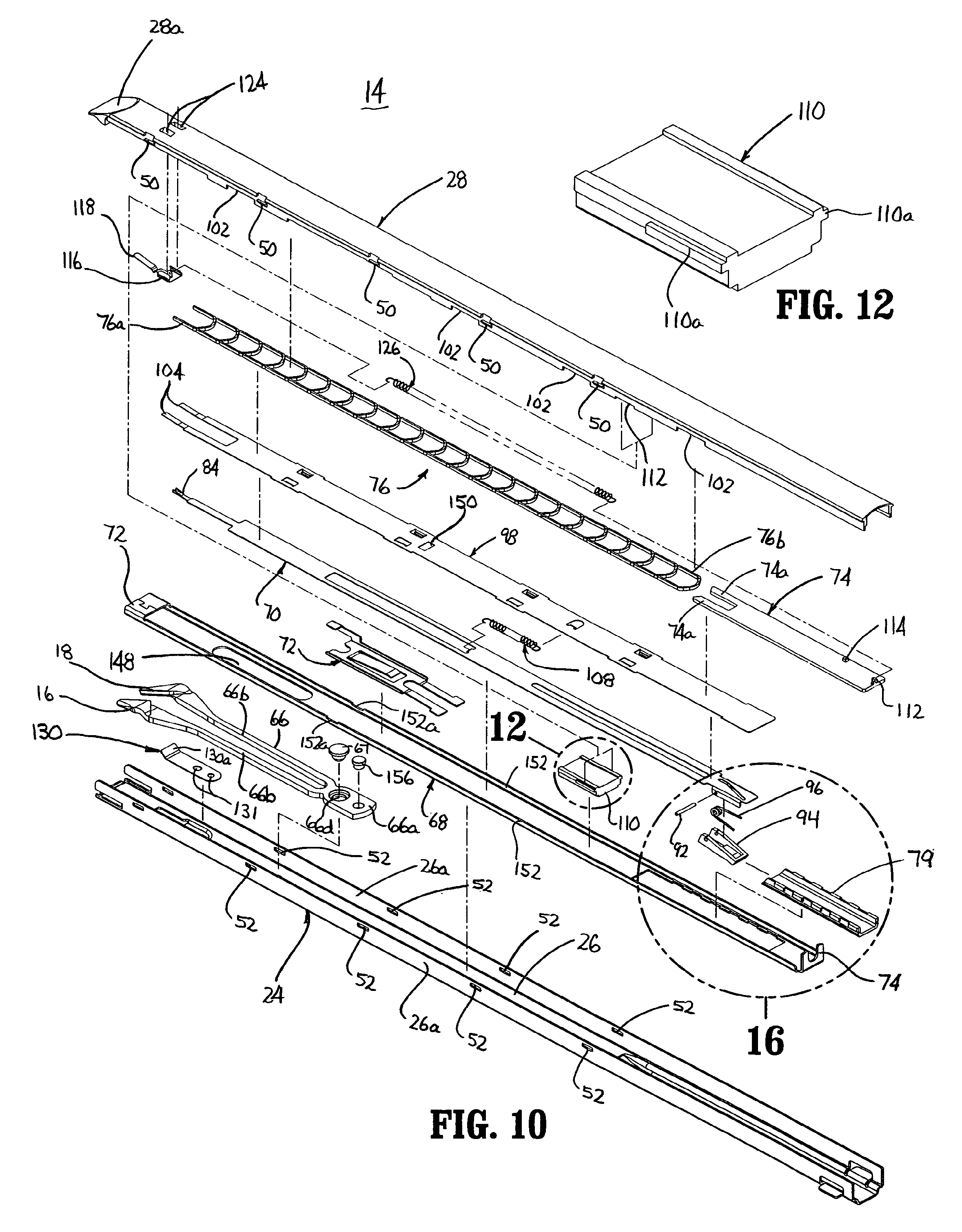
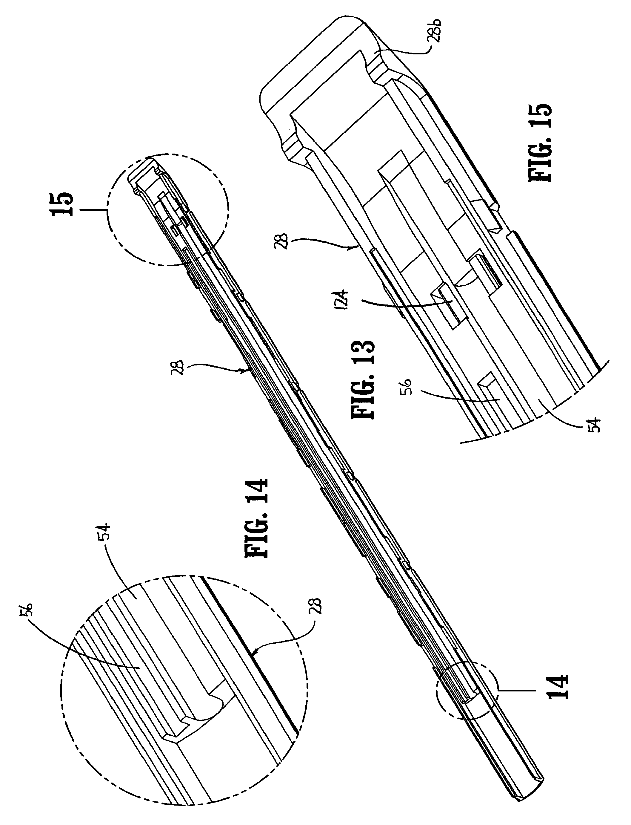
In accordance with the present disclosure, an apparatus for applying surgical clips is provided which includes a handle portion including a housing and at least one movable handle and a body portion housing a clip stack. A pair of jaws is supported at the distal end of the body portion. The body portion includes a clip pusher, a camming member and a clip follower. The clip pusher is movably positioned within the body portion and is operable to advance a distal-most clip from the clip stack to a position between the pair of jaws. The camming member is movably positioned within the body portion and is operable to approximate or move the pair of jaws toward each other to deform the distal-most clip of the clip stack. The clip follower is positioned proximally of the clip stack and is operable to urge the clip stack distally towards the pair of jaws. In one embodiment, the body portion includes a lockout member and a stop member. The lockout member is movable from a first position in slidable relation to the camming member to a second position interlocked with the camming member. In its second position, the lockout member is positioned to abut the stop member to limit distal movement of the camming member.
In one embodiment, the lockout member includes at least one flexible leg having a projection and the camming member includes at least one slot dimensioned to receive the projection to interlock or secure the lockout member to the camming member. The at least one flexible leg can include a pair of flexible legs and the at least one slot can include a pair of slots.
The lockout member can include a resilient finger which is positioned to releasably retain the lockout member in its first position. In one embodiment, the body portion further includes a separator plate which includes an opening dimensioned to receive a portion of the resilient finger of the lockout member to retain the lockout member in its first position. The clip follower may include a tab and the lockout member may include an engagement member such that the tab is movable into the engagement member to move the lockout member from its first position to its second position. In one embodiment, the tab is positioned to engage the engagement member after the proximal most clip has been advanced to the pair of jaws. Alternately, the tab can be positioned to engage the engagement member when one or more clips are remaining in the apparatus.
In one embodiment, an apparatus for applying surgical clips is provided which includes a handle portion having at least one movable handle and a body portion including a clip pusher and a camming member. The clip pusher is movably supported within the body portion to advance a distal-most clip of a clip stack to a position between a pair of jaws supported at a distal end of the body portion. The camming member is movably supported within the body portion from a retracted position to an advanced position to approximate the pair of jaws. A latch assembly is supported on the clip pusher and includes a pivotal latch member which is movable from a first position engaged with an abutment supported on the camming member to a second position disengaged from the abutment of the camming member. The camming member is operably connected to the at least one movable handle such that movement of the at least one movable handle through an actuation stroke effects movement of the camming member from its advanced position to its retracted position. In one embodiment, the pivotal latch member is urged towards its first position by a biasing member such that movement of the camming member from its retracted position to its advanced position initially effects advancement of the clip pusher. A latch cam is fixedly supported on the body portion and is positioned to engage the pivotal latch member after the clip pusher has advanced the distal-most clip of the clip stack to its position between the jaws to disengage the latch member from the abutment. In one embodiment, a biasing member is positioned to urge the clip pusher to a retracted position after the latch member is disengaged from the abutment. In one embodiment, the body portion includes a housing body and a housing cover and the latch cam is supported on the housing cover. The handle portion can include a yoke which is connected to a proximal end of the camming member. In one embodiment, the at least one handle is operably connected to the yoke by at least one front link such that movement of the at least one handle through an actuation stroke effects advancement of the yoke and the camming member. The handle portion can include a pair of handles with each handle operably connected to the yoke by one front link. In one embodiment, a pair of rear links are provided. Each of the rear links has a first end pivotally connected to a respective front link by a first pivot member and a second end pivotally connected to the handle portion by a second pivot member. Each of the pair of handles defines a cam channel for slidably receiving a respective one of the first pivot members.
In one embodiment, an apparatus for applying surgical clips includes a handle portion, a body portion extending distally from the handle portion, and a jaw body supported at a distal end of the body portion. The jaw body includes first and second jaws movable from a spaced position to a more approximated position. In one embodiment, the body portion includes a camming member which is movable from a retracted position to an advanced position to effect movement of the first and second jaws from their spaced position to their more approximated position. The body portion further includes a resilient jaw locking member removably positioned between the first and second jaws to prevent the jaws from moving from their spaced position to their more approximated position. In one embodiment, the jaw locking member is in the form of a resilient plate and the jaw body includes a pair of inwardly deformable legs. Each of the legs supports one of the first and second jaws and the locking member being positioned between the legs of the jaw body. A distal end of the camming is slidably positioned about the legs of the jaw body and is movable from its retracted position to its advanced position to move the locking member from between the legs of the jaw body and subsequently to effect movement of the first and second jaws to their more approximated position.
BRIEF DESCRIPTION OF THE DRAWINGS
Various embodiments of the presently disclosed clip applying apparatus are described herein with reference to the drawings, wherein:
FIG. 1 is a perspective view of one embodiment of the presently disclosed clip applying apparatus;
FIG. 2 is an enlarged perspective view of the distal end of the clip applying apparatus shown in FIG. 1;
FIG. 3 is a top view of the clip applying apparatus shown in FIG. 1;
FIG. 4 is a side view of the clip applying apparatus shown in FIG. 1;
FIG. 5 is a perspective view of the proximal portion of the clip applying apparatus shown in FIG. 4 with the top housing half-section exploded;
FIG. 6 is a perspective view of the clip applying apparatus shown in FIG. 1 with the top housing half-section removed;
FIG. 7 is an enlarged view of the indicated area of detail shown in FIG. 6;
FIG. 8 is an enlarged view of the indicated area of detail shown in FIG. 6;
FIG. 9 is a perspective view of the proximal end of the body portion and the interior of a housing half-section with the internal components of the handle portion removed;
FIG. 10 is an exploded view of the body portion of the clip applying apparatus shown in FIG. 1;
FIG. 11 is a perspective view of the clip stop member of the clip applying apparatus shown in FIG. 1;
FIG. 12 is an enlarged view of the indicated area of detail shown in FIG. 12;
FIG. 13 is a bottom perspective view of the housing cover of the clip applying apparatus shown in FIG. 1;
FIG. 14 is an enlarged view of the indicated area of detail shown in FIG. 13;
FIG. 15 is an enlarged view of the indicated area of detail shown in FIG. 13;
FIG. 16 is an enlarged view of the indicated area of detail shown in FIG. 10;
FIG. 17 is a perspective view of the proximal end of the clip pusher of the clip applying apparatus shown in FIG. 1 with the pusher latch assembly secured thereto;
FIG. 18 is a bottom perspective view of the separator plate of the clip applying apparatus shown in FIG. 1;
FIG. 19 is an enlarged view of the indicated area of detail shown in FIG. 18;
FIG. 20 is a bottom perspective view of the clip pusher of the clip applying apparatus shown in FIG. 1;
FIG. 21 is a bottom perspective view of the housing body of the clip applying apparatus shown in FIG. 1;
FIG. 22 is a top perspective view of the clip follower of the clip applying apparatus shown in FIG. 1;
FIG. 23 is a top perspective view of the jaw body of the clip applying apparatus shown in FIG. 1;
FIG. 24 is a top perspective view of the clip applying apparatus shown in FIG. 1;
FIG. 25 is an exploded perspective view of the handle portion of the clip applying apparatus shown in FIG. 1;
FIG. 26 is a perspective view of the pawl of the handle portion shown in FIG. 25;
FIG. 27 is a perspective view of the pawl biasing member of the handle portion shown in FIG. 25;
FIG. 28 is a perspective view of the yoke of the handle portion shown in FIG. 25;
FIG. 29 is a perspective view of the body portion of the clip applying apparatus shown in FIG. 1 with the housing cover removed;
FIG. 30 is an enlarged perspective view of the distal end of the body portion shown in FIG. 29;
FIG. 31 is an enlarged perspective view of the proximal end of the body portion shown in FIG. 29;
FIG. 32 is an enlarged perspective view of the distal end of the body portion shown in FIG. 29 with the clip follower biasing member and the clip stop member removed;
FIG. 33 is an enlarged perspective view of the distal end of the body portion shown in FIG. 32 with the clip stack removed;
FIG. 34 is an enlarged perspective view of the distal end of the body portion shown in FIG. 33 with the separator plate shown removed;
FIG. 35 is an enlarged perspective view of the distal end of the body portion shown in FIG. 34 with the clip pusher removed;
FIG. 36 is a top cross-sectional view of the clip applying apparatus shown in FIG. 1 prior to actuation of the apparatus;
FIG. 37 is a side cross-sectional view of the clip applying apparatus shown in FIG. 36;
FIG. 38 is an enlarged view of the indicated area of detail shown in FIG. 36;
FIG. 39 is an enlarged view of the indicated area of detail shown in FIG. 37;
FIG. 40 is an enlarged view of the indicated area of detail shown in FIG. 37;
FIG. 41 is an enlarged view of the indicated area of detail shown in FIG. 36;
FIG. 42 is an enlarged view of the indicated area of detail shown in FIG. 37;
FIG. 43 is an enlarged view of the indicated area of detail shown in FIG. 36;
FIG. 44 is an enlarged view of the indicated area of detail shown in FIG. 37;
FIG. 45 is an enlarged view of the indicated area of detail shown in FIG. 36;
FIG. 46 is a top view of the jaw body and the distal end of the camming member of the clip applying apparatus shown in FIG. 36;
FIG. 47 is a cross-sectional view taken along section lines 47-47 of FIG. 44;
FIG. 48 is a cross-sectional view taken along section lines 48-48 of FIG. 40;
FIG. 49 is a cross-sectional view taken along section lines 49-49 of FIG. 42;
FIG. 50 is an enlarged view of the indicated area of detail shown in FIG. 49;
FIG. 51 is a top cross-sectional view of the handle portion of the clip applying apparatus shown in FIG. 1 during initial actuation of the handle portion;
FIG. 52 is a side cross-sectional view of the proximal portion of the body portion of the clip applying apparatus shown in FIG. 1 during initial actuation of the handle portion.
FIG. 53 is a side cross-sectional view of the distal end of the body portion of the clip applying apparatus shown in FIG. 1 during initial actuation of the handle portion;
FIG. 54 is a side cross-sectional view of the distal end of the body portion of the clip applying apparatus shown in FIG. 1 during further actuation of the handle portion;
FIG. 55 is a side cross-sectional view of the distal end of the body portion of the clip applying apparatus shown in FIG. 1 during further actuation of the handle portion;
FIG. 56 is a side cross-sectional view of the body portion shown in FIG. 42 after further actuation of the handle portion;
FIG. 57 is a side cross-sectional view of the body portion shown in FIG. 44 after further actuation of the handle portion;
FIG. 58 is a side cross-sectional view of the body portion shown in FIG. 57 after further actuation of the handle portion;
FIG. 59 is a side cross-sectional view of the distal end of the body portion shown in FIG. 55 after further actuation of the handle portion;
FIG. 60 is a top view of the jaw body and camming member shown in FIG. 46 with the camming member advanced further distally;
FIG. 61 is a top cross-sectional view of the handle portion shown in FIG. 51 with the handle portion after further actuation of the handle portion;
FIG. 62 is a side cross-sectional view of the body portion shown in FIG. 58 after further actuation of the handle portion;
FIG. 63 is a top view of the jaw body and camming member shown in FIG. 60 with camming member fully advanced;
FIG. 64 is a top cross-section view of the handle portion shown in FIG. 61 after the handle portion has been returned to the unactuated position;
FIG. 65 is a top view of the distal portion of the body portion of the clip applying apparatus shown in FIG. 36 illustrating the lockout tab of the clip follower engaging the engagement member of the lockout;
FIG. 66 is top perspective view of a portion of the body portion of the clip applying apparatus shown in FIG. 36 illustrating the lockout engaging the stop member; and
FIG. 67 is a perspective view of a clip of the clip stack of the clip applying apparatus shown in FIG. 36 deformed about tissue.
DETAILED DESCRIPTION
Embodiments of the presently disclosed surgical clip applier will now be described in detail with reference to the drawings wherein like reference numerals designate identical or corresponding elements in each of the several views. Throughout this description, the term "proximal" will refer to the portion of the instrument closest to the operator and the term "distal" will refer to the portion of the instrument furthest from the operator.
Referring to FIGS. 1-4, the presently disclosed surgical clip applier, shown generally as 10, includes a handle portion 12, an elongated body portion 14 extending distally from handle portion 12 and first and second jaws 16 and 18 which extend from the distal end of body portion 14. Briefly, handle portion 12 includes a handle housing 20 and a pair of movable handles or triggers 22. Each handle 22 includes a finger loop 22a for receiving a finger of a surgeon's hand.
Referring also to FIGS. 5-9, handle housing 20 can be formed from molded housing half-sections 20a and 20b (FIG. 5) which are secured together using screws 30 and nuts 32. Alternately, other fastening techniques may be used to secure housing half-sections 20a and 20b together, e.g., welding, rivets, interlocking structure, adhesives, etc. In one embodiment, the distal end of each handle 22 is pivotally secured about a pivot member 34 such that handles 22, when actuated, move in a scissor-like manner. Each pivot member 34 is positioned between recesses 36a and 36b formed in half-sections 20a and 20b, respectively, and may be formed integrally with a respective handle 22 or, in the alternative, as a separate element from a respective handle 22. In one embodiment, each handle 22 has a slip resistant grip member 40 secured to an outside surface thereof and a cam channel 42 formed on an inside surface thereof. Slip resistant grip member 40 can be formed from a cushioning material and overmolded onto each handle 22. It is also contemplated that other slip resistant materials and methods of application may be used to form grip member 40 and apply grip member 40 to a handle 22. Each cam channel 42 is configured to receive a pivot member for connecting a pair of pivotal links as will be described in more detail below.
Referring to FIG. 10, elongated body portion 14 includes a housing body 24 defining a channel 26 for receiving internal components of surgical clip applier 10. A housing cover 28 is secured to housing body 24 and covers channel 26. In one embodiment, housing cover 28 has a series of projections 50 which are dimensioned to be received within openings 52 formed along channel walls 26a of housing body 24 to secure housing cover 28 to housing body 24. Alternately, other securement techniques are contemplated, e.g., adhesives, crimping, screws, etc.
Referring also to FIGS. 13-15, an internal surface of housing cover 28 includes a first longitudinal groove 54 and a second longitudinal groove 56. Grooves 54 and 56 accommodate other components of the elongated body portion as will be discussed in further detail below. The distal end of housing cover 28 includes an outer surface 28a which is tapered or angled downwardly towards housing body 24. Angled outer surface 28a provides easier access to tissue and reduces the likelihood of the clip applier snagging tissue during use. An inner surface 28b formed on the distal end of housing cover 28 has a curvature which corresponds to the curvature of a top surface of jaws 16 and 18. Inner surface 28b is positioned in abutting relation to jaws 16 and 18 to provide stability to and prevent misalignment of jaws 16 and 18 during operation of clip applier 10.
Referring to FIGS. 10 and 21, housing body 24 includes a pair of distally located cutouts 60 configured to slidably receive jaws 16 and 18. Cutouts 60 are dimensioned to confine jaws 16 and 18 to prevent misalignment of the jaws during actuation of clip applier 10 (FIG. 30). The proximal end of housing body 24 includes a pair of transversely extending wings 62 which are dimensioned to be received within recesses 64 formed in housing half-sections 20a and 20b (FIG. 9) to secure elongated body portion 14 to handle portion 12.
As illustrated in FIG. 10, the internal components of clip applier 10 include a jaw body 66, a camming member 68, a clip pusher 70, a clip pusher lockout 72, a clip stack follower 74, and a clip stack 76 including a distal-most clip 76a and a proximal-most clip 76b. Referring also to FIG. 23, jaw body 66 includes jaws 16 and 18, a proximal mounting portion 66a and a pair of spaced distally extending legs 66b. Each of jaws 16 and 18 is supported on a distal end of a respective one of legs 66b and includes a clip channel 16a and 18a, respectively. A cam surface 70 is formed on an outer surface of each jaw 16 and 18. Cam surfaces 70 are positioned to be engaged by camming member 68 (FIG. 10) in a manner to be described in further detail below. Jaw body 66 is mounted within channel 26 of housing body 24 using a bolt 67 or the like. Bolt 67 extends through an opening 66d in body 66 and through housing body 24.
Referring now to FIGS. 10 and 16, camming member 68 is slidably supported within channel 26 (FIG. 10) of housing body 24 and includes a distal engagement member 72 which is positioned about legs 66b of jaw body 66 (FIG. 48). Engagement member 72 can have a substantially rectangular configuration. Alternately, other configurations are contemplated, e.g., C-shaped configuration. The proximal end of camming member 68 includes a bracket 74 to operably connect camming member 68 to handle portion 12 as will be discussed in further detail below. Handles 22 of handle portion 12 (FIG. 1) are operable to move camming member 68 between a retracted position and an advanced position along channel 26 of housing body 24. In the retracted position of camming member 68, engagement member 72 is positioned about legs 66b of jaw body 66 at a location proximal of cam surfaces 70 (FIG. 46). In the advanced position of camming member 68, engagement member 72 is positioned about jaws 16 and 18 in abutting relation to cam surfaces 70 (FIG. 60).
The proximal end of camming member 68 supports an abutment member 79. In one embodiment, abutment member 79 is supported within a cutout 78 formed in the proximal end of camming member 68. Cutout 78 includes a plurality of grooves 78a which receive tongues or projections 82 formed on abutment member 79 to secure abutment member 79 to camming member 68. It is contemplated that abutment member 79 may be attached to camming member 68 using other known fastening techniques. Alternately, abutment member 79 can be formed integrally with camming member 68. Abutment member 79 is positioned to engage a pusher latch assembly 80, as will be described in detail below.
Referring to FIGS. 10, 16, 17 and 20, clip pusher 70 includes an elongated body 82, a distal finger 84, and a proximal latch assembly mount 86. Distal finger 84 is semi-circular in shape and is positioned to engage distal-most clip 76a of the stack of clips 76 when clip pusher 70 is moved from a retracted position to an advanced position (FIG. 53). Latch assembly mount 86 includes a pair of spaced, vertical brackets 88. Brackets 88 each include an opening 90 for receiving a pivot pin 92 (FIG. 16) of pusher latch assembly 80.
Pusher latch assembly 80 includes a latch member 94, a biasing member 96, and pivot pin 92. Latch member 94 is pivotally secured at its distal end between brackets 88 of clip pusher 70 about pivot pin 92. Biasing member 96 is positioned between the proximal end of clip pusher 70 and latch member 94 to urge the proximal end of latch member 94 away from clip pusher 70 to a position to engage abutment member 79 when camming member 68 is moved from its retracted to its advanced position. Latch member 94 is pivotal against the urging of biasing member 96 towards the proximal end of clip pusher 70 to move latch member 94 out of engagement with abutment member 79 as will be discussed in further detail below.
Referring to FIGS. 10 and 18, a separator plate 98 is fixedly supported between housing body 24 and housing cover 28. Separator plate 98 includes a series of projections 100 which are received within recesses 102 formed in housing cover 28 to secure separator plate 98 to housing cover 28. The distal end of separator plate 98 includes a pair of spaced spring fingers 104 which are positioned to guide the distal-most clip 76a of clip stack 76 into jaws 16 and 18. A biasing member securement member 106 (FIG. 19) is formed on separator plate 98. A biasing member, which can be a coil spring 108, has one end secured to securement member 106 of separator plate 98 and a second end secured to a securement member 110 (FIG. 20) formed on clip pusher 70. Coil spring 108 is in tension and urges clip pusher 70 to its retracted position. When handles 22 (FIG. 1) are operated to move camming member 68 from its retracted position to its advanced position, abutment member 79 engages latch member 94 to move latch member 94 and clip pusher 70 distally toward its advanced position against the urging of coil spring 108. As clip pusher 70 moves distally with camming member 68, distal finger 82 of clip pusher 70 engages distal-most clip 76a of clip stack 76 to advance distal-most clip 76a into jaws 16 and 18.
Referring to FIGS. 10 and 12, a pusher latch cam 110 is supported in channel 26 between housing body 24 and housing cover 28. Pusher latch cam 110 includes a pair of tabs 110a which are received within recesses 112 formed in housing cover 28 to fixedly secure pusher latch cam 110 in relation to housing cover 28. Pusher latch cam 110 is positioned in channel 26 at a position to engage the distal end of latch member 94 (FIG. 57) to pivot and disengage latch member 94 from abutment member 79 when distal-most clip 76a has been fully advanced into jaws 16 and 18. When latch member 94 is disengaged from abutment member 79, coil spring 108 returns clip pusher 70 to its retracted position. Although pusher latch cam 110 is illustrated as block shaped, other configurations are envisioned. Further, pusher latch cam may be integrally formed with housing cover 28 or housing body 24.
Referring to FIGS. 10 and 22, clip stack 76 is slidably supported on a top surface of separator plate 98. A clip follower 74 is positioned behind the proximal-most clip 76b of clip stack 76. Clip follower 74 includes a pair of distally extending arms 74a. The distal end of each arm 74a is configured to engage the backspan of proximal-most clip 76b. A top surface of clip follower 74 includes a spring securement member 112 and a lockout tab 114. Lockout tab 114 is positioned to travel in second longitudinal groove 56 (FIG. 14) of housing cover 28 and is movable with clip follower 74 as clip follower 74 is advanced to move clip stack 76 distally within elongated body portion 14.
Referring to FIGS. 10 and 11, a clip stop member 116 includes a spring arm 118, a spring securement member 120 and a pair of anchor members 122. Anchor members 122 are dimensioned to be snap-fit into a pair of openings 124 formed through a distal portion of housing cover 28 to secure clip stop member 116 to the underside of housing cover 28. A biasing member 126 extends between spring securement member 120 of clip stop member 116 and spring securement member 112 of follower 74. Biasing member 126, which can be a coil spring, is supported in tension between follower 74 and clip stop member 116 to urge follower 74 and clip stack 76 distally within body portion 14 towards jaws 16 and 18. Biasing member 126 is positioned within first longitudinal groove 54 of housing cover 28 (FIG. 14). Clip stop member 116 prevents distal-most clip 76a from being pushed distally into jaws 16 and 18 until clip pusher 70 is moved to its advanced position. When clip pusher 70 is moved to its advanced position, clip stop member 116 is deflected upwardly by movement of distal-most clip 76a (FIG. 53).
A jaw locking member, e.g., plate 130 (FIG. 10) is secured to housing body 24 within channel 26 of housing body 24. Jaw locking plate 130 includes openings 131 which are dimensioned to receive projections 133 (FIG. 59) formed on housing body 24 to secure plate 130 to body 24. Jaw locking plate 130 has a resilient and flexible arm 130a which is positioned between legs 66b of jaw body 66 to prevent jaws 16 and 18 from being closed inadvertently during positioning of clip applier 10 at a surgical site. When camming member 68 is moved to its advanced position, the distal end of engagement member 72 of camming member 68 deflects arm 130a downwardly to move arm 130a from between jaws 16 and 18 and allow for closure of jaws 16 and 18 (FIG. 59). Alternately, the jaw locking member need not be in the form of a flat plate but rather other configurations are envisioned, e.g., cylindrical or any configuration positionable between jaws 16 and 18 to prevent closure of the jaws.
Referring to FIGS. 10 and 24, a lockout member 72 is positioned above camming member 68 within channel 26 of housing body 24. Lockout member 72 includes a central body portion 140, a pair of flexible legs 142 and a distally extending engagement member or flag 144. Central body portion 140 includes a proximally extending resilient finger 146 which extends upwardly towards separator plate 98 and includes a downwardly curved end 146a. End 146a is positioned to extend through an elongated slot 148 formed in clip pusher 70 and to be partially received within an opening 150 formed in separator plate 98. Engagement of end 146a of finger 146 in opening 150 of separator plate 98 releasably retains lockout 72 at a fixed position in relation to separator plate 98 until an external force is applied to engagement member 144 as will be discussed in detail below.
Each of flexible legs 142 of lockout 72 includes a radial projection 142a. Legs 142 are positioned within the confines of sidewalls 152 of camming member 68 and are urged inwardly by sidewalls 152. A pair of slots 152a are formed in sidewalls 152 such that when projections 142a are moved into alignment with slots 152a, legs 142 spring outwardly to move radial projections 142a into slots 152a. When projections 142a are positioned within slots 152a, lockout 72 is fixedly secured to camming member 68.
As discussed above, follower 74 is urged distally by biasing member 126 to urge clip stack 76 distally along separator plate 98. As each clip 76a is advanced into jaws 16 and 18, follower 74 moves further distally within elongated body 14. As the proximal-most clip 76b is advanced in jaws 16 and 18, lockout tab 114 of follower 74 engages engagement member or flag 144 of lockout 72 and effects distal movement of lockout 72 in relation to camming member 68, such that after proximal-most clip 76b is crimped between jaws 16 and 18 and camming member 68 is returned to its retracted position, radial projections 142a align with slots 152a in camming member 68 to fixedly secure lockout 72 to camming member 68.
A stop member 156 (FIG. 10) is secured to a proximal end of mounting portion 66a of jaw body 66. In one embodiment, stop member 156 includes a cylindrical dowel. Alternately, other stop member configurations are envisioned. The distal end of lockout 72 includes a recess 158 for receiving stop member 156. Since stop member 156 is fixedly secured within channel 26 of housing body 24, engagement between lockout 72 and stop member 156 prevents further distal advancement of lockout 72. As discussed above, after the proximal-most clip 76b has been applied to tissue, lockout 72 is fixedly secured to camming member 68. Stop member 156 is also received in recess 158 of lockout 72. Thus, after proximal-most clip 76b has been applied to tissue and lockout 72 is fixed to camming member 86, engagement between lockout 72 and stop member 156 prevents distal advancement of camming member 68. As will be discussed below, since camming member 68 is connected via linkages to handles 22 (FIG. 1), engagement between lockout 72 and stop member 156 will prevent actuation of handles 22 and thus, indicate to a surgeon that the clip applier clip stack 76 has been depleted.
Referring to FIGS. 5, 8, 25 and 28, handle portion 12 includes a yoke 170 which is slidably positioned between housing half-sections 20a and 20b between retracted and advanced positions. The distal end of yoke 170 includes an annular recess 172 which is dimensioned to be positioned in a semi-circular slot 174 (FIG. 16) formed in bracket 74 of camming member 68 to attach yoke 170 to camming member 68. The proximal end of yoke 170 includes a U-shaped connector 176 having a throughbore 178 dimensioned to receive a pivot pin 180. Pivot pin 180 pivotally connects yoke 170 to the distal end of front links 182a and 182b of a linkage assembly which connects handles 22 to yoke 170. The proximal end of front links 182a and 182b are pivotally secured to the distal end of rear links 184a and 184b, respectively, by pivot members 186. The proximal ends of rear links 184a and 184b are connected to each other and to handle housing 20 by a pivot member 188. Pivot member 188 is pivotally mounted between bores 190 formed in housing half-sections 20a and 20b (FIG. 5). Pivot members 186 are received within a respective cam channel 42 formed in a respective handle 22. When handles 22 are actuated, i.e., moved towards housing 20, pivot members 186 are caused to move through cam channels 42 such that front links 182a, 182b and rear links 184a, 184b are moved from a first misaligned position towards an aligned position (FIG. 51). Since the proximal end of rear links 184a and 184b are axially fixed between housing half-sections 20a and 20b, movement of front links 182a and 182b and rear links 184a and 184b toward an aligned position moves the distal end of front links 182a and 182b distally within housing 20. As discussed above, the distal end of front links 182a and 182b is axially fixed to yoke 170 by pivot member 180. As such, when handles 22 are actuated, yoke 170 is moved distally to move camming member 68 distally. A biasing member, e.g., coil spring 179, is positioned about a distal end of yoke 170 and abuts a spring stop 181 supported within housing 20 to urge yoke 170 to its retracted position.
Referring to FIGS. 25-27, handle portion 12 includes an anti-reverse ratchet mechanism which includes a pawl 192, a rack 194, and a pawl biasing member 196. Rack 194 includes a series of teeth 194a and is supported within a recess 198 formed in housing half-section 20a. In one embodiment, recess 198 is dovetail shaped and the backside of rack 194 has a dovetail shape projection 194b which is slidably received within recess 198 to secure rack 194 within housing 20. Alternately, other fastening techniques can be used to secure rack 194 within housing 20, e.g., adhesives, pins, welding, etc.
Pawl 192 includes a bore 192a dimensioned to receive pivot member 180 such that pawl 192 is rotatably mounted to yoke 170 about pivot member 180. Pawl biasing member 196 includes a pair of mounting holes 200 for securing bracket 196 to a plate extension 202 (FIG. 28) of yoke 170. Pawl biasing member 196 also includes a semi-circular cutout 204 which is positioned to be clipped partially about pivot member 180, and a cantilever or spring arm 206 which is positioned within a slot 192b formed in a backside of pawl 192. Cantilever arm 206 is resilient and provides a biasing force to urge pawl 192 to a position in which pawl finger 192c is substantially perpendicular to arm 206. Finger 192c is positioned to engage teeth 194a of rack 194 to retain yoke 170 at partially advanced positions during actuation of clip applier 10 against the bias of spring 179 which urges yoke 170 to its retracted position. The anti-reverse ratchet mechanism prevents retraction of yoke 170 and camming member 68 after handles 22 have been partially actuated until the clip applier has been fully actuated.
Referring to FIGS. 36-67, operation of clip applier 10 will now be described. FIGS. 36-50 illustrate clip applier 10 prior to actuation of handles 22, i.e., in the prefired position. In the prefired position, biasing member 179 urges yoke 170 to its retracted position. When yoke 170 is in its retracted position, pivot members 186 are positioned within cam channels 42 (FIG. 36) such that front links 182a and 182b and rear links 184a and 184b are in their misaligned position, handles 22 are spaced from housing 20 of clip applier 10, and pawl 192 (FIG. 38) is positioned proximally of rack 194 (FIG. 38). Referring to FIGS. 40-50, in the prefired position, camming member 68 is urged to its retracted position by yoke 170 and biasing member 179 (FIG. 39). Clip pusher 70 is urged to its retracted position by biasing member 108 (FIG. 42). Clip stack 76 is urged by follower 74 (FIG. 44) and biasing member 126 distally within body 14, but distal-most clip 76a is prevented from moving into jaws 16 and 18 by spring arm 118 of clip stop member 116 (FIG. 40). Jaw locking plate 130 is positioned between jaw legs 66b to prevent inadvertent closure of jaws 16 and 18 (FIG. 40). It is also noted that latch member 94 of pusher latch assembly 80 is spaced distally of but in a position to engage abutment member 79 which is supported on camming member 68 (FIG. 44). Further, radial projections 142a of lockout 72 are positioned proximally of slots 152a of camming member 68 and recess 158 of lockout 72 is positioned proximally of stop member 156.
FIGS. 51-63 illustrate clip applier 10 in various stages of operation. Referring to FIG. 51, handles 22 have been partially actuated or moved towards housing 20 in the direction indicated by arrow "A". Actuation of handles 22 moves front links 182a and 182b towards their aligned position to advance yoke 170 distally in the direction indicated by arrow "B". Referring to FIG. 52, as yoke 170 is advanced, camming member 68 which is secured to yoke 170 is advanced distally within elongated body 14 of clip applier 10. Abutment member 79 is supported on camming member 68 and is also advanced distally within elongated body 14 in the direction indicated by arrow "C". During the initial actuation stroke of handles 22, abutment member 79 engages latch member 94 of pusher latch assembly 80 to effect advancement of clip pusher 70 in the direction indicated by arrow "D". Referring to FIG. 53, as clip pusher 70 advances, engagement finger 84 of clip pusher 70 advances distal-most clip 76a of clip stack 76 past spring arm 118 of clip stop member 116 into jaws 16 and 18. As the distal-most clip 76a of clip stack 76 is advanced into the jaws, follower 74 (FIG. 52) under the force of biasing member 126 advances clip stack 76 distally in the direction indicated by arrow "E" in FIG. 53 to position the second distal-most clip 77 adjacent clip stop member 116 (See FIGS. 53-55).
Referring to FIGS. 55-57, as camming member 68 and clip pusher 70 advance within elongated body 14, the tension in spring 108 is increased, i.e., spring 108 is stretched (FIG. 56). When distal-most clip 76a is fully positioned within jaws 16 and 18, pusher latch cam 110 engages a distal end of latch member 94 and pivots latch member 94 in the direction indicated by arrow "F" against the urging of biasing member 96 to release latch member 94 from abutment member 79. When latch member 94 is released from abutment member 79, biasing member 108 returns clip pusher 70 to its retracted position (FIGS. 58 and 59).
As handles 22 are more fully actuated, i.e., moved closer to housing 20, camming member 68 engages finger 130a of jaw locking plate 130 (FIG. 55) to deform plate 130 downwardly from between legs 66b of jaw body 66. Continued advancement of camming member 68 advances engagement member 72 into camming surfaces 70 of jaws 16 and 18 to move jaws 16 and 18 from a spaced position (FIG. 46) to a crimping position (FIG. 63).
Referring to FIG. 51, as yoke 170 is moved from its retracted position within housing 20 to its advanced position, a finger 192c of pawl 192 engages teeth 194a of rack 194 to prevent spring 179 from returning yoke 170 to its retracted position when handles 22 are released. As such, once handles 22 begin to be actuated and pawl 192 engages rack 194 (FIG. 51) yoke 170 cannot be returned to its retracted position until clip applier 10 is fully actuated. When yoke 170 is moved to its advanced position, pawl 192 passes by the distal end of rack 194 (FIG. 61) and cantilevered or spring arm 206 of pawl biasing member 196 will rotate pawl 192 in the direction indicated by arrow "G" in FIG. 61 to a position in which finger 192a of pawl 192 is positioned at 12:00. Thus, when handles 22 are released and spring 179 returns yoke 170 to its retracted positioned (FIG. 64) finger 192c will engage the distal end of rack 194 and rotate counter-clockwise in the direction indicated by arrow "H" in FIG. 64 and ratchet over teeth 194a of rack 194. Note, in the fully retracted position of yoke 170, pawl 192 is positioned proximally of rack 194. In this position cantilevered arm 206 (FIG. 61) returns finger 192c of pawl 192 to the 12:00 position.
After the device has been fully actuated as shown in FIGS. 61-63 and handles 22 have been released, yoke 170 is moved to its retracted position by spring 179. Camming member 68, which is secured to yoke 170, is also moved toward its retracted position. As this occurs, resilient jaws 16 and 18 return to their spaced position and camming member 68 moves past jaw locking plate 130 allowing locking plate finger 130a to return to a position located between legs 66b of jaw body 66. As discussed above, the positioning of locking plate 130 between legs 66b of jaw body 66 prevents inadvertent closure of jaws 16 and 18.
Referring to FIGS. 65 and 66, after the proximal-most clip 76b has been advanced beyond clip stop member 116, clip follower 74 is advanced towards its fully advanced position by biasing member 126. As this occurs, lockout tab 114 formed on follower 74 engages engagement member 144 of lockout 72 to advance lockout 72 distally in relation to camming member 68 to move radial projections 142a of flexible legs 142 of lockout 72 into slots 152a of camming member 68 and secure or interlock lockout 72 to camming member 68. When lockout 72 is moved distally within elongated body 14 by follower 74, distal recess 158 of lockout 72 receives stop member 156, which is secured to mounting portion 66a of jaw body 66 such that the distal end of lockout 72 engages stop member 156. Engagement between the distal end of lockout 72 and stop member 156 prevents further distal movement of lockout 72 and, thus, camming member 68.
It will be understood that various modifications may be made to the embodiments disclosed herein. Therefore, the above description should not be construed as limiting, but merely as exemplifications of preferred embodiments. Those skilled in the art will envision other modifications within the scope and spirit of the claims appended hereto.
* * * * *
D00000
D00001
D00002
D00003
D00004
D00005
D00006
D00007
D00008
D00009
D00010
D00011
D00012
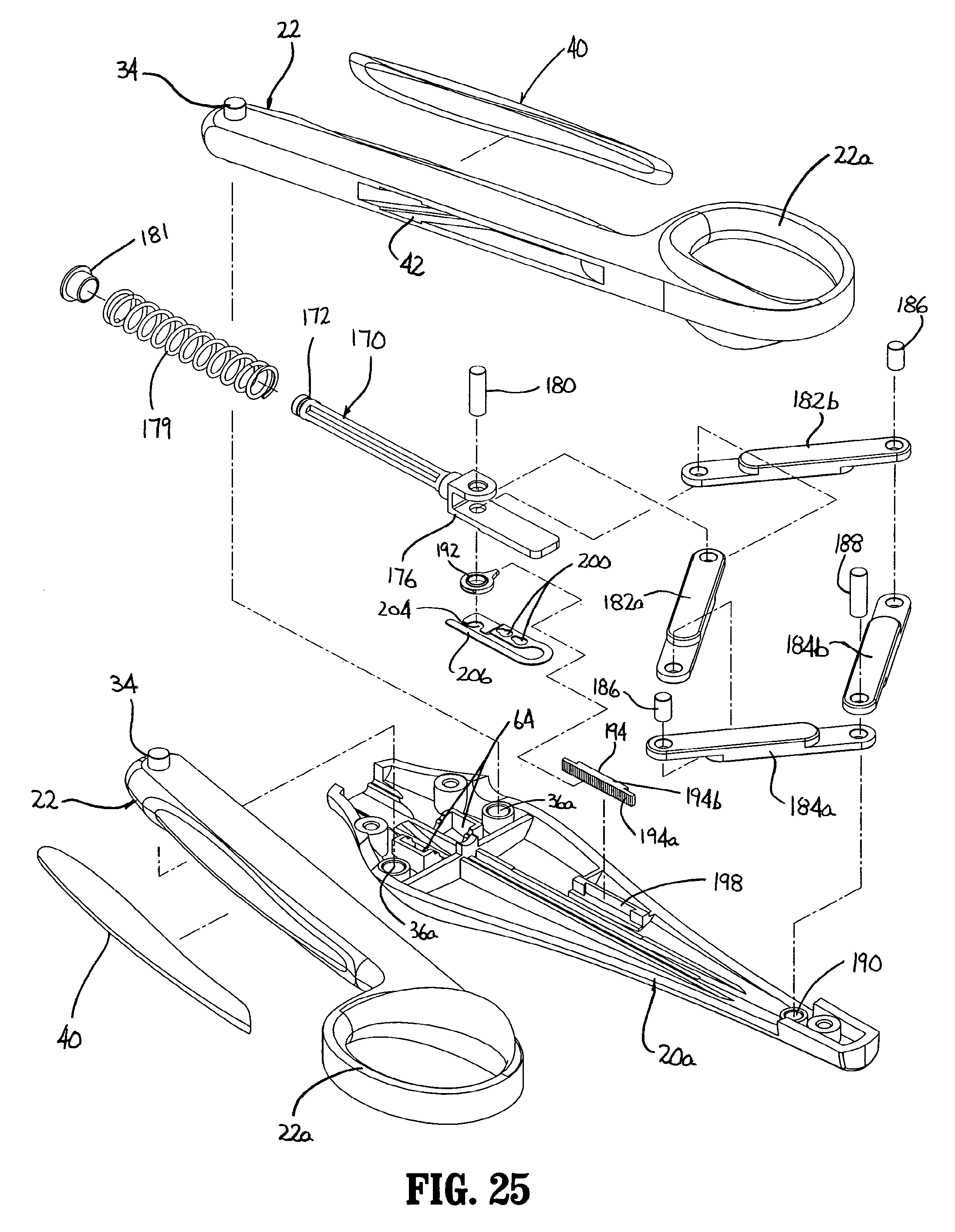
D00013
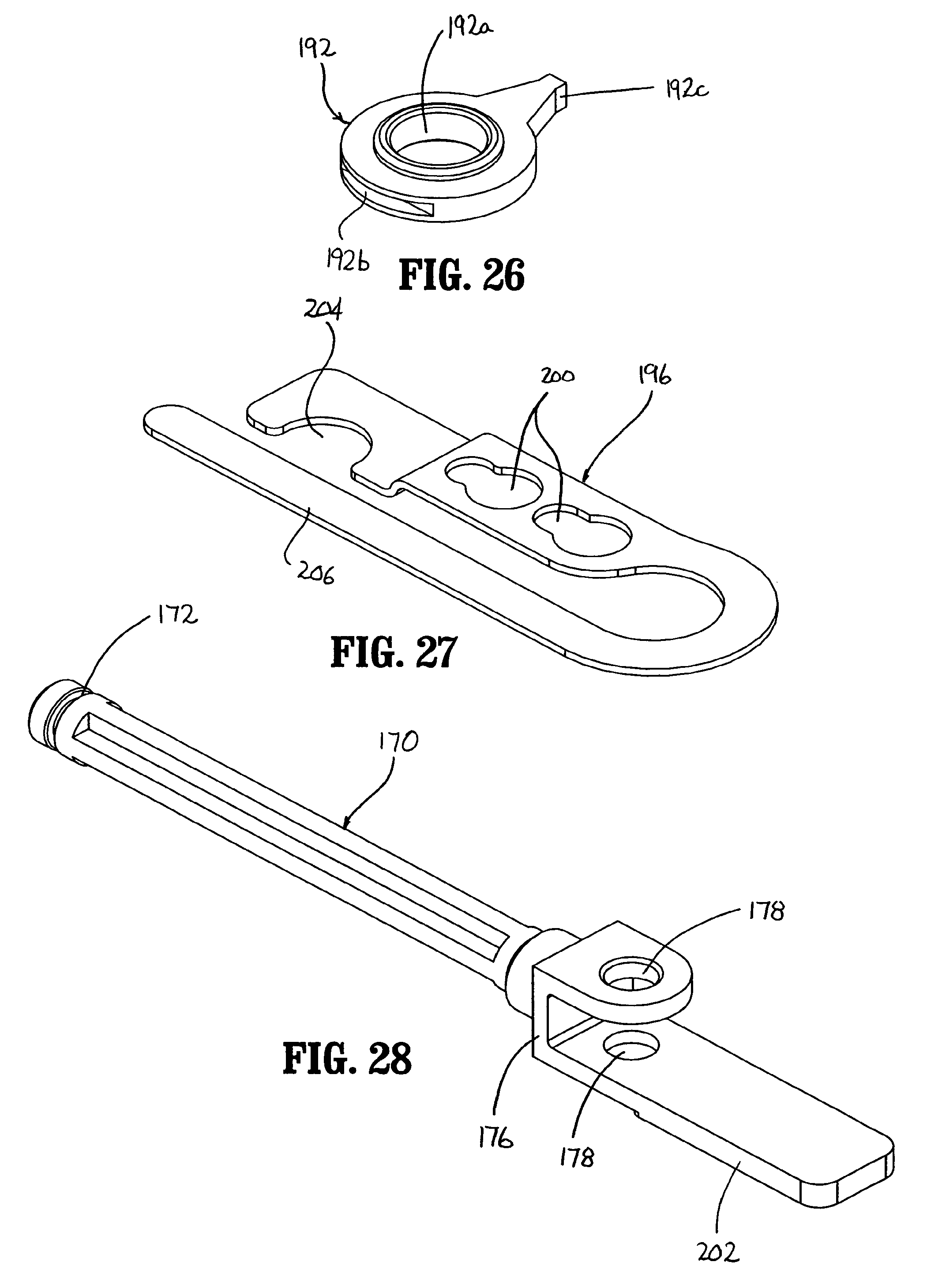
D00014
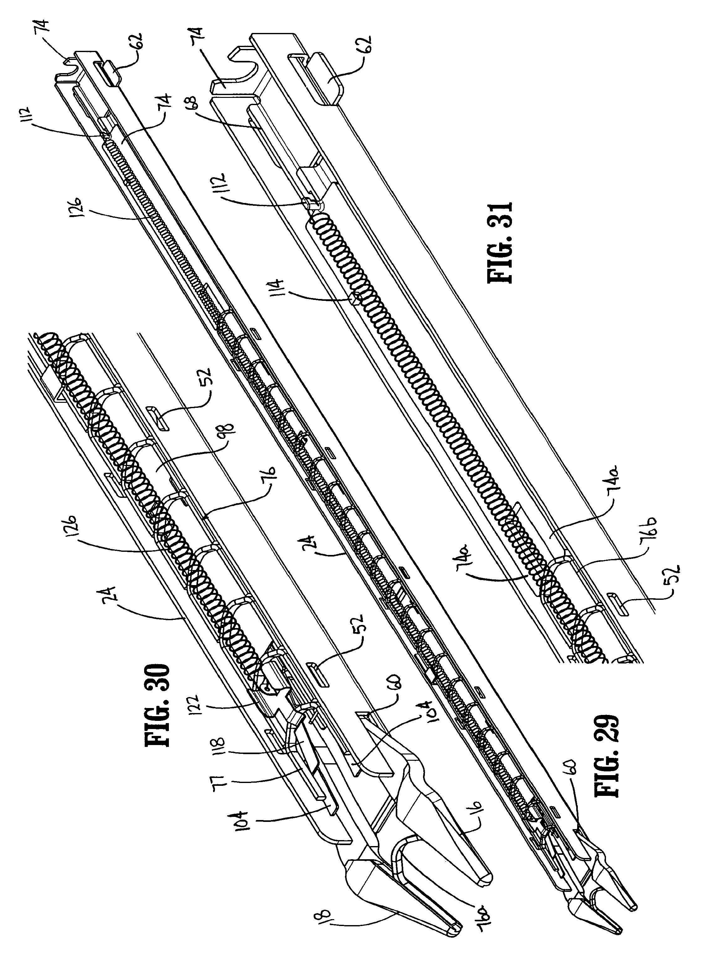
D00015
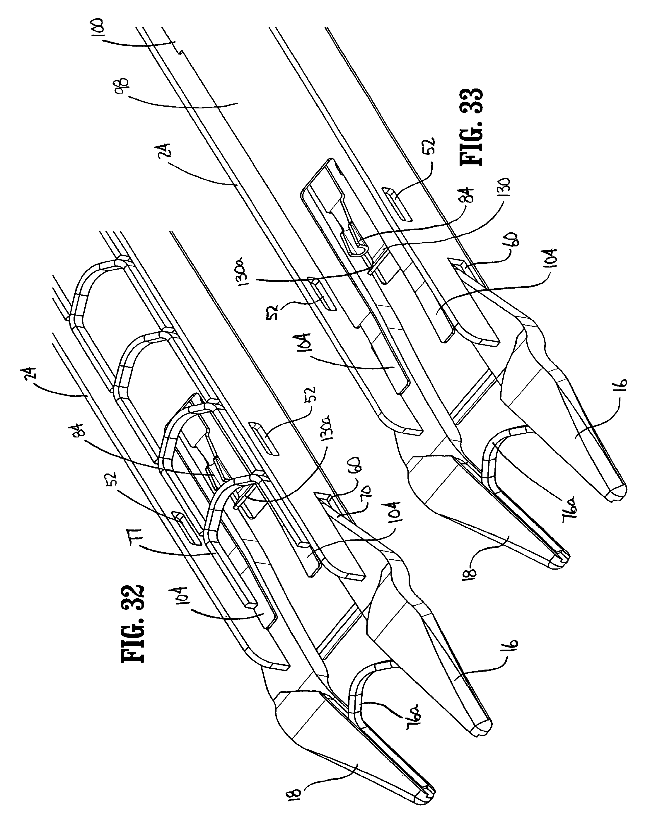
D00016
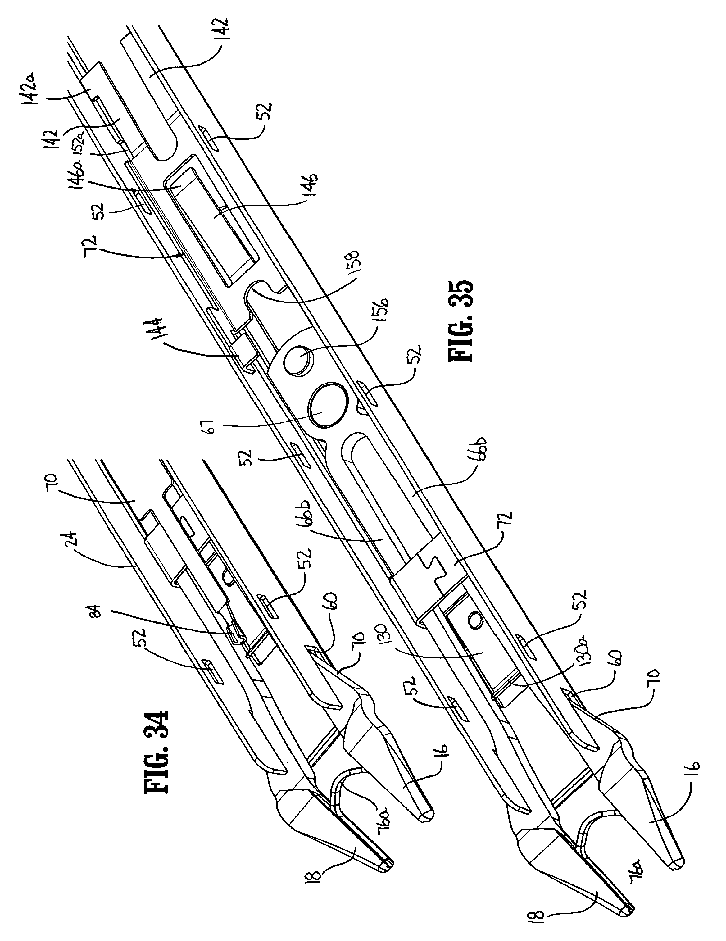
D00017
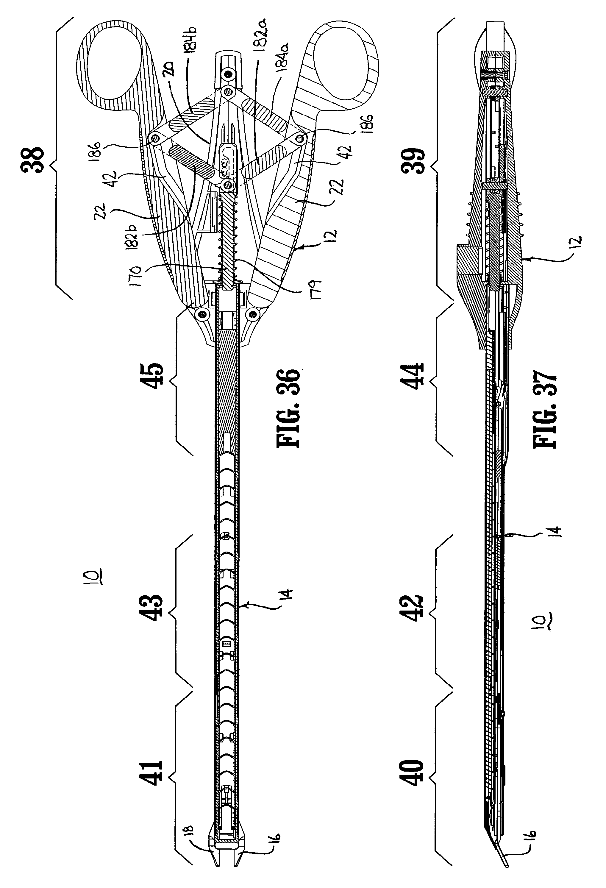
D00018
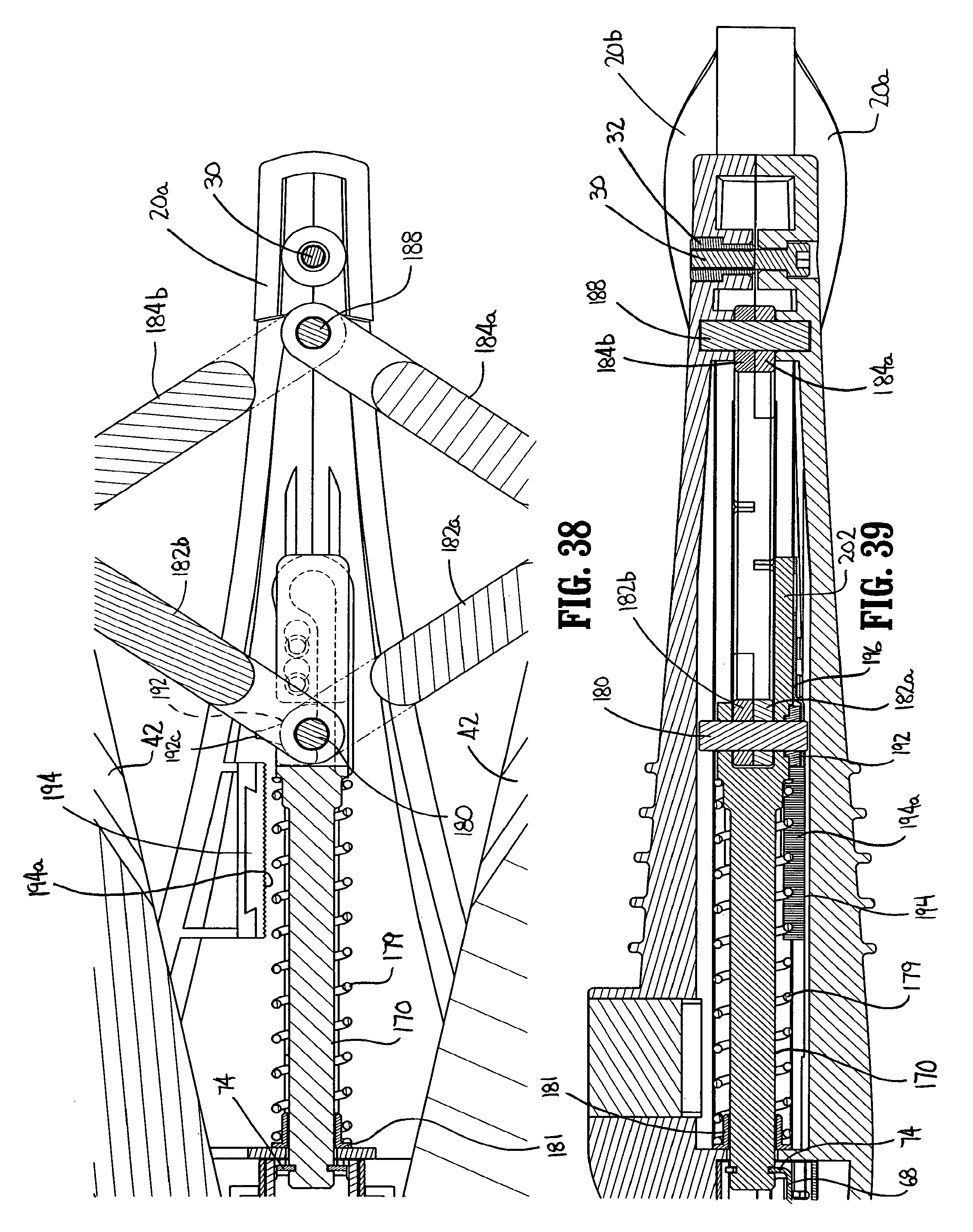
D00019
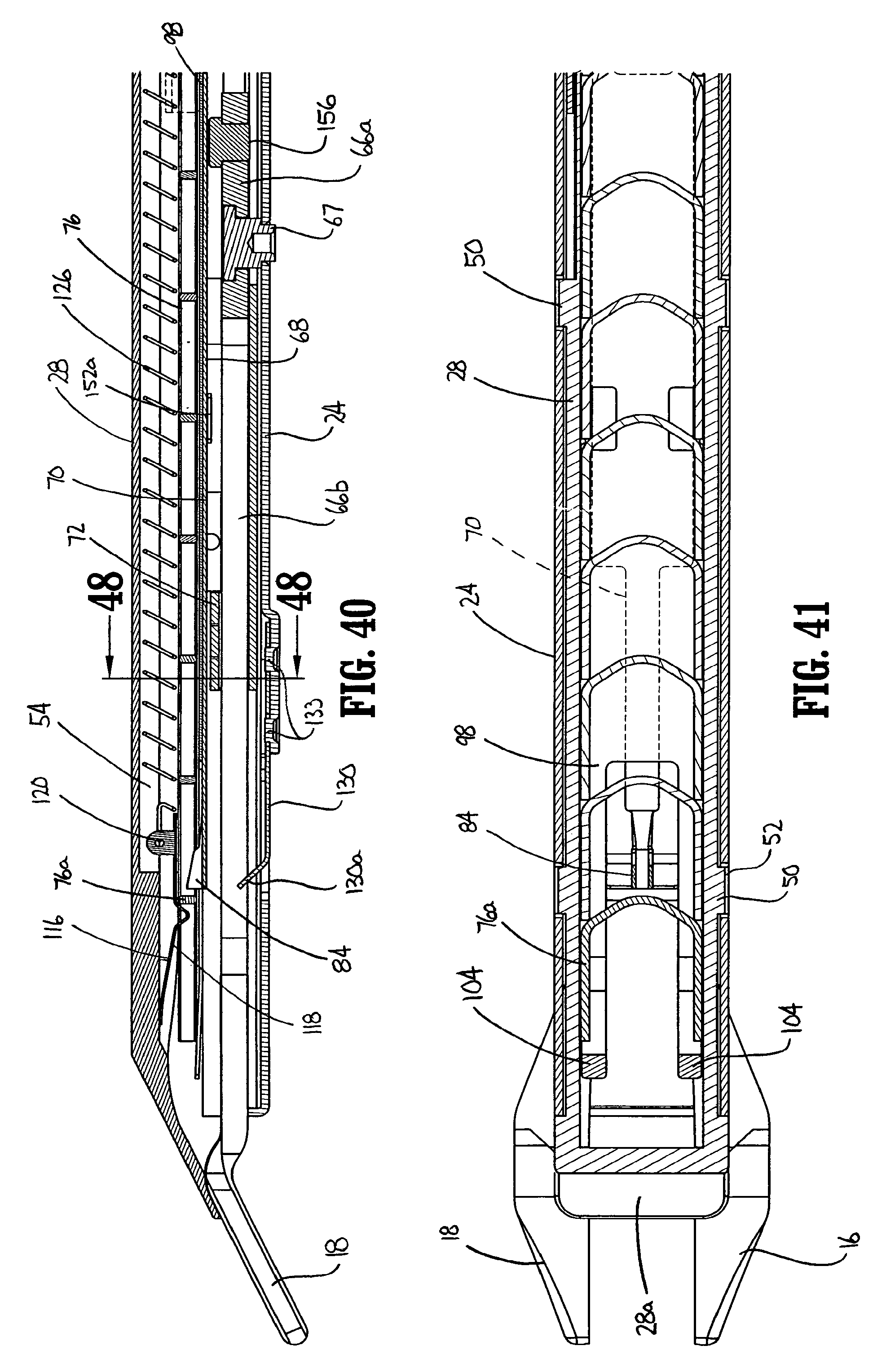
D00020
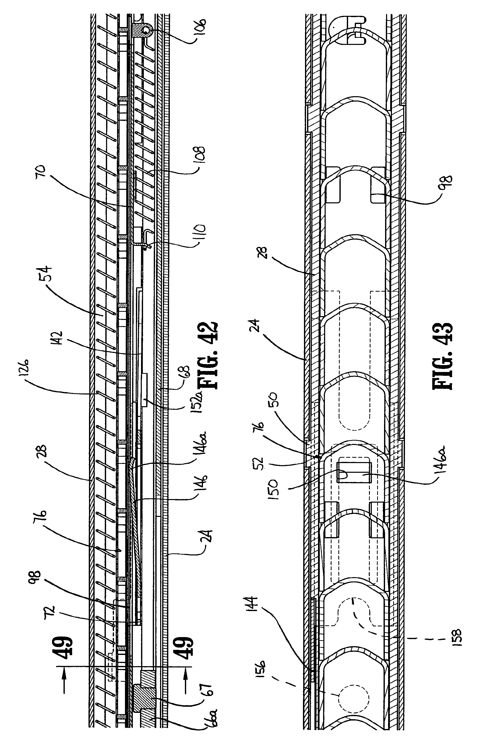
D00021
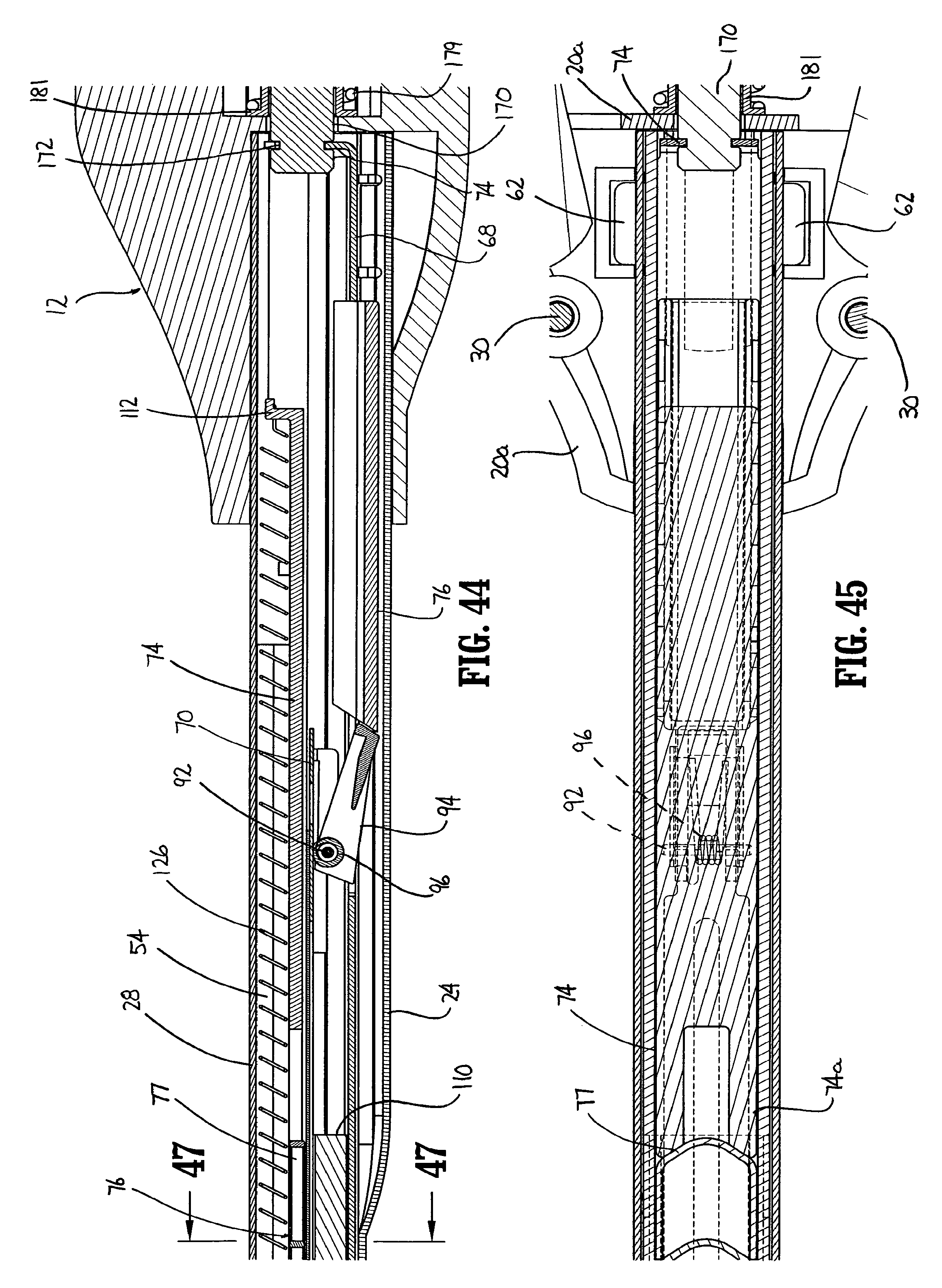
D00022
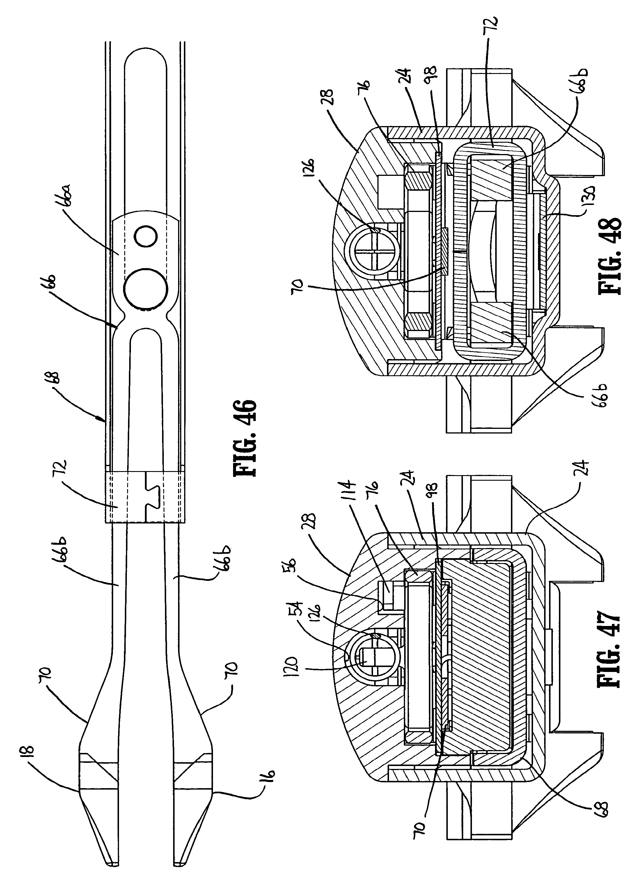
D00023
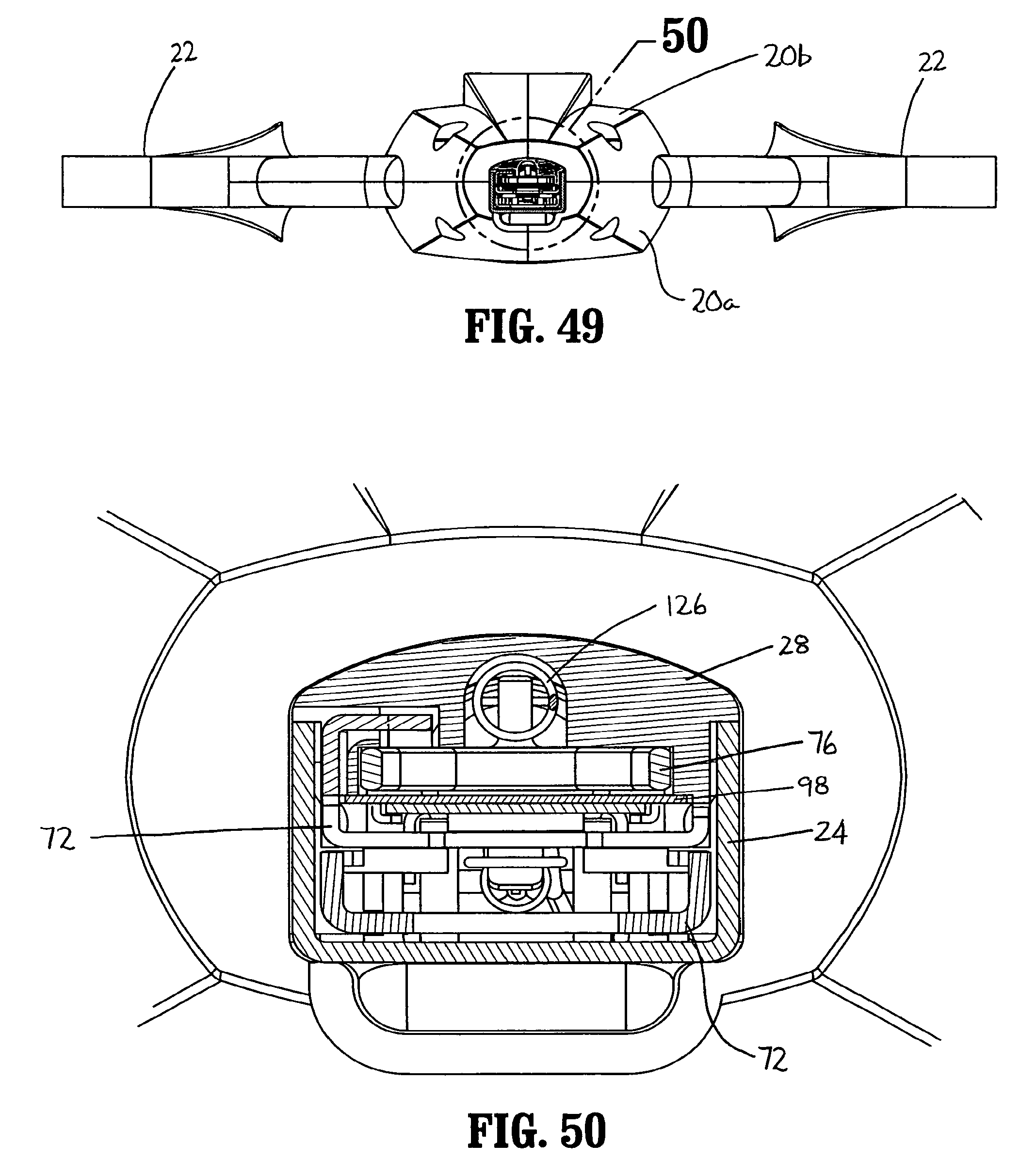
D00024
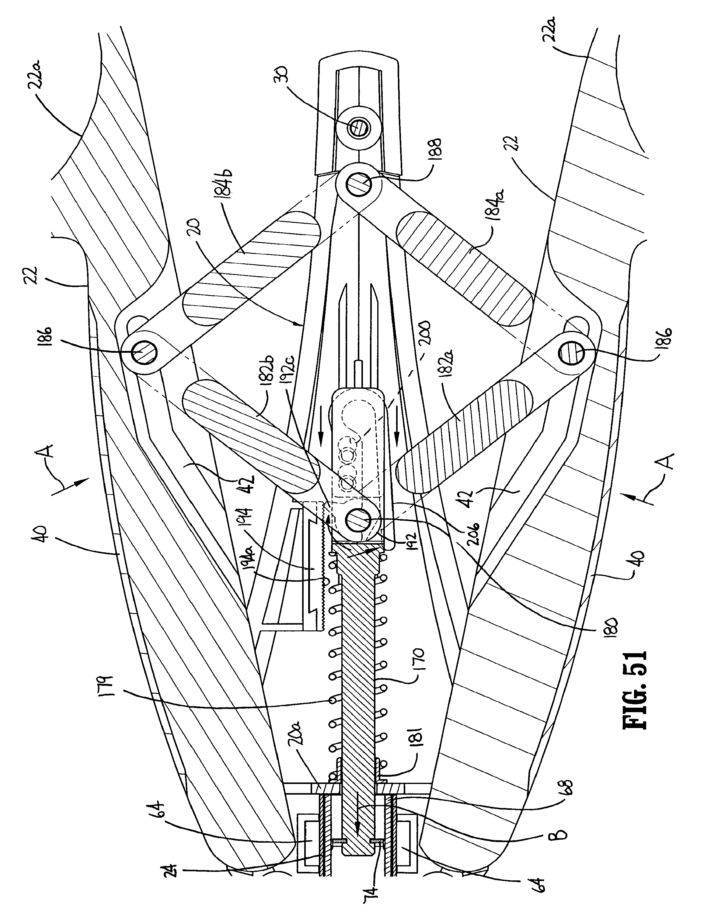
D00025
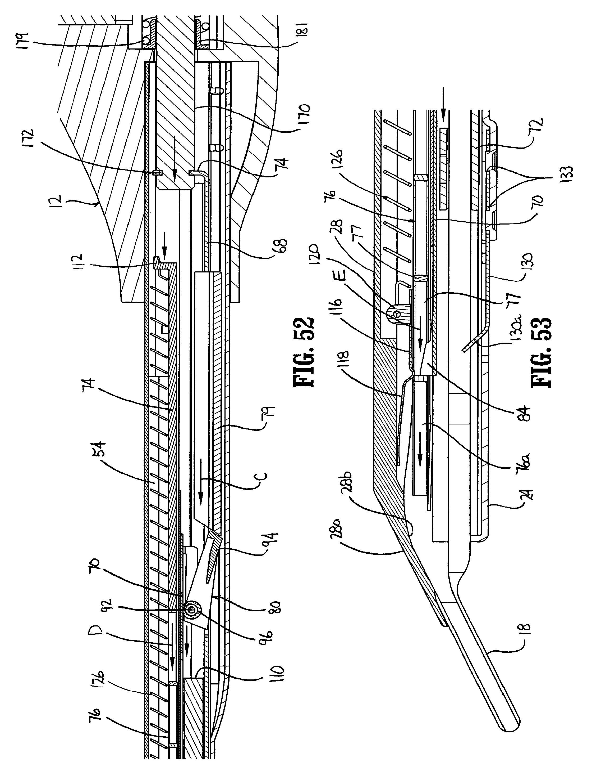
D00026
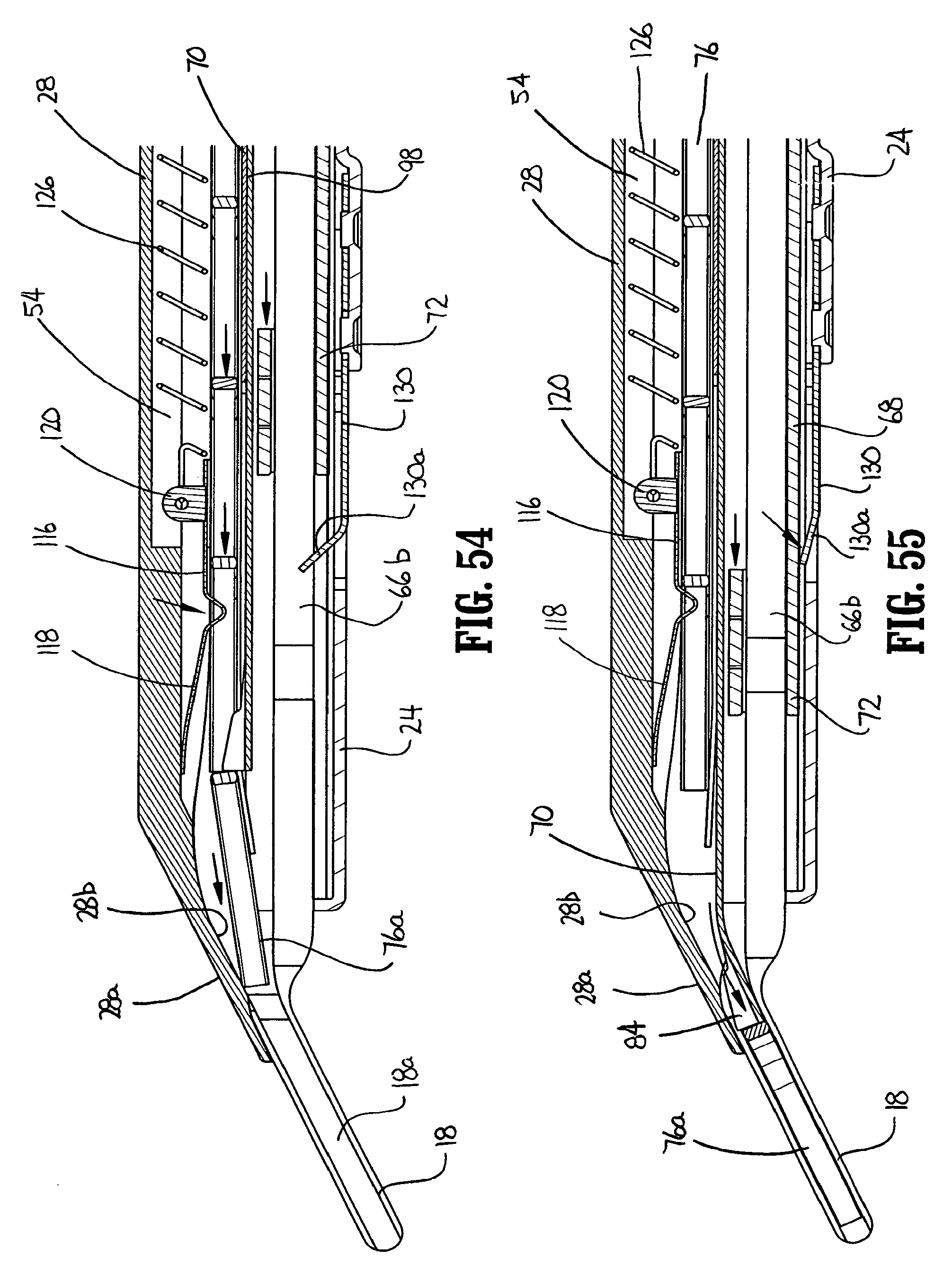
D00027
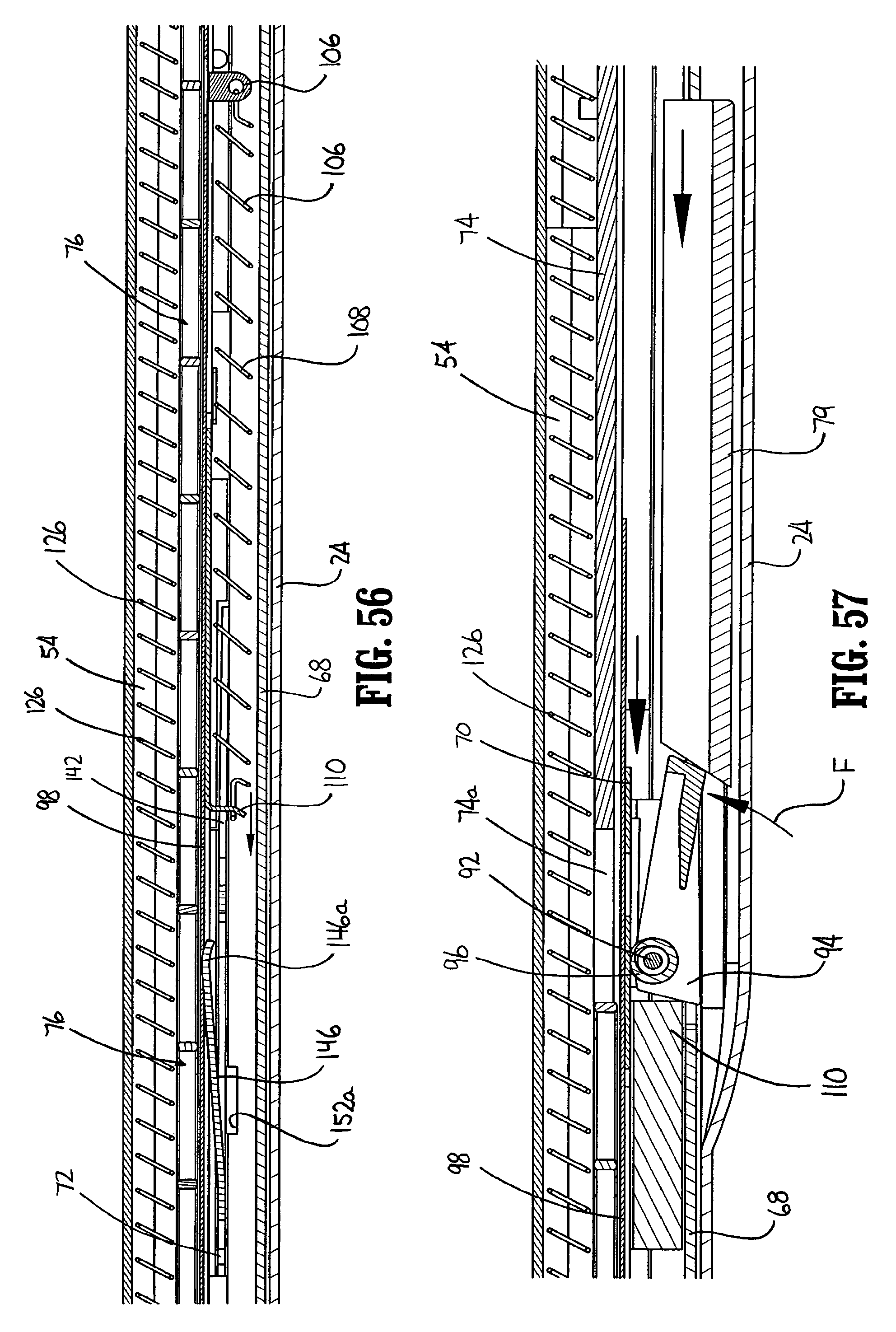
D00028
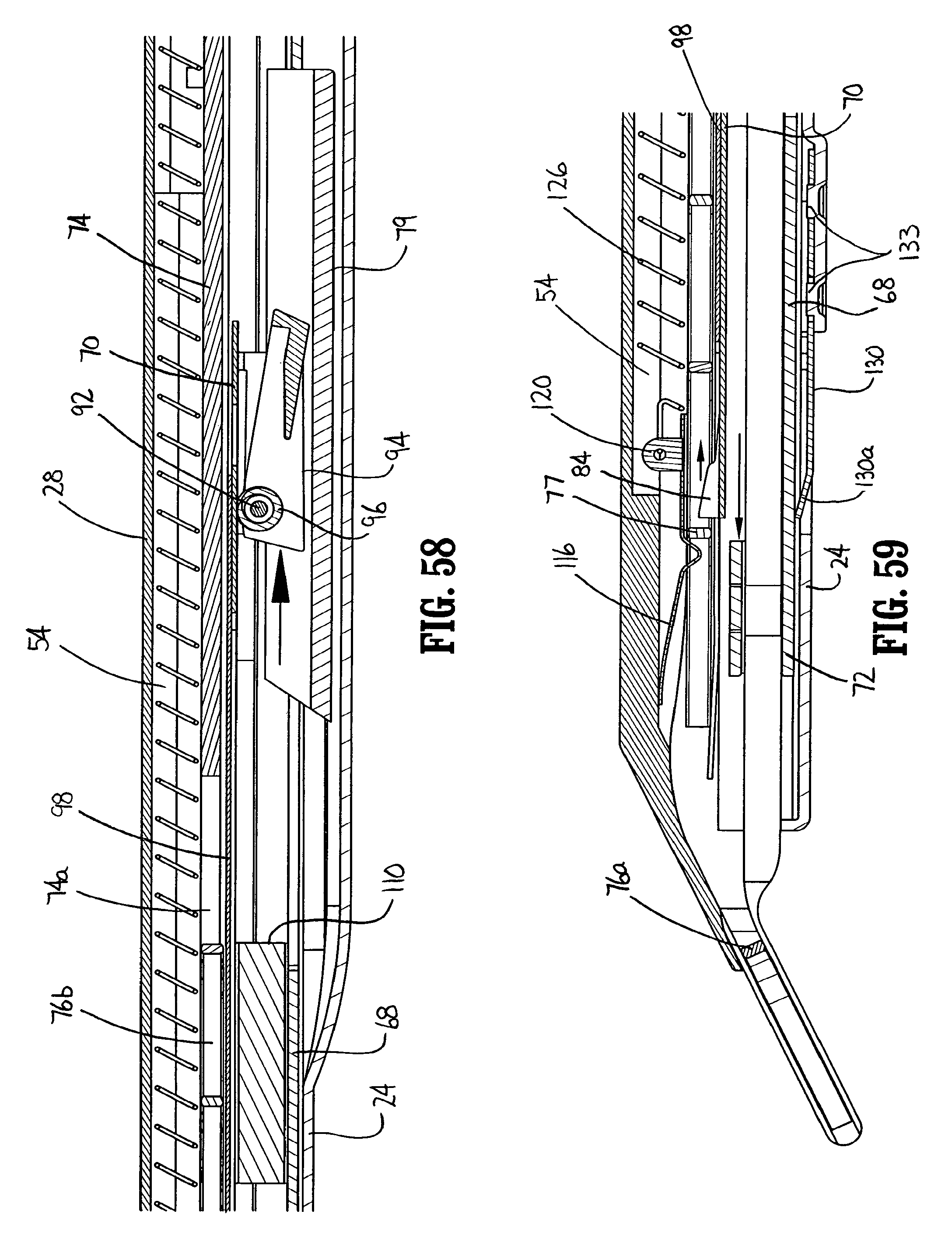
D00029
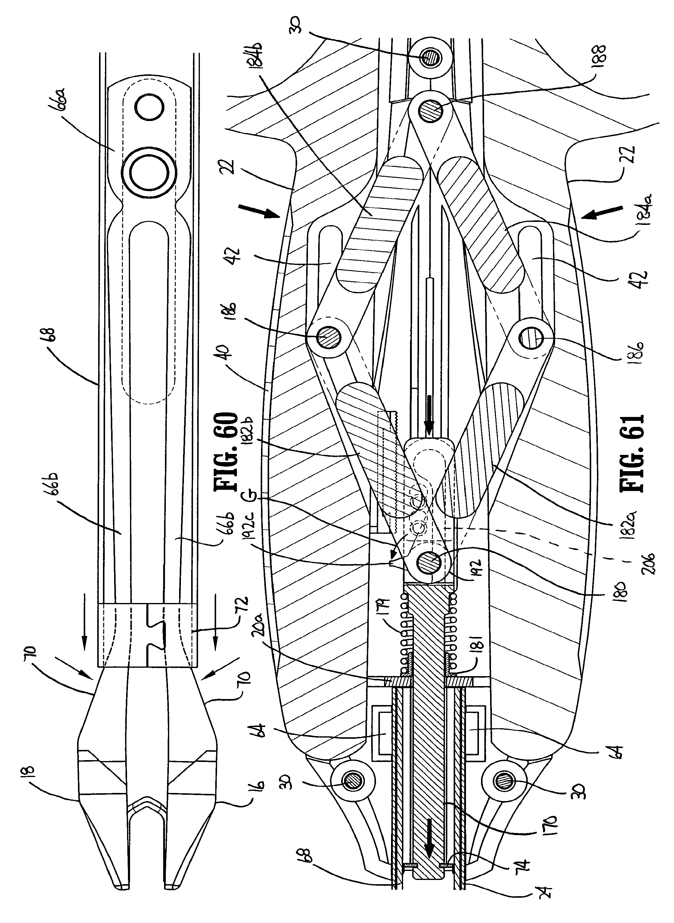
D00030
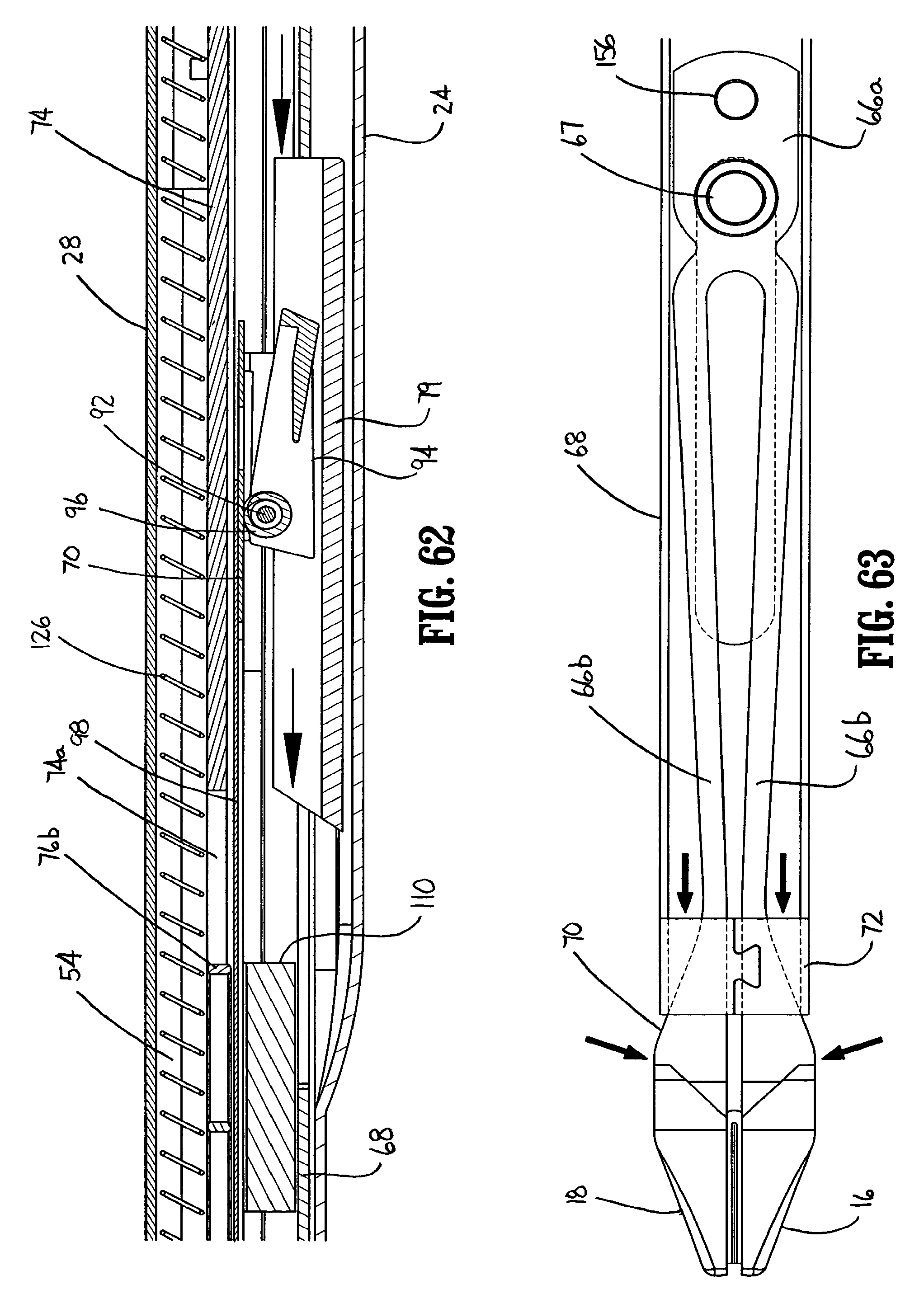
D00031
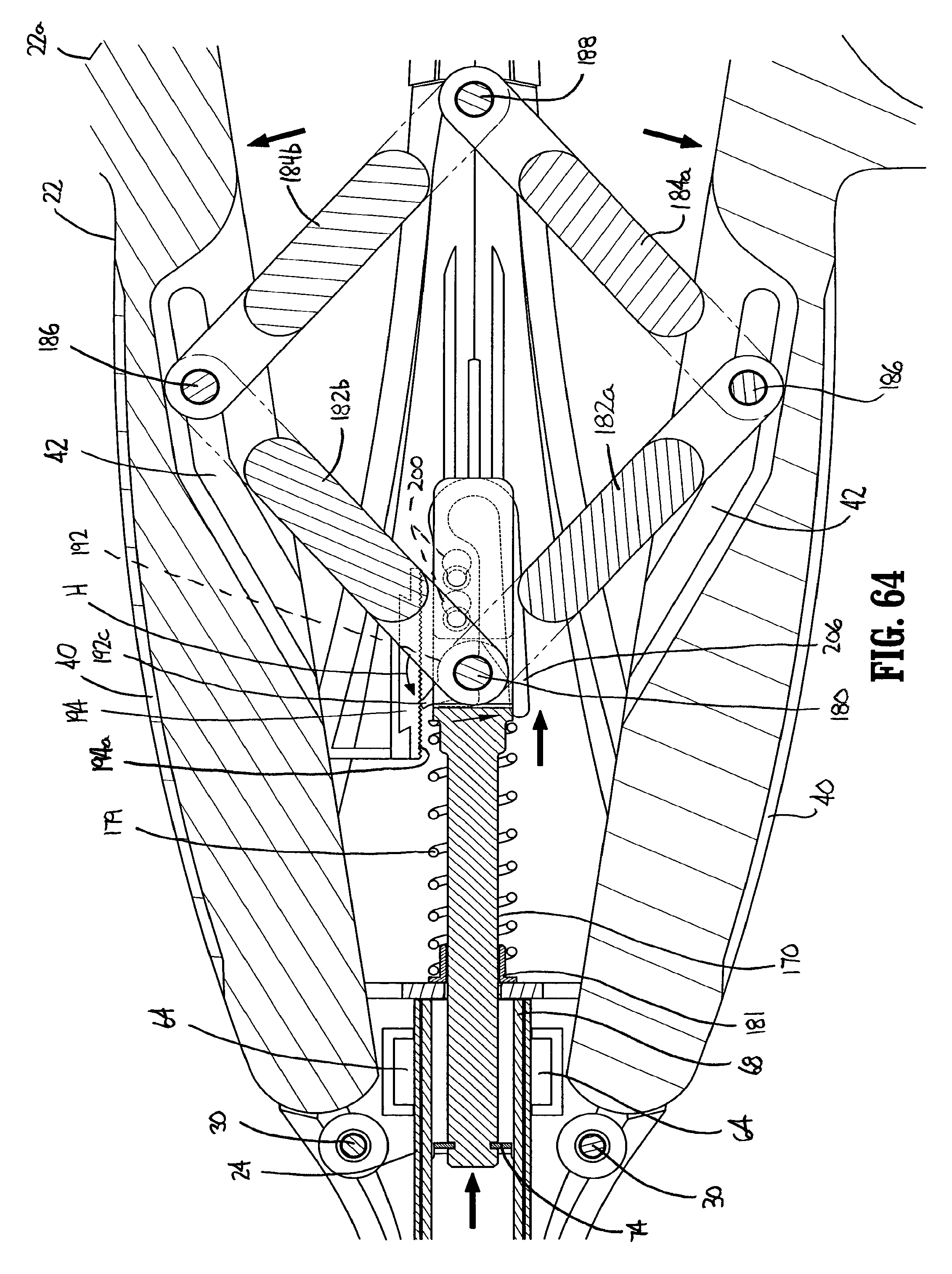
D00032
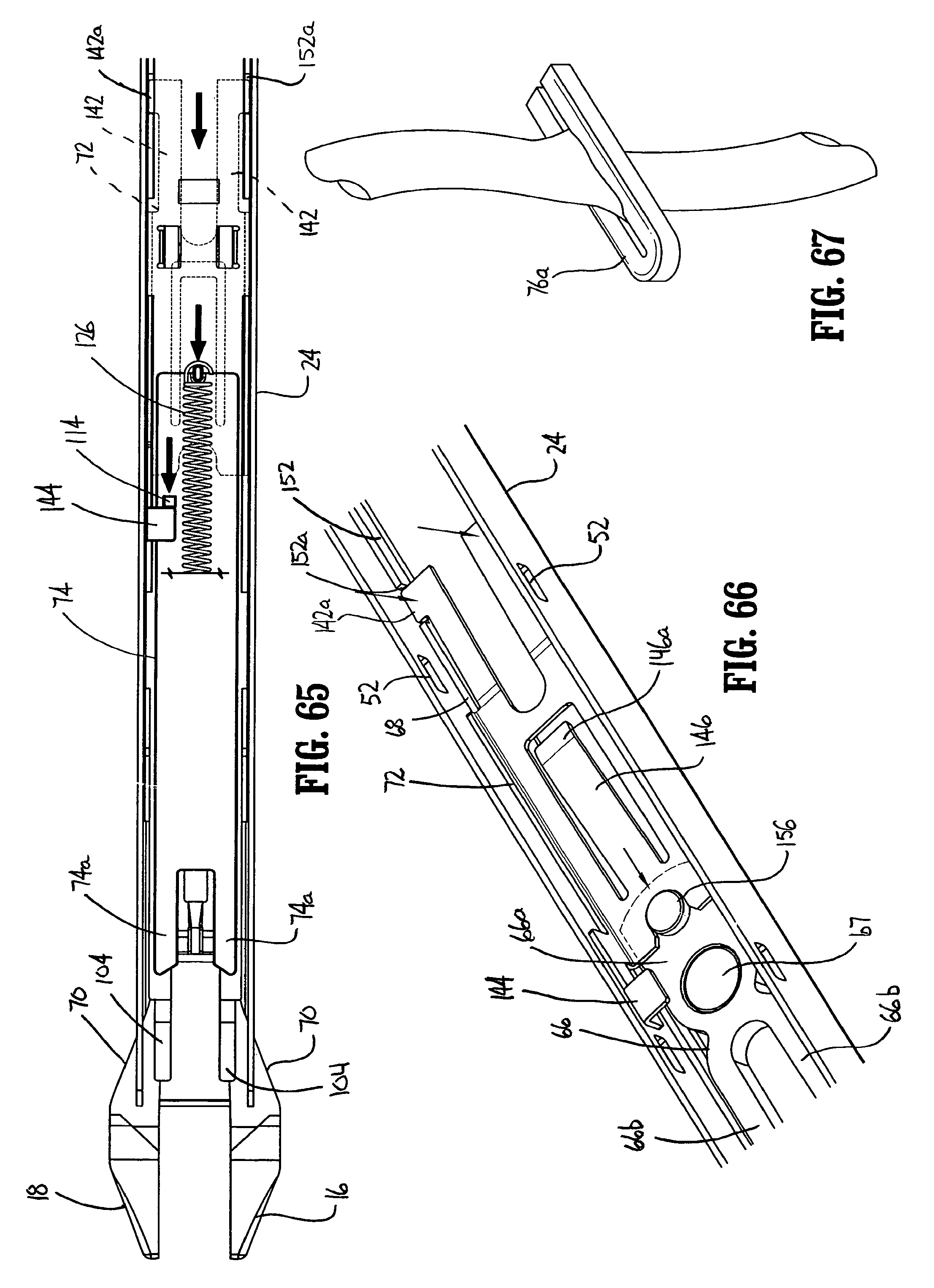
XML
uspto.report is an independent third-party trademark research tool that is not affiliated, endorsed, or sponsored by the United States Patent and Trademark Office (USPTO) or any other governmental organization. The information provided by uspto.report is based on publicly available data at the time of writing and is intended for informational purposes only.
While we strive to provide accurate and up-to-date information, we do not guarantee the accuracy, completeness, reliability, or suitability of the information displayed on this site. The use of this site is at your own risk. Any reliance you place on such information is therefore strictly at your own risk.
All official trademark data, including owner information, should be verified by visiting the official USPTO website at www.uspto.gov. This site is not intended to replace professional legal advice and should not be used as a substitute for consulting with a legal professional who is knowledgeable about trademark law.