Endoscopic Reposable Surgical Clip Applier
Zhang; Zhihua ; et al.
U.S. patent application number 15/768854 was filed with the patent office on 2019-02-21 for endoscopic reposable surgical clip applier. The applicant listed for this patent is Covidien LP. Invention is credited to Encheng Hu, Zhihua Zhang.
| Application Number | 20190053806 15/768854 |
| Document ID | / |
| Family ID | 58694575 |
| Filed Date | 2019-02-21 |


| United States Patent Application | 20190053806 |
| Kind Code | A1 |
| Zhang; Zhihua ; et al. | February 21, 2019 |
ENDOSCOPIC REPOSABLE SURGICAL CLIP APPLIER
Abstract
A reposable surgical clip applier (10) is provided and includes a handle assembly (100), an endoscopic assembly (200) selectively connectable to a housing of the handle assembly (100), and a clip cartridge assembly (300) selectively loadable in and connectable to the endoscopic assembly (200).
| Inventors: | Zhang; Zhihua; (ShenZhen, CN) ; Hu; Encheng; (Shanghai, CN) | ||||||||||
| Applicant: |
|
||||||||||
|---|---|---|---|---|---|---|---|---|---|---|---|
| Family ID: | 58694575 | ||||||||||
| Appl. No.: | 15/768854 | ||||||||||
| Filed: | November 10, 2015 | ||||||||||
| PCT Filed: | November 10, 2015 | ||||||||||
| PCT NO: | PCT/CN2015/094172 | ||||||||||
| 371 Date: | April 17, 2018 |
| Current U.S. Class: | 1/1 |
| Current CPC Class: | A61B 2017/00469 20130101; A61B 2017/00902 20130101; A61B 17/00234 20130101; A61B 17/105 20130101; A61B 17/1285 20130101; A61B 2017/00367 20130101; A61B 2017/0023 20130101 |
| International Class: | A61B 17/10 20060101 A61B017/10; A61B 17/00 20060101 A61B017/00 |
Claims
1. A reposable surgical clip applier, comprising: a handle assembly including: a housing defining a bore therein; a fixed handle extending from the housing; and a trigger pivotally connected to the fixed handle, the trigger including an actuating end disposed within the bore of the housing; an endoscopic assembly selectively connectable to the housing of the handle assembly, the endoscopic assembly including: an outer tube defining a lumen therethrough, the outer tube including a proximal end and a distal end; a pair of jaws fixedly supported and extending from the distal end of the outer tube; and a drive assembly slidably supported in the lumen of the outer tube, the drive assembly including: a shaft pusher tube slidably supported in the lumen of the outer tube, the shaft pusher tube including a proximal end, a distal end and defining a lumen therethrough, wherein a radial flange is provided at the proximal end of the shaft pusher tube; a closure drive rod slidably disposed within the lumen of the shaft pusher tube, the closure drive rod having a proximal end projecting from the proximal end of the outer tube and engagable by the actuating end of the trigger, and a distal end selectively engagable with the pair of jaws to approximate the pair of jaws, wherein a shoulder is provided at the proximal end of the closure drive rod; and a biasing member interposed between the shoulder of the closure drive rod and the radial flange of the shaft pusher tube; and a clip cartridge assembly selectively connectable to the distal end of the outer tube, and to the distal end of the shaft pusher tube, the clip cartridge assembly including: a clip tray; a plurality of surgical clips slidably supported in the clip tray; a clip follower slidably disposed within the clip tray and disposed proximal of the plurality of surgical clips; a biasing member tending to urge the clip follower in a distal direction; and a clip pusher bar slidably supported adjacent the clip tray, wherein the clip pusher bar includes a proximal end configured for engagement by the distal end of the shaft pusher tube, and a distal end configured to engage a distal-most clip of the plurality of surgical clips.
2. The reposable surgical clip applier according to claim 1, wherein during an initial actuation of the trigger, the actuating end of the trigger acts on the proximal end of the closure drive rod of the endoscopic assembly to distally advance the closure drive rod, wherein the closure drive rod acts on the biasing member to distally advance the biasing member against the radial flange of the shaft pusher tube to distally advance the shaft pusher tube, and wherein the shaft pusher tube acts on the clip pusher bar to distally advance the clip pusher bar of the clip cartridge assembly and load a distal-most surgical clip thereof into the pair of jaws.
3. The reposable surgical clip applier according to claim 2, wherein the endoscopic assembly includes a stop member supported in the outer tube thereof, wherein the stop member is disposed distal of the radial flange of the shaft pusher tube.
4. The reposable surgical clip applier according to claim 3, wherein the distal advancement of the shaft pusher tube is stopped by the stop member.
5. The reposable surgical clip applier according to claim 4, wherein following the stop member stopping the distal advancement of the shaft pusher tube, during a further actuation of the trigger, the actuating end of the trigger acts on the proximal end of the closure drive rod of the endoscopic assembly to further distally advance the closure drive rod, wherein the closure drive rod acts on the biasing member to compress the biasing member between the radial flange of the shaft pusher tube and the shoulder of the closure drive rod.
6. The reposable surgical clip applier according to claim 5, wherein during the further actuation of the trigger, the distal end of the closure drive rod acts on the pair of jaws to approximate the pair of jaws and to form any surgical clip loaded therein.
7. The reposable surgical clip applier according to claim 6, wherein the clip pusher bar of the clip cartridge assembly remains in a distal position during the approximation of the pair of jaws.
8. The reposable surgical clip applier according to claim 1, wherein the handle assembly includes an end cap selectively securable to a proximal end of the housing.
9. An endoscopic assembly configured for selective connection to a handle assembly and actuatable by a trigger of the handle assembly, the endoscopic assembly comprising: an outer tube defining a lumen therethrough, the outer tube including a proximal end and a distal end; a pair of jaws fixedly supported and extending from the distal end of the outer tube, the pair of jaws being movable between an open position and a closed position, wherein the pair of jaws are configured to form a surgical clip loaded therewithin when the pair of jaws are actuated from the open position to the closed position; and a drive assembly slidably supported in the lumen of the outer tube, the drive assembly including: a shaft pusher tube slidably supported in the lumen of the outer tube, the shaft pusher tube including a proximal end, a distal end and defining a lumen therethrough, wherein a radial flange is provided at the proximal end of the shaft pusher tube; and a closure drive rod slidably disposed within the lumen of the shaft pusher tube, the closure drive rod having a proximal end projecting from the proximal end of the outer tube and engagable by the trigger of the handle assembly, and a distal end configured to selectively engage the pair of jaws to move the pair of jaws to the closed position, wherein a shoulder is provided at the proximal end of the closure drive rod; and a biasing member interposed between the shoulder of the closure drive rod and the radial flange of the shaft pusher tube.
10. The endoscopic assembly according to claim 9, wherein during an initial distal advancement of closure drive rod, the shoulder of the closure drive rod acts on the biasing member to distally advance the biasing member against the radial flange of the shaft pusher tube to distally advance the shaft pusher tube, and wherein the shaft pusher tube acts on a clip cartridge assembly load in the outer tube to advance a distal-most surgical clip of the clip cartridge assembly into the pair of jaws.
11. The endoscopic assembly according to claim 10, wherein the endoscopic assembly includes a stop member supported in the outer tube thereof, wherein the stop member is disposed distal of the radial flange of the shaft pusher tube.
12. The endoscopic assembly according to claim 11, wherein the distal advancement of the shaft pusher tube is stopped by the stop member.
13. The endoscopic assembly according to claim 12, wherein following the stop member stopping the distal advancement of the shaft pusher tube, during a further advancement of the closure drive rod, the closure drive rod acts on the biasing member to compress the biasing member between the radial flange of the shaft pusher tube and the shoulder of the closure drive rod.
14. The endoscopic assembly according to claim 13, wherein during the further advancement of the closure drive rod, the distal end of the closure drive rod acts on the pair of jaws to approximate the pair of jaws and to form any surgical clip loaded therein.
15. A reposable surgical clip applier, comprising: a handle assembly including: a housing; and a trigger pivotally connected to the housing, the trigger including an actuating end disposed within the housing; an endoscopic assembly selectively connectable to the housing of the handle assembly, the endoscopic assembly including: an outer tube defining a lumen therethrough and a window in a distal end thereof; a pair of jaws fixedly supported and extending from a distal end of the outer tube; and a drive assembly slidably supported in the lumen of the outer tube, the drive assembly including: a shaft pusher tube slidably supported in the lumen of the outer tube, the shaft pusher tube including a proximal end, a distal end and defining a lumen therethrough, wherein a radial flange is provided at the proximal end of the shaft pusher tube; a closure drive rod slidably disposed within the lumen of the shaft pusher tube, the closure drive rod having a proximal end projecting from the proximal end of the outer tube and engagable by the actuating end of the trigger, and a distal end selectively engagable with the pair of jaws to approximate the pair of jaws, wherein a shoulder is provided at the proximal end of the closure drive rod; and a biasing member interposed between the shoulder of the closure drive rod and the radial flange of the shaft pusher tube; and a clip cartridge assembly selectively disposable within the window of the outer tube, and selectively connectable to the distal end of the shaft pusher tube, the clip cartridge assembly including: a clip tray; a plurality of surgical clips slidably supported in the clip tray; a clip follower slidably disposed within the clip tray and disposed proximal of the plurality of surgical clips; a biasing member tending to urge the clip follower in a distal direction; and a clip pusher bar slidably supported adjacent the clip tray, wherein the clip pusher bar includes a proximal end configured for engagement by the distal end of the shaft pusher tube, and a distal end configured to engage a distal-most clip of the plurality of surgical clips.
16. The reposable surgical clip applier according to claim 15, wherein during an initial actuation of the trigger, the actuating end of the trigger acts on the proximal end of the closure drive rod of the endoscopic assembly to distally advance the closure drive rod, wherein the closure drive rod acts on the biasing member to distally advance the biasing member against the radial flange of the shaft pusher tube to distally advance the shaft pusher tube, and wherein the shaft pusher tube acts on the clip pusher bar to distally advance the clip pusher bar of the clip cartridge assembly and load a distal-most surgical clip thereof into the pair of jaws.
17. The reposable surgical clip applier according to claim 16, wherein the endoscopic assembly includes a stop member supported in the outer tube thereof, wherein the stop member is disposed distal of the radial flange of the shaft pusher tube.
18. The reposable surgical clip applier according to claim 17, wherein the distal advancement of the shaft pusher tube is stopped by the stop member.
19. The reposable surgical clip applier according to claim 18, wherein following the stop member stopping the distal advancement of the shaft pusher tube, during a further actuation of the trigger, the actuating end of the trigger acts on the proximal end of the closure drive rod of the endoscopic assembly to further distally advance the closure drive rod, wherein the closure drive rod acts on the biasing member to compress the biasing member between the radial flange of the shaft pusher tube and the shoulder of the closure drive rod.
20. The reposable surgical clip applier according to claim 19, wherein during the further actuation of the trigger, the distal end of the closure drive rod acts on the pair of jaws to approximate the pair of jaws and to form any surgical clip loaded therein.
21. The reposable surgical clip applier according to claim 20, wherein the clip pusher bar of the clip cartridge assembly remains in a distal position during the approximation of the pair of jaws.
Description
BACKGROUND
Technical Field
[0001] The present disclosure relates to surgical clip appliers. More particularly, the present disclosure relates to endoscopic reposable surgical clip appliers having a reusable handle assembly, a reusable shaft assembly, and a disposable clip cartridge assembly.
Description of Related Art
[0002] Endoscopic staplers and clip appliers are known in the art and are used for a number of distinct and useful surgical procedures. In the case of a laparoscopic surgical procedure, access to the interior of an abdomen is achieved through narrow tubes or cannulas inserted through a small entrance incision in the skin. Minimally invasive procedures performed elsewhere in the body are often generally referred to as endoscopic procedures. Typically, a tube or cannula device is extended into the patient's body through the entrance incision to provide an access port. The port allows the surgeon to insert a number of different surgical instruments therethrough using a trocar and for performing surgical procedures far removed from the incision.
[0003] During a majority of these procedures, the surgeon must often terminate the flow of blood or another fluid through one or more vessels. The surgeon will often apply a surgical clip to a blood vessel or another duct to prevent the flow of body fluids therethrough during the procedure. An endoscopic clip applier is known in the art for applying a single clip during an entry to the body cavity. Such clips are typically fabricated from a biocompatible material and are usually compressed over a vessel. Once applied to the vessel, the compressed clip terminates the flow of fluid therethrough.
[0004] Endoscopic clip appliers that are able to apply multiple clips in endoscopic or laparoscopic procedures during a single entry into the body cavity are described in commonly-assigned U.S. Pat. Nos. 5,084,057 and 5,100,420 to Green et al., which are both incorporated by reference in their entirety. Another multiple endoscopic clip applier is disclosed in commonly-assigned U.S. Pat. No. 5,607,436 by Pratt et al., the contents of which is also hereby incorporated by reference herein in its entirety. These devices are typically, though not necessarily, used during a single surgical procedure. U.S. Pat. No. 5,695,502 to Pier et al., the disclosure of which is hereby incorporated by reference herein, discloses a resterilizable surgical clip applier. The clip applier advances and forms multiple clips during a single insertion into the body cavity. This resterilizable clip applier is configured to receive and cooperate with an interchangeable clip magazine so as to advance and form multiple clips during a single entry into a body cavity.
[0005] During endoscopic or laparoscopic procedures it may be desirable and/or necessary to use different size surgical clips depending on the underlying tissue or vessels to be ligated. In order to reduce overall costs of a surgical clip applier, it is desirable for a single surgical clip applier to be loadable with and capable of firing different size surgical clips as needed.
[0006] In addition, in order to reduce overall costs of a surgical clip applier, it is desirable to provide a surgical clip applier having components which may be reused (following proper cleaning, sterilizing and reconditioning procedures) multiple times, and which limits the number of disposable components thereof.
[0007] Accordingly, a need exists for improved endoscopic surgical clip appliers that include reusable handle assemblies, reusable shaft assemblies, and disposable clip cartridge assemblies.
SUMMARY
[0008] The present disclosure relates to reposable endoscopic surgical clip appliers.
[0009] According to an aspect of the present disclosure, a reposable surgical clip applier is provided and includes a handle assembly, an endoscopic assembly, and a clip cartridge assembly.
[0010] The handle assembly includes a housing defining a bore therein; a fixed handle extending from the housing; and a trigger pivotally connected to the fixed handle, the trigger including an actuating end disposed within the bore of the housing.
[0011] The endoscopic assembly is selectively connectable to the housing of the handle assembly. The endoscopic assembly includes an outer tube defining a lumen therethrough, the outer tube including a proximal end and a distal end; a pair of jaws fixedly supported and extending from the distal end of the outer tube; and a drive assembly slidably supported in the lumen of the outer tube.
[0012] The drive assembly includes a shaft pusher tube slidably supported in the lumen of the outer tube, the shaft pusher tube including a proximal end, a distal end and defining a lumen therethrough, wherein a radial flange is provided at the proximal end of the shaft pusher tube.
[0013] The drive assembly also includes a closure drive rod slidably disposed within the lumen of the shaft pusher tube, the closure drive rod having a proximal end projecting from the proximal end of the outer tube and engagable by the actuating end of the trigger, and a distal end selectively engagable with the pair of jaws to approximate the pair of jaws, wherein a shoulder is provided at the proximal end of the closure drive rod.
[0014] The drive assembly further includes a biasing member interposed between the shoulder of the closure drive rod and the radial flange of the shaft pusher tube.
[0015] The clip cartridge assembly is selectively connectable to the distal end of the outer tube, and to the distal end of the shaft pusher tube. The clip cartridge assembly includes a clip tray; a plurality of surgical clips slidably supported in the clip tray; a clip follower slidably disposed within the clip tray and disposed proximal of the plurality of surgical clips; a biasing member tending to urge the clip follower in a distal direction; and a clip pusher bar slidably supported adjacent the clip tray, wherein the clip pusher bar includes a proximal end configured for engagement by the distal end of the shaft pusher tube, and a distal end configured to engage a distal-most clip of the plurality of surgical clips.
[0016] In operation, during an initial actuation of the trigger, the actuating end of the trigger may act on the proximal end of the closure drive rod of the endoscopic assembly to distally advance the closure drive rod. The closure drive rod may act on the biasing member to distally advance the biasing member against the radial flange of the shaft pusher tube to distally advance the shaft pusher tube. The shaft pusher tube may act on the clip pusher bar to distally advance the clip pusher bar of the clip cartridge assembly and load a distal-most surgical clip thereof into the pair of jaws.
[0017] The endoscopic assembly may include a stop member supported in the outer tube thereof. The stop member may be disposed distal of the radial flange of the shaft pusher tube. The distal advancement of the shaft pusher tube may be stopped by the stop member.
[0018] In operation, following the stop member stopping the distal advancement of the shaft pusher tube, during a further actuation of the trigger, the actuating end of the trigger may act on the proximal end of the closure drive rod of the endoscopic assembly to further distally advance the closure drive rod. The closure drive rod may act on the biasing member to compress the biasing member between the radial flange of the shaft pusher tube and the shoulder of the closure drive rod.
[0019] In operation, during the further actuation of the trigger, the distal end of the closure drive rod may act on the pair of jaws to approximate the pair of jaws and to form any surgical clip loaded therein.
[0020] The clip pusher bar of the clip cartridge assembly may remain in a distal position during the approximation of the pair of jaws.
[0021] The handle assembly may include an end cap selectively securable to a proximal end of the housing.
[0022] According to another aspect of the present disclosure, an endoscopic assembly is configured for selective connection to a handle assembly and is actuatable by a trigger of the handle assembly. The endoscopic assembly includes an outer tube defining a lumen therethrough, the outer tube including a proximal end and a distal end; a pair of jaws fixedly supported and extending from the distal end of the outer tube, the pair of jaws being movable between an open position and a closed position, wherein the pair of jaws are configured to form a surgical clip loaded therewithin when the pair of jaws are actuated from the open position to the closed position; and a drive assembly slidably supported in the lumen of the outer tube.
[0023] The drive assembly includes a shaft pusher tube slidably supported in the lumen of the outer tube, the shaft pusher tube including a proximal end, a distal end and defining a lumen therethrough, wherein a radial flange is provided at the proximal end of the shaft pusher tube.
[0024] The drive assembly also includes a closure drive rod slidably disposed within the lumen of the shaft pusher tube, the closure drive rod having a proximal end projecting from the proximal end of the outer tube and engagable by the trigger of the handle assembly, and a distal end configured to selectively engage the pair of jaws to move the pair of jaws to the closed position, wherein a shoulder is provided at the proximal end of the closure drive rod.
[0025] The drive assembly further includes a biasing member interposed between the shoulder of the closure drive rod and the radial flange of the shaft pusher tube.
[0026] In operation, during an initial distal advancement of closure drive rod, the shoulder of the closure drive rod may act on the biasing member to distally advance the biasing member against the radial flange of the shaft pusher tube to distally advance the shaft pusher tube. The shaft pusher tube may act on a clip cartridge assembly load in the outer tube to advance a distal-most surgical clip of the clip cartridge assembly into the pair of jaws.
[0027] The endoscopic assembly may include a stop member supported in the outer tube thereof, wherein the stop member is disposed distal of the radial flange of the shaft pusher tube. The distal advancement of the shaft pusher tube may be stopped by the stop member.
[0028] In operation, following the stop member stopping the distal advancement of the shaft pusher tube, during a further advancement of the closure drive rod, the closure drive rod may act on the biasing member to compress the biasing member between the radial flange of the shaft pusher tube and the shoulder of the closure drive rod.
[0029] In operation, during the further advancement of the closure drive rod, the distal end of the closure drive rod may act on the pair of jaws to approximate the pair of jaws and to form any surgical clip loaded therein.
[0030] According to a further aspect of the present disclosure, a reposable surgical clip applier is provided comprising a handle assembly, an endoscopic assembly, and a clip cartridge assembly.
[0031] The handle assembly includes a housing; and a trigger pivotally connected to the housing, the trigger including an actuating end disposed within the housing.
[0032] The endoscopic assembly is selectively connectable to the housing of the handle assembly. The endoscopic assembly includes an outer tube defining a lumen therethrough and a window in a distal end thereof; a pair of jaws fixedly supported and extending from a distal end of the outer tube; and a drive assembly slidably supported in the lumen of the outer tube.
[0033] The drive assembly includes a shaft pusher tube slidably supported in the lumen of the outer tube, the shaft pusher tube including a proximal end, a distal end and defining a lumen therethrough, wherein a radial flange is provided at the proximal end of the shaft pusher tube.
[0034] The drive assembly also includes a closure drive rod slidably disposed within the lumen of the shaft pusher tube, the closure drive rod having a proximal end projecting from the proximal end of the outer tube and engagable by the actuating end of the trigger, and a distal end selectively engagable with the pair of jaws to approximate the pair of jaws, wherein a shoulder is provided at the proximal end of the closure drive rod.
[0035] The drive assembly further includes a biasing member interposed between the shoulder of the closure drive rod and the radial flange of the shaft pusher tube.
[0036] The clip cartridge assembly is selectively disposable within the window of the outer tube, and selectively connectable to the distal end of the shaft pusher tube. The clip cartridge assembly includes a clip tray; a plurality of surgical clips slidably supported in the clip tray; a clip follower slidably disposed within the clip tray and disposed proximal of the plurality of surgical clips; a biasing member tending to urge the clip follower in a distal direction; and a clip pusher bar slidably supported adjacent the clip tray, wherein the clip pusher bar includes a proximal end configured for engagement by the distal end of the shaft pusher tube, and a distal end configured to engage a distal-most clip of the plurality of surgical clips.
[0037] In operation, during an initial actuation of the trigger, the actuating end of the trigger may act on the proximal end of the closure drive rod of the endoscopic assembly to distally advance the closure drive rod. The closure drive rod may act on the biasing member to distally advance the biasing member against the radial flange of the shaft pusher tube to distally advance the shaft pusher tube. The shaft pusher tube may act on the clip pusher bar to distally advance the clip pusher bar of the clip cartridge assembly and load a distal-most surgical clip thereof into the pair of jaws.
[0038] The endoscopic assembly may include a stop member supported in the outer tube thereof, wherein the stop member is disposed distal of the radial flange of the shaft pusher tube. Distal advancement of the shaft pusher tube may be stopped by the stop member.
[0039] In operation, following the stop member stopping the distal advancement of the shaft pusher tube, during a further actuation of the trigger, the actuating end of the trigger may act on the proximal end of the closure drive rod of the endoscopic assembly to further distally advance the closure drive rod. The closure drive rod may act on the biasing member to compress the biasing member between the radial flange of the shaft pusher tube and the shoulder of the closure drive rod.
[0040] In operation, during the further actuation of the trigger, the distal end of the closure drive rod may act on the pair of jaws to approximate the pair of jaws and to form any surgical clip loaded therein.
[0041] The clip pusher bar of the clip cartridge assembly may remain in a distal position during the approximation of the pair of jaws.
BRIEF DESCRIPTION OF THE DRAWINGS
[0042] Particular embodiments of surgical clip appliers are disclosed herein with reference to the drawings wherein:
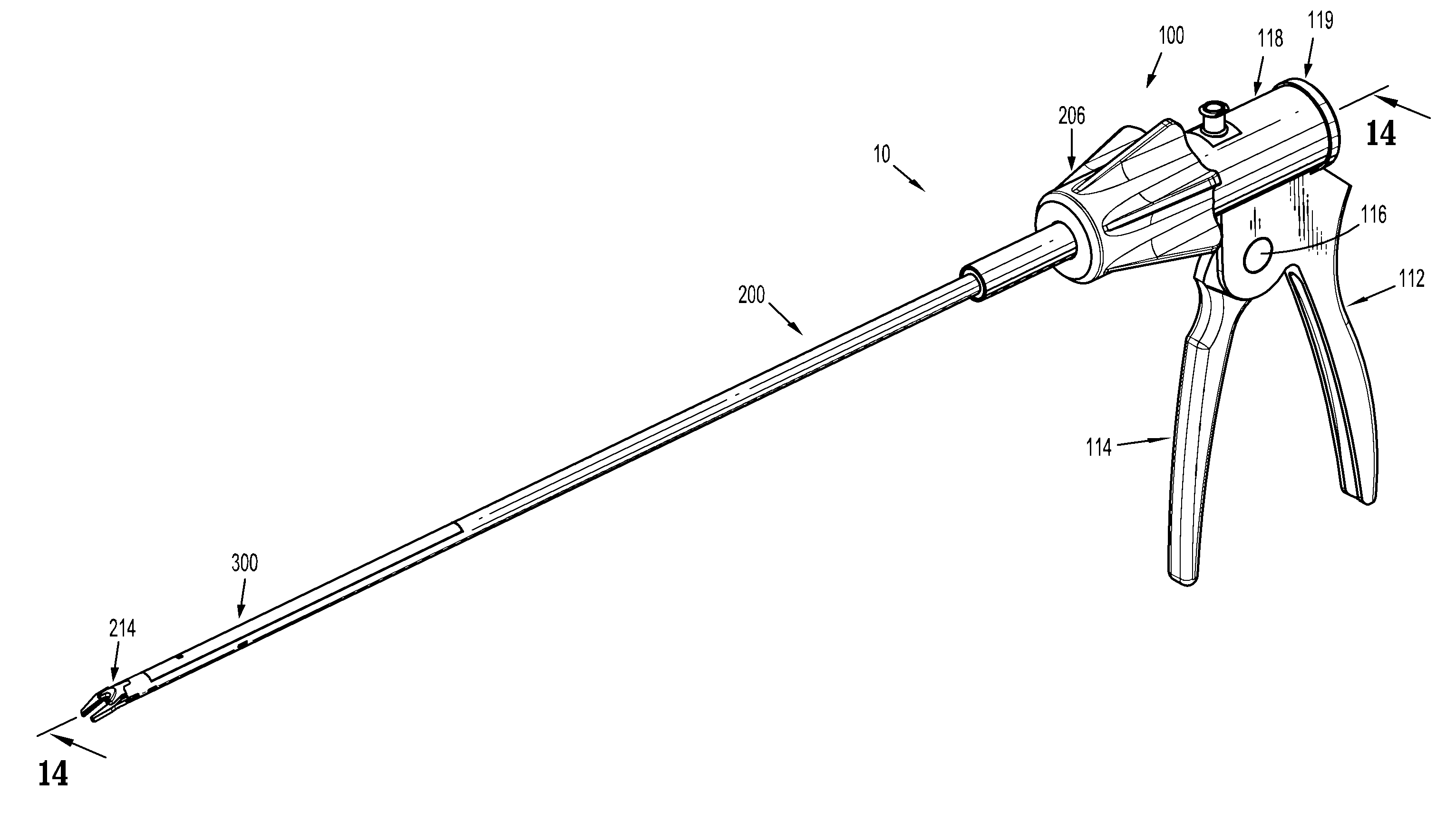
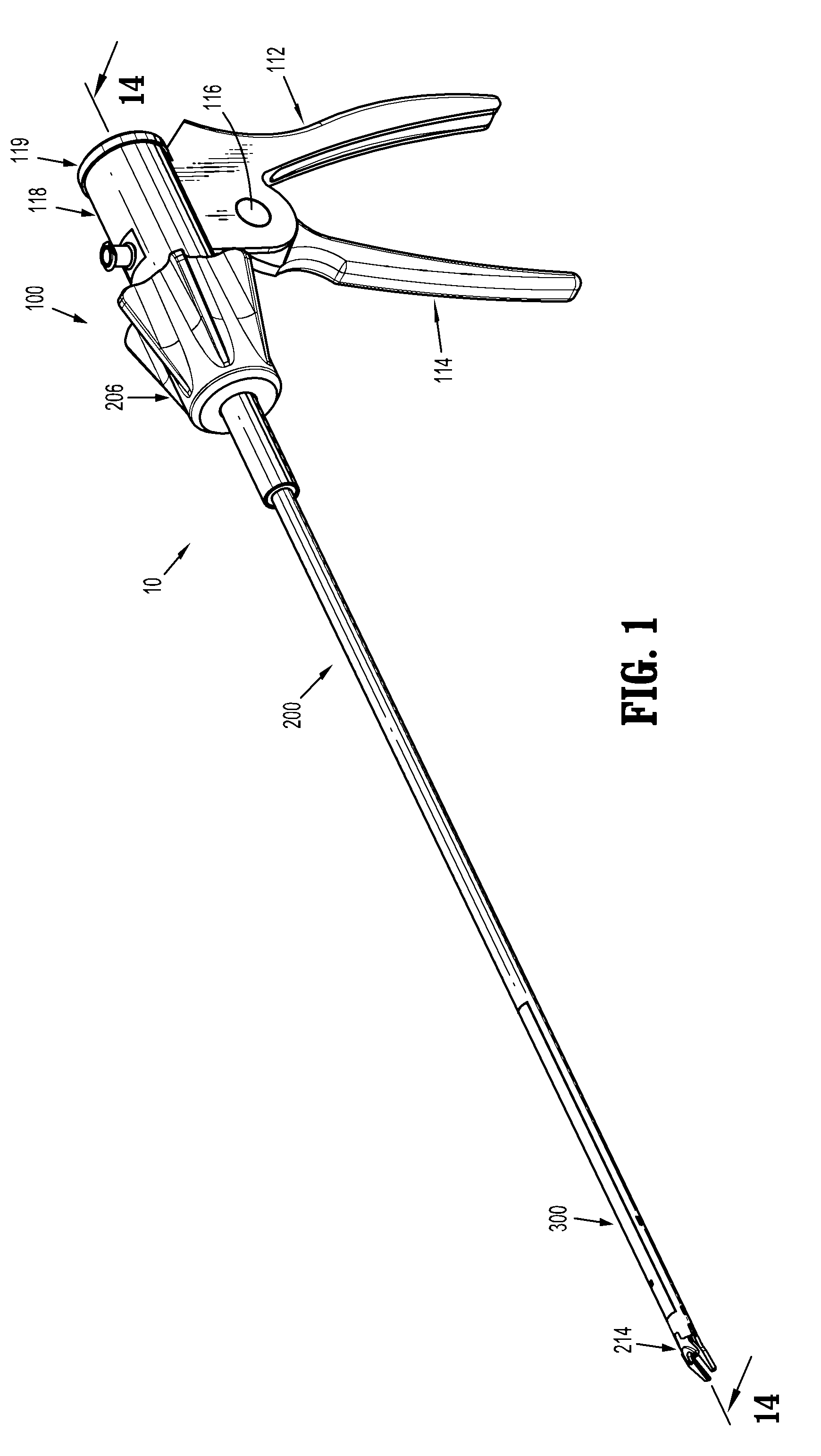
[0043] FIG. 1 is a top, front, perspective view, of a reposable endoscopic surgical clip applier, in accordance with the present disclosure;
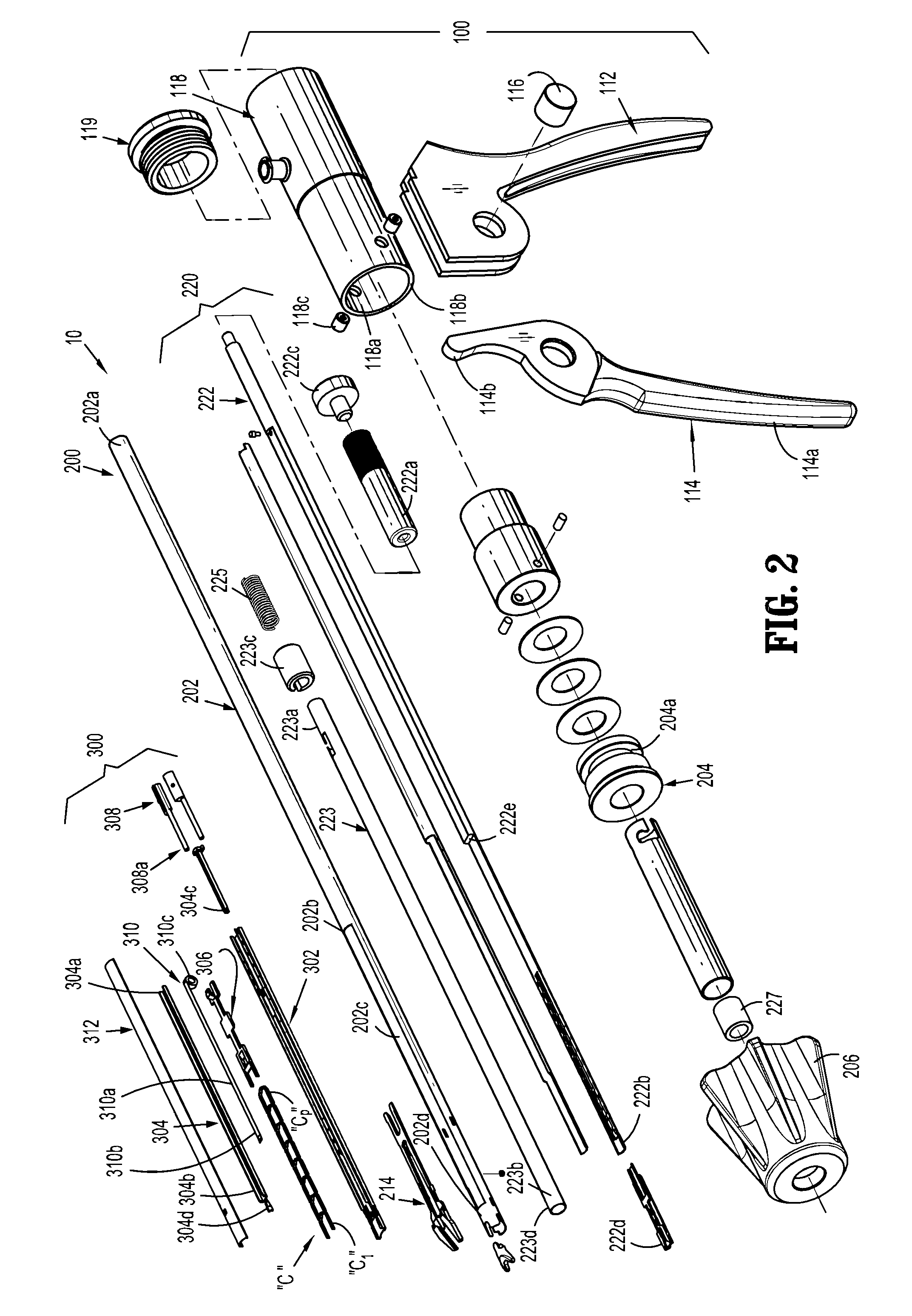
[0044] FIG. 2 is a perspective view, with parts separated, of the reposable endoscopic surgical clip applier of FIG. 1;
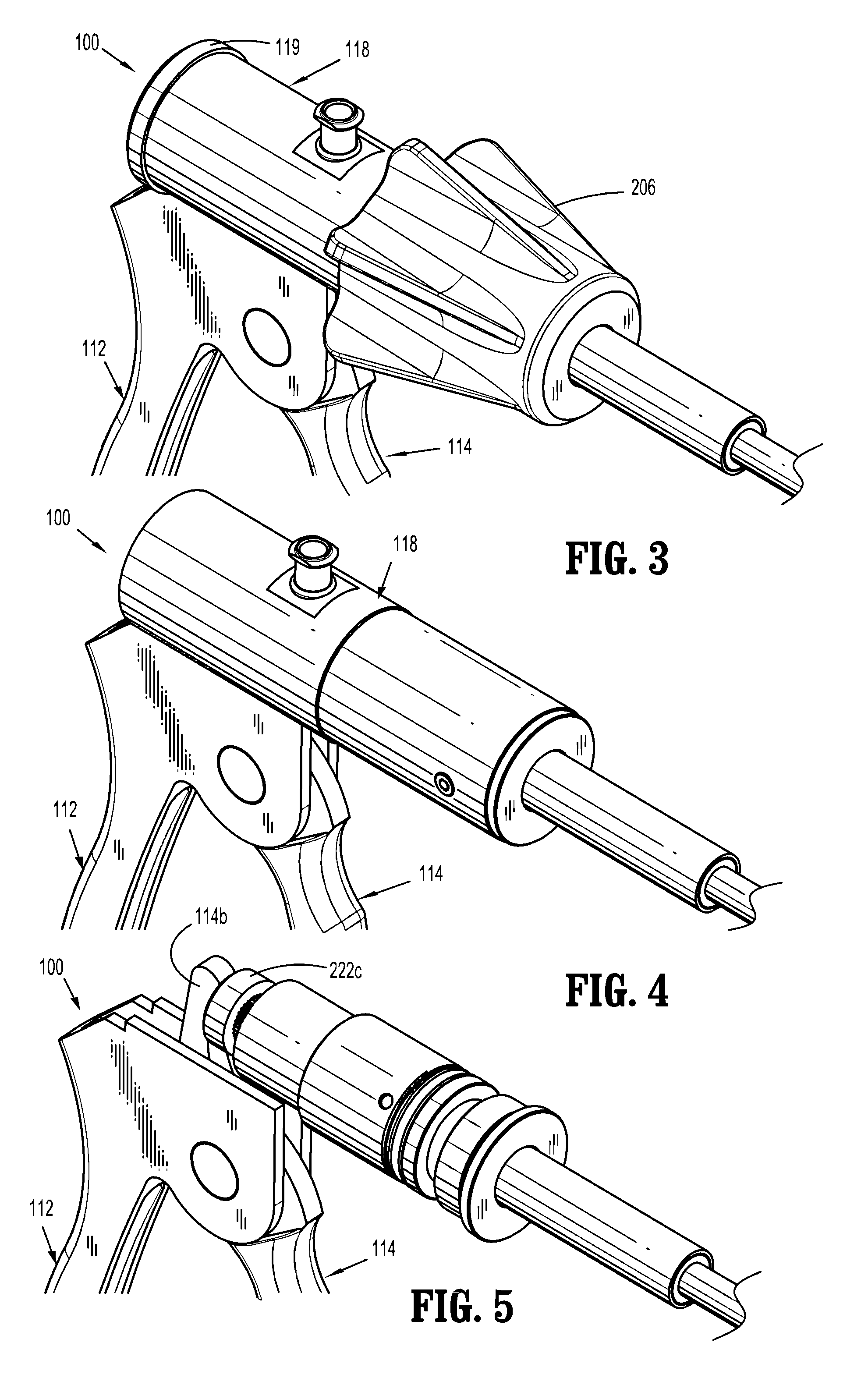
[0045] FIG. 3 is a distal, perspective view of a handle assembly of the reposable endoscopic surgical clip applier of FIGS. 1-2;
[0046] FIG. 4 is a distal, perspective view of the handle assembly of FIGS. 1-3, with a knob removed therefrom;
[0047] FIG. 5 is a distal, perspective view of the handle assembly of FIGS. 1-4, with the knob and a barrel removed therefrom;
[0048] FIG. 6 is a distal, perspective view of the handle assembly of FIGS. 1-5, with the knob, the barrel, and a distal collar removed therefrom;
[0049] FIG. 7 is a distal, perspective view of the handle assembly of FIGS. 1-6, with the knob, the barrel, the distal collar, and a fixed handle removed therefrom;
[0050] FIG. 8 is a distal, perspective view of the handle assembly of FIGS. 1-7, with the knob, the barrel, the distal collar, the fixed handle, and a cuff removed therefrom;
[0051] FIG. 9 is a perspective view of a distal end of an endoscopic shaft assembly with a cartridge assembly loaded therein, in accordance with the present disclosure, of the reposable endoscopic surgical clip applier of the present disclosure;
[0052] FIG. 10 is a perspective view of a distal end of the endoscopic shaft assembly with an outer tube removed therefrom, and with a cover of the cartridge assembly removed therefrom;
[0053] FIG. 11 is a perspective view of a distal end of the endoscopic shaft assembly with the outer tube removed therefrom, and with the cover, a constant force spring, and a stack of surgical clips of the cartridge assembly removed therefrom;
[0054] FIG. 12 is a perspective view of a distal end of the endoscopic shaft assembly with the outer tube removed therefrom, and with the cover, the constant force spring, the stack of surgical clips, and a clip tray of the cartridge assembly removed therefrom;
[0055] FIG. 13 is a perspective view of a distal end of a main closure drive rod of the endoscopic shaft assembly;
[0056] FIG. 14 is a cross-sectional view of the reposable endoscopic surgical clip applier, as taken through 14-14 of FIG. 1;
[0057] FIG. 15 is an enlarged view of the indicated area of detail of FIG. 14;
[0058] FIG. 16 is a cross-sectional view as taken through 16-16 of FIG. 15;
[0059] FIG. 17 is an enlarged view of the indicated area of detail of FIG. 14;
[0060] FIGS. 18A-18C are enlarged views illustrating an operation of a drive mechanism of the endoscopic shaft assembly of FIGS. 1-17;
[0061] FIG. 19 is a schematic, perspective view of an endoscopic shaft assembly according to another embodiment of the present disclosure;
[0062] FIG. 20 is a perspective view, with parts separated, of the endoscopic shaft assembly of FIG. 19;
[0063] FIG. 21 is a cross-sectional view as taken through 21-21 of FIG. 19; and
[0064] FIGS. 22A-22C are enlarged views illustrating an operation of a drive mechanism of the endoscopic shaft assembly of FIGS. 19-21.
DETAILED DESCRIPTION OF EMBODIMENTS
[0065] Embodiments of reposable surgical clip appliers, in accordance with the present disclosure, will now be described in detail with reference to the drawing figures wherein like reference numerals identify similar or identical structural elements. As shown in the drawings and described throughout the following description, as is traditional when referring to relative positioning on a surgical instrument, the term "proximal" refers to the end of the apparatus which is closer to the user and the term "distal" refers to the end of the apparatus which is further away from the user.
[0066] Referring initially to FIGS. 1-2, a surgical clip applier in accordance with an embodiment of the present disclosure is generally designated as 10. Surgical clip applier 10 includes a handle assembly 100, an elongated outer tube or endoscopic assembly 200 projecting from or extending from handle assembly 100, and a clip cartridge assembly 300 that can be removably and selectively mounted on/in a distal end of endoscopic assembly 200. As will be described in greater detail below, a plurality of surgical clips "C" (FIG. 2) is loaded into clip cartridge assembly 300. Also, as will be described in greater detail below, in operation, as handle assembly 100 is actuated, a single surgical clip "C" is fired and formed around a vessel to be ligated.
[0067] Handle assembly 100, as shown in FIGS. 1-8, includes a fixed handle 112 and a squeezable trigger 114 pivotally attached to fixed handle 112 at pivot shaft 116. Squeezable trigger 114 includes a proximal actuating end 114b, which extends proximally beyond pivot shaft 116, and which extends into a bore 118a of a barrel 118 supported on fixed handle 112.
[0068] A barrel 118 is supported on fixed handle 112 and is configured to receive a proximal end of endoscopic assembly 200. Barrel 118 defines a lumen or bore 118a therethrough. A threaded end cap 119 closes a proximal end of barrel 118. As seen in FIG. 2, a nose 118b of barrel 118 includes a pair of diametrically opposed nubs 118c projecting radially inward therefrom, and which are configured and dimensioned to slidably engage an annular outer channel or race 204a of a distal collar 204 of endoscopic assembly 200.
[0069] With reference to FIGS. 2-18C, endoscopic assembly 200 supports and/or includes a main drive assembly or advancing mechanism 220 removably supportable within bore 118b of barrel 118 or removably connectable to barrel 118. Main drive assembly 220 includes a main closure drive rod 222 having a proximal end 222a and a distal end 222b. Proximal end 222a of main closure drive rod 222 supports a flange, piston or drive head 222c thereon. Distal end 222b of main closure drive rod 222 defines a V-shaped cam groove 222d formed therein, which is configured and dimensioned to selectively engage cam wedges 214d of a pair of jaws 214 of endoscopic assembly 200, to thereby effectuate a closure or approximation of the pair of jaws 214.
[0070] Main closure drive rod 222 further defines a distally facing shoulder 222e along a length thereof. Shoulder 222e of main closure drive rod 222 is configured and dimensioned to selectively engage and distally advance a drive sled 308 of clip cartridge assembly 300, to thereby effectuate a loading of a surgical clip "C" into the pair of jaws 214, as will be described in greater detail below.
[0071] Main drive assembly 220 further includes a shaft pusher tube 223 having a proximal end 223a and a distal end 223b. Proximal end 223a of shaft pusher tube 223 supports an annular flange or cuff 223c thereon. Distal end 223b of shaft pusher tube 223 may include a coupling feature formed therein or define a driving distal-most end 223d.
[0072] With reference to FIGS. 2 and 9, endoscopic assembly 200 includes a hollow outer tube 202 having a proximal end 202a and a distal end 202b, and a collar or knob 206 secured to proximal end 202a of outer tube 202. Distal end 202b of outer tube 202 defines a channel or window 202c formed in a side thereof. Outer tube 202 includes a distal shroud 202d extending across window 202c at a distal location of window 202c.
[0073] Handle assembly 100, as well as endoscopic assembly 200, may be made from a biocompatible material, such as, for example, a high grade surgical stainless steel, from titanium, or from a high strength autoclavable polymer, thermoplastic or the like.
[0074] Endoscopic assembly 200 includes, as seen in FIGS. 2 and 9-12, a pair of jaws 214 mounted in window 202c of outer tube 202 and actuatable by an actuation of trigger 114 of handle assembly 100. The pair of jaws 214 is formed of a suitable biocompatible material such as, for example, stainless steel or titanium. The pair of jaws 214 may be removably or fixedly mounted in channel 202c of outer tube 202.
[0075] Referring momentarily to FIGS. 9-12, the pair of jaws 214 defines a channel 214c therebetween for receipt of a surgical clip "C" therein. The pair of jaws 214 include a pair of camming wedge surfaces 214d projecting therefrom. As will be described in detail below, the pair of camming wedge surfaces 214d is acted upon by V-shaped cam groove 222d of distal end 222b of main closure drive rod 222 to actuate the pair of jaws 214 to a closed position.
[0076] With continued reference to FIGS. 2 and 9-12, clip cartridge assembly 300 of surgical clip applier 10 is shown. As mentioned above, clip cartridge assembly 300 is configured and dimensioned for selective loading into window 202c formed in distal end 202b of outer tube 202 of endoscopic assembly 200, and is configured and dimensioned to selectively connect, couple or engage distally facing shoulder 222e of main closure drive rod 222, as will be discussed in greater detail below.
[0077] Clip cartridge assembly 300 includes a clip tray 302 including base wall, and a pair of spaced apart side walls or rails supported on the base wall, with the base wall and the side walls defining a clip channel therein.
[0078] A distal end of the base wall of clip tray 302 may include a resilient central tang (not shown) which is configured and adapted to selectively engage a backspan of a distal-most surgical clip "C.sub.1" of the stack of surgical clips "C" retained within clip tray 302 to thereby retain the stack of surgical clips "C" within clip tray 302 of clip cartridge assembly 300.
[0079] Clip cartridge assembly 300 includes a cartridge clip pusher bar 304 slidably disposed adjacent clip tray 302. Cartridge clip pusher bar 304 includes a proximal end 304a having a coupling stem 304c projecting therefrom and being connect to or being engagable by a drive sled 308 of clip cartridge assembly 300. Cartridge clip pusher bar 304 further includes a distal end portion 304b defining a pusher 304d configured to engage a distal-most clip "C.sub.1" of a stack of clips "C" for loading the distal-most clip "C.sub.1" into the pair of jaws 214 of endoscopic assembly 200. Clip pusher bar 304 may further define an elongate window (not shown) therein for operative receipt of a proximal end of a constant force spring 310 therein, as will be discussed in greater detail below.
[0080] Clip cartridge assembly 300 includes a stack of surgical clips "C" disposed within the channel of clip tray 302 and adjacent cartridge clip pusher bar 304. Clip cartridge assembly 300 may be loaded with eight (8) surgical clips "C" as shown in the exemplary embodiment illustrated, or, in embodiments, clip cartridge assembly 300 may be loaded with any number of surgical clips C", provided clip cartridge assembly 300 and endoscopic assembly 200 are each appropriately configured and dimensioned. Surgical clips "C" may be fabricated from materials know by those skilled in the art, including and not limited to stainless steel, titanium, or other metal alloys. In an embodiment it, is contemplated that at least a final surgical clip of the stack of surgical clips "C" may be dyed a particular color to indicate to the user when a final surgical clip of clip cartridge assembly 300 is loaded into the pair of jaws 214.
[0081] Clip cartridge assembly 300 further includes a clip follower 306 at least partially slidably disposed within the clip channel of clip tray 302. As will be described in greater detail below, clip follower 306 is positioned proximally of the stack of surgical clips "C" and is provided to help urge the stack of surgical clips "C" forward during an actuation of surgical clip applier 10. Additionally, as will also be described in greater detail below, clip follower 306 is actuated by a constant force spring 310 upon the advancement, by clip pusher bar 304, of the distal-most surgical clip "C.sub.1" into the pair of jaws 214, during a firing of surgical clip applier 10.
[0082] Clip follower 306 includes an elongate body having a distal end portion configured and dimensioned for passage through the clip channel of clip tray 302. The distal end portion of clip follower 306 is configured to seat against a backspan of a proximal-most clip "C.sub.p" of the stack of surgical clips "C".
[0083] Clip follower 306 includes a proximal fin 306d projecting transversely from a proximal end portion 306c thereof. Proximal fin 306d of clip follower 306 defines a proximal surface having a concave arcuate profile configured to receive and seat with a coiled or spooled portion 310c of a constant force spring 310.
[0084] Clip cartridge assembly 300 includes a drive sled 308 slidably disposed within the clip channel of clip tray 302. Drive sled 308 is configured to selectively engage or be selectively engaged by distally facing shoulder 222e of main closure drive rod 222 of endoscopic assembly 200. Drive sled 308 includes a cartridge pusher rod 308a extending distally therefrom. A distal end of cartridge pusher rod 308a of drive sled 308 is operatively connected to coupling stem 304c of cartridge clip pusher bar 304.
[0085] Clip cartridge assembly 300 includes a cartridge cover 312 configured for connection to and supported on clip tray 302. Cartridge cover 312 may include a substantially distally extending hook or tine (not shown) which projects from an inner surface thereof. The hook of cartridge cover 312 is configured to receive and retain a distal end 310b of constant force spring 310. Cartridge cover 312 may be fabricated from a transparent material, allowing the user to clearly see the stack of surgical clips "C".
[0086] With particular reference to FIGS. 2 and 10, clip cartridge assembly 300 includes, as mentioned above, a constant force spring 310 supported in the clip channel of clip tray 302. Constant force spring 310 is in the form of a ribbon including a body portion 310a having a distal end 310b, and a proximal end 310c coiled onto itself to form a spool.
[0087] Body portion 310a and distal end 310b of constant force spring 310 are disposed within clip channel 302c of clip tray 302 such that body portion 310a and distal end 310b of constant force spring 310 are interposed between cartridge cover 312 and clip pusher bar 304. Distal end 310b of constant force spring 310 is secured to the tine (not shown) of clip cartridge cover 312, as mentioned above. It is contemplated that distal end 310b of constant force spring 310 may define an opening therein that is slipped over the distally extending tine of clip cartridge cover 312. In this manner, the tine of clip cartridge cover 312 prevents distal end 310b of constant force spring 310 from moving proximally.
[0088] Proximal coiled or spooled end 310c of constant force spring 310 is disposed proximally of proximal fin 306d of clip follower 306. Due to a memory of constant force spring 310, proximal coiled or spooled end 310c thereof tends to want to roll-up onto itself along body portion 310a.
[0089] Constant force spring 310 is a pre-stressed flat strip of spring material which is formed into a virtually constant radius coil, wherein distal end 310b of constant force spring 310 is secured to the tine of clip cartridge cover 312, as described above, and wherein proximal coiled or spooled end 310c of constant force spring 310 is disposed proximally of proximal fin 306d of clip follower 306, as described above.
[0090] Constant force spring 310 functions to maintain a constant pressure or distal force on clip follower 306, and in turn on the stack of surgical clips "C" such that the stack of surgical clips "C" are pressed against the resilient central tang (not shown) of clip tray 302. In this manner, in operation, as will be described in greater detail below, the stack of surgical clips "C" advances distally, on demand, as clip pusher bar 304 distally advances the distal-most surgical clip "C.sub.1" any amount, and in particular, past the resilient central tang of clip tray 302.
[0091] With continued reference to FIGS. 1-18C, an exemplary mode of operation of clip applier 10 is shown and described. As shown in FIGS. 1 and 14-17, clip applier 10 is illustrated with clip cartridge assembly 300 connected to distal end of endoscopic assembly 200 such that drive sled 308 of clip cartridge assembly 300 is in operative engagement with distally facing shoulder 222e of main closure drive rod 222 of endoscopic assembly 200 (as described above).
[0092] With reference to FIGS. 14, 15, 18A and 18B, when trigger 114 is squeezed or pivoted about pivot shaft 116, actuating end 114b of trigger 114 engages the proximal end of main closure drive rod 222 of endoscopic assembly 200 thereby urging main closure drive rod 222 distally.
[0093] As main closure drive rod 222 of endoscopic assembly 200 is distally advanced, due to an actuation of trigger 114, enlarged proximal end 222a of main closure drive rod 222 acts on a biasing member 225 (e.g., a compression spring) which in turn acts on cuff 223c of shaft pusher tube 223 to distally advance shaft pusher tube 223. As shaft pusher tube 223 is advanced distally, a distal end 223d of shaft pusher tube 223 acts on coupling stem 304c of cartridge clip pusher bar 304 to distally advance cartridge clip pusher bar 304. Shaft pusher tube 223 is advanced distally until cuff 223c of shaft pusher tube 223 abuts a stopper 227 (see FIGS. 2, 15 and 17) of endoscopic assembly 200. At this point, shaft pusher tube 223 comes to a stop and rests.
[0094] When trigger 114 of handle assembly 100 is squeezed this initial amount, clip pusher bar 304 will have advanced an amount sufficient to distally advance a distal-most surgical clip "C.sub.1" past the resilient central tang of clip tray 302 and load the distal-most surgical clip "C.sub.1" into the pair of jaws 214. Specifically, pusher 304d of cartridge clip pusher bar 304 is moved in a distal direction such that pusher 304d engages the backspan of distal-most clip "C.sub.1" and pushes distal-most clip "C.sub.1" distally, out of clip tray 302 and into the pair of jaws 214.
[0095] As clip pusher bar 304 is advanced distally, and distal-most surgical clip "C.sub.1" is being advanced and loaded into the pair of jaws 214, constant force spring 310 is actuated such that spooled end 310c of constant force spring 310 presses on proximal fin 306d of clip follower 306 to distally advance the stack of surgical clips "C" until the next distal-most clip engages and is stopped by the resilient central tang of clip tray 302.
[0096] Clip pusher bar 304 will remain in a distally advanced position during the entire squeeze of trigger 114. Following a squeeze of trigger 114, as trigger 114 is released or returned to a full non-squeezed position, clip pusher bar 304 is returned to a home or proximal-most position by a biasing member or the like (not shown). When clip pusher bar 304 is returned to the home position, pusher 304d of clip pusher bar 304 is moved to a position proximal of the new distal-most surgical clip "C.sub.1".
[0097] Additionally, with reference to FIGS. 18B and 18C, as main closure drive rod 222 of endoscopic assembly 200 is distally advanced, due to a further actuation of trigger 114 beyond the initial amount, after cuff 223c of shaft pusher tube 223 abuts stopper 227, actuating end 114b of trigger 114 continues to distally advance main closure drive rod 222 and compress biasing member 225 between enlarged proximal end 222a of main closure drive rod 222 and cuff 223c of shaft pusher tube 223. As main closure drive rod 222 is continued to be advanced distally, following a dwell period, V-shaped cam groove 222d of main closure drive rod 222 is advanced distally into engagement with cam wedges 214d of the pair of jaws 214 of endoscopic assembly 200, to thereby effectuate a closure or approximation of the pair of jaws 214 and a formation of the distal-most clip "C1" loaded therewith.
[0098] Following formation of the distal-most clip "C1", trigger 114 may be released, whereby main closure drive rod 222 is moved in a proximal direction until main drive rod 122 is returned to a proximal-most position thereof. When main drive rod 122 is returned to the proximal-most position thereof, V-shaped cam groove 222d of main closure drive rod 222 is proximally withdrawn from cam wedges 214d of the pair of jaws 214 of endoscopic assembly 200 to permit the pair of jaws 214 to open as a result of their own resilient bias.
[0099] Also, when main drive rod 122 is returned to the proximal-most position thereof, biasing member 225 is permitted to expand and shaft pusher tube 223 is permitted to return to a proximal-most position thereof. As shaft pusher tube 223 returns to the proximal-most position thereof, clip pusher bar 304 is also returned to a proximal-most position thereof, as described above.
[0100] The operations described above can be repeated, as required, until all of the surgical clips "C" have been fired and formed.
[0101] Turning now to FIGS. 19-22C, an endoscopic assembly according to an alternate embodiment of the disclosure is generally designated as 400. Endoscopic assembly 400 includes a hollow outer tube 402 having a proximal end 402a and a distal end 402b defining a channel or window 402c formed in a side thereof. Hollow outer tube 402 includes a shoulder 402d extending radially into window 402c.
[0102] Main drive assembly 420 includes a main closure drive rod 422 having a proximal end 422a and a distal end 422b. Main closure drive rod 422 defines a channel 422c therein. Channel 422c of main closure drive rod 422 includes a proximal bore or recess 422d having a distal surface or shoulder 422e near a proximal end thereof, and a proximal face 422f.
[0103] Main drive assembly 420 further includes a shaft pusher rod 423 slidably disposed within channel 422c of main closure drive rod 422. Shaft pusher rod 423 includes a proximal end or stem 423a and a distal end or stem 423b, wherein a shoulder defining a proximally facing surface 423c is defined between proximal stem 423a and distal stem 423b. Proximal stem 423a of shaft pusher rod 423 extends into proximal bore 422d of channel 422c of main closure drive rod 422. Distal stem 423b of shaft pusher rod 423 extends distally of shoulder 402d of hollow outer tube 402.
[0104] Main drive assembly 420 also includes a biasing member 425 (e.g., a compression spring) supported on proximal stem 423a of shaft pusher rod 423 and interposed between distal surface or shoulder 422e of main closure drive rod 422 and proximally facing surface 423c of shaft pusher rod 423.
[0105] With continued reference to FIGS. 19-22C, an exemplary mode of operation of clip applier 10, including endoscopic assembly 400, is shown and described. In operation, when trigger 114 is squeezed or pivoted about pivot shaft 116, actuating end 114b of trigger 114 engages the proximal end of main closure drive rod 422 of endoscopic assembly 400 thereby urging main closure drive rod 422 distally.
[0106] As main closure drive rod 422 of endoscopic assembly 400 is distally advanced, due to an actuation of trigger 114, shoulder 422e of main closure drive rod 422 acts on biasing member 425, which in turn acts on proximally facing surface 423c of shaft pusher rod 423 to distally advance shaft pusher rod 423. As shaft pusher rod 423 is advanced distally, a distal end of distal stem 423b of shaft pusher rod 423 acts on a coupling stem or feature (e.g., coupling stem 304c) of cartridge clip pusher bar 304 to distally advance cartridge clip pusher bar 304. Shaft pusher rod 423 is advanced distally until shoulder 423c thereof abuts shoulder 402d of hollow outer tube 402, and comes to a stop and rests.
[0107] When trigger 114 of handle assembly 100 is squeezed this initial amount clip pusher bar 304 will have advanced an amount sufficient to distally advance a distal-most surgical clip "C.sub.1" past the resilient central tang of clip tray 302 and load the distal-most surgical clip "C.sub.1" into the pair of jaws 214. Specifically, pusher 304d of cartridge clip pusher bar 304 is moved in a distal direction such that pusher 304d engages the backspan of distal-most clip "C.sub.1" and pushes distal-most clip "C.sub.1" distally, out of clip tray 302 and into the pair of jaws 214.
[0108] As clip pusher bar 304 is advanced distally, and distal-most surgical clip "C.sub.1" is being advanced and loaded into the pair of jaws 214, constant force spring 310 is actuated such that spooled end 310c of constant force spring 310 presses on proximal fin 306d of clip follower 306 to distally advance the stack of surgical clips "C" until the next distal-most clip engages and is stopped by the resilient central tang of clip tray 302.
[0109] Clip pusher bar 304 will remain in a distally advanced position during the entire squeeze of trigger 114. Following a full squeeze of trigger 114, as trigger 114 is released or returned to a full non-squeezed position, clip pusher bar 304 is returned to a home or proximal-most position by a biasing member or the like (not shown). When clip pusher bar 304 is returned to the home position, pusher 304d of clip pusher bar 304 is moved to a position proximal of the new distal-most surgical clip "C.sub.1".
[0110] Additionally, with reference to FIGS. 22B and 22C, as main closure drive rod 422 of endoscopic assembly 400 is distally advanced, due to a further actuation of trigger 114 beyond the initial squeeze, after shoulder 423c of shaft pusher rod 423 abuts shoulder 402d of hollow outer tube 402, actuating end 114b of trigger 114 continues to distally advance main closure drive rod 422 and compress biasing member 425 between shoulder 423c of shaft pusher rod 423 and shoulder 422e of main closure drive rod 422. As main closure drive rod 422 is continued to be advanced distally, following a dwell period, a distal end of main closure drive rod 422 is advanced distally effectuate an engagement with cam wedges 214d of the pair of jaws 214 of endoscopic assembly 400, to thereby effectuate a closure or approximation of the pair of jaws 214 and a formation of the distal-most clip "C.sub.1" loaded therewith.
[0111] It should be understood that the foregoing description is only illustrative of the present disclosure. Various alternatives and modifications can be devised by those skilled in the art without departing from the disclosure. Accordingly, the present disclosure is intended to embrace all such alternatives, modifications and variances. The embodiments described with reference to the attached drawing figures are presented only to demonstrate certain examples of the disclosure. Other elements, steps, methods and techniques that are insubstantially different from those described above and/or in the appended claims are also intended to be within the scope of the disclosure.
* * * * *
D00000
D00001
D00002
D00003
D00004
D00005
D00006
D00007
D00008
D00009
D00010
XML
uspto.report is an independent third-party trademark research tool that is not affiliated, endorsed, or sponsored by the United States Patent and Trademark Office (USPTO) or any other governmental organization. The information provided by uspto.report is based on publicly available data at the time of writing and is intended for informational purposes only.
While we strive to provide accurate and up-to-date information, we do not guarantee the accuracy, completeness, reliability, or suitability of the information displayed on this site. The use of this site is at your own risk. Any reliance you place on such information is therefore strictly at your own risk.
All official trademark data, including owner information, should be verified by visiting the official USPTO website at www.uspto.gov. This site is not intended to replace professional legal advice and should not be used as a substitute for consulting with a legal professional who is knowledgeable about trademark law.