Clip Counting Mechanism For Surgical Clip Applier
Baril; Jacob C. ; et al.
U.S. patent application number 16/042084 was filed with the patent office on 2019-03-14 for clip counting mechanism for surgical clip applier. The applicant listed for this patent is Covidien LP. Invention is credited to Jacob C. Baril, Matthew A. Dinino.
| Application Number | 20190076148 16/042084 |
| Document ID | / |
| Family ID | 65630144 |
| Filed Date | 2019-03-14 |


| United States Patent Application | 20190076148 |
| Kind Code | A1 |
| Baril; Jacob C. ; et al. | March 14, 2019 |
CLIP COUNTING MECHANISM FOR SURGICAL CLIP APPLIER
Abstract
A clip counting mechanism for use with a surgical clip applier includes a display gear rotatably supported within a handle housing of the surgical clip applier and including an outer surface having a plurality of numbers disposed thereon, a biasing element in mechanical communication with the display gear and rotatably biasing the display gear, a counter switch reciprocally disposed within the handle housing and defining a cam slot therethrough, and an escapement gear rotatably supported within the handle housing and defining a proximal end portion in mechanical communication with the display gear and a distal end portion in mechanical communication with the cam slot. Translation of the counter switch causes the cam slot to cam the escapement gear and selectively disengage and then re-engage the display gear to enable the display gear to rotate a predetermined angle of rotation.
| Inventors: | Baril; Jacob C.; (White Plains, NY) ; Dinino; Matthew A.; (Newington, CT) | ||||||||||
| Applicant: |
|
||||||||||
|---|---|---|---|---|---|---|---|---|---|---|---|
| Family ID: | 65630144 | ||||||||||
| Appl. No.: | 16/042084 | ||||||||||
| Filed: | July 23, 2018 |
Related U.S. Patent Documents
| Application Number | Filing Date | Patent Number | ||
|---|---|---|---|---|
| 62557778 | Sep 13, 2017 | |||
| Current U.S. Class: | 1/1 |
| Current CPC Class: | A61B 17/1285 20130101; A61B 2090/0803 20160201; A61B 2017/00407 20130101 |
| International Class: | A61B 17/128 20060101 A61B017/128 |
Claims
1. A clip counting mechanism for use with a surgical clip applier, comprising: a display gear rotatably supported within a handle housing of a surgical clip applier and including an outer surface, the outer surface includes a plurality of numbers disposed thereon; a biasing element in mechanical communication with the display gear, the biasing element rotatably biasing the display gear; a counter switch reciprocally disposed within the handle housing and defining a proximal end portion and a distal end portion and opposed side surfaces extending therebetween, the opposed side surfaces defining a cam slot therethrough; and an escapement gear rotatably supported within the handle housing and defining a proximal end portion and a distal end portion, wherein the distal end portion is in mechanical communication with the cam slot of the counter switch and the proximal end portion is in mechanical communication with the display gear, wherein translation of the counter switch causes the cam slot to cam the escapement gear and selectively disengage the display gear and permit the display gear to rotate and selectively re-engage the display gear to inhibit rotation of the display gear, thereby enabling the display gear to rotate a predetermined angle of rotation.
2. The clip counting mechanism according to claim 1, wherein the outer surface of the display gear defines a plurality ratchet teeth thereon.
3. The clip counting mechanism according to claim 2, wherein the escapement gear defines a pair of arms disposed in juxtaposed relation, each arm of the pair of arms defining respective first and second teeth.
4. The clip counting mechanism according to claim 3, wherein the first and second teeth are configured to selectively engage a respective tooth of the plurality of ratchet teeth.
5. The clip counting mechanism according to claim 2, wherein the plurality of ratchet teeth includes 15 teeth such that the pre-determined angle of rotation of the display gear is 24 degrees.
6. The clip counting mechanism according to claim 5, wherein translation of the counter switch in a first direction causes the display gear to rotate 12 degrees in a first direction.
7. The clip counting mechanism according to claim 6, wherein translation of the counter switch in a second direction causes the display gear to rotate a further 12 degrees in the first direction.
8. The clip counting mechanism according to claim 7, wherein each 24 degree rotation of the display gear in the first direction causes a different number of the plurality of numbers to be displayed to a clinician, the number displayed to the clinician being a number of surgical clips remaining within the surgical clip applier.
9. The clip counting mechanism according to claim 1, further including a gear pin fixedly secured to the escapement gear, the gear pin configured to be slidably received within the cam slot of the counter switch such that translation of the counter switch cams the gear pin within the cam slot, thereby causing the escapement gear to rotate.
10. The clip counting mechanism according to claim 1, wherein the biasing element is a constant-force spring.
11. An endoscopic surgical clip applier, comprising: an endoscopic assembly; and a handle assembly, including: a housing selectively connectable to the endoscopic assembly; a trigger pivotally connected to the housing; a drive bar translatably disposed within the housing of the handle assembly and operably coupled to the trigger; and a clip counting mechanism, including: a display gear rotatably supported within a handle housing of a surgical clip applier and including an outer surface, the outer surface includes a plurality of numbers disposed thereon; a biasing element in mechanical communication with the display gear, the biasing element rotatably biasing the display gear; a counter switch reciprocally disposed within the handle housing and defining a proximal end portion and a distal end portion and opposed side surfaces extending therebetween, the opposed side surfaces defining a cam slot therethrough, the counter switch operably coupled to the drive bar; and an escapement gear rotatably supported within the handle housing and defining a proximal end portion and a distal end portion, wherein the distal end portion is in mechanical communication with the cam slot of the counter switch and the proximal end portion is in mechanical communication with the display gear, wherein translation of the drive bar causes a corresponding translation of the counter switch, wherein translation of the counter switch causes the cam slot to cam the escapement gear and selectively disengage the display gear and permit the display gear to rotate and selectively re-engage the display gear to inhibit rotation of the display gear, thereby enabling the display gear to rotate a predetermined angle of rotation.
12. The endoscopic surgical clip applier according to claim 11, wherein the outer surface of the display gear defines a plurality of ratchet teeth thereon.
13. The endoscopic surgical clip applier according to claim 12, wherein the escapement gear defines a pair of arms disposed in juxtaposed relation, each arm of the pair of arms defining respective first and second teeth.
14. The endoscopic surgical clip applier according to claim 13, wherein the first and second teeth are configured to selectively engage a respective tooth of the plurality of ratchet teeth.
15. The endoscopic surgical clip applier according to claim 12, wherein the plurality of ratchet teeth includes 15 teeth such that the pre-determined angle of rotation of the display gear is 24 degrees.
16. The endoscopic surgical clip applier according to claim 15, wherein translation of the counter switch in a first direction causes the display gear to rotate 12 degrees in a first direction.
17. The endoscopic surgical clip applier according to claim 16, wherein translation of the counter switch in a second direction causes the display gear to rotate a further 12 degrees in the first direction.
18. The endoscopic surgical clip applier according to claim 17, wherein each 24 degree rotation of the display gear in the first direction causes a different number of the plurality of numbers to be displayed to a clinician, the number displayed to the clinician being a number of surgical clips remaining within the endoscopic surgical clip applier.
19. The endoscopic surgical clip applier according to claim 1, further including a gear pin fixedly secured to the escapement gear, the gear pin configured to be slidably received within the cam slot of the counter switch such that translation of the counter switch cams the gear pin within the cam slot, thereby causing the escapement gear to rotate.
20. The endoscopic surgical clip applier according to claim 1, wherein the biasing element is a constant-force spring.
Description
CROSS-REFERENCE TO RELATED APPLICATIONS
[0001] This application claims the benefit of and priority to U.S. Provisional Patent Application No. 62/557,778 filed Sep. 13, 2017, the entire disclosure of which is incorporated by reference herein.
BACKGROUND
Technical Field
[0002] The present disclosure relates generally to surgical clip appliers. More particularly, the present disclosure relates to endoscopic surgical clip appliers having a mechanism for indicating the number of remaining clips.
Description of Related Art
[0003] Endoscopic surgical staplers and surgical clip appliers are used for a number of minimally invasive or endoscopic surgical procedures. Typically in a minimally invasive surgical procedure, a tube or cannula device is extended into the patient's body through an entrance incision to provide an access port. The port allows the surgeon to insert a number of different surgical instruments therethrough for performing surgical procedures far removed from the incision.
[0004] During a majority of these procedures, the surgeon will need to terminate the flow of blood or other fluids through one or more vessels within or near the surgical site. To terminate the flow of blood or fluid through these vessels, a surgical clip applier is often used to ligate the necessary vessels. As can be appreciated, these surgical clip appliers are only able to store a finite number of surgical clips therein. Therefore, surgeons are often unable to ascertain how many surgical clips remain within a clip cartridge of the surgical clip applier during a surgical procedure.
[0005] Accordingly, a need exists for surgical clip appliers that provide a clinician with a convenient way to determine the number of surgical clips remaining within a surgical clip applier.
SUMMARY
[0006] The present disclosure relates to surgical clip appliers having a mechanism for indicating the number of remaining clips.
[0007] According to an aspect of the present disclosure, a clip counting mechanism for use with a surgical clip applier includes a display gear, a biasing element, a counter switch, and an escapement gear. The display gear is rotatably supported within a handle housing of the surgical clip applier and includes an outer surface having a plurality of numbers disposed therein. The biasing element is in mechanical communication with the display gear and rotatably biases the display gear. The counter switch is reciprocally disposed within the handle housing and defines proximal and distal end portions and opposed side surfaces extending therebetween. The opposed side surfaces define a cam slot therethrough. The escapement gear is rotatably supported within the handle housing and defines a proximal end portion and a distal end portion. The distal end portion is in mechanical communication with the cam slot of the counter switch and the proximal end portion is in mechanical communication with the display gear. Translation of the counter switch causes the cam slot to cam the escapement gear and selectively disengage the display gear and permit the display gear to rotate and selectively re-engage the display gear to inhibit rotation of the display gear, thereby enabling the display gear to rotate a predetermined angle of rotation.
[0008] In aspects, the outer surface of the display gear may define a plurality of ratchet teeth thereon.
[0009] In other aspects, the escapement gear may define a pair of arms disposed in juxtaposed relation wherein each arm of the pair of arms defines respective first and second teeth. In certain aspects, the first and second teeth may be configured to selectively engage a respective tooth of the plurality of ratchet teeth.
[0010] In aspects, the plurality of ratchet teeth may include 15 teeth such that the pre-determined angle of rotation of the display gear is 24 degrees. In certain aspects, translation of the counter switch in a first direction may cause the display gear to rotate 12 degrees in a first direction. In other aspects, translation of the counter switch in a second direction may cause the display gear to rotate a further 12 degrees in the first direction.
[0011] In certain aspects, each 24 degree rotation of the display gear in the first direction may cause a different number of the plurality of numbers to be displayed to a clinician, where the number displayed to the clinician is a number of surgical clips remaining in the surgical clip applier.
[0012] In some aspects, the clip counting mechanism may include a gear pin fixedly secured to the escapement gear and configured to be slidably received within the cam slot of the counter switch such that translation of the counter switch cams the gear pin within the cam slot and causes the escapement gear to rotate.
[0013] In aspects, the biasing element may be a constant-force spring.
[0014] According to another aspect of the present disclosure, an endoscopic surgical clip applier includes an endoscopic assembly and a handle assembly. The handle assembly includes a housing selectively connectable to the endoscopic assembly, a trigger pivotally connected to the housing, a drive bar translatably disposed within the housing of the handle assembly and operably coupled to the trigger, and a clip counting mechanism. The clip counting mechanism includes a display gear, a biasing element, a counter switch, and an escapement gear. The display gear is rotatably supported within a handle housing of the surgical clip applier and includes an outer surface having a plurality of numbers disposed therein. The biasing element is in mechanical communication with the display gear and rotatably biases the display gear. The counter switch is reciprocally disposed within the handle housing and defines proximal and distal end portions and opposed side surfaces extending therebetween. The opposed side surfaces define a cam slot therethrough. The escapement gear is rotatably supported within the handle housing and defines a proximal end portion and a distal end portion. The distal end portion is in mechanical communication with the cam slot of the counter switch and the proximal end portion is in mechanical communication with the display gear. Translation of the counter switch causes the cam slot to cam the escapement gear and selectively disengage the display gear and permit the display gear to rotate and selectively re-engage the display gear to inhibit rotation of the display gear, thereby enabling the display gear to rotate a predetermined angle of rotation.
[0015] In aspects, the outer surface of the display gear may define a plurality of ratchet teeth thereon.
[0016] In other aspects, the escapement gear may define a pair of arms disposed in juxtaposed relation wherein each arm of the pair of arms defines respective first and second teeth. In certain aspects, the first and second teeth may be configured to selectively engage a respective tooth of the plurality of ratchet teeth.
[0017] In aspects, the plurality of ratchet teeth may include 15 teeth such that the pre-determined angle of rotation of the display gear is 24 degrees. In certain aspects, translation of the counter switch in a first direction may cause the display gear to rotate 12 degrees in a first direction. In other aspects, translation of the counter switch in a second direction may cause the display gear to rotate a further 12 degrees in the first direction.
[0018] In certain aspects, each 24 degree rotation of the display gear in the first direction may cause a different number of the plurality of numbers to be displayed to a clinician, where the number displayed to the clinician is a number of surgical clips remaining in the surgical clip applier.
[0019] In some aspects, the clip counting mechanism may include a gear pin fixedly secured to the escapement gear and configured to be slidably received within the cam slot of the counter switch such that translation of the counter switch cams the gear pin within the cam slot and causes the escapement gear to rotate.
[0020] In aspects, the biasing element may be a constant-force spring.
BRIEF DESCRIPTION OF THE DRAWINGS
[0021] Particular embodiments of surgical clip appliers are described herein with reference to the drawings wherein:
[0022] FIG. 1 is a perspective view of an endoscopic surgical clip applier, according to the present disclosure including an endoscopic assembly and a handle assembly;
[0023] FIG. 2 is a perspective view, with parts separated, of the handle assembly of FIG. 1;
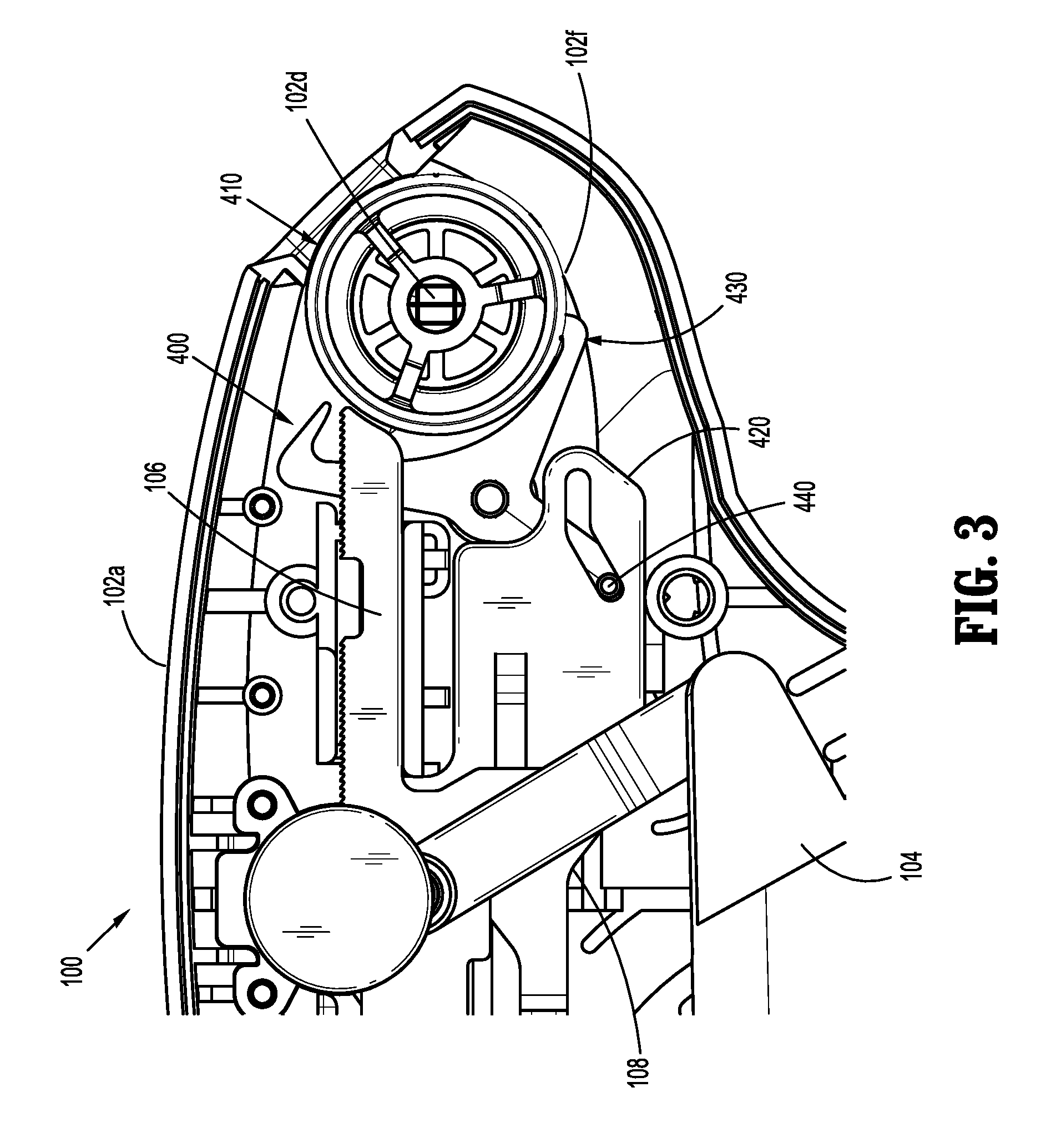
[0024] FIG. 3 is a side, cross-sectional view, of the handle assembly of FIG. 1, illustrating a clip counting mechanism in accordance with the present disclosure;
[0025] FIG. 4 is a perspective view of a counter switch of the clip counting mechanism of FIG. 3;
[0026] FIG. 5 is a side view of an escapement gear of the clip counting mechanism of FIG. 3;
[0027] FIG. 6A is a perspective view of a display gear of the clip counting mechanism of FIG. 3;
[0028] FIG. 6B is a side view of the display gear of FIG. 6A;
[0029] FIG. 7A is a side, cross-sectional view, of the handle assembly of FIG. 1, illustrating the clip counting mechanism of FIG. 3 in an initial, resting, position, prior to an actuation of a trigger;
[0030] FIG. 7B is a side, cross-sectional view, of the handle assembly of FIG. 1, illustrating the clip counting mechanism of FIG. 3 in an intermediate, advanced position, during actuation of the trigger;
[0031] FIG. 7C is a side, cross-sectional view, of the handle assembly of FIG. 1, illustrating the clip counting mechanism of FIG. 3 in an advanced position, following complete actuation of the trigger;
[0032] FIG. 8A is a side, cross-sectional view, of the handle assembly of FIG. 1, illustrating the clip counting mechanism of FIG. 3 in the advanced position, prior to a release of the trigger;
[0033] FIG. 8B is a side, cross-sectional view, of the handle assembly of FIG. 1, illustrating the clip counting mechanism of FIG. 3 in an intermediate, retracted position, during release of the trigger;
[0034] FIG. 8C is a side, cross-sectional view, of the handle housing of FIG. 1, illustrating the clip counting mechanism of FIG. 3 in a retracted position, following complete release of the trigger;
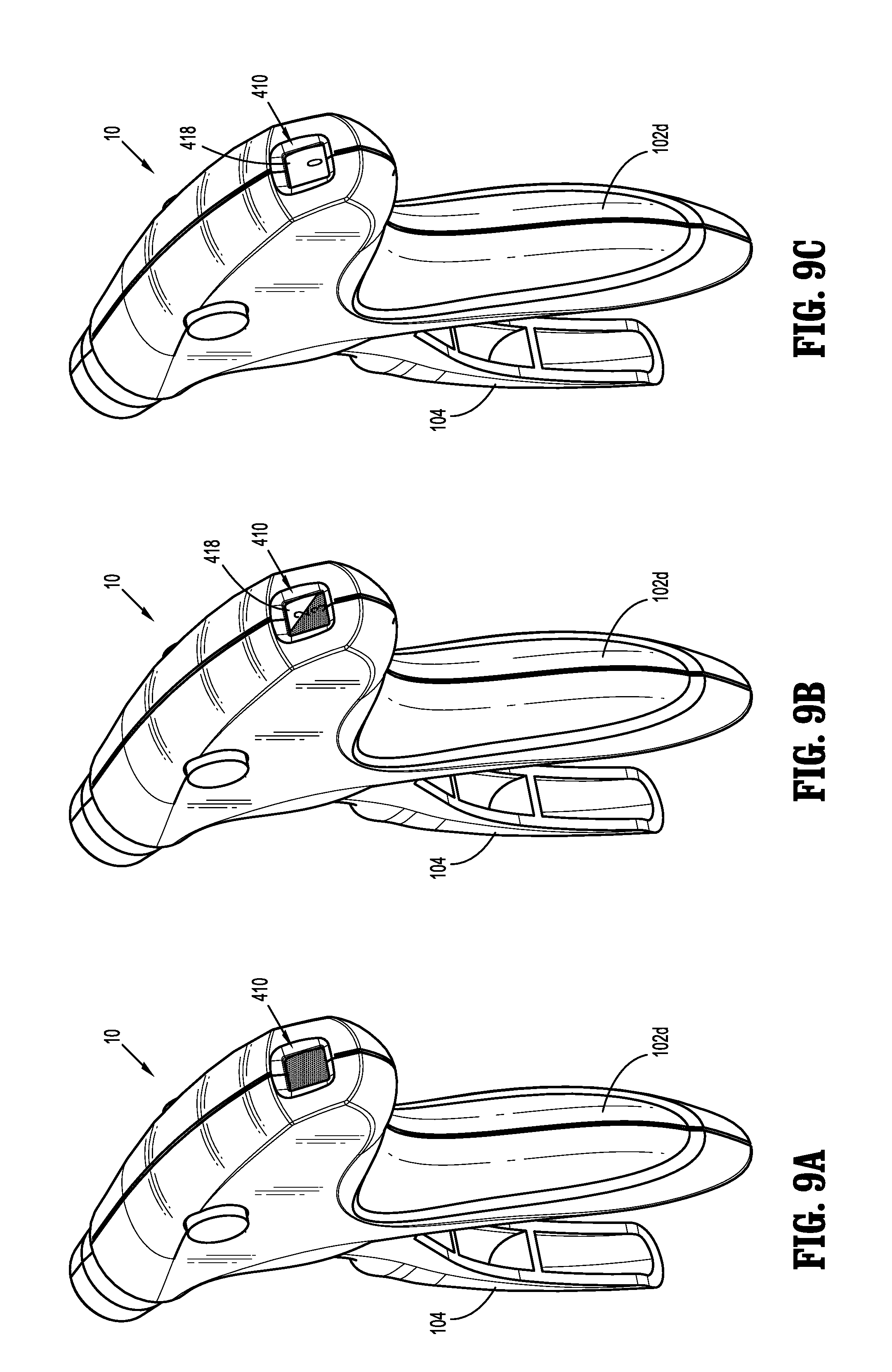
[0035] FIG. 9A is a perspective view of an indicator window of the clip counting mechanism of FIG. 3 shown in position where a clip cartridge of the endoscopic surgical clip applier of FIG. 1 is mostly full;
[0036] FIG. 9B is a perspective view of the indicator window of FIG. 9A, shown in a position where the clip cartridge of the endoscopic surgical clip applier of FIG. 1 is mostly empty;
[0037] FIG. 9C is a perspective view of the indicator window of FIG. 9A, shown in a position where the clip cartridge of the endoscopic surgical clip applier of FIG. 1 is empty; and
[0038] FIG. 10 is a perspective view of an endoscopic assembly of FIG. 1, with parts separated.
DETAILED DESCRIPTION OF EMBODIMENTS
[0039] In accordance with the present disclosure, an endoscopic surgical clip applier including a clip counting mechanism is provided. Although disclosed for use in an endoscopic surgical clip applier, the clip counting mechanism is usable in a wide variety of surgical clip appliers. The clip counting mechanism is disposed within a handle assembly of an endoscopic surgical clip applier and includes a display gear, a counter switch, an escapement gear, and a gear pin. The display gear is rotatably disposed about a display gear post of the handle assembly and is rotatably biased by a biasing element mechanically coupled to each of the display gear and the display gear post. The display gear defines an outer surface having a contrasting color disposed on a portion thereof to indicate that the number of remaining surgical clips is low. The outer surface of the display gear defines a plurality of ratchet teeth that are radially spaced apart such that each tooth represents a predetermined angle of rotation, which in embodiments is 24 degrees. The outer surface of the display gear includes a plurality of numbers disposed thereon and sequentially arranged thereon such that as the display gear rotates, the number of the plurality of numbers that is displayed to the clinician decreases with each firing of a surgical clip.
[0040] The counter switch defines a generally planar configuration having a laterally extending tab defined on a distal end thereof. The laterally extending tab is configured to selectively engage a protrusion of a drive bar such that translation of the drive bar in a distal direction effectuates a corresponding distal translation of the counter switch. An upper surface of the counter switch defines a vertically extending tab that is configured to selectively engage a drive bar pin of the handle assembly such that proximal translation of the drive bar, and therefore the drive bar pin, effectuates a corresponding proximal translation of the counter switch. A proximal portion of the counter switch defines a slot having a generally dog leg configuration that is configured to slidably engage the gear pin and cam the gear pin as the counter switch translates relative thereto.
[0041] The escapement gear defines a generally crescent wrench shape having a C-shaped proximal portion and a linearly extending distal portion. The proximal portion of the escapement gear defines a pair of opposed arms in juxtaposed relation, each defining a respective tooth configured to selectively engage a corresponding tooth of the plurality of ratchet teeth of the drive gear. The escapement gear is rotatably supported on a escapement gear boss defined on the housing of the endoscopic surgical clip applier. The gear pin is fixedly supported by the escapement gear such that translation of the counter switch causes the gear pin to cam within the cam slot of the counter switch. Distal translation of the counter switch effectuates clockwise rotation of the escapement gear and a release of the display gear from a tooth of the escapement gear such that the display gear rotates in a clockwise direction. Continued distal translation of the counter switch causes the gear pin to cam within the cam slot until an opposite tooth of the escapement gear engages a corresponding tooth of the display gear, stopping rotation of the display gear. After forming the surgical clip, retraction of the counter switch causes the gear pin to cam in an opposite direction and rotate the escapement gear in a counter-clockwise direction. Continued counter-clockwise rotation of the escapement gear releases the display gear and permits the display gear to further rotate in a clockwise direction until the escapement gear rotates further and engages another tooth of the display gear to stop rotation thereof. The clockwise rotation of the display gear causes the number of the plurality of numbers disposed on the display gear to decrease by one, until no surgical clip remain.
[0042] Embodiments of endoscopic surgical clip appliers and clip counting mechanisms, in accordance with the present disclosure, will now be described in detail with reference to the drawing figures wherein like reference numerals identify similar or identical structural elements. As shown in the drawings and described throughout the following description, as is traditional when referring to relative positioning on a surgical instrument, the term "proximal" refers to the end of the apparatus which is closer to the user and the term "distal" refers to the end of the apparatus which is further away from the user.
[0043] Referring now to FIGS. 1 and 2, an endoscopic surgical clip applier is provided in accordance with the present disclosure and generally identified by reference numeral 10. The surgical clip applier 10 generally includes a handle assembly 100 and an endoscopic assembly 200 that is selectively secured to the handle assembly 100 and extends distally therefrom. The endoscopic assembly 200 includes a hub assembly 210, a shaft assembly 220 extending from hub assembly 210, and a pair of jaws 250 pivotally connected to a distal end portion of the shaft assembly 220. In embodiments, at least one disposable surgical clip cartridge (not shown) may be selectively loadable into the shaft assembly 220 of the endoscopic assembly 200.
[0044] The handle assembly 100 of the surgical clip applier 10 includes a housing 102 having a first or right side half-section 102a and a second or left side half-section 102b. The housing 102 of the handle assembly 100 defines a nose 102c for supporting the hub assembly 210 of the endoscopic assembly 200, and a fixed handle 102d. It is contemplated that the housing 102 of the handle assembly 100 may be formed of a suitable polymer, such as a plastic or thermoplastic material, or may be formed from a metallic material such as stainless steel or the like.
[0045] The handle assembly 100 includes a trigger 104 pivotably supported between the right side half-section 102a and the left side half-section 102b of the housing 102. The trigger 104 is pivotably movable in a first direction such that the trigger 104 and the fixed handle 102d are approximated and pivotably movable in a second, opposite, direction such that the trigger 104 and the fixed handle 102d are spaced-apart.
[0046] A drive bar 106 (FIG. 2) is supported within the housing 102 of the handle assembly 100. The drive bar 106 may be a substantially flat member having a distal end portion 106a and a proximal end portion 106b. The distal end portion 106a of the drive bar 106 includes a hook member 114 that is provided to mate with a feature of the endoscopic assembly 200. The drive bar 106 defines an upper surface 106c and an opposite, lower surface 106d extending between the proximal and distal end portions 106a, 106b. The lower surface 106d of the drive bar 106 defines a protrusion 106e at a medial portion thereof and extending in a downward direction therefrom. The protrusion 106e defines a distal or leading surface 106f configured to selectively engage a portion of a counter switch, as will be described in further detail hereinbelow.
[0047] The drive bar 106 is operatively coupled to the trigger 104 and the pair of jaws 250 (FIG. 1) of the endoscopic assembly 200 to move the pair of jaws 250 between a spaced-apart configuration and an approximated configuration upon actuation of the trigger 104. Specifically, the handle assembly 100 includes a wishbone link 108 (FIG. 2) configured to couple the trigger 104 and the drive bar 106. The wishbone link 108 includes a first end portion having a tail 108a and a second end portion having a first arm 108b and a second arm 108c which are spaced apart to define a space 108d therebetween. The tail 108a of the wishbone link 108 is pivotably connected to the trigger 104 through a trigger slot 104a. Specifically, the tail 108a of the wishbone link 108 includes an opening 108f that is configured for pivotably locating a pin (not shown) defined within the trigger slot 104a. The space 108d between the first and second arms 108b, 108c of the wishbone link 108, and the drive bar 106, includes corresponding apertures 108e, 106g, respectively, which are configured to locate a drive bar pin 110 to pivotably connect the wishbone link 108 and the drive bar 106. The wishbone link 108 is configured to translate the pivotal movement of the trigger 104 into longitudinal movement of the drive bar 106, as will be described in further detail hereinbelow.
[0048] The drive bar 106 is configured to move one or more driving structures to load, and actuate the pair of jaws 250 to form a clip (not shown) fully or partially, and then reset to an initial position for the next clip application. To achieve this, a biasing member, such as, for example, a first return spring 112 is disposed to surround the drive bar 106 adjacent the distal end portion 106a such that, after the trigger 104 is actuated and the wishbone link 108 advances the drive bar 106 in a longitudinal or distal manner, the first return spring 112 is provided to return the drive bar 106 and the trigger 104 to its original position for the next clip application.
[0049] With continued reference to FIG. 2, the surgical clip applier 10 includes a ratchet assembly 300 disposed within the housing 102 of the handle assembly 100. The ratchet assembly 300 generally includes a first rack 310 disposed on the upper surface 106c of the drive bar 106 and a first pawl assembly 320 that is rotatably supported within the housing 102 of the handle assembly 100 and is operatively associated with the first rack 310. A second rack 350 is disposed on the upper surface 106c of the drive bar 106 proximal to, and spaced apart from, the first rack 310. A second pawl assembly 360 is rotatably supported within the housing 102 of the handle assembly 100 and is operatively associated with the second rack 350. The components of the ratchet assembly 300 cooperate to inhibit the trigger 104 from inadvertently returning to an unactuated position during a specific portion of the stroke. In one non-limiting embodiment, the ratchet assembly 300 inhibits the trigger 104 from returning to an unactuated position until a clip loaded into the pair of jaws 250 is partially formed, enough to be fired from the surgical clip applier 10, such that a new clip may be loaded into the pair of jaws 250 without an inadvertent double loading of clips into the pair of jaws 250.
[0050] For a more detailed description of the construction and operation of ratchet assembly 300, reference can be made to U.S. Provisional Patent Application No. 62/462,407 to Baril et al., titled "Endoscopic Surgical Clip Applier," filed on Feb. 23, 2017, the entire content of which is incorporated by reference herein.
[0051] A clip counting mechanism 400 is disposed within the handle assembly and includes a display gear 410, a counter switch 420, an escapement gear 430, and a gear pin 440. As illustrated in FIGS. 2, 3, 6A, and 6B, the display gear 410 defines a generally cylindrical profile, although any suitable profile may be utilized, such as square, oval, rectangular, octagonal, or the like. The display gear 410 defines opposed side surfaces 410a and 410b, which define a through-hole 412 (FIG. 6B) therethrough. The through-hole 412 is configured to be rotatably supported on a display gear post 102d (FIG. 2) extending from an interior surface of the right side half-section 102a of the housing 102. The side surface 410a of the display gear 410 defines a counterbore 414 (FIG. 6A) extending therethrough but not through the opposed side surface 410b. An outer surface 410c of the display gear 410 defines a plurality of concentrically disposed ratchet teeth 410d adjacent and through side surface 410b of the display gear 410. The plurality of ratchet teeth 410d are configured to selectively engage the escapement gear 430, as will be described in further detail hereinbelow. The outer surface 410c of the display gear 410 defines a plurality of numbers 416 sequentially arranged thereon. Each number of the plurality of numbers 416 is arranged around the circumference of the outer surface 410c such that the sequence of the plurality of numbers 416 is decreasing in nature as the display gear 410 rotates in a clockwise direction (e.g., 12-11-10-9-8, etc.), although it is contemplated that the sequence of the plurality of numbers 416 may increase as the drive gear 410 rotates in a clockwise direction. Each number of the plurality of numbers 416 is radially spaced apart by any suitable angle, and in one non-limiting embodiment each number of the plurality of numbers 416 is radially spaced apart at an angle of 24 degrees. In embodiments, the plurality of numbers 416 includes the numbers 3, 2, 1, and 0 to indicate that less than 4 clips remain in the endoscopic surgical clip applier 10. In this manner, the outer surface 410c of the display gear alerts the clinician to how many surgical clips remain in the endoscopic surgical clip applier 10.
[0052] To accommodate the radial spacing of 24 degrees between each number of the plurality of numbers 416, the plurality of ratchet teeth 410d includes 15 teeth, such that the display gear 410 rotates 24 degrees each time a clip is formed or fired, as will be described in further detail hereinbelow. As can be appreciated, it is contemplated that the plurality of teeth 410d may include any number of teeth corresponding to the radial angle defined between each number of the plurality of numbers, depending upon the needs of the procedure being performed.
[0053] As illustrated in FIGS. 9A, 9B, and 9C, the outer surface 410c includes a contrasting color 418 disposed thereon that overlaps the numbers "0" and "1" of the plurality of numbers 416 and overlaps a portion of the number "2" of the plurality of numbers 416. Although generally illustrated as defining a diagonal line through the number "2" of the plurality of numbers 416, it is contemplated that the contrasting color 418 may define any suitable configuration such that the clinician is able to quickly ascertain the number of clips remaining in the clip stack (not shown). As can be appreciated, the contrasting color 418 may be any suitable color capable of grabbing the clinician's attention during a surgical procedure and may vary depending upon the needs of the procedure being performed (e.g., ambient lighting, background color, color blindness, etc.). In one non-limiting embodiment, the contrasting color 418 is red.
[0054] A biasing element 408 is in mechanical communication with the display gear 410 and rotatably biases the display gear 410 in a clockwise direction about the display gear post 102d of the right side-half section 102a (FIG. 2), although it is contemplated that the biasing element 408 may rotatably bias the display gear in a counterclockwise direction about the display gear post 102d. The biasing element 408 may rotatably bias the display gear 410 using any suitable means, such as being interposed between the display gear 410 and the right side-half section 102a, being disposed within the counterbore 414 of the display gear 410, disposed remote from the display gear 410, etc. In one non-limiting embodiment, the biasing element 408 is disposed within the counterbore 414 of the display gear 410 and is coaxially aligned with the display gear post 102d of the right side-half section 102a such that the biasing element 408 engages a portion of the display gear post 102d and a portion of the display gear 410. The biasing element 408 may be any suitable biasing element capable of rotatably biasing the display gear 410, such a constant force spring, torsion spring, balance spring, torsion bar, or the like. In one non-limiting embodiment, the biasing element 408 is a constant force spring disposed within the counterbore 414 of the display gear 410 and disposed about the display gear post 102d of the right side-half section 102a, such that the constant force spring engages a portion of each of the display gear 410 and the display gear post 102d.
[0055] With reference to FIGS. 3 and 4, the counter switch 420 is reciprocally disposed within the housing 102 of the handle assembly 100 and defines a generally planar profile, although it is contemplated that any suitable profile may be utilized. The counter switch 420 defines a proximal end portion 420a and a distal end portion 420b opposite thereto and opposed side surfaces 420c and 420d extending therebetween. The counter switch 420 is interposed between the drive bar 106 and the right side half section 102a of the housing 102 (e.g., the side surface 420a is adjacent the drive bar 106 and the side surface 420b is adjacent the right side half section 102a). The side surface 420c defines a laterally extending tab 422 disposed adjacent the distal end portion 420b. Although generally shown as defining a right angle with respect to the side surface 420c of the counter switch 420, it is contemplated that the laterally extending tab 422 may define any suitable angle depending upon the location of the counter switch 420 within the housing 102, the stroke required to rotate the display gear 410, etc.
[0056] The counter switch 420 defines an upper surface 420e interposed between the opposed side surfaces 420c, 420d and extending between the proximal and distal end portions 420a, 420b. A medial portion of the upper surface 420e defines a vertically extending tab 424 and defines a leading or distal surface 424a configured to selectively engage the drive bar pin 110 (FIG. 2) on a return stroke, as will be described in further detail hereinbelow. The upper surface 420e defines a ramp or taper 426 interposed between the vertically extending tab and the laterally extending tab 422, such that the height of the counter switch 420 increases in a distal to proximal direction (e.g., in a direction from the distal end portion 420b to the proximal end portion 420a). In this manner, as the drive bar 106 is advanced in a distal direction, the drive bar pin 110 is free to translate relative to the counter switch 420 (e.g., the drive bar pin 110 does not contact the counter switch 420). However, as the drive bar 106 is retracted in a proximal direction, the drive bar pin 110 is inhibited from contacting the counter switch 420 until the leading surface 424a of the vertically extending tab 424 abuts the drive bar pin 110, and causes the counter switch 420 to translate in a proximal direction along with the drive bar 106 and drive bar pin 110.
[0057] The opposed side surfaces 420c, 420d of the counter switch 420 define a slot 428 having a proximal end portion 428a and a distal end portion 428b therethrough. The slot 428 extends in a proximal to distal direction along the counter switch 420, and in embodiments, the distal end portion 428a of the slot 428 is vertically aligned with the leading surface 424a of the vertically extending tab 424. The slot 428 defines a pair of tabs 428c and 428d at respective proximal and distal end portions 428a, 4268 thereof that extend from side surface 420b of the counter switch 420. In operation, the pair of tabs 428c, 428d serve as travel stops to define a maximum proximal travel distance and a maximum distal travel distance, as will be described in further detail hereinbelow. In embodiments, a bridge or connector 428e is interposed between the pair of tabs 428c, 428d and is configured to be slidably disposed within a corresponding channel (not shown) defined within the right side half section 102a.
[0058] The opposed side surfaces 420a, 420b of the counter switch 420 define a cam slot 429 therethrough adjacent to the proximal end portion 420a of the counter switch 420. The cam slot 429 includes a generally dogleg shaped profile having a proximal portion 429a and a distal portion 429b extending in a distal direction therefrom. The proximal portion 429a of the cam slot 429 is oriented in a horizontal manner (e.g., extends linearly along the counter switch 420 in a distal direction) and the distal portion 429b is oriented at an angle relative to the proximal portion 429a. Specifically, the distal portion 429b defines an obtuse angle relative to the proximal portion 429b and extends in a downward direction (e.g., away from the upper surface 420e of the counter switch 420). The cam slot 429 is configured to slidably receive the gear pin 440 therein, as will be described in further detail hereinbelow.
[0059] The escapement gear 430 (FIG. 5) defines a generally crescent wrench profile having a C-shaped proximal portion 432 and a rectangular shaped distal portion 434 extending distally therefrom. As best illustrated in FIG. 5, the distal portion 434 is oriented relative to the proximal portion 432 at a slight angle thereto (e.g., a centerline defined by the proximal portion 432 is not collinear with a centerline defined by the distal portion 434). In this manner, the C-shaped proximal portion 432 is able to straddle the plurality of ratchet teeth 410d (FIG. 6B) of the display gear 410, as will be described in further detail hereinbelow. The proximal portion 432 defines a pair of arms 432a and 432b that are arranged in a juxtaposed orientation. Each arm of the pair of arms 432a, 432b defines a respective tooth 432c and 432d oriented at a substantially perpendicular angle with respect to each respective arm 432a, 432b. As can be appreciated, it is contemplated that each tooth 432c, 432d may be oriented at any suitable angle with respect to each respective arm 432a, 432b, and may be disposed at the same angle or different angles than one another. The teeth 432c, 432d are configured to selectively engage a tooth of the plurality of ratchet teeth 410d of the display gear 410, as will be described in further detail hereinbelow.
[0060] The escapement gear 430 defines a bore 436 at a medial portion thereof that is configured to rotatably receive an escapement gear boss 102f (FIG. 2) therein that is defined on the right half section 102b of the housing 102. The distal portion 434 of the escapement gear 430 defines an aperture 438 therethrough configured to fixedly receive the gear pin 440 therein. As will be described in further detail hereinbelow, the gear pin 440 cams within the cam slot 428 of the counter switch 420 and the counter switch translates in a proximal or distal direction, causing the escapement gear 430 to rotate about the escapement gear boss 102f and selectively engage the display gear 410.
[0061] In operation, with reference to FIGS. 7A-C, 8A-C, and 9A-C, as the clinician actuates the trigger 104 (FIG. 2) of the handle assembly 100 to fire or form a clip (not shown), the drive bar 106 is urged in a distal direction. With continued actuation of the trigger 104, the drive bar 106 translates further in a distal direction until the leading surface 106f of the protrusion 106e of the drive bar 106 engages the laterally extending tab 422 of the counter switch 420 (FIG. 7A). As the clinician further actuates the trigger 104, the drive bar continues to advance in a distal direction and begins to cam the gear pin 440 within the cam slot 429 of the counter switch 420 (FIG. 7B).
[0062] Camming of the gear pin 440 within the cam slot 429 causes the escapement gear 430 to rotate about the escapement gear boss 102f of the handle housing 102 in a clockwise direction (e.g., tooth 432c of arm 432a of the pair of arms rotates toward the display gear 410). In this manner, tooth 432d of arm 432b of the escapement gear 430 disengages from a tooth of the plurality of ratchet teeth 410d of the display gear 410. As the drive bar 106, and therefore the counter switch 420 are further urged in a distal direction, the escapement gear 430 is caused to rotate further in a clockwise direction until the tooth 432d of arm 432b disengages from the tooth of the plurality of ratchet teeth 410d of the display gear 410. Disengagement of the tooth of the plurality of ratchet teeth 410d enables the biasing element 408 to begin to rotate the display gear 410 about the display gear post 102d of the right side-half section 102a in a clockwise direction and begin incrementally changing the number of the plurality of numbers 416 of the display gear 410 that is displayed to the clinician. The display gear 410 continues to rotate in a clockwise direction about the display gear post 102d until continued distal advancement of the drive bar 106 and the counter switch 420 causes the tooth 432c of the escapement gear 430 to engage a tooth of the plurality of ratchet teeth 410d of the display gear 410 (FIG. 7C). At this point, the display gear 410 has rotated 12 degrees about display gear post 102d, and therefore has completed half of a full rotation of 24 degrees.
[0063] Once the clip has been fully formed, or racks 310, 350 have fully cleared respective pawls assemblies 320, 360, the clinician releases the trigger 104 which enables the drive bar 106, and therefore the counter switch 420, to begin returning to the initial, retracted position (FIG. 8A). Initial translation of the drive bar 106 in a proximal direction urges the counter switch 420 in a proximal direction thereby causing the gear pin 440 to cam within the cam slot 429 of the counter switch 420 (FIG. 8B). Camming of the gear pin 440 within the cam slot 429 while the counter switch 420 is translating in a proximal direction causes the escapement gear 430 to rotate about the escapement gear boss 102f of the handle housing 102 in a counter-clockwise direction (e.g., tooth 432d of arm 432b of the pair of arms rotates toward the display gear 410). In this manner, escapement gear 430 rotates in an opposite direction to when the drive bar 106 is urged in a distal direction, thereby disengaging the tooth 432c of arm 432a from the plurality of ratchet teeth 410d of the display gear 410 and enabling the display gear 410 to rotate in a clockwise direction about the display gear post 102d. With continued proximal translation of the counter switch 420, the escapement gear 430 continues to rotate about the escapement gear boss 102f until tooth 432d of arm 432b of the escapement gear 430 engages a tooth of the plurality of ratchet teeth 410d of the display gear 410, thereby stopping rotation of the display gear 410 about the display gear post 102d (FIG. 8C). At this point, the display gear 410 has rotated a further 12 degrees about the display gear post 102d, such that the display gear 410 has rotated a total of 24 degrees during the full stroke of the surgical clip applier 10 to form or fire the surgical clip.
[0064] Each time the clinician wishes to fire or form a surgical clip, the above process is repeated until all of the remaining surgical clips have been fired or formed. As can be appreciated, the display gear 410 displays the number of surgical clips remaining to be fired and updates each time the clinician fires or forms a surgical clip using the above-described process. If the number of remaining surgical clips is 5 or greater, the outer surface 410c displays no contrasting color, and in embodiments, no numbers (FIG. 9A). If, during the surgical procedure, the number of remaining surgical clips is less than 4, then a portion of the outer surface 410c displays the contrasting color 418 (FIG. 9B), and the amount of the outer surface 410c displaying the contrasting color increases with the firing of each remaining surgical clip until the outer surface 410c entirely displays the contrasting color 418 to indicate that there are no surgical clip remaining (FIG. 9C).
[0065] Once the final surgical clip has been fired or formed, the surgical clip applier 10 engages a lockout mechanism (not shown) inhibiting the clinician from actuating the trigger 104.
[0066] Turning now to FIG. 10, the endoscopic assembly 200 of the surgical clip applier includes a hub assembly 210, a shaft assembly 220, and the pair of jaws 250. The hub assembly 210 is rotatably mounted on a nose 102c (FIG. 2) of the housing 102 of the handle assembly 100 and is connected to a proximal end portion of the shaft assembly 220 to enable the shaft assembly 220 and the pair of jaws 250 to rotate three hundred and sixty degrees relative to a longitudinal center axis of the shaft assembly 220. The hub assembly 210 has a suitable configuration so as to be rotated simply by using a clinician's finger.
[0067] The endoscopic assembly 200 includes a spindle link 260 for operatively connecting the drive bar 106 to a driving mechanism 500 to move the pair of jaws 250 between the spaced-apart configuration and the approximated configuration upon actuation of the trigger 104. Specifically, the hook member 114 (FIG. 2) of the drive bar 106 is coupled to a first end portion 260a of the spindle link 260 and a spindle 270 of the drive mechanism 500 is coupled to a second end portion 206b of the spindle link 260. In this manner, translation of the drive bar 106 in a distal and proximal direction can thus advance and retract the spindle 270, respectively.
[0068] The drive mechanism 500 further includes an elongated clip channel member 280 for retaining a number of surgical clips 290 shown in an aligned manner above the clip channel member 280. A clip follower 282 and a clip follower spring 284 are provided to urge the surgical clips 290 distally through the elongated clip channel member 280. A channel cover 286 is provided to overlay the elongated clip channel member 280 and retain and guide the clip follower 282 and the clip follower spring 284 and the surgical clips 290 distally in the elongated clip channel member 280. The drive mechanism 500 also has a feed bar 510 for feeding the surgical clips 290 between the pair of jaws 250 and a filler component 520 and wedge plate 530.
[0069] For a more detailed description of the construction and operation of endoscopic assembly 200, reference can be made to U.S. Pat. No. 7,637,917 to Whitfield et al., the entire content of which is incorporated by reference herein.
[0070] It should be understood that the foregoing description is only illustrative of the present disclosure. Various alternatives and modifications can be devised by those skilled in the art without departing from the disclosure. Accordingly, the present disclosure is intended to embrace all such alternatives, modifications and variances. The embodiments described with reference to the attached drawing figures are presented only to demonstrate certain examples of the disclosure. Other elements, steps, methods and techniques that are insubstantially different from those described above and/or in the appended claims are also intended to be within the scope of the disclosure.
* * * * *
D00000
D00001
D00002
D00003
D00004
D00005
D00006
D00007
D00008
D00009
XML
uspto.report is an independent third-party trademark research tool that is not affiliated, endorsed, or sponsored by the United States Patent and Trademark Office (USPTO) or any other governmental organization. The information provided by uspto.report is based on publicly available data at the time of writing and is intended for informational purposes only.
While we strive to provide accurate and up-to-date information, we do not guarantee the accuracy, completeness, reliability, or suitability of the information displayed on this site. The use of this site is at your own risk. Any reliance you place on such information is therefore strictly at your own risk.
All official trademark data, including owner information, should be verified by visiting the official USPTO website at www.uspto.gov. This site is not intended to replace professional legal advice and should not be used as a substitute for consulting with a legal professional who is knowledgeable about trademark law.