Endoscopic Reposable Surgical Clip Applier
Zammataro; Thomas A.
U.S. patent application number 16/140586 was filed with the patent office on 2019-06-13 for endoscopic reposable surgical clip applier. The applicant listed for this patent is Covidien LP. Invention is credited to Thomas A. Zammataro.
| Application Number | 20190175176 16/140586 |
| Document ID | / |
| Family ID | 64664657 |
| Filed Date | 2019-06-13 |


View All Diagrams
| United States Patent Application | 20190175176 |
| Kind Code | A1 |
| Zammataro; Thomas A. | June 13, 2019 |
ENDOSCOPIC REPOSABLE SURGICAL CLIP APPLIER
Abstract
A hub assembly for use with an endoscopic assembly of a reposable surgical clip applier includes an outer housing defining a channel therethrough, a stationary gear fixedly disposed within the channel, a display drum rotatably and slidably supported within the channel and in mechanical communication with the stationary gear, a sliding gear slidably supported within a portion of the stationary gear, and a rotating gear rotatably and slidably supported within a portion of the display drum. The rotating gear is rotatably coupled to the display drum. The display drum is caused to be rotated a first predetermined amount during each distal advancement of the sliding gear.
| Inventors: | Zammataro; Thomas A.; (Hamden, CT) | ||||||||||
| Applicant: |
|
||||||||||
|---|---|---|---|---|---|---|---|---|---|---|---|
| Family ID: | 64664657 | ||||||||||
| Appl. No.: | 16/140586 | ||||||||||
| Filed: | September 25, 2018 |
Related U.S. Patent Documents
| Application Number | Filing Date | Patent Number | ||
|---|---|---|---|---|
| 62597586 | Dec 12, 2017 | |||
| Current U.S. Class: | 1/1 |
| Current CPC Class: | A61B 2017/2933 20130101; A61B 17/1285 20130101; A61B 2017/00464 20130101; A61B 2017/00407 20130101; A61B 2017/00477 20130101; A61B 2090/0807 20160201; A61B 2017/0046 20130101; A61B 17/072 20130101; A61B 2017/00473 20130101; A61B 17/083 20130101; A61B 17/105 20130101 |
| International Class: | A61B 17/08 20060101 A61B017/08; A61B 17/072 20060101 A61B017/072; A61B 17/10 20060101 A61B017/10; A61B 17/128 20060101 A61B017/128 |
Claims
1. A hub assembly for use with an endoscopic assembly of a reposable surgical clip applier, the hub assembly comprising: an outer housing defining proximal and distal end surfaces, the proximal and distal end surfaces defining a channel therethrough; a stationary gear fixedly disposed within the channel; a display drum rotatably and slidably supported within the channel, the display drum in mechanical communication with the stationary gear; a sliding gear slidably supported within a portion of the stationary gear; and a rotating gear rotatably and slidably supported within a portion of the display drum, the rotating gear being rotatably coupled to the display drum, wherein the display drum is caused to be rotated a first predetermined amount during each distal advancement of the sliding gear.
2. The hub assembly according to claim 1, wherein the display drum is caused to be rotated a second predetermined amount during each proximal retraction of the sliding gear.
3. The hub assembly according to claim 2, wherein the stationary gear defines a plurality of teeth on a distal portion thereof.
4. The hub assembly according to claim 3, wherein the sliding gear defines a plurality of teeth on a distal portion thereof.
5. The hub assembly according to claim 4, wherein the plurality of teeth of the sliding gear are disposed proximal of the plurality of teeth of the stationary gear when the sliding gear is in an initial, proximal position.
6. The hub assembly according to claim 5, wherein the rotating gear defines a plurality of teeth on a proximal portion thereof.
7. The hub assembly according to claim 6, wherein the plurality of teeth of the sliding gear are configured to engage the plurality of teeth of the rotating gear when the sliding gear is placed in a second, advanced position to cause rotation of the rotating gear the first predetermined amount during engagement therewith.
8. The hub assembly according to claim 7, wherein the plurality of teeth of the stationary gear are configured to engage the plurality of teeth of the rotating gear when the rotating gear is placed in the first, initial position to cause rotation of the rotating gear the second predetermined amount during engagement therewith.
9. The hub assembly according to claim 1, further including a spring clip slidably coupled to the rotating gear at a first portion thereof and fixedly coupled to the display drum at a second, opposite portion thereof to rotatably couple the display drum to the rotating gear.
10. The hub assembly according to claim 1, wherein the outer surface of the display drum defines a first contrasting color and a second contrasting color.
11. The hub assembly according to claim 10, wherein the outer housing defines a plurality of windows therethrough, wherein the first contrasting color is visible through the plurality of windows after a third predetermined amount of rotation of the display drum.
12. The hub assembly according to claim 11, wherein the second contrasting color is visible through the plurality of windows after a fourth predetermined amount of rotation of the display drum.
13. The hub assembly according to claim 12, wherein an outer surface of the stationary gear defines an annular cam slot therein.
14. The hub assembly according to claim 13, wherein an inner surface of the display drum defines a post extending radially inward therefrom, the post configured to be slidably received within the cam slot.
15. The hub assembly according to claim 14, wherein the annular cam slot defines a first longitudinal portion at a first radial position and a second longitudinal portion at a second radial position.
16. The hub assembly according to claim 15, wherein the post of the display drum translates within the first longitudinal portion of the cam slot after the third predetermined amount of rotation of the display drum.
17. The hub assembly according to claim 16, wherein the post of the display drum translates within the second longitudinal portion of the cam slot after the fourth predetermined amount of rotation of the display drum.
18. The hub assembly according to claim 8, wherein each engagement of the plurality of teeth of the sliding gear with the plurality of teeth of the rotating gear causes the rotating gear to rotate 1/24.sup.th of a rotation.
19. The hub assembly according to claim 18, wherein each engagement of the plurality of teeth of the stationary gear with the plurality of teeth of the rotating gear causes the rotating gear to rotate 1/24.sup.th of a rotation.
20. The hub assembly according to claim 17, wherein the post of the display drum is received within the first longitudinal portion of the cam slot after the display drum has rotated 270 degrees and the post of the display drum is received within the second longitudinal portion of the cam slot after the display drum has rotated a further 90 degrees from the first longitudinal portion.
Description
CROSS-REFERENCE TO RELATED APPLICATION
[0001] This application claims the benefit of and priority to U.S. Provisional Patent Application No. 62/597,586 filed Dec. 12, 2017, the entire disclosure of which is incorporated by reference herein.
BACKGROUND
Technical Field
[0002] The present disclosure relates to surgical clip appliers. More particularly, the present disclosure relates to endoscopic reposable surgical clip appliers having a reusable handle assembly, at least one reusable shaft assembly, and at least one disposable clip cartridge assembly.
Description of Related Art
[0003] Endoscopic surgical staplers and surgical clip appliers are known in the art and are used for a number of distinct and useful surgical procedures. In the case of a laparoscopic surgical procedure, access to the interior of an abdomen is achieved through narrow tubes or cannulas inserted through a small entrance incision in the skin. Minimally invasive procedures performed elsewhere in the body are often generally referred to as endoscopic procedures. Typically, a tube or cannula device is extended into the patient's body through the entrance incision to provide an access port. The port allows the surgeon to insert a number of different surgical instruments therethrough using a trocar and for performing surgical procedures far removed from the incision.
[0004] During a majority of these procedures, the surgeon must often terminate the flow of blood or another fluid through one or more vessels. The surgeon will often use a particular endoscopic surgical clip applier to apply a surgical clip to a blood vessel or another duct to prevent the flow of body fluids therethrough during the procedure.
[0005] Endoscopic surgical clip appliers having various sizes (e.g., diameters), that are configured to apply a variety of diverse surgical clips, are known in the art, and which are capable of applying a single or multiple surgical clips during an entry to the body cavity. Such surgical clips are typically fabricated from a biocompatible material and are usually compressed over a vessel. Once applied to the vessel, the compressed surgical clip terminates the flow of fluid therethrough.
[0006] Endoscopic surgical clip appliers that are able to apply multiple clips in endoscopic or laparoscopic procedures during a single entry into the body cavity are described in commonly-assigned U.S. Pat. Nos. 5,084,057 and 5,100,420 to Green et al., which are both incorporated by reference in their entirety. Another multiple endoscopic surgical clip applier is disclosed in commonly-assigned U.S. Pat. No. 5,607,436 by Pratt et al., the contents of which is also hereby incorporated by reference herein in its entirety. These devices are typically, though not necessarily, used during a single surgical procedure. U.S. Pat. No. 5,695,502 to Pier et al., the disclosure of which is hereby incorporated by reference herein, discloses a resterilizable endoscopic surgical clip applier. The endoscopic surgical clip applier advances and forms multiple clips during a single insertion into the body cavity. This resterilizable endoscopic surgical clip applier is configured to receive and cooperate with an interchangeable clip magazine so as to advance and form multiple clips during a single entry into a body cavity.
[0007] During endoscopic or laparoscopic procedures it may be desirable and/or necessary to use different size surgical clips or different configured surgical clips depending on the underlying tissue or vessels to be ligated. In order to reduce overall costs of an endoscopic surgical clip applier, it is desirable for a single endoscopic surgical clip applier to be loadable with and capable of firing different size surgical clips as needed.
[0008] Accordingly, a need exists for endoscopic surgical clip appliers that include reusable handle assemblies, reusable shaft assemblies, and disposable clip cartridge assemblies, with each clip cartridge assembly being loaded with a particularly sized clip (e.g., relatively small, relatively medium, or relatively large).
SUMMARY
[0009] The present disclosure relates to reposable endoscopic surgical clip appliers.
[0010] According to an aspect of the present disclosure, a hub assembly for use with an endoscopic assembly of a reposable surgical clip applier is provided. The hub assembly includes an outer housing defining proximal and distal end surfaces that define a channel therethrough, a stationary gear fixedly disposed within the channel, a display drum rotatably and slidably supported within the channel and in mechanical communication with the stationary gear, a sliding gear slidably supported within a portion of the stationary gear, and a rotating gear rotatably and slidably supported within a portion of the display drum. The rotating gear is rotatably coupled to the display drum. The display drum is caused to be rotated a first predetermined amount during each distal advancement of the sliding gear.
[0011] In aspects, the display drum may be caused to be rotated a second predetermined amount during each proximal retraction of the sliding gear.
[0012] In other aspects, the stationary gear may define a plurality of teeth on a distal portion thereof.
[0013] In certain aspects, the sliding gear may define a plurality of teeth on a distal portion thereof.
[0014] In other aspects, the plurality of teeth of the sliding gear may be disposed proximal of the plurality of teeth of the stationary gear when the sliding gear is in an initial, proximal position.
[0015] In aspects, the rotating gear may define a plurality of teeth on a proximal portion thereof. In certain aspects, the plurality of teeth of the sliding gear may be configured to engage the plurality of teeth of the rotating gear when the sliding gear is placed in a second, advanced position to cause rotation of the rotating gear the first predetermined amount during engagement therewith.
[0016] In other aspects, the plurality of teeth of the stationary gear may be configured to engage the plurality of teeth of the rotating gear when the rotating gear is placed in the first, initial position to cause rotation of the rotating gear the second predetermined amount during engagement therewith.
[0017] In certain aspects, the hub assembly may include a spring clip slidably coupled to the rotating gear at a first portion thereof and fixedly coupled to the display drum at a second, opposite portion thereof to rotatably couple the display drum to the rotating gear.
[0018] In aspects, the outer surface of the display drum may define a first contrasting color and a second contrasting color.
[0019] In other aspects, the outer housing may define a plurality of windows therethrough, wherein the first contrasting color is visible through the plurality of windows after a third predetermined amount of rotation of the display drum.
[0020] In aspects, the second contrasting color may be visible through the plurality of windows after a fourth predetermined amount of rotation of the display drum.
[0021] In certain aspects, an outer surface of the stationary gear may define an annular cam slot therein. In aspects, an inner surface of the display drum may define a post extending radially inward therefrom that is configured to be slidably received within the cam slot.
[0022] In other aspects, the annular cam slot may define a first longitudinal portion at a first radial position and a second longitudinal portion at a second radial position.
[0023] In aspects, the post of the display drum may translate within the first longitudinal portion of the cam slot after the third predetermined amount of rotation of the display drum.
[0024] In other aspects, the post of the display drum may translate within the second longitudinal portion of the cam slot after the fourth predetermined amount of rotation of the display drum.
[0025] In certain aspects, each engagement of the plurality of teeth of the sliding gear with the plurality of teeth of the rotating gear may cause the rotating gear to rotate 1/24.sup.th of a rotation.
[0026] In aspects, each engagement of the plurality of teeth of the stationary gear with the plurality of teeth of the rotating gear may cause the rotating gear to rotate 1/24.sup.th of a rotation.
[0027] In other aspects, the post of the display drum may be received within the first longitudinal portion of the cam slot after the display drum has rotated 270 degrees and the post of the display drum is received within the second longitudinal portion of the cam slot after the display drum has rotated a further 90 degrees from the first longitudinal portion.
BRIEF DESCRIPTION OF THE DRAWINGS
[0028] A particular embodiment of a surgical clip applier is disclosed herein with reference to the drawings wherein:
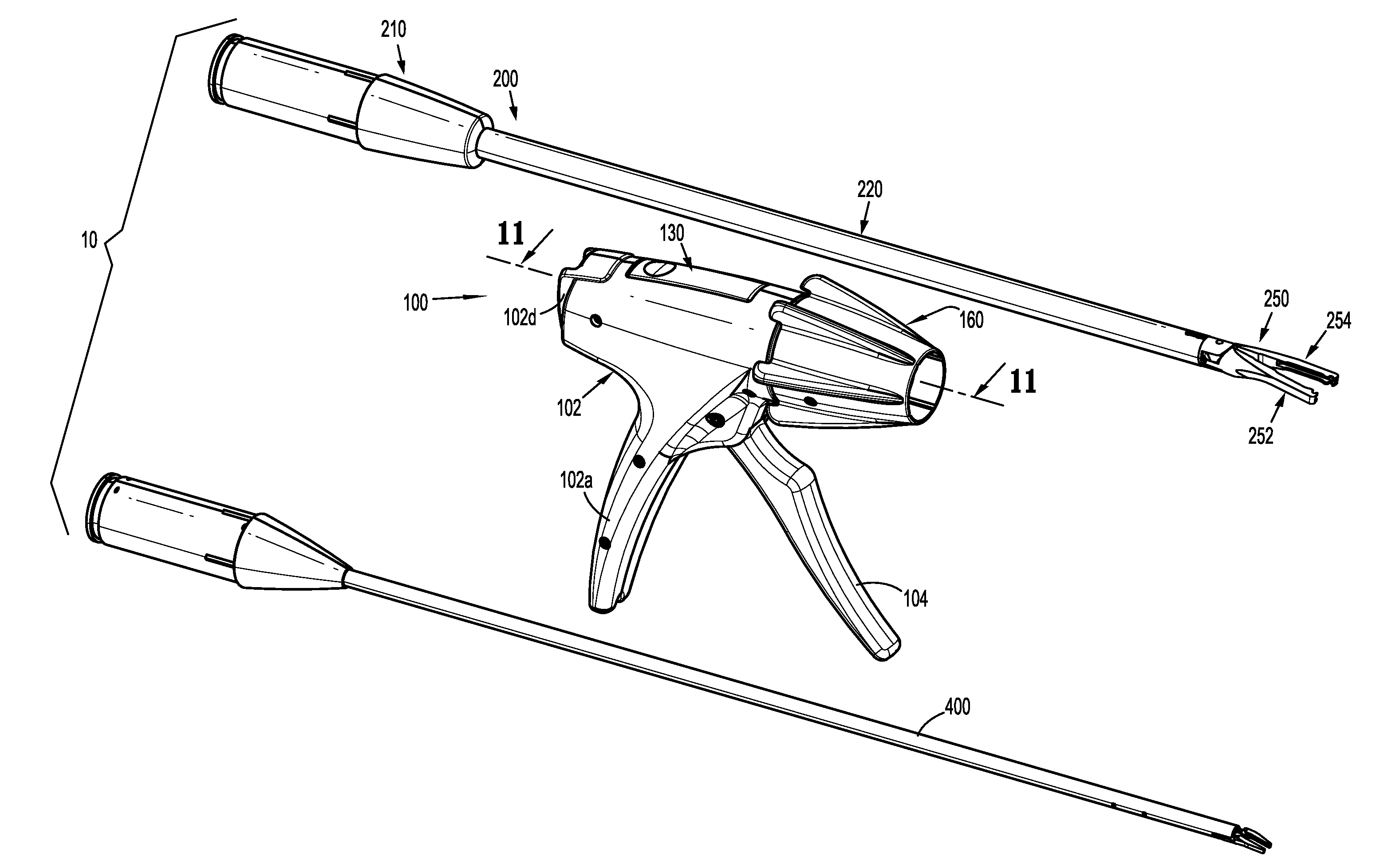
[0029] FIG. 1 is a perspective view of a reposable endoscopic surgical clip applier, according to the present disclosure including a reusable handle assembly, and a first endoscopic assembly and a second endoscopic assembly each selectively connectable to the handle assembly;
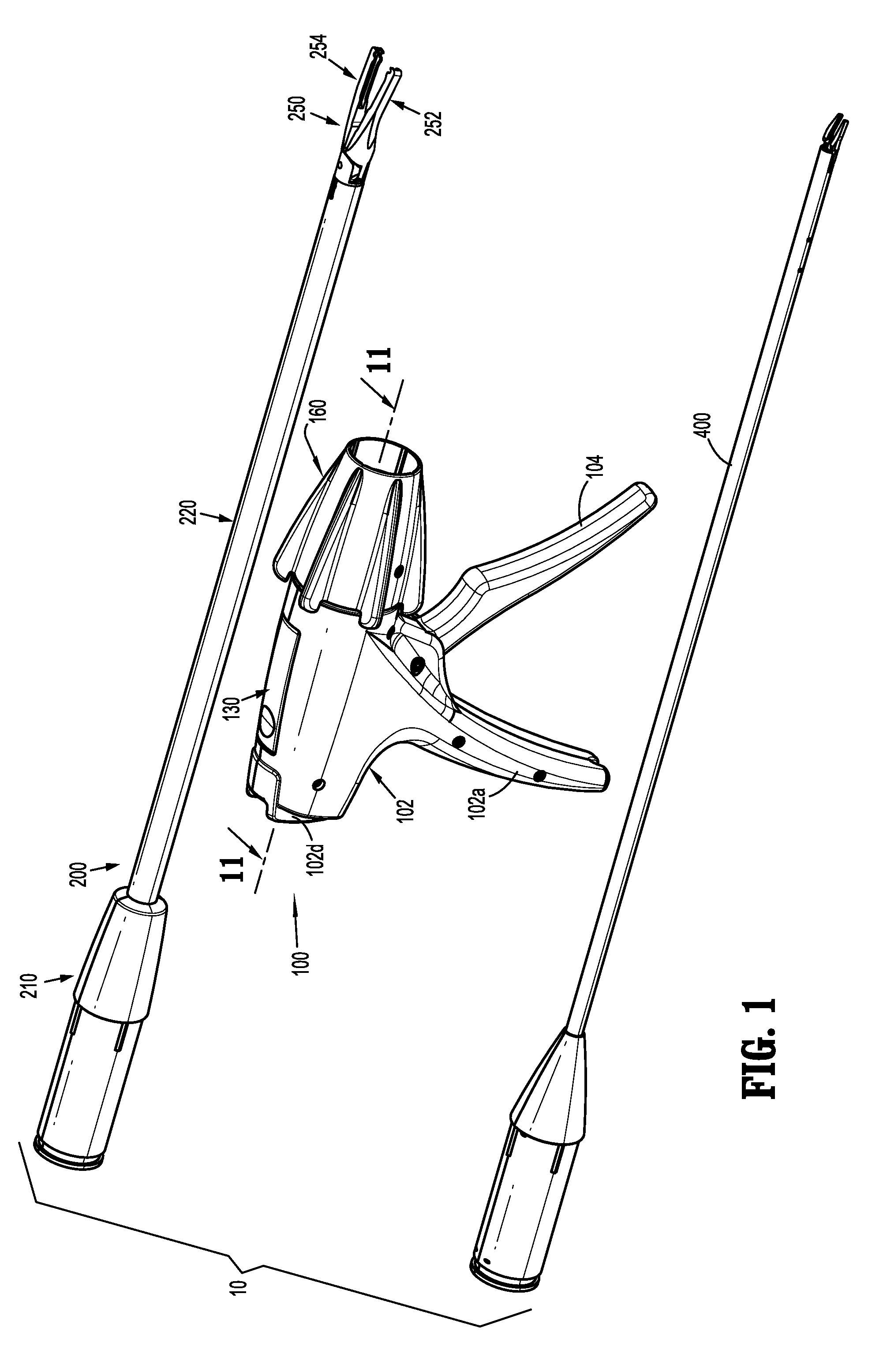
[0030] FIG. 2 is perspective view of the reposable endoscopic surgical clip applier including the reusable handle assembly and the first endoscopic assembly connected thereto;
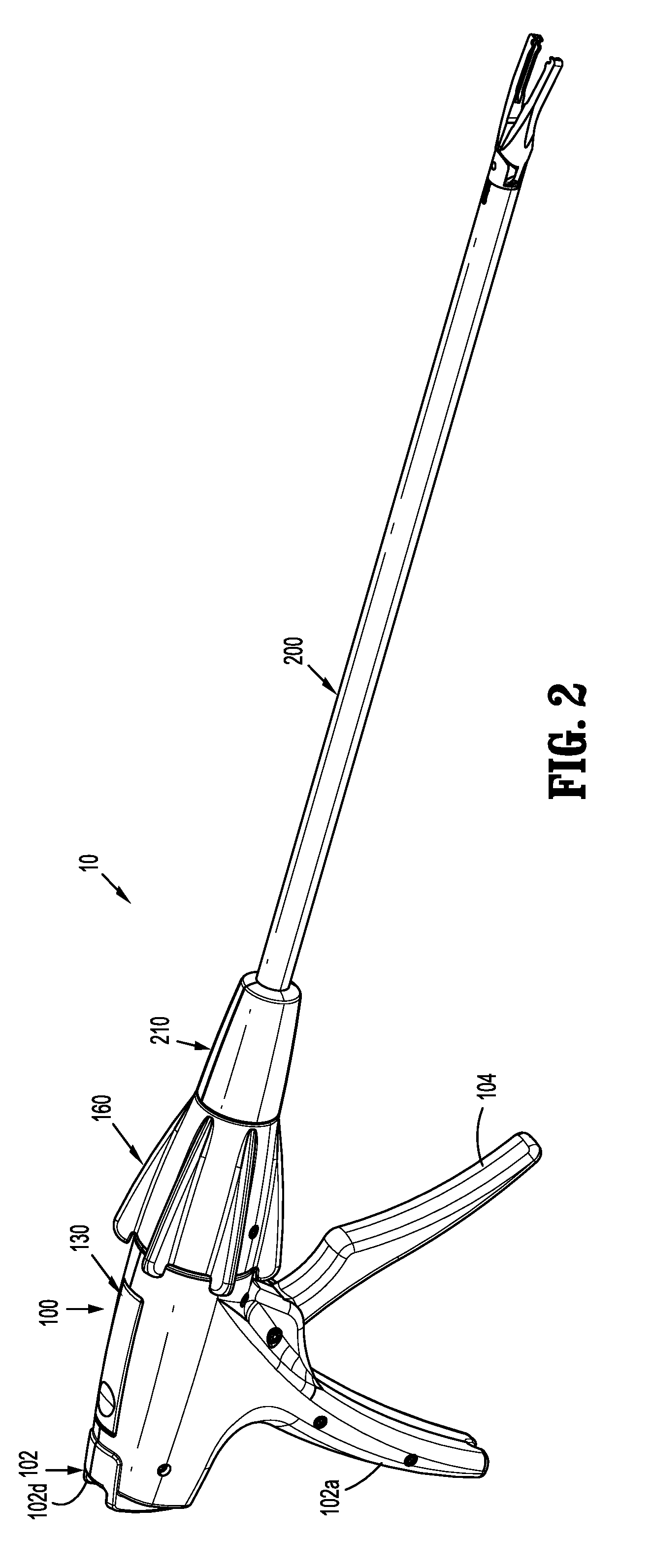
[0031] FIG. 3 is a perspective view of the handle assembly with at least a housing half-section removed therefrom;
[0032] FIG. 4 is a perspective view, with parts separated, of the handle assembly of FIGS. 1-3;
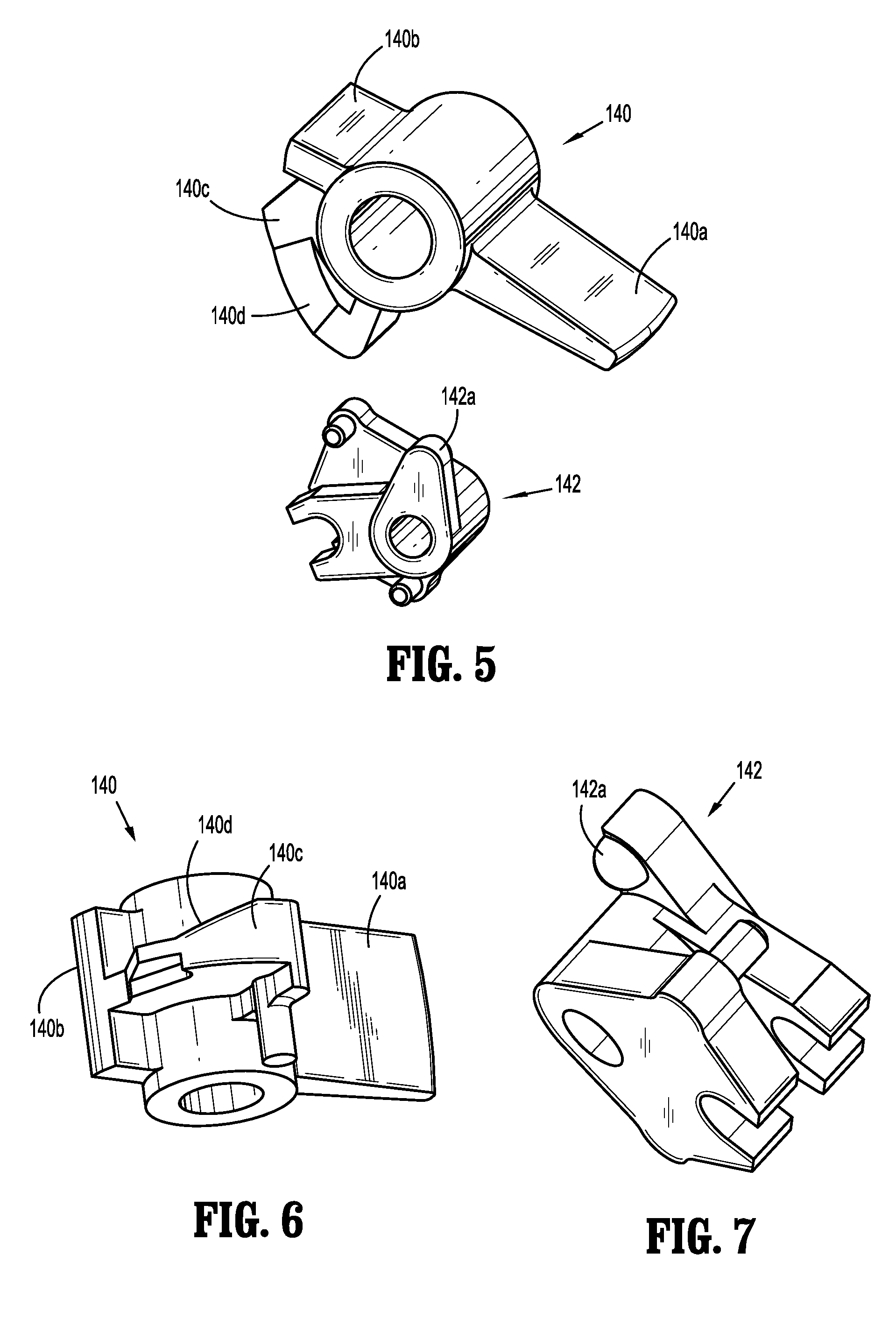
[0033] FIG. 5 is an enlarged perspective view of the indicated area of detail of FIG. 4, illustrating a pawl switch and a pawl actuator of the handle assembly of FIG. 1;
[0034] FIG. 6 is a further perspective view of the pawl switch of FIG. 5;
[0035] FIG. 7 is a further perspective view of the pawl actuator of FIG. 5;
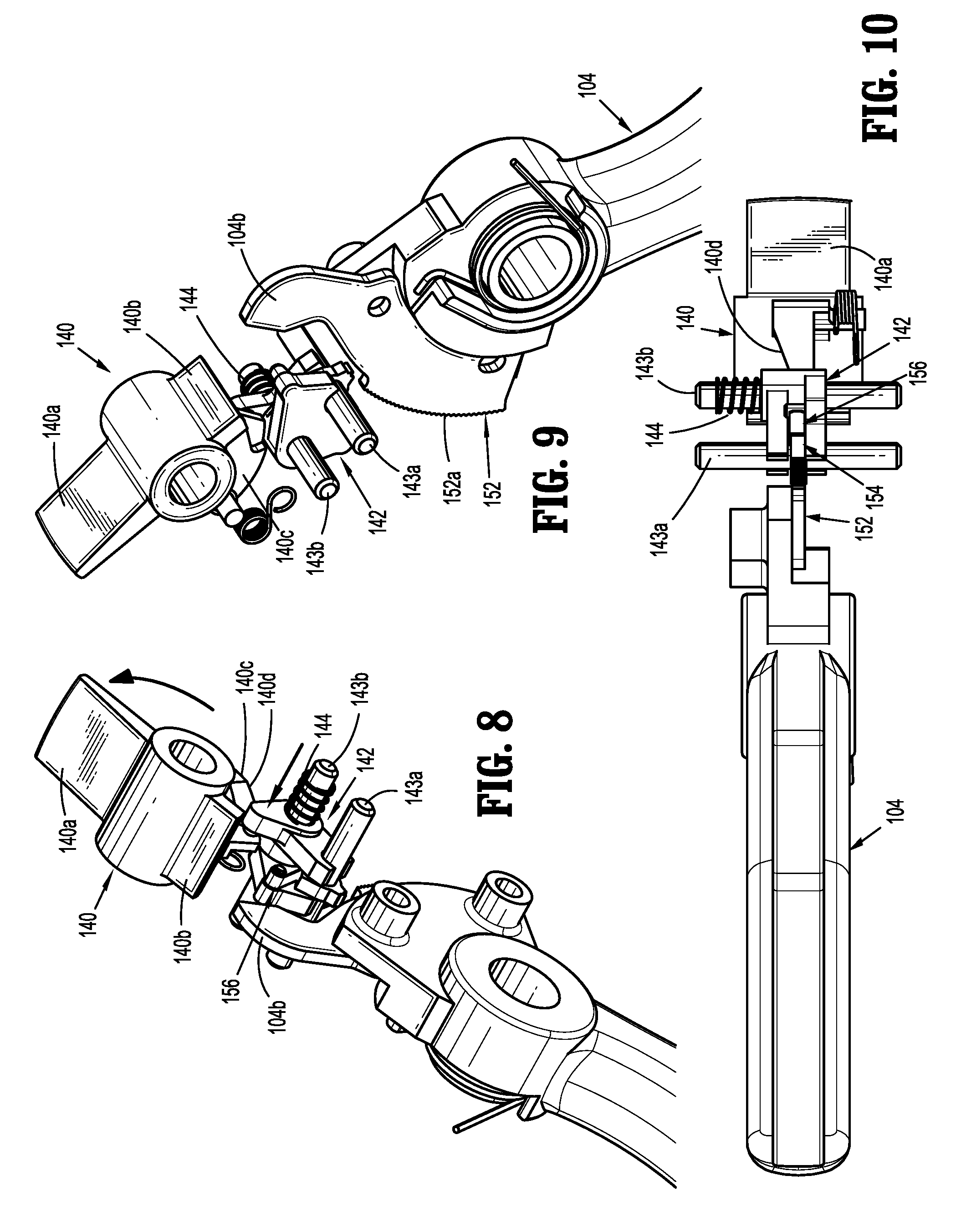
[0036] FIGS. 8-9 are various perspective views of the pawl switch and the pawl actuator of the handle assembly, shown in operation with the pawl switch in an un-actuated condition and the pawl actuator engaged with a pawl of a ratchet assembly;
[0037] FIG. 10 is a top plan view of the pawl switch and the pawl actuator of the handle assembly, shown in operation with the pawl switch in the un-actuated condition and the pawl actuator engaged from the pawl of the ratchet assembly;
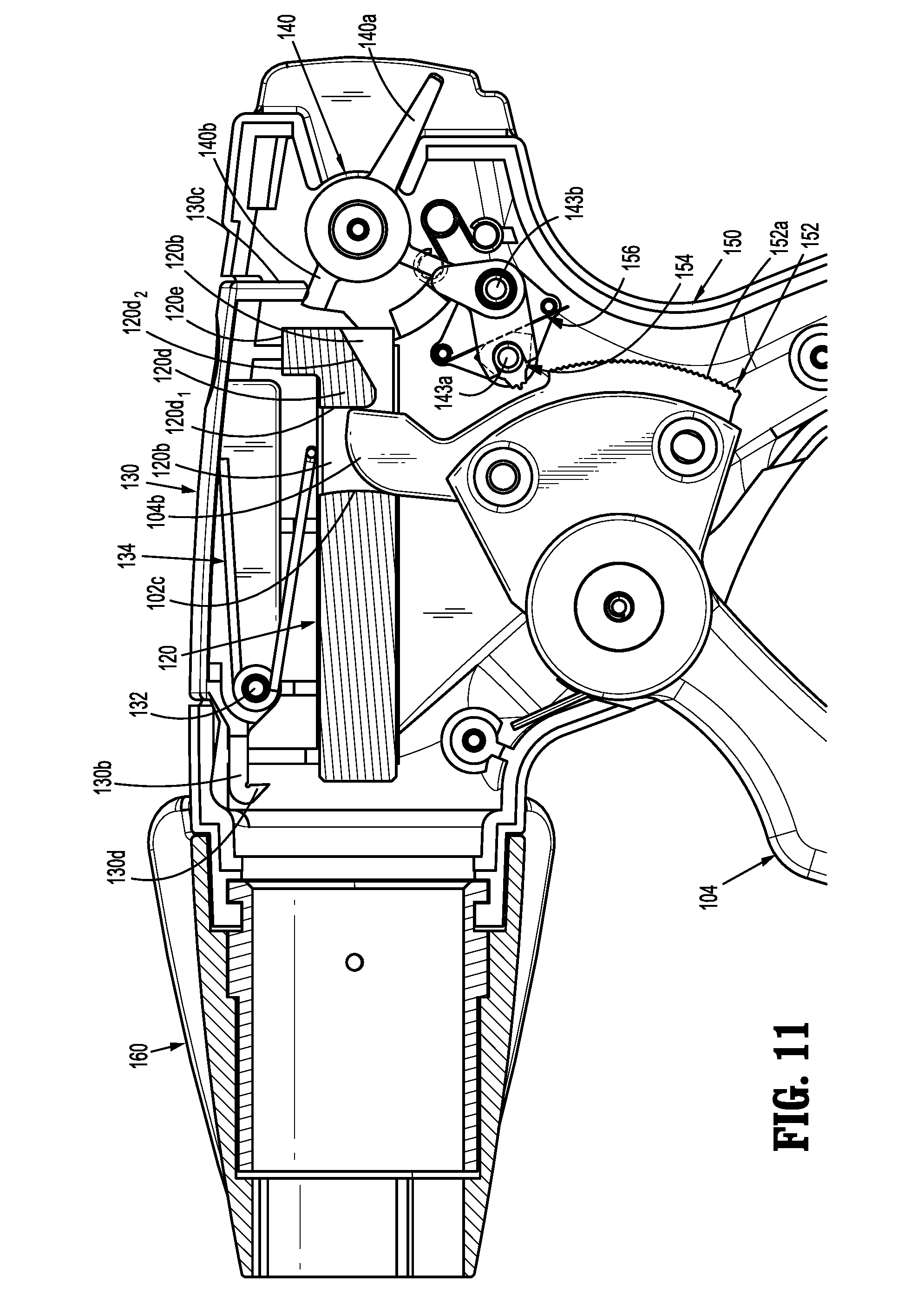
[0038] FIG. 11 is a transverse, cross-sectional view of the handle assembly of FIG. 1 as taken through 11-11 of FIG. 1, illustrating the pawl switch in an actuated condition;
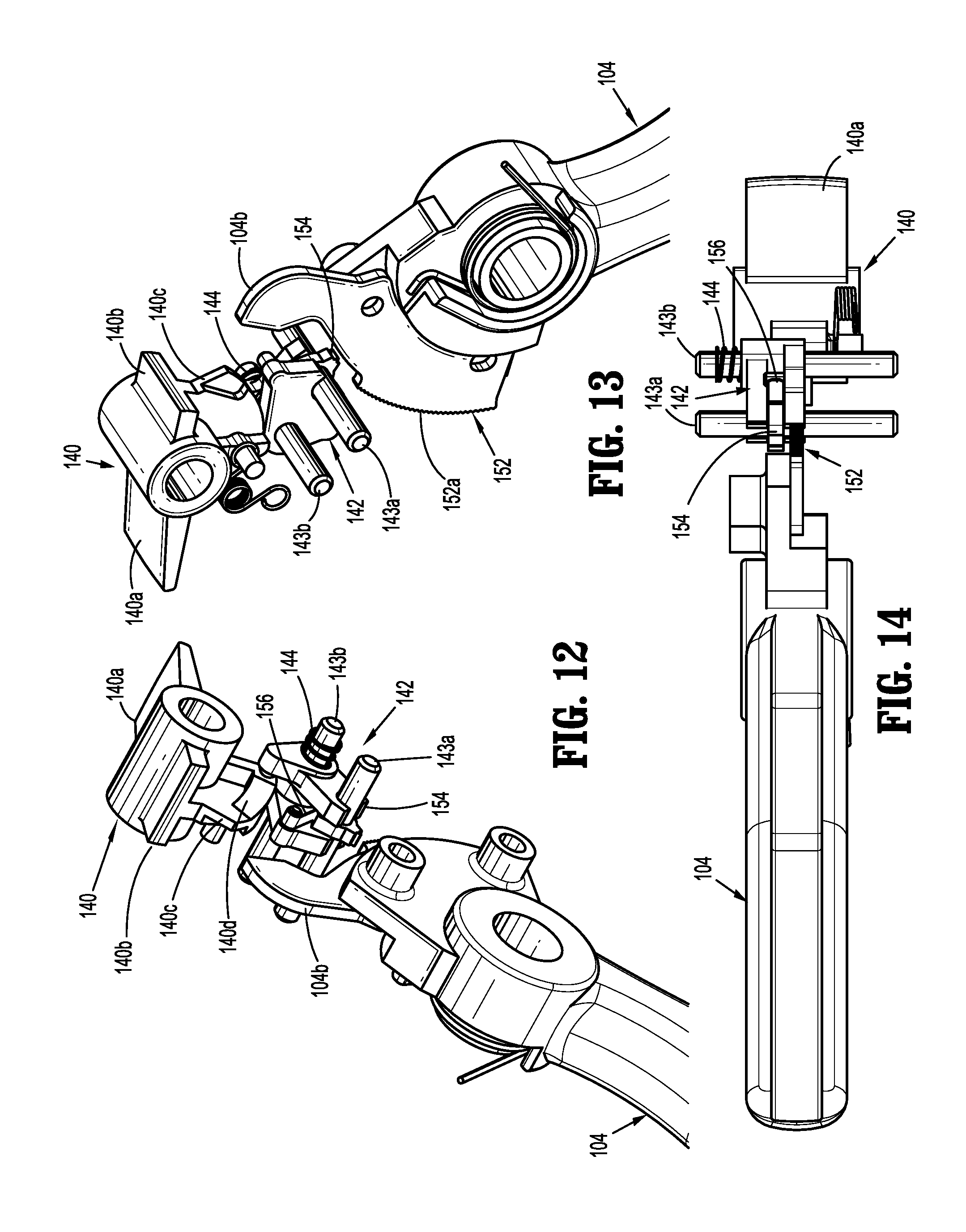
[0039] FIGS. 12-13 are various perspective views of the pawl switch and the pawl actuator of the handle assembly, shown in operation with the pawl switch in the actuated condition and the pawl actuator disengaged from the pawl of the ratchet assembly;
[0040] FIG. 14 is a top plan view of the pawl switch and the pawl actuator of the handle assembly, shown in operation with the pawl switch in the actuated condition and the pawl actuator disengaged from the pawl of the ratchet assembly;
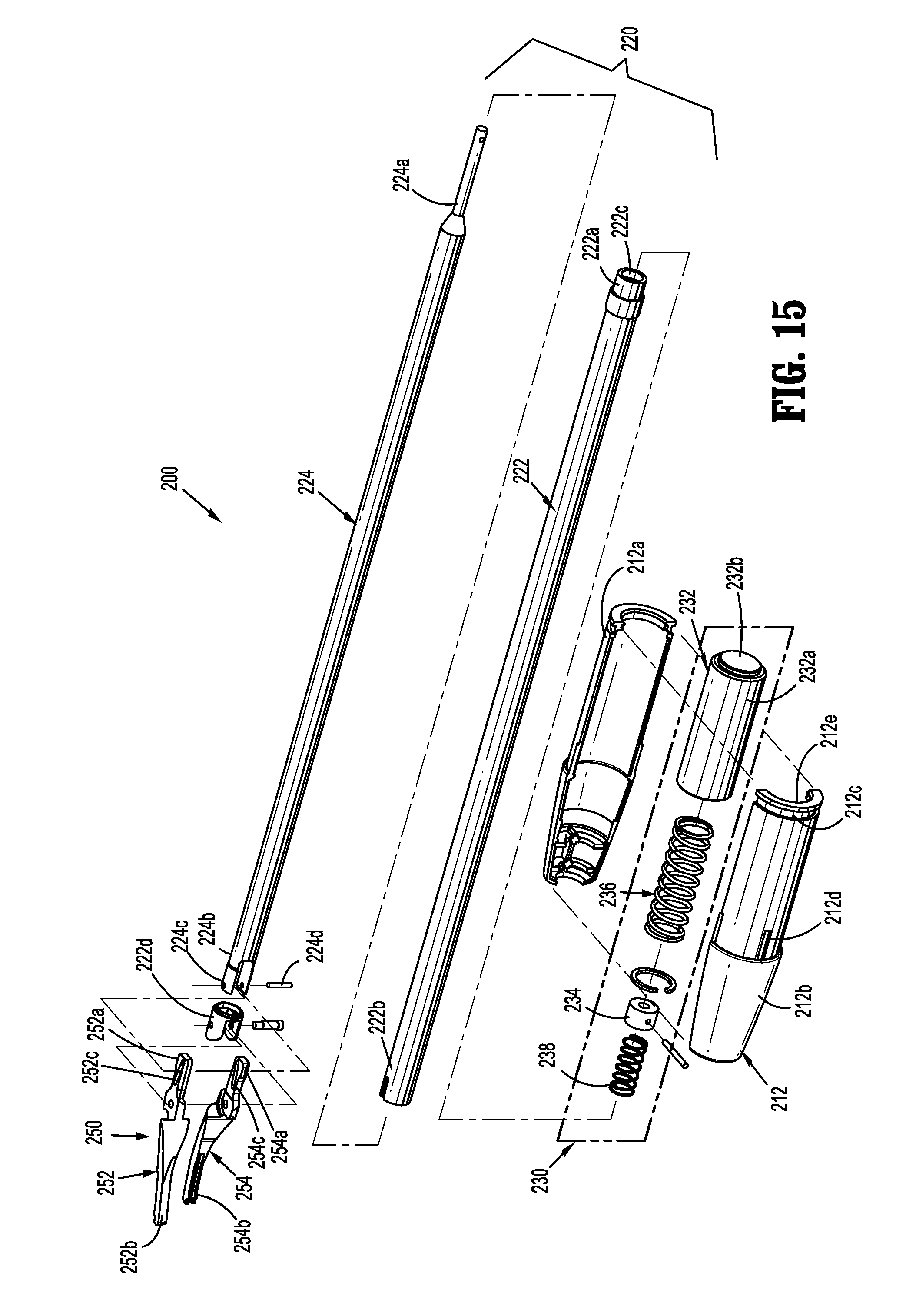
[0041] FIG. 15 is a perspective view, with parts separated, of the first endoscopic assembly of FIG. 1;
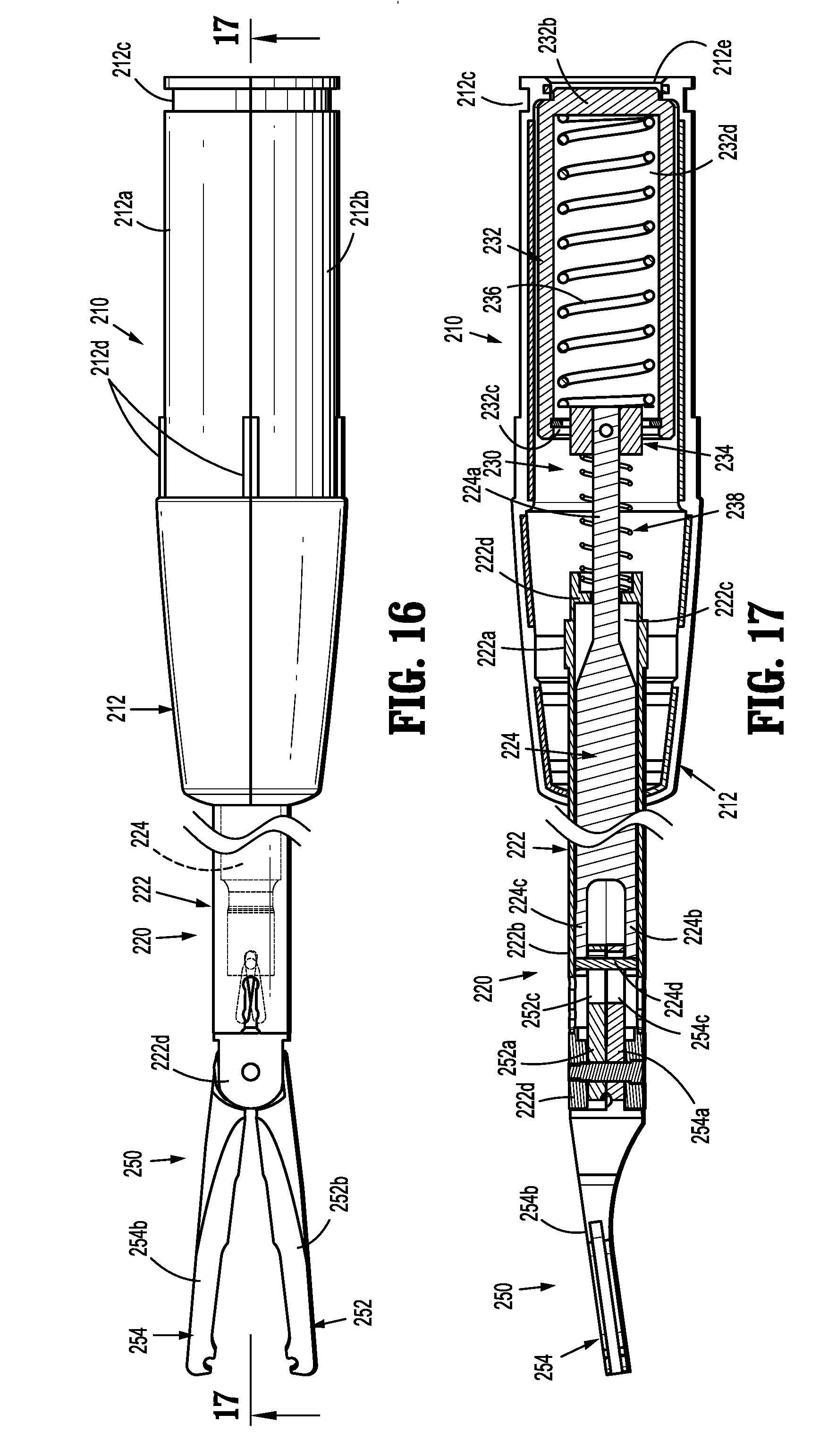
[0042] FIG. 16 is a top, plan view of the first endoscopic assembly of FIGS. 1 and 15;
[0043] FIG. 17 is a transverse, cross-sectional view of the first endoscopic assembly of FIGS. 1 and 15-16, as taken through 17-17 of FIG. 16;
[0044] FIG. 18 is a perspective view illustrating an initial connection of the handle assembly and the first endoscopic assembly;
[0045] FIG. 19 is a longitudinal, transverse cross-sectional view illustrating the initial connection of the handle assembly and the first endoscopic assembly;
[0046] FIG. 20 is an enlarged view of the indicated area of detail of FIG. 19;
[0047] FIG. 21 is a longitudinal, transverse cross-sectional view illustrating a complete connection of the handle assembly and the first endoscopic assembly;
[0048] FIG. 22 is an enlarged view of the indicated area of detail of FIG. 21;
[0049] FIG. 23 is a longitudinal, transverse cross-sectional view illustrating an initial actuation of the handle assembly with the first endoscopic assembly connected thereto;
[0050] FIG. 24 is an enlarged view of the indicated area of detail of FIG. 23;
[0051] FIG. 25 is a longitudinal, transverse cross-sectional view illustrating a complete actuation of the handle assembly with the first endoscopic assembly connected thereto;
[0052] FIG. 26 is perspective view of the reposable endoscopic surgical clip applier including the reusable handle assembly and the second endoscopic assembly connected thereto;
[0053] FIG. 27 is a perspective view, with parts separated, of the second endoscopic assembly of FIGS. 1 and 26;
[0054] FIG. 28 is a perspective view, with parts separated, of a shaft assembly of the second endoscopic assembly;
[0055] FIG. 29 is a perspective view of the distal end of the shaft assembly of the second endoscopic assembly with an outer tube removed therefrom;
[0056] FIG. 30 is an enlarged view of the indicated area of detail of FIG. 29;
[0057] FIG. 31 is an enlarged view of the indicated area of detail of FIG. 29;
[0058] FIG. 32 is a perspective view of the distal end of the shaft assembly of the second endoscopic assembly with the outer tube and a pusher bar removed therefrom;
[0059] FIG. 33 is an enlarged view of the indicated area of detail of FIG. 32;
[0060] FIG. 34 is an enlarged view of the indicated area of detail of FIG. 32;
[0061] FIG. 35 is a perspective view of the distal end of the shaft assembly of the second endoscopic assembly with the outer tube, the pusher bar and a clip channel removed therefrom;
[0062] FIG. 36 is an enlarged view of the indicated area of detail of FIG. 35;
[0063] FIG. 37 is an enlarged view of the indicated area of detail of FIG. 35;
[0064] FIG. 38 is a perspective view of the distal end of the shaft assembly of the second endoscopic assembly with the outer tube, the pusher bar, the clip channel and a pair of jaws and a filler component removed therefrom;
[0065] FIG. 39 is a perspective view of the distal end of the shaft assembly of the second endoscopic assembly with the outer tube, the pusher bar, the clip channel, the pair of jaws, the filler component, and a wedge plate removed therefrom;
[0066] FIG. 40 is a longitudinal, transverse cross-sectional view illustrating a complete connection of the handle assembly and the second endoscopic assembly, prior to actuation of a trigger of the handle assembly;
[0067] FIG. 41 is a longitudinal, transverse cross-sectional view illustrating a complete actuation of the handle assembly with the second endoscopic assembly connected thereto;
[0068] FIG. 42 is a perspective view of another embodiment of an endoscopic assembly provided in accordance with the present disclosure;
[0069] FIG. 43 is a longitudinal, cross-sectional view of the endoscopic assembly of FIG. 42, as taken through 43-43 of FIG. 42; FIG. 44 is a longitudinal, cross-sectional view of a housing half section of the endoscopic assembly of FIG. 42;
[0070] FIG. 45 is a perspective view, with parts separated of the endoscopic assembly of FIG. 42;
[0071] FIG. 46 is a perspective view of a cartridge cylinder of the endoscopic assembly of FIG. 42;
[0072] FIG. 46A is a longitudinal, cross-sectional view of the cartridge cylinder of FIG. 46, as taken through 46A-46A of FIG. 46;
[0073] FIG. 47 is a perspective view of a spindle of the endoscopic assembly of FIG. 42;
[0074] FIG. 48 is a perspective view of a stationary gear of the endoscopic assembly of FIG. 42;
[0075] FIG. 48A is a longitudinal, cross-sectional view of the stationary gear of FIG. 48, as taken through 48A-48A of FIG. 48;
[0076] FIG. 48B is an unwrapped view of an outer surface of the stationary gear of FIG. 48;
[0077] FIG. 49 is a perspective view of a sliding gear of the endoscopic assembly of FIG. 42;
[0078] FIG. 49A is a side view of the sliding gear of FIG. 49;
[0079] FIG. 50 is a perspective view of a display drum of the endoscopic assembly of FIG. 42;
[0080] FIG. 50A is a longitudinal, cross-sectional view of the display drum of FIG. 50, as taken through 50A-50A of FIG. 50;
[0081] FIG. 51 is a perspective view of a rotating gear of the endoscopic assembly of FIG. 42;
[0082] FIG. 52 is a rear view of the rotating gear of FIG. 51;
[0083] FIG. 53 is a longitudinal, cross-sectional view of the rotating gear of FIG. 51, as taken through 53-53 of FIG. 51;
[0084] FIG. 54A is a side view of a spring clip of the endoscopic assembly of FIG. 42;
[0085] FIG. 54B is a rear view of the spring clip of FIG. 54A;
[0086] FIG. 55A is a longitudinal, cross-sectional view of the endoscopic assembly of FIG. 42, shown in an unactuated position;
[0087] FIG. 55B is a longitudinal, cross-sectional view of the endoscopic assembly of FIG. 42, shown in a partially actuated position;
[0088] FIG. 56A is a longitudinal, cross-sectional view of the endoscopic assembly of FIG. 42, shown with the rotating gear of FIG. 51 in engagement with the stationary gear of FIG. 48 and with the spindle of FIG. 47 in an unactuated position;
[0089] FIG. 56B is a longitudinal, cross-sectional view of the endoscopic assembly of FIG. 42, shown with the rotating gear of FIG. 51 in engagement with the stationary gear of FIG. 48 and with the spindle of FIG. 47 in a partially actuated position;
[0090] FIG. 57 is a longitudinal, cross-sectional view of the endoscopic assembly of FIG. 42, shown with the sliding gear of FIG. 49 in engagement with the rotating gear of FIG. 51;
[0091] FIG. 58 is a longitudinal, cross-sectional view of the endoscopic assembly of FIG. 42, shown with the sliding gear of FIG. 49 disengaged from the rotating gear of FIG. 51 and with the rotating gear of FIG. 51 in engagement with the stationary gear of FIG. 48;
[0092] FIG. 59A is a longitudinal, partial cross-sectional view of the endoscopic assembly of FIG. 42, shown with a first and second contrasting color of the display drum of FIG. 50 hidden from view;
[0093] FIG. 59B is a longitudinal, partial cross-sectional view of the endoscopic assembly of FIG. 42, shown with the first contrasting color of the display drum of FIG. 50 visible through a window of the housing half section of FIG. 44;
[0094] FIG. 59C is a longitudinal, partial cross-sectional view of the endoscopic assembly of FIG. 42, shown with the second contrasting color of the display drum of FIG. 50 visible through the window of the housing half-section of FIG. 44;
[0095] FIG. 60 is a longitudinal, partial cross-sectional view of the endoscopic assembly of FIG. 42, shown with the spring clip of FIG. 54A received within a portion of the spindle of FIG. 47; and
[0096] FIG. 61 is a schematic illustration of a robotic surgical system configured for use in accordance with the present disclosure.
DETAILED DESCRIPTION OF EMBODIMENTS
[0097] Embodiments of reposable endoscopic surgical clip appliers, in accordance with the present disclosure, will now be described in detail with reference to the drawing figures wherein like reference numerals identify similar or identical structural elements. As shown in the drawings and described throughout the following description, as is traditional when referring to relative positioning on a surgical instrument, the term "proximal" refers to the end of the apparatus which is closer to the user and the term "distal" refers to the end of the apparatus which is further away from the user.
[0098] Referring now to FIGS. 1-29, an endoscopic surgical clip applier in accordance with an embodiment of the present disclosure, and assembly in a particular configuration, is generally designated as 10. Surgical clip applier 10 generally includes a reusable handle assembly or actuation assembly 100, at least one disposable or reusable endoscopic assembly 200 selectively connectable to and extendable distally from handle assembly 100; and optionally at least one disposable surgical clip cartridge assembly (not shown) selectively loadable into a shaft assembly of a respective endoscopic assembly 200.
[0099] Briefly, the shaft assembly of endoscopic assembly 200 may have various outer diameters such as, for example, about 5 mm or about 10 mm, depending on intended use. Further, the shaft assembly may have various relatively elongated or shortened lengths depending on intended use, such as, for example, in bariatric surgery. In one embodiment, in bariatric surgery, the shaft assembly may have a length of between about 30 cm and about 40 cm. Further, the shaft assembly may be configured to fire and form a specific type of surgical clip, either individually or multiply. However one skilled in the art should appreciate that the shaft assembly may have any length in excess of about 30 cm and the present disclosure is not limited to any of the above identified lengths.
[0100] In accordance with the present disclosure, as will be discussed in greater detail below, an endoscopic assembly or a surgical clip cartridge assembly (not shown) may be loaded with a particularly sized set of surgical clips (e.g., relatively small surgical clips, relatively medium surgical clips, or relatively large surgical clips). It is contemplated that clip cartridge assemblies may be configured to be selectively loaded into the shaft assembly of a respective endoscopic assembly 200, and to be actuated by the same or common handle assembly 100, to fire and form the surgical clip(s) loaded therein onto underlying tissue and/or vessels.
[0101] Referring now to FIGS. 1-14, handle assembly 100 of surgical clip applier 10 is shown and will be described. Handle assembly 100 includes a housing 102 having a first or right side half-section 102a and a second or left side half-section 102b. Housing 102 of handle assembly 100 further includes or defines, as seen in FIGS. 3 and 4, a nose 102c. Housing 102 of handle assembly 100 may be formed of a suitable plastic or thermoplastic material. It is further contemplated that housing 102 of handle assembly 100 may be fabricated from stainless steel of the like.
[0102] Handle assembly 100 includes a trigger 104 pivotably supported between right side half-section 102a and left side half-section 102b of housing 102. Trigger 104 is biased by a biasing member 104a (e.g., a return spring, compression spring or torsion spring) to an un-actuated condition. Specifically, biasing member 104a (FIG. 4) acts on a feature of trigger 104 and on a feature of housing 102 to bias or urge trigger 104 to the un-actuated condition. Trigger 104 includes a drive arm 104b extending therefrom. Drive arm 104b may be integrally formed therewith or may be separately and fixedly secured to trigger 104. Drive arm 104b may define a curved, radiused or filleted upper distal surface.
[0103] As illustrated in FIGS. 3, 4 and 8-14, trigger 104 supports or is provided with at least one linear rack 152 of teeth 152a of a ratchet assembly 150, as will be described in detail below.
[0104] With reference to FIGS. 3, 4, 11, handle assembly 100 includes a drive plunger 120 operatively connected to trigger 104. Specifically, drive plunger 120 is slidably supported within housing 102 and defines a pair of opposed, axially extending slots 120a formed in an outer surface thereof. Slots 120a of drive plunger 120 are configured to slidably engage or receive opposed tabs 102d of housing 102. Drive plunger 120 further defines a proximally extending trigger slot 120b formed in a proximal portion thereof for operatively receiving drive arm 104b of trigger 104. Trigger slot 120b defines a distal surface or wall 120c against which a distal surface of drive arm 104b of trigger 104 contacts in order to distally advance drive plunger 120 during an actuation of trigger 104.
[0105] Drive plunger 120 further includes a tooth 120d (FIG. 11) projecting into trigger slot 120b. Tooth 120d projects substantially toward trigger 104 and includes a distal surface or wall 120d1 (spaced proximally from distal surface or wall 120c of drive plunder 120), and a proximal, angled wall 120d2 tapering to a relatively smaller height in a proximal direction.
[0106] Drive plunger 120 additionally includes a tab or fin 120e projecting from a surface thereof. Tab 120e of drive plunger 120 may be substantially aligned or in registration with tooth 120d of drive plunger 120. Tab 120e of drive plunger 120 may project in a direction substantially opposite to tooth 120d of drive plunger 120 or to trigger 104.
[0107] With reference to FIGS. 1-4 and 11, handle assembly 100 includes an endoscopic assembly release lever 130 pivotally supported on and connected to housing 102 via a pivot pin 132. Pivot pin 132 is supported in housing 102. Release lever 130 includes a proximal end 130a extending proximally of pivot pin 132. Proximal end 130a of release lever 130 includes a wall 130c dimensioned to extend toward a pawl switch 140 of handle assembly 100, as will be described in greater detail below.
[0108] Release lever 130 includes a distal end 130b extending distally of pivot pin 132. Distal end 130b of release lever 130 includes a catch or tooth 130d projecting therefrom, in a direction towards drive plunger 120. Catch 130d may be located distal of drive plunger 120.
[0109] A biasing member 134, in the form of a leaf spring, may be provided which tends to bias distal end 130b and catch 130d of release lever 130 towards drive plunger 120 of handle assembly 100, and tends to bias proximal end 130a of release lever 130 away from pawl switch 140. Specifically, biasing member 134 tends to maintain catch 130d of release lever 130 in engagement with an engagement feature (e.g., annular channel 212c) of endoscopic assembly 200, as will be described in greater detail below.
[0110] With reference to FIGS. 3, 4 and 11-14, as mentioned above, handle assembly 100 includes a ratchet assembly 150 supported within housing 102. Ratchet assembly 150 includes, as also mentioned above, at least one linear rack 152 of teeth 152a supported on and projecting from trigger 104. Ratchet assembly 150 further includes a ratchet pawl 154 pivotally connected to housing 102 by a pawl pin at a location wherein pawl 154 is in substantial operative engagement with rack 152. Ratchet assembly 150 further includes a pawl spring 156 configured and positioned to bias pawl 154 into operative engagement with rack 152. Pawl spring 156 functions to maintain the tooth or teeth 154a of pawl 154 in engagement with teeth 152a of rack 152, as well as to maintain pawl 154 in a rotated or canted position.
[0111] Pawl 154 is engagable with rack 152 to restrict longitudinal movement of rack 152 and, in turn, trigger 104. In use, as trigger 104 is actuated (from a fully un-actuated position), rack 152 is also moved, into engagement with pawl 154. Rack 152 has a length which allows pawl 154 to reverse and advance back over rack 152, when rack 152 changes between proximal or distal movement, as trigger 104 reaches a fully actuated or fully un-actuated position. The relative lengths and sizes of rack 152 of ratchet assembly 150, trigger 104 and drive plunger 120 define a stroke length of trigger 104, drive plunger 120 or handle assembly 100 (e.g., a "full stroke").
[0112] Turning now to FIGS. 1, 2, 4, 11 and 18, handle assembly 100 includes a rotation knob 160 rotatably supported on nose 102c of housing 102. Rotation knob 160 includes a central axial bore 160a having an annular array of longitudinally extending grooves 160b (FIG. 18) formed in a surface thereof. Grooves 160b of rotation knob 160 function as clocking and alignment features for the connection of endoscopic assembly 200 with handle assembly 100. Rotation knob 160 further includes a plurality of finger grip ribs 160c projecting from an outer surface thereof.
[0113] With reference to FIGS. 3 and 4-14, handle assembly 100 further includes a pawl switch 140 and a pawl actuator 142 each pivotally supported in housing 102. Pawl switch 140 is operatively connected to pawl actuator 142 and is operable to selectively move pawl actuator 142 into or out of engagement with pawl spring 156, and in turn pawl 154, of ratchet assembly 150 whereby pawl 154 may be selectively engaged by pawl spring 156. In this manner, when pawl 154 is moved out of engagement with pawl spring 156, trigger 104 is free to open and close as needed due to pawl 154 having minimal blocking effect on rack 152 of ratchet assembly 150. As such, trigger 104 may be partially actuated (without having to be fully actuated), and may be returnable to a fully un-actuated position. Such a feature permits the user to partially squeeze or actuate trigger 104 for performing a cholangiogram procedure or the like.
[0114] Pawl switch 140 includes a finger lever 140a projecting from housing 102, whereby pawl switch 140 may be actuated by a finger of a user. Housing 102 of handle assembly 100 may be provided with guard walls 102d disposed on opposed sides of finger lever 140a in order to inhibit inadvertent actuation of pawl switch 140. Pawl switch 140 is movable, upon actuation of finger lever 140a, between a first position in which ratchet assembly 150 is "on" or "activated", and a second position in which ratchet assembly 150 is "off" or "de-activated." It is contemplated that pawl switch 140, and in turn ratchet assembly 150, default to the first position.
[0115] Pawl switch 140 further includes a first flange 140b projecting a first distance from a pivot point thereof, and a second flange 140c projecting a second distance from the pivot point thereof, wherein the projection of the second flange 140c is greater than the projection of the first flange 140b. First flange 140b of pawl switch 140 is selectively engagable by wall 130c of proximal end 130a of release lever 130. In this manner, each time an endoscopic assembly 200 is attached to handle assembly 100, and release lever 130 is actuated, wall 130c of release lever 130 engages first flange 140b of pawl switch 140 to move pawl switch to the first position (FIGS. 19-22).
[0116] Pawl switch 140 also includes a ramp or camming surface 140d projecting therefrom which selectively engages a tab or finger 142a of pawl actuator 142 to slidably move pawl actuator 142, and in turn pawl spring 156, into and out of operative engagement/registration with/from pawl 154.
[0117] Pawl actuator 142 is pivotally connected to housing 102 and operatively connected to pawl switch 140 such that actuation of pawl switch 140 actuates pawl actuator 142. Pawl actuator 142 is slidably supported on a pair of support pins 143a, 143b, and a biasing member 144 is provided to bias pawl actuator 142 against pawl switch 140. In operation, with reference to FIGS. 11-14, when pawl switch 140 is actuated to the second position, ramp or camming surface 140d of pawl switch 140 acts on tab 142a of pawl actuator 142 to transversely slide pawl actuator 142 along support pins 143a, 143b and move pawl spring 156 out of operative engagement/registration with pawl 154, thereby disabling the operability of ratchet assembly 150. Also, as pawl actuator 142 is slid transversely along support pins 143a, 143b, pawl actuator 142 biases biasing member 144.
[0118] Further in operation, with reference to FIGS. 8-10, when pawl switch 140 is actuated to the first position, ramp or camming surface 140d of pawl switch 140 is moved to permit biasing member 144 to expand and transversely slide pawl actuator 142 along support pins 143a, 143b, whereby pawl spring 156 is moved back into operative engagement/registration with pawl 154, thereby enabling or re-enabling the operability of ratchet assembly 150.
[0119] Turning now to FIGS. 1, 2, 16 and 17, an embodiment of an endoscopic assembly 200, of surgical clip applier 10, is shown and described. Endoscopic assembly 200 includes a hub assembly 210, a shaft assembly 220 extending from hub assembly 210, and a pair of jaws 250 pivotally connected to a distal end of shaft assembly 220. It is contemplated that endoscopic assembly 200 may be configured to close, fire or form surgical clips similar to those shown and described in U.S. Pat. No. 4,834,096, the entire content of which is incorporated herein by reference.
[0120] Hub assembly 210 functions as an adapter assembly which is configured for selective connection to rotation knob 160 and nose 102c of housing 102 of handle assembly 100. Hub assembly 210 includes an outer housing 212 having a cylindrical outer profile. Outer housing 212 includes a first or right side half section 212a, and a second or left side half section 212b. Outer housing 212 of hub assembly 210 defines an outer annular channel 212c formed in an outer surface thereof, and at least one (or an annular array) of axially extending ribs 212d projecting from an outer surface thereof. Outer annular channel 212c of outer housing 212 of endoscopic assembly 200 is configured to receive catch 130d of release lever 130 of handle assembly 100 (FIGS. 19-22) when endoscopic assembly 200 is coupled to handle assembly 100.
[0121] Ribs 212d of outer housing 212 function as a clocking/alignment feature during connection of endoscopic assembly 200 and handle assembly 100 with one another, wherein ribs 212d of outer housing 212 of endoscopic assembly 200 are radially and axially aligned with respective grooves 160b of rotation knob 160 of handle assembly 100. During connection of endoscopic assembly 200 and handle assembly 100, ribs 212d of outer housing 212 of endoscopic assembly 200 are slidably received in respective grooves 160b of rotation knob 160 of handle assembly 100.
[0122] The connection of hub assembly 210 of endoscopic assembly 200 with rotation knob 160 of handle assembly 100 enables endoscopic assembly 200 to rotate 360.degree., about a longitudinal axis thereof, relative to handle assembly 100.
[0123] Outer housing 212 of hub assembly 210 further defines an open proximal end 212e configured to slidably receive a distal end of drive plunger 120 of handle assembly 100, when endoscopic assembly 200 is coupled to handle assembly 100 and/or when surgical clip applier 10 is fired.
[0124] As mentioned above, endoscopic assembly 200 includes a shaft assembly 220 extending distally from hub assembly 210. Shaft assembly 220 includes an elongate outer tube 222 having a proximal end 222a supported and secured to outer housing 212 of hub assembly 210, a distal end 222b projecting from outer housing 212 of hub assembly 210, and a lumen 222c (FIGS. 15 and 17) extending longitudinally therethrough. Distal end 222b of outer tube 222 supports or defines an outer clevis 222d for pivotally supporting a pair of jaws 250, as will be described in greater detail below.
[0125] Shaft assembly 220 further includes an inner shaft 224 slidably supported within lumen 222c of outer tube 222. Inner shaft 224 includes a proximal end 224a projecting proximally from proximal end 222a of outer tube 222, and a distal end 224b defining an inner clevis 224c for supporting a cam pin 224d which engages camming slots 252c, 254c of a pair of jaws 250, as will be described in greater detail below.
[0126] With reference to FIGS. 15 and 17, hub assembly 210 includes a drive assembly 230 supported within outer housing 212 thereof. Drive assembly 230 includes a cartridge cylinder 232 having a cup-like configuration, wherein cartridge cylinder 232 includes an annular wall 232a, a proximal wall 232b supported at and closing off a proximal end of annular wall 232a, an open distal end 232c, and a cavity or bore 232d defined therewithin.
[0127] Drive assembly 230 also includes a cartridge plunger 234 slidably supported within bore 232d of cartridge cylinder 232. Cartridge plunger 234 is fixedly supported on inner shaft 224, at the proximal end 224a thereof. Cartridge plunger 234 is sized and configured for slidable receipt within bore 232d of cartridge cylinder 232 of drive assembly 230. A ring, flange or the like 235 may be fixedly supported at a distal end of bore 232d of cartridge cylinder 232, through which proximal end 224a of cartridge plunger 234 extends and which functions to maintain cartridge plunger 234 within bore 232d of cartridge cylinder 232.
[0128] Drive assembly 230 includes a first biasing member 236 (e.g., a compression spring) disposed within bore 232d of cartridge cylinder 232. Specifically, first biasing member 236 is interposed between proximal wall 232b of cartridge cylinder 232 and a proximal surface of cartridge plunger 234. First biasing member 236 has a first spring constant "K1" which is relatively more firm or more stiff, as compared to a second spring constant "K2" of a second biasing member 238, as is described in detail below.
[0129] Drive assembly 230 further includes a second biasing member 238 (e.g., a compression spring) supported on proximal end 224a of inner shaft 224. Specifically, second biasing member 238 is interposed between a proximal flange 222d of outer tube 222 and a distal surface of cartridge plunger 234. Second biasing member 238 has a second spring constant "K2" which is relatively less firm or less stiff, as compared to the first spring constant "K1" of first biasing member 236.
[0130] As illustrated in FIGS. 15 and 17, endoscopic assembly 200 includes a pair of jaws 250 pivotally supported in a clevis 222d at distal end 222b of outer tube 222 by a pivot pin 256. The pair of jaws 250 includes a first jaw 252 and a second jaw 254. Each jaw 252, 254 includes a respective proximal end 252a, 254a, and a respective distal end 252b, 254b, wherein proximal ends 252a, 254a and distal ends 252b, 254b of jaws 252, 254 are pivotable about pivot pin 256. Each proximal end 252a, 254a of respective jaws 252, 254 defines a cam slot 252c, 254c therein which is sized and configured to receive cam pin 224d of inner shaft 224. In use, as inner shaft 224 is axially displaced relative to outer shaft 222, inner shaft 224 translated cam pin 224d thereof through cam slot 252c, 254c of jaws 252, 254 to thereby open or close the pair of jaws 250.
[0131] When the pair of jaws 250 are in an open position, and a new, unformed or open surgical clip (not shown) is located or loaded within the distal ends 252b, 254b of jaws 252, 254 of the pair of jaws 250, as inner shaft 224 is moved distally relative to outer shaft 222, cam pin 224d is translated through cam slots 252c, 254c of jaws 252, 254. As cam pin 224d is translated through cam slots 252c, 254c of jaws 252, 254 the distal ends 252b, 254b of jaws 252, 254 are moved to the closed or approximated position to close and/or form the surgical clip located or loaded therewithin.
[0132] The dimensions of jaws 252, 254 and of cam slots 252c, 254c of jaws 252, 254 determines an overall length required to move jaws 252, 254 from a fully open position to a fully closed position, defining a closure stroke length of the pair of jaws 250.
[0133] With reference now to FIGS. 19-25, an operation or firing of surgical clip applier 10, including endoscopic assembly 200 operatively connected to handle assembly 100, is shown and described. With endoscopic assembly 200 operatively connected to handle assembly 100, and with a new, unformed or open surgical clip (not shown) is located or loaded within the distal ends 252b, 254b of jaws 252, 254 of the pair of jaws 250, as trigger 104 of handle assembly 100 is actuated drive bar 104b of trigger 104 acts on drive plunger 120 to distally advance drive plunger 120. As trigger 104 is actuated, pawl 154 of ratchet assembly 150 begins to engage rack 152 thereof. With pawl 154 engaged with rack 152, trigger 104 may not return to a fully unactuated position until trigger 104 completes a full actuation or stroke thereof.
[0134] As drive plunger 120 is distally advanced, a distal end of drive plunger 120 presses against proximal wall 232b of cartridge cylinder 232 of drive assembly 230 of endoscopic assembly 200 to distally advance cartridge cylinder 232. Due to first spring constant "K1" of first biasing member 236 being larger or greater than second spring constant "K2" of second biasing member 238, as cartridge cylinder 232 is advanced distally, cartridge cylinder 232 distally advances first biasing member 236, which in turn acts on cartridge plunger 234 to distally advance cartridge plunger 234. As cartridge plunger 234 is distally advanced, cartridge plunger 234 distally advances inner shaft 224 relative to outer shaft 222. Being that second biasing member 238 is interposed between proximal flange 222d of outer tube 222 and distal surface of cartridge plunger 234, as cartridge plunger 234 is distally advanced, cartridge plunger 234 also compresses second biasing member 238.
[0135] As inner shaft 224 is distally advanced relative to outer shaft 222, inner shaft 224 distally advances cam pin 224d through cam slot 252c, 254c of jaws 252, 254 to close the pair of jaws 250 and to close and/or form the surgical clip (not shown) loaded within the pair of jaws 250. Cam pin 224d of inner shaft 224 is advanced distally until cam pin 224d reaches an end of cam slots 252c, 254c of jaws 252, 254 of the pair of jaws 250 and/or until the distal ends 252b, 254b of jaws 252, 254 of the pair of jaws 250 are fully approximated against one another (e.g., in contact with one another or fully closed on the surgical clip (not shown)), whereby cam pin 224d may not have reached the end of cam slots 252c, 254c of jaws 252, 254. This position may be considered a hard stop of the pair of jaws 250. The axial distance that cam pin 224d has traveled from a proximal-most position thereof to when cam pin 224d reaches the end of cam slots 252c, 254c of jaws 252, 254 or when the distal ends 252b, 254b of jaws 252, 254 of the pair of jaws 250 are fully approximated against one another, may also define the closure stroke length of the pair of jaw 250.
[0136] When the pair of jaws 250 have reached the hard stop, or when the cam pin 224d has reached an end of the closure stroke length, pawl 154 of ratchet assembly 150 of handle assembly 100 may not have cleared rack 152 thereof, and thus blocks or prevents trigger 104 from returning to a fully unactuated position thereof. Since the pair of jaws 250 cannot close any further, and since cam pin 224d cannot be advanced distally any further, inner shaft 222 is also stopped from further distal advancement. However, as mentioned above, in order to return trigger 104 to the fully unactuated position, trigger 104 must first complete the full actuation stroke thereof. As such, as trigger 104 is further actuated to complete the full stroke thereof, as drive plunger 120 is continued to be driven distally, the distal end of drive plunger 120 continues to press against proximal wall 232b of cartridge cylinder 232 of drive assembly 230 of endoscopic assembly 200 to continue to distally advance cartridge cylinder 232.
[0137] With inner shaft 222, and in turn cartridge plunger 234, stopped from any further distal advancement, as cartridge cylinder 232 is continued to be advanced distally, cartridge cylinder 232 begins to and continues to compress first biasing member 236 until such time that pawl 154 of ratchet assembly 150 of handle assembly 100 clears and disengages rack 152 thereof. With pawl 154 of ratchet assembly 150 clear and disengaged from rack 152, trigger 104 may be released and returned to the fully unactuated position by hand, by a return spring 104a of trigger 104 and/or by first biasing member 236 and second biasing member 238 of endoscopic assembly 200.
[0138] In accordance with the present disclosure, the trigger stroke length for trigger 104 of handle assembly 100 is constant or fixed, while the closure stroke length of the pair of jaws 250 may vary depending on the particular endoscopic assembly 200 connected to handle assembly 100. For example, particular endoscopic assemblies 200 may require the pair of jaws 250 thereof to travel a relatively greater or smaller distance in order to complete a full opening and closing thereof. As such, various sized and dimensioned endoscopic assemblies, including a hub assembly in accordance with the present disclosure, substantially similar to hub assembly 210, may be connected to the universal handle assembly 100 and be actuatable by the universal handle assembly 100.
[0139] Accordingly, various endoscopic assemblies, constructed in accordance with the principles of the present disclosure, may be provided which are also capable of firing or forming or closing surgical clips of various sizes, materials, and configurations, across multiple platforms for multiple different manufactures.
[0140] Turning now to FIGS. 26-29, an endoscopic surgical clip applier, in accordance with the present disclosure, and assembly in another configuration, is generally designated as 10'. Surgical clip applier 10' generally includes reusable handle assembly 100, at least one disposable or reusable endoscopic assembly 400 selectively connectable to and extendable distally from handle assembly 100; and optionally at least one disposable surgical clip cartridge assembly (not shown) selectively loadable into a shaft assembly of a respective endoscopic assembly 400.
[0141] Turning now to FIGS. 1, 2, 16 and 17, an embodiment of an endoscopic assembly 400, of surgical clip applier 10', is shown and described. Endoscopic assembly 400 includes a hub assembly 410, a shaft assembly 420 extending from hub assembly 410, and a pair of jaws 450 pivotally connected to a distal end of shaft assembly 420. It is contemplated that endoscopic assembly 400 may be configured to close, fire or form surgical clips similar to those shown and described in U.S. Pat. Nos. 7,819,886 or 7,905,890, the entire contents of each of which is incorporated herein by reference.
[0142] Hub assembly 410 also functions as an adapter assembly which is configured for selective connection to rotation knob 160 and nose 102c of housing 102 of handle assembly 100. Hub assembly 410 includes an outer housing 412 having a cylindrical outer profile. Outer housing 412 includes a first or right side half section 412a, and a second or left side half section 412b. Outer housing 412 of hub assembly 410 defines an outer annular channel 412c formed in an outer surface thereof, and at least one (or an annular array) of axially extending ribs 412d projecting from an outer surface thereof. Outer annular channel 412c of outer housing 412 of endoscopic assembly 400 is configured to receive catch 130d of release lever 130 of handle assembly 100 (FIGS. 28 and 29) when endoscopic assembly 400 is coupled to handle assembly 100.
[0143] Ribs 412d of outer housing 412 function as a clocking/alignment feature during connection of endoscopic assembly 400 and handle assembly 100 with one another, wherein ribs 412d of outer housing 412 of endoscopic assembly 400 are radially and axially aligned with respective grooves 160b of rotation knob 160 (FIG. 18) of handle assembly 100. During connection of endoscopic assembly 400 and handle assembly 100, ribs 412d of outer housing 412 of endoscopic assembly 400 are slidably received in respective grooves 160b of rotation knob 160 of handle assembly 100.
[0144] The connection of hub assembly 410 of endoscopic assembly 400 with rotation knob 160 of handle assembly 100 enables endoscopic assembly 400 to rotate 360.degree., about a longitudinal axis thereof, relative to handle assembly 100.
[0145] Outer housing 412 of hub assembly 410 further defines an open proximal end 412e configured to slidably receive a distal end of drive plunger 120 of handle assembly 100, when endoscopic assembly 400 is coupled to handle assembly 100 and/or when surgical clip applier 10' is fired.
[0146] As mentioned above, endoscopic assembly 400 includes a shaft assembly 420 extending distally from hub assembly 410. Shaft assembly 420 includes an elongate outer tube 422 having a proximal end 422a supported and secured to outer housing 412 of hub assembly 410, a distal end 422b projecting from outer housing 412 of hub assembly 410, and a lumen 422c (FIG. 27) extending longitudinally therethrough. Distal end 422b of outer tube 422 supports a pair of jaws 450.
[0147] Shaft assembly 420 further includes an inner shaft 424 slidably supported within lumen 422c of outer tube 422. Inner shaft 424 includes a proximal end 424a projecting proximally from proximal end 422a of outer tube 422, and a distal end 424b configured to actuate the pair of jaws 450 to form a surgical clip (not shown) that has been loaded into the pair of jaws 450. Proximal end 424a, as illustrated in FIGS. 28 and 29, may define a hook 424c or other translational force coupling feature.
[0148] With reference to FIGS. 27-29, hub assembly 410 includes a drive assembly 430 supported within outer housing 412 thereof. Drive assembly 430 includes a cartridge cylinder 432 having a cup-like configuration, wherein cartridge cylinder 432 includes a longitudinally split annular wall 432a, a proximal wall 432b supported at and closing off a proximal end of annular wall 432a, an open distal end 432c, a cavity or bore 432d defined therewithin, and a pair of axially extending slits 432e. Cartridge cylinder 432 includes an annular flange 432f provided at distal end 432c thereof. A ring, flange or the like 435 may be fixedly supported at a proximal end of cartridge cylinder 432.
[0149] Drive assembly 430 also includes a cartridge plunger or key 434 slidably supported within bore 432d and within slits 432e of cartridge cylinder 432. Cartridge plunger 434 is selectively connectable to proximal end 424a of inner shaft 424. Cartridge plunger 434 is sized and configured for slidable receipt within slits 432e and bore 432d of cartridge cylinder 432 of drive assembly 430. Cartridge plunger 434 includes an elongate stem or body portion 434a having a proximal end 434b, and a distal end 434c, wherein distal end 434c of cartridge plunger 434 is configured for selective connection to proximal end 424a of inner shaft 424. Cartridge plunger 434 further includes a pair of opposed arms 434d supported at the proximal end 434b thereof and which extend in a distal direction along stem 434a and towards distal end 434c. Each arm 434d terminates in a radially extending finger 434e, wherein fingers 434e project from cartridge cylinder 432 when cartridge plunger 434 is disposed within cartridge cylinder 432.
[0150] Drive assembly 430 may also include a collar 437 defining a lumen therethrough and through with inner shaft 424 and stem 434a of cartridge plunger 434 extend. Collar 437 includes an outer annular flange 437a extending therefrom.
[0151] Drive assembly 430 includes a first biasing member 436 (e.g., a compression spring) disposed about cartridge cylinder 432. Specifically, first biasing member 436 is interposed between ring 435 supported on cartridge cylinder 432 and fingers 434e of cartridge plunger 434. First biasing member 436 has a first spring constant "K1" which is relatively more firm or more stiff, as compared to a second spring constant "K2" of a second biasing member 438, as is described in detail below.
[0152] Drive assembly 430 further includes a second biasing member 438 (e.g., a compression spring) supported on stem 434a of cartridge plunger 434 and on collar 437. Specifically, second biasing member 438 is interposed between a flange 437a of collar 437 and proximal end 434b of cartridge plunger 434. Second biasing member 438 has a second spring constant "K2" which is relatively less firm or less stiff, as compared to the first spring constant "K1" of first biasing member 436.
[0153] Turning now to FIGS. 26-41, shaft assembly 420 of endoscopic assembly 400 includes at least a spindle 440 slidably supported in lumen 422c of outer tube 422, a wedge plate 460 slidably supported within lumen 422c of outer tube 422 and interposed between the pair of jaws 450 and spindle 440; a clip channel 470 fixedly supported in lumen 422c of outer tube 422 and disposed adjacent the pair of jaws 450 (supported in and extending from distal end 422b of outer tube 422) on a side opposite wedge plate 460, and a pusher bar 480 slidably supported in lumen 422c of outer tube 422 and being disposed adjacent clip channel 470.
[0154] Spindle 440 includes a proximal end 440 defining an engagement feature (e.g., a nub or enlarged head) configured to engage a complementary engagement feature provided in distal end 424b of inner shaft 424. Spindle 440 further includes a distal end 440b operatively connected to a jaw cam closure wedge 442 via a slider joint 444. Jaw cam closure wedge 442 is selectively actuatable by spindle 440 to engage camming features of the pair of jaws 450 to close the pair of jaws 450 and form a surgical clip "C" loaded therewithin.
[0155] Slider joint 444 supports a latch member 446 for selective engagement with spindle 440. Latch member 446 may be cammed in a direction toward spindle 440, wherein latch member 446 extends into a corresponding slot formed in spindle 440 during actuation or translation of spindle 440. In operation, during distal actuation spindle 400, at a predetermined distance, latch member 446 is mechanically forced or cammed into and engage a channel of spindle 440. This engagement of latch member 446 in the channel of spindle 440 allows slider joint 444 to move together with jaw cam closure wedge 442. Jaw cam closure wedge 442 thus can engage the relevant surfaces of the pair of jaws 450 to close the pair of jaws 450.
[0156] As illustrated in FIGS. 28 and 39, slider joint 444 is connected, at a proximal end 444a thereof, to a channel formed in spindle 440. A distal end 444b of slider joint 444 defines a substantially T-shaped profile, wherein the distal end 444b thereof is connected to jaw cam closure wedge 442. Latch member 446 functions as a linkage and is disposed to move through an aperture 444c in slider joint 444 to link with another fixed member and prevent slider joint 444 from advancing jaw cam closure wedge 442, and thus preventing the camming of jaw cam closure wedge 442 from camming the pair of jaws 450 to a closed condition during an initial stroke of trigger 104.
[0157] Spindle 440 is provided with a camming feature configured to move a cam link 448 (pivotably connected to a filler component 466, as will be described in greater detail below) a perpendicular manner relatively to a longitudinal axis of spindle 440 during a distal advancement of spindle 440.
[0158] Clip channel 470 of shaft assembly 420 slidably retains a stack of surgical clips "C" therein for application, in seriatim, to the desired tissue or vessel. A clip follower 472 is provided and slidably disposed within clip channel 470 at a location proximal of the stack of surgical clips "C". A biasing member 474 is provided to spring bias clip follower 472, and in turn, the stack of surgical clips "C", distally. A clip channel cover 476 is provided that overlies clip channel 470 to retain and guide clip follower 472, biasing member 474 and the stack of surgical clips "C" in clip channel 470.
[0159] As mentioned above, shaft assembly 420 includes a pusher bar 480 for loading a distal-most surgical clip "C1" of the stack of surgical clips "C" into the pair of jaws 450. Pusher bar 480 includes a pusher 480a at a distal end thereof for engaging a backspan of the distal-most surgical clip "C1" and urging the distal-most surgical clip "C1" into the pair of jaws 450. Pusher bar 480 includes a fin or tab 480b extending therefrom and extending into a slot 482a of a trip block 482. Fin 480b of pusher bar 480 is acted upon by a biasing member (not shown) that is supported in trip block 482 to bias pusher bar 480 in a proximal direction.
[0160] In operation, in order for spindle 440 to advance pusher bar 480 during a distal movement thereof, spindle 440 supports a trip lever 484 and a biasing member 486 (e.g., leaf spring). During a distal movement of spindle 440, as illustrated in FIG. 31, a distal nose or tip 484a of trip lever 484 selectively engages pusher bar 480 to distally advance pusher bar 480 and load distal-most surgical clip "C1" into the pair of jaws 450.
[0161] Also as mentioned above, shaft assembly 420 further includes a wedge plate 460 that is biased to a proximal position by a wedge plate spring 462. Wedge plate 460 is a flat bar shaped member having a number of windows formed therein. Wedge plate 460 has a distal-most position wherein a tip or nose of wedge plate 460 is inserted between the pair of jaws 450 to maintain the pair of jaws 450 in an open condition for loading of the distal-most surgical clip "C1" therein. Wedge plate 460 has a proximal-most position, maintained by wedge plate spring 462, wherein the tip or nose of wedge plate 460 is retracted from between the pair of jaws 450.
[0162] As illustrated in FIGS. 28 and 38, wedge plate 460 defines a "U" or "C" shaped aperture or window 460b in a side edge thereof. The "C" shaped aperture or window 460b of wedge plate 460 selectively engages a cam link 448 supported on a filler plate 466. Cam link 448 selectively engages a surface of "C" shaped aperture or window 460b of wedge plate 460 to retain wedge plate 460 in a distal-most position such that a distal tip or nose 460a of wedge plate 460 is maintained inserted between the pair of jaws 450 to maintain the pair of jaws 450 splayed apart.
[0163] Shaft assembly 420 further includes a filler component 466 interposed between clip channel 470 and wedge plate 460, at a location proximal of the pair of jaws 450. Filler component 466 pivotably supports a cam link 448 that is engagable with wedge plate 460. In operation, during a distal advancement of spindle 440, a camming feature of spindle 440 engages a cam link boss of cam link 448 to thereby move cam link 448 out of engagement of wedge plate 460 and permit wedge plate 460 to return to the proximal-most position as a result of biasing member 462.
[0164] Trip block 482 defines an angled proximal surface 482b for engagement with a corresponding surface of trip lever 484 that will be discussed herein. As mentioned above, notch or slot 482a of trip block 482 is for receipt of fin 480b of pusher bar 480. In order to disengage trip lever 484 from a window 480c (FIG. 31) of pusher bar 480, and allow pusher bar 480 to return to a proximal-most position following loading of a surgical clip "C" into the pair of jaws 450, angled proximal surface 482b trip block 482 engages trip lever 484 to cam trip lever 484 out of window 480c of pusher bar 480. It is contemplated that spindle 440 may define a first cavity and a second cavity therein for receiving trip lever 484 and trip lever biasing spring 486, respectively. The first cavity may be provided with a pivoting boss to allow trip lever 484 to pivot between a first position and a second position. Trip lever biasing spring 486 may rest in the second cavity.
[0165] Trip lever biasing spring 486 functions to maintain a tip of trip lever 484 in contact with pusher bar 480, and more specifically, within window 480c of pusher bar 480 (FIG. 31) such that distal advancement of spindle 440 results in distal advancement of pusher bar 480, which in turn results in a loading of a distal-most surgical clip "C1" in the pair of jaws 450.
[0166] With reference to FIGS. 28, 33 and 36, clip applier 10' also has a lockout bar 490. Lockout bar 490 includes a first end, and a second opposite hook end. The second hook end of lockout bar 490 is adapted to engage clip follower 472 of shaft assembly 420. Lockout bar 490 is pivotally retained in a slot formed in clip follower 472. Lockout bar 490 does not by itself lockout clip applier 10', but instead cooperates with the ratchet mechanism 150 of handle assembly 100 to lock out clip applier 10'.
[0167] Lockout bar 490 is adapted to move distally with clip follower 472 each time clip applier 10' is fired, and clip follower 472 is advanced distally. In operation, each time a surgical clip "C" is fired from clip applier 10', clip follower 472 will advance distally relative to the clip channel 470.
[0168] Pusher bar 480 defines a distal window therein (not shown). In operation, when clip follower 472 is positioned beneath pusher bar 480 (e.g., when there are no remaining surgical clips), a distal end 490a of lockout bar 490 will deflect upward (due to a biasing of a lockout biasing member 492), and enter a distal window 480d of pusher bar 480 to engage pusher bar 480 at a distal end of distal window 480d. Further, a proximal end 490b of lockout bar 490, defines a hook (FIG. 37), which is rotated into and engages an aperture defined in a floor of clip channel 470.
[0169] With the distal end of pusher bar 480 disposed within distal window 480d of pusher bar 480, pusher bar 480, and in turn, spindle 440 cannot return to a fully proximal position. Since spindle 440 cannot return to the fully proximal position, pawl 152 of ratchet mechanism 150 of handle assembly 100 cannot return to the home or initial position relative to rack 154 thereof. Instead, pawl 154 will remain in an intermediate position along rack 154, thus preventing trigger 104 from returning to a fully unactuated position.
[0170] With continued reference to FIGS. 26-29, an operation or firing of surgical clip applier 10', including endoscopic assembly 400 operatively connected to handle assembly 100, is shown and described. With endoscopic assembly 400 operatively connected to handle assembly 100, as trigger 104 of handle assembly 100 is actuated drive bar 104b of trigger 104 acts on drive plunger 120 to distally advance drive plunger 120. As trigger 104 is actuated, pawl 154 of ratchet assembly 150 begins to engage rack 152 thereof. With pawl 154 engaged with rack 152, trigger 104 may not return to a fully unactuated position until trigger 104 completes a full actuation or stroke thereof.
[0171] As drive plunger 120 is distally advanced, a distal end of drive plunger 120 presses against proximal wall 432b of cartridge cylinder 432 of drive assembly 430 of endoscopic assembly 400 to distally advance cartridge cylinder 432. Due to first spring constant "K1" of first biasing member 436 being larger or greater than second spring constant "K2" of second biasing member 438, as cartridge cylinder 432 is advanced distally, ring 435 acts on first biasing member 436 which in turn acts on fingers 434e of cartridge plunger 434 to push cartridge plunger 434 distally. As cartridge plunger 434 is distally advanced, cartridge plunger 434 distally advances inner shaft 424 relative to outer shaft 422. Being that second biasing member 438 is interposed between a flange 437a of collar 437 and proximal end 434b of cartridge plunger 434, as cartridge plunger 434 is distally advanced, cartridge plunger 434 also compresses second biasing member 438.
[0172] As inner shaft 424 is distally advanced relative to outer shaft 422, inner shaft 424 actuates a clip pusher (not shown) which in turn acts on a distal-most surgical clip (not shown) of a stack of surgical clips (not shown) to distally advance the distal-most surgical clip into the pair of jaws 450. Following loading of the distal-most surgical clip into the pair of jaws 450, the distal advancement of inner shaft 424 effects a closure of the pair of jaws 450 to form the surgical clip loaded therewithin.
[0173] When the pair of jaws 450 have fully closed to form the surgical clip loaded therein, or when the pair of jaws 450 have reached a hard stop, pawl 154 of ratchet assembly 150 of handle assembly 100 may not have cleared rack 152 thereof, and thus blocks or prevents trigger 104 from returning to a fully unactuated position thereof. Since the pair of jaws 450 cannot close any further, inner shaft 422 is also stopped from further distal advancement. However, as mentioned above, in order to return trigger 104 to the fully unactuated position, trigger 104 must first complete the full actuation stroke thereof. As such, as trigger 104 is further actuated to complete the full stroke thereof, as drive plunger 120 is continued to be driven distally, the distal end of drive plunger 120 continues to press against proximal wall 432b of cartridge cylinder 432 of drive assembly 430 of endoscopic assembly 400 to continue to distally advance cartridge cylinder 432.
[0174] With inner shaft 422, and in turn cartridge plunger 434, stopped from any further distal advancement, as cartridge cylinder 432 is continued to be advanced distally relative to cartridge plunger 434, cartridge cylinder 432 begins to and continues to compress first biasing member 436 until such time that pawl 154 of ratchet assembly 150 of handle assembly 100 clears and disengages rack 152 thereof. With pawl 154 of ratchet assembly 150 clear and disengaged from rack 152, trigger 104 may be released and returned to the fully unactuated position by hand, by a return spring (not shown) of trigger 104 or handle assembly 100 and/or by first biasing member 436 and second biasing member 438 of endoscopic assembly 400.
[0175] With reference to FIGS. 42-54B, another embodiment of an endoscopic assembly is provided and generally identified by reference numeral 500. The endoscopic assembly 500 is similar to the endoscopic assembly 400, and therefore, for purposes of brevity, only the differences therebetween are described in detail hereinbelow.
[0176] The hub assembly 510 of the endoscopic assembly 500 includes an outer housing 512 having a first or right side half section 512a and a second or left side half section 512b. Although generally illustrated as having a cylindrical profile, it is contemplated that the outer housing may include any suitable profile, such as rectangular, square, octagonal, etc. An outer surface of the outer housing 512 of the hub assembly 510 defines an outer annular channel 512c therein to receive the catch 130d of the release lever 130 of the handle assembly 100 (FIGS. 28 and 29) when the endoscopic assembly 500 is coupled to the handle assembly 100.
[0177] An inner surface 514 (FIG. 44) of the outer housing 512 of the hub assembly 510 defines a channel 516 therethrough extending through proximal and distal end surfaces thereof. A proximal portion 516a of the channel 516 is configured to slidably receive a portion of a cartridge cylinder 520 (FIG. 45) therein. A middle portion 516b of the channel 516 is disposed adjacent to and distal from the proximal portion 516a. The greater width of the middle portion 516b defines a distal facing surface 516c at an intersection of the proximal portion 516a and the middle portion 516b. The inner surface 514 of the channel 516 defines a first annular flange 516d at a middle portion thereof extending radially inward therefrom, although it is contemplated that the first annular flange 516d may be disposed on the inner surface 514 at any suitable longitudinal location.
[0178] Distal of the annular flange 516d, the inner surface 514 of the channel 516 defines a chamber 516e having a greater width than that of the middle portion 516b of the channel 516. The inner surface 514 of the channel 516 defines a second annular flange 516f extending radially inward therefrom at a proximal portion of the chamber 516e. The second annular flange 516f is spaced apart from an intersection of the chamber 516e and the middle portion 516b such that a gap 516g is formed therebetween that is configured to receive a portion of the stationary gear 540 therein.
[0179] The inner surface 514 of the outer housing 512 defines a plurality of windows 516h therethrough at a proximal portion of the chamber 516e, but distal of the second annular flange 516f. As will be described in further detail hereinbelow, the plurality of windows 516h enable a contrasting color (FIG. 50) disposed on the display gear 560 to be visible therethrough when a final surgical clip (not shown) of a plurality of surgical clips has been formed. A distal most portion 516i of the channel 516 is configured to slidably receive a portion of the outer shaft 422 of the endoscopic assembly 400 therethrough.
[0180] With reference to FIGS. 46 and 46A, the cartridge cylinder 520 includes an elongate body 520a defining a proximal end wall 520b and a distal end wall 520c (FIG. 46A). The proximal end wall 520b is configured to engage the drive plunger 120 of the handle assembly 100, such that distal advancement of the drive plunger 120 causes a corresponding distal advancement of the cartridge cylinder 520 within the proximal portion 516a and the middle portion 516b of the channel 516. The elongate body 520a defines a radially extending flange 522 adjacent to the distal end wall 520c and defines a proximally facing surface 522a. As illustrated in FIG. 43, the proximally facing surface 522a is configured to abut the distal facing surface 516c of the middle portion 516b when the cartridge cylinder 520 is in an initial, proximal position and inhibit further proximal translation thereof. The distal end wall 520c of the cartridge cylinder 520 defines a longitudinally extending boss 524 that extends in a distal direction therefrom. An outer surface 524a of the longitudinally extending boss 524 defines a transverse bore 524b therethrough configured to receive a cartridge pin 592 therein. A distal facing surface 524c of the longitudinal extending boss 524 defines a blind hole 524d therein configured to slidably receive a portion of the spindle 530 therein.
[0181] The distal end wall 520c of the cartridge cylinder 520 further defines a pair of longitudinally extending tabs 526 thereon that extend in a distal direction therefrom. Although generally illustrated as having a complimentary shape to that of the cartridge cylinder 520 (e.g., cylindrical), it is contemplated that the pair of longitudinally extending tabs 526 may include any suitable shape, such as square, rectangular, octagonal, oval, or the like. The pair of longitudinally extending tabs 526 is concentric with, and spaced apart, from the longitudinally extending boss 524 defining an annular groove 528 therebetween. An outer surface 522b of the radially extending flange 522 defines a pair of opposed reliefs 522c thereon that extend through the pair of longitudinally extending tabs 526.
[0182] With reference to FIG. 47, the spindle 530 defines a generally cylindrical profile extending between proximal and distal end portions 530a and 530b, respectively, although it is contemplated that the spindle 530 may define other suitable profiles, such as elliptical, rectangular, square, etc. An outer surface 530c of the spindle 530 defines a pair of opposed flats 532 thereon. A proximal portion of the outer surface 530c of the spindle 530 defines a relief stem 530d thereon defining a generally cylindrical profile having a width that is substantially similar to the width of the pair of opposed flats 532. The relief stem 530d defines a longitudinal slot 534 therethrough configured to slidably receive the cartridge pin 592 (FIG. 45) therein. Although generally illustrated as being oriented perpendicular to the pair of opposed flats 532, it is contemplated that the longitudinal slot 534 may be disposed in any suitable orientation relative to the pair of opposed flats 532.
[0183] The pair of opposed flats 532 define a channel 536 through a middle portion thereof that is configured to slidably receive a sliding gear pin 594 (FIG. 45) therein. The outer surface 530c of the spindle 530 defines a relief 538 therein interposed between each flat of the pair of opposed flats 532 (e.g., transverse to the channel 536). The relief 538 is configured to selectively receive a lockout clip 580 (FIG. 45) therein once the final surgical clip (not shown) of the plurality of surgical clips has been formed. As can be appreciated, the relief 538 is disposed on the spindle 530 at any suitable location capable of capturing the lockout clip 580 therein after the final surgical clip of the plurality of surgical clips has been formed.
[0184] Turning now to FIGS. 48, 48A, and 48B, the hub assembly 510 of the endoscopic assembly 500 includes a stationary gear 540 fixedly disposed therein. The stationary gear 540 defines a generally cylindrical profile extending between proximal and distal end surfaces 540a and 540b, respectively. The proximal and distal end surfaces 540a, 540b of the stationary gear 540 define an aperture 542 (FIG. 48A) therethrough that is configured to slidably receive the spindle 530 therein. The proximal end surface 540a of the stationary gear 540 defines a circumferential relief 540c extending distally therefrom and terminating at a proximal facing surface 540d. The circumferential relief 540c defines a first annular groove 540e adjacent to, and proximal of the proximal facing surface 540d. An outer surface 540f of the stationary gear 540 defines a second annular groove 540g thereon distal of the proximal facing surface 540d, thereby defining a flange 540g. The outer surface 540f of the stationary gear 540 defines a cam slot 546 therein extending circumferentially thereabout. The cam slot 546 defines a first portion 546a extending circumferentially about the outer surface 540f of the stationary gear 540 for approximately 270 degrees. The cam slot 546 defines a second portion 546b extending longitudinally from the first portion 546a in a proximal direction. The cam slot 546 defines a third portion 546c extending circumferentially about the outer surface 540f for approximately 90 degrees from the second portion 546b and is disposed parallel to, and spaced apart from, the first portion 546a. The cam slot 546 defines a fourth portion 546d extending longitudinally from the third portion 546c in a proximal direction parallel to the second portion 546b. The cam slot 546 is configured to slidably receive a portion of the display drum 560 therein, such that the longitudinal location of the display drum 560 relative to the stationary gear 540 is driven by the location of a display drum pin 564b (FIG. 50A) within the cam slot 546.
[0185] The distal end surface 540b of the stationary gear 540 defines a plurality of teeth 548 arranged circumferentially thereon. The plurality of teeth 548 is configured to engage a corresponding plurality of teeth defined on the rotatable gear 570 (FIG. 45. The distal end surface 540b defines a counterbore 540h therein configured to slidably receive the sliding gear 550 therein. An inner surface 540i of the counterbore 540h defines a pair of opposed longitudinal channels 540j therein configured to slidably engage a portion of the sliding gear 550 to inhibit rotation thereof relative to the stationary gear 540.
[0186] With reference to FIGS. 49 and 49A, the hub assembly 510 of the endoscopic assembly 500 includes a sliding gear 550 slidably disposed within the stationary gear 540. The sliding gear 550 defines a generally cylindrical profile extending between proximal and distal end surfaces 550a and 550b, respectively. The proximal and distal end surfaces 550a, 550b define a throughbore 552 therethrough that is configured to slidably receive the spindle 530 therein. An outer surface 550c of the sliding gear 550 defines a pair of opposed bosses 554 thereon disposed adjacent to, and extending distally from, the proximal end surface 550a. Each boss of the pair of opposed bosses 554 is configured to be slidably received within a respective channel of the pair of opposed longitudinal channels 540j of the stationary gear 540. In this manner, the sliding gear 550 is permitted to translate in a proximal or distal direction within the counterbore 540h of the stationary gear, but is inhibited from rotating relative to the stationary gear 540. The outer surface 550c of the sliding gear 550 defines a plurality of teeth 556 therein extending circumferentially thereabout. As illustrated in FIG. 49A, the plurality of teeth 556 of sliding gear 550 is defined on the outer surface 550c thereof such that a distal-most portion of the plurality of teeth 556 is proximally spaced apart from the distal end surface 550b of the sliding gear 550, defining a gap therebetween. In embodiments, the distal end surface 550b may define a chamfer or radius 558 at the intersection between the distal end surface 550b and the outer surface 550c to aid alignment of the sliding gear 550 with the rotating gear 570 during engagement therewith.
[0187] With reference to FIGS. 50 and 50A, the hub assembly 510 of the endoscopic assembly 500 includes a display drum 560 slidably and rotatably disposed within the chamber 516e of the channel 516. The display drum 560 defines a generally cylindrical profile extending between proximal and distal end surfaces 560a and 560b, respectively. The proximal and distal end surfaces 560a, 560b define an aperture 562 therethrough configured to slidably receive the spindle 530 therein. The proximal end surface 560a defines a counterbore 564 therein configured to slidably and rotatably receive the rotating gear 570 therein. The distal end surface 560b defines a slot 566 therein configured to receive a portion of a spring clip 580 therein. The slot 566 defines a corresponding recess 566a adjacent to the aperture 562 such that the spring clip 580 does not extend distal of the distal end surface 560b when the spring clip 580 is received within the slot 566. An outer surface 560c of the display drum 560 defines first and second circumferential stripes 568a and 568b.
[0188] The first circumferential stripe 568a is disposed adjacent the proximal end surface 560a and the second circumferential stripe 568b is disposed adjacent to and distal of the first circumferential stripe 568a. The first circumferential stripe 568a of display drum 560 defines a contrasting color to the remainder of the outer surface 560c of the display drum 560, such as yellow or the like. The second circumferential stripe 568b of display drum 560 defines a contrasting color that is darker than the first circumferential stripe 568a, such as red or the like. Although generally described has the second circumferential stripe 568b having a darker color than that of the first circumferential stripe 568a, it is contemplated that each stripe of the first and second circumferential stripes 568a, 568b may be any color suitable for indicating to the user that the number of clips remaining is low. As can be appreciated, the second circumferential stripe 568b may include a color that has a greater ability to alert the clinician that the final surgical clip of the plurality of surgical clips has been formed. In this manner, the first circumferential stripe 568a indicates that there are few clips remaining of the plurality of surgical clips, and in one non-limiting embodiment, the first circumferential stripe 568a indicates that there are three surgical clips remaining. The second circumferential stripe 568b indicates that the final surgical clip of the plurality of surgical clips has been formed and there are no surgical clips remaining.
[0189] An inner surface 564a of the counterbore 564 defines a post 564b extending radially inward therefrom at a proximal portion thereof. The post 564b is configured to be slidably received within the cam slot 546, such that rotation of the display drum 560 about the stationary gear 540 causes the post 564b to slide within the cam slot 546, which in turn, cams the post 564b, and therefore the display drum 560, in a proximal direction at the second and third portions 546b, 546d of the cam slot 546, respectively.
[0190] With reference to FIGS. 51-53, the hub assembly 510 of the endoscopic assembly 500 includes a rotating gear 570 slidably disposed within the counterbore 564 of the display drum 560. The rotating gear 570 defines a generally cylindrical profile extending between proximal and distal end surfaces 570a and 570b, respectively. The proximal and distal end surfaces 570a, 570b define a throughbore 572 therethrough that is configured to slidably receive the spindle 530 therein. The proximal end surface 570a defines a counterbore 570c (FIG. 53) therein configured to selectively receive a portion of the sliding gear 550 therein. As can be appreciated, the counterbore increases the ability of the sliding gear 550 and the rotating gear 570 to remain concentric with one another during engagement therebetween. The counterbore 570c terminates at a proximal facing surface 570d configured to abut a rotating gear biasing element 596.
[0191] An outer surface 570e of the rotating gear 570 defines a radially extending flange 574 thereon adjacent the proximal end surface 570a. The radially extending flange 574 defines a distal facing surface 574a configured to abut the rotating gear biasing element 580. The distal facing surface 574a defines a concentric boss 574b thereon extending in a distal direction therefrom. The concentric boss 574b is configured to be received within an inner diameter of the rotating gear biasing element 596 to aid in locating and retaining the rotating gear biasing element 596 thereon. The outer surface 570e of the rotating gear 570 defines a longitudinal channel 576 therethrough extending from the distal facing surface 572a of the radially extending flange 572 and through the distal end surface 570b. The longitudinal channel 576 is configured to receive the spring clip 580 therein such that rotation of the rotating gear 570 causes a corresponding rotation of the spring clip 580.
[0192] The proximal end surface 570a of the rotating gear 570 defines a plurality of teeth 578 disposed circumferentially thereon and configured to selectively engage the plurality of teeth 548 of the stationary gear 540 and the plurality of teeth 556 of the sliding gear 550. The plurality of teeth 578 of the rotating gear 570 is oriented with respect to the plurality of teeth 548 and the plurality of teeth 556 of the stationary gear 540 and the sliding gear 550, respectively, such that engagement with the plurality of teeth 556 of the sliding gear 550 causes the rotating gear 570 to rotate 1/24.sup.th of a rotation and subsequent engagement with the plurality of teeth 548 of the stationary gear causes the rotating gear 570 to rotate an additional 1/24.sup.th of a rotation.
[0193] With reference to FIGS. 54A and 54B, the spring clip 580 defines elongate body 580a having a generally elongated "Z" shape profile extending between proximal and distal end portions 580b and 580c, respectively. The proximal end portion 580b defines a proximal tab 582 extending generally perpendicular from the elongate body 580a. The proximal tab 582 is configured to be received within the relief 538 of the spindle 530 when the final surgical clip of the plurality of surgical clips (not shown) has been formed.
[0194] The distal end portion 580c of spring clip 580 defines a distal tab 584 extending generally perpendicular from the elongate body 580a in an opposite direction to that of the proximal tab 582. The distal tab 584 defines a generally hook or U-shape profile having a laterally extending portion 584a and a proximal extending portion 584b disposed thereon such that a channel 584c is formed between the proximal extending portion 584b and the elongate body 580a. In embodiments, the distal tab 584 may include a pair of wings or opposing tabs 584d (FIG. 54b) disposed on opposed sides of the laterally extending portion 584a to provide additional support as rotation of the spring clip 580 causes a corresponding rotation of the display drum 560.
[0195] The spring clip 580 is configured to be received within the longitudinal slot 576 of the rotating gear 570 such that when the proximal tab 582 is received within the relief 538 of the spindle 530, the spindle 530 is locked relative to the spring clip 580 to inhibit further translation of the spindle 530. The distal tab 584 is configured to be received within the slot 566 of the display drum 560 such that the spring clip 580 is locked in position relative to the display drum 560 (e.g., the spring clip 580 and the display drum 560 may not move relative to one another). In this manner, rotation of the spring clip 580 causes a corresponding rotation of the display drum 560.
[0196] The spring clip 580 is configured to be received within the longitudinal slot 576 of the rotating gear 570 (e.g., a nested configuration) such that the spring clip 580 is captured within the longitudinal slot 576 when the rotating gear 570 is disposed within the counterbore 564 of the display drum 560. As will be described in further detail hereinbelow, due to the spring clip 580 being captured within the longitudinal slot 576 of the rotating gear 570 and the distal tab 584 of the spring clip 580 being captured within the slot 566 of the display drum 560, rotation of the rotating gear 570 effectuates a corresponding rotation of the spring clip 580, which in turn, effectuates a corresponding rotation of the display drum 560.
[0197] Returning to FIG. 43, the rotating gear biasing element 596 is disposed within the counterbore 564 of the display drum 560 and concentrically disposed over the outer surface 570e of the rotating gear 570 such that the rotating gear biasing element 596 is interposed between the distal facing surface 572a of the rotating spring 570 and the proximal facing surface 564c of the display drum 560. As can be appreciated, the rotating gear biasing element 596 biases the rotating gear 570 in a proximal direction and is compressed as the rotating spring 570 is urged in a distal direction by the sliding gear 550. Although generally illustrated as being a coil spring, it is contemplated that the rotating gear biasing element 596 may be any suitable biasing element capable of biasing the rotating gear 570 in a proximal direction, such as a Bellville washer, gas spring, elastomer spring, etc.
[0198] With continued reference to FIG. 43, a return biasing element 590 is disposed within the middle portion 516b of the outer housing 512 and interposed between the first annular flange 516d and the distal end wall 520c of the cartridge cylinder 520, such that the cartridge cylinder 520 is biased in a proximal direction. As can be appreciated, distal translation of the cartridge cylinder 520 effectuates compression of the return biasing element 590. Although generally illustrated as being a coil spring, it is contemplated that the return biasing element 590 may be any suitable biasing element capable of biasing the cartridge cylinder 520 in a proximal direction, such as a Bellville washer, gas spring, elastomer spring, or the like.
[0199] As illustrated in FIGS. 43 and 45, a display drum biasing element 598 is interposed between the distal end surface 560b of the display drum 560 and the inner surface 514 of the channel 516 of the outer housing 512 adjacent to the distal most portion 516i of the channel 516. The display drum biasing element 598 biases the display drum 560 in a proximal direction to maintain engagement between the display drum pin 564b (FIG. 50A) and the cam slot 546 of the stationary gear 540. Although generally illustrated as being a coil spring, it is contemplated that the display drum biasing element 598 may be any suitable biasing element capable of biasing the display drum 560 in a proximal direction, such as a Bellville washer, gas spring, elastomer spring, or the like.
[0200] With reference to FIGS. 43, 45, and 55a-60, in operation and in an initial state, the return biasing element 590 biases the cartridge cylinder 520 in a proximal direction to an initial, retracted position. In this initial position, a distal portion of the channel 536 of the spindle 530 abuts the sliding gear pin 594 to cause the sliding gear to be placed in an initial, proximal position, the display drum spring 598 biases the display drum to an initial position within the cam slot 546 of the stationary gear 540, and the rotating gear biasing element 586 biases the rotating gear 570 to an initial, proximal position, such that the plurality of teeth 578 of the rotating gear 570 engage the plurality of teeth 548 of the stationary gear 540.
[0201] As the clinician actuates the trigger 104 of the handle assembly 100, the drive plunger 120 is driven in a distal direction and abuts the proximal end wall 520b of the cartridge cylinder 520 (FIG. 55A). Continued actuation of the trigger 104 causes the drive plunger 120, and thereby the cartridge cylinder 520, to further advance in a distal direction and compress the return biasing element 590 (FIG.55B). The spindle pin 592 is initially disposed at a distal location within the longitudinal slot 534 of the spindle 530 such that as the cartridge cylinder 520, and thereby the spindle pin 592, is distally advanced, the spindle pin 592 translates within the longitudinal slot 534 without causing a corresponding distal advancement of the spindle 530. Continued distal advancement of the cartridge cylinder 520 causes the spindle pin 592 to translate within the longitudinal slot 534 of the spindle 530 until the spindle pin 592 abuts a distal portion of the longitudinal slot 534. The distal advancement of the cartridge cylinder 520 without a corresponding distal advancement of the spindle 530 is a first dwell period.
[0202] Additional actuation of the trigger 104 causes the spindle pin 592 to urge the spindle 530 is a distal direction to load a distal-most surgical clip of the plurality of surgical clips (not shown) into the pair of jaws 450. During initial advancement of the spindle 530, the sliding gear pin 594 translates within the channel 536 of the spindle 530 to allow distal advancement of the spindle 530 without causing a corresponding distal advancement of the sliding gear 550 (FIG. 56A). The distal advancement of the spindle 530 without a corresponding distal advancement of the sliding gear 550 is a second dwell period that ensures that the sliding gear 550 is not driven in a distal direction until the end of the firing stroke of the spindle 530.
[0203] As the trigger 104 is further actuated, the sliding gear pin 594 abuts a distal portion of the channel 536 and causes the sliding gear 550 to also advance in a distal direction (FIG. 56B). Continued actuation of the trigger 104 causes further distal advancement of the spindle 530 and a corresponding distal advancement of the sliding gear 550 until the sliding gear 550 engages the rotating gear 570. During engagement of the sliding gear 550 with the rotating gear 570, the plurality of teeth 556 of the sliding gear 550 engage the plurality of teeth 578 of the rotating gear 570 and causes the plurality of teeth 578 of the rotating gear 570 to disengage from the plurality of teeth 548 of the stationary gear 540. Further actuation of the trigger 104 causes the sliding gear 550 to further translate in a distal direction and cause the rotating gear 570, and thereby the display drum 560, to rotate 1/24.sup.th of a rotation (e.g., 15 degrees) (FIG. 57). Although generally illustrated as rotating in a counterclockwise direction, it is contemplated that the rotating gear 570 may also be caused to rotate in a clockwise direction.
[0204] Once the surgical clip has been formed and the clinician releases the trigger 104 of the handle housing 100, the return biasing element 590 biases the cartridge cylinder 520 in a proximal direction enabling the rotating gear biasing element 596 to bias the rotating gear 570 in a proximal direction. The proximal translation of the rotating gear 570 urges the sliding gear 550 in a corresponding proximal direction until the plurality of teeth 578 of the rotating gear 570 engage the plurality of teeth 548 of the stationary gear 540 and disengage from the plurality of teeth 556 of the sliding gear 550. Further proximal translation of the rotating gear 570 causes the rotating gear 570, and thereby the display drum 560, to rotate a further 1/24.sup.th of a rotation (e.g., 15 degrees) (FIG. 58).
[0205] This process is repeated each time the clinician actuates the trigger 104 of the handle housing 100 to form a surgical clip of the plurality of surgical clips. During each rotation of the display drum 560 relative to the stationary gear 540, the post 564b of the display drum 560 translates a corresponding 1/12.sup.th of a rotation within the cam slot 546. After nine surgical clips have been formed and the display drum 560 has rotated 270 degrees, the post 564b of the display drum 560 is aligned with the second portion 546b of the cam slot 546 thereby enabling the display drum biasing element 598 to bias the display drum 560 proximally therewithin, from a position where the first and second circumferential stripes 568a, 568b are not visible (FIG. 59A), to a position that reveals the first circumferential stripe 568a of the display drum within the plurality of windows 516h of the outer housing 512 to indicate that three surgical clips remain of the plurality of surgical clips (FIG. 59B). Once the final surgical clip has been formed and the display drum 560 has rotated an additional 90 degrees (e.g., a further three surgical clips have been formed), the post 564b of the display drum 560 is aligned with the fourth portion 546d of the cam slot 546, enabling the display drum biasing element 598 to bias the display drum 560 proximally therewithin to reveal the second circumferential stripe 568b to indicate to the clinician that the final surgical clip of the plurality of surgical clips has been formed (FIG. 59C).
[0206] After the formation of the final surgical clip of the plurality of surgical clips and as the display drum 560 is biased in the proximal direction, proximal tab 582 of the spring clip 580 is aligned with the relief 538 of the spindle 530, such that the proximal tab 582 of the spring clip 580 is received within the relief 538 (FIG. 60) to inhibit proximal and distal translation of the spindle 530 (e.g., locking the spindle 530 in place) such that if the clinician actuates the trigger 104 of the handle assembly 100 again, the clinician is unable to actuate the trigger 104 and close the pair of jaws 450 of the endoscopic assembly 400 to prevent injury to the patient and medical personnel and prevent damage to the surgical clip applier 10'.
[0207] In accordance with the present disclosure, the trigger stroke length for trigger 104 of handle assembly 100 is constant or fixed, while the closure stroke length of the pair of jaws 450 of endoscopic assembly 400 connected to handle assembly 100 is different than, for example, the closure stroke of the pair of jaws 250 of endoscopic assembly 200. For example, endoscopic assembly 400 may require the pair of jaws 450 thereof to travel a relatively greater or smaller distance as compared to the pair of jaws 250 of endoscopic assembly 200 in order to complete a full opening and closing thereof. As such, universal handle assembly 100 may be loaded with, and is capable of firing, either endoscopic assembly 200 or endoscopic assembly 400.
[0208] In accordance with the present disclosure, while the trigger stroke length of trigger 104 of handle assembly 100 is constant, the closure stroke length for the pair of jaws 250, 450 of each endoscopic assembly 200, 400 is unique for each respective endoscopic assembly 200, 400. Accordingly, each drive assembly 230, 430 of respective endoscopic assemblies 200, 400 functions to accommodate for the variations in the closure stroke lengths for the pair of jaws 250, 450 of respective endoscopic assemblies 200, 400.
[0209] To the extent consistent, handle assembly 100 and/or endoscopic assemblies 200, 400 may include any or all of the features of the handle assembly and/or endoscopic assemblies disclosed and described in International Patent Application No. PCT/CN2015/080845, filed Jun. 5, 2015, entitled "Endoscopic Reposable Surgical Clip Applier," International Patent Application No. PCT/CN2015/091603, filed on Oct. 10, 2015, entitled "Endoscopic Surgical Clip Applier," and/or International Patent Application No. PCT/CN2015/093626, filed on Nov. 3, 2015, entitled "Endoscopic Surgical Clip Applier," the entire content of each of which being incorporated herein by reference.
[0210] Surgical instruments such as the clip appliers described herein may also be configured to work with robotic surgical systems and what is commonly referred to as "Telesurgery." Such systems employ various robotic elements to assist the surgeon and allow remote operation (or partial remote operation) of surgical instrumentation. Various robotic arms, gears, cams, pulleys, electric and mechanical motors, etc. may be employed for this purpose and may be designed with a robotic surgical system to assist the surgeon during the course of an operation or treatment. Such robotic systems may include remotely steerable systems, automatically flexible surgical systems, remotely flexible surgical systems, remotely articulating surgical systems, wireless surgical systems, modular or selectively configurable remotely operated surgical systems, etc.
[0211] The robotic surgical systems may be employed with one or more consoles that are next to the operating theater or located in a remote location. In this instance, one team of surgeons or nurses may prep the patient for surgery and configure the robotic surgical system with one or more of the instruments disclosed herein while another surgeon (or group of surgeons) remotely control the instruments via the robotic surgical system. As can be appreciated, a highly skilled surgeon may perform multiple operations in multiple locations without leaving his/her remote console which can be both economically advantageous and a benefit to the patient or a series of patients.
[0212] The robotic arms of the surgical system are typically coupled to a pair of master handles by a controller. The handles can be moved by the surgeon to produce a corresponding movement of the working ends of any type of surgical instrument (e.g., end effectors, graspers, knifes, scissors, etc.) which may complement the use of one or more of the embodiments described herein. The movement of the master handles may be scaled so that the working ends have a corresponding movement that is different, smaller or larger, than the movement performed by the operating hands of the surgeon. The scale factor or gearing ratio may be adjustable so that the operator can control the resolution of the working ends of the surgical instrument(s).
[0213] The master handles may include various sensors to provide feedback to the surgeon relating to various tissue parameters or conditions, e.g., tissue resistance due to manipulation, cutting or otherwise treating, pressure by the instrument onto the tissue, tissue temperature, tissue impedance, etc. As can be appreciated, such sensors provide the surgeon with enhanced tactile feedback simulating actual operating conditions. The master handles may also include a variety of different actuators for delicate tissue manipulation or treatment further enhancing the surgeon's ability to mimic actual operating conditions.
[0214] Referring to FIG. 61, a medical work station is shown generally as work station 1000 and generally may include a plurality of robot arms 1002, 1003; a control device 1004; and an operating console 1005 coupled with control device 1004. Operating console 1005 may include a display device 1006, which may be set up in particular to display three-dimensional images; and manual input devices 1007, 1008, by means of which a person (not shown), for example a surgeon, may be able to telemanipulate robot arms 1002, 1003 in a first operating mode.
[0215] Each of the robot arms 1002, 1003 may include a plurality of members, which are connected through joints, and an attaching device 1009, 1011, to which may be attached, for example, a surgical tool "ST" supporting an end effector 1100, in accordance with any one of several embodiments disclosed herein, as will be described in greater detail below.
[0216] Robot arms 1002, 1003 may be driven by electric drives (not shown) that are connected to control device 1004. Control device 1004 (e.g., a computer) may be set up to activate the drives, in particular by means of a computer program, in such a way that robot arms 1002, 1003, their attaching devices 1009, 1011 and thus the surgical tool (including end effector 1100) execute a desired movement according to a movement defined by means of manual input devices 1007, 1008. Control device 1004 may also be set up in such a way that it regulates the movement of robot arms 1002, 1003 and/or of the drives.
[0217] Medical work station 1000 may be configured for use on a patient 1013 lying on a patient table 1012 to be treated in a minimally invasive manner by means of end effector 1100. Medical work station 1000 may also include more than two robot arms 1002, 1003, the additional robot arms likewise being connected to control device 1004 and being telemanipulatable by means of operating console 1005. A medical instrument or surgical tool (including an end effector 1100) may also be attached to the additional robot arm. Medical work station 1000 may include a database 1014, in particular coupled to with control device 1004, in which are stored, for example, pre-operative data from patient/living being 1013 and/or anatomical atlases.
[0218] Reference is made herein to U.S. Pat. No. 8,828,023, the entire content of which is incorporated herein by reference, for a more detailed discussion of the construction and operation of an exemplary robotic surgical system.
[0219] It is contemplated, and within the scope of the present disclosure, that other endoscopic assemblies, including a pair of jaws having a unique and diverse closure stroke length thereof, may be provided with a drive assembly, similar to any of the drive assemblies described herein, for accommodating and adapting the closure stroke length for the pair of jaws thereof to the constant trigger stroke length.
[0220] Accordingly, various endoscopic assemblies, constructed in accordance with the principles of the present disclosure, may be provided which are also capable of firing or forming or closing surgical clips of various sizes, materials, and configurations, across multiple platforms for multiple different manufactures.
[0221] It should be understood that the foregoing description is only illustrative of the present disclosure. Various alternatives and modifications can be devised by those skilled in the art without departing from the disclosure. Accordingly, the present disclosure is intended to embrace all such alternatives, modifications and variances. The embodiments described with reference to the attached drawing figures are presented only to demonstrate certain examples of the disclosure. Other elements, steps, methods and techniques that are insubstantially different from those described above and/or in the appended claims are also intended to be within the scope of the disclosure.
* * * * *
D00000
D00001
D00002
D00003
D00004
D00005
D00006
D00007
D00008
D00009
D00010
D00011
D00012

D00013

D00014
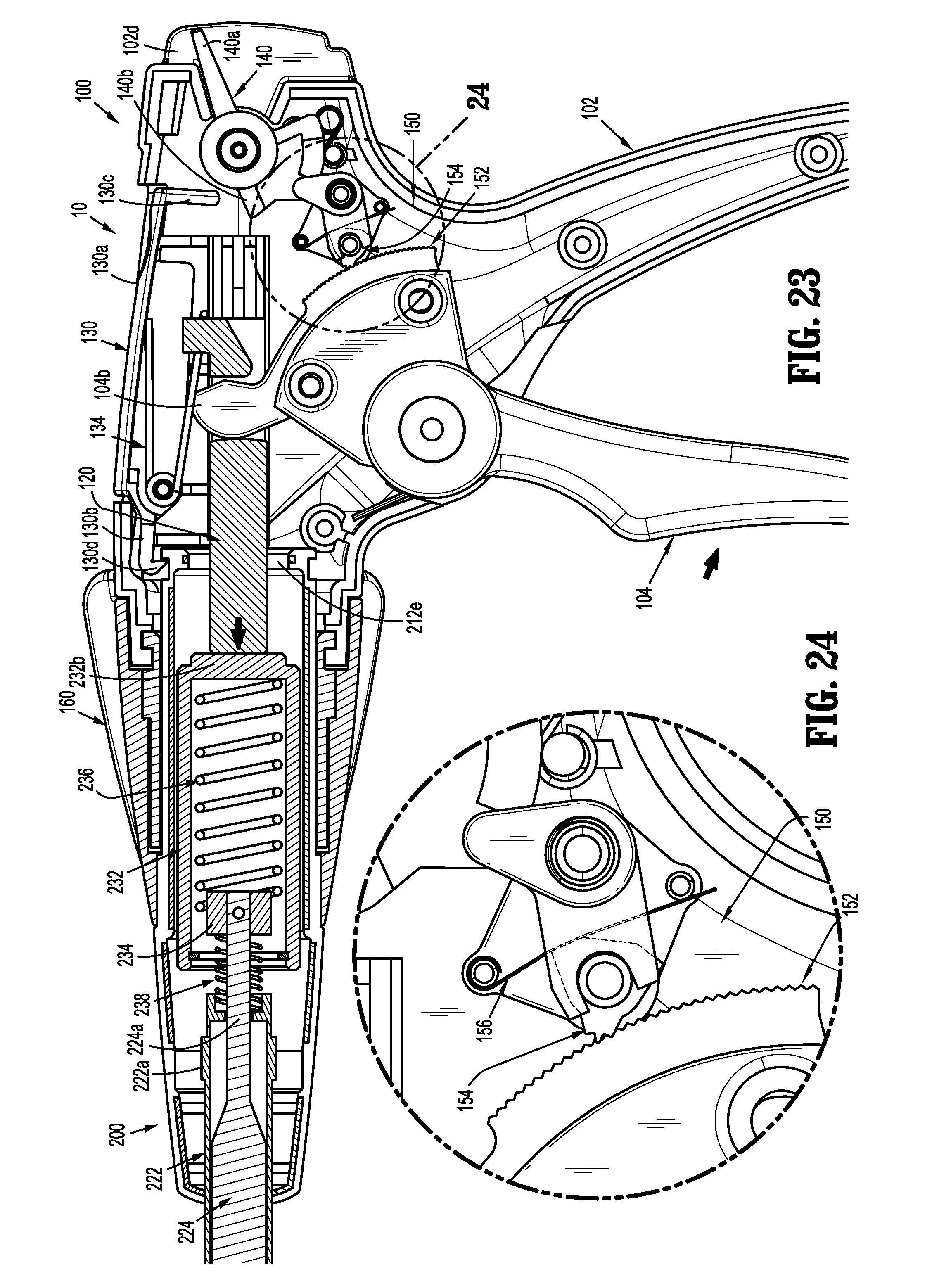
D00015
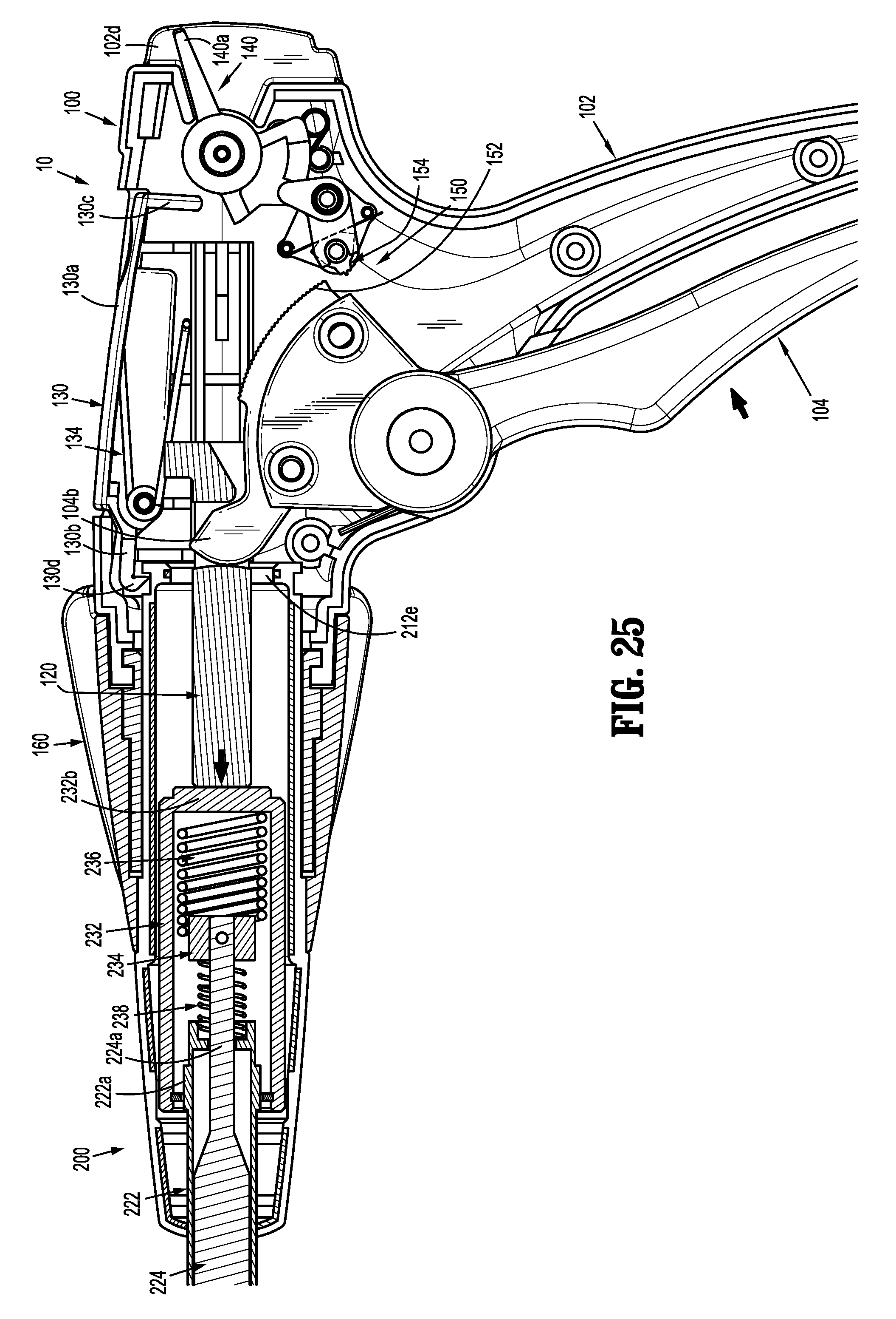
D00016
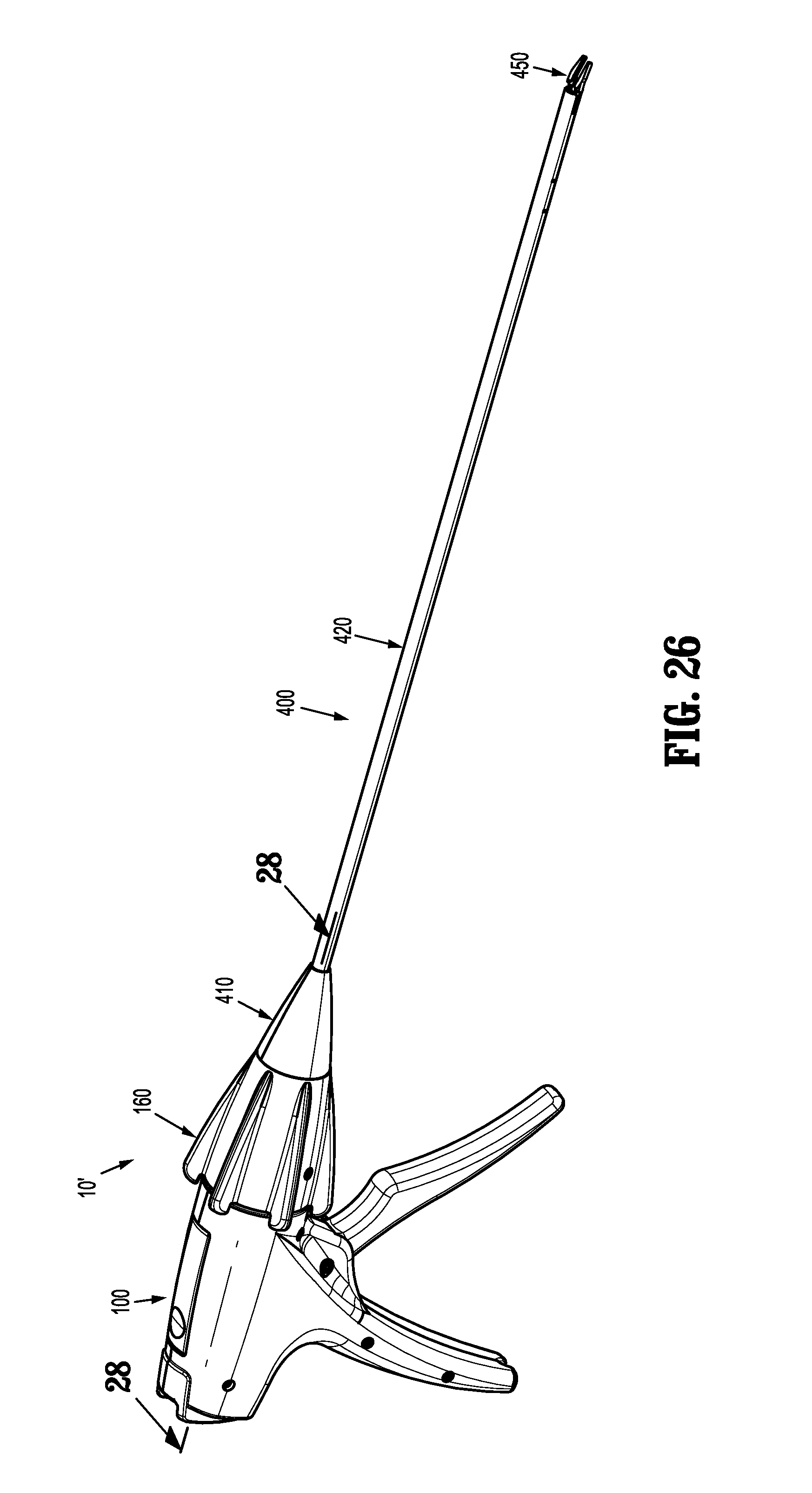
D00017
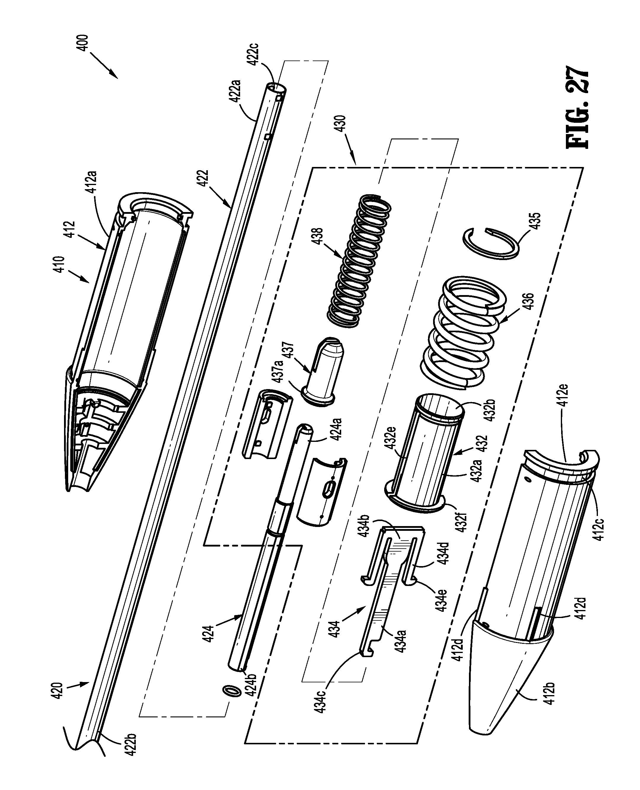
D00018
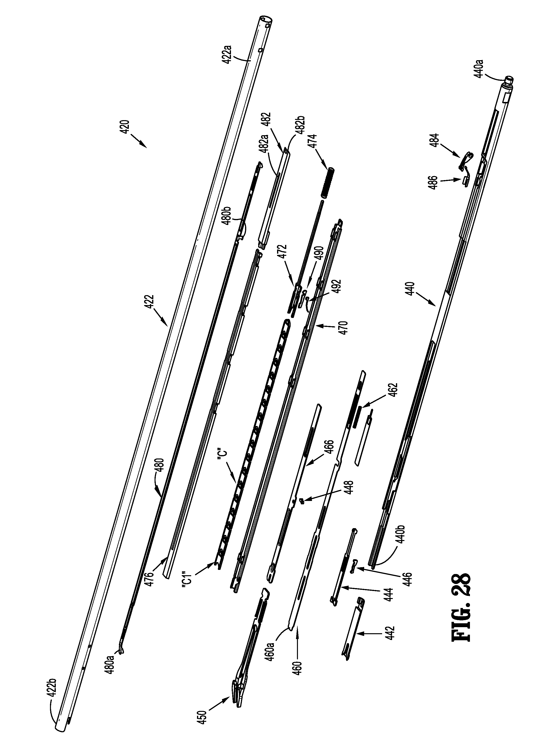
D00019
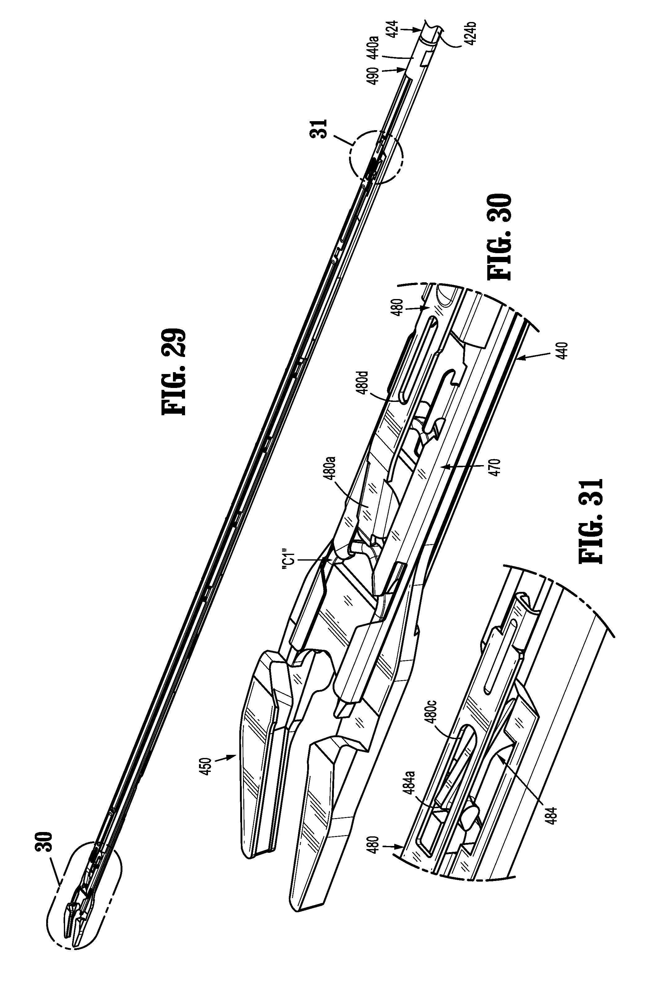
D00020

D00021
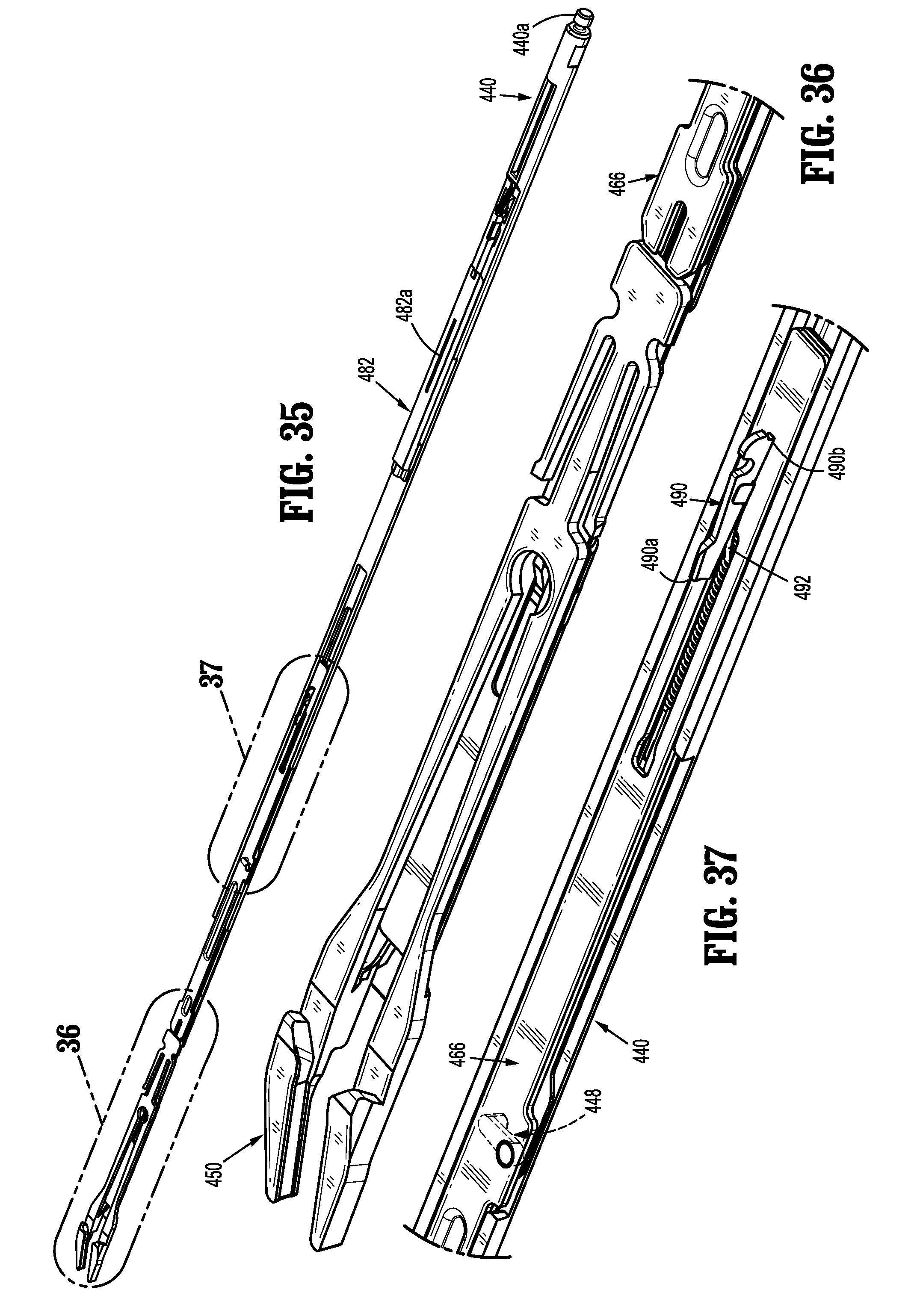
D00022
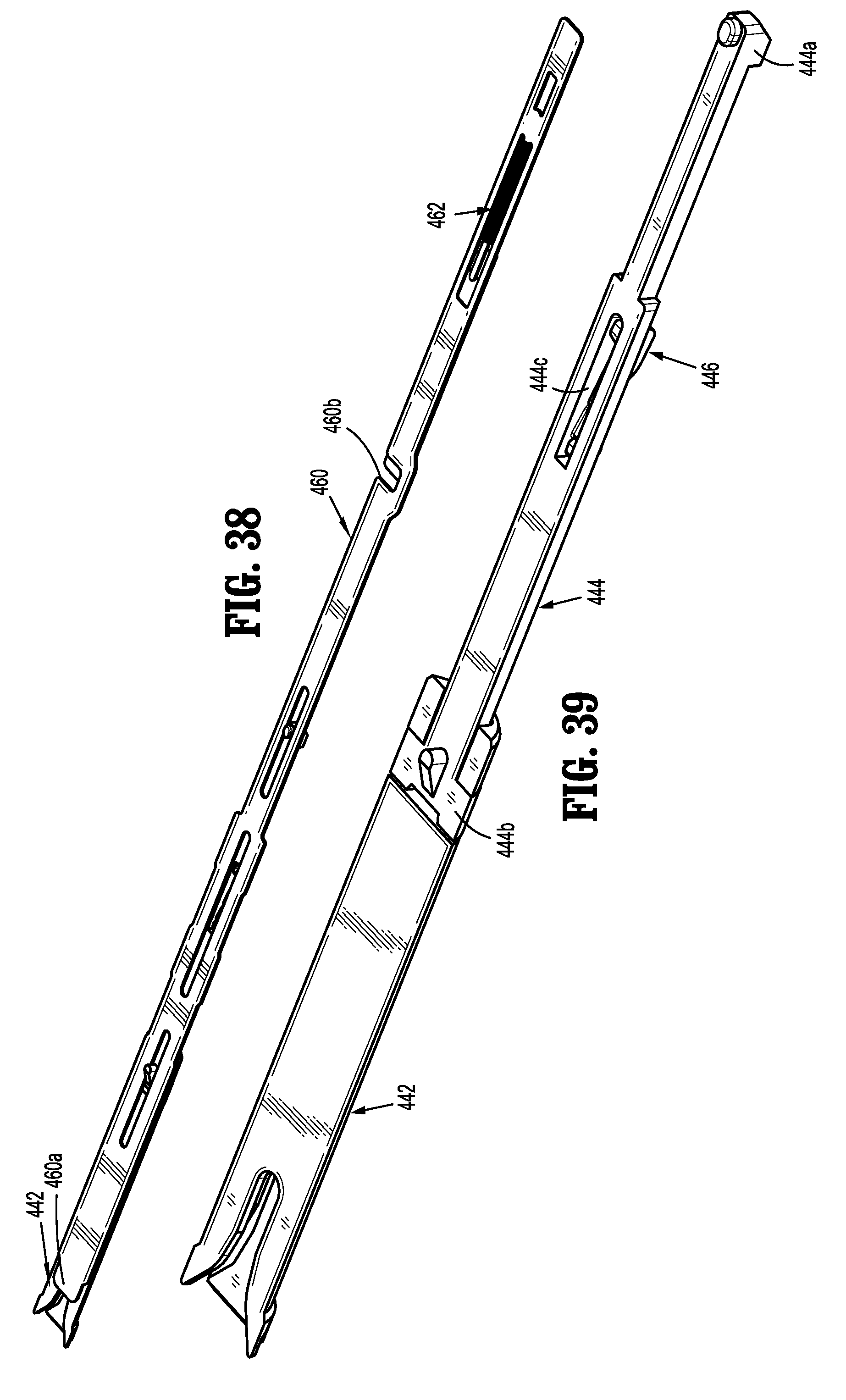
D00023
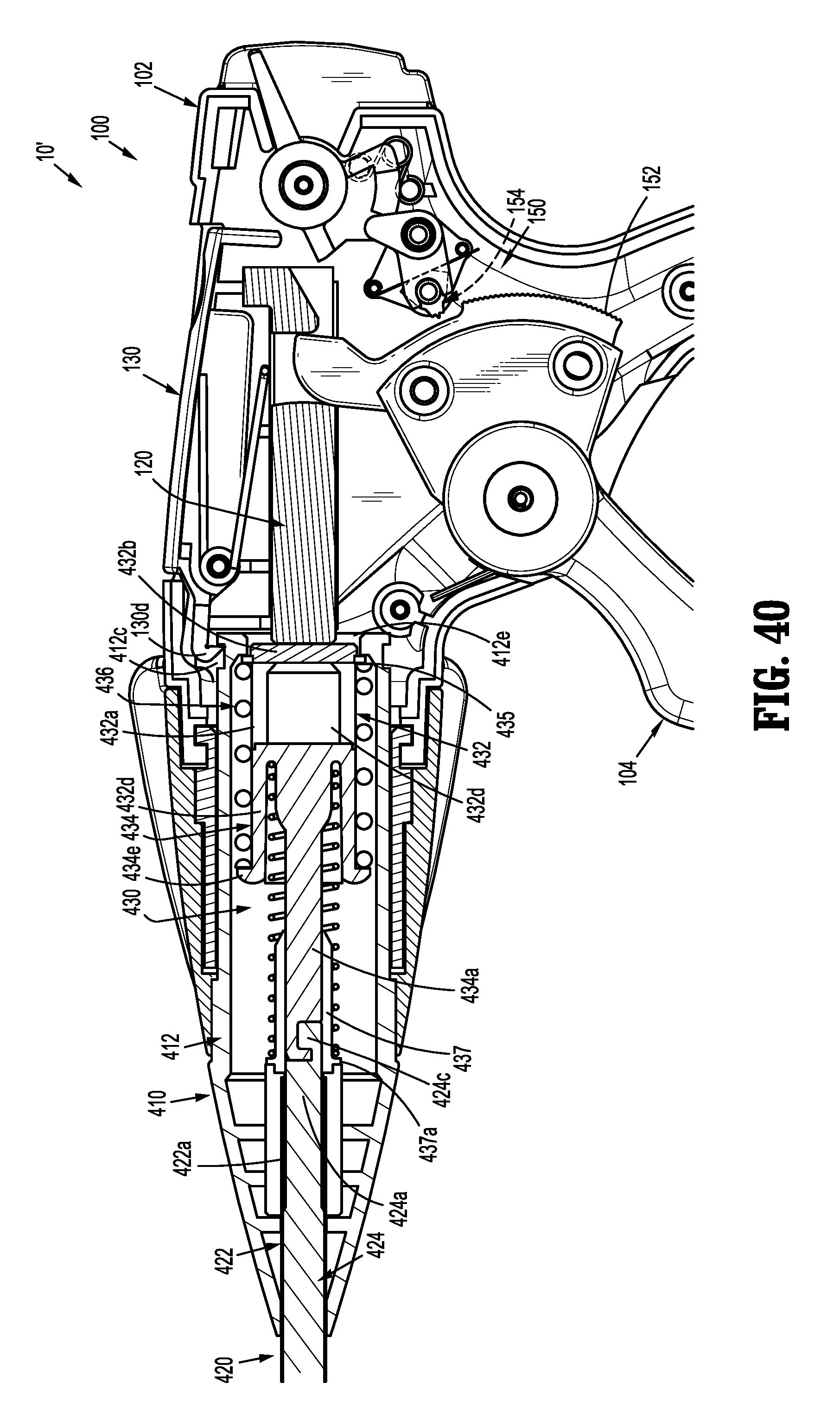
D00024
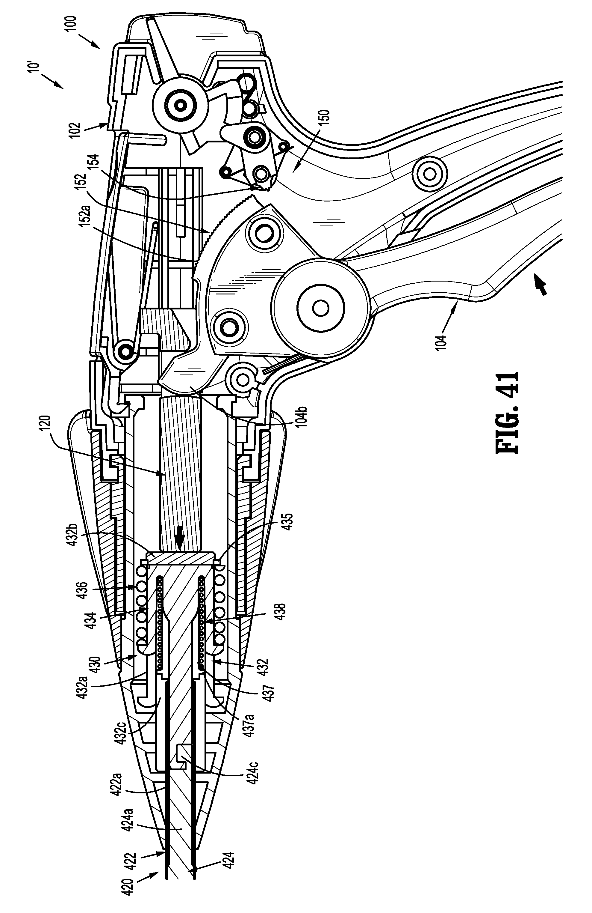
D00025

D00026
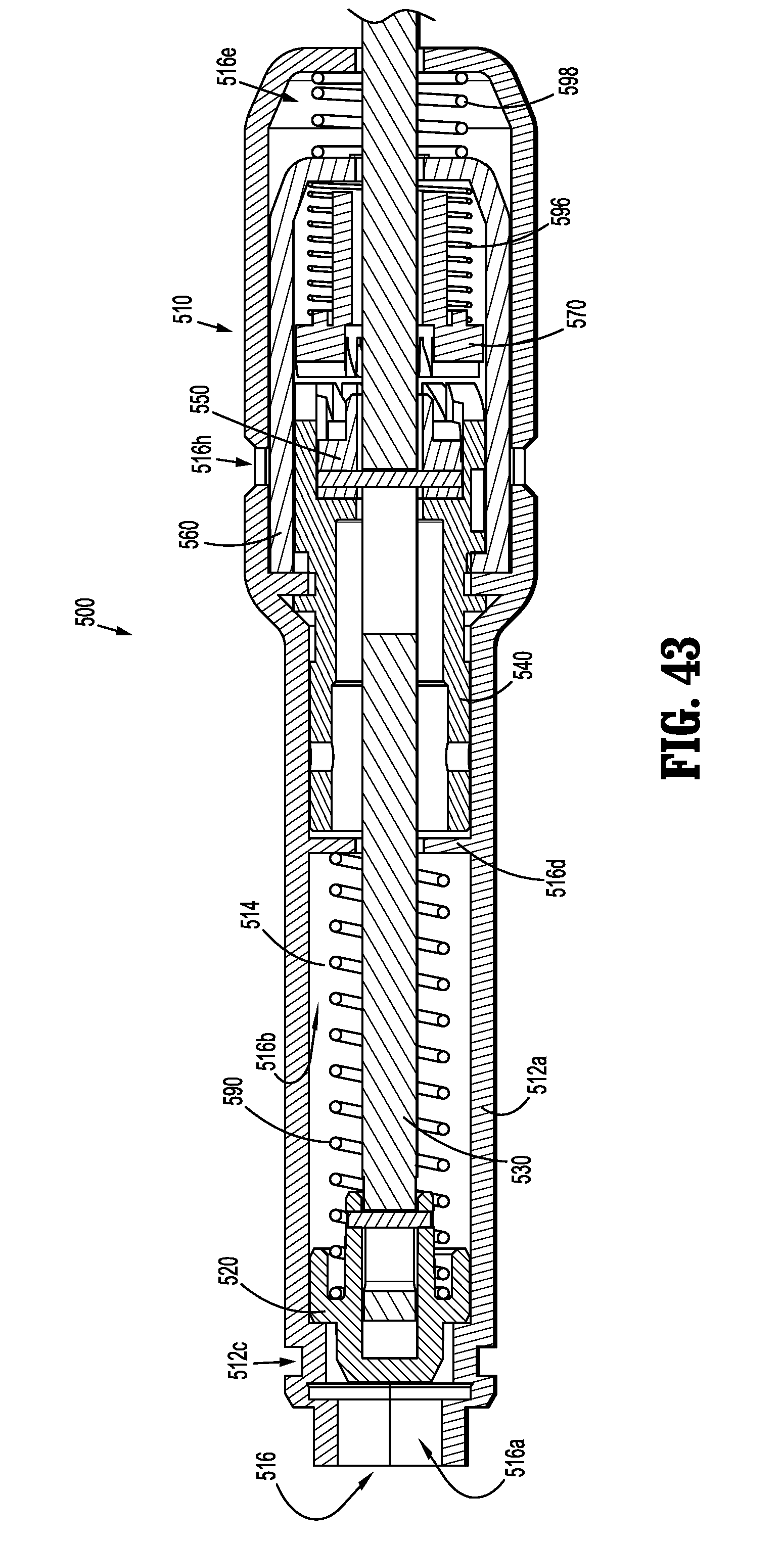
D00027

D00028
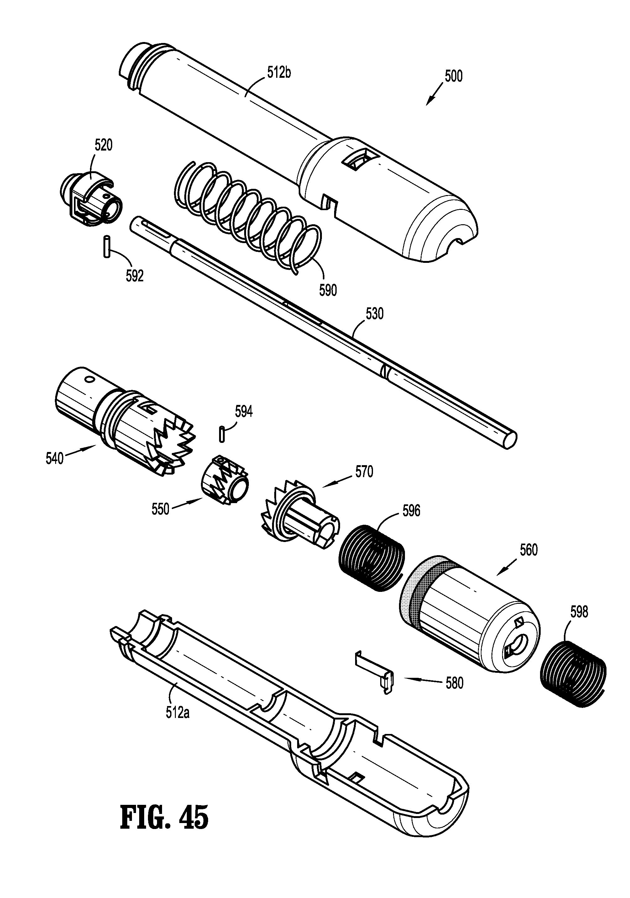
D00029
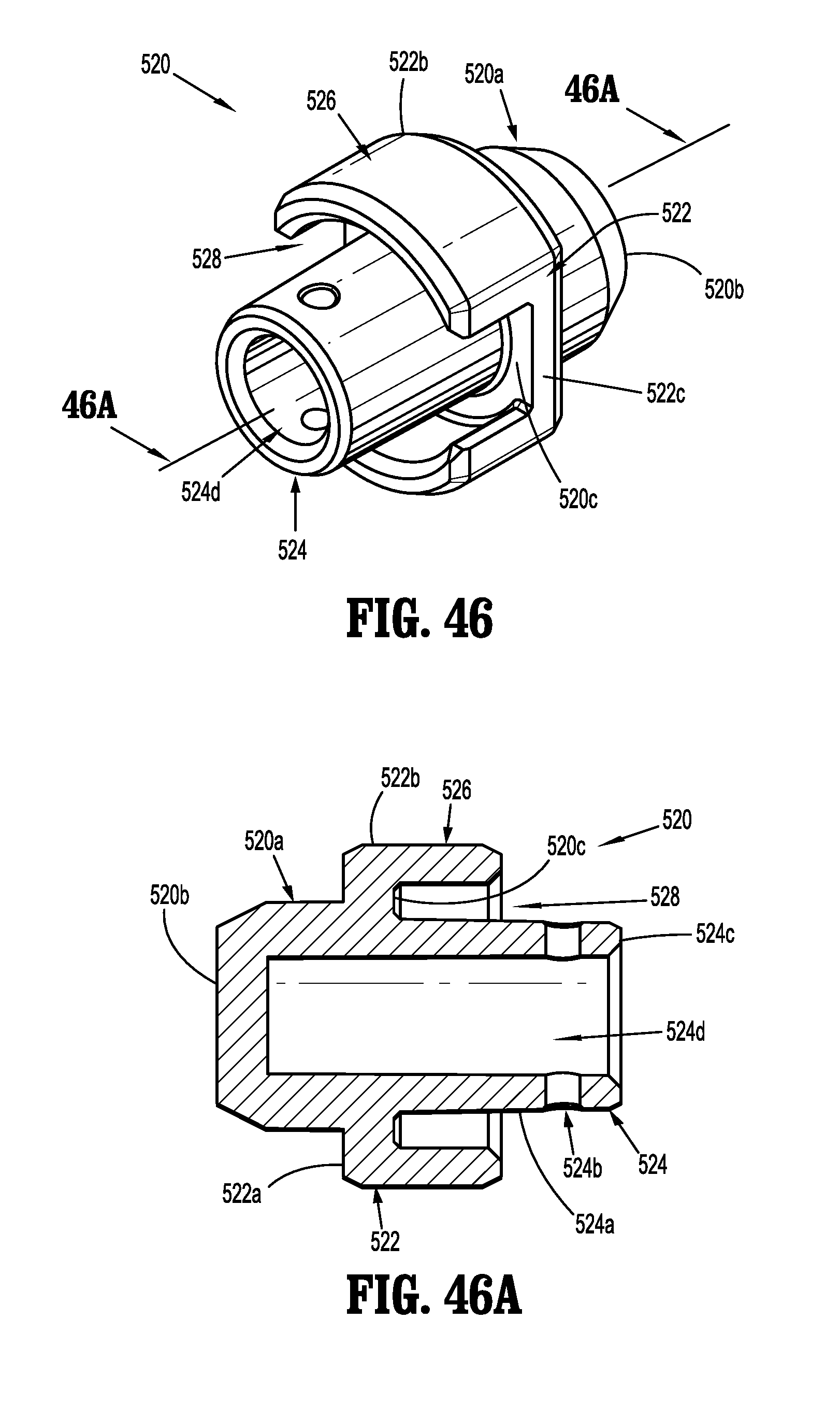
D00030
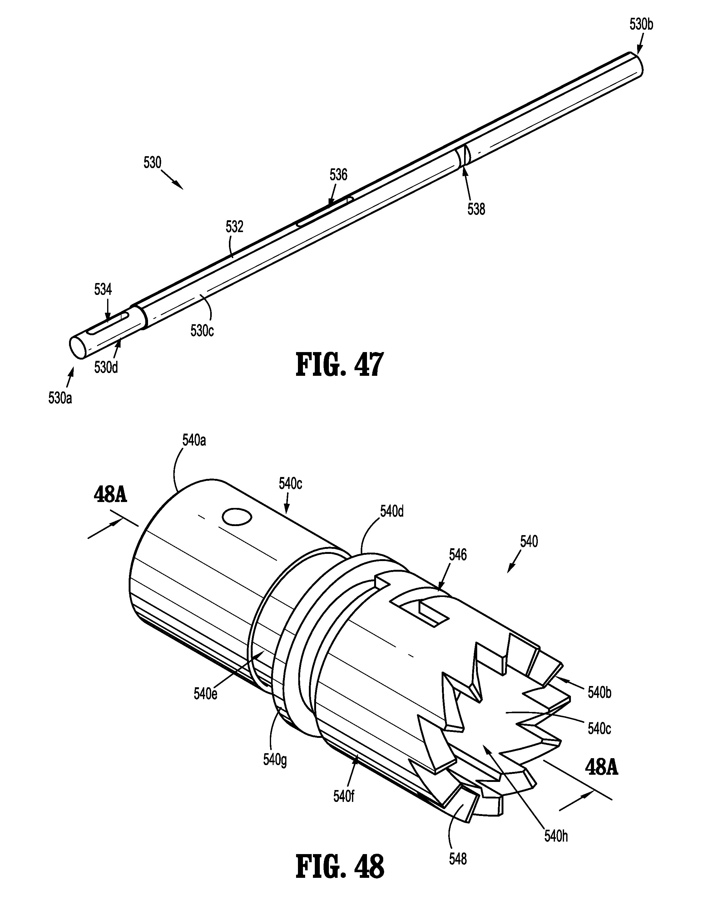
D00031

D00032
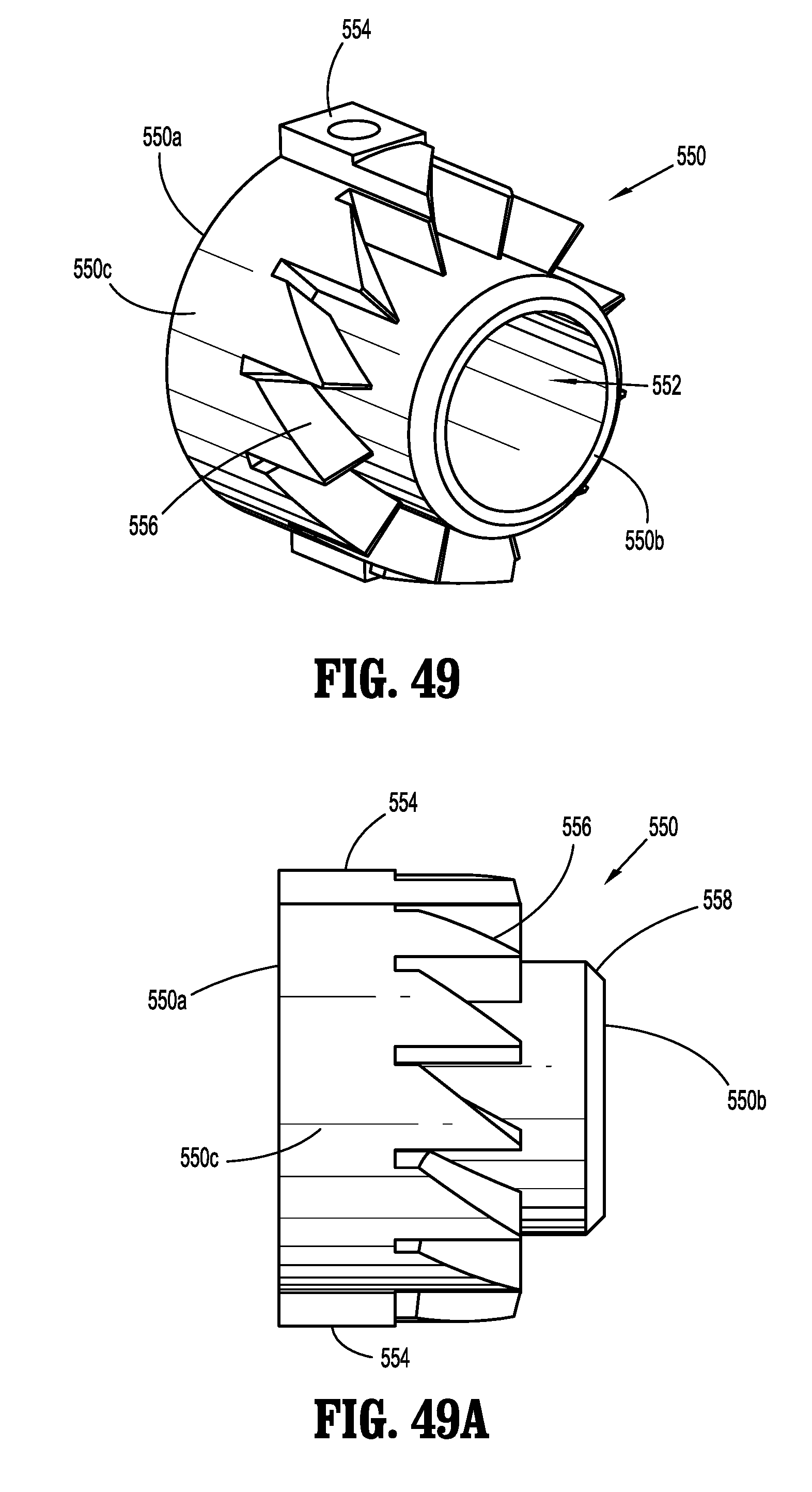
D00033
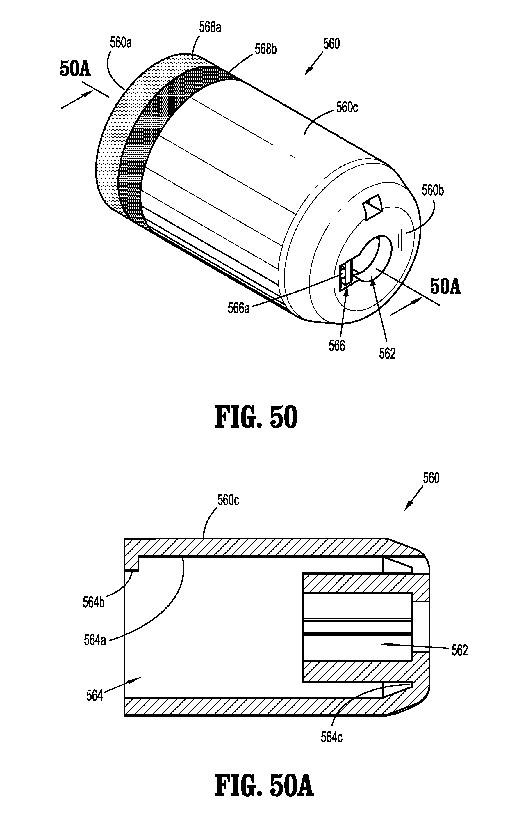
D00034
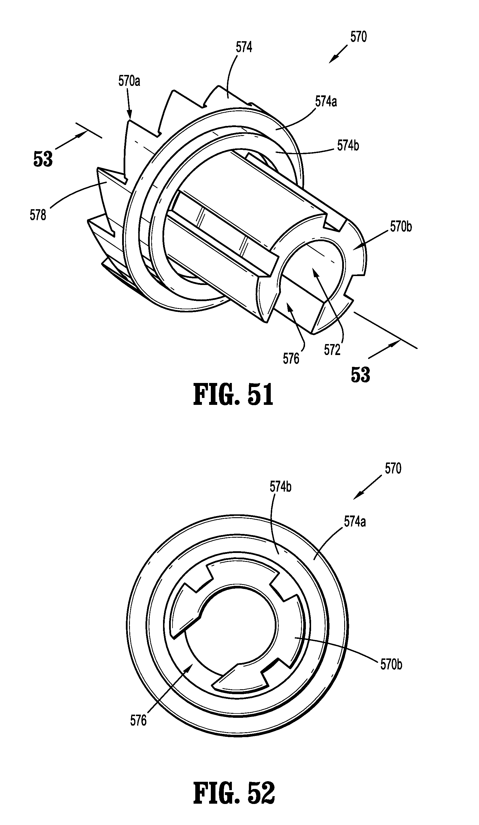
D00035

D00036
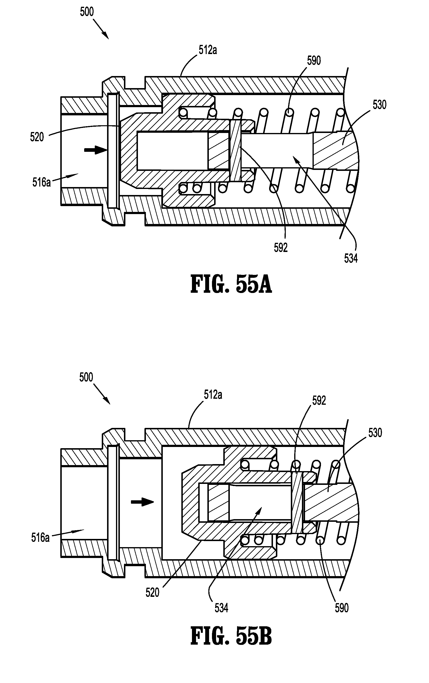
D00037
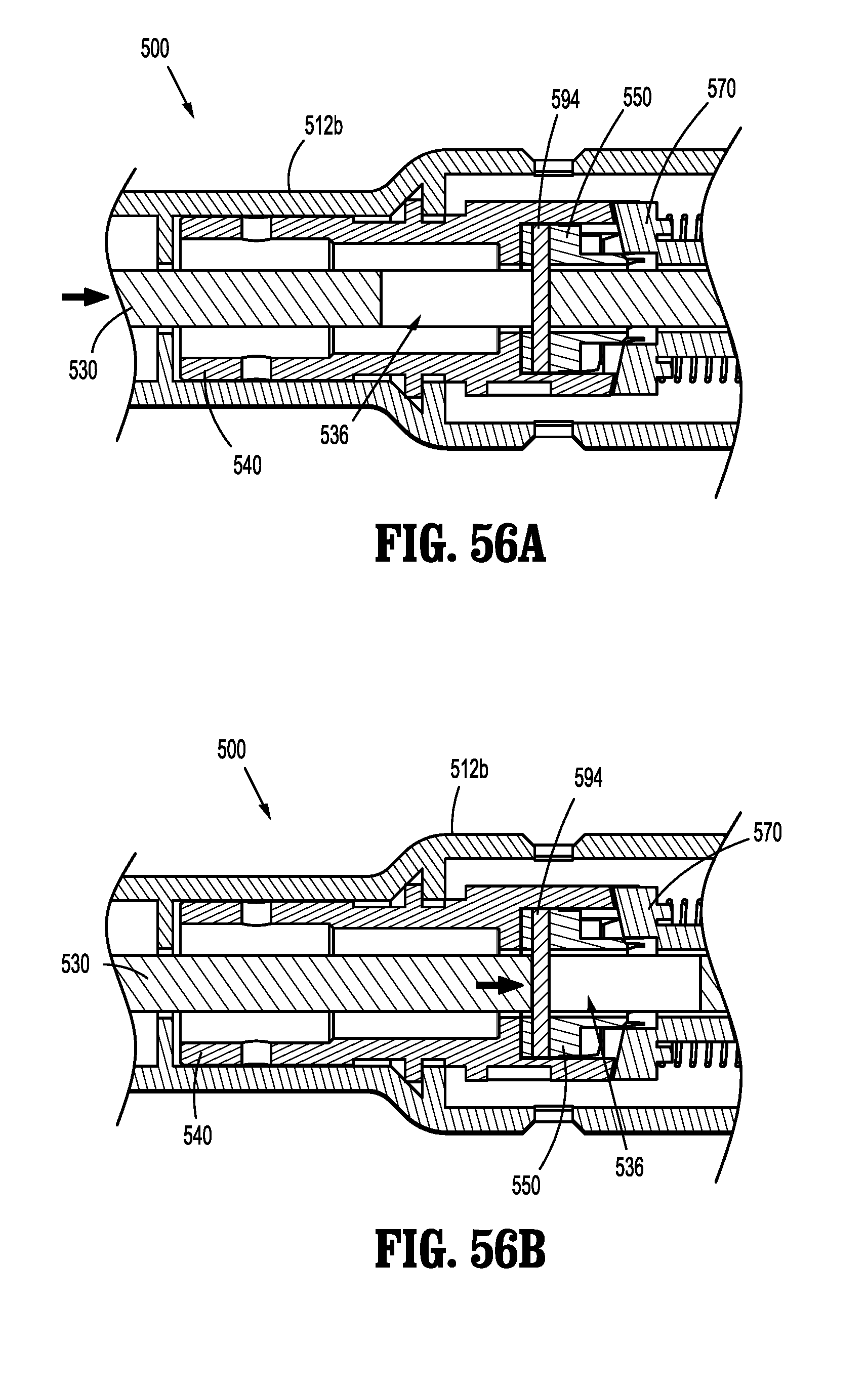
D00038
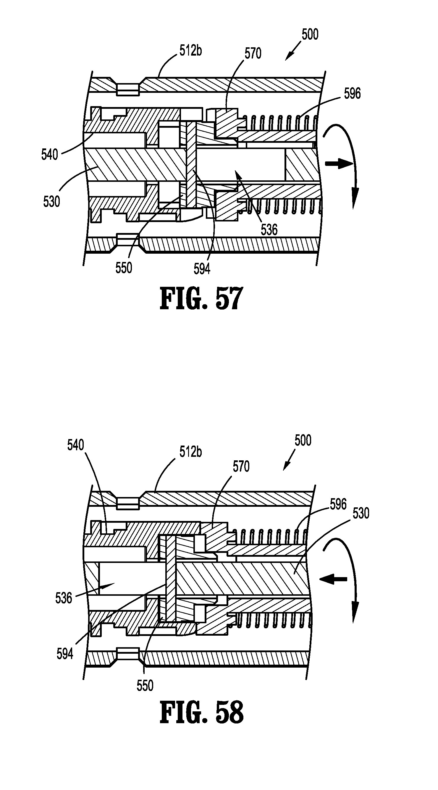
D00039

D00040
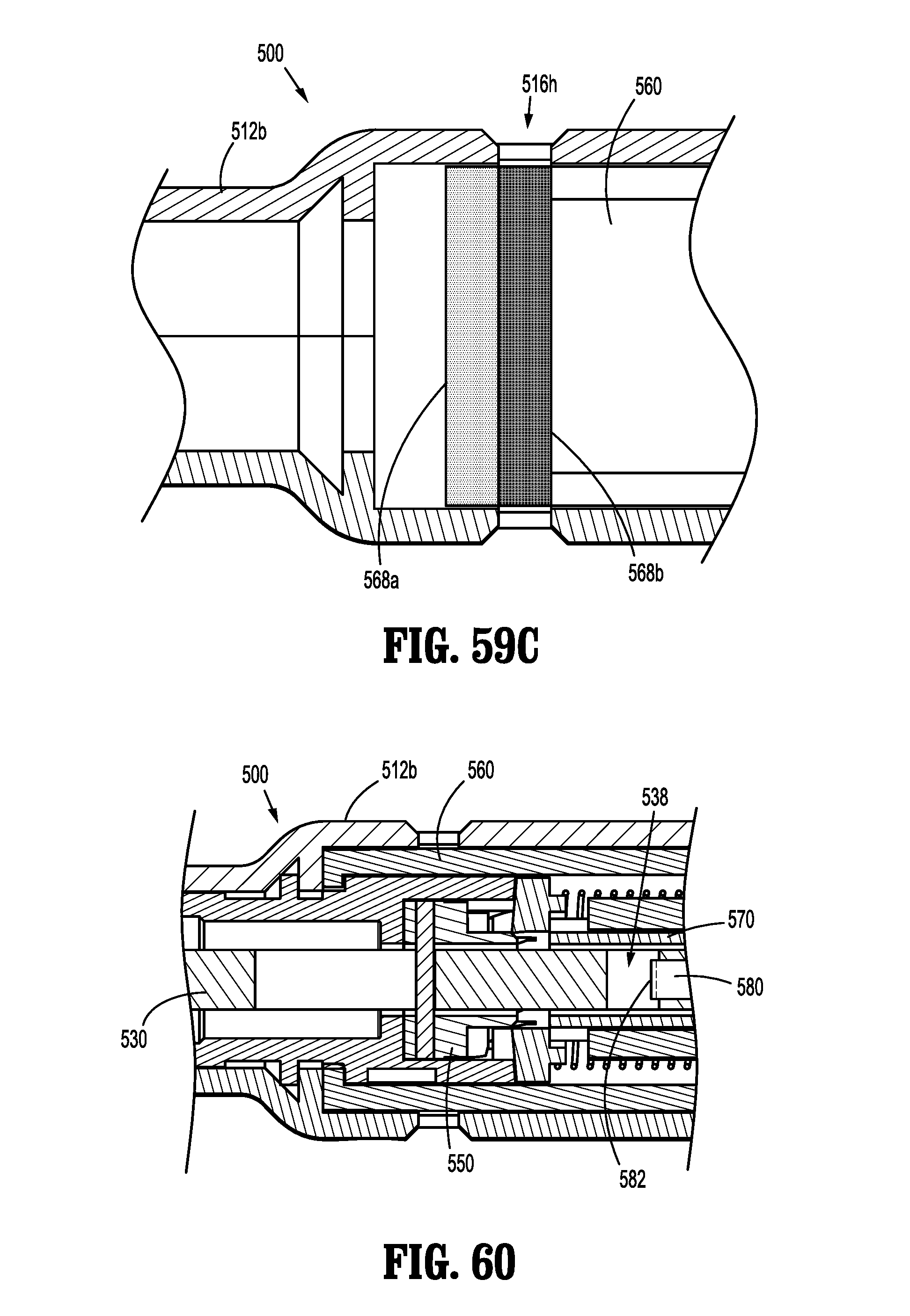
D00041

XML
uspto.report is an independent third-party trademark research tool that is not affiliated, endorsed, or sponsored by the United States Patent and Trademark Office (USPTO) or any other governmental organization. The information provided by uspto.report is based on publicly available data at the time of writing and is intended for informational purposes only.
While we strive to provide accurate and up-to-date information, we do not guarantee the accuracy, completeness, reliability, or suitability of the information displayed on this site. The use of this site is at your own risk. Any reliance you place on such information is therefore strictly at your own risk.
All official trademark data, including owner information, should be verified by visiting the official USPTO website at www.uspto.gov. This site is not intended to replace professional legal advice and should not be used as a substitute for consulting with a legal professional who is knowledgeable about trademark law.