Endoscopic Surgical Clip Applier Including Counter Assembly
Baril; Jacob C. ; et al.
U.S. patent application number 16/012884 was filed with the patent office on 2019-02-07 for endoscopic surgical clip applier including counter assembly. The applicant listed for this patent is Covidien LP. Invention is credited to Jacob C. Baril, Matthew A. Dinino.
| Application Number | 20190038375 16/012884 |
| Document ID | / |
| Family ID | 65230826 |
| Filed Date | 2019-02-07 |


| United States Patent Application | 20190038375 |
| Kind Code | A1 |
| Baril; Jacob C. ; et al. | February 7, 2019 |
ENDOSCOPIC SURGICAL CLIP APPLIER INCLUDING COUNTER ASSEMBLY
Abstract
A surgical clip applier includes a counter assembly including a counting wheel with a plurality of actuation features, a locking spring assembly, a driver, and a pin assembly. The counting wheel includes indicia visible through the handle assembly. The locking spring assembly is positioned within the counting wheel and is configured to prohibit multidirectional rotation of the counting wheel. The driver includes a grasping protrusion and a positioning protrusion. The driver translates between a proximal position and a distal position, wherein the grasping protrusion engages the plurality of actuation features to rotate the counting wheel to change the indicia. The pin assembly is configured to engage with the positioning protrusion of the driver, wherein during transitioning of the driver from the proximal position to the distal position, the positioning protrusion engages the stationary pin to pivot the driver, whereby the driver disengages from the plurality of actuation features.
| Inventors: | Baril; Jacob C.; (Norwalk, CT) ; Dinino; Matthew A.; (Newington, CT) | ||||||||||
| Applicant: |
|
||||||||||
|---|---|---|---|---|---|---|---|---|---|---|---|
| Family ID: | 65230826 | ||||||||||
| Appl. No.: | 16/012884 | ||||||||||
| Filed: | June 20, 2018 |
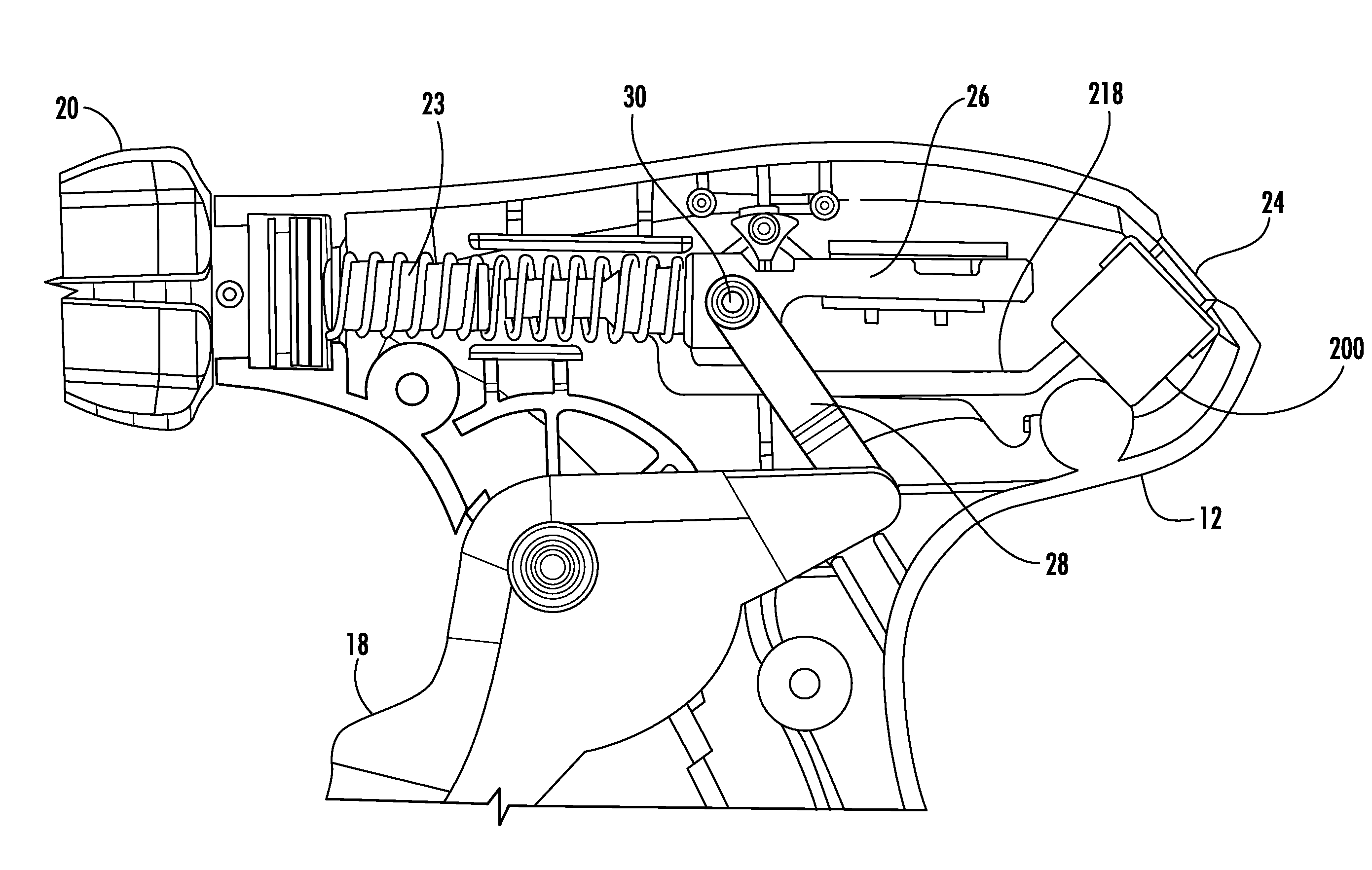
Related U.S. Patent Documents
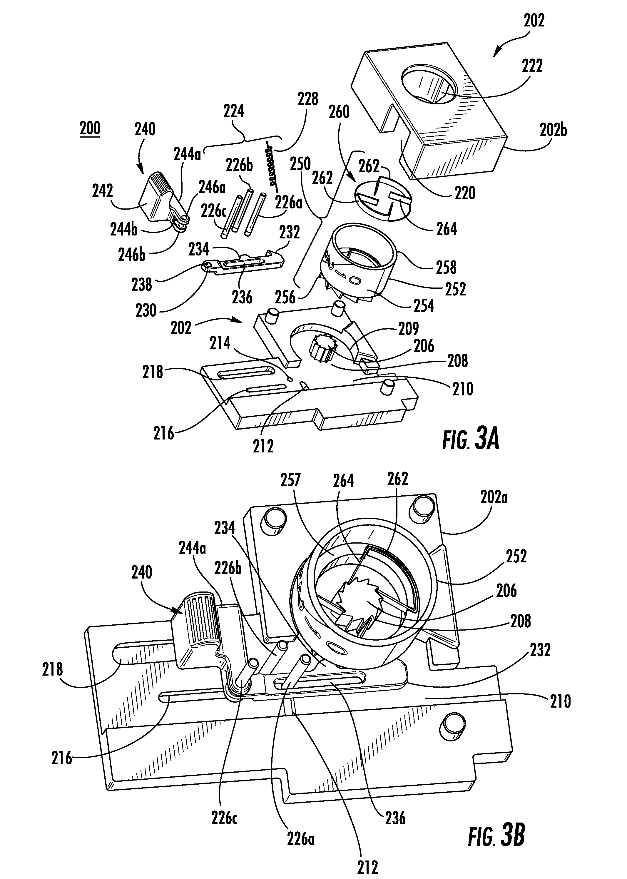
| Application Number | Filing Date | Patent Number | ||
|---|---|---|---|---|
| 62541873 | Aug 7, 2017 | |||
| Current U.S. Class: | 1/1 |
| Current CPC Class: | A61B 17/1285 20130101; A61B 2090/0803 20160201; A61B 2017/00367 20130101; A61B 90/08 20160201 |
| International Class: | A61B 90/00 20060101 A61B090/00; A61B 17/128 20060101 A61B017/128 |
Claims
1. A surgical clip applier, comprising: a handle assembly; an elongated tubular member extending distally from the handle assembly; a rack bar translatably supported in the handle assembly; and a counter assembly supported in the handle assembly, the counter assembly including: a housing having a first housing half and a second housing half; a stationary post positioned within the first housing half and including a plurality of locking teeth; a counting wheel positioned to rotate within the housing, the counting wheel including indicia visible through the handle assembly; a plurality of actuation features positioned circumferentially about the counting wheel; a locking spring assembly including a plurality of fingers, the locking spring assembly positioned within the counting wheel and configured to engage the plurality of locking teeth of the stationary post, wherein the engagement of the plurality of fingers of the locking spring assembly and the plurality of locking teeth of the stationary post prohibits multidirectional rotation of the counting wheel; a driver coupled to the rack bar for translation therewith, the driver including an grasping protrusion and a positioning protrusion, the driver positioned to translate between a proximal position and distal position, wherein transitioning from the proximal position to the distal position, the grasping protrusion of the driver engages an actuation feature of the plurality of actuation features to rotate the counting wheel to change the indicia of the counting wheel visible through the handle assembly; and a pin assembly including a stationary pin configured to engage with the positioning protrusion of the driver, wherein during transitioning of the driver from the proximal position to the distal position, the positioning protrusion of the driver engages the stationary pin to pivot the driver, whereby the driver disengages from the plurality of actuation features of the counting wheel.
2. The surgical clip applier of claim 1, wherein the pin assembly further includes a vertical translating pin, a horizontal translating pin, and a spring, wherein each of the vertical translating pin, the horizontal translating pin, and the spring is configured to permit the engagement and the disengagement between the stationary pin of the pin assembly and the positioning protrusion of the driver.
3. The surgical clip applier of claim 2, wherein the spring is connected to the vertical translating pin thereby allowing the vertical translating pin to transition between a first position and a second position.
4. The surgical clip applier of claim 3, wherein the driver defines a channel configured to receive the vertical translating pin of the pin assembly thereby connecting the driver to the pin assembly.
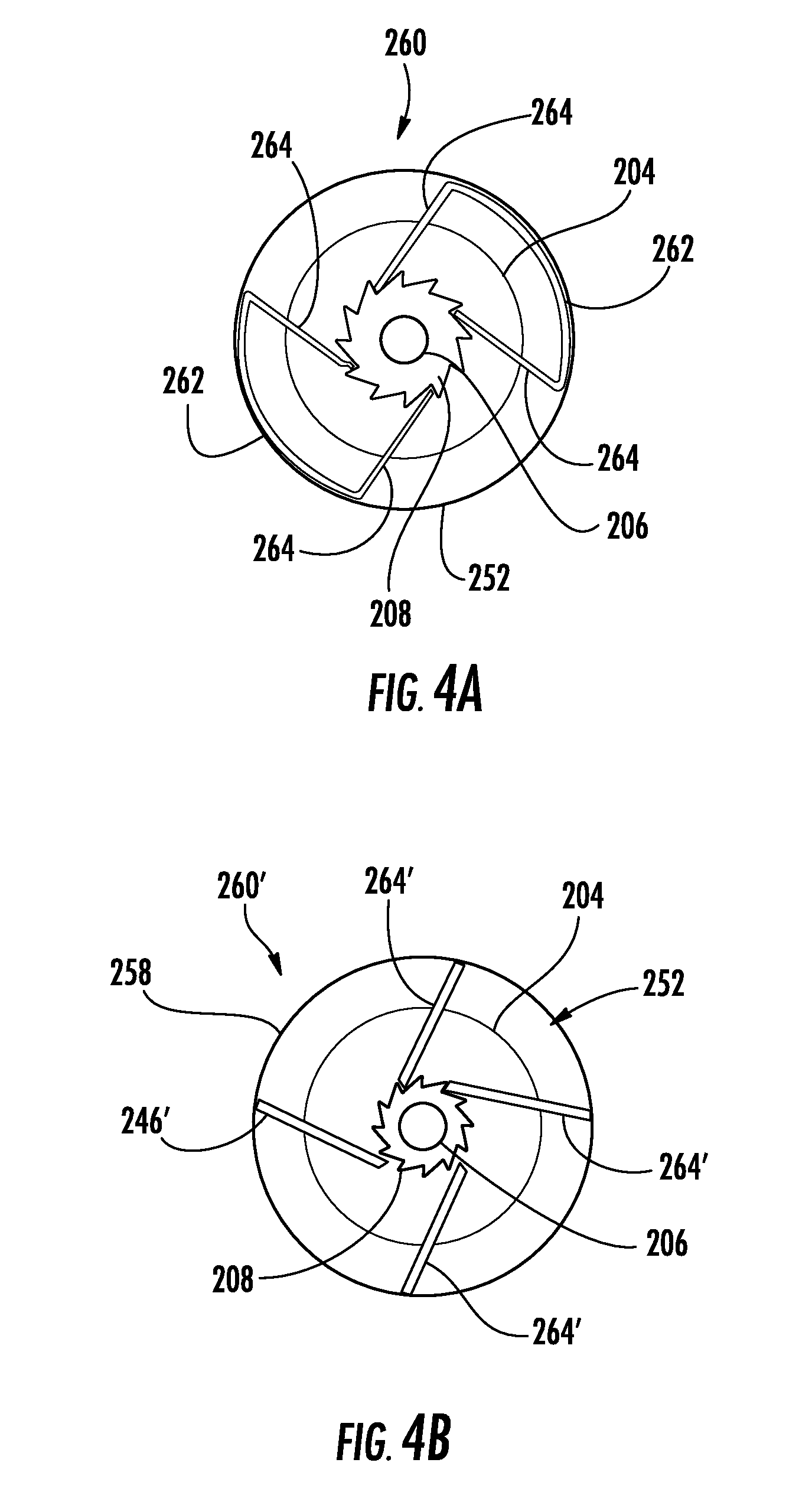
5. The surgical clip applier of claim 4, wherein the vertical translating pin is positioned within a vertical slot defined in at least one of the first housing half and second housing half and wherein the vertical translating pin is biased to the first position by the spring, the vertical translating pin being configured to translate from the first position to the second position in response to the driver engaging with the positioning protrusion.
6. The surgical clip applier of claim 5, further including an actuator coupled to the rack bar and the driver.
7. The surgical clip applier of claim 6, wherein the horizontal translating pin couples the driver to the actuator, wherein the horizontal translating pin translates in response to a translation of the actuator and thereby causes the driver to translate.
8. The surgical clip applier of claim 7, wherein the actuator is positioned within an actuator slot defined in at least one of the first housing half or the second housing half, the actuator translates in response to the translation of the rack bar and the driver translates in reaction to the translation of the actuator.
9. The surgical clip applier of claim 1, wherein the first housing half defines a linear channel configured to receive the driver.
10. The surgical clip applier of claim 1, wherein each finger of the plurality of fingers of the locking spring assembly is resilient and flexible, and extends in a substantially tangential direction to an inner surface of the counting wheel.
11. The surgical clip applier of claim 10, wherein the substantially tangential orientation and the length of each finger of the plurality of fingers prohibits multidirectional rotation of the counting wheel.
12. The surgical clip applier of claim 1, wherein the locking spring assembly includes a plurality of bodies and a plurality of fingers, wherein the plurality of fingers extend from the plurality of bodies.
13. The surgical clip applier of claim 1, wherein the housing further defines a circular recess configured to receive the counting wheel.
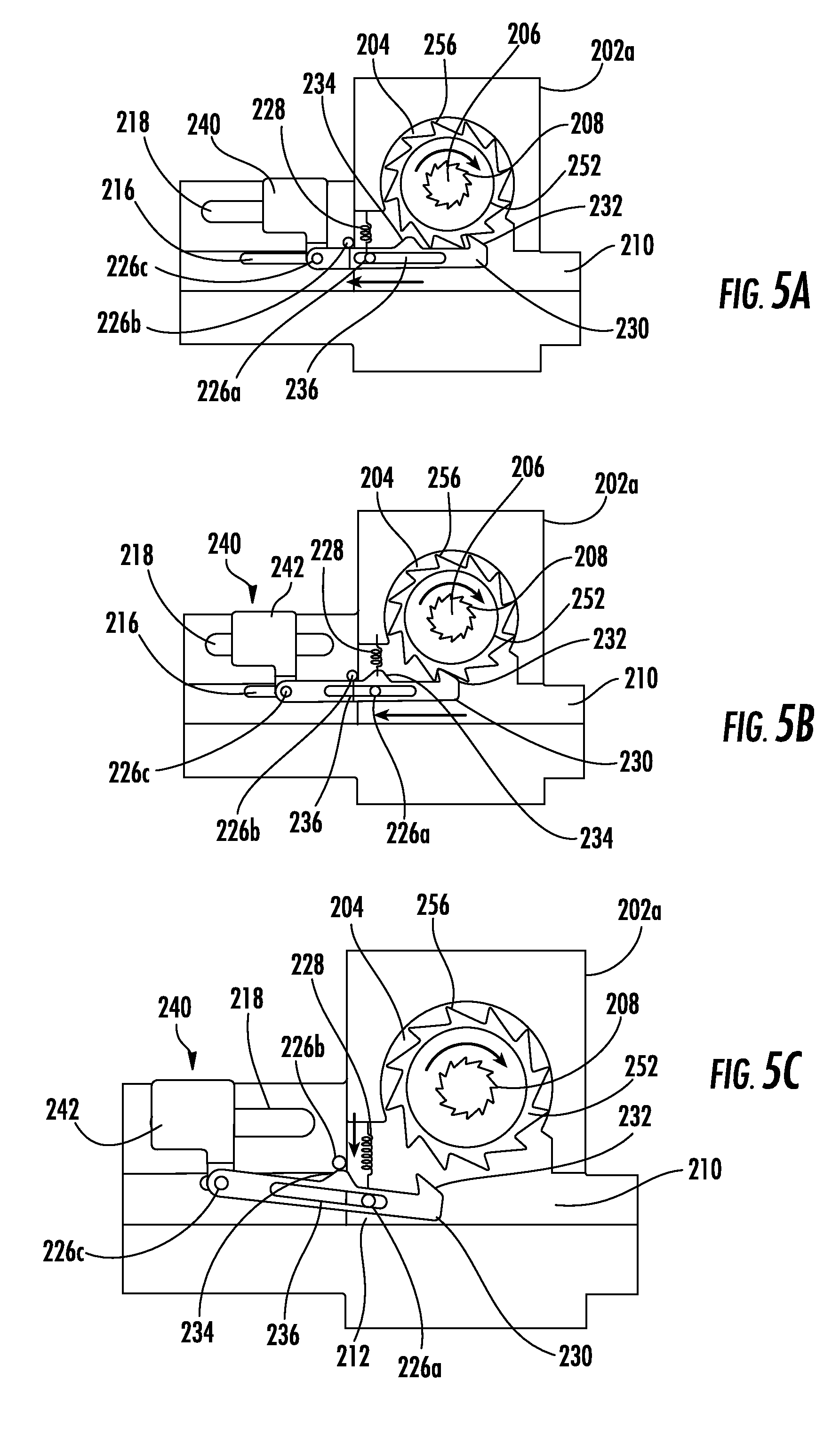
14. The surgical clip applier of claim 13, wherein the stationary post is concentrically positioned within the first housing half in relation to the circular recess.
15. The surgical clip applier of claim 1, wherein the second housing half defines an aperture configured to receive the counting wheel.
16. The surgical clip applier of claim 1, further including a plurality of surgical clips disposed within the elongated tubular member, wherein the indicia of the counting wheel indicates a remaining number of the plurality of surgical clips.
17. The surgical clip applier of claim 16, wherein a number of actuation features of the plurality of actuation features is equal to an initial number of surgical clips of the plurality of surgical clips.
18. The surgical clip applier of claim 16, wherein the indicia includes a plurality of numbers to indicate the remaining number of surgical clips of the plurality of surgical clips.
19. The surgical clip applier of claim 16, wherein the indicia includes one or more colors to indicate the remaining number of surgical clips of the plurality of surgical clips.
Description
CROSS-REFERENCE TO RELATED APPLICATIONS
[0001] This application claims the benefit of and priority to U.S. Provisional Patent Application No. 62/541,873 filed Aug. 7, 2017, the entire disclosure of which is incorporated by reference herein.
BACKGROUND
Technical Field
[0002] The presented disclosure relates generally to surgical clip appliers. More particularly, the present disclosure relates to an endoscopic surgical clip applier having a counter assembly.
Discussion of Related Art
[0003] Surgical clip appliers offer surgeons an alternative to conventional suturing of body tissues and vessels. Surgical clip appliers generally store a plurality of clips which are fed sequentially to a jaw mechanism at the distal end of the instrument upon opening and closing of handles at the proximal end of the instrument. As the handles are closed, the jaw members close to deform a clip positioned between the jaw members, and as the jaw members are opened to release the deformed clip, a new clip is fed from the plurality of clips to a position between the jaw members. This process is repeated until all the clips in the plurality of clips have been used.
[0004] A need exists for a user of the clip applier to know how many clips remain in the clip applier and/or to know when a final clip of the plurality of clips has been fired.
SUMMARY
[0005] The presented disclosure relates to endoscopic surgical clip appliers having a counter assembly. The surgical clip applier includes a handle assembly, an elongated member, a rack bar, and a counter assembly. The elongated member extends distally from the handle assembly. The rack bar is translatably supported in the handle assembly. The counter assembly is supported in the handle assembly and includes a housing, a stationary post, a counting wheel, a locking spring assembly, a driver, and a pin assembly. The housing includes a first housing half and a second housing half. The stationary post is positioned within the first housing half and includes a plurality of locking teeth. The counting wheel is positioned to rotate within the housing, and includes indicia visible through the handle assembly. A plurality of actuation features are positioned circumferentially about the counting wheel. The locking spring assembly includes a plurality of fingers, is positioned within the counting wheel, and is configured to engage the plurality of locking teeth of the stationary post. The engagement of the plurality of fingers of the locking spring assembly and the plurality of locking teeth of the stationary post prohibits multidirectional rotation of the counting wheel. The driver is coupled to the rack bar for translation therewith.
[0006] The driver includes a grasping protrusion and a positioning protrusion. The driver is positioned to translate between a proximal position and a distal position. The transitioning of the driver from the proximal position to the distal position causes the grasping protrusion of the driver to engage an actuation feature of the plurality of actuation features to rotate the counting wheel to change the indicia of the counting wheel visible through the handle assembly. The pin assembly includes a stationary pin configured to engage with the positioning protrusion of the driver. During transition of the driver from the proximal position to the distal position, the positioning protrusion of the driver engages the stationary pin to pivot the driver, whereby the driver disengages from the plurality of actuation features of the counting wheel.
[0007] In some embodiments, the pin assembly further includes a vertical translating pin, a horizontal translating pin, and a spring. Each of the vertical translating pin, horizontal translating pin, and spring may be configured to permit the engagement and the disengagement between the stationary pin of the pin assembly and the positioning protrusion of the driver. The spring may be connected to the vertical translating pin thereby allowing the vertical translating pin to transition between a first position and a second position. The driver may define a channel configured to receive the vertical translating pin of the pin assembly thereby connecting the driver to the pin assembly. The vertical translating pin may be positioned within a vertical slot defined in at least one of the first housing half or the second housing half. The vertical translating pin may be biased to the first position by the spring. The vertical translating pin may translate between the first and second position in response to the driver engaging with the positioning protrusion.
[0008] In embodiments, the surgical clip applier further includes an actuator coupled to the rack bar and the driver. The horizontal translating pin may couple the driver to the actuator. The horizontal translating pin may translate in response to a translation of the actuator and thereby causing the driver to translate. The actuator may be positioned within an actuator slot defined in at least one of the first housing half and second housing half. The actuator may translate in response to the translation of the rack bar and the driver translates in response to the translation of the actuator. In embodiments, the first housing half defines a linear channel configured to receive the driver.
[0009] In embodiments, each finger of the plurality of fingers of the locking spring assembly is resilient and flexible, and extends in a substantially tangential direction to an inner surface of the counting wheel. The substantially tangential orientation and length of each finger of the plurality of fingers may prohibit multidirectional rotation of the counting wheel. In other embodiments, the locking spring assembly includes a plurality of bodies and a plurality of fingers. The plurality of fingers may extend from the plurality of bodies.
[0010] In other embodiments, the housing further defines a circular recess configured to receive the counting wheel. The stationary post may be concentrically positioned within the first housing half in relation to the circular recess. The second housing half may define an aperture configured to receive the counting wheel.
[0011] The surgical clip applier may further include a plurality of surgical clips disposed within the elongated member. The indicia of the counting wheel may indicate a remaining number of the plurality of surgical clips. A number of actuation features of the plurality of actuation features may be equal to an initial number of surgical clips of the plurality of surgical clips. In some embodiment, the indicia may include a plurality of numbers to indicate the remaining number of surgical clips of the plurality of surgical clips. In other embodiments, the indicia include color to indicate the remaining number of surgical clips of the plurality of surgical clips.
[0012] Other aspects, features, and advantages will be apparent from the description, the drawings, and the claims that follow.
BRIEF DESCRIPTION OF THE DRAWINGS
[0013] An illustrative embodiment of a surgical clip applier with a counter assembly is disclosed herein with reference to the drawings wherein:
[0014] FIG. 1A is a perspective view of a surgical clip applier according to the present disclosure;
[0015] FIG. 1B is an enlarged perspective view of a jaw structure of the surgical clip applier of FIG. 1A;
[0016] FIG. 2 is a side view, with a half of a body removed, of a handle assembly of the surgical clip applier including a counter assembly;
[0017] FIG. 3A-3C are enlarged views of a counter assembly of the surgical clip applier of FIG. 1A;
[0018] FIGS. 4A and 4B are enlarged views of embodiments of locking spring assembly of the counter assembly of FIG. 3A; and
[0019] FIGS. 5A-5E are enlarged views of components of the counter assembly of FIG. 3A.
DETAILED DESCRIPTION OF EMBODIMENTS
[0020] Embodiments of surgical clip appliers in accordance with the present disclosure will now be described in detail with reference to the drawings wherein like reference numerals identify similar or identical structural elements. As shown in the drawings and described throughout the following description, as is traditional when referring to relative positioning on a surgical instrument, the term "proximal" refers to the end of the apparatus which is closer to a user and the term "distal" refers to the end of the apparatus which is farther away from the user.
[0021] Referring now to FIGS. 1A, 1B, and 2, surgical clip applier 10 generally includes a handle assembly 12 and an elongated member 14 extending distally from handle assembly 12. Handle assembly 12 may be formed of a plastic material while elongated tubular member 14 may be tubular and formed of stainless steel or any other metal material. A pair of jaws 16 is mounted on a distal end of elongated tubular member 14 and is actuated by a trigger 18 movably mounted in handle assembly 12. The pair of jaws 16 defines a channel 22 for receipt of a surgical clip "C" therein. The pair of jaws 16 may be formed of stainless steel or titanium. A knob 20 is rotatably mounted on a distal end of handle assembly 12 and affixed to elongated tubular member 14 to provide 360 degree rotation of elongated tubular member 14 and the pair of jaws 16 about its longitudinal axis. A counter window 24 is provided in handle assembly 12 to view an indicator, such as, for example, a counter assembly associated with handle assembly 12. Handle assembly 12 includes a longitudinally movable rack bar 26 (FIG. 2) which is connected to trigger 18 by means of a wishbone link 28 (FIG. 2). A pin 30 is provided to connect wishbone link 28 to rack bar 26 (FIG. 2). Rack bar 26 is provided for advancing and crimping a surgical clip between jaws 16 in response to actuation of trigger 18. Rack bar 26 is biased to a proximal position by a return spring 23 (FIG. 2). A complete description of the inner-workings and operation of surgical clip applier can be found in commonly-assigned U.S. Pat. No. 7,905,890 entitled "ENDOSCOPIC SURGICAL CLIP APPLIER" to Whitfield et al., the entire content of which is hereby incorporated by reference herein.
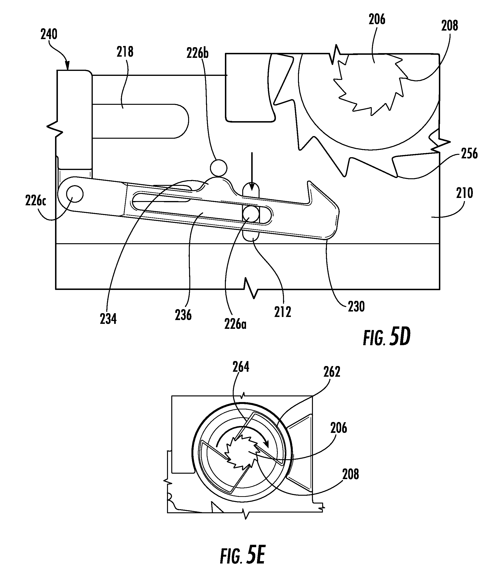
[0022] Moving now to FIGS. 3A-3C, 4A, 4B, and 5A-5E a counter assembly 200, for use in surgical clip applier 10, is illustrated. Counter assembly 200 is configured to provide an indication of either the number of clips fired or the number of clips remaining within surgical clip applier 10. Counter assembly 200 includes a housing 202, an actuator 240, a driver 230, a pin assembly 224, and a counting mechanism 250.
[0023] Housing 202 of counter assembly 200 includes a first housing half 202a and a second housing half 202b. First and second housing halves 202a, 202b may be snap fitted together or connected in any other appropriate method. When connected, first and second housing halves 202a, 202b define a window 220 therein which coincides with counter window 24 of handle assembly 12. Additionally, housing 202 encases the other components of counter assembly 200.
[0024] First housing half 202a of housing 202 defines and/or includes a circular recess 204, a stationary post 206 including a plurality of locking teeth 208, a linear channel 210, a vertical slot 212, a pin aperture 214, a driver slot 216, and an actuator slot 218.
[0025] Circular recess 204 is configured and adapted to rotationally support counting mechanism 250. A circumference of circular recess 204 is larger than an outer circumference of counting mechanism 250. Circular recess 204 is configured to align the counting mechanism 250 within first housing half 202a and to ensure that the plurality of locking teeth 208 of stationary post 206 remain engage with a plurality of fingers 264 of a locking spring assembly 260 of counting mechanism 250.
[0026] Stationary post 206 is concentrically positioned in circular recess 204 of first housing half 202a and extends perpendicular therefrom. An outer circumference of stationary post 206 includes a plurality of locking teeth 208, which allows the counting mechanism 250 to only transition/rotate in one direction upon engagement of driver 230 therewith.
[0027] Linear channel 210 is configured to receive driver 230, and permits linear translation thereof, for example, a horizontal translation between an initial position and a final position. Linear channel 210 is positioned in relation to circular recess 204 to permit interaction between a plurality of actuation features 256 of a counting wheel 252 of counting mechanism 250 and a grasping protrusion 232 of driver 230. In one embodiment, linear channel 210 is defined below circular recess 204 (FIG. 3A). In another embodiment, linear channel 210 is defined above circular recess 204 (not illustrated).
[0028] Vertical slot 212 is configured to receive a vertical translating pin 226a of pin assembly 224, and permits vertical translation thereof. Vertical slot 212 is defined within linear channel and positioned proximate to circular recess 204. Pin aperture 214 is configured to receive a stationary pin 226b of pin assembly 224. Pin aperture 214 is positioned proximately to vertical slot 212. Driver slot 216 is configured to receive a horizontal translating pin 226c, and permits linear translation of driver 230, such as a horizontal translation of horizontal translating pin 226c between an initial position and a final position. Drive slot 216 extends away from pin aperture 214 and is positioned proximately thereto. Actuator slot 218 is configured to receive actuator 240, and permits linear translation of actuator 240, such as a horizontal translation of actuator 240 between an initial position and a final position. Actuator slot 218 is defined parallel to driver slot 216. The length of both driver slot 216 and actuator slot 218 allow for a full stroke of surgical clip applier 10.
[0029] Second housing half 202b of housing 202 defines an aperture 222 therein that is adapted and configured to fit counting mechanism 250, thereby facilitating a connection of all of the components of counter assembly 200 (FIG. 3A).
[0030] Counting mechanism 250 includes a counting wheel 252 and a locking spring assembly 260. In some embodiments, counting wheel 252 is formed into a hollow cylinder. Counting wheel 252 includes indicia 254 positioned or displayed circumferentially thereabout (FIG. 3A). Indicia 254 may take the form of digits, which indicate either the number of remaining surgical clips or the number of surgical clips that have been fired. Indicia 254 may take other forms, such as one or more colors to indicate the number of surgical clips remaining. For example, the color red may indicate that a small number of surgical clips remain. Additionally, indicia 254 may include a combination of different indicia, such as alpha-numeric digits and colors. For example, as a number of indicia 254 of counting wheel 252 increases or decreases, a color of indicia 254 of counting wheel 252 may also change.
[0031] Counting wheel 252 includes a plurality of actuation features 256, which may be positioned circumferentially thereabout. In some embodiments, the plurality of actuation features 256 take the form of teeth, which allow counting wheel 252 to only transition/rotate in one direction upon engagement with driver 230. Additionally, the number of actuation features 256 may be equivalent to the number of surgical clips of clip applier 10.
[0032] In some embodiments, the counting wheel 252 includes an inner circular shelf 257 (FIG. 3B). Inner circular shelf 257 is adhered to an inner surface of counting wheel 252 and/or formed with counting wheel 252. Inner circular shelf 257 extends radially from the inner surface of counting wheel 252. In one embodiment, inner circular shelf 257 is continuous and extends the entire inner surface of counting wheel 252 (FIG. 3B). In other embodiments, inner circular shelf 257 is non-continuous and extends the entire inner surface of counting wheel 252 (not illustrated). In this embodiment, inner circular shelf 257 includes multiple pieces separated by spaces. Inner circular shelf 257 is configured to provide a surface for a locking spring assembly 260.
[0033] As seen specifically in FIGS. 3A, 4A, and 4B, embodiments of locking spring assemblies are displayed. As seen in FIG. 4A, one embodiment of locking spring assembly 260 includes a plurality of bodies 262 and a plurality of fingers 264. In some embodiments, each body 262 of the locking spring assembly 260 is press fitted to an inner surface 258 of counting wheel 252. In other embodiments, each body 262 of the locking spring assembly 260 is adhered and/or fused to inner circular shelf 257 of counting wheel 252. The plurality of fingers 264 extend from the plurality of bodies 262. In one embodiment, two fingers 264 will extend from each body 262. In this embodiment, body 262 and the two fingers 264 form a generally "C" shape, such that one finger extends almost perpendicularly from body 262 and the other finger extends almost parallel from body 262. Fingers 264 are substantially orthogonal to one another, such that the two fingers are spaced 90 degrees apart. In other embodiments, each finger 264 takes the form of a long protrusion which is positioned at an angle with respect to the body 262 that the finger 264 extends therefrom. Each finger 264 is resilient and flexible, and extends in a substantially tangential direction to an inner surface 258 of counting wheel 252.
[0034] The angle and size of each finger 264 is compatible with a profile of each locking tooth 208 of stationary post 206 of first housing half 202a, such that the angle of each finger 264 allows counting wheel 252 to transition/rotate in a first direction, but prohibits counting wheel 252 to transition/rotate in a second direct, opposite the first direction.
[0035] FIG. 4B illustrates another embodiment of a locking spring assembly in accordance with the present disclosure, and is generally designated by 260'. In this embodiment, locking spring assembly 260' includes a plurality of fingers 264'. The fingers 264' extend from the inner surface 258 of the counting wheel 252. In one embodiment, fingers 264' are integrally formed with inner surface 258 of counting wheel 252. In other embodiments, fingers 264' are adhered to or fused to inner circular shelf 257 (not illustrated) of counting wheel 252 by any appropriate method. Generally, each finger 264' is substantially orthogonal to one another, such that the fingers 264' are spaced 90 degrees apart. Additionally, each finger 264' may take the form of a protrusion which is positioned at an angle with respect to inner surface 258 of counting wheel 252. Specifically, each finger 264' is resilient and flexible, and extends in a substantially tangential direction to inner surface 258 of counting wheel 252. Each finger 264' extends in a generally common tangential direction as the plurality of actuation features 256. The angle and size of each inner finger 264' is compatible with a profile of each locking tooth 206 of stationary post 206 of first housing half 202a, such that the positioning angle of each finger 264' allows counting wheel 252 to transition/rotate in a first direction, but prohibits counting wheel 252 to transition/rotate in a second direct, opposite the first direction.
[0036] In operation, during rotation of counting wheel 252 in the first direction, each finger 264 flexes over the plurality of locking teeth 208 of stationary post 206 thereby allowing the counting wheel 252 to transition/rotate in reaction to driver 230 and actuator 240. After fingers 262 flex over the plurality of locking teeth 208, each finger 262 is positioned within the valleys defined between the plurality of locking teeth 208 of stationary post 206 thereby prohibiting movement of counting wheel 252 in a second direction, upon the return of driver 230 and actuator 240.
[0037] Referring back to FIG. 3A, driver 230 includes a grasping protrusion 232, a positioning protrusion 234, a channel or window 236, and an aperture 238. Grasping protrusion 232 extends and/or is formed at a proximal end of the driver 230. Grasping protrusion 232 is configured to engage the plurality of actuation features 256 of counting wheel 252. Positioning protrusion 234 extends from and/or is formed upon an upper surface of driver 230. The position of positioning protrusion 234 facilitates engagement of driver 230 with pin assembly 224. Channel or window 236 is defined through driver 230 and extends between the proximal end and a distal end of driver 230. Channel 236 is configured to receive vertical translating pin 226a of pin assembly 224. Aperture 238 is defined through the distal end of driver 230. Aperture 238 is configured to receive horizontal translating pin 226c of pin assembly 224.
[0038] With continue reference to FIG. 3A, as briefly mentioned above, pin assembly 224 includes a vertical translating pin 226a, a stationary pin 226b, a horizontal translating pin 226c, and a spring 228. Also as described above, vertical translating pin 226a is configured to be received within channel 236 of driver 230. Vertical translating pin 226a is configured to linearly/vertically translate within vertical slot 212 between a first position and a second position. Spring 228 is connected to vertical translating pin 226a and is configured to bias vertical translating pin 226a to the first position. In the first position, vertical translating pin 226a is horizontally aligned with horizontal translating pin 226c, while in the second position, vertical translating pin 226a is horizontally misaligned with horizontal translating pin 226c. Stationary pin 226b is configured to engage with positioning protrusion 234 of driver 230. Horizontal translating pin 226c is positioned at the distal end of driver 230 and attaches driver 230 to first housing half 202a. Also, horizontal translating pin 226c is configured to linearly/horizontally translate within driver slot 216 between a first position and a second position. In the first position, horizontal translating pin 226c is positioned proximal of stationary pin 226b and vertical translating pin 226a, while in the second position, horizontal translating pin 226c is positioned distal to stationary pin 226b and vertical translating pin 226a. Additionally, horizontal translating pin 226c is configured to allow driver 230 to pivot in response to engagement with stationary pin 226b.
[0039] With reference to FIGS. 3A and 3B, actuator 240 includes a body 242, a pair of arms 244a, 244b, which each define an aperture 246a, 246b, respectively. Actuator 240 is coupled to rack bar 26 and configured to translate in reaction to actuation of the surgical clip applier 10. Body 242 of actuator 240 is coupled to first housing half 202a and is configured to linearly/horizontally translate within actuator slot 218. Actuator 240 includes arms 244a, 244b that extend from body 242. Apertures 246a, 246b are defined through arms 244a, 244b, respectively, and are configured to receive horizontal translating pin 226c of pin assembly 224, thus connecting actuator 240 to driver 230.
[0040] Referring back to FIG. 3B, a method of assembly of counter assembly 200 is illustrated. Actuator 240 is coupled to the first housing half 202a via actuator slot 218. Driver 230 is coupled to actuator 240 via horizontal translating pin 226c of pin assembly 224. Driver 230 is seated within linear channel 210 of first housing half 202a with vertical translating pin 226a positioned within channel 236 of driver 230 and vertical slot 212, and horizontal pin 226b positioned within aperture 238 of driver 230 and the apertures 246a, 246b of actuator 240. Stationary pin 226b is positioned within pin aperture 214. Spring 228 is coupled to vertical translating pin 226a of pin assembly 224. Locking spring assembly 260 is fitted within counting wheel 252. Counting wheel 252 is seated within circular recess 204 of first housing half 202a with stationary post 206 extending therethrough. The plurality of locking teeth 208 of stationary post 206 engaging with the plurality of fingers 262 of locking spring assembly 260. Counting assembly 250 is seated within aperture 222 of second housing half 202b. First housing half 202a and second housing half 202b are snap-fitted together thereby assembling all components of counter assembly 200.
[0041] In an alternative embodiment, counter assembly 200 may not include housing 202. In this embodiment, the other components of counter assembly 200 will be directly coupled to or formed in handle assembly 12 of surgical clip applier 10, such that first circular recess 204, stationary post 206 including the plurality of locking teeth 208, linear channel 210, vertical slot 212, pin aperture 214, driver slot 216, and actuator slot 218 will be formed and defined within a first half of handle assembly 12 (not illustrated). A second circular recess (not illustrated), configured to receive the counting wheel 252 and permit rotation thereof, will be defined within a second half of handle assembly 12 (not illustrated). In this embodiment, each component engages with one another similarly or exactly how they engage with one another as described above.
[0042] Referring now to FIGS. 5A-5E, actuation of counter assembly 200 is illustrated. In FIG. 5A, driver 230, vertical translating pin 226a, horizontal translating pin 226c, and actuator 240 are all in a first position. As surgical clip applier 10 is actuated via trigger 18 (FIG. 1A), actuator 240 begins to transition or translate distally from the first position to a second position. Driver 230 is coupled to actuator 240 via horizontal translating pin 226c, and thus, driver 230 and horizontal translating pin 226c also begin to transition or translate from the first position to a second position.
[0043] As driver 230 is translated, grasping protrusion 232 of driver 230 engages with at least one of the plurality of actuation features 256 of counting wheel 252 thereby causing the counting wheel 252 to rotate in a first direction. The engagement between grasping protrusion 232 of driver 230 and the actuation feature 256 of counting wheel 252 remains until positioning protrusion 234 of driver 230 engages with stationary pin 226b of pin assembly 224 (FIG. 5C). As driver 230 continues to translate distally, upon engagement of positioning protrusion 234 with stationary pin 226b, driver 230 transitions or translates vertical translating pin 226a between the first position and a second position whereby grasping protrusion 232 of driver 230 pivots and disengages from the plurality of actuation features 256 of counting wheel 252. In some embodiments, upon engagement between the grasping protrusion 232 of driver 230 and the plurality of actuation features 256, counting wheel 252 will begin to rotate from an initial position. Counting wheel 252 will rotate 30 degrees from the initial position before positioning protrusion 234 of driver 230 engages with stationary pin 226b. As counting wheel 252 continues to rotate past 30 degrees from the initial position, positioning protrusion 234 will engage with stationary pin 226b causing the driver 230 to cam down and disengage with the plurality of actuation features of counting wheel 252.
[0044] Driver 230 and actuator 240 continue to linearly/horizontally translate until reaching the second position, wherein the trigger 18 is full compressed and surgical clip applier 10 is fully actuated. In the second position, the positioning protrusion 234 of driver 230 is distal to stationary pin 226b. Upon release of trigger 18, driver 230 and actuator 240 begin to translate proximally from the second position back to the first position. Again, positioning protrusion 234 of driver 230 engages with stationary pin 226b thereby forcing driver 230 to pivot. Simultaneously, vertical translating pin 226a translates from the first position to the second position. Once positioning protrusion 234 is proximal to stationary pin 226b, driver 230 is again engaged with the plurality of actuation features 256 of the counting wheel 252.
[0045] Locking spring assembly 260 permits rotation of counting wheel 252 in the first direction. In operation, during rotation of the counting wheel 252, in the first direction, the plurality of fingers 264 flex radially outward upon engagement with the plurality of locking teeth 208 of the stationary post 206. In contrast, free ends of the plurality of fingers 264 of locking spring assembly 260 abut the plurality of locking teeth 208 of stationary post 206, if counting wheel 252 should begin to rotate in the second direction, thus prohibiting rotation of counting wheel 252 in a second direction. The shape and positioning of the plurality of fingers 264 prevents counting wheel 252 from rotating in a second direction.
[0046] As described above, counting wheel 252 is configured for unidirectional rotation. The cooperation of the plurality of fingers 264 of locking spring assembly 260 and the plurality of locking teeth 208 of stationary post 206 prohibits rotation of counting mechanism 250 during the translation of driver 230 and actuator 240 from the second/distal position to the first/proximal position, for example, a secondary direction opposite to the first direction.
[0047] Referring back to FIG. 2, as noted above, handle assembly 12 is provided with a counter window 24 at a proximal end thereof which may reveal counter assembly 200 associated therewith. Window 220 of counter assembly 200 aligns with counter window 24 such that user may view indicia 254 during use of clip applier 10. As mentioned above, driver 230 causes the rotation of counter assembly 250 by using the linear force created by the transition of the rack bar 26, actuator 240, and driver 230.
[0048] It should be understood that the forgoing description is only illustrative of the present clip applier and counter assembly. Various alternatives and modifications can be devised by those skilled in the art without departing from the disclosure. Accordingly, the present disclosure is intended to embrace all such alternatives, modifications, and variances. The embodiments described with reference to the attached drawings are presented only to demonstrate certain examples of the clip applier and counter assembly. Other elements, steps, methods, and techniques that are insubstantially different from those described above and/or in the appended claims are also intended to be within the scope of the disclosure.
* * * * *
D00000
D00001
D00002
D00003
D00004
D00005
D00006
D00007
XML
uspto.report is an independent third-party trademark research tool that is not affiliated, endorsed, or sponsored by the United States Patent and Trademark Office (USPTO) or any other governmental organization. The information provided by uspto.report is based on publicly available data at the time of writing and is intended for informational purposes only.
While we strive to provide accurate and up-to-date information, we do not guarantee the accuracy, completeness, reliability, or suitability of the information displayed on this site. The use of this site is at your own risk. Any reliance you place on such information is therefore strictly at your own risk.
All official trademark data, including owner information, should be verified by visiting the official USPTO website at www.uspto.gov. This site is not intended to replace professional legal advice and should not be used as a substitute for consulting with a legal professional who is knowledgeable about trademark law.