Inner shield for a substrate processing chamber
Babu , et al. March 23, 2
U.S. patent number D913,979 [Application Number D/703,655] was granted by the patent office on 2021-03-23 for inner shield for a substrate processing chamber. This patent grant is currently assigned to APPLIED MATERIALS, INC.. The grantee listed for this patent is APPLIED MATERIALS, INC.. Invention is credited to Sarath Babu, Kelvin Boh, Ananthkrishna Jupudi, Yueh Sheng Ow, Yuichi Wada, Junqi Wei, Kang Zhang.


View All Diagrams
| United States Patent | D913,979 |
| Babu , et al. | March 23, 2021 |
Inner shield for a substrate processing chamber
Claims
CLAIM The ornamental design for an inner shield for a substrate processing chamber, as shown and described.
| Inventors: | Babu; Sarath (Singapore, SG), Jupudi; Ananthkrishna (Singapore, SG), Ow; Yueh Sheng (Singapore, SG), Wei; Junqi (Singapore, SG), Boh; Kelvin (Singapore, SG), Wada; Yuichi (Chiba, JP), Zhang; Kang (Singapore, SG) | ||||||||||
|---|---|---|---|---|---|---|---|---|---|---|---|
| Applicant: |
|
||||||||||
| Assignee: | APPLIED MATERIALS, INC. (Santa
Clara, CA) |
||||||||||
| Appl. No.: | D/703,655 | ||||||||||
| Filed: | August 28, 2019 |
| Current U.S. Class: | D13/182 |
| Current International Class: | 1303 |
| Field of Search: | ;D13/118,133,162,182,184,199 ;D15/144.1,144.2,150,199 ;D23/213 ;D24/232 |
References Cited [Referenced By]
U.S. Patent Documents
| 5762748 | June 1998 | Banholzer et al. |
| 6583064 | June 2003 | Wicker et al. |
| D557425 | December 2007 | Nakamura |
| D642605 | August 2011 | Ishikawa |
| D655258 | March 2012 | Honma |
| D693782 | November 2013 | Mori |
| D703160 | April 2014 | Tanimura |
| D711331 | August 2014 | Lau |
| D716239 | October 2014 | Lau |
| D802790 | November 2017 | Tauchi |
| D804436 | December 2017 | Tauchi |
| 9865437 | January 2018 | Chia et al. |
| D812578 | March 2018 | Uemura |
| D827592 | September 2018 | Ichino |
| D830981 | October 2018 | Jeong |
| D840364 | February 2019 | Ichino |
| D840365 | February 2019 | Ichino |
| D855027 | July 2019 | Okajima |
| D891382 | July 2020 | Koppa |
| D893441 | August 2020 | Rao |
| 2004/0149216 | August 2004 | Osada et al. |
| 2007/0113783 | May 2007 | Lee |
| 2010/0291319 | November 2010 | Yamashita et al. |
| 2011/0108524 | May 2011 | Dhindsa et al. |
| 2013/0098554 | April 2013 | Chhatre et al. |
| 2013/0284700 | October 2013 | Nangoy et al. |
Other References
|
International Search Report and Written Opinion for PCT/US2020/048302 dated Dec. 4, 2020. cited by applicant. |
Primary Examiner: Stout; Michael C
Assistant Examiner: Butac; Fritzgerald L
Attorney, Agent or Firm: Moser Taboada
Description
FIG. 1 is a top isometric view of the first embodiment for an inner shield for a substrate processing chamber, according to the new design.
FIG. 2 is a top plan view thereof.
FIG. 3 is a bottom plan view thereof.
FIG. 4 is a front elevation view thereof.
FIG. 5 is a back elevation view thereof.
FIG. 6 is a right side elevation view thereof.
FIG. 7 is a left side elevation view thereof.
FIG. 8 is a cross-sectional view taken along line 8-8 in FIG. 2.
FIG. 9 is a top isometric view of the second embodiment for an inner shield for a substrate processing chamber, according to the new design.
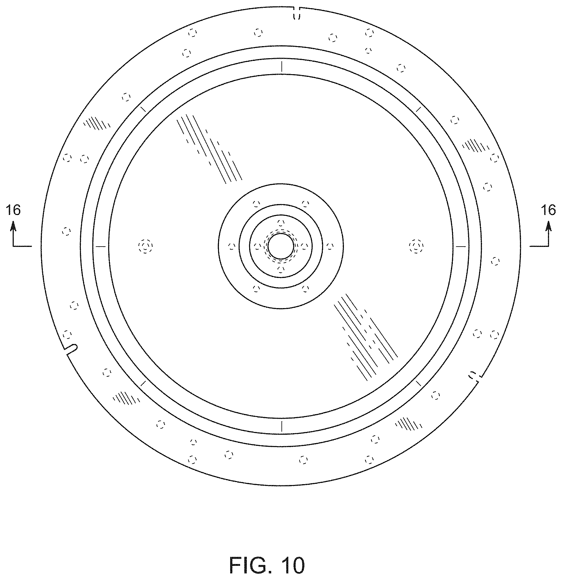
FIG. 10 is a top plan view thereof.
FIG. 11 is a bottom plan view thereof.
FIG. 12 is a front elevation view thereof.
FIG. 13 is a back elevation view thereof.
FIG. 14 is a right side elevation view thereof.
FIG. 15 is a left side elevation view thereof; and,
FIG. 16 is a cross-sectional view taken along line 16-16 in FIG. 10.
The broken lines in FIGS. 1-16 show portions of an inner shield for a substrate processing chamber which form no part of the claimed design.
* * * * *
D00000
D00001
D00002
D00003
D00004
D00005
D00006
D00007
D00008
D00009
D00010
D00011
D00012

XML
uspto.report is an independent third-party trademark research tool that is not affiliated, endorsed, or sponsored by the United States Patent and Trademark Office (USPTO) or any other governmental organization. The information provided by uspto.report is based on publicly available data at the time of writing and is intended for informational purposes only.
While we strive to provide accurate and up-to-date information, we do not guarantee the accuracy, completeness, reliability, or suitability of the information displayed on this site. The use of this site is at your own risk. Any reliance you place on such information is therefore strictly at your own risk.
All official trademark data, including owner information, should be verified by visiting the official USPTO website at www.uspto.gov. This site is not intended to replace professional legal advice and should not be used as a substitute for consulting with a legal professional who is knowledgeable about trademark law.