Thermoelectric device having a plurality of sealing materials
Jovovic , et al. April 27, 2
U.S. patent number 10,991,869 [Application Number 16/377,091] was granted by the patent office on 2021-04-27 for thermoelectric device having a plurality of sealing materials. This patent grant is currently assigned to GENTHERM INCORPORATED. The grantee listed for this patent is Gentherm Incorporated. Invention is credited to Vladimir Jovovic, Eric Poliquin.


| United States Patent | 10,991,869 |
| Jovovic , et al. | April 27, 2021 |
Thermoelectric device having a plurality of sealing materials
Abstract
A thermoelectric device includes a thermally conductive first plate and at least one thermoelectric sub-assembly comprises a thermally conductive second plate and a plurality of thermoelectric elements in a region between the first plate and the second plate. The at least one thermoelectric sub-assembly further includes a first material along a first portion of a perimeter of the region and having a first stiffness and a second material along a second portion of the perimeter of the region and having a second stiffness less than the first stiffness.
| Inventors: | Jovovic; Vladimir (Ann Arbor, MI), Poliquin; Eric (Claremont, CA) | ||||||||||
|---|---|---|---|---|---|---|---|---|---|---|---|
| Applicant: |
|
||||||||||
| Assignee: | GENTHERM INCORPORATED
(Northville, MI) |
||||||||||
| Family ID: | 1000005517041 | ||||||||||
| Appl. No.: | 16/377,091 | ||||||||||
| Filed: | April 5, 2019 |
Prior Publication Data
| Document Identifier | Publication Date | |
|---|---|---|
| US 20200035896 A1 | Jan 30, 2020 | |
Related U.S. Patent Documents
| Application Number | Filing Date | Patent Number | Issue Date | ||
|---|---|---|---|---|---|
| 62712131 | Jul 30, 2018 | ||||
| 62715709 | Aug 7, 2018 | ||||
| 62712143 | Jul 30, 2018 | ||||
| 62712112 | Jul 30, 2018 | ||||
| Current U.S. Class: | 1/1 |
| Current CPC Class: | H01L 35/34 (20130101); H01L 35/32 (20130101); H01L 35/02 (20130101); H01L 35/04 (20130101); H01L 35/30 (20130101) |
| Current International Class: | H01L 35/32 (20060101); H01L 35/02 (20060101); H01L 35/30 (20060101); H01L 35/34 (20060101); H01L 35/04 (20060101) |
References Cited [Referenced By]
U.S. Patent Documents
| 1120781 | December 1914 | Altenkirch et al. |
| 1839156 | December 1931 | Lumpkin |
| 2235620 | March 1941 | Nessell |
| 2362259 | November 1944 | Findley |
| 2363168 | November 1944 | Findley |
| 2461432 | February 1949 | Mitchell |
| 2462984 | March 1949 | Maddison |
| 2493067 | January 1950 | Goldsmith |
| 2499901 | March 1950 | Brown, Jr. |
| 2512559 | June 1950 | Williams |
| 2519241 | August 1950 | Findley |
| 2782834 | February 1957 | Vigo |
| 2791956 | May 1957 | Guest |
| 2813708 | November 1957 | Frey |
| 2884956 | May 1959 | Perlin |
| 2931286 | April 1960 | Fry, Sr. et al. |
| 2938357 | May 1960 | Sheckler |
| 2959017 | November 1960 | Gilman et al. |
| 2975638 | March 1961 | Morrison |
| 2976700 | March 1961 | Jackson |
| 2984077 | May 1961 | Gaskill |
| 2992538 | July 1961 | Siegfried |
| 3004393 | October 1961 | Alsing |
| 3006979 | October 1961 | Rich |
| 3019609 | February 1962 | Pietsch |
| 3030145 | April 1962 | Kottemann |
| 3039817 | June 1962 | Taylor |
| 3071495 | January 1963 | Hanlein |
| 3077079 | February 1963 | Pietsch |
| 3085405 | April 1963 | Frantti |
| 3090206 | May 1963 | Anders |
| 3129116 | April 1964 | Corry |
| 3136577 | June 1964 | Richard |
| 3137142 | June 1964 | Venema |
| 3137523 | June 1964 | Karner |
| 3138934 | June 1964 | Roane |
| 3178894 | April 1965 | Mole et al. |
| 3178895 | April 1965 | Mole et al. |
| 3186240 | June 1965 | Daubert |
| 3197342 | July 1965 | Neild |
| 3212275 | October 1965 | Tillman |
| 3240628 | March 1966 | Sonntag, Jr. |
| 3253649 | May 1966 | Laing |
| 3266064 | August 1966 | Figman |
| 3282267 | November 1966 | Eidus |
| 3298195 | January 1967 | Raskhodoff |
| 3300649 | January 1967 | Strawn |
| 3325312 | June 1967 | Sonntag, Jr. |
| 3326727 | June 1967 | Fritts |
| 3351498 | November 1967 | Shinn et al. |
| 3366164 | January 1968 | Newton |
| 3392535 | July 1968 | De Castelet |
| 3442718 | May 1969 | Dingwall |
| 3486177 | December 1969 | Marshack |
| 3505728 | April 1970 | Hare et al. |
| 3508974 | April 1970 | Bressler |
| 3522106 | July 1970 | Debiesse et al. |
| 3527621 | September 1970 | Newton |
| 3529310 | September 1970 | Olmo |
| 3550523 | December 1970 | Segal |
| 3554815 | January 1971 | Osborn |
| 3599437 | August 1971 | Panas |
| 3607444 | September 1971 | Debucs |
| 3615870 | October 1971 | Crouthamel |
| 3626704 | December 1971 | Coe, Jr. |
| 3627299 | December 1971 | Schwartze et al. |
| 3632451 | January 1972 | Abbott |
| 3635037 | January 1972 | Hubert |
| 3640456 | February 1972 | Sturgis |
| 3648469 | March 1972 | Chapman |
| 3657014 | April 1972 | Faber |
| 3663307 | May 1972 | Mole |
| 3681929 | August 1972 | Schering |
| 3703141 | November 1972 | Pernoud |
| 3726100 | April 1973 | Widakowich |
| 3767470 | October 1973 | Hines |
| 3779814 | December 1973 | Miles et al. |
| 3786230 | January 1974 | Brandenburg, Jr. |
| 3819418 | June 1974 | Winkler et al. |
| 3839876 | October 1974 | Privas |
| 3859143 | January 1975 | Krebs |
| 3870568 | March 1975 | Oesterhelt et al. |
| 3876860 | April 1975 | Nomura et al. |
| 3880674 | April 1975 | Saunders |
| 3894213 | July 1975 | Agarwala |
| 3899054 | August 1975 | Huntress et al. |
| 3902923 | September 1975 | Evans et al. |
| 3916151 | October 1975 | Reix |
| 3926052 | December 1975 | Bechtel |
| 3927299 | December 1975 | Sturgis |
| 3928876 | December 1975 | Starr |
| 3958324 | May 1976 | Alais et al. |
| 4002108 | January 1977 | Drori |
| 4038831 | August 1977 | Gaudel et al. |
| 4044824 | August 1977 | Eskeli |
| 4055053 | October 1977 | Elfving |
| 4056406 | November 1977 | Markman et al. |
| 4065936 | January 1978 | Fenton et al. |
| 4124794 | November 1978 | Eder |
| 4125122 | November 1978 | Stachurski |
| 4195687 | April 1980 | Taziker |
| 4199953 | April 1980 | Richter, Jr. et al. |
| 4211889 | July 1980 | Kortier et al. |
| 4223205 | September 1980 | Sturgis |
| 4224565 | September 1980 | Sosniak et al. |
| 4242778 | January 1981 | Kay |
| 4281516 | August 1981 | Berthet et al. |
| 4297841 | November 1981 | Cheng |
| 4297849 | November 1981 | Buffet |
| 4301658 | November 1981 | Reed |
| 4315599 | February 1982 | Biancardi |
| 4336444 | June 1982 | Bice et al. |
| 4338944 | July 1982 | Arkans |
| 4391009 | July 1983 | Schild et al. |
| 4402188 | September 1983 | Skala |
| 4413857 | November 1983 | Hayashi |
| 4420940 | December 1983 | Buffet |
| 4423308 | December 1983 | Callaway et al. |
| 4437702 | March 1984 | Agosta |
| 4438070 | March 1984 | Stephens et al. |
| 4448028 | May 1984 | Chao et al. |
| 4459428 | July 1984 | Chou |
| 4491173 | January 1985 | Demand |
| 4493939 | January 1985 | Blaske et al. |
| 4494380 | January 1985 | Cross |
| 4497973 | February 1985 | Heath et al. |
| 4499329 | February 1985 | Benicourt et al. |
| 4506510 | March 1985 | Tircot |
| 4518700 | May 1985 | Stephens |
| 4518847 | May 1985 | Horst, Sr. et al. |
| 4549134 | October 1985 | Weiss |
| 4554968 | November 1985 | Haas |
| 4567351 | January 1986 | Kitagawa et al. |
| 4572430 | February 1986 | Takagi et al. |
| 4611089 | September 1986 | Elsner et al. |
| 4634803 | January 1987 | Mathiprakasam |
| 4639883 | January 1987 | Michaelis |
| 4651019 | March 1987 | Gilbert et al. |
| 4665707 | May 1987 | Hamilton |
| 4671567 | June 1987 | Frobose |
| 4677416 | June 1987 | Nishimoto et al. |
| 4685727 | August 1987 | Cremer et al. |
| 4688390 | August 1987 | Sawyer |
| 4704320 | November 1987 | Mizunoya et al. |
| 4711294 | December 1987 | Jacobs et al. |
| 4712832 | December 1987 | Antolini et al. |
| 4730459 | March 1988 | Schicklin et al. |
| 4731338 | March 1988 | Ralston et al. |
| 4777802 | October 1988 | Feher |
| 4782664 | November 1988 | Sterna et al. |
| 4791274 | December 1988 | Horst |
| 4793651 | December 1988 | Inagaki et al. |
| 4802929 | February 1989 | Schock |
| 4812733 | March 1989 | Tobey |
| 4823554 | April 1989 | Trachtenberg et al. |
| 4825488 | May 1989 | Bedford |
| 4828627 | May 1989 | Connery |
| 4853992 | August 1989 | Yu |
| 4907060 | March 1990 | Nelson et al. |
| 4923248 | May 1990 | Feher |
| 4947648 | August 1990 | Harwell et al. |
| 4969684 | November 1990 | Zarotti |
| 4981324 | January 1991 | Law |
| 4988847 | January 1991 | Argos et al. |
| 4989626 | February 1991 | Takagi et al. |
| 4997230 | March 1991 | Spitalnick |
| 5002336 | March 1991 | Feher |
| 5006178 | April 1991 | Bijvoets |
| 5012325 | April 1991 | Mansuria et al. |
| 5014909 | May 1991 | Yasuo |
| 5016304 | May 1991 | Ryhiner |
| 5022462 | June 1991 | Flint et al. |
| 5057490 | October 1991 | Skertic |
| 5070937 | December 1991 | Mougin et al. |
| 5077709 | December 1991 | Feher |
| 5088790 | February 1992 | Wainwright et al. |
| 5097674 | March 1992 | Imaiida et al. |
| 5102189 | April 1992 | Saito et al. |
| 5106161 | April 1992 | Meiller |
| 5111025 | May 1992 | Barma et al. |
| 5111664 | May 1992 | Yang |
| 5117638 | June 1992 | Feher |
| 5119640 | June 1992 | Conrad |
| 5125238 | June 1992 | Ragan et al. |
| 5148977 | September 1992 | Hibino et al. |
| 5166777 | November 1992 | Kataoka |
| 5171372 | December 1992 | Recine, Sr. |
| 5180293 | January 1993 | Hartl |
| 5187349 | February 1993 | Curhan et al. |
| 5188286 | February 1993 | Pence, IV |
| 5228923 | July 1993 | Hed |
| 5232516 | August 1993 | Hed |
| 5254178 | October 1993 | Yamada et al. |
| 5255735 | October 1993 | Raghava et al. |
| 5256857 | October 1993 | Curhan et al. |
| 5265599 | November 1993 | Stephenson et al. |
| 5278936 | January 1994 | Shao |
| 5279128 | January 1994 | Tomatsu et al. |
| 5296534 | March 1994 | Senuma et al. |
| 5335381 | August 1994 | Chang |
| 5367728 | November 1994 | Chang |
| 5372402 | December 1994 | Kuo |
| 5375421 | December 1994 | Hsieh |
| 5382075 | January 1995 | Shih |
| 5385382 | January 1995 | Single, II et al. |
| 5409547 | April 1995 | Watanabe et al. |
| 5413166 | May 1995 | Kerner et al. |
| 5416935 | May 1995 | Nieh |
| 5419489 | May 1995 | Burd |
| 5419780 | May 1995 | Suski |
| 5429680 | July 1995 | Fuschetti |
| 5430322 | July 1995 | Koyanagi et al. |
| 5448788 | September 1995 | Wu |
| 5448891 | September 1995 | Nakagiri et al. |
| 5456081 | October 1995 | Chrysler et al. |
| 5473783 | December 1995 | Allen |
| 5493742 | February 1996 | Klearman |
| 5493864 | February 1996 | Pomerene et al. |
| 5497625 | March 1996 | Manz et al. |
| 5497632 | March 1996 | Robinson |
| 5505520 | April 1996 | Frusti et al. |
| 5515238 | May 1996 | Fritz et al. |
| 5524439 | June 1996 | Gallup et al. |
| 5542503 | August 1996 | Dunn et al. |
| 5544487 | August 1996 | Attey et al. |
| 5544488 | August 1996 | Reid |
| 5555732 | September 1996 | Whiticar |
| 5561981 | October 1996 | Quisenberry et al. |
| 5576512 | November 1996 | Doke |
| 5584084 | December 1996 | Klearman et al. |
| 5584183 | December 1996 | Wright et al. |
| 5594609 | January 1997 | Lin |
| 5597200 | January 1997 | Gregory et al. |
| 5601399 | February 1997 | Okpara et al. |
| 5606639 | February 1997 | Lehoe et al. |
| 5613729 | March 1997 | Summer, Jr. |
| 5613730 | March 1997 | Buie et al. |
| 5623828 | April 1997 | Harrington |
| 5626021 | May 1997 | Karunasiri et al. |
| 5626386 | May 1997 | Lush |
| 5634342 | June 1997 | Peeters et al. |
| 5637921 | June 1997 | Burward-Hoy |
| 5640728 | June 1997 | Graebe |
| 5642539 | July 1997 | Kuo |
| 5645314 | July 1997 | Liou |
| 5650904 | July 1997 | Gilley et al. |
| 5653741 | August 1997 | Grant |
| 5660310 | August 1997 | LeGrow |
| 5667622 | September 1997 | Hasegawa et al. |
| 5675852 | October 1997 | Watkins |
| 5682748 | November 1997 | DeVilbiss et al. |
| 5690849 | November 1997 | DeVilbiss et al. |
| 5692952 | December 1997 | Chih-Hung |
| 5704213 | January 1998 | Smith et al. |
| 5705770 | January 1998 | Ogassawara et al. |
| 5715695 | February 1998 | Lord |
| 5721804 | February 1998 | Greene, III |
| 5724818 | March 1998 | Iwata et al. |
| 5729981 | March 1998 | Markus et al. |
| 5734122 | March 1998 | Aspden |
| 5761908 | June 1998 | Oas et al. |
| 5761909 | June 1998 | Hughes et al. |
| 5772500 | June 1998 | Harvey et al. |
| 5798583 | August 1998 | Morita |
| 5800490 | September 1998 | Patz et al. |
| 5802855 | September 1998 | Yamaguchi et al. |
| 5802856 | September 1998 | Schaper et al. |
| 5822993 | October 1998 | Attey |
| 5827424 | October 1998 | Gillis et al. |
| 5833321 | November 1998 | Kim et al. |
| 5850741 | December 1998 | Feher |
| 5860472 | January 1999 | Batchelder |
| 5865031 | February 1999 | Itakura |
| 5867990 | February 1999 | Ghoshal |
| 5871151 | February 1999 | Fiedrich |
| 5884485 | March 1999 | Yamaguchi et al. |
| 5884486 | March 1999 | Hughes et al. |
| 5887304 | March 1999 | Von der Heyde |
| 5888261 | March 1999 | Fortune |
| 5895964 | April 1999 | Nakayama |
| 5900071 | May 1999 | Harman |
| 5902014 | May 1999 | Dinkel et al. |
| 5921100 | July 1999 | Yoshinori et al. |
| 5921314 | July 1999 | Schuller et al. |
| 5921858 | July 1999 | Kawai et al. |
| 5924289 | July 1999 | Bishop, II |
| 5924766 | July 1999 | Esaki et al. |
| 5924767 | July 1999 | Pietryga |
| 5927817 | July 1999 | Ekman et al. |
| 5934748 | August 1999 | Faust et al. |
| 5936192 | August 1999 | Tauchi |
| 5937908 | August 1999 | Inoshiri et al. |
| 5948303 | September 1999 | Larson |
| 5950067 | September 1999 | Maegawa et al. |
| 5952728 | September 1999 | Imanishi et al. |
| 5959341 | September 1999 | Tsuno et al. |
| 5966941 | October 1999 | Ghoshal |
| 5987893 | November 1999 | Schultz-Harder et al. |
| 5988568 | November 1999 | Drews |
| 5992154 | November 1999 | Kawada et al. |
| 5994637 | November 1999 | Imanushi et al. |
| 5995711 | November 1999 | Fukuoka et al. |
| 6000225 | December 1999 | Ghoshal |
| 6003950 | December 1999 | Larsson |
| 6006524 | December 1999 | Park |
| 6019420 | February 2000 | Faust et al. |
| 6038865 | March 2000 | Watanabe et al. |
| 6048024 | April 2000 | Wallman |
| 6049655 | April 2000 | Vazirani |
| 6052853 | April 2000 | Schmid |
| 6053163 | April 2000 | Bass |
| 6059018 | May 2000 | Yoshinori et al. |
| 6062641 | May 2000 | Suzuki et al. |
| 6072924 | June 2000 | Sato et al. |
| 6072938 | June 2000 | Peterson et al. |
| 6073998 | June 2000 | Siarkowski et al. |
| 6079485 | June 2000 | Esaki et al. |
| 6084172 | July 2000 | Kishi et al. |
| 6085369 | July 2000 | Feher |
| 6086831 | July 2000 | Harness et al. |
| 6087638 | July 2000 | Silverbrook |
| 6094919 | August 2000 | Bhatia |
| 6096966 | August 2000 | Nishimoto et al. |
| 6097088 | August 2000 | Sakuragi |
| 6100463 | August 2000 | Ladd et al. |
| 6101815 | August 2000 | Van Oort et al. |
| 6103967 | August 2000 | Cauchy et al. |
| 6105373 | August 2000 | Watanabe et al. |
| 6109688 | August 2000 | Wurz et al. |
| 6112525 | September 2000 | Yoshida et al. |
| 6112531 | September 2000 | Yamaguchi |
| 6116029 | September 2000 | Krawec |
| 6119463 | September 2000 | Bell |
| 6120370 | September 2000 | Asou et al. |
| 6127619 | October 2000 | Xi et al. |
| 6141969 | November 2000 | Launchbury et al. |
| 6145925 | November 2000 | Eksin et al. |
| 6158224 | December 2000 | Hu et al. |
| 6161241 | December 2000 | Zysman |
| 6161388 | December 2000 | Ghoshal |
| 6164076 | December 2000 | Chu et al. |
| 6164719 | December 2000 | Rauh |
| 6171333 | January 2001 | Nelson et al. |
| 6178292 | January 2001 | Fukuoka et al. |
| 6179706 | January 2001 | Yoshinori et al. |
| 6186592 | February 2001 | Orizakis et al. |
| 6189966 | February 2001 | Faust et al. |
| 6189967 | February 2001 | Short |
| 6196627 | March 2001 | Faust et al. |
| 6196839 | March 2001 | Ross |
| 6206465 | March 2001 | Faust et al. |
| 6213198 | April 2001 | Shikata et al. |
| 6222243 | April 2001 | Kishi et al. |
| 6223539 | May 2001 | Bell |
| 6226994 | May 2001 | Yamada et al. |
| 6233959 | May 2001 | Kang et al. |
| 6250083 | June 2001 | Chou |
| 6256996 | July 2001 | Ghoshal |
| 6262357 | July 2001 | Johnson et al. |
| 6263530 | July 2001 | Feher |
| 6266962 | July 2001 | Ghoshal |
| 6274802 | August 2001 | Fukuda et al. |
| 6282907 | September 2001 | Ghoshal |
| 6289982 | September 2001 | Naji |
| 6291803 | September 2001 | Fourrey |
| 6302196 | October 2001 | Haussmann |
| 6306673 | October 2001 | Imanishi et al. |
| 6319744 | November 2001 | Hoon et al. |
| 6320280 | November 2001 | Kanesaka |
| 6326610 | December 2001 | Muramatsu et al. |
| 6336237 | January 2002 | Schmid |
| 6338251 | January 2002 | Ghoshal |
| 6341395 | January 2002 | Chao |
| 6347521 | February 2002 | Kadotani et al. |
| 6357518 | March 2002 | Sugimoto et al. |
| 6378311 | April 2002 | McCordic |
| 6385976 | May 2002 | Yamamura et al. |
| 6391676 | May 2002 | Tsuzaki |
| 6393842 | May 2002 | Kim et al. |
| 6400013 | June 2002 | Tsuzaki et al. |
| 6402470 | June 2002 | Kvasnak et al. |
| 6407435 | June 2002 | Ma et al. |
| 6410971 | June 2002 | Otey |
| 6425527 | July 2002 | Smole |
| 6427449 | August 2002 | Logan et al. |
| 6434328 | August 2002 | Rutherford |
| 6438964 | August 2002 | Giblin |
| 6446442 | September 2002 | Batchelor et al. |
| 6452740 | September 2002 | Ghoshal |
| 6470696 | October 2002 | Palfy et al. |
| 6474073 | November 2002 | Uetsuji et al. |
| 6477844 | November 2002 | Ohkubo et al. |
| 6481801 | November 2002 | Schmale |
| 6487739 | December 2002 | Harker |
| 6489551 | December 2002 | Chu et al. |
| 6490879 | December 2002 | Lloyd et al. |
| 6492585 | December 2002 | Zamboni et al. |
| 6493888 | December 2002 | Salvatini et al. |
| 6493889 | December 2002 | Kocurek |
| 6499306 | December 2002 | Gillen |
| 6509704 | January 2003 | Brown |
| 6511125 | January 2003 | Gendron |
| 6519949 | February 2003 | Wernlund et al. |
| 6530231 | March 2003 | Nagy et al. |
| 6539725 | April 2003 | Bell |
| 6541737 | April 2003 | Eksin et al. |
| 6541743 | April 2003 | Chen |
| 6546576 | April 2003 | Lin |
| 6548750 | April 2003 | Picone |
| 6548894 | April 2003 | Chu et al. |
| 6552256 | April 2003 | Shakouri et al. |
| 6557353 | May 2003 | Fusco et al. |
| 6563039 | May 2003 | Caillat et al. |
| RE38128 | June 2003 | Gallup et al. |
| 6571564 | June 2003 | Upadhye et al. |
| 6573596 | June 2003 | Saika |
| 6574967 | June 2003 | Park et al. |
| 6578986 | June 2003 | Swaris et al. |
| 6580025 | June 2003 | Guy |
| 6581225 | June 2003 | Imai |
| 6583638 | June 2003 | Costello et al. |
| 6598251 | July 2003 | Habboub et al. |
| 6598403 | July 2003 | Ghoshal |
| 6598405 | July 2003 | Bell |
| 6604576 | August 2003 | Noda et al. |
| 6604785 | August 2003 | Bargheer et al. |
| 6605955 | August 2003 | Costello et al. |
| 6606754 | August 2003 | Flick |
| 6606866 | August 2003 | Bell |
| 6613972 | September 2003 | Cohen et al. |
| 6619044 | September 2003 | Batchelor et al. |
| 6619736 | September 2003 | Stowe et al. |
| 6625990 | September 2003 | Bell |
| 6626488 | September 2003 | Pfahler |
| 6629724 | October 2003 | Ekern et al. |
| 6637210 | October 2003 | Bell |
| 6644735 | November 2003 | Bargheer et al. |
| 6672076 | January 2004 | Bell |
| 6676207 | January 2004 | Rauh et al. |
| 6684437 | February 2004 | Koenig |
| 6686532 | February 2004 | Macris |
| 6687937 | February 2004 | Harker |
| 6695402 | February 2004 | Sloan, Jr. |
| 6700052 | March 2004 | Bell |
| 6700053 | March 2004 | Hara et al. |
| 6705089 | March 2004 | Chu et al. |
| 6708352 | March 2004 | Salvatini et al. |
| 6711767 | March 2004 | Klamm |
| 6711904 | March 2004 | Law et al. |
| 6718954 | April 2004 | Ryon |
| 6719039 | April 2004 | Calaman et al. |
| 6725669 | April 2004 | Melaragni |
| 6727422 | April 2004 | Macris |
| 6730115 | May 2004 | Heaton |
| 6739138 | May 2004 | Saunders et al. |
| 6739655 | May 2004 | Schwochert et al. |
| 6743972 | June 2004 | Macris |
| 6761399 | July 2004 | Bargheer et al. |
| 6764502 | July 2004 | Bieberich |
| 6767766 | July 2004 | Chu et al. |
| 6772829 | August 2004 | Lebrun |
| 6774346 | August 2004 | Clothier |
| 6786541 | September 2004 | Haupt et al. |
| 6786545 | September 2004 | Bargheer et al. |
| 6790481 | September 2004 | Bishop et al. |
| 6793016 | September 2004 | Aoki et al. |
| 6804966 | October 2004 | Chu et al. |
| 6808230 | October 2004 | Buss et al. |
| 6812395 | November 2004 | Bell |
| 6815814 | November 2004 | Chu et al. |
| 6817191 | November 2004 | Watanabe |
| 6817197 | November 2004 | Padfield |
| 6817675 | November 2004 | Buss et al. |
| 6818817 | November 2004 | Macris |
| 6823678 | November 2004 | Li |
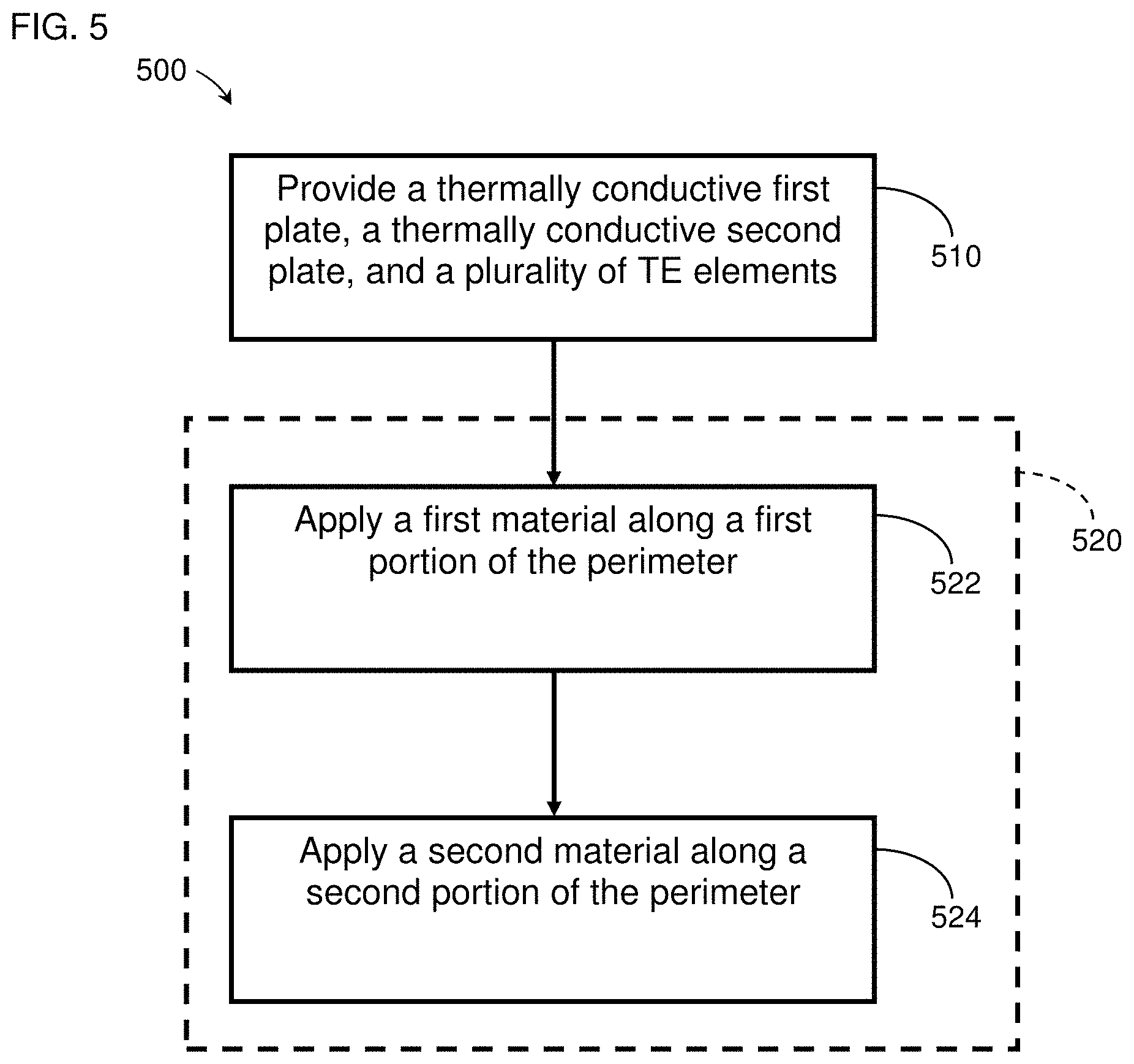
| 6828528 | December 2004 | Stowe et al. |
| 6832732 | December 2004 | Burkett et al. |
| 6834509 | December 2004 | Palfy et al. |
| 6840305 | January 2005 | Zheng et al. |
| 6840576 | January 2005 | Ekern et al. |
| 6841957 | January 2005 | Brown |
| 6845622 | January 2005 | Sauciuc et al. |
| 6855158 | February 2005 | Stolpmann |
| 6855880 | February 2005 | Feher |
| 6857697 | February 2005 | Brennan et al. |
| 6857954 | February 2005 | Luedtke |
| 6868690 | March 2005 | Faqih |
| 6871365 | March 2005 | Flick et al. |
| 6876549 | April 2005 | Beitmal et al. |
| 6880346 | April 2005 | Tseng et al. |
| 6886351 | May 2005 | Palfy et al. |
| 6892807 | May 2005 | Fristedt et al. |
| 6893086 | May 2005 | Bajic et al. |
| 6894369 | May 2005 | Irino et al. |
| 6904629 | June 2005 | Wu |
| 6907739 | June 2005 | Bell |
| 6923216 | August 2005 | Extrand et al. |
| 6935122 | August 2005 | Huang |
| 6942728 | September 2005 | Caillat et al. |
| 6948321 | September 2005 | Bell |
| 6954944 | October 2005 | Feher |
| 6959555 | November 2005 | Bell |
| 6962195 | November 2005 | Smith et al. |
| 6963053 | November 2005 | Lutz |
| 6967309 | November 2005 | Wyatt et al. |
| 6976734 | December 2005 | Stoewe |
| 6977360 | December 2005 | Weiss |
| 6981380 | January 2006 | Chrysler et al. |
| 6990701 | January 2006 | Litvak |
| 7000490 | February 2006 | Micheels |
| 7036163 | May 2006 | Schmid |
| 7040710 | May 2006 | White et al. |
| 7052091 | May 2006 | Bajic et al. |
| 7063163 | June 2006 | Steele et al. |
| 7066306 | June 2006 | Gavin |
| 7070231 | July 2006 | Wong |
| 7070232 | July 2006 | Minegishi et al. |
| 7075034 | July 2006 | Bargheer et al. |
| 7082772 | August 2006 | Welch |
| 7084502 | August 2006 | Bottner et al. |
| 7100978 | September 2006 | Ekern et al. |
| 7108319 | September 2006 | Hartwich et al. |
| 7111465 | September 2006 | Bell |
| 7114771 | October 2006 | Lofy et al. |
| 7124593 | October 2006 | Feher |
| 7131689 | November 2006 | Brennan et al. |
| 7134715 | November 2006 | Fristedt et al. |
| 7141763 | November 2006 | Moroz |
| 7147279 | December 2006 | Bevan et al. |
| 7165281 | January 2007 | Larssson et al. |
| 7168758 | January 2007 | Bevan et al. |
| 7178344 | February 2007 | Bell |
| 7201441 | April 2007 | Stoewe et al. |
| 7213876 | May 2007 | Stoewe |
| 7220048 | May 2007 | Kohlgruber et al. |
| 7222489 | May 2007 | Pastorino |
| 7224059 | May 2007 | Shimada et al. |
| 7231772 | June 2007 | Bell |
| 7235735 | June 2007 | Venkatasubramanian et al. |
| 7244887 | July 2007 | Miley |
| 7246496 | July 2007 | Goenka et al. |
| 7272936 | September 2007 | Feher |
| 7273981 | September 2007 | Bell |
| 7299639 | November 2007 | Leija et al. |
| 7337615 | March 2008 | Reidy |
| 7338117 | March 2008 | Iqbal et al. |
| 7340907 | March 2008 | Vogh et al. |
| 7355146 | April 2008 | Angelis et al. |
| 7356912 | April 2008 | Iqbal et al. |
| 7360365 | April 2008 | Codecasa et al. |
| 7360416 | April 2008 | Manaka et al. |
| 7370479 | May 2008 | Pfannenberg |
| 7370911 | May 2008 | Bajic et al. |
| 7380586 | June 2008 | Gawthrop |
| 7421845 | September 2008 | Bell |
| 7425034 | September 2008 | Bajic et al. |
| 7426835 | September 2008 | Bell et al. |
| 7462028 | December 2008 | Cherala et al. |
| 7469432 | December 2008 | Chambers |
| 7475464 | January 2009 | Lofy et al. |
| 7475551 | January 2009 | Ghoshal |
| 7475938 | January 2009 | Stoewe et al. |
| 7478869 | January 2009 | Lazanja et al. |
| 7480950 | January 2009 | Feher |
| 7480984 | January 2009 | Sakamoto |
| 7506924 | March 2009 | Bargheer et al. |
| 7506938 | March 2009 | Brennan et al. |
| 7513273 | April 2009 | Bivin |
| 7523617 | April 2009 | Venkatasubramanian et al. |
| 7581785 | September 2009 | Heckmann et al. |
| 7587901 | September 2009 | Petrovski |
| 7587902 | September 2009 | Bell |
| 7591507 | September 2009 | Giffin et al. |
| 7608777 | October 2009 | Bell et al. |
| 7621594 | November 2009 | Hartmann et al. |
| 7640754 | January 2010 | Wolas |
| 7665803 | February 2010 | Wolas |
| 7708338 | May 2010 | Wolas |
| 7731279 | June 2010 | Asada et al. |
| RE41765 | September 2010 | Gregory et al. |
| 7788933 | September 2010 | Goenka |
| 7827620 | November 2010 | Feher |
| 7827805 | November 2010 | Comiskey et al. |
| 7862113 | January 2011 | Knoll |
| 7866017 | January 2011 | Knoll |
| 7870745 | January 2011 | Goenka |
| 7877827 | February 2011 | Marquette et al. |
| 7915516 | March 2011 | Hu |
| 7926293 | April 2011 | Bell |
| 7932460 | April 2011 | Bell |
| 7937789 | May 2011 | Feher |
| 7942010 | May 2011 | Bell |
| 7946120 | May 2011 | Bell |
| 7963594 | June 2011 | Wolas |
| 7966835 | June 2011 | Petrovski |
| 7969738 | June 2011 | Koo |
| 7996936 | August 2011 | Marquette et al. |
| 8039726 | October 2011 | Zhang et al. |
| 8062797 | November 2011 | Fisher et al. |
| 8065763 | November 2011 | Brykalski et al. |
| 8079223 | December 2011 | Bell |
| 8104295 | January 2012 | Lofy |
| 8143554 | March 2012 | Lofy |
| 8181290 | May 2012 | Brykalski et al. |
| 8191187 | June 2012 | Brykalski et al. |
| 8198116 | June 2012 | Chen et al. |
| 8222511 | July 2012 | Lofy |
| 8256236 | September 2012 | Lofy |
| 8332975 | December 2012 | Brykalski et al. |
| 8375728 | February 2013 | Bell |
| 8397518 | March 2013 | Vistakula |
| 8402579 | March 2013 | Marquette et al. |
| 8418286 | April 2013 | Brykalski et al. |
| 8424315 | April 2013 | Goenka |
| 8434314 | May 2013 | Comiskey et al. |
| 8438863 | May 2013 | Lofy |
| RE44272 | June 2013 | Bell |
| 8495884 | July 2013 | Bell et al. |
| 8505320 | August 2013 | Lofy |
| 8516842 | August 2013 | Petrovski |
| 8539624 | September 2013 | Terech et al. |
| 8540466 | September 2013 | Halliar |
| 8575518 | November 2013 | Walsh |
| 8614390 | December 2013 | Watts |
| 8621687 | January 2014 | Brykalski et al. |
| 8640466 | February 2014 | Bell et al. |
| 8646262 | February 2014 | Magnetto |
| 8658881 | February 2014 | Cheng et al. |
| 8701422 | April 2014 | Bell et al. |
| 8729380 | May 2014 | Stefan et al. |
| 8732874 | May 2014 | Brykalski et al. |
| 8782830 | July 2014 | Brykalski et al. |
| 8869596 | October 2014 | Hagl |
| 8893329 | November 2014 | Petrovksi |
| 8893513 | November 2014 | June et al. |
| 8969704 | March 2015 | Bruck et al. |
| 9006557 | April 2015 | LaGrandeur et al. |
| 9020572 | April 2015 | Mensinger et al. |
| 9105808 | August 2015 | Petrovksi |
| 9105809 | August 2015 | Lofy |
| 9121414 | September 2015 | Lofy et al. |
| 9125497 | September 2015 | Brykalski et al. |
| 9178128 | November 2015 | Jovovic et al. |
| 9293680 | March 2016 | Poliquin et al. |
| 9306143 | April 2016 | Ranalli et al. |
| 9310112 | April 2016 | Bell et al. |
| 9335073 | May 2016 | Lofy |
| 9445524 | September 2016 | Lofy et al. |
| 9451723 | September 2016 | Lofy et al. |
| 9603459 | March 2017 | Brykalski et al. |
| 9651279 | May 2017 | Lofy |
| 9662962 | May 2017 | Steinman et al. |
| 9685599 | June 2017 | Petrovski et al. |
| 9719701 | August 2017 | Bell et al. |
| 9814641 | November 2017 | Brykalski et al. |
| 9857107 | January 2018 | Inaba et al. |
| 9863672 | January 2018 | Goenka |
| 9865794 | January 2018 | Jovovic et al. |
| 9989267 | June 2018 | Brykalski et al. |
| 10005337 | June 2018 | Petrovski |
| 10170811 | January 2019 | Kossakovski et al. |
| 10208990 | February 2019 | Petrovski et al. |
| 10228166 | March 2019 | Lofy |
| 10266031 | April 2019 | Steinman et al. |
| 10270141 | April 2019 | Piggott et al. |
| 10288084 | May 2019 | Lofy et al. |
| 10290796 | May 2019 | Boukai |
| 10405667 | September 2019 | Marquette et al. |
| 10457173 | October 2019 | Lofy et al. |
| 10473365 | November 2019 | Bell et al. |
| 10495322 | December 2019 | Brykalski et al. |
| 2001/0005990 | July 2001 | Kim et al. |
| 2001/0014212 | August 2001 | Rutherford |
| 2001/0028185 | October 2001 | Stowe et al. |
| 2002/0017102 | February 2002 | Bell |
| 2002/0026226 | February 2002 | Ein |
| 2002/0062854 | May 2002 | Sharp |
| 2002/0092308 | July 2002 | Bell |
| 2002/0100121 | August 2002 | Kocurek |
| 2002/0108380 | August 2002 | Nelsen et al. |
| 2002/0121094 | September 2002 | VanHoudt |
| 2002/0171132 | November 2002 | Buchwalter et al. |
| 2002/0195844 | December 2002 | Hipwell |
| 2003/0019044 | January 2003 | Larsson et al. |
| 2003/0039298 | February 2003 | Eriksson et al. |
| 2003/0041892 | March 2003 | Fleurial et al. |
| 2003/0070235 | April 2003 | Suzuki et al. |
| 2003/0084511 | May 2003 | Salvatini et al. |
| 2003/0094265 | May 2003 | Chu et al. |
| 2003/0106677 | June 2003 | Memory et al. |
| 2003/0110779 | June 2003 | Otey et al. |
| 2003/0133492 | July 2003 | Watanabe |
| 2003/0145380 | August 2003 | Schmid |
| 2003/0150060 | August 2003 | Huang |
| 2003/0160479 | August 2003 | Minuth et al. |
| 2003/0188382 | October 2003 | Klamm et al. |
| 2003/0234247 | December 2003 | Stern |
| 2004/0042181 | March 2004 | Nagasaki |
| 2004/0089336 | May 2004 | Hunt |
| 2004/0090093 | May 2004 | Kamiya et al. |
| 2004/0098991 | May 2004 | Heyes |
| 2004/0113549 | June 2004 | Roberts et al. |
| 2004/0164594 | August 2004 | Stoewe et al. |
| 2004/0177622 | September 2004 | Harvie |
| 2004/0177876 | September 2004 | Hightower |
| 2004/0177877 | September 2004 | Hightower |
| 2004/0195870 | October 2004 | Bohlender |
| 2004/0238022 | December 2004 | Hiller et al. |
| 2004/0255364 | December 2004 | Feher |
| 2004/0264009 | December 2004 | Hwang et al. |
| 2005/0011009 | January 2005 | Wu |
| 2005/0012204 | January 2005 | Strnad |
| 2005/0056310 | March 2005 | Shikata et al. |
| 2005/0067862 | March 2005 | Iqbal et al. |
| 2005/0072165 | April 2005 | Bell |
| 2005/0076944 | April 2005 | Kanatzidis et al. |
| 2005/0078451 | April 2005 | Sauciuc et al. |
| 2005/0086739 | April 2005 | Wu |
| 2005/0121065 | June 2005 | Otey |
| 2005/0126184 | June 2005 | Cauchy |
| 2005/0140180 | June 2005 | Hesch |
| 2005/0143797 | June 2005 | Parish et al. |
| 2005/0145285 | July 2005 | Extrand |
| 2005/0161072 | July 2005 | Esser et al. |
| 2005/0173950 | August 2005 | Bajic et al. |
| 2005/0183763 | August 2005 | Christiansen |
| 2005/0193742 | September 2005 | Arnold |
| 2005/0200166 | September 2005 | Noh |
| 2005/0202774 | September 2005 | Lipke |
| 2005/0220167 | October 2005 | Kanai et al. |
| 2005/0251120 | November 2005 | Anderson et al. |
| 2005/0257532 | November 2005 | Ikeda et al. |
| 2005/0268956 | December 2005 | Take |
| 2005/0278863 | December 2005 | Bahash et al. |
| 2005/0285438 | December 2005 | Ishima et al. |
| 2005/0288749 | December 2005 | Lachenbruch |
| 2006/0005548 | January 2006 | Ruckstuhl |
| 2006/0005873 | January 2006 | Kambe |
| 2006/0005944 | January 2006 | Wang et al. |
| 2006/0053529 | March 2006 | Feher |
| 2006/0075760 | April 2006 | Im et al. |
| 2006/0078319 | April 2006 | Maran |
| 2006/0080778 | April 2006 | Chambers |
| 2006/0087160 | April 2006 | Dong et al. |
| 2006/0102224 | May 2006 | Chen et al. |
| 2006/0118158 | June 2006 | Zhang et al. |
| 2006/0118159 | June 2006 | Tsuneoka et al. |
| 2006/0118160 | June 2006 | Funahashi et al. |
| 2006/0123799 | June 2006 | Tateyama et al. |
| 2006/0137099 | June 2006 | Feher |
| 2006/0137359 | June 2006 | Ghoshal |
| 2006/0137360 | June 2006 | Ghoshal |
| 2006/0157101 | July 2006 | Sakamoto et al. |
| 2006/0157102 | July 2006 | Nakajima et al. |
| 2006/0158011 | July 2006 | Marlovits et al. |
| 2006/0162074 | July 2006 | Bader |
| 2006/0162341 | July 2006 | Milazzo |
| 2006/0168969 | August 2006 | Mei et al. |
| 2006/0175877 | August 2006 | Alionte et al. |
| 2006/0197363 | September 2006 | Lofy et al. |
| 2006/0200398 | September 2006 | Botton et al. |
| 2006/0201161 | September 2006 | Hirai et al. |
| 2006/0201162 | September 2006 | Hsieh |
| 2006/0214480 | September 2006 | Terech |
| 2006/0219281 | October 2006 | Kuroyanagi et al. |
| 2006/0219699 | October 2006 | Geisel et al. |
| 2006/0225441 | October 2006 | Goenka et al. |
| 2006/0225773 | October 2006 | Venkatasubramanian et al. |
| 2006/0237166 | October 2006 | Otey et al. |
| 2006/0243317 | November 2006 | Venkatasubramanian |
| 2006/0244289 | November 2006 | Bedro |
| 2006/0273646 | December 2006 | Comiskey et al. |
| 2006/0289051 | December 2006 | Niimi et al. |
| 2007/0017666 | January 2007 | Goenka et al. |
| 2007/0034356 | February 2007 | Kenny et al. |
| 2007/0035162 | February 2007 | Bier et al. |
| 2007/0040421 | February 2007 | Zuzga et al. |
| 2007/0069554 | March 2007 | Comiskey et al. |
| 2007/0086757 | April 2007 | Feher |
| 2007/0095378 | May 2007 | Ito et al. |
| 2007/0095383 | May 2007 | Tajima |
| 2007/0101602 | May 2007 | Bae et al. |
| 2007/0107450 | May 2007 | Sasao et al. |
| 2007/0125413 | June 2007 | Olsen et al. |
| 2007/0138844 | June 2007 | Kim |
| 2007/0142883 | June 2007 | Quincy, III |
| 2007/0145808 | June 2007 | Minuth et al. |
| 2007/0157630 | July 2007 | Kadle et al. |
| 2007/0158981 | July 2007 | Almasi et al. |
| 2007/0163269 | July 2007 | Chung et al. |
| 2007/0190712 | August 2007 | Lin et al. |
| 2007/0193279 | August 2007 | Yoneno et al. |
| 2007/0200398 | August 2007 | Wolas et al. |
| 2007/0204850 | September 2007 | Pickard et al. |
| 2007/0214956 | September 2007 | Carlson et al. |
| 2007/0220902 | September 2007 | Matsuoka et al. |
| 2007/0220907 | September 2007 | Ehlers |
| 2007/0227158 | October 2007 | Kuchimachi |
| 2007/0234742 | October 2007 | Aoki et al. |
| 2007/0241592 | October 2007 | Giffin et al. |
| 2007/0251016 | November 2007 | Feher |
| 2007/0256722 | November 2007 | Kondoh |
| 2007/0261412 | November 2007 | Heine |
| 2007/0261413 | November 2007 | Hatamian et al. |
| 2007/0261548 | November 2007 | Vrzalik et al. |
| 2007/0261914 | November 2007 | Wahlgren et al. |
| 2007/0262621 | November 2007 | Dong et al. |
| 2007/0296251 | December 2007 | Krobok et al. |
| 2008/0000025 | January 2008 | Feher |
| 2008/0000511 | January 2008 | Kuroyanagi et al. |
| 2008/0022694 | January 2008 | Anderson et al. |
| 2008/0023056 | January 2008 | Kambe et al. |
| 2008/0028536 | February 2008 | Hadden-Cook |
| 2008/0028768 | February 2008 | Goenka |
| 2008/0028769 | February 2008 | Goenka |
| 2008/0053108 | March 2008 | Wen |
| 2008/0053509 | March 2008 | Flitsch et al. |
| 2008/0077211 | March 2008 | Levinson et al. |
| 2008/0078186 | April 2008 | Cao |
| 2008/0084095 | April 2008 | Wolas |
| 2008/0087316 | April 2008 | Inaba et al. |
| 2008/0154518 | June 2008 | Manaka et al. |
| 2008/0155990 | July 2008 | Gupta et al. |
| 2008/0163916 | July 2008 | Tsuneoka et al. |
| 2008/0164733 | July 2008 | Giffin et al. |
| 2008/0166224 | July 2008 | Giffin et al. |
| 2008/0245092 | October 2008 | Forsberg et al. |
| 2008/0263776 | October 2008 | O'Reagan |
| 2008/0289677 | November 2008 | Bell et al. |
| 2008/0307796 | December 2008 | Bell et al. |
| 2009/0000031 | January 2009 | Feher |
| 2009/0007952 | January 2009 | Kondoh et al. |
| 2009/0015042 | January 2009 | Bargheer et al. |
| 2009/0026813 | January 2009 | Lofy |
| 2009/0032080 | February 2009 | Kawauchi et al. |
| 2009/0033130 | February 2009 | Marquette et al. |
| 2009/0106907 | April 2009 | Chambers |
| 2009/0108094 | April 2009 | Ivri |
| 2009/0126110 | May 2009 | Feher |
| 2009/0178700 | July 2009 | Heremans et al. |
| 2009/0211619 | August 2009 | Sharp et al. |
| 2009/0218855 | September 2009 | Wolas |
| 2009/0235969 | September 2009 | Heremans et al. |
| 2009/0269584 | October 2009 | Bell et al. |
| 2009/0293488 | December 2009 | Coughlan, III et al. |
| 2010/0031987 | February 2010 | Bell |
| 2010/0132379 | June 2010 | Wu |
| 2010/0132380 | June 2010 | Robinson, II |
| 2010/0133883 | June 2010 | Walker |
| 2010/0147351 | June 2010 | Takahashi |
| 2010/0153066 | June 2010 | Federer et al. |
| 2010/0154437 | June 2010 | Nepsha |
| 2010/0154911 | June 2010 | Yoskowitz |
| 2010/0170554 | July 2010 | Hiroyama |
| 2010/0186398 | July 2010 | Huber |
| 2010/0186399 | July 2010 | Huttinger |
| 2010/0198322 | August 2010 | Joseph et al. |
| 2010/0307168 | December 2010 | Kohl et al. |
| 2010/0326092 | December 2010 | Goenka |
| 2011/0005562 | January 2011 | Bisges |
| 2011/0066217 | March 2011 | Diller et al. |
| 2011/0101741 | May 2011 | Kolich |
| 2011/0209740 | September 2011 | Bell et al. |
| 2011/0271994 | November 2011 | Gilley |
| 2011/0289684 | December 2011 | Parish et al. |
| 2012/0000901 | January 2012 | Bajic et al. |
| 2012/0003510 | January 2012 | Eisenhour |
| 2012/0017371 | January 2012 | Pollard |
| 2012/0046823 | February 2012 | Schneider et al. |
| 2012/0080911 | April 2012 | Brykalski et al. |
| 2012/0103381 | May 2012 | Leavitt et al. |
| 2012/0111386 | May 2012 | Bell et al. |
| 2012/0132242 | May 2012 | Chu |
| 2012/0160293 | June 2012 | Jinushi et al. |
| 2012/0167937 | July 2012 | Fann et al. |
| 2012/0174567 | July 2012 | Limbeck et al. |
| 2012/0174568 | July 2012 | Bruck et al. |
| 2012/0174956 | July 2012 | Smythe et al. |
| 2012/0177864 | July 2012 | Limbeck et al. |
| 2012/0198616 | August 2012 | Makansi et al. |
| 2012/0201008 | August 2012 | Hershberger et al. |
| 2012/0234078 | September 2012 | Hagl |
| 2012/0235444 | September 2012 | Dilley et al. |
| 2012/0239123 | September 2012 | Weber et al. |
| 2012/0261399 | October 2012 | Lofy |
| 2012/0289761 | November 2012 | Boyden et al. |
| 2012/0305043 | December 2012 | Kossakovski et al. |
| 2012/0325281 | December 2012 | Akiyama |
| 2013/0008181 | January 2013 | Makansi et al. |
| 2013/0097777 | April 2013 | Marquette et al. |
| 2013/0125563 | May 2013 | Jun |
| 2013/0160809 | June 2013 | Mueller |
| 2013/0186448 | July 2013 | Ranalli et al. |
| 2013/0200424 | August 2013 | An et al. |
| 2013/0232996 | September 2013 | Goenka et al. |
| 2013/0239592 | September 2013 | Lofy |
| 2013/0255739 | October 2013 | Kossakovski et al. |
| 2013/0340802 | December 2013 | Jovovic et al. |
| 2014/0014871 | January 2014 | Haddon et al. |
| 2014/0026320 | January 2014 | Marquette et al. |
| 2014/0030082 | January 2014 | Helmenstein |
| 2014/0090513 | April 2014 | Zhang et al. |
| 2014/0096807 | April 2014 | Ranalli |
| 2014/0113536 | April 2014 | Goenka et al. |
| 2014/0131343 | May 2014 | Walsh |
| 2014/0137569 | May 2014 | Parish et al. |
| 2014/0159442 | June 2014 | Helmenstein |
| 2014/0165608 | June 2014 | Tseng |
| 2014/0180493 | June 2014 | Csonti et al. |
| 2014/0182646 | July 2014 | Choi et al. |
| 2014/0187140 | July 2014 | Lazanja et al. |
| 2014/0194959 | July 2014 | Fries et al. |
| 2014/0230455 | August 2014 | Chandler et al. |
| 2014/0250918 | September 2014 | Lofy |
| 2014/0256244 | September 2014 | Sakurai et al. |
| 2014/0260331 | September 2014 | Lofy et al. |
| 2014/0305625 | October 2014 | Petrovski |
| 2014/0338366 | November 2014 | Adldinger et al. |
| 2015/0194590 | July 2015 | LaGrandeur |
| 2015/0238020 | August 2015 | Petrovski et al. |
| 2015/0298524 | October 2015 | Goenka |
| 2016/0030234 | February 2016 | Lofy et al. |
| 2016/0133817 | May 2016 | Makansi et al. |
| 2016/0137110 | May 2016 | Lofy et al. |
| 2016/0240585 | August 2016 | Ranalli et al. |
| 2017/0047500 | February 2017 | Shiraishi et al. |
| 2017/0066355 | March 2017 | Kozlowski |
| 2017/0071359 | March 2017 | Petrovski et al. |
| 2017/0343253 | November 2017 | Bell et al. |
| 2017/0354190 | December 2017 | Cauchy |
| 2017/0365764 | December 2017 | Shingai et al. |
| 2018/0111527 | April 2018 | Tait et al. |
| 2018/0170223 | June 2018 | Wolas |
| 2018/0172325 | June 2018 | Inaba et al. |
| 2018/0279416 | September 2018 | Sajic et al. |
| 2018/0290574 | October 2018 | Kozlowski |
| 2019/0003726 | January 2019 | Brykalski et al. |
| 2019/0252745 | August 2019 | Piggott et al. |
| 2020/0025424 | January 2020 | Cauchy |
| 2020/0035897 | January 2020 | Jovovic |
| 2020/0035898 | January 2020 | Jovovic et al. |
| 2020/0035899 | January 2020 | Buck |
| 2020/0266327 | August 2020 | Jovovic et al. |
| 979490 | Dec 1975 | CA | |||
| 2128076 | Mar 1993 | CN | |||
| 1295345 | May 2001 | CN | |||
| 1299950 | Jun 2001 | CN | |||
| 1320087 | Oct 2001 | CN | |||
| 1343294 | Apr 2002 | CN | |||
| 1929761 | Mar 2007 | CN | |||
| 101 097 986 | Jan 2008 | CN | |||
| 101 219 025 | Jul 2008 | CN | |||
| 101 332 785 | Dec 2008 | CN | |||
| 102 801 105 | Nov 2012 | CN | |||
| 104 282 643 | Jan 2015 | CN | |||
| 106 937 799 | Jul 2017 | CN | |||
| 208 355 060 | Jan 2019 | CN | |||
| 4 329 816 | Mar 1994 | DE | |||
| 195 03 291 | Aug 1996 | DE | |||
| 199 12 764 | Sep 2000 | DE | |||
| 299 11 519 | Nov 2000 | DE | |||
| 102 38 552 | Aug 2001 | DE | |||
| 101 15 242 | Oct 2002 | DE | |||
| 201 20 516 | Apr 2003 | DE | |||
| 10 2009 036 332 | Feb 2011 | DE | |||
| 10 2010 012 629 | Sep 2011 | DE | |||
| 10 2010 035 152 | Feb 2012 | DE | |||
| 0 272 937 | Jun 1988 | EP | |||
| 0 424 160 | Apr 1991 | EP | |||
| 0 411 375 | May 1994 | EP | |||
| 0 621 026 | Oct 1994 | EP | |||
| 0 834 421 | Apr 1998 | EP | |||
| 0 862 901 | Sep 1998 | EP | |||
| 0 878 851 | Nov 1998 | EP | |||
| 1 174 996 | Jan 2002 | EP | |||
| 1 324 400 | Jul 2003 | EP | |||
| 1 475 532 | Nov 2004 | EP | |||
| 1 515 376 | Mar 2005 | EP | |||
| 1 598 223 | Nov 2005 | EP | |||
| 1 744 326 | Jan 2007 | EP | |||
| 1 780 807 | May 2007 | EP | |||
| 1 906 463 | Apr 2008 | EP | |||
| 1 972 312 | Sep 2008 | EP | |||
| 1 845 914 | Sep 2009 | EP | |||
| 2 159 854 | Mar 2010 | EP | |||
| 2 275 755 | Jan 2011 | EP | |||
| 2 378 577 | Oct 2011 | EP | |||
| 2 439 799 | Apr 2012 | EP | |||
| 2 541 634 | Jan 2013 | EP | |||
| 2 396 619 | Aug 2015 | EP | |||
| 2 921 083 | Sep 2015 | EP | |||
| 1 280 711 | Jan 1962 | FR | |||
| 2 261 638 | Sep 1975 | FR | |||
| 2 316 557 | Jan 1977 | FR | |||
| 2 419 479 | Oct 1979 | FR | |||
| 2 481 786 | Nov 1981 | FR | |||
| 2 543 275 | Sep 1984 | FR | |||
| 2 550 324 | Feb 1985 | FR | |||
| 2 806 666 | Sep 2001 | FR | |||
| 2 879 728 | Jun 2006 | FR | |||
| 2 893 826 | Jun 2007 | FR | |||
| 231 192 | May 1926 | GB | |||
| 817 077 | Jul 1959 | GB | |||
| 874660 | Aug 1961 | GB | |||
| 952 678 | Mar 1964 | GB | |||
| 978057 | Dec 1964 | GB | |||
| 1 151 947 | May 1969 | GB | |||
| 2 027 534 | Feb 1980 | GB | |||
| 2 267 338 | Dec 1993 | GB | |||
| 2 333 352 | Jul 1999 | GB | |||
| 45-008280 | Mar 1970 | JP | |||
| 56-097416 | Aug 1981 | JP | |||
| 59-097457 | Jun 1984 | JP | |||
| 60-080044 | May 1985 | JP | |||
| 60-085297 | May 1985 | JP | |||
| 63-262076 | Oct 1988 | JP | |||
| 01-131830 | May 1989 | JP | |||
| 01-200122 | Aug 1989 | JP | |||
| 01-281344 | Nov 1989 | JP | |||
| 04-052470 | Jun 1990 | JP | |||
| 03-102219 | Oct 1991 | JP | |||
| 03-263382 | Nov 1991 | JP | |||
| 04-165234 | Jun 1992 | JP | |||
| 05-026762 | Feb 1993 | JP | |||
| 05-277020 | Oct 1993 | JP | |||
| 06-089955 | Mar 1994 | JP | |||
| 06-342940 | Dec 1994 | JP | |||
| 07-007187 | Jan 1995 | JP | |||
| 07-198284 | Jan 1995 | JP | |||
| 07-074397 | Mar 1995 | JP | |||
| 07-111344 | Apr 1995 | JP | |||
| 07-202275 | Aug 1995 | JP | |||
| 07-226538 | Aug 1995 | JP | |||
| 07-253264 | Oct 1995 | JP | |||
| 07-307493 | Nov 1995 | JP | |||
| 08-222771 | Aug 1996 | JP | |||
| 08-293627 | Nov 1996 | JP | |||
| 09-042801 | Feb 1997 | JP | |||
| 09-089284 | Apr 1997 | JP | |||
| 09-275692 | Oct 1997 | JP | |||
| 09-276076 | Oct 1997 | JP | |||
| 09-321355 | Dec 1997 | JP | |||
| 10-012935 | Jan 1998 | JP | |||
| 10-035268 | Feb 1998 | JP | |||
| 10-044756 | Feb 1998 | JP | |||
| 10-074986 | Mar 1998 | JP | |||
| 10-227508 | Aug 1998 | JP | |||
| 10-238406 | Sep 1998 | JP | |||
| 10-275943 | Oct 1998 | JP | |||
| 10-290590 | Oct 1998 | JP | |||
| 10-297243 | Nov 1998 | JP | |||
| 10-325561 | Dec 1998 | JP | |||
| 10-332883 | Dec 1998 | JP | |||
| 11-032492 | Feb 1999 | JP | |||
| 11-046021 | Feb 1999 | JP | |||
| 11-182907 | Jul 1999 | JP | |||
| 11-201475 | Jul 1999 | JP | |||
| 11-274574 | Oct 1999 | JP | |||
| 11-274575 | Oct 1999 | JP | |||
| 11-317481 | Nov 1999 | JP | |||
| 2000-018095 | Jan 2000 | JP | |||
| 2000-058930 | Feb 2000 | JP | |||
| 2000-060681 | Feb 2000 | JP | |||
| 2000-164945 | Jun 2000 | JP | |||
| 2000-208823 | Jul 2000 | JP | |||
| 2000-214934 | Aug 2000 | JP | |||
| 2000-244024 | Sep 2000 | JP | |||
| 2000-274788 | Oct 2000 | JP | |||
| 2000-274871 | Oct 2000 | JP | |||
| 2000-274874 | Oct 2000 | JP | |||
| 2001-007263 | Jan 2001 | JP | |||
| 2001-024240 | Jan 2001 | JP | |||
| 2001-174028 | Jun 2001 | JP | |||
| 2001-208405 | Aug 2001 | JP | |||
| 2001-210879 | Aug 2001 | JP | |||
| 2001-267642 | Sep 2001 | JP | |||
| 2001-304778 | Oct 2001 | JP | |||
| 2001-336853 | Dec 2001 | JP | |||
| 2002-13758 | Jan 2002 | JP | |||
| 2002-059736 | Feb 2002 | JP | |||
| 2002-514735 | May 2002 | JP | |||
| 2002-227798 | Aug 2002 | JP | |||
| 2002-232028 | Aug 2002 | JP | |||
| 2003-174203 | Jun 2003 | JP | |||
| 2003-204087 | Jul 2003 | JP | |||
| 2003-254636 | Sep 2003 | JP | |||
| 2003-259671 | Sep 2003 | JP | |||
| 2003-332642 | Nov 2003 | JP | |||
| 2003-332644 | Nov 2003 | JP | |||
| 2003-338641 | Nov 2003 | JP | |||
| 2004-031696 | Jan 2004 | JP | |||
| 2004-055621 | Feb 2004 | JP | |||
| 2004-079883 | Mar 2004 | JP | |||
| 2004-174138 | Jun 2004 | JP | |||
| 2004-360522 | Dec 2004 | JP | |||
| 2005-079210 | Feb 2005 | JP | |||
| 2005-237171 | Sep 2005 | JP | |||
| 2005-251950 | Sep 2005 | JP | |||
| 2005-294695 | Oct 2005 | JP | |||
| 2005-303183 | Oct 2005 | JP | |||
| 2005-317648 | Nov 2005 | JP | |||
| 2005-333083 | Dec 2005 | JP | |||
| 2006-001392 | Jan 2006 | JP | |||
| 2006-021572 | Jan 2006 | JP | |||
| 2006-076398 | Mar 2006 | JP | |||
| 2008-274790 | Nov 2008 | JP | |||
| 2008-300465 | Dec 2008 | JP | |||
| 2009-010138 | Jan 2009 | JP | |||
| 2009-033806 | Feb 2009 | JP | |||
| 2010-034508 | Feb 2010 | JP | |||
| 2010-108958 | May 2010 | JP | |||
| 2010-182940 | Aug 2010 | JP | |||
| 2011-077163 | Apr 2011 | JP | |||
| 2012-522176 | Sep 2012 | JP | |||
| 2014-135455 | Jul 2014 | JP | |||
| 5893556 | Mar 2016 | JP | |||
| 2001-0060500 | Jul 2001 | KR | |||
| 10-2003-0082589 | Oct 2003 | KR | |||
| 10-2005-0011494 | Jan 2005 | KR | |||
| 66619 | Feb 1973 | LU | |||
| 2 142 178 | Nov 1999 | RU | |||
| 2 154 875 | Aug 2000 | RU | |||
| 2562507 | Sep 2015 | RU | |||
| 329 870 | Oct 1970 | SE | |||
| 337 227 | May 1971 | SE | |||
| 184886 | Jul 1966 | SU | |||
| 1142711 | Feb 1985 | SU | |||
| 1170234 | Jul 1985 | SU | |||
| WO 94/01893 | Jan 1994 | WO | |||
| WO 94/020801 | Sep 1994 | WO | |||
| WO 95/014899 | Jun 1995 | WO | |||
| WO 95/031688 | Nov 1995 | WO | |||
| WO 96/005475 | Feb 1996 | WO | |||
| WO 97/22486 | Jun 1997 | WO | |||
| WO 97/47930 | Dec 1997 | WO | |||
| WO 98/007898 | Feb 1998 | WO | |||
| WO 98/031311 | Jul 1998 | WO | |||
| WO 98/034451 | Aug 1998 | WO | |||
| WO 98/56047 | Dec 1998 | WO | |||
| WO 99/10191 | Mar 1999 | WO | |||
| WO 99/13511 | Mar 1999 | WO | |||
| WO 99/023980 | May 1999 | WO | |||
| WO 99/34451 | Jul 1999 | WO | |||
| WO 99/044552 | Sep 1999 | WO | |||
| WO 99/058907 | Nov 1999 | WO | |||
| WO 01/52332 | Jul 2001 | WO | |||
| WO 01/63674 | Aug 2001 | WO | |||
| WO 02/011968 | Feb 2002 | WO | |||
| WO 02/053400 | Jul 2002 | WO | |||
| WO 02/058165 | Jul 2002 | WO | |||
| WO 02/065029 | Aug 2002 | WO | |||
| WO 02/065030 | Aug 2002 | WO | |||
| WO 02/081982 | Oct 2002 | WO | |||
| WO 03/014634 | Feb 2003 | WO | |||
| WO 03/051666 | Jun 2003 | WO | |||
| WO 03/063257 | Jul 2003 | WO | |||
| WO 03/074951 | Sep 2003 | WO | |||
| WO 03/090286 | Oct 2003 | WO | |||
| WO 2004/011861 | Feb 2004 | WO | |||
| WO 2004/019379 | Mar 2004 | WO | |||
| WO 2004/026757 | Apr 2004 | WO | |||
| WO 2005/023571 | Mar 2005 | WO | |||
| WO 2005/115794 | Dec 2005 | WO | |||
| WO 2006/001827 | Jan 2006 | WO | |||
| WO 2006/037178 | Apr 2006 | WO | |||
| WO 2006/041935 | Apr 2006 | WO | |||
| WO 2006/064432 | Jun 2006 | WO | |||
| WO 2006/078394 | Jul 2006 | WO | |||
| WO 2006/102509 | Sep 2006 | WO | |||
| WO 2007/060371 | May 2007 | WO | |||
| WO 2007/089789 | Aug 2007 | WO | |||
| WO 2007/097059 | Aug 2007 | WO | |||
| WO 2007/109368 | Sep 2007 | WO | |||
| WO 2008/013946 | Jan 2008 | WO | |||
| WO 2008/023942 | Feb 2008 | WO | |||
| WO 2008/025707 | Mar 2008 | WO | |||
| WO 2008/045964 | Apr 2008 | WO | |||
| WO 2008/046110 | Apr 2008 | WO | |||
| WO 2008/057962 | May 2008 | WO | |||
| WO 2008/076588 | Jun 2008 | WO | |||
| WO 2008/086499 | Jul 2008 | WO | |||
| WO 2008/091293 | Jul 2008 | WO | |||
| WO 2008/115831 | Sep 2008 | WO | |||
| WO 2009/015235 | Jan 2009 | WO | |||
| WO 2009/036077 | Mar 2009 | WO | |||
| WO 2009/097572 | Aug 2009 | WO | |||
| WO 2010/009422 | Jan 2010 | WO | |||
| WO 2010/088405 | Aug 2010 | WO | |||
| WO 2010/0112961 | Oct 2010 | WO | |||
| WO 2010/129803 | Nov 2010 | WO | |||
| WO 2011/011795 | Jan 2011 | WO | |||
| WO 2011/026040 | Mar 2011 | WO | |||
| WO 2011/156643 | Dec 2011 | WO | |||
| WO 2012/022684 | Feb 2012 | WO | |||
| WO 2012/031980 | Mar 2012 | WO | |||
| WO 2012/045542 | Apr 2012 | WO | |||
| WO 2012/061763 | May 2012 | WO | |||
| WO 2012/061777 | May 2012 | WO | |||
| WO 2012/170443 | Dec 2012 | WO | |||
| WO 2013/052823 | Apr 2013 | WO | |||
| WO 2013/074967 | May 2013 | WO | |||
| WO 2014/055447 | Apr 2014 | WO | |||
| WO 2014/120688 | Aug 2014 | WO | |||
| WO 2014/164887 | Oct 2014 | WO | |||
| WO 2016/077843 | May 2016 | WO | |||
| WO 2017/059256 | Apr 2017 | WO | |||
| WO 2017/066261 | Apr 2017 | WO | |||
| WO 2017/100718 | Jun 2017 | WO | |||
| WO 2017/136793 | Aug 2017 | WO | |||
| WO 2018/175506 | Sep 2018 | WO | |||
| WO 2019/173553 | Sep 2019 | WO | |||
| WO 2020/112902 | Jun 2020 | WO | |||
| WO 2020/172255 | Aug 2020 | WO | |||
| WO 2020/180632 | Sep 2020 | WO | |||
Other References
|
US. Appl. No. 15/042,846, filed Feb. 12, 2016. cited by applicant . Derwent-Acc-No. 1998-283540, Kwon, H et al., Hyundai Motor Co., corresponding to KR 97026106 A, published Jun. 24, 1997 (2 pages). cited by applicant . Diller, R. W., et al., "Experimental results confirming improved performance of systems using thermal isolation" Thermoelectrics, 2002. Proceedings ICT '02. Twenty-First International Conference on Aug. 25-29, 2002, Piscataway, NJ USA, IEEE, Aug. 25, 2002 (Aug. 25, 2002), pp. 548-550, XP010637541 ISBN: 0-7803-7683-8. cited by applicant . Diller, R.W., et al., "Experimental Results Confirming Improved Efficiency of Thermoelectric Power Generation Systems with Alternate Thermodynamic Cycles," 22nd International Conference on Thermoelectrics, 2003, pp. 571-573. cited by applicant . Funahashi et al., "Preparation and properties of thermoelectric pipe-type modules", ICT 25th International Conference on Aug. 6-10, 2006, Thermoelectrics, 2006, pp. 58-61. cited by applicant . Hendricks, Terry et al., "Advanced Thermoelectric Power System Investigations for Light-Duty and Heavy Duty Applications," National Renewable Energy Laboratory, Center for Transportation Technology & Systems, Colorado, Proc. 21st Int'l Cont. on Thermoelectrics, Aug. 2002, pp. 381-386. cited by applicant . Hsu, Kuei Fang et al., Cubic AgPbmSbTe2+m: Bulk Thermoelectric Materials with High Figure of Merit, Science, Feb. 6, 2004, p. 818-821, vol. 303. cited by applicant . Kambe et al., "Encapsulated Thermoelectric Modules and Compliant Pads for Advanced Thermoelectric Systems," J. Electronic Materials, vol. 39, No. 9, 1418-21 (2010). cited by applicant . Lofy, John et al., "Thermoelectrics for Environmental Control Automobiles," 21st International Conference on Thermoelectronics, 2002, p. 471-476. cited by applicant . Menchen, et al., "Thermoelectric Conversion to Recover Heavy Duty Diesel Exhaust Energy", Proceedings of the Annual Automotive Technology Development Contractors Meeting, pp. 445-449, Apr. 1991. cited by applicant . Min et al., "Ring-structured thermoelectric module," Semiconductor Science and Technology, Semicond. Sci. Technol. 22 (2007) 880-8. cited by applicant . Miner, A., et al. "Thermo-Electro-Mechanical Refrigeration Based on Transient Thermoelectric Effects", Applied Physics letters, vol. 75, pp. 1176-1178 (1999). cited by applicant . Snyder, G. Jeffrey, et al., "Complex thermoelectric materials," Nature Materials, vol. 7, Feb. 2008, pp. 105-114. cited by applicant . Snyder, G. Jeffrey, et al., "Thermoelectric Efficiency and Compatibility," The American Physical Society, Oct. 2, 2003, vol. 91, No. 14. cited by applicant . Snyder, G. Jeffrey: "Application of the compatibility factor to the design of segmented and cascaded thermoelectric generators", Applied Physics Letters, AIP, American Institute of Physics, Melville, NY, vol. 84, No. 13, Mar. 29, 2004 (Mar. 29, 2004), pp. 2436-2438, XPO12060957 ISSN: 0003-6951. cited by applicant . Tada, S., et al., "A New Concept of Porous Thermoelectric Module Using a Reciprocating Flow for Cooling/Heating Systems (Numerical Analysis for Heating Systems)" 16th International Conference on Thermoelectrics (1977). cited by applicant . Tech Briefs, "Nickel-Graphite Composite Compliant Interface and/or Hot Shoe Material," article dated Sep. 1, 2013. From http://www.techbriefs.com/legal-footer-127/50-ntb/tech-briefs/materials52- /17192-npo-48621 on Feb. 27, 2015. cited by applicant . Thermoelectrics Handbook: Macro to Nano, Thermoelectric Module Design Theories, 11.7 Ring-Structure Module, pp. 11-11 to 11-15. CRC Press, 2006. cited by applicant . U.S. Appl. No. 14/821,514, filed Aug. 7, 2015, Lofy. cited by applicant . U.S. Appl. No. 15/685,912, filed Aug. 24, 2017, Petrovski et al. cited by applicant . U.S. Appl. No. 16/277,765, filed Feb. 15, 2019, Petrovski et al. cited by applicant . U.S. Appl. No. 16/377,109, filed Apr. 5, 2019, Janovic. cited by applicant . U.S. Appl. No. 16/377,134, filed Apr. 5, 2019, Buck. cited by applicant . U.S. Appl. No. 16/377,125, filed Apr. 5, 2019, Jovovic et al. cited by applicant . Feher, Steve, "Thermoelectric Air Conditioned Variable Temperature Seat (VTS) & Effect Upon Vehicle Occupant Comfort, Vehicle Energy Efficiency, and Vehicle Environment Compatibility", SAE Technical Paper, Apr. 1993, pp. 341-349. cited by applicant . Lofy et al., "Thermoelectrics for Environmental Control in Automobiles", Proceeding of Twenty-First International Conference on Thermoelectrics (ICT 2002), 2002, pp. 471-476. cited by applicant . Luo, Zhaoxia, "A Simple Method to Estimate the Physical Characteristics of a Thermoelectric Cooler from Vendor Datasheets", Electronics Cooling, Aug. 2008, in 17 pages from https://www.electronics-cooling.com/2008/08/a-simple-method-to-estimate-t- he-physical-characteristics-of-a-thermoelectric-cooler-from-vendor-datashe- ets/. cited by applicant . Photographs and accompanying description of climate control seat assembly system components publicly disclosed as early as Jan. 1998. cited by applicant . Photographs and accompanying description of a component of a climate control seat assembly system sold prior to Nov. 1, 2005. cited by applicant . Photographs and accompanying description of a component of a climate control seat assembly system sold prior to Dec. 20, 2003. cited by applicant . U.S. Appl. No. 16/417,149, filed May 20, 2019, Jovovic et al. cited by applicant. |
Primary Examiner: Mershon; Jayne L
Attorney, Agent or Firm: Knobbe, Martens, Olson & Bear, LLP
Claims
What is claimed is:
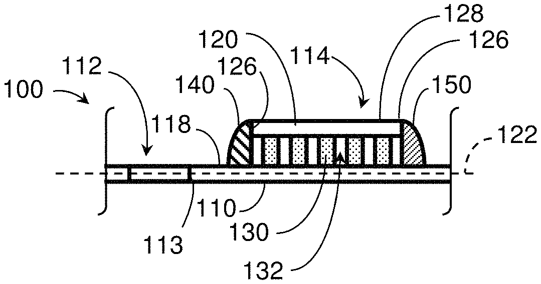
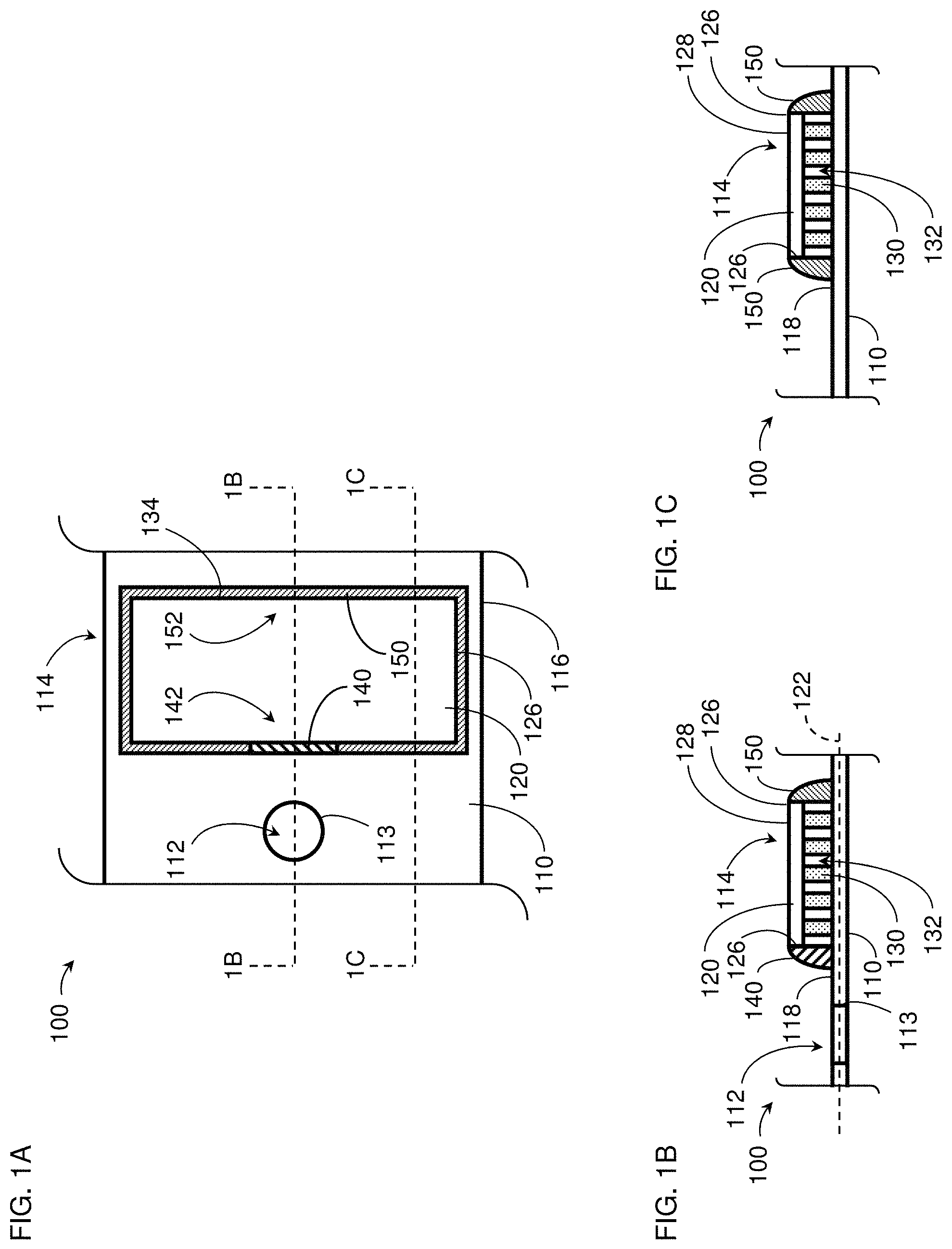
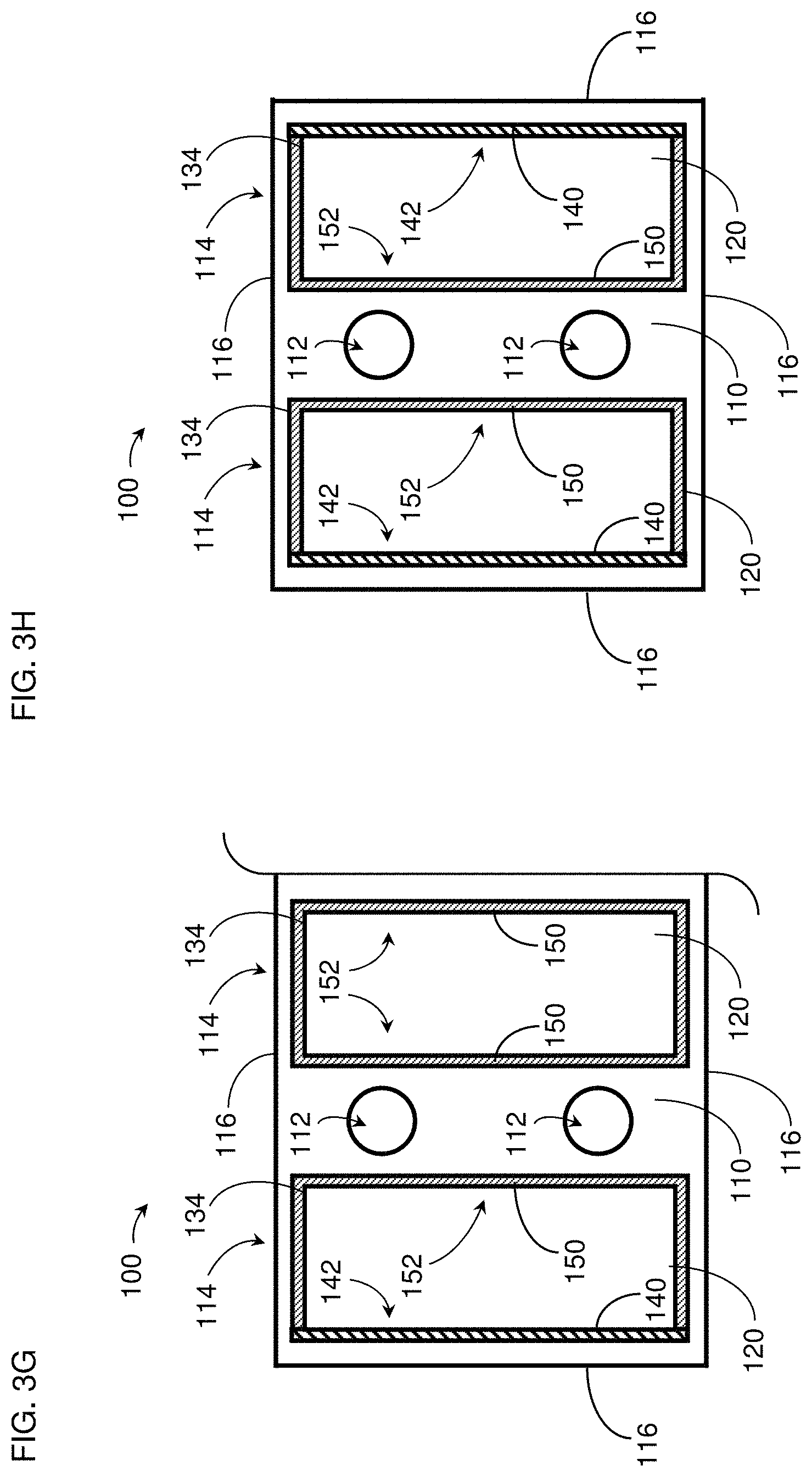
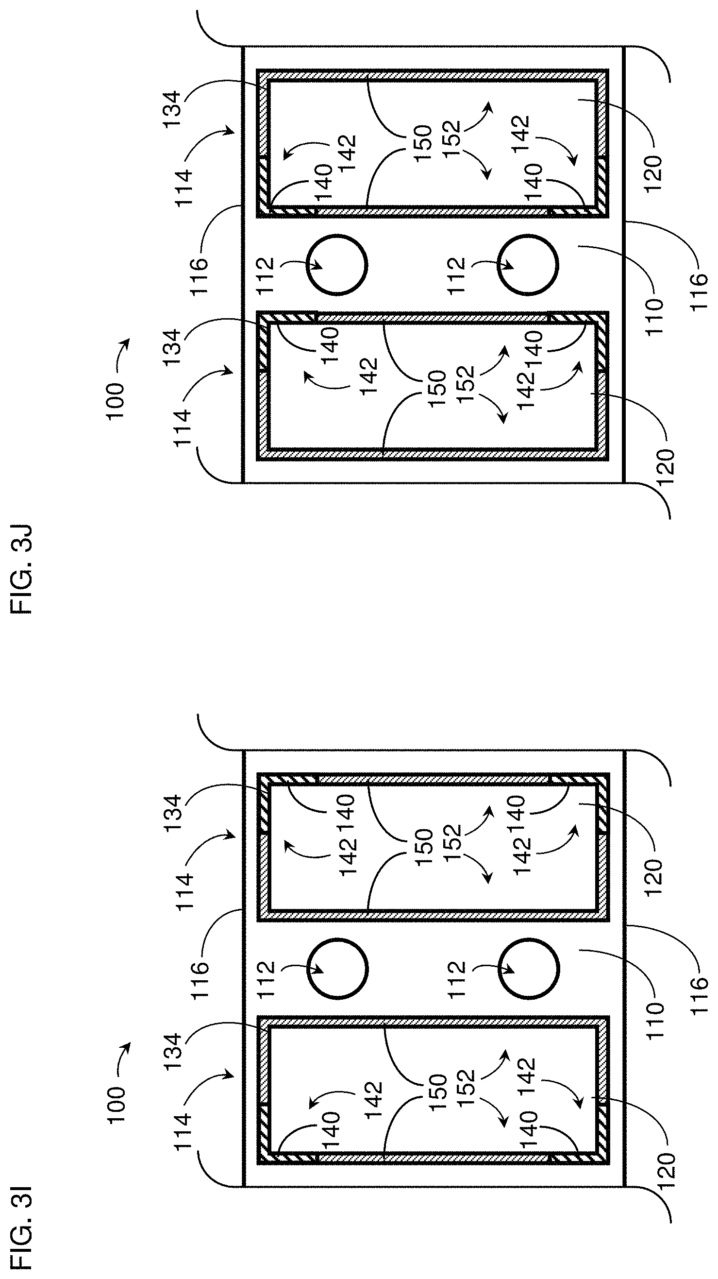
1. A thermoelectric device comprising: a thermally conductive first plate comprising at least one hole extending through the first plate; and at least one thermoelectric sub-assembly comprising: a thermally conductive second plate displaced from the at least one hole in a direction parallel to the first plate such that the second plate does not extend over the at least one hole along the direction parallel to the first plate; a plurality of thermoelectric elements in a region between the first plate and the second plate, the plurality of thermoelectric elements in thermal communication with the first plate and the second plate via a plurality of shunts positioned on the first and second plates; a first material along a first portion of a perimeter of the region, the first material in mechanical communication with the first plate and the second plate, the first material having a first stiffness; and a second material along a second portion of the perimeter of the region, the second material in mechanical communication with the first plate and the second plate, the second material having a second stiffness less than the first stiffness.
2. The thermoelectric device of claim 1, wherein the first material and the second material form a seal along the perimeter of the region.
3. The thermoelectric device of claim 1, wherein the first material comprises epoxy and the second material comprises silicone.
4. The thermoelectric device of claim 1, wherein the second plate has a planar polygonal shape with a plurality of edges and a plurality of corners.
5. The thermoelectric device of claim 4, wherein the second plate has a rectangular shape and the plurality of edges comprises two shorter edges and two longer edges.
6. The thermoelectric device of claim 5, wherein the first portion extends along at least one longer edge of the two longer edges, the first portion comprising a portion of the perimeter closest to the at least one hole.
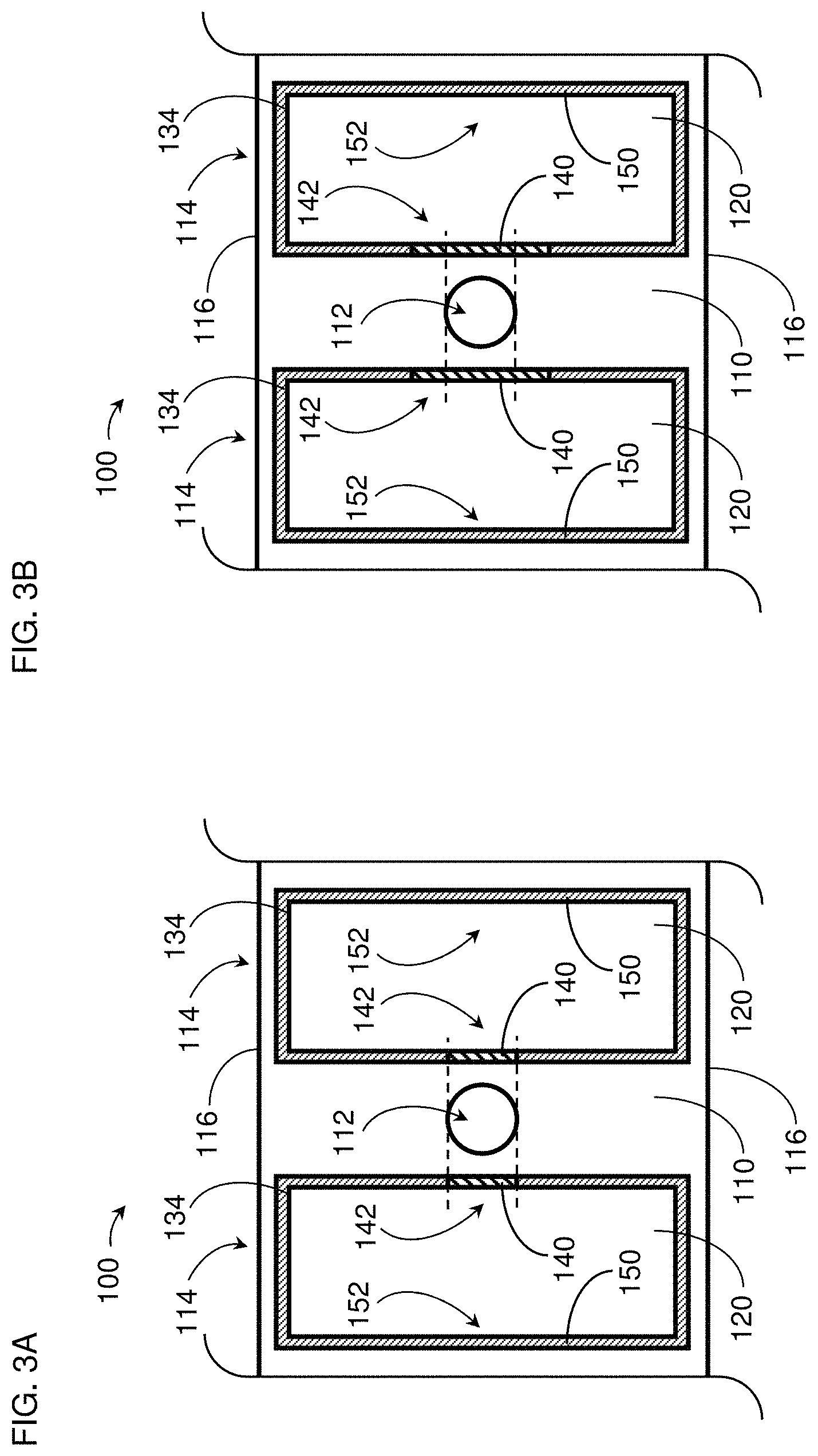
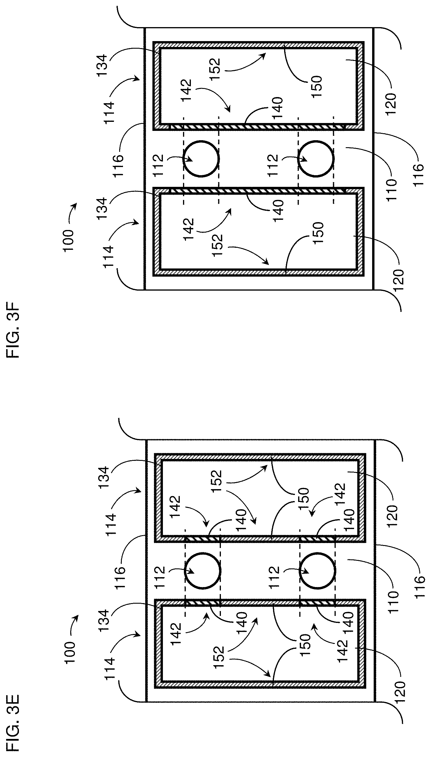
7. The thermoelectric device of claim 6, wherein the first portion comprises at least two sub-portions separated from one another by one or more sub-portions of the second portion.
8. The thermoelectric device of claim 5, wherein the first portion extends along at least one longer edge of the two longer edges, the at least one longer edge facing away from an other thermoelectric sub-assembly.
9. The thermoelectric device of claim 4, wherein the first portion extends along at least one corner of the plurality of corners.
10. The thermoelectric device of claim 1, wherein the first plate has a first surface area and the second plate has a second surface area less than the first surface area.
11. The thermoelectric device of claim 10, wherein the first plate comprises a first plurality of edges and the second plate comprises a second plurality of edges, the first plurality of edges extending beyond the second plurality of edges.
12. The thermoelectric device of claim 1, further comprising at least one seal along the perimeter of the region, the at least one seal comprising at least a portion of the first material and at least a portion of the second material.
13. The thermoelectric device of claim 12, wherein the second plate has a planar polygonal shape and the at least one seal is formed along a perimeter of the planar polygonal shape.
14. The thermoelectric device of claim 1, wherein the thermoelectric device is configured to be in thermal communication with a heat spreader.
15. The thermoelectric device of claim 14, wherein the heat spreader is configured to have a liquid flow therethrough.
16. The thermoelectric device of claim 14, wherein the thermoelectric device is configured to be operatively engaged with the heat spreader via a fastener extending through the at least one hole.
17. The thermoelectric device of claim 14, wherein the first portion of the perimeter of the region is configured to have a first mechanical force from the heat spreader and the second portion of the perimeter of the region is configured to have a second mechanical force from the heat spreader, the second mechanical force less than the first mechanical force.
18. The thermoelectric device of claim 14, wherein the thermoelectric device is configured to be in thermal communication with an other heat spreader, the other heat spreader spaced from the heat spreader.
19. The thermoelectric device of claim 18, wherein the thermoelectric device is configured to be at least partially surrounded by a material, the material configured to be positioned between the heat spreader and the other heat spreader around the thermoelectric device.
20. The thermoelectric device of claim 19, wherein the material is configured to thermally insulate between the heat spreader and the other heat spreader.
21. The thermoelectric device of claim 19, wherein the material is compressible between the heat spreader and the other heat spreader.
22. The thermoelectric device of claim 1, further comprising: at least one other thermoelectric sub-assembly comprising: a thermally conductive third plate displaced from the at least one hole in the direction parallel to the first plate such that the third plate does not extend over the at least one hole along the direction parallel to the first plate; a plurality of thermoelectric elements in an other region between the first plate and the third plate, the plurality of thermoelectric elements in thermal communication with the first plate and the third plate via an other plurality of shunts positioned on the first and third plates; the first material positioned along a third portion of a perimeter of the other region, the first material in mechanical communication with the first plate and the third plate; and the second material positioned along a fourth portion of the perimeter of the other region, the second material in mechanical communication with the first plate and the third plate.
23. The thermoelectric device of claim 22, wherein the second and third plates each have planar polygonal shapes with a plurality of edges and a plurality of corners, wherein the first portion is at a corner of the second plate with the first material extending from the corner of the second plate along at least two edges of the second plate, and wherein the third portion is at a corner of the third plate with the first material extending from the corner of the third plate along at least two edges of the third plate.
24. The thermoelectric device of claim 23, wherein the corner of the second plate is farther from the at least one hole relative to at least one other corner of the second plate, and wherein the corner of the third plate is farther from the at least one hole relative to at least one other corner of the third plate.
25. A thermoelectric device comprising: a thermally conductive first plate comprising a hole extending through the first plate, the first plate configured to be in thermal communication with a first heat spreader for transferring thermal energy to or from the first plate; and a thermoelectric sub-assembly comprising: a thermally conductive second plate displaced from the hole in a direction parallel to the first plate, the second plate configured to be in thermal communication with a second heat spreader for transferring thermal energy to and from the second plate; a plurality of thermoelectric elements in a region between the first plate and the second plate, the plurality of thermoelectric elements in thermal communication with the first plate and the second plate; a first material along a first portion of a perimeter of the region, the first material connected with the first plate and the second plate, the first material having a first stiffness; and a second material along a second portion of the perimeter of the region, the second material connected with the first plate and the second plate, the second material having a second stiffness less than the first stiffness.
26. The thermoelectric device of claim 25, wherein the first and second plates are configured to be connected with the first and second heat spreaders, respectively, by a fastener extending through the hole of the first plate to couple the first and second heat spreaders with the first and second plates between the first and second heat spreaders.
27. A thermoelectric device comprising: a thermally conductive first plate comprising a hole extending through the first plate; a first thermoelectric sub-assembly comprising: a thermally conductive second plate displaced from the hole in a direction parallel to the first plate; a plurality of thermoelectric elements in a first region between the first plate and the second plate, the plurality of thermoelectric elements in thermal communication with the first plate and the second plate; a first material along a first portion of a perimeter of the first region, the first material in mechanical communication with the first plate and the second plate, the first material having a first stiffness; and a second material along a second portion of the perimeter of the first region, the second material in mechanical communication with the first plate and the second plate, the second material having a second stiffness less than the first stiffness; and a second thermoelectric sub-assembly comprising: a thermally conductive third plate displaced from the hole in the direction parallel to the first plate opposite the second plate such that the hole is positioned between the second and third plate along the direction parallel to the first plate; a plurality of thermoelectric elements in a second region between the first plate and the third plate, the plurality of thermoelectric elements in thermal communication with the first plate and the third plate; the first material positioned along a third portion of a perimeter of the second region, the first material in mechanical communication with the first plate and the third plate; and the second material positioned along a fourth portion of the perimeter of the other region, the second material in mechanical communication with the first plate and the third plate.
28. The thermoelectric device of claim 27, wherein the first plate has a planar polygonal shape with a plurality of edges and a plurality of corners, wherein the first portion is at a first corner of the first plate with the first material extending from the first corner along at least two edges of the first plate, and wherein the third portion is at a second corner of the first plate with the first material extending from the second corner along at least two other edges of the first plate.
29. The thermoelectric device of claim 27, wherein the thermoelectric device is configured to be connected with a heat spreader via a fastener extending through the hole of the first plate and extending between the second plate and the third plates.
Description
INCORPORATION BY REFERENCE TO ANY PRIORITY APPLICATIONS
Any and all applications for which a foreign or domestic priority claim is identified in the Application Data Sheet as filed with the present application are incorporated by reference and made a part of this specification.
BACKGROUND
Field
This application relates to thermoelectric devices and modules used for thermal management of components and/or systems, including but not limited to batteries.
Description of the Related Art
Power electronics and other electrical devices, such as batteries, can be sensitive to overheating, cold temperatures, extreme temperatures, and operating temperature limits. The performance of such devices may be diminished, sometimes severely, when the devices are operated outside of recommended temperature ranges. In semiconductor devices, integrated circuit dies can overheat and malfunction. In batteries, including, for example, batteries used for automotive applications in electrified or electrical vehicles, battery cells and their components can degrade when overheated or overcooled. Such degradation can manifest itself in reduced battery storage capacity and/or reduced ability for the battery to be recharged over multiple duty cycles. Furthermore, high performance batteries for use in large systems (including, for example, lithium based batteries used in electrical vehicles) have certain properties (e.g., charging characteristics) and/or safety-related events (e.g., potential fires due to over-temperature conditions) that make thermal management of the batteries and/or containment system desirable.
SUMMARY
In certain embodiments, a thermoelectric device is provided. The thermoelectric device comprises a thermally conductive first plate and at least one thermoelectric sub-assembly. The first plate comprises at least one hole extending through the first plate. The at least one thermoelectric sub-assembly comprises a thermally conductive second plate displaced from the at least one hole in a direction parallel to the first plate and a plurality of thermoelectric elements in a region between the first plate and the second plate, the plurality of thermoelectric elements is in thermal communication with the first plate and the second plate. The at least one thermoelectric sub-assembly further comprises a first material along a first portion of a perimeter of the region, the first material in mechanical communication with the first plate and the second plate, the first material having a first stiffness. The at least one thermoelectric sub-assembly further comprises a second material along a second portion of the perimeter of the region, the second material in mechanical communication with the first plate and the second plate, the second material having a second stiffness less than the first stiffness.
In certain embodiments, a thermoelectric module for thermally conditioning a component is provided. The module comprises first and second heat spreaders spaced apart from one another and configured to respectively provide cold and hot sides and to be mechanically coupled together by at least one fastener. The module further comprises a material arranged between the first and second heat spreaders and a thermoelectric device operatively engaged with the first and second heat spreaders. The thermoelectric device comprises a thermally conductive first plate in thermal communication with the first heat spreader, the first plate comprising at least one hole configured to have the at least one fastener extend therethrough. The thermoelectric device further comprises a plurality of thermoelectric sub-assemblies arranged to have the at least one fastener between adjacent thermoelectric sub-assemblies. Each thermoelectric sub-assembly comprises a thermally conductive second plate in thermal communication with the second heat spreader and having a plurality of edges, a plurality of thermoelectric elements between and in thermal communication with the first plate and the second plate, and a first material along a first portion of the plurality of edges and having a first stiffness and a second material along a second portion of the plurality of edges and having a second stiffness less than the first stiffness.
In certain embodiments, a method of forming a thermoelectric device is provided. The method comprises providing a thermally conductive first plate, a thermally conductive second plate, and a plurality of thermoelectric elements in a region between the first plate and the second plate. The plurality of thermoelectric elements is in thermal communication with the first plate and the second plate. The first plate comprises at least one hole extending through the first plate and the second plate is displaced from the at least one hole such that the second plate does not extend over or around the at least one hole. The method further comprises applying material along a perimeter of the region. Applying the material comprises applying a first material along a first portion of the perimeter of the region, the first material in mechanical communication with the first plate and the second plate, the first material having a first stiffness. Applying the material further comprises applying a second material along a second portion of the perimeter of the region, the second material in mechanical communication with the first plate and the second plate, the second material having a second stiffness less than the first stiffness.
BRIEF DESCRIPTION OF THE DRAWINGS
FIG. 1A schematically illustrates a top view of an example thermoelectric device in accordance with certain embodiments described herein.
FIGS. 1B and 1C schematically illustrate two cross-sectional views in two different planes of the example thermoelectric device of FIG. 1A.
FIGS. 2A and 2B schematically illustrate a perspective view and an exploded view, respectively, of an example thermoelectric device comprising four thermoelectric sub-assemblies in accordance with certain embodiments described herein.
FIGS. 3A-3J schematically illustrate portions of various example thermoelectric devices with the first material and the second material along various portions of the perimeter of the one or more thermoelectric assemblies in accordance with certain embodiments described herein.
FIG. 4 schematically illustrates a thermoelectric module for thermally conditioning a component (e.g., an electronics component; a battery) in accordance with certain embodiments described herein.
FIG. 5 is a flow diagram of an example method of forming a thermoelectric device or a thermoelectric module in accordance with certain embodiments described herein.
DETAILED DESCRIPTION
FIG. 1A schematically illustrates a top view of an example thermoelectric device 100 in accordance with certain embodiments described herein. FIGS. 1B and 1C schematically illustrate two cross-sectional views in two different planes of the example thermoelectric device 100 of FIG. 1A.
The thermoelectric device 100 of FIGS. 1A-1C comprises a thermally conductive first plate 110 comprising at least one hole 112 extending through the first plate 110. The thermoelectric device 100 further comprises at least one thermoelectric sub-assembly 114 which comprises a thermally conductive second plate 120 displaced from the at least one hole 112 in a direction 122 parallel to the first plate 110. The at least one thermoelectric sub-assembly 114 further comprises a plurality of thermoelectric ("TE") elements 130 in a region 132 between the first plate 110 and the second plate 120. The plurality of TE elements 130 are in thermal communication with the first plate 110 and the second plate 120.
The at least one thermoelectric sub-assembly 114 further comprises a first material 140 along a first portion 142 of a perimeter 134 of the region 132. The first material 140 (e.g., epoxy) has a first stiffness and is in mechanical communication with the first plate 110 and the second plate 120. The at least one thermoelectric sub-assembly 114 further comprises a second material 150 (e.g., silicone) along a second portion 152 of the perimeter 134 of the region 132. The second material 150 has a second stiffness less than the first stiffness and is in mechanical communication with the first plate 110 and the second plate 120.
In certain embodiments, each of the first plate 110 and the second plate 120 comprises a planar laminate structure (e.g., a printed circuit board or PCB) having one or more electrically conductive layers (e.g., copper; aluminum; metal; metal alloy or composite) and one or more electrically insulating layers (e.g., fiberglass; resin; polymer; fibrous material preimpregnated with a resin material such as epoxy). The one or more electrically conductive layers can be configured to provide electrical connections to the plurality of TE elements 130. For example, an outer electrically conductive layer of the one or more electrically conductive layers can comprise electrically conductive pads configured to be coupled (e.g., soldered) to the TE elements 130, and the pads can be in electrical communication with other pads (e.g., by electrically conductive lines formed by selective chemical etching of the electrically conductive layers and by electrically conductive vias formed through the electrically insulating layers).
In certain embodiments, the first plate 110 has a planar parallelogram shape (e.g., rhombus shape; rectangular shape; square shape) with four edges 116 (e.g., a rectangular shape with two shorter edges 116a and two longer edges 116b). The first plate 110 can have other planar shapes (e.g., polygonal) with other numbers of edges 116 in accordance with certain embodiments described herein (e.g., triangular shapes with three edges; trapezoidal shapes with four edges; pentagonal shapes with five edges; hexagonal shapes with six edges; etc.). In certain embodiments, the second plate 120 has a planar parallelogram shape (e.g., rhombus shape; rectangular shape; square shape) with four edges 126 (e.g., a rectangular shape with two shorter edges 126a and two longer edges 126b). The second plate 120 can have other planar shapes (e.g., polygonal) with other numbers of edges 126 in accordance with certain embodiments described herein (e.g., triangular shapes with three edges; trapezoidal shapes with four edges; pentagonal shapes with five edges; hexagonal shapes with six edges; etc.).
In certain embodiments, the plurality of TE elements 130 comprises p-type TE elements and n-type TE elements in electrical communication with one another through a plurality of shunts (e.g., electrically conductive pads of the first plate 110 and the second plate 120). For example, the plurality of TE elements 130 can be arranged in a "stonehenge" configuration in which p-type and n-type TE elements alternate with one another and are in series electrical communication with one another by shunts which are alternately positioned on the first plate 110 and the second plate 120 such that electrical current can flow serially through the TE elements 130 and the shunts in a serpentine fashion. In certain embodiments, the plurality of TE elements 130 are in thermal communication with the first plate 110 through the shunts (e.g., electrically conductive pads) of the first plate 110 and in thermal communication with the second plate 120 through the shunts (e.g., electrically conductive pads) of the second plate 120. In certain embodiments, the region 132 containing the plurality of TE elements 130 is between the first plate 110 and the second plate 120 and has a perimeter 134 defined by the second plate 120 (e.g., the perimeter 134 is coincident with the plurality of edges 126 of the second plate 120 such that the first portion 142 and the second portion 152 correspond to respective portions of the plurality of edges 126).
In certain embodiments, the at least one hole 112 of the first plate 110 is configured to have at least one fastener extend through the at least one hole 112. As described more fully herein, the thermoelectric device 100 and the at least one fastener (e.g., bolt; screw; pin; rivet) are components of a thermoelectric module in which the thermoelectric device 100 is sandwiched between and in thermal communication with first and second heat spreaders that are mechanically coupled together by the at least one fastener. The shape of the at least one hole 112 can be circular, as schematically illustrated in FIG. 1A, or non-circular (e.g., rectangular). In certain embodiments, the at least one hole 112 and the at least one thermoelectric sub-assembly 114 are displaced (e.g., located away) from one another in the direction 122 parallel to the first plate 110 (e.g., laterally displaced from one another). For example, as schematically shown in FIGS. 1A and 1B, the direction 122 extends along the first plate 110 and an edge 113 of the at least one hole 112 is spaced away from the at least one thermoelectric sub-assembly 114 (e.g., spaced away from the second plate 120) in the direction 122. In certain such embodiments, the second plate 120 of the thermoelectric sub-assembly 114 does not extend over or around the at least one hole 112.
In certain embodiments, the first plate 110 has a first surface 118 (e.g., a top surface of the first plate 110; a surface of the first plate 110 closest to the second plate 120) with a first surface area and the second plate 120 has a second surface 128 (e.g., a top surface of the second plate 120; a surface of the second plate 120 farthest from the first plate 110) with a second surface area less than the first surface area. For example, the thermoelectric device 100 can comprise a plurality of thermoelectric sub-assemblies 114, each comprising a corresponding second plate 120 and a corresponding plurality of thermoelectric elements 130 (e.g., the plurality of second plates 120 are mounted to a common first plate 110), and the first plate 110 can have a surface area larger than the sum of the surface areas of the second plates 120.
In certain embodiments, the first material 140 is in mechanical communication with the first plate 110 and the second plate 120, and the second material 150 is in mechanical communication with the first plate 110 and the second plate 120. For example, the first plate 110 can comprise a first plurality of edges 116 and the second plate 120 can comprise a second plurality of edges 126, with the first plurality of edges 116 extending beyond the second plurality of edges 126, as schematically shown in FIG. 1A. The portion of the first plate 110 extending beyond the second plurality of edges 126 (e.g., the portion between the edge 116 and the nearest edge 126) can provide sufficient area to be mechanically coupled to the first material 140 and the second material 150. As shown in FIGS. 1B and 1C, the first material 140 and/or the second material 150 can be mechanically coupled to the first surface of the first plate 110 and to an edge 126 of the second plate 120. In certain other embodiments, at least some of the edges 126 of the second plates 120 are aligned (e.g., flush) with one or more edges 116 of the first plate 110, and the first material 140 and the second material 150 can be mechanically coupled to the aligned edges 116, 126 without one of the first plate 110 and the second plate 120 extending past the other in a direction generally parallel to the first plate 110 and/or the second plate 120.
In certain embodiments, the first material 140 and the second material 150 are selected to provide mechanical stiffness sufficient to withstand the mechanical stresses, pressures, and/or forces expected to be experienced by the thermoelectric sub-assembly 114 at the respective first portion 142 and second portion 152 of the perimeter 134 (e.g., during assembly and/or operation of a thermoelectric module comprising the thermoelectric device 100). For example, the first material 140 can comprise epoxy and the second material 150 can comprise silicone. The first material 140 and the second material 150 of certain other embodiments can comprise other materials or combinations of materials.
In certain embodiments, the first material 140 extending along the first portion 142 of the perimeter 134 and the second material 150 extending along the second portion 152 of the perimeter 134 form a seal (e.g., a hermetic seal) along the perimeter 134 of the region 132. For example, as schematically illustrated by FIG. 1A, the first portion 142 and the second portion 152 do not overlap (e.g., do not extend over) one another, with the first material 140 adjacent to and in contact with the second material 150 to form a continuous seal completely around the region 132. In another example, the first portion 142 and the second portion 152 partially overlap (e.g., extend over) one another, such that one of the first material 140 and the second material 150 overlays the other where the first portion 142 and the second portion 152 overlap to form a continuous seal completely around the region 132. In certain embodiments, the thermoelectric sub-assembly 114 does not have any gaps between the first material 140 and the second material 150.
FIGS. 2A and 2B schematically illustrate a perspective view and an exploded view, respectively, of an example thermoelectric device 100 comprising four thermoelectric sub-assemblies 114 in accordance with certain embodiments described herein. In FIGS. 2A and 2B, the thermoelectric device 100 comprises a first plate 110 (e.g., PCB) having a rectangular shape with four edges 116 (e.g., two shorter edges 116a and two longer edges 116b). The first plate 110 comprises a plurality of holes 112 (e.g., configured to mount the thermoelectric device 100 within a thermoelectric module) and a plurality of electrically conductive shunts 210 (e.g., solder pads) configured to be in electrical communication and thermal communication with the TE elements 130 of the four thermoelectric sub-assemblies 114. Each of the four thermoelectric sub-assemblies 114 of FIGS. 2A and 2B comprises a plurality of TE elements 130, and a second plate 120 having a rectangular shape with four edges 126 (e.g., two shorter edges 126a and two longer edges 126b) and having a plurality of electrically conductive shunts (not shown) (e.g., solder pads) configured to be in electrical and thermal communication with the plurality of TE elements 130. FIG. 2A also shows a pair of electrical conductors (e.g., wires) configured to be in electrical communication with electrically conductive pads (e.g., solder pads) of the first plate 110 and to transmit electrical power to and/or from the thermoelectric sub-assemblies 114. FIGS. 2A and 2B do not show the first material 140 or the second material 150 of the thermoelectric device 100, but various configurations of the first and second materials 140, 150 compatible to be used with the thermoelectric device 100 of FIGS. 2A and 2B in accordance with certain embodiments are described elsewhere herein (e.g., see FIGS. 3A-3J).
The thermoelectric sub-assemblies 114 of FIGS. 2A and 2B are substantially equally spaced from one another (e.g., within .+-.5%; within .+-.1%) across the first plate 110 with a pair of holes 112 between the longer edges 126b of the second plates 120 of adjacent thermoelectric sub-assemblies 114. The edges 113 of the holes 112 of FIGS. 2A and 2B are displaced from the longer edges 126b of the second plates 120 (e.g., along a direction 122 parallel to the first plate 110; along a direction perpendicular to the longer edge 126b and to the edge 113). In certain other embodiments, the thermoelectric sub-assemblies 114 are not substantially equally spaced from one another, and/or the number of holes 112 between the adjacent thermoelectric sub-assemblies 114 is not equal to two (e.g., one; more than two).
The two shorter edges 126a of the second plates 120 of each of the thermoelectric sub-assemblies 114 of FIGS. 2A and 2B are aligned (e.g., flush) with longer edges 116b of the first plate 110, and the two thermoelectric sub-assemblies 114 at opposite ends of the thermoelectric device 100 have one of the longer edges 126b of the second plate 120 aligned (e.g., flush) with a respective shorter edge 116a of the first plate 110. In certain other embodiments, other edges 116 of the first plate 110 and other edges 126 of the second plate 120 can be aligned (e.g., flush) with one another or can extend past one another. The two longer edges 126b of the two adjacent second plates 120 that face one another (e.g., the longer edges 126b of the second plates 120 with two holes 112 between them and that are not adjacent to a shorter edge 116a of the first plate 110) can be referred to as "interior" edges and the two longer edges 126b of the two second plates 120 that face away from the thermoelectric device 100 can be referred to as "exterior" edges (e.g., the longer edges 126b of the second plates 120 that are adjacent to a shorter edge 116a of the first plate 110).
FIGS. 3A-3J schematically illustrate portions of various example thermoelectric devices 100 with the first material 140 and the second material 150 along various portions 142, 152 of the perimeter 134 of the one or more thermoelectric assemblies 114 in accordance with certain embodiments described herein. In each of FIGS. 3A-3J, the one or more second plates 120 are displaced (e.g., laterally displaced; spaced away) from the adjacent one or more holes 112 (e.g., the second plates 120 do not extend over or around the one or more holes 112). While the second plates 120 schematically shown in FIGS. 3A-3J are rectangular with two longer edges and two shorter edges each, other embodiments have other planar shapes with other numbers of edges. In addition, while the second plates 120 schematically shown in FIGS. 3A-3J have their shorter edges adjacent to two opposite edges 116 of the first plate 110, other embodiments have the second plates 120 at other positions and/or orientations relative to the edges 116 of the first plate 110. Various combinations of the thermoelectric sub-assemblies 114 and the portions 142 schematically shown in FIGS. 3A-3J, with the portion 152 extending along the remaining length of the perimeter 134, are also compatible with certain embodiments described herein.
FIGS. 3A-3C schematically illustrate portions of various example thermoelectric devices 100 comprising at least two thermoelectric sub-assemblies 114 each having a second plate 120 with a hole 112 of the first plate 110 therebetween in accordance with certain embodiments described herein. FIGS. 3A-3C are compatible with certain embodiments in which the portions of the thermoelectric sub-assemblies 114 closest to the hole 112 are expected to experience higher mechanical stresses, pressures, and/or forces than other portions (e.g., during assembly and/or operation of a thermoelectric module comprising the thermoelectric device 100). In FIG. 3A, the first portion 142 comprises a portion of the perimeter 134 that is closest to the hole 112 and the first portion 142 extends along a length of the perimeter 134 that is substantially equal (e.g., within .+-.5%; within .+-.1%) to a width (e.g., the diameter) of the hole 112 (indicated by the dashed lines), and the second portion 152 extends along the remaining length of the perimeter 134. In FIG. 3B, the first portion 142 comprises a portion of the perimeter 134 that is closest to the hole 112 and the first portion 142 extends along a length of the perimeter 134 that is greater than a width (e.g., the diameter) of the hole 112 (indicated by the dashed lines), and the second portion 152 extends along the remaining length of the perimeter 134. For example, the length of the first portion 142 can be between 5% and 10% greater than the width; between 10% and 20% greater than the width; between 20% and 100% greater than the width; between 50% and 150% greater than the width). In certain other embodiments, the first portion 142 comprises a portion of the perimeter 134 that is closest to the hole 112 and the first portion 142 extends along a length of the perimeter 134 that is less than a width (e.g., the diameter) of the hole 112 (e.g., between 2% and 10% less than the width; between 10% and 20% less than the width; between 20% and 50% less than the width), and the second portion 152 extends along the remaining length of the perimeter 134. In FIG. 3C, the first portion 142 comprises a portion of the perimeter 134 that is closest to the hole 112 and the first portion 142 extends along a length of the perimeter 134 that is substantially equal (e.g., within .+-.5%; within .+-.1%) of the longer edge 126b of the second plate 120 (e.g., the full length of the interior edge of each of the two second plates 120), and the second portion 152 extends along the remaining length of the perimeter 134.
FIG. 3D schematically illustrates a portion of another example thermoelectric device 100 comprising a hole 112 of the first plate 110 positioned between a thermoelectric sub-assembly 114 and an edge 116 of the first plate 110 in accordance with certain embodiments described herein. FIG. 3D is compatible with certain embodiments in which the portions of the thermoelectric sub-assemblies 114 closest to the hole 112 are expected to experience higher mechanical stresses, pressures, and/or forces than other portions (e.g., during assembly and/or operation of a thermoelectric module comprising the thermoelectric device 100). The first portion 142 comprises a portion of the perimeter 134 that is closest to the hole 112 and the first portion 142 extends along a length of the perimeter 134 that is substantially equal (e.g., within .+-.5%; within .+-.1%) to a width (e.g., the diameter) of the hole 112 (indicated by the dashed lines), that is greater than the width (e.g., between 5% and 10% greater than the width; between 10% and 20% greater than the width; between 20% and 100% greater than the width; between 50% and 150% greater than the width), that is less than the width (e.g., between 2% and 10% less than the width; between 10% and 20% less than the width; between 20% and 50% less than the width), or that is substantially equal (e.g., within .+-.5%; within .+-.1%) to the longer edge 126b of the second plate 120 (e.g., the full length of the exterior edge of the second plate 120).
FIGS. 3E-3F schematically illustrate portions of various example thermoelectric devices 100 comprising at least two thermoelectric sub-assemblies 114 each having a second plate 120 with two holes 112 of the first plate 110 therebetween in accordance with certain embodiments described herein. FIGS. 3E-3F are compatible with certain embodiments in which the portions of the thermoelectric sub-assemblies 114 closest to the holes 112 are expected to experience higher mechanical stresses, pressures, and/or forces than other portions (e.g., during assembly and/or operation of a thermoelectric module comprising the thermoelectric device 100). In FIG. 3E, the first portion 142 comprises multiple sub-portions comprising a portion of the perimeter 134 that is closest to a corresponding one of the two holes 112. For example, the first portion 142 of FIG. 3E comprises two sub-portions separated from one another by a sub-portion of the second portion 152. More generally, in certain embodiments, the first portion 142 can comprise at least two sub-portions separated from one another by one or more sub-portions of the second portion 152. Each of the sub-portions in FIG. 3E extends along a length of the perimeter 134 that is substantially equal (e.g., within .+-.5%; within .+-.1%) to a width (e.g., the diameter) of the corresponding hole 112 (indicated by the dashed lines), and the second portion 152 extends along the remaining length of the perimeter 134 and includes a sub-portion between the two sub-portions of the first portion 142. In certain other embodiments, each of the sub-portions extend along a length of the perimeter 134 adjacent to the corresponding hole 112 with the length greater than the width (e.g., between 5% and 10% greater than the width; between 10% and 20% greater than the width; between 20% and 100% greater than the width; between 50% and 150% greater than the width) or that is less than the width (e.g., between 2% and 10% less than the width; between 10% and 20% less than the width; between 20% and 50% less than the width) of the corresponding hole 112 (indicated by the dashed lines). The second portion 152 extends along the remaining length of the perimeter 134 and includes a sub-portion between the two sub-portions of the first portion 142.
In FIG. 3F, the first portion 142 comprises portions of the perimeter 134 that are closest to the two holes 112 and the first portion 142 extends along a length of the perimeter 134 that is greater than a width (e.g., the diameter) of either of the two holes 112 (indicated by the dashed lines) including a sub-portion between the two holes 112, and the second portion 152 extends along the remaining length of the perimeter 134. For example, the length of the first portion 142 can be between 5% and 10% greater than the width; between 10% and 20% greater than the width; between 20% and 100% greater than the width; between 50% and 150% greater than the width). In certain embodiments, the first portion 142 extends along a length of the perimeter 134 that is substantially equal (e.g., within .+-.5%; within .+-.1%) of the longer edge 126b of the second plate 120 (e.g., the full length of the interior edge of each of the two second plates 120), and the second portion 152 extends along the remaining length of the perimeter 134.
FIGS. 3G and 3H schematically illustrate portions of example thermoelectric devices 100 in which the first portion 142 of the perimeter 134 extends along a full length of one or more exterior edges of the second plates 120 in accordance with certain embodiments described herein. FIGS. 3G-3H are compatible with certain embodiments in which the portions of the thermoelectric sub-assemblies 114 along the exterior edges of the second plates 120 are expected to experience higher mechanical stresses, pressures, and/or forces than other portions (e.g., during assembly and/or operation of a thermoelectric module comprising the thermoelectric device 100). In FIG. 3G, one of the two thermoelectric sub-assemblies 114 has an exterior edge (e.g., a longer edge of a second plate 120 facing away from the other thermoelectric sub-assemblies 114 of the thermoelectric device 100; a longer edge of a second plate 120 adjacent to a shorter edge of the first plate 110) and the first portion 142 extends along a full length of the exterior edge. In FIG. 3H, two thermoelectric sub-assemblies 114 each have an exterior edge and the first portion 142 extends along a full length of each of the exterior edges.
FIGS. 3I and 3J schematically illustrated portions of thermoelectric devices 100 in which the first portion 142 of the perimeter 134 extends along at least one corner of the second plates 120 in accordance with certain embodiments described herein. FIGS. 3I-3J are compatible with certain embodiments in which the portions of the thermoelectric sub-assemblies 114 around at least some of the corners of the second plates 120 are expected to experience higher mechanical stresses, pressures, and/or forces than other portions (e.g., during assembly and/or operation of a thermoelectric module comprising the thermoelectric device 100). In FIG. 3I, the first portion 142 extends along (e.g., around) the corners of an exterior edge of the second plate 120 (e.g., the corners farthest from the at least one hole 112), and the second portion 152 extending along the remaining length of the perimeter 134. In FIG. 3J, the first portion 142 extends along (e.g., around) the corners of an interior edge of the second plate 120 (e.g., the corners closest to the at least one hole 112), and the second portion 152 extending along the remaining length of the perimeter 134. While FIGS. 3I and 3J show the first portion 142 extending along two corners of each second plate 120, certain other embodiments have the first portion 142 extending along different numbers of corners of the second plate 120 (e.g., one; more than two).
FIG. 4 schematically illustrates a thermoelectric module 400 for thermally conditioning a component (e.g., an electronics component; a battery) in accordance with certain embodiments described herein. The module 400 comprises a first heat spreader 410 and a second heat spreader 420 spaced apart from one another and configured to respectively provide cold and hot sides and to be mechanically coupled together by at least one fastener (e.g., bolt; screw; pin; rivet) (not shown). The module 400 further comprises a material 430 arranged between the first heat spreader 410 and the second heat spreader 420. The module 400 further comprises a thermoelectric device 100 operatively engaged with the first heat spreader 410 and the second heat spreader 420.
The thermoelectric device 100 comprises a thermally conductive first plate 110 in thermal communication with the first heat spreader 410, the first plate 110 comprising at least one hole 112 configured to have the at least one fastener extend therethrough. The thermoelectric device 100 further comprises a plurality of thermoelectric sub-assemblies 114 arranged to have the at least one fastener between adjacent thermoelectric sub-assemblies 114.
Each thermoelectric sub-assembly 114 comprises a thermally conductive second plate 120 in thermal communication with the second heat spreader 420 and having a plurality of edges 126, and a plurality of thermoelectric elements 130 between and in thermal communication with the first plate 110 and the second plate 120. Each thermoelectric sub-assembly 114 further comprises a first material 140 along a first portion 142 of the plurality of edges 126 and having a first stiffness and a second material 150 along a second portion 152 of the plurality of edges 126 and having a second stiffness less than the first stiffness. FIGS. 1A-1C, 2A-2B, and 3A-3J schematically illustrate various example thermoelectric devices 100 and thermoelectric sub-assemblies 114 in accordance with certain embodiments described herein.
In certain embodiments, the first heat spreader 410 and the second heat spreader 420 are configured to transfer heat away from the component to be thermally conditioned. For example, as schematically illustrated by FIG. 4, the first heat spreader 410 can be configured to transfer heat to the thermoelectric device 100 from the component to be thermally conditioned, and the second heat spreader 420 can be configured to transfer heat away from the thermoelectric device 100. The first heat spreader 410 can comprise at least one first surface 412 configured to be in thermal communication with the thermoelectric device 100 and at least one second surface 414 configured to be in thermal communication with the component to be thermally conditioned by the module 400, and the second heat spreader 420 can comprise at least one first surface 422 configured to be in thermal communication with the thermoelectric device 100. For example, at least one second surface 424 of the second heat spreader 420 can comprise at least one heat dissipation structure (e.g., at least one fin) configured to transfer heat from the second heat spreader 420 to the ambient surroundings. For another example, the second heat spreader 420 can be configured to have a fluid coolant (e.g., liquid; air; refrigerant) flow therethrough. While FIG. 4 schematically illustrates an example thermoelectric module 400 in which the first heat spreader 410 provides at least one cold side that receives heat from the component to be thermally conditioned and in which the second heat spreader 420 provides at least one hot side that serves as a heat sink which receives heat from the thermoelectric device 100, in certain other embodiments, the second heat spreader 420 provides the at least one cold side and the first heat spreader 410 provides the at least one hot side.
In certain embodiments, the material 430 comprises a compressible material (e.g., polymer; plastic; rubber; fiberglass) and is configured to be at least partially compressed by the first heat spreader 410 and the second heat spreader 420 during assembly of the thermoelectric module 400 while keeping the first heat spreader 410 and the second heat spreader 420 from contacting one another. In certain embodiments, the material 430 generally surrounds the thermoelectric device 100 (e.g., as shown in FIG. 4), and comprises conduits (e.g., holes; recesses; cut-out portions) (not shown) configured to accommodate one or more electrical conduits (e.g., wires) in electrical communication with the thermoelectric device 100 by allowing the one or more electrical conduits to extend from the thermoelectric device 100 to outside the thermoelectric module 400. In certain embodiments in which the thermoelectric device 100 comprises a plurality of thermoelectric sub-assemblies 114, the material 430 does not extend between the thermoelectric sub-assemblies 114. In certain embodiments, the material 430 provides thermal insulation between the first heat spreader 410 and the second heat spreader 420. For example, the material 430 can have a low thermal conductivity (e.g., less than 10 W/mK) and can be configured to reduce a thermal short between the first heat spreader 410 and the second heat spreader 420 (e.g., heat transfer along a thermal path between the first and second heat spreaders 410, 420 that does not extend through the thermoelectric device 100). In certain embodiments, the material 430 provides hermetic sealing and/or a moisture barrier for the volume occupied by the thermoelectric device 100. For example the material 430 can comprise an insulation ring configured to prevent dust, condensate, moisture, or other particulates and/or fluids from entering the volume occupied by the thermoelectric device 100.
In certain embodiments, during operation and/or assembly of the thermoelectric module 400, the first portion 142 of the plurality of edges 126 experiences a first mechanical force, pressure, and/or stress from the second heat spreader 420 and the second portion 150 of the plurality of edges 126 experiences a second mechanical force, pressure, and/or stress from the second heat spreader 420, with the second mechanical force, pressure, and/or stress less than the first mechanical force, pressure, and/or stress. By having the first material 140 with its first stiffness along portions of the thermoelectric sub-assemblies 114 where the mechanical force and/or stress from the second heat spreader 420 are expected to be higher than along other portions, where the second material 150 with its second stiffness is located, certain embodiments described herein advantageously provide enhanced durability and reliability of the thermoelectric device 100 and the thermoelectric module 400 (e.g., during assembly and/or operation of the thermoelectric module 400).
In certain embodiments, the thermoelectric module 400 comprises at least one seal (e.g., hermetic seal) at least partially surrounding a volume containing the thermoelectric elements 130 of the thermoelectric device 100. For example, the at least one seal can comprise at least a portion of the first material 140 and at least a portion of the second material 150 along the plurality of edges 126, such that the first plate 110, second plate 120, first material 140, and second material 150 seal a volume containing the thermoelectric elements 130. For another example, the at least one seal can comprise a material (e.g., epoxy; acrylic; polymer; silicone) between the first heat spreader 410 and the second heat spreader 420 and at least partially surrounding a volume containing the thermoelectric device 100 (e.g., potting a portion of the volume between the at least one first surface 412 of the first heat spreader 410 and the at least one first surface 422 of the second heat spreader 420. The material can be sufficiently rigid to provide mechanical strength to the thermoelectric module 400. In certain embodiments, additional material (e.g., epoxy; acrylic; polymer; silicone) is located and forms at least one seal between at least one screw head of the at least one fastener (not shown) and the at least one second surface 424 of the second heat spreader 420.
FIG. 5 is a flow diagram of an example method 500 of forming a thermoelectric device 100 or a thermoelectric module 400 in accordance with certain embodiments described herein. While the method 500 is described by referring to the structures schematically illustrated in FIGS. 1A-1C, 2A-2B, 3A-3J, and 4, the method 500 is also compatible with other structures.
In an operational block 510, a thermally conductive first plate 110, a thermally conductive second plate 120, and a plurality of thermoelectric elements 130 in a region 132 between the first plate 110 and the second plate 120 are provided. The plurality of thermoelectric elements 130 are in thermal communication with the first plate 110 and the second plate 120. In an operational block 520, material is applied along a perimeter of the region 132.
In an operational block 522, said applying comprises applying a first material 140 (e.g., epoxy) along a first portion 142 of the perimeter 134 of the region 132. The first material 140 is in mechanical communication with the first plate 110 and the second plate 120, and the first material 140 has a first stiffness. For example, the first material 140 can be applied by extruding or spraying the first material 140 from a first nozzle placed in proximity to the first portion 142 and moved along the perimeter 134 to selectively place the first material 140 such that the first material 140 is in mechanical contact with the first plate 110 and the second plate 120 along the first portion 142 of the perimeter 134.
In an operational block 524, said applying further comprises applying a second material 150 (e.g., silicone) along a second portion 152 of the perimeter 134 of the region 132. The second material 150 is in mechanical communication with the first plate 110 and the second plate 120 and has a second stiffness less than the first stiffness. For example, the second material 150 can be applied by extruding or spraying the second material 150 from a second nozzle placed in proximity to the second portion 152 and moved along the perimeter 134 to selectively place the second material 150 such that the second material 150 is in mechanical contact with the first plate 110 and the second plate 120 along the second portion 152 of the perimeter 134. In certain embodiments, applying the material comprises forming a seal along the perimeter of the region, the seal comprising at least a portion of the first material 140 and at least a portion of the second material 150.
Discussion of the various embodiments herein has generally followed the embodiments schematically illustrated in the figures. However, it is contemplated that the particular features, structures, or characteristics of any embodiments discussed herein may be combined in any suitable manner in one or more separate embodiments not expressly illustrated or described. In many cases, structures that are described or illustrated as unitary or contiguous can be separated while still performing the function(s) of the unitary structure. In many instances, structures that are described or illustrated as separate can be joined or combined while still performing the function(s) of the separated structures. Various features and aspects of the disclosed embodiments can be combined with or substituted for one another. Any methods disclosed herein need not be performed in the order recited.
The ranges disclosed herein also encompass any and all overlap, sub-ranges, and combinations thereof. Language such as "up to," "at least," "greater than," "less than," "between," and the like includes the number recited. With respect to the use of any plural and/or singular terms herein, those having skill in the art can translate from the plural to the singular and/or from the singular to the plural as is appropriate to the context and/or application. The various singular/plural permutations may be expressly set forth herein for sake of clarity. In general, terms used herein are generally intended as "open" terms (e.g., the term "including" should be interpreted as "including but not limited to," the term "having" should be interpreted as "having at least," the term "includes" should be interpreted as "includes but is not limited to," etc.). If a specific number is intended, such an intent will be explicitly recited in the embodiment, and in the absence of such recitation, no such intent is present.
Various embodiments have been described above. Although the inventions have been described with reference to these specific embodiments, the descriptions are intended to be illustrative and are not intended to be limiting. Various modifications and applications may occur to those skilled in the art without departing from the spirit and scope of the inventions as defined in the appended claims.
* * * * *
References
D00000
D00001
D00002
D00003
D00004
D00005
D00006
D00007
D00008
D00009
XML
uspto.report is an independent third-party trademark research tool that is not affiliated, endorsed, or sponsored by the United States Patent and Trademark Office (USPTO) or any other governmental organization. The information provided by uspto.report is based on publicly available data at the time of writing and is intended for informational purposes only.
While we strive to provide accurate and up-to-date information, we do not guarantee the accuracy, completeness, reliability, or suitability of the information displayed on this site. The use of this site is at your own risk. Any reliance you place on such information is therefore strictly at your own risk.
All official trademark data, including owner information, should be verified by visiting the official USPTO website at www.uspto.gov. This site is not intended to replace professional legal advice and should not be used as a substitute for consulting with a legal professional who is knowledgeable about trademark law.