Thermoelectric Device Having Circuitry That Facilitates Manufacture
Jovovic; Vladimir ; et al.
U.S. patent application number 16/377125 was filed with the patent office on 2020-01-30 for thermoelectric device having circuitry that facilitates manufacture. The applicant listed for this patent is Gentherm Incorporated. Invention is credited to Vladimir Jovovic, Eric Poliquin.
| Application Number | 20200035898 16/377125 |
| Document ID | / |
| Family ID | 69178759 |
| Filed Date | 2020-01-30 |


| United States Patent Application | 20200035898 |
| Kind Code | A1 |
| Jovovic; Vladimir ; et al. | January 30, 2020 |
THERMOELECTRIC DEVICE HAVING CIRCUITRY THAT FACILITATES MANUFACTURE
Abstract
A thermoelectric device includes a thermally conductive first plate and a plurality of thermoelectric sub-assemblies, each having a thermally conductive second plate and a plurality of thermoelectric elements in a region between the first plate and the second plate. At least some electrically conductive portions of the first plate are positioned at least partially outside the regions, in electrical communication with the plurality of thermoelectric sub-assemblies, and include a first electrically conductive portion and a second electrically conductive portion. The first electrically conductive portion is configured to be in electrical communication with an input electrical conduit and the second electrically conductive portion is configured to be in electrical communication with an output electrical conduit. The first electrically conductive portion and the second electrically conductive portion are positioned at a first edge of the first plate without a thermoelectric sub-assembly of the plurality of thermoelectric sub-assemblies between the first electrically conductive portion and the second electrically conductive portion.
| Inventors: | Jovovic; Vladimir; (Ann Arbor, MI) ; Poliquin; Eric; (Claremont, CA) | ||||||||||
| Applicant: |
|
||||||||||
|---|---|---|---|---|---|---|---|---|---|---|---|
| Family ID: | 69178759 | ||||||||||
| Appl. No.: | 16/377125 | ||||||||||
| Filed: | April 5, 2019 |
Related U.S. Patent Documents
| Application Number | Filing Date | Patent Number | ||
|---|---|---|---|---|
| 62712112 | Jul 30, 2018 | |||
| 62712131 | Jul 30, 2018 | |||
| 62715709 | Aug 7, 2018 | |||
| 62712143 | Jul 30, 2018 | |||
| Current U.S. Class: | 1/1 |
| Current CPC Class: | H01L 35/34 20130101; H01L 35/32 20130101; H01L 35/02 20130101; H01L 35/30 20130101; H01L 35/04 20130101 |
| International Class: | H01L 35/32 20060101 H01L035/32; H01L 35/34 20060101 H01L035/34 |
Claims
1. A thermoelectric device comprising: a thermally conductive first plate comprising: a layer comprising a plurality of electrically conductive portions and a plurality of electrically insulating portions separating the electrically conductive portions from one another; and a plurality of thermoelectric sub-assemblies, each thermoelectric sub-assembly of the plurality of thermoelectric sub-assemblies comprising: a thermally conductive second plate; and a plurality of thermoelectric elements in a region between the first plate and the second plate, the plurality of thermoelectric elements in electrical communication with the electrically conductive portions of the first plate, in electrical communication with electrically conductive portions of the second plate, and in thermal communication with the first plate and the second plate, at least some of the electrically conductive portions of the first plate positioned at least partially outside the region, in electrical communication with the plurality of thermoelectric sub-assemblies, and comprising: a first electrically conductive portion configured to be in electrical communication with an input electrical conduit; and a second electrically conductive portion configured to be in electrical communication with an output electrical conduit, the first electrically conductive portion and the second electrically conductive portion positioned at a first edge of the first plate without a thermoelectric sub-assembly of the plurality of thermoelectric sub-assemblies between the first electrically conductive portion and the second electrically conductive portion.
2. The thermoelectric device of claim 1, wherein the plurality of electrically conductive portions comprises copper.
3. The thermoelectric device of claim 1, wherein the plurality of electrically insulating portions does not contain an electrically conductive material.
4. The thermoelectric device of claim 3, wherein the plurality of electrically insulating portions comprises portions of the layer from which an electrically conductive material has been removed.
5. The thermoelectric device of claim 1, further comprising a series electrical circuit comprising the at least some of the electrically conductive portions of the first plate and the thermoelectric elements of the thermoelectric sub-assemblies with the first electrically conductive portion at a first end of the series electrical circuit and the second electrically conductive portion at a second end of the series electrical circuit.
6. The thermoelectric device of claim 1, further comprising at least one material along at least a first portion of a perimeter of the region, the at least one material in mechanical communication with the first plate and the second plate, wherein the at least one material extends over at least some of the electrically conductive portions of the first plate.
7. A thermoelectric module for thermally conditioning a component, the module comprising: the thermoelectric device of claim 1; first and second heat spreaders spaced apart from one another and configured to respectively provide cold and hot sides and to be mechanically coupled together by at least one fastener, the first and second heat spreaders operatively engaged with the thermoelectric device; and a material arranged between the first and second heat spreaders.
8. The thermoelectric module of claim 7, wherein the material has a thermal conductivity less than 10 W/mK and is configured to reduce heat transfer along a thermal path between the first and second heat spreaders that does not extend through the thermoelectric device.
9. The thermoelectric module of claim 7, wherein the material provides hermetic sealing and/or a moisture barrier for the volume occupied by the thermoelectric device.
10. A method of fabricating a thermoelectric device, the method comprising: providing a first plate comprising an electrically conductive layer; and removing portions of the electrically conductive layer to form: a first electrically conductive portion configured to be in electrical communication with an input electrical conduit and a series electrical circuit comprising a plurality of thermoelectric sub-assemblies; a second electrically conductive portion configured to be in electrical communication with an output electrical conduit and the series electrical circuit; and a plurality of third electrically conductive portions configured to be in electrical communication and in thermal communication with a plurality of thermoelectric elements of the plurality of thermoelectric sub-assemblies, the first electrically conductive portion and the second electrically conductive portion positioned at a first edge of the first plate without the plurality of electrically conductive portions between the first electrically conductive portion and the second electrically conductive portion.
11. The method of claim 10, wherein removing portions of the electrically conductive layer comprises forming a plurality of electrically insulating portions separating the first electrically conductive portion, the second electrically conductive portion, and the plurality of electrically conductive portions from one another.
12. The method of claim 10, wherein removing portions of the electrically conductive layer comprises etching the electrically conductive layer.
13. The method of claim 10, further comprising forming the plurality of thermoelectric sub-assemblies on the first plate, wherein said forming the plurality of thermoelectric sub-assemblies comprises: connecting the plurality of thermoelectric elements in electrical communication and in thermal communication with the plurality of electrically conductive portions of the first plate; and connecting a plurality of second plates to the plurality of thermoelectric elements, wherein each thermoelectric sub-assembly of the plurality of thermoelectric sub-assemblies comprises a corresponding portion of the plurality of thermoelectric elements in a region between the first plate and the corresponding second plate.
14. The method of claim 13, further comprising depositing at least one material along at least a first portion of a perimeter of the region, the at least one material in mechanical communication with the first plate and the second plate.
Description
INCORPORATION BY REFERENCE TO ANY PRIORITY APPLICATIONS
[0001] Any and all applications for which a foreign or domestic priority claim is identified in the Application Data Sheet as filed with the present application are incorporated by reference and made a part of this specification.
BACKGROUND
Field
[0002] This application relates to thermoelectric devices and modules used for thermal management of components and/or systems, including but not limited to batteries.
Description of the Related Art
[0003] Power electronics and other electrical devices, such as batteries, can be sensitive to overheating, cold temperatures, extreme temperatures, and operating temperature limits. The performance of such devices may be diminished, sometimes severely, when the devices are operated outside of recommended temperature ranges. In semiconductor devices, integrated circuit dies can overheat and malfunction. In batteries, including, for example, batteries used for automotive applications in electrified or electrical vehicles, battery cells and their components can degrade when overheated or overcooled. Such degradation can manifest itself in reduced battery storage capacity and/or reduced ability for the battery to be recharged over multiple duty cycles. Furthermore, high performance batteries for use in large systems (including, for example, lithium based batteries used in electrical vehicles) have certain properties (e.g., charging characteristics) and/or safety-related events (e.g., potential fires due to over-temperature conditions) that make thermal management of the batteries and/or containment system desirable.
SUMMARY
[0004] In certain embodiments, a thermoelectric device is provided. The thermoelectric device comprises a thermally conductive first plate and a plurality of thermoelectric sub-assemblies. The first plate comprises a layer comprising a plurality of electrically conductive portions and a plurality of electrically insulating portions separating the electrically conductive portions from one another. Each thermoelectric sub-assembly of the plurality of thermoelectric sub-assemblies comprises a thermally conductive second plate and a plurality of thermoelectric elements in a region between the first plate and the second plate. The plurality of thermoelectric elements is in electrical communication with the electrically conductive portions of the first plate, in electrical communication with electrically conductive portions of the second plate, and in thermal communication with the first plate and the second plate. At least some of the electrically conductive portions of the first plate are positioned at least partially outside the region, in electrical communication with the plurality of thermoelectric sub-assemblies, and comprise a first electrically conductive portion and a second electrically conductive portion. The first electrically conductive portion is configured to be in electrical communication with an input electrical conduit and the second electrically conductive portion is configured to be in electrical communication with an output electrical conduit. The first electrically conductive portion and the second electrically conductive portion are positioned at a first edge of the first plate without a thermoelectric sub-assembly of the plurality of thermoelectric sub-assemblies between the first electrically conductive portion and the second electrically conductive portion.
[0005] In certain embodiments, a thermoelectric module for thermally conditioning a component is provided. The module comprises the thermoelectric device as described herein and first and second heat spreaders spaced apart from one another and configured to respectively provide cold and hot sides and to be mechanically coupled together by at least one fastener. The first and second heat spreaders are operatively engaged with the thermoelectric device. The module further comprises a material arranged between the first and second heat spreaders.
[0006] In certain embodiments, a method of fabricating a thermoelectric device is provided. The method comprises providing a first plate comprising an electrically conductive layer. The method further comprises removing portions of the electrically conductive layer to form a first electrically conductive portion, a second electrically conductive portion, and a plurality of third electrically conductive portions. The first electrically conductive portion is configured to be in electrical communication with an input electrical conduit and a series electrical circuit comprising a plurality of thermoelectric sub-assemblies. The second electrically conductive portion is configured to be in electrical communication with an output electrical conduit and the series electrical circuit. The plurality of third electrically conductive portions is configured to be in electrical communication and in thermal communication with a plurality of thermoelectric elements of the plurality of thermoelectric sub-assemblies. The first electrically conductive portion and the second electrically conductive portion are positioned at a first edge of the first plate without the plurality of electrically conductive portions between the first electrically conductive portion and the second electrically conductive portion.
BRIEF DESCRIPTION OF THE DRAWINGS
[0007] FIG. 1A schematically illustrates a top view of an example thermoelectric device in accordance with certain embodiments described herein.
[0008] FIGS. 1B and 1C schematically illustrate two cross-sectional views of the example thermoelectric device of FIG. 1A.
[0009] FIGS. 2A-2B schematically illustrate a perspective view and an exploded view, respectively, of an example thermoelectric device comprising a plurality of thermoelectric sub-assemblies in accordance with certain embodiments described herein.
[0010] FIG. 3A schematically illustrates an example first plate in accordance with certain embodiments described herein.
[0011] FIG. 3B schematically illustrates an example series electrical path in accordance with certain embodiments described herein.
[0012] FIG. 4A schematically illustrates the example first plate of FIG. 3A with a solder mask layer in accordance with certain embodiments described herein.
[0013] FIG. 4B schematically illustrates a magnified view of a corner of the first plate of FIG. 4A.
[0014] FIG. 5 schematically illustrates a thermoelectric module for thermally conditioning a component in accordance with certain embodiments described herein.
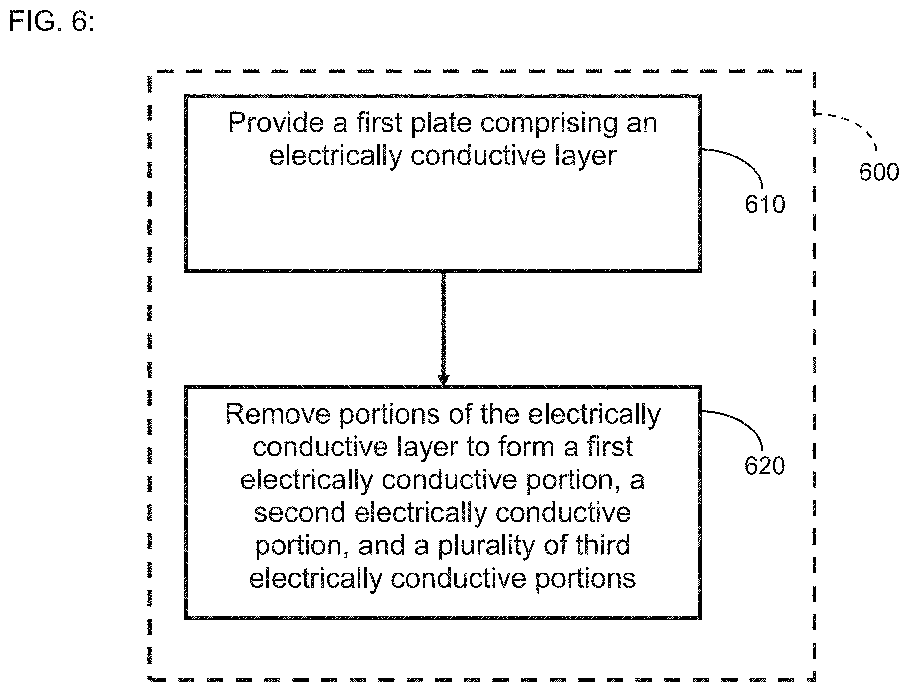
[0015] FIG. 6 is a flow diagram of an example method of fabricating a thermoelectric device in accordance with certain embodiments described herein.
DETAILED DESCRIPTION
[0016] Certain embodiments described herein advantageously provide a thermoelectric device having circuitry that facilitates manufacture of the thermoelectric device and/or of a thermoelectric module comprising the thermoelectric device. For example, by having the circuitry arranged such that the input electrical conduit and output electrical conduit are in close proximity (e.g., next) to one another, the electrical conduits of certain embodiments can be run parallel to one another through the other structures of the thermoelectric module, and the process of connecting the electrical conduits to the thermoelectric device can be easier than if the two electrical conduits were spaced further apart from one another.
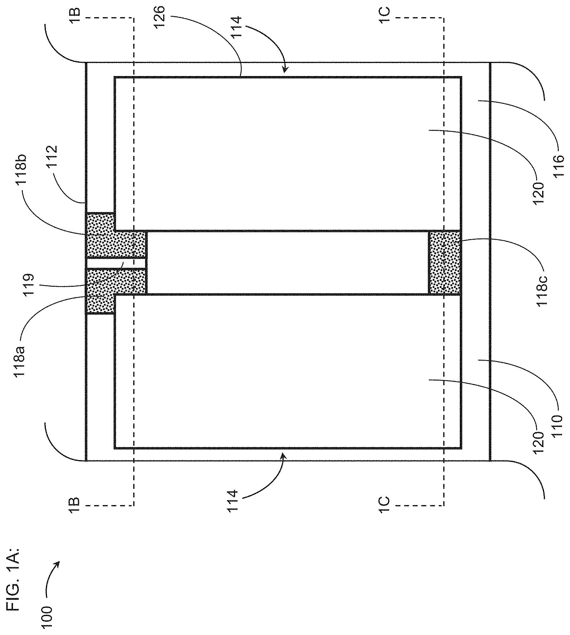
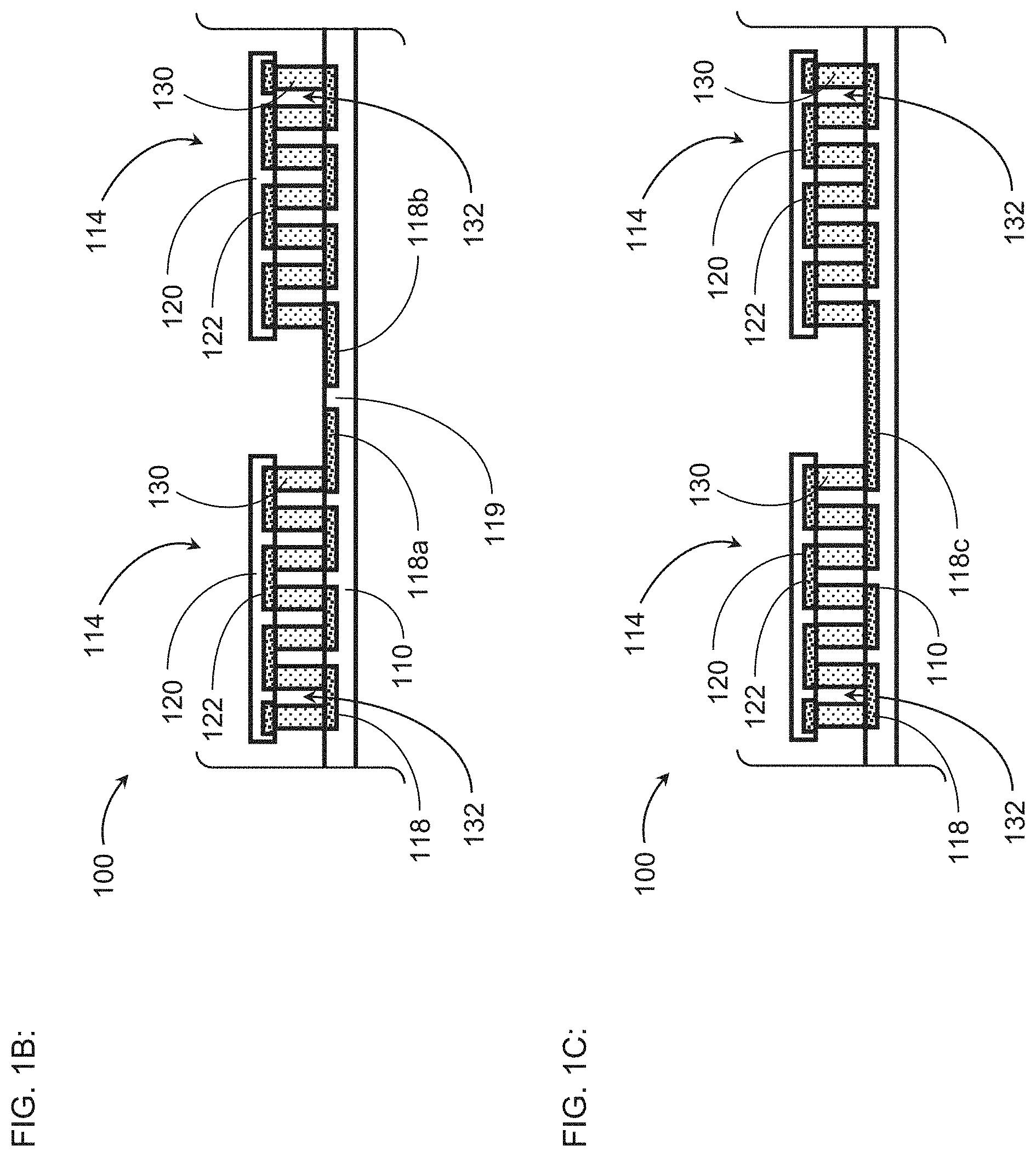
[0017] FIG. 1A schematically illustrates a top view of an example thermoelectric device 100 in accordance with certain embodiments described herein. FIGS. 1B and 1C schematically illustrate two cross-sectional views of the example thermoelectric device 100 of FIG. 1A.
[0018] The thermoelectric device 100 of FIGS. 1A-1B comprises a thermally conductive first plate 110 and a plurality of thermoelectric sub-assemblies 114, each thermoelectric sub-assembly 114 comprising a thermally conductive second plate 120 and a plurality of thermoelectric ("TE") elements 130. As shown schematically in FIG. 1A, the first plate 110 comprises a layer 116 comprising a plurality of electrically conductive portions 118 and a plurality of electrically insulating portions 119 separating the electrically conductive portions 118 from one another. The plurality of TE elements 130 is in a region 132 bounded by and including (e.g., between) the first plate 110 and the second plate 120 and is in electrical communication with the electrically conductive portions 118 of the first plate 110, in electrical communication with electrical conductive portions 122 of the second plate 120, and in thermal communication with the first plate 110 and the second plate 120. At least some of the electrically conductive portions 118 of the first plate 110 are positioned at least partially outside the regions 132, are in electrical communication with the plurality of thermoelectric sub-assemblies 114, and comprise a first electrically conductive portion 118a configured to be in electrical communication with an input electrical conduit (not shown) and a second electrically conductive portion 118b configured to be in electrical communication with an output electrical conduit (not shown). The first electrically conductive portion 118a and the second electrically conductive portion 118b are positioned at a first edge 112 of the first plate 110 without a thermoelectric sub-assembly 114 of the plurality of thermoelectric sub-assemblies 114 between the first electrically conductive portion 118a and the second electrically conductive portion 118b.
[0019] In certain embodiments, each of the first plate 110 and the second plate 120 comprises a planar laminate structure (e.g., a printed circuit board or PCB) having one or more electrically conductive layers (e.g., copper; aluminum; metal; metal alloy or composite) and one or more electrically insulating layers (e.g., fiberglass; resin; polymer; fibrous material preimpregnated with a resin material such as epoxy). The one or more electrically conductive layers can be configured to provide electrical connections to the plurality of TE elements 130. For example, the layer 116 can comprises an electrically conductive layer of the first plate 110 wherein at least some of the electrically conductive portions 118 comprise electrically conductive pads on a surface of the first plate 110 in the region 132. The pads can be configured to be coupled (e.g., soldered) to the TE elements 130, and the pads can be in electrical communication with other pads of the first plate 110 (e.g., by electrically conductive lines formed by selective chemical etching of the electrically conductive layers and by electrically conductive vias formed through the electrically insulating layers). Similarly, at least some portions 122 of an electrically conductive layer of the second plate 120 can comprise electrically conductive pads on a surface of the second plate 120 in the region 132 which are configured to be coupled (e.g., soldered) to the TE elements 130, and the pads can be in electrical communication with other pads of the second plate 120 (e.g., by electrically conductive lines formed by selective chemical etching of the electrically conductive layers and by electrically conductive vias formed through the electrically insulating layers).
[0020] In certain embodiments, the first plate 110 has a planar parallelogram shape (e.g., rhombus shape; rectangular shape; square shape) with four edges (e.g., a rectangular shape with two shorter edges and two longer edges). The first plate 110 can have other planar shapes (e.g., polygonal) with other numbers of edges in accordance with certain embodiments described herein (e.g., triangular shapes with three edges; trapezoidal shapes with four edges; pentagonal shapes with five edges; hexagonal shapes with six edges; etc.). In certain embodiments, the second plate 120 has a planar parallelogram shape (e.g., rhombus shape; rectangular shape; square shape) with four edges 126 (e.g., a rectangular shape with two shorter edges and two longer edges). The second plate 120 can have other planar shapes (e.g., polygonal) with other numbers of edges 126 in accordance with certain embodiments described herein (e.g., triangular shapes with three edges; trapezoidal shapes with four edges; pentagonal shapes with five edges; hexagonal shapes with six edges; etc.).
[0021] In certain embodiments, the plurality of TE elements 130 comprises p-type TE elements and n-type TE elements in electrical communication with one another through a plurality of shunts (e.g., electrically conductive pads of the first plate 110 and the second plate 120). For example, the plurality of TE elements 130 can be arranged in a "stonehenge" configuration in which p-type and n-type TE elements alternate with one another and are in series electrical communication with one another by shunts (e.g., electrically conductive portions 118 of the first plate 110 and electrically conductive portions 122 of the second plate 120) which are alternately positioned on the first plate 110 and the second plate 120 such that electrical current can flow serially through the TE elements 130 and the shunts in a serpentine fashion. In certain embodiments, the plurality of TE elements 130 are in thermal communication with the first plate 110 through the shunts (e.g., electrically conductive pads) on the surface of the first plate 110 and in thermal communication with the second plate 120 through the shunts (e.g., electrically conductive pads) on the surface of the second plate 120. In certain embodiments, the region 132 containing the plurality of TE elements 130 is bounded by and includes (e.g., between) the first plate 110 and the second plate 120 and has a perimeter defined by the second plate 120 (e.g., the perimeter is coincident with the plurality of edges 126 of the second plate 120).
[0022] In certain embodiments, a top surface of the first plate 110 (e.g., a surface of the first plate 110 closest to the second plate 120) has a first surface area and a top surface of the second plate 120 (e.g., a surface of the second plate 120 farthest from the first plate 110) has a second surface area less than the first surface area. For example, each thermoelectric sub-assembly 114 of the plurality of thermoelectric sub-assemblies 114 can comprise a corresponding second plate 120 and a corresponding plurality of TE elements 130 (e.g., the plurality of second plates 120 are mounted to a common first plate 110), and the first plate 110 can have a surface area larger than the sum of the surface areas of the second plates 120. In certain embodiments, the first plate 110 and the second plate 120 are spaced from one another by a gap having a gap height. For example, the gap between the top surface of the first plate 110 and a bottom surface of the second plate 120 (e.g., a surface of the second plate 120 closest to the first plate 110) is equal to the height of the TE elements 130 within the region 132, as schematically illustrated by FIGS. 1B and 1C.
[0023] In certain embodiments, the plurality of electrically conductive portions 118 of the layer 116 comprises an electrically conductive material, examples of which include but are not limited to: copper; aluminum; metal; metal alloy or composite, and the plurality of electrically insulating portions 119 of the layer 116 does not contain an electrically conductive material. For example, the layer 116 can comprise a copper layer from which some of the copper has been removed (e.g., etched) such that the electrically conductive portions 118 comprise copper remaining after this removal (e.g., etching) from the layer 116, and the electrically insulating portions 119 comprise portions of the layer 116 from which the electrically conductive material (e.g., copper) has been removed (e.g., etched), so the portions 119 comprise etched portions of the layer 116.
[0024] In certain embodiments, at least some of the electrically conductive portions 118 of the first plate 110 are positioned at least partially outside the regions 132 and are in electrical communication with the plurality of thermoelectric sub-assemblies 114. For example, as schematically illustrated in FIGS. 1A-1C, electrically conductive portions 118a, 118b, 118c are positioned partially outside the regions 132 of the thermoelectric sub-assemblies 114 and are in electrical communication with the TE elements 130 of the thermoelectric sub-assemblies 114. The electrically conductive portions 118a, 118b of the layer 116 are separated from one another by an electrically insulating portion 119 of the layer 116 and are configured to be in electrical communication with an input electrical conduit (e.g., wire) and an output electrical conduit (e.g., wire), respectively. The electrically conductive portions 118a, 118b are positioned at the first edge 112 of the first plate 110 without a thermoelectric sub-assembly between the first electrically conductive portion 118a and the second electrically conductive portion 118b.
[0025] The electrically conductive portion 118c is in electrical communication with TE elements 130 of both thermoelectric sub-assemblies 114 of FIGS. 1A-1C. For example, the TE elements 130 of the two thermoelectric sub-assemblies 114 are in series electrical communication with one another by being in electrical communication with the electrically conductive portion 118c. As schematically illustrated in FIGS. 1A-1C, the series electrical circuit comprises the electrically conductive portions 118a, 118b of the first plate 110 and the thermoelectric elements 130 of the thermoelectric sub-assemblies 114 with the first electrically conductive portion 118a at a first end of the series electrical circuit and the second electrically conductive portion 118b at a second end of the series electrical circuit.
[0026] In certain embodiments, one or more of the thermoelectric sub-assemblies 114 comprises at least one material (e.g., an electrically insulating material; epoxy; polymer) along at least a first portion of a perimeter of the region 132. The at least one material is in mechanical communication with the first plate 110 and the second plate 120, and the at least one material extends over at least some of the electrically conductive portions of the first plate 110 (e.g., over the electrically conductive portions 118a, 118b, 118c). The at least one material can also extend over the at least some of the electrically insulating portions 119 of the first plate 110.
[0027] FIGS. 2A and 2B schematically illustrate a perspective view and an exploded view, respectively, of an example thermoelectric device 100 comprising a plurality of thermoelectric sub-assemblies 114 (e.g., four thermoelectric sub-assemblies 114) in accordance with certain embodiments described herein. In FIGS. 2A and 2B, the thermoelectric device 100 comprises a first plate 110 (e.g., PCB) having a rectangular shape with a length L.sub.1 and a width W.sub.1. The first plate 110 further comprises a plurality of holes 160 (e.g., configured to mount the thermoelectric device 100 within a thermoelectric module) between the thermoelectric sub-assemblies 114. Each of the four thermoelectric sub-assemblies 114 of FIGS. 2A and 2B comprises a plurality of TE elements 130, and a second plate 120 having a rectangular shape with a length L.sub.2 and a width W.sub.2, and having a plurality of electrically conductive shunts (not shown) (e.g., solder pads) configured to be in electrical and thermal communication with the plurality of TE elements 130.
[0028] FIG. 2A also shows a pair of electrical conduits 162a, 162b (e.g., wires) configured to be in electrical communication with (e.g., soldered to) the first electrically conductive portion 118a and the second electrically conductive portion 118b, respectively, to transmit electrical power to and/or from the thermoelectric sub-assemblies 114. The electrically conductive portions 118c electrically connect the TE elements 130 of different thermoelectric sub-assemblies 114 in series with one another. In certain embodiments, the portions of the electrical conduits 162a, 162b that are coupled to (e.g., soldered onto) the electrically conductive portions 118a, 118b is covered by at least one electrically insulating material (e.g., epoxy; polymer) configured to provide electrical insulation and/or structural rigidity to the portions of the electrical conduits 162a, 162b that are coupled to the electrically conductive portions 118a, 118b.
[0029] The thermoelectric sub-assemblies 114 of FIGS. 2A and 2B are substantially equally spaced from one another (e.g., within .+-.5%; within .+-.1%) across the first plate 110 with a pair of holes 160 between the longer edges of the second plates 120 of adjacent thermoelectric sub-assemblies 114. In certain other embodiments, the thermoelectric sub-assemblies 114 are not substantially equally spaced from one another, and/or the number of holes 160 between the adjacent thermoelectric sub-assemblies 114 is not equal to two (e.g., one; more than two). The two shorter edges of the second plates 120 of each of the thermoelectric sub-assemblies 114 of FIGS. 2A and 2B are aligned (e.g., flush) with longer edges of the first plate 110, and the two thermoelectric sub-assemblies 114 at opposite ends of the thermoelectric device 100 have one of the longer edges of the second plate 120 aligned (e.g., flush) with a respective shorter edge of the first plate 110. In certain other embodiments, other edges of the first plate 110 and other edges of the second plate 120 can be aligned (e.g., flush) with one another or can extend past one another.
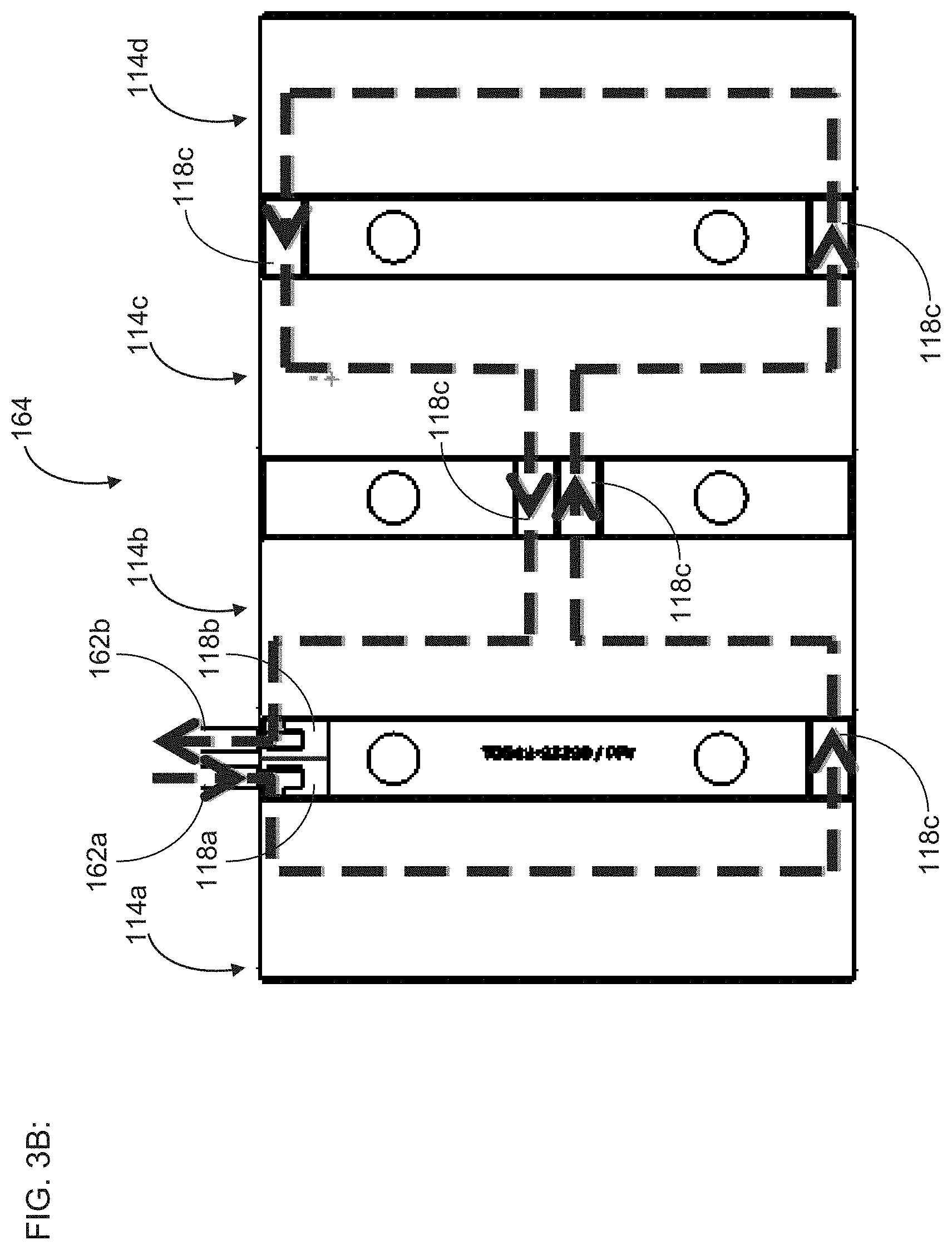
[0030] FIG. 3A schematically illustrates an example first plate 110 in accordance with certain embodiments described herein. The first plate 110 is configured to support four thermoelectric sub-assemblies 114 and for each thermoelectric sub-assembly 114, the first plate 110 comprises a plurality of electrically conductive portions 118 and a plurality of electrically insulating portions 119. In addition, at least some of the electrically conductive portions 118a, 118b, 118c are positioned at least partially outside the regions 132 of the thermoelectric sub-assemblies 114 and are configured to form a series electrical circuit 164 with the TE elements 130 of the thermoelectric sub-assemblies 114. FIG. 3B schematically illustrates an example electrical current path of the series electrical circuit 164 among the various thermoelectric sub-assemblies 114 as a dashed arrowed line. The electrical current path begins at the first electrical conduit 162a and extends in series through the following: [0031] the electrically conductive portion 118a; [0032] the TE elements 130 of a first thermoelectric sub-assembly 114a; [0033] an electrically conductive portion 118c extending from the first thermoelectric sub-assembly 114a to a second thermoelectric sub-assembly 114b; [0034] a first set of TE elements 130 of the second thermoelectric sub-assembly 114b; [0035] an electrically conductive portion 118c extending from the second thermoelectric sub-assembly 114b to a third thermoelectric sub-assembly 114c; [0036] a first set of TE elements 130 of the third thermoelectric sub-assembly 114b; [0037] an electrically conductive portion 118c extending from the third thermoelectric sub-assembly 114c to a fourth thermoelectric sub-assembly 114d; [0038] the TE elements of the fourth thermoelectric sub-assembly 114d; [0039] an electrically conductive portion 118c extending from the fourth thermoelectric sub-assembly 114d to the third thermoelectric sub-assembly 114c; [0040] a second set of TE elements 130 of the third thermoelectric sub-assembly 114c; [0041] an electrically conductive portion 118c extending from the third thermoelectric sub-assembly 114c to the second thermoelectric sub-assembly 114b; [0042] a second set of TE elements 130 of the second thermoelectric sub-assembly 114b; and [0043] the second electrically conductive portion 118b to the second electrical conduit 162b. Other configurations with other series electrical circuits, electrical current paths, thermoelectric sub-assemblies are also compatible with certain embodiments described herein.
[0044] FIG. 4A schematically illustrates the example first plate 110 of FIG. 3A (excluding the plurality of holes 160) with a solder mask layer 170 overlaying the plurality of electrically conductive portions 118 and the plurality of electrically insulating portions 119 in accordance with certain embodiments described herein. FIG. 4B schematically illustrates a magnified view of a corner of the first plate 110 of FIG. 4A, showing the solder mask layer 170 overlying peripheral regions 172 of the portions 118 and not overlying central regions 174 (e.g., solder pad regions) of the portions 118. The central regions 174 are configured to be used as shunts which provide electrical communication and thermal communication to the TE elements 130 of the thermoelectric sub-assemblies 114. FIG. 4B also schematically illustrates that the example first plate 110 has a laminate structure with a metal base layer 180 (e.g., copper; aluminum; metal; metal alloy or composite), an electrically insulating layer 182 (e.g., fiberglass; resin; polymer; fibrous material preimpregnated with a resin material such as epoxy) overlying the metal base, the layer 116 overlaying the electrically insulating layer, and the solder mask layer overlaying the layer 116.
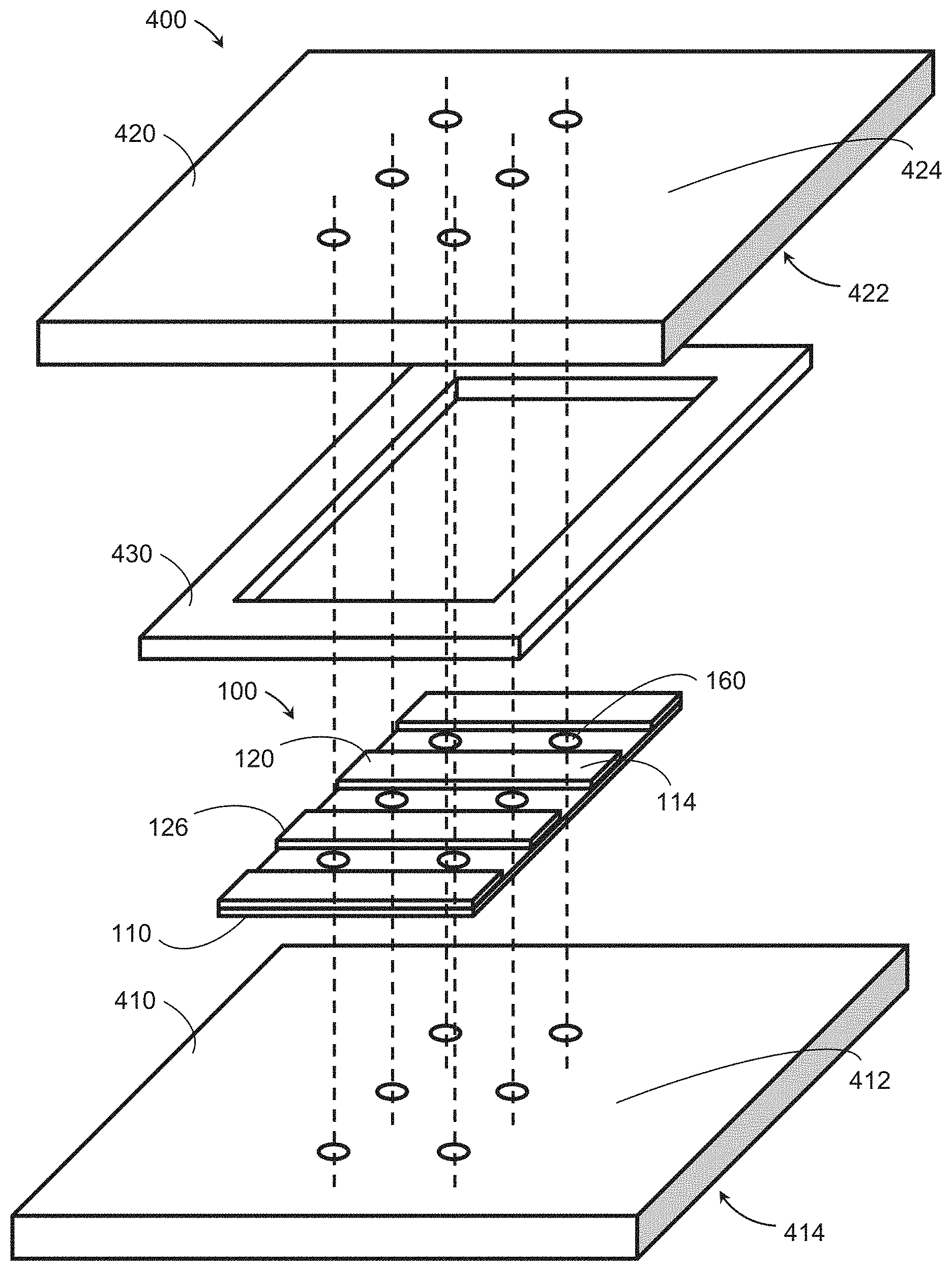
[0045] FIG. 5 schematically illustrates a thermoelectric module 400 for thermally conditioning a component (e.g., an electronics component; a battery) in accordance with certain embodiments described herein. The module 400 comprises a first heat spreader 410 and a second heat spreader 420 spaced apart from one another and configured to respectively provide cold and hot sides. The module 400 further comprises a material 430 arranged between the first heat spreader 410 and the second heat spreader 420. The module 400 further comprises a thermoelectric device 100 operatively engaged with the first heat spreader 410 and the second heat spreader 420. In certain embodiments, the first heat spreader 410 and the second heat spreader 420 are configured to be mechanically coupled together by at least one fastener (e.g., bolt; screw; pin; rivet) (not shown).
[0046] The thermoelectric device 100 comprises a thermally conductive first plate 110 in thermal communication with the first heat spreader 410 and a plurality of thermoelectric sub-assemblies 114. For example, the first plate 110 can comprise at least one hole 160 configured to have the at least one fastener extend therethrough and the plurality of thermoelectric sub-assemblies 114 can be arranged to have the at least one fastener between adjacent thermoelectric sub-assemblies 114 (see, e.g., FIG. 5). Although not shown in FIG. 5, the first plate 110 comprises electrically conductive portions 118 and electrically insulating portions 119 in accordance with certain embodiments described herein (see, e.g., FIGS. 1A-1C, 2A-2B, and 3A-3B). Each thermoelectric sub-assembly 114 comprises a thermally conductive second plate 120 in thermal communication with the second heat spreader 420 and having a plurality of edges 126, and a plurality of TE elements 130 in a region 132 bounded by and including (e.g., between) the first plate 110 and the second plate 120 and in thermal communication with the first plate 110 and the second plate 120.
[0047] In certain embodiments, the first heat spreader 410 and the second heat spreader 420 are configured to transfer heat away from the component to be thermally conditioned. For example, as schematically illustrated by FIG. 5, the first heat spreader 410 can be configured to transfer heat to the thermoelectric device 100 from the component to be thermally conditioned, and the second heat spreader 420 can be configured to transfer heat away from the thermoelectric device 100. The first heat spreader 410 can comprise at least one first surface 412 configured to be in thermal communication with the thermoelectric device 100 and at least one second surface 414 configured to be in thermal communication with the component to be thermally conditioned by the module 400, and the second heat spreader 420 can comprise at least one first surface 422 configured to be in thermal communication with the thermoelectric device 100. For example, at least one second surface 424 of the second heat spreader 420 can comprise at least one heat dissipation structure (e.g., at least one fin) configured to transfer heat from the second heat spreader 420 to the ambient surroundings. For another example, the second heat spreader 420 can be configured to have a fluid coolant (e.g., liquid; air; refrigerant) flow therethrough. While FIG. 5 schematically illustrates an example thermoelectric module 400 in which the first heat spreader 410 provides at least one cold side that receives heat from the component to be thermally conditioned and in which the second heat spreader 420 provides at least one hot side that serves as a heat sink which receives heat from the thermoelectric device 100, in certain other embodiments, the second heat spreader 420 provides the at least one cold side and the first heat spreader 410 provides the at least one hot side.
[0048] In certain embodiments, the material 430 comprises a compressible material (e.g., polymer; plastic; rubber; fiberglass) and is configured to be at least partially compressed by the first heat spreader 410 and the second heat spreader 420 during assembly of the thermoelectric module 400 while keeping the first heat spreader 410 and the second heat spreader 420 from contacting one another. In certain embodiments, the material 430 generally surrounds the thermoelectric device 100 (e.g., as shown in FIG. 5), and comprises conduits (e.g., holes; recesses; cut-out portions) (not shown) configured to accommodate one or more electrical conduits (e.g., wires) in electrical communication with the thermoelectric device 100 by allowing the one or more electrical conduits to extend from the thermoelectric device 100 to outside the thermoelectric module 400. In certain embodiments in which the thermoelectric device 100 comprises a plurality of thermoelectric sub-assemblies 114, the material 430 does not extend between the thermoelectric sub-assemblies 114. In certain embodiments, the material 430 provides thermal insulation between the first heat spreader 410 and the second heat spreader 420. For example, the material 430 can have a low thermal conductivity (e.g., less than 10 W/mK) and can be configured to reduce a thermal short between the first heat spreader 410 and the second heat spreader 420 (e.g., heat transfer along a thermal path between the first and second heat spreaders 410, 420 that does not extend through the thermoelectric device 100). In certain embodiments, the material 430 provides hermetic sealing and/or a moisture barrier for the volume occupied by the thermoelectric device 100. For example the material 430 can comprise an insulation ring configured to prevent dust, condensate, moisture, or other particulates and/or fluids from entering the volume occupied by the thermoelectric device 100.
[0049] In certain embodiments, the thermoelectric module 400 comprises at least one seal (e.g., hermetic seal) at least partially surrounding a volume containing the thermoelectric elements 130 of the thermoelectric device 100. For example, the at least one seal can comprise a material (e.g., an electrically insulating material; epoxy; polymer) along at least a portion of a perimeter of the region 132 containing the thermoelectric elements 130. For another example, the at least one seal can comprise a material (e.g., epoxy; acrylic; polymer; silicone) between the first heat spreader 410 and the second heat spreader 420 and at least partially surrounding a volume containing the thermoelectric device 100 (e.g., potting a portion of the volume between the at least one first surface 412 of the first heat spreader 410 and the at least one first surface 422 of the second heat spreader 420. The material can be sufficiently rigid to provide mechanical strength to the thermoelectric module 400. In certain embodiments, additional material (e.g., epoxy; acrylic; polymer; silicone) is located and forms at least one seal between at least one screw head of the at least one fastener (not shown) and the at least one second surface 424 of the second heat spreader 420.
[0050] FIG. 6 is a flow diagram of an example method 600 of fabricating a thermoelectric device 100 in accordance with certain embodiments described herein. The example method 600 of certain embodiments can also be used for fabricating a thermoelectric module 400. While the method 600 is described by referring to the structures schematically illustrated in FIGS. 1A-1C, 2A-2B, 3A-3B, 4A-4B, and 5, the method 600 is also compatible with other structures.
[0051] In an operational block 610, the method 600 comprises providing a first plate 110 comprising an electrically conductive layer 116. In an operational block 620, the method further comprises removing portions of the electrically conductive layer 116 to form a first electrically conductive portion 118a, a second electrically conductive portion 118b, and a plurality of third electrically conductive portions 118c. The first electrically conductive portion 118a is configured to be in electrical communication with an input electrical conduit 162a and a series electrical circuit 164 comprising a plurality of thermoelectric sub-assemblies 114. The second electrically conductive portion 118b is configured to be in electrical communication with an output electrical conduit 162b and the series electrical circuit 164. The plurality of third electrically conductive portions 118c is configured to be in electrical communication and in thermal communication with a plurality of thermoelectric elements 130 of the plurality of thermoelectric sub-assemblies 114. The first electrically conductive portion 118a and the second electrically conductive portion 118b are positioned at a first edge 112 of the first plate 110 without the plurality of third electrically conductive portions 118c between the first electrically conductive portion 118a and the second electrically conductive portion 118b.
[0052] In certain embodiments, removing portions of the electrically conductive layer 116 comprises forming a plurality of electrically insulating portions 119 separating the first electrically conductive portion 118a, the second electrically conductive portion 118b, and the plurality of third electrically conductive portions 118c from one another. For example, removing portions of the electrically conductive layer 116 can comprise etching the electrically conductive layer 116 to form the plurality of electrically conductive portions 118 and the plurality of electrically insulating portions 119.
[0053] In certain embodiments, the method 600 further comprises forming the plurality of thermoelectric sub-assemblies 114 on the first plate 110. For example, forming the plurality of thermoelectric sub-assemblies can comprise connecting the plurality of TE elements 130 in electrical communication and in thermal communication with the plurality of electrically conductive portions 118 of the first plate 110, and connecting a plurality of second plates 120 to the plurality of TE elements 130. Each thermoelectric sub-assembly can comprise a corresponding portion of the plurality of thermoelectric elements 130 in a region 132 between the first plate 110 and the corresponding second plate 120. In certain embodiments, the method 600 further comprises providing the second plates 120. For example, providing the second plates 120 can comprise etching an electrically conductive layer of the second plates to form the plurality of electrically conductive portions of the second plates 120.
[0054] In certain embodiments, connecting the plurality of TE elements 130 to the plurality of electrically conductive portions 118 of the first plate 110 and to the plurality of electrically conductive portions of the second plate 120 comprises applying solder to the electrically conductive portions 118 of the first plate 110 and to the electrically conductive portions of the second plate 120 and heating the solder to above a temperature above a melting temperature of the solder while the TE elements 130 are in contact with the solder. In certain embodiments, the method 600 further comprises applying a solder mask layer 170 over the first plate 110 such that the solder mask layer 170 does not overlie solder pad regions 174 of the electrically conductive first portions 118, and the solder can be applied to the solder pad regions 174. In certain embodiments, the method 600 further comprises depositing at least one material along at least a first a portion of a perimeter of the region 132, the at least one material in mechanical communication with the first plate 110 and the second plate 120 (e.g., to hermetically seal the TE elements 130; to provide additional structural rigidity to the thermoelectric assembly 100).
[0055] Discussion of the various embodiments herein has generally followed the embodiments schematically illustrated in the figures. However, it is contemplated that the particular features, structures, or characteristics of any embodiments discussed herein may be combined in any suitable manner in one or more separate embodiments not expressly illustrated or described. In many cases, structures that are described or illustrated as unitary or contiguous can be separated while still performing the function(s) of the unitary structure. In many instances, structures that are described or illustrated as separate can be joined or combined while still performing the function(s) of the separated structures. Various features and aspects of the disclosed embodiments can be combined with or substituted for one another. Any methods disclosed herein need not be performed in the order recited.
[0056] The ranges disclosed herein also encompass any and all overlap, sub-ranges, and combinations thereof. Language such as "up to," "at least," "greater than," "less than," "between," and the like includes the number recited. With respect to the use of any plural and/or singular terms herein, those having skill in the art can translate from the plural to the singular and/or from the singular to the plural as is appropriate to the context and/or application. The various singular/plural permutations may be expressly set forth herein for sake of clarity. In general, terms used herein are generally intended as "open" terms (e.g., the term "including" should be interpreted as "including but not limited to," the term "having" should be interpreted as "having at least," the term "includes" should be interpreted as "includes but is not limited to," etc.). If a specific number is intended, such an intent will be explicitly recited in the embodiment, and in the absence of such recitation, no such intent is present.
[0057] Various embodiments have been described above. Although the inventions have been described with reference to these specific embodiments, the descriptions are intended to be illustrative and are not intended to be limiting. Various modifications and applications may occur to those skilled in the art without departing from the spirit and scope of the inventions as defined in the appended claims.
* * * * *
D00000
D00001
D00002
D00003
D00004
D00005
D00006
D00007
D00008
XML
uspto.report is an independent third-party trademark research tool that is not affiliated, endorsed, or sponsored by the United States Patent and Trademark Office (USPTO) or any other governmental organization. The information provided by uspto.report is based on publicly available data at the time of writing and is intended for informational purposes only.
While we strive to provide accurate and up-to-date information, we do not guarantee the accuracy, completeness, reliability, or suitability of the information displayed on this site. The use of this site is at your own risk. Any reliance you place on such information is therefore strictly at your own risk.
All official trademark data, including owner information, should be verified by visiting the official USPTO website at www.uspto.gov. This site is not intended to replace professional legal advice and should not be used as a substitute for consulting with a legal professional who is knowledgeable about trademark law.