Climate controlled beds and methods of operating the same
Marquette , et al. Sept
U.S. patent number 10,405,667 [Application Number 15/880,433] was granted by the patent office on 2019-09-10 for climate controlled beds and methods of operating the same. This patent grant is currently assigned to GENTHERM INCORPORATED. The grantee listed for this patent is Gentherm Incorporated. Invention is credited to Brian D. Comiskey, David Marquette, Dusko Petrovski.


| United States Patent | 10,405,667 |
| Marquette , et al. | September 10, 2019 |
Climate controlled beds and methods of operating the same
Abstract
A climate controlled seat, bed or other assembly configured to receive a person includes a blower and two or more thermoelectric devices or other conditioning fluid modules. According to one embodiment of an operational scheme, a control system for the seat or bed is configured to continuously discharge air from the blower through the thermoelectric devices. In one arrangement, the thermoelectric devices are sequenced between an activated and a deactivated position. Consequently, the desired cooling and/or cooling effect can be maintained while reducing energy consumption of the climate control system.
| Inventors: | Marquette; David (Farmington Hills, MI), Petrovski; Dusko (Washington, MI), Comiskey; Brian D. (Coto de Caza, CA) | ||||||||||
|---|---|---|---|---|---|---|---|---|---|---|---|
| Applicant: |
|
||||||||||
| Assignee: | GENTHERM INCORPORATED
(Northville, MI) |
||||||||||
| Family ID: | 40430280 | ||||||||||
| Appl. No.: | 15/880,433 | ||||||||||
| Filed: | January 25, 2018 |
Prior Publication Data
| Document Identifier | Publication Date | |
|---|---|---|
| US 20180213942 A1 | Aug 2, 2018 | |
Related U.S. Patent Documents
| Application Number | Filing Date | Patent Number | Issue Date | ||
|---|---|---|---|---|---|
| 13848620 | Mar 21, 2013 | ||||
| 13210110 | Mar 26, 2013 | 8402579 | |||
| 13018167 | Aug 16, 2011 | 7996936 | |||
| 12208254 | Feb 1, 2011 | 7877827 | |||
| 60971220 | Sep 10, 2007 | ||||
| Current U.S. Class: | 1/1 |
| Current CPC Class: | A47C 21/044 (20130101); A47C 7/74 (20130101); F24H 3/0429 (20130101); F24H 9/2071 (20130101); B60H 1/00285 (20130101); B60H 1/00742 (20130101); F24H 3/022 (20130101); F25B 21/02 (20130101); B60H 2001/003 (20130101); F25B 2321/0211 (20130101); F25B 2321/0212 (20130101) |
| Current International Class: | A47C 21/04 (20060101); F24H 9/20 (20060101); F25B 21/02 (20060101); F24H 3/04 (20060101); F24H 3/02 (20060101); B60H 1/00 (20060101); A47C 7/74 (20060101) |
| Field of Search: | ;5/423,421,426,505.1 ;62/3.5 |
References Cited [Referenced By]
U.S. Patent Documents
| 96989 | November 1869 | Somes |
| 771461 | October 1904 | Clifford |
| 1777982 | June 1929 | Popp |
| 1839156 | December 1931 | Lumpkin |
| 2235620 | March 1941 | Nessell |
| 2362259 | November 1944 | Findley |
| 2363168 | November 1944 | Findley |
| 2461432 | February 1949 | Mitchell |
| 2462984 | March 1949 | Maddison |
| 2493067 | January 1950 | Goldsmith |
| 2512559 | June 1950 | Williams |
| 2519241 | August 1950 | Findley |
| 2782834 | February 1957 | Vigo |
| 2791956 | May 1957 | Guest |
| 2813708 | November 1957 | Frey |
| 2884956 | May 1959 | Perlin |
| 2931286 | April 1960 | Fry, Sr. et al. |
| 2959017 | November 1960 | Gilman et al. |
| 2976700 | March 1961 | Jackson |
| 2984077 | May 1961 | Gaskill |
| 3019609 | February 1962 | Pietsch |
| 3030145 | April 1962 | Kottemann |
| 3039817 | June 1962 | Taylor |
| 3077079 | February 1963 | Pietsch |
| 3085405 | April 1963 | Frantti |
| 3090206 | May 1963 | Anders |
| 3136577 | June 1964 | Richard |
| 3137142 | June 1964 | Venema |
| 3137523 | June 1964 | Karner |
| 3138934 | June 1964 | Roane |
| 3178894 | April 1965 | Mole et al. |
| 3186240 | June 1965 | Daubert |
| 3197342 | July 1965 | Neild |
| 3209380 | October 1965 | Watsky |
| 3212275 | October 1965 | Tillman |
| 3240628 | March 1966 | Sonntag, Jr. |
| 3253649 | May 1966 | Laing |
| 3266064 | August 1966 | Figman |
| 3282267 | November 1966 | Eidus |
| 3298195 | January 1967 | Raskhodoff |
| 3300649 | January 1967 | Strawn |
| 3325312 | June 1967 | Sonntag, Jr. |
| 3326727 | June 1967 | Fritts |
| 3351498 | November 1967 | Shinn et al. |
| 3366164 | January 1968 | Newton |
| 3392535 | July 1968 | De Castelet |
| 3486177 | December 1969 | Marshack |
| 3529310 | September 1970 | Olmo |
| 3550523 | December 1970 | Segal |
| 3599437 | August 1971 | Panas |
| 3615870 | October 1971 | Crouthamel |
| 3627299 | December 1971 | Schwartze et al. |
| 3632451 | January 1972 | Abbott |
| 3640456 | February 1972 | Sturgis |
| 3644950 | February 1972 | Lindsay, Jr. |
| 3648469 | March 1972 | Chapman |
| 3653083 | April 1972 | Lapidus |
| 3703141 | November 1972 | Pernoud |
| 3767470 | October 1973 | Hines |
| 3778851 | December 1973 | Howorth |
| 3786230 | January 1974 | Brandenburg, Jr. |
| 3819418 | June 1974 | Winkler et al. |
| 3839876 | October 1974 | Privas |
| 3870568 | March 1975 | Oesterhelt et al. |
| 3876860 | April 1975 | Nomura et al. |
| 3894213 | July 1975 | Agarwala |
| 3899054 | August 1975 | Huntress et al. |
| 3902923 | September 1975 | Evans et al. |
| 3916151 | October 1975 | Reix |
| 3926052 | December 1975 | Bechtel |
| 3927299 | December 1975 | Sturgis |
| 3928876 | December 1975 | Starr |
| 4002108 | January 1977 | Drori |
| 4044824 | August 1977 | Eskeli |
| 4124794 | November 1978 | Eder |
| 4195687 | April 1980 | Taziker |
| 4223205 | September 1980 | Sturgis |
| 4224565 | September 1980 | Sosniak et al. |
| 4281516 | August 1981 | Berthet et al. |
| 4315599 | February 1982 | Biancardi |
| 4336444 | June 1982 | Bice et al. |
| 4338944 | July 1982 | Arkans |
| 4391009 | July 1983 | Schild et al. |
| 4413857 | November 1983 | Hayashi |
| 4423308 | December 1983 | Callaway et al. |
| 4437702 | March 1984 | Agosta |
| 4438070 | March 1984 | Stephens et al. |
| 4459428 | July 1984 | Chou |
| 4491173 | January 1985 | Demand |
| 4493939 | January 1985 | Blaske et al. |
| 4497973 | February 1985 | Heath et al. |
| 4506510 | March 1985 | Tircot |
| 4518700 | May 1985 | Stephens |
| 4518847 | May 1985 | Horst, Sr. et al. |
| 4549134 | October 1985 | Weiss |
| 4554968 | November 1985 | Haas |
| 4563387 | January 1986 | Takagi et al. |
| 4567351 | January 1986 | Kitagawa et al. |
| 4572430 | February 1986 | Takagi et al. |
| 4639883 | January 1987 | Michaelis |
| 4665707 | May 1987 | Hamilton |
| 4671567 | June 1987 | Frobose |
| 4677416 | June 1987 | Nishimoto et al. |
| 4685727 | August 1987 | Cremer et al. |
| 4688390 | August 1987 | Sawyer |
| 4704320 | November 1987 | Mizunoya et al. |
| 4711294 | December 1987 | Jacobs et al. |
| 4712832 | December 1987 | Antolini et al. |
| 4777802 | October 1988 | Feher |
| 4782664 | November 1988 | Sterna et al. |
| 4791274 | December 1988 | Horst |
| 4793651 | December 1988 | Inagaki et al. |
| 4802929 | February 1989 | Schock |
| 4812733 | March 1989 | Tobey |
| 4823554 | April 1989 | Trachtenberg et al. |
| 4825488 | May 1989 | Bedford |
| 4828627 | May 1989 | Connery |
| 4853992 | August 1989 | Yu |
| 4859250 | August 1989 | Buist |
| 4905475 | March 1990 | Tuomi |
| 4923248 | May 1990 | Feher |
| 4947648 | August 1990 | Harwell et al. |
| 4969684 | November 1990 | Zarotti |
| 4981324 | January 1991 | Law |
| 4988847 | January 1991 | Argos et al. |
| 4997230 | March 1991 | Spitalnick |
| 5002336 | March 1991 | Feher |
| 5012325 | April 1991 | Mansuria et al. |
| 5014909 | May 1991 | Yasuo |
| 5016304 | May 1991 | Ryhiner |
| 5022462 | June 1991 | Flint et al. |
| 5057490 | October 1991 | Skertic |
| 5070937 | December 1991 | Mougin et al. |
| 5077709 | December 1991 | Feher |
| 5088790 | February 1992 | Wainwright et al. |
| 5097674 | March 1992 | Imaiida et al. |
| 5102189 | April 1992 | Saito et al. |
| 5106161 | April 1992 | Meiller |
| 5111025 | May 1992 | Barma et al. |
| 5111664 | May 1992 | Yang |
| 5117638 | June 1992 | Feher |
| 5119640 | June 1992 | Conrad |
| 5125238 | June 1992 | Ragan et al. |
| 5148977 | September 1992 | Hibino et al. |
| 5166777 | November 1992 | Kataoka |
| 5187349 | February 1993 | Curhan et al. |
| 5188286 | February 1993 | Pence, IV |
| 5255735 | October 1993 | Raghava et al. |
| 5256857 | October 1993 | Curhan et al. |
| 5265599 | November 1993 | Stephenson et al. |
| 5278936 | January 1994 | Shao |
| 5279128 | January 1994 | Tomatsu et al. |
| 5335381 | August 1994 | Chang |
| 5350417 | September 1994 | Augustine et al. |
| 5367728 | November 1994 | Chang |
| 5372402 | December 1994 | Kuo |
| 5375421 | December 1994 | Hsieh |
| 5382075 | January 1995 | Shih |
| 5385382 | January 1995 | Single, II et al. |
| 5409547 | April 1995 | Watanabe et al. |
| 5413166 | May 1995 | Kerner et al. |
| 5416935 | May 1995 | Nieh |
| 5419489 | May 1995 | Burd |
| 5419780 | May 1995 | Suski |
| 5430322 | July 1995 | Koyanagi et al. |
| 5433741 | July 1995 | Truglio |
| 5448788 | September 1995 | Wu |
| 5448891 | September 1995 | Nakagiri et al. |
| 5456081 | October 1995 | Chrysler et al. |
| 5473783 | December 1995 | Allen |
| 5493742 | February 1996 | Klearman |
| 5493864 | February 1996 | Pomerene et al. |
| 5497632 | March 1996 | Robinson |
| 5505520 | April 1996 | Frusti et al. |
| 5515238 | May 1996 | Fritz et al. |
| 5524439 | June 1996 | Gallup et al. |
| 5542503 | August 1996 | Dunn et al. |
| 5544487 | August 1996 | Attey et al. |
| 5544488 | August 1996 | Reid |
| 5555732 | September 1996 | Whiticar |
| 5561981 | October 1996 | Quisenberry et al. |
| 5576512 | November 1996 | Doke |
| 5584084 | December 1996 | Klearman et al. |
| 5584183 | December 1996 | Wright et al. |
| 5597200 | January 1997 | Gregory et al. |
| 5601399 | February 1997 | Okpara et al. |
| 5606639 | February 1997 | Lehoe et al. |
| 5613729 | March 1997 | Summer, Jr. |
| 5613730 | March 1997 | Buie et al. |
| 5623828 | April 1997 | Harrington |
| 5626021 | May 1997 | Karunasiri et al. |
| 5626386 | May 1997 | Lush |
| 5634342 | June 1997 | Peeters et al. |
| 5637921 | June 1997 | Burward-Hoy |
| 5640728 | June 1997 | Graebe |
| 5642539 | July 1997 | Kuo |
| 5645314 | July 1997 | Liou |
| 5650904 | July 1997 | Gilley et al. |
| 5653741 | August 1997 | Grant |
| 5667622 | September 1997 | Hasegawa et al. |
| 5675852 | October 1997 | Watkins |
| 5690849 | November 1997 | DeVilbiss et al. |
| 5692952 | December 1997 | Chih-Hung |
| 5704213 | January 1998 | Smith et al. |
| 5715695 | February 1998 | Lord |
| 5721804 | February 1998 | Greene, III |
| 5724818 | March 1998 | Iwata et al. |
| 5729981 | March 1998 | Markus et al. |
| 5761908 | June 1998 | Oas et al. |
| 5761909 | June 1998 | Hughes et al. |
| 5798583 | August 1998 | Morita |
| 5800490 | September 1998 | Patz et al. |
| 5802855 | September 1998 | Yamaguchi et al. |
| 5802856 | September 1998 | Schaper et al. |
| 5822993 | October 1998 | Attey |
| 5827424 | October 1998 | Gillis et al. |
| 5833321 | November 1998 | Kim et al. |
| 5850741 | December 1998 | Feher |
| 5865031 | February 1999 | Itakura |
| 5871151 | February 1999 | Fiedrich |
| 5884485 | March 1999 | Yamaguchi et al. |
| 5884486 | March 1999 | Hughes et al. |
| 5887304 | March 1999 | Von der Heyde |
| 5888261 | March 1999 | Fortune |
| 5895964 | April 1999 | Nakayama |
| 5902014 | May 1999 | Dinkel et al. |
| 5921100 | July 1999 | Yoshinori et al. |
| 5921314 | July 1999 | Schuller et al. |
| 5921858 | July 1999 | Kawai et al. |
| 5924289 | July 1999 | Bishop, II |
| 5924766 | July 1999 | Esaki et al. |
| 5924767 | July 1999 | Pietryga |
| 5926884 | July 1999 | Biggie et al. |
| 5927817 | July 1999 | Ekman et al. |
| 5934748 | August 1999 | Faust et al. |
| 5936192 | August 1999 | Tauchi |
| 5937908 | August 1999 | Inoshiri et al. |
| 5948303 | September 1999 | Larson |
| 5950067 | September 1999 | Maegawa et al. |
| 5952728 | September 1999 | Imanishi et al. |
| 5963997 | October 1999 | Hagopian |
| 5987893 | November 1999 | Schultz-Harder et al. |
| 5988568 | November 1999 | Drews |
| 5992154 | November 1999 | Kawada et al. |
| 5994637 | November 1999 | Imanushi et al. |
| 5995711 | November 1999 | Fukuoka et al. |
| 6000225 | December 1999 | Ghoshal |
| 6003950 | December 1999 | Larsson |
| 6006524 | December 1999 | Park |
| 6019420 | February 2000 | Faust et al. |
| 6038865 | March 2000 | Watanabe et al. |
| 6048024 | April 2000 | Wallman |
| 6049655 | April 2000 | Vazirani |
| 6052853 | April 2000 | Schmid |
| 6053163 | April 2000 | Bass |
| 6059018 | May 2000 | Yoshinori et al. |
| 6062641 | May 2000 | Suzuki et al. |
| 6072924 | June 2000 | Sato et al. |
| 6072938 | June 2000 | Peterson et al. |
| 6073998 | June 2000 | Siarkowski et al. |
| 6079485 | June 2000 | Esaki et al. |
| 6084172 | July 2000 | Kishi et al. |
| 6085369 | July 2000 | Feher |
| 6086831 | July 2000 | Harness et al. |
| 6087638 | July 2000 | Silverbrook |
| 6094919 | August 2000 | Bhatia |
| 6097088 | August 2000 | Sakuragi |
| 6100463 | August 2000 | Ladd et al. |
| 6101815 | August 2000 | Van Oort et al. |
| 6105373 | August 2000 | Watanabe et al. |
| 6109688 | August 2000 | Wurz et al. |
| 6112525 | September 2000 | Yoshida et al. |
| 6112531 | September 2000 | Yamaguchi |
| 6116029 | September 2000 | Krawec |
| 6119463 | September 2000 | Bell |
| 6120370 | September 2000 | Asou et al. |
| 6127619 | October 2000 | Xi et al. |
| 6141969 | November 2000 | Launchbury et al. |
| 6145925 | November 2000 | Eksin et al. |
| 6148457 | November 2000 | Sul |
| 6158224 | December 2000 | Hu et al. |
| 6161241 | December 2000 | Zysman |
| 6161388 | December 2000 | Ghoshal |
| 6164076 | December 2000 | Chu et al. |
| 6164719 | December 2000 | Rauh |
| 6171333 | January 2001 | Nelson et al. |
| 6178292 | January 2001 | Fukuoka et al. |
| 6179706 | January 2001 | Yoshinori et al. |
| 6186592 | February 2001 | Orizakis et al. |
| 6189966 | February 2001 | Faust et al. |
| 6189967 | February 2001 | Short |
| 6196627 | March 2001 | Faust et al. |
| 6196839 | March 2001 | Ross |
| 6206465 | March 2001 | Faust et al. |
| 6213198 | April 2001 | Shikata et al. |
| 6222243 | April 2001 | Kishi et al. |
| 6223539 | May 2001 | Bell |
| 6233768 | May 2001 | Harding |
| 6233959 | May 2001 | Kang et al. |
| 6250083 | June 2001 | Chou |
| 6256996 | July 2001 | Ghoshal |
| 6262357 | July 2001 | Johnson et al. |
| 6263530 | July 2001 | Feher |
| 6266962 | July 2001 | Ghoshal |
| 6282907 | September 2001 | Ghoshal |
| 6289982 | September 2001 | Naji |
| 6291803 | September 2001 | Fourrey |
| 6306673 | October 2001 | Imanishi et al. |
| 6326610 | December 2001 | Muramatsu et al. |
| 6336237 | January 2002 | Schmid |
| 6338251 | January 2002 | Ghoshal |
| 6341395 | January 2002 | Chao |
| 6347521 | February 2002 | Kadotani et al. |
| 6378311 | April 2002 | McCordic |
| 6385976 | May 2002 | Yamamura et al. |
| 6391676 | May 2002 | Tsuzaki et al. |
| 6393842 | May 2002 | Kim et al. |
| 6400013 | June 2002 | Tsuzaki et al. |
| 6402470 | June 2002 | Kvasnak et al. |
| 6410971 | June 2002 | Otey |
| 6425527 | July 2002 | Smole |
| 6427449 | August 2002 | Logan et al. |
| 6434328 | August 2002 | Rutherford |
| 6452740 | September 2002 | Ghoshal |
| 6470696 | October 2002 | Palfy et al. |
| 6474073 | November 2002 | Uetsuji et al. |
| 6481801 | November 2002 | Schmale |
| 6487739 | December 2002 | Harker |
| 6489551 | December 2002 | Chu et al. |
| 6490879 | December 2002 | Lloyd et al. |
| 6492585 | December 2002 | Zamboni et al. |
| 6493888 | December 2002 | Salvatini et al. |
| 6493889 | December 2002 | Kocurek |
| 6497720 | December 2002 | Augustine et al. |
| 6509704 | January 2003 | Brown |
| 6511125 | January 2003 | Gendron |
| 6519949 | February 2003 | Wernlund et al. |
| 6539725 | April 2003 | Bell |
| 6541737 | April 2003 | Eksin et al. |
| 6541743 | April 2003 | Chen |
| 6546576 | April 2003 | Lin |
| 6548894 | April 2003 | Chu et al. |
| 6552256 | April 2003 | Shakouri et al. |
| RE38128 | June 2003 | Gallup |
| 6571564 | June 2003 | Upadhye et al. |
| 6573596 | June 2003 | Saika |
| 6574967 | June 2003 | Park et al. |
| 6580025 | June 2003 | Guy |
| 6581224 | June 2003 | Yoon |
| 6581225 | June 2003 | Imai |
| 6583638 | June 2003 | Costello et al. |
| 6596018 | July 2003 | Endo et al. |
| 6598251 | July 2003 | Habboub et al. |
| 6598405 | July 2003 | Bell |
| 6604576 | August 2003 | Noda et al. |
| 6604785 | August 2003 | Bargheer et al. |
| 6605955 | August 2003 | Costello et al. |
| 6606754 | August 2003 | Flick |
| 6606866 | August 2003 | Bell |
| 6619044 | September 2003 | Batchelor et al. |
| 6619736 | September 2003 | Stowe et al. |
| 6625990 | September 2003 | Bell |
| 6626488 | September 2003 | Pfahler |
| 6629724 | October 2003 | Ekern et al. |
| 6637210 | October 2003 | Bell |
| 6644735 | November 2003 | Bargheer et al. |
| 6672076 | January 2004 | Bell |
| 6676207 | January 2004 | Rauh et al. |
| 6684437 | February 2004 | Koenig |
| 6686532 | February 2004 | Macris |
| 6687937 | February 2004 | Harker |
| 6695402 | February 2004 | Sloan, Jr. |
| 6700052 | March 2004 | Bell |
| 6705089 | March 2004 | Chu et al. |
| 6708352 | March 2004 | Salvatini et al. |
| 6711767 | March 2004 | Klamm |
| 6711904 | March 2004 | Law et al. |
| 6719039 | April 2004 | Calaman et al. |
| 6725669 | April 2004 | Melaragni |
| 6727422 | April 2004 | Macris |
| 6730115 | May 2004 | Heaton |
| 6739138 | May 2004 | Saunders et al. |
| 6739655 | May 2004 | Schwochert et al. |
| 6743972 | June 2004 | Macris |
| 6761399 | July 2004 | Bargheer et al. |
| 6764502 | July 2004 | Bieberich |
| 6767766 | July 2004 | Chu et al. |
| 6772825 | August 2004 | Lachenbuch et al. |
| 6772829 | August 2004 | Lebrun |
| 6774346 | August 2004 | Clothier |
| 6782574 | August 2004 | Totton et al. |
| 6786541 | September 2004 | Haupt et al. |
| 6786545 | September 2004 | Bargheer et al. |
| 6790481 | September 2004 | Bishop et al. |
| 6793016 | September 2004 | Aoki et al. |
| 6804966 | October 2004 | Chu et al. |
| 6808230 | October 2004 | Buss et al. |
| 6812395 | November 2004 | Bell |
| 6815814 | November 2004 | Chu et al. |
| 6817191 | November 2004 | Watanabe |
| 6817197 | November 2004 | Padfield |
| 6817675 | November 2004 | Buss et al. |
| 6818817 | November 2004 | Macris |
| 6823678 | November 2004 | Li |
| 6828528 | December 2004 | Stowe et al. |
| 6832732 | December 2004 | Burkett et al. |
| 6834509 | December 2004 | Palfy et al. |
| 6840305 | January 2005 | Zheng et al. |
| 6840576 | January 2005 | Ekern et al. |
| 6841957 | January 2005 | Brown |
| 6845622 | January 2005 | Sauciuc et al. |
| 6855158 | February 2005 | Stolpmann |
| 6855880 | February 2005 | Feher |
| 6857697 | February 2005 | Brennan et al. |
| 6857954 | February 2005 | Luedtke |
| 6868690 | March 2005 | Faqih |
| 6871365 | March 2005 | Flick et al. |
| 6886351 | May 2005 | Palfy et al. |
| 6892807 | May 2005 | Fristedt et al. |
| 6893086 | May 2005 | Bajic et al. |
| 6904629 | June 2005 | Wu |
| 6907633 | June 2005 | Paolini et al. |
| 6907739 | June 2005 | Bell |
| 6923216 | August 2005 | Extrand et al. |
| 6935122 | August 2005 | Huang |
| 6954944 | October 2005 | Feher |
| 6959555 | November 2005 | Bell |
| 6962195 | November 2005 | Smith et al. |
| 6963053 | November 2005 | Lutz |
| 6967309 | November 2005 | Wyatt et al. |
| 6976734 | December 2005 | Stoewe |
| 6977360 | December 2005 | Weiss |
| 6981380 | January 2006 | Chrysler et al. |
| 6990701 | January 2006 | Litvak |
| 7000490 | February 2006 | Micheels |
| 7036163 | May 2006 | Schmid |
| 7036575 | May 2006 | Rodney et al. |
| 7040710 | May 2006 | White et al. |
| 7052091 | May 2006 | Bajic et al. |
| 7063163 | June 2006 | Steele et al. |
| 7066306 | June 2006 | Gavin |
| 7070231 | July 2006 | Wong |
| 7070232 | July 2006 | Minegishi et al. |
| 7075034 | July 2006 | Bargheer et al. |
| 7082772 | August 2006 | Welch |
| 7084502 | August 2006 | Bottner et al. |
| 7100978 | September 2006 | Ekern et al. |
| 7108319 | September 2006 | Hartwich et al. |
| 7111465 | September 2006 | Bell |
| 7114771 | October 2006 | Lofy et al. |
| 7124593 | October 2006 | Feher |
| 7131689 | November 2006 | Brennan et al. |
| 7134715 | November 2006 | Fristedt et al. |
| 7141763 | November 2006 | Moroz |
| 7147279 | December 2006 | Bevan et al. |
| 7165281 | January 2007 | Larssson et al. |
| 7168758 | January 2007 | Bevan et al. |
| 7178344 | February 2007 | Bell |
| 7181786 | February 2007 | Schoettle |
| 7201441 | April 2007 | Stoewe et al. |
| 7213876 | May 2007 | Stoewe |
| 7220048 | May 2007 | Kohlgruber et al. |
| 7224059 | May 2007 | Shimada et al. |
| 7231772 | June 2007 | Bell |
| 7244887 | July 2007 | Miley |
| 7246496 | July 2007 | Goenka et al. |
| 7272936 | September 2007 | Feher |
| 7273981 | September 2007 | Bell |
| 7296315 | November 2007 | Totton et al. |
| 7299639 | November 2007 | Leija et al. |
| 7337615 | March 2008 | Reidy |
| 7338117 | March 2008 | Iqbal et al. |
| 7340907 | March 2008 | Vogh et al. |
| 7355146 | April 2008 | Angelis et al. |
| 7356912 | April 2008 | Iqbal et al. |
| 7360365 | April 2008 | Codecasa et al. |
| 7360416 | April 2008 | Manaka et al. |
| 7370479 | May 2008 | Pfannenberg |
| 7370911 | May 2008 | Bajic et al. |
| 7380586 | June 2008 | Gawthrop |
| 7425034 | September 2008 | Bajic et al. |
| 7426835 | September 2008 | Bell et al. |
| 7462028 | December 2008 | Cherala et al. |
| 7469432 | December 2008 | Chambers |
| 7475464 | January 2009 | Lofy et al. |
| 7475938 | January 2009 | Stoewe et al. |
| 7478869 | January 2009 | Lazanja et al. |
| 7480950 | January 2009 | Feher |
| 7506924 | March 2009 | Bargheer et al. |
| 7506938 | March 2009 | Brennan et al. |
| 7513273 | April 2009 | Bivin |
| 7555792 | July 2009 | Heaton |
| 7581785 | September 2009 | Heckmann et al. |
| 7587901 | September 2009 | Petrovski |
| 7587902 | September 2009 | Bell |
| 7591507 | September 2009 | Giffin et al. |
| 7608777 | October 2009 | Bell et al. |
| 7621594 | November 2009 | Hartmann et al. |
| 7640754 | January 2010 | Wolas |
| 7665803 | February 2010 | Wolas |
| 7708338 | May 2010 | Wolas |
| 7731279 | June 2010 | Asada et al. |
| RE41765 | September 2010 | Gregory et al. |
| 7827620 | November 2010 | Feher |
| 7827805 | November 2010 | Comiskey et al. |
| 7862113 | January 2011 | Knoll |
| 7866017 | January 2011 | Knoll |
| 7877827 | February 2011 | Marquette et al. |
| 7892271 | February 2011 | Schock et al. |
| 7908687 | March 2011 | Ward et al. |
| 7914611 | March 2011 | Vrzalik et al. |
| 7937789 | May 2011 | Feher |
| 7963594 | June 2011 | Wolas |
| 7966835 | June 2011 | Petrovski |
| 7969738 | June 2011 | Koo |
| 7996936 | August 2011 | Marquette et al. |
| 8062797 | November 2011 | Fisher et al. |
| 8065763 | November 2011 | Brykalski et al. |
| 8104295 | January 2012 | Lofy |
| 8143554 | March 2012 | Lofy |
| 8181290 | May 2012 | Brykalski et al. |
| 8191187 | June 2012 | Brykalski et al. |
| 8222511 | July 2012 | Lofy |
| 8256236 | September 2012 | Lofy |
| 8332975 | December 2012 | Brykalski et al. |
| 8353069 | January 2013 | Miller |
| 8359871 | January 2013 | Woods et al. |
| 8402579 | March 2013 | Marquette et al. |
| 8418286 | April 2013 | Brykalski et al. |
| 8434314 | May 2013 | Comiskey et al. |
| 8438863 | May 2013 | Lofy |
| RE44272 | June 2013 | Bell |
| 8505320 | August 2013 | Lofy |
| 8516842 | August 2013 | Petrovski |
| 8539624 | September 2013 | Terech et al. |
| 8575518 | November 2013 | Walsh |
| 8621687 | January 2014 | Brykalski et al. |
| 8732874 | May 2014 | Brykalski et al. |
| 8782830 | July 2014 | Brykalski et al. |
| 8893329 | November 2014 | Petrovski et al. |
| 9105808 | August 2015 | Petrovski |
| 9105809 | August 2015 | Lofy |
| 9121414 | September 2015 | Lofy et al. |
| 9125497 | September 2015 | Brykalski et al. |
| 9186479 | November 2015 | Franceschetti et al. |
| 9310112 | April 2016 | Bell et al. |
| 9326616 | May 2016 | De Franks et al. |
| 9335073 | May 2016 | Lofy |
| 9445524 | September 2016 | Lofy et al. |
| 9451723 | September 2016 | Lofy et al. |
| 9572433 | February 2017 | Lachenbruch et al. |
| 9596945 | March 2017 | Ghanei et al. |
| 9603459 | March 2017 | Brykalski et al. |
| 9622588 | April 2017 | Brykalski et al. |
| 9651279 | May 2017 | Lofy |
| 9662962 | May 2017 | Steinman et al. |
| 9685599 | June 2017 | Petrovski et al. |
| 9756952 | September 2017 | Alletto, Jr. et al. |
| 9814641 | November 2017 | Brykalski et al. |
| 9857107 | January 2018 | Inaba et al. |
| 9974394 | May 2018 | Brykalski et al. |
| 9989267 | June 2018 | Brykalski et al. |
| 10005337 | June 2018 | Petrovski |
| 2001/0005990 | July 2001 | Kim et al. |
| 2001/0014212 | August 2001 | Rutherford |
| 2001/0028185 | October 2001 | Stowe et al. |
| 2002/0017102 | February 2002 | Bell |
| 2002/0026226 | February 2002 | Ein |
| 2002/0062854 | May 2002 | Sharp |
| 2002/0083528 | July 2002 | Fisher et al. |
| 2002/0092308 | July 2002 | Bell |
| 2002/0100121 | August 2002 | Kocurek |
| 2002/0108380 | August 2002 | Nelsen et al. |
| 2002/0121094 | September 2002 | VanHoudt |
| 2002/0195844 | December 2002 | Hipwell |
| 2003/0019044 | January 2003 | Larsson et al. |
| 2003/0039298 | February 2003 | Eriksson et al. |
| 2003/0041892 | March 2003 | Fleurial et al. |
| 2003/0070235 | April 2003 | Suzuki et al. |
| 2003/0084511 | May 2003 | Salvatini et al. |
| 2003/0110779 | June 2003 | Otey et al. |
| 2003/0133492 | July 2003 | Watanabe |
| 2003/0145380 | August 2003 | Schmid |
| 2003/0150060 | August 2003 | Huang |
| 2003/0160479 | August 2003 | Minuth et al. |
| 2003/0188382 | October 2003 | Klamm et al. |
| 2003/0234247 | December 2003 | Stern |
| 2004/0090093 | May 2004 | Kamiya et al. |
| 2004/0098991 | May 2004 | Heyes |
| 2004/0113549 | June 2004 | Roberts et al. |
| 2004/0139758 | July 2004 | Kamiya et al. |
| 2004/0164594 | August 2004 | Stoewe et al. |
| 2004/0177622 | September 2004 | Harvie |
| 2004/0177876 | September 2004 | Hightower |
| 2004/0177877 | September 2004 | Hightower |
| 2004/0195870 | October 2004 | Bohlender |
| 2004/0238022 | December 2004 | Hiller et al. |
| 2004/0255364 | December 2004 | Feher |
| 2005/0011009 | January 2005 | Wu |
| 2005/0012204 | January 2005 | Strnad |
| 2005/0056310 | March 2005 | Shikata et al. |
| 2005/0067862 | March 2005 | Iqbal et al. |
| 2005/0072165 | April 2005 | Bell |
| 2005/0076944 | April 2005 | Kanatzidis et al. |
| 2005/0078451 | April 2005 | Sauciuc et al. |
| 2005/0086739 | April 2005 | Wu |
| 2005/0121065 | June 2005 | Otey |
| 2005/0126184 | June 2005 | Cauchy |
| 2005/0140180 | June 2005 | Hesch |
| 2005/0143797 | June 2005 | Parish et al. |
| 2005/0145285 | July 2005 | Extrand |
| 2005/0161072 | July 2005 | Esser et al. |
| 2005/0173950 | August 2005 | Bajic et al. |
| 2005/0200166 | September 2005 | Noh |
| 2005/0202774 | September 2005 | Lipke |
| 2005/0220167 | October 2005 | Kanai et al. |
| 2005/0251120 | November 2005 | Anderson et al. |
| 2005/0257532 | November 2005 | Ikeda et al. |
| 2005/0268956 | December 2005 | Take |
| 2005/0278863 | December 2005 | Bahash et al. |
| 2005/0285438 | December 2005 | Ishima et al. |
| 2005/0288749 | December 2005 | Lachenbruch |
| 2006/0005548 | January 2006 | Ruckstuhl |
| 2006/0005944 | January 2006 | Wang et al. |
| 2006/0053529 | March 2006 | Feher |
| 2006/0053558 | March 2006 | Ye |
| 2006/0078319 | April 2006 | Maran |
| 2006/0080778 | April 2006 | Chambers |
| 2006/0087160 | April 2006 | Dong et al. |
| 2006/0102224 | May 2006 | Chen et al. |
| 2006/0118158 | June 2006 | Zhang et al. |
| 2006/0123799 | June 2006 | Tateyama et al. |
| 2006/0137099 | June 2006 | Feher |
| 2006/0157102 | July 2006 | Nakajima et al. |
| 2006/0158011 | July 2006 | Marlovits et al. |
| 2006/0162074 | July 2006 | Bader |
| 2006/0175877 | August 2006 | Alionte et al. |
| 2006/0197363 | September 2006 | Lofy et al. |
| 2006/0200398 | September 2006 | Botton et al. |
| 2006/0201161 | September 2006 | Hirai et al. |
| 2006/0201162 | September 2006 | Hsieh |
| 2006/0214480 | September 2006 | Terech |
| 2006/0219699 | October 2006 | Geisel et al. |
| 2006/0225441 | October 2006 | Goenka et al. |
| 2006/0225773 | October 2006 | Venkatasubramanian et al. |
| 2006/0237166 | October 2006 | Otey et al. |
| 2006/0243317 | November 2006 | Venkatasubramanian |
| 2006/0244289 | November 2006 | Bedro |
| 2006/0273646 | December 2006 | Comiskey et al. |
| 2007/0000898 | January 2007 | Tung et al. |
| 2007/0017666 | January 2007 | Goenka et al. |
| 2007/0035162 | February 2007 | Bier et al. |
| 2007/0040421 | February 2007 | Zuzga et al. |
| 2007/0069554 | March 2007 | Comiskey et al. |
| 2007/0086757 | April 2007 | Feher |
| 2007/0095378 | May 2007 | Ito et al. |
| 2007/0095383 | May 2007 | Tajima |
| 2007/0101602 | May 2007 | Bae et al. |
| 2007/0107450 | May 2007 | Sasao et al. |
| 2007/0138844 | June 2007 | Kim |
| 2007/0142883 | June 2007 | Quincy, III |
| 2007/0145808 | June 2007 | Minuth et al. |
| 2007/0157630 | July 2007 | Kadle et al. |
| 2007/0158981 | July 2007 | Almasi et al. |
| 2007/0163269 | July 2007 | Chung et al. |
| 2007/0190712 | August 2007 | Lin et al. |
| 2007/0193279 | August 2007 | Yoneno et al. |
| 2007/0200398 | August 2007 | Wolas et al. |
| 2007/0214956 | September 2007 | Carlson et al. |
| 2007/0227158 | October 2007 | Kuchimachi |
| 2007/0234742 | October 2007 | Aoki et al. |
| 2007/0241592 | October 2007 | Giffin et al. |
| 2007/0251016 | November 2007 | Feher |
| 2007/0256722 | November 2007 | Kondoh |
| 2007/0261412 | November 2007 | Heine |
| 2007/0261413 | November 2007 | Hatamian et al. |
| 2007/0261548 | November 2007 | Vrzalik et al. |
| 2007/0262621 | November 2007 | Dong et al. |
| 2007/0296251 | December 2007 | Krobok et al. |
| 2008/0000025 | January 2008 | Feher |
| 2008/0022694 | January 2008 | Anderson et al. |
| 2008/0023056 | January 2008 | Kambe et al. |
| 2008/0028536 | February 2008 | Hadden-Cook |
| 2008/0028768 | February 2008 | Goenka |
| 2008/0028769 | February 2008 | Goenka |
| 2008/0053108 | March 2008 | Wen |
| 2008/0053509 | March 2008 | Flitsch et al. |
| 2008/0077211 | March 2008 | Levinson et al. |
| 2008/0078186 | April 2008 | Cao |
| 2008/0084095 | April 2008 | Wolas |
| 2008/0087316 | April 2008 | Inaba et al. |
| 2008/0154518 | June 2008 | Manaka et al. |
| 2008/0155990 | July 2008 | Gupta et al. |
| 2008/0163916 | July 2008 | Tsuneoka et al. |
| 2008/0164733 | July 2008 | Giffin et al. |
| 2008/0166224 | July 2008 | Giffin et al. |
| 2008/0245092 | October 2008 | Forsberg et al. |
| 2008/0263776 | October 2008 | O'Reagan |
| 2008/0289677 | November 2008 | Bell et al. |
| 2008/0307796 | December 2008 | Bell et al. |
| 2009/0000031 | January 2009 | Feher |
| 2009/0015042 | January 2009 | Bargheer et al. |
| 2009/0026813 | January 2009 | Lofy |
| 2009/0033130 | February 2009 | Marquette et al. |
| 2009/0106907 | April 2009 | Chambers |
| 2009/0108094 | April 2009 | Ivri |
| 2009/0126109 | May 2009 | Lee |
| 2009/0126110 | May 2009 | Feher |
| 2009/0178700 | July 2009 | Heremans et al. |
| 2009/0211619 | August 2009 | Sharp et al. |
| 2009/0218855 | September 2009 | Wolas |
| 2009/0235969 | September 2009 | Heremans et al. |
| 2009/0269584 | October 2009 | Bell et al. |
| 2009/0293488 | December 2009 | Coughlan, III et al. |
| 2010/0132379 | June 2010 | Wu |
| 2010/0132380 | June 2010 | Robinson, II |
| 2010/0133883 | June 2010 | Walker |
| 2010/0153066 | June 2010 | Federer et al. |
| 2010/0154437 | June 2010 | Nepsha |
| 2010/0154911 | June 2010 | Yoskowitz |
| 2010/0198322 | August 2010 | Joseph et al. |
| 2010/0235991 | September 2010 | Ward et al. |
| 2010/0307168 | December 2010 | Kohl et al. |
| 2010/0325796 | December 2010 | Lachenbruch et al. |
| 2011/0010850 | January 2011 | Frias |
| 2011/0041246 | February 2011 | Li et al. |
| 2011/0066217 | March 2011 | Diller et al. |
| 2011/0101741 | May 2011 | Kolich |
| 2011/0247143 | October 2011 | Richards et al. |
| 2011/0271994 | November 2011 | Gilley |
| 2011/0289684 | December 2011 | Parish et al. |
| 2011/0314837 | December 2011 | Parish et al. |
| 2012/0003510 | January 2012 | Eisenhour |
| 2012/0017371 | January 2012 | Pollard |
| 2012/0080911 | April 2012 | Brykalski et al. |
| 2012/0235444 | September 2012 | Dilley et al. |
| 2012/0239123 | September 2012 | Weber et al. |
| 2012/0261399 | October 2012 | Lofy |
| 2012/0289761 | November 2012 | Boyden et al. |
| 2013/0097777 | April 2013 | Marquette et al. |
| 2013/0125563 | May 2013 | Jun |
| 2013/0145549 | June 2013 | Piegdon et al. |
| 2013/0206852 | August 2013 | Brykalski et al. |
| 2013/0232996 | September 2013 | Goenka et al. |
| 2013/0239592 | September 2013 | Lofy |
| 2013/0298330 | November 2013 | Lachenbruch et al. |
| 2014/0026320 | January 2014 | Marquette et al. |
| 2014/0030082 | January 2014 | Helmenstein |
| 2014/0033441 | February 2014 | Morgan et al. |
| 2014/0090513 | April 2014 | Zhang et al. |
| 2014/0090829 | April 2014 | Petrovski |
| 2014/0113536 | April 2014 | Goenka et al. |
| 2014/0131343 | May 2014 | Walsh |
| 2014/0137569 | May 2014 | Parish et al. |
| 2014/0159442 | June 2014 | Helmenstein |
| 2014/0180493 | June 2014 | Csonti et al. |
| 2014/0182061 | July 2014 | Zaiss et al. |
| 2014/0187140 | July 2014 | Lazanja et al. |
| 2014/0194959 | July 2014 | Fries et al. |
| 2014/0250918 | September 2014 | Lofy |
| 2014/0256244 | September 2014 | Sakurai et al. |
| 2014/0260331 | September 2014 | Lofy et al. |
| 2014/0305625 | October 2014 | Petrovski |
| 2014/0338366 | November 2014 | Adldinger et al. |
| 2015/0238020 | August 2015 | Petrovski et al. |
| 2015/0289667 | October 2015 | Oakhill et al. |
| 2015/0351556 | December 2015 | Franceschetti et al. |
| 2015/0351700 | December 2015 | Franceschetti et al. |
| 2015/0352313 | December 2015 | Franceschetti et al. |
| 2015/0355605 | December 2015 | Franceschetti et al. |
| 2015/0355612 | December 2015 | Franceschetti et al. |
| 2016/0030234 | February 2016 | Lofy et al. |
| 2016/0053772 | February 2016 | Lofy et al. |
| 2016/0137110 | May 2016 | Lofy et al. |
| 2016/0150891 | June 2016 | Brykalski et al. |
| 2016/0320104 | November 2016 | Lofy |
| 2017/0071359 | March 2017 | Petrovski et al. |
| 2017/0273470 | September 2017 | Brykalski et al. |
| 2017/0284710 | October 2017 | Petrovski et al. |
| 2017/0290437 | October 2017 | Brykalski et al. |
| 2017/0291467 | October 2017 | Steinman et al. |
| 2018/0140489 | May 2018 | Brykalski et al. |
| 2018/0172325 | June 2018 | Inaba et al. |
| 2019/0003726 | January 2019 | Brykalski et al. |
| 979490 | Dec 1975 | CA | |||
| 2128076 | Mar 1993 | CN | |||
| 1299950 | Jun 2001 | CN | |||
| 1320087 | Oct 2001 | CN | |||
| 1929761 | Mar 2007 | CN | |||
| 101 219 025 | Jul 2008 | CN | |||
| 195 03 291 | Aug 1996 | DE | |||
| 199 12 764 | Sep 2000 | DE | |||
| 299 11 519 | Nov 2000 | DE | |||
| 102 38 552 | Aug 2001 | DE | |||
| 101 15 242 | Oct 2002 | DE | |||
| 201 20 516 | Apr 2003 | DE | |||
| 10 2009 036 332 | Feb 2011 | DE | |||
| 0 424 160 | Apr 1991 | EP | |||
| 0 411 375 | May 1994 | EP | |||
| 0 617 946 | Oct 1994 | EP | |||
| 0 621 026 | Oct 1994 | EP | |||
| 0 834 421 | Apr 1998 | EP | |||
| 0 862 901 | Sep 1998 | EP | |||
| 0 878 150 | Nov 1998 | EP | |||
| 1 064 905 | Jan 2001 | EP | |||
| 1 598 223 | Nov 2005 | EP | |||
| 1 972 312 | Sep 2008 | EP | |||
| 1 845 914 | Sep 2009 | EP | |||
| 1 804 616 | Feb 2012 | EP | |||
| 2 073 669 | Nov 2012 | EP | |||
| 2 921 083 | Sep 2015 | EP | |||
| 1 327 862 | May 1963 | FR | |||
| 2 790 430 | Sep 2000 | FR | |||
| 2 893 826 | Jun 2007 | FR | |||
| 874660 | Aug 1961 | GB | |||
| 978057 | Dec 1964 | GB | |||
| 2 351 352 | Dec 2000 | GB | |||
| 56-097416 | Aug 1981 | JP | |||
| 60-080044 | May 1985 | JP | |||
| 60-085297 | May 1985 | JP | |||
| 62-193457 | Dec 1987 | JP | |||
| 01-281344 | Nov 1989 | JP | |||
| 04-052470 | Jun 1990 | JP | |||
| 04-108411 | Apr 1992 | JP | |||
| 04-165234 | Jun 1992 | JP | |||
| 05-026762 | Feb 1993 | JP | |||
| 05-277020 | Oct 1993 | JP | |||
| 06-343664 | Dec 1994 | JP | |||
| 07-003403 | Jan 1995 | JP | |||
| 09-140506 | Jun 1997 | JP | |||
| 10-044756 | Feb 1998 | JP | |||
| 10-165259 | Jun 1998 | JP | |||
| 10-227508 | Aug 1998 | JP | |||
| 10-297243 | Nov 1998 | JP | |||
| 10-332883 | Dec 1998 | JP | |||
| 11-266968 | Oct 1999 | JP | |||
| 2000-060681 | Feb 2000 | JP | |||
| 2000-164945 | Jun 2000 | JP | |||
| 2001-174028 | Jun 2001 | JP | |||
| 2001-208405 | Aug 2001 | JP | |||
| 2002-514735 | May 2002 | JP | |||
| 2002-227798 | Aug 2002 | JP | |||
| 2003-204087 | Jul 2003 | JP | |||
| 2003-254636 | Sep 2003 | JP | |||
| 2004-055621 | Feb 2004 | JP | |||
| 2004-174138 | Jun 2004 | JP | |||
| 2005-079210 | Feb 2005 | JP | |||
| 2005-333083 | Dec 2005 | JP | |||
| 2006-001392 | Jan 2006 | JP | |||
| 2006-021572 | Jan 2006 | JP | |||
| 2006-076398 | Mar 2006 | JP | |||
| 2001-0060500 | Jul 2001 | KR | |||
| 10-2005-0011494 | Jan 2005 | KR | |||
| 66619 | Feb 1973 | LU | |||
| 2297207 | Apr 2007 | RU | |||
| WO 94/020801 | Sep 1994 | WO | |||
| WO 95/014899 | Jun 1995 | WO | |||
| WO 95/031688 | Nov 1995 | WO | |||
| WO 96/005475 | Feb 1996 | WO | |||
| WO 97/017930 | May 1997 | WO | |||
| WO 98/007898 | Feb 1998 | WO | |||
| WO 98/0031311 | Jul 1998 | WO | |||
| WO 99/002074 | Jan 1999 | WO | |||
| WO 99/023980 | May 1999 | WO | |||
| WO 99/044552 | Sep 1999 | WO | |||
| WO 99/058907 | Nov 1999 | WO | |||
| WO 01/078643 | Oct 2001 | WO | |||
| WO 01/084982 | Nov 2001 | WO | |||
| WO 02/011968 | Feb 2002 | WO | |||
| WO 02/053400 | Jul 2002 | WO | |||
| WO 02/058165 | Jul 2002 | WO | |||
| WO 03/014634 | Feb 2003 | WO | |||
| WO 03/051666 | Jun 2003 | WO | |||
| WO 03/063257 | Jul 2003 | WO | |||
| WO 2004/011861 | Feb 2004 | WO | |||
| WO 2005/115794 | Dec 2005 | WO | |||
| WO 2005/120295 | Dec 2005 | WO | |||
| WO 2006/078394 | Jul 2006 | WO | |||
| WO 2007/060371 | May 2007 | WO | |||
| WO 2007/089789 | Aug 2007 | WO | |||
| WO 2008/045964 | Apr 2008 | WO | |||
| WO 2008/046110 | Apr 2008 | WO | |||
| WO 2008/057962 | May 2008 | WO | |||
| WO 2008/076588 | Jun 2008 | WO | |||
| WO 2008/086499 | Jul 2008 | WO | |||
| WO 2008/115831 | Sep 2008 | WO | |||
| WO 2009/015235 | Jan 2009 | WO | |||
| WO 2009/036077 | Mar 2009 | WO | |||
| WO 2009/097572 | Aug 2009 | WO | |||
| WO 2010/009422 | Jan 2010 | WO | |||
| WO 2010/088405 | Aug 2010 | WO | |||
| WO 2010/129803 | Nov 2010 | WO | |||
| WO 2011/026040 | Mar 2011 | WO | |||
| WO 2011/150427 | Dec 2011 | WO | |||
| WO 2011/156643 | Dec 2011 | WO | |||
| WO 2012/061777 | May 2012 | WO | |||
| WO 2013/052823 | Apr 2013 | WO | |||
| WO 2014/164887 | Oct 2014 | WO | |||
| WO 2015/188156 | Dec 2015 | WO | |||
Other References
|
Feher, Steve, "Stirling Air Conditioned Variable Temperature Seat (SVTS) and Comparison with Thermoelectric Air Conditioned Variable Temperature Seat (VTS)", SAE Technical Paper Series, International Congress and Exposition, No. 980661, Feb. 23-26, 1998, pp. 1-9. cited by applicant . Feher, Steve, "Thermoelectric Air Conditioned Variable Temperature Seat (VTS) & Effect Upon Vehicle Occupant Comfort, Vehicle Energy Efficiency, and Vehicle Environment Compatibility", SAE Technical Paper, Apr. 1993, pp. 341-349. cited by applicant . I-CAR Advantage Online: The Climate Control Seat System, online article dated Aug. 27, 2001 in 2 pages. cited by applicant . Lofy et al., "Thermoelectrics for Environmental Control in Automobiles", Proceeding of Twenty-First International Conference on Thermoelectrics (ICT 2002), 2002, pp. 471-476. cited by applicant . Murph, Darren, "Kuchofuku's Air Conditioned Bed, Clothing Line", as posted Jun. 29, 2007 to http://www.engadget.com/2007/06/29/kuchofukus-air-conditioned-bed-clothin- g-line/ in 1 page. cited by applicant . Okamoto et al., "The Effects of a Newly Designed Air Mattress upon Sleep and Bed Climate", Applied Human Science, 1997, vol. 16, No. 4, pp. 161-166. cited by applicant . Photographs and accompanying description of climate control seat assembly system components publicly disclosed as early as Jan. 1998. cited by applicant . Photographs and accompanying description of a component of a climate control seat assembly system sold prior to Nov. 1, 2005. cited by applicant . Photographs and accompanying description of a component of a climate control seat assembly system sold prior to Dec. 20, 2003. cited by applicant . Product information for a "Thermo-Electric Cooling & Heating Seat Cushion"; retrieved on May 12, 2008 from http://www.coolorheat.com/. cited by applicant . Product information retrieved on Jan. 30, 2007 from http://store.yahoo.co.jp/maruhachi/28tbe20567.html (no English translation available). cited by applicant . Product information for "SleepDeep.TM.," Fact Sheet retrieved on or about Jun. 2008 from http://www.sleepdeep.se. cited by applicant . Winder et al., "Heat-Retaining Mattress for Temperature Control in Surgery", British Medical Journal, Jan. 17, 1970, p. 168. cited by applicant . International Search Report and Written Opinion received in PCT Application No. PCT/US2010/047173, dated Oct. 7, 2010. cited by applicant . U.S. Appl. No. 14/821,514, filed Aug. 7, 2015, Lofy. cited by applicant . U.S. Appl. No. 15/685,912, filed Aug. 24, 2017, Petrovski et al.. cited by applicant . U.S. Appl. No. 15/790,729, filed Oct. 23, 2017, Brykalski et al. cited by applicant . U.S. Appl. No. 15/842,535, filed Dec. 14, 2017, Inaba et al. cited by applicant . Luo, Zhaoxia, "A Simple Method to Estimate the Physical Characteristics of a Thermoelectric Cooler from Vendor Datasheets", Electronics Cooling, Aug. 2008, in 17 pages from https://www.electronics-cooling.com/2008/08/a-simple-method-to-estimate-t- he-physical-characteristics-of-a-thermoelectric-cooler-from-vendor-datashe- ets/. cited by applicant . International Search Report and Written Opinion received in PCT Application No. PCT/US2008/075875, dated Jan. 6, 2009. cited by applicant . International Preliminary Report on Patentability received in PCT Application No. PCT/US2008/075875, dated Mar. 25, 2010. cited by applicant . U.S. Appl. No. 15/973,279, filed May 7, 2018, Brykalski et al. cited by applicant. |
Primary Examiner: Conley; Fredrick C
Attorney, Agent or Firm: Knobbe, Martens, Olson & Bear, LLP
Claims
What is claimed is:
1. A climate controlled seat assembly configured to receive an occupant, the climate controlled seat assembly comprising: one or more support members configured to receive an occupant; one or more air transfer devices configured to deliver air; a first thermoelectric device configured to heat or cool air delivered by the one or more air transfer devices; a second thermoelectric device configured to heat or cool air delivered by the one or more air transfer devices; a first air distribution device downstream of and in fluid communication with the first thermoelectric device, the first air distribution device configured to distribute air from the one or more air transfer devices toward the occupant on the one or more support members along a first area of the one or more support members; a second air distribution device downstream of and in fluid communication with the second thermoelectric device, the second air distribution device configured to distribute air from the one or more air transfer devices toward the occupant on the one or more support members along a second area of the one or more support members; a control module configured to: selectively regulate the first and second thermoelectric devices and the one or more air transfer devices to deliver a volume of air to first and second air distribution devices; and maintain a generally consistent overall power consumption rate for the climate controlled seat assembly over a predetermined period of time by turning on or off or modulating electrical energy delivered to the first and second thermoelectric devices and the one or more air transfer devices.
2. The climate controlled seat assembly of claim 1, wherein the control module is configured to have at least one of the first thermoelectric device or the second thermoelectric device activated to deliver conditioned air to at least one of the first air distribution device or the second air distribution device.
3. The climate controlled seat assembly of claim 1, wherein the control module is configured operate the one or more air transfer devices without operating the first and second thermoelectric devices to provide ambient air to the first and second air distribution devices.
4. The climate controlled seat assembly of claim 1, wherein the control module is configured to reduce energy consumption of the climate controlled seat assembly by selectively modulating, over the predetermined period of time, the electrical energy delivered to at least one of the first thermoelectric device, the second thermoelectric device, or the one or more air transfer devices.
5. The climate controlled seat assembly of claim 1, wherein the control module is configured to selectively regulate the first and second thermoelectric devices and the one or more air transfer devices based at least in part on a reading from a sensor.
6. The climate controlled seat assembly of claim 5, wherein the sensor comprises at least one of a temperature sensor, a humidity sensor, or a condensation sensor.
7. The climate controlled seat assembly of claim 6, wherein the temperature sensor is configured to detect temperature of a volume of air downstream of at least one of the first thermoelectric device or the second thermoelectric device for closed loop control.
8. The climate controlled seat assembly of claim 6, wherein the temperature sensor is configured to detect an ambient temperature of air.
9. The climate controlled seat assembly of claim 5, wherein the sensor comprises a pressure sensor, wherein the pressure sensor is configured to indicate when the occupant is positioned on a portion of the climate controlled seat assembly.
10. A climate controlled system configured to maintain a generally consistent overall power consumption rate, the climate controlled system comprising: one or more support members configured to contact an occupant; a first conditioning zone extending along a first area of the one or more support members; a second conditioning zone extending along a second area of the one or more support members; a first thermal conditioning device configured to heat or cool the first conditioning zone; a second thermal conditioning device configured to heat or cool the second conditioning zone; and a control module configured to: selectively regulate the first and second thermal conditioning devices to heat or cool the first and second conditioning zones; and maintain a generally consistent overall power consumption rate for the climate controlled system over a predetermined period of time by turning on or off or modulating electrical energy delivered to at least one of the first thermal conditioning device or the second thermal conditioning device.
11. The climate controlled system of claim 10, wherein at least one of the first thermal conditioning device or the second thermal conditioning device comprises a thermoelectric device.
12. The climate controlled system of claim 10, further comprising one or more fluid transfer devices configured to deliver fluid to the first and second thermal conditioning devices, wherein the first and second thermal conditioning devices are configured to heat or cool the fluid delivered by the one or more fluid transfer devices, wherein the control module is configured to maintain a generally consistent overall power consumption rate for the climate controlled system over the predetermined period of time by turning on or off or modulating electrical energy delivered to at least one of the first thermal conditioning device, the second thermal conditioning device, or the one or more fluid transfer devices.
13. The climate controlled system of claim 12, wherein the control module is configured to reduce energy consumption of the climate controlled system by selectively modulating, over the predetermined period of time, the electrical energy delivered to at least one of the first thermal conditioning device, the second thermal conditioning device, or the one or more fluid transfer devices.
14. The climate controlled system of claim 12, further comprising: a first fluid distribution device downstream of and in fluid communication with the first thermal conditioning device, the first fluid distribution device configured to distribute fluid from the one or more fluid transfer devices toward the occupant along the first area of the first conditioning zone; and a second fluid distribution device downstream of and in fluid communication with the second thermal conditioning device, the second fluid distribution device configured to distribute fluid from the one or more fluid transfer devices toward the occupant along the second area of the second conditioning zone.
15. The climate controlled system of claim 10, wherein the control module is configured to selectively regulate the first and second thermoelectric devices based at least in part on a reading from at least one of a temperature sensor, a humidity sensor, or a condensation sensor.
16. A method of maintaining a generally consistent overall power consumption rate for a climate controlled system, the method comprising: selectively heating or cooling a first conditioning zone with a first thermal conditioning device; selectively heating or cooling a second conditioning zone with a second thermal conditioning device; and maintaining a generally consistent overall power consumption rate for the climate controlled system over a predetermined period of time by turning on or off or modulating electrical energy delivered to at least one of the first thermal conditioning device or the second thermal conditioning device.
17. The method of claim 16, further comprising: delivering fluid to the first and second thermal conditioning devices with one or more fluid transfer devices; selectively heating or cooling the fluid with the first thermal conditioning device; selectively heating or cooling the fluid with the second thermal conditioning device; and maintaining a generally consistent overall power consumption rate for the climate controlled system over the predetermined period of time by turning on or off or modulating electrical energy delivered to at least one of the first thermal conditioning device, the second thermal conditioning device, or the one or more fluid transfer devices.
18. The method of claim 17, further comprising reducing energy consumption of the climate controlled system by selectively modulating, over the predetermined period of time, the electrical energy delivered to at least one of the first thermal conditioning device, the second thermal conditioning device, or the one or more fluid transfer devices.
19. The method of claim 17, further comprising: distributing fluid from the one or more fluid transfer devices along a first area of the first conditioning zone; and distributing fluid from the one or more fluid transfer devices along a second area of the second conditioning zone.
20. The method of claim 16, wherein at least one of the first thermal conditioning device or the second thermal conditioning device comprises a thermoelectric device.
Description
PRIORITY INFORMATION
Any and all applications for which a foreign or domestic priority claim is identified in the Application Data Sheet as filed with the present application are incorporated by reference under 37 CFR 1.57 and made a part of this specification.
BACKGROUND OF THE INVENTION
Field of the Invention
This application relates generally to climate control systems, and more specifically, to operational schemes for climate controlled seats, beds or the like.
Description of the Related Art
Temperature modified air for environmental control of living or working space is typically provided to relatively extensive areas, such as entire buildings, selected offices, or suites of rooms within a building. In the case of vehicles, such as automobiles, the entire vehicle is typically cooled or heated as a unit. There are many situations, however, in which more selective or restrictive air temperature modification is desirable. For example, it is often desirable to provide an individualized climate control for an occupant seat so that substantially instantaneous heating or cooling can be achieved. For example, an automotive vehicle exposed to the summer weather, where the vehicle has been parked in an unshaded area for a long period of time, can cause the vehicle seat to be very hot and uncomfortable for the occupant for some time after entering and using the vehicle, even with normal air conditioning. Furthermore, even with normal air-conditioning, on a hot day, the seat occupant's back and other pressure points may remain sweaty while seated. In the winter time, it is highly desirable to have the ability to quickly warm the seat of the occupant to facilitate the occupant's comfort, especially where the normal vehicle heater is unlikely to warm the vehicle's interior as quickly.
For such reasons, there exist various types of individualized climate control systems for seats, beds and other similar assemblies. Such climate control systems typically include a blower which distributes ambient air or other fluid past air conditioning devices (e.g., TEDs). The conditioned air can then be delivered to certain desired locations of the seat, bed or other assembly. In order to reduce energy consumption while still maintaining user comfort, it is desirable to operate the climate control system according to one or more control schemes.
SUMMARY OF THE INVENTION
Accordingly, one aspect of the present inventions comprises a climate controlled seat assembly configured to receive a user. The seat assembly includes at least one blower, two or more thermoelectric devices in fluid communication with the blower, an air distribution device downstream of each thermoelectric device and a control system configured to operate the thermoelectric devices according to a desired control scheme. In one embodiment, the control scheme is configured to selectively activate or deactivate the thermoelectric devices while the blower continuously delivers a volume of air to the thermoelectric devices.
According to other embodiments, the seat assembly includes a seating device, a bed or another device configured to receive one or more users. In another embodiment, the control scheme is configured to have only a one thermoelectric device activated at a time. In yet other aspects, the control scheme is configured to have at least two thermoelectric device activated at a time.
In some embodiments, the control system comprises a control module. In other embodiments, the control scheme is based at least in part on a pre-programmed time sequence. In yet other embodiments, the control scheme is based at least in part on a user-selected mode of operation. According to other aspect of the present invention, the user-selected mode of operation includes a plurality of temperature settings. In some embodiments, the user-selected mode of operation comprises a desired temperature value. In still other arrangements, the assembly further comprises a user-interface device, which is configured to allow a user to select a mode of operation. In several embodiments, the user interface device includes a button, a knob, a keypad or the like.
In one embodiment, the control scheme is based at least in part on a reading from at least one sensor. In other embodiments, the sensor comprises a temperature sensor. In some aspects of the present invention, the temperature sensor is configured to detect the temperature of a volume of air downstream of the thermoelectric device. In still other embodiments, the sensor comprises a pressure sensor, which is configured to recognize when a user is positioned on a portion of the seat assembly.
According to other embodiments, a method of delivering conditioned air to a climate controlled item of furniture includes delivering a volume of air into a fluid conduit using a blower, distributing the volume of air to at least two branches and conveying a volume of air directed into each branch through a thermoelectric device. The method further comprises delivering the volume of air from the thermoelectric device to a user situated on the furniture through a fluid distribution device and activating or deactivating the thermoelectric device to regulate the temperature of air entering the fluid distribution device.
In accordance with some embodiments, the item of furniture is a bed, seating device or the like. In other embodiments, the step of delivering a volume of air into a fluid conduit using a blower is substantially continuous. In another embodiment, the method further comprises measuring the temperature of air exiting the thermoelectric device. In still other embodiments, the step of activating or deactivating the thermoelectric device is at least partially regulated by the measured temperature of the air exiting the thermoelectric device.
BRIEF DESCRIPTION OF THE DRAWINGS
These and other features, aspects and advantages of the present inventions are described with reference to drawings of certain preferred embodiments, which are intended to illustrate, but not to limit, the present invention. The drawings include seven (7) figures. It is to be understood that the attached drawings are for the purpose of illustrating concepts of the present inventions and may not be to scale.
FIG. 1 is a schematic illustration of a climate control system that is configured in accordance with one embodiment;
FIG. 2A is a schematic illustration of a control scheme for a climate control system according to a first embodiment;
FIG. 2B is a schematic illustration of a control scheme for a climate control system according to a second embodiment;
FIG. 2C is a schematic illustration of a control scheme for a climate control system according to a third embodiment;
FIG. 2D is a schematic illustration of a control scheme for a climate control system according to a fourth embodiment;
FIG. 3A is a schematic illustration of a climate control system for a bed which is configured according to one embodiment;
FIG. 3B is detailed view of a portion of the illustrated of FIG. 3A;
FIG. 4 illustrates a top view of a climate controlled bed with the vast majority of a top member removed in accordance with one embodiment;
FIG. 5 illustrates a top view of a climate controlled bed with the vast majority of a top member removed in accordance with another embodiment; and
FIG. 6 is a schematic illustration on another embodiment of a climate controlled bed.
DETAILED DESCRIPTION OF THE PREFERRED EMBODIMENTS
FIG. 1 schematically illustrates one embodiment of a climate control system 10. The depicted climate control system 10 is particularly well suited to be used in a seat or bed assembly. However, it will be appreciated that the climate control features described herein may be incorporated into other types of assemblies and systems. For example, the control system can be used in office chairs, recliner chairs, sofas, beds, automobile seats, airplane seats, stadium seats, benches and the like.
With continued reference to FIG. 1, the climate control system 10 of the seat assembly comprises a plurality of thermoelectric devices (TEDs) 20 (or other types of fluid modules) and air distribution devices 40. As described herein, one or more blowers 50 or other air transfer devices are configured to deliver air to the air distribution devices 40 via the TEDs 20 or other fluid modules.
In some embodiments, the fluid modules 20 comprise thermoelectric devices (TEDs) that are configured to temperature condition (i.e. to selectively heat or cool) the air or other fluid flowing through them. A preferred thermoelectric device can be a Peltier thermoelectric module. The TED schematically illustrated in FIG. 1 can include a main heat exchanger for transferring or removing thermal energy from the fluid flowing through TED 20 or other type of fluid module and to any downstream distribution systems. Preferably, the TED 20 can also include a secondary heat exchanger that extends from the TED 20 generally opposite the main heat exchanger. In one embodiment, the TED 20 can be configured to cool the main heat exchanger when electrical current is applied to the TED 20 in a first direction. Thus, transferring heat away from the air or other fluid passing in the vicinity of the main heat exchanger. In such an embodiment, the TED 20 is configured to heat the secondary heat exchanger, thereby transferring heat to the air or other fluid passing in the vicinity of the secondary heat exchanger. However, it should be appreciated that if the electrical current is reversed, the main heat exchanger will be heated and the secondary heat exchanger will be cooled. In addition, the extent of heating and/or cooling can be regulated by controlling the amount of electrical current being delivered to each TED 20. Thus, in some embodiments, a fluid module (e.g., TED) can be used to selectively heat and/or cool a volume of air flowing past it. It should also be appreciated in some embodiments described herein the TED can be eliminated or turned off. In such embodiments, a cooling effect ban be provided by blowing ambient air through the distribution system and to the occupant.
As illustrated, a blower 50 is preferably configured to deliver a volume of air through a main header 80. From the main header 80, air can then be distributed to one or more branches 82. In the illustrated embodiment, the air from the main header 80 is divided into three branches 82, each of which delivers a volume of air past a TED 20 or other fluid module. It will be appreciated that a climate control system can have more or fewer branches 82 and/or headers. The blower 50 or other air delivery device can comprise an electrical fan or blower, such as, for example, an axial blower and/or radial fan. In the illustrated embodiment, a single pumping device 50 is used to deliver air to both the main and waste heat exchangers. However, in other embodiments, separate pumping devices can be used to deliver air to the main and waste heat exchangers.
With continued reference to FIG. 1, air flowing past the main heat exchanger portion of each TED 20 is discharged into a main discharge conduit 84. In some embodiments, this conditioned air is then routed to one or more air distribution devices 40 where it is distributed through a plurality of orifices or other openings. Such air distribution devices 40 can be placed immediately adjacent to a chair or bed assembly surface 14 or other user-interface surface. In some embodiments, one or more intermediate layers or devices can be situated between the air distribution device 40 and user-interface surface 14.
In FIG. 1, air flowing through a secondary or waste heat exchanger is routed into separate secondary or waste discharge conduits 88. In some preferred embodiments, the secondary discharge conduits 88 are configured so as to be in hydraulic communication with one another. Therefore, a single collection header (not shown) can be used to collect and remove the secondary or waste air stream to a desired location.
The TEDs 20 illustrated in FIG. 1 are configured to cool (e.g., remove heat) the air flowing past the main heat exchanger and towards the air distribution devices 40. In such embodiments, when the heat exchangers are activated, air flowing past the secondary or waste heat exchangers is warmer than the air entering the TEDs 20. Alternatively, however, one, some or all of the TEDs 20 can be configured to warm air flowing through the main heat exchanger and cool air flowing through the secondary or waste heat exchangers. In other embodiments, a climate control system can be configured so that some TEDs 20 deliver cooler air and some deliver warmer air to air distribution devices 40. Preferably, the climate control system is configured to permit a user to easily modify whether warmer or cooler air is delivered to the air distribution devices 40.
The TEDs 20 described herein represent only one exemplary embodiment of devices that can be used to condition the air or other fluid supplied by a blower 50. Thus, any of a variety of differently configured fluid modules or other devices may be used to condition a volume of fluid. Other examples of fluid modules that may be used are described in U.S. Pat. Nos. 6,223,539, 6,119,463, 5,524,439 or 5,626,021, which are hereby incorporated by reference in their entirety. Another example of such a fluid module is currently sold under the trademark Micro-Thermal Module.TM. by Amerigon Inc. In another example, the TED 20 or other fluid module can share one or more components (e.g., blowers, pumping devices, TEDs, etc.) with the vehicles general climate control system.
Such climate control systems can be advantageously configured and/or controlled to reduce capital and/or energy costs. As described herein, the climate control system 10 can include fewer blowers 50 or other air transfer devices. Further, in some embodiments, the climate control system can be operated according to one or more control routines which are adapted to reduce energy consumption. In addition, such energy and cost saving measures can be implemented while maintaining or improving the performance of the climate control system 10.
The climate control systems 10, the control routines and their various features described herein can be used in a variety of user-interface apparatuses, such as, for example, beds (e.g., normal spring beds, select comfort beds, hospital beds, reclining beds, etc.), chairs (e.g., office chairs, task chairs, recliners, etc.), other seating assemblies, sofas, airplane seats, train seats or the like.
The energy consumption of the control system can be reduced by advantageously controlling the operation of one or more of the TEDs 20 or other fluid modules 20. For example, the TEDs 20, which are electrically operated, can be turned on or off according to an energy-reducing control scheme. In other embodiments, the electrical current delivered to one or more TEDs 20 is modulated to achieve a desired level of cooling and/or heating for the air passing therethrough.
In some embodiments, the blower 50 or other air transfer device is configured to continuously operate as fluid modules 20 are turned on/off or modulated. Alternatively, however, the blower 50 can be configured to turn on or off during the operation of the climate control system 10. In other embodiments, the amount of air being delivered to the blower 50 can be varied by controlling the speed of the blower, by modulating one or more valves or by some other method.
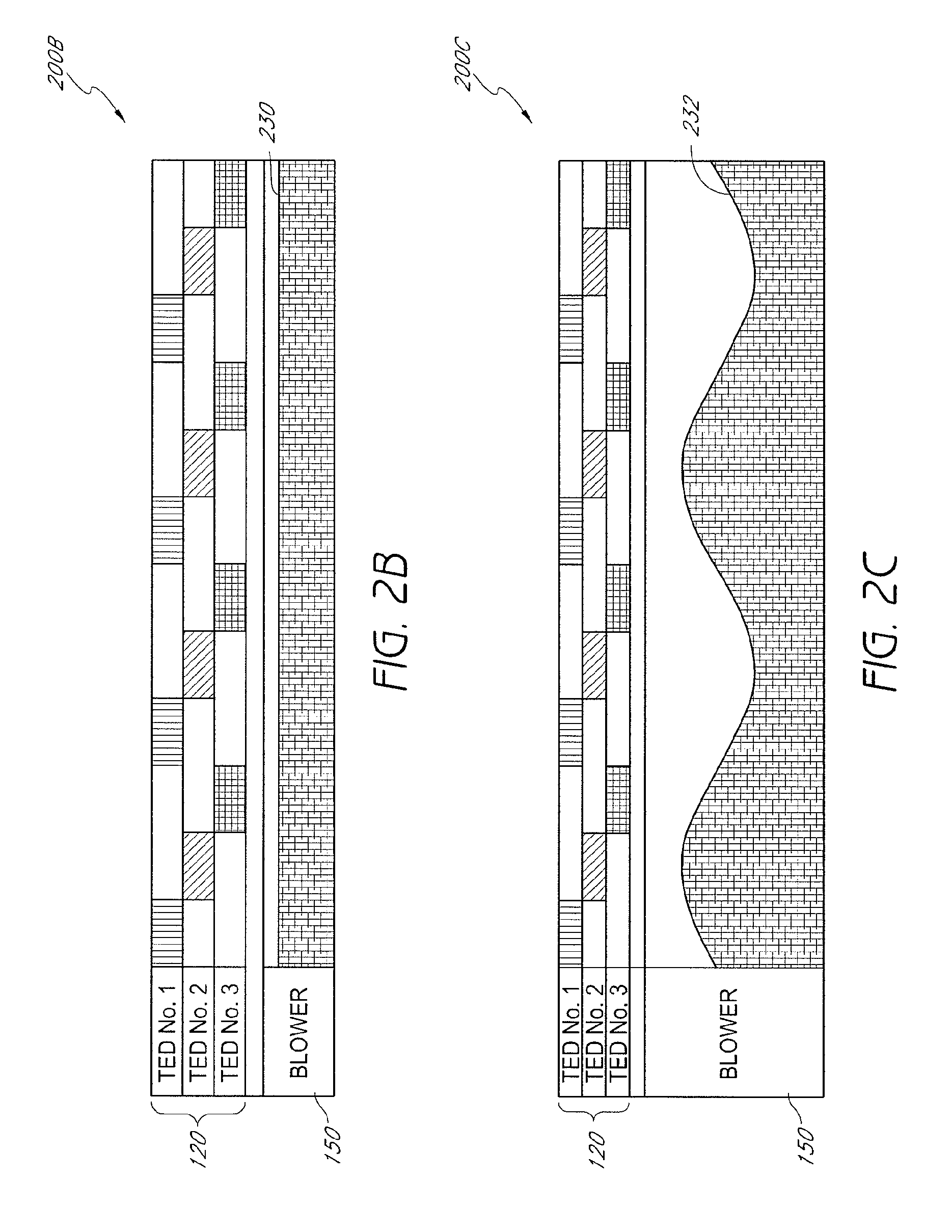
FIG. 2A schematically illustrates one embodiment of a scheme 200A for controlling the operation of the various components of a climate control system, including TEDs, other fluid modules, blowers and the like over a particular time period. In the depicted embodiment, the control system includes three TEDs 120 and one blower 150. During such an operational scheme 200A, the TEDs 120 can either be turned on or off. Further, the blower 150 can be operated at any one of a plurality of operational levels. Alternatively, the blower can be configured to operate at a constant speed (e.g., on/off operation). In FIG. 2A, the shaded regions indicate that the particular device is operating (or, in the case of a device capable of variable operational levels, the level at which the device is operating) and the white regions indicate that the particular device is not operating.
Thus, during the initial time period 250 in the illustrated embodiment, TED No. 1 is activated and TED Nos. 2 and 3 are deactivated. During that same time period, the blower 150 is delivering air to the climate control system at a relatively low rate (schematically represented by level 212).
With continued reference to FIG. 2A, during the next time interval 252, all three TEDs 120 are activated. In addition, the blower 150 is configured to deliver the maximum volume of air through the control system (schematically represented by operational level 214).
As schematically illustrated, TED Nos. 2 and 3 are configured to remain activated, and TED No. 1 is configured to be deactivated during the subsequent time period 254. Further, under this embodiment, the blower 214 continues to operate at the same level 214 as it did in the previous time interval 252. As shown in FIG. 2A, the operation of the TEDs 120 and the blower 150 can be varied from one time interval to the next. The operational characteristics of the TEDs 120 and/or the blower 150 can be modified (e.g., on/off, speed variation, etc.) in accordance with one or more desired control schemes.
Therefore, if the climate control system is similar to the embodiment illustrated in FIG. 1, the blower can continue to deliver air or other fluid past the TEDs 20 or other fluid modules even when the TEDs 20 are not activated (e.g., not electrically energized). Under such circumstances, fluid distributed through a fluid distribution device 40 may not be temperature conditioned (e.g., cooled or heated) if upstream TEDs 20 are deactivated. In other embodiments, the electrical current supplied to the TEDs 20 can be modulated, either in addition to or in lieu of simple TED activation/deactivation, in order to vary the extent to which air or other fluid is temperature conditioned. Consequently, the flow rate of fluid discharged from a particular fluid distribution device 40 towards a user can remain substantially constant even though the temperature of that fluid varies with time. In other arrangements, both the flow rate and the temperature of a fluid discharged from a fluid distribution device 40 can fluctuate, as TEDs 20 are activated/deactivated and the blower's capacity is modified.
The incorporation of such control schemes in climate control systems can help reduce energy consumption, as some TEDs 20 can be deactivated and/or turned down during certain time periods. In some embodiments, additional energy savings can be realized if the blowers 50 or other fluid delivery devices are configured for adjustable operation. Further, the capital costs and overall complexity of a climate control system can be reduced by utilizing a common header to deliver air or other fluid from a blower 50 to multiple fluid modules 20 (e.g., 20), as illustrated in the embodiment of FIG. 1. As a result, fewer blowers 50, electrical connections and the like may be needed.
FIG. 2B illustrates another embodiment of a scheme 200B for controlling the operation of a climate control system. As shown, the TEDs 120 are configured to turn on or off so that only a single TED 120 is operating at a time. Alternatively, the operational scheme can be configured so that two or more TEDs 120 operate simultaneously. In the illustrated embodiment, the TEDs 120 are configured to be switched on and off in a sequential, orderly pattern. However, the order in which TEDs 120 are activated and deactivated can vary. For example, TEDs 120 can be operated in accordance with a more random pattern.
With continued reference to FIG. 2B, the blower 150 is configured to operate at a constant operating level 230 (e.g., speed, output, etc.). Thus, the amount of air or other fluid being delivered to each TED 120, and consequently to each downstream fluid distribution device, can remain substantially constant. This can help provide a consistent feel and comfort level to users of climate control seating assemblies (e.g., chairs, beds, etc.), as the flow rate of air being discharged from a particular surface or user-interface location does not fluctuate. However, it will be appreciated that as TEDs 120 are activated and deactivated, the temperature of the discharged air or other fluid will vary.
According to certain preferred embodiments, schemes regulating the operation of the TEDs 120 and the blower 40 advantageously maintain a desired cooling or warming effect for the climate controlled seating assembly, while simultaneously reducing unnecessary energy consumption. This can help maintain a generally consistent power consumption rate during the operation of the TEDs 120, the blower 40 and any other components of a temperature conditioning system. Such a consistent power consumption rate can eliminate undesirable and potentially harmful spikes during the delivery of electrical energy. Further, such schemes can help maintain thermal inertia by allowing the temperature conditioning system to more quickly respond to desired temperature variations. In addition, the fairly constant volumetric delivery of conditioned and/or unconditioned air helps provide a more consistent feel to the occupant. Thus, the occupant is less likely to be disturbed or otherwise affected by a modulating flow rate and all the noticeable changes that accompany it (e.g., variations in sounds, feel, etc.).
In FIG. 2C, the control scheme 200C is configured to sequence the TEDs 120 between activated and deactivated positions similarly to the embodiment of FIG. 2B. However, in the illustrated arrangement, the control scheme 200C varies the operation (e.g., speed, flowrate, etc.) of the blower 150. As shown, the operation of the blower 150 follows a substantially sinusoidal pattern over time. Alternatively, the operation of the blower 150 can fluctuate in one or more other manners. For example, the speed and/or output of the blower 150 can follow a linear, non-linear, random, step-like or any other type of pattern. As discussed below, in some embodiments, the blower 150 can be controlled in response to one or more sensor measurements, an input from a user, a preprogrammed schedule, a mode change and/or the like.
With reference to FIG. 2D, the energy supplied to each TED can be varied according to a sinusoidal or other type of pattern (e.g., linear, non-linear, random, etc.). As shown, if the control scheme is configured to vary the energy (e.g., voltage) supplied to the TEDs according to a particular timing offset, the total amount of energy consumed by the TEDs can remain at a substantially constant level 270 over time. It will be appreciated that in other embodiments the total energy consumption of the TEDs can vary with time. As discussed above, there may be certain advantages associated with having a system that includes generally consistent power consumption and/or fluid flowrate characteristics.
According to certain embodiments, the operational scheme used to control the TEDs, blower and/or other components of a climate control system is based on a preprogrammed sequence. For example, the TEDs and blower can be configured to follow a particular time-based operational schedule, such as in the embodiments illustrated in FIGS. 2A-2D and discussed herein. Therefore, once such a sequence is activated, a climate control system can follow a predetermined pattern in which the operation of the TEDs and/or blowers is modified. In some embodiments, such a time-activated sequence is initiated and/or terminated by the pressing of a button or turning of a knob. However, one or more other methods of initiating such operational sequences can also be used. For example, the sequence can be commenced by manipulating a lever or by entering a command on using a keypad, keyboard, touch screen or other controller.
In other embodiments, an operational sequence is configured to automatically begin and/or end based on the time of day, a timer (e.g., elapsed time from a particular event or occurrence) or the like. In still other configurations, a particular operational scheme can be activated and/or deactivated using feedback received from one or more sensors. For example, a temperature sensor, humidity or dew point sensor, condensation sensor, motion sensor, pressure sensor or the like. For example, a pressure sensor can be used to detect the presence of an individual on or near a climate controlled seat assembly (e.g., chair, bed, etc.). Thus, such seating assemblies can be configured to function in a desired manner when a user triggers a sensor or other activation device. In another embodiment, a humidity sensor can adjust the operating parameters to avoid condensation in the TEDs during humid conditions. In another embodiment, a condensation sensor can be used to adjust the operating parameters if condensation is detected.
Moreover, the climate controlled seating assembly can be configured to function under two or more operational modes. For example, a climate controlled chair or bed can permit a user to select a level of cooling and/or heating (e.g., "Low-Medium-High", "1-2-3-4-5", etc.). Alternatively, seating assemblies can be configured with climate control systems that allow user to enter an actual temperature. In other embodiments, users can select a desired setting, temperature and/or other operational mode using a knob, lever, switch, keypad or the like. In still other arrangements, users are permitted to program an operational scheme for a climate controlled seating assembly that satisfies their unique preferences and/or requirements.
As discussed, control of the TEDs, blower and/or other components of the climate control system can be based, at least partially, on feedback received from one or more sensors. For example, a climate controlled seat, bed or the like can include one or more thermal sensors, optical sensors, motion sensors, audible sensors, pressure sensors and/or the like. In some embodiments, such sensors can be positioned on or near the climate controlled seat assembly to determine whether cooling and/or heating of the assembly is required or desired. For instance, thermal sensors can help determine if the temperature at a surface of the seat assembly is above or below a desired level. Alternatively, one or more thermal sensors can be positioned in or near a TED or fluid conduit to detect the temperature of the discharged fluid. In still other embodiments, temperature sensors can be used to detect the ambient temperature and the control system can be configured to activate the TEDs and/or blowers if the ambient temperature drops or rises below a predetermined temperature and/or a temperature setting determined by the user Likewise, pressure sensors can be configured to detect when a user has been in contact with a surface of a seat, bed or the like for a prolonged time period. Depending on their type, sensors can contact a portion of the seating assembly. In some embodiments, a sensor is located within and/or on the surface of the seating assembly. However, in other arrangements, the sensors are configured so they do not contact the seating assembly.
In some preferred embodiments, a control module is used to control the operation of the TEDs, blowers and/or other system components. Thus, a control module can be configured to execute a desired operational scheme as described herein. The control module can be configured to activate, deactivate and/or modulate the TEDs, blowers and the like. In addition, the control module can include connections to one or more sensors, user-interface devices (e.g., knobs, buttons, or other mode selection devices, keypads, etc.), timers and any other devices that are desirable or necessary for the proper execution of a particular operational scheme. Further, the control module can be adapted to cooperate and communicate with one or more other control systems, such as, for example, an automotive control panel or the like. Thus, a user can select a desired mode of operation directly from a car's dashboard or other instrument panel.
FIGS. 3A and 3B schematically illustrate one embodiment of a climate controlled bed 310 equipped with a control scheme as described herein. As shown, the climate controlled bed 310 comprises a single blower 350 and three TEDs 320. However, in other arrangements, the bed 310 can include more or fewer blowers 350 and TEDs 320, as desired. In some preferred embodiments, the climate controlled bed 310 is configured so that the blower 350, the TEDs 320, conduits 380, 382, 388, the control module (not shown) and any other components of the climate control system are conveniently positioned underneath the mattress, pad or other member on which users can be positioned. For example, such items can be positioned within a box spring or other interior portion of the bed 310 so they are not visible to users. In addition, the bed 310 preferably comprises an power source (e.g., power cord, battery, etc.) from which the various components (e.g., blower 350, TEDs 320, control module, etc.) can be electrically energized.
With continued reference to FIGS. 3A and 3B, the blower 350 can be configured to draw a volume of ambient air or other fluid and discharge it into a main discharge header 380. As illustrated, the bed 310 can include one or more openings 390 to permit fluid to enter the bed interior 316. Once air or other fluid has been delivered into the main discharge header 380, it can be directed to the various distribution branches 382. Although not shown, the main header 380 and/or the distribution branches 382 can include valves and/or other regulation devices to selective control the fluid flowrate and/or pressure to each TED 320 and fluid distribution device 340.
In the illustrated embodiment, air or other fluid diverted into each distribution branch 382 enters a TED 320 or other type of fluid conditioning module. As shown in FIG. 3B, fluid flowing through the TEDs 320 enters either a main discharge conduit 384 or a secondary discharge conduit 388. The TED 320 can be configured to either cool or heat the air entering the main discharge conduit 384. In the event a particular TED 320 is not activated, however, the air exiting into the main discharge conduit 384 will be approximately at the same temperature as the ambient air entering the blower. As discussed, whether a TED is activated or deactivated can depend on the particular operational scheme being used by the climate control system.
With continued reference to FIGS. 3A and 3B, air or other fluid directed into the main discharge conduit 384 can enter into a fluid distribution device 340, regardless of whether or not it was actually conditioned by a TED 320. In some embodiments, the fluid distribution device 340 comprises a plurality of openings 342 through which the air or other fluid exits. As illustrated in FIGS. 3A and 3B, air or other fluid discharged from the air distribution device 340 can contact and diffuse through a mattress 314, pad or other member. Preferably such a mattress 314, pad or other member can be configured to permit fluid discharged from the fluid distribution devices 340 to reach one or more of its exposed surfaces 312.
As illustrated, air or fluid discharged from the TED 320 into the secondary discharge conduit 388 can be collected into a common header and expelled from the bed 310 through one or more outlets 394.
A control scheme as described herein can be advantageously used to manage the operation of the three TEDs 320 and blower 350 depicted in FIGS. 3A and 3B. As discussed, such an operational scheme can be configured to sequence the TEDs 320 between activated and deactivated positions in order to reduce energy consumption. In other embodiments, the operational scheme is capable of modulating the TEDs 320 between minimum and maximum levels. Likewise, under certain arrangements, the control scheme can modulate the flowrate, speed and/or discharge pressure of the blower 350 within a desired range.
Consequently, air or other fluid can flow through the various fluid distribution devices 340 to the exposed surfaces 312 of the mattress 314, regardless of which TEDs 320 were activated or deactivated. Thus, a user can sense a consistent flow of air or other fluid when he or she is situated on the mattress 314. In some embodiments, the climate controlled bed 310 includes a switch, keypad or other user-interface device (not shown) to allow a user to adjust the target temperature, the mode of operation and/or any other setting related to the climate control system. Further, the bed 310 can include one or more sensors that can further enhance the function of the climate control system under certain operational schemes, as described above. For example, as described above, in one embodiment the bed 310 can include a temperature sensor positioned near the TEDs 310, within the distribution devices 340 and/or near the support surface of the mattress 314. A closed loop control routine can be provided for regulating the temperature of the air provided by the TEDs to a predetermined and/or user selected temperature. In another embodiment (or in combination with the previous embodiment), the closed loop control routine can be configured to regulate the temperature of the air provided by the TED in response to measure of the ambient temperature. In another modification, the control system can be configured to deactivate the blower and/or the TEDs after a user selected or predetermined amount of time.
FIGS. 4 and 5 illustrate two different embodiments of climate-controlled beds having distinct zones or sections. Such schemes can provide enhanced cooling and/or heating control to certain portions of the bed. Consequently, a user can customize a temperature-conditioning effect to his or her liking. For example, a user can choose to provide more or less cooling or heating to a particular zone or section. Further, such embodiments permit each occupant (e.g., in a dual occupant bed) of a single bed to select a desired level of cooling and/or heating.
In FIG. 4, the illustrated bed 110 includes six different cooling and/or heating zones 412A-F. For clarity, the vast majority of a top member or pad 480 has been removed to reveal the distribution system 470A-F positioned below the pad 480. Each zone 412A-F includes its own flow thermoelectric device (not shown) such that each distribution system can be associated with its own thermoelectric device. In addition, each flow distribution system 470A-F can be configured to receive conditioned (e.g., heated and/or cooled) or unconditioned (e.g., ambient) air or other fluid from one or more fluid transfer devices (not shown). In some embodiments, the air or other fluid delivered by the fluid transfer devices can be routed through, past or in the vicinity of one or more thermoelectric devices to selectively temperature condition the air or other fluid.
With continued reference to FIG. 4, the distribution system 470A-F used in each zone 412A-F is substantially identical in size and shape. However, it will be appreciated that the shape, size, air distribution effect and/or characteristics of the distribution systems 470A-F used within a particular bed 110 can vary, as desired or required by a particular application. In FIG. 5, the flow distribution systems 470A-F are generally positioned where the bed's occupants are most likely to be situated. Thus, depending on the size of the bed, the number of occupants it is intended to hold and/or the like, the number, shape, size, spacing, location and other characteristics of the flow conditioning members 470A-F can vary.
The embodiment of the climate-controlled bed 210 illustrated in FIG. 5 includes only four cooling and/or heating zones 512A-D. As shown, each zone comprises a flow distribution member 570A-D. However, unlike the flow distribution members 470A-F discussed and illustrated with reference to FIG. 4, these flow distribution members 570A-D vary from zone to zone. For example, the flow conditioning members 570A, 570B located in zones 512A, 512B on one end of the bed 510 are larger in surface area than the flow conditioning members 570C, 570D in the other two zones 512C, 512D. As discussed, such a scheme can be used when a higher volume of conditioned fluid is desired in selected zones (e.g., 512A and 512B). Flow distribution members 570A, 570B that require additional volumetric flow and/or better temperature-conditioning abilities can be supplied by additional fluid transfer devices and/or thermoelectric devices.
Additional details and/or embodiments of a climate controlled bed that can be used in combination, sub-combination or as replacement of a certain features are disclosed in U.S. patent application Ser. No. 11/872,657, filed Oct. 15, 2008 and published as No. 2008-0148481 on Jun. 26, 2008, the entire contents of which are hereby incorporated by reference herein.
FIG. 6 illustrates another embodiment of a climate controlled bed 600. In this embodiment, the bed 600 includes a first side 602 and a second side 604. Each side of the bed can be associated with a set of thermoelectric devices 606, 608. In other embodiment, more or less than two thermoelectric devices can be associated with each zone. Air can be supplied to the thermoelectric devices through a distribution header and then from the thermoelectric devices through a distribution system and air permeable pad as described above. In one embodiment, each side 602, 604 of the bed has a separate distribution system.
The thermoelectric devices 606, 608 can be operatively coupled to a control module 610, which can also be operatively coupled to a blower (not shown) The control module 610 can in turn be operatively coupled to a first and second input device 612, 614. Thus, in one embodiment, a user can input a temperature or conditioning setting for each side of the bed 600 using the input devices 612. In other embodiments, the input devices 612 can be combined into a single device with, for example, different modes.
In one embodiment, the control module 610 is configured for open loop operation which based upon the settings from the input devices the control module 610 operates the TEDs 606, 608 and/or blowers according to a predetermined setting or control routine. In another embodiment, temperature sensors 616 can be provided for detecting the temperature of the air delivered by the TEDs 606, 608 and/or ambient temperature. In such embodiments, the temperature measured by the sensors 616 can be used as a fail safe and/or as part of a closed loop control routine. In one modified arrangement, the control module 610 can be configured to shut off the TEDs and/or blowers after a predetermined amount of time and/or after an amount of time inputted by the user through the input devices 612, 614.
FIG. 6 also illustrates a power supply 618 that can be coupled to the control module. In one embodiment, a single box or housing 620 contains the power supply 618 and the control module 610.
To assist in the description of the disclosed embodiments, words such as upward, upper, downward, lower, vertical, horizontal, upstream, and downstream have and used above to describe the accompanying figures. It will be appreciated, however, that the illustrated embodiments can be located and oriented in a variety of desired positions.
In addition, in the description above, various components are described as being "coupled" together or "operatively coupled" together. It is to be understand that these are intended to be broad terms that includes components that are directly or indirectly connected to each other and/or connected to each other through one or more intermediate members. In addition, with respect to electrical components, the components can be electrically connected directly or indirectly through intermediate components and/or wirelessly (e.g., through IR or other wireless transmission devices.
Although these inventions have been disclosed in the context of certain preferred embodiments and examples, it will be understood by those skilled in the art that the present inventions extend beyond the specifically disclosed embodiments to other alternative embodiments and/or uses of the inventions and obvious modifications and equivalents thereof. In addition, while a number of variations of the inventions have been shown and described in detail, other modifications, which are within the scope of these inventions, will be readily apparent to those of skill in the art based upon this disclosure. It is also contemplated that various combinations or subcombinations of the specific features and aspects of the embodiments may be made and still fall within the scope of the inventions. Accordingly, it should be understood that various features and aspects of the disclosed embodiments can be combine with or substituted for one another in order to form varying modes of the disclosed inventions. Thus, it is intended that the scope of the present inventions herein disclosed should not be limited by the particular disclosed embodiments described above, but should be determined only by a fair reading of the claims that follow.
* * * * *
References
D00000
D00001
D00002
D00003
D00004
D00005
D00006
D00007
XML
uspto.report is an independent third-party trademark research tool that is not affiliated, endorsed, or sponsored by the United States Patent and Trademark Office (USPTO) or any other governmental organization. The information provided by uspto.report is based on publicly available data at the time of writing and is intended for informational purposes only.
While we strive to provide accurate and up-to-date information, we do not guarantee the accuracy, completeness, reliability, or suitability of the information displayed on this site. The use of this site is at your own risk. Any reliance you place on such information is therefore strictly at your own risk.
All official trademark data, including owner information, should be verified by visiting the official USPTO website at www.uspto.gov. This site is not intended to replace professional legal advice and should not be used as a substitute for consulting with a legal professional who is knowledgeable about trademark law.