Endoscopic surgical clip applier
Czernik , et al. December 15, 2
U.S. patent number 10,863,992 [Application Number 16/030,926] was granted by the patent office on 2020-12-15 for endoscopic surgical clip applier. This patent grant is currently assigned to Covidien LP. The grantee listed for this patent is Covidien LP. Invention is credited to Jacob C. Baril, Brian J. Creston, Roman Czernik, Thomas A. Zammataro.


| United States Patent | 10,863,992 |
| Czernik , et al. | December 15, 2020 |
Endoscopic surgical clip applier
Abstract
A shaft assembly of an apparatus for applying surgical clips to body tissue includes an elongated spindle, a trip block reciprocally supported on a proximal portion of the spindle, a biasing member extending between the proximal portion of the spindle and the trip block, and a pusher bar having a proximal portion fixedly coupled to the trip block. The pusher bar has a distal portion configured to load a distal-most surgical clip into a pair of jaws during distal movement of the trip block, via distal movement of the spindle, and remain in a distally advanced position during an approximation of the pair of jaws.
| Inventors: | Czernik; Roman (Trumbull, CT), Creston; Brian J. (West Haven, CT), Baril; Jacob C. (White Plains, NY), Zammataro; Thomas A. (Hamden, CT) | ||||||||||
|---|---|---|---|---|---|---|---|---|---|---|---|
| Applicant: |
|
||||||||||
| Assignee: | Covidien LP (Mansfield,
MA) |
||||||||||
| Family ID: | 1000005242079 | ||||||||||
| Appl. No.: | 16/030,926 | ||||||||||
| Filed: | July 10, 2018 |
Prior Publication Data
| Document Identifier | Publication Date | |
|---|---|---|
| US 20190046207 A1 | Feb 14, 2019 | |
Related U.S. Patent Documents
| Application Number | Filing Date | Patent Number | Issue Date | ||
|---|---|---|---|---|---|
| 62542325 | Aug 8, 2017 | ||||
| Current U.S. Class: | 1/1 |
| Current CPC Class: | A61B 34/35 (20160201); A61B 17/1285 (20130101); A61B 34/37 (20160201); A61B 2090/034 (20160201); A61B 2017/0046 (20130101); A61B 2017/00367 (20130101); A61B 2034/301 (20160201); A61B 2017/00477 (20130101) |
| Current International Class: | A61B 17/128 (20060101); A61B 34/35 (20160101); A61B 17/00 (20060101); A61B 90/00 (20160101); A61B 34/37 (20160101); A61B 34/30 (20160101) |
References Cited [Referenced By]
U.S. Patent Documents
| 3120230 | February 1964 | Skold |
| 3638847 | February 1972 | Noiles et al. |
| 3735762 | May 1973 | Bryan et al. |
| 4226242 | October 1980 | Jarvik |
| 4242902 | January 1981 | Green |
| 4296751 | October 1981 | Blake, III et al. |
| 4372316 | February 1983 | Blake, III et al. |
| 4408603 | October 1983 | Blake, III et al. |
| 4418694 | December 1983 | Beroff et al. |
| 4471780 | September 1984 | Menges et al. |
| 4480640 | November 1984 | Becht |
| 4480641 | November 1984 | Failla et al. |
| 4487204 | December 1984 | Hrouda |
| 4487205 | December 1984 | Di Giovanni et al. |
| 4491133 | January 1985 | Menges et al. |
| 4492232 | January 1985 | Green |
| 4498476 | February 1985 | Cerwin et al. |
| 4500024 | February 1985 | DiGiovanni et al. |
| 4509518 | April 1985 | McGarry et al. |
| 4512345 | April 1985 | Green |
| 4522207 | June 1985 | Klieman et al. |
| 4532925 | August 1985 | Blake, III |
| 4534351 | August 1985 | Rothfuss et al. |
| 4545377 | October 1985 | Cerwin et al. |
| 4549544 | October 1985 | Favaron |
| 4556058 | December 1985 | Green |
| 4557263 | December 1985 | Green |
| 4562839 | January 1986 | Blake, III et al. |
| 4572183 | February 1986 | Juska |
| 4576165 | March 1986 | Green et al. |
| 4576166 | March 1986 | Montgomery et al. |
| 4590937 | May 1986 | Deniega |
| 4598711 | July 1986 | Deniega |
| 4602631 | July 1986 | Funatsu |
| 4611595 | September 1986 | Klieman et al. |
| 4612932 | September 1986 | Caspar et al. |
| 4616650 | October 1986 | Green et al. |
| 4616651 | October 1986 | Golden |
| 4624254 | November 1986 | McGarry et al. |
| 4637395 | January 1987 | Caspar et al. |
| 4646740 | March 1987 | Peters et al. |
| 4647504 | March 1987 | Kimimura et al. |
| 4658822 | April 1987 | Kees, Jr. |
| 4660558 | April 1987 | Kees, Jr. |
| 4662373 | May 1987 | Montgomery et al. |
| 4662374 | May 1987 | Blake, III |
| 4671278 | June 1987 | Chin |
| 4671282 | June 1987 | Tretbar |
| 4674504 | June 1987 | Klieman et al. |
| 4681107 | July 1987 | Kees, Jr. |
| 4696396 | September 1987 | Samuels |
| 4702247 | October 1987 | Blake, III et al. |
| 4706668 | November 1987 | Backer |
| 4712549 | December 1987 | Peters et al. |
| 4726372 | February 1988 | Perlin |
| 4733664 | March 1988 | Kirsch et al. |
| 4733666 | March 1988 | Mercer, Jr. |
| 4759364 | July 1988 | Boebel |
| 4765335 | August 1988 | Schmidt et al. |
| 4777949 | October 1988 | Perlin |
| 4777950 | October 1988 | Kees, Jr. |
| 4796625 | January 1989 | Kees, Jr. |
| 4799481 | January 1989 | Transue et al. |
| 4815466 | March 1989 | Perlin |
| 4817604 | April 1989 | Smith, III |
| 4821721 | April 1989 | Chin et al. |
| 4822348 | April 1989 | Casey |
| 4827930 | May 1989 | Kees, Jr. |
| 4834096 | May 1989 | Oh et al. |
| 4850355 | July 1989 | Brooks et al. |
| 4854317 | August 1989 | Braun |
| 4856517 | August 1989 | Collins et al. |
| 4929239 | May 1990 | Braun |
| 4929240 | May 1990 | Kirsch et al. |
| 4931058 | June 1990 | Cooper |
| 4932955 | June 1990 | Merz et al. |
| 4934364 | June 1990 | Green |
| 4943298 | July 1990 | Fujita et al. |
| 4957500 | September 1990 | Liang et al. |
| 4966603 | October 1990 | Focelle et al. |
| 4967949 | November 1990 | Sandhaus |
| 4983176 | January 1991 | Cushman et al. |
| 4988355 | January 1991 | Leveen et al. |
| 5002552 | March 1991 | Casey |
| 5026379 | June 1991 | Yoon |
| 5030224 | July 1991 | Wright et al. |
| 5030226 | July 1991 | Green et al. |
| 5032127 | July 1991 | Frazee et al. |
| 5035692 | July 1991 | Lyon et al. |
| 5047038 | September 1991 | Peters et al. |
| 5049152 | September 1991 | Simon et al. |
| 5049153 | September 1991 | Nakao et al. |
| 5053045 | October 1991 | Schmidt et al. |
| 5059202 | October 1991 | Liang et al. |
| 5062846 | November 1991 | Oh et al. |
| 5078731 | January 1992 | Hayhurst |
| 5084057 | January 1992 | Green et al. |
| 5100416 | March 1992 | Oh et al. |
| 5100420 | March 1992 | Green et al. |
| 5104394 | April 1992 | Knoepfler |
| 5104395 | April 1992 | Thornton et al. |
| 5112343 | May 1992 | Thornton |
| 5122150 | June 1992 | Puig |
| 5127915 | July 1992 | Mattson |
| 5129885 | July 1992 | Green et al. |
| 5156608 | October 1992 | Troidl et al. |
| 5160339 | November 1992 | Chen et al. |
| 5163945 | November 1992 | Ortiz et al. |
| 5171247 | December 1992 | Hughett et al. |
| 5171249 | December 1992 | Stefanchik et al. |
| 5171250 | December 1992 | Yoon |
| 5171251 | December 1992 | Bregen et al. |
| 5171252 | December 1992 | Friedland |
| 5171253 | December 1992 | Klieman |
| 5192288 | March 1993 | Thompson et al. |
| 5197970 | March 1993 | Green et al. |
| 5199566 | April 1993 | Ortiz et al. |
| 5201746 | April 1993 | Shichman |
| 5201900 | April 1993 | Nardella |
| 5207691 | May 1993 | Nardella |
| 5207692 | May 1993 | Kraus et al. |
| 5217473 | June 1993 | Yoon |
| 5219353 | June 1993 | Garvey, III et al. |
| 5246450 | September 1993 | Thornton et al. |
| 5269792 | December 1993 | Kovac et al. |
| 5281228 | January 1994 | Wolfson |
| 5282807 | February 1994 | Knoepfler |
| 5282808 | February 1994 | Kovac et al. |
| 5282832 | February 1994 | Toso et al. |
| 5289963 | March 1994 | McGarry et al. |
| 5290299 | March 1994 | Fain et al. |
| 5300081 | April 1994 | Young et al. |
| 5304183 | April 1994 | Gourlay et al. |
| 5306280 | April 1994 | Bregen et al. |
| 5306283 | April 1994 | Conners |
| 5312426 | May 1994 | Segawa et al. |
| 5330442 | July 1994 | Green et al. |
| 5330487 | July 1994 | Thornton et al. |
| 5340360 | August 1994 | Stefanchik |
| 5342373 | August 1994 | Stefanchik et al. |
| 5354304 | October 1994 | Allen et al. |
| 5354306 | October 1994 | Garvey, III et al. |
| 5356064 | October 1994 | Green et al. |
| 5359993 | November 1994 | Slater et al. |
| 5366458 | November 1994 | Korthoff et al. |
| 5366459 | November 1994 | Yoon |
| 5368600 | November 1994 | Failla et al. |
| 5382253 | January 1995 | Hogendijk |
| 5382254 | January 1995 | McGarry et al. |
| 5382255 | January 1995 | Castro et al. |
| 5383881 | January 1995 | Green et al. |
| 5395375 | March 1995 | Turkel et al. |
| 5395381 | March 1995 | Green et al. |
| 5403327 | April 1995 | Thornton et al. |
| 5409498 | April 1995 | Braddock et al. |
| 5413584 | May 1995 | Schulze |
| 5423835 | June 1995 | Green et al. |
| 5425740 | June 1995 | Hutchinson, Jr. |
| 5431667 | July 1995 | Thompson et al. |
| 5431668 | July 1995 | Burbank, III et al. |
| 5431669 | July 1995 | Thompson et al. |
| 5439468 | August 1995 | Schulze et al. |
| 5441509 | August 1995 | Vidal et al. |
| 5447513 | September 1995 | Davison et al. |
| 5448042 | September 1995 | Robinson et al. |
| 5449365 | September 1995 | Green et al. |
| 5462555 | October 1995 | Bolanos et al. |
| 5462558 | October 1995 | Kolesa et al. |
| 5464416 | November 1995 | Steckel |
| 5474566 | December 1995 | Alesi et al. |
| 5474567 | December 1995 | Stefanchik et al. |
| 5474572 | December 1995 | Hayhurst |
| 5487746 | January 1996 | Yu et al. |
| 5501693 | March 1996 | Gravener |
| 5509920 | April 1996 | Phillips et al. |
| 5514149 | May 1996 | Green et al. |
| 5520701 | May 1996 | Lerch |
| 5522823 | June 1996 | Kuntz et al. |
| 5527318 | June 1996 | McGarry |
| 5527319 | June 1996 | Green et al. |
| 5527320 | June 1996 | Carruthers et al. |
| 5542949 | August 1996 | Yoon |
| 5547474 | August 1996 | Kloeckl et al. |
| 5562655 | October 1996 | Mittelstadt et al. |
| 5569274 | October 1996 | Rapacki et al. |
| 5571121 | November 1996 | Heifetz |
| 5575802 | November 1996 | McQuilkin et al. |
| 5582615 | December 1996 | Foshee et al. |
| 5584840 | December 1996 | Ramsey et al. |
| 5591178 | January 1997 | Green et al. |
| 5593414 | January 1997 | Shipp et al. |
| 5593421 | January 1997 | Bauer |
| 5601573 | February 1997 | Fogelberg et al. |
| 5601574 | February 1997 | Stefanchik et al. |
| 5607436 | March 1997 | Pratt et al. |
| 5618291 | April 1997 | Thompson et al. |
| 5618306 | April 1997 | Roth et al. |
| 5620452 | April 1997 | Yoon |
| 5626585 | May 1997 | Mittelstadt et al. |
| 5626586 | May 1997 | Pistl et al. |
| 5626592 | May 1997 | Phillips et al. |
| RE35525 | June 1997 | Stefanchik et al. |
| 5634930 | June 1997 | Thornton et al. |
| 5643291 | July 1997 | Pier et al. |
| 5645551 | July 1997 | Green et al. |
| 5645553 | July 1997 | Kolesa et al. |
| 5649937 | July 1997 | Bito et al. |
| 5653720 | August 1997 | Johnson et al. |
| 5662676 | September 1997 | Koninckx |
| 5662679 | September 1997 | Voss et al. |
| 5665097 | September 1997 | Baker et al. |
| 5676676 | October 1997 | Porter |
| 5681330 | October 1997 | Hughett et al. |
| 5683405 | November 1997 | Yacoubian et al. |
| 5695502 | December 1997 | Pier et al. |
| 5695505 | December 1997 | Yoon |
| 5697938 | December 1997 | Jensen et al. |
| 5697942 | December 1997 | Palti |
| 5700270 | December 1997 | Peyser et al. |
| 5700271 | December 1997 | Whitfield et al. |
| 5702048 | December 1997 | Eberlin |
| 5709706 | January 1998 | Kienzle et al. |
| 5713911 | February 1998 | Racenet et al. |
| 5713912 | February 1998 | Porter |
| 5720756 | February 1998 | Green et al. |
| 5722982 | March 1998 | Ferreira et al. |
| 5725537 | March 1998 | Green et al. |
| 5725538 | March 1998 | Green et al. |
| 5725542 | March 1998 | Yoon |
| 5733295 | March 1998 | Back et al. |
| 5743310 | April 1998 | Moran |
| 5755726 | May 1998 | Pratt et al. |
| 5766189 | June 1998 | Matsuno |
| 5769857 | June 1998 | Reztzov et al. |
| 5772673 | June 1998 | Cuny et al. |
| 5776146 | July 1998 | Sackier et al. |
| 5776147 | July 1998 | Dolendo |
| 5779718 | July 1998 | Green et al. |
| 5779720 | July 1998 | Walder-Utz et al. |
| 5782844 | July 1998 | Yoon et al. |
| 5788698 | August 1998 | Savornin |
| 5792149 | August 1998 | Sheds et al. |
| 5792150 | August 1998 | Pratt et al. |
| 5797922 | August 1998 | Hessel et al. |
| 5810853 | September 1998 | Yoon |
| 5817116 | October 1998 | Takahashi et al. |
| 5827306 | October 1998 | Yoon |
| 5833695 | November 1998 | Yoon |
| 5833696 | November 1998 | Whitfield et al. |
| 5833700 | November 1998 | Fogelberg et al. |
| 5843097 | December 1998 | Mayenberger et al. |
| 5843101 | December 1998 | Fry |
| 5846255 | December 1998 | Casey |
| 5849019 | December 1998 | Yoon |
| 5858018 | January 1999 | Shipp et al. |
| 5861005 | January 1999 | Kontos |
| 5868759 | February 1999 | Peyser et al. |
| 5868761 | February 1999 | Nicholas et al. |
| 5876410 | March 1999 | Petillo |
| 5895394 | April 1999 | Kienzle et al. |
| 5897565 | April 1999 | Foster |
| 5904693 | May 1999 | Dicesare et al. |
| 5913862 | June 1999 | Ramsey et al. |
| 5913876 | June 1999 | Taylor et al. |
| 5918791 | July 1999 | Sorrentino et al. |
| 5921991 | July 1999 | Whitehead et al. |
| 5921996 | July 1999 | Sherman |
| 5921997 | July 1999 | Fogelberg et al. |
| 5928251 | July 1999 | Aranyi |
| 5938667 | August 1999 | Peyser et al. |
| 5951574 | September 1999 | Stefarichik et al. |
| 5972003 | October 1999 | Rousseau et al. |
| 5976159 | November 1999 | Bolduc et al. |
| 5993465 | November 1999 | Shipp et al. |
| 6004335 | December 1999 | Vaitekunas et al. |
| 6017358 | January 2000 | Yoon et al. |
| 6044971 | April 2000 | Esposito et al. |
| 6053908 | April 2000 | Crainich et al. |
| RE36720 | May 2000 | Green et al. |
| 6059799 | May 2000 | Aranyi et al. |
| 6099536 | August 2000 | Petillo |
| 6099537 | August 2000 | Sugai et al. |
| 6139555 | October 2000 | Hart et al. |
| 6210418 | April 2001 | Storz et al. |
| 6217590 | April 2001 | Levinson |
| 6228097 | May 2001 | Levinson et al. |
| 6241740 | June 2001 | Davis et al. |
| 6258105 | July 2001 | Hart et al. |
| 6261302 | July 2001 | Voegele et al. |
| 6273898 | August 2001 | Kienzle et al. |
| 6277131 | August 2001 | Kalikow |
| 6306149 | October 2001 | Meade |
| 6318619 | November 2001 | Lee |
| 6322571 | November 2001 | Adams |
| 6350269 | February 2002 | Shipp et al. |
| 6352541 | March 2002 | Kienzle et al. |
| 6391035 | May 2002 | Appleby et al. |
| 6423079 | July 2002 | Blake, III |
| 6428548 | August 2002 | Durgin et al. |
| 6440144 | August 2002 | Bacher |
| 6461363 | October 2002 | Gadberry et al. |
| 6464710 | October 2002 | Foster |
| 6494886 | December 2002 | Wilk et al. |
| 6517536 | February 2003 | Hooven et al. |
| 6520972 | February 2003 | Peters |
| 6527786 | March 2003 | Davis et al. |
| 6537289 | March 2003 | Kayan et al. |
| 6546935 | April 2003 | Hooven |
| 6551333 | April 2003 | Kuhns et al. |
| 6569171 | May 2003 | DeGuillebon et al. |
| 6579304 | June 2003 | Hart et al. |
| 6599298 | July 2003 | Forster et al. |
| 6602252 | August 2003 | Mollenauer |
| 6607540 | August 2003 | Shipp |
| 6613060 | September 2003 | Adams et al. |
| 6626916 | September 2003 | Yeung et al. |
| 6626922 | September 2003 | Hart et al. |
| 6648898 | November 2003 | Baxter |
| 6652538 | November 2003 | Kayan et al. |
| 6652539 | November 2003 | Shipp et al. |
| 6673083 | January 2004 | Kayan et al. |
| 6676659 | January 2004 | Hutchins et al. |
| 6679894 | January 2004 | Damarati |
| RE38445 | February 2004 | Pistl et al. |
| 6695854 | February 2004 | Kayan et al. |
| 6706057 | March 2004 | Bidoia et al. |
| 6716226 | April 2004 | Sixto, Jr. et al. |
| 6723109 | April 2004 | Solingen |
| 6743240 | June 2004 | Smith et al. |
| 6773438 | August 2004 | Knodel et al. |
| 6773440 | August 2004 | Gannoe et al. |
| 6776783 | August 2004 | Frantzen et al. |
| 6776784 | August 2004 | Ginn |
| 6780195 | August 2004 | Porat |
| 6793663 | September 2004 | Kneifel et al. |
| 6793664 | September 2004 | Mazzocchi et al. |
| 6802848 | October 2004 | Anderson et al. |
| 6814742 | November 2004 | Kimura et al. |
| 6818009 | November 2004 | Hart et al. |
| 6821273 | November 2004 | Mollenauer |
| 6821284 | November 2004 | Sturtz et al. |
| 6824547 | November 2004 | Wilson, Jr. et al. |
| 6824548 | November 2004 | Smith et al. |
| 6835199 | December 2004 | McGuckin, Jr. et al. |
| 6835200 | December 2004 | Laufer et al. |
| 6837893 | January 2005 | Miller |
| 6837894 | January 2005 | Pugsley, Jr. et al. |
| 6837895 | January 2005 | Mayenberger |
| 6840945 | January 2005 | Manetakis et al. |
| 6843794 | January 2005 | Sixto, Jr. et al. |
| 6849078 | February 2005 | Durgin et al. |
| 6849079 | February 2005 | Blake, III et al. |
| 6853879 | February 2005 | Sunaoshi |
| 6869435 | March 2005 | Blake, III |
| 6869436 | March 2005 | Wendlandt |
| 6889116 | May 2005 | Jinno |
| 6896682 | May 2005 | McClellan et al. |
| 6905503 | June 2005 | Gifford, III et al. |
| 6911032 | June 2005 | Jugenheimer et al. |
| 6911033 | June 2005 | de Guillebon et al. |
| 6913607 | July 2005 | Ainsworth et al. |
| 6916327 | July 2005 | Northrup, III et al. |
| 6923818 | August 2005 | Muramatsu et al. |
| 6939356 | September 2005 | Debbas |
| 6942674 | September 2005 | Belef et al. |
| 6942676 | September 2005 | Buelna |
| 6945978 | September 2005 | Hyde |
| 6945979 | September 2005 | Kortenbach et al. |
| 6949107 | September 2005 | McGuckin, Jr. et al. |
| 6953465 | October 2005 | Dieck et al. |
| 6955643 | October 2005 | Gellman et al. |
| 6959852 | November 2005 | Shelton, IV et al. |
| 6960218 | November 2005 | Rennich |
| 6960221 | November 2005 | Ho et al. |
| 6962594 | November 2005 | Thevenet |
| 6963792 | November 2005 | Green |
| 6964363 | November 2005 | Wales et al. |
| 6964668 | November 2005 | Modesitt et al. |
| 6966875 | November 2005 | Longobardi |
| 6966917 | November 2005 | Suyker et al. |
| 6966919 | November 2005 | Sixto, Jr. et al. |
| 6969391 | November 2005 | Gazzani |
| 6972023 | December 2005 | Whayne et al. |
| 6972027 | December 2005 | Fallin et al. |
| 6973770 | December 2005 | Schnipke et al. |
| 6974462 | December 2005 | Sater |
| 6974466 | December 2005 | Ahmed et al. |
| 6974475 | December 2005 | Wall |
| 6981505 | January 2006 | Krause et al. |
| 6981628 | January 2006 | Wales |
| 6991635 | January 2006 | Takamoto et al. |
| 7052504 | May 2006 | Hughett |
| 7056330 | June 2006 | Gayton |
| 7108703 | September 2006 | Danitz et al. |
| 7144402 | December 2006 | Kuester, III |
| 7175648 | February 2007 | Nakao |
| 7179265 | February 2007 | Manetakis et al. |
| 7207997 | April 2007 | Shipp et al. |
| 7211091 | May 2007 | Fowler et al. |
| 7211092 | May 2007 | Hughett |
| 7214230 | May 2007 | Brock et al. |
| 7214232 | May 2007 | Bowman et al. |
| 7223271 | May 2007 | Muramatsu et al. |
| 7223272 | May 2007 | Francese et al. |
| 7232445 | June 2007 | Kortenbach et al. |
| 7261724 | August 2007 | Molitor et al. |
| 7261725 | August 2007 | Binmoeller |
| 7264625 | September 2007 | Buncke |
| 7288098 | October 2007 | Huitema et al. |
| 7297149 | November 2007 | Vitali et al. |
| 7316693 | January 2008 | Viola |
| 7316696 | January 2008 | Wilson, Jr. et al. |
| 7320692 | January 2008 | Bender et al. |
| 7326223 | February 2008 | Wilson, Jr. |
| 7329266 | February 2008 | Royse et al. |
| 7331968 | February 2008 | Arp et al. |
| 7338503 | March 2008 | Rosenberg et al. |
| 7344544 | March 2008 | Bender et al. |
| 7357805 | April 2008 | Masuda et al. |
| 7357806 | April 2008 | Rivera et al. |
| 7407074 | August 2008 | Ortiz et al. |
| 7419495 | September 2008 | Menn et al. |
| 7431724 | October 2008 | Manetakis et al. |
| 7458978 | December 2008 | Bender et al. |
| 7473258 | January 2009 | Clauson et al. |
| 7485124 | February 2009 | Kuhns et al. |
| 7510562 | March 2009 | Lindsay |
| 7585304 | September 2009 | Hughett |
| 7637917 | December 2009 | Whitfield et al. |
| 7695482 | April 2010 | Viola |
| 7717926 | May 2010 | Whitfield et al. |
| 7819886 | October 2010 | Whitfield et al. |
| 7905890 | March 2011 | Whitfield et al. |
| 7988027 | August 2011 | Olson et al. |
| 8011550 | September 2011 | Aranyi et al. |
| 8011555 | September 2011 | Tarinelli et al. |
| 8016178 | September 2011 | Olson et al. |
| 8021375 | September 2011 | Aldrich et al. |
| 8021378 | September 2011 | Sixto, Jr. et al. |
| 8048088 | November 2011 | Green et al. |
| 8056565 | November 2011 | Zergiebel |
| 8070760 | December 2011 | Fujita |
| 8075571 | December 2011 | Vitali et al. |
| 8083668 | December 2011 | Durgin et al. |
| 8088061 | January 2012 | Wells et al. |
| 8091755 | January 2012 | Kayan et al. |
| 8128643 | March 2012 | Aranyi et al. |
| 8142451 | March 2012 | Boulnois et al. |
| 8157149 | April 2012 | Olson et al. |
| 8157151 | April 2012 | Ingmanson et al. |
| 8216257 | July 2012 | Huitema et al. |
| 8236012 | August 2012 | Molitor et al. |
| 8246634 | August 2012 | Huitema et al. |
| 8246635 | August 2012 | Huitema |
| 8262679 | September 2012 | Nguyen |
| 8267944 | September 2012 | Sorrentino et al. |
| 8267945 | September 2012 | Nguyen et al. |
| 8267946 | September 2012 | Whitfield et al. |
| 8282655 | October 2012 | Whitfield et al. |
| 8328822 | December 2012 | Huitema et al. |
| 8336556 | December 2012 | Zergiebel |
| 8348130 | January 2013 | Shah et al. |
| 8357171 | January 2013 | Whitfield et al. |
| 8371491 | February 2013 | Huitema et al. |
| 8382773 | February 2013 | Whitfield et al. |
| 8403138 | March 2013 | Weisshaupt et al. |
| 8403945 | March 2013 | Whitfield et al. |
| 8403946 | March 2013 | Whitfield et al. |
| 8409222 | April 2013 | Whitfield et al. |
| 8409223 | April 2013 | Sorrentino et al. |
| 8419752 | April 2013 | Sorrentino et al. |
| 8430892 | April 2013 | Bindra et al. |
| 8444660 | May 2013 | Adams et al. |
| 8465502 | June 2013 | Zergiebel |
| 8475473 | July 2013 | Vandenbroek et al. |
| 8480688 | July 2013 | Boulnois et al. |
| 8486091 | July 2013 | Sorrentino et al. |
| 8491608 | July 2013 | Sorrentino et al. |
| 8496673 | July 2013 | Nguyen et al. |
| 8506580 | August 2013 | Zergiebel et al. |
| 8512357 | August 2013 | Viola |
| 8523882 | September 2013 | Huitema et al. |
| 8529585 | September 2013 | Jacobs et al. |
| 8529586 | September 2013 | Rosenberg et al. |
| 8529588 | September 2013 | Ahlberg et al. |
| 8545486 | October 2013 | Malkowski |
| 8579918 | November 2013 | Whitfield et al. |
| 8585717 | November 2013 | Sorrentino et al. |
| 8603109 | December 2013 | Aranyi et al. |
| 8753356 | June 2014 | Vitali et al. |
| 8821516 | September 2014 | Huitema |
| 8828023 | September 2014 | Neff et al. |
| 8894665 | November 2014 | Sorrentino et al. |
| 8915930 | December 2014 | Huitema et al. |
| 8939974 | January 2015 | Boudreaux et al. |
| 9282972 | March 2016 | Patel et al. |
| 9445810 | September 2016 | Cappola |
| 9526565 | December 2016 | Strobl |
| 9717504 | August 2017 | Huitema |
| 9782181 | October 2017 | Vitali et al. |
| 10004502 | June 2018 | Malkowski et al. |
| 10136939 | November 2018 | Minnelli et al. |
| 10159484 | December 2018 | Sorrentino et al. |
| 10159491 | December 2018 | Gokharu |
| 10159492 | December 2018 | Zammataro |
| 10166027 | January 2019 | Aranyi et al. |
| 10231732 | March 2019 | Racenet et al. |
| 10231735 | March 2019 | Sorrentino et al. |
| 10231738 | March 2019 | Sorrentino et al. |
| 10258346 | April 2019 | Zergiebel et al. |
| 10292712 | May 2019 | Shankarsetty |
| 10349936 | July 2019 | Rockrohr et al. |
| 10349950 | July 2019 | Aranyi et al. |
| 10357250 | July 2019 | Zammataro |
| 10363045 | July 2019 | Whitfield et al. |
| 10368876 | August 2019 | Bhatnagar et al. |
| 10390831 | August 2019 | Holsten et al. |
| 10426489 | October 2019 | Baril |
| 2001/0047178 | November 2001 | Peters |
| 2002/0068947 | June 2002 | Kuhns |
| 2002/0082618 | June 2002 | Shipp et al. |
| 2002/0087169 | July 2002 | Brock et al. |
| 2002/0087170 | July 2002 | Kuhns et al. |
| 2002/0099388 | July 2002 | Mayenberger |
| 2002/0120279 | August 2002 | Deguillebon et al. |
| 2002/0123742 | September 2002 | Baxter et al. |
| 2002/0128668 | September 2002 | Manetakis et al. |
| 2002/0177859 | November 2002 | Monassevitch et al. |
| 2002/0198537 | December 2002 | Smith et al. |
| 2002/0198538 | December 2002 | Kortenbach et al. |
| 2002/0198539 | December 2002 | Sixto, Jr. et al. |
| 2002/0198540 | December 2002 | Smith et al. |
| 2002/0198541 | December 2002 | Smith et al. |
| 2003/0014060 | January 2003 | Wilson, Jr. et al. |
| 2003/0018345 | January 2003 | Green |
| 2003/0023249 | January 2003 | Manetakis |
| 2003/0040759 | February 2003 | De Guillebon et al. |
| 2003/0105476 | June 2003 | Sancoff et al. |
| 2003/0114867 | June 2003 | Bolduc et al. |
| 2003/0135224 | July 2003 | Blake, III |
| 2003/0167063 | September 2003 | Kerr |
| 2003/0225423 | December 2003 | Huitema |
| 2003/0233105 | December 2003 | Gayton |
| 2004/0010272 | January 2004 | Manetakis et al. |
| 2004/0097970 | May 2004 | Hughett |
| 2004/0097971 | May 2004 | Hughett |
| 2004/0138681 | July 2004 | Pier |
| 2004/0153100 | August 2004 | Ahlberg et al. |
| 2004/0193213 | September 2004 | Aranyi |
| 2004/0232197 | November 2004 | Shelton et al. |
| 2005/0080440 | April 2005 | Durgin et al. |
| 2005/0085830 | April 2005 | Lehman et al. |
| 2005/0090837 | April 2005 | Sixto et al. |
| 2005/0090838 | April 2005 | Sixto et al. |
| 2005/0096670 | May 2005 | Wellman et al. |
| 2005/0096671 | May 2005 | Wellman et al. |
| 2005/0096672 | May 2005 | Manetakis et al. |
| 2005/0101975 | May 2005 | Nguyen et al. |
| 2005/0107807 | May 2005 | Nakao |
| 2005/0107809 | May 2005 | Litscher et al. |
| 2005/0107810 | May 2005 | Morales et al. |
| 2005/0107811 | May 2005 | Starksen et al. |
| 2005/0107812 | May 2005 | Starksen et al. |
| 2005/0107871 | May 2005 | Realyvasquez et al. |
| 2005/0113847 | May 2005 | Gadberry et al. |
| 2005/0119671 | June 2005 | Reydel et al. |
| 2005/0119673 | June 2005 | Gordon et al. |
| 2005/0119677 | June 2005 | Shipp |
| 2005/0125010 | June 2005 | Smith et al. |
| 2005/0143767 | June 2005 | Kimura et al. |
| 2005/0149063 | July 2005 | Young et al. |
| 2005/0149064 | July 2005 | Peterson et al. |
| 2005/0149068 | July 2005 | Williams et al. |
| 2005/0149069 | July 2005 | Bertolero et al. |
| 2005/0165415 | July 2005 | Wales |
| 2005/0165418 | July 2005 | Chan |
| 2005/0171560 | August 2005 | Hughett |
| 2005/0175703 | August 2005 | Hunter |
| 2005/0177176 | August 2005 | Gerbi et al. |
| 2005/0177177 | August 2005 | Viola |
| 2005/0203547 | September 2005 | Weller et al. |
| 2005/0203548 | September 2005 | Weller et al. |
| 2005/0216036 | September 2005 | Nakao |
| 2005/0216056 | September 2005 | Valdevit et al. |
| 2005/0222588 | October 2005 | Vandenbroek et al. |
| 2005/0222590 | October 2005 | Gadberry et al. |
| 2005/0222665 | October 2005 | Aranyi |
| 2005/0228411 | October 2005 | Manzo |
| 2005/0228416 | October 2005 | Burbank et al. |
| 2005/0234478 | October 2005 | Wixey et al. |
| 2005/0251183 | November 2005 | Buckman et al. |
| 2005/0251184 | November 2005 | Anderson |
| 2005/0256529 | November 2005 | Yawata et al. |
| 2005/0267495 | December 2005 | Ginn et al. |
| 2005/0273122 | December 2005 | Theroux et al. |
| 2005/0277951 | December 2005 | Smith et al. |
| 2005/0277952 | December 2005 | Arp et al. |
| 2005/0277953 | December 2005 | Francese et al. |
| 2005/0277954 | December 2005 | Smith et al. |
| 2005/0277955 | December 2005 | Palmer et al. |
| 2005/0277956 | December 2005 | Francese et al. |
| 2005/0277958 | December 2005 | Levinson |
| 2005/0288689 | December 2005 | Kammerer et al. |
| 2005/0288690 | December 2005 | Bourque et al. |
| 2006/0000867 | January 2006 | Shelton et al. |
| 2006/0004388 | January 2006 | Whayne et al. |
| 2006/0004390 | January 2006 | Rosenberg et al. |
| 2006/0009789 | January 2006 | Gambale et al. |
| 2006/0009790 | January 2006 | Blake et al. |
| 2006/0009792 | January 2006 | Baker et al. |
| 2006/0020270 | January 2006 | Jabba et al. |
| 2006/0020271 | January 2006 | Stewart et al. |
| 2006/0047305 | March 2006 | Ortiz et al. |
| 2006/0047306 | March 2006 | Ortiz et al. |
| 2006/0064117 | March 2006 | Aranyi et al. |
| 2006/0079115 | April 2006 | Aranyi |
| 2006/0079912 | April 2006 | Whitfield et al. |
| 2006/0079913 | April 2006 | Whitfield et al. |
| 2006/0085015 | April 2006 | Whitfield et al. |
| 2006/0085021 | April 2006 | Wenzler |
| 2006/0100649 | May 2006 | Hart |
| 2006/0111731 | May 2006 | Manzo |
| 2006/0124485 | June 2006 | Kennedy |
| 2006/0129170 | June 2006 | Royce et al. |
| 2006/0163312 | July 2006 | Viola et al. |
| 2006/0173470 | August 2006 | Oray et al. |
| 2006/0178683 | August 2006 | Shimoji et al. |
| 2006/0184182 | August 2006 | Aranyi et al. |
| 2006/0190013 | August 2006 | Menn |
| 2006/0195125 | August 2006 | Sakakine et al. |
| 2006/0200179 | September 2006 | Barker et al. |
| 2006/0217749 | September 2006 | Wilson et al. |
| 2006/0224170 | October 2006 | Duff |
| 2006/0235437 | October 2006 | Vitali et al. |
| 2006/0235438 | October 2006 | Huitema et al. |
| 2006/0235439 | October 2006 | Molitor et al. |
| 2006/0235440 | October 2006 | Huitema et al. |
| 2006/0235441 | October 2006 | Huitema et al. |
| 2006/0235442 | October 2006 | Huitema |
| 2006/0235443 | October 2006 | Huitema et al. |
| 2006/0235444 | October 2006 | Huitema et al. |
| 2006/0241655 | October 2006 | Viola |
| 2006/0259045 | November 2006 | Damarati |
| 2006/0259049 | November 2006 | Harada et al. |
| 2006/0264987 | November 2006 | Sgro |
| 2006/0271072 | November 2006 | Hummel et al. |
| 2007/0016228 | January 2007 | Salas |
| 2007/0021761 | January 2007 | Phillips |
| 2007/0021766 | January 2007 | Belagali et al. |
| 2007/0023476 | February 2007 | Whitman et al. |
| 2007/0023477 | February 2007 | Whitman et al. |
| 2007/0027458 | February 2007 | Sixto, Jr. et al. |
| 2007/0034669 | February 2007 | De La Torre et al. |
| 2007/0038233 | February 2007 | Martinez et al. |
| 2007/0049947 | March 2007 | Menn et al. |
| 2007/0049948 | March 2007 | Menn et al. |
| 2007/0049949 | March 2007 | Manetakis |
| 2007/0049950 | March 2007 | Theroux et al. |
| 2007/0049951 | March 2007 | Menn |
| 2007/0049953 | March 2007 | Shimoji et al. |
| 2007/0073314 | March 2007 | Gadberry et al. |
| 2007/0083218 | April 2007 | Morris |
| 2007/0093790 | April 2007 | Downey et al. |
| 2007/0093856 | April 2007 | Whitfield et al. |
| 2007/0106314 | May 2007 | Dunn |
| 2007/0112365 | May 2007 | Hilal et al. |
| 2007/0118155 | May 2007 | Goldfarb et al. |
| 2007/0118161 | May 2007 | Kennedy et al. |
| 2007/0118163 | May 2007 | Boudreaux et al. |
| 2007/0118174 | May 2007 | Chu |
| 2007/0123916 | May 2007 | Maier et al. |
| 2007/0142848 | June 2007 | Ainsworth et al. |
| 2007/0142851 | June 2007 | Sixto et al. |
| 2007/0149988 | June 2007 | Michler et al. |
| 2007/0149989 | June 2007 | Santini et al. |
| 2007/0162060 | July 2007 | Wild |
| 2007/0185504 | August 2007 | Manetakis et al. |
| 2007/0191868 | August 2007 | Theroux et al. |
| 2007/0213747 | September 2007 | Monassevitch et al. |
| 2007/0250080 | October 2007 | Jones et al. |
| 2007/0265640 | November 2007 | Kortenbach et al. |
| 2007/0276417 | November 2007 | Mendes, Jr. et al. |
| 2007/0282355 | December 2007 | Brown et al. |
| 2007/0288039 | December 2007 | Aranyi |
| 2007/0293875 | December 2007 | Soetikno et al. |
| 2008/0004636 | January 2008 | Walberg et al. |
| 2008/0004637 | January 2008 | Klassen et al. |
| 2008/0004639 | January 2008 | Huitema et al. |
| 2008/0015615 | January 2008 | Molitor et al. |
| 2008/0027465 | January 2008 | Vitali et al. |
| 2008/0027466 | January 2008 | Vitali et al. |
| 2008/0045978 | February 2008 | Kuhns et al. |
| 2008/0045981 | February 2008 | Margolin et al. |
| 2008/0051808 | February 2008 | Rivera et al. |
| 2008/0065118 | March 2008 | Damarati |
| 2008/0065119 | March 2008 | Viola |
| 2008/0114377 | May 2008 | Shibata et al. |
| 2008/0114378 | May 2008 | Matsushita |
| 2008/0125796 | May 2008 | Graham |
| 2008/0132915 | June 2008 | Buckman et al. |
| 2008/0140089 | June 2008 | Kogiso et al. |
| 2008/0140090 | June 2008 | Aranyi et al. |
| 2008/0147092 | June 2008 | Rogge et al. |
| 2008/0147093 | June 2008 | Roskopf et al. |
| 2008/0154287 | June 2008 | Rosenberg et al. |
| 2008/0167665 | July 2008 | Arp et al. |
| 2008/0188872 | August 2008 | Duff |
| 2008/0207995 | August 2008 | Kortenbach et al. |
| 2008/0208217 | August 2008 | Adams |
| 2008/0228199 | September 2008 | Cropper et al. |
| 2008/0228202 | September 2008 | Cropper et al. |
| 2008/0243143 | October 2008 | Kuhns et al. |
| 2008/0243145 | October 2008 | Whitfield et al. |
| 2008/0255589 | October 2008 | Blakeney et al. |
| 2008/0294178 | November 2008 | Kortenbach et al. |
| 2008/0306491 | December 2008 | Cohen et al. |
| 2008/0306492 | December 2008 | Shibata et al. |
| 2008/0306493 | December 2008 | Shibata et al. |
| 2008/0312665 | December 2008 | Shibata et al. |
| 2008/0312666 | December 2008 | Ellingwood et al. |
| 2008/0312670 | December 2008 | Lutze et al. |
| 2008/0319456 | December 2008 | Hart |
| 2009/0204115 | August 2009 | Dees, Jr. et al. |
| 2009/0261142 | October 2009 | Milliman et al. |
| 2009/0264904 | October 2009 | Aldrich et al. |
| 2009/0312775 | December 2009 | Gilkey et al. |
| 2010/0057105 | March 2010 | Sorrentino |
| 2010/0057107 | March 2010 | Sorrentino |
| 2010/0089970 | April 2010 | Smith et al. |
| 2010/0274262 | October 2010 | Schulz et al. |
| 2010/0318103 | December 2010 | Cheng et al. |
| 2010/0331862 | December 2010 | Monassevitch et al. |
| 2011/0087220 | April 2011 | Felder et al. |
| 2011/0087242 | April 2011 | Pribanic |
| 2011/0087268 | April 2011 | Livneh |
| 2011/0137323 | June 2011 | Malkowski et al. |
| 2011/0208212 | August 2011 | Zergiebel |
| 2011/0224701 | September 2011 | Menn |
| 2011/0245847 | October 2011 | Menn |
| 2012/0022526 | January 2012 | Aldridge et al. |
| 2012/0029534 | February 2012 | Whitfield |
| 2012/0109158 | May 2012 | Zammataro |
| 2012/0116420 | May 2012 | Sorrentino |
| 2012/0123446 | May 2012 | Aranyi |
| 2012/0197269 | August 2012 | Zammataro |
| 2012/0226291 | September 2012 | Malizia et al. |
| 2012/0253298 | October 2012 | Henderson et al. |
| 2012/0265220 | October 2012 | Menn |
| 2012/0277765 | November 2012 | Zammataro |
| 2012/0330326 | December 2012 | Creston |
| 2013/0041379 | February 2013 | Bodor et al. |
| 2013/0110135 | May 2013 | Whitfield |
| 2013/0131697 | May 2013 | Hartoumbekis |
| 2013/0165952 | June 2013 | Whitfield |
| 2013/0172910 | July 2013 | Malkowski |
| 2013/0172911 | July 2013 | Rockrohr |
| 2013/0172912 | July 2013 | Whitfield et al. |
| 2013/0175320 | July 2013 | Mandakolathur Vasudevan et al. |
| 2013/0190779 | July 2013 | Whitfield |
| 2013/0190780 | July 2013 | Whitfield et al. |
| 2013/0226200 | August 2013 | Kappel et al. |
| 2013/0253540 | September 2013 | Castro et al. |
| 2013/0274767 | October 2013 | Sorrentino et al. |
| 2013/0289583 | October 2013 | Zergiebel |
| 2013/0296891 | November 2013 | Hartoumbekis |
| 2013/0296892 | November 2013 | Sorrentino |
| 2013/0310849 | November 2013 | Malkowski |
| 2013/0325040 | December 2013 | Zammataro |
| 2013/0325057 | December 2013 | Larson et al. |
| 2014/0039526 | February 2014 | Malkowski |
| 2014/0052157 | February 2014 | Whitfield |
| 2014/0058412 | February 2014 | Aranyi |
| 2014/0074143 | March 2014 | Fitzgerald et al. |
| 2014/0188159 | July 2014 | Steege |
| 2014/0276970 | September 2014 | Messerly et al. |
| 2014/0371728 | December 2014 | Vaughn |
| 2015/0201953 | July 2015 | Strobl et al. |
| 2015/0265282 | September 2015 | Miles et al. |
| 2015/0313452 | November 2015 | Nasser et al. |
| 2015/0314451 | November 2015 | Nixon |
| 2016/0004956 | January 2016 | Reynolds et al. |
| 2016/0030044 | February 2016 | Zammataro |
| 2017/0049449 | February 2017 | Aranyi et al. |
| 2017/0065277 | March 2017 | Malkowski |
| 2017/0065281 | March 2017 | Zammataro |
| 2017/0086846 | March 2017 | Sorrentino et al. |
| 2017/0086850 | March 2017 | Zergiebel |
| 2017/0128071 | May 2017 | Holsten et al. |
| 2017/0202567 | July 2017 | Griffiths et al. |
| 2017/0245921 | August 2017 | Joseph et al. |
| 2017/0252042 | September 2017 | Kethman et al. |
| 2017/0290587 | October 2017 | Schober et al. |
| 2018/0021041 | January 2018 | Zhang et al. |
| 2018/0168660 | June 2018 | Gokharu |
| 2018/0214156 | August 2018 | Baril et al. |
| 2018/0221028 | August 2018 | Williams |
| 2018/0228492 | August 2018 | Aranyi et al. |
| 2018/0228567 | August 2018 | Baril et al. |
| 2018/0235632 | August 2018 | Mujawar et al. |
| 2018/0235633 | August 2018 | Baril et al. |
| 2018/0235637 | August 2018 | Xu et al. |
| 2018/0242977 | August 2018 | Tan et al. |
| 2018/0263624 | September 2018 | Malkowski et al. |
| 2018/0271526 | September 2018 | Zammataro |
| 2018/0317927 | November 2018 | Cal et al. |
| 2018/0317928 | November 2018 | P V R |
| 2018/0325519 | November 2018 | Baril et al. |
| 2019/0000449 | January 2019 | Baril et al. |
| 2019/0000482 | January 2019 | Hu et al. |
| 2019/0000584 | January 2019 | Baril |
| 2019/0021738 | January 2019 | Hartoumbekis |
| 2019/0038375 | February 2019 | Baril et al. |
| 2019/0046202 | February 2019 | Baril et al. |
| 2019/0046203 | February 2019 | Baril et al. |
| 2019/0046207 | February 2019 | Czemik et al. |
| 2019/0046208 | February 2019 | Baril et al. |
| 2019/0053806 | February 2019 | Zhang et al. |
| 2019/0053808 | February 2019 | Baril et al. |
| 2019/0059904 | February 2019 | Zammataro |
| 2019/0076147 | March 2019 | Baril et al. |
| 2019/0076148 | March 2019 | Baril et al. |
| 2019/0076149 | March 2019 | Baril et al. |
| 2019/0076150 | March 2019 | Gokharu |
| 2019/0076210 | March 2019 | Baril et al. |
| 2019/0133583 | May 2019 | Baril et al. |
| 2019/0133584 | May 2019 | Baril et al. |
| 2019/0133593 | May 2019 | P V R |
| 2019/0133594 | May 2019 | Dinino et al. |
| 2019/0133595 | May 2019 | Baril et al. |
| 2019/0150935 | May 2019 | Raikar et al. |
| 2019/0175176 | June 2019 | Zammataro |
| 2019/0175187 | June 2019 | P V R |
| 2019/0175188 | June 2019 | P V R |
| 2019/0175189 | June 2019 | P V R |
| 2019/0192139 | June 2019 | Rockrohr et al. |
| 2019/0209177 | July 2019 | Whitfield et al. |
| 2019/0216464 | July 2019 | Baril et al. |
| 2019/0239893 | August 2019 | Shankarsetty |
| 2013254887 | Nov 2013 | AU | |||
| 1163889 | Mar 1984 | CA | |||
| 103251441 | Aug 2013 | CN | |||
| 104605911 | Feb 2017 | CN | |||
| 202007003398 | Jun 2007 | DE | |||
| 20 2009 006113 | Jul 2009 | DE | |||
| 0085931 | Aug 1983 | EP | |||
| 0086721 | Aug 1983 | EP | |||
| 0324166 | Jul 1989 | EP | |||
| 0392750 | Oct 1990 | EP | |||
| 0569223 | Nov 1993 | EP | |||
| 0594003 | Apr 1994 | EP | |||
| 0598529 | May 1994 | EP | |||
| 0685204 | Dec 1995 | EP | |||
| 0732078 | Sep 1996 | EP | |||
| 0755655 | Jan 1997 | EP | |||
| 0769274 | Apr 1997 | EP | |||
| 0769275 | Apr 1997 | EP | |||
| 0834286 | Apr 1998 | EP | |||
| 1317906 | Jun 2003 | EP | |||
| 1609427 | Dec 2005 | EP | |||
| 1712187 | Oct 2006 | EP | |||
| 1712191 | Oct 2006 | EP | |||
| 1757236 | Feb 2007 | EP | |||
| 1813199 | Aug 2007 | EP | |||
| 1908423 | Apr 2008 | EP | |||
| 1913881 | Apr 2008 | EP | |||
| 2229895 | Sep 2010 | EP | |||
| 2332471 | Jun 2011 | EP | |||
| 3132756 | Feb 2017 | EP | |||
| 2003033361 | Feb 2003 | JP | |||
| 2011186812 | Sep 2011 | JP | |||
| 2013166982 | Aug 2013 | JP | |||
| 9003763 | Apr 1990 | WO | |||
| 0042922 | Jul 2000 | WO | |||
| 0166001 | Sep 2001 | WO | |||
| 0167965 | Sep 2001 | WO | |||
| 03086207 | Oct 2003 | WO | |||
| 03092473 | Nov 2003 | WO | |||
| 2005091457 | Sep 2005 | WO | |||
| 2006042076 | Apr 2006 | WO | |||
| 2006042084 | Apr 2006 | WO | |||
| 2006042110 | Apr 2006 | WO | |||
| 2006042141 | Apr 2006 | WO | |||
| 2006135479 | Dec 2006 | WO | |||
| 2008118928 | Oct 2008 | WO | |||
| 2008127968 | Oct 2008 | WO | |||
| 2016192096 | Dec 2016 | WO | |||
| 2016192718 | Dec 2016 | WO | |||
| 2016197350 | Dec 2016 | WO | |||
| 2016206015 | Dec 2016 | WO | |||
| 2017084000 | May 2017 | WO | |||
| 2017146138 | Aug 2017 | WO | |||
Other References
|
International Search Report corresponding to Int'l Patent Appln. PCT/US2018/050316 dated Dec. 31, 2018. cited by applicant . International Search Report corresponding to Int'l Patent Appln. PCT/US2018/050336 dated Jan. 7, 2019. cited by applicant . International Search Report corresponding to Int'l Patent Appin. PCT/US2018/050325 dated Jan. 7, 2019. cited by applicant . International Search Report corresponding to Int'l Patent Appln. PCT/US2018/045306 dated Jan. 16, 2019. cited by applicant . International Search Report corresponding to Int'l Patent Appln. PCT/US2018/050349 dated Jan. 21, 2019. cited by applicant . International Search Report corresponding to Int'l Patent Appln. PCT/US2018/045725 dated Jan. 28, 2019. cited by applicant . Extended European Search Report corresponding to European Patent Application EP 18208630.6 dated Feb. 12, 2019. cited by applicant . International Search Report corresponding to Int'l Patent Appln. PCT/US2018/057910 dated Feb. 22, 2019. cited by applicant . International Search Report corresponding to Int'l Patent Appln. PCT/US2018/057922 dated Feb. 22, 2019. cited by applicant . International Search Report corresponding to Int'l Patent Appln. PCT/US2018/058078 dated Feb. 22, 2019. cited by applicant . International Search Report corresponding to Int'l Patent Appln. PCT/US2018/058603 dated Feb. 22, 2019. cited by applicant . International Search Report corresponding to Int'l Patent Appin. PCT/US2018/057221 dated Mar. 11, 2019. cited by applicant . Extended European Search Report corresponding to European Patent Application EP 18212043.6 dated Apr. 24, 2019. cited by applicant . Extended European Search Report corresponding to European Patent Application EP 18211565.9 dated Apr. 26, 2019. cited by applicant . Extended European Search Report corresponding to European Patent Application EP 18211921.4 dated Apr. 30, 2019. cited by applicant . Chinese First Office Action corresponding to Chinese Patent Application CN 201510868226.8 dated May 29, 2019. cited by applicant . Extended European Search Report corresponding to European Patent Application EP 15905685.2 dated May 29, 2019. cited by applicant . European Office Action corresponding to European Patent Application EP 17157606.9 dated Jul. 2, 2019. cited by applicant . Extended European Search Report corresponding to European Patent Application EP 15908025.8 dated Jul. 2, 2019. cited by applicant . Extended European Search Report corresponding to European Patent Application EP 18212054.3 dated Jul. 3, 2019. cited by applicant . Partial Supplementary European Search Report corresponding to European Patent Application EP 16884297.9 dated Jul. 30, 2019. cited by applicant . Extended European Search Report corresponding to Patent Application EP 18154617.7 dated Jun. 25, 2018. cited by applicant . Extended European Search Report corresponding to Patent Application EP 18155158.1 dated Jun. 28, 2018. cited by applicant . Extended European Search Report corresponding to Patent Application EP 15877428.1 dated Jul. 2, 2018. cited by applicant . Extended European Search Report corresponding to Patent Application EP 18157789.1 dated Jul. 5, 2018. cited by applicant . Canadian Office Action corresponding to Patent Application CA 2,972,444 dated Aug. 9, 2018. cited by applicant . Extended European Search Report corresponding to Patent Application EP 18156458.4 dated Sep. 3, 2018. cited by applicant . Extended European Search Report corresponding to Patent Application EP 18171682.0 dated Sep. 18, 2018. cited by applicant . Extended European Search Report corresponding to Patent Application EP 15878354.8 dated Sep. 19, 2018. cited by applicant . Extended European Search Report corresponding to Patent Application EP 18183394.8 dated Sep. 28, 2018. cited by applicant . Extended European Search Report corresponding to Patent Application EP 18163041.9 dated Sep. 28, 2018. cited by applicant . Extended European Search Report corresponding to Patent Application EP 18170524.5 dated Oct. 1, 2018. cited by applicant . Japanese Office Action corresponding to Patent Application JP 2017-536546 dated Oct. 15, 2018. cited by applicant . Extended European Search Report corresponding to Patent Application EP 18187640.0 dated Nov. 30, 2018. cited by applicant . Extended European Search Report corresponding to Patent Application EP 18187690.5 dated Nov. 30, 2018. cited by applicant . Chinese First Office Action corresponding to Patent Application CN 201510696298.9 dated Dec. 3, 2018. cited by applicant . Extended European Search Report corresponding to Patent Application EP 18158143.0 dated Dec. 5, 2018. cited by applicant. |
Primary Examiner: Ulsh; George J
Assistant Examiner: Restaino; Andrew P.
Attorney, Agent or Firm: Carter, DeLuca & Farrell LLP
Parent Case Text
CROSS-REFERENCE TO RELATED APPLICATIONS
This application claims the benefit of and priority to U.S. Provisional Patent Application No. 62/542,325 filed Aug. 8, 2017, the entire disclosure of which is incorporated by reference herein.
Claims
What is claimed is:
1. An apparatus for application of surgical clips to body tissue, the apparatus comprising: a handle assembly; and a shaft assembly selectively connectable to the handle assembly and actuatable upon actuation of the handle assembly, the shaft assembly including: a pair of jaws movable between a spaced-apart position and an approximated position; an elongated spindle having a proximal portion configured to be coupled to an actuator, and a distal portion operably coupled to the pair of jaws to selectively approximate the pair of jaws during distal advancement of the spindle; a trip block reciprocally supported on the proximal portion of the spindle and axially movable both with and relative to the spindle; a biasing member extending between the proximal portion of the spindle and the trip block; and a pusher bar having a proximal portion fixedly coupled to the trip block, and a distal portion configured to load a distal-most surgical clip into the pair of jaws during distal movement of the trip block, via distal movement of the spindle, and remain in a distally advanced position during approximation of the pair of jaws; and wherein both the trip block and the pusher bar are configured to move with the spindle in response to a first distal movement of the spindle to engage the distal portion of the pusher bar with the distal-most surgical clip, and movement of both the trip block and the pusher bar with the spindle is resisted during a second distal movement of the spindle.
2. The apparatus according to claim 1, wherein the shaft assembly further includes a clip channel slidably retaining a stack of surgical clips including the distal-most surgical clip therein, the clip channel having a distal stop that couples to the distal portion of the pusher bar via the distal-most surgical clip after the first distal movement of the spindle, whereby the distal stop resists both the trip block and the pusher bar from advancing distally during the second distal movement of the spindle.
3. The apparatus according to claim 2, wherein the second distal movement of the spindle compresses the biasing member between the spindle and the trip block to increase a spring force of the biasing member.
4. The apparatus according to claim 3, wherein the spring force of the biasing member exceeds a holding force exerted on the distal-most surgical clip by the distal stop of the clip channel upon the spindle completing the second distal movement, such that the trip block and the pusher bar are moved distally relative to the spindle via the biasing member to position the distal-most surgical clip between the pair of jaws.
5. The apparatus according to claim 4, wherein the pair of jaws are configured to form the distal-most surgical clip in response to a third distal movement of the spindle while the distal portion of the pusher bar is maintained in engagement with the distal-most surgical clip by the biasing member.
6. The apparatus according to claim 2, wherein the distal stop of the clip channel includes at least one resilient tang that captures the distal-most clip to resist distal movement of the distal-most surgical clip relative thereto.
7. The apparatus according to claim 1, wherein the biasing member is in a preloaded condition prior to the first distal movement of the spindle to distally bias the trip block and the pusher bar relative to the spindle.
8. The apparatus according to claim 1, wherein the proximal portion of the spindle defines an elongate channel, and the trip block defines an elongate channel in communication with the elongate channel of the spindle, the elongate channel of each of the spindle and the trip block having the biasing member extending therethrough.
9. The apparatus according to claim 8, wherein the proximal portion of the spindle has a distally-oriented wall having a proximal portion of the biasing member coupled thereto, and the trip block has a proximally-oriented wall having a distal portion of the biasing member coupled thereto.
10. The apparatus according to claim 8, wherein the pusher bar includes a fin extending laterally from the proximal portion thereof, and the trip block defines a notch having the fin of the pusher bar received therein.
11. The apparatus according to claim 1, wherein the shaft assembly includes a stop axially fixed relative to the pair of jaws, the trip block having a distal portion configured to contact the stop upon the trip block moving to a distal position, such that the stop resists further distal movement of the pusher bar.
12. The apparatus according to claim 11, wherein the distal portion of the pusher bar positions the distal-most surgical clip between the pair of jaws when the trip block is in the distal position.
13. The apparatus according to claim 11, wherein the shaft assembly includes an outer member having the stop axially fixed therein.
14. The apparatus according to claim 1, wherein the spindle defines a longitudinally-extending channel through which a distal portion of the trip block axially moves, the channel of the spindle having a distal limit that contacts the distal portion of the trip block during proximal retraction of the spindle.
15. The apparatus according to claim 1, wherein the pusher bar includes a pusher formed at a distal end thereof, wherein the pusher has a narrow profile for allowing the pair of jaws to move to the approximated position while the pusher is disposed therebetween.
16. A shaft assembly of an apparatus for applying surgical clips to body tissue, the shaft assembly comprising: a pair of jaws movable between a spaced-apart position and an approximated position; an elongated spindle having a proximal portion configured to be coupled to an actuator, and a distal portion configured to be operably coupled to the pair of jaws to selectively approximate the pair of jaws during distal advancement of the spindle; a trip block reciprocally supported on the proximal portion of the spindle and axially movable both with and relative to the spindle; a biasing member extending between the proximal portion of the spindle and the trip block; a pusher bar having a proximal portion fixedly coupled to the trip block, and a distal portion configured to load a distal-most surgical clip into the pair of jaws during distal movement of the trip block, via distal movement of the spindle, and remain in a distally advanced position during approximation of the pair of jaws; and wherein both the trip block and the pusher bar are configured to move with the spindle in response to a first distal movement of the spindle to engage the distal portion of the pusher bar with the distal-most surgical clip, and movement of both the trip block and the pusher bar with the spindle is resisted during a second distal movement of the spindle.
17. The shaft assembly according to claim 16, further comprising a clip channel slidably retaining a stack of surgical clips including the distal-most surgical clip therein, the clip channel having a distal stop that couples to the distal portion of the pusher bar via the distal-most surgical clip after the first distal movement of the spindle, whereby the distal stop resists both the trip block and the pusher bar from advancing distally during the second distal movement of the spindle.
18. The shaft assembly according to claim 17, wherein the second distal movement of the spindle compresses the biasing member between the spindle and the trip block to increase a spring force of the biasing member.
19. The shaft assembly according to claim 18, wherein the spring force of the biasing member exceeds a holding force exerted on the distal-most surgical clip by the distal stop of the clip channel upon the spindle completing the second distal movement, such that the pusher bar is moved distally relative to the spindle via the biasing member to position the distal-most surgical clip between the pair of jaws.
Description
BACKGROUND
Technical Field
The present application relates generally to surgical clip appliers. More particularly, the present disclosure relates to endoscopic surgical clip appliers having a clip pusher bar that maintains a surgical clip between jaws of the surgical clip applier during clip formation.
Description of Related Art
Endoscopic surgical staplers and surgical clip appliers are known in the art and are used for a number of distinct and useful surgical procedures. In the case of a laparoscopic surgical procedure, access to the interior of an abdomen is achieved through narrow tubes or cannulas inserted through a small entrance incision in the skin. Minimally invasive procedures performed elsewhere in the body are often generally referred to as endoscopic procedures. Typically, a tube or cannula device is extended into the patient's body through the entrance incision to provide an access port. The port allows the surgeon to insert a number of different surgical instruments therethrough using a trocar and for performing surgical procedures far removed from the incision.
During a majority of these procedures, the surgeon must often terminate the flow of blood or another fluid through one or more vessels. The surgeon will often use a particular endoscopic surgical clip applier to apply a surgical clip to a blood vessel or another duct to prevent the flow of body fluids therethrough during the procedure.
Endoscopic surgical clip appliers having various sizes (e.g., diameters) that are configured to apply a variety of diverse surgical clips are known in the art, and which are capable of applying a single or multiple surgical clips during an entry to the body cavity. Such surgical clips are typically fabricated from a biocompatible material and are usually compressed over a vessel. Once applied to the vessel, the compressed surgical clip terminates the flow of fluid therethrough.
Endoscopic surgical clip appliers that are able to apply multiple clips in endoscopic or laparoscopic procedures during a single entry into the body cavity are described in commonly-assigned U.S. Pat. Nos. 5,084,057 and 5,100,420, which are both incorporated by reference herein in their entirety. Another multiple endoscopic surgical clip applier is disclosed in commonly-assigned U.S. Pat. No. 5,607,436, the contents of which are also hereby incorporated by reference herein in its entirety. These devices are typically, though not necessarily, used during a single surgical procedure. U.S. Pat. No. 5,695,502, the disclosure of which is hereby incorporated by reference herein, discloses a resterilizable endoscopic surgical clip applier. The endoscopic surgical clip applier advances and forms multiple clips during a single insertion into the body cavity. This resterilizable endoscopic surgical clip applier is configured to receive and cooperate with an interchangeable clip magazine so as to advance and form multiple clips during a single entry into a body cavity.
Sometimes prior to or during formation of the clip, the clip may be prematurely dislocated from between the jaws of the clip applier by, for example, the vessel being closed. Accordingly, a need exists for a clip applier having an improved mechanism that prevents clip dislocation during use.
SUMMARY
Accordingly, the present application provides an apparatus for application of surgical clips to body tissue. The apparatus includes a handle assembly and a shaft assembly selectively connectable to the handle assembly and actuatable upon actuation of the handle assembly. The shaft assembly includes a pair of jaws movable between a spaced-apart position and an approximated position, an elongated spindle, a trip block, a biasing member, and a pusher bar. The spindle has a proximal portion configured to be coupled to an actuator, and a distal portion operably coupled to the pair of jaws to selectively approximate the pair of jaws during distal advancement of the spindle. The trip block is reciprocally supported on the proximal portion of the spindle and axially movable both with and relative to the spindle. The biasing member extends between the proximal portion of the spindle and the trip block. The pusher bar has a proximal portion fixedly coupled to the trip block, and a distal portion configured to load a distal-most surgical clip into the pair of jaws during distal movement of the trip block, via distal movement of the spindle, and remain in a distally advanced position during approximation of the pair of jaws.
In embodiments, both the trip block and the pusher bar may be configured to move with the spindle in response to a first distal movement of the spindle to engage the distal portion of the pusher bar with the distal-most surgical clip. Movement of both the trip block and the pusher bar with the spindle may be resisted during a second distal movement of the spindle.
It is contemplated that the shaft assembly may further include a clip channel slidably retaining a stack of surgical clips. The clip channel may include the distal-most surgical clip therein and have a distal stop that couples to the distal portion of the pusher bar via the distal-most surgical clip after the first distal movement of the spindle. The distal stop may resist both the trip block and the pusher bar from advancing distally during the second distal movement of the spindle.
It is envisioned that the second distal movement of the spindle may compress the biasing member between the spindle and the trip block to increase a spring force of the biasing member. The spring force of the biasing member may exceed a holding force exerted on the distal-most surgical clip by the distal stop of the clip channel upon the spindle completing the second distal movement, such that the trip block and the pusher bar are moved distally relative to the spindle via the biasing member to position the distal-most surgical clip between the pair of jaws.
In embodiments, the pair of jaws may be configured to form the distal-most surgical clip in response to a third distal movement of the spindle while the distal portion of the pusher bar is maintained in engagement with the distal-most surgical clip by the biasing member.
It is contemplated that the distal stop of the clip channel may include a resilient tang that captures the distal-most clip to resist distal movement of the distal-most surgical clip relative thereto.
It is envisioned that the biasing member may be in a preloaded condition prior to the first distal movement of the spindle to distally bias the trip block and the pusher bar relative to the spindle.
In embodiments, the proximal portion of the spindle may define an elongate channel, and the trip block may define an elongate channel in communication with the elongate channel of the spindle. The elongate channel of each of the spindle and the trip block may have the biasing member extending therethrough.
It is contemplated that the proximal portion of the spindle may have a distally-oriented wall having a proximal portion of the biasing member coupled thereto, and the trip block may have a proximally-oriented wall having a distal portion of the biasing member coupled thereto.
It is envisioned that the pusher bar may include a fin extending laterally from the proximal portion thereof, and the trip block may define a notch having the fin of the pusher bar received therein.
In embodiments, the shaft assembly may include a stop axially fixed relative to the pair of jaws, and the trip block may have a distal portion configured to contact the stop upon the trip block moving to a distal position, such that the stop resists further distal movement of the pusher bar.
It is contemplated that the distal portion of the pusher bar may position the distal-most surgical clip between the pair of jaws when the trip block is in the distal position.
It is envisioned that the shaft assembly may include an outer member having the stop axially fixed therein.
In embodiments, the spindle may define a longitudinally-extending channel through which a distal portion of the trip block axially moves. The channel of the spindle may have a distal limit that contacts the distal portion of the trip block during proximal retraction of the spindle.
It is contemplated that the pusher bar may include a pusher formed at a distal end thereof. The pusher may have a narrow profile for allowing the pair of jaws to move to the approximated position while the pusher is disposed therebetween.
In another aspect of the present disclosure, a shaft assembly of an apparatus for applying surgical clips to body tissue is provided. The shaft assembly includes an elongated spindle, a trip block, a biasing member, and a pusher bar. The elongated spindle has a proximal portion configured to be coupled to an actuator, and a distal portion configured to be operably coupled to a pair of jaws to selectively approximate the pair of jaws during distal advancement of the spindle. The trip block is reciprocally supported on the proximal portion of the spindle and axially movable both with and relative to the spindle. The biasing member extends between the proximal portion of the spindle and the trip block. The pusher bar has a proximal portion fixedly coupled to the trip block, and a distal portion configured to load a distal-most surgical clip into the pair of jaws during distal movement of the trip block, via distal movement of the spindle, and remain in a distally advanced position during approximation of the pair of jaws.
BRIEF DESCRIPTION OF THE DRAWINGS
A particular embodiment of a surgical clip applier is disclosed herein with reference to the drawings wherein:
FIG. 1 is a perspective view of a reposable endoscopic surgical clip applier including a reusable handle assembly and a shaft assembly connected thereto;
FIG. 2 is a perspective view of the handle assembly of FIG. 1 with at least a housing half-section removed therefrom;
FIG. 3 is a perspective view of the shaft assembly of the endoscopic surgical clip applier of FIG. 1;
FIG. 4 is a cross-sectional view, taken alone line 4-4 of FIG. 3, illustrating inner components of the shaft assembly;
FIG. 5 is a perspective view, with parts separated, of the shaft assembly of FIG. 3;
FIG. 6 is a perspective view, with parts assembled, of the inner components of the shaft assembly of FIG. 3;
FIG. 7 is an enlarged view of the area of detail labeled "7" in FIG. 6, illustrating a distal portion of the shaft assembly;
FIG. 8 is an enlarged view of the area of detail labeled "8" in FIG. 6, illustrating a proximal portion of the shaft assembly;
FIG. 9 is an enlarged view of the area of detail labeled "9" in FIG. 4, illustrating a trip block, a pusher, and a biasing member of the shaft assembly in an advanced position; and
FIG. 10 is a schematic illustration of a robotic surgical system configured for use in accordance with the present disclosure.
DETAILED DESCRIPTION
Embodiments of endoscopic surgical clip appliers and shaft assemblies thereof, in accordance with the present disclosure, will now be described in detail with reference to the drawing figures wherein like reference numerals identify similar or identical structural elements. As shown in the drawings and described throughout the following description, as is traditional when referring to relative positioning on a surgical instrument, the term "proximal" refers to the end of the apparatus which is closer to the user and the term "distal" refers to the end of the apparatus which is further away from the user.
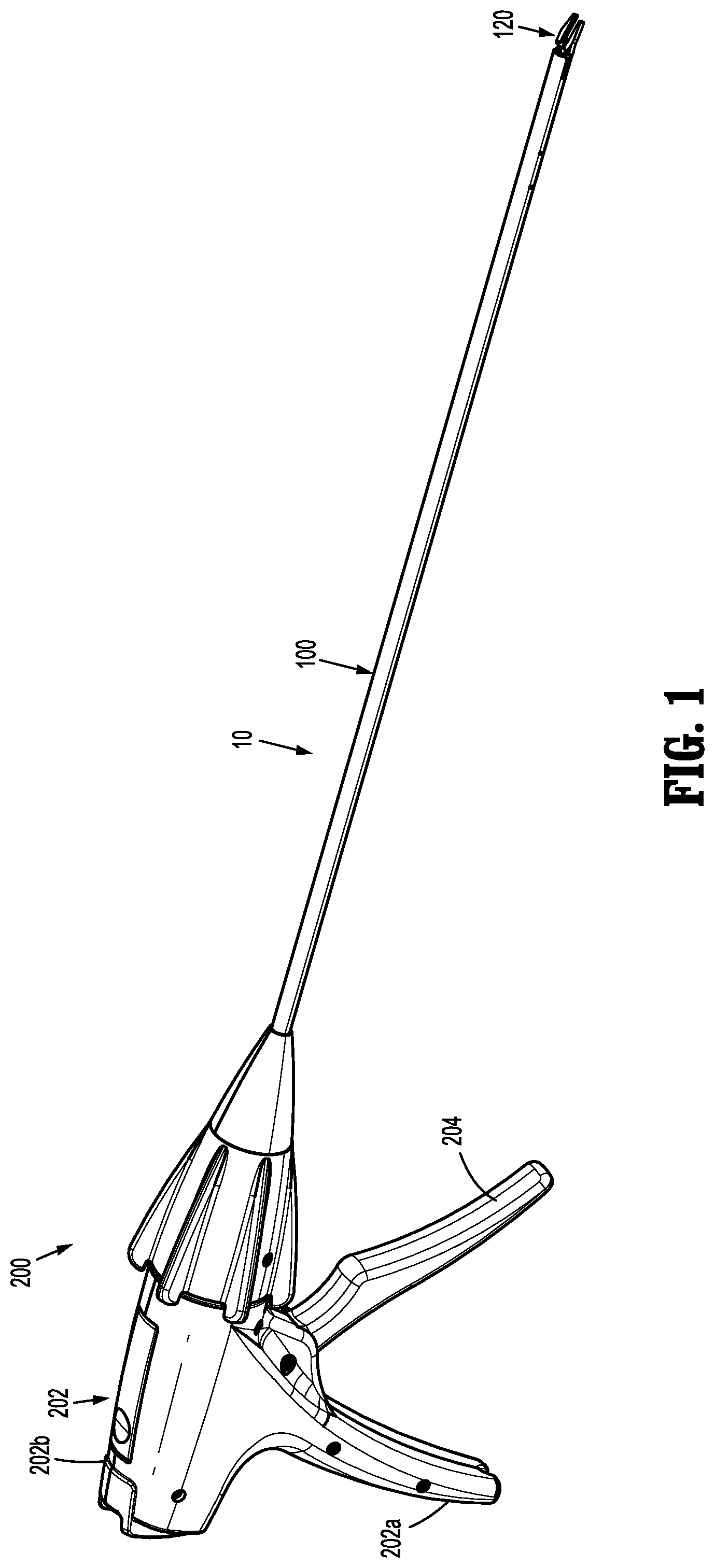
With reference to FIGS. 1 and 2, an apparatus for application of surgical clips to body tissue is illustrated and designated 10. The apparatus or surgical clip applier 10 generally includes a reusable handle assembly 200 and a disposable shaft assembly 100 operably coupled to the handle assembly 200. The handle assembly 200 includes a housing 202 having a first or right side half-section 202a and a second or left side half-section 202b. Housing 202 of handle assembly 200 further includes or defines a nose 202c dimensioned for receipt of a hub 130 of shaft assembly 100. Housing 202 of handle assembly 200 may be formed of a suitable plastic or thermoplastic material. It is further contemplated that housing 202 of handle assembly 200 may be fabricated from stainless steel of the like.
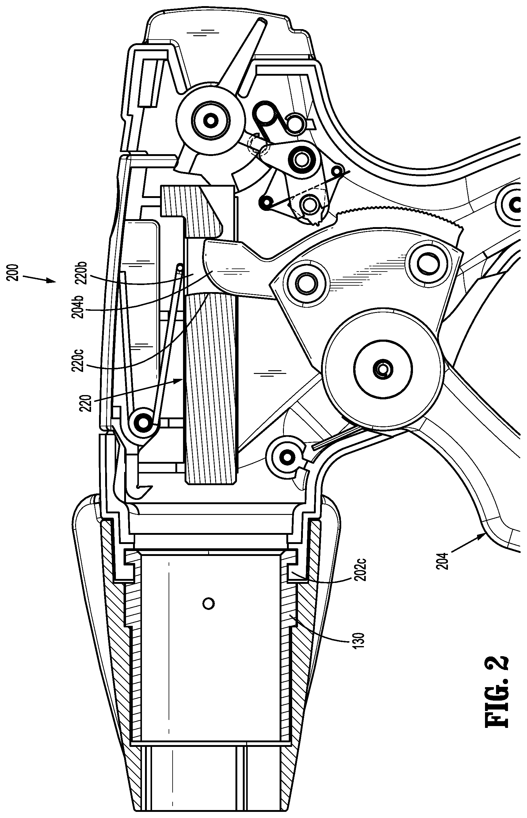
Handle assembly 200 includes a trigger 204 pivotably supported between right side half-section 202a and left side half-section 202b of housing 202. Trigger 204 is biased by a biasing member (not explicitly shown) to bias or urge trigger 204 to the un-actuated condition. Trigger 204 includes a drive arm 204b extending therefrom. Drive arm 204b may be integrally formed therewith or may be separately and fixedly secured to trigger 204. Drive arm 204b may define a curved, radiused or filleted upper distal surface.
Handle assembly 200 further includes a drive plunger 220 operatively connected to trigger 204. Drive plunger 220 defines a proximally extending trigger slot 220b formed in a proximal portion thereof for operatively receiving drive arm 204b of trigger 204. Trigger slot 220b defines a distal surface or wall 220c against which a distal surface of drive arm 204b of trigger 204 contacts in order to distally advance drive plunger 220 during an actuation of trigger 204. Drive plunger 220 has a distal end operably coupled to a proximal end of a spindle 124 (FIG. 5) of shaft assembly 100 to effect axial movement of the spindle 124 upon actuation of the trigger 204 of handle assembly 200.
For a more detailed description of the components and operation of the handle assembly 200 of clip applier 10, reference may be made to, for example, U.S. Patent Application Publication No. 2017/0128071, the entire contents of which being incorporated by reference herein.
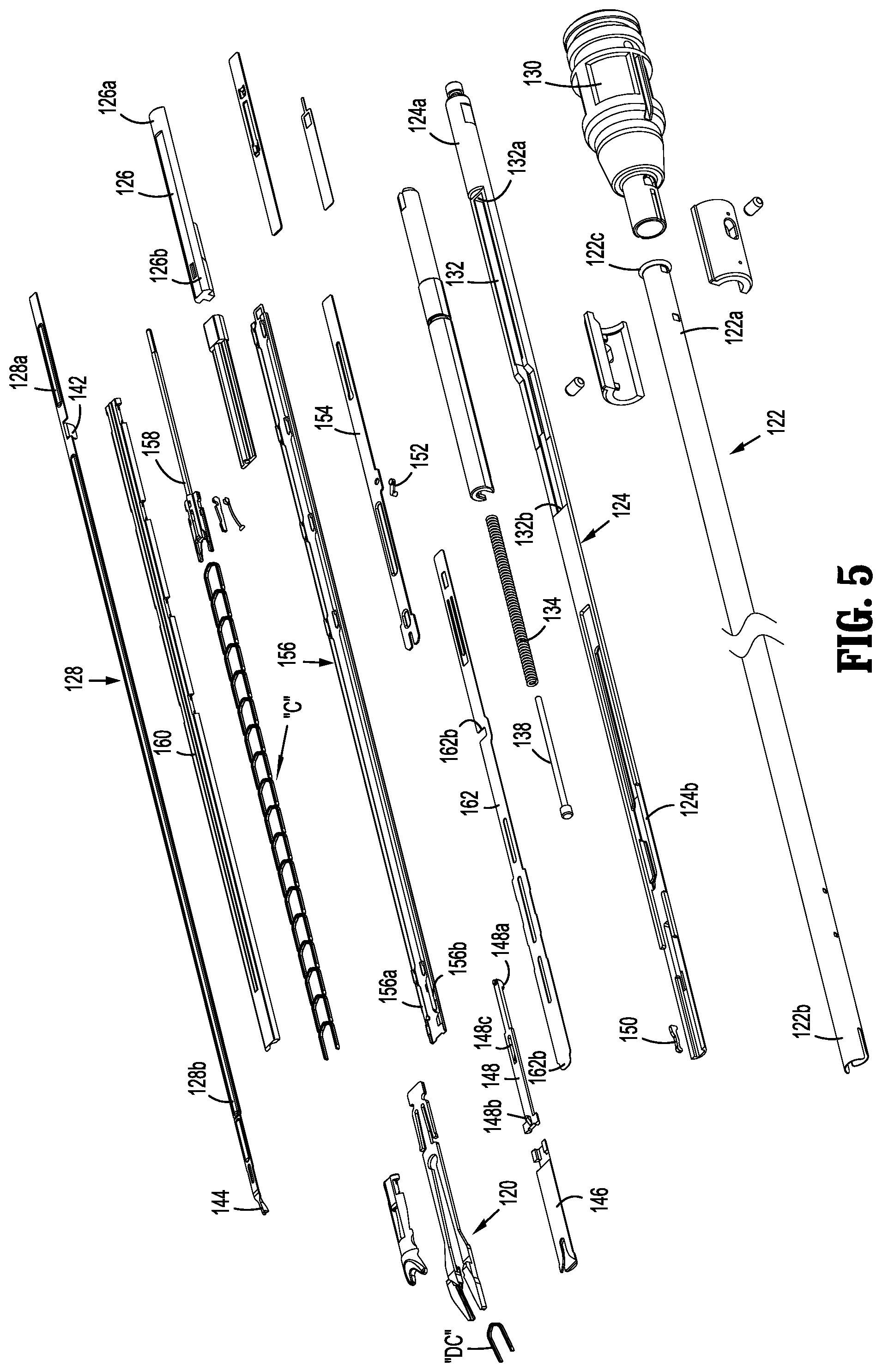
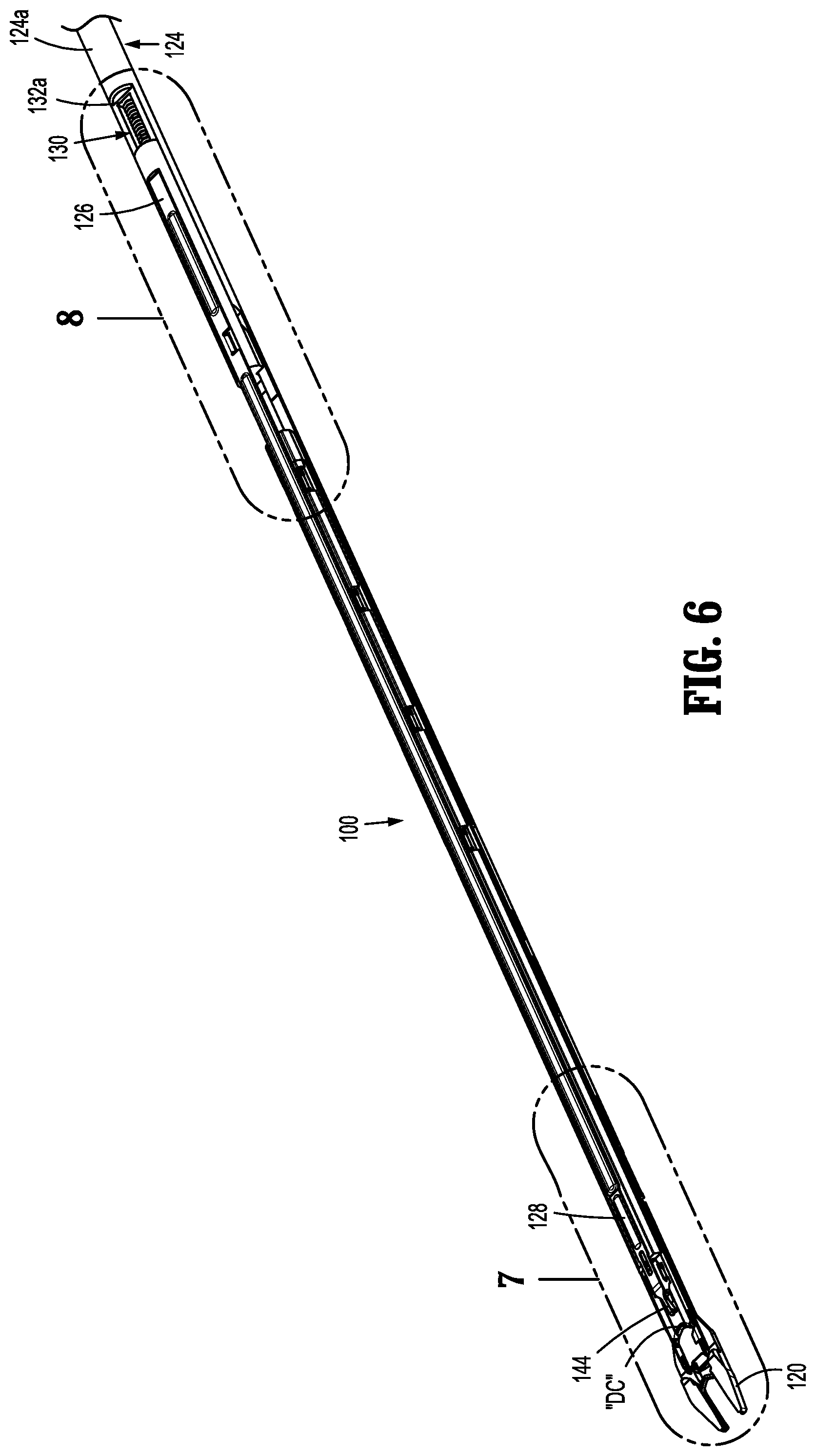
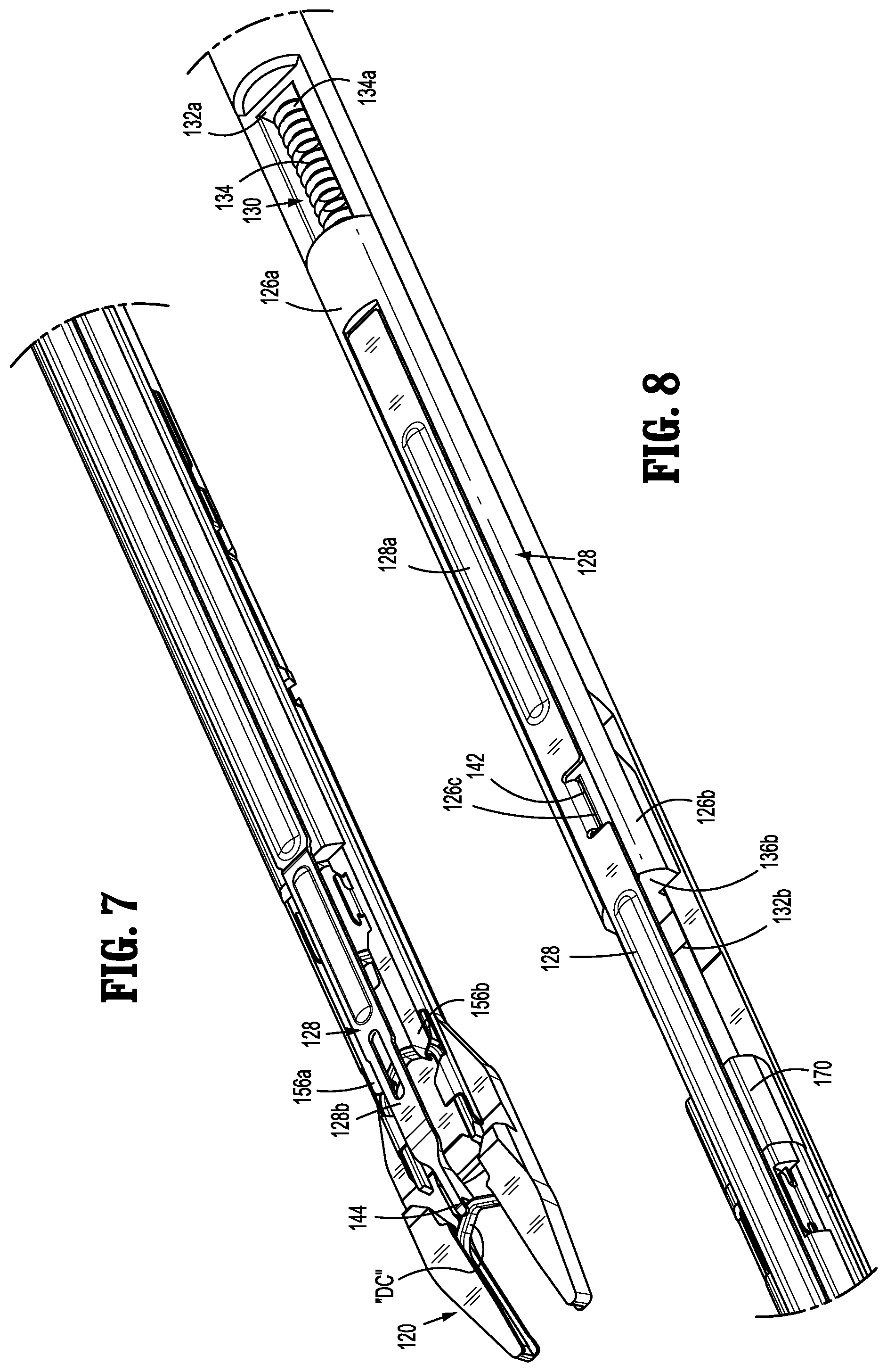
With reference to FIGS. 3-5, the shaft assembly 100 of the clip applier 10 is operably coupled to the handle assembly 200 for actuation by the handle assembly 200. The shaft assembly 100 stores a stack of surgical clips "C" therein and has a pair of jaws 120 configured to form, in seriatim, the surgical clips "C" received from a pusher bar 128 of the shaft assembly 120 upon actuation of the handle assembly 200. The shaft assembly 100 includes an elongated outer member or outer tube 122, an elongated spindle or inner shaft 124 axially movable within the outer tube 122 for actuating the clip applier 10, and a trip block 126 movably coupled to the spindle 124 for axially translating a pusher bar 128 to load and hold the surgical clips "C" in the jaws 120 during clip formation, as will be described. The outer tube 122 of the shaft assembly 100 has a proximal portion 122a supported and secured to a hub 130, and a distal portion 122b supporting the jaws 120. The hub 130 may be configured to be coupled to the handle assembly 200 (FIGS. 1 and 2) or an actuator of a robotic system 1000 (FIG. 10). The outer tube 122 defines a lumen 122c extending longitudinally therethrough dimensioned for slidable receipt of the spindle 124.
With reference to FIGS. 5-9, the spindle or inner shaft 124 is slidably supported within the lumen 122c of the outer tube 122 and has a generally elongated configuration. The spindle 124 includes a proximal portion 124a, and a distal portion 124b configured to selectively actuate the pair of jaws 120 during distal advancement of the spindle 124. The proximal portion 124a of the spindle 124 may define a hook, an enlarged head or other translational force coupling feature configured to be coupled to an actuator (e.g., the drive plunger 220 of the handle assembly 200 or an actuator of the robotic surgical system 1000). The proximal portion 124a of the spindle 124 defines an elongate channel 132 extending longitudinally along the spindle 124. The channel 132 of the spindle 124 has proximal and distal limits defined respectively by proximal and distal walls 132a, 132b.
The proximal portion 124a of the spindle 124 supports a biasing member 134 (e.g., a coil spring) disposed within the channel 132 of the spindle 124. The biasing member 134 has a proximal portion 134a fixed to the proximal wall 132a of the proximal portion 124a of the spindle 124, and a distal portion 134b coupled to a wall 136a defined by the trip block 126. The biasing member 134 is held within the channel 132 of the spindle 124 between the proximal wall 132a of the proximal portion 124a of the spindle 124 and the wall 136 of the trip block 126 in a preloaded condition so as to exert a distally-oriented resilient bias on the trip block 126 relative to the spindle 124. The biasing member 134 may have a rod member 138 extending through a central passageway thereof to maintain the biasing member 134 in a linear configuration (e.g., to prevent buckling).
The trip block 126 of the shaft assembly 100 has an elongated configuration and is reciprocally supported on the proximal portion 124a of the spindle 124 and axially movable both with and relative to the spindle 124. In particular, the trip block 126 includes a proximal portion 126a supported on an upper surface of the proximal portion 124a of the spindle 124, and a distal portion 124b movably received in the channel 132 of the spindle 124. The trip block 126 defines an elongate channel 140 (FIG. 9) in communication with the channel 132 of the spindle 124, whereby the channels 132, 140 of the spindle 124 and the trip block 126, respectively, together form a unitary channel in which the biasing member 134 is disposed.
The distal portion 126b of the trip block 126 has a proximally-oriented wall 136a having the distal portion 134b of the biasing member 134 coupled thereto. As briefly mentioned above, the biasing member 134 is fixed at its proximal portion 134a to the proximal wall 132a of the spindle 124, such that the biasing member 134 exerts a distally-oriented resilient bias on the trip block 126 relative to the spindle 124. In this way, a first distal advancement of the spindle 124 results in the concomitant distal advancement of the trip block 126. The distal portion 126b of the trip block also has a distally-oriented wall 136b configured to contact the distal wall 132b of the spindle 124 during retraction of the spindle 124, as will be described in detail below. A block or stop 170 is disposed distally of the trip block 126 and axially fixed within and relative to the outer tube 122 for providing a distal limit to the axial movement of the trip block 126. The stop 170 resists the trip block 126 and the pusher bar 128 from advancing distally beyond the stop 170 upon the distally-oriented wall 136b of the trip block 126 contacting the stop 170.
The distal portion of the trip block 126 defines a notch 126c therein for receiving a proximal portion 128a of the pusher bar 128. The pusher bar 128 has a proximal portion 128a, and a distal portion 128b for loading a distal-most surgical clip "DC" of the stack of surgical clips "C" between the jaws 120. The proximal portion 128a of the pusher bar 128 includes a fin 142 extending laterally therefrom, which is received in the notch 126c of the distal portion 126b of the trip block 126 for fixing the pusher bar 128 to the trip block 126 so that the pusher bar 128 moves axially with axial movement of the trip block 126. In embodiments, the proximal portion 128a of the pusher bar 128 may be fixed to the distal portion 126b of the trip block 126 via any suitable fastening engagement, such as, for example, various fasteners, adhesives, snap-fit engagements, or the like. Since the proximal portion 128a of the pusher bar 128 is fixed to the distal portion 126b of the trip block 126, axial movement of the trip block 126 results in a corresponding axial movement of the pusher bar 128.
The distal portion 128b of the pusher bar 128 defines a pusher 144 configured to position the distal-most surgical clip "DC" between the pair of jaws 120 as the trip block 126 is advanced toward a distal position, as shown in FIG. 7. The pusher 144 has a narrow profile for allowing the pair of jaws 120 to move to an approximated position while the pusher 144 is disposed therebetween. For example, the pusher 144 may have a width that is less than a horizontal distance the pair of jaws 120 are spaced from one another after completing a clip formation.
With continued reference to FIG. 5, additional components of the shaft assembly 100 responsible for effecting formation of the surgical clips "C" will be described. The distal portion 124b of the spindle 124 is operatively connected to a jaw cam closure wedge 146 via a slider joint 148. The jaw cam closure wedge 146 is selectively actuatable by the spindle 124 to engage camming features of the pair of jaws 120 to close the pair of jaws 120 and form a surgical clip "C" loaded therewithin. The slider joint 148 supports a latch member 150 for selective engagement with the spindle 124. The latch member 150 may be cammed in a direction toward the spindle 124 during actuation or translation of the spindle 124. In particular, during distal actuation of the spindle 124, at a predetermined distance, the latch member 150 is mechanically forced or cammed into and engaged with a slot in the spindle 124. This engagement of the latch member 150 in the slot of the spindle 124 allows the slider joint 148 to move together with the jaw cam closure wedge 146. The jaw cam closure wedge 146 thus can engage the relevant surfaces of the pair of jaws 120 to close the pair of jaws 120.
The slider joint 148 is connected, at a proximal portion 148a thereof, to a passageway formed in the distal portion 124b of the spindle 124. A distal portion 148b of the slider joint 148 defines a substantially T-shaped profile, wherein the distal portion 148b thereof is connected to the jaw cam closure wedge 146. The latch member 150 functions as a linkage and is disposed to move through an aperture 148c in the slider joint 148 to link with another fixed member and prevent the slider joint 148 from advancing the jaw cam closure wedge 146, and thus preventing the camming of the jaw cam closure wedge 146 from camming the pair of jaws 120 to a closed condition during an initial actuation of the clip applier 10. The distal portion 124b of the spindle 124 is provided with a camming feature configured to move a cam link 152 (pivotably connected to a filler component 154) in a perpendicular manner relative to a longitudinal axis of the spindle 124 during a distal advancement of the spindle 124.
The shaft assembly 100 further includes a clip channel 156 received within the outer tube 122. The clip channel 156 slidably retains the stack of surgical clips "C" therein for application, in seriatim, to the desired tissue or vessel. The clip channel 156 includes a pair of distal stops, such as, for example, resilient tangs 156a, 156b (FIGS. 5 and 7) disposed in parallel relation to one another. The resilient tangs 156a, 156b are transversely spaced from one another a distance substantially equal to a width of the surgical clips "C" so as to capture the distal-most surgical clip "DC" therebetween and resist distal advancement of the distal-most surgical clip "DC." Due to the resilient nature of the resilient tangs 156a, 156b, an application of a threshold distally-oriented force on the distal-most surgical clip "DC" splays outward the resilient tangs 156a, 156b to dislodge the surgical clip "DC" from the hold of the tangs 156a, 156b.
A clip follower 158 is provided and slidably disposed within the clip channel 156 at a location proximal of the stack of surgical clips "C." A spring (not shown) is provided to spring-bias the clip follower 158, and in turn, the stack of surgical clips "C", distally. A clip channel cover 160 is provided that overlies the clip channel 156 to retain and guide the clip follower 158, the spring, and the stack of surgical clips "C" in the clip channel 156.
The shaft assembly 100 further includes a wedge plate 162 that is biased to a proximal position by a wedge plate spring (not shown). The wedge plate 162 is a flat bar shaped member having a number of windows formed therein. The wedge plate 162 has a distal-most position wherein a tip or nose of the wedge plate 162 is inserted between the pair of jaws 120 to maintain the pair of jaws 120 in an open condition for loading of the distal-most surgical clip "DC" therein. The wedge plate 162 has a proximal-most position, maintained by the wedge plate spring, wherein the tip or nose of the wedge plate 162 is retracted from between the pair of jaws 120.
The wedge plate 162 defines a "U" or "C" shaped aperture or notch 162b in a side edge thereof. The C-shaped aperture or notch 162b of the wedge plate 162 selectively engages the cam link 152 supported on the filler plate 154. The cam link 152 selectively engages a surface of C-shaped aperture or notch 162b of the wedge plate 162 to retain the wedge plate 162 in a distal-most position such that a distal tip 162a of the wedge plate 162 is maintained inserted between the pair of jaws 120 to maintain the pair of jaws 120 splayed apart.
The filler component 154 of the shaft assembly 100 is interposed between the clip channel 156 and the wedge plate 162, at a location proximal of the pair of jaws 120. The filler component 154 pivotably supports the cam link 152 that is engagable with the wedge plate 162. During a distal advancement of the spindle 124, a camming feature of the spindle 124 engages a cam link boss of the cam link 152 to thereby move the cam link 152 out of engagement with the wedge plate 162 and permit the wedge plate 162 to return to the proximal-most position as a result of the spring.
It is contemplated that the clip applier 10 may be configured to close, fire, or form surgical clips similar to those shown and described in U.S. Patent Application Publication No. 2017/0128071, and U.S. Pat. Nos. 7,819,886 or 7,905,890, the entire contents of each of which are incorporated herein by reference.
In operation, the clip applier 10 is actuated to effect a stapling function thereof. In particular, the handle assembly 200 (FIGS. 1 and 2) or a control 1004 of a robotic assembly 1000 (FIG. 10) is actuated to advance the spindle 124 of the shaft assembly 100 in a distal direction within and relative to the outer tube 122. During a first distal movement of the spindle 124, the trip block 126 and the associated pusher bar 128 are advanced distally with the spindle 124 due to the preloaded condition of the biasing member 134. As the pusher bar 128 is moved distally, the pusher 144 of the distal portion 128b of the pusher bar 128 carries or pushes the distal-most surgical clip "DC" of the surgical clips "C" through the clip channel 156 in a distal direction until the distal-most clip "DC" is received or captured by the resilient tangs 156a, 156b of the shaft assembly 100. The resilient tangs 156a, 156b resist further distal advancement of the distal-most surgical clip "DC," and in turn the pusher bar 128 and the trip block 126, signifying the conclusion of the first distal movement of the spindle 124, trip block 126, and pusher bar 128.
After completion of the first distal movement of the spindle 124, the spindle 124 undergoes a second distal advancement or movement, via actuation of the handle assembly 200 or the control 1004 (FIG. 10), during which the trip block 126 and pusher bar 128 are resisted from moving therewith due to the engagement of the resilient tangs 156a, 156b with the distal-most surgical clip "DC." As the spindle 124 is distally advanced relative to the trip block 124 and the pusher bar 128, the biasing member 134 is compressed between the proximal wall 134a of the proximal portion 124a of the spindle 124 and the distal wall 136a of the distal portion 126b of the trip block 126 to increase the spring force of the biasing member 134. The trip block 126 and the pusher bar 128 remain axially fixed within the outer tube 122 and relative to the jaws 120 until the spring force of the biasing member 134 exceeds a holding force exerted on the distal-most surgical clip "DC" by the resilient tangs 156a, 156b of the clip channel 156, signifying a completion of the second distal movement of the spindle 124.
Upon the spring force of the biasing member 134 exceeding the holding force of the resilient tangs 156a, 156b of the clip channel 156, the distal-most surgical clip "DC" is forced distally out of the resilient tangs 156a, 156b of the clip channel 156 under the resilient bias of the biasing member 134. Due to the release of the distal-most surgical clip "DC" from the resilient tangs 156a, 156b, the trip block 126 and pusher bar 128 are advanced distally relative to the spindle 124, by the resilient bias of the biasing member 134, to advance the distal-most surgical clip "DC." The pusher bar 128 and trip block 126 are advanced distally relative to the spindle 124 until the distally-oriented wall 136b of the distal portion 126b of the trip block 126 contacts the stop 170 of the shaft assembly 100, whereby the stop 170 resists both the trip block 126 and the pusher bar 128 from advancing further distally. Upon the trip block 126 contacting the stop 170, the pusher 144 of the pusher bar 128 and the associated distal-most surgical clip "DC" are at a location between the jaws 120 and maintained in this location due to the continued distally-oriented bias of the biasing member 134.
With the distal portion 126b of the trip block 126 contacting the stop 170 of the shaft assembly 100, a third distal advancement or movement of the spindle 124 will cease to result in a distal advancement of the trip block 126, the pusher bar 128, and the distal-most surgical clip "DC." The third distal advancement of the spindle 124 approximates the jaws 120 to form the distal-most surgical clip "DC" all while the pusher 144 of the pusher bar 128 remains engaged with the distal-most surgical clip "DC" due to the distally-oriented bias of the biasing member 134. The pusher 144 grasps the backspan of the clip "DC" to maintain the clip "DC" between the jaws 120 as the jaws 120 approximate to form the clip "DC."
To reset the clip applier 10, the spindle 124 is retracted proximally within the outer tube 122 and out of engagement with the jaws 120 to allow the jaws 120 to expand (due to their own spring bias) to their open configuration. Proximal movement of the spindle 124 relative to the trip block 126 and the pusher bar 128 is continued until the distal wall 132b of the proximal portion 124a of the spindle 124 contacts the wall 136b of the distal portion 126b of the trip block 126. As such, a continued proximal retraction of the spindle 124 results in the trip block 126 and the attached pusher bar 128 moving proximally with the spindle 124, thereby removing the pusher 144 of the pusher bar 128 from between the jaws 120.
It is contemplated, and within the scope of the present disclosure, that other endoscopic assemblies, including a pair of jaws having a unique and diverse closure stroke length thereof, may be provided with a drive assembly, similar to any of the drive assemblies described herein, for accommodating and adapting the closure stroke length for the pair of jaws thereof to the constant trigger stroke length.
Accordingly, various endoscopic assemblies, constructed in accordance with the principles of the present disclosure, may be provided which are also capable of firing or forming or closing surgical clips of various sizes, materials, and configurations, across multiple platforms for multiple different manufactures.
Surgical instruments such as the clip appliers described herein may also be configured to work with robotic surgical systems and what is commonly referred to as "Telesurgery." Such systems employ various robotic elements to assist the surgeon and allow remote operation (or partial remote operation) of surgical instrumentation. Various robotic arms, gears, cams, pulleys, electric and mechanical motors, etc. may be employed for this purpose and may be designed with a robotic surgical system to assist the surgeon during the course of an operation or treatment. Such robotic systems may include remotely steerable systems, automatically flexible surgical systems, remotely flexible surgical systems, remotely articulating surgical systems, wireless surgical systems, modular or selectively configurable remotely operated surgical systems, etc.
The robotic surgical systems may be employed with one or more consoles that are next to the operating theater or located in a remote location. In this instance, one team of surgeons or nurses may prep the patient for surgery and configure the robotic surgical system with one or more of the instruments disclosed herein while another surgeon (or group of surgeons) remotely controls the instruments via the robotic surgical system. As can be appreciated, a highly skilled surgeon may perform multiple operations in multiple locations without leaving his/her remote console which can be both economically advantageous and a benefit to the patient or a series of patients.
The robotic arms of the surgical system are typically coupled to a pair of master handles by a controller. The handles can be moved by the surgeon to produce a corresponding movement of the working ends of any type of surgical instrument (e.g., end effectors, graspers, knifes, scissors, etc.) which may complement the use of one or more of the embodiments described herein. The movement of the master handles may be scaled so that the working ends have a corresponding movement that is different, smaller or larger, than the movement performed by the operating hands of the surgeon. The scale factor or gearing ratio may be adjustable so that the operator can control the resolution of the working ends of the surgical instrument(s).
The master handles may include various sensors to provide feedback to the surgeon relating to various tissue parameters or conditions, e.g., tissue resistance due to manipulation, cutting or otherwise treating, pressure by the instrument onto the tissue, tissue temperature, tissue impedance, etc. As can be appreciated, such sensors provide the surgeon with enhanced tactile feedback simulating actual operating conditions. The master handles may also include a variety of different actuators for delicate tissue manipulation or treatment further enhancing the surgeon's ability to mimic actual operating conditions.
Referring to FIG. 10, a medical work station is shown generally as robotic system or work station 1000 and generally may include a plurality of robot arms 1002, 1003; a control device 1004; and an operating console 1005 coupled with control device 1004. Operating console 1005 may include a display device 1006, which may be set up in particular to display three-dimensional images; and manual input devices 1007, 1008, by means of which a person (not shown), for example a surgeon, may be able to telemanipulate robot arms 1002, 1003 in a first operating mode.
Each of the robot arms 1002, 1003 may include a plurality of members, which are connected through joints, and an attaching device 1009, 1011, to which may be attached, for example, the shaft assembly of FIGS. 1-9, in accordance with any one of several embodiments disclosed herein, as will be described in greater detail below.
Robot arms 1002, 1003 may be driven by electric drives (not shown) that are connected to control device 1004. Control device 1004 (e.g., a computer) may be set up to activate the drives, in particular by means of a computer program, in such a way that robot arms 1002, 1003, their attaching devices 1009, 1011 and thus the shaft assembly 100, execute a desired movement according to a movement defined by means of manual input devices 1007, 1008. Control device 1004 may also be set up in such a way that it regulates the movement of robot arms 1002, 1003 and/or of the drives.
Medical work station 1000 may be configured for use on a patient 1013 lying on a patient table 1012 to be treated in a minimally invasive manner by means of the shaft assembly 100. Medical work station 1000 may also include more than two robot arms 1002, 1003, the additional robot arms likewise being connected to control device 1004 and being telemanipulatable by means of operating console 1005. A surgical end effector, such as, for example, the shaft assembly 100 of the clip applier 10 (FIGS. 1-9), may also be attached to the additional robot arm. Medical work station 1000 may include a database 1014, in particular coupled to with control device 1004, in which are stored, for example, pre-operative data from patient/living being 1013 and/or anatomical atlases.
Reference is made herein to U.S. Pat. No. 8,828,023, the entire content of which is incorporated herein by reference, for a more detailed description of the construction and operation of an exemplary robotic surgical system.
It should be understood that the foregoing description is only illustrative of the present disclosure. Various alternatives and modifications can be devised by those skilled in the art without departing from the disclosure. Accordingly, the present disclosure is intended to embrace all such alternatives, modifications and variances. The embodiments described with reference to the attached drawing figures are presented only to demonstrate certain examples of the disclosure. Other elements, steps, methods and techniques that are insubstantially different from those described above and/or in the appended claims are also intended to be within the scope of the disclosure.
* * * * *
D00000
D00001
D00002
D00003
D00004
D00005
D00006
D00007
D00008
XML
uspto.report is an independent third-party trademark research tool that is not affiliated, endorsed, or sponsored by the United States Patent and Trademark Office (USPTO) or any other governmental organization. The information provided by uspto.report is based on publicly available data at the time of writing and is intended for informational purposes only.
While we strive to provide accurate and up-to-date information, we do not guarantee the accuracy, completeness, reliability, or suitability of the information displayed on this site. The use of this site is at your own risk. Any reliance you place on such information is therefore strictly at your own risk.
All official trademark data, including owner information, should be verified by visiting the official USPTO website at www.uspto.gov. This site is not intended to replace professional legal advice and should not be used as a substitute for consulting with a legal professional who is knowledgeable about trademark law.