Rotation knob assemblies for handle assemblies
Baril , et al. September 29, 2
U.S. patent number 10,786,273 [Application Number 16/369,199] was granted by the patent office on 2020-09-29 for rotation knob assemblies for handle assemblies. This patent grant is currently assigned to Covidien LP. The grantee listed for this patent is Covidien LP. Invention is credited to Jacob C. Baril, Brian J. Creston, Matthew A. Dinino, Roy J. Pilletere, Justin Thomas, Thomas A. Zammataro.


View All Diagrams
| United States Patent | 10,786,273 |
| Baril , et al. | September 29, 2020 |
Rotation knob assemblies for handle assemblies
Abstract
Rotation knob assemblies for handle assemblies of surgical instruments rotatably support a laparoscopic end effector relative to a housing of the handle assemblies. The rotation knob assemblies may include friction reducing screws, bearing members, snap rings, and/or bearing assemblies to facilitate rotation of an outer knob relative to an inner collar.
| Inventors: | Baril; Jacob C. (Norwalk, CT), Creston; Brian J. (West Haven, CT), Pilletere; Roy J. (North Haven, CT), Zammataro; Thomas A. (Hamden, CT), Thomas; Justin (New Haven, CT), Dinino; Matthew A. (Newington, CT) | ||||||||||
|---|---|---|---|---|---|---|---|---|---|---|---|
| Applicant: |
|
||||||||||
| Assignee: | Covidien LP (Mansfield,
MA) |
||||||||||
| Family ID: | 1000005080646 | ||||||||||
| Appl. No.: | 16/369,199 | ||||||||||
| Filed: | March 29, 2019 |
Prior Publication Data
| Document Identifier | Publication Date | |
|---|---|---|
| US 20200015835 A1 | Jan 16, 2020 | |
Related U.S. Patent Documents
| Application Number | Filing Date | Patent Number | Issue Date | ||
|---|---|---|---|---|---|
| 62697418 | Jul 13, 2018 | ||||
| Current U.S. Class: | 1/1 |
| Current CPC Class: | A61B 17/2909 (20130101); A61B 2017/2912 (20130101); A61B 2017/00367 (20130101); A61B 2017/0042 (20130101) |
| Current International Class: | A61B 17/29 (20060101); A61B 17/00 (20060101) |
References Cited [Referenced By]
U.S. Patent Documents
| 3120230 | February 1964 | Skold |
| 3363628 | January 1968 | Wood |
| 3638847 | February 1972 | Noiles et al. |
| 3675688 | July 1972 | Bryan et al. |
| 3735762 | May 1973 | Bryan et al. |
| 3867944 | February 1975 | Samuels |
| 4226242 | October 1980 | Jarvik |
| 4242902 | January 1981 | Green |
| 4296751 | October 1981 | Blake, III et al. |
| 4372316 | February 1983 | Blake, III et al. |
| 4408603 | October 1983 | Blake, III et al. |
| 4412539 | November 1983 | Jarvik |
| 4418694 | December 1983 | Beroff et al. |
| 4471780 | September 1984 | Menges et al. |
| 4480640 | November 1984 | Becht |
| 4480641 | November 1984 | Failla et al. |
| 4487204 | December 1984 | Hrouda |
| 4487205 | December 1984 | Di Giovanni et al. |
| 4491133 | January 1985 | Menges et al. |
| 4492232 | January 1985 | Green |
| 4498476 | February 1985 | Cerwin et al. |
| 4500024 | February 1985 | DiGiovanni et al. |
| 4509518 | April 1985 | McGarry et al. |
| 4512345 | April 1985 | Green |
| 4522207 | June 1985 | Klieman et al. |
| 4532925 | August 1985 | Blake, III |
| 4534351 | August 1985 | Rothfuss et al. |
| 4545377 | October 1985 | Cerwin et al. |
| 4549544 | October 1985 | Favaron |
| 4556058 | December 1985 | Green |
| 4557263 | December 1985 | Green |
| 4562839 | January 1986 | Blake, III et al. |
| 4572183 | February 1986 | Juska |
| 4576165 | March 1986 | Green et al. |
| 4576166 | March 1986 | Montgomery et al. |
| 4590937 | May 1986 | Deniega |
| 4598711 | July 1986 | Deniega |
| 4602631 | July 1986 | Funatsu |
| 4611595 | September 1986 | Klieman et al. |
| 4612932 | September 1986 | Caspar et al. |
| 4616650 | October 1986 | Green et al. |
| 4616651 | October 1986 | Golden |
| 4624254 | November 1986 | McGarry et al. |
| 4637395 | January 1987 | Caspar et al. |
| 4646740 | March 1987 | Peters et al. |
| 4647504 | March 1987 | Kimimura et al. |
| 4658822 | April 1987 | Kees, Jr. |
| 4660558 | April 1987 | Kees, Jr. |
| 4662373 | May 1987 | Montgomery et al. |
| 4662374 | May 1987 | Blake, III |
| 4671278 | June 1987 | Chin |
| 4671282 | June 1987 | Tretbar |
| 4674504 | June 1987 | Klieman et al. |
| 4681107 | July 1987 | Kees, Jr. |
| 4696396 | September 1987 | Samuels |
| 4702247 | October 1987 | Blake, III et al. |
| 4706668 | November 1987 | Backer |
| 4712549 | December 1987 | Peters et al. |
| 4726372 | February 1988 | Perlin |
| 4733664 | March 1988 | Kirsch et al. |
| 4733666 | March 1988 | Mercer, Jr. |
| 4759364 | July 1988 | Boebel |
| 4765335 | August 1988 | Schmidt et al. |
| 4777949 | October 1988 | Perlin |
| 4777950 | October 1988 | Kees, Jr. |
| 4796625 | January 1989 | Kees, Jr. |
| 4799481 | January 1989 | Transue et al. |
| 4815466 | March 1989 | Perlin |
| 4817604 | April 1989 | Smith, III |
| 4821721 | April 1989 | Chin et al. |
| 4822348 | April 1989 | Casey |
| 4827930 | May 1989 | Kees, Jr. |
| 4834096 | May 1989 | Oh et al. |
| 4850355 | July 1989 | Brooks et al. |
| 4854317 | August 1989 | Braun |
| 4856517 | August 1989 | Collins et al. |
| 4929239 | May 1990 | Braun |
| 4929240 | May 1990 | Kirsch et al. |
| 4931058 | June 1990 | Cooper |
| 4932955 | June 1990 | Merz et al. |
| 4934364 | June 1990 | Green |
| 4943298 | July 1990 | Fujita et al. |
| 4957500 | September 1990 | Liang et al. |
| 4966603 | October 1990 | Focelle et al. |
| 4967949 | November 1990 | Sandhaus |
| 4983176 | January 1991 | Cushman et al. |
| 4988355 | January 1991 | Leveen et al. |
| 5002552 | March 1991 | Casey |
| 5026379 | June 1991 | Yoon |
| 5030224 | July 1991 | Wright et al. |
| 5030226 | July 1991 | Green et al. |
| 5032127 | July 1991 | Frazee et al. |
| 5035692 | July 1991 | Lyon et al. |
| 5047038 | September 1991 | Peters et al. |
| 5049152 | September 1991 | Simon et al. |
| 5049153 | September 1991 | Nakao et al. |
| 5053045 | October 1991 | Schmidt et al. |
| 5059202 | October 1991 | Liang et al. |
| 5062563 | November 1991 | Green et al. |
| 5062846 | November 1991 | Oh et al. |
| 5078731 | January 1992 | Hayhurst |
| 5084057 | January 1992 | Green et al. |
| 5100416 | March 1992 | Oh et al. |
| 5100420 | March 1992 | Green et al. |
| 5104394 | April 1992 | Knoepfler |
| 5104395 | April 1992 | Thornton et al. |
| 5112343 | May 1992 | Thornton |
| 5122150 | June 1992 | Puig |
| 5127915 | July 1992 | Mattson |
| 5129885 | July 1992 | Green et al. |
| 5156608 | October 1992 | Troidl et al. |
| 5160339 | November 1992 | Chen et al. |
| 5163945 | November 1992 | Ortiz et al. |
| 5171247 | December 1992 | Hughett et al. |
| 5171249 | December 1992 | Stefanchik et al. |
| 5171250 | December 1992 | Yoon |
| 5171251 | December 1992 | Bregen et al. |
| 5171252 | December 1992 | Friedland |
| 5171253 | December 1992 | Klieman |
| 5192288 | March 1993 | Thompson et al. |
| 5197970 | March 1993 | Green et al. |
| 5199566 | April 1993 | Ortiz et al. |
| 5201746 | April 1993 | Shichman |
| 5201900 | April 1993 | Nardella |
| 5207691 | May 1993 | Nardella |
| 5207692 | May 1993 | Kraus et al. |
| 5217473 | June 1993 | Yoon |
| 5219353 | June 1993 | Garvey, III et al. |
| 5246450 | September 1993 | Thornton et al. |
| 5269792 | December 1993 | Kovac et al. |
| 5281228 | January 1994 | Wolfson |
| 5282807 | February 1994 | Knoepfler |
| 5282808 | February 1994 | Kovac et al. |
| 5282832 | February 1994 | Toso et al. |
| 5289963 | March 1994 | McGarry et al. |
| 5290299 | March 1994 | Fain et al. |
| 5300081 | April 1994 | Young et al. |
| 5304183 | April 1994 | Gourlay et al. |
| 5306280 | April 1994 | Bregen et al. |
| 5306283 | April 1994 | Conners |
| 5312426 | May 1994 | Segawa et al. |
| 5330442 | July 1994 | Green et al. |
| 5330487 | July 1994 | Thornton et al. |
| 5336458 | August 1994 | Hutchison et al. |
| 5340360 | August 1994 | Stefanchik |
| 5342373 | August 1994 | Stefanchik et al. |
| 5354304 | October 1994 | Allen et al. |
| 5354306 | October 1994 | Garvey, III et al. |
| 5356064 | October 1994 | Green et al. |
| 5359993 | November 1994 | Slater et al. |
| 5366458 | November 1994 | Korthoff et al. |
| 5366459 | November 1994 | Yoon |
| 5368600 | November 1994 | Failla et al. |
| 5381943 | January 1995 | Allen et al. |
| 5382253 | January 1995 | Hogendijk |
| 5382254 | January 1995 | McGarry et al. |
| 5382255 | January 1995 | Castro et al. |
| 5383880 | January 1995 | Hooven |
| 5383881 | January 1995 | Green et al. |
| 5395375 | March 1995 | Turkel et al. |
| 5395381 | March 1995 | Green et al. |
| 5403327 | April 1995 | Thornton et al. |
| 5409498 | April 1995 | Braddock et al. |
| 5413584 | May 1995 | Schulze |
| 5423835 | June 1995 | Green et al. |
| 5425740 | June 1995 | Hutchinson, Jr. |
| 5431667 | July 1995 | Thompson et al. |
| 5431668 | July 1995 | Burbank, III et al. |
| 5431669 | July 1995 | Thompson et al. |
| 5439468 | August 1995 | Schulze et al. |
| 5441509 | August 1995 | Vidal et al. |
| 5447513 | September 1995 | Davison et al. |
| 5448042 | September 1995 | Robinson et al. |
| 5449365 | September 1995 | Green et al. |
| 5462555 | October 1995 | Bolanos et al. |
| 5462558 | October 1995 | Kolesa et al. |
| 5464416 | November 1995 | Steckel |
| 5474566 | December 1995 | Alesi et al. |
| 5474567 | December 1995 | Stefanchik et al. |
| 5474572 | December 1995 | Hayhurst |
| 5487499 | January 1996 | Sorrentino et al. |
| 5487746 | January 1996 | Yu et al. |
| 5501693 | March 1996 | Gravener |
| 5509920 | April 1996 | Phillips et al. |
| 5514149 | May 1996 | Green et al. |
| 5520701 | May 1996 | Lerch |
| 5522823 | June 1996 | Kuntz et al. |
| 5527318 | June 1996 | McGarry |
| 5527319 | June 1996 | Green et al. |
| 5527320 | June 1996 | Carruthers et al. |
| 5542949 | August 1996 | Yoon |
| 5547474 | August 1996 | Kloeckl et al. |
| 5562655 | October 1996 | Mittelstadt et al. |
| 5569274 | October 1996 | Rapacki et al. |
| 5571121 | November 1996 | Heifetz |
| 5575802 | November 1996 | McQuilkin et al. |
| 5582615 | December 1996 | Foshee et al. |
| 5584840 | December 1996 | Ramsey et al. |
| 5591178 | January 1997 | Green et al. |
| 5593414 | January 1997 | Shipp et al. |
| 5593421 | January 1997 | Bauer |
| 5601573 | February 1997 | Fogelberg et al. |
| 5601574 | February 1997 | Stefanchik et al. |
| 5607436 | March 1997 | Pratt et al. |
| 5618291 | April 1997 | Thompson et al. |
| 5618306 | April 1997 | Roth et al. |
| 5620452 | April 1997 | Yoon |
| 5626585 | May 1997 | Mittelstadt et al. |
| 5626586 | May 1997 | Pistl et al. |
| 5626587 | May 1997 | Bishop et al. |
| 5626592 | May 1997 | Phillips et al. |
| RE35525 | June 1997 | Stefanchik et al. |
| 5634930 | June 1997 | Thornton et al. |
| 5643291 | July 1997 | Pier et al. |
| 5645551 | July 1997 | Green et al. |
| 5645553 | July 1997 | Kolesa et al. |
| 5649937 | July 1997 | Bito et al. |
| 5653720 | August 1997 | Johnson et al. |
| 5662662 | September 1997 | Bishop et al. |
| 5662676 | September 1997 | Koninckx |
| 5662679 | September 1997 | Voss et al. |
| 5665097 | September 1997 | Baker et al. |
| 5676676 | October 1997 | Porter |
| 5681330 | October 1997 | Hughett et al. |
| 5683405 | November 1997 | Yacoubian et al. |
| 5695502 | December 1997 | Pier et al. |
| 5695505 | December 1997 | Yoon |
| 5697938 | December 1997 | Jensen et al. |
| 5697942 | December 1997 | Palti |
| 5700270 | December 1997 | Peyser et al. |
| 5700271 | December 1997 | Whitfield et al. |
| 5702048 | December 1997 | Eberlin |
| 5709706 | January 1998 | Kienzle et al. |
| 5713911 | February 1998 | Racenet et al. |
| 5713912 | February 1998 | Porter |
| 5720756 | February 1998 | Green et al. |
| 5722982 | March 1998 | Ferreira et al. |
| 5725537 | March 1998 | Green et al. |
| 5725538 | March 1998 | Green et al. |
| 5725542 | March 1998 | Yoon |
| 5733295 | March 1998 | Back et al. |
| 5743310 | April 1998 | Moran |
| 5749881 | May 1998 | Sackier et al. |
| 5755726 | May 1998 | Pratt et al. |
| 5766189 | June 1998 | Matsuno |
| 5769857 | June 1998 | Reztzov et al. |
| 5772673 | June 1998 | Cuny et al. |
| 5776146 | July 1998 | Sackier et al. |
| 5776147 | July 1998 | Dolendo |
| 5779718 | July 1998 | Green et al. |
| 5779720 | July 1998 | Walder-Utz et al. |
| 5782844 | July 1998 | Yoon et al. |
| 5788698 | August 1998 | Savornin |
| 5792149 | August 1998 | Sheds et al. |
| 5792150 | August 1998 | Pratt et al. |
| 5797922 | August 1998 | Hessel et al. |
| 5810853 | September 1998 | Yoon |
| 5817116 | October 1998 | Takahashi et al. |
| 5824547 | October 1998 | Hashino et al. |
| 5824548 | October 1998 | Hearn |
| 5827306 | October 1998 | Yoon |
| 5827323 | October 1998 | Klieman et al. |
| 5833695 | November 1998 | Yoon |
| 5833696 | November 1998 | Whitfield et al. |
| 5833700 | November 1998 | Fogelberg et al. |
| 5835199 | November 1998 | Phillips et al. |
| 5843097 | December 1998 | Mayenberger et al. |
| 5843101 | December 1998 | Fry |
| 5846255 | December 1998 | Casey |
| 5849019 | December 1998 | Yoon |
| 5858018 | January 1999 | Shipp et al. |
| 5861005 | January 1999 | Kontos |
| 5868759 | February 1999 | Peyser et al. |
| 5868761 | February 1999 | Nicholas et al. |
| 5876410 | March 1999 | Petillo |
| 5895394 | April 1999 | Kienzle et al. |
| 5897565 | April 1999 | Foster |
| 5904693 | May 1999 | Dicesare et al. |
| 5906625 | May 1999 | Bito et al. |
| 5913862 | June 1999 | Ramsey et al. |
| 5913876 | June 1999 | Taylor et al. |
| 5918791 | July 1999 | Sorrentino et al. |
| 5921991 | July 1999 | Whitehead et al. |
| 5921996 | July 1999 | Sherman |
| 5921997 | July 1999 | Fogelberg et al. |
| 5928251 | July 1999 | Aranyi et al. |
| 5938667 | August 1999 | Peyser et al. |
| 5951574 | September 1999 | Stefanchik et al. |
| 5972003 | October 1999 | Rousseau et al. |
| 5976159 | November 1999 | Bolduc et al. |
| 5993465 | November 1999 | Shipp et al. |
| 6004335 | December 1999 | Vaitekunas et al. |
| 6009551 | December 1999 | Sheynblat |
| 6017358 | January 2000 | Yoon et al. |
| 6044971 | April 2000 | Esposito et al. |
| 6045560 | April 2000 | McKean et al. |
| 6053908 | April 2000 | Crainich et al. |
| RE36720 | May 2000 | Green et al. |
| 6059799 | May 2000 | Aranyi et al. |
| 6099536 | August 2000 | Petillo |
| 6099537 | August 2000 | Sugai et al. |
| 6139555 | October 2000 | Hart et al. |
| 6210418 | April 2001 | Storz et al. |
| 6217590 | April 2001 | Levinson |
| 6228097 | May 2001 | Levinson et al. |
| 6241740 | June 2001 | Davis et al. |
| 6258105 | July 2001 | Hart et al. |
| 6261302 | July 2001 | Voegele et al. |
| 6273898 | August 2001 | Kienzle et al. |
| 6277131 | August 2001 | Kalikow |
| 6306149 | October 2001 | Meade |
| 6318619 | November 2001 | Lee |
| 6322571 | November 2001 | Adams |
| 6350269 | February 2002 | Shipp et al. |
| 6352541 | March 2002 | Kienzle et al. |
| 6391035 | May 2002 | Appleby et al. |
| 6423079 | July 2002 | Blake, III |
| 6428548 | August 2002 | Durgin et al. |
| 6440144 | August 2002 | Bacher |
| 6461363 | October 2002 | Gadberry et al. |
| 6464710 | October 2002 | Foster |
| 6494886 | December 2002 | Wilk et al. |
| 6517536 | February 2003 | Hooven et al. |
| 6520972 | February 2003 | Peters |
| 6527786 | March 2003 | Davis et al. |
| 6530880 | March 2003 | Pagliuca |
| 6537289 | March 2003 | Kayan et al. |
| 6546935 | April 2003 | Hooven |
| 6551333 | April 2003 | Kuhns et al. |
| 6562051 | May 2003 | Bolduc et al. |
| 6569171 | May 2003 | DeGuillebon et al. |
| 6579304 | June 2003 | Hart et al. |
| 6599298 | July 2003 | Forster et al. |
| 6602252 | August 2003 | Mollenauer |
| 6607540 | August 2003 | Shipp |
| 6613060 | September 2003 | Adams et al. |
| 6626916 | September 2003 | Yeung et al. |
| 6626922 | September 2003 | Hart et al. |
| 6648898 | November 2003 | Baxter |
| 6652538 | November 2003 | Kayan et al. |
| 6652539 | November 2003 | Shipp et al. |
| 6656193 | December 2003 | Grant et al. |
| 6673083 | January 2004 | Kayan et al. |
| 6676659 | January 2004 | Hutchins et al. |
| 6679894 | January 2004 | Damarati |
| RE38445 | February 2004 | Pistl et al. |
| 6695854 | February 2004 | Kayan et al. |
| 6706057 | March 2004 | Bidoia et al. |
| 6716226 | April 2004 | Sixto, Jr. et al. |
| 6723109 | April 2004 | Solingen |
| 6733514 | May 2004 | Miser |
| 6743240 | June 2004 | Smith et al. |
| 6743241 | June 2004 | Kerr |
| 6773438 | August 2004 | Knodel et al. |
| 6773440 | August 2004 | Gannoe et al. |
| 6776783 | August 2004 | Frantzen et al. |
| 6776784 | August 2004 | Ginn |
| 6780195 | August 2004 | Porat |
| 6793663 | September 2004 | Kneifel et al. |
| 6793664 | September 2004 | Mazzocchi et al. |
| 6802848 | October 2004 | Anderson et al. |
| 6814742 | November 2004 | Kimura et al. |
| 6818009 | November 2004 | Hart et al. |
| 6821273 | November 2004 | Mollenauer |
| 6821284 | November 2004 | Sturtz et al. |
| 6821285 | November 2004 | Laufer et al. |
| 6824547 | November 2004 | Wilson, Jr. et al. |
| 6824548 | November 2004 | Smith et al. |
| 6835199 | December 2004 | McGuckin, Jr. et al. |
| 6835200 | December 2004 | Laufer et al. |
| 6837893 | January 2005 | Miller |
| 6837894 | January 2005 | Pugsley, Jr. et al. |
| 6837895 | January 2005 | Mayenberger |
| 6840945 | January 2005 | Manetakis et al. |
| 6843794 | January 2005 | Sixto, Jr. et al. |
| 6849078 | February 2005 | Durgin et al. |
| 6849079 | February 2005 | Blake, III et al. |
| 6853879 | February 2005 | Sunaoshi |
| 6869435 | March 2005 | Blake, III |
| 6869436 | March 2005 | Wendlandt |
| 6889116 | May 2005 | Jinno |
| 6896676 | May 2005 | Zubok et al. |
| 6896682 | May 2005 | McClellan et al. |
| 6896684 | May 2005 | Monassevitch et al. |
| 6905503 | June 2005 | Gifford, III et al. |
| 6911032 | June 2005 | Jugenheimer et al. |
| 6911033 | June 2005 | de Guillebon et al. |
| 6913607 | July 2005 | Ainsworth et al. |
| 6916327 | July 2005 | Northrup, III et al. |
| 6916332 | July 2005 | Adams |
| 6923818 | August 2005 | Muramatsu et al. |
| 6939356 | September 2005 | Debbas |
| 6942674 | September 2005 | Belef et al. |
| 6942676 | September 2005 | Buelna |
| 6945978 | September 2005 | Hyde |
| 6945979 | September 2005 | Kortenbach et al. |
| 6949107 | September 2005 | McGuckin, Jr. et al. |
| 6953465 | October 2005 | Dieck et al. |
| 6955643 | October 2005 | Gellman et al. |
| 6959852 | November 2005 | Shelton, IV et al. |
| 6960218 | November 2005 | Rennich |
| 6960221 | November 2005 | Ho et al. |
| 6962594 | November 2005 | Thevenet |
| 6963792 | November 2005 | Green |
| 6964363 | November 2005 | Wales et al. |
| 6964668 | November 2005 | Modesitt et al. |
| 6966875 | November 2005 | Longobardi |
| 6966917 | November 2005 | Suyker et al. |
| 6966919 | November 2005 | Sixto, Jr. et al. |
| 6966981 | November 2005 | Binder et al. |
| 6969391 | November 2005 | Gazzani |
| 6972023 | December 2005 | Whayne et al. |
| 6972027 | December 2005 | Fallin et al. |
| 6973770 | December 2005 | Schnipke et al. |
| 6974446 | December 2005 | Hommann et al. |
| 6974462 | December 2005 | Sater |
| 6974466 | December 2005 | Ahmed et al. |
| 6974475 | December 2005 | Wall |
| 6981505 | January 2006 | Krause et al. |
| 6981628 | January 2006 | Wales |
| 6991597 | January 2006 | Gellman et al. |
| 6991635 | January 2006 | Takamoto et al. |
| 7001399 | February 2006 | Damarati |
| 7037315 | May 2006 | Sancoff et al. |
| 7041119 | May 2006 | Green |
| 7052504 | May 2006 | Hughett |
| 7056330 | June 2006 | Gayton |
| 7070602 | July 2006 | Smith et al. |
| 7108700 | September 2006 | Chan |
| 7108703 | September 2006 | Danitz et al. |
| 7141056 | November 2006 | Manetakis |
| 7144402 | December 2006 | Kuester, III |
| 7175648 | February 2007 | Nakao |
| 7179265 | February 2007 | Manetakis et al. |
| 7207997 | April 2007 | Shipp et al. |
| 7211091 | May 2007 | Fowler et al. |
| 7211092 | May 2007 | Hughett |
| 7213736 | May 2007 | Wales et al. |
| 7214230 | May 2007 | Brock et al. |
| 7214232 | May 2007 | Bowman et al. |
| 7223271 | May 2007 | Muramatsu et al. |
| 7223272 | May 2007 | Francese et al. |
| 7232445 | June 2007 | Kortenbach et al. |
| 7238191 | July 2007 | Bachmann |
| 7261724 | August 2007 | Molitor et al. |
| 7261725 | August 2007 | Binmoeller |
| 7264625 | September 2007 | Buncke |
| 7288098 | October 2007 | Huitema et al. |
| 7297149 | November 2007 | Vitali et al. |
| 7312188 | December 2007 | Kiso |
| 7316693 | January 2008 | Viola |
| 7316696 | January 2008 | Wilson, Jr. et al. |
| 7322995 | January 2008 | Buckman et al. |
| 7326223 | February 2008 | Wilson, Jr. |
| 7329266 | February 2008 | Royse et al. |
| 7331968 | February 2008 | Arp et al. |
| 7338503 | March 2008 | Rosenberg et al. |
| 7357805 | April 2008 | Masuda et al. |
| 7367939 | May 2008 | Smith et al. |
| 7407074 | August 2008 | Ortiz et al. |
| 7419495 | September 2008 | Menn et al. |
| 7422137 | September 2008 | Manzo |
| 7431724 | October 2008 | Manetakis et al. |
| 7452327 | November 2008 | Durgin et al. |
| 7485124 | February 2009 | Kuhns et al. |
| 7488335 | February 2009 | Sgro |
| 7510562 | March 2009 | Lindsay |
| 7552853 | June 2009 | Mas et al. |
| 7559937 | July 2009 | de la Torre et al. |
| 7572266 | August 2009 | Young et al. |
| 7578827 | August 2009 | Gadberry et al. |
| 7582095 | September 2009 | Shipp et al. |
| 7585304 | September 2009 | Hughett |
| 7615058 | November 2009 | Sixto, Jr. et al. |
| 7615060 | November 2009 | Stokes et al. |
| 7621926 | November 2009 | Wixey et al. |
| 7637917 | December 2009 | Whitfield et al. |
| 7644848 | January 2010 | Swayze et al. |
| 7686820 | March 2010 | Huitema et al. |
| 7695482 | April 2010 | Viola |
| 7717926 | May 2010 | Whitfield et al. |
| 7727247 | June 2010 | Kimura et al. |
| 7727248 | June 2010 | Smith et al. |
| 7731724 | June 2010 | Huitema et al. |
| 7731725 | June 2010 | Gadberry et al. |
| 7736388 | June 2010 | Goldfarb et al. |
| 7740639 | June 2010 | Hummel et al. |
| 7740641 | June 2010 | Huitema |
| 7744623 | June 2010 | Anderson |
| 7752853 | July 2010 | Singh et al. |
| 7753250 | July 2010 | Clauson et al. |
| 7766207 | August 2010 | Mather et al. |
| 7766925 | August 2010 | Stokes et al. |
| 7770773 | August 2010 | Whitman et al. |
| 7776058 | August 2010 | Rosenberg et al. |
| 7780688 | August 2010 | Sakakine et al. |
| 7793813 | September 2010 | Bettuchi |
| 7806903 | October 2010 | Shibata et al. |
| 7819886 | October 2010 | Whitfield et al. |
| 7823592 | November 2010 | Bettuchi et al. |
| 7857828 | December 2010 | Jabba et al. |
| 7871416 | January 2011 | Phillips |
| 7875029 | January 2011 | Hausen |
| 7887553 | February 2011 | Lehman |
| 7887554 | February 2011 | Stokes et al. |
| 7892244 | February 2011 | Monassevitch et al. |
| 7896895 | March 2011 | Boudreaux et al. |
| 7901420 | March 2011 | Dunn |
| 7905890 | March 2011 | Whitfield et al. |
| 7914544 | March 2011 | Nguyen et al. |
| 7914551 | March 2011 | Ortiz et al. |
| 7942890 | May 2011 | D'Agostino et al. |
| 7947052 | May 2011 | Baxter, III et al. |
| 7954682 | June 2011 | Giordano et al. |
| 7963433 | June 2011 | Whitman et al. |
| 7967831 | June 2011 | Rosenberg et al. |
| 7988027 | August 2011 | Olson et al. |
| 7998155 | August 2011 | Manzo |
| 8011550 | September 2011 | Aranyi et al. |
| 8011555 | September 2011 | Tarinelli et al. |
| 8016178 | September 2011 | Olson et al. |
| 8021375 | September 2011 | Aldrich et al. |
| 8021378 | September 2011 | Sixto, Jr. et al. |
| 8038686 | October 2011 | Huitema et al. |
| 8048088 | November 2011 | Green et al. |
| 8056565 | November 2011 | Zergiebel |
| 8062310 | November 2011 | Shibata et al. |
| 8062311 | November 2011 | Litscher et al. |
| 8062314 | November 2011 | Sixto, Jr. et al. |
| 8066720 | November 2011 | Knodel et al. |
| 8066721 | November 2011 | Kortenbach et al. |
| 8066722 | November 2011 | Miyagi et al. |
| 8070760 | December 2011 | Fujita |
| 8074857 | December 2011 | Peterson et al. |
| 8075571 | December 2011 | Vitali et al. |
| 8080021 | December 2011 | Griego |
| 8083668 | December 2011 | Durgin et al. |
| 8088061 | January 2012 | Wells et al. |
| 8091755 | January 2012 | Kayan et al. |
| 8100926 | January 2012 | Filshie et al. |
| 8128643 | March 2012 | Aranyi et al. |
| 8133240 | March 2012 | Damarati |
| 8137368 | March 2012 | Kayan et al. |
| 8142451 | March 2012 | Boulnois et al. |
| 8157145 | April 2012 | Shelton, IV et al. |
| 8157149 | April 2012 | Olson et al. |
| 8157151 | April 2012 | Ingmanson et al. |
| 8172859 | May 2012 | Matsuno et al. |
| 8172870 | May 2012 | Shipp |
| 8177797 | May 2012 | Shimoji et al. |
| 8182529 | May 2012 | Gordon et al. |
| 8187290 | May 2012 | Buckman et al. |
| 8192449 | June 2012 | Maier et al. |
| 8211119 | July 2012 | Palmer et al. |
| 8211120 | July 2012 | Itoh |
| 8211124 | July 2012 | Ainsworth et al. |
| 8216255 | July 2012 | Smith et al. |
| 8216257 | July 2012 | Huitema et al. |
| 8236012 | August 2012 | Molitor et al. |
| 8241322 | August 2012 | Whitman et al. |
| 8246634 | August 2012 | Huitema et al. |
| 8246635 | August 2012 | Huitema |
| 8262678 | September 2012 | Matsuoka et al. |
| 8262679 | September 2012 | Nguyen |
| 8267944 | September 2012 | Sorrentino et al. |
| 8267945 | September 2012 | Nguyen et al. |
| 8267946 | September 2012 | Whitfield et al. |
| 8272554 | September 2012 | Whitman et al. |
| 8282655 | October 2012 | Whitfield et al. |
| 8287559 | October 2012 | Barker et al. |
| 8308743 | November 2012 | Matsuno et al. |
| 8313497 | November 2012 | Walberg et al. |
| 8328822 | December 2012 | Huitema et al. |
| 8336556 | December 2012 | Zergiebel |
| 8348130 | January 2013 | Shah et al. |
| 8357171 | January 2013 | Whitfield et al. |
| 8366709 | February 2013 | Schechter et al. |
| 8366726 | February 2013 | Dennis |
| 8371491 | February 2013 | Huitema et al. |
| 8372095 | February 2013 | Viola |
| 8382773 | February 2013 | Whitfield et al. |
| 8398655 | March 2013 | Cheng et al. |
| 8403138 | March 2013 | Weisshaupt et al. |
| 8403945 | March 2013 | Whitfield et al. |
| 8403946 | March 2013 | Whitfield et al. |
| 8408442 | April 2013 | Racenet et al. |
| 8409222 | April 2013 | Whitfield et al. |
| 8409223 | April 2013 | Sorrentino et al. |
| 8419752 | April 2013 | Sorrentino et al. |
| 8430892 | April 2013 | Bindra et al. |
| 8444660 | May 2013 | Adams et al. |
| 8465460 | June 2013 | Yodfat et al. |
| 8465502 | June 2013 | Zergiebel |
| 8475473 | July 2013 | Vandenbroek et al. |
| 8480688 | July 2013 | Boulnois et al. |
| 8486091 | July 2013 | Sorrentino et al. |
| 8491608 | July 2013 | Sorrentino et al. |
| 8496673 | July 2013 | Nguyen et al. |
| 8506580 | August 2013 | Zergiebel et al. |
| 8512357 | August 2013 | Viola |
| 8518055 | August 2013 | Cardinale et al. |
| 8523882 | September 2013 | Huitema et al. |
| 8529585 | September 2013 | Jacobs et al. |
| 8529586 | September 2013 | Rosenberg et al. |
| 8529588 | September 2013 | Ahlberg et al. |
| 8545486 | October 2013 | Malkowski |
| 8545519 | October 2013 | Aguirre et al. |
| 8556920 | October 2013 | Huitema et al. |
| 8568430 | October 2013 | Shipp |
| 8579918 | November 2013 | Whitfield et al. |
| 8585716 | November 2013 | Roskopf et al. |
| 8585717 | November 2013 | Sorrentino et al. |
| 8603109 | December 2013 | Aranyi et al. |
| 8623044 | January 2014 | Timm et al. |
| 8628547 | January 2014 | Weller et al. |
| 8632520 | January 2014 | Otley |
| 8636191 | January 2014 | Meagher |
| 8652151 | February 2014 | Lehman et al. |
| 8652152 | February 2014 | Aranyi et al. |
| 8663247 | March 2014 | Menn et al. |
| 8685048 | April 2014 | Adams et al. |
| 8690899 | April 2014 | Kogiso et al. |
| 8708210 | April 2014 | Zemlok et al. |
| 8708213 | April 2014 | Shelton, IV et al. |
| 8709027 | April 2014 | Adams et al. |
| 8715299 | May 2014 | Menn et al. |
| 8720766 | May 2014 | Hess et al. |
| 8734469 | May 2014 | Pribanic et al. |
| 8747423 | June 2014 | Whitfield et al. |
| 8753356 | June 2014 | Vitali et al. |
| 8758392 | June 2014 | Crainich |
| 8771169 | July 2014 | Whitman et al. |
| 8795302 | August 2014 | Wild |
| 8808310 | August 2014 | Jones et al. |
| 8814884 | August 2014 | Whitfield et al. |
| 8821516 | September 2014 | Huiterna |
| 8828023 | September 2014 | Neff et al. |
| 8839954 | September 2014 | Disch |
| 8845659 | September 2014 | Whitfield et al. |
| 8864785 | October 2014 | Pagliuca et al. |
| 8894665 | November 2014 | Sorrentino et al. |
| 8894666 | November 2014 | Schulz et al. |
| 8900253 | December 2014 | Aranyi et al. |
| 8915930 | December 2014 | Huiterna et al. |
| 8915931 | December 2014 | Boudreaux et al. |
| 8939974 | January 2015 | Boudreaux et al. |
| 8945151 | February 2015 | Salas |
| 8950646 | February 2015 | Viola |
| 8968337 | March 2015 | Whitfield et al. |
| 8968342 | March 2015 | Wingardner, III et al. |
| 8973804 | March 2015 | Hess et al. |
| 8986343 | March 2015 | Bourque et al. |
| 8998935 | April 2015 | Hart |
| 9011464 | April 2015 | Zammataro |
| 9011465 | April 2015 | Whitfield et al. |
| 9028511 | May 2015 | Weller et al. |
| 9050133 | June 2015 | Boone, III et al. |
| 9060779 | June 2015 | Martinez |
| 9084604 | July 2015 | Litscher et al. |
| 9089334 | July 2015 | Sorrentino et al. |
| 9113892 | August 2015 | Malkowski et al. |
| 9113893 | August 2015 | Sorrentino et al. |
| 9119629 | September 2015 | Cardinale et al. |
| 9186136 | November 2015 | Malkowski et al. |
| 9186153 | November 2015 | Zammataro |
| 9208429 | December 2015 | Thornton et al. |
| 9220507 | December 2015 | Patel et al. |
| 9226825 | January 2016 | Starksen et al. |
| 9232947 | January 2016 | Brenner et al. |
| 9265486 | February 2016 | Hughett, Sr. et al. |
| 9271737 | March 2016 | Castro et al. |
| 9282972 | March 2016 | Patel et al. |
| 9282973 | March 2016 | Hughett, Sr. et al. |
| 9358011 | June 2016 | Sorrentino et al. |
| 9364216 | June 2016 | Rockrohr et al. |
| 9364240 | June 2016 | Whitfield et al. |
| 9370400 | June 2016 | Parihar |
| 9393024 | July 2016 | Whitfield et al. |
| 9408610 | August 2016 | Hartoumbekis |
| 9414844 | August 2016 | Zergiebel et al. |
| 9433411 | September 2016 | Racenet et al. |
| 9433422 | September 2016 | Crainich et al. |
| 9439654 | September 2016 | Sorrentino et al. |
| 9445810 | September 2016 | Cappola |
| 9445820 | September 2016 | Whiting |
| 9456824 | October 2016 | Willett et al. |
| 9468444 | October 2016 | Menn et al. |
| 9480477 | November 2016 | Aranyi et al. |
| 9480480 | November 2016 | Santilli et al. |
| 9486225 | November 2016 | Michler et al. |
| 9498227 | November 2016 | Zergiebel et al. |
| 9504472 | November 2016 | Kamler |
| 9510895 | December 2016 | Houser et al. |
| 9517064 | December 2016 | Sarradon |
| 9526501 | December 2016 | Malkowski |
| 9526565 | December 2016 | Strobl |
| 9532787 | January 2017 | Zammataro |
| 9545254 | January 2017 | Sorrentino et al. |
| 9549741 | January 2017 | Zergiebel |
| 9561038 | February 2017 | Shelton, IV et al. |
| 9566066 | February 2017 | Kasvikis |
| 9597089 | March 2017 | Menn |
| 9642627 | May 2017 | Zammataro |
| 9681877 | June 2017 | Blake, III et al. |
| 9687247 | June 2017 | Aranyi et al. |
| 9700324 | July 2017 | Mazzucco et al. |
| 9717504 | August 2017 | Huitema |
| 9717505 | August 2017 | Whitfield et al. |
| 9724163 | August 2017 | Orban |
| 9737310 | August 2017 | Whitfield et al. |
| 9750500 | September 2017 | Malkowski |
| 9763668 | September 2017 | Whitfield et al. |
| 9763669 | September 2017 | Griego |
| 9775623 | October 2017 | Zammataro et al. |
| 9775624 | October 2017 | Rockrohr et al. |
| 9782164 | October 2017 | Mumaw et al. |
| 9782181 | October 2017 | Vitali et al. |
| 9808257 | November 2017 | Armenteros et al. |
| 9848886 | December 2017 | Malkowski et al. |
| 9855043 | January 2018 | Malkowski |
| 9883866 | February 2018 | Roundy et al. |
| 9931124 | April 2018 | Gokharu |
| 9968361 | May 2018 | Aranyi et al. |
| 9968362 | May 2018 | Malkowski et al. |
| 10004502 | June 2018 | Malkowski et al. |
| 10136939 | November 2018 | Minnelli et al. |
| 10159484 | December 2018 | Sorrentino et al. |
| 10159491 | December 2018 | Gokharu |
| 10159492 | December 2018 | Zammataro |
| 10166027 | January 2019 | Aranyi et al. |
| 10231732 | March 2019 | Racenet et al. |
| 10231735 | March 2019 | Sorrentino et al. |
| 10231738 | March 2019 | Sorrentino et al. |
| 10258346 | April 2019 | Zergiebel et al. |
| 10292712 | May 2019 | Shankarsetty |
| 10349936 | July 2019 | Rockrohr et al. |
| 10349950 | July 2019 | Aranyi et al. |
| 10357250 | July 2019 | Zammataro |
| 10363045 | July 2019 | Whitfield et al. |
| 10368876 | August 2019 | Bhatnagar et al. |
| 10390831 | August 2019 | Holsten et al. |
| 10426489 | October 2019 | Baril |
| 2001/0047178 | November 2001 | Peters |
| 2002/0068947 | June 2002 | Kuhns et al. |
| 2002/0082618 | June 2002 | Shipp et al. |
| 2002/0087169 | July 2002 | Brock et al. |
| 2002/0087170 | July 2002 | Kuhns et al. |
| 2002/0099388 | July 2002 | Mayenberger |
| 2002/0120279 | August 2002 | Deguillebon et al. |
| 2002/0123742 | September 2002 | Baxter et al. |
| 2002/0128668 | September 2002 | Manetakis et al. |
| 2002/0177859 | November 2002 | Monassevitch et al. |
| 2002/0198537 | December 2002 | Smith et al. |
| 2002/0198538 | December 2002 | Kortenbach et al. |
| 2002/0198539 | December 2002 | Sixto et al. |
| 2002/0198540 | December 2002 | Smith et al. |
| 2002/0198541 | December 2002 | Smith et al. |
| 2003/0014060 | January 2003 | Wilson, Jr. et al. |
| 2003/0018345 | January 2003 | Green |
| 2003/0023249 | January 2003 | Manetakis |
| 2003/0040759 | February 2003 | de Guillebon et al. |
| 2003/0105476 | June 2003 | Sancoff et al. |
| 2003/0114867 | June 2003 | Bolduc et al. |
| 2003/0135224 | July 2003 | Blake |
| 2003/0167063 | September 2003 | Kerr |
| 2003/0208231 | November 2003 | Williamson et al. |
| 2003/0225423 | December 2003 | Huiterna |
| 2003/0229360 | December 2003 | Gayton |
| 2003/0233105 | December 2003 | Gayton |
| 2004/0010272 | January 2004 | Manetakis et al. |
| 2004/0097970 | May 2004 | Hughett |
| 2004/0097971 | May 2004 | Hughett |
| 2004/0133215 | July 2004 | Baxter |
| 2004/0138681 | July 2004 | Pier |
| 2004/0153100 | August 2004 | Ahlberg et al. |
| 2004/0167545 | August 2004 | Sadler et al. |
| 2004/0176783 | September 2004 | Edoga et al. |
| 2004/0176784 | September 2004 | Okada |
| 2004/0193213 | September 2004 | Aranyi et al. |
| 2004/0232197 | November 2004 | Shelton et al. |
| 2005/0010242 | January 2005 | Lindsay |
| 2005/0080440 | April 2005 | Durgin et al. |
| 2005/0085830 | April 2005 | Lehman et al. |
| 2005/0090837 | April 2005 | Sixto et al. |
| 2005/0090838 | April 2005 | Sixto et al. |
| 2005/0096670 | May 2005 | Wellman et al. |
| 2005/0096671 | May 2005 | Wellman et al. |
| 2005/0096672 | May 2005 | Manetakis et al. |
| 2005/0101975 | May 2005 | Nguyen et al. |
| 2005/0107807 | May 2005 | Nakao |
| 2005/0107809 | May 2005 | Litscher et al. |
| 2005/0107810 | May 2005 | Morales et al. |
| 2005/0107811 | May 2005 | Starksen et al. |
| 2005/0107812 | May 2005 | Starksen et al. |
| 2005/0107871 | May 2005 | Realyvasquez et al. |
| 2005/0113847 | May 2005 | Gadberry et al. |
| 2005/0119671 | June 2005 | Reydel et al. |
| 2005/0119673 | June 2005 | Gordon et al. |
| 2005/0119677 | June 2005 | Shipp |
| 2005/0125010 | June 2005 | Smith et al. |
| 2005/0143767 | June 2005 | Kimura et al. |
| 2005/0149063 | July 2005 | Young et al. |
| 2005/0149064 | July 2005 | Peterson et al. |
| 2005/0149068 | July 2005 | Williams et al. |
| 2005/0149069 | July 2005 | Bertolero et al. |
| 2005/0165415 | July 2005 | Wales |
| 2005/0165418 | July 2005 | Chan |
| 2005/0171560 | August 2005 | Hughett |
| 2005/0175703 | August 2005 | Hunter et al. |
| 2005/0177176 | August 2005 | Gerbi et al. |
| 2005/0177177 | August 2005 | Viola |
| 2005/0203547 | September 2005 | Weller et al. |
| 2005/0203548 | September 2005 | Weller et al. |
| 2005/0216036 | September 2005 | Nakao |
| 2005/0216056 | September 2005 | Valdevit et al. |
| 2005/0222588 | October 2005 | Vandenbroek et al. |
| 2005/0222590 | October 2005 | Gadberry et al. |
| 2005/0222665 | October 2005 | Aranyi |
| 2005/0228411 | October 2005 | Manzo |
| 2005/0228416 | October 2005 | Burbank et al. |
| 2005/0234478 | October 2005 | Wixey et al. |
| 2005/0251183 | November 2005 | Buckman et al. |
| 2005/0251184 | November 2005 | Anderson |
| 2005/0256529 | November 2005 | Yawata et al. |
| 2005/0267495 | December 2005 | Ginn et al. |
| 2005/0273122 | December 2005 | Theroux et al. |
| 2005/0277951 | December 2005 | Smith et al. |
| 2005/0277952 | December 2005 | Arp et al. |
| 2005/0277953 | December 2005 | Francese et al. |
| 2005/0277954 | December 2005 | Smith et al. |
| 2005/0277955 | December 2005 | Palmer et al. |
| 2005/0277956 | December 2005 | Francese et al. |
| 2005/0277958 | December 2005 | Levinson |
| 2005/0288689 | December 2005 | Kammerer et al. |
| 2005/0288690 | December 2005 | Bourque et al. |
| 2006/0000867 | January 2006 | Shelton et al. |
| 2006/0004388 | January 2006 | Whayne et al. |
| 2006/0004390 | January 2006 | Rosenberg et al. |
| 2006/0009789 | January 2006 | Gambale et al. |
| 2006/0009790 | January 2006 | Blake et al. |
| 2006/0009792 | January 2006 | Baker et al. |
| 2006/0020270 | January 2006 | Jabba et al. |
| 2006/0020271 | January 2006 | Stewart et al. |
| 2006/0047305 | March 2006 | Ortiz et al. |
| 2006/0047306 | March 2006 | Ortiz et al. |
| 2006/0064117 | March 2006 | Aranyi |
| 2006/0079115 | April 2006 | Aranyi |
| 2006/0079912 | April 2006 | Whitfield et al. |
| 2006/0079913 | April 2006 | Whitfield et al. |
| 2006/0085015 | April 2006 | Whitfield et al. |
| 2006/0085021 | April 2006 | Wenzler |
| 2006/0100649 | May 2006 | Hart |
| 2006/0111731 | May 2006 | Manzo |
| 2006/0124485 | June 2006 | Kennedy |
| 2006/0129170 | June 2006 | Royce et al. |
| 2006/0163312 | July 2006 | Viola et al. |
| 2006/0173470 | August 2006 | Oray et al. |
| 2006/0178683 | August 2006 | Shimoji et al. |
| 2006/0184182 | August 2006 | Aranyi et al. |
| 2006/0190013 | August 2006 | Menn |
| 2006/0195125 | August 2006 | Sakakine et al. |
| 2006/0200179 | September 2006 | Barker et al. |
| 2006/0217749 | September 2006 | Wilson et al. |
| 2006/0224165 | October 2006 | Surti et al. |
| 2006/0224170 | October 2006 | Duff |
| 2006/0235437 | October 2006 | Vitali et al. |
| 2006/0235438 | October 2006 | Huitema et al. |
| 2006/0235439 | October 2006 | Molitor et al. |
| 2006/0235440 | October 2006 | Huitema et al. |
| 2006/0235441 | October 2006 | Huitema et al. |
| 2006/0235442 | October 2006 | Huitema |
| 2006/0235443 | October 2006 | Huitema et al. |
| 2006/0235444 | October 2006 | Huitema et al. |
| 2006/0241655 | October 2006 | Viola |
| 2006/0259045 | November 2006 | Damarati |
| 2006/0259049 | November 2006 | Harada et al. |
| 2006/0264987 | November 2006 | Sgro |
| 2006/0271072 | November 2006 | Hummel et al. |
| 2007/0016228 | January 2007 | Salas |
| 2007/0021761 | January 2007 | Phillips |
| 2007/0021766 | January 2007 | Belagali et al. |
| 2007/0023476 | February 2007 | Whitman et al. |
| 2007/0023477 | February 2007 | Whitman et al. |
| 2007/0027458 | February 2007 | Sixto, Jr. et al. |
| 2007/0034669 | February 2007 | de la Torre et al. |
| 2007/0038233 | February 2007 | Martinez et al. |
| 2007/0049947 | March 2007 | Menn et al. |
| 2007/0049948 | March 2007 | Menn et al. |
| 2007/0049949 | March 2007 | Manetakis |
| 2007/0049950 | March 2007 | Theroux et al. |
| 2007/0049951 | March 2007 | Menn |
| 2007/0049953 | March 2007 | Shimoji et al. |
| 2007/0073314 | March 2007 | Gadberry et al. |
| 2007/0083218 | April 2007 | Morris |
| 2007/0093790 | April 2007 | Downey |
| 2007/0093856 | April 2007 | Whitfield et al. |
| 2007/0106314 | May 2007 | Dunn |
| 2007/0112365 | May 2007 | Hilal et al. |
| 2007/0118161 | May 2007 | Kennedy et al. |
| 2007/0118163 | May 2007 | Boudreaux et al. |
| 2007/0118174 | May 2007 | Chu |
| 2007/0123916 | May 2007 | Maier et al. |
| 2007/0142848 | June 2007 | Ainsworth et al. |
| 2007/0142851 | June 2007 | Sixto et al. |
| 2007/0149988 | June 2007 | Michler et al. |
| 2007/0149989 | June 2007 | Santilli et al. |
| 2007/0162060 | July 2007 | Wild |
| 2007/0173866 | July 2007 | Sorrentino et al. |
| 2007/0185504 | August 2007 | Manetakis et al. |
| 2007/0191868 | August 2007 | Theroux et al. |
| 2007/0203510 | August 2007 | Bettuchi |
| 2007/0213747 | September 2007 | Monassevitch et al. |
| 2007/0250080 | October 2007 | Jones et al. |
| 2007/0265640 | November 2007 | Kortenbach et al. |
| 2007/0276417 | November 2007 | Mendes, Jr. et al. |
| 2007/0282355 | December 2007 | Brown et al. |
| 2007/0288039 | December 2007 | Aranyi et al. |
| 2007/0293875 | December 2007 | Soetikno et al. |
| 2008/0004636 | January 2008 | Walberg et al. |
| 2008/0004637 | January 2008 | Klassen et al. |
| 2008/0004639 | January 2008 | Huitema et al. |
| 2008/0045981 | February 2008 | Margolin et al. |
| 2008/0051808 | February 2008 | Rivera et al. |
| 2008/0103510 | May 2008 | Taylor et al. |
| 2008/0147092 | June 2008 | Rogge et al. |
| 2008/0167665 | July 2008 | Arp et al. |
| 2008/0228199 | September 2008 | Cropper et al. |
| 2008/0255413 | October 2008 | Zemlok et al. |
| 2008/0255589 | October 2008 | Blakeney et al. |
| 2008/0306492 | December 2008 | Shibata et al. |
| 2008/0306493 | December 2008 | Shibata et al. |
| 2008/0312670 | December 2008 | Lutze et al. |
| 2009/0088783 | April 2009 | Kennedy et al. |
| 2009/0182193 | July 2009 | Whitman et al. |
| 2009/0204115 | August 2009 | Dees, Jr. et al. |
| 2009/0209946 | August 2009 | Swayze et al. |
| 2009/0228023 | September 2009 | Cui |
| 2009/0261142 | October 2009 | Milliman et al. |
| 2009/0264904 | October 2009 | Aldrich et al. |
| 2009/0312775 | December 2009 | Gilkey et al. |
| 2009/0326558 | December 2009 | Cui et al. |
| 2010/0089970 | April 2010 | Smith et al. |
| 2010/0274264 | October 2010 | Schulz et al. |
| 2010/0318103 | December 2010 | Cheng et al. |
| 2010/0331862 | December 2010 | Monassevitch et al. |
| 2011/0054498 | March 2011 | Monassevitch et al. |
| 2011/0087220 | April 2011 | Felder et al. |
| 2011/0087268 | April 2011 | Livneh |
| 2011/0144662 | June 2011 | McLawhorn et al. |
| 2011/0208211 | August 2011 | Whitfield et al. |
| 2011/0208212 | August 2011 | Zergiebel et al. |
| 2011/0218554 | September 2011 | Cheng et al. |
| 2011/0224700 | September 2011 | Schmidt et al. |
| 2011/0295290 | December 2011 | Whitfield |
| 2011/0313437 | December 2011 | Yeh |
| 2012/0022526 | January 2012 | Aldridge et al. |
| 2012/0046671 | February 2012 | Matsuoka et al. |
| 2012/0048759 | March 2012 | Disch et al. |
| 2012/0053402 | March 2012 | Conlon et al. |
| 2012/0226291 | September 2012 | Malizia et al. |
| 2012/0253298 | October 2012 | Henderson et al. |
| 2012/0265220 | October 2012 | Menn |
| 2012/0330326 | December 2012 | Creston et al. |
| 2013/0041379 | February 2013 | Bodor et al. |
| 2013/0131697 | May 2013 | Hartoumbekis |
| 2013/0165951 | June 2013 | Blake, III |
| 2013/0172909 | July 2013 | Harris |
| 2013/0172910 | July 2013 | Malkowski |
| 2013/0175320 | July 2013 | Mandakolathur Vasudevan et al. |
| 2013/0226200 | August 2013 | Kappel et al. |
| 2013/0253540 | September 2013 | Castro et al. |
| 2013/0325057 | December 2013 | Larson et al. |
| 2014/0074143 | March 2014 | Fitzgerald et al. |
| 2014/0188159 | July 2014 | Steege |
| 2014/0263565 | September 2014 | Lytle, IV et al. |
| 2014/0276970 | September 2014 | Messerly et al. |
| 2014/0371728 | December 2014 | Vaughn |
| 2015/0032131 | January 2015 | Sorrentino et al. |
| 2015/0201953 | July 2015 | Strobl et al. |
| 2015/0265282 | September 2015 | Miles et al. |
| 2015/0313452 | November 2015 | Hasser et al. |
| 2015/0314451 | November 2015 | Nixon |
| 2016/0004956 | January 2016 | Reynolds et al. |
| 2016/0030044 | February 2016 | Zammataro |
| 2016/0113655 | April 2016 | Holsten |
| 2016/0151071 | June 2016 | Tokarz et al. |
| 2016/0213377 | July 2016 | Shankarsetty |
| 2016/0242767 | August 2016 | Kasvikis |
| 2016/0242789 | August 2016 | Sorrentino et al. |
| 2016/0256157 | September 2016 | Rockrohr et al. |
| 2016/0256158 | September 2016 | Whitfield et al. |
| 2016/0262764 | September 2016 | Gokharu |
| 2016/0296236 | October 2016 | Whitfield et al. |
| 2016/0338695 | November 2016 | Hartoumbekis |
| 2016/0338699 | November 2016 | Sorrentino et al. |
| 2017/0027581 | February 2017 | Zergiebel et al. |
| 2017/0049449 | February 2017 | Aranyi et al. |
| 2017/0065277 | March 2017 | Malkowski |
| 2017/0065281 | March 2017 | Zammataro |
| 2017/0086846 | March 2017 | Sorrentino et al. |
| 2017/0086850 | March 2017 | Zergiebel |
| 2017/0128071 | May 2017 | Holsten et al. |
| 2017/0172780 | June 2017 | Murthy Aravalli |
| 2017/0202567 | July 2017 | Griffiths et al. |
| 2017/0238936 | August 2017 | Mujawar |
| 2017/0245921 | August 2017 | Joseph et al. |
| 2017/0252042 | September 2017 | Kethman et al. |
| 2017/0258472 | September 2017 | Aranyi et al. |
| 2017/0290587 | October 2017 | Schober et al. |
| 2017/0325814 | November 2017 | Malkowski |
| 2017/0340325 | November 2017 | Baril et al. |
| 2017/0340331 | November 2017 | Hu et al. |
| 2017/0340332 | November 2017 | Whitfield et al. |
| 2017/0360449 | December 2017 | Rockrohr et al. |
| 2018/0008276 | January 2018 | Bhatnagar et al. |
| 2018/0008277 | January 2018 | Baril |
| 2018/0021041 | January 2018 | Zhang et al. |
| 2018/0070952 | March 2018 | Malkowski et al. |
| 2018/0116671 | May 2018 | Prior |
| 2018/0116673 | May 2018 | Baril et al. |
| 2018/0116674 | May 2018 | Baril |
| 2018/0116675 | May 2018 | Baril |
| 2018/0116676 | May 2018 | Williams |
| 2018/0168660 | June 2018 | Gokharu |
| 2018/0214156 | August 2018 | Baril et al. |
| 2018/0221028 | August 2018 | Williams |
| 2018/0228492 | August 2018 | Aranyi et al. |
| 2018/0228567 | August 2018 | Baril et al. |
| 2018/0235632 | August 2018 | Mujawar et al. |
| 2018/0235633 | August 2018 | Baril et al. |
| 2018/0235637 | August 2018 | Xu et al. |
| 2018/0242977 | August 2018 | Tan et al. |
| 2018/0263624 | September 2018 | Malkowski et al. |
| 2018/0271526 | September 2018 | Zammataro |
| 2018/0317927 | November 2018 | Cai et al. |
| 2018/0317928 | November 2018 | P V R |
| 2018/0325519 | November 2018 | Baril et al. |
| 2019/0000449 | January 2019 | Baril et al. |
| 2019/0000482 | January 2019 | Hu et al. |
| 2019/0000584 | January 2019 | Baril |
| 2019/0021738 | January 2019 | Hartoumbekis |
| 2019/0038375 | February 2019 | Baril et al. |
| 2019/0046202 | February 2019 | Baril et al. |
| 2019/0046203 | February 2019 | Baril et al. |
| 2019/0046207 | February 2019 | Czernik et al. |
| 2019/0046208 | February 2019 | Baril et al. |
| 2019/0053806 | February 2019 | Zhang et al. |
| 2019/0053808 | February 2019 | Baril et al. |
| 2019/0059904 | February 2019 | Zammataro |
| 2019/0076147 | March 2019 | Baril et al. |
| 2019/0076148 | March 2019 | Baril et al. |
| 2019/0076149 | March 2019 | Baril et al. |
| 2019/0076150 | March 2019 | Gokharu |
| 2019/0076210 | March 2019 | Baril et al. |
| 2019/0133583 | May 2019 | Baril et al. |
| 2019/0133584 | May 2019 | Baril et al. |
| 2019/0133593 | May 2019 | P V R |
| 2019/0133594 | May 2019 | Dinino et al. |
| 2019/0133595 | May 2019 | Baril et al. |
| 2019/0150935 | May 2019 | Raikar et al. |
| 2019/0175176 | June 2019 | Zammataro |
| 2019/0175187 | June 2019 | P V R |
| 2019/0175188 | June 2019 | P V R |
| 2019/0175189 | June 2019 | P V R |
| 2019/0192139 | June 2019 | Rockrohr et al. |
| 2019/0209177 | July 2019 | Whitfield et al. |
| 2019/0216464 | July 2019 | Baril et al. |
| 2019/0239893 | August 2019 | Shankarsetty |
| 2013254887 | Nov 2013 | AU | |||
| 1163889 | Mar 1984 | CA | |||
| 103251441 | Aug 2013 | CN | |||
| 104605911 | Feb 2017 | CN | |||
| 107205747 | Sep 2017 | CN | |||
| 202007003398 | Jun 2007 | DE | |||
| 0732078 | Sep 1996 | EP | |||
| 0755655 | Jan 1997 | EP | |||
| 0769274 | Apr 1997 | EP | |||
| 0769275 | Apr 1997 | EP | |||
| 0834286 | Apr 1998 | EP | |||
| 1317906 | Jun 2003 | EP | |||
| 1609427 | Dec 2005 | EP | |||
| 1712191 | Oct 2006 | EP | |||
| 1813199 | Aug 2007 | EP | |||
| 1908423 | Apr 2008 | EP | |||
| 1913881 | Apr 2008 | EP | |||
| 3132756 | Feb 2017 | EP | |||
| 2011186812 | Sep 2011 | JP | |||
| 2013166982 | Aug 2013 | JP | |||
| 9003763 | Apr 1990 | WO | |||
| 0042922 | Jul 2000 | WO | |||
| 2005091457 | Sep 2005 | WO | |||
| 2006042076 | Apr 2006 | WO | |||
| 2006042084 | Apr 2006 | WO | |||
| 2006042110 | Apr 2006 | WO | |||
| 2008118928 | Oct 2008 | WO | |||
| 2008127968 | Oct 2008 | WO | |||
| 2016192096 | Dec 2016 | WO | |||
| 2016192718 | Dec 2016 | WO | |||
| 2016197350 | Dec 2016 | WO | |||
| 2016206015 | Dec 2016 | WO | |||
| 2017079895 | May 2017 | WO | |||
| 2017084000 | May 2017 | WO | |||
| 2017146138 | Aug 2017 | WO | |||
| 2018035796 | Mar 2018 | WO | |||
Other References
|
Partial European Search Report dated Nov. 14, 2019, issued in EP Appln. No. 19185820, 12 pages. cited by applicant . International Search Report corresponding to Int'l Patent Appln. PCT/US2018/050316 dated Dec. 31, 2018. cited by applicant . International Search Report corresponding to Int'l Patent Appln. PCT/US2018/050336 dated Jan. 7, 2019. cited by applicant . International Search Report corresponding to Int'l Patent Appln. PCT/US2018/050325 dated Jan. 7, 2019. cited by applicant . International Search Report corresponding to Int'l Patent Appln. PCT/US2018/045306 dated Jan. 16, 2019. cited by applicant . International Search Report corresponding to Int'l Patent Appln. PCT/US2018/050349 dated Jan. 21, 2019. cited by applicant . International Search Report corresponding to Int'l Patent Appln. PCT/US2018/045725 dated Jan. 28, 2019. cited by applicant . Extended European Search Report corresponding to European Patent Application EP 18208630.6 dated Feb. 12, 2019. cited by applicant . International Search Report corresponding to Int'l Patent Appln. PCT/US2018/057910 dated Feb. 22, 2019. cited by applicant . International Search Report corresponding to Int'l Patent Appln. PCT/US2018/057922 dated Feb. 22, 2019. cited by applicant . International Search Report corresponding to Int'l Patent Appln. PCT/US2018/058078 dated Feb. 22, 2019. cited by applicant . International Search Report corresponding to Int'l Patent Appln. PCT/US2018/058603 dated Feb. 22, 2019. cited by applicant . International Search Report corresponding to Int'l Patent Appln. PCT/US2018/057221 dated Mar. 11, 2019. cited by applicant . Extended European Search Report corresponding to European Patent Application EP 18212043.6 dated Apr. 24, 2019. cited by applicant . Extended European Search Report corresponding to European Patent Application EP 18211565.9 dated Apr. 26, 2019. cited by applicant . Extended European Search Report corresponding to European Patent Application EP 18211921.4 dated Apr. 30, 2019. cited by applicant . Chinese First Office Action corresponding to Chinese Patent Application CN 201510868226.8 dated May 29, 2019. cited by applicant . Extended European Search Report corresponding to European Patent Application EP 15905685.2 dated May 29, 2019. cited by applicant . European Office Action corresponding to European Patent Application EP 17157606.9 dated Jul. 2, 2019. cited by applicant . Extended European Search Report corresponding to European Patent Application EP 15908025.8 dated Jul. 2, 2019. cited by applicant . Extended European Search Report corresponding to European Patent Application EP 18212054.3 dated Jul. 3, 2019. cited by applicant . Partial Supplementary European Search Report corresponding to European Patent Application EP 16884297.9 dated Jul. 30, 2019. cited by applicant . European Search Report dated Feb. 17, 2020, issued in EP Appln. No. 19185820, 11 pages. cited by applicant. |
Primary Examiner: Bollinger; David H
Attorney, Agent or Firm: Carter, DeLuca & Farrell LLP
Parent Case Text
CROSS-REFERENCE TO RELATED APPLICATION
This application claims the benefit of and priority to U.S. Provisional Patent Application No. 62/697,418 filed Jul. 13, 2018, the entire disclosure of which is incorporated by reference herein.
Claims
What is claimed is:
1. A rotation knob assembly for a surgical instrument, the rotation knob assembly comprising: an outer knob including a body defining a lumen extending longitudinally therethrough, the lumen including a proximal lumen portion and a distal lumen portion; an inner collar disposed within the proximal lumen portion of the outer knob and rotatably engaged with the outer knob, the inner collar defining an annular groove; and a plurality of screws protruding radially inwardly through the body of the outer knob into the proximal lumen portion of the outer knob, each screw of the plurality of screws including a ball portion received within the annular groove of the inner collar such that, upon rotation of the outer knob relative to the inner collar, the ball portions slide along the annular groove.
2. The rotation knob assembly of claim 1, wherein the plurality of screws includes two screws.
3. The rotation knob assembly of claim 1, wherein the plurality of screws is formed of low friction material.
4. The rotation knob assembly of claim 1, wherein the inner collar includes an annular protrusion for securing the inner collar to a handle assembly.
5. The rotation knob assembly of claim 4, wherein the annular protrusion is configured to longitudinally fix the inner collar to a handle assembly.
6. The rotation knob assembly of claim 4, wherein the annular protrusion is configured to rotationally fix the inner collar to a handle assembly.
7. The rotation knob assembly of claim 1, wherein the body defining the distal lumen portion includes longitudinal grooves.
8. A rotation knob assembly for a surgical instrument, the rotation knob assembly comprising: an outer knob including a body defining a lumen extending longitudinally therethrough, the lumen including a proximal lumen portion and a distal lumen portion; an inner collar disposed within the proximal lumen portion of the outer knob and rotatably engaged with the outer knob, the inner collar defining an annular groove; and a bearing assembly disposed within the outer knob and received about the inner collar, the bearing assembly including an annular ring received within the annular groove of the inner collar and a plurality of outwardly extending projections extending into the outer knob, wherein the plurality of projections rotationally fixes the bearing assembly to the outer knob.
9. The rotation knob assembly of claim 8, wherein the inner collar includes an annular protrusion for securing the inner collar to a handle assembly.
10. The rotation knob assembly of claim 9, wherein the annular protrusion is configured to longitudinally fix the inner collar to a handle assembly.
11. The rotation knob assembly of claim 9, wherein the annular protrusion is configured to rotationally fix the inner collar to a handle assembly.
12. The rotation knob assembly of claim 8, wherein the body defines longitudinal grooves about the distal lumen portion.
13. A rotation knob assembly for a surgical instrument, the rotation knob assembly comprising: an outer knob including a body defining a lumen extending longitudinally therethrough and an annular groove, the lumen including a proximal lumen portion and a distal lumen portion; an inner collar disposed within the proximal lumen portion of the outer knob and rotatably engaged with the outer knob, the inner collar defining an annular groove; and a snap ring disposed within the outer knob and received about the inner collar, the snap ring including a plurality of alternating annular segments and flange segments, the annular segments being received within the annular groove in the inner collar and the flange segments being received within the annular groove of the outer knob, wherein the outer collar is rotatable relative to the inner collar.
14. The rotation knob assembly of claim 13, wherein the snap ring is rotationally fixed relative to the inner collar.
15. The rotation knob assembly of claim 13, wherein the snap ring is rotationally fixed relative to the outer knob.
16. The rotation knob assembly of claim 13, wherein the inner collar includes an annular protrusion for securing the inner collar to a handle assembly.
17. The rotation knob assembly of claim 16, wherein the annular protrusion is configured to longitudinally fix the inner collar to a handle assembly.
18. The rotation knob assembly of claim 16, wherein the annular protrusion is configured to rotationally fix the inner collar to a handle assembly.
19. The rotation knob assembly of claim 13, wherein the body defines longitudinal grooves about the distal lumen portion.
20. A rotation knob assembly for a surgical instrument, the rotation knob assembly comprising: an outer knob including a body defining a lumen extending longitudinally therethrough, the lumen including a proximal lumen portion and a distal lumen portion; an inner collar disposed within the proximal lumen portion of the outer knob and rotatably engaged with the outer knob, the inner collar including a bearing surface; and a bearing assembly disposed within the proximal lumen portion of the outer knob between the body of the outer knob and the inner collar, the bearing assembly including an annular housing and a plurality of paired ball bearings, the annular housing including an annular protrusion for securing the annular housing to a handle assembly, wherein the inner collar and the outer knob are rotationally fixed relative to each other.
21. The rotation knob assembly of claim 20, wherein the annular housing defines a pair of annular grooves and the bearing surface of the inner collar defines a plurality of paired semi-spherical recesses, wherein the pair of annular grooves and the plurality of paired semi-spherical recesses define a plurality of paired cavities for receiving the plurality of paired ball bearings.
22. The rotation knob assembly of claim 21, wherein the plurality of paired ball bearings is rotatably supported within the plurality of paired cavities.
23. The rotation knob assembly of claim 20, wherein the annular housing includes first and second housing halves.
Description
BACKGROUND
Technical Field
The present disclosure relates to handle assemblies for endoscopic surgical instruments. More particularly, the present disclosure relates to rotation knob assemblies for the handle assemblies of the endoscopic surgical instruments.
Description of Related Art
Surgical clip appliers and other surgical instruments are known in the art and are used for a number of distinct and useful surgical procedures. In the case of a laparoscopic surgical procedure, access to the interior of an abdomen is achieved through narrow tubes or cannulas inserted through a small entrance incision in the skin. Minimally invasive procedures performed elsewhere in the body are often generally referred to as endoscopic procedures.
To facilitate orienting an end effector of the surgical instruments relative to the target tissue without rotating an entire handle assembly, an endoscopic portion of surgical instruments is rotatably coupled to the handle assembly by a rotation knob assembly. The rotation knob assembly provides a means for rotating the end effector about a longitudinal axis of the endoscopic portion.
SUMMARY
A rotation knob assembly for a surgical handle assembly is provided. The rotation knob assembly includes an outer knob, an inner collar disposed within the outer knob, and a plurality of screws received through the outer knob and engaging the inner collar. The outer knob includes a body defining a lumen extending longitudinally therethrough. The lumen includes a proximal lumen portion and a distal lumen portion. The inner collar is disposed within the proximal lumen portion of the outer knob and is rotatably engaged with the outer knob. The inner collar defines an annular groove. The plurality of screws protrude radially inwardly through the body of the outer knob into the proximal lumen portion of the outer knob. Each screw of the plurality of screws includes a ball portion received within the annular groove of the inner collar such that, upon rotation of the outer knob relative to the inner collar, the ball portions slide along the annular groove.
In embodiments, the plurality of screws is formed of low friction material. The inner collar may include an annular protrusion for securing the inner collar to a handle assembly. The annular protrusion may be configured to longitudinally fix the inner collar to a handle assembly. The annular protrusion may be configured to rotationally fix the inner collar to a handle assembly.
In embodiments, the body of the outer knob defines the distal lumen portion including longitudinal grooves.
Another rotation knob assembly for a surgical handle assembly includes an outer knob, an inner collar disposed within the outer knob, and a bearing assembly disposed between the outer knob and the inner collar. The outer knob includes a body defining a lumen extending longitudinally therethrough. The lumen includes a proximal lumen portion and a distal lumen portion. The inner collar is disposed within the proximal lumen portion of the outer knob and is rotatably engaged with the outer knob. The inner collar defines an annular groove. The bearing assembly is disposed within the outer knob and is received about the inner collar. The bearing assembly includes an annular ring received within the annular groove of the inner collar and a plurality of outwardly extending projections extending into the outer knob. The plurality of projections rotationally fixes the bearing assembly to the outer knob.
In embodiments, the inner collar includes an annular protrusion for securing the inner collar to a handle assembly. The annular protrusion may be configured to longitudinally fix the inner collar to a handle assembly. The annular protrusion may be configured to rotationally fix the inner collar to a handle assembly. In embodiments, the body of the outer knob defines longitudinal grooves about the distal lumen portion.
Still another rotation knob assembly for a surgical handle assembly includes an outer knob, an inner collar disposed with the outer knob, and a snap ring disposed within the outer knob and received about the inner collar. The outer knob includes a body defining a lumen extending longitudinally therethrough and an annular groove. The lumen includes a proximal lumen portion and a distal lumen portion. The inner collar is disposed within the proximal lumen portion of the outer knob and rotatably engages the outer knob. The inner collar defines an annular groove. The snap ring includes a plurality of alternating annular segments and flange segments. The annular segments are received within the annular groove in the inner collar and the flange segments are received within the annular groove of the outer knob. The outer collar is rotatable relative to the inner collar.
In embodiments, the snap ring is rotationally fixed relative to the inner collar. The snap ring may be rotationally fixed relative to the outer knob. The inner collar may include an annular protrusion for securing the inner collar to a handle assembly. The annular protrusion may be configured to longitudinally fix the inner collar to a handle assembly. The annular protrusion may be configured to rotationally fix the inner collar to a handle assembly. The body may define longitudinal grooves about the distal lumen portion.
Still yet another rotation knob assembly for a surgical instrument is provided. The rotation knob assembly an outer knob, an inner collar disposed within the outer knob, and a bearing assembly disposed between the outer knob and the inner collar. The outer knob includes a body defining a lumen extending longitudinally therethrough. The lumen includes a proximal lumen portion and a distal lumen portion. The inner collar is disposed within the proximal lumen portion of the outer knob and rotatably engages the outer knob. The inner collar includes a bearing surface. The bearing assembly is disposed within the proximal lumen portion of the outer knob between the body of the outer knob and the inner collar. The bearing assembly includes an annular housing and a plurality of paired ball bearings. The annular housing includes an annular protrusion for securing the annular housing to a handle assembly. The inner collar and the outer knob are rotationally fixed relative to each other.
In embodiments, the annular housing defines a pair of annular grooves and the bearing surface of the inner collar defines a plurality of paired semi-spherical recesses. The pair of annular grooves and the plurality of paired semi-spherical recesses may define a plurality of paired cavities for receiving the plurality of paired ball bearings. The plurality of paired ball bearings may be rotatably supported within the plurality of paired cavities. The annular housing may include first and second housing halves.
BRIEF DESCRIPTION OF THE DRAWINGS
Aspects and features of the present disclosure are described in detail with reference to the drawing figures wherein like reference numerals identify similar or identical structural elements and:
FIG. 1 is a front, perspective view of a surgical clip applier provided in accordance with the present disclosure including a handle assembly having an elongated assembly engaged therewith;
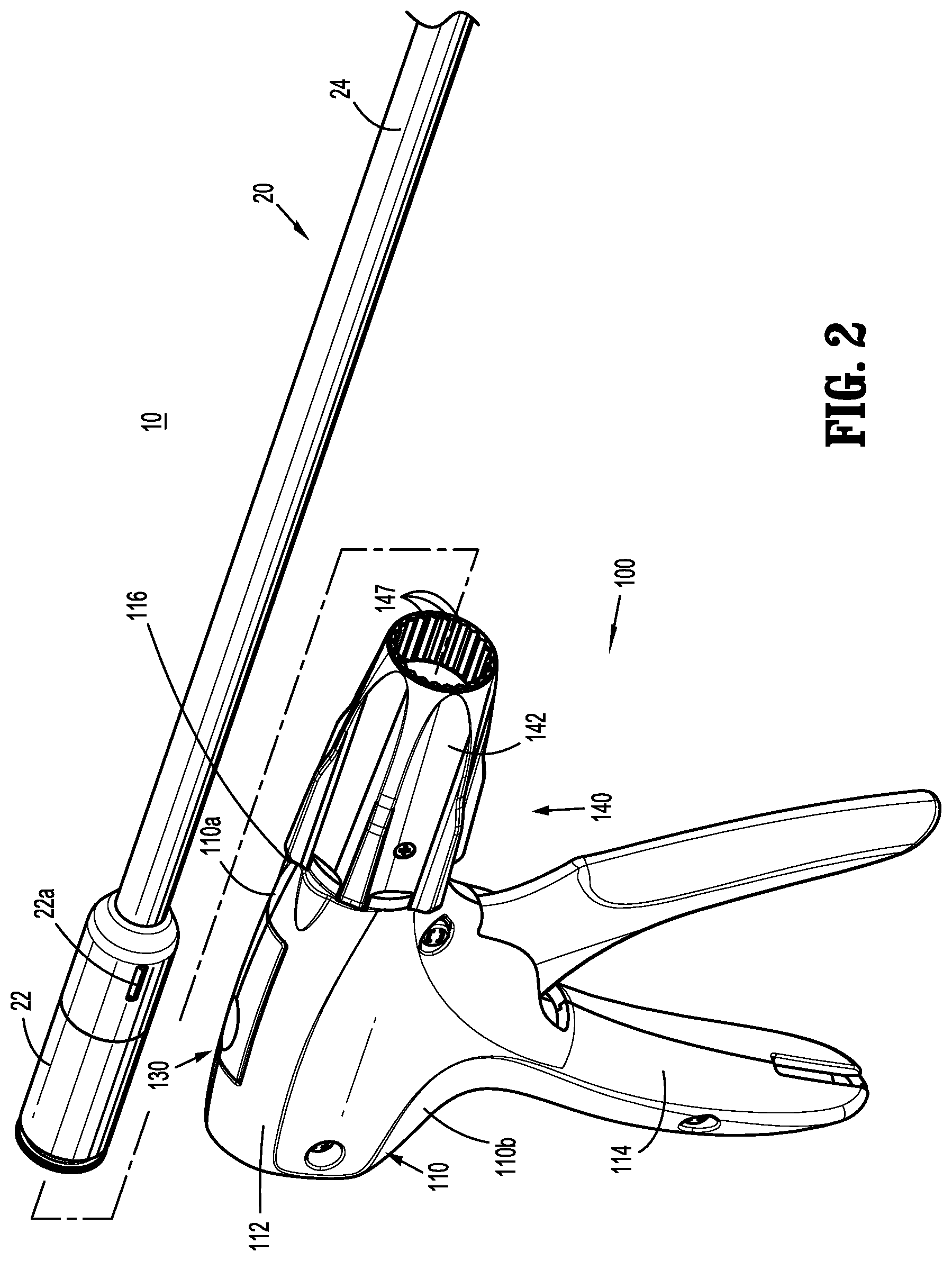
FIG. 2 is front, perspective view of the surgical clip applier shown in FIG. 1 with the elongated assembly removed from the handle assembly;
FIG. 3 is an enlarged, side view of the handle assembly of the surgical clip applier shown in FIG. 1 with a housing half removed;
FIG. 4 is a side, perspective view of a rotation knob assembly of the surgical clip applier shown in FIG. 1;
FIG. 5 is a side, perspective view of the rotation knob assembly shown in FIG. 4 with parts separated;
FIG. 6 is a side, perspective view of a screw of the rotation knob assembly shown in FIG. 4;
FIG. 7 is a side, cross-sectional view taken along line 7-7 shown in FIG. 4;
FIG. 8 is a side, perspective view of a rotation knob assembly according to another embodiment of the present disclosure;
FIG. 9 is an end, perspective view of an outer knob of the rotation knob assembly shown in FIG. 8;
FIG. 10 is a side, perspective view of the rotation knob assembly shown in FIG. 8 with parts separated;
FIG. 11 is a side, cross-sectional view taken along line 11-11 shown in FIG. 8;
FIG. 12 is an end, cross-sectional view taken along line 12-12 shown in FIG. 11;
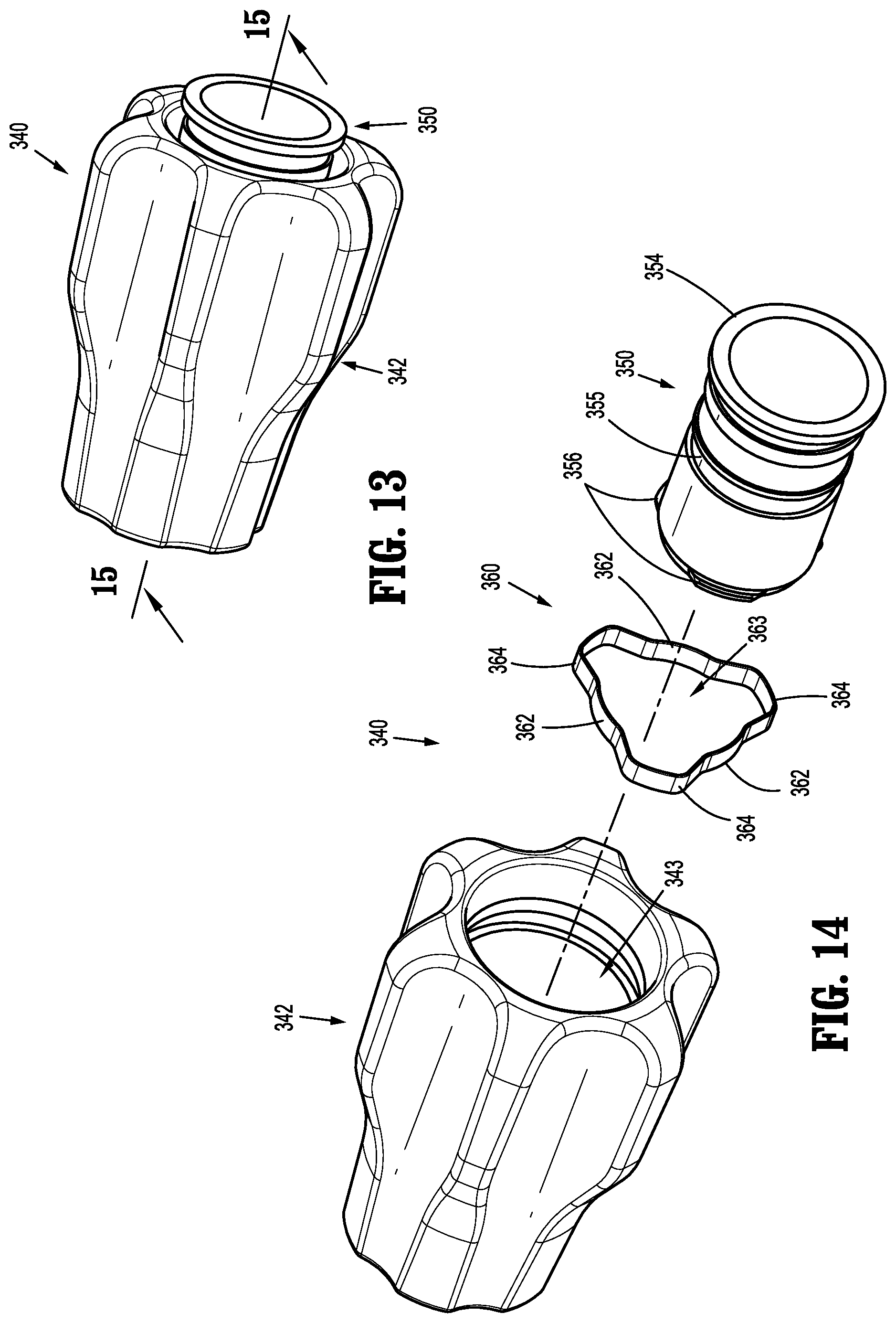
FIG. 13 is a side, perspective view of a rotation knob assembly according to another embodiment of the present disclosure;
FIG. 14 is a side, perspective view of the rotation knob assembly shown in FIG. 13 with parts separated;
FIG. 15 is a side, cross-sectional view taken along line 15-15 shown in FIG. 13;
FIG. 16 is an end, cross-sectional view taken along line 16-16 shown in FIG. 15;
FIG. 17 is a side, perspective view of a rotation knob assembly according to another embodiment of the present disclosure with parts separated;
FIG. 18 is a side, cross-sectional view of the rotation knob assembly shown in FIG. 17; and
FIG. 19 is a cross-sectional end view taken along line 19-19 shown in FIG. 18.
DETAILED DESCRIPTION
As detailed herein and shown in the drawing figures, as is traditional when referring to relative positioning on a surgical instrument, the term "proximal" refers to the end of the apparatus or component thereof which is closer to the user and the term "distal" refers to the end of the apparatus or component thereof which is further away from the user. Further, to the extent consistent, any or all of the aspects and features detailed herein may be used in conjunction with any or all of the other aspects and features detailed herein.
The present disclosure provides rotation knob assemblies for surgical instruments. Although detailed herein as incorporated into a surgical clip applier, the rotation knob assemblies of the present disclosure may alternatively be incorporated into any suitable surgical instrument.
Turning to FIGS. 1 and 2, a surgical clip applier according to aspects of the present disclosure is shown generally as clip applier 10. The clip applier 10 generally includes a handle assembly 100 and an adapter assembly 20 selectively connectable to the handle assembly 100. The handle assembly 100 is configured to operate the adapter assembly 20 upon connection thereto, and may be configured as a sterilizable, reusable component such that handle assembly 100 may be repeatedly used with different and/or additional elongated assemblies (not shown) during the course of one or more surgical procedures. The adapter assembly 20 may be configured as single-use disposable component, limited-use disposable components, or reusable components, depending upon a particular purpose and/or the configuration of the particular elongated assembly. In either configuration, the need for multiple handle assemblies 100 is obviated and, instead, the surgeon need only select an appropriate elongated assembly, and connect that elongated assembly to the handle assembly 100 in preparation for use.
The handle assembly 100 includes a housing 110, an actuation mechanism 120 (FIG. 3) operably disposed within the housing 110, a latch assembly 130 (FIG. 3) operably disposed within housing 110, and a rotation knob assembly 140 operably coupled to a distal portion of housing 110. The housing 110 supports and/or encloses the operating components of handle assembly 100, the actuation mechanism 120 is configured to enable selective firing of one or more surgical clips (not shown) from the end effector (not shown) of the attached adapter assembly 20. The latch mechanism 130 is configured to facilitate releasable locking engagement of the adapter assembly 20 with handle assembly 100. The rotation knob assembly 140 enables the selective rotation of the attached adapter assembly 20 relative to the housing 110.
The handle assembly 100 will only be described to the extent necessary to fully disclose the aspects of the present disclosure. For a detailed description of the operation and function of an exemplary handle assembly, including an exemplary actuation mechanism and an exemplary latch assembly, please refer to commonly owned U.S. Prov. Pat. App. Ser. No. 62/581,144 ("the '144 application"), filed Nov. 3, 2017, the content of which is incorporated herein by reference in its entirety. Other exemplary embodiments of handle assemblies may be found in commonly owned Intl. Pat. App. Nos. PCT/CN2016/096666 and PCT/CN2016/071178, filed on Aug. 26, 2016 and Jan. 18, 2016, respectively, the content of each is hereby incorporated herein by reference in its entirety.
Referring to FIGS. 1 and 2, the adapter assembly 20 of the clip applier 10 generally includes a proximal hub 22, an elongated shaft 24 extending distally from the proximal hub 22, an end effector assembly (not shown) disposed towards a distal end portion of the elongated shaft 24, and an inner drive assembly (not shown) operably coupled between the handle assembly 100 and the end effector assembly when adapter assembly 20 is engaged with the handle assembly 100, to enable the sequential firing of at least one surgical clip (not shown) about tissue. The end effector may be integrally formed with the adapter assembly 20, or may be a separate component releasably secured to the adapter assembly 20. The end effector assembly may be configured to fire surgical clips similar to those shown and described in U.S. Pat. Nos. 7,819,886 or 7,905,890, the content of each of which is hereby incorporated herein by reference in its entirety.
With additional reference to FIG. 3, the housing 110 of the handle assembly 100 may be formed from first and second housing halves 110a, 110b that cooperate to define a body portion 112 and a fixed handle portion 114 depending from the body portion 112. The body portion 112 of the housing 110 includes a distal nose 116 defining a distal opening 117 (FIG. 3) therethrough. A proximal end portion of the proximal hub 22 of the adapter assembly 20 is configured to extend at least partially through the distal opening 117 of the distal nose 116 of the housing 110 when the adapter assembly 20 is engaged with the handle assembly 100.
The distal nose 116 of the body portion 112 of the housing 110 further includes an annular recess 119 defined on an interior surface thereof surrounding the distal opening 117. The annular recess 119 is configured to receive an annular protrusion 154 of an inner collar 150 of the rotation knob assembly 140 to secure the rotation knob assembly 140 with the distal nose 116 of the body portion 112 of the housing 110. To this end, the annular recess 119 and/or the annular protrusion 154 of the inner collar 150 may include one or more keying features to facilitate rotationally lock the inner collar 150 to the distal nose 116 of the housing 110. In embodiments, and as shown, the inner collar 150 defines an opening 153 (FIG. 5) that receives a tab (not shown) extending from the distal nose 116 of the body portion 112 of the housing 110 for longitudinally and rotationally locking the inner collar 150 relative to the housing 110.
With reference to FIGS. 3-7, an outer knob 142 of the rotation knob assembly 140 is rotatably coupled to the distal nose 116 of the body portion 112 of the housing 110 and is configured to receive the proximal hub 22 (FIG. 1) of the adapter assembly 20. As described below, the outer knob 142 of the rotation knob assembly 140 is coupled to the adapter assembly 20 in fixed rotational engagement therewith to enable selective rotation of the adapter assembly 20 relative to the housing 110 upon rotation of an outer knob 142 relative to housing 110. The rotation knob assembly 140 includes the outer knob 142, the inner collar 150, and a pair of screws 160 rotatably securing the outer knob 142 to the inner collar 150.
The outer knob 142 of the rotation knob assembly 140 may be formed from a polymeric material, e.g., a biocompatible, sterilizable plastic, or other suitable material, and includes a body 144 defining a substantially cone shaped-configuration tapering in diameter from a proximal end portion to a distal end portion thereof, although other suitable configurations are also contemplated. The body 144 defines a plurality of flutes 146 arranged radially about the body 144 to facilitate grasping or gripping of the body 144 by a user at any rotational orientation to enable rotation of the rotation knob assembly 140.
The body 144 of the outer knob 142 of the rotation knob assembly 140 defines a longitudinally-extending lumen 143 therethrough. The longitudinally-extending lumen 143 includes a proximal portion 143a and a distal portion 143b which may define equal or different diameters, e.g., the proximal portion 143a may define a larger diameter as compared to the distal portion 143b. The proximal portion 143a of lumen 143 communicates with the proximal opening of the body 144 of the outer knob 142. The body 144 of the outer knob 142 defines a pair of threaded transverse apertures 145 (FIG. 5, only one shown) that communicate with the proximal portion 143a of the lumen 143. Each of the threaded transverse apertures 145 is configured to receive one of the screws 160 as detailed below.
The distal portion 143b of the lumen 143 communicates with the distal opening of the body 144 of the outer knob 142 at the distal end thereof and with the proximal portion 143a of the lumen 143 at the proximal end thereof. The body 144 includes a plurality of longitudinally-extending grooves 147 arranged annularly on an interior surface thereof and disposed about at least a portion of the distal portion 143b of the lumen 143. The grooves 147 are configured to slidably receive indexing protrusions 22a (FIG. 2) of the proximal hub 22 of adapter assembly 20 to rotationally fix the proximal hub 22 relative to the outer knob 142 upon insertion of proximal hub 22 into handle assembly 100.
The inner collar 150 of the rotation knob assembly 140 may be formed from a metal, e.g., stainless steel, or other suitable material, and includes a body 152 defining a longitudinally-extending lumen 151 therethrough. The inner collar 150 further includes an annular protrusion 154 disposed about a proximal end portion thereof and a distal head 156 disposed about a distal end portion thereof. The inner collar 150 defines an annular groove or channel 155 defined within an exterior surface of the inner collar 150, disposed between the annular protrusion 154 and the distal head 156. The annular protrusion 154, as noted above, is configured for receipt within the annular recess 119 of the distal nose 116 of the housing 110 (see FIG. 3) to engage the inner collar 150 with the distal nose 116 of the body portion 112 of the housing 110, e.g., upon engagement of the first and second housing halves 110a, 110b (FIG. 1) forming the housing 110 with one another. As noted above, the inner collar 150 defines the opening 154 for receiving a tab (not shown) extending from the distal nose 116 of the housing 110 for rotationally locking the inner collar 150 relative to the housing 110.
The inner collar 150 is configured to be received within the proximal portion 143a of the lumen 143 of the body 144 of the outer knob 142. The inner collar 150 is configured such that the annular groove 155 aligns with the pair of threaded transverse apertures 145 in the body 144 of the outer knob 142 when the outer knob 142 is received about the inner collar 150.
With particular reference to FIG. 6, each screw 160 of the rotation knob assembly 140 includes a head portion 162, a threaded post portion 164 extending from the head 162, and a ball portion 166 disposed on an end of the threaded post portion 164. In embodiments, at least the ball portion 166 of the screws 160 is formed from PLASTITE.RTM. (a registered trademark of Research Engineering & Manufacturing, Inc., Rhode Island) or other low friction or lubricious material to facilitate rotation of the outer knob 142 of the rotation knob assembly 140 relative to the inner collar 150. In alternative embodiments, the screws are biased radially inward to facilitate assembly of the rotation knob assembly.
Turing to FIG. 7, the screws 160 of the rotation knob assembly 140 are received within the transverse apertures 145 defined through the body 144 of the outer knob 142, and are oriented such that the ball portions 166 of the screws 160 protrude radially inwardly into the proximal portion 143a of the lumen 143 of the body 144 of the outer knob 142. As noted above, the annular groove 155 of the inner collar 150 aligns with the transverse apertures 145 in the outer knob 142 when the outer knob 142 is received about the inner collar 150. In this manner, the ball portions 166 of the screws 166 extending from the transvers apertures 145 are received within the annular groove 155 of the inner collar 150 to rotatably retain the outer knob 142 relative to the inner collar 150. The ball portions 166 of the screws 160 are configured to provide minimal friction with inner collar 150 to allow ease of rotation of the outer knob 142 relative to the inner collar 150. The outer knob 142 may be rotated continuously through an infinite number of positions.
With reference now to FIGS. 8-12, a rotation knob assembly according to another embodiment of the present disclosure is shown generally as rotation knob assembly 240. The rotation knob assembly 240 is substantially similar to rotation knob assembly 140 described herein above, and will only be described in detail as relates to the differences therebetween.
The rotation knob assembly 240 includes an outer knob 242, an inner collar 250, and a bearing assembly 260 rotatable securing the outer knob 242 to the inner collar 250. The outer knob 242 includes a body 244 defining a longitudinally-extending lumen 243 therethrough. The longitudinally-extending lumen 243 includes a proximal portion 243a and a distal portion 243b. The body 244 of the outer knob 242 defines a plurality of longitudinally extending openings 245 that communicate with the proximal portion 243a of the lumen 243. Each of the longitudinal openings 245 is configured to receive a locking member 270 (FIG. 10) as detailed below. The body 244 of the outer knob 242 also defines a plurality of notches 247 extending radially outward from the proximal portion 243a of the longitudinally extending lumen 243. The notches 247 accommodate protrusions 266 of an annular body 264 of the bearing member 262 of the bearing assembly 260.
The inner collar 250 of the rotation knob assembly 240 includes a body 252. The inner collar 250 includes an annular protrusion 254 disposed about a proximal end portion thereof, an annular flange 256 disposed about a mid-portion thereof, and a bearing surface 258 disposed between the annular protrusion 254 and the annular flange 256. As described below, the bearing surface 258 of the inner collar 250 is configured to rotatably support the bearing member 262 of the bearing assembly 260.
The bearing assembly 260 of the rotation knob assembly 240 includes the bearing member 262 and the plurality of fastening members 270. The bearing member 262 includes an annular body 264 and a plurality of protrusions 266 extending radially outward from the annular body 264. The annular body 264 of the bearing member 266 is configured to be received about the bearing surface 258 of the inner collar 250 and within the proximal portion 243a of the lumen 243 in the outer knob 242 of the rotation knob assembly 240. The protrusions 266 of the bearing member 262 are configured to be received within the notches 247 in the body 244 of the outer knob 242. Although shown as having three protrusions 266 with a triangular shape, it is envisioned that the bearing member 262 may include any number of protrusions 266 and the protrusions 266 may include any suitable shape. The number and shape of the notches 247 in the body 244 of the outer knob 242 correspond to the number and shape of the protrusions 266. Each of the protrusions 266 of the bearing member 262 defines an opening 267 for engaging a proximal end of one of the fastener members 270.
The fastener members 270 of the rotation knob assembly 240 may include a threaded outer surface (not shown) for threading engagement with the protrusions 266 of the bearing member 262. Alternatively, the fastener members 270 may be received within the openings 267 in the protrusions 266 of the bearing member 262 with a friction fit. The fastener members 270 may be further secured to the protrusions 266 of the bearing member 262 with adhesive. In embodiments, either or both of inner collar 250 and the bearing member 262 are formed from PLASTITE.RTM. or other low friction or lubricious material to facilitate rotation of the bearing member 262 relative to the inner collar 250. Alternatively, either or both of the bearing member 262 and inner collar 250 may include a friction reducing coating to facilitate rotation of the outer knob 242 about the inner collar 250.
With reference now to FIG. 13-16, another embodiment of a rotation knob assembly according to the present disclosure is shown generally as rotation knob assembly 340. The rotation knob assembly 340 is substantially similar to rotation knob assemblies 140, 240 described herein above, and will only be described in detail as relates to the differences therebetween.
The rotation knob assembly 340 includes an outer knob 342, an inner collar 350, and a snap ring 360. The outer knob 342 includes a body 344 defining a longitudinally-extending lumen 343 therethrough. The longitudinally-extending lumen 343 includes a proximal portion 343a and a distal portion 343b. The body 344 of the outer knob 342 defines an annular groove 345 disposed within the proximal portion 343a of the longitudinally extending lumen 343. The annular groove 345 is configured to receive a plurality of flange portions 364 of the snap ring 360. Alternatively, the body 344 of the outer knob 342 includes a plurality of cutouts (not shown) for accommodating the plurality of flange portions 364 of the snap ring.
The inner collar 350 of the rotation knob assembly 340 includes a body 352. The inner collar 350 includes an annular protrusion 354 disposed about a proximal end portion thereof and distal head sections 356 disposed about a mid-portion thereof. The inner collar 350 defines an annular groove 355 disposed between the annular protrusion 354 and the annular flange sections 356. As described below, the annular groove 355 is configured to accept the snap ring 360 of the rotation knob assembly 340.
The snap ring 360 of the rotation knob assembly 340 includes alternating annular segments 362 and flange segments 364. Together the annular segments 362 define a cylindrical opening 363 configured to be received within the annular groove 355 in the inner collar 350. The flange segments 364 of the snap ring 360 extend outwardly between the annular segments 362 and are configured to be received within the annular groove 345 in the proximal portion 343a of the longitudinally extending lumen 343 of the body 352 of the outer knob 350.
The snap ring 360 may be secured within the annular groove 345 of the outer knob 342 in a rotationally fixed condition such that the snap ring 360 rotates along with the outer knob 342 when the outer knob 342 is rotated relative to the inner collar 350. In this manner, the snap ring 360 is rotatably received within the annular groove 355 of the inner collar 350 and the snap ring 360 and outer knob 342 rotate relative to the inner collar 350. Alternatively, the snap ring 360 may be secured within the annular groove 345 of the inner collar 350 in a rotationally fixed condition such that the snap ring 360 does not rotate with the outer knob 342 as the outer knob 342 is rotated relative to the inner collar 350. In this manner, the snap ring 360 is rotatably received within the annular groove 345 of the outer knob 342 and the outer knob 342 rotates relative to the snap ring 360. In embodiments the snap ring 360 may be rotationally received within the annular groove 345 of the outer knob 342 and the annular groove 355 of the inner collar 350 such that the snap ring 360 may rotate relative to either or both of the outer knob 342 and inner collar 350 when the outer knob 342 is rotated relative to the inner collar 350.
With reference now to FIG. 17-19, still another embodiment of a rotation knob assembly according to the present disclosure is shown generally as rotation knob assembly 440. The rotation knob assembly 440 is substantially similar to rotation knob assemblies 140, 240, 340 described herein above, and will only be described in detail as relates to the differences therebetween.
The rotation knob assembly 440 includes an outer knob 442, an inner collar 450, and a bearing assembly 460. The outer knob 442 includes a body 444 defining a longitudinally-extending lumen 443 therethrough. The longitudinally-extending lumen 443 includes a proximal portion 443a and a distal portion 443b. The body 444 includes a plurality of longitudinally-extending grooves 447 arranged annularly on an interior surface thereof and disposed about at least a portion of the proximal portion 443a of the lumen 443. The grooves 447 frictionally engage a grooved outer surface 456 of the inner collar 450.
The inner collar 450 of the rotation knob assembly 440 includes a body 452. The inner collar 450 includes a bearing surface 454 disposed about a proximal end portion thereof and the grooved outer surface 456 about a distal portion thereof. A plurality of paired semi-spherical recesses 453 are defined in the bearing surface 454 of the inner collar 450. As described below, the semi-spherical recesses 453 support ball bearings 466 of the bearing assembly 460. The grooved outer surface 456 of the inner collar 450 frictionally engages and rotationally fixes the inner collar 450 to the outer knob 442.
The bearing assembly 460 of the rotation knob assembly 440 includes an annular housing 462 having first and second housing halves 462a, 462b. The annular housing 462 includes proximal and distal annular flanges 464a, 464b. The proximal annular flange 464a of the annular housing 462 is configured to be received within the annular recess 119 (FIG. 3) in the distal nose 116 (FIG. 3) of the body portion 114 (FIG. 3) of the housing 110. The distal annular flange 464b of the annular housing 462 is configured to be received within the proximal portion 443a of the lumen 443 of the body 444 of the outer knob 442 to support the inner collar 450 within the outer knob 442.
The annular housing 462 of the bearing assembly 460 defines a pair of annular grooves 463 that align with the plurality of paired semi-spherical recesses 453 in the inner collar 450 when the inner collar 450 is received within the outer knob 442. The annular grooves 463 cooperate with the semi-spherical recesses 453 to support the ball bearings 466. Receipt of the ball bearings 466 within the semi-spherical recesses 453 and the annular grooves 463 longitudinally fixes the outer knob 442 and the inner collar 450 relative to the housing 112 of the handle assembly 100 and facilitates rotation of the outer knob 442 relative to the housing 110.
It should be understood that the foregoing description is only illustrative of the present disclosure. Various alternatives and modifications can be devised by those skilled in the art without departing from the disclosure. Accordingly, the present disclosure is intended to embrace all such alternatives, modifications and variances. The embodiments described with reference to the attached drawing figures are presented only to demonstrate certain examples of the disclosure. Other elements, steps, methods and techniques that are insubstantially different from those described above and/or in the appended claims are also intended to be within the scope of the disclosure.
* * * * *
D00000
D00001
D00002
D00003
D00004
D00005
D00006
D00007
D00008
D00009
D00010
D00011
D00012

XML
uspto.report is an independent third-party trademark research tool that is not affiliated, endorsed, or sponsored by the United States Patent and Trademark Office (USPTO) or any other governmental organization. The information provided by uspto.report is based on publicly available data at the time of writing and is intended for informational purposes only.
While we strive to provide accurate and up-to-date information, we do not guarantee the accuracy, completeness, reliability, or suitability of the information displayed on this site. The use of this site is at your own risk. Any reliance you place on such information is therefore strictly at your own risk.
All official trademark data, including owner information, should be verified by visiting the official USPTO website at www.uspto.gov. This site is not intended to replace professional legal advice and should not be used as a substitute for consulting with a legal professional who is knowledgeable about trademark law.