Chemical control features in wafer process equipment
Liang , et al. July 16, 2
U.S. patent number 10,354,843 [Application Number 15/581,357] was granted by the patent office on 2019-07-16 for chemical control features in wafer process equipment. This patent grant is currently assigned to Applied Materials, Inc.. The grantee listed for this patent is Applied Materials, Inc.. Invention is credited to Xinglong Chen, Kien Chuc, Saurabh Garg, Kimberly Hinckley, Qiwei Liang, Dmitry Lubomirsky, Soonam Park, Toan Tran, Shankar Venkataraman, Jang-Gyoo Yang.


View All Diagrams
| United States Patent | 10,354,843 |
| Liang , et al. | July 16, 2019 |
Chemical control features in wafer process equipment
Abstract
Gas distribution assemblies are described including an annular body, an upper plate, and a lower plate. The upper plate may define a first plurality of apertures, and the lower plate may define a second and third plurality of apertures. The upper and lower plates may be coupled with one another and the annular body such that the first and second apertures produce channels through the gas distribution assemblies, and a volume is defined between the upper and lower plates.
| Inventors: | Liang; Qiwei (Fremont, CA), Chen; Xinglong (San Jose, CA), Chuc; Kien (San Francisco, CA), Lubomirsky; Dmitry (Cupertino, CA), Park; Soonam (Sunnyvale, CA), Yang; Jang-Gyoo (San Jose, CA), Venkataraman; Shankar (San Jose, CA), Tran; Toan (San Jose, CA), Hinckley; Kimberly (Mountain View, CA), Garg; Saurabh (San Jose, CA) | ||||||||||
|---|---|---|---|---|---|---|---|---|---|---|---|
| Applicant: |
|
||||||||||
| Assignee: | Applied Materials, Inc. (Santa
Clara, CA) |
||||||||||
| Family ID: | 50341854 | ||||||||||
| Appl. No.: | 15/581,357 | ||||||||||
| Filed: | April 28, 2017 |
Prior Publication Data
| Document Identifier | Publication Date | |
|---|---|---|
| US 20170236691 A1 | Aug 17, 2017 | |
Related U.S. Patent Documents
| Application Number | Filing Date | Patent Number | Issue Date | ||
|---|---|---|---|---|---|
| 14853838 | Sep 14, 2015 | ||||
| 13799840 | Sep 15, 2015 | 9132436 | |||
| 61704257 | Sep 21, 2012 | ||||
| Current U.S. Class: | 1/1 |
| Current CPC Class: | H01J 37/3244 (20130101); H01J 37/32357 (20130101); H01J 37/32449 (20130101); H01J 37/32568 (20130101); H01L 21/67069 (20130101); C23C 16/452 (20130101); B05B 1/005 (20130101); C23C 16/45565 (20130101); C23C 16/455 (20130101); C23C 16/45582 (20130101); C23C 16/50 (20130101); C23C 16/45561 (20130101); B05B 1/18 (20130101); C23C 16/45574 (20130101); H01J 37/32009 (20130101); H01J 2237/002 (20130101) |
| Current International Class: | C23C 16/455 (20060101); B05B 1/00 (20060101); C23C 16/452 (20060101); B05B 1/18 (20060101); C23C 16/50 (20060101); H01L 21/67 (20060101); H01J 37/32 (20060101) |
| Field of Search: | ;118/715 ;156/345.33,345.34 |
References Cited [Referenced By]
U.S. Patent Documents
| 2369620 | February 1945 | Sullivan et al. |
| 3401302 | September 1968 | Thorpe |
| 3451840 | June 1969 | Hough |
| 3537474 | November 1970 | Rohrer |
| 3756511 | September 1973 | Shinroku |
| 3937857 | February 1976 | Brummett et al. |
| 3969077 | July 1976 | Hill |
| 4006047 | February 1977 | Brummett et al. |
| 4190488 | February 1980 | Winters |
| 4209357 | June 1980 | Gorin et al. |
| 4214946 | July 1980 | Forget et al. |
| 4232060 | November 1980 | Mallory, Jr. |
| 4234628 | November 1980 | DuRose |
| 4265943 | May 1981 | Goldstein et al. |
| 4340462 | July 1982 | Koch |
| 4341592 | July 1982 | Shortes et al. |
| 4361418 | November 1982 | Tscheppe |
| 4361441 | November 1982 | Tylko |
| 4364803 | December 1982 | Nidola et al. |
| 4368223 | January 1983 | Kobayashi et al. |
| 4374698 | February 1983 | Sanders et al. |
| 4397812 | August 1983 | Mallory, Jr. |
| 4468413 | August 1984 | Bachmann |
| 4565601 | January 1986 | Kakehi et al. |
| 4579618 | April 1986 | Celestino et al. |
| 4585920 | April 1986 | Hoog et al. |
| 4610775 | September 1986 | Phifer |
| 4625678 | December 1986 | Shloya et al. |
| 4632857 | December 1986 | Mallory, Jr. |
| 4656052 | April 1987 | Satou et al. |
| 4656076 | April 1987 | Vetanen et al. |
| 4668335 | May 1987 | Mockler |
| 4690746 | September 1987 | McInerney et al. |
| 4715937 | December 1987 | Moslehi et al. |
| 4749440 | June 1988 | Blackwood et al. |
| 4753898 | June 1988 | Parrillo et al. |
| 4786360 | November 1988 | Cote et al. |
| 4792378 | December 1988 | Rose et al. |
| 4793897 | December 1988 | Dunfield et al. |
| 4807016 | February 1989 | Douglas |
| 4810520 | March 1989 | Wu |
| 4816638 | March 1989 | Ukai et al. |
| 4820377 | April 1989 | Davis et al. |
| 4828649 | May 1989 | Davis |
| 4857140 | August 1989 | Loewenstein |
| 4867841 | September 1989 | Loewenstein et al. |
| 4904621 | February 1990 | Lowenstein et al. |
| 4913929 | April 1990 | Moslehi et al. |
| 4919750 | April 1990 | Bausmith et al. |
| 4946903 | August 1990 | Gardella et al. |
| 4951601 | August 1990 | Maydan et al. |
| 4960488 | October 1990 | Law et al. |
| 4980018 | December 1990 | Mu et al. |
| 4981551 | January 1991 | Palmour |
| 4985372 | January 1991 | Narita et al. |
| 4991542 | February 1991 | Kohmura et al. |
| 4992136 | February 1991 | Tachi et al. |
| 4993358 | February 1991 | Mahawili |
| 4994404 | February 1991 | Sheng et al. |
| 5000113 | March 1991 | Wang et al. |
| 5006192 | April 1991 | Deguchi |
| 5010842 | April 1991 | Oda et al. |
| 5013691 | May 1991 | Lory et al. |
| 5028565 | July 1991 | Chang |
| 5030319 | July 1991 | Nishino et al. |
| 5038713 | August 1991 | Kawakami et al. |
| 5045244 | September 1991 | Marlett |
| 5061838 | October 1991 | Lane et al. |
| 5069938 | December 1991 | Lorimer et al. |
| 5083030 | January 1992 | Stavov |
| 5089441 | February 1992 | Moslehi |
| 5089442 | February 1992 | Olmer |
| 5147692 | September 1992 | Bengston |
| 5156881 | October 1992 | Okano et al. |
| 5180435 | January 1993 | Markunas et al. |
| 5186718 | February 1993 | Tepman et al. |
| 5188706 | February 1993 | Hori et al. |
| 5198034 | March 1993 | deBoer et al. |
| 5200016 | April 1993 | Namose |
| 5203911 | April 1993 | Sricharoenchalkit et al. |
| 5215787 | June 1993 | Homma |
| 5221427 | June 1993 | Koinuma et al. |
| 5228501 | July 1993 | Tepman et al. |
| 5231690 | July 1993 | Soma et al. |
| 5235139 | August 1993 | Bengston et al. |
| 5238499 | August 1993 | van de Ven et al. |
| 5240497 | August 1993 | Shacham et al. |
| 5248371 | September 1993 | Maher et al. |
| 5248527 | September 1993 | Uchida et al. |
| 5252178 | October 1993 | Moslehi |
| 5266157 | November 1993 | Kadomura |
| 5269881 | December 1993 | Sekiya |
| 5270125 | December 1993 | America et al. |
| 5271972 | December 1993 | Kwok et al. |
| 5275977 | January 1994 | Otsubo et al. |
| 5277750 | January 1994 | Wolgang |
| 5279669 | January 1994 | Lee |
| 5279865 | January 1994 | Chebi et al. |
| 5288518 | February 1994 | Homma |
| 5290382 | March 1994 | Zarowin et al. |
| 5290383 | March 1994 | Koshimizu |
| 5292370 | March 1994 | Tsai et al. |
| 5292682 | March 1994 | Stevens et al. |
| 5300463 | April 1994 | Cathey et al. |
| 5302233 | April 1994 | Kim et al. |
| 5304250 | April 1994 | Sameshima et al. |
| 5306530 | April 1994 | Strongin et al. |
| 5314724 | May 1994 | Tsukune et al. |
| 5319247 | June 1994 | Matsuura |
| 5326427 | July 1994 | Jerbic |
| 5328558 | July 1994 | Kawamura et al. |
| 5328810 | July 1994 | Lowrey et al. |
| 5330578 | July 1994 | Sakama |
| 5334552 | August 1994 | Homma |
| 5345999 | September 1994 | Hosokawa |
| 5352636 | October 1994 | Beinglass |
| 5356478 | October 1994 | Chen et al. |
| 5362526 | November 1994 | Wang et al. |
| 5366585 | November 1994 | Robertson et al. |
| 5368897 | November 1994 | Kurihara et al. |
| 5378316 | January 1995 | Franke et al. |
| 5380560 | January 1995 | Kaja et al. |
| 5382311 | January 1995 | Ishikawa et al. |
| 5384284 | January 1995 | Doan et al. |
| 5385763 | January 1995 | Okano et al. |
| 5399237 | March 1995 | Keswick et al. |
| 5399529 | March 1995 | Homma |
| 5403434 | April 1995 | Moslehi |
| 5413670 | May 1995 | Langan et al. |
| 5413967 | May 1995 | Matsuda et al. |
| 5415890 | May 1995 | Kloiber et al. |
| 5416048 | May 1995 | Blalock et al. |
| 5420075 | May 1995 | Homma et al. |
| 5429995 | July 1995 | Nishiyama et al. |
| 5439553 | August 1995 | Grant et al. |
| 5451259 | September 1995 | Krogh |
| 5464499 | November 1995 | Moslehi |
| 5468342 | November 1995 | Nulty et al. |
| 5474589 | December 1995 | Ohga et al. |
| 5478403 | December 1995 | Shinigawa et al. |
| 5478462 | December 1995 | Walsh |
| 5483920 | January 1996 | Pryor |
| 5494494 | February 1996 | Mizuno et al. |
| 5500249 | March 1996 | Telford et al. |
| 5505816 | April 1996 | Barnes et al. |
| 5510216 | April 1996 | Calabrese et al. |
| 5516367 | May 1996 | Lei et al. |
| 5518962 | May 1996 | Murao |
| 5531835 | July 1996 | Fodor et al. |
| 5534070 | July 1996 | Okamura et al. |
| 5536360 | July 1996 | Nguyen et al. |
| 5549780 | August 1996 | Koinuma et al. |
| 5558717 | September 1996 | Zhao et al. |
| 5560779 | October 1996 | Knowles et al. |
| 5563105 | October 1996 | Dobuzinsky et al. |
| 5567243 | October 1996 | Foster et al. |
| 5571576 | November 1996 | Qian et al. |
| 5575853 | November 1996 | Arami et al. |
| 5578130 | November 1996 | Hayashi et al. |
| 5578161 | November 1996 | Auda |
| 5580421 | December 1996 | Hiatt et al. |
| 5591269 | January 1997 | Arami et al. |
| 5592358 | January 1997 | Shamouilian |
| 5597439 | January 1997 | Salzman |
| 5599740 | February 1997 | Jang et al. |
| 5614055 | March 1997 | Fairbairn et al. |
| 5616518 | April 1997 | Foo et al. |
| 5624582 | April 1997 | Cain |
| 5626922 | May 1997 | Miyanaga et al. |
| 5628829 | May 1997 | Foster et al. |
| 5635086 | June 1997 | Warren, Jr. |
| 5645645 | July 1997 | Zhang et al. |
| 5648125 | July 1997 | Cane |
| 5648175 | July 1997 | Russell et al. |
| 5656093 | August 1997 | Burkhart et al. |
| 5660957 | August 1997 | Chou et al. |
| 5661093 | August 1997 | Ravi et al. |
| 5670066 | September 1997 | Barnes et al. |
| 5674787 | October 1997 | Zhao et al. |
| 5676758 | October 1997 | Hasgawa et al. |
| 5679606 | October 1997 | Wang et al. |
| 5685946 | November 1997 | Fathauer et al. |
| 5688331 | November 1997 | Aruga et al. |
| 5695810 | December 1997 | Dubin et al. |
| 5712185 | January 1998 | Tsai et al. |
| 5716500 | February 1998 | Bardos et al. |
| 5716506 | February 1998 | Maclay et al. |
| 5719085 | February 1998 | Moon et al. |
| 5733816 | March 1998 | Iyer et al. |
| 5747373 | May 1998 | Yu |
| 5753886 | May 1998 | Iwamura et al. |
| 5755859 | May 1998 | Brusic et al. |
| 5756400 | May 1998 | Ye et al. |
| 5756402 | May 1998 | Jimbo et al. |
| 5772770 | June 1998 | Suda et al. |
| 5781693 | July 1998 | Ballance et al. |
| 5786276 | July 1998 | Brooks et al. |
| 5788825 | August 1998 | Park et al. |
| 5789300 | August 1998 | Fulford |
| 5792376 | August 1998 | Kanai et al. |
| 5800686 | September 1998 | Littau et al. |
| 5804259 | September 1998 | Robles |
| 5812403 | September 1998 | Fong et al. |
| 5814238 | September 1998 | Ashby et al. |
| 5814365 | September 1998 | Mahawill |
| 5820723 | October 1998 | Benjamin et al. |
| 5824599 | October 1998 | Schacham-Diamand et al. |
| 5830805 | November 1998 | Schacham-Diamand et al. |
| 5835334 | November 1998 | McMillin et al. |
| 5843538 | December 1998 | Ehrsam et al. |
| 5843847 | December 1998 | Pu et al. |
| 5844195 | December 1998 | Fairbairn et al. |
| 5846332 | December 1998 | Zhao et al. |
| 5846373 | December 1998 | Pirkle et al. |
| 5846375 | December 1998 | Gilchrist et al. |
| 5846598 | December 1998 | Semkow et al. |
| 5849639 | December 1998 | Molloy et al. |
| 5850105 | December 1998 | Dawson et al. |
| 5855681 | January 1999 | Maydan et al. |
| 5855685 | January 1999 | Tobe et al. |
| 5856240 | January 1999 | Sinha et al. |
| 5858876 | January 1999 | Chew |
| 5863376 | January 1999 | Wicker |
| 5865896 | February 1999 | Nowak |
| 5866483 | February 1999 | Shiau et al. |
| 5868897 | February 1999 | Ohkawa |
| 5872052 | February 1999 | Iyer |
| 5872058 | February 1999 | Van Cleemput et al. |
| 5882424 | March 1999 | Taylor et al. |
| 5882786 | March 1999 | Nassau et al. |
| 5883012 | March 1999 | Chiou |
| 5885404 | March 1999 | Kim et al. |
| 5885749 | March 1999 | Huggins et al. |
| 5888906 | March 1999 | Sandhu et al. |
| 5891349 | April 1999 | Tobe et al. |
| 5891513 | April 1999 | Dubin et al. |
| 5897751 | April 1999 | Makowiecki |
| 5899752 | May 1999 | Hey et al. |
| 5900163 | May 1999 | Yi et al. |
| 5904827 | May 1999 | Reynolds |
| 5907790 | May 1999 | Kellam |
| 5910340 | June 1999 | Uchida et al. |
| 5913147 | June 1999 | Dubin et al. |
| 5913978 | June 1999 | Kato et al. |
| 5915190 | June 1999 | Pirkle |
| 5918116 | June 1999 | Chittipeddi |
| 5919332 | July 1999 | Koshiishi et al. |
| 5920792 | July 1999 | Lin |
| 5926737 | July 1999 | Ameen et al. |
| 5932077 | August 1999 | Reynolds |
| 5933757 | August 1999 | Yoshikawa et al. |
| 5935334 | August 1999 | Fong et al. |
| 5935340 | August 1999 | Xia et al. |
| 5937323 | August 1999 | Orczyk et al. |
| 5939831 | August 1999 | Fong et al. |
| 5942075 | August 1999 | Nagahata et al. |
| 5944049 | August 1999 | Beyer et al. |
| 5944902 | August 1999 | Redeker et al. |
| 5948702 | September 1999 | Rotondaro |
| 5951601 | September 1999 | Lesinski et al. |
| 5951776 | September 1999 | Selyutin et al. |
| 5951896 | September 1999 | Mahawill |
| 5953591 | September 1999 | Ishihara et al. |
| 5953635 | September 1999 | Andideh |
| 5963840 | October 1999 | Xia et al. |
| 5968587 | October 1999 | Frankel et al. |
| 5968610 | October 1999 | Liu et al. |
| 5969422 | October 1999 | Ting et al. |
| 5976327 | November 1999 | Tanaka |
| 5990000 | November 1999 | Hong et al. |
| 5990013 | November 1999 | Berenguer et al. |
| 5993916 | November 1999 | Zhao et al. |
| 5994209 | November 1999 | Yieh et al. |
| 5997649 | December 1999 | Hillman |
| 5997962 | December 1999 | Ogasawara et al. |
| 6004884 | December 1999 | Abraham |
| 6007635 | December 1999 | Mahawill |
| 6007785 | December 1999 | Liou |
| 6010962 | January 2000 | Liu et al. |
| 6013191 | January 2000 | Nasser-Faili et al. |
| 6013584 | January 2000 | M'Saad |
| 6015724 | January 2000 | Yamazaki et al. |
| 6015747 | January 2000 | Lopatin et al. |
| 6017414 | January 2000 | Koemtzopoulos et al. |
| 6019848 | February 2000 | Kiyama et al. |
| 6020271 | February 2000 | Yanagida |
| 6030666 | February 2000 | Lam et al. |
| 6030881 | February 2000 | Papasouliotis et al. |
| 6035101 | March 2000 | Sajoto et al. |
| 6036878 | March 2000 | Collins et al. |
| 6037018 | March 2000 | Jang et al. |
| 6037266 | March 2000 | Tao et al. |
| 6039834 | March 2000 | Tanaka et al. |
| 6039851 | March 2000 | Iyer |
| 6053982 | April 2000 | Halpin et al. |
| 6059643 | May 2000 | Hu et al. |
| 6063683 | May 2000 | Wu et al. |
| 6063712 | May 2000 | Gilton et al. |
| 6065424 | May 2000 | Shacham-Diamand et al. |
| 6065425 | May 2000 | Takaki et al. |
| 6072147 | June 2000 | Koshiishi |
| 6072227 | June 2000 | Yau et al. |
| 6074512 | June 2000 | Collins et al. |
| 6074514 | June 2000 | Bjorkman et al. |
| 6077384 | June 2000 | Collins et al. |
| 6077780 | June 2000 | Dubin |
| 6079356 | June 2000 | Umotoy et al. |
| 6080529 | June 2000 | Ye et al. |
| 6081414 | June 2000 | Flanigan et al. |
| 6083344 | July 2000 | Hanawa et al. |
| 6083844 | July 2000 | Bui-Le et al. |
| 6086677 | July 2000 | Umotoy et al. |
| 6087278 | July 2000 | Kim et al. |
| 6090212 | July 2000 | Mahawill |
| 6093457 | July 2000 | Okumura |
| 6093594 | July 2000 | Yeap et al. |
| 6099697 | August 2000 | Hausmann |
| 6107199 | August 2000 | Allen et al. |
| 6110530 | August 2000 | Chen et al. |
| 6110832 | August 2000 | Morgan et al. |
| 6110836 | August 2000 | Cohen et al. |
| 6110838 | August 2000 | Loewenstein |
| 6113771 | September 2000 | Landau et al. |
| 6114216 | September 2000 | Yieh et al. |
| 6117245 | September 2000 | Mandrekar et al. |
| 6120640 | September 2000 | Shih et al. |
| 6136163 | October 2000 | Cheung et al. |
| 6136165 | October 2000 | Moslehi et al. |
| 6136685 | October 2000 | Narwankar et al. |
| 6136693 | October 2000 | Chan et al. |
| 6140234 | October 2000 | Uzoh et al. |
| 6144099 | November 2000 | Lopatin et al. |
| 6147009 | November 2000 | Grill et al. |
| 6148761 | November 2000 | Majewski et al. |
| 6149828 | November 2000 | Vaartstra |
| 6150628 | November 2000 | Smith et al. |
| 6153935 | November 2000 | Edelstein et al. |
| 6161500 | December 2000 | Kopacz et al. |
| 6161576 | December 2000 | Maher et al. |
| 6162302 | December 2000 | Raghavan et al. |
| 6162370 | December 2000 | Hackett et al. |
| 6165912 | December 2000 | McConnell et al. |
| 6167834 | January 2001 | Wang et al. |
| 6169021 | January 2001 | Akram et al. |
| 6170428 | January 2001 | Redeker et al. |
| 6171661 | January 2001 | Zheng et al. |
| 6174450 | January 2001 | Patrick et al. |
| 6174810 | January 2001 | Patrick et al. |
| 6174812 | January 2001 | Hsuing et al. |
| 6176198 | January 2001 | Kao et al. |
| 6176667 | January 2001 | Fairbairn |
| 6177245 | January 2001 | Ward et al. |
| 6179924 | January 2001 | Zhao et al. |
| 6180523 | January 2001 | Lee et al. |
| 6182602 | February 2001 | Redeker et al. |
| 6182603 | February 2001 | Shang et al. |
| 6184121 | February 2001 | Buchwalter et al. |
| 6186091 | February 2001 | Chu et al. |
| 6189483 | February 2001 | Ishikawa et al. |
| 6190233 | February 2001 | Hong et al. |
| 6194038 | February 2001 | Rossman |
| 6197181 | March 2001 | Chen |
| 6197364 | March 2001 | Paunovic et al. |
| 6197680 | March 2001 | Lin et al. |
| 6197688 | March 2001 | Simpson |
| 6197705 | March 2001 | Vassiliev |
| 6198616 | March 2001 | Dahimene et al. |
| 6203863 | March 2001 | Liu et al. |
| 6204200 | March 2001 | Shieh et al. |
| 6210486 | April 2001 | Mizukami et al. |
| 6217658 | April 2001 | Orczyk et al. |
| 6220201 | April 2001 | Nowak |
| 6225745 | May 2001 | Srivastava |
| 6228233 | May 2001 | Lakshmikanthan et al. |
| 6228751 | May 2001 | Yamazaki et al. |
| 6228758 | May 2001 | Pellerin et al. |
| 6235643 | May 2001 | Mui et al. |
| 6237527 | May 2001 | Kellerman et al. |
| 6238513 | May 2001 | Arnold et al. |
| 6238582 | May 2001 | Williams et al. |
| 6197151 | June 2001 | Kaji et al. |
| 6241845 | June 2001 | Gadgil et al. |
| 6242349 | June 2001 | Nogami et al. |
| 6244211 | June 2001 | Nishikawa et al. |
| 6245396 | June 2001 | Nogami |
| 6245670 | June 2001 | Cheung et al. |
| 6251236 | June 2001 | Stevens |
| 6251802 | June 2001 | Moore et al. |
| 6258170 | July 2001 | Somekh et al. |
| 6258220 | July 2001 | Dordi et al. |
| 6258223 | July 2001 | Cheung et al. |
| 6258270 | July 2001 | Hilgendorff et al. |
| 6261637 | July 2001 | Oberle |
| 6277733 | August 2001 | Smith |
| 6277752 | August 2001 | Chen |
| 6277763 | August 2001 | Kugimiya et al. |
| 6281072 | August 2001 | Li et al. |
| 6281135 | August 2001 | Han et al. |
| 6284146 | September 2001 | Kim et al. |
| 6291282 | September 2001 | Wilk et al. |
| 6291348 | September 2001 | Lopatin et al. |
| 6302964 | October 2001 | Umotoy et al. |
| 6303044 | October 2001 | Koemtzopoulos |
| 6303418 | October 2001 | Cha et al. |
| 6306772 | October 2001 | Lin |
| 6308654 | October 2001 | Schneider et al. |
| 6308776 | October 2001 | Sloan |
| 6310755 | October 2001 | Busato et al. |
| 6312554 | November 2001 | Ye |
| 6312995 | November 2001 | Yu |
| 6319387 | November 2001 | Krishnamoorthy et al. |
| 6321587 | November 2001 | Laush |
| 6322716 | November 2001 | Qiao et al. |
| 6323128 | November 2001 | Sambucetti et al. |
| 6335288 | January 2002 | Kwan et al. |
| 6340435 | January 2002 | Bjorkman et al. |
| 6342733 | January 2002 | Hu et al. |
| RE37546 | February 2002 | Mahawill |
| 6344410 | February 2002 | Lopatin et al. |
| 6348407 | February 2002 | Gupta et al. |
| 6350320 | February 2002 | Sherstinsky et al. |
| 6350697 | February 2002 | Richardson |
| 6351013 | February 2002 | Luning et al. |
| 6352081 | March 2002 | Lu et al. |
| 6355573 | March 2002 | Okumura |
| 6364949 | April 2002 | Or et al. |
| 6364954 | April 2002 | Umotoy et al. |
| 6364957 | April 2002 | Schneider et al. |
| 6375748 | April 2002 | Yudovsky et al. |
| 6376386 | April 2002 | Oshima |
| 6379575 | April 2002 | Yin et al. |
| 6383896 | May 2002 | Kirimura et al. |
| 6383951 | May 2002 | Li |
| 6387207 | May 2002 | Janakiraman et al. |
| 6391753 | May 2002 | Yu |
| 6395150 | May 2002 | Van Cleemput et al. |
| 6403491 | June 2002 | Liu et al. |
| 6415736 | July 2002 | Hao et al. |
| 6416647 | July 2002 | Dordi et al. |
| 6418874 | July 2002 | Cox et al. |
| 6423284 | July 2002 | Arno |
| 6427623 | August 2002 | Ko |
| 6429465 | August 2002 | Yagi et al. |
| 6432819 | August 2002 | Pavate et al. |
| 6432831 | August 2002 | Dhindsa et al. |
| 6436193 | August 2002 | Kasai et al. |
| 6436816 | August 2002 | Lee et al. |
| 6440863 | August 2002 | Tsai et al. |
| 6441492 | August 2002 | Cunningham |
| 6446572 | September 2002 | Brcka |
| 6448537 | September 2002 | Nering |
| 6458718 | October 2002 | Todd |
| 6461974 | October 2002 | Ni et al. |
| 6462371 | October 2002 | Weimer et al. |
| 6462372 | October 2002 | Xia et al. |
| 6465051 | October 2002 | Sahin et al. |
| 6465350 | October 2002 | Taylor et al. |
| 6465366 | October 2002 | Nemani et al. |
| 6477980 | November 2002 | White et al. |
| 6479373 | November 2002 | Dreybrodt et al. |
| 6488984 | December 2002 | Wada et al. |
| 6494959 | December 2002 | Samoilov et al. |
| 6499425 | December 2002 | Sandhu et al. |
| 6500728 | December 2002 | Wang |
| 6503843 | January 2003 | Xia et al. |
| 6506291 | January 2003 | Tsai et al. |
| 6509283 | January 2003 | Thomas |
| 6509623 | January 2003 | Zhao |
| 6516815 | February 2003 | Stevens et al. |
| 6518548 | February 2003 | Sugaya et al. |
| 6527968 | March 2003 | Wang et al. |
| 6528409 | March 2003 | Lopatin et al. |
| 6528751 | March 2003 | Hoffman et al. |
| 6537707 | March 2003 | Lee |
| 6537733 | March 2003 | Campana et al. |
| 6541397 | April 2003 | Bencher |
| 6541671 | April 2003 | Martinez et al. |
| 6544340 | April 2003 | Yudovsky |
| 6547977 | April 2003 | Yan et al. |
| 6551924 | April 2003 | Dalton et al. |
| 6558564 | May 2003 | Loewenhardt |
| 6565661 | May 2003 | Nguyen |
| 6565729 | May 2003 | Chen et al. |
| 6569773 | May 2003 | Gellrich et al. |
| 6572937 | June 2003 | Hakovirta et al. |
| 6573030 | June 2003 | Fairbairn et al. |
| 6573606 | June 2003 | Sambucetti et al. |
| 6585851 | July 2003 | Ohmi et al. |
| 6586163 | July 2003 | Okabe et al. |
| 6596599 | July 2003 | Guo |
| 6596654 | July 2003 | Bayman et al. |
| 6602434 | August 2003 | Hung et al. |
| 6602806 | August 2003 | Xia et al. |
| 6603269 | August 2003 | Vo et al. |
| 6605874 | August 2003 | Leu et al. |
| 6616967 | September 2003 | Test |
| 6627532 | September 2003 | Gaillard et al. |
| 6635575 | October 2003 | Xia et al. |
| 6635578 | October 2003 | Xu et al. |
| 6638810 | October 2003 | Bakli et al. |
| 6645301 | November 2003 | Sainty et al. |
| 6645550 | November 2003 | Cheung et al. |
| 6656831 | December 2003 | Lee et al. |
| 6656837 | December 2003 | Xu et al. |
| 6656848 | December 2003 | Scanlan et al. |
| 6663715 | December 2003 | Yuda et al. |
| 6677242 | January 2004 | Liu et al. |
| 6679981 | January 2004 | Pan et al. |
| 6688375 | February 2004 | Turner |
| 6713356 | March 2004 | Skotnicki et al. |
| 6713835 | March 2004 | Horak et al. |
| 6717189 | April 2004 | Inoue et al. |
| 6720213 | April 2004 | Gambino et al. |
| 6736147 | May 2004 | Satoh et al. |
| 6736987 | May 2004 | Cho |
| 6740247 | May 2004 | Han et al. |
| 6740585 | May 2004 | Yoon et al. |
| 6740977 | May 2004 | Ahn et al. |
| 6743473 | June 2004 | Parkhe et al. |
| 6743732 | June 2004 | Lin et al. |
| 6756235 | June 2004 | Liu et al. |
| 6759261 | July 2004 | Shimokohbe et al. |
| 6762127 | July 2004 | Boiteux et al. |
| 6762435 | July 2004 | Towle |
| 6764958 | July 2004 | Nemani et al. |
| 6765273 | July 2004 | Chau et al. |
| 6767834 | July 2004 | Chung et al. |
| 6768079 | July 2004 | Kosakai |
| 6770166 | August 2004 | Fisher |
| 6772827 | August 2004 | Keller et al. |
| 6792889 | September 2004 | Nakano et al. |
| 6794290 | September 2004 | Papasouliotis et al. |
| 6794311 | September 2004 | Huang et al. |
| 6796314 | September 2004 | Graff et al. |
| 6797189 | September 2004 | Hung et al. |
| 6800336 | October 2004 | Fornsel et al. |
| 6800830 | October 2004 | Mahawili |
| 6802944 | October 2004 | Ahmad et al. |
| 6808564 | October 2004 | Dietze |
| 6808747 | October 2004 | Shih et al. |
| 6808748 | October 2004 | Kapoor et al. |
| 6815633 | November 2004 | Chen et al. |
| 6821571 | November 2004 | Huang |
| 6823589 | November 2004 | White et al. |
| 6828241 | December 2004 | Kholodenko et al. |
| 6830624 | December 2004 | Janakiraman et al. |
| 6835995 | December 2004 | Li |
| 6846745 | January 2005 | Papasouliotis et al. |
| 6849854 | February 2005 | Sainty |
| 6852550 | February 2005 | Tuttle et al. |
| 6852584 | February 2005 | Chen et al. |
| 6853533 | February 2005 | Parkhe et al. |
| 6858153 | February 2005 | Bjorkman et al. |
| 6861097 | March 2005 | Goosey et al. |
| 6861332 | March 2005 | Park et al. |
| 6869880 | March 2005 | Krishnaraj et al. |
| 6875280 | April 2005 | Ikeda et al. |
| 6878206 | April 2005 | Tzu et al. |
| 6879981 | April 2005 | Rothschild et al. |
| 6886491 | May 2005 | Kim et al. |
| 6892669 | May 2005 | Xu et al. |
| 6893967 | May 2005 | Wright et al. |
| 6897532 | May 2005 | Schwarz et al. |
| 6900596 | May 2005 | Yang et al. |
| 6903511 | June 2005 | Chistyakov |
| 6908862 | June 2005 | Li et al. |
| 6911112 | June 2005 | An |
| 6911401 | June 2005 | Khandan et al. |
| 6916399 | July 2005 | Rozenzon et al. |
| 6921556 | July 2005 | Shimizu et al. |
| 6924191 | August 2005 | Liu et al. |
| 6930047 | August 2005 | Yamazaki |
| 6935269 | August 2005 | Lee et al. |
| 6942753 | September 2005 | Choi et al. |
| 6946033 | September 2005 | Tsuei et al. |
| 6951821 | October 2005 | Hamelin et al. |
| 6958175 | October 2005 | Sakamoto et al. |
| 6958286 | October 2005 | Chen et al. |
| 6969619 | November 2005 | Winniczek |
| 6995073 | February 2006 | Liou |
| 7017269 | March 2006 | White et al. |
| 7018941 | March 2006 | Cui et al. |
| 7030034 | April 2006 | Fucsko et al. |
| 7049200 | May 2006 | Arghavani et al. |
| 7052553 | May 2006 | Shih et al. |
| 7071532 | July 2006 | Geffken et al. |
| 7084070 | August 2006 | Lee et al. |
| 7115525 | October 2006 | Abatchev et al. |
| 7122949 | October 2006 | Strikovski |
| 7138767 | November 2006 | Chen et al. |
| 7145725 | December 2006 | Hasel et al. |
| 7148155 | December 2006 | Tarafdar et al. |
| 7166233 | January 2007 | Johnson et al. |
| 7183214 | February 2007 | Nam et al. |
| 7196342 | March 2007 | Ershov et al. |
| 7226805 | June 2007 | Hallin et al. |
| 7235137 | June 2007 | Kitayama et al. |
| 7244474 | July 2007 | Hanawa et al. |
| 7252011 | August 2007 | Traverso |
| 7252716 | August 2007 | Kim et al. |
| 7253123 | August 2007 | Arghavani et al. |
| 7256370 | August 2007 | Guiver |
| 7274004 | September 2007 | Benjamin et al. |
| 7288482 | October 2007 | Panda et al. |
| 7291360 | November 2007 | Hanawa et al. |
| 7316761 | January 2008 | Doan et al. |
| 7329608 | February 2008 | Babayan et al. |
| 7341633 | March 2008 | Lubomirsky et al. |
| 7344912 | March 2008 | Okoroanyanwu |
| 7358192 | April 2008 | Merry et al. |
| 7361865 | April 2008 | Maki et al. |
| 7364956 | April 2008 | Saito |
| 7365016 | April 2008 | Ouellet et al. |
| 7396480 | July 2008 | Kao et al. |
| 7396773 | July 2008 | Blosse et al. |
| 7416989 | August 2008 | Liu et al. |
| 7465358 | December 2008 | Weidman et al. |
| 7465953 | December 2008 | Koh et al. |
| 7468319 | December 2008 | Lee |
| 7479303 | January 2009 | Byun et al. |
| 7484473 | February 2009 | Keller et al. |
| 7488688 | February 2009 | Chung et al. |
| 7494545 | February 2009 | Lam et al. |
| 7500445 | March 2009 | Zhao et al. |
| 7513214 | April 2009 | Okumura et al. |
| 7520957 | April 2009 | Kao et al. |
| 7553756 | June 2009 | Hayashi et al. |
| 7575007 | August 2009 | Tang et al. |
| 7581511 | September 2009 | Mardian et al. |
| 7604708 | October 2009 | Wood et al. |
| 7611980 | November 2009 | Wells |
| 7628897 | December 2009 | Mungekar et al. |
| 7658799 | February 2010 | Ishikawa et al. |
| 7682518 | March 2010 | Chandrachood et al. |
| 7695590 | April 2010 | Hanawa et al. |
| 7708859 | May 2010 | Huang et al. |
| 7722925 | May 2010 | White et al. |
| 7723221 | May 2010 | Hayashi |
| 7749326 | July 2010 | Kim |
| 7780790 | August 2010 | Nogami |
| 7785672 | August 2010 | Choi et al. |
| 7790634 | September 2010 | Munro et al. |
| 7806077 | October 2010 | Lee et al. |
| 7806078 | October 2010 | Yoshida |
| 7807578 | October 2010 | Bencher et al. |
| 7825038 | November 2010 | Ingle et al. |
| 7837828 | November 2010 | Ikeda et al. |
| 7845309 | December 2010 | Condrashoff et al. |
| 7867926 | January 2011 | Satoh et al. |
| 7915139 | March 2011 | Lang et al. |
| 7922863 | April 2011 | Ripley |
| 7932181 | April 2011 | Singh et al. |
| 7939422 | May 2011 | Ingle et al. |
| 7968441 | June 2011 | Xu |
| 7976631 | July 2011 | Burrows |
| 7977249 | July 2011 | Liu |
| 7981806 | July 2011 | Jung |
| 7989365 | August 2011 | Park et al. |
| 8008166 | August 2011 | Sanchez et al. |
| 8048811 | November 2011 | Feustel et al. |
| 8058179 | November 2011 | Draeger et al. |
| 8071482 | December 2011 | Kawada |
| 8074599 | December 2011 | Choi et al. |
| 8076198 | December 2011 | Lee et al. |
| 8083853 | December 2011 | Choi et al. |
| 8114245 | February 2012 | Ohmi et al. |
| 8119530 | February 2012 | Hori et al. |
| 8133349 | March 2012 | Panagopoulos |
| 8173228 | May 2012 | Choi et al. |
| 8183134 | May 2012 | Wu |
| 8187486 | May 2012 | Liu et al. |
| 8211808 | July 2012 | Sapre et al. |
| 8216486 | July 2012 | Dhindsa |
| 8222128 | July 2012 | Sasaki et al. |
| 8252194 | August 2012 | Kiehlbauch et al. |
| 8272346 | September 2012 | Bettencourt et al. |
| 8295089 | October 2012 | Jeong et al. |
| 8298627 | October 2012 | Minami et al. |
| 8298959 | October 2012 | Cheshire |
| 8309440 | November 2012 | Sanchez et al. |
| 8312839 | November 2012 | Baek |
| 8313610 | November 2012 | Dhindsa |
| 8328939 | December 2012 | Choi et al. |
| 8329262 | December 2012 | Miller et al. |
| 8336188 | December 2012 | Monteen |
| 8357435 | January 2013 | Lubomirsky |
| 8361892 | January 2013 | Tam et al. |
| 8368308 | February 2013 | Banna et al. |
| 8390980 | March 2013 | Sansoni et al. |
| 8427067 | April 2013 | Espiau et al. |
| 8435902 | May 2013 | Tang et al. |
| 8440523 | May 2013 | Guillorn et al. |
| 8466073 | June 2013 | Wang et al. |
| 8475674 | July 2013 | Thadani et al. |
| 8480850 | July 2013 | Tyler et al. |
| 8491805 | July 2013 | Kushibiki et al. |
| 8501629 | August 2013 | Tang et al. |
| 8506713 | August 2013 | Takagi |
| 8512509 | August 2013 | Bera |
| 8528889 | September 2013 | Sansoni et al. |
| 8540844 | September 2013 | Hudson et al. |
| 8551891 | October 2013 | Liang |
| 8573152 | November 2013 | De La Llera |
| 8622021 | January 2014 | Taylor et al. |
| 8623471 | January 2014 | Tyler et al. |
| 8633423 | January 2014 | Lin et al. |
| 8642481 | February 2014 | Wang et al. |
| 8652298 | February 2014 | Dhindsa et al. |
| 8668836 | March 2014 | Mizukami et al. |
| 8679982 | March 2014 | Wang et al. |
| 8679983 | March 2014 | Wang et al. |
| 8691023 | April 2014 | Bao et al. |
| 8702902 | April 2014 | Blom et al. |
| 8741778 | June 2014 | Yang et al. |
| 8747680 | June 2014 | Deshpande |
| 8748322 | June 2014 | Fung et al. |
| 8765574 | July 2014 | Zhang et al. |
| 8771536 | July 2014 | Zhang et al. |
| 8771539 | July 2014 | Zhang et al. |
| 8772888 | July 2014 | Jung et al. |
| 8778079 | July 2014 | Begarney |
| 8801952 | August 2014 | Wang et al. |
| 8802572 | August 2014 | Nemani et al. |
| 8808563 | August 2014 | Wang et al. |
| 8815720 | August 2014 | Godet et al. |
| 8846163 | September 2014 | Kao et al. |
| 8869742 | October 2014 | Dhindsa |
| 8871651 | October 2014 | Choi et al. |
| 8888087 | November 2014 | Okabe et al. |
| 8894767 | November 2014 | Goradia et al. |
| 8895449 | November 2014 | Zhu et al. |
| 8900364 | December 2014 | Wright |
| 8921234 | December 2014 | Liu et al. |
| 8927390 | January 2015 | Sapre et al. |
| 8932947 | January 2015 | Han et al. |
| 8937017 | January 2015 | Cheshire et al. |
| 8945414 | February 2015 | Su et al. |
| 8951429 | February 2015 | Liu et al. |
| 8956980 | February 2015 | Chen et al. |
| 8969212 | March 2015 | Ren et al. |
| 8970114 | March 2015 | Busche et al. |
| 8980005 | March 2015 | Carlson |
| 8980758 | March 2015 | Ling et al. |
| 8980763 | March 2015 | Wang et al. |
| 8992723 | March 2015 | Sorensen et al. |
| 8999656 | April 2015 | Jirstrom et al. |
| 8999839 | April 2015 | Su et al. |
| 8999856 | April 2015 | Zhang et al. |
| 9012302 | April 2015 | Sapre et al. |
| 9017481 | April 2015 | Pettinger |
| 9023732 | May 2015 | Wang et al. |
| 9023734 | May 2015 | Chen et al. |
| 9034770 | May 2015 | Park et al. |
| 9040422 | May 2015 | Wang et al. |
| 9064815 | June 2015 | Zhang et al. |
| 9064816 | June 2015 | Kim et al. |
| 9072158 | June 2015 | Ikeda et al. |
| 9093371 | July 2015 | Wang et al. |
| 9093389 | July 2015 | Nemani |
| 9093390 | July 2015 | Wang et al. |
| 9111877 | August 2015 | Chen et al. |
| 9111907 | August 2015 | Kamineni |
| 9114438 | August 2015 | Hoinkis et al. |
| 9117855 | August 2015 | Cho et al. |
| 9132436 | September 2015 | Liang |
| 9136273 | September 2015 | Purayath et al. |
| 9144147 | September 2015 | Yang et al. |
| 9153442 | October 2015 | Wang et al. |
| 9159606 | October 2015 | Purayath et al. |
| 9165783 | October 2015 | Nemani et al. |
| 9165786 | October 2015 | Purayath et al. |
| 9184055 | November 2015 | Wang et al. |
| 9190290 | November 2015 | Xue et al. |
| 9190293 | November 2015 | Wang et al. |
| 9190302 | November 2015 | Ni |
| 9202708 | December 2015 | Chen et al. |
| 9209012 | December 2015 | Chen et al. |
| 9236265 | January 2016 | Korolik et al. |
| 9236266 | January 2016 | Zhang et al. |
| 9240315 | January 2016 | Hsieh et al. |
| 9245762 | January 2016 | Zhang et al. |
| 9263278 | February 2016 | Purayath et al. |
| 9269590 | February 2016 | Luere et al. |
| 9275834 | March 2016 | Park et al. |
| 9287095 | March 2016 | Nguyen et al. |
| 9287134 | March 2016 | Wang et al. |
| 9293568 | March 2016 | Ko |
| 9299537 | March 2016 | Kobayashi et al. |
| 9299538 | March 2016 | Kobayashi et al. |
| 9299575 | March 2016 | Park et al. |
| 9299582 | March 2016 | Ingle et al. |
| 9299583 | March 2016 | Wang et al. |
| 9309598 | April 2016 | Wang et al. |
| 9324576 | April 2016 | Zhang et al. |
| 9343272 | May 2016 | Pandit et al. |
| 9343327 | May 2016 | Zhang et al. |
| 9349605 | May 2016 | Xu et al. |
| 9355856 | May 2016 | Wang et al. |
| 9355862 | May 2016 | Pandit et al. |
| 9355863 | May 2016 | Chen et al. |
| 9355922 | May 2016 | Park et al. |
| 9362130 | June 2016 | Ingle et al. |
| 9362163 | June 2016 | Danek et al. |
| 9368364 | June 2016 | Park et al. |
| 9373517 | June 2016 | Yang et al. |
| 9373522 | June 2016 | Wang et al. |
| 9378969 | June 2016 | Hsu et al. |
| 9378978 | June 2016 | Purayath et al. |
| 9384997 | July 2016 | Ren et al. |
| 9385028 | July 2016 | Nemani et al. |
| 9390937 | July 2016 | Chen et al. |
| 9396961 | July 2016 | Arghavani et al. |
| 9396989 | July 2016 | Purayath et al. |
| 9406523 | August 2016 | Chen et al. |
| 9412608 | August 2016 | Wang et al. |
| 9418858 | August 2016 | Wang et al. |
| 9425041 | August 2016 | Berry et al. |
| 9425058 | August 2016 | Kim et al. |
| 9431268 | August 2016 | Lill et al. |
| 9343358 | September 2016 | Montgomery |
| 9437451 | September 2016 | Chen et al. |
| 9443749 | September 2016 | Smith |
| 9449845 | September 2016 | Liu et al. |
| 9449846 | September 2016 | Liu et al. |
| 9449850 | September 2016 | Wang et al. |
| 9460959 | October 2016 | Xie et al. |
| 9466469 | October 2016 | Khaja |
| 9472412 | October 2016 | Zhang et al. |
| 9472417 | October 2016 | Ingle et al. |
| 9478432 | October 2016 | Chen et al. |
| 9478433 | October 2016 | Zhou et al. |
| 9478434 | October 2016 | Wang et al. |
| 9493879 | November 2016 | Hoinkis et al. |
| 9496167 | November 2016 | Purayath et al. |
| 9499898 | November 2016 | Nguyen et al. |
| 9502258 | November 2016 | Xue et al. |
| 9508529 | November 2016 | Valcore et al. |
| 9520303 | December 2016 | Wang et al. |
| 9543163 | January 2017 | Ling et al. |
| 9564296 | February 2017 | Kobayashi et al. |
| 9564338 | February 2017 | Zhang et al. |
| 9576788 | February 2017 | Liu et al. |
| 9576809 | February 2017 | Korolik et al. |
| 9607856 | March 2017 | Wang et al. |
| 9613822 | April 2017 | Chen et al. |
| 9659753 | May 2017 | Cho et al. |
| 9659791 | May 2017 | Wang et al. |
| 9659792 | May 2017 | Wang et al. |
| 9666449 | May 2017 | Koval et al. |
| 9691645 | June 2017 | Ayers |
| 9704723 | July 2017 | Wang et al. |
| 9711366 | July 2017 | Ingle et al. |
| 9721789 | August 2017 | Yang et al. |
| 9728437 | August 2017 | Tran et al. |
| 9741593 | August 2017 | Benjaminson et al. |
| 9754800 | September 2017 | Zhang et al. |
| 9768034 | September 2017 | Xu et al. |
| 9773648 | September 2017 | Cho et al. |
| 9773695 | September 2017 | Purayath et al. |
| 9779956 | October 2017 | Zhang et al. |
| 9822009 | November 2017 | Kagaya et al. |
| 9831097 | November 2017 | Ingle et al. |
| 9837249 | December 2017 | Kobayashi et al. |
| 9837284 | December 2017 | Chen et al. |
| 9837286 | December 2017 | Yang et al. |
| 9842744 | December 2017 | Zhang et al. |
| 9865484 | January 2018 | Citla et al. |
| 9881805 | January 2018 | Li et al. |
| 9885117 | February 2018 | Lubomirsky et al. |
| 9887096 | February 2018 | Park et al. |
| 9903020 | February 2018 | Kim et al. |
| 9934942 | April 2018 | Lubomirsky |
| 9947549 | April 2018 | Park et al. |
| 9966240 | May 2018 | Park et al. |
| 9978564 | May 2018 | Liang |
| 9991134 | June 2018 | Wang et al. |
| 10026621 | July 2018 | Ko et al. |
| 10032606 | July 2018 | Yang et al. |
| 10043674 | August 2018 | Korolik et al. |
| 10043684 | August 2018 | Arnepalli et al. |
| 10049891 | August 2018 | Wang et al. |
| 10062578 | August 2018 | Zhang et al. |
| 10062579 | August 2018 | Chen et al. |
| 10062585 | August 2018 | Lubomirsky |
| 10062587 | August 2018 | Chen et al. |
| 2001/0006093 | July 2001 | Tabuchi et al. |
| 2001/0008803 | July 2001 | Takamatsu et al. |
| 2001/0015175 | August 2001 | Masuda et al. |
| 2001/0015261 | August 2001 | Kobayashi et al. |
| 2001/0028093 | October 2001 | Yamazaki et al. |
| 2001/0028922 | October 2001 | Sandhu |
| 2001/0029891 | October 2001 | Oh et al. |
| 2001/0030366 | October 2001 | Nakano et al. |
| 2001/0034106 | October 2001 | Moise et al. |
| 2001/0034121 | October 2001 | Fu et al. |
| 2001/0035124 | November 2001 | Okayama et al. |
| 2001/0036706 | November 2001 | Kitamura |
| 2001/0037856 | November 2001 | Park |
| 2001/0037941 | November 2001 | Thompson |
| 2001/0039921 | November 2001 | Rolfson et al. |
| 2001/0042512 | November 2001 | Xu et al. |
| 2001/0047760 | December 2001 | Moslehi |
| 2001/0053585 | December 2001 | Kikuchi et al. |
| 2001/0053610 | December 2001 | Athavale |
| 2001/0054381 | December 2001 | Umotoy et al. |
| 2001/0054387 | December 2001 | Frankel et al. |
| 2002/0000202 | January 2002 | Yuda et al. |
| 2002/0001778 | January 2002 | Latchford et al. |
| 2002/0009560 | January 2002 | Ozono |
| 2002/0009885 | January 2002 | Brankner et al. |
| 2002/0011210 | January 2002 | Satoh et al. |
| 2002/0011214 | January 2002 | Kamarehi et al. |
| 2002/0016080 | February 2002 | Khan et al. |
| 2002/0016085 | February 2002 | Huang et al. |
| 2002/0023899 | February 2002 | Khater et al. |
| 2002/0028582 | March 2002 | Nallan et al. |
| 2002/0028585 | March 2002 | Chung et al. |
| 2002/0029747 | March 2002 | Powell et al. |
| 2002/0033233 | March 2002 | Savas |
| 2002/0036143 | March 2002 | Segawa et al. |
| 2002/0040764 | April 2002 | Kwan et al. |
| 2002/0040766 | April 2002 | Takahashi et al. |
| 2002/0043690 | April 2002 | Doyle et al. |
| 2002/0045966 | April 2002 | Lee et al. |
| 2002/0054962 | May 2002 | Huang |
| 2002/0062954 | May 2002 | Getchel et al. |
| 2002/0069820 | June 2002 | Yudovsky |
| 2002/0070414 | June 2002 | Drescher et al. |
| 2002/0074573 | June 2002 | Takeuchi et al. |
| 2002/0086501 | July 2002 | O'Donnell et al. |
| 2002/0090781 | July 2002 | Skotnicki et al. |
| 2002/0090835 | July 2002 | Chakravarti et al. |
| 2002/0094378 | July 2002 | O-Donnell |
| 2002/0094591 | July 2002 | Sill et al. |
| 2002/0096493 | July 2002 | Hattori |
| 2002/0098681 | July 2002 | Hu et al. |
| 2002/0106845 | August 2002 | Chao et al. |
| 2002/0112819 | August 2002 | Kamarehi et al. |
| 2002/0124867 | September 2002 | Kim et al. |
| 2002/0129769 | September 2002 | Kim et al. |
| 2002/0129902 | September 2002 | Babayan et al. |
| 2002/0144657 | October 2002 | Chiang et al. |
| 2002/0153808 | October 2002 | Skotnicki et al. |
| 2002/0164885 | November 2002 | Lill et al. |
| 2002/0170678 | November 2002 | Hayashi et al. |
| 2002/0177322 | November 2002 | Li et al. |
| 2002/0179248 | December 2002 | Kabansky et al. |
| 2002/0182878 | December 2002 | Hirose et al. |
| 2002/0187280 | December 2002 | Johnson et al. |
| 2002/0187655 | December 2002 | Tan et al. |
| 2003/0000647 | January 2003 | Yudovsky et al. |
| 2003/0003757 | January 2003 | Naltan et al. |
| 2003/0007910 | January 2003 | Lazarovich et al. |
| 2003/0010645 | January 2003 | Ting et al. |
| 2003/0019428 | January 2003 | Ku et al. |
| 2003/0019580 | January 2003 | Strang |
| 2003/0026060 | February 2003 | Hiramatsu et al. |
| 2003/0029566 | February 2003 | Roth |
| 2003/0029567 | February 2003 | Dhindsa et al. |
| 2003/0029715 | February 2003 | Yu et al. |
| 2003/0031905 | February 2003 | Saito et al. |
| 2003/0032284 | February 2003 | Enomoto et al. |
| 2003/0038127 | February 2003 | Liu et al. |
| 2003/0038305 | February 2003 | Wasshuber |
| 2003/0054608 | March 2003 | Tseng et al. |
| 2003/0066482 | April 2003 | Pokharna et al. |
| 2003/0071035 | April 2003 | Brailove |
| 2003/0072639 | April 2003 | White et al. |
| 2003/0075808 | April 2003 | Inoue et al. |
| 2003/0077857 | April 2003 | Xia et al. |
| 2003/0077909 | April 2003 | Jiwari |
| 2003/0079686 | May 2003 | Chen et al. |
| 2003/0087488 | May 2003 | Fink |
| 2003/0087531 | May 2003 | Kang et al. |
| 2003/0091938 | May 2003 | Fairbairn et al. |
| 2003/0094134 | May 2003 | Minami et al. |
| 2003/0098125 | May 2003 | An |
| 2003/0109143 | June 2003 | Hsieh et al. |
| 2003/0116087 | June 2003 | Nguyen et al. |
| 2003/0116439 | June 2003 | Seo et al. |
| 2003/0121608 | July 2003 | Chen et al. |
| 2003/0121609 | July 2003 | Ohmi et al. |
| 2003/0124465 | July 2003 | Lee et al. |
| 2003/0124842 | July 2003 | Hytros et al. |
| 2003/0127049 | July 2003 | Han et al. |
| 2003/0127740 | July 2003 | Hsu et al. |
| 2003/0129106 | July 2003 | Sorensen et al. |
| 2003/0129827 | July 2003 | Lee et al. |
| 2003/0132319 | July 2003 | Hytros et al. |
| 2003/0140844 | July 2003 | Maa et al. |
| 2003/0143328 | July 2003 | Chen et al. |
| 2003/0148035 | August 2003 | Lingampalli |
| 2003/0150530 | August 2003 | Lin et al. |
| 2003/0152691 | August 2003 | Baude |
| 2003/0159307 | August 2003 | Sago et al. |
| 2003/0164226 | September 2003 | Kanno et al. |
| 2003/0168439 | September 2003 | Kanno et al. |
| 2003/0170945 | September 2003 | Igeta et al. |
| 2003/0173333 | September 2003 | Wang et al. |
| 2003/0173347 | September 2003 | Guiver |
| 2003/0173675 | September 2003 | Watanabe |
| 2003/0181040 | September 2003 | Ivanov et al. |
| 2003/0183244 | October 2003 | Rossman |
| 2003/0190426 | October 2003 | Padhi et al. |
| 2003/0196760 | October 2003 | Tyler et al. |
| 2003/0199170 | October 2003 | Li |
| 2003/0200929 | October 2003 | Otsuki |
| 2003/0205329 | November 2003 | Gujer et al. |
| 2003/0205479 | November 2003 | Lin et al. |
| 2003/0209323 | November 2003 | Yokogaki et al. |
| 2003/0215570 | November 2003 | Seutter et al. |
| 2003/0215963 | November 2003 | AmRhein et al. |
| 2003/0216044 | November 2003 | Lin et al. |
| 2003/0221780 | December 2003 | Lei et al. |
| 2003/0224217 | December 2003 | Byun et al. |
| 2003/0224617 | December 2003 | Baek et al. |
| 2003/0230385 | December 2003 | Bach et al. |
| 2004/0003828 | January 2004 | Jackson |
| 2004/0005726 | January 2004 | Huang |
| 2004/0018304 | January 2004 | Chung et al. |
| 2004/0020801 | February 2004 | Solling |
| 2004/0026371 | February 2004 | Nguyen et al. |
| 2004/0033678 | February 2004 | Arghavani et al. |
| 2004/0033684 | February 2004 | Li |
| 2004/0050328 | March 2004 | Kumagai et al. |
| 2004/0058070 | March 2004 | Takeuchi et al. |
| 2004/0058293 | March 2004 | Nguyen et al. |
| 2004/0060514 | April 2004 | Janakiraman et al. |
| 2004/0061447 | April 2004 | Saigusa et al. |
| 2004/0069225 | April 2004 | Fairbairn et al. |
| 2004/0070346 | April 2004 | Choi |
| 2004/0072446 | April 2004 | Liu et al. |
| 2004/0076529 | April 2004 | Gnauck et al. |
| 2004/0083967 | May 2004 | Yuda et al. |
| 2004/0087139 | May 2004 | Yeh et al. |
| 2004/0092063 | May 2004 | Okumura |
| 2004/0099285 | May 2004 | Wange et al. |
| 2004/0099378 | May 2004 | Kim et al. |
| 2004/0101667 | May 2004 | O'Loughlin et al. |
| 2004/0107908 | June 2004 | Collins et al. |
| 2004/0108067 | June 2004 | Fischione et al. |
| 2004/0108068 | June 2004 | Senzaki et al. |
| 2004/0115876 | June 2004 | Goundar et al. |
| 2004/0124280 | July 2004 | Shih et al. |
| 2004/0129671 | July 2004 | Ji et al. |
| 2004/0137161 | July 2004 | Segawa et al. |
| 2004/0140053 | July 2004 | Srivastava et al. |
| 2004/0144311 | July 2004 | Chen et al. |
| 2004/0144490 | July 2004 | Zhao et al. |
| 2004/0147126 | July 2004 | Yamashita et al. |
| 2004/0149223 | August 2004 | Collison et al. |
| 2004/0149394 | August 2004 | Doan et al. |
| 2004/0152342 | August 2004 | Li |
| 2004/0154535 | August 2004 | Chen et al. |
| 2004/0157444 | August 2004 | Chiu |
| 2004/0161921 | August 2004 | Ryu |
| 2004/0175913 | September 2004 | Johnson et al. |
| 2004/0175929 | September 2004 | Schmitt et al. |
| 2004/0182315 | September 2004 | Laflamme et al. |
| 2004/0187787 | September 2004 | Dawson |
| 2004/0192032 | September 2004 | Ohmori et al. |
| 2004/0194799 | October 2004 | Kim et al. |
| 2004/0195216 | October 2004 | Strang |
| 2004/0200499 | October 2004 | Harvey |
| 2004/0211357 | October 2004 | Gadgil et al. |
| 2004/0219723 | November 2004 | Peng et al. |
| 2004/0219737 | November 2004 | Quon |
| 2004/0219789 | November 2004 | Wood et al. |
| 2004/0221809 | November 2004 | Ohmi et al. |
| 2004/0231706 | November 2004 | Bhatnagar et al. |
| 2004/0237897 | December 2004 | Hanawa et al. |
| 2004/0263827 | December 2004 | Xu |
| 2005/0001276 | January 2005 | Gao et al. |
| 2005/0003676 | January 2005 | Ho et al. |
| 2005/0009340 | January 2005 | Saijo et al. |
| 2005/0009358 | January 2005 | Choi et al. |
| 2005/0026430 | February 2005 | Kim et al. |
| 2005/0026431 | February 2005 | Kazumi et al. |
| 2005/0035455 | February 2005 | Hu et al. |
| 2005/0039679 | February 2005 | Kleshock |
| 2005/0051094 | March 2005 | Schaepkens et al. |
| 2005/0056218 | March 2005 | Sun et al. |
| 2005/0073051 | April 2005 | Yamamoto et al. |
| 2005/0079706 | April 2005 | Kumar et al. |
| 2005/0087517 | April 2005 | Ott et al. |
| 2005/0090078 | April 2005 | Ishihara |
| 2005/0090120 | April 2005 | Hasegawa et al. |
| 2005/0098111 | May 2005 | Shimizu et al. |
| 2005/0103267 | May 2005 | Hur et al. |
| 2005/0105991 | May 2005 | Hofmeister et al. |
| 2005/0109279 | May 2005 | Suzuki |
| 2005/0112876 | May 2005 | Wu |
| 2005/0112901 | May 2005 | Ji et al. |
| 2005/0123690 | June 2005 | Derderian et al. |
| 2005/0136188 | June 2005 | Chang |
| 2005/0145341 | July 2005 | Suzuki |
| 2005/0164479 | July 2005 | Perng et al. |
| 2005/0167394 | August 2005 | Liu et al. |
| 2005/0176258 | August 2005 | Hirose et al. |
| 2005/0178746 | August 2005 | Gorin |
| 2005/0181588 | August 2005 | Kim |
| 2005/0183666 | August 2005 | Tsuji et al. |
| 2005/0194094 | September 2005 | Yasaka |
| 2005/0196967 | September 2005 | Savas et al. |
| 2005/0199489 | September 2005 | Stevens et al. |
| 2005/0205110 | September 2005 | Kao et al. |
| 2005/0205862 | September 2005 | Koemtzopoulos et al. |
| 2005/0208215 | September 2005 | Eguchi et al. |
| 2005/0208217 | September 2005 | Shinriki et al. |
| 2005/0214477 | September 2005 | Hanawa et al. |
| 2005/0217582 | October 2005 | Kim et al. |
| 2005/0218507 | October 2005 | Kao et al. |
| 2005/0219786 | October 2005 | Brown et al. |
| 2005/0221552 | October 2005 | Kao et al. |
| 2005/0224181 | October 2005 | Merry et al. |
| 2005/0229848 | October 2005 | Shinriki et al. |
| 2005/0230350 | October 2005 | Kao et al. |
| 2005/0236694 | October 2005 | Wu et al. |
| 2005/0238807 | October 2005 | Lin et al. |
| 2005/0239282 | October 2005 | Chen et al. |
| 2005/0251990 | November 2005 | Choi et al. |
| 2005/0266622 | December 2005 | Arghavani et al. |
| 2005/0266650 | December 2005 | Ahn et al. |
| 2005/0266691 | December 2005 | Gu et al. |
| 2005/0269030 | December 2005 | Kent et al. |
| 2005/0274324 | December 2005 | Takahashi et al. |
| 2005/0279454 | December 2005 | Snijders |
| 2005/0283321 | December 2005 | Yue et al. |
| 2005/0287688 | December 2005 | Won et al. |
| 2005/0287755 | December 2005 | Bachmann et al. |
| 2005/0287771 | December 2005 | Seamons et al. |
| 2006/0000802 | January 2006 | Kumar et al. |
| 2006/0000805 | January 2006 | Todorow et al. |
| 2006/0005856 | January 2006 | Sun et al. |
| 2006/0005930 | January 2006 | Ikeda et al. |
| 2006/0006057 | January 2006 | Laermer |
| 2006/0008676 | January 2006 | Ebata et al. |
| 2006/0011298 | January 2006 | Lim et al. |
| 2006/0011299 | January 2006 | Condrashoff et al. |
| 2006/0016783 | January 2006 | Wu et al. |
| 2006/0019456 | January 2006 | Bu et al. |
| 2006/0019477 | January 2006 | Hanawa et al. |
| 2006/0019486 | January 2006 | Yu et al. |
| 2006/0021574 | February 2006 | Armour et al. |
| 2006/0021701 | February 2006 | Tobe et al. |
| 2006/0021703 | February 2006 | Umotoy et al. |
| 2006/0024954 | February 2006 | Wu et al. |
| 2006/0024956 | February 2006 | Zhijian et al. |
| 2006/0033678 | February 2006 | Lubomirsky et al. |
| 2006/0040055 | February 2006 | Nguyen et al. |
| 2006/0043066 | March 2006 | Kamp |
| 2006/0046412 | March 2006 | Nguyen et al. |
| 2006/0046419 | March 2006 | Sandhu et al. |
| 2006/0046470 | March 2006 | Becknell |
| 2006/0051966 | March 2006 | Or et al. |
| 2006/0051968 | March 2006 | Joshi et al. |
| 2006/0054184 | March 2006 | Mozetic et al. |
| 2006/0057828 | March 2006 | Omura et al. |
| 2006/0060942 | March 2006 | Minixhofer et al. |
| 2006/0065629 | March 2006 | Chen et al. |
| 2006/0073349 | April 2006 | Aihara et al. |
| 2006/0076108 | April 2006 | Holland et al. |
| 2006/0087644 | April 2006 | McMillin et al. |
| 2006/0090700 | May 2006 | Satoh et al. |
| 2006/0093756 | May 2006 | Rajagopalan et al. |
| 2006/0097397 | May 2006 | Russell et al. |
| 2006/0102076 | May 2006 | Smith et al. |
| 2006/0102587 | May 2006 | Kimura |
| 2006/0113038 | June 2006 | Gondhalekar et al. |
| 2006/0118178 | June 2006 | Desbiolles et al. |
| 2006/0118240 | June 2006 | Holber et al. |
| 2006/0121724 | June 2006 | Yue et al. |
| 2006/0124151 | June 2006 | Yamasaki et al. |
| 2006/0124242 | June 2006 | Kanarik et al. |
| 2006/0130971 | June 2006 | Chang et al. |
| 2006/0151115 | July 2006 | Kim et al. |
| 2006/0157449 | July 2006 | Takahashi et al. |
| 2006/0162661 | July 2006 | Jung et al. |
| 2006/0166107 | July 2006 | Chen et al. |
| 2006/0166515 | July 2006 | Karim et al. |
| 2006/0169327 | August 2006 | Shajii et al. |
| 2006/0169410 | August 2006 | Maeda et al. |
| 2006/0178008 | August 2006 | Yeh et al. |
| 2006/0183270 | August 2006 | Humpston |
| 2006/0185592 | August 2006 | Matsuura |
| 2006/0191479 | August 2006 | Mizukami et al. |
| 2006/0191637 | August 2006 | Zajac et al. |
| 2006/0207504 | September 2006 | Hasebe et al. |
| 2006/0207595 | September 2006 | Ohmi et al. |
| 2006/0207971 | September 2006 | Moriya et al. |
| 2006/0210713 | September 2006 | Brcka |
| 2006/0210723 | September 2006 | Ishizaka |
| 2006/0215347 | September 2006 | Wakabayashi et al. |
| 2006/0216878 | September 2006 | Lee |
| 2006/0219360 | October 2006 | Iwasaki |
| 2006/0222481 | October 2006 | Foree |
| 2006/0226121 | October 2006 | Aoi |
| 2006/0228889 | October 2006 | Edelberg et al. |
| 2006/0240661 | October 2006 | Annapragada et al. |
| 2006/0244107 | November 2006 | Sugihara |
| 2006/0245852 | November 2006 | Iwabuchi |
| 2006/0246217 | November 2006 | Weidman et al. |
| 2006/0251800 | November 2006 | Weidman et al. |
| 2006/0251801 | November 2006 | Weidman et al. |
| 2006/0252252 | November 2006 | Zhu et al. |
| 2006/0252265 | November 2006 | Jin et al. |
| 2006/0254716 | November 2006 | Mosden et al. |
| 2006/0260750 | November 2006 | Rueger |
| 2006/0261490 | November 2006 | Su et al. |
| 2006/0264043 | November 2006 | Stewart et al. |
| 2006/0266288 | November 2006 | Choi |
| 2006/0286774 | December 2006 | Singh et al. |
| 2006/0289384 | December 2006 | Pavel et al. |
| 2006/0292846 | December 2006 | Pinto et al. |
| 2007/0022952 | February 2007 | Ritchie et al. |
| 2007/0025907 | February 2007 | Rezeq |
| 2007/0039548 | February 2007 | Johnson |
| 2007/0048977 | March 2007 | Lee et al. |
| 2007/0051471 | March 2007 | Kawaguchi et al. |
| 2007/0056925 | March 2007 | Liu et al. |
| 2007/0062453 | March 2007 | Ishikawa |
| 2007/0066084 | March 2007 | Wajda et al. |
| 2007/0071888 | March 2007 | Shanmugasundram et al. |
| 2007/0072408 | March 2007 | Enomoto et al. |
| 2007/0077737 | April 2007 | Kobayashi et al. |
| 2007/0079758 | April 2007 | Holland et al. |
| 2007/0090325 | April 2007 | Hwang et al. |
| 2007/0099428 | May 2007 | Shamiryan et al. |
| 2007/0099431 | May 2007 | Li |
| 2007/0099438 | May 2007 | Ye et al. |
| 2007/0107750 | May 2007 | Sawin et al. |
| 2007/0108404 | May 2007 | Stewart et al. |
| 2007/0111519 | May 2007 | Lubomirsky et al. |
| 2007/0117396 | May 2007 | Wu et al. |
| 2007/0119370 | May 2007 | Ma et al. |
| 2007/0119371 | May 2007 | Ma et al. |
| 2007/0123051 | May 2007 | Arghavani et al. |
| 2007/0128864 | June 2007 | Ma |
| 2007/0131274 | June 2007 | Stollwerck et al. |
| 2007/0145023 | June 2007 | Holber et al. |
| 2007/0154838 | July 2007 | Lee |
| 2007/0163440 | July 2007 | Kim et al. |
| 2007/0175861 | August 2007 | Hwang et al. |
| 2007/0181057 | August 2007 | Lam et al. |
| 2007/0193515 | August 2007 | Jeon et al. |
| 2007/0197028 | August 2007 | Byun et al. |
| 2007/0207275 | September 2007 | Nowak et al. |
| 2007/0212288 | September 2007 | Holst |
| 2007/0221620 | September 2007 | Sakthivel et al. |
| 2007/0227554 | October 2007 | Satoh et al. |
| 2007/0231109 | October 2007 | Pak et al. |
| 2007/0232071 | October 2007 | Balseanu et al. |
| 2007/0235134 | October 2007 | Limuro |
| 2007/0238199 | October 2007 | Yamashita |
| 2007/0238321 | October 2007 | Futase et al. |
| 2007/0243685 | October 2007 | Jiang et al. |
| 2007/0243714 | October 2007 | Shin et al. |
| 2007/0254169 | November 2007 | Kamins et al. |
| 2007/0259467 | November 2007 | Tweet et al. |
| 2007/0264820 | November 2007 | Liu |
| 2007/0266946 | November 2007 | Choi |
| 2007/0277734 | December 2007 | Lubomirsky et al. |
| 2007/0280816 | December 2007 | Kurita et al. |
| 2007/0281106 | December 2007 | Lubomirsky et al. |
| 2007/0287292 | December 2007 | Li et al. |
| 2007/0296967 | December 2007 | Gupta et al. |
| 2008/0003836 | January 2008 | Nishimura et al. |
| 2008/0017104 | January 2008 | Matyushkin et al. |
| 2008/0020570 | January 2008 | Naik |
| 2008/0035608 | February 2008 | Thomas et al. |
| 2008/0044593 | February 2008 | Seo et al. |
| 2008/0044990 | February 2008 | Lee |
| 2008/0050538 | February 2008 | Hirata |
| 2008/0063810 | March 2008 | Park et al. |
| 2008/0075668 | March 2008 | Goldstein |
| 2008/0081483 | April 2008 | Wu |
| 2008/0085604 | April 2008 | Hoshino et al. |
| 2008/0099147 | May 2008 | Myo et al. |
| 2008/0099431 | May 2008 | Kumar et al. |
| 2008/0099876 | May 2008 | Seto |
| 2008/0100222 | May 2008 | Lewington et al. |
| 2008/0102570 | May 2008 | Fischer et al. |
| 2008/0102640 | May 2008 | Hassan et al. |
| 2008/0102646 | May 2008 | Kawaguchi et al. |
| 2008/0104782 | May 2008 | Hughes |
| 2008/0105555 | May 2008 | Iwazaki et al. |
| 2008/0115726 | May 2008 | Ingle et al. |
| 2008/0121970 | May 2008 | Aritome |
| 2008/0124937 | May 2008 | Xu et al. |
| 2008/0142831 | June 2008 | Su |
| 2008/0153306 | June 2008 | Cho et al. |
| 2008/0156631 | July 2008 | Fair et al. |
| 2008/0156771 | July 2008 | Jeon et al. |
| 2008/0157225 | July 2008 | Datta et al. |
| 2008/0160210 | July 2008 | Yang et al. |
| 2008/0169588 | July 2008 | Shih et al. |
| 2008/0171407 | July 2008 | Nakabayashi et al. |
| 2008/0173906 | July 2008 | Zhu |
| 2008/0176412 | July 2008 | Komeda |
| 2008/0178797 | July 2008 | Fodor et al. |
| 2008/0178805 | July 2008 | Paterson et al. |
| 2008/0182381 | July 2008 | Kiyotoshi |
| 2008/0182382 | July 2008 | Ingle et al. |
| 2008/0182383 | July 2008 | Lee et al. |
| 2008/0196666 | August 2008 | Toshima |
| 2008/0202688 | August 2008 | Wu et al. |
| 2008/0202892 | August 2008 | Smith et al. |
| 2008/0216901 | September 2008 | Chamberlain et al. |
| 2008/0216958 | September 2008 | Goto et al. |
| 2008/0230519 | September 2008 | Takahashi |
| 2008/0233709 | September 2008 | Conti et al. |
| 2008/0236751 | October 2008 | Aramaki et al. |
| 2008/0254635 | October 2008 | Benzel et al. |
| 2008/0261404 | October 2008 | Kozuka et al. |
| 2008/0264337 | October 2008 | Sano et al. |
| 2008/0268645 | October 2008 | Kao et al. |
| 2008/0292798 | November 2008 | Huh et al. |
| 2008/0293248 | November 2008 | Park et al. |
| 2009/0000743 | January 2009 | Iizuka |
| 2009/0001480 | January 2009 | Cheng |
| 2009/0004849 | January 2009 | Eun |
| 2009/0004873 | January 2009 | Yang |
| 2009/0014127 | January 2009 | Shah et al. |
| 2009/0014323 | January 2009 | Yendler et al. |
| 2009/0014324 | January 2009 | Kawaguchi et al. |
| 2009/0017227 | January 2009 | Fu et al. |
| 2009/0036292 | February 2009 | Sun et al. |
| 2009/0045167 | February 2009 | Maruyama |
| 2009/0072401 | March 2009 | Arnold et al. |
| 2009/0081878 | March 2009 | Dhindsa |
| 2009/0084317 | April 2009 | Wu et al. |
| 2009/0087960 | April 2009 | Cho et al. |
| 2009/0087979 | April 2009 | Raghuram |
| 2009/0095221 | April 2009 | Tam et al. |
| 2009/0095222 | April 2009 | Tam et al. |
| 2009/0095621 | April 2009 | Kao et al. |
| 2009/0098276 | April 2009 | Burrows |
| 2009/0098706 | April 2009 | Kim et al. |
| 2009/0104738 | April 2009 | Ring et al. |
| 2009/0104782 | April 2009 | Lu et al. |
| 2009/0111280 | April 2009 | Kao et al. |
| 2009/0117270 | May 2009 | Yamasaki et al. |
| 2009/0120464 | May 2009 | Rasheed et al. |
| 2009/0162647 | June 2009 | Sun et al. |
| 2009/0170221 | July 2009 | Jacques et al. |
| 2009/0170331 | July 2009 | Cheng et al. |
| 2009/0179300 | July 2009 | Arai |
| 2009/0189246 | July 2009 | Wu et al. |
| 2009/0189287 | July 2009 | Yang et al. |
| 2009/0191711 | July 2009 | Rui et al. |
| 2009/0194233 | August 2009 | Tamura |
| 2009/0194810 | August 2009 | Kiyotoshi et al. |
| 2009/0197418 | August 2009 | Sago |
| 2009/0202721 | August 2009 | Nogami et al. |
| 2009/0214825 | August 2009 | Sun et al. |
| 2009/0223928 | September 2009 | Colpo |
| 2009/0236314 | September 2009 | Chen |
| 2009/0255902 | October 2009 | Satoh et al. |
| 2009/0258162 | October 2009 | Furuta et al. |
| 2009/0269934 | October 2009 | Kao et al. |
| 2009/0274590 | November 2009 | Willwerth et al. |
| 2009/0275146 | November 2009 | Takano et al. |
| 2009/0275205 | November 2009 | Kiehlbauch et al. |
| 2009/0275206 | November 2009 | Katz et al. |
| 2009/0277587 | November 2009 | Lubomirsky et al. |
| 2009/0277874 | November 2009 | Rui et al. |
| 2009/0280650 | November 2009 | Lubomirsky et al. |
| 2009/0286400 | November 2009 | Heo et al. |
| 2009/0286405 | November 2009 | Okesaku et al. |
| 2009/0317978 | November 2009 | Higashi |
| 2009/0293809 | December 2009 | Cho et al. |
| 2009/0294898 | December 2009 | Feustel et al. |
| 2009/0320756 | December 2009 | Tanaka |
| 2010/0000683 | January 2010 | Kadkhodayan et al. |
| 2010/0003824 | January 2010 | Kadkhodayan et al. |
| 2010/0006543 | January 2010 | Sawada et al. |
| 2010/0022030 | January 2010 | Ditizio |
| 2010/0025370 | February 2010 | Dieguez-Campo et al. |
| 2010/0039747 | February 2010 | Sansoni |
| 2010/0047080 | February 2010 | Bruce |
| 2010/0048027 | February 2010 | Cheng et al. |
| 2010/0055408 | March 2010 | Lee et al. |
| 2010/0055917 | March 2010 | Kim |
| 2010/0059889 | March 2010 | Gosset et al. |
| 2010/0062603 | March 2010 | Ganguly et al. |
| 2010/0075503 | March 2010 | Bencher |
| 2010/0081285 | April 2010 | Chen et al. |
| 2010/0093151 | April 2010 | Arghavani et al. |
| 2010/0093168 | April 2010 | Naik |
| 2010/0096367 | April 2010 | Jeon et al. |
| 2010/0099236 | April 2010 | Kwon et al. |
| 2010/0099263 | April 2010 | Kao et al. |
| 2010/0101727 | April 2010 | Ji |
| 2010/0105209 | April 2010 | Winniczek et al. |
| 2010/0116788 | May 2010 | Singh et al. |
| 2010/0119843 | May 2010 | Sun et al. |
| 2010/0129974 | May 2010 | Futase et al. |
| 2010/0130001 | May 2010 | Noguchi |
| 2010/0139889 | June 2010 | Kurita et al. |
| 2010/0144140 | June 2010 | Chandrashekar et al. |
| 2010/0147219 | June 2010 | Hsieh et al. |
| 2010/0151149 | June 2010 | Ovshinsky |
| 2010/0164422 | July 2010 | Shu et al. |
| 2010/0173499 | July 2010 | Tao et al. |
| 2010/0178748 | July 2010 | Subramanian |
| 2010/0178755 | July 2010 | Lee et al. |
| 2010/0180819 | July 2010 | Hatanaka et al. |
| 2010/0183825 | July 2010 | Becker et al. |
| 2010/0187534 | July 2010 | Nishi et al. |
| 2010/0187588 | July 2010 | Kim et al. |
| 2010/0187694 | July 2010 | Yu et al. |
| 2010/0190352 | July 2010 | Jaiswal |
| 2010/0197143 | August 2010 | Nishimura |
| 2010/0203739 | August 2010 | Becker et al. |
| 2010/0207205 | August 2010 | Grebs et al. |
| 2010/0240205 | September 2010 | Son |
| 2010/0243165 | September 2010 | Um |
| 2010/0243606 | September 2010 | Koshimizu |
| 2010/0244204 | September 2010 | Matsuoka et al. |
| 2010/0252068 | October 2010 | Kannan et al. |
| 2010/0258913 | October 2010 | Lue |
| 2010/0267224 | October 2010 | Choi et al. |
| 2010/0267248 | October 2010 | Ma et al. |
| 2010/0273290 | October 2010 | Kryliouk |
| 2010/0273291 | October 2010 | Kryliouk et al. |
| 2010/0288369 | November 2010 | Chang et al. |
| 2010/0294199 | November 2010 | Tran et al. |
| 2010/0310785 | December 2010 | Sasakawa et al. |
| 2010/0314005 | December 2010 | Saito et al. |
| 2010/0330814 | December 2010 | Yokota et al. |
| 2011/0005607 | January 2011 | Desbiolles et al. |
| 2011/0005684 | January 2011 | Hayami et al. |
| 2011/0008950 | January 2011 | Xu |
| 2011/0011338 | January 2011 | Chuc et al. |
| 2011/0034035 | February 2011 | Liang et al. |
| 2011/0039407 | February 2011 | Nishizuka |
| 2011/0042799 | February 2011 | Kim et al. |
| 2011/0045676 | February 2011 | Park |
| 2011/0048325 | March 2011 | Choi et al. |
| 2011/0053380 | March 2011 | Sapre et al. |
| 2011/0058303 | March 2011 | Migita |
| 2011/0061810 | March 2011 | Ganguly et al. |
| 2011/0061812 | March 2011 | Ganguly et al. |
| 2011/0065276 | March 2011 | Ganguly et al. |
| 2011/0076401 | March 2011 | Chao et al. |
| 2011/0081782 | April 2011 | Liang et al. |
| 2011/0100489 | May 2011 | Orito |
| 2011/0111596 | May 2011 | Kanakasabapathy |
| 2011/0114601 | May 2011 | Lubomirsky et al. |
| 2011/0115378 | May 2011 | Lubomirsky et al. |
| 2011/0124144 | May 2011 | Schlemm et al. |
| 2011/0127156 | June 2011 | Foad et al. |
| 2011/0133650 | June 2011 | Kim |
| 2011/0140229 | June 2011 | Rachmady et al. |
| 2011/0143542 | June 2011 | Feurprier et al. |
| 2011/0147363 | June 2011 | Yap et al. |
| 2011/0151674 | June 2011 | Tang et al. |
| 2011/0151677 | June 2011 | Wang et al. |
| 2011/0151678 | June 2011 | Ashtiani et al. |
| 2011/0155181 | June 2011 | Inatomi |
| 2011/0159690 | June 2011 | Chandrashekar et al. |
| 2011/0165057 | July 2011 | Honda et al. |
| 2011/0165347 | July 2011 | Miller et al. |
| 2011/0165771 | July 2011 | Ring et al. |
| 2011/0174778 | July 2011 | Sawada et al. |
| 2011/0180847 | July 2011 | Ikeda et al. |
| 2011/0195575 | August 2011 | Wang |
| 2011/0198034 | August 2011 | Sun et al. |
| 2011/0204025 | August 2011 | Tahara |
| 2011/0207332 | August 2011 | Liu et al. |
| 2011/0217851 | September 2011 | Liang et al. |
| 2011/0226734 | September 2011 | Sumiya et al. |
| 2011/0227028 | September 2011 | Sekar et al. |
| 2011/0230008 | September 2011 | Lakshmanan et al. |
| 2011/0230052 | September 2011 | Tang et al. |
| 2011/0232737 | September 2011 | Ruletzki et al. |
| 2011/0232845 | September 2011 | Riker et al. |
| 2011/0244686 | October 2011 | Aso et al. |
| 2011/0244693 | October 2011 | Tamura et al. |
| 2011/0256421 | October 2011 | Bose et al. |
| 2011/0265884 | November 2011 | Xu et al. |
| 2011/0265887 | November 2011 | Lee et al. |
| 2011/0265951 | November 2011 | Xu |
| 2011/0266252 | November 2011 | Thadani et al. |
| 2011/0266256 | November 2011 | Cruse et al. |
| 2011/0266682 | November 2011 | Edelstein et al. |
| 2011/0278260 | November 2011 | Lai et al. |
| 2011/0287633 | November 2011 | Lee et al. |
| 2011/0294300 | December 2011 | Zhang et al. |
| 2011/0298061 | December 2011 | Siddiqui et al. |
| 2011/0304078 | December 2011 | Lee et al. |
| 2012/0003782 | January 2012 | Byun et al. |
| 2012/0009796 | January 2012 | Cui et al. |
| 2012/0025289 | February 2012 | Liang et al. |
| 2012/0031559 | February 2012 | Dhindsa et al. |
| 2012/0034786 | February 2012 | Dhindsa et al. |
| 2012/0035766 | February 2012 | Shajii et al. |
| 2012/0037596 | February 2012 | Eto et al. |
| 2012/0040492 | February 2012 | Ovshinsky et al. |
| 2012/0052683 | March 2012 | Kim et al. |
| 2012/0055402 | March 2012 | Moriya et al. |
| 2012/0068242 | March 2012 | Shin et al. |
| 2012/0070982 | March 2012 | Yu et al. |
| 2012/0070996 | March 2012 | Hao et al. |
| 2012/0091108 | April 2012 | Lin et al. |
| 2012/0097330 | April 2012 | Iyengar et al. |
| 2012/0100720 | April 2012 | Winniczek et al. |
| 2012/0103518 | May 2012 | Kakimoto et al. |
| 2012/0104564 | May 2012 | Won et al. |
| 2012/0119225 | May 2012 | Shiomi et al. |
| 2012/0122319 | May 2012 | Shimizu |
| 2012/0129354 | May 2012 | Luong |
| 2012/0135576 | May 2012 | Lee et al. |
| 2012/0148369 | June 2012 | Michalski et al. |
| 2012/0149200 | June 2012 | Culp et al. |
| 2012/0161405 | June 2012 | Mohn et al. |
| 2012/0164839 | June 2012 | Nishimura |
| 2012/0171852 | July 2012 | Yuan et al. |
| 2012/0180954 | July 2012 | Yang et al. |
| 2012/0181599 | July 2012 | Lung |
| 2012/0182808 | July 2012 | Lue et al. |
| 2012/0187844 | July 2012 | Hoffman et al. |
| 2012/0196447 | August 2012 | Yang et al. |
| 2012/0196451 | August 2012 | Mallick |
| 2012/0202408 | August 2012 | Shajii et al. |
| 2012/0208361 | August 2012 | Ha |
| 2012/0211462 | August 2012 | Zhang et al. |
| 2012/0211722 | August 2012 | Kellam et al. |
| 2012/0222616 | September 2012 | Han et al. |
| 2012/0222815 | September 2012 | Sabri et al. |
| 2012/0223048 | September 2012 | Paranjpe et al. |
| 2012/0223418 | September 2012 | Stowers et al. |
| 2012/0225557 | September 2012 | Serry et al. |
| 2012/0228642 | September 2012 | Aube et al. |
| 2012/0234945 | September 2012 | Olgado |
| 2012/0238102 | September 2012 | Zhang et al. |
| 2012/0238103 | September 2012 | Zhang et al. |
| 2012/0238108 | September 2012 | Chen et al. |
| 2012/0241411 | September 2012 | Darling et al. |
| 2012/0247390 | October 2012 | Sawada et al. |
| 2012/0247670 | October 2012 | Dobashi et al. |
| 2012/0247671 | October 2012 | Sugawara |
| 2012/0247677 | October 2012 | Himori et al. |
| 2012/0255491 | October 2012 | Hadidi |
| 2012/0258600 | October 2012 | Godet et al. |
| 2012/0267346 | October 2012 | Kao et al. |
| 2012/0269968 | October 2012 | Rayner |
| 2012/0282779 | November 2012 | Arnold et al. |
| 2012/0285619 | November 2012 | Matyushkin et al. |
| 2012/0285621 | November 2012 | Tan |
| 2012/0291696 | November 2012 | Clarke |
| 2012/0292664 | November 2012 | Kanike |
| 2012/0304933 | December 2012 | Mai et al. |
| 2012/0309204 | December 2012 | Kang et al. |
| 2012/0309205 | December 2012 | Wang et al. |
| 2012/0322015 | December 2012 | Kim |
| 2013/0001899 | January 2013 | Hwang et al. |
| 2013/0005103 | January 2013 | Liu et al. |
| 2013/0005140 | January 2013 | Jeng et al. |
| 2013/0012032 | January 2013 | Liu et al. |
| 2013/0023062 | January 2013 | Masuda et al. |
| 2013/0023124 | January 2013 | Nemani et al. |
| 2013/0026135 | January 2013 | Kim |
| 2013/0032574 | February 2013 | Liu et al. |
| 2013/0034666 | February 2013 | Liang et al. |
| 2013/0034968 | February 2013 | Zhang et al. |
| 2013/0037919 | February 2013 | Sapra et al. |
| 2013/0045605 | February 2013 | Wang et al. |
| 2013/0052804 | February 2013 | Song |
| 2013/0052827 | February 2013 | Wang et al. |
| 2013/0052833 | February 2013 | Ranjan et al. |
| 2013/0059440 | March 2013 | Wang et al. |
| 2013/0062675 | March 2013 | Thomas |
| 2013/0065398 | March 2013 | Ohsawa et al. |
| 2013/0082197 | April 2013 | Yang et al. |
| 2013/0084654 | April 2013 | Gaylord et al. |
| 2013/0087309 | April 2013 | Volfovski |
| 2013/0089988 | April 2013 | Wang et al. |
| 2013/0098868 | April 2013 | Nishimura et al. |
| 2013/0105303 | May 2013 | Lubomirsky et al. |
| 2013/0105948 | May 2013 | Kewley |
| 2013/0115372 | May 2013 | Pavol et al. |
| 2013/0118686 | May 2013 | Carducci et al. |
| 2013/0119016 | May 2013 | Kagoshima et al. |
| 2013/0119457 | May 2013 | Lue et al. |
| 2013/0119483 | May 2013 | Alptekin et al. |
| 2013/0130507 | May 2013 | Wang et al. |
| 2013/0150303 | June 2013 | Kungl et al. |
| 2013/0155568 | June 2013 | Todorow et al. |
| 2013/0161726 | June 2013 | Kim et al. |
| 2013/0171810 | July 2013 | Sun et al. |
| 2013/0175654 | July 2013 | Muckenhirn et al. |
| 2013/0187220 | July 2013 | Surthi |
| 2013/0193108 | August 2013 | Zheng |
| 2013/0213935 | August 2013 | Liao et al. |
| 2013/0217243 | August 2013 | Underwood et al. |
| 2013/0224953 | August 2013 | Salinas et al. |
| 2013/0224960 | August 2013 | Payyapilly et al. |
| 2013/0260533 | October 2013 | Sapre et al. |
| 2013/0260564 | October 2013 | Sapre et al. |
| 2013/0279066 | October 2013 | Lubomirsky et al. |
| 2013/0284369 | October 2013 | Kobayashi et al. |
| 2013/0284370 | October 2013 | Kobayashi et al. |
| 2013/0284373 | October 2013 | Sun et al. |
| 2013/0284374 | October 2013 | Lubomirsky et al. |
| 2013/0286530 | October 2013 | Lin et al. |
| 2013/0295297 | November 2013 | Chou et al. |
| 2013/0298942 | November 2013 | Ren et al. |
| 2013/0302980 | November 2013 | Chandrashekar et al. |
| 2013/0337655 | December 2013 | Lee et al. |
| 2013/0343829 | December 2013 | Benedetti et al. |
| 2014/0004707 | January 2014 | Thedjoisworo et al. |
| 2014/0004708 | January 2014 | Thedjoisworo |
| 2014/0008880 | January 2014 | Miura et al. |
| 2014/0020708 | January 2014 | Kim et al. |
| 2014/0021673 | January 2014 | Chen et al. |
| 2014/0026813 | January 2014 | Wang et al. |
| 2014/0053866 | February 2014 | Baluja et al. |
| 2014/0057447 | February 2014 | Yang et al. |
| 2014/0062285 | March 2014 | Chen |
| 2014/0065827 | March 2014 | Kang et al. |
| 2014/0065842 | March 2014 | Anthis et al. |
| 2014/0080308 | March 2014 | Chen et al. |
| 2014/0080309 | March 2014 | Park |
| 2014/0080310 | March 2014 | Chen et al. |
| 2014/0083362 | March 2014 | Lubomirsky et al. |
| 2014/0087488 | March 2014 | Nam et al. |
| 2014/0097270 | April 2014 | Liang et al. |
| 2014/0099794 | April 2014 | Ingle |
| 2014/0102367 | April 2014 | Ishibashi |
| 2014/0124364 | May 2014 | Yoo et al. |
| 2014/0134842 | May 2014 | Zhange et al. |
| 2014/0134847 | May 2014 | Seya |
| 2014/0141621 | May 2014 | Ren et al. |
| 2014/0147126 | May 2014 | Linnartz et al. |
| 2014/0152312 | June 2014 | Snow et al. |
| 2014/0154668 | June 2014 | Chou et al. |
| 2014/0165912 | June 2014 | Kao et al. |
| 2014/0166617 | June 2014 | Chen |
| 2014/0166618 | June 2014 | Tadigadapa et al. |
| 2014/0186772 | July 2014 | Pohlers et al. |
| 2014/0190410 | July 2014 | Kim |
| 2014/0191388 | July 2014 | Chen |
| 2014/0199850 | July 2014 | Kim et al. |
| 2014/0199851 | July 2014 | Nemani et al. |
| 2014/0209245 | July 2014 | Yamamoto et al. |
| 2014/0216337 | August 2014 | Swaminathan et al. |
| 2014/0225504 | August 2014 | Kaneko et al. |
| 2014/0227881 | August 2014 | Lubomirsky et al. |
| 2014/0234466 | August 2014 | Gao et al. |
| 2014/0248773 | September 2014 | Tsai et al. |
| 2014/0248780 | September 2014 | Ingle et al. |
| 2014/0256131 | September 2014 | Wang et al. |
| 2014/0256145 | September 2014 | Abdallah et al. |
| 2014/0262031 | September 2014 | Belostotskiy |
| 2014/0262038 | September 2014 | Wang et al. |
| 2014/0263172 | September 2014 | Xie et al. |
| 2014/0263272 | September 2014 | Duan et al. |
| 2014/0264507 | September 2014 | Lee et al. |
| 2014/0264533 | September 2014 | Simsek-Ege |
| 2014/0271097 | September 2014 | Wang et al. |
| 2014/0273373 | September 2014 | Makala et al. |
| 2014/0273406 | September 2014 | Wang et al. |
| 2014/0273451 | September 2014 | Wang et al. |
| 2014/0273462 | September 2014 | Simsek-Ege et al. |
| 2014/0273487 | September 2014 | Deshmukh et al. |
| 2014/0273489 | September 2014 | Wang et al. |
| 2014/0273491 | September 2014 | Zhang et al. |
| 2014/0273492 | September 2014 | Anthis et al. |
| 2014/0273496 | September 2014 | Kao |
| 2014/0288528 | September 2014 | Py et al. |
| 2014/0302678 | October 2014 | Paterson et al. |
| 2014/0302680 | October 2014 | Singh |
| 2014/0308758 | October 2014 | Nemani et al. |
| 2014/0308816 | October 2014 | Wang et al. |
| 2014/0311581 | October 2014 | Belostotskiy et al. |
| 2014/0342532 | November 2014 | Zhu |
| 2014/0342569 | November 2014 | Zhu et al. |
| 2014/0349477 | November 2014 | Chandrashekar et al. |
| 2014/0357083 | December 2014 | Ling et al. |
| 2014/0361684 | December 2014 | Ikeda et al. |
| 2014/0363979 | December 2014 | Or et al. |
| 2015/0011096 | January 2015 | Chandrasekharan |
| 2015/0014152 | January 2015 | Hoinkis et al. |
| 2015/0031211 | January 2015 | Sapre et al. |
| 2015/0037980 | February 2015 | Rha |
| 2015/0041430 | February 2015 | Yoshino et al. |
| 2015/0050812 | February 2015 | Smith |
| 2015/0060265 | March 2015 | Cho et al. |
| 2015/0064918 | March 2015 | Ranjan et al. |
| 2015/0072508 | March 2015 | Or et al. |
| 2015/0076110 | March 2015 | Wu et al. |
| 2015/0076586 | March 2015 | Rabkin et al. |
| 2015/0079797 | March 2015 | Chen et al. |
| 2015/0093891 | April 2015 | Zope |
| 2015/0118822 | April 2015 | Zhang et al. |
| 2015/0118858 | April 2015 | Takaba |
| 2015/0126035 | May 2015 | Diao et al. |
| 2015/0126039 | May 2015 | Korolik et al. |
| 2015/0126040 | May 2015 | Korolik et al. |
| 2015/0129541 | May 2015 | Wang et al. |
| 2015/0129545 | May 2015 | Ingle et al. |
| 2015/0129546 | May 2015 | Ingle et al. |
| 2015/0132953 | May 2015 | Nowling |
| 2015/0132968 | May 2015 | Ren et al. |
| 2015/0152072 | June 2015 | Cantat et al. |
| 2015/0155177 | June 2015 | Zhang et al. |
| 2015/0170879 | June 2015 | Nguyen et al. |
| 2015/0170920 | June 2015 | Purayath et al. |
| 2015/0170924 | June 2015 | Nguyen et al. |
| 2015/0170926 | June 2015 | Michalak |
| 2015/0170935 | June 2015 | Wang et al. |
| 2015/0170943 | June 2015 | Nguyen et al. |
| 2015/0171008 | June 2015 | Luo |
| 2015/0179464 | June 2015 | Wang et al. |
| 2015/0187625 | July 2015 | Busche et al. |
| 2015/0200042 | July 2015 | Ling et al. |
| 2015/0206764 | July 2015 | Wang et al. |
| 2015/0214066 | July 2015 | Luere et al. |
| 2015/0214067 | July 2015 | Zhang et al. |
| 2015/0214092 | July 2015 | Purayath et al. |
| 2015/0214337 | July 2015 | Ko et al. |
| 2015/0221479 | August 2015 | Chen et al. |
| 2015/0221541 | August 2015 | Nemani et al. |
| 2015/0228456 | August 2015 | Ye et al. |
| 2015/0235809 | August 2015 | Ito et al. |
| 2015/0235860 | August 2015 | Tomura et al. |
| 2015/0235863 | August 2015 | Chen |
| 2015/0235865 | August 2015 | Wang et al. |
| 2015/0235867 | August 2015 | Nishizuka |
| 2015/0247231 | September 2015 | Nguyen et al. |
| 2015/0249018 | September 2015 | Park et al. |
| 2015/0270140 | September 2015 | Gupta et al. |
| 2015/0275361 | October 2015 | Lubomirsky et al. |
| 2015/0275375 | October 2015 | Kim et al. |
| 2015/0279687 | October 2015 | Xue et al. |
| 2015/0294980 | October 2015 | Lee et al. |
| 2015/0332930 | November 2015 | Wang et al. |
| 2015/0340225 | November 2015 | Kim et al. |
| 2015/0345029 | December 2015 | Wang et al. |
| 2015/0357201 | December 2015 | Chen et al. |
| 2015/0357205 | December 2015 | Wang et al. |
| 2015/0371861 | December 2015 | Li et al. |
| 2015/0371864 | December 2015 | Hsu et al. |
| 2015/0371865 | December 2015 | Chen et al. |
| 2015/0371866 | December 2015 | Chen et al. |
| 2015/0380431 | December 2015 | Kanamori et al. |
| 2016/0005572 | January 2016 | Liang et al. |
| 2016/0005833 | January 2016 | Collins et al. |
| 2016/0027654 | January 2016 | Kim et al. |
| 2016/0027673 | January 2016 | Wang et al. |
| 2016/0035586 | February 2016 | Purayath et al. |
| 2016/0035614 | February 2016 | Purayath et al. |
| 2016/0042968 | February 2016 | Purayath et al. |
| 2016/0043099 | February 2016 | Purayath et al. |
| 2016/0056167 | February 2016 | Wang et al. |
| 2016/0064212 | March 2016 | Thedjoisworo et al. |
| 2016/0064233 | March 2016 | Wang et al. |
| 2016/0079062 | March 2016 | Zheng et al. |
| 2016/0079072 | March 2016 | Wang et al. |
| 2016/0086772 | March 2016 | Khaja |
| 2016/0086807 | March 2016 | Park et al. |
| 2016/0086808 | March 2016 | Zhang et al. |
| 2016/0086815 | March 2016 | Pandit et al. |
| 2016/0086816 | March 2016 | Wang et al. |
| 2016/0093505 | March 2016 | Chen et al. |
| 2016/0093506 | March 2016 | Chen et al. |
| 2016/0093737 | March 2016 | Li et al. |
| 2016/0104606 | April 2016 | Park et al. |
| 2016/0109863 | April 2016 | Valcore et al. |
| 2016/0117425 | April 2016 | Povolny et al. |
| 2016/0118227 | April 2016 | Valcore et al. |
| 2016/0118268 | April 2016 | Ingle et al. |
| 2016/0118396 | April 2016 | Rabkin et al. |
| 2016/0126118 | May 2016 | Chen et al. |
| 2016/0133480 | May 2016 | Ko et al. |
| 2016/0148805 | May 2016 | Jongbloed et al. |
| 2016/0148821 | May 2016 | Singh et al. |
| 2016/0163512 | June 2016 | Lubomirsky |
| 2016/0163513 | June 2016 | Lubomirsky |
| 2016/0172216 | June 2016 | Marakhtanov et al. |
| 2016/0181112 | June 2016 | Xue et al. |
| 2016/0181116 | June 2016 | Berry et al. |
| 2016/0189933 | June 2016 | Kobayashi et al. |
| 2016/0196969 | July 2016 | Berry et al. |
| 2016/0196984 | July 2016 | Lill et al. |
| 2016/0196985 | July 2016 | Tan et al. |
| 2016/0204009 | July 2016 | Nguyen et al. |
| 2016/0218018 | July 2016 | Liu et al. |
| 2016/0222522 | August 2016 | Wang et al. |
| 2016/0225651 | August 2016 | Tran et al. |
| 2016/0225652 | August 2016 | Tran et al. |
| 2016/0237570 | August 2016 | Tan et al. |
| 2016/0240389 | August 2016 | Zhang et al. |
| 2016/0240402 | August 2016 | Park et al. |
| 2016/0260588 | September 2016 | Park et al. |
| 2016/0260616 | September 2016 | Li et al. |
| 2016/0260619 | September 2016 | Zhang et al. |
| 2016/0284556 | September 2016 | Ingle et al. |
| 2016/0293438 | October 2016 | Zhou et al. |
| 2016/0300694 | October 2016 | Yang et al. |
| 2016/0307772 | October 2016 | Choi et al. |
| 2016/0307773 | October 2016 | Lee et al. |
| 2016/0314961 | October 2016 | Liu et al. |
| 2016/0314985 | October 2016 | Yang et al. |
| 2016/0319452 | November 2016 | Eidschun et al. |
| 2016/0343548 | November 2016 | Howald et al. |
| 2017/0040175 | February 2017 | Xu et al. |
| 2017/0040190 | February 2017 | Benjaminson et al. |
| 2017/0040191 | February 2017 | Benjaminson et al. |
| 2017/0040207 | February 2017 | Purayath |
| 2017/0040214 | February 2017 | Lai et al. |
| 2017/0053808 | February 2017 | Kamp et al. |
| 2017/0062184 | March 2017 | Tran et al. |
| 2017/0110290 | April 2017 | Kobayashi et al. |
| 2017/0110335 | April 2017 | Yang et al. |
| 2017/0110475 | April 2017 | Liu et al. |
| 2017/0133202 | May 2017 | Berry |
| 2017/0178894 | June 2017 | Stone et al. |
| 2017/0178899 | June 2017 | Kabansky et al. |
| 2017/0178924 | June 2017 | Chen et al. |
| 2017/0207088 | July 2017 | Kwon et al. |
| 2017/0226637 | August 2017 | Lubomirsky et al. |
| 2017/0229287 | August 2017 | Xu et al. |
| 2017/0229289 | August 2017 | Lubomirsky et al. |
| 2017/0229291 | August 2017 | Singh et al. |
| 2017/0229293 | August 2017 | Park et al. |
| 2017/0229326 | August 2017 | Tran et al. |
| 2017/0229328 | August 2017 | Benjaminson et al. |
| 2017/0229329 | August 2017 | Benjaminson et al. |
| 2017/0236694 | August 2017 | Eason et al. |
| 2017/0309509 | October 2017 | Tran et al. |
| 2017/0338133 | November 2017 | Tan et al. |
| 2017/0338134 | November 2017 | Tan et al. |
| 2018/0005850 | January 2018 | Citla et al. |
| 2018/0025900 | January 2018 | Park et al. |
| 2018/0069000 | March 2018 | Bergendahl et al. |
| 2018/0076031 | March 2018 | Yan et al. |
| 2018/0076044 | March 2018 | Choi et al. |
| 2018/0076083 | March 2018 | Ko et al. |
| 2018/0082861 | March 2018 | Citla et al. |
| 2018/0096818 | April 2018 | Lubomirsky |
| 2018/0096819 | April 2018 | Lubomirsky et al. |
| 2018/0096821 | April 2018 | Lubomirsky et al. |
| 2018/0096865 | April 2018 | Lubomirsky et al. |
| 2018/0102255 | April 2018 | Chen et al. |
| 2018/0102256 | April 2018 | Chen et al. |
| 2018/0102259 | April 2018 | Wang et al. |
| 2018/0138049 | May 2018 | Ko et al. |
| 2018/0138055 | May 2018 | Xu et al. |
| 2018/0138075 | May 2018 | Kang et al. |
| 2018/0138085 | May 2018 | Wang et al. |
| 2018/0182633 | June 2018 | Pandit et al. |
| 2018/0226223 | August 2018 | Lubomirsky |
| 2018/0226230 | August 2018 | Kobayashi et al. |
| 2018/0226259 | August 2018 | Choi et al. |
| 2018/0226278 | August 2018 | Arnepalli et al. |
| 2018/0226425 | August 2018 | Purayath |
| 2018/0226426 | August 2018 | Purayath |
| 2018/0240654 | August 2018 | Park et al. |
| 2018/0261516 | September 2018 | Lin et al. |
| 2018/0261686 | September 2018 | Lin et al. |
| 1124364 | Jun 1996 | CN | |||
| 1847450 | Oct 2006 | CN | |||
| 101236893 | Aug 2008 | CN | |||
| 101378850 | Mar 2009 | CN | |||
| 102893705 | Jan 2013 | CN | |||
| 1675160 | Jun 2006 | EP | |||
| S59-126778 | Jul 1984 | JP | |||
| S62-45119 | Feb 1987 | JP | |||
| 63301051 | Dec 1988 | JP | |||
| H01-200627 | Aug 1989 | JP | |||
| H02-114525 | Apr 1990 | JP | |||
| H07-153739 | Jun 1995 | JP | |||
| H8-31755 | Feb 1996 | JP | |||
| H08-107101 | Apr 1996 | JP | |||
| H08-264510 | Oct 1996 | JP | |||
| H09-260356 | Oct 1997 | JP | |||
| 2001-313282 | Nov 2001 | JP | |||
| 2001-332608 | Nov 2001 | JP | |||
| 2002-075972 | Mar 2002 | JP | |||
| 2002-083869 | Mar 2002 | JP | |||
| 2003-174020 | Jun 2003 | JP | |||
| 2003-282591 | Oct 2003 | JP | |||
| 2004-508709 | Mar 2004 | JP | |||
| 2004-296467 | Oct 2004 | JP | |||
| 2005-050908 | Feb 2005 | JP | |||
| 2006-041039 | Feb 2006 | JP | |||
| 2006-066408 | Mar 2006 | JP | |||
| 2008-288560 | Nov 2008 | JP | |||
| 4191137 | Dec 2008 | JP | |||
| 2009-141343 | Jun 2009 | JP | |||
| 2009-530871 | Aug 2009 | JP | |||
| 2009-239056 | Oct 2009 | JP | |||
| 2010-180458 | Aug 2010 | JP | |||
| 2011-508436 | Mar 2011 | JP | |||
| 2011-518408 | Jun 2011 | JP | |||
| 4763293 | Aug 2011 | JP | |||
| 2011-171378 | Sep 2011 | JP | |||
| 2012-19164 | Jan 2012 | JP | |||
| 2012-019194 | Jan 2012 | JP | |||
| 2012-512531 | May 2012 | JP | |||
| 2013-243418 | Dec 2013 | JP | |||
| 5802323 | Oct 2015 | JP | |||
| 2016-111177 | Jun 2016 | JP | |||
| 10-2000-008278 | Feb 2000 | KR | |||
| 10-2000-0064946 | Nov 2000 | KR | |||
| 10-2001-0056735 | Jul 2001 | KR | |||
| 2003-0023964 | Mar 2003 | KR | |||
| 10-2003-0054726 | Jul 2003 | KR | |||
| 10-2003-0083663 | Oct 2003 | KR | |||
| 100441297 | Jul 2004 | KR | |||
| 10-2005-0007143 | Jan 2005 | KR | |||
| 10-2005-0042701 | May 2005 | KR | |||
| 2005-0049903 | May 2005 | KR | |||
| 10-2006-0080509 | Jul 2006 | KR | |||
| 1006-41762 | Nov 2006 | KR | |||
| 10-2006-0127173 | Dec 2006 | KR | |||
| 100663668 | Jan 2007 | KR | |||
| 100678696 | Jan 2007 | KR | |||
| 100712727 | Apr 2007 | KR | |||
| 2007-0079870 | Aug 2007 | KR | |||
| 10-2008-0063988 | Jul 2008 | KR | |||
| 10-0843236 | Jul 2008 | KR | |||
| 10-2009-0040869 | Apr 2009 | KR | |||
| 10-2009-0128913 | Dec 2009 | KR | |||
| 10-2010-0013980 | Feb 2010 | KR | |||
| 10-2010-0093358 | Aug 2010 | KR | |||
| 10-2011-0086540 | Jul 2011 | KR | |||
| 10-2011-0114538 | Oct 2011 | KR | |||
| 10-2011-0126675 | Nov 2011 | KR | |||
| 10-2012-0022251 | Mar 2012 | KR | |||
| 10-2012-0082640 | Jul 2012 | KR | |||
| 10-2016-0002543 | Jan 2016 | KR | |||
| 2006-12480 | Apr 2006 | TW | |||
| 200709256 | Mar 2007 | TW | |||
| 2007-35196 | Sep 2007 | TW | |||
| 2011-27983 | Aug 2011 | TW | |||
| 2012-07919 | Feb 2012 | TW | |||
| 2012-13594 | Apr 2012 | TW | |||
| 2012-33842 | Aug 2012 | TW | |||
| 2008-112673 | Sep 2008 | WO | |||
| 2009-009611 | Jan 2009 | WO | |||
| 2009-084194 | Jul 2009 | WO | |||
| 2010-010706 | Jan 2010 | WO | |||
| 2010-113946 | Oct 2010 | WO | |||
| 2011-027515 | Mar 2011 | WO | |||
| 2011-031556 | Mar 2011 | WO | |||
| 2011070945 | Jun 2011 | WO | |||
| 2011-095846 | Aug 2011 | WO | |||
| 2011-149638 | Dec 2011 | WO | |||
| 2012-050321 | Apr 2012 | WO | |||
| 2012-118987 | Sep 2012 | WO | |||
| 2012-125656 | Sep 2012 | WO | |||
| 2012-148568 | Nov 2012 | WO | |||
| 2013-118260 | Aug 2013 | WO | |||
Other References
|
Won et al. Derwent 2006-065772; Sep. 7, 2014, 10 pages. cited by applicant . International Search Report and Written Opinion of PCT/US2017/060696 dated Jan. 25, 2018, all pages. cited by applicant . International Search Report and Written Opinion of PCT/US2017/055431 dated Jan. 19, 2018, all pages. cited by applicant . International Search Report and Written Opinion of PCT/US2017/047209 dated Nov. 24, 2017, all pages. cited by applicant . International Search Report and Written Opinion of PCT/US2017/033362 dated Aug. 24, 2017, all pages. cited by applicant . H. Xiao, Introduction to Semiconductor Manufacturing Technology, published by Prentice Hall, 2001, ISBN 0-13-022404-9, pp. 354-356. cited by applicant . Manual No. TQMA72E1. "Bayard-Alpert Pirani Gauge FRG-730: Short Operating Instructions" Mar. 2012. Agilent Technologies, Lexington, MA 02421, USA. pp. 1-45. cited by applicant . International Search Report and Written Opinion of PCT/US2016/045551 dated Nov. 17, 2016, all pages. cited by applicant . International Search Report and Written Opinion of PCT/US2016/045543 dated Nov. 17, 2016, all pages. cited by applicant . "Liang et al. Industrial Application of Plasma Process vol. 3, pp. 61-74, 2010". cited by applicant . Instrument Manual: Vacuum Gauge Model MM200, Rev D. TELEVAC (website: www.televac.com), A Division of the Fredericks Company, Huntingdon Valley, PA, US. 2008. pp. 162. cited by applicant . J.J. Wang and et al., "Inductively coupled plasma etching of bulk 1-20 6H--SiC and thin-film SiCN in NF3 chemistries," Journal of Vacuum Science & Technology A: Vacuum, Surfaces, and Films 16, 2204 (1998). cited by applicant . International Search Report and Written Opinion of PCT/US2018/016261 dated May 21, 2018, all pages. cited by applicant . International Search Report and Written Opinion of PCT/US2018/016648 dated May 18, 2018, all pages. cited by applicant. |
Primary Examiner: Zervigon; Rudy
Attorney, Agent or Firm: Kilpatrick Townsend & Stockton LLP
Parent Case Text
CROSS-REFERENCES TO RELATED APPLICATIONS
This application is a continuation of U.S. patent application Ser. No. 14/853,838, filed Sep. 14, 2015, which is a divisional of and claims benefit to U.S. patent application Ser. No. 13/799,840, now U.S. Pat. No. 9,132,436, which claims the benefit of U.S. Provisional Application No. 61/704,257, filed Sep. 21, 2012, entitled "Chemical Control Features in Wafer Process Equipment." The entire disclosures of which are hereby incorporated by reference for all purposes.
Claims
What is claimed is:
1. A substrate processing chamber comprising: a faceplate; a showerhead comprising: an annular body comprising: an inner annular wall located at an inner diameter, an outer annular wall located at an outer diameter, an upper surface, and a lower surface; a first fluid channel defined in the upper surface that is located in the annular body radially inward of an upper recess; and an upper plate coupled with the annular body at the upper recess and covering the first fluid channel, wherein the upper plate defines a plurality of first apertures, wherein a remote plasma region is at least partially defined between the faceplate and the showerhead.
2. The substrate processing chamber of claim 1, further comprising a lower plates are bonded with the lower plate.
3. The substrate processing chamber of claim 1, further comprising a second fluid channel defined in the upper surface that is located in the annular body radially outward of the first fluid channel, wherein a plurality of ports are defined in a portion of the annular body defining an outer wall of the first fluid channel and an inner wall of the second fluid channel.
4. The substrate processing chamber of claim 3, wherein the second fluid channel is located radially outward of the upper recess such that the second fluid channel is not covered by the upper plate.
5. The substrate processing chamber of claim 4, wherein a second upper recess is defined by the annular body proximate a top of the second fluid channel in both the inner wall and an outer wall.
6. The substrate processing chamber of claim 5, further comprising an annular member positioned within the second upper recess so as to cover the second fluid channel.
7. The substrate processing chamber of claim 3, wherein the upper recess defines a ledge that intersects the outer wall of the first fluid channel.
8. The substrate processing chamber of claim 3, further comprising a pair of isolation channels wherein one of the pair of isolation channels is defined in the upper surface of the annular body, and the other of the pair of isolation channels is defined in the lower surface of the annular body, and wherein the pair of isolation channels are vertically aligned with one another.
9. The substrate processing chamber of claim 3, wherein the second fluid channel is located radially inward of the upper recess such that the second fluid channel is covered by the upper plate.
10. The substrate processing chamber of claim 9, wherein a portion of the upper plate extends into the second channel below a bottom of the upper recess.
11. The substrate processing chamber of claim 10, wherein the plurality of ports are angled upward from the second fluid channel to the first fluid channel such that the ports are fluidly accessible below the portion of the upper plate extending into the second channel.
12. The substrate processing chamber of claim 9, further comprising an isolation channel defined in the lower surface of the annular body.
13. The substrate processing chamber of claim 1, further comprising an annular temperature channel defined in the annular body and configured to receive a cooling fluid operable to maintain a temperature of the annular body.
14. The substrate processing chamber of claim 1, further comprising an annular temperature channel defined in the annular body and configured to receive a heating element disposed within the channel and operable to maintain a temperature of the annular body.
15. A semiconductor processing system comprising: a remote plasma unit; and a processing chamber, fluidly coupled with the remote plasma unit, the processing chamber comprising: a faceplate; a substrate support; a showerhead comprising: an annular body comprising: an inner annular wall located at an inner diameter, an outer annular wall located at an outer diameter, an upper surface, and a lower surface; an upper recess formed in the upper surface; a lower recess formed in the lower surface; a first fluid channel defined in the lower surface that is located in the annular body radially inward of the lower recess; an upper plate coupled with the annular body at the upper recess, wherein the upper plate defines a plurality of first apertures; and a lower plate coupled with the annular body at the lower recess, and covering the first fluid channel, the lower plate comprising: a plurality of second apertures defined therein, wherein the second apertures align with the first apertures defined in the upper plate; a plurality of third apertures defined therein and located between the second apertures; wherein the upper plate and the lower plate are coupled with one another such that the first and second apertures are aligned to form a channel through the upper and lower plates a first plasma region defined between the faceplate and the showerhead; and a second plasma region defined between the showerhead and the substrate support.
16. The semiconductor processing system of claim 15, further comprising a second fluid channel defined in the lower surface that is located in the annular body radially outward of the first fluid channel, wherein a plurality of ports are defined in a portion of the annular body defining an outer wall of the first fluid channel and an inner wall of the second fluid channel, wherein the plurality of ports are configured to fluidly couple the second fluid channel with the first fluid channel.
17. The semiconductor processing system of claim 16, wherein the second fluid channel is located radially inward of the lower recess such that the second fluid channel is covered by the lower plate, and wherein a portion of the lower plate extends into the second channel above a top of the lower recess.
18. The semiconductor processing system of claim 17, wherein the plurality of ports are angled downward from the second fluid channel to the first fluid channel such that the ports are fluidly accessible above the portion of the lower plate extending into the second channel.
19. The semiconductor processing system of claim 15, wherein the first apertures comprise a conical shape of decreasing diameter as the first apertures extend through the upper plate, and wherein the second and third apertures comprise a conical shape of increasing diameter as the second and third apertures extend through the lower plate.
20. The semiconductor processing system of claim 15, wherein each of the second and third apertures comprise at least three sections of different shape or diameter.
Description
TECHNICAL FIELD
The present technology relates to semiconductor processes and equipment. More specifically, the present technology relates to processing system plasma components.
BACKGROUND
Integrated circuits are made possible by processes which produce intricately patterned material layers on substrate surfaces. Producing patterned material on a substrate requires controlled methods for removal of exposed material. Chemical etching is used for a variety of purposes including transferring a pattern in photoresist into underlying layers, thinning layers, or thinning lateral dimensions of features already present on the surface. Often it is desirable to have an etch process that etches one material faster than another facilitating, for example, a pattern transfer process. Such an etch process is said to be selective to the first material. As a result of the diversity of materials, circuits, and processes, etch processes have been developed with a selectivity towards a variety of materials.
Dry etches produced in local plasmas formed within the substrate processing region can penetrate more constrained trenches and exhibit less deformation of delicate remaining structures. However, as integrated circuit technology continues to scale down in size, the equipment that delivers the precursors can impact the uniformity and quality of the precursors and plasma species used.
Thus, there is a need for improved system components that can be used in plasma environments effectively while providing suitable degradation profiles. These and other needs are addressed by the present technology.
SUMMARY
Gas distribution assemblies are described including an annular body, an upper plate, and a lower plate. The upper plate may define a first plurality of apertures, and the lower plate may define a second and third plurality of apertures. The upper and lower plates may be coupled with one another and the annular body such that the first and second apertures produce channels through the gas distribution assemblies, and a volume is defined between the upper and lower plates.
The assemblies may include an annular body having an inner annular wall located at an inner diameter, an outer annular wall located at an outer diameter, as well as an upper surface and a lower surface. The annular body may further include a first upper recess formed in the upper surface, a first lower recess formed in the lower surface at the inner annular wall, and a second lower recess formed in the lower surface below and radially outward of the first lower recess. The annular body may also define a first fluid channel in the upper surface that is located in the annular body radially inward of the first upper recess. The assemblies may include an upper plate coupled with the annular body at the first upper recess and covering the first fluid channel, and the upper plate may define a plurality of first apertures. The assemblies may also include a lower plate coupled with the annular body at the first lower recess and having a plurality of second apertures defined in the plate where the second apertures align with the first apertures defined in the upper plate. The lower plate may also define a plurality of third apertures located between the second apertures. The upper and lower plates may be coupled with one another such that the first and second apertures are aligned to form a channel through the upper and lower plates.
The upper and lower plates of the assemblies may be bonded together. The annular body of the assemblies may further define a second fluid channel in the upper surface that is located radially outward of the first fluid channel, and a plurality of ports may be defined in a portion of the annular body defining an outer wall of the first fluid channel and an inner wall of the second fluid channel. The second fluid channel may be located radially outward of the upper recess such that the second fluid channel is not covered by the upper plate. The annular body may define a second upper recess near the top of the second fluid channel in both the inner wall and an outer wall, and the gas distribution assembly may include an annular member positioned within the second upper recess so as to cover the second fluid channel. The upper recess may include a bottom portion that intersects the outer wall of the first fluid channel.
The assemblies may further include a pair of isolation channels, where one of the pair of isolation channels is defined in the upper surface of the annular body, and the other of the pair of isolation channels is defined in the lower surface of the annular body. The pair of isolation channels may be vertically aligned with one another. The second fluid channel may be located radially inward of the upper recess such that the second fluid channel is covered by the upper plate in embodiments. A portion of the upper plate may also extend into the second channel below a bottom of the upper recess. The plurality of ports may be angled upward from the second fluid channel to the first fluid channel such that the ports are fluidly accessible below the portion of the upper plate extending into the second channel. The isolation channels may be disposed in embodiments so that one of the pair of isolation channels is defined in the upper plate at a location radially inward from the upper recess, and the other of the pair of isolation channels is defined in the lower surface of the annular body so that the pair of isolation channels are vertically aligned with one another. The annular body may also define an annular temperature channel configured to receive a cooling fluid operable to maintain a temperature of the annular body. The temperature channel may also be configured to receive a heating element disposed within the channel and operable to maintain a temperature of the annular body.
Gas distribution assemblies are also described that may include an annular body. The annular body may include an inner annular wall located at an inner diameter, an outer annular wall located at an outer diameter, and an upper surface and a lower surface. An upper recess may be formed in the upper surface and a lower recess may be formed in the lower surface. A first fluid channel may be defined in the lower surface that is located in the annular body radially inward of the lower recess. The assemblies may also include an upper plate coupled with the annular body at the upper recess, where the upper plate defines a plurality of first apertures. The assemblies may also include a lower plate coupled with the annular body at the lower recess, and covering the first fluid channel. The lower plate may define a plurality of second apertures that align with the first apertures defined in the upper plate. The lower plate may further define a plurality of third apertures located between the second apertures. The upper and lower plates may be coupled with one another such that the first and second apertures are aligned to form a channel through the upper and lower plates.
The gas distribution assemblies may include a second fluid channel defined in the lower surface that is located in the annular body radially outward of the first fluid channel. A plurality of ports may be defined in a portion of the annular body defining an outer wall of the first fluid channel and an inner wall of the second fluid channel, and the plurality of ports may be configured to fluidly couple the second fluid channel with the first fluid channel. The second fluid channel may be located radially inward of the lower recess such that the second fluid channel may be covered by the lower plate, and where a portion of the lower plate extends into the second channel above a top of the lower recess. The plurality of ports may be angled downward from the second fluid channel to the first fluid channel such that the ports are fluidly accessible above the portion of the lower plate extending into the second channel. The first apertures may also have a conical shape of decreasing diameter as the first apertures extend through the upper plate. The second and third apertures may have a conical shape of increasing diameter as the second and third apertures extend through the lower plate. Each of the second and third apertures may also include at least three sections of different shape or diameter.
Gas distribution assemblies are also described having an annular body having an inner wall located at an inner diameter, an outer wall located at an outer diameter, an upper surface, and a lower surface. The assemblies may also include an upper plate coupled with the annular body, and the upper plate may define a plurality of first apertures. An intermediate plate may be coupled with the upper plate, and the intermediate plate may define a plurality of second and third apertures, where the second apertures align with the first apertures of the upper plate. The assemblies may also include a lower plate coupled with the annular body and the intermediate plate. The lower plate may define a plurality of fourth apertures that align with the first apertures of the upper plate and the second apertures of the intermediate plate to form a first set of fluid channels through the plates. The lower plate may also define a plurality of fifth apertures that align with the third apertures of the intermediate plate to form a second set of fluid channels through the intermediate and lower plates, where the second set of fluid channels are fluidly isolated from the first set of fluid channels. The lower plate may further define a sixth set of apertures that form a third set of fluid channels through the lower plate, where the third set of fluid channels are fluidly isolated from the first and second set of fluid channels.
The lower plate of the gas distribution assemblies may include an orientation of the fourth, fifth, and sixth apertures such that a majority of fourth apertures are each surrounded by at least four of the fifth apertures and four of the sixth apertures. The fifth apertures may be located around the fourth apertures with centers of the fifth apertures at about 90.degree. intervals from one another about a center of the fourth apertures, and the sixth apertures may be located around the fourth apertures with centers of the sixth apertures at about 90.degree. intervals from one another about the center of the fourth apertures and offset from the fifth apertures by about 45.degree.. The fifth apertures may be located around the fourth apertures with centers of the fifth apertures at about 60.degree. intervals from one another about a center of the fourth apertures, and where the sixth apertures are located around the fourth apertures with centers of the sixth apertures at about 60.degree. intervals from one another about the center of the fourth apertures and offset from the fifth apertures by about 30.degree..
Such technology may provide numerous benefits over conventional systems and techniques. For example, leakage through the assembly may be minimized or avoided providing improved flow characteristics, which may lead to improved process uniformity. Additionally, multiple precursors may be delivered through the assembly while being maintained fluidly isolated from one another. These and other embodiments, along with many of their advantages and features, are described in more detail in conjunction with the below description and attached figures.
BRIEF DESCRIPTION OF THE DRAWINGS
A further understanding of the nature and advantages of the disclosed technology may be realized by reference to the remaining portions of the specification and the drawings.
FIG. 1 shows a top plan view of one embodiment of an exemplary processing tool.
FIGS. 2A-2E show schematic cross-sectional views of an exemplary processing chamber.
FIGS. 3A-3E show schematic views of exemplary showerhead configurations according to the disclosed technology.
FIGS. 4A-4B show additional schematic views of exemplary showerhead configurations according to the disclosed technology.
FIGS. 5A-5C show additional schematic views of exemplary showerhead configurations according to the disclosed technology.
In the appended figures, similar components and/or features may have the same numerical reference label. Further, various components of the same type may be distinguished by following the reference label by a letter that distinguishes among the similar components and/or features. If only the first numerical reference label is used in the specification, the description is applicable to any one of the similar components and/or features having the same first numerical reference label irrespective of the letter suffix.
DETAILED DESCRIPTION
The present technology includes improved gas distribution assembly or showerhead designs for distributing processing gases to produce flow patterns for forming deposition layers on a semiconductor substrate of a more uniform height and/or etching deposited layers in a more uniform fashion. While conventional showerhead designs may simply provide pass-through distribution systems for processing and precursor gases, the presently described technology allows for improved control of the flow characteristics of gases as they are delivered to a substrate processing chamber. In so doing, deposition operations may produce more accurate film profiles during manufacturing operations.
Although some conventional gas distribution assemblies or showerheads may include multiple fluid channels covered by a plate, for example, such designs routinely suffer from gaps along the intersections of the plate with the portions of the body located between the channels and the inner walls. When the plate is coupled with the body, for example via bonding, brazing, etc., the plate may warp. Because the coupling may be performed only around the outer edge, no additional bonding may exist at other interfaces of the plate and body. Even slight warping of the plate may produce an uneven surface at the interfaces between the upper plate and annular body, and interface locations where warping has occurred may not properly couple with the annular body. As such, in operation, fluid may leak between the first and second fluid channels, as well as between the first fluid channel and a central region. Such leakage can affect fluid delivery into the processing region, which can impact deposition or etching. Aspects of the present technology, however, overcome many if not all of these issues by providing components that are less likely to warp, and/or designs that are less impacted by warping.
FIG. 1 shows a top plan view of one embodiment of a processing tool 100 of deposition, etching, baking, and/or curing chambers according to disclosed embodiments. In the figure, a pair of FOUPs (front opening unified pods) 102 supply substrates (e.g., various specified diameter semiconductor wafers) that may be received by robotic arms 104 and placed into a low-pressure holding area 106 before being placed into one of the substrate processing sections 108a-f of the tandem process chambers 109a-c. A second robotic arm 110 may be used to transport the substrates from the holding area 106 to the processing chambers 108a-f and back.
The substrate processing sections 108a-f of the tandem process chambers 109a-c may include one or more system components for depositing, annealing, curing and/or etching substrates or films thereon. Exemplary films may be flowable dielectrics, but many types of films may be formed or processed with the processing tool. In one configuration, two pairs of the tandem processing sections of the processing chamber (e.g., 108c-d and 108e-f) may be used to deposit the dielectric material on the substrate, and the third pair of tandem processing sections (e.g., 108a-b) may be used to anneal the deposited dielectric. In another configuration, the two pairs of the tandem processing sections of processing chambers (e.g., 108c-d and 108e-f) may be configured to both deposit and anneal a dielectric film on the substrate, while the third pair of tandem processing sections (e.g., 108a-b) may be used for UV or E-beam curing of the deposited film. In still another configuration, all three pairs of tandem processing sections (e.g., 108a-f) may be configured to deposit and cure a dielectric film on the substrate or etch features into a deposited film.
In yet another configuration, two pairs of tandem processing sections (e.g., 108c-d and 108e-f) may be used for both deposition and UV or E-beam curing of the dielectric, while a third pair of tandem processing sections (e.g. 108a-b) may be used for annealing the dielectric film. In addition, one or more of the tandem processing sections 108a-f may be configured as a treatment chamber, and may be a wet or dry treatment chamber. These process chambers may include heating the dielectric film in an atmosphere that includes moisture. Thus, embodiments of system 100 may include wet treatment tandem processing sections 108a-b and anneal tandem processing sections 108c-d to perform both wet and dry anneals on the deposited dielectric film. It will be appreciated that additional configurations of deposition, annealing, and curing chambers for dielectric films are contemplated by system 100.
FIG. 2A is a cross-sectional view of an exemplary process chamber section 200 with partitioned plasma generation regions within the processing chambers. During film deposition (e.g., silicon oxide, silicon nitride, silicon oxynitride, or silicon oxycarbide), a process gas may be flowed into the first plasma region 215 through a gas inlet assembly 205. A remote plasma system (RPS) 201 may process a gas which then travels through gas inlet assembly 205. Two distinct gas supply channels are visible within the gas inlet assembly 205. A first channel 206 carries a gas that passes through the remote plasma system (RPS) 201, while a second channel 207 bypasses the RPS 201. The first channel 206 may be used for the process gas and the second channel 207 may be used for a treatment gas in disclosed embodiments. The process gas may be excited prior to entering the first plasma region 215 within a remote plasma system (RPS) 201. A lid 212, a showerhead 225, and a substrate support 265, having a substrate 255 disposed thereon, are shown according to disclosed embodiments. The lid 212 may be pyramidal, conical, or of another similar structure with a narrow top portion expanding to a wide bottom portion. Additional geometries of the lid 212 may also be used. The lid (or conductive top portion) 212 and showerhead 225 are shown with an insulating ring 220 in between, which allows an AC potential to be applied to the lid 212 relative to showerhead 225. The insulating ring 220 may be positioned between the lid 212 and the showerhead 225 enabling a capacitively coupled plasma (CCP) to be formed in the first plasma region. A baffle (not shown) may additionally be located in the first plasma region 215 to affect the flow of fluid into the region through gas inlet assembly 205.
A fluid, such as a precursor, for example a silicon-containing precursor, may be flowed into the processing region 233 by embodiments of the showerhead described herein. Excited species derived from the process gas in the plasma region 215 may travel through apertures in the showerhead 225 and react with the precursor flowing into the processing region 233 from the showerhead. Little or no plasma may be present in the processing region 233. Excited derivatives of the process gas and the precursor may combine in the region above the substrate and, on occasion, on the substrate to form a film on the substrate that may be flowable in disclosed applications. For flowable films, as the film grows, more recently added material may possess a higher mobility than underlying material. Mobility may decrease as organic content is reduced by evaporation. Gaps may be filled by the flowable film using this technique without leaving traditional densities of organic content within the film after deposition is completed. A curing step may still be used to further reduce or remove the organic content from a deposited film.
Exciting the process gas in the first plasma region 215 directly, exciting the process gas in the RPS, or both, may provide several benefits. The concentration of the excited species derived from the process gas may be increased within the processing region 233 due to the plasma in the first plasma region 215. This increase may result from the location of the plasma in the first plasma region 215. The processing region 233 may be located closer to the first plasma region 215 than the remote plasma system (RPS) 201, leaving less time for the excited species to leave excited states through collisions with other gas molecules, walls of the chamber, and surfaces of the showerhead.
The uniformity of the concentration of the excited species derived from the process gas may also be increased within the processing region 233. This may result from the shape of the first plasma region 215, which may be more similar to the shape of the processing region 233. Excited species created in the remote plasma system (RPS) 201 may travel greater distances in order to pass through apertures near the edges of the showerhead 225 relative to species that pass through apertures near the center of the showerhead 225. The greater distance may result in a reduced excitation of the excited species and, for example, may result in a slower growth rate near the edge of a substrate. Exciting the process gas in the first plasma region 215 may mitigate this variation.
The processing gas may be excited in the RPS 201 and may be passed through the showerhead 225 to the processing region 233 in the excited state. Alternatively, power may be applied to the first processing region to either excite a plasma gas or enhance an already exited process gas from the RPS. While a plasma may be generated in the processing region 233, a plasma may alternatively not be generated in the processing region. In one example, the only excitation of the processing gas or precursors may be from exciting the processing gas in the RPS 201 to react with the precursors in the processing region 233.
The processing chamber and this discussed tool are more fully described in patent application Ser. No. 12/210,940 filed on Sep. 15, 2008, and patent application Ser. No. 12/210,982 filed on Sep. 15, 2008, which are incorporated herein by reference to the extent not inconsistent with the claimed aspects and description herein.
FIGS. 2B-2C are side schematic views of one embodiment of the precursor flow processes in the processing chambers and the gas distribution assemblies described herein. The gas distribution assemblies for use in the processing chamber section 200 may be referred to as dual channel showerheads (DCSH) or triple channel showerheads (TCSH) and are detailed in the embodiments described in FIGS. 3A-3G, 4A-4B, and 5A-5C herein. The dual or triple channel showerhead may allow for flowable deposition of a dielectric material, and separation of precursor and processing fluids during operation. The showerhead may alternatively be utilized for etching processes that allow for separation of etchants outside of the reaction zone to provide limited interaction with chamber components.
Precursors may be introduced into the distribution zone by first being introduced into an internal showerhead volume 294 defined in the showerhead 225 by a first manifold 226, or upper plate, and second manifold 227, or lower plate. The manifolds may be perforated plates that define a plurality of apertures. The precursors in the internal showerhead volume 294 may flow 295 into the processing region 233 via apertures 296 formed in the lower plate. This flow path may be isolated from the rest of the process gases in the chamber, and may provide for the precursors to be in an unreacted or substantially unreacted state until entry into the processing region 233 defined between the substrate 217 and a bottom of the lower plate 227. Once in the processing region 233, the precursor may react with a processing gas. The precursor may be introduced into the internal showerhead volume 294 defined in the showerhead 225 through a side channel formed in the showerhead, such as channels 322, 422 as shown in the showerhead embodiments herein. The process gas may be in a plasma state including radicals from the RPS unit or from a plasma generated in the first plasma region. Additionally, a plasma may be generated in the processing region.
Processing gases may be provided into the first plasma region 215, or upper volume, defined by the faceplate 217 and the top of the showerhead 225. The processing gas may be plasma excited in the first plasma region 215 to produce process gas plasma and radicals. Alternatively, the processing gas may already be in a plasma state after passing through a remote plasma system prior to introduction to the first plasma processing region 215 defined by the faceplate 217 and the top of the showerhead 225.
The processing gas including plasma and radicals may then be delivered to the processing region 233 for reaction with the precursors though channels, such as channels 290, formed through the apertures in the showerhead plates or manifolds. The processing gasses passing though the channels may be fluidly isolated from the internal showerhead volume 294 and may not react with the precursors passing through the internal showerhead volume 294 as both the processing gas and the precursors pass through the showerhead 225. Once in the processing volume, the processing gas and precursors may mix and react.
In addition to the process gas and a dielectric material precursor, there may be other gases introduced at varied times for varied purposes. A treatment gas may be introduced to remove unwanted species from the chamber walls, the substrate, the deposited film and/or the film during deposition. A treatment gas may be excited in a plasma and then used to reduce or remove residual content inside the chamber. In other disclosed embodiments the treatment gas may be used without a plasma. When the treatment gas includes water vapor, the delivery may be achieved using a mass flow meter (MFM), an injection valve, or by commercially available water vapor generators. The treatment gas may be introduced from the first processing region, either through the RPS unit or bypassing the RPS unit, and may further be excited in the first plasma region.
The axis 292 of the opening of apertures 291 and the axis 297 of the opening of apertures 296 may be parallel or substantially parallel to one another. Alternatively, the axis 292 and axis 297 may be angled from each other, such as from about 1.degree. to about 80.degree., for example, from about 1.degree. to about 30.degree.. Alternatively, each of the respective axes 292 may be angled from each other, such as from about 1.degree. to about 80.degree., for example, from about 1.degree. to about 30.degree., and each of the respective axis 297 may be angled from each other, such as from about 1.degree. to about 80.degree., for example, from about 1.degree. to about 30.degree..
The respective openings may be angled, such as shown for aperture 291 in FIG. 2B, with the opening having an angle from about 1.degree. to about 80.degree., such as from about 1.degree. to about 30.degree.. The axis 292 of the opening of apertures 291 and the axis 297 of the opening of apertures 296 may be perpendicular or substantially perpendicular to the surface of the substrate 217. Alternatively, the axis 292 and axis 297 may be angled from the substrate surface, such as less than about 5.degree..
FIG. 2C illustrates a partial schematic view of the processing chamber 200 and showerhead 225 illustrating the precursor flow 295 from the internal volume 294 through apertures 296 into the processing region 233. The figure also illustrates an alternative embodiment showing axis 297 and 297' of two apertures 296 being angled from one another.
FIG. 2D shows a simplified cross-sectional view of another exemplary processing system 200 according to embodiments of the present technology that may include an alternative fluid delivery system. Distribution of the processing gas may be achieved by use of a faceplate 217 as shown. Processing gases may be delivered through a fluid supply system 210, and the chamber may or may not include components as previously described including RPS 201, first plasma region 215, insulating ring 220, showerhead 225, processing region 233, pedestal 265, and substrate 255. The system may also include cooling plate 203 in the modified distribution system.
Plasma generating gases and/or plasma excited species, depending on use of the RPS 201, may pass through a plurality of holes, shown in FIG. 2E, in faceplate 217 for a more uniform delivery into the first plasma region 215. Exemplary configurations include having the gas inlet assembly 205 open into a gas supply region 258 partitioned from the first plasma region 215 by faceplate 217 so that the gases/species flow through the holes in the faceplate 217 into the first plasma region 215. Structural and operational features may be selected to prevent significant backflow of plasma from the first plasma region 215 back into the supply region 258, gas inlet assembly 205, and fluid supply system 210. The structural features may include the selection of dimensions and cross-sectional geometry of the apertures in faceplate 217 that deactivates back-streaming plasma. The operational features may include maintaining a pressure difference between the gas supply region 258 and first plasma region 215 that maintains a unidirectional flow of plasma through the showerhead 225.
The processing system may further include a power supply 240 electrically coupled with the processing chamber to provide electric power to the faceplate 217 and/or showerhead 225 to generate a plasma in the first plasma region 215 or processing region 233. The power supply may be configured to deliver an adjustable amount of power to the chamber depending on the process performed.
FIG. 2E shows a detailed view of the features affecting the processing gas distribution through faceplate 217. As shown in FIGS. 2D and 2E, faceplate 217, cooling plate 203, and gas inlet assembly 205 intersect to define a gas supply region 258 into which process gases may be delivered from gas inlet 205. The gases may fill the gas supply region 258 and flow to first plasma region 215 through apertures 259 in faceplate 217. The apertures 259 may be configured to direct flow in a substantially unidirectional manner such that process gases may flow into processing region 233, but may be partially or fully prevented from backflow into the gas supply region 258 after traversing the faceplate 217.
An additional dual-channel showerhead, as well as this processing system and chamber, are more fully described in patent application Ser. No. 13/251,714 filed on Oct. 3, 2011, which is hereby incorporated by reference for all purposes to the extent not inconsistent with the claimed features and description herein.
FIG. 3A illustrates an upper perspective view of a gas distribution assembly 300. In usage, the gas distribution system 300 may have a substantially horizontal orientation such that an axis of the gas apertures formed therethrough may be perpendicular or substantially perpendicular to the plane of the substrate support (see substrate support 265 in FIG. 2A). FIG. 3B illustrates a bottom perspective view of the gas distribution assembly 300. FIG. 3C is a bottom plan view of the gas distribution assembly 300. FIGS. 3D and 3E are cross sectional views of disclosed embodiments of gas distribution assembly 300 taken along line A-A of FIG. 3C.
Referring to FIGS. 3A-3E, the gas distribution assembly 300 generally includes the annular body 340, the upper plate 320, and the lower plate 325. The annular body 340 may be a ring which has an inner annular wall 301 located at an inner diameter, an outer annular wall 305 located at an outer diameter, an upper surface 315, and a lower surface 310. The upper surface 315 and lower surface 310 define the thickness of the annular body 340. A conduit 350 or annular temperature channel may be defined within the annular body and may be configured to receive a cooling fluid or a heating element that may be used to maintain or regulate the temperature of the annular body. As shown in FIG. 3A, the cooling channel 350 may include an inlet and outlet on the outer diameter 305 of the annular body. This may provide access from the side of the processing chamber from which a cooling fluid may be flowed. An additional embodiment is shown in FIG. 3B, in which conduit 355 may be formed in the bottom surface 310 and a heating element may be disposed therein. A heater recess 342 may be formed in the bottom surface 310 and be adapted to hold the heating element, and which provides access for disposing the heating element within the annular temperature channel or conduit 355.
One or more recesses and/or channels may be formed in or defined by the annular body as shown in disclosed embodiments including that illustrated in FIG. 3D. The annular body may include an upper recess 303 formed in the upper surface, and a first lower recess 302 formed in the lower surface at the inner annular wall 301. The upper recess 303 may be a first upper recess formed in the annular body 340. The annular body may also include a second lower recess 304 formed in the lower surface 310 below and radially outward from the first lower recess 302. As shown in FIG. 3D, a first fluid channel 306 may be defined in the upper surface 315, and may be located in the annular body radially inward of the upper recess 303. The first fluid channel 306 may be annular in shape and be formed the entire distance around the annular body 340. In disclosed embodiments, a bottom portion of the upper recess 303 intersects an outer wall of the first fluid channel 306. The first fluid channel may also be at least partially radially outward of the second lower recess 304. A plurality of ports 312 may be defined in an inner wall of the first fluid channel, also the inner annular wall 301 of the annular body 340. The ports 312 may provide access between the first fluid channel and the internal volume defined between the upper plate 320 and lower plate 325. The ports may be defined around the circumference of the channel at specific intervals, and may facilitate distribution across the entire region of the volume defined between the upper and lower plates. The intervals of spacing between the ports 312 may be constant, or may be varied in different locations to affect the flow of fluid into the volume. The inner and outer walls, radially, of the first fluid channel 306 may be of similar or dissimilar height. For example, the inner wall may be formed higher than the outer wall to affect the distribution of fluids in the first fluid channel to avoid or substantially avoid the flow of fluid over the inner wall of the first fluid channel.
Again referring to FIG. 3D, a second fluid channel 308a may be defined in the upper surface 315 that is located in the annular body radially outward of the first fluid channel 306. Second fluid channel 308a may be an annular shape and be located radially outward from and concentric with first fluid channel 306. The second fluid channel 308a may also be located radially outward of the first upper recess 303 such that the second fluid channel 308a is not covered by the upper plate 320 as discussed below. A second plurality of ports 314 may be defined in the portion of the annular body 340 defining the outer wall of the first fluid channel 306 and the inner wall of the second fluid channel 308a. The second plurality of ports 314 may be located at intervals of a pre-defined distance around the channel to provide fluid access to the first fluid channel 306 at several locations about the second fluid channel 308a. A second upper recess 309 may be formed in a top portion of the second fluid channel 308a in both the inner wall and outer wall of the second fluid channel. The second upper recess may be configured to receive an annular member 316 that may be positioned to cover the second fluid channel by extending radially inward and outward into the annular body past the inner and outer walls of the channel into the recess spaces 309. The annular member 316 may be braised or bonded with the annular body 340 to fluidly isolate the second fluid channel 308a from above. In operation, a precursor may be flowed from outside the process chamber to a delivery channel 322 located in the side of the annular body 340. The fluid may flow into the second fluid channel 308a, through the second plurality of ports 314 into the first fluid channel 306, through the first plurality of ports 312 into the internal volume defined between the upper and lower plates, and through the third apertures 375 located in the bottom plate. As such, a fluid provided in such a fashion can be isolated or substantially isolated from any fluid delivered into the first plasma region through apertures 360 until the fluids separately exit the lower plate 325.
By providing annular member 316 to cover the second fluid channel 308a, leakage between the first and second fluid channels may be substantially eliminated, and in disclosed embodiments may be completely eliminated. Annular member 316 may be coupled with the annular body 340, such as by bonding for example, on both sides of the channel in both recesses 309. Because the annular member 316 does not extend radially beyond the width of the second fluid channel 308a and recesses 309, annular member 316 is less prone to radial warping. As such, an improved covering profile may be produced, and leakage from the second fluid channel may be substantially or completely prevented.
The upper plate 320 may be a disk-shaped body, and may be coupled with the annular body 340 at the first upper recess 303. The upper plate 320 may thus cover the first fluid channel 306 to prevent or substantially prevent fluid flow from the top of the first fluid channel 306. The upper plate may have a diameter selected to mate with the diameter of the upper recess 303, and the upper plate may comprise a plurality of first apertures 360 formed therethrough. The first apertures 360 may extend beyond a bottom surface of the upper plate 320 thereby forming a number of raised cylindrical bodies. In between each raised cylindrical body may be a gap. As seen in FIG. 3A, the first apertures 360 may be arranged in a polygonal pattern on the upper plate 320, such that an imaginary line drawn through the centers of the outermost first apertures 360 define or substantially define a polygonal figure, which may be for example, a six-sided polygon.
The pattern may also feature an array of staggered rows from about 5 to about 60 rows, such as from about 15 to about 25 rows of first apertures 360. Each row may have, along the y-axis, from about 5 to about 20 first apertures 360, with each row being spaced between about 0.4 and about 0.7 inches apart. Each first aperture 360 in a row may be displaced along the x-axis from a prior aperture between about 0.4 and about 0.8 inches from each respective diameter. The first apertures 360 may be staggered along the x-axis from an aperture in another row by between about 0.2 and about 0.4 inches from each respective diameter. The first apertures 360 may be equally spaced from one another in each row. Referring to FIG. 3D, an edge portion of the upper plate 320 may comprise a second thickness greater than a first thickness located more towards the central portion of the plate, and the second thickness may be equivalent or substantially equivalent to the height of the outer wall of first upper recess 303. The edge portion may extend radially inward from an outer edge a distance equivalent or substantially equivalent to a bottom portion of the upper recess. Accordingly, the edge portion may not extend radially inward past the inward most portion of first upper recess 303 in disclosed embodiments.
The lower plate 325 may have a disk-shaped body having a number of second apertures 365 and third apertures 375 formed therethrough, as especially seen in FIG. 3C. The lower plate 325 may have multiple thicknesses, with the thickness of defined portions greater than the central thickness of the upper plate 320, and in disclosed embodiments at least about twice the thickness of the upper plate 320. The lower plate 325 may also have a diameter that mates with the diameter of the inner annular wall 301 of the annular body 340 at the first lower recess 302. As mentioned, the lower plate 325 may comprise multiple thicknesses, and for example, a first thickness of the plate may be the thickness through which the third apertures 375 extend. A second thickness greater than the first may be the thickness of an edge region of the plate that intersects the first lower recess 302 of the annular body 340. The second thickness with respect to the first lower recess may be dimensioned similar to the edge portion of the upper plate with respect to the first upper recess. In disclosed embodiments, the first and second thicknesses are substantially similar. A third thickness greater than the second may be a thickness of the plate around the second apertures 365. For example, the second apertures 365 may be defined by the lower plate 325 as cylindrical bodies extending up to the upper plate 320. In this way, channels may be formed between the first and second apertures that are fluidly isolated from one another. Additionally, the volume formed between the upper and lower plates may be fluidly isolated from the channels formed between the first and second apertures. As such, a fluid flowing through the first apertures 360 will flow through the second apertures 365 and a fluid within the internal volume between the plates will flow through the third apertures 375, and the fluids will be fluidly isolated from one another until they exit the lower plate 325 through either the second or third apertures. This separation may provide numerous benefits including preventing a radical precursor from contacting a second precursor prior to reaching a reaction zone. By preventing the interaction of the gases, deposition within the chamber may be minimized prior to the processing region in which deposition is desired.
The second apertures 365 may be arranged in a pattern that aligns with the pattern of the first apertures 360 as described above. In one embodiment, when the upper plate 320 and bottom plate 325 are positioned one on top of the other, the axes of the first apertures 360 and second apertures 365 align. In disclosed embodiments, the upper and lower plates may be coupled with one another or directly bonded together. Under either scenario, the coupling of the plates may occur such that the first and second apertures are aligned to form a channel through the upper and lower plates. The plurality of first apertures 360 and the plurality of second apertures 365 may have their respective axes parallel or substantially parallel to each other, for example, the apertures 360, 365 may be concentric. Alternatively, the plurality of first apertures 360 and the plurality of second apertures 365 may have the respective axis disposed at an angle from about 1.degree. to about 30.degree. from one another. At the center of the bottom plate 325 there may be no second aperture 365.
As stated previously, the gas distribution assembly 300 generally consists of the annular body 340, the upper plate 320, and the lower plate 325. The lower plate 325 may be positioned within the first lower recess 303 with the raised cylindrical bodies facing toward the bottom surface of the upper plate 320, as shown in FIG. 3D. The bottom plate 325 may then be positioned in the first lower recess 304 and rotatably oriented so that the axes of the first and second apertures 360, 365 may be aligned. The upper plate 320 may be sealingly coupled with the bottom plate 325 to fluidly isolate the first and second apertures 360, 365 from the third apertures 375. For example, the upper plate 320 may be brazed to the bottom plate 325 such that a seal is created between a surface of the raised cylindrical bodies on the lower plate 325, and a surface of the bottom of the upper plate 320. The upper plate 320 and bottom plate 325 may then be E-beam welded or otherwise bonded to the annular body 340. The upper plate 320 may be E-beam welded such that a seal is created between an outer edge of the circular body and an inner edge of the upper recess 303. The bottom plate 325 may be E-beam welded such that a seal is created between an outer edge of the circular body and the inner annular wall 301. In disclosed embodiments, the surfaces of the gas distribution assembly 300 may be electro-polished, plated with metal, or coated with various metal-based substances or oxides.
The plurality of second apertures 365 and the plurality of third apertures 375 may form alternating staggered rows. The third apertures 375 may be arranged in between at least two of the second apertures 365 of the bottom plate 325. Between each second aperture 365 there may be a third aperture 375, which is evenly spaced between the two second apertures 365. There may also be a number of third apertures 375 positioned around the center of the bottom plate 325 in a hexagonal pattern, such as for example six third apertures, or a number of third apertures 375 forming another geometric shape. There may be no third aperture 375 formed in the center of the bottom plate 325. There may also be no third apertures 375 positioned between the perimeter second apertures 365 which form the vertices of the polygonal pattern of second apertures. Alternatively there may be third apertures 375 located between the perimeter second apertures 365, and there may also be additional third apertures 375 located outwardly from the perimeter second apertures 365 forming the outermost ring of apertures as shown, for example, in FIG. 3C.
Alternatively, the arrangement of the first and second apertures may make any other geometrical pattern, and may be distributed as rings of apertures located concentrically outward from each other and based on a centrally located position on the plate. As one example, and without limiting the scope of the technology, FIG. 3A shows a pattern formed by the apertures that includes concentric hexagonal rings extending outwardly from the center. Each outwardly located ring may have the same number, more, or less apertures than the preceding ring located inwardly. In one example, each concentric ring may have an additional number of apertures based on the geometric shape of each ring. In the example of a six-sided polygon, each ring moving outwardly may have six apertures more than the ring located directly inward, with the first internal ring having six apertures. With a first ring of apertures located nearest to the center of the upper and bottom plates, the upper and bottom plates may have more than two rings, and depending on the geometric pattern of apertures used, may have between about one and about fifty rings of apertures. Alternatively, the plates may have between about two and about forty rings, or up to about thirty rings, about twenty rings, about fifteen rings, about twelve rings, about ten rings, about nine rings, about eight rings, about seven rings, about six rings, etc. or less. In one example, as shown in FIG. 3A, there may be nine hexagonal rings on the exemplary upper plate.
The concentric rings of apertures may also not have one of the concentric rings of apertures, or may have one of the rings of apertures extending outward removed from between other rings. For example with reference to FIG. 3A, where an exemplary nine hexagonal rings are on the plate, the plate may instead have eight rings, but it may be ring four that is removed. In such an example, channels may not be formed where the fourth ring would otherwise be located which may redistribute the gas flow of a fluid being passed through the apertures. The rings may still also have certain apertures removed from the geometric pattern. For example again with reference to FIG. 3A, a tenth hexagonal ring of apertures may be formed on the plate shown as the outermost ring. However, the ring may not include apertures that would form the vertices of the hexagonal pattern, or other apertures within the ring.
The first, second, and third apertures 360, 365, 375 may all be adapted to allow the passage of fluid therethrough. The first and second apertures 360, 365 may have cylindrical shape and may, alternatively, have a varied cross-sectional shape including conical, cylindrical, or a combination of multiple shapes. In one example, as shown in FIG. 3D, the first and second apertures may have a substantially cylindrical shape, and the third apertures may be formed by a series of cylinders of different diameters. For example, the third apertures may comprise three cylinders where the second cylinder is of a diameter smaller than the diameters of the other cylinders. These and numerous other variations can be used to modulate the flow of fluid through the apertures.
When all first and second apertures are of the same diameter, the flow of gas through the channels may not be uniform. As process gases flow into the processing chamber, the flow of gas may be such as to preferentially flow a greater volume of gas through certain channels. As such, certain of the apertures may be reduced in diameter from certain other apertures in order to redistribute the precursor flow as it is delivered into a first plasma region. The apertures may be selectively reduced in diameter due to their relative position, such as near a baffle, and as such, apertures located near the baffle may be reduced in diameter to reduce the flow of process gas through those apertures. In one example, as shown in FIG. 3A, where nine hexagonal rings of first apertures are located concentrically on the plates, certain rings of apertures may have some or all of the apertures reduced in diameter. For example, ring four may include a subset of first apertures that have a smaller diameter than the first apertures in the other rings. Alternatively, rings two through eight, two through seven, two through six, two through five, two through four, three through seven, three through six, three through five, four through seven, four through six, two and three, three and four, four and five, five and six, etc., or some other combination of rings may have reduced aperture diameters for some or all of the apertures located in those rings.
Referring again to FIG. 3D, a pair of isolation channels, 318 may be formed in the annular body 340. One of the pair of isolation channels 318 may be defined in the upper surface 315 of the annular body 340, and the other of the pair of isolation channels 318 may be defined in the lower surface 310 of the annular body 340. The pair of isolation channels may be vertically aligned with one another, and in disclosed embodiments may be in direct vertical alignment. Alternatively, the pair of isolation channels may be offset from vertical alignment in either direction. The channels may provide locations for isolation barriers such as o-rings in disclosed embodiments.
Turning to FIG. 3E, additional features of gas distribution assemblies are shown according to disclosed embodiments, and may include many of the features described above with respect to FIG. 3D. The assembly 300 includes annular body 340 having inner annular wall 301, outer annular wall 305, upper surface 315, and lower surface 310. The annular body 340 may additionally include an upper recess 303, a first lower recess 302, and a second lower recess 304. The annular body may also have a first fluid channel 306 formed in the upper surface 315 with a plurality of ports 312 defined in the inner channel wall that provide fluid access to a volume formed between upper plate 320 and lower plate 325. Lower plate 325 may be coupled with annular body 340 at first lower recess 302. Lower plate 325 may additionally define first and second apertures as discussed above with regard to FIG. 3D.
Upper plate 320 may be coupled with annular body 340 at upper recess 303. First fluid channel 306 may be defined similar to first fluid channel 306 of FIG. 3D. Alternatively, the inner and outer walls of the first fluid channel 306 may be of substantially similar height, and in disclosed embodiments may be of identical height. Upper plate 320 may cover first fluid channel 306 in order to prevent a flow path from the top of the first fluid channel 306. The first plurality of ports 312 may be defined in the annular body similar to that of FIG. 3D. Alternatively, the first plurality of ports 312 may be partially formed in the upper surface 315 at the inner annular wall 301. When upper plate 320 is coupled with the annular body 340, the upper plate may further define the top of the plurality of ports 312.
A second fluid channel 308b may be formed in the upper surface 315 of annular body 340, and may be configured to receive a fluid delivered through fluid delivery channel 322 as previously described. Second fluid channel 308b, however, may be located radially inward of the first upper recess 303 such that the second fluid channel 308b is covered by the upper plate 320. An outer wall of second fluid channel 308b may intersect a bottom portion of upper recess 303. A second plurality of ports 314 may be defined by a portion of the annular body forming an inner wall of the second fluid channel 308b and the outer wall of first fluid channel 306. The ports may provide fluid communication between the first and second fluid channels, and may be located similarly as described above. Upper plate 320 may be configured to limit warping at each interface of contact with the annular body 340. For example, upper plate 320 may have a first thickness in the central portion of the upper plate 320 where the apertures are located, and may be a second thickness greater than the first thickness at the edge portions of the plate. These edge portions may extend from the upper recess 303 over the second fluid channel 308b, the first fluid channel 306, and the inner annular wall 301. The increased thickness of the upper plate 320 at the edge regions may better absorb the stress produced during the coupling of the upper plate to the annular body, and thereby reduce warping.
A portion of upper plate 320 may extend a distance into the second fluid channel 308b. The portion of the upper plate may extend into the second channel below a level of the bottom of the upper recess 303. In disclosed embodiments, second fluid channel 308b is formed to a greater depth in the upper surface 315 than the first fluid channel 306. The portion of upper plate 320 extending into the second fluid channel 308b may extend to a depth equivalent to the depth of the first fluid channel 306 within the annular body 340. By having a portion of the upper plate extend into the second fluid channel 308b, warping that may occur in the upper plate when it is coupled with the annular body 340 may not produce any leak paths between the first and second fluid channels as the extent of warping may be overcome by the amount of the upper plate 320 that extends into the second fluid channel 308b. The second plurality of ports 314 may be defined similar to those of FIG. 3D, or alternatively may be partially formed in the upper surface similar to the first plurality of ports 312. The top of the plurality of ports 314 may be defined by the bottom surface of the upper plate 320. The second plurality of ports 314 may be formed at an angle increasing vertically between the second fluid channel 308b and the first fluid channel 306. By forming the ports at an angle, the ports may not be blocked by the portion of the upper plate extending into the second fluid channel 308b. In disclosed embodiments the second plurality of ports 314 may be slots of various shapes or dimensions formed in the annular body. The slots may be formed at an angle increasing or upward from the second fluid channel 308b to the first fluid channel 306 such that the ports are fluidly accessible below the portion of the upper plate 320 extending into the second fluid channel 308b.
A pair of isolation channels 324 may be formed in the gas distribution assembly in disclosed embodiments where at least a portion of the isolation channels are vertically aligned with the portion of the annular body forming the inner wall of the second fluid channel 308b and the inner wall of the first fluid channel 306. To produce this configuration, one of the pair of isolation channels may be defined in the upper plate at a location radially inward from the first upper recess. The other of the pair of isolation channels may be defined in the lower surface 310 of the annular body, and the pair of isolation channels may be vertically aligned with one another. In disclosed embodiments the pair of isolation channels may be in direct vertical alignment. In operation, the isolation channels may receive o-rings, for example, or other isolation devices. By providing the isolation channels at a location that is at least partially aligned with the shared wall of the first and second fluid channels, the compression produced at the isolation channels may be used to offset, reduce, or remove warping that may have occurred at the interface of the upper plate 320 and the annular body.
Referring to FIGS. 4A-4B, gas distribution assembly 400, or showerhead, is provided including a first or upper plate 420 and a second or lower plate 425, and the top of the lower plate 425 may be configured to be coupled with the bottom of the upper plate 420. The upper and lower plates may be perforated plates with a plurality of apertures defined in each plate. In usage, the orientation of the showerhead 400 to the substrate may be done in such a way that the axis of any apertures formed in the showerhead may be perpendicular or substantially perpendicular to the substrate plane.
Referring to FIG. 4B, annular body 440 may include an upper recess 403 in upper surface 415, and a lower recess 402 in lower surface 410. A first fluid channel 406 may be defined in the lower surface 410 and may be located in the annular body radially inward of the lower recess 402. The first fluid channel may be annular in shape, and the channel may be covered by lower plate 425. A plurality of ports 412 may be at least partially defined in the annular body at the inner annular wall 401, and may be located along the entire channel at defined intervals that may be equal or modified across the plurality of ports. In disclosed embodiments, lower plate 425 may define a top portion of the plurality of ports 412. Upper plate 420 may be coupled with the annular body 440 at upper recess 403, and the upper plate 420 may define a plurality of first apertures 460. Lower plate 425 may be coupled with the annular body 440 at the lower recess 402, and may cover first fluid channel 406. Lower plate 425 may define a plurality of second apertures 465 that may align with the first apertures 460 defined in the upper plate 420 in order to form a first set of channels through the assembly 400. The lower plate 425 may also define a plurality of third apertures 475 that are located between and around the second apertures 465. The lower plate 425 may include raised portions around second apertures 465 that extend up to the upper plate 420 to produce fluidly isolated channels through the assembly.
The upper and lower plates may be sealingly coupled with one another such that the first and second apertures are aligned to form a channel through the upper and lower plates with the raised portions of the lower plate such that an internal volume is defined between the upper and lower plate. The volume may be fluidly accessed through the plurality of ports 412. The assembly may be configured such that a first fluid may flow through the first apertures and extend through the assembly 400 through the isolated channels formed between the first and second apertures. Additionally, a second fluid may be flowed through the assembly via the first fluid channel 406 and delivered into the volume defined between the upper and lower plates.
The fluid flowing through the volume may flow through the third apertures and around the raised portions of the lower plate such that the first and second fluid may be fluidly isolated through the showerhead, and remain separated until they exit the lower plate through the second and third apertures respectively.
The first apertures 460 may be shaped to suppress the migration of ionically-charged species out of the first plasma region 215 described previously, while allowing uncharged neutral or radical species to pass through the showerhead 225, or gas distribution assembly 400. These uncharged species may include highly reactive species that are transported with less reactive carrier gas through the holes. As noted above, the migration of ionic species through the holes may be reduced, and in some instances completely suppressed. Controlling the amount of ionic species passing through the gas distribution assembly 400 may provide increased control over the gas mixture brought into contact with the underlying wafer substrate, which in turn increases control of the deposition and/or etch characteristics of the gas mixture. Accordingly, in disclosed embodiments, the first apertures may include a conical shape extending through the upper plate with decreasing diameter in order to control fluid characteristics. This upper plate may specifically act as an ion-supression plate or ion blocker such that a configuration effectively combines ion-suppression directly into the showerhead design, and an additional suppression element may not be additionally required.
Each first aperture 460 may have a conical inlet portion tapering to a first cylindrical portion that intersects second apertures 465. The second apertures may include multiple sections of various shapes to further affect fluid flow through the channels formed between the first and second apertures. In an exemplary design, the second apertures 465 may include multiple cylindrical sections of increasing diameter leading to a conical section extending with increasing diameter to the bottom of the lower plate 425. Third apertures 475 may similarly include multiple sections of various shapes, and in an exemplary configuration the third apertures 475 may include multiple cylindrical sections of decreasing diameter leading to a conical section extending with increasing diameter to the bottom of the lower plate 425. In disclosed embodiments, the second and third apertures include at least three sections of different shape or diameter.
For ion-suppression assemblies such as exemplary configuration assembly 400, the number of apertures may be greater than the number of apertures in configurations such as exemplary assemblies of FIG. 3D and 3E. Providing a greater number of apertures may increase the density of species delivered to the processing region of the chamber. FIG. 4A shows a bottom view of gas distribution assembly 400 including lower plate 425 with second apertures 465 and third apertures 475. Although only one quadrant of apertures is shown, it will be readily understood that the apertures are defined similarly in all four quadrants of the assembly. While FIG. 3A shows an exemplary nine hexagonal rings of apertures, a similarly sized gas distribution assembly such as shown in FIG. 4A may include between about eighteen and twenty-five rings of apertures. The total number of apertures in the high-density design illustrated in FIGS. 4A-4B may include between 2-10 times as many total second and third apertures. The high-density configuration as shown in FIG. 3E may include an additional second aperture 365 directly in the center of the plate.
Referring back to FIG. 4B, the gas distribution assembly may additionally include a second fluid channel 408 defined in the lower surface 410 that is located in the annular body 440 radially outward of the first fluid channel 406. The second fluid channel 408 may be formed around the entire annular body 360, and may also be concentric with the first fluid channel 406. A second plurality of ports 414 may be defined in at least a portion of the annular body defining an outer wall of the first fluid channel 406 and an inner wall of the second fluid channel 408. The second fluid channel 408 may also be located radially inward of the lower recess such that the second fluid channel is covered by the lower plate 425. Similar to the design described in FIG. 4E, a portion of the lower plate may extend up into the second fluid channel 408.
The portion of the lower plate 425 may extend into the second channel above a level of the top of the lower recess 402. In disclosed embodiments, second fluid channel 408 is formed to a greater height in the lower surface 410 than the first fluid channel 406. The portion of lower plate 425 extending into the second fluid channel 408 may extend to a height equivalent to the height of the first fluid channel 406 or less within the annular body 440, or to a height equivalent to about half of the height of first fluid channel 406. As explained above, a portion of the lower plate extending into the second fluid channel 408 may limit the effects of warping that may occur in the lower plate when it is coupled with the annular body 440. The second plurality of ports 414 may be defined similar to those of FIG. 3D or 3E but in the lower surface 410. The bottom of the plurality of ports 414 may be defined by the top surface of the lower plate 425.
The second plurality of ports 414 may be formed at an angle decreasing vertically between the second fluid channel 408 and the first fluid channel 406. By forming the ports at an angle, the ports may not be blocked by the portion of the lower plate extending into the second fluid channel 408. In disclosed embodiments the second plurality of ports 414 may be slots of various shapes or dimensions formed in the annular body, and may be angled downward from the second fluid channel 408 to the first fluid channel 406 such that the ports are fluidly accessible above the portion of the lower plate extending into the second fluid channel 408. In operation, a fluid may be delivered through the gas distribution assembly 400 through a side port in the chamber, for example, fluid delivery channel 422. The fluid may flow into second fluid channel 408 and then through the second plurality of ports 414 that may fluidly couple the second fluid channel 408 with the first fluid channel 406. The fluid may then flow through the first plurality of ports 412 that may fluidly couple the first fluid channel 406 with the volume defined between the upper plate 420 and lower plate 425. The fluid may continue to flow through third apertures 475 into the processing region. In this configuration, such a fluid may be fluidly isolated from the first and second apertures that form channels through the gas distribution assembly. In this way, the distribution assembly may prevent the flow of this fluid from accessing the first apertures, and may prevent the fluid from flowing through the top of the gas distribution assembly without a pressure differential or forced flow.
FIG. 5A shows an exemplary gas distribution assembly 500 configured to provide three isolated fluid paths to a processing region. The assembly 500 may include similar components as previously described including an annular body 540 having an inner annular wall 501 located at an inner diameter, an outer annular wall 505 located at an outer diameter, an upper surface 515, and a lower surface 510. Gas distribution assembly 500 may include an upper plate 520 coupled with the annular body 540 that defines a first set of apertures. Intermediate plate 530 may be coupled with the upper plate 520 and may comprise a plurality of second apertures and a plurality of third apertures. The intermediate plate 530 may be coupled such that the second apertures align with the first apertures of the upper plate. The assembly may additionally include a lower plate 525 coupled with the annular body 540 and the intermediate plate 530. The lower plate 525 may define a plurality of fourth apertures that align with the first apertures of the upper plate and the second apertures of the intermediate plate to form a first plurality of fluid channels 561 through the plates. The lower plate may also define a fifth set of apertures that align with the third apertures of the intermediate plate to form a second plurality of fluid channels 566 through the intermediate and lower plates. The second plurality of fluid channels 566 may be fluidly isolated from the first plurality of fluid channels 561. The lower plate may also define a sixth set of apertures that form a third plurality of fluid channels 576 through the lower plate. The third plurality of fluid channels 576 may be fluidly isolated from the first and second pluralities of fluid channels.
In operation, the gas distribution assembly may be configured such that two fluids may be delivered into the showerhead from the side, but maintained fluidly separate in two fluidly isolated volumes produced in the assembly. A first fluid may be delivered from above the gas distribution assembly 500 and may include radical species produced in an RPS or first plasma region, for example. The first fluid may flow through the first plurality of fluid channels 561 that may be individually isolated and may not be accessed from within the assembly volumes. A second fluid may be introduced into the showerhead from a side port or first delivery channel that delivers the second fluid between the upper plate 520 and intermediate plate 530. The second fluid may flow within this first defined volume and through the second plurality of fluid channels. These channels may also be fluidly isolated from the other channels formed through the assembly. A third fluid may be introduced into the showerhead from an additional side port or second delivery channel that delivers the third fluid between the intermediate plate 530 and lower plate 525. The third fluid may flow within this second defined volume and through the third plurality of fluid channels, which may be fluidly isolated from the other channels formed through the assembly. The additional side port or second delivery channel, as well as the second defined volume, may be fluidly isolated from the first delivery channel and first defined volume. In this way, three fluids may be delivered to a processing region through a single gas distribution assembly, but may be separated until they each exit the gas distribution assembly and enter the processing region.
Although a variety of aperture configurations are encompassed by the disclosed technology, FIGS. 5B and 5C illustrate two exemplary configurations of fourth apertures 567, fifth apertures 568, and sixth apertures 577. The figures show partial plan views of lower plate 525 and exemplary orientations of fourth, fifth, and sixth apertures. In some disclosed configurations, the lower plate may include an orientation of fourth, fifth, and sixth apertures such that a majority of fourth apertures 567 are each surrounded by at least four of the fifth apertures 568 and four of the sixth apertures 577.
As shown in FIG. 5B, fourth apertures 567 may have four of the fifth apertures 568 positioned around each of the fourth apertures 567. Additionally, four of the sixth apertures 577 may also be positioned around each of the fourth apertures 567. In this configuration, the fifth apertures 568a-d may be located around the fourth apertures 567 with the centers of the fifth apertures at about 90.degree. intervals from one another as identified about a center of one of the fourth apertures 567. Similarly, the sixth apertures 577 may be located around the fourth apertures with centers of the sixth apertures at about 90.degree. intervals from one another as identified about a center of the fourth apertures 577. The sixth apertures 577 may also be offset from fifth apertures 568 by about 45.degree. as identified about a center of the fourth apertures 577. Each of the fifth apertures 568 may additionally have four of the sixth apertures 577 located around the fifth apertures 568 at about 90.degree. intervals from one another as identified about a center of the fifth apertures 568. The apertures may also be considered as rows of apertures based on the fourth apertures 567 and fifth apertures 568. As shown in FIG. 5B, each horizontal row of fourth apertures 567 or fifth apertures 568 alternates sixth apertures 577 with each of the fourth or fifth apertures of the individual rows. The rows are additionally displaced by one aperture in alternating rows, such that each of the fourth or fifth apertures has a located sixth aperture above or below it in each alternating row.
As shown in FIG. 5C, fourth apertures 567 may have four or more of the fifth apertures 568 positioned around each of the fourth apertures 567. The sixth apertures 568 may be located in alternating columns with the fourth apertures 567. Additionally, six of the sixth apertures 577 may also be positioned around each of the fourth apertures 567. In this configuration, the fifth apertures 568 may be located around the fourth apertures 567 with the centers of the fifth apertures at about 60.degree. intervals from one another as identified about a center of the fourth apertures 567. Similarly, the sixth apertures 577 may be located around the fourth apertures with centers of the sixth apertures at about 60.degree. intervals from one another as identified about a center of the fourth apertures 577. The sixth apertures 577 may also be offset from fifth apertures 568 by about 30.degree. as identified about a center of the fourth apertures 577. The fifth apertures 568 may be located a first radial distance from the center of each of the fourth apertures 567. Additionally, the sixth apertures 577 may be located a second radial distance from the center of each of the fourth apertures 567. As illustrated in FIG. 5C, the second radial distance may be less than the first radial distance. Other disclosed embodiments may have the second radial distance greater than the first radial distance. The apertures may again be considered as alternating horizontal rows of apertures of fourth or fifth apertures. As shown in the figure, each fourth or fifth aperture is separated from the next fourth or fifth aperture in a row by two sixth apertures. The rows of apertures may be offset such that each row is displaced by half the distance between any two fourth or fifth apertures such that every other row of apertures is aligned in terms of the sixth apertures 577.
In the preceding description, for the purposes of explanation, numerous details have been set forth in order to provide an understanding of various embodiments of the present invention. It will be apparent to one skilled in the art, however, that certain embodiments may be practiced without some of these details, or with additional details.
Having disclosed several embodiments, it will be recognized by those of skill in the art that various modifications, alternative constructions, and equivalents may be used without departing from the spirit of the disclosed embodiments. Additionally, a number of well-known processes and elements have not been described in order to avoid unnecessarily obscuring the present invention. Accordingly, the above description should not be taken as limiting the scope of the invention.
Where a range of values is provided, it is understood that each intervening value, to the smallest fraction of the unit of the lower limit, unless the context clearly dictates otherwise, between the upper and lower limits of that range is also specifically disclosed. Each smaller range between any stated value or intervening value in a stated range and any other stated or intervening value in that stated range is encompassed. The upper and lower limits of those smaller ranges may independently be included or excluded in the range, and each range where either, neither, or both limits are included in the smaller ranges is also encompassed within the invention, subject to any specifically excluded limit in the stated range. Where the stated range includes one or both of the limits, ranges excluding either or both of those included limits are also included.
As used herein and in the appended claims, the singular forms "a", "an", and "the" include plural references unless the context clearly dictates otherwise. Thus, for example, reference to "an aperture" includes a plurality of such apertures, and reference to "the plate" includes reference to one or more plates and equivalents thereof known to those skilled in the art, and so forth.
Also, the words "comprise(s)", "comprising", "contain(s)", "containing", "include(s)", and "including", when used in this specification and in the following claims, are intended to specify the presence of stated features, integers, components, or steps, but they do not preclude the presence or addition of one or more other features, integers, components, steps, acts, or groups.
* * * * *
References
D00000
D00001
D00002
D00003
D00004
D00005
D00006
D00007
D00008
D00009
D00010
D00011
D00012
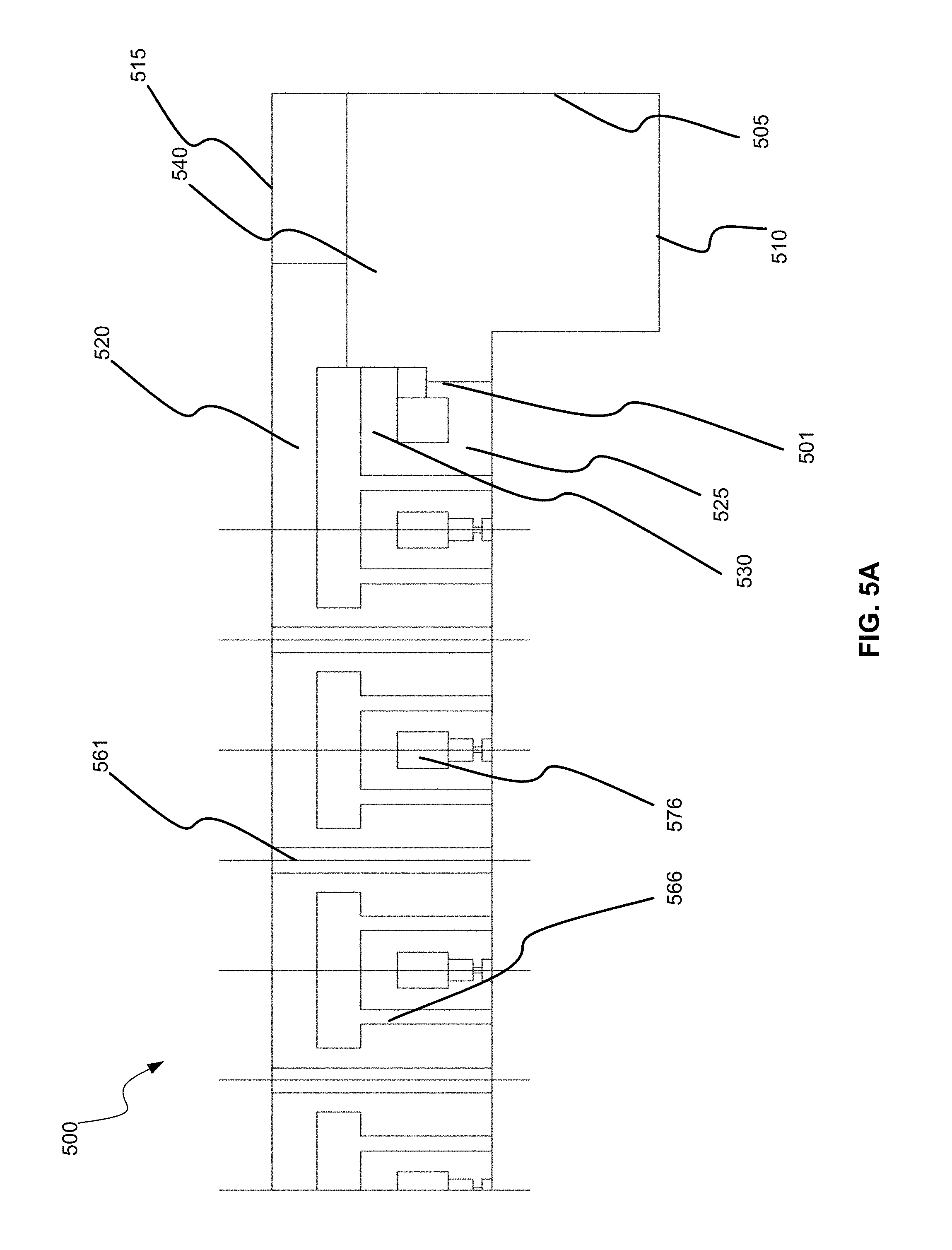
D00013
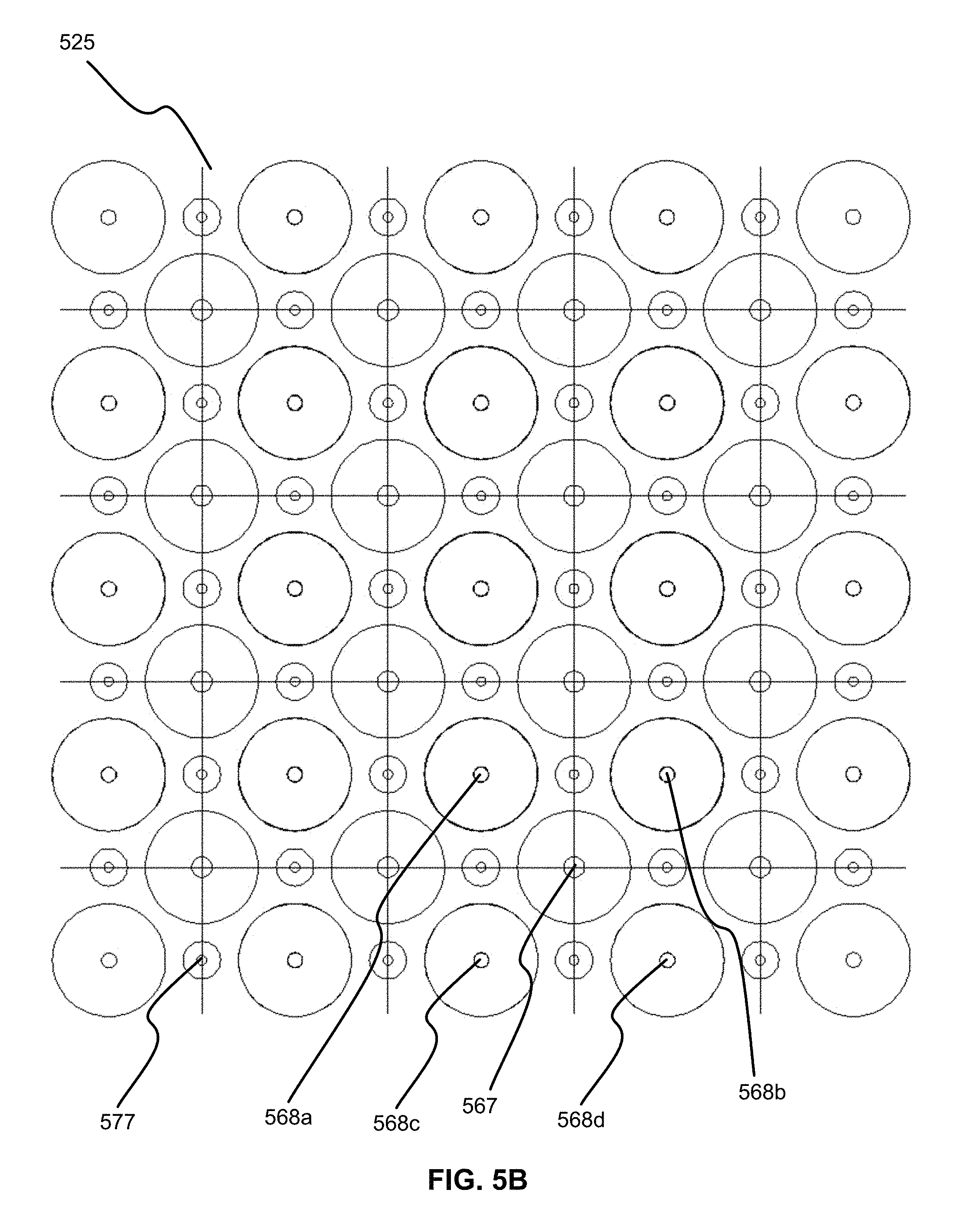
D00014

XML
uspto.report is an independent third-party trademark research tool that is not affiliated, endorsed, or sponsored by the United States Patent and Trademark Office (USPTO) or any other governmental organization. The information provided by uspto.report is based on publicly available data at the time of writing and is intended for informational purposes only.
While we strive to provide accurate and up-to-date information, we do not guarantee the accuracy, completeness, reliability, or suitability of the information displayed on this site. The use of this site is at your own risk. Any reliance you place on such information is therefore strictly at your own risk.
All official trademark data, including owner information, should be verified by visiting the official USPTO website at www.uspto.gov. This site is not intended to replace professional legal advice and should not be used as a substitute for consulting with a legal professional who is knowledgeable about trademark law.