Analysis Device and Analysis System
Shibata; Shohei ; et al.
U.S. patent application number 16/184302 was filed with the patent office on 2019-11-07 for analysis device and analysis system. The applicant listed for this patent is Mizuno Corporation. Invention is credited to Kiyoshi Hirose, Yuto Kase, Takeshi Naruo, Shohei Shibata.
| Application Number | 20190336826 16/184302 |
| Document ID | / |
| Family ID | 68384539 |
| Filed Date | 2019-11-07 |

View All Diagrams
| United States Patent Application | 20190336826 |
| Kind Code | A1 |
| Shibata; Shohei ; et al. | November 7, 2019 |
Analysis Device and Analysis System
Abstract
An analysis device for analyzing a spin axis of a ball receives an input of acceleration data and geomagnetic data detected on a time-series basis by a sensor device built in the ball; calculates attitude information of the ball, based on the acceleration data and the geomagnetic data; calculates the spin rate of the ball released from a subject, based on the geomagnetic data; and calculates an angle of the spin axis of the ball relative to a predetermined direction, using a predetermined filter and based on the attitude information, the spin rate, the geomagnetic data, and a first-order differential value and a second-order differential value of the geomagnetic data.
| Inventors: | Shibata; Shohei; (Osaka, JP) ; Naruo; Takeshi; (Osaka, JP) ; Kase; Yuto; (Osaka, JP) ; Hirose; Kiyoshi; (Kyoto, JP) | ||||||||||
| Applicant: |
|
||||||||||
|---|---|---|---|---|---|---|---|---|---|---|---|
| Family ID: | 68384539 | ||||||||||
| Appl. No.: | 16/184302 | ||||||||||
| Filed: | November 8, 2018 |
| Current U.S. Class: | 1/1 |
| Current CPC Class: | A63B 2220/35 20130101; A63B 2220/833 20130101; A63B 2220/803 20130101; A63B 69/0002 20130101; A63B 2069/0006 20130101; A63B 2102/182 20151001; A63B 2220/16 20130101; A63B 2209/00 20130101; A63B 71/0622 20130101; A63B 2220/89 20130101; A63B 2024/0034 20130101; A63B 24/0003 20130101; A63B 2220/62 20130101; A63B 2225/02 20130101; A63B 24/0021 20130101; A63B 2220/808 20130101; A63B 2220/40 20130101; A63B 43/004 20130101; A63B 2102/18 20151001; A63B 2225/50 20130101; A63B 2071/0625 20130101 |
| International Class: | A63B 24/00 20060101 A63B024/00 |
Foreign Application Data
| Date | Code | Application Number |
|---|---|---|
| May 7, 2018 | JP | 2018-089050 |
| Oct 30, 2018 | JP | 2018-204326 |
Claims
1. An analysis device for analyzing a spin axis of a ball, the analysis device comprising: an information input unit configured to receive an input of acceleration data and geomagnetic data detected on a time-series basis by a sensor device built in the ball; an attitude calculation unit configured to calculate attitude information of the ball, based on the acceleration data and the geomagnetic data; a spin rate calculation unit configured to calculate the spin rate of the ball released from a subject, based on the geomagnetic data; and a spin axis calculation unit configured to calculate an angle of the spin axis of the ball relative to a predetermined direction, using a predetermined filter and based on the attitude information, the spin rate, the geomagnetic data, and a first-order differential value and a second-order differential value of the geomagnetic data.
2. The analysis device according to claim 1, wherein the spin axis calculation unit is configured to calculate the angle of the spin axis of the ball in a predetermined period around a timing at which the ball was released.
3. The analysis device according to claim 1, wherein the spin axis calculation unit is configured to, based on the attitude information, the spin rate, the geomagnetic data, the first-order differential value, and the second-order differential value, calculate the angle of the spin axis of the ball by applying the predetermined filter to an observation equation where the geomagnetic data, the first-order differential value, and the second-order differential value are observation values.
4. The analysis device according to claim 1, further comprising a direction calculation unit configured to calculate a traveling direction of the ball released from the subject, using the predetermined filter and based on the acceleration data, wherein the predetermined direction is the traveling direction calculated by the direction calculation unit.
5. The analysis device according to claim 4, wherein the direction calculation unit is configured to calculate a rotation matrix that defines the traveling direction, by applying the predetermined filter to a state equation where the rotation matrix that defines the traveling direction is a state value, and an observation equation where a maximum value of the acceleration data in a predetermined period is an observation value, the predetermined period being a period around a timing at which the ball was released.
6. The analysis device according to claim 1, wherein the sensor device includes a low acceleration sensor configured to detect a low acceleration, and a high acceleration sensor configured to detect a high acceleration, the acceleration data includes low acceleration data detected by the low acceleration sensor, and high acceleration data detected by the high acceleration sensor, and the attitude calculation unit is configured to, when calculating initial attitude information of the ball, adopt the low acceleration data as the acceleration data.
7. The analysis device according to claim 1, wherein the predetermined filter is an extended Kalman filter.
8. An analysis device for analyzing a spin axis of a ball, the analysis device comprising: an information input unit configured to receive an input of acceleration data and geomagnetic data detected on a time-series basis by a sensor device built in the ball; an attitude calculation unit configured to calculate attitude information of the ball, based on the acceleration data and the geomagnetic data; a spin rate calculation unit configured to calculate the spin rate of the ball released from a subject, based on the geomagnetic data; and a spin axis calculation unit configured to calculate an angle of the spin axis of the ball relative to a predetermined direction, using a predetermined filter and based on the attitude information, the spin rate, the acceleration data, and a first-order differential value and a second-order differential value of the acceleration data.
9. The analysis device according to claim 8, wherein the spin axis calculation unit is configured to, based on the attitude information, the spin rate, the acceleration data, the first-order differential value, and the second-order differential value, calculate the angle of the spin axis of the ball by applying the predetermined filter to an observation equation where the acceleration data, the first-order differential value, and the second-order differential value are observation values.
10. An analysis system comprising: an analysis device for analyzing a spin axis of a ball; and a sensor device built in the ball, the analysis device including: an information input unit configured to receive an input of acceleration data and geomagnetic data detected on a time-series basis by the sensor device; an attitude calculation unit configured to calculate attitude information of the ball, based on the acceleration data and the geomagnetic data; a spin rate calculation unit configured to calculate the spin rate of the ball released from a subject, based on the geomagnetic data; and a spin axis calculation unit configured to calculate an angle of the spin axis of the ball relative to a predetermined direction, using a predetermined filter and based on the attitude information, the spin rate, the geomagnetic data, and a first-order differential value and a second-order differential value of the geomagnetic data.
Description
BACKGROUND OF THE INVENTION
Field of the Invention
[0001] The present disclosure relates to a technique for analyzing the spin axis of a ball.
Description of the Background Art
[0002] In recent years, a method has been known by which to measure spin parameters of a thrown baseball, such as the movement locus, the spin rate, and the spin axis direction, by using information from a sensor built in the ball. For example, Japanese Patent Laying-Open No. 2018-134153 discloses a throw analysis system.
[0003] The throw analysis system according to Japanese Patent Laying-Open No. 2018-134153 includes a ball having a sensor unit and a transmitting unit that are built in the ball, and an analysis device to receive the detection value of the sensor unit transmitted from the transmitting unit and analyze the detection value. The sensor unit includes a substrate; and an acceleration sensor, a geomagnetic sensor, and a gyroscope sensor mounted on the substrate. The analysis device identifies and stores the initial direction of the substrate in the global coordinate system, calculates the successively changing direction of the substrate in the global coordinate system, calculates the successively changing acceleration of the ball in the global coordinate system, and calculates the movement locus of the ball in the global coordinate system.
[0004] Japanese Patent Laying-Open No. 2018-134153 discloses calculating the spin axis direction using a gyroscope sensor. However, since a gyroscope sensor is generally large in size, a gyroscope sensor that is small enough to be built in a ball can measure only a limited range. Accordingly, when a thrown ball rotates at a high speed, such as in baseball, the angle of the spin axis of the ball may not be calculated accurately with a gyroscope sensor due to saturation.
SUMMARY OF THE INVENTION
[0005] An object of the present disclosure in one aspect is to provide an analysis device and an analysis system that can calculate the angle of the spin axis of a ball more accurately.
[0006] According to an embodiment, an analysis device for analyzing a spin axis of a ball is provided. The analysis device includes: an information input unit configured to receive an input of acceleration data and geomagnetic data detected on a time-series basis by a sensor device built in the ball; an attitude calculation unit configured to calculate attitude information of the ball, based on the acceleration data and the geomagnetic data; a spin rate calculation unit configured to calculate the spin rate of the ball released from a subject, based on the geomagnetic data; and a spin axis calculation unit configured to calculate an angle of the spin axis of the ball relative to a predetermined direction, using a predetermined filter and based on the attitude information, the spin rate, the geomagnetic data, and a first-order differential value and a second-order differential value of the geomagnetic data.
[0007] Preferably, the spin axis calculation unit is configured to calculate the angle of the spin axis of the ball in a predetermined period around a timing at which the ball was released.
[0008] Preferably, the spin axis calculation unit is configured to, based on the attitude information, the spin rate, the geomagnetic data, the first-order differential value, and the second-order differential value, calculate the angle of the spin axis of the ball by applying the predetermined filter to an observation equation where the geomagnetic data, the first-order differential value, and the second-order differential value are observation values.
[0009] Preferably, the analysis device further includes a direction calculation unit configured to calculate a traveling direction of the ball released from the subject, using the predetermined filter and based on the acceleration data. The predetermined direction is the traveling direction calculated by the direction calculation unit.
[0010] Preferably, the direction calculation unit is configured to calculate a rotation matrix that defines the traveling direction, by applying the predetermined filter to a state equation where the rotation matrix that defines the traveling direction is a state value, and to an observation equation where a maximum value of the acceleration data in a predetermined period is an observation value, the predetermined period being a period around a timing at which the ball was released.
[0011] Preferably, the sensor device includes a low acceleration sensor configured to detect a low acceleration, and a high acceleration sensor configured to detect a high acceleration. The acceleration data includes low acceleration data detected by the low acceleration sensor, and high acceleration data detected by the high acceleration sensor. The attitude calculation unit is configured to, when calculating initial attitude information of the ball, adopt the low acceleration data as the acceleration data.
[0012] Preferably, the predetermined filter is an extended Kalman filter.
[0013] According to another embodiment, an analysis device for analyzing a spin axis of a ball is provided. The analysis device includes: an information input unit configured to receive an input of acceleration data and geomagnetic data detected on a time-series basis by a sensor device built in the ball; an attitude calculation unit configured to calculate attitude information of the ball, based on the acceleration data and the geomagnetic data; a spin rate calculation unit configured to calculate the spin rate of the ball released from a subject, based on the geomagnetic data; and a spin axis calculation unit configured to calculate an angle of the spin axis of the ball relative to a predetermined direction, using a predetermined filter and based on the attitude information, the spin rate, the acceleration data, and a first-order differential value and a second-order differential value of the acceleration data.
[0014] Preferably, the spin axis calculation unit is configured to, based on the attitude information, the spin rate, the acceleration data, the first-order differential value, and the second-order differential value, calculate the angle of the spin axis of the ball by applying the predetermined filter to an observation equation where the acceleration data, the first-order differential value, and the second-order differential value are observation values.
[0015] An analysis system according to still another embodiment includes: an analysis device for analyzing a spin axis of a ball; and a sensor device built in the ball. The analysis device includes: an information input unit configured to receive an input of acceleration data and geomagnetic data detected on a time-series basis by the sensor device; an attitude calculation unit configured to calculate attitude information of the ball, based on the acceleration data and the geomagnetic data; a spin rate calculation unit configured to calculate the spin rate of the ball released from a subject, based on the geomagnetic data; and a spin axis calculation unit configured to calculate an angle of the spin axis of the ball relative to a predetermined direction, using a predetermined filter and based on the geomagnetic data, the attitude information, the spin rate, and a first-order differential value and a second-order differential value of the geomagnetic data.
[0016] The foregoing and other objects, features, aspects and advantages of the present invention will become more apparent from the following detailed description of the present invention when taken in conjunction with the accompanying drawings.
BRIEF DESCRIPTION OF THE DRAWINGS
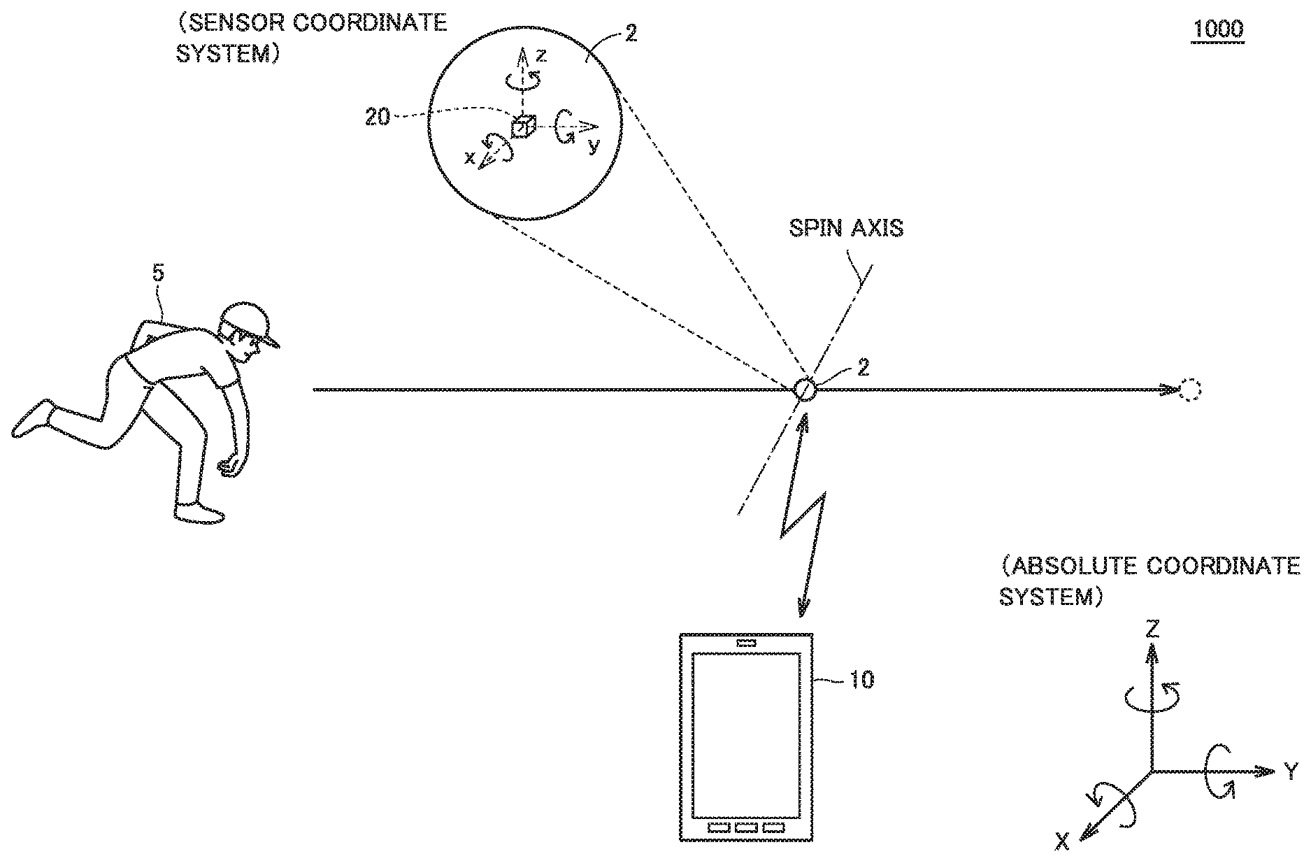
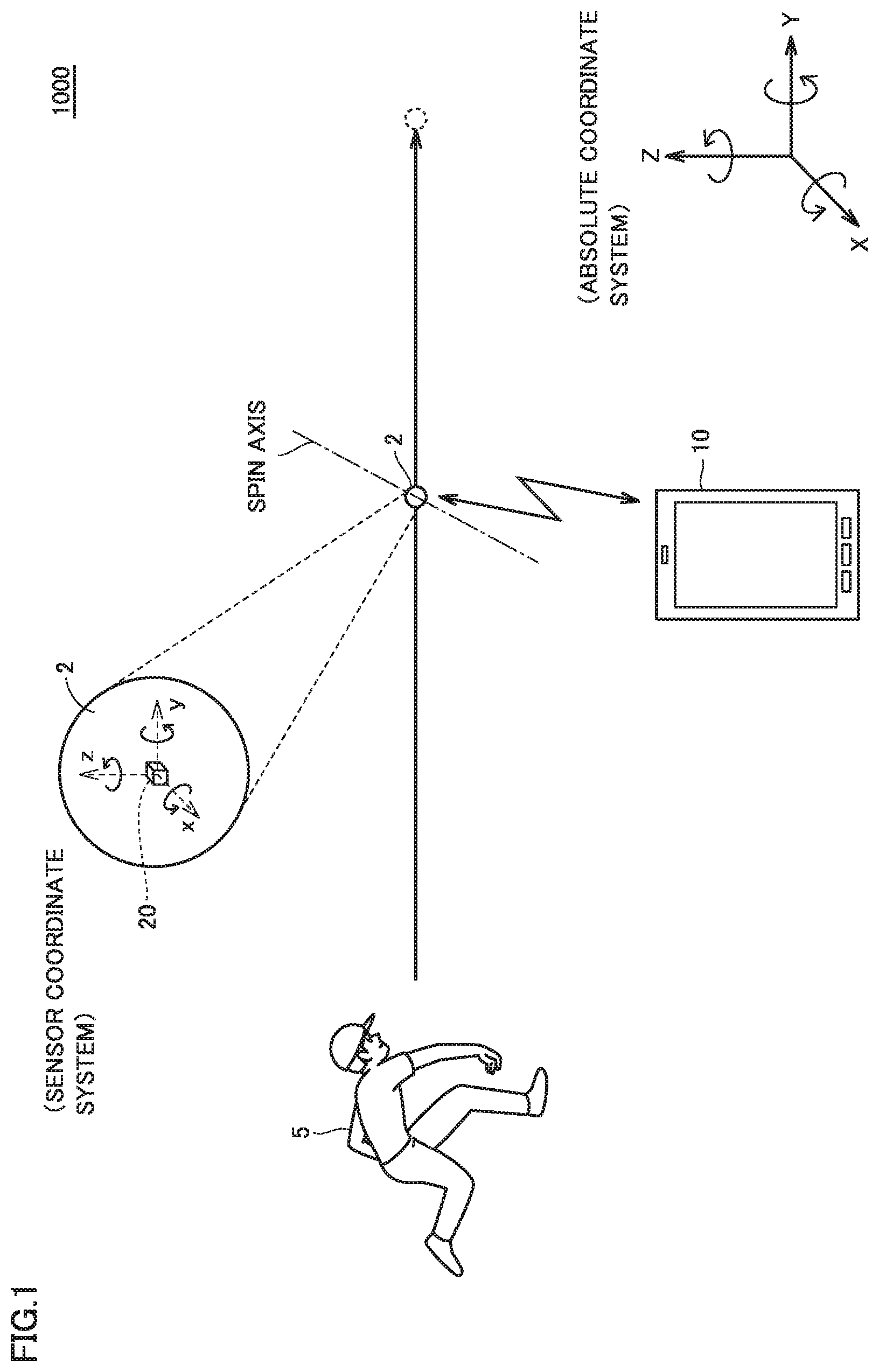
[0017] FIG. 1 is a view for explaining a general configuration of an analysis system according to embodiment 1.
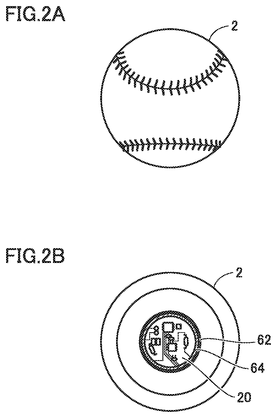
[0018] FIG. 2A is a view for explaining a schematic configuration of a ball according to embodiment 1.
[0019] FIG. 2B is a view for explaining a schematic configuration of a ball according to embodiment 1.
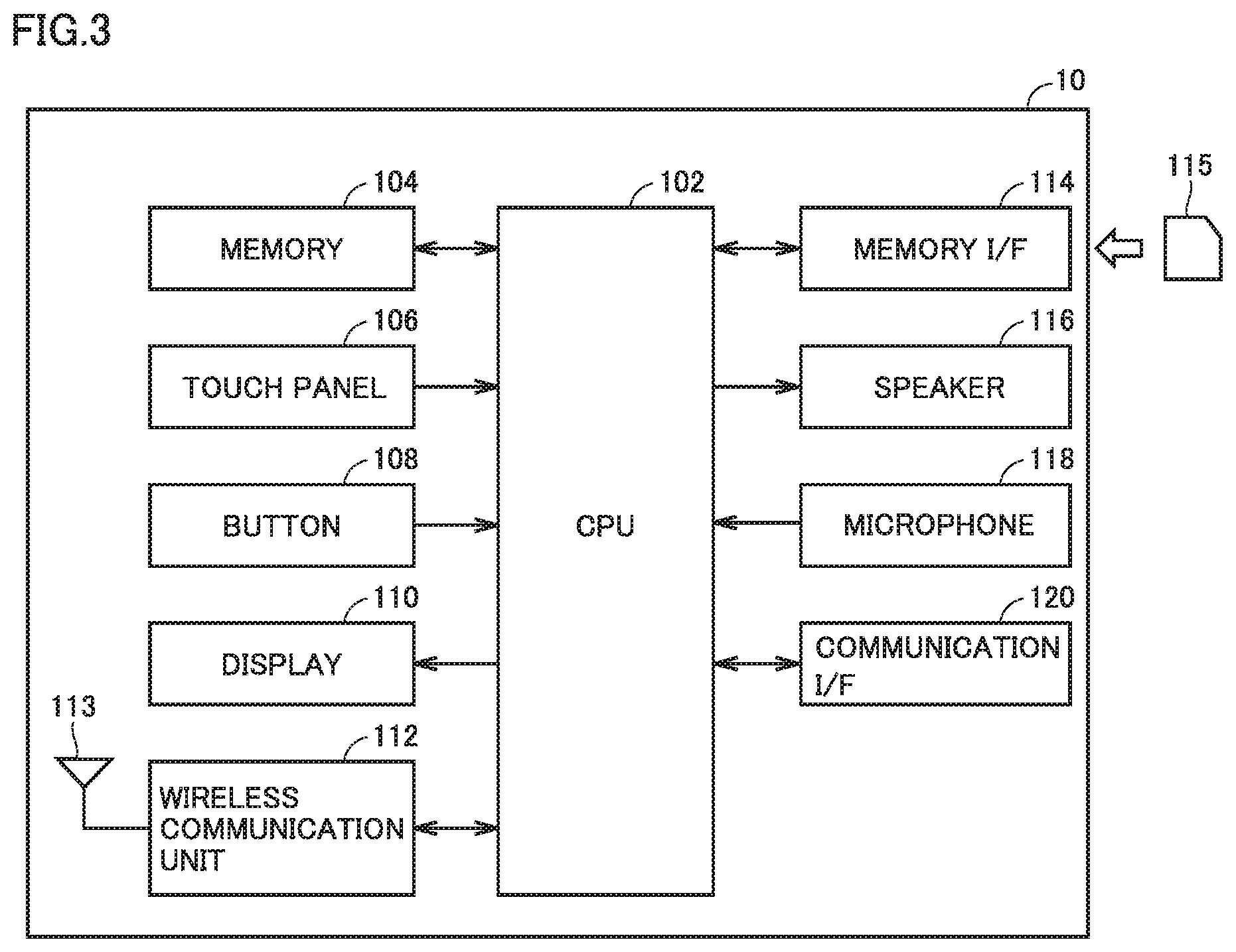
[0020] FIG. 3 is a block diagram showing a hardware configuration of an analysis device according to embodiment 1.
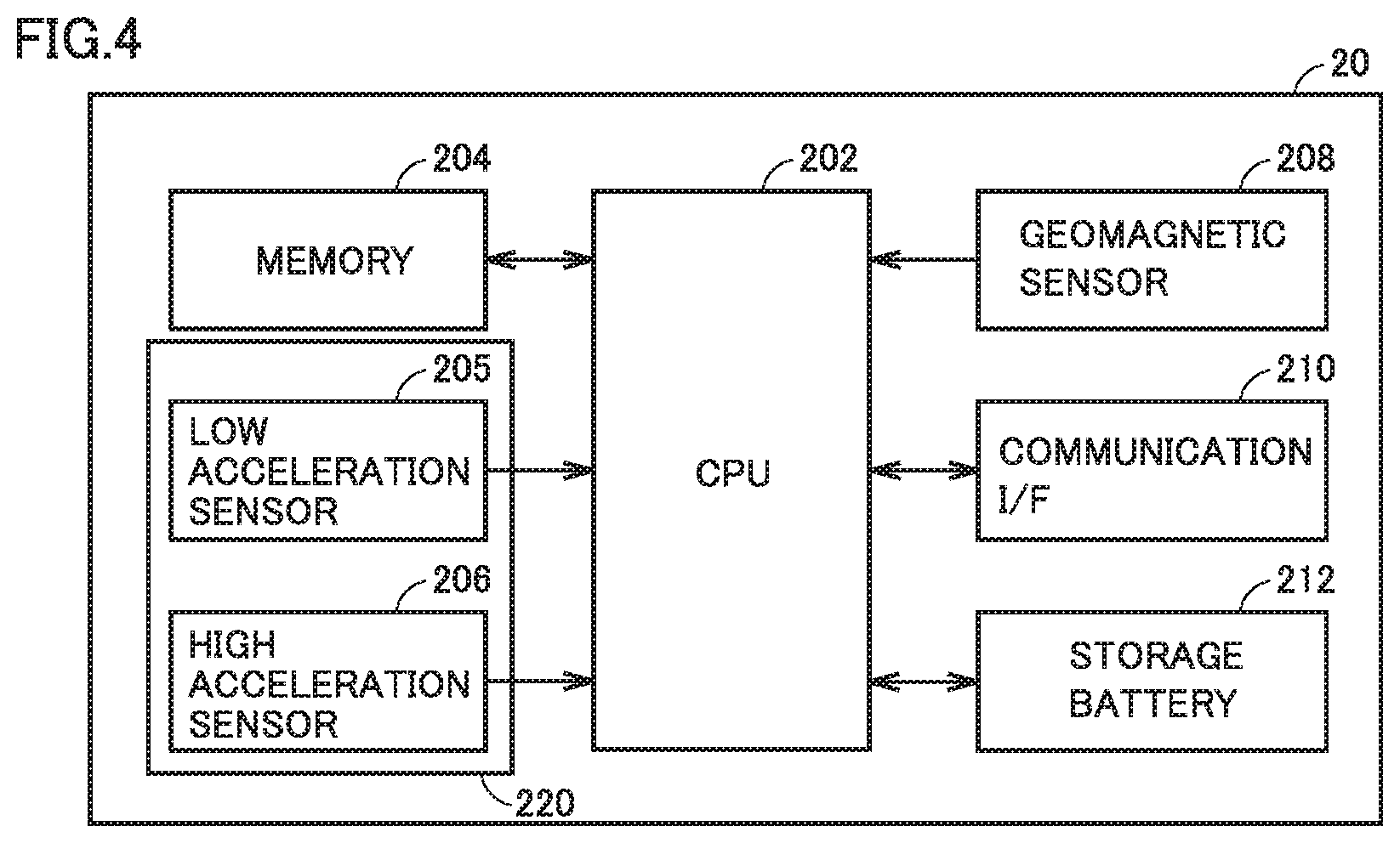
[0021] FIG. 4 is a block diagram showing a hardware configuration of a sensor device according to embodiment 1.
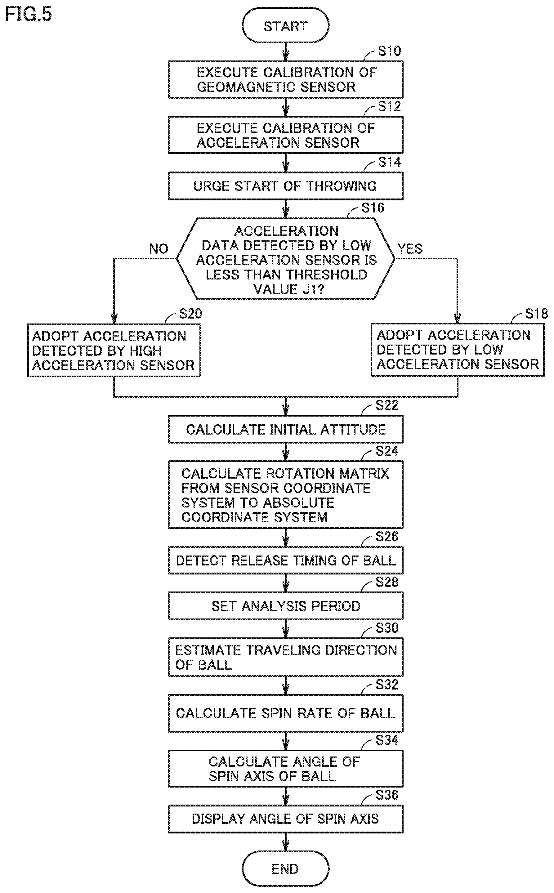
[0022] FIG. 5 is a flowchart for explaining the operation of an analysis device according to embodiment 1.
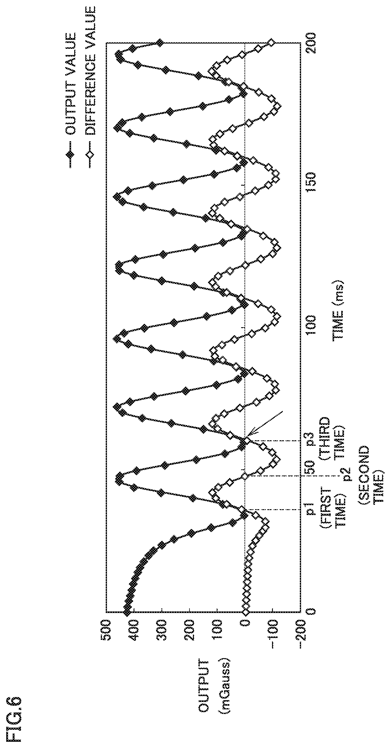
[0023] FIG. 6 is a view for explaining a method for calculating the spin rate of a ball according to embodiment 1.
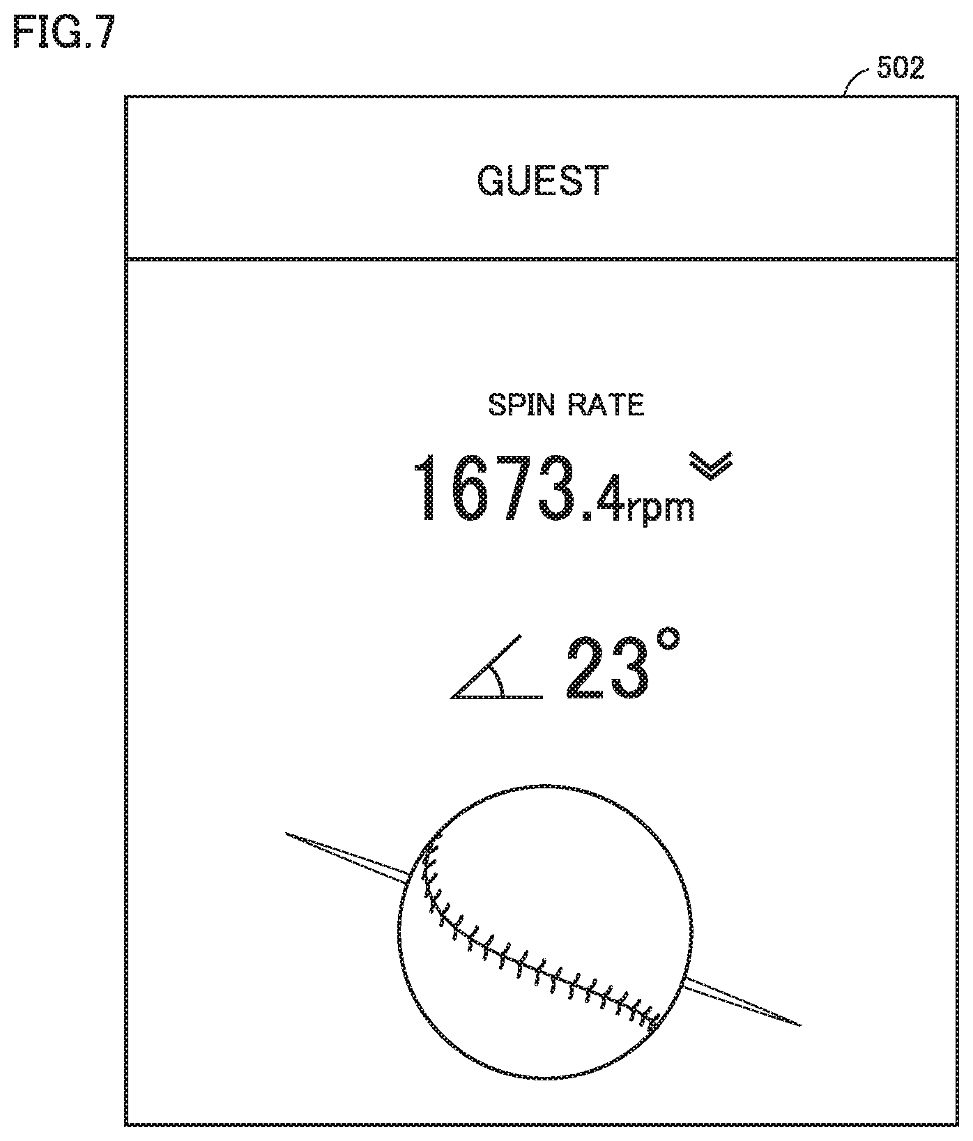
[0024] FIG. 7 shows example display of the angle of the spin axis of a ball according to embodiment 1.
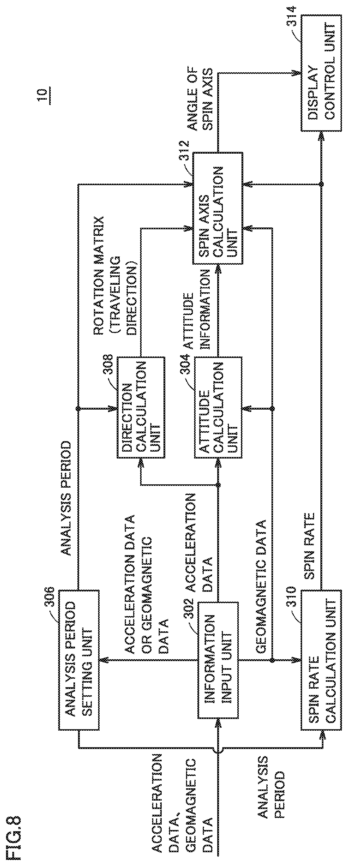
[0025] FIG. 8 is a block diagram of an example functional configuration of an analysis device according to embodiment 1.
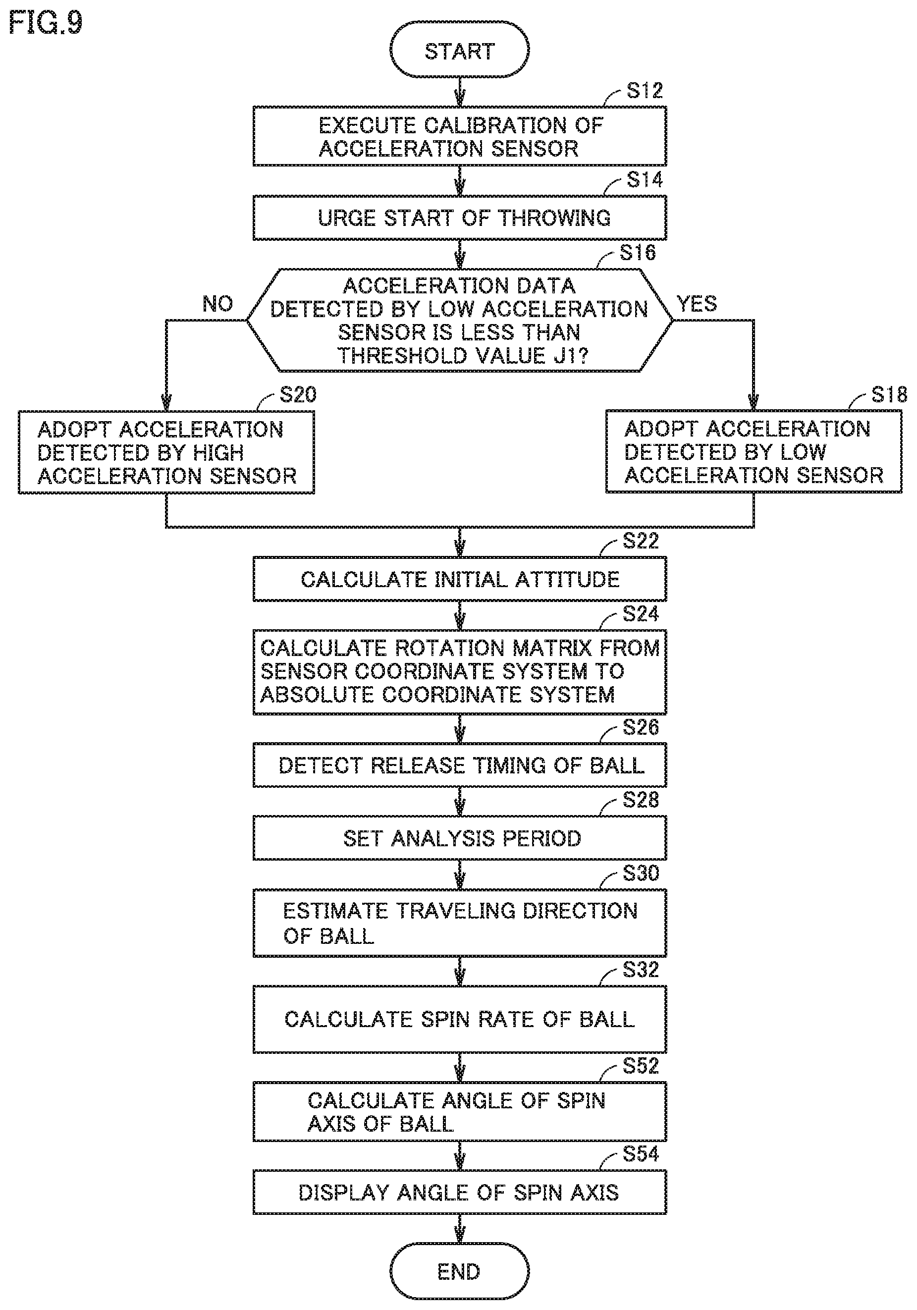
[0026] FIG. 9 is a flowchart for explaining the operation of an analysis device according to embodiment 2.
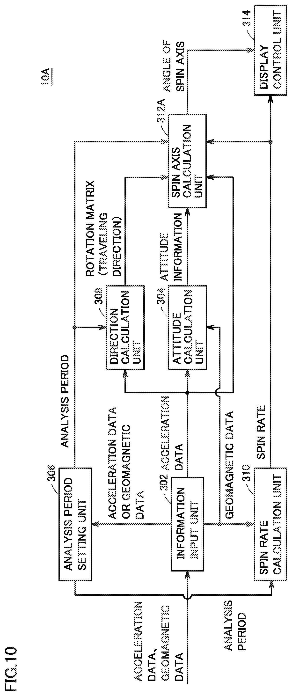
[0027] FIG. 10 is a block diagram showing an example functional configuration of an analysis device according to embodiment 2.
DESCRIPTION OF THE PREFERRED EMBODIMENTS
[0028] Embodiments of the present invention are described hereinafter with reference to the drawings. In the description hereinafter, identical parts are identically denoted.
[0029] They have the same names and functions. The detailed explanation of such parts is not repeated.
Embodiment 1
<General Configuration of System>
[0030] FIG. 1 is a view for explaining a general configuration of an analysis system 1000 according to embodiment 1. With reference to FIG. 1, analysis system 1000 is a system for analyzing the spin axis of a baseball thrown by a subject 5 (pitcher), and displaying the results of the analysis. Analysis system 1000 includes an analysis device 10, and a ball 2 including a built-in sensor device 20. In FIG. 1, three axes orthogonal to one another in the sensor coordinate system are represented by an x-axis, a y-axis, and a z-axis; and three axes orthogonal to one another in the absolute coordinate system are represented by an X-axis, a Y-axis, and a Z-axis.
[0031] Analysis device 10 is a smartphone. However, analysis device 10 may be implemented as any type of device. For example, analysis device 10 may be a laptop personal computer (PC), a tablet-type device, a desktop PC, or the like.
[0032] Analysis device 10 communicates with sensor device 20 by a wireless communication system. As the wireless communication system, Bluetooth (registered trademark) low energy (BLE) is adopted, for example. However, analysis device 10 may adopt other wireless communication systems, such as Bluetooth (registered trademark), wireless local area network (LAN), or the like.
[0033] FIG. 2A and FIG. 2B are views for explaining a schematic configuration of ball 2 according to embodiment 1. FIG. 2A shows an external appearance of ball 2. FIG. 2B shows a schematic configuration of the inside of ball 2.
[0034] With reference to FIG. 2A, the external appearance of ball 2 is equivalent to that of a typical regulation ball. Ball 2 has a leather outer skin with seams showing. With reference to FIG. 2B, ball 2 includes built-in sensor device 20 in its center for detecting the behavior of ball 2. Sensor device 20 is fixed with a polycarbonate capsule 62 and a silicone gel 64 and thus has a good shock resistance.
[0035] Referring back to FIG. 1, sensor device 20 detects accelerations and magnetic fields (magnetic flux densities) in the sensor coordinate system (local coordinate system). Specifically, sensor device 20 includes two acceleration sensors (a low acceleration sensor and a high acceleration sensor) and a geomagnetic sensor. The acceleration sensors detect acceleration data representing the accelerations in the directions of three axes (the x-axis, the y-axis, and the z-axis) orthogonal to one another.
[0036] The geomagnetic sensor detects geomagnetic data representing the magnetic fields (magnetic flux densities) in the directions of three axes orthogonal to one another. For example, a magneto-resistive (MR) element, a magneto-impedance (MI) element, a Hall element, or the like is used as the geomagnetic sensor.
<Hardware Configuration>
(Analysis Device 10)
[0037] FIG. 3 is a block diagram showing a hardware configuration of analysis device 10 according to embodiment 1. With reference to FIG. 3, analysis device 10 includes a central processing unit (CPU) 102, a memory 104, a touch panel 106, a button 108, a display 110, a wireless communication unit 112, a communication antenna 113, a memory interface (I/F) 114, a speaker 116, a microphone 118, and a communication interface (I/F) 120, as main components. A storage medium 115 is an external storage medium.
[0038] CPU 102 controls the operation of each unit in analysis device 10 by reading a program stored in memory 104 and executing the program. Specifically, CPU 102 implements the later-described processes (steps) in analysis device 10 by executing the program.
[0039] Memory 104 is implemented as a random access memory (RAM), a read-only memory (ROM), a flash memory or the like. Memory 104 stores a program to be executed by CPU 102, data to be used by CPU 102, and the like.
[0040] Touch panel 106 is provided on display 110 which serves as a display unit. Touch panel 106 may be of any type, such as a resistive type and a capacitive type. Button 108 is arranged on the surface of analysis device 10. Button 108 receives user instructions and inputs the instructions to CPU 102.
[0041] Wireless communication unit 112 connects with a mobile communication network via communication antenna 113, and sends and receives a signal for wireless communication. Thus, analysis device 10 can communicate with a predetermined external device via a mobile communication network, such as long term evolution (LTE).
[0042] Memory interface (I/F) 114 reads data from external storage medium 115. CPU 102 reads data stored in external storage medium 115 via memory interface 114 and stores the data in memory 104. CPU 102 reads data from memory 104 and stores the data in external storage medium 115 via memory interface 114.
[0043] Examples of storage medium 115 include a medium having stored thereon a program in a nonvolatile manner, such as a compact disc (CD), a digital versatile disk (DVD), a Blu-ray (registered trademark) Disc (BD), a universal serial bus (USB) memory, a memory card, a flexible disk (FD), or a hard disk.
[0044] Speaker 116 outputs a voice based on instructions from CPU 102. Microphone 118 receives an utterance for analysis device 10.
[0045] Communication interface (I/F) 120 is a communication interface for exchanging data between, for example, analysis device 10 and sensor device 20. Communication interface (I/F) 120 is implemented as an adapter, a connector, or the like. The communication system may be wireless communication, such as BLE, wireless LAN, or the like.
(Sensor Device 20)
[0046] FIG. 4 is a block diagram showing a hardware configuration of sensor device 20 according to embodiment 1. With reference to FIG. 4, sensor device 20 includes a CPU 202 for executing various types of processes; a memory 204 for storing a program to be executed by CPU 202, data, and the like; an acceleration sensor 220; a geomagnetic sensor 208 to detect magnetic fields in the three axis directions orthogonal to one another; a communication interface (I/F) 210 for communicating with analysis device 10; and a storage battery 212 to supply power to the components of sensor device 20, as a main components.
[0047] Acceleration sensor 220 includes a low acceleration sensor 205 and a high acceleration sensor 206. Low acceleration sensor 205, which is an acceleration sensor for detecting a low acceleration range (e.g. less than 24 G), detects accelerations in the three axis directions orthogonal to one another. High acceleration sensor 206, which is an acceleration sensor for detecting a high acceleration range that is not detectable by the low acceleration sensor (e.g. 24 G or more), detects accelerations in the three axis directions orthogonal to one another. For the low acceleration range, the detection accuracy is higher with low acceleration sensor 205 than with high acceleration sensor 206, though still detectable by high acceleration sensor 206.
<Operation>
[0048] FIG. 5 is a flowchart for explaining the operation of analysis device 10 according to embodiment 1. The steps below are implemented typically by CPU 102 of analysis device 10 executing the program stored in memory 104.
[0049] Analysis device 10 is operated by, for example, a shop clerk. Analysis device 10 may be operated also by subject 5 him/herself. Here, analysis device 10 always acquires the acceleration data detected by each of low acceleration sensor 205 and high acceleration sensor 206, and the geomagnetic data detected by geomagnetic sensor 208.
[0050] With reference to FIG. 5, analysis device 10 executes calibration of geomagnetic sensor 208 (step S10). Specifically, subject 5 spins ball 2 (e.g. throws ball 2) in accordance with a clerk's instruction. Analysis device 10 successively plots the magnetic fields in the three axis directions detected by geomagnetic sensor 208. Analysis device 10 approximates the plotted data (e.g. 18-point data) by the equation of an ellipse and calculates the central point and the radius of the ellipse. Next, analysis device 10 calibrates the geomagnetic data so that the approximated ellipse will be a perfect circle around the origin. Thus, the offset error and the sensitivity error of the geomagnetic sensor are corrected. Analysis device 10 may use other known methods to perform calibration of geomagnetic sensor 208.
[0051] Analysis device 10 executes calibration of low acceleration sensor 205 and high acceleration sensor 206 (step S12). Specifically, subject 5 brings ball 2 into a stationary state (e.g. puts ball 2 on the ground) in accordance with a clerk's instruction. When ball 2 is in a stationary state, analysis device 10 acquires the acceleration data detected by each of low acceleration sensor 205 and high acceleration sensor 206.
[0052] Analysis device 10 calculates the average acceleration in a predetermined period of time (e.g. one second) for each of the accelerations in the three axis directions detected by low acceleration sensor 205. Analysis device 10 calculates a synthetic acceleration As by synthesizing average accelerations a.sub.cx, a.sub.cy, a.sub.cz of the three axes, the x-axis, the y-axis, and the z-axis, using the following formula (1).
As= {square root over (a.sub.cx.sup.2+a.sub.cy.sup.2+a.sub.cz.sup.2)} (1)
[0053] Analysis device 10 performs bias correction of low acceleration sensor 205 (i.e., performs calibration of low acceleration sensor 205) by subtracting a value obtained by dividing synthetic acceleration As by 1000 from the accelerations in the three axis directions detected by low acceleration sensor 205.
[0054] Calibration for high acceleration sensor 206 is performed in the same manner. Specifically, analysis device 10 calculates the average value in a predetermined period of time (e.g. one second) for each of the accelerations in the three axis directions detected by high acceleration sensor 206. Analysis device 10 then calculates the synthetic acceleration of the three axes using the above-described formula (1). Analysis device 10 performs offset correction of high acceleration sensor 206 (i.e., performs calibration of high acceleration sensor 206) by subtracting a value obtained by dividing the synthetic acceleration by 1000 from the accelerations in the three axis directions detected by high acceleration sensor 206.
[0055] When the calibration of low acceleration sensor 205 and high acceleration sensor 206 is completed, analysis device 10 gives notification that urges subject 5 to throw (step S14). For example, analysis device 10 may output a voice of "Throw the ball" or may display the words on display 110. Subject 5 throws ball 2 in accordance with the notification.
[0056] Analysis device 10 determines whether or not the acceleration data detected by low acceleration sensor 205 is less than threshold value J1 (step S16). Specifically, analysis device 10 determines, for the acceleration in each axis direction detected by low acceleration sensor 205, whether or not the acceleration in the axis direction is less than threshold value J1.
[0057] If the acceleration in the axis direction is less than threshold value J1 (YES in step S16), analysis device 10 adopts the acceleration in the axis direction detected by low acceleration sensor 205 as the acceleration to be used in the subsequent steps (step S18). If the acceleration in the axis direction is equal to or more than threshold value J1 (NO in step S16), analysis device 10 adopts the acceleration in the axis direction detected by high acceleration sensor 206 as the acceleration to be used in the subsequent steps (step S20).
[0058] The processes in steps S16 to S20 are described with a specific example. For example, suppose the accelerations in the x-axis direction and the y-axis direction detected by low acceleration sensor 205 are less than threshold value J1, and the acceleration in the z-axis direction is equal to or more than threshold value J1. In this case, analysis device 10 adopts the accelerations detected by low acceleration sensor 205, as the accelerations in the x-axis direction and the y-axis direction to be used in the processes after step S20; and adopts the acceleration detected by high acceleration sensor 206 as the acceleration in the z-axis direction. Thus, the acceleration detected by low acceleration sensor 205, which has a high detection accuracy for a low acceleration range, is used for the acceleration less than threshold value J1.
[0059] Next, analysis device 10 calculates the attitude of ball 2 of when ball 2 is in a stationary state (i.e., the initial attitude of ball 2) (step S22). Specifically, analysis device 10 calculates a roll angle .phi. that represents the spin angle around the x-axis and a pitch angle .theta. that represents the spin angle around the y-axis, based on the acceleration data detected by sensor device 20. Roll angle .phi. is expressed by the following formula (2) using average accelerations a.sub.cy, a.sub.cz of when ball 2 is in a stationary state.
.PHI. = tan - 1 ( a cz a cy ) ( 2 ) ##EQU00001##
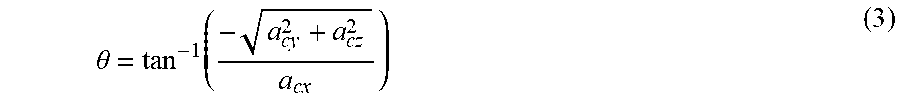
[0060] Pitch angle .theta. is expressed by the following formula (3) using average accelerations a.sub.cx, a.sub.cy, a.sub.cz of when ball 2 is in a stationary state.
.theta. = tan - 1 ( - a cy 2 + a cz 2 a cx ) ( 3 ) ##EQU00002##
[0061] At this time, since ball 2 is in a stationary state, the acceleration data detected by low acceleration sensor 205 is used to calculate roll angle .phi. and pitch angle .theta..
[0062] Analysis device 10 calculates a yaw angle .PSI. that represents the spin angle around the z-axis, based on the geomagnetic data detected by sensor device 20 (geomagnetic sensor 208), roll angle .phi. calculated using formula (2), and pitch angle .theta. calculated using formula (3).
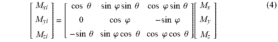
[0063] Specifically, analysis device 10 corrects a tilt error in the geomagnetic data of geomagnetic sensor 208 using a rotation matrix composed of roll angle .phi. and pitch angle .theta.. When the magnetic fields in the x-axis, y-axis, and z-axis directions after the correction are denoted by M.sub.xi, M.sub.yi, M.sub.zi, respectively, they are expressed by the following formula (4), using M.sub.x, M.sub.y, M.sub.z that represent the magnetic fields before the correction in the x-axis, y-axis, and z-axis directions, respectively, and using the rotation matrix.
[ M xi M yi M zi ] = [ cos .theta. sin .PHI. sin .theta. cos .PHI. sin .theta. 0 cos .PHI. - sin .PHI. - sin .theta. sin .PHI. cos .theta. cos .PHI. cos .theta. ] [ M x M y M z ] ( 4 ) ##EQU00003##
[0064] Using magnetic fields M.sub.xi, M.sub.yi, M.sub.zi with the tilt error being corrected, yaw angle .PSI. is expressed by the following formula (5).
.psi. = tan - 1 - M yi M xi ( 5 ) ##EQU00004##
[0065] As described above, the information (i.e., roll angle .phi., pitch angle .theta., and yaw angle .PSI.) representing the initial attitude of ball 2 in a stationary state is calculated.
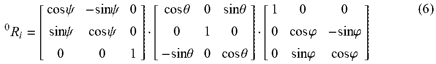
[0066] Analysis device 10 calculates the rotation matrix from the sensor coordinate system to the absolute coordinate system using roll angle .phi., pitch angle .theta., and yaw angle .PSI. (step S24). Specifically, analysis device 10 calculates rotation matrix .sup.0R.sub.i from the sensor coordinate system to the absolute coordinate system of when ball 2 is in a stationary state, using the following formula (6).
R i 0 = [ cos .psi. - sin .psi. 0 sin .psi. cos .psi. 0 0 0 1 ] [ cos .theta. 0 sin .theta. 0 1 0 - sin .theta. 0 cos .theta. ] [ 1 0 0 0 cos .PHI. - sin .PHI. 0 sin .PHI. cos .PHI. ] ( 6 ) ##EQU00005##
[0067] Next, analysis device 10 detects the timing at which subject 5 released ball 2 (i.e., at which subject 5 released ball 2 from his/her hand) (step S26). Specifically, analysis device 10 calculates an inexact differential value D of the geomagnetic data using the following formula (7). The character of s denotes the Laplace operator, and the character of n denotes a differential coefficient. Inexact differential value D is calculated for each of the magnetic fields in the three axis directions.
D = s 1 + n s ( 7 ) ##EQU00006##
[0068] Analysis device 10 detects, as the release timing, the point of time at which inexact differential value D becomes 0. For example, analysis device 10 detects, as the release timing, the point of time at which any one of three inexact differential values D corresponding to the respective magnetic fields in the three axis directions becomes 0.
[0069] Analysis device 10 may detect the release timing using the acceleration data. In this case, analysis device 10 detects, as the release timing, the point of time at which the differential value of the acceleration data detected by high acceleration sensor 206 becomes more than threshold value J2. For example, analysis device 10 detects, as the release timing, the point of time at which any one of the three differential values corresponding to the respective accelerations in the three axis directions becomes more than threshold value J2.
[0070] Next, analysis device 10 sets a target period (hereinafter also referred to as an "analysis period") during which the spin axis of ball 2 is to be analyzed (step S28). Specifically, analysis device 10 sets a certain period around the timing at which ball 2 was released, as the analysis period to analyze the spin axis of ball 2. More specifically, analysis device 10 sets a specified period of time (e.g. 100 ms) before the release timing, as the analysis start timing (i.e., the point of time at which the analysis period starts); and sets a specified period of time (e.g. 60 ms) after the release timing, as the analysis end timing (i.e., the point of time at which the analysis period ends).
[0071] Analysis device 10 applies the extended Kalman filter to the acceleration data detected by high acceleration sensor 206 and estimates the traveling direction of ball 2 in the analysis period (step S30). Specifically, analysis device 10 executes the following computation.
[0072] Analysis device 10 calculates the rotation matrices around the x-axis, the y-axis, and the z-axis by solving the following formula (8) that expresses a non-linear state equation and the following formula (9) that expresses a non-linear observation equation, with the input of the maximum values of the accelerations in the x-axis, y-axis, and z-axis directions (sensor coordinate system) in the analysis period detected by high acceleration sensor 206.
x.sub.t+1=F(x.sub.t)+w.sub.t (8)
y.sub.t=H(x.sub.t)+v.sub.t (9)
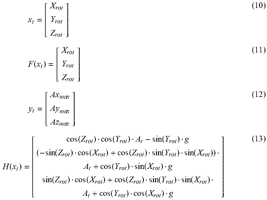
[0073] The character oft denotes a step as a discrete time. In formula (8), the characters of x.sub.t, F(x.sub.t), and w.sub.t respectively denote the state value at step t (time t), the linear model related to the time transition in the system, and the system noise. In formula (9), the characters of y.sub.t, H(x.sub.t), and v.sub.t respectively denote the observation value at time t, the observation model obtained by linearly mapping the state space into the observation space, and the observation noise. The characters of x.sub.t, F(x.sub.t), y.sub.t, and H(x.sub.t) in formula (8) are respectively expressed by formulae (10), (11), (12), and (13).
x t = [ X rot Y rot Z rot ] ( 10 ) F ( x t ) = [ X rot Y rot Z rot ] ( 11 ) y t = [ Ax ma x Ay ma x Az ma x ] ( 12 ) H ( x t ) = [ cos ( Z rot ) cos ( Y rot ) A t - sin ( Y rot ) g ( - sin ( Z rot ) cos ( X rot ) + cos ( Z rot ) sin ( Y rot ) sin ( X rot ) ) A t + cos ( Y rot ) sin ( X rot ) g sin ( Z rot ) cos ( X rot ) + cos ( Z rot ) sin ( Y rot ) sin ( X rot ) A t + cos ( Y rot ) cos ( X rot ) g ] ( 13 ) ##EQU00007##
[0074] In formulae (10) and (11), the characters of X.sub.rot, Y.sub.rot, Z.sub.rot respectively denote the rotation matrices around the x-axis, the y-axis, and the z-axis. From formulae (8), (10), and (11), rotation matrices X.sub.rot, Y.sub.rot, Z.sub.rot at step (t+1) are obtained by adding the system noise to rotation matrices X.sub.rot, Y.sub.rot, Z.sub.rot at step t. The acceleration of ball 2 is maximum at around a release (i.e., the acceleration is maximum in the analysis period), and the direction defined by the rotation matrices of when the acceleration is maximum generally shows the traveling direction of ball 2. Therefore, the direction defined by rotation matrices X.sub.rot, Y.sub.rot, Z.sub.rot, with the input of the maximum values of the accelerations in the respective axis directions, is determined as the traveling direction of ball 2.
[0075] In formula (12), the characters of Ax.sub.max, Ay.sub.max, Az.sub.max respectively denote the maximum values of the accelerations in the x-axis, y-axis, and z-axis directions (sensor coordinate system). In formula (13), the character of A.sub.t denotes the synthetic acceleration of accelerations Ax.sub.t, Ay.sub.t, Az.sub.t in the x-axis, y-axis, and z-axis directions (sensor coordinate system) at time t in the analysis period detected by high acceleration sensor 206. Synthetic acceleration A.sub.t is the square root of the sum of squares of the components of accelerations Ax.sub.t, Ay.sub.t, Az.sub.t.
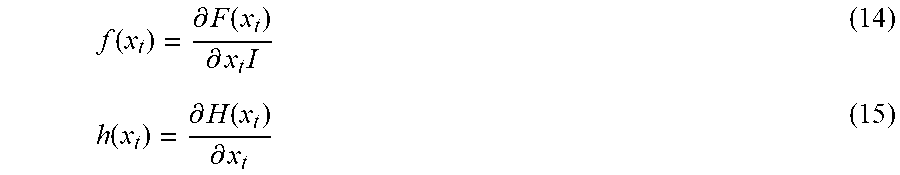
[0076] Here, f(x.sub.t) obtained by partially differentiating F(x.sub.t) with respect to x.sub.t is defined by formula (14), and h(x.sub.t) obtained by partially differentiating H(x.sub.t) with respect to x.sub.t is defined by formula (15).
f ( x t ) = .differential. F ( x t ) .differential. x t I ( 14 ) h ( x t ) = .differential. H ( x t ) .differential. x t ( 15 ) ##EQU00008##
[0077] The character of I denotes a unit matrix. The extended Kalman filter algorithm using f(x.sub.t) and h(x.sub.t) defined as described above are given by the following formulae (16), (17), (18), and (19).
P.sub.t.sup.-=f.sub.t-1P.sub.t-1f.sub.t-1T+Q.sub.t (16)
K.sub.t=P.sub.t.sup.-h.sub.t.sup.T(h.sub.tP.sub.t.sup.-h.sub.t.sup.T+R.s- ub.t).sup.-1 (17)
P.sub.t=(I-K.sub.th.sub.t)P.sub.t.sup.- (18)
x.sub.t=x.sub.t.sup.-+K.sub.t(y.sub.t-H.sub.tx.sub.t.sup.-) (19)
where P.sub.t and P.sub.t.sup.- denote the error covariance matrix, K.sub.t denotes the Kalman gain, Q.sub.t denotes the covariance matrix of the system noise, and R.sub.t denotes the covariance matrix of the observation noise.
[0078] The above-described algorithm consists of two parts: a part to predict an estimated value in the next step, and a part to update the estimated value using an obtained observation value. Formula (16) falls under the former, and formulae (17) to (19) fall under the latter. By repeatedly calculating formulae (16) to (19), given as described above, using a value at a certain moment (here, the maximum value of the accelerations in each axis direction), state value x.sub.t converges on an optimal value. That is, by applying the extended Kalman filter to f(x.sub.t) expressed by formula (14) and h(x.sub.t) expressed by formula (15), the most probable estimated value of state value x.sub.t at time t (here, the traveling direction of ball 2 defined by the rotation matrix around each axis) can be calculated.
[0079] Next, analysis device 10 calculates the spin rate of ball 2 based on the geomagnetic data in the analysis period detected by geomagnetic sensor 208 (step S32).
[0080] FIG. 6 is a view for explaining a method for calculating the spin rate of ball 2 according to embodiment 1. With reference to FIG. 6, graph 602 shows the output value of the geomagnetic data. For example, the output value is the magnetic field in the x-axis direction. Graph 604 shows the difference value for the output value of the geomagnetic data. For example, the difference value is the value that represents the difference between the current output value and the last output value.
[0081] Analysis device 10 counts the points (zero cross points) at which the difference value crosses 0, and counts a predetermined number of counts (e.g. three counts) as one rotation. With reference to graph 604, the first, second, and third zero cross points are counted at times p1, p2, and p3, respectively. Analysis device 10 calculates the spin rate (rpm) of ball 2 from the number of zero cross points counted in a unit period (e.g. 0.5 seconds).
[0082] Referring back to FIG. 5, analysis device 10 calculates the angle of the spin axis of ball 2 by applying the extended Kalman filter to the geomagnetic data in the analysis period detected by geomagnetic sensor 208 (step S34). Specifically, analysis device 10 executes the following computation.
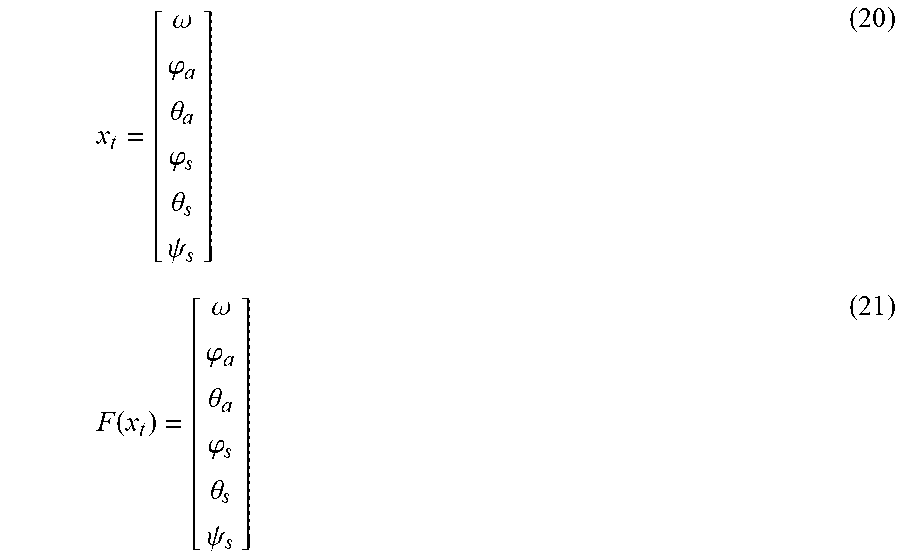
[0083] Analysis device 10 calculates the angle of the spin axis of ball 2 by solving the above-described non-linear state equation (8) and non-linear observation equation (9), with the input of the magnetic field component of each of the x-axis, y-axis, and z-axis directions (sensor coordinate system) in the analysis period detected by geomagnetic sensor 208; the first-order differential value of each magnetic field component; and the second-order differential value of each magnetic field component. The characters of x.sub.t and F(x.sub.t) in formula (8) are respectively expressed by the following formulae (20) and (21).
x t = [ .omega. .PHI. a .theta. a .PHI. s .theta. s .psi. s ] ( 20 ) F ( x t ) = [ .omega. .PHI. a .theta. a .PHI. s .theta. s .psi. s ] ( 21 ) ##EQU00009##
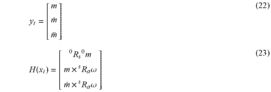
[0084] The character of .omega. denotes the spin rate of ball 2 which corresponds to the spin rate calculated in step S32. The characters of .phi..sub.a and .theta..sub.a respectively denote the roll angle and the pitch angle at time t in the absolute coordinate system. The characters of .phi..sub.s, .theta..sub.s, and .PSI..sub.s respectively denote the roll angle, the pitch angle, and the yaw angle at time t in the sensor coordinate system. The characters of y.sub.t and H(x.sub.t) in formula (9) are respectively expressed by formulae (22) and (23).
y t = [ m m . m ] ( 22 ) H ( x t ) = [ R s 0 0 m m .times. R a s .omega. m . .times. R a s .omega. ] ( 23 ) ##EQU00010##
where m denotes the matrix representing the magnetic field components (m.sub.x, m.sub.y, m.sub.z) in the three axes at time t in the sensor coordinate system; {dot over (m)} denotes the first-order differential value of m; {umlaut over (m)} denotes the second-order differential value of m; and .sup.0m denotes the matrix representing the magnetic field components in the three axes at time t in the absolute coordinate system.
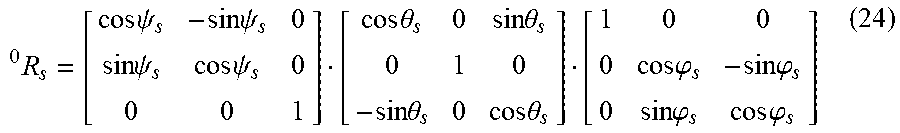
[0085] The character of .sup.0R.sub.s which denotes the rotation matrix from the sensor coordinate system to the absolute coordinate system is expressed by the following formula (24). The initial value of rotation matrix .sup.sR.sub.s corresponds to .sup.iR.sub.s which denotes the rotation matrix from the sensor coordinate system to the absolute coordinate system of when ball 2 is in a stationary state. That is, the initial values of roll angle .phi..sub.s, pitch angle .theta..sub.s, and yaw angle .PSI..sub.s in the sensor coordinate system correspond to roll angle .phi., pitch angle .theta., and yaw angle .PSI. of when ball 2 is in a stationary state.
0 R s = [ cos .psi. s - sin .psi. s 0 sin .psi. s cos .psi. s 0 0 0 1 ] [ cos .theta. s 0 sin .theta. s 0 1 0 - sin .theta. s 0 cos .theta. s ] [ 1 0 0 0 cos .PHI. s - sin .PHI. s 0 sin .PHI. s cos .PHI. s ] ( 24 ) ##EQU00011##
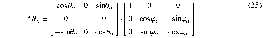
[0086] The character of .sup.SR.sub.a which denotes the rotation matrix from the spin axis coordinate system to the sensor coordinate system is expressed by the following formula (25).
R a s = [ cos .theta. a 0 sin .theta. a 0 1 0 - sin .theta. a 0 cos .theta. a ] [ 1 0 0 0 cos .PHI. a - sin .PHI. a 0 sin .PHI. a cos .PHI. a ] ( 25 ) ##EQU00012##
[0087] As in the calculation of the traveling direction in step S30, by repeatedly calculating formulae (14) to (19) using x.sub.t, F(x.sub.t), y.sub.t, H(x.sub.t) expressed by formulae (20) to (23), the most probable estimated value of state value x.sub.t at time tin the analysis period can be calculated. That is, roll angle .phi..sub.a and pitch angle .theta..sub.a of the spin axis of ball 2 in the absolute coordinate system; and roll angle .phi..sub.s, pitch angle .theta..sub.s, and yaw angle .PSI..sub.s of the spin axis of the ball in the sensor coordinate system are estimated. Although the spin rate .omega. is included as the estimated value in formula (20), the spin rate calculated in step S32 may be used as the spin rate .omega., as describe above. Thus, the spin rate .omega. may not be adopted as the estimated value.
[0088] Then, analysis device 10 calculates angle .theta..sub.h of the spin axis of ball 2 relative to a horizontal plane (i.e., a plane orthogonal to the gravity direction) using the estimated roll angle .phi..sub.a and pitch angle .theta..sub.a. Specifically, analysis device 10 calculates .sup.0R.sub.a which denotes the rotation matrix from the spin axis coordinate system to the absolute coordinate system, using the following formula (26).
.sup.0R.sub.a=.sup.0R.sub.s.times..sup.sR.sub.a (26)
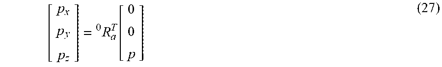
[0089] Next, when the vector representing the direction of the spin axis of ball 2 is defined as (p.sub.x, p.sub.y, p.sub.z), formula (27) is satisfied, where p denotes a constant, and .sup.0R.sub.a.sup.T is a transposed matrix of .sup.0R.sub.a.
[ p x p y p z ] = R a T 0 [ 0 0 p ] ( 27 ) ##EQU00013##
[0090] Using vector (p.sub.x, p.sub.y, p.sub.z) obtained by formula (27), angle .theta..sub.h is expressed by formula (28).
.theta. h = tan - 1 ( p z p x 2 + p y 2 ) ( 28 ) ##EQU00014##
[0091] Analysis device 10 displays, on display 110, angle .theta..sub.h of the spin axis of ball 2 calculated in step S36 (step S36).
[0092] FIG. 7 shows example display of the angle of the spin axis of ball 2 according to embodiment 1. With reference to FIG. 7, analysis device 10 displays, on display 110, a screen 502 showing the angle of the spin axis. For example, screen 502 shows that the angle of the spin axis of ball 2 is 23 degrees and that the spin rate of ball 2 is 1673.4 rpm. The angle of 23 degrees is the average value of .theta..sub.h calculated in the analysis period.
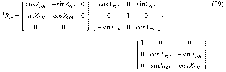
[0093] Analysis device 10 may calculate angle .PSI..sub.h of the spin axis relative to the traveling direction using the traveling direction of ball 2 calculated in step S30 (i.e., the rotation matrix in each axis direction), and using rotation matrix .sup.0R.sub.a from the spin axis coordinate system to the absolute coordinate system shown in formula (26). First, using rotation matrices X.sub.rot, Y.sub.rot, Z.sub.rot that define the traveling direction of ball 2, rotation matrix .sup.0R.sub.tr from the traveling direction coordinate system to the absolute coordinate system is expressed by the following formula (29).
R tr 0 = [ cos Z rot - sin Z rot 0 sin Z rot cos Z rot 0 0 0 1 ] [ cos Y rot 0 sin Y rot 0 1 0 - sin Y rot 0 cos Y rot ] [ 1 0 0 0 cos X rot - sin X rot 0 sin X rot cos X rot ] ( 29 ) ##EQU00015##
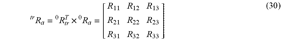
[0094] Next, rotation matrix .sup.trR.sub.a from the spin axis coordinate system to the traveling direction coordinate system is expressed by the following formula (30), using transposed matrix .sup.0R.sub.tr.sup.T of rotation matrix .sup.0R.sub.tr and using rotation matrix .sup.0R.sub.a.
R a tr = R tr T 0 .times. R a 0 = [ R 11 R 12 R 13 R 21 R 22 R 23 R 31 R 32 R 33 ] ( 30 ) ##EQU00016##
[0095] Using components of rotation matrix .sup.trR.sub.a obtained by formula (30), angle .PSI..sub.h, which is the azimuth of the spin axis as seen from the traveling direction coordinate system, is expressed by formula (31).
.psi. h = tan - 1 ( R 21 R 11 ) ( 31 ) ##EQU00017##
[0096] Analysis device 10 may display angle .sup.trP.sub.h of the spin axis of ball 2 on display 110.
<Functional Configuration>
[0097] FIG. 8 is a block diagram of an example functional configuration of analysis device 10 according to embodiment 1. With reference to FIG. 8, analysis device 10 includes an information input unit 302, an attitude calculation unit 304, an analysis period setting unit 306, a direction calculation unit 308, a spin rate calculation unit 310, a spin axis calculation unit 312, and a display control unit 314. The functional configuration is implemented basically by CPU 102 of analysis device 10 executing a program stored in memory 104 and giving instructions to the components of analysis device 10.
[0098] Information input unit 302 receives an input of the acceleration data and the geomagnetic data detected on a time-series basis by sensor device 20. In the present embodiment, sensor device 20 is built in the center of ball 2. Accordingly, information input unit 302 receives an input of the acceleration data and the geomagnetic data of ball 2. Typically, information input unit 302 receives the acceleration data and the geomagnetic data transmitted from sensor device 20 via communication interface 120.
[0099] Attitude calculation unit 304 calculates the attitude information of ball 2 based on the acceleration data and the geomagnetic data. Typically, attitude calculation unit 304 calculates, as the initial attitude information of ball 2, rotation matrix .sup.0R.sub.s from the sensor coordinate system to the absolute coordinate system of when ball 2 is in a stationary state. In this case, when calculating the initial attitude information of ball 2, attitude calculation unit 304 adopts, as the acceleration data to be used for the process, the acceleration data detected by low acceleration sensor 205.
[0100] Specifically, attitude calculation unit 304 calculates roll angle .phi. and pitch angle .theta. in the sensor coordinate system, using the acceleration data of when ball 2 is in a stationary state. Attitude calculation unit 304 calculates yaw angle .PSI. (sensor coordinate system), using the calculated roll angle .phi. and pitch angle .theta., and using the geomagnetic data of when ball 2 is in a stationary state. Attitude calculation unit 304 calculates rotation matrix .sup.0R.sub.s from the sensor coordinate system to the absolute coordinate system, using the calculated roll angle .phi., pitch angle .theta., and yaw angle .PSI., and using formula (6).
[0101] Analysis period setting unit 306 sets, as the analysis period, a predetermined period around the timing at which the ball was released. Specifically, analysis period setting unit 306 detects the timing (release timing) at which ball 2 was released from subject 5, based on the amount of change in geomagnetic data or the amount of change in acceleration data. For example, analysis period setting unit 306 uses formula (7) to detect, as the release timing, the point of time at which inexact differential value D, indicating the amount of change in geomagnetic data, becomes 0. Alternatively, analysis period setting unit 306 detects, as the release timing, the point of time at which the differential value of the acceleration data detected by high acceleration sensor 206 becomes more than threshold value J2.
[0102] Then, analysis period setting unit 306 sets a specified period of time (e.g. 100 ms) before the release timing, as the analysis start timing (i.e., the point of time at which the analysis period starts); and sets a specified period of time (e.g. 60 ms) after the release timing, as the analysis end timing (i.e., the point of time at which the analysis period ends).
[0103] Direction calculation unit 308 calculates the traveling direction of ball 2 released from subject 5, using the extended Kalman filter and based on the acceleration data. Specifically, direction calculation unit 308 calculates the rotation matrix that defines the traveling direction of ball 2, by applying the extended Kalman filter to a state equation where the rotation matrix that defines the traveling direction of ball 2 is a state value, and to an observation equation where the maximum value of the acceleration data in the analysis period is an observation value. More specifically, direction calculation unit 308 calculates rotation matrices X.sub.rot, Y.sub.rot, Z.sub.rot around the respective axes that define the traveling direction of ball 2 by executing the computation using the above-described formulae (8) to (19).
[0104] Spin rate calculation unit 310 calculates the spin rate of ball 2 based on the geomagnetic data in the analysis period. Specifically, spin rate calculation unit 310 counts the number of times at which the difference value of the output value of the geomagnetic data becomes zero (the number of zero cross points) as described with reference to FIG. 6, and calculates the spin rate of ball 2 based on the number of counts of the zero cross points in a unit period.
[0105] Spin axis calculation unit 312 calculates (estimates) the angle of the spin axis of ball 2 relative to a predetermined direction using the extended Kalman filter, based on the attitude information calculated by attitude calculation unit 304, the spin rate of ball 2 calculated by spin rate calculation unit 310, the geomagnetic data (i.e., the magnetic fields in the x-axis, y-axis, and z-axis directions) in the analysis period detected by geomagnetic sensor 208, the first-order differential value of the geomagnetic data, and the second-order differential value of the geomagnetic data.
[0106] Specifically, based on the attitude information, the spin rate, the geomagnetic data, and the first-order and second-order differential values of the geomagnetic data, spin axis calculation unit 312 calculates angle .theta..sub.h of the spin axis of ball 2 relative to a horizontal plane, by applying the extended Kalman filter to a state equation where the angle of the spin axis of ball 2 (e.g. roll .phi..sub.a, pitch angle .theta..sub.a) is a state value, and to an observation equation where the geomagnetic data and the first-order and second-order differential values of the geomagnetic data are observation values. More specifically, spin axis calculation unit 312 calculates angle .theta..sub.h by executing the computation using the above-described formulae (8), (9), and (14) to (28).
[0107] In another aspect, spin axis calculation unit 312 calculates angle .PSI..sub.h of the spin axis of ball 2 relative to the traveling direction, based on rotation matrices X.sub.rot, Y.sub.rot, Z.sub.rot around the respective axes and based on rotation matrix .sup.0R.sub.a from the spin axis coordinate system to the absolute coordinate system. More specifically, spin axis calculation unit 312 calculates angle .PSI..sub.h representing the azimuth of the spin axis of ball 2 relative to the traveling direction, by executing the computation using the above-described formulae (8), (9), (14) to (26), and (29) to (31).
[0108] Display control unit 314 displays, on display 110, the angle of the spin axis of ball 2 (e.g. angles .theta..sub.h, .PSI..sub.h) calculated by spin axis calculation unit 312. Display control unit 314 may display, on display 110, the spin rate of ball 2 calculated by spin rate calculation unit 310. For example, display control unit 314 displays screen 502 as shown in FIG. 7.
<Advantages>
[0109] According to embodiment 1, the acceleration data and the geomagnetic data can be used to calculate the angle of the spin axis of the ball. Therefore, the angle of the spin axis of the ball can be calculated more accurately with no saturation that would occur in a gyroscope sensor.
[0110] Measurement with a sensor device and a terminal device (e.g. a smartphone) each having a built-in geomagnetic sensor is also known. Generally, geomagnetic sensors have individual differences in performance and thus require, for example, calibration. If a terminal device and a ball each have a built-in geomagnetic sensor, the geomagnetic sensors have different sensitivities, leading to decrease in performance. For example, if a geomagnetic sensor having a low sensitivity and a geomagnetic sensor having a high sensitivity are combined, the performance depends on the lower one. If they are used at different places (e.g. places close to each other but not the same), they have different error factors in detection (e.g. magnetic fields in the absolute coordinate system, such as magnetic dip and sensitivity), leading to reduction in accuracy.
[0111] Therefore, in order to maximize the performance of the geomagnetic sensor built in a ball, it is preferable that calibration be preformed and then the magnetic field information in the absolute coordinate system be calculated using only the geomagnetic sensor built in the ball for calculation of the spin axis, as in the present embodiment.
Embodiment 2
[0112] Embodiment 1 describes a configuration in which the angle of the spin axis is calculated using geomagnetic data. Embodiment 2 describes a configuration in which the angle of the spin axis is calculated using acceleration data. The <General Configuration> and <Hardware Configuration> of embodiment 2 are the same as those of embodiment 1, and thus the detailed explanation thereof is not repeated.
<Operation>
[0113] FIG. 9 is a flowchart for explaining the operation of analysis device 10 according to embodiment 2. The steps below are implemented typically by CPU 102 of analysis device 10 according to embodiment 2 executing a program stored in memory 104.
[0114] With reference to FIG. 9, the processes in step S12 to step S32 are as described with reference to FIG. 5. However, FIG. 9 does not include step S10 of FIG. 5. This is because, in embodiment 2, acceleration data is used to calculate the angle of the spin axis and thus no calibration of geomagnetic sensor 208 will not significantly affect the accuracy of the angle of the spin axis. However, in embodiment 2, calibration of geomagnetic sensor 208 may be executed in the same manner as embodiment 1.
[0115] Analysis device 10 according to embodiment 2 calculates the angle of the spin axis of ball 2 by applying the extended Kalman filter to the acceleration data in the analysis period detected by acceleration sensor 220 (step S52). Specifically, analysis device 10 executes the following computation.
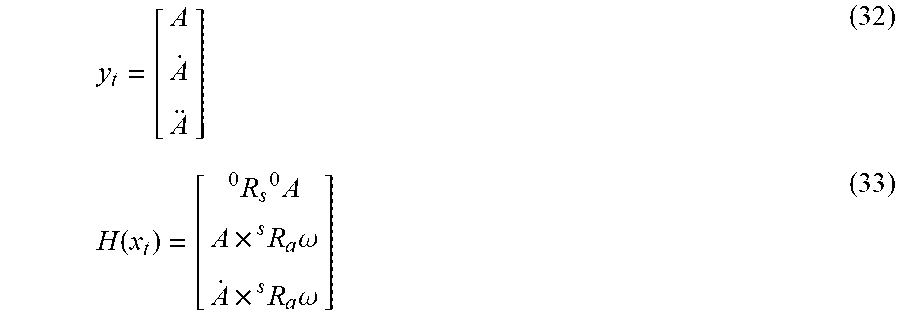
[0116] Analysis device 10 calculates the angle of the spin axis of ball 2 by solving the above-described non-linear state equation (8) and non-linear observation equation (9), with the input of the respective acceleration components in the x-axis, y-axis, and z-axis directions in the analysis period detected by high acceleration sensor 206, the first-order differential value of each acceleration component, and the second-order differential value of each acceleration component. Here, the characters of x.sub.t and F(x.sub.t) in formula (8) are expressed by the above-described formulae (20) and (21). The characters of y.sub.t and H(x.sub.t) in formula (9) are expressed by the following formulae (32) and (33).
y t = [ A A . A ] ( 32 ) H ( x t ) = [ R s 0 0 A A .times. R a s .omega. A . .times. R a s .omega. ] ( 33 ) ##EQU00018##
where A denotes a matrix showing the acceleration components (A.sub.x, A.sub.y, A.sub.z) of the three axes at time t in the sensor coordinate system; {dot over (A)} denotes the first-order differential value of A; A denotes the second-order differential value of A; and .sup.0A denotes a matrix showing the acceleration components of the three axes at time t in the absolute coordinate system.
[0117] The character of .sup.sR.sub.s which denotes a rotation matrix from the sensor coordinate system to the absolute coordinate system is expressed by the above-described formula (24), and the character of .sup.SR.sub.a which denotes a rotation matrix from the spin axis coordinate system to the sensor coordinate system is expressed by the above-described formula (25).
[0118] As in the calculation of the traveling direction in step S30, by repeatedly calculating formulae (14) to (19) using x.sub.t and F(x.sub.t) expressed by formulae (20) and (21) and using y.sub.t and H(x.sub.t) expressed by formulae (32) and (33), the most probable estimated value of state value x.sub.t at time t can be calculated. That is, roll angle .phi..sub.a and pitch angle .theta..sub.a of the spin axis of ball 2 in the absolute coordinate system, and roll angle .phi..sub.s, pitch angle .theta..sub.s, and yaw angle of the spin axis of the ball in the sensor coordinate system are estimated.
[0119] Then, analysis device 10 calculates angle .theta..sub.h of the spin axis of ball 2 relative to a horizontal plane (a plane orthogonal to the gravity direction) using the estimated roll angle .phi..sub.a and pitch angle .theta..sub.a. Specifically, analysis device 10 executes the computation using the above-described formulae (26) to (28). Also, analysis device 10 can calculate angle .PSI..sub.h of the spin axis relative to the traveling direction, using the traveling direction of ball 2 calculated in step S30 (i.e., the rotation matrix in each axis direction), and using rotation matrix .sup.0R.sub.a from the spin axis coordinate system to the absolute coordinate system shown in formula (26). In this case, analysis device 10 executes the computation using the above-described formulae (29) to (31).
[0120] Analysis device 10 displays, on display 110, the angle of the spin axis of ball 2 (e.g. angles .theta..sub.h, .PSI..sub.h) calculated in step S52 (step S54), and ends the process.
<Functional Configuration>
[0121] FIG. 10 is a block diagram showing an example functional configuration of an analysis device 10A according to embodiment 2. With reference to FIG. 10, analysis device 10A includes a spin axis calculation unit 312A, instead of spin axis calculation unit 312 in analysis device 10 in FIG. 8. The other functional configuration is the same as that of analysis device 10, and thus the detailed explanation thereof is not repeated.
[0122] Spin axis calculation unit 312A calculates (estimates) the angle of the spin axis of ball 2 relative to a predetermined direction using the extended Kalman filter, based on the attitude information calculated by attitude calculation unit 304, the spin rate of ball 2 calculated by spin rate calculation unit 310, the accelerations in the x-axis, y-axis, and z-axis directions (sensor coordinate system) in the analysis period detected by acceleration sensor 220, the first-order differential value of the acceleration, and the second-order differential value of the acceleration.
[0123] Specifically, based on the attitude information, the spin rate, the acceleration data, and the first-order and second-order differential values of the acceleration data, spin axis calculation unit 312A calculates angle .theta..sub.h of the spin axis of ball 2 relative to a horizontal plane and angle .PSI..sub.h of the spin axis relative to the traveling direction, by applying the extended Kalman filter to a state equation where the angle of the spin axis of ball 2 (e.g. roll .phi..sub.a, pitch angle .theta..sub.a) is a state value, and to an observation equation where the acceleration data and the first-order and second-order differential values of the acceleration data are observation values. More specifically, spin axis calculation unit 312A calculates angle .theta..sub.h and angle .PSI..sub.h by executing the computation using the above-described formulae (8), (9), (14) to (21), and (24) to (33).
<Advantages>
[0124] According to embodiment 2, the angle of the spin axis of ball 2 is calculated using acceleration data but without geomagnetic data. Accordingly, the angle of the spin axis of ball 2 can be calculated accurately even at a place vulnerable to magnetic field.
OTHER EMBODIMENTS
[0125] (1) In analysis system 1000 in the above-described embodiments, ball 2 is a baseball, by way of example but without limitation. For example, analysis system 1000 is applicable to a softball as well.
[0126] (2) In the above-described embodiment, a computer may be used to provide a program to execute control as described above in the flowcharts. Such a program may be provided as a program product by being stored in a non-transitory computer-readable storage medium, such as a flexible disk, a compact disk read only memory (CD-ROM), a ROM, a RAM, and a memory card for the computer. Alternatively, the program may be provided by being stored in a storage medium built in a computer, such as a hard disk. Further, the program may be provided through download via a network.
[0127] The program may be the one that calls a necessary module among program modules provided as a part of an operating system (OS) of the computer at a predetermined timing and executes the process. In this case, the program itself does not include the above-described module but cooperates with the OS to execute the process. Such a program that does not include a module may also be included in a program according to the present embodiment.
[0128] A program according to the present embodiment may be provided by being incorporated in a part of another program. In such a case, the program itself does not include a module included in the other program but cooperates with the other program to execute the process. Such a program incorporated in another program may also be included in a program according to the present embodiment.
[0129] (3) The configurations shown above in the embodiments are examples of the present invention. They may be combined with other known techniques or may be modified by, for example, skipping a part thereof, within the scope not departing from the gist of the present invention.
[0130] Although the present invention has been described and illustrated in detail, it is clearly understood that the same is by way of illustration and example only and is not to be taken by way of limitation, the scope of the present invention being interpreted by the terms of the appended claims.
* * * * *
D00000
D00001
D00002
D00003
D00004
D00005
D00006
D00007
D00008
D00009
D00010


XML
uspto.report is an independent third-party trademark research tool that is not affiliated, endorsed, or sponsored by the United States Patent and Trademark Office (USPTO) or any other governmental organization. The information provided by uspto.report is based on publicly available data at the time of writing and is intended for informational purposes only.
While we strive to provide accurate and up-to-date information, we do not guarantee the accuracy, completeness, reliability, or suitability of the information displayed on this site. The use of this site is at your own risk. Any reliance you place on such information is therefore strictly at your own risk.
All official trademark data, including owner information, should be verified by visiting the official USPTO website at www.uspto.gov. This site is not intended to replace professional legal advice and should not be used as a substitute for consulting with a legal professional who is knowledgeable about trademark law.