Harvesting energy from a surgical generator
Yates , et al. December 8, 2
U.S. patent number 10,856,929 [Application Number 15/712,678] was granted by the patent office on 2020-12-08 for harvesting energy from a surgical generator. This patent grant is currently assigned to Ethicon LLC. The grantee listed for this patent is Ethicon LLC. Invention is credited to Geoffrey S. Strobl, David C. Yates.


View All Diagrams
| United States Patent | 10,856,929 |
| Yates , et al. | December 8, 2020 |
Harvesting energy from a surgical generator
Abstract
Various embodiments are directed to methods for use with a surgical device to harvest energy from a surgical generator. The surgical device in use in conjunction with the surgical generator may comprise an energy storage device in electrical communication with a surgical generator to provide energy to charge the energy storage device. The method may comprise the steps of receiving a drive signal from the generator. The method may also comprise directing at least a portion of the drive signal to the energy storage device in a first mode. The method may further comprise directing at least a portion of the drive signal to at least one energy element in a second mode.
| Inventors: | Yates; David C. (West Chester, OH), Strobl; Geoffrey S. (Williamsburg, OH) | ||||||||||
|---|---|---|---|---|---|---|---|---|---|---|---|
| Applicant: |
|
||||||||||
| Assignee: | Ethicon LLC (Guaynabo,
PR) |
||||||||||
| Family ID: | 1000005227860 | ||||||||||
| Appl. No.: | 15/712,678 | ||||||||||
| Filed: | September 22, 2017 |
Prior Publication Data
| Document Identifier | Publication Date | |
|---|---|---|
| US 20180028257 A1 | Feb 1, 2018 | |
Related U.S. Patent Documents
| Application Number | Filing Date | Patent Number | Issue Date | ||
|---|---|---|---|---|---|
| 14149294 | Jan 7, 2014 | 9795436 | |||
| Current U.S. Class: | 1/1 |
| Current CPC Class: | A61B 18/04 (20130101); A61B 18/1206 (20130101); A61B 2017/320094 (20170801); A61B 2017/320071 (20170801); A61B 2017/00734 (20130101); A61B 18/1445 (20130101); A61B 2017/320095 (20170801); A61B 2017/320069 (20170801); A61B 2018/1226 (20130101) |
| Current International Class: | A61B 18/12 (20060101); A61B 18/04 (20060101); A61B 17/32 (20060101); A61B 18/14 (20060101); A61B 17/00 (20060101) |
References Cited [Referenced By]
U.S. Patent Documents
| 969528 | September 1910 | Disbrow |
| 1570025 | January 1926 | Young |
| 1813902 | July 1931 | Bovie |
| 2188497 | January 1940 | Calva |
| 2366274 | January 1945 | Luth et al. |
| 2425245 | August 1947 | Johnson |
| 2442966 | June 1948 | Wallace |
| 2458152 | January 1949 | Eakins |
| 2510693 | June 1950 | Green |
| 2597564 | May 1952 | Bugg |
| 2704333 | March 1955 | Calosi et al. |
| 2736960 | March 1956 | Armstrong |
| 2748967 | June 1956 | Roach |
| 2845072 | July 1958 | Shafer |
| 2849788 | September 1958 | Creek |
| 2867039 | January 1959 | Zach |
| 2874470 | February 1959 | Richards |
| 2990616 | July 1961 | Balamuth et al. |
| RE25033 | August 1961 | Balamuth et al. |
| 3015961 | January 1962 | Roney |
| 3033407 | May 1962 | Alfons |
| 3053124 | September 1962 | Balamuth et al. |
| 3082805 | March 1963 | Royce |
| 3166971 | January 1965 | Stoecker |
| 3322403 | May 1967 | Murphy |
| 3432691 | March 1969 | Shoh |
| 3433226 | March 1969 | Boyd |
| 3489930 | January 1970 | Shoh |
| 3513848 | May 1970 | Winston et al. |
| 3514856 | June 1970 | Camp et al. |
| 3525912 | August 1970 | Wallin |
| 3526219 | September 1970 | Balamuth |
| 3554198 | January 1971 | Tatoian et al. |
| 3580841 | May 1971 | Cadotte et al. |
| 3606682 | September 1971 | Camp et al. |
| 3614484 | October 1971 | Shoh |
| 3616375 | October 1971 | Inoue |
| 3629726 | December 1971 | Popescu |
| 3636943 | January 1972 | Balamuth |
| 3668486 | June 1972 | Silver |
| 3702948 | November 1972 | Balamuth |
| 3703651 | November 1972 | Blowers |
| 3776238 | December 1973 | Peyman et al. |
| 3777760 | December 1973 | Essner |
| 3805787 | April 1974 | Banko |
| 3809977 | May 1974 | Balamuth et al. |
| 3830098 | August 1974 | Antonevich |
| 3854737 | December 1974 | Gilliam, Sr. |
| 3862630 | January 1975 | Balamuth |
| 3875945 | April 1975 | Friedman |
| 3885438 | May 1975 | Harris, Sr. et al. |
| 3900823 | August 1975 | Sokal et al. |
| 3918442 | November 1975 | Nikolaev et al. |
| 3924335 | December 1975 | Balamuth et al. |
| 3946738 | March 1976 | Newton et al. |
| 3955859 | May 1976 | Stella et al. |
| 3956826 | May 1976 | Perdreaux, Jr. |
| 3989952 | November 1976 | Hohmann |
| 4005714 | February 1977 | Hiltebrandt |
| 4012647 | March 1977 | Balamuth et al. |
| 4034762 | July 1977 | Cosens et al. |
| 4058126 | November 1977 | Leveen |
| 4074719 | February 1978 | Semm |
| 4156187 | May 1979 | Murry et al. |
| 4167944 | September 1979 | Banko |
| 4188927 | February 1980 | Harris |
| 4200106 | April 1980 | Douvas et al. |
| 4203430 | May 1980 | Takahashi |
| 4203444 | May 1980 | Bonnell et al. |
| 4220154 | September 1980 | Semm |
| 4237441 | December 1980 | van Konynenburg et al. |
| 4244371 | January 1981 | Farin |
| 4281785 | August 1981 | Brooks |
| 4300083 | November 1981 | Heiges |
| 4302728 | November 1981 | Nakamura |
| 4304987 | December 1981 | van Konynenburg |
| 4306570 | December 1981 | Matthews |
| 4314559 | February 1982 | Allen |
| 4353371 | October 1982 | Cosman |
| 4409981 | October 1983 | Lundberg |
| 4445063 | April 1984 | Smith |
| 4463759 | August 1984 | Garito et al. |
| 4491132 | January 1985 | Aikins |
| 4492231 | January 1985 | Auth |
| 4494759 | January 1985 | Kieffer |
| 4504264 | March 1985 | Kelman |
| 4512344 | April 1985 | Barber |
| 4526571 | July 1985 | Wuchinich |
| 4535773 | August 1985 | Yoon |
| 4541638 | September 1985 | Ogawa et al. |
| 4545374 | October 1985 | Jacobson |
| 4545926 | October 1985 | Fouts, Jr. et al. |
| 4549147 | October 1985 | Kondo |
| 4550870 | November 1985 | Krumme et al. |
| 4553544 | November 1985 | Nomoto et al. |
| 4562838 | January 1986 | Walker |
| 4574615 | March 1986 | Bower et al. |
| 4582236 | April 1986 | Hirose |
| 4593691 | June 1986 | Lindstrom et al. |
| 4608981 | September 1986 | Rothfuss et al. |
| 4617927 | October 1986 | Manes |
| 4633119 | December 1986 | Thompson |
| 4633874 | January 1987 | Chow et al. |
| 4634420 | January 1987 | Spinosa et al. |
| 4640279 | February 1987 | Beard |
| 4641053 | February 1987 | Takeda |
| 4646738 | March 1987 | Trott |
| 4646756 | March 1987 | Watmough et al. |
| 4649919 | March 1987 | Thimsen et al. |
| 4662068 | May 1987 | Polonsky |
| 4674502 | June 1987 | Imonti |
| 4694835 | September 1987 | Strand |
| 4708127 | November 1987 | Abdelghani |
| 4712722 | December 1987 | Hood et al. |
| 4735603 | April 1988 | Goodson et al. |
| 4761871 | August 1988 | O'Connor et al. |
| 4808154 | February 1989 | Freeman |
| 4819635 | April 1989 | Shapiro |
| 4827911 | May 1989 | Broadwin et al. |
| 4830462 | May 1989 | Karny et al. |
| 4832683 | May 1989 | Idemoto et al. |
| 4836186 | June 1989 | Scholz |
| 4838853 | June 1989 | Parisi |
| 4844064 | July 1989 | Thimsen et al. |
| 4849133 | July 1989 | Yoshida et al. |
| 4850354 | July 1989 | McGurk-Burleson et al. |
| 4852578 | August 1989 | Companion et al. |
| 4860745 | August 1989 | Farin et al. |
| 4862890 | September 1989 | Stasz et al. |
| 4865159 | September 1989 | Jamison |
| 4867157 | September 1989 | McGurk-Burleson et al. |
| 4878493 | November 1989 | Pasternak et al. |
| 4880015 | November 1989 | Nierman |
| 4881550 | November 1989 | Kothe |
| 4896009 | January 1990 | Pawlowski |
| 4903696 | February 1990 | Stasz et al. |
| 4910389 | March 1990 | Sherman et al. |
| 4915643 | April 1990 | Samejima et al. |
| 4920978 | May 1990 | Colvin |
| 4922902 | May 1990 | Wuchinich et al. |
| 4936842 | June 1990 | D'Amelio et al. |
| 4954960 | September 1990 | Lo et al. |
| 4965532 | October 1990 | Sakurai |
| 4979952 | December 1990 | Kubota et al. |
| 4981756 | January 1991 | Rhandhawa |
| 5001649 | March 1991 | Lo et al. |
| 5009661 | April 1991 | Michelson |
| 5013956 | May 1991 | Kurozumi et al. |
| 5015227 | May 1991 | Broadwin et al. |
| 5020514 | June 1991 | Heckele |
| 5026370 | June 1991 | Lottick |
| 5026387 | June 1991 | Thomas |
| 5035695 | July 1991 | Weber, Jr. et al. |
| 5042461 | August 1991 | Inoue et al. |
| 5042707 | August 1991 | Taheri |
| 5061269 | October 1991 | Muller |
| 5075839 | December 1991 | Fisher et al. |
| 5084052 | January 1992 | Jacobs |
| 5099840 | March 1992 | Goble et al. |
| 5104025 | April 1992 | Main et al. |
| 5105117 | April 1992 | Yamaguchi |
| 5106538 | April 1992 | Barma et al. |
| 5108383 | April 1992 | White |
| 5109819 | May 1992 | Custer et al. |
| 5112300 | May 1992 | Ureche |
| 5113139 | May 1992 | Furukawa |
| 5123903 | June 1992 | Quaid et al. |
| 5126618 | June 1992 | Takahashi et al. |
| D327872 | July 1992 | McMills et al. |
| 5152762 | October 1992 | McElhenney |
| 5156633 | October 1992 | Smith |
| 5160334 | November 1992 | Billings et al. |
| 5162044 | November 1992 | Gahn et al. |
| 5163421 | November 1992 | Bernstein et al. |
| 5163537 | November 1992 | Radev |
| 5163945 | November 1992 | Ortiz et al. |
| 5167619 | December 1992 | Wuchinich |
| 5167725 | December 1992 | Clark et al. |
| 5172344 | December 1992 | Ehrlich |
| 5174276 | December 1992 | Crockard |
| D332660 | January 1993 | Rawson et al. |
| 5176677 | January 1993 | Wuchinich |
| 5176695 | January 1993 | Dulebohn |
| 5184605 | February 1993 | Grzeszykowski |
| 5188102 | February 1993 | Idemoto et al. |
| D334173 | March 1993 | Liu et al. |
| 5190517 | March 1993 | Zieve et al. |
| 5190518 | March 1993 | Takasu |
| 5190541 | March 1993 | Abele et al. |
| 5196007 | March 1993 | Ellman et al. |
| 5205459 | April 1993 | Brinkerhoff et al. |
| 5205817 | April 1993 | Idemoto et al. |
| 5209719 | May 1993 | Baruch et al. |
| 5213569 | May 1993 | Davis |
| 5214339 | May 1993 | Naito |
| 5217460 | June 1993 | Knoepfler |
| 5218529 | June 1993 | Meyer et al. |
| 5221282 | June 1993 | Wuchinich |
| 5222937 | June 1993 | Kagawa |
| 5226909 | July 1993 | Evans et al. |
| 5226910 | July 1993 | Kajiyama et al. |
| 5231989 | August 1993 | Middleman et al. |
| 5234428 | August 1993 | Kaufman |
| 5241236 | August 1993 | Sasaki et al. |
| 5241968 | September 1993 | Slater |
| 5242339 | September 1993 | Thornton |
| 5242460 | September 1993 | Klein et al. |
| 5246003 | September 1993 | DeLonzor |
| 5254129 | October 1993 | Alexander |
| 5257988 | November 1993 | L'Esperance, Jr. |
| 5258004 | November 1993 | Bales et al. |
| 5258006 | November 1993 | Rydell et al. |
| 5261922 | November 1993 | Hood |
| 5263957 | November 1993 | Davison |
| 5264925 | November 1993 | Shipp et al. |
| 5269297 | December 1993 | Weng et al. |
| 5275166 | January 1994 | Vaitekunas et al. |
| 5275607 | January 1994 | Lo et al. |
| 5275609 | January 1994 | Pingleton et al. |
| 5282800 | February 1994 | Foshee et al. |
| 5282817 | February 1994 | Hoogeboom et al. |
| 5285795 | February 1994 | Ryan et al. |
| 5285945 | February 1994 | Brinkerhoff et al. |
| 5290286 | March 1994 | Parins |
| 5293863 | March 1994 | Zhu et al. |
| 5300068 | April 1994 | Rosar et al. |
| 5304115 | April 1994 | Pflueger et al. |
| D347474 | May 1994 | Olson |
| 5307976 | May 1994 | Olson et al. |
| 5309927 | May 1994 | Welch |
| 5312023 | May 1994 | Green et al. |
| 5312425 | May 1994 | Evans et al. |
| 5318525 | June 1994 | West et al. |
| 5318563 | June 1994 | Malis et al. |
| 5318564 | June 1994 | Eggers |
| 5318570 | June 1994 | Hood et al. |
| 5318589 | June 1994 | Lichtman |
| 5322055 | June 1994 | Davison et al. |
| 5324299 | June 1994 | Davison et al. |
| 5326013 | July 1994 | Green et al. |
| 5326342 | July 1994 | Pflueger et al. |
| 5330471 | July 1994 | Eggers |
| 5330502 | July 1994 | Hassler et al. |
| 5334183 | August 1994 | Wuchinich |
| 5339723 | August 1994 | Huitema |
| 5342356 | August 1994 | Ellman et al. |
| 5342359 | August 1994 | Rydell |
| 5344420 | September 1994 | Hilal et al. |
| 5345937 | September 1994 | Middleman et al. |
| 5346502 | September 1994 | Estabrook et al. |
| 5353474 | October 1994 | Good et al. |
| 5357164 | October 1994 | Imabayashi et al. |
| 5357423 | October 1994 | Weaver et al. |
| 5359994 | November 1994 | Krauter et al. |
| 5361583 | November 1994 | Huitema |
| 5366466 | November 1994 | Christian et al. |
| 5368557 | November 1994 | Nita et al. |
| 5370645 | December 1994 | Klicek et al. |
| 5371429 | December 1994 | Manna |
| 5374813 | December 1994 | Shipp |
| D354564 | January 1995 | Medema |
| 5381067 | January 1995 | Greenstein et al. |
| 5383874 | January 1995 | Jackson et al. |
| 5383917 | January 1995 | Desai et al. |
| 5387207 | February 1995 | Dyer et al. |
| 5387215 | February 1995 | Fisher |
| 5389098 | February 1995 | Tsuruta et al. |
| 5394187 | February 1995 | Shipp |
| 5395033 | March 1995 | Byrne et al. |
| 5395312 | March 1995 | Desai |
| 5395363 | March 1995 | Billings et al. |
| 5395364 | March 1995 | Anderhub et al. |
| 5396266 | March 1995 | Brimhall |
| 5396900 | March 1995 | Slater et al. |
| 5400267 | March 1995 | Denen et al. |
| 5403312 | April 1995 | Yates et al. |
| 5403334 | April 1995 | Evans et al. |
| 5406503 | April 1995 | Williams, Jr. et al. |
| 5408268 | April 1995 | Shipp |
| D358887 | May 1995 | Feinberg |
| 5411481 | May 1995 | Allen et al. |
| 5417709 | May 1995 | Slater |
| 5419761 | May 1995 | Narayanan et al. |
| 5421829 | June 1995 | Olichney et al. |
| 5423844 | June 1995 | Miller |
| 5428504 | June 1995 | Bhatla |
| 5429131 | July 1995 | Scheinman et al. |
| 5438997 | August 1995 | Sieben et al. |
| 5441499 | August 1995 | Fritzsch |
| 5443463 | August 1995 | Stern et al. |
| 5445638 | August 1995 | Rydell et al. |
| 5445639 | August 1995 | Kuslich et al. |
| 5447509 | September 1995 | Mills et al. |
| 5449370 | September 1995 | Vaitekunas |
| 5451053 | September 1995 | Garrido |
| 5451161 | September 1995 | Sharp |
| 5451220 | September 1995 | Ciervo |
| 5451227 | September 1995 | Michaelson |
| 5456684 | October 1995 | Schmidt et al. |
| 5458598 | October 1995 | Feinberg et al. |
| 5462604 | October 1995 | Shibano et al. |
| 5465895 | November 1995 | Knodel et al. |
| 5471988 | December 1995 | Fujio et al. |
| 5472443 | December 1995 | Cordis et al. |
| 5476479 | December 1995 | Green et al. |
| 5478003 | December 1995 | Green et al. |
| 5480409 | January 1996 | Riza |
| 5483501 | January 1996 | Park et al. |
| 5484436 | January 1996 | Eggers et al. |
| 5486162 | January 1996 | Brumbach |
| 5486189 | January 1996 | Mudry et al. |
| 5490860 | February 1996 | Middle et al. |
| 5496317 | March 1996 | Goble et al. |
| 5499992 | March 1996 | Meade et al. |
| 5500216 | March 1996 | Julian et al. |
| 5501654 | March 1996 | Failla et al. |
| 5504650 | April 1996 | Katsui et al. |
| 5505693 | April 1996 | Mackool |
| 5507297 | April 1996 | Slater et al. |
| 5507738 | April 1996 | Ciervo |
| 5509922 | April 1996 | Aranyi et al. |
| 5511556 | April 1996 | DeSantis |
| 5520704 | May 1996 | Castro et al. |
| 5522832 | June 1996 | Kugo et al. |
| 5522839 | June 1996 | Pilling |
| 5527331 | June 1996 | Kresch et al. |
| 5531744 | July 1996 | Nardella et al. |
| 5540681 | July 1996 | Strul et al. |
| 5540693 | July 1996 | Fisher |
| 5542916 | August 1996 | Hirsch et al. |
| 5548286 | August 1996 | Craven |
| 5549637 | August 1996 | Crainich |
| 5553675 | September 1996 | Pitzen et al. |
| 5558671 | September 1996 | Yates |
| 5562609 | October 1996 | Brumbach |
| 5562610 | October 1996 | Brumbach |
| 5562659 | October 1996 | Morris |
| 5562703 | October 1996 | Desai |
| 5563179 | October 1996 | Stone et al. |
| 5569164 | October 1996 | Lurz |
| 5571121 | November 1996 | Heifetz |
| 5573424 | November 1996 | Poppe |
| 5573533 | November 1996 | Strul |
| 5573534 | November 1996 | Stone |
| 5577654 | November 1996 | Bishop |
| 5584830 | December 1996 | Ladd et al. |
| 5591187 | January 1997 | Dekel |
| 5593414 | January 1997 | Shipp et al. |
| 5599350 | February 1997 | Schulze et al. |
| 5600526 | February 1997 | Russell et al. |
| 5601601 | February 1997 | Tal et al. |
| 5603773 | February 1997 | Campbell |
| 5607436 | March 1997 | Pratt et al. |
| 5607450 | March 1997 | Zvenyatsky et al. |
| 5609573 | March 1997 | Sandock |
| 5611813 | March 1997 | Lichtman |
| 5618304 | April 1997 | Hart et al. |
| 5618307 | April 1997 | Donlon et al. |
| 5618492 | April 1997 | Auten et al. |
| 5620447 | April 1997 | Smith et al. |
| 5624452 | April 1997 | Yates |
| 5626587 | May 1997 | Bishop et al. |
| 5626595 | May 1997 | Sklar et al. |
| 5626608 | May 1997 | Cuny et al. |
| 5628760 | May 1997 | Knoepfler |
| 5630420 | May 1997 | Vaitekunas |
| 5632432 | May 1997 | Schulze et al. |
| 5632717 | May 1997 | Yoon |
| 5640741 | June 1997 | Yano |
| D381077 | July 1997 | Hunt |
| 5647871 | July 1997 | Levine et al. |
| 5649937 | July 1997 | Bito et al. |
| 5649955 | July 1997 | Hashimoto et al. |
| 5651780 | July 1997 | Jackson et al. |
| 5653713 | August 1997 | Michelson |
| 5655100 | August 1997 | Ebrahim et al. |
| 5658281 | August 1997 | Heard |
| 5662662 | September 1997 | Bishop et al. |
| 5662667 | September 1997 | Knodel |
| 5665085 | September 1997 | Nardella |
| 5665100 | September 1997 | Yoon |
| 5669922 | September 1997 | Hood |
| 5674219 | October 1997 | Monson et al. |
| 5674220 | October 1997 | Fox et al. |
| 5674235 | October 1997 | Parisi |
| 5678568 | October 1997 | Uchikubo et al. |
| 5688270 | November 1997 | Yates et al. |
| 5690269 | November 1997 | Bolanos et al. |
| 5693051 | December 1997 | Schulze et al. |
| 5694936 | December 1997 | Fujimoto et al. |
| 5695510 | December 1997 | Hood |
| 5700261 | December 1997 | Brinkerhoff |
| 5704534 | January 1998 | Huitema et al. |
| 5704791 | January 1998 | Gillio |
| 5707369 | January 1998 | Vaitekunas et al. |
| 5709680 | January 1998 | Yates et al. |
| 5711472 | January 1998 | Bryan |
| 5713896 | February 1998 | Nardella |
| 5715817 | February 1998 | Stevens-Wright et al. |
| 5716366 | February 1998 | Yates |
| 5717306 | February 1998 | Shipp |
| 5720742 | February 1998 | Zacharias |
| 5720744 | February 1998 | Eggleston et al. |
| 5722980 | March 1998 | Schulz et al. |
| 5723970 | March 1998 | Bell |
| 5728130 | March 1998 | Ishikawa et al. |
| 5730752 | March 1998 | Alden et al. |
| 5733074 | March 1998 | Stock et al. |
| 5735848 | April 1998 | Yates et al. |
| 5741226 | April 1998 | Strukel et al. |
| 5743906 | April 1998 | Parins et al. |
| 5752973 | May 1998 | Kieturakis |
| 5755717 | May 1998 | Yates et al. |
| 5762255 | June 1998 | Chrisman et al. |
| 5766164 | June 1998 | Mueller et al. |
| 5772659 | June 1998 | Becker et al. |
| 5776130 | July 1998 | Buysse et al. |
| 5776155 | July 1998 | Beaupre et al. |
| 5779130 | July 1998 | Alesi et al. |
| 5779701 | July 1998 | McBrayer et al. |
| 5782834 | July 1998 | Lucey et al. |
| 5792135 | August 1998 | Madhani et al. |
| 5792138 | August 1998 | Shipp |
| 5792165 | August 1998 | Klieman et al. |
| 5796188 | August 1998 | Bays |
| 5797941 | August 1998 | Schulze et al. |
| 5797958 | August 1998 | Yoon |
| 5797959 | August 1998 | Castro et al. |
| 5800432 | September 1998 | Swanson |
| 5800448 | September 1998 | Banko |
| 5800449 | September 1998 | Wales |
| 5805140 | September 1998 | Rosenberg et al. |
| 5807393 | September 1998 | Williamson, IV et al. |
| 5808396 | September 1998 | Boukhny |
| 5810811 | September 1998 | Yates et al. |
| 5810828 | September 1998 | Lightman et al. |
| 5810859 | September 1998 | DiMatteo et al. |
| 5817033 | October 1998 | DeSantis et al. |
| 5817084 | October 1998 | Jensen |
| 5817093 | October 1998 | Williamson, IV et al. |
| 5817119 | October 1998 | Klieman et al. |
| 5823197 | October 1998 | Edwards |
| 5827271 | October 1998 | Buysse et al. |
| 5827323 | October 1998 | Klieman et al. |
| 5828160 | October 1998 | Sugishita |
| 5833696 | November 1998 | Whitfield et al. |
| 5836897 | November 1998 | Sakurai et al. |
| 5836909 | November 1998 | Cosmescu |
| 5836943 | November 1998 | Miller, III |
| 5836957 | November 1998 | Schulz et al. |
| 5836990 | November 1998 | Li |
| 5843109 | December 1998 | Mehta et al. |
| 5851212 | December 1998 | Zirps et al. |
| 5853412 | December 1998 | Mayenberger |
| 5854590 | December 1998 | Dalstein |
| 5858018 | January 1999 | Shipp et al. |
| 5865361 | February 1999 | Milliman et al. |
| 5873873 | February 1999 | Smith et al. |
| 5873882 | February 1999 | Straub et al. |
| 5876401 | March 1999 | Schulze et al. |
| 5878193 | March 1999 | Wang et al. |
| 5879364 | March 1999 | Bromfield et al. |
| 5880668 | March 1999 | Hall |
| 5883615 | March 1999 | Fago et al. |
| 5891142 | April 1999 | Eggers et al. |
| 5893835 | April 1999 | Witt et al. |
| 5897523 | April 1999 | Wright et al. |
| 5897569 | April 1999 | Kellogg et al. |
| 5903607 | May 1999 | Tailliet |
| 5904681 | May 1999 | West, Jr. |
| 5906625 | May 1999 | Bito et al. |
| 5906627 | May 1999 | Spaulding |
| 5906628 | May 1999 | Miyawaki et al. |
| 5910129 | June 1999 | Koblish et al. |
| 5911699 | June 1999 | Anis et al. |
| 5913823 | June 1999 | Hedberg et al. |
| 5916229 | June 1999 | Evans |
| 5921956 | July 1999 | Grinberg et al. |
| 5929846 | July 1999 | Rosenberg et al. |
| 5935143 | August 1999 | Hood |
| 5935144 | August 1999 | Estabrook |
| 5938633 | August 1999 | Beaupre |
| 5944718 | August 1999 | Austin et al. |
| 5944737 | August 1999 | Tsonton et al. |
| 5947984 | September 1999 | Whipple |
| 5954717 | September 1999 | Behl et al. |
| 5954736 | September 1999 | Bishop et al. |
| 5954746 | September 1999 | Holthaus et al. |
| 5957882 | September 1999 | Nita et al. |
| 5957943 | September 1999 | Vaitekunas |
| 5968007 | October 1999 | Simon et al. |
| 5968060 | October 1999 | Kellogg |
| 5974342 | October 1999 | Petrofsky |
| D416089 | November 1999 | Barton et al. |
| 5980510 | November 1999 | Tsonton et al. |
| 5980546 | November 1999 | Hood |
| 5984938 | November 1999 | Yoon |
| 5987344 | November 1999 | West |
| 5989274 | November 1999 | Davison et al. |
| 5989275 | November 1999 | Estabrook et al. |
| 5993465 | November 1999 | Shipp et al. |
| 5993972 | November 1999 | Reich et al. |
| 5994855 | November 1999 | Lundell et al. |
| 6003517 | December 1999 | Sheffield et al. |
| 6004335 | December 1999 | Vaitekunas et al. |
| 6013052 | January 2000 | Durman et al. |
| 6024741 | February 2000 | Williamson, IV et al. |
| 6024744 | February 2000 | Kese et al. |
| 6024750 | February 2000 | Mastri et al. |
| 6027515 | February 2000 | Cimino |
| 6031526 | February 2000 | Shipp |
| 6033375 | March 2000 | Brumbach |
| 6033399 | March 2000 | Gines |
| 6036667 | March 2000 | Manna et al. |
| 6036707 | March 2000 | Spaulding |
| 6039734 | March 2000 | Goble |
| 6048224 | April 2000 | Kay |
| 6050943 | April 2000 | Slayton et al. |
| 6050996 | April 2000 | Schmaltz et al. |
| 6051010 | April 2000 | DiMatteo et al. |
| 6056735 | May 2000 | Okada et al. |
| 6063098 | May 2000 | Houser et al. |
| 6066132 | May 2000 | Chen et al. |
| 6066151 | May 2000 | Miyawaki et al. |
| 6068627 | May 2000 | Orszulak et al. |
| 6068629 | May 2000 | Haissaguerre et al. |
| 6068647 | May 2000 | Witt et al. |
| 6074389 | June 2000 | Levine et al. |
| 6077285 | June 2000 | Boukhny |
| 6080149 | June 2000 | Huang et al. |
| 6083191 | July 2000 | Rose |
| 6086584 | July 2000 | Miller |
| 6090120 | July 2000 | Wright et al. |
| 6091995 | July 2000 | Ingle et al. |
| 6096033 | August 2000 | Tu et al. |
| 6099483 | August 2000 | Palmer et al. |
| 6099542 | August 2000 | Cohn et al. |
| 6099550 | August 2000 | Yoon |
| 6109500 | August 2000 | Alli et al. |
| 6110127 | August 2000 | Suzuki |
| 6113594 | September 2000 | Savage |
| 6113598 | September 2000 | Baker |
| 6117152 | September 2000 | Huitema |
| H1904 | October 2000 | Yates et al. |
| 6126629 | October 2000 | Perkins |
| 6126658 | October 2000 | Baker |
| 6129735 | October 2000 | Okada et al. |
| 6129740 | October 2000 | Michelson |
| 6132368 | October 2000 | Cooper |
| 6132427 | October 2000 | Jones et al. |
| 6132429 | October 2000 | Baker |
| 6132448 | October 2000 | Perez et al. |
| 6139320 | October 2000 | Hahn |
| 6139561 | October 2000 | Shibata et al. |
| 6142615 | November 2000 | Qiu et al. |
| 6142994 | November 2000 | Swanson et al. |
| 6144402 | November 2000 | Norsworthy et al. |
| 6147560 | November 2000 | Erhage et al. |
| 6152902 | November 2000 | Christian et al. |
| 6152923 | November 2000 | Ryan |
| 6154198 | November 2000 | Rosenberg |
| 6156029 | December 2000 | Mueller |
| 6159160 | December 2000 | Hsei et al. |
| 6159175 | December 2000 | Strukel et al. |
| 6162194 | December 2000 | Shipp |
| 6162208 | December 2000 | Hipps |
| 6165150 | December 2000 | Banko |
| 6174309 | January 2001 | Wrublewski et al. |
| 6174310 | January 2001 | Kirwan, Jr. |
| 6176857 | January 2001 | Ashley |
| 6179853 | January 2001 | Sachse et al. |
| 6183426 | February 2001 | Akisada et al. |
| 6187003 | February 2001 | Buysse et al. |
| 6190386 | February 2001 | Rydell |
| 6193709 | February 2001 | Miyawaki et al. |
| 6204592 | March 2001 | Hur |
| 6205383 | March 2001 | Hermann |
| 6205855 | March 2001 | Pfeiffer |
| 6206844 | March 2001 | Reichel et al. |
| 6206876 | March 2001 | Levine et al. |
| 6210337 | April 2001 | Dunham et al. |
| 6210402 | April 2001 | Olsen et al. |
| 6210403 | April 2001 | Klicek |
| 6214023 | April 2001 | Whipple et al. |
| 6228080 | May 2001 | Gines |
| 6231565 | May 2001 | Tovey et al. |
| 6232899 | May 2001 | Craven |
| 6233476 | May 2001 | Strommer et al. |
| 6238366 | May 2001 | Savage et al. |
| 6241724 | June 2001 | Fleischman et al. |
| 6245065 | June 2001 | Panescu et al. |
| 6251110 | June 2001 | Wampler |
| 6252110 | June 2001 | Uemura et al. |
| D444365 | July 2001 | Bass et al. |
| D445092 | July 2001 | Lee |
| D445764 | July 2001 | Lee |
| 6254623 | July 2001 | Haibel, Jr. et al. |
| 6257241 | July 2001 | Wampler |
| 6258034 | July 2001 | Hanafy |
| 6259230 | July 2001 | Chou |
| 6267761 | July 2001 | Ryan |
| 6270831 | August 2001 | Kumar et al. |
| 6273852 | August 2001 | Lehe et al. |
| 6274963 | August 2001 | Estabrook et al. |
| 6277115 | August 2001 | Saadat |
| 6277117 | August 2001 | Tetzlaff et al. |
| 6278218 | August 2001 | Madan et al. |
| 6280407 | August 2001 | Manna et al. |
| 6283981 | September 2001 | Beaupre |
| 6287344 | September 2001 | Wampler et al. |
| 6290575 | September 2001 | Shipp |
| 6292700 | September 2001 | Morrison et al. |
| 6299591 | October 2001 | Banko |
| 6306131 | October 2001 | Hareyama et al. |
| 6306157 | October 2001 | Shchervinsky |
| 6309400 | October 2001 | Beaupre |
| 6311783 | November 2001 | Harpell |
| 6319221 | November 2001 | Savage et al. |
| 6325795 | December 2001 | Lindemann et al. |
| 6325799 | December 2001 | Goble |
| 6325811 | December 2001 | Messerly |
| 6328751 | December 2001 | Beaupre |
| 6332891 | December 2001 | Himes |
| 6338657 | January 2002 | Harper et al. |
| 6340352 | January 2002 | Okada et al. |
| 6340878 | January 2002 | Oglesbee |
| 6350269 | February 2002 | Shipp et al. |
| 6352532 | March 2002 | Kramer et al. |
| 6356224 | March 2002 | Wohlfarth |
| 6358246 | March 2002 | Behl et al. |
| 6358264 | March 2002 | Banko |
| 6364888 | April 2002 | Niemeyer et al. |
| 6379320 | April 2002 | Lafon et al. |
| D457958 | May 2002 | Dycus et al. |
| 6383194 | May 2002 | Pothula |
| 6384690 | May 2002 | Wilhelmsson et al. |
| 6387094 | May 2002 | Eitenmuller |
| 6387109 | May 2002 | Davison et al. |
| 6388657 | May 2002 | Natoli |
| 6390973 | May 2002 | Ouchi |
| 6391026 | May 2002 | Hung et al. |
| 6391042 | May 2002 | Cimino |
| 6398779 | June 2002 | Buysse et al. |
| 6402743 | June 2002 | Orszulak et al. |
| 6402748 | June 2002 | Schoenman et al. |
| 6405184 | June 2002 | Bohme et al. |
| 6405733 | June 2002 | Fogarty et al. |
| 6409722 | June 2002 | Hoey et al. |
| H2037 | July 2002 | Yates et al. |
| 6416469 | July 2002 | Phung et al. |
| 6416486 | July 2002 | Wampler |
| 6419675 | July 2002 | Gallo, Sr. |
| 6423073 | July 2002 | Bowman |
| 6423082 | July 2002 | Houser et al. |
| 6425906 | July 2002 | Young et al. |
| 6428538 | August 2002 | Blewett et al. |
| 6428539 | August 2002 | Baxter et al. |
| 6430446 | August 2002 | Knowlton |
| 6432118 | August 2002 | Messerly |
| 6436114 | August 2002 | Novak et al. |
| 6436115 | August 2002 | Beaupre |
| 6440062 | August 2002 | Ouchi |
| 6443968 | September 2002 | Holthaus et al. |
| 6443969 | September 2002 | Novak et al. |
| 6449006 | September 2002 | Shipp |
| 6454781 | September 2002 | Witt et al. |
| 6454782 | September 2002 | Schwemberger |
| 6458128 | October 2002 | Schulze |
| 6458130 | October 2002 | Frazier et al. |
| 6458142 | October 2002 | Faller et al. |
| 6459363 | October 2002 | Walker et al. |
| 6461363 | October 2002 | Gadberry et al. |
| 6464689 | October 2002 | Qin et al. |
| 6464702 | October 2002 | Schulze et al. |
| 6468270 | October 2002 | Hovda et al. |
| 6475211 | November 2002 | Chess et al. |
| 6475215 | November 2002 | Tanrisever |
| 6480796 | November 2002 | Wiener |
| 6485490 | November 2002 | Wampler et al. |
| 6491690 | December 2002 | Goble et al. |
| 6491701 | December 2002 | Tierney et al. |
| 6491708 | December 2002 | Madan et al. |
| 6497715 | December 2002 | Satou |
| 6500112 | December 2002 | Khouri |
| 6500176 | December 2002 | Truckai et al. |
| 6500188 | December 2002 | Harper et al. |
| 6500312 | December 2002 | Wedekamp |
| 6503248 | January 2003 | Levine |
| 6506208 | January 2003 | Hunt et al. |
| 6511478 | January 2003 | Burnside et al. |
| 6511480 | January 2003 | Tetzlaff et al. |
| 6511493 | January 2003 | Moutafis et al. |
| 6514252 | February 2003 | Nezhat et al. |
| 6514267 | February 2003 | Jewett |
| 6517565 | February 2003 | Whitman et al. |
| 6524251 | February 2003 | Rabiner et al. |
| 6524316 | February 2003 | Nicholson et al. |
| 6527736 | March 2003 | Attinger et al. |
| 6531846 | March 2003 | Smith |
| 6533784 | March 2003 | Truckai et al. |
| 6537272 | March 2003 | Christopherson et al. |
| 6537291 | March 2003 | Friedman et al. |
| 6543452 | April 2003 | Lavigne |
| 6543456 | April 2003 | Freeman |
| 6544260 | April 2003 | Markel et al. |
| 6551309 | April 2003 | LePivert |
| 6554829 | April 2003 | Schulze et al. |
| 6558376 | May 2003 | Bishop |
| 6561983 | May 2003 | Cronin et al. |
| 6562035 | May 2003 | Levin |
| 6562037 | May 2003 | Paton et al. |
| 6565558 | May 2003 | Lindenmeier et al. |
| 6572563 | June 2003 | Ouchi |
| 6572632 | June 2003 | Zisterer et al. |
| 6572639 | June 2003 | Ingle et al. |
| 6575969 | June 2003 | Rittman, III et al. |
| 6582427 | June 2003 | Goble et al. |
| 6582451 | June 2003 | Marucci et al. |
| 6584360 | June 2003 | Francischelli et al. |
| D477408 | July 2003 | Bromley |
| 6585735 | July 2003 | Frazier et al. |
| 6588277 | July 2003 | Giordano et al. |
| 6589200 | July 2003 | Schwemberger et al. |
| 6589239 | July 2003 | Khandkar et al. |
| 6590733 | July 2003 | Wilson et al. |
| 6599288 | July 2003 | Maguire et al. |
| 6602252 | August 2003 | Mollenauer |
| 6607540 | August 2003 | Shipp |
| 6610059 | August 2003 | West, Jr. |
| 6610060 | August 2003 | Mulier et al. |
| 6611793 | August 2003 | Burnside et al. |
| 6616450 | September 2003 | Mossle et al. |
| 6619529 | September 2003 | Green et al. |
| 6620161 | September 2003 | Schulze et al. |
| 6622731 | September 2003 | Daniel et al. |
| 6623482 | September 2003 | Pendekanti et al. |
| 6623500 | September 2003 | Cook et al. |
| 6623501 | September 2003 | Heller et al. |
| 6626848 | September 2003 | Neuenfeldt |
| 6626926 | September 2003 | Friedman et al. |
| 6629974 | October 2003 | Penny et al. |
| 6632221 | October 2003 | Edwards et al. |
| 6633234 | October 2003 | Wiener et al. |
| 6635057 | October 2003 | Harano et al. |
| 6644532 | November 2003 | Green et al. |
| 6651669 | November 2003 | Burnside |
| 6652513 | November 2003 | Panescu et al. |
| 6652539 | November 2003 | Shipp et al. |
| 6652545 | November 2003 | Shipp et al. |
| 6656132 | December 2003 | Ouchi |
| 6656177 | December 2003 | Truckai et al. |
| 6656198 | December 2003 | Tsonton et al. |
| 6660017 | December 2003 | Beaupre |
| 6662127 | December 2003 | Wiener et al. |
| 6663941 | December 2003 | Brown et al. |
| 6666860 | December 2003 | Takahashi |
| 6666875 | December 2003 | Sakurai et al. |
| 6669690 | December 2003 | Okada et al. |
| 6669710 | December 2003 | Moutafis et al. |
| 6673248 | January 2004 | Chowdhury |
| 6676660 | January 2004 | Wampler et al. |
| 6678621 | January 2004 | Wiener et al. |
| 6679875 | January 2004 | Honda et al. |
| 6679882 | January 2004 | Kornerup |
| 6679899 | January 2004 | Wiener et al. |
| 6682501 | January 2004 | Nelson et al. |
| 6682544 | January 2004 | Mastri et al. |
| 6685700 | February 2004 | Behl et al. |
| 6685701 | February 2004 | Orszulak et al. |
| 6685703 | February 2004 | Pearson et al. |
| 6689145 | February 2004 | Lee et al. |
| 6689146 | February 2004 | Himes |
| 6690960 | February 2004 | Chen et al. |
| 6695840 | February 2004 | Schulze |
| 6702821 | March 2004 | Bonutti |
| 6716215 | April 2004 | David et al. |
| 6719692 | April 2004 | Kleffner et al. |
| 6719765 | April 2004 | Bonutti |
| 6719776 | April 2004 | Baxter et al. |
| 6722552 | April 2004 | Fenton, Jr. |
| 6723091 | April 2004 | Goble et al. |
| D490059 | May 2004 | Conway et al. |
| 6730080 | May 2004 | Harano et al. |
| 6731047 | May 2004 | Kauf et al. |
| 6733498 | May 2004 | Paton et al. |
| 6733506 | May 2004 | McDevitt et al. |
| 6736813 | May 2004 | Yamauchi et al. |
| 6739872 | May 2004 | Turri |
| 6740079 | May 2004 | Eggers et al. |
| D491666 | June 2004 | Kimmell et al. |
| 6743245 | June 2004 | Lobdell |
| 6746284 | June 2004 | Spink, Jr. |
| 6746443 | June 2004 | Morley et al. |
| 6752815 | June 2004 | Beaupre |
| 6755825 | June 2004 | Shoenman et al. |
| 6761698 | July 2004 | Shibata et al. |
| 6762535 | July 2004 | Take et al. |
| 6766202 | July 2004 | Underwood et al. |
| 6770072 | August 2004 | Truckai et al. |
| 6773409 | August 2004 | Truckai et al. |
| 6773434 | August 2004 | Ciarrocca |
| 6773435 | August 2004 | Schulze et al. |
| 6773443 | August 2004 | Truwit et al. |
| 6773444 | August 2004 | Messerly |
| 6775575 | August 2004 | Bommannan et al. |
| 6778023 | August 2004 | Christensen |
| 6783524 | August 2004 | Anderson et al. |
| 6786382 | September 2004 | Hoffman |
| 6786383 | September 2004 | Stegelmann |
| 6789939 | September 2004 | Schrodinger et al. |
| 6790173 | September 2004 | Saadat et al. |
| 6790216 | September 2004 | Ishikawa |
| 6794027 | September 2004 | Araki et al. |
| 6796981 | September 2004 | Wham et al. |
| D496997 | October 2004 | Dycus et al. |
| 6800085 | October 2004 | Selmon et al. |
| 6802843 | October 2004 | Truckai et al. |
| 6808525 | October 2004 | Latterell et al. |
| 6809508 | October 2004 | Donofrio |
| 6810281 | October 2004 | Brock et al. |
| 6811842 | November 2004 | Ehrnsperger et al. |
| 6814731 | November 2004 | Swanson |
| 6819027 | November 2004 | Saraf |
| 6821273 | November 2004 | Mollenauer |
| 6827712 | December 2004 | Tovey et al. |
| 6828712 | December 2004 | Battaglin et al. |
| 6835082 | December 2004 | Gonnering |
| 6835199 | December 2004 | McGuckin, Jr. et al. |
| 6840938 | January 2005 | Morley et al. |
| 6843789 | January 2005 | Goble |
| 6849073 | February 2005 | Hoey et al. |
| 6860878 | March 2005 | Brock |
| 6860880 | March 2005 | Treat et al. |
| 6863676 | March 2005 | Lee et al. |
| 6866671 | March 2005 | Tierney et al. |
| 6869439 | March 2005 | White et al. |
| 6875220 | April 2005 | Du et al. |
| 6877647 | April 2005 | Green et al. |
| 6882439 | April 2005 | Ishijima |
| 6887209 | May 2005 | Kadziauskas et al. |
| 6887252 | May 2005 | Okada et al. |
| 6893435 | May 2005 | Goble |
| 6898536 | May 2005 | Wiener et al. |
| 6899685 | May 2005 | Kermode et al. |
| 6905497 | June 2005 | Truckai et al. |
| 6908463 | June 2005 | Treat et al. |
| 6908472 | June 2005 | Wiener et al. |
| 6913579 | July 2005 | Truckai et al. |
| 6915623 | July 2005 | Dey et al. |
| 6923804 | August 2005 | Eggers et al. |
| 6923806 | August 2005 | Hooven et al. |
| 6926712 | August 2005 | Phan |
| 6926716 | August 2005 | Baker et al. |
| 6926717 | August 2005 | Garito et al. |
| 6929602 | August 2005 | Hirakui et al. |
| 6929622 | August 2005 | Chian |
| 6929632 | August 2005 | Nita et al. |
| 6929644 | August 2005 | Truckai et al. |
| 6933656 | August 2005 | Matsushita et al. |
| D509589 | September 2005 | Wells |
| 6942660 | September 2005 | Pantera et al. |
| 6942677 | September 2005 | Nita et al. |
| 6945981 | September 2005 | Donofrio et al. |
| 6946779 | September 2005 | Birgel |
| 6948503 | September 2005 | Refior et al. |
| 6953461 | October 2005 | McClurken et al. |
| 6958070 | October 2005 | Witt et al. |
| D511145 | November 2005 | Donofrio et al. |
| 6974450 | December 2005 | Weber et al. |
| 6976844 | December 2005 | Hickok et al. |
| 6976969 | December 2005 | Messerly |
| 6977495 | December 2005 | Donofrio |
| 6979332 | December 2005 | Adams |
| 6981628 | January 2006 | Wales |
| 6984220 | January 2006 | Wuchinich |
| 6988295 | January 2006 | Tillim |
| 6994708 | February 2006 | Manzo |
| 6994709 | February 2006 | Iida |
| 7000818 | February 2006 | Shelton, IV et al. |
| 7001335 | February 2006 | Adachi et al. |
| 7001379 | February 2006 | Behl et al. |
| 7001382 | February 2006 | Gallo, Sr. |
| 7004951 | February 2006 | Gibbens, III |
| 7011657 | March 2006 | Truckai et al. |
| 7014638 | March 2006 | Michelson |
| 7018389 | March 2006 | Camerlengo |
| 7025732 | April 2006 | Thompson et al. |
| 7033356 | April 2006 | Latterell et al. |
| 7033357 | April 2006 | Baxter et al. |
| 7037306 | May 2006 | Podany et al. |
| 7041083 | May 2006 | Chu et al. |
| 7041088 | May 2006 | Nawrocki et al. |
| 7041102 | May 2006 | Truckai et al. |
| 7044949 | May 2006 | Orszulak et al. |
| 7052494 | May 2006 | Goble et al. |
| 7052496 | May 2006 | Yamauchi |
| 7055731 | June 2006 | Shelton, IV et al. |
| 7063699 | June 2006 | Hess et al. |
| 7066893 | June 2006 | Hibner et al. |
| 7066895 | June 2006 | Podany |
| 7066936 | June 2006 | Ryan |
| 7070597 | July 2006 | Truckai et al. |
| 7074218 | July 2006 | Washington et al. |
| 7074219 | July 2006 | Levine et al. |
| 7077039 | July 2006 | Gass et al. |
| 7077845 | July 2006 | Hacker et al. |
| 7077853 | July 2006 | Kramer et al. |
| 7083075 | August 2006 | Swayze et al. |
| 7083613 | August 2006 | Treat |
| 7083618 | August 2006 | Couture et al. |
| 7083619 | August 2006 | Truckai et al. |
| 7087054 | August 2006 | Truckai et al. |
| 7090672 | August 2006 | Underwood et al. |
| 7094235 | August 2006 | Francischelli |
| 7101371 | September 2006 | Dycus et al. |
| 7101372 | September 2006 | Dycus et al. |
| 7101373 | September 2006 | Dycus et al. |
| 7101378 | September 2006 | Salameh et al. |
| 7104834 | September 2006 | Robinson et al. |
| 7108695 | September 2006 | Witt et al. |
| 7111769 | September 2006 | Wales et al. |
| 7112201 | September 2006 | Truckai et al. |
| 7113831 | September 2006 | Hooven |
| D531311 | October 2006 | Guerra et al. |
| 7117034 | October 2006 | Kronberg |
| 7118564 | October 2006 | Ritchie et al. |
| 7118570 | October 2006 | Tetzlaff et al. |
| 7118587 | October 2006 | Dycus et al. |
| 7119516 | October 2006 | Denning |
| 7124932 | October 2006 | Isaacson et al. |
| 7125409 | October 2006 | Truckai et al. |
| 7128720 | October 2006 | Podany |
| 7131860 | November 2006 | Sartor et al. |
| 7131970 | November 2006 | Moses et al. |
| 7135018 | November 2006 | Ryan et al. |
| 7135030 | November 2006 | Schwemberger et al. |
| 7137980 | November 2006 | Buysse et al. |
| 7143925 | December 2006 | Shelton, IV et al. |
| 7144403 | December 2006 | Booth |
| 7147138 | December 2006 | Shelton, IV |
| 7153315 | December 2006 | Miller |
| D536093 | January 2007 | Nakajima et al. |
| 7156189 | January 2007 | Bar-Cohen et al. |
| 7156846 | January 2007 | Dycus et al. |
| 7156853 | January 2007 | Muratsu |
| 7157058 | January 2007 | Marhasin et al. |
| 7159750 | January 2007 | Racenet et al. |
| 7160259 | January 2007 | Tardy et al. |
| 7160296 | January 2007 | Pearson et al. |
| 7160298 | January 2007 | Lawes et al. |
| 7160299 | January 2007 | Baily |
| 7163548 | January 2007 | Stulen et al. |
| 7166103 | January 2007 | Carmel et al. |
| 7169144 | January 2007 | Hoey et al. |
| 7169146 | January 2007 | Truckai et al. |
| 7169156 | January 2007 | Hart |
| 7179254 | February 2007 | Pendekanti et al. |
| 7179271 | February 2007 | Friedman et al. |
| 7186253 | March 2007 | Truckai et al. |
| 7189233 | March 2007 | Truckai et al. |
| 7195631 | March 2007 | Dumbauld |
| D541418 | April 2007 | Schechter et al. |
| 7198635 | April 2007 | Danek et al. |
| 7204820 | April 2007 | Akahoshi |
| 7207471 | April 2007 | Heinrich et al. |
| 7207997 | April 2007 | Shipp et al. |
| 7208005 | April 2007 | Frecker et al. |
| 7210881 | May 2007 | Greenberg |
| 7211079 | May 2007 | Treat |
| 7217128 | May 2007 | Atkin et al. |
| 7217269 | May 2007 | El-Galley et al. |
| 7220951 | May 2007 | Truckai et al. |
| 7223229 | May 2007 | Inman et al. |
| 7225964 | June 2007 | Mastri et al. |
| 7226447 | June 2007 | Uchida et al. |
| 7226448 | June 2007 | Bertolero et al. |
| 7229455 | June 2007 | Sakurai et al. |
| 7232440 | June 2007 | Dumbauld et al. |
| 7235071 | June 2007 | Gonnering |
| 7235073 | June 2007 | Levine et al. |
| 7241294 | July 2007 | Reschke |
| 7244262 | July 2007 | Wiener et al. |
| 7251531 | July 2007 | Mosher et al. |
| 7252641 | August 2007 | Thompson et al. |
| 7252667 | August 2007 | Moses et al. |
| 7258688 | August 2007 | Shah et al. |
| 7264618 | September 2007 | Murakami et al. |
| 7267677 | September 2007 | Johnson et al. |
| 7267685 | September 2007 | Butaric et al. |
| 7269873 | September 2007 | Brewer et al. |
| 7273483 | September 2007 | Wiener et al. |
| D552241 | October 2007 | Bromley et al. |
| 7282048 | October 2007 | Goble et al. |
| 7285895 | October 2007 | Beaupre |
| 7287682 | October 2007 | Ezzat et al. |
| 7297149 | November 2007 | Vitali et al. |
| 7300431 | November 2007 | Dubrovsky |
| 7300435 | November 2007 | Wham et al. |
| 7300446 | November 2007 | Beaupre |
| 7300450 | November 2007 | Vleugels et al. |
| 7303531 | December 2007 | Lee et al. |
| 7303557 | December 2007 | Wham et al. |
| 7306597 | December 2007 | Manzo |
| 7307313 | December 2007 | Ohyanagi et al. |
| 7309849 | December 2007 | Truckai et al. |
| 7311706 | December 2007 | Schoenman et al. |
| 7311709 | December 2007 | Truckai et al. |
| 7317955 | January 2008 | McGreevy |
| 7318831 | January 2008 | Alvarez et al. |
| 7318832 | January 2008 | Young et al. |
| 7326236 | February 2008 | Andreas et al. |
| 7329257 | February 2008 | Kanehira et al. |
| 7331410 | February 2008 | Yong et al. |
| 7335165 | February 2008 | Truwit et al. |
| 7335997 | February 2008 | Wiener |
| 7337010 | February 2008 | Howard et al. |
| 7353068 | April 2008 | Tanaka et al. |
| 7354440 | April 2008 | Truckal et al. |
| 7357287 | April 2008 | Shelton, IV et al. |
| 7357802 | April 2008 | Palanker et al. |
| 7361172 | April 2008 | Cimino |
| 7364577 | April 2008 | Wham et al. |
| 7367976 | May 2008 | Lawes et al. |
| 7371227 | May 2008 | Zeiner |
| RE40388 | June 2008 | Gines |
| 7380695 | June 2008 | Doll et al. |
| 7380696 | June 2008 | Shelton, IV et al. |
| 7381209 | June 2008 | Truckai et al. |
| 7384420 | June 2008 | Dycus et al. |
| 7390317 | June 2008 | Taylor et al. |
| 7396356 | July 2008 | Mollenauer |
| 7403224 | July 2008 | Fuller et al. |
| 7404508 | July 2008 | Smith et al. |
| 7407077 | August 2008 | Ortiz et al. |
| 7408288 | August 2008 | Hara |
| 7412008 | August 2008 | Lliev |
| 7416101 | August 2008 | Shelton, IV et al. |
| 7416437 | August 2008 | Sartor et al. |
| D576725 | September 2008 | Shumer et al. |
| 7419490 | September 2008 | Falkenstein et al. |
| 7422139 | September 2008 | Shelton, IV et al. |
| 7422463 | September 2008 | Kuo |
| 7422582 | September 2008 | Malackowski et al. |
| D578643 | October 2008 | Shumer et al. |
| D578644 | October 2008 | Shumer et al. |
| D578645 | October 2008 | Shumer et al. |
| 7431694 | October 2008 | Stefanchik et al. |
| 7431704 | October 2008 | Babaev |
| 7431720 | October 2008 | Pendekanti et al. |
| 7435582 | October 2008 | Zimmermann et al. |
| 7441684 | October 2008 | Shelton, IV et al. |
| 7442193 | October 2008 | Shields et al. |
| 7445621 | November 2008 | Dumbauld et al. |
| 7449004 | November 2008 | Yamada et al. |
| 7451904 | November 2008 | Shelton, IV |
| 7455208 | November 2008 | Wales et al. |
| 7455641 | November 2008 | Yamada et al. |
| 7462181 | December 2008 | Kraft et al. |
| 7464846 | December 2008 | Shelton, IV et al. |
| 7464849 | December 2008 | Shelton, IV et al. |
| 7472815 | January 2009 | Shelton, IV et al. |
| 7473145 | January 2009 | Ehr et al. |
| 7473253 | January 2009 | Dycus et al. |
| 7473263 | January 2009 | Johnston et al. |
| 7479148 | January 2009 | Beaupre |
| 7479160 | January 2009 | Branch et al. |
| 7481775 | January 2009 | Weikel, Jr. et al. |
| 7488285 | February 2009 | Honda et al. |
| 7488319 | February 2009 | Yates |
| 7491201 | February 2009 | Shields et al. |
| 7491202 | February 2009 | Odom et al. |
| 7494468 | February 2009 | Rabiner et al. |
| 7494501 | February 2009 | Ahlberg et al. |
| 7498080 | March 2009 | Tung et al. |
| 7502234 | March 2009 | Goliszek et al. |
| 7503893 | March 2009 | Kucklick |
| 7503895 | March 2009 | Rabiner et al. |
| 7506790 | March 2009 | Shelton, IV |
| 7506791 | March 2009 | Omaits et al. |
| 7507239 | March 2009 | Shadduck |
| 7510107 | March 2009 | Timm et al. |
| 7510556 | March 2009 | Nguyen et al. |
| 7513025 | April 2009 | Fischer |
| 7517349 | April 2009 | Truckai et al. |
| 7520865 | April 2009 | Radley Young et al. |
| 7524320 | April 2009 | Tierney et al. |
| 7530986 | May 2009 | Beaupre et al. |
| 7534243 | May 2009 | Chin et al. |
| 7535233 | May 2009 | Kojovic et al. |
| D594983 | June 2009 | Price et al. |
| 7540871 | June 2009 | Gonnering |
| 7540872 | June 2009 | Schechter et al. |
| 7543730 | June 2009 | Marczyk |
| 7544200 | June 2009 | Houser |
| 7549564 | June 2009 | Boudreaux |
| 7550216 | June 2009 | Ofer et al. |
| 7553309 | June 2009 | Buysse et al. |
| 7554343 | June 2009 | Bromfield |
| 7559450 | July 2009 | Wales et al. |
| 7559452 | July 2009 | Wales et al. |
| 7563259 | July 2009 | Takahashi |
| 7566318 | July 2009 | Haefner |
| 7567012 | July 2009 | Namikawa |
| 7568603 | August 2009 | Shelton, IV et al. |
| 7569057 | August 2009 | Liu et al. |
| 7572266 | August 2009 | Young et al. |
| 7572268 | August 2009 | Babaev |
| 7578820 | August 2009 | Moore et al. |
| 7582084 | September 2009 | Swanson et al. |
| 7582086 | September 2009 | Privitera et al. |
| 7582087 | September 2009 | Tetzlaff et al. |
| 7582095 | September 2009 | Shipp et al. |
| 7585181 | September 2009 | Olsen |
| 7586289 | September 2009 | Andruk et al. |
| 7587536 | September 2009 | McLeod |
| 7588176 | September 2009 | Timm et al. |
| 7588177 | September 2009 | Racenet |
| 7594925 | September 2009 | Danek et al. |
| 7597693 | October 2009 | Garrison |
| 7601119 | October 2009 | Shahinian |
| 7601136 | October 2009 | Akahoshi |
| 7604150 | October 2009 | Boudreaux |
| 7607557 | October 2009 | Shelton, IV et al. |
| 7617961 | November 2009 | Viola |
| 7621930 | November 2009 | Houser |
| 7625370 | December 2009 | Hart et al. |
| 7628791 | December 2009 | Garrison et al. |
| 7628792 | December 2009 | Guerra |
| 7632267 | December 2009 | Dahla |
| 7632269 | December 2009 | Truckai et al. |
| 7637410 | December 2009 | Marczyk |
| 7641653 | January 2010 | Dalla Betta et al. |
| 7641671 | January 2010 | Crainich |
| 7644848 | January 2010 | Swayze et al. |
| 7645240 | January 2010 | Thompson et al. |
| 7645277 | January 2010 | McClurken et al. |
| 7645278 | January 2010 | Ichihashi et al. |
| 7648499 | January 2010 | Orszulak et al. |
| 7649410 | January 2010 | Andersen et al. |
| 7654431 | February 2010 | Hueil et al. |
| 7655003 | February 2010 | Lorang et al. |
| 7658311 | February 2010 | Boudreaux |
| 7659833 | February 2010 | Warner et al. |
| 7662151 | February 2010 | Crompton, Jr. et al. |
| 7665647 | February 2010 | Shelton, IV et al. |
| 7666206 | February 2010 | Taniguchi et al. |
| 7667592 | February 2010 | Ohyama et al. |
| 7670334 | March 2010 | Hueil et al. |
| 7670338 | March 2010 | Albrecht et al. |
| 7674263 | March 2010 | Ryan |
| 7678069 | March 2010 | Baker et al. |
| 7678105 | March 2010 | McGreevy et al. |
| 7678125 | March 2010 | Shipp |
| 7682366 | March 2010 | Sakurai et al. |
| 7686770 | March 2010 | Cohen |
| 7686826 | March 2010 | Lee et al. |
| 7688028 | March 2010 | Phillips et al. |
| 7691095 | April 2010 | Bednarek et al. |
| 7691098 | April 2010 | Wallace et al. |
| 7699846 | April 2010 | Ryan |
| 7703459 | April 2010 | Saadat et al. |
| 7703653 | April 2010 | Shah et al. |
| 7708735 | May 2010 | Chapman et al. |
| 7708751 | May 2010 | Hughes et al. |
| 7708758 | May 2010 | Lee et al. |
| 7708768 | May 2010 | Danek et al. |
| 7713202 | May 2010 | Boukhny et al. |
| 7713267 | May 2010 | Pozzato |
| 7714481 | May 2010 | Sakai |
| 7717312 | May 2010 | Beetel |
| 7717914 | May 2010 | Kimura |
| 7717915 | May 2010 | Miyazawa |
| 7721935 | May 2010 | Racenet et al. |
| 7722527 | May 2010 | Bouchier et al. |
| 7722607 | May 2010 | Dumbauld et al. |
| D618797 | June 2010 | Price et al. |
| 7726537 | June 2010 | Olson et al. |
| 7727177 | June 2010 | Bayat |
| 7731717 | June 2010 | Odom et al. |
| 7738969 | June 2010 | Bleich |
| 7740594 | June 2010 | Hibner |
| 7744615 | June 2010 | Couture |
| 7749240 | July 2010 | Takahashi et al. |
| 7751115 | July 2010 | Song |
| 7753245 | July 2010 | Boudreaux et al. |
| 7753904 | July 2010 | Shelton, IV et al. |
| 7753908 | July 2010 | Swanson |
| 7762445 | July 2010 | Heinrich et al. |
| D621503 | August 2010 | Otten et al. |
| 7766210 | August 2010 | Shelton, IV et al. |
| 7766693 | August 2010 | Sartor et al. |
| 7766910 | August 2010 | Hixson et al. |
| 7768510 | August 2010 | Tsai et al. |
| 7770774 | August 2010 | Mastri et al. |
| 7770775 | August 2010 | Shelton, IV et al. |
| 7771425 | August 2010 | Dycus et al. |
| 7771444 | August 2010 | Patel et al. |
| 7775972 | August 2010 | Brock et al. |
| 7776036 | August 2010 | Schechter et al. |
| 7776037 | August 2010 | Odom |
| 7778733 | August 2010 | Nowlin et al. |
| 7780054 | August 2010 | Wales |
| 7780593 | August 2010 | Ueno et al. |
| 7780651 | August 2010 | Madhani et al. |
| 7780659 | August 2010 | Okada et al. |
| 7780663 | August 2010 | Yates et al. |
| 7784662 | August 2010 | Wales et al. |
| 7784663 | August 2010 | Shelton, IV |
| 7789883 | September 2010 | Takashino et al. |
| 7793814 | September 2010 | Racenet et al. |
| 7794475 | September 2010 | Hess et al. |
| 7796969 | September 2010 | Kelly et al. |
| 7798386 | September 2010 | Schall et al. |
| 7799020 | September 2010 | Shores et al. |
| 7799027 | September 2010 | Hafner |
| 7799045 | September 2010 | Masuda |
| 7803152 | September 2010 | Honda et al. |
| 7803156 | September 2010 | Eder et al. |
| 7803168 | September 2010 | Gifford et al. |
| 7806891 | October 2010 | Nowlin et al. |
| 7810693 | October 2010 | Broehl et al. |
| 7811283 | October 2010 | Moses et al. |
| 7815238 | October 2010 | Cao |
| 7815641 | October 2010 | Dodde et al. |
| 7819298 | October 2010 | Hall et al. |
| 7819299 | October 2010 | Shelton, IV et al. |
| 7819819 | October 2010 | Quick et al. |
| 7819872 | October 2010 | Johnson et al. |
| 7821143 | October 2010 | Wiener |
| D627066 | November 2010 | Romero |
| 7824401 | November 2010 | Manzo et al. |
| 7832408 | November 2010 | Shelton, IV et al. |
| 7832611 | November 2010 | Boyden et al. |
| 7832612 | November 2010 | Baxter, III et al. |
| 7834484 | November 2010 | Sartor |
| 7837699 | November 2010 | Yamada et al. |
| 7845537 | December 2010 | Shelton, IV et al. |
| 7846155 | December 2010 | Houser et al. |
| 7846159 | December 2010 | Morrison et al. |
| 7846160 | December 2010 | Payne et al. |
| 7846161 | December 2010 | Dumbauld et al. |
| 7854735 | December 2010 | Houser et al. |
| D631155 | January 2011 | Peine et al. |
| 7861906 | January 2011 | Doll et al. |
| 7862560 | January 2011 | Marion |
| 7862561 | January 2011 | Swanson et al. |
| 7867228 | January 2011 | Nobis et al. |
| 7871392 | January 2011 | Sartor |
| 7871423 | January 2011 | Livneh |
| 7876030 | January 2011 | Taki et al. |
| D631965 | February 2011 | Price et al. |
| 7877852 | February 2011 | Unger et al. |
| 7878991 | February 2011 | Babaev |
| 7879033 | February 2011 | Sartor et al. |
| 7879035 | February 2011 | Garrison et al. |
| 7879070 | February 2011 | Ortiz et al. |
| 7883475 | February 2011 | Dupont et al. |
| 7892606 | February 2011 | Thies et al. |
| 7896875 | March 2011 | Heim et al. |
| 7897792 | March 2011 | Iikura et al. |
| 7901400 | March 2011 | Wham et al. |
| 7901423 | March 2011 | Stulen et al. |
| 7905881 | March 2011 | Masuda et al. |
| 7909220 | March 2011 | Viola |
| 7909820 | March 2011 | Lipson et al. |
| 7909824 | March 2011 | Masuda et al. |
| 7918848 | April 2011 | Lau et al. |
| 7919184 | April 2011 | Mohapatra et al. |
| 7922061 | April 2011 | Shelton, IV et al. |
| 7922651 | April 2011 | Yamada et al. |
| 7931611 | April 2011 | Novak et al. |
| 7931649 | April 2011 | Couture et al. |
| D637288 | May 2011 | Houghton |
| D638540 | May 2011 | Ijiri et al. |
| 7935114 | May 2011 | Takashino et al. |
| 7936203 | May 2011 | Zimlich |
| 7951095 | May 2011 | Makin et al. |
| 7951165 | May 2011 | Golden et al. |
| 7955331 | June 2011 | Truckai et al. |
| 7956620 | June 2011 | Gilbert |
| 7959050 | June 2011 | Smith et al. |
| 7959626 | June 2011 | Hong et al. |
| 7963963 | June 2011 | Francischelli et al. |
| 7967602 | June 2011 | Lindquist |
| 7972328 | July 2011 | Wham et al. |
| 7972329 | July 2011 | Refior et al. |
| 7976544 | July 2011 | McClurken et al. |
| 7980443 | July 2011 | Scheib et al. |
| 7981050 | July 2011 | Ritchart et al. |
| 7981113 | July 2011 | Truckai et al. |
| 7997278 | August 2011 | Utley et al. |
| 7998157 | August 2011 | Culp et al. |
| 8002732 | August 2011 | Visconti |
| 8002770 | August 2011 | Swanson et al. |
| 8020743 | September 2011 | Shelton, IV |
| 8028885 | October 2011 | Smith et al. |
| 8033173 | October 2011 | Ehlert et al. |
| 8034049 | October 2011 | Odom et al. |
| 8038693 | October 2011 | Allen |
| 8048070 | November 2011 | O'Brien et al. |
| 8052672 | November 2011 | Laufer et al. |
| 8055208 | November 2011 | Lilla et al. |
| 8056720 | November 2011 | Hawkes |
| 8056787 | November 2011 | Boudreaux et al. |
| 8057468 | November 2011 | Konesky |
| 8057498 | November 2011 | Robertson |
| 8058771 | November 2011 | Giordano et al. |
| 8061014 | November 2011 | Smith et al. |
| 8066167 | November 2011 | Measamer et al. |
| 8070036 | December 2011 | Knodel |
| 8070711 | December 2011 | Bassinger et al. |
| 8070762 | December 2011 | Escudero et al. |
| 8075555 | December 2011 | Truckai et al. |
| 8075558 | December 2011 | Truckai et al. |
| 8089197 | January 2012 | Rinner et al. |
| 8092475 | January 2012 | Cotter et al. |
| 8096459 | January 2012 | Ortiz et al. |
| 8097012 | January 2012 | Kagarise |
| 8100894 | January 2012 | Mucko et al. |
| 8105230 | January 2012 | Honda et al. |
| 8105323 | January 2012 | Buysse et al. |
| 8105324 | January 2012 | Palanker et al. |
| 8114104 | February 2012 | Young et al. |
| 8118276 | February 2012 | Sanders et al. |
| 8128624 | March 2012 | Couture et al. |
| 8133218 | March 2012 | Daw et al. |
| 8136712 | March 2012 | Zingman |
| 8141762 | March 2012 | Bedi et al. |
| 8142421 | March 2012 | Cooper et al. |
| 8142461 | March 2012 | Houser et al. |
| 8147485 | April 2012 | Wham et al. |
| 8147488 | April 2012 | Masuda |
| 8147508 | April 2012 | Madan et al. |
| 8152801 | April 2012 | Goldberg et al. |
| 8152825 | April 2012 | Madan et al. |
| 8157145 | April 2012 | Shelton, IV et al. |
| 8161977 | April 2012 | Shelton, IV et al. |
| 8162966 | April 2012 | Connor et al. |
| 8172846 | May 2012 | Brunnett et al. |
| 8172870 | May 2012 | Shipp |
| 8177800 | May 2012 | Spitz et al. |
| 8182502 | May 2012 | Stulen et al. |
| 8186560 | May 2012 | Hess et al. |
| 8186877 | May 2012 | Klimovitch et al. |
| 8187267 | May 2012 | Pappone et al. |
| D661801 | June 2012 | Price et al. |
| D661802 | June 2012 | Price et al. |
| D661803 | June 2012 | Price et al. |
| D661804 | June 2012 | Price et al. |
| 8197472 | June 2012 | Lau et al. |
| 8197479 | June 2012 | Olson et al. |
| 8197502 | June 2012 | Smith et al. |
| 8207651 | June 2012 | Gilbert |
| 8210411 | July 2012 | Yates et al. |
| 8211100 | July 2012 | Podhajsky et al. |
| 8220688 | July 2012 | Laurent et al. |
| 8221306 | July 2012 | Okada et al. |
| 8221415 | July 2012 | Francischelli |
| 8221418 | July 2012 | Prakash et al. |
| 8226580 | July 2012 | Govari et al. |
| 8226665 | July 2012 | Cohen |
| 8226675 | July 2012 | Houser et al. |
| 8231607 | July 2012 | Takuma |
| 8235917 | August 2012 | Joseph et al. |
| 8236018 | August 2012 | Yoshimine et al. |
| 8236019 | August 2012 | Houser |
| 8236020 | August 2012 | Smith et al. |
| 8241235 | August 2012 | Kahler et al. |
| 8241271 | August 2012 | Millman et al. |
| 8241282 | August 2012 | Unger et al. |
| 8241283 | August 2012 | Guerra et al. |
| 8241284 | August 2012 | Dycus et al. |
| 8241312 | August 2012 | Messerly |
| 8246575 | August 2012 | Viola |
| 8246615 | August 2012 | Behnke |
| 8246616 | August 2012 | Amoah et al. |
| 8246618 | August 2012 | Bucciaglia et al. |
| 8246642 | August 2012 | Houser et al. |
| 8251994 | August 2012 | McKenna et al. |
| 8252012 | August 2012 | Stulen |
| 8253303 | August 2012 | Giordano et al. |
| 8257377 | September 2012 | Wiener et al. |
| 8257387 | September 2012 | Cunningham |
| 8262563 | September 2012 | Bakos et al. |
| 8267300 | September 2012 | Boudreaux |
| 8267935 | September 2012 | Couture et al. |
| 8273087 | September 2012 | Kimura et al. |
| D669992 | October 2012 | Schafer et al. |
| D669993 | October 2012 | Merchant et al. |
| 8277446 | October 2012 | Heard |
| 8277447 | October 2012 | Garrison et al. |
| 8277471 | October 2012 | Wiener et al. |
| 8282581 | October 2012 | Zhao et al. |
| 8282669 | October 2012 | Gerber et al. |
| 8286846 | October 2012 | Smith et al. |
| 8287485 | October 2012 | Kimura et al. |
| 8287528 | October 2012 | Wham et al. |
| 8287532 | October 2012 | Carroll et al. |
| 8292886 | October 2012 | Kerr et al. |
| 8292888 | October 2012 | Whitman |
| 8292905 | October 2012 | Taylor et al. |
| 8295902 | October 2012 | Salahieh et al. |
| 8298223 | October 2012 | Wham et al. |
| 8298225 | October 2012 | Gilbert |
| 8298232 | October 2012 | Unger |
| 8298233 | October 2012 | Mueller |
| 8303576 | November 2012 | Brock |
| 8303579 | November 2012 | Shibata |
| 8303580 | November 2012 | Wham et al. |
| 8303583 | November 2012 | Hosier et al. |
| 8303613 | November 2012 | Crandall et al. |
| 8306629 | November 2012 | Mioduski et al. |
| 8308040 | November 2012 | Huang et al. |
| 8319400 | November 2012 | Houser et al. |
| 8323302 | December 2012 | Robertson et al. |
| 8323310 | December 2012 | Kingsley |
| 8328061 | December 2012 | Kasvikis |
| 8328761 | December 2012 | Widenhouse et al. |
| 8328802 | December 2012 | Deville et al. |
| 8328833 | December 2012 | Cuny |
| 8328834 | December 2012 | Isaacs et al. |
| 8333778 | December 2012 | Smith et al. |
| 8333779 | December 2012 | Smith et al. |
| 8334468 | December 2012 | Palmer et al. |
| 8334635 | December 2012 | Voegele et al. |
| 8337407 | December 2012 | Quistgaard et al. |
| 8338726 | December 2012 | Palmer et al. |
| 8343146 | January 2013 | Godara et al. |
| 8344596 | January 2013 | Nield et al. |
| 8348880 | January 2013 | Messerly et al. |
| 8348947 | January 2013 | Takashino et al. |
| 8348967 | January 2013 | Stulen |
| 8353297 | January 2013 | Dacquay et al. |
| 8357103 | January 2013 | Mark et al. |
| 8357149 | January 2013 | Govari et al. |
| 8357158 | January 2013 | McKenna et al. |
| 8361066 | January 2013 | Long et al. |
| 8361072 | January 2013 | Dumbauld et al. |
| 8361569 | January 2013 | Saito et al. |
| 8366727 | February 2013 | Witt et al. |
| 8372064 | February 2013 | Douglass et al. |
| 8372099 | February 2013 | Deville et al. |
| 8372101 | February 2013 | Smith et al. |
| 8372102 | February 2013 | Stulen et al. |
| 8374670 | February 2013 | Selkee |
| 8377044 | February 2013 | Coe et al. |
| 8377059 | February 2013 | Deville et al. |
| 8377085 | February 2013 | Smith et al. |
| 8382748 | February 2013 | Geisel |
| 8382775 | February 2013 | Bender et al. |
| 8382782 | February 2013 | Robertson et al. |
| 8382792 | February 2013 | Chojin |
| 8388646 | March 2013 | Chojin |
| 8388647 | March 2013 | Nau, Jr. et al. |
| 8393514 | March 2013 | Shelton, IV et al. |
| 8394115 | March 2013 | Houser et al. |
| 8397971 | March 2013 | Yates et al. |
| 8398394 | March 2013 | Sauter et al. |
| 8403926 | March 2013 | Nobis et al. |
| 8403945 | March 2013 | Whitfield et al. |
| 8403948 | March 2013 | Deville et al. |
| 8403949 | March 2013 | Palmer et al. |
| 8403950 | March 2013 | Palmer et al. |
| 8409234 | April 2013 | Stahler et al. |
| 8414577 | April 2013 | Boudreaux et al. |
| 8418073 | April 2013 | Mohr et al. |
| 8418349 | April 2013 | Smith et al. |
| 8419757 | April 2013 | Smith et al. |
| 8419758 | April 2013 | Smith et al. |
| 8419759 | April 2013 | Dietz |
| 8423182 | April 2013 | Robinson et al. |
| 8425410 | April 2013 | Murray et al. |
| 8425545 | April 2013 | Smith et al. |
| 8430811 | April 2013 | Hess et al. |
| 8430874 | April 2013 | Newton et al. |
| 8430876 | April 2013 | Kappus et al. |
| 8430897 | April 2013 | Novak et al. |
| 8430898 | April 2013 | Wiener et al. |
| 8435257 | May 2013 | Smith et al. |
| 8437832 | May 2013 | Govari et al. |
| 8439912 | May 2013 | Cunningham et al. |
| 8439939 | May 2013 | Deville et al. |
| 8444637 | May 2013 | Podmore et al. |
| 8444662 | May 2013 | Palmer et al. |
| 8444663 | May 2013 | Houser et al. |
| 8444664 | May 2013 | Balanev et al. |
| 8453906 | June 2013 | Huang et al. |
| 8454599 | June 2013 | Inagaki et al. |
| 8454639 | June 2013 | Du et al. |
| 8459525 | June 2013 | Yates et al. |
| 8460284 | June 2013 | Aronow et al. |
| 8460288 | June 2013 | Tamai et al. |
| 8460292 | June 2013 | Truckai et al. |
| 8461744 | June 2013 | Wiener et al. |
| 8469981 | June 2013 | Robertson et al. |
| 8471685 | June 2013 | Shingai |
| 8479969 | July 2013 | Shelton, IV |
| 8480703 | July 2013 | Nicholas et al. |
| 8484833 | July 2013 | Cunningham et al. |
| 8485413 | July 2013 | Scheib et al. |
| 8485970 | July 2013 | Widenhouse et al. |
| 8486057 | July 2013 | Behnke, II |
| 8486096 | July 2013 | Robertson et al. |
| 8491578 | July 2013 | Manwaring et al. |
| 8491625 | July 2013 | Horner |
| 8496682 | July 2013 | Guerra et al. |
| D687549 | August 2013 | Johnson et al. |
| 8506555 | August 2013 | Ruiz Morales |
| 8509318 | August 2013 | Tailliet |
| 8512336 | August 2013 | Couture |
| 8512337 | August 2013 | Francischelli et al. |
| 8512359 | August 2013 | Whitman et al. |
| 8512364 | August 2013 | Kowalski et al. |
| 8512365 | August 2013 | Wiener et al. |
| 8518067 | August 2013 | Masuda et al. |
| 8521331 | August 2013 | Itkowitz |
| 8523882 | September 2013 | Huitema et al. |
| 8523889 | September 2013 | Stulen et al. |
| 8528563 | September 2013 | Gruber |
| 8529437 | September 2013 | Taylor et al. |
| 8529565 | September 2013 | Masuda et al. |
| 8531064 | September 2013 | Robertson et al. |
| 8535308 | September 2013 | Govari et al. |
| 8535311 | September 2013 | Schall |
| 8535340 | September 2013 | Allen |
| 8535341 | September 2013 | Allen |
| 8540128 | September 2013 | Shelton, IV et al. |
| 8546996 | October 2013 | Messerly et al. |
| 8546999 | October 2013 | Houser et al. |
| 8551077 | October 2013 | Main et al. |
| 8551086 | October 2013 | Kimura et al. |
| 8556929 | October 2013 | Harper et al. |
| 8561870 | October 2013 | Baxter, III et al. |
| 8562592 | October 2013 | Conlon et al. |
| 8562598 | October 2013 | Falkenstein et al. |
| 8562600 | October 2013 | Kirkpatrick et al. |
| 8562604 | October 2013 | Nishimura |
| 8568390 | October 2013 | Mueller |
| 8568397 | October 2013 | Horner et al. |
| 8568400 | October 2013 | Gilbert |
| 8568412 | October 2013 | Brandt et al. |
| 8569997 | October 2013 | Lee |
| 8573461 | November 2013 | Shelton, IV et al. |
| 8573465 | November 2013 | Shelton, IV |
| 8574231 | November 2013 | Boudreaux et al. |
| 8574253 | November 2013 | Gruber et al. |
| 8579176 | November 2013 | Smith et al. |
| 8579897 | November 2013 | Vakharia et al. |
| 8579928 | November 2013 | Robertson et al. |
| 8579937 | November 2013 | Gresham |
| 8585727 | November 2013 | Polo |
| 8588371 | November 2013 | Ogawa et al. |
| 8591459 | November 2013 | Clymer et al. |
| 8591506 | November 2013 | Wham et al. |
| 8591536 | November 2013 | Robertson |
| D695407 | December 2013 | Price et al. |
| D696631 | December 2013 | Price et al. |
| 8596513 | December 2013 | Olson et al. |
| 8597193 | December 2013 | Grunwald et al. |
| 8597287 | December 2013 | Benamou et al. |
| 8602031 | December 2013 | Reis et al. |
| 8602288 | December 2013 | Shelton, IV et al. |
| 8603089 | December 2013 | Viola |
| 8608044 | December 2013 | Hueil et al. |
| 8608045 | December 2013 | Smith et al. |
| 8608745 | December 2013 | Guzman et al. |
| 8613383 | December 2013 | Beckman et al. |
| 8616431 | December 2013 | Timm et al. |
| 8617152 | December 2013 | Werneth et al. |
| 8617194 | December 2013 | Beaupre |
| 8622274 | January 2014 | Yates et al. |
| 8623011 | January 2014 | Spivey |
| 8623016 | January 2014 | Fischer |
| 8623027 | January 2014 | Price et al. |
| 8623044 | January 2014 | Timm et al. |
| 8628529 | January 2014 | Aldridge et al. |
| 8628534 | January 2014 | Jones et al. |
| 8632461 | January 2014 | Glossop |
| 8636736 | January 2014 | Yates et al. |
| 8638428 | January 2014 | Brown |
| 8640788 | February 2014 | Dachs, II et al. |
| 8641663 | February 2014 | Kirschenman et al. |
| 8647350 | February 2014 | Mohan et al. |
| 8650728 | February 2014 | Wan et al. |
| 8652120 | February 2014 | Giordano et al. |
| 8652132 | February 2014 | Tsuchiya et al. |
| 8652155 | February 2014 | Houser et al. |
| 8657489 | February 2014 | Ladurner et al. |
| 8659208 | February 2014 | Rose et al. |
| 8663214 | March 2014 | Weinberg et al. |
| 8663220 | March 2014 | Wiener et al. |
| 8663222 | March 2014 | Anderson et al. |
| 8663223 | March 2014 | Masuda et al. |
| 8663262 | March 2014 | Smith et al. |
| 8668691 | March 2014 | Heard |
| 8668710 | March 2014 | Slipszenko et al. |
| 8684253 | April 2014 | Giordano et al. |
| 8685016 | April 2014 | Wham et al. |
| 8685020 | April 2014 | Weizman et al. |
| 8690582 | April 2014 | Rohrbach et al. |
| 8695866 | April 2014 | Leimbach et al. |
| 8696366 | April 2014 | Chen et al. |
| 8696665 | April 2014 | Hunt et al. |
| 8696666 | April 2014 | Sanai et al. |
| 8702609 | April 2014 | Hadjicostis |
| 8702704 | April 2014 | Shelton, IV et al. |
| 8704425 | April 2014 | Giordano et al. |
| 8708213 | April 2014 | Shelton, IV et al. |
| 8709031 | April 2014 | Stulen |
| 8709035 | April 2014 | Johnson et al. |
| 8715270 | May 2014 | Weitzner et al. |
| 8715277 | May 2014 | Weizman |
| 8721640 | May 2014 | Taylor et al. |
| 8721657 | May 2014 | Kondoh et al. |
| 8733613 | May 2014 | Huitema et al. |
| 8734443 | May 2014 | Hixson et al. |
| 8747238 | June 2014 | Shelton, IV et al. |
| 8747351 | June 2014 | Schultz |
| 8747404 | June 2014 | Boudreaux et al. |
| 8749116 | June 2014 | Messerly et al. |
| 8752264 | June 2014 | Ackley et al. |
| 8752749 | June 2014 | Moore et al. |
| 8753338 | June 2014 | Widenhouse et al. |
| 8754570 | June 2014 | Voegele et al. |
| 8758342 | June 2014 | Bales et al. |
| 8758352 | June 2014 | Cooper et al. |
| 8758391 | June 2014 | Swayze et al. |
| 8764735 | July 2014 | Coe et al. |
| 8764747 | July 2014 | Cummings et al. |
| 8767970 | July 2014 | Eppolito |
| 8770459 | July 2014 | Racenet et al. |
| 8771269 | July 2014 | Sherman et al. |
| 8771270 | July 2014 | Burbank |
| 8771293 | July 2014 | Surti et al. |
| 8773001 | July 2014 | Wiener et al. |
| 8777944 | July 2014 | Frankhouser et al. |
| 8777945 | July 2014 | Floume et al. |
| 8779648 | July 2014 | Giordano et al. |
| 8783541 | July 2014 | Shelton, IV et al. |
| 8784415 | July 2014 | Malackowski et al. |
| 8784418 | July 2014 | Romero |
| 8790342 | July 2014 | Stulen et al. |
| 8795274 | August 2014 | Hanna |
| 8795276 | August 2014 | Dietz et al. |
| 8795327 | August 2014 | Dietz et al. |
| 8800838 | August 2014 | Shelton, IV |
| 8801710 | August 2014 | Ullrich et al. |
| 8801752 | August 2014 | Fortier et al. |
| 8808204 | August 2014 | Irisawa et al. |
| 8808319 | August 2014 | Houser et al. |
| 8814856 | August 2014 | Elmouelhi et al. |
| 8814870 | August 2014 | Paraschiv et al. |
| 8820605 | September 2014 | Shelton, IV |
| 8821388 | September 2014 | Naito et al. |
| 8827992 | September 2014 | Koss et al. |
| 8827995 | September 2014 | Schaller et al. |
| 8834466 | September 2014 | Cummings et al. |
| 8834518 | September 2014 | Faller et al. |
| 8844789 | September 2014 | Shelton, IV et al. |
| 8845537 | September 2014 | Tanaka et al. |
| 8845630 | September 2014 | Mehta et al. |
| 8848808 | September 2014 | Dress |
| 8851354 | October 2014 | Swensgard et al. |
| 8852184 | October 2014 | Kucklick |
| 8858547 | October 2014 | Brogna |
| 8862955 | October 2014 | Cesari |
| 8864749 | October 2014 | Okada |
| 8864757 | October 2014 | Klimovitch et al. |
| 8864761 | October 2014 | Johnson et al. |
| 8870865 | October 2014 | Frankhouser et al. |
| 8874220 | October 2014 | Draghici et al. |
| 8876726 | November 2014 | Amit et al. |
| 8876858 | November 2014 | Braun |
| 8882766 | November 2014 | Couture et al. |
| 8882791 | November 2014 | Stulen |
| 8888776 | November 2014 | Dietz et al. |
| 8888783 | November 2014 | Young |
| 8888809 | November 2014 | Davison et al. |
| 8899462 | December 2014 | Kostrzewski et al. |
| 8900259 | December 2014 | Houser et al. |
| 8906016 | December 2014 | Boudreaux et al. |
| 8906017 | December 2014 | Rioux et al. |
| 8911438 | December 2014 | Swoyer et al. |
| 8911460 | December 2014 | Neurohr et al. |
| 8920412 | December 2014 | Fritz et al. |
| 8920414 | December 2014 | Stone et al. |
| 8920421 | December 2014 | Rupp |
| 8926607 | January 2015 | Norvell et al. |
| 8926608 | January 2015 | Bacher et al. |
| 8926620 | January 2015 | Chasmawala et al. |
| 8931682 | January 2015 | Timm et al. |
| 8932282 | January 2015 | Gilbert |
| 8932299 | January 2015 | Bono et al. |
| 8936614 | January 2015 | Allen, IV |
| 8939974 | January 2015 | Boudreaux et al. |
| 8951248 | February 2015 | Messerly et al. |
| 8951272 | February 2015 | Robertson et al. |
| 8956349 | February 2015 | Aldridge et al. |
| 8960520 | February 2015 | McCuen |
| 8961515 | February 2015 | Twomey et al. |
| 8961547 | February 2015 | Dietz et al. |
| 8967443 | March 2015 | McCuen |
| 8968283 | March 2015 | Kharin |
| 8968294 | March 2015 | Maass et al. |
| 8968296 | March 2015 | McPherson |
| 8968355 | March 2015 | Malkowski et al. |
| 8974447 | March 2015 | Kimball et al. |
| 8974477 | March 2015 | Yamada |
| 8974479 | March 2015 | Ross et al. |
| 8979843 | March 2015 | Timm et al. |
| 8979844 | March 2015 | White et al. |
| 8979890 | March 2015 | Boudreaux |
| 8986287 | March 2015 | Park et al. |
| 8986297 | March 2015 | Daniel et al. |
| 8986302 | March 2015 | Aldridge et al. |
| 8989855 | March 2015 | Murphy et al. |
| 8989903 | March 2015 | Weir et al. |
| 8991678 | March 2015 | Wellman et al. |
| 8992422 | March 2015 | Spivey et al. |
| 8992526 | March 2015 | Brodbeck et al. |
| 8998891 | April 2015 | Garito et al. |
| 9005199 | April 2015 | Beckman et al. |
| 9011437 | April 2015 | Woodruff et al. |
| 9011471 | April 2015 | Timm et al. |
| 9017326 | April 2015 | DiNardo et al. |
| 9017355 | April 2015 | Smith et al. |
| 9017372 | April 2015 | Artale et al. |
| 9023070 | May 2015 | Levine et al. |
| 9023071 | May 2015 | Miller et al. |
| 9028397 | May 2015 | Naito |
| 9028476 | May 2015 | Bonn |
| 9028478 | May 2015 | Mueller |
| 9028494 | May 2015 | Shelton, IV et al. |
| 9028519 | May 2015 | Yates et al. |
| 9031667 | May 2015 | Williams |
| 9033973 | May 2015 | Krapohl et al. |
| 9035741 | May 2015 | Hamel et al. |
| 9037259 | May 2015 | Mathur |
| 9039690 | May 2015 | Kersten et al. |
| 9039695 | May 2015 | Giordano et al. |
| 9039705 | May 2015 | Takashino |
| 9039731 | May 2015 | Joseph |
| 9043018 | May 2015 | Mohr |
| 9044227 | June 2015 | Shelton, IV et al. |
| 9044238 | June 2015 | Orszulak |
| 9044243 | June 2015 | Johnson et al. |
| 9044245 | June 2015 | Condie et al. |
| 9044256 | June 2015 | Cadeddu et al. |
| 9044261 | June 2015 | Houser |
| 9050093 | June 2015 | Aldridge et al. |
| 9050098 | June 2015 | Deville et al. |
| 9050123 | June 2015 | Krause et al. |
| 9050124 | June 2015 | Houser |
| 9055961 | June 2015 | Manzo et al. |
| 9059547 | June 2015 | McLawhorn |
| 9060770 | June 2015 | Shelton, IV et al. |
| 9060775 | June 2015 | Wiener et al. |
| 9060776 | June 2015 | Yates et al. |
| 9066720 | June 2015 | Ballakur et al. |
| 9066723 | June 2015 | Beller et al. |
| 9066747 | June 2015 | Robertson |
| 9072523 | July 2015 | Houser et al. |
| 9072535 | July 2015 | Shelton, IV et al. |
| 9072536 | July 2015 | Shelton, IV et al. |
| 9072538 | July 2015 | Suzuki et al. |
| 9072539 | July 2015 | Messerly et al. |
| 9084624 | July 2015 | Larkin et al. |
| 9089327 | July 2015 | Worrell et al. |
| 9089360 | July 2015 | Messerly et al. |
| 9095362 | August 2015 | Dachs, II et al. |
| 9095367 | August 2015 | Olson et al. |
| 9099863 | August 2015 | Smith et al. |
| 9101358 | August 2015 | Kerr et al. |
| 9101385 | August 2015 | Shelton, IV et al. |
| 9107684 | August 2015 | Ma |
| 9107689 | August 2015 | Robertson et al. |
| 9107690 | August 2015 | Bales, Jr. et al. |
| 9113900 | August 2015 | Buysse et al. |
| 9113907 | August 2015 | Allen, IV et al. |
| 9113940 | August 2015 | Twomey |
| 9119657 | September 2015 | Shelton, IV et al. |
| 9119957 | September 2015 | Gantz et al. |
| 9125662 | September 2015 | Shelton, IV |
| 9125667 | September 2015 | Stone et al. |
| 9144453 | September 2015 | Rencher et al. |
| 9147965 | September 2015 | Lee |
| 9149324 | October 2015 | Huang et al. |
| 9149325 | October 2015 | Worrell et al. |
| 9161803 | October 2015 | Yates et al. |
| 9165114 | October 2015 | Jain et al. |
| 9168054 | October 2015 | Turner et al. |
| 9168085 | October 2015 | Juzkiw et al. |
| 9168089 | October 2015 | Buysse et al. |
| 9173656 | November 2015 | Schurr et al. |
| 9179912 | November 2015 | Yates et al. |
| 9186199 | November 2015 | Strauss et al. |
| 9186204 | November 2015 | Nishimura et al. |
| 9186796 | November 2015 | Ogawa |
| 9192380 | November 2015 | Racenet et al. |
| 9192421 | November 2015 | Garrison |
| 9192428 | November 2015 | Houser et al. |
| 9192431 | November 2015 | Woodruff et al. |
| 9198714 | December 2015 | Worrell et al. |
| 9198715 | December 2015 | Livneh |
| 9198718 | December 2015 | Marczyk et al. |
| 9198776 | December 2015 | Young |
| 9204879 | December 2015 | Shelton, IV |
| 9204891 | December 2015 | Weitzman |
| 9204918 | December 2015 | Germain et al. |
| 9204923 | December 2015 | Manzo et al. |
| 9216050 | December 2015 | Condie et al. |
| 9216051 | December 2015 | Fischer et al. |
| 9216062 | December 2015 | Duque et al. |
| 9220483 | December 2015 | Frankhouser et al. |
| 9220527 | December 2015 | Houser et al. |
| 9220559 | December 2015 | Worrell et al. |
| 9226750 | January 2016 | Weir et al. |
| 9226751 | January 2016 | Shelton, IV et al. |
| 9226766 | January 2016 | Aldridge et al. |
| 9226767 | January 2016 | Stulen et al. |
| 9232979 | January 2016 | Parihar et al. |
| 9237891 | January 2016 | Shelton, IV |
| 9237921 | January 2016 | Messerly et al. |
| 9241060 | January 2016 | Fujisaki |
| 9241692 | January 2016 | Gunday et al. |
| 9241728 | January 2016 | Price et al. |
| 9241730 | January 2016 | Babaev |
| 9241731 | January 2016 | Boudreaux et al. |
| 9241768 | January 2016 | Sandhu et al. |
| 9247953 | February 2016 | Palmer et al. |
| 9254165 | February 2016 | Aronow et al. |
| 9259234 | February 2016 | Robertson et al. |
| 9259265 | February 2016 | Harris et al. |
| 9265567 | February 2016 | Orban, III et al. |
| 9265926 | February 2016 | Strobl et al. |
| 9265973 | February 2016 | Akagane |
| 9277962 | March 2016 | Koss et al. |
| 9282974 | March 2016 | Shelton, IV |
| 9283027 | March 2016 | Monson et al. |
| 9283045 | March 2016 | Rhee et al. |
| 9289256 | March 2016 | Shelton, IV et al. |
| 9295514 | March 2016 | Shelton, IV et al. |
| 9301759 | April 2016 | Spivey et al. |
| 9305497 | April 2016 | Seo et al. |
| 9307388 | April 2016 | Liang et al. |
| 9307986 | April 2016 | Hall et al. |
| 9308009 | April 2016 | Madan et al. |
| 9308014 | April 2016 | Fischer |
| 9314261 | April 2016 | Bales, Jr. et al. |
| 9314292 | April 2016 | Trees et al. |
| 9314301 | April 2016 | Ben-Haim et al. |
| 9326754 | May 2016 | Polster |
| 9326787 | May 2016 | Sanai et al. |
| 9326788 | May 2016 | Batross et al. |
| 9333025 | May 2016 | Monson et al. |
| 9333034 | May 2016 | Hancock |
| 9339289 | May 2016 | Robertson |
| 9339323 | May 2016 | Eder et al. |
| 9339326 | May 2016 | McCullagh et al. |
| 9345481 | May 2016 | Hall et al. |
| 9345534 | May 2016 | Artale et al. |
| 9345900 | May 2016 | Wu et al. |
| 9351642 | May 2016 | Nadkarni et al. |
| 9351726 | May 2016 | Leimbach et al. |
| 9351754 | May 2016 | Vakharia et al. |
| 9352173 | May 2016 | Yamada et al. |
| 9358065 | June 2016 | Ladtkow et al. |
| 9364171 | June 2016 | Harris et al. |
| 9364230 | June 2016 | Shelton, IV et al. |
| 9364279 | June 2016 | Houser et al. |
| 9370364 | June 2016 | Smith et al. |
| 9370400 | June 2016 | Parihar |
| 9370611 | June 2016 | Ross et al. |
| 9375230 | June 2016 | Ross et al. |
| 9375232 | June 2016 | Hunt et al. |
| 9375256 | June 2016 | Cunningham et al. |
| 9375267 | June 2016 | Kerr et al. |
| 9385831 | July 2016 | Marr et al. |
| 9386983 | July 2016 | Swensgard et al. |
| 9393037 | July 2016 | Olson et al. |
| 9393070 | July 2016 | Gelfand et al. |
| 9398911 | July 2016 | Auld |
| 9402680 | August 2016 | Ginnebaugh et al. |
| 9402682 | August 2016 | Worrell et al. |
| 9408606 | August 2016 | Shelton, IV |
| 9408622 | August 2016 | Stulen et al. |
| 9408660 | August 2016 | Strobl et al. |
| 9414853 | August 2016 | Stulen et al. |
| 9414880 | August 2016 | Monson et al. |
| 9421060 | August 2016 | Monson et al. |
| 9427249 | August 2016 | Robertson et al. |
| 9427279 | August 2016 | Muniz-Medina et al. |
| 9439668 | September 2016 | Timm et al. |
| 9439669 | September 2016 | Wiener et al. |
| 9439671 | September 2016 | Akagane |
| 9442288 | September 2016 | Tanimura |
| 9445784 | September 2016 | O'Keeffe |
| 9445832 | September 2016 | Wiener et al. |
| 9451967 | September 2016 | Jordan et al. |
| 9456863 | October 2016 | Moua |
| 9456864 | October 2016 | Witt et al. |
| 9468498 | October 2016 | Sigmon, Jr. |
| 9474542 | October 2016 | Slipszenko et al. |
| 9474568 | October 2016 | Akagane |
| 9486236 | November 2016 | Price et al. |
| 9492146 | November 2016 | Kostrzewski et al. |
| 9492224 | November 2016 | Boudreaux et al. |
| 9498245 | November 2016 | Voegele et al. |
| 9498275 | November 2016 | Wham et al. |
| 9504483 | November 2016 | Houser et al. |
| 9504520 | November 2016 | Worrell et al. |
| 9504524 | November 2016 | Behnke, II |
| 9504855 | November 2016 | Messerly et al. |
| 9510850 | December 2016 | Robertson et al. |
| 9510906 | December 2016 | Boudreaux et al. |
| 9522029 | December 2016 | Yates et al. |
| 9522032 | December 2016 | Behnke |
| 9526564 | December 2016 | Rusin |
| 9526565 | December 2016 | Strobl |
| 9545253 | January 2017 | Worrell et al. |
| 9545497 | January 2017 | Wenderow et al. |
| 9554846 | January 2017 | Boudreaux |
| 9554854 | January 2017 | Yates et al. |
| 9560995 | February 2017 | Addison et al. |
| 9561038 | February 2017 | Shelton, IV et al. |
| 9574644 | February 2017 | Parihar |
| 9592072 | March 2017 | Akagane |
| 9597143 | March 2017 | Madan et al. |
| 9603669 | March 2017 | Govari et al. |
| 9610091 | April 2017 | Johnson et al. |
| 9610114 | April 2017 | Baxter, III et al. |
| 9615877 | April 2017 | Tyrrell et al. |
| 9623237 | April 2017 | Turner et al. |
| 9636135 | May 2017 | Stulen |
| 9636165 | May 2017 | Larson et al. |
| 9638770 | May 2017 | Dietz et al. |
| 9642644 | May 2017 | Houser et al. |
| 9642669 | May 2017 | Takashino et al. |
| 9643052 | May 2017 | Tchao et al. |
| 9649111 | May 2017 | Shelton, IV et al. |
| 9649126 | May 2017 | Robertson et al. |
| 9655670 | May 2017 | Larson et al. |
| 9662131 | May 2017 | Omori et al. |
| 9668806 | June 2017 | Unger et al. |
| 9671860 | June 2017 | Ogawa et al. |
| 9675374 | June 2017 | Stulen et al. |
| 9675375 | June 2017 | Houser et al. |
| 9687290 | June 2017 | Keller |
| 9690362 | June 2017 | Leimbach et al. |
| 9700309 | July 2017 | Jaworek et al. |
| 9700339 | July 2017 | Nield |
| 9700343 | July 2017 | Messerly et al. |
| 9705456 | July 2017 | Gilbert |
| 9707004 | July 2017 | Houser et al. |
| 9707027 | July 2017 | Ruddenklau et al. |
| 9707030 | July 2017 | Davison et al. |
| 9713507 | July 2017 | Stulen et al. |
| 9717548 | August 2017 | Couture |
| 9717552 | August 2017 | Cosman et al. |
| 9724118 | August 2017 | Schulte et al. |
| 9724120 | August 2017 | Faller et al. |
| 9724152 | August 2017 | Horlle et al. |
| 9737326 | August 2017 | Worrell et al. |
| 9737355 | August 2017 | Yates et al. |
| 9737358 | August 2017 | Beckman et al. |
| 9743929 | August 2017 | Leimbach et al. |
| 9743946 | August 2017 | Faller et al. |
| 9743947 | August 2017 | Price et al. |
| 9757142 | September 2017 | Shimizu |
| 9757186 | September 2017 | Boudreaux et al. |
| 9764164 | September 2017 | Wiener et al. |
| 9770285 | September 2017 | Zoran et al. |
| 9782214 | October 2017 | Houser et al. |
| 9788851 | October 2017 | Dannaher et al. |
| 9795405 | October 2017 | Price et al. |
| 9795436 | October 2017 | Yates et al. |
| 9795808 | October 2017 | Messerly et al. |
| 9801648 | October 2017 | Houser et al. |
| 9802033 | October 2017 | Hibner et al. |
| 9808246 | November 2017 | Shelton, IV et al. |
| 9808308 | November 2017 | Faller et al. |
| 9814514 | November 2017 | Shelton, IV et al. |
| 9820768 | November 2017 | Gee et al. |
| 9820771 | November 2017 | Norton et al. |
| 9820806 | November 2017 | Lee et al. |
| 9839443 | December 2017 | Brockman et al. |
| 9848901 | December 2017 | Robertson et al. |
| 9848902 | December 2017 | Price et al. |
| 9848937 | December 2017 | Trees et al. |
| 9861381 | January 2018 | Johnson |
| 9861428 | January 2018 | Trees et al. |
| 9867651 | January 2018 | Wham |
| 9867670 | January 2018 | Brannan et al. |
| 9872722 | January 2018 | Lech |
| 9872725 | January 2018 | Worrell et al. |
| 9872726 | January 2018 | Morisaki |
| 9877720 | January 2018 | Worrell et al. |
| 9877776 | January 2018 | Boudreaux |
| 9878184 | January 2018 | Beaupre |
| 9883884 | February 2018 | Neurohr et al. |
| 9888919 | February 2018 | Leimbach et al. |
| 9888958 | February 2018 | Evans et al. |
| 9901383 | February 2018 | Hassler, Jr. |
| 9907563 | March 2018 | Germain et al. |
| 9913656 | March 2018 | Stulen |
| 9913680 | March 2018 | Voegele et al. |
| 9918730 | March 2018 | Trees et al. |
| 9925003 | March 2018 | Parihar et al. |
| 9949785 | April 2018 | Price et al. |
| 9949788 | April 2018 | Boudreaux |
| 9962182 | May 2018 | Dietz et al. |
| 9974539 | May 2018 | Yates et al. |
| 9987033 | June 2018 | Neurohr et al. |
| 10004526 | June 2018 | Dycus et al. |
| 10010339 | July 2018 | Witt et al. |
| 10010341 | July 2018 | Houser et al. |
| 10016207 | July 2018 | Suzuki et al. |
| 10022142 | July 2018 | Aranyi et al. |
| 10022567 | July 2018 | Messerly et al. |
| 10022568 | July 2018 | Messerly et al. |
| 10028761 | July 2018 | Leimbach et al. |
| 10028786 | July 2018 | Mucilli et al. |
| 10034684 | July 2018 | Weisenburgh, II et al. |
| 10034704 | July 2018 | Asher et al. |
| 10039588 | August 2018 | Harper et al. |
| 10045794 | August 2018 | Witt et al. |
| 10045810 | August 2018 | Schall et al. |
| 10045819 | August 2018 | Jensen et al. |
| 10070916 | September 2018 | Artale |
| 10080609 | September 2018 | Hancock et al. |
| 10085762 | October 2018 | Timm et al. |
| 10085792 | October 2018 | Johnson et al. |
| 10092310 | October 2018 | Boudreaux et al. |
| 10092344 | October 2018 | Mohr et al. |
| 10092348 | October 2018 | Boudreaux |
| 10092350 | October 2018 | Rothweiler et al. |
| 10111699 | October 2018 | Boudreaux |
| 10111703 | October 2018 | Cosman, Jr. et al. |
| 10117667 | November 2018 | Robertson et al. |
| 10117702 | November 2018 | Danziger et al. |
| 10123835 | November 2018 | Keller et al. |
| 10130410 | November 2018 | Strobl et al. |
| 10130412 | November 2018 | Wham |
| 10154848 | December 2018 | Chernov et al. |
| 10154852 | December 2018 | Conlon et al. |
| 10159524 | December 2018 | Yates et al. |
| 10166060 | January 2019 | Johnson et al. |
| 10172665 | January 2019 | Heckel et al. |
| 10172669 | January 2019 | Felder et al. |
| 10179022 | January 2019 | Yates et al. |
| 10188455 | January 2019 | Hancock et al. |
| 10194972 | February 2019 | Yates et al. |
| 10194973 | February 2019 | Wiener et al. |
| 10194976 | February 2019 | Boudreaux |
| 10194977 | February 2019 | Yang |
| 10194999 | February 2019 | Bacher et al. |
| 10201364 | February 2019 | Leimbach et al. |
| 10201365 | February 2019 | Boudreaux et al. |
| 10201382 | February 2019 | Wiener et al. |
| 10226273 | March 2019 | Messerly et al. |
| 10231747 | March 2019 | Stulen et al. |
| 10238391 | March 2019 | Leimbach et al. |
| 10245095 | April 2019 | Boudreaux |
| 10245104 | April 2019 | McKenna et al. |
| 10251664 | April 2019 | Shelton, IV et al. |
| 10263171 | April 2019 | Wiener et al. |
| 10265117 | April 2019 | Wiener et al. |
| 10265118 | April 2019 | Gerhardt |
| 10271840 | April 2019 | Sapre |
| 10278721 | May 2019 | Dietz et al. |
| 10285724 | May 2019 | Faller et al. |
| 10285750 | May 2019 | Coulson et al. |
| 10299810 | May 2019 | Robertson et al. |
| 10299821 | May 2019 | Shelton, IV et al. |
| 10314638 | June 2019 | Gee et al. |
| 10321950 | June 2019 | Yates et al. |
| 10335182 | July 2019 | Stulen et al. |
| 10335183 | July 2019 | Worrell et al. |
| 10335614 | July 2019 | Messerly et al. |
| 10342602 | July 2019 | Strobl et al. |
| 10342606 | July 2019 | Cosman et al. |
| 10349999 | July 2019 | Yates et al. |
| 10357303 | July 2019 | Conlon et al. |
| 10363084 | July 2019 | Friedrichs |
| 10376305 | August 2019 | Yates et al. |
| 10398466 | September 2019 | Stulen et al. |
| 10398497 | September 2019 | Batross et al. |
| 10413352 | September 2019 | Thomas et al. |
| 10420579 | September 2019 | Wiener et al. |
| 10420607 | September 2019 | Woloszko et al. |
| 10426507 | October 2019 | Wiener et al. |
| 10426978 | October 2019 | Akagane |
| 10433865 | October 2019 | Witt et al. |
| 10433866 | October 2019 | Witt et al. |
| 10433900 | October 2019 | Harris et al. |
| 10441308 | October 2019 | Robertson |
| 10441310 | October 2019 | Olson et al. |
| 10441345 | October 2019 | Aldridge et al. |
| 10448986 | October 2019 | Zikorus et al. |
| 10456193 | October 2019 | Yates et al. |
| 10463421 | November 2019 | Boudreaux et al. |
| 10463887 | November 2019 | Witt et al. |
| 10485607 | November 2019 | Strobl et al. |
| 10492849 | December 2019 | Juergens et al. |
| 10512795 | December 2019 | Voegele et al. |
| RE47996 | May 2020 | Turner et al. |
| 2001/0025173 | September 2001 | Ritchie et al. |
| 2001/0025183 | September 2001 | Shahidi |
| 2001/0025184 | September 2001 | Messerly |
| 2001/0031950 | October 2001 | Ryan |
| 2001/0039419 | November 2001 | Francischelli et al. |
| 2002/0002377 | January 2002 | Cimino |
| 2002/0002380 | January 2002 | Bishop |
| 2002/0019649 | February 2002 | Sikora et al. |
| 2002/0022836 | February 2002 | Goble et al. |
| 2002/0029036 | March 2002 | Goble et al. |
| 2002/0029055 | March 2002 | Bonutti |
| 2002/0049551 | April 2002 | Friedman et al. |
| 2002/0052617 | May 2002 | Anis et al. |
| 2002/0077550 | June 2002 | Rabiner et al. |
| 2002/0107517 | August 2002 | Witt et al. |
| 2002/0156466 | October 2002 | Sakurai et al. |
| 2002/0156493 | October 2002 | Houser et al. |
| 2002/0165577 | November 2002 | Witt et al. |
| 2002/0177862 | November 2002 | Aranyi et al. |
| 2003/0014053 | January 2003 | Nguyen et al. |
| 2003/0014087 | January 2003 | Fang et al. |
| 2003/0036705 | February 2003 | Hare et al. |
| 2003/0040758 | February 2003 | Wang et al. |
| 2003/0050572 | March 2003 | Brautigam et al. |
| 2003/0055443 | March 2003 | Spotnitz |
| 2003/0109778 | June 2003 | Rashidi |
| 2003/0109875 | June 2003 | Tetzlaff et al. |
| 2003/0114851 | June 2003 | Truckai et al. |
| 2003/0130693 | July 2003 | Levin et al. |
| 2003/0139741 | July 2003 | Goble et al. |
| 2003/0144680 | July 2003 | Kellogg et al. |
| 2003/0158548 | August 2003 | Phan et al. |
| 2003/0171747 | September 2003 | Kanehira et al. |
| 2003/0181898 | September 2003 | Bowers |
| 2003/0199794 | October 2003 | Sakurai et al. |
| 2003/0204199 | October 2003 | Novak et al. |
| 2003/0212332 | November 2003 | Fenton et al. |
| 2003/0212363 | November 2003 | Shipp |
| 2003/0212392 | November 2003 | Fenton et al. |
| 2003/0212422 | November 2003 | Fenton et al. |
| 2003/0225332 | December 2003 | Okada et al. |
| 2003/0229344 | December 2003 | Dycus et al. |
| 2004/0030254 | February 2004 | Babaev |
| 2004/0030330 | February 2004 | Brassell et al. |
| 2004/0047485 | March 2004 | Sherrit et al. |
| 2004/0054364 | March 2004 | Aranyi et al. |
| 2004/0064151 | April 2004 | Mollenauer |
| 2004/0087943 | May 2004 | Dycus et al. |
| 2004/0092921 | May 2004 | Kadziauskas et al. |
| 2004/0092992 | May 2004 | Adams et al. |
| 2004/0097911 | May 2004 | Murakami et al. |
| 2004/0097912 | May 2004 | Gonnering |
| 2004/0097919 | May 2004 | Wellman et al. |
| 2004/0097996 | May 2004 | Rabiner et al. |
| 2004/0116952 | June 2004 | Sakurai et al. |
| 2004/0122423 | June 2004 | Dycus et al. |
| 2004/0132383 | July 2004 | Langford et al. |
| 2004/0138621 | July 2004 | Jahns et al. |
| 2004/0142667 | July 2004 | Lochhead et al. |
| 2004/0147934 | July 2004 | Kiester |
| 2004/0147945 | July 2004 | Fritzsch |
| 2004/0158237 | August 2004 | Abboud et al. |
| 2004/0167508 | August 2004 | Wham et al. |
| 2004/0176686 | September 2004 | Hare et al. |
| 2004/0176751 | September 2004 | Weitzner et al. |
| 2004/0193150 | September 2004 | Sharkey et al. |
| 2004/0193153 | September 2004 | Sartor et al. |
| 2004/0199193 | October 2004 | Hayashi et al. |
| 2004/0215132 | October 2004 | Yoon |
| 2004/0243147 | December 2004 | Lipow |
| 2004/0249374 | December 2004 | Tetzlaff et al. |
| 2004/0260273 | December 2004 | Wan |
| 2004/0260300 | December 2004 | Gorensek et al. |
| 2004/0267311 | December 2004 | Viola et al. |
| 2005/0015125 | January 2005 | Mioduski et al. |
| 2005/0020967 | January 2005 | Ono |
| 2005/0021018 | January 2005 | Anderson et al. |
| 2005/0021065 | January 2005 | Yamada et al. |
| 2005/0021078 | January 2005 | Vleugels et al. |
| 2005/0033278 | February 2005 | McClurken et al. |
| 2005/0033337 | February 2005 | Muir et al. |
| 2005/0070800 | March 2005 | Takahashi |
| 2005/0080427 | April 2005 | Govari et al. |
| 2005/0088285 | April 2005 | Jei |
| 2005/0090817 | April 2005 | Phan |
| 2005/0096683 | May 2005 | Ellins et al. |
| 2005/0099824 | May 2005 | Dowling et al. |
| 2005/0107777 | May 2005 | West et al. |
| 2005/0131390 | June 2005 | Heinrich et al. |
| 2005/0143769 | June 2005 | White et al. |
| 2005/0149108 | July 2005 | Cox |
| 2005/0165429 | July 2005 | Douglas et al. |
| 2005/0171522 | August 2005 | Christopherson |
| 2005/0177184 | August 2005 | Easley |
| 2005/0182339 | August 2005 | Lee et al. |
| 2005/0188743 | September 2005 | Land |
| 2005/0192610 | September 2005 | Houser et al. |
| 2005/0192611 | September 2005 | Houser |
| 2005/0222598 | October 2005 | Ho et al. |
| 2005/0234484 | October 2005 | Houser et al. |
| 2005/0249667 | November 2005 | Tuszynski et al. |
| 2005/0256405 | November 2005 | Makin et al. |
| 2005/0261588 | November 2005 | Makin et al. |
| 2005/0262175 | November 2005 | Iino et al. |
| 2005/0267464 | December 2005 | Truckai et al. |
| 2005/0271807 | December 2005 | Iljima et al. |
| 2005/0273090 | December 2005 | Nieman et al. |
| 2005/0288659 | December 2005 | Kimura et al. |
| 2006/0025757 | February 2006 | Heim |
| 2006/0030797 | February 2006 | Zhou et al. |
| 2006/0030848 | February 2006 | Craig et al. |
| 2006/0058825 | March 2006 | Ogura et al. |
| 2006/0063130 | March 2006 | Hayman et al. |
| 2006/0064086 | March 2006 | Odom |
| 2006/0066181 | March 2006 | Bromfield et al. |
| 2006/0074442 | April 2006 | Noriega et al. |
| 2006/0079874 | April 2006 | Faller et al. |
| 2006/0079879 | April 2006 | Faller et al. |
| 2006/0095046 | May 2006 | Trieu et al. |
| 2006/0109061 | May 2006 | Dobson et al. |
| 2006/0159731 | July 2006 | Shoshan |
| 2006/0190034 | August 2006 | Nishizawa et al. |
| 2006/0206100 | September 2006 | Eskridge et al. |
| 2006/0206115 | September 2006 | Schomer et al. |
| 2006/0211943 | September 2006 | Beaupre |
| 2006/0217729 | September 2006 | Eskridge et al. |
| 2006/0224160 | October 2006 | Trieu et al. |
| 2006/0247558 | November 2006 | Yamada |
| 2006/0253050 | November 2006 | Yoshimine et al. |
| 2006/0259026 | November 2006 | Godara et al. |
| 2006/0264809 | November 2006 | Hansmann et al. |
| 2006/0264995 | November 2006 | Fanton et al. |
| 2006/0265035 | November 2006 | Yachi et al. |
| 2006/0270916 | November 2006 | Skwarek et al. |
| 2006/0271030 | November 2006 | Francis et al. |
| 2006/0293656 | December 2006 | Shadduck et al. |
| 2007/0016235 | January 2007 | Tanaka et al. |
| 2007/0016236 | January 2007 | Beaupre |
| 2007/0021738 | January 2007 | Hasser et al. |
| 2007/0027468 | February 2007 | Wales et al. |
| 2007/0032704 | February 2007 | Gandini et al. |
| 2007/0055228 | March 2007 | Berg et al. |
| 2007/0056596 | March 2007 | Fanney et al. |
| 2007/0060935 | March 2007 | Schwardt et al. |
| 2007/0063618 | March 2007 | Bromfield |
| 2007/0066971 | March 2007 | Podhajsky |
| 2007/0067123 | March 2007 | Jungerman |
| 2007/0073185 | March 2007 | Nakao |
| 2007/0073341 | March 2007 | Smith et al. |
| 2007/0074584 | April 2007 | Talarico et al. |
| 2007/0106317 | May 2007 | Shelton et al. |
| 2007/0118115 | May 2007 | Artale et al. |
| 2007/0130771 | June 2007 | Ehlert et al. |
| 2007/0135803 | June 2007 | Belson |
| 2007/0149881 | June 2007 | Rabin |
| 2007/0156163 | July 2007 | Davison et al. |
| 2007/0166663 | July 2007 | Telles et al. |
| 2007/0173803 | July 2007 | Wham et al. |
| 2007/0173813 | July 2007 | Odom |
| 2007/0173872 | July 2007 | Neuenfeldt |
| 2007/0175955 | August 2007 | Shelton et al. |
| 2007/0185474 | August 2007 | Nahen |
| 2007/0191712 | August 2007 | Messerly et al. |
| 2007/0191713 | August 2007 | Eichmann et al. |
| 2007/0203483 | August 2007 | Kim et al. |
| 2007/0208336 | September 2007 | Kim et al. |
| 2007/0208340 | September 2007 | Ganz et al. |
| 2007/0219481 | September 2007 | Babaev |
| 2007/0232926 | October 2007 | Stulen et al. |
| 2007/0232928 | October 2007 | Wiener et al. |
| 2007/0236213 | October 2007 | Paden et al. |
| 2007/0239101 | October 2007 | Kellogg |
| 2007/0249941 | October 2007 | Salehi et al. |
| 2007/0260242 | November 2007 | Dycus et al. |
| 2007/0265560 | November 2007 | Soltani et al. |
| 2007/0265613 | November 2007 | Edelstein et al. |
| 2007/0265616 | November 2007 | Couture et al. |
| 2007/0265620 | November 2007 | Kraas et al. |
| 2007/0275348 | November 2007 | Lemon |
| 2007/0287933 | December 2007 | Phan et al. |
| 2007/0288055 | December 2007 | Lee |
| 2007/0299895 | December 2007 | Johnson et al. |
| 2008/0005213 | January 2008 | Holtzman |
| 2008/0013809 | January 2008 | Zhu et al. |
| 2008/0015575 | January 2008 | Odom et al. |
| 2008/0033465 | February 2008 | Schmitz et al. |
| 2008/0039746 | February 2008 | Hissong et al. |
| 2008/0051812 | February 2008 | Schmitz et al. |
| 2008/0058775 | March 2008 | Darian et al. |
| 2008/0058845 | March 2008 | Shimizu et al. |
| 2008/0071269 | March 2008 | Hilario et al. |
| 2008/0077145 | March 2008 | Boyden et al. |
| 2008/0082039 | April 2008 | Babaev |
| 2008/0082098 | April 2008 | Tanaka et al. |
| 2008/0097501 | April 2008 | Blier |
| 2008/0114355 | May 2008 | Whayne et al. |
| 2008/0114364 | May 2008 | Goldin et al. |
| 2008/0122496 | May 2008 | Wagner |
| 2008/0125768 | May 2008 | Tahara et al. |
| 2008/0147058 | June 2008 | Horrell et al. |
| 2008/0147062 | June 2008 | Truckai et al. |
| 2008/0147092 | June 2008 | Rogge et al. |
| 2008/0171938 | July 2008 | Masuda et al. |
| 2008/0177268 | July 2008 | Daum et al. |
| 2008/0188755 | August 2008 | Hart |
| 2008/0200940 | August 2008 | Eichmann et al. |
| 2008/0208108 | August 2008 | Kimura |
| 2008/0208231 | August 2008 | Ota et al. |
| 2008/0214967 | September 2008 | Aranyi et al. |
| 2008/0234709 | September 2008 | Houser |
| 2008/0243162 | October 2008 | Shibata et al. |
| 2008/0255413 | October 2008 | Zemlok et al. |
| 2008/0281200 | November 2008 | Voic et al. |
| 2008/0281315 | November 2008 | Gines |
| 2008/0287944 | November 2008 | Pearson et al. |
| 2008/0287948 | November 2008 | Newton et al. |
| 2008/0296346 | December 2008 | Shelton, IV et al. |
| 2008/0300588 | December 2008 | Groth et al. |
| 2009/0012516 | January 2009 | Curtis et al. |
| 2009/0023985 | January 2009 | Ewers |
| 2009/0048537 | February 2009 | Lydon et al. |
| 2009/0048589 | February 2009 | Takashino et al. |
| 2009/0054886 | February 2009 | Yachi et al. |
| 2009/0054889 | February 2009 | Newton et al. |
| 2009/0054894 | February 2009 | Yachi |
| 2009/0076506 | March 2009 | Baker |
| 2009/0082716 | March 2009 | Akahoshi |
| 2009/0082766 | March 2009 | Unger et al. |
| 2009/0088785 | April 2009 | Masuda |
| 2009/0090763 | April 2009 | Zemlok et al. |
| 2009/0118751 | May 2009 | Wiener et al. |
| 2009/0143678 | June 2009 | Keast et al. |
| 2009/0143799 | June 2009 | Smith et al. |
| 2009/0143800 | June 2009 | Deville et al. |
| 2009/0163807 | June 2009 | Sliwa |
| 2009/0182322 | July 2009 | D'Amelio et al. |
| 2009/0182331 | July 2009 | D'Amelio et al. |
| 2009/0182332 | July 2009 | Long et al. |
| 2009/0204114 | August 2009 | Odom |
| 2009/0216157 | August 2009 | Yamada |
| 2009/0223033 | September 2009 | Houser |
| 2009/0240244 | September 2009 | Malis et al. |
| 2009/0248021 | October 2009 | McKenna |
| 2009/0254077 | October 2009 | Craig |
| 2009/0254080 | October 2009 | Honda |
| 2009/0259149 | October 2009 | Tahara et al. |
| 2009/0264909 | October 2009 | Beaupre |
| 2009/0270771 | October 2009 | Takahashi |
| 2009/0270812 | October 2009 | Litscher et al. |
| 2009/0270853 | October 2009 | Yachi et al. |
| 2009/0270891 | October 2009 | Beaupre |
| 2009/0270899 | October 2009 | Carusillo et al. |
| 2009/0287205 | November 2009 | Ingle |
| 2009/0292283 | November 2009 | Odom |
| 2009/0299141 | December 2009 | Downey et al. |
| 2009/0327715 | December 2009 | Smith et al. |
| 2010/0004508 | January 2010 | Naito et al. |
| 2010/0022825 | January 2010 | Yoshie |
| 2010/0030233 | February 2010 | Whitman et al. |
| 2010/0034605 | February 2010 | Huckins et al. |
| 2010/0036370 | February 2010 | Mirel et al. |
| 2010/0042093 | February 2010 | Wham et al. |
| 2010/0049180 | February 2010 | Wells et al. |
| 2010/0057118 | March 2010 | Dietz et al. |
| 2010/0063525 | March 2010 | Beaupre et al. |
| 2010/0063528 | March 2010 | Beaupre |
| 2010/0081863 | April 2010 | Hess et al. |
| 2010/0081864 | April 2010 | Hess et al. |
| 2010/0081883 | April 2010 | Murray et al. |
| 2010/0094323 | April 2010 | Isaacs et al. |
| 2010/0106173 | April 2010 | Yoshimine |
| 2010/0109480 | May 2010 | Forslund et al. |
| 2010/0158307 | June 2010 | Kubota et al. |
| 2010/0168741 | July 2010 | Sanai et al. |
| 2010/0181966 | July 2010 | Sakakibara |
| 2010/0187283 | July 2010 | Crainich et al. |
| 2010/0204721 | August 2010 | Young et al. |
| 2010/0222714 | September 2010 | Muir et al. |
| 2010/0222752 | September 2010 | Collins, Jr. et al. |
| 2010/0228250 | September 2010 | Brogna |
| 2010/0234906 | September 2010 | Koh |
| 2010/0274160 | October 2010 | Yachi et al. |
| 2010/0274278 | October 2010 | Fleenor et al. |
| 2010/0280368 | November 2010 | Can et al. |
| 2010/0298743 | November 2010 | Nield et al. |
| 2010/0331742 | December 2010 | Masuda |
| 2011/0004233 | January 2011 | Muir et al. |
| 2011/0028964 | February 2011 | Edwards |
| 2011/0071523 | March 2011 | Dickhans |
| 2011/0106141 | May 2011 | Nakamura |
| 2011/0112400 | May 2011 | Emery et al. |
| 2011/0125149 | May 2011 | El-Galley et al. |
| 2011/0125151 | May 2011 | Strauss et al. |
| 2011/0160725 | June 2011 | Kabaya et al. |
| 2011/0238010 | September 2011 | Kirschenman et al. |
| 2011/0273465 | November 2011 | Konishi et al. |
| 2011/0278343 | November 2011 | Knodel et al. |
| 2011/0279268 | November 2011 | Konishi et al. |
| 2011/0284014 | November 2011 | Cadeddu et al. |
| 2011/0290856 | December 2011 | Shelton, IV et al. |
| 2011/0295295 | December 2011 | Shelton, IV et al. |
| 2011/0306967 | December 2011 | Payne et al. |
| 2011/0313415 | December 2011 | Fernandez et al. |
| 2012/0004655 | January 2012 | Kim et al. |
| 2012/0016413 | January 2012 | Timm et al. |
| 2012/0022519 | January 2012 | Huang et al. |
| 2012/0022526 | January 2012 | Aldridge et al. |
| 2012/0022583 | January 2012 | Sugalski et al. |
| 2012/0041358 | February 2012 | Mann et al. |
| 2012/0059286 | March 2012 | Hastings et al. |
| 2012/0059289 | March 2012 | Nield et al. |
| 2012/0071863 | March 2012 | Lee et al. |
| 2012/0078244 | March 2012 | Worrell et al. |
| 2012/0080344 | April 2012 | Shelton, IV |
| 2012/0101495 | April 2012 | Young et al. |
| 2012/0109186 | May 2012 | Parrott et al. |
| 2012/0116222 | May 2012 | Sawada et al. |
| 2012/0116265 | May 2012 | Houser et al. |
| 2012/0116266 | May 2012 | Houser et al. |
| 2012/0116381 | May 2012 | Houser et al. |
| 2012/0136386 | May 2012 | Kishida et al. |
| 2012/0143211 | June 2012 | Kishi |
| 2012/0150049 | June 2012 | Zielinski et al. |
| 2012/0150169 | June 2012 | Zielinksi et al. |
| 2012/0172904 | July 2012 | Muir et al. |
| 2012/0191091 | July 2012 | Allen |
| 2012/0211542 | August 2012 | Racenet |
| 2012/0253328 | October 2012 | Cunningham et al. |
| 2012/0265241 | October 2012 | Hart et al. |
| 2012/0296325 | November 2012 | Takashino |
| 2012/0296371 | November 2012 | Kappus et al. |
| 2012/0310229 | December 2012 | Gregg |
| 2013/0023925 | January 2013 | Mueller |
| 2013/0035685 | February 2013 | Fischer et al. |
| 2013/0085510 | April 2013 | Stefanchik et al. |
| 2013/0123776 | May 2013 | Monson et al. |
| 2013/0158659 | June 2013 | Bergs et al. |
| 2013/0158660 | June 2013 | Bergs et al. |
| 2013/0165929 | June 2013 | Muir et al. |
| 2013/0214025 | August 2013 | Zemlok et al. |
| 2013/0253256 | September 2013 | Griffith et al. |
| 2013/0253480 | September 2013 | Kimball et al. |
| 2013/0277410 | October 2013 | Fernandez et al. |
| 2013/0296843 | November 2013 | Boudreaux et al. |
| 2014/0001231 | January 2014 | Shelton, IV et al. |
| 2014/0001234 | January 2014 | Shelton, IV et al. |
| 2014/0005640 | January 2014 | Shelton, IV et al. |
| 2014/0005678 | January 2014 | Shelton, IV et al. |
| 2014/0005702 | January 2014 | Timm et al. |
| 2014/0005705 | January 2014 | Weir et al. |
| 2014/0005718 | January 2014 | Shelton, IV et al. |
| 2014/0012299 | January 2014 | Stoddard et al. |
| 2014/0014544 | January 2014 | Bugnard et al. |
| 2014/0121569 | May 2014 | Schafer et al. |
| 2014/0135804 | May 2014 | Weisenburgh, II et al. |
| 2014/0194868 | July 2014 | Sanai et al. |
| 2014/0194874 | July 2014 | Dietz et al. |
| 2014/0194875 | July 2014 | Reschke et al. |
| 2014/0207135 | July 2014 | Winter |
| 2014/0246475 | September 2014 | Hall et al. |
| 2014/0263541 | September 2014 | Leimbach et al. |
| 2014/0263552 | September 2014 | Hall et al. |
| 2014/0276754 | September 2014 | Gilbert et al. |
| 2014/0276797 | September 2014 | Batchelor et al. |
| 2014/0276806 | September 2014 | Heim |
| 2015/0032150 | January 2015 | Ishida et al. |
| 2015/0080876 | March 2015 | Worrell et al. |
| 2015/0080887 | March 2015 | Sobajima et al. |
| 2015/0112335 | April 2015 | Boudreaux et al. |
| 2015/0157356 | June 2015 | Gee |
| 2015/0164533 | June 2015 | Felder et al. |
| 2015/0164534 | June 2015 | Felder et al. |
| 2015/0164535 | June 2015 | Felder et al. |
| 2015/0164536 | June 2015 | Czarnecki et al. |
| 2015/0164537 | June 2015 | Cagle et al. |
| 2015/0164538 | June 2015 | Aldridge et al. |
| 2015/0238260 | August 2015 | Nau, Jr. |
| 2015/0257780 | September 2015 | Houser |
| 2015/0272659 | October 2015 | Boudreaux et al. |
| 2015/0282879 | October 2015 | Ruelas |
| 2015/0313667 | November 2015 | Allen, IV |
| 2015/0320481 | November 2015 | Cosman, Jr. et al. |
| 2016/0045248 | February 2016 | Unger et al. |
| 2016/0051316 | February 2016 | Boudreaux |
| 2016/0074108 | March 2016 | Woodruff et al. |
| 2016/0157927 | June 2016 | Corbett et al. |
| 2016/0175029 | June 2016 | Witt et al. |
| 2016/0199125 | July 2016 | Jones |
| 2016/0206342 | July 2016 | Robertson et al. |
| 2016/0262786 | September 2016 | Madan et al. |
| 2016/0270842 | September 2016 | Strobl et al. |
| 2016/0270843 | September 2016 | Boudreaux et al. |
| 2016/0278848 | September 2016 | Boudreaux et al. |
| 2016/0296251 | October 2016 | Olson et al. |
| 2016/0296252 | October 2016 | Olson et al. |
| 2016/0296270 | October 2016 | Strobl et al. |
| 2016/0324537 | November 2016 | Green et al. |
| 2016/0346001 | December 2016 | Vakharia et al. |
| 2016/0367281 | December 2016 | Gee et al. |
| 2016/0374709 | December 2016 | Timm et al. |
| 2017/0000516 | January 2017 | Stulen et al. |
| 2017/0000541 | January 2017 | Yates et al. |
| 2017/0000542 | January 2017 | Yates et al. |
| 2017/0000553 | January 2017 | Wiener et al. |
| 2017/0000554 | January 2017 | Yates et al. |
| 2017/0086876 | March 2017 | Wiener et al. |
| 2017/0086908 | March 2017 | Wiener et al. |
| 2017/0086909 | March 2017 | Yates et al. |
| 2017/0086910 | March 2017 | Wiener et al. |
| 2017/0086911 | March 2017 | Wiener et al. |
| 2017/0086912 | March 2017 | Wiener et al. |
| 2017/0086913 | March 2017 | Yates et al. |
| 2017/0086914 | March 2017 | Wiener et al. |
| 2017/0105757 | April 2017 | Weir et al. |
| 2017/0105782 | April 2017 | Scheib et al. |
| 2017/0105786 | April 2017 | Scheib et al. |
| 2017/0105791 | April 2017 | Yates et al. |
| 2017/0119426 | May 2017 | Akagane |
| 2017/0135751 | May 2017 | Rothweiler et al. |
| 2017/0164994 | June 2017 | Smith |
| 2017/0189095 | July 2017 | Danziger et al. |
| 2017/0189096 | July 2017 | Danziger et al. |
| 2017/0196586 | July 2017 | Witt et al. |
| 2017/0202571 | July 2017 | Shelton, IV et al. |
| 2017/0202572 | July 2017 | Shelton, IV et al. |
| 2017/0202591 | July 2017 | Shelton, IV et al. |
| 2017/0202592 | July 2017 | Shelton, IV et al. |
| 2017/0202594 | July 2017 | Shelton, IV et al. |
| 2017/0202595 | July 2017 | Shelton, IV |
| 2017/0202596 | July 2017 | Shelton, IV et al. |
| 2017/0202597 | July 2017 | Shelton, IV et al. |
| 2017/0202598 | July 2017 | Shelton, IV et al. |
| 2017/0202599 | July 2017 | Shelton, IV et al. |
| 2017/0202605 | July 2017 | Shelton, IV et al. |
| 2017/0202607 | July 2017 | Shelton, IV et al. |
| 2017/0202608 | July 2017 | Shelton, IV et al. |
| 2017/0202609 | July 2017 | Shelton, IV et al. |
| 2017/0207467 | July 2017 | Shelton, IV et al. |
| 2017/0209167 | July 2017 | Nield |
| 2017/0238991 | August 2017 | Worrell et al. |
| 2017/0245875 | August 2017 | Timm et al. |
| 2017/0312014 | November 2017 | Strobl et al. |
| 2017/0312015 | November 2017 | Worrell et al. |
| 2017/0312017 | November 2017 | Trees et al. |
| 2017/0312018 | November 2017 | Trees et al. |
| 2017/0312019 | November 2017 | Trees et al. |
| 2017/0325874 | November 2017 | Noack et al. |
| 2017/0348064 | December 2017 | Stewart et al. |
| 2017/0360468 | December 2017 | Eichmann et al. |
| 2018/0014872 | January 2018 | Dickerson |
| 2018/0042658 | February 2018 | Shelton, IV et al. |
| 2018/0064961 | March 2018 | Wiener et al. |
| 2018/0078277 | March 2018 | Illizaliturri-Sanchez et al. |
| 2018/0098785 | April 2018 | Price et al. |
| 2018/0098808 | April 2018 | Yates et al. |
| 2018/0146976 | May 2018 | Clauda et al. |
| 2018/0177545 | June 2018 | Boudreaux et al. |
| 2018/0235691 | August 2018 | Voegele et al. |
| 2018/0280083 | October 2018 | Parihar et al. |
| 2019/0021783 | January 2019 | Asher et al. |
| 2019/0105067 | April 2019 | Boudreaux et al. |
| 2019/0201048 | July 2019 | Stulen et al. |
| 2019/0209201 | July 2019 | Boudreaux et al. |
| 2019/0262030 | August 2019 | Faller et al. |
| 2019/0274700 | September 2019 | Robertson et al. |
| 2019/0282288 | September 2019 | Boudreaux |
| 2019/0282292 | September 2019 | Wiener et al. |
| 2020/0015883 | January 2020 | Batross et al. |
| 2020/0022724 | January 2020 | Worrell et al. |
| 2020/0030021 | January 2020 | Yates et al. |
| 2020/0054382 | February 2020 | Yates et al. |
| 2020/0078085 | March 2020 | Yates et al. |
| 2020/0078609 | March 2020 | Messerly et al. |
| 2020/0085465 | March 2020 | Timm et al. |
| 2020/0113624 | April 2020 | Worrell et al. |
| 2020/0138473 | May 2020 | Shelton, IV et al. |
| 2535467 | Apr 1993 | CA | |||
| 2460047 | Nov 2001 | CN | |||
| 1634601 | Jul 2005 | CN | |||
| 1775323 | May 2006 | CN | |||
| 1922563 | Feb 2007 | CN | |||
| 2868227 | Feb 2007 | CN | |||
| 101474081 | Jul 2009 | CN | |||
| 202027624 | Nov 2011 | CN | |||
| 3904558 | Aug 1990 | DE | |||
| 9210327 | Nov 1992 | DE | |||
| 4300307 | Jul 1994 | DE | |||
| 29623113 | Oct 1997 | DE | |||
| 20004812 | Sep 2000 | DE | |||
| 20021619 | Mar 2001 | DE | |||
| 10042606 | Aug 2001 | DE | |||
| 10201569 | Jul 2003 | DE | |||
| 102012109037 | Apr 2014 | DE | |||
| 0171967 | Feb 1986 | EP | |||
| 0336742 | Oct 1989 | EP | |||
| 0136855 | Nov 1989 | EP | |||
| 0705571 | Apr 1996 | EP | |||
| 1698289 | Sep 2006 | EP | |||
| 1862133 | Dec 2007 | EP | |||
| 1972264 | Sep 2008 | EP | |||
| 2060238 | May 2009 | EP | |||
| 1747761 | Oct 2009 | EP | |||
| 2131760 | Dec 2009 | EP | |||
| 1214913 | Jul 2010 | EP | |||
| 1946708 | Jun 2011 | EP | |||
| 1767164 | Jan 2013 | EP | |||
| 2578172 | Apr 2013 | EP | |||
| 2668922 | Dec 2013 | EP | |||
| 2076195 | Dec 2015 | EP | |||
| 2510891 | Jun 2016 | EP | |||
| 2032221 | Apr 1980 | GB | |||
| 2317566 | Apr 1998 | GB | |||
| S50100891 | Aug 1975 | JP | |||
| S5968513 | May 1984 | JP | |||
| S59141938 | Aug 1984 | JP | |||
| S62221343 | Sep 1987 | JP | |||
| S62227343 | Oct 1987 | JP | |||
| S62292153 | Dec 1987 | JP | |||
| S62292154 | Dec 1987 | JP | |||
| S63109386 | May 1988 | JP | |||
| S63315049 | Dec 1988 | JP | |||
| H01151452 | Jun 1989 | JP | |||
| H01198540 | Aug 1989 | JP | |||
| H0271510 | May 1990 | JP | |||
| H02286149 | Nov 1990 | JP | |||
| H02292193 | Dec 1990 | JP | |||
| H0337061 | Feb 1991 | JP | |||
| H0425707 | Feb 1992 | JP | |||
| H0464351 | Feb 1992 | JP | |||
| H0430508 | Mar 1992 | JP | |||
| H04152942 | May 1992 | JP | |||
| H 0541716 | Feb 1993 | JP | |||
| H0595955 | Apr 1993 | JP | |||
| H05115490 | May 1993 | JP | |||
| H0670938 | Mar 1994 | JP | |||
| H06104503 | Apr 1994 | JP | |||
| H0824266 | Jan 1996 | JP | |||
| H08229050 | Sep 1996 | JP | |||
| H08275951 | Oct 1996 | JP | |||
| H08299351 | Nov 1996 | JP | |||
| H08336545 | Dec 1996 | JP | |||
| H09130655 | May 1997 | JP | |||
| H09135553 | May 1997 | JP | |||
| H09140722 | Jun 1997 | JP | |||
| H105237 | Jan 1998 | JP | |||
| 10127654 | May 1998 | JP | |||
| H10295700 | Nov 1998 | JP | |||
| H11128238 | May 1999 | JP | |||
| 2000210299 | Aug 2000 | JP | |||
| 2000271145 | Oct 2000 | JP | |||
| 2000287987 | Oct 2000 | JP | |||
| 2001029353 | Feb 2001 | JP | |||
| 2002059380 | Feb 2002 | JP | |||
| 2002186901 | Jul 2002 | JP | |||
| 2002263579 | Sep 2002 | JP | |||
| 2002330977 | Nov 2002 | JP | |||
| 2003000612 | Jan 2003 | JP | |||
| 2003010201 | Jan 2003 | JP | |||
| 2003116870 | Apr 2003 | JP | |||
| 2003126104 | May 2003 | JP | |||
| 2003126110 | May 2003 | JP | |||
| 2003153919 | May 2003 | JP | |||
| 2003339730 | Dec 2003 | JP | |||
| 2004129871 | Apr 2004 | JP | |||
| 2004147701 | May 2004 | JP | |||
| 2005003496 | Jan 2005 | JP | |||
| 2005027026 | Jan 2005 | JP | |||
| 2005074088 | Mar 2005 | JP | |||
| 2005337119 | Dec 2005 | JP | |||
| 2006068396 | Mar 2006 | JP | |||
| 2006081664 | Mar 2006 | JP | |||
| 2006114072 | Apr 2006 | JP | |||
| 2006217716 | Aug 2006 | JP | |||
| 2006288431 | Oct 2006 | JP | |||
| 2007037568 | Feb 2007 | JP | |||
| 200801876 | Jan 2008 | JP | |||
| 200833644 | Feb 2008 | JP | |||
| 2008188160 | Aug 2008 | JP | |||
| D1339835 | Aug 2008 | JP | |||
| 2010009686 | Jan 2010 | JP | |||
| 2010121865 | Jun 2010 | JP | |||
| 2012071186 | Apr 2012 | JP | |||
| 2012235658 | Nov 2012 | JP | |||
| 100789356 | Dec 2007 | KR | |||
| 2154437 | Aug 2000 | RU | |||
| 22035 | Mar 2002 | RU | |||
| 2201169 | Mar 2003 | RU | |||
| 2405603 | Dec 2010 | RU | |||
| 2013119977 | Nov 2014 | RU | |||
| 850068 | Jul 1981 | SU | |||
| WO-8103272 | Nov 1981 | WO | |||
| WO-9308757 | May 1993 | WO | |||
| WO-9314708 | Aug 1993 | WO | |||
| WO-9421183 | Sep 1994 | WO | |||
| WO-9424949 | Nov 1994 | WO | |||
| WO-9639086 | Dec 1996 | WO | |||
| WO-9800069 | Jan 1998 | WO | |||
| WO-9920213 | Apr 1999 | WO | |||
| WO-9923960 | May 1999 | WO | |||
| WO-0024330 | May 2000 | WO | |||
| WO-0064358 | Nov 2000 | WO | |||
| WO-0128444 | Apr 2001 | WO | |||
| WO-0167970 | Sep 2001 | WO | |||
| WO-0172251 | Oct 2001 | WO | |||
| WO-0195810 | Dec 2001 | WO | |||
| WO-03095028 | Nov 2003 | WO | |||
| WO-2004037095 | May 2004 | WO | |||
| WO-2004078051 | Sep 2004 | WO | |||
| WO-2004098426 | Nov 2004 | WO | |||
| WO-2007008710 | Jan 2007 | WO | |||
| WO-2008118709 | Oct 2008 | WO | |||
| WO-2008130793 | Oct 2008 | WO | |||
| WO-2010104755 | Sep 2010 | WO | |||
| WO-2011008672 | Jan 2011 | WO | |||
| WO-2011044343 | Apr 2011 | WO | |||
| WO-2011052939 | May 2011 | WO | |||
| WO-2011060031 | May 2011 | WO | |||
| WO-2012044606 | Apr 2012 | WO | |||
| WO-2012/150567 | Nov 2012 | WO | |||
Other References
|
Covidien Brochure, [Value Analysis Brief], LigaSure Advance.TM. Pistol Grip, dated Rev. Apr. 2010 (7 pages). cited by applicant . Wright, et al., "Time-Temperature Equivalence of Heat-Induced Changes in Cells and Proteins," Feb. 1998. ASME Journal of Biomechanical Engineering, vol. 120, pp. 22-26. cited by applicant . Covidien Brochure, LigaSure Impact.TM. Instrument LF4318, dated Feb. 2013 (3 pages). cited by applicant . Covidien Brochure, LigaSure Atlas.TM. Hand Switching Instruments, dated Dec. 2008 (2 pages). cited by applicant . Covidien Brochure, The LigaSure.TM. 5 mm Blunt Tip Sealer/Divider Family, dated Apr. 2013 (2 pages). cited by applicant . Erbe Electrosurgery VIO.RTM. 200 S, (2012), p. 7, 12 pages, accessed Mar. 31, 2014 at http://www.erbe-med. com/erbe/media/Marketing materialien/85140170 ERBE EN VIO 200 S D027541. cited by applicant . Jang, J. et al. "Neuro-fuzzy and Soft Computing." Prentice Hall, 1997, pp. 13-89, 199-293, 335-393, 453-496, 535-549. cited by applicant . Sullivan, "Optimal Choice for Number of Strands in a Litz-Wire Transformer Winding," IEEE Transactions on Power Electronics, vol. 14, No. 2, Mar. 1999, pp. 283-291. cited by applicant . Wall et al., "Thermal modification of collagen," J Shoulder Elbow Surg, No. 8, pp. 339-344 (Jul./Aug. 1999). cited by applicant . Chen et al., "Heat-Induced Changes in the Mechanics of a Collagenous Tissue: Isothermal Free Shrinkage," Transactions of the ASME, vol. 119, pp. 372-378 (Nov. 1997). cited by applicant . Chen et al., "Phenomenological Evolution Equations for Heat-Induced Shrinkage of a Collagenous Tissue," IEEE Transactions on Biomedical Engineering, vol. 45, No. 10, pp. 1234-1240 (Oct. 1998). cited by applicant . Harris et al., "Kinetics of Thermal Damage to a Collagenous Membrane Under Biaxial Isotonic Loading," IEEE Transactions on Biomedical Engineering, vol. 51, No. 2, pp. 371-379 (Feb. 2004). cited by applicant . Harris et al., "Altered Mechanical Behavior of Epicardium Due to Isothermal Heating Under Biaxial Isotonic Loads," Journal of Biomechanical Engineering, vol. 125, pp. 381-388 (Jun. 2003). cited by applicant . Lee et al., "A multi-sample denaturation temperature tester for collagenous biomaterials," Med. Eng. Phy., vol. 17, No. 2, pp. 115-121 (Mar. 1995). cited by applicant . Moran et al., "Thermally Induced Shrinkage of Joint Capsule," Clinical Orthopaedics and Related Research, No. 281, pp. 248-255 (Dec. 2000). cited by applicant . Wells et al., "Altered Mechanical Behavior of Epicardium Under Isothermal Biaxial Loading," Transactions of the ASME, Journal of Biomedical Engineering, vol. 126, pp. 492-497 (Aug. 2004). cited by applicant . Gibson, "Magnetic Refrigerator Successfully Tested," U.S. Department of Energy Research News, accessed online on Aug. 6, 2010 at http://www.eurekalert.org/features/doe/2001-11/dl-mrs062802.php (Nov. 1, 2001). cited by applicant . Humphrey, J.D., "Continuum Thermomechanics and the Clinical Treatment of Disease and Injury," Appl. Mech. Rev., vol. 56, No. 2 pp. 231-260 (Mar. 2003). cited by applicant . National Semiconductors Temperature Sensor Handbook--http://www.national.com/appinfo/tempsensors/files/temphb.pdf; accessed online: Apr. 1, 2011. cited by applicant . Hayashi et al., "The Effect of Thermal Heating on the Length and Histologic Properties of the Glenohumeral Joint Capsule," American Journal of Sports Medicine, vol. 25, Issue 1, 11 pages (Jan. 1997), URL: http://www.mdconsult.com/das/article/body/156183648-2/jorg=journal&source- =Ml&sp=1 . . . , accessed Aug. 25, 2009. cited by applicant . Douglas, S.C. "Introduction to Adaptive Filter". Digital Signal Processing Handbook. Ed. Vijay K. Madisetti and Douglas B. Williams. Boca Raton: CRC Press LLC, 1999. cited by applicant . Weir, C.E., "Rate of shrinkage of tendon collagen--heat, entropy and free energy of activation of the shrinkage of untreated tendon. Effect of acid salt, pickle, and tannage on the activation of tendon collagen." Journal of the American Leather Chemists Association, 44, pp. 108-140 (1949). cited by applicant . Chen et al., "Heat-induced changes in the mechanics of a collagenous tissue: pseudoelastic behavior at 37.degree. C.," Journal of Biomechanics, 31, pp. 211-216 (1998). cited by applicant . Technology Overview, printed from www.harmonicscalpel.com, Internet site, website accessed on Jun. 13, 2007, (3 pages). cited by applicant . Sherrit et al., "Novel Horn Designs for Ultrasonic/Sonic Cleaning Welding, Soldering, Cutting and Drilling," Proc. SPIE Smart Structures Conference, vol. 4701, Paper No. 34, San Diego, CA, pp. 353-360, Mar. 2002. cited by applicant . AST Products, Inc., "Principles of Video Contact Angle Analysis," 20 pages, (2006). cited by applicant . Lim et al., "A Review of Mechanism Used in Laparoscopic Surgical Instruments," Mechanism and Machine Theory, vol. 38, pp. 1133-1147, (2003). cited by applicant . Huston et al., "Magnetic and Magnetostrictive Properties of Cube Textured Nickel for Magnetostrictive Transducer Applications," IEEE Transactions on Magnetics, vol. 9(4), pp. 636-640 (Dec. 1973). cited by applicant . F. A. Duck, "Optical Properties of Tissue Including Ultraviolet and Infrared Radiation," pp. 43-71 in Physical Properties of Tissue (1990). cited by applicant . Graff, K.F., "Elastic Wave Propagation in a Curved Sonic Transmission Line," IEEE Transactions on Sonics and Ultrasonics, SU-17(1), 1-6 (1970). cited by applicant . Makarov, S. N., Ochmann, M., Desinger, K., "The longitudinal vibration response of a curved fiber used for laser ultrasound surgical therapy," Journal of the Acoustical Society of America 102, 1191-1199 (1997). cited by applicant . Walsh, S. J., White, R. G., "Vibrational Power Transmission in Curved Beams," Journal of Sound and Vibration, 233(3), 455-488 (2000). cited by applicant . Covidien 501(k) Summary Sonicision, dated Feb. 24, 2011 (7 pages). cited by applicant . Morley, L. S. D., "Elastic Waves in a Naturally Curved Rod," Quarterly Journal of Mechanics and Applied Mathematics, 14: 155-172 (1961). cited by applicant . Gooch et al., "Recommended Infection-Control Practices for Dentistry, 1993," Published: May 28, 1993; [retrieved on Aug. 23, 2008]. Retrieved from the internet: URL: http//wonder.cdc.gov/wonder/prevguid/p0000191/p0000191.asp (15 pages). cited by applicant . Sullivan, "Cost-Constrained Selection of Strand Diameter and Numbeer in a Litz-Wire Transformer Winding," IEEE Transactions on Power Electronics, vol. 16, No. 2, Mar. 2001, pp. 281-288. cited by applicant . Orr et al., "Overview of Bioheat Transfer," pp. 367-384 in Optical-Thermal Response of Laser-Irradiated Tissue, A. J. Welch and M. J. C. van Gernert, eds., Plenum, New York (1995). cited by applicant . Fowler, K.R., "A Programmable, Arbitrary Waveform Electrosurgical Device," IEEE Engineering in Medicine and Biology Society 10th Annual International Conference, pp. 1324, 1325 (1988). cited by applicant . LaCourse, J.R.; Vogt, M.C.; Miller, W.T., III; Selikowitz, S.M., "Spectral Analysis Interpretation of Electrosurgical Generator Nerve and Muscle Stimulation," IEEE Transactions on Biomedical Engineering, vol. 35, No. 7, pp. 505-509, Jul. 1988. cited by applicant . Campbell et al, "Thermal Imaging in Surgery," p. 19-3, in Medical Infrared Imaging, N. A. Diakides and J. D. Bronzino, Eds. (2008). cited by applicant . Gerhard, Glen C., "Surgical Electrotechnology: Quo Vadis?," IEEE Transactions on Biomedical Engineering, vol. BME-31, No. 12, pp. 787-792, Dec. 1984. cited by applicant . Henriques. F.C., "Studies in thermal injury V. The predictability and the significance of thermally induced rate processes leading to irreversible epidermal injury." Archives of Pathology, 434, pp. 489-502 (1947). cited by applicant . Arnoczky et al., "Thermal Modification of Conective Tissues: Basic Science Considerations and Clinical Implications," J. Am Acad Orthop Surg, vol. 8, No. 5, pp. 305-313 (Sep./Oct. 2000). cited by applicant . Chen et al., "Heat-Induced Changes in the Mechanics of a Collagenous Tissue: Isothermal, Isotonic Shrinkage," Transactions of the ASME, vol. 120, pp. 382-388 (Jun. 1998). cited by applicant . Kurt Gieck & Reiner Gieck, Engineering Formulas .sctn. Z.7 (7th ed. 1997). cited by applicant . https://www.kjmagnetics.com/fieldcalculator.asp, retrieved Jul. 11, 2016, backdated to Nov. 11, 2011 via https://web.archive.org/web/20111116164447/http://www.kjmagnetics.com/fie- ldcalculator.asp. cited by applicant . Leonard I. Malis, M.D., "The Value of Irrigation During Bipolar Coagulation," 1989. cited by applicant . Covidien Brochure, The LigaSure Precise.TM. Instrument, dated Mar. 2011 (2 pages). cited by applicant . Hormann et al., "Reversible and irreversible denaturation of collagen fibers." Biochemistry, 10, pp. 932-937 (1971). cited by applicant . Dean, D.A., "Electrical Impedance Spectroscopy Study of Biological Tissues," J. Electrostat, 66(3-4), Mar. 2008, pp. 165-177. Accessed Apr. 10, 2018: https://www.ncbi.nlm.nih.gov/pmc/articles/PMC2597841/. cited by applicant . Moraleda et al., A Temperature Sensor Based on a Polymer Optical Fiber Macro-Bend, Sensors 2013, 13, 13076-13089, doi: 10.3390/s131013076, ISSN 1424-8220. cited by applicant. |
Primary Examiner: Hupczey, Jr.; Ronald
Parent Case Text
CROSS REFERENCE TO RELATED APPLICATIONS
This application is a divisional application claiming priority under 35 U.S.C. .sctn. 121 to U.S. patent application Ser. No. 14/149,294, entitled HARVESTING ENERGY FROM A SURGICAL GENERATOR, filed Jan. 7, 2014, now U.S. Patent Application Publication No. 2015/0190189, the entire disclosure of which is hereby incorporated by reference herein.
Claims
What is claimed is:
1. A method of operating a surgical device in conjunction with a surgical generator, wherein the surgical device comprises an energy storage device in electrical communication with a surgical generator connection to provide energy from the surgical generator to charge the energy storage device and in electrical communication with at least one load component to be powered by the energy storage device; at least one energy element for treating tissue; and a signal separator circuit, the method comprising: receiving, by the signal separator circuit that is positioned between the surgical generator connection and the energy storage device and between the surgical generator connection and the at least one energy element, a combined signal from the surgical generator; wherein the combined signal comprises a simultaneously provided charge signal portion and therapeutic drive signal portion; wherein the charge signal portion and the therapeutic drive signal portion are present in the combined signal at different frequencies or phases; the method further comprising: dividing the combined signal into the charge signal portion and the therapeutic drive signal portion; in a first mode, directing the charge signal portion of the combined signal to the energy storage device; and in a second mode, directing the therapeutic drive signal portion of the combined signal to the at least one energy element.
2. The method of claim 1, wherein the energy storage device comprises at least one capacitor.
3. The method of claim 1, wherein the energy storage device comprises at least one battery.
4. The method of claim 1, wherein dividing is performed by at least one component selected from the group consisting of a rectifier and a frequency-dependent filter.
5. The method of claim 1, the method further comprising providing to the surgical generator at least one characteristic of the surgical device, wherein the at least one characteristic indicates that the surgical device is configured to harvest energy from the surgical generator.
6. The method of claim 1, wherein the at least one energy element comprises at least one of the group consisting of: at least one electrode positioned at an end effector; and an ultrasonic transducer, and wherein the surgical device further comprises an ultrasonic waveguide and an ultrasonic blade in mechanical communication with the ultrasonic transducer.
7. The method of claim 1, wherein the energy storage device is positioned at at least one location selected from the group consisting of: integral to the surgical device; and external to the surgical device.
8. The method of claim 6, further comprising: requesting from the surgical generator an ultrasonic drive signal to drive the ultrasonic transducer; and alternately requesting from the surgical generator a charge signal to charge the energy storage device.
Description
BACKGROUND
Various embodiments are directed to surgical devices and/or associated surgical generators for harvesting energy provided by the generator and storing the harvested energy at the surgical device for use in powering functionality of the surgical device.
Electrosurgical devices for applying electrical energy to tissue in order to treat and/or destroy the tissue are commonly used in surgical procedures. An electrosurgical device may comprise a hand piece and an instrument having a distally-mounted end effector (e.g., one or more electrodes). The end effector can be positioned against the tissue such that electrical current is introduced into the tissue. Electrosurgical devices can be configured for bipolar or monopolar operation. During bipolar operation, current is introduced into and returned from the tissue by active and return electrodes, respectively, of the end effector. During monopolar operation, current is introduced into the tissue by an active electrode of the end effector and returned through a return electrode (e.g., a grounding pad) separately located on a patient's body. Heat generated by the current flow through the tissue may form hemostatic seals within the tissue and/or between tissues and thus may be particularly useful for sealing blood vessels, for example. The end effector of an electrosurgical device may also comprise a cutting member that is movable relative to the tissue and the electrodes to transect the tissue.
Electrical energy applied by an electrosurgical device can be transmitted to the instrument by a generator in communication with the hand piece. The electrical energy may be in the form of radio frequency ("RF") energy. RF energy is a form of electrical energy that may be in the frequency range of 300 kHz to 1 MHz. During its operation, an electrosurgical device can transmit low frequency RF energy through tissue, which causes ionic agitation, or friction, in effect resistive heating, thereby increasing the temperature of the tissue. Because a sharp boundary may be created between the affected tissue and the surrounding tissue, surgeons can operate with a high level of precision and control, without sacrificing un-targeted adjacent tissue. The low operating temperatures of RF energy may be useful for removing, shrinking, or sculpting soft tissue while simultaneously sealing blood vessels. RF energy may work particularly well on connective tissue, which is primarily comprised of collagen and shrinks when contacted by heat.
Ultrasonic surgical devices, such as ultrasonic scalpels, are another type of powered surgical devices used in surgical procedures. Depending upon specific device configurations and operational parameters, ultrasonic surgical devices can provide substantially simultaneous transection of tissue and homeostasis by coagulation, desirably minimizing patient trauma. An ultrasonic surgical device may comprise a hand piece containing an ultrasonic transducer, and an instrument coupled to the ultrasonic transducer having a distally-mounted end effector (e.g., a blade tip) to cut and seal tissue. In some cases, the instrument may be permanently affixed to the hand piece. In other cases, the instrument may be detachable from the hand piece, as in the case of a disposable instrument or an instrument that is interchangeable between different hand pieces. The end effector transmits ultrasonic energy to tissue brought into contact with the end effector to realize cutting and sealing action. Ultrasonic surgical devices of this nature can be configured for open surgical use, laparoscopic, or endoscopic surgical procedures including robotic-assisted procedures.
Ultrasonic energy cuts and coagulates tissue using temperatures lower than those used in electrosurgical procedures and can be transmitted to the end effector by an ultrasonic generator in communication with the hand piece. Vibrating at high frequencies (e.g., 55,500 times per second), the ultrasonic blade denatures protein in the tissue to form a sticky coagulum. Pressure exerted on tissue by the blade surface collapses blood vessels and allows the coagulum to form a hemostatic seal. A clinician can control the cutting speed and coagulation by the force applied to the tissue by the end effector, the time over which the force is applied and the selected excursion level of the end effector.
Electrosurgical and ultrasonic devices that operate in conjunction with an external generator typically do not carry an on-board power supply. This limits the functionality that can be provided by the devices themselves. For example, in generator-connected surgical devices it is not currently feasible to include components that consume high levels of power such as, for example, motors, powered sensors, microprocessors, etc.
SUMMARY
Various embodiments are directed surgical devices and systems and methods for use with a surgical device to harvest energy from a surgical generator. The surgical device may comprise an energy storage device. The energy storage device may be in electrical communication with a surgical generator connection to provide energy from a surgical generator to charge the energy storage device and in electrical communication with at least one load component to be powered by the energy storage device. The surgical device may also comprise an end effector and at least one energy element for treating tissue. The at least one energy element may be in electrical communication with the surgical generator connection to provide a therapeutic drive signal to the energy element.
The method may comprise the steps of receiving a drive signal from the generator. The method may also comprise directing at least a portion of the drive signal to the energy storage device in a first mode. The method may further comprise directing at least a portion of the drive signal to at least one energy element in a second mode.
FIGURES
The novel features of the various embodiments are set forth with particularity in the appended claims. The described embodiments, however, both as to organization and methods of operation, may be best understood by reference to the following description, taken in conjunction with the accompanying drawings in which:
FIG. 1 illustrates one embodiment of a surgical system comprising a generator and various surgical devices usable therewith.
FIG. 2 illustrates one embodiment of an example ultrasonic device that may be used for transection and/or sealing.
FIG. 3 illustrates one embodiment of the end effector of the example ultrasonic device of FIG. 2.
FIG. 4 illustrates one embodiment of an example electrosurgical device that may also be used for transection and sealing.
FIGS. 5, 6 and 7 illustrate one embodiment of the end effector shown in FIG. 4.
FIG. 8 illustrates one embodiment of the surgical system of FIG. 1.
FIGS. 9 and 10 illustrate embodiments of memory circuits for surgical devices configured to encode device properties on an interrogation signal.
FIG. 11 illustrates one embodiment of a memory circuit comprising a digital data storage element.
FIG. 12 illustrates one embodiment of the ultrasonic instrument of FIG. 1 with the hand piece comprising a motor.
FIG. 13 is a block diagram illustrating one embodiment of a surgical system configured for harvesting energy provided by the generator.
FIG. 13A is a block diagram of another embodiment of a surgical system illustrating additional methods of communication between the device and the generator.
FIG. 14 is a block diagram illustrating one embodiment of a surgical system configured for harvesting energy provided by the generator and utilizing the energy in an ultrasonic surgical device.
FIG. 15 is a flow chart illustrating one embodiment of a process flow that may be executed by the generator to provide a charge signal to a surgical device.
FIG. 16 is a flow chart illustrating one embodiment of a process flow that may be implemented by a surgical device, such as one of the devices, to charge an energy storage device.
FIG. 17 is a timing diagram illustrating one embodiment of a charging and firing cycle of the electrosurgical device.
FIG. 18 is a graph illustrating a charging cycle of one embodiment of an energy storage device comprising a bank of super capacitors exhibiting a collective capacitance of 5 farads (F).
FIG. 19 is a graph illustrating an example Li-ion battery energy storage device placed through four consecutive charge and discharge cycles.
FIG. 20 is a block diagram illustrating one embodiment of a surgical system configured for harvesting energy provided by a generator as a combined drive signal.
FIG. 21 is a flow chart illustrating one embodiment of a process flow that may be executed by the generator in the surgical system of FIG. 20.
FIG. 22 is a flow chart illustrating one embodiment of a process flow that may be executed by a surgical device to harvest energy from the generator in the surgical system of FIG. 20.
FIG. 23 is a diagram of one embodiment of a surgical system utilizing super capacitors as energy storage devices.
FIG. 24 is a diagram of another embodiment of a surgical system utilizing capacitors in an energy storage device.
FIG. 25 is a diagram of one embodiment of a surgical system utilizing series capacitors in an energy storage device.
FIG. 26 is a diagram of one embodiment of a surgical system utilizing an alternative capacitor bank as an energy storage device.
FIG. 27 is diagram of one embodiment of a surgical system utilizing multiple regulators in conjunction with a capacitor bank.
FIG. 28 is a diagram of one embodiment of a surgical system utilizing a Lithium ion battery in an energy storage device.
FIG. 29 is a diagram of one embodiment of a surgical system utilizing an isolated energy storage device.
FIG. 30 is a diagram showing one embodiment of a surgical system utilizing a center-tapped isolation transformer.
FIG. 31 is a diagram of one embodiment of a surgical system utilizing a center-tapped isolation transformer with a series-connected capacitor bank.
DESCRIPTION
Before explaining various embodiments of surgical devices and generators in detail, it should be noted that the illustrative embodiments are not limited in application or use to the details of construction and arrangement of parts illustrated in the accompanying drawings and description. The illustrative embodiments may be implemented or incorporated in other embodiments, variations and modifications, and may be practiced or carried out in various ways. Further, unless otherwise indicated, the terms and expressions employed herein have been chosen for the purpose of describing the illustrative embodiments for the convenience of the reader and are not for the purpose of limitation thereof. Also, it will be appreciated that one or more of the following-described embodiments, expressions of embodiments and/or examples, can be combined with any one or more of the other following-described embodiments, expressions of embodiments and/or examples.
Various embodiments are directed to surgical devices and/or associated surgical generators for harvesting energy provided by the generator and storing the harvested energy at the surgical device for use in powering functionality of the surgical device. In various embodiments, a surgical device may comprise an energy storage device, an end effector and at least one energy element for treating tissue. For example, when the surgical device is an electrosurgical device, the at least one energy element may comprise one or more electrodes positioned in the end effector. Also, for example, when the surgical device is an ultrasonic device, the at least one energy element may comprise a transducer mechanically coupled to an ultrasonic blade (e.g., via an intermediate wave guide).
The energy storage device may be in electrical communication with a surgical generator connection. The surgical generator connection may, in turn, be in communication with a surgical generator. In some embodiments, the surgical device also comprises a switch positioned to alternately to connect the surgical generator connection to the energy storage device or to the at least one energy element. For example, the surgical generator may alternately provide a charge signal or a therapeutic drive signal. When the surgical generator provides the charge signal, the surgical device may configure the switch so that the charge signal is provided to the energy storage device, thus charging the energy storage device. When the generator provides the therapeutic drive signal, the surgical device may configure the switch so that the therapeutic drive signal is provided to the at least one energy element. In some embodiments, the generator may provide a combined signal comprising a charge signal component and a therapeutic drive signal component. The surgical device may comprise a signal separator circuit positioned to receive the combined signal and divide it into a charge signal portion, provided to the energy storage device, and a therapeutic drive signal portion, provided to the at least one energy element. The energy storage device and associated circuitry may physically positioned at any suitable location. For example, the energy storage device may be positioned in an enclosure separate from the generator and the surgical device (e.g. a break-out box). Also, in some embodiments, the energy storage device and associated circuitry may be integral to the generator itself and/or integral to the surgical device.
Once charged, the energy storage device may be utilized to power various load components present at the surgical device. Load components may comprise any component of the surgical device for which electrical power is required and/or desirable. Examples of load devices include, for example, sensors for sensing a property of the surgical device and/or tissue being acted upon by the surgical device. Load components may also include a display or displays for providing a clinician with various information regarding the surgical device, the patient, conditions or properties of the tissue, the generator, etc. In some embodiments, the load components may comprise a transmission circuit for communicating to other devices the information about the surgical device, the patient, conditions or properties of the tissue, the generator, etc. Also, in some embodiments, the load components may comprise a motor or drive train. The motor and/or drive train may be mechanically coupled to, for example, cause or assist firing of the surgical device, articulate the surgical device, etc. These and other benefits of embodiments of the present invention will be apparent from the description to follow.
It will be appreciated that the terms "proximal" and "distal" are used herein with reference to a clinician gripping a hand piece. Thus, an end effector is distal with respect to the more proximal hand piece. It will be further appreciated that, for convenience and clarity, spatial terms such as "top" and "bottom" may also be used herein with respect to the clinician gripping the hand piece. However, surgical devices are used in many orientations and positions, and these terms are not intended to be limiting and absolute.
FIG. 1 illustrates one embodiment of a surgical system 100 comprising a generator 102 configurable for use with surgical devices. According to various embodiments, the generator 102 may be configurable for use with surgical devices of different types, including, for example, the ultrasonic surgical device 104 and electrosurgical or RF surgical device 106. Although in the embodiment of FIG. 1 the generator 102 is shown separate from the surgical devices 104, 106, in certain embodiments the generator 102 may be formed integrally with either of the surgical devices 104, 106 to form a unitary surgical system. A break-out box 149 is shown placed on top of the generator 102. The break-out box may house circuitry or other hardware that is not included in the generator 102 or the devices 104, 106 themselves. For example, the break-out box 149 may house the energy harvesting circuit 1302 (e.g., FIG. 13) in embodiments where that circuit is not integral to either the generator 102 or the device 104, 106. For example, the break-out box 149 may be electrically coupled to the generator (e.g., surgical generator connection 1350 of FIG. 13) and to the device (e.g., connections 1352 and 1352 of FIG. 13).
FIG. 2 illustrates one embodiment of an example ultrasonic device 104 that may be used for transection and/or sealing. The device 104 may comprise a hand piece 116 which may, in turn, comprise an ultrasonic transducer 114. The transducer 114 may be in electrical communication with the generator 102, for example, via a cable 112 (e.g., a multi-conductor cable). The transducer 114 may comprise piezoceramic elements, or other elements or components suitable for converting the electrical energy of a drive signal into mechanical vibrations. When activated by the generator 102, the ultrasonic transducer 114 may cause longitudinal vibration. The vibration may be transmitted through an instrument portion 124 of the device 104 (e.g., via a waveguide embedded in an outer sheath) to an end effector 126 of the instrument portion 124.
FIG. 3 illustrates one embodiment of the end effector 126 of the example ultrasonic device 104. The end effector 126 may comprise a blade 151 that may be coupled to the ultrasonic transducer 114 via the wave guide (not shown). When driven by the transducer 114, the blade 151 may vibrate and, when brought into contact with tissue, may cut and/or coagulate the tissue, as described herein. According to various embodiments, and as illustrated in FIG. 3, the end effector 126 may also comprise a clamp arm 155 that may be configured for cooperative action with the blade 151 of the end effector 126. With the blade 151, the clamp arm 155 may comprise a set of jaws 140. The clamp arm 155 may be pivotally connected at a distal end of a shaft 153 of the instrument portion 124. The clamp arm 155 may include a clamp arm tissue pad 163, which may be formed from TEFLON.RTM. or other suitable low-friction material. The pad 163 may be mounted for cooperation with the blade 151, with pivotal movement of the clamp arm 155 positioning the clamp pad 163 in substantially parallel relationship to, and in contact with, the blade 151. By this construction, a tissue bite to be clamped may be grasped between the tissue pad 163 and the blade 151. The tissue pad 163 may be provided with a sawtooth-like configuration including a plurality of axially spaced, proximally extending gripping teeth 161 to enhance the gripping of tissue in cooperation with the blade 151. The clamp arm 155 may transition from the open position shown in FIG. 3 to a closed position (with the clamp arm 155 in contact with or proximity to the blade 151) in any suitable manner. For example, the hand piece 116 may comprise a jaw closure trigger 138. When actuated by a clinician, the jaw closure trigger 138 may pivot the clamp arm 155 in any suitable manner. For example, the jaw closure trigger 138 may be coupled to a jaw closure member 141 extending through the shaft 124 to the clamp arm 155. Proximal motion of the jaw closure trigger 138 may cause corresponding proximal motion of the jaw closure member 141, which may pull the clamp arm 155 towards the blade.
The generator 102 may be activated to provide the drive signal to the transducer 114 in any suitable manner. For example, the generator 102 may comprise a foot switch 120 coupled to the generator 102 via a footswitch cable 122 (FIGS. 1, 8). A clinician may activate the transducer 114, and thereby the blade 151, by depressing the foot switch 120. In addition, or instead of the foot switch 120 some embodiments of the device 104 may utilize one or more switches or buttons positioned on the hand piece 116 that, when activated, may cause the generator 102 to activate the transducer 114. In some embodiments, the hand piece 116 may comprise a pair of buttons 136a, 136b positioned relative to the closure trigger 138 to allow the clinician to operate the buttons 136a, 136b with an index finger, for example, while gripping the closure trigger 138. In other embodiments, the buttons 136a, 136b may be replaced with a single similarly located button. Also, for example, one or more additional buttons, such as 136c, may be positioned on an upper portion of the hand piece 116. For example, the button 136c may be configured to, when depressed, cause the generator 102 to provide a pulsed output. The pulses may be provided at any suitable frequency and grouping, for example. In certain embodiments, the power level of the pulses may be the power levels set utilizing buttons 136a, 136b, as described above. Also, in some embodiments, the generator 102 may be activated based on the position of the jaw closure trigger 138, (e.g., as the clinician depresses the jaw closure trigger 138 to close the jaws 140, ultrasonic energy may be applied).
The various buttons 136a, 136b, 136c may be hardwired and/or programmable to, when depressed, bring about various effects on the drive signal provided to the transducer 114. For example, in some embodiments, the state of the buttons 136a, 136b be communicated to the generator 102. In response to the state of the buttons, the generator 102 may determine an operating mode of the device 104, expressed as the form of the drive signal provided by the generator 102. When the button 136a is depressed, for example, the ultrasonic generator 102 may provide a maximum drive signal to the transducer 114, causing it to produce maximum ultrasonic energy output. Depressing button 136b may cause the generator 102 to provide a user-selectable drive signal to the transducer 114, causing it to produce less than the maximum ultrasonic energy output.
It will be appreciated that the ultrasonic device 104 may comprise any combination of the buttons 136a, 136b, 136c. For example, the device 104 could be configured to have only two buttons: a button 136a for producing maximum ultrasonic energy output and a button 136c for producing a pulsed output at either the maximum or less than maximum power level per. In this way, the drive signal output configuration of the generator 102 could be 5 continuous signals and 5 or 4 or 3 or 2 or 1 pulsed signals. In certain embodiments, the specific drive signal configuration may be controlled based upon, for example, EEPROM settings in the generator 102 and/or user power level selection(s).
In certain embodiments, a two-position switch may be provided as an alternative to a button 136c. For example, a device 104 may include a button 136a for producing a continuous output at a maximum power level and a two-position button 136b. In a first detented position, button 136b may produce a continuous output at a less than maximum power level, and in a second detented position the button 136b may produce a pulsed output (e.g., at either a maximum or less than maximum power level, depending upon the EEPROM settings).
In some embodiments, the end effector 126 may also comprise a pair of electrodes 159, 157. The electrodes 159, 157 may be in communication with the generator 102, for example, via the cable 128. The electrodes 159, 157 may be used, for example, to measure an impedance of a tissue bite present between the clamp arm 155 and the blade 151. The generator 102 may provide a signal (e.g., a non-therapeutic signal) to the electrodes 159, 157. The impedance of the tissue bite may be found, for example, by monitoring the current, voltage, etc. of the signal. In some embodiments, the non-therapeutic signal provided to the electrodes 159, 157 may be provided by the surgical device 106 itself. For example, the electrodes 159, 157 may be load components powered by the energy storage device described herein.
FIG. 4 illustrates one embodiment of an example electrosurgical device 106 that may also be used for transection and sealing. According to various embodiments, the transection and sealing device 106 may comprise a hand piece assembly 130, a shaft 165 and an end effector 132. The shaft 165 may be rigid, as shown, (e.g., for laparoscopic and/or open surgical application) or flexible, (e.g., for endoscopic application). In various embodiments, the shaft 165 may comprise one or more articulation points. The end effector 132 may comprise jaws 144 having a first jaw member 167 and a second jaw member 169. A translating member 173 may extend within the shaft 165 from the end effector 132 to the hand piece 130. At the hand piece 130, the shaft 165 may be directly or indirectly coupled to a jaw closure trigger 142 (FIG. 4).
The jaw members 167, 169 of the end effector 132 may comprise respective electrodes 177, 179. The electrodes 177, 179 may be connected to the generator 102 via electrical leads 187a, 187b (FIG. 5) extending from the end effector 132 through the shaft 165 and hand piece 130 and ultimately to the generator 102 (e.g., by a multi-conductor cable 128). The generator 102 may provide a drive signal to the electrodes 177, 179 to bring about a therapeutic effect to tissue present within the jaw members 167, 169. The electrodes 177, 179 may comprise an active electrode and a return electrode, wherein the active electrode and the return electrode can be positioned against, or adjacent to, the tissue to be treated such that current can flow from the active electrode to the return electrode through the tissue. As illustrated in FIG. 4, the end effector 132 is shown with the jaw members 167, 169 in an open position.
FIGS. 5, 6 and 7 illustrate one embodiment of the end effector 132 shown in FIG. 4. To close the jaws 144 of the end effector 132, a clinician may cause the jaw closure trigger 142 to pivot along arrow 183 from a first position to a second position. This may cause the jaws 144 to open and close according to any suitable method. For example, motion of the jaw closure trigger 142 may, in turn, cause the translating member 173 to translate within a bore 185 of the shaft 165. A distal portion of the translating member 173 may be coupled to a reciprocating member 197 such that distal and proximal motion of the translating member 173 causes corresponding distal and proximal motion of the reciprocating member. The reciprocating member 197 may have shoulder portions 191a, 191b, while the jaw members 167, 169 may have corresponding cam surfaces 189a, 189b. As the reciprocating member 197 is translated distally from the position shown in FIG. 6 to the position shown in FIG. 7, the shoulder portions 191a, 191b may contact the cam surfaces 189a, 189b, causing the jaw members 167, 169 to transition to the closed position. Also, in various embodiments, the blade 175 may be positioned at a distal end of the reciprocating member 197. As the reciprocating member extends to the fully distal position shown in FIG. 7, the blade 175 may be pushed through any tissue present between the jaw members 167, 169, in the process, severing it.
In use, a clinician may place the end effector 132 and close the jaws 144 around a tissue bite to be acted upon, for example, by pivoting the jaw closure trigger 142 along arrow 183 as described. Once the tissue bite is secure between the jaws 144, the clinician may initiate the provision of RF or other electro-surgical energy by the generator 102 and through the electrodes 177, 179. The provision of RF energy may be accomplished in any suitable way. For example, the clinician may activate the foot switch 120 (FIG. 8) of the generator 102 to initiate the provision of RF energy. Also, for example, the hand piece 130 may comprise one or more switches 181 that may be actuated by the clinician to cause the generator 102 to begin providing RF energy. Additionally, in some embodiments, RF energy may be provided based on the position of the jaw closure trigger 142. For example, when the trigger 142 is fully depressed (indicating that the jaws 144 are closed), RF energy may be provided. Also, according to various embodiments, the blade 175 may be advanced during closure of the jaws 144 or may be separately advanced by the clinician after closure of the jaws 144 (e.g., after a RF energy has been applied to the tissue).
FIG. 8 is a diagram of the surgical system 100 of FIG. 1. In various embodiments, the generator 102 may comprise several separate functional elements, such as modules and/or blocks. Different functional elements or modules may be configured for driving the different kinds of surgical devices 104, 106. For example an ultrasonic generator module 108 may drive an ultrasonic device, such as the ultrasonic device 104. An electrosurgery/RF generator module 110 may drive the electrosurgical device 106. For example, the respective modules 108, 110 may generate respective drive signals for driving the surgical devices 104, 106. In various embodiments, the ultrasonic generator module 108 and/or the electrosurgery/RF generator module 110 each may be formed integrally with the generator 102. Alternatively, one or more of the modules 108, 110 may be provided as a separate circuit module electrically coupled to the generator 102. (The modules 108 and 110 are shown in phantom to illustrate this option.) Also, in some embodiments, the electrosurgery/RF generator module 110 may be formed integrally with the ultrasonic generator module 108, or vice versa.
In accordance with the described embodiments, the ultrasonic generator module 108 may produce a drive signal or signals of particular voltages, currents, and frequencies, e.g. 55,500 cycles per second (Hz). The drive signal or signals may be provided to the ultrasonic device 104, and specifically to the transducer 114, which may operate, for example, as described above. In one embodiment, the generator 102 may be configured to produce a drive signal of a particular voltage, current, and/or frequency output signal that can be stepped with high resolution, accuracy, and repeatability.
In accordance with the described embodiments, the electrosurgery/RF generator module 110 may generate a drive signal or signals with output power sufficient to perform bipolar electrosurgery using radio frequency (RF) energy. In bipolar electrosurgery applications, the drive signal may be provided, for example, to the electrodes 177, 179 of the electrosurgical device 106, for example, as described above. Accordingly, the generator 102 may be configured for therapeutic purposes by applying electrical energy to the tissue sufficient for treating the tissue (e.g., coagulation, cauterization, tissue welding, etc.).
In various embodiments, the generator 102 may be configured to provide a charge signal to allow the respective surgical devices to harvest energy for on-board use. The charge signal may be provided by any suitable hardware of the generator 102. For example, in some embodiments, the ultrasonic generator module 108 may provide the charge signal to ultrasonic devices, such as 104 while the electrosurgery/RF module 110 may provide the charge signal to electrosurgical devices, such as 106. The generator 102 may be programmed to configure the signals generated by the respective modules 108, 110 to alternately provide therapeutic drive signals and charge signals, for example, as described herein below. For example, a processor or processors of the generator 102 may receive from a connected surgical device an indication of whether the device is enabled to harvest energy from the generator 102 as well as parameters of the charge signal that the device expects to receive.
The charge signal may have a waveform or frequency that is conducive to efficient charging of the energy harvesting circuit. For example, the energy harvesting circuit may comprise frequency-dependent circuitry such as a filter (e.g., separator circuit 2002 of FIG. 20 below). The charge signal may have a frequency and/or waveform that is synchronous with this frequency-dependent circuitry. Other considerations may include using a high enough frequency to optimize the energy density of the charging waveform while keeping the frequency low enough to provide efficient energy transfer. Also, in some embodiments, the charge signal is bandwidth limited to better operate with rectifiers, such as the rectifiers 1312, 2308, 2402, etc. For example, some rectifier diodes that may be used in the rectifiers described herein have a limited bandwidth due to their junction capacitance. When diodes of this nature are used, the bandwidth of the charge signal may be limited to accommodate them. In some embodiments, the a charge signal may be a direct current (DC) signal and may provide a higher voltage and/or current so as to deliver more power more quickly to charge energy storage associated with the surgical device, as described herein. In some embodiments, the generator 102 may be configured to provide a combined signal that may be divided by the surgical device, for example, as described herein, to yield a charge signal portion for charging the energy storage device and a therapeutic signal portion for deriving the energy element of the device (e.g., electrosurgical electrodes, ultrasonic transducer, etc.).
The generator 102 may comprise an input device 145 located, for example, on a front panel of the generator 102 console. The input device 145 may comprise any suitable device that generates signals suitable for programming the operation of the generator 102. In operation, the user can program or otherwise control operation of the generator 102 using the input device 145. The input device 145 may comprise any suitable device that generates signals that can be used by the generator (e.g., by one or more processors contained in the generator) to control the operation of the generator 102 (e.g., operation of the ultrasonic generator module 108 and/or electrosurgery/RF generator module 110). In various embodiments, the input device 145 includes one or more of buttons, switches, thumbwheels, keyboard, keypad, touch screen monitor, pointing device, remote connection to a general purpose or dedicated computer. In other embodiments, the input device 145 may comprise a suitable user interface, such as one or more user interface screens displayed on a touch screen monitor, for example. Accordingly, by way of the input device 145, the user can set or program various operating parameters of the generator, such as, for example, current (I), voltage (V), frequency (f), and/or period (T) of a drive signal or signals generated by the ultrasonic generator module 108 and/or electrosurgery/RF generator module 110.
The generator 102 may also comprise an output device 147 (FIG. 1) located, for example, on a front panel of the generator 102 console. The output device 147 includes one or more devices for providing a sensory feedback to a user. Such devices may comprise, for example, visual feedback devices (e.g., an LCD display screen, LED indicators), audio feedback devices (e.g., a speaker, a buzzer) or tactile feedback devices (e.g., haptic actuators). Although certain modules and/or blocks of the generator 102 may be described by way of example, it can be appreciated that a greater or lesser number of modules and/or blocks may be used and still fall within the scope of the embodiments. Further, although various embodiments may be described in terms of modules and/or blocks to facilitate description, such modules and/or blocks may be implemented by one or more hardware components, e.g., processors, Digital Signal Processors (DSPs), Programmable Logic Devices (PLDs), Application Specific Integrated Circuits (ASICs), circuits, registers and/or software components, e.g., programs, subroutines, logic and/or combinations of hardware and software components.
In one embodiment, the ultrasonic generator drive module 108 and electrosurgery/RF drive module 110 may comprise one or more embedded applications implemented as firmware, software, hardware, or any combination thereof. The modules 108, 110 may comprise various executable modules such as software, programs, data, drivers, application program interfaces (APIs), and so forth. The firmware may be stored in nonvolatile memory (NVM), such as in bit-masked read-only memory (ROM) or flash memory. In various implementations, storing the firmware in ROM may preserve flash memory. The NVM may comprise other types of memory including, for example, programmable ROM (PROM), erasable programmable ROM (EPROM), electrically erasable programmable ROM (EEPROM), or battery backed random-access memory (RAM) such as dynamic RAM (DRAM), Double-Data-Rate DRAM (DDRAM), and/or synchronous DRAM (SDRAM).
In one embodiment, the modules 108, 110 comprise a hardware component implemented as a processor for executing program instructions for monitoring various measurable characteristics of the devices 104, 106 and generating a corresponding output drive signal or signals for operating the devices 104, 106. In embodiments in which the generator 102 is used in conjunction with the ultrasonic device 104, the drive signal may drive the ultrasonic transducer 114 in cutting and/or coagulation operating modes. Electrical characteristics of the device 104 and/or tissue may be measured and used to control operational aspects of the generator 102 and/or provided as feedback to the user. In embodiments in which the generator 102 is used in conjunction with the device 106, the drive signal may supply electrical energy (e.g., RF energy) to the end effector 132 in cutting, coagulation and/or desiccation modes. Electrical characteristics of the device 106 and/or tissue may be measured and used to control operational aspects of the generator 102 and/or provided as feedback to the user. In various embodiments, as previously discussed, the hardware components may be implemented as DSP, PLD, ASIC, circuits, and/or registers. In one embodiment, the processor may be configured to store and execute computer software program instructions to generate the step function output signals for driving various components of the devices 104, 106, such as the ultrasonic transducer 114 and the end effectors 126, 132.
In various embodiments, the generator 102 may be capable of communication with a memory circuit of an attached surgical device (e.g., 104, 106) in communication with the generator 102 to determine properties of the surgical device and/or write information to the memory circuit. Device properties stored on the memory circuit may include, for example, a model number, a serial number, a number of operations in which the surgical device has been used, whether and how the device is enabled for energy harvesting, and/or any other type of information. In some embodiments, the generator 102 may also write to the memory circuit, for example, to update a number of times that the surgical device has been used, record other information about the use of the device, etc. The memory circuit itself may comprise a digital memory device or other data circuit and/or a series of switches, diodes, resistors, etc. assuming a state that may be sensed by the generator 102 to infer a property of the surgical device. The memory circuit may be associated with the surgical device. For example, the memory circuit may be physically positioned within the surgical device, within a cable connecting the surgical device to the generator 102, within an adapter for connecting the cable to the generator 102 or surgical device, within a companion piece of hardware positioned between the generator 102 and the surgical device, etc.
In some embodiments, the generator 102 creates an interrogation signal and provides the interrogation signal to the surgical device. For example, the interrogation signal may be provided via a conductive pair in a cable that connects the generator 102 to the surgical device. The memory circuit at the device may act on the interrogation signal to encode device properties on the interrogation signal. The generator 102 may monitor the interrogation signal to discern the encoded properties. FIGS. 9 and 10 illustrate embodiments of memory circuits 282, 280 for surgical devices configured to encode device properties on an interrogation signal. The memory circuits 282, 280 of FIGS. 9 and 10 may modify characteristics of an interrogation signal transmitted by the generator 102. The characteristics of the interrogation signal, which may uniquely indicate the state or configuration of the control circuit, can be discerned by the generator 102 and used, for example, to control aspects of its operation. The memory circuits 282, 280 of FIGS. 9 and 10 may be utilized in any kind of surgical device including, for example, an ultrasonic surgical device such as 104 and/or an electrosurgical device, such as 106.
Referring to FIG. 9, memory circuit 282 may be connected to the generator 102 to receive an interrogation signal (e.g., a bipolar interrogation signal at 2 kHz). The memory circuit 282 may comprise series-connected resistors R2, R3 and R4, with switches SW1 and SW2 connected across R2 and R4, respectively. The generator 102 may apply the interrogation signal across at least one of the series-connected resistors to generate a voltage drop across the memory circuit 282. The state of the switches SW1 and SW2 may determine the characteristics of the interrogation signal and, therefore, also indicate properties of the surgical device. For example, when both SW1 and SW2 are open, the voltage drop may be determined by R2, R3 and R4. When SW1 is closed and SW2 is open, the voltage drop may be determined by R3 and R4. When SW1 is open and SW2 is closed, the voltage drop may be determined by R2 and R3. When both SW1 and SW2 are closed, the voltage drop may be determined by R3. Accordingly, based on the voltage drop across the memory circuit 282 the state or configuration of the memory circuit 282 may be discerned by the generator 102.
Referring to FIG. 10, the memory circuit 280 may be coupled to the generator 102 to receive an interrogation signal (e.g., a bipolar interrogation signal at 2 kHz). The memory circuit 280 may comprise a first switch SW1 in series with a first diode D1 to define a first branch, and a second switch SW2 in series with a second diode D2 to define a second branch. The first and second branches may be connected in parallel such that the forward conduction direction of D2 is opposite that of D1. The interrogation signal may be applied across both branches. Again, the state of the switches SW1, SW2 may determine characteristics of the interrogation signal. When both SW1 and SW2 are open, the memory circuit 280 may define an open circuit. When SW1 is closed and SW2 is open, the interrogation signal may undergo half-wave rectification in a first direction (e.g., positive half of interrogation signal blocked). When SW1 is open and SW2 is closed, the interrogation signal may undergo half-wave rectification in a second direction (e.g., negative half of interrogation signal blocked). When both SW1 and SW2 are closed, no rectification may occur. Accordingly, based on the different characteristics of the interrogation signal corresponding to the different states of SW1 and SW2, the state or configuration of the memory circuit 280 may be discerned by the generator 102 based on a voltage signal appearing across the inputs of the memory circuit 280, as measured by the generator 102.
In addition to or instead of the switches SW1, SW2, various surgical device memory circuits may also include digital data storage elements. For example, referring to FIG. 14, the cable 112 is shown to comprise a digital data storage element 206. The digital data storage element 206 may comprise, for example, a non-volatile storage device, such as an EEPROM device. The generator 102 may exchange information with the digital data storage element 206. Such information may be specific to a surgical device integral with, or configured for use with, the cable 112 and may comprise, for example, a model number, a serial number, a number of operations in which the surgical device has been used, whether and how the device is configured for information harvesting, and/or any other type of information. Information may also be communicated from the generator 102 to the digital data storage element 206 for storage therein, as discussed above in connection with FIG. 10.
In certain embodiments, the digital data circuits, such as 206, may be positioned in the surgical device itself and/or in an adaptor for interfacing a specific surgical device type or model with the generator 102. For example, FIG. 11 illustrates one embodiment of a memory circuit 280-1 comprising a digital data storage circuit 284 comprising a digital data storage element 286. In certain embodiments, the digital data storage element 286, and possibly other components of the memory circuit 284, may be contained in the device and/or cable 112, with other components of the memory circuit 280-1 (e.g., SW1, SW2, D1, D2, D3, D4, C1) being contained in the hand piece (e.g., hand piece 116). In certain embodiments, the data storage element 286 may be a single-wire bus device (e.g., a single-wire protocol EEPROM), or other single-wire protocol or local interconnect network (LIN) protocol device. In one embodiment, for example, the data storage element 286 may comprise a Maxim DS28EC20 1-Wire.RTM. EEPROM, available from Maxim Integrated Products, Inc., Sunnyvale, Calif.
In certain embodiments, the generator 102 may be configured to communicate with the digital data circuit 284, and, in particular, with the digital data storage element 286, via the conductive pair of the cable 112. In particular, the frequency band of the communication protocol used to communicate with the memory circuit 284 may be higher than the frequency band of the interrogation signal. In certain embodiments, for example, the frequency of the communication protocol for the data storage element 286 may be, for example, 200 kHz or a significantly higher frequency, whereas the frequency of the interrogation signal used to determine the different states of SW1 and SW2 may be, for example, 2 kHz. Accordingly, the value of capacitor C1 of the digital data circuit 284 may be selected such that the digital data storage element 286 is "hidden" from the relatively low frequency of the interrogation signal while allowing the generator 102 to communicate with the data storage element 286 at the higher frequency of the communication protocol. A series diode D3 may protect the data storage element 286 from negative cycles of the interrogation signal, and a parallel Zener diode D4 may limit the voltage supplied to the data storage element 286 to a suitable operating range (e.g., 3.3-5V). When in the forward conduction mode, D4 may also clamp negative cycles of the interrogation signal to ground. In some embodiments, the generator 102 may be configured to write to the digital data storage element 286. For example, the generator 102 may write an updated number of operations in which the device has been used and/or dates and/or times of its usage. Additional examples of suitable memory circuits that may be used with surgical devices are disclosed in United States Patent Application Publication No. 2012-0265196, filed on Apr. 16, 2012, and in United States Patent Application Publication No. 2011-0087212, filed on Oct. 1, 2010, both incorporated herein by reference in their entireties.
In some example embodiments, either of the surgical devices 104, 106 may have respective end effectors that are operated by a motor or according to a motor assist system. For example, FIG. 12 illustrates one embodiment of the instrument 104 with the hand piece 116 comprising a motor 1204. The jaw closure member 141 is shown with a rack gear 1203 attached thereto. A gear 1202 is positioned to contact the rack gear 1203 such that rotation of the gear 1202 causes linear translation of the rack gear 1203 and jaw closure member 141. The motor 1204 may be coupled to the gear 1202 such that rotation of the motor 1204 causes rotation of the gear 1202 and, consequently, linear translation of the jaw closure member 141 along alternately distal and proximal directions depending on the direction of rotation of the motor 1204. The motor 1204 may be configured to be actuated when the clinician actuates the jaw closure trigger 138. The jaw closure trigger 138 may be mechanically coupled to the jaw closure member 141 such that the motor 1204 provides an "assist" to the closing of the clamp arm 155. In some embodiments, the jaw closure trigger 138 is not mechanically coupled to the jaw closure member 141 such that most or all of the power provided to close the clamp arm 155 is provided by the motor 1204. Although the motor 1204 is illustrated in the context of the ultrasonic surgical device 104, it will be appreciated that a similar arrangement may be created with respect to devices, such as the electrosurgical device 106. For example, the rack gear 1203 may be coupled to the translating member 173 to close the jaw members 167, 169 and/or drive the blade 175.
FIG. 13 is a block diagram illustrating one embodiment of a surgical system 1300 configured for harvesting energy provided by the generator. The system 1300 comprises a generator 102, an energy harvesting circuit, and an electrosurgical device 1306. The generator 102 may be configured to alternately provide a therapeutic drive signal and a charge signal. The therapeutic drive signal may be provided to a pair of electrodes 1322, similar to the electrodes 179, 177 described herein, to treat tissue. The charge signal may be utilized to charge an energy storage device 1314 that may be, for example, a capacitor (e.g., a super capacitor, or high-voltage electrolytic capacitor) or any suitable type of battery (e.g., a Lithium Ion or Li-ion battery). As used herein, the term battery shall refer to one or more energy storage cells utilized to store electrical energy. The energy storage device 1314 may be subsequently used to power various components of the surgical device 1306 including, for example, one or more displays 1328, one or more mechanical drive trains 1326, one or more sensors 1332, etc. In some embodiments utilizing a generator 102 configured for both ultrasonic and electrosurgical devices, the charge signal may simply be the standard electrosurgical therapeutic drive signal. For example, an electrosurgical drive signal may be suited to energy harvesting because it may have a higher frequency and a higher output current capability relative to an ultrasonic drive signal. Accordingly, in some embodiments of the surgical system 1300 with the electrosurgical device (1306) there may be no difference or minimal differences between the therapeutic drive signal and the charge signal. Similarly, in some embodiments of the surgical system 1300 with an ultrasonic device 1304 (FIG. 14), the therapeutic drive signal may be a form of the generator's ultrasonic drive signal while the charge signal may be a form of the generator's electrosurgical therapeutic drive signal.
The energy harvesting circuit 1302 may include the energy storage device 1314 as well as various components for charging, discharging and conditioning the energy storage device 1314. The energy harvesting circuit 1302 is shown in FIG. 13 as a distinct component of the surgical system. It may, however, be physically embodied in any suitable manner. For example, the energy harvesting circuit 1302 may be incorporated into the surgical device 1306 itself, for example, within the hand piece assembly such as 130 described above. Also, in some embodiments, the energy harvesting circuit 1302 may be included as self-contained box that may, for example, be placed on a table or other location in the surgical environment, such as the break-out box 149 of FIG. 1. For example, the self-contained box may receive the therapeutic drive signal and charge signal from the generator 102 and provide its outputs to the surgical device 1306 via additional connections. In some embodiments, some or all of the components and functionality of the energy harvesting circuit 1302 may be incorporated into the generator 102 itself.
The energy harvesting circuit 1302 may receive a drive signal from the generator 102, for example, via a surgical generator connection 1350. The connection 1350 may be a multi-conductor cable, such as 112 and 128 described above. The drive signal, in various embodiments, is provided to a switch 1310. The switch 1310 may alternately direct the drive signal to the electrodes of the surgical device 1306 and/or to the energy storage device 1314. For example, when the generator 102 provides a therapeutic drive signal, the switch 1310 may be configured to direct the therapeutic drive signal to the surgical device via a connection 1354. The connection 1354 may also be a multi-conductor cable, for example, similar to the cables 112 and 128 above. When the generator 102 provides a charge signal, the switch 1310 may be configured to direct the charge signal to the energy storage device 1314.
The charge signal, as directed by the switch 1310, may be provided to the energy storage device 1314 via one or more additional components of the energy harvesting circuit 1302. For example, although the charge signal may be a direct current signal suitable for charging the energy storage device 1314, in some embodiments, the charge signal will be an alternating current signal. For example, the generator 102 may be configured to provide alternating current therapeutic drive signals. Accordingly, utilizing an alternating current charge signal may, in some embodiments, avoid the necessity of hardware changes to the generator 102. Also, in some embodiments, an alternating current charge signal may be desirable for other reasons. In various embodiments, the switch 1310 may comprise a relay or other mechanical switch in addition to or instead of a transistor or other soft switch. This may minimize the risk that the charge signal will be provided to the electrodes 1322 and, therefore, to the patient. The state of the charge switch 1310 may be controlled in any suitable manner. For example, in some embodiments, the charge switch 1310 may comprise a control circuit. The control circuit may be configured to switch the charge switch 1310 based on characteristics of the received drive signal. For example, when the drive signal is a therapeutic drive signal, the switch 1310 may be set to the energy storage device 1314 and when the drive signal is a charge signal, the switch 1310 may be set to the device 1306. Also, in some embodiments, the state of the charge switch 1310 may be controlled by a microprocessor or other suitable component or functionality of the charge management circuit 1316, described in more detail herein below.
When the charge signal is an alternating current signal, the energy harvesting circuit 1302 may comprise a rectifier 1312 to convert the charge signal from alternating current to direct current. The resulting direct current charge signal may be provided to the energy storage device 1314 for charging. The charge management circuit 1316 may provide various functionalities for managing the charging (and discharging) of the energy storage device 1314. For example, the charge management circuit 1316 may comprise a charge monitoring module 1360. The charge monitoring module 1360 may monitor the level of charge on the energy storage device 1314. In some embodiments, the charge monitoring module 1360 may also generate a signal indicating a level of charge for the energy storage device 1314. For example, the charge monitoring module may provide a binary signal indicating whether the energy storage device 1314 has reached a threshold level of charge. For example, the signal may be asserted when the energy storage device 1314 comprises enough charge to complete a predetermined number of firings of the device 1306 (e.g., one firing). In some embodiments, the charge monitoring module 1360 may comprise a comparator tied to a reference voltage. When the voltage level of the energy storage device 1314 exceeds the reference voltage, the output of the comparator may be pulled high, generating the signal. The signal may be provided to a light emitting diode (LED) or other display device. Also, in some embodiments, the charge monitoring module may generate a signal indicating a level of charge on the device 1314. The level may be expressed in any suitable manner including, for example, a voltage drop across the device, a percentage of total charge, a number of device firings available, etc. In embodiments where the energy storage device comprises one or more batteries, such as Li-ion batteries, the charge monitoring module 1360 may include additional functionality for quantifying the charge provided to the battery. For example, some embodiments may utilize an available battery fuel gauge integrated circuit (IC) such as the BQ2754DRZT-G1 available from TEXAS INSTRUMENTS.
In embodiments where the energy storage device 1314 comprises a bank of super capacitors or high-voltage electrolytic capacitors, the charge management circuit 1316 may comprise a balancing module 1360 for balancing the charge across each of the capacitors during charging so as to avoid overvoltage damage to the individual capacitors. It will be appreciated that the charge management circuit 1316 may be configured to perform various other functionalities in the system 1300. For example, in some embodiments, the charge management circuit 1316 is configured to provide other functionality related to the charging or discharging of the energy storage 1314. For example, the charge management circuit may condition the charge signal. In some embodiments, some functions of the charge management circuit 1316 and the rectifier 1312 may be combined into a single circuit, for example, utilizing a charge management IC, such as the BQ24600RVAT management chip available from TEXAS INSTRUMENTS.
The energy storage device 1314 may provide power to various components of the surgical device 1306. For example, the energy storage device 1314 may be coupled to components of the surgical device 1306 via a regulator 1318. The regulator 1318 may be configured according to any known linear and/or switching regulator design to condition energy discharged by the energy storage device 1314 to provide power to the surgical device 1306. The regulator 1318 may provide a single output voltage. In some embodiments, the output voltage provided by the regulator 1318 is configurable between two alternate values (e.g., 12 volts or 15 volts) for example by a switch and/or jumper. Also, in some embodiments, the regulator 1318 is configured to simultaneously provide two output voltages. For example, the regulator 1318 may provide a power signal for driving the mechanic drive train 1326 and other powered components of the surgical device 1306 as well as a lower logic signal for powering displays, such as 1328, sensors, such as 1332 and 1338 or other similar components. The regulator may provide the one or more output voltages to the surgical device 1306 (e.g., the load components thereof) via a supply line and/or bus 1352. When the energy harvesting circuit 1302 is integral to the surgical device 1306, the supply line 1352 may also be integral. Alternatively, when the energy harvesting circuit 1302 is external to the surgical device 1306, the supply line 1352 may comprise one or more conductor pairs positioned between the components 1302, 1306. For example, the additional conductor lines may be included in a single cable that also houses conductors for the connection 1350 described herein above.
Referring now to the device 1306, when the drive signal is a therapeutic drive signal and the switch 1310 is configured to provide the therapeutic drive signal via the connection 1320, the therapeutic drive signal may be, in turn, provided to the electrodes 1322. The clinician may initiate actuation of the therapeutic drive signal to the electrodes 1322, for example, utilizing one or more actuation switches 1324, which may be manifested on the device 1306, for example, as switch 181. Actuation switches 1324 may comprise any switch on the device 1306 by which the clinician indicates an operation to be performed by the device including, for example, jaw closer triggers 138, 142, buttons 136a, 136b, 136c, switch 181, etc. For example, actuation of the switch 181 by the clinician may cause an actuation signal that may be communicated to the generator 102 and/or a component of the device 1306 itself. The actuation signal may be provided to the generator 102 in any suitable manner including, for example, via the connections 1350 and 1352 and/or as described herein with respect to FIG. 13A. For example, the generator 102 may be configured to not provide any drive signal and/or to provide a charging drive signal until the actuation signal is received. When the actuation signal is received, the generator 102 may provide the therapeutic drive signal. Also, in some embodiments, the actuation switches 1324 may comprise more than one switch and/or a switch with more than one position. In this case, the resulting actuation signal may have multiple states. The generator 102 may modify a mode of the drive signal, for example, depending on the state of the actuation signal. In some embodiments, the actuation signal may be received by a component of the device 1306 itself such as, for example, the charge management circuit 1316. The charge management circuit 1316 may separately communicate with the generator 102 to configure the received drive signal and/or may manipulate the switch 1310 to ensure that the drive signal is provided to the electrodes 1322 only when called for by the clinician.
The device 1306 may also comprise a memory circuit 1320. The memory circuit 1320 may be configured in a manner similar to that described herein above with respect to FIGS. 9-11. For example, the memory circuit 1306 may store information describing the surgical device 1306 and/or a state of the surgical device 1306. In some embodiments, the memory circuit 1320 may indicate to the generator 102 that the surgical device 1306 is configured for energy harvesting, which may signal to the generator 102 to provide a charge signal. The memory circuit 1320 may also comprise data indicating the form of the charging and various control information such as, for example, when the device 1306 expects to receive the charge signal, etc. As described herein above, information may be encoded in the memory circuit 1320 in any suitable manner including, for example, by the position of switches and/or utilizing a digital memory device such as electrically erasable read only memory (ROM) or random access memory (RAM). In some embodiments, the generator 102 may comprise a capacity to write to the memory circuit. For example, the generator 102 (and/or other control component at the device 106) may indicate various data about how the device has been used (a number of firings, a number of charge cycles on the energy harvesting circuit 1302, etc.). Additional embodiments showing configurations for communication between the device 1306 and the generator 102 are described herein with respect to FIG. 13A.
As illustrated, the electrosurgical device 1306 may comprise various powered components that may draw power from the energy harvesting circuit 1302. For example, the electrosurgical device 1306 may comprise one or more displays 1328. The display 1328 may be any suitable type of display such as, for example, in indicator light or set of indicator lights, a liquid crystal or other suitable display, etc. In some embodiments, the display 1328 is in communication with the memory circuit 1320 or other suitable data storage to receive and display data about how the device has been used. In some embodiments, the display 1328 is in communication with the charge management circuit 1316 or other suitable component to receive an indication of the charge state of the energy storage device 1314. The display 1328 may indicate the charge state in any suitable manner including, for example, as a bar or in numerical form. Either representation may express the charge state in terms of output voltage, portion or percentage of charge available, etc. In some embodiments, the device 1304, 1306 may comprise a haptic feedback device 1329. For example, the haptic feedback device 1329 may be configured to provide haptic feedback to the clinician using the device. For example, the haptic feedback device may comprise a motor configured to create a vibration in the device, a motor configured to provide force-feedback on one or more of the actuation switches 1324, etc. In some embodiments, haptic feedback device 1329 may be utilized to indicate that the energy storage device 1314 is either charged and/or charged sufficiently to perform a firing of the instrument. The electrosurgical device 1306 may also comprise one or more sensors 1332 powered by the energy storage device 1314. The sensors may be configured to sense various properties of the device 1306 and/or the patient or tissue being treated. For example, in some embodiments the sensor 1332 may comprise electrodes, such as electrodes 157, 159, for measuring the electrical impedance of a tissue bite. Power to the electrodes 157, 159 may be provided by the energy harvesting circuit 1302.
In various embodiments, the powered components may also comprise a mechanical drive train 1326. The mechanical drive train 1326 may comprise one or more motors 1334 and may be configured to perform one or more mechanical tasks in the device 1306. For example, the mechanical drive train 1326 may be configured to actuate the jaw/blade mechanism of the device 1306, for example, in a manner similar to that described above with respect to FIG. 12. In some embodiments, a motor 1334 for this purpose may be configured to output 150 joules (J) per cycle. Also, in some embodiments, the drive train 1326 may be configured to articulate a jointed shaft 124, 165.
The drive train 1326 may comprise various components suitable for performing the described tasks. For example, the drive train 1326 may comprise a motor controller 1330 and motor 1334. The motor controller 1330 may receive a signal from one of the actuation switches 1324 when the clinician desires to execute a power or power-assisted function of the device. For example, when the power or power-assisted function is a closing of the jaws and advancement of the blade mechanism, the signal may be received from the jaw closure trigger 142. In response, the motor controller 1330 may instruct the motor 1334 to make appropriate motions to execute the function. The motor 1334 may be any suitable type of motor. For example, in some embodiments, the motor 1334 is a stepper motor configured to run on 12 and/or 15 volts DC. In some embodiments, the drive train 1326 comprises a tachometer 1336 for measuring a rate of rotation of the motor 1334. The tachometer 1336 may be implemented, for example, utilizing a rotary or other suitable type of encoder. The tachometer 1336, for example, may provide a signal to the display 1328 for display to the clinician and/or to the memory circuit 1320 for storage and later retrieval. The motor 1334 may be in mechanical communication with the jaw/blade mechanism 1342 via a gearbox 1340. One example configuration of the gearbox 1340 is described above with respect to FIG. 12. For example, the gearbox 1340 may comprise gears similar to the gears 1202, 1203 described therein. The drive train 1326 may comprise one or more sensors 1338 to indicate a position of the jaw/blade mechanism 1342. For example, the sensor 1338 may comprise a proximity sensor positioned on the translating member 173 to measure a position of the translating member 173 relative to the shaft. Also, in some embodiments, the sensor 1338 comprises a proximity and/or contact sensor to sense a position of the jaw members 167, 169 relative to one another. Also, in some embodiments, the sensor 1338 comprises an end-of-stroke sensor positioned to sense the jaw members 167, 169 and/or the translating member at the end of their respective strokes. Outputs from the sensor or sensors 1338 may be provided, for example, to the motor controller 1330 which may, in accordance, drive the motor 1334.
FIG. 13A is a block diagram of another embodiment of a surgical system 1300' illustrating additional methods of communication between the device 1306 and the generator 102. In the surgical system 1300', the device 1306, optionally, comprises additional communication lines to the generator including, for example, a communication line 1376, a presence line 1378, a signal return line 1380, and a 1-wire line 1382. The additional communication lines, for example, may be physically consolidated with the line 1350, for example, in a common cable such as 112, 128 described herein above. Some or all of the signal communication between the device 1306 and the generator 102 may be managed through an application specific integrated circuit (ASIC) 1370. The ASIC 1370 may be configured to store and transmit to the generator 102 a number of inputs from the device 1306. Communications between the ASIC 1370 and the generator 102 may be conducted over the communication line 1376 and signal ground 1380. The inputs may be received from various components of the device 1306. For example, the ASIC 1370 may be in communication with one or more EEPROMS or other digital memory devices 1384. The digital memory devices 1384 may store various information about the device 1306 such as, for example, a model number, a serial number, a number of operations in which the surgical device has been used, whether and how the device is configured for information harvesting, and/or any other type of information. The ASIC 1370 may also receive inputs from the various activation switches 1324. For example, as described herein, the activation switches 1324 may include a switch for initiating the delivery of electrosurgical energy, a switch for initiating the clamping and/or cutting of tissue, etc.
In some embodiments, the ASIC 1370 may also receive input signals from the harvested energy storage 1374 and drive train 1390. The harvested energy storage 1374 may comprise some or all of the components described herein above with respect to the energy harvesting circuit 1302. For example, the harvested energy storage 1374 may comprise an energy storage device, similar to 1314 and a charge management circuit, similar to 1316. The energy harvesting circuit 1302 may provide one or more inputs to the ASIC 1370 (and ultimately to the generator 102) that indicate a status of the energy storage device including, for example, a level of charge, a voltage level, a number of charge cycles performed, or any other suitable information about the energy storage device. The drive train 1390 may also provide an input to the ASIC 1370 indicating its status. For example, an encoder 1392 may provide an input to the ASIC 1370 that indicates the position of the motor 1334 (and thereby, a position of the jaw/blade mechanism 1342). In some embodiments, the encoder 1392 is replaced and/or supplemented by the tachometer 1336 shown in FIG. 13.
In some embodiments, the motor controller 1330 may have a separate control line 1382 to the generator 102 via a bidirectional buffer. The control line 1382 may be utilized to control the pulse width modulation of the control signal to the motor. For example, in some embodiments, control of the motor or other device component may be implemented at the generator rather than local to the device. This may provide advantages, for example, when the motor or other device component is controlled based on a parameter measured at the generator. For example, when the motor 1334 is advancing the jaw/blade mechanism 1342, the advance of the blade may be timed based on a tissue property, such as impedance. In some embodiments, a presence resistor or network of resistors 1386 may also be in communication with the generator 102 via a separate conductor 1378. The value of the resistor or resistor network 1386 may indicate the device 1306 and/or other information about the device, for example, similar to the resistor networks described herein with respect to FIGS. 9-11. As illustrated in FIG. 13A, some components of the device 1306 may be electrically isolated from the generator 102 within an isolation boundary 1372. Signal lines crossing the isolation boundary may utilize a transformer or other suitable isolation component to maintain isolation. Additionally, in some embodiments, it will be appreciated that the communication lines 1376, 1378 and/or 1382 may be replaced by a wireless communication system for communicating between the generator 102 and the device 1306.
FIG. 14 is a block diagram illustrating one embodiment of a surgical system 1300 configured for harvesting energy provided by the generator 102 and utilizing the energy in an ultrasonic surgical device 1304. The generator 102 and energy harvesting circuit 1302 may operate in a manner similar to that described herein with respect to FIG. 13. In place of the electrodes 1322 of the electrosurgical device 1306, the ultrasonic device 1304 may comprise a transducer 1364, waveguide 1366 and blade 1368. The transducer 1364 may receive a therapeutic drive signal in a manner similar to that described above with respect to the electrodes 1322. Additionally, some ultrasonic devices may omit a blade 151 and may, instead, comprise a jaw mechanism 1370 for closing the clamp arm, such as clamp arm 155.
Although the energy harvesting embodiments shown above are described with reference to a bi-polar electrosurgical device and an ultrasonic electrosurgical device, it will be appreciated that the energy harvesting arrangements described herein may be utilized with any surgical device that is used in conjunction with a surgical generator 102, including surgical devices with different energy elements. For example, a surgical device for use with the energy harvesting circuit 1302 may be a monopolar surgical device comprising a single electrode. The single electrode may be positioned on a member of the jaws 140, or any other feature of the end effector 126. Also, for example, the energy harvesting circuit 1302 described herein may be used in conjunction with a cautery end effector comprising a heating element, a laser end effector, etc. In devices that do not typically utilize a bi-polar connection to the generator 102 (e.g., monopolar electrosurgical devices), the charge signal may be generated in any suitable manner. For example, the devices may utilize a bi-polar connection to the generator with the monopolar drive signal derived at the energy harvesting circuit 1302. Also, in some embodiments, a monopolar drive signal may be utilized by the energy harvesting circuit 1302. For example, the energy harvesting circuit may comprise a transformer to generate a bi-polar charge signal from a monopolar signal received from the generator 102.
FIG. 15 is a flow chart illustrating one embodiment of a process flow 1500 that may be executed by the generator 102 to provide a charge signal to a surgical device, such as one of the surgical devices 1304, 1306 described herein. At 1502, the generator may interrogate the surgical device, for example, by providing an interrogation signal. For example, the interrogation signal may be provided when the device is first coupled to the generator 102 and/or when the clinician first activates an actuation switch 1324 or other input of the device. In response to the interrogation signal, the surgical device (e.g., via the memory circuit 1320) may provide a status of the surgical device. The status of the surgical device may indicate any suitable information about the device, for example, as described herein. The status of the surgical device may include an indication of whether the device is configured for energy harvesting. The generator 102 may receive the status of the surgical device at 1504. For example, the status may be received as a modification to the characteristics of the interrogation signal and/or by communications with a digital memory device, for example, as described herein with reference to FIGS. 9-11.
In instances where the surgical device is not configured for energy harvesting, the generator 102 may provide a therapeutic drive signal, for example, in response to actuation of an actuation switch. When the device is configured for energy harvesting, the generator may provide a charge signal at 1506. The surgical device may utilize the charge signal, as described herein, to charge the energy storage device 1314. At 1508, the generator 102 may determine whether the charge is complete. The generator 102 may determine whether the charge is complete in any suitable manner. For example, in some embodiments, the device may provide a signal indicating that the charge is complete. Also, in some embodiments, when the charge is complete, the device may be configured to modify the state of the switch 1310. For example, the switch 1310 may have a third state where the generator 102 is not in electrical communication with either the energy storage device 1314 or the electrodes 1322 (in an electrosurgical device 1306) or the transducer 1364 (in an ultrasonic device 1304). Instead, the generator 102 may be electrically coupled to a load having predetermined characteristics (e.g., a predetermined impedance, predetermined reactive properties, etc.) The generator 102 may sense the change in the load to determine that the charge is complete.
If the charge is not complete, the generator 102 may continue to provide the charge signal at 1506. If the charge is complete, the generator 102 may provide the therapeutic drive signal at 1510. In some embodiments, instead of providing the therapeutic drive signal at 1510, the generator 102 may enter a state where it is configured to provide the therapeutic drive signal in response to actuation of the actuation switch 1324. The generator 102 may determine whether the charge is complete in any suitable manner. For example, in some embodiments, the status of the device may indicate a length in time that the charge signal is to be provided. For example, the status of the device may indicate that a charge signal is to be provided for a defined amount of time (e.g., one minute) when the device is initially connected to the generator 102 and then for a second defined amount of time (e.g., 20 seconds) after each firing of the device. Also, in some embodiments, the generator 102 may be directly or indirectly in communication with the charge management circuit 1316 to monitor a charge status of the energy storage device 1314. In some embodiments, the generator 102 is configured to determine the charge status of the energy storage device 1314 based on characteristics of the charge signal. For example, a current and voltage level of the charge signal may provide the generator 102 with an indication of the voltage drop and, therefore, the charge status of the energy storage device 1314.
FIG. 16 is a flow chart illustrating one embodiment of a process flow 1600 that may be implemented by a surgical device, such as one of the devices 1304, 1306, to charge an energy storage device 1314. At 1602, the device may receive a charge signal. At 1604, the device may configure the switch 1310 to direct the charge signal to the energy storage device 1314 (e.g., via the rectifier 1312 and, in some embodiments, the charge management circuit 1316. In some embodiments, the device may configure the switch 1310 before the charge signal begins. For example, before the charge signal is received, the device may configure the switch 1310 to electrically connect the generator 102 to the energy storage device 1314 and/or place the switch in a third state where the generator 102 is not in electrical communication with either the electrodes 1322 (in an electrosurgical device 1306) or the transducer 1364 (in an ultrasonic device 1304), for example as described above with respect to action 1508.
At 1606, the device may monitor the charge status of the energy storage device 1314. For example, the charge management circuit 1316 may monitor the charge on the energy storage device 1314. This may be accomplished in any suitable manner. For example, when the energy storage device 1314 comprises one or more capacitors and/or batteries of certain chemistries, the charge management circuit 1316 may monitor the voltage drop across the capacitors. When the energy storage device 1314 comprises Li-ion batteries or batteries of similar chemistries, the charge management circuit (e.g., the charge monitoring circuit 1360) may monitor charge provided to and expended from the battery, sometimes referred to as coulomb counting.
At 1608, the device (e.g., the charge management circuit 1316) may determine whether the energy storage device 1314 is completely charged. For example, this may be determined when the energy storage device 1314 exhibits a voltage drop above a given threshold, has received a net increase of a threshold amount of charge, etc. If the charge is complete, the device may indicate completion of the charge to the generator 102 at 1614. For example, the charge management circuit 1316 may be configured to generate an indication signal as indicated above. Also, in some embodiments, to the charge management circuit 1316 may indicate completion of the charge to the generator 102 by modifying a state of the switch 1310, for example, to a third state where the generator 102 is not electrically coupled to either the energy storage 1314 or the electrodes 1322 (in an electrosurgical device 1306) or the transducer 1364 (in an ultrasonic device 1304). In some embodiments, the device also indicates completion of the charge to the clinician using the device at 1616. For example, the charge management circuit 1316 may provide a charge completion signal to the display 1328, haptic feedback device 1329, etc. The display 1328, haptic feedback device 1329, etc., in turn, may indicate charge completion to the clinician in any suitable manner.
If the charge is not complete at 1608, the device may continue to monitor the charge status of the energy storage device 1314 at 1606. Optionally, when the charge is not complete at 1608, the device (e.g., the charge management circuit 1316) may determine whether the charge level of the energy storage device 1314 is sufficient for one firing of the device. For example, the charge may be considered sufficient for one firing of the device when a voltage, net charge provided to the device 1314, or other suitable measure has reached a second threshold. The second threshold may correspond to a level of charge that is less than a complete charge. If the level of charge is sufficient for a single firing, the device (e.g., the charge management circuit 1316) may indicate this status to the clinician at 1612. For example, the indication may be displayed to the clinician via the display 1328.
It will be appreciated that FIGS. 15 and 16 illustrate just one example manner in which the generator 102 may operate to charge the energy storage device 1314. In some embodiments, the generator 102 may not be configured to discriminate between devices that are and are not enabled to harvest signal energy. For example, the generator 102 may simply be configured to provide a therapeutic drive signal when requested by the device. In these embodiments, the device may utilize the therapeutic drive signal both for driving the electrodes 1322 (in an electrosurgical device 1306) or the transducer 1364 (in an ultrasonic device 1304) and for charging the energy storage device 1314. For example, the charge management circuit 1316 or other suitable component of the device may be configured to request the therapeutic drive signal when it is desirable to charge the charge monitoring device. For example, the device may provide the generator 102 with a signal similar or identical to the signal generated by the actuation switch. At these times, the switch 1310 may be configured to direct the therapeutic drive signal to the energy storage device 1314, where it may be used for charging. As described above, in some embodiments, an electrosurgical drive signal may be more desirable for charging the energy storage device 1314, even in an ultrasonic instrument such as 104, 1304. Accordingly, the surgical device may be configured to request an electrosurgical drive signal for charging the energy storage device 1314.
FIG. 17 is a timing diagram illustrating one embodiment of a charging and firing cycle of the electrosurgical device 1306. It will be appreciated that a similar cycle may be utilized with an ultrasonic instrument 1304. Also, it will be appreciated that the timing diagram of FIG. 17 may apply to embodiments utilizing an energy storage device 1314 comprising a battery, such as a Li-ion battery, as well as to embodiments utilizing an energy storage device comprising one or more capacitors. Row 1702 indicates the output of the motor 1334 in watts. Row 1704 indicates the charge level of the energy storage device 1314. Row 1706 indicates the status of the electrodes 1322 (e.g., whether they are providing a therapeutic signal to the tissue). Row 1708 indicates the position of the switch 1310. Row 1710 indicates the direction of the motor 1334. Row 1712 indicates the state of the motor (e.g., on or off). Row 1714 indicates the position of the translating member (such as the translating member 173). Row 1716 shows the state of the surgical system 1300.
At 1720, the instrument 1300 may be connected to or plugged-in to the generator 102. At this point, the generator 102 may identify the instrument, for example, as described herein at 1502 and 1504. The instrument may be identified at 1722. After the instrument is identified, the energy storage 1314 may begin to charge. For example, the switch 1310 may be set to a charge setting where the generator 102 is coupled to the energy storage, as described herein. The charge status of the energy storage 1314 may rise after 1722, as indicated in row 1704. At 1724, the energy storage 1314 may be fully charged (and/or sufficiently charged for a single firing of the device 1306). As illustrated, the time between the beginning of the charge signal and the full charging of the energy storage 1314 may be about twenty (20) seconds, though; different implementations may have different values.
At 1726, the clinician may trigger an actuation switch 1324 indicating that a cutting and sealing operation is to begin. This may transition the device 1306 to a clamp mode. The motor controller 1330 may cause the motor 1334 to engage the jaw/blade mechanism 1342 (e.g., by advancing the translating member 173 distally). Referring to row 1702, the motor may initially draw peak power, enter a period of constant power while the mechanism 1342 is engaged and then again draw peak power as the jaw members 167, 169 clamp tissue there between. When the clamping is complete, at 1728, the switch 1310 may be transitioned to connect the generator 102 to the electrodes 1322 and the generator may begin to provide a therapeutic drive signal, indicated in columns 1708 and 1706, respectively. It will be appreciated that the switch 1310 may be transitioned at any time after the completion of the charging at 1724. At 1730, the clinician may actuate an actuation switch 1324 indicating that cutting is to be completed. (In some embodiments, the device 1306 will automatically determine when cutting is to be completed, for example, based on the amount of time that the therapeutic drive signal has been applied to the electrodes 1322, the state of the tissue as measured by a sensor 1332, etc.). At 1730, the motor 1334 is again engaged in a forward direction to further actuate the jaw/blade mechanism 1342. Columns 1702 and 1704 illustrate the resulting effects on the charge state of the energy storage device 1314 and the power drawn by the motor 1334. When the jaw/blade mechanism is fully extended at 1732 (shown in column 1714), the motor 1334 may again draw peak current (column 1702). Full extension of the jaw/blade mechanism may be indicated, for example, by an end of stroke sensor 1338. As the cutting and sealing operation is then complete, the motor controller 1330 may reverse the direction of the motor 1334 (indicated at 1710 and 1702) to return the jaw/blade mechanism 1342 to its un-actuated state. At this point, the switch 1310 may be again configured for charging. The generator 102 may provide a charge signal and the energy storage device 1314 may begin to re-charge, as shown in column 1704.
The energy harvesting circuit 1302 may be configured to meet different power parameters for different implementations. For example, in some embodiments of an electrosurgical device 1306 where the energy harvesting circuit 1302 is to power a drivetrain for actuating the jaw/blade mechanism 1342, the energy harvesting circuit may be configured to provide 3.5 watts (W) at 15 volts (V) continuously and 10.5 W peak power during start-up and stall conditions of the motor 1334 (e.g., 0.7 amperes (A) at 15 V). In other embodiments for powering a drivetrain for a jaw/blade mechanism 1342, the energy harvesting circuit may be configured to provide 50 W over the course of a firing cycle which may take, for example six seconds. Charging specifications may be determined based on specific use requirements. In some embodiments, for example, it may be desirable for the energy storage device 1314 to take an initial charge in about one minute or less and to "re-charge" after discharge in about twenty seconds or less. Of course, different embodiments and different surgical situations may utilize devices with different parameters.
The energy storage device 1314 may comprise any suitable device or component capable of storing electrical energy. As indicated above, in some embodiments, the energy storage device 1314 comprises one or more super capacitors or other suitable capacitors such as high voltage electrolytic capacitors. Equation (1) below indicates the energy that may be stored in a capacitor: E.sub.C(C,V)=1/2CV.sup.2 (1) A capacitor or bank of capacitors may be selected to provide the desired amount of energy (in some example embodiments, 150 J or more). In some embodiments, it is difficult to completely discharge a capacitor. Accordingly, the capacitor or bank of capacitors may be selected with an energy storage potential that is higher than what is actually desired. For example, when a capacitor is discharged to 50% of its initial voltage, it expends 75% of its initial stored energy. Accordingly, it may be desirable to select a capacitor or capacitors with an energy capacity at least 133% of the total energy to be delivered and discharge the capacitors to 50% of their initial voltage.
Also, as indicated above, the energy storage device 1314 may comprise one or more batteries, such as Li-ion batteries. In some embodiments, it may be desirable to select fast-charging Li-ion batteries such as, for example, the MOLICEL IBR18650BC available from E-ONE MOLI ENERGY. Also, various embodiments may utilize lithium ion capacitors, such as those available from TAIYO YUDEN.
Different types of suitable energy storage devices 1314 may exhibit different charge and discharge characteristics. For example, in some embodiments, the energy storage device 1314 may comprise one or a bank of super capacitors. For example, FIG. 18 is a graph illustrating a charging cycle of one embodiment of an energy storage device 1314 comprising a bank of super capacitors exhibiting a collective capacitance of 5 farads (F). In FIG. 18, plot 1802 corresponds to the current provided to the energy storage device 1314, plot 1804 corresponds to the power provided to the energy storage device 1314 and plot 1806 corresponds to the voltage drop across the energy storage device 1314. As illustrated, the energy storage device 1314 was charged from a completely discharged state to a full charge of about 13 V in about 17 seconds (s). It was found that, when starting from an initial energy storage device 1314 voltage of about 4 V, rather than a completely discharged state, the energy storage device 1314 reached its full charge in about 12.5 s. On discharge, with the output configured to 15 V and an example 20 ohm (.OMEGA.) resistive load (750 mA, 11.25 W), the energy storage device 1314 delivered between about 180 and about 195 J, with an average of 188 J.
As indicated above, some embodiments of the energy storage device 1314 may also comprise batteries, such as a Li-ion battery. In one example utilizing a Li-ion battery model number UR18650RX available from PANASONIC, the battery was discharged to a voltage level of 2.9 V, which is below the rated Li-ion lockout voltage (3.22 V) and below the fast charge threshold (3.1 V). This was to approximate a charge from a fully discharged state. For some embodiments, the generator 102 may be configured to provide a charge signal of 5 A to the energy storage device 1314 to charge the Li-ion battery. From this state, the energy storage device 1314 required approximately one minute to reach full charge. After charging, the energy storage device 1314 was able to deliver about 350 J to a load from a 12 V supply output. After delivering the load current, the voltage of the energy storage device 1314 dropped below its lockout voltage (e.g., 3.22 V).
In implementations where less than a threshold amount of energy (e.g., 150 J) is delivered from the battery, re-charge times may be less. For example, the Li-ion battery energy storage device 1314 described was placed through four consecutive charge cycles. FIG. 19 is a graph illustrating an example Li-ion battery energy storage device (e.g., as described above) placed through four consecutive charge and discharge cycles. In FIG. 19, the current provided to the battery is indicated by 1902; the voltage drop across the battery is indicated by 1904, the state of charge of the battery (by percentage or %) is indicated by 1906 and the passed charge, measured in miliampere-hours (mAh) is indicated by 1908. As shown, the energy storage device 1314 was at about a 16% state of charge when the cycle began. The illustrated four cycle charge raised the state of charge from 16% to 21% and the passed charge from 45 mAh to 141 mAh, respectively. It was found that each of the four charge cycles provided approximately 300 J of energy to the energy storage device 1314.
In various embodiments, the generator 102 may provide a combined drive signal that simultaneously comprises a charge signal portion and a therapeutic drive signal portion. For example, the energy harvesting circuit may be configured to separate the charge signal portion and therapeutic signal portions, directing the charge signal portion to the energy storage device 1314 the therapeutic drive signal portion to the electrodes 1322 (or transducer 1364 in the case of an ultrasonic device 1304). The combined drive signal may be provided in any suitable manner. For example, in some embodiments, the charge signal portion and the therapeutic signal portion may be present in the combined drive signal at different frequencies. For example, the therapeutic drive signal portion may be present at relatively high frequencies while the charge signal portion may be present at relatively low frequencies including, for example, at direct current or DC. Also, in some embodiments, the charge signal portion and therapeutic drive signal portion may be present in the combined drive signal in different phases. For example, the therapeutic drive signal portion may be present on the positive phase of the combined signal while the charge signal portion may be present on the negative phase of the combined signal.
FIG. 20 is a block diagram illustrating one embodiment of a surgical system 2000 configured for harvesting energy provided by a generator as a combined drive signal. The system 2000 comprises a modified energy harvesting circuit 1302'. In lieu of the switch 1310, the energy harvesting circuit 1302' comprises a signal separator circuit 2002 that may include a rectifier and/or a filter. The signal separator circuit 2002 may be configured to separate the combined drive signal into the therapeutic drive signal portion, which may be directed to the electrodes 1322 and the charge signal portion, which may be directed to the energy storage device 1314 for charging. The signal separator circuit 2002 may utilize any suitable hardware and/or software. For example, in embodiments where the combined signal is split by frequency, the signal separator circuit 2002 may comprise one or more filters. For example, a low pass filter may be applied, with the output (constituting the charge signal portion) provided to the energy storage 1314. A high-pass filter may also be applied, with the output (constituting the therapeutic signal portion) being applied to the electrodes 1322. Various other filtering and/or rectification may also be applied as the implementation warrants. Also, for example, in embodiments where the combined signal is split by polarity, the signal separator circuit 2002 may comprise one or more rectifiers configured to provide the positive polarity portion of the combined signal (e.g., the therapeutic drive signal portion) to the electrodes 1322 and the negative polarity portion of the combined signal (e.g., the charge signal portion) to the energy storage 1314. It will be appreciated that the polarities of the respective signal portions may also be reversed.
FIG. 21 is a flow chart illustrating one embodiment of a process flow 2100 that may be executed by the generator 102 in the surgical system 2000 of FIG. 20. At 2102, the generator may interrogate the surgical device (which may be an ultrasonic surgical device like 1304, an electrosurgical device like 1306, or other suitable device). The generator 102 may receive the status of the surgical device at 2104. Actions 2102 and 2104 may be similar to actions 1502 and 1504 described herein above. At 2106, the generator 102 may provide the combined signal to the device.
FIG. 22 is a flow chart illustrating one embodiment of a process flow 2200 that may be executed by a surgical device to harvest energy from the generator 102 in the surgical system 2000 of FIG. 20. The process flow 2200 may be executed by any suitable surgical device capable of energy harvesting including, for example, the ultrasonic surgical device 1304, the electrosurgical device like 1306, etc. At 2202, the device may receive the combined drive signal. As shown, because the combined drive signal comprises both the therapeutic drive signal portion and the charge signal portion, it may not be necessary for the device to alternately direct the combined drive signal to the energy storage device 1314 and the electrodes 1322. The device may monitor the charge status of the energy storage device 1314 at 2204. If the charge is sufficient at 2206, the device may indicate completion of the charge to the clinician at 2208. For example, 2204, 2206 and 2208 may be similar to actions 1606, 1608, and 1614 described herein above. In some embodiments, the device may also indicate when the charge level of the energy storage device 1314 is sufficient for a single firing of the device, as described above with respect to 1610 and 1612. In some example embodiments, the device may additional indicate to the generator 102 that the charge is complete. In response, the generator 102 may modify the combined drive signal so as to omit the drive signal portion. Similarly, in some embodiments, the generator 102 may be in communication with the device and may modify the combined drive signal to include the therapeutic drive signal portion only when requested by the device or clinician, for example, as illustrated in FIG. 17.
Various embodiments of the surgical systems described herein utilize an energy storage circuit comprising one or more capacitors. FIG. 23 is a diagram of one embodiment of a surgical system 2300 utilizing capacitors in an energy storage device. In FIG. 23, the generator 102 utilizes a transformer or other suitable component to isolate itself from the device 2302 (and, therefore, the patient). The system 2300 comprises a bank 2304 of five (5) 3 Farad (F) capacitors in parallel with one another and with the load 2306 to be powered. Examples of such capacitors are the model number PAS1016LS2R5205 capacitors available from TAIYI YUDEN. The load, for example, may comprise the display 1328, the drive train 1326, the sensor 1332, the haptic feedback device 1329, or any other suitable component of the device 2302. A half-wave rectifier 2308 may rectify the charge signal so as to charge the capacitors 2304. FIG. 24 is a diagram of another embodiment of a surgical system 2400 utilizing capacitors in an energy storage device. The system 2400 may be similar to the system 2300, but the half-wave rectifier 2308 may be replaced with a full wave rectifier 2402.
FIG. 25 is a diagram of one embodiment of a surgical system 2500 utilizing series capacitors in an energy storage device. In FIG. 25, the parallel capacitor configuration of the systems 2300 and 2400 is replaced with a bank of series connected capacitors 2502. The bank 2502 may comprise six capacitors rated at 3F and 5V. Additionally, the device 2302 may comprise one or more balancing circuits 2504 shunting the capacitors of the bank 2502 so as to prevent overvoltage conditions in individual capacitors on charging and discharge. The output of the capacitor bank 2502 may be provided to a regulator 2506. The regulator 2506 is illustrated as a buck regulator, though any sort of linear and/or switched regulator may be used. FIG. 26 is a diagram of one embodiment of a surgical system 2600 utilizing an alternative capacitor bank as an energy storage device. For example, the system 2600 may utilize a capacitor bank comprising four examples of the capacitor bank 2502 connected in parallel.
FIG. 27 is diagram of one embodiment of a surgical system 2700 utilizing multiple regulators in conjunction with a capacitor bank 2704. A buck regulator 2506 is connected between the rectifier 2402 and the capacitor bank 2704. The capacitor bank 2704 may comprise three capacitors rated at 50 F and 3V. A boost regulator 2702 is positioned between the capacitor bank 2704 and the load (not shown in FIG. 27).
FIG. 28 is a diagram of one embodiment of a surgical system 2800 utilizing a Lithium ion battery 2806 in an energy storage device. The system 2800 comprises a signal smoothing capacitor 2802 in parallel with a battery charger circuit 2804 and the battery 2806. The battery charger circuit 2804 may operate in a manner similar to that described herein above with respect to the charge management circuit 1316 to manage the charging and discharging of the battery 2806. In some embodiments, a boost regulator (similar to 2702) may be positioned between the battery and the load (not shown in FIG. 28).
FIG. 29 is a diagram of one embodiment of a surgical system 2900 utilizing an isolated energy storage device. The system 2900 comprises a transformer 2902 positioned between the generator 102 and the additional components of the device 2302. The transformer 2902 may be a step-up transformer (10:1 shown in FIG. 29). This may increase the current level of the charge signal as provided to the capacitor bank 2904, allowing a larger capacitance to be charged in a given time. For example, the capacitor bank 2904 may comprise four capacitors rated at 50 F and 3V. A boost regulator 2702 may be utilized to increase the output voltage, for example, to 12 or 15 V. The transformer 2902 may also create isolation between the generator 102 and the device 2302, which may obviate the need for separate logic isolation, which may be desirable for the non-isolated embodiments described in FIGS. 23-28. FIG. 30 is a diagram showing one embodiment of a surgical system 3000 utilizing a center-tapped isolation transformer 3002. Use of the center-tapped isolation transformer 3002 may allow full-wave rectification to be performed with two diodes 3004, 3006 as opposed to the four diodes often required for a full-wave rectifier 2402. FIG. 31 is a diagram of one embodiment of a surgical system 3100 utilizing a center-tapped isolation transformer 3102 with a series-connected capacitor bank 3104. The capacitor bank 3104 may comprise four capacitors connected in series and rated at 50 F and 3 V.
Although FIGS. 23-31 show various different values and configurations for capacitors and batteries, it will be appreciated that any suitable capacitor or capacitor bank may be utilized in any of the disclosed architectures. Also, the various systems described with respect to FIGS. 23-31 may be managed by a charge management circuit, such as the circuit 1316 described herein above, that is present on device side and/or by similar functionality executed by the generator 102.
Although the various embodiments of the devices have been described herein in connection with certain disclosed embodiments, many modifications and variations to those embodiments may be implemented. For example, different types of end effectors may be employed. Also, where materials are disclosed for certain components, other materials may be used. The foregoing description and following claims are intended to cover all such modification and variations.
Any patent, publication, or other disclosure material, in whole or in part, that is said to be incorporated by reference herein is incorporated herein only to the extent that the incorporated materials does not conflict with existing definitions, statements, or other disclosure material set forth in this disclosure. As such, and to the extent necessary, the disclosure as explicitly set forth herein supersedes any conflicting material incorporated herein by reference. Any material, or portion thereof, that is said to be incorporated by reference herein, but which conflicts with existing definitions, statements, or other disclosure material set forth herein will only be incorporated to the extent that no conflict arises between that incorporated material and the existing disclosure material.
Various aspects of the subject matter described herein are set out in the following numbered clauses:
1. A surgical device for use with a surgical generator, the surgical device comprising: an energy storage device, the energy storage device in electrical communication with a surgical generator connection to provide energy from a surgical generator to charge the energy storage device and in electrical communication with at least one load component to be powered by the energy storage device; and an end effector; and at least one energy element for treating tissue, wherein the at least one energy element is in electrical communication with the surgical generator connection to provide a therapeutic drive signal to the energy element.
2. The surgical device of clause 1, wherein the energy storage device comprises at least one capacitor.
3. The surgical device of clause 1, wherein the energy storage device comprises at least one battery.
4. The surgical device of clause 1, further comprising a switch device positioned between the surgical generator connection and the energy storage device and between the surgical generator connection and the at least one energy element, wherein the switch is configured to alternately electrically connect the surgical generator connection to the energy storage device or to the at least one energy element.
5. The surgical device of clause 1, further comprising a signal separator circuit positioned between the surgical generator connection and the energy storage device and between the surgical generator connection at the at least one energy element, wherein the signal separator circuit is configured to receive a combined signal and divide the drive signal into a charge signal portion that is directed to the energy storage device and a therapeutic drive signal portion that is directed towards the at least one energy element.
6. The surgical device of clause 5, wherein the signal separator circuit comprises at least one of a rectifier and a frequency-dependent filter.
7. The surgical device of clause 1, further comprising a memory circuit storing information describing the surgical device, wherein the information comprises an indication that the surgical device is configured to harvest energy from a surgical generator.
8. The surgical device of clause 1, wherein the at least one energy element comprises at least one of the group consisting of: at least one electrodes positioned at the end effector; and an ultrasonic transducer, and wherein the surgical device further comprises an ultrasonic waveguide and an ultrasonic blade in mechanical communication with the transducer.
9. The surgical device of clause 1, wherein the energy storage device is positioned at at least one location selected from the group consisting of: integral to the surgical device; and external to the surgical device.
10. The surgical device of clause 9, wherein the surgical device is programmed to request from the surgical generator an ultrasonic drive signal to drive the transducer and alternately requesting from the surgical generator an charge signal to charge the energy storage device.
11. A method of operating a surgical device in conjunction with a surgical generator, wherein the surgical device comprises an energy storage device in electrical communication with a surgical generator to provide energy to charge the energy storage device and in electrical communication with at least one load component to be powered by the energy storage device; and at least one energy element for treating tissue, the method comprising: receiving a drive signal from the generator; in a first mode, direct at least a portion of the drive signal to the energy storage device; in a second mode, direct at least a portion of the drive signal to at least one energy element.
12. The method of clause 11, wherein the energy storage device comprises at least one capacitor.
13. The method of clause 11, wherein the energy storage device comprises at least one battery.
14. The method of clause 11, wherein the drive signal is a charge signal during a first time period and is a therapeutic drive signal during a second time period, the method further comprising: during the first time period, configuring a switch of the surgical device such that the charge signal is directed to the energy storage device; and during the second time period, configuring the switch of the surgical device such that the therapeutic drive signal is directed to the at least one energy element.
15. The method of clause 11, wherein the drive signal comprises a simultaneously provided charge signal portion and therapeutic drive signal portion, the method further comprising: separating the charge signal portion from the therapeutic drive signal portion; providing the charge signal portion to the energy storage device; and providing the therapeutic drive signal portion to the at least one energy element.
16. The method of clause 15, wherein the separating is performed by at least one components selected from the group consisting of a rectifier and a frequency-dependent filter.
17. The method of clause 11, the method further comprising providing to the surgical generator at least one characteristic of the surgical device, wherein the at least one surgical characteristic indicates that the surgical device is configured to harvest energy from the surgical generator.
18. The method of clause 11, wherein the at least one energy element comprises at least one of the group consisting of: at least one electrode positioned at the end effector; and an ultrasonic transducer, and wherein the surgical device further comprises an ultrasonic waveguide and an ultrasonic blade in mechanical communication with the transducer.
19. The method of clause 11, wherein the energy storage device is positioned at at least one location selected from the group consisting of: integral to the surgical device; and external to the surgical device.
20. The method of clause 19, further comprising: requesting from the surgical generator an ultrasonic drive signal to drive the transducer; and alternately requesting from the surgical generator an charge signal to charge the energy storage device.
* * * * *
References
-
erbe-med
-
eurekalert.org/features/doe/2001-11/dl-mrs062802.php
-
national.com/appinfo/tempsensors/files/temphb.pdf
-
mdconsult.com/das/article/body/156183648-2/jorg=journal&source=Ml&sp=1
-
harmonicscalpel.com
-
kjmagnetics.com/fieldcalculator.asp
-
-
ncbi.nlm.nih.gov/pmc/articles/PMC2597841
D00000
D00001
D00002
D00003
D00004
D00005
D00006
D00007
D00008
D00009
D00010
D00011
D00012
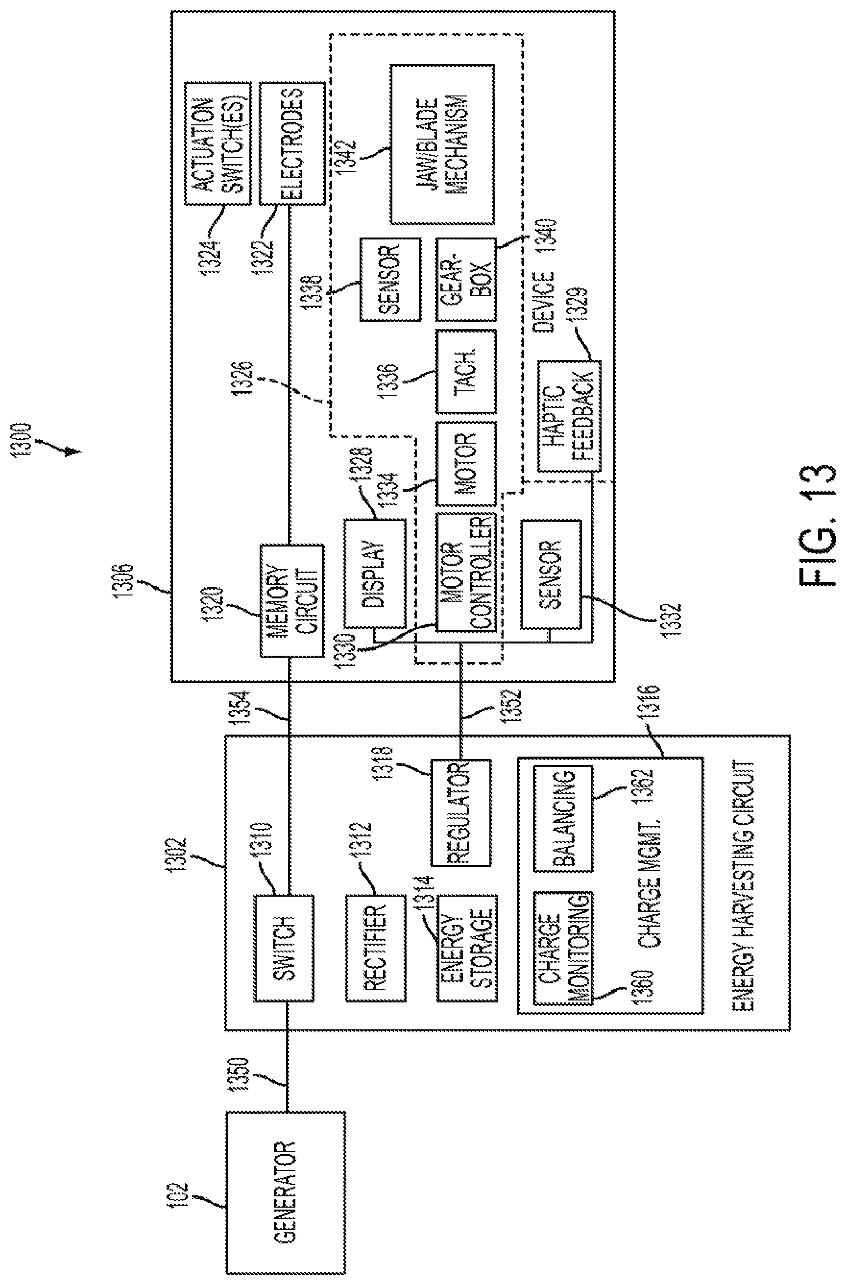
D00013
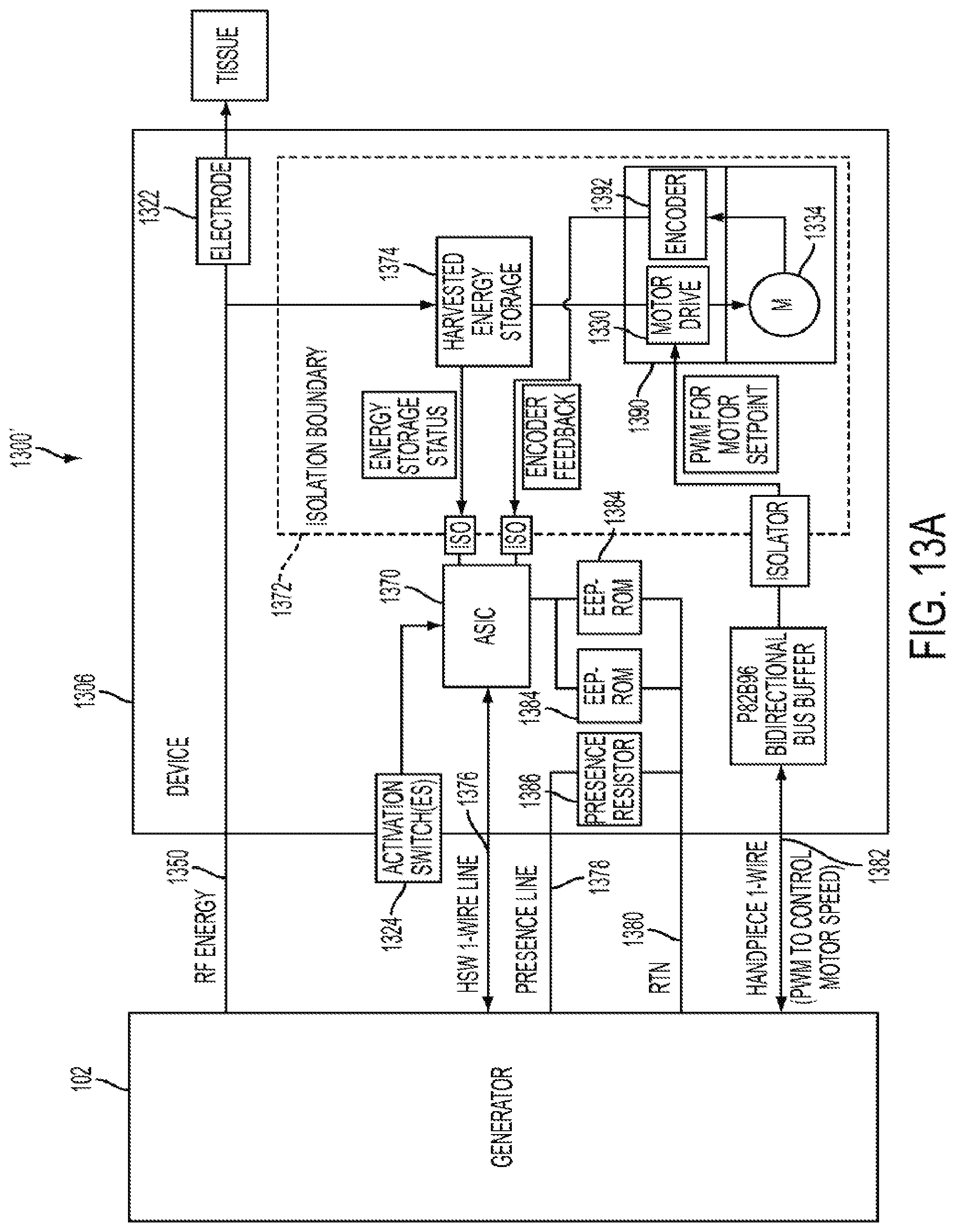
D00014
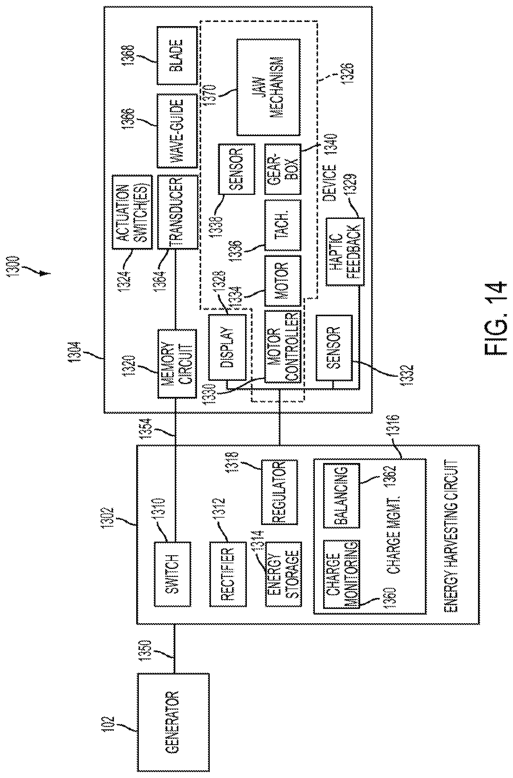
D00015

D00016

D00017

D00018

D00019

D00020

D00021

D00022

D00023
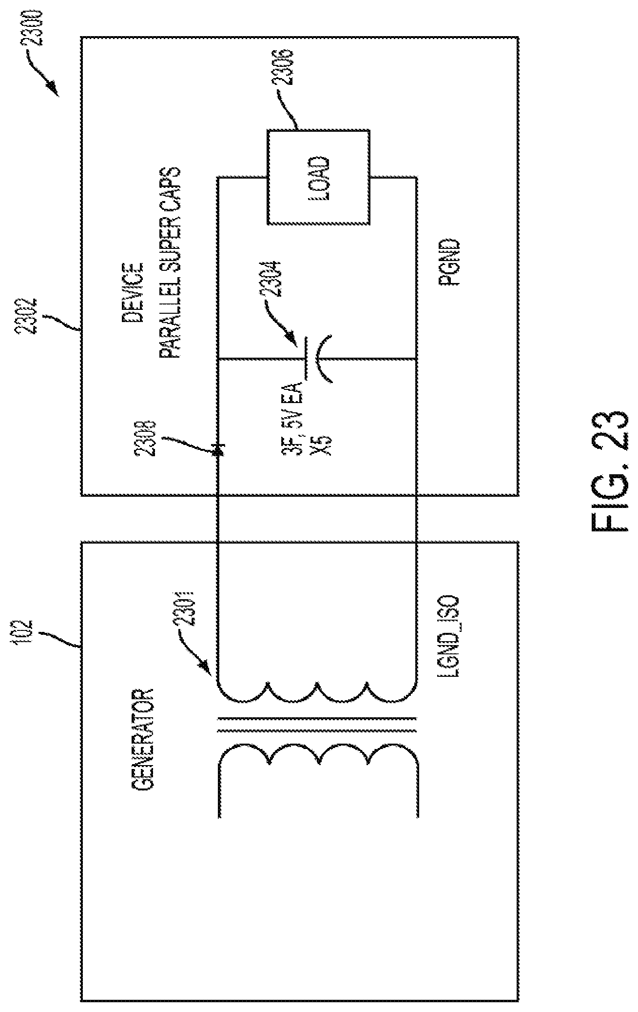
D00024
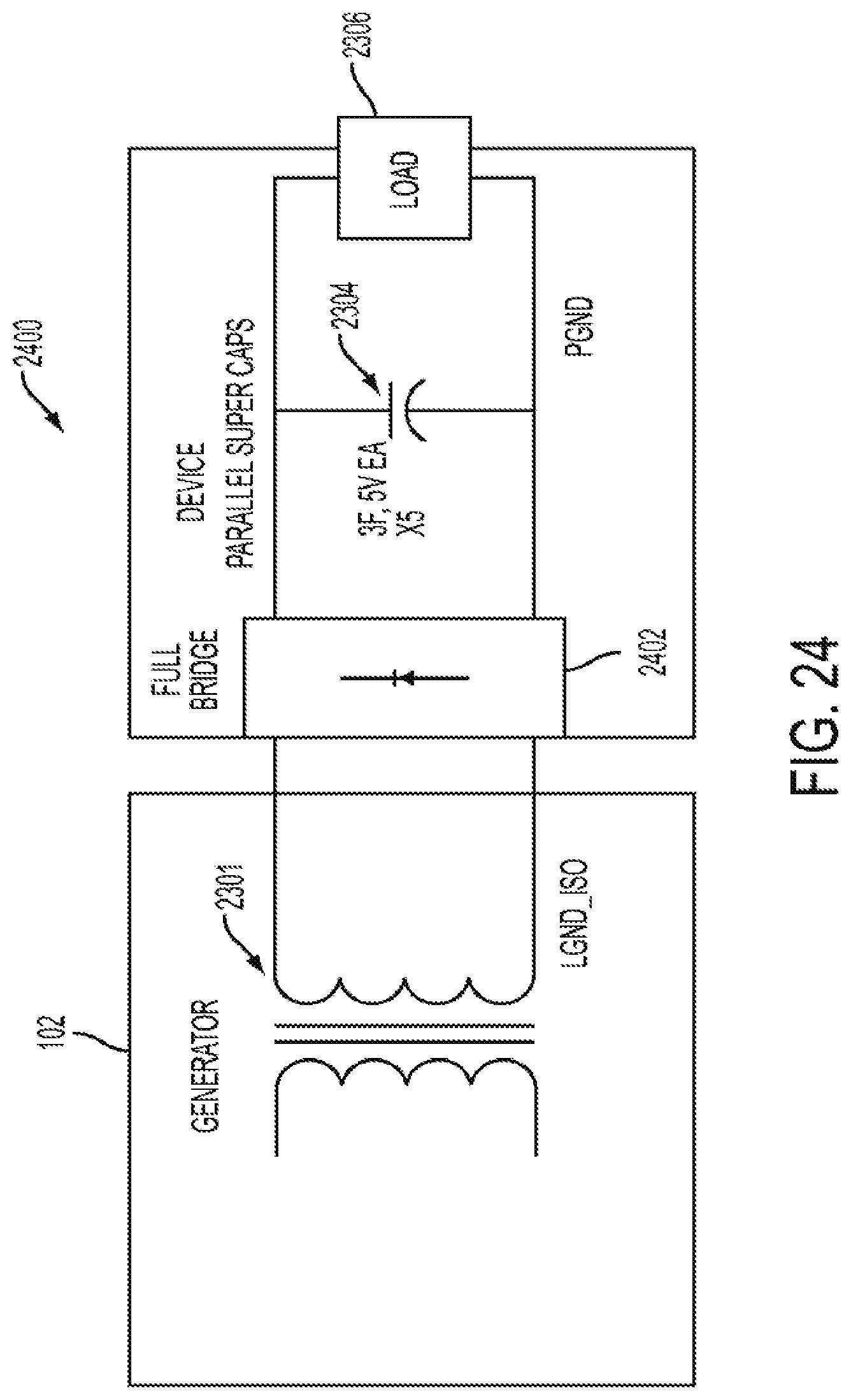
D00025
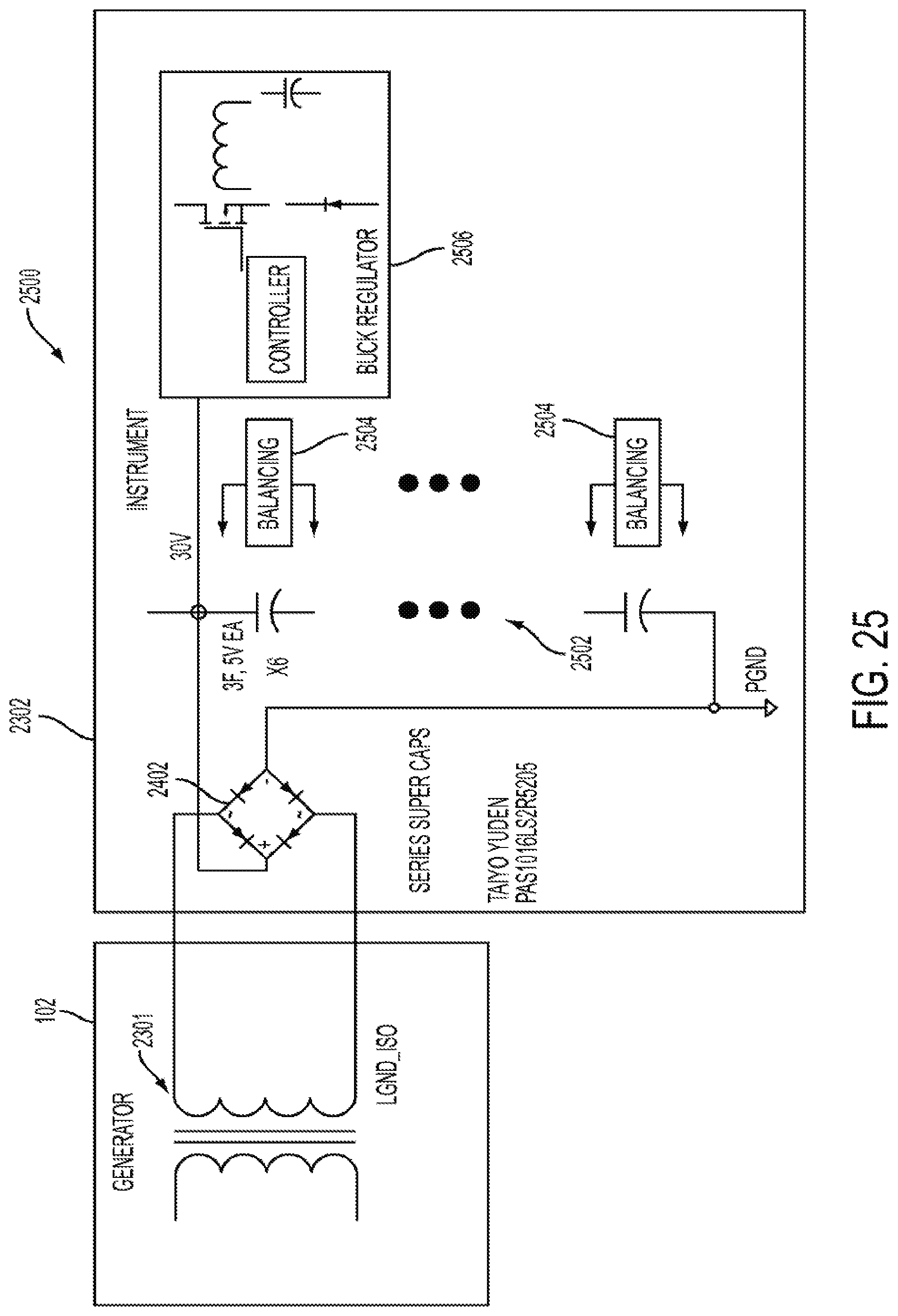
D00026
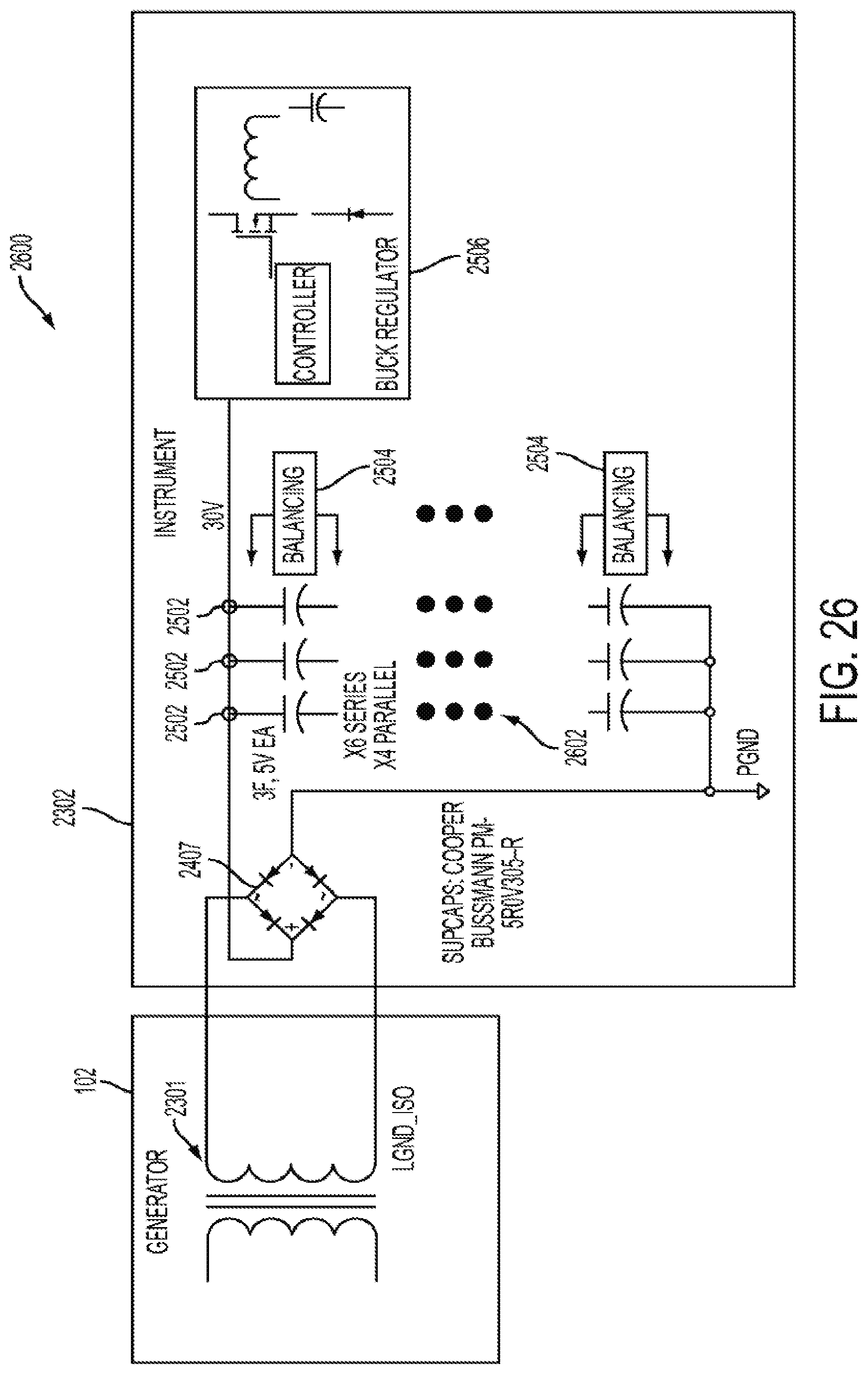
D00027

D00028
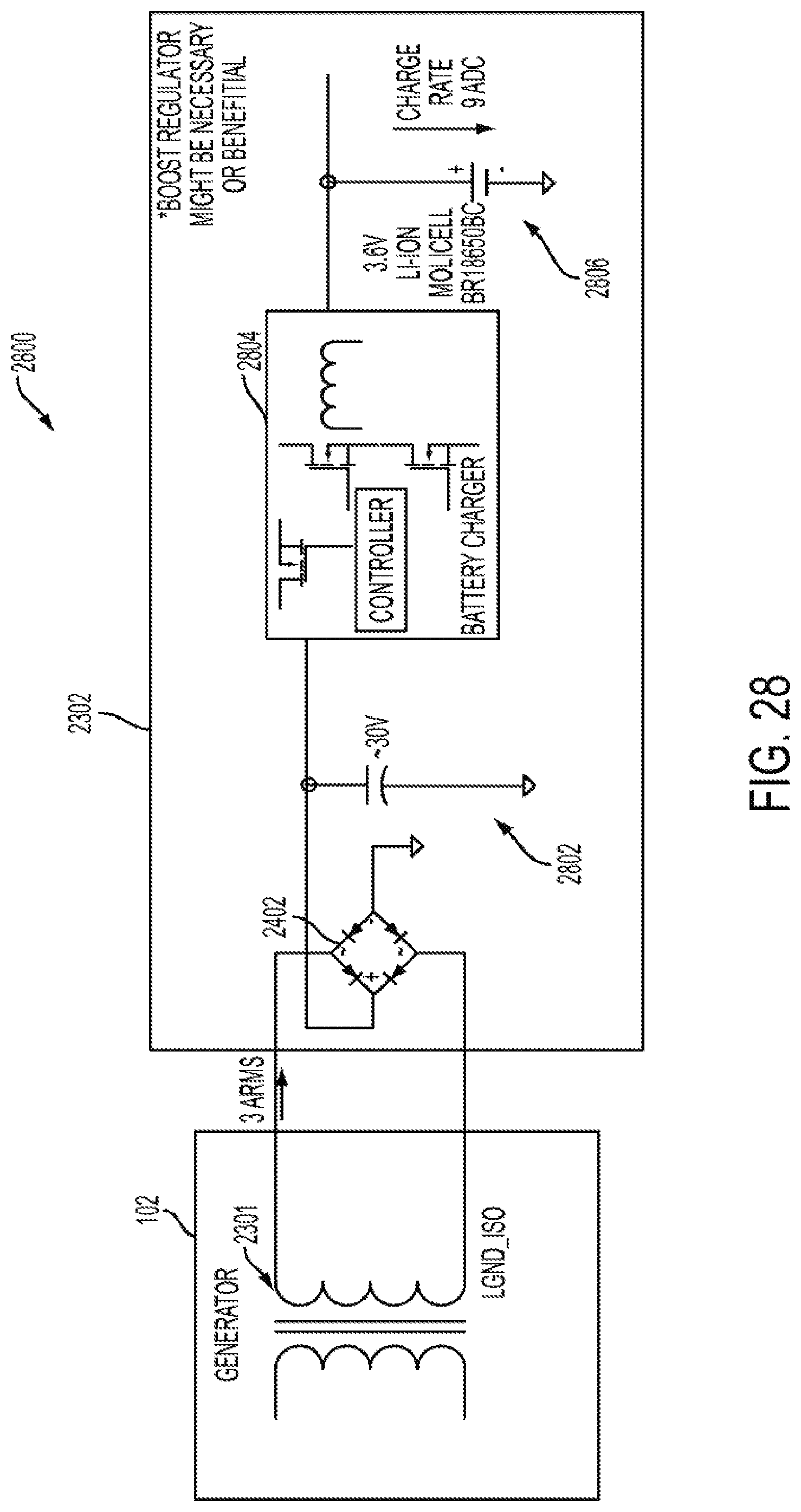
D00029

D00030
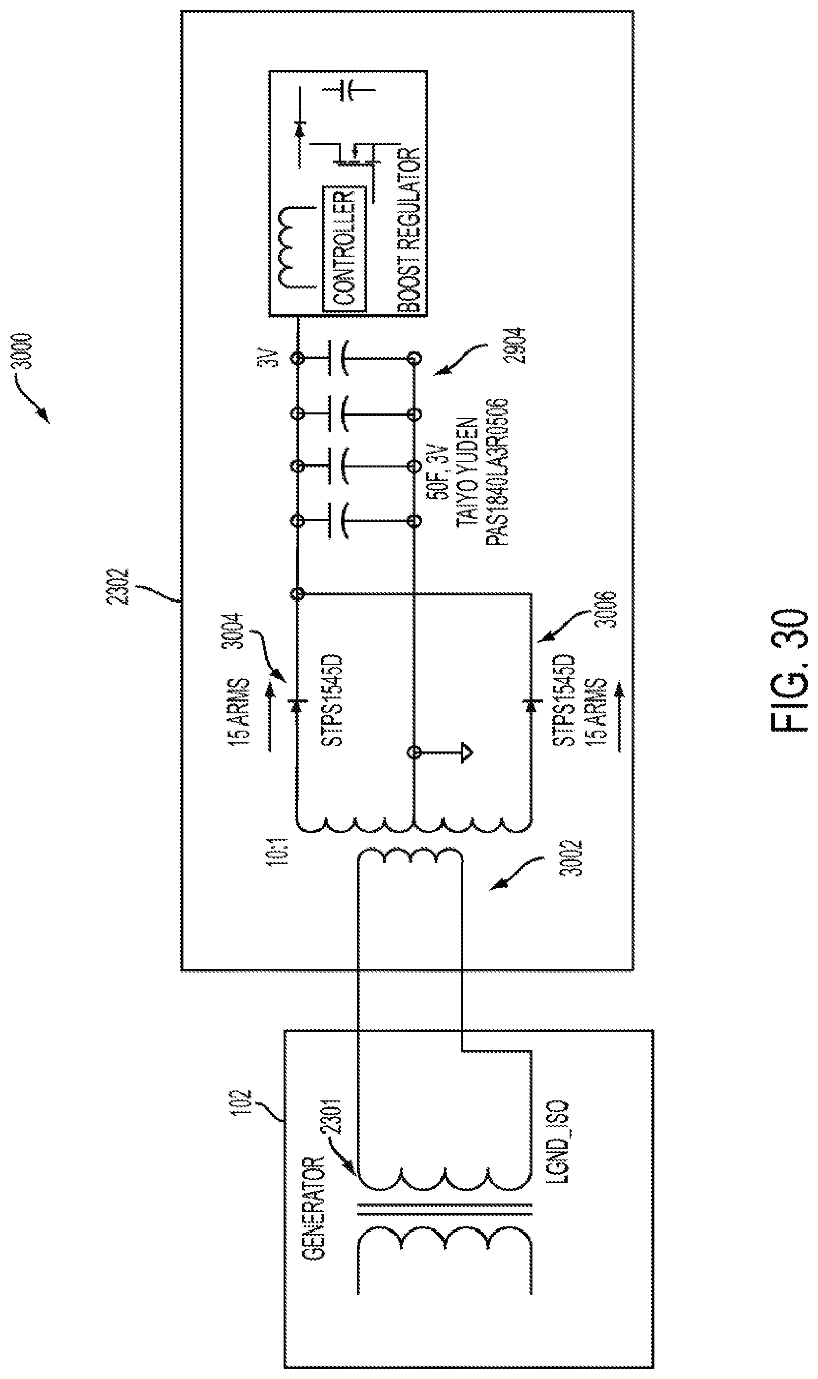
D00031
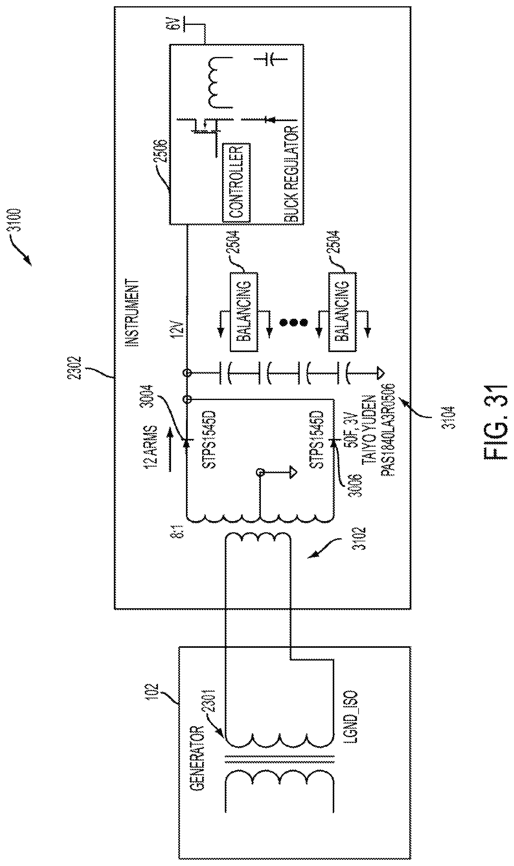
XML
uspto.report is an independent third-party trademark research tool that is not affiliated, endorsed, or sponsored by the United States Patent and Trademark Office (USPTO) or any other governmental organization. The information provided by uspto.report is based on publicly available data at the time of writing and is intended for informational purposes only.
While we strive to provide accurate and up-to-date information, we do not guarantee the accuracy, completeness, reliability, or suitability of the information displayed on this site. The use of this site is at your own risk. Any reliance you place on such information is therefore strictly at your own risk.
All official trademark data, including owner information, should be verified by visiting the official USPTO website at www.uspto.gov. This site is not intended to replace professional legal advice and should not be used as a substitute for consulting with a legal professional who is knowledgeable about trademark law.