Electrosurgical Devices
Boudreaux; Chad P. ; et al.
U.S. patent application number 16/153107 was filed with the patent office on 2019-04-11 for electrosurgical devices. The applicant listed for this patent is Ethicon LLC. Invention is credited to Scott R. Bingham, Chad P. Boudreaux, Catherine A. Corbett, Gregory A. Trees.
| Application Number | 20190105067 16/153107 |
| Document ID | / |
| Family ID | 52781276 |
| Filed Date | 2019-04-11 |


View All Diagrams
| United States Patent Application | 20190105067 |
| Kind Code | A1 |
| Boudreaux; Chad P. ; et al. | April 11, 2019 |
ELECTROSURGICAL DEVICES
Abstract
In various embodiments, a surgical instrument is disclosed. The surgical instrument comprises a handle assembly having a closure trigger, a closure actuator coupled to the closure trigger at a first pivot, and a closure spring. The closure actuator moves proximally on a longitudinal axis in response to actuation of the closure trigger. The closure spring applies a force vector to the closure spring tangential to the longitudinal axis. A shaft assembly is coupled to the handle assembly. An end effector is coupled to a distal end of the shaft assembly. The end effector comprises a jaw assembly comprising a first jaw member and a second jaw member. The first jaw member is pivotally moveable with respect to the second jaw member. At least one of the first and second jaw members are operatively coupled to the closure actuator.
| Inventors: | Boudreaux; Chad P.; (Cincinnati, OH) ; Corbett; Catherine A.; (Cincinnati, OH) ; Trees; Gregory A.; (Loveland, OH) ; Bingham; Scott R.; (Mason, OH) | ||||||||||
| Applicant: |
|
||||||||||
|---|---|---|---|---|---|---|---|---|---|---|---|
| Family ID: | 52781276 | ||||||||||
| Appl. No.: | 16/153107 | ||||||||||
| Filed: | October 5, 2018 |
Related U.S. Patent Documents
| Application Number | Filing Date | Patent Number | ||
|---|---|---|---|---|
| 14227708 | Mar 27, 2014 | 10092310 | ||
| 16153107 | ||||
| Current U.S. Class: | 1/1 |
| Current CPC Class: | A61B 17/2841 20130101; A61B 2017/2919 20130101; A61B 2017/2845 20130101; A61B 2017/00738 20130101; A61B 2017/2923 20130101; A61B 18/1445 20130101; A61B 17/285 20130101; A61B 2017/2922 20130101; A61B 2017/292 20130101; A61B 2018/1455 20130101 |
| International Class: | A61B 17/28 20060101 A61B017/28; A61B 18/14 20060101 A61B018/14; A61B 17/285 20060101 A61B017/285 |
Claims
1-16. (canceled)
17. A surgical instrument comprising: a handle assembly comprising: a closure trigger; an L-shaped lever arm coupled to the closure trigger at a first pivot by a pivot pin, wherein the L-shaped lever arm is configured to move proximally in a longitudinal axis in response to actuation of the closure trigger; a closure spring configured to apply a force to the first pivot, wherein the closure spring is compressed in response to movement of the closure trigger, wherein a vector of the force applied to the pivot pin is tangential to the longitudinal axis; a shaft assembly coupled to the handle assembly, the shaft assembly comprising a jaw closure actuator coupled to the L-shaped lever arm; and an end effector coupled to a distal end of the shaft assembly, the end effector comprising: a jaw assembly having a proximal end and a distal end, the jaw assembly comprising: a first jaw member; and a second jaw member, wherein the first jaw member is pivotably moveable with respect to the second jaw member, wherein the first jaw member is coupled to the jaw closure actuator, and wherein actuation of the closure trigger pivots the first jaw member with respect to the second jaw member.
18. The surgical instrument of claim 17, wherein the pivot pin is slideably moveable within a pivot pin channel.
19. The surgical instrument of claim 18, wherein the pivot pin is configured to move within the pivot pin slot to provide a first load at a beginning of a stroke of the closure trigger comprises and a second load at an end of the stroke of the closure trigger.
20. The surgical instrument of claim 19, wherein actuation of the closure trigger to a first position causes proximal movement of the closure actuator and actuation of the closure trigger to a second position causes movement of the toggle pin within the toggle pin channel, wherein movement of the toggle pin changes an angle of the force vector applied by the closure spring to the closure actuator, and wherein the first position corresponds to the first and second jaws being fully closed.
21. The surgical instrument of claim 20, wherein the closure trigger defines a closure spring slot, and wherein the closure spring is located within the closure spring slot.
22-25. (canceled)
26. A surgical instrument comprising: a handle assembly comprising: a closure trigger; a lever arm coupled to the closure trigger at a first pivot by a pivot pin, wherein the lever arm is configured to move proximally in a longitudinal axis in response to actuation of the closure trigger; a closure spring configured to apply a force to the first pivot, wherein the closure spring is compressed in response to movement of the closure trigger, wherein a vector of the force applied to the pivot pin is tangential to the longitudinal axis; a shaft assembly coupled to the handle assembly, the shaft assembly comprising a jaw closure actuator coupled to the lever arm; and an end effector coupled to a distal end of the shaft assembly, the end effector comprising: a jaw assembly having a proximal end and a distal end, the jaw assembly comprising: a first jaw member; and a second jaw member, wherein the first jaw member is pivotably moveable with respect to the second jaw member, wherein the first jaw member is coupled to the jaw closure actuator, and wherein actuation of the closure trigger pivots the first jaw member with respect to the second jaw member.
27. The surgical instrument of claim 26, wherein the pivot pin is slideably moveable within a pivot pin channel.
28. The surgical instrument of claim 27, wherein the pivot pin is configured to move within the pivot pin slot to provide a first load at a beginning of a stroke of the closure trigger comprises and a second load at an end of the stroke of the closure trigger.
29. The surgical instrument of claim 28, wherein actuation of the closure trigger to a first position causes proximal movement of the closure actuator and actuation of the closure trigger to a second position causes movement of the toggle pin within the toggle pin channel, wherein movement of the toggle pin changes an angle of the force vector applied by the closure spring to the closure actuator, and wherein the first position corresponds to the first and second jaws being fully closed.
30. The surgical instrument of claim 29, wherein the closure trigger defines a closure spring slot, and wherein the closure spring is located within the closure spring slot.
Description
CROSS-REFERENCE TO RELATED APPLICATION
[0001] This application is a continuation application claiming priority under 35 U.S.C. .sctn. 120 to U.S. patent application Ser. No. 14/227,708, entitled ELECTROSURGICAL DEVICES, filed Mar. 27, 2014, now U.S. Patent Application Publication No. 2015/0272602, the entire disclosure of which is hereby incorporated by reference herein.
BACKGROUND
[0002] The present disclosure is related generally to electrosurgical devices with various mechanisms for clamping and treating tissue. In particular, the present disclosure is related to electrosurgical devices with various mechanisms for controlling a force applied to a jaw closure mechanism.
[0003] While several devices have been made and used, it is believed that no one prior to the inventors has made or used the device described in the appended claims.
SUMMARY
[0004] In various embodiments, a surgical instrument is disclosed. The surgical instrument comprises a handle assembly. The handle assembly comprises a closure trigger, a closure actuator coupled to the closure trigger at a first pivot, and a closure spring configured to apply a force to the closure actuator at the first pivot. The closure actuator moves proximally on a longitudinal axis in response to actuation of the closure trigger. The closure spring is compressed in response to movement of the closure trigger. A force vector of the force applied by the closure spring is tangential to the longitudinal axis. A shaft assembly is coupled to the handle assembly. An end effector is coupled to a distal end of the shaft assembly. The end effector comprises a jaw assembly having a proximal end and a distal end. The jaw assembly comprises a first jaw member and a second jaw member. At least the first jaw member is pivotally moveable with respect to the second jaw member. At least one of the first and second jaw members are operatively coupled to the closure actuator.
[0005] In one embodiment, a surgical instrument is disclosed. The surgical instrument comprises a handle assembly. The handle assembly comprises a closure trigger, a three-bar linkage comprising a first pivot and a second pivot, a yoke, and a closure spring configured to apply a force to a toggle pin. The closure trigger is operatively coupled to the first pivot by the toggle pin. The yoke is coupled to the second pivot of the three-bar linkage. The yoke is configured to move proximally in a longitudinal axis in response to actuation of the closure trigger. The closure spring is compressed in response to movement of the closure trigger. A vector of the force applied to the toggle pin is tangential to the longitudinal axis. A shaft assembly is coupled to the handle assembly. The shaft assembly comprises a jaw closure actuator operatively coupled to the yoke. An end effector is coupled to a distal end of the shaft assembly. The end effector comprises a jaw assembly having a proximal end and a distal end. The jaw assembly comprises a first jaw member and a second jaw member. The first jaw member is pivotably moveable with respect to the second jaw member. The first jaw member is coupled to the jaw closure actuator. Actuation of the closure trigger pivots the first jaw member with respect to the second jaw member.
[0006] In one embodiment, a surgical instrument is disclosed. The surgical instrument comprises a handle assembly. The handle assembly comprises a closure trigger, an L-shaped lever arm coupled to the closure trigger at a first pivot by a toggle pin, and a closure spring configured to apply a force to the first pivot. The L-shaped lever arm is configured to move proximally in a longitudinal axis in response to actuation of the closure trigger. The closure spring is compressed in response to movement of the closure trigger. A vector of the force applied to the toggle pin is tangential to the longitudinal axis. A shaft assembly is coupled to the handle assembly. The shaft assembly comprises a jaw closure actuator coupled to the L-shaped lever arm. An end effector is coupled to a distal end of the shaft assembly. The end effector comprises a jaw assembly having a proximal end and a distal end. The jaw assembly comprises a first jaw member and a second jaw member. The first jaw member is pivotably moveable with respect to the second jaw member. The first jaw member is coupled to the jaw closure actuator. Actuation of the closure trigger pivots the first jaw member with respect to the second jaw member.
DRAWINGS
[0007] The novel features of the embodiments described herein are set forth with particularity in the appended claims. The embodiments, however, both as to organization and methods of operation may be better understood by reference to the following description, taken in conjunction with the accompanying drawings as follows.
[0008] FIG. 1 illustrates one embodiment of an electrosurgical instrument.
[0009] FIG. 2 illustrates a side-perspective of the electrosurgical instrument of FIG. 1.
[0010] FIG. 3 illustrates a side-view of the electrosurgical instrument of FIG. 1.
[0011] FIG. 4 illustrates a side-view of the electrosurgical instrument of FIG. 1 with the left handle housing removed.
[0012] FIG. 5 illustrates one embodiment of the electrosurgical instrument of FIG. 4 having the closure trigger in a fully closed position and corresponding to thin tissue being located between the first and second jaws.
[0013] FIG. 6 illustrates one embodiment of the electrosurgical instrument of FIG. 4 having the closure trigger in a fully closed position and corresponding to thick tissue being located between the first and second jaws.
[0014] FIG. 7 illustrates one embodiment of a jaw position sensor.
[0015] FIG. 8 illustrates one embodiment of a jaw position sensor comprising an adjustment screw lock spring.
[0016] FIG. 9 illustrates one embodiment of a jaw position sensor.
[0017] FIG. 10 illustrates one embodiment of return stroke dampener.
[0018] FIG. 11 illustrates one embodiment of a rack spring washer.
[0019] FIG. 12 illustrates one embodiment of an electrical energy system comprising an energy button, a source cable, and a return cable.
[0020] FIG. 13 illustrates one embodiment of a surgical instrument comprising an offset closure spring and an L-shaped lever arm.
[0021] FIG. 14 illustrates one embodiment of the surgical instrument of FIG. 13 having the closure trigger in a fully closed position and corresponding to thin tissue grasped in the end effector.
[0022] FIG. 15 illustrates one embodiment of the surgical instrument of FIG. 13 having the closure trigger in a fully closed position and corresponding to thick tissue grasped in the end effector.
[0023] FIG. 16 illustrates one embodiment of a closure handle comprising an offset closure spring slot.
[0024] FIG. 17 illustrates a wireframe view of the surgical instrument handle of FIG. 16.
[0025] FIG. 18 illustrates a wireframe view of the surgical instrument handle of FIG. 16.
[0026] FIG. 19 is a graph illustrating a user force to fire with the jaw assembly empty and the jaw assembly full.
[0027] FIGS. 20A and 20B illustrate one embodiment of an electrosurgical end effector comprising a curved shape.
[0028] FIG. 21 illustrates one embodiment of the electrosurgical end effector of FIGS. 21A-21B comprising an off-set jaw closure actuator.
[0029] FIG. 22 illustrates one embodiment of an electrosurgical end effector comprising a first jaw member and a second jaw member having a smooth taper, curved shape.
[0030] FIG. 23 illustrates one embodiment of the electrosurgical end effector of FIG. 22 in a closed position.
[0031] FIG. 24 illustrates one embodiment of a lower jaw of the electrosurgical end effector of FIGS. 22-23 comprising a curved longitudinal cutting member slot.
DESCRIPTION
[0032] In the following detailed description, reference is made to the accompanying drawings, which form a part hereof. In the drawings, similar symbols and reference characters typically identify similar components throughout the several views, unless context dictates otherwise. The illustrative embodiments described in the detailed description, drawings, and claims are not meant to be limiting. Other embodiments may be utilized, and other changes may be made, without departing from the scope of the subject matter presented here.
[0033] The following description of certain examples of the technology should not be used to limit its scope. Other examples, features, aspects, embodiments, and advantages of the technology will become apparent to those skilled in the art from the following description, which is by way of illustration, one of the best modes contemplated for carrying out the technology. As will be realized, the technology described herein is capable of other different and obvious aspects, all without departing from the technology. Accordingly, the drawings and descriptions should be regarded as illustrative in nature and not restrictive.
[0034] It is further understood that any one or more of the teachings, expressions, embodiments, examples, etc. described herein may be combined with any one or more of the other teachings, expressions, embodiments, examples, etc. that are described herein. The following-described teachings, expressions, embodiments, examples, etc. should therefore not be viewed in isolation relative to each other. Various suitable ways in which the teachings herein may be combined will be readily apparent to those of ordinary skill in the art in view of the teachings herein. Such modifications and variations are intended to be included within the scope of the claims.
[0035] Before explaining the various embodiments of the surgical devices having an offset jaw closure spring in detail, it should be noted that the various embodiments disclosed herein are not limited in their application or use to the details of construction and arrangement of parts illustrated in the accompanying drawings and description. Rather, the disclosed embodiments may be positioned or incorporated in other embodiments, variations and modifications thereof, and may be practiced or carried out in various ways. Accordingly, embodiments of the surgical devices with close quarter articulation features disclosed herein are illustrative in nature and are not meant to limit the scope or application thereof. Furthermore, unless otherwise indicated, the terms and expressions employed herein have been chosen for the purpose of describing the embodiments for the convenience of the reader and are not to limit the scope thereof. In addition, it should be understood that any one or more of the disclosed embodiments, expressions of embodiments, and/or examples thereof, can be combined with any one or more of the other disclosed embodiments, expressions of embodiments, and/or examples thereof, without limitation.
[0036] Also, in the following description, it is to be understood that terms such as front, back, inside, outside, top, bottom and the like are words of convenience and are not to be construed as limiting terms. Terminology used herein is not meant to be limiting insofar as devices described herein, or portions thereof, may be attached or utilized in other orientations. The various embodiments will be described in more detail with reference to the drawings.
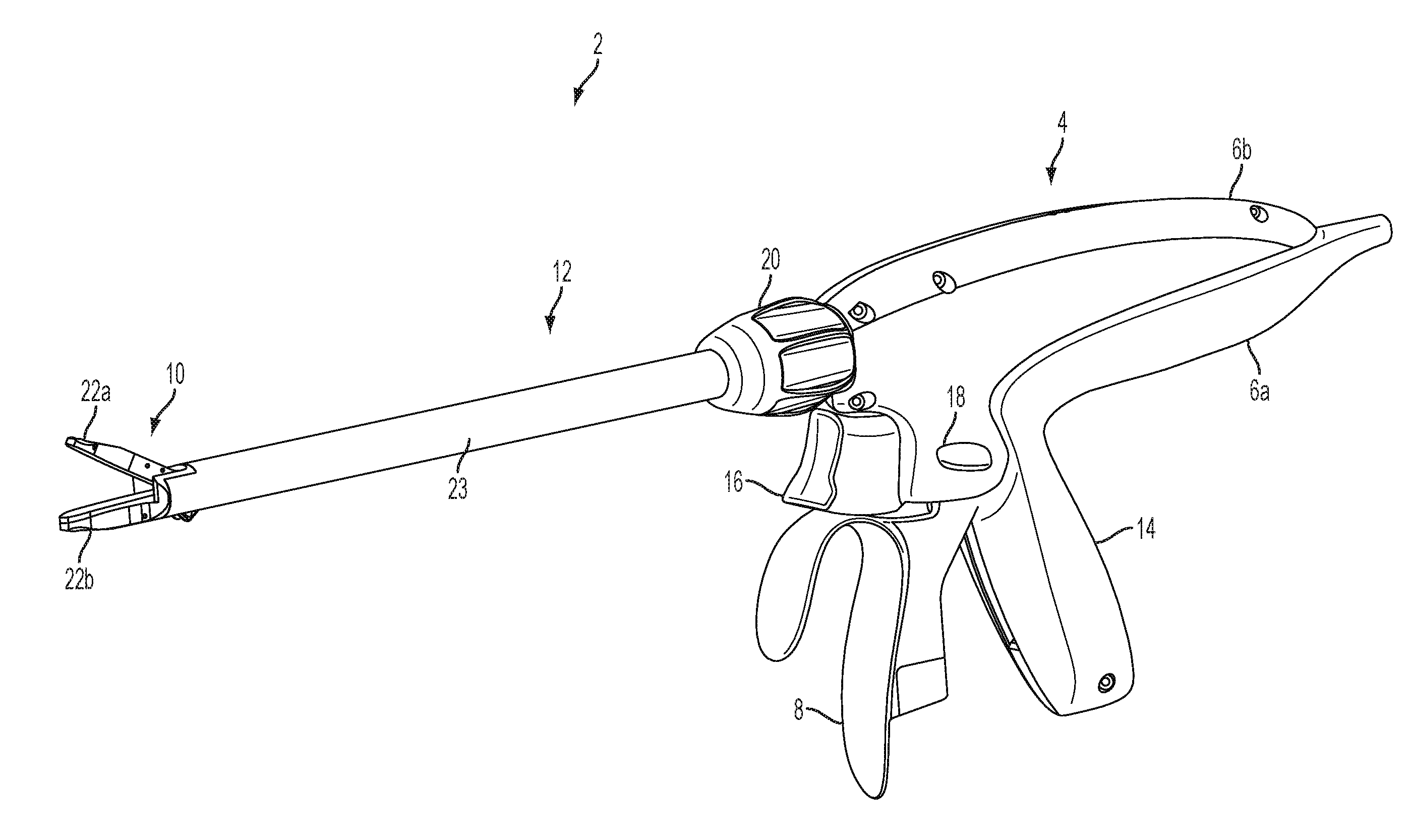
[0037] Turning now to the figures, FIG. 1 illustrates one embodiment of an electrosurgical instrument 2. The electrosurgical instrument 2 comprises a two-trigger clamp and cut mechanism. The electrosurgical instrument 2 comprises a handle assembly 4, a shaft assembly 12 coupled to a distal end of the handle assembly 4, and an end effector 10 coupled to the distal end of the shaft assembly 12. The handle assembly 4 is configured as a pistol grip and comprises left and right handle housing shrouds 6a, 6b, a closure trigger 8, a pistol-grip handle 14, a firing trigger 16, an energy button 18, and a rotatable shaft knob 20. An electrical cable 21 enters the handle assembly 4 at a proximal end.
[0038] The shaft assembly 12 comprises a jaw actuator, a cutting member actuator, and an outer sheath 23. The jaw actuator is operatively coupled to the closure trigger 8 of the handle assembly 4. In some embodiments, the outer sheath 23 comprises the jaw actuator. The cutting member actuator is operatively coupled to the firing trigger 16 of the handle assembly 4. The outer sheath 23 comprises one or more contact electrodes on the distal end configured to interface with the end effector 10. The one or more contact electrodes are operatively coupled to the energy button 18 and an energy source (not shown).
[0039] The energy source may be suitable for therapeutic tissue treatment, tissue cauterization/sealing, as well as sub-therapeutic treatment and measurement. The energy button 18 controls the delivery of energy to the electrode. As used throughout this disclosure, a button refers to a switch mechanism for controlling some aspect of a machine or a process. The buttons may be made out of a hard material such as usually plastic or metal. The surface may be formed or shaped to accommodate the human finger or hand, so as to be easily depressed or pushed. Buttons can be most often biased switches, though even many un-biased buttons (due to their physical nature) require a spring to return to their un-pushed state. Terms for the "pushing" of the button, may include press, depress, mash, and punch.
[0040] In some embodiments, an end effector 10 is coupled to the distal end of the shaft assembly 12. The end effector 10 comprises a first jaw member 22a and a second jaw member 22b. The first jaw member 22a is pivotably coupled to the second jaw member 22b. The first jaw member 22a is pivotally moveable with respect to the second jaw member 22b to grasp tissue therebetween. In some embodiments, the second jaw member 22b is fixed. In other embodiments, the first jaw member 22a and the second jaw member 22b are pivotally movable. The end effector 10 comprises at least one electrode 92. The electrode 92 is configured to delivery energy. Energy delivered by the electrode 92 may comprise, for example, radiofrequency (RF) energy, sub-therapeutic RF energy, ultrasonic energy, and/or other suitable forms of energy. In some embodiments, a cutting member (not shown) is receivable within a longitudinal slot defined by the first jaw member 22a and/or the second jaw member 22b. The cutting member is configured to cut tissue grasped between the first jaw member 22a and the second jaw member 22b. In some embodiments, the cutting member comprises an electrode for delivering energy, such as, for example, RF and/or ultrasonic energy.
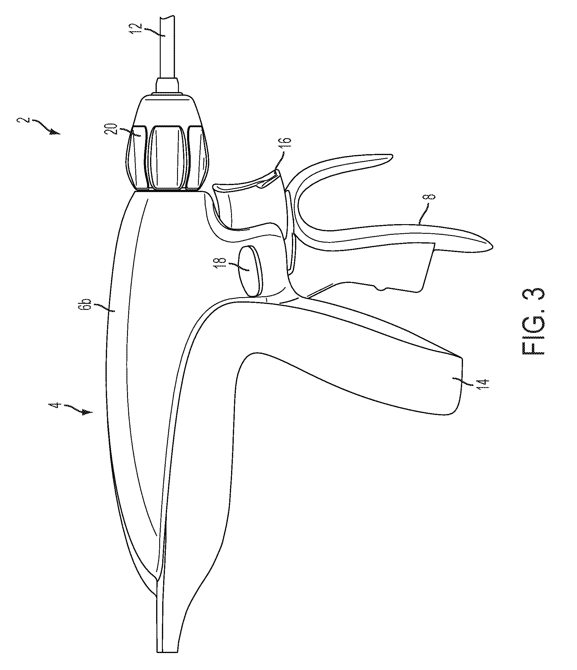
[0041] FIG. 2 illustrates a side perspective view of the electrosurgical instrument 2 illustrated in FIG. 1. FIG. 2 illustrates the right handle housing 6b. The energy button 18 extends through the handle assembly 4 and is accessible on both sides of the handle assembly 4. The closure trigger 8, the firing trigger 16, and the energy button 18 comprise an ergonomic design. In some embodiments, the handle assembly 4 is thinner near the energy button 18 to allow ease of access to the energy button 18 by a clinician. In some embodiments, the energy button 18 is disposed on either the left handle housing 6a or the right handle housing 6b. FIG. 3 illustrates a side view of the electrosurgical instrument 2 and the right handle housing 6b. U.S. patent application Ser. No. 14/075,839, now U.S. Pat. No. 9,265,926, and Ser. No. 14/075,863, now U.S. Pat. No. 9,526,565, are incorporated herein by reference in their entireties.
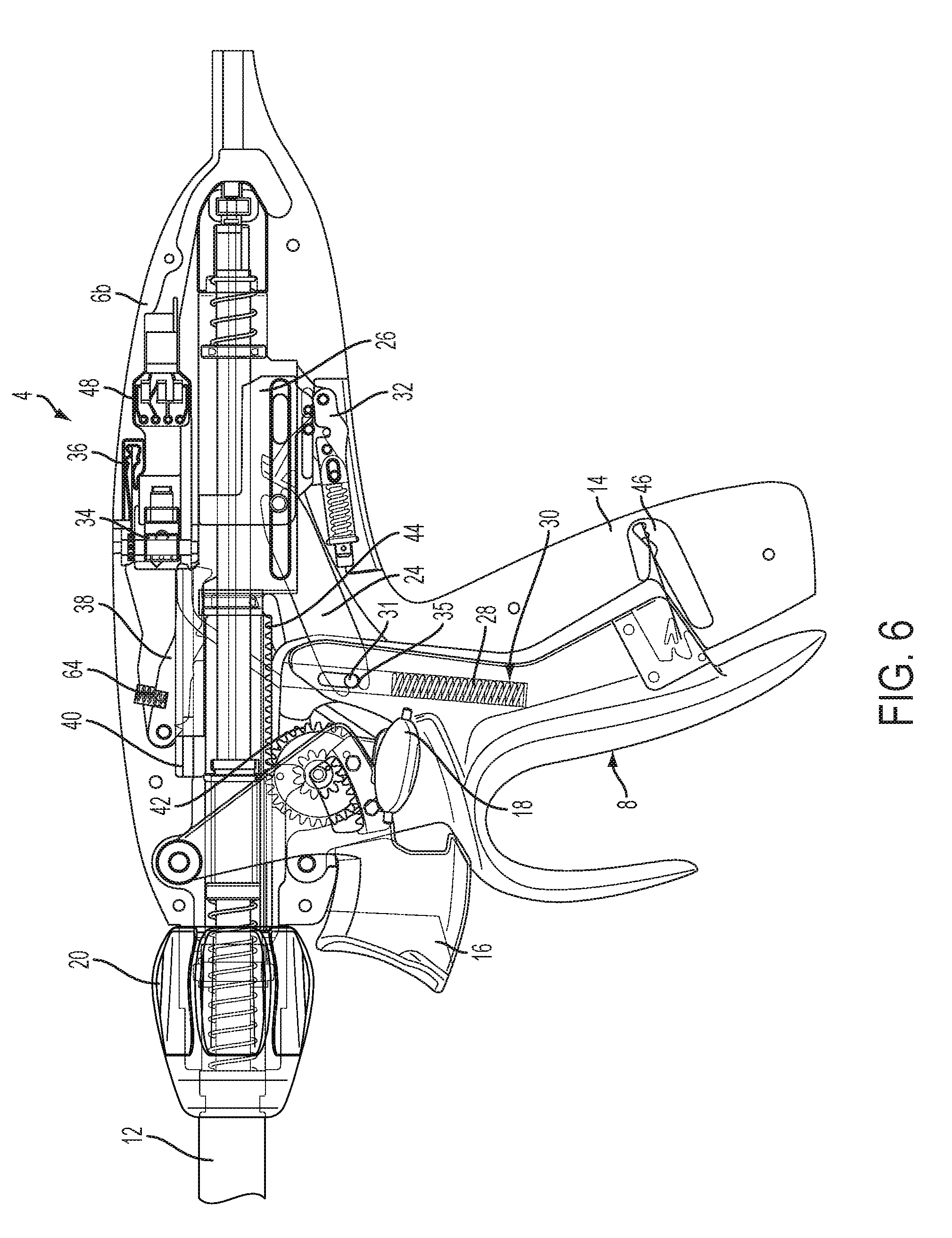
[0042] FIG. 4 illustrates one embodiment of the surgical instrument 2 of FIG. 1 with the left handle housing 6a removed. The handle assembly 4 comprises a plurality of components for actuating the surgical instrument 2, such as, for example, mechanisms for affecting closure of the jaws 22a, 22b of the end effector 10, deploying a cutting member within the end effector 10, and/or delivering energy to one or more electrodes 92 coupled to the end effector 10. A closure trigger 8 is configured to transition the jaws 22a, 22b from an open position to a closed position. The closure trigger 8 is connected to a closure actuator 21 located within the handle assembly 4 at a first pivot point 25. In the illustrated embodiment, the closure actuator 21 comprises a toggle arm 24 and a yoke 26. The toggle arm 24 is coupled to the closure trigger 8 at the first pivot 25 and to the yoke 26 at a second pivot 27. In other embodiments, the closure actuator 21 may comprise any suitable actuator for coupling the closure trigger 8 to a jaw actuator of the shaft assembly. For example, in some embodiments, the closure actuator comprises an L-shaped lever arm. When the closure trigger 8 is actuated towards the pistol grip handle 14, the toggle arm 24 drives the yoke 26 proximally on a longitudinal axis. Proximal longitudinal movement of the yoke 26 drives a jaw actuator, such as, for example, the outer shaft 23, proximally to transition the jaws 22a, 22b to a closed position. Actuation of the closure trigger 8 compresses an offset closure spring 28. The direction of compression of the closure spring 28 is offset with respect to the direction of travel of the toggle arm 24 and the yoke 26. The closure spring 28 applies a force to the first pivot 25.
[0043] The closure trigger 8 defines a closure spring slot 30. The closure spring 28 is located within the closure spring slot 30. The toggle arm 24 is pivotally coupled to the closure trigger 8 by a toggle pin 31 at the first pivot 25. The toggle pin 31 is slideably moveable within a toggle pin channel 33 defined by the closure trigger 8. Actuation of the closure trigger 8 causes the closure spring 28 to exert a force on the toggle pin 31, which then exerts a force on the toggle arm 24. The force exerted by the closure spring 28 varies based on actuation of the closure trigger 8 and the location of the toggle pin 31 within the toggle pin channel 33. In some embodiments, the closure spring 28 and the toggle pin 31 provide a first force during the beginning of a stroke of the closure trigger 8 and a second force during the end of the stroke of the closure trigger 8. A vector of the force applied by the closure spring to the toggle pin 31 is tangential to the longitudinal axis of movement of the yoke 26.
[0044] A firing trigger 16 is configured to deploy a cutting member within the end effector 10. The firing trigger 16 is operatively coupled to a compound gear 42. The compound gear 42 interfaces with a rack 44. The rack 44 is coupled to a firing actuator 13. When the firing trigger 16 is actuated, the compound gear 42 rotates and moves the rack 44 distally. The distal movement of the rack 44 causes distal movement of the firing actuator and deployment of a cutting member within the end effector 10. The cutting member is deployed from a proximal end of the end effector 10 to a distal end of the end effector 10. In one embodiment, the firing trigger 16 comprises a high pivot to provide a linear feel during actuation of the firing trigger 16. The linear feel provides increased control and comfort to a clinician actuating the firing trigger 16.
[0045] In some embodiments, the rack 44 comprises a lock mechanism. In the illustrated embodiment, the rack 44 comprises a rack unlock block 40. The rack unlock block 40 interfaces with a lock arm 38 to prevent actuation of the cutting member firing switch 16 prior to actuation of the closure trigger 8. When the closure trigger 8 is in an open position, the lock arm 38 interfaces with the rack unlock block 40 to lock the rack 44 and prevent actuation of the firing trigger 16. When the closure trigger 8 is actuated, the yoke 26 raises the lock arm 38 away from the rack unlock block 40. When the closure trigger 8 is sufficiently actuated, corresponding to the jaws 22a, 22b of the end effector 10 being in a sufficiently closed position to prevent the cutting member from exiting a slot in the jaws 22a, 22b, the lock arm 38 is decoupled from the rack unlock block 40, allowing actuation of the firing trigger 16.
[0046] In some embodiments, the surgical instrument 2 comprises a firing trigger lock mechanism. A lock arm 38 interfaces with a rack unlock block 40 to prevent actuation of the firing trigger 16 prior to closure of the jaws 22a, 22b. The lock arm 38 is unlocked through actuation of the closure trigger 8. The yoke 26 is coupled to an unlock bar 41. When the yoke 26 is moved distally through actuation of the closure trigger 8, the lock bar 41 lifts the lock arm 38 vertically away from the rack unlock block 40. When the lock arm 38 has been lifted a sufficient distance, the rack 44 is allowed to move distally and the firing trigger 16 is actuatable to deploy the cutting member within the end effector 10. When the lock arm 38 is lifted a sufficient distance, the lock arm allows actuation of the firing trigger 16 prior to full rotation of the closure trigger 8. The firing trigger 16 is unlocked when the jaws 22a, 22b are sufficiently closed such that the cutting member cannot skip out of a slot formed in the end effector 10. For example, in some embodiments, the lock arm 38 is released when the closure trigger 8 is compressed about 8 degrees, corresponding to jaw opening of about 2.5 degrees. In other embodiments, the lock arm 38 may be released at a lower or higher degree of rotation of the closure trigger 8.
[0047] In some embodiments, a lock spring 64 is coupled to the lock arm 38 to apply a biasing force to the lock arm 38. The biasing force biases the lock arm 38 towards the rack unlock block 40 and maintains the lock arm 38 in contact with the rack unlock block 40 until the closure trigger 8 has been sufficiently actuated. When the closure trigger 8 is released and the yoke 26 returns to a rest position, the lock spring 64 biases the lock arm 38 back into a locked configuration with the rack unlock block 40.
[0048] In the unlocked position, a clinician may actuate the firing trigger 16 to drive the rack 44 distally and deploy the cutting member within the end effector 10. In some embodiments, a jaw position sensor 34 is configured to indicate when the jaws 22a, 22b are sufficiently closed to allow deployment of the cutting member. In some embodiments, the jaw position sensor 34 comprises a bypass switch. In other embodiments, other types of switches may be used, such as, for example, normally open, normally closed, and/or other switch types. In some embodiments, a jaw sensor 34 is mounted in the handle assembly 4. The handle assembly 4 comprises a plurality of access holes 79 to allow the screw lock spring 36 to be depressed and the screw 76 to be rotated to adjust the contact 77.
[0049] In some embodiments, the firing trigger 16 is coupled to a compound gear 42 interfaced with a rack 44. The rack 44 is mechanically coupled to a firing actuator 13 configured to deploy the cutting member distally within the end effector 10. Rotation of the firing trigger 16 proximally towards the handle assembly 4 causes the rack 44 to advance distally within the handle assembly 4 and drive the cutting member within the end effector 10. Advancement of the rack 44 in a distal direction compresses a spring washer 58. When the clinician releases the firing trigger 16, the spring washer forces the rack 44 in a proximal direction, withdrawing the cutting member from the end effector 10. The firing trigger 16 comprises a mechanical advantage that adjusts the force applied by the cutting member with respect to the force applied to the firing trigger 16. For example, in one embodiment, the firing trigger 16 comprises a mechanical advantage of 0.6, such that one pound of force applied to the firing trigger 16 corresponds to 0.6 pounds of force applied by the cutting member to a tissue section grasped within the end effector 10. In some embodiments, the firing trigger 16 comprises a maximum rotation corresponding to the cutting member being located at a distal-most portion of the end effector 10. For example, the firing trigger 16 may rotate about nineteen degrees to fully deploy the cutting member within the end effector 10. In some embodiments, the handle assembly 4 comprises a rack-biasing spring 47 configured to bias the rack in an proximal position. The closure trigger lock 46 is released to open the jaws 22a, 22b and release tissue grasped therein.
[0050] In some embodiments, the jaws 22a, 22b are configured to maintain a minimal spacing therebetween to prevent damage to components of the surgical instrument 2 and/or the tissue section. In some embodiments, full actuation of the closure trigger 8 corresponds to a rotation of about 30 degrees. When the closure trigger 8 is fully rotated against the pistol grip handle 14, a closure trigger lock 46 is engaged to maintain the jaws 22a, 22b in a closed position. A hole 19 defined by the closure trigger 8 allows the closure trigger 8 to be fully rotated against the pistol grip handle 14 without interfering with the energy button 18. Once the trigger lock 46 has been engaged, the clinician may release the closure trigger 8 and the trigger lock 46 maintains the closure trigger 8 in a closed position.
[0051] The trigger lock 46 may maintain the closure trigger 8 in a less than fully retracted position to prevent damage to components of the surgical instrument 2 due to over application of force to the jaws 22a, 22b. The trigger lock 46 maintains the closure trigger 8 in a sufficiently rotated position to release the lock arm 38 from the rack unlock block 40 and to engage the jaw position sensor 34. For example, in the some embodiments, the trigger lock 46 maintains the closure trigger 8 at a rotation of about 28 degrees. With the closure trigger 8 in a locked position, the clinician may actuate the firing trigger 16 to deploy the cutting member within the end effector 10. In some embodiments, the clinician may actuate the energy button 18 to deliver energy to a tissue section grasped between the jaws 22a, 22b prior to or simultaneously with, deployment of the cutting member.
[0052] FIG. 4 illustrates the closure trigger 8 in an initial position corresponding to the jaws 22a, 22b of the end effector 10 being in an open position. In operation, a clinician actuates the closure trigger 8 to transition the jaws 22a, 22b to a closed position. Actuation of the closure trigger 8 causes the closure spring 28 to apply a force to the toggle pin 31 and moves the toggle arm 24 proximally. Proximal movement of the toggle arm 24 drives the yoke 26 proximally along a longitudinal axis. Proximal movement of the yoke 26 causes a jaw closure actuator, such as, for example, the outer tube 23, to move proximally and transition the jaws 22a, 22b to a closed position. The closure spring 28 and the toggle pin 31 allows the closure trigger 8 to be further actuated after the jaws 22a, 22b have closed on a tissue section in order to apply additional force to the tissue section and to provide a consistent force to fire to actuation of the closure trigger 8. For example, in one embodiment, actuation of the closure trigger 8 to a first rotation causes the jaws 22a, 22b to close over a tissue section. Continued actuation of the closure trigger 8 to a second rotation the toggle pin 31 to slide within the toggle pin channel 33, changing the angle at which the force vector is applied by the closure spring 28 to the toggle pin 31. The changing vector angle increases the force transferred to the tissue section located between the jaws 22a, 22b and compresses the tissue section. The force applied by the closure spring 28 increases as the toggle pin 31 traverses the toggle pin channel 33. Actuation of the closure trigger 8 after the jaws 22a, 22b have closed on the tissue section increases the force applied by the closure spring until the toggle pin 31 contacts a toggle pin stop 35. When the toggle pin 31 reaches the toggle pin stop 35, the full force of the closure spring 28 is transferred to the jaws 22a, 22b.
[0053] In some embodiments, the closure spring slot 30 comprises an offset angle with respect to the direction of travel of the toggle pin 31. The offset angle of the closure spring slot 30 allows a weaker spring to do more work and apply a greater force to the jaws 22a, 22b as compared to a linear spring compressed in a vector parallel with the longitudinal axis of movement of the yoke 26. In some embodiments, the closure spring 28 and the toggle pin 31 provide a first load at a beginning of a stroke, such as, for example, rotation of the closure trigger 8 to a predetermined rotation, and a second load at the end of the stroke. As the toggle pin 31 traverses the closure spring slot 30, the mechanical advantage changes. The changing mechanical advantage provides a consistent force to fire when larger tissues are located between the first and second jaws 22a, 22b. In some embodiments, the toggle pin channel 33 comprises a toggle pin stop 35 for the toggle pin 31. When the toggle pin 31 reaches the toggle pin stop 35, the full force of the trigger load is placed on the jaws 22a, 22b. The amount of compression of the closure spring 8 may be proportional to, for example, the force exerted on a tissue section by the first and second jaw members 22a, 22b.
[0054] FIG. 5 illustrates the closure trigger 8 in a fully closed position corresponding to grasping thin tissue between the jaws 22a, 22b. The closure trigger 8 is fully rotated into the pistol grip handle 16. When the closure trigger 8 is actuated, the closure spring 28 applies a force to the toggle pin 31. Rotation of the closure trigger 8 causes the toggle arm 24 to move proximally, which drives the yoke 26 proximally along a longitudinal axis. Proximal movement of the yoke 26 rotates the jaws 22a, 22b into a closed position. The toggle arm 24 and the yoke 26 moves proximally until tissue is fully grasped by the jaws 22a, 22b and/or the jaws reach a predetermined "full closed" position. For example, when thin tissue is grasped within the jaws 22a, 22b, the yoke 26 may move approximately 0.1 inches. As shown in FIG. 5, when thin tissue is located within the jaws 22a, 22b, the toggle arm 24 and the yoke 26 move proximally without moving the toggle pin 31 significantly within the toggle pin channel 33, corresponding to a lower force applied by the jaws 22a, 22b to the tissue section. The toggle pin 31 stays nearly at the top of the toggle pin channel 33 and the closure spring 28 is partially compressed, corresponding to the smaller force being applied by the jaws 22a, 22b. The toggle arm 24 and the toggle pin 31 allows a variable force to be applied based on the tissue grasped by the end effector 10.
[0055] FIG. 6 illustrates the closure trigger 8 in a fully closed position corresponding to grasping thick tissue between the jaws 22a, 22b. When the closure trigger 8 is actuated, the closure spring 28 applies a force to the toggle pin 31. Rotation of the closure trigger 8 causes the toggle arm 24 to move proximally, which drives the yoke 26 proximally along a longitudinal axis. Proximal movement of the yoke 26 rotates the jaws 22a, 22b into a closed position. The toggle arm 24 and the yoke 26 moves proximally until tissue is fully grasped by the jaws 22a, 22b. For example, in the embodiment of FIG. 6 the toggle pin 31 has moved within the toggle pin channel 33 to the toggle pin stop 35, transferring the full force of the closure spring 28 to the yoke 26, corresponding to a greater force at the jaws 22a, 22b. In some embodiments, as the toggle pin 31 moves inward during rotation of the closure trigger 8, the mechanical advantage of the pivot decreases, providing a consistent force to fire for the thicker tissue. When the toggle pin 31 contacts the toggle pin stop 35, the full force of the trigger load is transferred to the jaws 22a, 22b.
[0056] As shown in FIGS. 5-6, the closure spring slot 30 and the toggle pin channel 33 comprise an offset angle with respect to the direction of movement of the toggle arm 24. The offset of the closure spring slot 30 redirects the force vector loaded onto the closure spring 28, allowing the closure spring 28 to apply a greater force than a similarly sized spring having a compression vector parallel to the longitudinal axis of movement of the yoke 26. In some embodiments, the toggle pin channel 33 is offset with respect to a force vector applied by the closure spring 28 to the toggle pin 31. The offset angle provides a first load during the beginning of a closing stroke of the closure trigger 8 and a second load at the end of the closing stroke. The force to fire the jaws 22a, 22b is consistent when larger tissue is located within the jaws 22a, 22b. The toggle pin 31 and the closure spring 28 allow the surgical instrument 2 to apply a correct load to tissue grasped within the end effector 10 irrespective of the thickness of the tissue. The toggle pin 31 traverses the toggle pin channel 33 when thicker tissue is located within the jaws 22a, 22b.
[0057] Movement of the toggle pin 31 within the toggle pin channel 33 changes the mechanical advantage of the toggle arm 24 and the yoke 26. For example, movement of the toggle pin 31 increases the mechanical disadvantage of the closure trigger 8. The output load at the jaws 22a, 22b is modified by the angled closure spring 28 and the toggle pin channel 33 based on how far the jaws 22a, 22b close. The closure spring 28 and the toggle pin 31 provide a constant force to the closure trigger 8, compared with an ever increasing force as applied by only a spring in-line with movement of the yoke 26. The yoke 26 transmits close to the same load to the end effector 10 regardless of the thickness of tissue located within the jaws 22a, 22b. In some embodiments, a linear spring is included to provide additional force to the closure trigger 8 and/or the end effector 10.
[0058] In some embodiments, movement of the toggle pin 31 within the toggle pin channel 33 provides a specific profile to the force vector applied by the closure spring 28. For example, movement of the toggle pin 31 may increase the mechanical disadvantage of the closure spring 28. As the toggle pin 31 traverses the toggle pin channel 33, the compression of the jaws 22a, 22b increases, corresponding to an increased force applied by the jaws 22a, 22b. When a thin tissue section is grasped within the jaws 22a, 22b, the toggle pin 31 moves a first amount providing a small compression at the jaws 22a, 22b. When a thick tissue section is grasped within the jaws 22a, 22b, the toggle pin 31 moves a second, greater, amount, providing a larger compression at the jaws 22a, 22b. Variable loads are delivered by the jaws 22a, 22b as the force vector changes due to movement of the toggle pin 31. In some embodiments, the toggle pin 31 and toggle pin channel 33 are arranged to act on the closure spring 28 in a non-linear arrangement corresponding to the movement of the jaws 22a, 22b.
[0059] FIG. 7 illustrates one embodiment of a jaw position sensor 34. The jaw position sensor 34 comprises an adjustable contact 77. The adjustable contact 77 is mechanically adjustable to adjust the jaw sense activation point of the jaw position sensor 34. The contact 77 is adjusted by rotating a screw 76 coupled to the jaw position sensor 34. Rotation of the screw 76 increases or decreases (depending on the direction of rotation) the necessary height of the lock arm 38, corresponding to a specific rotation of the closure trigger 8, required to activate the jaw position sensor 34. In some embodiments, such as the embodiment illustrated in FIG. 8, a screw lock spring 36 is coupled to the screw 76 to prevent accidental adjustment of the contact 77. In order to adjust the contact 77 in the embodiment illustrated in FIG. 8, the screw lock spring 36 must be depressed prior to rotation of the screw 76. The screw lock spring 36 is released after adjustment of the screw 76 to lock the screw 76 in place. In some embodiments, the screw 76 comprises a locking thread. Activation of the jaw position sensor 34 may correspond to, for example, a distance of about 0.01 inches between the first jaw 22a and the second jaw 22b.
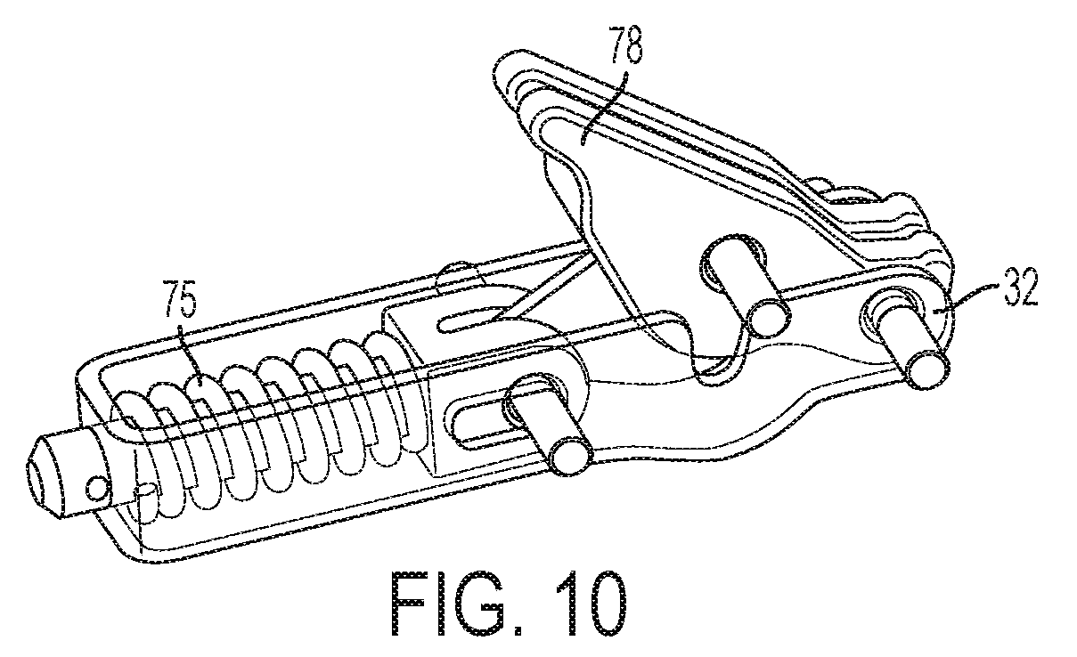
[0060] FIG. 9 illustrates one embodiment of a jaw position sensor 134. The jaw position sensor 134 comprises a switch 170. When the contact 177 of the switch 170 is depressed by the lock bar 41, an electrical connection within the switch 170 is opened. The break in the electrical connection of the switch 170 is detected by a two-position connection header 172. The connection header 172 is coupled to, for example, a control board 38. A connected receptacle 174 couples the connection header 172 to the handle assembly 4. FIG. 10 illustrates one embodiment of a return stroke dampener 32. The return stroke dampener 32 is configured to provide a dampening force to the return stroke of the yoke 26. The return stroke dampener 32 comprises a toggle arm 78 and a dampening spring 76. The yoke 26 comprises a dampener interface pin 79. When the yoke 26 moves distally, for example, when the jaws 22a, 22b are released and the closure trigger 8 returns to an unactuated position, the interface pin 79 forces the toggle arm 78 down, compressing the dampening spring 76 and reducing the load from the closure spring 28 on the closure trigger 8. Once the interface pin 79 pushes the toggle arm 78 close to over center, the load on the yoke pin 79 goes almost to zero such that the dampener effect is eliminated for the remainder of the stroke. The return stroke dampener 32 reduces the force of the closure spring 28 when the closure trigger 8 is released from an actuated position. In some embodiments, the return stroke dampener may comprise a hydraulic dampener, a pneumatic dampener, or any other suitable return stroke dampener. U.S. patent application Ser. No. 14/158,248, now U.S. Pat. No. 9,408,660, which is hereby incorporated by reference in its entirety. FIG. 11 illustrates one embodiment of a spring washer 158 configured to interface with a rack spring 59 when the rack 44 is advanced in a distal direction. The spring washer 158 and the rack spring 59 cause the rack 44 to move proximally if the firing trigger 16 is released.
[0061] FIG. 12 illustrates one embodiment of an electrical energy system 80 mounted within the handle assembly 4. An energy button 18 is configured to deliver energy to an electrode 92 coupled to the end effector 10. The energy button 18 is coupled to a plurality of power activation wires 82. When the energy button 18 is depressed, a circuit is completed allowing delivery of energy to the electrode 92. A source path 84 couples an electrical contact mounted on the distal end of the outer tube 23 of the shaft assembly 12. In some embodiments, the source path comprises the outer tube 23. Alternatively, in some embodiments, the source path comprises a solid or stranded conductor housed within the outer tube 23. A return path 85 acts as a return for bipolar RF energy delivered to the electrode. For monopolar RF energy, the return path may comprise a grounding electrode coupled to a patient. In some embodiments, the power activation wires 82 are coupled to a generator. The control board 48 is further coupled to the jaw position switch 34 and the generator. The generator may prevent delivery of energy to the electrode 92 unless the jaw position sensor 34 indicates that the jaws 22a, 22b are in a sufficiently closed position.
[0062] FIG. 13 illustrates one embodiment of a surgical instrument 202 comprising an offset closure spring 228 and an L-shaped lever arm 224. The surgical instrument 202 comprises a handle assembly 204 and a shaft assembly 12. The shaft assembly 12 is configured to couple to an end effector, such as, for example, the end effector 10 illustrated in FIG. 1. The handle assembly 204 comprises a pistol grip handle 214 and a closure trigger 208. The closure trigger 208 is configured to affect closure of the jaws 22a, 22b of an end effector 10 coupled to the shaft assembly 12. The surgical instrument 202 is similar to the surgical instrument 2 illustrated in FIGS. 1-12.
[0063] The closure trigger 208 is operatively coupled to an L-shaped lever arm 224 at a first pivot 225. Actuation of the closure trigger 208 causes a closure spring 228 to apply a force to the first pivot. Actuation of the closure trigger further causes proximal movement of the L-shaped lever arm 224 along a longitudinal axis. Proximal movement of the L-shaped lever arm 224 causes the jaws 22a, 22b to pivot to a closed position to, for example, grasp tissue therebetween. The L-shaped lever arm 224 comprises a toggle pin slot 233 and is coupled to the closure trigger 208 by a toggle pin 231 at the first pivot 225. In operation, an operator actuates the closure trigger 208 to rotate the closure trigger 208 towards the pistol grip handle 214. The closure trigger 208 pushes on the closure spring 228 as the closure trigger 208 is rotated. The closure spring 228 applies a force to the L-shaped lever arm 224 at the first pivot 225. The L-shaped lever arm 224 is driven proximally and causes a jaw closing shaft 223 to move proximally. Proximal movement of the jaw closing shaft 223 causes the jaws 22a, 22b to transition from an open position to a closed position.
[0064] The L-shaped lever arm 224 and the jaw closing shaft 223 move proximally until the tissue is fully grasped by the jaws and/or the jaws reach a predetermined "full closed" position. After the jaws 22a, 22b are closed on a tissue section, continued actuation of the closure trigger 208 drives the toggle pin 231 within the toggle pin channel 233, altering the vector of the force applied to the toggle pin 231 by the closure spring 228. The toggle pin channel 233 comprises an offset with respect to the movement of the toggle pin 231. The offset of the toggle pin channel 233 increases the load delivered by the closure spring 228, as it requires a greater load for the L-shaped lever arm 224 to compress the closure spring 228 in a vector other than the vector perpendicular to the L-shaped lever arm 224.
[0065] FIG. 13 illustrates the closure trigger 208 in an initial position corresponding to the jaws 22a, 22b of the end effector 10 being in an open position. In operation, a clinician actuates the closure trigger 208 to transition the jaws 22a, 22b to a closed position. Actuation of the closure trigger 208 causes the closure spring 228 to apply a force to the toggle pin 231 and drives the L-shaped lever arm 224 proximally. Proximal movement of the L-shaped lever arm 224 causes a jaw closure actuator 223 to move proximally and transition the jaws 22a, 22b to a closed position. After the jaws 22a, 22b have closed on a tissue section, the closure trigger 208 is further rotatable to apply additional force to the tissue section. For example, in one embodiment, actuation of the closure trigger 208 to a first rotation causes the jaws 22a, 22b to close over a tissue section. Continued actuation of the closure trigger 208 to a second rotation the toggle pin 231 to slide within the toggle pin channel 233, changing the angle at which the force vector is applied by the closure spring 228 to the toggle pin 231. The changing vector angle increases the force transferred to the tissue section located between the jaws 22a, 22b and compresses the tissue section. The force applied by the closure spring 228 increases as the toggle pin 231 traverses the toggle pin channel 233. Actuation of the closure trigger 208 after the jaws 22a, 22b have closed on the tissue section increases the force applied by the closure spring until the toggle pin 231 contacts a toggle pin stop 235. When the toggle pin 231 reaches the toggle pin stop 235, the full force of the closure spring 228 is transferred to the jaws 22a, 22b. The closure trigger 208 provides a consistent force to fire over the entire stroke of the closure trigger 208.
[0066] In some embodiments, the closure spring slot 230 comprises an offset angle with respect to the direction of travel of the toggle pin 231. The offset angle of the closure spring slot 230 allows a weaker spring to do more work and apply a greater force to the jaws 22a, 22b as compared to a linear spring compressed in a vector parallel with the longitudinal axis of movement of the L-shaped lever arm 224. In some embodiments, the closure spring 228 and the toggle pin 231 provide a first load at a beginning of a stroke, such as, for example, rotation of the closure trigger 208 to a predetermined rotation, and a second load at the end of the stroke. As the toggle pin 231 traverses the closure spring slot 230, the mechanical disadvantage of the closure trigger 208 increases. The changing mechanical disadvantage provides a consistent force to fire when larger tissue is located between the first and second jaws 22a, 22b. In some embodiments, the toggle pin channel 233 comprises a toggle pin stop 235 for the toggle pin 231. When the toggle pin 231 reaches the toggle pin stop 235, the full force of the closure trigger 208 load is placed on the jaws 22a, 22b. The amount of compression of the closure spring 228 may be proportional to, for example, the force exerted on a tissue section by the first and second jaw members 22a, 22b.
[0067] FIG. 14 illustrates the closure trigger 208 in a fully closed position corresponding to thin tissue grasped within the end effector 10. When thin tissue is grasped within the jaws 22a, 22b, the L-shaped lever arm 224 and the jaw closing shaft 223 move a first longitudinal distance, such as, for example, 0.1 inches. The toggle pin 231 is minimally displaced within the toggle pin channel 233 and stays nearly at the top of the toggle pin channel 233. The minimum movement of the toggle pin 231 causes the surgical instrument 202 to apply a lower force to thinner tissue grasped within the end effector 10.
[0068] FIG. 15 illustrates the closure trigger 208 in a fully closed position corresponding to thick tissue grasped within the end effector 10. When thick tissue is grasped within the jaws 22a, 22b the L-shaped lever arm 224 and the jaw closing shaft 223 move a second longitudinal distance, such as, for example, 0.05 inches. The movement of the L-shaped lever arm 224 and the jaw closing shaft 223 is less when thicker tissue is present in the jaws 22a, 22b, as the jaws 22a, 22b have a larger spacing when closed around thicker tissue than thin tissue. The toggle pin 231 is slideably moved within the toggle pin channel 233 to the toggle pin stop 235. Movement of the toggle pin 231 within the toggle pin channel 233 changes the angle of the force vector applied by the closure spring to the toggle pin 231. When the toggle pin 231 reaches the toggle pin stop 235, the full load of the closure trigger 208 is applied to the toggle pin 231 and the L-shaped lever arm 224. The movement of the toggle pin 231 within the toggle pin channel 233 provides a consistent force to fire during grasping of thicker tissue. When the toggle pin 231 contacts the toggle pin stop 235, the offset angle between the closure spring 228 to the toggle pin 231 and the L-shaped lever arm 224 is minimized to allow the closure spring 228 to apply more force to L-shaped lever arm 224 directly. Therefore, even though the closure spring 228 load is greater, the offset angle of the toggle pin channel 233 is less, causing less load to be delivered to the L-shaped lever arm 224, making it easier for the L-shaped lever arm 224 to compress the closure spring 228.
[0069] In the illustrated embodiment, the toggle pin 231 traverses the toggle pin channel 233 and moves up the L-shaped lever arm 224. Movement of the toggle pin 231 within the toggle pin channel 233 increases the mechanical disadvantage of the L-shaped lever arm 224. The output load at the jaws 22a, 22b is modified by the angled closure spring 228 and the toggle pin channel 233 based on how far the jaws 22a, 22b close. The closure spring 228 and the toggle pin 231 provide a constant force to the L-shaped lever arm 224, compared with an ever increasing force as applied by only a spring in-line with movement of the L-shaped lever arm 224. The L-shaped lever arm 224 transmits close to the same load to the end effector 10 regardless of the thickness of tissue located within the jaws 22a, 22b. In some embodiments, a linear spring is included to provide additional force to the closure trigger 208 and/or the end effector 10.
[0070] FIG. 16 illustrates one embodiment of a closure trigger 308 comprising an offset closure spring slot 330. The closure trigger 308 may be used with any suitable surgical instrument, such as, for example, the surgical instruments 2, 202 illustrated in FIGS. 1-15. The closure trigger 308 comprises a closure spring 328 located within an offset closure spring slot 330. The closure spring slot 330 comprises a toggle pin slot 333 comprising a slot length 334 and a slot angle 332. The slot length 334 and the slot angle 332 may be configured to optimize the user load and force transferred to a jaw actuator, such as, for example, the outer tube 23, to close the first and second jaw members 22a, 22b of an end effector 10. In some embodiments, increasing the slot length 334 enables compliance in the surgical instrument 2, 202 such that a clinician can latch the closure handle 308 despite larger jaw angles of the first and second jaw members 22a, 22b. The slot length 334 may comprise any suitable length, such as, for example, a length of about 0.500'' to about 0.662''. The slot angle may comprise any suitable angle 332, such as, for example, a slot angle 332 of about 75.degree. to about 92.degree. relative to a line connecting a pivot of the closure trigger 308 to the top of the slot 333.
[0071] FIG. 17 illustrates a wireframe view of the closure trigger 308 of FIG. 16. The toggle pin slot 333 comprises a slot angle 332 and slot length 334. The slot angle 332 comprises an angle between a longitudinal plane defined by the top of the closure trigger 308 and a plane defined by the toggle pin slot 333. The slot angle 332 of the toggle pin slot 333 corresponds to an offset angle of the closure spring slot 330. In some embodiments, the toggle pin slot 333 comprises a predetermined slot angle and a predetermined slot length. The slot angle 332 of the toggle pin slot 333 may comprise, for example, an angle of 85.degree.. The slot length 334 of the toggle pin slot 333 may comprise, for example, a length of 0.632''. Those skilled in the art will recognize that the closure spring slot 330 and/or the toggle spring slot 330 may comprise any suitable slot angle 332 and slot length 334. A spring (not shown) located within the closure spring slot 333 may comprise any suitable spring constant, such as, for example, a spring constant configured to provide a closure force of about 9 lbf to about 32 lbf at a 2.25'' moment arm while maintaining about a 14 lbf to about a 7 lbf jaw tip load when the jaw members 22a, 22b are in a fully open position.
[0072] FIG. 18 illustrates a wireframe view of the closure trigger 308 of FIG. 16. FIG. 18 illustrates an alternative slot angle measurement. As discussed above, the slot angle 332a may comprise an offset angle between a plane defined by the top of the closure trigger 308 and a plane defined by the toggle pin slot 333. In some embodiments, the slot angle 332b comprises an offset angle between a plane defined between a pivot point 336 of the closure trigger 308 and the top of the toggle pin slot 333. The slot angle 332b may comprise, for example, an angle of 87.degree., although those skilled in the art will recognize that the offset angle 332b may comprise any suitable angle.
[0073] FIG. 19 is a graph 350 illustrating a force applied by first and second jaw members 22a, 22b of an end effector 10 coupled to a surgical instrument comprising the closure trigger 308 illustrated in FIGS. 16-18. FIG. 19 illustrates a force 352 applied by the first and second jaw members 22a, 22b when the first and second jaw members 22a, 22b are full and a force 354 applied by the first and second jaw members 22a, 22b when the first and second jaw members 22a, 22b are empty. As shown in FIG. 19, in one embodiment, the force 352 applied by the first and second jaw members 22a, 22b increases to a peak of about 30 lbs over the entire stroke when the first and second jaw member 22a, 22b are full, that is, when the first and second jaw members 22a, 22b are clamping a maximum thickness of tissue. When the first and second jaw members are empty, the force 354 applied is zero until the jaws 22a, 22b are fully closed. The maximum force 352, 354 applied by the first and second jaw members 22a, 22b is applied at an over-closed position, in which the closure trigger 308 is rotated past a latch point. In the illustrated embodiment, the maximum force occurs at about 2.degree. past latch, but those skilled in the art will recognize that any suitable over-closed position is possible.
[0074] FIGS. 20A and 20B illustrate one embodiment of an electrosurgical end effector 410 comprising a curved shape. The end effector 410 comprises a first jaw member 422a and a second jaw member 422b. The first jaw member 422a is pivotally coupled by a pivot pin 479 to the second jaw member. The electrosurgical end effector 410 is configured to be coupled to an electrosurgical instrument, such as, for example, the electrosurgical instrument 2 illustrated in FIGS. 1-23. In some embodiments, the first jaw member 422a and the second jaw member 422b are smoothly tapered with the proximal portion of the jaw members 422a, 422b being the widest portion and the distal end of the jaw members 422a, 422b being the narrowest portion of the jaw members 422a, 422b. The smooth taper comprises a taper in a plane of curvature of the end effector 410 and parallel to a central axis of the shaft 412. For example, in some embodiments, the distal portion of the end effector 410 may comprise approximately 25% to 50% of the proximal width of the end effector 410, such as, for example, 33%. The smooth taper provides better dissection while maintaining a wide electrode through most of the end effector 410 for better sealing. The first jaw member 422a and the second jaw member 422b are curved along a longitudinal axis of the end effector 410. The curve of the end effector 410 comprises a radius of curvature. The radius of curvature may comprise, for example, a radius of about 1.000'' to about 4.000''.
[0075] The taper and curvature of the end effector 410 increase visibility of the tip 491. The taper compensates for the loss of force on the tissue on more proximal locations of the end effector 410 providing a more constant pressure on the tissue. The smooth transitions along the longitudinal axis of the end effector 410 and the taper distribute deflection along the length of the end effector 410 and reduce stress concentration allowing greater loads to be applied by the end effector 410. The reduced stresses and deflection permit the end effector 410 to be lengthened beyond non-curved, non-tapered end effectors. For example, in some embodiments, the end effector 410 comprises a length of approximately 23 mm.
[0076] In some embodiments, the end effector 410 comprises an offset pivot 486. The offset pivot 486 comprises a pivot point offset from the longitudinal axis of the shaft 412 and the end effector 410. The offset pivot enables the use of a linkage-style closure mechanism. The link pin 488 and offset pivot 486 provides precise control of the movement of the first jaw member 422a. FIG. 21 illustrates one embodiment of an end effector 510 comprising an offset pivot 586 coupled to an offset actuator. The offset actuator comprises a single asymmetric lever arm 590 coupled to the first jaw member 522a. The asymmetric lever arm 590 provides additional material around the pivot 586 when compared to a traditional two lever arm end effector.
[0077] FIG. 22 illustrates one embodiment of an end effector 610 comprising an offset pivot 686 and an asymmetric lever arm 690 coupled to a shaft 612. The end effector 610 comprises a first jaw member 622a and a second jaw member 622b. The first jaw member 622a is pivotally moveable with respect to the second jaw member 622b. The second jaw member 622b is fixed. The first and second jaw members 622a, 622b comprises a curved shape having a radius of curvature with respect to a longitudinal axis of a shaft 612. The first jaw member 622a and the second jaw member 622b comprise a smooth taper from the proximal end to the distal end. The distal tip 690 comprises a width less than the width of the proximal section of the end effector 610. For example, in some embodiments, the distal tip comprises a width of about 25% to about 50% of the width of the proximal section of the end effector 610. The end effector 610 is illustrated in an open position in FIG. 22. In some embodiments, movement of the first jaw member 622a with respect to the second jaw member 622b is accomplished by a linked connection between the asymmetric lever arm 690 and an outer sheath 623 of the shaft 612. A low friction bushing 698, such as, for example, a lubricious metal or plastic, comprises a sliding interface between the asymmetric lever arm 690 and the outer sheath 623. The low friction bushing 698 is disposed between an outer diameter of the asymmetric lever arm 690 and an inner diameter of the shaft 612. FIG. 23 illustrates the end effector 610 of FIG. 22 in a closed position. As shown in FIG. 23, the end effector 610 is transitioned to a closed position by moving the asymmetric lever arm 690 proximally. Proximal movement of the asymmetric lever arm 690 may be affected by, for example, actuating a closure trigger 8 of a handle assembly 4 coupled to the end effector 610 by the shaft 612.
[0078] In some embodiments, an electrode 692 is coupled to the second jaw member 622b. The electrode 692 is adhered to the second jaw member 622b by an adhesive, such as, for example, a silicon or epoxy adhesive. The electrode 692 is selectively coated with a ceramic coating that provides electrical insulation to prevent shorting between the electrode 692 and the second jaw member 622b. In some embodiments, the ceramic coating and adhesive comprise a thermal conductivity of about 0.5 W/(mK) to about 2.0 W/(mK). The electrode 692 contacts a source electrode on the distal end of the outer tube 623 when the first jaw member 622a is rotated into a closed position with respect to the second jaw member 622b. Placement of the contact electrode on the outer shaft 623 ensures a good connection between the electrode 692 and an energy source. In some embodiments, the first jaw member 622a and/or the second jaw member 622b define a cutting member slot. FIG. 24 illustrates one embodiment of the second jaw member 622b comprising a cutting member slot 696. The proximal end of the cutting member slot 696 begins in a plane through a central axis of the shaft 612. The cutting member slot 696 biases to a first side of the central axis of the shaft 612 then crosses the central axis to a location biased to the opposite side of the central axis at the distal-most portion of the cutting member slot 696. The cutting member slot 696 shape maximizes the radius of the cutting member slot 696 reducing the bending load on the cutting member 695. The geometry of the cutting member slot 696 maintains a nearly equivalent electrode 692 width on both sides of the cutting member slot 696. In some embodiments, the curvature of the cutting member slot 696 is substantially equal to the curvature of the end effector 610, which is substantially equal to the curvature of the anatomy being transected. In some embodiments, a radius of curvature of the cutting member slot 696 varies from about 2.000'' to about 4.000'' over the length of the cutting member slot 696. In some embodiments, the cutting member slot 696 is biased to either the first side and/or the second side of the central axis of the shaft 612 by a distance of greater than 0.000'' to a maximum of about 0.065''.
[0079] While the examples herein are described mainly in the context of electrosurgical instruments, it should be understood that the teachings herein may be readily applied to a variety of other types of medical instruments. By way of example only, the teachings herein may be readily applied to tissue graspers, tissue retrieval pouch deploying instruments, surgical staplers, ultrasonic surgical instruments, etc. It should also be understood that the teachings herein may be readily applied to any of the instruments described in any of the references cited herein, such that the teachings herein may be readily combined with the teachings of any of the references cited herein in numerous ways. Other types of instruments into which the teachings herein may be incorporated will be apparent to those of ordinary skill in the art.
[0080] It should be appreciated that any patent, publication, or other disclosure material, in whole or in part, that is said to be incorporated by reference herein is incorporated herein only to the extent that the incorporated material does not conflict with existing definitions, statements, or other disclosure material set forth in this disclosure. As such, and to the extent necessary, the disclosure as explicitly set forth herein supersedes any conflicting material incorporated herein by reference. Any material, or portion thereof, that is said to be incorporated by reference herein, but which conflicts with existing definitions, statements, or other disclosure material set forth herein will only be incorporated to the extent that no conflict arises between that incorporated material and the existing disclosure material.
[0081] The disclosed embodiments have application in conventional endoscopic and open surgical instrumentation as well as application in robotic-assisted surgery.
[0082] Embodiments of the devices disclosed herein can be designed to be disposed of after a single use, or they can be designed to be used multiple times. Embodiments may, in either or both cases, be reconditioned for reuse after at least one use. Reconditioning may include any combination of the steps of disassembly of the device, followed by cleaning or replacement of particular pieces, and subsequent reassembly. In particular, embodiments of the device may be disassembled, and any number of the particular pieces or parts of the device may be selectively replaced or removed in any combination. Upon cleaning and/or replacement of particular parts, embodiments of the device may be reassembled for subsequent use either at a reconditioning facility, or by a surgical team immediately prior to a surgical procedure. Those skilled in the art will appreciate that reconditioning of a device may utilize a variety of techniques for disassembly, cleaning/replacement, and reassembly. Use of such techniques, and the resulting reconditioned device, are all within the scope of the present application.
[0083] By way of example only, embodiments described herein may be processed before surgery. First, a new or used instrument may be obtained and if necessary cleaned. The instrument may then be sterilized. In one sterilization technique, the instrument is placed in a closed and sealed container, such as a plastic or TYVEK bag. The container and instrument may then be placed in a field of radiation that can penetrate the container, such as gamma radiation, x-rays, or high-energy electrons. The radiation may kill bacteria on the instrument and in the container. The sterilized instrument may then be stored in the sterile container. The sealed container may keep the instrument sterile until it is opened in a medical facility. A device may also be sterilized using any other technique known in the art, including but not limited to beta or gamma radiation, ethylene oxide, or steam.
[0084] It is worthy to note that any reference to "one aspect," "an aspect," "one embodiment," or "an embodiment" means that a particular feature, structure, or characteristic described in connection with the aspect is included in at least one aspect. Thus, appearances of the phrases "in one aspect," "in an aspect," "in one embodiment," or "in an embodiment" in various places throughout the specification are not necessarily all referring to the same aspect.
[0085] One skilled in the art will recognize that the herein described components (e.g., operations), devices, objects, and the discussion accompanying them are used as examples for the sake of conceptual clarity and that various configuration modifications are contemplated. Consequently, as used herein, the specific exemplars set forth and the accompanying discussion are intended to be representative of their more general classes. In general, use of any specific exemplar is intended to be representative of its class, and the non-inclusion of specific components (e.g., operations), devices, and objects should not be taken as limiting.
[0086] With respect to the use of substantially any plural and/or singular terms herein, those having skill in the art can translate from the plural to the singular and/or from the singular to the plural as is appropriate to the context and/or application. The various singular/plural permutations are not expressly set forth herein for sake of clarity.
[0087] The herein described subject matter sometimes illustrates different components contained within, or connected with, different other components. It is to be understood that such depicted architectures are merely examples and that in fact many other architectures may be implemented which achieve the same functionality. In a conceptual sense, any arrangement of components to achieve the same functionality is effectively "associated" such that the desired functionality is achieved. Hence, any two components herein combined to achieve a particular functionality can be seen as "associated with" each other such that the desired functionality is achieved, irrespective of architectures or intermedial components. Likewise, any two components so associated can also be viewed as being "operably connected," or "operably coupled," to each other to achieve the desired functionality, and any two components capable of being so associated can also be viewed as being "operably couplable," to each other to achieve the desired functionality. Specific examples of operably couplable include but are not limited to physically mateable and/or physically interacting components, and/or wirelessly interactable, and/or wirelessly interacting components, and/or logically interacting, and/or logically interactable components.
[0088] Some aspects may be described using the expression "coupled" and "connected" along with their derivatives. It should be understood that these terms are not intended as synonyms for each other. For example, some aspects may be described using the term "connected" to indicate that two or more elements are in direct physical or electrical contact with each other. In another example, some aspects may be described using the term "coupled" to indicate that two or more elements are in direct physical or electrical contact. The term "coupled," however, also may mean that two or more elements are not in direct contact with each other, but yet still co-operate or interact with each other.
[0089] In some instances, one or more components may be referred to herein as "configured to," "configurable to," "operable/operative to," "adapted/adaptable," "able to," "conformable/conformed to," etc. Those skilled in the art will recognize that "configured to" can generally encompass active-state components and/or inactive-state components and/or standby-state components, unless context requires otherwise.
[0090] While particular aspects of the present subject matter described herein have been shown and described, it will be apparent to those skilled in the art that, based upon the teachings herein, changes and modifications may be made without departing from the subject matter described herein and its broader aspects and, therefore, the appended claims are to encompass within their scope all such changes and modifications as are within the true scope of the subject matter described herein. It will be understood by those within the art that, in general, terms used herein, and especially in the appended claims (e.g., bodies of the appended claims) are generally intended as "open" terms (e.g., the term "including" should be interpreted as "including but not limited to," the term "having" should be interpreted as "having at least," the term "includes" should be interpreted as "includes but is not limited to," etc.). It will be further understood by those within the art that if a specific number of an introduced claim recitation is intended, such an intent will be explicitly recited in the claim, and in the absence of such recitation no such intent is present. For example, as an aid to understanding, the following appended claims may contain usage of the introductory phrases "at least one" and "one or more" to introduce claim recitations. However, the use of such phrases should not be construed to imply that the introduction of a claim recitation by the indefinite articles "a" or "an" limits any particular claim containing such introduced claim recitation to claims containing only one such recitation, even when the same claim includes the introductory phrases "one or more" or "at least one" and indefinite articles such as "a" or "an" (e.g., "a" and/or "an" should typically be interpreted to mean "at least one" or "one or more"); the same holds true for the use of definite articles used to introduce claim recitations.
[0091] In addition, even if a specific number of an introduced claim recitation is explicitly recited, those skilled in the art will recognize that such recitation should typically be interpreted to mean at least the recited number (e.g., the bare recitation of "two recitations," without other modifiers, typically means at least two recitations, or two or more recitations). Furthermore, in those instances where a convention analogous to "at least one of A, B, and C, etc." is used, in general such a construction is intended in the sense one having skill in the art would understand the convention (e.g., "a system having at least one of A, B, and C" would include but not be limited to systems that have A alone, B alone, C alone, A and B together, A and C together, B and C together, and/or A, B, and C together, etc.). In those instances where a convention analogous to "at least one of A, B, or C, etc." is used, in general such a construction is intended in the sense one having skill in the art would understand the convention (e.g., "a system having at least one of A, B, or C" would include but not be limited to systems that have A alone, B alone, C alone, A and B together, A and C together, B and C together, and/or A, B, and C together, etc.). It will be further understood by those within the art that typically a disjunctive word and/or phrase presenting two or more alternative terms, whether in the description, claims, or drawings, should be understood to contemplate the possibilities of including one of the terms, either of the terms, or both terms unless context dictates otherwise. For example, the phrase "A or B" will be typically understood to include the possibilities of "A" or "B" or "A and B."
[0092] With respect to the appended claims, those skilled in the art will appreciate that recited operations therein may generally be performed in any order. Also, although various operational flows are presented in a sequence(s), it should be understood that the various operations may be performed in other orders than those which are illustrated, or may be performed concurrently. Examples of such alternate orderings may include overlapping, interleaved, interrupted, reordered, incremental, preparatory, supplemental, simultaneous, reverse, or other variant orderings, unless context dictates otherwise. Furthermore, terms like "responsive to," "related to," or other past-tense adjectives are generally not intended to exclude such variants, unless context dictates otherwise.
[0093] In summary, numerous benefits have been described which result from employing the concepts described herein. The foregoing description of the one or more embodiments has been presented for purposes of illustration and description. It is not intended to be exhaustive or limiting to the precise form disclosed. Modifications or variations are possible in light of the above teachings. The one or more embodiments were chosen and described in order to illustrate principles and practical application to thereby enable one of ordinary skill in the art to utilize the various embodiments and with various modifications as are suited to the particular use contemplated. It is intended that the claims submitted herewith define the overall scope.
[0094] Various aspects of the subject matter described herein are set out in the following numbered clauses:
[0095] 1. A surgical instrument comprising: a handle assembly comprising: a closure trigger; a closure actuator coupled to the closure trigger at a first pivot, wherein the closure actuator moves proximally on a longitudinal axis in response to actuation of the closure trigger; a closure spring configured to apply a force to the closure actuator at the first pivot, wherein the closure spring is compressed in response to movement of the closure trigger, and wherein a force vector of the force applied by the closure spring is tangential to the longitudinal axis; a shaft assembly coupled to the handle assembly; and an end effector coupled to a distal end of the shaft assembly, the end effector comprising: a jaw assembly having a proximal end and a distal end, the jaw assembly comprising: a first jaw member; and a second jaw member, wherein the first jaw member is pivotally moveable with respect to the second jaw member, and wherein the first jaw member is operatively coupled to the closure actuator.
[0096] 2. The surgical instrument of clause 1, wherein the jaw closure actuator is coupled to the closure trigger by a toggle pin at the first pivot, and wherein the closure spring applies the force to the toggle pin when the closure trigger is actuated.
[0097] 3. The surgical instrument of clause 2, wherein the toggle pin is slideably moveable within a toggle pin channel.
[0098] 4. The surgical instrument of clause 3, wherein actuation of the closure trigger to a first position causes proximal movement of the closure actuator and actuation of the closure trigger to a second position causes movement of the toggle pin within the toggle pin channel, wherein movement of the toggle pin changes an angle of the force vector applied by the closure spring to the closure actuator, and wherein the first position corresponds to the first and second jaws being fully closed.
[0099] 5. The surgical instrument of clause 4, wherein the toggle pin channel comprises a toggle pin stop configured to prevent the toggle pin from traveling beyond a predetermined limit.
[0100] 6. The surgical instrument of clause 4, wherein the toggle pin is configured to move within the toggle pin channel to provide a first load at a beginning of a stroke of the closure trigger and a second load at an end of the stroke of the closure trigger.
[0101] 7. The surgical instrument of clause 4, wherein the closure trigger defines a closure spring slot, and wherein the closure spring is located within the closure spring slot.
[0102] 8. The surgical instrument of clause 2, wherein the jaw closure actuator comprises: a three-bar linkage comprising a first pivot and a second pivot; and a yoke, wherein the closure trigger is operatively coupled to a first pivot and the yoke is operatively coupled to the second pivot.
[0103] 9. The surgical instrument of clause 2, wherein the jaw closure actuator comprises an L-shaped lever arm.
[0104] 10. The surgical instrument of clause 1, comprising a firing actuator coupled to the first pivot, wherein the first jaw member and the second jaw member define a longitudinal slot, wherein the firing actuator is configured to advance a cutting member within the longitudinal slot, and wherein the force applied by the closure spring provides a force limit to one of the closure actuator or the firing actuator.
[0105] 11. A surgical instrument comprising: a handle assembly comprising: a closure trigger; a three-bar linkage comprising a first pivot and a second pivot, wherein the closure trigger is operatively coupled to the first pivot by a toggle pin; a yoke coupled to the second pivot of the three-bar linkage, wherein the yoke is configured to move proximally in a longitudinal axis in response to actuation of the closure trigger; a closure spring configured to apply a force to the toggle pin, wherein the closure spring is compressed in response to movement of the closure trigger, and wherein a vector of the force applied to the toggle pin is tangential to the longitudinal axis; a shaft assembly coupled to the handle assembly, the shaft assembly comprising a jaw closure actuator operatively coupled to the yoke; and an end effector coupled to a distal end of the shaft assembly, the end effector comprising: a jaw assembly having a proximal end and a distal end, the jaw assembly comprising: a first jaw member; and a second jaw member, wherein the first jaw member is pivotably moveable with respect to the second jaw member, wherein the first jaw member is coupled to the jaw closure actuator, and wherein actuation of the closure trigger pivots the first jaw member with respect to the second jaw member.
[0106] 12. The surgical instrument of clause 11, wherein the toggle pin is slideably moveable within a toggle pin channel.
[0107] 13. The surgical instrument of clause 12, wherein the toggle pin is configured to move within the toggle pin channel to provide a first load at a beginning of a stroke of the closure trigger and a second load at an end of the stroke of the closure trigger.
[0108] 14. The surgical instrument of clause 13, wherein actuation of the closure trigger to a first position causes proximal movement of the jaw closure actuator and actuation of the closure trigger to a second position causes movement of the toggle pin within the toggle pin channel, wherein movement of the toggle pin changes an angle of the force vector applied by the closure spring to the jaw closure actuator, and wherein the first position corresponds to the first and second jaws being fully closed.
[0109] 15. The surgical instrument of clause 14, wherein the toggle pin channel comprises a toggle pin stop configured to prevent the toggle pin from traveling beyond a predetermined limit.
[0110] 16. The surgical instrument of clause 14, wherein the closure trigger defines a closure spring slot, and wherein the closure spring is located within the closure spring slot.
[0111] 17. A surgical instrument comprising: a handle assembly comprising: a closure trigger; an L-shaped lever arm coupled to the closure trigger at a first pivot by a toggle pin, wherein the L-shaped lever arm is configured to move proximally in a longitudinal axis in response to actuation of the closure trigger; a closure spring configured to apply a force to the toggle pin, wherein the closure spring is compressed in response to movement of the closure trigger, wherein a vector of the force applied to the toggle pin is tangential to the longitudinal axis; a shaft assembly coupled to the handle assembly, the shaft assembly comprising a jaw closure actuator coupled to the L-shaped lever arm; and an end effector coupled to a distal end of the shaft assembly, the end effector comprising: a jaw assembly having a proximal end and a distal end, the jaw assembly comprising: a first jaw member; and a second jaw member, wherein the first jaw member is pivotably moveable with respect to the second jaw member, wherein the first jaw member is coupled to the jaw closure actuator, and wherein actuation of the closure trigger pivots the first jaw member with respect to the second jaw member.
[0112] 18. The surgical instrument of clause 17, wherein the toggle pin is slideably moveable within a toggle pin channel.
[0113] 19. The surgical instrument of clause 18, wherein the toggle pin is configured to move within the toggle pin channel to provide a first load at a beginning of a stroke of the closure trigger and a second load at an end of the stroke of the closure trigger.
[0114] 20. The surgical instrument of clause 19, wherein actuation of the closure trigger to a first position causes proximal movement of the jaw closure actuator and actuation of the closure trigger to a second position causes movement of the toggle pin within the toggle pin channel, wherein movement of the toggle pin changes an angle of the force vector applied by the closure spring to the jaw closure actuator, and wherein the first position corresponds to the first and second jaws being fully closed.
[0115] 21. The surgical instrument of clause 20, wherein the closure trigger defines a closure spring slot, and wherein the closure spring is located within the closure spring slot.
[0116] 22. A surgical instrument comprising: a handle assembly comprising: a closure trigger; a closure actuator coupled to the closure trigger, wherein the closure actuator moves proximally on a longitudinal axis in response to actuation of the closure trigger; a firing actuator coupled to the closure trigger; and a mechanism configured to force limit one of the jaw closure actuator or the firing actuator, the mechanism comprising a closure spring configured to apply a force to a first pivot of the closure trigger, wherein the closure spring is compressed in response to movement of the closure trigger, and wherein a force vector of the force applied by the closure spring is tangential to a longitudinal axis; a shaft assembly coupled to the handle assembly; and an end effector coupled to a distal end of the shaft assembly, the end effector comprising: a jaw assembly having a proximal end and a distal end, the jaw assembly comprising: a first jaw member; and a second jaw member, wherein the first jaw member is pivotally moveable with respect to the second jaw member, wherein the first jaw member is operatively coupled to the closure actuator, wherein the first and second jaw members define a longitudinal slot configured to receive a cutting member, and wherein the cutting member is coupled to the firing actuator.
[0117] 23. The surgical instrument of clause 22, wherein the mechanism configured to force limit one of the jaw closure actuator or the firing actuator defines a slot length of about 0.500'' inches to about 0.662''.
[0118] 24. The surgical instrument of clause 22, wherein the mechanism configured to force limit one of the jaw closure actuator or the firing actuator defines a slot angle of about 75 degrees to about 92 degrees.
[0119] 25. The surgical instrument of clause 22, wherein the mechanism configured to force limit one of the jaw closure actuator or the firing actuator comprises a spring defining a spring constant configured to provide a closure force of about 9 lbf to about 32 lbf at a 2.25'' moment arm while maintaining about a 14 lbf to about a 7 lbf jaw tip load when the first jaw member and the second jaw members are open.
* * * * *
D00000
D00001
D00002
D00003
D00004
D00005
D00006
D00007
D00008
D00009
D00010
D00011
D00012
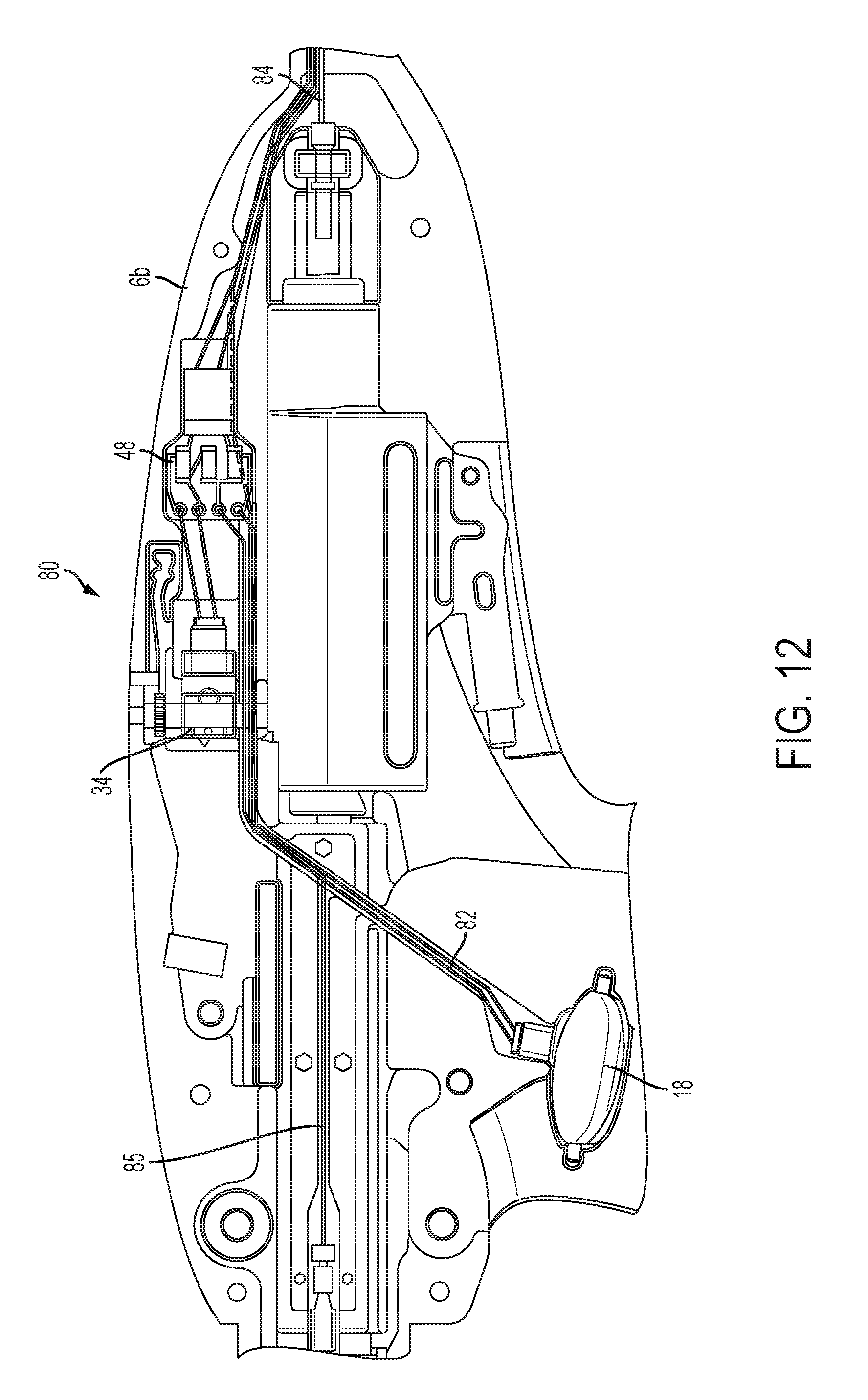
D00013
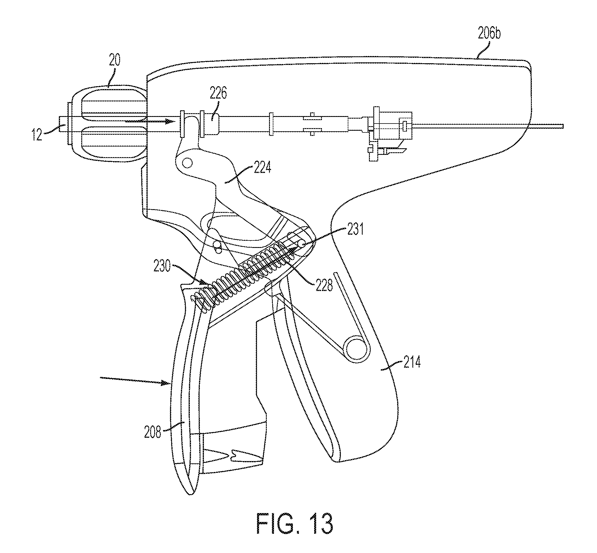
D00014

D00015

D00016

D00017

D00018

D00019

D00020
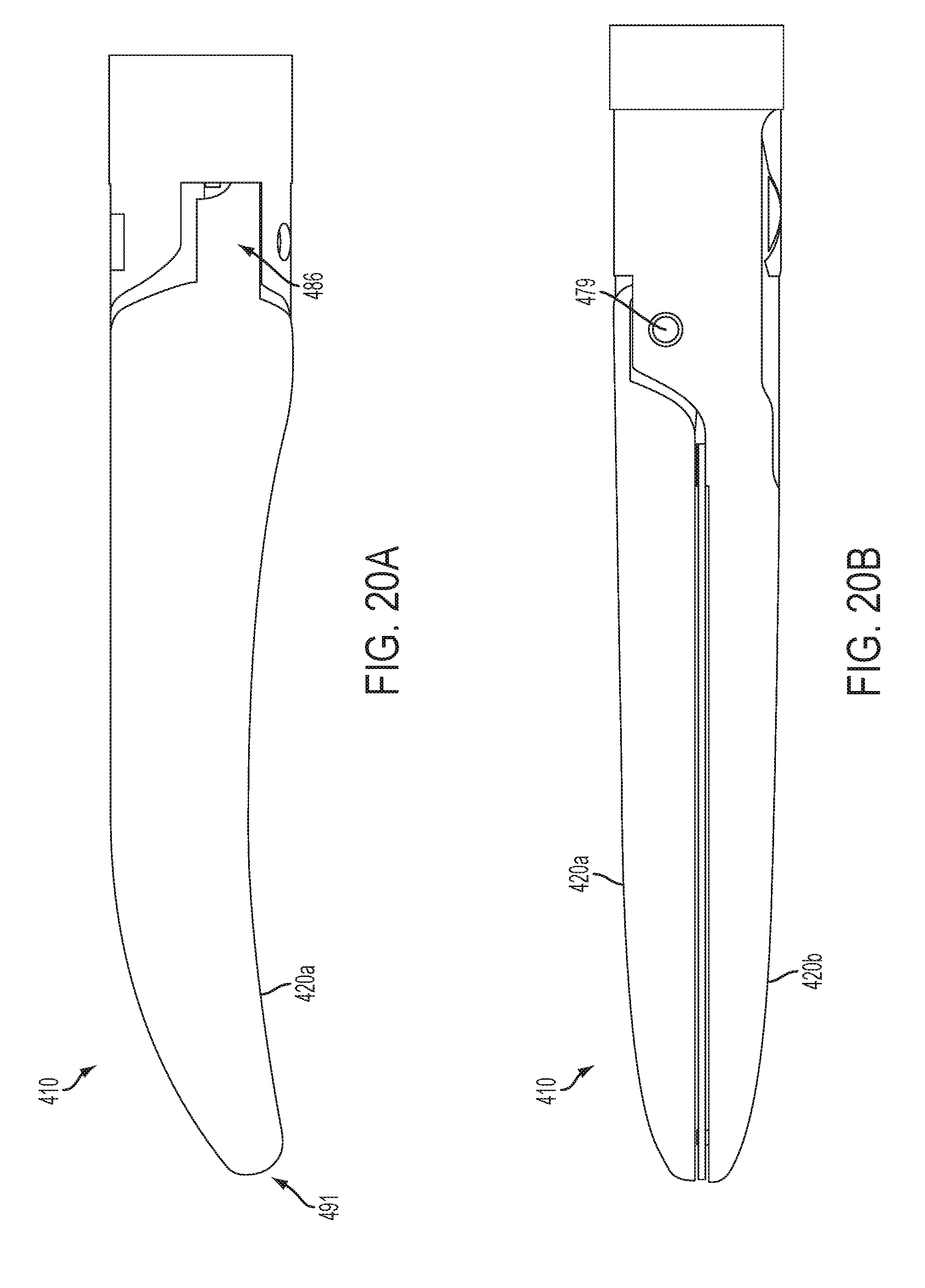
D00021

D00022

D00023

D00024

XML
uspto.report is an independent third-party trademark research tool that is not affiliated, endorsed, or sponsored by the United States Patent and Trademark Office (USPTO) or any other governmental organization. The information provided by uspto.report is based on publicly available data at the time of writing and is intended for informational purposes only.
While we strive to provide accurate and up-to-date information, we do not guarantee the accuracy, completeness, reliability, or suitability of the information displayed on this site. The use of this site is at your own risk. Any reliance you place on such information is therefore strictly at your own risk.
All official trademark data, including owner information, should be verified by visiting the official USPTO website at www.uspto.gov. This site is not intended to replace professional legal advice and should not be used as a substitute for consulting with a legal professional who is knowledgeable about trademark law.