Surgical instrument comprising an energy trigger lockout
Felder , et al. J
U.S. patent number 10,172,669 [Application Number 12/576,756] was granted by the patent office on 2019-01-08 for surgical instrument comprising an energy trigger lockout. This patent grant is currently assigned to Ethicon LLC. The grantee listed for this patent is Michael J. Andreyko, Chad P. Boudreaux, Kevin D. Felder. Invention is credited to Michael J. Andreyko, Chad P. Boudreaux, Kevin D. Felder.


View All Diagrams
| United States Patent | 10,172,669 |
| Felder , et al. | January 8, 2019 |
Surgical instrument comprising an energy trigger lockout
Abstract
A surgical instrument can comprise a lock movable between a locked position and an unlocked position, wherein the lock can be engaged with a drive shaft in order to prevent the drive shaft from being advanced when the lock is in its locked position. The surgical instrument can further comprise an electrical input and, in addition, a switch movable between an unactuated position and an actuated position, wherein the electrical input is electrically disconnected from an electrode when the switch is in its unactuated position, wherein the switch is configured to electrically couple the electrical input and the electrode when the switch is in its actuated position, and wherein the switch and the lock are operably coupled such that the movement of the switch from its unactuated position to its actuated position moves the lock from its locked position to its unlocked position.
| Inventors: | Felder; Kevin D. (Cincinnati, OH), Boudreaux; Chad P. (Cincinnati, OH), Andreyko; Michael J. (Cincinnati, OH) | ||||||||||
|---|---|---|---|---|---|---|---|---|---|---|---|
| Applicant: |
|
||||||||||
| Assignee: | Ethicon LLC (Guaynabo,
PR) |
||||||||||
| Family ID: | 43855418 | ||||||||||
| Appl. No.: | 12/576,756 | ||||||||||
| Filed: | October 9, 2009 |
Prior Publication Data
| Document Identifier | Publication Date | |
|---|---|---|
| US 20110087220 A1 | Apr 14, 2011 | |
| Current U.S. Class: | 1/1 |
| Current CPC Class: | A61B 18/1445 (20130101); A61B 2018/00083 (20130101); A61B 2018/1412 (20130101); A61B 18/1233 (20130101); A61B 2018/1455 (20130101); A61B 2018/00196 (20130101); A61B 2018/00708 (20130101) |
| Current International Class: | A61B 18/14 (20060101); A61B 18/00 (20060101); A61B 18/12 (20060101) |
| Field of Search: | ;606/32,37,48,50,52,208 |
References Cited [Referenced By]
U.S. Patent Documents
| 2366274 | January 1945 | Luth et al. |
| 2458152 | January 1949 | Eakins |
| 2510693 | June 1950 | Green |
| 2736960 | March 1956 | Armstrong |
| 2849788 | September 1958 | Creek |
| 2867039 | January 1959 | Zach |
| 3015961 | January 1962 | Roney |
| 3043309 | July 1962 | McCarthy |
| 3166971 | January 1965 | Stoecker |
| 3358676 | December 1967 | Frei et al. |
| 3525912 | August 1970 | Wallin |
| 3526219 | September 1970 | Balamuth |
| 3580841 | May 1971 | Cadotte et al. |
| 3614484 | October 1971 | Shoh |
| 3636943 | January 1972 | Balamuth |
| 3703651 | November 1972 | Blowers |
| 3710399 | January 1973 | Hurst |
| 3776238 | December 1973 | Peyman et al. |
| 3777760 | December 1973 | Essner |
| 3805787 | April 1974 | Banko |
| 3862630 | January 1975 | Balamuth |
| 3900823 | August 1975 | Sokal et al. |
| 3906217 | September 1975 | Lackore |
| 3918442 | November 1975 | Nikolaev et al. |
| 3946738 | March 1976 | Newton et al. |
| 3955859 | May 1976 | Stella et al. |
| 3956826 | May 1976 | Perdreaux, Jr. |
| 3988535 | October 1976 | Hickman et al. |
| 4005714 | February 1977 | Hiltebrandt |
| 4034762 | July 1977 | Cosens et al. |
| 4047136 | September 1977 | Satto |
| 4058126 | November 1977 | Leveen |
| 4063561 | December 1977 | McKenna |
| 4099192 | July 1978 | Aizawa et al. |
| 4156187 | May 1979 | Murry et al. |
| 4188927 | February 1980 | Harris |
| 4200106 | April 1980 | Douvas et al. |
| 4203430 | May 1980 | Takahashi |
| 4220154 | September 1980 | Semm |
| 4237441 | December 1980 | van Konynenburg et al. |
| 4278077 | July 1981 | Mizumoto |
| 4281785 | August 1981 | Brooks |
| 4304987 | December 1981 | van Konynenburg |
| 4314559 | February 1982 | Allen |
| 4384584 | May 1983 | Chen |
| 4445063 | April 1984 | Smith |
| 4463759 | August 1984 | Garito et al. |
| 4491132 | January 1985 | Aikins |
| 4492231 | January 1985 | Auth |
| 4535773 | August 1985 | Yoon |
| 4545926 | October 1985 | Fouts, Jr. et al. |
| 4550870 | November 1985 | Krumme et al. |
| 4582236 | April 1986 | Hirose |
| 4585282 | April 1986 | Bosley |
| 4597390 | July 1986 | Mulhollan et al. |
| 4617927 | October 1986 | Manes |
| 4634420 | January 1987 | Spinosa et al. |
| 4640279 | February 1987 | Beard |
| 4655746 | April 1987 | Daniels et al. |
| 4671287 | June 1987 | Fiddian-Green |
| 4708127 | November 1987 | Abdelghani |
| 4735603 | April 1988 | Goodson et al. |
| 4761871 | August 1988 | O'Connor et al. |
| 4777951 | October 1988 | Cribier et al. |
| 4797803 | January 1989 | Carroll |
| 4798588 | January 1989 | Aillon |
| 4802461 | February 1989 | Cho |
| 4803506 | February 1989 | Diehl et al. |
| 4830462 | May 1989 | Karny et al. |
| 4832683 | May 1989 | Idemoto et al. |
| 4838853 | June 1989 | Parisi |
| 4849133 | July 1989 | Yoshida et al. |
| 4850354 | July 1989 | McGurk-Burleson et al. |
| 4860745 | August 1989 | Farin et al. |
| 4865159 | September 1989 | Jamison |
| 4878493 | November 1989 | Pasternak et al. |
| 4880015 | November 1989 | Nierman |
| 4896009 | January 1990 | Pawlowski |
| 4910389 | March 1990 | Sherman et al. |
| 4910633 | March 1990 | Quinn |
| 4911148 | March 1990 | Sosnowski et al. |
| 4920978 | May 1990 | Colvin |
| 4922902 | May 1990 | Wuchinich et al. |
| 4936842 | June 1990 | D'Amelio et al. |
| 4961738 | October 1990 | Mackin |
| 4967670 | November 1990 | Morishita et al. |
| 4981756 | January 1991 | Rhandhawa |
| 5007919 | April 1991 | Silva et al. |
| 5019075 | May 1991 | Spears et al. |
| 5020514 | June 1991 | Heckele |
| 5026387 | June 1991 | Thomas |
| 5061269 | October 1991 | Muller |
| 5093754 | March 1992 | Kawashima |
| 5099216 | March 1992 | Pelrine |
| 5099840 | March 1992 | Goble et al. |
| 5104025 | April 1992 | Main et al. |
| 5106538 | April 1992 | Barma et al. |
| 5108383 | April 1992 | White |
| 5112300 | May 1992 | Ureche |
| 5123903 | June 1992 | Quaid et al. |
| 5150102 | September 1992 | Takashima |
| 5150272 | September 1992 | Danley et al. |
| 5156633 | October 1992 | Smith |
| 5160334 | November 1992 | Billings et al. |
| 5162044 | November 1992 | Gahn et al. |
| 5167725 | December 1992 | Clark et al. |
| D332660 | January 1993 | Rawson et al. |
| 5176695 | January 1993 | Dulebohn |
| 5184605 | February 1993 | Grzeszykowski |
| 5190541 | March 1993 | Abele et al. |
| 5196007 | March 1993 | Ellman et al. |
| 5205459 | April 1993 | Brinkerhoff et al. |
| 5213569 | May 1993 | Davis |
| 5217460 | June 1993 | Knoepfler |
| 5221282 | June 1993 | Wuchinich |
| 5226910 | July 1993 | Kajiyama et al. |
| 5234428 | August 1993 | Kaufman |
| 5241236 | August 1993 | Sasaki et al. |
| 5253647 | October 1993 | Takahashi et al. |
| 5257988 | November 1993 | L'Esperance, Jr. |
| 5258006 | November 1993 | Rydell et al. |
| 5261922 | November 1993 | Hood |
| 5263957 | November 1993 | Davison |
| 5267091 | November 1993 | Chen |
| 5282800 | February 1994 | Foshee et al. |
| 5285945 | February 1994 | Brinkerhoff et al. |
| 5290286 | March 1994 | Parins |
| 5304115 | April 1994 | Pflueger et al. |
| D347474 | May 1994 | Olson |
| 5309927 | May 1994 | Welch |
| 5312023 | May 1994 | Green et al. |
| 5313306 | May 1994 | Kuban et al. |
| 5318563 | June 1994 | Malis et al. |
| 5318564 | June 1994 | Eggers |
| 5318565 | June 1994 | Kuriloff et al. |
| 5318589 | June 1994 | Lichtman |
| 5322055 | June 1994 | Davison et al. |
| 5324260 | June 1994 | O'Neill et al. |
| 5324299 | June 1994 | Davison et al. |
| 5326013 | July 1994 | Green et al. |
| 5330471 | July 1994 | Eggers |
| 5330502 | July 1994 | Hassler et al. |
| 5333624 | August 1994 | Tovey |
| 5339723 | August 1994 | Huitema |
| 5342359 | August 1994 | Rydell |
| 5344420 | September 1994 | Hilal et al. |
| 5346502 | September 1994 | Estabrook et al. |
| 5352219 | October 1994 | Reddy |
| 5359992 | November 1994 | Hori et al. |
| 5361583 | November 1994 | Huitema |
| 5366466 | November 1994 | Christian et al. |
| 5370640 | December 1994 | Kolff |
| D354564 | January 1995 | Medema |
| 5381067 | January 1995 | Greenstein et al. |
| 5383874 | January 1995 | Jackson et al. |
| 5387207 | February 1995 | Dyer et al. |
| 5389098 | February 1995 | Tsuruta et al. |
| 5395312 | March 1995 | Desai |
| 5395331 | March 1995 | O'Neill et al. |
| 5395363 | March 1995 | Billings et al. |
| 5395364 | March 1995 | Anderhub et al. |
| 5396266 | March 1995 | Brimhall |
| 5396900 | March 1995 | Slater et al. |
| 5403312 | April 1995 | Yates et al. |
| 5409483 | April 1995 | Campbell et al. |
| D358887 | May 1995 | Feinberg |
| 5411481 | May 1995 | Allen et al. |
| 5417709 | May 1995 | Slater |
| 5419761 | May 1995 | Narayanan et al. |
| 5421829 | June 1995 | Olichney et al. |
| 5428504 | June 1995 | Bhatla |
| 5429131 | July 1995 | Scheinman et al. |
| 5431640 | July 1995 | Gabriel |
| 5443463 | August 1995 | Stern et al. |
| 5445615 | August 1995 | Yoon |
| 5445638 | August 1995 | Rydell et al. |
| 5449370 | September 1995 | Vaitekunas |
| 5451227 | September 1995 | Michaelson |
| 5456684 | October 1995 | Schmidt et al. |
| 5458598 | October 1995 | Feinberg et al. |
| 5465895 | November 1995 | Knodel et al. |
| 5472443 | December 1995 | Cordis et al. |
| 5476479 | December 1995 | Green et al. |
| 5477788 | December 1995 | Morishita |
| 5478003 | December 1995 | Green et al. |
| 5480409 | January 1996 | Riza |
| 5483501 | January 1996 | Park et al. |
| 5484436 | January 1996 | Eggers et al. |
| 5486162 | January 1996 | Brumbach |
| 5486189 | January 1996 | Mudry et al. |
| 5489256 | February 1996 | Adair |
| 5496317 | March 1996 | Goble et al. |
| 5500216 | March 1996 | Julian et al. |
| 5501654 | March 1996 | Failla et al. |
| 5504650 | April 1996 | Katsui et al. |
| 5505693 | April 1996 | Mackool |
| 5509922 | April 1996 | Aranyi et al. |
| 5511556 | April 1996 | DeSantis |
| 5520704 | May 1996 | Castro et al. |
| 5522839 | June 1996 | Pilling |
| 5531744 | July 1996 | Nardella et al. |
| 5540648 | July 1996 | Yoon |
| 5540681 | July 1996 | Strul et al. |
| 5542916 | August 1996 | Hirsch et al. |
| 5542938 | August 1996 | Avellanet et al. |
| 5558671 | September 1996 | Yates |
| 5562609 | October 1996 | Brumbach |
| 5562610 | October 1996 | Brumbach |
| 5562657 | October 1996 | Griffin |
| 5563179 | October 1996 | Stone et al. |
| 5569164 | October 1996 | Lurz |
| 5571121 | November 1996 | Heifetz |
| 5573534 | November 1996 | Stone |
| 5584830 | December 1996 | Ladd et al. |
| 5599350 | February 1997 | Schulze et al. |
| 5601601 | February 1997 | Tal et al. |
| 5604531 | February 1997 | Iddan et al. |
| 5607436 | March 1997 | Pratt et al. |
| 5607450 | March 1997 | Zvenyatsky et al. |
| 5611813 | March 1997 | Lichtman |
| 5618307 | April 1997 | Donlon et al. |
| 5618492 | April 1997 | Auten et al. |
| 5624452 | April 1997 | Yates |
| 5626578 | May 1997 | Tihon |
| 5628760 | May 1997 | Knoepfler |
| 5630420 | May 1997 | Vaitekunas |
| 5632432 | May 1997 | Schulze et al. |
| D381077 | July 1997 | Hunt |
| 5643175 | July 1997 | Adair |
| 5645065 | July 1997 | Shapiro et al. |
| 5647871 | July 1997 | Levine et al. |
| 5651780 | July 1997 | Jackson et al. |
| 5653677 | August 1997 | Okada et al. |
| 5653713 | August 1997 | Michelson |
| 5657697 | August 1997 | Murai |
| 5658281 | August 1997 | Heard |
| 5662667 | September 1997 | Knodel |
| 5665085 | September 1997 | Nardella |
| 5665100 | September 1997 | Yoon |
| 5669922 | September 1997 | Hood |
| 5674219 | October 1997 | Monson et al. |
| 5674220 | October 1997 | Fox et al. |
| 5674235 | October 1997 | Parisi |
| 5681260 | October 1997 | Ueda et al. |
| 5688270 | November 1997 | Yates et al. |
| 5690269 | November 1997 | Bolanos et al. |
| 5693051 | December 1997 | Schulze et al. |
| 5694936 | December 1997 | Fujimoto et al. |
| 5700243 | December 1997 | Narciso, Jr. |
| 5700261 | December 1997 | Brinkerhoff |
| 5704900 | January 1998 | Dobrovolny et al. |
| 5709680 | January 1998 | Yates et al. |
| 5711472 | January 1998 | Bryan |
| 5713896 | February 1998 | Nardella |
| 5716366 | February 1998 | Yates |
| 5720742 | February 1998 | Zacharias |
| 5720744 | February 1998 | Eggleston et al. |
| 5722326 | March 1998 | Post |
| 5722426 | March 1998 | Kolff |
| 5732636 | March 1998 | Wang et al. |
| 5733074 | March 1998 | Stock et al. |
| 5735848 | April 1998 | Yates et al. |
| 5738652 | April 1998 | Boyd et al. |
| 5741226 | April 1998 | Strukel et al. |
| 5743906 | April 1998 | Parins et al. |
| 5752973 | May 1998 | Kieturakis |
| 5755717 | May 1998 | Yates et al. |
| 5762255 | June 1998 | Chrisman et al. |
| 5779701 | July 1998 | McBrayer et al. |
| 5782834 | July 1998 | Lucey et al. |
| 5792135 | August 1998 | Madhani et al. |
| 5792138 | August 1998 | Shipp |
| 5796188 | August 1998 | Bays |
| 5797941 | August 1998 | Schulze et al. |
| 5800432 | September 1998 | Swanson |
| 5800449 | September 1998 | Wales |
| 5805140 | September 1998 | Rosenberg et al. |
| 5807393 | September 1998 | Williamson, IV et al. |
| 5810718 | September 1998 | Akiba et al. |
| 5810811 | September 1998 | Yates et al. |
| 5810859 | September 1998 | DiMatteo et al. |
| 5817033 | October 1998 | DeSantis et al. |
| 5817084 | October 1998 | Jensen |
| 5817093 | October 1998 | Williamson, IV et al. |
| 5827323 | October 1998 | Klieman et al. |
| 5828160 | October 1998 | Sugishita |
| 5836867 | November 1998 | Speier et al. |
| 5836909 | November 1998 | Cosmescu |
| 5836943 | November 1998 | Miller, III |
| 5836990 | November 1998 | Li |
| 5843109 | December 1998 | Mehta et al. |
| 5853412 | December 1998 | Mayenberger |
| 5876401 | March 1999 | Schulze et al. |
| 5878193 | March 1999 | Wang et al. |
| 5879364 | March 1999 | Bromfield et al. |
| 5880668 | March 1999 | Hall |
| 5883454 | March 1999 | Hones et al. |
| 5887018 | March 1999 | Bayazitoglu et al. |
| 5891142 | April 1999 | Eggers et al. |
| 5893835 | April 1999 | Witt et al. |
| 5897569 | April 1999 | Kellogg et al. |
| 5902239 | May 1999 | Buurman |
| 5904147 | May 1999 | Conlan et al. |
| 5906579 | May 1999 | Vander Salm et al. |
| 5906625 | May 1999 | Bito et al. |
| 5910129 | June 1999 | Koblish et al. |
| 5921956 | July 1999 | Grinberg et al. |
| 5929846 | July 1999 | Rosenberg et al. |
| 5935143 | August 1999 | Hood |
| 5935144 | August 1999 | Estabrook |
| 5938633 | August 1999 | Beaupre |
| 5944298 | August 1999 | Koike |
| 5944718 | August 1999 | Austin et al. |
| 5944737 | August 1999 | Tsonton et al. |
| 5954736 | September 1999 | Bishop et al. |
| 5954746 | September 1999 | Holthaus et al. |
| 5957849 | September 1999 | Munro |
| 5957882 | September 1999 | Nita et al. |
| 5957943 | September 1999 | Vaitekunas |
| 5968007 | October 1999 | Simon et al. |
| 5968060 | October 1999 | Kellogg |
| D416089 | November 1999 | Barton et al. |
| 5984938 | November 1999 | Yoon |
| 5989182 | November 1999 | Hori et al. |
| 5989274 | November 1999 | Davison et al. |
| 5989275 | November 1999 | Estabrook et al. |
| 5993972 | November 1999 | Reich et al. |
| 6003517 | December 1999 | Sheffield et al. |
| 6007484 | December 1999 | Thompson |
| 6013052 | January 2000 | Durman et al. |
| 6014580 | January 2000 | Blume et al. |
| 6024741 | February 2000 | Williamson, IV et al. |
| 6024744 | February 2000 | Kese et al. |
| 6033375 | March 2000 | Brumbach |
| 6033399 | March 2000 | Gines |
| 6039734 | March 2000 | Goble |
| 6050996 | April 2000 | Schmaltz et al. |
| 6063098 | May 2000 | Houser et al. |
| 6066132 | May 2000 | Chen et al. |
| 6068629 | May 2000 | Haissaguerre et al. |
| 6068647 | May 2000 | Witt et al. |
| 6074389 | June 2000 | Levine et al. |
| 6077285 | June 2000 | Boukhny |
| 6083151 | July 2000 | Renner et al. |
| 6083191 | July 2000 | Rose |
| 6086584 | July 2000 | Miller |
| 6090120 | July 2000 | Wright et al. |
| 6091995 | July 2000 | Ingle et al. |
| 6099483 | August 2000 | Palmer et al. |
| 6099550 | August 2000 | Yoon |
| 6109500 | August 2000 | Alli et al. |
| 6113594 | September 2000 | Savage |
| 6123466 | September 2000 | Persson et al. |
| H1904 | October 2000 | Yates et al. |
| 6127757 | October 2000 | Swinbanks |
| 6132368 | October 2000 | Cooper |
| 6139320 | October 2000 | Hahn |
| 6144402 | November 2000 | Norsworthy et al. |
| 6152902 | November 2000 | Christian et al. |
| 6152923 | November 2000 | Ryan |
| 6154198 | November 2000 | Rosenberg |
| 6159160 | December 2000 | Hsei et al. |
| 6159175 | December 2000 | Strukel et al. |
| 6162208 | December 2000 | Hipps |
| 6173199 | January 2001 | Gabriel |
| 6173715 | January 2001 | Sinanan et al. |
| 6174309 | January 2001 | Wrublewski et al. |
| 6176857 | January 2001 | Ashley |
| 6190386 | February 2001 | Rydell |
| 6206844 | March 2001 | Reichel et al. |
| 6206876 | March 2001 | Levine et al. |
| 6206877 | March 2001 | Kese et al. |
| 6210403 | April 2001 | Klicek |
| 6214023 | April 2001 | Whipple et al. |
| 6219572 | April 2001 | Young |
| 6221007 | April 2001 | Green |
| 6228080 | May 2001 | Gines |
| 6231565 | May 2001 | Tovey et al. |
| 6233476 | May 2001 | Strommer et al. |
| 6238366 | May 2001 | Savage et al. |
| 6248074 | June 2001 | Ohno et al. |
| D444365 | July 2001 | Bass et al. |
| 6254623 | July 2001 | Haibel, Jr. et al. |
| 6258034 | July 2001 | Hanafy |
| 6259230 | July 2001 | Chou |
| 6267761 | July 2001 | Ryan |
| 6270831 | August 2001 | Kumar et al. |
| 6273852 | August 2001 | Lehe et al. |
| 6273887 | August 2001 | Yamauchi et al. |
| 6274963 | August 2001 | Estabrook et al. |
| 6277115 | August 2001 | Saadat |
| 6277117 | August 2001 | Tetzlaff et al. |
| 6278218 | August 2001 | Madan et al. |
| 6283981 | September 2001 | Beaupre |
| 6292700 | September 2001 | Morrison et al. |
| 6309400 | October 2001 | Beaupre |
| 6315789 | November 2001 | Cragg |
| 6319221 | November 2001 | Savage et al. |
| 6325799 | December 2001 | Goble |
| 6325811 | December 2001 | Messerly |
| 6328751 | December 2001 | Beaupre |
| 6340878 | January 2002 | Oglesbee |
| 6352532 | March 2002 | Kramer et al. |
| 6364888 | April 2002 | Niemeyer et al. |
| 6371952 | April 2002 | Madhani et al. |
| 6379320 | April 2002 | Lafon et al. |
| D457958 | May 2002 | Dycus et al. |
| 6383194 | May 2002 | Pothula |
| 6387109 | May 2002 | Davison et al. |
| 6388657 | May 2002 | Natoli |
| 6391026 | May 2002 | Hung et al. |
| 6391042 | May 2002 | Cimino |
| 6398779 | June 2002 | Buysse et al. |
| 6409722 | June 2002 | Hoey et al. |
| H2037 | July 2002 | Yates et al. |
| 6416486 | July 2002 | Wampler |
| 6419675 | July 2002 | Gallo, Sr. |
| 6423073 | July 2002 | Bowman |
| 6423082 | July 2002 | Houser et al. |
| 6430446 | August 2002 | Knowlton |
| 6432118 | August 2002 | Messerly |
| 6436114 | August 2002 | Novak et al. |
| 6436115 | August 2002 | Beaupre |
| 6443968 | September 2002 | Holthaus et al. |
| 6443969 | September 2002 | Novak et al. |
| 6454781 | September 2002 | Witt et al. |
| 6454782 | September 2002 | Schwemberger |
| 6458128 | October 2002 | Schulze |
| 6458142 | October 2002 | Faller et al. |
| 6464689 | October 2002 | Qin et al. |
| 6464702 | October 2002 | Schulze et al. |
| 6464703 | October 2002 | Bartel |
| 6471172 | October 2002 | Lemke et al. |
| 6475216 | November 2002 | Mulier et al. |
| 6480796 | November 2002 | Wiener |
| 6485490 | November 2002 | Wampler et al. |
| 6491690 | December 2002 | Goble et al. |
| 6491691 | December 2002 | Morley et al. |
| 6491708 | December 2002 | Madan et al. |
| 6497715 | December 2002 | Satou |
| 6500112 | December 2002 | Khouri |
| 6500176 | December 2002 | Truckai et al. |
| 6500188 | December 2002 | Harper et al. |
| 6503248 | January 2003 | Levine |
| 6511480 | January 2003 | Tetzlaff et al. |
| 6514252 | February 2003 | Nezhat et al. |
| 6517565 | February 2003 | Whitman et al. |
| 6520960 | February 2003 | Blocher et al. |
| 6522909 | February 2003 | Garibaldi et al. |
| 6524316 | February 2003 | Nicholson et al. |
| 6531846 | March 2003 | Smith |
| 6533784 | March 2003 | Truckai et al. |
| 6537196 | March 2003 | Creighton, IV et al. |
| 6537272 | March 2003 | Christopherson et al. |
| 6537291 | March 2003 | Friedman et al. |
| 6540693 | April 2003 | Burbank et al. |
| 6543456 | April 2003 | Freeman |
| 6544260 | April 2003 | Markel et al. |
| 6551309 | April 2003 | LePivert |
| 6554829 | April 2003 | Schulze et al. |
| 6558376 | May 2003 | Bishop |
| 6561983 | May 2003 | Cronin et al. |
| 6562037 | May 2003 | Paton et al. |
| 6572632 | June 2003 | Zisterer et al. |
| 6572639 | June 2003 | Ingle et al. |
| 6575969 | June 2003 | Rittman, III et al. |
| 6582451 | June 2003 | Marucci et al. |
| 6584360 | June 2003 | Francischelli et al. |
| 6585735 | July 2003 | Frazier et al. |
| 6589200 | July 2003 | Schwemberger et al. |
| 6589239 | July 2003 | Khandkar et al. |
| 6594517 | July 2003 | Nevo |
| 6602252 | August 2003 | Mollenauer |
| 6610060 | August 2003 | Mulier et al. |
| 6616450 | September 2003 | Mossle et al. |
| 6616600 | September 2003 | Pauker |
| 6619529 | September 2003 | Green et al. |
| 6620129 | September 2003 | Stecker et al. |
| 6620161 | September 2003 | Schulze et al. |
| 6622731 | September 2003 | Daniel et al. |
| 6623482 | September 2003 | Pendekanti et al. |
| 6623501 | September 2003 | Heller et al. |
| 6626926 | September 2003 | Friedman et al. |
| 6633234 | October 2003 | Wiener et al. |
| 6635057 | October 2003 | Harano et al. |
| 6644532 | November 2003 | Green et al. |
| 6648817 | November 2003 | Schara et al. |
| 6651669 | November 2003 | Burnside |
| 6656177 | December 2003 | Truckai et al. |
| 6656198 | December 2003 | Tsonton et al. |
| 6662127 | December 2003 | Wiener et al. |
| 6663941 | December 2003 | Brown et al. |
| 6673248 | January 2004 | Chowdhury |
| 6676660 | January 2004 | Wampler et al. |
| 6678621 | January 2004 | Wiener et al. |
| 6679882 | January 2004 | Kornerup |
| 6679899 | January 2004 | Wiener et al. |
| 6682501 | January 2004 | Nelson et al. |
| 6682544 | January 2004 | Mastri et al. |
| 6695840 | February 2004 | Schulze |
| 6716215 | April 2004 | David et al. |
| 6719684 | April 2004 | Kim et al. |
| 6722552 | April 2004 | Fenton, Jr. |
| 6726686 | April 2004 | Buysse et al. |
| 6731047 | May 2004 | Kauf et al. |
| 6733498 | May 2004 | Paton et al. |
| 6733506 | May 2004 | McDevitt et al. |
| 6736813 | May 2004 | Yamauchi et al. |
| 6743229 | June 2004 | Buysse et al. |
| 6746443 | June 2004 | Morley et al. |
| 6752815 | June 2004 | Beaupre |
| 6762535 | July 2004 | Take et al. |
| 6766202 | July 2004 | Underwood et al. |
| 6770072 | August 2004 | Truckai et al. |
| 6773409 | August 2004 | Truckai et al. |
| 6773435 | August 2004 | Schulze et al. |
| 6773444 | August 2004 | Messerly |
| 6775575 | August 2004 | Bommannan et al. |
| 6776165 | August 2004 | Jin |
| 6783524 | August 2004 | Anderson et al. |
| 6786382 | September 2004 | Hoffman |
| 6786383 | September 2004 | Stegelmann |
| 6789939 | September 2004 | Schrodinger et al. |
| 6790216 | September 2004 | Ishikawa |
| 6796981 | September 2004 | Wham et al. |
| D496997 | October 2004 | Dycus et al. |
| 6800085 | October 2004 | Selmon et al. |
| 6802843 | October 2004 | Truckai et al. |
| 6806317 | October 2004 | Morishita et al. |
| 6808491 | October 2004 | Kortenbach et al. |
| 6811842 | November 2004 | Ehrnsperger et al. |
| 6821273 | November 2004 | Mollenauer |
| 6828712 | December 2004 | Battaglin et al. |
| 6832998 | December 2004 | Goble |
| 6835199 | December 2004 | McGuckin, Jr. et al. |
| 6840938 | January 2005 | Morley et al. |
| 6860880 | March 2005 | Treat et al. |
| 6869439 | March 2005 | White et al. |
| 6875220 | April 2005 | Du et al. |
| 6877647 | April 2005 | Green et al. |
| 6893435 | May 2005 | Goble |
| 6905497 | June 2005 | Truckai et al. |
| 6908463 | June 2005 | Treat et al. |
| 6908472 | June 2005 | Wiener et al. |
| 6913579 | July 2005 | Truckai et al. |
| 6926716 | August 2005 | Baker et al. |
| 6929622 | August 2005 | Chian |
| 6929632 | August 2005 | Nita et al. |
| 6929644 | August 2005 | Truckai et al. |
| 6936003 | August 2005 | Iddan |
| D509589 | September 2005 | Wells |
| 6945981 | September 2005 | Donofrio et al. |
| 6953461 | October 2005 | McClurken et al. |
| D511145 | November 2005 | Donofrio et al. |
| 6959852 | November 2005 | Shelton, IV et al. |
| 6974462 | December 2005 | Sater |
| 6976844 | December 2005 | Hickok et al. |
| 6976969 | December 2005 | Messerly |
| 6977495 | December 2005 | Donofrio |
| 6984220 | January 2006 | Wuchinich |
| 6986738 | January 2006 | Glukhovsky et al. |
| 6986780 | January 2006 | Rudnick et al. |
| 6994709 | February 2006 | Iida |
| 7000818 | February 2006 | Shelton, IV et al. |
| 7011657 | March 2006 | Truckai et al. |
| 7029435 | April 2006 | Nakao |
| 7039453 | May 2006 | Mullick et al. |
| 7041083 | May 2006 | Chu et al. |
| 7041088 | May 2006 | Nawrocki et al. |
| 7041102 | May 2006 | Truckai et al. |
| 7044352 | May 2006 | Shelton, IV et al. |
| 7044937 | May 2006 | Kirwan et al. |
| 7052496 | May 2006 | Yamauchi |
| 7055731 | June 2006 | Shelton, IV et al. |
| 7056284 | June 2006 | Martone et al. |
| 7063699 | June 2006 | Hess et al. |
| 7066879 | June 2006 | Fowler et al. |
| 7066936 | June 2006 | Ryan |
| 7070597 | July 2006 | Truckai et al. |
| 7074219 | July 2006 | Levine et al. |
| 7077039 | July 2006 | Gass et al. |
| 7077853 | July 2006 | Kramer et al. |
| 7083579 | August 2006 | Yokoi et al. |
| 7083617 | August 2006 | Kortenbach et al. |
| 7083618 | August 2006 | Couture et al. |
| 7083619 | August 2006 | Truckai et al. |
| 7087054 | August 2006 | Truckai et al. |
| 7090673 | August 2006 | Dycus et al. |
| 7094235 | August 2006 | Francischelli |
| 7096560 | August 2006 | Oddsen, Jr. |
| 7101371 | September 2006 | Dycus et al. |
| 7101372 | September 2006 | Dycus et al. |
| 7101373 | September 2006 | Dycus et al. |
| 7108695 | September 2006 | Witt et al. |
| 7112201 | September 2006 | Truckai et al. |
| 7118564 | October 2006 | Ritchie et al. |
| 7118570 | October 2006 | Tetzlaff et al. |
| 7120498 | October 2006 | Imran et al. |
| 7124932 | October 2006 | Isaacson et al. |
| 7125409 | October 2006 | Truckai et al. |
| 7131970 | November 2006 | Moses et al. |
| 7131971 | November 2006 | Dycus et al. |
| 7135018 | November 2006 | Ryan et al. |
| 7135030 | November 2006 | Schwemberger et al. |
| 7137980 | November 2006 | Buysse et al. |
| 7143925 | December 2006 | Shelton, IV et al. |
| 7147138 | December 2006 | Shelton, IV |
| 7147638 | December 2006 | Chapman et al. |
| 7153315 | December 2006 | Miller |
| 7156189 | January 2007 | Bar-Cohen et al. |
| 7156846 | January 2007 | Dycus et al. |
| 7156853 | January 2007 | Muratsu |
| 7157058 | January 2007 | Marhasin et al. |
| 7159750 | January 2007 | Racenet et al. |
| 7160296 | January 2007 | Pearson et al. |
| 7160298 | January 2007 | Lawes et al. |
| 7163548 | January 2007 | Stulen et al. |
| 7169104 | January 2007 | Ueda et al. |
| 7169146 | January 2007 | Truckai et al. |
| 7169156 | January 2007 | Hart |
| 7170823 | January 2007 | Fabricius et al. |
| 7179271 | February 2007 | Friedman et al. |
| 7186253 | March 2007 | Truckai et al. |
| 7189233 | March 2007 | Truckai et al. |
| 7195631 | March 2007 | Dumbauld |
| D541418 | April 2007 | Schechter et al. |
| 7199545 | April 2007 | Oleynikov et al. |
| 7204820 | April 2007 | Akahoshi |
| 7207471 | April 2007 | Heinrich et al. |
| 7211094 | May 2007 | Gannoe et al. |
| 7220951 | May 2007 | Truckai et al. |
| 7223229 | May 2007 | Inman et al. |
| 7225964 | June 2007 | Mastri et al. |
| 7226448 | June 2007 | Bertolero et al. |
| 7229455 | June 2007 | Sakurai et al. |
| 7232440 | June 2007 | Dumbauld et al. |
| 7235064 | June 2007 | Hopper et al. |
| 7235073 | June 2007 | Levine et al. |
| 7241290 | July 2007 | Doyle et al. |
| 7241294 | July 2007 | Reschke |
| 7241296 | July 2007 | Buysse et al. |
| 7246734 | July 2007 | Shelton, IV |
| 7251531 | July 2007 | Mosher et al. |
| 7252667 | August 2007 | Moses et al. |
| 7255697 | August 2007 | Dycus et al. |
| 7267677 | September 2007 | Johnson et al. |
| 7267685 | September 2007 | Butaric et al. |
| 7270664 | September 2007 | Johnson et al. |
| 7273483 | September 2007 | Wiener et al. |
| 7276065 | October 2007 | Morley et al. |
| 7282773 | October 2007 | Li et al. |
| 7287682 | October 2007 | Ezzat et al. |
| 7297149 | November 2007 | Vitali et al. |
| 7300450 | November 2007 | Vleugels et al. |
| 7303557 | December 2007 | Wham et al. |
| 7307313 | December 2007 | Ohyanagi et al. |
| 7309849 | December 2007 | Truckai et al. |
| 7311709 | December 2007 | Truckai et al. |
| 7317955 | January 2008 | McGreevy |
| 7326236 | February 2008 | Andreas et al. |
| 7329257 | February 2008 | Kanehira et al. |
| 7331410 | February 2008 | Yong et al. |
| 7353068 | April 2008 | Tanaka et al. |
| 7354440 | April 2008 | Truckai et al. |
| 7357287 | April 2008 | Shelton, IV et al. |
| 7364577 | April 2008 | Wham et al. |
| 7367973 | May 2008 | Manzo et al. |
| 7367976 | May 2008 | Lawes et al. |
| 7371227 | May 2008 | Zeiner |
| RE40388 | June 2008 | Gines |
| 7380695 | June 2008 | Doll et al. |
| 7381209 | June 2008 | Truckai et al. |
| 7384420 | June 2008 | Dycus et al. |
| 7390317 | June 2008 | Taylor et al. |
| 7396356 | July 2008 | Mollenauer |
| 7403224 | July 2008 | Fuller et al. |
| 7404508 | July 2008 | Smith et al. |
| 7407077 | August 2008 | Ortiz et al. |
| 7408288 | August 2008 | Hara |
| 7416101 | August 2008 | Shelton, IV et al. |
| D576725 | September 2008 | Shumer et al. |
| 7422139 | September 2008 | Shelton, IV et al. |
| 7429259 | September 2008 | Cadeddu et al. |
| D578643 | October 2008 | Shumer et al. |
| D578644 | October 2008 | Shumer et al. |
| D578645 | October 2008 | Shumer et al. |
| 7431704 | October 2008 | Babaev |
| 7435249 | October 2008 | Buysse et al. |
| 7435582 | October 2008 | Zimmermann et al. |
| 7441684 | October 2008 | Shelton, IV et al. |
| 7442193 | October 2008 | Shields et al. |
| 7442194 | October 2008 | Dumbauld et al. |
| 7445621 | November 2008 | Dumbauld et al. |
| 7448993 | November 2008 | Yokoi et al. |
| 7450998 | November 2008 | Zilberman et al. |
| 7464846 | December 2008 | Shelton, IV et al. |
| 7472815 | January 2009 | Shelton, IV et al. |
| 7473253 | January 2009 | Dycus et al. |
| 7479148 | January 2009 | Beaupre |
| 7479160 | January 2009 | Branch et al. |
| 7487899 | February 2009 | Shelton, IV et al. |
| 7488319 | February 2009 | Yates |
| 7491201 | February 2009 | Shields et al. |
| 7494468 | February 2009 | Rabiner et al. |
| 7494501 | February 2009 | Ahlberg et al. |
| 7498080 | March 2009 | Tung et al. |
| 7503893 | March 2009 | Kucklick |
| 7506791 | March 2009 | Omaits et al. |
| 7510107 | March 2009 | Timm et al. |
| 7511733 | March 2009 | Takizawa et al. |
| 7513025 | April 2009 | Fischer |
| 7517349 | April 2009 | Truckai et al. |
| 7524320 | April 2009 | Tierney et al. |
| 7534243 | May 2009 | Chin et al. |
| D594983 | June 2009 | Price et al. |
| 7540872 | June 2009 | Schechter et al. |
| 7543730 | June 2009 | Marczyk |
| 7544200 | June 2009 | Houser |
| 7550216 | June 2009 | Ofer et al. |
| 7553309 | June 2009 | Buysse et al. |
| 7559452 | July 2009 | Wales et al. |
| 7566318 | July 2009 | Haefner |
| 7567012 | July 2009 | Namikawa |
| 7582086 | September 2009 | Privitera et al. |
| 7582087 | September 2009 | Tetzlaff et al. |
| 7586289 | September 2009 | Andruk et al. |
| 7588176 | September 2009 | Timm et al. |
| 7594925 | September 2009 | Danek et al. |
| 7597693 | October 2009 | Garrison |
| 7599743 | October 2009 | Hassler, Jr. et al. |
| 7601119 | October 2009 | Shahinian |
| 7604150 | October 2009 | Boudreaux |
| 7611512 | November 2009 | Ein-Gal |
| 7621910 | November 2009 | Sugi |
| 7621930 | November 2009 | Houser |
| 7625370 | December 2009 | Hart et al. |
| 7628791 | December 2009 | Garrison et al. |
| 7628792 | December 2009 | Guerra |
| 7632267 | December 2009 | Dahla |
| 7632269 | December 2009 | Truckai et al. |
| 7640447 | December 2009 | Qiu |
| 7641653 | January 2010 | Dalla Betta et al. |
| 7641671 | January 2010 | Crainich |
| 7644848 | January 2010 | Swayze et al. |
| 7645277 | January 2010 | McClurken et al. |
| 7648499 | January 2010 | Orszulak et al. |
| 7658311 | February 2010 | Boudreaux |
| 7662151 | February 2010 | Crompton, Jr. et al. |
| 7665647 | February 2010 | Shelton, IV et al. |
| 7666206 | February 2010 | Taniguchi et al. |
| 7670334 | March 2010 | Hueil et al. |
| 7678043 | March 2010 | Gilad |
| 7686804 | March 2010 | Johnson et al. |
| 7691095 | April 2010 | Bednarek et al. |
| 7691098 | April 2010 | Wallace et al. |
| 7691103 | April 2010 | Fernandez et al. |
| 7703459 | April 2010 | Saadat et al. |
| 7703653 | April 2010 | Shah et al. |
| 7708751 | May 2010 | Hughes et al. |
| 7717915 | May 2010 | Miyazawa |
| 7722527 | May 2010 | Bouchier et al. |
| 7725214 | May 2010 | Diolaiti |
| D618797 | June 2010 | Price et al. |
| 7726537 | June 2010 | Olson et al. |
| 7744615 | June 2010 | Couture |
| 7751115 | July 2010 | Song |
| 7753904 | July 2010 | Shelton, IV et al. |
| 7753908 | July 2010 | Swanson |
| 7753909 | July 2010 | Chapman et al. |
| 7762445 | July 2010 | Heinrich et al. |
| D621503 | August 2010 | Otten et al. |
| 7766210 | August 2010 | Shelton, IV et al. |
| 7770774 | August 2010 | Mastri et al. |
| 7770775 | August 2010 | Shelton, IV et al. |
| 7775972 | August 2010 | Brock et al. |
| 7776036 | August 2010 | Schechter et al. |
| 7776037 | August 2010 | Odom |
| 7780651 | August 2010 | Madhani et al. |
| 7780659 | August 2010 | Okada et al. |
| 7780663 | August 2010 | Yates et al. |
| 7784663 | August 2010 | Shelton, IV |
| 7789878 | September 2010 | Dumbauld et al. |
| 7789883 | September 2010 | Takashino et al. |
| 7793814 | September 2010 | Racenet et al. |
| 7799027 | September 2010 | Hafner |
| 7803156 | September 2010 | Eder et al. |
| 7806891 | October 2010 | Nowlin et al. |
| 7810693 | October 2010 | Broehl et al. |
| 7815641 | October 2010 | Dodde et al. |
| 7819298 | October 2010 | Hall et al. |
| 7819299 | October 2010 | Sheltoin, IV et al. |
| 7819872 | October 2010 | Johnson et al. |
| D627066 | November 2010 | Romero |
| 7824401 | November 2010 | Manzo et al. |
| 7832408 | November 2010 | Shelton, IV et al. |
| 7832612 | November 2010 | Baxter, III et al. |
| 7845537 | December 2010 | Shelton, IV et al. |
| 7846159 | December 2010 | Morrison et al. |
| 7846160 | December 2010 | Payne et al. |
| 7850688 | December 2010 | Hafner |
| D631155 | January 2011 | Peine et al. |
| 7861906 | January 2011 | Doll et al. |
| 7871392 | January 2011 | Sartor |
| 7879070 | January 2011 | Ortiz et al. |
| D631965 | February 2011 | Price et al. |
| 7877852 | February 2011 | Unger et al. |
| 7877853 | February 2011 | Unger et al. |
| 7879035 | February 2011 | Garrison et al. |
| 7892606 | February 2011 | Thies et al. |
| 7896875 | March 2011 | Heim et al. |
| 7896878 | March 2011 | Johnson et al. |
| 7901400 | March 2011 | Wham et al. |
| 7901423 | March 2011 | Stulen et al. |
| 7905881 | March 2011 | Masuda et al. |
| 7909220 | March 2011 | Viola |
| 7919184 | April 2011 | Mohapatra et al. |
| 7922061 | April 2011 | Shelton, IV et al. |
| 7922651 | April 2011 | Yamada et al. |
| 7922953 | April 2011 | Guerra |
| 7931649 | April 2011 | Couture et al. |
| D637288 | May 2011 | Houghton |
| D638540 | May 2011 | Ijiri et al. |
| 7935114 | May 2011 | Takashino et al. |
| 7942868 | May 2011 | Cooper |
| 7951165 | May 2011 | Golden et al. |
| 7955331 | June 2011 | Truckai et al. |
| 7959050 | June 2011 | Smith et al. |
| 7959626 | June 2011 | Hong et al. |
| 7967602 | June 2011 | Lindquist |
| 7976544 | July 2011 | McClurken et al. |
| 7981113 | July 2011 | Truckai et al. |
| 7997278 | August 2011 | Utley et al. |
| 8020743 | September 2011 | Shelton, IV |
| 8033173 | October 2011 | Ehlert et al. |
| 8038612 | October 2011 | Paz |
| 8038693 | October 2011 | Allen |
| 8052672 | November 2011 | Laufer et al. |
| 8056720 | November 2011 | Hawkes |
| 8056787 | November 2011 | Boudreaux et al. |
| 8057498 | November 2011 | Robertson |
| 8061014 | November 2011 | Smith et al. |
| 8062211 | November 2011 | Duval et al. |
| 8070036 | December 2011 | Knodel et al. |
| 8070748 | December 2011 | Hixson et al. |
| 8092475 | January 2012 | Cotter et al. |
| 8105323 | January 2012 | Buysse et al. |
| 8114104 | February 2012 | Young et al. |
| 8114119 | February 2012 | Spivey et al. |
| 8128657 | March 2012 | Shiono et al. |
| 8133218 | March 2012 | Daw et al. |
| 8136712 | March 2012 | Zingman |
| 8141762 | March 2012 | Bedi et al. |
| 8142461 | March 2012 | Houser et al. |
| 8157145 | April 2012 | Shelton, IV et al. |
| 8162940 | April 2012 | Johnson et al. |
| 8177794 | May 2012 | Cabrera et al. |
| 8182502 | May 2012 | Stulen et al. |
| 8187166 | May 2012 | Kuth et al. |
| 8192433 | June 2012 | Johnson et al. |
| 8197472 | June 2012 | Lau et al. |
| 8197479 | June 2012 | Olson et al. |
| 8197502 | June 2012 | Smith et al. |
| 8206212 | June 2012 | Iddings et al. |
| 8221415 | July 2012 | Francischelli |
| 8226675 | July 2012 | Houser et al. |
| 8236019 | August 2012 | Houser |
| 8236020 | August 2012 | Smith et al. |
| 8241235 | August 2012 | Kahler et al. |
| 8241284 | August 2012 | Dycus et al. |
| 8241312 | August 2012 | Messerly |
| 8246615 | August 2012 | Behnke |
| 8246618 | August 2012 | Bucciaglia et al. |
| 8251994 | August 2012 | McKenna et al. |
| 8252012 | August 2012 | Stulen |
| 8257352 | September 2012 | Lawes et al. |
| 8257377 | September 2012 | Wiener et al. |
| 8267300 | September 2012 | Boudreaux |
| 8267854 | September 2012 | Asada et al. |
| 8267935 | September 2012 | Couture et al. |
| 8273085 | September 2012 | Park et al. |
| 8277446 | October 2012 | Heard |
| 8277447 | October 2012 | Garrison et al. |
| 8282669 | October 2012 | Gerber et al. |
| 8287528 | October 2012 | Wham et al. |
| 8292886 | October 2012 | Kerr et al. |
| 8298228 | October 2012 | Buysse et al. |
| 8298232 | October 2012 | Unger |
| 8303583 | November 2012 | Hosier et al. |
| 8306629 | November 2012 | Mioduski et al. |
| 8319400 | November 2012 | Houser et al. |
| 8322455 | December 2012 | Shelton, IV et al. |
| 8323302 | December 2012 | Robertson et al. |
| 8323310 | December 2012 | Kingsley |
| 8333778 | December 2012 | Smith et al. |
| 8333779 | December 2012 | Smith et al. |
| 8334468 | December 2012 | Palmer et al. |
| 8334635 | December 2012 | Voegele et al. |
| 8338726 | December 2012 | Palmer et al. |
| 8344596 | January 2013 | Nield et al. |
| 8348880 | January 2013 | Messerly et al. |
| 8348947 | January 2013 | Takashino et al. |
| 8348967 | January 2013 | Stulen |
| 8357158 | January 2013 | McKenna et al. |
| 8361569 | January 2013 | Saito et al. |
| 8372064 | February 2013 | Douglass et al. |
| 8372099 | February 2013 | Deville et al. |
| 8372101 | February 2013 | Smith et al. |
| 8377053 | February 2013 | Orszulak |
| 8377059 | February 2013 | Deville et al. |
| 8377085 | February 2013 | Smith et al. |
| 8382754 | February 2013 | Odom et al. |
| 8382782 | February 2013 | Robertson et al. |
| 8382792 | February 2013 | Chojin |
| 8394094 | March 2013 | Edwards et al. |
| 8397971 | March 2013 | Yates et al. |
| 8403948 | March 2013 | Deville et al. |
| 8403949 | March 2013 | Palmer et al. |
| 8403950 | March 2013 | Palmer et al. |
| 8409076 | April 2013 | Pang et al. |
| 8414577 | April 2013 | Boudreaux et al. |
| 8418349 | April 2013 | Smith et al. |
| 8419757 | April 2013 | Smith et al. |
| 8419758 | April 2013 | Smith et al. |
| 8419759 | April 2013 | Dietz |
| 8425545 | April 2013 | Smith et al. |
| 8430876 | April 2013 | Kappus et al. |
| 8430897 | April 2013 | Novak et al. |
| 8430898 | April 2013 | Wiener et al. |
| 8435257 | May 2013 | Smith et al. |
| 8439939 | May 2013 | Deville et al. |
| 8444662 | May 2013 | Palmer et al. |
| 8444664 | May 2013 | Balanev et al. |
| 8454639 | June 2013 | Du et al. |
| 8460288 | June 2013 | Tamai et al. |
| 8460292 | June 2013 | Truckai et al. |
| 8461744 | June 2013 | Wiener et al. |
| 8469956 | June 2013 | McKenna et al. |
| 8469981 | June 2013 | Robertson et al. |
| 8475361 | July 2013 | Barlow et al. |
| 8480703 | July 2013 | Nicholas et al. |
| 8485413 | July 2013 | Scheib et al. |
| 8486057 | July 2013 | Behnke, II |
| 8486096 | July 2013 | Robertson et al. |
| 8491625 | July 2013 | Horner |
| 8512336 | August 2013 | Couture |
| 8512365 | August 2013 | Wiener et al. |
| 8523889 | September 2013 | Stulen et al. |
| 8529565 | September 2013 | Masuda et al. |
| 8531064 | September 2013 | Robertson et al. |
| 8535340 | September 2013 | Allen |
| 8535341 | September 2013 | Allen |
| 8540128 | September 2013 | Shelton, IV et al. |
| 8542501 | September 2013 | Kyono |
| 8553430 | October 2013 | Melanson et al. |
| 8562516 | October 2013 | Saadat et al. |
| 8562598 | October 2013 | Falkenstein et al. |
| 8562604 | October 2013 | Nishimura |
| 8568390 | October 2013 | Mueller |
| 8568412 | October 2013 | Brandt et al. |
| 8569997 | October 2013 | Lee |
| 8574187 | November 2013 | Marion |
| 8579928 | November 2013 | Robertson et al. |
| 8591506 | November 2013 | Wham et al. |
| D695407 | December 2013 | Price et al. |
| 8597182 | December 2013 | Stein et al. |
| 8597297 | December 2013 | Couture et al. |
| 8608044 | December 2013 | Hueil et al. |
| 8623011 | January 2014 | Spivey |
| 8623016 | January 2014 | Fischer |
| 8623027 | January 2014 | Price et al. |
| 8632461 | January 2014 | Glossop |
| 8632539 | January 2014 | Twomey et al. |
| 8636648 | January 2014 | Gazdzinski |
| 8636761 | January 2014 | Cunningham et al. |
| 8638428 | January 2014 | Brown |
| 8640788 | February 2014 | Dachs, II et al. |
| 8641712 | February 2014 | Couture |
| 8647350 | February 2014 | Mohan et al. |
| 8650728 | February 2014 | Wan et al. |
| 8652155 | February 2014 | Houser et al. |
| 8663220 | March 2014 | Wiener et al. |
| 8663222 | March 2014 | Anderson et al. |
| 8663223 | March 2014 | Masuda et al. |
| 8668691 | March 2014 | Heard |
| RE44834 | April 2014 | Dumbauld et al. |
| 8684253 | April 2014 | Giordano et al. |
| 8685020 | April 2014 | Weizman et al. |
| 8685056 | April 2014 | Evans et al. |
| 8696662 | April 2014 | Eder et al. |
| 8702609 | April 2014 | Hadjicostis |
| 8708213 | April 2014 | Shelton, IV et al. |
| 8715270 | May 2014 | Weitzner et al. |
| 8721640 | May 2014 | Taylor et al. |
| 8734443 | May 2014 | Hixson et al. |
| 8747238 | June 2014 | Shelton, IV et al. |
| 8747351 | June 2014 | Schultz |
| 8752264 | June 2014 | Ackley et al. |
| 8752749 | June 2014 | Moore et al. |
| 8758342 | June 2014 | Bales et al. |
| 8770459 | July 2014 | Racenet et al. |
| 8784418 | July 2014 | Romero |
| 8795274 | August 2014 | Hanna |
| 8800838 | August 2014 | Shelton, IV |
| 8808319 | August 2014 | Houser et al. |
| 8814856 | August 2014 | Elmouelhi et al. |
| 8814865 | August 2014 | Reschke |
| 8814870 | August 2014 | Paraschiv et al. |
| 8827992 | September 2014 | Koss et al. |
| 8834488 | September 2014 | Farritor et al. |
| 8845630 | September 2014 | Mehta et al. |
| 8852184 | October 2014 | Kucklick |
| 8864757 | October 2014 | Klimovitch et al. |
| 8864761 | October 2014 | Johnson et al. |
| 8870867 | October 2014 | Walberg et al. |
| 8876858 | November 2014 | Braun |
| 8882766 | November 2014 | Couture et al. |
| 8882791 | November 2014 | Stulen |
| 8888783 | November 2014 | Young |
| 8888809 | November 2014 | Davison et al. |
| 8906017 | December 2014 | Rioux et al. |
| 8911460 | December 2014 | Neurohr et al. |
| 8926608 | January 2015 | Bacher et al. |
| 8929888 | January 2015 | Rao et al. |
| 8931682 | January 2015 | Timm et al. |
| 8939287 | January 2015 | Markovitch |
| 8939975 | January 2015 | Twomey et al. |
| 8944997 | February 2015 | Fernandez et al. |
| 8945125 | February 2015 | Schechter et al. |
| 8951248 | February 2015 | Messerly et al. |
| 8951272 | February 2015 | Robertson et al. |
| 8956349 | February 2015 | Aldridge et al. |
| 8961515 | February 2015 | Twomey et al. |
| 8961547 | February 2015 | Dietz et al. |
| 8968308 | March 2015 | Horner et al. |
| 8968312 | March 2015 | Marczyk et al. |
| 8968332 | March 2015 | Farritor et al. |
| 8978845 | March 2015 | Kim |
| 8979890 | March 2015 | Boudreaux |
| 8986302 | March 2015 | Aldridge et al. |
| 8992422 | March 2015 | Spivey et al. |
| 9017326 | April 2015 | DiNardo et al. |
| 9017372 | April 2015 | Artale et al. |
| 9028494 | May 2015 | Shelton, IV et al. |
| 9028519 | May 2015 | Yates et al. |
| 9031667 | May 2015 | Williams |
| 9033983 | May 2015 | Takashino et al. |
| 9039695 | May 2015 | Giordano et al. |
| 9039731 | May 2015 | Joseph |
| 9044245 | June 2015 | Condie et al. |
| 9044256 | June 2015 | Cadeddu et al. |
| 9044261 | June 2015 | Houser |
| 9050093 | June 2015 | Aldridge et al. |
| 9050098 | June 2015 | Deville et al. |
| 9055961 | June 2015 | Manzo et al. |
| 9060770 | June 2015 | Shelton, IV et al. |
| 9060775 | June 2015 | Wiener et al. |
| 9060776 | June 2015 | Yates et al. |
| 9066723 | June 2015 | Beller et al. |
| 9072535 | July 2015 | Shelton, IV et al. |
| 9072536 | July 2015 | Shelton, IV et al. |
| 9078664 | July 2015 | Palmer et al. |
| 9089327 | July 2015 | Worrell et al. |
| 9089360 | July 2015 | Messerly et al. |
| 9094006 | July 2015 | Gravati et al. |
| 9095362 | August 2015 | Dachs, II et al. |
| 9101385 | August 2015 | Shelton, IV et al. |
| 9107672 | August 2015 | Tetzlaff et al. |
| 9113900 | August 2015 | Buysse et al. |
| 9119630 | September 2015 | Townsend et al. |
| 9119657 | September 2015 | Shelton, IV et al. |
| 9119957 | September 2015 | Gantz et al. |
| 9125662 | September 2015 | Shelton, IV |
| 9125667 | September 2015 | Stone et al. |
| 9138289 | September 2015 | Conley et al. |
| 9149325 | October 2015 | Worrell et al. |
| 9155585 | October 2015 | Bales, Jr. et al. |
| 9161803 | October 2015 | Yates et al. |
| 9168054 | October 2015 | Turner et al. |
| 9168085 | October 2015 | Juzkiw et al. |
| 9168089 | October 2015 | Buysse et al. |
| 9179912 | November 2015 | Yates et al. |
| 9186204 | November 2015 | Nishimura et al. |
| 9187758 | November 2015 | Cai et al. |
| 9192380 | November 2015 | Racenet et al. |
| 9192421 | November 2015 | Garrison |
| 9198714 | December 2015 | Worrell et al. |
| 9198716 | December 2015 | Masuda et al. |
| 9204879 | December 2015 | Shelton, IV |
| 9204919 | December 2015 | Brandt et al. |
| 9216050 | December 2015 | Condie et al. |
| 9220559 | December 2015 | Worrell et al. |
| 9226751 | January 2016 | Shelton, IV et al. |
| 9226767 | January 2016 | Stulen et al. |
| 9237891 | January 2016 | Shelton, IV |
| 9254165 | February 2016 | Aronow et al. |
| 9259234 | February 2016 | Robertson et al. |
| 9265567 | February 2016 | Orban, III et al. |
| 9265571 | February 2016 | Twomey et al. |
| 9265926 | February 2016 | Strobl et al. |
| 9274988 | March 2016 | Hsu et al. |
| 9277962 | March 2016 | Koss et al. |
| 9282974 | March 2016 | Shelton, IV |
| 9283027 | March 2016 | Monson et al. |
| 9283045 | March 2016 | Rhee et al. |
| 9289256 | March 2016 | Shelton, IV et al. |
| 9295514 | March 2016 | Shelton, IV et al. |
| 9314292 | April 2016 | Trees et al. |
| 9326788 | May 2016 | Batross et al. |
| 9333025 | May 2016 | Monson et al. |
| 9339326 | May 2016 | McCullagh et al. |
| 9344042 | May 2016 | Mao |
| 9345900 | May 2016 | Wu et al. |
| 9351754 | May 2016 | Vakharia et al. |
| 9364230 | June 2016 | Shelton, IV et al. |
| 9375232 | June 2016 | Hunt et al. |
| 9375256 | June 2016 | Cunningham et al. |
| 9375267 | June 2016 | Kerr et al. |
| 9386983 | July 2016 | Swensgard et al. |
| 9393037 | July 2016 | Olson et al. |
| 9402682 | August 2016 | Worrell et al. |
| 9408606 | August 2016 | Shelton, IV |
| 9408622 | August 2016 | Stulen et al. |
| 9408660 | August 2016 | Strobl et al. |
| 9414880 | August 2016 | Monson et al. |
| 9421060 | August 2016 | Monson et al. |
| 9456863 | October 2016 | Moua |
| 9456864 | October 2016 | Witt et al. |
| 9456876 | October 2016 | Hagn |
| 9492224 | November 2016 | Boudreaux et al. |
| 9504524 | November 2016 | Behnke, II |
| 9510906 | December 2016 | Boudreaux et al. |
| 9522029 | December 2016 | Yates et al. |
| 9526564 | December 2016 | Rusin |
| 9526565 | December 2016 | Strobl |
| 9549663 | January 2017 | Larkin |
| 9554845 | January 2017 | Arts |
| 9554846 | January 2017 | Boudreaux |
| 9554854 | January 2017 | Yates et al. |
| 9561038 | February 2017 | Shelton, IV et al. |
| 9597143 | March 2017 | Madan et al. |
| 9610091 | April 2017 | Johnson et al. |
| 9610114 | April 2017 | Baxter, III et al. |
| 9615877 | April 2017 | Tyrrell et al. |
| 9627120 | April 2017 | Scott et al. |
| 9629629 | April 2017 | Leimbach et al. |
| 9649111 | May 2017 | Shelton, IV et al. |
| 9649151 | May 2017 | Goodman et al. |
| 9662131 | May 2017 | Omori et al. |
| 9668806 | June 2017 | Unger et al. |
| 9687295 | June 2017 | Joseph |
| 9700339 | July 2017 | Nield |
| 9707030 | July 2017 | Davison et al. |
| 9724118 | August 2017 | Schulte et al. |
| 9724152 | August 2017 | Horlle et al. |
| 9737355 | August 2017 | Yates et al. |
| 9737358 | August 2017 | Beckman et al. |
| 9757142 | September 2017 | Shimizu |
| 9757186 | September 2017 | Boudreaux et al. |
| 9782214 | October 2017 | Houser et al. |
| 9795436 | October 2017 | Yates et al. |
| 9808308 | November 2017 | Faller et al. |
| 9814514 | November 2017 | Shelton, IV et al. |
| 9820768 | November 2017 | Gee et al. |
| 9848937 | December 2017 | Trees et al. |
| 9848939 | December 2017 | Mayer et al. |
| 9861428 | January 2018 | Trees et al. |
| 9872725 | January 2018 | Worrell et al. |
| 9877720 | January 2018 | Worrell et al. |
| 9877776 | January 2018 | Boudreaux |
| 9877782 | January 2018 | Voegele et al. |
| 9888958 | February 2018 | Evans et al. |
| 9901390 | February 2018 | Allen, IV et al. |
| 9901754 | February 2018 | Yamada |
| 9907563 | March 2018 | Germain et al. |
| 9913680 | March 2018 | Voegele et al. |
| 9931157 | April 2018 | Strobl et al. |
| 9937001 | April 2018 | Nakamura |
| 9943357 | April 2018 | Cunningham et al. |
| 9949620 | April 2018 | Duval et al. |
| 9949785 | April 2018 | Price et al. |
| 9949788 | April 2018 | Boudreaux |
| 10010339 | July 2018 | Witt et al. |
| 2001/0025184 | September 2001 | Messerly |
| 2001/0031950 | October 2001 | Ryan |
| 2001/0039419 | November 2001 | Francischelli et al. |
| 2002/0002377 | January 2002 | Cimino |
| 2002/0019649 | February 2002 | Sikora et al. |
| 2002/0022836 | February 2002 | Goble et al. |
| 2002/0049551 | April 2002 | Friedman et al. |
| 2002/0077550 | June 2002 | Rabiner et al. |
| 2002/0095175 | July 2002 | Brock et al. |
| 2002/0107517 | August 2002 | Witt et al. |
| 2002/0156493 | October 2002 | Houser et al. |
| 2002/0165541 | November 2002 | Whitman |
| 2003/0014053 | January 2003 | Nguyen et al. |
| 2003/0055443 | March 2003 | Spotnitz |
| 2003/0066938 | April 2003 | Zimmerman |
| 2003/0105474 | June 2003 | Bonutti |
| 2003/0109875 | June 2003 | Tetzlaff et al. |
| 2003/0114731 | June 2003 | Cadeddu et al. |
| 2003/0114851 | June 2003 | Truckai et al. |
| 2003/0130693 | July 2003 | Levin et al. |
| 2003/0139741 | July 2003 | Goble et al. |
| 2003/0158548 | August 2003 | Phan et al. |
| 2003/0171747 | September 2003 | Kanehira et al. |
| 2003/0204199 | October 2003 | Novak et al. |
| 2003/0212332 | November 2003 | Fenton et al. |
| 2003/0216722 | November 2003 | Swanson |
| 2003/0229344 | December 2003 | Dycus et al. |
| 2004/0019350 | January 2004 | O'Brien et al. |
| 2004/0030254 | February 2004 | Babaev |
| 2004/0047485 | March 2004 | Sherrit et al. |
| 2004/0054364 | March 2004 | Aranyi et al. |
| 2004/0092921 | May 2004 | Kadziauskas et al. |
| 2004/0092992 | May 2004 | Adams et al. |
| 2004/0093039 | May 2004 | Schumert |
| 2004/0097919 | May 2004 | Wellman et al. |
| 2004/0097996 | May 2004 | Rabiner et al. |
| 2004/0102804 | May 2004 | Chin |
| 2004/0133089 | July 2004 | Kilcoyne et al. |
| 2004/0138621 | July 2004 | Jahns et al. |
| 2004/0167508 | August 2004 | Wham et al. |
| 2004/0193150 | September 2004 | Sharkey et al. |
| 2004/0199193 | October 2004 | Hayashi et al. |
| 2004/0232196 | November 2004 | Shelton, IV et al. |
| 2004/0249367 | December 2004 | Saadat et al. |
| 2004/0249374 | December 2004 | Tetzlaff et al. |
| 2004/0260273 | December 2004 | Wan |
| 2004/0260300 | December 2004 | Gorensek et al. |
| 2005/0015125 | January 2005 | Mioduski et al. |
| 2005/0033278 | February 2005 | McClurken et al. |
| 2005/0033337 | February 2005 | Muir et al. |
| 2005/0085809 | April 2005 | Mucko et al. |
| 2005/0090817 | April 2005 | Phan |
| 2005/0096502 | May 2005 | Khalili |
| 2005/0119640 | June 2005 | Sverduk et al. |
| 2005/0131390 | June 2005 | Heinrich et al. |
| 2005/0143769 | June 2005 | White et al. |
| 2005/0149108 | July 2005 | Cox |
| 2005/0165429 | July 2005 | Douglas et al. |
| 2005/0171522 | August 2005 | Christopherson |
| 2005/0177184 | August 2005 | Easley |
| 2005/0192610 | September 2005 | Houser et al. |
| 2005/0203507 | September 2005 | Truckai et al. |
| 2005/0215858 | September 2005 | Vail |
| 2005/0256405 | November 2005 | Makin et al. |
| 2005/0261581 | November 2005 | Hughes et al. |
| 2005/0261588 | November 2005 | Makin et al. |
| 2005/0267464 | December 2005 | Truckai et al. |
| 2005/0272972 | December 2005 | Iddan |
| 2005/0273139 | December 2005 | Krauss et al. |
| 2005/0288555 | December 2005 | Binmoeller |
| 2005/0288659 | December 2005 | Kimura et al. |
| 2006/0030797 | February 2006 | Zhou et al. |
| 2006/0041254 | February 2006 | Francischelli et al. |
| 2006/0052778 | March 2006 | Chapman et al. |
| 2006/0058825 | March 2006 | Ogura et al. |
| 2006/0063130 | March 2006 | Hayman et al. |
| 2006/0064086 | March 2006 | Odom |
| 2006/0069388 | March 2006 | Truckai et al. |
| 2006/0159731 | July 2006 | Shoshan |
| 2006/0190034 | August 2006 | Nishizawa et al. |
| 2006/0211943 | September 2006 | Beaupre |
| 2006/0217709 | September 2006 | Couture et al. |
| 2006/0253050 | November 2006 | Yoshimine et al. |
| 2006/0270916 | November 2006 | Skwarek et al. |
| 2006/0293656 | December 2006 | Shadduck et al. |
| 2007/0008744 | January 2007 | Heo et al. |
| 2007/0010709 | January 2007 | Reinschke |
| 2007/0016235 | January 2007 | Tanaka et al. |
| 2007/0016236 | January 2007 | Beaupre |
| 2007/0020065 | January 2007 | Kirby |
| 2007/0027469 | February 2007 | Smith et al. |
| 2007/0032701 | February 2007 | Fowler et al. |
| 2007/0051766 | March 2007 | Spencer |
| 2007/0055228 | March 2007 | Berg et al. |
| 2007/0063618 | March 2007 | Bromfield |
| 2007/0073185 | March 2007 | Nakao |
| 2007/0073341 | March 2007 | Smith et al. |
| 2007/0106158 | May 2007 | Madan et al. |
| 2007/0106297 | May 2007 | Dumbauld et al. |
| 2007/0106317 | May 2007 | Shelton et al. |
| 2007/0118115 | May 2007 | Artale et al. |
| 2007/0123748 | May 2007 | Meglan |
| 2007/0130771 | June 2007 | Ehlert et al. |
| 2007/0135686 | June 2007 | Pruitt et al. |
| 2007/0146113 | June 2007 | Truckai et al. |
| 2007/0149881 | June 2007 | Rabin |
| 2007/0173803 | July 2007 | Wham et al. |
| 2007/0173813 | July 2007 | Odom |
| 2007/0173814 | July 2007 | Hixson et al. |
| 2007/0173872 | July 2007 | Neuenfeldt |
| 2007/0182842 | August 2007 | Sonnenschein et al. |
| 2007/0185474 | August 2007 | Nahen |
| 2007/0191713 | August 2007 | Eichmann et al. |
| 2007/0203483 | August 2007 | Kim et al. |
| 2007/0208312 | September 2007 | Norton et al. |
| 2007/0208340 | September 2007 | Ganz et al. |
| 2007/0219481 | September 2007 | Babaev |
| 2007/0232920 | October 2007 | Kowalski et al. |
| 2007/0232926 | October 2007 | Stulen et al. |
| 2007/0232927 | October 2007 | Madan et al. |
| 2007/0232928 | October 2007 | Wiener et al. |
| 2007/0236213 | October 2007 | Paden et al. |
| 2007/0239025 | October 2007 | Wiener et al. |
| 2007/0249941 | October 2007 | Salehi et al. |
| 2007/0260242 | November 2007 | Dycus et al. |
| 2007/0265560 | November 2007 | Soltani et al. |
| 2007/0265613 | November 2007 | Edelstein et al. |
| 2007/0265616 | November 2007 | Couture et al. |
| 2007/0270651 | November 2007 | Gilad et al. |
| 2007/0275348 | November 2007 | Lemon |
| 2007/0276424 | November 2007 | Mikkaichi et al. |
| 2007/0287933 | December 2007 | Phan et al. |
| 2008/0015413 | January 2008 | Barlow et al. |
| 2008/0015575 | January 2008 | Odom et al. |
| 2008/0058775 | March 2008 | Darian et al. |
| 2008/0058845 | March 2008 | Shimizu et al. |
| 2008/0071269 | March 2008 | Hilario et al. |
| 2008/0082039 | April 2008 | Babaev |
| 2008/0082098 | April 2008 | Tanaka et al. |
| 2008/0114355 | May 2008 | Whayne et al. |
| 2008/0147058 | June 2008 | Horrell et al. |
| 2008/0147062 | June 2008 | Truckai et al. |
| 2008/0167522 | July 2008 | Giordano et al. |
| 2008/0177268 | July 2008 | Daum et al. |
| 2008/0188755 | August 2008 | Hart |
| 2008/0188851 | August 2008 | Truckai et al. |
| 2008/0200940 | August 2008 | Eichmann et al. |
| 2008/0208231 | August 2008 | Ota et al. |
| 2008/0214967 | September 2008 | Aranyi et al. |
| 2008/0221565 | September 2008 | Eder et al. |
| 2008/0234709 | September 2008 | Houser |
| 2008/0262491 | October 2008 | Swoyer et al. |
| 2008/0281200 | November 2008 | Voic et al. |
| 2008/0281315 | November 2008 | Gines |
| 2008/0287948 | November 2008 | Newton et al. |
| 2008/0294158 | November 2008 | Pappone et al. |
| 2008/0300588 | December 2008 | Groth et al. |
| 2009/0012516 | January 2009 | Curtis et al. |
| 2009/0048589 | February 2009 | Takashino et al. |
| 2009/0076506 | March 2009 | Baker |
| 2009/0076534 | March 2009 | Shelton, IV et al. |
| 2009/0082716 | March 2009 | Akahoshi |
| 2009/0082766 | March 2009 | Unger et al. |
| 2009/0099582 | April 2009 | Isaacs et al. |
| 2009/0125027 | May 2009 | Fischer |
| 2009/0182322 | July 2009 | D'Amelio et al. |
| 2009/0182331 | July 2009 | D'Amelio et al. |
| 2009/0182332 | July 2009 | Long et al. |
| 2009/0206140 | August 2009 | Scheib et al. |
| 2009/0209979 | August 2009 | Yates et al. |
| 2009/0248002 | October 2009 | Takashino et al. |
| 2009/0248021 | October 2009 | McKenna |
| 2009/0254080 | October 2009 | Honda |
| 2009/0270853 | October 2009 | Yachi et al. |
| 2009/0287205 | November 2009 | Ingle |
| 2009/0320268 | December 2009 | Cunningham et al. |
| 2010/0010299 | January 2010 | Bakos et al. |
| 2010/0032470 | February 2010 | Hess et al. |
| 2010/0036370 | February 2010 | Mirel et al. |
| 2010/0036380 | February 2010 | Taylor et al. |
| 2010/0036405 | February 2010 | Giordano et al. |
| 2010/0081863 | April 2010 | Hess et al. |
| 2010/0081864 | April 2010 | Hess et al. |
| 2010/0081880 | April 2010 | Widenhouse et al. |
| 2010/0081881 | April 2010 | Murray et al. |
| 2010/0081882 | April 2010 | Hess et al. |
| 2010/0081883 | April 2010 | Murray et al. |
| 2010/0081995 | April 2010 | Widenhouse et al. |
| 2010/0094323 | April 2010 | Isaacs et al. |
| 2010/0158307 | June 2010 | Kubota et al. |
| 2010/0187283 | July 2010 | Crainich et al. |
| 2010/0222752 | September 2010 | Collins, Jr. et al. |
| 2010/0237132 | September 2010 | Measamer et al. |
| 2010/0264194 | October 2010 | Huang et al. |
| 2010/0274278 | October 2010 | Fleenor et al. |
| 2010/0298743 | November 2010 | Nield et al. |
| 2011/0087208 | April 2011 | Boudreaux et al. |
| 2011/0087209 | April 2011 | Boudreaux et al. |
| 2011/0087218 | April 2011 | Boudreaux et al. |
| 2011/0087219 | April 2011 | Boudreaux et al. |
| 2011/0087224 | April 2011 | Cadeddu et al. |
| 2011/0155781 | June 2011 | Swensgard et al. |
| 2011/0238065 | September 2011 | Hunt et al. |
| 2011/0251608 | October 2011 | Timm et al. |
| 2011/0251609 | October 2011 | Johnson et al. |
| 2011/0251612 | October 2011 | Faller et al. |
| 2011/0251613 | October 2011 | Guerra et al. |
| 2011/0257680 | October 2011 | Reschke et al. |
| 2011/0264093 | October 2011 | Schall |
| 2011/0276049 | November 2011 | Gerhardt |
| 2011/0276057 | November 2011 | Conlon et al. |
| 2011/0278343 | November 2011 | Knodel et al. |
| 2011/0282339 | November 2011 | Weizman et al. |
| 2011/0284014 | November 2011 | Cadeddu et al. |
| 2011/0290856 | December 2011 | Shelton, IV et al. |
| 2011/0295295 | December 2011 | Shelton, IV et al. |
| 2011/0306963 | December 2011 | Dietz et al. |
| 2011/0306964 | December 2011 | Stulen et al. |
| 2011/0306965 | December 2011 | Norvell et al. |
| 2011/0306966 | December 2011 | Dietz et al. |
| 2011/0306967 | December 2011 | Payne et al. |
| 2011/0306968 | December 2011 | Beckman et al. |
| 2011/0306972 | December 2011 | Widenhouse et al. |
| 2011/0306973 | December 2011 | Cummings et al. |
| 2011/0313415 | December 2011 | Fernandez et al. |
| 2012/0010615 | January 2012 | Cummings et al. |
| 2012/0010616 | January 2012 | Huang et al. |
| 2012/0012636 | January 2012 | Beckman et al. |
| 2012/0012638 | January 2012 | Huang et al. |
| 2012/0016413 | January 2012 | Timm et al. |
| 2012/0022519 | January 2012 | Huang et al. |
| 2012/0022524 | January 2012 | Timm et al. |
| 2012/0022525 | January 2012 | Dietz et al. |
| 2012/0022526 | January 2012 | Aldridge et al. |
| 2012/0022527 | January 2012 | Woodruff et al. |
| 2012/0022528 | January 2012 | White et al. |
| 2012/0022529 | January 2012 | Shelton, IV et al. |
| 2012/0022530 | January 2012 | Woodruff et al. |
| 2012/0078139 | March 2012 | Aldridge et al. |
| 2012/0078244 | March 2012 | Worrell et al. |
| 2012/0085358 | April 2012 | Cadeddu et al. |
| 2012/0101488 | April 2012 | Aldridge et al. |
| 2012/0109186 | May 2012 | Parrott et al. |
| 2012/0116265 | May 2012 | Houser et al. |
| 2012/0150176 | June 2012 | Weizman |
| 2012/0265241 | October 2012 | Hart et al. |
| 2012/0296371 | November 2012 | Kappus et al. |
| 2013/0023875 | January 2013 | Harris et al. |
| 2013/0023925 | January 2013 | Mueller |
| 2013/0035685 | February 2013 | Fischer et al. |
| 2013/0053831 | February 2013 | Johnson et al. |
| 2013/0123776 | May 2013 | Monson et al. |
| 2013/0158659 | June 2013 | Bergs et al. |
| 2013/0158660 | June 2013 | Bergs et al. |
| 2013/0253256 | September 2013 | Griffith et al. |
| 2013/0296843 | November 2013 | Boudreaux et al. |
| 2014/0001231 | January 2014 | Shelton, IV et al. |
| 2014/0001234 | January 2014 | Shelton, IV et al. |
| 2014/0005640 | January 2014 | Shelton, IV et al. |
| 2014/0005678 | January 2014 | Shelton, IV et al. |
| 2014/0005702 | January 2014 | Timm et al. |
| 2014/0005705 | January 2014 | Weir et al. |
| 2014/0005718 | January 2014 | Shelton, IV et al. |
| 2014/0014544 | January 2014 | Bugnard et al. |
| 2014/0194874 | July 2014 | Dietz et al. |
| 2014/0194875 | July 2014 | Reschke et al. |
| 2014/0257284 | September 2014 | Artale |
| 2014/0330271 | November 2014 | Dietz et al. |
| 2015/0032150 | January 2015 | Ishida et al. |
| 2015/0080876 | March 2015 | Worrell et al. |
| 2015/0137422 | May 2015 | Horner et al. |
| 2015/0209103 | July 2015 | Artale et al. |
| 2015/0230853 | August 2015 | Johnson et al. |
| 2015/0230861 | August 2015 | Woloszko et al. |
| 2015/0250531 | September 2015 | Dycus et al. |
| 2015/0272602 | October 2015 | Boudreaux et al. |
| 2015/0272659 | October 2015 | Boudreaux et al. |
| 2015/0272660 | October 2015 | Boudreaux et al. |
| 2015/0305796 | October 2015 | Wang |
| 2015/0327918 | November 2015 | Sobajima et al. |
| 2015/0374430 | December 2015 | Weiler et al. |
| 2016/0008023 | January 2016 | Yates et al. |
| 2016/0038225 | February 2016 | Couture et al. |
| 2016/0045248 | February 2016 | Unger et al. |
| 2016/0051316 | February 2016 | Boudreaux |
| 2016/0051317 | February 2016 | Boudreaux |
| 2016/0058492 | March 2016 | Yates et al. |
| 2016/0066980 | March 2016 | Schall et al. |
| 2016/0074099 | March 2016 | Kappus et al. |
| 2016/0074108 | March 2016 | Woodruff et al. |
| 2016/0128762 | May 2016 | Harris et al. |
| 2016/0157927 | June 2016 | Corbett et al. |
| 2016/0175024 | June 2016 | Yates et al. |
| 2016/0175029 | June 2016 | Witt et al. |
| 2016/0175030 | June 2016 | Boudreaux |
| 2016/0175031 | June 2016 | Boudreaux |
| 2016/0175032 | June 2016 | Yang |
| 2016/0199123 | July 2016 | Thomas et al. |
| 2016/0199125 | July 2016 | Jones |
| 2016/0228171 | August 2016 | Boudreaux |
| 2016/0270840 | September 2016 | Yates et al. |
| 2016/0270841 | September 2016 | Strobl et al. |
| 2016/0270842 | September 2016 | Strobl et al. |
| 2016/0270843 | September 2016 | Boudreaux et al. |
| 2016/0278848 | September 2016 | Boudreaux et al. |
| 2016/0296268 | October 2016 | Gee et al. |
| 2016/0296270 | October 2016 | Strobl et al. |
| 2016/0296271 | October 2016 | Danziger et al. |
| 2016/0302844 | October 2016 | Strobl et al. |
| 2017/0056097 | March 2017 | Monson et al. |
| 2017/0105787 | April 2017 | Witt et al. |
| 2017/0105789 | April 2017 | Boudreaux et al. |
| 2017/0189102 | July 2017 | Hibner et al. |
| 2017/0312014 | November 2017 | Strobl et al. |
| 2017/0312015 | November 2017 | Worrell et al. |
| 2017/0312016 | November 2017 | Strobl et al. |
| 2017/0312017 | November 2017 | Trees et al. |
| 2017/0312018 | November 2017 | Trees et al. |
| 2017/0312019 | November 2017 | Trees et al. |
| 2017/0325878 | November 2017 | Messerly et al. |
| 2017/0367751 | December 2017 | Ruddenklau et al. |
| 2018/0085156 | March 2018 | Witt et al. |
| 2018/0125571 | May 2018 | Witt et al. |
| 1634601 | Jul 2005 | CN | |||
| 1640365 | Jul 2005 | CN | |||
| 1694649 | Nov 2005 | CN | |||
| 1922563 | Feb 2007 | CN | |||
| 2868227 | Feb 2007 | CN | |||
| 102834069 | Dec 2012 | CN | |||
| 4300307 | Jul 1994 | DE | |||
| 19608716 | Apr 1997 | DE | |||
| 29623113 | Oct 1997 | DE | |||
| 10201569 | Jul 2003 | DE | |||
| 102005032371 | Jan 2007 | DE | |||
| 0171967 | Feb 1986 | EP | |||
| 0443256 | Aug 1991 | EP | |||
| 0456470 | Nov 1991 | EP | |||
| 0340803 | Aug 1993 | EP | |||
| 0630612 | Dec 1994 | EP | |||
| 0482195 | Jan 1996 | EP | |||
| 0705571 | Apr 1996 | EP | |||
| 0612570 | Jun 1997 | EP | |||
| 0557806 | May 1998 | EP | |||
| 0640317 | Sep 1999 | EP | |||
| 0908148 | Jan 2002 | EP | |||
| 0722696 | Dec 2002 | EP | |||
| 1199044 | Dec 2005 | EP | |||
| 1293172 | Apr 2006 | EP | |||
| 0875209 | May 2006 | EP | |||
| 1704824 | Sep 2006 | EP | |||
| 1738795 | Jan 2007 | EP | |||
| 1749479 | Feb 2007 | EP | |||
| 1767157 | Mar 2007 | EP | |||
| 1254637 | Aug 2007 | EP | |||
| 1813201 | Aug 2007 | EP | |||
| 1844720 | Oct 2007 | EP | |||
| 1862133 | Dec 2007 | EP | |||
| 1878399 | Jan 2008 | EP | |||
| 1915953 | Apr 2008 | EP | |||
| 1532933 | May 2008 | EP | |||
| 1707143 | Jun 2008 | EP | |||
| 1943957 | Jul 2008 | EP | |||
| 1974771 | Oct 2008 | EP | |||
| 1435852 | Dec 2008 | EP | |||
| 1849424 | Apr 2009 | EP | |||
| 2042117 | Apr 2009 | EP | |||
| 2060238 | May 2009 | EP | |||
| 1832259 | Jun 2009 | EP | |||
| 2074959 | Jul 2009 | EP | |||
| 1810625 | Aug 2009 | EP | |||
| 2090238 | Aug 2009 | EP | |||
| 2090256 | Aug 2009 | EP | |||
| 2092905 | Aug 2009 | EP | |||
| 2105104 | Sep 2009 | EP | |||
| 1747761 | Oct 2009 | EP | |||
| 1769766 | Feb 2010 | EP | |||
| 2151204 | Feb 2010 | EP | |||
| 2153791 | Feb 2010 | EP | |||
| 2243439 | Oct 2010 | EP | |||
| 1510178 | Jun 2011 | EP | |||
| 2090239 | Jul 2011 | EP | |||
| 1728475 | Aug 2011 | EP | |||
| 1728475 | Aug 2011 | EP | |||
| 2353518 | Aug 2011 | EP | |||
| 2436327 | Apr 2012 | EP | |||
| 2529681 | Dec 2012 | EP | |||
| 1767164 | Jan 2013 | EP | |||
| 2316359 | Mar 2013 | EP | |||
| 2578172 | Apr 2013 | EP | |||
| 2508143 | Feb 2014 | EP | |||
| 2032221 | Apr 1980 | GB | |||
| 2472216 | Feb 2011 | GB | |||
| 2447767 | Aug 2011 | GB | |||
| S537994 | Mar 1978 | JP | |||
| H08229050 | Sep 1996 | JP | |||
| 2002186627 | Jul 2002 | JP | |||
| 2008018226 | Jan 2008 | JP | |||
| 5714508 | May 2015 | JP | |||
| WO-8103272 | Nov 1981 | WO | |||
| WO-9222259 | Dec 1992 | WO | |||
| WO-9307817 | Apr 1993 | WO | |||
| WO-9314708 | Aug 1993 | WO | |||
| WO 93/22973 | Nov 1993 | WO | |||
| WO-9510978 | Apr 1995 | WO | |||
| WO 96/35382 | Nov 1996 | WO | |||
| WO-9710764 | Mar 1997 | WO | |||
| WO 98/00069 | Jan 1998 | WO | |||
| WO-9837815 | Sep 1998 | WO | |||
| WO-9840020 | Sep 1998 | WO | |||
| WO 98/57588 | Dec 1998 | WO | |||
| WO 99/23960 | May 1999 | WO | |||
| WO 99/40861 | Aug 1999 | WO | |||
| WO-9940857 | Aug 1999 | WO | |||
| WO-9947058 | Sep 1999 | WO | |||
| WO 00/25691 | May 2000 | WO | |||
| WO-0024330 | May 2000 | WO | |||
| WO-0024331 | May 2000 | WO | |||
| WO 01/28444 | Apr 2001 | WO | |||
| WO-0154590 | Aug 2001 | WO | |||
| WO-0195817 | Dec 2001 | WO | |||
| WO-02062241 | Aug 2002 | WO | |||
| WO-02080794 | Oct 2002 | WO | |||
| WO-02080797 | Oct 2002 | WO | |||
| WO-03001986 | Jan 2003 | WO | |||
| WO 03/013374 | Feb 2003 | WO | |||
| WO 03/020339 | Mar 2003 | WO | |||
| WO 03/028541 | Apr 2003 | WO | |||
| WO 03/030708 | Apr 2003 | WO | |||
| WO 03/068046 | Aug 2003 | WO | |||
| WO 2004/011037 | Feb 2004 | WO | |||
| WO-2004032754 | Apr 2004 | WO | |||
| WO-2004032762 | Apr 2004 | WO | |||
| WO-2004032763 | Apr 2004 | WO | |||
| WO-2004078051 | Sep 2004 | WO | |||
| WO-2004084709 | Oct 2004 | WO | |||
| WO-2004112618 | Dec 2004 | WO | |||
| WO-2005002415 | Jan 2005 | WO | |||
| WO-2005009211 | Feb 2005 | WO | |||
| WO 2005/052959 | Jun 2005 | WO | |||
| WO-2005122917 | Dec 2005 | WO | |||
| WO 2006/021269 | Mar 2006 | WO | |||
| WO 2006/036706 | Apr 2006 | WO | |||
| WO-2006042210 | Apr 2006 | WO | |||
| WO 2006/055166 | May 2006 | WO | |||
| WO-2006119139 | Nov 2006 | WO | |||
| WO-2006129465 | Dec 2006 | WO | |||
| WO-2007047531 | Apr 2007 | WO | |||
| WO-2007063550 | Jun 2007 | WO | |||
| WO-2007130382 | Nov 2007 | WO | |||
| WO-2007143665 | Dec 2007 | WO | |||
| WO-2008020964 | Feb 2008 | WO | |||
| WO-2008031025 | Mar 2008 | WO | |||
| WO-2008035089 | Mar 2008 | WO | |||
| WO 2008/045348 | Apr 2008 | WO | |||
| WO 2008/099529 | Aug 2008 | WO | |||
| WO 2008/101356 | Aug 2008 | WO | |||
| WO-2008130793 | Oct 2008 | WO | |||
| WO 2009/022614 | Feb 2009 | WO | |||
| WO-2009018406 | Feb 2009 | WO | |||
| WO 2009/036818 | Mar 2009 | WO | |||
| WO-2009027065 | Mar 2009 | WO | |||
| WO-2009039179 | Mar 2009 | WO | |||
| WO 2009/059741 | May 2009 | WO | |||
| WO-2009067649 | May 2009 | WO | |||
| WO 2009/082477 | Jul 2009 | WO | |||
| WO-2009149234 | Dec 2009 | WO | |||
| WO 2010/017266 | Feb 2010 | WO | |||
| WO-2010056716 | May 2010 | WO | |||
| WO-2010083480 | Jul 2010 | WO | |||
| WO 2010/104755 | Sep 2010 | WO | |||
| WO-2011008672 | Jan 2011 | WO | |||
| WO-2011044343 | Apr 2011 | WO | |||
| WO-2011044468 | Apr 2011 | WO | |||
| WO-2011044471 | Apr 2011 | WO | |||
| WO 2011/089717 | Jul 2011 | WO | |||
| WO-2011084768 | Jul 2011 | WO | |||
| WO-2011144911 | Nov 2011 | WO | |||
| WO-2011146691 | Nov 2011 | WO | |||
| WO-2011146698 | Nov 2011 | WO | |||
| WO-2011146709 | Nov 2011 | WO | |||
| WO-2012044606 | Apr 2012 | WO | |||
| WO-2012166510 | Dec 2012 | WO | |||
| WO-2013034629 | Mar 2013 | WO | |||
| WO-2013062978 | May 2013 | WO | |||
| WO-2013102602 | Jul 2013 | WO | |||
| WO-2013131823 | Sep 2013 | WO | |||
| WO-2013154157 | Oct 2013 | WO | |||
| WO-2015017989 | Feb 2015 | WO | |||
| WO-2015017995 | Feb 2015 | WO | |||
| WO-2015197395 | Dec 2015 | WO | |||
Other References
|
Partial International Search Report for PCT/US2010/051794, dated Feb. 18, 2011 (2 pages). cited by applicant . Weir, C.E., "Rate of shrinkage of tendon collagen--heat, entropy and free energy of activation of the shrinkage of untreated tendon. Effect of acid salt, pickle, and tannage on the activation of tendon collagen." Journal of the American Leather Chemists Association, 44, pp. 108-140 (1949). cited by applicant . Henriques. F.C., "Studies in thermal injury V. The predictability and the significance of thermally induced rate processes leading to irreversible epidermal injury." Archives of Pathology, 434, pp. 489-502 (1947). cited by applicant . Arnoczky et al., "Thermal Modification of Conective Tissues: Basic Science Considerations and Clinical Implications," J. Am Acad Orthop Surg, vol. 8, No. 5, pp. 305-313 (Sep./Oct. 2000). cited by applicant . Chen et al., "Heat-induced changes in the mechanics of a collagenous tissue: pseudoelastic behavior at 37.degree. C.," Journal of Biomechanics, 31, pp. 211-216 (1998). cited by applicant . Chen et al., "Heat-Induced Changes in the Mechanics of a Collagenous Tissue: Isothermal Free Shrinkage," Transactions of the ASME, vol. 119, pp. 372-378 (Nov. 1997). cited by applicant . Chen et al., "Heat-Induced Changes in the Mechanics of a Collagenous Tissue: Isothermal, Isotonic Shrinkage," Transactions of the ASME, vol. 120, pp. 382-388 (Jun. 1998). cited by applicant . Chen et al., "Phenomenological Evolution Equations for Heat-Induced Shrinkage of a Collagenous Tissue," IEEE Transactions on Biomedical Engineering, vol. 45, No. 10, pp. 1234-1240 (Oct. 1998). cited by applicant . Harris et al., "Kinetics of Thermal Damage to a Collagenous Membrane Under Biaxial Isotonic Loading," IEEE Transactions on Biomedical Engineering, vol. 51, No. 2, pp. 371-379 (Feb. 2004). cited by applicant . Harris et al., "Altered Mechanical Behavior of Epicardium Due to Isothermal Heating Under Biaxial Isotonic Loads," Journal of Biomechanical Engineering, vol. 125, pp. 381-388 (Jun. 2003). cited by applicant . Hayashi et al., "The Effect of Thermal Heating on the Length and Histologic Properties of the Glenohumeral Joint Capsule," American Journal of Sports Medicine, vol. 25, Issue 1, 11 pages (Jan. 1997), URL: http://www.mdconsult.com/das/article/body/156183648-2/jorg=journal&source- =Ml&sp=1 . . . , accessed Aug. 25, 2009. cited by applicant . Lee et al., "A multi-sample denaturation temperature tester for collagenous biomaterials," Med. Eng. Phy., vol. 17, No. 2, pp. 115-121 (Mar. 1995). cited by applicant . Moran et al., "Thermally Induced Shrinkage of Joint Capsule," Clinical Orthopaedics and Related Research, No. 281, pp. 248-255 (Dec. 2000). cited by applicant . Wall et al., "Thermal modification of collagen," J Shoulder Elbow Surg, No. 8, pp. 339-344 (Jul./Aug. 1999). cited by applicant . Wells et al., "Altered Mechanical Behavior of Epicardium Under Isothermal Biaxial Loading," Transactions of the ASME, Journal of Biomedical Engineering, vol. 126, pp. 492-497 (Aug. 2004). cited by applicant . Gibson, "Magnetic Refrigerator Successfully Tested," U.S. Department of Energy Research News, accessed online on Aug. 6, 2010 at http://www.eurekalertorg/features/doe/2001-11/dl-mrs062802.php (Nov. 1, 2001). cited by applicant . Humphrey, J.D., "Continuum Thermomechanics and the Clinical Treatment of Disease and Injury," Appl. Mech. Rev., vol. 56, No. 2 pp. 231-260 (Mar. 2003). cited by applicant . U.S. Appl. No. 12/836,366, filed Jul. 14, 2010. cited by applicant . U.S. Appl. No. 12/836,383, filed Jul. 14, 2010. cited by applicant . U.S. Appl. No. 12/836,396, filed Jul. 14, 2010. cited by applicant . U.S. Appl. No. 12/842,464, filed Jul. 23, 2010. cited by applicant . U.S. Appl. No. 12/842,476, filed Jul. 23, 2010. cited by applicant . U.S. Appl. No. 12/842,507, filed Jul. 23, 2010. cited by applicant . U.S. Appl. No. 12/842,518, filed Jul. 23, 2010. cited by applicant . U.S. Appl. No. 12/842,538, filed Jul. 23, 2010. cited by applicant . U.S. Appl. No. 12/842,565, filed Jul. 23, 2010. cited by applicant . U.S. Appl. No. 12/758,253, filed Apr. 12, 2010. cited by applicant . U.S. Appl. No. 12/758,268, filed Apr. 12, 2010. cited by applicant . U.S. Appl. No. 12/758,284, filed Apr. 12, 2010. cited by applicant . U.S. Appl. No. 12/758,298, filed Apr. 12, 2010. cited by applicant . U.S. Appl. No. 12/765,175, filed Apr. 22, 2010. cited by applicant . U.S. Appl. No. 12/911,943, filed Oct. 26, 2010. cited by applicant . U.S. Appl. No. 12/841,480, filed Jul. 22, 2010. cited by applicant . U.S. Appl. No. 12/963,001, filed Dec. 8, 2010. cited by applicant . U.S. Appl. No. 12/732,992, filed Mar. 26, 2010. cited by applicant . U.S. Appl. No. 12/797,207, filed Jun. 9, 2010. cited by applicant . U.S. Appl. No. 12/797,252, filed Jun. 9, 2010. cited by applicant . U.S. Appl. No. 12/797,288, filed Jun. 9, 2010. cited by applicant . U.S. Appl. No. 12/797,305, filed Jun. 9, 2010. cited by applicant . U.S. Appl. No. 12/841,370, filed Jul. 22, 2010. cited by applicant . U.S. Appl. No. 12/797,844, filed Jun. 10, 2010. cited by applicant . U.S. Appl. No. 12/797,853, filed Jun. 10, 2010. cited by applicant . U.S. Appl. No. 12/797,861, filed Jun. 10, 2010. cited by applicant . U.S. Appl. No. 12/797,866, filed Jun. 10, 2010. cited by applicant . U.S. Appl. No. 12/832,345, filed Jul. 8, 2010. cited by applicant . U.S. Appl. No. 12/832,361, filed Jul. 8, 2010. cited by applicant . U.S. Appl. No. 12/781,243, filed May 17, 2010. cited by applicant . International Search Report for PCT/US2010/051794, dated Jun. 8, 2011 (8 pages). cited by applicant . Kurt Gieck & Reiner Gieck, Engineering Formulas .sctn. Z.7 (7th ed. 1997). cited by applicant . U.S. Appl. No. 12/775,724, filed May 7, 2010. cited by applicant . U.S. Appl. No. 12/622,113, filed Nov. 19, 2009. cited by applicant . U.S. Appl. No. 12/635,415, filed Dec. 10, 2009. cited by applicant . U.S. Appl. No. 12/647,134, filed Dec. 24, 2009. cited by applicant . U.S. Appl. No. 12/576,776, filed Oct. 9, 2009. cited by applicant . U.S. Appl. No. 12/576,789, filed Oct. 9, 2009. cited by applicant . U.S. Appl. No. 12/576,808, filed Oct. 9, 2009. cited by applicant . U.S. Appl. No. 12/576,831, filed Oct. 9, 2009. cited by applicant . Wright, et al., "Time-Temperature Equivalence of Heat-Induced Changes in Cells and Proteins," Feb. 1998. ASME Journal of Biomechanical Engineering, vol. 120, pp. 22-26. cited by applicant . U.S. Appl. No. 13/221,410, filed Aug. 30, 2011. cited by applicant . U.S. Appl. No. 13/189,169, filed Jul. 22, 2011. cited by applicant . Abbott, et al. Proceedings of the 2007 IEEEIRDJ International Conference on Intelligent Robots and Systems. 410-416, 2007. cited by applicant . Cadeddu et al., "Magnetic positioning system for trocarless laparoscopic instruments," American College of Surgeons Poster, 2004. cited by applicant . Cadeddu et al., "Novel magnetically guided intra-abdominal camera to facilitate laparoendoscopic single site surgery: initial human experience," Surgical Endoscopy, SAGES Oral Manuscript, 2009. cited by applicant . Cadeddu et al., "Transabdominal magnetic anchoring system for trocar-less laparoscopic surgery," American Urological Association Poster, 2002. cited by applicant . Cadeddu et al., "Transabdominal magnetic anchoring system for trocar-less laparoscopic surgery," Journal of Urology Abstract, 2002. cited by applicant . Castellvi et al., "Completely transvaginal Notes cholecystectomy in a porcine model using novel endoscopic instrumentation," Accepted for Poster Presentation, SAGES Annual Meeting, 2009. cited by applicant . Castellvi et al., "Hybrid transgastric Notes cholecystectomy in a porcine model using a magnetically anchored cautery and novel instrumentation," Submitted for Presentation, ASGE, 2009. cited by applicant . Castellvi et al., "Hybrid transvaginal Notes sleeve gastrectomy in a porcine model using a magnetically anchored camera and novel instrumentation," Accepted for Poster Presentation, SAGES Annual Meeting, 2009. cited by applicant . Duchene et al., "Magnetic positioning system for trocarless laparoscopic instruments," Engineering and Urology Society Poster, 2004. cited by applicant . Fernandez et al., "Development of a transabdominal anchoring system for trocar-less laparoscopic surgery," ASME Proceedings of/MECE, 2003. cited by applicant . Gedeon et al., "Maximizing coupling strength of magnetically anchored notes instruments: How thick can we go?" Submittedfor Presentation, Poster, SAGES Annual Meeting, 2008. cited by applicant . Gedeon et al., "Maximizing coupling strength of magnetically anchored notes instruments: How thick can we go?" SAGES Annual Meeting Poster, 2008. cited by applicant . Park et al., "Trocar-less Instrumentation for Laparoscopy: Magnetic Positioning of Intra-Abdominal Camera and Retractor", Annals of Surgery, vol. 245, No. 3, pp. 379-384, Mar. 2007. cited by applicant . Peirs et al., "A miniature manipulator for integration in self-propelling endoscope," Sensors and Actuators, 92:343-9, 2001. cited by applicant . Raman et al., "Complete transvaginal Notes nephrectomy using magnetically anchored instrumentation," Journal of Endourology, 23(3):, 2009.367-371,2009. cited by applicant . Rapaccini et al., "Gastric Wall Thickness in Normal and Neoplastic Subjects: A Prospective Study Performed by Abdominal Ultrasound", Gastrointestinal Radiology, vol. 13, pp. 197-199. 1988. cited by applicant . Scott et al., "A randomized comparison of laparoscopic, flexible endoscopic, and wired and wireless magnetic Notes cameras on ex-vivo and in-vivo surgical performance," Digestive Disease Week (DDW), American Society for Gastrointestinal Endoscopy (ASGE) Annual Meeting Abstract, 2008. cited by applicant . Scott et al., "Completely transvaginal Notes cholecystectomy using magnetically anchored instruments," Surg. Endosc., 21:2308-2316, 2007. cited by applicant . Scott et al., "Evaluation of a novel air seal access port for transvaginal notes cholecystectomy," Submitted for Presentation, SAGES Annual Meeting, 2008. cited by applicant . Scott et al., "Magnetically anchored instruments for transgastric endoscopic surgery," Oral Presentation for SAGES Annual Meeting, Emerging Technology Oral Abstract ET005, 2006. cited by applicant . Scott et al., "Optimizing magnetically anchored camera, light source, graspers, and cautery dissector for transvaginal notes cholecystectomy," Submitted for Presentation, SAGES Annual Meeting, 2008. cited by applicant . Scott et al., "Short-term survival outcomes following transvaginal Notes cholecystectomy using magnetically anchored instruments," Oral Presentation, ASGE Annual Meeting/DDW, 2007. cited by applicant . Scott et al., "Trans gastric, transcolonic, and transvaginal cholecystectomy using magnetically anchored instruments," SAGES Annual Meeting Poster, 2007. cited by applicant . Scott et al., "Transvaginal Notes cholecystectomy using magnetically anchored instruments," Abstract for Video Submission, ASGE ll1h Annual Video Forum, 2007. cited by applicant . Scott et al., "Transvaginal single access `pure` Notes sleeve gastrectomy using a deployable magnetically anchored video camera," Digestive Disease Week (DDW), American Society for Gastrointestinal Endoscopy (ASGE) Annual Meeting Poster, 2008. cited by applicant . Swain et al., "Linear stapler formation of ileo-rectal, entero-enteral and gastrojejunal anastomoses during dual and single access `pure` Notes procedures: Methods, magnets and stapler modifications," Digestive Disease Week (DDW), American Society for Gastrointestinal Endoscopy (ASGE) Annual Meeting Abstract, 2008. cited by applicant . Swain et al., "Wireless endosurgery for Notes," Digestive Disease Week (DDW), American Society for Gastrointestinal Endoscopy (ASGE) Annual Meeting Abstract, 2008. cited by applicant . Tang et al., "Live video manipulator for endoscopy and natural orifice transluminal endoscopic surgery (with videos)," Gastrointestinal Endoscopy, 68:559-564, 2008. cited by applicant . Zeltser et al., "Single trocar laparoscopic nephrectomy using magnetic anchoring and guidance system in the porcine model," The Journal of Urology, 178:288-291, 2007. cited by applicant . Covidien Brochure, [Value Analysis Brief], LigaSure Advance.TM. Pistol Grip, dated Rev. Apr. 2010 (7 pages). cited by applicant . Covidien Brochure, LigaSure Impact.TM. Instrument LF4318, dated Feb. 2013 (3 pages). cited by applicant . Covidien Brochure, LigaSure Atlas.TM. Hand Switching Instruments, dated Dec. 2008 (2 pages). cited by applicant . Covidien Brochure, The LigaSure.TM. 5 mm Blunt Tip Sealer/Divider Family, dated Apr. 2013 (2 pages). cited by applicant . Covidien Brochure, The LigaSure Precise.TM. Instrument, dated Mar. 2011 (2 pages). cited by applicant . Sullivan, "Cost-Constrained Selection of Strand Diameter and Number in a Litz-Wire Transformer Winding," IEEE Transactions on Power Electronics, vol. 16, No. 2, Mar. 2001, pp. 281-288. cited by applicant . Sullivan, "Optimal Choice for Number of Strands in a Litz-Wire Transformer Winding," IEEE Transactions on Power Electronics, vol. 14, No. 2, Mar. 1999, pp. 283-291. cited by applicant . Douglas, S.C. "Introduction to Adaptive Filter". Digital Signal Processing Handbook. Ed. Vijay K. Madisetti and Douglas B. Williams. Boca Raton: CRC Press LLC, 1999. cited by applicant . Jang, J. et al. "Neuro-fuzzy and Soft Computing." Prentice Hall, 1997, pp. 13-89, 199-293, 335-393, 453-496, 535-549. cited by applicant . Erbe Electrosurgery VIO.RTM. 200 S, (2012), p. 7, 12 pages, accessed Mar. 31, 2014 at http://www.erbe-med.com/erbe/media/Marketing materialien/85140170 ERBE EN VIO 200 S D027541. cited by applicant . Leonard I. Malis, M.D., "The Value of Irrigation During Bipolar Coagulation," 1989. cited by applicant . AST Products, Inc., "Principles of Video Contact Angle Analysis," 20 pages, (2006). cited by applicant . Lim et al., "A Review of Mechanism Used in Laparoscopic Surgical Instruments," Mechanism and Machine Theory, vol. 38, pp. 1133-1147, (2003). cited by applicant . F. A. Duck, "Optical Properties of Tissue Including Ultraviolet and Infrared Radiation," pp. 43-71 in Physical Properties of Tissue (1990). cited by applicant . Orr et al., "Overview of Bioheat Transfer," pp. 367-384 in Optical-Thermal Response of Laser-Irradiated Tissue, A. J. Welch and M. J. C. van Gernert, eds., Plenum, New York (1995). cited by applicant . Campbell et al, "Thermal Imaging in Surgery," p. 19-3, in Medical Infrared Imaging, N. A. Diakides and J. D. Bronzino, Eds. (2008). cited by applicant . Huston et al., "Magnetic and Magnetostrictive Properties of Cube Textured Nickel for Magnetostrictive Transducer Applications," IEEE Transactions on Magnetics, vol. 9(4), pp. 636-640 (Dec. 1973). cited by applicant . Technology Overview, printed from www.harmonicscalpel.com, Internet site, website accessed on Jun. 13, 2007, (3 pages). cited by applicant . Gooch et al., "Recommended Infection-Control Practices for Dentistry, 1993," Published: May 28, 1993; [retrieved on Aug. 23, 2008]. Retrieved from the internet: URL: http//wonder.cdc.gov/wonder/prevguid/p0000191/p0000191.asp (15 pages). cited by applicant . Sherrit et al., "Novel Horn Designs for Ultrasonic/Sonic Cleaning Welding, Soldering, Cutting and Drilling," Proc. SPIE Smart Structures Conference, vol. 4701, Paper No. 34, San Diego, CA, pp. 353-360, Mar. 2002. cited by applicant . Hormann et al., "Reversible and irreversible denaturation of collagen fibers." Biochemistry, 10, pp. 932-937 (1971). cited by applicant . Dean, D.A., "Electrical Impedance Spectroscopy Study of Biological Tissues," J. Electrostat, 66(3-4), Mar. 2008, pp. 165-177. Accessed Apr. 10, 2018: https://www.ncbi.nlm.nih.gov/pmc/articles/PMC2597841/. cited by applicant. |
Primary Examiner: Giuliani; Thomas
Claims
What is claimed is:
1. A surgical instrument, comprising: an end effector, comprising: an electrode; and a cutting member; an elongate shaft comprising a proximal end and a distal end, wherein said end effector is coupled to said distal end of said elongate shaft, and wherein said elongate shaft further comprises: a conductor electrically coupled with said electrode; and a drive shaft operably coupled with said cutting member; and a handle coupled to said proximal end of said elongate shaft, wherein said handle comprises: a lock movable between a locked position and an unlocked position, wherein said lock is engaged with said drive shaft to prevent said drive shaft from being advanced toward said distal end of said elongate shaft when said lock is in said locked position, and wherein said lock is disengaged from said drive shaft to permit said drive shaft to be advanced toward said distal end of said elongate shaft when said lock is in said unlocked position; an electrical input; and a multipurpose power switch configured to move said lock between said locked position and said unlocked position and to electrically couple and electrically uncouple said electrical input and said conductor, wherein said multipurpose power switch is movable between an unactuated position and an actuated position, wherein said electrical input is electrically uncoupled from said conductor when said multipurpose power switch is in said unactuated position, wherein said multipurpose power switch is configured to electrically couple said electrical input and said conductor when said multipurpose power switch is in said actuated position, wherein said multipurpose power switch and said lock are operably coupled such that the movement of said multipurpose power switch from said unactuated position to said actuated position moves said lock from said locked position to said unlocked position.
2. The surgical instrument of claim 1, further comprising a link rotatably mounted to said handle, wherein said multipurpose power switch is mounted to said link, wherein the movement of said multipurpose power switch between said unactuated position and said actuated position rotates said link about an axis, and wherein said link and said lock are operably engaged such that the rotation of said link rotates said lock.
3. The surgical instrument of claim 1, further comprising a link rotatably mounted to said handle, wherein said multipurpose power switch is mounted to said link, wherein said multipurpose power switch comprises a button and a spring, wherein said spring is positioned intermediate said button and said link, wherein a force applied to said button to compress said spring rotates said link about an axis, and wherein said link and said lock are operably engaged such that the rotation of said link moves said lock between said locked position and said unlocked position.
4. The surgical instrument of claim 1, wherein said multipurpose power switch is moved into said actuated position and said lock is moved into said unlocked position simultaneously.
5. A surgical instrument, comprising: an end effector, comprising: an electrode, wherein said electrode is energized when in an energized state; and a cutting member; an elongate shaft comprising a proximal end and a distal end, wherein said end effector is coupled to said distal end of said elongate shaft, and wherein said elongate shaft further comprises: a conductor electrically coupled with said electrode; and a drive shaft operably coupled with said cutting member, wherein said drive shaft is advanced toward said distal end of said elongate shaft when in a firing state; and a handle coupled to said proximal end of said elongate shaft, wherein said handle comprises: a lock movable between a locked position and an unlocked position, wherein said lock is engaged with said drive shaft to prevent said drive shaft from being advanced toward said distal end of said elongate shaft when said lock is in said locked position, and wherein said lock is disengaged from said drive shaft to permit said drive shaft to be advanced toward said distal end of said elongate shaft when said lock is in said unlocked position; an electrical input; and a dual-function power switch configured to move said lock between said locked position and said unlocked position and to electrically couple and electrically uncouple said electrical input and said conductor, wherein said dual-function power switch is movable between an unactuated position and an actuated position upon the application of a first force to said dual-function power switch, wherein said electrical input is electrically uncoupled from said conductor when said dual-function power switch is in said unactuated position, wherein said dual-function power switch is configured to electrically couple said electrical input and said conductor when said dual-function power switch is in said actuated position, wherein said dual-function power switch and said lock are operably coupled such that a second force applied to said dual-function power switch moves said lock from said locked position to said unlocked position, and wherein said second force is larger than said first force such that initiation of the energizing state precedes initiation of the firing state.
6. The surgical instrument of claim 5, further comprising a link rotatably mounted to said handle, wherein said dual-function power switch is mounted to said link, wherein the movement of said dual-function power switch between said unactuated position and said actuated position rotates said link about an axis, and wherein said link and said lock are operably engaged such that the rotation of said link rotates said lock.
7. The surgical instrument of claim 5, further comprising a link rotatably mounted to said handle, wherein said dual-function power switch is mounted to said link, wherein said dual-function power switch comprises a button and a spring, wherein said spring is positioned intermediate said button and said link, wherein said first force is applied to said button to compress said spring and rotate said link about an axis, and wherein said link and said lock are operably engaged such that the rotation of said link moves said lock between said locked position and said unlocked position upon the application of said second force.
8. The surgical instrument of claim 5, wherein said dual-function power switch is depressed a first distance upon the application of said first force, and wherein said dual-function power switch is moved a second distance upon the application of said second force.
9. The surgical instrument of claim 5, wherein said lock is moved into said unlocked position after said dual-function power switch is moved into said actuated position.
10. A surgical instrument, comprising: an end effector, comprising: an electrode; and a cutting member; an elongate shaft comprising a proximal end and a distal end, wherein said end effector is coupled to said distal end of said elongate shaft, and wherein said elongate shaft further comprises: a conductor electrically coupled with said electrode; and a drive shaft operably coupled with said cutting member; and a handle coupled to said proximal end of said elongate shaft, wherein said handle comprises: a lock movable between a locked position and an unlocked position, wherein said lock is engaged with said drive shaft to prevent said drive shaft from being advanced toward said distal end of said elongate shaft when said lock is in said locked position, and wherein said lock is disengaged from said drive shaft to permit said drive shaft to be advanced toward said distal end of said elongate shaft when said lock is in said unlocked position; an electrical input; and a multifunction switch configured to move said lock between said locked position and said unlocked position and to electrically couple and electrically uncouple said electrical input and said conductor, wherein said multifunction switch is movable between an unactuated position, an actuated position, and a third position, wherein said electrical input is electrically uncoupled from said conductor when said multifunction switch is in said unactuated position, wherein said multifunction switch is configured to electrically couple said electrical input and said conductor when said multifunction switch is in said actuated position, and wherein said multifunction switch and said lock are operably coupled such that the movement of said multifunction switch from said actuated position to said third position moves said lock from said locked position to said unlocked position such that said multifunction switch electrically couples said electrical input and said conductor before said drive shaft is advanced toward said distal end of said elongate shaft.
11. The surgical instrument of claim 10, further comprising a link rotatably mounted to said handle, wherein said multifunction switch is mounted to said link, wherein the movement of said multifunction switch between said actuated position and said third position rotates said link about an axis, and wherein said link and said lock are operably engaged such that the rotation of said link rotates said lock.
12. The surgical instrument of claim 10, further comprising a link rotatably mounted to said handle, wherein said multifunction switch is mounted to said link, wherein said multifunction switch comprises a button and a spring, wherein said spring is positioned intermediate said button and said link, wherein a force applied to said button to compress said spring rotates said link about an axis, and wherein said link and said lock are operably engaged such that the rotation of said link moves said lock between said locked position and said unlocked position.
13. The surgical instrument of claim 12, wherein a first force applied to said multifunction switch is required to move said multifunction switch between said unactuated position and said actuated position, wherein a second force applied to said multifunction switch is required to move said multifunction switch between said actuated position and a third position, and wherein said second force is greater than said first force.
14. The surgical instrument of claim 10, wherein said lock is moved into said unlocked position after said multifunction switch is moved into said actuated position.
15. A surgical instrument, comprising: an end effector comprising an electrode and a cutting member; a drive shaft operably coupled to said cutting member; a handle, comprising: a firing trigger operably coupled to said drive shaft; and an energy switch in communication with said electrode; a lock movable from a locked position to an unlocked position to unlock said drive shaft; and means for moving said lock from said locked position to said unlocked position by actuating said energy switch.
Description
BACKGROUND
i. Field of the Invention
The present invention is directed to surgical instruments and methods for the use thereof.
ii. Description of the Related Art
In various circumstances, a surgical instrument can be configured to apply energy to tissue in order to treat and/or destroy the tissue. In certain circumstances, a surgical instrument can comprise one or more electrodes which can be positioned against and/or positioned relative to the tissue such that electrical current can flow through the electrodes and into the tissue. The surgical instrument can further comprise an electrical input, a supply conductor electrically coupled with the electrodes, and/or a return conductor which can be configured to allow current to flow from the electrical input, through the supply conductor, through the electrodes and tissue, and then through the return conductor to an electrical output, for example. In various circumstances, the current can generate heat within the electrodes wherein the heat can create one or more hemostatic seals within the tissue. Such embodiments may be particularly useful for sealing blood vessels, for example. The surgical instrument can further comprise a cutting member which can be moved relative to the tissue and electrodes in order to transect the tissue.
The foregoing discussion is intended only to illustrate various aspects of the related art in the field of the invention at the time, and should not be taken as a disavowal of claim scope.
SUMMARY
In at least one form, a surgical instrument can comprise an end effector comprising an electrode and a cutting member. The surgical instrument can further comprise an elongate shaft comprising a proximal end and a distal end, wherein said end effector is coupled to said distal end of said elongate shaft, and wherein said elongate shaft further comprises a conductor electrically coupled with said electrode. The surgical instrument can further comprise a drive shaft operably coupled with said cutting member. The surgical instrument can further comprise a handle coupled to said proximal end of said elongate shaft, wherein said handle comprises a lock movable between a locked position and an unlocked position, wherein said lock is engaged with said drive shaft to prevent said drive shaft from being advanced toward said distal end of said elongate shaft when said lock is in said locked position, and wherein said lock is disengaged from said drive shaft to permit said drive shaft to be advanced toward said distal end of said elongate shaft when said lock is in said unlocked position. The handle can further comprise an electrical input, and a switch movable between an unactuated position and an actuated position, wherein said electrical input is electrically uncoupled from said conductor when said switch is in said unactuated position, wherein said switch is configured to electrically couple said electrical input and said conductor when said switch is in said actuated position, and wherein said switch and said lock are operably coupled such that the movement of said switch from said unactuated position to said actuated position moves said lock from said locked position to said unlocked position.
In at least one form, a surgical instrument can comprise an end effector comprising an electrode and a cutting member, and an elongate shaft comprising a proximal end and a distal end, wherein said end effector is coupled to said distal end of said elongate shaft, and wherein said elongate shaft further comprises a conductor electrically coupled with said electrode. The surgical instrument can further comprise a drive shaft operably coupled with said cutting member. The surgical instrument can further comprise a handle coupled to said proximal end of said elongate shaft, wherein said handle comprises a lock movable between a locked position and an unlocked position, wherein said lock is engaged with said drive shaft to prevent said drive shaft from being advanced toward said distal end of said elongate shaft when said lock is in said locked position, and wherein said lock is disengaged from said drive shaft to permit said drive shaft to be advanced toward said distal end of said elongate shaft when said lock is in said unlocked position. The handle can further comprise an electrical input, and a switch movable between an unactuated position and an actuated position upon the application of a first force to said switch, wherein said electrical input is electrically uncoupled from said conductor when said switch is in said unactuated position, wherein said switch is configured to electrically couple said electrical input and said conductor when said switch is in said actuated position, wherein said switch and said lock are operably coupled such that a second force applied to said switch moves said lock from said locked position to said unlocked position, and wherein said second force is larger than said first force.
In at least one form, a surgical instrument can comprise an end effector comprising an electrode and a cutting member, and an elongate shaft comprising a proximal end and a distal end, wherein said end effector is coupled to said distal end of said elongate shaft, and wherein said elongate shaft further comprises a conductor electrically coupled with said electrode, and a drive shaft operably coupled with said cutting member. The surgical instrument can further comprise a handle coupled to said proximal end of said elongate shaft, wherein said handle comprises a lock movable between a locked position and an unlocked position, wherein said lock is engaged with said drive shaft to prevent said drive shaft from being advanced toward said distal end of said elongate shaft when said lock is in said locked position, and wherein said lock is disengaged from said drive shaft to permit said drive shaft to be advanced toward said distal end of said elongate shaft when said lock is in said unlocked position. The handle can further comprise an electrical input, and a switch movable between an unactuated position, an actuated position, and a third position, wherein said electrical input is electrically uncoupled from said conductor when said switch is in said unactuated position, wherein said switch is configured to electrically couple said electrical input and said conductor when said switch is in said actuated position, and wherein said switch and said lock are operably coupled such that the movement of said switch from said actuated position to said third position moves said lock from said locked position to said unlocked position.
In at least one form, a surgical instrument for supplying energy to tissue can comprise a handle comprising a trigger and an electrical input, and a shaft extending from said handle, wherein said shaft comprises a conductor, and wherein said trigger is selectively actuatable to electrically couple said electrical input and said conductor. The surgical instrument can further comprise an end effector comprising a first jaw member and a second jaw member, wherein at least one of said first jaw member and said second jaw member is movable relative to the other of said first jaw member and said second jaw member to clamp tissue intermediate said first jaw member and said second jaw member. The end effector can further comprise an electrode electrically coupled with said conductor, wherein said electrode is configured to generate heat when electrical energy is supplied to said electrode, and at least one steam path within said electrode, wherein said at least one steam path is configured to vent steam generated when the tissue is heated by the electrode.
In at least one form, a surgical instrument for supplying energy to tissue can comprise a handle comprising a trigger and an electrical input, and a shaft extending from said handle, wherein said shaft comprises a conductor, and wherein said trigger is selectively actuatable to electrically couple said electrical input and said conductor. The surgical instrument can further comprise an end effector comprising a first jaw member and a second jaw member, wherein at least one of said first jaw member and said second jaw member is movable relative to the other of said first jaw member and said second jaw member to clamp tissue intermediate said first jaw member and said second jaw member. The end effector can further comprise an electrode electrically coupled with said conductor, wherein said electrode is configured to generate heat when electrical energy is supplied to said electrode, a return electrode electrically coupled with said return conductor, and at least one steam path within said return electrode, wherein said at least one steam path is configured to vent steam generated when the tissue is heated by the electrode.
In at least one form, a surgical instrument for supplying energy to tissue can comprise a handle comprising a trigger and an electrical input, and a shaft extending from said handle, wherein said shaft comprises a conductor, and wherein said trigger is selectively actuatable to electrically couple said electrical input and said conductor. The surgical instrument can further comprise an end effector comprising a first jaw member and a second jaw member, wherein at least one of said first jaw member and said second jaw member is movable relative to the other of said first jaw member and said second jaw member to clamp tissue intermediate said first jaw member and said second jaw member. The end effector can further comprise an electrode electrically coupled with said conductor, wherein said electrode is configured to generate heat when electrical energy is supplied to said electrode, and steam conduction means for conducting steam generated when the tissue is heated by the electrode.
In at least one form, a surgical instrument for supplying energy to tissue can comprise a handle comprising a trigger and an electrical input, and a shaft extending from said handle, wherein said shaft comprises a conductor, and wherein said trigger is selectively actuatable to electrically couple said electrical input and said conductor. The surgical instrument can further comprise an end effector comprising a first jaw member and a second jaw member, wherein at least one of said first jaw member and said second jaw member is movable relative to the other of said first jaw member and said second jaw member to clamp tissue intermediate said first jaw member and said second jaw member. The end effector can further comprise an electrode electrically coupled with said conductor, wherein said electrode is configured to generate heat when electrical energy is supplied to said electrode, and a tissue-grasping portion comprising a plurality of teeth, wherein said tissue-grasping portion is comprised of an electrically non-conductive material.
In at least one form, a surgical instrument for supplying energy to tissue can comprise a handle comprising a trigger and an electrical input, and a shaft extending from said handle, wherein said shaft comprises a conductor, and wherein said trigger is selectively actuatable to electrically couple said electrical input and said conductor. The surgical instrument can further comprise an end effector comprising a first jaw member and a second jaw member, wherein at least one of said first jaw member and said second jaw member is movable relative to the other of said first jaw member and said second jaw member to clamp tissue intermediate said first jaw member and said second jaw member. The end effector can further comprise an electrode electrically coupled with said conductor, wherein said electrode is configured to generate heat when electrical energy is supplied to said electrode, and an array of electrically non-conductive teeth positioned adjacent to and extending away from said electrode.
In at least one form, a surgical instrument for supplying energy to tissue can comprise a handle comprising a trigger and an electrical input, and a shaft extending from said handle, wherein said shaft comprises a conductor, and wherein said trigger is selectively actuatable to electrically couple said electrical input and said conductor. The surgical instrument can further comprise a first jaw member comprising an electrode electrically coupled with said conductor, wherein said electrode is configured to generate heat when electrical energy is supplied to said electrode, and wherein said electrode comprises a top surface, and an insulator positioned adjacent to said electrode, wherein said insulator comprises a top surface movable between a first position and a second position relative to said top surface of said electrode, and wherein said top surface of said insulator is closer to said top surface of said electrode when said insulator is in said first position than when said insulator is in said second position. The surgical instrument can further comprise a second jaw member, wherein at least one of said first jaw member and said second jaw member is movable relative to the other of said first jaw member and said second jaw member to clamp tissue intermediate said first jaw member and said second jaw member.
In at least one form, a surgical instrument for supplying energy to tissue can comprise a handle comprising a trigger and an electrical input, and a shaft extending from said handle, wherein said shaft comprises a conductor, wherein said trigger is selectively actuatable to electrically couple said electrical input and said conductor. The surgical instrument can further comprise a first jaw member comprising an electrode electrically coupled with said conductor, wherein said electrode is configured to generate heat when electrical energy is supplied to said electrode, and wherein said electrode comprises a top surface, and an insulator positioned adjacent to said electrode, wherein said insulator is movable relative to said tissue-contacting surface between a first height and a second height, and wherein said insulator is positioned closer to said tissue-contacting surface when said insulator is at said first height than when said insulator is at said second height. The surgical instrument can further comprise a second jaw member, wherein at least one of said first jaw member and said second jaw member is movable relative to the other of said first jaw member and said second jaw member to clamp tissue intermediate said first jaw member and said second jaw member.
In at least one form, a surgical instrument for supplying energy to tissue can comprise a handle comprising a trigger and an electrical input, and a shaft extending from said handle, wherein said shaft comprises a conductor, and wherein said trigger is selectively actuatable to electrically couple said electrical input and said conductor. The surgical instrument can further comprise a first jaw member comprising an electrode electrically coupled with said conductor, wherein said electrode is configured to generate heat when electrical energy is supplied to said electrode, and wherein said electrode comprises a top surface, and an insulator positioned adjacent to said electrode, wherein said insulator comprises a top surface, wherein said top surface of said electrode is movable between a first position and a second position relative to said top surface of said insulator, and wherein said top surface of said electrode is closer to said top surface of said insulator when said electrode is in said first position than when said electrode is in said second position. The surgical instrument can further comprise a second jaw member, wherein at least one of said first jaw member and said second jaw member is movable relative to the other of said first jaw member and said second jaw member to clamp tissue intermediate said first jaw member and said second jaw member.
In at least one form, a surgical instrument can comprise a handle comprising a trigger movable between an unactuated position and an actuated position, a first drive system comprising a toggle clamp, and a second drive system. The second drive system can comprise a rack, a pinion operably engaged with said rack, and a yoke comprising a rack lock selectively engageable with said rack, wherein said trigger is movable between a first range of motion and a second range of motion when said trigger is moved between said unactuated position and said actuated position, wherein said trigger is operably engageable with said first drive system such that said trigger is configured to actuate said toggle clamp during said first range of motion, and wherein said trigger is operably engageable with said second drive system such that said trigger is configured to actuate said rack during said second range of motion. The surgical instrument can further comprise a shaft extending from said handle, wherein said shaft comprises a knife bar movable between a first position, a second position, and a third position, wherein said toggle clamp and said rack are operably engageable with said knife bar, wherein said toggle clamp is configured to move said knife bar between said first position and said second position, and wherein said rack is configured to move said knife bar between said second position and said third position. The surgical instrument can further comprise an end effector extending from said shaft, wherein said end effector comprises a distal end, a first jaw, and a second jaw, wherein said first jaw is movable relative to said second jaw between an open position and a closed position, wherein said knife bar is configured to move said first jaw between said open position and said closed position when said knife bar is moved between said first position and said second position, and wherein said knife bar is configured to move toward said distal end of said end effector when said knife bar is moved between said second position and said third position.
In at least one form, a surgical instrument configured to deliver energy to tissue can comprise a trigger movable between an unactuated position and an actuated position, a first drive system comprising a toggle clamp, and a second drive system comprising a rack and pinion system, wherein said trigger is movable between a first range of motion and a second range of motion when said trigger is moved between said unactuated position and said actuated position, wherein said trigger is operably engageable with said first drive system such that said trigger is configured to actuate said toggle clamp during said first range of motion, wherein said trigger is operably disengaged from said second drive system during said first range of motion, wherein said trigger is operably engageable with said second drive system such that said trigger is configured to actuate said rack during said second range of motion, and wherein said trigger is operable disengaged from said first drive system during said second range of motion. The surgical instrument can further comprise a shaft extending from said handle, wherein said shaft comprises a firing member movable between a first position, a second position, and a third position, wherein said toggle clamp and said rack are operably engageable with said firing member, wherein said toggle clamp is configured to move said firing member between said first position and said second position, and wherein said rack is configured to move said firing member between said second position and said third position. The surgical instrument can further comprise an end effector extending from said shaft, wherein said end effector comprises a distal end, a first jaw, and a second jaw, wherein said first jaw is movable relative to said second jaw between an open position and a closed position, and wherein said firing member is configured to move said first jaw between said open position and said closed position when said firing member is moved between said first position and said second position, and wherein said firing member is configured to move toward said distal end of said end effector when said firing member is moved between said second position and said third position.
The foregoing discussion should not be taken as a disavowal of claim scope.
FIGURES
Various features of the embodiments described herein are set forth with particularity in the appended claims. The various embodiments, however, both as to organization and methods of operation, together with advantages thereof, may be understood in accordance with the following description taken in conjunction with the accompanying drawings as follows.
FIG. 1 is a cross-sectional view of a handle of a surgical instrument illustrated with some components removed in accordance with at least one embodiment.
FIG. 2 illustrates the handle of FIG. 1 in an unactuated configuration with various components removed.
FIG. 3 is an elevational view of an end effector of the surgical instrument of FIG. 1 illustrated in an open configuration and the distal end of a knife bar in an unadvanced position.
FIG. 4 illustrates a trigger and a first drive system of the handle of FIG. 2 in a partially actuated configuration.
FIG. 5 is an elevational view of the end effector of FIG. 3 illustrated in a partially closed configuration and the knife bar of FIG. 3 in a partially advanced position.
FIG. 6 illustrates a toggle clamp of the first drive system of FIG. 4 in a completely actuated configuration.
FIG. 7 is an elevational view of the end effector of FIG. 3 illustrated in a fully closed configuration and the knife bar in a partially advanced position.
FIG. 8 is a detail view of a yoke spring positioned intermediate a shaft of the surgical instrument of FIG. 1 and a yoke of the first drive system of FIG. 4.
FIG. 9 illustrates a lock system for locking and unlocking a second drive system of the handle of FIG. 2, wherein the lock system is illustrated in an unactuated and locked configuration. FIG. 9 further illustrates a portion of the first drive system of FIG. 4 in an unactuated configuration.
FIG. 10 illustrates the lock system of FIG. 9 in an actuated, but locked configuration and the first drive system of FIG. 4 in an unactuated configuration.
FIG. 11 illustrates the lock system of FIG. 9 in an actuated and unlocked configuration and the first drive system of FIG. 4 in an actuated configuration.
FIG. 12 illustrates the lock system of FIG. 9 in an unactuated and locked configuration and the first drive system of FIG. 4 in an actuated configuration.
FIG. 13 illustrates the lock system of FIG. 9 in an actuated and unlocked configuration and the first drive system of FIG. 4 in an actuated configuration.
FIG. 14 illustrates the lock system of FIG. 9 returned to a locked configuration.
FIG. 15 illustrates the toggle clamp of the first drive system in a completely actuated configuration and the trigger of FIG. 4 operably engaged with a second drive system.
FIG. 16 illustrates a trigger gear portion of the trigger of FIG. 4 operably engaged with a compound gear system of the second drive system.
FIG. 17 illustrates the end effector of FIG. 3 in a fully closed position and the knife bar of FIG. 3 in a partially advanced position.
FIG. 18 illustrates the trigger of FIG. 4 in a fully actuated position and a rack of the second drive system of FIG. 15 in a fully advanced position.
FIG. 19 illustrates the end effector of FIG. 3 in a fully closed position and the knife bar of FIG. 3 in a fully advanced position proximal to a distal end of the end effector.
FIG. 20 is a detail view of the distal end of the end effector of FIG. 19.
FIG. 21 illustrates a return plate of the handle of FIG. 2 operably engaged with the trigger gear of FIG. 16. FIG. 21 also illustrates the trigger of FIG. 4 and the rack of FIG. 18 in a partially retracted, or partially returned, position.
FIG. 22 illustrates the trigger of FIG. 4 and the rack of FIG. 18 in a further partially retracted, or further partially returned, position.
FIG. 23 illustrates the trigger of FIG. 4 engaged with the toggle clamp of FIG. 6 and the toggle clamp being moved from its fully actuated configuration to a partially actuated configuration. FIG. 23 also illustrates the rack of FIG. 18 in a further partially retracted, or further partially returned, position and the lock system of FIG. 9 re-engaged with the rack of FIG. 18.
FIG. 24 illustrates the toggle clamp of FIG. 6 in a further partially actuated configuration and the rack of FIG. 18 in a further partially retracted, or further partially returned, position.
FIG. 25 illustrates the end effector of FIG. 3 in a partially opened position and the knife bar of FIG. 3 in a partially retracted position.
FIG. 26 illustrates the toggle clamp of FIG. 6 in an unactuated configuration.
FIG. 27 illustrates the end effector of FIG. 3 in a fully opened position and the knife bar of FIG. 3 in a fully retracted position.
FIG. 28 illustrates the toggle clamp of FIG. 6 in an unactuated configuration and the rack of FIG. 18 in a fully retracted position.
FIG. 29 is a perspective view of a handle of an alternative embodiment of a surgical instrument in an unactuated configuration illustrated with various components removed.
FIG. 30 is another perspective view of the handle of FIG. 29 in a partially actuated position illustrating a trigger coming into operative engagement with a gear of a second drive system.
FIG. 31 is a perspective view of the lock system of FIG. 9 in an unactuated, but locked configuration with an alternative embodiment of a rack of the second drive system.
FIG. 32 is an elevational view of the lock system of FIG. 9 in the unactuated, but locked configuration of FIG. 31. FIG. 32 further illustrates a button switch of the lock system in an unactuated configuration.
FIG. 33 illustrates the button switch of FIG. 32 in an actuated position.
FIG. 34 illustrates the button switch of FIG. 32 in an actuated position, a link of the lock system in an actuated position, and the lock of the lock system in an unlocked position.
FIG. 34A is a detail view of the lock of FIG. 34 and a lock spring configured to bias the lock into engagement with the rack.
FIG. 35 illustrates the lock system of FIG. 9 in an actuated, unlocked configuration and the rack of FIG. 31 in an unadvanced position.
FIG. 36 illustrates the lock system of FIG. 9 in an actuated, unlocked configuration and the rack of FIG. 18 in an unadvanced position.
FIG. 37 illustrates a jaw of an end effector in accordance with at least one embodiment.
FIG. 38 illustrates a jaw of an end effector comprising steam control paths in accordance with at least one embodiment.
FIG. 38A is a cross-sectional view of the jaw of FIG. 38 illustrating the steam control paths extending through an electrode of the end effector. Various components of the end effector have been removed in FIG. 38A.
FIG. 38B is a cross-sectional view of a jaw of an alternative embodiment of an end effector illustrating steam control paths in supply electrodes, return electrodes, insulators positioned intermediate the supply electrodes and the return electrodes, and a cutting member movable within the end effector.
FIG. 39 illustrates a jaw of an end effector comprising a movable electrode.
FIG. 40 illustrates a jaw of an end effector comprising first and second insulators which are movable relative to an electrode.
FIG. 41 illustrates a trigger assembly of an alternative embodiment of a surgical instrument, wherein the trigger assembly further comprises a mechanism for limiting the force that can be transmitted through the trigger assembly. FIG. 41 further illustrates a first part of the trigger assembly (illustrated with phantom lines) moved relative to a second part of the trigger assembly.
FIG. 42 is an elevational view of the first part of the trigger assembly.
FIG. 43 is an elevational view of the second part of the trigger assembly.
FIG. 44 illustrates a trigger assembly of an alternative embodiment of a surgical instrument, wherein the trigger assembly further comprises a mechanism for limiting the force that can be transmitted through the trigger assembly. FIG. 44 further illustrates a first part of the trigger assembly (illustrated with phantom lines) moved relative to a second part of the trigger assembly.
FIG. 45 is a diagram of an energy trigger assembly in accordance with at least one alternative embodiment of the present invention.
FIG. 46 is a diagram of another energy trigger assembly in accordance with at least one alternative embodiment of the present invention.
Corresponding reference characters indicate corresponding parts throughout the several views. The exemplifications set out herein illustrate various embodiments of the invention, in one form, and such exemplifications are not to be construed as limiting the scope of the invention in any manner.
DETAILED DESCRIPTION
Various embodiments are directed to apparatuses, systems, and methods for the treatment of tissue Numerous specific details are set forth to provide a thorough understanding of the overall structure, function, manufacture, and use of the embodiments as described in the specification and illustrated in the accompanying drawings. It will be understood by those skilled in the art, however, that the embodiments may be practiced without such specific details. In other instances, well-known operations, components, and elements have not been described in detail so as not to obscure the embodiments described in the specification. Those of ordinary skill in the art will understand that the embodiments described and illustrated herein are non-limiting examples, and thus it can be appreciated that the specific structural and functional details disclosed herein may be representative and do not necessarily limit the scope of the embodiments, the scope of which is defined solely by the appended claims.
Reference throughout the specification to "various embodiments," "some embodiments," "one embodiment," or "an embodiment", or the like, means that a particular feature, structure, or characteristic described in connection with the embodiment is included in at least one embodiment. Thus, appearances of the phrases "in various embodiments," "in some embodiments," "in one embodiment," or "in an embodiment", or the like, in places throughout the specification are not necessarily all referring to the same embodiment. Furthermore, the particular features, structures, or characteristics may be combined in any suitable manner in one or more embodiments. Thus, the particular features, structures, or characteristics illustrated or described in connection with one embodiment may be combined, in whole or in part, with the features structures, or characteristics of one or more other embodiments without limitation.
It will be appreciated that the terms "proximal" and "distal" may be used throughout the specification with reference to a clinician manipulating one end of an instrument used to treat a patient. The term "proximal" refers to the portion of the instrument closest to the clinician and the term "distal" refers to the portion located furthest from the clinician. It will be further appreciated that for conciseness and clarity, spatial terms such as "vertical," "horizontal," "up," and "down" may be used herein with respect to the illustrated embodiments. However, surgical instruments may be used in many orientations and positions, and these terms are not intended to be limiting and absolute.
The entire disclosures of the following commonly-owned, non-provisional United States patent applications are hereby incorporated by reference herein: U.S. patent application Ser. No. 12/576,831, now U.S. Publication No. 2011/0087209, entitled SURGICAL INSTRUMENT FOR TRANSMITTING ENERGY TO TISSUE COMPRISING STEAM CONTROL PATHS, filed on even date herewith; U.S. patent application Ser. No. 12/576,789, now U.S. Publication No. 2011/0087219, entitled SURGICAL INSTRUMENT FOR TRANSMITTING ENERGY TO TISSUE COMPRISING NON-CODNDUCTIVE GRASPING PORTIONS, filed on even date herewith; U.S. patent application Ser. No. 12/576,808, now U.S. Publication No. 2011/0087208, entitled SURGICAL INSTRUMENT FOR TRANSMITTING ENERGY TO TISSUE COMPRISING A MOVABLE ELECTRODE OR INSULATOR, filed on even date herewith; and U.S. patent application Ser. No. 12/576,776, now U.S. Publication No. 2011/0087218, entitled SURGICAL INSTRUMENT COMPRISING FIRST AND SECOND DRIVE SYSTEMS ACTUATABLE BY A COMMON TRIGGER MECHANISM, filed on even date herewith.
The entire disclosures of the following non-provisional United States patents are hereby incorporated by reference herein: U.S. Pat. No. 7,381,209, entitled ELECTROSURGICAL INSTRUMENT; U.S. Pat. No. 7,354,440, entitled ELECTROSURGICAL INSTRUMENT AND METHOD OF USE; U.S. Pat. No. 7,311,709, entitled ELECTROSURGICAL INSTRUMENT AND METHOD OF USE; U.S. Pat. No. 7,309,849, entitled POLYMER COMPOSITIONS EXHIBITING A PTC PROPERTY AND METHODS OF FABRICATION; U.S. Pat. No. 7,220,951, entitled SURGICAL SEALING SURFACES AND METHODS OF USE; U.S. Pat. No. 7,189,233, entitled ELECTROSURGICAL INSTRUMENT; U.S. Pat. No. 7,186,253, entitled ELECTROSURGICAL JAW STRUCTURE FOR CONTROLLED ENERGY DELIVERY; U.S. Pat. No. 7,169,146, entitled ELECTROSURGICAL PROBE AND METHOD OF USE; U.S. Pat. No. 7,125,409, entitled ELECTROSURGICAL WORKING END FOR CONTROLLED ENERGY DELIVERY; and U.S. Pat. No. 7,112,201, entitled ELECTROSURGICAL INSTRUMENT AND METHOD OF USE.
A surgical instrument can be configured to supply energy, such as electrical energy and/or heat energy, for example, to the tissue of a patient. In various embodiments, referring now to FIG. 1, a surgical instrument, such as surgical instrument 100, for example, can comprise a handle 102, a shaft 104, and an end effector 106 (FIG. 3). As described in greater detail below, the handle 102 can comprise one or more switches or triggers which can be configured to supply electrical energy to end effector 106 and/or advance a knife or cutting member within the end effector 106, for example, in order to transect the tissue positioned within the end effector 106.
In various embodiments, referring to FIG. 1, the handle 102 can comprise one or more electrical inputs, such as input, or terminal, 110, for example, which can be operably coupled with a power supply, such as a voltage supply, for example. In various embodiments, such a power supply can provide an electrical current to the surgical instrument 100, wherein the magnitude, duration, wave form, and/or frequency, for example, of the current can be sufficiently controlled or modulated to provide a desired amount of energy to the surgical instrument 100. Such power supplies are well known within the art and a more detailed description thereof is not required. In various embodiments, the handle 102 can comprise a handle body 112 which, as described in greater detail below, can be configured to operably support a switch or trigger, such as trigger system 120, for example, which can be configured to electrically couple electrical input 110 with a conductor in shaft 104 such that the current supplied to input 110 can be transmitted to end effector 106. In various embodiments, referring to FIG. 1, handle body 112 can comprise two portions which are assembled together to form handle body 112. As the reader will note, only one of the portions, or halves, is depicted in FIG. 1, although the other portion, or half, can be a mirror image of, or at least substantially similar to, the half depicted in FIG. 1. In various embodiments, the halves of handle body 112 can be snap-fit, press-fit, adhered, and/or fastened to one another.
In various embodiments, further to the above, the electrical conductor within the shaft 104 can comprise a wire, such as insulated wire, for example, which can extend between trigger system 120 and an electrode 130 (FIG. 3) in end effector 106. In certain embodiments, referring again to FIG. 1, the handle 102 can further comprise a supply wire 114 which can be electrically coupled with an electrical supply conductor (not illustrated) encased within an outer housing, or spine, 105 (FIG. 8) of the shaft 104. In at least one embodiment, the supply conductor can comprise a conductive insert, comprised of copper, for example, which is at least partially positioned within an insulative plastic jacket or sheath, for example, of the spine 105. In certain circumstances, the plastic jacket can be molded over the conductive insert during an injection molding process. In various embodiments, referring again to FIG. 1, the handle 102 can comprise a slip ring 116 which can be configured to electrically couple wire 114 with the supply conductor within shaft 104. More particularly, in at least one embodiment, the slip ring 116 can comprise a circular, or an at least semi-circular, contact, for example, mounted to handle body 102 which can remain in contact with a corresponding circular, or an at least semi-circular, contact mounted to shaft 104. Such corresponding contacts can permit relative rotational movement between shaft 104 and handle 102 and yet still provide an electrical path between wire 114 and the electrical supply conductor within shaft 104.
In various embodiments, the shaft 104 can further comprise another slip ring connector which, similar to the above, can maintain electrical contact between the supply conductor of shaft 104 and a supply contact 132 (FIG. 3) of electrode 130. As described in greater detail below, electrical current can flow from the electrical input 110, through supply wire 114, through the electrical conductor in shaft 104, and into the electrode 130 such that current can flow from the electrode 130 and into the tissue captured within the end effector 106. In various embodiments, as also described in greater detail below, the end effector can further comprise one or more return electrodes and/or conductors which can comprise a return path, or circuit, for the current. In at least one embodiment, similar to the above, the return path can comprise a slip ring contact operably coupled with a return electrode in the end effector 106 and a return conductor embedded within the shaft 104, for example. Also similar to the above, the handle 102 can further comprise a slip ring 117, for example, which can maintain the return conductor within shaft 104 in electrical contact with return wire 115. In at least one such embodiment, the return wire 115 can extend between the slip ring 117 and an electrical output, or terminal, which can, in various embodiments, be positioned adjacent to electrical input, or terminal, 110.
Further to the above, referring to FIG. 37, an end effector 306 can comprise an electrode 330 which can extend between a proximal end of end effector 306 and a distal end 307 of end effector 306. In at least one such embodiment, the electrode 330 can comprise a first lateral portion 331 extending along a first side of jaw member 334, a second lateral portion 333 extending along a second side of jaw member 334, and a transverse intermediate portion 335 connecting the first lateral portion 331 and the second lateral portion 333. In various embodiments, further to the above, the first jaw member can further comprise a return electrode and/or the end effector can further comprise a second jaw member having a return electrode which can be positioned opposite the first jaw member. In any event, referring again to FIG. 1, the trigger system 120 can comprise a button 122 which can be selectively actuated in order to electrically couple the electrical input 110 with supply wire 114 and/or selectively actuated in order to electrically couple the return wire 115 with the electrical output of handle 102. More particularly, in at least one embodiment, the button 122 can be movable between an undepressed, or unactuated, position in which current cannot flow to electrode 130, and a depressed, or actuated, position in which current can flow to electrode 130. Although the button 122, and/or any similar button, can be used to actuate the switch 123, and/or any other suitable switch, other energy actuation mechanisms, such as toggles, levers, and/or any suitable actuators, can be used in addition to or in lieu of the above.
When electrical current is supplied to an electrode, referring again to FIG. 37, the electrical current can pass through the tissue positioned against and/or surrounding the electrode 330, for example. In various circumstances, the current flowing through the electrode 330 can generate heat within the electrode and the surrounding tissue. In certain circumstances, the heat can denature the collagen within the tissue and, in co-operation with clamping pressure provided by the jaws of the end effector, the denatured collagen can form a seal within the tissue, for example. In at least one circumstance, the first side 331 of electrode 330 can be configured to create a first seal within the tissue and the second side 333 of electrode 330 can be configured to create a second seal within the tissue. Other embodiments are envisioned in which multiple electrodes, and/or multiple electrode portions, can create any suitable number of seals within the tissue. In various embodiments, as described in greater detail below, one or more of the jaw members of an end effector can comprise grasping portions which can be utilized to manipulate tissue within a surgical site and/or position and hold the tissue within the end effector.
In at least one embodiment, referring to FIG. 37, first jaw member 334 can comprise at least one grasping member, such as a grasping portion 337, for example, which can be comprised of an electrically non-conductive, or insulative, material, such as plastic and/or ceramic, for example. In use, the grasping portions 337 can hold the tissue within the end effector without conducting, or at least not significantly conducting, current and/or heat to the tissue. In various embodiments, as a result, the possibility of the treated tissue adhering to, or becoming stuck to, the grasping portions 337 can be reduced or eliminated. In various embodiments, each grasping portion 337 can comprise an array or row of teeth 339, for example, wherein, in at least one embodiment, a first grasping portion can comprise a first array or row of teeth 339 and a second grasping portion can comprise a second array or row of teeth 339. In at least one such embodiment, the first row of teeth 339 can be positioned adjacent to the first lateral portion 331 of electrode 330 and the second row of teeth 339 can be positioned adjacent to the second lateral portion 333 of electrode 330.
In various circumstances, further to the above, the grasping portions 337 can be comprised of an electrically non-conductive plastic, glass, and/or ceramic, for example, and, in at least one embodiment, the grasping portions 337 can be formed by an injection molding process. In certain embodiments, at least one lubricant additive, such as Teflon, for example, can be mixed or embedded within the plastic. In various circumstances, the one or more lubricants can prevent, or at least inhibit, the tissue captured within the end effector 306 from sticking or adhering to the teeth 339, for example. In addition to or in lieu of the above, in certain embodiments, at least one lubricant, such as Teflon, for example, can be coated on the grasping portions 337. In certain embodiments, the grasping portions 337 can be comprised of an electrically conductive material which can be coated, or at least partially coated, with an electrically non-conductive material, for example
Owing to current flowing through the tissue and/or the heat generated by the one or more electrodes of an end effector of the surgical instrument, water, and/or other fluids, within the tissue can be vaporized. In certain circumstances, the heated vapors, such as steam, for example, can flow out of the end effector and into the surgical site surrounding the end effector. In various circumstances, the heated vapors can damage the surrounding tissue. In various embodiments, referring now to FIG. 38, at least one of the jaws, such as first jaw 434, for example, of end effector 406 can comprise at least one steam control path, passage, or conduit for conveying the steam, and/or other vapors created by the current and/or heat, away from the surgical site. In certain embodiments, an electrode, such as electrode 430, for example, can comprise an electrode body and at least one steam control path therein. In at least one embodiment, referring to FIG. 38A, the steam control path can comprise one or more passages 439 which can extend longitudinally through the first lateral portion 431 and the second lateral portion 433 of electrode 430, for example. The steam control paths can further comprise one or more passages, or holes, 437 which can extend between an outside surface of electrode 430 and the passages 439 such that steam can flow from the tissue being treated, through the holes 437, and into the passages 439. In at least one embodiment, the passage 439 extending though the first lateral portion 431 and the passage 439 extending through the second lateral portion 433 can be in fluid communication via a passage within intermediate portion 435 of electrode 430. In various embodiments, the shaft of the surgical instrument, such as shaft 104 of surgical instrument 100, for example, can comprise one or more passages or conduits therein which can be in fluid communication with the passages 439, for example, such that the heated vapors can be conveyed away from the end effector and out of the patient. In at least one such embodiment, the handle of the surgical instrument, such as handle 102, for example, can comprise at least one vent configured to allow the heated vapors to vent into the atmosphere surrounding the patient, for example.
In various embodiments, referring now to FIG. 38B, a jaw 434' of an end effector 406' can comprise, similar to the above, a supply electrode 430 having first and second portions 431, 433 and steam control paths comprising passages 437, 439 extending therethrough. The end effector 406' can further comprise at least one return electrode 436 and one or more electrically non-conductive insulators 438 positioned intermediate portions of the supply electrode 430 and portions of the return electrode 436. In various embodiments, the return electrode and/or the insulators can comprise one or more steam control paths for conveying steam away from the tissue being treated. For example, the return electrode can comprise one or more channels 432 therein which can be configured to convey the steam in a space intermediate the tissue and an outside surface of the return electrode 436. Also, for example, the insulators 438 can comprise one or more passages 439' extending therethrough. Although passages 437, 439, and 439' are illustrated as comprising round, or at least substantially round, elongate configurations, the passages extending through the supply electrode, the return electrode, and/or the insulators can comprise any suitable configuration, such as square and/or rectangular configurations, for example. Furthermore, although channels 432 are illustrated as having substantially orthogonal sidewalls, the sidewalls of the channels can comprise any suitable configuration, such as arcuate and/or semi-circular configurations, for example. In any event, any one of the supply electrode, return electrode, and/or insulators can comprise any suitable number of exterior channels and/or internal passages therein for conveying heated vapors away from the tissue in the end effector. In certain embodiments, referring again to FIG. 38B, a cutting member 440 can comprise one or more steam paths 439'' extending therethrough.
As described above, electrical energy, or current, can be supplied to the electrodes of an end effector, such as electrode 130 of end effector 106, for example, in order to treat, heat, and/or seal tissue captured within the end effector 106. As also described above, the tissue can be transected by a knife or cutting member. In various circumstances, however, it may not be desirable to transect the tissue prior to supplying electrode 130 with current and/or prior to the application of heat to the tissue. In various embodiments described herein, surgical instrument 100, for example, can comprise a trigger system, such as trigger system 120, for example, which can be configured to prevent the cutting member 140 (FIG. 3) of surgical instrument 100 from being advanced toward the distal end 107 of end effector 106 prior to the electrical current being supplied to electrode 130. In certain embodiments, the cutting member 140 can be advanced at the same time that current is supplied to electrode 130. In certain other embodiments, the current can be supplied to electrode 130 prior to cutting member 140 being advanced to transect the tissue.
In various embodiments, referring now to FIGS. 31-36, the trigger system 120 can comprise an energy actuation button 122 mounted to a first link 124, a second link 126 operably coupled with first link 124, and a pivotable lock 150 which can be moved between a locked position and an unlocked position by second link 126. The button 122 can be moveable between an unactuated, or undepressed, position (FIG. 32) and an actuated, or depressed, position (FIG. 33) in order to electrically connect, or couple, a first portion 114a of supply wire 114 and a second portion 114b of supply wire 114. More particularly, the trigger system 120 can further comprise a switch 123 mounted to first link 124 which can be switched, or closed, when button 122 is depressed such that current can flow from the electrical input 110, through the first supply wire portion 114a, and into the second supply wire portion 114b and slip ring 116. As described above, the current can then flow to electrode 130, through return wire 117, and then through the electrical outlet in order to complete the electrical circuit. In various embodiments, the switch 123 can comprise a spring, such as a linear coil spring, for example, positioned therein which can be compressed when the button 122 is moved from its unactuated position to its actuated position. In at least one such embodiment, the coil spring can be positioned intermediate the button 122 and a housing of the switch 123 and/or first link 124. In any event, in certain embodiments, a force is required to compress the spring and, in addition, the button 122 is required to move a predetermined distance in order to actuate switch 123.
In various embodiments, further to the above, the force applied to button 122 in order to actuate switch 123 can cause first link 124 to move. More particularly, the force applied to button 122 can be transmitted through the coil spring to switch 123 wherein the force can then be transferred to first link 124. In at least one embodiment, referring again to FIG. 32, the first link 124 can comprise a first end 125 pivotably mounted to handle body 112 via a pivot or pin 118 extending from handle body 112 and through an aperture in first end 125. When first link 124 is moved by the force, the first link 124 can rotate or pivot about an axis defined by pin 118 in a direction indicated by arrow A (FIG. 32). In various embodiments, the first link 124 can further comprise a drive member 127 extending therefrom which can be configured to move second link 126. In at least one embodiment, the second link 126 can comprise a first end 129 pivotably mounted to handle body 112 via a pivot or pin 119 extending from handle body 112 and through an aperture in first end 129. The drive member 127 can extend into a slot 128 in second link 126 such that, when the first link 124 is rotated about pivot 118 in direction A, the second link 126 can be rotated about pivot 119 in a direction indicated by arrow B (FIG. 32). More particularly, the drive member 127 extending into slot 128 can engage a sidewall of the slot 128 so as to transmit movement between first link 124 and second link 126. In various embodiments, further to the above, the second link 126 can further comprise a second end 151 which can be configured to engage rack 150 and rotate rack lock 150 between an unactuated, locked position (FIG. 33) and an actuated, unlocked position (FIG. 34). More particularly, when second link 126 is rotated in direction B, the rack lock 150 can be rotated in a direction indicated by arrow C (FIG. 32) about an axis defined by pivot 152 on yoke 154. When rack lock 150 is sufficiently rotated in direction C, as described in greater detail further below, tooth 155 extending from rack lock 150 may be sufficiently removed from notch 162a in rack 160 such that rack 160 can be moved relative to lock 150.
As described above, the force applied to button 122 in order to actuate switch 123 can rotate first link 124 about pivot 118, rotate second link 126 about pivot 119, and rotate rack lock 150 between locked and unlocked positions. In at least one embodiment, such a force can be sufficient to actuate switch 123 and unlock rack 150 at the same time, or at least substantially the same time. In such embodiments, energy can be supplied to the electrode 130 at the same time that rack 160 becomes unlocked and capable of advancing knife bar 140 distally within end effector 106 as described in greater detail below. In various circumstances, as a result, the trigger system 120 can assure that the tissue positioned within the end effector is not transected before it is at least partially treated and/or sealed. In various other embodiments, referring again to FIG. 32, the trigger system 120 can further comprise a trigger spring 121 operably engaged with the first link 124, for example, which can be configured to resist the movement of first link 124 in the direction indicated by arrow A. In at least one embodiment, the force applied to button 122 to actuate switch 123 may be insufficient to rotate first link 124 and second link 126 a sufficient distance to move rack lock 150 into its unlocked position. In such embodiments, the switch 123 can be actuated to supply electrode 130 with current while the rack 160 can remain locked in place by rack lock 150. More particularly, further to the above, the tooth 155 of rack lock 150 can remain biased into first notch 162a by lock spring 156 such that rack 160 is prevented from moving, or at least substantially moving, relative to rack lock 150. In various other embodiments, further to the above, a rack lock may be slid between a first position in which it is locked with a rack, such as rack 160, for example, and a second position in which it is unlocked from the rack. In at least one such embodiment, the rack lock can be moved along a straight line.
In order to overcome the biasing force of trigger spring 121, further to the above, a larger, or second, force may need to be applied to button 122 and/or first link 124. More particularly, in the event that the force, or first force, used to depress button 122 and actuate switch 123 is insufficient to unlock rack lock 150, a second, or larger, force can be applied to button 122, for example, in order to sufficiently compress spring 121, sufficiently rotate first link 124 and second link 126, and rotate rack lock 150 into an unlocked position. In such circumstances, a clinician may apply a light force to button 122 in order to actuate the electrical energy system and a heavier force to button 122 in order to unlock the rack 160. In various embodiments, referring to FIG. 1, trigger spring 121 can be positioned intermediate first link 124 and handle body 112 such that trigger spring 121 is compressed as first link 124 is rotated in the direction indicated by arrow A. The length and/or stiffness of trigger spring 121 can be selected such that the coil spring within switch 123 is sufficiently compressed to supply electrode 130 with electrical energy before the trigger spring 121 is sufficiently compressed to unlock rack 160. In such embodiments, as a result, the treatment or sealing of the tissue positioned within the end effector 106, for example, can begin before rack 160 and cutting member 140 can be advanced. In certain circumstances, the difference between the first force and the second force can be large enough such that a surgeon, or other clinician, using the surgical instrument 100 may be provided with a tactile feedback as to whether the surgical instrument is in a first operating condition in which energy is being applied to the tissue and the cutting member is not being advanced within the end effector and a second operating condition in which energy is being applied to the tissue and the cutting member is being advanced within the end effector to transect the tissue. For example, the switch spring and the trigger spring 121 can be selected such that a significantly smaller force is required to depress button 122 and actuate switch 123 as compared to a significantly larger force required to unlock rack lock 150. In the various alternative embodiments where it may be desirable for the electrical energy to be supplied to electrode 130 at the same time, or at least substantially the same time, that the rack 160 becomes unlocked, the stiffness of the spring in switch 123 and the stiffness of trigger spring 121 can be selected such that a force which is sufficient to actuate button 122 can also be sufficient to rotate lock 150 into an unlocked configuration. In at least one such embodiment, the force necessary to actuate button 122 can be the same, or at least substantially the same, as the force necessary to unlock rack 160.
In various circumstances, the surgeon can release button 122 such that the spring of switch 123 can return button 122 to an unactuated position and operably disconnect first portion 114a and second portion 114b of supply wire 114. In such circumstances, electrical current may no longer flow to electrode 130 and, as a result, the electrode 130 and the tissue within the end effector may begin to cool. In addition to the above, the trigger spring 121 may return first link 124 and/or second link 126 to their unactuated positions and the lock spring 156 may return rack lock 150 to an unlocked position. More particularly, referring now to FIG. 36, in the event that the button 122 is released and the rack 160 has not been advanced, or has been returned to its starting position, the lock spring 156 can reposition the lock tooth 155 within the notch 162a and relock the rack 160 in position. In various other circumstances, the rack 160 may be sufficiently advanced such that the rack tooth 155 cannot be reseated within the notch 162a and, as a result, the lock spring 156 may position the tooth 155 against a top surface 161 of rack 160 in an unlocked position. In such circumstances, the rack 160 and the cutting member 140 can be advanced within the tissue without current flowing to the electrode 130. In various other embodiments, referring now to FIG. 35, a rack 160' can comprise a plurality of notches 162a-162e, for example, which can, once the button 122 has been released, allow the lock spring 156 to return the lock 150 to a locked configuration even though the rack 160' and the cutting member 140 have already been advanced. More particularly, depending on the distance that rack 160 has been advanced, the lock spring 156 can position the lock tooth 155 in any one of the notches 162b-162e, for example. In order to prevent the lock 150 from re-engaging with the rack 160' as it is being advanced, in at least one such embodiment, the surgeon may keep the button 122 depressed and the first link 124 and the second link 126 sufficiently rotated in order to keep the lock 150 in an unlocked position. In such circumstances, owing to the constant depression of button 122, electrical energy can be supplied to the electrode 130 during the entire, or at least substantially entire, advancement of rack 160 and cutting member 140.
As discussed above, lock spring 156 can be configured to bias lock 150 into engagement with rack 160. In various embodiments, referring now to FIG. 34A, lock spring 156 can comprise a torsion spring including a coil 156a positioned about pivot pin 152, a first end extending from coil 156a mounted to yoke 154, and a second end 156b. In at least one embodiment, the second end 156b can comprise a torque arm which, when the lock 150 is rotated about pivot pin 152 as described above, the second end 156b can torque or compress the spring coil 156a. In such circumstances, the spring 156 can store potential energy therein which, when released, can act to move lock 150 from its unlocked position into its locked position. In various embodiments, the second end 156b can comprise a hook or attachment portion 156c which can mount the second end 156b to lock 150 such that the second end 156b moves the lock 150.
In various embodiments, referring again to FIGS. 32-34, the distance to move button 122 from an unactuated position to an actuated position can be shorter than the distance to rotate link 124 sufficiently to move lock 150 between a locked position and an unlocked position. Stated another way, in various embodiments, the actuation of button 122, although it may cause first link 124 and second link 126 to rotate, may be insufficient to rotate first link 124 and second link 126 a sufficient distance to move lock 150 into its unlocked configuration. In at least one such embodiment, as a result, the button 122 can be depressed to supply electrical energy to the electrode 130 while the rack 160, for example, can remain locked in position by rack lock 150. In such circumstances, the tissue can be sealed, or at least partially sealed, before the cutting member 140 is advanced through the tissue within the end effector 106. In various circumstances, the button 122 and the first link 124 can be moved an additional distance in order to sufficiently rotate lock 150 into an unlocked configuration such that rack 160 and cutting member 140 can be advanced into and/or through the tissue. Stated another way, in various embodiments, the button 122 can be moved a first distance to supply electrical current to electrode 130 although the button 122 can be moved a total distance which is greater than the first distance to unlock rack lock 150. In various embodiments, the difference between the first distance and the total distance that button 122 is moved can be sufficient to provide a sufficiently large window of operation to allow the surgeon to move button 122 within a range of distances while not unlocking the rack lock 150. In the various alternative embodiments where it may desired to supply electrical energy to electrode 130 at the same time, or at least substantially the same time, that rack 160 becomes unlocked, the distance necessary to actuate button 122 may the same, or at least substantially the same, as the distance necessary to move lock 150 between its locked and unlocked configurations.
Once rack lock 150 has been disengaged from rack 160, as described above, rack 160 and cutting member 140 can be advanced toward distal end 107 (FIG. 3) of end effector 106. In various embodiments, as described in greater detail below, the advancement of cutting member 140 can, one, move jaw 108 toward jaw 109 and, two, incise the tissue captured between jaw 108 and jaw 109. Referring to FIG. 1, the handle 102 can further comprise a trigger 170 which can be moved between an unactuated position, as illustrated in FIG. 1, and an actuated position, as illustrated in FIG. 18. The movement of trigger 170 between its actuated position and unactuated position can define one stroke of trigger 170, although such a stroke can comprise two different ranges of motion. More particularly, in at least one embodiment, the stroke can comprise a first range of motion which drives a first drive system and a second range of motion which drives a second drive system. In various embodiments, the trigger 170, in co-operation with the first drive system, can advance the rack 160 and the cutting member 140 between a first position (FIG. 3) and a second position (FIG. 7) during the first range of motion of trigger 170, wherein the trigger 170, in co-operation with the second drive system, can advance the rack 160 and the cutting member 140 between a second position (FIG. 7) and a third position (FIG. 19) during the second range of motion of trigger 170. When the cutting member 140 is moved between its first position (FIG. 3) and its second position (FIG. 7), as described in greater detail below, the cutting member 140 can move the second jaw 108 toward the first jaw 109 and clamp tissue positioned therebetween. When the cutting member 140 is moved between its second position (FIG. 7) and its third position (FIG. 19), as described in greater detail further below, the cutting member 140 can be advanced toward the distal end 107 to incise the tissue clamped between jaw 108 and jaw 109.
In various embodiments, referring now to FIG. 2, the first drive system can comprise a toggle clamp 180 which can be moved between a first configuration (FIG. 2) associated with the first position (FIG. 3) of cutting member 140 and a second configuration (FIG. 6) associated with the second position (FIG. 7) of cutting member 140. The toggle clamp 180, referring again to FIG. 2, can comprise a first link 182 and a second link 184. The first link 182 can comprise a first end pivotably mounted to handle body 112 at first pivot 181, via a pivot pin, for example, and, in addition, the second link 184 can comprise a first end pivotably mounted to yoke 154 at a second pivot 183, also via a pivot pin, for example. Further to the above, the first link 182 and the second link 184 can each comprise second ends which are pivotably mounted to each other via an intermediate pivot pin 185, for example. In certain embodiments, the intermediate pivot pin 185 can comprise a vertex of an angle defined between a first line, or axis, 186 extending through the centers of first pivot 181 and intermediate pivot 185 and a second line, or axis, 187 extending through the centers of second pivot 183 and intermediate pivot 185. In various embodiments, the first line 186 and the second line 187 can define a vertex angle .alpha. therebetween. Opposite vertex angle .alpha. is a line, or axis, 188 defined between the center of first pivot 181 and the center of second pivot 183. When toggle clamp 180 is in its first configuration, in various embodiments, the vertex angle .alpha. can be about 90 degrees and/or slightly greater than 90 degrees, for example. In at least one embodiment, angle .alpha. can be about 120 degrees when toggle clamp 180 is in its first configuration, for example. Although such angles may be suitable in various circumstances, any other suitable angle can be used.
In various embodiments, further to the above, the trigger 170 can be moved from its unactuated position (FIG. 2) into a partially actuated position (FIG. 4) as part of its first range of motion. As the reader will see when comparing FIG. 2 and FIG. 4, trigger 170 is pivotably mounted to handle body 112 via a pivot 171, such as a pivot pin, for example. When trigger 170 is rotated about pivot 171, trigger 170 can begin to move the toggle clamp 180 from its first configuration (FIG. 2) into its second configuration (FIG. 6). More particularly, in at least one embodiment, the trigger 170 can further comprise a cam, or driver, 172 extending therefrom which can be configured to engage first link 182 and lift the second end of link 182 upwardly and, at the same time, rotate first link 182 about first pivot 181 in a direction indicated by arrow D (FIG. 4). Owing to the pivoted connection of the second ends of first link 182 and second link 184, the upward movement of the second end of first link 182 can cause the second end of second link 184 to move upwardly and, at the same time, rotate about second pivot 183 in a direction indicated by arrow E (FIG. 4). In various embodiments, the first link 182 can comprise a cam, or drive, pocket 173 which can be engaged by cam, or driver, 172 in order to transmit the rotation of trigger 170 to first link 182. In order to accommodate the upward movement of the second ends of links 182 and 184 and the upward movement of intermediate pivot 185, the yoke 154 can translate distally in a direction indicated by arrow F (FIG. 4).
In various embodiments, referring again to FIG. 4, the distal movement of yoke 154 in the direction F can be transmitted to rack 160 and cutting member 140 such that rack 160 and cutting member 140 are also moved in direction F. More particularly, further to the above, the rack lock 150 mounted to yoke 154, when engaged with rack 160, can allow the yoke 154 to pull the rack 160 distally when the yoke 154 is pushed distally by toggle clamp 180 as described above. Furthermore, owing to the connection between rack 160 and cutting member 140, the distal movement of rack 160 can be transmitted to cutting member 140. More particularly, in at least one embodiment, the cutting member 140 can comprise a proximal portion 142 which can be connected to the distal end 165 of rack 160. In various embodiments, such a connection can prevent, or at least inhibit, relative longitudinal movement between cutting member proximal end 142 and rack distal end 165 while permitting relative rotational movement therebetween owing to a round head 143 of the proximal end 142 captured within a round cavity in the distal end 165 of rack 160. In any event, referring now to FIG. 5, the proximal movement of cutting member 140 can, in at least one embodiment, cause cutting member 140 to engage the second jaw 108 and move, or rotate, second jaw 108 toward first jaw 109. More particularly, the cutting member 140 can comprise one or more cams, or cam pins, 144a which can be configured to engage one or more cam surfaces 145 on second jaw 108 and rotate second jaw 108 downwardly about one or more pivot pins 103, for example.
In various embodiments, further to the above, the rotation of trigger 170 through its first range of motion can move the toggle clamp 180 between its first, or unactuated, configuration (FIG. 2) and its second, or fully actuated, configuration (FIG. 6). Also further to the above, the movement of the toggle clamp 180 between its first configuration and its second configuration can move the cutting member 140 between its first position (FIG. 3) and its second position (FIG. 7) and, as a result, move second jaw 108 between its fully open position (FIG. 3) and its fully closed position (FIG. 7). When comparing the toggle clamp 180 in its second configuration as compared to its first configuration, the reader will note that the vertex angle .alpha. defined between first line 186 and second line 187 is about 180 degrees, for example. In at least one embodiment, the vertex angle .alpha. can be about 175 degrees, for example. Furthermore, the reader will note that the second pivot 183 has moved distally respect to first pivot 181 as yoke 154 has been moved distally as described above. As a result of the above, the toggle clamp 180 can transmit a very large longitudinal force to rack 160 and cutting member 140 in the distal direction F. In fact, this very large longitudinal force can increase exponentially and/or asymptotically as the vertex angle .alpha. approaches approximately 180 degrees. This very large longitudinal force can apply a large biasing force to second jaw 108 such that a large clamping force, or pressure, is applied to the tissue positioned intermediate the first jaw 109 and the second jaw 108.
In various embodiments, referring now to FIG. 8, the distal movement of yoke 154 can compress a yoke spring, such as axial spring 147, for example, intermediate yoke 154 and a spine 105 of shaft 104. In at least one embodiment, as described in greater detail below, the axial spring 147 can store potential energy therein which can be released in order to at least partially retract rack 160 and cutting member 140. Although the toggle clamp 180 is illustrated in its first, or unactuated configuration, in FIG. 8, the axial spring 147 is at least partially compressed between shaft spine 105 and yoke 154. In various circumstances, the compression force applied to shaft spine 105 and yoke 154 by spring 147 can provide an additional benefit of inhibiting relative movement between shaft spine 105 and yoke 154.
In various embodiments, referring now to FIG. 9 which illustrates the toggle clamp 180 in its first configuration and the trigger assembly 120 in its unactuated configuration, the rack lock 150 is in its locked position and rack 160 is in its unadvanced position. In such a configuration, further to the above and referring now to FIG. 10, the trigger assembly 120 can be actuated so as to rotate first link 124 about pivot 118 and rotate second link 126 about pivot 119; however, in circumstances where the rack 160 and cutting member have not yet been advanced into their second positions, for example, the actuation of trigger assembly 120 may not move rack lock 150 into its unlocked position. Upon the advancement of rack 160 and cutting member 140 into their second positions, referring now to FIG. 11, the rack lock 150 can be moved into contact with second link 126 such that rack lock 150 is rotated from its locked position to its unlocked position. Alternatively, referring now to FIG. 12, the rack 160 and cutting member 140 can be advanced from their first positions (FIG. 9) to their second positions (FIG. 12) when the toggle clamp 180 is moved from its first configuration into its second configuration, as described above, and wherein, upon a sufficient actuation of trigger assembly 120, as described above, the second link 126 can contact rack lock 150 and rotate rack lock 150 into its unlocked configuration as illustrated in FIG. 13. In any event, upon the completion of its first range of motion, trigger 170 can, as described in greater detail below, become operably disengaged from the first drive system and/or operably engaged with the second drive system.
Referring now to FIG. 15 which depicts the trigger 170 at the end of its first range of motion, the reader will see that the cam 172 is no longer positioned within pocket 173 in first link 182. As a result, the cam 172 may no longer drive the toggle clamp 180 despite any further rotation of trigger 170 toward its actuated position (FIG. 18), and, as a result, the trigger 170 may be operably disconnected from the first drive system. The reader will also see that, at this position of trigger 170, the trigger 170 has been moved into operative engagement with trigger gear 175 and the second drive system. More particularly, referring now to FIG. 16, the trigger 170 can further comprise a drive pin 176 extending therefrom which is configured to contact the bottom surface 177 of trigger gear 175 and, once engaged with trigger gear 175, push, or rotate, the trigger gear 175 upwardly such that the trigger gear 175 rotates a compounding gear 191 of the rack and pinion system 190 as trigger 170 is moved through its second range of motion. As the reader will note, the trigger gear 175 comprises an array of teeth 178 which are operably engaged with, or meshed with, the compounding gear 191 while the trigger 170 is moved through its first range of motion, although, the teeth 178 do not drive the compounding gear 191 during the first range of motion of trigger 170. On the other hand, the rotation of trigger 170 in its second range of motion can cause trigger gear 175 to drive or rotate compounding gear 191 as described in greater detail further below. In various embodiments, further to the above, the disengagement of cam 172 from pocket 173 in first link 182 can occur at the same time, or at least substantially the same time, as the trigger 170 comes into operative engagement with trigger gear 175. Alternatively, the trigger 170 may not come into operative engagement with trigger gear 175 until after the cam 172 has been disengaged from pocket 173. In at least one such embodiment, the rotation of trigger 170 may comprise a dwell period in which the trigger 170 is not operatively engaged with either the first drive system of the second drive system.
Once trigger 170 has been operatively engaged with trigger gear 175, further to the above, the further rotation of trigger 170 can, one, cause the cam 172 to move relative to a bottom surface 187 of first link 182, and, two, rotate compounding gear 191. In at least one embodiment, the compounding gear 191 can be mounted to a pin 192 which can be rotatably mounted between the two halves of handle body 112. Referring again to FIG. 16, the rack and pinion system 190 can further comprise an additional, or second, compounding gear 193 which can be mounted to pin 192. In at least one such embodiment, the compounding gears 191, 193 can be mounted to pin 192 such that the rotation of one of compounding gears 191, 193 causes the rotation of the other of the compounding gears 191, 193. In various embodiments, the rack and pinion system 190 can further comprise a third compounding gear 195 which can be mounted to a pin 194 which can be rotatably mounted between the two halves of handle body 112. As illustrated in FIG. 16, the third compounding gear 195 can be operably meshed with the second compounding gear 193 such that the rotation of second compounding gear 193 can rotate the third compounding gear 195. The rack and pinion system 190 can further comprise a pinion gear 197 which can also be mounted to pin 194, wherein, similar to the above, the compounding gear 195 and the pinion gear 197 can be mounted to pin 194 such that the rotation of one of gears 195, 197 causes the rotation of the other of the gears 195, 197. As also illustrated in FIG. 16, the pinion gear 197 is operably or meshingly engaged with the rack teeth 164 on rack 160 such that the rotation of pinion gear 197 can move, or displace, rack 160 along a straight, or at least substantially straight, path, for example.
During the second range of motion of trigger 170, further to the above, the rotation of trigger 170 can be transmitted to pinion gear 197 via compounding gears 191, 193, and 195 such that, owing to the gear ratio of gears 191, 193, 195, and 197, a small rotation of trigger 170 can result in a large displacement of rack 160 and cutting member 140. In various embodiments, as described above, the rotation of trigger 170 through its second range of motion can move cutting member 140 between its second position (FIG. 17) and its third position (FIG. 19). In its second position, referring to FIG. 17, the cutting member 140 can be positioned within the end effector 106 such that the knife edge 146 of cutting member 140 is positioned to be advanced through the tissue captured between first jaw 109 and second jaw 108, and owing to the rotation of trigger 170, trigger gear 175, and gears 191, 193, 195, and 197, the rack 160 can be displaced in the distal direction F so as to displace the cutting member 140 toward the distal end 107 of end effector 106. In its third position, referring to FIGS. 18 and 19, the cutting member 140 can be positioned at the distal end 107 of end effector 106. In at least one embodiment, referring to FIG. 20, jaw 108 and/or jaw 109 can comprise a slot 149 which can be configured to receive at least a portion of cutting member 140 and guide cutting member 140 toward the distal end 107. In certain embodiments, the cam pins 144a extending from cutting member 140 can be configured to ride on top of cam surface 148a on the outside of jaw 108 such that jaw 108 is compressed toward jaw 109. Similarly, cutting member 140 can further comprise cam pins 144b extending therefrom which can be configured to ride on cam surface 148b on the outside of jaw 109 such that jaw 109 is compressed toward jaw 108. Stated another way, the cam pins 144a and 144b can engage the cam surfaces 148a and 148b, respectively, in order to apply a clamping force or pressure to the tissue positioned intermediate jaw 108 and jaw 109. In certain embodiments, referring again to FIG. 20, jaw 108 and/or jaw 109 can further comprise a stop 147 which can be configured to stop the distal displacement of cutting member 140 through the tissue. In at least one embodiment, the stop 147 can be positioned proximally with respect to the distal end of electrode 130 such that the knife edge 146 may not transect tissue which has not been sealed.
Once the trigger 170 has been moved through its second range of motion and/or at any suitable moment during the second range of motion, the trigger 170 can be released. Upon the release of trigger 170, a return spring, such as torsion spring 199 (FIG. 28), for example, can reverse the rotation of compounding gears 191, 193, and 195 and pinion gear 197 in order to retract rack 160 and cutting member 140 in a proximal direction, i.e., in a direction opposite direction F. In at least one embodiment, referring to FIG. 28, one end of the torsion spring 199 can be engaged with the compounding gear 191 and another end of the torsion spring 199 can be engaged with the handle body 112, for example, such that potential energy stored within the torsion spring 199 when the rack 160 is advanced can be released when the trigger 170 is released in order to rotate compounding gear 191 in a reverse direction. In addition to the above, referring to FIG. 21 the reverse rotation of compounding gear 191 can, owing to the meshing engagement of trigger gear teeth 178 and compounding gear 191, rotate trigger gear 175 downwardly in a direction indicated by arrow G. In various embodiments, the downward rotation of trigger gear 175 can be transmitted to trigger 170 via the interaction of drive surface 177 acting against the drive pin 176 in order to retract, or return, the trigger 170 through its second range of motion, as illustrated in FIG. 22. In at least one embodiment, the surgical instrument can further comprise a reversing plate 200 which can be operably engaged with compounding gear 191 such that the reverse rotation of compounding gear 191 can also be transmitted to trigger gear 175 via reversing plate 200. The reversing plate 200 can be keyed to compounding gear 191 and/or pin 192 such that, as compounding gear 191 is driven in a reverse direction by return spring 199, the reversing plate 200 is driven downwardly and rotated about an axis defined by pin 192 in a direction indicated by arrow H. In such circumstances, referring to FIG. 22, the reversing plate 200 can act against drive pin 202 extending from trigger gear 175 to drive trigger gear 175 downwardly.
In various embodiments, further to the above, the return spring 199, via gears 191, 193, 195, and 197, can return the cutting member 140 and the rack 160 from their third position to their second position and allow the rack lock 150 to re-engage the rack 160 as illustrated in FIG. 23. Owing to the re-engagement of rack lock 150 with rack 160, the yoke spring 147 can push yoke 154, rack 160, and cutting member 140 in a proximal direction, i.e., a direction opposite direction F. In various circumstances, the yoke spring 147, via yoke 154, can move the rack 160 and the cutting member 140 from their second positions to their first positions. In addition to the above, when yoke spring 147 pushes yoke 154 backward, the yoke 154 can drive, or collapse, the toggle clamp 180 between its second configuration (FIG. 22) into its first configuration (FIG. 23). In such circumstances, referring to FIGS. 23 and 24, the cam 172 extending from trigger 170 can become re-engaged with the pocket 173 in first link 182 such that the first link 182 can drive the trigger 170 through its first range of motion into its unactuated position as illustrated in FIG. 26.
When the cutting member 140 is returned to its first position from its second position, as described above and referring to FIGS. 25 and 27, the cutting member 140 can move second jaw 109 from its closed position to its open position. More particularly, in at least one embodiment, the cutting member 140 can further comprise at least one opening cam pin 141 extending therefrom which, when moved proximally, can engage cam surface 101a on second jaw 109 such that second jaw 109 is pivoted upwardly about pivot pins 103 into its open position as illustrated in FIG. 27. Once jaw 109 has been moved into its open position, the cam pin 141 can be further retracted such that it is positioned over and/or against lock surface 101b which is positioned proximally with respect to cam surface 101a. In such circumstances, the second jaw 109 can be locked or held in an open position by cam pin 141. In any event, in order to assure that the cutting member 140 has been fully returned to its first position, the drive pin 176 extending from trigger 170 can engage the sidewall of a slot 204 in reversing plate 200 as trigger 170 is returned to its unactuated position. More particularly, the drive pin 176 can assure that the reversing plate 200, the compounding gears 191, 193, 195, and 197, and the rack 160 have been returned to their initial positions and, as a result, assure that cutting member 140 has been returned to its initial position.
As described above, the trigger 170 comprises a drive pin 176 which, at the end of the first range of motion of trigger 170, can contact the drive surface 177 of trigger gear 175 in order to move trigger gear 175 upwardly. In such circumstances, the trigger 170 and trigger gear 175 move together about a common axis of rotation defined by pivot 171. When trigger 170 is released and returned to its unactuated position, however, the trigger 170 and trigger gear 175 can, referring to FIGS. 21-24, for example, move independently of one another and rotate relative to one another. More particularly, the trigger 170 and trigger gear 175 can move relative to one another about a pivot 179 on trigger 170 as trigger 170 is returned to its unactuated position and as the surgical instrument 100 is reset to its initial configuration.
In various embodiments, referring now to FIG. 41, an alternative surgical instrument can comprise substantially the same components and systems as surgical instrument 100, although the alternative surgical instrument can comprise a trigger assembly 170' comprising a first portion 170a' and a second portion 170b'. In certain embodiments, relative movement between the first portion 170a' and the second portion 170b' is possible during the actuation of trigger 170'. More particularly, in at least one embodiment, a force overload mechanism can be positioned intermediate the first trigger portion 170a' and the second trigger portion 170b' such that, when the force applied to trigger portion 170a' exceeds a predetermined value, the trigger portion 170a' can move relative to the trigger portion 170b' and prevent any force in excess of the predetermined value from being transmitted to trigger gear 175 via drive pin 176'. Referring now to FIG. 42, the first trigger portion 170a' can comprise a pivot hole 171a' which can be aligned with, referring to FIG. 43, a pivot hole 171b' in second trigger portion 170b' wherein, when the first portion 170a' and the second portion 170b' are assembled together, as illustrated in FIG. 41, the first portion 170a' and the second portion 170b' can rotate together about an axis defined by pivot 171'. More particularly, a force, or load, FA applied to first portion 170a' can cause first portion 170a' to rotate about pivot 171' and, owing to drive pin 176', the rotation of first portion 170a' can be transmitted to second portion 170b' in order to cause second portion 170b' to be rotated about pivot 171'. In at least one embodiment, the drive pin 176' can be slidably positioned within a slot 212' within first portion 170a', wherein the first portion 170a' can further comprise a spring, such as an axial compression 216', for example, configured to bias the drive pin 176' against the end 214' of slot 212'. As illustrated in FIG. 41, the drive pin 176' can extend through a drive aperture 218' in second portion 170b', wherein, in various circumstances, at least a portion of the force FA applied to first trigger portion 170a' can be transmitted through the spring 216', drive pin 176', and a sidewall of drive aperture 218' in order to apply a force to second trigger portion 170b'.
In various embodiments, further to the above, the force transmitted between the first trigger portion 170a' and the second trigger portion 170b' can be represented by a force FT (FIG. 41) which is transmitted through spring 216. As illustrated in FIG. 41, the force FT can be aligned, or collinear, with the longitudinal, or axial, axis of spring 216'. When the force FT is at or below the predetermined, or threshold, value described above, the first portion 170a' and the second portion 170b' can move together with little, if any, relative movement therebetween. In at least one such embodiment, the spring 216' can be compressed between the drive pin 176' and a second sidewall 215' of the slot 212 such that the spring 216' is compressed by a preload force which is equal to, or at least substantially equal to, the predetermined threshold value. In such circumstances, the spring 216' may not be further compressed unless and if the force FT exceeds the predetermined threshold value. Once the force FT exceeds the predetermined threshold value, the spring 216' may be further compressed, thereby permitting relative movement between first portion 170a' and second portion 170b'. Furthermore, owing to such relative movement, the force in excess of the predetermined threshold value may be absorbed by the spring 216' instead of being transmitted to trigger gear 175 via drive pin 176'. Such embodiments can prevent an excessive force from being applied to rack 160 and cutting member 140 and, as a result, an overload condition can be avoided, or at least partially ameliorated.
In various embodiments, referring now to FIG. 44, an alternative surgical instrument can comprise substantially the same components and systems as surgical instrument 100, although the alternative surgical instrument can comprise a trigger assembly 170''' comprising a first portion 170a''' and a second portion 170b'''. In certain embodiments, relative movement between the first portion 170a''' and the second portion 170b''' is possible during the actuation of trigger 170'''. Similar to the above, in at least one embodiment, a force overload mechanism can be positioned intermediate the first trigger portion 170a''' and the second trigger portion 170b''' such that, when the force applied to trigger portion 170a''' exceeds a predetermined value, the trigger portion 170a''' can move relative to the trigger portion 170b''' and prevent any force in excess of the predetermined value from being transmitted to trigger gear 175 via drive pin 176'''. Similar to the above, the first trigger portion 170a''' and the second trigger portion 170b''' can be pivotable about pivot pin 171''', wherein a force, or load, FA applied to first portion 170a'' can cause first portion 170a'' to rotate about pivot 171''' and, owing to beam, or link, 216''', the rotation of first portion 170a''' can be transmitted to second portion 170b''' in order to cause second portion 170b''' to be rotated about pivot 171'''. More particularly, in at least one embodiment, a first end 217'' of beam 216''' can be fixedly mounted to first trigger portion 170a''' and a second end 218''' of bean 216''' can be fixedly mounted to second trigger portion 170b''', wherein, in various circumstances, at least a portion of the force FA applied to first trigger portion 170a''' can be transmitted through the beam 216''' in order to apply a force to second trigger portion 170b'''.
In various embodiments, when the force transmitted through beam 216'' is at or below a predetermined, or threshold, value, the first portion 170a'' and the second portion 170b'' can move together with little, if any, relative movement therebetween. More particularly, the beam 216'' can be configured such that, although the below-threshold force transmitted through beam 216'' may create a compressive contraction or other minor elastic deformation within the beam 216'', the beam 216'' will remain largely undeflected as long as the force transmitted therethrough is below the threshold value. Once the force transmitted through beam 216'' exceeds the predetermined threshold value, however, the beam 216' may buckle, thereby permitting relative movement between first portion 170a' and second portion 170b'. Such relative movement is depicted in FIG. 44 which illustrates the first portion 170a'' in phantom lines as having moved relative to second trigger portion 170b''. In such circumstances, the first end 217'' can move toward the second end 218'' such that beam 216 buckles or collapses laterally. In various circumstances, such buckling can be elastic or resilient which could allow the first trigger portion 170a'' to be reset relative to the second trigger portion 170b''. In other circumstances, the buckling can be at least partially inelastic, or plastic, which may prevent or inhibit such a reset. In any event, the various embodiments described above can prevent an excessive force from being applied to rack 160 and cutting member 140 and, as a result, an overload condition can be avoided, or at least partially ameliorated.
In various alternative embodiments, referring now to FIGS. 29 and 30, an alternative surgical instrument 100'' can comprise a one piece trigger 170'' which can drive the first drive system and the second drive system described above. More particularly, in at least one embodiment, the trigger 170'' can be, similar to the above, configured to be rotated between an actuated position and an unactuated position about pivot 171 during a stroke of trigger 170''. Also similar to the above, this stroke of trigger 170'' can comprise a first range of motion for driving the first drive system and a second range of motion for driving the second drive system. Referring to FIG. 29, the trigger 170'' is illustrated in an unactuated position wherein trigger gear teeth 178'' are not operably engaged with compounding gear 191 and the toggle clamp 180 is in its first, or unactuated, configuration. During the first range of motion of trigger 170'', referring now to FIG. 30, the trigger 170'' can move the toggle clamp 180 from its first configuration into its second configuration, similar to the above, and, in addition, operably engage trigger gear teeth 178'' with compounding gear 191. During the second range of motion of trigger 170'', similar to the above, the trigger 170'' can rotate compounding gear 191 to advance rack 160 and cutting member 140 and, as trigger 170'' is no longer operably engaged with toggle clamp 180, the trigger 170'' can move relative to first link 182. When trigger 170'' is released, similar to the above, the surgical instrument 100'' can comprise a spring which can bias toggle clamp 180 back into its first configuration and return trigger 170'' to its unactuated position. The surgical instrument 100'' can further comprise a second spring which can reverse the rotation of compounding gear 191 to return the rack 160 and cutting member 140 to their initial, or starting, positions. In various embodiments, the trigger 170'' can further comprise a return tooth 178'' which can be configured to engage compounding gear 191 and assure that compounding gear 191, rack 160, and cutting member 140 are returned to their initial, or starting, positions as trigger 170'' is moved into its unactuated position as illustrated in FIG. 29.
As described above, in various embodiments, the trigger assembly 120 can comprise a button 122 for actuating switch 123, wherein switch 123 is mounted to first link 124, wherein first link 124 is operably engaged with second link 126, and wherein second link 126 is configured to rotate lock 150. Referring now to the embodiment illustrated in FIG. 45, a surgical instrument can comprise a trigger assembly 720 comprising, similar to the above, a switch 723 mounted to a link 724, wherein the switch 723 can comprise a button 722 configured to actuate switch 723. In various embodiments, button 722 and switch 723 can operate in substantially the same manner as button 122 and switch 123; however, in at least one embodiment, the link 724 of trigger assembly 720 may be configured such that it can engage lock 750 directly, i.e., without the presence of a second link, such as second link 126, for example, operably positioned therebetween. In at least one such embodiment, a force F can be applied to button 722 in order to actuate the switch 723 and, simultaneously, rotate link 724 about pivot 718 in a direction indicated by arrow Z. In such circumstances, a drive end 751 of the link 724 can contact lock 750 and rotate lock 750 about pivot pin 752 of yoke 754 in a direction indicated by arrow Y. In various embodiments, further to the above, the force sufficient to actuate switch 723 may be sufficient to move lock 750 from its locked position (FIG. 45), in which lock tooth 755 is positioned within recess 762 in rack 760, into an unlocked position in which rack 760 can move relative to lock 750 and yoke 754. In at least one such embodiment, similar to the above, the stiffness of a spring within switch 723 and the stiffness of spring 721, positioned intermediate link 724 and handle frame 712, can be selected such that switch 723 is actuated at the same time, or at least substantially the same time, as rack 760 is unlocked. In various other embodiments, also similar to the above, the stiffness of spring 721 and the spring of switch 723 can be selected such that switch 723 can be actuated without moving lock 750 into an unlocked configuration. In such embodiments, a second, or larger, force could be applied to button 722 in order to unlock lock 750. In various alternative embodiments, the lock can include a lock spring configured to bias the lock 750 into a locked configuration and, in at least one embodiment, the lock spring can be used in lieu of spring 721, for example.
Referring now to the embodiment of FIG. 46, a surgical instrument can comprise a trigger assembly 820 comprising, similar to the above, a switch 823 comprising a button 822, wherein the switch 823 is mounted to a first link 824, and wherein upon an application of a force F to button 820, the force can rotate link 824 about pivot 818 in a direction indicated by arrow X. As illustrated in FIG. 46, the trigger assembly 820 can further comprise a slider 826 which is operably engaged with first link 824 such that, as link 824 is rotated in direction X, link 824 can drive slider 826 upwardly in a direction indicated by arrow W within a slot defined by handle portion 812. When slider 826 is moved upwardly, a drive end 851 of slider 826 can pass through a slot 869 in rack 860 in order to engage lock 850 and lift it upwardly out of recess 862 in rack 860. In various embodiments, further to the above, the trigger assembly 820 can further comprise a lock spring 856 positioned intermediate the lock 850, for example, and the handle frame 812 wherein the lock spring 856 can be configured to bias lock 850 into recess 862. In certain embodiments, similar to the above, the switch 823 can comprise a spring wherein the stiffness of the switch spring and the lock spring 856 can be selected such that the force sufficient to actuate switch 823 can be sufficient to move lock 850 into an unlocked position and, as a result, unlock rack 860. In various alternative embodiments, also similar to the above, the spring of switch 823 and lock spring 856 can be selected such that switch 823 can be actuated without moving lock 850 into an unlocked position. In such embodiments, a second, or larger, force could be applied to button 822 in order to unlock lock 850.
In various embodiments, as described above, the end effector 106 of surgical instrument 100 can comprise an electrode 130 which, in co-operation with a ground or return electrode, can allow current to flow through tissue positioned within the end effector 106. In various circumstances, as also described above, the current flowing through the electrode 130 can generate heat within the electrode 130 in order to seal the tissue, for example. In at least one embodiment, the electrode 130 can be securely positioned within the first jaw 108, for example, such that the electrode 130 does not move relative to the first jaw 108. In addition to the above, the jaw 108 can comprise one or more insulators positioned intermediate the electrode 130 and the return electrode, wherein the insulators can assure that current does not flow directly between the electrode 130 and the return electrode without at least first passing through the tissue. In various alternative embodiments, referring now to FIG. 39, an alternative surgical instrument can comprise an electrode 530 which can be moved relative to an insulator 532 and/or a return 534, for example. In at least one embodiment, the electrode 530 can comprise a top surface, or tissue-contacting surface, 531 which can be configured to be positioned against the tissue T positioned within the end effector 506. In various circumstances, the top surface 531 of electrode 530 can be raised and/or lowered with respect to the insulator 532 and/or return 534. More particularly, in at least one such embodiment, the top surface 531 of electrode 530 can be moved relative to the top surfaces 533a and 533b of insulator 532 and/or relative to the top surfaces 535a and 535b of return 534. In various circumstances, raising the electrode 530, or top surface 531, relative to the insulator 532 and/or return 534 can increase the amount of tissue exposed to the electrode 530. In such circumstances, the size of the seal created within the tissue can be increased as compared to when the electrode 530 is in a lower position, for example. When the electrode 530 is lowered, the size of the seal created within the tissue can be decreased as compared to when the electrode 530 is in a raised position, for example. In various circumstances, when the electrode 530 is in a lower position, the lateral spread of heat to tissue adjacent the end effector 506 can be reduced as compared to when the electrode 530 is in a raised position.
In various embodiments, further to the above, a surgical instrument can comprise means for lifting and/or lowering electrode 530 relative to insulator 532. In at least one embodiment, the electrode 530 can comprise a bottom surface comprising a ramp or inclined surface, wherein, when the electrode 530 is slid longitudinally within the end effector 506, the inclined surface can contact a cam within the end effector 506 such that the electrode 530 is lifted upwardly, i.e., in a direction which is orthogonal, or at least substantially orthogonal, to a plane defined by one of top surfaces 531, 533a, 533b, 535a, and/or 535b, for example. In other circumstances, the electrode 530 can be lowered downwardly relative to the plane when the electrode 530 is slid or pulled down the cam. In various embodiments, the end effector 506 can comprise two or more electrodes which can be raised and/or lowered together or independently. In embodiments where the electrodes are raised or lowered together, the surgical instrument can comprise an actuator which moves the electrodes longitudinally within the end effector at the same time. In embodiments where the electrodes can be raised and/or lowered independently, the surgical instrument can comprise two or more actuators which can be actuated independently in order to independently move the electrodes. In various other embodiments, a surgical instrument can comprise one or more drivers comprising an inclined surface which are slid under the electrodes in a longitudinal direction and, depending on the direction the drivers are slid, the drivers can raise or lower the electrodes.
In various alternative embodiments, referring now to FIG. 40, an end effector 606 can comprise an electrode 630, a first insulator 632a positioned on a first side of electrode 630, a second insulator 632b positioned on a second side of electrode 630, a first return 634a positioned adjacent to first insulator 632a, and a second return 634b positioned adjacent to second insulator 632b. The end effector 606 can further comprise a first actuator 636a operably coupled to first insulator 632a, wherein the first actuator 636a can be configured to slide first insulator 632a up and/or down ramp, or cam, 637. Similarly, the end effector 606 can further comprise a second actuator 636b operably coupled to second insulator 632b, wherein the second actuator 636b can be configured to slide second insulator 632b up and/or down ramp, or cam, 637. As illustrated in FIG. 40, the second insulator 632b can comprise an inclined bottom surface 638b which can co-operate with the inclined surface of cam 673 in order to move top surface 633b of second insulator 632b relative to the top surface 631 of electrode 630 and/or the top surface 635b of return 634b, for example. Similarly, the first insulator 632a can comprise an inclined bottom surface which can co-operate with the inclined surface of cam 673 in order to move top surface 633a of first insulator 632a relative to the top surface 631 of electrode 630 and/or the top surface 635a of return 634a, for example. Various other embodiments are envisioned in which one or more returns can be raised and/or lowered relative to an electrode, for example.
The embodiments of the devices described herein may be introduced inside a patient using minimally invasive or open surgical techniques. In some instances it may be advantageous to introduce the devices inside the patient using a combination of minimally invasive and open surgical techniques. Minimally invasive techniques may provide more accurate and effective access to the treatment region for diagnostic and treatment procedures. To reach internal treatment regions within the patient, the devices described herein may be inserted through natural openings of the body such as the mouth, anus, and/or vagina, for example. Minimally invasive procedures performed by the introduction of various medical devices into the patient through a natural opening of the patient are known in the art as NOTES.TM. procedures. Some portions of the devices may be introduced to the tissue treatment region percutaneously or through small--keyhole--incisions.
Endoscopic minimally invasive surgical and diagnostic medical procedures are used to evaluate and treat internal organs by inserting a small tube into the body. The endoscope may have a rigid or a flexible tube. A flexible endoscope may be introduced either through a natural body opening (e.g., mouth, anus, and/or vagina) or via a trocar through a relatively small--keyhole--incision incisions (usually 0.5-1.5 cm). The endoscope can be used to observe surface conditions of internal organs, including abnormal or diseased tissue such as lesions and other surface conditions and capture images for visual inspection and photography. The endoscope may be adapted and configured with working channels for introducing medical instruments to the treatment region for taking biopsies, retrieving foreign objects, and/or performing surgical procedures.
Preferably, the various embodiments of the devices described herein will be processed before surgery. First, a new or used instrument is obtained and if necessary cleaned. The instrument can then be sterilized. In one sterilization technique, the instrument is placed in a closed and sealed container, such as a plastic or TYVEK.RTM. bag. The container and instrument are then placed in a field of radiation that can penetrate the container, such as gamma radiation, x-rays, or high-energy electrons. The radiation kills bacteria on the instrument and in the container. The sterilized instrument can then be stored in the sterile container. The sealed container keeps the instrument sterile until it is opened in the medical facility. Other sterilization techniques can be done by any number of ways known to those skilled in the art including beta or gamma radiation, ethylene oxide, and/or steam.
Although the various embodiments of the devices have been described herein in connection with certain disclosed embodiments, many modifications and variations to those embodiments may be implemented. For example, different types of end effectors may be employed. Also, where materials are disclosed for certain components, other materials may be used. The foregoing description and following claims are intended to cover all such modification and variations.
Any patent, publication, or other disclosure material, in whole or in part, that is said to be incorporated by reference herein is incorporated herein only to the extent that the incorporated materials does not conflict with existing definitions, statements, or other disclosure material set forth in this disclosure. As such, and to the extent necessary, the disclosure as explicitly set forth herein supersedes any conflicting material incorporated herein by reference. Any material, or portion thereof, that is said to be incorporated by reference herein, but which conflicts with existing definitions, statements, or other disclosure material set forth herein will only be incorporated to the extent that no conflict arises between that incorporated material and the existing disclosure material.
* * * * *
References
D00000
D00001
D00002
D00003
D00004
D00005
D00006
D00007
D00008
D00009
D00010
D00011
D00012

D00013

D00014

D00015

D00016

D00017

D00018

D00019

D00020

D00021

D00022

D00023

D00024

D00025

D00026

D00027
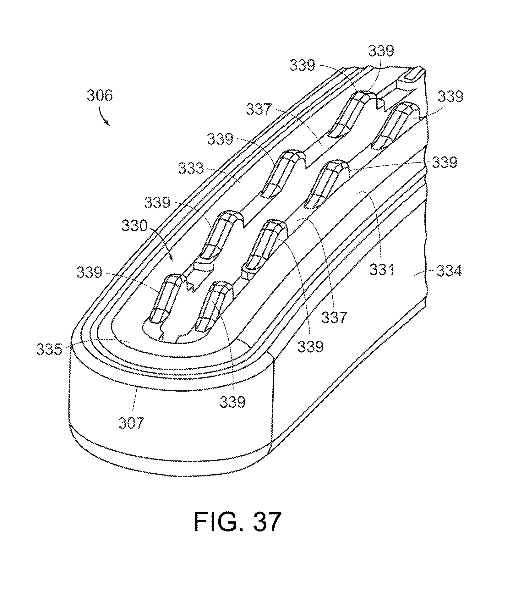
D00028

D00029

D00030

D00031

D00032

D00033

D00034

XML
uspto.report is an independent third-party trademark research tool that is not affiliated, endorsed, or sponsored by the United States Patent and Trademark Office (USPTO) or any other governmental organization. The information provided by uspto.report is based on publicly available data at the time of writing and is intended for informational purposes only.
While we strive to provide accurate and up-to-date information, we do not guarantee the accuracy, completeness, reliability, or suitability of the information displayed on this site. The use of this site is at your own risk. Any reliance you place on such information is therefore strictly at your own risk.
All official trademark data, including owner information, should be verified by visiting the official USPTO website at www.uspto.gov. This site is not intended to replace professional legal advice and should not be used as a substitute for consulting with a legal professional who is knowledgeable about trademark law.