Apparatus and method for differentiating between tissue and mechanical obstruction in a surgical instrument
Sapre
U.S. patent number 10,271,840 [Application Number 14/463,164] was granted by the patent office on 2019-04-30 for apparatus and method for differentiating between tissue and mechanical obstruction in a surgical instrument. This patent grant is currently assigned to Covidien LP. The grantee listed for this patent is Covidien LP. Invention is credited to Parag Sapre.


View All Diagrams
| United States Patent | 10,271,840 |
| Sapre | April 30, 2019 |
Apparatus and method for differentiating between tissue and mechanical obstruction in a surgical instrument
Abstract
A surgical instrument is provided. The surgical instrument includes: a handle assembly; a jaw assembly comprising a staple cartridge containing a plurality of staples and an anvil to form the plurality of staples upon firing; a drive assembly at least partially located within the handle and connected to the jaw assembly and the lockout mechanism; a motor disposed within the handle assembly and operatively coupled to the drive assembly; and a controller operatively coupled to the motor, the controller configured to control supply of electrical current to the motor and to monitor a current draw of the motor, wherein the controller is further configured to terminate the supply of electrical current to the motor in response to a rate of change of the current draw indicative of a mechanical limit of at least one of the jaw assembly, the drive assembly, or the motor.
| Inventors: | Sapre; Parag (Yardley, PA) | ||||||||||
|---|---|---|---|---|---|---|---|---|---|---|---|
| Applicant: |
|
||||||||||
| Assignee: | Covidien LP (Mansfield,
MA) |
||||||||||
| Family ID: | 52668635 | ||||||||||
| Appl. No.: | 14/463,164 | ||||||||||
| Filed: | August 19, 2014 |
Prior Publication Data
| Document Identifier | Publication Date | |
|---|---|---|
| US 20150080912 A1 | Mar 19, 2015 | |
Related U.S. Patent Documents
| Application Number | Filing Date | Patent Number | Issue Date | ||
|---|---|---|---|---|---|
| 61879445 | Sep 18, 2013 | ||||
| Current U.S. Class: | 1/1 |
| Current CPC Class: | A61B 17/068 (20130101); A61B 17/07207 (20130101); A61B 2090/0811 (20160201); A61B 2017/00734 (20130101); A61B 90/03 (20160201); A61B 2017/00398 (20130101); A61B 2017/00017 (20130101); A61B 2017/0046 (20130101); A61B 2017/00137 (20130101); A61B 2090/0803 (20160201); A61B 2090/0804 (20160201); A61B 2017/00115 (20130101); A61B 2017/00473 (20130101) |
| Current International Class: | A61B 17/068 (20060101); A61B 17/072 (20060101); A61B 17/00 (20060101); A61B 90/00 (20160101) |
| Field of Search: | ;227/175.1-182.1 |
References Cited [Referenced By]
U.S. Patent Documents
| 2245994 | June 1941 | McWane |
| 2777340 | January 1957 | Hettwer et al. |
| 2957353 | October 1960 | Babacz |
| 2961808 | November 1960 | Dunigan |
| 3111328 | November 1963 | Di Rito et al. |
| 3695058 | October 1972 | Keith, Jr. |
| 3734515 | May 1973 | Dudek |
| 3759336 | September 1973 | Marcovitz et al. |
| 4072888 | February 1978 | Bechtle |
| 4162399 | July 1979 | Hudson |
| 4606343 | August 1986 | Conta et al. |
| 4705038 | November 1987 | Sjostrom et al. |
| 4722685 | February 1988 | de Estrada et al. |
| 4823807 | April 1989 | Russell et al. |
| 4874181 | October 1989 | Hsu |
| 5129118 | July 1992 | Walmesley |
| 5129570 | July 1992 | Schulze et al. |
| 5152744 | October 1992 | Krause et al. |
| 5301061 | April 1994 | Nakada et al. |
| 5312023 | May 1994 | Green et al. |
| 5326013 | July 1994 | Green et al. |
| 5350355 | September 1994 | Sklar |
| 5383874 | January 1995 | Jackson et al. |
| 5383880 | January 1995 | Hooven |
| 5389098 | February 1995 | Tsuruta et al. |
| 5395033 | March 1995 | Byrne et al. |
| 5400267 | March 1995 | Denen et al. |
| 5411508 | May 1995 | Bessler et al. |
| 5413267 | May 1995 | Solyntjes et al. |
| 5427087 | June 1995 | Ito et al. |
| 5467911 | November 1995 | Tsuruta et al. |
| 5476379 | December 1995 | Disel |
| 5487499 | January 1996 | Sorrentino et al. |
| 5518163 | May 1996 | Hooven |
| 5518164 | May 1996 | Hooven |
| 5526822 | June 1996 | Burbank et al. |
| 5529235 | June 1996 | Boiarski et al. |
| 5530788 | June 1996 | Saijima |
| 5535934 | July 1996 | Boiarski et al. |
| 5535937 | July 1996 | Boiarski et al. |
| 5540375 | July 1996 | Bolanos et al. |
| 5540706 | July 1996 | Aust et al. |
| 5542594 | August 1996 | McKean et al. |
| 5549637 | August 1996 | Crainich |
| 5553675 | September 1996 | Pitzen et al. |
| 5562239 | October 1996 | Boiarski et al. |
| 5564615 | October 1996 | Bishop et al. |
| 5609560 | March 1997 | Ichikawa et al. |
| 5632432 | May 1997 | Schulze et al. |
| 5647526 | July 1997 | Green et al. |
| 5653374 | August 1997 | Young et al. |
| 5658300 | August 1997 | Bito et al. |
| 5667517 | September 1997 | Hooven |
| 5693042 | December 1997 | Boiarski et al. |
| 5704534 | January 1998 | Huitema et al. |
| 5713505 | February 1998 | Huitema |
| 5762603 | June 1998 | Thompson |
| 5779130 | July 1998 | Alesi et al. |
| 5782396 | July 1998 | Mastri et al. |
| 5782397 | July 1998 | Koukline |
| 5797536 | August 1998 | Smith et al. |
| 5820009 | October 1998 | Melling et al. |
| 5863159 | January 1999 | Lasko |
| 5865361 | February 1999 | Milliman et al. |
| 5878607 | March 1999 | Nunes |
| 5908427 | June 1999 | McKean et al. |
| 5954259 | September 1999 | Viola et al. |
| 5964774 | October 1999 | McKean et al. |
| 5993454 | November 1999 | Longo |
| 6010054 | January 2000 | Johnson et al. |
| 6017354 | January 2000 | Culp et al. |
| 6032849 | March 2000 | Mastri et al. |
| 6045560 | April 2000 | McKean et al. |
| 6086544 | July 2000 | Hibner |
| 6090123 | July 2000 | Culp et al. |
| 6126651 | October 2000 | Mayer |
| 6129547 | October 2000 | Cise et al. |
| 6165169 | December 2000 | Panescu et al. |
| 6239732 | May 2001 | Cusey |
| 6241139 | June 2001 | Milliman et al. |
| 6264086 | July 2001 | McGuckin, Jr. |
| 6264087 | July 2001 | Whitman |
| 6302311 | October 2001 | Adams et al. |
| 6315184 | November 2001 | Whitman |
| 6321855 | November 2001 | Barnes |
| 6329778 | December 2001 | Culp et al. |
| 6343731 | February 2002 | Adams et al. |
| 6348061 | February 2002 | Whitman |
| 6368324 | April 2002 | Dinger et al. |
| 6371909 | April 2002 | Hoeg et al. |
| 6434507 | August 2002 | Clayton et al. |
| 6443973 | September 2002 | Whitman |
| 6461372 | October 2002 | Jensen et al. |
| 6488197 | December 2002 | Whitman |
| 6491201 | December 2002 | Whitman |
| 6533157 | March 2003 | Whitman |
| 6537280 | March 2003 | Dinger et al. |
| 6610066 | August 2003 | Dinger et al. |
| 6611793 | August 2003 | Burnside et al. |
| 6645218 | November 2003 | Cassidy et al. |
| 6654999 | December 2003 | Stoddard et al. |
| 6698643 | March 2004 | Whitman |
| 6699177 | March 2004 | Wang et al. |
| 6716233 | April 2004 | Whitman |
| 6743240 | June 2004 | Smith et al. |
| 6783533 | August 2004 | Green et al. |
| 6792390 | September 2004 | Burnside et al. |
| 6793652 | September 2004 | Whitman et al. |
| 6817508 | November 2004 | Racenet et al. |
| 6830174 | December 2004 | Hillstead et al. |
| 6846308 | January 2005 | Whitman et al. |
| 6846309 | January 2005 | Whitman et al. |
| 6849071 | February 2005 | Whitman et al. |
| 6899538 | May 2005 | Matoba |
| 6905057 | June 2005 | Swayze et al. |
| 6959852 | November 2005 | Shelton, IV et al. |
| 6964363 | November 2005 | Wales et al. |
| 6981628 | January 2006 | Wales |
| 6981941 | January 2006 | Whitman et al. |
| 6986451 | January 2006 | Mastri et al. |
| 6988649 | January 2006 | Shelton, IV et al. |
| 7032798 | April 2006 | Whitman et al. |
| RE39152 | June 2006 | Aust et al. |
| 7055731 | June 2006 | Shelton, IV et al. |
| 7059508 | June 2006 | Shelton, IV et al. |
| 7077856 | July 2006 | Whitman |
| 7091683 | August 2006 | Smith et al. |
| 7111769 | September 2006 | Wales et al. |
| 7122029 | October 2006 | Koop et al. |
| 7140528 | November 2006 | Shelton, IV |
| 7143923 | December 2006 | Shelton, IV et al. |
| 7143925 | December 2006 | Shelton, IV et al. |
| 7143926 | December 2006 | Shelton, IV et al. |
| 7147138 | December 2006 | Shelton, IV |
| 7172104 | February 2007 | Scirica et al. |
| 7225964 | June 2007 | Mastri et al. |
| 7238021 | July 2007 | Johnson |
| 7246734 | July 2007 | Shelton, IV |
| 7328828 | February 2008 | Ortiz et al. |
| 7364061 | April 2008 | Swayze et al. |
| 7380695 | June 2008 | Doll et al. |
| 7380696 | June 2008 | Shelton, IV et al. |
| 7404508 | July 2008 | Smith et al. |
| 7407078 | August 2008 | Shelton, IV et al. |
| 7416101 | August 2008 | Shelton, IV et al. |
| 7419080 | September 2008 | Smith et al. |
| 7422139 | September 2008 | Shelton, IV et al. |
| 7431189 | October 2008 | Shelton, IV et al. |
| 7441684 | October 2008 | Shelton, IV et al. |
| 7448525 | November 2008 | Shelton, IV et al. |
| 7464846 | December 2008 | Shelton, IV et al. |
| 7464847 | December 2008 | Viola et al. |
| 7464849 | December 2008 | Shelton, IV et al. |
| 7481347 | January 2009 | Roy |
| 7481824 | January 2009 | Boudreaux et al. |
| 7487899 | February 2009 | Shelton, IV et al. |
| 7549564 | June 2009 | Boudreaux |
| 7565993 | July 2009 | Milliman et al. |
| 7568603 | August 2009 | Shelton, IV et al. |
| 7575144 | August 2009 | Ortiz et al. |
| 7588175 | September 2009 | Timm et al. |
| 7588176 | September 2009 | Timm et al. |
| 7637409 | December 2009 | Marczyk |
| 7641093 | January 2010 | Doll et al. |
| 7644848 | January 2010 | Swayze et al. |
| 7670334 | March 2010 | Hueil et al. |
| 7673780 | March 2010 | Shelton, IV et al. |
| 7699835 | April 2010 | Lee et al. |
| 7721931 | May 2010 | Shelton, IV et al. |
| 7738971 | June 2010 | Swayze et al. |
| 7740159 | June 2010 | Shelton, IV et al. |
| 7743960 | June 2010 | Whitman et al. |
| 7758613 | July 2010 | Whitman |
| 7766210 | August 2010 | Shelton, IV et al. |
| 7770773 | August 2010 | Whitman et al. |
| 7770775 | August 2010 | Shelton, IV et al. |
| 7793812 | September 2010 | Moore et al. |
| 7799039 | September 2010 | Shelton, IV et al. |
| 7802712 | September 2010 | Milliman et al. |
| 7803151 | September 2010 | Whitman |
| 7822458 | October 2010 | Webster et al. |
| 7845534 | December 2010 | Viola et al. |
| 7845537 | December 2010 | Shelton, IV et al. |
| 7857185 | December 2010 | Swayze et al. |
| 7870989 | January 2011 | Viola et al. |
| 7905897 | March 2011 | Whitman et al. |
| 7918230 | April 2011 | Whitman et al. |
| 7922061 | April 2011 | Shelton, IV et al. |
| 7922719 | April 2011 | Ralph et al. |
| 7947034 | May 2011 | Whitman |
| 7951071 | May 2011 | Whitman et al. |
| 7954682 | June 2011 | Giordano et al. |
| 7959051 | June 2011 | Smith et al. |
| 7963433 | June 2011 | Whitman et al. |
| 7967178 | June 2011 | Scirica et al. |
| 7967179 | June 2011 | Olson et al. |
| 7992758 | August 2011 | Whitman et al. |
| 8016178 | September 2011 | Olson et al. |
| 8016855 | September 2011 | Whitman et al. |
| 8020743 | September 2011 | Shelton, IV |
| 8025199 | September 2011 | Whitman et al. |
| 8035487 | October 2011 | Malackowski |
| 8052024 | November 2011 | Viola et al. |
| 8056787 | November 2011 | Boudreaux et al. |
| 8114118 | February 2012 | Knodel et al. |
| 8132705 | March 2012 | Viola et al. |
| 8152516 | April 2012 | Harvey et al. |
| 8157150 | April 2012 | Viola et al. |
| 8157151 | April 2012 | Ingmanson et al. |
| 8182494 | May 2012 | Yencho et al. |
| 8186555 | May 2012 | Shelton, IV et al. |
| 8186587 | May 2012 | Zmood et al. |
| 8220367 | July 2012 | Hsu |
| 8235273 | August 2012 | Olson et al. |
| 8241322 | August 2012 | Whitman et al. |
| 8272554 | September 2012 | Whitman et al. |
| 8281681 | October 2012 | Kimura |
| 8292150 | October 2012 | Bryant |
| 8292888 | October 2012 | Whitman |
| 8303581 | November 2012 | Arts et al. |
| 8342379 | January 2013 | Whitman et al. |
| 8348855 | January 2013 | Hillely et al. |
| 8353440 | January 2013 | Whitman et al. |
| 8357144 | January 2013 | Whitman et al. |
| 8365633 | February 2013 | Simaan et al. |
| 8365972 | February 2013 | Aranyi et al. |
| 8371492 | February 2013 | Aranyi et al. |
| 8372057 | February 2013 | Cude et al. |
| 8391957 | March 2013 | Carlson et al. |
| 8424739 | April 2013 | Racenet et al. |
| 8454585 | June 2013 | Whitman |
| 8505802 | August 2013 | Viola et al. |
| 8517241 | August 2013 | Nicholas et al. |
| 8551076 | October 2013 | Duval et al. |
| 8561871 | October 2013 | Rajappa et al. |
| 8623000 | January 2014 | Humayun et al. |
| 8632463 | January 2014 | Drinan et al. |
| 8647258 | February 2014 | Aranyi et al. |
| 8657174 | February 2014 | Yates et al. |
| 8657177 | February 2014 | Scirica et al. |
| 8672206 | March 2014 | Aranyi et al. |
| 8684253 | April 2014 | Giordano |
| 8696552 | April 2014 | Whitman |
| 8708213 | April 2014 | Shelton, IV et al. |
| 8752749 | June 2014 | Moore et al. |
| 8758391 | June 2014 | Swayze et al. |
| 8806973 | August 2014 | Ross et al. |
| 8851355 | October 2014 | Aranyi et al. |
| 8858571 | October 2014 | Shelton, IV et al. |
| 8875972 | November 2014 | Weisenburgh, II et al. |
| 8893946 | November 2014 | Boudreaux et al. |
| 8899462 | December 2014 | Kostrzewski et al. |
| 8939344 | January 2015 | Olson et al. |
| 8960519 | February 2015 | Whitman et al. |
| 8961396 | February 2015 | Azarbarzin et al. |
| 8967443 | March 2015 | McCuen |
| 8968276 | March 2015 | Zemlok et al. |
| 8968337 | March 2015 | Whitfield et al. |
| 8992422 | March 2015 | Spivey et al. |
| 9064653 | June 2015 | Prest et al. |
| 9113875 | August 2015 | Viola et al. |
| 9216013 | December 2015 | Scirica et al. |
| 9282961 | March 2016 | Whitman et al. |
| 9282963 | March 2016 | Bryant |
| 9295522 | March 2016 | Kostrzewski |
| 9307986 | April 2016 | Hall et al. |
| 2001/0031975 | October 2001 | Whitman et al. |
| 2002/0049454 | April 2002 | Whitman et al. |
| 2002/0165541 | November 2002 | Whitman |
| 2003/0038938 | February 2003 | Jung et al. |
| 2003/0066858 | April 2003 | Holgersson |
| 2003/0165794 | September 2003 | Matoba |
| 2004/0111012 | June 2004 | Whitman |
| 2004/0133189 | July 2004 | Sakurai |
| 2004/0176751 | September 2004 | Weitzner et al. |
| 2004/0193146 | September 2004 | Lee et al. |
| 2005/0055795 | March 2005 | Zeiler |
| 2005/0131442 | June 2005 | Yachia et al. |
| 2006/0142656 | June 2006 | Malackowski et al. |
| 2006/0142740 | June 2006 | Sherman et al. |
| 2006/0142744 | June 2006 | Boutoussov |
| 2006/0259073 | November 2006 | Miyamoto et al. |
| 2006/0273135 | December 2006 | Beetel |
| 2006/0278680 | December 2006 | Viola et al. |
| 2007/0023476 | February 2007 | Whitman et al. |
| 2007/0023477 | February 2007 | Whitman et al. |
| 2007/0029363 | February 2007 | Popov |
| 2007/0049435 | March 2007 | Jinno et al. |
| 2007/0055219 | March 2007 | Whitman et al. |
| 2007/0084897 | April 2007 | Shelton et al. |
| 2007/0102472 | May 2007 | Shelton |
| 2007/0152014 | July 2007 | Gillum et al. |
| 2007/0175947 | August 2007 | Ortiz et al. |
| 2007/0175949 | August 2007 | Shelton et al. |
| 2007/0175950 | August 2007 | Shelton et al. |
| 2007/0175951 | August 2007 | Shelton et al. |
| 2007/0175955 | August 2007 | Shelton et al. |
| 2007/0175961 | August 2007 | Shelton et al. |
| 2007/0270790 | November 2007 | Smith |
| 2008/0029570 | February 2008 | Shelton et al. |
| 2008/0029573 | February 2008 | Shelton et al. |
| 2008/0029574 | February 2008 | Shelton et al. |
| 2008/0029575 | February 2008 | Shelton et al. |
| 2008/0058801 | March 2008 | Taylor et al. |
| 2008/0109012 | May 2008 | Falco et al. |
| 2008/0110958 | May 2008 | McKenna et al. |
| 2008/0167644 | July 2008 | Shelton |
| 2008/0167670 | July 2008 | Shelton et al. |
| 2008/0167671 | July 2008 | Giordano |
| 2008/0167736 | July 2008 | Swayze |
| 2008/0185419 | August 2008 | Smith et al. |
| 2008/0188841 | August 2008 | Tomasello et al. |
| 2008/0197167 | August 2008 | Viola et al. |
| 2008/0208195 | August 2008 | Shores et al. |
| 2008/0237296 | October 2008 | Boudreaux et al. |
| 2008/0251561 | October 2008 | Eades et al. |
| 2008/0255413 | October 2008 | Zemlok et al. |
| 2008/0255607 | October 2008 | Zemlok |
| 2008/0262654 | October 2008 | Omori et al. |
| 2008/0308603 | December 2008 | Shelton et al. |
| 2009/0090763 | April 2009 | Zemlok et al. |
| 2009/0099876 | April 2009 | Whitman |
| 2009/0138006 | May 2009 | Bales et al. |
| 2009/0171147 | July 2009 | Lee et al. |
| 2009/0182193 | July 2009 | Whitman et al. |
| 2009/0206136 | August 2009 | Moore |
| 2009/0209990 | August 2009 | Yates et al. |
| 2009/0254094 | October 2009 | Knapp et al. |
| 2010/0069942 | March 2010 | Shelton, IV |
| 2010/0089970 | April 2010 | Smith |
| 2010/0117580 | May 2010 | Miwa |
| 2010/0193568 | August 2010 | Scheib et al. |
| 2010/0211053 | August 2010 | Ross et al. |
| 2010/0225073 | September 2010 | Porter et al. |
| 2010/0294829 | November 2010 | Giordano |
| 2011/0006101 | January 2011 | Hall et al. |
| 2011/0017801 | January 2011 | Zemlok et al. |
| 2011/0071508 | March 2011 | Duval et al. |
| 2011/0077673 | March 2011 | Grubac et al. |
| 2011/0121049 | May 2011 | Malinouskas et al. |
| 2011/0125138 | May 2011 | Malinouskas et al. |
| 2011/0139851 | June 2011 | McCuen |
| 2011/0155783 | June 2011 | Rajappa et al. |
| 2011/0155786 | June 2011 | Shelton, IV |
| 2011/0172648 | July 2011 | Jeong |
| 2011/0174099 | July 2011 | Ross et al. |
| 2011/0204119 | August 2011 | McCuen |
| 2011/0218522 | September 2011 | Whitman |
| 2011/0253765 | October 2011 | Nicholas et al. |
| 2011/0276057 | November 2011 | Conlon et al. |
| 2011/0290854 | December 2011 | Timm et al. |
| 2011/0290855 | December 2011 | Moore et al. |
| 2011/0295242 | December 2011 | Spivey et al. |
| 2011/0295269 | December 2011 | Swensgard et al. |
| 2011/0297729 | December 2011 | Whitman |
| 2012/0000962 | January 2012 | Racenet et al. |
| 2012/0055972 | March 2012 | Marczyk |
| 2012/0074199 | March 2012 | Olson et al. |
| 2012/0089131 | April 2012 | Zemlok et al. |
| 2012/0104071 | May 2012 | Bryant |
| 2012/0116368 | May 2012 | Viola |
| 2012/0143002 | June 2012 | Aranyi et al. |
| 2012/0172924 | July 2012 | Allen, IV |
| 2012/0223121 | September 2012 | Viola et al. |
| 2012/0223122 | September 2012 | Roy |
| 2012/0245428 | September 2012 | Smith et al. |
| 2012/0253329 | October 2012 | Zemlok et al. |
| 2012/0310220 | December 2012 | Malkowski et al. |
| 2012/0323226 | December 2012 | Chowaniec et al. |
| 2012/0330285 | December 2012 | Hartoumbekis et al. |
| 2013/0018361 | January 2013 | Bryant |
| 2013/0093149 | April 2013 | Saur et al. |
| 2013/0098966 | April 2013 | Kostrzewski et al. |
| 2013/0098968 | April 2013 | Aranyi et al. |
| 2013/0098969 | April 2013 | Scirica et al. |
| 2013/0105189 | May 2013 | Murthy |
| 2013/0168431 | July 2013 | Zemlok |
| 2013/0181035 | July 2013 | Milliman |
| 2013/0184704 | July 2013 | Beardsley et al. |
| 2013/0214025 | August 2013 | Zemlok et al. |
| 2013/0240596 | September 2013 | Whitman |
| 2013/0274722 | October 2013 | Kostrzewski et al. |
| 2013/0282052 | October 2013 | Aranyi et al. |
| 2013/0292451 | November 2013 | Viola et al. |
| 2013/0313304 | November 2013 | Shelton, IV et al. |
| 2013/0317486 | November 2013 | Nicholas et al. |
| 2013/0319706 | December 2013 | Nicholas et al. |
| 2013/0324978 | December 2013 | Nicholas et al. |
| 2013/0324979 | December 2013 | Nicholas et al. |
| 2013/0334281 | December 2013 | Williams |
| 2014/0012236 | January 2014 | Williams et al. |
| 2014/0012237 | January 2014 | Pribanic et al. |
| 2014/0012289 | January 2014 | Snow et al. |
| 2014/0025046 | January 2014 | Williams et al. |
| 2014/0107697 | April 2014 | Patani |
| 2014/0110455 | April 2014 | Ingmanson et al. |
| 2014/0144970 | May 2014 | Aranyi et al. |
| 2014/0207125 | July 2014 | Applegate et al. |
| 2014/0207182 | July 2014 | Zergiebel et al. |
| 2014/0207185 | July 2014 | Goble et al. |
| 2014/0236173 | August 2014 | Scirica et al. |
| 2014/0236174 | August 2014 | Williams et al. |
| 2014/0275872 | September 2014 | Merritt |
| 2014/0276932 | September 2014 | Williams et al. |
| 2014/0299647 | October 2014 | Scirica et al. |
| 2014/0303668 | October 2014 | Nicholas et al. |
| 2014/0358129 | December 2014 | Zergiebel et al. |
| 2014/0361068 | December 2014 | Aranyi et al. |
| 2014/0373652 | December 2014 | Zergiebel et al. |
| 2015/0048144 | February 2015 | Whitman |
| 2015/0076205 | March 2015 | Zergiebel |
| 2015/0076206 | March 2015 | Sapre |
| 2015/0080912 | March 2015 | Sapre |
| 2015/0157321 | June 2015 | Zergiebel et al. |
| 2015/0164502 | June 2015 | Richard et al. |
| 2015/0272577 | October 2015 | Zemlok et al. |
| 2015/0272583 | October 2015 | Leimbach |
| 2015/0297199 | October 2015 | Nicholas et al. |
| 2015/0303996 | October 2015 | Calderoni |
| 2015/0320420 | November 2015 | Penna et al. |
| 2015/0327850 | November 2015 | Kostrzewski |
| 2015/0342601 | December 2015 | Williams et al. |
| 2015/0342603 | December 2015 | Zergiebel et al. |
| 2015/0374366 | December 2015 | Zergiebel et al. |
| 2015/0374370 | December 2015 | Zergiebel et al. |
| 2015/0374371 | December 2015 | Richard et al. |
| 2015/0374372 | December 2015 | Zergiebel et al. |
| 2015/0374449 | December 2015 | Chowaniec et al. |
| 2015/0380187 | December 2015 | Zergiebel et al. |
| 2016/0095585 | April 2016 | Zergiebel et al. |
| 2016/0095596 | April 2016 | Scirica et al. |
| 2016/0106406 | April 2016 | Cabrera et al. |
| 2016/0113648 | April 2016 | Zergiebel et al. |
| 2016/0113649 | April 2016 | Zergiebel et al. |
| 2008229795 | Apr 2009 | AU | |||
| 2451558 | Jan 2003 | CA | |||
| 101234033 | Aug 2008 | CN | |||
| 101856251 | Oct 2010 | CN | |||
| 102028509 | Apr 2011 | CN | |||
| 102247182 | Nov 2011 | CN | |||
| 102008053842 | May 2010 | DE | |||
| 0634144 | Jan 1995 | EP | |||
| 0648476 | Apr 1995 | EP | |||
| 0686374 | Dec 1995 | EP | |||
| 0705571 | Apr 1996 | EP | |||
| 1690502 | Aug 2006 | EP | |||
| 1723913 | Nov 2006 | EP | |||
| 1736112 | Dec 2006 | EP | |||
| 1759652 | Mar 2007 | EP | |||
| 1769754 | Apr 2007 | EP | |||
| 1772105 | Apr 2007 | EP | |||
| 1 813 203 | Aug 2007 | EP | |||
| 1813199 | Aug 2007 | EP | |||
| 1813211 | Aug 2007 | EP | |||
| 1908412 | Apr 2008 | EP | |||
| 1917929 | May 2008 | EP | |||
| 1943954 | Jul 2008 | EP | |||
| 1943956 | Jul 2008 | EP | |||
| 1943958 | Jul 2008 | EP | |||
| 1943976 | Jul 2008 | EP | |||
| 1952769 | Aug 2008 | EP | |||
| 2005898 | Dec 2008 | EP | |||
| 2027819 | Feb 2009 | EP | |||
| 2044890 | Apr 2009 | EP | |||
| 2055243 | May 2009 | EP | |||
| 2090247 | Aug 2009 | EP | |||
| 2098170 | Sep 2009 | EP | |||
| 2100561 | Sep 2009 | EP | |||
| 2100562 | Sep 2009 | EP | |||
| 2165664 | Mar 2010 | EP | |||
| 2236098 | Oct 2010 | EP | |||
| 2245994 | Nov 2010 | EP | |||
| 2263568 | Dec 2010 | EP | |||
| 2272443 | Jan 2011 | EP | |||
| 2316345 | May 2011 | EP | |||
| 2324776 | May 2011 | EP | |||
| 2329773 | Jun 2011 | EP | |||
| 2333509 | Jun 2011 | EP | |||
| 2377472 | Oct 2011 | EP | |||
| 2462878 | Jun 2012 | EP | |||
| 2462880 | Jun 2012 | EP | |||
| 2491872 | Aug 2012 | EP | |||
| 2586382 | May 2013 | EP | |||
| 2606834 | Jun 2013 | EP | |||
| 2668910 | Dec 2013 | EP | |||
| 2676615 | Dec 2013 | EP | |||
| 2815705 | Dec 2014 | EP | |||
| 2333509 | Feb 2010 | ES | |||
| 2861574 | May 2005 | FR | |||
| H0347249 | Feb 1991 | JP | |||
| 08-038488 | Feb 1996 | JP | |||
| 2005-125075 | May 2005 | JP | |||
| 2010253272 | Nov 2010 | JP | |||
| 2011078772 | Apr 2011 | JP | |||
| 2011224368 | Nov 2011 | JP | |||
| 20120022521 | Mar 2012 | KR | |||
| 99/15086 | Apr 1999 | WO | |||
| 2000/072760 | Dec 2000 | WO | |||
| 2000/072765 | Dec 2000 | WO | |||
| 2003/000138 | Jan 2003 | WO | |||
| 2003/026511 | Apr 2003 | WO | |||
| 2003/030743 | Apr 2003 | WO | |||
| 2003065916 | Aug 2003 | WO | |||
| 2003/077769 | Sep 2003 | WO | |||
| 2003090630 | Nov 2003 | WO | |||
| 2004/107989 | Dec 2004 | WO | |||
| 2006/042210 | Apr 2006 | WO | |||
| 2007016290 | Feb 2007 | WO | |||
| 2007/026354 | Mar 2007 | WO | |||
| 2007137304 | Nov 2007 | WO | |||
| 2008/131362 | Oct 2008 | WO | |||
| 2008/133956 | Nov 2008 | WO | |||
| 2009039506 | Mar 2009 | WO | |||
| 2007014355 | Apr 2009 | WO | |||
| 2009/132359 | Oct 2009 | WO | |||
| 2009/143092 | Nov 2009 | WO | |||
| 2009149234 | Dec 2009 | WO | |||
| 2011/108840 | Sep 2011 | WO | |||
| 2012040984 | Apr 2012 | WO | |||
Other References
|
Chinese Office Action dated Oct. 24, 2017 in corresponding Chinese Patent Application No. 201410479971.9 together with English translation, 12 pages. cited by applicant . Extended European Search Report corresponding to International Application No. EP 15 15 1076.5 dated Apr. 22, 2015. cited by applicant . Japanese Office Action corresponding to International Application No. JP 2011-084092 dated Jan. 14, 2016. cited by applicant . Extended European Search Report corresponding to International Application No. EP 12 19 7970.2 dated Jan. 28, 2016. cited by applicant . Chinese Office Action corresponding to International Application No. CN 201210560638.1 dated Oct. 21, 2015. cited by applicant . European Office Action corresponding to International Application No. EP 14 15 9056.2 dated Oct. 26, 2015. cited by applicant . Australian Examination Report No. 1 corresponding to International Application No. AU 2015200153 dated Dec. 11, 2015. cited by applicant . Australian Examination Report No. 1 corresponding to International Application No. AU 2014204542 dated Jan. 7, 2016. cited by applicant . Chinese Office Action corresponding to International Application No. CN 201310125449.6 dated Feb. 3, 2016. cited by applicant . Extended European Search Report corresponding to International Application No. EP 15 19 0245.9 dated Jan. 28, 2016. cited by applicant . Extended European Search Report corresponding to International Application No. EP 15 16 7793.7 dated Apr. 5, 2016. cited by applicant . European Office Action corresponding to International Application No. EP 14 18 4882.0 dated Apr. 25, 2016. cited by applicant . Extended European Search Report corresponding to International Application No. EP 14 19 6704.2 dated Sep. 24, 2015. cited by applicant . International Search Report and Written Opinion corresponding to Int'l Appln. No. PCT/US2015/051837, dated Dec. 21, 2015. cited by applicant . Extended European Search Report corresponding to International Application No. EP 14 19 7563.1 dated Aug. 5, 2015. cited by applicant . Partial European Search Report corresponding to International Application No. EP 15 19 0643.5 dated Feb. 26, 2016. cited by applicant . Extended European Search Report corresponding to International Application No. EP 15 16 6899.3 dated Feb. 3, 2016. cited by applicant . Extended European Search Report corresponding to International Application No. EP 14 19 9783.3 dated Dec. 22, 2015. cited by applicant . Extended European Search Report corresponding to International Application No. EP 15 17 3807.7 dated Nov. 24, 2015. cited by applicant . Extended European Search Report corresponding to International Application No. EP 15 19 0760.7 dated Apr. 1, 2016. cited by applicant . Extended European Search Report corresponding to International Application No. EP 15 17 3803.6 dated Nov. 24, 2015. cited by applicant . Extended European Search Report corresponding to International Application No. EP 15 17 3804.4 dated Nov. 24, 2015. cited by applicant . Extended European Search Report corresponding to International Application No. EP 15 18 8539.9 dated Feb. 17, 2016. cited by applicant . Extended European Search Report corresponding to International Application No. EP 15 17 3910.9 dated Nov. 13, 2015. cited by applicant . European Office Action corresponding to International Application No. EP 14 15 2236.7 dated Aug. 11, 2015. cited by applicant . Extended European Search Report corresponding to International Application No. EP 15 18 4915.5 dated Jan. 5, 2016. cited by applicant . European Search Report No. 14185097.4 dated Jan. 27, 2015. cited by applicant . European Search Report No. 13189650.8 dated Sep. 10, 2014. cited by applicant . Australian Examination Report dated May 14, 2018 in corresponding Australian Patent Application No. 2014218361. cited by applicant . Japanese Office Action dated May 17, 2018 in corresponding Japanese Patent Application No. 2014-187528, together with English translation. cited by applicant . Chinese Office Action dated Jun. 20, 2018 in corresponding Chinese Patent Application No. 201410479971.9 with English translation. cited by applicant . Australian Examination Report dated Apr. 26, 2018 in corresponding Australian Patent Application No. 2014218366. cited by applicant. |
Primary Examiner: Long; Robert
Parent Case Text
CROSS-REFERENCE TO RELATED APPLICATION
The present application claims the benefit of and priority to a U.S. Provisional Patent Application Ser. No. 61/879,445, filed on Sep. 18, 2013, the entire contents of which are incorporated by reference herein.
Claims
What is claimed is:
1. A method for controlling a surgical instrument comprising: monitoring a current draw of a motor coupled to a drive assembly for actuating a jaw assembly of the surgical instrument; calculating a plurality of rate of change values based on a plurality of samples of the current draw; and continuously determining whether the motor has reached a mechanical limit based on whether the plurality of rate of change values are within a first range and whether the current draw of the motor is stable based on the plurality of rate of change values being within a second range, wherein the first range corresponds to the motor reaching the mechanical limit and the second range corresponds to stable operation of the motor.
2. The method according to claim 1, further comprising: determining whether the current draw of the motor is unstable based on the plurality of rate of change values being within a third range.
3. The method according to claim 2, further comprising: storing a stability counter of rate of change values calculated as being within the second range; and determining whether operation of the motor is stable when the stability counter is above a predetermined stability threshold.
4. The method according to claim 3, wherein the first range is within the second range and the third range is higher than the second range.
5. The method according to claim 3, further comprising: storing an event counter of rate of change values within the third range; and determining whether the motor is unstable when the event counter is above a predetermined event threshold.
6. The method according to claim 1, further comprising: controlling the current draw of the motor for actuating the jaw assembly of the surgical instrument.
7. The method according to claim 6, wherein controlling includes reducing the current draw of the motor based on a determination that the motor has reached a mechanical limit.
Description
BACKGROUND
1. Technical Field
The present disclosure relates to surgical apparatuses, devices and/or systems for performing endoscopic surgical procedures and methods of use thereof. More specifically, the present disclosure relates to electromechanical, hand-held surgical apparatus, devices and/or systems configured for use with removable disposable end effectors and/or single use end effectors for clamping, cutting and/or stapling tissue.
2. Background of the Related Art
A number of surgical device manufacturers have developed product lines with proprietary drive systems for operating and/or manipulating electromechanical surgical devices. In many instances the electromechanical surgical devices include a reusable handle assembly, and disposable or single use end effectors. The end effectors are selectively connected to the handle assembly prior to use and then disconnected from the handle assembly following use in order to be disposed of or in some instances sterilized for re-use.
Many of these electromechanical surgical devices include complex drive components that utilize a variety of user interfaces that accept user inputs (e.g., controls) for controlling the devices as well as provide feedback to the user. To prevent actuation of drive mechanisms beyond mechanical limits, various switches and sensors are used to detect operational state of the surgical devices. Inclusion of multiple switches and/or sensors in the devices as well as end effectors presents various problems. In addition, cost or other considerations prevent the use of such devices. Accordingly, there is a need for systems and apparatuses having safety mechanisms that can detect mechanical limits without relying on multiple mechanical limit sensors and/or switches disposed throughout the surgical device.
SUMMARY
According to one embodiment of the present disclosure a surgical instrument is provided. The surgical instrument includes: a handle assembly; a jaw assembly including a staple cartridge containing a plurality of staples and an anvil to form the plurality of staples upon firing; a drive assembly at least partially located within the handle and connected to the jaw assembly and the lockout mechanism; a motor disposed within the handle assembly and operatively coupled to the drive assembly; and a controller operatively coupled to the motor, the controller configured to control supply of electrical current to the motor and to monitor a current draw of the motor, wherein the controller is further configured to terminate the supply of electrical current to the motor in response to a rate of change of the current draw indicative of a mechanical limit of at least one of the jaw assembly, the drive assembly, or the motor.
According to one aspect of the above embodiment, the controller is further configured to determine if motor current is unstable by determining whether the rate of change of the current draw is outside a first range.
According to one aspect of the above embodiment, the controller is further configured to determine if motor current is stable by determining whether the rate of change of the current draw is within a second range, wherein the second range is within the first range.
According to one aspect of the above embodiment, the controller is further configured to store a stability counter of current draw samples within the second range.
According to one aspect of the above embodiment, the controller determines whether motor current is stable if the stability counter is above a predetermined stability threshold.
According to one aspect of the above embodiment, the controller is further configured to determine if the motor reached the mechanical limit by determining whether the motor current is stable and the rate of change of the current draw is within a third range.
According to one aspect of the above embodiment, the third range is within the first range and is higher than the second range.
According to one aspect of the above embodiment, the controller is further configured to store an event counter of current draw samples within the third range.
According to one aspect of the above embodiment, the controller determines whether the motor reached the mechanical limit if the event counter is above a predetermined event threshold.
According to another embodiment of the present disclosure a surgical instrument is provided. The surgical instrument includes: a handle assembly; a jaw assembly including a staple cartridge containing a plurality of staples and an anvil to form the plurality of staples upon firing; a drive assembly at least partially located within the handle and connected to the jaw assembly and the lockout mechanism; a motor disposed within the handle assembly and operatively coupled to the drive assembly; and a controller operatively coupled to the motor, the controller to determine whether the motor has reached a mechanical limit based on a rate of change of a current draw by the motor indicative of the mechanical limit.
According to one aspect of the above embodiment, the controller is further configured to determine whether motor current is unstable by determining whether the rate of change of the current draw is outside a first range.
According to one aspect of the above embodiment, the controller is further configured to determine whether motor current is stable by determining whether a plurality of samples of the rate of change of the current draw are within a second range.
According to one aspect of the above embodiment, the controller is further configured to store a stability counter of current draw samples within the second range.
According to one aspect of the above embodiment, the controller determines whether motor current is stable if the stability counter is above a predetermined stability threshold.
According to one aspect of the above embodiment, the controller is further configured to determine whether the motor reached the mechanical limit by determining whether the motor current is stable and a plurality of samples of the rate of change of the current draw are within a third range.
According to one aspect of the above embodiment, the second and third ranges are within the first range and the third range is higher than the second range.
According to one aspect of the above embodiment, the controller is further configured to store an event counter of current draw samples within the third range.
According to one aspect of the above embodiment, the controller determines whether the motor reached the mechanical limit if the event counter is above a predetermined event threshold.
According to a further embodiment of the present disclosure a method for controlling a surgical instrument is provided. The method includes: monitoring a current draw of a motor coupled to a drive assembly for actuating a jaw assembly; calculating a rate of change of the current draw; and determining whether the motor has reached a mechanical limit based on the rate of change of the current draw by the motor.
According to one aspect of the above embodiment, the method further includes determining whether the rate of change of the current draw is outside a first range to determine whether motor current is unstable.
According to one aspect of the above embodiment, the method further includes determining whether a plurality of samples of the rate of change of the current draw are within a second range to determine whether motor current is stable.
According to one aspect of the above embodiment, the method further includes: storing a stability counter of current draw samples within the second range; and determining whether motor current is stable if the stability counter is above a predetermined stability threshold.
According to one aspect of the above embodiment, the method further includes: whether the motor current is stable and a plurality of samples of the rate of change of the current draw are within a third range to determine whether the motor reached the mechanical limit by.
According to one aspect of the above embodiment, the second and third ranges are within the first range and the third range is higher than the second range.
According to one aspect of the above embodiment, the method further includes: storing an event counter of current draw samples within the third range; and determining whether the motor reached the mechanical limit if the event counter is above a predetermined event threshold.
DESCRIPTION OF THE DRAWINGS
Embodiments of the present disclosure are described herein with reference to the accompanying drawings, wherein:
FIG. 1 is a perspective, disassembled view of an electromechanical surgical system including a surgical instrument, an adapter, and an end effector, according to the present disclosure;
FIG. 2 is a perspective view of the surgical instrument of FIG. 1, according to the present disclosure;
FIG. 3 is perspective, exploded view of the surgical instrument of FIG. 1, according to the present disclosure;
FIG. 4 is a perspective view of a battery of the surgical instrument of FIG. 1, according to the present disclosure;
FIG. 5 is a top, partially-disassembled view of the surgical instrument of FIG. 1, according to the present disclosure;
FIG. 6 is a front, perspective view of the surgical instrument of FIG. 1 with the adapter separated therefrom, according to the present disclosure;
FIG. 7 is a side, cross-sectional view of the surgical instrument of FIG. 1, as taken through 7-7 of FIG. 2, according to the present disclosure;
FIG. 8 is a top, cross-sectional view of the surgical instrument of FIG. 1, as taken through 8-8 of FIG. 2, according to the present disclosure;
FIG. 9 is a perspective, exploded view of a end effector of FIG. 1, according to the present disclosure;
FIG. 10 is a schematic diagram of the surgical instrument of FIG. 1 according to the present disclosure;
FIG. 11 is a schematic diagram of motor current values stored in memory of the surgical instrument of FIG. 1 according to the present disclosure;
FIG. 12 is a flow chart of a method for controlling the surgical instrument of FIG. 1 according to the present disclosure;
FIGS. 13-15 are plots of motor current of the surgical instrument as controlled by the method of the present disclosure; and
FIG. 16 is a flow chart of a method for controlling the surgical instrument of FIG. 1 according to another embodiment of the present disclosure.
DETAILED DESCRIPTION
A surgical system, in accordance with an embodiment of the present disclosure, is generally designated as 10, and is in the form of a powered hand held electromechanical instrument configured for selective attachment thereto of a plurality of different end effectors that are each configured for actuation and manipulation by the powered hand held electromechanical surgical instrument.
As illustrated in FIG. 1, surgical instrument 100 is configured for selective connection with an adapter 200, and, in turn, adapter 200 is configured for selective connection with an end effector or single use loading unit 300.
As illustrated in FIGS. 1-3, surgical instrument 100 includes a handle housing 102 having a lower housing portion 104, an intermediate housing portion 106 extending from and/or supported on lower housing portion 104, and an upper housing portion 108 extending from and/or supported on intermediate housing portion 106. Intermediate housing portion 106 and upper housing portion 108 are separated into a distal half-section 110a that is integrally formed with and extending from the lower portion 104, and a proximal half-section 110b connectable to distal half-section 110a by a plurality of fasteners. When joined, distal and proximal half-sections 110a, 110b define a handle housing 102 having a cavity 102a therein in which a circuit board 150 and a drive mechanism 160 is situated.
Distal and proximal half-sections 110a, 110b are divided along a plane that traverses a longitudinal axis "X" of upper housing portion 108, as seen in FIGS. 2 and 3. Handle housing 102 includes a gasket 112 extending completely around a rim of distal half-section and/or proximal half-section 110a, 110b and being interposed between distal half-section 110a and proximal half-section 110b. Gasket 112 seals the perimeter of distal half-section 110a and proximal half-section 110b. Gasket 112 functions to establish an air-tight seal between distal half-section 110a and proximal half-section 110b such that circuit board 150 and drive mechanism 160 are protected from sterilization and/or cleaning procedures.
In this manner, the cavity 102a of handle housing 102 is sealed along the perimeter of distal half-section 110a and proximal half-section 110b yet is configured to enable easier, more efficient assembly of circuit board 150 and a drive mechanism 160 in handle housing 102.
Intermediate housing portion 106 of handle housing 102 provides a housing in which circuit board 150 is situated. Circuit board 150 is configured to control the various operations of surgical instrument 100, as will be set forth in additional detail below.
Lower housing portion 104 of surgical instrument 100 defines an aperture (not shown) formed in an upper surface thereof and which is located beneath or within intermediate housing portion 106. The aperture of lower housing portion 104 provides a passage through which wires 152 pass to electrically interconnect electrical components (a battery 156, as illustrated in FIG. 4, a circuit board 154, as illustrated in FIG. 3, etc.) situated in lower housing portion 104 with electrical components (circuit board 150, drive mechanism 160, etc.) situated in intermediate housing portion 106 and/or upper housing portion 108.
Handle housing 102 includes a gasket 103 disposed within the aperture of lower housing portion 104 (not shown) thereby plugging or sealing the aperture of lower housing portion 104 while allowing wires 152 to pass therethrough. Gasket 103 functions to establish an air-tight seal between lower housing portion 106 and intermediate housing portion 108 such that circuit board 150 and drive mechanism 160 are protected from sterilization and/or cleaning procedures.
As shown, lower housing portion 104 of handle housing 102 provides a housing in which a rechargeable battery 156, is removably situated. Battery 156 is configured to supply power to any of the electrical components of surgical instrument 100. Lower housing portion 104 defines a cavity (not shown) into which battery 156 is inserted. Lower housing portion 104 includes a door 105 pivotally connected thereto for closing cavity of lower housing portion 104 and retaining battery 156 therein.
With reference to FIGS. 3 and 5, distal half-section 110a of upper housing portion 108 defines a nose or connecting portion 108a. A nose cone 114 is supported on nose portion 108a of upper housing portion 108. Nose cone 114 is fabricated from a transparent material. An illumination member 116 is disposed within nose cone 114 such that illumination member 116 is visible therethrough. Illumination member 116 is may be a light emitting diode printed circuit board (LED PCB). Illumination member 116 is configured to illuminate multiple colors with a specific color pattern being associated with a unique discrete event.
Upper housing portion 108 of handle housing 102 provides a housing in which drive mechanism 160 is situated. As illustrated in FIG. 5, drive mechanism 160 is configured to drive shafts and/or gear components in order to perform the various operations of surgical instrument 100. In particular, drive mechanism 160 is configured to drive shafts and/or gear components in order to selectively move tool assembly 304 of end effector 300 (see FIGS. 1 and 9) relative to proximal body portion 302 of end effector 300, to rotate end effector 300 about a longitudinal axis "X" (see FIG. 2) relative to handle housing 102, to move anvil assembly 306 relative to cartridge assembly 308 of end effector 300, and/or to fire a stapling and cutting cartridge within cartridge assembly 308 of end effector 300.
The drive mechanism 160 includes a selector gearbox assembly 162 that is located immediately proximal relative to adapter 200. Proximal to the selector gearbox assembly 162 is a function selection module 163 having a first motor 164 that functions to selectively move gear elements within the selector gearbox assembly 162 into engagement with an input drive component 165 having a second motor 166.
As illustrated in FIGS. 1-4, and as mentioned above, distal half-section 110a of upper housing portion 108 defines a connecting portion 108a configured to accept a corresponding drive coupling assembly 210 of adapter 200.
As illustrated in FIGS. 6-8, connecting portion 108a of surgical instrument 100 has a cylindrical recess 108b that receives a drive coupling assembly 210 of adapter 200 when adapter 200 is mated to surgical instrument 100. Connecting portion 108a houses three rotatable drive connectors 118, 120, 122.
When adapter 200 is mated to surgical instrument 100, each of rotatable drive connectors 118, 120, 122 of surgical instrument 100 couples with a corresponding rotatable connector sleeve 218, 220, 222 of adapter 200 as shown in FIG. 6. In this regard, the interface between corresponding first drive connector 118 and first connector sleeve 218, the interface between corresponding second drive connector 120 and second connector sleeve 220, and the interface between corresponding third drive connector 122 and third connector sleeve 222 are keyed such that rotation of each of drive connectors 118, 120, 122 of surgical instrument 100 causes a corresponding rotation of the corresponding connector sleeve 218, 220, 222 of adapter 200.
The mating of drive connectors 118, 120, 122 of surgical instrument 100 with connector sleeves 218, 220, 222 of adapter 200 allows rotational forces to be independently transmitted via each of the three respective connector interfaces. The drive connectors 118, 120, 122 of surgical instrument 100 are configured to be independently rotated by drive mechanism 160. In this regard, the function selection module 163 of drive mechanism 160 selects which drive connector or connectors 118, 120, 122 of surgical instrument 100 is to be driven by the input drive component 165 of drive mechanism 160.
Since each of drive connectors 118, 120, 122 of surgical instrument 100 has a keyed and/or substantially non-rotatable interface with respective connector sleeves 218, 220, 222 of adapter 200, when adapter 200 is coupled to surgical instrument 100, rotational force(s) are selectively transferred from drive mechanism 160 of surgical instrument 100 to adapter 200.
The selective rotation of drive connector(s) 118, 120 and/or 122 of surgical instrument 100 allows surgical instrument 100 to selectively actuate different functions of end effector 300. As will be discussed in greater detail below, selective and independent rotation of first drive connector 118 of surgical instrument 100 corresponds to the selective and independent opening and closing of tool assembly 304 of end effector 300, and driving of a stapling/cutting component of tool assembly 304 of end effector 300. Also, the selective and independent rotation of second drive connector 120 of surgical instrument 100 corresponds to the selective and independent articulation of tool assembly 304 of end effector 300 transverse to longitudinal axis "X" (see FIG. 2). Additionally, the selective and independent rotation of third drive connector 122 of surgical instrument 100 corresponds to the selective and independent rotation of end effector 300 about longitudinal axis "X" (see FIG. 2) relative to handle housing 102 of surgical instrument 100.
As mentioned above and as illustrated in FIGS. 5 and 8, drive mechanism 160 includes a selector gearbox assembly 162; and a function selection module 163, located proximal to the selector gearbox assembly 162, that functions to selectively move gear elements within the selector gearbox assembly 162 into engagement with second motor 166. Thus, drive mechanism 160 selectively drives one of drive connectors 118, 120, 122 of surgical instrument 100 at a given time.
As illustrated in FIGS. 1-3, handle housing 102 supports a control assembly 107 on a distal surface or side of intermediate housing portion 108. The control assembly 107 is a fully-functional mechanical subassembly that can be assembled and tested separately from the rest of the instrument 100 prior to coupling thereto.
Control assembly 107, in cooperation with intermediate housing portion 108, supports a pair of finger-actuated control buttons 124, 126 and a pair rocker devices 128, 130 within a housing 107a. The control buttons 124, 126 are coupled to extension shafts 125, 127 respectively. In particular, control assembly 107 defines an upper aperture 124a for slidably receiving the extension shaft 125, and a lower aperture 126a for slidably receiving the extension shaft 127.
Reference may be made to a commonly-owned U.S. patent application Ser. No. 13/331,047, the entire contents of which are incorporated by reference herein, for a detailed discussion of the construction and operation of the surgical instrument 100.
Referring to FIG. 9, drive assembly 360 of end effector 300 includes a flexible drive shaft 364 having a distal end which is secured to a dynamic drive beam 365, and a proximal engagement section 368. Engagement section 368 includes a stepped portion defining a shoulder 370. A proximal end of engagement section 368 includes diametrically opposed inwardly extending fingers 372. Fingers 372 engage a hollow drive member 374 to fixedly secure drive member 374 to the proximal end of shaft 364. Drive member 374 defines a proximal porthole which receives a connection member of drive tube 246 (FIG. 1) of adapter 200 when end effector 300 is attached to distal coupling 230 of adapter 200.
When drive assembly 360 is advanced distally within tool assembly 304, an upper beam of drive beam 365 moves within a channel defined between anvil plate 312 and anvil cover 310 and a lower beam moves within a channel of the staple cartridge 305 and over the exterior surface of carrier 316 to close tool assembly 304 and fire staples therefrom.
Proximal body portion 302 of end effector 300 includes a sheath or outer tube 301 enclosing an upper housing portion 301a and a lower housing portion 301b. The housing portions 301a and 301b enclose an articulation link 366 having a hooked proximal end 366a which extends from a proximal end of end effector 300. Hooked proximal end 366a of articulation link 366 engages a coupling hook (not shown) of adapter 200 when end effector 300 is secured to distal housing 232 of adapter 200. When drive bar (not shown) of adapter 200 is advanced or retracted as described above, articulation link 366 of end effector 300 is advanced or retracted within end effector 300 to pivot tool assembly 304 in relation to a distal end of proximal body portion 302.
As illustrated in FIG. 9 above, cartridge assembly 308 of tool assembly 304 includes a staple cartridge 305 supportable in carrier 316. Staple cartridge 305 defines a central longitudinal slot 305a, and three linear rows of staple retention slots 305b positioned on each side of longitudinal slot 305a. Each of staple retention slots 305b receives a single staple 307 and a portion of a staple pusher 309. During operation of instrument 100, drive assembly 360 abuts an actuation sled 350 and pushes actuation sled 350 through cartridge 305. As the actuation sled moves through cartridge 305, cam wedges of the actuation sled 350 sequentially engage staple pushers 309 to move staple pushers 309 vertically within staple retention slots 305b and sequentially eject a single staple 307 therefrom for formation against anvil plate 312.
The end effector 300 may also include one or more mechanical lockout mechanisms, such as those described in commonly-owned U.S. Pat. Nos. 5,071,052, 5,397,046, 5,413,267, 5,415,335, 5,715,988, 5,718,359, 6,109,500, the entire contents of all of which are incorporated by reference herein.
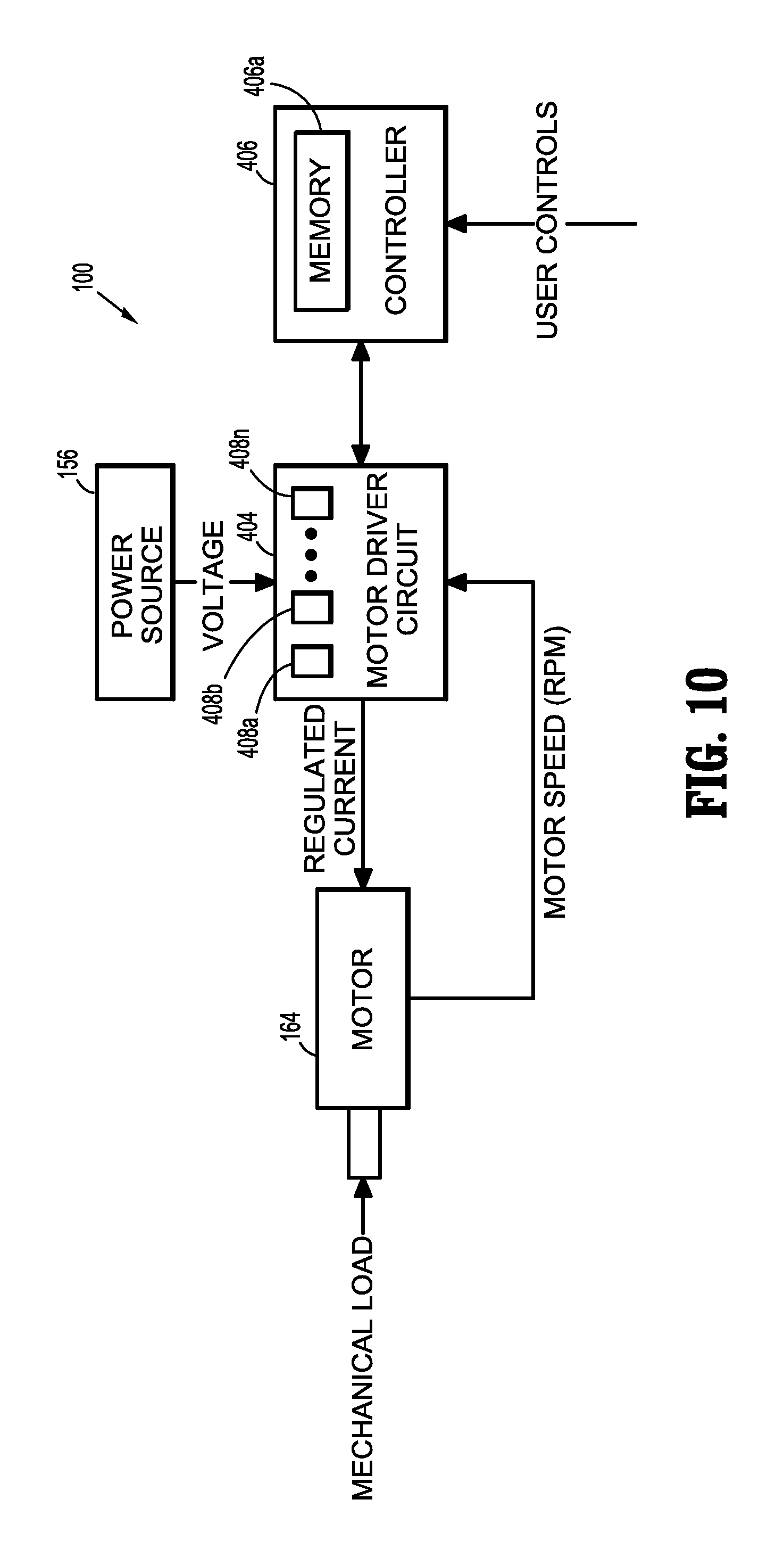
Another embodiment of the instrument 100 is shown in FIG. 10. The instrument 100 includes the motor 164. The motor 164 may be any electrical motor configured to actuate one or more drives (e.g., rotatable drive connectors 118, 120, 122 of FIG. 6). The motor 164 is coupled to the battery 156, which may be a DC battery (e.g., rechargeable lead-based, nickel-based, lithium-ion based, battery etc.), an AC/DC transformer, or any other power source suitable for providing electrical energy to the motor 164.
The battery 156 and the motor 164 are coupled to a motor driver circuit 404 disposed on the circuit board 154 which controls the operation of the motor 164 including the flow of electrical energy from the battery 156 to the motor 164. The driver circuit 404 includes a plurality of sensors 408a, 408b, . . . 408n configured to measure operational states of the motor 164 and the battery 156. The sensors 408a-n may include voltage sensors, current sensors, temperature sensors, telemetry sensors, optical sensors, and combinations thereof. The sensors 408a-408n may measure voltage, current, and other electrical properties of the electrical energy supplied by the battery 156. The sensors 408a-408n may also measure rotational speed as revolutions per minute (RPM), torque, temperature, current draw, and other operational properties of the motor 164. RPM may be determined by measuring the rotation of the motor 164. Position of various drive shafts (e.g., rotatable drive connectors 118, 120, 122 of FIG. 6) may be determined by using various linear sensors disposed in or in proximity to the shafts or extrapolated from the RPM measurements. In embodiments, torque may be calculated based on the regulated current draw of the motor 164 at a constant RPM. In further embodiments, the driver circuit 404 and/or the controller 406 may measure time and process the above-described values as a function thereof, including integration and/or differentiation, e.g., to determine the change in the measured values and the like.
The driver circuit 404 is also coupled to a controller 406, which may be any suitable logic control circuit adapted to perform the calculations and/or operate according to a set of instructions described in further detail below. The controller 406 may include a central processing unit operably connected to a memory which may include transitory type memory (e.g., RAM) and/or non-transitory type memory (e.g., flash media, disk media, etc.). The controller 406 includes a plurality of inputs and outputs for interfacing with the driver circuit 404. In particular, the controller 406 receives measured sensor signals from the driver circuit 404 regarding operational status of the motor 164 and the battery 156 and, in turn, outputs control signals to the driver circuit 404 to control the operation of the motor 164 based on the sensor readings and specific algorithm instructions, which are discussed in more detail below. The controller 406 is also configured to accept a plurality of user inputs from a user interface (e.g., switches, buttons, touch screen, etc. of the control assembly 107 coupled to the controller 406).
The present disclosure provides for an apparatus and method for controlling the instrument 100 or any other powered surgical instrument, including, but not limited to, linear powered staplers, circular or arcuate powered staplers, graspers, electrosurgical sealing forceps, rotary tissue blending devices, and the like. In particular, torque, RPM, position, and acceleration of drive shafts of the instrument 100 can be correlated to motor characteristics (e.g., current draw). Current drawn by the motor 164 may be used for detecting mechanical limits since the current drawn by the motor 164 changes with the load and speed of the motor 164. Thus, analysis of the amount of change (e.g., rate of change) of current draw allows for distinguishing between different types of load conditions, e.g., load exerted by tissue versus load exerted by a mechanical stop.
During normal operation of the motor 164 the current draw generally does not fall outside a predetermined range (e.g., first range). During clamping and stapling, the load exerted on the motor 164 by the tissue varies within a second range, encompassed by the first range. In particular, as the motor 164 encounters an increased load due to the tissue being clamped by the anvil and cartridge assemblies 306, 308 the current draw increases and is within the second range for a second period of time (e.g., increase in the current draw occurs for a predetermined period of time). If the motor 164 encounters a mechanical limit there is also a corresponding increase in current draw in a relatively short time that is larger than the current draw associated with tissue clamping. In particular, the current draw due to a mechanical stop is within a third range that is higher than the second range for a third period of time. In comparison, startup of the motor 164 draws more current than either clamping/fastening or the mechanical stop and the duration of the increased current draw is the shortest of the two current draws described above.
In embodiments, mechanical stops may be detected by comparing motor current with a predetermined threshold since the current drawn by the motor 164 upon encountering a mechanical stop is usually much higher than the normal operating current. The controller 406 may use the satisfaction of this condition to shut off the motor 164.
This approach presents some challenges when the motor 164 encounters high momentary loads during normal operation (e.g., clamping tissue). The current draw associated with tissue clamping can reach the threshold, thus causing the controller 406 to shut off the motor 164 prematurely. In embodiments, the premature shutoff may be prevented by analyzing normal current draw of the motor 164 and construct a normal motor load profile. The controller 406 may then be programmed to adjust the shutoff threshold in accordance with that profile. This configuration is well-suited to motors 164 having little variation in the load profile. However, large variations can produce false positives if the load profile deviates from the current draw associated with normal use.
Efficiency of the motor 164 and drive mechanism also have an effect in calculating the motor current limit. Since mechanical efficiencies can vary from one instrument to another, each instrument needs to be individually calibrated during assembly. Further, mechanical efficiencies change with wear and tear of the instrument and can also affect performance of the software.
The algorithm according to the present disclosure overcomes the issues of using single-threshold or profile-based algorithms. An advantage of the algorithm according to the present disclosure is that the algorithm utilizes rate of change/current over time rather than comparing amplitude of the motor current to a predetermined threshold. The rate of change of the motor current associated with different loads, e.g., normal load, heavy loads, mechanical stops, load spikes, etc. may be classified into different ranges, in which each range is associated with a specific load. The classification into ranges may then be used to identify distinct loads on the motor 164 and filtering out spikes caused by starting and stopping of the motor 164. Since the identification of the mechanical loads is based on the rate of change in motor current rather than its amplitude, deviation from the load profiles do not affect load identification. In addition, mechanical efficiencies do not affect load identification based on rate of change in motor current. Less efficient instruments draw more current to attain the same speed, however, the slopes (e.g., rate of change in current draw) for reaching those speeds remains similar to those of more efficient systems. This eliminates the need for load profiling and calibration operation during assembly of the instrument 100.
Another advantage of the algorithm according to the present disclosure is the low computational overhead. The algorithm relies on calculating the rate of change of the motor current and as such can be determined by taking the difference between two values, allowing for implementation of the algorithm in an 8-bit microcontroller.
The change in motor current can be measured by sampling current periodically. In embodiments, the sampling rate may be from about 100 per second to about 10,000 per second, in embodiments from about 500 per second to about 1,000 per second. The samples may then be used by the controller 406 to calculate the change in the motor current (e.g., current draw). The controller 406 may then use the change in motor current to determine the operating condition of the instrument 100 and take appropriate action.
The present disclosure also provides a feedback system and method for controlling the instrument 100 based on external operating conditions such as firing difficulty encountered by the instrument 100 due to tissue thickness and/or mechanical stop (e.g., the drive beam 365 reaching the distal end of the channel defined in the anvil plate 312 and the staple cartridge 305. In addition, the present disclosure provides for modeling of different usages of the instrument 100 in response to the external operating conditions (e.g., specific failures) to derive internal system feedback. The sensor information from the sensors 408a-n is used by the controller 406 to alter operating characteristics of the instrument 100 and/or notify users of specific operational conditions. In embodiments, the controller 406 controls (e.g., limits) the current supplied to the motor 164.
The controller 406 includes a computer-readable memory 406a and/or non-transitory medium for storing software instructions (e.g., algorithm) for detecting mechanical limits of the instrument 100 based on the measured current draw. As used herein, the term "mechanical limit" denotes any of the electromechanical components reaching end-of-travel positions including, but not limited to, e.g., the drive beam 365 reaching the distal end of the channel defined in the anvil plate 312 and the staple cartridge 305, actuation of mechanical safety lockout mechanisms preventing travel of the shaft 364, articulation link 366 reaching articulation limits of the end effector 300, and the like.
The change in motor current associated with the onset of certain load conditions (e.g., tissue clamping or mechanical limits) falls within predefined ranges and persists for a certain duration. These conditions are used by the algorithm to identify operating properties of the motor 164 and react accordingly in response thereto.
With reference to FIG. 11, the memory 406a stores a plurality of current draw values. The memory 406a includes look-up table 500 or any other suitable data structure having values "I-V." The first value I and the fifth value "V" define a first range encompassing a stable current draw signal indicative of normal (e.g., load-bearing) operation of the motor 164. The second and third values "II" and "III" define a second range corresponding to the current draw associated with current draw of the motor 164 during tissue clamping and fourth and fifth values "IV" and "V" defining a third range corresponding to the current draw associated with a mechanical stop. In embodiments, the first value "I" may be the same as the second value "II."
The controller 406 also includes a condition-of-interest counter which counts the number of samples during which the slope (e.g., rate of change) of the motor current lies within the desired range (e.g., either first, second or third ranges). The controller 406 also includes a signal stability counter, which counts the number of samples for which the slope lies within the second range. The controller 406 determines if the measured rate of change current draw signal is stable using the values of the table 500. The signal is considered to be unstable if a predetermined number of current draw samples are outside the first range and stable if a predetermined number of samples are within the second range.
FIG. 12 shows a method according to the present disclosure for determining if the motor 164 encounters a mechanical stop. The method may be implemented as software instructions (e.g., algorithm) stored in the controller 406 as described above. Initially, the controller 406 calculates a moving average of the measured motor current (e.g., current draw). As used herein, the term "moving average" denotes an average of a predetermined subset of samples that is updated every time a new sample is obtained. The moving average may include from about 2 plurality of samples to about 256 plurality of samples, and in embodiments, from about plurality of samples 16 about plurality of samples 64, depending on the sampling rate described above. The controller 406 stores the first moving average and calculates the second moving average for the subsequent sample set. The controller 406 then determines the difference between the moving averages to calculate the sample-to-sample change.
As shown in FIGS. 12-13, the moving average of the samples may be graphed as plots 700, 800, 900, with the sample-to-sample change being represented as the slope of the plots 700, 800, 900. The plots 700, 800, 900 may be generated and outputted on a display allowing the user to view the current draw of the motor 164. In embodiments, the plots 700, 800, 900 may be stored in the memory 406a as a series of values, without reproducing the sample values as a plot.
The change in the monitored motor current, also defined as the slope is used to differentiate between different types of loads encountered by motor 164. The controller 406 initially determines if the signal is stable by determining whether the calculated slope/change is outside the first range (e.g., the slope is larger than fifth value "V" or less than first value "I"). If the slope lies outside the first range for a predefined number of samples, the controller 406 initializes or resets the condition-of-interest and signal stability counters by setting them to zero, 0. In addition, the controller 406 also sets the signal status as "unstable."
With reference to FIGS. 14 and 15, the samples below first value "I," as shown in FIG. 14, and above the fifth value "V," as shown in FIG. 15, are filtered out since they represent abnormal negative and positive spikes in current draw. These spikes may be caused by starting and stopping of the motor 164 and may result false positives in threshold-based decision making algorithms.
After determining if the slope is outside the first range, the controller 406 determines if the slope is within the second range (value II.ltoreq.slope.ltoreq.value III). If so, the stability counter is incremented. The controller 406 checks if the stability counter has reached a predetermined threshold before changing the signal status to "stable." This ensures that the sample has been within the second range for a sufficient period of time. Any deviation, e.g., the slope being outside the first range, resets the condition-of-interest and signal stability counters and sets the signal status as "unstable" as described above.
With reference to FIGS. 13-15, the signal is considered to be stable if the slope is within the second range, irrelevant of the actual amplitude of the motor current samples. Thus, the higher amplitude of the samples within the second range of FIG. 15 and lower amplitude of the samples within the second range of FIGS. 13 and 14 is treated similarly by the algorithm of the present disclosure as the attribute of interest is the rate of change of slope of the motor current samples.
The controller 406 also determines if the sample is within the third range. For each sample within the third range, while the signal is deemed stable, the condition-of-interest counter is incremented. Every time the sample falls below second value "II," the condition-of-interest counter is decremented. The condition-of-interest counter is used to identify a mechanical stop, as described in further detail below. If the condition-of-interest counter is above a predetermined threshold, then the controller 406 determines that a mechanical stop has been reached. With reference to FIG. 13, a plurality of samples have a slope that falls within the third range, this increments the condition-of-interest counter and upon reaching the predetermined count triggers the indication that the mechanical stop has been reached. Once the controller 406 determines that the mechanical limit has been reached the supply of current to the motor 164 may be terminated to prevent further operation of the instrument 100 and/or the instrument 100 may issue an alarm.
FIG. 16 shows a method according another embodiment of to the present disclosure for determining if the motor 164 encounters a mechanical stop.
The controller 406 includes the stability and condition-of-interest counters, as described above. The controller 406 further includes a positive spike counter and a negative spike counter. These counters maintain a number of times a current (e.g., slope) has spiked outside the first range. More specifically, the positive spike counter is incremented when the motor current is above the value "V" and the negative spike counter is incremented when the motor current is below the value "I." The controller 406 determines if the measured rate of change current draw signal is stable using the values of the table 500. The signal is considered to be unstable if a predetermined number of current draw samples are outside the first range (e.g., is the number of positive and negative spikes is above a predetermined positive and negative spike threshold) and stable if a predetermined number of samples are within the second range.
The method of FIG. 16 may also be implemented as software instructions (e.g., algorithm) stored in the controller 406 as described above. Initially, the controller 406 calculates a moving average of the measured motor current (e.g., current draw). As used herein, the term "moving average" denotes an average of a predetermined subset of samples that is updated every time a new sample is obtained. The moving average may include from about 2 samples to about 256 samples, and in embodiments, from about 16 to about 64 samples, depending on the sampling rate described above. The controller 406 stores the first moving average and calculates the second moving average for the subsequent sample set. The controller 406 then determines the difference between the moving averages to calculate the sample-to-sample change (e.g., slope).
The change in the monitored motor current, also defined as the slope, is used to differentiate between different types of loads encountered by motor 164. The controller 406 initially determines if the slope is larger than fifth value "V" and updated the previous moving average to the presently calculated moving average. If the slope is above the fifth value "V," the positive spike counter is incremented while the negative spike counter is decremented. In addition, the controller 406 verifies if the positive spike counter is above a predetermined positive spike counter threshold. If so, the controller 406 initializes or resets the condition-of-interest and signal stability counters by setting them to zero, 0. In addition, the controller 406 also sets the signal status as "unstable." If the positive spike counter is below the predetermined positive spike counter threshold, the stability counter is decremented.
After determining if the slope is above the fifth value "V," the controller 406 determines if the sample falls below second value "II," the condition-of-interest counter is decremented.
The controller 406 also determines if the slope is smaller than the first value "I" and updated the previous moving average to the presently calculated moving average. If the slope is above the first value "I," the negative spike counter is incremented while the positive spike counter is decremented. In addition, the controller 406 verifies if the negative spike counter is above a predetermined negative spike counter threshold. If so, the controller 406 initializes or resets the condition-of-interest and signal stability counters by setting them to zero, 0. In addition, the controller 406 also sets the signal status as "unstable." If the negative spike counter is below the predetermined negative spike counter threshold, the stability counter is decremented.
With reference to FIGS. 14 and 15, the samples below first value "I," as shown in FIG. 14, and above the fifth value "V," as shown in FIG. 15, are filtered out since they represent abnormal negative and positive spikes in current draw. These spikes may be caused by starting and stopping of the motor 164 and may result false positives in threshold-based decision making algorithms.
The controller 406 also determines if the slope is within the second range (e.g., value "II".ltoreq.slope.ltoreq.value "III"). If so, the stability counter is incremented. The controller 406 also checks if the stability counter has reached a predetermined threshold before changing the signal status to "stable." This ensures that the sample has been within the second range for a sufficient period of time. In addition, the controller 406 initializes or resets the positive and negative spike counters by setting them to zero, 0. Regardless whether the stability counter is below or above the predetermined threshold, the previous moving average is updated to the presently calculated moving average. Any deviation, e.g., the slope being outside the first range, also resets the condition-of-interest and signal stability counters and sets the signal status as "unstable" as described above.
The controller 406 also determines if the sample is within the third range. For each sample within the third range, while the signal is deemed stable, the condition-of-interest counter is incremented. The condition-of-interest counter is used to identify a mechanical stop, as described in further detail below. If the condition-of-interest counter is above a predetermined threshold, then the controller 406 determines that a mechanical stop has been reached. With reference to FIG. 13, a plurality of samples have a slope that falls within the third range, this increments the condition-of-interest counter and upon reaching the predetermined count triggers the indication that the mechanical stop has been reached. Once the controller 406 determines that the mechanical limit has been reached the supply of current to the motor 164 may be terminated to prevent further operation of the instrument 100 and/or the instrument 100 may issue an alarm.
In addition to basic feedback about device performance the present disclosure also provides a method for powered devices to detect and discern other external factors, e.g., thicker tissue, which previously were difficult to detect. As a result, improved cutoffs and values for limits can be implemented, greatly improving the safety of powered devices in use. Using the feedback mechanisms discussed above, users may make intelligent decisions about what settings and techniques should be used when operating the instrument 100. This intelligence can range from choosing a different reload to fire with a linear stapler, deciding to fire at a different articulation angle, to choosing to use a completely different surgical technique.
It should be understood that the foregoing description is only illustrative of the present disclosure. Various alternatives and modifications can be devised by those skilled in the art without departing from the disclosure. Accordingly, the present disclosure is intended to embrace all such alternatives, modifications and variances. The embodiments described with reference to the attached drawing figures are presented only to demonstrate certain examples of the disclosure. Other elements, steps, methods and techniques that are insubstantially different from those described above and/or in the appended claims are also intended to be within the scope of the disclosure.
* * * * *
D00000
D00001
D00002
D00003
D00004
D00005
D00006
D00007
D00008
D00009
D00010
D00011
D00012
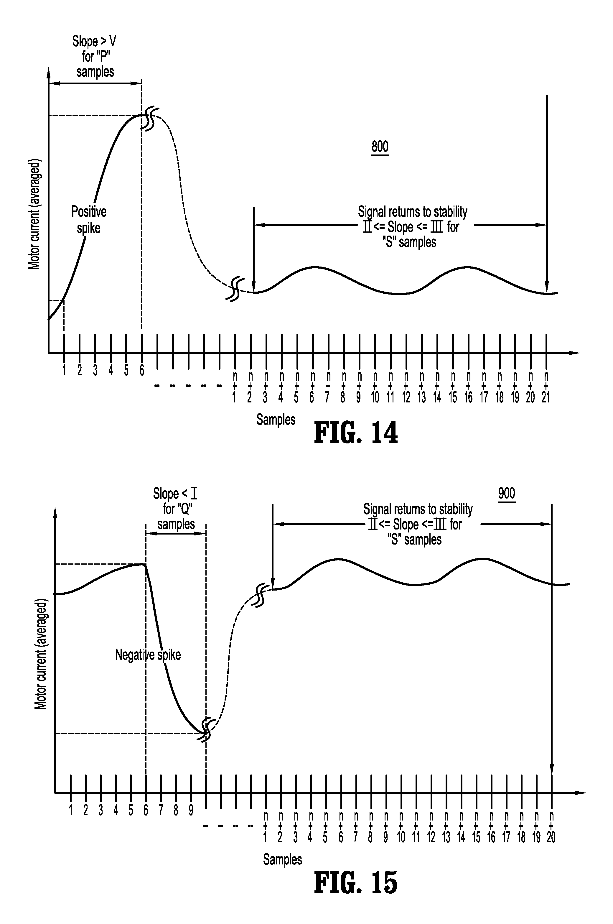
D00013

XML
uspto.report is an independent third-party trademark research tool that is not affiliated, endorsed, or sponsored by the United States Patent and Trademark Office (USPTO) or any other governmental organization. The information provided by uspto.report is based on publicly available data at the time of writing and is intended for informational purposes only.
While we strive to provide accurate and up-to-date information, we do not guarantee the accuracy, completeness, reliability, or suitability of the information displayed on this site. The use of this site is at your own risk. Any reliance you place on such information is therefore strictly at your own risk.
All official trademark data, including owner information, should be verified by visiting the official USPTO website at www.uspto.gov. This site is not intended to replace professional legal advice and should not be used as a substitute for consulting with a legal professional who is knowledgeable about trademark law.