Vehicular exterior rearview mirror assembly with blind spot indicator
Lynam November 10, 2
U.S. patent number 10,829,053 [Application Number 16/429,166] was granted by the patent office on 2020-11-10 for vehicular exterior rearview mirror assembly with blind spot indicator. This patent grant is currently assigned to MAGNA MIRRORS OF AMERICA, INC.. The grantee listed for this patent is MAGNA MIRRORS OF AMERICA, INC.. Invention is credited to Niall R. Lynam.


View All Diagrams
| United States Patent | 10,829,053 |
| Lynam | November 10, 2020 |
Vehicular exterior rearview mirror assembly with blind spot indicator
Abstract
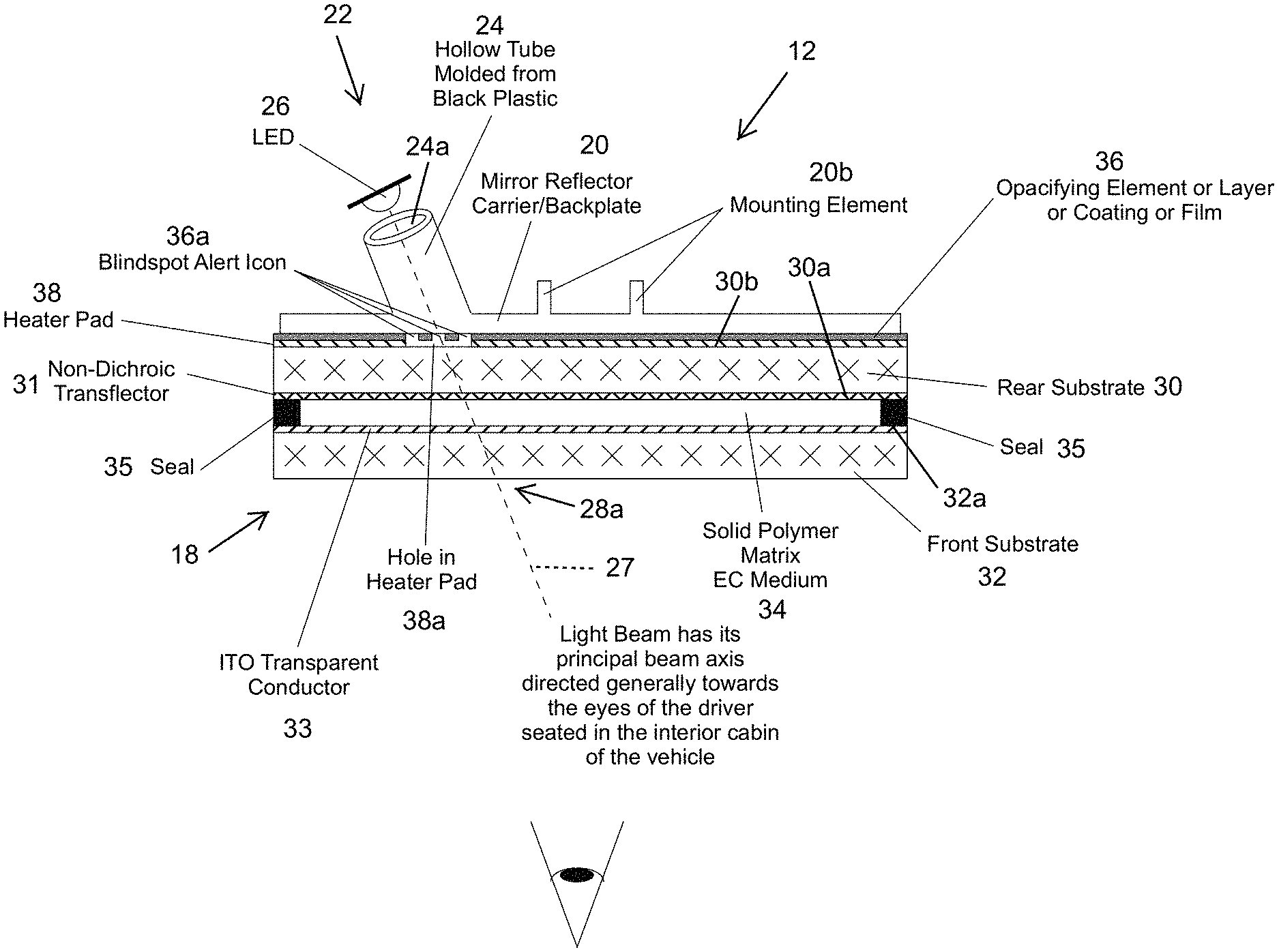
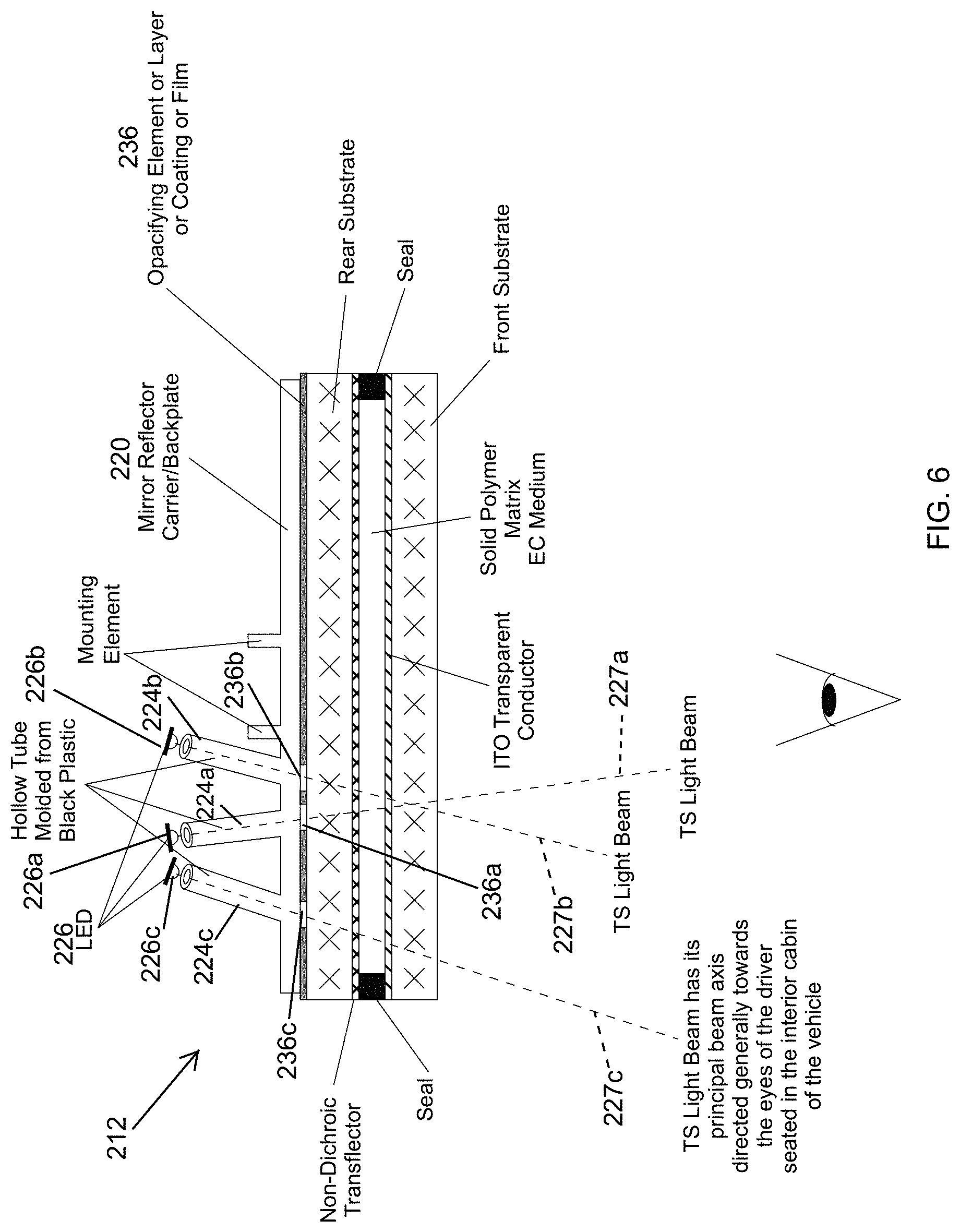
An exterior rearview mirror assembly for a vehicle equipped with a blind spot monitoring system includes a mirror reflective element sub-assembly having a mirror reflective element, a mirror back plate and a heater pad disposed between the mirror reflective element and the mirror back plate. A light transmitting aperture of the heater pad is juxtaposed with a light transmitting aperture of the mirror reflector of the reflective element and with a light transmitting aperture of the mirror back plate. The mirror back plate includes first structure that is configured to attach at an actuator. A blind spot indicator is disposed at the light transmitting aperture of the mirror back plate, and, when activated responsive to a blind spot monitoring system of the vehicle, emits light through the light transmitting apertures, forming an illuminated icon viewable by a driver of the vehicle viewing the mirror reflective element.
| Inventors: | Lynam; Niall R. (Holland, MI) | ||||||||||
|---|---|---|---|---|---|---|---|---|---|---|---|
| Applicant: |
|
||||||||||
| Assignee: | MAGNA MIRRORS OF AMERICA, INC.
(Holland, MI) |
||||||||||
| Family ID: | 1000005171719 | ||||||||||
| Appl. No.: | 16/429,166 | ||||||||||
| Filed: | June 3, 2019 |
Prior Publication Data
| Document Identifier | Publication Date | |
|---|---|---|
| US 20190283676 A1 | Sep 19, 2019 | |
Related U.S. Patent Documents
| Application Number | Filing Date | Patent Number | Issue Date | ||
|---|---|---|---|---|---|
| 16214294 | Dec 10, 2018 | 10308186 | |||
| 15700270 | Dec 11, 2018 | 10150417 | |||
| 15638663 | Sep 12, 2017 | 9758102 | |||
| 14726907 | Jul 4, 2017 | 9694753 | |||
| 14486133 | Jun 2, 2015 | 9045091 | |||
| 13646960 | Sep 16, 2014 | 8833987 | |||
| 13335135 | Oct 9, 2012 | 8282253 | |||
| 12550054 | Dec 27, 2011 | 8083386 | |||
| 11520193 | Sep 1, 2009 | 7581859 | |||
| 60717093 | Sep 14, 2005 | ||||
| Current U.S. Class: | 1/1 |
| Current CPC Class: | B60R 1/088 (20130101); B60R 1/1207 (20130101); B60Q 1/2665 (20130101); B60R 1/0602 (20130101); B60Q 1/0023 (20130101); B60Q 1/26 (20130101); B60R 2001/1223 (20130101); B60R 2001/1215 (20130101); B60R 2001/1284 (20130101) |
| Current International Class: | B60R 1/12 (20060101); B60Q 1/00 (20060101); B60Q 1/26 (20060101); B60R 1/08 (20060101); B60R 1/06 (20060101) |
References Cited [Referenced By]
U.S. Patent Documents
| 1096452 | May 1914 | Perrin |
| 1563258 | November 1925 | Cunningham |
| 2069368 | February 1937 | Horinstein |
| 2166303 | July 1939 | Hodney et al. |
| 2263382 | November 1941 | Gotzinger |
| 2414223 | January 1947 | De Virgilis |
| 2457348 | December 1948 | Chambers |
| 2561582 | July 1951 | Marbel |
| 2580014 | December 1951 | Gazda |
| 3004473 | October 1961 | Athur et al. |
| 3075430 | January 1963 | Woodward et al. |
| 3141393 | July 1964 | Platt |
| 3152216 | October 1964 | Woodward |
| 3162008 | December 1964 | Berger et al. |
| 3185020 | May 1965 | Thelen |
| 3266016 | August 1966 | Maru |
| 3280701 | October 1966 | Donnelly et al. |
| 3432225 | March 1969 | Rock |
| 3451741 | June 1969 | Manos |
| 3453038 | July 1969 | Kissa et al. |
| 3467465 | September 1969 | Van Noord |
| 3473867 | October 1969 | Byrnes |
| 3480781 | November 1969 | Mandalakas |
| 3499112 | March 1970 | Heilmeier et al. |
| 3499702 | March 1970 | Goldmacher et al. |
| 3521941 | July 1970 | Deb et al. |
| 3543018 | November 1970 | Barcus et al. |
| 3557265 | January 1971 | Chisholm et al. |
| 3565985 | February 1971 | Schrenk et al. |
| 3612654 | October 1971 | Klein et al. |
| 3614210 | October 1971 | Caplan |
| 3628851 | December 1971 | Robertson |
| 3676668 | July 1972 | Collins et al. |
| 3680951 | August 1972 | Jordan et al. |
| 3689695 | September 1972 | Rosenfield et al. |
| 3711176 | January 1973 | Alfrey, Jr. et al. |
| 3712710 | January 1973 | Castellion et al. |
| 3748017 | July 1973 | Yamamura et al. |
| 3781090 | December 1973 | Sumita |
| 3806229 | April 1974 | Schoot et al. |
| 3807832 | April 1974 | Castellion |
| 3807833 | April 1974 | Graham et al. |
| 3821590 | June 1974 | Kosman et al. |
| 3837129 | September 1974 | Losell |
| 3860847 | January 1975 | Carley |
| 3862798 | January 1975 | Hopkins |
| 3870404 | March 1975 | Wilson et al. |
| 3876287 | April 1975 | Sprokel |
| 3932024 | January 1976 | Yaguchi et al. |
| 3940822 | March 1976 | Emerick et al. |
| 3956017 | May 1976 | Shigemasa |
| 3978190 | August 1976 | Kurz, Jr. et al. |
| 3985424 | October 1976 | Steinacher |
| 4006546 | February 1977 | Anderson et al. |
| 4035681 | July 1977 | Savage, Jr. |
| 4040727 | August 1977 | Ketchpel |
| 4052712 | October 1977 | Ohama et al. |
| 4075468 | February 1978 | Marcus |
| 4088400 | May 1978 | Assouline et al. |
| 4093364 | June 1978 | Miller |
| 4097131 | June 1978 | Nishiyama |
| 4109235 | August 1978 | Bouthors |
| 4139234 | February 1979 | Morgan |
| 4159866 | July 1979 | Wunsch et al. |
| 4161653 | July 1979 | Bedini et al. |
| 4171875 | October 1979 | Taylor et al. |
| 4174152 | November 1979 | Giglia et al. |
| 4200361 | April 1980 | Malvano et al. |
| 4202607 | May 1980 | Washizuka et al. |
| 4211955 | July 1980 | Ray |
| 4214266 | July 1980 | Myers |
| 4219760 | August 1980 | Ferro |
| 4221955 | September 1980 | Joslyn |
| 4228490 | October 1980 | Thillays |
| 4247870 | January 1981 | Gabel et al. |
| 4257703 | March 1981 | Goodrich |
| 4274078 | June 1981 | Isobe et al. |
| 4277804 | July 1981 | Robison |
| 4281899 | August 1981 | Oskam |
| 4288814 | September 1981 | Talley et al. |
| RE30835 | December 1981 | Giglia |
| 4306768 | December 1981 | Egging |
| 4310851 | January 1982 | Pierrat |
| 4331382 | May 1982 | Graff |
| 4338000 | July 1982 | Kamimori et al. |
| 4377613 | March 1983 | Gordon |
| 4398805 | August 1983 | Cole |
| 4419386 | December 1983 | Gordon |
| 4420238 | December 1983 | Felix |
| 4425717 | January 1984 | Marcus |
| 4435042 | March 1984 | Wood et al. |
| 4435048 | March 1984 | Kamimori et al. |
| 4436371 | March 1984 | Wood et al. |
| 4438348 | March 1984 | Casper et al. |
| 4443057 | April 1984 | Bauer et al. |
| 4446171 | May 1984 | Thomas |
| 4465339 | August 1984 | Baucke et al. |
| 4473695 | September 1984 | Wrighton et al. |
| 4490227 | December 1984 | Bitter |
| 4491390 | January 1985 | Tong-Shen |
| 4499451 | February 1985 | Suzuki et al. |
| 4521079 | June 1985 | Leenhouts et al. |
| 4524941 | June 1985 | Wood et al. |
| 4538063 | August 1985 | Bulat |
| 4546551 | October 1985 | Franks |
| 4555694 | November 1985 | Yanagishima et al. |
| 4561625 | December 1985 | Weaver |
| 4572619 | February 1986 | Reininger et al. |
| 4580196 | April 1986 | Task |
| 4580875 | April 1986 | Bechtel et al. |
| 4581827 | April 1986 | Higashi |
| 4588267 | May 1986 | Pastore |
| 4603946 | August 1986 | Kato et al. |
| 4623222 | November 1986 | Itoh et al. |
| 4625210 | November 1986 | Sagl |
| 4626850 | December 1986 | Chey |
| 4630040 | December 1986 | Haertling |
| 4630109 | December 1986 | Barton |
| 4630904 | December 1986 | Pastore |
| 4634835 | January 1987 | Suzuki |
| 4635033 | January 1987 | Inukai et al. |
| 4636782 | January 1987 | Nakamura et al. |
| 4638287 | January 1987 | Umebayashi et al. |
| 4646210 | February 1987 | Skogler et al. |
| 4652090 | March 1987 | Uchikawa et al. |
| 4655549 | April 1987 | Suzuki et al. |
| 4665311 | May 1987 | Cole |
| 4665430 | May 1987 | Hiroyasu |
| 4669827 | June 1987 | Fukada et al. |
| 4671615 | June 1987 | Fukada et al. |
| 4671619 | June 1987 | Kamimori et al. |
| 4678281 | July 1987 | Bauer |
| 4679906 | July 1987 | Brandenburg |
| 4682083 | July 1987 | Alley |
| 4692798 | September 1987 | Seko et al. |
| 4694295 | September 1987 | Miller et al. |
| 4697883 | October 1987 | Suzuki et al. |
| 4701022 | October 1987 | Jacob |
| 4702566 | October 1987 | Tukude |
| 4704740 | November 1987 | McKee et al. |
| 4711544 | December 1987 | Iino et al. |
| 4712879 | December 1987 | Lynam et al. |
| 4713685 | December 1987 | Nishimura et al. |
| RE32576 | January 1988 | Pastore |
| 4718756 | January 1988 | Lancaster |
| 4721364 | January 1988 | Itoh et al. |
| 4729068 | March 1988 | Ohe |
| 4729076 | March 1988 | Masami et al. |
| 4731669 | March 1988 | Hayashi et al. |
| 4733335 | March 1988 | Serizawa et al. |
| 4733336 | March 1988 | Skogler et al. |
| 4740838 | April 1988 | Mase et al. |
| 4761061 | August 1988 | Nishiyama et al. |
| 4773740 | September 1988 | Kawakami et al. |
| 4780752 | October 1988 | Angerstein et al. |
| 4781436 | November 1988 | Armbruster |
| 4789904 | December 1988 | Peterson |
| 4793690 | December 1988 | Gahan et al. |
| 4793695 | December 1988 | Wada et al. |
| 4794261 | December 1988 | Rosen |
| D299491 | January 1989 | Masuda |
| 4799768 | January 1989 | Gahan |
| 4803599 | February 1989 | Trine et al. |
| 4807096 | February 1989 | Skogler et al. |
| 4820933 | April 1989 | Hong et al. |
| 4825232 | April 1989 | Howdle |
| 4826289 | May 1989 | Vandenbrink et al. |
| 4827086 | May 1989 | Rockwell |
| 4837551 | June 1989 | Iino |
| 4842378 | June 1989 | Flasck et al. |
| 4845402 | July 1989 | Smith |
| 4847772 | July 1989 | Michalopoulos et al. |
| 4855161 | August 1989 | Moser et al. |
| 4855550 | August 1989 | Schultz, Jr. |
| 4859813 | August 1989 | Rockwell |
| 4859867 | August 1989 | Larson et al. |
| 4860171 | August 1989 | Kojima |
| 4862594 | September 1989 | Schierbeek et al. |
| 4871917 | October 1989 | O'Farrell et al. |
| 4872051 | October 1989 | Dye |
| 4882466 | November 1989 | Friel |
| 4882565 | November 1989 | Gallmeyer |
| 4883349 | November 1989 | Mittelhauser |
| 4884135 | November 1989 | Schiffman |
| 4886960 | December 1989 | Molyneux et al. |
| 4889412 | December 1989 | Clerc et al. |
| 4891828 | January 1990 | Kawazoe |
| 4892345 | January 1990 | Rachael, III |
| 4902103 | February 1990 | Miyake et al. |
| 4902108 | February 1990 | Byker |
| 4906085 | March 1990 | Sugihara et al. |
| 4909606 | March 1990 | Wada et al. |
| 4910591 | March 1990 | Petrossian et al. |
| 4916374 | April 1990 | Schierbeek et al. |
| 4917477 | April 1990 | Bechtel et al. |
| 4926170 | May 1990 | Beggs et al. |
| 4930742 | June 1990 | Schofield et al. |
| 4933814 | June 1990 | Sanai |
| 4935665 | June 1990 | Murata |
| 4936533 | June 1990 | Adams et al. |
| 4937796 | June 1990 | Tendler |
| 4937945 | July 1990 | Schofield et al. |
| 4943796 | July 1990 | Lee |
| 4948242 | August 1990 | Desmond et al. |
| 4953305 | September 1990 | Van Lente et al. |
| 4956591 | September 1990 | Schierbeek et al. |
| 4957349 | September 1990 | Clerc et al. |
| 4959247 | September 1990 | Moser et al. |
| 4959865 | September 1990 | Stettiner et al. |
| 4970653 | November 1990 | Kenue |
| 4973844 | November 1990 | O'Farrell et al. |
| 4974122 | November 1990 | Shaw |
| 4978196 | December 1990 | Suzuki et al. |
| 4983951 | January 1991 | Igarashi et al. |
| 4985809 | January 1991 | Matsui et al. |
| 4987357 | January 1991 | Masaki |
| 4996083 | February 1991 | Moser et al. |
| 5001386 | March 1991 | Sullivan et al. |
| 5001558 | March 1991 | Burley et al. |
| 5005213 | April 1991 | Hanson et al. |
| 5006971 | April 1991 | Jenkins |
| 5014167 | May 1991 | Roberts |
| 5016988 | May 1991 | Iimura |
| 5016996 | May 1991 | Ueno |
| 5017903 | May 1991 | Krippelz, Sr. |
| 5018839 | May 1991 | Yamamoto et al. |
| 5027200 | June 1991 | Petrossian et al. |
| 5037182 | August 1991 | Groves et al. |
| 5038255 | August 1991 | Nishihashi et al. |
| 5052163 | October 1991 | Czekala |
| 5056899 | October 1991 | Warszawski |
| 5057974 | October 1991 | Mizobe |
| 5058851 | October 1991 | Lawlor et al. |
| 5059015 | October 1991 | Tran |
| 5066108 | November 1991 | McDonald |
| 5066112 | November 1991 | Lynam et al. |
| 5069535 | December 1991 | Baucke et al. |
| 5070323 | December 1991 | Iino et al. |
| 5073012 | December 1991 | Lynam |
| 5076673 | December 1991 | Lynam et al. |
| 5076674 | December 1991 | Lynam |
| 5078480 | January 1992 | Warszawski |
| 5096287 | March 1992 | Kakinami et al. |
| 5100095 | March 1992 | Haan et al. |
| 5101139 | March 1992 | Lechter |
| 5105127 | April 1992 | Lavaud et al. |
| 5115346 | May 1992 | Lynam |
| 5119220 | June 1992 | Narita et al. |
| 5121200 | June 1992 | Choi |
| 5122619 | June 1992 | Dlubak |
| 5123077 | June 1992 | Endo et al. |
| 5124845 | June 1992 | Shimojo |
| 5124890 | June 1992 | Choi et al. |
| 5128799 | July 1992 | Byker |
| 5130898 | July 1992 | Akahane |
| 5131154 | July 1992 | Schierbeek et al. |
| 5134507 | July 1992 | Ishii |
| 5134549 | July 1992 | Yokoyama |
| 5135298 | August 1992 | Feltman |
| 5136483 | August 1992 | Schoniger et al. |
| 5140455 | August 1992 | Varaprasad et al. |
| 5140465 | August 1992 | Yasui et al. |
| 5142407 | August 1992 | Varaprasad et al. |
| 5145609 | September 1992 | Varaprasad et al. |
| 5148306 | September 1992 | Yamada et al. |
| 5150232 | September 1992 | Gunkima et al. |
| 5151816 | September 1992 | Varaprasad et al. |
| 5151824 | September 1992 | O'Farrell |
| 5154617 | October 1992 | Suman et al. |
| 5158638 | October 1992 | Osanami et al. |
| 5160200 | November 1992 | Cheselske |
| 5160201 | November 1992 | Wrobel |
| 5166815 | November 1992 | Elderfield |
| 5168378 | December 1992 | Black |
| 5173881 | December 1992 | Sindle |
| 5177031 | January 1993 | Buchmann et al. |
| 5178448 | January 1993 | Adams et al. |
| 5179471 | January 1993 | Caskey et al. |
| 5183099 | February 1993 | Bechu |
| 5184956 | February 1993 | Langlais et al. |
| 5189537 | February 1993 | O'Farrell |
| 5193029 | March 1993 | Schofield et al. |
| 5197562 | March 1993 | Kakinami et al. |
| 5202950 | April 1993 | Arego et al. |
| 5207492 | May 1993 | Roberts |
| 5210967 | May 1993 | Brown |
| 5212819 | May 1993 | Wada |
| 5214408 | May 1993 | Asayama |
| 5217794 | June 1993 | Schrenk |
| 5223814 | June 1993 | Suman |
| 5223844 | June 1993 | Mansell et al. |
| 5229975 | July 1993 | Truesdell et al. |
| 5230400 | July 1993 | Kakinami et al. |
| 5233461 | August 1993 | Dornan et al. |
| 5235316 | August 1993 | Qualizza |
| 5239405 | August 1993 | Varaprasad et al. |
| 5239406 | August 1993 | Lynam |
| 5243417 | September 1993 | Pollard |
| 5245422 | September 1993 | Borcherts et al. |
| 5252354 | October 1993 | Cronin et al. |
| 5253109 | October 1993 | O'Farrell et al. |
| 5255442 | October 1993 | Schierbeek et al. |
| 5260626 | November 1993 | Takase et al. |
| 5277986 | January 1994 | Cronin et al. |
| 5280555 | January 1994 | Ainsburg |
| 5285060 | February 1994 | Larson et al. |
| 5289321 | February 1994 | Secor |
| 5296924 | March 1994 | de Saint Blancard et al. |
| 5303075 | April 1994 | Wada et al. |
| 5303205 | April 1994 | Gauthier et al. |
| 5304980 | April 1994 | Maekawa |
| 5305012 | April 1994 | Faris |
| 5307136 | April 1994 | Saneyoshi |
| 5313335 | May 1994 | Gray et al. |
| 5325096 | June 1994 | Pakett |
| 5325386 | June 1994 | Jewell et al. |
| 5327288 | July 1994 | Wellington et al. |
| 5330149 | July 1994 | Haan et al. |
| 5331312 | July 1994 | Kudoh |
| 5331358 | July 1994 | Schurle et al. |
| 5339075 | August 1994 | Abst et al. |
| 5339529 | August 1994 | Lindberg |
| 5340503 | August 1994 | Varaprasad et al. |
| 5341437 | August 1994 | Nakayama |
| D351370 | October 1994 | Lawlor et al. |
| 5354965 | October 1994 | Lee |
| 5355118 | October 1994 | Fukuhara |
| 5355245 | October 1994 | Lynam |
| 5355284 | October 1994 | Roberts |
| 5361190 | November 1994 | Roberts et al. |
| 5363294 | November 1994 | Yamamoto et al. |
| 5371659 | December 1994 | Pastrick et al. |
| 5373482 | December 1994 | Gauthier |
| 5379146 | January 1995 | Defendini |
| 5386285 | January 1995 | Asayama |
| 5386306 | January 1995 | Gunjima et al. |
| 5400158 | March 1995 | Ohnishi et al. |
| 5402103 | March 1995 | Tashiro |
| 5406395 | April 1995 | Wilson et al. |
| 5406414 | April 1995 | O'Farrell et al. |
| 5408353 | April 1995 | Nichols et al. |
| 5408357 | April 1995 | Beukema |
| 5410346 | April 1995 | Saneyoshi et al. |
| 5414439 | May 1995 | Groves et al. |
| 5414461 | May 1995 | Kishi et al. |
| 5416313 | May 1995 | Larson et al. |
| 5416478 | May 1995 | Morinaga |
| 5418610 | May 1995 | Fischer |
| 5422756 | June 1995 | Weber |
| 5424726 | June 1995 | Beymer |
| 5424865 | June 1995 | Lynam |
| 5424952 | June 1995 | Asayama |
| 5426524 | June 1995 | Wada et al. |
| 5430431 | July 1995 | Nelson |
| 5432496 | July 1995 | Lin |
| 5432626 | July 1995 | Sasuga et al. |
| 5436741 | July 1995 | Crandall |
| 5437931 | August 1995 | Tsai et al. |
| 5439305 | August 1995 | Santo |
| 5444478 | August 1995 | Lelong et al. |
| 5446576 | August 1995 | Lynam et al. |
| 5455716 | October 1995 | Suman et al. |
| 5461361 | October 1995 | Moore |
| D363920 | November 1995 | Roberts et al. |
| 5469187 | November 1995 | Yaniv |
| 5469298 | November 1995 | Suman et al. |
| 5475366 | December 1995 | Van Lente et al. |
| 5475494 | December 1995 | Nishida et al. |
| 5481409 | January 1996 | Roberts |
| 5483453 | January 1996 | Uemura et al. |
| 5485161 | January 1996 | Vaughn |
| 5485378 | January 1996 | Franke et al. |
| 5487522 | January 1996 | Hook |
| 5488496 | January 1996 | Pine |
| 5497305 | March 1996 | Pastrick et al. |
| 5497306 | March 1996 | Pastrick |
| 5500760 | March 1996 | Varaprasad et al. |
| 5506701 | April 1996 | Ichikawa |
| 5509606 | April 1996 | Breithaupt et al. |
| 5510983 | April 1996 | Lino |
| 5515448 | May 1996 | Nishitani |
| 5519621 | May 1996 | Wortham |
| 5521744 | May 1996 | Mazurek |
| 5521760 | May 1996 | De Young et al. |
| 5523811 | June 1996 | Wada et al. |
| 5523877 | June 1996 | Lynam |
| 5525264 | June 1996 | Cronin et al. |
| 5525977 | June 1996 | Suman |
| 5528422 | June 1996 | Roberts |
| 5528474 | June 1996 | Roney et al. |
| 5529138 | June 1996 | Shaw et al. |
| 5530240 | June 1996 | Larson et al. |
| 5530420 | June 1996 | Tsuchiya et al. |
| 5530421 | June 1996 | Marshall et al. |
| 5535056 | July 1996 | Caskey et al. |
| 5535144 | July 1996 | Kise |
| 5539397 | July 1996 | Asanuma et al. |
| 5541590 | July 1996 | Nishio |
| 5550677 | August 1996 | Schofield et al. |
| 5555172 | September 1996 | Potter |
| 5561333 | October 1996 | Darius |
| 5566224 | October 1996 | ul Azam et al. |
| 5567360 | October 1996 | Varaprasad et al. |
| 5568316 | October 1996 | Schrenk et al. |
| 5570127 | October 1996 | Schmidt |
| 5572354 | November 1996 | Desmond et al. |
| 5574426 | November 1996 | Shisgal et al. |
| 5574443 | November 1996 | Hsieh |
| 5575552 | November 1996 | Faloon et al. |
| 5576687 | November 1996 | Blank et al. |
| 5576854 | November 1996 | Schmidt et al. |
| 5576975 | November 1996 | Sasaki et al. |
| 5578404 | November 1996 | Kliem |
| 5587236 | December 1996 | Agrawal et al. |
| 5587699 | December 1996 | Faloon et al. |
| 5593221 | January 1997 | Evanicky et al. |
| 5594222 | January 1997 | Caldwell |
| 5594560 | January 1997 | Jelley et al. |
| 5594615 | January 1997 | Spijkerman et al. |
| 5602542 | February 1997 | Widmann |
| 5602670 | February 1997 | Keegan |
| 5603104 | February 1997 | Phelps, III et al. |
| 5608550 | March 1997 | Epstein et al. |
| 5609652 | March 1997 | Yamada et al. |
| 5610380 | March 1997 | Nicolaisen |
| 5610756 | March 1997 | Lynam et al. |
| 5611966 | March 1997 | Varaprasad et al. |
| 5614885 | March 1997 | Van Lente et al. |
| 5615023 | March 1997 | Yang |
| 5615857 | April 1997 | Hook |
| 5617085 | April 1997 | Tsutsumi et al. |
| 5619374 | April 1997 | Roberts |
| 5619375 | April 1997 | Roberts |
| 5626800 | May 1997 | Williams et al. |
| 5631089 | May 1997 | Center, Jr. et al. |
| 5631638 | May 1997 | Kaspar et al. |
| 5631639 | May 1997 | Hibino et al. |
| 5632092 | May 1997 | Blank et al. |
| 5632551 | May 1997 | Roney et al. |
| 5634709 | June 1997 | Iwama |
| 5640216 | June 1997 | Hasegawa et al. |
| 5642238 | June 1997 | Sala |
| 5644851 | July 1997 | Blank et al. |
| 5646614 | July 1997 | Abersfelder et al. |
| 5649756 | July 1997 | Adams et al. |
| 5649758 | July 1997 | Dion |
| 5650765 | July 1997 | Park |
| 5650929 | July 1997 | Potter et al. |
| 5661455 | August 1997 | Van Lente et al. |
| 5661651 | August 1997 | Geschke et al. |
| 5661804 | August 1997 | Dykema et al. |
| 5662375 | September 1997 | Adams et al. |
| 5666157 | September 1997 | Aviv |
| 5667289 | September 1997 | Akahane et al. |
| 5668663 | September 1997 | Varaprasad et al. |
| 5668675 | September 1997 | Fredricks |
| 5669698 | September 1997 | Veldman et al. |
| 5669699 | September 1997 | Pastrick et al. |
| 5669704 | September 1997 | Pastrick |
| 5669705 | September 1997 | Pastrick et al. |
| 5670935 | September 1997 | Schofield et al. |
| 5671996 | September 1997 | Bos et al. |
| 5673994 | October 1997 | Fant, Jr. et al. |
| 5673999 | October 1997 | Koenck |
| 5677598 | October 1997 | De Hair et al. |
| 5679283 | October 1997 | Tonar et al. |
| 5680123 | October 1997 | Lee |
| 5680245 | October 1997 | Lynam |
| 5680263 | October 1997 | Zimmermann et al. |
| 5686975 | November 1997 | Lipton |
| 5686979 | November 1997 | Weber et al. |
| 5689241 | November 1997 | Clarke, Sr. et al. |
| 5689370 | November 1997 | Tonar et al. |
| 5691848 | November 1997 | Van Lente et al. |
| 5692819 | December 1997 | Mitsutake et al. |
| 5696529 | December 1997 | Evanicky et al. |
| 5696567 | December 1997 | Wada et al. |
| 5699044 | December 1997 | Van Lente et al. |
| 5699188 | December 1997 | Gilbert et al. |
| 5703568 | December 1997 | Hegyi |
| 5708410 | January 1998 | Blank et al. |
| 5708415 | January 1998 | Van Lente et al. |
| 5708857 | January 1998 | Ishibashi |
| 5715093 | February 1998 | Schierbeek et al. |
| 5724187 | March 1998 | Varaprasad et al. |
| 5724316 | March 1998 | Brunts |
| 5729194 | March 1998 | Spears et al. |
| 5737226 | April 1998 | Olson et al. |
| 5741966 | April 1998 | Handfield et al. |
| 5744227 | April 1998 | Bright et al. |
| 5745050 | April 1998 | Nakagawa |
| 5745266 | April 1998 | Smith |
| 5748172 | May 1998 | Song et al. |
| 5748287 | May 1998 | Takahashi et al. |
| 5751211 | May 1998 | Shirai et al. |
| 5751246 | May 1998 | Hertel |
| 5751390 | May 1998 | Crawford et al. |
| 5751489 | May 1998 | Caskey et al. |
| 5754099 | May 1998 | Nishimura et al. |
| D394833 | June 1998 | Muth |
| 5760828 | June 1998 | Cortes |
| 5760931 | June 1998 | Saburi et al. |
| 5760962 | June 1998 | Schofield et al. |
| 5761094 | June 1998 | Olson et al. |
| 5762823 | June 1998 | Hikmet |
| 5764139 | June 1998 | Nojima et al. |
| 5765940 | June 1998 | Levy et al. |
| 5767793 | June 1998 | Agravante et al. |
| 5768020 | June 1998 | Nagao |
| 5775762 | July 1998 | Vitito |
| 5777779 | July 1998 | Hashimoto et al. |
| 5780160 | July 1998 | Allemand et al. |
| 5786772 | July 1998 | Schofield et al. |
| 5788357 | August 1998 | Muth et al. |
| 5790298 | August 1998 | Tonar |
| 5790502 | August 1998 | Horinouchi et al. |
| 5790973 | August 1998 | Blaker et al. |
| 5793308 | August 1998 | Rosinski et al. |
| 5793420 | August 1998 | Schmidt |
| 5796094 | August 1998 | Schofield et al. |
| 5796176 | August 1998 | Kramer et al. |
| 5798057 | August 1998 | Hikmet |
| 5798575 | August 1998 | O'Farrell et al. |
| 5798688 | August 1998 | Schofield |
| 5800918 | September 1998 | Chartier et al. |
| 5802727 | September 1998 | Blank et al. |
| 5803579 | September 1998 | Turnbull et al. |
| 5805330 | September 1998 | Byker et al. |
| 5805367 | September 1998 | Kanazawa |
| 5806879 | September 1998 | Hamada et al. |
| 5806965 | September 1998 | Deese |
| 5808197 | September 1998 | Dao |
| 5808566 | September 1998 | Behr et al. |
| 5808589 | September 1998 | Fergason |
| 5808713 | September 1998 | Broer et al. |
| 5808777 | September 1998 | Lynam et al. |
| 5808778 | September 1998 | Bauer et al. |
| 5812321 | September 1998 | Schierbeek et al. |
| 5813745 | September 1998 | Fant, Jr. et al. |
| 5818625 | October 1998 | Forgette et al. |
| 5820097 | October 1998 | Spooner |
| 5820245 | October 1998 | Desmond et al. |
| 5822023 | October 1998 | Suman et al. |
| 5823654 | October 1998 | Pastrick et al. |
| 5825527 | October 1998 | Forgette et al. |
| 5835166 | November 1998 | Hall et al. |
| 5837994 | November 1998 | Stam et al. |
| 5844505 | December 1998 | Van Ryzin |
| 5848373 | December 1998 | DeLorme et al. |
| 5850176 | December 1998 | Kinoshita et al. |
| 5850205 | December 1998 | Blouin |
| 5863116 | January 1999 | Pastrick et al. |
| 5864419 | January 1999 | Lynam |
| 5867801 | February 1999 | Denny |
| 5871275 | February 1999 | O'Farrell et al. |
| 5871843 | February 1999 | Yoneda et al. |
| 5877707 | March 1999 | Kowalick |
| 5877897 | March 1999 | Schofield et al. |
| 5878353 | March 1999 | ul Azam et al. |
| 5878370 | March 1999 | Olson |
| 5879074 | March 1999 | Pastrick |
| 5883605 | March 1999 | Knapp |
| 5883739 | March 1999 | Ashihara et al. |
| 5888431 | March 1999 | Tonar et al. |
| 5894196 | April 1999 | McDermott |
| D409540 | May 1999 | Muth |
| 5899551 | May 1999 | Neijzen et al. |
| 5899956 | May 1999 | Chan |
| 5900999 | May 1999 | Huizenga et al. |
| 5904729 | May 1999 | Ruzicka |
| 5910854 | June 1999 | Varaprasad et al. |
| 5914815 | June 1999 | Bos |
| 5917664 | June 1999 | O'Neill et al. |
| 5918180 | June 1999 | Dimino |
| 5922176 | July 1999 | Caskey |
| 5923027 | July 1999 | Stam et al. |
| 5923457 | July 1999 | Byker et al. |
| 5924212 | July 1999 | Domanski |
| 5926087 | July 1999 | Busch et al. |
| 5927792 | July 1999 | Welling et al. |
| 5928572 | July 1999 | Tonar et al. |
| 5929786 | July 1999 | Schofield et al. |
| 5935702 | August 1999 | Macquart et al. |
| 5936774 | August 1999 | Street |
| 5938320 | August 1999 | Crandall |
| 5938321 | August 1999 | Bos et al. |
| 5938721 | August 1999 | Dussell et al. |
| 5940011 | August 1999 | Agravante et al. |
| 5940120 | August 1999 | Frankhouse et al. |
| 5940201 | August 1999 | Ash et al. |
| 5942895 | August 1999 | Popovic et al. |
| 5947586 | September 1999 | Weber |
| 5949331 | September 1999 | Schofield et al. |
| 5949506 | September 1999 | Jones et al. |
| 5956079 | September 1999 | Ridgley |
| 5956181 | September 1999 | Lin |
| 5959367 | September 1999 | O'Farrell et al. |
| 5959555 | September 1999 | Furuta |
| 5959577 | September 1999 | Fan et al. |
| 5963247 | October 1999 | Banitt |
| 5963284 | October 1999 | Jones et al. |
| 5965247 | October 1999 | Jonza et al. |
| 5968538 | October 1999 | Snyder, Jr. |
| 5971552 | October 1999 | O'Farrell et al. |
| 5973760 | October 1999 | Dehmlow |
| 5975715 | November 1999 | Bauder |
| 5984482 | November 1999 | Rumsey et al. |
| 5986364 | November 1999 | Bingle et al. |
| 5986730 | November 1999 | Hansen et al. |
| 5990469 | November 1999 | Bechtel et al. |
| 5990625 | November 1999 | Meissner et al. |
| 5995180 | November 1999 | Moriwaki et al. |
| 5998617 | December 1999 | Srinivasa et al. |
| 5998929 | December 1999 | Bechtel et al. |
| 6000823 | December 1999 | Desmond et al. |
| 6001486 | December 1999 | Varaprasad et al. |
| 6002511 | December 1999 | Varaprasad et al. |
| 6002983 | December 1999 | Alland et al. |
| 6005724 | December 1999 | Todd |
| 6007222 | December 1999 | Thau |
| 6008486 | December 1999 | Stam et al. |
| 6008871 | December 1999 | Okumura |
| 6009359 | December 1999 | El-Hakim et al. |
| 6016035 | January 2000 | Eberspacher et al. |
| 6016215 | January 2000 | Byker |
| 6019411 | February 2000 | Carter et al. |
| 6019475 | February 2000 | Lynam et al. |
| 6020987 | February 2000 | Baumann et al. |
| 6021371 | February 2000 | Fultz |
| 6023229 | February 2000 | Bugno et al. |
| 6025872 | February 2000 | Ozaki et al. |
| 6028537 | February 2000 | Suman et al. |
| 6037689 | March 2000 | Bingle et al. |
| 6040939 | March 2000 | Demiryont et al. |
| 6042253 | March 2000 | Fant, Jr. et al. |
| 6042934 | March 2000 | Guiselin et al. |
| 6045243 | April 2000 | Muth et al. |
| 6045643 | April 2000 | Byker et al. |
| 6046766 | April 2000 | Sakata |
| 6046837 | April 2000 | Yamamoto |
| 6049171 | April 2000 | Stam et al. |
| D425466 | May 2000 | Todd et al. |
| 6060989 | May 2000 | Gehlot |
| 6061002 | May 2000 | Weber et al. |
| 6062920 | May 2000 | Jordan et al. |
| 6064508 | May 2000 | Forgette et al. |
| 6065840 | May 2000 | Caskey et al. |
| 6066920 | May 2000 | Torihara et al. |
| 6067111 | May 2000 | Hahn et al. |
| 6067500 | May 2000 | Morimoto et al. |
| 6068380 | May 2000 | Lynn et al. |
| D426506 | June 2000 | Todd et al. |
| D426507 | June 2000 | Todd et al. |
| D427128 | June 2000 | Mathieu |
| 6072391 | June 2000 | Suzuki et al. |
| 6074077 | June 2000 | Pastrick et al. |
| 6074777 | June 2000 | Reimers et al. |
| 6076948 | June 2000 | Bukosky et al. |
| 6078355 | June 2000 | Zengel |
| 6078865 | June 2000 | Koyanagi |
| D428372 | July 2000 | Todd et al. |
| D428373 | July 2000 | Todd et al. |
| 6082881 | July 2000 | Hicks |
| 6084700 | July 2000 | Knapp et al. |
| 6086131 | July 2000 | Bingle et al. |
| 6086229 | July 2000 | Pastrick |
| 6087012 | July 2000 | Varaprasad et al. |
| 6087953 | July 2000 | DeLine et al. |
| 6091343 | July 2000 | Dykema et al. |
| 6093976 | July 2000 | Kramer et al. |
| 6094618 | July 2000 | Harada |
| D428842 | August 2000 | Todd et al. |
| D429202 | August 2000 | Todd et al. |
| D430088 | August 2000 | Todd et al. |
| 6097023 | August 2000 | Schofield et al. |
| 6097316 | August 2000 | Liaw et al. |
| 6099131 | August 2000 | Fletcher et al. |
| 6099155 | August 2000 | Pastrick et al. |
| 6102546 | August 2000 | Carter |
| 6102559 | August 2000 | Nold et al. |
| 6104552 | August 2000 | Thau et al. |
| 6106121 | August 2000 | Buckley et al. |
| 6111498 | August 2000 | Jobes, I et al. |
| 6111683 | August 2000 | Cammenga et al. |
| 6111684 | August 2000 | Forgette et al. |
| 6111685 | August 2000 | Tench et al. |
| 6111696 | August 2000 | Allen et al. |
| 6115086 | September 2000 | Rosen |
| 6115651 | September 2000 | Cruz |
| 6116743 | September 2000 | Hoek |
| 6118219 | September 2000 | Okigami et al. |
| 6122597 | September 2000 | Saneyoshi et al. |
| 6122921 | September 2000 | Brezoczky et al. |
| 6124647 | September 2000 | Marcus et al. |
| 6124886 | September 2000 | DeLine et al. |
| 6127919 | October 2000 | Wylin |
| 6127945 | October 2000 | Mura-Smith |
| 6128576 | October 2000 | Nishimoto et al. |
| 6130421 | October 2000 | Bechtel et al. |
| 6130448 | October 2000 | Bauer et al. |
| 6132072 | October 2000 | Turnbull et al. |
| 6137620 | October 2000 | Guarr et al. |
| 6139171 | October 2000 | Waldmann |
| 6139172 | October 2000 | Bos et al. |
| 6140933 | October 2000 | Bugno et al. |
| 6142656 | November 2000 | Kurth |
| 6146003 | November 2000 | Thau |
| 6147934 | November 2000 | Arikawa et al. |
| 6148261 | November 2000 | Obradovich et al. |
| 6149287 | November 2000 | Pastrick et al. |
| 6150014 | November 2000 | Chu et al. |
| 6151065 | November 2000 | Steed |
| 6151539 | November 2000 | Bergholz et al. |
| 6152551 | November 2000 | Annas |
| 6152590 | November 2000 | Furst et al. |
| 6154149 | November 2000 | Tyckowski et al. |
| 6154306 | November 2000 | Varaprasad et al. |
| 6157294 | December 2000 | Urai et al. |
| 6157418 | December 2000 | Rosen |
| 6157424 | December 2000 | Eichenlaub |
| 6157480 | December 2000 | Anderson et al. |
| 6158655 | December 2000 | DeVries, Jr. et al. |
| 6161865 | December 2000 | Rose et al. |
| 6164564 | December 2000 | Franco et al. |
| 6166625 | December 2000 | Teowee et al. |
| 6166629 | December 2000 | Hamma et al. |
| 6166834 | December 2000 | Taketomi et al. |
| 6166847 | December 2000 | Tench et al. |
| 6166848 | December 2000 | Cammenga et al. |
| 6167255 | December 2000 | Kennedy, III et al. |
| 6167755 | January 2001 | Damson et al. |
| 6169955 | January 2001 | Fultz |
| 6170956 | January 2001 | Rumsey et al. |
| 6172600 | January 2001 | Kakinami et al. |
| 6172601 | January 2001 | Wada et al. |
| 6172613 | January 2001 | DeLine et al. |
| 6173501 | January 2001 | Blank et al. |
| 6175164 | January 2001 | O'Farrell et al. |
| 6175300 | January 2001 | Kendrick |
| 6176602 | January 2001 | Pastrick et al. |
| 6178034 | January 2001 | Allemand et al. |
| 6178377 | January 2001 | Ishihara et al. |
| 6181387 | January 2001 | Rosen |
| 6182006 | January 2001 | Meek |
| 6183119 | February 2001 | Desmond et al. |
| 6184679 | February 2001 | Popovic et al. |
| 6184781 | February 2001 | Ramakesavan |
| 6185492 | February 2001 | Kagawa et al. |
| 6185501 | February 2001 | Smith et al. |
| 6188505 | February 2001 | Lomprey et al. |
| 6191704 | February 2001 | Takenaga et al. |
| 6193912 | February 2001 | Thieste et al. |
| 6195194 | February 2001 | Roberts et al. |
| 6196688 | March 2001 | Caskey et al. |
| 6198409 | March 2001 | Schofield et al. |
| 6199014 | March 2001 | Walker et al. |
| 6199810 | March 2001 | Wu et al. |
| 6200010 | March 2001 | Anders |
| 6201642 | March 2001 | Bos |
| 6206553 | March 2001 | Boddy et al. |
| 6207083 | March 2001 | Varaprasad et al. |
| 6210008 | April 2001 | Hoekstra et al. |
| 6210012 | April 2001 | Broer |
| 6212470 | April 2001 | Seymour et al. |
| 6213612 | April 2001 | Schnell et al. |
| 6217181 | April 2001 | Lynam et al. |
| 6218934 | April 2001 | Regan |
| 6222447 | April 2001 | Schofield et al. |
| 6222460 | April 2001 | DeLine et al. |
| 6222689 | April 2001 | Higuchi et al. |
| 6227689 | May 2001 | Miller |
| 6229226 | May 2001 | Kramer et al. |
| 6232937 | May 2001 | Jacobsen et al. |
| 6236514 | May 2001 | Sato |
| 6239851 | May 2001 | Hatazawa et al. |
| 6239898 | May 2001 | Byker et al. |
| 6239899 | May 2001 | DeVries et al. |
| 6243003 | June 2001 | DeLine et al. |
| 6243218 | June 2001 | Whitehead |
| 6244716 | June 2001 | Steenwyk et al. |
| 6245262 | June 2001 | Varaprasad et al. |
| 6247820 | June 2001 | Van Order |
| 6249214 | June 2001 | Kashiwazaki |
| 6249310 | June 2001 | Lefkowitz |
| 6249369 | June 2001 | Theiste et al. |
| 6250148 | June 2001 | Lynam |
| 6250766 | June 2001 | Strumolo et al. |
| 6250783 | June 2001 | Stidham et al. |
| 6255639 | July 2001 | Stam et al. |
| 6257746 | July 2001 | Todd et al. |
| 6259412 | July 2001 | Duroux |
| 6259475 | July 2001 | Ramachandran et al. |
| 6260608 | July 2001 | Kim |
| 6262842 | July 2001 | Ouderkirk et al. |
| 6264353 | July 2001 | Caraher et al. |
| 6265968 | July 2001 | Betzitza et al. |
| 6268803 | July 2001 | Gunderson et al. |
| 6268837 | July 2001 | Kobayashi et al. |
| 6269308 | July 2001 | Kodaka et al. |
| 6271901 | August 2001 | Ide et al. |
| 6274221 | August 2001 | Smith et al. |
| 6276821 | August 2001 | Pastrick et al. |
| 6276822 | August 2001 | Bedrosian et al. |
| 6277471 | August 2001 | Tang |
| 6278271 | August 2001 | Schott |
| 6278377 | August 2001 | DeLine et al. |
| 6278941 | August 2001 | Yokoyama |
| 6280068 | August 2001 | Mertens et al. |
| 6280069 | August 2001 | Pastrick et al. |
| 6281804 | August 2001 | Haller et al. |
| 6286965 | September 2001 | Caskey et al. |
| 6286984 | September 2001 | Berg |
| 6289332 | September 2001 | Menig et al. |
| 6290378 | September 2001 | Buchalla et al. |
| 6291905 | September 2001 | Drummond et al. |
| 6291906 | September 2001 | Marcus et al. |
| 6294989 | September 2001 | Schofield et al. |
| 6296379 | October 2001 | Pastrick |
| 6297781 | October 2001 | Turnbull et al. |
| 6299333 | October 2001 | Pastrick et al. |
| 6300879 | October 2001 | Regan et al. |
| 6301039 | October 2001 | Tench |
| 6304173 | October 2001 | Pala et al. |
| 6305807 | October 2001 | Schierbeek |
| 6310611 | October 2001 | Caldwell |
| 6310714 | October 2001 | Lomprey et al. |
| 6310738 | October 2001 | Chu |
| 6313454 | November 2001 | Bos et al. |
| 6314295 | November 2001 | Kawamoto |
| 6315419 | November 2001 | Platzer, Jr. |
| 6315440 | November 2001 | Satoh |
| 6317057 | November 2001 | Lee |
| 6317180 | November 2001 | Kuroiwa et al. |
| 6317248 | November 2001 | Agrawal et al. |
| 6318870 | November 2001 | Spooner et al. |
| 6320176 | November 2001 | Schofield et al. |
| 6320282 | November 2001 | Caldwell |
| 6320612 | November 2001 | Young |
| 6324295 | November 2001 | Valery et al. |
| 6326613 | December 2001 | Heslin et al. |
| 6326900 | December 2001 | DeLine et al. |
| 6329925 | December 2001 | Skiver et al. |
| 6330511 | December 2001 | Ogura et al. |
| 6331066 | December 2001 | Desmond et al. |
| 6333759 | December 2001 | Mazzilli |
| 6335680 | January 2002 | Matsuoka |
| 6336737 | January 2002 | Thau |
| 6340850 | January 2002 | O'Farrell et al. |
| 6341523 | January 2002 | Lynam |
| 6344805 | February 2002 | Yasui et al. |
| 6346698 | February 2002 | Turnbull |
| 6347880 | February 2002 | Furst et al. |
| 6348858 | February 2002 | Weis et al. |
| 6351708 | February 2002 | Takagi et al. |
| 6353392 | March 2002 | Schofield et al. |
| 6356206 | March 2002 | Takenaga et al. |
| 6356376 | March 2002 | Tonar et al. |
| 6356389 | March 2002 | Nilsen et al. |
| 6357883 | March 2002 | Strumolo et al. |
| 6362121 | March 2002 | Chopin et al. |
| 6362548 | March 2002 | Bingle et al. |
| 6363326 | March 2002 | Scully |
| 6366013 | April 2002 | Leenders et al. |
| 6366213 | April 2002 | DeLine et al. |
| 6370329 | April 2002 | Teuchert |
| 6371636 | April 2002 | Wesson |
| 6379013 | April 2002 | Bechtel et al. |
| 6379788 | April 2002 | Choi et al. |
| 6382805 | May 2002 | Miyabukuro |
| 6385139 | May 2002 | Arikawa et al. |
| 6386742 | May 2002 | DeLine et al. |
| 6390529 | May 2002 | Bingle et al. |
| 6390626 | May 2002 | Knox |
| 6390635 | May 2002 | Whitehead et al. |
| 6396397 | May 2002 | Bos et al. |
| 6396408 | May 2002 | Drummond et al. |
| 6396637 | May 2002 | Roest et al. |
| 6407468 | June 2002 | LeVesque et al. |
| 6407847 | June 2002 | Poll et al. |
| 6408247 | June 2002 | Ichikawa et al. |
| 6411204 | June 2002 | Bloomfield et al. |
| 6412959 | July 2002 | Tseng |
| 6412973 | July 2002 | Bos et al. |
| 6414910 | July 2002 | Kaneko et al. |
| 6415230 | July 2002 | Maruko et al. |
| 6416208 | July 2002 | Pastrick et al. |
| 6417786 | July 2002 | Learman et al. |
| 6418376 | July 2002 | Olson |
| 6419300 | July 2002 | Pavao et al. |
| 6420036 | July 2002 | Varaprasad et al. |
| 6420800 | July 2002 | LeVesque et al. |
| 6420975 | July 2002 | DeLine et al. |
| 6421081 | July 2002 | Markus |
| 6424272 | July 2002 | Gutta et al. |
| 6424273 | July 2002 | Gutta et al. |
| 6424786 | July 2002 | Beeson et al. |
| 6424892 | July 2002 | Matsuoka |
| 6426492 | July 2002 | Bos et al. |
| 6426568 | July 2002 | Turnbull et al. |
| 6427349 | August 2002 | Blank et al. |
| 6428172 | August 2002 | Hutzel et al. |
| 6433676 | August 2002 | DeLine et al. |
| 6433680 | August 2002 | Ho |
| 6433914 | August 2002 | Lomprey et al. |
| 6437688 | August 2002 | Kobayashi |
| 6438491 | August 2002 | Farmer |
| 6439755 | August 2002 | Fant, Jr. et al. |
| 6441872 | August 2002 | Ho |
| 6441943 | August 2002 | Roberts et al. |
| 6441963 | August 2002 | Murakami et al. |
| 6441964 | August 2002 | Chu et al. |
| 6445287 | September 2002 | Schofield et al. |
| 6447128 | September 2002 | Lang et al. |
| 6449082 | September 2002 | Agrawal et al. |
| 6452533 | September 2002 | Yamabuchi et al. |
| 6452572 | September 2002 | Fan et al. |
| 6462795 | October 2002 | Clarke |
| 6463369 | October 2002 | Sadano et al. |
| 6466701 | October 2002 | Ejiri et al. |
| 6467920 | October 2002 | Schnell et al. |
| 6471362 | October 2002 | Carter et al. |
| 6472977 | October 2002 | Pochmuller |
| 6472979 | October 2002 | Schofield et al. |
| 6473001 | October 2002 | Blum |
| 6474853 | November 2002 | Pastrick et al. |
| 6476731 | November 2002 | Miki et al. |
| 6477460 | November 2002 | Kepler |
| 6477464 | November 2002 | McCarthy et al. |
| 6483429 | November 2002 | Yasui et al. |
| 6483438 | November 2002 | DeLine et al. |
| 6483613 | November 2002 | Woodgate et al. |
| 6487500 | November 2002 | Lemelson et al. |
| 6494602 | December 2002 | Pastrick et al. |
| 6498620 | December 2002 | Schofield et al. |
| 6501387 | December 2002 | Skiver et al. |
| 6512203 | January 2003 | Jones et al. |
| 6512624 | January 2003 | Tonar et al. |
| 6513252 | February 2003 | Schierbeek |
| 6515378 | February 2003 | Drummond et al. |
| 6515581 | February 2003 | Ho |
| 6515582 | February 2003 | Teowee et al. |
| 6515597 | February 2003 | Wada et al. |
| 6516664 | February 2003 | Lynam |
| 6518691 | February 2003 | Baba |
| 6519209 | February 2003 | Arikawa et al. |
| 6520667 | February 2003 | Mousseau |
| 6522451 | February 2003 | Lynam |
| 6522969 | February 2003 | Kannonji |
| 6525707 | February 2003 | Kaneko et al. |
| 6534884 | March 2003 | Marcus et al. |
| 6538709 | March 2003 | Kurihara et al. |
| 6539306 | March 2003 | Turnbull |
| 6542085 | April 2003 | Yang |
| 6542182 | April 2003 | Chutorash |
| 6543163 | April 2003 | Ginsberg |
| 6545598 | April 2003 | de Villeroche |
| 6549253 | April 2003 | Robbie et al. |
| 6549335 | April 2003 | Trapani et al. |
| 6550949 | April 2003 | Bauer et al. |
| 6552326 | April 2003 | Turnbull |
| 6552653 | April 2003 | Nakaho et al. |
| 6553308 | April 2003 | Uhlmann et al. |
| 6559902 | May 2003 | Kusuda et al. |
| 6560004 | May 2003 | Theiste et al. |
| 6560027 | May 2003 | Meine |
| 6566821 | May 2003 | Nakatsuka et al. |
| 6567060 | May 2003 | Sekiguchi |
| 6567708 | May 2003 | Bechtel et al. |
| 6568839 | May 2003 | Pastrick et al. |
| 6572233 | June 2003 | Northman et al. |
| 6573957 | June 2003 | Suzuki |
| 6573963 | June 2003 | Ouderkirk et al. |
| 6575582 | June 2003 | Tenmyo |
| 6575643 | June 2003 | Takahashi |
| 6578989 | June 2003 | Osumi et al. |
| 6580373 | June 2003 | Ohashi |
| 6580479 | June 2003 | Sekiguchi et al. |
| 6580562 | June 2003 | Aoki et al. |
| 6581007 | June 2003 | Hasegawa et al. |
| 6582109 | June 2003 | Miller |
| 6583730 | June 2003 | Lang et al. |
| 6591192 | July 2003 | Okamura et al. |
| 6592230 | July 2003 | Dupay |
| 6593565 | July 2003 | Heslin et al. |
| 6593984 | July 2003 | Arakawa et al. |
| 6594065 | July 2003 | Byker et al. |
| 6594067 | July 2003 | Poll et al. |
| 6594090 | July 2003 | Kruschwitz et al. |
| 6594583 | July 2003 | Ogura et al. |
| 6594614 | July 2003 | Studt et al. |
| 6595649 | July 2003 | Hoekstra et al. |
| 6597489 | July 2003 | Guarr et al. |
| 6606183 | August 2003 | Ikai et al. |
| 6611202 | August 2003 | Schofield et al. |
| 6611227 | August 2003 | Nebiyeloul-Kifle et al. |
| 6611759 | August 2003 | Brosche |
| 6612723 | September 2003 | Futhey et al. |
| 6614387 | September 2003 | Deadman |
| 6614419 | September 2003 | May |
| 6614579 | September 2003 | Roberts et al. |
| 6615438 | September 2003 | Franco et al. |
| 6616313 | September 2003 | Furst et al. |
| 6616764 | September 2003 | Kramer et al. |
| 6618672 | September 2003 | Sasaki et al. |
| 6621616 | September 2003 | Bauer et al. |
| 6624936 | September 2003 | Kotchick et al. |
| 6627918 | September 2003 | Getz et al. |
| 6630888 | October 2003 | Lang et al. |
| 6636190 | October 2003 | Hirakata et al. |
| 6636258 | October 2003 | Strumolo |
| 6638582 | October 2003 | Uchiyama et al. |
| 6639360 | October 2003 | Roberts et al. |
| 6642840 | November 2003 | Lang et al. |
| 6642851 | November 2003 | Deline et al. |
| 6646697 | November 2003 | Sekiguchi et al. |
| 6648477 | November 2003 | Hutzel et al. |
| 6650457 | November 2003 | Busscher et al. |
| 6657607 | December 2003 | Evanicky et al. |
| 6661482 | December 2003 | Hara |
| 6661830 | December 2003 | Reed et al. |
| 6663262 | December 2003 | Boyd et al. |
| 6665592 | December 2003 | Kodama |
| 6669109 | December 2003 | Ivanov et al. |
| 6669285 | December 2003 | Park et al. |
| 6670207 | December 2003 | Roberts |
| 6670910 | December 2003 | Delcheccolo et al. |
| 6670941 | December 2003 | Albu et al. |
| 6671080 | December 2003 | Poll et al. |
| 6672731 | January 2004 | Schnell et al. |
| 6672734 | January 2004 | Lammers |
| 6672744 | January 2004 | DeLine et al. |
| 6672745 | January 2004 | Bauer et al. |
| 6674370 | January 2004 | Rodewald et al. |
| 6675075 | January 2004 | Engelsberg et al. |
| 6678083 | January 2004 | Anstee |
| 6678614 | January 2004 | McCarthy et al. |
| 6679608 | January 2004 | Bechtel et al. |
| 6683539 | January 2004 | Trajkovic et al. |
| 6683969 | January 2004 | Nishigaki et al. |
| 6685348 | February 2004 | Pastrick et al. |
| 6685864 | February 2004 | Bingle et al. |
| 6690262 | February 2004 | Winnett |
| 6690268 | February 2004 | Schofield et al. |
| 6690413 | February 2004 | Moore |
| 6690438 | February 2004 | Sekiguchi |
| 6693517 | February 2004 | McCarthy et al. |
| 6693518 | February 2004 | Kumata et al. |
| 6693519 | February 2004 | Keirstead |
| 6693524 | February 2004 | Payne |
| 6700692 | March 2004 | Tonar et al. |
| 6709136 | March 2004 | Pastrick et al. |
| 6713783 | March 2004 | Mase et al. |
| 6717109 | April 2004 | Macher et al. |
| 6717610 | April 2004 | Bos et al. |
| 6717712 | April 2004 | Lynam et al. |
| 6719215 | April 2004 | Drouillard |
| 6724446 | April 2004 | Motomura et al. |
| 6726337 | April 2004 | Whitehead et al. |
| 6727807 | April 2004 | Trajkovic et al. |
| 6727808 | April 2004 | Uselmann et al. |
| 6727844 | April 2004 | Zimmermann et al. |
| 6731332 | May 2004 | Yasui et al. |
| 6734807 | May 2004 | King |
| 6736526 | May 2004 | Matsuba et al. |
| 6737629 | May 2004 | Nixon et al. |
| 6737630 | May 2004 | Turnbull |
| 6737964 | May 2004 | Samman et al. |
| 6738088 | May 2004 | Uskolovsky et al. |
| 6742904 | June 2004 | Bechtel et al. |
| 6744353 | June 2004 | Sjonell |
| 6746775 | June 2004 | Boire et al. |
| 6747716 | June 2004 | Kuroiwa et al. |
| 6748211 | June 2004 | Isaac et al. |
| 6749308 | June 2004 | Niendort et al. |
| 6755542 | June 2004 | Bechtel et al. |
| 6755544 | June 2004 | Schnell et al. |
| 6756912 | June 2004 | Skiver et al. |
| 6757039 | June 2004 | Ma |
| 6757109 | June 2004 | Bos |
| D493131 | July 2004 | Lawlor et al. |
| D493394 | July 2004 | Lawlor et al. |
| 6759113 | July 2004 | Tang |
| 6759945 | July 2004 | Richard |
| 6760157 | July 2004 | Allen et al. |
| 6765480 | July 2004 | Tseng |
| 6773116 | August 2004 | De Vaan et al. |
| 6774356 | August 2004 | Heslin et al. |
| 6774810 | August 2004 | DeLine et al. |
| 6778904 | August 2004 | Iwami et al. |
| 6779900 | August 2004 | Nolan-Brown |
| 6781738 | August 2004 | Kikuchi et al. |
| 6782718 | August 2004 | Lingle et al. |
| 6784129 | August 2004 | Seto et al. |
| 6797396 | September 2004 | Liu et al. |
| 6800871 | October 2004 | Matsuda et al. |
| 6801127 | October 2004 | Mizusawa et al. |
| 6801244 | October 2004 | Takeda et al. |
| 6801283 | October 2004 | Koyama et al. |
| 6805474 | October 2004 | Walser et al. |
| 6806452 | October 2004 | Bos et al. |
| 6806922 | October 2004 | Ishitaka |
| 6810323 | October 2004 | Bullock et al. |
| 6812463 | November 2004 | Okada |
| 6812907 | November 2004 | Gennetten et al. |
| 6819231 | November 2004 | Berberich et al. |
| 6823261 | November 2004 | Sekiguchi |
| 6824281 | November 2004 | Schofield et al. |
| 6831268 | December 2004 | Bechtel et al. |
| 6832848 | December 2004 | Pastrick |
| 6834969 | December 2004 | Bade et al. |
| 6836725 | December 2004 | Millington et al. |
| 6838980 | January 2005 | Gloger et al. |
| 6842189 | January 2005 | Park |
| 6842276 | January 2005 | Poll et al. |
| 6845805 | January 2005 | Koster |
| 6846098 | January 2005 | Bourdelais et al. |
| 6847424 | January 2005 | Gotoh et al. |
| 6847487 | January 2005 | Burgner |
| 6848817 | February 2005 | Bos et al. |
| 6849165 | February 2005 | Kloppel et al. |
| 6853491 | February 2005 | Ruhle et al. |
| 6855431 | February 2005 | Varaprasad et al. |
| 6859148 | February 2005 | Miller et al. |
| 6861789 | March 2005 | Wei |
| 6870655 | March 2005 | Northman et al. |
| 6870656 | March 2005 | Tonar et al. |
| 6871982 | March 2005 | Holman et al. |
| 6877888 | April 2005 | DeLine et al. |
| 6882287 | April 2005 | Schofield |
| 6889064 | May 2005 | Baratono et al. |
| 6891563 | May 2005 | Schofield et al. |
| 6891677 | May 2005 | Nilsen et al. |
| 6898518 | May 2005 | Padmanabhan |
| 6902284 | June 2005 | Hutzel et al. |
| 6904348 | June 2005 | Drummond et al. |
| 6906620 | June 2005 | Nakai et al. |
| 6906632 | June 2005 | DeLine et al. |
| 6909486 | June 2005 | Wang et al. |
| 6910779 | June 2005 | Abel et al. |
| 6912396 | June 2005 | Sziraki et al. |
| 6914521 | July 2005 | Rothkop |
| 6916099 | July 2005 | Su et al. |
| 6916100 | July 2005 | Pavao |
| 6917404 | July 2005 | Baek |
| 6918674 | July 2005 | Drummond et al. |
| 6919796 | July 2005 | Boddy et al. |
| 6922902 | August 2005 | Schierbeek et al. |
| 6926431 | August 2005 | Foote et al. |
| 6928180 | August 2005 | Stam et al. |
| 6928366 | August 2005 | Ockerse et al. |
| 6930737 | August 2005 | Weindorf et al. |
| 6933837 | August 2005 | Gunderson et al. |
| 6934067 | August 2005 | Ash et al. |
| 6940423 | September 2005 | Takagi et al. |
| 6946978 | September 2005 | Schofield |
| 6947576 | September 2005 | Stam et al. |
| 6947577 | September 2005 | Stam et al. |
| 6949772 | September 2005 | Shimizu et al. |
| 6950035 | September 2005 | Tanaka et al. |
| 6951410 | October 2005 | Parsons |
| 6951681 | October 2005 | Hartley et al. |
| 6952312 | October 2005 | Weber et al. |
| 6958495 | October 2005 | Nishijima et al. |
| 6958683 | October 2005 | Mills et al. |
| 6959994 | November 2005 | Fujikawa et al. |
| 6961178 | November 2005 | Sugino et al. |
| 6961661 | November 2005 | Sekiguchi |
| 6963438 | November 2005 | Busscher et al. |
| 6968273 | November 2005 | Ockerse et al. |
| 6971181 | December 2005 | Ohm et al. |
| 6972888 | December 2005 | Poll et al. |
| 6974236 | December 2005 | Tenmyo |
| 6975215 | December 2005 | Schofield et al. |
| 6977702 | December 2005 | Wu |
| 6980092 | December 2005 | Turnbull et al. |
| 6985291 | January 2006 | Watson et al. |
| 6989736 | January 2006 | Berberich et al. |
| 6992573 | January 2006 | Blank et al. |
| 6992718 | January 2006 | Takahara |
| 6992826 | January 2006 | Wang |
| 6995687 | February 2006 | Lang et al. |
| 6997571 | February 2006 | Tenmyo |
| 7001058 | February 2006 | Inditsky |
| 7004592 | February 2006 | Varaprasad et al. |
| 7004593 | February 2006 | Weller et al. |
| 7005974 | February 2006 | McMahon et al. |
| 7006173 | February 2006 | Hiyama et al. |
| 7008090 | March 2006 | Blank |
| 7009751 | March 2006 | Tonar et al. |
| 7012543 | March 2006 | DeLine et al. |
| 7012727 | March 2006 | Hutzel et al. |
| 7023331 | April 2006 | Kodama |
| 7029156 | April 2006 | Suehiro et al. |
| 7030738 | April 2006 | Ishii |
| 7030775 | April 2006 | Sekiguchi |
| 7038577 | May 2006 | Pawlicki et al. |
| 7041965 | May 2006 | Heslin et al. |
| 7042616 | May 2006 | Tonar et al. |
| 7046418 | May 2006 | Lin et al. |
| 7046448 | May 2006 | Burgner |
| 7050908 | May 2006 | Schwartz et al. |
| 7057505 | June 2006 | Iwamoto |
| 7057681 | June 2006 | Hinata et al. |
| 7063893 | June 2006 | Hoffman |
| 7064882 | June 2006 | Tonar et al. |
| 7068289 | June 2006 | Satoh et al. |
| 7073914 | July 2006 | Pavao |
| 7074486 | July 2006 | Boire et al. |
| 7080914 | July 2006 | Boddy |
| 7081810 | July 2006 | Henderson et al. |
| 7083312 | August 2006 | Pastrick et al. |
| 7085633 | August 2006 | Nishira et al. |
| 7090363 | August 2006 | Boddy et al. |
| 7092052 | August 2006 | Okamoto et al. |
| 7095432 | August 2006 | Nakayama et al. |
| 7095567 | August 2006 | Troxell et al. |
| 7097312 | August 2006 | Platzer, Jr. |
| 7106213 | September 2006 | White |
| 7106392 | September 2006 | You |
| 7108409 | September 2006 | DeLine et al. |
| 7110021 | September 2006 | Nobori et al. |
| 7114554 | October 2006 | Bergman et al. |
| 7121028 | October 2006 | Shoen et al. |
| 7125131 | October 2006 | Olczak |
| 7126456 | October 2006 | Boddy et al. |
| 7130727 | October 2006 | Liu et al. |
| 7132064 | November 2006 | Li et al. |
| 7136091 | November 2006 | Ichikawa et al. |
| 7138974 | November 2006 | Hirakata et al. |
| 7149613 | December 2006 | Stam et al. |
| 7150552 | December 2006 | Weidel |
| 7151515 | December 2006 | Kim et al. |
| 7151997 | December 2006 | Uhlmann et al. |
| 7153588 | December 2006 | McMan et al. |
| 7154657 | December 2006 | Poll et al. |
| 7158881 | January 2007 | McCarthy et al. |
| 7160017 | January 2007 | Lee et al. |
| 7161567 | January 2007 | Homma et al. |
| 7167796 | January 2007 | Taylor et al. |
| 7168830 | January 2007 | Pastrick et al. |
| 7175291 | February 2007 | Li |
| 7176790 | February 2007 | Yamazaki |
| 7184190 | February 2007 | McCabe et al. |
| 7185995 | March 2007 | Hatanaka et al. |
| 7187498 | March 2007 | Bengoechea et al. |
| 7188963 | March 2007 | Schofield et al. |
| 7193764 | March 2007 | Lin et al. |
| 7195381 | March 2007 | Lynam et al. |
| 7199767 | April 2007 | Spero |
| 7202987 | April 2007 | Varaprasad et al. |
| 7206697 | April 2007 | Olney et al. |
| 7209277 | April 2007 | Tonar et al. |
| 7215238 | May 2007 | Buck et al. |
| 7215473 | May 2007 | Fleming |
| 7221363 | May 2007 | Roberts et al. |
| 7224324 | May 2007 | Quist et al. |
| 7227472 | June 2007 | Roe |
| 7230523 | June 2007 | Harter, Jr. et al. |
| 7232231 | June 2007 | Shih |
| 7233304 | June 2007 | Aratani et al. |
| 7235918 | June 2007 | McCullough et al. |
| 7241030 | July 2007 | Mok et al. |
| 7241037 | July 2007 | Mathieu et al. |
| 7245207 | July 2007 | Dayan et al. |
| 7245231 | July 2007 | Kiefer et al. |
| 7245336 | July 2007 | Hiyama et al. |
| 7248283 | July 2007 | Takagi et al. |
| 7248305 | July 2007 | Ootsuta et al. |
| 7249860 | July 2007 | Kulas et al. |
| 7251079 | July 2007 | Capaldo et al. |
| 7253723 | August 2007 | Lindahl et al. |
| 7255451 | August 2007 | McCabe et al. |
| 7255465 | August 2007 | DeLine et al. |
| 7259036 | August 2007 | Borland et al. |
| 7262406 | August 2007 | Heslin et al. |
| 7262916 | August 2007 | Kao et al. |
| 7265342 | September 2007 | Heslin et al. |
| 7268841 | September 2007 | Kasajima et al. |
| 7269327 | September 2007 | Tang |
| 7269328 | September 2007 | Tang |
| 7271951 | September 2007 | Weber et al. |
| 7274501 | September 2007 | McCabe et al. |
| 7281491 | October 2007 | Iwamaru |
| 7286280 | October 2007 | Whitehead et al. |
| 7287868 | October 2007 | Carter et al. |
| 7289037 | October 2007 | Uken et al. |
| 7290919 | November 2007 | Pan et al. |
| 7292208 | November 2007 | Park et al. |
| 7300183 | November 2007 | Kiyomoto et al. |
| 7302344 | November 2007 | Olney et al. |
| 7304661 | December 2007 | Ishikura |
| 7308341 | December 2007 | Schofield et al. |
| 7310177 | December 2007 | McCabe et al. |
| 7311428 | December 2007 | Deline et al. |
| 7316485 | January 2008 | Roose |
| 7317386 | January 2008 | Lengning et al. |
| 7318664 | January 2008 | Hatanaka et al. |
| 7323819 | January 2008 | Hong et al. |
| 7324043 | January 2008 | Purden et al. |
| 7324172 | January 2008 | Yamazaki |
| 7324174 | January 2008 | Hafuka et al. |
| 7324261 | January 2008 | Tonar et al. |
| 7327225 | February 2008 | Nicholas et al. |
| 7327226 | February 2008 | Turnbull et al. |
| 7327855 | February 2008 | Chen |
| 7328103 | February 2008 | McCarthy et al. |
| 7329013 | February 2008 | Blank et al. |
| 7329850 | February 2008 | Drummond et al. |
| 7331415 | February 2008 | Hawes et al. |
| 7338177 | March 2008 | Lynam |
| 7342707 | March 2008 | Roberts et al. |
| 7344284 | March 2008 | Lynam et al. |
| 7349143 | March 2008 | Tonar et al. |
| 7349144 | March 2008 | Varaprasad et al. |
| 7349582 | March 2008 | Takeda et al. |
| 7355524 | April 2008 | Schofield |
| 7360932 | April 2008 | Uken et al. |
| 7362505 | April 2008 | Hikmet et al. |
| 7368714 | May 2008 | Remillard et al. |
| 7370983 | May 2008 | DeWind et al. |
| 7372611 | May 2008 | Tonar et al. |
| 7375895 | May 2008 | Brynielsson |
| 7379224 | May 2008 | Tonar et al. |
| 7379225 | May 2008 | Tonar et al. |
| 7379243 | May 2008 | Horsten et al. |
| 7379814 | May 2008 | Ockerse et al. |
| 7379817 | May 2008 | Tyson et al. |
| 7380633 | June 2008 | Shen et al. |
| 7389171 | June 2008 | Rupp |
| 7391563 | June 2008 | McCabe et al. |
| 7396147 | July 2008 | Munro |
| 7400435 | July 2008 | Byers et al. |
| 7411732 | August 2008 | Kao et al. |
| 7412328 | August 2008 | Uhlmann et al. |
| 7417781 | August 2008 | Tonar et al. |
| 7420159 | September 2008 | Heslin et al. |
| 7420756 | September 2008 | Lynam |
| 7429998 | September 2008 | Kawauchi et al. |
| 7446462 | November 2008 | Lim et al. |
| 7446650 | November 2008 | Scholfield et al. |
| 7446924 | November 2008 | Schofield et al. |
| 7448776 | November 2008 | Tang |
| 7452090 | November 2008 | Weller et al. |
| 7453057 | November 2008 | Drummond et al. |
| 7455412 | November 2008 | Rottcher |
| 7460007 | December 2008 | Schofield et al. |
| 7467883 | December 2008 | DeLine et al. |
| 7468651 | December 2008 | DeLine et al. |
| 7471438 | December 2008 | McCabe et al. |
| 7474963 | January 2009 | Taylor et al. |
| 7477439 | January 2009 | Tonar et al. |
| 7480149 | January 2009 | DeWard et al. |
| 7488080 | February 2009 | Skiver et al. |
| 7488099 | February 2009 | Fogg et al. |
| 7489374 | February 2009 | Utsumi et al. |
| 7490007 | February 2009 | Taylor et al. |
| 7490943 | February 2009 | Kikuchi et al. |
| 7490944 | February 2009 | Blank et al. |
| 7492281 | February 2009 | Lynam et al. |
| 7494231 | February 2009 | Varaprasad et al. |
| 7495719 | February 2009 | Adachi et al. |
| 7496439 | February 2009 | McCormick |
| 7502156 | March 2009 | Tonar et al. |
| 7505188 | March 2009 | Niiyama et al. |
| 7511607 | March 2009 | Hubbard et al. |
| 7511872 | March 2009 | Tonar et al. |
| 7525604 | April 2009 | Xue |
| 7525715 | April 2009 | McCabe et al. |
| 7526103 | April 2009 | Schofield et al. |
| 7533998 | May 2009 | Schofield et al. |
| 7538316 | May 2009 | Heslin et al. |
| 7540620 | June 2009 | Weller et al. |
| 7541570 | June 2009 | Drummond et al. |
| 7542193 | June 2009 | McCabe et al. |
| 7543946 | June 2009 | Ockerse et al. |
| 7543947 | June 2009 | Varaprasad et al. |
| 7545429 | June 2009 | Travis |
| 7547467 | June 2009 | Olson et al. |
| 7548291 | June 2009 | Lee et al. |
| 7551354 | June 2009 | Horsten et al. |
| 7561181 | July 2009 | Schofield et al. |
| 7562985 | July 2009 | Cortenraad et al. |
| 7567291 | July 2009 | Bechtel et al. |
| 7571038 | August 2009 | Butler et al. |
| 7571042 | August 2009 | Taylor et al. |
| 7572017 | August 2009 | Varaprasad et al. |
| 7572490 | August 2009 | Park et al. |
| 7579939 | August 2009 | Schofield et al. |
| 7579940 | August 2009 | Schofield et al. |
| 7580795 | August 2009 | McCarthy et al. |
| 7581859 | September 2009 | Lynam |
| 7581867 | September 2009 | Lee et al. |
| 7583184 | September 2009 | Schofield et al. |
| 7586566 | September 2009 | Nelson et al. |
| 7586666 | September 2009 | McCabe et al. |
| 7589883 | September 2009 | Varaprasad et al. |
| 7589893 | September 2009 | Rottcher |
| 7600878 | October 2009 | Blank et al. |
| 7605883 | October 2009 | Yamaki et al. |
| 7619508 | November 2009 | Lynam et al. |
| 7623202 | November 2009 | Araki et al. |
| 7626749 | December 2009 | Baur et al. |
| 7629996 | December 2009 | Rademacher et al. |
| 7633567 | December 2009 | Yamada et al. |
| 7636188 | December 2009 | Baur et al. |
| 7636195 | December 2009 | Nieuwkerk et al. |
| 7636930 | December 2009 | Chang |
| 7643200 | January 2010 | Varaprasad et al. |
| 7643927 | January 2010 | Hils |
| 7651228 | January 2010 | Skiver et al. |
| 7658521 | February 2010 | DeLine et al. |
| 7663798 | February 2010 | Tonar et al. |
| 7667579 | February 2010 | DeLine et al. |
| 7670016 | March 2010 | Weller et al. |
| 7688495 | March 2010 | Tonar et al. |
| 7695174 | April 2010 | Takayanagi et al. |
| 7696964 | April 2010 | Lankhorst et al. |
| 7706046 | April 2010 | Bauer et al. |
| 7710631 | May 2010 | McCabe et al. |
| 7711479 | May 2010 | Taylor et al. |
| 7720580 | May 2010 | Higgins-Luthman |
| 7724434 | May 2010 | Cross et al. |
| 7726822 | June 2010 | Blank et al. |
| 7728276 | June 2010 | Drummond et al. |
| 7728721 | June 2010 | Schofield et al. |
| 7728927 | June 2010 | Nieuwkerk et al. |
| 7731403 | June 2010 | Lynam et al. |
| 7734392 | June 2010 | Schofield et al. |
| 7742864 | June 2010 | Sekiguchi |
| 7746534 | June 2010 | Tonar et al. |
| 7771061 | August 2010 | Varaprasad et al. |
| 7787077 | August 2010 | Kondoh et al. |
| 7791694 | September 2010 | Molsen et al. |
| 7795675 | September 2010 | Darwish et al. |
| 7815326 | October 2010 | Blank et al. |
| 7821697 | October 2010 | Varaprasad et al. |
| 7822543 | October 2010 | Taylor et al. |
| 7826123 | November 2010 | McCabe et al. |
| 7830583 | November 2010 | Neuman et al. |
| 7832882 | November 2010 | Weller et al. |
| 7842154 | November 2010 | Lynam |
| 7854514 | December 2010 | Conner et al. |
| 7855755 | December 2010 | Weller et al. |
| 7859565 | December 2010 | Schofield et al. |
| 7859737 | December 2010 | McCabe et al. |
| 7864398 | January 2011 | Dozeman et al. |
| 7864399 | January 2011 | McCabe et al. |
| 7871169 | January 2011 | Varaprasad et al. |
| 7873593 | January 2011 | Schofield et al. |
| 7881496 | February 2011 | Camilleri et al. |
| 7888629 | February 2011 | Heslin et al. |
| 7898398 | March 2011 | DeLine et al. |
| 7898719 | March 2011 | Schofield et al. |
| 7903324 | March 2011 | Kobayashi et al. |
| 7903335 | March 2011 | Nieuwkerk et al. |
| 7906756 | March 2011 | Drummond et al. |
| 7914188 | March 2011 | DeLine et al. |
| 7916009 | March 2011 | Schofield et al. |
| 7916380 | March 2011 | Tonar et al. |
| 7918570 | April 2011 | Weller et al. |
| 7926960 | April 2011 | Skiver et al. |
| 7937667 | May 2011 | Kramer et al. |
| 7965336 | June 2011 | Bingle et al. |
| 7965357 | June 2011 | Van De Witte et al. |
| 7980711 | July 2011 | Takayanagi et al. |
| 7994471 | August 2011 | Heslin et al. |
| 8000894 | August 2011 | Taylor et al. |
| 8004768 | August 2011 | Takayanagi et al. |
| 8019505 | September 2011 | Schofield et al. |
| 8027691 | September 2011 | Bernas et al. |
| 8044776 | October 2011 | Schofield et al. |
| 8047667 | November 2011 | Weller et al. |
| 8049640 | November 2011 | Uken et al. |
| 8063753 | November 2011 | DeLine et al. |
| 8072318 | December 2011 | Lynam et al. |
| 8083386 | December 2011 | Lynam |
| 8094002 | January 2012 | Schofield et al. |
| 8095260 | January 2012 | Schofield et al. |
| 8095310 | January 2012 | Taylor et al. |
| 8100568 | January 2012 | DeLine et al. |
| 8106347 | January 2012 | Drummond et al. |
| 8282253 | October 2012 | Lynam |
| 8833987 | September 2014 | Lynam |
| 9045091 | June 2015 | Lynam |
| 9308867 | April 2016 | Henion et al. |
| 9694753 | July 2017 | Lynam |
| 9758102 | September 2017 | Lynam |
| 10150417 | December 2018 | Lynam |
| 10308186 | June 2019 | Lynam |
| 2001/0026316 | October 2001 | Senatore |
| 2001/0035853 | November 2001 | Hoelen et al. |
| 2002/0049535 | April 2002 | Rigo et al. |
| 2002/0085155 | July 2002 | Arikawa |
| 2002/0092958 | July 2002 | Lusk |
| 2002/0118321 | August 2002 | Ge |
| 2002/0133144 | September 2002 | Chan et al. |
| 2002/0149727 | October 2002 | Wang |
| 2002/0154007 | October 2002 | Yang |
| 2003/0002165 | January 2003 | Mathias et al. |
| 2003/0007261 | January 2003 | Hutzel et al. |
| 2003/0030724 | February 2003 | Okamoto |
| 2003/0069690 | April 2003 | Correia et al. |
| 2003/0090568 | May 2003 | Pico |
| 2003/0090569 | May 2003 | Poechmueller |
| 2003/0098908 | May 2003 | Misaiji et al. |
| 2003/0103142 | June 2003 | Hitomi et al. |
| 2003/0122929 | July 2003 | Minaudo et al. |
| 2003/0133014 | July 2003 | Mendoza |
| 2003/0137586 | July 2003 | Lewellen |
| 2003/0156193 | August 2003 | Nakamura |
| 2003/0169158 | September 2003 | Paul |
| 2003/0179293 | September 2003 | Oizumi |
| 2003/0202096 | October 2003 | Kim |
| 2003/0206256 | November 2003 | Drain et al. |
| 2003/0214576 | November 2003 | Koga |
| 2003/0214584 | November 2003 | Ross |
| 2003/0227546 | December 2003 | Hilborn et al. |
| 2004/0004541 | January 2004 | Hong |
| 2004/0027695 | February 2004 | Lin |
| 2004/0036768 | February 2004 | Green |
| 2004/0080404 | April 2004 | White |
| 2004/0239243 | December 2004 | Roberts et al. |
| 2004/0239849 | December 2004 | Wang |
| 2005/0018738 | January 2005 | Duan et al. |
| 2005/0024591 | February 2005 | Lian et al. |
| 2005/0117095 | June 2005 | Ma |
| 2005/0168995 | August 2005 | Kittelmann et al. |
| 2005/0237440 | October 2005 | Sugimura et al. |
| 2005/0270766 | December 2005 | Kung et al. |
| 2006/0001641 | January 2006 | Degwekar et al. |
| 2006/0050018 | March 2006 | Hutzel et al. |
| 2006/0056003 | March 2006 | Tonar et al. |
| 2006/0056086 | March 2006 | Hannah |
| 2006/0061008 | March 2006 | Karner et al. |
| 2006/0076860 | April 2006 | Hoss |
| 2006/0139953 | June 2006 | Chou et al. |
| 2006/0187378 | August 2006 | Bong et al. |
| 2006/0279522 | December 2006 | Kurihara |
| 2007/0058257 | March 2007 | Lynam |
| 2007/0064108 | March 2007 | Haler |
| 2007/0080585 | April 2007 | Lyu |
| 2007/0183037 | August 2007 | De Boer et al. |
| 2007/0262732 | November 2007 | Shen |
| 2008/0030311 | February 2008 | Dayan et al. |
| 2008/0068520 | March 2008 | Minikey et al. |
| 2008/0231704 | September 2008 | Schofield et al. |
| 2008/0266389 | October 2008 | DeWind et al. |
| 2008/0316054 | December 2008 | Lynam et al. |
| 2009/0002491 | January 2009 | Haler |
| 2009/0040778 | February 2009 | Takayanagi et al. |
| 2009/0052003 | February 2009 | Schofield et al. |
| 2009/0085729 | April 2009 | Nakamura et al. |
| 2009/0096937 | April 2009 | Bauer et al. |
| 2009/0115631 | May 2009 | Foote et al. |
| 2009/0184904 | July 2009 | S. et al. |
| 2009/0201137 | August 2009 | Weller et al. |
| 2009/0243824 | October 2009 | Peterson et al. |
| 2009/0262192 | October 2009 | Schofield et al. |
| 2009/0296190 | December 2009 | Anderson et al. |
| 2010/0026475 | February 2010 | Hwang |
| 2010/0045899 | February 2010 | Ockerse |
| 2010/0110523 | May 2010 | Varaprasad et al. |
| 2010/0110553 | May 2010 | Anderson et al. |
| 2010/0194890 | August 2010 | Weller et al. |
| 2010/0195226 | August 2010 | Heslin et al. |
| 2010/0201896 | August 2010 | Ostreko et al. |
| 2010/0245701 | September 2010 | Sato et al. |
| 2010/0246017 | September 2010 | Tonar et al. |
| 2010/0277786 | November 2010 | Anderson et al. |
| 2010/0289995 | November 2010 | Hwang et al. |
| A-40317/95 | Feb 1995 | AU | |||
| 1063695 | Oct 1979 | CA | |||
| 1189224 | Jul 1998 | CN | |||
| 2775680 | Apr 2006 | CN | |||
| 200939857 | Aug 2007 | CN | |||
| 201009817 | Jan 2008 | CN | |||
| 941408 | Apr 1956 | DE | |||
| 944531 | Jul 1956 | DE | |||
| 7323996 | Nov 1973 | DE | |||
| 3248511 | Jul 1984 | DE | |||
| 3301945 | Jul 1984 | DE | |||
| 3614882 | Nov 1987 | DE | |||
| 3720848 | Jan 1989 | DE | |||
| 9306989.8 | Jul 1993 | DE | |||
| 4329983 | Mar 1995 | DE | |||
| 4444443 | Jun 1996 | DE | |||
| 29703084 | Apr 1997 | DE | |||
| 29805142 | May 1998 | DE | |||
| 19741896 | Apr 1999 | DE | |||
| 29902344 | May 1999 | DE | |||
| 19755008 | Jul 1999 | DE | |||
| 19934999 | Feb 2001 | DE | |||
| 19943355 | Mar 2001 | DE | |||
| 20118868 | Mar 2002 | DE | |||
| 10054315 | May 2002 | DE | |||
| 10131459 | Jan 2003 | DE | |||
| 0299509 | Jan 1989 | EP | |||
| 0443185 | Aug 1991 | EP | |||
| 0513476 | Nov 1992 | EP | |||
| 0524766 | Nov 1992 | EP | |||
| 0728618 | Aug 1996 | EP | |||
| 0729864 | Sep 1996 | EP | |||
| 0825477 | Feb 1998 | EP | |||
| 0830985 | Mar 1998 | EP | |||
| 0899157 | Mar 1999 | EP | |||
| 0928723 | Jul 1999 | EP | |||
| 937601 | Aug 1999 | EP | |||
| 1075986 | Feb 2001 | EP | |||
| 1097848 | May 2001 | EP | |||
| 1152285 | Nov 2001 | EP | |||
| 1193773 | Apr 2002 | EP | |||
| 1256833 | Nov 2002 | EP | |||
| 1315639 | Jun 2003 | EP | |||
| 1652727 | May 2006 | EP | |||
| 1021987 | Feb 1953 | FR | |||
| 1461419 | Feb 1966 | FR | |||
| 2551005 | Mar 1985 | FR | |||
| 2585991 | Feb 1987 | FR | |||
| 2672857 | Aug 1992 | FR | |||
| 2673499 | Sep 1992 | FR | |||
| 2759045 | Aug 1998 | FR | |||
| 810010 | Mar 1959 | GB | |||
| 934037 | Aug 1963 | GB | |||
| 1008411 | Oct 1965 | GB | |||
| 1136134 | Dec 1968 | GB | |||
| 1553376 | Sep 1979 | GB | |||
| 2137573 | Oct 1984 | GB | |||
| 2161440 | Jan 1986 | GB | |||
| 2192370 | Jan 1988 | GB | |||
| 2222991 | Mar 1990 | GB | |||
| 2255539 | Nov 1992 | GB | |||
| 2275329 | Aug 1994 | GB | |||
| 2351055 | Dec 2000 | GB | |||
| 2362494 | Nov 2001 | GB | |||
| 50-000638 | Jan 1975 | JP | |||
| 52-146988 | Nov 1977 | JP | |||
| 55-039843 | Mar 1980 | JP | |||
| 57208530 | Dec 1982 | JP | |||
| 58-020954 | Feb 1983 | JP | |||
| 58-030729 | Feb 1983 | JP | |||
| 58110334 | Jun 1983 | JP | |||
| 58-180347 | Oct 1983 | JP | |||
| 58209635 | Dec 1983 | JP | |||
| 59114139 | Jul 1984 | JP | |||
| 6080953 | May 1985 | JP | |||
| 60212730 | Oct 1985 | JP | |||
| 60261275 | Dec 1985 | JP | |||
| 61-127186 | Jun 1986 | JP | |||
| 61-260217 | Nov 1986 | JP | |||
| 62043543 | Feb 1987 | JP | |||
| 62-075619 | Apr 1987 | JP | |||
| 62-131232 | Jun 1987 | JP | |||
| 62122487 | Jun 1987 | JP | |||
| 63-02753 | Jan 1988 | JP | |||
| 63-085525 | Apr 1988 | JP | |||
| 63-106730 | May 1988 | JP | |||
| 63-106731 | May 1988 | JP | |||
| 63-274286 | Nov 1988 | JP | |||
| 6414700 | Jan 1989 | JP | |||
| 01-130578 | May 1989 | JP | |||
| 01123587 | May 1989 | JP | |||
| 02-122844 | Oct 1990 | JP | |||
| 03-28947 | Mar 1991 | JP | |||
| 03-052097 | Mar 1991 | JP | |||
| 30-061192 | Mar 1991 | JP | |||
| 03-110855 | May 1991 | JP | |||
| 03-198026 | Aug 1991 | JP | |||
| 03-243914 | Oct 1991 | JP | |||
| 04114587 | Apr 1992 | JP | |||
| 04245886 | Sep 1992 | JP | |||
| 05-080716 | Apr 1993 | JP | |||
| 05-183194 | Jul 1993 | JP | |||
| 05-213113 | Aug 1993 | JP | |||
| 05-257142 | Oct 1993 | JP | |||
| 06-318734 | Nov 1994 | JP | |||
| 07-146467 | Jun 1995 | JP | |||
| 07-175035 | Jul 1995 | JP | |||
| 07-191311 | Jul 1995 | JP | |||
| 07-266928 | Oct 1995 | JP | |||
| 07-267002 | Oct 1995 | JP | |||
| 07-277072 | Oct 1995 | JP | |||
| 07-281150 | Oct 1995 | JP | |||
| 07-281185 | Oct 1995 | JP | |||
| 08-008083 | Jan 1996 | JP | |||
| 08-083581 | Mar 1996 | JP | |||
| 08-216789 | Aug 1996 | JP | |||
| 08-227769 | Sep 1996 | JP | |||
| 08268188 | Oct 1996 | JP | |||
| 09-033886 | Feb 1997 | JP | |||
| 09-260074 | Mar 1997 | JP | |||
| 05-077657 | Jul 1997 | JP | |||
| 09-220976 | Aug 1997 | JP | |||
| 09-230827 | Sep 1997 | JP | |||
| 09-266078 | Oct 1997 | JP | |||
| 09-288262 | Nov 1997 | JP | |||
| 10-076880 | Mar 1998 | JP | |||
| 10-190960 | Jul 1998 | JP | |||
| 10-199480 | Jul 1998 | JP | |||
| 10-206643 | Aug 1998 | JP | |||
| 10-221692 | Aug 1998 | JP | |||
| 10-239659 | Sep 1998 | JP | |||
| 10-276298 | Oct 1998 | JP | |||
| 11-038381 | Feb 1999 | JP | |||
| 11-067485 | Mar 1999 | JP | |||
| 11-078693 | Mar 1999 | JP | |||
| 11-109337 | Apr 1999 | JP | |||
| 11-160539 | Jun 1999 | JP | |||
| 11-212073 | Aug 1999 | JP | |||
| 11-283759 | Oct 1999 | JP | |||
| 11-298058 | Oct 1999 | JP | |||
| 11-305197 | Nov 1999 | JP | |||
| 2000-131681 | May 2000 | JP | |||
| 2000-153736 | Jun 2000 | JP | |||
| 2000-159014 | Jun 2000 | JP | |||
| 2000-255321 | Sep 2000 | JP | |||
| 2000-330107 | Nov 2000 | JP | |||
| 2001-083509 | Mar 2001 | JP | |||
| 2001-222005 | Aug 2001 | JP | |||
| 2002-072901 | Mar 2002 | JP | |||
| 2002-122860 | Apr 2002 | JP | |||
| 2002120649 | Apr 2002 | JP | |||
| 2002-162626 | Jun 2002 | JP | |||
| 2002-352611 | Dec 2002 | JP | |||
| 2003-267129 | Sep 2003 | JP | |||
| 2004-182156 | Jul 2004 | JP | |||
| 2005-148119 | Jun 2005 | JP | |||
| 2005-327600 | Nov 2005 | JP | |||
| 38-46073 | Nov 2006 | JP | |||
| 2008-083657 | Apr 2008 | JP | |||
| 57-30639 | Jun 2015 | JP | |||
| 61-07035 | Apr 2017 | JP | |||
| 6227318 | Nov 2017 | JP | |||
| 20060038856 | May 2006 | KR | |||
| 100663930 | Jan 2007 | KR | |||
| 1982/002448 | Jul 1982 | WO | |||
| 1986/006179 | Oct 1986 | WO | |||
| 1994019212 | Sep 1994 | WO | |||
| 1996021581 | Jul 1996 | WO | |||
| 1998014974 | Apr 1998 | WO | |||
| 1998/038547 | Sep 1998 | WO | |||
| 1999/015360 | Apr 1999 | WO | |||
| 2000/023826 | Apr 2000 | WO | |||
| 2000/052661 | Sep 2000 | WO | |||
| 2000/055685 | Sep 2000 | WO | |||
| 2001001192 | Jan 2001 | WO | |||
| 2002/018174 | Mar 2002 | WO | |||
| 2002/049881 | Jun 2002 | WO | |||
| 2003/021343 | Mar 2003 | WO | |||
| 2003/078941 | Sep 2003 | WO | |||
| 2006124682 | Nov 2006 | WO | |||
| 2007005942 | Jan 2007 | WO | |||
Other References
|
Stewart, James W.; HP SnapLED: LED Assemblies for Automotive Signal Applications; Nov. 1, 1998; Hewlett-Packard Journal; vol. 50, No. 1, www.hpl.hp.com/hpjournal/98nov/nov98al.pdf. cited by applicant . Edgar, Julian; Goodbye 12 Volts . . . Hello 42 Volts!; Oct. 5, 1999; Autospeed 50; Issue 50; www.autospeed.co.nz/cms/A_0319/article.html. cited by applicant . Kobe, Gerry; 42 Volts Goes Underhood; Mar. 2000; Automotive Industries; Cahners Publishing Company; www.findarticles.com/p/articles/mi_m3012/is_3_180/ai_61361677. cited by applicant . Jewett, Dale; Aug. 2000; Automotive Industries; Cahners Publising Company; www.findarticles.com/p/articles/mi_m3012/is_8_180ai_64341779. cited by applicant . National Semiconductor, LM78S40, Universal Switching Regulator Subsystem, National Semiconductor Corporation, Apr. 1996, p .6. cited by applicant . Dana H. Ballard and Christopher M. Brown, Computer Vision, Prentice-Hall, Englewood Cliffs, New Jersey, 5 pages, 1982. cited by applicant . G. Wang, D. Renshaw, P.B. Denyer and M. Lu, CMOS Video Cameras, article, 1991, 4 pages, University of Edinburgh, UK. cited by applicant. |
Primary Examiner: Hines; Anne M
Attorney, Agent or Firm: Honigman LLP
Parent Case Text
CROSS REFERENCE TO RELATED APPLICATIONS
The present application is a continuation of U.S. patent application Ser. No. 16/214,294, filed Dec. 10, 2018, now U.S. Pat. No. 10,308,186, which is a continuation of U.S. patent application Ser. No. 15/700,270, filed Sep. 11, 2017, now U.S. Pat. No. 10,150,417, which is a continuation of U.S. patent application Ser. No. 15/638,663, filed Jun. 30, 2017, now U.S. Pat. No. 9,758,102, which is a continuation of U.S. patent application Ser. No. 14/726,907, filed Jun. 1, 2015, now U.S. Pat. No. 9,694,753, which is a continuation of U.S. patent application Ser. No. 14/486,133, filed Sep. 15, 2014, now U.S. Pat. No. 9,045,091, which is a continuation of U.S. patent application Ser. No. 13/646,960, filed Oct. 8, 2012, now U.S. Pat. No. 8,833,987, which is a continuation of U.S. patent application Ser. No. 13/335,135, filed Dec. 22, 2011, now U.S. Pat. No. 8,282,253, which is a continuation of U.S. patent application Ser. No. 12/550,054, filed Aug. 28, 2009, now U.S. Pat. No. 8,083,386, which is a continuation of U.S. patent application Ser. No. 11/520,193, filed Sep. 13, 2006, now U.S. Pat. No. 7,581,859, which claims the benefit of U.S. provisional application Ser. No. 60/717,093, filed Sep. 14, 2005, which is hereby incorporated herein by reference in its entirety.
Claims
The invention claimed is:
1. An exterior rearview mirror assembly for a vehicle equipped with a blind spot monitoring system, said exterior rearview mirror assembly comprising: a mirror reflective element sub-assembly; said mirror reflective element sub-assembly comprising a mirror reflective element; said mirror reflective element comprising a mirror glass substrate; said mirror glass substrate comprising a surface coated with a metallic mirror reflector; wherein said metallic mirror reflector comprises a light transmitting aperture established therethrough, said light transmitting aperture having the form of an icon; wherein said icon is established by local removal of said metallic mirror reflector; said mirror reflective element sub-assembly comprising a heater pad, wherein said heater pad comprises a light transmitting aperture; said mirror reflective element sub-assembly comprising a mirror back plate, wherein said mirror back plate comprises a light transmitting aperture; wherein said mirror back plate has a front plate side and a rear plate side spaced from said front plate side by a thickness dimension of said mirror back plate; wherein said heater pad is disposed between said mirror glass substrate and said front plate side of said mirror back plate, with said light transmitting aperture of said heater pad juxtaposed with said light transmitting aperture of said metallic mirror reflector of said mirror glass substrate and with said light transmitting aperture of said heater pad juxtaposed with said light transmitting aperture of said mirror back plate; said mirror back plate comprising first structure at said rear plate side, wherein said first structure is configured to attach at an electrically-operable actuator that is operable to move said mirror reflective element sub-assembly about two orthogonal axes to allow a driver of a vehicle equipped with said exterior rearview mirror assembly who is viewing said mirror reflective element to adjust his or her rearward view; wherein said mirror back plate is formed of a polymeric material by injection molding, and wherein said first structure and said light transmitting aperture of said mirror back plate are formed during injection molding of said mirror back plate; wherein said heater pad is adhered to said mirror reflective element at a rear side of said mirror reflective element; wherein said front plate side of said mirror back plate is adhered to said heater pad; a blind spot indicator comprising a light source that is electrically activatable to emit light; wherein said light source comprises at least one light emitting diode having a luminous efficiency of at least 1 lumen per watt; wherein said at least one light emitting diode having a luminous efficiency of at least 1 lumen per watt is mounted on a printed circuit board; wherein said blind spot indicator comprises a self-contained unit accommodating at least said printed circuit board; wherein, with said blind spot indicator disposed at said light transmitting aperture of said mirror back plate, said printed circuit board is orientated so that said at least one light emitting diode having a luminous efficiency of at least 1 lumen per watt faces toward said mirror reflective element; wherein said blind spot indicator, when said light source is activated, emits light through said light transmitting aperture of said mirror back plate and through said light transmitting aperture of said heater pad and through said mirror reflective element; wherein movement of said mirror backing plate by said actuator moves said blind spot indicator and said mirror reflective element in tandem; wherein, when said exterior rearview mirror assembly is attached at a side of the equipped vehicle and when said light source is activated, light emitted by said light source passes through said light transmitting aperture of said metallic mirror reflector, forming an illuminated icon viewable by the driver of the equipped vehicle viewing said mirror reflective element; wherein a blind spot monitoring system of the equipped vehicle activates said light source of said blind spot indicator forming said illuminated icon to indicate to the driver of the equipped vehicle presence of another vehicle in a traffic lane adjacent the side of the equipped vehicle at which said exterior rearview mirror assembly is attached; and wherein, when said exterior rearview mirror assembly is attached at the side of the equipped vehicle and when said light source is activated, said illuminated icon is present and is viewable by the driver of the equipped vehicle at an outboard region of said mirror reflective element that is outboard relative to the side of the equipped vehicle at which said exterior rearview mirror assembly is attached.
2. The exterior rearview mirror assembly of claim 1, wherein said light source said light source comprises at least two light emitting diodes, each having a luminous efficiency of at least 1 lumen per watt.
3. The exterior rearview mirror assembly of claim 2, wherein said mirror back plate is formed of ABS polymeric material.
4. The exterior rearview mirror assembly of claim 2, wherein said mirror back plate is formed of a polycarbonate polymeric material.
5. The exterior rearview mirror assembly of claim 2, wherein said mirror back plate is formed of a black polymeric material.
6. The exterior rearview mirror assembly of claim 2, wherein said icon has a triangular shape.
7. The exterior rearview mirror assembly of claim 2, wherein said icon comprises an ISO icon.
8. The exterior rearview mirror assembly of claim 1, wherein, when said exterior rearview mirror assembly is attached at the side of the equipped vehicle, electrical circuitry of said blind spot indicator receives a feed from a LIN bus controller of the equipped vehicle.
9. The exterior rearview mirror assembly of claim 1, wherein said mirror back plate comprises second structure at said rear plate side adjacent said light transmitting aperture of said mirror back plate, and wherein said second structure is formed during injection molding of said mirror back plate, and wherein said blind spot indicator makes mechanical connection at said second structure when disposed at said light transmitting aperture of said mirror back plate.
10. The exterior rearview mirror assembly of claim 1, wherein said at least one light emitting diode having a luminous efficiency of at least 1 lumen per watt is electrically operable to emit a luminous flux of at least 1 lumen.
11. The exterior rearview mirror assembly of claim 10, wherein said at least one light emitting diode having a luminous efficiency of at least 1 lumen per watt is electrically operable to emit a luminous flux of at least 5 lumens.
12. The exterior rearview mirror assembly of claim 1, wherein said mirror reflective element comprises an electrochromic mirror reflective element having a front glass substrate and a reflector-coated rear glass substrate with an electrochromic medium disposed therebetween, and wherein said reflector-coated rear glass substrate comprises said mirror glass substrate coated at a surface thereof with said metallic mirror reflector, and wherein said electrochromic medium is disposed in an interpane cavity established between said front glass substrate and said mirror glass substrate and is bounded by a perimeter seal, and wherein no part of said mirror glass substrate extends beyond any part of said front glass substrate, and wherein said front glass substrate has an outermost first surface and an opposing second surface separated from said outermost first surface by a glass thickness of said front glass substrate, and wherein a perimeter metallic band circumscribes an outer border region of said second surface of said front glass substrate, said perimeter metallic band hiding said perimeter seal from view by the driver of the equipped vehicle who views said mirror reflective element.
13. The exterior rearview mirror assembly of claim 1, wherein said self-contained unit is impervious to water.
14. The exterior rearview mirror assembly of claim 1, wherein said blind spot indicator comprises a diffuser that diffuses light emitted by said light source.
15. The exterior rearview mirror assembly of claim 14, wherein said heater pad is adhered via a pressure sensitive adhesive layer to said mirror reflective element at the rear side of said mirror reflective element.
16. The exterior rearview mirror assembly of claim 14, wherein said front plate side of said mirror back plate is adhered via a pressure sensitive adhesive layer to said heater pad.
17. The exterior rearview mirror assembly of claim 14, wherein said at least one light emitting diode has a luminous efficiency of at least 3 lumens per watt.
18. The exterior rearview mirror assembly of claim 14, wherein, when said exterior rearview mirror assembly is attached at the side of the equipped vehicle and when said light source is activated, the outboard region of said mirror reflective element at which said illuminated icon is present and is viewable by the driver of the equipped vehicle comprises an upper quadrant region of said mirror reflective element that is outboard relative to the side of the equipped vehicle at which said exterior rearview mirror assembly is attached.
19. An exterior rearview mirror assembly for a vehicle equipped with a blind spot monitoring system, said exterior rearview mirror assembly comprising: a mirror reflective element sub-assembly; said mirror reflective element sub-assembly comprising a mirror reflective element; said mirror reflective element comprising a mirror glass substrate; said mirror glass substrate comprising a surface coated with a metallic mirror reflector; wherein said metallic mirror reflector comprises a light transmitting aperture established therethrough, said light transmitting aperture having the form of an icon; wherein said icon is established by local removal of said metallic mirror reflector; said mirror reflective element sub-assembly comprising a heater pad, wherein said heater pad comprises a light transmitting aperture; said mirror reflective element sub-assembly comprising a mirror back plate, wherein said mirror back plate comprises a light transmitting aperture; wherein said mirror back plate has a front plate side and a rear plate side spaced from said front plate side by a thickness dimension of said mirror back plate; wherein said heater pad is disposed between said mirror glass substrate and said front plate side of said mirror back plate, with said light transmitting aperture of said heater pad juxtaposed with said light transmitting aperture of said metallic mirror reflector of said mirror glass substrate and with said light transmitting aperture of said heater pad juxtaposed with said light transmitting aperture of said mirror back plate; said mirror back plate comprising first structure at said rear plate side, wherein said first structure is configured to attach at an electrically-operable actuator that is operable to move said mirror reflective element sub-assembly about two orthogonal axes to allow a driver of a vehicle equipped with said exterior rearview mirror assembly who is viewing said mirror reflective element to adjust his or her rearward view; wherein said mirror back plate is formed of a polymeric material by injection molding, and wherein said first structure and said light transmitting aperture of said mirror back plate are formed during injection molding of said mirror back plate; wherein said heater pad is adhered to said mirror reflective element at a rear side of said mirror reflective element; wherein said front plate side of said mirror back plate is adhered to said heater pad; a blind spot indicator comprising a light source that is electrically activatable to emit light; wherein said light source comprises at least two light emitting diodes, each having a luminous efficiency of at least 1 lumen per watt; wherein said at least two light emitting diodes, each having a luminous efficiency of at least 1 lumen per watt, are mounted on a printed circuit board; wherein said blind spot indicator comprises a self-contained unit accommodating at least said printed circuit board; wherein said blind spot indicator, when said light source is activated, emits light through said light transmitting aperture of said mirror back plate and through said light transmitting aperture of said heater pad and through said mirror reflective element; wherein movement of said mirror backing plate by said actuator moves said blind spot indicator and said mirror reflective element in tandem; wherein, when said exterior rearview mirror assembly is attached at a side of the equipped vehicle and when said light source is activated, light emitted by said light source passes through said light transmitting aperture of said metallic mirror reflector, forming an illuminated icon viewable by the driver of the equipped vehicle viewing said mirror reflective element; wherein a blind spot monitoring system of the equipped vehicle activates said light source of said blind spot indicator forming said illuminated icon to indicate to the driver of the equipped vehicle presence of another vehicle in a traffic lane adjacent the side of the equipped vehicle at which said exterior rearview mirror assembly is attached; and wherein, when said exterior rearview mirror assembly is attached at the side of the equipped vehicle and when said light source is activated, said illuminated icon is present and is viewable by the driver of the equipped vehicle at an outboard region of said mirror reflective element that is outboard relative to the side of the equipped vehicle at which said exterior rearview mirror assembly is attached.
20. The exterior rearview mirror assembly of claim 19, wherein said heater pad is adhered via a pressure sensitive adhesive layer to said mirror reflective element at the rear side of said mirror reflective element.
21. The exterior rearview mirror assembly of claim 19, wherein said front plate side of said mirror back plate is adhered via a pressure sensitive adhesive layer to said heater pad.
22. The exterior rearview mirror assembly of claim 19, wherein said heater pad is adhered via a pressure sensitive adhesive layer to said mirror reflective element at the rear side of said mirror reflective element, and wherein said front plate side of said mirror back plate is adhered via a pressure sensitive adhesive layer to said heater pad.
23. The exterior rearview mirror assembly of claim 22, wherein each of said at least two light emitting diodes has a luminous efficiency of at least 3 lumens per watt.
24. The exterior rearview mirror assembly of claim 22, wherein said mirror back plate is formed of ABS polymeric material.
25. The exterior rearview mirror assembly of claim 22, wherein said mirror back plate is formed of a polycarbonate polymeric material.
26. The exterior rearview mirror assembly of claim 22, wherein said icon has a triangular shape.
27. The exterior rearview mirror assembly of claim 22, wherein said icon comprises an ISO icon.
28. The exterior rearview mirror assembly of claim 22, wherein, when said exterior rearview mirror assembly is attached at the side of the equipped vehicle, electrical circuitry of said blind spot indicator receives a feed from a LIN bus controller of the equipped vehicle.
29. The exterior rearview mirror assembly of claim 22, wherein said mirror back plate comprises second structure at said rear plate side adjacent said light transmitting aperture of said mirror back plate, and wherein said second structure is formed during injection molding of said mirror back plate, and wherein said blind spot indicator makes mechanical connection at said second structure when disposed at said light transmitting aperture of said mirror back plate.
30. The exterior rearview mirror assembly of claim 22, wherein said at least two light emitting diodes, each having a luminous efficiency of at least 1 lumen per watt, are each electrically operable to emit a luminous flux of at least 1 lumen.
31. The exterior rearview mirror assembly of claim 30, wherein said at least two light emitting diodes, each having a luminous efficiency of at least 1 lumen per watt, are each electrically operable to emit a luminous flux of at least 5 lumens.
32. The exterior rearview mirror assembly of claim 22, wherein said mirror reflective element comprises an electrochromic mirror reflective element having a front glass substrate and a reflector-coated rear glass substrate with an electrochromic medium disposed therebetween, and wherein said reflector-coated rear glass substrate comprises said mirror glass substrate coated at a surface thereof with said metallic mirror reflector, and wherein said electrochromic medium is disposed in an interpane cavity established between said front glass substrate and said mirror glass substrate and is bounded by a perimeter seal, and wherein no part of said mirror glass substrate extends beyond any part of said front glass substrate, and wherein said front glass substrate has an outermost first surface and an opposing second surface separated from said outermost first surface by a glass thickness of said front glass substrate, and wherein a perimeter metallic band circumscribes an outer border region of said second surface of said front glass substrate, said perimeter metallic band hiding said perimeter seal from view by the driver of the equipped vehicle who views said mirror reflective element.
33. The exterior rearview mirror assembly of claim 32, wherein said self-contained unit is impervious to water.
34. The exterior rearview mirror assembly of claim 32, wherein said blind spot indicator comprises a diffuser that diffuses light emitted by said light source.
35. The exterior rearview mirror assembly of claim 34, wherein, when said exterior rearview mirror assembly is attached at the side of the equipped vehicle and when said light source is activated, the outboard region of said mirror reflective element at which said illuminated icon is present and is viewable by the driver of the equipped vehicle comprises an upper quadrant region of said mirror reflective element that is outboard relative to the side of the equipped vehicle at which said exterior rearview mirror assembly is attached.
36. The exterior rearview mirror assembly of claim 32, wherein, with said blind spot indicator disposed at said light transmitting aperture of said mirror back plate, said printed circuit board is orientated so that said at least two light emitting diodes, each having a luminous efficiency of at least 1 lumen per watt, face toward said mirror reflective element.
37. An exterior rearview mirror assembly for a vehicle equipped with a blind spot monitoring system, said exterior rearview mirror assembly comprising: a mirror reflective element sub-assembly; said mirror reflective element sub-assembly comprising a mirror reflective element; said mirror reflective element comprising a mirror glass substrate; said mirror glass substrate comprising a surface coated with a metallic mirror reflector; wherein said metallic mirror reflector comprises a light transmitting aperture established therethrough, said light transmitting aperture having the form of an icon; said mirror reflective element sub-assembly comprising a heater pad, wherein said heater pad comprises a light transmitting aperture; said mirror reflective element sub-assembly comprising a mirror back plate, wherein said mirror back plate comprises a light transmitting aperture; wherein said mirror back plate has a front plate side and a rear plate side spaced from said front plate side by a thickness dimension of said mirror back plate; wherein said heater pad is disposed between said mirror glass substrate and said front plate side of said mirror back plate, with said light transmitting aperture of said heater pad juxtaposed with said light transmitting aperture of said metallic mirror reflector of said mirror glass substrate and with said light transmitting aperture of said heater pad juxtaposed with said light transmitting aperture of said mirror back plate; said mirror back plate comprising first structure at said rear plate side, wherein said first structure is configured to attach at an electrically-operable actuator that is operable to move said mirror reflective element sub-assembly about two orthogonal axes to allow a driver of a vehicle equipped with said exterior rearview mirror assembly who is viewing said mirror reflective element to adjust his or her rearward view; wherein said mirror back plate is formed of a polymeric material by injection molding, and wherein said first structure and said light transmitting aperture of said mirror back plate are formed during injection molding of said mirror back plate; wherein said heater pad is adhered via a pressure sensitive adhesive layer to said mirror reflective element at a rear side of said mirror reflective element; wherein said front plate side of said mirror back plate is adhered via a pressure sensitive adhesive layer to said heater pad; a blind spot indicator comprising a light source that is electrically activatable to emit light; wherein said light source comprises at least one light emitting diode having a luminous efficiency of at least 1 lumen per watt; wherein said at least one light emitting diode having a luminous efficiency of at least 1 lumen per watt is mounted on a printed circuit board; wherein said blind spot indicator comprises a self-contained unit accommodating at least said printed circuit board; wherein said blind spot indicator, when said light source is activated, emits light through said light transmitting aperture of said mirror back plate and through said light transmitting aperture of said heater pad and through said mirror reflective element; wherein movement of said mirror backing plate by said actuator moves said blind spot indicator and said mirror reflective element in tandem; wherein, when said exterior rearview mirror assembly is attached at a side of the equipped vehicle and when said light source is activated, light emitted by said light source passes through said light transmitting aperture of said metallic mirror reflector, forming an illuminated icon viewable by the driver of the equipped vehicle viewing said mirror reflective element; wherein a blind spot monitoring system of the equipped vehicle activates said light source of said blind spot indicator forming said illuminated icon to indicate to the driver of the equipped vehicle presence of another vehicle in a traffic lane adjacent the side of the equipped vehicle at which said exterior rearview mirror assembly is attached; and wherein, when said exterior rearview mirror assembly is attached at the side of the equipped vehicle and when said light source is activated, said illuminated icon is present and is viewable by the driver of the equipped vehicle at an outboard region of said mirror reflective element that is outboard relative to the side of the equipped vehicle at which said exterior rearview mirror assembly is attached.
38. The exterior rearview mirror assembly of claim 37, wherein said at least one light emitting diode having a luminous efficiency of at least 1 lumen per watt is electrically operable to emit a luminous flux of at least 1 lumen.
39. The exterior rearview mirror assembly of claim 38, wherein said at least one light emitting diode having a luminous efficiency of at least 1 lumen per watt is electrically operable to emit a luminous flux of at least 5 lumens.
40. The exterior rearview mirror assembly of claim 38, wherein, with said blind spot indicator disposed at said light transmitting aperture of said mirror back plate, said printed circuit board is orientated so that said at least one light emitting diode having a luminous efficiency of at least 1 lumen per watt faces toward said mirror reflective element.
41. The exterior rearview mirror assembly of claim 40, wherein said icon is established by local removal of said metallic mirror reflector.
42. The exterior rearview mirror assembly of claim 41, wherein said icon has a triangular shape.
43. The exterior rearview mirror assembly of claim 41, wherein said icon comprises an ISO icon.
44. The exterior rearview mirror assembly of claim 37, wherein, when said exterior rearview mirror assembly is attached at the side of the equipped vehicle, electrical circuitry of said blind spot indicator receives a feed from a LIN bus controller of the equipped vehicle.
45. The exterior rearview mirror assembly of claim 37, wherein said mirror back plate comprises second structure at said rear plate side adjacent said light transmitting aperture of said mirror back plate, and wherein said second structure is formed during injection molding of said mirror back plate, and wherein said blind spot indicator makes mechanical connection at said second structure when disposed at said light transmitting aperture of said mirror back plate.
46. The exterior rearview mirror assembly of claim 37, wherein said blind spot indicator comprises a diffuser that diffuses light emitted by said light source.
47. The exterior rearview mirror assembly of claim 46, wherein, when said exterior rearview mirror assembly is attached at the side of the equipped vehicle and when said light source is activated, the outboard region of said mirror reflective element at which said illuminated icon is present and is viewable by the driver of the equipped vehicle comprises an upper quadrant region of said mirror reflective element that is outboard relative to the side of the equipped vehicle at which said exterior rearview mirror assembly is attached.
48. The exterior rearview mirror assembly of claim 46, wherein said mirror reflective element comprises an electrochromic mirror reflective element having a front glass substrate and a reflector-coated rear glass substrate with an electrochromic medium disposed therebetween, and wherein said reflector-coated rear glass substrate comprises said mirror glass substrate coated at a surface thereof with said metallic mirror reflector, and wherein said electrochromic medium is disposed in an interpane cavity established between said front glass substrate and said mirror glass substrate and is bounded by a perimeter seal, and wherein no part of said mirror glass substrate extends beyond any part of said front glass substrate, and wherein said front glass substrate has an outermost first surface and an opposing second surface separated from said outermost first surface by a glass thickness of said front glass substrate, and wherein a perimeter metallic band circumscribes an outer border region of said second surface of said front glass substrate, said perimeter metallic band hiding said perimeter seal from view by the driver of the equipped vehicle who views said mirror reflective element.
49. The exterior rearview mirror assembly of claim 48, wherein said at least one light emitting diode has a luminous efficiency of at least 3 lumens per watt.
50. The exterior rearview mirror assembly of claim 49, wherein said self-contained unit is impervious to water.
Description
FIELD OF THE INVENTION
The present invention relates to exterior rearview mirror assemblies and, more particularly, to an exterior rearview mirror assembly having a blind spot/object detection indicator and/or a lane change aid (LCA) indicator and/or a turn signal or indicator at the exterior rearview mirror assembly.
BACKGROUND OF THE INVENTION
It is known to provide an object in a blind spot detection/LCA system for a vehicle that detects the presence of another vehicle or object in the lane next to the host vehicle, where it may be difficult for the driver of the host vehicle to determine whether or not there is another vehicle or object adjacent to the host vehicle. Such an object in a blind spot detection/LCA system often includes a visual indicator that visually indicates the detection of another vehicle or object to the driver of the host vehicle. It is also know to provide a turn signal indicator that is activated when a turn signal is activated by the driver of the host vehicle so as to provide an indication of the vehicle turning or changing lanes to the driver of a vehicle in an adjacent lane to the host or subject vehicle or to another person external to the host or subject vehicle. The visual indicator or indicators (commonly a light emitting diode or the like) of such systems is/are often located at the mirror reflective element of the exterior rearview mirror assembly.
The object/LCA visual indicator or indicators indicate or alert the driver of the host vehicle of the presence or impending presence of another vehicle or object in a blind spot in an adjacent side lane that typically cannot be readily seen within the field of view of the exterior mirror reflective element of the exterior mirror assembly mounted at that side of the vehicle and/or cannot be readily seen by the driver's peripheral vision or the like. The object/LCA visual indicators typically are arranged to be viewable principally or solely by the driver of the host vehicle and not by drivers of other vehicles. Similarly, the turn signal visual indicator or indicators indicate or alert a person external of the host vehicle (such as the driver of another vehicle alongside or approaching the host vehicle) that the turn signal of the host vehicle is activated to indicate that the driver of the host vehicle is contemplating or commencing a turn or lane change or the like. It is desirable that such turn signal visual indicators are not readily viewable by the driver of the host vehicle when they are activated. Because of vehicle regulations and mirror and vehicle configurations and geometries, and because of the need to provide an uninterrupted reflective surface to satisfy the likes of the FMVSS 111 field of view regulation, blind spot/LCA indicators in the prior art are typically located towards or at the outboard edge, and typically towards or at the upper corner/quadrant, of the reflective mirror element of the exterior mirror assembly.
Somewhat costly and complicated indicator constructions have been contemplated that, when placed behind and supported by the mirror reflective element, attempt to have their projected beam of emitted light directed principally to be viewed by the driver of the host vehicle (or other person external to the host vehicle for turn signal applications) through the mirror reflective element and shielded from view by other drivers (or from the driver of the host vehicle for turn signal applications). In some applications, the mirror reflective element may have a transflective reflector coating or may have a window or port formed in a non-transflective reflector coating. For example, transflective mirror coatings (such as, for example, those described in U.S. Pat. Nos. 3,280,701; 6,855,431; 5,724,187; 5,340,503; 6,286,965; 6,196,688; 5,535,056; 5,751,489 and 6,065,840, which are hereby incorporated herein by reference in their entireties) may be used, or alternately, a transmissive window or port may be formed in the reflective coating or coatings of the mirror reflective element. An illumination source or indicator may be positioned so as to direct or emit illumination through the window or display area and toward the driver of the host vehicle so as to be viewable by the driver of the host vehicle (or outwardly away from the vehicle so as to be generally not viewable by the driver of the host vehicle for turn signal applications).
Such a mirror assembly and indicator often include a baffle or other light directing element and an illumination source positioned at the rear of the mirror reflective element (and generally at the transmissive window or port if applicable). The baffle or light directing element directs the light or illumination from the illumination source toward the desired or appropriate viewer (such as the driver of the host vehicle for blind spot/LCA applications or the driver of another vehicle for turn signal applications) and away from others (such as away from other drivers for blind spot/LCA applications or away from the driver of the host vehicle for turn signal applications).
Typically, such baffles or light directing elements are adhered to the rear surface of the mirror reflective element. In some applications, the illumination source may be provided as a module to the mirror assembly facility and adhered to the rear of the mirror reflective element as a unit or module (for instance, light from LEDs facing and emitting light in the direction away from the mirror element may be reflected back towards the mirror reflector, and hence through the mirror element, using suitably angled or disposed mirrored surfaces). After the baffle or module is attached to the reflective element, the back plate of the mirror assembly may be adhered to the mirror reflective element to complete the mirror reflector sub assembly that is then assembled with the actuator and casing and other components to form the complete mirror assembly for mounting to the side of the vehicle.
A variety of interior and exterior mirror assemblies with indicators are known in the art, such as U.S. Pat. Nos. 5,788,357; 6,257,746; 6,005,724; 5,481,409; 6,512,624; 6,356,376; 2,263,382; 2,580,014; 3,266,016; 4,499,451; 4,588,267; 4,630,904; 4,623,222; 4,721,364; 4,906,085; 5,313,335; 5,587,699; 5,575,552; 5,938,320; 6,700,692 and 5,786,772, Canadian Pat. No. CA 1,063,695, Pat. Abstracts of Japan Publication No. 0917573, published Jul. 8, 1997, which are all hereby incorporated herein by reference in their entireties.
Therefore, there is a need in the art for an improved object in a blind spot/LCA indicator that is readily viewable by a driver of the host vehicle and not visible or viewable by a driver of another vehicle and/or an improved turn signal indicator that is readily viewable by the driver of another vehicle and not visible or viewable by the driver of the host vehicle.
SUMMARY OF THE INVENTION
The present invention provides an object in a blind spot indicator or lane change assist (LCA) indicator or turn signal indicator or other indicator that is integral with the mirror reflector carrier or back plate of the mirror reflector sub-assembly so as to be positioned at and attached to the mirror reflective element as the back plate is adhered or otherwise attached at the back of the mirror reflective element. Preferably, the signal indicator is provided as a sealed or substantially sealed unit or module that can be snapped into or otherwise attached or secured (preferably mechanically but optionally adhesively) at the mirror back plate, preferably at the mirror sub-assembly manufacturing operation when the mirror reflective element (and any associated heater or other item or element) is joined to the mirror back plate. The present invention thus provides a mirror reflector carrier or back plate with an integrated blind spot indicator/indicators and/or turn signal indicator/indicators and/or other indicator/indicators.
According to an aspect of the present invention, an exterior rearview mirror assembly for a vehicle includes a mirror reflective element, a back plate and an indicator or display device. The back plate is attached to the rear surface of the reflective element (the surface opposite the front surface, with the front surface facing generally rearward and toward the driver of the vehicle when the mirror assembly is mounted to the vehicle) and includes an indicator mount or mounting portion for mounting the indicator at the back plate. The indicator mounting portion extends rearward away from the reflective element and may be integrally formed with the back plate, preferably by injection molding. The indicator mounting portion is formed at an acute angle relative to the rear surface of the back plate and is generally hollow so as to provide a passageway therealong. The indicator is mounted at the indicator mounting portion and is activatable so that illumination from the indicator is directed along the angled indicator mounting portion and is thus viewable through the reflective element by a person viewing the mirror reflective element at a desired or generally corresponding angle.
The back plate may comprise a plastic molding, such as a plastic molding formed by injection molding or co-injection molding or the like. The back plate may be formed with an attaching portion, such as a raised annular ring or annular prongs or annular snaps or the like at its rear surface (opposite from the mounting face or surface that attaches to the mirror reflective element) for attaching the back plate to a mirror actuator (for manually or electrically adjusting an angle of the mirror reflective element relative to the mirror casing).
According to another aspect of the present invention, a mirror reflective element sub-assembly for an exterior rearview mirror assembly of a vehicle includes a mirror reflective element, a mirror back plate attached at a rear surface of the mirror reflective element, and a display element having a light source that is activatable to emit light. The mirror back plate is formed by injection molding and has a display receiving portion established thereat. The display element attaches to the display receiving portion of the mirror back plate and the light source is activatable to emit light through the display receiving portion. The mirror back plate and the display receiving portion are configured to orient the display element at a predetermined angle so that light exiting the display element when the light source is activated is directed one of (a) generally away from the vehicle when the mirror assembly is mounted to the vehicle so as to be principally viewed by drivers of other vehicles and so as to be substantially not viewed by the driver of the host vehicle, and (b) generally toward the driver of the vehicle when the mirror assembly is mounted to the vehicle so as to be principally viewed by the driver of the host vehicle and so as to be substantially not viewed by drivers of other vehicles.
Optionally, the light emanating from the display element when the light source is activated passes through the reflective element before exiting the mirror reflective element sub-assembly. Optionally, the light emanating from the display element when the light source is activated does not pass through the reflective element before exiting the mirror reflective element sub-assembly. The light emanating from the display element when the light source is activated thus may be directed through the display receiving portion at a location separate from the reflective element.
The display receiving portion may include at least one passageway therethrough, with the emitted light being directed through the passageway or passageways. A cover element may be disposed at a forward surface of the display receiving portion, so as to at least partially cover and preferably substantially seal the passageway or passageways of the display receiving portion.
Optionally, the display element is associated with a blind spot detection system of the vehicle. Optionally, the display element is associated with a turn signal of the vehicle. Optionally, the display element may comprise first and second display elements, with a first display element being associated with a turn signal of the vehicle and a second display element being associated with a blind spot detection system of the vehicle.
Therefore, the present invention provides a display device or indicator at the back plate of a mirror reflector sub-assembly. The mirror reflector sub-assembly thus may achieve enhanced assembly processes, and may be supplied or provided to a mirror manufacturer or assembler as a unit that includes the indicator mounting portion (and that may also include the indicator) and display. The integrally formed back plate and indicator mount or mounting portion may be readily attached to the mirror reflective element, and the indicator may be readily plugged into or connected to or received in the indicator mount to assemble the mirror reflector sub-assembly. The back plate may include one or more indicator mounts or mounting portions for providing one or more displays at the reflective element, such as a blind spot/LCA display and/or a turn signal display and/or the like.
These and other objects, advantages, purposes and features of the present invention will become apparent upon review of the following specification in conjunction with the drawings.
BRIEF DESCRIPTION OF THE DRAWINGS
FIG. 1 is a view of an exterior mirror assembly with a display device or indicator in accordance with the present invention, shown as viewed in the direction of travel of the vehicle;
FIG. 2 is a top plan view of the mirror assembly of FIG. 1 with a portion of the casing cut away to show additional details;
FIG. 3 is a partial sectional view of a mirror reflector sub-assembly having a back plate and display device in accordance with the present invention;
FIG. 3A is a sectional view of the mirror reflector sub-assembly having a back plate and display device in accordance with the present invention;
FIG. 3B is an enlarged sectional view of the indicator mounting portion and display area of the mirror reflector sub-assembly of FIG. 3A;
FIG. 4 is a partial sectional view of a portion of another mirror reflector sub-assembly of the present invention;
FIG. 5 is a partial sectional view of a portion of another mirror reflector sub-assembly of the present invention;
FIG. 6 is a partial sectional view of another mirror reflector sub-assembly of the present invention;
FIG. 7 is a sectional view of another mirror reflector sub-assembly of the present invention;
FIG. 8 is a sectional view of another mirror reflector sub-assembly of the present invention;
FIG. 9 is a view of another exterior mirror reflector sub-assembly with a display device or indicator in accordance with the present invention, shown as viewed in the direction of travel of the vehicle;
FIG. 10 is a sectional view of the mirror reflector sub-assembly of FIG. 9;
FIG. 11 is a view of another exterior mirror reflector sub-assembly with another display device or indicator in accordance with the present invention, shown as viewed in the direction of travel of the vehicle;
FIG. 12 is a sectional view of the mirror reflector sub-assembly of FIG. 11;
FIG. 13 is a view of another exterior mirror reflector sub-assembly with another display device or indicator in accordance with the present invention, shown as viewed in the direction of travel of the vehicle;
FIG. 14 is a sectional view of the mirror reflector sub-assembly of FIG. 13;
FIG. 15 is a view of another exterior mirror reflector sub-assembly with a display device or indicator in accordance with the present invention, shown as viewed in the direction of travel of the vehicle;
FIG. 16 is a sectional view of the mirror reflector sub-assembly of FIG. 15;
FIG. 17 is a view of another exterior mirror assembly with a display device or indicator in accordance with the present invention, shown as viewed in the direction of travel of the vehicle; and
FIG. 18 is a sectional view of the mirror reflector sub-assembly of FIG. 17.
DESCRIPTION OF THE PREFERRED EMBODIMENTS
Referring now to the drawings and the illustrative embodiments depicted therein, an exterior rearview mirror assembly 10 for a vehicle includes a mirror reflector sub-assembly 12 and a mirror shell or casing 14 (FIG. 1). Mirror assembly 10 is mounted at the side 16a of a host or subject vehicle 16. As shown in FIG. 2, mirror reflector sub-assembly 12 includes a mirror reflective element 18 and a mirror reflector carrier or back plate 20 attached to or mounted to or adhered to a rear surface 18a of mirror reflective element 18. Mirror assembly 10 includes a display element or device 22 that is operable to provide a display or indication at the reflective element for viewing the display or indication through the mirror reflective element. Display device 22 includes a generally hollow indicator mounting portion or indicator receiving portion or extension or tube 24 (that extends rearwardly from a rear surface 20a of back plate 20 so as to extend generally away from the mirror reflective element 18) and an illumination source or indicator 26, which is attached to or mounted to or received in or at the indicator mounting portion 24. In the illustrated embodiment of FIG. 2, the mirror assembly includes a display device 22 for an object in a blind spot detection system or LCA system, as discussed below, but could also or otherwise include a display device for a turn signal indicator or other indicator device (as discussed below).
Optionally, the mirror assembly may include multiple display elements or devices (such as two or more display elements or devices) for providing both an object in a blind spot/LCA indicator and display area 28a and a turn signal indicator and display area 28b, such as shown in FIG. 1 and such as discussed below with respect to FIG. 6. The two or more display devices may be incorporated together into a single unitary display module or unit (and thus with a common connector incorporated in the single unitary module and servicing, for example, a commonly housed turn signal indicator element and blind spot indicator element), or the two or more display devices may be separate display devices (for example, a LCA blind spot indicator unitary module may be disposed at a bottom/lower inward portion of the mirror sub-assembly and a separate turn signal indicator unitary module may be disposed at an upper outward portion of the mirror sub-assembly), while remaining within the spirit and scope of the present invention. Optionally, for example, a turn signal indicator or device or element or module of the present invention may be incorporated into a mirror sub-assembly, and the exterior rearview mirror assembly may include a blind spot or lane change assist indicating device or element at a portion of the mirror casing (such as at an inboard facing portion of the casing), such as by utilizing aspects of the indicating elements described in PCT Application No. PCT/US2006/026148, filed Jul. 5, 2006 and published on Jan. 11, 2007 as International Publication No. WO 2007/005942, which is hereby incorporated herein by reference in its entirety.
Indicator mounting portion 24 is unitarily or integrally formed with back plate 20 and is formed at an acute angle relative to the generally planar rear surface 20a of back plate 20. Indicator 26 is operable or activatable or energizable to provide illumination at and through or along the indicator mounting portion 24, whereby the illumination is viewable through mirror reflective element 18 by a person viewing the mirror assembly 10. The display device 18 may comprise a blind spot or object detection indicating device that is operable to indicate to the driver of the subject or host vehicle that an object or other vehicle is detected at the side or blind spot region of the host vehicle by a blind spot detection system (or may comprise a turn signal indicating device that is operable to indicate to the driver or passenger of another vehicle that the vehicle is turning or changing lanes, or may comprise other forms or types of display or illumination or indicating devices, as discussed below).
Back plate 20 includes an attachment portion 20b (such as an annular ring or tab or annular prongs or annular snaps or the like) for attaching the back plate to an actuator 21, which is adjustable or operable to adjust a viewing angle of mirror reflective element 18. As can be seen in FIG. 2, when the mirror reflective element is canted or angled partially toward the driver of the host vehicle (which is typically the orientation of the reflective element during use so as to provide a generally rearward field of view to the driver of the host vehicle), there is sufficient space within the mirror casing at or near the outboard portion of the mirror assembly for the indicator mounting portion. The back plate and display device of the present invention thus utilizes the space within the mirror head or casing that is already available and typically not used or occupied by other components.
Indicator 26 may include an illumination or light source (such as one or more light emitting diodes (LEDs) or organic light emitting diodes (OLEDs) or the like) that is/are energized to direct or emit illumination through and along indicator mounting portion 24 so that the illumination is viewable through the reflective element. The mirror reflective element may include one or more iconistic display areas (such as the single display area 28a shown in FIG. 3 or the two display areas 28a and 28b shown in FIG. 1) so that the illumination is viewable and discernible at the reflective element by the desired or targeted viewer, depending on the angle of the indicator mounting portion 24. The mirror assembly thus may provide an iconistic display for an object detection/LCA system and/or an iconistic display for a turn signal indication, and/or may provide other displays or illumination devices, without affecting the scope of the present invention. As shown in FIG. 3, the indicator mounting portion may be angled so as to direct the light toward the vehicle and toward a driver or occupant of the host vehicle. More particularly, the light beam emitted from the indicator 26 and transmitted through the reflective element is angled so as to have its principle beam axis 27 directed generally toward the eyes of a driver seated in the interior cabin of the host vehicle.
The indicator may be activated or energized in response to a detection of an object or other vehicle approaching or adjacent to the host vehicle in order to alert or warn the driver of the host vehicle not to attempt or initiate a lane change that moves the subject or host vehicle into the already occupied (or soon to be occupied) side lane or region adjacent either the driver side or the passenger side of the host vehicle. As shown in FIG. 1, display area 28a may be for displaying or indicating to the driver of the host vehicle that an object has been detected in the blind spot, while the display area 28b may be for displaying or indicating a turn signal activation to the driver of another vehicle. In the illustrated embodiment, display area 28a comprises an ISO icon (showing icons representing the host vehicle and another vehicle at the side and/or rearward of the host vehicle) to indicate to the driver of the host vehicle that another vehicle has been detected at the side and/or rearward of the host vehicle.
Optionally, however, the display area may comprise other forms, such as, for example, a multi-stage indicator having multiple indicating portions or elements or devices for indicating a degree of hazard or the like of an object or vehicle detected alongside and/or rearward of the host vehicle (such as an indicating display of the types described in PCT Application No. PCT/US2006/026148, filed Jul. 5, 2006 and published Jan. 11, 2007 as International Publication No. WO 2007/005942; and U.S. provisional applications, Ser. No. 60/696,953, filed Jul. 6, 2005, and Ser. No. 60/784,570, filed Mar. 22, 2006, which are hereby incorporated herein by reference in their entireties), or other types of indicating means, without affecting the scope of the present invention.
In the illustrated embodiment, and as shown in FIG. 3, mirror reflective element 18 comprises an electro-optic (such as electrochromic) reflective element that includes a rear substrate 30 (such as a glass substrate) with a transflective coating or layer 31 (such as a non-dichroic transflector or the like and/or such as utilizing aspects of the transflective reflective elements described below) on its front or forward surface 30a, a front substrate 32 with a transparent conductive coating 33 (such as an indium tin oxide (ITO) or the like) on its rear surface 32a, and an electro-optic medium 34 disposed between the front substrate 32 and rear substrate 30 and contained therebetween via a perimeter seal 35, such as by utilizing aspects of electro-optic or electrochromic reflective elements or cells as discussed below. A dark or opacifying element or layer or coating or film 36 (such as black or dark color, such as dark blue or dark grey, paint or ink or film or coating or tape or lacquer or the like, and preferably a dark, light-absorbing layer that is printed or screened onto the fourth or rear surface of the electrochromic reflective element or cell) is disposed or established on a rear surface 30b of rear substrate 30 of reflective element 18. The dark layer may be established via any suitable establishing methods or means, such as painting, printing, ink jet printing, pad printing, screening or the like.
The icons or pattern that define the display may be established at the rear of the rear substrate 30 and between the rear surface 30b of substrate 30 and the back plate 20. As can be seen with reference to FIGS. 3, 3A and 3B, the icons or pattern that define the display may be established through or defined by the dark layer 36 so that icons or iconistic portions 36a of the dark layer 36 form the icon or icons of the iconistic display area 28a. Optionally, the iconistic portions of the display area may be established by etching the dark layer or by a mask or the like positioned at the rear surface of the substrate during the painting or screening or coating process that applies the dark layer. Optionally, the iconistic portions of the display area may be established by etching or masking at a fourth surface conductive busbar or coating (such as a fourth surface conductive busbar of the types described in U.S. patent application Ser. No. 11/021,065, filed Dec. 23, 2004, now U.S. Pat. No. 7,255,451; and/or Ser. No. 11/334,139, filed Jan. 18, 2006, now U.S. Pat. No. 7,400,435; and/or U.S. provisional applications, Ser. No. 60/644,903, filed Jan. 19, 2005; and Ser. No. 60/667,049, filed Mar. 31, 2005, which are hereby incorporated herein by reference). Optionally, the icons or pattern may be established via cutouts or holes or patterns or indicia portions formed in and through or partially through a heater pad (that may be attached to or adhered to the dark or opacifying layer at the rear surface of the reflective element, as discussed below), with the dark layer having an opening or aperture formed therethrough and generally corresponding with the indicia portions of the heater pad when the heater pad is adhered to the dark layer at the rear surface of the reflective element.
In the illustrated embodiment, mirror reflector sub-assembly 12 includes a heater pad 38 adhered or applied at the rear surface 30b of rear substrate 30 of reflective element 18, such as over the dark or opacifying element or layer 36 as shown in FIGS. 3, 3A and 3B. The heater pad 38 includes a hole or opening or aperture 38a therethrough that generally corresponds to the iconistic portions 36a when the heater pad 38 is attached to the opacifying layer 36 at the rear surface 30b of reflective element 18. As shown in FIGS. 3A and 3B, the heater pad 38 may include an adhesive layer 40 (such as a pressure sensitive adhesive layer) at its rear surface for adhering the back plate 20 to the heater pad 38 and thus to the rear surface 30b of the reflective element 18.
In the illustrated embodiment of FIGS. 3, 3A and 3B, back plate 20 is adhered to heater pad 38 such that indicator mounting portion 24 is positioned or located generally at the aperture 38a of heater pad 38 and the portions 36a of dark layer 36 so as to be generally at the display area 28a of the reflective element. Indicator mounting portion 24 is generally hollow and includes or provides a passageway 24a therethrough or therealong, whereby illumination source or indicator 26 is mounted at or positioned at the outer or rearward end of indicator mounting portion 24 and at or at partially in passageway 24a. Indicator mounting portion 24 is preferably molded of a plastic material, such as a dark or black plastic or polymeric material, and is preferably molded or formed when molding/forming the back plate 20.
Indicator 26 may snap into or may be threaded into the end of the indicator mounting portion 24 or may otherwise be attached or stuck at the end of the indicator mounting portion, and may have a gasket or seal at the indicator to provide a substantially water proof or water resistant or water tight seal at the indicator, whereby the indicator may be sealed at the indicator mounting portion, such as by gluing or pressing or screwing or gasketing or hermetically sealing or otherwise substantially sealing the indicator at the indicator mounting portion. The indicator may comprise a self-contained, unitary, sealed or substantially sealed, indicator module that includes an illumination source (such as one or more LEDs or the like), a DC converter with a voltage dropping resistor (such as described in U.S. Pat. Nos. 6,902,284 and 6,690,268 and/or U.S. patent application Ser. No. 10/054,633, filed Jan. 22, 2002, now U.S. Pat. No. 7,195,381, which are hereby incorporated herein by reference in their entireties). The module thus may be connected to a power source and may be activated or energized to illuminate the display for viewing by the driver of the vehicle. Optionally, the electrical connections to the indicator or indicator module may be made while the indicator module is attached to the mirror assembly, such as via a plug and socket type arrangement or configuration, and such as by utilizing aspects of the mirror assembly described in U.S. Pat. No. 6,669,267, which is hereby incorporated herein by reference in its entirety. The unitary indicator module may include or utilize aspects of various light modules or systems or devices, such as the types described in U.S. Pat. Nos. 6,227,689; 6,582,109; 5,371,659; 5,497,306; 5,669,699; 5,823,654; 6,176,602 and/or 6,276,821, which are hereby incorporated herein by reference in their entireties.
For example, and such as described in U.S. Pat. No. 6,227,689, incorporated above, the mirror assembly may include a mounting portion, which is secured along a side of a vehicle, and which may further include a sail or trim portion. The housing and mounting portion may be a one piece construction for fixedly mounting the housing relative to the vehicle. Alternately, the mirror assembly may be a foldable mirror, such that the housing is pivotally mounted to the mounting portion and is pivotable about a pivot spindle between an operative position and a folded position where the housing is folded alongside the vehicle. Preferably, the rearview mirror assembly further includes a mirror wiring harness, which is electronically connectable to the vehicle wiring within the vehicle, for providing power and/or control to one or more electronic accessories within the mirror assembly.
Optionally, the module may be supplied or provided to an assembly facility (such as a mirror assembly facility or the like) from a module supplier while the back plate may be supplied or provided to the assembly facility from a back plate supplier. An operator at the assembly facility may attach the module to the back plate, preferably by snapping the module to the back plate to assemble the display or indicator to the back plate. Optionally, and desirably, electrical connection (such as to a power supply or 12 volt power wire of the vehicle battery/ignition system or to a power feed from a LIN bus controller) to the module may be made when the module is snapped or otherwise attached (preferably mechanically but optionally adhesively) to the back plate (such as by making electrical contact between the module and mirror circuitry [including circuitry associated with the reflective element and/or mirror assembly, such as electrochromic mirror circuitry, mirror lights and display circuitry and the like, typically disposed at a printed circuit board of the mirror assembly] when the module is snapped to the back plate, such as by press attaching the display module into receiving fingers or clips or snaps or the like that are integrally formed with the back plate in the injection molding operation that manufactures or forms the back plate itself) or alternately, electrical connection to the module may be made via other means, such as wires or leads or the like before or after the module is snapped or attached to the back plate.
As best seen in FIG. 3B, indicator mounting portion 24 extends at an acute angle A (such as approximately seventy to eighty degrees or thereabouts) relative to the plane defined by back plate 20 so as to direct or guide light through the passageway and in the desired direction for viewing the object/LCA indication principally or solely by the driver of the host vehicle. Indicator mounting portion 24 thus directs the illumination from indicator 26 to and through the reflective element to illuminate the display area 28a so that the iconistic display is viewable by the driver of the vehicle.
Preferably, indicator mounting portion 24 includes light absorbing means to substantially absorb non-axially directed light rays passing through the passageway 24a (such as illustrated via the light rays 29 in FIG. 3B). For example, the inner wall or surface 24b of passageway 24a of indicator mounting portion 24 may be black or dark, and may be at least partially light absorbing, and preferably substantially light absorbing, and most preferably fully light absorbing of light incident thereon. Thus, principally only light rays that pass substantially or entirely through the full length of the inner passageway exit the end of the light emitting passageway, and, therefore, the light emitting source is mainly visible only by viewing axially along or substantially along the line of direction of the passageway. This helps ensure that, for example, only a driver of the host vehicle principally sees and views the light source when actuated, such as in a blind spot detection/alert system. As shown in FIGS. 3A and 3B, the inner surface 24b of passageway 24a of indicator mounting portion 24 may include light absorbing elements or structure 24c, such as graining or stippling or holes (where the light may escape or leak from the indicator mounting portion and into the mirror casing where it is not readily seen by a person viewing the mirror assembly) or dark, light absorbing cavities or fluting or the like formed at the inner surface 24b of passageway 24a to provide a rough surface or otherwise diffuse reflecting surface along the passageway 24a. The walls of the indicator mounting portion passageway thus function as a light trap and/or at least partially absorb the light emitted by the indicator and, thus, limit reflecting of light along the extension or indicator mounting portion.
Optionally, and as shown in FIG. 4, the indicator mounting portion 24' of back plate 20' may be bent or curved or kinked to further trap light or illumination emitted by the indicator. The illumination beam of indicator 26' is thus off-axis with respect to the desired angle of projection of the light (the angle A' of the portion 24a' of indicator mounting portion 24' that is directed toward the driver of the vehicle). The indicator thus may emit light at the bent portion 24b', and the off-axis angled portion 24a' of the indicator mounting portion 24' that is at or adjacent to the reflective element (not shown in FIG. 4) may be at the desired angle so that the principle beam axis of the emitted light is directed generally toward the driver of the vehicle.
Thus, the indicator mounting portion or extension that is integrally formed with the back plate functions as a guide or light directing device or element for directing illumination from the indicator through the mirror reflective element and in the desired direction or angle for viewing principally by the driver of the vehicle. The angle A (FIG. 3B) of indicator mounting portion 24 relative to back plate 20 may be selected to be directed toward a typical driver's head area when the reflective element is positioned to provide a typical or desired sideward and rearward field of view to a typical driver of the vehicle. The passageway may be generally cylindrical or may be generally conical or non-cylindrical, with a wider end at the reflective element. As shown in FIG. 3B, the width dimension B of the area at which iconistic portions 132a are established may be wider than the dimension C at the passageway opening at the reflective element. The length D of the indicator mounting portion and passageway may be selected to provide the desired light directing function, and may be selected to be a greater length to provide enhanced directing of light in the desired direction.
Although shown in FIGS. 2 and 3 as having a single indicator mounting portion for providing an object in a blind spot/LCA display/indication to the driver of the host vehicle, the mirror assembly may also or otherwise include an indicator mounting portion and indicator for providing a turn signal indicator or display that is principally viewable by the drivers of other vehicles adjacent to or rearward of the host vehicle. For example, and with reference to FIG. 5, a mirror reflector sub-assembly 112 may include a back plate 120 that has two extensions or indicator mounting portions 124a, 124b integrally formed therewith. Mirror reflector sub-assembly 112 includes a reflective element with a rear substrate 130 having a transflective coating 131 at its front surface 130a and a dark or opacifying element or layer or coating or tape or film 136 at its opposite rear surface. The dark layer 136 forms or defines two iconistic display portions 136a, 136b (in a similar manner as described above) to form or define two display areas 128a, 128b. A pair of indicators or indicator modules 126a, 126b are mounted to or attached to or received in the respective indicator mounting portions 124a, 124b as described above, and are operable or energizable to provide illumination at and along the respective indicator mounting portion so as to illuminate the respective iconistic portions 136a, 136b and display areas 128a, 128b.
For example, indicator mounting portion 124a may be angled as described above to direct the principle beam axis of emitted/transmitted illumination toward the driver of the vehicle so that the iconistic portions 136a and display area 128a may display an ISO type display or the like, while indicator mounting portion 124b may be angled so that the turn signal light beam emitted by the indicator 126b and transmitted through the reflective element has its principle beam axis directed generally away from the eyes of the driver seated in the interior cabin of the host vehicle and generally away from the side of the vehicle so as to be viewable by the driver or occupant of a vehicle that is overtaking the host vehicle. The indicator mounting portion 124b thus directs illumination away from the driver of the vehicle so that the iconistic portions 136b and display area 128b may display a turn signal icon or the like for viewing by drivers of other vehicles.
The back plate 120 and indicator mounting portions 124a, 124b and indicators 126a, 126b and mirror reflector sub-assembly 112 may be otherwise substantially similar to the back plates and indicator mounting portions and indicators and mirror reflector sub-assemblies described above, such that a detailed discussion of the mirror reflector sub-assemblies will not be repeated herein. The indicator mounting portions or extensions may be arranged side-by-side one another (such as shown in FIG. 5) or may be vertically staggered or offset or otherwise oriented or arranged at the back plate to position the indicator at the desired location and to direct the illumination at the desired angle through the respective iconistic portions and display areas established or defined at the reflective element.
Optionally, and with reference to FIG. 6, a mirror reflector sub-assembly 212 includes a back plate 220 that is molded or formed with three hollow indicator mounting portions 224a, 224b, 224c and associated or respective illumination sources or LEDs 226. The indicator mounting portions 224a, 224b, 224c may be generally aligned with respective indicia portions 236a, 236b, 236c established in an opacifying element or layer or coating or film 236 sandwiched between the mirror reflector carrier or back plate 220 and the rear surface of the rear substrate 230 of the reflective element 218 (although not shown in FIG. 6, the mirror reflector sub-assembly may also include a heater pad as described above, without affecting the scope of the present invention). In the illustrated embodiment, one of the indicators 226a and indicator mounting portions 224a function as an object/LCA indicator and direct the principle beam axis 227a toward the driver of the host vehicle, while two of the indicators 226b, 226c and indicator mounting portions 224b, 224c function as turn signal indicators (or other indicators for indicating information to drivers of other vehicles, such as brake light indicators or hazard indicators or the like) and direct the principle beam axes 227b, 227c away from the host vehicle for viewing by the drivers of other vehicles alongside or overtaking the host vehicle. Optionally, the indicator mounting portion or tube 224a, or another similarly angled indicator mounting portion or tube, may be angled so as to direct the principle beam axis or axes toward the host vehicle for conveying other vehicle information to the driver of the host vehicle.
Optionally, and with reference to FIG. 7, a mirror reflector sub-assembly 312 includes a hollow indicator mounting portion or tube or extension 324 that may be attached to (such as by adhering or the like) the rear surface 330b of a rear substrate 330 of a reflective element 318. The indicator mounting portion 324 may be positioned at and attached to a mask 337 disposed at the rear surface 330b of rear substrate 330 and between the indicator mounting portion 324 and the rear surface 330b. The indicator mounting portion 324 comprises a hollow tube molded from a dark (such as black or dark blue or the like) plastic material, and receives or attaches to an indicator 326 at its end opposite the reflective element 318, so that illumination or light from the indicator 326 passes through a passageway 324a of indicator mounting portion 324, such as in a similar manner as described above. The mask 337 has indicia or icons 337a established therethrough so that illumination passing through the passageway of the indicator mounting portion passes through the holes or apertures formed in the mask so that the desired indicia or icon or symbol is viewable by a person viewing the reflective element.
The rear substrate 330 of reflective element 318 includes a metallic reflector or reflective coating or layer 331 disposed on its forward or third surface 330a, and further includes an electrochromic medium 334 (and perimeter seal 335) sandwiched between the metallic reflector 331 at the rear substrate 330 and a transparent conductive coating or layer 333 at a rear surface 332a of a front substrate 332. In the illustrated embodiment, the metallic reflective coating 331 is substantially reflective and may not comprise a transflective coating or layer. Thus, an aperture or hole 331a is formed or established through the metallic reflective coating or layer 331 and generally at or near the location at which the indicator mounting portion 324 and mask 337 are positioned or mounted. In such an embodiment, the reflective element 318 may not include an opacifying layer, whereby a separate mask may be disposed at the rear surface of the rear substrate to establish the icons or indicia for the indicator device.
Optionally, and as shown in FIG. 8, a mirror reflector sub-assembly 312' includes an indicator mounting portion or hollow tube 324' and indicator 326' located at or attached or adhered to an opacifying layer 336' disposed at the rear surface 330a' of a rear substrate 330' of a reflective element 318', where the blind spot alert icon or indicia 336a' is established through the opacifying layer 336', such as in a similar manner as described above. In the illustrated embodiment, the rear substrate 330' includes a non-dichroic transflector or transflective coating or layer 331' disposed on its forward or third surface 330a', and further includes an electrochromic medium 334 (and perimeter seal 335) sandwiched between the transflector 331' and a transparent conductive coating or layer 333 at a rear surface 332a of a front substrate 332. In the illustrated embodiment, the transflective coating 331' is at least partially transmitting, and thus does not require an aperture or hole formed or established therethrough. The indicator mounting portion 324' comprises a hollow tube molded from a dark (such as black or dark blue or the like) plastic material, and receives or attaches to indicator 326' at its end opposite the reflective element 318', so that illumination or light from the indicator 326' passes through a passageway 324a' of indicator mounting portion, such as in a similar manner as described above. The opacifying layer 336' has indicia or icons 336a' established therethrough so that illumination passing through the passageway of the indicator mounting portion passes through the holes or apertures formed in the mask and passes through the reflective element so that the desired indicia or icon or symbol is viewable by a person viewing the reflective element.
The indicator mounting portions 324, 324' may be formed at the desired angle and may be adhered to or otherwise attached to the mask or the opacifying layer or the rear surface of the rear substrate or the like, whereby illumination from the associated indicator is guided in the desired or appropriate direction (such as generally toward the driver of the host vehicle for a blind spot alert indicator or generally away from the driver of the host vehicle for a turn signal indicator or the like) in a similar manner as described above. The plastic tube or tubes or indicator mounting portion/portions may be similar to the indicator mounting portions of the back plates discussed above, and may include light absorbing or substantially light absorbing means on or in or through or partially through the inner surface of the passageway defined along the tube, such that principally only light rays that pass substantially through the full length of the inner passageway exit the end of the light emitting passageway, whereby the light emitted by the light emitting source is mainly visible only by viewing axially along or substantially along the line of direction of the passageway. Optionally, the indicator mounting portions and indicators may be provided as an indicator module that is readily attached to the rear of the reflective element and electrically connected to the appropriate circuitry or wires of the mirror assembly.
The reflective elements 318, 318' may be otherwise substantially similar to the reflective elements described above, such that a detailed discussion of the reflective elements will not be repeated herein. The angle and direction of the indicator mounting portions may be selected depending on the particular associated display indicia or icons and on the particular mirror application. The reflector carrier or back plate (not shown in FIGS. 7 and 8) of the mirror reflector sub-assemblies may have an aperture or opening therethrough for at least partially receiving the indicator mounting portion or portions or hollow tube or tubes therethrough when the back plate is attached to the rear surface of the reflective element, whereby the hollow tube or tubes (and associated indicator or indicators) may protrude at least partially through the back plate when the mirror reflector sub-assembly is assembled. Optionally, the icons or displays of the mirror reflector sub-assemblies described herein may be established utilizing aspects of the icons or symbols or indicia described in U.S. patent application Ser. No. 11/226,628, filed Sep. 14, 2005 and published Mar. 23, 2006 as U.S. Publication No. US-2006-0061008; and/or PCT Application No. PCT/US2006/018567, filed May 15, 2006 and published Nov. 23, 2006 as International Publication No. WO 2006/124682, which are hereby incorporated herein by reference in their entireties.
Optionally, the mirror reflector sub-assembly may include masks or baffles or light direction means or occluding means or directional filtering, such as louvers or shutters or filters or light directing film or the like, at the rear of the reflective element (such as between the back plate and the iconistic portions) for further directing or guiding the illumination from the illumination source at the desired angle and through the reflective element so as to be principally or solely viewable by the driver of the host vehicle (for blind spot/LCA applications) or so as to be principally or solely viewable by others at the side or rear of the vehicle (for turn signal applications).
Therefore, the present invention provides a back plate that includes one or more indicator mounting portions or display receiving portions integrally formed therewith, so that the display element or device may be readily assembled to the mirror reflector sub-assembly via attachment or adherence of the back plate to the mirror reflective element. The present invention thus provides a display element or device that is readily assembled to a mirror reflector sub-assembly, and thus facilitates assembly of the mirror reflector sub-assembly at a facility remote from the mirror assembly facility, such that the mirror reflector sub-assembly (including the back plate and indicator mounting portion) may be provided or supplied to the mirror manufacturer as a unit. The mirror manufacturer then may install or attach the indicator or indicator module to the indicator mounting or receiving portion (or may electrically connect an already installed indicator to a wire or lead of the mirror assembly), and may attach the mirror reflector sub-assembly to the mirror actuator. The present invention thus provides enhanced assembly processing of the mirror assembly, while taking advantage of the otherwise typically unused space within the casing and behind the back plate of the exterior rearview mirror assembly.
Although shown and described as being located at a driver side exterior mirror, the blind spot/LCA/turn signal indicator of the present invention may also or otherwise be located at the passenger side exterior mirror, if desired. Optionally, a blind spot indicator in accordance with the present invention may be located at both the driver side mirror assembly and the passenger side mirror assembly of the host vehicle. The indicator at either side may be selectively activated or illuminated to indicate to the driver of the host vehicle that an object or other vehicle has been detected at that particular side lane region of the host vehicle. Optionally, the blind spot indicator may be associated with a blind spot detection and indication system that includes one or more indicators at the interior rearview mirror assembly of the host vehicle. The blind spot indicators may utilize aspects of the blind spot indicators and/or blind spot detection systems described in U.S. Pat. Nos. 6,198,409; 5,929,786 and 5,786,772, and/or PCT Application No. PCT/US2006/026148, filed Jul. 5, 2006 and published Jan. 11, 2007 as International Publication No. WO 2007/005942, which are hereby incorporated herein by reference in their entireties.
For example, and such as described in International Publication No. WO 2007/005942, incorporated above, the blind spot indicator may be operable in association with a blind spot detection system, which may include an imaging sensor or sensors, or ultrasonic sensor or sensors, or sonar sensor or sensors or the like.
Such an indicator or indicators may function as a lane change assist (LCA) indicator or indicators and/or a blind spot indicator or indicators. Such blind spot indicators are typically activated when an object is detected (via a side object or blind spot detection system or the like such as described in U.S. Pat. Nos. 7,038,577; 6,882,287; 6,198,409; 5,929,786 and 5,786,772, and/or U.S. patent application Ser. No. 11/315,675, filed Dec. 22, 2005, now U.S. Pat. No. 7,720,580; and/or PCT Application No. PCT/US2006/026148, filed Jul. 5, 2006 and published Jan. 11, 2007 as International Publication No. WO 2007/005942, which are hereby incorporated herein by reference in their entireties) at the side and/or rear of the vehicle (at the blind spot) and when the turn signal is also activated, so as to provide an alert to the driver of the host vehicle that there is an object or vehicle in the lane next to the host vehicle at a time when the driver of the host vehicle intends to move over into the adjacent lane. Optionally, and alternately, the indicator or indicators may function as a lane change assist indicator or indicators, where the host vehicle may be detected to be moving into an adjacent lane without the turn signal being activated, and an object or vehicle may be detected at the adjacent lane, whereby the LCA indicator or indicators may be activated to provide an alert to the driver of the lane change to assist the driver in avoiding unintentional lane changes and/or lane changes when a vehicle or object is detected in the adjacent lane.
Optionally, and with reference to FIGS. 9 and 10, a mirror reflector sub-assembly 412 includes a mirror reflective element 418 and a mirror reflector carrier or back plate 420 attached to or mounted to or adhered to a rear surface 418a of mirror reflective element 418. The mirror reflector sub-assembly 412 includes a display device or display element 422 that is operable to provide a display or indication at the reflective element for viewing the display or indication through the mirror reflective element when the display device is electrically actuated. Display element 422 includes a light source 434, which is disposed at a display portion or a display mounting or attaching portion or display receiving portion or structure 430 (such as a corner portion or region, such as an upper outside/far quadrant or corner portion or region that is outboard of and separate from the reflective element so that light emitted by the light source or sources of the display element does not impinge on or pass through any portion of the reflective element 418, and is desirably at the outer or far side of the reflective element and away from the vehicle at which the mirror assembly is mounted) of the back plate 420 and is located at a perimeter region of the reflective element sub-assembly so as to be operable to emit light outside of the perimeter of the reflective element 418 and not through the reflective element 418, such as discussed below. Since the back plate itself is mounted on the mirror actuator, the back plate, reflective element and display element move in tandem when the mirror actuator is actuated to adjust the rearward field of view as reflected by the mirror reflective element.
Back plate 420 is molded or formed, such as by injection molding, so as to provide the display receiving portion 430 and a generally planar backing portion 420a that attaches to the rear surface 418a of the reflective element 418 (such as via adhesive or other suitable attachment means). Preferably, back plate 420, including display receiving portion 430, is molded of a substantially dark or opaque or black material, such as from an ABS or polycarbonate polymeric resin material or from any other suitable material such as known in the exterior rearview mirror art, so as to be substantially opaque such that light does not pass through the opaque back plate and display receiving portion. An attachment element or elements 420b may be formed or established at the rear of the backing portion 420a for attaching the back plate 420 and reflective element to a mirror actuator, such as a mirror actuator as known in the art and/or as described in U.S. Pat. Nos. 7,080,914; 7,073,914; 6,916,100; 6,755,544; 6,685,864; 6,467,920; 6,362,548; 6,243,218; 6,229,226; 6,213,612; 5,986,364 and 5,900,999, which are hereby incorporated herein by reference herein in their entireties.
Optionally, a heater pad 437 may be provided at the rear surface 418a of the reflective element 418 and between the backing portion 420a of back plate 420 and the reflective element 418 to provide an anti-fogging of de-fogging feature to the exterior mirror assembly (such as by utilizing aspects of the heater elements or pads described in U.S. patent application Ser. No. 11/334,139, filed Jan. 18, 2006, now U.S. Pat. No. 7,400,435, which is hereby incorporated herein by reference in its entirety). The back plate and/or heater pad may include suitable electrical connectors and connections incorporated therein (such as by utilizing aspects of the mirror assembly described in U.S. patent application Ser. No. 11/334,139, filed Jan. 18, 2006, now U.S. Pat. No. 7,400,435, which is hereby incorporated herein by reference in its entirety) for electrically connecting the heater pad and/or display element (or other suitable electrical connectors may be utilized, such as electrical leads or wire harnesses or pigtails or other separate connectors or cables or the like).
Back plate 420 may include a perimeter framing portion or bezel portion 420c that extends around the perimeter edges of the reflective element 418 to support the reflective element and frame the reflective element at the mirror assembly. The perimeter bezel portion may be narrow or small depending on the particular application of the reflective element and mirror reflector sub-assembly. Optionally, the mirror reflector sub-assembly may comprise a bezelless or frameless reflective element (such as the types described in U.S. patent application Ser. No. 11/226,628, filed Sep. 14, 2005 and published Mar. 23, 2006 as U.S. Publication No. US-2006-0061008; Ser. No. 10/533,762, filed May 4, 2005, now U.S. Pat. No. 7,184,190; and/or Ser. No. 11/021,065, filed Dec. 23, 2004, now U.S. Pat. No. 7,255,451, and/or PCT Application No. PCT/US2006/018567, filed May 15, 2006 and published Nov. 23, 2006 as International Publication No. WO 2006/124682, which are hereby incorporated herein by reference in their entireties), whereby the back plate may not include a perimeter framing portion or bezel portion around the perimeter of the reflective element.
Optionally, and as shown in phantom in FIG. 10, the bezel portion 420c may include a lip or tab or shelf 420d at a portion thereof. The lip 420d protrudes forward of the bezel portion and over a portion of a forward surface of the reflective element when the reflective element is attached to the back plate. Thus, the reflective element and heater pad may be inserted or loaded into the back plate by inserting a perimeter region of the reflective element into the back plate and under or behind the tab 420d and pivoting the reflective element into position whereby the reflective element is at least partially recessed within the frame or bezel portion of the back plate.
In the illustrated embodiment, display receiving portion 430 of back plate 420 is formed or established or disposed at the outer and upper corner of the reflective element sub-assembly 412 so as to be readily viewable by drivers of other vehicles at the side of or rearward of the host vehicle, while not unduly interfering with the primary rearward field of view of the driver of the host vehicle via the mirror reflector of the mirror reflective element. As shown in FIGS. 9 and 10, display receiving portion 430 may be received at a corner region or cut-out region of the reflective element 418 so as to be viewable outside of the reflective element and not through the reflective element. The size and shape of the display receiving portion and display area may be selected depending on the particular application of the mirror reflector sub-assembly, and may be nested in a corner region of the mirror reflective element (or could be located along a side region, such as the outer or inner side region of the reflective element, or an upper or lower region of the reflective element), and may be formed to have a reduced or minimum size or footprint at the perimeter or corner of the reflective element.
Thus, because the display element is separate from the reflective element and does not project or emit light through the reflective element (so that light emitted by the light source and emanating from the display element does not pass through the reflective element before exiting the mirror sub-assembly), the mirror reflector manufacturer does not have to specially modify the mirror reflector of the reflective element, such as by creating apertures or windows in the reflective coating or reflector or by making the reflector a transflective or transreflective mirror reflector. Thus, the mirror reflector may comprise a mirror reflector that does not require any etching or removal of the reflector coating and does not require any special coatings that may provide a transmissive function as well as a reflective function. Such a mirror assembly and display is thus in stark contrast to known mirror assemblies with through-the-glass displays such as the types described in U.S. Pat. Nos. 5,788,357 and 6,700,692, which are hereby incorporated herein by reference in their entireties.
As shown in FIG. 10, a rear surface 430a of display receiving portion 430 may be angled or canted or slanted and may receive or support display element 422 thereat. For example, rear surface 430a may receive and support a circuit board or circuit element 432 (such as a printed circuit board or the like) thereat or thereon, while a front surface 430b of display receiving portion 430 may be generally flush with the front or outer surface 418b of the reflective element 418 (the surface that faces rearward when the mirror assembly is mounted at the vehicle). Circuit element 432 is thus located at the rear surface 430a of display receiving portion 430 and includes or supports one or more illumination sources or light sources or indicators 434 (preferably light emitting diodes (LEDs) or the like, which emit or project light through display receiving portion 430, such as via one or more passageways 430c formed or established through display receiving portion 430. The LEDs 434 may be received at a recess or rearward end of the passageways 430c so that light emitted by the LEDs 434 is directed along the passageways 430c and through the display receiving portion 430 and not through the reflective element 418.
In the illustrated embodiment, the passageways 430c are angled through display receiving portion 430 and are generally normal to circuit element 432. As can be seen in FIG. 10, the passageways 430c are angled outward and away from the reflective element and thus away from the host vehicle and away from the driver of the host vehicle. The illumination sources or LEDs 434 are located at circuit element 432 and at or near the end of passageways 430c so that light 434a emitted by LEDs 434 is emitted through passageways 430c and away from the view of the driver of the host vehicle sitting in the vehicle cabin. The angle of the rear surface and/or the passageways may be selected to provide the desired angle of the light path as the light exits the display receiving portion, depending on the particular application of the display device and reflective element sub-assembly. The passageways or slots may be established to provide the desired indicator form or shape, such as a chevron shape or arrowhead shape or other suitable shape or form (such as five or seven individual segments or indicating elements (or more or less) that are configured and/or arranged to form the selected icon or chevron shape or arrow shape or the like), and may be readily viewable and discernible and recognizable when the indicators or LEDs are activated. Because the back plate 420 and display receiving portion 430 of back plate 420 are substantially opaque, the passageways and indicators are not readily viewable and discernible when the indicators or LEDs are deactivated.
Although shown and described as having hollow passageways, it is envisioned that the display receiving portion may include tubes or pipes through the display portion, whereby light emitted by the light sources passes through the tubes or pipes disposed at or in or through the display receiving portion. Also, although shown and described as having hollow passageways, it is envisioned that the display receiving portion may be filled with a transparent light conducting material or optical plastic, such as polycarbonate or acrylic or acrylate or polystyrene or COC olefin or the like, or other suitable optical medium, such as via co-injection molding of such materials, whereby light emitted by the light sources passes through the optical medium of the display receiving portion. The light conducting passageways or light pipes or light tubes or light conducting material may be configured to provide the desired or appropriate icon or display, and may provide a solid arrow display (or other suitable solid shape) or may provide a series of individual holes or apertures or pipes or tubes or the like that combine to form an arrow (or other suitable shape), while remaining within the spirit and scope of the present invention. It is further envisioned that if the passageways are filled or partially filled with a light conducting material or other optical medium, the passageways would not be open at the exterior end of the passageways and thus, the light conducting material would limit or substantially preclude dirt or debris or water or other environmental elements from entering or blocking the passageways, whereby a cover plate (discussed below) may not be needed at the outer surface of the display element.
Thus, the back plate of the mirror sub-assembly may be molded or formed to include the display portion at its upper far corner or quadrant (or elsewhere as desired) so that the display receiving portion is outside of the glass or reflective element and thus does not provide a "through-the-glass" turn signal indicator (such as the through-the-glass types of indicators described in U.S. Pat. Nos. 5,788,357 and 6,700,692, which are hereby incorporated herein by reference in their entireties). The molded display receiving portion is angled with correspondingly angled holes or passageways or slots that form or establish the desired shape of the indicator. Optionally, the display element or device may include a light directing film and/or a polarizing film to direct/modify the light emitted by the LEDs along the passageways or slots through the display receiving portion of the back plate, such as by utilizing aspects of the display devices described in U.S. provisional applications, Ser. No. 60/732,245, filed Nov. 1, 2005; Ser. No. 60/759,992, filed Jan. 18, 2006; and Ser. No. 60/836,219, filed Aug. 8, 2006; and/or U.S. patent application Ser. No. 10/993,302, filed Nov. 19, 2004, now U.S. Pat. No. 7,338,177; and/or Ser. No. 11/226,628, filed Sep. 14, 2005 and published Mar. 23, 2006 as U.S. Publication No. US-2006-0061008, and/or PCT Application No. PCT/US2006/018567, filed May 15, 2006 and published Nov. 23, 2006 as International Publication No. WO 2006/124682; and/or U.S. Pat. No. 7,083,312, which are hereby incorporated herein by reference in their entireties.
Optionally, the display element (preferably comprising a stand-alone unitary module that is substantially sealed so as to be substantially impervious to water ingress or to debris ingress, and most preferably with electrical connectors (such as a plug or socket connector) established or incorporated therein or with a lead or wire harness (such as a flying lead or pigtail) established or incorporated therein), including the light source and circuitry, may be supplied or provided to an assembly facility (such as a mirror assembly facility or the like) from a display element supplier, while the back plate may be molded and supplied or provided to the assembly facility from a back plate supplier. An operator at the assembly facility may attach the display device and/or circuitry to the back plate (such as to the rear surface of the display receiving portion of the back plate), preferably by snapping the display device or module to snaps or clips or clasps or fingers or the like molded into the back plate (at its display element receiving portion) to assemble the display or indicator to the back plate. Optionally, and desirably, the display receiving portion of the back plate and/or the display element (such as at the circuit element or circuit board) may have attaching elements or snaps or clips or prongs to ease the assembly and securement of the display element to the display receiving portion of the back plate so that an operator may attach the display element to the back plate via a snap connection or attachment.
Optionally, and desirably, electrical connection (such as to a power supply or 12 volt power wire of the vehicle battery/ignition system or to a power feed from a LIN bus controller) to the display circuitry may be made when the display element is snapped or otherwise attached (preferably mechanically but optionally adhesively) to the back plate, such as by making electrical contact between the display element and mirror circuitry (including circuitry associated with the reflective element and/or mirror assembly, such as electrochromic mirror circuitry, mirror lights and/or display circuitry and the like, typically disposed at a printed circuit board of the mirror assembly) when the display element is snapped to the back plate, such as via pressed contact or connection between respective electrical terminals or contacts of the display element and mirror circuitry as the display element is pressed or snapped or received to the display receiving portion of the back plate, such as by press attaching the display element or module into receiving fingers or clips or snaps or the like that are integrally formed with the display receiving portion of the back plate in the injection molding operation that manufactures or forms the back plate itself. For example, electrical terminals or contacts may be insert molded in the display receiving portion so as to be exposed at (or otherwise located at) the rear surface of the display receiving portion for electrical connection to the display element when the display element is attached or snapped to the display receiving portion of the back plate. Alternately, electrical connection to the display device may be made via other means, such as wires or leads or flying leads or wire harnesses or the like such as pigtails or other suitable connectors or leads, and before or after the display device is snapped or otherwise attached to the back plate, while remaining within the spirit and scope of the present invention.
Thus, a method of assembling such a mirror reflective element sub-assembly may include molding the back plate having a display receiving portion and providing the back plate and reflective element to an assembly facility, while also providing a display element or module at the assembly facility. Preferably, the display element and the back plate are supplied or provided to the assembly facility from different sources. An operator at the assembly facility takes a back plate and a display element and snaps the display element to the rear surface of the display receiving portion of the back plate to attach and secure the display element at the display receiving portion. The operator also makes the electrical connection between circuitry or wiring of the mirror assembly or sub-assembly and the display element, either as the display element is snapped to the display receiving portion of the back plate (such as via contacts at the display element and display receiving portion of the back plate) or at a separate time from the attachment of the display element to the back plate (such as via separate connectors at or extending from the display element). Optionally, electrical connection to the display element may be made during assembly of the reflective element sub-assembly to the mirror casing of the mirror assembly (such as via connectors or leads or pigtails extending from the display element).
Optionally, and with reference to FIGS. 11 and 12, a display element or device 422' of a mirror reflective element sub-assembly 412' is operable to provide a display or indication at the reflective element for viewing the display or indication through the mirror reflective element. Display device 422' is disposed at a display receiving portion 430' (such as a corner portion or region, such as an upper outside/far quadrant or corner portion or region that is at the outer side of the reflective element and away from the vehicle at which the mirror assembly is mounted) of the back plate 420' and is located at a perimeter region of the reflective element sub-assembly so as to be operable to emit light outside of the perimeter of the reflective element 418' and not through the reflective element 418', such as in a similar manner as described above.
As shown in FIG. 12, display device 422' includes a light control film 436' established or disposed between the rear surface 430a' of display receiving portion 430' and the LEDs 434' and circuit element 432'. For example, the light control film 436' may be disposed or adhered otherwise attached at the rear surface 430a' so that light 434a' that is emitted by LEDs 434' is directed through the light control film 436' and through the passageways 430c' established through display receiving portion 430'. Light control film 436' may comprise any suitable film and may function as microlouvers, so as to preferentially direct light that is received from one angle whereby the light is redirected or controlled to another direction (such as the films of the types described in PCT Application No. PCT/US2006/018567, filed May 15, 2006 and published on Nov. 23, 2006 as International Publication No. WO 2006/124682, which is hereby incorporated herein by reference in its entirety). An example of a suitable light control film or material is disclosed in U.S. Pat. No. 5,481,409 (which is hereby incorporated herein by reference in its entirety), and may comprise a light control film manufactured by the 3M Company of Minn., such as the light control film commercially available under the trade name LCF-P (light control film-polycarbonate).
Such a film comprises a thin plastic film enclosing a plurality of closely spaced, light black colored microlouvers. A preferred light control film is approximately 0.75 mm thick or thereabouts, and the angled microlouvers are spaced approximately 0.127 mm apart. The microlouvers may be in various angular positions to provide a particular viewing angle, such as from as narrow as about a 48 degree angle to as wide as about a 90 degree angle, depending on the desired angle of the microlouvers for the particular application for angling/directing the light in a desired or appropriate direction or angle. Thus, the light control film controls or directs the light 434a' emitted by the illumination sources or LEDs 434' along a desired or appropriate or predetermined angle with respect to front surface 430b' of display receiving portion 430' and the mirror substrate or reflective element 418', and helps assure that the driver of the host vehicle is largely unaware or not bothered by actuation of the turn signal indicating light sources.
The likes of a 3M Light Control Film comprises a thin plastic film containing closely spaced dark or black or light absorbing microlouvers. When used as described herein, the film simulates a tiny Venetian blind, wherein the microlouvers allow for controlled transmission of the light emitted by the indicator light sources (that are disposed behind the transflective mirror element) along the axis of the microlouvers so that the light is seen by drivers overtaking the host vehicle in a side-lane blind spot area but the line of sight from the driver of the host vehicle to the turn signal indicator's emitted light beam is substantially blocked by the microlouvers. Examples of light directing or regulating filters or baffle assemblies can be found in U.S. Pat. Nos. 4,906,085 and 5,313,335, the entire disclosures of which are hereby incorporated by reference herein.
Optionally, and typically, the light control film may have its microlouvers at an angle of about zero degrees (i.e., generally perpendicular to the plane of the light control film) so as to direct the principle beam axis of the light emitted by the illumination sources at the desired or appropriate angle established by the angling of the rear surface of the display receiving portion relative to its front surface and so as to have the light beam emitted by the light sources pass through the display receiving portion to exit at the desired or set or selected angle. Placement of the light control film on the angled rear surface of the display receiving portion is advantageous when the light control film (such as 3M's VIKUITI.TM. ALCF-P or LCF-P) is used where the louver angle is zero degrees and where on-axis vertically incident light from the light sources is highly transmitted but where off-axis light is cut-off by the embedded microlouvers. Such zero degree louvered light control film is used for privacy filters for laptop computer screens and ATM screens, and so is economically available. By being able to purchase and use zero angle louvered light control film, and by using the likes of an angled rear surface (pre-established via molding of the mirror back plate at its display receiving portion) to support the light control film at an angle in front of the light sources that are similarly angled and supported, economical assembly can be enhanced. Optionally, and alternatively, a mechanical support to mutually support and angle the light control film/light sources relative to the plane of the rear of the mirror reflective element may be used so that light emitted by the light sources is generally aligned with or on-axis with the light transmission axis between the louvers, and so that the light beam passed through the light control film has its principal beam axis directed in the desired or appropriate direction, such as in a direction generally away (for a turn signal indicator) from the vehicle body side and away from direct view by a driver of the host vehicle to which the exterior mirror reflective element is attached, or such as in a direction generally toward (for a blind spot indicator) the vehicle body side for direct viewing by the driver of the host vehicle and away from direct view by a driver of another vehicle.
As shown in FIG. 12, display device 422' further includes a light transmitting lens cover or cover element 438' that covers and substantially seals the passageways 430c' at the front surface 430b' of display receiving portion 430' to limit or substantially preclude dirt, debris, water and other elements and/or contaminants from being received at the outer ends of the passageways so as to keep the passageways clear and to protect and seal the electronic circuitry at the rear of the display portion. Cover element 438' may comprise a substantially transparent or clear cover element or may be tinted (such as red-tinted or amber-tinted) to provide a desired or appropriate color or tint to the light passing therethrough. Optionally, one or more diffusers or diffusing elements may be incorporated in the cover element or incorporated into the indicator or light module so as to provide a covered and/or tinted and/or diffused display at the mirror sub-assembly.
As can be seen with reference to FIGS. 11 and 12, cover element 438' may comprise a desired shape or form, such as a triangular form or shape or arrow shape or the like, while the LEDs 434' and passageways 430c' may function to illuminate the cover element 438'. Optionally, the cover element 438' may comprise an optical lens element with light directing properties configured to direct the light passing therethrough away from or further away from the body-side of the host vehicle so as to be generally not viewable by the driver of the host vehicle. Optionally, cover element 438' may be countersunk or received in a recess 430d' formed or established at the front surface 430b' of display portion 430' (for example the cover element may be molded or snapped into the recess). The display device thus is substantially water sealed and substantially water impervious and substantially impervious to dirt and debris and other environmental elements that the reflective element sub-assembly may typically encounter. Thus, the display device and back plate may be provided as a self-contained sealed module (or may be readily assembled to form a self-contained sealed module), and may have electrical connectors for electrically connecting the module to electrical connectors of the mirror assembly and/or of a vehicle wire harness or the like.
Thus, the back plate may be readily molded or formed with holes or apertures or passageways through its display receiving portion, and a cover element may be attached at the outer surface of the display receiving portion to substantially seal the passageways to limit or substantially preclude water intrusion and/or dirt or debris intrusion into the passageways. The snapping of the cover element at the display receiving portion thus forms a substantially tight fit over the passageways to substantially seal the passageways. Optionally, the cover element may partially plug or fill the passageways in a sealing manner (and/or a separate sealing material or element may be disposed between the cover and the display receiving portion to partially plug or fill the passageways), while providing for light transmission through the passageways and through the cover element. Preferably, the cover element may snap or otherwise mechanically attach to the display receiving portion to substantially seal the passageways as the mirror sub-assembly is formed and/or assembled.
The angle of the rear surface 430a' of display portion and/or of the passageways 430c', and of the microlouvers or other optical guiding elements, may be selected to provide the desired angle of the light path as the light exits the display portion and passes through the cover element 438', depending on the particular application of the display device and mirror reflective element sub-assembly. Mirror reflective element sub-assembly 412' may otherwise be substantially similar as mirror reflective element sub-assembly 412 described above, such that a detailed discussion of the mirror reflective element sub-assemblies need not be repeated herein. The common or substantially similar components of the sub-assemblies not specifically discussed with respect to FIGS. 11 and 12 are shown in FIGS. 11 and 12 with the same reference numbers as used in FIGS. 9 and 10.
Optionally, and with reference to FIGS. 13 and 14, a display element or device 422'' of a mirror reflective element sub-assembly 412'' is operable to provide a display or indication at the reflective element for viewing the display or indication through the mirror reflective element. Display device 422'' is disposed at a display receiving portion 430'' (such as a corner portion or region, such as an upper outside/far quadrant or corner portion or region that is at the outer side of the reflective element and away from the vehicle at which the mirror assembly is mounted) of the back plate 420'' and is located at a perimeter region of the reflective element sub-assembly so as to be operable to emit light outside of the perimeter of the reflective element 418'' and not through the reflective element 418'', such as in a similar manner as described above.
In the illustrated embodiment of FIGS. 13 and 14, display receiving portion 430'' has a rear surface 430a'' that is generally parallel to front surface 430b'' and to the front surface of the reflective element 418''. Display receiving portion 430'' includes one or more curved passageways 430c'' established therethrough for guiding and directing light emitted by illumination sources or LEDs 434'' so that the emitted light 434a'' is directed outward and away from the body side of the host vehicle. The circuitry element 432'' and LEDs 434'' may be located or established at the rear surface of the display receiving portion in a similar manner as described above with respect to display device 422, or optionally may include a light control film such as described above with respect to display device 422', while remaining within the spirit and scope of the present invention. Further, the display device may include a light transmitting lens cover or cover element 438'' at a front surface 430b'' of display receiving portion 430'', such as a cover element that substantially covers and seals the front surface of the display receiving portion and the passageways, such as in a similar manner as described above with respect to display device 422'.
Thus, the curved passageways 430c'' of opaque display receiving portion 430'' function to curve or direct the light 434a'' emitted by the LEDs 434'' in the desired or appropriate direction as the light passes through the cover element 438'', so that the light 434a'' is directed generally away from the body side of the host vehicle and is not readily viewable by the driver of the host vehicle. The LEDs 434'' and circuit element 432'' thus may be located at a flat or non-angled or non-canted rear surface 430a'' of display receiving portion 430'', whereby the curved passageways 430c'' provide the desired guidance and directing of the light emitted by the LEDs 434''. The angle of curvature of the passageways may be selected to provide the desired angle of the light path as the light exits the display portion and passes through the cover element 438''. Mirror reflective element sub-assembly 412'' may otherwise be substantially similar as mirror reflective element sub-assembly 412 or 412' described above, such that a detailed discussion of the mirror reflective element sub-assemblies need not be repeated herein. The common or substantially similar components of the sub-assemblies not specifically discussed with respect to FIGS. 13 and 14 are shown in FIGS. 13 and 14 with the same reference numbers as used in FIGS. 9 and 10.
In the illustrated embodiments of FIGS. 9-14, the mirror sub-assembly includes a display device for a turn signal indicator (with the light beam projected by or emanating from the display device being directed away from the vehicle as it exits the mirror element sub-assembly and away from direct view of the driver of the host vehicle so that the driver is not unduly bothered by glare from the light sources at night), but the mirror sub-assembly could also or otherwise include a display device for a blind spot detection system or LCA system (where the passageways may be angled to emit light generally toward the vehicle so as to be readily viewable by the driver of the host vehicle so the driver principally sees the light emanating from the indicator while the light is not directly viewed by drivers of other vehicles). Optionally, the mirror assembly could include two display devices for providing both a display for a blind spot/LCA indicator and a display for a turn signal indicator, while remaining within the spirit and scope of the present invention.
For example, and with reference to FIGS. 15 and 16, a mirror reflective element sub-assembly 512 includes a mirror reflective element 518 and a mirror reflector carrier or back plate 520 attached to or mounted to or adhered to a rear surface 518a of mirror reflective element 518. The mirror reflector sub-assembly 512 includes a display element or device or blind spot indicating device 522 that is operable to provide a display or indication at the reflective element for viewing the display or indication through the mirror reflective element, such as in a similar manner as described above. Display element or device 522 is disposed at a display receiving portion 530 (such as a corner portion or region, such as a lower inside/near quadrant or corner portion or region that is at the inner side of the reflective element and toward the body side of the host vehicle at which the mirror assembly is mounted) of the back plate 520 and is located at a perimeter region of the reflective element sub-assembly so as to be operable to emit light outside of the perimeter of the reflective element 518 and not through the reflective element 518.
Back plate 520 is molded or formed so as to provide the display receiving portion 530 and a generally planar backing portion 520a that attaches to the rear surface of the reflective element (such as via adhesive or other suitable attachment means). Preferably, back plate 520, including display receiving portion 530, is molded of a substantially dark or opaque or black material so as to be substantially opaque such that light does not pass through the opaque back plate and display portion. An attachment element or elements 520b may be formed or established at the rear of the backing portion 520a for attaching the back plate 520 and reflective element to a mirror actuator, such as a mirror actuator as known in the art and/or as described in U.S. Pat. Nos. 7,080,914; 7,073,914; 6,916,100; 6,755,544; 6,685,864; 6,467,920; 6,362,548; 6,243,218; 6,229,226; 6,213,612; 5,986,364 and 5,900,999, which are hereby incorporated herein by reference herein in their entireties.
Optionally, a heater pad 537 may be provided at the rear surface 518a of the reflective element 518 and between the backing portion 520a of back plate 520 and the reflective element to provide an anti-fogging of de-fogging feature to the exterior mirror assembly (such as by utilizing aspects of the heater elements or pads described in U.S. patent application Ser. No. 11/334,139, filed Jan. 18, 2006, now U.S. Pat. No. 7,400,435, which is hereby incorporated herein by reference in its entirety). Back plate 520 may include a perimeter framing portion or bezel portion 520c that extends around the perimeter edges of the reflective element 518 to support the reflective element and frame the reflective element at the mirror assembly.
Display receiving portion 530 of back plate 520 is formed or established at the inner and lower corner or quadrant of the reflective element sub-assembly 512 so as to be readily viewable by the driver of the host vehicle. As shown in FIGS. 15 and 16, display receiving portion 530 may be received at a corner region or cut-out region of the reflective element 518 so as to be viewable outside of the reflective element and not through the reflective element. As shown in FIG. 16, a rear surface 530a of display receiving portion 530 may be angled or canted or slanted and may receive or support a circuit board or element 532 thereat or thereon, while a front surface 530b may be generally flush with the front or outer surface 518b of the reflective element (the surface that faces rearward when the mirror assembly is mounted at the vehicle). Circuit element 532 includes one or more illumination sources or LEDs 534 that emit light along and through passageways 530c established through display receiving portion 530, such as in a similar manner as described above.
As shown in FIG. 16, display element or device 522 includes a light control film 536 (such as a light control film of the types described above with respect to display element 422') established or disposed between the rear surface 530a of display receiving portion 530 and the LEDs 534 and circuit element 532. For example, the light control film 536 may be disposed or adhered otherwise attached at the rear surface 530a so that light 534a that is emitted by LEDs 534 is directed through the light control film 536 and through the passageways 530c established through display receiving portion 530. Light control film 536 may comprise any suitable film and may function as microlouvers, so as to preferentially direct light that is received from one angle whereby the light is redirected or controlled to another direction (such as the films of the types described in PCT Application No. PCT/US2006/018567, filed May 15, 2006 and published Nov. 23, 2006 as International Publication No. WO 2006/124682, which is hereby incorporated herein by reference in its entirety). An example of a suitable light control film or material is disclosed in U.S. Pat. No. 5,481,409 (which is hereby incorporated herein by reference in its entirety), and may comprise a light control film manufactured by the 3M Company of Minn., such as the light control film commercially available under the trade name LCF-P (light control film-polycarbonate), such as discussed above.
Further, display device 522 includes a light transmitting lens cover or cover element 538 that covers and substantially seals the passageways 530c at the front surface 530b of display receiving portion 530 to limit or substantially preclude dirt, debris, water and other elements and/or contaminants from being received at the outer ends of the passageways so as to keep the passageways clear and to protect and seal the electronic circuitry at the rear of the display portion. The cover element thus may seal or substantially seal the display element and display receiving portion to make the display device substantially water impervious and substantially impervious to other elements, such as dirt, debris and the like. Cover element 538 may comprise a substantially transparent or clear cover element or may be tinted (such as red-tinted or amber-tinted) to provide a desired or appropriate color or tint to the light passing therethrough. As can be seen with reference to FIGS. 15 and 16, cover element 538 may comprise a desired shape or form, such as a triangular form or shape or other suitable indicating shape or the like, while the LEDs 534 and passageways 530c may function to illuminate and project light through the cover element 538. Optionally, the cover element 538 may comprise an optical lens element with light directing properties configured to direct the light passing therethrough away from the body-side of the host vehicle so as to be generally not viewable by the driver of the host vehicle. Optionally, cover element 538 may be received in a recess 530d formed or established at the front surface 530b of display receiving portion 530. The angle of the rear surface 530a of display portion and/or of the passageways 530c, and of the microlouvers or other optical guiding elements, may be selected to provide the desired angle of the light path as the light exits the display receiving portion and passes through the cover element 538, depending on the particular application of the display device and mirror reflective element sub-assembly.
In the illustrated embodiment, the passageways 530c are angled through display receiving portion 530 and are generally normal to circuit element 532. As can be seen in FIG. 16, the passageways 530c are angled inward and toward the host vehicle and toward the driver of the host vehicle. The illumination sources or LEDs 534 are located at circuit element 532 and at or near the end of passageways 530c so that light 534a emitted by LEDs 534 is emitted through passageways 530c and toward the view of the driver of the host vehicle sitting in the vehicle cabin. The angle of the rear surface and/or the passageways may be selected to provide the desired angle of the light path as the light exits the display receiving portion, depending on the particular application of the display device and reflective element sub-assembly. The passageways or slots may be established to provide the desired indicator form or shape (such as an alert or warning shape or other suitable shape or form), and may be readily viewable and discernible and recognizable when the indicators or LEDs are activated. Because the back plate 520 and display receiving portion 530 of back plate 520 are substantially opaque, the passageways and indicators are not readily viewable and discernible when the indicators or LEDs are deactivated.
Thus, the blind spot indicator or display element or device 522 provides an indication of a detection of an object or vehicle in the "blind spot" of the host vehicle (such as at the driver side of the vehicle and partially rearward of the vehicle). The blind spot indicator 522 thus may provide an alert or indication (via activation of the LEDs 534) to alert the driver of the vehicle as to the detected presence of an object or vehicle in the adjacent lane, such as may be detected by such systems including a radar detector or an ultrasonic detector or a camera detector or the like. The blind spot indicator device may be operable in conjunction with any suitable side object detection system or blind spot alert system or the like, such as by utilizing aspects of the systems and/or devices discussed below. Optionally, the mirror reflective element sub-assembly 512 may also include a turn signal indicator at an outer corner or quadrant of the reflective element, such as described above.
Optionally, and with reference to FIGS. 17 and 18, a display element or device 622 of a mirror reflective element sub-assembly 612 includes a turn signal indicating element or device 622a and a blind spot indicating element or device 622b for providing both a turn signal indicator and display area or icon or indicator 623a and an object in a blind spot/LCA indicator and display area or indicator 623b, respectively. Display device 622 is disposed at a display receiving portion 630 (such as a corner portion or region, such as an upper outside/far quadrant or corner portion or region that is at the outer side of the reflective element and away from the body side of the host vehicle at which the mirror assembly is mounted) of the back plate 620 and is located at a perimeter region of the reflective element sub-assembly so as to be operable to emit light outside of the perimeter of the reflective element 618 and not through the reflective element 618. As can be seen in FIG. 18, display device 622a is angled outward so as to direct illumination or light outward and away from the body side of the host vehicle for displaying a turn signal indicator, such as in a similar manner as described above with display devices 422, 422', 422'', while display device 622b is angled inward so as to direct illumination or light inward and toward the body side of the host vehicle for displaying a blind spot detection indicator, such as in a similar manner as described above with respect to display device 522.
As shown in FIG. 18, display receiving portion 630 is formed as part of the back plate 620, such as in a similar manner as described above. A rear surface 630a of display receiving portion 630 is generally V-shaped, with an outward angled display receiving portion 630a' and an inward angled display receiving portion 630a''. Each angled portion 630a', 630a'' includes or receives or supports a respective circuit element or circuit board 632 (optionally, a single circuit element or circuit board may be established at and across the angled portions 630a', 630a''), with one or more illumination sources or LEDs 634a, 634b established at the circuit element or elements for emitting light through a respective passageway or passageways 630c', 630c'' of display receiving portion 630. Each display device 622a, 622b may include a light directing film 636a, 636b, such as described above, and/or a lens cover or cover element 638 (which may comprise separate cover elements or may comprise a single cover element across the display portion) to substantially seal the passageways 630c', 630c'' of display receiving portion 630, such as described above.
Thus, display device 622a is operable to activate LED or LEDs 634a, which emits light 635a through light directing film 636a and along passageway or passageways 630c' of display receiving portion 630 and through cover element 638, so that the LEDs emit light in a direction outward and away from the body side of the host vehicle so that the light is readily viewable by a driver of a vehicle at the side and/or rearward of the host vehicle. Similarly, display device 622b is operable to activate LED or LEDs 634b, which emits light 635b through light directing film 636b and along passageway or passageways 630c'' of display receiving portion 630 and through cover element 638, so that the LEDs emit light in a direction inward and toward the body side of the host vehicle so that the light is readily viewable by the driver of the host vehicle.
As shown in FIG. 17, the display indicators or areas of the display receiving portion 630 and display device 622 may be selected to be a desired or appropriate shape or form for their respective functions. For example, a display indicator 623a for display device or turn signal indicator device 622a may comprise an arrow or chevron shape or a triangle shape with a tip pointing outward away from the vehicle or other suitable turn signal indicator shape, while a display indicator 623b for display device or blind spot indicator device 622b may comprise a triangular shape with a tip pointing downward or may comprise any other suitable shape or indicator or icon, such as the indicator shown in FIG. 1 or such as other suitable blind spot detection or LCA indicators or icons, such as those described in PCT Application No. PCT/US2006/026148, filed Jul. 5, 2006 and published Jan. 11, 2007 as International Publication No. WO 2007/005942, which is hereby incorporated herein by reference in its entirety.
Thus, the display elements or devices of the present invention provide a desired or appropriate iconistic display that, when electrically actuated, emits light that is not directed through the mirror reflective element. The display element may be formed with the back plate or may attach to the back plate (such as by snapping to the back plate or the like), and provides the desired angle effect relative to the reflective element. For example, the reflective element may be attached to or snapped into the back plate (which includes the display element at a perimeter region thereof), whereby the display element is thus positioned at a desired or appropriate angle relative to the reflective element to provide the desired or appropriate angle effect for directing the light from the light sources (when electrically actuated) in a desired or predetermined angle relative to the mirror reflective element. Thus, the display element provides the desired or appropriate preset angle when the mirror reflective element is attached to the back plate.
The blind spot indicators of the present invention thus provide a display element or indicator that is disposed at or integrally provided with the back plate. A back plate thus may be provided to a mirror manufacturer with mounting or attachment structure or receiving structure for the display element or display circuitry integrally formed with the back plate. The attachment structure or receiving portion is configured to receive or attach to a display element or display circuitry or indicator element. A mirror assembler or manufacturer may attach the display element to the attachment structure or receiving portion of the back plate (such as by snapping display circuitry or a circuit board at the attachment structure), whereby the display element is oriented at a desired angle relative to the mirror reflective element when attached to the back plate. Thus, illumination emanating from the display element is directed at the desired or appropriate angle for viewing, either by the driver of the host vehicle (for a blind spot detection system) or a driver of another vehicle (for a turn signal indicator).
The blind spot indicators of the present invention thus are operable to provide an indication to the driver of the host vehicle that an object or other vehicle has been detected in the lane or area adjacent to the side of the host vehicle. The blind spot indicator may be operable in association with a blind spot detection system, which may include an imaging sensor or sensors, or an ultrasonic sensor or sensors, or a sonar sensor or sensors or the like. For example, the blind spot detection system may utilize aspects of the blind spot detection and/or imaging systems described in U.S. Pat. Nos. 7,038,577; 6,882,287; 6,198,409; 5,929,786 and/or 5,786,772, and/or U.S. patent application Ser. No. 11/239,980, filed Sep. 30, 2005, now U.S. Pat. No. 7,881,496; and/or Ser. No. 11/315,675, filed Dec. 22, 2005, now U.S. Pat. No. 7,720,580, and/or U.S. provisional applications, Ser. No. 60/638,687, filed Dec. 23, 2004; Ser. No. 60/628,709, filed Nov. 17, 2004; Ser. No. 60/614,644, filed Sep. 30, 2004; and/or Ser. No. 60/618,686, filed Oct. 14, 2004, and/or of the reverse or backup aid systems, such as the rearwardly directed vehicle vision systems described in U.S. Pat. Nos. 5,550,677; 5,760,962; 5,670,935; 6,201,642; 6,396,397; 6,498,620; 6,717,610 and/or 6,757,109, and/or U.S. patent application Ser. No. 10/418,486, filed Apr. 18, 2003, now U.S. Pat. No. 7,005,974, and/or of the automatic headlamp controls described in U.S. Pat. Nos. 5,796,094 and/or 5,715,093; and/or U.S. patent application Ser. No. 11/105,757, filed Apr. 14, 2005, now U.S. Pat. No. 7,526,103; and/or U.S. provisional application Ser. No. 60/607,963, filed Sep. 8, 2004, and/or of the rain sensors described in U.S. Pat. Nos. 6,250,148 and 6,341,523, and/or of other imaging systems, such as the types described in U.S. Pat. Nos. 6,353,392 and 6,313,454, which may utilize various imaging sensors or imaging array sensors or cameras or the like, such as a CMOS imaging array sensor, a CCD sensor or other sensors or the like, such as the types disclosed in commonly assigned, U.S. Pat. Nos. 5,550,677; 5,760,962; 6,097,023 and 5,796,094, and U.S. patent application Ser. No. 09/441,341, filed Nov. 16, 1999, now U.S. Pat. No. 7,339,149, and/or PCT Application No. PCT/US2003/036177, filed Nov. 14, 2003 and published Jun. 3, 2004 as International Publication No. WO 2004/047421, with all of the above referenced U.S. patents, patent applications and provisional applications and PCT applications being commonly assigned and being hereby incorporated herein by reference in their entireties.
Optionally, the indicator or indicators of the present invention may alert the driver of the host vehicle of other situations or status or the like. For example, the indicator could function to alert the driver of the host vehicle that the brake lights of the host vehicle are functioning properly. Other applications or uses of the indicator may be implemented, without affecting the scope of the present invention.
The reflective element of the rearview mirror assembly may comprise an electro-optic or electrochromic reflective element or cell, such as an electrochromic mirror assembly and electrochromic reflective element utilizing principles disclosed in commonly assigned U.S. Pat. Nos. 6,690,268; 5,140,455; 5,151,816; 6,178,034; 6,154,306; 6,002,544; 5,567,360; 5,525,264; 5,610,756; 5,406,414; 5,253,109; 5,076,673; 5,073,012; 5,117,346; 5,724,187; 5,668,663; 5,910,854; 5,142,407 and/or 4,712,879, and/or U.S. patent application Ser. No. 10/054,633, filed Jan. 22, 2002, now U.S. Pat. No. 7,195,381; Ser. No. 11/021,065, filed Dec. 23, 2004, now U.S. Pat. No. 7,255,451; and/or Ser. No. 11/226,628, filed Sep. 14, 2005 and published Mar. 23, 2006 as U.S. Publication No. US-2006-0061008, and/or U.S. provisional applications, Ser. No. 60/695,149, filed Jun. 29, 2005; Ser. No. 60/690,400, filed Jun. 14, 2005; Ser. No. 60/681,250, filed May 16, 2005; and/or Ser. No. 60/692,113, filed Jun. 20, 2005, which are all hereby incorporated herein by reference in their entireties, and/or as disclosed in the following publications: N. R. Lynam, "Electrochromic Automotive Day/Night Mirrors", SAE Technical Paper Series 870636 (1987); N. R. Lynam, "Smart Windows for Automobiles", SAE Technical Paper Series 900419 (1990); N. R. Lynam and A. Agrawal, "Automotive Applications of Chromogenic Materials", Large Area Chromogenics: Materials and Devices for Transmittance Control, C. M. Lampert and C. G. Granquist, EDS., Optical Engineering Press, Wash. (1990), which are hereby incorporated by reference herein in their entireties. The thicknesses and materials of the coatings on the substrates of the electrochromic reflective element, such as on the third surface of the reflective element assembly, may be selected to provide a desired color or tint to the mirror reflective element, such as a blue colored reflector, such as is known in the art and/or such as described in U.S. Pat. Nos. 5,910,854 and 6,420,036, and in PCT Application No. PCT/US03/29776, filed Sep. 9, 2003 and published Apr. 1, 2004 as International Publication No. WO 2004/026633, which are all hereby incorporated herein by reference.
Optionally, use of an elemental semiconductor mirror, such as a silicon metal mirror, such as disclosed in U.S. Pat. Nos. 6,286,965; 6,196,688; 5,535,056; 5,751,489 and 6,065,840, and/or in U.S. patent application Ser. No. 10/993,302, filed Nov. 19, 2004, now U.S. Pat. No. 7,338,177, which are all hereby incorporated herein by reference in their entireties, can be advantageous because such elemental semiconductor mirrors (such as can be formed by depositing a thin film of silicon) can be greater than 50 percent reflecting in the photopic (SAE J964a measured), while being also substantially transmitting of light (up to 20 percent or even more). Such silicon mirrors also have the advantage of being able to be deposited onto a flat glass substrate and to be bent into a curved (such as a convex or aspheric) curvature, which is also advantageous since many passenger-side exterior rearview mirrors are bent or curved.
Optionally, the reflective element may include a perimeter metallic band, such as the types described in PCT Application No. PCT/US03/29776, filed Sep. 19, 2003 and published on Apr. 1, 2004 as International Publication No. WO 2004/026633; and/or PCT Application No. PCT/US03/35381, filed Nov. 5, 2003 and published May 21, 2004 as International Publication No. WO 2004/042457; and/or U.S. patent application Ser. No. 11/021,065, filed Dec. 23, 2004, now U.S. Pat. No. 7,255,451; and/or Ser. No. 11/226,628, filed Sep. 14, 2005 and published Mar. 23, 2006 as U.S. Publication No. US-2006-0061008; and/or U.S. provisional applications, Ser. No. 60/692,113, filed Jun. 20, 2005; Ser. No. 60/677,990, filed May 5, 2005; Ser. No. 60/653,787, filed Feb. 17, 2005; Ser. No. 60/642,227, filed Jan. 7, 2005; Ser. No. 60/638,250, filed Dec. 21, 2004; Ser. No. 60/624,091, filed Nov. 1, 2004, and Ser. No. 60/609,642, filed Sep. 14, 2004, which are all hereby incorporated herein by reference. Optionally, the reflective element may include indicia formed at and viewable at the reflective element, such as by utilizing aspects of the reflective elements described in PCT Application No. PCT/US2006/018567, filed May 15, 2006 and published Nov. 23, 2006 as International Publication No. WO 2006/124682; and U.S. provisional applications, Ser. No. 60/681,250, filed May 16, 2005; Ser. No. 60/690,400, filed Jun. 14, 2005; Ser. No. 60/695,149, filed Jun. 29, 2005; Ser. No. 60/730,334, filed Oct. 26, 2005; Ser. No. 60/750,199, filed Dec. 14, 2005; Ser. No. 60/774,449, filed Feb. 17, 2006; and Ser. No. 60/783,496, filed Mar. 18, 2006, which are all hereby incorporated herein by reference in their entireties.
Optionally, the reflective element may comprise a single substrate with a reflective coating at its rear surface, without affecting the scope of the present invention. The mirror assembly thus may comprise a prismatic mirror assembly or other mirror having a single substrate reflective element, such as a mirror assembly utilizing aspects described in U.S. Pat. Nos. 6,318,870; 6,598,980; 5,327,288; 4,948,242; 4,826,289; 4,436,371 and 4,435,042; and PCT Application No. PCT/US04/015424, filed May 18, 2004 and published Dec. 2, 2004, as International Publication No. WO 2004/103772; and U.S. patent application Ser. No. 10/933,842, filed Sep. 3, 2004, now U.S. Pat. No. 7,249,860, which are hereby incorporated herein by reference in their entireties. Optionally, the reflective element may comprise a conventional prismatic or flat reflective element or prism, or may comprise a prismatic or flat reflective element of the types described in PCT Application No. PCT/US03/29776, filed Sep. 19, 2003 and published Apr. 1, 2004 as International Publication No. WO 2004/026633; U.S. patent application Ser. No. 10/709,434, filed May 5, 2004, now U.S. Pat. No. 7,420,756; Ser. No. 10/933,842, filed Sep. 3, 2004, now U.S. Pat. No. 7,249,860; Ser. No. 11/021,065, filed Dec. 23, 2004, now U.S. Pat. No. 7,255,451; and/or Ser. No. 10/993,302, filed Nov. 19, 2004, now U.S. Pat. No. 7,338,177, and/or PCT Application No. PCT/US2004/015424, filed May 18, 2004 and published Dec. 2, 2004, as International Publication No. WO 2004/103772, which are all hereby incorporated herein by reference in their entireties, without affecting the scope of the present invention.
Optionally, the mirror assembly may include one or more displays, such as the types disclosed in U.S. Pat. Nos. 5,530,240 and/or 6,329,925, which are hereby incorporated herein by reference, and/or display-on-demand or transflective type displays, such as the types disclosed in U.S. Pat. Nos. 6,690,268; 5,668,663 and/or 5,724,187, and/or in U.S. patent application Ser. No. 10/054,633, filed Jan. 22, 2002, now U.S. Pat. No. 7,195,381; Ser. No. 10/528,269, filed Mar. 17, 2005, now U.S. Pat. No. 7,274,501; Ser. No. 10/533,762, filed May 4, 2005, now U.S. Pat. No. 7,184,190; Ser. No. 10/538,724, filed Jun. 13, 2005 and published Mar. 9, 2006 as U.S. Publication No. US-2006-0050018; and/or Ser. No. 11/021,065, filed Dec. 23, 2004, now U.S. Pat. No. 7,255,451; and/or PCT Application No. PCT/US03/29776, filed Sep. 9, 2003 and published Apr. 1, 2004 as International Publication No. WO 2004/026633; and/or PCT Application No. PCT/US03/35381, filed Nov. 5, 2003 and published May 21, 2004 as International Publication No. WO 2004/042457; and/or U.S. provisional applications, Ser. No. 60/630,061, filed Nov. 22, 2004; Ser. No. 60/667,048, filed Mar. 31, 2005; Ser. No. 60/629,926, filed Nov. 22, 2004; Ser. No. 60/531,838, filed Dec. 23, 2003; Ser. No. 60/553,842, filed Mar. 17, 2004; and Ser. No. 60/563,342, filed Apr. 19, 2004, and/or PCT Application No. PCT/US03/40611, filed Dec. 19, 2003 and published Jul. 15, 2004 as International Publication No. WO 2004/058540, which are all hereby incorporated herein by reference in their entireties, or may include or incorporate video displays or the like, such as the types described in PCT Application No. PCT/US03/40611, filed Dec. 19, 2003 and published Jul. 15, 2004 as International Publication No. WO 2004/058540, and/or U.S. patent application Ser. No. 10/538,724, filed Jun. 13, 2005 and published Mar. 9, 2006 as U.S. Publication No. US-2006-0050018; and/or Ser. No. 11/284,543, filed Nov. 22, 2005, now U.S. Pat. No. 7,370,983; and/or U.S. provisional applications, Ser. No. 60/630,061, filed Nov. 22, 2004; and Ser. No. 60/667,048, filed Mar. 31, 2005, which are hereby incorporated herein by reference in their entireties.
Optionally, the display may be associated with a navigation system and/or a telematics system of the vehicle, such as, for example, an ONSTAR.RTM. system as found in General Motors vehicles and/or such as telematics systems and/or navigation systems such as described in U.S. Pat. Nos. 4,862,594; 4,937,945; 5,131,154; 5,255,442; 5,632,092; 5,798,688; 5,971,552; 5,924,212; 6,243,003; 6,278,377; 6,420,975; 6,946,978; 6,477,464; 6,678,614 and/or 7,004,593, and/or U.S. patent application Ser. No. 10/645,762, filed Aug. 20, 2003, now U.S. Pat. No. 7,167,796; Ser. No. 10/964,512, filed Oct. 13, 2004, now U.S. Pat. No. 7,308,341; Ser. No. 10/538,724, filed Jun. 13, 2005 and published Mar. 9, 2006 as U.S. Publication No. US-2006-0050018; Ser. No. 11/284,543, filed Nov. 22, 2005, now U.S. Pat. No. 7,370,983; and/or Ser. No. 10/529,715, filed Mar. 30, 2005, now U.S. Pat. No. 7,657,052, which are all hereby incorporated herein by reference in their entireties.
Thus, the display (such as a video display and such as a slide-out video display of the types described in U.S. patent application Ser. No. 10/538,724, filed Jun. 13, 2005 and published Mar. 9, 2006 as U.S. Publication No. US-2006-0050018; and/or Ser. No. 11/284,543, filed Nov. 22, 2005, now U.S. Pat. No. 7,370,983, which are hereby incorporated herein by reference in their entireties, or such as display on demand transflective display such as those described above) may display directional instructions or information (and may activate or slide-out at an appropriate time for displaying such directional instructions) as the vehicle approaches waypoints along a set or selected navigational route. Optionally, a telematics system (such as ONSTAR.RTM. or the like) may provide audible instructions to provide step-by-step vocal instructions to the driver of the vehicle as the vehicle is driven along the set route. For example, an operator at a remote service center may, after receiving instructions from the driver of the vehicle (such as a request for turn-by-turn or other directions for the driver to follow from the location where the driver and vehicle are to a targeted location or destination), provide step-by-step vocal directions to the driver's vehicle via the telematics system. The vehicle-based control or system may digitally record the step-by-step vocal instructions (or the directions may be downloaded to the vehicle-based system), and the audio directions (as keyed or corresponding to specific waypoints along the route) may then be played automatically through the vehicle's speakers of the vehicle's audio system or through other speakers, such as when the vehicle approaches the specific waypoints along the set or selected route (as may be determined by a vehicle-based global positioning system).
Optionally, the display or video display may provide visible step-by-step directional or navigational instructions along the route (such as by utilizing aspects of the systems described in U.S. patent application Ser. No. 10/645,762, filed Aug. 20, 2003, now U.S. Pat. No. 7,167,796; Ser. No. 10/538,724, filed Jun. 13, 2005 and published Mar. 9, 2006 as U.S. Publication No. US-2006-0050018; and/or Ser. No. 11/284,543, filed Nov. 22, 2005, now U.S. Pat. No. 7,370,983, which are all hereby incorporated herein by reference in their entireties). Such a display (preferably a display on demand transflective display or through-the-mirror display that displays or projects or emits display information through the mirror reflective element for viewing by the driver of the vehicle) may be activated as the vehicle approaches the next waypoint so that the next turn instruction is displayed only when the vehicle approaches or is proximate to the next waypoint, and then may be deactivated (so that the display may "disappear" or no be longer viewable by the driver of the vehicle) after the waypoint is passed (and then may reappear or reactivate again as the vehicle approaches the next waypoint).
In applications where the display is located behind the mirror reflector of the interior rearview mirror assembly and is operable as a display on demand transflective display, the display may be activated to be viewed through the reflective element and, when the display is deactivated, the mirror functions as a normal reflective mirror to provide a normal rearward field of view to the driver of the vehicle. Such a display on demand transflective display thus provides a covert display that is viewable only when activated and thus only during times when it is appropriate or desired to view the display, and is substantially non-viewable or non-visible at other times.
Optionally, the turn-by-turn or step-by-step display may be associated with or may supplement the audible message from the telematics system operator. This may be beneficial since some drivers or consumers may feel that such audible or vocal turn-by-turn or step-by-step instructions are intrusive to conversations or music listening or the like, and may be "nagging", if continually repeated as the driver approaches each turn or waypoint. Thus, the driver may elect to have the audible instructions or visible display instructions or both during the navigational sequence. The display may display a written text message (such as a text message of the vocal instruction) pertaining to the next instruction (such as "turn left at next intersection" or "take right fork ahead" or "take exit 98" or "turn right on Woodward Avenue" or the like) or may display a graphic or iconistic display (such as a turn arrow or a cross-street map or the like) at the appropriate time corresponding to the vehicle approaching the next waypoint or turn (and/or at an appropriate distance from the next waypoint or turn) along the route (and corresponding to the next vocal or audible message as provided by the remote operator of the telematics system, such as ONSTAR.RTM. or the like). Optionally, the distance or time before the waypoint or turn at which the display is activated may vary depending on the speed of the vehicle or other parameters, such as weather or driving or traffic conditions or the like. It is envisioned that the audible or vocal message could be played or communicated once as the vehicle approaches the next waypoint (such as when the vehicle is a predetermined distance or time until arrival at the next waypoint), and the visible display may provide the iconistic display or textual display during the time that elapses between the audible or vocal message and the arrival at the waypoint by the vehicle.
The visible iconistic or textual display/message thus may supplement and/or complement the audio or vocal message. The display system and navigation system thus may receive and process the information provided by ONSTAR.RTM. or the like (such as information data and/or vocal message/recording that corresponds to or is coded to a set of parameters that corresponds to and/or defines particular geographical locations or waypoints, such as degrees longitude and latitude of the geographical locations or waypoints), whereby the audible message may be triggered or activated as the vehicle approaches the next waypoint, and the visible message may supplement or complement the audible message. Optionally, the visible information may be displayed without the audible message, which may be particularly appreciated by deaf or hearing impaired drivers.
Optionally, when the display on demand transflective display is not displaying the directional instructions/information (such as between waypoints along the set route), it may be desirable to have the display continue to display other information, such as a compass directional heading display or the like (such as a compass display associated with a compass system of the types described in U.S. Pat. Nos. 7,004,593; 5,924,212; 4,862,594; 4,937,945; 5,131,154; 5,255,442 and/or 5,632,092, and/or U.S. patent application Ser. No. 11/305,637, filed Dec. 16, 2005, now U.S. Pat. No. 7,329,013, which are all hereby incorporated herein by reference in their entireties). In such a situation, it is envisioned that a backlit display (such as a backlit LCD display of the types described in U.S. patent application Ser. No. 10/538,724, filed Jun. 13, 2005 and published Mar. 9, 2006 as U.S. Publication No. US-2006-0050018; and/or Ser. No. 11/284,543, filed Nov. 22, 2005, now U.S. Pat. No. 7,370,983, which are hereby incorporated herein by reference in their entireties) may have some of the backlighting deactivated (such as a portion or zone of the backlighting that backlights the directional instructions provided at the video LCD display element or monitor), while one or more other portions or elements or zones of the backlighting are activated, so as to continue displaying other information (such as compass directional heading information or icons or characters or the like). For example, with a backlighting device or element that comprises a plurality of illumination or light sources that are operable to backlight a LCD video display (such as a backlit LCD display of the types described in U.S. patent application Ser. No. 11/284,543, filed Nov. 22, 2005, now U.S. Pat. No. 7,370,983, which is hereby incorporated herein by reference in its entirety), a zone or region of the backlighting device comprising a plurality of adjacent light sources (such as light emitting diodes (LEDs) or the like) may be activated to backlight a corresponding zone or region of the LCD display, while other zones or regions of the backlighting device may be deactivated so as to not backlight the corresponding zones or regions of the LCD display (and thus not displaying information at those zones or regions, even if the LCD display is fully activated).
Thus, if it is desired to not have the entire backlighting device lit or activated, the display may be operable to activate or light a small area (such as about 1 cm.sup.2 or thereabouts, or smaller or larger if desired) to backlight compass directional heading information of the display. Thus, the backlighting device or element may be selectively or differentially activated to provide the desired display on demand transflective display at the mirror reflective element, while not displaying other portions of the display when those other portions are not desired to be viewed by the driver. Although described as selectively or differentially activating portions or zones or elements or regions of the display to display directional instructions or information and compass information, it is envisioned that a backlighting element or device of a display may be differentially activated to selectively illuminate or backlight other display portions or display information, such as display information pertaining to a vehicle status (such as a low fuel indicator or oil change indicator or the like) or a telephone or telematics system status or function, or any other suitable display at the interior rearview mirror assembly of the vehicle, while remaining within the spirit and scope of the present invention. As disclosed in U.S. patent application Ser. No. 10/054,633, filed Jan. 22, 2002, now U.S. Pat. No. 7,195,381, depending on the application, LEDs emitting a colored light can be used, such as high intensity amber and reddish orange light emitting diode sources, such as solid state light emitting diode LED sources utilizing double hydro junction AlGaAs/GaAs Material Technology, such as very high intensity red LED lamps (5 mm) HLMP-4100/4101 available from Hewlett Packard Corporation of Palo Alto, Calif., or transparent substrate aluminum indium gallium phosphide (AlInGaP) Material Technology, commercially available from Hewlett Packard Corporation of Palo Alto, Calif. Also, blue can be used, or a combination of individual different colored diodes, such as red, blue, white, green, amber, orange etc. can be used with color mixing thereof to form a desired color or to deliver a desired local intensity of illumination as noted above. Other suitable white emitting light-emitting diodes are available from Nichia Chemical Industries of Tokyo, Japan and from Cree Research Inc., of Durham, N.C. For example, a white light emitting diode is available from Nichia Chemical Industries of Tokyo, Japan under Model Nos. NSPW 300AS, NSPW 500S, NSPW 310AS, NSPW 315AS, NSPW 510S, NSPW 515S and NSPW WF50S, such as is disclosed in U.S. patent application Ser. No. 09/448,700, filed Nov. 24, 1999, now U.S. Pat. No. 6,329,925, and in U.S. patent application Ser. No. 09/244,726, filed Feb. 5, 1999, now U.S. Pat. No. 6,172,613, the entire disclosures of which are hereby incorporated by reference herein. A variety of constructions are used including GaAsP on GaP substrate, gallium aluminum phosphide, indium gallium nitride, and GaN on a SiC substrate. Optionally, a plurality of LEDs such as a cluster of two, three, four, six, eight or the like LEDs (each of the same color or the cluster comprising different colored LEDs) can be used to target and illuminate a local area for higher illumination at that area, such as may be useful in a map light or as a reading light or as an interior light or as an illumination source for an interior vehicle cabin-mounted and monitoring camera (most preferably illuminating the target area with white light). Such a cluster of high efficiency LEDs can be mounted at the mirror mount so as to project an intense pattern of light generally downwardly into the vehicle cabin for purposes of map reading, general illumination, courtesy illumination and the like. Also, a cluster of LED's, preferably including at least one white emitting LED and/or at least one blue emitting LED, can be mounted in a roof portion, side portion or any other portion of the vehicle cabin to furnish dome lighting, rail lighting, compartment lighting and the like. Use of white emitting LEDs is disclosed in U.S. Pat. No. 6,152,590, the entire disclosure of which is hereby incorporated by reference herein.
Other suitable LEDs may include high-intensity, high current capability light emitting diodes such as the high-flux power LEDs available from LumiLeds Lighting, U.S., LLC of San Jose, Calif. under the SunPower Series High-Flux LED tradename. Such high-intensity power LEDs comprise a power package allowing high current operation of at least about 100 milliamps forward current, more preferably at least about 250 milliamps forward current, and most preferably at least about 350 milliamps forward current through a single LED. Such high current/high-intensity power LEDs (as high as 500 mA or more current possible, and especially with use of heat sinks) are capable of delivering a luminous efficiency of at least about 1 lumen per watt, more preferably at least about 3 lumens per watt, and most preferably at least about 5 lumens per watt. Such high intensity power LEDs are available in blue, green, blue-green, red, amber, yellow and white light emitting forms, as well as other colors. Such high-intensity LEDs can provide a wide-angle radiation pattern, such as an about 30 degree to an about 160 degree cone. Such high-intensity power LEDs, when normally operating, emit a luminous flux of at least about 1 lumen, more preferably at least about 5 lumens and most preferably at least about 10 lumens. For certain applications such as ground illumination from lighted exterior mirror assemblies and interior mirror map lights, such high-intensity power LEDs preferably conduct at least about 250 milliamps forward current when operated at a voltage in the about 2 volts to about 5 volts range, and emit a luminous flux of at least about 10 lumens, more preferably at least about 15 lumens and most preferably at least about 25 lumens, preferably emitting white light. Typically, such high-intensity power LEDs are fabricated using Indium Gallium Nitride technology. However, to maintain the low temperatures associated with lower-intensity LEDs, for example below about 130 degrees Celsius, more preferably below about 100.degree. Celsius, and most preferably below about 70 degrees Celsius, a heat sink can be incorporated into incandescent light source unit 16. Preferably such a heat sink comprises a metal heat dissipater (such as an aluminum metal heat sink) with a surface area dissipating heat of at least about 1 square inch, more preferably of at least about 2.5 square inches, and most preferably of at least about 3.5 square inches. Further details of suitable heat sinks are described in U.S. Pat. No. 7,195,381 in reference to the embodiments depicted in FIGS. 25-27 and 30-33 of U.S. Pat. No. 7,195,381. When used as, for example, a map/reading light assembly for an interior mirror assembly (such as in the mirror housing or in a pod attaching to the mirror mount to the vehicle), a single high-intensity power LED (for example, a single white light emitting power LED passing about 350 mA and emitting white light with a luminous efficiency of at least about 3 lumens per watt, and with a light pattern of about 120 degrees or so) can be used. As noted above, though not required, such a light source may be combined with a reflector element and a lens to form a high-intensity power LED interior light module capable of directing an intense white light beam of light from the interior mirror assembly to the lap area of a driver or a front-seat passenger in order to allow a reading function, such as a map reading function and/or to provide courtesy or theatre lighting within the vehicle cabin.
For example, and such as described in U.S. Pat. No. 6,916,100, incorporated above, the lens may be an optical lens and may comprise a segmented lens, a prismatic lens, or a Fresnel lens in order to generate the desired light pattern and may use diffractive optics or refractive optics or their combination.
Optionally, the mirror assembly may include an imaging device, such as an imaging array sensor for imaging systems of the types described in U.S. Pat. Nos. 6,757,109; 6,717,610; 6,396,397; 6,201,642; 6,353,392; 6,313,454; 6,396,397; 5,550,677; 5,670,935; 5,796,094; 5,877,897; 6,097,023 and 6,498,620, and U.S. patent application Ser. No. 09/441,341, filed Nov. 16, 1999, now U.S. Pat. No. 7,339,149, and Ser. No. 10/427,051, filed Apr. 30, 2003, now U.S. Pat. No. 7,038,577, which are all hereby incorporated herein by reference in their entireties.
Such displays and imaging systems may be associated with a night vision system. Night vision systems are known in the vehicle imaging art and typically capture images of or data representative or indicative of a forward scene and display or show the captured images to the driver to alert the driver as to what is ahead of or in the path of the vehicle. However, the driver has to look at the display and distinguish what the images are that are captured by the night vision system.
Optionally, a night vision system may include a forward facing sensor that detects or senses objects in a forward field of view ahead of the vehicle as the vehicle travels along the road. For example, a night vision system may include a passive forward facing sensor, such as a far infrared or thermal sensor or imager or the like, or an active forward facing sensor, such as a near infrared sensor or infrared sensor that that captures images of the forward scene as illuminated or flooded by near infrared or infrared light emitting diodes (LEDs) or laser diodes or the like. Such near infrared or infrared energy sources may substantially flood the forward scene with infrared or near infrared energy to enhance the imaging or capturing of image data by a forward facing sensor (which may be at the interior rearview mirror assembly or a windshield electronics module or accessory module or the like, with a forward field of view through the windshield of the vehicle, and which is selected to be sensitive to such infrared or near infrared energy) while limiting or substantially precluding glare to the driver of the host vehicle and other vehicles approaching the host vehicle. An output of the forward facing sensor is fed to or communicated to a processor or control (such as an image processor of the types described in U.S. Pat. No. 7,038,577 and/or U.S. patent application Ser. No. 11/408,776, filed Apr. 21, 2006, now U.S. Pat. No. 7,463,138; and/or Ser. No. 11/315,675, filed Dec. 22, 2005, now U.S. Pat. No. 7,720,580, which are all hereby incorporated herein by reference in their entireties, and/or such as a processor of the type incorporated in Mobileye's EYEQ.TM. system-on-a-chip video-based object detection sensing system, such as is commercially available from Mobileye Vision Technologies Ltd. of Jerusalem, Israel, or such as any other suitable image data processor) that processes the captured image data and determines or detects objects that are in the forward field of view and beyond the visible or viewable range of the driver. When such objects are detected (such as a deer or other object in the road ahead of the vehicle), an alert (such as an audible or visual alert) is generated to alert the driver that the vehicle is approaching an object that is not yet visible or viewable or discernible to the driver of the vehicle.
The alert may be provided as an iconistic display or image display or video display for viewing by the driver of the host vehicle. Desirably, the display may be located at the interior rearview mirror assembly, such as a display on demand type of display at and behind the mirror reflective element of the interior rearview mirror assembly (such as the types disclosed in U.S. Pat. Nos. 6,690,268; 5,668,663 and/or 5,724,187, and/or in U.S. patent application Ser. No. 10/054,633, filed Jan. 22, 2002, now U.S. Pat. No. 7,195,381; Ser. No. 10/528,269, filed Mar. 17, 2005, now U.S. Pat. No. 7,274,501; Ser. No. 10/533,762, filed May 4, 2005, now U.S. Pat. No. 7,184,190; Ser. No. 10/538,724, filed Jun. 13, 2005 and published Mar. 9, 2006 as U.S. Publication No. US-2006-0050018; and/or Ser. No. 11/021,065, filed Dec. 23, 2004, now U.S. Pat. No. 7,255,451, which are all hereby incorporated herein by reference in their entireties), or such as a slide-out display or the like (such as displays of the types described in U.S. patent application Ser. No. 10/538,724, filed Jun. 13, 2005 and published Mar. 9, 2006 as U.S. Publication No. US-2006-0050018; and/or Ser. No. 11/284,543, filed Nov. 22, 2005, now U.S. Pat. No. 7,370,983, which are hereby incorporated herein by reference in their entireties). The display is activated to display the alert or icon or image/images (such as a video image of the forward scene) in response to a detection of an object by the sensor or imager, and thus is an episodal type of display that is tied to the detection of an object and is activated to display pertinent information to the driver of the vehicle and is deactivated when no object is detected in the forward scene. Thus, the display may provide episodal displays or images or icons as needed to alert the driver that the vehicle is approaching an object that may not yet be visible to the driver, yet is deactivated when not needed so as to avoid bothering or distracting the driver when no object is detected ahead of the vehicle.
Changes and modifications to the specifically described embodiments may be carried out without departing from the principles of the present invention, which is intended to be limited only by the scope of the appended claims as interpreted according to the principles of patent law.
* * * * *
References
D00000
D00001
D00002
D00003
D00004
D00005
D00006
D00007
D00008
D00009
D00010
D00011
D00012

D00013

D00014

XML
uspto.report is an independent third-party trademark research tool that is not affiliated, endorsed, or sponsored by the United States Patent and Trademark Office (USPTO) or any other governmental organization. The information provided by uspto.report is based on publicly available data at the time of writing and is intended for informational purposes only.
While we strive to provide accurate and up-to-date information, we do not guarantee the accuracy, completeness, reliability, or suitability of the information displayed on this site. The use of this site is at your own risk. Any reliance you place on such information is therefore strictly at your own risk.
All official trademark data, including owner information, should be verified by visiting the official USPTO website at www.uspto.gov. This site is not intended to replace professional legal advice and should not be used as a substitute for consulting with a legal professional who is knowledgeable about trademark law.