Wiper blade
Tolentino
U.S. patent number 10,363,905 [Application Number 15/335,138] was granted by the patent office on 2019-07-30 for wiper blade. This patent grant is currently assigned to Pylon Manufacturing Corp.. The grantee listed for this patent is Pylon Manufacturing Corp.. Invention is credited to Vambi Raymundo Tolentino.


View All Diagrams
| United States Patent | 10,363,905 |
| Tolentino | July 30, 2019 |
Wiper blade
Abstract
A wiper blade including an elongate wiper strip, an elastic backing element and a mounting base. The wiper strip including a lip, a wide portion, and narrower intermediate portion between the lip and the wide portion. The backing element having a top portion from which two legs descend, such that each leg includes a claw that extends towards the opposite leg and has ends that define a gap sized to receive the intermediate portion of the wiper strip. The top portion, legs and claws of defining a wiper strip cavity where the wide portion of the wiper strip is disposed. The mounting base disposed on a section of the backing element and capable of connecting the wiper blade to a wiper arm and receiving force from same, such that the mounting base applies the force from the wiper arm to the backing element, which distributes same along the wiper strip.
| Inventors: | Tolentino; Vambi Raymundo (Coconut Creek, FL) | ||||||||||
|---|---|---|---|---|---|---|---|---|---|---|---|
| Applicant: |
|
||||||||||
| Assignee: | Pylon Manufacturing Corp.
(Deerfield Beach, FL) |
||||||||||
| Family ID: | 58562298 | ||||||||||
| Appl. No.: | 15/335,138 | ||||||||||
| Filed: | October 26, 2016 |
Prior Publication Data
| Document Identifier | Publication Date | |
|---|---|---|
| US 20170113656 A1 | Apr 27, 2017 | |
Related U.S. Patent Documents
| Application Number | Filing Date | Patent Number | Issue Date | ||
|---|---|---|---|---|---|
| 62246567 | Oct 26, 2015 | ||||
| Current U.S. Class: | 1/1 |
| Current CPC Class: | B60S 1/3858 (20130101); B60S 1/3849 (20130101); B60S 1/381 (20130101); B60S 1/3881 (20130101); B60S 2001/3818 (20130101) |
| Current International Class: | B60S 1/38 (20060101) |
| Field of Search: | ;15/250.201,250.43 |
References Cited [Referenced By]
U.S. Patent Documents
| D56762 | July 1866 | Minier |
| 2310751 | February 1943 | Scinta |
| 2550094 | April 1951 | Smulski |
| 2589339 | March 1952 | Carson |
| 2616112 | November 1952 | Smulski |
| 2643411 | June 1953 | Nesson |
| 2658223 | November 1953 | Enochian |
| 2799887 | July 1957 | Nemic |
| 2801436 | August 1957 | Scinta |
| 2814820 | December 1957 | Elliot et al. |
| 2890472 | June 1959 | Olson |
| 2932843 | April 1960 | Zaiger et al. |
| 2937393 | May 1960 | Brueder |
| 2946078 | July 1960 | Deibel et al. |
| 3029460 | April 1962 | Hoyler |
| 3037233 | June 1962 | Peras et al. |
| 3056991 | October 1962 | Smithers |
| 3082464 | March 1963 | Smithers |
| 3088155 | May 1963 | Smithers |
| 3089174 | May 1963 | Bignon |
| 3104412 | September 1963 | Hinder |
| 3116510 | January 1964 | Oishei et al. |
| 3132367 | May 1964 | Wise |
| 3139644 | July 1964 | Smith |
| 3147506 | September 1964 | Williams |
| 3147507 | September 1964 | Glynn |
| 3192551 | July 1965 | Appel |
| 3234578 | February 1966 | Goulb et al. |
| 3296647 | January 1967 | Gumbleton |
| 3317945 | May 1967 | Ludwig |
| 3317946 | May 1967 | Anderson |
| 3350738 | November 1967 | Anderson |
| D211570 | July 1968 | Tomlin |
| 3405421 | October 1968 | Tomlin |
| 3418679 | December 1968 | Barth et al. |
| 3480986 | December 1969 | Forster |
| 3588941 | June 1971 | Schlesinger |
| 3588942 | June 1971 | Schlesinger |
| 3618155 | November 1971 | Mower |
| 3665544 | May 1972 | Sakamoto |
| 3673631 | July 1972 | Yamadai et al. |
| 3685086 | August 1972 | Froehlich |
| 3751754 | August 1973 | Quinlan et al. |
| 3757377 | September 1973 | Hayhurst |
| 3780395 | December 1973 | Quinlan et al. |
| 3857741 | December 1974 | Hultgren et al. |
| 3862465 | January 1975 | Ito |
| 3872535 | March 1975 | Arman |
| 3872537 | March 1975 | Bianchi |
| 3879793 | April 1975 | Schlegel |
| 3879794 | April 1975 | Roberts, Jr. |
| 3881213 | May 1975 | Tilli |
| 3881214 | May 1975 | Palu |
| D236337 | August 1975 | Deibel |
| 3929222 | December 1975 | Smith et al. |
| 3942212 | March 1976 | Steger et al. |
| 3969784 | July 1976 | Journee |
| D240809 | August 1976 | Deibel |
| 3995347 | December 1976 | Kohler |
| 4007511 | February 1977 | Deibel |
| 4009504 | March 1977 | Arman |
| 4028770 | June 1977 | Appel |
| 4047480 | September 1977 | Vassiliou |
| 4063328 | December 1977 | Arman |
| D248375 | July 1978 | Bergstein |
| D248388 | July 1978 | Hughes |
| 4102003 | July 1978 | Hancu |
| 4120069 | October 1978 | Sharp et al. |
| 4127912 | December 1978 | Deibel et al. |
| 4127916 | December 1978 | van den Berg et al. |
| D253040 | October 1979 | Fournier et al. |
| D253167 | October 1979 | Fournier et al. |
| D257339 | October 1980 | Ellinwood |
| 4239104 | December 1980 | Roccaforte et al. |
| 4308635 | January 1982 | Maiocco |
| 4309790 | January 1982 | Bauer et al. |
| 4324019 | April 1982 | Mohnach et al. |
| 4327458 | May 1982 | Maiocco |
| 4334001 | June 1982 | Horie et al. |
| 4339839 | July 1982 | Knights |
| 4342126 | August 1982 | Neefeldt |
| 4343063 | August 1982 | Batt |
| 4343064 | August 1982 | van den Berg et al. |
| 4354293 | October 1982 | Le Sausse et al. |
| D267939 | February 1983 | Duvoux |
| D267940 | February 1983 | Duvoux |
| D268020 | February 1983 | Duvoux |
| 4400845 | August 1983 | Noguchi et al. |
| 4416032 | November 1983 | Mohnach et al. |
| 4422207 | December 1983 | Maiocco et al. |
| 4438543 | March 1984 | Noguchi et al. |
| 4464808 | August 1984 | Berry |
| 4547925 | October 1985 | Blackborow et al. |
| 4561143 | December 1985 | Beneteau |
| D282243 | January 1986 | Mason |
| D282718 | February 1986 | Fireman |
| 4570284 | February 1986 | Verton |
| 4587686 | May 1986 | Thompson |
| 4590638 | May 1986 | Beneteau |
| D286499 | November 1986 | Moreno |
| D287709 | January 1987 | Mower et al. |
| 4649591 | March 1987 | Guerard |
| 4670284 | June 1987 | Berkoff |
| 4670934 | June 1987 | Epple et al. |
| D295020 | April 1988 | Franchi |
| 4741071 | May 1988 | Bauer et al. |
| D296317 | June 1988 | Mower et al. |
| 4760934 | August 1988 | Netsch |
| 4766636 | August 1988 | Shinpo |
| D298116 | October 1988 | Sussich |
| 4782547 | November 1988 | Mohnach |
| D298926 | December 1988 | Rusnak |
| 4795288 | January 1989 | Sakai |
| 4807326 | February 1989 | Arai et al. |
| D301329 | May 1989 | Cavicchioli |
| 4852206 | August 1989 | Fisher |
| D304709 | November 1989 | Sussich |
| D307408 | April 1990 | Mower et al. |
| D308352 | June 1990 | Bradley |
| D308660 | June 1990 | Fisher |
| D308845 | June 1990 | Charet et al. |
| 4930180 | June 1990 | Longman |
| D310193 | August 1990 | Charet |
| 4971472 | November 1990 | Pethers |
| 4976001 | December 1990 | Wright |
| 4984325 | January 1991 | Arai et al. |
| 4989290 | February 1991 | Hoshino |
| 5027947 | July 1991 | Reighart |
| 5042106 | August 1991 | Maubray |
| 5056183 | October 1991 | Haney, III |
| 5062176 | November 1991 | Unterborn et al. |
| D322053 | December 1991 | Bradley |
| D322772 | December 1991 | Leu et al. |
| D322952 | January 1992 | Wu |
| 5082078 | January 1992 | Umeda et al. |
| D323637 | February 1992 | Dipple |
| D324014 | February 1992 | Ruminer |
| 5084933 | February 1992 | Buechele |
| 5086534 | February 1992 | Journee |
| D324359 | March 1992 | Chen |
| D324667 | March 1992 | Williams |
| 5093954 | March 1992 | Kuzuno |
| D327013 | June 1992 | Reighart |
| D327461 | June 1992 | Nelson |
| 5123140 | June 1992 | Raymond |
| D327667 | July 1992 | Mar |
| D328061 | July 1992 | Su |
| 5138739 | August 1992 | Maubray |
| D329034 | September 1992 | Charet et al. |
| D329997 | October 1992 | Leu |
| D330181 | October 1992 | Charet et al. |
| D330691 | November 1992 | Leu |
| D330696 | November 1992 | Alain |
| D331036 | November 1992 | Isley |
| D331037 | November 1992 | Hsi |
| D331212 | November 1992 | Poteet |
| D331556 | December 1992 | Ismert |
| 5168596 | December 1992 | Maubray |
| 5170527 | December 1992 | Lyon, II |
| D332593 | January 1993 | Gerardiello et al. |
| 5179761 | January 1993 | Buechele et al. |
| 5182831 | February 1993 | Knight |
| D334161 | March 1993 | Wu et al. |
| D334549 | April 1993 | Esquibel |
| 5206969 | May 1993 | Patterson et al. |
| D336739 | June 1993 | Wu et al. |
| 5218735 | June 1993 | Maubray |
| 5228167 | July 1993 | Yang |
| 5233721 | August 1993 | Yang |
| D341561 | November 1993 | Heckman et al. |
| 5257436 | November 1993 | Yang |
| D342225 | December 1993 | Heckman et al. |
| 5276937 | January 1994 | Lan |
| 5283925 | February 1994 | Maubray |
| D345329 | March 1994 | Kanellis et al. |
| D345330 | March 1994 | Yang |
| D345537 | March 1994 | Bianco et al. |
| D345538 | March 1994 | Bianco et al. |
| 5289608 | March 1994 | Kim |
| 5307536 | May 1994 | Lescher |
| 5311636 | May 1994 | Lee |
| 5312177 | May 1994 | Coulter |
| D347610 | June 1994 | Charet et al. |
| 5319826 | June 1994 | Mower |
| 5325564 | July 1994 | Swanepoel |
| D349877 | August 1994 | Oyama |
| 5333351 | August 1994 | Sato |
| D350723 | September 1994 | Longazel |
| 5349716 | September 1994 | Millar |
| 5361896 | November 1994 | Yang |
| D353354 | December 1994 | Oyama |
| 5372449 | December 1994 | Bauer et al. |
| 5383248 | January 1995 | Ho |
| 5383249 | January 1995 | Yang |
| 5392489 | February 1995 | Mohnach |
| D357626 | April 1995 | Snow et al. |
| 5408719 | April 1995 | DeRees et al. |
| 5412177 | May 1995 | Clark |
| 5435041 | July 1995 | Ho |
| 5454135 | October 1995 | Okuya et al. |
| 5459900 | October 1995 | Mege et al. |
| 5463790 | November 1995 | Chiou et al. |
| D365079 | December 1995 | Abbott et al. |
| 5485650 | January 1996 | Swanepoel |
| 5487205 | January 1996 | Scherch et al. |
| D367839 | March 1996 | Abbott et al. |
| 5497528 | March 1996 | Wu |
| 5509166 | April 1996 | Wagner et al. |
| D370199 | May 1996 | Kim |
| 5519913 | May 1996 | Schedule |
| D370653 | June 1996 | Kim |
| D370654 | June 1996 | Kim |
| D372217 | July 1996 | Abbott et al. |
| 5564157 | October 1996 | Kushida et al. |
| 5566419 | October 1996 | Zhou |
| 5568670 | October 1996 | Samples et al. |
| D375289 | November 1996 | Waselewski et al. |
| 5577292 | November 1996 | Blachetta et al. |
| D376792 | December 1996 | Chodkiewicz |
| 5593125 | January 1997 | Storz et al. |
| D377754 | February 1997 | Abbott et al. |
| 5606766 | March 1997 | Lee |
| 5628085 | May 1997 | Edele et al. |
| 5633932 | May 1997 | Davis et al. |
| D379613 | June 1997 | Chen |
| 5647088 | July 1997 | Bommer et al. |
| D382848 | August 1997 | Chen |
| 5661870 | September 1997 | Eustache et al. |
| 5661871 | September 1997 | Scorsiroli |
| D389449 | January 1998 | Hussaini |
| D390823 | February 1998 | Baranowski et al. |
| D392612 | March 1998 | Jonasson et al. |
| 5732437 | March 1998 | Jonasson et al. |
| D393619 | April 1998 | Jeffer et al. |
| 5742973 | April 1998 | Kessler |
| D395271 | June 1998 | Kim |
| D395864 | July 1998 | Stahlhut et al. |
| D395865 | July 1998 | Powell et al. |
| D396840 | August 1998 | Vita |
| 5791010 | August 1998 | Brady et al. |
| 5819361 | October 1998 | Merkel et al. |
| 5836110 | November 1998 | Buening |
| D402953 | December 1998 | Kim |
| D404354 | January 1999 | Witek et al. |
| D406094 | February 1999 | Lai |
| D406257 | March 1999 | Lee |
| D406755 | March 1999 | Garganese |
| D406756 | March 1999 | Garganese |
| 5875672 | March 1999 | Fourie et al. |
| 5885023 | March 1999 | Witek et al. |
| 5889334 | March 1999 | Hongo |
| 5899334 | May 1999 | Domerchie et al. |
| D411161 | June 1999 | Wooten |
| D411504 | June 1999 | Hsu |
| 5907885 | June 1999 | Tilli et al. |
| 5911358 | June 1999 | Kenner et al. |
| 5920947 | July 1999 | Varner |
| D413261 | August 1999 | Yerich |
| D414456 | September 1999 | Hussaini et al. |
| 5970569 | October 1999 | Merkel et al. |
| 5970570 | October 1999 | Groninger |
| D417180 | November 1999 | Shih |
| D418103 | December 1999 | Don |
| D418474 | January 2000 | Witek et al. |
| D419950 | February 2000 | Spector |
| 6026537 | February 2000 | Hojnacki |
| 6055697 | May 2000 | Wollenschlaeger |
| 6063216 | May 2000 | Damm et al. |
| D427134 | June 2000 | Lee |
| 6070723 | June 2000 | Lewis |
| 6088872 | July 2000 | Schmid et al. |
| D430097 | August 2000 | Breesch et al. |
| 6101665 | August 2000 | Sahara et al. |
| D431223 | September 2000 | Breesch et al. |
| 6119301 | September 2000 | Nakatsukasa et al. |
| D431520 | October 2000 | Breesch et al. |
| D432072 | October 2000 | Breesch et al. |
| D434715 | December 2000 | Wang |
| 6158078 | December 2000 | Kotlarski |
| 6161248 | December 2000 | Merkel et al. |
| 6192546 | February 2001 | Kotlarski |
| 6202251 | March 2001 | Kotlarski |
| 6216311 | April 2001 | Van Damme et al. |
| D442537 | May 2001 | Kim |
| 6226829 | May 2001 | Kotlarski |
| D443245 | June 2001 | Kim |
| D443582 | June 2001 | De Block |
| D443854 | June 2001 | De Block |
| 6247590 | June 2001 | Baker |
| D444760 | July 2001 | Houssat et al. |
| D445754 | July 2001 | Benoit |
| 6266843 | July 2001 | Doman et al. |
| 6279191 | August 2001 | Kotlarski et al. |
| 6279746 | August 2001 | Hussaini et al. |
| D448295 | September 2001 | Mozes |
| 6286176 | September 2001 | Westermann et al. |
| 6292974 | September 2001 | Merkel et al. |
| 6295690 | October 2001 | Merkel et al. |
| 6301742 | October 2001 | Kota |
| 6305066 | October 2001 | De Paoli et al. |
| 6308373 | October 2001 | Merkel et al. |
| 6327738 | December 2001 | Lewis |
| 6332236 | December 2001 | Ku |
| 6336243 | January 2002 | Charng |
| D453316 | February 2002 | Watanabe |
| 6363569 | April 2002 | Kotlarski |
| 6367117 | April 2002 | Sahara et al. |
| D457479 | May 2002 | De Block et al. |
| 6393654 | May 2002 | Nacamuli |
| 6397428 | June 2002 | Kotlarski |
| 6415473 | July 2002 | Rapp |
| D462044 | August 2002 | Gfatter et al. |
| 6427282 | August 2002 | Kotlarski |
| 6434780 | August 2002 | Kotlarski |
| D462262 | September 2002 | Leja |
| 6449797 | September 2002 | De Block |
| 6453505 | September 2002 | Terai |
| D464012 | October 2002 | Hussaini et al. |
| D464600 | October 2002 | Chen |
| 6499181 | December 2002 | Kotlarski |
| D469731 | February 2003 | Geer |
| 6513186 | February 2003 | Zimmer |
| 6516491 | February 2003 | Merkel et al. |
| 6523218 | February 2003 | Kotlarski |
| D471505 | March 2003 | Wang |
| 6530111 | March 2003 | Kotlarski |
| D472510 | April 2003 | Lin |
| D473180 | April 2003 | Sun |
| D473507 | April 2003 | Huang |
| 6550096 | April 2003 | Stewart et al. |
| 6553607 | April 2003 | De Block |
| D474143 | May 2003 | Ho |
| 6564441 | May 2003 | Ibe et al. |
| 6581237 | June 2003 | Kotlarski |
| 6606759 | August 2003 | Hoshino |
| 6609267 | August 2003 | Journee et al. |
| 6611988 | September 2003 | De Block |
| 6619094 | September 2003 | Juhl |
| 6622540 | September 2003 | Jones et al. |
| 6625842 | September 2003 | De Block |
| 6632738 | October 2003 | Sone |
| 6634056 | October 2003 | De Block |
| 6640380 | November 2003 | Rosenstein et al. |
| 6643889 | November 2003 | Kotlarski |
| 6651292 | November 2003 | Komerska |
| 6665904 | December 2003 | Kerchaert |
| 6668419 | December 2003 | Kotlarski |
| 6675433 | January 2004 | Stewart et al. |
| 6675434 | January 2004 | Wilhelm et al. |
| 6681440 | January 2004 | Zimmer et al. |
| D487047 | February 2004 | Kim |
| 6687948 | February 2004 | Kotlarski |
| 6718594 | April 2004 | Kotlarski |
| D490763 | June 2004 | Kim |
| 6766906 | June 2004 | Charng |
| D494125 | August 2004 | Leu |
| D494527 | August 2004 | Hsu |
| D494528 | August 2004 | Chiang |
| 6785931 | September 2004 | Lee et al. |
| 6789289 | September 2004 | Roodt |
| 6792644 | September 2004 | Roodt |
| 6796000 | September 2004 | Varner |
| 6806452 | October 2004 | Bos et al. |
| 6810555 | November 2004 | Ritt |
| 6810556 | November 2004 | Kotlarski |
| 6813803 | November 2004 | Leutsch |
| 6813923 | November 2004 | Jones et al. |
| 6820302 | November 2004 | Zimmer |
| 6820303 | November 2004 | Zimmer et al. |
| 6820304 | November 2004 | Gossez et al. |
| D499962 | December 2004 | Lee et al. |
| D500728 | January 2005 | Leu |
| 6836924 | January 2005 | Egan-Walter |
| 6836925 | January 2005 | Swanepoel |
| 6836926 | January 2005 | De Block |
| 6836927 | January 2005 | De Block et al. |
| D501819 | February 2005 | Hsu |
| 6857160 | February 2005 | Weiler et al. |
| 6859971 | March 2005 | Siklosi |
| 6874195 | April 2005 | Kotlarski et al. |
| 6883966 | April 2005 | Zimmer |
| 6886213 | May 2005 | Merkel et al. |
| 6904639 | June 2005 | Dietrich et al. |
| 6910243 | June 2005 | Zimmer |
| 6910244 | June 2005 | De Block et al. |
| D508226 | August 2005 | Lin |
| D508888 | August 2005 | Carroll |
| 6944905 | September 2005 | De Block et al. |
| 6946810 | September 2005 | Kohlrausch |
| 6951043 | October 2005 | Fehrsen |
| D511735 | November 2005 | Aoyama et al. |
| 6964079 | November 2005 | Zimmer |
| 6964080 | November 2005 | Knauf |
| 6966096 | November 2005 | Baseotto et al. |
| D512362 | December 2005 | Breesch et al. |
| 6973698 | December 2005 | Kotlarski |
| 6978511 | December 2005 | Poton |
| 6978512 | December 2005 | Dietrich et al. |
| 7007339 | March 2006 | Weiler et al. |
| 7024722 | April 2006 | Neubauer et al. |
| 7036181 | May 2006 | Zimmer |
| D522380 | June 2006 | Dibnah et al. |
| 7055207 | June 2006 | Coughlin |
| 7055208 | June 2006 | Merkel et al. |
| 7076829 | July 2006 | Ritt |
| D527336 | August 2006 | Van Baelen |
| 7093317 | August 2006 | Zimmer |
| 7134163 | November 2006 | Varner |
| 7137167 | November 2006 | Torii et al. |
| 7143463 | December 2006 | Baseotto et al. |
| 7150065 | December 2006 | Zimmer |
| 7150066 | December 2006 | Huang |
| 7150795 | December 2006 | Javaruski et al. |
| 7166979 | January 2007 | Zimmer |
| 7171718 | February 2007 | Moein et al. |
| D538218 | March 2007 | Elwell et al. |
| 7196440 | March 2007 | Lamprecht |
| 7207082 | April 2007 | Lee |
| 7228588 | June 2007 | Kraemer et al. |
| D546669 | July 2007 | Sheppard et al. |
| D547713 | July 2007 | Goeller |
| D549151 | August 2007 | Janssis et al. |
| D549152 | August 2007 | Goeller |
| 7256565 | August 2007 | Merkel et al. |
| 7257856 | August 2007 | Zimmer |
| 7258233 | August 2007 | Lee |
| 7272890 | September 2007 | Zimmer et al. |
| D552486 | October 2007 | Herring et al. |
| 7281294 | October 2007 | Wilms et al. |
| D556118 | November 2007 | Claes |
| 7293321 | November 2007 | Breesch |
| 7299520 | November 2007 | Huang |
| 7316047 | January 2008 | Thienard |
| 7316048 | January 2008 | Yamane et al. |
| 7316087 | January 2008 | Smith |
| D564434 | March 2008 | Claes |
| D564955 | March 2008 | Claes |
| 7337900 | March 2008 | Reiber et al. |
| 7341396 | March 2008 | Huang |
| 7353562 | April 2008 | Huang |
| D569327 | May 2008 | Lin |
| D569328 | May 2008 | Lin |
| 7370385 | May 2008 | Chiang |
| D573457 | July 2008 | Park |
| 7398577 | July 2008 | Genet |
| D575146 | August 2008 | Lee |
| D577324 | September 2008 | McCray |
| 7434291 | October 2008 | Chiang |
| D579849 | November 2008 | Garrastacho et al. |
| 7451520 | November 2008 | Weiler et al. |
| D582765 | December 2008 | Gustafson et al. |
| 7461429 | December 2008 | Huang |
| 7464433 | December 2008 | Thomar et al. |
| D584160 | January 2009 | Zimmermann |
| 7472451 | January 2009 | Hara et al. |
| D586663 | February 2009 | Tidqvist |
| D586716 | February 2009 | Radfar |
| D586717 | February 2009 | Depondt |
| D587186 | February 2009 | Herinckx et al. |
| 7484264 | February 2009 | Kraemer et al. |
| 7493672 | February 2009 | Op't Roodt |
| D588933 | March 2009 | Bonzagni et al. |
| 7503095 | March 2009 | Lin et al. |
| 7506401 | March 2009 | Park |
| 7509704 | March 2009 | Bauer et al. |
| 7523519 | April 2009 | Egner-Walter et al. |
| 7523520 | April 2009 | Breesch |
| 7523522 | April 2009 | Herring et al. |
| D592121 | May 2009 | Bratec et al. |
| 7526832 | May 2009 | Matsumoto et al. |
| 7527151 | May 2009 | Park |
| D593480 | June 2009 | Kim |
| D593923 | June 2009 | Bratec et al. |
| 7543353 | June 2009 | Ko |
| 7552502 | June 2009 | Kagawa et al. |
| D596102 | July 2009 | Kim |
| 7559110 | July 2009 | Kotlarski et al. |
| D601077 | September 2009 | Kim |
| 7581280 | September 2009 | Op't Roodt et al. |
| 7581887 | September 2009 | Zimmer |
| 7584520 | September 2009 | Hussaini et al. |
| 7596479 | September 2009 | Weiler et al. |
| 7603741 | October 2009 | Verelst et al. |
| 7603742 | October 2009 | Nakano et al. |
| 7607194 | October 2009 | Weber et al. |
| 7614499 | November 2009 | Mueller |
| 7621016 | November 2009 | Verelst et al. |
| 7628560 | December 2009 | Westermann et al. |
| 7634833 | December 2009 | Boland et al. |
| 7636980 | December 2009 | Nakano |
| D608717 | January 2010 | Aglassinger |
| D610518 | February 2010 | Aglassinger |
| D610519 | February 2010 | Aglassinger |
| D610520 | February 2010 | Aglassinger |
| D611809 | March 2010 | Borgerson et al. |
| 7669276 | March 2010 | Verelst et al. |
| 7687565 | March 2010 | Geilenkirchen |
| 7690073 | April 2010 | Marmoy et al. |
| 7690509 | April 2010 | Herring et al. |
| 7699169 | April 2010 | Lewis |
| D615918 | May 2010 | Kim |
| 7707680 | May 2010 | Hawighorst et al. |
| 7716780 | May 2010 | Scholl et al. |
| 7718509 | May 2010 | Endo et al. |
| 7743457 | June 2010 | Metz |
| 7748076 | July 2010 | Weiler et al. |
| D621322 | August 2010 | Lee et al. |
| 7780214 | August 2010 | Kraus et al. |
| 7788761 | September 2010 | Weiler et al. |
| 7793382 | September 2010 | Van De Rovaart |
| 7797787 | September 2010 | Wilms et al. |
| 7805800 | October 2010 | Wilms et al. |
| 7810206 | October 2010 | Weiler et al. |
| 7814611 | October 2010 | Heinrich et al. |
| D627288 | November 2010 | Lee |
| 7823953 | November 2010 | Haas |
| 7832045 | November 2010 | Weiler et al. |
| 7832047 | November 2010 | Herinckx et al. |
| 7836542 | November 2010 | Dietrich et al. |
| 7849553 | December 2010 | Weiler et al. |
| D632557 | February 2011 | Clamagirand et al. |
| 7886401 | February 2011 | Weber et al. |
| 7891043 | February 2011 | Kraus et al. |
| 7891044 | February 2011 | Fink et al. |
| 7895702 | March 2011 | Tisch et al. |
| 7895703 | March 2011 | Ina et al. |
| 7898141 | March 2011 | Hurst et al. |
| 7899596 | March 2011 | Zimmer et al. |
| 7908703 | March 2011 | van Bealen |
| 7908704 | March 2011 | Kraemer |
| 7921503 | April 2011 | Chiang |
| 7921504 | April 2011 | Chiang |
| 7921506 | April 2011 | Baek et al. |
| 7926659 | April 2011 | Kim |
| 7930796 | April 2011 | Weiler et al. |
| D637132 | May 2011 | Kim |
| 7937798 | May 2011 | Fink et al. |
| 7941891 | May 2011 | Breesch |
| 7941892 | May 2011 | Kraus et al. |
| 7945985 | May 2011 | Stubner |
| 7945987 | May 2011 | Verelst et al. |
| 7950717 | May 2011 | Metz |
| 7962787 | June 2011 | Camilleri et al. |
| 7966689 | June 2011 | Rovaart et al. |
| 7971312 | July 2011 | Crabbee et al. |
| 7975849 | July 2011 | Kim |
| 7979950 | July 2011 | Boland |
| 7989955 | August 2011 | Yagi |
| 7989995 | August 2011 | Reith et al. |
| 7992248 | August 2011 | Koppen et al. |
| 7996953 | August 2011 | Braun et al. |
| D644925 | September 2011 | Jaworski |
| 8020246 | September 2011 | Bauer et al. |
| 8020248 | September 2011 | Hasegawa |
| 8020249 | September 2011 | Masuda et al. |
| 8024836 | September 2011 | Moll et al. |
| 8026645 | September 2011 | Stubner et al. |
| D647451 | October 2011 | Lin |
| 8042690 | October 2011 | Lewis |
| D647795 | November 2011 | Eaton et al. |
| 8051526 | November 2011 | Summerville et al. |
| 8060976 | November 2011 | Mayer et al. |
| 8069528 | December 2011 | Verelst et al. |
| 8076807 | December 2011 | Bohn et al. |
| D651509 | January 2012 | Methe et al. |
| 8096013 | January 2012 | Eschenbrenner et al. |
| 8099823 | January 2012 | Kraemer et al. |
| 8104134 | January 2012 | Ritt |
| 8104136 | January 2012 | Carangelo |
| 8117710 | February 2012 | Kraus et al. |
| 8125111 | February 2012 | Bohn et al. |
| 8141198 | March 2012 | Wilms et al. |
| 8148467 | April 2012 | Pieters et al. |
| 8151656 | April 2012 | Nicgorski, II |
| 8156604 | April 2012 | Kraus et al. |
| 8156605 | April 2012 | Dietrich et al. |
| 8165796 | April 2012 | Hoetzer |
| D658494 | May 2012 | Raimer et al. |
| 8166605 | May 2012 | Lee |
| 8169791 | May 2012 | Wolf et al. |
| 8180518 | May 2012 | Petricoin, Jr. |
| 8181305 | May 2012 | Boos |
| 8181306 | May 2012 | Merkel |
| 8181307 | May 2012 | Wilms et al. |
| 8181308 | May 2012 | Kwon et al. |
| 8186002 | May 2012 | Kinnaert et al. |
| 8191200 | June 2012 | Kim |
| 8191201 | June 2012 | De Block et al. |
| 8196253 | June 2012 | Barlas |
| 8196254 | June 2012 | Mahfoudh et al. |
| 8196255 | June 2012 | De Block et al. |
| 8205290 | June 2012 | Weiler et al. |
| 8205291 | June 2012 | Eschenbrenner et al. |
| 8214965 | July 2012 | Volz et al. |
| 8230547 | July 2012 | Wilms et al. |
| 8234746 | August 2012 | Lutterodt et al. |
| 8245350 | August 2012 | Van De Rostyne et al. |
| 8256851 | September 2012 | Pelosse |
| 8261403 | September 2012 | Ehde |
| 8261405 | September 2012 | Kim et al. |
| 8261628 | September 2012 | Moecklin et al. |
| 8266759 | September 2012 | Braun et al. |
| 8272096 | September 2012 | Wilms et al. |
| 8272360 | September 2012 | Hartmann et al. |
| 8286533 | October 2012 | Hurst et al. |
| 8294327 | October 2012 | Chaumet et al. |
| D671827 | December 2012 | Raimer et al. |
| 8322456 | December 2012 | Pozgay et al. |
| 8327500 | December 2012 | De Block et al. |
| 8328011 | December 2012 | Skurdalsvold et al. |
| 8333093 | December 2012 | Kleckner et al. |
| D674733 | January 2013 | Lee |
| 8341799 | January 2013 | Koppen et al. |
| 8347449 | January 2013 | Genet et al. |
| 8356520 | January 2013 | Hurst et al. |
| 8359701 | January 2013 | De Block et al. |
| 8361595 | January 2013 | Van De Rostyne et al. |
| 8370986 | February 2013 | Wilms et al. |
| 8370987 | February 2013 | Ritt |
| 8370988 | February 2013 | Kraus et al. |
| 8373322 | February 2013 | Wegner et al. |
| 8375503 | February 2013 | Aznag |
| 8381348 | February 2013 | Egner-Walter et al. |
| 8381349 | February 2013 | Ku |
| 8381350 | February 2013 | Op't Roodt et al. |
| 8397340 | March 2013 | Weiler et al. |
| 8397341 | March 2013 | Ehde |
| D679234 | April 2013 | Depondt |
| D679235 | April 2013 | Depondt |
| D680051 | April 2013 | Tolentino et al. |
| 8410651 | April 2013 | Lauk |
| 8413291 | April 2013 | Wu |
| 8413292 | April 2013 | Yang et al. |
| 8418644 | April 2013 | Fiedor et al. |
| 8424149 | April 2013 | Coemans et al. |
| 8429786 | April 2013 | Van Baelen et al. |
| 8434621 | May 2013 | Hun et al. |
| 8448289 | May 2013 | Reith et al. |
| 8448290 | May 2013 | Op't Roodt et al. |
| D684862 | June 2013 | DiFranza |
| 8453292 | June 2013 | Jeon |
| D685260 | July 2013 | Thielemier |
| D686912 | July 2013 | Ehde et al. |
| 8474088 | July 2013 | Wu |
| 8484794 | July 2013 | Westermann et al. |
| 8490239 | July 2013 | Ehde |
| 8495787 | July 2013 | Garrastacho et al. |
| 8499408 | August 2013 | Boland |
| 8505151 | August 2013 | Depondt et al. |
| 8505152 | August 2013 | Boland |
| 8505724 | August 2013 | Bult et al. |
| 8510895 | August 2013 | Beelen et al. |
| 8510897 | August 2013 | Ku |
| 8510898 | August 2013 | Ku |
| 8522393 | September 2013 | Boland |
| 8539634 | September 2013 | Wilms et al. |
| 8544136 | October 2013 | Kraemer et al. |
| 8544137 | October 2013 | Thienard |
| 8549695 | October 2013 | Reith et al. |
| 8552113 | October 2013 | Pieters et al. |
| 8555455 | October 2013 | Boland |
| 8555456 | October 2013 | Ehde |
| 8561717 | October 2013 | Pozgay et al. |
| D692750 | November 2013 | Ehde et al. |
| D692818 | November 2013 | Tolentino et al. |
| D692819 | November 2013 | Tolentino et al. |
| D693213 | November 2013 | Lee et al. |
| 8574791 | November 2013 | Maus et al. |
| 8575078 | November 2013 | Duval et al. |
| 8581530 | November 2013 | Tisch |
| 8582809 | November 2013 | Halimeh et al. |
| 8584303 | November 2013 | Wolfgarten et al. |
| 8590097 | November 2013 | Bohn et al. |
| D695632 | December 2013 | Akana et al. |
| 8595888 | December 2013 | Op't Roodt et al. |
| 8595889 | December 2013 | Op't Roodt et al. |
| 8613357 | December 2013 | Putnam |
| D697790 | January 2014 | Iwegbu |
| 8646181 | February 2014 | Baumann et al. |
| D700524 | March 2014 | Ferriter |
| 8661602 | March 2014 | Op't Roodt et al. |
| D702619 | April 2014 | Kim |
| 8686612 | April 2014 | Roos et al. |
| 8707506 | April 2014 | Wu |
| D704127 | May 2014 | Depondt |
| D704128 | May 2014 | Depondt |
| D704129 | May 2014 | Depondt |
| D704619 | May 2014 | Kim |
| D704620 | May 2014 | Kim |
| 8717011 | May 2014 | Henning |
| 8719994 | May 2014 | Thienard et al. |
| 8720033 | May 2014 | Koppen et al. |
| 8728367 | May 2014 | Lay et al. |
| D706200 | June 2014 | Tolentino et al. |
| D706201 | June 2014 | Depondt |
| D706202 | June 2014 | Depondt |
| 8745812 | June 2014 | Kruse et al. |
| 8745813 | June 2014 | Ishida et al. |
| 8749186 | June 2014 | Stubner et al. |
| 8759449 | June 2014 | Pieters et al. |
| D708890 | July 2014 | Kim et al. |
| D709362 | July 2014 | Kim |
| 8769762 | July 2014 | Op't Roodt et al. |
| 8770063 | July 2014 | Bhatti |
| 8782847 | July 2014 | Depondt |
| D711217 | August 2014 | Jacobs et al. |
| 8800097 | August 2014 | Wegner et al. |
| 8800099 | August 2014 | Boland |
| 8806700 | August 2014 | Tolentino et al. |
| 8813608 | August 2014 | Hurst et al. |
| 8823228 | September 2014 | Mili et al. |
| 8839483 | September 2014 | Roodt et al. |
| D714635 | October 2014 | Demar et al. |
| D715142 | October 2014 | Allen et al. |
| 8850653 | October 2014 | Depondt |
| 8854455 | October 2014 | Haug |
| 8857595 | October 2014 | Mili et al. |
| 8863370 | October 2014 | Weiler et al. |
| 8871994 | October 2014 | Wei et al. |
| D717225 | November 2014 | Kuo |
| 8881338 | November 2014 | Thielen et al. |
| 8893348 | November 2014 | Vankerkhove et al. |
| 8909421 | December 2014 | Zimmer |
| 8913132 | December 2014 | Seger et al. |
| 8913133 | December 2014 | Huelsen et al. |
| 8917323 | December 2014 | Seger et al. |
| 8931133 | January 2015 | Coart et al. |
| 8935056 | January 2015 | Zimmer |
| 8938847 | January 2015 | Avasiloaie et al. |
| 8950034 | February 2015 | Wilms |
| 8950035 | February 2015 | Benner et al. |
| 8957619 | February 2015 | Karcher |
| 8963464 | February 2015 | Braun et al. |
| D725025 | March 2015 | Poton |
| 8973207 | March 2015 | Depondt |
| 8973209 | March 2015 | Depondt |
| 8979066 | March 2015 | Pfetzer et al. |
| 8984707 | March 2015 | Boland |
| 8985241 | March 2015 | Pozgay et al. |
| 8997304 | April 2015 | Oslizlo et al. |
| 9003594 | April 2015 | Guidez |
| 9003596 | April 2015 | Avasiloaie et al. |
| 9008905 | April 2015 | Prskawetz et al. |
| 9015896 | April 2015 | De Block |
| 9018877 | April 2015 | Braun et al. |
| 9021651 | May 2015 | Wolfgarten |
| 9021652 | May 2015 | Coemans et al. |
| 9045111 | June 2015 | Zimmer |
| 9045113 | June 2015 | Aznag et al. |
| 9050946 | June 2015 | Zimmer et al. |
| 9056595 | June 2015 | Wegner et al. |
| 9071089 | June 2015 | Kastinger et al. |
| 9073519 | July 2015 | Depondt |
| 9079567 | July 2015 | Wegner et al. |
| 9096196 | August 2015 | Criel et al. |
| 9108595 | August 2015 | Tolentino et al. |
| 9114754 | August 2015 | Ehlgen et al. |
| 9114783 | August 2015 | Depondt |
| 9120463 | September 2015 | Kim et al. |
| 9120464 | September 2015 | Pack et al. |
| 9151372 | October 2015 | Keller |
| 9174609 | November 2015 | Tolentino et al. |
| 9174611 | November 2015 | Tolentino et al. |
| 9180839 | November 2015 | Oslizlo et al. |
| D744331 | December 2015 | Vos et al. |
| 9211867 | December 2015 | Beelen et al. |
| 9211868 | December 2015 | Bousset et al. |
| 9225274 | December 2015 | Lingenfelser et al. |
| D746700 | January 2016 | Boehnen et al. |
| 9227596 | January 2016 | Van De Rovaart et al. |
| 9227598 | January 2016 | Smets et al. |
| 9233664 | January 2016 | Weidlich |
| 9254820 | February 2016 | Geubel et al. |
| 9260085 | February 2016 | Bex et al. |
| 9266504 | February 2016 | De Block |
| 9272676 | March 2016 | Heger et al. |
| D765501 | September 2016 | Peers et al. |
| 9505380 | November 2016 | Tolentino et al. |
| D777079 | January 2017 | Tolentino et al. |
| D784804 | April 2017 | Peers et al. |
| D787308 | May 2017 | Kawashima et al. |
| D787312 | May 2017 | Peers et al. |
| D796413 | September 2017 | Di Iulio |
| 2001/0013236 | August 2001 | Weyerstall et al. |
| 2002/0043092 | April 2002 | Jones et al. |
| 2002/0112306 | August 2002 | Komerska |
| 2002/0174505 | November 2002 | Kim |
| 2002/0192017 | December 2002 | Rosenstein et al. |
| 2003/0014828 | January 2003 | Edner-Walter et al. |
| 2003/0028990 | February 2003 | Zimmer |
| 2003/0033683 | February 2003 | Kotlarski |
| 2003/0074763 | April 2003 | Egner-Walter et al. |
| 2003/0159229 | August 2003 | Weiler et al. |
| 2003/0209049 | November 2003 | Jones et al. |
| 2003/0221276 | December 2003 | Siklosi |
| 2003/0229961 | December 2003 | Barnett |
| 2004/0010882 | January 2004 | Breesch |
| 2004/0025280 | February 2004 | Krickau et al. |
| 2004/0025281 | February 2004 | Baseotto et al. |
| 2004/0052577 | March 2004 | Lee et al. |
| 2004/0098821 | May 2004 | Kraemer et al. |
| 2004/0159994 | August 2004 | Lenzen et al. |
| 2004/0211021 | October 2004 | Weber et al. |
| 2004/0244137 | December 2004 | Poton |
| 2004/0250369 | December 2004 | Matsumoto et al. |
| 2005/0005387 | January 2005 | Kinoshita et al. |
| 2005/0011033 | January 2005 | Thomar et al. |
| 2005/0039292 | February 2005 | Boland |
| 2005/0166349 | August 2005 | Nakano et al. |
| 2005/0177970 | August 2005 | Scholl et al. |
| 2005/0252812 | November 2005 | Lewis |
| 2006/0010636 | January 2006 | Vacher |
| 2006/0026786 | February 2006 | Ku |
| 2006/0112511 | June 2006 | Op't Roodt et al. |
| 2006/0117515 | June 2006 | Fink et al. |
| 2006/0130263 | June 2006 | Coughlin |
| 2006/0156529 | July 2006 | Thomar et al. |
| 2006/0179597 | August 2006 | Hoshino et al. |
| 2006/0218740 | October 2006 | Coughlin |
| 2006/0230571 | October 2006 | Son |
| 2006/0248675 | November 2006 | Vacher et al. |
| 2006/0282972 | December 2006 | Huang |
| 2007/0017056 | January 2007 | Cooke et al. |
| 2007/0067939 | March 2007 | Huang |
| 2007/0067941 | March 2007 | Huang |
| 2007/0089257 | April 2007 | Harita et al. |
| 2007/0089527 | April 2007 | Shank et al. |
| 2007/0186366 | August 2007 | Alley |
| 2007/0220698 | September 2007 | Huang |
| 2007/0226940 | October 2007 | Thienard |
| 2007/0226941 | October 2007 | Kraemer et al. |
| 2007/0234501 | October 2007 | Ho et al. |
| 2007/0266517 | November 2007 | Kim et al. |
| 2008/0052865 | March 2008 | Chiang |
| 2008/0083082 | April 2008 | Rovaart et al. |
| 2008/0086830 | April 2008 | Kim |
| 2008/0092320 | April 2008 | Cempura et al. |
| 2008/0098554 | May 2008 | Cho |
| 2008/0098559 | May 2008 | Machida et al. |
| 2008/0115308 | May 2008 | Lee |
| 2008/0148509 | June 2008 | Bacarella et al. |
| 2008/0196192 | August 2008 | Yao |
| 2008/0222830 | September 2008 | Chiang |
| 2008/0222831 | September 2008 | Thienard |
| 2008/0222832 | September 2008 | Huang |
| 2008/0263805 | October 2008 | Sebring |
| 2008/0289133 | November 2008 | Kim |
| 2009/0007364 | January 2009 | Jarasson et al. |
| 2009/0013492 | January 2009 | Henin |
| 2009/0056049 | March 2009 | Jarasson et al. |
| 2009/0064440 | March 2009 | Boland |
| 2009/0126140 | May 2009 | Heinrich et al. |
| 2009/0151110 | June 2009 | Ku |
| 2009/0158545 | June 2009 | Grasso et al. |
| 2009/0158547 | June 2009 | Kim |
| 2009/0172910 | July 2009 | De Block et al. |
| 2009/0178226 | July 2009 | Lee et al. |
| 2009/0197047 | August 2009 | Teranishi |
| 2009/0199357 | August 2009 | Thienard |
| 2009/0223010 | September 2009 | Richey |
| 2010/0000041 | January 2010 | Boland |
| 2010/0005608 | January 2010 | Chien |
| 2010/0005609 | January 2010 | Kim |
| 2010/0024149 | February 2010 | Erdal |
| 2010/0024151 | February 2010 | Ku |
| 2010/0050360 | March 2010 | Chiang |
| 2010/0050361 | March 2010 | Chang et al. |
| 2010/0064468 | March 2010 | Kang |
| 2010/0083454 | April 2010 | Op't Roodt et al. |
| 2010/0186185 | July 2010 | Grasso et al. |
| 2010/0205763 | August 2010 | Ku |
| 2010/0212101 | August 2010 | Thienard et al. |
| 2010/0236008 | September 2010 | Yang et al. |
| 2010/0236675 | September 2010 | Schneider |
| 2010/0242204 | September 2010 | Chien |
| 2010/0251502 | October 2010 | Summerville et al. |
| 2010/0281645 | November 2010 | Kim et al. |
| 2011/0005020 | January 2011 | Koppen et al. |
| 2011/0041280 | February 2011 | Choi et al. |
| 2011/0047742 | March 2011 | Kim et al. |
| 2011/0072607 | March 2011 | Van Bealen et al. |
| 2011/0107542 | May 2011 | Op't Roodt |
| 2011/0113582 | May 2011 | Kruse et al. |
| 2011/0113583 | May 2011 | Shanmugham et al. |
| 2011/0162161 | July 2011 | Amado |
| 2011/0192511 | August 2011 | Marrone |
| 2011/0219563 | September 2011 | Guastella et al. |
| 2011/0277264 | November 2011 | Ehde |
| 2011/0277266 | November 2011 | Umeno |
| 2012/0027206 | February 2012 | Suzuki et al. |
| 2012/0030894 | February 2012 | Garrastacho et al. |
| 2012/0047673 | March 2012 | Depondt |
| 2012/0054976 | March 2012 | Yang et al. |
| 2012/0060316 | March 2012 | Avasiloaie et al. |
| 2012/0066857 | March 2012 | Webert |
| 2012/0090123 | April 2012 | Caillot et al. |
| 2012/0102669 | May 2012 | Lee et al. |
| 2012/0144615 | June 2012 | Song et al. |
| 2012/0159733 | June 2012 | Kwon |
| 2012/0180245 | July 2012 | Ku |
| 2012/0180246 | July 2012 | Ku |
| 2012/0186035 | July 2012 | Lee |
| 2012/0266405 | October 2012 | Tolentinto et al. |
| 2012/0279008 | November 2012 | Depondt |
| 2012/0311808 | December 2012 | Yang et al. |
| 2012/0317740 | December 2012 | Yang et al. |
| 2013/0025084 | January 2013 | Tolentino et al. |
| 2013/0067674 | March 2013 | Chiang |
| 2013/0067675 | March 2013 | Chien |
| 2013/0067678 | March 2013 | Ehde |
| 2013/0104334 | May 2013 | Depondt |
| 2013/0117957 | May 2013 | Ku |
| 2013/0125333 | May 2013 | Tolentino et al. |
| 2013/0152323 | June 2013 | Chien |
| 2013/0152326 | June 2013 | Oslizlo et al. |
| 2013/0152330 | June 2013 | Kim et al. |
| 2013/0167316 | July 2013 | Egner-Walter et al. |
| 2013/0185889 | July 2013 | Tolentino et al. |
| 2013/0185890 | July 2013 | Ku |
| 2013/0192015 | August 2013 | Tolentino et al. |
| 2013/0192016 | August 2013 | Kim et al. |
| 2013/0198992 | August 2013 | Tolentino et al. |
| 2013/0205532 | August 2013 | Tolentino et al. |
| 2013/0212828 | August 2013 | Coughlin |
| 2013/0219649 | August 2013 | Tolentinto et al. |
| 2013/0227809 | September 2013 | Tolentinto et al. |
| 2013/0227810 | September 2013 | Tolentinto et al. |
| 2013/0247323 | September 2013 | Geubel et al. |
| 2013/0255026 | October 2013 | Depondt |
| 2013/0263400 | October 2013 | Duesterhoeft et al. |
| 2013/0291329 | November 2013 | Izabel |
| 2013/0298348 | November 2013 | Caillot et al. |
| 2013/0305475 | November 2013 | Kim et al. |
| 2013/0305478 | November 2013 | Kim et al. |
| 2013/0333145 | December 2013 | Depondt |
| 2013/0333146 | December 2013 | Depondt |
| 2014/0026348 | January 2014 | Schaeuble |
| 2014/0026349 | January 2014 | Schaeuble |
| 2014/0026350 | January 2014 | Boland |
| 2014/0068886 | March 2014 | Ku |
| 2014/0082875 | March 2014 | Peers et al. |
| 2014/0115811 | May 2014 | Kim et al. |
| 2014/0130283 | May 2014 | Boland et al. |
| 2014/0130287 | May 2014 | Bex et al. |
| 2014/0150198 | June 2014 | Kim et al. |
| 2014/0182075 | July 2014 | Polocoser et al. |
| 2014/0196241 | July 2014 | Kim et al. |
| 2014/0215746 | August 2014 | Bex |
| 2014/0259504 | September 2014 | Piotrowski et al. |
| 2014/0259505 | September 2014 | Fournier et al. |
| 2014/0283325 | September 2014 | Kawashima et al. |
| 2014/0317875 | October 2014 | Tolentino et al. |
| 2014/0338144 | November 2014 | An et al. |
| 2014/0359963 | December 2014 | An et al. |
| 2014/0373301 | December 2014 | Kim et al. |
| 2015/0026908 | January 2015 | Izabel et al. |
| 2015/0047141 | February 2015 | Houssat et al. |
| 2015/0059116 | March 2015 | An et al. |
| 2015/0074935 | March 2015 | An et al. |
| 2015/0089764 | April 2015 | Wu |
| 2015/0121644 | May 2015 | Young, III et al. |
| 2015/0135468 | May 2015 | Kim |
| 2015/0151718 | June 2015 | Moll |
| 2015/0158463 | June 2015 | Yi |
| 2015/0166016 | June 2015 | Wang |
| 2015/0246659 | September 2015 | Park |
| 2015/0251636 | September 2015 | Kim et al. |
| 2015/0251637 | September 2015 | Tolentino et al. |
| 2015/0258965 | September 2015 | An |
| 2015/0274130 | October 2015 | Tolentinto et al. |
| 2015/0274131 | October 2015 | Tolentinto et al. |
| 2015/0329085 | November 2015 | Shen |
| 2015/0353054 | December 2015 | Tolentino et al. |
| 2016/0046263 | February 2016 | Tolentino et al. |
| 2016/0059828 | March 2016 | Tolentino et al. |
| 2016/0159323 | June 2016 | Tolentinto et al. |
| 2016/0280186 | September 2016 | Peers et al. |
| 2016/0375867 | December 2016 | Tolentino et al. |
| 2017/0057464 | March 2017 | Tolentinto et al. |
| 2017/0057465 | March 2017 | Houssat |
| 2017/0072912 | March 2017 | Tolentino et al. |
| 2017/0334400 | November 2017 | Kawashima |
| 2017/0334404 | November 2017 | Kawashima |
| 2017/0334406 | November 2017 | Kawashima |
| 2017/0334407 | November 2017 | Kawashima |
| 2017/0334769 | November 2017 | Luzzato et al. |
| 2006203445 | Oct 2007 | AU | |||
| 2009238193 | Oct 2009 | AU | |||
| 0007263 | Jan 2009 | BR | |||
| PI0519259 | Jan 2009 | BR | |||
| 0006917 | Aug 2009 | BR | |||
| 102015007588 | Apr 2016 | BR | |||
| 2514372 | Jan 2006 | CA | |||
| 2574330 | Feb 2006 | CA | |||
| 2523315 | Apr 2006 | CA | |||
| 2598104 | Sep 2006 | CA | |||
| 2541641 | Oct 2006 | CA | |||
| 2560155 | Sep 2007 | CA | |||
| 2645821 | Oct 2007 | CA | |||
| 2617013 | Nov 2008 | CA | |||
| 10036122 | Apr 2002 | DE | |||
| 10230457 | Jan 2004 | DE | |||
| 102005019389 | Nov 2006 | DE | |||
| 4224866 | Jan 2007 | DE | |||
| 102005062462 | Jun 2007 | DE | |||
| 102007030169 | Jan 2009 | DE | |||
| 212007000044 | Apr 2009 | DE | |||
| 102008001045 | Oct 2009 | DE | |||
| 102008021457 | Nov 2009 | DE | |||
| 1612113 | Jan 2006 | EP | |||
| 1708911 | Oct 2006 | EP | |||
| 1719673 | Nov 2006 | EP | |||
| 1800977 | Jun 2007 | EP | |||
| 1833708 | Sep 2007 | EP | |||
| 2109557 | Oct 2009 | EP | |||
| 2113432 | Nov 2009 | EP | |||
| 2781416 | Sep 2014 | EP | |||
| PA06008594 | Aug 2006 | MX | |||
| 2007007828 | Jul 2007 | MX | |||
| 2007007829 | Jul 2007 | MX | |||
| 2008012325 | Oct 2008 | MX | |||
| 2008013480 | Oct 2008 | MX | |||
| 2008013814 | Dec 2008 | MX | |||
| 2011003911 | Sep 2011 | MX | |||
| 122308 | Apr 2006 | MY | |||
| 2268176 | Jan 2006 | RU | |||
| 2271287 | Mar 2006 | RU | |||
| 2369500 | Oct 2009 | RU | |||
| 108350 | Sep 2011 | RU | |||
| 108741 | Sep 2011 | RU | |||
| 2005/123471 | Dec 2005 | WO | |||
| 2006/000393 | Jan 2006 | WO | |||
| 2006/013152 | Feb 2006 | WO | |||
| 2006/040259 | Apr 2006 | WO | |||
| 2006/106006 | Oct 2006 | WO | |||
| 2006/106109 | Oct 2006 | WO | |||
| 2006/114355 | Nov 2006 | WO | |||
| 2006/117081 | Nov 2006 | WO | |||
| 2006/117085 | Nov 2006 | WO | |||
| 2007/071487 | Jun 2007 | WO | |||
| 2007/073974 | Jul 2007 | WO | |||
| 2007/102404 | Sep 2007 | WO | |||
| 2008/122453 | Oct 2008 | WO | |||
| 2008/124113 | Oct 2008 | WO | |||
| 2008/135308 | Nov 2008 | WO | |||
| 2009/000498 | Dec 2008 | WO | |||
| 2009/115494 | Sep 2009 | WO | |||
| 2009/121849 | Oct 2009 | WO | |||
| 2009/124792 | Oct 2009 | WO | |||
| 2009/132982 | Nov 2009 | WO | |||
| 2017/201458 | Nov 2017 | WO | |||
| 2017/201464 | Nov 2017 | WO | |||
| 2017/201470 | Nov 2017 | WO | |||
| 2017/201473 | Nov 2017 | WO | |||
| 2017/201485 | Nov 2017 | WO | |||
Other References
|
Machine translation of description portion of German publication 212007000044, published Apr. 2009. (Year: 2009). cited by examiner . Machine translation of description portion of German publication 10036122, published Apr. 2002. (Year: 2002). cited by examiner . Forch, R., et al., "Appendix C: Contact Angle Goniometry," Surface Design: Applications in Bioscience and Nanotechnology, pp. 471-473 (Sep. 9, 2009). cited by applicant . International Search Report and Written Opinion issued in PCT Application No. PCT/US2017/059275 dated Jan. 25, 2018. cited by applicant . Naedele, M.,"An Access Control Protocol for Embedded Devices," Industrial Informatics, 2006 IEEE International Conference on IEEE, PI, dated Aug. 1, 2006, Retrieved from the Internet URL: http://ieeexplore.ieee.org/document/4053450/, pp. 565-569. cited by applicant . "DuPont Wiper Blade Installation: Trapezoid Arm Style," Pylon Manufacturing Corp., dated Jan. 1, 2015, Retrieved from the Internet URL: http://http://windshield-wiperblades.com/resources?do=installation_remova- l&country=United%20States#, on Jul. 28, 2017, pp. 1-2. cited by applicant . "First Time Fit Wiper Blades: Top Lock 1 Connector Wiper Blade Installation Instructions" DENSO Auto Parts, Retrieved from the Internet URL: http://densoautoparts.com/wiper-blades-first-time-fit-wiper-blades.a- spx#undefined, on Jul. 28, 2017, pp. 1-3. cited by applicant . Final Rejection towards U.S. Appl. No. 13/679,646 dated Jul. 14, 2017. cited by applicant . Office Action issued in connection with EP Application No. 12171721.9 dated Aug. 16, 2017. cited by applicant . Non-Final Rejection towards U.S. Appl. No. 14/715,144 dated Nov. 15, 2017. cited by applicant . International Search Report and Written Opinion issued in PCT Application No. PCT/US2017/033622 dated Aug. 11, 2017. cited by applicant . International Search Report and Written Opinion issued in PCT Application No. PCT/US2017/033629 dated Aug. 22, 2017. cited by applicant . International Search Report and Written Opinion issued in PCT Application No. PCT/US2017/033640 dated Aug. 23, 2017. cited by applicant . International Search Report and Written Opinion issued in PCT Application No. PCT/US2017/033657 dated Sep. 28, 2017. cited by applicant . International Search Report and Written Opinion issued in PCT Application No. PCT/US2017/033643 dated Oct. 2, 2017. cited by applicant. |
Primary Examiner: Graham; Gary K.
Attorney, Agent or Firm: Cozen O'Connor
Parent Case Text
CROSS-REFERENCE TO RELATED APPLICATIONS
This application claims priority from U.S. Provisional Patent Application No. 62/246,567, filed Oct. 26, 2015.
Claims
I claim:
1. A wiper blade comprising: an elongate wiper strip comprising a wiping lip, a wide portion, and an intermediate portion between the wiping lip and the wide portion, wherein the intermediate portion is narrower than the wide portion; an elastic elongate backing element having a top portion from which two opposing, elongate legs descend, wherein each leg comprises an elongate claw that extends towards the opposite leg and having an end such that the ends of the claws of the two legs may define a gap sized to receive the intermediate portion of the wiper strip, such that the top portion, legs and claws define a wiper strip cavity and the wide portion of the wiper strip is disposed within the wiper strip cavity; a mounting base that is capable of connecting the wiper blade to a wiper arm, and receiving a force from the wiper arm, wherein the mounting base is disposed on a section of the backing element such that the mounting base is capable of applying a force from the wiper arm to the backing element, and the backing element is capable of distributing the force along the length of the wiper strip; and a first cover section extending from a first end of the mounting base to a first end of the backing element, wherein the first end of the mounting base further comprises a projecting extension, and the first cover section is further provided with an extension recess, such that the projecting extension fits within, and is covered by the extension recess of the first cover section; and wherein the mounting base further comprises a cover securing peg located on the projecting extension, and the first cover section further comprises a securing hole located in the extension recess, wherein the cover securing peg is located within the securing hole.
2. The wiper blade of claim 1, wherein the top portion of the backing element further comprises a securing hole disposed within the section of the backing element on which the mounting base is disposed.
3. The wiper blade of claim 2, wherein the mounting base further comprises a backing element securing peg, wherein the backing element securing peg is disposed within the securing hole of the backing element.
4. The wiper blade of claim 1, further comprising a second cover section extending from a second end of the mounting base to a second end of the backing element.
5. The wiper blade of claim 1, wherein the first cover section is provided with at least one leg, such that the leg comprises a bottom claw, wherein the bottom claw secures the first cover section to the backing element.
6. The wiper blade of claim 1, wherein the first cover section further comprises a backing element cavity, and the backing element further comprises a first covered section extending from the first end of the mounting base to the first end of the backing element, wherein the first covered section of the backing element is disposed within the backing element cavity of the first cover section.
7. The wiper blade of claim 6, wherein the backing element cavity of the first cover section further comprises a backing element top cavity, wherein the top portion of the backing element is disposed within the backing element top cavity along the first covered section of the backing element.
8. The wiper blade of claim 6, wherein the backing element further comprises a first rail, and the first cover section further comprises a backing element channel cavity such that the first rail of the backing element is disposed within the backing element channel cavity of the first section along the first covered section of the backing element.
9. The wiper blade of claim 8, wherein the backing element further comprises a second rail, wherein a first groove is formed by and between the first rail and the second rail.
10. The wiper blade of claim 9, wherein a vertebra is disposed within the first groove.
11. The wiper blade of claim 10, wherein the backing element further comprises a third and fourth rails, wherein a second groove is formed by and between the third and fourth rails, and a second vertebra is disposed within the second groove.
12. The wiper blade of claim 1, wherein the first cover section embodies a spoiler having an apex and an attack surface.
13. The wiper blade of claim 1, wherein the mounting base further comprises a first and second base wall which extend downwards from a bottom surface, and wherein each base wall is provided with a bottom base claw which extends inwardly towards the other base wall, such that the base walls cover and secure the portion of the backing element on which the mounting base is disposed.
14. The wiper blade of claim 1, wherein the mounting base further comprises a pair of cavity walls and a rivet extending therebetween such that the rivet may receive and secure a connector such that the mounting base is capable of connecting to a wiper arm through the use of the connector.
15. A wiper blade comprising: an elongate wiper strip comprising a wiping lip, a wide portion, and an intermediate portion between the wiping lip and the wide portion, wherein the intermediate portion is narrower than the wide portion; an elastic elongate backing element having a top portion from which two opposing, elongate legs descend, wherein each leg comprises an elongate claw that extends towards the opposite leg and having an end such that the ends of the claws of the two legs may define a gap sized to receive the intermediate portion of the wiper strip, such that the top portion, legs and claws define a wiper strip cavity and the wide portion of the wiper strip is disposed within the wiper strip cavity; a mounting base that is capable of connecting the wiper blade to a wiper arm, and receiving a force from the wiper arm, wherein the mounting base is disposed on a section of the backing element such that the mounting base is capable of applying a force from the wiper arm to the backing element, and the backing element is capable of distributing the force along the length of the wiper strip; and a first cover section extending from a first end of the mounting base to a first end of the backing element and a second cover section extending from a second end of the mounting base to a second end of the backing element; wherein the first and second ends of the mounting base comprises projecting extensions, and the first and second cover sections comprise extension recesses, such that the projecting extensions of the first and second ends of the mounting base fit within, and are covered by, the extension recesses of the first and second cover sections, respectively; and wherein the mounting base further comprises a cover securing peg located on each of the projecting extensions, and the first and second cover section further comprise a securing hole located in the extension recess, wherein the cover securing peg is located within the securing hole.
16. A wiper blade comprising: an elongate wiper strip comprising a wiping lip, a wide portion, and an intermediate portion between the wiping lip and the wide portion, wherein the intermediate portion is narrower than the wide portion; an elastic elongate backing element having a top portion from which two opposing, elongate legs descend, wherein each leg comprises an elongate claw that extends towards the opposite leg and having an end such that the ends of the claws of the two legs may define a gap sized to receive the intermediate portion of the wiper strip, such that the top portion, legs and claws define a wiper strip cavity and the wide portion of the wiper strip is disposed within the wiper strip cavity; a mounting base that is capable of connecting the wiper blade to a wiper arm, and receiving a force from the wiper arm, wherein the mounting base is disposed on a section of the backing element such that the mounting base is capable of applying a force from the wiper arm to the backing element, and the backing element is capable of distributing the force along the length of the wiper strip; and a first cover section extending from a first end of the mounting base to a first end of the backing element; wherein the first cover section further comprises a backing element cavity, and the backing element further comprises a first covered section extending from the first end of the mounting base to the first end of the backing element, wherein the first covered section of the backing element is disposed within the backing element cavity of the first cover section; wherein the backing element further comprises a first rail, and the first cover section further comprises a backing element channel cavity such that the first rail of the backing element is disposed within the backing element channel cavity of the first section along the first covered section of the backing element; wherein the backing element further comprises a second rail, wherein a first groove is formed by and between the first rail and the second rail, and a vertebra is disposed within the first groove; wherein the backing element further comprises a third and fourth rails, wherein a second groove is formed by and between the third and fourth rails, and a second vertebra is disposed within the second groove.
17. The wiper blade of claim 16, wherein the first end of the mounting base further comprises a projecting extension, and the first cover section is further provided with an extension recess, such that the projecting extension fits within, and is covered by the extension recess of the first cover section.
18. The wiper blade of claim 17, wherein the mounting base further comprises a cover securing peg located on the projecting extension, and the first cover section further comprises a securing hole located in the extension recess, wherein the cover securing peg is located within the securing hole.
19. The wiper blade of claim 16, further comprising a second cover section extending from a second end of the mounting base to a second end of the backing element.
20. The wiper blade of claim 16, wherein the first cover section is provided with at least one leg, such that the leg comprises a bottom claw, wherein the bottom claw secures the first cover section to the backing element.
Description
TECHNICAL FIELD
Aspects of the disclosure relate in general to windshield wipers, and more particularly, to a wiper blade including a backing element, a wiper strip, a mounting base and a cover.
BACKGROUND
There are a variety of different types of wiper blades currently used on vehicles. "Traditional" or "conventional" wiper blades have a series of brackets (also called yokes or frames) arranged in tournament-style, which distribute the force from the wiper arm down to the wiper strip. "Beam" wiper blades, or beam blades, use a spring-elastic metal beam (also called a support element) to distribute the force from the wiper arm to the wiper strip. "Hybrid" wiper blades use both a beam and brackets to distribute the force from the wiper arm to the wiper strip.
The disclosed concepts offer a new solution, using a shaped backing element in place of a beam or traditional frames.
SUMMARY
The following presents a simplified summary of the invention in order to provide a basic understanding of some aspects of the invention. This summary is not an extensive overview of the invention. It is intended to neither identify key or critical elements of the invention nor delineate the scope of the invention. Its sole purpose is to present some concepts of the invention in a simplified form as a prelude to the more detailed description that is presented later.
In certain embodiments, a wiper blade may include an elongate wiper strip, an elastic backing element and a mounting base. The elongate wiper strip may include a wiping lip, a wide portion, and an intermediate portion between the wiping lip and the wide portion, such that the intermediate portion is narrower than the wide portion. The elastic elongate backing element may have a top portion from which two opposing, elongate legs descend, such that each leg includes an elongate claw that extends towards the opposite leg. Each leg may have an end such that the ends of the claws of the two legs may define a gap sized to receive the intermediate portion of the wiper strip. The top portion, legs and claws of the backing element may define a wiper strip cavity such that the wide portion of the wiper strip may be disposed within the wiper strip cavity. The mounting base may be capable of connecting the wiper blade to a wiper arm, and capable of receiving a force from the wiper arm. The mounting base may be disposed on a section of the backing element such that the mounting base is capable of applying a force from the wiper arm to the backing element. In turn, the backing element may thereby be capable of distributing the force along the length of the wiper strip.
In certain embodiments, a wiper blade may include an elongate wiper strip, an elastic backing element, a mounting base and first and second cover sections. The wiper strip may include a wiping lip, a wide portion, and an intermediate portion between the wiping lip and the wide portion, such that the intermediate portion is narrower than the wide portion. The backing element may include a top portion from which two opposing, elongate legs descend, such that each leg comprises an elongate claw that extends towards the opposite leg. The claws may have ends such that the ends of the claws of the two legs may define a gap sized to receive the intermediate portion of the wiper strip. The top portion, legs and claws may define a wiper strip cavity such that the wide portion of the wiper strip is disposed within the wiper strip cavity. The mounting base may be capable of connecting the wiper blade to a wiper arm and receiving force from the wiper arm. The mounting base may be disposed on a section of the backing element such that the mounting base is capable of applying a force from the wiper arm to the backing element, and the backing element is capable of distributing the force along the length of the wiper strip. A first cover section may extend from a first end of the mounting base to a first end of the backing element. A second cover section may extend from a second end of the mounting base to a second end of the backing element. The first and second ends of the mounting base may be provided with projecting extensions. The first and second cover sections may be provided with extension recesses. The projecting extensions of the first and second ends of the mounting base may fit within, and be covered by, the extension recesses of the first and second cover sections, respectively.
In certain embodiments, a wiper blade may include an elongate wiper strip, an elastic backing element, a mounting base and a first cover section. The elongate wiper strip may include a wiping lip, a wide portion, and an intermediate portion between the wiping lip and the wide portion, wherein the intermediate portion is narrower than the wide portion. The elastic, elongate backing element may have a top portion from which two opposing, elongate legs descend, such that each leg may include an elongate claw that extends towards the opposite leg. The claws may each have an end such that the ends of the claws of the two legs may define a gap sized to receive the intermediate portion of the wiper strip. The top portion, legs and claws may define a wiper strip cavity and the wide portion of the wiper strip may be disposed within the wiper strip cavity. The mounting base may be capable of connecting the wiper blade to a wiper arm and may receive a force from the wiper arm. The mounting base may be disposed on a section of the backing element such that the mounting base may be capable of applying a force from the wiper arm to the backing element, and the backing element may be capable of distributing the force along the length of the wiper strip. The first cover section may extend from a first end of the mounting base to a first end of the backing element. The first end of the mounting base may include a projecting extension, and the first cover section may include an extension recess, such that the projecting extension fits within, and is covered by, the extension recess of the first cover section. The mounting base may further include a first and second base wall which may extend downwards from a bottom surface. Each base wall may be provided with a bottom base claw which extends inwardly towards the other base wall, such that the base walls cover and secure the portion of the backing element on which the mounting base is disposed.
BRIEF DESCRIPTION OF THE DRAWINGS
The drawings set forth exemplary embodiments of the disclosed concepts, and are not intended to be limiting in any way.
FIG. 1 illustrates a perspective view of an embodiment of a wiper blade.
FIG. 1A illustrates a perspective view of the wiper blade shown in FIG. 1, with a portion of the cover drawn transparent.
FIG. 1B illustrates a perspective view of an exploded rendition of the components of the wiper blade shown in FIG. 1.
FIG. 2 illustrates a perspective view from above of the mounting base of the wiper blade shown in FIG. 1.
FIG. 3 illustrates a perspective view from below of the mounting base of the wiper blade shown in FIG. 1.
FIG. 4 illustrates a front view of the mounting base of the wiper blade shown in FIG. 1.
FIG. 5 illustrates a back view of the mounting base of the wiper blade shown in FIG. 1.
FIG. 6 illustrates a top view of the mounting base of the wiper blade shown in FIG. 1.
FIG. 7 illustrates a bottom view of the mounting base of the wiper blade shown in FIG. 1.
FIG. 8 illustrates a side view of the mounting base of the wiper blade shown in FIG. 1.
FIG. 9 illustrates a side view of the mounting base of the wiper blade shown in FIG. 1.
FIG. 10 illustrates a cross-sectional view from the front of the mounting base of the wiper blade shown in FIG. 1.
FIG. 11 illustrates a cross-sectional view from behind of the mounting base of the wiper blade shown in FIG. 1.
FIG. 12 illustrates a perspective view from above of a cover section of the wiper blade shown in FIG. 1.
FIG. 13 illustrates a perspective view from below of a cover section of the wiper blade shown in FIG. 1.
FIG. 14 illustrates a front view of a cover section of the wiper blade shown in FIG. 1.
FIG. 15 illustrates a back view of a cover section of the wiper blade shown in FIG. 1.
FIG. 16 illustrates a cross-sectional view from the front of a cover section of the wiper blade shown in FIG. 1.
FIG. 17 illustrates a cross-sectional view from behind of a cover section of the wiper blade shown in FIG. 1.
FIG. 18 illustrates a side view of a cover section of the wiper blade shown in FIG. 1.
FIG. 19 illustrates a side view of a cover section of the wiper blade shown in FIG. 1.
FIG. 20 illustrates a perspective view from below of a cover section of the wiper blade shown in FIG. 1.
FIG. 21 illustrates a perspective view from above of the shaped backing element of the wiper blade shown in FIG. 1.
FIG. 22 illustrates a perspective view from below of the shaped backing element of the wiper blade shown in FIG. 1.
FIG. 23 illustrates a side view of the shaped backing element of the wiper blade shown in FIG. 1.
FIG. 24 illustrates a cross-sectional profile of the shaped backing element of the wiper blade shown in FIG. 1.
FIG. 25 illustrates a front view of the shaped backing element of the wiper blade shown in FIG. 1.
FIG. 26 illustrates a cross-sectional view from the front of the shaped backing element of the wiper blade shown in FIG. 1.
FIG. 27 illustrates a top view of the shaped backing element of the wiper blade shown in FIG. 1.
FIG. 28 illustrates a bottom view of the shaped backing element of the wiper blade shown in FIG. 1.
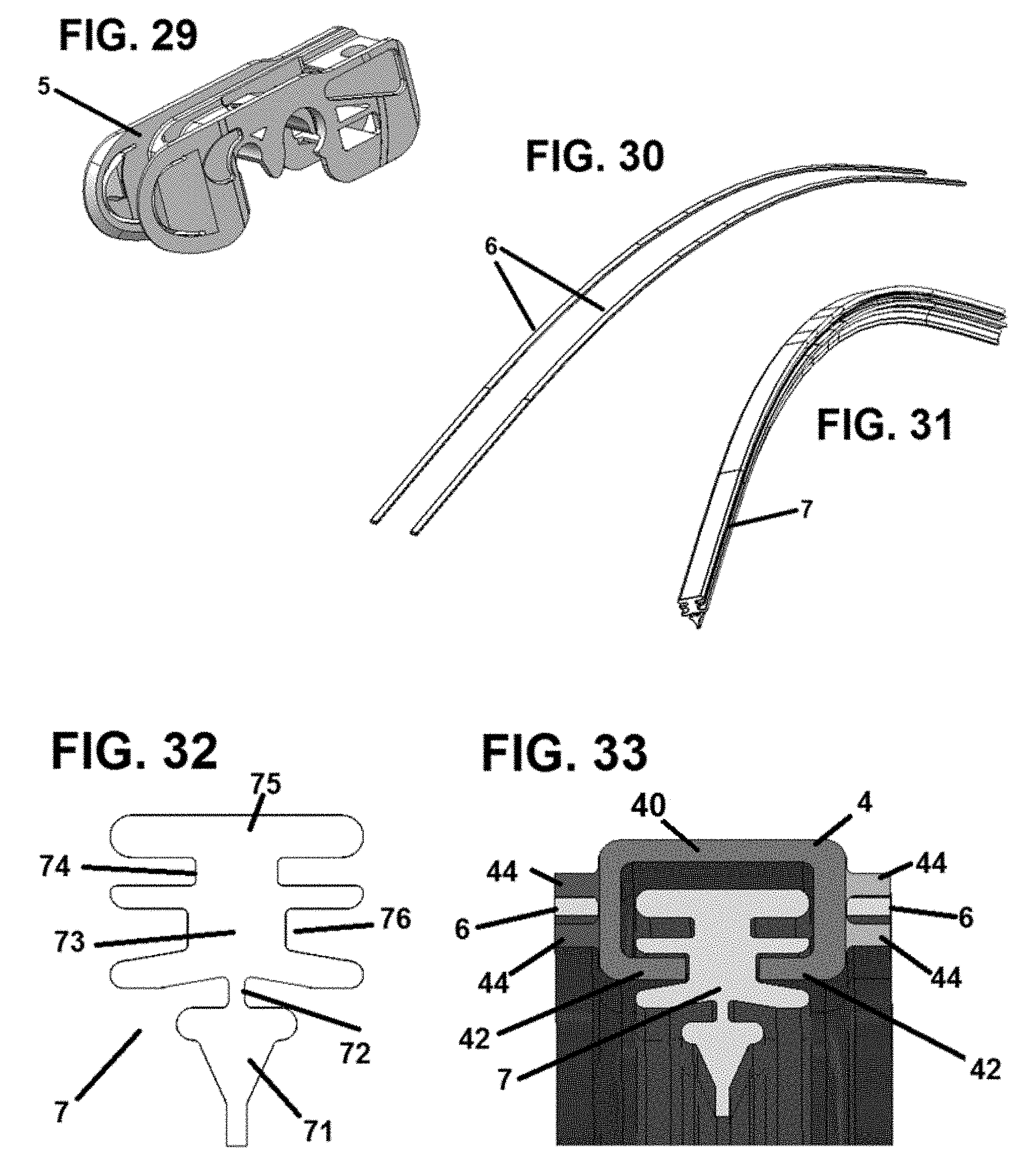
FIG. 29 illustrates an example connector that may be used with the wiper blade shown in FIG. 1.
FIG. 30 illustrates a perspective view from above of the vertebrae of the wiper blade shown in FIG. 1.
FIG. 31 illustrates a perspective view from above of the wiper strip of the wiper blade shown in FIG. 1.
FIG. 32 illustrates a cross-sectional profile of the wiper strip of the wiper blade shown in FIG. 1.
FIG. 33 illustrates a cross-sectional view from the side of the backing element, vertebrae and wiper strip of the wiper blade shown in FIG. 1.
FIG. 34 illustrates a perspective view from above of the junction between the mounting base, backing element and cover section of the wiper blade shown in FIG. 1.
FIG. 35 illustrates a perspective view from above of the junction between the mounting base and cover section of the wiper blade shown in FIG. 1.
FIG. 36 illustrates a perspective view from below of the end of the wiper strip and cover section of the wiper blade shown in FIG. 1.
FIG. 37 illustrates a perspective view from the side of the end of the wiper strip, backing element, vertebrae and cover section of the wiper blade shown in FIG. 1.
FIG. 38 illustrates a cross-sectional view of an alternative embodiment of the backing element.
FIG. 39 illustrates a cross-sectional view of an alternative embodiment of the backing element.
FIG. 40 illustrates a cross-sectional view of an alternative embodiment of the backing element.
DETAILED DESCRIPTION OF THE ILLUSTRATIVE EMBODIMENT
The following detailed description and the appended drawings describe and illustrate exemplary embodiments solely for the purpose of enabling one of ordinary skill in the relevant art to make and use the invention. As such, the detailed description and illustration of these embodiments are purely exemplary in nature and are in no way intended to limit the scope of the invention, or its protection, in any manner. It should also be understood that the drawings are not to scale and in certain instances details have been omitted, which are not necessary for an understanding of the present invention, such as conventional details of fabrication and assembly.
In certain embodiments a wiper blade may include an elongate wiper strip, an elastic backing element and a mounting base. The elongate wiper strip may include a wiping lip, a wide portion, and an intermediate portion between the wiping lip and the wide portion, such that the intermediate portion is narrower than the wide portion. The elastic elongate backing element may have a top portion from which two opposing, elongate legs descend, such that each leg includes an elongate claw that extends towards the opposite leg. Each leg may have an end such that the ends of the claws of the two legs may define a gap sized to receive the intermediate portion of the wiper strip. The top portion, legs and claws of the backing element may define a wiper strip cavity such that the wide portion of the wiper strip may be disposed within the wiper strip cavity. The mounting base may be capable of connecting the wiper blade to a wiper arm, and capable of receiving a force from the wiper arm. The mounting base may be disposed on a section of the backing element such that the mounting base is capable of applying a force from the wiper arm to the backing element. In turn, the backing element may, thereby, be capable of distributing the force along the length of the wiper strip.
In certain embodiments, the top portion of the backing element may include a securing hole disposed within the section of the backing element on which the mounting base is disposed. In certain such embodiments, the mounting base may include a backing element securing peg, wherein the backing element securing peg is disposed within the securing hole of the backing element.
In certain embodiments, a first cover section may extend from a first end of the mounting base to a first end of the backing element. In certain embodiments, the first end of the mounting base further comprises a projecting extension, and the first cover section may be provided with an extension recess, such that the projecting extension fits within, and is covered by, the extension recess of the first cover section. In certain such embodiments, the mounting base may also include a cover securing peg located on the projecting extension, and the first cover section may include a securing hole located in the extension recess, wherein the cover securing beg is located within the securing hole. In certain embodiments, a second cover section may extend from a second end of the mounting base to a second end of the backing element. In certain embodiments, the first cover section may be provided with at least one leg, such that the leg comprises a bottom claw, wherein the bottom claw secures the first cover section to the backing element.
In certain embodiments, the first cover section may include a backing element cavity, and the backing element may include a first covered section extending from the first end of the mounting base to the first end of the backing element, wherein the first covered section of the backing element is disposed within the backing element cavity of the first cover section. In certain such embodiments, the backing element cavity of the first cover section may include a backing element top cavity, such that the top portion of the backing element top cavity is disposed within the backing element top cavity along the first covered section of the backing element. In certain embodiments, the backing element may further include a first rail, and the first cover section may further include a backing element channel cavity such that the first rail of the backing element is disposed within the backing element channel cavity of the first cover section along the first covered section of the backing element. In certain embodiments, the backing element may include a second rail, wherein a first groove is formed by and between the first rail and the second rail. In certain such embodiments, a vertebra is disposed within the first groove. In certain embodiments, the backing element further comprises third and fourth rails, wherein a second groove is formed by and between the third and fourth rails, and a second vertebra is disposed within the second groove.
In certain embodiments, the first cover section may embody a spoiler having an apex and an attack surface. In certain embodiments, a vertebra may be disposed inside the wiper strip cavity above the wiper strip.
In certain embodiments, the mounting base may further include a first and second base wall which extend downwards from a bottom surface, such that each base wall is provided with a bottom base claw which extends inwardly towards the other base wall. The base walls may cover and secure the portion of the backing element on which the mounting base is disposed.
In certain embodiments, the mounting base may include a pair of cavity walls and a rivet extending therebetween such that the rivet may receive and secure a connector such that the mounting base is capable of connecting to a wiper arm through the use of the connector.
In certain embodiments, a wiper blade may include an elongate wiper strip, an elastic backing element, a mounting base and a first cover section. The elongate wiper strip may include a wiping lip, a wide portion, and an intermediate portion between the wiping lip and the wide portion, wherein the intermediate portion is narrower than the wide portion. The elastic, elongate backing element may have a top portion from which two opposing, elongate legs descend such that each leg may include an elongate claw that extends towards the opposite leg. The claws may each have an end such that the ends of the claws of the two legs may define a gap sized to receive the intermediate portion of the wiper strip. The top portion, legs and claws may define a wiper strip cavity and the wide portion of the wiper strip may be disposed within the wiper strip cavity. The mounting base may be capable of connecting the wiper blade to a wiper arm and may receive a force from the wiper arm. The mounting base may be disposed on a section of the backing element such that the mounting base may be capable of applying a force from the wiper arm to the backing element, and the backing element may be capable of distributing the force along the length of the wiper strip. The first cover section may extend from a first end of the mounting base to a first end of the backing element. The first end of the mounting base may include a projecting extension, and the first cover section may include an extension recess, such that the projecting extension fits within, and is covered by, the extension recess of the first cover section. The mounting base may further include a first and second base wall which may extend downwards from a bottom surface. Each base wall may be provided with a bottom base claw which extends inwardly towards the other base wall, such that the base walls cover and secure the portion of the backing element on which the mounting base is disposed.
FIGS. 1, 1A and 1B illustrate a wiper blade 1 which may have a mounting base 2, cover sections 3, a backing element 4, vertebrae 6, and a wiper strip 7. The mounting base 2 may be configured to connect to a wiper arm through the use of a connector 5 or an adapter. One possible connector 5 which may be used in accordance with the disclosed concepts is depicted in FIG. 29. Such a connector is described in U.S. Pat. No. 6,640,380, which is incorporated herein by reference in its entirety. Any other suitable connectors or adapters known in the art may also be used with the disclosed concepts, including the connectors described in U.S. Pat. Nos. 8,806,700 and 9,108,595, and U.S. Publication Nos. 2013/0185889, 2013/0192015, 2014/0283325 and 2015/0251637, which are each incorporated herein by reference in their entireties. Persons of skill in the art will also recognize that the mounting base may be specifically adapted to connect to a particular type of wiper arm directly without the use of a connector or an adapter, including the mounting base designs disclosed in U.S. Publication No. 2014/0082875, which is incorporated herein by reference in its entirety. Similarly, persons of skill in the art will recognize that the cover with a spoiler depicted in FIGS. 1, 1A and 1B is exemplary, and that any suitable cover, with or without a spoiler, may also be used in accordance with the disclosed concepts, including covers having spoilers with constant height and shape, covers having decreasing height, spoilers forming a centered isosceles triangle, or an off-center spoiler (as shown in FIGS. 1, 1A and 1B), including covers as described in U.S. Patent Publication Nos. 2012/0266405 and 2013/0205532, which are incorporated herein by reference in their entirety. Additionally, persons of ordinary skill in the art will recognize that any suitable wiper strip known in the art may be used in accordance with the disclosed concepts, including the wiper strips described in U.S. Provisional Application Ser. No. 62/139,383, which is incorporated herein by reference in its entirety.
One exemplary mounting base 2 that may be used in accordance with the disclosed concepts is illustrated in FIGS. 2-11. The mounting base is preferably made of hard plastic, though any other suitable material or combination of materials known in the art, including metals, rubber, and resins, may also be used. In some embodiments, the mounting base, or portions thereof, may be made from a material having a Shore Hardness A of 85.+-.5 or greater. In some embodiments, the mounting base, or portions thereof, may be made from a material having a Shore Hardness A of 95.+-.5 or greater. In other embodiments, the mounting base 2 may be made from multiple materials, or have multiple hardnesses. For example, in one such embodiment, the hardness of the cavity walls 20 and claws 241, 242, 261, 262 and the material joining same may be greater than the hardness of the other parts of the mounting base 2. For example, the cavity walls 20 and claws 241, 242, 261, 262 may be made from metal or hard plastic, while the other portions of the mounting base 2 may be made from a softer plastic or rubber. Persons of skill in the art will recognize that disclosed concepts may be implemented in many different ways, and different design choices may be made with respect to materials for all components, including the mounting base.
The mounting base 2 may have two or more cavity side walls 20 defining a cavity 23 therebetween. As shown in FIG. 2, two of the sidewalls 20 may extend in the longitudinal direction of the wiper blade 1, and a rivet 21 may extend and be secured between same. The mounting base may further have one or more pin holes 22 to allow the pin of a pin-type wiper arm to pass through and be secured, by a connector 5 or otherwise. The mounting base may further have a shoulder 25 having a shape that is complementary to, identical to, or otherwise follows the shape of the cover sections 3. The mounting base may have a base section 24 defining a backing element cavity 29 therewithin. The base section 24 may have a base bottom surface 240, legs, a base bottom claw 241, and a base top claw 242.
As shown in FIG. 3, the base bottom surface 240 may be recessed from the top claw 242 to form a backing element top cavity 290. The base bottom claw 241 and base top claw 242 may form a groove having a backing element channel cavity 291 therewithin. The backing element cavity 29 may receive the backing element 4, with the top portion 40 of the backing element 4 being received by the backing element top cavity 290 and the rails 44 and vertebra 6 being received by the channel cavity 291. If no vertebrae are located in the groove 45 between the rails 44 of the backing element, the mounting base 2 may include an intermediate claw (not shown) to engage and accommodate the groove 45. The mounting base may further have one or more backing element securing pegs 28, which may extend from the base bottom surface 240 and engage securing holes 46 in the backing element. The mounting base 2 may also have one or more cover securing pegs 27 that engages with a securing hole 37 in the cover section in order to secure the cover section 3 to the mounting base 2.
The mounting base may further have a projecting extension 26, which projects into, and is received by the extension recess 36 in the cover section 3, as shown in FIGS. 34 and 35. Persons of skill in the art will recognize that the projecting extension 26 and the extension recess 36 may be swapped such that the mounting base 2 may have an extension recess that receives a projecting extension from the cover section 3. As shown in FIGS. 2-6, the projecting extension 26 may be recessed from the base wall 24 and shoulder 25. As also shown in those figures, the securing pegs 27, 28 may be disposed on the projecting extension 26. The securing pegs 27, 28 and securing hole 37, 46 may engage via a snap fit, friction fit, or other form fitting connection. Persons of skill in the art will recognize that the securing mechanism may be swapped, having the securing holes located in the mounting base 2, and the securing pegs located in the cover section/backing element. Persons of skill in the art will also recognize that any other suitable securing mechanism known in the art may be used, including detents and recesses, dovetails, opposed projections, and other such structures may be used. Persons of skill in the art will also recognize that the securing mechanism need not be on the top surface of the projecting extension, but may be on the side, or may extend from the side of the shoulder, or any other arrangement known in the art.
As shown in FIGS. 3 & 7, the base bottom surface 240 may extend and continue into the projection 26. Similarly, the projecting extension may include an extension top claw 262 and an extension bottom claw 261 that may extend from and be aligned with the top base claw 242 and bottom base claw 241, respectively.
FIGS. 12-20 illustrate an exemplary cover section 3 in accordance with the disclosed concepts. The cover section 3 is preferably made of soft, elastic plastic or rubber, although any other suitable material or combination of materials known in the art, such as resins and silicon, for instance, may be used. In some embodiments, the cover section, or portions thereof, may be made from a material having a Shore Hardness A of 70.+-.5 or less. In other embodiments, the cover section, or portions thereof, may be made from a material having a Shore Hardness A of 60.+-.5 or less. In other embodiments, the mounting base 2 may be made from multiple materials, or having multiple hardnesses. It may be advantageous to have some portions of the cover section, such as the claws, made from a harder material, such as one having a Shore Hardness A of 85.+-.5 or greater, or one having a Shore Hardness A of 95.+-.5 or greater. For example, in one such embodiment, the hardness of the claws 32, 34 352 may be greater than the hardness of the other parts of the cover section 3. For example, the claws 32, 34 352 may be made from hard plastic, while the other portions of the cover section 3 may be made from a softer plastic or rubber. Persons of skill in the art will recognize that disclosed concepts may be implemented in many different ways, and different design choices may be made with respect to materials for all components, including the cover section.
The cover section 3 may include a top surface 30. As discussed above, any suitable cover known in the art may be used, with or without a spoiler. As shown in FIGS. 12-20, the top surface of the cover 30 may form a spoiler having an apex 300, an attack surface 301, and a back surface 302. As shown in FIG. 12, the attack surface 302 may be concave. The cover may further have at least one leg 31, where the back surface 302 may blend into, or be in line with, the leg 31. Thus, the bottom portion of the back surface 302 may also be considered a leg 31. As discussed above, the apex 300 may be centered (not shown), and the back surface may also be provided with an attack surface such that the spoiler forms an isosceles triangle (with or without concave attack surface sides) such that the front of the wiper blade 1 functions the same as the back of the wiper blade 1. As illustrated in FIG. 12, the apex 300 may end before the end of cover section 3, and a top wall 303 may join the attack surface 301 and the back surface 302. An end wall 35 may be provided and used to join the ends of the top surface 30 (including the top wall 303, attack surface 301, back surface 302, and/or the apex 300) and the leg(s) 31. As shown in FIG. 36, the end wall 35 encapsulates and surrounds the wiper strip 7 and backing element 4.
As discussed above, the inner end of the cover section 3, adjacent to the mounting base 2, may have an extension recess 36, which receives the projecting extension 26 from the mounting base 2. As also discussed above, an extension recess 36 may be provided with a securing hole 37 that receives a cover securing peg 27 from the mounting base. As discussed above, persons of skill in the art will recognize that the cover securing peg 27 and securing hole 37 may engage via a snap fit, friction fit, or other form fitting connection. Persons of skill in the art will recognize that securing mechanism may be swapped, having the securing holes located in the mounting base 2, and the securing pegs located in the cover section/backing element. Persons of skill in the art will also recognize that any other suitable securing mechanism known in the art may be used, including detents and recesses, dovetails, opposed projections, and other such structures may be used. Persons of skill in the art will also recognize that the securing mechanism need not be on the top surface of the projecting extension and bottom surface of the extension recess, but may be on the side, or may extend from the side of the shoulder, or any other arrangement known in the art. The extension recess 36 may have walls and a bottom claw 362 to cover and secure the projecting extension 26 of the mounting base.
The cover section may also have a bottom surface 38. The bottom surface 38, together with the legs 31, may define a backing element cavity 33 to receive the backing element 4. Each leg 31 may also define a top claw 34 and a bottom claw 32. The bottom surface 38 may be recessed from the top claws 34 such that the backing element cavity 33 may have a top cavity 330 to receive a top portion 40 of the backing element 4. The legs 31, including the top claws 34 and bottom claws 32, may define one or more channel cavities 331, which may be sized to receive the rails 44 of the backing element 4, and one or more vertebrae 6. If no vertebrae are included, the legs may define an intermediate claw to engage a groove 45, if one is present between the rails 44. The claws 32, 34 may extend along the entire length of the cover section, or may be intermittent, or have gaps. The cover section may optionally have backing element securing structures, such as pegs, detents, shoulders, projections, recesses, holes, and other such structures known in the art, along the bottom surface 38, the claws 32, 34 or the groove formed therebetween, such that these securing structures engage corresponding complementary securing structures in the backing element 4, such as holes, shoulders, detents, recesses, projections, pegs and other such structures known in the art.
FIGS. 21-28 illustrate an exemplary backing element 4 in accordance with the disclosed concepts. The backing element 4 is preferably made of hard, elastic plastic, though any other suitable material or combination of materials known in the art, including metals, rubber, and resins, for example, may be used. In some embodiments, the backing element 4, or portions thereof may be made from a material having a Shore Hardness A of 85.+-.5 or greater. In some embodiments, the backing element 4, or portions thereof, may be made from a material having a Shore Hardness A of 95.+-.5 or greater. In other embodiments, the backing element 4 may be made from multiple materials, or have multiple hardnesses. Persons of skill in the art will recognize that disclosed concepts may be implemented in many different ways, and different design choices may be made with respect to materials for all components, including the mounting base. The backing element may connect to the mounting base 2, which in turn is capable of connecting to a wiper arm directly or through the use of a connector 5 or adapter. The backing element 5, alone or with the help of the vertebrae, distribute the force received from the wiper arm along the length of the wiper strip 7.
The elongate backing element 4 may have a top portion 40, from which two opposing legs 41 descend. Each opposing leg may have a claw 42 which extends towards the opposing leg. The claws 42, legs 41, and top portion 40 may define a wiper strip cavity 43 sized to receive the wide portion 75 of a wiper strip 7. Similarly, the opposing claws 42 may define a gap therebetween sized to receive the intermediate portion of 73 of a wiper strip 7--which may be narrower than the wide portion 75 of the wiper strip 7--by engaging a recess or securing groove 76 (these terms may be used interchangeably) adjacent to the intermediate portion 73.
The backing element 4 may also have rails 44 extending along the outer surface of the legs 41 or extending from the top portion 40. As shown in FIG. 24, there may be two rails 44 extending from each outer surface of the legs 41/top portion 40 to define a groove 45 therebetween. The groove 45 may be sized to receive a vertebra 6 or flexor 6 (these terms may be used interchangeably). The rails 44 may extend along the entire length of the backing element 4, or may be intermittent or have gaps. In certain embodiments where no vertebrae are used on the outside of the backing element, the groove 45 between the rails 44 may optionally be removed. Alternatively, in other embodiments, not using rails 44 or grooves 45, the cavities in the mounting base 2 and cover sections 3 may be sized to receive and secure the entire backing element 4.
As discussed above, the backing element 4 may have securing holes 46 to receive securing pegs 28 in the mounting base. As also discussed above, the backing element may also have other securing structures, including pegs, projections, detents, recesses, holes, shoulders, and any other suitable structure known in the art in order to engage and secure a complementary structure in the mounting base 2 or cover sections 3.
As discussed above, FIG. 29 illustrates an exemplary connector that may be used in accordance with the disclosed concepts to connect the mounting base to a wiper arm. Persons of skill in the art will recognize that any suitable connector known in the art may be used with the disclosed concepts, including those set forth above and incorporated by reference.
FIG. 30 illustrates vertebrae in accordance with the disclosed concepts. The vertebrae are preferably made out of metal, such as steel, though may be made from any suitable material. The vertebrae may be made from a spring-elastic material, including spring-elastic metal. Accordingly, the vertebrae 6 may, with the backing element 4, distribute the force received from a wiper arm along the length of the wiper strip 7. Vertebrae may also be disposed within grooves 74 in the wide portion 75 of the wiper strip 7. In embodiments not having grooves 45 and/or outer rails 44 on the backing element 4, the vertebrae may be disposed in grooves 75 in the wiper strip, or may be disposed above the wiper strip, as shown in FIGS. 38-40.
FIGS. 31 & 32 illustrate an example wiper strip that may be used in accordance with the disclosed concepts. The wiper strip is preferably made of a soft rubber or plastic, but may be made of any suitable material. The wiper strip may have a wide portion 75 from which a narrower, intermediate portion 73 descends. The wide portion 75 may optionally have one or more grooves 74 which may optionally house vertebrae 6. The intermediate portion may be sized to fit between the claws 42 of the backing element 4, and may have a recessed portion or securing groove 76 which is sized to receive the claws 42.
FIG. 33 illustrates the backing element 4 of the disclosed concepts having vertebrae 6 disposed between its rails 44, and a wiper strip 7 disposed within its wiper strip cavity 43.
FIG. 34 illustrates the securing pegs 27, 28 in the mounting base which secure the carrier element 4 and cover section 3 to the mounting base 2.
FIG. 35 illustrates the securing pegs 27 in the mounting base which secures the cover section 3 to the mounting base 2.
FIGS. 1 and 36 illustrate how the end wall 35 of the cover section 3 surrounds and encapsulates the backing element 4 and wiper strip 7 to secure them against longitudinal movement.
FIG. 37 illustrates how the cover section 3 of the disclosed concept can be disengaged from the rails 44 of the backing element 4 and folded upwards. This allows a user to slidably remove the wiper strip 7 from the backing element 4 and to replace it with a new wiper strip 7. In this fashion, the disclosed concept allows for a refillable wiper blade, such that the end user of the product does not need to replace the entire product when ordinary wear and tear on the wiper strip 7 requires its replacement. Instead, the user can simply fold up the end of the cover section 3 of the wiper blade 1, as shown in FIG. 37, and quickly remove the old wiper strip and slide in a new wiper strip. In some embodiments, the claws 32, 34 of the cover section may end a distance away from the end wall 35 to facilitate the folding up of the cover strip to allow access to the backing element 4 and wiper strip 7.
As discussed above, FIGS. 38-40 illustrate alternative embodiments of the backing element 4 having a singular internal vertebra. If the embodiment illustrated in FIG. 38, the top portion 40 of the backing element contains a gap, there is an internal wall defining a cavity between the top portion and the internal wall, and the vertebra 6 resides in that cavity. In the embodiment illustrated in FIG. 39, there is an internal wall defining a cavity between the top portion 40 and the internal wall and the vertebra 6 resides in that cavity. In the embodiment illustrated in FIG. 40, there vertebra 6 is inserted into the wiper strip cavity 43 above the wiper strip.
Those skilled in the art will recognize that while the invention will most likely be used in conjunction with automobiles, it is suitable for use with any vehicle. For example, in addition to automobiles, trucks, buses, locomotives, aircrafts, or any other vehicle type that uses a windshield wiper can benefit from the invention.
While specific embodiments have been discussed to illustrate the invention, it will be understood by those skilled in the art that the descriptions herein are intended as illustrative, and not as limiting, and that variations in the embodiments can be made without departing from the spirit of the invention.
Accordingly, the foregoing descriptions are intended as illustrative, and not as limiting.
LIST OF REFERENCE NUMBERS
1. Wiper blade. 2. Mounting base. 20. Cavity walls. 21. Rivet. 22. Pin holes. 23. Connector cavity. 24. Base wall. 240. Base bottom surface. 241. Bottom base claw. 242. Top base claw. 25. Shaped shoulder. 26. Projecting extension. 261. Extension bottom claw. 262. Extension top claw. 27. Cover securing peg 28. Backing element securing peg. 29. Backing element cavity. 290. Backing element top cavity 291. Backing element channel cavity. 3. Cover section. 30. Top surface. 300. Apex. 301. Attack surface. 302. Back surface. 303. Top wall. 31. Leg. 32. Bottom claw 33. Backing element cavity. 330. Backing element top cavity. 331. Backing element channel cavity. 34. Top claw 35. End wall 36. Extension recess. 362. Extension bottom claw. 37. Securing hole. 38. Bottom surface 4. Backing element. 40. Top portion 41. Legs. 42. Claw 43. Wiper strip cavity. 44. Rail. 45. Groove. 46. Securing hole 5. Connector. 6. Vertebra/vertebrae. 7. Wiper strip. 71. Wiper lip. 72. Neck 73. Intermediate portion. 74. Vertebra groove. 75. Wide portion. 76. Securing groove.
* * * * *
References
D00000
D00001
D00002
D00003
D00004
D00005
D00006
D00007
D00008
D00009
D00010
D00011
D00012

D00013

XML
uspto.report is an independent third-party trademark research tool that is not affiliated, endorsed, or sponsored by the United States Patent and Trademark Office (USPTO) or any other governmental organization. The information provided by uspto.report is based on publicly available data at the time of writing and is intended for informational purposes only.
While we strive to provide accurate and up-to-date information, we do not guarantee the accuracy, completeness, reliability, or suitability of the information displayed on this site. The use of this site is at your own risk. Any reliance you place on such information is therefore strictly at your own risk.
All official trademark data, including owner information, should be verified by visiting the official USPTO website at www.uspto.gov. This site is not intended to replace professional legal advice and should not be used as a substitute for consulting with a legal professional who is knowledgeable about trademark law.