Exhaust apparatus and substrate processing apparatus having an exhaust line with a first ring having at least one hole on a lateral side thereof placed in the exhaust line
Lee , et al.
U.S. patent number 10,364,493 [Application Number 15/672,063] was granted by the patent office on 2019-07-30 for exhaust apparatus and substrate processing apparatus having an exhaust line with a first ring having at least one hole on a lateral side thereof placed in the exhaust line. This patent grant is currently assigned to ASM IP Holding B.V.. The grantee listed for this patent is ASM IP Holding B.V.. Invention is credited to Dae Youn Kim, Jae Hyun Kim, Seung Wook Kim, Hak Joo Lee, Jin Seok Park.


View All Diagrams
| United States Patent | 10,364,493 |
| Lee , et al. | July 30, 2019 |
Exhaust apparatus and substrate processing apparatus having an exhaust line with a first ring having at least one hole on a lateral side thereof placed in the exhaust line
Abstract
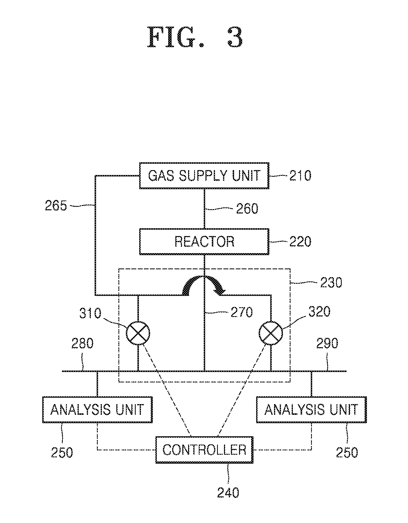
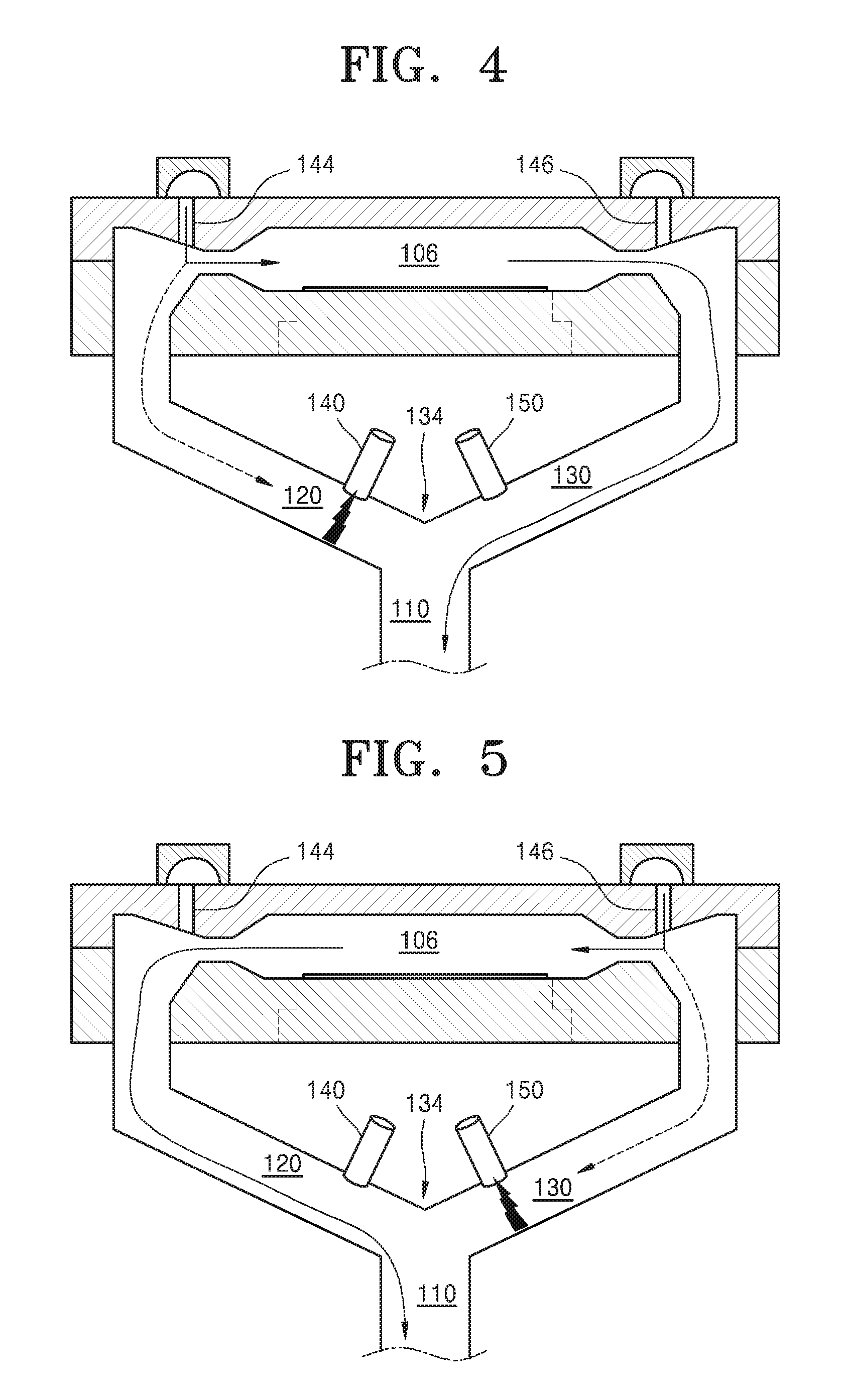
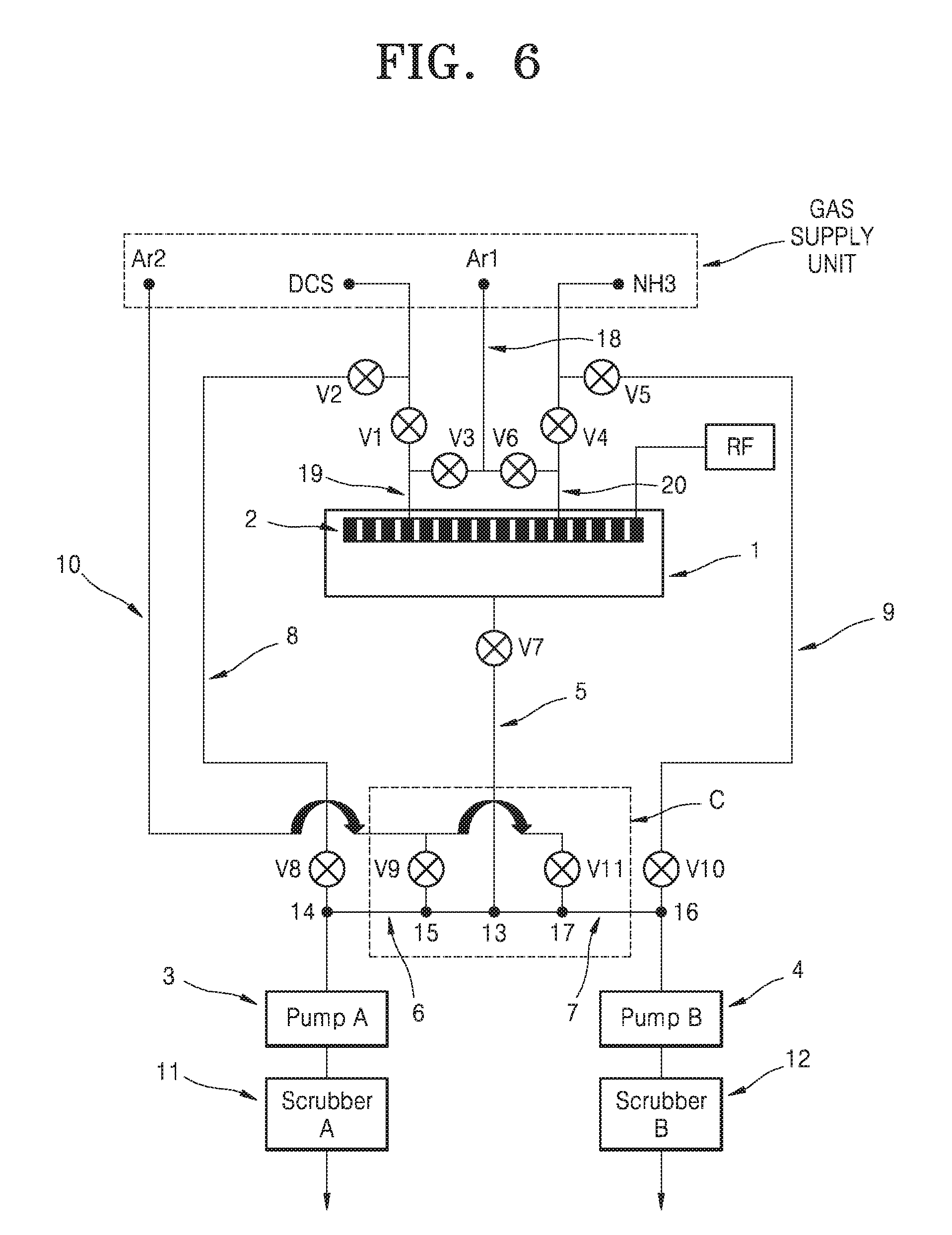
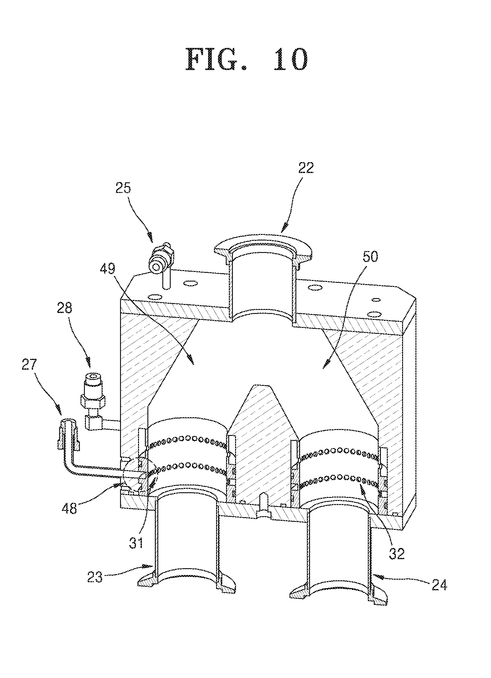
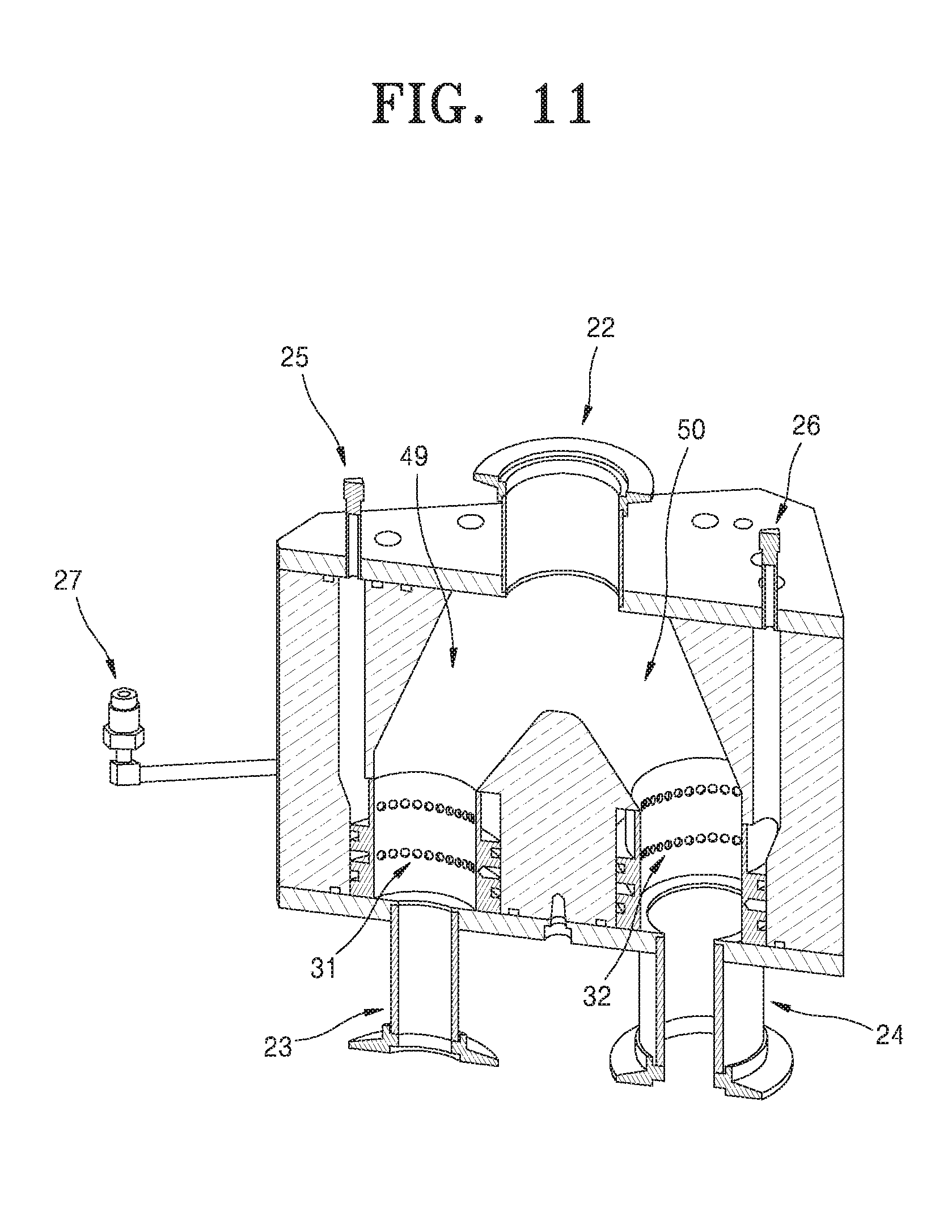
An exhaust apparatus using a gas curtain instead of a mechanical opening/closing structure is provided. The exhaust apparatus includes: a first region; a second region connected to the first region; a third region connected to the first region; and a first gas line connected to the second region, wherein when gas is supplied to the first gas line, the first region does not communicate with the second region but communicates with the third region.
| Inventors: | Lee; Hak Joo (Incheon, KR), Kim; Dae Youn (Daejeon, KR), Kim; Seung Wook (Gyeongsangnam-do, KR), Park; Jin Seok (Gyeonggi-do, KR), Kim; Jae Hyun (Gyeongsangbuk-do, KR) | ||||||||||
|---|---|---|---|---|---|---|---|---|---|---|---|
| Applicant: |
|
||||||||||
| Assignee: | ASM IP Holding B.V. (Almere,
NL) |
||||||||||
| Family ID: | 61241853 | ||||||||||
| Appl. No.: | 15/672,063 | ||||||||||
| Filed: | August 8, 2017 |
Prior Publication Data
| Document Identifier | Publication Date | |
|---|---|---|
| US 20180057937 A1 | Mar 1, 2018 | |
Foreign Application Priority Data
| Aug 25, 2016 [KR] | 10-2016-0108380 | |||
| Current U.S. Class: | 1/1 |
| Current CPC Class: | C23C 16/4412 (20130101); H01J 37/32449 (20130101); C23C 16/345 (20130101); C23C 16/455 (20130101); C23C 16/45544 (20130101); C23C 16/45561 (20130101); H01J 37/32513 (20130101); H01J 37/32834 (20130101); C23C 16/4554 (20130101) |
| Current International Class: | C23C 16/44 (20060101); C23C 16/34 (20060101); C23C 16/455 (20060101); H01J 37/32 (20060101) |
| Field of Search: | ;117/84,88,102,200-202 ;118/715,722,733 |
References Cited [Referenced By]
U.S. Patent Documents
| D30036 | January 1899 | Rhind |
| D31889 | November 1899 | Gill |
| 2059480 | November 1936 | Obermaier |
| 2161626 | June 1939 | Loughner et al. |
| 2266416 | December 1941 | Duclos Aeneas Jn |
| 2280778 | April 1942 | Anderson |
| 2410420 | November 1946 | Bennett |
| 2563931 | August 1951 | Harrison |
| 2660061 | November 1953 | Lewis |
| 2745640 | May 1956 | Cushman |
| 2990045 | September 1959 | Root |
| 3038951 | June 1962 | Mead |
| 3089507 | May 1963 | Drake et al. |
| 3094396 | June 1963 | Flugge et al. |
| 3232437 | February 1966 | Hultgren |
| 3263502 | August 1966 | Springfield |
| 3410349 | November 1968 | Troutman |
| 3588192 | June 1971 | Drutchas et al. |
| 3647387 | March 1972 | Benson |
| 3647716 | March 1972 | Koches |
| 3713899 | January 1973 | Sebestyen |
| 3718429 | February 1973 | Williamson |
| 3833492 | September 1974 | Bollyky |
| 3854443 | December 1974 | Baerg |
| 3862397 | January 1975 | Anderson et al. |
| 3867205 | February 1975 | Schley |
| 3885504 | May 1975 | Baermann |
| 3887790 | June 1975 | Ferguson |
| 3904371 | September 1975 | Neti |
| 3913058 | October 1975 | Nishio et al. |
| 3913617 | October 1975 | van Laar |
| 3947685 | March 1976 | Meinel |
| 3960559 | June 1976 | Suzuki |
| 4054071 | October 1977 | Patejak |
| 4058430 | November 1977 | Suntola et al. |
| 4093491 | June 1978 | Whelpton et al. |
| D249341 | September 1978 | Mertz |
| 4126027 | November 1978 | Smith et al. |
| 4134425 | January 1979 | Gussefeld et al. |
| 4145699 | March 1979 | Hu et al. |
| 4164959 | August 1979 | Wurzburger |
| 4176630 | December 1979 | Elmer |
| 4181330 | January 1980 | Kojima |
| 4194536 | March 1980 | Stine et al. |
| 4217463 | August 1980 | Swearingen |
| 4234449 | November 1980 | Wolson et al. |
| 4355912 | October 1982 | Haak |
| 4444990 | April 1984 | Villar |
| 4454370 | June 1984 | Voznick |
| 4455193 | June 1984 | Jeuch et al. |
| 4466766 | August 1984 | Geren et al. |
| 4527005 | July 1985 | McKelvey et al. |
| 4537001 | August 1985 | Uppstrom |
| 4579378 | April 1986 | Snyders |
| 4590326 | May 1986 | Woldy |
| 4611966 | September 1986 | Johnson |
| 4620998 | November 1986 | Lalvani |
| 4721533 | January 1988 | Phillippi et al. |
| 4749416 | June 1988 | Greenspan |
| 4830515 | May 1989 | Cortes |
| 4854266 | August 1989 | Simson et al. |
| 4934831 | June 1990 | Volbrecht |
| 4949848 | August 1990 | Kos |
| D311126 | October 1990 | Crowley |
| 4989992 | February 1991 | Piai |
| 5061083 | October 1991 | Grimm et al. |
| 5071258 | December 1991 | Usher et al. |
| 5108192 | April 1992 | Mailliet et al. |
| 5154301 | October 1992 | Kos |
| 5158128 | October 1992 | Inoue et al. |
| 5176451 | January 1993 | Sasada |
| 5181779 | January 1993 | Shia et al. |
| 5228114 | July 1993 | Suzuki |
| 5246218 | September 1993 | Yap et al. |
| 5294778 | March 1994 | Carman et al. |
| 5314570 | May 1994 | Ikegaya et al. |
| 5356672 | October 1994 | Schmitt et al. |
| D353452 | December 1994 | Groenhoff |
| 5374315 | December 1994 | Deboer et al. |
| 5388945 | February 1995 | Garric et al. |
| 5407449 | April 1995 | Zinger |
| 5423942 | June 1995 | Robbins et al. |
| 5523616 | June 1996 | Yasuhide |
| 5527111 | June 1996 | Lysen et al. |
| 5616264 | April 1997 | Nishi et al. |
| 5663899 | September 1997 | Zvonar et al. |
| 5697706 | December 1997 | Ciaravino et al. |
| 5708825 | January 1998 | Sotomayor |
| 5716133 | February 1998 | Hosokawa et al. |
| D392855 | March 1998 | Pillow |
| 5753835 | May 1998 | Gustin |
| 5761328 | June 1998 | Solberg et al. |
| 5779203 | July 1998 | Edlinger |
| 5791782 | August 1998 | Wooten et al. |
| 5806980 | September 1998 | Berrian |
| 5813851 | September 1998 | Nakao |
| 5819092 | October 1998 | Ferguson et al. |
| 5827435 | October 1998 | Seiji |
| 5844683 | December 1998 | Pavloski et al. |
| 5857777 | January 1999 | Schuh |
| 5863123 | January 1999 | Lee |
| 5884640 | March 1999 | Fishkin et al. |
| D412270 | July 1999 | Fredrickson |
| 5947718 | September 1999 | Weaver |
| 5954375 | September 1999 | Trickle et al. |
| 5961775 | October 1999 | Fujimura |
| 5970621 | October 1999 | Bazydola |
| 5982931 | November 1999 | Ishimaru |
| 5984391 | November 1999 | Vanderpot et al. |
| 5987480 | November 1999 | Donohue et al. |
| 5998870 | December 1999 | Lee et al. |
| 6013920 | January 2000 | Gordon et al. |
| 6045260 | April 2000 | Schwartz et al. |
| 6054678 | April 2000 | Miyazaki |
| 6060721 | May 2000 | Huang |
| 6073973 | June 2000 | Boscaljon et al. |
| 6091062 | July 2000 | Pfahnl et al. |
| 6093252 | July 2000 | Wengert et al. |
| 6102565 | August 2000 | Kita et al. |
| 6104011 | August 2000 | Juliano |
| 6104401 | August 2000 | Parsons |
| 6119710 | September 2000 | Brown |
| 6121061 | September 2000 | Van Bilsen et al. |
| 6158941 | December 2000 | Muka et al. |
| 6203613 | March 2001 | Gates et al. |
| 6235858 | May 2001 | Swarup et al. |
| 6243654 | June 2001 | Johnson et al. |
| 6257758 | July 2001 | Culbertson |
| 6293700 | September 2001 | Lund et al. |
| 6311016 | October 2001 | Yanagawa et al. |
| 6344084 | February 2002 | Koinuma et al. |
| D455024 | April 2002 | Mimick et al. |
| 6432849 | August 2002 | Endo et al. |
| 6435865 | August 2002 | Tseng et al. |
| 6438502 | August 2002 | Awtrey |
| 6441350 | August 2002 | Stoddard et al. |
| 6447232 | September 2002 | Davis et al. |
| 6494998 | December 2002 | Brcka |
| 6496819 | December 2002 | Bello et al. |
| 6503079 | January 2003 | Kogano et al. |
| 6507410 | January 2003 | Robertson et al. |
| 6536950 | March 2003 | Green |
| 6559026 | May 2003 | Rossman et al. |
| 6574644 | June 2003 | Hsu et al. |
| 6580050 | June 2003 | Miller et al. |
| 6607948 | August 2003 | Sugiyama et al. |
| 6660662 | December 2003 | Ishikawa et al. |
| 6676290 | January 2004 | Lu |
| 6682971 | January 2004 | Tsuneda et al. |
| 6684659 | February 2004 | Tanaka et al. |
| 6699399 | March 2004 | Qian et al. |
| 6722837 | April 2004 | Inui |
| 6755221 | June 2004 | Jeong et al. |
| 6756085 | June 2004 | Waldfried |
| 6828235 | December 2004 | Takano |
| 6846146 | January 2005 | Inui |
| D505590 | May 2005 | Greiner |
| 6889211 | May 2005 | Yoshiura et al. |
| 6913152 | July 2005 | Zuk |
| 6981832 | January 2006 | Zinger et al. |
| 6982046 | January 2006 | Srivastava et al. |
| 7010580 | March 2006 | Fu et al. |
| 7017514 | March 2006 | Shepherd et al. |
| 7070178 | July 2006 | Van Der Toorn et al. |
| 7073834 | July 2006 | Matsumoto et al. |
| 7080545 | July 2006 | Dimeo et al. |
| 7090394 | August 2006 | Hashikura et al. |
| 7111232 | September 2006 | Bascom |
| 7156380 | January 2007 | Soininen |
| 7168852 | January 2007 | Linnarsson |
| 7223014 | May 2007 | Lojen |
| 7274867 | September 2007 | Peukert |
| 7296460 | November 2007 | Dimeo et al. |
| 7307028 | December 2007 | Goto et al. |
| 7320544 | January 2008 | Hsieh |
| 7351057 | April 2008 | Berenbak et al. |
| 7354873 | April 2008 | Fukazawa et al. |
| 7376520 | May 2008 | Wong |
| 7379785 | May 2008 | Higashi et al. |
| 7410290 | August 2008 | Tanaka |
| D576001 | September 2008 | Brunderman |
| 7422635 | September 2008 | Zheng et al. |
| 7456429 | November 2008 | Levy |
| 7475588 | January 2009 | Dimeo et al. |
| 7497614 | March 2009 | Gaff |
| 7547633 | June 2009 | Ravish et al. |
| 7561982 | July 2009 | Rund et al. |
| D600223 | September 2009 | Aggarwal |
| 7582575 | September 2009 | Fukazawa et al. |
| 7591601 | September 2009 | Matsuoka et al. |
| 7621672 | November 2009 | Ripley |
| 7622369 | November 2009 | Lee et al. |
| 7623940 | November 2009 | Huskamp et al. |
| 7651269 | January 2010 | Comendant |
| 7651959 | January 2010 | Fukazawa et al. |
| 7661299 | February 2010 | Kusunoki |
| 7692171 | April 2010 | Kaszuba et al. |
| 7716993 | May 2010 | Ozawa et al. |
| 7736437 | June 2010 | Cadwell et al. |
| 7749563 | July 2010 | Zheng et al. |
| 7753584 | July 2010 | Gambino et al. |
| 7781352 | August 2010 | Fukazawa et al. |
| 7789559 | September 2010 | Waser et al. |
| 7806587 | October 2010 | Kobayashi |
| 7807566 | October 2010 | Tsuji et al. |
| 7829460 | November 2010 | Streck et al. |
| 7858519 | December 2010 | Liu et al. |
| 7871198 | January 2011 | Rempe et al. |
| 7874726 | January 2011 | Jacobs et al. |
| D634329 | March 2011 | Wastrom |
| 7915667 | March 2011 | Knoefler et al. |
| 7946762 | May 2011 | Yednak |
| 7955650 | June 2011 | Tsuji |
| 7957708 | June 2011 | Karschnia et al. |
| 7967913 | June 2011 | Hua et al. |
| 7997795 | August 2011 | Schwagerman et al. |
| 8046193 | October 2011 | Yetter et al. |
| D651291 | December 2011 | Liebson et al. |
| 8076251 | December 2011 | Akae et al. |
| 8078310 | December 2011 | Nishimoto et al. |
| 8084104 | December 2011 | Shinriki et al. |
| 8100583 | January 2012 | Aggarwal |
| 8110099 | February 2012 | Hersey et al. |
| 8158512 | April 2012 | Ji et al. |
| 8172947 | May 2012 | Shibata et al. |
| 8178436 | May 2012 | King et al. |
| 8349083 | January 2013 | Takasuka et al. |
| 8398773 | March 2013 | Jdira et al. |
| 8415258 | April 2013 | Akae |
| 8496377 | July 2013 | Harr et al. |
| 8497213 | July 2013 | Yasui et al. |
| 8501599 | August 2013 | Ueno et al. |
| 8506162 | August 2013 | Schick et al. |
| 8529701 | September 2013 | Morita |
| D695240 | December 2013 | Iida et al. |
| 8616765 | December 2013 | Darabnia et al. |
| D698904 | February 2014 | Milligan et al. |
| D702188 | April 2014 | Jacobs |
| 8710580 | April 2014 | Sakuma et al. |
| D705762 | May 2014 | Yu |
| 8664127 | May 2014 | Bhatia et al. |
| 8722510 | May 2014 | Watanabe et al. |
| 8779502 | July 2014 | Sakuma et al. |
| 8790749 | July 2014 | Omori et al. |
| 8846502 | September 2014 | Haukka et al. |
| 8882923 | November 2014 | Saido et al. |
| 8901016 | December 2014 | Jeongseok et al. |
| 8945305 | February 2015 | Marsh |
| 8945339 | February 2015 | Kakimoto |
| D723330 | March 2015 | York |
| 8974868 | March 2015 | Ishikawa et al. |
| 8993457 | March 2015 | Ramkumar et al. |
| 9018567 | April 2015 | de Ridder et al. |
| 9023738 | May 2015 | Kato et al. |
| 9029244 | May 2015 | Won et al. |
| D733843 | July 2015 | Yamagishi |
| 9099505 | August 2015 | Kusakabe et al. |
| 9129897 | September 2015 | Pore et al. |
| 9136180 | September 2015 | Machkaoutsan |
| 9142437 | September 2015 | Fosnight et al. |
| D742202 | November 2015 | Cyphers et al. |
| D743357 | November 2015 | Vyne |
| 9190264 | November 2015 | Yuasa et al. |
| 9257274 | February 2016 | Kang et al. |
| 9267850 | February 2016 | Aggarwal |
| 9297705 | March 2016 | Aggarwal |
| 9299557 | March 2016 | Tolle et al. |
| D753269 | April 2016 | Yamagishi et al. |
| 9343343 | May 2016 | Mori |
| 9412582 | August 2016 | Sasaki et al. |
| D770993 | November 2016 | Yoshida et al. |
| 9484191 | November 2016 | Winkler |
| 9514927 | December 2016 | Tolle et al. |
| 9514932 | December 2016 | Mallick et al. |
| D783351 | April 2017 | Fujino et al. |
| D785766 | May 2017 | Sato |
| D787458 | May 2017 | Kim et al. |
| 9640448 | May 2017 | Ikegawa et al. |
| D789888 | June 2017 | Jang et al. |
| 9708707 | July 2017 | Ditizio et al. |
| 9708708 | July 2017 | Isobe et al. |
| D793572 | August 2017 | Kozuka et al. |
| 9748145 | August 2017 | Kannan et al. |
| D796458 | September 2017 | Jang et al. |
| 9759489 | September 2017 | Kaneko |
| D802546 | November 2017 | Jang et al. |
| 9890456 | February 2018 | Tolle et al. |
| 9929011 | March 2018 | Hawryluk et al. |
| 10032628 | June 2018 | Xie et al. |
| 10023960 | July 2018 | Alokozai |
| 10032792 | July 2018 | Kim et al. |
| 10043661 | August 2018 | Kato et al. |
| 10083836 | September 2018 | Milligan |
| D830981 | October 2018 | Jeong et al. |
| 10087522 | October 2018 | Raisanen et al. |
| 10087525 | October 2018 | Schmotzer et al. |
| 10090316 | October 2018 | Ootsuka |
| 10103040 | October 2018 | Oosterlaken et al. |
| 2001/0003191 | June 2001 | Kovacs et al. |
| 2001/0038783 | November 2001 | Nakashima et al. |
| 2001/0040511 | November 2001 | Bushner et al. |
| 2001/0049080 | December 2001 | Asano |
| 2002/0005400 | January 2002 | Gat et al. |
| 2002/0009119 | January 2002 | Matthew et al. |
| 2002/0011211 | January 2002 | Halpin |
| 2002/0013792 | January 2002 | Imielinski et al. |
| 2002/0014483 | February 2002 | Suzuki et al. |
| 2002/0016829 | February 2002 | Defosse |
| 2002/0043337 | April 2002 | Goodman et al. |
| 2002/0064598 | May 2002 | Wang et al. |
| 2002/0069222 | June 2002 | McNeely |
| 2002/0109115 | August 2002 | Cederstav et al. |
| 2002/0112114 | August 2002 | Blair et al. |
| 2002/0136214 | September 2002 | Do et al. |
| 2002/0151327 | October 2002 | Levitt |
| 2002/0152244 | October 2002 | Dean et al. |
| 2002/0155219 | October 2002 | Wang et al. |
| 2002/0174106 | November 2002 | Martin |
| 2002/0184111 | December 2002 | Swanson |
| 2003/0002562 | January 2003 | Yerlikaya et al. |
| 2003/0010451 | January 2003 | Tzu |
| 2003/0029303 | February 2003 | Hasegawa et al. |
| 2003/0035002 | February 2003 | Moles |
| 2003/0036272 | February 2003 | Shamouilian et al. |
| 2003/0040841 | February 2003 | Nasr et al. |
| 2003/0049372 | March 2003 | Cook et al. |
| 2003/0065413 | April 2003 | Liteplo et al. |
| 2003/0082296 | May 2003 | Elers et al. |
| 2003/0109107 | June 2003 | Hsieh et al. |
| 2003/0109951 | June 2003 | Hsiung et al. |
| 2003/0168699 | September 2003 | Honda |
| 2003/0219972 | November 2003 | Green |
| 2003/0231698 | December 2003 | Yamaguchi |
| 2004/0010772 | January 2004 | McKenna et al. |
| 2004/0026372 | February 2004 | Takenaka et al. |
| 2004/0037675 | February 2004 | Zinger et al. |
| 2004/0087141 | May 2004 | Ramanathan et al. |
| 2004/0129671 | July 2004 | Ji et al. |
| 2004/0151844 | August 2004 | Zhang et al. |
| 2004/0231600 | November 2004 | Lee |
| 2004/0250600 | December 2004 | Bevers et al. |
| 2004/0253867 | December 2004 | Matsumoto |
| 2005/0000428 | January 2005 | Shero et al. |
| 2005/0042778 | February 2005 | Peukert |
| 2005/0092733 | May 2005 | Ito et al. |
| 2005/0098107 | May 2005 | Du Bois et al. |
| 2005/0101843 | May 2005 | Quinn et al. |
| 2005/0118837 | June 2005 | Todd |
| 2005/0130427 | June 2005 | Seok-Jun |
| 2005/0141591 | June 2005 | Sakano |
| 2005/0233477 | October 2005 | Yamazaki et al. |
| 2005/0245058 | November 2005 | Lee et al. |
| 2005/0263072 | December 2005 | Balasubramanian et al. |
| 2005/0285097 | December 2005 | Shang et al. |
| 2006/0013674 | January 2006 | Elliott et al. |
| 2006/0026314 | February 2006 | Franchuk et al. |
| 2006/0040054 | February 2006 | Pearlstein et al. |
| 2006/0068104 | March 2006 | Ishizaka |
| 2006/0128142 | June 2006 | Whelan et al. |
| 2006/0156981 | July 2006 | Fondurulia |
| 2006/0166428 | July 2006 | Kamioka |
| 2006/0175669 | August 2006 | Kim et al. |
| 2006/0188360 | August 2006 | Bonora et al. |
| 2006/0211259 | September 2006 | Maes |
| 2006/0216942 | September 2006 | Kim et al. |
| 2006/0252351 | November 2006 | Kundracik |
| 2006/0269690 | November 2006 | Watanabe et al. |
| 2006/0275933 | December 2006 | Du Bois et al. |
| 2007/0012402 | January 2007 | Sneh |
| 2007/0032045 | February 2007 | Kasahara |
| 2007/0034477 | February 2007 | Inui |
| 2007/0062439 | March 2007 | Wada et al. |
| 2007/0066038 | March 2007 | Sadjadi et al. |
| 2007/0066084 | March 2007 | Wajda et al. |
| 2007/0119370 | May 2007 | Ma et al. |
| 2007/0123189 | May 2007 | Saito et al. |
| 2007/0129621 | June 2007 | Kellogg et al. |
| 2007/0137794 | June 2007 | Qiu et al. |
| 2007/0202678 | August 2007 | Plombon et al. |
| 2007/0258506 | November 2007 | Schwagerman et al. |
| 2007/0266945 | November 2007 | Shuto et al. |
| 2007/0269983 | November 2007 | Sneh |
| 2008/0020593 | January 2008 | Wang et al. |
| 2008/0031708 | February 2008 | Bonora et al. |
| 2008/0038485 | February 2008 | Fuzakawa et al. |
| 2008/0042165 | February 2008 | Sugizaki |
| 2008/0043803 | February 2008 | Bandoh |
| 2008/0056860 | March 2008 | Natume |
| 2008/0075562 | March 2008 | Maria et al. |
| 2008/0118334 | May 2008 | Bonora |
| 2008/0121626 | May 2008 | Thomas et al. |
| 2008/0132046 | June 2008 | Walther |
| 2008/0202689 | August 2008 | Kim |
| 2008/0205483 | August 2008 | Rempe et al. |
| 2008/0228306 | September 2008 | Yetter et al. |
| 2008/0241387 | October 2008 | Keto |
| 2008/0268635 | October 2008 | Yu et al. |
| 2008/0289574 | November 2008 | Jacobs et al. |
| 2008/0291964 | November 2008 | Shrimpling |
| 2008/0299758 | December 2008 | Harada et al. |
| 2009/0017631 | January 2009 | Bencher |
| 2009/0042408 | February 2009 | Maeda |
| 2009/0052498 | February 2009 | Halpin et al. |
| 2009/0095221 | April 2009 | Tam et al. |
| 2009/0108308 | April 2009 | Yang et al. |
| 2009/0112458 | April 2009 | Nakai |
| 2009/0122458 | May 2009 | Lischer et al. |
| 2009/0124131 | May 2009 | Breunsbach et al. |
| 2009/0130859 | May 2009 | Itatani et al. |
| 2009/0159000 | June 2009 | Aggarwal et al. |
| 2009/0179365 | July 2009 | Lerner et al. |
| 2009/0186571 | July 2009 | Haro |
| 2009/0204403 | August 2009 | Hollander et al. |
| 2009/0236276 | September 2009 | Kurth et al. |
| 2009/0302434 | December 2009 | Pallem et al. |
| 2009/0308315 | December 2009 | de Ridder |
| 2009/0308425 | December 2009 | Yednak |
| 2010/0032587 | February 2010 | Hosch et al. |
| 2010/0032842 | February 2010 | Herdt et al. |
| 2010/0040441 | February 2010 | Obikane |
| 2010/0051597 | March 2010 | Morita et al. |
| 2010/0075037 | March 2010 | Marsh |
| 2010/0081094 | April 2010 | Hasebe et al. |
| 2010/0105936 | April 2010 | Tada et al. |
| 2010/0112496 | May 2010 | Nakajima et al. |
| 2010/0144968 | June 2010 | Lee et al. |
| 2010/0145547 | June 2010 | Darabnia et al. |
| 2010/0159707 | June 2010 | Huang et al. |
| 2010/0170868 | July 2010 | Lin et al. |
| 2010/0230863 | September 2010 | Moench et al. |
| 2010/0233885 | September 2010 | Kushibiki et al. |
| 2010/0255218 | October 2010 | Oka et al. |
| 2010/0246630 | November 2010 | Kaszynski et al. |
| 2010/0282163 | November 2010 | Aggarwal et al. |
| 2010/0285237 | November 2010 | Ditizio et al. |
| 2010/0326358 | December 2010 | Choi |
| 2011/0046314 | February 2011 | Klipp et al. |
| 2011/0139272 | June 2011 | Matsumoto et al. |
| 2011/0198417 | August 2011 | Detmar et al. |
| 2011/0298062 | December 2011 | Ganguli et al. |
| 2012/0028454 | February 2012 | Swaminathan et al. |
| 2012/0033695 | February 2012 | Hayashi et al. |
| 2012/0064690 | March 2012 | Hirota et al. |
| 2012/0074533 | March 2012 | Aoyama |
| 2012/0088031 | April 2012 | Neel |
| 2012/0115250 | May 2012 | Ariga et al. |
| 2012/0119337 | May 2012 | Sasaki et al. |
| 2012/0183689 | July 2012 | Suzuki et al. |
| 2012/0216743 | August 2012 | Itoh et al. |
| 2012/0231771 | September 2012 | Marcus |
| 2012/0252229 | October 2012 | Timans et al. |
| 2012/0264051 | October 2012 | Angelov et al. |
| 2012/0305026 | December 2012 | Nomura et al. |
| 2012/0310440 | December 2012 | Darabnia et al. |
| 2013/0020246 | January 2013 | Hoots et al. |
| 2013/0025786 | January 2013 | Davidkovich et al. |
| 2013/0026451 | January 2013 | Bangsaruntip et al. |
| 2013/0037858 | February 2013 | Hong et al. |
| 2013/0065189 | March 2013 | Yoshii et al. |
| 2013/0143401 | June 2013 | Yu et al. |
| 2013/0189854 | July 2013 | Hausmann et al. |
| 2013/0270676 | October 2013 | Lindert et al. |
| 2013/0288485 | October 2013 | Liang et al. |
| 2013/0295779 | November 2013 | Chandra et al. |
| 2014/0061770 | March 2014 | Lee |
| 2014/0076861 | March 2014 | Cornelius et al. |
| 2014/0144500 | May 2014 | Cao et al. |
| 2014/0167187 | June 2014 | Kuo et al. |
| 2014/0191389 | July 2014 | Lee et al. |
| 2014/0260684 | September 2014 | Christmann |
| 2014/0272194 | September 2014 | Xiao et al. |
| 2014/0346142 | November 2014 | Chapuis et al. |
| 2015/0014823 | January 2015 | Mallikarjunan et al. |
| 2015/0041431 | February 2015 | Zafiropoulo et al. |
| 2015/0072509 | March 2015 | Chi et al. |
| 2015/0099065 | April 2015 | Canizares et al. |
| 2015/0102466 | April 2015 | Colinge |
| 2015/0147488 | May 2015 | Choi et al. |
| 2015/0171177 | June 2015 | Cheng et al. |
| 2015/0179564 | June 2015 | Lee et al. |
| 2015/0225850 | August 2015 | Arora et al. |
| 2015/0255385 | September 2015 | Lee et al. |
| 2015/0263033 | September 2015 | Aoyama |
| 2015/0287710 | October 2015 | Yun et al. |
| 2015/0292088 | October 2015 | Canizares |
| 2015/0303056 | November 2015 | Varadarajan et al. |
| 2015/0340247 | November 2015 | Balakrishnan et al. |
| 2015/0340500 | November 2015 | Brunco |
| 2015/0348755 | December 2015 | Han et al. |
| 2015/0380296 | December 2015 | Antonelli et al. |
| 2016/0020092 | January 2016 | Kang et al. |
| 2016/0079054 | March 2016 | Chen et al. |
| 2016/0102214 | April 2016 | Dietz et al. |
| 2016/0111438 | April 2016 | Tsutsumi et al. |
| 2016/0115590 | April 2016 | Haukka et al. |
| 2016/0148811 | May 2016 | Nakatani et al. |
| 2016/0155629 | June 2016 | Hawryluk et al. |
| 2016/0163556 | June 2016 | Briggs et al. |
| 2016/0168699 | June 2016 | Fukazawa et al. |
| 2016/0181368 | June 2016 | Weeks |
| 2016/0245704 | August 2016 | Osaka et al. |
| 2016/0293398 | October 2016 | Danek et al. |
| 2016/0307766 | October 2016 | Jongbloed et al. |
| 2016/0312360 | October 2016 | Rasheed et al. |
| 2016/0314964 | October 2016 | Tang et al. |
| 2016/0334709 | November 2016 | Huli et al. |
| 2016/0365280 | December 2016 | Brink et al. |
| 2016/0372365 | December 2016 | Tang et al. |
| 2016/0372744 | December 2016 | Essaki et al. |
| 2017/0011889 | January 2017 | Winkler |
| 2017/0029945 | February 2017 | Kamakura |
| 2017/0033004 | February 2017 | Siew et al. |
| 2017/0051408 | February 2017 | Kosuke et al. |
| 2017/0062204 | March 2017 | Suzuki et al. |
| 2017/0092847 | March 2017 | Kim et al. |
| 2017/0114464 | April 2017 | Iriuda |
| 2017/0117222 | April 2017 | Kim et al. |
| 2017/0191164 | July 2017 | Alokozai et al. |
| 2017/0232457 | August 2017 | Toshiki et al. |
| 2017/0243734 | August 2017 | Ishikawa et al. |
| 2017/0250075 | August 2017 | Caymax et al. |
| 2017/0263437 | September 2017 | Li et al. |
| 2017/0267527 | September 2017 | Kim et al. |
| 2017/0271256 | September 2017 | Inatsuka |
| 2017/0287681 | October 2017 | Nitadori et al. |
| 2017/0294318 | October 2017 | Yoshida et al. |
| 2017/0338192 | November 2017 | Lee et al. |
| 2017/0343896 | November 2017 | Darling et al. |
| 2018/0033645 | February 2018 | Saido et al. |
| 2018/0033679 | February 2018 | Pore |
| 2018/0040746 | February 2018 | Johnson et al. |
| 2018/0076021 | March 2018 | Fukushima et al. |
| 2018/0087152 | March 2018 | Yoshida |
| 2018/0087154 | March 2018 | Pore et al. |
| 2018/0087156 | March 2018 | Kohei et al. |
| 2018/0105930 | April 2018 | Kang et al. |
| 2018/0122959 | May 2018 | Calka et al. |
| 2018/0130652 | May 2018 | Pettinger et al. |
| 2018/0135173 | May 2018 | Kim et al. |
| 2018/0135179 | May 2018 | Toshiyuki et al. |
| 2018/0142353 | May 2018 | Tetsuya et al. |
| 2018/0142357 | May 2018 | Yoshikazu |
| 2018/0151358 | May 2018 | Margetis et al. |
| 2018/0166258 | June 2018 | Kim et al. |
| 2018/0166315 | June 2018 | Coomer |
| 2018/0171475 | June 2018 | Maes et al. |
| 2018/0171477 | June 2018 | Kim et al. |
| 2018/0174826 | June 2018 | Raaijmakers et al. |
| 2018/0182613 | June 2018 | Blanquart et al. |
| 2018/0182618 | June 2018 | Blanquart et al. |
| 2018/0189923 | July 2018 | Zhong et al. |
| 2018/0195174 | July 2018 | Kim et al. |
| 2018/0223429 | August 2018 | Fukazawa et al. |
| 2018/0233372 | August 2018 | Vayrynen et al. |
| 2588350 | Nov 2003 | CN | |||
| 1664987 | Sep 2005 | CN | |||
| 101681873 | Mar 2010 | CN | |||
| 0887632 | Dec 1998 | EP | |||
| 1889817 | Feb 2008 | EP | |||
| 1408266 | Aug 1965 | FR | |||
| 2233614 | Jan 1975 | FR | |||
| 752-277 | Jul 1956 | GB | |||
| 58-19462 | Apr 1983 | JP | |||
| 59-211779 | Nov 1984 | JP | |||
| H02-185038 | Jul 1990 | JP | |||
| H05-023079 | Mar 1993 | JP | |||
| H05-118928 | May 1993 | JP | |||
| H06-053210 | Feb 1994 | JP | |||
| H07297271 | Jan 1995 | JP | |||
| H07-109576 | Apr 1995 | JP | |||
| H07-034936 | Aug 1995 | JP | |||
| H07-209093 | Nov 1995 | JP | |||
| H08181135 | Jul 1996 | JP | |||
| 9-89676 | Apr 1997 | JP | |||
| H10-153494 | Jun 1998 | JP | |||
| H10-227703 | Aug 1998 | JP | |||
| H11-118615 | Apr 1999 | JP | |||
| H11-183264 | Jul 1999 | JP | |||
| H11-183265 | Jul 1999 | JP | |||
| H11-287715 | Oct 1999 | JP | |||
| 2003035574 | Feb 2003 | JP | |||
| 2003153706 | May 2003 | JP | |||
| 2004023043 | Jan 2004 | JP | |||
| 2004113270 | Apr 2004 | JP | |||
| 2005033221 | Feb 2005 | JP | |||
| 2005172489 | Jun 2005 | JP | |||
| 2006059931 | Mar 2006 | JP | |||
| 2006090762 | Apr 2006 | JP | |||
| 2006153706 | Jun 2006 | JP | |||
| 2007027777 | Feb 2007 | JP | |||
| 2009088421 | Apr 2009 | JP | |||
| 2009194248 | Aug 2009 | JP | |||
| 2016174158 | Sep 2016 | JP | |||
| 10-2000-0031098 | Jun 2000 | KR | |||
| 10-2000-0045257 | Jul 2000 | KR | |||
| 2002-0086763 | Nov 2002 | KR | |||
| 2003-0092305 | Dec 2003 | KR | |||
| 10-0547248 | Jan 2006 | KR | |||
| 10-0593960 | Jun 2006 | KR | |||
| 10-0688484 | Feb 2007 | KR | |||
| 10-1114219 | Mar 2012 | KR | |||
| 538327 | Jun 2003 | TW | |||
| M292692 | Jun 2006 | TW | |||
| 200731357 | Aug 2007 | TW | |||
| 201247690 | Dec 2012 | TW | |||
| 1999023690 | May 1999 | WO | |||
| DM/048579 | Jul 1999 | WO | |||
| 2004008491 | Jul 2002 | WO | |||
| 2005112082 | Nov 2005 | WO | |||
| 2007117718 | Oct 2007 | WO | |||
| 2008121463 | Oct 2008 | WO | |||
| 2008147731 | Dec 2008 | WO | |||
| 2009028619 | Mar 2009 | WO | |||
| 2009154896 | Dec 2009 | WO | |||
| 2010077533 | Jul 2010 | WO | |||
| 2010129428 | Nov 2010 | WO | |||
| 2010129430 | Nov 2010 | WO | |||
| 2010129431 | Nov 2010 | WO | |||
| 2018109553 | Jun 2016 | WO | |||
| 2018109554 | Jun 2016 | WO | |||
| 2017108713 | Jun 2017 | WO | |||
| 2017212546 | Dec 2017 | WO | |||
| 2018008088 | Jan 2018 | WO | |||
| 2018020316 | Feb 2018 | WO | |||
| 2018020318 | Feb 2018 | WO | |||
| 2018020320 | Feb 2018 | WO | |||
| 2018020327 | Feb 2018 | WO | |||
| 2008045972 | Apr 2018 | WO | |||
| 2018109551 | Jun 2018 | WO | |||
| 2018109552 | Jun 2018 | WO | |||
Other References
|
USPTO; Notice of Allowance dated Jun. 28, 2017 in U.S. Appl. No. 13/166,367. cited by applicant . USPTO; Non-Final Office Action dated Sep. 20, 2018 in U.S. Appl. No. 13/651,144. cited by applicant . USPTO; Notice of Allowance dated Aug. 13, 2018 in U.S. Appl. No. 13/941,226. cited by applicant . USPTO; Notice of Allowance dated Oct. 3, 2018 in U.S. Appl. No. 13/941,226. cited by applicant . USPTO; Notice of Allowance dated Aug. 29, 2018 in U.S. Appl. No. 14/090,750. cited by applicant . USPTO; Notice of Allowance dated Sep. 24, 2018 in U.S. Appl. No. 14/218,690. cited by applicant . USPTO; Final Office Action dated Sep. 5, 2018 in U.S. Appl. No. 14/752,712. cited by applicant . USPTO; Advisory Action dated Aug. 10, 2018 in U.S. Appl. No. 14/829,565. cited by applicant . USPTO; Non-Final Office Action dated Sep. 6, 2018 in U.S. Appl. No. 14/829,565. cited by applicant . USPTO; Notice of Allowance dated Oct. 20, 2017 in U.S. Appl. No. 14/884,695. cited by applicant . USPTO; Notice of Allowance dated Oct. 4, 2018 in U.S. Appl. No. 14/919,536. cited by applicant . USPTO; Non-Final Office Action dated Aug. 27, 2018 in U.S. Appl. No. 15/067,028. cited by applicant . USPTO; Notice of Allowance dated Oct. 14, 2018 in U.S. Appl. No. 15/135,333. cited by applicant . USPTO; Notice of Allowance dated May 22, 2017 in U.S. Appl. No. 15/222,738. cited by applicant . USPTO; Notice of Allowance dated Sep. 10, 2018 in U.S. Appl. No. 15/222,749. cited by applicant . USPTO; Non-Final Office Action dated Oct. 1, 2018 in U.S. Appl. No. 15/222,780. cited by applicant . USPTO; Non-Final Office Action dated Sep. 13, 2018 in U.S. Appl. No. 15/262,990. cited by applicant . USPTO; Non-Final Office Action dated Oct. 3, 2017 in U.S. Appl. No. 15/388,410. cited by applicant . USPTO; Non-Final Office Action dated Sep. 20, 2018 in U.S. Appl. No. 15/410,503. cited by applicant . USPTO; Final Office Action dated Aug. 29, 2018 in U.S. Appl. No. 15/434,051. cited by applicant . USPTO; Non-Final Office Action dated Sep. 10, 2018 in U.S. Appl. No. 15/489,453. cited by applicant . USPTO; Notice of Allowance dated Jul. 18, 2018 in U.S. Appl. No. 15/640,239. cited by applicant . USPTO; Notice of Allowance dated Aug. 30, 2018 in U.S. Appl. No. 15/640,239. cited by applicant . USPTO; Non-Final Office Action dated Sep. 21, 2017 in U.S. Appl. No. 15/659,631. cited by applicant . USPTO; Non-Final Office Action dated Aug. 27, 2018 in U.S. Appl. No. 15/662,107. cited by applicant . USPTO; Requirement for Restriction dated Sep. 11, 2018 in U.S. Appl. No. 15/672,063. cited by applicant . USPTO; Requirement for Restriction dated Aug. 14, 2018 in U.S. Appl. No. 15/705,955. cited by applicant . USPTO; Non-Final Office Action dated Oct. 4, 2018 in U.S. Appl. No. 15/726,222. cited by applicant . USPTO; Restriction Requirement dated Aug. 31, 2018 in U.S. Appl. No. 15/795,056. cited by applicant . USPTO; Non-Final Office Action dated Jun. 26, 2018 in U.S. Appl. No. 15/796,693. cited by applicant . USPTO; Non-Final Office Action dated Sep. 10, 2018 in U.S. Appl. No. 15/836,547. cited by applicant . European Patent Office; Office Action dated Aug. 10, 2018 in Application No. 09767208.3. cited by applicant . Korean Patent Office; Office Action dated Apr. 2, 2018 in Application No. 10-2011-0036449. cited by applicant . Korean Patent Office; Office Action dated Sep. 18, 2018 in Application No. 10-2012-0064526. cited by applicant . Korean Patent Office; Office Action dated Sep. 27, 2018 in Application No. 10-2012-0076564. cited by applicant . Korean Patent Office; Office Action dated Sep. 28, 2017 in Application No. 10-2017-7023740. cited by applicant . Taiwanese Patent Office; Office Action dated Sep. 26, 2018 in Application No. 103132230. cited by applicant . Taiwanese Patent Office; Office Action dated May 21, 2018 Application No. 103139014. cited by applicant . Taiwanese Patent Office; Office Action dated Jul. 9, 2018 in Application No. 104107876. cited by applicant . Taiwanese Patent Office; Office Action dated Aug. 7, 2018 Application No. 104107888. cited by applicant . Taiwanese Patent Office; Office Action dated Jul. 9, 2018 in Application No. 104110326. cited by applicant . Taiwanese Patent Office; Office Action dated Jul. 11, 2018 in Application No. 104124377. cited by applicant . Taiwanese Patent Office; Office Action dated Jun. 25, 2018 in Application No. 106138800. cited by applicant . Taiwanese Patent Office; Office Action dated Aug. 31, 2018 in Application No. 10720809210. cited by applicant . WIPO; International Search Report and Written Opinion dated Jul. 9, 2018 in Application No. PCT/IB2018/000419. cited by applicant . WIPO; International Search Report and Written Opinion dated Sep. 14, 2018 in Application No. PCT/IB2017/001640. cited by applicant . Crystal IS "Application Note: Using UV Reflective Materials to Maximize Disinfection"; AN011; Jun. 16, 2016. cited by applicant . Kukli et al., "Properties of hafnium oxide films grown by atomic layer deposition from hafnium tetraiodide and oxygen". Journal of Applied Physics, vol. 92, No. 10, Nov. 15, 2002, pp. 5698-5703. cited by applicant . Liang et al. "Conversion of Metal Carbides to Carbide Derived Carbon by Reactive Ion Etching in Halogen Gas" Micro (MEMS) and Nanotechnologies for Space Applications, Thomas George et al. vol. 6223, 2006 p. 62230J-I to 62230J-11 lines 3-14 in the "Abstract" section and lines 7-9 in the "Introduction" section of p. 1, lines 3-4 in the "Introduction" section and lines 3-4 in the "Experimental Procedure" section of p. 2. cited by applicant . Sellers, Making Your Own Timber Dogs, Paul Sellers blog, Published on Nov. 18, 2014, [online], [site visited Jun. 10, 2017]. Available from Internet, <URL:. cited by applicant . "Polyurethane HF"; webpage; no date. Cited in Notice of References Cited by Examiner dated May 18, 2017 in U.S. Appl. No. 14/884,695. cited by applicant . Xu et al., "14NM Metal Gate Film Stack Development and Challenges," Smic et al. (2016). cited by applicant . PCT; International Preliminary Report on Patentability dated Nov. 24, 2009 and International Search Report dated Jul. 31, 208 in Application No. PCT/US2008/063919. cited by applicant . PCT; International Preliminary Report on Patentability dated Feb. 24, 2010 in Application No. PCT/US2008/074063. cited by applicant . PCT; International Preliminary Report on Patentability dated Nov. 26, 2009 in Application No. PCT/US2009/043454. cited by applicant . PCT; International Preliminary Report on Patentability dated Jun. 14, 2011 in Application No. PCT/US2009/066377. cited by applicant . PCT; International Preliminary Report on Patentability dated Nov. 9, 2011 in Application No. PCT/US2010/033244. cited by applicant . PCT; International Preliminary Report on Patentability dated Nov. 9, 2011 in Application No. PCT/US2010/033248. cited by applicant . PCT; International Preliminary Report on Patentability dated Nov. 9, 2011 in Application No. PCT/US2010/033252. cited by applicant . USPTO; Notice of Allowance dated Jul. 26, 2005 in U.S. Appl. No. 10/033,058. cited by applicant . USPTO; Non-Final Office Action dated Aug. 25, 2005 in U.S. Appl. No. 10/191,635. cited by applicant . USPTO; Final Office Action dated Apr. 25, 2006 in U.S. Appl. No. 10/191,635. cited by applicant . USPTO; Non-Final Office Action dated Nov. 20, 2006 in U.S. Appl. No. 10/191,635. cited by applicant . USPTO; Notice of Allowance dated May 21, 2007 in U.S. Appl. No. 10/191,635. cited by applicant . USPTO; Notice of Allowance dated Feb. 20, 2008 in U.S. Appl. No. 10/191,635. cited by applicant . USPTO; Non-Final Office Action dated May 13, 2003 in U.S. Appl. No. 10/222,229. cited by applicant . USPTO; Non-Final Office Action dated Oct. 22, 2003 in U.S. Appl. No. 10/222,229. cited by applicant . USPTO; Final Office Action dated Mar. 22, 2004 in U.S. Appl. No. 10/222,229. cited by applicant . USPTO; Advisory Action dated Oct. 7, 2004 in U.S. Appl. No. 10/222,229. cited by applicant . USPTO; Non-Final Office Action dated Dec. 22, 2004 in U.S. Appl. No. 10/222,229. cited by applicant . USPTO; Final Office Action dated Jun. 20, 2005 in U.S. Appl. No. 10/222,229. cited by applicant . USPTO; Advisory Action dated Nov. 16, 2005 in U.S. Appl. No. 10/222,229. cited by applicant . USPTO; Notice of Allowance dated Mar. 8, 2006 in U.S. Appl. No. 10/222,229. cited by applicant . USPTO; Non-Final Office Action dated Jan. 26, 2005 in U.S. Appl. No. 10/838,510. cited by applicant . USPTO; Notice of Allowance dated Jul. 12, 2005 in U.S. Appl. No. 10/838,510. cited by applicant . USPTO; Non-Final Office Action dated Mar. 28, 2010 in U.S. Appl. No. 12/121,085. cited by applicant . USPTO; Notice of Allowance dated Jul. 26, 2010 in U.S. Appl. No. 12/121,085. cited by applicant . USPTO; Notice of Allowance dated Oct. 4, 2010 in U.S. Appl. No. 12/121,085. cited by applicant . USPTO; Final Office Action dated Dec. 28, 2010 in U.S. Appl. No. 12/140,809. cited by applicant . USPTO; Notice of Allowance dated Mar. 17, 2011 in U.S. Appl. No. 12/140,809. cited by applicant . USPTO; Requirement for Restriction dated Sep. 10, 2010 in U.S. Appl. No. 12/148,956. cited by applicant . USPTO; Non-Final Office Action dated Mar. 15, 2011 in U.S. Appl. No. 12/193,924. cited by applicant . USPTO; Final Office Action dated Sep. 30, 2011 in U.S. Appl. No. 12/193,924. cited by applicant . USPTO; Non-Final Office Action dated Oct. 24, 2012 in U.S. Appl. No. 12/193,924. cited by applicant . USPTO; Final Office Action dated Apr. 17, 2013 in U.S. Appl. No. 12/193,924. cited by applicant . USPTO; Advisory Action dated Jul. 9, 2013 in U.S. Appl. No. 12/193,924. cited by applicant . USPTO ; Non-Final Office Action dated Jul. 28, 2011 in U.S. Appl. No. 12/330,096. cited by applicant . USPTO ; Final Office Action dated Jan. 13, 2012 in U.S. Appl. No. 12/330,096. cited by applicant . USPTO; Notice of Allowance dated Mar. 6, 2012 in U.S. Appl. No. 12/330,096. cited by applicant . USPTO; Non-Final Office Action dated Mar. 20, 2012 in U.S. Appl. No. 12/330,096. cited by applicant . USPTO; Notice of Allowance dated Jun. 7, 2012 in U.S. Appl. No. 12/330,096. cited by applicant . USPTO; Notice of Allowance dated Apr. 2, 2012 in U.S. Appl. No. 12/416,809. cited by applicant . USPTO; Advisory Action dated Feb. 3, 2012 in U.S. Appl. No. 12/416,809. cited by applicant . USPTO; Non-Final Office Action dated Aug. 3, 2011 in U.S. Appl. No. 12/436,300. cited by applicant . USPTO; Final Office Action dated Jan. 23, 2012 in U.S. Appl. No. 12/436,300. cited by applicant . USPTO; Advisory Action dated Mar. 6, 2012 in U.S. Appl. No. 12/436,300. cited by applicant . USPTO; Non-Final Office Action dated May 22, 2012 in U.S. Appl. No. 12/436,300. cited by applicant . USPTO; Notice of Allowance dated Nov. 28, 2012 in U.S. Appl. No. 12/436,300. cited by applicant . USPTO; Restriction Requirement dated Dec. 20, 2011 in U.S. Appl. No. 12/436,306. cited by applicant . USPTO; Non-Final Office Action dated Apr. 11, 2012 in U.S. Appl. No. 12/436,306. cited by applicant . USPTO; Final Office Action dated Sep. 26, 2012 in U.S. Appl. No. 12/436,306. cited by applicant . USPTO; Non-Final Office Action dated May 31, 2013 in U.S. Appl. No. 12/436,306. cited by applicant . USPTO; Final Office Action dated Oct. 17, 2013 in U.S. Appl. No. 12/436,306. cited by applicant . USPTO; Advisory Action dated Oct. 1, 2014 in U.S. Appl. No. 12/436,306. cited by applicant . USPTO; Non-Final Office Action dated Feb. 4, 2014 in U.S. Appl. No. 12/436,306. cited by applicant . USPTO; Final Office Action dated Jun. 23, 2014 in U.S. Appl. No. 12/436,306. cited by applicant . USPTO; Non-Final Office Action dated Feb. 3, 2015 in U.S. Appl. No. 12/436,306. cited by applicant . USPTO; Final Office Action dated May 13, 2015 in U.S. Appl. No. 12/436,306. cited by applicant . USPTO; Non-Final Office Action dated Oct. 14, 2015 in U.S. Appl. No. 12/436,306. cited by applicant . USPTO; Final Office Action dated Dec. 31, 2015 in U.S. Appl. No. 12/436,306. cited by applicant . USPTO; Notice of Allowance dated Feb. 3, 2016 in U.S. Appl. No. 12/436,306. cited by applicant . USPTO; Non-Final Office Action dated Aug. 3, 2011 in U.S. Appl. No. 12/436,315. cited by applicant . USPTO; Notice of Allowance dated Nov. 17, 2011 in U.S. Appl. No. 12/436,315. cited by applicant . USPTO; Advisory Action dated Jul. 13, 2011 in U.S. Appl. No. 12/553,759. cited by applicant . USPTO; Advisory Action dated Jul. 23, 2013 in U.S. Appl. No. 12/618,355. cited by applicant . USPTO; Advisory Action dated Mar. 4, 2016 in U.S. Appl. No. 12/618,355. cited by applicant . USPTO; Advisory Action dated May 16, 2017 in U.S. Appl. No. 12/618,355. cited by applicant . USPTO; Final Office Action dated Aug. 10, 2018 in U.S. Appl. No. 12/618,355. cited by applicant . USPTO; Advisory Action dated Aug. 9, 2012 in U.S. Appl. No. 12/618,419. cited by applicant . USPTO; Notice of Allowance dated Oct. 9, 2013 in U.S. Appl. No. 12/618,419. cited by applicant . USPTO; Requirement for Restriction dated Sep. 12, 2011 in U.S. Appl. No. 12/718,731. cited by applicant . USPTO; Advisory Action dated Jul. 1, 2013 in U.S. Appl. No. 12/847,848. cited by applicant . USPTO; Requirement for Restriction dated Jul. 22, 2013 in U.S. Appl. No. 12/910,607. cited by applicant . USPTO; Advisory Action dated Jul. 9, 2014 in U.S. Appl. No. 12/910,607. cited by applicant . USPTO; Advisory Action dated Jul. 8, 2013 in U.S. Appl. No. 12/953,870. cited by applicant . USPTO; Non-Final Office Action dated Aug. 28, 2013 in U.S. Appl. No. 12/953,870. cited by applicant . USPTO; Final Office Action dated Apr. 17, 2014 in U.S. Appl. No. 12/953,870. cited by applicant . USPTO; Advisory Action dated Jun. 12, 2014 in U.S. Appl. No. 13/102,980. cited by applicant . USPTO; Notice of Allowance dated Sep. 17, 2014 in U.S. Appl. No. 13/102,980. cited by applicant . USPTO; Requirement for Restriction dated Jun. 5, 2014 in U.S. Appl. No. 13/154,271. cited by applicant . USPTO; Requirement for Restriction dated Apr. 6, 2016 in U.S. Appl. No. 13/166,367. cited by applicant . USPTO; Advisory Action dated Apr. 21, 2017 in U.S. Appl. No. 13/166,367. cited by applicant . USPTO; Requirement for Restriction dated Jun. 18, 2014 in U.S. Appl. No. 13/169,951. cited by applicant . USPTO; Advisory Action dated May 13, 2016 in U.S. Appl. No. 13/169,951. cited by applicant . USPTO; Advisory Action dated Feb. 15, 2017 in U.S. Appl. No. 13/169,951. cited by applicant . USPTO; Advisory Action dated Feb. 8, 2018 in U.S. Appl. No. 13/169,951. cited by applicant . USPTO; Advisory Action dated Dec. 17, 2014 in U.S. Appl. No. 13/181,407. cited by applicant . USPTO; Requirement for Restriction dated Sep. 25, 2012 in U.S. Appl. No. 13/184,351. cited by applicant . USPTO; Advisory Action dated Nov. 7, 2013 in U.S. Appl. No. 13/184,351. cited by applicant . USPTO; Advisory Action dated May 18, 2015 in U.S. Appl. No. 13/184,351. cited by applicant . USPTO; Advisory Action dated Oct. 4, 2017 in U.S. Appl. No. 13/184,351. cited by applicant . USPTO; Non-Final Office Action dated Jul. 26, 2018 in U.S. Appl. No. 13/184,351. cited by applicant . USPTO; Restriction Requirement dated Aug. 21, 2014 in U.S. Appl. No. 13/187,300. cited by applicant . USPTO; Advisory Action dated Mar. 28, 2016 in U.S. Appl. No. 13/283,408. cited by applicant . USPTO; Restriction Requirement dated Oct. 2, 2013 in U.S. Appl. No. 13/312,591. cited by applicant . USPTO; Advisory Action dated Aug. 26, 2014 in U.S. Appl. No. 13/312,591. cited by applicant . USPTO; Notice of Allowance dated Jun. 11, 2015 in U.S. Appl. No. 13/312,591. cited by applicant . USPTO; Requirement for Restriction dated Nov. 26, 2013 in U.S. Appl. No. 13/333,420. cited by applicant . USPTO; Advisory Action dated Mar. 27, 2013 in U.S. Appl. No. 13/406,791. cited by applicant . USPTO; Advisory Action dated Oct. 29, 2013 in U.S. Appl. No. 13/406,791. cited by applicant . USPTO; Advisory Action dated Apr. 22, 2015 in U.S. Appl. No. 13/411,271. cited by applicant . USPTO; Advisory Action dated Mar. 31, 2014 in U.S. Appl. No. 13/550,419. cited by applicant . USPTO; Advisory Action dated Apr. 16, 2015 in U.S. Appl. No. 13/563,066. cited by applicant . USPTO; Non-Final Office Action dated May 28, 2013 in U.S. Appl. No. 13/563,274. cited by applicant . USPTO; Notice of Allowance dated Sep. 27, 2013 in U.S. Appl. No. 13/563,274. cited by applicant . USPTO; Advisory Action dated May 5, 2014 in U.S. Appl. No. 13/565,564. cited by applicant . USPTO; Notice of Allowance dated Sep. 13, 2013 in U.S. Appl. No. 13/566,069. cited by applicant . USPTO; Advisory Action dated Sep. 2, 2015 in U.S. Appl. No. 13/597,108. cited by applicant . USPTO; Notice of Allowance dated Mar. 7, 2017 in U.S. Appl. No. 13/597,108. cited by applicant . USPTO; Restriction Requirement dated Jul. 9, 2013 in U.S. Appl. No. 13/612,538. cited by applicant . USPTO; Notice of Allowance dated Feb. 25, 2015 in U.S. Appl. No. 13/612,538. cited by applicant . USPTO; Requirement for Restriction dated Feb. 4, 2015 in U.S. Appl. No. 13/646,403. cited by applicant . USPTO; Requirement for Restriction dated Apr. 11, 2014 in U.S. Appl. No. 13/646,471. cited by applicant . USPTO; Advisory Action dated Nov. 14, 2014 in U.S. Appl. No. 13/646,471. cited by applicant . USPTO; Advisory Action dated Apr. 15, 2016 in U.S. Appl. No. 13/646,471. cited by applicant . USPTO; Final Office Action dated Oct. 20, 2016 in U.S. Appl. No. 13/646,471. cited by applicant . USPTO; Restriction Requirement dated Mar. 4, 2015 in U.S. Appl. No. 13/651,144. cited by applicant . USPTO; Advisory Action dated Apr. 19, 2018 in U.S. Appl. No. 13/651,144. cited by applicant . USPTO; Requirement for Restriction dated Dec. 24, 2014 in U.S. Appl. No. 13/665,366. cited by applicant . USPTO; Final Office Action dated Mar. 1, 2016 in U.S. Appl. No. 13/665,366. cited by applicant . USPTO; Advisory Action dated May 13, 2016 in U.S. Appl. No. 13/665,366. cited by applicant . USPTO; Non-Final Office Action dated Jun. 17, 2016 in U.S. Appl. No. 13/665,366. cited by applicant . USPTO; Final Office Action dated May 3, 2017 in Application No. 13/665,366. cited by applicant . USPTO; Notice of Allowance dated Aug. 24, 2015 in Application No. 13/677,133. cited by applicant . USPTO; Notice of Allowance dated Mar. 17, 2015 in U.S. Appl. No. 13/677,151. cited by applicant . USPTO; Advisory Action dated Apr. 6, 2016 in U.S. Appl. No. 13/727,324. cited by applicant . USPTO; Non-Final Office Action dated Sep. 16, 2013 in U.S. Appl. No. 13/760,160. cited by applicant . USPTO; Final Office Action dated Dec. 27, 2013 in U.S. Appl. No. 13/760,160. cited by applicant . USPTO; Non-Final Office Action dated Jun. 4, 2014 in U.S. Appl. No. 13/760,160. cited by applicant . USPTO; Final Office Action dated Sep. 25, 2014 in U.S. Appl. No. 13/760,160. cited by applicant . USPTO; Final Office Action dated Jan. 28, 2015 in U.S. Appl. No. 13/760,160. cited by applicant . USPTO; Final Office Action dated May 12, 2015 in U.S. Appl. No. 13/760,160. cited by applicant . USPTO; Notice of Allowance dated Oct. 21, 2015 in U.S. Appl. No. 13/760,160. cited by applicant . USPTO; Notice of Allowance dated Jan. 20, 2016 in U.S. Appl. No. 13/760,160. cited by applicant . USPTO; Advisory Action dated Jul. 13, 2016 in U.S. Appl. No. 13/791,246. cited by applicant . USPTO; Notice of Allowance dated Oct. 19, 2016 in U.S. Appl. No. 13/791,246. cited by applicant . USPTO; Advisory Action dated Jul. 14, 2016 in U.S. Appl. No. 13/791,339. cited by applicant . USPTO; Advisory Action dated Jun. 29, 2015 in U.S. Appl. No. 13/901,372. cited by applicant . USPTO; Advisory Action dated Dec. 11, 2014 in U.S. Appl. No. 13/912,666. cited by applicant . USPTO; Requirement for Restriction dated Sep. 4, 2014 in U.S. Appl. No. 13/915,732. cited by applicant . USPTO; Non-Final Office Action dated Jan. 14, 2014 in U.S. Appl. No. 13/941,226. cited by applicant . USPTO; Non-Final Office Action dated Jul. 8, 2014 in U.S. Appl. No. 13/941,226. cited by applicant . USPTO; Non-Final Office Action dated Feb. 3, 2015 in U.S. Appl. No. 13/941,226. cited by applicant . USPTO; Final Office Action dated Feb. 12, 2016 in U.S. Appl. No. 13/941,226. cited by applicant . USPTO; Advisory Action dated Jul. 29, 2016 in U.S. Appl. No. 13/941,226. cited by applicant . USPTO; Non-Final Office Action dated Aug. 8, 2017 in U.S. Appl. No. 13/941,226. cited by applicant . USPTO; Notice of Allowance dated Feb. 27, 2015 in U.S. Appl. No. 13/948,055. cited by applicant . USPTO; Notice of Allowance dated Mar. 31, 2015 in U.S. Appl. No. 13/948,055. cited by applicant . USPTO; Notice of Allowance dated Mar. 21, 2016 in U.S. Appl. No. 13/966,782. cited by applicant . USPTO; Non-Final Office Action Restriction dated Jan. 2, 2015 in U.S. Appl. No. 14/040,196. cited by applicant . USPTO; Advisory Action dated Aug. 24, 2015 in U.S. Appl. No. 14/065,114. cited by applicant . USPTO; Non-Final Office Action dated Dec. 23, 2015 in U.S. Appl. No. 14/079,302. cited by applicant . USPTO; Requirement for Restriction dated Aug. 11, 2015 in U.S. Appl. No. 14/090,750. cited by applicant . USPTO; Non-Final Office Action dated Sep. 9, 2015 in U.S. Appl. No. 14/090,750. cited by applicant . USPTO; Final Office Action dated Feb. 11, 2016 in U.S. Appl. No. 14/090,750. cited by applicant . USPTO; Advisory Action dated May 5, 2016 in U.S. Appl. No. 14/090,750. cited by applicant . USPTO; Advisory Action dated Dec. 21, 2016 in U.S. Appl. No. 14/090,750. cited by applicant . USPTO; Advisory Action dated Jan. 30, 2018 in U.S. Appl. No. 14/090,750. cited by applicant . USPTO; Advisory Action dated Feb. 20, 2015 in U.S. Appl. No. 14/183,187. cited by applicant . USPTO; Notice of Allowance dated Aug. 31, 2015 in U.S. Appl. No. 14/183,187. cited by applicant . USPTO; Requirement for Restriction dated Sep. 24, 2015 in U.S. Appl. No. 14/188,760. cited by applicant . USPTO; Advisory Action dated Jan. 12, 2017 in U.S. Appl. No. 14/188,760. cited by applicant . USPTO; Advisory Action dated Jan. 3, 2018 in U.S. Appl. No. 14/188,760. cited by applicant . USPTO; Advisory Action dated Apr. 29, 2016 in U.S. Appl. No. 14/218,374. cited by applicant . USPTO; Notice of Allowance dated Aug. 5, 2016 in U.S. Appl. No. 14/218,374. cited by applicant . USPTO; Advisory Action dated Jun. 30, 2016 in U.S. Appl. No. 14/219,839. cited by applicant . USPTO; Final Office action dated May 19, 2016 in U.S. Appl. No. 14/219,879. cited by applicant . USPTO; Advisory Action dated Aug. 22, 2016 in U.S. Appl. No. 14/219,879. cited by applicant . USPTO; Final Office action dated Jul. 6, 2017 in U.S. Appl. No. 14/219,879. cited by applicant . USPTO; Advisory Action dated Aug. 2, 2016 in U.S. Appl. No. 14/246,969. cited by applicant . USPTO; Notice of Allowance dated Feb. 27, 2017 in U.S. Appl. No. 14/246,969. cited by applicant . USPTO; Requirement for Restriction dated Jun. 15, 2015 in U.S. Appl. No. 14/268,348. cited by applicant . USPTO; Notice of Allowance dated Aug. 30, 2016 in U.S. Appl. No. 14/268,348. cited by applicant . USPTO; Requirement for Restriction dated May 21, 2015 in U.S. Appl. No. 14/281,477. cited by applicant . USPTO; Advisory Action dated Mar. 28, 2016 in U.S. Appl. No. 14/281,477. cited by applicant . USPTO; Non-Final Office Action dated Jul. 27, 2018 in U.S. Appl. No. 14/444,744. cited by applicant . USPTO; Notice of Allowance dated Nov. 28, 2016 in U.S. Appl. No. 14/449,838. cited by applicant . USPTO; Advisory Action dated Sep. 21, 2016 in U.S. Appl. No. 14/457,058. cited by applicant . USPTO; Final Office Action dated Jun. 14, 2018 in U.S. Appl. No. 14/457,058. cited by applicant . USPTO; Requirement for Restriction dated Sep. 3, 2015 in U.S. Appl. No. 14/498,036. cited by applicant . USPTO; Advisory Action dated Jun. 16, 2016 in U.S. Appl. No. 14/498,036. cited by applicant . USPTO; Notice of Allowance dated Aug. 17, 2016 in U.S. Appl. No. 14/498,036. cited by applicant . USPTO; Requirement for Restriction dated Mar. 20, 2015 in U.S. Appl. No. 14/505,290. cited by applicant . USPTO; Advisory Action dated Aug. 17, 2016 in U.S. Appl. No. 14/508,296. cited by applicant . USPTO; Notice of Allowance dated Jan. 27, 2017 in U.S. Appl. No. 14/508,296. cited by applicant . USPTO; Advisory Action dated Dec. 21, 2016 in U.S. Appl. No. 14/568,647. cited by applicant . USPTO; Advisory Action dated Apr. 12, 2018 in U.S. Appl. No. 14/568,647. cited by applicant . USPTO; Notice of Allowance dated May 18, 2016 in U.S. Appl. No. 14/571,126. cited by applicant . USPTO; Restriction Requirement dated Mar. 7, 2016 in U.S. Appl. No. 14/606,364. cited by applicant . USPTO; Final Office Action dated Jun. 14, 2016 in U.S. Appl. No. 14/606,364. cited by applicant . USPTO; Advisory Action dated Aug. 25, 2016 in U.S. Appl. No. 14/606,364. cited by applicant . USPTO; Non-Final Office Action dated Sep. 27, 2016 in U.S. Appl. No. 14/606,364. cited by applicant . USPTO; Notice of Allowance dated Aug. 2, 2016 in U.S. Appl. No. 14/622,603. cited by applicant . USPTO; Notice of Allowance dated Feb. 16, 2016 in U.S. Appl. No. 14/634,342. cited by applicant . USPTO; Final Office Action dated Aug. 10, 2018 in U.S. Appl. No. 14/645,234. cited by applicant . USPTO; Requirement for Restriction dated Oct. 26, 2015 in U.S. Appl. No. 14/659,152. cited by applicant . USPTO; Final Office Action dated Mar. 17, 2016 in U.S. Appl. No. 14/659,437. cited by applicant . USPTO; Non-Final Office Action dated Aug. 10, 2018 in U.S. Appl. No. 14/793,323. cited by applicant . USPTO; Notice of Allowance dated Jun. 27, 2018 in U.S. Appl. No. 14/808,979. cited by applicant . USPTO; Notice of Allowance dated Jul. 11, 2018 in U.S. Appl. No. 14/817,953. cited by applicant . USPTO; Requirement for Restriction dated Mar. 17, 2016 in U.S. Appl. No. 14/827,177. cited by applicant . USPTO; Notice of Allowance dated Jan. 27, 2017 in U.S. Appl. No. 14/827,177. cited by applicant . USPTO; Requirement for Restriction dated Aug. 8, 2016 in U.S. Appl. No. 14/829,565. cited by applicant . USPTO; Advisory Action dated Apr. 20, 2017 in U.S. Appl. No. 14/829,565. cited by applicant . USPTO; Advisory Action dated Feb. 14, 2017 in U.S. Appl. No. 14/835,637. cited by applicant . USPTO; Notice of Allowance dated Apr. 25, 2017 in U.S. Appl. No. 14/835,637. cited by applicant . USPTO; Final Office Action dated Feb. 9, 2017 in U.S. Appl. No. 14/884,695. cited by applicant . USPTO; Advisory Action dated Apr. 20, 2017 in U.S. Appl. No. 14/884,695. cited by applicant . USPTO; Non-Final Office Action dated May 18, 2017 in U.S. Appl. No. 14/884,695. cited by applicant . USPTO; Requirement for Restriction dated Dec. 1, 2016 in U.S. Appl. No. 14/886,571. cited by applicant . USPTO; Final Office Action dated Sep. 21, 2017 in U.S. Appl. No. 14/886,571. cited by applicant . USPTO; Notice of Allowance dated Dec. 6, 2017 in U.S. Appl. No. 14/886,571. cited by applicant . USPTO; Requirement for Restriction dated Sep. 20, 2016 in U.S. Appl. No. 14/919,536. cited by applicant . USPTO; Non-Final Office Action dated May 3, 2016 in U.S. Appl. No. 14/937,053. cited by applicant . USPTO; Notice of Allowance dated Jul. 26, 2016 in U.S. Appl. No. 14/937,053. cited by applicant . USPTO; Requirement for Restriction dated Sep. 15, 2016 in U.S. Appl. No. 14/938,180. cited by applicant . USPTO; Notice of Allowance dated Nov. 21, 2016 in U.S. Appl. No. 14/981,434. cited by applicant . USPTO; Notice of Allowance dated Jun. 7, 2017 in U.S. Appl. No. 14/981,468. cited by applicant . USPTO; Non-Final Office Action dated Jun. 20, 2018 in U.S. Appl. No. 14/997,683. cited by applicant . USPTO; Non-Final Office Action dated Apr. 22, 2016 in U.S. Appl. No. 15/055,122. cited by applicant . USPTO; Notice of Allowance dated Sep. 15, 2016 in U.S. Appl. No. 15/055,122. cited by applicant . USPTO; Requirement for Restriction dated Jun. 28, 2018 in U.S. Appl. No. 15/074,813. cited by applicant . USPTO; Notice of Allowance dated Jun. 29, 2018 in U.S. Appl. No. 15/135,224. cited by applicant . USPTO; Final Office Action dated Jul. 6, 2018 in U.S. Appl. No. 15/135,258. cited by applicant . USPTO; Final Office Action dated Jul. 26, 2018 in U.S. Appl. No. 15/144,506. cited by applicant . USPTO; Requirement for Restriction dated Jun. 22, 2018 in U.S. Appl. No. 15/182,504. cited by applicant . USPTO; Advisory Action dated Aug. 23, 2017 in U.S. Appl. No. 15/203,632. cited by applicant . USPTO; Requirement for Restriction dated Jan. 26, 2017 in U.S. Appl. No. 15/205,890. cited by applicant . USPTO; Requirement for Restriction dated Apr. 3, 2017 in U.S. Appl. No. 15/222,715. cited by applicant . USPTO; Notice of Allowance dated Jul. 14, 2017 in U.S. Appl. No. 15/222,715. cited by applicant . USPTO; Notice of Allowance dated Sep. 27, 2017 in U.S. Appl. No. 15/222,715. cited by applicant . USPTO; Notice of Allowance dated Feb. 3, 2017 in U.S. Appl. No. 15/222,738. cited by applicant . USPTO; Notice of Allowance dated Aug. 23, 2017 in U.S. Appl. No. 15/222,738. cited by applicant . USPTO; Requirement for Restriction dated Dec. 5, 2017 in U.S. Appl. No. 15/254,605. cited by applicant . USPTO; Notice of Allowance dated Jul. 12, 2018 in U.S. Appl. No. 15/254,605. cited by applicant . USPTO; Notice of Allowance dated Apr. 2, 2018 in U.S. Appl. No. 15/254,724. cited by applicant . USPTO; Non-Final Office Action dated Aug. 3, 2018 in U.S. Appl. No. 15/273,488. cited by applicant . USTPO; Non-Final Office Action dated Jul. 2, 2018 in U.S. Appl. No. 15/286,503. cited by applicant . USPTO; Requirement for Restriction dated Sep. 12, 2017 in U.S. Appl. No. 15/377,439. cited by applicant . USPTO; Advisory Action dated Aug. 8, 2018 in U.S. Appl. No. 15/377,439. cited by applicant . USPTO; Notice of Allowance dated Oct. 11, 2017 in U.S. Appl. No. 15/380,895. cited by applicant . USPTO; Requirement for Restriction dated Sep. 21, 2017 in U.S. Appl. No. 15/380,921. cited by applicant . USPTO; Final Office Action dated Jun. 28, 2018 in U.S. Appl. No. 15/380,921. cited by applicant . USPTO; Final Office Action dated May 15, 2018 in U.S. Appl. No. 15/388,410. cited by applicant . USPTO; Notice of Allowance dated Dec. 22, 2017 in U.S. Appl. No. 15/397,237. cited by applicant . USPTO; Non-Final Office Action dated Aug. 7, 2018 in U.S. Appl. No. 15/428,808. cited by applicant . USPTO; Notice of Allowance dated Apr. 20, 2018 in U.S. Appl. No. 15/466,149. cited by applicant . USPTO; Non-Final Office Action dated Apr. 6, 2018 in U.S. Appl. No. 15/472,750. cited by applicant . USPTO; Notice of Allowance dated Mar. 21, 2018 in U.S. Appl. No. 15/476,035. cited by applicant . USPTO; Notice of Allowance dated Aug. 14, 2018 in U.S. Appl. No. 15/476,035. cited by applicant . USPTO; Notice of Allowance dated Dec. 19, 2017 in U.S. Appl. No. 15/489,660. cited by applicant . USPTO; Notice of Allowance dated May 23, 2018 in U.S. Appl. No. 15/499,647. cited by applicant . USPTO; Non-Final Office Action dated Jun. 21, 2018 in U.S. Appl. No. 15/499,647. cited by applicant . USPTO; Requirement of Restriction dated Mar. 30, 2018 in U.S. Appl. No. 15/589,849. cited by applicant . USPTO; Office Action dated Aug. 30, 2018 in U.S. Appl. No. 15/589,849. cited by applicant . USPTO; Office Action dated May 3, 2018 in U.S. Appl. No. 15/589,861. cited by applicant . USPTO; Requirement for Restriction dated Aug. 1, 2018 in U.S. Appl. No. 15/627,189. cited by applicant . USPTO; Non-Final Office Action dated Jun. 5, 2018 in U.S. Appl. No. 15/650,686. cited by applicant . USPTO; Requirement for Restriction dated Apr. 6, 2018 in U.S. Appl. No. 15/659,631. cited by applicant . USPTO; Non-Final Office Action dated Aug. 9, 2018 in U.S. Appl. No. 15/660,805. cited by applicant . USPTO; Non-Final Office Action dated Jul. 27, 2018 in U.S. Appl. No. 15/673,110. cited by applicant . USPTO; Final Office Action dated Aug. 24, 2018 in U.S. Appl. No. 15/683,701. cited by applicant . USPTO; Non-Final Office Action dated Aug. 9, 2018 in U.S. Appl. No. 15/691,241. cited by applicant . USPTO; Requirement for Restriction dated Jul. 11, 2018 in U.S. Appl. No. 15/707,786. cited by applicant . USPTO; Non-Final Office Action dated May 29, 2018 in U.S. Appl. No. 15/719,208. cited by applicant . USPTO; Non-Final Office Action dated May 17, 2018 in U.S. Appl. No. 15/729,485. cited by applicant . USPTO; Non-Final Office Action dated Jun. 26, 2018 in U.S. Appl. No. 15/796,593. cited by applicant . USPTO; Notice of Allowance dated Jun. 13, 2018 in U.S. Appl. No. 15/798,120. cited by applicant . USPTO; Non-Final Office Action dated Aug. 9, 2018 in U.S. Appl. No. 15/798,201. cited by applicant . USPTO; Non-Final Office Action dated Jul. 2, 2018 in U.S. Appl. No. 15/815,483. cited by applicant . USPTO; Requirement for Restriction dated Mar. 21, 2018 in U.S. Appl. No. 15/863,340. cited by applicant . USPTO; Non-Final Office Action dated Jul. 23, 2018 in U.S. Appl. No. 15/863,340. cited by applicant . USPTO; Notice of Allowance dated May 14, 2012 in U.S. Appl. No. 29/411,637. cited by applicant . USPTO; Notice of Allowance dated Oct. 2, 2013 in U.S. Appl. No. 29/412,887. cited by applicant . USPTO; Notice of Allowance dated Dec. 19, 2013 in U.S. Appl. No. 29/448,094. cited by applicant . USPTO; Requirement for Restriction dated Dec. 1, 2014 in U.S. Appl. No. 29/481,312. cited by applicant . USPTO; Requirement for Restriction dated Dec. 4, 2014 in U.S. Appl. No. 29/481,315. cited by applicant . USPTO; Notice of Allowance dated Jun. 26, 2018 in U.S. Appl. No. 29/604,288. cited by applicant . Chinese Patent Office; Office Action dated Aug. 1, 2013 in Application No. 201080015699.9. cited by applicant . Chinese Patent Office; Office Action dated Jan. 21, 2014 in Application No. 201080015699.9. cited by applicant . Chinese Patent Office; Office Action dated Jul. 24, 2014 in Application No. 201080015699.9. cited by applicant . Chinese Patent Office; Office Action dated Dec. 10, 2013 in Application No. 201080020267.7. cited by applicant . Chinese Patent Office; Office Action dated Jan. 21, 2013 in Application No. 201080020268.1. cited by applicant . Chinese Patent Office; Office Action dated Sep. 26, 2013 in Application No. 201080020268.1. cited by applicant . Chinese Patent Office; Office Action dated Apr. 3, 2014 in Application No. 201080020268.1. cited by applicant . Chinese Patent Office; Office Action dated Sep. 23, 2014 in Application No. 201080020268.1. cited by applicant . Chinese Patent Office; Office Action dated Apr. 7, 2015 in Application No. 201080020268.1. cited by applicant . Chinese Patent Office; Office Action dated Dec. 4, 2015 in Application No. 201210201995.9. cited by applicant . Chinese Patent Office; Office Action dated Jul. 14, 2016 in Application No. 201210201995.9. cited by applicant . Chinese Patent Office; Office Action dated Jan. 20, 2017 in Application No. 201210201995.9. cited by applicant . Chinese Patent Office; Office Action dated Dec. 24, 2015 in Application No. 201280057466.4. cited by applicant . Chinese Patent Office; Office Action dated Dec. 4, 2015 in Application No. 201280057542.1. cited by applicant . Chinese Patent Office; Office Action dated May 16, 2016 in Application No. 201280057542.1. cited by applicant . Chinese Patent Office; Office Action dated Sep. 9, 2016 in Application No. 201280057542.1. cited by applicant . Chinese Patent Office; Office Action dated Dec. 5, 2016 in Application No. 201310412808.6. cited by applicant . Chinese Patent Office; Office Action dated Feb. 5, 2018 in Application No. 201410331047.6. cited by applicant . European Patent Office; Supplementary European Search Report and Opinion dated Nov. 9, 2012 in Application No. 08798519.8. cited by applicant . European Patent Office; Office Action dated Jul. 18, 2016 in Application No. 08798519.8. cited by applicant . European Patent Office; Extended European Search Report dated Dec. 9, 2016 in Application No. 9767208.3. cited by applicant . European Patent Office; Supplementary European Search Report and Opinion dated Jan. 5, 2017 in Application No. 09836647.9. cited by applicant . European Patent Office; Office Action dated Feb. 28, 2018 in Application No. 09836647.9. cited by applicant . Japanese Patent Office; Office Action dated Dec. 20, 2011 in Application No. 2010-522075. cited by applicant . Japanese Patent Office; Office Action dated Apr. 11, 2012 in Application No. 2010-522075. cited by applicant . Japanese Patent Office; Office Action dated May 31, 2012 in Application No. 2011-514650. cited by applicant . Japanese Patent Office; Office Action dated Sep. 11, 2012 in Application No. 2011-514650. cited by applicant . Japanese Patent Office; Office Action dated Dec. 25, 2013 in Application No. 2012-504786. cited by applicant . Japanese Patent Office; Office Action dated Mar. 11, 2013 in Application No. 2012-509857. cited by applicant . Korean Patent Office; Final Office Action dated Jun. 29, 2016 in Application No. 10-2010-0028336. cited by applicant . Korean Patent Office; Office Action dated Mar. 3, 2016 in Application No. 10-2010-0067768. cited by applicant . Korean Patent Office; Office Action dated Aug. 1, 2016 in Application No. 10-2010-0067768. cited by applicant . Korean Patent Office; Office Action dated May 2, 2016 in Application No. 10-2010-0082446. cited by applicant . Korean Patent Office; Office Action dated Sep. 19, 2016 in Application No. 10-2010-0082446. cited by applicant . Korean Patent Office; Office Action dated Nov. 24, 2017 in Application No. 10-20110036449. cited by applicant . Korean Patent Office; Office Action dated May 23, 2017 in Application No. 10-20110036449. cited by applicant . Korean Patent Office; Office Action dated Dec. 11, 2015 in Application No. 10-20117023416. cited by applicant . Korean Patent Office; Office Action dated Mar. 13, 2016 in Application No. 10-20117023416. cited by applicant . Korean Patent Office; Office Action dated Sep. 4, 2017 in Application No. 10-2011-0087600. cited by applicant . Korean Patent Office; Office Action dated Oct. 23, 2017 in Application No. 10-2011-0142924. cited by applicant . Korean Patent Office; Office Action dated Oct. 30, 2017 in Application No. 10-2012-0041878. cited by applicant . Korean Patent Office; Office Action dated Mar. 21, 2018 in Application No. 10-20120042518. cited by applicant . Korean Patent Office; Office Action dated Mar. 21, 2018 in Application No. 10-2012-0064526. cited by applicant . Korean Patent Office; Office Action dated Mar. 30, 2018 in Application No. 10-2012-0076564. cited by applicant . Korean Patent Office; Office Action dated Apr. 30, 2018 in Application No. 10-2012-0103114. cited by applicant . Korean Patent Office; Office Action dated Oct. 24, 2016 in Application No. 10-20127004062. cited by applicant . Korean Patent Office; Office Action dated Jul. 24, 2017 in Application No. 10-20127004062. cited by applicant . Korean Patent Office; Office Action dated Sep. 28, 2017 in Application No. 10-20147017112. cited by applicant . Korean Patent Office; Office Action dated Nov. 9, 2016 in Application No. 10-20167023913. cited by applicant . Korean Patent Office; Office Action dated Sep. 15, 2017 in Application No. 30-2017-0001320. cited by applicant . Korean Patent Office; Office Action dated Jul. 11, 2018 in Application No. 30-2018-006016. cited by applicant . Taiwanese Patent Office; Office Action dated Aug. 30, 2013 in Application No. 97132391. cited by applicant . Taiwanese Patent Office; Office Action dated Dec. 20, 2013 in Application No. 98117513. cited by applicant . Taiwanese Patent Office; Office Action dated Aug. 27, 2014 in Application No. 99114329. cited by applicant . Taiwanese Patent Office; Office Action dated Dec. 26, 2014 in Application No. 99114330. cited by applicant . Taiwanese Patent Office; Office Action dated Aug. 14, 2014 in Application No. 99114331. cited by applicant . Taiwanese Patent Office; Office Action received in Application No. 100113130. cited by applicant . Taiwanese Patent Office; Office Action dated Aug. 1, 2016 in Application No. 101124745. cited by applicant . Taiwanese Patent Office; Office Action received in Application No. 102113028. cited by applicant . Taiwanese Patent Office; Office Action received in Application No. 102115605. cited by applicant . Taiwanese Patent Office; Office Action dated Feb. 24, 2017 in Application No. 102115605. cited by applicant . Taiwanese Patent Office; Office Action received in Application No. 102125191. cited by applicant . Taiwanese Patent Office; Office Action dated Dec. 6, 2016 in Application No. 102126071. cited by applicant . Taiwanese Patent Office; Office Action dated May 17, 2018 in Application No. 102126071. cited by applicant . Taiwanese Patent Office; Office Action dated Feb. 10, 2017 in Application No. 102127065. cited by applicant . Taiwanese Patent Office; Office Action dated Mar. 11, 2016 in Application No. 102129262. cited by applicant . Taiwanese Patent Office; Office Action dated Dec. 29, 2016 in Application No. 102129397. cited by applicant . Taiwanese Patent Office; Office Action dated Nov. 4, 2016 in Application No. 102131839. cited by applicant . Taiwanese Patent Office; Office Action dated Nov. 11, 2016 in Application No. 102132952. cited by applicant . Taiwanese Patent Office; Office Action dated Dec. 2, 2016 in Application No. 102136496. cited by applicant . Taiwanese Patent Office; Office Action dated Jan. 10, 2018 in Application No. 102136496. cited by applicant . Taiwanese Patent Office; Office Action dated Jul. 17, 2017 in Application No. 103101400. cited by applicant . Taiwanese Patent Office; Office Action dated Feb. 23, 2017 in Application No. 103102563. cited by applicant . Taiwanese Patent Office; Office Action dated Mar. 3, 2017 in Application No. 103105251. cited by applicant . Taiwanese Patent Office; Office Action received in Application No. 103106021. cited by applicant . Taiwanese Patent Office; Office Action dated Oct. 31, 2017 in Application No. 103106022. cited by applicant . Taiwanese Patent Office; Office Action dated Jul. 5, 2017 in Application No. 103117477. cited by applicant . Taiwanese Patent Office; Office Action dated Nov. 22, 2017 in Application No. 103117478. cited by applicant . Taiwanese Patent Office; Office Action dated May 19, 2017 in Application No. 103120478. cited by applicant . Taiwanese Patent Office; Office Action dated Nov. 8, 2017 in Application No. 103124509. cited by applicant . Taiwanese Patent Office; Office Action dated Nov. 20, 2017 in Application No. 103127588. cited by applicant . Taiwanese Patent Office; Office Action dated Sep. 19, 2017 in Application No. 103127734. cited by applicant . Taiwanese Patent Office; Office Action dated Nov. 22, 2017 in Application No. 103134537. cited by applicant . Taiwanese Patent Office; Office Action dated Aug. 24, 2017 in Application No. 103136251. cited by applicant . Taiwanese Patent Office; Office Action dated Feb. 26, 2018 in Application No. 103138510. cited by applicant . Taiwanese Patent Office; Office Action dated May 21, 2018 in Application No. 103139014. cited by applicant . Taiwanese Patent Office; Office Action dated Jun. 22, 2018 in Application No. 104105533. cited by applicant . Taiwanese Patent Office; Office Action dated Jun. 13, 2018 in Application No. 104111910. cited by applicant . Taiwanese Patent Office; Office Action received in Application No. 106117181. cited by applicant . Guan et al., "Voltage gated ion and molecule transport in engineered nanochannels: theory, fabrication and applications," Nanotechnology 25 (2014) 122001. cited by applicant . Hudis, "Surface Crosslinking of Polyethylene Using a Hydrogen Glow Discharge," J. Appl. Polym. Sci., 16 (1972) 2397. cited by applicant . Mix et al., "Characterization of plasma-polymerized allyl alcohol polymers and copolymers with styrene," Adhes. Sci. Technol., 21 (2007), S. 487-507. cited by applicant . SIPO; First Office Action dated Dec. 20, 2018 in Application No. 201710738549.4. cited by applicant . TIPO; First Office Action dated Dec. 26, 2018 in Application No. 106127690. cited by applicant. |
Primary Examiner: Bratland, Jr.; Kenneth A
Attorney, Agent or Firm: Snell & Wilmer L.L.P.
Claims
What is claimed is:
1. An exhaust apparatus comprising: a first exhaust line; a second exhaust line connected to the first exhaust line; a third exhaust line connected to the first exhaust line; a first ring placed in the second exhaust line, the first ring having at least one hole on a lateral side thereof; and a first gas line connected to the second exhaust line through the first ring, wherein when gas is supplied to the first gas line, the first exhaust line does not communicate with the second exhaust line but communicates with the third exhaust line.
2. The exhaust apparatus of claim 1, further comprising a second gas line connected to the third exhaust line, wherein when gas is supplied to the second gas line, the first exhaust line does not communicate with the third exhaust line but communicates with the second exhaust line.
3. The exhaust apparatus of claim 2, wherein the first gas line and the second gas line are connected to each other.
4. The exhaust apparatus of claim 1, wherein the at least one hole of the first gas supply ring is connected to the first gas line.
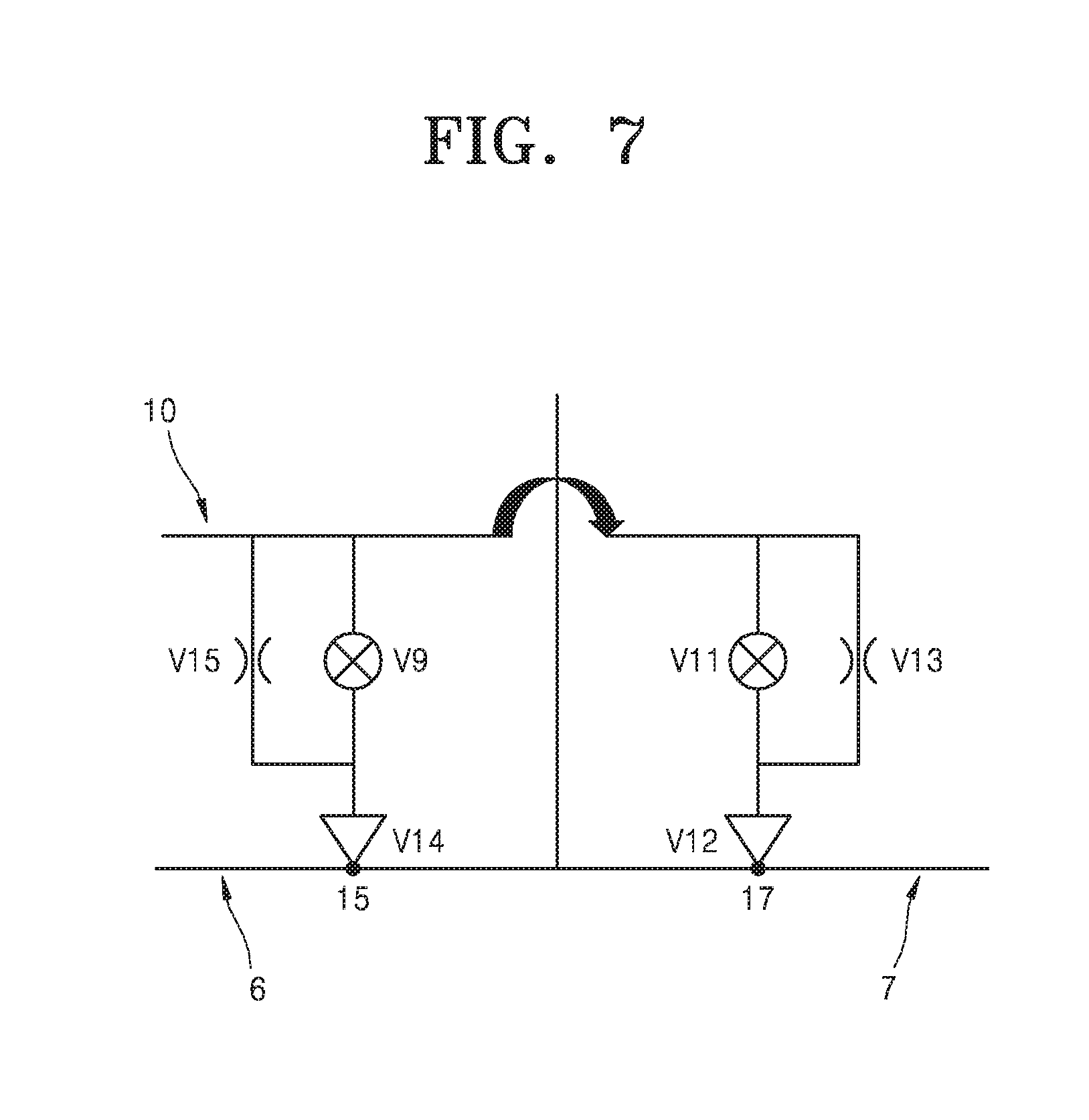
5. The exhaust apparatus of claim 1, further comprising a bypass line connected to the second exhaust line.
6. The exhaust apparatus of claim 5, wherein the first ring comprises: a first hole connected to the first gas line; and a second hole connected to the bypass line.
7. The exhaust apparatus of claim 6, wherein the first hole is located between the second hole and the first exhaust line.
8. The exhaust apparatus of claim 7, wherein when gas is supplied to the first gas line, gas from the first exhaust line is discharged to the third exhaust line, and gas from the bypass line is discharged to the second exhaust line.
9. The exhaust apparatus of claim 8, wherein gas supplied through the first gas line does not react with gas supplied through the bypass line.
10. The exhaust apparatus of claim 2, wherein the first gas line comprises a first opening/closing unit, the second gas line comprises a second opening/closing unit, and the exhaust apparatus further comprises a controller configured to control the first and second opening/closing units.
11. The exhaust apparatus of claim 10, further comprising a gas analysis unit connected to at least one of the first exhaust line, the second exhaust line, and the third exhaust line, wherein the controller communicates with the gas analysis unit and determines operation timing of the first and second opening/closing units.
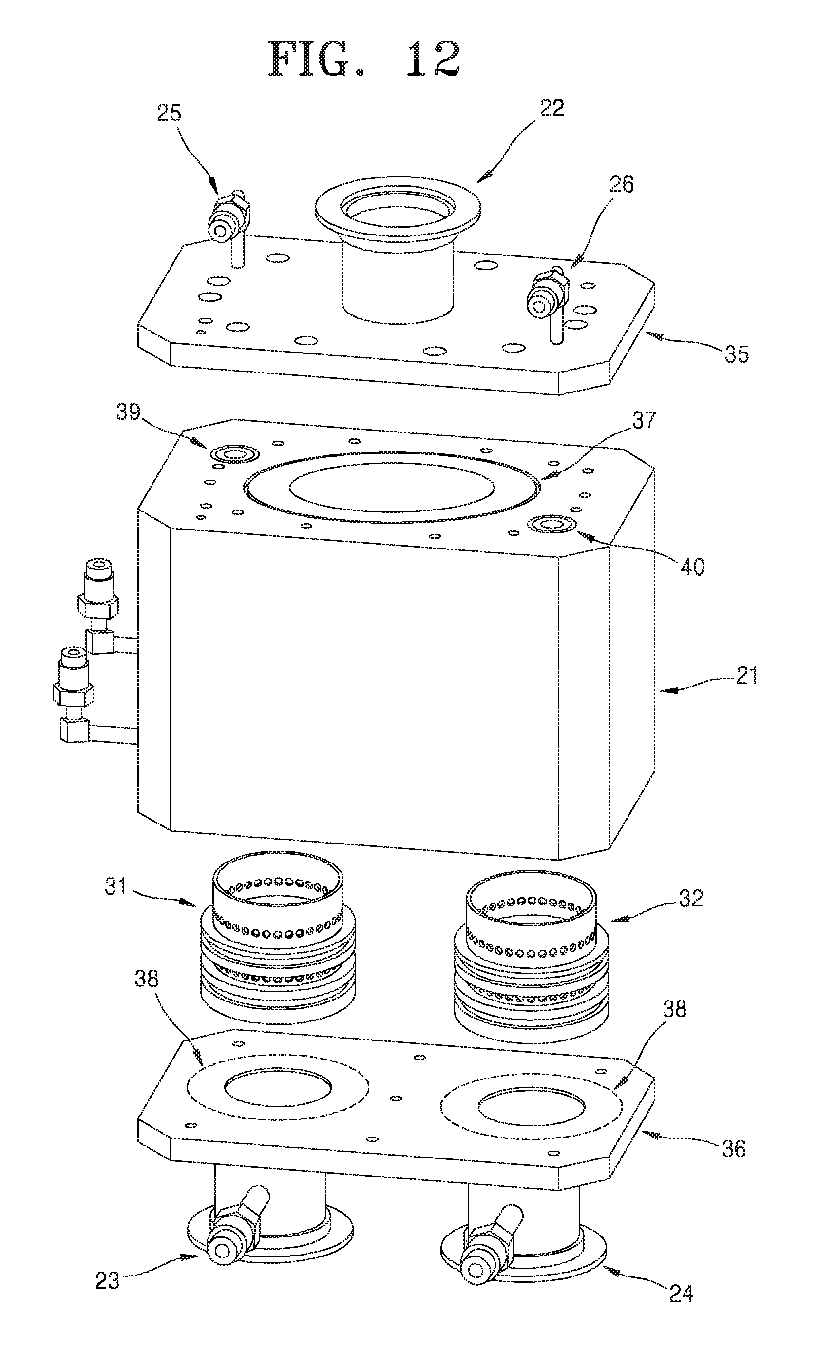
12. An exhaust apparatus comprising: a main exhaust line; an upper plate connected to the main exhaust line; a body having a first exhaust path and a second exhaust path that branch off from the main exhaust line; at least one ring inserted into the body, the ring having at least one hole on a lateral side thereof; a lower plate having a portion connected to the ring; a first sub-exhaust line connected to the first exhaust path; and a second sub-exhaust line.
13. The exhaust apparatus of claim 12, further comprising at least one purge gas supply path penetrating the body and connected to the ring.
14. The exhaust apparatus of claim 13, wherein the gas supply ring is located between the exhaust path and the first sub-exhaust line or between the exhaust path and the second sub-exhaust line.
15. The exhaust apparatus of claim 14, further comprising at least one bypass gas supply path penetrating the body and connected to the gas supply ring.
16. The exhaust apparatus of claim 15, wherein the at least one gas hole of the ring comprises: an upper hole connected to the purge gas supply path; and a lower hole connected to the bypass gas supply path, wherein the exhaust apparatus further comprises a sealing measure between the upper hole and the lower hole.
17. The exhaust apparatus of claim 16, wherein purge gas discharged to the exhaust path formed in the body through the purge gas supply path and the upper hole forms a gas curtain in the exhaust path.
18. The exhaust apparatus of claim 16, wherein gas flowing to the exhaust path through the purge gas supply path and the upper hole of the ring is an inert gas, and gas flowing to the exhaust path through the bypass gas supply path and the lower hole of the ring is dichlorosilane (DCS, SiH.sub.2Cl.sub.2) gas or NH.sub.3 gas.
19. The exhaust apparatus of claim 12, further comprising an anti-backflow device connected to the purge gas supply path.
20. A substrate processing apparatus comprising: a gas supply unit; a reactor; an exhaust unit; and an exhaust pump unit, wherein the gas supply unit comprises: at least one gas line through which gas is supplied to the reactor from the gas supply unit; a bypass line branching off from the gas line and connected to the exhaust unit; and a purge gas line connected from the gas supply unit to the exhaust unit, wherein the exhaust unit comprises: a main exhaust line; an upper plate connected to the main exhaust line; a body having a first exhaust path and a second exhaust path that branch off from the main exhaust line; at least one ring inserted into the body, the ring having at least one hole on a lateral side thereof; a lower plate having a portion connected to the ring; a first sub-exhaust line connected to the first exhaust path; a second sub-exhaust line connected to the second exhaust path; and at least one purge gas supply path penetrating the body and connected to the ring.
21. The substrate processing apparatus of claim 20, wherein the main exhaust line is connected to the reactor, and the sub-exhaust line is connected to the exhaust pump unit.
22. The substrate processing apparatus of claim 21, wherein the gas supply ring is located between the exhaust path and the sub-exhaust line.
23. The substrate processing apparatus of claim 22, wherein the at least one purge gas supply path penetrates the upper plate and is connected to the exhaust path, and wherein the substrate processing apparatus further comprises at least one bypass supply path penetrating the body and connected to exhaust path and the gas supply ring, wherein the purge gas supply path is connected to the purge gas line, and the bypass gas supply path is connected to the bypass line.
24. The substrate processing apparatus of claim 23, wherein the gas supply ring comprises at least one hole at a lateral side of the body, wherein the at least one hole comprises: an upper hole through which a purge gas from the purge gas supply path passes; and a lower hole through which a bypass gas from the bypass gas supply path passes.
25. The substrate processing apparatus of claim 24, wherein the lower hole is located between the upper hole and the lower plate.
Description
CROSS-REFERENCE TO RELATED APPLICATION
This application claims the benefit of Korean Patent Application No. 10-2016-0108380, filed on Aug. 25, 2016, in the Korean Intellectual Property Office, the disclosure of which is incorporated herein in its entirety by reference.
BACKGROUND
1. Field
One or more embodiments relate to an exhaust apparatus, a substrate processing apparatus using the exhaust apparatus, and a thin film fabricating method using the exhaust apparatus, and more particularly, to an exhaust apparatus configured to selectively discharge gases, a substrate processing apparatus using the exhaust apparatus, and a thin film fabricating method using the exhaust apparatus.
2. Description of the Related Art
Along with the development of semiconductor technology, semiconductor substrate processing processes such as a deposition process or an etching process have become more intricate, and various chemical materials have been used as source materials. Thus, substrate processing apparatuses having various structures have been developed to process various source materials.
If different chemical materials having high reactivity are used as source materials, the operation of equipment may be affected by reaction byproducts. For example, reaction byproducts may remain in solid form in; reactors or exhaust lines. Such remaining solid matter may decrease the efficiency of exhaust systems and may cause internal components such as valves or pressure gauges to malfunction. In addition, such solid matter may remain in exhaust pumps or scrubbers configured to collect harmful chemicals before the harmful chemicals are discharged to the air. In this case, the operation of substrate processing apparatuses may stop, or the operation or productivity of substrate processing apparatuses may be negatively affected.
SUMMARY
One or more embodiments include an exhaust apparatus configured to prevent the formation of reaction byproducts by selectively discharging gases, a substrate processing apparatus using the exhaust apparatus, and a thin film fabricating method using the exhaust apparatus.
Additional aspects will be set forth in part in the description which follows and, in part, will be apparent from the description, or may be learned by practice of the presented embodiments.
According to one or more embodiments, an exhaust apparatus (or a substrate processing apparatus) includes: a first region; a second region connected to the first region; a third region connected to the first region; and a first gas line connected to the second region, wherein when gas is supplied to the first gas line, the first region does not communicate with the second region but communicates with the third region.
The exhaust apparatus (or the substrate processing apparatus) may further include a second gas line connected to the third region, wherein when gas is supplied to the second gas line, the first region may not communicate with the third region but may communicate with the second region.
The first gas line and the second gas line may be connected to each other.
The exhaust apparatus (or the substrate processing apparatus) may further include a first gas supply ring placed in the second region, wherein the first gas supply ring may include at least one hole connected to the first gas line.
The exhaust apparatus (or the substrate processing apparatus) may further include a bypass line connected to the second region.
The exhaust apparatus (or the substrate processing apparatus) may further include a first gas supply ring placed in the second region, wherein the first gas supply ring may include: a first hole connected to the first gas line; and a second hole connected to the bypass line.
The first hole may be located between the second hole and the first region. When gas is supplied to the first gas line, gas from the first region may be discharged to the third region, and gas from the bypass line may be discharged to the second region.
Gas supplied through the first gas line may not react with gas supplied through the bypass line.
The first gas line may include a first opening/closing unit, the second gas line may include a second opening/closing unit, and the exhaust apparatus (or the substrate processing apparatus) may further include a controller configured to control the first and second opening/closing units.
The exhaust apparatus (or the substrate processing apparatus) may further include a gas analysis unit connected to at least one of the first region, the second region, and the third region, wherein the controller may communicate with the gas analysis unit and determine operation timing of the first and second opening/closing units.
According to one or more embodiments, an exhaust apparatus (or a substrate processing apparatus) includes: an upper plate; a body; at least one gas supply ring; a lower plate; a first sub-exhaust line; a second sub-exhaust line; and at least one purge gas supply path penetrating the body and connected to the gas supply ring.
At least one exhaust path branching off from the main exhaust line may be formed in the body, and the exhaust path may be connected with the first sub-exhaust line and the second sub-exhaust line.
The gas supply ring may be located between the exhaust path and the first sub-exhaust line or between the exhaust path and the second sub-exhaust line.
The exhaust apparatus (or the substrate processing apparatus) may further include at least one bypass gas supply path penetrating the body and connected to the gas supply ring.
The gas supply ring may include at least one gas hole in a lateral side thereof, wherein the at least one gas hole may include: an upper hole connected to the purge gas supply path; and a lower hole connected to the bypass gas supply path, wherein the exhaust apparatus (or the substrate processing apparatus) may further include a sealing measure between the upper hole and the lower hole.
Purge gas discharged to the exhaust path formed in the body through the purge gas supply path and the upper hole may form a gas curtain in the exhaust path.
Gas flowing to the exhaust path through the purge gas supply path and the upper hole of the gas supply ring may be an inert gas, and gas flowing to the exhaust path through the bypass gas supply path and the lower hole of the gas supply ring may be dichlorosilane (DCS, SiH.sub.2Cl.sub.2) gas or NH.sub.3 gas.
The exhaust apparatus (or the substrate processing apparatus) may further include an anti-backflow device connected to the purge gas supply path.
According to one or more embodiments, a substrate processing apparatus includes: a gas supply unit; a reactor; an exhaust unit; and an exhaust pump unit, wherein the gas supply unit includes: at least one gas line through which gas is supplied to the reactor from the gas supply unit; a bypass line branching off from the gas line and connected to the exhaust unit; and a purge gas line connected from the gas supply unit to the exhaust unit.
The exhaust unit may include: a main exhaust line; an upper plate; a body; a gas supply ring; a lower plate; and at least one sub-exhaust line, wherein the main exhaust line may be connected to the reactor, and the sub-exhaust line may be connected to the exhaust pump unit.
The body may include at least one exhaust path formed in the body and branching off from the main exhaust line, and the exhaust path may be connected to the sub-exhaust line, wherein the gas supply ring may be located between the exhaust path and the sub-exhaust line.
The substrate processing apparatus may further include: at least one purge gas supply path penetrating the upper plate and the body and connected to the exhaust path and the gas supply ring; and at least one bypass supply path penetrating the body and connected to exhaust path and the gas supply ring, wherein the purge gas supply path may be connected to the purge gas line, and the bypass gas supply path may be connected to the bypass line.
The gas supply ring may include at least one hole at a lateral side of the body, wherein the at least one hole may include: an upper hole through which a purge gas from the purge gas supply path passes; and a lower hole through which a bypass gas from the bypass gas supply path passes.
The lower hole may be located between the upper hole and the lower plate.
According to one or more embodiments, a thin film fabricating method includes: a first step of supplying a source gas; a second step of purging the source gas; a third step of supplying a reaction gas; and a fourth step of supplying plasma, wherein the source gas, the reaction gas, and the plasma are sequentially supplied, and a first purge gas is continuously supplied to a reaction space while the source gas, the reaction gas, and the plasma are supplied.
During the second step of purging the source gas, the source gas and the first purge gas may be discharged through a first path of an exhaust unit, and a second purge gas may be supplied to a second path of the exhaust unit.
During the second step of purging the source gas, the second purge gas may form a gas curtain in the second path.
When one of the source gas and the reaction gas is supplied to a reactor, the other gas may be bypassed to the exhaust unit.
A path to which the bypassed gas is discharged may be different from a path to which gas discharged from the reactor is discharged.
During the first step of supplying the source gas, the source gas and the first purge gas may be supplied to the reaction space, and the reaction gas may be supplied to the second path of the exhaust unit.
During the second step of purging the source gas, the first purge gas may be supplied to the reaction space, the source gas may be supplied to the first path of the exhaust unit, and the reaction gas may be supplied to the second path of the exhaust unit.
A first flow rate of the first purge gas supplied during the first step of supplying the source gas may be lower than a second flow rate of the second purge gas supplied during the second step of purging the source gas.
During the third step of supplying the reaction gas and the fourth step of supplying the plasma, the reaction gas and the first purge gas may be supplied to the reaction space, and the source gas may be supplied to the first path of the exhaust unit.
During the third step of supplying the reaction gas and the fourth step of supplying the plasma, the second purge gas may be supplied to the first path of the exhaust unit.
According to one or more embodiments, a thin film fabricating method includes: discharging a first gas from a first region to a second region; and discharging a second gas from the first region to a third region, wherein during the discharging of the first gas, a third gas is supplied to the third region to form a gas curtain including the third gas in the third region, and during the discharging of the second gas, the third gas is supplied to the second region to form a gas curtain including the third gas in the second region.
BRIEF DESCRIPTION OF THE DRAWINGS
These and/or other aspects will become apparent and more readily appreciated from the following description of the embodiments, taken in conjunction with the accompanying drawings in which:
FIGS. 1 and 2 are schematic views illustrating an exhaust apparatus according to an embodiment;
FIG. 3 is a schematic view illustrating a substrate processing apparatus according to an embodiment;
FIGS. 4 and 5 are schematic views illustrating a substrate processing apparatus including an exhaust apparatus according to another embodiment;
FIG. 6 is a schematic view illustrating a substrate processing apparatus including an exhaust apparatus according to another embodiment;
FIG. 7 is a schematic view illustrating an exhaust apparatus according to another embodiment;
FIGS. 8 to 13 are schematic views illustrating an exhaust apparatus according to another embodiment;
FIG. 14 is a schematic view illustrating a gas supply ring according to an embodiment;
FIGS. 15 to 17 are cross-sectional views illustrating modifications of the gas supply ring illustrated in FIG. 14;
FIG. 18 is a schematic view illustrating a thin film fabricating method according to an embodiment; and
FIG. 19 is a schematic view illustrating a thin film fabricating method according to another embodiment.
DETAILED DESCRIPTION
Reference will now be made in detail to embodiments, examples of which are illustrated in the accompanying drawings, wherein like reference numerals refer to like elements throughout. In this regard, the present embodiments may have different forms and should not be construed as being limited to the descriptions set forth herein. Accordingly, the embodiments are merely described below, by referring to the figures, to explain aspects of the present description. Expressions such as "at least one of," when preceding a list of elements, modify the entire list of elements and do not modify the individual elements of the list.
Embodiments will now be described with reference to the accompanying drawings.
The inventive concept may, however, be embodied in many different forms and should not be construed as being limited to the embodiments set forth herein; rather, these embodiments are provided to give a clear understanding of the inventive concept to those of ordinary skill in the art. That is, the embodiments are provided so that this disclosure will be thorough and complete, and will fully convey the inventive concept to those of ordinary skill in the art.
In the following description, terms are used only for explaining specific embodiments while not limiting the inventive concept. The terms of a singular form may include plural forms unless referred to the contrary. The meaning of "comprise" and/or "comprising" specifies a shape, a fixed number, a step, a process, a member, an element, and/or a combination thereof but does not exclude other shapes, fixed numbers, steps, processes, members, elements, and/or combinations thereof. As used herein, the term "and/or" includes any and all combinations of one or more of the associated listed items.
It will be understood that, although the terms first, second, etc. may be used herein to describe various members, regions, and/or elements, these members, regions, and/or elements should not be limited by these terms. These terms are not used to denote a particular order, a positional relationship, or ratings of members, regions, or elements, but are only used to distinguish one member, region, or element from another member, region, or element. Thus, a first member, region, or element discussed below could be termed a second member, region, or element without departing from the teachings of the inventive concept.
Hereinafter, embodiments will be described with reference to the accompanying drawing. Shapes illustrated in the drawings may be varied according to various factors such as manufacturing methods and/or tolerances. That is, the embodiments are not limited to particular shapes illustrated in the drawings. Factors such as shape changes in manufacturing processes should be considered.
FIGS. 1 and 2 are schematic views illustrating an exhaust apparatus according to an embodiment.
Referring to FIG. 1, the exhaust apparatus may include a first region 110, a second region 120, a third region 130, a first gas line 140, and a second gas line 150.
The first region 110, the second region 120, and the third region 130 may be connected to each other and may extend in different directions. For example, the first region 110 may be a region of an exhaust path and may be connected to a main exhaust line. The second region 120 and the third region 130 may be other regions of the exhaust path and may be respectively connected to sub-exhaust lines branching off from the main exhaust line.
The first gas line 140 may be connected to the second region 120 and may have a function of determining whether the first region 110 and the second region 120 communicate with each other. Herein, the term or expression "communication" or "communicate with" may be used to indicate the possibility of exchange of flow of gas. For example, when the first region 110 communicates with the second region 120, gas may flow from the first region 110 to the second region 120 and from the second region 120 to the first region 110.
The second gas line 150 may be connected to the third region 130 and may have a function of determining whether the first region 110 and the second region 130 communicate with each other. For example, if gas is supplied to the first gas line 140, the first region 110 may not communicate with the second region 120 but may communicate with the third region 130 (refer to FIG. 1). In addition, if gas is supplied to the second gas line 150, the first region 110 may not communicate with the third region 130 but may communicate with the second region 120 (refer to FIG. 2).
In the exhaust apparatus, many kinds of gases may be supplied to the first region 110. Such gases may be selectively discharged to the second region 120 or the third region 130. For example, when gas is supplied to the first gas line 140, since the first region 110 communicates with the third region 130, gas (for example, a first gas) of the first region 110 may be discharged to the third region 130. However, when gas is supplied to the second gas line 150, since the first region 110 communicates with the second region 120, gas (for example, a second gas) of the first region 110 may be discharged to the second region 120.
The current embodiment relates to an exhaust line structure including a plurality of exhaust lines. In the current embodiment, gas lines are used to individually discharge at least two source gases. Such a gas line supplies gas having low reactivity (for example, an inert gas such as argon (Ar)) to an exhaust line to form a gas curtain in the exhaust line. Then, the exhaust line is substantially closed, and thus a particular gas may be selectively discharged.
Referring to FIG. 1, the first region 110 communicates with the third region 130, and thus a first gas is discharged from the first region 110 to the third region 130 by a pump B. Gas supplied to the second region 120 through the first gas line 140 is discharged from the second region 120 by a pump A. In other words, a gas having low reactivity with the first gas is supplied to the second region 120, and thus a gas curtain including the gas is formed in the second region 120.
Referring to FIG. 2, the first region 110 communicates with the second region 120, and thus a second gas is discharged from the first region 110 to the second region 120 by the pump A. Gas supplied to the third region 130 through the second gas line 150 is discharged from the third region 130 by the pump B. In other words, a gas having low reactivity with the second gas is supplied to the third region 130, and thus a gas curtain including the gas is formed in the third region 130.
As described above, the first region 110 may be adjacent to the main exhaust line, and the second region 120 and the third region 130 may respectively be adjacent to a first sub-exhaust line and a second sub-exhaust line. Therefore, gases supplied through the first gas line 140 and the second gas line 150 may respectively form gas curtains in entrances of the first and second sub-exhaust lines, and thus it may be possible to selectively discharge gases. In some embodiments, the flow rates of gases supplied through the first gas line 140 and/or the second gas line 150 may be maintained to be substantially equal to the flow rate of gas flowing out from a reactor.
As described above, the current embodiment provides a gas-based opening/closing structure that enables fast switching compared to a mechanical opening/closing structure. For example, fast switching between gases may be required in an atomic layer deposition process. However, if a mechanical opening/closing structure (for example, a flapper valve) is used in such an atomic layer deposition process, it may be difficult to control the atomic layer deposition process according to the required short gas exchange intervals because of limitations in mechanical operations. In addition, mechanical opening/closing structures are likely to break down or malfunction because of frequent physical operations.
However, the embodiment provides an opening/closing structure using a gas curtain instead of using a mechanical structure, thereby guaranteeing high speed operations. In addition, problems such as mechanical abrasion may not occur in the gas-based opening/closing structure of the embodiment. Thus, the gas-based opening/closing structure may have an infinite lifespan, and the durability of the exhaust apparatus having the gas-based opening/closing structure may be improved. Materials remaining after chemical reactions may accumulate on such mechanical opening/closing structures. However, such remaining materials may not accumulate on the gas-based opening/closing structure of the embodiment, and thus problems relating to such remaining materials may not occur. In addition, the gas-based opening/closing structure does not require an additional structure in exhaust lines, and thus a space for maintenance/repair may easily be ensured in the exhaust lines. That is, improvements may be made in terms of maintenance/repair.
The embodiment may have positive technical effects (for example, allowing rapid gas exchange and preventing inefficient operations of equipment caused by reaction byproducts) on atomic layer deposition processes such as a silicon nitride atomic layer deposition process in which dichlorosilane (DCS: SiH.sub.2Cl.sub.2) and NH.sub.3 are used as source materials. This will be described hereinafter.
FIG. 3 is a schematic view illustrating a substrate processing apparatus according to an embodiment. The substrate processing apparatus of the current embodiment may be configured using the exhaust apparatus of the previous embodiment. Thus, the same description as that presented in the previous embodiment will not be presented here.
Referring to FIG. 3, the substrate processing apparatus may include a gas supply unit 210, a reactor 220, an exhaust unit 230, a controller 240, and gas analysis units 250. The substrate processing apparatus may further include exhaust pumps (not shown) connected to the exhaust unit 230 (refer to FIGS. 1 and 2).
The gas supply unit 210 may supply at least two source gases and/or a first purge gas to the reactor 220 through at least one reaction gas line 260. The gas supply unit 210 may be connected to a showerhead configured to supply gas to a substrate in a vertical direction. In another embodiment, the gas supply unit 210 may be connected to a lateral-flow device configured to supply gas in a lateral direction. In another embodiment, the gas supply unit 210 may be connected to any device configured to supply gas to a reaction space.
A first gas line 140 and a second gas line 150 may be connected to each other, and the gas supply unit 210 may supply a second purge gas to the first gas line 140 and/or the second gas line 150 through a purge gas line 265. In addition, the substrate processing apparatus may further include a bypass line (not shown) branching off from the reaction gas line 260 and joining the exhaust unit 230. Therefore, source gases and/or a first purge gas may be directly supplied from the gas supply unit 210 to the exhaust unit 230 through the bypass line (refer to FIG. 6).
The exhaust unit 230 may selectively discharge gases received from the reactor 220. For example, as described above, the exhaust unit 230 may include a main exhaust line 270 connected to a first region, a first sub-exhaust line 280 connected to a second region, a second sub-exhaust line 290 connected to a third region, the first gas line 140, and the second gas line 150.
The first gas line 140 may include a first opening/closing unit 310. In addition, the second gas line 150 may include a second opening/closing unit 320. A purge gas may be supplied from the gas supply unit 210 to the first sub-exhaust line 280 and/or the second sub-exhaust line 290 depending on whether the first opening/closing unit 310 and/or the second opening/closing unit 320 are/is opened or closed.
The controller 240 may control the first opening/closing unit 310 and/or the second opening/closing unit 320. For example, the controller 240 may communicate with the analysis units 250 to determine operation timing of the first opening/closing unit 310 and/or the second opening/closing unit 320.
The analysis units 250 may analyze the compositions or properties of gases (for example, the components, temperatures, flow rates, pressures, or concentrations of gases). The analysis units 250 may be connected to at least one of the gas supply unit 210, the reaction gas line 260, the main exhaust line 270 connected to the first region, the first sub-exhaust line 280 connected to the second region, and the second sub-exhaust line 290 connected to the third region.
The controller 240 may communicate with the analysis units 250 to determine a time period during which gas reaches from the gas supply unit 210 to the first sub-exhaust line 280 (or the second sub-exhaust line 290). Then, the first opening/closing unit 310 or the second opening/closing unit 320 may be opened or closed based on the determined time period. Based on the operations of the first opening/closing unit 310 and the second opening/closing unit 320, a second purge gas may be supplied to the first sub-exhaust line 280 or the second sub-exhaust line 290 to form a gas curtain. As a result, source gases supplied from the gas supply unit 210 may be selectively discharged.
FIGS. 4 and 5 are schematic views illustrating a substrate processing apparatus including an exhaust apparatus according to another embodiment. The exhaust apparatus and the substrate processing apparatus of the current embodiment may be modifications of the exhaust apparatus and the substrate processing apparatus of the previous embodiments. Thus, the same description as that presented in the previous embodiments will not be presented here.
Referring to FIGS. 4 and 5, the substrate processing apparatus may include a first discharge part 144, a second discharge part 146, a reaction chamber 106, and the exhaust apparatus 134. The exhaust apparatus 134 may include a first region 110, a second region 120, a third region 130, a first gas line 140 connected to the second region 120, and a second gas line 150 connected to the third region 130.
The substrate processing apparatus may be a lateral-flow type substrate processing apparatus configured to supply gas in a lateral direction and discharge the gas through the exhaust apparatus 134. For example, a first gas (for example, a deposition or cleaning gas) may be supplied to the reaction chamber 106 through the first discharge part 144. In this case, the exhaust apparatus 134 may be operated such that gas flowing in the reaction chamber 106 may be discharged through the third region 130.
For example, the exhaust apparatus 134 may supply a low-reactivity gas (and the first gas) to the first gas line 140. In this case, the first region 110 does not communicate with the second region 120 owing to the low-reactivity gas but communicates with the third region 130. Therefore, the first gas supplied through the first discharge part 144 may be discharged through only the third region 130.
Referring to FIG. 5, a second gas may be supplied to the reaction chamber 106 through the second discharge part 146. In this case, the exhaust apparatus 134 may be operated such that gas flowing in the reaction chamber 106 may be discharged through the second region 120.
For example, the exhaust apparatus 134 may supply a low-reactivity gas (and the second gas) to the second gas line 150. In this case, the first region 110 does not communicate with the third region 130 owing to the low-reactivity gas but communicates with the second region 120. Therefore, the second gas supplied through the second discharge part 146 may be discharged through only the second region 120.
FIG. 6 is a schematic view illustrating a substrate processing apparatus including an exhaust apparatus C according to another embodiment. The exhaust apparatus C and the substrate processing apparatus of the current embodiment may be modifications of the exhaust apparatuses and the substrate processing apparatuses of the previous embodiments. Thus, the same description as that presented in the previous embodiments will not be presented here.
Referring to FIG. 6, like in the previous embodiments, the substrate processing apparatus may include a gas supply unit, a reactor 1, the exhaust apparatus C, a first pump 3, a first scrubber 11, a second pump 4, and a second scrubber 12. The substrate processing apparatus may be configured to supply gas to a substrate using a gas injection unit 2 in a direction perpendicular to the substrate.
For example, the substrate processing apparatus illustrated in FIG. 6 may be an atomic layer deposition apparatus configured to form a silicon nitride film. In the current embodiment, DCS (Dichlorosilane; SiH.sub.2Cl.sub.2) is used as a silicon source, and ammonia (NH.sub.3) is used as a nitrogen source. The atomic layer deposition apparatus (substrate processing apparatus) of the current embodiment may include the reactor 1, the gas injection unit 2, the first pump (DCS exhaust pump) 3, the second pump (NH.sub.3 exhaust pump) 4, a main exhaust line 5, a DCS sub-exhaust line 6, a NH.sub.3 sub-exhaust line 7, a DCS bypass line 8, an NH.sub.3 bypass line 9, a purge argon line 10, the first scrubber (DCS scrubber) 11, and the second scrubber (NH.sub.3 scrubber) 12. In addition, the atomic layer deposition apparatus may further include valves v1 to v11 to control flows of gases in lines.
The reactor 1 may provide a space (for example, a closed space) in which a silicon nitride thin film is deposited on a substrate. To this end, the reactor 1 may be isolated from the outside of the reactor 1 using a sealing measure such as an O-ring. In general, the reactor 1 may be maintained at a pressure equal to or lower than atmospheric pressure. A substrate support or susceptor (not shown) may be placed in the reactor 1, and a gate valve (not shown) may be located at a lateral side of the reactor 1 to introduce and discharge substrates therethrough. The gate valve may be opened only when a substrate is introduced or discharged through the gate valve and may be maintained in a closed state during a process.
DCS and NH.sub.3 supplied through a DCS line 19 and an NH.sub.3 line 20, and process argon Ar1 supplied through a process argon line 18 may be uniformly supplied to a silicon substrate through the gas injection unit 2. For example, the gas injection unit 2 may be a showerhead. In some embodiments, the gas injection unit 2 may be connected to a radio frequency (RF) plasma generator to perform a plasma atomic layer deposition process. In other embodiments, the gas injection unit 2 may function as a plasma electrode.
Exhaust pumps may include the DCS exhaust pump 3 and the NH.sub.3 exhaust pump 4. Source gases used in a process are toxic, corrosive, and inflammable and are thus collected using a scrubber before being discharged to the outside air. In the embodiment, scrubbers are connected to rear ends of the exhaust pumps such that gases discharged through the pumps after a process may be filtered by the scrubbers and may then be discharged to the outside air in a purified state. That is, as illustrated in FIG. 6, the DCS scrubber 11 and the NH.sub.3 scrubber 12 may respectively be connected to the DCS exhaust pump 3 and the NH.sub.3 exhaust pump 4. The DCS exhaust pump 3 and the DCS scrubber 11 may process a DCS source gas, and the NH.sub.3 exhaust pump 4 and the NH.sub.3 scrubber 12 may process NH.sub.3 gas.
After passing through the reactor 1, source/reaction gases may be discharged through the exhaust apparatus C. The exhaust apparatus C may include the main exhaust line 5 and the two sub-exhaust lines 6 and 7. The main exhaust line 5 may branch into the two sub-exhaust lines 6 and 7 at a branching point 13. The two sub-exhaust lines 6 and 7 are a DCS sub-exhaust line and an NH.sub.3 sub-exhaust line, respectively.
The substrate processing apparatus may further include bypass lines. For example, the substrate processing apparatus being configured as an atomic layer deposition apparatus in the current embodiment may include the DCS bypass line 8 and the NH.sub.3 bypass line 9. In this case, DCS and NH.sub.3 may be alternately supplied to the reactor 1 during an atomic layer deposition process. When DCS is supplied to the reactor 1, NH.sub.3 may be discharged to the NH.sub.3 exhaust pump 4 through the NH.sub.3 bypass line 9, and when NH.sub.3 is supplied to the reactor 1, DCS may be discharged to the DCS exhaust pump 3 through the DCS bypass line 8. That is, a continuous flow may be maintained while source/reaction gases are alternately supplied to the reactor 1 and the bypass lines 8 and 9 in a switching manner, and thus the inside pressure of gas lines and the reactor 1 may be constantly maintained, thereby ensuring process stability.
In the embodiment illustrated in FIG. 6, the substrate processing apparatus may further include the purge argon line 10. The purge argon line 10 may be connected to the DCS sub-exhaust line 6 and the NH.sub.3 sub-exhaust line 7, and thus purge argon Ar2 may be supplied to the DCS sub-exhaust line 6 and the NH.sub.3 sub-exhaust line 7 through the purge argon line 10.
For example, the purge argon line 10 may be connected to the DCS sub-exhaust line 6 at a front end 15 of a connection part 14 between the DCS bypass line 8 and the DCS sub-exhaust line 6 and may be connected to the NH.sub.3 sub-exhaust line 7 at a front end 17 of a connection part 16 between the NH.sub.3 bypass line 9 and the NH.sub.3 sub-exhaust line 7. In some embodiments, check valves may be respectively provided in the connection parts and ends 14, 15, 16, and 17 to prevent gases from flowing backward from the sub-exhaust lines 6 and 7 to the bypass lines 8 and 9 or the purge argon line 10.
FIG. 7 is a schematic view illustrating an exhaust apparatus according to another embodiment. The exhaust apparatus of the current embodiment may be a modification of the exhaust apparatuses of the previous embodiments. Thus, the same description as that presented in the previous embodiments will not be presented here.
Referring to FIG. 7, a purge argon line 10 may branch into a DCS sub-exhaust line 6 and an NH.sub.3 sub-exhaust line 7. Devices allowing gas to flow only in one direction such as check valves v14 and v12 may be provided in connection parts 15 and 17 between the purge argon line 10 and the sub-exhaust lines 6 and 7.
In some embodiments, as illustrated in FIG. 7, orifices v15 and v13 may be further provided between the purge argon line 10 and the sub-exhaust lines 6 and 7. Each of the orifices v15 and v13 may be configured to maintain the flow rate of gas at a constant level. Therefore, owing to the orifices v15 and v13, purge argon may always flow in the purge argon line 10 and the sub-exhaust lines 6 and 7 regardless of whether a DCS purge argon valve v9 and an NH.sub.3 purge argon valve v11 are closed or opened.
For example, when the DCS purge argon valve v9 is in a closed state, a certain amount of argon gas may be filled in a gas exhaust line between the check valve v14 and the DCS purge argon valve v9 so as to prevent a backflow of gas in the DCS sub-exhaust line 6. The flow rate of purge argon at the orifices v15 and v13 may be set to be about 10% to about 15% of the flow rate of purge argon supplied to the purge argon line 10.
FIGS. 8 to 13 are schematic views illustrating an exhaust apparatus according to another embodiment. The exhaust apparatus of the current embodiment may be a modification of the exhaust apparatuses of the previous embodiments. Thus, the same description as that presented in the previous embodiments will not be presented here.
Referring to FIGS. 8 and 9, the exhaust apparatus may include an exhaust unit body 21, a main exhaust line 22, a DCS sub-exhaust line 23, an NH.sub.3 sub-exhaust line 24, a DCS purge argon line 25, an NH.sub.3 purge argon line 26, a DCS bypass line 27, an NH.sub.3 bypass line 28, connection parts 29 and 30, and cartridge heater holes 33 and 34.
The main exhaust line 22, the DCS sub-exhaust line 23, the NH.sub.3 sub-exhaust line 24, the DCS bypass line 27, and the NH.sub.3 bypass line 28 of the exhaust apparatus illustrated in FIGS. 8 and 9 may respectively correspond to the main exhaust line 5, the DCS sub-exhaust line 6, the NH.sub.3 sub-exhaust line 7, the DCS bypass line 8, and the NH.sub.3 bypass line 9 of the substrate processing apparatus illustrated in FIG. 6.
In addition, the DCS purge argon line 25 and the NH.sub.3 purge argon line 26 of the exhaust apparatus illustrating in FIG. 8 may branch off from the purge argon line 10 illustrated in FIG. 6. Therefore, argon gas may be supplied to the DCS purge argon line 25 and the NH.sub.3 purge argon line 26 in an alternating manner by switching operations of the valves v9 and v11 (refer to FIG. 6). Similarly, DCS gas and NH.sub.3 gas may be respectively supplied to the DCS bypass line 27 and the NH.sub.3 bypass line 28 in an alternating manner by switching operations of valves v2 and v5 (refer to FIG. 6).
The connection parts 29 and 30 of the exhaust apparatus may be connected to gas analysis units (not shown). For example, the connection parts 29 and 30 may be connected to pressure gauges, and thus the pressures of the DCS sub-exhaust line 23 and the NH.sub.3 sub-exhaust line 24 may be measured. In some embodiments, the connection parts 29 and 30 may be connected to exhaust gas component analyzers, and thus the compositions of exhaust gases may be analyzed to determine the amounts and compositions of remaining gases and gas supply conditions such as flow rates and supply times.
In addition, as described above, the DCS purge argon line 25, the NH.sub.3 purge argon line 26, the DCS bypass line 27, and the NH.sub.3 bypass line 28 may include anti-backflow devices. The anti-backflow devices may be check valves and/or orifices allowing only unidirectional flows.
FIG. 9 is a top view of the exhaust apparatus depicted in FIG. 8. The DCS bypass line 27 may be connected to the DCS sub-exhaust line 23 at a lateral side of the exhaust unit body 21, and the NH.sub.3 bypass line 28 may be connected to the NH.sub.3 sub-exhaust line 24 at a rear side of the exhaust unit body 21.
In some embodiments, cartridge heaters may be inserted into the cartridge heater holes 33 and 34 to heat the exhaust unit body 21. If the exhaust unit body 21 is heated, reaction byproducts may not be deposited on internal exhaust lines or may not float in the exhaust unit body 21.
FIGS. 10 and 11 are cross-sectional views taken along lines A-A' and B-B' of FIG. 8. Referring to the cross-sectional view of an exhaust unit in FIG. 10, a DCS exhaust path 49 and an NH.sub.3 exhaust path 50 branching off from the main exhaust line 22 may be formed inside the exhaust unit body 21, and the DCS exhaust path 49 and the NH.sub.3 exhaust path 50 may be respectively connected to the DCS sub-exhaust line 23 and the NH.sub.3 sub-exhaust line 24.
The exhaust apparatus may further include a DCS gas supply ring 31 and an NH.sub.3 gas supply ring 32. The DCS gas supply ring 31 may be located between the DCS exhaust path 49 and the DCS sub-exhaust line 23, and the NH.sub.3 gas supply ring 32 may be located between the NH.sub.3 exhaust path 50 and the NH.sub.3 sub-exhaust line 24.
The DCS gas supply ring 31 and the NH.sub.3 gas supply ring 32 may be connected to the DCS bypass line 27, the NH.sub.3 bypass line 28, the DCS purge argon line 25, and the NH.sub.3 purge argon line 26. Therefore, Bypassed DCS and DCS purge argon may be discharged through the DCS gas supply ring 31, the DCS sub-exhaust line 23, the DCS exhaust pump 3, and the DCS scrubber 11, and bypassed NH.sub.3 and NH.sub.3 purge argon may be discharged through the NH.sub.3 gas supply ring 32, the NH.sub.3 sub-exhaust line 24, the NH.sub.3 exhaust pump 4, and the NH.sub.3 scrubber 12.
As illustrated in FIG. 10, the DCS bypass line 27 may be connected to the DCS gas supply ring 31 through a DCS bypass gas supply path 48 formed in a lateral side of the exhaust unit body 21. Similarly, the NH.sub.3 bypass line 28 may be connected to the NH.sub.3 gas supply ring 32 through an NH.sub.3 bypass gas supply path (not shown) formed in a rear side of the exhaust unit body 21.
As illustrated in FIG. 11, the DCS purge argon line 25 and the NH.sub.3 purge argon line 26 may respectively be connected to the DCS gas supply ring 31 and the NH.sub.3 gas supply ring 32 through pipes penetrating an upper portion of the exhaust unit body 21.
Purge gas (argon) may be discharged to the DCS exhaust pump 3 and the NH.sub.3 exhaust pump 4 through the DCS purge argon line 25, the NH.sub.3 purge argon line 26, purge gas supply paths formed in the exhaust unit body 21, the DCS gas supply ring 31, the NH.sub.3 gas supply ring 32, the DCS sub-exhaust line 23, and the NH.sub.3 sub-exhaust line 24.
Similarly, bypassed DCS may be discharged to the DCS exhaust pump 3 through the DCS bypass line 27, the DCS bypass gas supply path 48, the DCS gas supply ring 31, and the DCS sub-exhaust line 23. In addition, bypassed NH.sub.3 may be discharged to the NH.sub.3 exhaust pump 4 through the NH.sub.3 bypass line 28, the NH.sub.3 bypass gas supply path (not shown), the NH.sub.3 gas supply ring 32, and the NH.sub.3 sub-exhaust line 24.
FIG. 12 is an exploded perspective view illustrating the exhaust apparatus depicted in FIG. 8, and FIG. 13 is a cross-sectional view illustrating the exhaust unit body 21. Referring to FIG. 12, the exhaust unit may include an upper plate 35, the exhaust unit body 21, the DCS gas supply ring 31, and the NH.sub.3 gas supply ring 32, and a lower plate 36.
The upper plate 35 is connected to the main exhaust line 22, and as described above, the exhaust unit body 21 may include the DCS exhaust path 49 and the NH.sub.3 exhaust path 50 that branch off from the main exhaust line 22 in the exhaust unit body 21. A sealing measure 37 may be inserted between the exhaust unit body 21 and the upper plate 35, and thus when the exhaust unit body 21 and the upper plate 35 are coupled to each other, sealing (isolation) may be provided. In the embodiment, the sealing measure may be an O-ring.
In addition, the purge gas supply paths may be formed in the exhaust unit body 21. For example, a DCS purge argon supply path 39 and an NH.sub.3 purge argon supply path 40 may be formed in the exhaust unit body 21 as the purge gas supply paths. The DCS purge argon supply path 39 may be connected between the DCS purge argon line 25 and the DCS gas supply ring 31. The NH.sub.3 purge argon supply path 40 may be connected between the NH.sub.3 purge argon line 26 and the NH.sub.3 gas supply ring 32.
As illustrated in FIGS. 12 and 13, the DCS gas supply ring 31 and the NH.sub.3 gas supply ring 32 are inserted into the exhaust unit body 21. Each of the DCS gas supply ring 31 and the NH.sub.3 gas supply ring 32 may include gas supply holes. Bypassed DCS gas and NH.sub.3 gas, DCS purge argon, and NH.sub.3 purge argon may be discharged through the gas supply holes. The DCS gas supply ring 31 and the NH.sub.3 gas supply ring 32 will be further described hereinafter.
Referring to FIG. 13, exhaust paths may be continuously formed in the exhaust unit body 21. In other words, paths may be bored through upper and lower portions of the exhaust unit body 21 so that exhaust paths connected to each other may be formed. Purge argon supplied to the exhaust unit body 21 through the DCS purge argon supply path 39 may be supplied to the DCS gas supply ring 31 through a gas supply hole 46. In addition, bypassed NH.sub.3 gas supplied to the exhaust unit body 21 through the NH.sub.3 bypass line 28 and the NH.sub.3 bypass gas supply path (not shown) may be supplied to the NH.sub.3 gas supply ring 32 through a gas supply hole 47. The positions, sizes, and shapes of holes illustrated in the drawings are examples.
An upper portion of the lower plate 36 may be connected to the DCS gas supply ring 31 and the NH.sub.3 gas supply ring 32, and a lower portion of the lower plate 36 may be connected to the DCS sub-exhaust line 23 and the NH.sub.3 sub-exhaust line 24. A sealing measure 38 may be inserted between the lower plate 36 and the gas supply rings 31 and 32. Thus, when the lower plate 36 is coupled to the gas supply rings 31 and 32, outside air may not permeate. In the embodiment, the sealing measure may be an O-ring.
FIG. 14 is a schematic view illustrating a gas supply ring 31 or 32 according to an embodiment. FIGS. 15 to 17 are cross-sectional views illustrating modifications of the gas supply ring illustrated in FIG. 14. The gas supply ring of the current embodiment may be applied to the exhaust apparatuses of the previous embodiments.
Referring to FIG. 14, the gas supply ring 31 or 32 may be inserted into the exhaust unit body 21 and may be connected to the DCS sub-exhaust line 23 or the NH.sub.3 sub-exhaust line 24. The gas supply ring 31 or 32 may include upper holes 41, lower holes 42, and sealing measure insertion portions 43 and 44.
The upper holes 41 provide paths through which DCS and NH.sub.3 purge argon are discharged, and the lower holes 42 provide paths through which bypassed DCS and NH.sub.3 are discharged. That is, the upper holes 41 may be arranged between the lower holes 42 and the main exhaust line 22 including a first region. A gas curtain may be formed in an exhaust path by supplying purge argon to the upper holes 41 arranged as described above. In addition, the upper holes 41 through which purge argon is discharged are located between the lower holes 42 of the gas supply ring 31 or 32 and the first region through which DCS and NH.sub.3 are respectively discharged (or NH.sub.3 and DCS are respectively discharged), thereby preventing DCS and NH.sub.3 from meeting each other and the formation of reaction byproducts in an exhaust unit.
O-rings may be inserted in the sealing measure insertion portions 43 and 44. Thus, gas discharged through the upper holes 41 (or the lower holes 42) may not leak to the lower holes 42 (or the upper holes 41). In addition, gas leakage between the gas supply ring 31 or 32 and the exhaust unit body 21 may be prevented. That is, owing to the sealing measures (the O-rings), gases passing through the upper holes 41 and the lower holes 42 may be not mixed with each other and isolated from the outside.
Referring to FIG. 14, an upper portion 45 of the gas supply ring 31 or 32 and an exhaust path formed inside the exhaust unit body 21 may be brought into tight contact with each other and thus be sealed via face sealing. In other embodiments, however, a sealing measure such as an O-ring may be provided on the upper portion 45 of the gas supply ring 31 or 32.
As described above, a purge argon gas curtain may be uniformly formed in an exhaust line owing to the upper holes 41 and the lower holes 42, and thus bypassed DCS gas or NH.sub.3 gas may be uniformly discharged.
In addition, as illustrated in FIGS. 15 to 17, a plurality of holes may be symmetrically arranged along a lateral side of the gas supply ring 31 or 32. For example, four holes may be symmetrically arranged as illustrated in FIG. 15, eight holes may be symmetrically arranged as illustrated in FIG. 16, or sixteen holes may be symmetrically arranged as illustrated in FIG. 17.
The diameter and number of such symmetric holes may be determined to minimize adiabatic expansion of DCS gas and NH.sub.3 gas (and a resulting increase in gas flow velocity and a temperature decrease) during a bypass process. Both DCS and NH.sub.3 are gases that may be liquefied, and thus if the temperature of DCS or NH.sub.3 is rapidly decreased, solid byproducts may be formed on the exhaust apparatus (for example, on an exhaust line, a pump, or a scrubber). Therefore, the diameter and number of such symmetric holes may be adjusted to previously prevent clogging of the exhaust apparatus.
In other words, according to the embodiment, as illustrated in FIGS. 15 to 17, the amount of source gas or reaction gas passing through a unit hole (a single hole) per unit time may be reduced by forming a plurality of holes. Therefore, the temperature of bypassed source gas (DCS) or reaction gas (NH.sub.3) passing through the lower holes 42 may not be decreased by adiabatic expansion.
Alternatively, the amount of source gas or reaction gas passing through a unit hole (a single hole) per unit time may be reduced by forming small holes, so as to prevent a decrease in the temperature of the source gas or reaction gas (NH.sub.3) caused by adiabatic expansion. The diameter of the lower holes 42 may be within the range of about 2 mm to about 3 mm. For example, the diameter of the lower holes 42 may be 2 mm.
FIG. 18 is a schematic view illustrating a thin film fabricating method according to an embodiment. The thin film fabricating method of the current embodiment may be performed using the exhaust apparatuses or the substrate processing apparatuses of the previous embodiments. Thus, the same description as that presented in the previous embodiments will not be presented here.
Referring to FIG. 18, the thin film forming method may include a first step t1 in which a source gas is supplied, a second step t2 in which the source gas is purged, a third step t3 in which a reaction gas is supplied, and a fourth step t4 in which plasma is supplied. The source gas, the reaction gas, and the plasma may be sequentially supplied, and while the source gas, the reaction gas, and the plasma are supplied, a first purge gas and a second purge gas may be continuously supplied to a reaction space.
In addition, a fifth step t5 may be performed to purge remaining gases after the first to fourth steps t1 to t4. In addition, a cycle of the first to fourth steps t1 to t4 (or the first to fifth steps t1 to t5) may be repeated several times.
During the second step t2, the source gas and the first purge gas from a reactor may be discharged through a first path (for example, a first sub-exhaust line) of an exhaust unit. At the same time, the second purge gas may be supplied to a second path (for example, a second sub-exhaust line) of the exhaust unit. The second purge gas may form a gas curtain in the second path of the exhaust unit.
Meanwhile, when one of the source gas and the reaction gas is supplied to the reactor, the other gas may be bypassed to the exhaust unit. While the source gas is supplied in the first step t1, the reaction gas may flow to the exhaust unit through a bypass line. This exhaust flow through the bypass line may maintain continuous flows of gases, and thus the inside pressures of gas lines and the reactor may be constantly maintained.
A path through which bypassed gas is discharged is different from a path through which gas discharged from the reactor is discharged. For example, during the third step t3, the reaction gas and the first purge gas may be supplied to the reactor, and during the fourth step t4, the reaction gas and the first purge gas may be discharged from the reactor. In this case, the reaction gas and the first purge gas may be discharged through the second path (for example, the second sub-exhaust line), and bypassed gas (the source gas) may be discharged through the first path (for example, the first sub-exhaust line).
FIG. 19 is a schematic view illustrating a thin film forming method according to another embodiment. The thin film forming method of the current embodiment may be a modification of the thin film forming method of the previous embodiment. Thus, the same description as that presented in the previous embodiment will not be presented here.
The thin film forming method may be a method of depositing silicon nitride through an atomic layer deposition process. That is, DCS gas and NH.sub.3 gas may be sequentially supplied as a source gas and a reaction gas, and plasma may be supplied in synchronization with the supply of NH.sub.3 gas. NH.sub.3 gas may be activated by the plasma and react with DCS molecules adsorbed on a substrate, and thus a SixNy layer may be formed on the substrate. These steps may be repeated to increase the thickness of the SixNy layer to a target thickness.
Referring to FIG. 19, a basic cycle including DCS supply (first step step t1), purge (second step t2), NH.sub.3 pre-flow (third step t3), NH.sub.3 plasma (fourth step t4), and purge (fifth step t5) may be repeated several times until a thin film having a desired thickness is deposited. In third step t3, NH.sub.3 may be supplied before plasma is applied. Owing to this NH.sub.3 pre-flow, NH.sub.3 may be uniformly distributed in a reaction space, and in the next NH.sub.3 excitation operation (fourth step t4), NH.sub.3 plasma may be uniformly distributed in the reaction space.
During steps t1 to t5, process argon Ar1 may be continuously supplied to the reaction space. The process argon Ar1 may uniformize the inside pressure of the reaction space and may have a function of purging DCS or NH.sub.3 gas from the reaction space during steps t2 or t5.
In addition, the flow rate of process argon Ar1 may be adjusted in each step by taking into consideration a total gas flow rate including the flow rate of DCS and the flow rate of NH.sub.3. That is, the sum of the flow rate of process argon Ar1 and the flow rate of DCS supplied to the reaction space in step t1 may be set to be equal to the flow rate of process argon Ar1 supplied to the reaction space in step t2. In other words, the flow rate of process argon Ar1 in step t1 may be lower than the flow rate of process argon Ar1 in step t2.
Similarly, since NH.sub.3 and process argon Ar1 are supplied to the reaction space in steps t3 and t4, the flow rate of process argon Ar1 supplied to the reaction space during steps t3 and t4 may be lower than the flow rate of process argon Ar1 supplied to the reaction space in step t2 or t5. In this manner, the total flow rate of gases supplied to the reaction space may be constantly maintained throughout steps t1 to t5. Thus, the inside pressure of the reaction space may be constantly maintained during steps t1 to t5, and process stability may be improved.
Referring to FIG. 19, purge argon Ar2 may be continuously supplied during steps t1 to t5. However, unlike the process argon Ar1, the purge argon Ar2 may not be supplied to the reaction space but may be supplied to the DCS sub-exhaust line 6 or the NH.sub.3 sub-exhaust line 7 through the purge argon line 10. In the current embodiment, the purge argon Ar2 may flow to the NH.sub.3 sub-exhaust line 7 during steps t1 to t2 and to the DCS sub-exhaust line 6 during steps t3 to t5.
Gas flows during steps t1 to t5 will now be specifically described with reference to FIG. 19.
1) Step 1 (t1): DCS is supplied (DCS feeding step). In step 1 (t1), DCS source gas is supplied to a reactor and adsorbed in a substrate loaded in the reactor.
Referring to FIG. 6, a DCS supply valve V1 of the DCS line 19 is opened to supply DCS to the reactor 1. At the same time, process argon Ar1 is supplied to the reactor 1 through the process argon line 18, a second process argon supply valve v6, and the NH.sub.3 line 20. At this time, an exhaust valve v7 of the main exhaust line 5 is in an opened state, and DCS and process argon Ar1 remaining in the reactor 1 is directed to the DCS sub-exhaust line 6 and the DCS exhaust pump 3 and is discharged to the outside after being purified by the DCS scrubber 11. At this time, an NH.sub.3 supply valve v4 is in a closed state, and thus NH.sub.3 is discharged to the outside through a first NH.sub.3 bypass valve v5, the NH.sub.3 bypass line 9, a second NH.sub.3 bypass valve v10, the NH.sub.3 exhaust pump 4, and the NH.sub.3 scrubber 12.
Meanwhile, purge argon Ar2 may be supplied to the NH.sub.3 sub-exhaust line 7 through the purge argon line 10 and an NH.sub.3 purge argon valve v11 and may then be discharged to the outside through the NH.sub.3 exhaust pump 4 and the NH.sub.3 scrubber 12. The purge argon Ar2 supplied to the NH.sub.3 sub-exhaust line 7 may form a gas curtain between the NH.sub.3 sub-exhaust line 7 and the DCS sub-exhaust line 6. Therefore, DCS source gas discharged to the DCS sub-exhaust line 6 may not flow back to the NH.sub.3 sub-exhaust line 7, and thus solid byproducts may not be formed on the NH.sub.3 sub-exhaust line 7 by preventing a reaction between the DCS source gas and NH.sub.3.
In this step, a first DCS bypass valve v2, a second DCS bypass valve v8, and a DCS purge argon valve v9 are in a closed state. In this case, an anti-backflow device such as a check valve (not shown) may be placed in the connection part 16 between the NH.sub.3 bypass line 9 and the NH.sub.3 sub-exhaust line 7. Therefore, purge argon Ar2 and NH.sub.3 discharged to the NH.sub.3 sub-exhaust line 7 may not flow back to the NH.sub.3 bypass line 9. In some embodiments, during step 1, the first NH.sub.3 bypass valve v5 may be closed to prevent NH.sub.3 from flowing to the NH.sub.3 bypass line 9. In this case, the consumption of NH.sub.3 may be reduced.
2) Step 2 (t2): DCS is purged (DCS purge step). In step 2, the supply of DCS is stopped, and DCS source gas having not undergone a reaction and remaining in the reactor 1 and on a substrate is purged from the reactor 1. In this step, the DCS supply valve v1 and the second process argon supply valve v6 are closed, and a first process argon supply valve v3 is opened, so as to supply process argon Ar1 to the reactor 1 through the DCS line 19. Therefore, DCS gas remaining in the DCS line 19, the gas injection unit 2, and the reactor 1 may be purged to the main exhaust line 5.
During step 2, DCS may be discharged to the outside through the first DCS bypass valve v2, the DCS bypass line 8, the second DCS bypass valve v8, the DCS exhaust pump 3, and the DCS scrubber 11.
An anti-backflow device such as a check valve (not shown) may be placed in the connection part 14 between the DCS bypass line 8 and the DCS sub-exhaust line 6 so as to prevent gas flowing from the reactor 1 to the DCS sub-exhaust line 6 and DCS source gas discharged from the DCS bypass line 8 from flowing back along the DCS bypass line 8. In some embodiments, during step 2, however, the first DCS bypass valve v2 may be closed to prevent DCS gas from flowing to the DCS bypass line 8. In this case, the consumption of DCS source gas may be reduced.
During step 2, like in step 1, NH.sub.3 may be discharged to the outside through the NH.sub.3 bypass line 9, the NH.sub.3 sub-exhaust line 7, the NH.sub.3 exhaust pump 4, and the NH.sub.3 scrubber 12. In addition, purge argon Ar2 may flow to the NH.sub.3 sub-exhaust line 7 through the purge argon line 10 and the NH.sub.3 purge argon valve v11, and thus a gas curtain may be formed between the DCS sub-exhaust line 6 and the NH.sub.3 sub-exhaust line 7.
3) Step 3 (t3): NH.sub.3 previously flows (NH.sub.3 pre-flow operation). In this step, NH.sub.3 is supplied to the reactor 1 as a reaction gas. As NH.sub.3 is supplied to the reactor 1, the distribution of NH.sub.3 in the reactor 1 becomes uniform, and when the NH.sub.3 is activated by plasma in the next step 4, the concentration of NH.sub.3 radicals in a reactor 1 may become uniform.
Referring to FIG. 6, the NH.sub.3 supply valve v4 of the NH.sub.3 line 20 is opened to supply NH.sub.3 to the reactor 1. At the same time, process argon Ar1 is supplied to the reactor 1 through the process argon line 18, the first process argon supply valve v3, and the DCS line 19. At this time, the exhaust valve v7 of the main exhaust line 5 may be in an opened state, and NH.sub.3 and process argon Ar1 remaining in the reactor 1 may be discharged to the outside through the NH.sub.3 sub-exhaust line 7, the NH.sub.3 exhaust pump 4, and the NH.sub.3 scrubber 12 after being purified. During step 3, the first NH.sub.3 bypass valve v5, the second NH.sub.3 bypass valve v10, and the NH.sub.3 purge argon valve v11 are in a closed state.
The DCS supply valve v1 is in a closed state, and thus DCS gas may be discharged to the outside through the first DCS bypass valve v2, the DCS bypass line 8, the second DCS bypass valve v8, the DCS sub-exhaust line 6, the DCS exhaust pump 3, and the DCS scrubber 11.
Meanwhile, purge argon Ar2 may be supplied to the DCS sub-exhaust line 6 through the purge argon line 10 and the DCS purge argon valve v9 and may then be discharged to the outside through the DCS exhaust pump 3 and the DCS scrubber 11. The purge argon Ar2 supplied to the DCS sub-exhaust line 6 may form a gas curtain between the DCS sub-exhaust line 6 and the NH.sub.3 sub-exhaust line 7. Therefore, discharged NH.sub.3 reaction gas may not flow back to the DCS sub-exhaust line 6, and thus solid byproducts may not be formed on the DCS sub-exhaust line 6 by preventing a reaction between the NH.sub.3 reaction gas and DCS gas.
An anti-backflow device such as a check valve (not shown) may be placed in the connection part 14 between the DCS bypass line 10 and the DCS sub-exhaust line 6. Therefore, DCS source gas and purge argon Ar2 flowing in the DCS sub-exhaust line 6 may be prevented from flowing back to the DCS bypass line 8. In step 3, however, the first DCS bypass valve v2 may be closed to prevent DCS gas from flowing to the DCS bypass line 8. In this case, the consumption of DCS source gas may be reduced.
4) Step 4 (t4): NH.sub.3 is activated by plasma (plasma excitation step). In this step, NH.sub.3 supplied to the reactor 1 in step 3 is activated by plasma. In this step, NH.sub.3 is continuously supplied, and each valve and each gas are operated and directed in the same manner as in step 3. As illustrated in FIG. 6, plasma may be generated above a substrate placed inside the reactor 1 by an in-situ plasma method. Alternatively, plasma may be generated outside the reactor 1 and may be supplied to a reaction space of the reactor 1 by a remote plasma method. NH.sub.3 may be activated using an ultraviolet (UV) generator instead of using an RF generator.
5) Step5 5 (t5): NH.sub.3 is purged (NH.sub.3 purge operation). In step 5 (t5), the supply of NH.sub.3 is stopped, and NH.sub.3 reaction gas having not undergone a reaction and remaining in the reactor 1 and on a substrate is discharged from the reactor 1. In step 5, the NH.sub.3 supply valve v4 and the first process argon supply valve v3 are closed, and the second process argon supply valve v6 is opened, so as to supply process argon Ar1 to the reactor 1 through the NH.sub.3 line 20. Therefore, NH.sub.3 gas remaining in the NH.sub.3 line 20, the gas injection unit 2, and the reactor 1 is purged to the main exhaust line 5. At this time, NH.sub.3 is discharged to the outside through the first NH.sub.3 bypass valve v5, the NH.sub.3 bypass line 9, the second NH.sub.3 bypass valve v10, the NH.sub.3 sub-exhaust line 7, the NH.sub.3 exhaust pump 4, and the NH.sub.3 scrubber 12.
An anti-backflow device such as a check valve (not shown) may be placed in the connection part 16 between the NH.sub.3 bypass line 9 and the NH.sub.3 sub-exhaust line 7 so as to prevent purge argon Ar2 and NH.sub.3 discharged to the NH.sub.3 sub-exhaust line 7 from flowing back to the NH.sub.3 bypass line 9. However, the first NH.sub.3 bypass valve v5 may be closed to prevent NH.sub.3 from flowing to the NH.sub.3 bypass line 9. In this case, the consumption of NH.sub.3 may be reduced.
During step 5, like in steps 3 and 4, DCS gas may be discharged to the outside through the DCS bypass line 8, the DCS sub-exhaust line 6, the DCS exhaust pump 3, and the DCS scrubber 11. Purge argon Ar2 may flow to the DCS sub-exhaust line 6 through the purge argon line 10 and the DCS purge argon valve v9, and thus a gas curtain may be formed between the DCS sub-exhaust line 6 and the NH.sub.3 sub-exhaust line 7. In this step, however, the first DCS bypass valve v2 may be closed to prevent DCS gas from flowing to the DCS bypass line 8. In this case, the consumption of DCS source gas may be reduced.
The descriptions of the previous embodiments have been presented based on an atomic layer deposition process or a plasma atomic layer deposition process. However, the embodiments are for illustrative purposes only. The inventive concept is to form a gas curtain in a second region to prevent a first gas from being discharged through the second region when the first gas is supplied and discharged through a first region and a gas curtain in the first region to prevent a second gas from being discharged through the first region when the second gas is supplied and discharged through the second region, and the inventive concept may be applied to not only deposition processes but also chemical vapor deposition (CVD) processes, cleaning processes, and other processes in which fluids are required to be separately discharged.
It should be understood that embodiments described herein should be considered in a descriptive sense only and not for purposes of limitation. Descriptions of features or aspects within each embodiment should typically be considered as available for other similar features or aspects in other embodiments.
While one or more embodiments have been described with reference to the figures, it will be understood by those of ordinary skill in the art that various changes in form and details may be made therein without departing from the spirit and scope of the inventive concept as defined by the following claims.
* * * * *
D00000
D00001
D00002
D00003
D00004
D00005
D00006
D00007
D00008
D00009
D00010
D00011
D00012

D00013
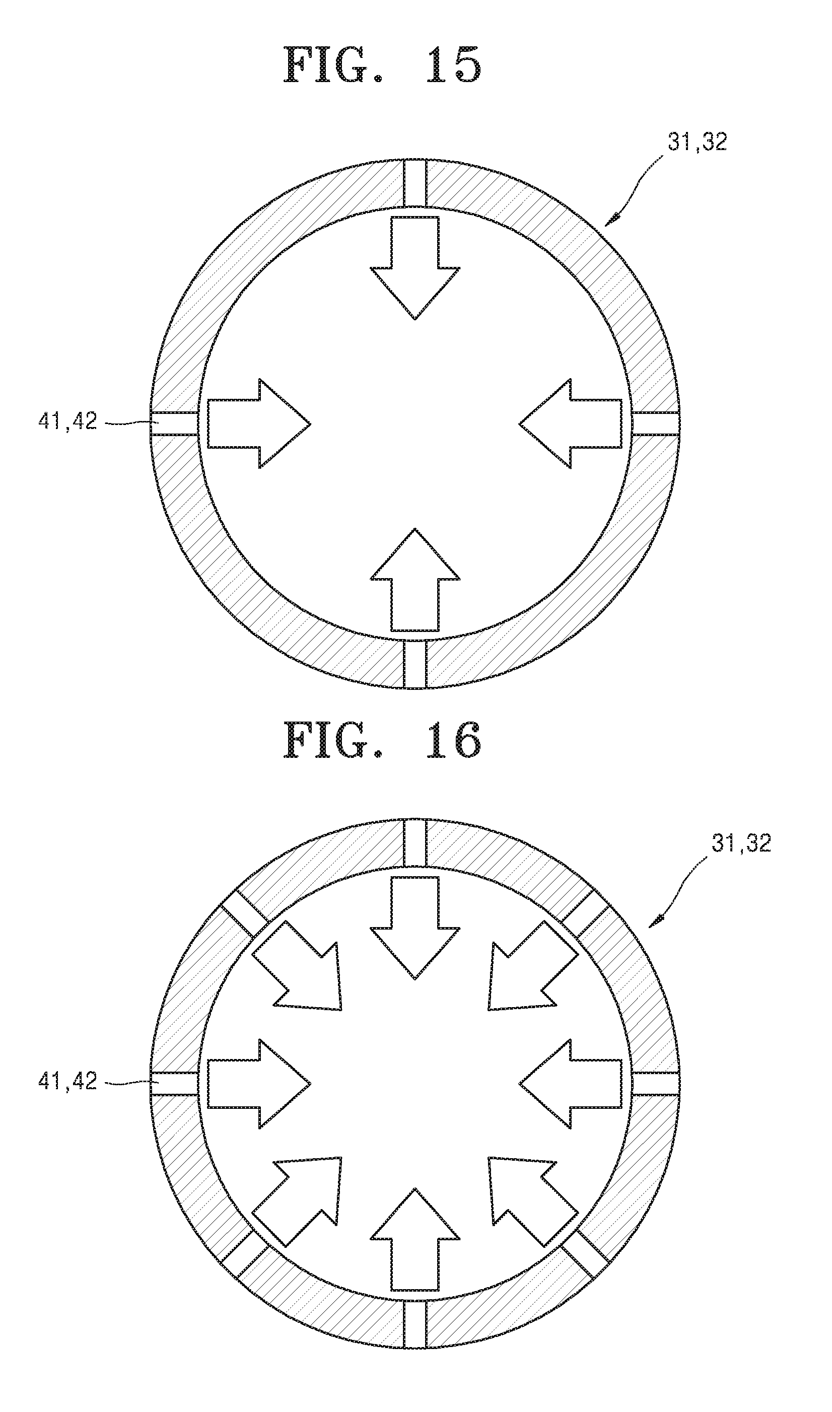
D00014

D00015

XML
uspto.report is an independent third-party trademark research tool that is not affiliated, endorsed, or sponsored by the United States Patent and Trademark Office (USPTO) or any other governmental organization. The information provided by uspto.report is based on publicly available data at the time of writing and is intended for informational purposes only.
While we strive to provide accurate and up-to-date information, we do not guarantee the accuracy, completeness, reliability, or suitability of the information displayed on this site. The use of this site is at your own risk. Any reliance you place on such information is therefore strictly at your own risk.
All official trademark data, including owner information, should be verified by visiting the official USPTO website at www.uspto.gov. This site is not intended to replace professional legal advice and should not be used as a substitute for consulting with a legal professional who is knowledgeable about trademark law.