Panel with a fastening device
Boo , et al. April 6, 2
U.S. patent number 10,968,936 [Application Number 15/567,507] was granted by the patent office on 2021-04-06 for panel with a fastening device. This patent grant is currently assigned to VALINGE INNOVATION AB. The grantee listed for this patent is VALINGE INNOVATION AB. Invention is credited to Christian Boo, Peter Derelov, Agne Palsson.


| United States Patent | 10,968,936 |
| Boo , et al. | April 6, 2021 |
Panel with a fastening device
Abstract
A set comprising a panel and a fastening device for securing a furniture component, such as a hinge, an interior fitting, a carrying device or a slider, to the panel. The fastening device includes an element with a first element surface comprising a protruding part which protrudes from the first element surface. The panel comprises an edge surface and a panel surface, which includes an insertion groove. The fastening device is configured to be assembled to the panel with the first element surface facing the panel surface. The edge surface includes an edge groove and a flexible tongue is arranged in the edge groove. The protruding part is configured to be inserted into the insertion groove and includes a recess and the flexible tongue is configured to cooperate with the recess for a locking of the fastening device to the panel.
| Inventors: | Boo; Christian (Kagerod, SE), Derelov; Peter (Helsinborg, SE), Palsson; Agne (Viken, SE) | ||||||||||
|---|---|---|---|---|---|---|---|---|---|---|---|
| Applicant: |
|
||||||||||
| Assignee: | VALINGE INNOVATION AB (Viken,
SE) |
||||||||||
| Family ID: | 1000005469037 | ||||||||||
| Appl. No.: | 15/567,507 | ||||||||||
| Filed: | April 26, 2016 | ||||||||||
| PCT Filed: | April 26, 2016 | ||||||||||
| PCT No.: | PCT/SE2016/050368 | ||||||||||
| 371(c)(1),(2),(4) Date: | October 18, 2017 | ||||||||||
| PCT Pub. No.: | WO2016/175701 | ||||||||||
| PCT Pub. Date: | November 03, 2016 |
Prior Publication Data
| Document Identifier | Publication Date | |
|---|---|---|
| US 20180112695 A1 | Apr 26, 2018 | |
Foreign Application Priority Data
| Apr 30, 2015 [SE] | 1550538-1 | |||
| Current U.S. Class: | 1/1 |
| Current CPC Class: | F16B 21/186 (20130101); F16B 12/10 (20130101); A47B 88/423 (20170101); A47B 88/43 (20170101); A47B 96/201 (20130101); F16B 12/24 (20130101); F16B 12/26 (20130101); Y10T 403/4602 (20150115); Y10T 403/7073 (20150115); A47B 2230/12 (20130101) |
| Current International Class: | F16B 12/26 (20060101); A47B 88/43 (20170101); A47B 88/423 (20170101); F16B 12/10 (20060101); F16B 21/18 (20060101); A47B 96/20 (20060101); F16B 12/24 (20060101) |
References Cited [Referenced By]
U.S. Patent Documents
| 291032 | January 1884 | Cleland |
| 634581 | October 1899 | Miller |
| 701000 | May 1902 | Ahrens |
| 861911 | July 1907 | Stewart |
| 881673 | March 1908 | Ellison |
| 1533099 | April 1925 | Carroll |
| 1534468 | April 1925 | Shea, Jr. |
| 1800386 | April 1931 | Hoffman |
| 1800387 | April 1931 | Greist |
| 1802245 | April 1931 | Foretich |
| 1954242 | April 1934 | Heppenstall |
| 2360451 | October 1944 | Stone |
| 2362904 | November 1944 | Kramer |
| 2496184 | January 1950 | Von Canon |
| 2681483 | June 1954 | Morawetz |
| 3002630 | October 1961 | Heisser |
| 3195968 | July 1965 | Freeman |
| 3284152 | November 1966 | Schorghuber |
| 3313054 | April 1967 | Madey |
| 3347610 | October 1967 | Pilliod |
| 3410441 | November 1968 | Rhyne |
| 3722704 | March 1973 | Piretti |
| 3722971 | March 1973 | Zeischegg |
| 3742807 | July 1973 | Manning |
| 3765465 | October 1973 | Gulistan |
| 3784271 | January 1974 | Schreiber |
| 3884002 | May 1975 | Logie |
| 3885845 | May 1975 | Krieks |
| 3981118 | September 1976 | Johnson et al. |
| 4089614 | May 1978 | Harley |
| 4099293 | July 1978 | Pittasch |
| 4099887 | July 1978 | Mackenroth |
| 4116510 | September 1978 | Franco |
| 4142271 | March 1979 | Busse |
| 4211379 | July 1980 | Morgan et al. |
| 4222544 | September 1980 | Crowder |
| 4279397 | July 1981 | Larsson |
| 4299067 | November 1981 | Bertschi |
| 4308961 | January 1982 | Kunce |
| 4324517 | April 1982 | Dey |
| 4403886 | September 1983 | Haeusler |
| 4405253 | September 1983 | Stockum |
| 4509648 | April 1985 | Govang |
| 4593734 | June 1986 | Wallace |
| 4595105 | June 1986 | Gold |
| 4597122 | July 1986 | Handler |
| 4615448 | October 1986 | Johnstonbaugh |
| 4629076 | December 1986 | Amstutz et al. |
| 4750794 | June 1988 | Vegh |
| 4752150 | June 1988 | Salice |
| 4815908 | March 1989 | Duran et al. |
| 4817900 | April 1989 | Whittington et al. |
| 4844266 | July 1989 | Small et al. |
| 4883331 | November 1989 | Mengel |
| 4886326 | December 1989 | Kuzyk |
| 4888933 | December 1989 | Guomundsson |
| 4891897 | January 1990 | Gieske et al. |
| 4909581 | March 1990 | Haheeb |
| 4938625 | July 1990 | Matsui |
| 4944416 | July 1990 | Petersen et al. |
| 4961295 | October 1990 | Kosch, Sr. et al. |
| 5004116 | April 1991 | Cattarozzi |
| 5018323 | May 1991 | Clausen |
| 5109993 | May 1992 | Hutchison |
| 5114265 | May 1992 | Grisley |
| 5121578 | June 1992 | Holz |
| 5125518 | June 1992 | Ward |
| 5138803 | August 1992 | Grossen |
| 5209556 | May 1993 | Anderson |
| 5212925 | May 1993 | McClinton |
| 5299509 | April 1994 | Ballard |
| 5360121 | November 1994 | Sothman |
| 5375802 | December 1994 | Branham, II |
| 5423155 | June 1995 | Bauer |
| 5451102 | September 1995 | Chuan |
| 5458433 | October 1995 | Stastny |
| 5471804 | December 1995 | Winter, IV |
| 5475960 | December 1995 | Lindal |
| 5499667 | March 1996 | Nakanishi |
| 5499886 | March 1996 | Short et al. |
| 5507331 | April 1996 | Nakanishi |
| 5527103 | June 1996 | Pittman |
| 5536108 | July 1996 | Kvalheim |
| 5658086 | August 1997 | Brokaw et al. |
| 5711115 | January 1998 | Wirt |
| 5775521 | July 1998 | Tisbo |
| 5810505 | September 1998 | Henriott |
| 5893617 | April 1999 | Lee |
| 5941026 | August 1999 | Eisenreich |
| 5944294 | August 1999 | Baer |
| 5950380 | September 1999 | Porter |
| 5950389 | September 1999 | Porter |
| 6045290 | April 2000 | Nocievski |
| 6050426 | April 2000 | Leurdijk |
| 6142436 | November 2000 | Thurston et al. |
| 6312186 | November 2001 | Rock et al. |
| 6349507 | February 2002 | Muellerleile |
| 6363645 | April 2002 | Hunter |
| 6413007 | July 2002 | Lambright |
| 6418683 | July 2002 | Martensson |
| 6491172 | December 2002 | Chance |
| 6505452 | January 2003 | Hannig |
| 6547086 | April 2003 | Harvey |
| 6578498 | June 2003 | Draudt et al. |
| 6675979 | January 2004 | Taylor |
| D486676 | February 2004 | Campbell et al. |
| 6769219 | August 2004 | Schwitte et al. |
| 6772890 | August 2004 | Campbell et al. |
| 6827028 | December 2004 | Callaway |
| 6971614 | December 2005 | Fischer et al. |
| 7127860 | October 2006 | Pervan |
| 7223045 | May 2007 | Migli |
| 7228977 | June 2007 | Perkins et al. |
| 7300120 | November 2007 | Shin |
| 7451535 | November 2008 | Wells et al. |
| 7451578 | November 2008 | Hannig |
| 7584583 | September 2009 | Bergelin et al. |
| 7614350 | November 2009 | Tuttle et al. |
| 7621092 | November 2009 | Groeke et al. |
| 7641414 | January 2010 | Joyce |
| 7717278 | May 2010 | Kao |
| 7721503 | May 2010 | Pervan et al. |
| 7793450 | September 2010 | Chasmer et al. |
| 7818939 | October 2010 | Bearinger |
| 7998549 | August 2011 | Susnjara |
| 8033074 | October 2011 | Pervan |
| 8038363 | October 2011 | Hannig |
| 8042311 | October 2011 | Pervan |
| 8146754 | April 2012 | Apgood |
| 8220217 | July 2012 | Muehlebach |
| 8234830 | August 2012 | Pervan |
| 8365499 | February 2013 | Nilsson et al. |
| 8387327 | March 2013 | Pervan |
| 8464408 | June 2013 | Hazzard |
| 8495849 | July 2013 | Pervan |
| 8505257 | August 2013 | Boo et al. |
| 8544230 | October 2013 | Pervan |
| 8596013 | December 2013 | Boo |
| 8602227 | December 2013 | McDonald |
| 8615952 | December 2013 | Engstrom |
| 8713886 | May 2014 | Pervan |
| 8745952 | June 2014 | Perra |
| 8764137 | July 2014 | Fehre |
| 8776473 | July 2014 | Pervan |
| 8833028 | September 2014 | Whispell et al. |
| 8864407 | October 2014 | Sorum |
| 8882416 | November 2014 | Baur et al. |
| 8887468 | November 2014 | Hakansson et al. |
| 9175703 | November 2015 | Maertens et al. |
| 9216541 | December 2015 | Boo |
| 9290948 | March 2016 | Cappelle et al. |
| 9375085 | June 2016 | Derelov |
| 9538842 | January 2017 | Hakansson et al. |
| 9655442 | May 2017 | Boo et al. |
| 9700157 | July 2017 | Keyvanloo |
| 9714672 | July 2017 | Derelov et al. |
| 9723923 | August 2017 | Derelov |
| 9726210 | August 2017 | Derelov et al. |
| 9745756 | August 2017 | Hannig |
| 9758973 | September 2017 | Segaert |
| 9763528 | September 2017 | Lung |
| 9809983 | November 2017 | Trudel |
| 9945121 | April 2018 | Derelov |
| 10034541 | July 2018 | Boo et al. |
| 10202996 | February 2019 | Hakansson et al. |
| 10378570 | August 2019 | Broughton |
| 10415613 | September 2019 | Boo |
| 10448739 | October 2019 | Derelov et al. |
| 10451097 | October 2019 | Brannstrom et al. |
| 10486245 | November 2019 | Fridlund |
| 10506875 | December 2019 | Boo et al. |
| 10544818 | January 2020 | Fridlund |
| 10548397 | February 2020 | Derelov et al. |
| 10669716 | June 2020 | Derelov |
| 10670064 | June 2020 | Derelov |
| 10724564 | July 2020 | Derelov |
| 10731688 | August 2020 | Brannstrom et al. |
| 10736416 | August 2020 | Derelov et al. |
| 10871179 | December 2020 | HaKansson et al. |
| 10876562 | December 2020 | Pervan |
| 10876563 | December 2020 | Derelov et al. |
| 2002/0170258 | November 2002 | Schwitte et al. |
| 2004/0165946 | August 2004 | Areh et al. |
| 2005/0042027 | February 2005 | Migli |
| 2005/0236544 | October 2005 | Mancino |
| 2005/0247653 | November 2005 | Brooks |
| 2006/0091093 | May 2006 | Armari |
| 2006/0101769 | May 2006 | Pervan et al. |
| 2006/0180561 | August 2006 | Wisnoski et al. |
| 2006/0236642 | October 2006 | Pervan |
| 2006/0273085 | December 2006 | Casto |
| 2007/0006543 | January 2007 | Engstrom |
| 2007/0028547 | February 2007 | Grafenauer et al. |
| 2008/0010937 | January 2008 | Pervan et al. |
| 2008/0066415 | March 2008 | Pervan |
| 2008/0193209 | August 2008 | Henderson |
| 2008/0216435 | September 2008 | Nolan |
| 2008/0236088 | October 2008 | Hannig et al. |
| 2008/0244882 | October 2008 | Woxman et al. |
| 2009/0014401 | January 2009 | Tallman |
| 2009/0064624 | March 2009 | Sokol |
| 2010/0028592 | February 2010 | Barkdoll et al. |
| 2010/0083603 | April 2010 | Goodwin |
| 2010/0104354 | April 2010 | Spalding |
| 2010/0173122 | July 2010 | Susnjara |
| 2010/0289389 | November 2010 | Crabtree, II |
| 2011/0023303 | February 2011 | Pervan et al. |
| 2011/0225921 | September 2011 | Schulte |
| 2011/0225922 | September 2011 | Pervan et al. |
| 2011/0280655 | November 2011 | Maertens et al. |
| 2011/0283650 | November 2011 | Pervan et al. |
| 2012/0009383 | January 2012 | Hardesty |
| 2012/0027967 | February 2012 | Maertens et al. |
| 2012/0073235 | March 2012 | Hannig |
| 2012/0124932 | May 2012 | Schulte et al. |
| 2012/0145845 | June 2012 | Hightower |
| 2012/0180416 | July 2012 | Perra et al. |
| 2012/0279161 | November 2012 | Hakansson et al. |
| 2012/0286637 | November 2012 | Fehre |
| 2013/0014463 | January 2013 | Pervan |
| 2013/0048632 | February 2013 | Chen |
| 2013/0071172 | March 2013 | Maertens et al. |
| 2013/0081349 | April 2013 | Pervan |
| 2013/0097846 | April 2013 | Pettigrew |
| 2013/0111845 | May 2013 | Pervan |
| 2013/0170904 | July 2013 | Cappelle et al. |
| 2013/0232905 | September 2013 | Pervan |
| 2013/0287484 | October 2013 | Phillips |
| 2014/0013919 | January 2014 | Gerke et al. |
| 2014/0055018 | February 2014 | Shein et al. |
| 2014/0111076 | April 2014 | Devos |
| 2014/0286701 | September 2014 | Sauer |
| 2014/0294498 | October 2014 | Logan |
| 2015/0034522 | February 2015 | Itou et al. |
| 2015/0035422 | February 2015 | Hakansson et al. |
| 2015/0078807 | March 2015 | Brannstrom et al. |
| 2015/0078819 | March 2015 | Derelov et al. |
| 2015/0196118 | July 2015 | Derelov |
| 2015/0198191 | July 2015 | Boo |
| 2015/0230600 | August 2015 | Schulte |
| 2015/0330088 | November 2015 | Derelov |
| 2015/0368896 | December 2015 | Schulte |
| 2016/0000220 | January 2016 | Devos |
| 2016/0007751 | January 2016 | Derelov |
| 2016/0145029 | May 2016 | Ranade et al. |
| 2016/0174704 | June 2016 | Boo et al. |
| 2016/0186925 | June 2016 | Bettin |
| 2016/0192775 | July 2016 | Andersson |
| 2016/0270631 | September 2016 | Derelov |
| 2017/0079433 | March 2017 | Derelov et al. |
| 2017/0089379 | March 2017 | Pervan |
| 2017/0097033 | April 2017 | Hakansson et al. |
| 2017/0159291 | June 2017 | Derelov |
| 2017/0208938 | July 2017 | Derelov et al. |
| 2017/0227031 | August 2017 | Boo |
| 2017/0227032 | August 2017 | Fridlund |
| 2017/0227035 | August 2017 | Fridlund |
| 2017/0234346 | August 2017 | Fridlund |
| 2017/0298973 | October 2017 | Derelov |
| 2017/0360193 | December 2017 | Boo et al. |
| 2018/0080488 | March 2018 | Derelov |
| 2018/0087552 | March 2018 | Derelov et al. |
| 2018/0119717 | May 2018 | Derelov |
| 2018/0202160 | July 2018 | Derelov |
| 2018/0283430 | October 2018 | Leistert |
| 2018/0328396 | November 2018 | Fransson et al. |
| 2019/0113061 | April 2019 | Hakansson et al. |
| 2019/0166989 | June 2019 | Boo et al. |
| 2019/0191870 | June 2019 | Derelov |
| 2019/0195256 | June 2019 | Derelov |
| 2019/0289999 | September 2019 | Derelov et al. |
| 2019/0320793 | October 2019 | Boo |
| 2019/0323532 | October 2019 | Boo |
| 2019/0323533 | October 2019 | Boo |
| 2019/0323534 | October 2019 | Derelov |
| 2019/0323535 | October 2019 | Derelov |
| 2020/0003242 | January 2020 | Brannstrom et al. |
| 2020/0055126 | February 2020 | Fridlund |
| 2020/0069048 | March 2020 | Derelov et al. |
| 2020/0069049 | March 2020 | Derelov et al. |
| 2020/0102978 | April 2020 | Fridlund |
| 2020/0121076 | April 2020 | Derelov et al. |
| 2020/0214447 | July 2020 | Derelov et al. |
| 365507 | Nov 1962 | CH | |||
| 685 276 | May 1995 | CH | |||
| 696 889 | Jan 2008 | CH | |||
| 698 988 | Dec 2009 | CH | |||
| 705 082 | Dec 2012 | CH | |||
| 101099618 | Jan 2008 | CN | |||
| 102 917 616 | Feb 2013 | CN | |||
| 203424576 | Feb 2014 | CN | |||
| 1107910 | May 1961 | DE | |||
| 24 14 104 | Oct 1975 | DE | |||
| 25 14 357 | Oct 1975 | DE | |||
| 26 35 237 | Feb 1978 | DE | |||
| 31 03 281 | Aug 1982 | DE | |||
| 228 872 | Oct 1985 | DE | |||
| 42 29 115 | Mar 1993 | DE | |||
| 94 17 168 | Feb 1995 | DE | |||
| 198 31 936 | Feb 1999 | DE | |||
| 298 20 031 | Feb 1999 | DE | |||
| 198 05 538 | Aug 1999 | DE | |||
| 203 04 761 | Apr 2004 | DE | |||
| 299 24 630 | May 2004 | DE | |||
| 20 2005 019 986 | Feb 2006 | DE | |||
| 20 2004 017 486 | Apr 2006 | DE | |||
| 20 2008 011 580 | Nov 2008 | DE | |||
| 20 2009 008 825 | Oct 2009 | DE | |||
| 102008035293 | Feb 2010 | DE | |||
| 10 2009 041 142 | Mar 2011 | DE | |||
| 10 2011 057 018 | Jun 2013 | DE | |||
| 10 2013 008 595 | Nov 2013 | DE | |||
| 10 2015 103 429 | Oct 2015 | DE | |||
| 10 2014 110 124 | Jan 2016 | DE | |||
| 20 2017 101 856 | Apr 2017 | DE | |||
| 0 060 203 | Sep 1982 | EP | |||
| 0 060 203 | Sep 1982 | EP | |||
| 0 357 129 | Mar 1990 | EP | |||
| 0 362 968 | Apr 1990 | EP | |||
| 0 675 332 | Oct 1995 | EP | |||
| 0 871 156 | Oct 1998 | EP | |||
| 0 935 076 | Aug 1999 | EP | |||
| 1 048 423 | Nov 2000 | EP | |||
| 1 048 423 | May 2005 | EP | |||
| 1 650 375 | Apr 2006 | EP | |||
| 1 671 562 | Jun 2006 | EP | |||
| 1 650 375 | Sep 2006 | EP | |||
| 1 863 984 | May 2008 | EP | |||
| 1 922 954 | May 2008 | EP | |||
| 2 017 403 | Jan 2009 | EP | |||
| 2 037 128 | Mar 2009 | EP | |||
| 1 922 954 | Jul 2009 | EP | |||
| 2 333 353 | Jun 2011 | EP | |||
| 1 863 984 | Nov 2011 | EP | |||
| 2 487 373 | Aug 2012 | EP | |||
| 3 031 998 | Jun 2016 | EP | |||
| 2 062 731 | Jun 1971 | FR | |||
| 2 517 187 | Jun 1983 | FR | |||
| 2 597 173 | Oct 1987 | FR | |||
| 2 602 013 | Jan 1988 | FR | |||
| 245332 | Jan 1926 | GB | |||
| 1 022 377 | Mar 1966 | GB | |||
| 2 163 825 | Mar 1986 | GB | |||
| 2 315 988 | Feb 1998 | GB | |||
| 2 445 954 | Jul 2008 | GB | |||
| 2 482 213 | Jan 2012 | GB | |||
| 2 520 927 | Jun 2015 | GB | |||
| S53-113160 | Sep 1978 | JP | |||
| H06-22606 | Mar 1994 | JP | |||
| 2003-239921 | Aug 2003 | JP | |||
| 10-1147274 | May 2012 | KR | |||
| 2014-0042314 | Apr 2014 | KR | |||
| WO 87/07339 | Dec 1987 | WO | |||
| WO 90/07066 | Jun 1990 | WO | |||
| WO 99/22150 | May 1999 | WO | |||
| WO 99/41508 | Aug 1999 | WO | |||
| WO 00/66856 | Nov 2000 | WO | |||
| WO 01/02669 | Jan 2001 | WO | |||
| WO 01/02670 | Jan 2001 | WO | |||
| WO 01/51733 | Jul 2001 | WO | |||
| WO 01/53628 | Jul 2001 | WO | |||
| WO 02/055809 | Jul 2002 | WO | |||
| WO 02/055810 | Jul 2002 | WO | |||
| WO 03/016654 | Feb 2003 | WO | |||
| WO 03/027510 | Apr 2003 | WO | |||
| WO 03/083234 | Oct 2003 | WO | |||
| WO 2004/079130 | Sep 2004 | WO | |||
| WO 2005/068747 | Jul 2005 | WO | |||
| WO 2006/043893 | Apr 2006 | WO | |||
| WO 2006/103500 | Oct 2006 | WO | |||
| WO 2006/104436 | Oct 2006 | WO | |||
| WO 2007/015669 | Feb 2007 | WO | |||
| WO 2007/015669 | Feb 2007 | WO | |||
| WO 2007/079845 | Jul 2007 | WO | |||
| WO 2008/004960 | Jan 2008 | WO | |||
| WO 2008/004960 | Jan 2008 | WO | |||
| WO 2008/004960 | Jan 2008 | WO | |||
| WO 2008/150234 | Dec 2008 | WO | |||
| WO 2009/136195 | Nov 2009 | WO | |||
| WO 2010/023042 | Mar 2010 | WO | |||
| WO 2010/070472 | Jun 2010 | WO | |||
| WO 2010/070472 | Jun 2010 | WO | |||
| WO 2010/070605 | Jun 2010 | WO | |||
| WO 2010/070605 | Jun 2010 | WO | |||
| WO 2010/082171 | Jul 2010 | WO | |||
| WO 2010/087752 | Aug 2010 | WO | |||
| WO 2011/012104 | Feb 2011 | WO | |||
| WO 2011/012104 | Feb 2011 | WO | |||
| WO 2011/085710 | Jul 2011 | WO | |||
| WO 2011/151737 | Dec 2011 | WO | |||
| WO 2011/151737 | Dec 2011 | WO | |||
| WO 2011/151737 | Dec 2011 | WO | |||
| WO 2011/151758 | Dec 2011 | WO | |||
| WO 2011/151758 | Dec 2011 | WO | |||
| WO 2012/095454 | Jul 2012 | WO | |||
| WO 2012/154113 | Nov 2012 | WO | |||
| WO 2013/009257 | Jan 2013 | WO | |||
| WO 2013/025163 | Feb 2013 | WO | |||
| WO 2013/080160 | Jun 2013 | WO | |||
| WO 2013/093636 | Jun 2013 | WO | |||
| WO 2013/093636 | Jun 2013 | WO | |||
| WO 2013/118075 | Aug 2013 | WO | |||
| WO 2014/072080 | May 2014 | WO | |||
| WO 2014/108114 | Jul 2014 | WO | |||
| WO 2014/121410 | Aug 2014 | WO | |||
| WO 2015/015603 | Feb 2015 | WO | |||
| WO 2015/038059 | Mar 2015 | WO | |||
| WO 2015/105449 | Jul 2015 | WO | |||
| WO 2015/105450 | Jul 2015 | WO | |||
| WO 2015/105451 | Jul 2015 | WO | |||
| WO 2016/099396 | Jun 2016 | WO | |||
| WO 2016/175701 | Nov 2016 | WO | |||
| WO 2016/187533 | Nov 2016 | WO | |||
| WO 2017/131574 | Aug 2017 | WO | |||
| WO 2017/135874 | Aug 2017 | WO | |||
| WO 2017/138874 | Aug 2017 | WO | |||
Other References
|
US. Appl. No. 14/486,681, filed Sep. 15, 2014, Hans Brannstrom, Agne Palsson and Peter Derelov, (Cited herein as US Patent Application Publication No. 2015/0078807 A1 of Mar. 19, 2015). cited by applicant . U.S. Appl. No. 14/573,572, filed Dec. 17, 2014, Christian Boo, (Cited herein as US Patent Application Publication No. 2015/0198191 A1 of Jul. 16, 2015). cited by applicant . U.S. Appl. No. 15/271,622, filed Sep. 21, 2016, Peter Derelov and Mats Nilsson, (Cited herein as US Patent Application Publication No. 2017/0079433 A1 of Mar. 23, 2017). cited by applicant . U.S. Appl. No. 15/308,872, filed Nov. 4, 2016, Darko Pervan, (Cited herein as US Patent Application Publication No. 2017/0089379 A1 of Mar. 30, 2017). cited by applicant . U.S. Appl. No. 15/379,791, filed Dec. 15, 2016, Niclas Hakansson and Darko Pervan, (Cited herein as US Patent Application Publication No. 2017/0097033 A1 of Apr. 6, 2017). cited by applicant . U.S. Appl. No. 15/415,356, filed Jan. 25, 2017, Peter Derelov and Christian Boo, (Cited herein as US Patent Application Publication No. 2017/0208938 A1 of Jul. 27, 2017). cited by applicant . U.S. Appl. No. 15/422,798, filed Feb. 2, 2017, Magnus Fridlund, (Cited herein as US Patent Application Publication No. 2017/0227035 A1 of Aug. 10, 2017). cited by applicant . U.S. Appl. No. 15/428,469, filed Feb. 9, 2017, Magnus Fridlund, (Cited herein as US Patent Application Publication No. 2017/0227032 A1 of Aug. 10, 2017). cited by applicant . U.S. Appl. No. 15/428,504, filed Feb. 9, 2017, Christian Boo, (Cited herein as US Patent Application publication No. 2017/0227031 A1 of Aug. 10, 2017). cited by applicant . U.S. Appl. No. 15/432,190, filed Feb. 14, 2017, Magnus Fridlund, (Cited herein as US Patent Application Publication No. 2017/0234346 A1 of Aug. 17, 2017). cited by applicant . U.S. Appl. No. 15/642,757, filed Jul. 6, 2017, Peter Derelov, (Cited herein as US Patent Application Publication No. 2017/0298973 A1 of Oct. 19, 2017). cited by applicant . U.S. Appl. No. 15/646,714, filed Jul. 11, 2017, Peter Derelov, (Cited herein as US Patent Application Publication No. 2018/0087552 A1 of Mar. 29, 2018). cited by applicant . U.S. Appl. No. 15/562,254, filed Sep. 27, 2017, Peter Derelov, (Cited herein as US Patent Application Publication No. 2018/0080488 A1 of Mar. 22, 2018). cited by applicant . U.S. Appl. No. 15/794,491, filed Oct. 26, 2017, Peter Derelov, (Cited herein as US Patent Application Publication No. 2018/0119717 A1 of May 3, 2018). cited by applicant . U.S. Appl. No. 15/923,701, filed Mar. 16, 2018, Peter Derelov. cited by applicant . U.S. Appl. No. 15/956,949, filed Apr. 19, 2018, Peter Derelov. cited by applicant . U.S. Appl. No. 15/978,630, filed May 14, 2018, Jonas Fransson, Niclas Hakansson and Agne Palsson. cited by applicant . U.S. Appl. No. 16/027,479, filed Jul. 5, 2018, Christian Boo and Peter Derelov. cited by applicant . U.S. Appl. No. 15/923,701, Derelov. cited by applicant . U.S. Appl. No. 15/956,949, Derelov. cited by applicant . U.S. Appl. No. 15/978,630, Fransson, et al. cited by applicant . U.S. Appl. No. 16/027,479, Boo, et al. cited by applicant . International Search Report/Written Opinion dated Jun. 21, 2016 in PCT/SE2016/050368, ISA/SE, Patent-och registreringsverket, Stockholm, SE, 10 pages. cited by applicant . Derelov, Peter, U.S. Appl. No. 15/923,701 entitled "Panels Comprising a Mechanical Locking Device and an Assembled Product Comprising the Panels", filed Mar. 16, 2018. cited by applicant . Derelov, Peter, U.S. Appl. No. 15/956,949 entitled "Panels for an Assembled Product", filed Apr. 19, 2018. cited by applicant . Fransson, Jonas, et al., U.S. Appl. No. 15/978,630 entitled "Elements and a Locking Device for an Assembled Product," filed May 14, 2018. cited by applicant . Boo, Christian, et al., U.S. Appl. No. 16/027,479 entitled "Panels Comprising a Mechanical Locking Device and an Assembled Product Comprising the Panels," filed Jul. 5, 2018. cited by applicant . Extended European Search Report issued in EP Application No. 16786854.6, dated Sep. 24, 2018, European Patent Office, Munich, DE, 7 pages. cited by applicant . U.S. Appl. No. 16/220,574, filed Dec. 14, 2018, Peter Derelov. cited by applicant . U.S. Appl. No. 16/220,585, filed Dec. 14, 2018, Peter Derelov. cited by applicant . U.S. Appl. No. 16/228,975, filed Dec. 21, 2018, Niclas Hakansson and Darko Pervan. cited by applicant . U.S. Appl. No. 16/361,609, filed Mar. 22, 2019, Peter Derelov, Johan Svensson and Lars Gunnarsson. cited by applicant . U.S. Appl. No. 16/386,732, filed Apr. 17, 2019, Christian Boo. cited by applicant . U.S. Appl. No. 16/386,810, filed Apr. 17, 2019, Christian Boo. cited by applicant . U.S. Appl. No. 16/386,824, filed Apr. 17, 2019, Christian Boo. cited by applicant . U.S. Appl. No. 16/386,874, filed Apr. 17, 2019, Peter Derelov. cited by applicant . U.S. Appl. No. 16/220,574, Derelov. cited by applicant . U.S. Appl. No. 16/220,585, Derelov. cited by applicant . U.S. Appl. No. 16/228,975, Hakansson et al. cited by applicant . U.S. Appl. No. 16/361,609, Derelov et al. cited by applicant . U.S. Appl. No. 16/386,732, Boo. cited by applicant . U.S. Appl. No. 16/386,810, Boo. cited by applicant . U.S. Appl. No. 16/386,824, Boo. cited by applicant . U.S. Appl. No. 16/386,874, Derelov. cited by applicant . Derelov, Peter, U.S. Appl. No. 16/220,574 entitled "Set of Panels," filed Dec. 14, 2018. cited by applicant . Derelov, Peter, U.S. Appl. No. 16/220,585 entitled "Set of Panels," filed Dec. 14, 2018. cited by applicant . Hakansson, Niclas, et al., U.S. Appl. No. 16/228,975 entitled "Mechanical Locking System for Building Panels," filed Dec. 21, 2018. cited by applicant . Derelov, Peter, et al., U.S. Appl. No. 16/361,609 entitled "Panels Comprising a Mechanical Locking Device and an Assembled Product Comprising the Panels," filed Mar. 22, 2019. cited by applicant . Boo, Christian, U.S. Appl. No. 16/386,732 entitled "Set of Panels With a Mechanical Locking Device," filed Apr. 17, 2019. cited by applicant . Boo, Christian, U.S. Appl. No. 16/386,810 entitled "Set of Panels With a Mechanical Locking Device," filed Apr. 17, 2019. cited by applicant . Boo, Christian, U.S. Appl. No. 16/386,824 entitled "Set of Panels With a Mechanical Locking Device," filed Apr. 17, 2019. cited by applicant . Derelov, Peter, U.S. Appl. No. 16/386,874 entitled "Symmetric Tongue and T-Cross," filed Apr.17, 2019. cited by applicant . U.S. Appl. No. 16/553,325, filed Aug. 28, 2019, Peter Derelov and Johan Svensson. cited by applicant . U.S. Appl. No. 16/553,350, filed Aug. 28, 2019, Peter Derelov and Johan Svensson. cited by applicant . U.S. Appl. No. 16/564,438, filed Sep. 9, 2019, Hans Brannstrom, Agne Palsson and Peter Derelov. cited by applicant . U.S. Appl. No. 16/567,436, filed Sep. 11, 2019, Peter Derelov and Mats Nilsson. cited by applicant . U.S. Appl. No. 16/663,603, filed Oct. 25, 2019, Magnus Fridlund. cited by applicant . U.S. Appl. No. 16/697,335, filed Nov. 27, 2019, Christian Boo and Peter Derelov. cited by applicant . U.S. Appl. No. 16/553,325, Derelov et al. cited by applicant . U.S. Appl. No. 16/553,350, Derelov et al. cited by applicant . U.S. Appl. No. 16/564,438, Brannstrom et al. cited by applicant . U.S. Appl. No. 16/567,436, Derelov. cited by applicant . U.S. Appl. No. 16/663,603, Fridlund. cited by applicant . U.S. Appl. No. 16/697,335, Boo et al. cited by applicant . Derelov, Peter, U.S. Appl. No. 16/553,325 entitled "Set of Panels with a Mechanical Locking Device," filed Aug. 28, 2019. cited by applicant . Derelov, Peter, U.S. Appl. No. 16/553,350 entitled "Set of Panels with a Mechanical Locking Device," filed Aug. 28, 2019. cited by applicant . Brannstrom, Hans, et al., U.S. Appl. No. 16/564,438 entitled "Assembled Product and a Method of Assembling the Assembled Product," filed Sep. 9, 2019. cited by applicant . Derelov, Peter, U.S. Appl. No. 16/567,436 entitled "Panels Comprising a Mechanical Locking Device and an Assembled Product Comprising the Panels," filed Sep. 11, 2019. cited by applicant . Fridlund, Magnus, U.S. Appl. No. 16/663,603 entitled "Element and Method for Providing Dismantling Groove," filed Oct. 25, 2019. cited by applicant . Boo, Christian, et al., U.S. Appl. No. 16/697,335 entitled "Panels Comprising a Mechanical Locking Device and an Assembled Product Comprising the Panels," filed Nov. 27, 2019. cited by applicant . U.S. Appl. No. 16/703,077, Fridlund. cited by applicant . U.S. Appl. No. 16/722,096, Derelov et al. cited by applicant . Fridlund, Magnus, U.S. Appl. No. 16/703,077 entitled "Set of Panels for an Assembled Product," filed Dec. 4, 2019. cited by applicant . Derelov, Peter, et al., U.S. Appl. No. 16/722,096 entitled "Panels Comprising a Mechanical Locking Device and an Assembled Product Comprising the Panels," filed Dec. 20, 2019. cited by applicant . U.S. Appl. No. 16/861,639, filed Apr. 29, 2020, Peter Derelov. cited by applicant . U.S. Appl. No. 16/681,639, Derelov et al. cited by applicant . Derelov, Peter, U.S. Appl. No. 16/861,639 entitled "Panels Comprising a Mechanical Locking Device and an Assembled Product Comprising the Panels," filed Apr. 29, 2020. cited by applicant . U.S. Appl. No. 16/946,047, filed Jun. 4, 2020, Darko Pervan. cited by applicant . U.S. Appl. No. 16/915,258, filed Jun. 29, 2020, Hans Brannstrom, Agne Palsson and Peter Derelov. cited by applicant . U.S. Appl. No. 16/946,047, Pervan. cited by applicant . U.S. Appl. No. 16/915,258, Brannstrom et al. cited by applicant . Pervan, Darko, U.S. Appl. No. 16/946,047 entitled "Mechanical Locking System for Building Panels," filed Jun. 4, 2020. cited by applicant . Brannstrom, Hans, et al., U.S. Appl. No. 16/915,258 entitled "Assembled Product and Method of Assembling the Assembled Product," filed Jun. 29, 2020. cited by applicant. |
Primary Examiner: McMahon; Matthew R
Attorney, Agent or Firm: Buchanan Ingersoll & Rooney P.C.
Claims
The invention claimed is:
1. A set comprising a panel and a fastening device for securing a furniture component to the panel, the fastening device comprising an element with a first element surface comprising a protruding part which protrudes from the first element surface, the panel comprising an edge surface and a panel surface, the edge surface extending between first and second edges, and between third and fourth edges, the first and second edges being longer than the third and fourth edges, and the panel surface being a main surface of the panel which is larger than the edge surface, the panel surface being wider than the fastening device as viewed along a direction orthogonal to the panel surface, the panel surface extending along the first edge and perpendicularly to the edge surface, the fastening device being configured to be assembled to the panel with the first element surface facing and contacting the panel surface in an assembled position of the fastening device to the panel surface, wherein the edge surface comprises an edge groove, the panel surface includes an insertion groove extending perpendicular to the edge groove, a flexible tongue is arranged in the edge groove such that the flexible tongue protrudes partially into the insertion groove, the protruding part comprises a recess, the protruding part is configured to be inserted into the insertion groove, and the flexible tongue is configured to cooperate with the recess for locking the fastening device to the panel.
2. The set as claimed in claim 1, wherein the insertion groove extends from the panel surface to the edge groove.
3. The set as claimed in claim 1, wherein the insertion groove is a bottom-ended groove comprising a bottom surface which is positioned at a distance from the edge groove.
4. The set as claimed in claim 1, wherein the element comprises two or more of said protruding parts and the panel surface comprises two or more of said insertion grooves, wherein each of the protruding parts is configured to be inserted into one of the insertion grooves.
5. The set as claimed in claim 1, wherein the edge groove is a longitudinal groove that extends in a longitudinal direction of the edge surface.
6. The set as claimed claim 1, wherein the edge groove extends from the edge surface to the insertion groove.
7. The set as claimed in claim 1, wherein the edge groove is a bottom-ended groove, comprising a bottom surface which is positioned at a distance from the insertion groove.
8. The set as claimed in claim 7, wherein the flexible tongue is arranged at the bottom surface of the edge groove.
9. The set as claimed in claim 7, wherein the flexible tongue is arranged between the recess and the bottom surface of the edge groove in a locked position of the fastening device and the panel.
10. The set as claimed in claim 1, wherein the fastening device and the panel are configured to be automatically locked together when the protruding part is inserted into the insertion groove and the first element surface is arranged against panel surface.
11. The set as claimed in claim 1, wherein the protruding part is rotatable relative to the element in order to unlock the fastening device from the panel.
12. The set as claimed in claim 1, wherein the protruding part extends from the first element surface, through the element, and to a second element surface.
13. The set as claimed in claim 1, wherein a second element surface comprises a fastener for securing the furniture component, the fastener being located directly opposite to a portion of the element which is free of any protruding part.
14. The set as claimed in claim 1, wherein the insertion groove is adjacent the edge surface.
15. The set as claimed in claim 1, wherein the flexible tongue is configured to be linearly displaced to cooperate with the recess for locking the fastening device to the panel.
Description
TECHNICAL FIELD OF THE INVENTION
The present invention relates to a fastening device for connecting a furniture component to a panel.
TECHNICAL BACKGROUND
Furniture components are known that are fixed to e.g. a furniture panel by screws. A drawback with the known systems is that it time consuming to assemble the furniture components to the furniture.
The above description of various known aspects is the applicant's characterization of such, and is not an admission that any of the above description is considered as prior art.
SUMMARY OF THE INVENTION
It is an object of certain embodiments of the present invention to provide an improvement over the above described techniques and known art. Particularly to reduce the time for assembling and to provide a to provide a tool-less assembling.
At least some of these and other objects and advantages that will be apparent from the description have been achieved by a first aspect of the invention that comprises a set comprising a panel and a fastening device for securing a furniture component, such as a hinge, an interior fitting, a carrying device or a slider, to the panel. The fastening device comprises an element with a first element surface comprising a protruding part which protrudes from the element surface. The panel comprises an edge surface and a panel surface. The edge surface is preferably essentially perpendicular to the panel surface. The panel surface comprises an insertion groove. The fastening device is being configured to be assembled to the panel with the first element surface facing the panel surface. The edge surface comprises an edge groove and a flexible tongue is arranged in the edge groove and the protruding part comprises a recess. The protruding part is configured to be inserted into the insertion groove and the flexible tongue is configured to cooperate with the recess for a locking of the fastening device to the panel.
An advantage of the invention may be that the fastening device may be locked to the panel without tools.
The insertion groove preferably extends from the panel surface to the edge groove. The insertion groove may be a bottom-ended groove, such as a bottom ended drill hole, comprising a bottom surface which is positioned at a distance from the edge groove.
The element may comprise two or more of said protruding part and the panel surface may comprise two or more of said insertion groove. The insertion grooves are preferably arranged linearly. Each of the protruding parts is configured to be inserted into one of the insertion grooves.
The edge groove may be a longitudinal groove that extends in a longitudinal direction of the edge surface and edge groove may be covered by e.g. an edging.
The edge groove preferably extends from the edge surface to the insertion groove. The edge groove is preferably a bottom-ended groove, comprising a bottom surface which is positioned at a distance from the edge groove. The flexible tongue may be arranged at the bottom surface of the edge groove.
The flexible tongue may be arranged between the recess and the bottom surface of the edge groove in a locked position of the fastening device and the panel.
The fastening device and the panel are preferably configured to be automatically locked together when the protruding part is inserted into the insertion groove and the element surface is arranged against panel surface.
The protruding past is preferably rotatable relative the element. The fastening device is preferably unlocked from the panel by a rotation of the protruding part relative the element. The rotation may force the flexible tongue out of the recess. The protruding part may extend from the first element surface, through the element, and to a second element surface. The protruding part may comprise a grip device, such as a recess or a wing, at the second element surface.
The second element surface may comprise a fastener for securing the furniture component.
The core of the panel may be a wood-based core, preferably made of MDF, HDF, OSB, WPC, plywood or particleboard. The core may also be a plastic core comprising thermosetting plastic or thermoplastic e.g. vinyl PVC, PU or PET. The plastic core may comprise filters. The panel may be provided with a decorative layer, such as a foil or a veneer, on one or more surfaces. The panel may also be of solid wood.
BRIEF DESCRIPTION OF THE DRAWINGS
The present invention will by way of example be described in more detail with reference to the appended schematic drawings, which shows embodiments of the present invention.
FIG. 1 shows a 3D-view of an embodiment of the invention during assembling.
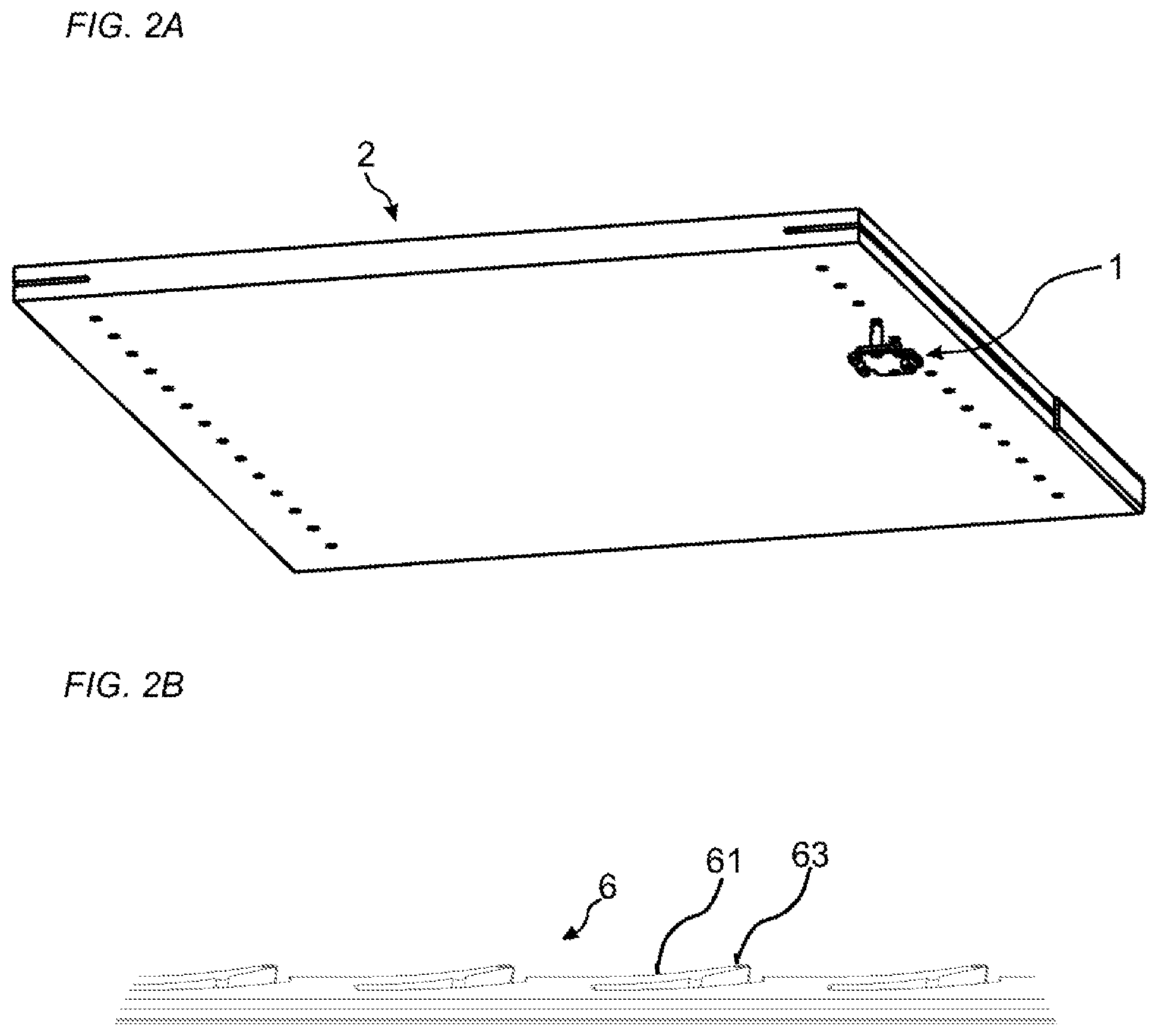
FIG. 2A shows a 3D-view of an embodiment of the invention during assembling.
FIG. 2B shows an embodiment of a flexible tongue of an embodiment of the invention.
FIGS. 3A-D show an embodiment of an assembling of an embodiment of the invention.
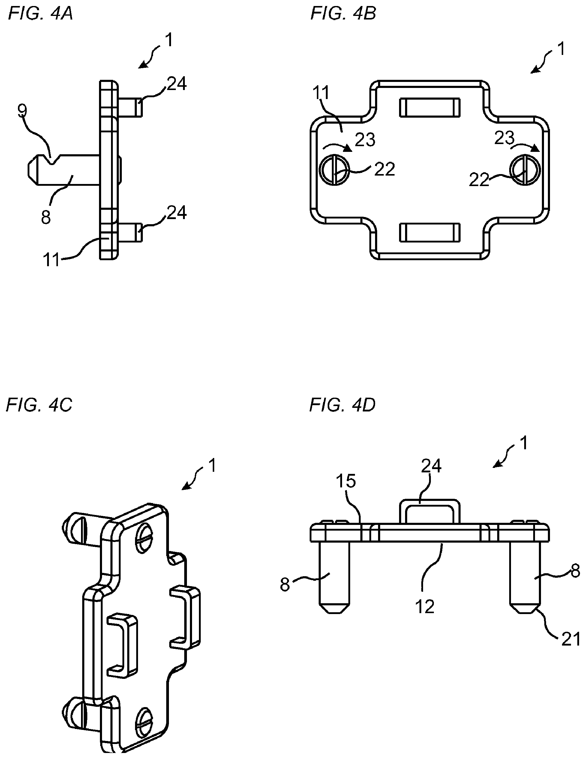
FIGS. 4A-D show in different views an embodiment of the invention.
FIGS. 5A-B show an embodiment of the invention before and after assembling, respectively.
FIG. 6A-C show in different views an embodiment of a flexible tongue of an embodiment of the invention.
FIG. 6C shows an embodiment of the locking device adapted to the flexible tongue in FIG. 6A-C
DETAILED DESCRIPTION
An embodiment of the invention is shown in FIG. 1. The embodiment comprises a panel 2 and a fastening device 1 for securing a furniture component, such as a hinge, an interior fitting, a carrying device or a slider, to the panel 2. The fastening device 1 comprises an element 11 with a first element surface 12 comprising two protruding parts 8 which protrudes from the element surface 12, even though the element surface may comprise one or several protruding parts. The panel comprises an edge surface 4 and a panel surface 3, which is the main surface of the panel. FIG. 1 shows only a part of the panel in a 3D-view. The whole panel is shown in a 3D-view in FIG. 2A. The panel surface comprises a row of insertion grooves 7 adjacent the edge surface 4. The panel surface may comprise one or several insertion grooves. The fastening device 1 is configured to be assembled to the panel with the first element surface 12 facing the panel surface 3. The edge surface 4 comprises an edge groove 5 and a flexible tongue 6 is arranged in the edge groove 5. The edge groove 5 is a longitudinal groove that extends in a longitudinal direction of the edge surface 4. The edge groove may extend along essentially the whole edge surface 4. FIG. 2A shows that also an opposite edge surface may comprise an edge groove. The protruding part 8 is configured to be inserted into the insertion groove 7 and comprises a recess 9. The flexible tongue 6 is configured to cooperate with the recess 9 for a locking of the fastening device 1 to the panel 2. The edge groove is preferably covered by a covering element 10, such as an edge band or a veneer layer, after an insertion of the flexible tongue in the edge groove 5. The insertion grooves may be bottom ended drill holes with a diameter of about 3 mm to about 10 mm. The insertion grooves may be arranged in a line and at a centre-to-centre distance of about 20 mm to about 50 mm. The drill holes may have furniture standard diameter of 5 mm or 3.2 mm that may be arranged at a standard centre-to-centre distance of 32 mm. The protruding part may be of a cylindrical shape, such as a rod, with a diameter that essentially corresponds to the diameter of the drill hole. The protruding part may comprise a polymeric and/or metallic material. An embodiment that comprises protruding parts with a small diameter may comprise three or more protruding parts in order to increase the strength of the fastening device.
An embodiment of the flexible tongue 6 is shown in FIG. 2B. The embodiment comprises a first essentially straight edge, which is configured to cooperate with the recess 9 on the protruding part 8, and a second edge that comprises flexible protruding parts 61. The protruding parts are preferably arranged against a bottom surface 14 of the edge groove 14, see FIG. 3A. The flexible tongue may comprise a friction connection 63, preferably at an outer tip of one or more of the flexible protruding parts 61.
FIGS. 3A-D show an embodiment of the fastening device 1 and a cross cut of an embodiment of the panel 2 during assembling of the fastening device 1 to the panel 2. The fastening device 1 is displaced in a direction which is essentially perpendicular to the panel surface 3. The insertion groove 7 extends from the panel surface 3 to the edge groove 5. The insertion groove 7 is a bottom-ended groove, such as a bottom ended drill hole, comprising a bottom surface 13 which is positioned at a distance from the edge groove 5. The edge groove 5 extends from the edge surface 4 to the insertion groove 7. The edge groove 7 is a bottom-ended groove, comprising a bottom surface 14 which is positioned at a distance from the insertion groove 7. The flexible tongue 6 is arranged at the bottom surface 14 of the edge groove 5. The fastening device and the panel are configured to be automatically locked together when the protruding part 8 is inserted into the insertion groove 7 and the first element surface 12 is arranged against panel surface 3.
The protruding part 8 is in FIG. 3B partly displaced into the insertion groove 7 and a guiding surface at an outer edge of the protruding part 8 is cooperating with a guiding surface at an outer edge of the flexible tongue 6.
The protruding part 8 is in FIG. 3C displaced further into insertion groove 7 and the flexible tongue 6 is in FIG. 3C pushed against the bottom surface 14 of the edge groove 5 by the protruding part 8.
The flexible tongue 6 is configured to spring back and into the recess 9 of the protruding part 8 when the protruding part 8 is displaced to a locked position which is shown in FIG. 3D. The flexible tongue 6 is arranged between the recess 9 and the bottom surface 14 and a locking surface of the flexible tongue 6 cooperates with a locking surface of the recess 9 for the locking of the fastening device to the panel.
FIG. 4A-D show an embodiment of the fastening element in a first side view, a top view, a 3D-view and a second side view, respectively. The embodiment comprises two fasteners 24 at a second surface 15 of the element 11. The fasteners may be used for locking a furniture component, such as a hinge, to the fastening element. Other embodiments may, depending on the furniture component, lack a fastener or comprise one or several fasteners. The protruding part 8 is rotatable relative the element 1, as is shown in FIG. 4B. The fastening device 1 is preferably unlocked from the panel 2 by a rotation 23 of the protruding part 8 relative the element 11. The rotation 23 may force the flexible tongue 6 out of the recess 9. The protruding part may extend from the first element surface 12, through the element 11, and to a second element surface 15. The protruding part 8 may comprise a grip device 22, such as a recess or a wing (not shown), at the second element surface 15. The protruding part 8 may comprise an angled tip 21.
FIG. 5A-B show in 3D-views an embodiment comprising a first of said fastening device 1 attached to a first end of a connecting element 50 and a second of said fastening device 1 attached to a second end of the connecting element 50. A furniture component 51, such as a slider may be attached to the connecting element. FIG. 5A shows the embodiment before assembling and FIG. 5B shows the embodiment in an assembled configuration. A flexible tongue 6 is arranged in a first and a second of said edge groove 5, respectively, and a covering element 10 is attached to a first and a second of said edge surfaces as is shown in FIG. 5B. The first fastening device is configured to be locked to the panel at a first edge of the panel 2 and the second fastening device is configured to be locked to the panel at an opposite second edge of the panel 2. The panel comprises a first row of said insertion grooves 7 the first edge and a second row of said insertion grooves at the second edge. The embodiment may further comprise a third of said fastening device 1 at the first edge. A furniture component, such as a hinge, may be attached to the third fastening device.
FIG. 6A-C show in a top view, a side view and a 3D-view, respectively, an embodiment of the flexible tongue 6. The flexible tongue comprises a recess 62 which comprises a first flexible wall 65 and a second flexible wall 66 at a first and a second edge, respectively, of the flexible tongue. The first and the second flexible wall are configured to be displaced by the protruding part 8 during assembling of the fastening device 1 to the panel 2. The flexible tongue 6 may comprise one or several of said recesses 62. The first and/or the second edge of the flexible tongue may comprise a protrusion 64 that may facilitate the displacement of the first flexible wall 65 or the second flexible wall 66 during the assembling. An outer surface of the protrusion 64 is configured to cooperate with the bottom surface 14 of the edge groove 5. The flexible tongue 6 may comprise one or several of said protrusion 64. The flexible tongue may further comprise one or more a friction connections 63. The flexible tongue 6 may cooperate with an embodiment of the fastening device, shown in FIG. 6D, that comprises a protruding part which comprises a first of said recess 9 at a first side and a second of said recess 9 at a second side. The first flexible wall is configured to cooperate with the recess at the first side and the second flexible wall is configured to cooperate with the recess at the second side for the locking of the fastening device 1 to the panel 2.
* * * * *
D00000
D00001
D00002
D00003
D00004
D00005
D00006
XML
uspto.report is an independent third-party trademark research tool that is not affiliated, endorsed, or sponsored by the United States Patent and Trademark Office (USPTO) or any other governmental organization. The information provided by uspto.report is based on publicly available data at the time of writing and is intended for informational purposes only.
While we strive to provide accurate and up-to-date information, we do not guarantee the accuracy, completeness, reliability, or suitability of the information displayed on this site. The use of this site is at your own risk. Any reliance you place on such information is therefore strictly at your own risk.
All official trademark data, including owner information, should be verified by visiting the official USPTO website at www.uspto.gov. This site is not intended to replace professional legal advice and should not be used as a substitute for consulting with a legal professional who is knowledgeable about trademark law.