Element and method for providing dismantling groove
Fridlund Nov
U.S. patent number 10,486,245 [Application Number 15/428,469] was granted by the patent office on 2019-11-26 for element and method for providing dismantling groove. This patent grant is currently assigned to VALINGE INNOVATION AB. The grantee listed for this patent is Valinge Innovation AB. Invention is credited to Magnus Fridlund.


| United States Patent | 10,486,245 |
| Fridlund | November 26, 2019 |
Element and method for providing dismantling groove
Abstract
A method for providing a dismantling groove in an element for a product to be assembled by a plurality of elements locked by a locking arrangement including a flexible tongue is disclosed. The method includes providing an insertion groove and a dismantling groove in the same element. The dismantling groove extends along the element between a first side and a second side and is configured for receiving the flexible tongue of the locking arrangement for locking the element to another element having a tongue groove. The dismantling groove is provided in the element such that it extends from the first side to the insertion groove and along a portion of the insertion groove, and is configured to receive a dismantling tool for dismantling the element from the other element. An element with an insertion groove and a dismantling groove is also disclosed.
| Inventors: | Fridlund; Magnus (Ahus, SE) | ||||||||||
|---|---|---|---|---|---|---|---|---|---|---|---|
| Applicant: |
|
||||||||||
| Assignee: | VALINGE INNOVATION AB (Viken,
SE) |
||||||||||
| Family ID: | 59496827 | ||||||||||
| Appl. No.: | 15/428,469 | ||||||||||
| Filed: | February 9, 2017 |
Prior Publication Data
| Document Identifier | Publication Date | |
|---|---|---|
| US 20170227032 A1 | Aug 10, 2017 | |
Foreign Application Priority Data
| Feb 9, 2016 [SE] | 1650159 | |||
| Current U.S. Class: | 1/1 |
| Current CPC Class: | F16B 12/26 (20130101); F16B 5/0044 (20130101); B23C 3/30 (20130101); B27F 1/04 (20130101); B65D 9/34 (20130101); B23C 2220/36 (20130101); Y10T 403/148 (20150115); A47B 2230/07 (20130101); Y10T 409/303752 (20150115); Y10S 403/10 (20130101); Y10S 403/11 (20130101); B23C 2220/04 (20130101) |
| Current International Class: | B23C 3/30 (20060101); B27F 1/04 (20060101); F16B 5/00 (20060101); F16B 12/26 (20060101); B27M 1/04 (20060101); B65D 6/34 (20060101); A47B 47/00 (20060101) |
| Field of Search: | ;403/9,20,DIG.10 ;409/131-132,143,138 ;144/371 |
References Cited [Referenced By]
U.S. Patent Documents
| 291032 | January 1884 | Cleland |
| 634581 | October 1899 | Miller |
| 701000 | May 1902 | Ahrens |
| 861911 | July 1907 | Stewart |
| 881673 | March 1908 | Ellison |
| 1533099 | April 1925 | Carroll |
| 1534468 | April 1925 | Shea, Jr. |
| 1800386 | April 1931 | Hoffman |
| 1800387 | April 1931 | Greist |
| 1802245 | April 1931 | Foretich |
| 1954242 | April 1934 | Heppenstall |
| 2360451 | October 1944 | Stone |
| 2362904 | November 1944 | Kramer |
| 2496184 | January 1950 | Von Canon |
| 3002630 | October 1961 | Heisser |
| 3195968 | July 1965 | Freeman |
| 3284152 | November 1966 | Schorghuber |
| 3313054 | April 1967 | Madey |
| 3347610 | October 1967 | Pilliod |
| 3410441 | November 1968 | Rhyne |
| 3722704 | March 1973 | Piretti |
| 3722971 | March 1973 | Zeischegg |
| 3765465 | October 1973 | Gulistan |
| 3784271 | January 1974 | Schreiber |
| 3884002 | May 1975 | Logie |
| 3885845 | May 1975 | Krieks |
| 3981118 | September 1976 | Johnson et al. |
| 4089614 | May 1978 | Harley |
| 4099887 | July 1978 | Mackenroth |
| 4116510 | September 1978 | Franco |
| 4142271 | March 1979 | Busse |
| 4211379 | July 1980 | Morgan et al. |
| 4222544 | September 1980 | Crowder |
| 4279397 | July 1981 | Larsson |
| 4299067 | November 1981 | Bertschi |
| 4308961 | January 1982 | Kunce |
| 4324517 | April 1982 | Dey |
| 4403886 | September 1983 | Haeusler |
| 4405253 | September 1983 | Stockum |
| 4509648 | April 1985 | Govang |
| 4593734 | June 1986 | Wallace |
| 4595105 | June 1986 | Gold |
| 4597122 | July 1986 | Handler |
| 4615448 | October 1986 | Johnstonbaugh |
| 4629076 | December 1986 | Amstutz et al. |
| 4750794 | June 1988 | Vegh |
| 4752150 | June 1988 | Salice |
| 4815908 | March 1989 | Duran et al. |
| 4817900 | April 1989 | Whittington et al. |
| 4844266 | July 1989 | Small et al. |
| 4883331 | November 1989 | Mengel |
| 4886326 | December 1989 | Kuzyk |
| 4888933 | December 1989 | Guomundsson |
| 4891897 | January 1990 | Gieske et al. |
| 4909581 | March 1990 | Haheeb |
| 4944416 | July 1990 | Petersen et al. |
| 4961295 | October 1990 | Kosch, Sr. et al. |
| 5004116 | April 1991 | Cattarozzi |
| 5018323 | May 1991 | Clausen |
| 5109993 | May 1992 | Hutchison |
| 5114265 | May 1992 | Grisley |
| 5121578 | June 1992 | Holz |
| 5125518 | June 1992 | Ward |
| 5138803 | August 1992 | Grossen |
| 5209556 | May 1993 | Anderson |
| 5212925 | May 1993 | McClinton |
| 5360121 | November 1994 | Sothman |
| 5375802 | December 1994 | Branham, II |
| 5423155 | June 1995 | Bauer |
| 5451102 | September 1995 | Chuan |
| 5458433 | October 1995 | Stastny |
| 5471804 | December 1995 | Winter, IV |
| 5475960 | December 1995 | Lindal |
| 5499667 | March 1996 | Nakanishi |
| 5499886 | March 1996 | Short et al. |
| 5507331 | April 1996 | Nakanishi |
| 5527103 | June 1996 | Pittman |
| 5658086 | August 1997 | Brokaw et al. |
| 5711115 | January 1998 | Wirt |
| 5775521 | July 1998 | Tisbo |
| 5810505 | September 1998 | Henriott |
| 5893617 | April 1999 | Lee |
| 5944294 | August 1999 | Baer |
| 5950389 | September 1999 | Porter |
| 6050426 | April 2000 | Leurdijk |
| 6142436 | November 2000 | Thurston et al. |
| 6312186 | November 2001 | Rock et al. |
| 6363645 | April 2002 | Hunter |
| 6413007 | July 2002 | Lambright |
| 6491172 | December 2002 | Chance |
| 6505452 | January 2003 | Hannig |
| 6547086 | April 2003 | Harvey |
| 6675979 | January 2004 | Taylor |
| D486676 | February 2004 | Campbell et al. |
| 6769219 | August 2004 | Schwitte et al. |
| 6772890 | August 2004 | Campbell et al. |
| 6827028 | December 2004 | Callaway |
| 6971614 | December 2005 | Fischer et al. |
| 7127860 | October 2006 | Pervan |
| 7223045 | May 2007 | Migli |
| 7228977 | June 2007 | Perkins et al. |
| 7300120 | November 2007 | Shin |
| 7451535 | November 2008 | Wells et al. |
| 7451578 | November 2008 | Hannig |
| 7584583 | September 2009 | Bergelin et al. |
| 7621092 | November 2009 | Groeke et al. |
| 7641414 | January 2010 | Joyce |
| 7717278 | May 2010 | Kao |
| 7721503 | May 2010 | Pervan et al. |
| 7793450 | September 2010 | Chasmer et al. |
| 7818939 | October 2010 | Bearinger |
| 7998549 | August 2011 | Susnjara |
| 8033074 | October 2011 | Pervan |
| 8038363 | October 2011 | Hannig |
| 8042311 | October 2011 | Pervan |
| 8146754 | April 2012 | Apgood |
| 8220217 | July 2012 | Muehlebach |
| 8234830 | August 2012 | Pervan |
| 8365499 | February 2013 | Nilsson et al. |
| 8387327 | March 2013 | Pervan |
| 8464408 | June 2013 | Hazzard |
| 8495849 | July 2013 | Pervan |
| 8505257 | August 2013 | Boo et al. |
| 8544230 | October 2013 | Pervan |
| 8596013 | December 2013 | Boo |
| 8602227 | December 2013 | McDonald |
| 8615952 | December 2013 | Engstrom |
| 8713886 | May 2014 | Pervan |
| 8745952 | June 2014 | Perra |
| 8764137 | July 2014 | Fehre |
| 8776473 | July 2014 | Pervan |
| 8833028 | September 2014 | Whispell et al. |
| 8864407 | October 2014 | Sorum |
| 8882416 | November 2014 | Baur |
| 8887468 | November 2014 | Hakansson et al. |
| 9175703 | November 2015 | Maertens |
| 9216541 | December 2015 | Boo |
| 9290948 | March 2016 | Cappelle et al. |
| 9375085 | June 2016 | Derelov |
| 9538842 | January 2017 | Hakansson et al. |
| 9655442 | May 2017 | Boo et al. |
| 9700157 | July 2017 | Keyvanloo |
| 9714672 | July 2017 | Derelov et al. |
| 9723923 | August 2017 | Derelov |
| 9726210 | August 2017 | Derelov et al. |
| 9745756 | August 2017 | Hannig |
| 9758973 | September 2017 | Segaert |
| 9763528 | September 2017 | Lung |
| 9809983 | November 2017 | Trudel |
| 9945121 | April 2018 | Derelov |
| 10034541 | July 2018 | Boo et al. |
| 10202996 | February 2019 | Hakansson et al. |
| 2002/0170258 | November 2002 | Schwitte et al. |
| 2005/0042027 | February 2005 | Migli |
| 2005/0236544 | October 2005 | Mancino |
| 2005/0247653 | November 2005 | Brooks |
| 2006/0091093 | May 2006 | Armari |
| 2006/0101769 | May 2006 | Pervan et al. |
| 2006/0180561 | August 2006 | Wisnoski et al. |
| 2006/0236642 | October 2006 | Pervan |
| 2006/0273085 | December 2006 | Casto |
| 2007/0006543 | January 2007 | Engstrom |
| 2008/0010937 | January 2008 | Pervan et al. |
| 2008/0066415 | March 2008 | Pervan |
| 2008/0193209 | August 2008 | Henderson |
| 2008/0216435 | September 2008 | Nolan |
| 2008/0236088 | October 2008 | Hannig et al. |
| 2009/0014401 | January 2009 | Tallman |
| 2009/0064624 | March 2009 | Sokol |
| 2010/0028592 | February 2010 | Barkdoll et al. |
| 2010/0083603 | April 2010 | Goodwin |
| 2010/0173122 | July 2010 | Susnjara |
| 2010/0289389 | November 2010 | Crabtree, II |
| 2011/0225921 | September 2011 | Schulte |
| 2011/0225922 | September 2011 | Pervan et al. |
| 2011/0280655 | November 2011 | Maertens |
| 2011/0283650 | November 2011 | Pervan et al. |
| 2012/0009383 | January 2012 | Hardesty |
| 2012/0027967 | February 2012 | Maertens |
| 2012/0073235 | March 2012 | Hannig |
| 2012/0124932 | May 2012 | Schulte et al. |
| 2012/0145845 | June 2012 | Hightower |
| 2012/0180416 | July 2012 | Perra et al. |
| 2012/0279161 | November 2012 | Hakansson et al. |
| 2012/0286637 | November 2012 | Fehre |
| 2013/0014463 | January 2013 | Pervan |
| 2013/0048632 | February 2013 | Chen |
| 2013/0071172 | March 2013 | Maertens et al. |
| 2013/0081349 | April 2013 | Pervan |
| 2013/0097846 | April 2013 | Pettigrew |
| 2013/0111845 | May 2013 | Pervan |
| 2013/0170904 | July 2013 | Cappelle et al. |
| 2013/0232905 | September 2013 | Pervan |
| 2013/0287484 | October 2013 | Phillips |
| 2014/0013919 | January 2014 | Gerke et al. |
| 2014/0055018 | February 2014 | Shein et al. |
| 2014/0111076 | April 2014 | Devos |
| 2014/0286701 | September 2014 | Sauer |
| 2014/0294498 | October 2014 | Logan |
| 2015/0035422 | February 2015 | Hakansson et al. |
| 2015/0078807 | March 2015 | Brannstrom et al. |
| 2015/0078819 | March 2015 | Derelov et al. |
| 2015/0196118 | July 2015 | Derelov |
| 2015/0198191 | July 2015 | Boo |
| 2015/0230600 | August 2015 | Schulte |
| 2015/0368896 | December 2015 | Schulte |
| 2016/0000220 | January 2016 | Devos |
| 2016/0007751 | January 2016 | Derelov |
| 2016/0145029 | May 2016 | Ranade et al. |
| 2016/0174704 | June 2016 | Boo et al. |
| 2016/0186925 | June 2016 | Bettin |
| 2016/0192775 | July 2016 | Andersson |
| 2016/0270531 | September 2016 | Derelov |
| 2017/0079433 | March 2017 | Derelov et al. |
| 2017/0089379 | March 2017 | Pervan |
| 2017/0097033 | April 2017 | Hakansson et al. |
| 2017/0159291 | June 2017 | Derelov |
| 2017/0208938 | July 2017 | Derelov et al. |
| 2017/0227031 | August 2017 | Boo |
| 2017/0227035 | August 2017 | Fridlund |
| 2017/0234346 | August 2017 | Fridlund |
| 2017/0298973 | October 2017 | Derelov |
| 2017/0360193 | December 2017 | Boo |
| 2018/0080488 | March 2018 | Derelov |
| 2018/0087552 | March 2018 | Derelov et al. |
| 2018/0112695 | April 2018 | Boo et al. |
| 2018/0119717 | May 2018 | Derelov |
| 2018/0202160 | July 2018 | Derelov |
| 2018/0328396 | November 2018 | Fransson et al. |
| 2019/0113061 | April 2019 | Hakansson et al. |
| 2019/0166989 | June 2019 | Boo et al. |
| 2019/0191870 | June 2019 | Derelov |
| 2019/0195256 | June 2019 | Derelov |
| 365 507 | Nov 1962 | CH | |||
| 685 276 | May 1995 | CH | |||
| 696 889 | Jan 2008 | CH | |||
| 698 988 | Dec 2009 | CH | |||
| 101099618 | Jan 2008 | CN | |||
| 203424576 | Feb 2014 | CN | |||
| 26 35 237 | Feb 1978 | DE | |||
| 31 03 281 | Aug 1982 | DE | |||
| 298 20 031 | Feb 1999 | DE | |||
| 20 2008 011 589 | Nov 2008 | DE | |||
| 20 2009 008 825 | Oct 2009 | DE | |||
| 10 2008 035 293 | Feb 2010 | DE | |||
| 10 2009 041 142 | Mar 2011 | DE | |||
| 10 2011 057 018 | Jun 2013 | DE | |||
| 10 2014 110 124 | Jan 2016 | DE | |||
| 0 060 203 | Sep 1982 | EP | |||
| 0 060 203 | Sep 1982 | EP | |||
| 0 362 968 | Apr 1990 | EP | |||
| 0 675 332 | Oct 1995 | EP | |||
| 0 871 156 | Oct 1998 | EP | |||
| 1 048 423 | Nov 2000 | EP | |||
| 1 048 423 | May 2005 | EP | |||
| 1 650 375 | Apr 2006 | EP | |||
| 1 671 562 | Jun 2006 | EP | |||
| 1 863 984 | Dec 2007 | EP | |||
| 1 922 954 | May 2008 | EP | |||
| 2 017 403 | Jan 2009 | EP | |||
| 2 037 128 | Mar 2009 | EP | |||
| 1 922 954 | Jul 2009 | EP | |||
| 2 333 353 | Jun 2011 | EP | |||
| 1 863 984 | Nov 2011 | EP | |||
| 2 487 373 | Aug 2012 | EP | |||
| 3 031 998 | Jun 2016 | EP | |||
| 2 062 731 | Jun 1971 | FR | |||
| 2 517 187 | Jun 1983 | FR | |||
| 2 597 173 | Oct 1987 | FR | |||
| 2 602 013 | Jan 1988 | FR | |||
| 1 022 377 | Mar 1966 | GB | |||
| 2 482 213 | Jan 2012 | GB | |||
| 2 520 927 | Jun 2015 | GB | |||
| 2003-239921 | Aug 2003 | JP | |||
| 10-1147274 | May 2012 | KR | |||
| 2014-0042314 | Apr 2014 | KR | |||
| WO 87/07339 | Dec 1987 | WO | |||
| WO-90/07066 | Jun 1990 | WO | |||
| WO 99/22150 | May 1999 | WO | |||
| WO 00/66856 | Nov 2000 | WO | |||
| WO 01/02669 | Jan 2001 | WO | |||
| WO 01/02670 | Jan 2001 | WO | |||
| WO 01/51733 | Jul 2001 | WO | |||
| WO 01/53628 | Jul 2001 | WO | |||
| WO 02/055809 | Jul 2002 | WO | |||
| WO 02/055810 | Jul 2002 | WO | |||
| WO 03/016654 | Feb 2003 | WO | |||
| WO 03/027510 | Apr 2003 | WO | |||
| WO 03/083234 | Oct 2003 | WO | |||
| WO 2004/079130 | Sep 2004 | WO | |||
| WO 2005/068747 | Jul 2005 | WO | |||
| WO 2006/043893 | Apr 2006 | WO | |||
| WO 2006/103500 | Oct 2006 | WO | |||
| WO 2006/104436 | Oct 2006 | WO | |||
| WO 2007/015669 | Feb 2007 | WO | |||
| WO 2007/015669 | Feb 2007 | WO | |||
| WO 2007/079845 | Jul 2007 | WO | |||
| WO 2008/004960 | Jan 2008 | WO | |||
| WO 2008/004960 | Jan 2008 | WO | |||
| WO 2008/017281 | Feb 2008 | WO | |||
| WO 2008/017301 | Feb 2008 | WO | |||
| WO 2008/017301 | Feb 2008 | WO | |||
| WO 2008/150234 | Dec 2008 | WO | |||
| WO 2010/023042 | Mar 2010 | WO | |||
| WO 2010/070472 | Jun 2010 | WO | |||
| WO 2010/070472 | Jun 2010 | WO | |||
| WO 2010/070605 | Jun 2010 | WO | |||
| WO 2010/070605 | Jun 2010 | WO | |||
| WO 2010/082171 | Jul 2010 | WO | |||
| WO 2010/087752 | Aug 2010 | WO | |||
| WO 2011/012104 | Feb 2011 | WO | |||
| WO 2011/012104 | Feb 2011 | WO | |||
| WO 2011/085710 | Jul 2011 | WO | |||
| WO 2011/151737 | Dec 2011 | WO | |||
| WO 2011/151737 | Dec 2011 | WO | |||
| WO 2011/151737 | Dec 2011 | WO | |||
| WO 2011/151758 | Dec 2011 | WO | |||
| WO 2011/151758 | Dec 2011 | WO | |||
| WO 2012/095454 | Jul 2012 | WO | |||
| WO 2012/154113 | Nov 2012 | WO | |||
| WO 2013/009257 | Jan 2013 | WO | |||
| WO 2013/025163 | Feb 2013 | WO | |||
| WO 2013/080160 | Jun 2013 | WO | |||
| WO 2013/093636 | Jun 2013 | WO | |||
| WO 2013/093636 | Jun 2013 | WO | |||
| WO 2013/118075 | Aug 2013 | WO | |||
| WO 2014/072080 | May 2014 | WO | |||
| WO 2014/108114 | Jul 2014 | WO | |||
| WO 2014/121410 | Aug 2014 | WO | |||
| WO 2015/015603 | Feb 2015 | WO | |||
| WO 2015/038059 | Mar 2015 | WO | |||
| WO 2015/105449 | Jul 2015 | WO | |||
| WO 2015/105450 | Jul 2015 | WO | |||
| WO 2015/105451 | Jul 2015 | WO | |||
| WO 2017/131574 | Aug 2017 | WO | |||
| WO 2017/135874 | Aug 2017 | WO | |||
| WO 2018/080387 | May 2018 | WO | |||
Other References
|
US. Appl. No. 16/220,574. cited by applicant . U.S. Appl. No. 16/220,585. cited by applicant . U.S. Appl. No. 16/228,975. cited by applicant . U.S. Appl. No. 16/361,609. cited by applicant . U.S. Appl. No. 16/386,732. cited by applicant . U.S. Appl. No. 16/386,810. cited by applicant . U.S. Appl. No. 16/386,824. cited by applicant . U.S. Appl. No. 16/386,874. cited by applicant . Derelov, Peter, U.S. Appl. No. 16/220,574 entitled "Set of Panels," filed Dec. 14, 2018. cited by applicant . Derelov, Peter, U.S. Appl. No. 16/220,585 entitled "Set of Panels," filed Dec. 14, 2018. cited by applicant . Hakansson, Niclas, et al., U.S. Appl. No. 16/228,975 entitled "Mechanical Locking System for Building Panels," filed Dec. 21, 2018. cited by applicant . Derelov, Peter, et al., U.S. Appl. No. 16/361,609 entitled "Panels Comprising a Mechanical Locking Device and an Assembled Product Comprising the Panels," filed Mar. 22, 2019. cited by applicant . Boo, Christian, U.S. Appl. No. 16/386,732 entitled "Set of Panels With a Mechanical Locking Device," filed Apr. 17, 2019. cited by applicant . Boo, Christian, U.S. Appl. No. 16/386,810 entitled "Set of Panels With a Mechanical Locking Device," filed in the U.S. Patent and Trademark Office Apr. 17, 2019. cited by applicant . Boo, Christian, U.S. Appl. No. 16/386,824 entitled "Set of Panels With a Mechanical Locking Device," filed Apr. 17, 2019. cited by applicant . Derelov, Peter, U.S. Appl. No. 16/386,874 entitled "Symmetric Tongue and T-Cross," filed Apr. 17, 2019. cited by applicant . U.S. Appl. No. 15/646,714. cited by applicant . U.S. Appl. No. 15/562,254. cited by applicant . U.S. Appl. No. 15/567,507. cited by applicant . U.S. Appl. No. 15/794,491. cited by applicant . U.S. Appl. No. 15/848,164. cited by applicant . U.S. Appl. No. 15/923,701. cited by applicant . International Search Report/Written Opinion dated May 11, 2017 in PCT/SE2017/050124, ISA/SE, Patent-och registreringsverket, Stockholm, SE, 12 pages. cited by applicant . Derelov, Peter, et al., U.S. Appl. No. 15/646,714 entitled "Assembled Product and a Method of Assembling the Product", filed Jul. 11, 2017. cited by applicant . Derelov, Peter, U.S. Appl. No. 15/562,254 entitled "Panel with a Slider", filed Sep. 27, 2017. cited by applicant . Boo, Christian, et al., U.S. Appl. No. 15/567,507 entitled "Panel With a Fastening Device," filed Oct. 18, 2017. cited by applicant . 38 Derelov, Peter, U.S. Appl. No. 15/794,491 entitled "Set of Panels with a Mechanical Locking Device", filed Oct. 26, 2017. cited by applicant . Fransson, Jonas, et al., U.S. Appl. No. 15/848,164 entitled "Device for Inserting a Tongue", filed Dec. 20, 2017. cited by applicant . Derelov, Peter, U.S. Appl. No. 15/923,701 entitled "Panels Comprising a Mechanical Locking Device and an Assembled Product Comprising the Panels", filed Mar. 16, 2018. cited by applicant . U.S. Appl. No. 15/956,949. cited by applicant . U.S. Appl. No. 15/978,630. cited by applicant . U.S. Appl. No. 16/027,479. cited by applicant . Derelov, Peter, U.S. Appl. No. 15/956,949 entitled "Panels for an Assembled Product", filed Apr. 19, 2018. cited by applicant . Fransson, Jonas, et al., U.S. Appl. No. 15/978,630 entitled "Elements and a Locking Device for an Assembled Product," filed May 14, 2018. cited by applicant . Boo, Christian, et al., U.S. Appl. No. 16/027,479 entitled "Panels Comprising a Mechanical Locking Device and an Assembled Product Comprising the Panels," filed Jul. 5, 2018. cited by applicant . U.S. Appl. No. 15/366,704. cited by applicant . U.S. Appl. No. 15/415,356. cited by applicant . U.S. Appl. No. 15/422,798. cited by applicant . U.S. Appl. No. 15/428,504. cited by applicant . U.S. Appl. No. 15/432,190. cited by applicant . Derelov, Peter, U.S. Appl. No. 15/366,704 entitled "Panels Comprising a Mechanical Locking Device and an Assembled Product Comprising the Panels", filed Dec. 1, 2016. cited by applicant . Derelov, Peter, et al., U.S. Appl. No. 15/415,356 entitled "Panels Comprising a Mechanical Locking Device and an Assembled Product Comprising the Panels", filed Jan. 25, 2017. cited by applicant . Fridlund, Magnus, U.S. Appl. No. 15/422,798 entitled "Set of Panels for an Assembled Product," filed Feb. 2, 2017. cited by applicant . Boo, Christian, U.S. Appl. No. 15/428,504 entitled "Set of Panel-Shaped Elements for a Composed Element," filed Feb. 9, 2017. cited by applicant . Fridlund, Magnus, U.S. Appl. No. 15/432,190 entitled "Method for Forming a Panel," filed Feb. 14, 2017. cited by applicant . Extended European Search Report issued in EP Application No. 17750523.7, Jul. 26, 2019, European Patent Office, Munich, DE, 7 pages. cited by applicant. |
Primary Examiner: Cadugan; Erica E
Attorney, Agent or Firm: Buchanan Ingersoll & Rooney P.C.
Claims
The invention claimed is:
1. Method for providing a dismantling groove in a first element for a product to be assembled so as to include a plurality of elements that are locked by a locking arrangement including a flexible tongue, the method comprising: providing the first element, which has a first side and an opposing second side; providing an insertion groove in the first element, which insertion groove extends along the first element between the first side and the second side and is configured for receiving the flexible tongue of the locking arrangement for locking the first element to a second element having a tongue groove; and providing a dismantling groove in the first element, which dismantling groove extends from the first side to the insertion groove and along a portion of the insertion groove, and is configured to receive a dismantling tool for dismantling the first element from the second element; the providing of the insertion groove and the providing of the dismantling groove comprising milling with a single milling tool having a first cutting surface for milling the insertion groove and having a second cutting surface for milling the dismantling groove, wherein the milling of the insertion groove is carried out with the milling tool in a first position with respect to a radial direction that is radial relative to a longitudinal axis of the milling tool, and wherein the milling of the dismantling groove is carried out by moving the milling tool to a second position spaced in the radial direction from the first position.
2. The method according to claim 1, comprising providing the insertion groove with at least a first depth into the first element along the entire insertion groove, and providing the insertion groove with a second depth into the first element at the location of the dismantling groove and such that the second depth is deeper than the first depth.
3. The method according to claim 1, wherein providing the dismantling groove comprises providing a guide surface extending from the first side towards the second side and having at least a portion that is angled less than 90 degrees relative the first side.
4. The method according to claim 1, comprising controlling the single milling tool to mill the insertion groove and the dismantling groove in a continuous milling action.
5. The method according to claim 1, wherein the first side comprises an edge section groove and the second element comprises an edge section, wherein the edge section is configured to cooperate with the edge section groove for locking the second element and the first element together.
6. The method according claim 5, wherein the edge section groove is contiguous with the insertion groove.
7. The method according claim 5, wherein the edge section comprises the tongue groove, wherein the flexible tongue is configured to cooperate with the tongue groove for locking the second element and the first element together.
Description
CROSS REFERENCE TO RELATED APPLICATIONS
The present application claims the benefit of Swedish Application No. 1650159-5, filed on Feb. 9, 2016. The entire contents of Swedish Application No. 1650159-5 are hereby incorporated herein by reference in their entirety.
FIELD OF THE INVENTION
Embodiments of the present invention relate to a method for providing a dismantling groove in an element, such as a panel-shaped element, for a product to be assembled by a plurality of elements locked by a locking arrangement including a flexible tongue. Embodiments of the invention also relate to such an element comprising, in one and the same element, an insertion groove for receiving a tongue and a dismantling groove for receiving the dismantling tool. The elements can be dismantled by pushing the tongue into the insertion groove using the dismantling tool.
BACKGROUND OF THE INVENTION
A conventional furniture product may be assembled by a plurality of elements or panels. The panels may be assembled with a mechanical locking system, such as disclosed in, for example, WO 2012/154113 A1. The product comprises a first panel connected perpendicularly to a second panel by a mechanical locking system comprising a flexible tongue in an insertion groove.
In some situations, it may be desired to disassemble or dismantle the product after it has been assembled. WO2015/038059 discloses a product assembled by a plurality of elements that are locked by a mechanical locking system comprising a flexible tongue in an insertion groove. The insertion groove is provided in a first element and a dismantling groove is provided in a second element. The dismantling groove is adapted for insertion of a dismantling tool, which pushes the flexible tongue into the insertion groove, which facilitates dismantling of the elements.
The elements are generally produced in a continuous production process. The insertion groove and the dismantling groove of WO2015/038059 are provided in separate elements and using separate tools.
Embodiments of the present invention address a widely recognized need to provide an efficient production process for, and design of, an element that can be locked by a tongue with another element and be dismantled using a tool to dismantle assembled elements.
SUMMARY OF THE INVENTION
Accordingly, embodiments of the present invention preferably seek to mitigate, alleviate or eliminate one or more deficiencies, disadvantages or issues in the art, such as the above-identified, singly or in any combination by providing a method for providing a dismantling groove and an insertion groove in an element, and an element comprising a dismantling groove and an insertion groove in the same element.
For example, embodiments of the present invention may allow a new product to be produced in existing production equipment that is adapted to the number of available milling tool positions.
Embodiments may comprise a method for providing a dismantling groove in an element for a product to be assembled by a plurality of elements locked by a locking arrangement including a flexible tongue. The method may comprise providing an element having a first side and an opposing second side; providing an insertion groove in the element that extends along the element between the first side and the second side and that is configured for receiving a flexible tongue of the locking arrangement for locking the element to another element having a tongue groove; and providing a dismantling groove in the element that extends from the first side to the insertion groove and along a portion of the insertion groove, and being configured to receive a dismantling tool for dismantling the element from the other element. The element may comprise one or more of said dismantling groove.
The insertion groove and the dismantling groove may be provided by milling with a single milling tool having a first cutting surface for milling the insertion groove and a second cutting surface for milling the dismantling groove. The insertion groove may be milled with the milling tool in a first position and the dismantling groove may be milled by moving the milling tool in a radial direction relative its longitudinal axis to a second position. Then, the tool may be moved along the element to extend the length of the dismantling groove to a desired length.
The insertion groove may be provided with at least a first depth into the element along the entire insertion groove. It may also be provided with a second depth into the element at the location of the dismantling groove and such that the second depth is deeper than the first depth.
Providing the dismantling groove may comprise providing a guide surface that extends from the first side towards the second side and that is angled at least partially less than 90 degrees relative the first side.
A single milling tool may be controlled to mill the insertion groove and the dismantling groove in a continuous milling action.
Embodiments may comprise an element for a product to be assembled by a plurality of elements locked by a locking arrangement including a flexible tongue. The element may comprise a first side and an opposing second side; an insertion groove extending along the element and between the first side and the second side, and being configured for receiving a flexible tongue of a locking arrangement for locking the element to another element; and a dismantling groove extending from the first side to the insertion groove and along a portion of the insertion groove, and being configured to receive a dismantling tool for dismantling the element from the other element.
The depth of the insertion groove may be extended at the location of the dismantling groove.
A guide surface of the dismantling groove may extend from the first side towards the insertion groove and be angled at least partially less than 90 degrees relative the first side.
Some embodiments provide for an efficient production process for, and design of, an element with an insertion groove for a flexible tongue and a dismantling groove for receiving a dismantling tool to dismantle assembled elements locked by the flexible tongue. Since the dismantling groove and the insertion groove are provided in the same element, an efficient production process is facilitated for. It also facilitates using a single tool for providing both the dismantling groove and the insertion groove, wherein the production process may be made even more efficient. Also, the element may be produced in production lines already producing elements with an insertion groove. Such existing production lines only need to be updated with a new tool, and programmed to control the tool to generate the dismantling groove. Hence implementation into existing production lines is both time and cost efficient. The design of the element also provides for assembling the element with other elements efficiently to a stable product, which may also be disassembled if desired.
The term "comprises/comprising" when used in this specification is taken to specify the presence of stated features, integers, steps or components but does not preclude the presence or addition of one or more other features, integers, steps, components or groups thereof.
BRIEF DESCRIPTION OF THE DRAWINGS
These and other aspects, features and advantages of which embodiments of the invention are capable of, will be apparent and elucidated from the following description of embodiments of the present invention, reference being made to the accompanying drawings, in which
FIG. 1 is a cross-sectional view of an element and another element illustrating the insertion groove and the dismantling groove;
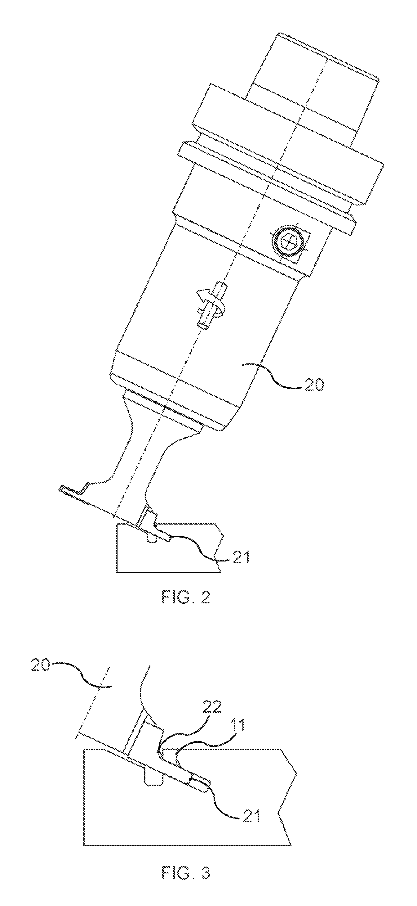
FIG. 2 is a partly cross-sectional view of the element and the tool for providing the insertion groove and the dismantling groove when the tool is in a position for only providing the insertion groove;
FIG. 3 is a cross-sectional view of the element and the tool for providing the insertion groove and the dismantling groove when the tool is in a position after the dismantling groove has been provided and is positioned for providing of the insertion groove;
FIG. 4a is a perspective view of the element connected to the adjacent element and illustrating a dismantling groove along an edge of a portion of the element 1.
FIG. 4b is a top view of the element connected to the adjacent element and illustrating a dismantling groove along an edge of a portion of the element 1;
FIG. 4c is an enlarged top view of the dismantling groove of FIG. 4b.
FIG. 5a is a cross-sectional view of the element and another element in a connected state; and
FIG. 5b is a cross-sectional view of the element and another element during an insertion of a dismantling tool.
DESCRIPTION OF EMBODIMENTS
Specific embodiments of the invention will now be described with reference to the accompanying drawings. This invention may, however, be embodied in many different forms and should not be construed as limited to the embodiments set forth herein; rather, these embodiments are provided so that this disclosure will be thorough and complete, and will fully convey the scope of the invention to those skilled in the art. The terminology used in the detailed description of the embodiments illustrated in the accompanying drawings is not intended to be limiting of the invention. In the drawings, like numbers refer to like elements.
The present description of an embodiment is given with reference to an element 1, such as a panel-shaped element, that may be arranged perpendicular to another panel-shaped element 7. The elements may be locked together with a mechanical locking device as an example only. The panels may be assembled and locked together to obtain a product, e.g. furniture, such as a bookshelf, a cupboard, a wardrobe, a box, a drawer or a furniture component. The locking device may comprise a flexible tongue. It should be born in mind, however, that embodiments of the present invention is not limited strictly to furniture, but can be easily adapted to any product wherein elements are assembled by locking devices. Further examples of the product and the mechanical locking device can be found in WO2015/105449 and WO2015/038059, which are incorporated herein by reference in their entirety for all purposes, particularly with regard to arranging a flexible tongue in an insertion groove 2 for locking in a tongue groove 3 of another element.
FIG. 1 illustrates the element 1 comprising a dismantling groove 4 as well as the insertion groove 2 in one and the same element 1. The insertion groove 2 extends along the element 1 and from a first side 5 towards a second side 6 of the element 1. Also, the insertion groove 2 may extend along an edge of the element, and be located a distance from the edge. The dismantling groove 4 extends from the first side 5 to the insertion groove 2. The dismantling groove 4 is configured to receive a dismantling tool 60 for pushing the tongue away from the tongue groove 3. Since the insertion groove 2 and the dismantling groove 4 are provided in the same element, the production process may be simplified, making it more efficient to produce, and may be thus more cost efficient. Particularly, it allows, in embodiments, for using a single tool for providing the insertion groove 2 as well as the dismantling groove 4. This in turn means that the panel is particularly suited to be produced in existing production equipment where elements are produced with an insertion groove 2, but in which a separate tool for providing the dismantling groove 4 cannot be added, or added with significant difficulty. However, the insertion groove 2 and the dismantling groove 4 may in some embodiments be provided using separate tools, which may be still more efficient than providing the insertion groove and the dismantling groove in separate elements.
FIG. 1 illustrates an embodiment of the element 1 arranged for assembly using a locking device for locking the element 1 to an adjacent element 7. The element 1 and the adjacent element 7 may be boards or panels of a furniture product that are connected perpendicular to each other, i.e., with a main surface of the element 1 perpendicular to a main surface of the adjacent element 7. An edge section 8 of the adjacent element 7 is arranged in an edge section groove 9 of the element 1 for locking the adjacent element 7 and the element 1 together in a first direction. A locking device in the form of a flexible tongue may be arranged in the insertion groove 2 in the edge section groove 9 and extend into a tongue groove 3 at the edge section 8. The tongue groove 3 and a tip of the tongue extending into the tongue groove 3 may have complementary shapes. The flexible tongue and the tongue groove 3 cooperate for locking the element 1 and the adjacent element 7 together in a second direction, which is essentially perpendicular to the first direction. The flexible tongue is, during assembly of the element 1 and the adjacent element 7, pushed into the insertion groove 2 when the edge section 8 is inserted into the edge section groove 9. The flexible tongue springs back and into the tongue groove 3 when the element 1 and the adjacent element 7 have reached a connected state.
FIGS. 2-3 illustrate embodiments of a method for providing the dismantling groove 4 in the element 1. The element 1 may be panel-shaped having a first side 5 and an opposing second side 6. Various other grooves and/or profiles may already be present in the element 1, such as the edge section groove 9. The insertion groove 2 and the dismantling groove 4 may be provided using a milling tool. The element 1 may be passed through a production line wherein a number of milling tools are present in order to provide various grooves, recesses and profiles along the element 1.
As is illustrated in FIG. 2, the insertion groove 2 is provided in the element 1 such that it extends along the element 1, for example along an edge of the element 1, and between the first side 5 and the second side 6. Also, the insertion groove 2 is configured for receiving a flexible tongue of a locking arrangement for locking the element 1 to the adjacent element 7 having the tongue groove 3. The insertion groove 2 may be provided to extend at a non-perpendicular angle relative the first side 5, such that the tongue is arranged non-perpendicularly relative the adjacent element 7. For example, the insertion groove 2 may be provided to extend at an angle of 20.degree. to 70.degree., for example, 30 to 45.degree.. The dismantling groove 4 is provided in the same element 1 as the insertion groove 2 and such that it extends from the first side 5 to the insertion groove 2. Hence, access to the insertion groove 2, and thus to a tongue when arranged therein, is provided from the first side 5 of the element 1.
The dismantling groove 4 is configured to receive a dismantling tool 60 for dismantling the element 1 from the adjacent element 7. For example, at least one dismantling groove 4 may extend along a portion of the insertion groove 2. For example, a dismantling groove 4 may be 2 to 20% of the length of the insertion groove, for example, 5 to 10% of the length of the insertion groove. Multiple tongues may be arranged spaced apart in the insertion groove 2. Each tongue may, e.g., be about 20-400 mm long. If multiple tongues are provided in the same element 1, the tongues may be spaced apart, e.g., 0.5-1 times the length of the tongue. The distance between two tongues depends on the required strength of the locking arrangement. No distance or a shorter distance, such as about 1 mm to about 5 mm, between two tongues provides a stronger locking arrangement.
The dismantling groove 4 may be provided to coincide with the location between the locations for two tongues. Hence, the dismantling groove 4 may be about 20-80 mm long, or about the same length as, or shorter than, the distance between two tongues. This provides for inserting a dismantling tool through the dismantling groove 4, and pushing the dismantling tool along the insertion groove 2. If the dismantling groove is provided on a top surface of the element 1 and visible during use of the element 1, the dismantling groove 4 may be about 20-50 mm long. If the dismantling groove is provided on a bottom surface of the element 1 and non-visible during use of the element 1, the dismantling groove 4 may be about 20-80 mm long. Hence, different elements may have different lengths of the dismantling groove 4 in order to optimize strength and at the same time reduce the impact on surfaces that are used. For example, reducing the length on visible surfaces reduces the risk of dust and particle agglomeration in such surfaces.
The dismantling tool may, e.g., be rod-shaped with a cross-sectional shape that substantially corresponds to a portion of the cross-sectional shape of the insertion groove 2. A tip of the dismantling tool may be pointed, such that the tongue is pushed into the insertion groove 2 and away from the tongue groove 3 when the dismantling tool is positioned between the tongue and the tongue groove 3.
The dismantling groove 4 is sufficiently wide to receive the dismantling tool, and may be about 1-3 mm, preferably about 2 mm. The dismantling groove 4 measured from the edge section groove 9 parallel with the first side 5 has a first width. The insertion groove 2 measured from the edge section groove 9 parallel with the first side 5 has a second width, which is larger than the first width. Hence, insertion groove 2 may be configured for a flexible tongue that may be received between the dismantling tool and a bottom wall 10 (FIG. 1) of the insertion groove 2 when the dismantling tool is received in the insertion groove 2. FIG. 1 shows a cross-section of element 1, wherein, at the location of the dismantling groove 4, the bottom of the insertion groove 2 is extended to a second depth into the element 1, providing a deeper bottom wall 15 in a portion of the insertion groove 2 which coincides with the dismantling groove 4.
In some embodiments, the insertion groove 2 and the dismantling groove 4 are provided by milling with a single milling tool 20, such as illustrated in the embodiment of FIG. 3. The milling tool 20 may have a first cutting surface 21 for milling the insertion groove 2 and a second cutting surface 22 for milling the dismantling groove 4. The insertion groove 2 may be milled with the milling tool 20 in a first position, such as the position illustrated in FIGS. 2-3. The dismantling groove 4 may be milled by moving the milling tool in a radial direction relative its longitudinal axis to a second position while the element 1 and/or the tool is moving along the element 1. When the length of the dismantling groove 4 has been provided, the milling tool 20 is returned to the first position. Hence, the insertion groove 2 as well as the dismantling groove 4 may be generated simultaneously while the milling tool 20 is in the second position. This provides for increased efficiency for producing the element 1. It also provides for high production tolerances between the insertion groove 2 and the dismantling groove 4, which will be provided with a fixed relationship. This in turn leads to a stable assembled product. When the milling tool is in the first position, only the insertion groove 2 may be provided but not the dismantling groove 4. Hence, milling tool 20 may be controlled to mill, e.g. by CNC milling, the insertion groove 2 and the dismantling groove 4 in a continuous milling action, such as while the element 1 is passed along a production line.
In some embodiments, the insertion groove 2 is provided with a first depth into the element 1 along the insertion groove 2. At the location of the dismantling groove 4, the depth of the insertion groove 2 may be extended to a second depth into the element 1, which is deeper than the first depth. For example, the difference between the second depth and first depth may be correlated to the width of the insertion groove 2. Hence, the insertion groove 2 and the dismantling groove 4 may be provided with a single tool in a continuous, or substantially continuous, action.
In some embodiments, such as illustrated in FIG. 1, the dismantling groove 4 is provided with a guide surface 11 extending from the first side 5 of the element 1 towards the second side 6 of the element 1 and along the insertion groove 2. The guide surface may be angled at less than 90 degrees relative the first side 5 of the element 1. For example, the guide surface may be angled 45 to 85 degrees, for example, 60 to 80 degrees, relative to the first side 5 of the element 1. The dismantling groove 4 has an opening at the first side 5 of the element 1 that is wider than further down in the dismantling groove 4 towards the insertion groove 2, which forms the guide surface. This provides for guiding the dismantling tool towards the insertion groove 2. In some embodiments, the guide surface is straight. In other embodiments, such as illustrated in FIG. 3, the guide surface 11 is curved between first side 5 and the insertion groove 2. This forms a narrowed portion of the dismantling groove. This further facilitates guiding the dismantling tool to a correct position in the insertion groove 2 without jamming the tool when it is positioned below the narrowed portion for pushing the tongue into the insertion groove 2. When the dismantling groove 4 is curved with a widened portion towards the insertion groove 2, the guide surface may initially be angled less than 90 degrees relative the first side 5 at the first side, and have a gradually increased width from a narrowed section and towards the insertion groove 2 such that it is angled more than 90 degrees relative the first side 5 when it reaches the insertion groove 2. Such a curved guide surface may be provided with the second cutting surface 22 of the tool 20 having a curved shape.
The method embodiments described above may be used to produce the element 1, such as in wood, composite wood, laminate, plastic etc. The element may be a panel, comprising a wood based material, such as a MDF or HDF panel, a particleboard or a plywood board. The panel may be covered by a decorative layer. The element 1 may also be produced using other production techniques, such as extrusion, wherein milling is not required. Such an element 1 comprises the first side 5 and the opposing second side 6. The insertion groove 2 extends along the element 1 and between the first side 5 and the second side 6. The insertion groove 2 may extend at a non-perpendicular angle relative the first side 5. Also, the insertion groove 2 is configured for receiving a flexible tongue of a locking arrangement for locking the element 1 to another element, such as adjacent element 7. The dismantling groove 4 extends from the first side 5 to the insertion groove 2 and along a portion of the insertion groove 2.
The dismantling groove 4 is configured to receive a dismantling tool for dismantling the element 1 from the other element. The dismantling groove 4 may be open towards the edge section groove 9 of the element 1. Hence, the dismantling groove 4 may have one or several walls 4a, 4b, 4c (FIG. 4c) extending from the first side 5 of the element 1 to the insertion groove 2, and from one end of the dismantling groove 4 to the other end of the dismantling groove 4 along the insertion groove 2. Hence, the dismantling groove 4 may have a substantially U-shaped cross section taken parallel to the first side 5.
When the adjacent panel 7 is positioned in the edge section groove 9, it is supported by an upper side surface 12 of the edge section groove 9, which may be substantially perpendicular to the first side 5, at the positions where only the insertion groove 2 is located, i.e., where the dismantling groove 4 is not located. It is also supported by a lower side surface 13 of the edge section groove 9, which is parallel with the upper side surface 12. At the location of the dismantling groove 4, the adjacent panel 7 is only supported by the lower side surface 13. This provides for sufficient stability of the adjacent panel 7 and yet an efficient production of the element 1 with the insertion groove 2 and the dismantling groove 4.
FIGS. 4a-4c illustrates the element 1 connected to the adjacent panel 7. A single dismantling groove 4 is provided in the element 1, and between two insertion grooves (not illustrated). Multiple dismantling grooves 4 may be provided as described above. As can be seen in FIGS. 4a and 4b, the dismantling groove 4 extends along the element 1. Furthermore, the dismantling groove 4 is open towards the adjacent element 7. As is illustrated in FIG. 4c, the edge of the dismantling groove 4 at the first side 5 of the element 1 may be partly curved, such as with a curved section at each end of the dismantling groove 4 and a substantially straight section therebetween.
The element 1 and the other element 7 may be arranged such that the first side 5 with the dismantling groove 4 is facing upwards as in the illustrated in the FIGS. The panels may be arranged in any way e.g. such that the first side 5 with the dismantling groove 4 is facing downwards. A dismantling groove facing downward may have the advantage that the dismantling groove is less visible and/or that less particles, such as dust, are accumulated in the insertion groove.
FIG. 5a shows in a cross-sectional view an embodiment of the element 1 and the other element 2 in a connected state. The flexible tongue 50 cooperates with the tongue groove 3 for locking the adjacent element 7 and the element 1 together in the second direction.
FIG. 5b is a cross-sectional view an embodiment of the element 1 and other element 7 during an insertion of the dismantling tool 60 into the dismantling groove an the insertion groove 2.
It should also be appreciated that features disclosed in the foregoing description, and/or in the foregoing drawings and/or following claims both separately and in any combination thereof, be material for realizing the present invention in diverse forms thereof. When used in the following claims, the terms "comprise", "include", "have" and their conjugates mean, "including but not limited to".
When the word "about" is used in this specification in connection with a numerical value, it is intended that the associated numerical value include a tolerance of .+-.10% around the stated numerical value.
The present invention has been described above with reference to specific embodiments. However, other embodiments than the above described are equally possible within the scope of the invention. Different method steps than those described above may be provided within the scope of the invention. The different features and steps of the invention may be combined in other combinations than those described.
Embodiments
1. Method for providing a dismantling groove (4) in an element (1) for a product to be assembled by a plurality of elements locked by a locking arrangement including a flexible tongue, comprising:
providing an element (1) having a first side (5) and an opposing second side (6);
providing an insertion groove (2) in the element (1) that extends along the element (1) between the first side (5) and the second side (6) and that is configured for receiving a flexible tongue of a locking arrangement for locking the element (1) to another element (7) having a tongue groove (3); and
providing a dismantling groove (4) in the element (1) that extends from the first side (5) to the insertion groove (2) and along a portion of the insertion groove (2), and being configured to receive a dismantling tool for dismantling the element (1) from the other element (7).
2. The method according to embodiment 1, comprising providing the insertion groove (2) and the dismantling groove (4) by milling with a single milling tool (20) having a first cutting surface (21) for milling the insertion groove (2) and a second cutting surface (22) for milling the dismantling groove (4), and milling the insertion groove (2) with the milling tool (20) in a first position and the dismantling groove (4) by moving the milling tool (20) in a radial direction relative its longitudinal axis to a second position.
3. The method according to any of the previous embodiments, comprising providing the insertion groove (2) with at least a first depth into the element (1) along the entire insertion groove (2), and providing the insertion groove (2) with a second depth into the element (1) at the location of the dismantling groove (4) and such that the second depth is deeper than the first depth.
4. The method according to any of the previous embodiments, wherein providing the dismantling groove (4) comprises providing a guide surface (11) extending from the first side (5) towards the second side (6) and being angled at least partially less than 90 degrees relative the first side (5).
5. The method according to any of the previous embodiments, comprising controlling a single milling tool (20) to mill the insertion groove (2) and the dismantling groove (4) in a continuous milling action.
6. The method according to any of the previous embodiments, wherein the first side (5) comprises a edge section groove (9) and the other element (7) comprises an edge section (8), wherein the edge section (8) is configured to cooperate with the edge section groove (9) for locking the other element (7) and the element (1) together in a first direction.
7. The method according embodiment 6, wherein the edge section groove (9) comprises the insertion groove (2).
8. The method according embodiment 6 or 7, wherein in the edge section (8) comprises the tongue groove (3), wherein the flexible tongue is configured to cooperate with the tongue groove (3) for locking the other element (7) and the element (1) together in a second direction, which is perpendicular to the first direction.
9. Element (1) for a product to be assembled by a plurality of elements locked by a locking arrangement including a flexible tongue, comprising
a first side (5) and an opposing second side (6);
an insertion groove (2) extending along the element (1) and between the first side (5) and the second side (6), and being configured for receiving a flexible tongue of a locking arrangement for locking the element (1) to another element (7); and
a dismantling groove (4) extending from the first side (5) to the insertion groove (2) and along a portion of the insertion groove (2), and being configured to receive a dismantling tool for dismantling the element (1) from the other element (7).
10. The element according to embodiment 9, wherein the depth of the insertion groove (2) is extended at the location of the dismantling groove (4).
11. The element according to any of embodiments 9 or 10, wherein a guide surface (11) of the dismantling groove (4), which extends from the first side (5) towards the insertion groove (2), is angled at least partially less than 90 degrees relative the first side (5).
12. The element according to any of embodiments 9-11, wherein the first side (5) comprises a edge section groove (9) and the other element (7) comprises an edge section (8), wherein the edge section (8) is configured to cooperate with the edge section groove (9) for locking the other element (7) and the element (1) together in a first direction.
13. The element according to embodiment 12, wherein the edge section groove (9) comprises the insertion groove (2).
14. The element according to embodiment 12 or 13, wherein in the edge section (8) comprises the tongue groove (3), wherein the flexible tongue is configured to cooperate with the tongue groove (3) for locking the other element (7) and the element (1) together in a second direction, which is perpendicular to the first direction.
15. The element according to any of embodiments 9-14, wherein the flexible tongue is configured to be pushed into the insertion groove (2) when the edge section (8) is inserted into the edge section groove (9) during assembly of the element (1) and the other element (7) or during dismantling.
16. The element according to embodiment 15, wherein the flexible tongue springs back and into the tongue groove (3) when the element (1) and the other element (7) have reached a connected state.
* * * * *
D00000
D00001
D00002
D00003
D00004
XML
uspto.report is an independent third-party trademark research tool that is not affiliated, endorsed, or sponsored by the United States Patent and Trademark Office (USPTO) or any other governmental organization. The information provided by uspto.report is based on publicly available data at the time of writing and is intended for informational purposes only.
While we strive to provide accurate and up-to-date information, we do not guarantee the accuracy, completeness, reliability, or suitability of the information displayed on this site. The use of this site is at your own risk. Any reliance you place on such information is therefore strictly at your own risk.
All official trademark data, including owner information, should be verified by visiting the official USPTO website at www.uspto.gov. This site is not intended to replace professional legal advice and should not be used as a substitute for consulting with a legal professional who is knowledgeable about trademark law.