Panels Comprising A Mechanical Locking Device And An Assembled Product Comprising The Panels
DERELOV; Peter ; et al.
U.S. patent application number 16/722096 was filed with the patent office on 2020-04-23 for panels comprising a mechanical locking device and an assembled product comprising the panels. This patent application is currently assigned to Valinge Innovation AB. The applicant listed for this patent is Valinge Innovation AB. Invention is credited to Christian BOO, Peter DERELOV.
| Application Number | 20200121076 16/722096 |
| Document ID | / |
| Family ID | 59360012 |
| Filed Date | 2020-04-23 |


| United States Patent Application | 20200121076 |
| Kind Code | A1 |
| DERELOV; Peter ; et al. | April 23, 2020 |
PANELS COMPRISING A MECHANICAL LOCKING DEVICE AND AN ASSEMBLED PRODUCT COMPRISING THE PANELS
Abstract
A set of panels including a first panel with a first main plane and a second panel with a second main plane. The first and the second panel are provided with a mechanical locking device for locking a first edge of the first panel to a second edge of the second panel at a junction plane, wherein the first main plane is essentially perpendicular to the second main plane and the junction plane is extending between the first main plane and the second main plane. The first edge includes an edge tongue that extends from the junction plane. The second edge includes an edge groove at the junction plane. The edge tongue is configured to cooperate with the edge groove for locking together the first and the second edges in a first direction which is perpendicular to the first main plane. The edge tongue includes a tongue groove.
| Inventors: | DERELOV; Peter; (Helsingborg, SE) ; BOO; Christian; (Kagerod, SE) | ||||||||||
| Applicant: |
|
||||||||||
|---|---|---|---|---|---|---|---|---|---|---|---|
| Assignee: | Valinge Innovation AB Viken SE |
||||||||||
| Family ID: | 59360012 | ||||||||||
| Appl. No.: | 16/722096 | ||||||||||
| Filed: | December 20, 2019 |
Related U.S. Patent Documents
| Application Number | Filing Date | Patent Number | ||
|---|---|---|---|---|
| 15415356 | Jan 25, 2017 | 10548397 | ||
| 16722096 | ||||
| Current U.S. Class: | 1/1 |
| Current CPC Class: | A47B 88/941 20170101; A47B 47/042 20130101; F16B 12/46 20130101; F16B 12/125 20130101; A47B 2088/902 20170101; F16B 12/26 20130101 |
| International Class: | A47B 47/04 20060101 A47B047/04; F16B 12/26 20060101 F16B012/26; F16B 12/46 20060101 F16B012/46; F16B 12/12 20060101 F16B012/12 |
Foreign Application Data
| Date | Code | Application Number |
|---|---|---|
| Jan 26, 2016 | SE | 1650089-4 |
Claims
1. A set of panels for a furniture, the set comprising a first panel with a first main plane and a second panel with a second main plane, wherein the first panel and the second panel are provided with a mechanical locking device for locking a first edge of the first panel to a second edge of the second panel at a junction plane, wherein the first main plane is essentially perpendicular to the second main plane and the junction plane is extending between the first main plane and the second main plane, wherein: the first edge comprises an edge tongue that extends beyond the junction plane, the second edge comprises an edge groove at the junction plane, wherein the edge tongue is configured to cooperate with the edge groove for locking together the first and the second edges in a first direction which is perpendicular to the first main plane, the edge tongue comprises a tongue groove, the edge groove comprises a flexible tongue arranged in an insertion groove, said flexible tongue is configured to cooperate with the tongue groove for locking together the first and the second edges in a second direction which is perpendicular to the second main plane, the mechanical locking device comprises a first space between the edge tongue and the edge groove at an opening of the edge groove and at the junction plane in a locked position of the first and the second edge, the angle between the junction plane and the first main plane is about 45 degrees, the mechanical locking device comprises a first contact surface at the first edge and a second contact surface at the second edge, the first contact surface and the second contact surface are at an outer corner, in a locked position of the first and the second panel, and in the junction plane and are configured to cooperate, and the first edge surface and/or the second edge surface comprises a recess extending from the first contact surface and the second contact surface, respectively, to the edge tongue and the edge groove, respectively.
2. (canceled)
3. The set of panels as claimed in claim 1, wherein edge tongue extends, from the junction plane, essentially in the second direction.
4. The set of panels as claimed in claim 1, wherein a first side of the edge tongue comprises, at or near the junction plane, a first locking surface, and the edge groove comprises, at or near the junction plane, a second locking surface, wherein the first locking surface and the second locking surface are essentially parallel and are configured to cooperate for locking in the first direction.
5. The set of panels as claimed in claim 1, wherein the edge tongue at a second side, which is opposite the first side, comprises a third locking surface and the edge groove comprises a fourth locking surface, wherein the third locking surface and the fourth locking surface are essentially parallel and are configured to cooperate at a distance from the junction plane for locking in the first direction.
6. The set of panels as claimed in claim 5, wherein the third locking surface and the fourth locking surface cooperate at an area extending over a first distance in the second direction, wherein the third locking surface and the fourth locking surface are displaced from the junction plane by a second distance, wherein the first distance is within the range of about 20% to about 200% of the second distance.
7. The set of panels as claimed in claim 1, wherein the first side of the edge tongue, at a distance from the junction plane, comprises a fifth locking surface and the edge groove comprises a sixth locking surface at a distance from the junction plane, wherein the fifth locking surface and the sixth locking surface are essentially parallel and are configured to cooperate for locking in the first direction.
8. (canceled)
9. The set of panels as claimed in claim 1 wherein the mechanical locking device comprises a second space extending in the junction plane from the first and the second contact surfaces and to an opening of the edge groove.
10. The set of panels as claimed in claim 1 wherein the first and the second contact surfaces are cooperating over a first width, in a direction from an inner corner to the outer corner of the first and the second panel, wherein said first width is in the range of about 5% to about 40% of an edge width of the first and/or second edge surface.
11. (canceled)
12. The set of panels as claimed in claim 1, wherein the mechanical locking device comprises a third contact surface at the first edge and a fourth contact surface at the second edge, the third and the fourth contact surface are at an inner corner, in a locked position of the first and the second panel, and in the junction plane, and are configured to cooperate.
13. The set of panels as claimed in claim 12, wherein the third and the fourth contact surfaces are cooperating over a second width, in a direction from an inner corner to the outer corner of the first and the second panel, wherein said second width is in the range of about 2% to about 20% of an edge width of the first and/or second edge surface.
14. The set of panels as claimed in claim 1, wherein the first panel comprises an inner half and an outer half in a direction of a thickness of the first panel, wherein the entire edge tongue is at the inner half of the first panel.
Description
CROSS REFERENCE TO RELATED APPLICATIONS
[0001] The present application is a continuation of U.S. application Ser. No. 15/415,356, filed on Jan. 25, 2017, which claims the benefit of Swedish Application No. 1650089-4, filed on Jan. 26, 2016. The entire contents of each of U.S. application Ser. No. 15/415,356 and Swedish Application No. 1650089-4 are hereby incorporated herein by reference in their entirety.
TECHNICAL FIELD
[0002] Embodiments of the present invention relates to panels that may be arranged perpendicular to each other and locked together with a mechanical locking device. The panels may be assembled and locked together to obtain a furniture product, such as a bookshelf, a cupboard, a wardrobe, a box, a drawer or a furniture component. The locking device may comprise a flexible tongue.
BACKGROUND
[0003] A furniture product provided with a mechanical locking device is known in the art, as evidenced by WO2015/038059. The furniture comprises a first panel connected perpendicular to a second panel by a mechanical locking device comprising a flexible tongue in an insertion groove.
SUMMARY
[0004] One object of certain embodiments of the present invention to provide an improvement over the above described technique and the known art. A specific objective is to improve assembling of panels, such as furniture panels, locked together by a mechanical locking device and/or to increase the strength of the mechanical locking device. The panels may be a part of a furniture product, such as a furniture component, a drawer, a cupboard, a bookshelf, a wardrobe, a kitchen fixture, or a box.
[0005] At least some of these and other objects and advantages that will be apparent from the description have been achieved by a first aspect of the invention that includes a set of panels comprising a first panel with a first main plane and a second panel with a second main plane. The first and the second panel are provided with a mechanical locking device for locking a first edge of the first panel to a second edge of the second panel at a junction plane. The first main plane is essentially perpendicular to the second main plane and the junction plane is extending between the first main plane and the second main plane. The first edge comprises an edge tongue that extends from the junction plane. The second edge comprises an edge groove at the junction plane. The edge tongue is configured to cooperate with the edge groove for locking together the first and the second edges in a first direction which is perpendicular to the first main plane. The edge tongue comprises a tongue groove. The edge groove comprises a flexible tongue arranged in an insertion groove. Said flexible tongue is configured to cooperate with the tongue groove for locking together the first and the second edges in a second direction which is perpendicular to the second main plane. The mechanical locking device comprises a first space, between the edge tongue and the edge groove, at an opening of the edge groove and at the junction plane, in a locked position of the first and the second edge. The first space may have the advantage that a loading of a part of the second edge at the opening of the edge groove is avoided. This part of the second edge may be a weak part, since little material is available to absorb a load.
[0006] The angle between the junction plane and the first main plane may be in a range of about 30.degree. to about 60.degree., for example about 45.degree..
[0007] The edge tongue may extend, from the junction plane, essentially in the second direction, and preferably with a longitudinal direction along the first edge.
[0008] A first side of the edge tongue may comprise, at the junction plane, a first locking surface. The edge groove, at the junction plane, may comprise a second locking surface. The first locking surface and the second locking surface may be essentially parallel and may be configured to cooperate for locking in the first direction. The first locking surface and the second locking surface are preferably extending essentially in the second direction.
[0009] The edge tongue, at a second side, which is opposite the first side, may comprise a third locking surface and the edge groove may comprise a fourth locking surface. The third locking surface and the fourth locking surface may be essentially parallel and may be configured to cooperate, at a distance from the junction plane, for locking in the first direction. The third locking surface and the fourth locking surface are preferably extending essentially in the second direction.
[0010] The third locking surface and the fourth locking surface may cooperate at an area, extending in the second direction, over a first distance. The third locking surface and the fourth locking surface may be displaced from the junction plane by a second distance. The first distance may be within the range of about 20% to about 200% of the second distance, preferably within the range of about 50% to about 150% of the second distance. The first distance may be essentially the same as the second distance.
[0011] The first side of the edge tongue, at a distance from the junction plane, may comprise a fifth locking surface and the edge groove may comprise a sixth locking surface at a distance from the junction plane. The fifth locking surface and the sixth locking surface may be essentially parallel and may be configured to cooperate for locking in the first direction. The fifth locking surface and the sixth locking surface are preferably extending essentially in the second direction.
[0012] The mechanical locking device may comprise a first contact surface at the first edge and a second contact surface at the second edge. The first and the second contact surface may be at an outer corner, in a locked position of the first and the second panel, and may be in the junction plane. The first and the second contact surface may be configured to cooperate.
[0013] The mechanical locking device may comprise a second space extending in the junction plane from the first and the second contact surfaces and to an opening of the edge groove.
[0014] The first and the second contact surfaces may be configured to cooperate over a first width, in a direction from an inner corner to the outer corner of the first and the second panel, said first width may be in the range of about 5% to about 40%, about 5% to about 30%, or about 5% to about 20% of an edge width of a first and/or second edge surface.
[0015] A first edge surface and/or a second edge surface may comprise a recess extending from the first contact surface and the second contact surface, respectively, to the edge tongue and the edge groove, respectively.
[0016] The mechanical locking device may comprise a third contact surface at the first edge and a fourth contact surface at the second edge. The third and the fourth contact surface may be at an inner corner in a locked position of the first and the second panel. The third and the fourth contact surface may be in the junction planer and are preferably configured to cooperate.
[0017] The third and the fourth contact areas may be cooperating over a second width, in a direction from an inner corner to the outer corner of the first and the second panel. Said second width may be in the range of about 2% to about 20%, about 2% to about 10%, or about 2% to about 5% of an edge width of the first and/or second edge surface.
[0018] The first panel may comprise an inner half and an outer half in a direction of the thickness of the first panel. The entire edge tongue is preferably at the inner half of the first panel.
[0019] The insertion groove may be parallel to the second main plane or at an acute angle to the second main plane, such that a bottom of the insertion groove is at a greater distance from an inner face of the second panel than an opening of the insertion groove to the edge groove.
[0020] The insertion groove may extend along essentially the entire length of the edge groove.
[0021] The edge groove may extend along essentially the entire length of the second edge.
[0022] The flexible tongue may be displaceable in the insertion groove.
[0023] A core material of the first and the second panel may comprise a wood fibre based board, such as a HDF, MDF, plywood, solid wood or particleboard, or a reinforced plastic board or a wood fibre composite board. The core may be provided with a decorative layer.
[0024] The locking device may comprise a bevel or rounding at an opening of the tongue groove. This may facilitate disassembling as the bevel or the rounding may prevent that the flexible tongue got stuck during the disassembling.
[0025] The locking device is preferably configured such that the flexible tongue moves out of the tongue groove when a tool is inserted into the tongue groove and pushed back into the insertion groove.
[0026] The first panel and the second panel are preferably configured to be assembled by displacing the first panel relative the second panel in the second direction, wherein the first panel is perpendicular to the second panel. The edge tongue is inserted into the edge groove, wherein the flexible tongue is pushed back into the insertion groove and springs back into the tongue groove to obtain a locked position.
[0027] The flexible tongue may be according to the flexible tongue described and shown in FIGS. 2A-2F or FIGS. 3A-3B in WO2015/105449. FIGS. 2A-2F and FIGS. 3A-3B, and the accompanying disclosure at page 6, line 15 to page 7, line 15, are hereby expressly incorporated by reference herein.
[0028] The set of panels may be furniture panels.
[0029] A second aspect of the invention includes an assembled furniture product comprising a corner of a frame comprising the set of panels as described above.
BRIEF DESCRIPTION OF THE DRAWINGS
[0030] Embodiments of the present invention will by way of example be described in more detail with reference to the appended schematic drawings, in which:
[0031] FIG. 1 shows an embodiment of the invention comprising the first panel and the second panel in a locked position.
[0032] FIG. 2 shows an enlargement of the encircled area in FIG. 1 without the flexible tongue.
[0033] FIGS. 3A-3B show an embodiment of the invention comprising the first edge and the second edge.
[0034] FIGS. 4A-4F show a part of the invention comprising an embodiment of the flexible tongue.
DETAILED DESCRIPTION
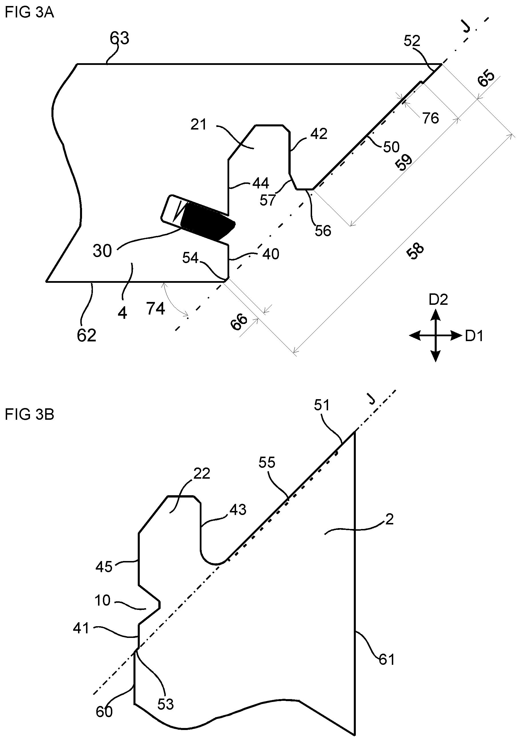
[0035] FIG. 1 and FIG. 2 show an embodiment including a set of panels comprising a first panel 2 with a first main plane and a second panel 4 with a second main plane. The first and the second panel are provided with a mechanical locking device for locking a first edge of the first panel 2 to a second edge of the second panel 4 at a junction plane J. The first main plane is essentially perpendicular to the second main plane and the junction plane is extending between the first main plane and the second main plane. The panels are shown in a locked position in a crosscut view. A longitudinal direction of the first and the second edge are extending perpendicular to the view shown. The first edge comprises an edge tongue 22 that extends from the junction plane J. The second edge comprises an edge groove 21 at the junction plane, wherein the edge tongue is configured to cooperate with the edge groove for locking together the first and the second edges in a first direction D1 which is perpendicular to the first main plane. The edge tongue 22 comprises a tongue groove 10. The edge groove 21 comprises a flexible tongue 30 arranged in an insertion groove 20, said flexible tongue is configured to cooperate with the tongue groove 10 for locking together the first and the second edges in a second direction D2 which is perpendicular to the second main plane. The mechanical locking device comprises a first space 46 between the edge tongue 22 and the edge groove 21 at an opening of the edge groove 21 and at the junction plane in a locked position of the first and the second edge. The first space 46 may have the advantage that a loading of a part of the second edge at the opening of the edge groove is avoided. This part of the second edge may be a weak part, since little material is available to absorb a load. FIG. 2 shows an enlargement of the encircled area in FIG. 1 without the flexible tongue. The angle 74 between the junction plane and the first main plane may be in a range of about 30.degree. to about 60.degree., for example about 45.degree.. The edge tongue 22 preferably extends, from the junction plane, essentially in the second direction.
[0036] The first panel 2 has a first thickness 65 and the second panel 4 has a second thickness 64. The first and the second thickness may be essentially the same. The first panel 2 comprises an inner half 66, at a first side of a central plane 68 of the first panel, and an outer half 67, at second side of the central plane 68 of the first panel, in a direction of the thickness of the first panel. The entire edge tongue 22 is preferably at the inner half of the first panel. This may have the effect that more material is obtained between the edge groove 21 and an outer corner, in a locked position of the first and the second panel, which may increase the strength of the mechanical locking device. The first panel comprises an inner face 60 and an outer face 61. The second panel comprises an inner face 62 and an outer face 63.
[0037] FIG. 2 shows that a first side of the edge tongue 22 may comprise, at or near the junction plane J, a first locking surface 41, and the edge groove 21 may comprises, at or near the junction plane J, a second locking surface 40. The first locking surface and the second locking surface are essentially parallel and are configured to cooperate for locking in the first direction. The first locking surface and the second locking surface are preferably extending essentially in the second direction. The edge tongue 22 at a second side, which is opposite the first side, may comprise a third locking surface 43 and the edge groove 21 may comprise a fourth locking surface 42, wherein the third locking surface and the fourth locking surface are essentially parallel and are configured to cooperate at a distance from the junction plane for locking in the first direction. The third locking surface and the fourth locking surface are preferably extending essentially in the second direction. The first, second, third and fourth locking surfaces may all be parallel to each other. Said parallel first, second, third and fourth locking surfaces may have the advantage that panels are easy to assemble and that, e.g., a furniture comprising said set of panels may be more stable. The fourth locking surface 42 is preferably closer to the central plane 68 than the second locking surface 40.
[0038] The third locking surface 43 and the fourth locking surface 42 may cooperate, to absorb a load, at an area extending over a first distance 47 in the second direction. The third locking surface and the fourth locking surface are preferably displaced from the junction plane by a second distance 48. This may have the effect that more material is obtained, in the first direction D1, between the fourth locking surface 42 and the junction plane, which may increase the strength of the mechanical locking device. The first distance 47 may be within the range of about 20% to about 200% of the second distance 48 or within the range of about 50% to about 150% of the second distance 48. The first 47 distance is essentially the same as the second distance 48 in the embodiment shown in FIG. 2.
[0039] The first side of the edge tongue 22, at a distance from the junction plane, may comprise a fifth locking surface 45 and the edge groove 21 may comprise a sixth locking surface 44 at a distance from the junction plane J. The fifth locking surface and the sixth locking surface are essentially parallel and are preferably configured to cooperate for locking in the first direction. The fifth locking surface and the sixth locking surface are preferably extending essentially in the second direction. The insertion groove 20 is, in the embodiment shown FIG. 2, positioned between the sixth locking surface 44 and the second locking surface 40. The tongue groove 10 may be positioned between the fifth locking surface 45 and the first locking surface 41.
[0040] FIG. 3A-3B show an embodiment of the mechanical locking device, before assembling of the first and the second panel, comprising a first contact surface 51 at the first edge and a second contact surface 52 at the second edge. Said first and the second contact surface are at an outer corner, in an assembled and locked position of the first and the second panel, and in the junction plane, and are configured to cooperate. A second space 49 may extend in the junction plane from the first and the second contact surfaces 51,52 and to an opening of the edge groove, see FIG. 2. The second space 49 may extend in a longitudinal direction along the first edge, along the second edge, or along both the first edge and the second edge. The first and the second contact surfaces 51,52 may cooperate over a first width 71, in a direction from an inner corner to the outer corner of the first and the second panel, wherein said first width is in the range of about 5% to about 40%, about 5% to about 30%, or about 5% to about 20% of an edge width 58 of a first and/or second edge surface of the first and the second edge, respectively. This may improve the contact between the first edge surface and the second edge surface, with increased pressure over smaller contacts areas, and irregularities, such as loose fibres that remains from a mechanical cutting of the mechanical locking device, in the first edge surface or the second edge surface are compressed and that a tight joint is obtained between the first and the second panel.
[0041] The first edge surface of the first edge may comprise a recess 55, indicated by a dotted line in FIG. 3B, extending from the first contact surface 51 to the edge tongue 22. The second edge surface of the second edge may comprise a recess 50, with a depth 76 and width 59, see FIG. 3A, extending from the second contact surface 52 to the edge groove 21. The depth 76 of the recess 50 of the second edge surface may be about in the range of about 0.1 mm to about 1 mm, preferably in the range of about 0.2 mm to about 0.5 mm. The recess 55 of the first edge surface may have the same depth and essentially the same length as the recess 50 of the first edge surface. The depth of the recess may be adjusted to the material of the core of the panel. Mechanical cutting of e.g. a core of a particle board may result in a rougher surface with protruding fibers than mechanical cutting of e.g. a core of a HDF board. A rougher surface may require an increased depth 76 of the recess of the first edge surface and/or the second edge surface.
[0042] The mechanical locking device may comprise a third contact surface 53 at the first edge and a fourth contact surface 54 at the second edge. The third and the fourth contact surfaces are at an inner corner, in a locked position of the first and the second panel, and in the junction plane, and are configured to cooperate. The third and the fourth contact surfaces are cooperating over a second width 72, in a direction from an inner corner to the outer corner of the first and the second panel. The second width 72 may be in the range of about 2% to about 20%, about 2% to about 10%, or about 2% to about 5% of the edge width 58 of the first and/or second edge surface.
[0043] The first panel 2 and the second panel 4 are preferably configured to be assembled by displacing the first panel 2 relative the second panel 4 in the second direction D2, wherein the first panel is perpendicular to the second panel. The edge tongue 22 is inserted into the edge groove 21, wherein the flexible tongue 30 is pushed back into the insertion groove and springs back into the tongue groove 10 to obtain a locked position. The set of panels may be furniture panels.
[0044] The insertion groove 20 may extend along essentially the entire length of the edge groove.
[0045] The edge groove 21 may extend along essentially the entire length of the second edge in a longitudinal direction of the second edge.
[0046] The flexible tongue 30 may be displaceable in the insertion groove.
[0047] The locking device is preferably configured such that the flexible tongue 30 moves out of the tongue groove 10 when a tool is inserted into the tongue groove and pushed back into the insertion groove.
[0048] The insertion groove 20 may be parallel to the second main plane or at an acute angle 75 to the second main plane, such that a bottom of the insertion groove 20 is at a greater distance from an inner face 62 of the second panel than an opening of the insertion groove to the inner face 62.
[0049] The locking device may comprise a bevel or rounding at an opening of the tongue groove 10. This may facilitate disassembling as the bevel or the rounding may prevent the flexible tongue from getting stuck during the disassembling.
[0050] The set of panels as described above may be a part of an assembled furniture product, such as a corner of a frame. The tongue groove 10 may be open at a backside of the furniture, such that a tool may be inserted into the tongue groove to push back the flexible tongue 30 into the insertion groove 20 and unlock the locking device.
[0051] A core material of the first and the second panel may comprise a wood fibre based board, such as a HDF, MDF, plywood, solid wood or particleboard, or a reinforced plastic board or a wood fibre composite board. The core may be provided with a decorative layer or layers. Parts of the locking device may be formed, preferably by mechanical cutting, such as milling, of material of the first and the second panel.
[0052] An embodiment of the flexible tongue 30, which is displaceable in an insertion groove 20, is shown in FIGS. 4A-4D. FIGS. 4A-4B show the flexible tongue 30 in a locked potion and FIGS. 4C-4D show the flexible tongue 30 during assembling of the first panel 2 and the second panel 4. FIG. 4B shows a cross section of the flexible tongue 30 in FIG. 4A. FIG. 4D shows a cross section of the flexile tongue 30 in FIG. 4C. The flexible tongue 30 comprises bendable protruding parts 24. A space 23 is provided between the flexible tongue 30 and a bottom wall of the insertion groove 20. FIG. 4C shows that the flexible tongue 30 is pushed into the insertion groove 20 and towards the bottom wall of the insertion groove 20 during an assembly of the first panel 2 with the second panel 4. The flexible tongue 30 springs back toward its initial position when the first panel 2 and the second panel 4 have reached a locked position. A recess 25 is preferably arranged at each bendable protruding part.
[0053] The flexible tongue 30 may have a first displacement surface 26 and an opposite second displacement surface 27, configured to be displaced along a third displacement surface 28 and a fourth displacement locking surface 29, respectively, of the insertion groove 20.
[0054] An alternative embodiment of the flexible tongue 30, without the protruding bendable parts 24, is shown in FIGS. 4E-4F. FIG. 4F shows a cross section of the flexible tongue 30 shown in FIG. 4E. The alternative embodiment is bendable in its length direction in order to accomplish a similar function as the embodiment shown in FIGS. 4A-4D.
[0055] When the word "about" is used in this specification in connection with a numerical value, it is intended that the associated numerical value include a tolerance of .+-.10% around the stated numerical value.
Embodiments
[0056] 1. A set of panels comprising a first panel (2) with a first main plane and a second panel (4) with a second main plane, wherein the first panel and the second panel are provided with a mechanical locking device for locking a first edge of the first panel (2) to a second edge of the second panel (4) at a junction plane (J), wherein the first main plane is essentially perpendicular to the second main plane and the junction plane is extending between the first main plane and the second main plane, characterized in that: [0057] the first edge comprises an edge tongue (22) that extends beyond the junction plane (J), [0058] the second edge comprises an edge groove (21) at the junction plane, wherein the edge tongue is configured to cooperate with the edge groove for locking together the first and the second edges in a first direction (D1) which is perpendicular to the first main plane, [0059] the edge tongue (22) comprises a tongue groove (10), [0060] the edge groove (21) comprises a flexible tongue (30) arranged in an insertion groove (20), said flexible tongue is configured to cooperate with the tongue groove (10) for locking together the first and the second edges in a second direction (D2) which is perpendicular to the second main plane, [0061] the mechanical locking device comprises a first space (46) between the edge tongue (22) and the edge groove (21) at an opening of the edge groove (21) and at the junction plane in a locked position of the first and the second edge.
[0062] 2. The set of panels as in embodiment 1, wherein the angle (74) between the junction plane and the first main plane is about 45.degree..
[0063] 3. The set of panels as in embodiment 1 or 2, wherein edge tongue (22) extends, from the junction plane, essentially in the second direction.
[0064] 4. The set of panels as in any one of the preceding embodiments, wherein a first side of the edge tongue (22) comprises, at or near the junction plane (J), a first locking surface (41), and the edge groove (21) comprises, at or near the junction plane (J), a second locking surface (40), wherein the first locking surface and the second locking surface are essentially parallel and are configured to cooperate for locking in the first direction, the first locking surface and the second locking surface are preferably extending essentially in the second direction.
[0065] 5. The set of panels as in any one of the preceding embodiments, wherein the edge tongue (22) at a second side, which is opposite the first side, comprises a third locking surface (43) and the edge groove (21) comprises a fourth locking surface (42), wherein the third locking surface and the fourth locking surface are essentially parallel and are configured to cooperate at a distance from the junction plane for locking in the first direction, the third locking surface and the fourth locking surface preferably extend essentially in the second direction.
[0066] 6. The set of panels as in embodiment 5, wherein the third locking surface (43) and the fourth locking surface (42) cooperate at an area extending over a first distance (47) in the second direction, wherein the third locking surface and the fourth locking surface are displaced from the junction plane by a second distance (48), wherein the first distance (47) is within the range of about 20% to about 200% of the second distance (48) or within the range of about 50% to about 150% of the second distance (48).
[0067] 7. The set of panels as in any one of the preceding embodiments, wherein the first side of the edge tongue (22), at a distance from the junction plane, comprises a fifth locking surface (45) and the edge groove (21) comprises a sixth locking surface (44) at a distance from the junction plane (J), wherein the fifth locking surface and the sixth locking surface are essentially parallel and are configured to cooperate for locking in the first direction, the fifth locking surface and the sixth locking surface preferably extend essentially in the second direction.
[0068] 8. The set of panels as in any one of the preceding embodiments, wherein the mechanical locking device comprises a first contact surface (51) at the first edge and a second contact surface (52) at the second edge, the first contact surface and the second contact surface are at an outer corner, in a locked position of the first and the second panel, and in the junction plane and are configured to cooperate.
[0069] 9. The set of panels as in embodiment 8, wherein the mechanical locking device comprises a second space (49) extending in the junction plane from the first and the second contact surfaces (51,52) and to an opening of the edge groove.
[0070] 10. The set of panels as in embodiment 8 or 9, wherein the first and the second contact surfaces (51,52) are cooperating over a first width (71), in a direction from an inner corner to the outer corner of the first and the second panel, wherein said first width is in the range of about 5% to about 40%, about 5% to about 30%, or about 5% to about 20% of an edge width (58) of the first and/or second edge surface.
[0071] 11. The set of panels as in any one of the embodiments 8-10, wherein the first edge surface and/or the second edge surface comprises a recess (50,55) extending from the first contact surface (51) and the second contact surface (52), respectively, to the edge tongue (22) and the edge groove (21), respectively.
[0072] 12. The set of panels as in any one of the preceding embodiments, wherein the mechanical locking device comprises a third contact surface (53) at the first edge and a fourth contact surface (54) at the second edge, the third and the fourth contact surface are at an inner corner, in a locked position of the first and the second panel, and in the junction plane, and are configured to cooperate.
[0073] 13. The set of panels as in embodiment 12, wherein the third and the fourth contact areas are cooperating over a second width (72), in a direction from an inner corner to the outer corner of the first and the second panel, said second width may be in the range of about 2% to about 20%, about 2% to about 10%, or about 2% to about 5% of an edge width (58) of the first and/or second edge surface.
[0074] 14. The set of panels as in any one of the preceding embodiments, wherein the first panel comprises an inner half (66) and an outer half (67) in a direction of a thickness of the first panel, wherein the entire edge tongue (22) is at the inner half of the first panel.
* * * * *
D00000
D00001
D00002
D00003
D00004
XML
uspto.report is an independent third-party trademark research tool that is not affiliated, endorsed, or sponsored by the United States Patent and Trademark Office (USPTO) or any other governmental organization. The information provided by uspto.report is based on publicly available data at the time of writing and is intended for informational purposes only.
While we strive to provide accurate and up-to-date information, we do not guarantee the accuracy, completeness, reliability, or suitability of the information displayed on this site. The use of this site is at your own risk. Any reliance you place on such information is therefore strictly at your own risk.
All official trademark data, including owner information, should be verified by visiting the official USPTO website at www.uspto.gov. This site is not intended to replace professional legal advice and should not be used as a substitute for consulting with a legal professional who is knowledgeable about trademark law.