Set of panels with a mechanical locking device
Derelov
U.S. patent number 10,724,564 [Application Number 15/794,491] was granted by the patent office on 2020-07-28 for set of panels with a mechanical locking device. This patent grant is currently assigned to VALINGE INNOVATION AB. The grantee listed for this patent is Valinge Innovation AB. Invention is credited to Peter Derelov.


| United States Patent | 10,724,564 |
| Derelov | July 28, 2020 |
Set of panels with a mechanical locking device
Abstract
A set including a first panel, a second panel and a mechanical locking device for locking the first panel to the second panel. The first panel includes a first edge surface and a first panel surface, and the second panel includes a second edge surface and a second panel surface. The first edge surface is facing the second panel surface in a locked position of the first and the second panel. The mechanical locking device includes a rod-shaped element at the first edge surface and an insertion groove at the second panel surface and an edge groove at the second edge surface and a flexible tongue positioned in the edge groove. The rod-shaped element includes a recess and is configured to be inserted into the insertion groove. The flexible tongue is configured to cooperate with the recess for a locking of the first panel to the second panel.
| Inventors: | Derelov; Peter (Helsingborg, SE) | ||||||||||
|---|---|---|---|---|---|---|---|---|---|---|---|
| Applicant: |
|
||||||||||
| Assignee: | VALINGE INNOVATION AB (Viken,
SE) |
||||||||||
| Family ID: | 62021240 | ||||||||||
| Appl. No.: | 15/794,491 | ||||||||||
| Filed: | October 26, 2017 |
Prior Publication Data
| Document Identifier | Publication Date | |
|---|---|---|
| US 20180119717 A1 | May 3, 2018 | |
Foreign Application Priority Data
| Oct 27, 2016 [SE] | 1651409 | |||
| Current U.S. Class: | 1/1 |
| Current CPC Class: | F16B 12/26 (20130101); A47B 47/0075 (20130101); F16B 12/125 (20130101); F16B 12/24 (20130101); A47B 96/201 (20130101); Y10T 403/4602 (20150115); Y10T 403/7073 (20150115); A47B 2230/0081 (20130101) |
| Current International Class: | F16B 12/00 (20060101); F16B 12/26 (20060101); F16B 12/12 (20060101); F16B 12/24 (20060101); A47B 96/20 (20060101); A47B 47/00 (20060101) |
References Cited [Referenced By]
U.S. Patent Documents
| 291032 | January 1884 | Cleland |
| 634581 | October 1899 | Miller |
| 701000 | May 1902 | Ahrens |
| 861911 | July 1907 | Stewart |
| 881673 | March 1908 | Ellison |
| 1533099 | April 1925 | Carroll |
| 1534468 | April 1925 | Shea, Jr. |
| 1800386 | April 1931 | Hoffman |
| 1800387 | April 1931 | Greist |
| 1802245 | April 1931 | Foretich |
| 1954242 | April 1934 | Heppenstall |
| 2360451 | October 1944 | Stone |
| 2362904 | November 1944 | Kramer |
| 2496184 | January 1950 | Von Canon |
| 3002630 | October 1961 | Heisser |
| 3195968 | July 1965 | Freeman |
| 3284152 | November 1966 | Schorghuber |
| 3313054 | April 1967 | Madey |
| 3347610 | October 1967 | Pilliod |
| 3410441 | November 1968 | Rhyne |
| 3722704 | March 1973 | Piretti |
| 3722971 | March 1973 | Zeischegg |
| 3765465 | October 1973 | Gulistan |
| 3784271 | January 1974 | Schreiber |
| 3884002 | May 1975 | Logie |
| 3885845 | May 1975 | Krieks |
| 3981118 | September 1976 | Johnson et al. |
| 4089614 | May 1978 | Harley |
| 4099887 | July 1978 | Mackenroth |
| 4116510 | September 1978 | Franco |
| 4142271 | March 1979 | Busse |
| 4211379 | July 1980 | Morgan et al. |
| 4222544 | September 1980 | Crowder |
| 4279397 | July 1981 | Larsson |
| 4299067 | November 1981 | Bertschi |
| 4308961 | January 1982 | Kunce |
| 4324517 | April 1982 | Dey |
| 4403886 | September 1983 | Hauesler |
| 4405253 | September 1983 | Stockum |
| 4509648 | April 1985 | Govang |
| 4595105 | June 1986 | Gold |
| 4597122 | July 1986 | Handler |
| 4615448 | October 1986 | Johnstonbaugh |
| 4629076 | December 1986 | Amstutz et al. |
| 4750794 | June 1988 | Vegh |
| 4752150 | June 1988 | Salice |
| 4815908 | March 1989 | Duran et al. |
| 4817900 | April 1989 | Whittington et al. |
| 4844266 | July 1989 | Small et al. |
| 4883331 | November 1989 | Mengel |
| 4886326 | December 1989 | Kuzyk |
| 4888933 | December 1989 | Guomundsson |
| 4891897 | January 1990 | Gieske et al. |
| 4909561 | March 1990 | Haheeb |
| 4944416 | July 1990 | Petersen et al. |
| 4961295 | October 1990 | Kosch, Sr. et al. |
| 5004116 | April 1991 | Cattarozzi |
| 5018323 | May 1991 | Clausen |
| 5109993 | May 1992 | Hutchison |
| 5114265 | May 1992 | Grisley |
| 5121578 | June 1992 | Holz |
| 5125518 | June 1992 | Ward |
| 5138803 | August 1992 | Grossen |
| 5209556 | May 1993 | Anderson |
| 5212925 | May 1993 | McClinton |
| 5360121 | November 1994 | Sothman |
| 5375802 | December 1994 | Branham, II |
| 5423155 | June 1995 | Bauer |
| 5451102 | September 1995 | Chuan |
| 5471804 | December 1995 | Winter, IV |
| 5475960 | December 1995 | Lindal |
| 5499886 | March 1996 | Short et al. |
| 5527103 | June 1996 | Pittman |
| 5658086 | August 1997 | Brokaw et al. |
| 5711115 | January 1998 | Wirt |
| 5775521 | July 1998 | Tisbo |
| 5810505 | September 1998 | Henriott |
| 5893617 | April 1999 | Lee |
| 5944294 | August 1999 | Baer |
| 5950389 | September 1999 | Porter |
| 6050426 | April 2000 | Leurdijk |
| 6142436 | November 2000 | Thurston et al. |
| 6312186 | November 2001 | Rock et al. |
| 6363645 | April 2002 | Hunter |
| 6413007 | July 2002 | Lambright |
| 6491172 | December 2002 | Chance |
| 6505452 | January 2003 | Hannig |
| 6547086 | April 2003 | Harvey |
| 6675979 | January 2004 | Taylor |
| D486676 | February 2004 | Campbell et al. |
| 6769219 | August 2004 | Schwitte et al. |
| 6772890 | August 2004 | Campbell et al. |
| 6827028 | December 2004 | Callaway |
| 6971614 | December 2005 | Fischer et al. |
| 7127860 | October 2006 | Pervan |
| 7223045 | May 2007 | Migli |
| 7228977 | June 2007 | Perkins et al. |
| 7300120 | November 2007 | Shin |
| 7451535 | November 2008 | Wells et al. |
| 7451578 | November 2008 | Hannig |
| 7584583 | September 2009 | Bergelin et al. |
| 7621092 | November 2009 | Groeke et al. |
| 7641414 | January 2010 | Joyce |
| 7717278 | May 2010 | Kao |
| 7721503 | May 2010 | Pervan et al. |
| 7793450 | September 2010 | Chasmer et al. |
| 7818939 | October 2010 | Bearinger |
| 7998549 | August 2011 | Susnjara |
| 8033074 | October 2011 | Pervan |
| 8038363 | October 2011 | Hannig |
| 8042311 | October 2011 | Pervan |
| 8146754 | April 2012 | Apgood |
| 8220217 | July 2012 | Muehlebach |
| 8234830 | August 2012 | Pervan |
| 8365499 | February 2013 | Nilsson et al. |
| 8387327 | March 2013 | Pervan |
| 8464408 | June 2013 | Hazzard |
| 8495849 | July 2013 | Pervan |
| 8505257 | August 2013 | Boo et al. |
| 8544230 | October 2013 | Pervan |
| 8596013 | December 2013 | Boo |
| 8602227 | December 2013 | McDonald |
| 8615952 | December 2013 | Engstrom |
| 8713886 | May 2014 | Pervan |
| 8745952 | June 2014 | Perra |
| 8764137 | July 2014 | Fehre |
| 8776473 | July 2014 | Pervan |
| 8833028 | September 2014 | Whispell et al. |
| 8864407 | October 2014 | Sorum |
| 8887468 | November 2014 | Hakansson et al. |
| 9175703 | November 2015 | Maertens |
| 9216541 | December 2015 | Boo |
| 9290948 | March 2016 | Cappelle et al. |
| 9375085 | June 2016 | Derelov |
| 9538842 | January 2017 | Hakansson et al. |
| 9655442 | May 2017 | Boo et al. |
| 9700157 | July 2017 | Keyvanloo |
| 9714672 | July 2017 | Derelov et al. |
| 9723923 | August 2017 | Derelov |
| 9726210 | August 2017 | Derelov et al. |
| 9745756 | August 2017 | Hannig |
| 9758973 | September 2017 | Segaert |
| 9763528 | September 2017 | Lung |
| 9809983 | November 2017 | Trudel |
| 9945121 | April 2018 | Derelov |
| 10034541 | July 2018 | Boo et al. |
| 10202996 | February 2019 | HaKansson et al. |
| 10378570 | August 2019 | Broughton |
| 10415613 | September 2019 | Boo |
| 10448739 | October 2019 | Derelov et al. |
| 10451097 | October 2019 | Brannstrom et al. |
| 10486245 | November 2019 | Fridlund |
| 2002/0170258 | November 2002 | Schwitte et al. |
| 2005/0042027 | February 2005 | Migli |
| 2005/0236544 | October 2005 | Mancino |
| 2005/0247653 | November 2005 | Brooks |
| 2006/0091093 | May 2006 | Armari |
| 2006/0101769 | May 2006 | Pervan et al. |
| 2006/0180561 | August 2006 | Wisnoski et al. |
| 2006/0236642 | October 2006 | Pervan |
| 2006/0273085 | December 2006 | Casto |
| 2007/0006543 | January 2007 | Engstrom |
| 2008/0010937 | January 2008 | Pervan et al. |
| 2008/0066415 | March 2008 | Pervan |
| 2008/0193209 | August 2008 | Henderson |
| 2008/0216435 | September 2008 | Nolan |
| 2008/0236088 | October 2008 | Hannig et al. |
| 2009/0014401 | January 2009 | Tallman |
| 2009/0064624 | March 2009 | Sokol |
| 2010/0028592 | February 2010 | Barkdoll et al. |
| 2010/0083603 | April 2010 | Goodwin |
| 2010/0173122 | July 2010 | Susnjara |
| 2010/0289389 | November 2010 | Crabtree, II |
| 2011/0225921 | September 2011 | Schulte |
| 2011/0225922 | September 2011 | Pervan et al. |
| 2011/0280655 | November 2011 | Maertens et al. |
| 2011/0283650 | November 2011 | Pervan et al. |
| 2012/0009383 | January 2012 | Hardesty |
| 2012/0027967 | February 2012 | Maertens et al. |
| 2012/0073235 | March 2012 | Hannig |
| 2012/0124932 | May 2012 | Schulte et al. |
| 2012/0145845 | June 2012 | Hightower |
| 2012/0180416 | July 2012 | Perra et al. |
| 2012/0279161 | November 2012 | Hakansson et al. |
| 2012/0286637 | November 2012 | Fehre |
| 2013/0014463 | January 2013 | Pervan |
| 2013/0048632 | February 2013 | Chen |
| 2013/0071172 | March 2013 | Maertens et al. |
| 2013/0081349 | April 2013 | Pervan |
| 2013/0097846 | April 2013 | Pettigrew |
| 2013/0111845 | May 2013 | Pervan |
| 2013/0170904 | July 2013 | Cappelle et al. |
| 2013/0232905 | September 2013 | Pervan |
| 2014/0013919 | January 2014 | Gerke et al. |
| 2014/0055018 | February 2014 | Shein et al. |
| 2014/0111076 | April 2014 | Devos |
| 2014/0286701 | September 2014 | Sauer |
| 2014/0294498 | October 2014 | Logan |
| 2015/0035422 | February 2015 | Hakansson et al. |
| 2015/0078807 | March 2015 | Brannstrom et al. |
| 2015/0078819 | March 2015 | Derelov et al. |
| 2015/0196118 | July 2015 | Derelov |
| 2015/0198191 | July 2015 | Boo |
| 2015/0230600 | August 2015 | Schulte |
| 2015/0368896 | December 2015 | Schulte |
| 2016/0000220 | January 2016 | Devos |
| 2016/0007751 | January 2016 | Derelov |
| 2016/0145029 | May 2016 | Ranade et al. |
| 2016/0174704 | June 2016 | Boo et al. |
| 2016/0186925 | June 2016 | Bettin |
| 2016/0192775 | July 2016 | Andersson |
| 2016/0270531 | September 2016 | Derelov |
| 2017/0079433 | March 2017 | Derelov et al. |
| 2017/0089379 | March 2017 | Pervan |
| 2017/0097033 | April 2017 | Hakansson et al. |
| 2017/0159291 | June 2017 | Derelov |
| 2017/0208938 | July 2017 | Derelov et al. |
| 2017/0227031 | August 2017 | Boo |
| 2017/0227032 | August 2017 | Fridlund |
| 2017/0227035 | August 2017 | Fridlund |
| 2017/0234346 | August 2017 | Fridlund |
| 2017/0298973 | October 2017 | Derelov |
| 2017/0360193 | December 2017 | Boo et al. |
| 2018/0080488 | March 2018 | Derelov |
| 2018/0087552 | March 2018 | Derelov et al. |
| 2018/0112695 | April 2018 | Boo et al. |
| 2018/0202160 | July 2018 | Derelov |
| 2018/0328396 | November 2018 | Fransson et al. |
| 2019/0113061 | April 2019 | Hakansson et al. |
| 2019/0166989 | June 2019 | Boo et al. |
| 2019/0289999 | September 2019 | Derelov et al. |
| 2019/0320793 | October 2019 | Boo |
| 2019/0323532 | October 2019 | Boo |
| 2019/0323533 | October 2019 | Boo |
| 2019/0323534 | October 2019 | Derelov |
| 2019/0323535 | October 2019 | Derelov |
| 2020/0003242 | January 2020 | Brannstrom et al. |
| 2020/0069048 | March 2020 | Derelov et al. |
| 2020/0069049 | March 2020 | Derelov et al. |
| 2020/0102978 | April 2020 | Fridlund |
| 2020/0121076 | April 2020 | Derelov et al. |
| 365507 | Nov 1962 | CH | |||
| 685 276 | May 1995 | CH | |||
| 696 889 | Jan 2008 | CH | |||
| 698 988 | Dec 2009 | CH | |||
| 101099618 | Jan 2008 | CN | |||
| 203424576 | Feb 2014 | CN | |||
| 26 35 237 | Feb 1978 | DE | |||
| 31 03 281 | Aug 1982 | DE | |||
| 298 20 031 | Feb 1999 | DE | |||
| 20 2008 011 589 | Nov 2008 | DE | |||
| 20 2009 008 825 | Oct 2009 | DE | |||
| 102008035293 | Feb 2010 | DE | |||
| 10 2009 041 142 | Mar 2011 | DE | |||
| 10 2014 110 124 | Jan 2016 | DE | |||
| 0 060 203 | Sep 1982 | EP | |||
| 0 060 203 | Sep 1982 | EP | |||
| 0 362 968 | Apr 1990 | EP | |||
| 0 675 332 | Oct 1995 | EP | |||
| 0 871 156 | Oct 1998 | EP | |||
| 0 935 076 | Aug 1999 | EP | |||
| 1 048 423 | Nov 2000 | EP | |||
| 1 048 423 | May 2005 | EP | |||
| 1 650 375 | Apr 2006 | EP | |||
| 1 671 562 | Jun 2006 | EP | |||
| 1 650 375 | Sep 2006 | EP | |||
| 1 863 984 | Dec 2007 | EP | |||
| 1 922 954 | May 2008 | EP | |||
| 2 017 403 | Jan 2009 | EP | |||
| 2 037 128 | Mar 2009 | EP | |||
| 1 922 954 | Jul 2009 | EP | |||
| 2 333 353 | Jun 2011 | EP | |||
| 1 863 984 | Nov 2011 | EP | |||
| 2 487 373 | Aug 2012 | EP | |||
| 3 031 998 | Jun 2016 | EP | |||
| 2 062 731 | Jun 1971 | FR | |||
| 2 517 187 | Jun 1983 | FR | |||
| 2 597 173 | Oct 1987 | FR | |||
| 2 602 013 | Jan 1988 | FR | |||
| 1 022 377 | Mar 1966 | GB | |||
| 2 482 213 | Jan 2012 | GB | |||
| 2 520 927 | Jun 2015 | GB | |||
| 2003-239921 | Aug 2003 | JP | |||
| 10-1147274 | May 2012 | KR | |||
| 2014-0042314 | Apr 2014 | KR | |||
| WO 87/07339 | Dec 1987 | WO | |||
| WO 99/22150 | May 1999 | WO | |||
| WO 00/66856 | Nov 2000 | WO | |||
| WO 01/02669 | Jan 2001 | WO | |||
| WO 01/02670 | Jan 2001 | WO | |||
| WO 01/51733 | Jul 2001 | WO | |||
| WO 01/53628 | Jul 2001 | WO | |||
| WO 02/055809 | Jul 2002 | WO | |||
| WO 02/055810 | Jul 2002 | WO | |||
| WO 03/016654 | Feb 2003 | WO | |||
| WO 03/027510 | Apr 2003 | WO | |||
| WO 03/083234 | Oct 2003 | WO | |||
| WO 2004/079130 | Sep 2004 | WO | |||
| WO 2005/068747 | Jul 2005 | WO | |||
| WO 2006/043893 | Apr 2006 | WO | |||
| WO 2006/103500 | Oct 2006 | WO | |||
| WO 2006/104436 | Oct 2006 | WO | |||
| WO 2007/015669 | Feb 2007 | WO | |||
| WO 2007/015669 | Feb 2007 | WO | |||
| WO 2007/079845 | Jul 2007 | WO | |||
| WO 2008/004960 | Jan 2008 | WO | |||
| WO 2008/004960 | Jan 2008 | WO | |||
| WO 2008/004960 | Jan 2008 | WO | |||
| WO 2008/017281 | Feb 2008 | WO | |||
| WO 2008/017301 | Feb 2008 | WO | |||
| WO 2008/017301 | Feb 2008 | WO | |||
| WO 2008/150234 | Dec 2008 | WO | |||
| WO 2010/023042 | Mar 2010 | WO | |||
| WO 2010/070472 | Jun 2010 | WO | |||
| WO 2010/070472 | Jun 2010 | WO | |||
| WO 2010/070605 | Jun 2010 | WO | |||
| WO 2010/070605 | Jun 2010 | WO | |||
| WO 2010/082171 | Jul 2010 | WO | |||
| WO 2010/087752 | Aug 2010 | WO | |||
| WO 2011/012104 | Feb 2011 | WO | |||
| WO 2011/012104 | Feb 2011 | WO | |||
| WO 2011/086710 | Jul 2011 | WO | |||
| WO 2011/151737 | Dec 2011 | WO | |||
| WO 2011/151737 | Dec 2011 | WO | |||
| WO 2011/151737 | Dec 2011 | WO | |||
| WO 2011/151758 | Dec 2011 | WO | |||
| WO 2011/151758 | Dec 2011 | WO | |||
| WO 2012/095454 | Jul 2012 | WO | |||
| WO 2012/154113 | Nov 2012 | WO | |||
| WO 2013/009257 | Jan 2013 | WO | |||
| WO 2013/025163 | Feb 2013 | WO | |||
| WO 2013/080160 | Jun 2013 | WO | |||
| WO 2013/093636 | Jun 2013 | WO | |||
| WO 2013/093636 | Jun 2013 | WO | |||
| WO 2013/118075 | Aug 2013 | WO | |||
| WO 2014/072080 | May 2014 | WO | |||
| WO 2014/108114 | Jul 2014 | WO | |||
| WO 2014/121410 | Aug 2014 | WO | |||
| WO 2015/015603 | Feb 2015 | WO | |||
| WO 2015/038059 | Mar 2015 | WO | |||
| WO 2015/105449 | Jul 2015 | WO | |||
| WO 2015/105450 | Jul 2015 | WO | |||
| WO 2015/105451 | Jul 2015 | WO | |||
| WO 2017/131574 | Aug 2017 | WO | |||
| WO 2017/135874 | Aug 2017 | WO | |||
| WO 2018/080387 | May 2018 | WO | |||
Other References
|
US. Appl. No. 14/486,681, Hans Brannstom, Agne Palsson and Peter Derelov filed Sep. 15, 2014 (Cited herein as US Patent Publication No. 2015/0078807 A1 of Mar. 19, 2015). cited by applicant . U.S. Appl. No. 14/573,572, Christian Boo, filed Dec. 17, 2014 (Cited herein as US Patent Publication No. 2015/0198191 A1 of Jul. 16, 2015). cited by applicant . U.S. Appl. No. 15/271,622, Peter Derelov and Mats Nilsson, filed Sep. 21, 2016 (Cited herein as US Patent Publication No. 2017/0079433 A1 of Mar. 23, 2017). cited by applicant . U.S. Appl. No. 15/308,872, Darko Pervan, filed Nov. 4, 2016 (Cited herein as US Patent Application Publication No. 2017/0089379 A1 of Mar. 30, 2017). cited by applicant . U.S. Appl. No. 15/379,791, Niclas Hakansson and Darko Pervan, filed Dec. 15, 2016 (Cited herein as US Patent Application Publication No. 2017/0097033 A1 of Apr. 6, 2017). cited by applicant . U.S. Appl. No. 15/415,356, Peter Derelov and Christian Boo, filed Jan. 25, 2017 (Cited herein as US Patent Application Publication No. 2017/0208938 A1 of Jul. 27, 2017). cited by applicant . U.S. Appl. No. 15/422,798, Magnus Fridlund, filed Feb. 2, 2017 (Cited herein as US Patent Application Publication No. 2017/0227035 Al of 10 Aug. 2017). cited by applicant . U.S. Appl. No. 15/428,469, Magnus Fridlund, filed Feb. 9, 2017 (Cited herein as US Patent Application Publication No. 2017/0227032 A1 of Aug. 10, 2017). cited by applicant . U.S. Appl. No. 15/428,504, Christian Boo, filed Feb. 9, 2017 (Cited herein as US Patent Application publication No. 2017/0227031 A1 of Aug. 10, 2017). cited by applicant . U.S. Appl. No. 15/432,190, Magnus Fridlund, filed Feb. 14, 2017 (Cited herein as US Patent Application Publication No. 2017/0234346 A1 of Aug. 17, 2017). cited by applicant . U.S. Appl. No. 15/642,757, Peter Derelov, filed Jul. 6, 2017 (Cited herein as US Patent Application Publication No. 2017/0298973 A1 of Oct. 19, 2017). cited by applicant . U.S. Appl. No. 15/646,714, Peter Derelov, filed Jul. 11, 2017 (Cited herein as US Patent Application Publication No. 2018/0087552 A1 of Mar. 29, 2018). cited by applicant . U.S. Appl. No. 15/562,254, Peter Derelov, filed Sep. 27, 2017 (Cited herein as US Patent Application Publication No. 2018/0080488 A1 of Mar. 22, 2018). cited by applicant . U.S. Appl. No. 15/567,507, Christian Boo, Peter Derelov and Agne Palsson, filed Oct. 18, 2017 (Cited herein as US Patent Application Publication No. 2018/0112695 A1 of Apr. 26, 2018). cited by applicant . U.S. Appl. No. 15/923,701, Peter Derelov, filed Mar. 16, 2018. cited by applicant . U.S. Appl. No. 15/956,949, Peter Derelov, filed Apr. 19, 2018. cited by applicant . U.S. Appl. No. 15/978,630, Jonas Fransson, Niclas Hakansson and Agne Palsson, filed May 14, 2018. cited by applicant . U.S. Appl. No. 16/020,479, Christian Boo and Peter Derelov, filed Jul. 5, 2018. cited by applicant . U.S. Appl. No. 15/923,701, Derelov. cited by applicant . U.S. Appl. No. 15/956,949, Derelov. cited by applicant . U.S. Appl. No. 15/978,630, Fransson, et al. cited by applicant . U.S. Appl. No. 16/027,479, Boo, et al. cited by applicant . International Search Report/Written Opinion dated Dec. 18, 2017 in PCT/SE2017/051053, ISA/SE, Patent-och registreringsverket, Stockholm, SE, 12 pages. cited by applicant . Derelov, Peter, U.S. Appl. No. 15/923,701 entitled "Panels Comprising a Mechanical Locking Device and an Assembled Product Comprising the Panels", filed Mar. 16, 2018. cited by applicant . Derelov, Peter, U.S. Appl. No. 15/956,949 entitled "Panels for an Assembled Product", filed Apr. 19, 2018. cited by applicant . Fransson, Jonas, et al., U.S. Appl. No. 15/978,630 entitled "Elements and a Locking Device for an Assembled Product," filed May 14, 2018. cited by applicant . Boo, Christian, et al., U.S. Appl. No. 16/027,479 entitled "Panels Comprising a Mechanical Locking Device and an Assembled Product Comprising the Panels," filed Jul. 5, 2018. cited by applicant . U.S. Appl. No. 16/228,975, Niclas Hakansson and Darko Pervan, filed Dec. 21, 2018 (Cited herein as US Patent Application Publication No. 2019/0113061 A1 of Apr. 18, 2019). cited by applicant . U.S. Appl. No. 16/220,574, Peter Derelov, filed Dec. 14, 2018. cited by applicant . U.S. Appl. No. 16/220,585, Peter Derelov, filed Dec. 14, 2018. cited by applicant . U.S. Appl. No. 16/361,609, Peter Derelov, Johan Svensson and Lars Gunnarsson, filed Mar. 22, 2019. cited by applicant . U.S. Appl. No. 16/386,732, Christian Boo, filed Apr. 17, 2019. cited by applicant . U.S. Appl. No. 16/386,810, Christian Boo, filed Apr. 17, 2019. cited by applicant . U.S. Appl. No. 16/386,824, Christian Boo, filed Apr. 17, 2019. cited by applicant . U.S. Appl. No. 16/386,874, Peter Derelov, filed Apr. 17, 2019. cited by applicant . U.S. Appl. No. 16/220,574, Derelov. cited by applicant . U.S. Appl. No. 16/220,585, Derelov. cited by applicant . U.S. Appl. No. 16/361,609, Derelov. cited by applicant . U.S. Appl. No. 16/386,732, Boo. cited by applicant . U.S. Appl. No. 16/386,810, Boo. cited by applicant . U.S. Appl. No. 16/386,824, Boo. cited by applicant . U.S. Appl. No. 16/386,874, Derelov. cited by applicant . Derelov, Peter, U.S. Appl. No. 16/220,574 entitled "Set of Panels," filed Dec. 14, 2018. cited by applicant . Derelov, Peter, U.S. Appl. No. 16/220,585 entitled "Set of Panels," filed Dec. 14, 2018. cited by applicant . Derelov, Peter, et al., U.S. Appl. No. 16/361,609 entitled "Panels Comprising a Mechanical Locking Device and an Assembled Product Comprising the Panels," filed Mar. 22, 2019. cited by applicant . Boo, Christian, U.S. Appl. No. 16/386,732 entitled "Set of Panels With a Mechanical Locking Device," filed Apr. 17, 2019. cited by applicant . Boo, Christian, U.S. Appl. No. 16/386,810 entitled "Set of Panels With a Mechanical Locking Device," filed Apr. 17, 2019. cited by applicant . Boo, Christian, U.S. Appl. No. 16/386,824 entitled "Set of Panels With a Mechanical Locking Device," filed Apr. 17, 2019. cited by applicant . Derelov, Peter, U.S. Patent Application No. 16/386,874 entitled "Symmetric Tongue and T-Cross," filed Apr. 17, 2019. cited by applicant . U.S. Appl. No. 16/703,077, Fridlund. cited by applicant . U.S. Appl. No. 16/722,096, Derelov et al. cited by applicant . Fridlund, Magnus, U.S. Appl. No. 16/703,077 entitled "Set of Panels for an Assembled Product," filed Dec. 4, 2019. cited by applicant . Derelov, Peter, et al., U.S. Appl. No. 16/722,096 entitled "Panels Comprising a Mechanical Locking Device and an Assembled Product Comprising the Panels," filed Dec. 20, 2019. cited by applicant . U.S. Appl. No. 16/553,325, Derelov et al. cited by applicant . U.S. Appl. No. 16/553,350, Derelov et al. cited by applicant . U.S. Appl. No. 16/564,438, Brannstrom et al. cited by applicant . U.S. Appl. No. 16/567,436, Derelov. cited by applicant . U.S. Appl. No. 16/663,603, Fridlund. cited by applicant . U.S. Appl. No. 16/697,335, Boo et al. cited by applicant . Derelov, Peter, U.S. Appl. No. 16/553,325 entitled "Set of Panels with a Mechanical Locking Device," filed Aug. 28, 2019. cited by applicant . Derelov, Peter, U.S. Appl. No. 16/553,350 entitled "Set of Panels with a Mechanical Locking Device," filed Aug. 28, 2019. cited by applicant . Brannstrom, Hans, et al., U.S. Appl. No. 16/564,438 entitled "Assembled Product and a Method of Assembling the Assembled Product," filed Sep. 9, 2019. cited by applicant . Derelov, Peter, U.S. Appl. No. 16/567,436 entitled "Panels Comprising a Mechanical Locking Device and an Assembled Product Comprising the Panels," filed Sep. 11, 2019. cited by applicant . Fridlund, Magnus, U.S. Appl. No. 16/663,603 entitled "Element and Method for Providing Dismantling Groove," filed Oct. 25, 2019. cited by applicant . Boo, Christian, et al., U.S. Appl. No. 16/697,335 entitled "Panels Comprising a Mechanical Locking Device and an Assembled Product Comprising the Panels," filed Nov. 27, 2019. cited by applicant . Extended European Search Report issued in EP Application No. 17863769.0, dated Feb. 27, 2020, European Patent Office, Munich, DE, 7 pages. cited by applicant . **Derelov, Peter, U.S. Appl. No. 16/861,639 entitled "Panels Comprising a Mechanical Locking Device and an Assembled Product Comprising the Panels," filed in the U.S. Patent and Trademark Office on Apr. 29, 2020. cited by applicant. |
Primary Examiner: McMahon; Matthew R
Attorney, Agent or Firm: Buchanan Ingersoll & Rooney P.C.
Claims
The invention claimed is:
1. A set comprising a first panel, a second panel and a mechanical locking device for locking the first panel to the second panel, wherein the first panel comprises a first edge surface and a first panel surface, wherein the second panel comprises a second edge surface and a second panel surface, wherein the first edge surface is facing the second panel surface in a locked position of the first and second panels, wherein: the mechanical locking device comprises a cylindrical rod-shaped element at the first edge surface and a cylindrical insertion groove at the second panel surface, the mechanical locking device comprises an edge groove at the second edge surface and a longitudinal flexible tongue positioned in the edge groove and extending transversely to the cylindrical insertion groove, the edge groove being a longitudinal groove that extends in a longitudinal direction of the second edge surface, and the edge groove extending from the second edge surface to the insertion groove, the rod-shaped element comprises a recess, the rod-shaped element is configured to be inserted into the insertion groove, and the flexible tongue is configured to cooperate with the recess for a locking of the first panel to the second panel in a first direction which is perpendicular to the second panel surface.
2. The set as claimed in claim 1, wherein the insertion groove extends from the second panel surface to the edge groove.
3. The set as claimed in claim 1, wherein the mechanical locking device is configured to automatically lock the first panel to the second panel when the rod-shaped element is inserted into the insertion groove and the first edge surface is arranged against the second panel surface.
4. The set as claimed in claim 1, wherein the rod-shaped element has a longitudinal shape with a length direction which is parallel to the first panel surface.
5. The set as claimed in claim 1, wherein a second cross cut of the insertion groove, in a plane parallel to the second panel surface, has a shape that matches a first cross cut of the rod-shaped element, in a plane parallel to the second panel surface.
6. The set as claimed in claim 1, wherein the insertion groove is a bottom-ended groove comprising a bottom surface which is positioned at a distance from the edge groove.
7. The set as claimed in claim 6, wherein the insertion groove has a first part on a first side of the edge groove and a second part on a second side of the edge groove, wherein the second part comprises the bottom surface and side walls, wherein, in a locked position, the rod-shaped element passes through the first part of the insertion groove, through the edge groove and into the second part of the insertion groove.
8. The set as claimed in claim 7, wherein the rod-shaped element is configured to cooperate with the side walls of the second part of the insertion groove.
9. The set as claimed in claim 7, wherein the rod-shaped element is configured to cooperate with the bottom surface.
10. The set as claimed in claim 6, wherein the insertion groove is a bottom-ended drill hole.
11. The set as claimed in claim 1, wherein the first edge surface comprises two or more of said rod shaped element and the second panel surface comprises two or more of said insertion groove, wherein each of the rod-shaped elements is configured to be inserted into one of the insertion grooves.
12. The set as claimed in claim 11, wherein the two or more of said insertion groove are arranged linearly.
13. The set as claimed in claim 1, wherein the edge groove is a bottom-ended groove, comprising a bottom surface which is positioned at a distance from the insertion groove.
14. The set as claimed in claim 13, wherein the flexible tongue is arranged at the bottom surface of the edge groove.
15. The set as claimed in claim 14, wherein the rod-shaped element is configured to be attached in an attachment groove in the first edge surface.
16. The set as claimed in claim 13, wherein the flexible tongue is arranged between the recess and the bottom surface of the edge groove in the locked position.
17. The set as claimed in claim 1, wherein the second edge surface is essentially perpendicular to the second panel surface.
18. A set comprising a first panel, a second panel and a mechanical locking device for locking the first panel to the second panel, wherein the first panel comprises a first edge surface and a first panel surface, wherein the second panel comprises a second edge surface and a second panel surface, wherein the first edge surface is facing the second panel surface in a locked position of the first and second panels, wherein: the mechanical locking device comprises a cylindrical rod-shaped element at the first edge surface and a cylindrical insertion groove at the second panel surface, the mechanical locking device comprises an edge groove at the second edge surface and a longitudinal flexible tongue positioned in the edge groove and extending transversely to the cylindrical insertion groove, the edge groove being a longitudinal groove that extends in a longitudinal direction of the second edge surface, the rod-shaped element comprises a recess, the rod-shaped element has a longitudinal shape with a length direction which is transverse to the first edge surface and to the second panel surface in the locked position of the first and second panels, the rod-shaped element is configured to be inserted into the insertion groove, and the flexible tongue is configured to cooperate with the recess for a locking of the first panel to the second panel in a first direction which is perpendicular to the second panel surface.
Description
CROSS REFERENCE TO RELATED APPLICATIONS
The present application claims the benefit of Swedish Application No. SE 1651409-3, filed on Oct. 27, 2016. The entire contents of Swedish Application No. SE 1651409-3 are hereby incorporated herein by reference in their entirety.
TECHNICAL FIELD
Embodiments of the present invention relate to panels that may be arranged perpendicular to each other and locked together with a mechanical locking device. The panels may be assembled and locked together to obtain a furniture product, such as a bookshelf, a cupboard, a wardrobe, a box, a drawer or a furniture component. The locking device may comprise a flexible tongue.
TECHNICAL BACKGROUND
A furniture product provided with a mechanical locking device is known in the art, as evidenced by WO2015/038059. The furniture product comprises a first panel connected perpendicular to a second panel by a mechanical locking device comprising a flexible tongue in an insertion groove.
The above description of various known aspects is the applicant's characterization of such, and is not an admission that any of the above description is considered as prior art.
SUMMARY
It is an object of certain embodiments of the present invention to provide an improvement over the above described techniques and known art; particularly, to reduce the size of the insertion groove at the second panel surface of the second panel. The reduced size may have the advantage of an increased locking strength.
At least some of these and other objects and advantages that will be apparent from the description have been achieved by a first aspect of the invention that includes a set comprising a first panel, a second panel and a mechanical locking device for locking the first panel to the second panel. The first panel comprises a first edge surface and a first panel surface. The second panel comprises a second edge surface and a second panel surface. The first edge surface is facing the second panel surface in a locked position of the first and the second panel. The mechanical locking device comprises a rod-shaped element at the first edge surface and an insertion groove at the second panel surface. The mechanical locking device further comprises an edge groove at the second edge surface and a flexible tongue positioned in the edge groove. The rod-shaped element comprises a recess. The rod-shaped element is configured to be inserted into the insertion groove, and the flexible tongue is configured to cooperate with the recess for a locking of the first panel to the second panel in a first direction which is perpendicular to the second panel surface.
A locking surface of the flexible tongue may cooperate with a locking surface of the recess for the locking of the first panel to the second.
The insertion groove may be formed in the second panel surface and in a core of the second panel.
The second panel surface may comprise a decorative layer and the insertion groove may extend though the decorative layer.
The insertion groove may be formed by mechanical cutting, such as milling, drilling or sawing.
The rod-shaped element and the insertion groove at the second panel surface may have the advantage that the sizes of the grooves of the locking device are reduced compared to the known mechanical locking devices. An edge element, such as an edge band, is preferably attached to the second edge for covering the edge groove and for enforcing the second edge.
A further advantage may be that the insertion groove may be produced by drilling, which may improve the position of the first panel relative the second panel in the locked position.
The first panel and the second panel are preferably panels for a furniture product and may be a part of a frame of a furniture product.
The set is preferably configured for locking the first panel to the second panel with the first panel surface perpendicular or essentially perpendicular to the second panel surface.
The mechanical locking device is preferably configured to automatically lock the first panel to the second panel when the rod-shaped element is inserted into the insertion groove and the first edge surface is arranged against second panel surface.
The rod-shaped element is preferably configured to cooperate with the insertion groove for a locking of the first panel to the second panel in a second direction which is perpendicular to the first panel surface.
The rod-shaped element is preferably configured to cooperate with the insertion groove for a locking of the first panel to the second panel in a third direction which is perpendicular to the first direction and the second direction.
The rod-shaped element preferably has a longitudinal shape with a length direction which is parallel to the first panel surface.
A first crosscut of the rod-shaped element, in a plane parallel to the second panel surface, may have a circular shape or a rectangular shape.
A second cross cut of the insertion groove, in a plane parallel to the second panel surface, preferably has a shape that matches the first cross cut.
The insertion groove may extend from the second panel surface to the edge groove.
A part of the rod-shaped element, such as an outer surface or an envelope surface of the rod shaped element, may be configured to cooperate, for the locking in the second direction, with side walls of the of the insertion groove.
The sidewalls may comprise material of the core of the second panel.
The insertion groove may be a bottom-ended groove, such as a bottom ended drill hole, comprising a bottom surface which is positioned at a distance from the edge groove.
The insertion groove may have a first part on a first side of the edge groove and a second part on a second side of the edge groove, wherein the second part comprises a bottom surface and side walls, wherein, in a locked position, the rod-shaped element passes through the first part of the insertion groove, through the edge groove and into the second part of the insertion groove.
The rod-shaped element may be configured to cooperate, in a locked position, with the bottom surface.
The first edge surface may comprise two or more of said rod shaped element and the second panel surface may comprise two or more of said insertion groove, preferably arranged linearly, wherein each of the rod-shaped elements is configured to be inserted into one of the insertion grooves.
The edge groove may be formed in the second edge surface and in the core of second panel by e.g. mechanical cutting, such as milling, drilling or sawing.
The edge groove may comprise a circular cross section in a plane parallel to the first panel surface.
The edge groove may be a longitudinal groove that extends in a longitudinal direction of the second edge surface.
The edge groove may extend from the second edge surface to the insertion groove.
The edge groove may be a bottom-ended groove, comprising a bottom surface which is positioned at a distance from the insertion groove.
The flexible tongue is preferably arranged at the bottom surface of the edge groove.
The flexible tongue may be arranged between the recess and the bottom surface of the edge groove in the locked position
The rod-shaped element may be configured to be attached in an attachment groove in the first edge surface. An advantage with this embodiment may be that the material waste for the production of the first panel is reduced.
The insertion groove may be adjacent the second edge surface.
The second edge surface may be essentially perpendicular to the second panel surface.
The edge groove may have a length direction extending along the second edge.
The flexible tongue is preferably displaceable in the edge groove.
The flexible tongue may be according to the flexible tongue described and shown in FIGS. 2A-2F in WO2015/105449. FIGS. 2A-2F and the related disclosure from page 6, line 15 to page 7, line 2, in WO2015/105449 are hereby expressly incorporated by reference herein.
The core of the first panel and/or of the second panel may be a wood-based core, preferably made of MDF, HDF, OSB, WPC, plywood or particleboard. The core may also be a plastic core comprising thermosetting plastic or thermoplastic e.g. vinyl, PVC, PU or PET. The plastic core may comprise fillers.
The first panel and/or the second panel may also be of solid wood.
The first panel and/or the second panel may be provided with a decorative layer, such as a foil or a veneer, on one or more surfaces.
BRIEF DESCRIPTION OF THE DRAWINGS
The present invention will by way of example be described in more detail with reference to the appended schematic drawings, which shows embodiments of the present invention.
FIG. 1A shows an embodiment of the flexible tongue according to an embodiment of the invention.
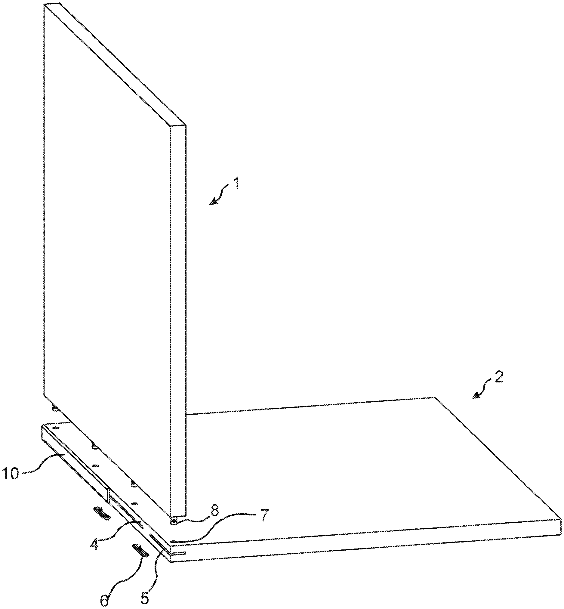
FIG. 1B shows a 3D-view of an embodiment of the invention during assembling.
FIGS. 2A-2B show side views of an embodiment of the first panel according to an embodiment of the invention.
FIG. 2C shows an enlargement of a part of the embodiment shown in FIG. 2B.
FIG. 3 shows an embodiment of the first panel and the second panel in a locked position according to an embodiment of the invention.
FIG. 4A shows a cross section of an embodiment of the first panel and the second panel in a locked position according to an embodiment of the invention.
FIG. 4B shows an enlargement of a part of the embodiment shown in FIG. 4A.
FIG. 5A shows an embodiment of the flexible tongue according to an embodiment of the invention.
FIG. 5B shows a 3D-view of an embodiment of the invention during assembling.
FIG. 6 shows an embodiment of the second panel according to an embodiment of the invention.
FIGS. 7A-7B show side views of an embodiment of the first panel and the second panel in a locked position according to an embodiment of the invention
FIG. 8A shows a cross section of an embodiment of the first panel and the second panel in a locked position according to an embodiment of the invention.
FIG. 8B shows an enlargement of a part of the embodiment shown in FIG. 8A.
DETAILED DESCRIPTION
Specific embodiments of the invention will now be described with reference to the accompanying drawings. This invention may, however, be embodied in many different forms and should not be construed as limited to the embodiments set forth herein; rather, these embodiments are provided so that this disclosure will be thorough and complete, and will fully convey the scope of the invention to those skilled in the art. The terminology used in the detailed description of the embodiments illustrated in the accompanying drawings is not intended to be limiting of the invention. In the drawings, like numbers refer to like elements.
A first embodiment of the invention is shown in FIGS. 1A-4B including a set comprising a first panel 1, a second panel 2 and a mechanical locking device for locking the first panel to the second panel. The first panel 1 comprises a first edge surface 12 and a first panel surface 13. The second panel 2 comprises a second edge surface 4 and a second panel surface 3. The first edge surface 12 is facing the second panel surface 3 in a locked position of the first and the second panel. The mechanical locking device comprises a rod-shaped element 8 at the first edge surface 12 and an insertion groove 7 at the second panel surface 3. The mechanical locking device further comprises an edge groove 5 at the second edge surface 4 and a flexible tongue 6 positioned in the edge groove 5. The rod-shaped element 8 comprises a recess 9. The rod-shaped element 8 is configured to be inserted into the insertion groove 7. The flexible tongue 6 is configured to cooperate with the recess 9 for a locking of the first panel 1 to the second panel 2 in a first direction which is perpendicular to the second panel surface 3.
The first panel 1 and the second panel 2 are preferably panels for a furniture product and may be a part of a frame of a furniture product.
The set is preferably configured for locking the first panel 1 to the second panel 2 with the first panel surface 13 perpendicular or essentially perpendicular to the second panel surface 3.
FIG. 1B shows the first embodiment in a 3D view during assembling. The first panel may be assembled by displacing the first panel relative the second panel in a direction which is perpendicular to the second panel surface 3. The mechanical locking device may be configured to automatically lock the first panel 1 to the second panel 2 when the rod-shaped element 8 is inserted into the insertion groove 7 and the first edge surface 12 is arranged against second panel surface 3.
The insertion groove 7 may be formed in the second panel surface 3 and in a core of the second panel 2.
The second panel surface 3 may comprise a decorative layer and the insertion groove may extend though the decorative layer.
The insertion groove may be formed by mechanical cutting, such as drilling.
An edge element 10, such as an edge band, is preferably attached to the second edge for covering the edge groove 5 and for enforcing the second edge 4. The edge element 10 may be glued to the second edge or attached by a mechanical locking device, which may comprise a part that protrudes from the edge element and is configured to be inserted into the edge groove 5. The part may be attached to the edge groove 5 by friction. The edge element is in FIG. 1B partly removed in order to visualize the flexible tongue 6 and the edge groove 5. The flexible tongue 6 is shown before it is positioned in the edge groove 5. The edge groove 5 may comprise a circular cross section.
An embodiment of the flexible tongue 6 is shown in FIG. 1A in a 3D view. The flexible tongue may have an envelope surface which preferably matches the circular cross section of the edge groove 5. A first part of the flexible tongue is configured to cooperate with the insertion groove and a second part is configured to cooperate with the recess 9 of the rod-shaped element 8. An advantage with this embodiment of the flexible tongue is that the size of the edge groove may be small. A small edge groove may have the advantage that the effect of the strength of the second edge of the second panel is limited or non-existent.
The second part may comprise a first bevel 65 which configured to cooperate with the rod-shaped element 8 during assembling and a second bevel 64 which is configured to cooperate with the recess for the locking.
The flexible tongue may comprise a flexible material to enable compression and a displacement of the flexible tongue in the edge groove during assembling.
The flexible tongue may comprise an element which is flexible to enable compression and a displacement of the flexible tongue in the edge groove during assembling and another element which is less flexible in order to improve the locking strength.
A part of the envelope surface of the flexible tongue 6 may be configured to be displaced against a surface, such as a cylindrical surface, of the edge groove 5.
The first edge surface 12 may comprise two or more of said rod shaped element and the second panel surface 3 may comprise two or more of said insertion groove 7, preferably arranged linearly, wherein each of the rod-shaped elements is configured to be inserted into one of the insertion grooves.
FIG. 2A shows a first side view of the first panel 1 and FIG. 2B shows a second side view of the first panel 1. FIG. 2C shows an enlargement of the encircled area indicated in FIG. 2B. 4. An embodiment of the rod-shaped element 8 is shown which comprises an embodiment of the recess 9. The rod-shaped element has a longitudinal shape with a length direction which is parallel to the first panel surface. A first crosscut of the rod-shaped element 8, in a plane parallel to the second panel surface 3 may have a circular shape, a rectangular shape a star shape, an oval shape or a hexagon shape.
A locking of the first panel to the second panel in a second direction which is perpendicular to the first panel surface may be obtained by cooperating locking surfaces between the insertion groove 7 and the rod-shaped element 8.
A locking of the first panel to the second panel in a third direction which is perpendicular to the first direction and the second direction surface may be obtained by cooperating locking surfaces between the insertion groove 7 and the rod-shaped element 8.
A second cross cut of the insertion groove 7, in a plane parallel to the second panel surface, preferably has a shape that matches a first cross cut of the rod-shaped element 8, in a plane parallel to the second panel surface. An advantage of this may be that an improved locking of the first panel to the second panel in the second direction is obtained and/or an improved locking of the first panel to the second panel in a third direction is obtained.
FIG. 3 shows a side view of the first panel and the second panel in the locked position.
FIG. 4A shows a cross cut, at the line indicated by 4A in FIG. 3; of the first panel and the second panel in the locked position. FIG. 4B show an enlargement of the encircled area indicated in FIG. 4A. The insertion groove may extend from the second panel surface 3 to the edge groove 5.
A locking surface 62 of the flexible tongue 6 may cooperate with a locking surface 82 of the recess 9 for the locking of the first panel to the second.
The insertion groove may a bottom-ended groove, such as a bottom ended drill hole, comprising a bottom surface 43 which is positioned at a distance from the edge groove 5.
The insertion groove may have a first part on a first side of the edge groove 5 and a second part on a second side of the edge groove 5, wherein the second part comprises a bottom surface 43 and side walls 71, 72, wherein, in a locked position, the rod-shaped element passes through the first part of the insertion groove, through the edge groove 5 and into the second part of the insertion groove.
The rod-shaped element 8 may be configured to cooperate, for the locking in the second direction, with the side walls 71, 72 of the second part of the insertion groove.
The rod-shaped element 8 may be configured to cooperate, in a locked position, with the bottom surface 43.
The first part may comprise side walls 73, 74, wherein the rod-shaped element 8 may be configured to cooperate, for the locking in the second direction, with side walls 73, 74 of the first part.
The edge groove may extend from the second edge surface 4 to the insertion groove 7.
The edge groove 5 may be a bottom-ended groove, comprising a bottom surface 44 which is positioned at a distance from the insertion groove 7.
The flexible tongue 6 may be arranged at the bottom surface 44 of the edge groove 5.
The flexible tongue may be arranged between the recess 9 and the bottom surface 44 of the edge groove in the locked position.
The rod-shaped element 8 may be configured to be attached in an attachment groove 45 in the first edge surface 12.
The rod-shaped element 8 may be configured to be glued in the attachment groove 45 in the first edge surface 12.
The rod-shaped element 8 may be configured to be locked in the attachment groove 45 by a friction connection or by a mechanically connection, such as threads or by a locking element, such as a barb.
The second edge surface 4 may be essentially perpendicular to the second panel surface 3.
A second embodiment of the invention is shown in FIGS. 5A-8B including a set comprising a first panel 1, a second panel 2 and a mechanical locking device for locking the first panel to the second panel. The embodiment comprises an embodiment of the edge groove 5 which is a longitudinal groove that extends in a longitudinal direction of the second edge surface 4.
FIG. 5B shows the second embodiment in a 3D view during assembling. The first panel may be assembled by displacing the first panel relative the second panel in a direction which is perpendicular to the second panel surface 3. The mechanical locking device may be configured to automatically lock the first panel 1 to the second panel 2 when the rod-shaped element 8 is inserted into the insertion groove 7 and the first edge surface 12 is arranged against second panel surface 3.
The insertion groove 7 may be formed in the second panel surface 3 and in a core of the second panel 2.
The second panel surface 3 may comprise a decorative layer and the insertion groove may extend though the decorative layer.
The insertion groove may be formed by mechanical cutting, such as milling or sawing.
An edge element 10, such as an edge band, is preferably attached to the second edge for covering the edge groove and for enforcing the second edge 4. The edge element 10 may be glued to the second edge or attached by a mechanical locking device, which may comprise a part that protrudes from the edge element and is configured to be inserted into the edge groove 5. The part may be attached to the edge groove by friction. The edge element is in FIG. 5B partly removed in order to visualize the flexible tongue 6 and the edge groove 5. The flexible tongue 6 is shown before it is positioned in the edge groove 5.
The first panel 1 and the rod-shaped element 8 of the second embodiment may be identical to the first panel 1 and the rod-shaped element 8, respectively, of the first embodiment.
An embodiment of the flexible tongue 6 is shown in FIG. 5A in a 3D view. The flexible tongue 6 may comprise a first essentially straight edge and a second edge which comprises a bendable part 61, preferably a first bendable part and a second bendable part. The first edge is preferably configured to cooperate with the recess 9 of the rod-shaped element 8. The flexible tongue preferably comprises a recess 63 at each of said bendable parts. An advantage with this embodiment of the flexible tongue is that a stronger spring force may be obtained which may provide a stronger locking. A disadvantage for some embodiments of the second panel is that the size of the edge groove may have to be larger which may weaken the second edge 4 of the second panel 2.
The first essentially edge may comprise a first bevel 65 which configured to cooperate with the rod-shaped element 8 during assembling and/or a second bevel 64 which is configured to cooperate with the recess for the locking.
FIG. 6 shows a top view of a part of the second panel 2. The second panel may comprise two or more of said edge groove 5. The edge grooves are hidden and the outline of said edge groove is indicated by a broken line. The bendable part of the flexible tongue may cooperate with a bottom surface of the edge groove 5.
FIG. 7A shows a first side view and FIG. 7B a second side view of the first panel 1 and the second panel 2 in a locked position.
FIG. 8A shows a cross cut, at the line indicated by 8A in FIG. 7B; of the first panel 1 and the second panel 2 in the locked position. FIG. 8B show an enlargement of the encircled area indicated in FIG. 8A. The insertion groove may extend from the second panel surface 3 to the edge groove 5.
A locking surface 62 of the flexible tongue 6 may cooperate with a locking surface 82 of the recess 9 for the locking of the first panel to the second.
The insertion groove may a bottom-ended groove, such as a bottom ended drill hole, comprising a bottom surface 43 which is positioned at a distance from the edge groove 5.
The insertion groove may have a first part on a first side of the edge groove 5 and a second part on a second side of the edge groove 5, wherein the second part comprises a bottom surface 43 and side walls 71, 72, wherein, in a locked position, the rod-shaped element passes through the first part of the insertion groove, through the edge groove 5 and into the second part of the insertion groove.
The rod-shaped element 8 may be configured to cooperate, for the locking in the second direction, with the side walls 71, 72 of the second part of the insertion groove.
The rod-shaped element 8 may be configured to cooperate, in a locked position, with the bottom surface 43.
The first part may comprise side walls 73, 74, wherein the rod-shaped element 8 may be configured to cooperate, for the locking in the second direction, with side walls 73, 74 of the first part.
The edge groove may extend from the second edge surface 4 to the insertion groove 7.
The edge groove 5 may comprise a first surface, an opposite second surface and a bottom surface 44 extending between the first surface and the opposite second surface.
The bottom surface may be positioned at a distance from the insertion groove 7.
The bendable part 61 of the flexible tongue 6 may be arranged at the bottom surface 44 of the edge groove 5.
The flexible tongue 6 may be arranged at the bottom surface 44 of the edge groove 5.
The flexible tongue may be arranged between the recess 9 and the bottom surface 44 of the edge groove in the locked position.
A part of the flexible tongue 6 may be configured to be displaced against a surface of the edge groove 5, such as the first surface and/or the second surface.
The rod-shaped element 8 may be configured to be attached in an attachment groove 45 in the first edge surface 12.
The rod-shaped element 8 may be configured to be glued in the attachment groove 45 in the first edge surface 12.
The rod-shaped element 8 may be configured to be locked in the attachment groove 45 by a friction connection or by a mechanically connection, such as threads or by a locking element, such as a barb.
The second edge surface 4 may be essentially perpendicular to the second panel surface 3. The flexible tongue 6 may be according to the flexible tongue described and shown in FIGS. 2A-2F in WO2015/105449. FIGS. 2A-2F and the related disclosure from page 6, line 15 to page 7, line 2, in WO2015/105449 are hereby expressly incorporated by reference herein.
The core of the first panel 1 and/or of the second panel 2 may be a wood-based core, preferably made of MDF, HDF, OSB, WPC, plywood or particleboard. The core may also be a plastic core comprising thermosetting plastic or thermoplastic e.g. vinyl, PVC, PU or PET.
The plastic core may comprise fillers.
The first panel 1 and/or the second panel 2 may also be of solid wood.
The first panel 1 and/or the second panel 2 may be provided with a decorative layer, such as a foil or a veneer, on one or more surfaces.
Embodiments
1. A set comprising a first panel (1), a second panel (2) and a mechanical locking device for locking the first panel to the second panel, wherein the first panel (1) comprises a first edge surface (12) and a first panel surface (13), wherein the second panel (2) comprises a second edge surface (4) and a second panel surface (3), wherein the first edge surface (12) is facing the second panel surface (3) in a locked position of the first and the second panel, characterized in
that the mechanical locking device comprises a rod-shaped element (8) at the first edge surface (12) and an insertion groove (7) at the second panel surface (3),
that the mechanical locking device comprises an edge groove (5) at the second edge surface (4) and a flexible tongue (6) positioned in the edge groove (5),
that the rod-shaped element (8) comprises a recess (9),
that the rod-shaped element (8) is configured to be inserted into the insertion groove (7), and
that the flexible tongue (6) is configured to cooperate with the recess (9) for a locking of the first panel (1) to the second panel (2) in a first direction which is perpendicular to the second panel surface (3).
2. The set as in embodiment 1, wherein the insertion groove (7) extends from the second panel surface (3) to the edge groove (5).
3. The set as in embodiments 1 or 2, wherein the mechanical locking device is configured to automatically lock the first panel (1) to the second panel (2) when the rod-shaped element (8) is inserted into the insertion groove (7) and the first edge surface (12) is arranged against second panel surface (3).
4. The set as in any one of the embodiments 1-3, wherein the rod-shaped element (8) has a longitudinal shape with a length direction which is parallel to the first panel surface.
5. The set as in any one of the embodiments 1-4, wherein a first crosscut of the rod-shaped element (8), in a plane parallel to the second panel surface (3) has a circular shape or a rectangular shape.
6. The set as in any one of the embodiments 1-5, wherein a second cross cut of the insertion groove (7), in a plane parallel to the second panel surface, has a shape that matches a first cross cut of the rod-shaped element (8), in a plane parallel to the second panel surface.
7. The set as in any one of the embodiments 1-6, wherein the insertion groove is a bottom-ended groove, such as a bottom ended drill hole, comprising a bottom surface (43) which is positioned at a distance from the edge groove (5).
8. The set as in embodiment 7, wherein the insertion groove has a first part on a first side of the edge groove (5) and a second part on a second side of the edge groove (5), wherein the second part comprises the bottom surface (43) and side walls (71, 72), wherein, in a locked position, the rod-shaped element passes through the first part of the insertion groove, through the edge groove (5) and into the second part of the insertion groove.
9. The set as in embodiment 8, wherein the rod-shaped element (8) is configured to cooperate with the side walls (71, 72) of the second part of the insertion groove.
10. The set as in embodiments 8 or 9, wherein the rod-shaped element (8) is configured to cooperate with the bottom surface (43).
11. The set as in any one of the embodiments 1-10, wherein the first edge surface (12) comprises two or more of said rod shaped element and the second panel surface (3) comprises two or more of said insertion groove (7), preferably arranged linearly, wherein each of the rod-shaped elements is configured to be inserted into one of the insertion grooves.
12. The set as in any one of the embodiments 1-11, wherein the edge groove (5) comprises a circular cross section.
13. The set as in any one of embodiments 1-11, wherein the edge groove (5) is a longitudinal groove that extends in a longitudinal direction of the second edge surface (4).
14. The set as in any one of the embodiments 1-13, wherein the edge groove extends from the second edge surface (4) to the insertion groove (7).
15. The set as in any one of the embodiments 1-14, wherein the edge groove (5) is a bottom-ended groove, comprising a bottom surface (44) which is positioned at a distance from the insertion groove (7).
16. The set as in embodiment 15, wherein the flexible tongue (6) is arranged at the bottom surface (44) of the edge groove (5).
17. The set as in embodiments 15 or 16, wherein the flexible tongue is arranged between the recess (9) and the bottom surface (44) of the edge groove in the locked position.
18. The set as in any one of the embodiments 16-17, wherein the rod-shaped element (8) is configured to be attached in an attachment groove (45) in the first edge surface (12).
19. The set as in any one of the embodiments 1-18, wherein the second edge surface (4) is essentially perpendicular to the second panel surface (3).
* * * * *
D00000
D00001
D00002
D00003
D00004
D00005
D00006
D00007
D00008
XML
uspto.report is an independent third-party trademark research tool that is not affiliated, endorsed, or sponsored by the United States Patent and Trademark Office (USPTO) or any other governmental organization. The information provided by uspto.report is based on publicly available data at the time of writing and is intended for informational purposes only.
While we strive to provide accurate and up-to-date information, we do not guarantee the accuracy, completeness, reliability, or suitability of the information displayed on this site. The use of this site is at your own risk. Any reliance you place on such information is therefore strictly at your own risk.
All official trademark data, including owner information, should be verified by visiting the official USPTO website at www.uspto.gov. This site is not intended to replace professional legal advice and should not be used as a substitute for consulting with a legal professional who is knowledgeable about trademark law.