Set of panel-shaped elements for a composed element
Boo Sept
U.S. patent number 10,415,613 [Application Number 15/428,504] was granted by the patent office on 2019-09-17 for set of panel-shaped elements for a composed element. This patent grant is currently assigned to VALINGE INNOVATION AB. The grantee listed for this patent is Valinge Innovation AB. Invention is credited to Christian Boo.


| United States Patent | 10,415,613 |
| Boo | September 17, 2019 |
Set of panel-shaped elements for a composed element
Abstract
A set of panel-shaped elements includes a first panel-shaped element, a second panel-shaped element, and a third panel-shaped element. The first panel-shaped element includes at least one recess that extends through the first panel-shaped element from a first side to a second side. The second panel-shaped element includes a first profiled portion, which is configured to extend into the recess from the first side of the first panel-shaped element. The third panel-shaped element includes a second profiled portion, which is configured to extend into the recess from the second side of the first panel-shaped element and for locking engagement with the first profiled portion. The set of panel-shaped elements can be assembled using a method where the third element is moved into locking engagement with the first and second elements.
| Inventors: | Boo; Christian (Kagerod, SE) | ||||||||||
|---|---|---|---|---|---|---|---|---|---|---|---|
| Applicant: |
|
||||||||||
| Assignee: | VALINGE INNOVATION AB (Viken,
SE) |
||||||||||
| Family ID: | 59496153 | ||||||||||
| Appl. No.: | 15/428,504 | ||||||||||
| Filed: | February 9, 2017 |
Prior Publication Data
| Document Identifier | Publication Date | |
|---|---|---|
| US 20170227031 A1 | Aug 10, 2017 | |
Foreign Application Priority Data
| Feb 9, 2016 [SE] | 16501587 | |||
| Current U.S. Class: | 1/1 |
| Current CPC Class: | A47B 47/042 (20130101); F16B 5/008 (20130101); F16B 12/125 (20130101); A47B 47/0075 (20130101); A47B 3/06 (20130101); F16B 12/46 (20130101); A47B 88/941 (20170101); A47B 2230/0081 (20130101); F16B 2012/466 (20130101) |
| Current International Class: | F16B 5/00 (20060101); A47B 3/06 (20060101); A47B 47/04 (20060101); F16B 12/46 (20060101); A47B 88/90 (20170101); A47B 47/00 (20060101); F16B 12/12 (20060101) |
References Cited [Referenced By]
U.S. Patent Documents
| 291032 | January 1884 | Cleland |
| 634581 | October 1899 | Miller |
| 701000 | May 1902 | Ahrens |
| 861911 | July 1907 | Stewart |
| 881673 | March 1908 | Ellison |
| 1533099 | April 1925 | Carroll |
| 1534468 | April 1925 | Shea, Jr. |
| 1800386 | April 1931 | Hoffman |
| 1800387 | April 1931 | Greist |
| 1802245 | April 1931 | Foretich |
| 1954242 | April 1934 | Heppenstall |
| 2360451 | October 1944 | Stone |
| 2362904 | November 1944 | Kramer |
| 2496184 | January 1950 | Von Canon |
| 3002630 | October 1961 | Heisser |
| 3195968 | July 1965 | Freeman |
| 3284152 | November 1966 | Schorghuber |
| 3313054 | April 1967 | Madey |
| 3347610 | October 1967 | Pilliod |
| 3410441 | November 1968 | Rhyne |
| 3722704 | March 1973 | Piretti |
| 3722971 | March 1973 | Zeischegg |
| 3765465 | October 1973 | Gulistan |
| 3784271 | January 1974 | Schreiber |
| 3885845 | May 1975 | Krieks |
| 3981118 | September 1976 | Johnson et al. |
| 4089614 | May 1978 | Harley |
| 4099887 | July 1978 | Mackenroth |
| 4116510 | September 1978 | Franco |
| 4142271 | March 1979 | Busse |
| 4211379 | July 1980 | Morgan et al. |
| 4222544 | September 1980 | Crowder |
| 4279397 | July 1981 | Larsson |
| 4308961 | January 1982 | Kunce |
| 4324517 | April 1982 | Dey |
| 4403886 | September 1983 | Haeusler |
| 4509648 | April 1985 | Govang |
| 4595105 | June 1986 | Gold |
| 4597122 | July 1986 | Handler |
| 4615448 | October 1986 | Johnstonbaugh |
| 4629076 | December 1986 | Amstutz et al. |
| 4750794 | June 1988 | Vegh |
| 4752150 | June 1988 | Salice |
| 4815908 | March 1989 | Duran et al. |
| 4817900 | April 1989 | Whittington et al. |
| 4844266 | July 1989 | Small et al. |
| 4883331 | November 1989 | Mengel |
| 4886326 | December 1989 | Kuzyk |
| 4888933 | December 1989 | Guomundsson |
| 4891897 | January 1990 | Gieske et al. |
| 4909581 | March 1990 | Haheeb |
| 4944416 | July 1990 | Petersen et al. |
| 4961295 | October 1990 | Kosch, Sr. et al. |
| 5004116 | April 1991 | Cattarozzi |
| 5018323 | May 1991 | Clausen |
| 5109993 | May 1992 | Hutchison |
| 5114265 | May 1992 | Grisley |
| 5121578 | June 1992 | Holz |
| 5125518 | June 1992 | Ward |
| 5138803 | August 1992 | Grossen |
| 5209556 | May 1993 | Anderson |
| 5212925 | May 1993 | McClinton |
| 5360121 | November 1994 | Sothman |
| 5375802 | December 1994 | Branham, II |
| 5423155 | June 1995 | Bauer |
| 5475960 | December 1995 | Lindal |
| 5499886 | March 1996 | Short et al. |
| 5527103 | June 1996 | Pittman |
| 5658086 | August 1997 | Brokaw et al. |
| 5711115 | January 1998 | Wirt |
| 5775521 | July 1998 | Tisbo |
| 5893617 | April 1999 | Lee |
| 5944294 | August 1999 | Baer |
| 5950389 | September 1999 | Porter |
| 6050426 | April 2000 | Leurdijk |
| 6142436 | November 2000 | Thurston et al. |
| 6312186 | November 2001 | Rock et al. |
| 6363645 | April 2002 | Hunter |
| 6413007 | July 2002 | Lambright |
| 6491172 | December 2002 | Chance |
| 6505452 | January 2003 | Hannig |
| 6547086 | April 2003 | Harvey |
| 6675979 | January 2004 | Taylor |
| D486676 | February 2004 | Campbell et al. |
| 6769219 | August 2004 | Schwitte et al. |
| 6772890 | August 2004 | Campbell et al. |
| 6827028 | December 2004 | Callaway |
| 6971614 | December 2005 | Fischer et al. |
| 7127860 | October 2006 | Pervan |
| 7228977 | June 2007 | Perkins et al. |
| 7300120 | November 2007 | Shin |
| 7451535 | November 2008 | Wells et al. |
| 7451578 | November 2008 | Hannig |
| 7584583 | September 2009 | Bergelin et al. |
| 7621092 | November 2009 | Groeke et al. |
| 7641414 | January 2010 | Joyce |
| 7717278 | May 2010 | Kao |
| 7721503 | May 2010 | Pervan et al. |
| 7793450 | September 2010 | Chasmer et al. |
| 7818939 | October 2010 | Bearinger |
| 7998549 | August 2011 | Susnjara |
| 8038363 | October 2011 | Hannig |
| 8042311 | October 2011 | Pervan |
| 8146754 | April 2012 | Apgood |
| 8220217 | July 2012 | Muehlebach |
| 8365499 | February 2013 | Nilsson et al. |
| 8387327 | March 2013 | Pervan |
| 8495849 | July 2013 | Pervan |
| 8505257 | August 2013 | Boo et al. |
| 8544230 | October 2013 | Pervan |
| 8602227 | December 2013 | McDonald |
| 8615952 | December 2013 | Engstrom |
| 8745952 | June 2014 | Perra |
| 8764137 | July 2014 | Fehre |
| 8833028 | September 2014 | Whispell et al. |
| 8864407 | October 2014 | Sorum |
| 8887468 | November 2014 | Hakansson et al. |
| 9175703 | November 2015 | Maertens |
| 9216541 | December 2015 | Boo |
| 9290948 | March 2016 | Cappelle et al. |
| 9375085 | June 2016 | Derelov |
| 9538842 | January 2017 | Hakansson et al. |
| 9655442 | May 2017 | Boo et al. |
| 9700157 | July 2017 | Keyvanloo |
| 9714672 | July 2017 | Derelov et al. |
| 9723923 | August 2017 | Derelov |
| 9726210 | August 2017 | Derelov et al. |
| 9745756 | August 2017 | Hannig |
| 9758973 | September 2017 | Segaert |
| 9763528 | September 2017 | Lung |
| 9809983 | November 2017 | Trudel |
| 9945121 | April 2018 | Derelov |
| 10034541 | July 2018 | Boo et al. |
| 10202996 | February 2019 | Hakansson et al. |
| 2002/0170258 | November 2002 | Schwitte et al. |
| 2005/0042027 | February 2005 | Migli |
| 2005/0236544 | October 2005 | Mancino |
| 2005/0247653 | November 2005 | Brooks |
| 2006/0091093 | May 2006 | Armari |
| 2006/0101769 | May 2006 | Pervan et al. |
| 2006/0180561 | August 2006 | Wisnoski et al. |
| 2006/0236642 | October 2006 | Pervan |
| 2006/0273085 | December 2006 | Casto |
| 2007/0006543 | January 2007 | Engstrom |
| 2008/0010937 | January 2008 | Pervan et al. |
| 2008/0066415 | March 2008 | Pervan |
| 2008/0193209 | August 2008 | Henderson |
| 2008/0216435 | September 2008 | Nolan |
| 2008/0236088 | October 2008 | Hannig et al. |
| 2009/0014401 | January 2009 | Tallman |
| 2009/0064624 | March 2009 | Sokol |
| 2010/0028592 | February 2010 | Barkdoll et al. |
| 2010/0083603 | April 2010 | Goodwin |
| 2010/0173122 | July 2010 | Susnjara |
| 2010/0289389 | November 2010 | Crabtree, II |
| 2011/0225921 | September 2011 | Schulte |
| 2011/0225922 | September 2011 | Pervan et al. |
| 2011/0280655 | November 2011 | Maertens |
| 2011/0283650 | November 2011 | Pervan et al. |
| 2012/0009383 | January 2012 | Hardesty |
| 2012/0027967 | February 2012 | Maertens |
| 2012/0073235 | March 2012 | Hannig |
| 2012/0124932 | May 2012 | Schulte et al. |
| 2012/0145845 | June 2012 | Hightower |
| 2012/0180416 | July 2012 | Perra et al. |
| 2012/0279161 | November 2012 | Hakansson et al. |
| 2012/0286637 | November 2012 | Fehre |
| 2013/0014463 | January 2013 | Pervan |
| 2013/0048632 | February 2013 | Chen |
| 2013/0071172 | March 2013 | Maertens et al. |
| 2013/0081349 | April 2013 | Pervan |
| 2013/0097846 | April 2013 | Pettigrew |
| 2013/0111845 | May 2013 | Pervan |
| 2013/0170904 | July 2013 | Cappelle et al. |
| 2013/0232905 | September 2013 | Pervan |
| 2014/0013919 | January 2014 | Gerke et al. |
| 2014/0055018 | February 2014 | Shein et al. |
| 2014/0111076 | April 2014 | Devos |
| 2014/0286701 | September 2014 | Sauer |
| 2015/0035422 | February 2015 | Hakansson et al. |
| 2015/0078807 | March 2015 | Brannstrom et al. |
| 2015/0078819 | March 2015 | Derelov et al. |
| 2015/0196118 | July 2015 | Derelov |
| 2015/0198191 | July 2015 | Boo |
| 2015/0230600 | August 2015 | Schulte |
| 2015/0368896 | December 2015 | Schulte |
| 2016/0000220 | January 2016 | Devos |
| 2016/0007751 | January 2016 | Derelov |
| 2016/0145029 | May 2016 | Ranade et al. |
| 2016/0174704 | June 2016 | Boo et al. |
| 2016/0186925 | June 2016 | Bettin |
| 2016/0192775 | July 2016 | Andersson |
| 2016/0270531 | September 2016 | Derelov |
| 2017/0079433 | March 2017 | Derelov et al. |
| 2017/0089379 | March 2017 | Pervan |
| 2017/0097033 | April 2017 | Hakansson et al. |
| 2017/0159291 | June 2017 | Derelov |
| 2017/0208938 | July 2017 | Derelov et al. |
| 2017/0227032 | August 2017 | Fridlund |
| 2017/0227035 | August 2017 | Fridlund |
| 2017/0234346 | August 2017 | Fridlund |
| 2017/0298973 | October 2017 | Derelov |
| 2017/0360193 | December 2017 | Boo |
| 2018/0080488 | March 2018 | Derelov |
| 2018/0087552 | March 2018 | Derelov et al. |
| 2018/0112695 | April 2018 | Boo et al. |
| 2018/0119717 | May 2018 | Derelov |
| 2018/0202160 | July 2018 | Derelov |
| 2018/0328396 | November 2018 | Fransson et al. |
| 2019/0113061 | April 2019 | Hakansson et al. |
| 685 276 | May 1995 | CH | |||
| 696 889 | Jan 2008 | CH | |||
| 698 988 | Dec 2009 | CH | |||
| 101099618 | Jan 2008 | CN | |||
| 203424576 | Feb 2014 | CN | |||
| 26 35 237 | Feb 1978 | DE | |||
| 31 03 281 | Aug 1982 | DE | |||
| 20 2008 011 589 | Nov 2008 | DE | |||
| 20 2009 008 825 | Oct 2009 | DE | |||
| 10 2009 041 142 | Mar 2011 | DE | |||
| 10 2014 110 124 | Jan 2016 | DE | |||
| 0 060 203 | Sep 1982 | EP | |||
| 0 362 968 | Apr 1990 | EP | |||
| 0 675 331 | Oct 1995 | EP | |||
| 0 871 156 | Oct 1998 | EP | |||
| 1 048 423 | Nov 2000 | EP | |||
| 1 048 423 | May 2005 | EP | |||
| 1 650 375 | Apr 2006 | EP | |||
| 1 671 562 | Jun 2006 | EP | |||
| 1 863 984 | Dec 2007 | EP | |||
| 1 992 954 | May 2008 | EP | |||
| 2 017 403 | Jan 2009 | EP | |||
| 2 037 128 | Mar 2009 | EP | |||
| 1 922 954 | Jul 2009 | EP | |||
| 2 333 353 | Jun 2011 | EP | |||
| 1 863 984 | Nov 2011 | EP | |||
| 2 487 373 | Aug 2012 | EP | |||
| 3 031 998 | Jun 2016 | EP | |||
| 2 062 731 | Jun 1971 | FR | |||
| 2 517 187 | Jun 1983 | FR | |||
| 2 597 173 | Oct 1987 | FR | |||
| 2 602 013 | Jan 1988 | FR | |||
| 1 022 377 | Mar 1966 | GB | |||
| 2 482 213 | Jan 2012 | GB | |||
| 2 520 927 | Jun 2015 | GB | |||
| 2003-239921 | Aug 2003 | JP | |||
| 10-1147274 | May 2012 | KR | |||
| 2014-0042314 | Apr 2014 | KR | |||
| WO 87/07339 | Dec 1987 | WO | |||
| WO 99/22150 | May 1999 | WO | |||
| WO 00/66856 | Nov 2000 | WO | |||
| WO 01/02669 | Jan 2001 | WO | |||
| WO 01/02670 | Jan 2001 | WO | |||
| WO 03/016654 | Jan 2001 | WO | |||
| WO 01/51733 | Jul 2001 | WO | |||
| WO 01/53628 | Jul 2001 | WO | |||
| WO 02/055809 | Jul 2002 | WO | |||
| WO 02/055810 | Jul 2002 | WO | |||
| WO 03/027510 | Apr 2003 | WO | |||
| WO 03/083234 | Oct 2003 | WO | |||
| WO 2004/079130 | Sep 2004 | WO | |||
| WO 2005/068747 | Jul 2005 | WO | |||
| WO 2006/043893 | Apr 2006 | WO | |||
| WO 2006/103500 | Oct 2006 | WO | |||
| WO 2006/104436 | Oct 2006 | WO | |||
| WO 2007/015669 | Feb 2007 | WO | |||
| WO 2007/015669 | Feb 2007 | WO | |||
| WO 2007/079845 | Jul 2007 | WO | |||
| WO 2008/004960 | Jan 2008 | WO | |||
| WO 2008/004960 | Jan 2008 | WO | |||
| WO 2008/017281 | Feb 2008 | WO | |||
| WO 2008/017301 | Feb 2008 | WO | |||
| WO 2008/017301 | Feb 2008 | WO | |||
| WO 2008/150234 | Dec 2008 | WO | |||
| WO 2010/023042 | Mar 2010 | WO | |||
| WO 2010/070472 | Jun 2010 | WO | |||
| WO 2010/070472 | Jun 2010 | WO | |||
| WO 2010/070605 | Jun 2010 | WO | |||
| WO 2010/070605 | Jun 2010 | WO | |||
| WO 2010/082171 | Jul 2010 | WO | |||
| WO 2010/087752 | Aug 2010 | WO | |||
| WO 2011/012104 | Feb 2011 | WO | |||
| WO 2011/012104 | Feb 2011 | WO | |||
| WO 2011/085710 | Jul 2011 | WO | |||
| WO 2011/151737 | Dec 2011 | WO | |||
| WO 2011/151737 | Dec 2011 | WO | |||
| WO 2011/151737 | Dec 2011 | WO | |||
| WO 2011/151758 | Dec 2011 | WO | |||
| WO 2011/151758 | Dec 2011 | WO | |||
| WO 2012/095454 | Jul 2012 | WO | |||
| WO 2012/154113 | Nov 2012 | WO | |||
| WO 2013/009257 | Jan 2013 | WO | |||
| WO 2013/025163 | Feb 2013 | WO | |||
| WO 2013/080160 | Jun 2013 | WO | |||
| WO 2013/093636 | Jun 2013 | WO | |||
| WO 2013/093636 | Jun 2013 | WO | |||
| WO 2013/118075 | Aug 2013 | WO | |||
| WO 2014/072080 | May 2014 | WO | |||
| WO 2014/108114 | Jul 2014 | WO | |||
| WO 2014/121410 | Aug 2014 | WO | |||
| WO 2015/015603 | Feb 2015 | WO | |||
| WO 2015/038059 | Mar 2015 | WO | |||
| WO 2015/105449 | Jul 2015 | WO | |||
| WO 2015/105450 | Jul 2015 | WO | |||
| WO 20151105451 | Jul 2015 | WO | |||
| WO 2017/131574 | Aug 2017 | WO | |||
| WO 2017/135874 | Aug 2017 | WO | |||
| WO 2018/080387 | May 2018 | WO | |||
Other References
|
US. Appl. No. 15/642,757, Peter Derelov, filed Jul. 6, 2017, (Cited herein as U.S. Pat. No. 2017/0298973 A1 of Oct. 19, 2017). cited by applicant . U.S. Appl. No. 15/584,633, Chrisitan Boo, filed May 2, 2017, (Cited herein as U.S. Pat. No. 2017/00360193 A1 of Dec. 21, 2017). cited by applicant . U.S. Appl. No. 15/646,714, Peter Derelov, filed Jul. 11, 2017. cited by applicant . U.S. Appl. No. 15/562,254, Peter Derelov, filed Sep. 27, 2017. cited by applicant . U.S. Appl. No. 15/567,507, Christian Boo, Peter Derelov and Agne Palsson, filed Oct. 18, 2017. cited by applicant . U.S. Appl. No. 15/794,491, Peter Derelov, filed Oct. 26, 2017. cited by applicant . U.S. Appl. No. 15/848,164, Jonas Fransson, Andreas Blomgren and Karl Erikson, filed Dec. 20, 2017. cited by applicant . U.S. Appl. No. 15/923,701, Peter Derelov, filed Mar. 16, 2018. cited by applicant . U.S. Appl. No. 15/646,714, Derelov et al. cited by applicant . U.S. Appl. No. 15/562,254, Derelov. cited by applicant . U.S. Appl. No. 15/567,507, Boo et al. cited by applicant . U.S. Appl. No. 15/794,491, Derelov. cited by applicant . U.S. Appl. No. 15/848,164, Fransson, et al. cited by applicant . U.S. Appl. No. 15/923,701, Derelov. cited by applicant . International Search Report/Written Opinion dated Mar. 30, 2017 in PCT/SE2017/050125, ISA/SE, Patent-och registreringsverket, Stockholm, SE, 11 pages. cited by applicant . Derelov, Peter, et al., U.S. Appl. No. 15/646,714 entitled "Assembled Product and a Method of Assembling the Product", filed in the U.S. Patent and Trademark Office filed Jul. 11, 2017. cited by applicant . Derelov, Peter, U.S. Appl. No. 15/562,254 entitled "Panel with a Slider", filed in the U.S. Patent and Trademark Office filed Sep. 27, 2017. cited by applicant . Boo, Christian, et al., U.S. Appl. No. 15/567,507 entitled "Panel With a Fastening Device," filed in the U.S. Patent and Trademark Office filed Oct. 18, 2017. cited by applicant . Derelov, Peter, U.S. Appl. No. 15/794,491 entitled "Set of Panels with a Mechanical Locking Device", filed in the U.S. Patent and Trademark Office filed Oct. 26, 2017. cited by applicant . Fransson, Jonas, et al., U.S. Appl. No. 15/848,164 entitled "Device for Inserting a Tongue", filed in the U.S. Patent and Trademark Office filed Dec. 20, 2017. cited by applicant . Derelov, Peter, U.S. Appl. No. 15/923,701 entitled "Panels Comprising a Mechanical Locking Device and an Assembled Product Comprising the Panels", filed in the U.S. Patent and Trademark Office filed Mar. 16, 2018. cited by applicant . U.S. Appl. No. 15/956,949, Peter Derelov, filed Apr. 19, 2018. cited by applicant . U.S. Appl. No. 15/978,630, Jonas Fransson, Niclas Hakansson and Agne Palsson, filed May 14, 2018. cited by applicant . U.S. Appl. No. 16/027,479, Christian Boo and Peter Derelov, filed Jul. 5, 2018. cited by applicant . U.S. Appl. No. 15/956,949, Derelov. cited by applicant . U.S. Appl. No. 15/978,630, Fransson, et al. cited by applicant . U.S. Appl. No. 16/027,479, Boo et al. cited by applicant . Derelov, Peter, U.S. Appl. No. 15/956,949 entitled "Panels for an Assembled Product", filed in the U.S. Patent and Trademark Office filed Apr. 19, 2018. cited by applicant . Fransson, Jonas, et al., U.S. Appl. No. 15/978,630 entitled "Elements and a Locking Device for an Assembled Product," filed in the U.S. Patent and Trademark Office filed May 14, 2018. cited by applicant . Boo, Christian, et al., U.S. Appl. No. 16/027,479 entitled "Panels Comprising a Mechanical Locking Device and an Assembled Product Comprising the Panels," filed in the U.S. Patent and Trademark Office filed Jul. 5, 2018. cited by applicant . U.S. Appl. No. 14/158,165, Peter Derelov, filed Jan. 17, 2014. cited by applicant . U.S. Appl. No. 14/486,681, Hans Brannstrom, filed Sep. 15, 2014, (Cited herein as U.S. Pat. No. 2015/0078807 A1 of Mar. 19, 2015). cited by applicant . U.S. Appl. No. 14/573,473, Peter Derelov, filed Dec. 17, 2014, (Cited herein as U.S. Pat. No. 2015/0196118 A1 of Jul. 16, 2015). cited by applicant . U.S. Appl. No. 14/573,572, Christian Boo, filed Dec. 17, 2014, (Cited herein as U.S. Pat. No. 2015/0198191 A1 of Jul. 16, 2015). cited by applicant . U.S. Appl. No. 14/972,949, Christian Boo, filed Dec. 17, 2015, (Cited herein as U.S. Pat. No. 2016/0174704 A1 of Jun. 23, 2016). cited by applicant . U.S. Appl. No. 15/171,403, Peter Derelov, filed Jun. 2, 2016 (Cited herein as U.S. Pat. No. 2016/0270531 A1 of Sep. 22, 2016). cited by applicant . U.S. Appl. No. 15/271,622, Peter Derelov, filed Sep. 21, 2016 (Cited herein as U.S. Pat. No. 2017/0079433 A1 of Mar. 23, 2017). cited by applicant . U.S. Appl. No. 15/308,872, Darko Pervan, filed Nov. 4, 2016 (Cited herein as U.S. Pat. No. 2017/0089379 A1 of Mar. 30, 2017). cited by applicant . U.S. Appl. No. 15/379,791, Niclas Hakansson, filed Dec. 15, 2016 (Cited herein as U.S. Pat. No. 2017/0097033 A1 of Apr. 6, 2017). cited by applicant . U.S. Appl. No. 15/366,704, Peter Derelov, filed Dec. 1, 2016. cited by applicant . U.S. Appl. No. 15/415,356, Peter Derelov, filed Jan. 25, 2017. cited by applicant . U.S. Appl. No. 15/422,798, Magnus Fridlund, filed Feb. 2, 2017. cited by applicant . U.S. Appl. No. 15/428,469, Magnus Fridlund, filed Feb. 9, 2017. cited by applicant . U.S. Appl. No. 15/432,190, Magnus Fridlund, filed Feb. 14, 2017. cited by applicant . U.S. Appl. No. 15/366,704, Derelov. cited by applicant . U.S. Appl. No. 15/415,356, Derelov, et al. cited by applicant . U.S. Appl. No. 15/422,798, Fridlund. cited by applicant . U.S. Appl. No. 15/428,469, Fridlund. cited by applicant . U.S. Appl. No. 15/432,190, Fridlund. cited by applicant . Derelov, Peter, U.S. Appl. No. 15/366,704 entitled "Panels Comprising a Mechanical Locking Device and an Assembled Product Comprising the Panels", filed in the U.S. Patent and Trademark Office filed Dec. 1, 2016. cited by applicant . Derelov, Peter, et al., U.S. Appl. No. 15/415,356 entitled "Panels Comprising a Mechanical Locking Device and an Assembled Product Comprising the Panels", filed in the U.S. Patent and Trademark Office filed Jan. 25, 2017. cited by applicant . Fridlund, Magnus, U.S. Appl. No. 15/422,798 entitled "Set of Panels for an Assembled Product," filed in the U.S. Patent and Trademark Office filed Feb. 2, 2017. cited by applicant . Fridlund, Magnus, U.S. Appl. No. 15/428,469 entitled "Element and Method for Providing Dismantling Groove," filed in the U.S. Patent and Trademark Office filed Feb. 9, 2017. cited by applicant . Fridlund, Magnus, U.S. Appl. No. 15/432,190 entitled "Method for Forming a Panel," filed in the U.S. Patent and Trademark Office filed Feb. 14, 2017. cited by applicant . U.S. Appl. No. 16/220,574, Peter Derelov, filed Dec. 14, 2018. cited by applicant . U.S. Appl. No. 16/220,585, Peter Derelov, filed Dec. 14, 2018. cited by applicant . U.S. Appl. No. 16/228,975, Niclas Hakansson and Darko Pervan, filed Dec. 21, 2018. cited by applicant . U.S. Appl. No. 16/361,609, Peter Derelov, Johan Svensson and Lars Gunnarsson, filed Mar. 22, 2019. cited by applicant . U.S. Appl. No. 16/386,732, Christian Boo, filed Apr. 17, 2019. cited by applicant . U.S. Appl. No. 16/386,810, Christian Boo, filed Apr. 17, 2019. cited by applicant . U.S. Appl. No. 16/386,824, Christian Boo, filed Apr. 17, 2019. cited by applicant . U.S. Appl. No. 16/386,874, Peter Derelov, filed Apr. 17, 2019. cited by applicant . U.S. Appl. No. 16/220,574, Derelov. cited by applicant . U.S. Appl. No. 16/220,585, Derelov. cited by applicant . U.S. Appl. No. 16/228,975, Hakansson et al. cited by applicant . U.S. Appl. No. 16/361,609, Derelov. cited by applicant . U.S. Appl. No. 16/386,732, Boo. cited by applicant . U.S. Appl. No. 16/386,810, Boo. cited by applicant . U.S. Appl. No. 16/386,824, Boo. cited by applicant . U.S. Appl. No. 16/386,874, Derelov. cited by applicant . Derelov, Peter, U.S. Appl. No. 16/220,574 entitled "Set of Panels," filed in the U.S. Patent and Trademark Office filed Dec. 14, 2018. cited by applicant . Derelov, Peter, U.S. Appl. No. 16/220,585 entitled "Set of Panels," filed in the U.S. Patent and Trademark Office filed Dec. 14, 2018. cited by applicant . Hakansson, Niclas, et al., U.S. Appl. No. 16/228,975 entitled "Mechanical Locking System for Building Panels," filed in the U.S. Patent and Trademark Office filed Dec. 21, 2018. cited by applicant . Derelov, Peter, et al., U.S. Appl. No. 16/361,609 entitled "Panels Comprising a Mechanical Locking Device and an Assembled Product Comprising the Panels," filed in the U.S. Patent and Trademark Office filed Mar. 22, 2019. cited by applicant . Boo, Christian, U.S. Appl. No. 16/386,732 entitled "Set of Panels With a Mechanical Locking Device," filed in the U.S. Patent and Trademark Office filed Apr. 17, 2019. cited by applicant . Boo, Christian, U.S. Appl. No. 16/386,810 entitled "Set of Panels With a Mechanical Locking Device," filed in the U.S. Patent and Trademark Office filed Apr. 17, 2019. cited by applicant . Boo, Christian, U.S. Appl. No. 16/386,824 entitled "Set of Panels With a Mechanical Locking Device," filed in the U.S. Patent and Trademark Office filed Apr. 17, 2019. cited by applicant . Derelov, Peter, U.S. Appl. No. 16/386,874 entitled "Symmetric Tongue and T-Cross," filed in the U.S. Patent and Trademark Office filed Apr. 17, 2019. cited by applicant . Extended European Search Report issued in EP Application No. 17750524.5, dated Jun. 21, 2019, European Patent Office, Munich, DE, 8 pages. cited by applicant. |
Primary Examiner: Masinick; Jonathan P
Attorney, Agent or Firm: Buchanan Ingersoll & Rooney P.C.
Claims
The invention claimed is:
1. A set of panel-shaped elements for assembly to a composed element, comprising a first panel-shaped element, a second panel-shaped element, and a third panel-shaped element, wherein the first panel-shaped element comprises a first side and an opposite second side extending in a longitudinal direction of the first panel-shaped element, and at least one recess at least partially extending through the first panel-shaped element from the first side to the second side; the second panel-shaped element comprises a first profiled portion at one of its ends, the first profiled portion being configured to extend into the recess from the first side of the first panel-shaped element; and the third panel-shaped element comprises a second profiled portion at one of its ends, the second profiled portion being configured to extend into the recess from the second side of the first panel-shaped element and for locking engagement with the first profiled portion, wherein each of the first profiled portion and the second profiled portion forms a tongue with a locking member, the locking members engage within the recess in a locking engagement, at least in a longitudinal direction of the second and the third panel.
2. The set of panel-shaped elements according to claim 1, wherein each locking member is sized and configured for mating engagement with the other of the first and the second profiled portion, wherein each locking member has a non-flat shape in a longitudinal direction of the second panel-shaped element and the third panel-shaped element, respectively, and the locking member of the second panel-shaped element and the locking member of the third panel-shaped element have complementary non-flat shapes and face in opposite directions when received in the recess.
3. The set of panel-shaped elements according to claim 1, wherein a lower surface of second profiled portion is angled at a non-zero angle relative a longitudinal direction of the third panel-shaped element for angled engagement of the second profiled portion with the first profiled portion when the set of panel-shaped elements are assembled.
4. The set of panel-shaped elements according to claim 1, wherein the first profiled portion comprises a tip portion, and a base portion, which is located closer to the centre of the second panel-shaped element, in the longitudinal direction of the second panel-shaped element, than the tip portion of the first profiled portion, the second profiled portion comprises a tip portion, and a base portion, which is located closer to the centre of the third panel-shaped element, in the longitudinal direction of the third panel-shaped element, than the tip portion of the second profiled portion; and the tip portion of the second profiled portion is configured to abut the base portion of the first profiled portion when the set of panel-shaped elements are assembled.
5. The set of panel-shaped elements according to claim 4, wherein the tip portion of the first profiled portion comprises an end surface facing in the longitudinal direction of the second panel, and the third panel comprises an end surface at the base of the second profiled portion, wherein the end surface of the tip portion of the first profiled portion is configured to abut the end surface of the third panel at the base of the second profiled portion.
6. The set of panel-shaped elements according to claim 5, wherein in a first position for assembling the set of panel-shaped elements a top end of the end surface of the tip portion of the first profiled portion abuts the end surface of the third panel at the base portion of the second profiled portion, and the base portion of the first profiled portion is separated from the tip portion of the second profiled portion; and the third panel is configured for angled motion from the first position to a second position, wherein the end surface of the tip portion of the first profiled portion abuts the end surface of the third panel at the base of the second profiled portion, and the base portion of the first profiled portion abuts the tip portion of the second profiled portion.
7. The set of panel-shaped elements according to claim 6, wherein a first surface between the tip portion and the base portion of the first profiled portion is configured to abut a second surface between the tip portion and the base portion of the second profiled portion when the third panel-shaped element is angled from the first position to the second position.
8. The set of panel-shaped elements according to claim 1, wherein a total width of the first profiled portion and the second profiled portion transverse to the longitudinal direction of the second panel-shaped element and the third panel-shaped element, respectively, substantially corresponds to a width of the recess in the longitudinal direction of the first panel-shaped element.
9. The set of panel-shaped elements according to claim 1, wherein the first profiled portion has at least one portion configured to extend into at least one support recess of the first panel-shaped element and having a width substantially corresponding to the width of the support recess.
10. The set of panel-shaped elements according to claim 9, wherein the support recess extends only partially through the first panel-shaped element, and is located on at least one transverse side of said recess extending through the first panel-shaped element.
11. The set of panel-shaped elements according to claim 1, wherein the first profiled portion comprises a tip portion, and a base portion which is located closer to a centre of the second panel-shaped element, in the longitudinal direction of the second panel-shaped element, than the tip portion of the first profiled portion, the base portion being substantially parallel to a main plane of the second panel-shaped element.
12. A method for assembling a set of panel-shaped elements, comprising providing a first panel-shaped element having a first side and an opposite second side extending in a longitudinal direction of the first panel-shaped element, and at least one recess at least partially extending through the first panel-shaped element from the first side to the second side; inserting a first profiled portion at one end of a second panel-shaped element into the recess from the first side of the first panel-shaped element such that the first profiled portion extends into the recess; inserting a second profiled portion at one end of a third panel-shaped element into the recess from the second side of the first panel-shaped element such that the second profiled portion extends into the recess; and moving the second profiled portion into locking engagement with the first profiled portion, moving the second profiled portion into locking engagement with the first profiled portion within the recess to thereby lock the second and third panel-shaped element at least in the longitudinal direction of the second and third panel-shaped element.
13. The method according to claim 12, comprising moving the second profiled portion into locking engagement with the first profiled portion by angling motion of the third panel while an end surface of a tip portion of the first profiled portion abuts an end surface of the third panel-shaped element.
14. The method according to claim 13, comprising moving the second profiled portion until a tip portion of the second profiled portion abuts a base portion of the first profiled portion.
15. The method according to claim 12, comprising moving the third panel-shaped element by angled motion from an unlocked position into said locking engagement with the first profiled portion while a first surface of the first profiled portion abuts a second surface of the second profiled portion such that the first profiled portion is displaced in a direction substantially perpendicular to the first panel-shaped element and towards the third panel-shaped element, and such that the third panel-shaped element is displaced in a direction substantially perpendicular to the first panel-shaped element and towards the second panel-shaped element.
16. The method according to claim 12, wherein inserting the first profiled portion into the recess comprises inserting into said recess a portion of the first profiled portion having a width substantially corresponding to a width of the recess.
17. The method according to claim 12, wherein the first profiled portion comprises a tip portion, and a base portion which is located closer to a centre of the second panel-shaped element, in the longitudinal direction of the second panel-shaped element, than the tip portion of the first profiled portion, the base portion being substantially parallel to a main plane of the second panel-shaped element.
Description
CROSS REFERENCE TO RELATED APPLICATIONS
The present application claims the benefit of Swedish Application No. 1650158-7, filed on Feb. 9, 2016. The entire contents of Swedish Application No. 1650158-7 are hereby incorporated herein by reference in their entirety.
FIELD OF THE INVENTION
Embodiments of the present invention relate to a set of panel-shaped elements that can be assembled to a composed element. More particularly, the set of panel-shaped elements comprises a first panel-shaped element, a second panel-shaped element, and a third panel-shaped element. The second panel-shaped element and the third panel-shaped element comprise locking members that can be engaged in locking engagement within a recess of the first panel-shaped element such that all three panel-shaped elements may be locked together. According to an embodiment of a method of the invention, the set of panel-shaped elements can be assembled by moving the third panel-shaped element into locking engagement with second panel-shaped element, which may lock them to the first element.
BACKGROUND OF THE INVENTION
A conventional furniture product, such as a shelf, a drawer, a cabinet, or a table may be composed of a plurality of vertical and horizontal elements or panels. The panels may be assembled with a mechanical locking system, such as disclosed in, for example, WO 2010/070472. The mechanical locking system comprises a flexible member in a first panel that fits into a profiled part of a second panel.
In some situations, it may be desired that the product comprises an element that forms an intermediate wall with elements extending substantially perpendicularly on each side of the wall, such as is illustrated in FIGS. 62 to 65 of WO2010/070472. Here, one and more connecting pieces provide for a coupling with each time an intermediate wall. Hence, the connecting piece with three separate grooves is required to receive the three profiled parts of the three elements. The elements can be used as supports for shelves, which are mounted in a conventional manner. The additional connecting piece adds cost to the product, and may make the product instable since a further member is introduced into the product. It also adds time for manufacturing the elements for the composed elements.
It is desired that an assembled product is stable and rigid. In some situations, it may be desired to assemble the product easily, and even disassemble or dismantle the product after it has been assembled, such as for fairs and other events, so it can be reused. Yet, the product should be stable, easy to assemble and dismantle, and time and cost efficient to produce.
Embodiments of the present invention addresses a widely recognized need to for a composed product made of panel-shaped elements that may be rigid, easy to assemble and/or dismantle, and/or efficient to produce, and thus saves time and reduces cost.
SUMMARY OF THE INVENTION
Accordingly, embodiments of the present invention preferably seek to mitigate, alleviate or eliminate one or more deficiencies, disadvantages or issues in the art, such as the above-identified singly or in any combination, by providing a set of panel-shaped elements for a composed element, and a method for assembling such a set of panel-shaped elements to a composed element.
Embodiments may comprise a set of panel-shaped elements for assembly to a composed element. The set may comprise a first panel-shaped element, a second panel-shaped element, and a third panel-shaped element. The first panel-shaped element comprises a first side and an opposite second side extending in a longitudinal direction of the first panel-shaped element, and at least one recess at least partially extending through the first panel-shaped element from the first side to the second side. The second panel-shaped element comprises a first profiled portion at one of its ends. The first profiled portion is configured to extend into the recess from the first side of the first panel-shaped element. The third panel-shaped element comprises a second profiled portion at one of its ends. The second profiled portion is configured to extend into the recess from the second side of the first panel-shaped element and for locking engagement with the first profiled portion.
Each of the first profiled portion and the second profiled portion may form a tongue with a locking member sized and configured for mating engagement with the other of the first and the second profiled portion. Each locking member may have a non-flat shape in a longitudinal direction of the second panel-shaped element and the third panel-shaped element, respectively. The locking member of the second panel-shaped element and the locking member of the third panel-shaped element may have complementary non-flat shapes and face in opposite directions when received in the recess.
A lower surface of second profiled portion may be angled at a non-zero angle relative a longitudinal direction of the third panel-shaped element for angled engagement of the second profiled portion with the first profiled portion when the set of panel-shaped elements are assembled.
The first profiled portion may comprise a tip portion, and a base portion, which is located closer to the centre of the second panel-shaped element, in the longitudinal direction of the second panel-shaped element, than the tip portion of the first profiled portion. The second profiled portion may comprise a tip portion, and a base portion, which is located closer to the centre of the third panel-shaped element, in the longitudinal direction of the third panel-shaped element, than the tip portion of the second profiled portion. The tip portion of the second profiled portion may be configured to abut the base portion of the first profiled portion when the set of panel-shaped elements are assembled.
The tip portion of the first profiled portion may comprise an end surface facing in the longitudinal direction of the second panel. The third panel may comprise an end surface at the base of the second profiled portion. The end surface of the tip portion of the first profiled portion may be configured to abut the end surface of the third panel at the base of the second profiled portion.
In a first position for assembling the set of panel-shaped elements, a top end of the end surface of the tip portion of the first profiled portion may abut the end surface of the third panel at the base portion of the second profiled portion. The base portion of the first profiled portion may be separated from the tip portion of the second profiled portion. The third panel may be configured for angled motion from the first position to a second position, wherein the end surface of the tip portion of the first profiled portion abuts the end surface of the third panel at the base of the second profiled portion, and the base portion of the first profiled portion abuts the tip portion of the second profiled portion.
A first surface between the tip portion and the base portion of the first profiled portion may be configured to engage or abut a second surface between the tip portion and the base portion of the second profiled portion when the third panel-shaped element is angled from the first position to the second position.
A total width of the first profiled portion and the second profiled portion transverse to the longitudinal direction of the second panel-shaped element and the third panel-shaped element, respectively, may substantially correspond to a width of the recess in the longitudinal direction of the first panel-shaped element.
The first profiled portion may have at least one portion configured to extend into at least one support recess of the first panel-shaped element and may have a width substantially corresponding to the width of the support recess.
The support recess may extend only partially through the first panel-shaped element. Additionally, the support recess may be located on at least one transverse side of said recess extending through the first panel-shaped element.
Embodiments may comprise a method for assembling a set of panel-shaped elements. The method may comprise providing a first panel-shaped element having a first side and an opposite second side extending in a longitudinal direction of the first panel-shaped element, and at least one recess at least partially extending through the first panel-shaped element from the first side to the second side; inserting a first profiled portion at one end of a second panel-shaped element into the recess from the first side of the first panel-shaped element such that the first profiled portion extends into the recess; inserting a second profiled portion at one end of a third panel-shaped element into the recess from the second side of the first panel-shaped element such that the second profiled portion extends into the recess; and moving the second profiled portion into locking engagement with the first profiled portion.
The second profiled portion may be moved into locking engagement with the first profiled portion by angling motion of the third panel while an end surface of a tip portion of the first profiled portion abuts an end surface of the third panel-shaped element.
The second profiled portion may be moved until a tip portion of the second profiled portion abuts a base portion of the first profiled portion.
The first profiled portion may be displaced in a direction substantially perpendicular to the first panel-shaped element and towards the third panel-shaped element. The third panel-shaped element may be displaced in a direction substantially perpendicular to the first panel-shaped element and towards the second panel-shaped element while the third panel-shaped element is angled from an unlocked position into said locking engagement with the first profiled portion.
Inserting the first profiled portion into the recess may comprise inserting into said recess a portion of the first profiled portion having a width substantially corresponding to a width of the recess.
Some embodiments provide for a set of panel-shaped elements that are efficient to assemble to a composed element. Since the number of individual components required to obtain the composed elements are reduced, the panel-shaped elements is easy to assemble and dismantle, which saves time and cost. Furthermore, locking the panel-shaped elements without any separate components adds to the stability of the composed element. It can also be produced with a relatively tight fit, which improves the stability.
The term "comprises/comprising" when used in this specification is taken to specify the presence of stated features, integers, steps or components but does not preclude the presence or addition of one or more other features, integers, steps, components or groups thereof.
BRIEF DESCRIPTION OF THE DRAWINGS
These and other aspects, features and advantages of which embodiments of the invention are capable of, will be apparent and elucidated from the following description of embodiments of the present invention, reference being made to the accompanying drawings, in which
FIG. 1 is a perspective view of the set of panel-shaped elements in an assembled state;
FIG. 2 is a perspective view of two of the set of panel-shaped elements in a disassembled state;
FIG. 3 is a perspective view of the set of panel-shaped elements mounted between two vertical side supports;
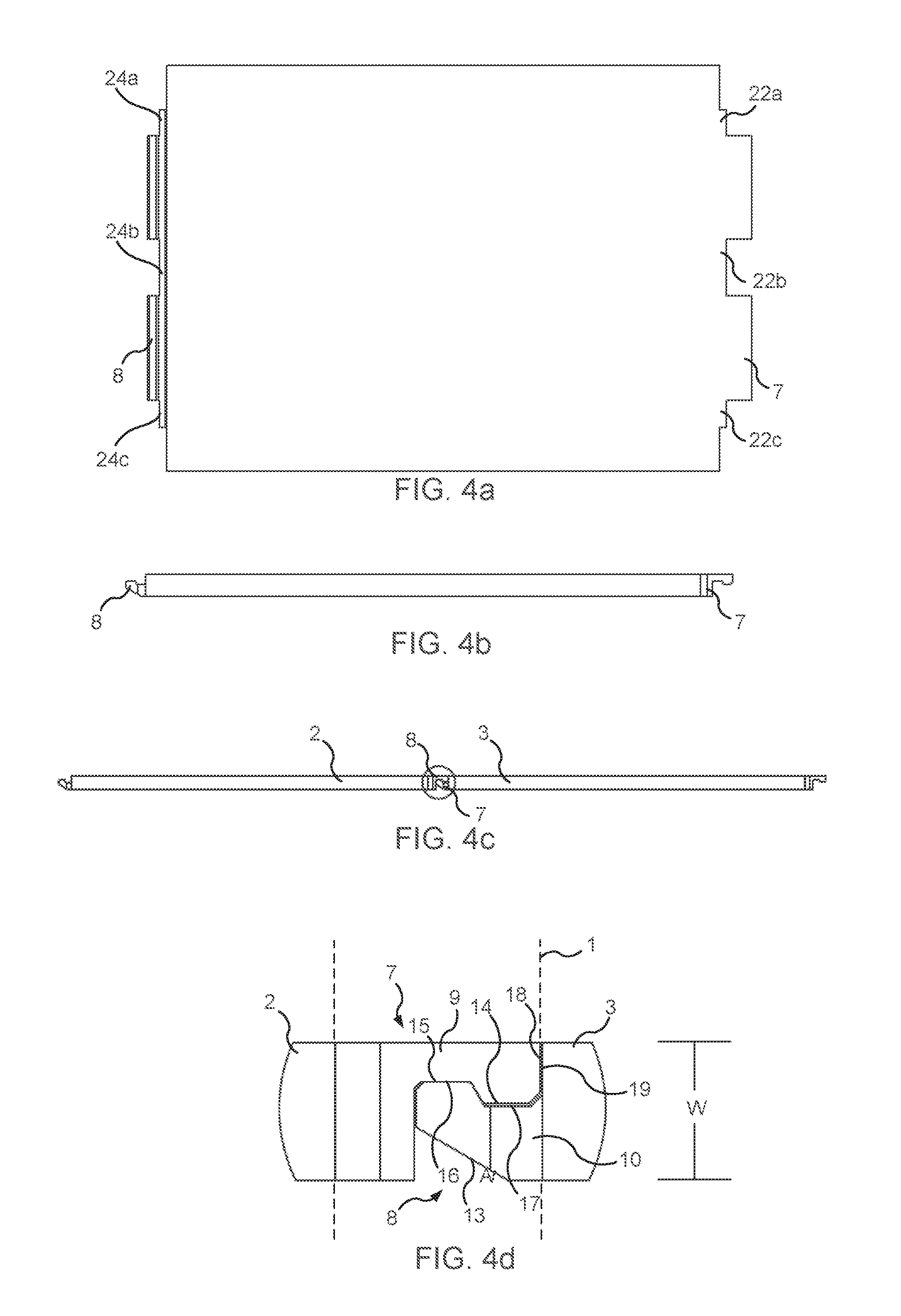
FIGS. 4a-4b is a top view and a side view, respectively, of a horizontal panel-shaped element;
FIG. 4c is a side view of horizontal panel-shaped elements with their respective locking members in an engaged state;
FIG. 4d is an enlarged side view of a section of FIG. 4c illustrating details of the locking members in the engaged state;
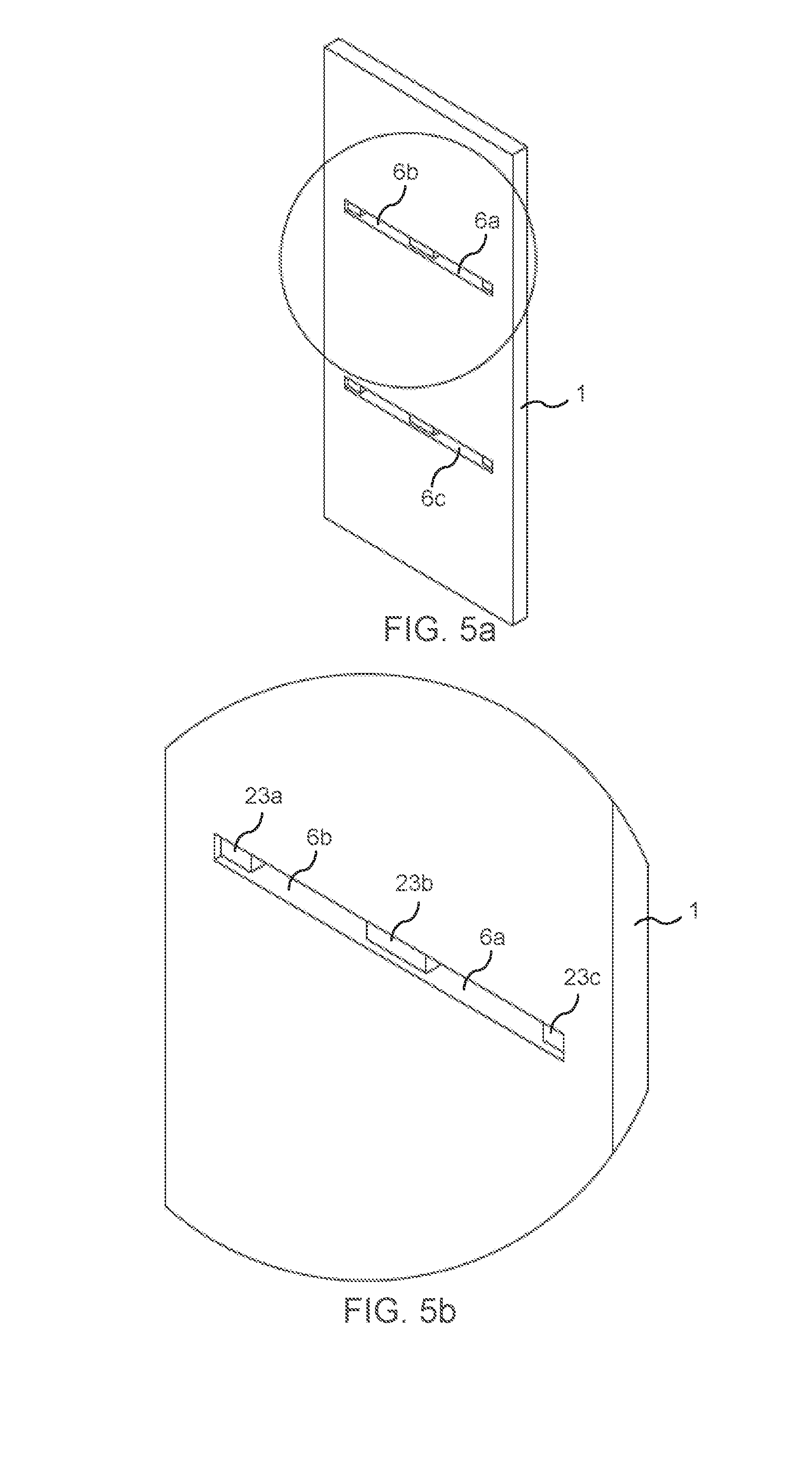
FIG. 5a is a perspective view of a vertical panel-shaped element with its recess for receiving the locking members;
FIG. 5b is an enlarged perspective view of a section of FIG. 5a illustrating details of the recess for receiving the locking members and a support recess;
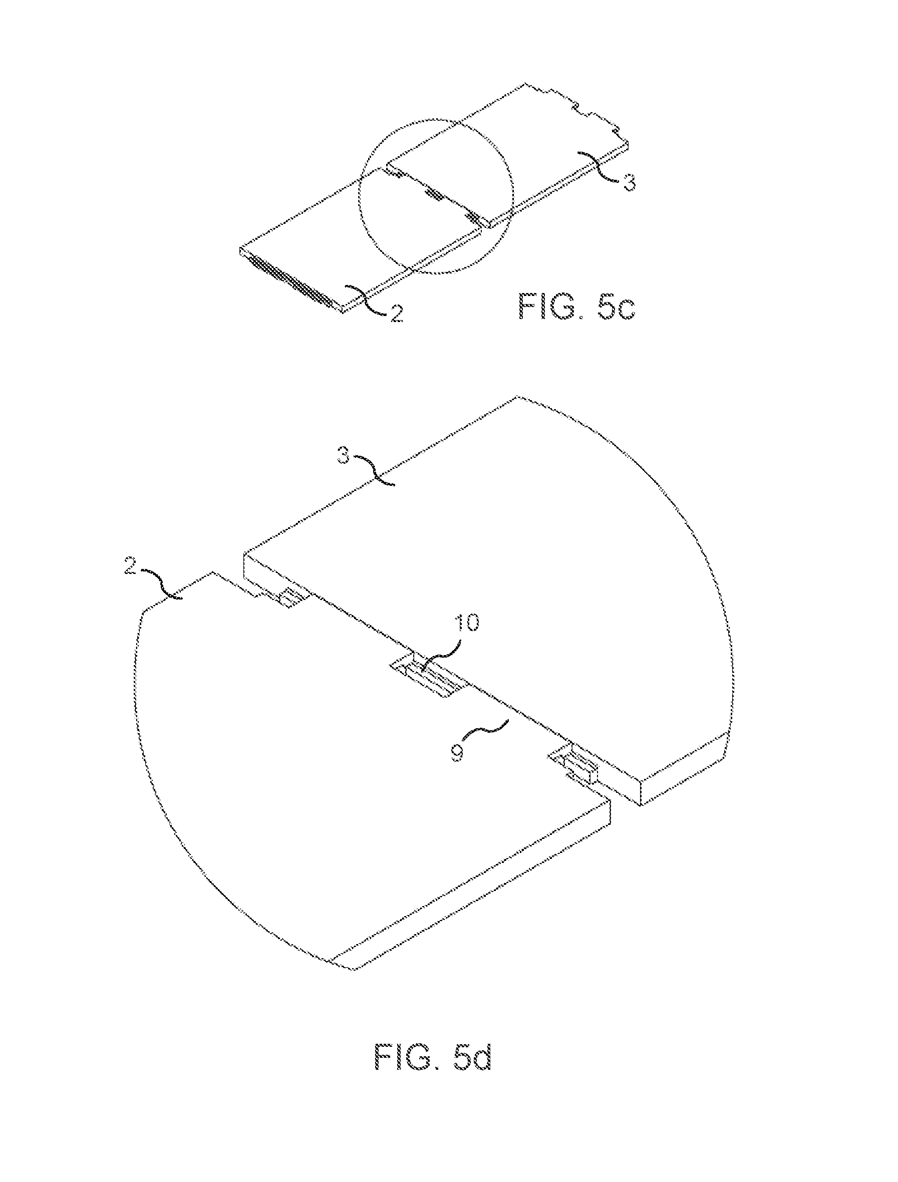
FIG. 5c is a perspective view of horizontal panel-shaped elements with their respective locking members in an engaged state;
FIG. 5d is an enlarged perspective view of a section of FIG. 5c illustrating details of the horizontal panel-shaped elements with their respective locking members in the engaged state;
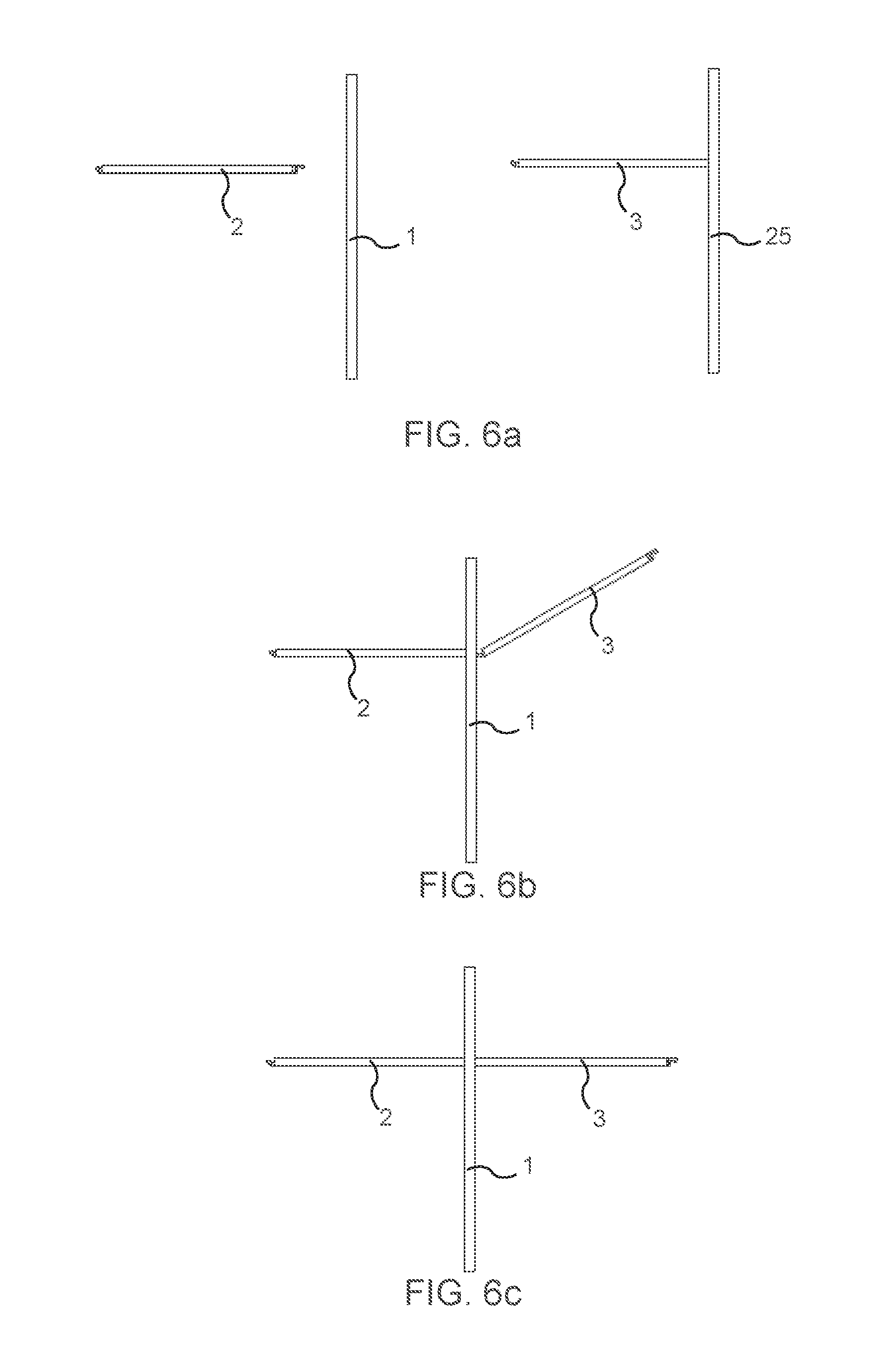
FIGS. 6a-6c are side views of the set of panel-shaped elements illustrating a method for assembling the panel-shaped elements to a composed element; and
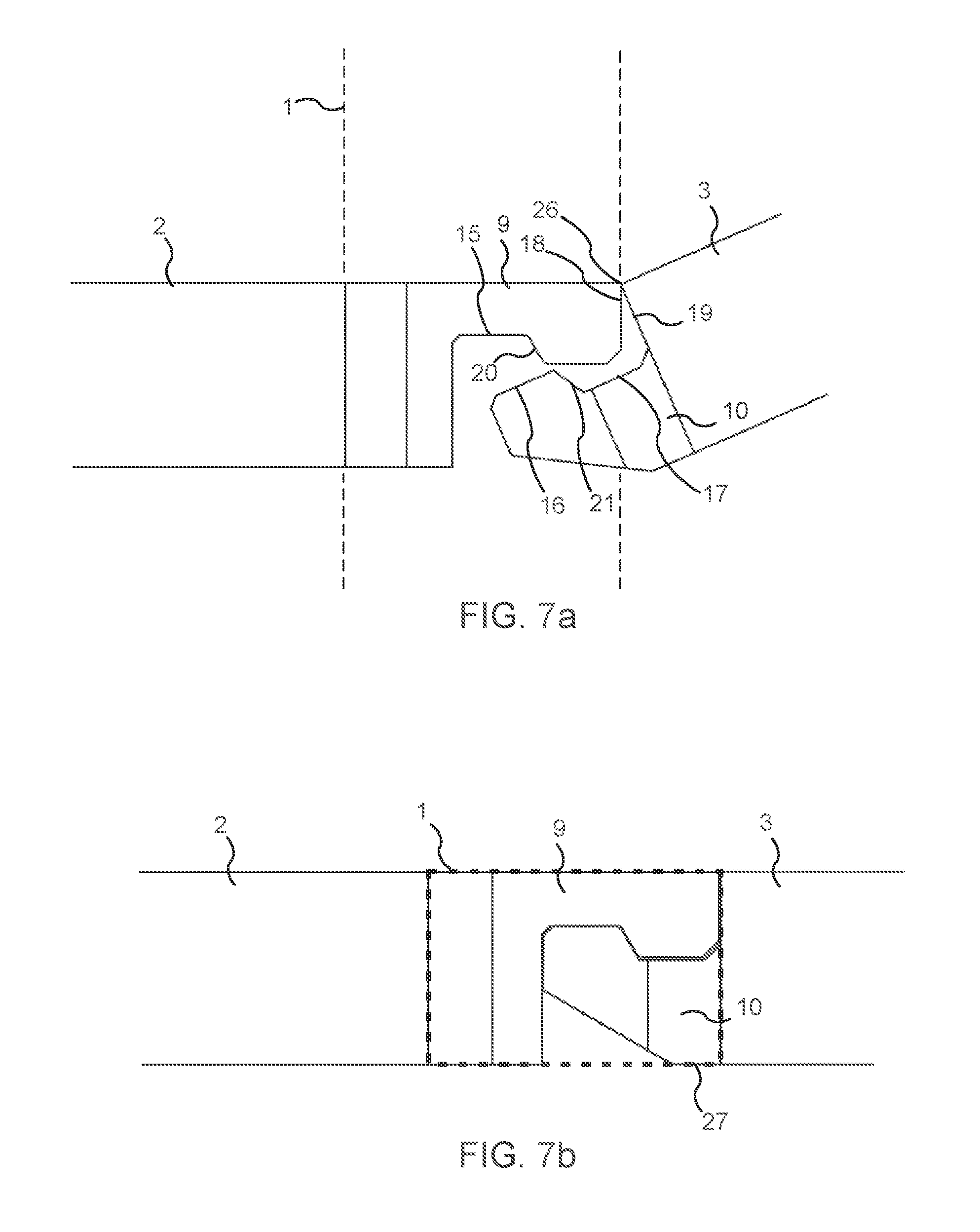
FIGS. 7a-7b are side views illustrating the engagement of the locking members of the respective horizontal panel-shaped elements during assembly from a disengaged position to an engaged position in the recess of a vertical panel-shaped element.
DESCRIPTION OF EMBODIMENTS
Specific embodiments of the invention will now be described with reference to the accompanying drawings. This invention may, however, be embodied in many different forms and should not be construed as limited to the embodiments set forth herein; rather, these embodiments are provided so that this disclosure will be thorough and complete, and will fully convey the scope of the invention to those skilled in the art. The terminology used in the detailed description of the embodiments illustrated in the accompanying drawings is not intended to be limiting of the invention. In the drawings, like numbers refer to like elements.
The present description of the current invention is given with reference to vertical and horizontal panel-shaped elements for a shelf as an example where the horizontal panel-shaped elements are arranged perpendicularly relative a vertical panel-shaped element. It should be born in mind, however, that the present invention is not limited strictly to a shelf, but can be easily adapted to other types of composed elements, wherein two panel-shaped elements can be arranged non-perpendicularly on each side of another panel-shaped element, to compose such elements as boxes, drawers, cabinets, tables, etc., or sections thereof.
FIG. 1 illustrates a set of panel-shaped elements including a first panel shaped element 1, a second panel shaped element 2, and a third panel-shaped element 3, which will be denoted first panel, second panel, and third panel, respectively, in the following. The first panel 1 may form a vertical element, such as a vertical wall or support of a shelf, for example an intermediate wall of a shelf or cabinet. The second and third panels 2, 3 may form horizontal elements, such as shelves arranged on each side of the first panel 1. In the following, reference will be made to a first panel 1 as a vertical panel of the set of panel-shaped elements. However, the set of panel-shaped elements may comprise any number of panels corresponding to the first panel 1, i.e., configured to support the second panel 2 and the third panel 3, as will be discussed below. Similarly, reference will be made to the second panel 2 and the third panel 3 in the following as horizontal panels of the set of panel-shaped elements. However, the set of panel-shaped elements may comprise any number of panels corresponding to the second panel 2 and the third panel 3. In FIG. 1, the panels 1-3 are assembled to a composed element.
FIG. 2 illustrates the first panel 1 and the second panel 2 in a disassembled state. Generally, the second panel 2 and the third panel 3 each comprises at least one member of a locking mechanism that may fit into the first panel 1 with a transition fit when the locking member of the other panel 2,3 is not present. However, when the three panels 1-3 are assembled, the locking members of the second and third panels 2,3 may be brought from an initial transition fit relative the first panel 1 to an interference or press fit when the locking members of the second and third panels 2,3 are fully engaged in the first panel 1, as is illustrated in FIG. 1 and will be further described below with regard to FIGS. 7a-7b.
As can be seen in FIGS. 1-2, the first panel 1 comprises a first side 4 and a second side 5 opposite the first side 4. The first side 4 and the second side 5 may be parallel, and extend in a longitudinal direction of the first panel 1. At least one recess 6a, 6b at least partially extends through the first panel 1 from the first side 4 to the second side 5. "At least partially extends through" meaning that at least a portion of the recess 6a, 6b extends all the way through the first panel 1 from the first side 4 to the second side 5. One or several portions may only extend partially through the first panel 1, also from each of the first side 4 and the second side 5 such that at least one wall is formed in the recesses from each of the first side 4 and the second side 5. Such a wall may be provided between and on the transverse side(s) of recesses that extends completely through the first panel 1. This provides for improved stability of the composed product and rigidity of the first panel 1.
FIG. 3 illustrates the set of panels-shaped elements composed within a shelf, wherein the second panel 2 and the third panel 3 are connected to vertical end or side supports. The first panel 1 forms an intermediate support. The set of panels according to embodiments described herein can be extended with any number of vertical panels, such that the length or number of shelf units is extended as desired. Vertical and horizontal panels can simply be added to the set of panel shaped elements. Hence, embodiments of the invention are very flexible. A vertical side support may be connected to the second panel 2 or the third panel 3 using the locking system of WO2012/154113, such as described and illustrated in FIGS. 1a-1c, and which is incorporated herein by reference for all purposes. Additionally or alternatively, the locking system of the present invention may be used to connect the second panel 2 or the third panel 3 to the vertical side support. The vertical side support may comprise one or several recesses 6a-6c as described above. In order to lock the second or third panel 2, 3, a plug may comprise the first profiled portion 9 or the second profiled portion 10 at one end. The other end may lie flush with a side surface of the vertical side support when the plug is inserted into the recess 6a-6c. The plug may thus be a panel-shaped element within the meaning of the invention, albeit rather short, which substantially does not extend beyond the recess 6a-6b. Depending on whether the plug should lock the second panel 2 or the third panel 3, it is inserted before or after the profiled portion 8, 9 in the same way as described with regard to embodiments herein.
FIGS. 4a-4b illustrate a single panel with a first locking member 7 at one end of the panel and a second locking member 8 at another end of the panel. The first locking member 7 is designed for engagement with the second locking member 8 when arranged on another panel, and vice versa. Hence, a single panel may be used as either the second panel 2 or the third panel 3. In other embodiments, the second panel 2 only comprises the first locking member 7, and the third panel 3 only comprises the second locking member 8. Such panels may be used to lock to a vertical end support. In the following, reference will be made to the second panel 2 having the first locking member 7, and the third panel 3 having the second locking member 8. However, complementary locking members may be provided at the other end even if that is not described. Thus, the locking members 7,8 will be described below as forming part of separate panels, but may be provided at opposing ends of one and the same panel.
As can be seen in FIGS. 4c-4d, the first locking member 7 of the second panel 2 comprises a first profiled portion 9 at one of its ends. The first profiled portion 9 is configured to extend into the recess 6a-6b from the first side 4 of the first panel 1. The second locking member 8 of the third panel 3 comprises a second profiled portion 10 at one of its ends. The second profiled portion 10 is configured to extend into the recess 6a-6b from the second side 5 of the first panel 1. The second profiled portion 10 is configured for locking engagement with the first profiled portion 9, such as is illustrated in FIGS. 4c-4d. Hence, when the first profiled portion 9 and the second profiled portion 10 are arranged in the recess 6a-6b, a joint is formed such that the second panel 2 and the third panel 3 cannot be disconnected in the longitudinal axis of these panels 2,3.
The total width W of the first profiled portion 9 and the second profiled portion 10 transverse to the longitudinal direction of the second panel 2 and the third panel 3, respectively, may substantially correspond to a width of the recess 6a, 6b measured parallel with the longitudinal axis of the first panel 1. Hence, when the first profiled portion 9 is arranged in engagement with the second profiled portion 10, the second panel 2 and the third panel 3 may be locked in the recess 6a, 6b at least in a direction perpendicular to the longitudinal axes of the second panel 2 and the third panel 3.
FIG. 4d illustrates an embodiment wherein each of the first profiled portion 9 and the second profiled portion 10 forms a tongue. Each tongue may comprise the locking member 7, 8. The first profiled portion 9 and the second profiled portion 10 are sized and configured for mating engagement with the other of the first profiled portion 9 and the second profiled portion 10, such as illustrated in FIG. 4d. Each locking member 7, 8 has in this embodiment a non-flat shape in a longitudinal direction of the second panel 2 and the third panel 3, respectively. The locking member 9 of the second panel 2 and the locking member 10 of the third panel 3 have complementary non-flat shapes and face in opposite directions when received in the recess 6a, 6b. Hence, the locking members 9, 10 engage within the recess 6a, 6b in a locking engagement, at least in a longitudinal direction of the second panel 2 and the third panel 3. Also, the total width W of the locking members 9, 10 may substantially correspond to the width of the recess 6a, 6b, such as described above, wherein the locking members 9, 10 are locked also in a direction perpendicular to the longitudinal direction of the second panel 2 and the third panel 3.
In other embodiments, the locking members have other shapes, such as one being a protrusion and the other being a recess that fit a snap fit engagement.
In the embodiment of FIG. 4d, a lower surface 13 of second profiled portion 10 is angled at a non-zero angle A relative a longitudinal direction of the third panel-shaped element 3. For example, the angle A may be between about 20 and about 70 degrees, for example, between about 35 and about 55 degrees, for example about 45 degrees. This provides for angled engagement of the second profiled portion 10 with the first profiled portion 9 when the set of panel-shaped elements are assembled. Assembly of the panels using angled motion will be further described with regard to FIGS. 7a-7b.
The first profiled portion 9 comprises a tip portion 14, and a base portion 15, which is located closer to the centre of the second panel 2, in the longitudinal direction of the second panel 2, than the tip portion 14 of the first profiled portion 9. Said differently, the base portion 15 is located closer to the first side 4 of the first panel 1 than the tip portion 14 when assembled with the first panel 1. Similarly, the second profiled portion 10 comprises a tip portion 16, and a base portion 17, which is located closer to the centre of the third panel 3, in the longitudinal direction of the third panel 3, than the tip portion 16 of the second profiled portion 10. Said differently, the base portion 17 is located closer to the second side 5 of the first panel 1 than the tip portion 16 when assembled with the first panel 1. The tip portion 16 of the second profiled portion 10 is configured to abut the base portion 15 of the first profiled portion 9 when the set of panel-shaped elements are assembled.
The tip portion 14,16 of each profiled portion 9,10 may form a protrusion, and the base portion 15,17 may for a recess as seen in a cross-section taken parallel to the interface between the first profiled portion 9 and the second profiled portion 10. This provides a locking arrangement.
Furthermore, the base portion 15 of the first profiled portion 9 and the tip portion 16 of the second profiled portion 10 may be sized and configured to be slightly larger than the recess 6a, 6b in a direction perpendicular to the longitudinal axis of the second panel 2 and the third panel 3, respectively. This means that the tip portion 16 of the second profiled portion 10 will press against the base portion 15 of the first profiled portion 9 to form a press-fit locking arrangement on the recess 6a, 6b. Hence, a stable locking arrangement is provided for. Hence, the total width W that substantially corresponds to a width of the recess 6a, 6b, as mentioned above, includes embodiments where the total width W and the width of the recess are dimensioned to provide a press-fit while not damaging the first panel 1 by providing a too high pressure. The dimensioning is dependent on, e.g., relative dimensions, thickness of panels, materials of panels, etc.
The angled lower surface 13 may extend from an outer end of the tip portion 16 towards the base portion 17 of the second profiled portion 10. A section of the base portion 17 may face and be parallel with the recess 6a, 6b, which provides for supporting the section of the base portion 17 within the recess 6a, 6b, which still provides for angled motion of the third panel 3 for assembly of the set of panel-shaped elements. An entire surface of the first profiled portion 9 that faces the recess 6a, 6b may be substantially parallel or parallel with the recess 6a, 6b. This provides for an even pressure against an opposing surface of the recess 6a, 6b, such that a stable press-fit connection may be formed without the risk of damaging the first panel 1.
In some embodiments, such as illustrated in FIGS. 4d and 7a-7b, the tip portion 14 of the first profiled portion 9 comprises an end surface 18 facing in the longitudinal direction of the second panel 2. The third panel 3 comprises an end surface 19 at the base 17 of the second profiled portion 10. The end surface 18 of the tip portion 14 of the first profiled portion 9 is configured to abut the end surface 19 of the third panel 3 at the base 17 of the second profiled portion 10. As is illustrated in FIG. 7a, a first surface 20 between the tip portion 14 and the base portion 15 of the first profiled portion 9 may engage or abut a second surface 21 between the tip portion 16 and the base portion 17 of the second profiled portion 10 when the third panel 3 is angled from a first position, illustrated in FIG. 7a, to a second position, illustrated in FIG. 7b. Hence, the second panel 2 and the third panel 3 will have a relatively fixed relationship in the first position due to the abutment of the end surface 18 of the tip portion 14 of the first profiled portion 9 with the end surface 19 of the second panel 3. The surfaces 20, 21 between the respective base portions 15, 17 and tip portions 14, 16 are non-parallel with the longitudinal axes of the second panel 2 and the third panel 3. The engagement of the first surfaces 20 and the second surface 21 between the respective base portions 15, 17 and tip portions 14, 16 during angling of the third panel 3 to the second position will force the second panel 2 towards the third panel 3, and vice versa. Hence, a stable locking arrangement is provided for. The fit between of the panels will also be tight, since the panels may be forced towards each other.
In some embodiments, such as illustrated in FIGS. 4a and 5a-b, the first profiled portion 9 has at least one portion 22a, 22b, 22c configured to extend into at least one support recess 23a, 23b, 23c of the first panel 1. The at least one portion 22a-22c of the first profiled portion 9 has a width substantially corresponding to the width of the support recess 23a-23c. The at least one portion 22a-22c and the support recess 23a, 23b, 23c may be sized and configured for an interference or press fit. Hence, the first profiled portion 9 may be supported within the recess 6a, 6b with a substantially fixed relationship within the recess 6a, 6b. This provide for a stable locking arrangement. It also makes it easier to assemble the panels 1-3, since the first panel 1 and second panel 2 can first be assembled, and then the third panel 3 is used to lock all three panels together to form a stable composed product.
As is illustrated in FIG. 5b, the support recess 23a-23c may extend only partially through the first panel 1. Also, it may be located on at least one transverse side of the recess 6a, 6b extending through the first panel 1. A support recess 23b located between a first recess 6a through the first panel 1 and another recess 6c through the first panel 1 for a single horizontal panel may form a wall between the first recess 6a and the other recess 6c. This provides for a stable locking arrangement. Separate tongues of the first profiled portion 9 of the single horizontal panel may fit into each of the first recess 6a and the other recess 6c, such as is illustrated in FIG. 2.
In FIGS. 5c-5d, the first profiled portion 9 is illustrated in locking engagement with the second profiled portion 10. At least one portion 24a, 24b, 24c, of the second profiled portion 10 may be configured to extend into a support recess extending from the second side 5 of the first panel, corresponding to support recess 23a-23c. However, the height of the support recess from the second side 5 may be lower than the height of the support recess from the first side 4. This provides for easy production of the base portion 17 of the second profiled portion 10, which can be provided in a single action together with the portion 24a-24c that extends into the support recess and to be used to form a stable locking arrangement. Hence, the shape of the base portion 17 and the shape of the support recess extending from the second side 5 of the first panel may be the same.
In the embodiments of FIGS. 1-4d, the profiled portions 9, 10 are illustrated with a first and a second tongue of the first and the second profiled portion 9, 10, respectively. Other embodiments comprise a single tongue, or more than two tongues, such as depending on the width of the panels 1-3, and/or the desired stability of a composed product.
FIGS. 6a-6c, and 7a-7b illustrate a method for assembling a set of panel-shaped elements to a composed product (FIG. 6c). First, the first panel 1, the second panel 2, and the third panel 3, such as described in the above embodiments, are provided. In FIG. 6a, the third panel 3 is attached to a vertical support 25 before being assembled together with the first panel 1 and the second panel 2. In other embodiments, such as illustrated in FIG. 6b, the third panel 3 is not attached to any other panel before being assembled with the first panel 1 and the second panel 2.
As is illustrated in FIGS. 6a and 7a, the first profiled portion 9 at one end of the second panel 2 is inserted into the recess 6a, 6b from the first side 4 of the first panel 1 such that the first profiled portion 9 extends into the recess 6a, 6b. The position of the first profiled portion 9 relative the first panel 1 is illustrated in FIG. 7a. Then, the second profiled portion 10 at one end of the third panel 3 is inserted into the recess 6a, 6b from the second side 5 of the first panel 1 such that the second profiled portion 10 extends into the recess 6a, 6b, such as is illustrated in FIG. 7a. The second profiled portion 10 is then moved into locking engagement with the first profiled portion 9. This provides for a stable locking of the panels 1-3 into a composed product, such as illustrated in FIG. 6c. It is also simple to disassemble the panels 1-3 by reversing the movement.
In some embodiments, the second profiled portion 10, and the third panel 3, may be inserted at a tilted angle relative the first panel 1 and the second panel 2 compared to its final position where it engages the first profiled portion 9, such as is illustrated in FIGS. 6b and 7a. Hence, the third panel 3 is inserted into the recess 6a, 6b at a non-parallel angle relative the second panel 2. Also it may be inserted at a non-perpendicular angle relative the first panel 1, if the final position between the longitudinal axes of the first panel 1 and the third panel 3 is perpendicular.
As is illustrated in FIGS. 7a-7b, in the first, unlocked, position for assembling the set of panel-shaped elements a top end 26 of the end surface 18 of the tip portion 14 of the first profiled portion 9 abuts the end surface 19 of the third panel 3. It may abut at the base portion 17 of the second profiled portion 10, such as above the base portion. In the first position, the base portion 15 of the first profiled portion 9 is separated from the tip portion 16 of the second profiled portion 10. Thus, third panel 3 is in this embodiment configured for rotational or angled motion from the first position to the second, locked or engaged, position. The third panel 3 may be rotated around the top end 26.
In the second position, the end surface 18 of the tip portion 14 of the first profiled portion 9 abuts the end surface 19 of the third panel 3, such as is illustrated in FIG. 7b. The base portion 15 of the first profiled portion 9 abuts the tip portion 16 of the second profiled portion 10. The base portion 17 of the second profiled portion 10 abuts the recess 6, 6b at a surface 27 facing in the opposite direction to the interface between the first locking member 7 and the second locking member 8. The end surface 19 of the third panel 3 at the base portion 17 of the second profiled portion 10, may be located outside of the recess 6a, 6b, or be substantially aligned with the second side 5 of the first panel 1. Ultimately, the third panel 3 will tend to pivot around the surface 27 of the base 17 of the second profiled portion 10 as the tip portion 16 is angled towards the base portion 15 of the first profiled portion 9. Hence, the tip portion 16 of the second profiled portion 10 will press the base portion 15 of the first profiled portion 9 in the longitudinal direction of the first panel 1. Hence, a press-fit locking arrangement is provided. Also, a small gap may be provided between the tip portion 14 of the first profiled portion 9 and the base portion 17 of the second profiled portion 10.
Hence, the second profiled portion 10 may be moved into locking engagement with the first profiled portion 9 by angling motion of the third panel 3 while the end surface 18 of the tip portion 18 of the first profiled portion 9 abuts the end surface 19 of the third panel-shaped element 3. The second profiled portion 10 may be moved until its tip portion 16 abuts the base portion 15 of the first profiled portion 9. The first profiled portion 9 may be displaced in a direction substantially perpendicular to the first panel 1 and towards the third panel 3. Also, the third panel 3 may be displaced in a direction substantially perpendicular to the first panel land towards the second panel 2 while the third panel 3 is angled from an unlocked position, such as illustrated in FIG. 7a, into the engagement with the first profiled portion 9, such as illustrated in FIG. 7b. As described above, a portion of the first profiled portion 9 having a width substantially corresponding to a width of the recess 6a, 6b may be inserted into the recess. Hence, the angling motion of the third panel transforms an initial slip fit between the first panel 1 and the second panel 2 into a press fit between the first panel 1, the second panel 2, and the third panel 3.
Furthermore, the tip portion 14, 16 of each profiled portion 9, 10 may form a protrusion, and the base portion 15, 17 may form a recess as seen in a cross-section taken parallel to the interface between the first profiled portion 9 and the second profiled portion 10. Hence, the shape of the profiled portions 9, 10 prevents the second panel 2 and third panel 3 to be separated in their longitudinal direction. The same elements may at the same time be configured to form a press-fit with the first panel 1 within the recess 6a, 6b.
When the word "about" is used in this specification in connection with a numerical value, it is intended that the associated numerical value include a tolerance of .+-.10% around the stated numerical value.
It should also be appreciated that features disclosed in the foregoing description, and/or in the foregoing drawings and/or following claims both separately and in any combination thereof, be material for realizing the present invention in diverse forms thereof. When used in the following claims, the terms "comprise", "include", "have" and their conjugates mean, "including but not limited to".
The present invention has been described above with reference to specific embodiments. However, other embodiments than the above described are equally possible within the scope of the invention. Different method steps than those described above may be provided within the scope of the invention. The different features and steps of the invention may be combined in other combinations than those described. The scope of the invention is only limited by the appended patent claims.
Embodiments
1. A set of panel-shaped elements for assembly to a composed element, comprising
a first panel-shaped element, a second panel-shaped element, and a third panel-shaped element, wherein
the first panel-shaped element comprises a first side and an opposite second side extending in a longitudinal direction of the first panel-shaped element, and at least one recess at least partially extending through the first panel-shaped element from the first side to the second side;
the second panel-shaped element comprises a first profiled portion at one of its ends, the first profiled portion being configured to extend into the recess from the first side of the first panel-shaped element; and
the third panel-shaped element comprises a second profiled portion at one of its ends, the second profiled portion being configured to extend into the recess from the second side of the first panel-shaped element and for locking engagement with the first profiled portion.
2. The set of panel-shaped elements according to embodiment 1, wherein
each of the first profiled portion and the second profiled portion forms a tongue with a locking member sized and configured for mating engagement with the other of the first and the second profiled portion, wherein
each locking member has a non-flat shape in a longitudinal direction of the second panel-shaped element and the third panel-shaped element, respectively, and
the locking member of the second panel-shaped element and the locking member of the third panel-shaped element have complementary non-flat shapes and face in opposite directions when received in the recess.
3. The set of panel-shaped elements according to any of the previous embodiments, wherein a lower surface of second profiled portion is angled at a non-zero angle relative a longitudinal direction of the third panel-shaped element for angled engagement of the second profiled portion with the first profiled portion when the set of panel-shaped elements are assembled.
4. The set of panel-shaped elements according to any of the previous embodiments, wherein
the first profiled portion comprises a tip portion, and a base portion, which is located closer to the centre of the second panel-shaped element, in the longitudinal direction of the second panel-shaped element, than the tip portion of the first profiled portion,
the second profiled portion comprises a tip portion, and a base portion, which is located closer to the centre of the third panel-shaped element, in the longitudinal direction of the third panel-shaped element, than the tip portion of the second profiled portion; and
the tip portion of the second profiled portion is configured to abut the base portion of the first profiled portion when the set of panel-shaped elements are assembled.
5. The set of panel-shaped elements according to embodiment 4, wherein the tip portion of the first profiled portion comprises an end surface facing in the longitudinal direction of the second panel, and the third panel comprises an end surface at the base of the second profiled portion, wherein the end surface of the tip portion of the first profiled portion is configured to abut the end surface of the third panel at the base of the second profiled portion.
6. The set of panel-shaped elements according to embodiment 5, wherein
in a first position for assembling the set of panel-shaped elements a top end of the end surface of the tip portion of the first profiled portion abuts the end surface of the third panel at the base portion of the second profiled portion, and the base portion of the first profiled portion is separated from the tip portion of the second profiled portion; and
the third panel is configured for angled motion from the first position to a second position, wherein the end surface of the tip portion of the first profiled portion abuts the end surface of the third panel at the base of the second profiled portion, and the base portion of the first profiled portion abuts the tip portion of the second profiled portion.
7. The set of panel-shaped elements according to embodiment 6, wherein a first surface between the tip portion and the base portion of the first profiled portion is configured to abut a second surface between the tip portion and the base portion of the second profiled portion when the third panel-shaped element is angled from the first position to the second position.
8. The set of panel-shaped elements according to any of the previous embodiments, wherein a total width of the first profiled portion and the second profiled portion transverse to the longitudinal direction of the second panel-shaped element and the third panel-shaped element, respectively, substantially corresponds to a width of the recess in the longitudinal direction of the first panel-shaped element.
9. The set of panel-shaped elements according to any of the previous embodiments, wherein the first profiled portion has at least one portion configured to extend into at least one support recess of the first panel-shaped element and having a width substantially corresponding to the width of the support recess.
10. The set of panel-shaped elements according to embodiment 9, wherein the support recess extends only partially through the first panel-shaped element, and is located on at least one transverse side of said recess extending through the first panel-shaped element.
11. A method for assembling a set of panel-shaped elements, comprising
providing a first panel-shaped element having a first side and an opposite second side extending in a longitudinal direction of the first panel-shaped element, and at least one recess at least partially extending through the first panel-shaped element from the first side to the second side;
inserting a first profiled portion at one end of a second panel-shaped element into the recess from the first side of the first panel-shaped element such that the first profiled portion extends into the recess;
inserting a second profiled portion at one end of a third panel-shaped element into the recess from the second side of the first panel-shaped element such that the second profiled portion extends into the recess; and
moving the second profiled portion into locking engagement with the first profiled portion.
12. The method according to embodiment 11, comprising moving the second profiled portion into locking engagement with the first profiled portion by angling motion of the third panel while an end surface of a tip portion of the first profiled portion abuts an end surface of the third panel-shaped element.
13. The method according to embodiment 12, comprising moving the second profiled portion until a tip portion of the second profiled portion abuts a base portion of the first profiled portion.
14. The method according to any of embodiments 11-13, comprising moving the third panel-shaped element by angled motion from an unlocked position into said locking engagement with the first profiled portion while a first surface of the first profiled portion abuts a second surface of the second profiled portion such that the first profiled portion is displaced in a direction substantially perpendicular to the first panel-shaped element and towards the third panel-shaped element, and such that the third panel-shaped element is displaced in a direction substantially perpendicular to the first panel-shaped element and towards the second panel-shaped element.
15. The method according to any of embodiments 11-14, wherein inserting the first profiled portion into the recess comprises inserting into said recess a portion of the first profiled portion having a width substantially corresponding to a width of the recess.
* * * * *
D00000
D00001
D00002
D00003
D00004
D00005
D00006
XML
uspto.report is an independent third-party trademark research tool that is not affiliated, endorsed, or sponsored by the United States Patent and Trademark Office (USPTO) or any other governmental organization. The information provided by uspto.report is based on publicly available data at the time of writing and is intended for informational purposes only.
While we strive to provide accurate and up-to-date information, we do not guarantee the accuracy, completeness, reliability, or suitability of the information displayed on this site. The use of this site is at your own risk. Any reliance you place on such information is therefore strictly at your own risk.
All official trademark data, including owner information, should be verified by visiting the official USPTO website at www.uspto.gov. This site is not intended to replace professional legal advice and should not be used as a substitute for consulting with a legal professional who is knowledgeable about trademark law.