Panels For An Assembled Product
DERELOV; Peter
U.S. patent application number 15/956949 was filed with the patent office on 2019-10-24 for panels for an assembled product. This patent application is currently assigned to Valinge Innovation AB. The applicant listed for this patent is Valinge Innovation AB. Invention is credited to Peter DERELOV.
| Application Number | 20190323535 15/956949 |
| Document ID | / |
| Family ID | 68237537 |
| Filed Date | 2019-10-24 |


View All Diagrams
| United States Patent Application | 20190323535 |
| Kind Code | A1 |
| DERELOV; Peter | October 24, 2019 |
PANELS FOR AN ASSEMBLED PRODUCT
Abstract
A set of panels for an assembled product is disclosed. A first panel and a second panel may be assembled with a third panel. An end surface of the third panel includes a first tongue and a second tongue. The first panel and the second panel are configured to be arranged with their respective end surfaces facing each other. A first tongue of the third panel is configured to be arranged in an edge groove of the first panel and a second tongue of the third panel is configured to be received in an edge groove of the second panel to join the panels at least in a first direction. The first panel and the second panel may be of a first panel type, and the third panel may be of a second panel type. A corner element may be connected to a side panel of an assembled product.
| Inventors: | DERELOV; Peter; (Helsingborg, SE) | ||||||||||
| Applicant: |
|
||||||||||
|---|---|---|---|---|---|---|---|---|---|---|---|
| Assignee: | Valinge Innovation AB Viken SE |
||||||||||
| Family ID: | 68237537 | ||||||||||
| Appl. No.: | 15/956949 | ||||||||||
| Filed: | April 19, 2018 |
| Current U.S. Class: | 1/1 |
| Current CPC Class: | F16B 12/20 20130101; A47B 61/003 20130101; A47B 47/042 20130101; A47B 88/941 20170101; F16B 12/26 20130101; A47B 2230/0081 20130101; F16B 12/46 20130101; A47B 96/201 20130101; A47B 47/0075 20130101; A47B 96/04 20130101; A47B 2230/0096 20130101 |
| International Class: | F16B 12/46 20060101 F16B012/46; A47B 47/00 20060101 A47B047/00; F16B 12/20 20060101 F16B012/20 |
Claims
1. A set of panels for an assembled product, comprising: a first panel; a second panel; and a third panel; wherein each of the first panel and the second panel comprises a first surface, a second surface, which is substantially parallel with the first surface, an edge groove, and an end surface; the third panel comprises a first surface and a second surface, which is substantially parallel with the first surface, and an end surface extending at least partially between the first surface and the second surface of the third panel; and the end surface of the third panel comprises a first tongue and a second tongue; wherein: the first panel and the second panel are configured to be arranged with their respective end surfaces facing each other, and with their respective edge grooves in parallel; and the first tongue of the third panel is configured to be arranged in the edge groove of the first panel to join the first panel and the third panel, and the second tongue of the third panel is configured to be received in the edge groove of the second panel to join the second panel to the third panel, whereby the first panel, the second panel, and the third panel are joined at least in a first direction.
2. The set of panels according to claim 1, wherein the first panel and the second panel are configured to be arranged with their respective end surfaces in abutment.
3. The set of panels according to claim 1, wherein each of the first panel and the second panel further comprises an insertion groove for a flexible tongue, the insertion groove being arranged between the end surface and the first surface of the respective first panel and the second panel, and wherein the third panel comprises a first tongue groove extending from the first surface thereof and a second tongue groove extending from the second surface thereof, wherein each tongue groove is arranged to receive a portion of the flexible tongue when the first panel, the second panel, and the third panel are joined.
4. The set of panels according to claim 1, wherein at least one of the first panel and the second panel comprises a flexible tongue formed integral with and in the same material as a material of said at least one of the first panel and the second panel.
5. The set of panels according to claim 3, wherein each insertion groove is inclined towards the respective first surface of the first panel and the second panel, and wherein the respective first tongue and second tongue of the third panel are arranged to push each flexible tongue into the insertion groove when the third panel is joined to the first panel and the second panel.
6. The set of panels according to claim 1, wherein each of the first panel and the second panel comprises a tongue formed by the end surface and the edge groove thereof, and wherein the third panel comprises at least one end groove between the first tongue and the second tongue thereof.
7. The set of panels according to claim 6, wherein the end groove is at least partially formed by a lateral surface of the first tongue of the third panel and a lateral surface of the second tongue of the third panel, and a surface extending between said lateral surfaces.
8. The set of panels according to claim 6, wherein the third panel comprises a single end groove between the first tongue and the second tongue of the third panel, and wherein the tongue of the first panel and the tongue of the second panel are tongue portions of a multi-part tongue, said multi-part tongue being formed when the first panel and the second panel are arranged with their respective end surfaces in abutment and with their respective edge grooves arranged in parallel, and said multi-part tongue being configured to be arranged in said single end groove of the third panel.
9. The set of panels according to claim 6 wherein: an end surface of the tongue of the first panel and an end surface of the tongue of the second panel are configured to abut the end groove of the third panel, and an end surface of the first tongue of the third panel is configured to be spaced apart from a bottom wall of the edge groove of the first panel and an end surface of the second tongue of the third panel is configured to be spaced apart from a bottom wall of the edge groove of the second panel, when the panels are assembled; or an end surface of the tongue of the first panel and an end surface of the tongue of the second panel are configured to be spaced apart from the end groove of the third panel, and an end surface of the first tongue of the third panel is configured to abut a bottom wall of the edge groove of the first panel and an end surface of the second tongue of the third panel is configured to abut a bottom wall of the edge groove of the second panel, when the panels are assembled.
10. The set of panels according to claim 1, wherein each of the first panel and the second panel comprises at least one of a front edge and a back edge, which extends between the first surface and the second surface of the respective first panel and the second panel, and wherein one adjacent end of the edge groove of the respective first panel and the second panel is spaced apart from said at least one of a front edge and a back edge.
11. A set of panels for forming a multi-module frame, wherein the set of panels comprises: a plurality of panels of a first panel type configured to be arranged in a first direction; a plurality of panels of a second panel type configured to be arranged in a second direction, which is substantially perpendicular to the first direction; and at least one corner element; wherein: the panels of the first panel type comprise locking elements extending along edge portions of opposite ends of each panel; the panels of the second panel type comprise a first locking element and a second locking element arranged at the same end of the panel of the second panel type; the first locking element and the second locking element of the panels of the second panel type being directly lockable to either of the locking elements of the panels of the first panel type; and the corner element is attachable to at least one of the first locking element and the second locking element at one end of the panel of the second panel type when said panel of the second panel type is directly locked to a single panel of the first panel type.
12. The set of panels according to claim 11, wherein the corner element comprises at least one of a support element configured to be supported by at least one of the panel of the first panel type and the panel of the second panel type, and a locking element locking against a tongue groove of the panel of the second panel type.
13. The set of panels according to claim 11, wherein the set comprises panels for forming at least two modules of a multi-modular frame, including: four panels of the first panel type; three panels of the second panel type of; and at least one corner element, wherein each end of a first panel of the second panel type is lockable to two panels of the first panel type, and each end of a second panel and a third panel of the second panel type is lockable to a single panel of the first panel type; and one corner element is attached to at least one of the end of the second panel and the third panel of the second panel type.
14. The set of panels according to claim 1, wherein a first panel is of the first panel type; a second panel is of the first panel type; and a third panel is of the second panel type; wherein: each of the first panel and the second panel comprises a first surface, a second surface, which is substantially parallel with the first surface, an edge groove, and an end surface; the third panel comprises a first surface and a second surface, which is substantially parallel with the first surface, and an end surface extending at least partially between the first surface and the second surface of the third panel; the end surface of the third panel comprises a first tongue and a second tongue; the first panel and the second panel are configured to be arranged with their respective end surfaces facing each other, and with their respective edge grooves in parallel; and the first tongue of the third panel is configured to be arranged in the edge groove of the first panel to join the first panel and the third panel, and the second tongue of the third panel is configured to be received in the edge groove of the second panel to join the second panel to the third panel, whereby the first panel, the second panel, and the third panel are joined at least in a first direction.
15. The set of panels according to claim 14, wherein the first panel and the second panel are configured to be arranged with their respective end surfaces in abutment.
16. The set of panels according to claim 14, wherein each of the first panel and the second panel further comprises an insertion groove for a flexible tongue, the insertion groove being arranged between the end surface and the first surface of the respective first panel and the second panel, and wherein the third panel comprises a first tongue groove extending from the first surface thereof and a second tongue groove extending from the second surface thereof, wherein each tongue groove is arranged to receive a portion of the flexible tongue when the first panel, the second panel, and the third panel are joined.
17. The set of panels according to claim 14, wherein at least one of the first panel and the second panel comprises a flexible tongue formed integral with and in the same material as a material of said at least one of the first panel and the second panel.
18. The set of panels according to claim 16, wherein each insertion groove is inclined towards the respective first surface of the first panel and the second panel, and wherein the respective first tongue and second tongue of the third panel are arranged to push each flexible tongue into the insertion groove when the third panel is joined to the first panel and the second panel.
19. The set of panels according to claim 14, wherein each of the first panel and the second panel comprises a tongue formed by the end surface and the edge groove thereof, and wherein the third panel comprises at least one end groove between the first tongue and the second tongue thereof.
20. The set of panels according to claim 19, wherein the end groove is at least partially formed by a lateral surface of the first tongue of the third panel and a lateral surface of the second tongue of the third panel, and a surface extending between said lateral surfaces.
21. The set of panels according to claim 18, wherein the third panel comprises a single end groove between the first tongue and the second tongue of the third panel, and wherein the tongue of the first panel and the tongue of the second panel are tongue portions of a multi-part tongue, said multi-part tongue being formed when the first panel and the second panel are arranged with their respective end surfaces in abutment and with their respective edge grooves arranged in parallel, and said multi-part tongue being configured to be arranged in said single end groove of the third panel.
22. The set of panels according to claim 18, wherein: an end surface of the tongue of the first panel and an end surface of the tongue of the second panel are configured to abut the end groove of the third panel, and an end surface of the first tongue of the third panel is configured to be spaced apart from a bottom wall of the edge groove of the first panel and an end surface of the second tongue of the third panel is configured to be spaced apart from a bottom wall of the edge groove of the second panel, when the panels are assembled; or an end surface of the tongue of the first panel and an end surface of the tongue of the second panel are configured to be spaced apart from the end groove of the third panel, and an end surface of the first tongue of the third panel is configured to abut a bottom wall of the edge groove of the first panel and an end surface of the second tongue of the third panel is configured to abut a bottom wall of the edge groove of the second panel, when the panels are assembled.
23. The set of panels according to claim 18, wherein each of the first panel and the second panel comprises at least one of a front edge and a back edge, which extends between the first surface and the second surface of the respective first panel and the second panel, and wherein one adjacent end of the edge groove of the respective first panel and the second panel is spaced apart from said at least one of a front edge and a back edge.
Description
TECHNICAL FIELD
[0001] The present disclosure relates to panels for assembled products, such as panels for a multi-module frame. More particularly, embodiments according to the disclosure relate to a set of panels for an assembled product such as a furniture component, a frame of one or multiple modules, such as for wardrobes, cabinets or shelves, drawers, partitioning walls, etc.
BACKGROUND
[0002] A conventional furniture product is provided with a mechanical locking system as shown, for example, in WO2012/154113. The furniture product comprises a first panel connected perpendicularly to a second panel by a mechanical locking system comprising a flexible tongue in an insertion groove.
[0003] An assembled product may include at least three elements arranged in three different planes as shown, for example, in WO2015/038059. A first element is connected perpendicularly to a second element, and a third element is connected perpendicularly to the second element.
[0004] A composed element comprises at least two panel-shaped elements as shown, for example, in WO2010070605. The panel-shaped elements are interconnected at an angle by means of coupling means. The composed element may form multiple modules, such as shown in FIG. 40 of WO2010070605. This figure illustrates that at the same edge zone of a panel-shaped element, a plurality of grooves are present, which allow a coupling in T-connection or crosswise connection of several panel-shaped elements. The ends of each of two horizontal panel-shaped elements are connected to opposing side surfaces of a third vertical panel. This connection is fairly unstable. Also it is cumbersome to assemble; each horizontal panel-shaped element is attached separately to each vertical panel-shaped element. In some embodiments, such as illustrated in FIG. 62, a connecting piece is required to assemble multiple modules. A separate connecting piece also makes the composed element unstable and cumbersome to assemble. Additional components need to be produced, which adds complexity to production and logistics, and cost to the composed element.
[0005] The present disclosure addresses a widely recognized need to provide a set of panels for an assembled product that is easy to assemble, and provides for a stable assembled product, reduced complexity and/or reduced cost.
SUMMARY
[0006] Accordingly, embodiments according to the present disclosure preferably seek to mitigate, alleviate or eliminate one or more deficiencies, disadvantages or issues in the art, such as the above-identified, singly or in any combination by providing a set of panels according to the appended patent claims.
[0007] In some embodiments, a set of panels for an assembled product is provided. The set of panels comprises a first panel, a second panel, and a third panel. Each of the first panel and the second panel comprises a first surface, a second surface, which is substantially parallel with the first surface, an edge groove, and an end surface. The third panel comprises a first surface and a second surface, which is substantially parallel with the first surface, and an end surface extending at least partially between the first surface and the second surface of the third panel. The end surface of the third panel comprises a first tongue and a second tongue. The first panel and the second panel are configured to be arranged with their respective end surfaces facing each other, and with their respective edge grooves in parallel. The first tongue of the third panel is configured to be arranged in the edge groove of the first panel to join the first panel and the third panel, and the second tongue of the third panel is configured to be received in the edge groove of the second panel to join the second panel to the third panel. The first panel, the second panel, and the third panel may be joined at least in a first direction.
[0008] The first panel and the second panel may be configured to be arranged with their respective end surfaces in abutment.
[0009] Each of the first panel and the second panel may further comprise an insertion groove for a flexible tongue. The insertion groove may be arranged between the end surface and the first surface of the respective first panel and the second panel. The third panel may comprise a first tongue groove extending from the first surface thereof. A second tongue groove may extend from the second surface of the third panel. Each tongue groove may be arranged to receive a portion of the flexible tongue when the first panel, the second panel, and the third panel are joined.
[0010] At least one of the first panel and the second panel may comprise a flexible tongue formed integral with and in the same material as a material of the at least one of the first panel and the second panel.
[0011] Each insertion groove may be inclined towards the respective first surface of the first panel and the second panel. The respective first tongue and second tongue of the third panel may be arranged to push each flexible tongue into the insertion groove when the third panel is joined to the first panel and the second panel.
[0012] Each of the first panel and the second panel may comprise a tongue formed by the end surface and the edge groove thereof. The third panel may comprise at least one end groove between the first tongue and the second tongue thereof. The end groove may be at least partially formed by a lateral surface of the first tongue of the third panel and a lateral surface of the second tongue of the third panel, and a surface extending between the lateral surfaces. The third panel may comprise a single end groove between the first tongue and the second tongue of the third panel. The tongue of the first panel and the tongue of the second panel may be tongue portions of a multi-part tongue. The multi-part tongue may be formed when the first panel and the second panel are arranged with their respective end surfaces in abutment and with their respective edge grooves arranged in parallel. The multi-part tongue may be configured to be arranged in the single end groove of the third panel.
[0013] An end surface of the tongue of the first panel and an end surface of the tongue of the second panel may be configured to abut the end groove of the third panel. An end surface of the first tongue of the third panel may be configured to be spaced apart from a bottom wall of the edge groove of the first panel. An end surface of the second tongue of the third panel may be configured to be spaced apart from a bottom wall of the edge groove of the second panel, when the panels are assembled.
[0014] Alternatively, an end surface of the tongue of the first panel and an end surface of the tongue of the second panel may be configured to be spaced apart from the end groove of the third panel. An end surface of the first tongue of the third panel may be configured to abut a bottom wall of the edge groove of the first panel. An end surface of the second tongue of the third panel may be configured to abut a bottom wall of the edge groove of the second panel, when the panels are assembled.
[0015] Each of the first panel and the second panel may comprise at least one of a front edge and a back edge, which extends between the first surface and the second surface of the respective first panel and the second panel. One adjacent end of the edge groove of the respective first panel and the second may be spaced apart from the at least one of a front edge and a back edge.
[0016] In some embodiments, a set of panels are provided for forming a multi-module frame. The set of panels comprises a plurality of panels of a first panel type configured to be arranged in a first direction, a plurality of panels of a second panel type configured to be arranged in a second direction, which is substantially perpendicular to the first direction. The set of panels may also comprise at least one corner element. The panels of the first panel type comprise locking elements extending along edge portions of opposite ends of each panel. The panels of the second panel type comprise a first locking element and a second locking element arranged at the same end of the panel of the second panel type. The first locking element and the second locking element of the panels of the second panel type are directly lockable to either of the locking elements of the panels of the first panel type. The corner element, when provided, is attachable to at least one of the first locking element and the second locking element at one end of the panel of the second panel type when the panel of the second panel type is directly locked to a single panel of the first panel type.
[0017] The corner element may comprise at least one of a support element configured to be supported by at least one of the panel of the first panel type and the panel of the second panel type, and a locking element configured to lock against a tongue groove of the panel of the second panel type.
[0018] The set of panels may comprise panels for forming at least two modules of a multi-modular frame, including at least four panels of the first panel type, at least three panels of the second panel type. Optionally at least one corner element is provided. Each end of a first panel of the second panel type may be lockable to two panels of the first panel type, and each end of a second panel and a third panel of the second panel type may be lockable to a single panel of the first panel type. The corner element is attachable to at least one of the end of the second panel and the third panel of the second panel type when provided.
[0019] In the set of panels, a first panel may be of the first panel type, a second panel may be of the first panel type; and a third panel may be of the second panel type. Each of the first panel and the second panel may comprise a first surface, a second surface, which is substantially parallel with the first surface, an edge groove, and an end surface. The third panel may comprise a first surface and a second surface, which is substantially parallel with the first surface, and an end surface extending at least partially between the first surface and the second surface of the third panel. The end surface of the third panel may comprise a first tongue and a second tongue. The first panel and the second panel may be configured to be arranged with their respective end surfaces facing each other, and with their respective edge grooves in parallel. The first tongue of the third panel may be configured to be arranged in the edge groove of the first panel to join the first panel and the third panel. The second tongue of the third panel may be configured to be received in the edge groove of the second panel to join the second panel to the third panel. The first panel, the second panel, and the third panel may be joined at least in a first direction.
[0020] In the set of panels, the first panel and the second panel may be configured to be arranged with their respective end surfaces in abutment.
[0021] In the set of panels, each of the first panel and the second panel may further comprise an insertion groove for a flexible tongue. The insertion groove may be arranged between the end surface and the first surface of the respective first panel and the second panel. The third panel may comprise a first tongue groove extending from the first surface thereof and a second tongue groove extending from the second surface thereof. Each tongue groove may be arranged to receive a portion of the flexible tongue when the first panel, the second panel, and the third panel are joined.
[0022] In the set of panels, at least one of the first panel and the second panel may comprise a flexible tongue formed integral with and in the same material as a material of the at least one of the first panel and the second panel.
[0023] In the set of panels, each insertion groove may be inclined towards the respective first surface of the first panel and the second panel. The respective first tongue and second tongue of the third panel may be arranged to push each flexible tongue into the insertion groove when the third panel is joined to the first panel and the second panel.
[0024] In the set of panels, each of the first panel and the second panel may comprise a tongue formed by the end surface and the edge groove thereof. The third panel may comprise at least one end groove between the first tongue and the second tongue thereof.
[0025] In the set of panels, the end groove may be at least partially formed by a lateral surface of the first tongue of the third panel and a lateral surface of the second tongue of the third panel, and a surface extending between the lateral surfaces. The third panel may comprise a single end groove between the first tongue and the second tongue of the third panel. The tongue of the first panel and the tongue of the second panel may be tongue portions of a multi-part tongue. The multi-part tongue may be formed when the first panel and the second panel are arranged with their respective end surfaces in abutment and with their respective edge grooves arranged in parallel. The multi-part tongue may be configured to be arranged in the single end groove of the third panel.
[0026] In the set of panels, an end surface of the tongue of the first panel and an end surface of the tongue of the second panel may be configured to abut the end groove of the third panel. An end surface of the first tongue of the third panel may be configured to be spaced apart from a bottom wall of the edge groove of the first panel. An end surface of the second tongue of the third panel may be configured to be spaced apart from a bottom wall of the edge groove of the second panel, when the panels are assembled. Alternatively, an end surface of the tongue of the first panel and an end surface of the tongue of the second panel may be configured to be spaced apart from the end groove of the third panel. An end surface of the first tongue of the third panel may be configured to abut a bottom wall of the edge groove of the first panel. An end surface of the second tongue of the third panel may be configured to abut a bottom wall of the edge groove of the second panel, when the panels are assembled.
[0027] In the set of panels, each of the first panel and the second panel may comprise at least one of a front edge and a back edge, which extends between the first surface and the second surface of the respective first panel and the second panel. One adjacent end of the edge groove of the respective first panel and the second panel may be spaced apart from the at least one of a front edge and a back edge.
[0028] Some embodiments according to the disclosure provide for an assembled product that is easy to assemble. Particularly, the assembled product may be composed of only two types of panels that may be locked relative each other without any separate fastening elements, such as bolts or screws. Also, the panels may be assembled without using any tools. Hence, the panels are also quick to assemble. Furthermore, the design of the panels provides for a stable assembled product. Also, the need of only two types of panels, and an optional corner element, reduces complexity, which in turn reduces complexity to produce and assemble. Reduced complexity as well as few parts that need to be produced also reduces production and logistic costs.
[0029] The term "comprises/comprising" when used in this specification is taken to specify the presence of stated features, integers, steps or components but does not preclude the presence or addition of one or more other features, integers, steps, components or groups thereof.
BRIEF DESCRIPTION OF THE DRAWINGS
[0030] These and other aspects, features and advantages of which embodiments according to the present disclosure are capable of, will be apparent and elucidated from the following description of embodiments, reference being made to the accompanying drawings, in which:
[0031] FIG. 1A is a side view of the back side of an embodiment of an assembled product;
[0032] FIG. 1B is an enlarged side view of the back side of a corner of the assembled product of FIG. 1A;
[0033] FIG. 1C is an enlarged side view the back side of the assembled product of FIG. 1A with a first panel arranged in abutment with a second panel, and a third panel with locking elements joining the panels together;
[0034] FIG. 1D is an enlarged side view of the back side of an alternative to the embodiment of the assembled product of FIG. 1A;
[0035] FIG. 2A is a side view of the front side of the embodiment of the assembled product of FIG. 1A;
[0036] FIG. 213 is an enlarged side view of the front side of the panels illustrated in FIG. 1C;
[0037] FIG. 2C is an enlarged side view of the front side of the corner illustrated in FIG. 1B;
[0038] FIG. 2D is a side view of the side of the assembled product of FIG. 1A;
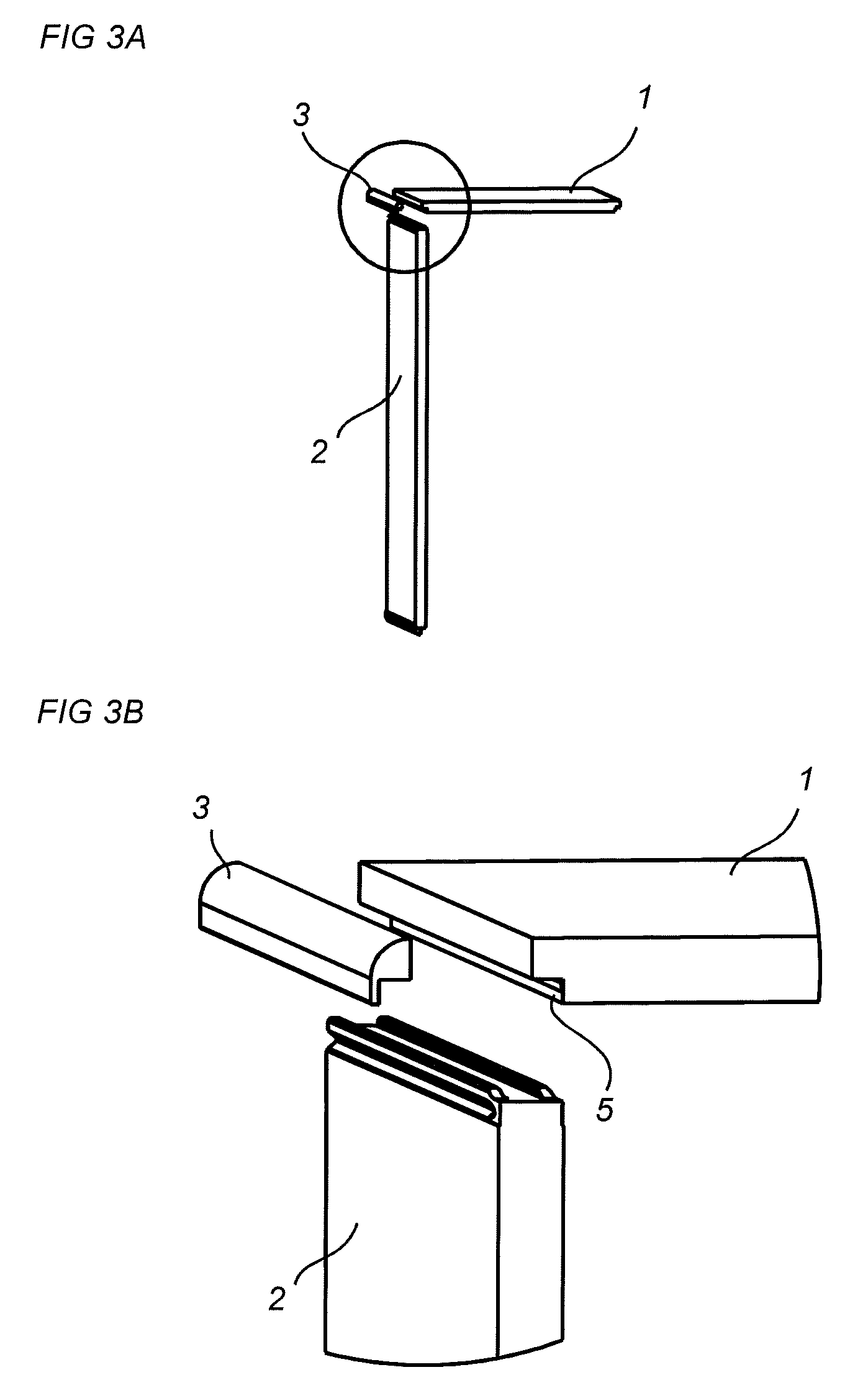
[0039] FIG. 3A is an exploded view of embodiments of a panel of a first panel type, a panel of a second panel type, and a corner element;
[0040] FIG. 3B is an enlarged view of the exploded view of FIG. 3A;
[0041] FIG. 4A is a side view of an embodiment of the panel of the second panel type;
[0042] FIG. 4B is a side view of an embodiment of the panel of the first panel type;
[0043] FIG. 5 is an exploded view of an embodiment of a set of panels for an assembled product including panels of the first panel type and panels of the second panel type;
[0044] FIG. 6A is a side view of the front side of an embodiment of an assembled product;
[0045] FIG. 6B is a side view of the side of the assembled product of FIG. 6A;
[0046] FIG. 6C is an enlarged side view the back side of the assembled product of FIG. 6A with a first panel arranged in abutment with a second panel, and a third panel with locking elements joining the panels together;
[0047] FIG. 6D is an enlarged side view of the front side of a corner of the assembled product of FIG. 6A;
[0048] FIG. 7A is a side view of the back side of the embodiment of the assembled product of FIG. 6A;
[0049] FIG. 7B is an enlarged side view of the back side of the corner illustrated in FIG. 6D;
[0050] FIG. 7C is an enlarged side view the back side of the panels illustrated in FIG. 6C;
[0051] FIG. 8A is an exploded view illustrating assembly of panels of the first panel type with panels of the second panel type;
[0052] FIG. 8B illustrates an enlarged view of panels of the first panel type joined with a panel of the second panel type with locking elements;
[0053] FIGS. 9A-9J are top and side views of embodiments of locking elements;
[0054] FIGS. 10A-10B are exploded views of panels of the first panel type, the second panel type, and a third panel type;
[0055] FIGS. 11A-11B are side views of the front side and the back side, respectively, of an embodiment of a corner element assembled with panels;
[0056] FIGS. 11C-11D are perspective views illustrating opposing ends of the corner element of FIGS. 11A-11C.
[0057] FIG. 12A is an enlarged side view of an end surface of the second panel type;
[0058] FIG. 12B is an enlarged side view of the back side of an alternative to the embodiment of the assembled product of FIG. 1A; and
[0059] FIG. 12C is an enlarged side view of the back side of an alternative to the embodiment of the assembled product of FIG. 1A.
DESCRIPTION OF EMBODIMENTS
[0060] Specific embodiments according to the disclosure now will be described with reference to the accompanying drawings. This disclosure may, however, be embodied in many different forms and should not be construed as limited to the embodiments set forth herein; rather, these embodiments are provided so that this disclosure will be thorough and complete, and will fully convey the scope of the disclosure to those skilled in the art. The terminology used in the detailed description of the embodiments illustrated in the accompanying drawings is not intended to be limiting of the disclosure. In the drawings, like numbers refer to like elements.
[0061] The disclosure concerns a set of panels for an assembled product, such as illustrated in FIG. 1A. The set of panels comprises a first panel 1a, a second panel 1b, and a third panel 2a. The first panel 1a, the second panel 1b, and the third panel 3a may be joined, such as illustrated in FIG. 1C. Particularly, the first panel 1a, the second panel 1b, and the third panel 3a may be locked to each other in at least one direction. Hence, the three panels may form a joint of the assembled product.
[0062] In some embodiments, a set of panels may be used to form a multi-module frame, such as illustrated in the embodiments of FIGS. 1A and 2A, FIG. 5, and FIG. 6A and FIG. 7A. FIGS. 1A and 7A illustrate the back side of embodiments of multi-module frames. FIG. 2A illustrates the front side of multi-module frame of FIG. 1A, and FIG. 6A illustrates the front side of the multi-module frame of FIG. 7A.
[0063] An entire multi-module frame may be assembled using only a plurality of panels of a first panel type and a plurality of panels of a second panel types. FIG. 4B illustrates an embodiment of the panel 1 of the first panel type. FIG. 4A illustrates an embodiment of the panel 2 of the second panel type.
[0064] The first panel 1a and the second panel 1b may be of the first panel type. The third panel 2a may be of the second panel type. In order to firm a single joint, it is only required to have the first panel 1a, the second panel 1b and the third panel 2a.
[0065] As is illustrated in FIGS. 1A and 2A, FIG. 5, and FIG. 6A and FIG. 7A the panel of the first panel type, such as panels 1a-1e, are configured to be arranged in a first direction, such as horizontally. The panel of the second panel type, such as panels 2a-2d, is configured to be arranged in a second direction, such as vertically. The second direction may be substantially perpendicular to the first direction.
[0066] In some embodiment, such as illustrated in the embodiment of FIG. 1A, at least one corner element 3a-3c may be included with the set of panels.
[0067] The corner element 3a-3c may be attached to at least one of the panel 1 of the first panel type or the panel 2 of the second panel type. As is illustrated in FIG. 1B, the corner element 3a-3c may be attached to the panel 2 of the second panel type. A panel 1 of the first panel type may be attached at the same corner of the panel 2 of the second panel type, to which the corner element 3a-3c is attached, as is illustrated in FIG. 1B. The corner element 3a-3c may extend along the length of an edge of the panel 2 of the second panel type, such as the upper/lower edge of a rectangular panel. Hence, the corner element 3a-3c may be used to conceal or cover any structure of the panel 1, 2 of the first and/or second panel type, which is less visibly appealing. Hence, a corner element 3a-3c may be used at any corner that is visible when the product, assembled by the panels 1a-1e, 2a-2b, is positioned in a final position for use. Hence, in some situations only two corner elements 3a-3c may be needed, such as when the assembled product is positioned with a side surface, such as a surface perpendicular to the front or back side, against wall. However, in other situations, four corner elements 3a-3c, one at each outer corner of the assembled product, are used. Only a single or three corner elements 3a-3c are also contemplated.
[0068] As shown for example in FIG. 1C, an end surface of the tongue of the first panel 1a and an end surface of the tongue of the second panel 1b are configured to abut the end groove of the third panel 2a, and an end surface of the first tongue 9a of the third panel 2a is configured to be spaced apart from a bottom wall of the edge groove 4a of the first panel and an end surface of the second tongue 9b of the third panel 2a is configured to be spaced apart from a bottom wall of the edge groove 4a of the second panel 1b, when the panels are assembled.
[0069] Alternatively, as shown for example in FIG. 1D, an end surface of the tongue of the first panel 1a and an end surface of the tongue of the second panel 1b are configured to be spaced apart from the end groove of the third panel 2a, and an end surface of the first tongue 9a of the third panel 2a is configured to abut a bottom wall of the edge groove 4a of the first panel 1a and an end surface of the second tongue 9b of the third panel 2a is configured to abut a bottom wall of the edge groove 4a of the second panel 1b, when the panels are assembled.
[0070] As is illustrated in the embodiments of FIGS. 1C and 7C, and which can also be seen in FIGS. 3B, 4A, 8A, 10A, 10B and 11C, the panel 1 of the first panel type comprises a locking element 4 extending at least partially along an edge portion 5. In some embodiments, a locking element 4 extends along each edge portion 5a, 5b of opposite ends of the panel 1, as is illustrated by the panel 1 in FIG. 4b. The panel 1 of the first panel type may have a locking element 4 at each of opposing ends of the panel 1, as is illustrated in FIG. 4B. Hence, locking elements 4 may be symmetrically arranged at each end of the panel 1 of the first panel type. Hence, the panel 1 may be symmetric at each end, such as relative a centre line S1 which is normal to a first surface 7a and a second surface 7b of the panel 1 of the first panel type. The centre line S1 may extend at the centre between each end of the panel 1 of the first panel type. Hence, the panel 1 of the first panel type may be symmetric about the centre line S1. Hence, the panel 1 of the first panel type may be connected at each end to a panel 2 of the second panel type, is illustrated in FIG. 1A.
[0071] Similarly and as can be seen in FIG. 4A, the panel 2 of the second panel type, such as panels 2a-2d, comprises a first locking element 6a and a second locking element 6b arranged at the same end of the panel 2 of the second panel type. The panel 2 of the second panel type may have a first locking element 6a and a second locking element 6b at each of opposing ends of the panel 2, as is illustrated in FIG. 4a. Hence, locking elements may be symmetrically arranged at each end of the panel 2 of the second panel type, such as relative a centre line S1 which is normal to a first surface 8a and a second surface 8b of the panel 2 of the second panel type. The centre line S1 may extend at the centre between each end of the panel 2 of the second panel type. Hence, the panel 2 of the second panel type may be symmetric about the centre line S1. Also, the first locking element 6a and the second locking element 6b may be symmetrically arranged along the edges of each end. Thus, the locking elements 6a, 6b may be symmetric at each end about a second centre line S2. The second centre line S2 may extend parallel with the first surface 8a and the second surface 8b of the panel 2 of the second panel type, such as in the centre between the first locking element 6a and the second element 6b and/or in the centre between the first surface 8a and the second surface 8b of the panel 2 of the second panel type. Hence, the entire panel 2 may be symmetric. Hence, each panel 2 of the second panel type may connect four panels 1 of the first panel type, e.g. that together form a bottom surface and a top surface, respectively, of a multi-module frame.
[0072] Each of the first locking element 6a and the second locking element 6b of the panel 2 of the second panel type is directly lockable to either of the locking elements 4 of the panel 1 of the first panel type.
[0073] The corner element 3a-3c may be attachable to at least one of the first locking element 6a and the second locking element 6b at one end of the panel 2 of the second panel type. As is illustrated in FIG. 1B, when the panel 2d of the second panel type is directly locked to a single panel 1 of the first panel type, such as to a panel of an outermost module of a multi-module frame, one of the locking elements 6a, 6b of an outermost panel of the outermost module is exposed, i.e. not connected to a panel 1 of the first panel type. The corner element 3a-3c may be attached to any such exposed locking element 6a, 6b.
[0074] As is illustrated in FIG. 4B, the panel 1 of the first panel type, such as each of the first panel 1a and the second panel 1b, comprises a first surface 7a, and a second surface 7b. The second surface 7b may be substantially parallel with and offset from the first surface 7a, such that the panel has a predefined thickness. Also, the panel 1 of the first panel type may comprise at least one edge groove 4a, and at least one end surface 4b, such as at each end of the panel 1. The at least one edge groove 4a and the at least one end surface 4b may extend at least partially along the edge of the panel 1 of the first panel type.
[0075] As is illustrated in FIG. 4A, the panel 2 of the second panel type, such as the third panel 2a, may comprise the first surface 8a, and the second surface 8b. The second surface 8b may be substantially parallel with and offset from the first surface 8a, such that the panel 2 has a predefined thickness. An end surface 9 may extend at least partially between the first surface 8a and the second surface 8b of the panel 2 of the second panel type. Each end of the panel 2 of the second panel type may comprise such an end surface 9. The end surface 9 of the panel 2 of the second panel type, such as the third panel 2a, may comprise a first tongue 9a. The panel 2 of the second panel type may also comprise a second tongue 9b. The first tongue 9a and/or the second tongue 9 may extend at least partially along the end surface 9.
[0076] As is illustrated in FIGS. 1C and 7C, the panels of the first panel type, such as the first panel 1a and the second panel 1b, may be configured to be arranged with their respective end surfaces 4b facing each other, and with their respective edge grooves 4a in parallel. The first tongue 9a of the panel 2 of the first panel type, such as the third panel 2a, may be configured to be arranged in the edge groove 4a of the first panel 2a to join the first panel 1a and the third panel 2a. The second tongue 9b of the panel 2 of the second panel type, such as the third panel 2a, may be configured to be received in the edge groove 4a of the second panel 1b. Hence, the third panel 2a may join the second panel 2b to the third panel 2b, whereby the first panel 1a, the second panel 2b, and the third panel 2a are joined at least in a first direction, such as in the direction of extension of first surface 7a and second surface 7b of the first panel 1a and the second panel 1b, respectively.
[0077] As is illustrated in FIGS. 1C and 7C, in some embodiments, panels 1 of the first panel type, such as the first panel 1a and the second panel 1b, are configured to be arranged with their respective end surfaces 4b in abutment when assembled. This provides for a stable joint, wherein the end surfaces may be pushed together when the tongues 9a, 9b are inserted into the respective edge groove 4a of the first panel 1a and second panel 1b.
[0078] In some embodiments, a side surface 9c, 9d of each tongue 9a, 9b facing the centre of the panel 2 of the second panel type may be configured to abut a first side wall 4c of the edge groove 4a of the panel 1 of the first panel type. Hence, the side surfaces 9a, 9b, and the first side wall 4c of the edge groove 4a may extend in parallel with the extension of the first surface 8a and the second surface 8b of the panel 2 of the second panel type. Hence, the side surfaces 9c, 9d, and the first side wall 4c, of the edge groove 4a may extend perpendicularly with the extension of the first surface 7a, and the second surface 7b of the panel 1 of the first panel type.
[0079] In other embodiments, panels 1 of the first panel type, such as the first panel 1a and the second panel 1b, are configured to be arranged with their respective end surfaces 4b spaced apart when assembled with a panel 2 of the second panel type. A gap may be provided between the end surfaces 4b. The gap may be unfilled. This may save material during production. Instead, second side surfaces 9e, 9f of each tongue 9a, 9b facing away from the centre of the panel 2 of the second panel type may be configured to abut a second side wall 4d of the edge groove 4a of the panel 1 of the first panel type. Hence, the second side surfaces 9e, 9f, and the second side wall 4d of the edge groove 4a may extend in parallel with the extension of the first surface 8a and the second surface 8b of the panel 2 of the second panel type. Hence, the side surfaces 9c, 9d, and the second side wall 4d, of the edge groove 4a may extend perpendicularly with the extension of the first surface 7a, and the second surface 7b of the panel 1 of the first panel type.
[0080] As is illustrated in FIGS. 1C and 7C, the edge groove 4a of the panel of the first panel type may comprise the first wall 4c and the second wall 4d configured to be in abutment with the first side surface 9c, 9d and the second side surface 9e, 9f, respectively, of each tongue 9a, 9b of the panel 2 of the second panel type. This provides for a stable joint. Furthermore, this provides for easy assembly, since the first panel 1a and the second panel 1b will not be pushed apart when the tongues 9a, 9b, are inserted into the edge grooves 4a. Additionally, in some embodiments the end surfaces 4b are also in abutment which further facilitates assembly as well as stabilizes the joint. When the end surfaces 4b are in abutment already before the tongues 9a, 9b are inserted, the edge grooves 4a may be arranged in parallel and at a predefined distance. This makes it easier to insert the tongues 9a, 9b of the panel 2 of the second panel type. This is further enhanced when the tongues 9a, 9b are symmetrical at the same end of the panel 2 of the second panel type, and the edge grooves 4a are symmetric at the opposing ends of the panel 1 of the first panel type.
[0081] As is illustrated in FIGS. 1C and 7C, and FIGS. 9A-91, the panel 1 of the first panel type, such as each of the first panel 1a and the second panel 1b, may comprise an insertion groove 20 for a flexible tongue 30, such as at each end thereof. Each insertion groove 20 may be arranged between the end surface 4b and the first surface 7a of the panel 1 of the first panel type, such as the first panel 1a and the second panel 1b. The panel 2 of the second panel type, such as the third panel 2a, may comprise a first tongue groove 21a extending from the first surface thereof 8a. In some embodiments, the panel 2 of the second panel type also comprises a second tongue groove 21b extending from the second surface 8b thereof. Each tongue groove 21a, 21b may be arranged to receive a portion of the flexible tongue 30 when the first panel 1a, the second panel 1b, and the third panel 2a are joined. Hence, the first panel 1a, the second panel 1b, and the third panel 2a may be joined and/or locked in a second direction, which may be perpendicular to the first direction in which the panels are joined and/or locked. Also, the arrangement of the flexible tongue 30 and tongue groove 21a, 21b may form a tight joint. Since the tongue 30 is flexible, it may be displaced in the tongue insertion groove 20 by the first tongue 9a or the second tongue 9b of the third panel 2a while the third panel 2a is positioned in its seated position relative the first panel 1a and the second panel 2b. Flexible tongues 30 of the first panel 1a and the second panel 2b may be arranged symmetrically around the third panel 2a during assembly, such that they are displaced simultaneously. Hence, easy and simultaneous assembly of the third panel with the first panel and the second panel is facilitated for.
[0082] FIG. 8B illustrates an embodiment wherein the locking element with the flexible tongues 30 are positioned in insertion grooves 20 in the panel 2 of the second panel type. The tongue groove 21a, 21b is arranged in the panel 1 of the first panel type. The function of the locking element of FIG. 8B corresponds to the function of the locking element discussed above as well as below.
[0083] Embodiments of the flexible tongue 30, which is displaceable in the insertion groove 20, are shown in FIGS. 9A-9D. FIGS. 9A-9B show the flexible tongue 30 in a locked position and FIGS. 9C-9D show the flexible tongue 30 during assembling of the third panel 2a and the first panel 1a and/or the second panel 1b. FIG. 9B shows a cross section of the flexible tongue 30 in FIG. 9A, which shows a top view. FIG. 9D shows a cross section of the flexile tongue 30 in FIG. 9C, which shows a top view. The flexible tongue 30 comprises bendable protruding parts 24. A space 23 is provided between the flexible tongue 30 and a bottom wall of the insertion groove 20. FIG. 9C shows that the flexible tongue 30 is pushed into the insertion groove 20 and towards the bottom wall of the insertion groove 20 during an assembly of the third panel 2a with the first panel 1a and/or second panel 1b. The flexible tongue 30 springs back towards its initial position when the third panel 2a has reached a locked position relative the first panel 1a and/or the second panel 1b. A recess 25 is preferably arranged at each bendable protruding part.
[0084] The flexible tongue 30 may have a first displacement surface 26 and an opposite second displacement surface 27, configured to be displaced along a third displacement surface 28 and a fourth displacement surface 29, respectively, of the insertion groove 20.
[0085] Another embodiment of the flexible tongue 30, without the protruding bendable parts 24, is shown in FIGS. 9E-9F. FIG. 9F shows a cross section of the flexible tongue 30 shown in FIG. 9E, which shows a top view. The alternative embodiment is bendable in the length direction of the flexible tongue 30 in order to accomplish a similar function as the embodiment shown in FIGS. 9A-9D.
[0086] Another embodiment of the flexible tongue 30 is shown in FIG. 9G in a top view. The tongue 30 comprises an inner part 38 and an outer part 39. The inner part 38 and the outer part 39 are preferably made of two different materials, wherein the inner part 38 is more flexible than the outer part 39. The inner part 38 is configured to be inserted into the insertion groove 20 and the outer part 39 is configured to extend into the tongue groove 21a, 21b.
[0087] FIGS. 9G-J show in cross section embodiments of the tongue 30 comprising an inner part 91 and a pivoting outer part 92. The inner part 91 is configured to be inserted into the insertion groove 20 and the outer part 92 is configured to extend into the tongue groove 21a, 21b and pivot during assembly of the third panel 2a with the first panel 1a and/or the second panel 1b. The embodiments in FIGS. 9H-91 are preferably produced in one material, such as a polymer, by extruding. The embodiment in FIG. 9J is preferably produced by coextruding and comprises at least two different polymer materials. The embodiment comprises a hinge portion 93 which connects the inner part 91 and the outer part 92. The material of the hinge portion 93 is preferably more flexible than the inner part 91 and the outer part 93.
[0088] In some embodiments, at least one of the panel 1 of the first panel type, such as the first panel 1a and the second panel 1b, and the panel 2 of the second panel type, such as the second panel 2a, comprises a flexible tongue formed integral with and in the same material as a material of the at least one panel 1 of the first panel type and the panel 2 of the second panel type.
[0089] Furthermore, the tongue groove may be formed integral with and in the same material as the panel in which it is formed. Such flexible tongues and tongue grooves formed integral with and in the same material as the panel may e.g. be configured as the tongue, such as the split tongue, disclosed in embodiments of WO2010070605, which is incorporated herein in its entirety by reference.
[0090] As is illustrated in FIGS. 1B-1C, 7B-7C, and 8B, each insertion groove 20 may be inclined towards the respective first surface 7a, 7b of the panel 1 of the first panel type. When the insertion groove 20 in provided in the panel 1 of the first panel type, such as the first panel 1a and the second panel 1b, the respective first tongue 9a and second tongue 9b of the panel 2 of the second panel type, such as the third panel 2a, is arranged to push each flexible tongue 30 into the insertion groove 20 when the third panel 2a is joined to the panel 1 of the first panel type. The first tongue 9a and second tongue 9b may have a chamfer between their respective end surfaces and the second side surfaces 9e, 9f. This provides for easier displacing of the flexible tongue, wherein it is easier to assemble the panels.
[0091] The flexible tongue 30 may be arranged between the first surface 7a and the edge groove 4a of the panel 1 of the first panel type, such as the first panel 1a, and the second panel 1b.
[0092] In some embodiments the panel 2 of the second panel type, such as the third panel 2a, may comprise at least one end groove formed between the first tongue 9a and the second tongue 9a. The end groove may be formed by the first side surfaces 9a, 9b, and a bottom surface 9g extending therebetween, such as is illustrated in FIGS. 1C, 7C, and 8B. Hence, the end groove is at least partially formed by a lateral surface of the first tongue 9a and a lateral surface of the second tongue 9b of the panel 2 of the second panel type, and a surface extending between the lateral surfaces.
[0093] The panel 2 of the second panel type, such as the third panel 2a, may comprise a single end groove between the first tongue 21a and the second tongue 21b thereof. A tongue of the panel 1 of the first panel type may be formed by the end surface 4a and the first side wall 4c. Such tongues of the first panel 1a and second panel 1b may form tongue portions of a multi-part tongue. The multi-part tongue may be formed when the first panel and the second panel are arranged with their respective end surfaces 4b in abutment and with their respective edge grooves 4a arranged in parallel. The multi-part tongue may be configured to be arranged in the single end groove of the panel 2 of the second panel type, such as the third panel 2a.
[0094] FIGS. 11A-11D illustrate embodiments of the corner element 3, 3b. The corner element 3 may comprise a support element 40 configured to be supported by at least one of the panel 1 of the first panel type and the panel 2 of the second panel type. In some embodiments, such as is illustrated in FIG. 11B, the support element 40 is supported by the panel 1 of the first panel type and the panel 2 of the second panel type, when fully seated. A first support portion 40a may be configured to abut the end surface 4a of the panel 1 of the first panel type. A second support portion 40b may be configured to abut the bottom surface 9g of the end groove of the panel 2 of the second panel type. A third support portion 40c may be configured to be supported by the first side wall 9d of the first tongue 9a or the second side wall 9d of the second tongue 9b of the panel 2 of the second panel type. The support element may comprise one, two or all of the first support portion 40a, second support portion 40b and the third support portion 40c. The support element and its respective portions may extend at least partially along the length of the corner element 3.
[0095] As can be seen in FIG. 11B, the corner element 3 may comprise a locking element 41 configured to lock against the first tongue groove 21a or the second tongue groove 21b of the panel 2 of the second panel type. The locking element 41 may extend from an inner side wall of the corner element 3. The locking element 41 may extend at least partially along the length of the corner element 3. For example, the locking element may be curved away from the support element 40.
[0096] The corner element 3 may be configured to be assembled by positioning the locking element 41 in the tongue groove 21, 21b of the panel of the second panel type, and then angling the corner element 3 towards the end groove of the panel of the second panel type, as is illustrated with the curved arrow in FIG. 11B, until the support element 40 is received in the end groove to be fully seated, as described above. Alternatively or additionally, the corner element 3 may be configured to be assembled by inserting the corner element 3 diagonally towards the panel of the second panel type, as is indicated with the straight arrow in FIG. 11B. The corner element is locked or held in place by the locking element 41 and the support element 40. For example, the tongue 9a, 9b may be received between the locking element 41 and the support element 40, such as snugly received therebetween.
[0097] As is illustrated in FIGS. 11A, and 11C-11D, the corner element 3 may comprise an end surface 42, such as an end plate. When a panel 1 of the first panel type is attached to a panel 2 of the second panel type to form a side surface of a frame, one of the first tongue 9a and the second tongue 9b may be visible and not covered by the panel of the first panel type, such as is illustrated in FIG. 11C. When the corner element 3 is attached to the panel 2 of the second panel type, the end surface 42 may cover any exposed part of the locking element, such as the first tongue 9a or second tongue 9b. For example, the end surface 42 may have a width/height that substantially corresponds to the thickness of the panel 1 of the first panel type and the thickness of the panel 2 of second panel type, as is illustrated in FIG. 11A. As is illustrated in FIG. 11D, the corner element 3 only has a single end surface 42 or end plate at one of its end. However, in other embodiments the corner element has an end surface 42 or end plate at each of its ends. The support element 40 and/or the locking element 41 may extend along the entire length of the corner element 3 from an inner side of the end plate to the other end of the corner element, or to the inner side surface of the end plate of at the other end of the corner element 3.
[0098] As is illustrated in FIGS. 2A-2C, 6A-6C, and 8A, the panel 1 of the first panel type, such as the first panel 1a and the second panel 2a, comprises at least one of a front edge and a back edge, which extends between the first surface 7a and the second surface 7b thereof. An adjacent end 44 of the edge groove 4a and/or the insertion groove 20 of the panel 1 of the first panel type may be spaced apart from the front edge. Hence, the locking element including the edge groove 4a and/or the insertion groove 20 is covered by the front edge. In some embodiments the edge groove 4a and/or the insertion groove 20 of the panel 1 of the first panel type is additionally or alternatively spaced apart from and a back edge, which extends between the first surface 7a and the second surface 7b thereof.
[0099] Similarly, the first tongue 9a and the second tongue 9b of the panel 2 of the second panel type may be spaced apart from at least one of a front edge and a back edge, which extends between the first surface 8a and the second surface 8b thereof. An adjacent end 44 of the first tongue 9a and the second tongue 9b of the panel 2 of the second panel type may be spaced apart from the front edge. Hence, the locking element including the first tongue 9a and the second tongue 9b is covered by the front edge. In some embodiments the first tongue 9a and the second tongue 9b of the panel 2 of the second panel type is additionally or alternatively spaced apart from and a back edge, which extends between the first surface 8a and the second surface 8b thereof. Hence, any separate component to conceal the locking element is unnecessary, wherein fewer parts are required to provide a visibly acceptable frame, which in turn simplifies production, logistics, and assembly.
[0100] FIG. 5 illustrates an embodiment that comprises panels for forming at least two modules of a multi-modular frame. The set of panels includes four panels 1a-1b, 1d-1e of the first panel type, and three panels 2a-2c of the second panel type. Optionally, the set of panels may also include any number of corner elements, such as two or four. Each end of a first panel 2a of the second panel type is locked to two panels, 1a-1b, 1d-1e of the first panel type. The first panel 2a may form a centre wall or centre partitioning of the multi-modular frame. Each end of a second panel 2b and a third panel 2c of the second panel type is locked to a single panel 1a-1b, 1d-1e of the first panel type. When a corner element is provided, one corner element may be attached to each end of the second panel 2b and the third panel 2c of the second panel type, such as to the first tongue 9a and/or second tongue 9b of the respective second panel 2b and third panel 2c of the second panel type, as is illustrated in FIGS. 3A-3B. Hence, a first panel 1a and a second panel 1b of the first panel type may form a bottom section of the multi-modular frame, and a third panel 1d and a fourth panel 1e of the first panel type may form a top section of the multi-modular frame. The second panel 2b and the third panel 2c of the second panel type may form side sections of the multi-modular frame.
[0101] The multi-modular frame can be extended to any number of modules. Each additional module only requires two panels of the first panel type, and one panel of the second panel type.
[0102] FIGS. 10A-10B illustrate a frame assembled by the panels 1 of the first panel type and the panels 2 of the second panel type and that comprises a panel or element 50 of a third panel type. The panel 50 of the third panel type may form a back of the frame. Although a multi-module frame is illustrated, the panel 50 of the third panel type may be used for a single module. A panel 2 of the second panel type is preferably connected to a panel 1 of the first panel type before the panel 50 of the third panel type is connected to the other panels. The panel of the third panel type 50 may be displaced in a diagonal direction such that a first edge 51 and a second edge 52 of the panel 50 of the third panel type is connected at the same time to an edge 53 of the panel 1 of the first panel type and to and edge 54 of the panel 2 of the second panel type. An alternative is to displace the panel 50 of the third panel type in a first direction perpendicular to the panel 1 of the first panel type and subsequently displace the panel 50 of the third panel type in a second direction perpendicular to the panel 2 of the second panel type. The first edge 51 of the panel 50 of the third panel type is in this embodiment connected displaceable at the first edge 51. Another alternative is to displace the panel 50 of the third panel type in the second direction perpendicular to the panel 2 of the second panel type and subsequently displace the panel 50 of the third panel type in the first direction perpendicular to the panel 1 of the first panel type. The second edge 52 of the panel 50 of the third panel type is in this embodiment connected displaceable at the second edge 52. Further, the connected panel 1 of the first panel type, the panel 2 of the second panel type, and another panel 1 of the first panel type can together be displaced diagonally opposite to the direction 55 such that the second edge 52 of the panel of the first panel 1 type and a second edge of the panel 2 of the second panel type are connected at the same time to the first edge 51 and the second edge 52 of the panel 50 of the third panel type. The panel 1 of the first panel type and the panel 2 of the second panel type may have edge grooves along the edges that are to form the back side of the frame, which are configured to mate with tongues of the panel of the third panel type, as is illustrated in FIGS. 10A-10B. Further detailed solutions of the edge groove at the back side and the tongue of the panel 50 of the third panel type are described in WO2015/038059, which is incorporated herein by reference in its entirety for all purposes.
[0103] The multi-module frame may be assembled by first placing two panels 1 of the first panel type with their end surfaces 4b in parallel, and optionally in abutment. One of the panels 1 of the first panel type can be placed with one side, i.e. the side opposing the side facing the other panel, against a stop surface, such as a wall. Then, a weight can be placed on the other panel. Preferably a person assembling the panels can simply stand on the other panel such that the two panels 1 of the first panel type are not separated or displaced during assembly with a first panel 2 of the second panel type. Once the panels 1 of the first panel type are positioned, panels 2 of the second panel type are connected to the positioned panels 1 of the first panel type. Preferably, one panel 2 of the second panel type is connected to join the two panels 1 of the first panel type and the panel 2 of the second panel type, as is described above. A back panel, i.e. a panel 50 of the third panel type as disclosed above, may be attached if desired, before two panels 2 of the second panel type are attached, one to each of the panels 1 of the first panel type. Finally, two panels 1 of the first panel type are attached at the top of the panels of the second panel type in order to form the top section of the multi-modular frame.
[0104] FIGS. 6A-6D illustrate embodiments of a frame, such as a multi-module frame, that is composed of three types of panels, and may optionally also comprise the third panel type as discussed above. Panels 60, 60a, 60b of a fourth panel type may be used as side elements of a frame. The panels 60, 60a, 60b of the fourth panel type may be used rather than panels 2 of the second panel type as side panels of the frame in order to avoid corner elements. The panel 60, 60a, 60b of the fourth panel type is configured to be joined to a single panel 1 of the first panel type at each end thereof. Hence, at each end of the panel 60, 60a, 60b of the fourth panel type only one of the tongues 9a, 9b described in embodiments above is provided. If the configuration of the panel 60, 60a, 60b of the fourth panel type is symmetric along the edge where the locking element is provided, the panel can be rotated such that a single panel may fit as a side section at either side of the frame. Furthermore, a corner portion 61 may be formed integral and in the same material as the panel 60, 60a, 60b. An end of the corner portion 61 may be configured to be substantially flush with the second side surface 7b of the panel 1 of the first panel type, as is illustrated in FIG. 7B. At the front edge of the panel 60 of the fourth panel type the tongue 9a, 9b may be spaced apart from the front edge, as has been described above, such that the tongue 9a, 9b is not visible from the front of the frame. In case the panel 60 of the fourth panel type is to be combined with a panel 50 of the third panel type, a separate panel for the left and right sides of the frame may be provided, such that the groove for the panel 50 of the third panel type is located towards the back of the frame.
[0105] FIG. 12A shows is an enlarged side view an embodiment of the end surface 9 of the second panel type 2a. The embodiment comprises tongues 9a, 9b which are displaced from the first surface 8a and a second surface 8b of the second panel 2a.
[0106] FIG. 12B illustrates an embodiment wherein the locking element with the flexible tongues 30 are positioned in insertion grooves 20 which extends essentially perpendicular to the first surface 8a and a second surface 8b, respectively of the second panel 2a. The function of the locking element of FIG. 12B corresponds to the function of the locking element discussed above as well as below.
[0107] FIG. 12C illustrates an embodiment wherein the locking element with the flexible tongues 30 are positioned in insertion grooves 20 in the panel 2 of the second panel type. The tongue groove 21a, 21b is arranged in the panel 1 of the first panel type. The insertion grooves 20 extends essentially perpendicular to the first surface 8a and a second surface 8b, respectively of the second panel 2a. The function of the locking element of FIG. 12C corresponds to the function of the locking element discussed above.
[0108] It should also be appreciated that features disclosed in the foregoing description, and/or in the foregoing drawings and/or following claims both separately and in any combination thereof, are material for realizing the present disclosure in diverse forms thereof. When used in the following claims, the terms "comprise", "include", "have" and their conjugates mean, "including but not limited to".
[0109] The present above disclosure has been described several specific embodiments. However, other embodiments than the above described are equally possible within the scope of the disclosure. Different method steps than those described above may be provided within the scope of the disclosure. The different features and steps may be combined in other combinations than those described. The scope of the invention is only limited by the appended patent claims.
EMBODIMENTS
[0110] 1. A set of panels for an assembled product, comprising:
[0111] a first panel (1a);
[0112] a second panel (1b); and
[0113] a third panel (2a); wherein
[0114] each of the first panel (1a) and the second panel (1b) comprises a first surface (7a), a second surface (7b), which is substantially parallel with the first surface (7a), an edge groove (4a), and an end surface (4b);
[0115] the third panel (2a) comprises a first surface (8a) and a second surface (8b), which is substantially parallel with the first surface (8a), and an end surface extending at least partially between the first surface (8a) and the second surface (8b) of the third panel (2a); and
[0116] the end surface of the third panel (2a) comprises a first tongue (9a) and a second tongue (9b);
[0117] characterized in that
[0118] the first panel (1a) and the second panel (1b) are configured to be arranged with their respective end surfaces (4b) facing each other, and with their respective edge grooves (4a) in parallel; and
[0119] the first tongue (9a) of the third panel (2a) is configured to be arranged in the edge groove (4a) of the first panel (1a) to join the first panel (1a) and the third panel (2a), and the second tongue (9b) of the third panel (2a) is configured to be received in the edge groove (4a) of the second panel (2b) to join the second panel (1b) to the third panel (2a), whereby the first panel (1a), the second panel (1b), and the third panel (2a) are joined at least in a first direction.
[0120] 2. The set of panels according to embodiment 1, wherein the first panel (1a) and the second panel (1b) are configured to be arranged with their respective end surfaces (4b) in abutment.
[0121] 3. The set of panels according to embodiment 1 or 2, wherein each of the first panel (1a) and the second panel (1b) further comprises an insertion groove (20) for a flexible tongue (30), the insertion groove (20) being arranged between the end surface (4b) and the first surface (7a) of the respective first panel (1a) and the second panel (1b), and wherein the third panel (2a) comprises a first tongue groove (21a) extending from the first surface (8a) thereof and a second tongue groove (21b) extending from the second surface (8b) thereof, wherein each tongue groove (21a, 21b) is arranged to receive a portion of the flexible tongue (30) when the first panel (1a), the second panel (1b), and the third panel (2a) are joined.
[0122] 4. The set of panels according to embodiment 1 or 2, wherein at least one of the first panel and the second panel comprises a flexible tongue formed integral with and in the same material as a material of said at least one of the first panel and the second panel.
[0123] 5. The set of panels according to embodiment 3, wherein each insertion groove (20) is inclined towards the respective first surface (7a) of the first panel (1a) and the second panel (1b), and wherein the respective first tongue (9a) and second tongue (9b) of the third panel (2a) are arranged to push each flexible tongue (30) into the insertion groove (20) when the third panel (2a) is joined to the first panel (1a) and the second panel (1b).
[0124] 6. The set of panels according to any of the previous embodiments, wherein each of the first panel (1a) and the second panel (1b) comprises a tongue formed by the end surface (4b) and the edge groove (4a) thereof, and wherein the third panel (2a) comprises at least one end groove between the first tongue (9a) and the second tongue (9b) thereof.
[0125] 7. The set of panels according to embodiment 6, wherein the end groove is at least partially formed by a lateral surface (9c) of the first tongue (9a) of the third panel (2a) and a lateral surface (9d) of the second tongue (9b) of the third panel (2a), and a surface (9g) extending between said lateral surfaces (9c, 9d).
[0126] 8. The set of panels according to embodiment 6 or 7, wherein the third panel (2a) comprises a single end groove between the first tongue (9a) and the second tongue (9b) of the third panel (2a), and wherein the tongue of the first panel (1a) and the tongue of the second panel (1b) are tongue portions of a multi-part tongue, said multi-part tongue being formed when the first panel (1a) and the second panel (1b) are arranged with their respective end surfaces (4a) in abutment and with their respective edge grooves (4a) arranged in parallel, and said multi-part tongue being configured to be arranged in said single end groove of the third panel (2a).
[0127] 9. The set of panels according to any of embodiments 6-8, wherein
[0128] an end surface of the tongue of the first panel (1a) and an end surface of the tongue of the second panel (1b) are configured to abut the end groove of the third panel (2a), and an end surface of the first tongue (9a) of the third panel (2a) is configured to be spaced apart from a bottom wall of the edge groove (4a) of the first panel (1a) and an end surface of the second tongue (9b) of the third panel (2a) is configured to be spaced apart from a bottom wall of the edge groove (4a) of the second panel (1b), when the panels are assembled; or
[0129] an end surface of the tongue of the first panel (1a) and an end surface of the tongue of the second panel (1b) are configured to be spaced apart from the end groove of the third panel (2a), and an end surface of the first tongue (9a) of the third panel (2a) is configured to abut a bottom wall of the edge groove (4a) of the first panel (1a) and an end surface of the second tongue of the third panel (2a) is configured to abut a bottom wall of the edge groove (4a) of the second panel (1b), when the panels are assembled.
[0130] 10. The set of panels according to any of the previous embodiments, wherein each of the first panel (1a) and the second panel (1b) comprises at least one of a front edge and a back edge, which extends between the first surface (7a) and the second surface (7b) of the respective first panel (1a) and the second panel (1b), and wherein one adjacent end of the edge groove (4a) of the respective first panel (1a) and the second panel (1b) is spaced apart from said at least one of a front edge and a back edge.
[0131] 11. A set of panels for forming a multi-module frame, wherein the set of panels comprises:
[0132] a plurality of panels (1) of a first panel type configured to be arranged in a first direction;
[0133] a plurality of panels (2) of a second panel type configured to be arranged in a second direction, which is substantially perpendicular to the first direction; and
[0134] at least one corner element (3); wherein the panels (1) of the first panel type comprise locking elements (4) extending along edge portions of opposite ends of each panel (1);
[0135] the panels of the second panel (2) type comprise a first locking element (6a) and a second locking element (6b) arranged at the same end of the panel (2) of the second panel type,
[0136] the first locking element (6a) and the second locking element (6b) of the panels (2) of the second panel type being directly lockable to either of the locking elements (4) of the panels (1) of the first panel type, and
[0137] the corner element (3) is attachable to at least one of the first locking element (6a) and the second locking element (6b) at one end of the panel (2) of the second panel type when said panel (2) of the second panel type is directly locked to a single panel (1) of the first panel type.
[0138] 12. The set of panels according to embodiment 11, wherein the corner element (3) comprises at least one of a support element (40) configured to be supported by at least one of the panel (1) of the first panel type and the panel (2) of the second panel type, and a locking element (41) locking against a tongue groove (21a, 21b) of the panel (2) of the second panel type.
[0139] 13. The set of panels according to any of embodiments 11-12, wherein the set comprises panels for forming at least two modules of a multi-modular frame, including:
[0140] four panels (1) of the first panel type;
[0141] three panels (2) of the second panel type of; and
[0142] at least one corner element (3), wherein
[0143] each end of a first panel (2a) of the second panel type is lockable to two panels (1a, 1b) of the first panel type, and each end of a second panel (2b) and a third panel (2c) of the second panel type is lockable to a single panel (1a, 1b) of the first panel type; and one corner element (3a, 3b, 3c, 3d) is attached to at least one of the end of the second panel and the third panel of the second panel type.
[0144] 14. The set of panels according to any of embodiments 1-13, wherein
[0145] a first panel (1a) is of the first panel type;
[0146] a second panel (1b) is of the first panel type; and
[0147] a third panel (2a) is of the second panel type; wherein
[0148] each of the first panel (1a) and the second panel (1b) comprises a first surface (7a), a second surface (7b), which is substantially parallel with the first surface (7a), an edge groove (4a), and an end surface (4b);
[0149] the third panel (2a) comprises a first surface (8a) and a second surface (8b), which is substantially parallel with the first surface (8a), and an end surface extending at least partially between the first surface (8a) and the second surface (8b) of the third panel (2a); the end surface of the third panel (2a) comprises a first tongue (9a) and a second tongue (9b);
[0150] the first panel (1a) and the second panel (2a) are configured to be arranged with their respective end surfaces (4b) facing each other, and with their respective edge grooves (4a) in parallel; and
[0151] the first tongue (9a) of the third panel (2a) is configured to be arranged in the edge groove (4a) of the first panel (1a) to join the first panel (1a) and the third panel (2a), and the second tongue (9b) of the third panel (2a) is configured to be received in the edge groove (4a) of the second panel (1b) to join the second panel (1b) to the third panel (2a), whereby the first panel (1a), the second panel (1b), and the third panel (2a) are joined at least in a first direction.
[0152] 15. The set of panels according to embodiment 14, wherein the first panel (1a) and the second panel (1b) are configured to be arranged with their respective end surfaces (4b) in abutment.
[0153] 16. The set of panels according to embodiment 14 or 15, wherein each of the first panel (1a) and the second panel (1b) further comprises an insertion groove (20) for a flexible tongue 30), the insertion groove (20) being arranged between the end surface (4b) and the first surface (7a) of the respective first panel (1a) and the second panel (1b), and wherein the third panel (2a) comprises a first tongue groove (21a) extending from the first surface (8a) thereof and a second tongue groove (21b) extending from the second surface (8b) thereof, wherein each tongue groove (21a, 21b) is arranged to receive a portion of the flexible tongue (30) when the first panel (1a), the second panel (1b), and the third panel (2a) are joined.
[0154] 17. The set of panels according to embodiment 14 or 15, wherein at least one of the first panel and the second panel comprises a flexible tongue formed integral with and in the same material as a material of said at least one of the first panel and the second panel.
[0155] 18. The set of panels according to embodiment 16, wherein each insertion groove (20) is inclined towards the respective first surface (7a) of the first panel (1a) and the second panel (1b), and wherein the respective first tongue (9a) and second tongue (9b) of the third panel (2a) are arranged to push each flexible tongue (30) into the insertion groove (20) when the third panel (2a) is joined to the first panel (1a) and the second panel (1b).
[0156] 19. The set of panels according to any of embodiments 14-18, wherein each of the first panel (1a) and the second panel (1b) comprises a tongue formed by the end surface (4b) and the edge groove (4a) thereof, and wherein the third panel (2a) comprises at least one end groove between the first tongue (9a) and the second tongue (9b) thereof.
[0157] 20. The set of panels according to embodiment 19, wherein the end groove is at least partially formed by a lateral surface (9c) of the first tongue (9a) of the third panel (2a) and a lateral surface (9d) of the second tongue (9b) of the third panel (2a), and a surface extending between said lateral surfaces (9c, 9d). 21. The set of panels according to embodiment 18 or 19, wherein the third panel (2a) comprises a single end groove between the first tongue (9a) and the second tongue (9b) of the third panel (2a), and wherein the tongue of the first panel (1a) and the tongue of the second panel (1b) are tongue portions of a multi-part tongue, said multi-part tongue being formed when the first panel (1a) and the second panel (1b) are arranged with their respective end surfaces (4b) in abutment and with their respective edge grooves (4a) arranged in parallel, and said multi-part tongue being configured to be arranged in said single end groove of the third panel (2a).
[0158] 22. The set of panels according to any of embodiments 18-21, wherein
[0159] an end surface of the tongue of the first panel (1a) and an end surface of the tongue of the second panel (1b) are configured to abut the end groove of the third panel (2a), and an end surface of the first tongue (9a) of the third panel (2a) is configured to be spaced apart from a bottom wall of the edge groove (4a) of the first panel and an end surface of the second tongue (9b) of the third panel (2a) is configured to be spaced apart from a bottom wall of the edge groove (4a) of the second panel (1b), when the panels are assembled; or
[0160] an end surface of the tongue of the first panel (1a) and an end surface of the tongue of the second panel (1b) are configured to be spaced apart from the end groove of the third panel (2a), and an end surface of the first tongue (9a) of the third panel (2a) is configured to abut a bottom wall of the edge groove (4a) of the first panel (1a) and an end surface of the second tongue (9b) of the third panel (2a) is configured to abut a bottom wall of the edge groove (4a) of the second panel (1b), when the panels are assembled.
[0161] 23. The set of panels according to any of embodiments 18-22, wherein each of the first panel (1a) and the second panel (1b) comprises at least one of a front edge and a back edge, which extends between the first surface (7a) and the second surface (7b) of the respective first panel (1a) and the second panel (1b), and wherein one adjacent end of the edge groove (4a) of the respective first panel (1a) and the second panel (1b) is spaced apart from said at least one of a front edge and a back edge.
* * * * *
D00000
D00001
D00002
D00003
D00004
D00005
D00006
D00007
D00008
D00009
D00010
D00011
D00012

D00013

XML
uspto.report is an independent third-party trademark research tool that is not affiliated, endorsed, or sponsored by the United States Patent and Trademark Office (USPTO) or any other governmental organization. The information provided by uspto.report is based on publicly available data at the time of writing and is intended for informational purposes only.
While we strive to provide accurate and up-to-date information, we do not guarantee the accuracy, completeness, reliability, or suitability of the information displayed on this site. The use of this site is at your own risk. Any reliance you place on such information is therefore strictly at your own risk.
All official trademark data, including owner information, should be verified by visiting the official USPTO website at www.uspto.gov. This site is not intended to replace professional legal advice and should not be used as a substitute for consulting with a legal professional who is knowledgeable about trademark law.