Direct drive unit removal system and associated methods
Yeung , et al. March 30, 2
U.S. patent number 10,961,912 [Application Number 17/122,433] was granted by the patent office on 2021-03-30 for direct drive unit removal system and associated methods. This patent grant is currently assigned to BJ Energy Solutions, LLC. The grantee listed for this patent is BJ Energy Solutions, LLC. Invention is credited to Joseph Foster, Ricardo Rodriguez-Ramon, Nicholas Tew, Tony Yeung.


View All Diagrams
| United States Patent | 10,961,912 |
| Yeung , et al. | March 30, 2021 |
Direct drive unit removal system and associated methods
Abstract
Described herein are embodiments of systems and methods for the removal of a direct drive unit (DDU) housed in an enclosure, such as a direct drive turbine (DDT) connected to a gearbox for driving a driveshaft connected to a pump for use in a hydraulic fracturing operations.
| Inventors: | Yeung; Tony (Tomball, TX), Rodriguez-Ramon; Ricardo (Tomball, TX), Foster; Joseph (Tomball, TX), Tew; Nicholas (Tomball, TX) | ||||||||||
|---|---|---|---|---|---|---|---|---|---|---|---|
| Applicant: |
|
||||||||||
| Assignee: | BJ Energy Solutions, LLC
(Houston, TX) |
||||||||||
| Family ID: | 1000005276260 | ||||||||||
| Appl. No.: | 17/122,433 | ||||||||||
| Filed: | December 15, 2020 |
Related U.S. Patent Documents
| Application Number | Filing Date | Patent Number | Issue Date | ||
|---|---|---|---|---|---|
| 15929924 | May 29, 2020 | 10895202 | |||
| 62899975 | Sep 13, 2019 | ||||
| Current U.S. Class: | 1/1 |
| Current CPC Class: | F02C 7/20 (20130101); F02C 7/32 (20130101); F02C 7/36 (20130101) |
| Current International Class: | F02C 7/20 (20060101); F02C 7/36 (20060101); F02C 7/32 (20060101) |
References Cited [Referenced By]
U.S. Patent Documents
| 2498229 | February 1950 | Adler |
| 3191517 | June 1965 | Solzman |
| 3257031 | June 1966 | Dietz |
| 3378074 | April 1968 | Kiel |
| 3739872 | June 1973 | McNair |
| 3773438 | November 1973 | Hall et al. |
| 3791682 | February 1974 | Mitchell |
| 3796045 | March 1974 | Foster |
| 3820922 | June 1974 | Buse et al. |
| 4010613 | March 1977 | McInerney |
| 4031407 | June 1977 | Reed |
| 4086976 | May 1978 | Holm et al. |
| 4222229 | September 1980 | Uram |
| 4269569 | May 1981 | Hoover |
| 4311395 | January 1982 | Douthitt et al. |
| 4357027 | November 1982 | Zeitlow |
| 4402504 | September 1983 | Christian |
| 4457325 | July 1984 | Green |
| 4470771 | September 1984 | Hall et al. |
| 4574880 | March 1986 | Handke |
| 4754607 | July 1988 | Mackay |
| 4782244 | November 1988 | Wakimoto |
| 4796777 | January 1989 | Keller |
| 4804162 | February 1989 | Rice |
| 4913625 | April 1990 | Gerlowski |
| 4983259 | January 1991 | Duncan |
| 4990058 | February 1991 | Eslinger |
| 5537813 | July 1996 | Davis et al. |
| 5553514 | September 1996 | Walkowc |
| 5560195 | October 1996 | Anderson et al. |
| 5622245 | April 1997 | Reik |
| 5651400 | July 1997 | Corts et al. |
| 5678460 | October 1997 | Walkowc |
| 5717172 | February 1998 | Griffin, Jr. et al. |
| 5983962 | November 1999 | Gerardot |
| 6041856 | March 2000 | Thrasher et al. |
| 6050080 | April 2000 | Horner |
| 6071188 | June 2000 | O'Neill et al. |
| 6123751 | September 2000 | Nelson et al. |
| 6129335 | October 2000 | Yokogi |
| 6145318 | November 2000 | Kaplan et al. |
| 6279309 | August 2001 | Lawlor, II et al. |
| 6321860 | November 2001 | Reddoch |
| 6334746 | January 2002 | Nguyen et al. |
| 6530224 | March 2003 | Conchieri |
| 6543395 | April 2003 | Green |
| 6655922 | December 2003 | Flek |
| 6765304 | July 2004 | Baten et al. |
| 6786051 | September 2004 | Kristich et al. |
| 6851514 | February 2005 | Han et al. |
| 6859740 | February 2005 | Stephenson et al. |
| 6901735 | June 2005 | Lohn |
| 7065953 | June 2006 | Kopko |
| 7222015 | May 2007 | Davis et al. |
| 7388303 | June 2008 | Seiver |
| 7545130 | June 2009 | Latham |
| 7552903 | June 2009 | Dunn et al. |
| 7563076 | July 2009 | Brunet et al. |
| 7627416 | December 2009 | Batenburg et al. |
| 7677316 | March 2010 | Butler et al. |
| 7721521 | May 2010 | Kunkle et al. |
| 7730711 | June 2010 | Kunkle et al. |
| 7845413 | December 2010 | Shampine et al. |
| 7900724 | March 2011 | Promersberger et al. |
| 7921914 | April 2011 | Bruins et al. |
| 7938151 | May 2011 | Hockner |
| 7980357 | July 2011 | Edwards |
| 8083504 | December 2011 | Williams et al. |
| 8186334 | May 2012 | Ooyama |
| 8196555 | June 2012 | Ikeda et al. |
| 8316936 | November 2012 | Roddy et al. |
| 8414673 | April 2013 | Raje et al. |
| 8506267 | August 2013 | Gambier et al. |
| 8575873 | November 2013 | Peterson et al. |
| 8616005 | December 2013 | Cousino, Sr. et al. |
| 8621873 | January 2014 | Robertson et al. |
| 8672606 | March 2014 | Glynn et al. |
| 8714253 | May 2014 | Sherwood et al. |
| 8770329 | July 2014 | Spitler |
| 8789601 | July 2014 | Broussard et al. |
| 8794307 | August 2014 | Coquilleau et al. |
| 8801394 | August 2014 | Anderson |
| 8851441 | October 2014 | Acuna et al. |
| 8905056 | December 2014 | Kendrick |
| 8973560 | March 2015 | Krug |
| 8997904 | April 2015 | Cryer et al. |
| 9032620 | May 2015 | Frassinelli et al. |
| 9057247 | June 2015 | Kumar et al. |
| 9103193 | August 2015 | Coli et al. |
| 9121257 | September 2015 | Coli et al. |
| 9140110 | September 2015 | Coli et al. |
| 9187982 | November 2015 | Dehring et al. |
| 9212643 | December 2015 | Deliyski |
| 9249733 | February 2016 | Hallam |
| 9341055 | May 2016 | Weightman et al. |
| 9346662 | May 2016 | Van Vliet et al. |
| 9366114 | June 2016 | Coli et al. |
| 9376786 | June 2016 | Numasawa |
| 9394829 | July 2016 | Cabeen et al. |
| 9395049 | July 2016 | Vicknair et al. |
| 9401670 | July 2016 | Minato et al. |
| 9410410 | August 2016 | Broussard et al. |
| 9410546 | August 2016 | Jaeger et al. |
| 9429078 | August 2016 | Crowe et al. |
| 9493997 | November 2016 | Liu et al. |
| 9512783 | December 2016 | Veilleux et al. |
| 9534473 | January 2017 | Morris et al. |
| 9546652 | January 2017 | Yin |
| 9550501 | January 2017 | Ledbetter |
| 9556721 | January 2017 | Jang et al. |
| 9562420 | February 2017 | Morris et al. |
| 9570945 | February 2017 | Fischer |
| 9579980 | February 2017 | Cryer et al. |
| 9587649 | March 2017 | Oehring |
| 9611728 | April 2017 | Oehring |
| 9617808 | April 2017 | Liu et al. |
| 9638101 | May 2017 | Crowe et al. |
| 9638194 | May 2017 | Wiegman et al. |
| 9650871 | May 2017 | Oehring et al. |
| 9656762 | May 2017 | Kamath et al. |
| 9689316 | June 2017 | Crom |
| 9739130 | August 2017 | Young |
| 9764266 | September 2017 | Carter |
| 9777748 | October 2017 | Lu et al. |
| 9803467 | October 2017 | Tang et al. |
| 9803793 | October 2017 | Davi et al. |
| 9809308 | November 2017 | Aguilar et al. |
| 9829002 | November 2017 | Crom |
| 9840897 | December 2017 | Larson |
| 9840901 | December 2017 | Oering et al. |
| 9850422 | December 2017 | Lestz et al. |
| 9856131 | January 2018 | Moffitt |
| 9863279 | January 2018 | Laing et al. |
| 9869305 | January 2018 | Crowe et al. |
| 9879609 | January 2018 | Crowe et al. |
| 9893500 | February 2018 | Oehring et al. |
| 9893660 | February 2018 | Peterson et al. |
| 9920615 | March 2018 | Zhang et al. |
| 9945365 | April 2018 | Hernandez et al. |
| 9964052 | May 2018 | Millican et al. |
| 9970278 | May 2018 | Broussard et al. |
| 9981840 | May 2018 | Shock |
| 9995102 | June 2018 | Dillie et al. |
| 9995218 | June 2018 | Oehring et al. |
| 10008880 | June 2018 | Vicknair et al. |
| 10018096 | July 2018 | Wallimann et al. |
| 10020711 | July 2018 | Oehring et al. |
| 10029289 | July 2018 | Wendorski et al. |
| 10030579 | July 2018 | Austin et al. |
| 10036238 | July 2018 | Oehring |
| 10040541 | August 2018 | Wilson et al. |
| 10060349 | August 2018 | lvarez et al. |
| 10082137 | September 2018 | Graham et al. |
| 10100827 | October 2018 | Devan et al. |
| 10107084 | October 2018 | Coli et al. |
| 10107085 | October 2018 | Coli et al. |
| 10114061 | October 2018 | Frampton et al. |
| 10119381 | November 2018 | Oehring et al. |
| 10134257 | November 2018 | Zhang et al. |
| 10151244 | December 2018 | Giancotti et al. |
| 10174599 | January 2019 | Shampine et al. |
| 10184397 | January 2019 | Austin et al. |
| 10196258 | February 2019 | Kalala et al. |
| 10221856 | March 2019 | Hernandez et al. |
| 10227854 | March 2019 | Glass |
| 10227855 | March 2019 | Coli et al. |
| 10246984 | April 2019 | Payne et al. |
| 10247182 | April 2019 | Zhang et al. |
| 10254732 | April 2019 | Oehring et al. |
| 10267439 | April 2019 | Pryce et al. |
| 10280724 | May 2019 | Hinderliter |
| 10287943 | May 2019 | Schiltz |
| 10303190 | May 2019 | Shock |
| 10316832 | June 2019 | Byrne |
| 10317875 | June 2019 | Pandurangan |
| 10337402 | July 2019 | Austin et al. |
| 10358035 | July 2019 | Cryer |
| 10371012 | August 2019 | Davis et al. |
| 10374485 | August 2019 | Morris et al. |
| 10378326 | August 2019 | Morris et al. |
| 10393108 | August 2019 | Chong et al. |
| 10407990 | September 2019 | Oehring et al. |
| 10408031 | September 2019 | Oehring et al. |
| 10415348 | September 2019 | Zhang et al. |
| 10415557 | September 2019 | Crowe et al. |
| 10415562 | September 2019 | Kajita et al. |
| RE47695 | November 2019 | Case et al. |
| 10465689 | November 2019 | Crom |
| 10526882 | January 2020 | Oehring et al. |
| 10563649 | February 2020 | Zhang et al. |
| 10577910 | March 2020 | Stephenson |
| 10598258 | March 2020 | Oehring et al. |
| 10610842 | April 2020 | Chong |
| 10711787 | July 2020 | Darley |
| 10738580 | August 2020 | Fischer et al. |
| 10753153 | August 2020 | Fischer et al. |
| 10753165 | August 2020 | Fischer et al. |
| 10794165 | October 2020 | Fischer et al. |
| 10794166 | October 2020 | Reckels et al. |
| 10801311 | October 2020 | Cui et al. |
| 10815764 | October 2020 | Yeung et al. |
| 10815978 | October 2020 | Glass |
| 10830032 | November 2020 | Zhang et al. |
| 10830104 | November 2020 | Rochin Machado |
| 10865624 | December 2020 | Cui et al. |
| 10865631 | December 2020 | Zhang et al. |
| 10907459 | February 2021 | Yeung et al. |
| 2004/0016245 | January 2004 | Pierson |
| 2004/0187950 | September 2004 | Cohen et al. |
| 2005/0139286 | June 2005 | Poulter |
| 2005/0226754 | October 2005 | Orr et al. |
| 2006/0260331 | November 2006 | Andreychuk |
| 2007/0029090 | February 2007 | Andreychuk et al. |
| 2007/0066406 | March 2007 | Keller et al. |
| 2007/0107981 | May 2007 | Sicotte |
| 2007/0181212 | August 2007 | Fell |
| 2007/0277982 | December 2007 | Shampine et al. |
| 2007/0295569 | December 2007 | Manzoor et al. |
| 2008/0098891 | May 2008 | Feher |
| 2008/0161974 | July 2008 | Alston |
| 2008/0187431 | August 2008 | Brown |
| 2008/0264625 | October 2008 | Ochoa |
| 2008/0264649 | October 2008 | Crawford |
| 2009/0064685 | March 2009 | Busekros et al. |
| 2009/0124191 | May 2009 | Van Becelaere et al. |
| 2010/0071899 | March 2010 | Coquilleau et al. |
| 2010/0218508 | September 2010 | Brown et al. |
| 2010/0300683 | December 2010 | Looper et al. |
| 2010/0310384 | December 2010 | Stephenson et al. |
| 2011/0054704 | March 2011 | Karpman et al. |
| 2011/0085924 | April 2011 | Shampine et al. |
| 2011/0197988 | August 2011 | Van Vliet et al. |
| 2011/0241888 | October 2011 | Lu et al. |
| 2011/0265443 | November 2011 | Ansari |
| 2011/0272158 | November 2011 | Neal |
| 2012/0048242 | March 2012 | Surnilla et al. |
| 2012/0199001 | August 2012 | Chillar et al. |
| 2012/0310509 | December 2012 | Pardo et al. |
| 2013/0068307 | March 2013 | Hains et al. |
| 2013/0087945 | April 2013 | Kusters et al. |
| 2013/0284455 | October 2013 | Kajaria et al. |
| 2013/0300341 | November 2013 | Gillette |
| 2013/0306322 | November 2013 | Sanborn |
| 2014/0013768 | January 2014 | Laing et al. |
| 2014/0044517 | February 2014 | Saha et al. |
| 2014/0048253 | February 2014 | Andreychuk |
| 2014/0090742 | April 2014 | Coskrey et al. |
| 2014/0130422 | May 2014 | Laing et al. |
| 2014/0147291 | May 2014 | Burnette |
| 2014/0277772 | September 2014 | Lopez et al. |
| 2014/0290266 | October 2014 | Veilleux, Jr. et al. |
| 2014/0318638 | October 2014 | Harwood et al. |
| 2015/0078924 | March 2015 | Zhang et al. |
| 2015/0101344 | April 2015 | Jarrier et al. |
| 2015/0114652 | April 2015 | Lestz et al. |
| 2015/0135659 | May 2015 | Jarrier et al. |
| 2015/0159553 | June 2015 | Kippel et al. |
| 2015/0192117 | July 2015 | Bridges |
| 2015/0204148 | July 2015 | Liu et al. |
| 2015/0204322 | July 2015 | Iund et al. |
| 2015/0211512 | July 2015 | Wiegman et al. |
| 2015/0217672 | August 2015 | Shampine et al. |
| 2015/0275891 | October 2015 | Chong et al. |
| 2015/0369351 | December 2015 | Hermann et al. |
| 2016/0017861 | January 2016 | Sigurdsson |
| 2016/0032703 | February 2016 | Broussard et al. |
| 2016/0102581 | April 2016 | Del Bono |
| 2016/0105022 | April 2016 | Oehring et al. |
| 2016/0108713 | April 2016 | Dunaeva et al. |
| 2016/0177675 | June 2016 | Morris et al. |
| 2016/0186671 | June 2016 | Austin et al. |
| 2016/0215774 | July 2016 | Oklejas et al. |
| 2016/0230525 | August 2016 | Lestz et al. |
| 2016/0244314 | August 2016 | Van Vliet et al. |
| 2016/0248230 | August 2016 | Tawy et al. |
| 2016/0253634 | September 2016 | Thomeer et al. |
| 2016/0273346 | September 2016 | Tang et al. |
| 2016/0290114 | October 2016 | Oehring et al. |
| 2016/0319650 | November 2016 | Oehring et al. |
| 2016/0348479 | December 2016 | Oehring et al. |
| 2016/0369609 | December 2016 | Morris et al. |
| 2017/0009905 | January 2017 | Arnold |
| 2017/0016433 | January 2017 | Chong et al. |
| 2017/0030177 | February 2017 | Oehring et al. |
| 2017/0038137 | February 2017 | Turney |
| 2017/0074076 | March 2017 | Joseph et al. |
| 2017/0082110 | March 2017 | Lammers |
| 2017/0089189 | March 2017 | Norris et al. |
| 2017/0145918 | May 2017 | Oehring et al. |
| 2017/0218727 | August 2017 | Oehring et al. |
| 2017/0226839 | August 2017 | Broussard et al. |
| 2017/0227002 | August 2017 | Mikulski et al. |
| 2017/0234165 | August 2017 | Kersey |
| 2017/0234308 | August 2017 | Buckley |
| 2017/0248034 | August 2017 | Dzieciol et al. |
| 2017/0275149 | September 2017 | Schmidt |
| 2017/0292409 | October 2017 | Aguilar |
| 2017/0302135 | October 2017 | Cory |
| 2017/0305736 | October 2017 | Haile et al. |
| 2017/0334448 | November 2017 | Schwunk |
| 2017/0350471 | December 2017 | Steidl et al. |
| 2017/0370199 | December 2017 | Witkowski et al. |
| 2018/0034280 | February 2018 | Pedersen |
| 2018/0038328 | February 2018 | Louven et al. |
| 2018/0041093 | February 2018 | Miranda |
| 2018/0045202 | February 2018 | Crom |
| 2018/0038216 | March 2018 | Zhang et al. |
| 2018/0058171 | March 2018 | Roesner et al. |
| 2018/0156210 | June 2018 | Oehring et al. |
| 2018/0172294 | June 2018 | Owen |
| 2018/0183219 | June 2018 | Oehring et al. |
| 2018/0186442 | July 2018 | Maier |
| 2018/0187662 | July 2018 | Hill et al. |
| 2018/0223640 | August 2018 | Keihany et al. |
| 2018/0224044 | August 2018 | Penney |
| 2018/0229998 | August 2018 | Shock |
| 2018/0258746 | September 2018 | Broussard et al. |
| 2018/0266412 | September 2018 | Stokkevag et al. |
| 2018/0278124 | September 2018 | Oehring et al. |
| 2018/0283102 | October 2018 | Cook |
| 2018/0283618 | October 2018 | Cook |
| 2018/0284817 | October 2018 | Cook et al. |
| 2018/0291781 | October 2018 | Pedrini |
| 2018/0298731 | October 2018 | Bishop |
| 2018/0298735 | October 2018 | Conrad |
| 2018/0307255 | October 2018 | Bishop |
| 2018/0328157 | November 2018 | Bishop |
| 2018/0334893 | November 2018 | Oehring |
| 2018/0363435 | December 2018 | Coli et al. |
| 2018/0363436 | December 2018 | Coli et al. |
| 2018/0363437 | December 2018 | Coli et al. |
| 2018/0363438 | December 2018 | Coli et al. |
| 2019/0003272 | January 2019 | Morris et al. |
| 2019/0003329 | January 2019 | Morris et al. |
| 2019/0010793 | January 2019 | Hinderliter |
| 2019/0063341 | February 2019 | Davis |
| 2019/0067991 | February 2019 | Davis et al. |
| 2019/0071992 | March 2019 | Feng |
| 2019/0072005 | March 2019 | Fisher et al. |
| 2019/0078471 | March 2019 | Braglia et al. |
| 2019/0091619 | March 2019 | Huang |
| 2019/0106316 | April 2019 | Van Vliet et al. |
| 2019/0106970 | April 2019 | Oehring |
| 2019/0112908 | April 2019 | Coli et al. |
| 2019/0112910 | April 2019 | Oehring et al. |
| 2019/0119096 | April 2019 | Haile et al. |
| 2019/0120024 | April 2019 | Oehring et al. |
| 2019/0120031 | April 2019 | Gilje |
| 2019/0120134 | April 2019 | Goleczka et al. |
| 2019/0128247 | May 2019 | Douglas, III |
| 2019/0131607 | May 2019 | Gillette |
| 2019/0136677 | May 2019 | Shampine et al. |
| 2019/0153843 | May 2019 | Headrick et al. |
| 2019/0154020 | May 2019 | Glass |
| 2019/0264667 | May 2019 | Byrne |
| 2019/0178234 | June 2019 | Beisel |
| 2019/0178235 | June 2019 | Coskrey et al. |
| 2019/0185312 | June 2019 | Bush et al. |
| 2019/0203572 | July 2019 | Morris et al. |
| 2019/0204021 | July 2019 | Morris et al. |
| 2019/0217258 | July 2019 | Bishop |
| 2019/0226317 | July 2019 | Payne et al. |
| 2019/0245348 | August 2019 | Hinderliter et al. |
| 2019/0249652 | August 2019 | Stephenson et al. |
| 2019/0249754 | August 2019 | Oehring et al. |
| 2019/0257297 | August 2019 | Bolting et al. |
| 2019/0277295 | September 2019 | Clyburn et al. |
| 2019/0316447 | October 2019 | Oehring et al. |
| 2019/0316456 | October 2019 | Beisel et al. |
| 2019/0322390 | October 2019 | Merrit |
| 2019/0323337 | October 2019 | Glass et al. |
| 2019/0330923 | October 2019 | Gable et al. |
| 2019/0331117 | October 2019 | Gable et al. |
| 2019/0338762 | November 2019 | Curry et al. |
| 2019/0345920 | November 2019 | Surjaatmadja et al. |
| 2019/0356199 | November 2019 | Morris et al. |
| 2020/0003205 | January 2020 | Stokkevag et al. |
| 2020/0040878 | February 2020 | Morris |
| 2020/0049136 | February 2020 | Stephenson |
| 2020/0049153 | February 2020 | Headrick et al. |
| 2020/0071998 | March 2020 | Oehring et al. |
| 2020/0088202 | March 2020 | Sigmar et al. |
| 2020/0095854 | March 2020 | Hinderliter |
| 2020/0132058 | April 2020 | Mollatt |
| 2020/0141219 | May 2020 | Oehring et al. |
| 2020/0141907 | May 2020 | Meck et al. |
| 2020/0166026 | May 2020 | Marica |
| 2020/0206704 | July 2020 | Chong |
| 2020/0224645 | July 2020 | Buckley |
| 2020/0256333 | August 2020 | Surjaatmadja |
| 2020/0263498 | August 2020 | Fischer et al. |
| 2020/0263525 | August 2020 | Reid |
| 2020/0263526 | August 2020 | Fischer et al. |
| 2020/0263527 | August 2020 | Fischer et al. |
| 2020/0263528 | August 2020 | Fischer et al. |
| 2020/0309113 | October 2020 | Hunter et al. |
| 2020/0325752 | October 2020 | Clark et al. |
| 2020/0325760 | October 2020 | Markham |
| 2020/0325761 | October 2020 | Williams |
| 2020/0332784 | October 2020 | Zhang et al. |
| 2020/0332788 | October 2020 | Cui et al. |
| 2020/0340313 | October 2020 | Fischer et al. |
| 2020/0340340 | October 2020 | Oehring et al. |
| 2020/0340344 | October 2020 | Reckels et al. |
| 2020/0340404 | October 2020 | Stockstill |
| 2020/0347725 | November 2020 | Morris et al. |
| 2020/0392826 | December 2020 | Cui et al. |
| 2020/0398238 | December 2020 | Zhong et al. |
| 2020/0400000 | December 2020 | Ghasripoor et al. |
| 2020/0400005 | December 2020 | Han et al. |
| 2020/0408071 | December 2020 | Li et al. |
| 2020/0408144 | December 2020 | Feng et al. |
| 2020/0408147 | December 2020 | Zhang et al. |
| 101949382 | Jan 2011 | CN | |||
| 203412658 | Jan 2014 | CN | |||
| 103790927 | Dec 2015 | CN | |||
| 105207097 | Dec 2015 | CN | |||
| 204944834 | Jan 2016 | CN | |||
| 205260249 | May 2016 | CN | |||
| 106715165 | May 2017 | CN | |||
| 107120822 | Sep 2017 | CN | |||
| 107956708 | Apr 2018 | CN | |||
| 110159432 | Aug 2019 | CN | |||
| 4241614 | Jun 1994 | DE | |||
| 102012018825 | Mar 2014 | DE | |||
| 1378683 | Jan 2004 | EP | |||
| 2143916 | Jan 2010 | EP | |||
| 2613023 | Jul 2013 | EP | |||
| 3095989 | Nov 2016 | EP | |||
| 3211766 | Aug 2017 | EP | |||
| 3354866 | Aug 2018 | EP | |||
| 1438172 | Jun 1976 | GB | |||
| S57135212 | Feb 1984 | JP | |||
| 20020026398 | Apr 2002 | KR | |||
| 2006025886 | Mar 2006 | WO | |||
| 2017213848 | Dec 2017 | WO | |||
| 2018044293 | Mar 2018 | WO | |||
| 2018044307 | Mar 2018 | WO | |||
| 2019045691 | Mar 2019 | WO | |||
| 2019126742 | Jun 2019 | WO | |||
| 2019147601 | Aug 2019 | WO | |||
| 2019169366 | Sep 2019 | WO | |||
| 2019210417 | Nov 2019 | WO | |||
| 2020018068 | Jan 2020 | WO | |||
| 2020072076 | Apr 2020 | WO | |||
| 2020104088 | May 2020 | WO | |||
| 2020131085 | Jun 2020 | WO | |||
Other References
|
AFGlobal Corporation, Durastim Hydraulic Fracturing Pump, A Revolutionary Design for Continuous Duty Hydraulic Fracturing, 2018. cited by applicant. |
Primary Examiner: Gartenberg; Ehud
Assistant Examiner: Olynick; David P.
Attorney, Agent or Firm: Womble Bond Dickinson (US) LLP
Parent Case Text
CROSS REFERENCE TO RELATED APPLICATIONS
This application is a divisional of U.S. Non-Provisional application Ser. No. 15/929,924, filed May 29, 2020, titled "DIRECT DRIVE UNIT REMOVAL SYSTEM AND ASSOCIATED METHODS," which claims the benefit of and priority to U.S. Provisional Application No. 62/899,975, filed Sep. 13, 2019, titled "TURBINE REMOVAL SYSTEM," the entire disclosures of each of which are incorporated herein by reference.
Claims
What is claimed is:
1. A direct drive unit (DDU) removal system, the system comprising: an enclosure housing a DDU, the DDU including a gearbox and a turbine engine connected to the gearbox to drive a driveshaft connected to a pump for use in high-pressure, high-power hydraulic fracturing operations, a DDU positioner assembly positioning the DDU housed in the enclosure and facilitating removal of the DDU from the enclosure, the DDU positioner assembly comprising: a plurality of longitudinal rails extending in a longitudinal direction along a central axis of the DDU; a plurality of lateral rails extending in a lateral direction transverse to the longitudinal direction and mounted to a floor of the enclosure; and a platform slidably connected to the plurality of lateral rails and having the plurality of longitudinal rails mounted thereon so that the DDU slidably connects to the longitudinal rails when positioned thereon thereby defining a DDU-mounted platform, the DDU being movable in the longitudinal direction along the longitudinal rails to longitudinally position the DDU within the enclosure, and the DDU-mounted platform movable in the lateral direction along the lateral rails to remove the DDU-mounted platform from the enclosure.
2. The DDU positioner assembly of claim 1, further comprising a plurality of lateral guide rollers slidably connecting the platform to a respective lateral rail of the plurality of lateral rails and a plurality of longitudinal guide rollers to slidably connect the DDU to a respective longitudinal rail of the plurality of longitudinal rails.
3. The DDU positioner assembly of claim 2, wherein the plurality of longitudinal guide rollers is positioned longitudinally between the plurality of lateral guide rollers.
4. The DDU positioner assembly of claim 3, wherein the platform is mounted to overlie the plurality of lateral guide rollers, and wherein the plurality of longitudinal rails is mounted to overlie the platform.
5. The DDU positioner assembly of claim 4, wherein the plurality of longitudinal guide rollers is configured to connect to the gearbox when positioned adjacent thereto.
6. The DDU positioner assembly of claim 4, further comprising a plurality of locking mechanisms for locking the platform in a fixed position on the plurality of lateral rails and the plurality of longitudinal rails.
7. The DDU positioner assembly of claim 2, wherein the platform is configured to connect to a support of the gearbox when positioned adjacent thereto, and the turbine engine is mounted to the gearbox and extends in the longitudinal direction from the gearbox.
Description
BACKGROUND OF THE DISCLOSURE
This disclosure relates to embodiments of systems and methods for the removal and/or positioning of a direct drive unit housed in an enclosure, such as a direct drive turbine (DDT) when connected to a gearbox for driving a driveshaft, which, in turn, may be connected to a pump such as for use in a hydraulic fracturing system.
Traditional fracturing pumping fleets have had fuel supplied from a single fuel source. In such units, when a unit runs low on fuel (for example diesel), that unit is shutdown while another stand by unit is brought in, refueled, and then put into service. Some inefficiencies included in this process are that the unit once low on primary fuel must be stopped, refueled while another unit is simultaneously being introduced into its place to make up for the loss of the pumping power that the unit provides. This may affect the pumping performance during a section as well as requiring human intervention to perform the refueling, lining up suction and discharge valves. This may require multiple personnel to relay back the information so the process is performed in the correct series of steps. Using a single fuel source also limits the ability for the fracturing fleet to make it continuously through a section when low on fuel which results in delays in pumping completion.
In addition, in cases where the unit needs to be taken offline for maintenance or replacement, significant disassembly is required to remove the unit from its enclosure and to install a replacement unit, potentially resulting in excessive downtime. In some cases, the entire trailer and enclosure need to be removed from the site so a new, fully equipped trailer may be moved into place.
Accordingly, it may be seen that a need exists for more efficient ways of accessing the drive units for maintenance purposes and/or replacement with minimum disruption to the system operations and the surrounding equipment. The present disclosure addresses these and other related and unrelated problems in the art.
SUMMARY OF THE DISCLOSURE
According to one embodiment of the disclosure, a method of removing a direct drive unit (DDU) housed in an enclosure. The DDU includes a gearbox and a turbine engine connected to the gearbox for driving a driveshaft connected to a pump for use in high-pressure, high-power hydraulic fracturing operations. The method may include accessing the enclosure. The enclosure contains air inlet ducting connected to the turbine engine and air exhaust ducting connected to the turbine engine. The method may further include disconnecting the turbine engine from the air inlet ducting, disconnecting the turbine engine from at least one fuel line, disconnecting the gearbox from the driveshaft, disconnecting the turbine engine from an at least one exhaust flange connected to the air exhaust ducting, and operating a DDU positioner assembly to position the DDU for withdrawal from the enclosure, and removing the DDU from the enclosure.
According to another embodiment of the disclosure, a direct drive unit (DDU) positioner assembly is disclosed for positioning a DDU housed in an enclosure for removal from the enclosure. The DDU includes a gearbox and a turbine engine connected to the gearbox for driving a driveshaft connected to a pump for use in high-pressure, high-power hydraulic fracturing operations. The DDU positioner assembly may include a plurality of longitudinal rails extending in a longitudinal direction along the central axis of the DDU and a plurality of lateral rails extending in a lateral direction transverse to the longitudinal direction. The DDU positioner assembly may further include a platform slidably connected to the plurality of lateral rails. The plurality of longitudinal rails may be mounted on the platform and the DDU may be slidably connected to the longitudinal rails. The DDU may be movable in the longitudinal direction along the longitudinal rails and the platform may be movable in the lateral direction along the lateral rails.
According to yet another embodiment of the disclosure, a direct drive unit (DDU) positioner assembly is disclosed for positioning a DDU housed in an enclosure for removal from the enclosure. The DDU includes a gearbox and a turbine engine connected to the gearbox for driving a driveshaft connected to a pump for use in high-pressure, high-power, hydraulic fracturing operations. The DDU positioner assembly may include a platform connected to a support of the gearbox and mounted on an enclosure base of the enclosure. The enclosure base may have a plurality of lubrication grooves for facilitating sliding movement of the platform relative to the enclosure base. The DDU positioner assembly may include a lubricator to convey lubricant to the lubrication grooves. The platform may be fixedly attached to the enclosure base by one or more fasteners during operation of the DDU and in slidable engagement with the enclosure base upon removal of the one or more fasteners.
Those skilled in the art will appreciate the benefits of various additional embodiments reading the following detailed description of the embodiments with reference to the below-listed drawing figures. It is within the scope of the present disclosure that the above-discussed aspects be provided both individually and in various combinations.
BRIEF DESCRIPTION OF THE DRAWINGS
According to common practice, the various features of the drawings discussed below are not necessarily drawn to scale. Dimensions of various features and elements in the drawings may be expanded or reduced to more clearly illustrate the embodiments of the disclosure.
FIG. 1A is a schematic diagram of a pumping unit according to an embodiment of the disclosure.
FIG. 1B is a schematic diagram of a layout of a fluid pumping system according to an embodiment of the disclosure.
FIG. 2 is a perspective view of an enclosure for housing a direct drive unit (DDU) according to an embodiment of the disclosure.
FIG. 3 is a top plan view of the enclosure housing the DDU according to an embodiment of the disclosure.
FIG. 4 is a side elevation view of the DDU mounted on a DDU positioner assembly according to a first embodiment of the disclosure.
FIG. 5 is an end elevation view of the DDU of FIG. 4 according to a first embodiment of the disclosure.
FIG. 6A is a perspective view of the DDU of FIG. 4 in a first position according to a first embodiment of the disclosure.
FIG. 6B is a perspective view of the DDU of FIG. 6A moved to a second position according to a first embodiment of the disclosure.
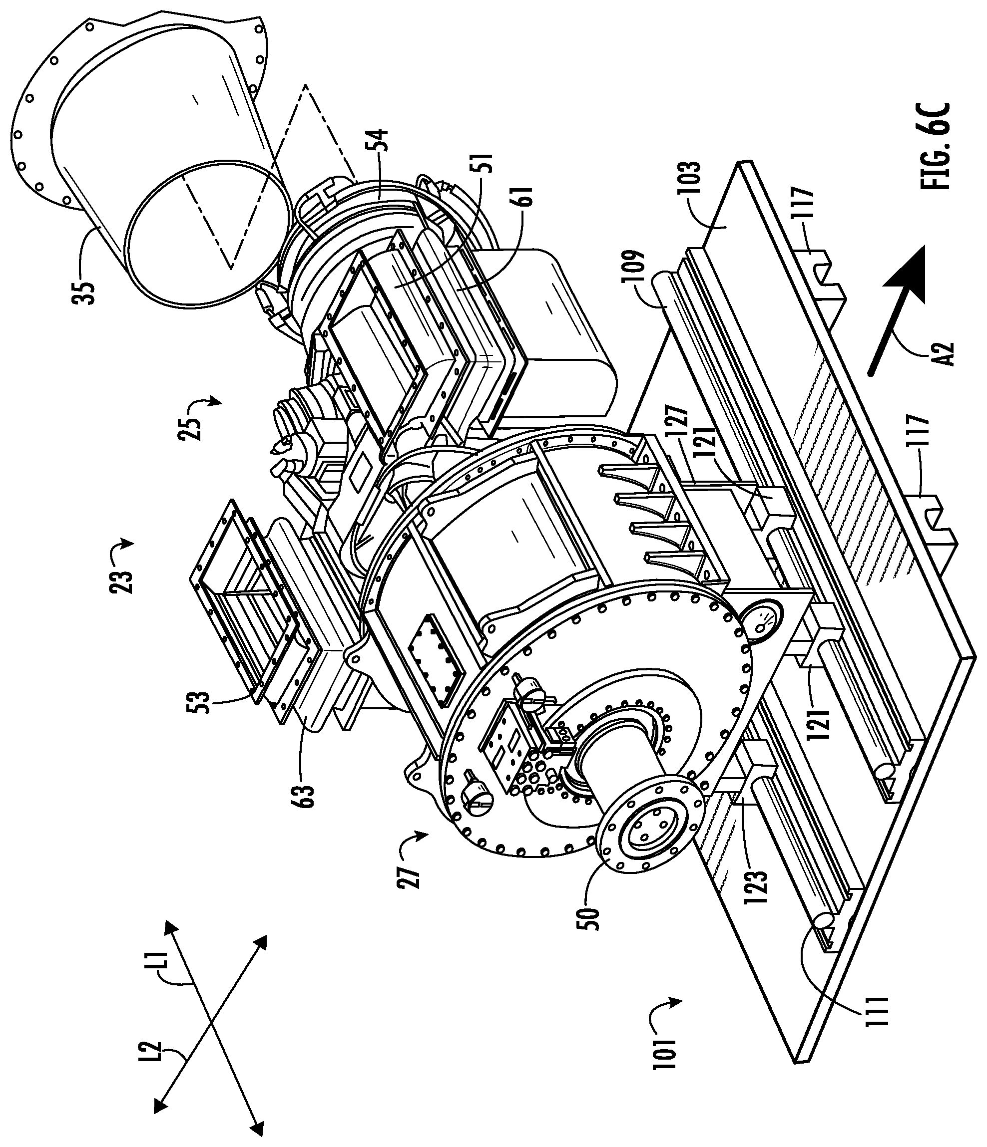
FIG. 6C is a perspective view of the DDU of FIG. 6B moved to a third position according to a first embodiment of the disclosure.
FIG. 7 is a side elevation view of the DDU mounted on a DDU positioner assembly according to a second embodiment of the disclosure.
FIG. 8A is a perspective view of the DDU of FIG. 7 in a first position according to a second embodiment of the disclosure.
FIG. 8B is a perspective view of the DDU of FIG. 8A moved to a second position according to a second embodiment of the disclosure.
FIG. 8C is a perspective view of the DDU of FIG. 8B moved to a third position according to a second embodiment of the disclosure.
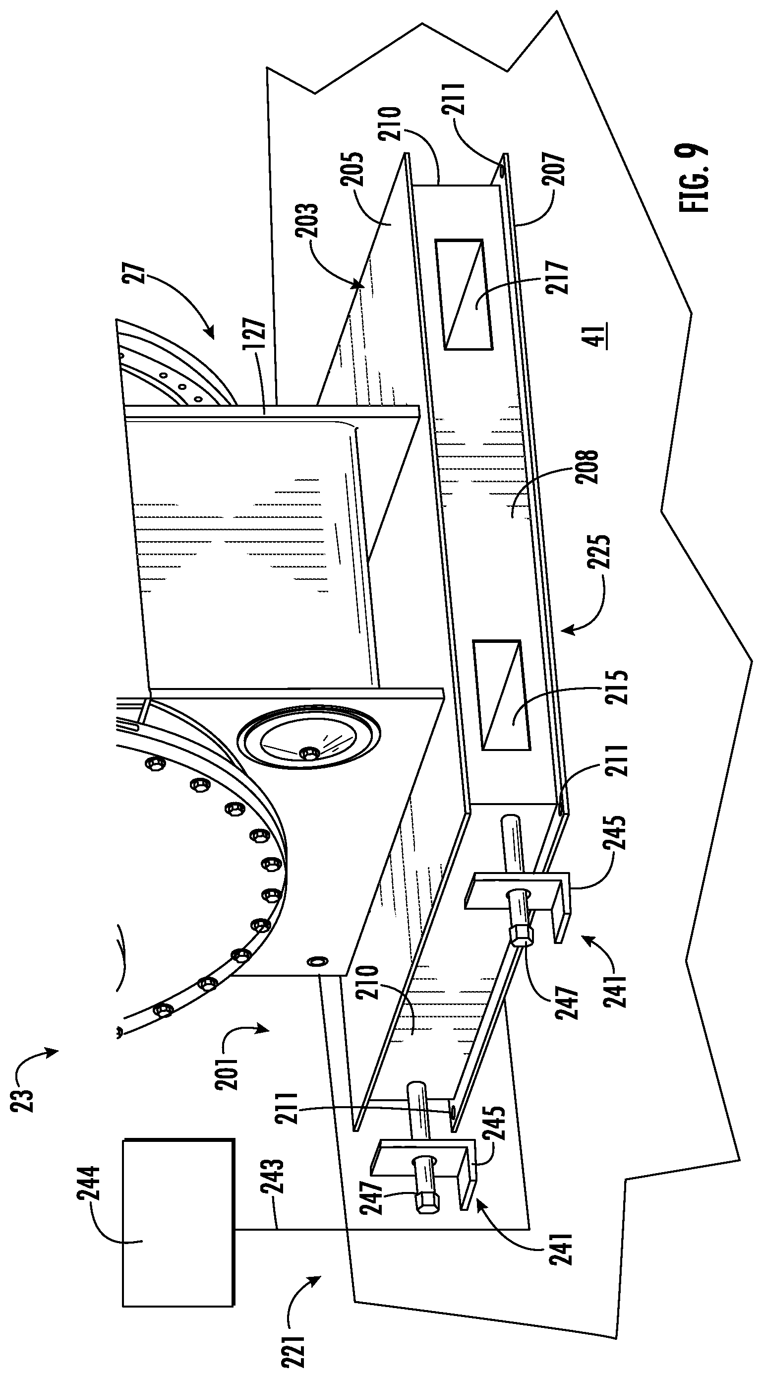
FIG. 9 is an enlarged detail of a portion of the DDU positioner assembly according to a second embodiment of the disclosure.
FIG. 10 is a detail of a portion of the DDU positioner assembly according to a second embodiment.
FIG. 11 is a side elevation view of the DDU mounted on a DDU positioner assembly according to a third embodiment of the disclosure.
FIG. 12A is a perspective view of the DDU of FIG. 11 in a first position according to a third embodiment of the disclosure.
FIG. 12B is a perspective view of the DDU of FIG. 12A moved to a second position according to a third embodiment of the disclosure.
FIG. 12C is a perspective view of the DDU of FIG. 12B moved to a third position according to a third embodiment of the disclosure.
Corresponding parts are designated by corresponding reference numbers throughout the drawings.
DETAILED DESCRIPTION
Generally, this disclosure is directed to a direct drive unit (DDU) positioner assembly, positioning system, removal system, and/or associated mechanisms that will allow a DDU including a gearbox and a turbine engine connected to the gearbox to be detached from surrounding equipment and removed through the side of an enclosure housing the direct drive unit. The system will allow for inspections, maintenance, or even a complete exchange of the direct drive unit with another if necessary.
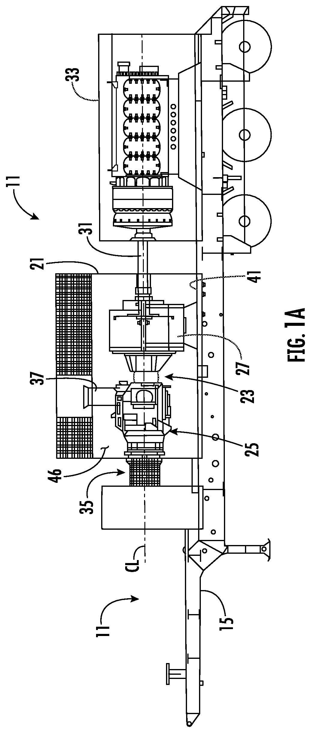
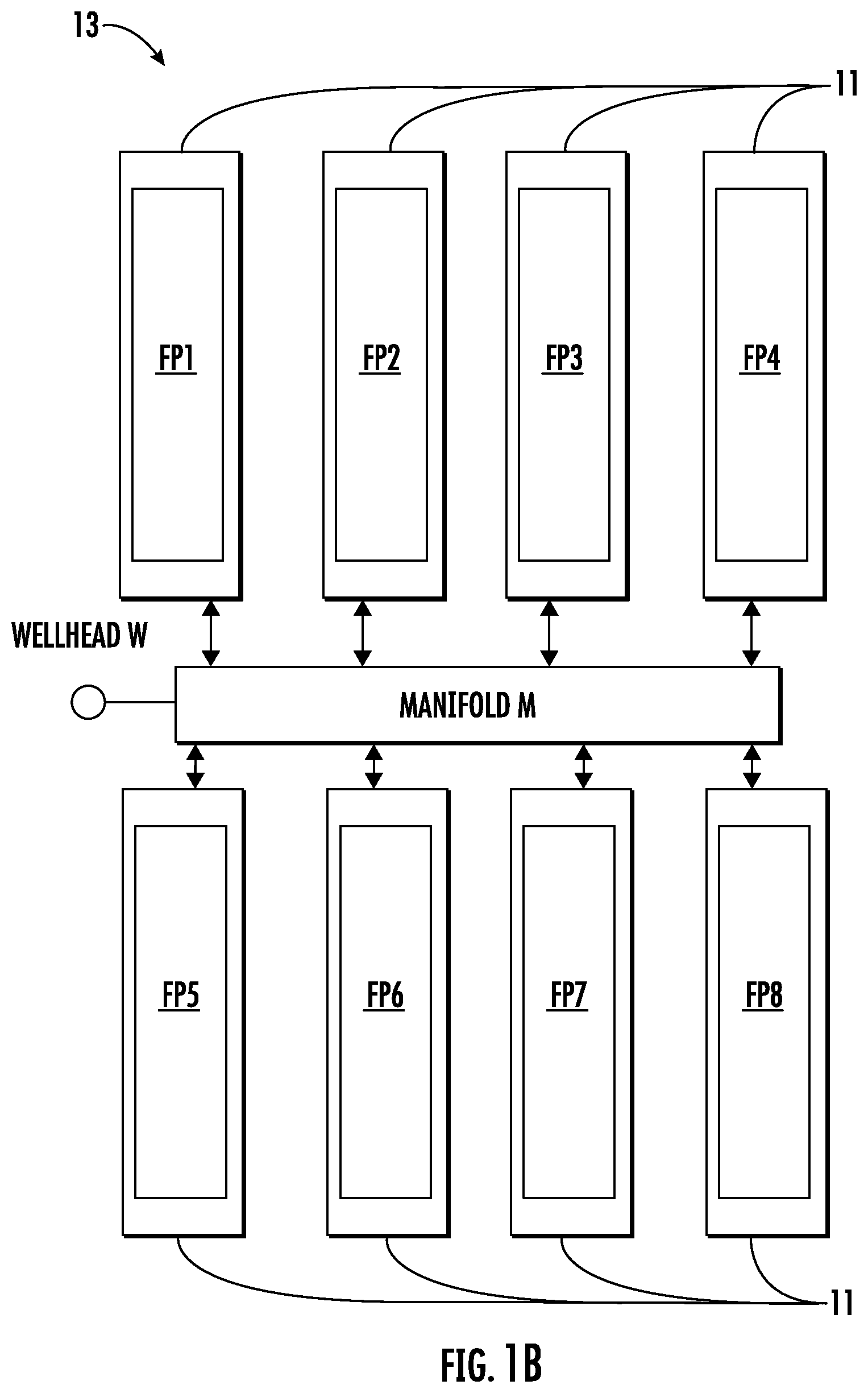
FIG. 1A illustrates a schematic view of a pumping unit 11 for use in a high-pressure, high power, fluid pumping system 13 (FIG. 1B) for use in hydraulic fracturing operations according to one embodiment of the disclosure. FIG. 1B shows a typical pad layout of the pumping units 11 (indicated as FP1, FP2, FP3, FP4, FP5, FP6, FP7, FP8) with the pumping units all operatively connected to a manifold M that is operatively connected to a wellhead W. By way of an example, the system 13 is a hydraulic fracturing application that may be sized to achieve a maximum rated horsepower of 24,000 HP for the pumping system 13, including a quantity of eight (8) 3000 horsepower (HP) pumping units 11 that may be used in one embodiment of the disclosure. It will be understood that the fluid pumping system 13 may include associated service equipment such as hoses, connections, and assemblies, among other devices and tools. As shown in FIG. 1, each of the pumping units 11 are mounted on a trailer 15 for transport and positioning at the jobsite. Each pumping unit 11 includes an enclosure 21 that houses a direct drive unit (DDU) 23 including a gas turbine engine 25 operatively connected to a gearbox 27. The pumping unit 11 has a driveshaft 31 operatively connected to the gearbox 27. The pumping unit 11 includes a high-pressure, high-power, reciprocating positive displacement pump 33 that is operatively connected to the DDU 23 via the driveshaft 31. In one embodiment, the pumping unit 11 is mounted on the trailer 15 adjacent the DDU 23. The trailer 15 includes other associated components such as a turbine exhaust duct 35 operatively connected to the gas turbine engine 25, air intake duct 37 operatively connected to the gas turbine, and other associated equipment hoses, connections, etc. to facilitate operation of the fluid pumping unit 11.
In the illustrated embodiment, the gas turbine engine 25 is a Vericor Model TF50F bi-fuel turbine; however, the direct drive unit 23 may include other gas turbines or suitable drive units, systems, and/or mechanisms suitable for use as a hydraulic fracturing pump drive without departing from the disclosure. The gas turbine engine 25 is cantilever mounted to the gearbox 27 with the gearbox supported by the floor 41 of the enclosure 21. The gearbox 27 may be a reduction helical gearbox that has a constant running power rating of 5500 SHP and intermittent power output of 5850 SHP, or other suitable gearbox. It should also be noted that, while the disclosure primarily describes the systems and mechanisms for use with direct drive units 23 to operate fracturing pumping units 33, the disclosed systems and mechanisms may also be directed to other equipment within the well stimulation industry such as, for example, blenders, cementing units, power generators and related equipment, without departing from the scope of the disclosure.
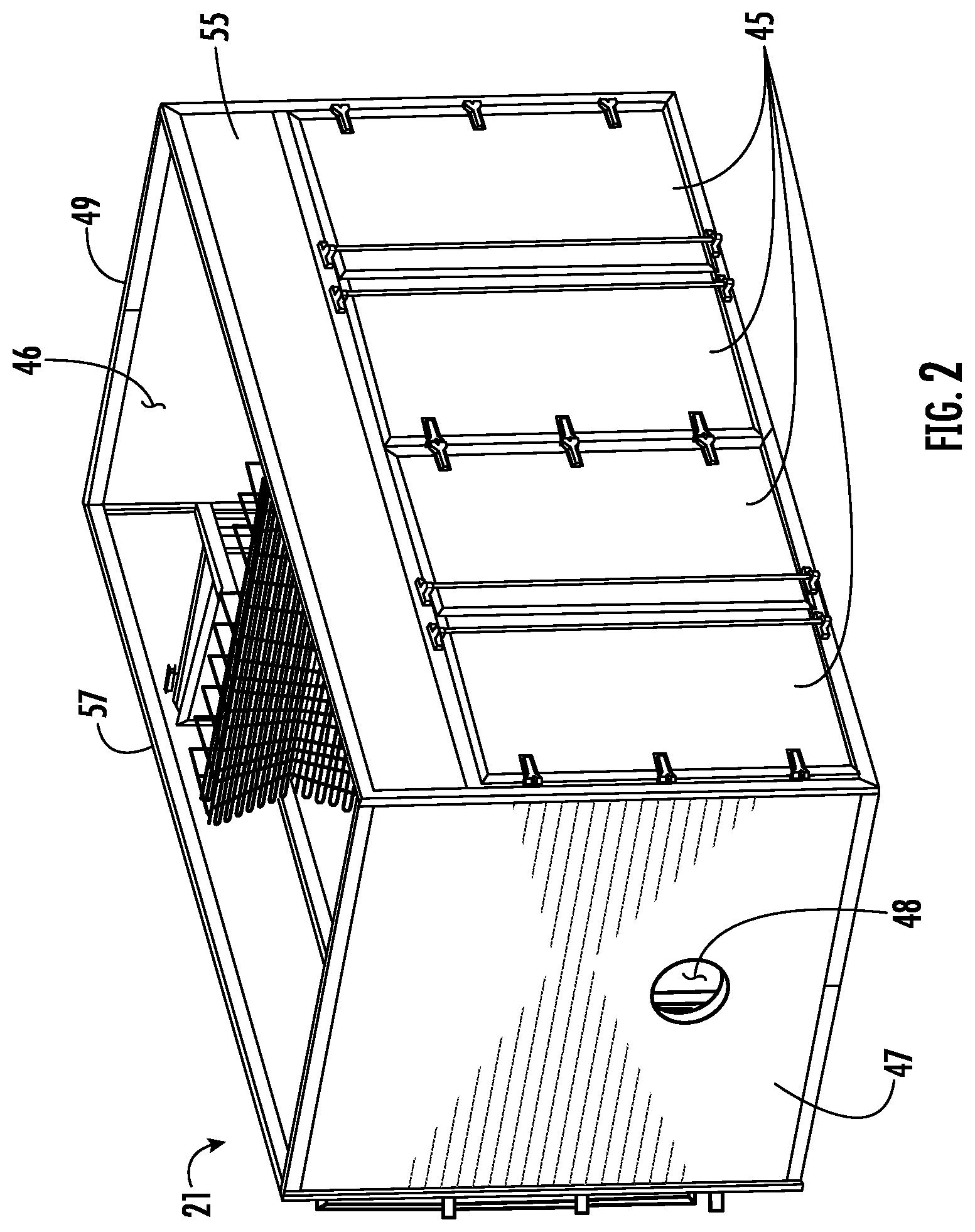
FIG. 2 illustrates the enclosure 21 that houses the direct drive unit 23 in an interior space 46 of the enclosure. In one embodiment, the enclosure has access doors 45 for removal of the DDU 23 from the enclosure and/or other components within the enclosure. The enclosure 21 provides sound attenuation of the DDU 23 during operation.
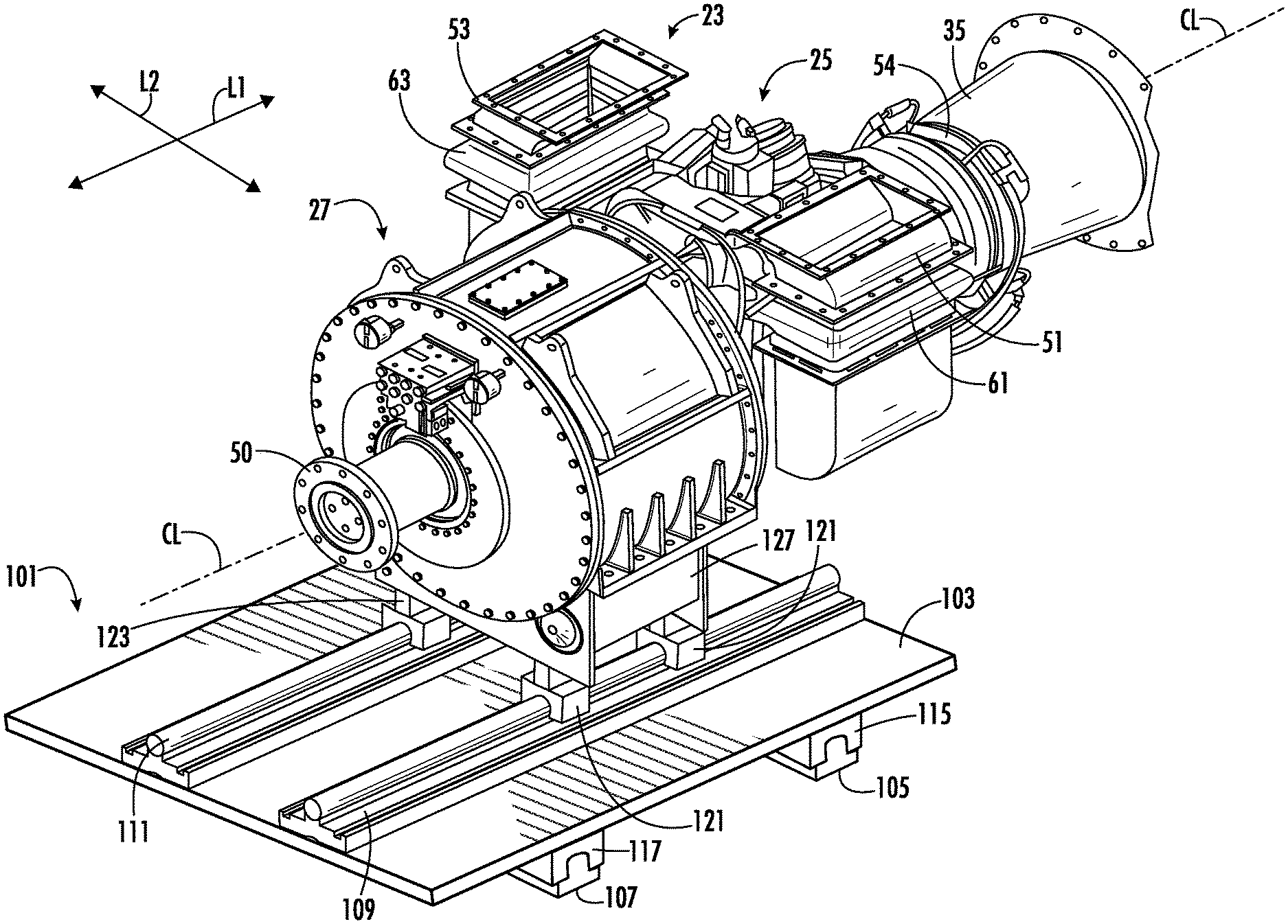
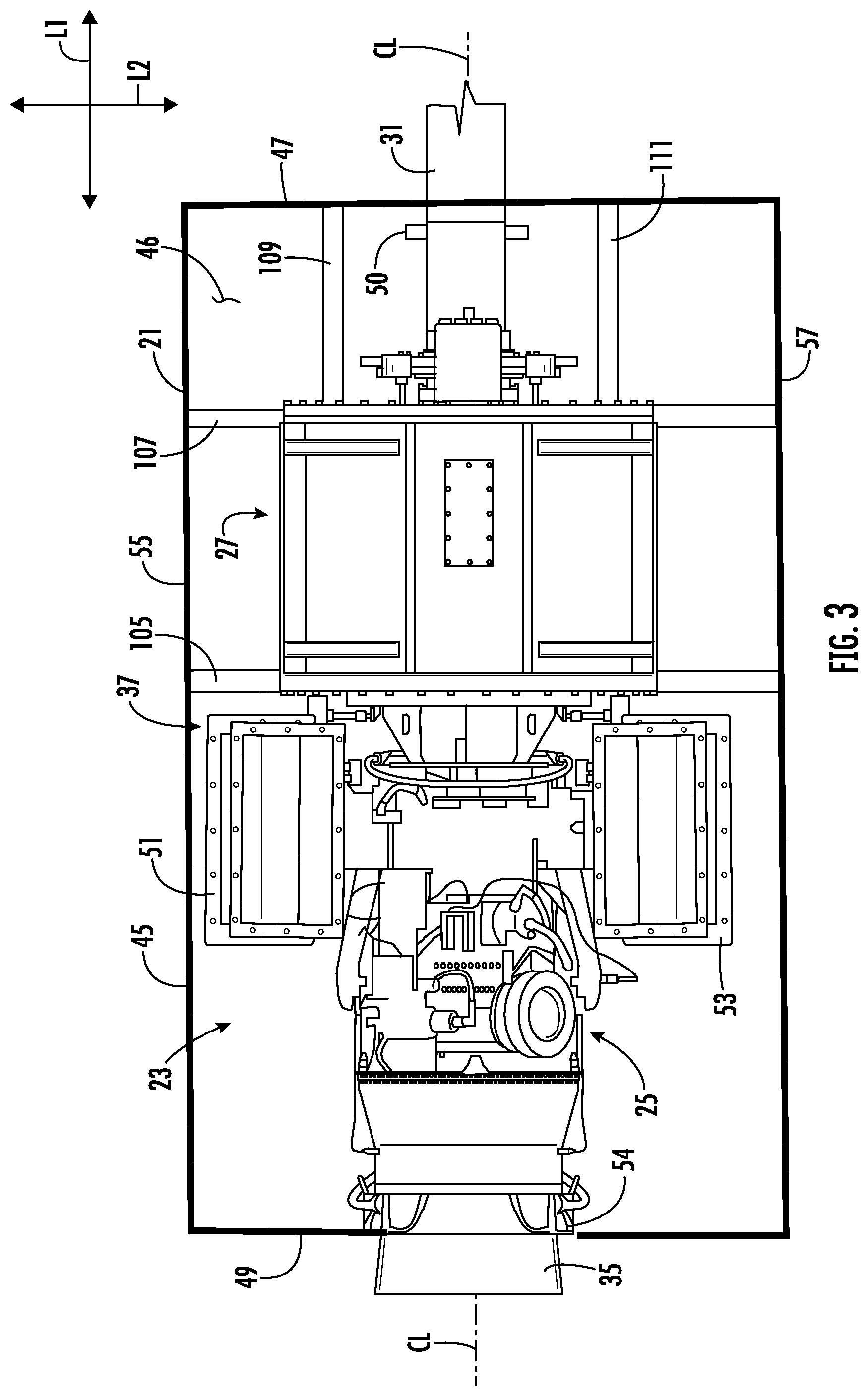
As shown in FIG. 3, the direct drive unit 23 and the enclosure 21 has a longitudinal axis L1 and a lateral axis L2 transverse to the longitudinal axis. FIG. 3 illustrates a top view of the enclosure 21 with the DDU 23 shown attached to the driveshaft 31 that extends through an opening 48 in a first longitudinal end 47 of the enclosure. An air exhaust assembly 35 extends through a second longitudinal end 49 of the enclosure. The DDU 23 has a central axis CL extending in the longitudinal direction L1 that extends through the centerline of the unit and is aligned with the centerline of the driveshaft 31. The gearbox 27 includes an outlet flange 50 that is connected to the driveshaft 31. The gas turbine engine 25 has two air inlet ports 51, 53 on a respective lateral side of the central axis CL and an exhaust duct flange 54 that connects the gas turbine engine to the air exhaust assembly 35 at the longitudinal end 49 of the enclosure 21. In one embodiment, the access doors 45 are mounted on a first lateral side 55 of the enclosure 21, but the enclosure may have additional access doors on a second lateral side 57 of the enclosure, or the access doors may be positioned only on the second lateral side without departing from the scope of this disclosure. The gas turbine engine 25 may include polymer expansion joints 61, 63 connected to air inlet ports 51, 53, to facilitate the removal of the gas turbine engine from the enclosure 21. The gas turbine engine 25 may include various fuel lines, communication lines, hydraulic and pneumatic connections, and other connections or accessories needed for operation of the gas turbine engine without departing from the disclosure. Such connections may utilize quick disconnect fittings and check valves to facilitate disconnection of the gas turbine engine 25 during removal of the DDU 23 from the enclosure 21. Further, such connections such as fuel lines and hydraulic lines may run to a single bulkhead (not shown) within or near the enclosure to allow for quick disconnection by locating these connections in a common location.
FIG. 4 is a side elevation view of the DDU 23 as viewed from the lateral side 55 of the enclosure 21, with the DDU being mounted on a DDU positioner assembly or DDU positioning system 101 (FIGS. 4-6C) for positioning the DDU for withdrawal or removal from the enclosure through the access doors 45. In one embodiment, the DDU positioner assembly 101 comprises a platform 103 slidably mounted to overlie two lateral rails 105, 107 mounted to overlie the floor 41 of the enclosure 21 and extending laterally across the enclosure generally between the lateral sides 55, 57. The DDU positioner assembly 101 comprises two longitudinal rails 109, 111 mounted to overlie the platform 103 and extending in the longitudinal direction L1. The DDU 23 is slidably mounted on the longitudinal rails 109, 111 for positioning the DDU in the longitudinal direction L1. In one embodiment, the DDU positioner assembly 101 includes lateral guide rollers 115, 117 mounted on a respective lateral rail 105, 107, and longitudinal guide rollers 121, 123 mounted on a respective longitudinal rail 109, 111. The platform 103 is connected to the lateral guide rollers 115, 117 to allow slidable movement and positioning of the DDU 23 mounted on the platform in the lateral direction L2 via the lateral rails 105, 107. The longitudinal guide rollers 121, 123 are connected to a mounting base 127 of the gearbox 27 to allow slidable movement and positioning of the DDU 23 in the longitudinal direction L1 via the longitudinal rails 109, 111. In one embodiment, the DDU positioner assembly 101 includes four lateral guide rollers 115, 117 and four longitudinal guide rollers 121, 123, but more or less than eight guide rollers may be provided without departing from the scope of the disclosure. Further, more or less than two longitudinal rails 109, 111, and more or less than two lateral rails 105, 107 may be provided without departing from the scope of the disclosure. In one embodiment, the guide rollers 115, 117, 121, 123 may be a caged ball type linear motion (LM) Guide, model number SPS20LR available from THK America Inc., or any similar make or model number without departing from the scope of the disclosure. The DDU positioner assembly 101 may be equipped with locking mechanisms 128 mounted on a respective guide roller 115, 117, 121, 123. The locking mechanisms 128 may be spring loaded and will default to the locked position to allow the DDU 23 to be secured in the operating position. The locking mechanism 128 may be otherwise located on the positioning system 101 without departing from the disclosure.
Exemplary loading calculations for sizing the guide rails 105, 107, 109, 111 are shown below and are based on the Vericor TF50F turbine parameters as follows: approximate turbine weight, 1475 lbs.; approximate fuel system weight, 85 lbs.; approximate gearbox weight, 4000 lbs.; for a total approximate weight of 5559 lbs. Various other parameters may be applicable based on the make, model, and size of the gas turbine engine 25.
Because of the arrangement the direct drive unit 23 including the gas turbine engine 25 cantilever mounted onto the gearbox 27 and extending in the longitudinal direction L1 from the gearbox, there is added load put onto the rear lateral guide rollers 115 and the rear longitudinal guide rollers 121, 123 (the guide rollers mounted closest to the gas turbine engine). Accordingly, an increased load rating may be applied to the rear guide rollers 115, 121, 123 if required. The calculation of the cantilever load and the reaction forces may be calculated with the formulas shown below, which may also be used for further design and implementation of the disclosed removal mechanisms.
Maximum Reaction at the fixed end may be expressed as: R.sub.A=qL.
where: R.sub.A=reaction force in A (N, lb), q=uniform distributed load (N/m, N/mm, lb/in), and
L=length of cantilever beam (m, mm, in).
Maximum Moment at the fixed end may be expressed as M.sub.A=-q L.sup.2/2
Maximum Deflection at the end may be expressed as .delta..sub.B=q L.sup.4/(8 E I).
where: .delta..sub.B=maximum deflection in B (m, mm, in).
In one embodiment, the longitudinal guide rollers 121, 123 connected to the support structure 127 of the gearbox 27 are positioned between each pair of the lateral guide rollers 115, 117 to ensure equal weight distribution over the platform 103 and to avoid cantilever loading the platform. Different configurations of platforms, sliders, rails and mounts are contemplated and considered within the scope of the disclosure. The configurations of the DDU positioner assembly 101 may vary to suit a particular DDU 23 with various alternative combinations of makes, model, and sizes of the gas turbine engine 25 and the gearbox 27.
In one embodiment, the guide rails 105, 107, 109, 111 are made from a steel composition that has been mill finished and shot blasted to protect the rail from the high heat environment within the turbine enclosure 21 and ensure strength retention under the exposed temperatures. In one embodiment, the platform 103 is constructed out of a composite material; however, other materials are contemplated and considered within the scope of the disclosure, such as but not limited to, steel or stainless steel. The guide rails 105, 107, 109, 111, platform 103, and/or other components of the DDU positioner assembly 101 may be made of various other suitable materials without departing from the scope of the disclosure.
FIGS. 6A-6B illustrate an exemplary method of removing the direct drive unit 23 from the enclosure 21 utilizing the DDU positioner assembly 101. FIG. 6A shows the DDU 23 in a first/operating position for operation with the pump 33 of the pumping unit 11. The method includes accessing the enclosure 21 and disconnecting the gas turbine engine 25 from the air inlet ducting 37. The flanges 51, 53 may be disconnected from the air inlet ducting 37 and the expansion joints 61, 63 flexed to allow separation of the DDU 23 from the air inlet ducting. The gas turbine engine 25 may be disconnected from the air exhaust ducting 35 by disconnecting the exhaust duct flange 54 from the air exhaust ducting. Corresponding hoses, piping, wiring, and cabling including fuel lines, electrical lines, hydraulic lines, control lines or any other connection that is needed for operation of the gas turbine engine 25 may also be disconnected so that the gas turbine engine is free to move without damaging any of the operational connections needed for operation of the gas turbine engine. For example, the air bleed off valve ducting may be removed from the turbine engine 25 and secured at a location free of interference with movement of the turbine engine. Alternatively, some hoses, piping, wiring, etc. may include enough slack or flexibility so that the DDU 23 may be initially moved before complete disconnection of the connections from the gas turbine engine 25 are required for removal of the DDU from the enclosure 21. The gearbox 27 may be disconnected from the driveshaft 31 by disconnecting the outlet flange 50 from the driveshaft. In one embodiment, the driveshaft 31 may be a slip-fit driveshaft allowing the driveshaft to contract to facilitate disconnection from the DDU 23. In one embodiment, the driveshaft 31 may be a 390. Series, GWB Model 390.80 driveshaft available Dana Corporation, or other suitable driveshaft. The gearbox 27 may be disconnected from any other connections needed for operation of the DDU 23 to obtain freedom of movement of the gearbox without damaging any of the operating connections.
Once the gas turbine engine 25 is disconnected from the respective connections and the gearbox 27 is disconnected from the driveshaft 31, the DDU positioner assembly 101 is operated to position the direct drive unit 23 for withdrawal from the enclosure 21. As shown in FIG. 6B, the DDU 23 is positioned in a second position where the DDU is first moved in the longitudinal direction L1 in the direction of arrow A1 by sliding the DDU along the longitudinal rails 109, 111. In one embodiment, prior to initial movement of the DDU 23 in the longitudinal direction L1, the longitudinal locks 128 associated with the longitudinal guide rollers 121, 123 must be released to allow the movement of the DDU in the longitudinal direction. After the movement of the DDU 23 in the longitudinal direction L1 to the second position, the longitudinal locks 128 may be reengaged to lock the longitudinal guide rollers 121, 123 and prevent further or additional unwanted movement of the DDU 23 along the longitudinal rails 109, 111, and the lateral locks 128 associated with the lateral guide rollers 115, 117 may be disengaged to allow lateral movement of the DDU 23. Next, the platform 103 may be moved to a third position by moving in the lateral direction L2 in the direction of arrow A2 (FIG. 6C) by sliding movement of the lateral guide rollers 115, 117 along the lateral guide rails 105, 107. The DDU 23 is mounted to the platform 103 and moves with the platform in the lateral direction L2 to the third position of FIG. 6C. As shown in FIGS. 3 and 5, the lateral guide rails 105, 107 may extend to the access doors 45 in either side 55, 57 of the enclosure 21. In some embodiments, lateral guide rail extensions 107' (FIG. 5) may be used to extend outside of the enclosure 21 to allow the platform 103 and DDU 23 to be slid out of the enclosure onto an adjacent supporting structure or vehicle (e.g., maintenance inspection platform or other suitable structure), or the platform 103 and DDU 23 may be accessed through the access doors 45 of the enclosure 21 by a lifting mechanism (e.g., a forklift, crane, or other suitable lifting mechanism) to fully remove the DDU from the enclosure. The various method steps described herein for the method of positioning or removing the DDU 23 may be otherwise performed in an alternative order or simultaneously, or more or less steps may be used without departing from the scope of the disclosure.
FIGS. 7-10 illustrates a second embodiment of a DDU positioner assembly or system 201 for positioning the direct drive unit 23 housed in the enclosure 21. In the illustrated embodiment, the DDU 23 includes a gas turbine engine 25 and a gearbox 27 identical to the first embodiment of the disclosure, but the DDU positioner assembly 201 may be used to position a DDU that is alternatively configured without departing from the disclosure. As such, like or similar reference numbers will be used to describe identical or similar features between the two embodiments.
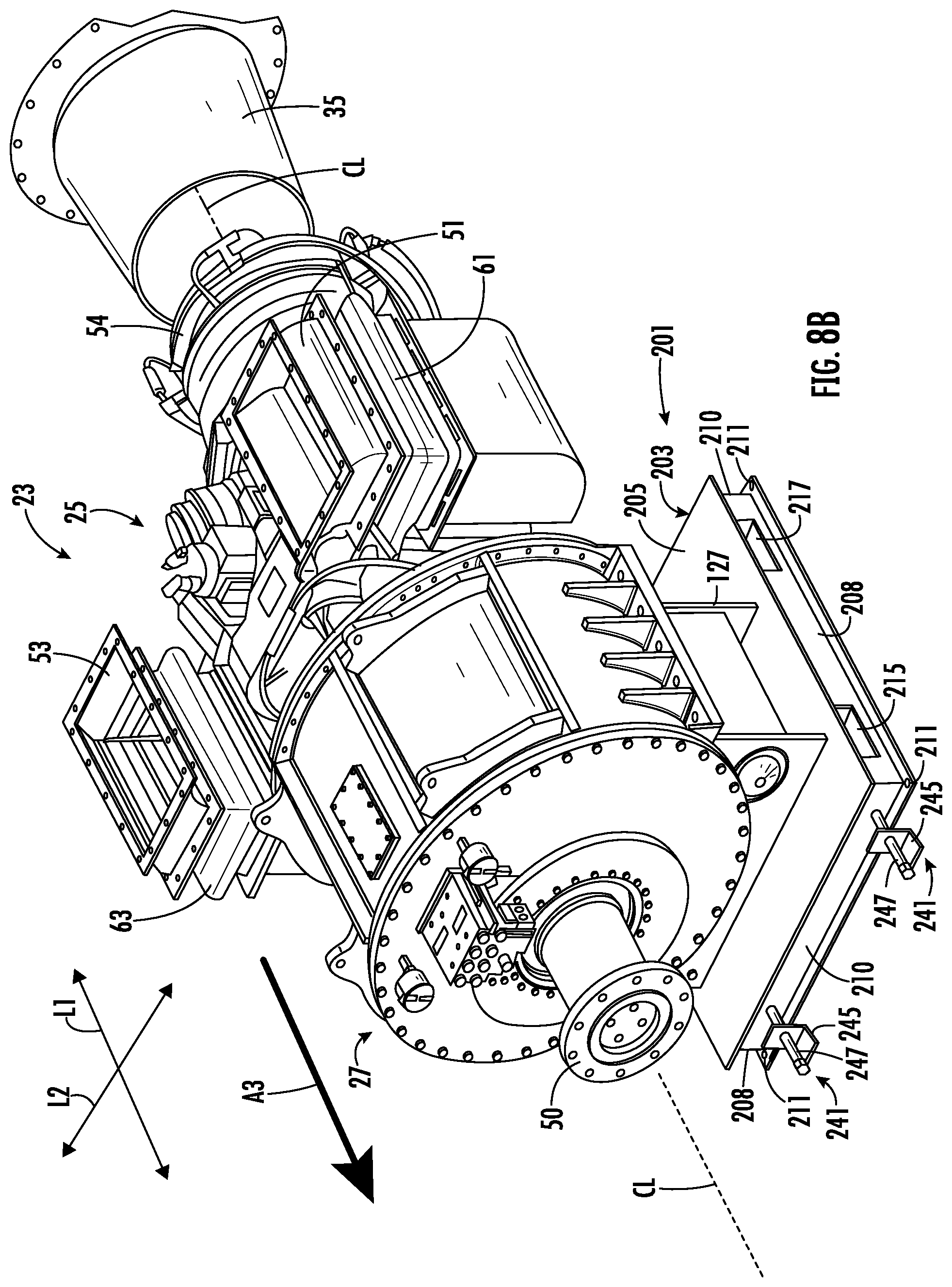
In one embodiment, the DDU positioner assembly 201 includes a platform 203 that supports the gearbox 27 and has a top surface 205, a bottom surface 207, two sides 208, and two ends 210. The gearbox 27 is fixedly mounted to the top surface 205 of the platform 203. The platform 203 is slidably mounted on the base 41 of the enclosure 21 with the bottom surface 207 of the platform being in slidable engagement with the floor of the enclosure. In a first or operating position (FIGS. 7 and 8A) of the direct drive unit 23, the platform 203 is fixedly attached to the base 41 by a plurality of fasteners 211. Upon removal of the fasteners 211, the platform 203 is capable of slidable movement with respect to the base 41. The platform 203 is connected to the support structure 127 of the gearbox 27 so that the drive unit 23 moves with the platform. In one embodiment, the platform 203 has two lifting openings 215, 217 extending between respective sides 208 of the platform. As shown in FIG. 7, the lifting opening 215 towards the front of the gearbox 27 (closest to the drive shaft flange 50) is spaced a first distance D1 from a centerline CT of the gearbox and the lifting opening 217 towards the rear of the gearbox (closest to the gas turbine engine 25) is spaced a second distance from the centerline CT of the gearbox, with the distance D2 being greater than the distance D2. The rear lifting opening 217 is farther from the centerline CT of the gearbox 27 because of the cantilever mounted gas turbine engine 25 that shifts the center of gravity of the DDU 23 from the centerline CT of the gearbox in the longitudinal direction toward the gas turbine engine. The platform 203 may be otherwise configured and/or arranged without departing from the scope of the disclosure.
In one embodiment, the DDU positioner assembly 201 includes a lubricator or lubrication system 221 (FIG. 9) to convey lubricant (e.g., grease or other suitable lubricant) from a lubricant reservoir 244 to a location between the bottom surface 207 of the platform 201 and the base 41 of the enclosure. The DDU positioner assembly 201 includes a lubrication portion 225 (FIG. 10) of the base 41 below the platform 203. As shown in FIG. 10, the portion 225 of the base 41 includes a plurality of lubrication grooves 227. The lubrication grooves 227 are in fluid communication with the lubricator 221 so that the lubricator provides lubricant to the grooves to facilitate sliding engagement between the platform 203 and the portion 225 of the base 41. The lubricator 221 includes a source of lubricant 244, tubing 243, and other required components (e.g., pump, controls, etc.) for delivering the lubricant to the lubrication portion 225 at a sufficiently high pressure for lubricant to fill the grooves 227 of the lubrication portion 225. In one embodiment, the lubricator 221 may be an automatic lubricator such as a model TLMP lubricator available from SKF Corporation, or the lubricator may be any other suitable lubricator including other automatic lubricators or manual lubricators without departing from the scope of the disclosure. In one embodiment, the lubrication portion 225 of the base 41 is an integral portion with the base or the floor of the enclosure 21, but the lubrication portion 225 may be a separate pad or component that is mounted between the base and the platform without departing from the disclosure. The lubricator 221 may be mounted inside the enclosure 21 or at least partially outside the enclosure without departing from the scope of the disclosure.
In one embodiment, the DDU positioner assembly 201 includes drive fasteners 241 mounted at one end 210 of the platform 203. In the illustrated embodiment, the drive fasteners 241 include a bracket 245 mounted to the floor 41 of the enclosure 21 and an impact screw 247 operatively connected to the bracket and the platform 203. The drive fasteners 241 may have other components and be otherwise arranged without departing from the disclosure. Further, more or less than two drive fasteners 241 may be provided without departing from the disclosure.
FIGS. 8A-9 illustrate an exemplary method of removing the DDU 23 from the enclosure 21 utilizing the DDU positioner assembly 201 of the second embodiment. The method is similar to the method of the first embodiment, in that the gas turbine engine 25 is disconnected from the air inlet ducting 37, the air exhaust ducting 35, and from other corresponding connections and components in a similar manner as discussed above for the first embodiment so that the gas turbine engine is free to move without damaging any of the operational connections and components needed for operation of the gas turbine engine. Further, the gearbox 27 is disconnected from the driveshaft 31 in a similar manner as the first embodiment, so that the DDU 23 has clearance for movement in the longitudinal direction L1 without interference with the driveshaft.
FIG. 8A shows the direct drive unit 23 in the first/operating position. Once the gas turbine engine 25 is disconnected from the respective components and connections and the gearbox 27 is disconnected from the driveshaft 31 and any other connections, the DDU positioner assembly 201 is operated to position the DDU 23 for withdrawal from the enclosure 21. First, the fasteners 211 fixedly attaching the platform 203 to the base 41 are removed. The lubricator 221 is operated to convey lubricant to the lubrication grooves 227 of the lubrication portion 225 of the base 41. After a sufficient amount of lubrication is located between the platform 203 and the lubrication portion 225 of the base 41, the drive fasteners 241 may be operated to move the platform 203 in the longitudinal direction L1 to a second position (FIG. 8B). As the impact screws 247 of the drive fasteners 241 are turned, the platform 203 is slid in the longitudinal direction L1 in the direction of arrow A3 (FIG. 8B). The lubricant provided in the lubrication grooves 227 and between the lubrication portion 225 and the bottom surface 207 of the platform reduces the sliding friction and allows the rotation of the impact screws 247 in the bracket 245 to advance the platform in the direction of arrow A3. The platform 203 is moved in the direction of arrow A3 a sufficient amount to allow access to the lifting openings 215, 217 by a lifting mechanism (e.g., forklift) 261 (FIG. 8C). The lifting mechanism 261 may include a forklift or other lifting mechanism that may access the interior 46 of the enclosure through the enclosure access doors 45. The lifting mechanism 261 is inserted into the lifting openings 215, 217 of the platform 203, and the DDU 23 is lifted and/or slid in the direction of arrow A4. The lifting mechanism 261 may move the DDU 23 to the third position (FIG. 8C), or transfer the DDU onto an adjacent supporting structure or vehicle (e.g., maintenance inspection platform or other suitable structure), or completely remove the platform 203 and DDU 23 from the enclosure. The various method steps described herein for the method of positioning or removing the DDU 23 by operating the DDU positioner assembly 201 may be otherwise performed in an alternative order or simultaneously, or more or less steps may be used without departing from the scope of the disclosure.
FIGS. 11-12C illustrate a third embodiment of a DDU positioner assembly or system 301 for positioning the direct drive unit 23 housed in the enclosure 21. In the illustrated embodiment, the DDU 23 includes a gas turbine engine 25 and a gearbox 27 identical to the first and second embodiments of the disclosure, but the DDU positioner assembly 301 may be used to position a DDU that is alternatively configured without departing from the disclosure as will be understood by those skilled in the art. The DDU positioner assembly 301 is generally similar to the DDU positioner assembly 201 of the second embodiment, except the drive fasteners 241 have been removed and an actuator 341 is added to the DDU positioner assembly of the third embodiment. As such, like or similar reference numbers will be used to describe identical or similar features between the second and third embodiments.
As shown in FIG. 11, the DDU positioner assembly 301 includes the actuator 341 that has a first end 345 connected to the base 41 of the enclosure 21 and a second end 347 connected to the end 210 of the platform 203. In one embodiment, the actuator 341 is a hydraulic cylinder that has a piston rod 351 that is extendible from a cylinder body 349 upon operation of the actuator. The actuator 341 may be controlled by a manual control valve or the actuator may be configured for remote operation by connection to corresponding automated control valves. In the illustrated embodiment, one actuator 341 is shown, but the DDU positioner assembly 301 may include more than one actuator without departing from the scope of the disclosure. Further, the actuator 341 may be otherwise located for attachment to the platform 203 without departing from the scope of the disclosure.
FIGS. 12A-12C illustrate an exemplary method of removing the DDU 23 from the enclosure 21 utilizing the DDU positioner assembly 301 of the second embodiment. The method is similar to the method of the utilizing the DDU positioner assembly 201 of the second embodiment, in that the gas turbine engine 25 is disconnected from the air inlet ducting 37, the air exhaust ducting 35, and from other corresponding connections and components in a similar manner as discussed above for the first embodiment so that the gas turbine engine is free to move without damaging any of the operational connections and components needed for operation of the gas turbine engine. Further, the gearbox 27 is disconnected from the driveshaft 31 in a similar manner as the first embodiment, so that the DDU 23 has clearance for movement in the longitudinal direction L1 without interference with the driveshaft. Also, the DDU positioner assembly 301 of the third embodiment includes the lubricator 221 (FIG. 9) for providing lubrication to lubrication grooves 227 of the lubrication portion 225 of the base 41 to facilitate sliding of the platform 203 in the longitudinal direction L1, so that the DDU positioner assembly of the third embodiment operates in a similar manner as the DDU positioner assembly 201 of the second embodiment.
FIG. 12A shows the direct drive unit 23 in the first/operating position. Once the gas turbine engine 25 is disconnected from the respective components and connections, and the gearbox 27 is disconnected from the driveshaft 31 and any other connections, the DDU positioner assembly 301 is operated to position the DDU 23 for withdrawal from the enclosure 21. First, the fasteners 211 fixedly attaching the platform 203 to the base 41 are removed. The lubricator 221 is operated to convey lubricant to the lubrication grooves 227 of the lubrication portion 225 of the base 41. After a sufficient amount of lubrication is located between the platform 203 and the lubrication portion 225 of the base 41, the actuator 341 may be operated to move the platform 203 in the longitudinal direction L1 to a second position (FIG. 12B). The extension of the piston rod 351 of the actuator 341 exerts a force on the platform 203 to slide the platform in the longitudinal direction L1 in the direction of arrow A3 (FIG. 12B). The lubricant provided in the lubrication grooves 227 and between the lubrication portion 225 and the bottom surface 207 of the platform reduces the sliding friction and allows the actuator 341 to advance the platform in the direction of arrow A3. As with the previous embodiment, the platform 203 is moved in the direction of arrow A3 a sufficient distance to allow access to the lifting openings 215, 217 by a lifting mechanism (e.g., forklift) 261 (FIG. 8C). The lifting mechanism 261 may include a forklift or other lifting mechanism that may access the interior 46 of the enclosure through the enclosure access doors 45. The lifting mechanism 261 is inserted into the lifting openings 215, 217 of the platform 203, and the DDU 23 is lifted and/or slid in the direction of arrow A4. Prior to moving the platform 203 in the direction of arrow A4, the actuator 341 may be disconnected from the platform (FIG. 12C) with the first end 347 of the actuator being separated from the platform and the second end 345 of the actuator remaining attached to the floor 41 of the enclosure. Alternatively, the second end 345 of the actuator 341 may be disconnected from the floor 41 of the enclosure and the first end 341 of the actuator may remain attached to the platform 203, or both ends of the actuator may be disconnected and the actuator removed without departing from the enclosure.
The lifting mechanism 261 may move the DDU 23 to the third position (FIG. 12C), or transfer the DDU onto an adjacent supporting structure or vehicle (e.g., maintenance inspection platform or other suitable structure), or completely remove the platform 203 and DDU 23 from the enclosure. The various method steps described herein for the method of positioning or removing the DDU 23 by operating the DDU positioner assembly 301 may be otherwise performed in an alternative order or simultaneously, or more or less steps may be used without departing from the scope of the disclosure.
Having now described some illustrative embodiments of the disclosure, it should be apparent to those skilled in the art that the foregoing is merely illustrative and not limiting, having been presented by way of example only. Numerous modifications and other embodiments are within the scope of one of ordinary skill in the art and are contemplated as falling within the scope of the disclosure. In particular, although many of the examples presented herein involve specific combinations of method acts or system elements, it should be understood that those acts and those elements may be combined in other ways to accomplish the same objectives. Those skilled in the art should appreciate that the parameters and configurations described herein are exemplary and that actual parameters and/or configurations will depend on the specific application in which the systems and techniques are used. Those skilled in the art should also recognize or be able to ascertain, using no more than routine experimentation, equivalents to the specific embodiments of the disclosure. It is, therefore, to be understood that the embodiments described herein are presented by way of example only and that, within the scope of any appended claims and equivalents thereto; the embodiments of the disclosure may be practiced other than as specifically described.
Furthermore, the scope of the present disclosure shall be construed to cover various modifications, combinations, additions, alterations, etc., above and to the above-described embodiments, which shall be considered to be within the scope of this disclosure. Accordingly, various features and characteristics as discussed herein may be selectively interchanged and applied to other illustrated and non-illustrated embodiment, and numerous variations, modifications, and additions further may be made thereto without departing from the spirit and scope of the present disclosure as set forth in the appended claims.
* * * * *
D00000
D00001
D00002
D00003
D00004
D00005
D00006
D00007
D00008
D00009
D00010
D00011
D00012
D00013

D00014
D00015

D00016

D00017

D00018

D00019

XML
uspto.report is an independent third-party trademark research tool that is not affiliated, endorsed, or sponsored by the United States Patent and Trademark Office (USPTO) or any other governmental organization. The information provided by uspto.report is based on publicly available data at the time of writing and is intended for informational purposes only.
While we strive to provide accurate and up-to-date information, we do not guarantee the accuracy, completeness, reliability, or suitability of the information displayed on this site. The use of this site is at your own risk. Any reliance you place on such information is therefore strictly at your own risk.
All official trademark data, including owner information, should be verified by visiting the official USPTO website at www.uspto.gov. This site is not intended to replace professional legal advice and should not be used as a substitute for consulting with a legal professional who is knowledgeable about trademark law.