Electric Powered Hydraulic Fracturing System Without Gear Reduction
Oehring; Jared
U.S. patent application number 16/152732 was filed with the patent office on 2019-04-11 for electric powered hydraulic fracturing system without gear reduction. This patent application is currently assigned to U.S. Well Services, LLC. The applicant listed for this patent is U.S. Well Services, LLC. Invention is credited to Jared Oehring.
| Application Number | 20190106970 16/152732 |
| Document ID | / |
| Family ID | 65993026 |
| Filed Date | 2019-04-11 |


| United States Patent Application | 20190106970 |
| Kind Code | A1 |
| Oehring; Jared | April 11, 2019 |
ELECTRIC POWERED HYDRAULIC FRACTURING SYSTEM WITHOUT GEAR REDUCTION
Abstract
Embodiments include a hydraulic fracturing system for fracturing a subterranean formation including an electric pump fluidly connected to a well associated with the subterranean formation and powered by at least one electric motor, and configured to pump fluid into a wellbore associated with the well at a high pressure so that the fluid passes from the wellbore into the subterranean formation and fractures the subterranean formation. The system also includes at least one generator electrically coupled to the electric motor so as to generate electricity for use by the electric pump. In the system, a shaft of the motor is directly coupled to a crankshaft of the pump without an intermediate gear reduction system such that the shaft of the motor rotates at substantially the same speed as the crankshaft of the pump.
| Inventors: | Oehring; Jared; (Houston, TX) | ||||||||||
| Applicant: |
|
||||||||||
|---|---|---|---|---|---|---|---|---|---|---|---|
| Assignee: | U.S. Well Services, LLC Houston TX |
||||||||||
| Family ID: | 65993026 | ||||||||||
| Appl. No.: | 16/152732 | ||||||||||
| Filed: | October 5, 2018 |
Related U.S. Patent Documents
| Application Number | Filing Date | Patent Number | ||
|---|---|---|---|---|
| 62568723 | Oct 5, 2017 | |||
| Current U.S. Class: | 1/1 |
| Current CPC Class: | E21B 43/26 20130101 |
| International Class: | E21B 43/26 20060101 E21B043/26 |
Claims
1. A hydraulic fracturing system for fracturing a subterranean formation comprising: an electric pump fluidly connected to a well associated with the subterranean formation and powered by at least one electric motor, and configured to pump fluid into a wellbore associated with the well at a high pressure so that the fluid passes from the wellbore into the subterranean formation and fractures the subterranean formation; at least one generator electrically coupled to the electric motor so as to generate electricity for use by the electric pump; wherein a shaft of the motor is directly coupled to a crankshaft of the pump without an intermediate gear reduction system such that the shaft of the motor rotates at substantially the same speed as the crankshaft of the pump.
2. The system of claim 1, further comprising: a coupling device connecting the shaft of the motor to the crankshaft.
3. The system of claim 2, wherein the coupling device is a flexible coupling device or a rigid coupling device.
4. The system of claim 2, wherein the coupling device is at least one of a beam coupling, a bellows coupling, a chain coupling, a jaw coupling, a diaphragm coupling, a disc coupling, a gear coupling, a grid coupling, an Oldham coupling, a Schmidt coupling, or clamping coupling.
5. The system of claim 1, further comprising: a variable frequency drive connected to the at least one electric motor to control the speed of the at least one electric motor.
6. The system of claim 1, wherein the at least one generator comprises one of a turbine generator or a reciprocating engine generator, or a combination thereof.
7. The system of claim 1, wherein the electric pump comprises limited gearing.
8. A hydraulic fracturing system for fracturing a subterranean formation comprising: an electric pump fluidly connected to a well associated with the subterranean formation and configured to pump fluid into a wellbore associated with the well at a high pressure so that the fluid passes from the wellbore into the subterranean formation and fractures the subterranean formation; at least one electric motor providing operational energy to the electric pump; at least one generator electrically coupled to the electric motor so as to generate electricity for use by the electric pump; a variable frequency drive connected to the at least one electric motor to control the speed of the at least one electric motor; wherein a shaft of the motor is directly coupled to a crankshaft of the pump such that the shaft of the motor rotates at substantially the same speed as the crankshaft of the pump.
9. The system of claim 8, further comprising: a coupling device connecting the shaft of the motor to the crankshaft.
10. The system of claim 9, wherein the coupling device is a flexible coupling device or a rigid coupling device.
11. The system of claim 9, wherein the coupling device is at least one of a beam coupling, a bellows coupling, a chain coupling, a jaw coupling, a diaphragm coupling, a disc coupling, a gear coupling, a grid coupling, an Oldham coupling, a Schmidt coupling, or clamping coupling.
12. The system of claim 1, wherein the at least one generator comprises one of a turbine generator or a reciprocating engine generator, or a combination thereof.
13. The system of claim 1, wherein the electric pump comprises limited gearing.
14. The system of claim 13, wherein the limited gearing is internal to the electric pump.
15. The system of claim 13, wherein the limited gearing is external to the electric pump.
16. A hydraulic fracturing system for fracturing a subterranean formation comprising: an electric pump fluidly connected to a well associated with the subterranean formation and configured to pump fluid into a wellbore associated with the well at a high pressure so that the fluid passes from the wellbore into the subterranean formation and fractures the subterranean formation; at least one electric motor providing operational energy to the electric pump; a variable frequency drive connected to the at least one electric motor to control the speed of the at least one electric motor; wherein a shaft of the motor is directly coupled to a crankshaft of the pump such that the shaft of the motor rotates at substantially the same speed as the crankshaft of the pump and a torque output of the at least one electric motor is directly transmitted to the electric pump.
17. The system of claim 16, further comprising: a coupling device connecting the shaft of the motor to the crankshaft.
18. The system of claim 17, wherein the coupling device is a flexible coupling device or a rigid coupling device.
19. The system of claim 17, wherein the coupling device is at least one of a beam coupling, a bellows coupling, a chain coupling, a jaw coupling, a diaphragm coupling, a disc coupling, a gear coupling, a grid coupling, an Oldham coupling, a Schmidt coupling, or clamping coupling.
20. The system of claim 1, further comprising: at least one generator electrically coupled to the electric motor so as to generate electricity for use by the electric pump, wherein the at least one generator comprises one of a turbine generator or a reciprocating engine generator, or a combination thereof.
Description
CROSS REFERENCE TO RELATED APPLICATIONS
[0001] This application claims priority to and the benefit of co-pending U.S. Provisional Application Ser. No. 62/568,723 filed Oct. 5, 2017 titled "ELECTRIC POWERED HYDRAULIC FRACTURING SYSTEM WITHOUT GEAR REDUCTION" the full disclosure of which is hereby incorporated herein by reference in its entirety for all purposes.
BACKGROUND
1. Technical Field
[0002] This disclosure relates generally to hydraulic fracturing and more particularly to systems and methods for simplifying pumping components.
2. Background
[0003] With advancements in technology over the past few decades, the ability to reach unconventional sources of hydrocarbons has tremendously increased. Horizontal drilling and hydraulic fracturing are two such ways that new developments in technology have led to hydrocarbon production from previously unreachable shale formations. Hydraulic fracturing (fracturing) operations typically require powering numerous components in order to recover oil and gas resources from the ground. For example, hydraulic fracturing usually includes pumps that inject fracturing fluid down the wellbore, blenders that mix proppant into the fluid, cranes, wireline units, and many other components that all must perform different functions to carry out fracturing operations.
[0004] Typical fracturing operations utilize diesel engines to power fracturing pumps to deliver high pressure fracturing fluid into the formation. These diesel engines are typically coupled to a transmission and gear box (e.g., gear reducer) to step down the operation of the diesel engine compared to the operating parameters of the pump. A typical system may include a gear ratio of 6.353:1. This additional equipment adds cost and complexity to the overall system. The pumping units weigh more and cost more to ship. Additionally, the added components may be more prone to damage.
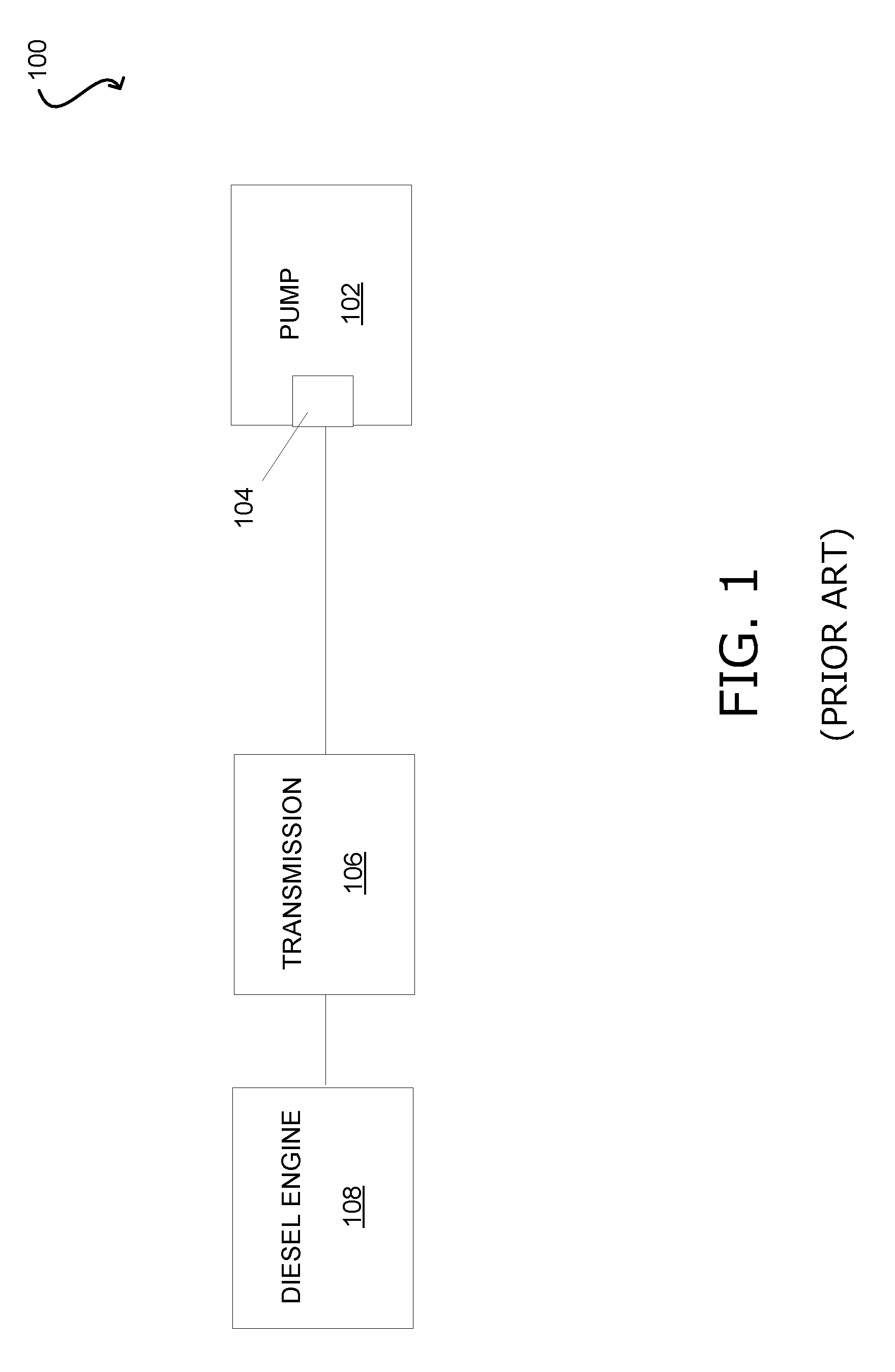
[0005] FIG. 1 is a block diagram of an embodiment of a pump arrangement 100 having one or more disadvantages described above. For example, the pump 102 includes an internal gear reduction system 104. The pump 102 is coupled to a transmission 106, which receives motive power from a diesel engine 108. This diesel engine may be loud or have significant environmental emissions. Additionally, the components such as the transmission 106 and the gear reduction system 104 add weight and complexity to the unit.
SUMMARY
[0006] Applicant recognized the problems noted above herein and conceived and developed embodiments of systems and methods, according to the present disclosure, for operating electric fracturing pumps.
[0007] In an embodiment a hydraulic fracturing system for fracturing a subterranean formation includes an electric pump fluidly connected to a well associated with the subterranean formation and powered by at least one electric motor, and configured to pump fluid into a wellbore associated with the well at a high pressure so that the fluid passes from the wellbore into the subterranean formation and fractures the subterranean formation. The system also includes at least one generator electrically coupled to the electric motor so as to generate electricity for use by the electric pump. In the system, a shaft of the motor is directly coupled to a crankshaft of the pump without an intermediate gear reduction system such that the shaft of the motor rotates at substantially the same speed as the crankshaft of the pump.
[0008] In an embodiment a hydraulic fracturing system for fracturing a subterranean formation includes an electric pump fluidly connected to a well associated with the subterranean formation and configured to pump fluid into a wellbore associated with the well at a high pressure so that the fluid passes from the wellbore into the subterranean formation and fractures the subterranean formation. The system includes at least one electric motor providing operational energy to the electric pump. The system also includes at least one generator electrically coupled to the electric motor so as to generate electricity for use by the electric pump. The system further includes variable frequency drive connected to the at least one electric motor to control the speed of the at least one electric motor. In the system, a shaft of the motor is directly coupled to a crankshaft of the pump such that the shaft of the motor rotates at substantially the same speed as the crankshaft of the pump.
[0009] In an embodiment a hydraulic fracturing system for fracturing a subterranean formation includes an electric pump fluidly connected to a well associated with the subterranean formation and configured to pump fluid into a wellbore associated with the well at a high pressure so that the fluid passes from the wellbore into the subterranean formation and fractures the subterranean formation. The system also includes at least one electric motor providing operational energy to the electric pump. The system includes a variable frequency drive connected to the at least one electric motor to control the speed of the at least one electric motor. In the system, a shaft of the motor is directly coupled to a crankshaft of the pump such that the shaft of the motor rotates at substantially the same speed as the crankshaft of the pump and a torque output of the at least one electric motor is directly transmitted to the electric pump.
BRIEF DESCRIPTION OF DRAWINGS
[0010] The foregoing aspects, features, and advantage of embodiments of the present disclosure will further be appreciated when considered with reference to the following description of embodiments and accompanying drawings. In describing embodiments of the disclosure illustrated in the appended drawings, specific terminology will be used for the sake of clarity. However, the disclosure is not intended to be limited to the specific terms used, and it is to be understood that each specific term includes equivalents that operate in a similar manner to accomplish a similar purpose.
[0011] FIG. 1 is a block diagram of a prior art diesel powered pumping system;
[0012] FIG. 2 is a block diagram of an embodiment of a hydraulic fracturing system, in accordance with embodiments of the present disclosure;
[0013] FIG. 3 is a block diagram of an embodiment of an electric powered pump assembly, in accordance with embodiments of the present disclosure; and
[0014] FIG. 4 is a block diagram of an embodiment of an electric powered pump assembly, in accordance with embodiments of the present disclosure.
DETAILED DESCRIPTION
[0015] The foregoing aspects, features, and advantages of the present disclosure will be further appreciated when considered with reference to the following description of embodiments and accompanying drawings. In describing the embodiments of the disclosure illustrated in the appended drawings, specific terminology will be used for the sake of clarity. However, the disclosure is not intended to be limited to the specific terms used, and it is to be understood that each specific term includes equivalents that operate in a similar manner to accomplish a similar purpose.
[0016] When introducing elements of various embodiments of the present disclosure, the articles "a", "an", "the", and "said" are intended to mean that there are one or more of the elements. The terms "comprising", "including", and "having" are intended to be inclusive and mean that there may be additional elements other than the listed elements. Any examples of operating parameters and/or environmental conditions are not exclusive of other parameters/conditions of the disclosed embodiments. Additionally, it should be understood that references to "one embodiment", "an embodiment", "certain embodiments", or "other embodiments" of the present disclosure are not intended to be interpreted as excluding the existence of additional embodiments that also incorporate the recited features. Furthermore, reference to terms such as "above", "below", "upper", "lower", "side", "front", "back", or other terms regarding orientation or direction are made with reference to the illustrated embodiments and are not intended to be limiting or exclude other orientations or directions. Additionally, recitations of steps of a method should be understood as being capable of being performed in any order unless specifically stated otherwise. Furthermore, the steps may be performed in series or in parallel unless specifically stated otherwise.
[0017] Embodiments of the present disclosure describe an electric powered pumping assembly with fewer components than a traditional diesel system for reduced weight and simplified operation. In certain embodiments, the assembly removes a transmission arranged between a power generator and the pump. Moreover, in embodiments, internal gearing or additional gear boxes are also removed. Accordingly, the assembly generally has a simplified configuration with reduced weight and fewer components for potential failure points.
[0018] FIG. 2 is a schematic diagram of an embodiment of a hydraulic fracturing system 10 that is used for pressurizing a wellbore 12 to create fractures 14 in a subterranean formation 16 that surrounds the wellbore 12. Included with the system 10 is a hydration unit 18 that receives fluid from a fluid source 20 via line 22, and also selectively receives additives from an additive source 24 via line 26. The additive source 24 can be separate from the hydration unit 18 as a stand-alone unit, or can be included as part of the same unit as the hydration unit 18. The fluid, which in one example is water, is mixed inside of the hydration unit 18 with the additives. In an embodiment, the fluid and additives are mixed over a period of time, to allow for uniform distribution of the additives within the fluid. In the example of FIG. 2, the fluid and additive mixture is transferred to a blender unit 28 via line 30. A proppant source 32 contains proppant, which is delivered to the blender unit 28 as represented by line 34, where line 34 can be a conveyer. Inside the blender unit 28, the proppant and fluid/additive mixture are combined to form a fracturing slurry, which is then transferred to a fracturing pump system 36 via line 38; thus fluid in line 38 includes the discharge of blender unit 28 which is the suction (or boost) for the fracturing pump system 36.
[0019] Blender unit 28 can have an onboard chemical additive system, such as with chemical pumps and augers. Optionally, additive source 24 can provide chemicals to blender unit 28; or a separate and standalone chemical additive system (not shown) can be provided for delivering chemicals to the blender unit 28. In an example, the pressure of the slurry in line 38 ranges from around 80 psi to around 100 psi. The pressure of the slurry can be increased up to around 15,000 psi by pump system 36. A motor 39, which connects to pump system 36 via connection 40, drives pump system 36 so that it can pressurize the slurry. In one example, the motor 39 is controlled by a variable frequency drive ("VFD").
[0020] After being discharged from pump system 36, slurry is pumped into a wellhead assembly 41. Discharge piping 42 connects discharge of pump system 36 with wellhead assembly 41 and provides a conduit for the slurry between the pump system 36 and the wellhead assembly 41. In an alternative, hoses or other connections can be used to provide a conduit for the slurry between the pump system 36 and the wellhead assembly 41. Optionally, any type of fluid can be pressurized by the fracturing pump system 36 to form injection fracturing fluid that is then pumped into the wellbore 12 for fracturing the formation 14, and is not limited to fluids having chemicals or proppant.
[0021] An example of a turbine 44 is provided in the example of FIG. 2. The turbine can be gas powered, receiving a combustible fuel from a fuel source 46 via a feed line 48. In one example, the combustible fuel is natural gas, and the fuel source 46 can be a container of natural gas or a well (not shown) proximate the turbine 44. Combustion of the fuel in the turbine 44 in turn powers a generator 50 that produces electricity. A shaft 52 connects the generator 50 to the turbine 44. The combination of the turbine 44, the generator 50, and the shaft 52 define a turbine generator 53. In another example, gearing can also be used to connect the turbine 44 and generator 50.
[0022] An example of a micro-grid 54 is further illustrated in FIG. 2, and which distributes electricity generated by the turbine generator 53. Included with the micro-grid 54 is a transformer 56 for stepping down voltage of the electricity generated by the generator 50 to a voltage more compatible for use by electrically powered devices in the hydraulic fracturing system 10. In another example, the power generated by the turbine generator and the power utilized by the electrically powered devices in the hydraulic fracturing system 10 are of the same voltage, such as 4160 V, so that main power transformers are not needed. In one embodiment, multiple 3500 kVA dry cast coil transformers are utilized. Electricity generated in generator 50 is conveyed to transformer 56 via line 58. In one example, transformer 56 steps the voltage down from 13.8 kV to around 600 V. Other step down voltages can include 4,160 V, 480 V, or other voltages.
[0023] The output or low voltage side of the transformer 56 connects to a power bus 60, lines 62, 64, 66, 68, 70, and 71 connect to power bus 60 and deliver electricity to electrically powered components of the system 10. More specifically, line 62 connects fluid source 20 to bus 60, line 64 connects additive source 24 to bus 60, line 66 connects hydration unit 18 to bus 60, line 68 connects proppant source 32 to bus 60, line 70 connects blender unit 28 to bus 60, and line 71 connects bus 60 to an optional variable frequency drive ("VFD") 72. Line 73 connects VFD 72 to motor 39. In one example, VFD 72 can be used to control operation of motor 39, and thus also operation of pump 36.
[0024] In an example, additive source 24 contains ten or more chemical pumps for supplementing the existing chemical pumps on the hydration unit 18 and blender unit 28. Chemicals from the additive source 24 can be delivered via lines 26 to either the hydration unit 18 and/or the blender unit 28. In one embodiment, the elements of the system 10 are mobile and can be readily transported to a well site adjacent the wellbore 12, such as on trailers or other platforms equipped with wheels or tracks.
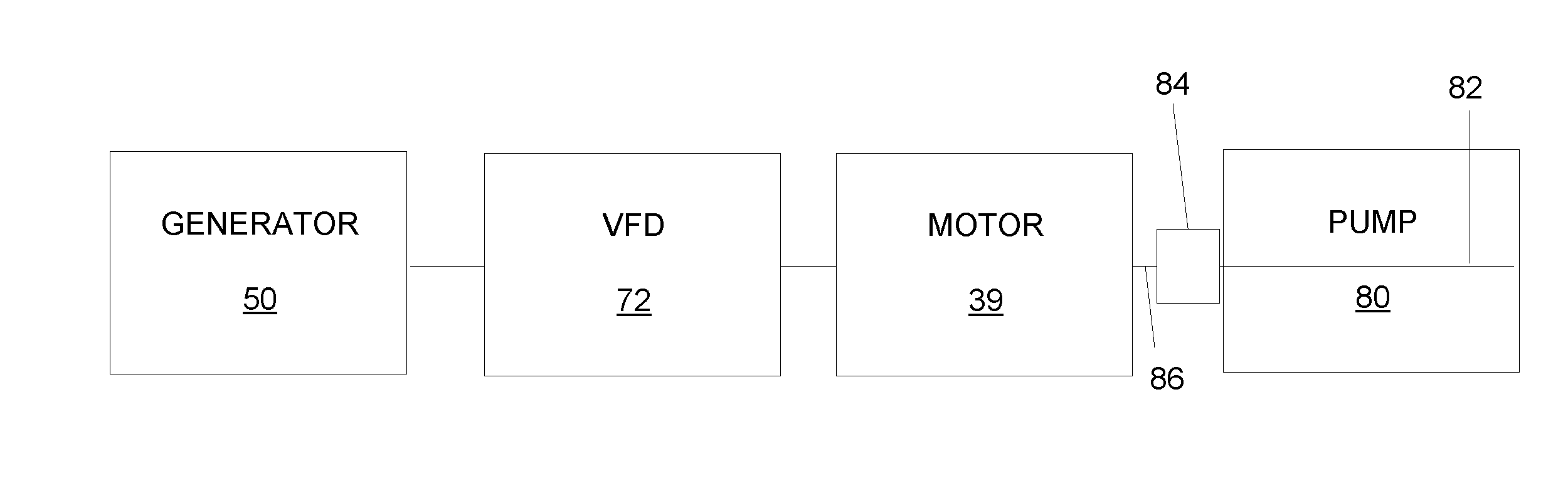
[0025] FIG. 3 is a schematic diagram of an embodiment of a pump 80 utilized in a fracturing operation. The illustrated pump 80 is powered by the generator 50, which may be part of the turbine generator 53 in certain embodiments. The pump 80 includes the motor 39 which transmits rotational force to the pump 80 via the electrical power transmitted from the generator 50. In the illustrated embodiment, the motor 39 is mechanically coupled directly to a crankshaft 82 of the pump 80, for example via a coupling device 84. The coupling device 84 may be rigid or flexible and arranged to align a shaft 86 of the motor 39 and the crankshaft 82, or to absorb alignment inaccuracies. In various embodiments, the coupling device 84 may include a beam, a bellows, a chain, a jaw, a diaphragm, a disc, a gear, a grid, an Oldham, a Schmidt, a clamping, or the like. It should be appreciated that the coupling device 84 may be omitted in certain embodiments. As illustrated, components such as a transmission and/or gear box (e.g., gear reducer) have been removed from the system in FIG. 3. Accordingly, the pump 80 and associated equipment, which may be mounted on one or more trailers, will have a reduced weight, thereby decreasing the cost of transporting the units to different well sites. Furthermore, the elimination of components such as the transmission and gear box, which may include complex moving parts and/or auxiliary fluid systems, reduces the complexity of the overall systems and improves reliability by eliminating components that may be prone to damage or breakdown. Additionally, maintenance costs may be reduced because there are fewer components to maintain.
[0026] In the illustrated embodiment, the pump 80 is coupled to the motor 39, which is coupled to the VFD 72 and the generator 50. As described above, the VFD may control operation of the motor 39, which thereby regulates operation of the pump. It should be appreciated that the generator 50 may be a turbine generator or any other type of electric power source. For example, in embodiments the VFD may be coupled to a grid or other power supply. Accordingly, the embodiment illustrated in FIG. 3 enables the crankshaft 82 of the pump 80 to rotate at substantially the same speed as the shaft 86 of the motor 39. As such, the speed of the motor 39 may be adjusted in order to change operating parameters of the pump 80. In various embodiments, the pump 80 may be configured to provide a sufficient output pressure at a speed that is compatible with operation of the motor 39. Accordingly, additional components such as the above-described gear reduction may be removed, providing a more streamlined system that weighs less and also eliminates potential failure points.
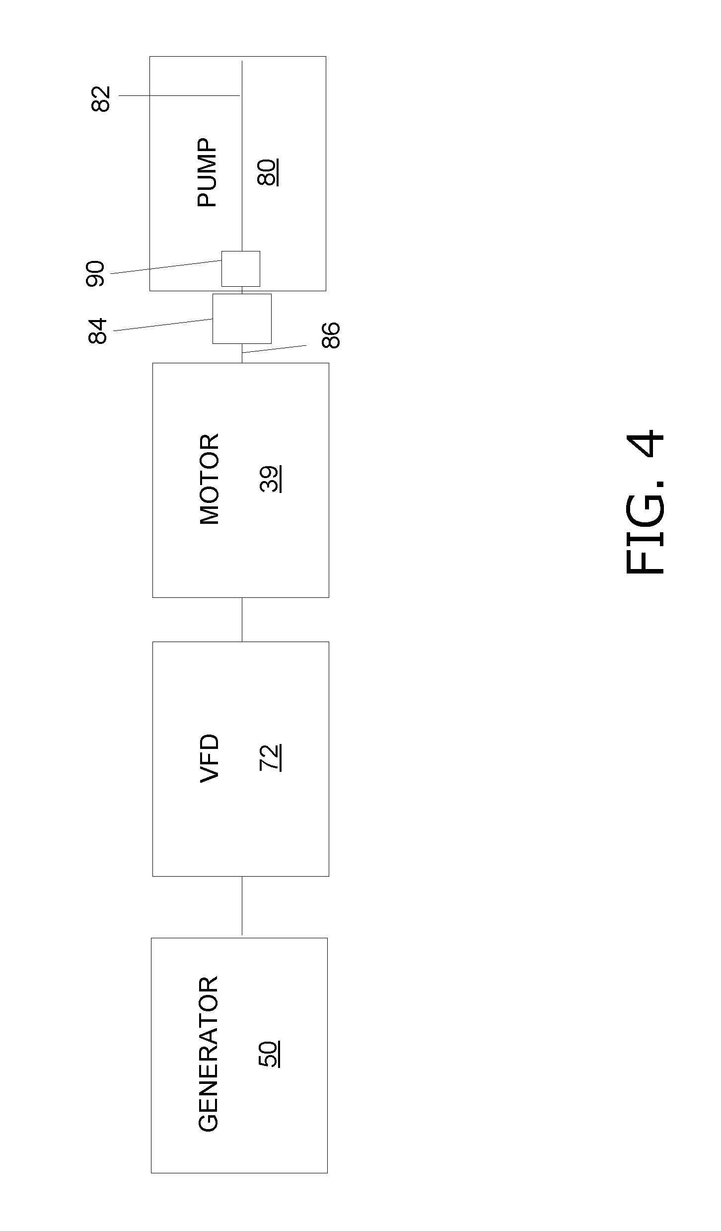
[0027] FIG. 4 is a schematic diagram of an embodiment of the pump 80 which includes gearing 90 for spacing. As described above, this configuration removes the transmission and therefore produces a smaller, lighter, and less complicated pumping arrangement. In certain embodiments, the gearing 90 may be referred to as limited gearing which is utilized for spacing or for other components, such as lube oil. The gearing 90 may be internal to the pump 90, as illustrated in FIG. 4, or may be an external component. The illustrated embodiment also includes the coupling device 84, which may be eliminated in certain embodiments.
[0028] The foregoing disclosure and description of the disclosed embodiments is illustrative and explanatory of the embodiments of the invention. Various changes in the details of the illustrated embodiments can be made within the scope of the appended claims without departing from the true spirit of the disclosure. The embodiments of the present disclosure should only be limited by the following claims and their legal equivalents.
* * * * *
D00000
D00001
D00002
D00003
D00004
XML
uspto.report is an independent third-party trademark research tool that is not affiliated, endorsed, or sponsored by the United States Patent and Trademark Office (USPTO) or any other governmental organization. The information provided by uspto.report is based on publicly available data at the time of writing and is intended for informational purposes only.
While we strive to provide accurate and up-to-date information, we do not guarantee the accuracy, completeness, reliability, or suitability of the information displayed on this site. The use of this site is at your own risk. Any reliance you place on such information is therefore strictly at your own risk.
All official trademark data, including owner information, should be verified by visiting the official USPTO website at www.uspto.gov. This site is not intended to replace professional legal advice and should not be used as a substitute for consulting with a legal professional who is knowledgeable about trademark law.