Well Service Pump Systems And Related Methods
GABLE; Tom ; et al.
U.S. patent application number 16/395855 was filed with the patent office on 2019-10-31 for well service pump systems and related methods. The applicant listed for this patent is AMERIFORGE GROUP INC.. Invention is credited to Shelton BURNETT, Tom GABLE, Eric MARTIN, Lyle MEYER, Garrett Smith.
| Application Number | 20190330923 16/395855 |
| Document ID | / |
| Family ID | 66476842 |
| Filed Date | 2019-10-31 |

| United States Patent Application | 20190330923 |
| Kind Code | A1 |
| GABLE; Tom ; et al. | October 31, 2019 |
WELL SERVICE PUMP SYSTEMS AND RELATED METHODS
Abstract
A well service pump system supplies high pressure working fluid to a well. The pump system includes a closed-loop hydraulic circuit for actuating a plurality of working pump assemblies. The pump system is powered by a motor, which transfers mechanical energy to a plurality of pumps, which, in turn, provide hydraulic fluid to operate hydraulic ram cylinders, and thereby operate the working pump assemblies. Each of the polished rods of the hydraulic ram cylinders is connected axially to a plunger rod end of the working fluid end cylinder to operate the working pump assembly.
| Inventors: | GABLE; Tom; (Houston, TX) ; Smith; Garrett; (Houston, TX) ; BURNETT; Shelton; (Houston, TX) ; MARTIN; Eric; (Houston, TX) ; MEYER; Lyle; (Houston, TX) | ||||||||||
| Applicant: |
|
||||||||||
|---|---|---|---|---|---|---|---|---|---|---|---|
| Family ID: | 66476842 | ||||||||||
| Appl. No.: | 16/395855 | ||||||||||
| Filed: | April 26, 2019 |
Related U.S. Patent Documents
| Application Number | Filing Date | Patent Number | ||
|---|---|---|---|---|
| 62664072 | Apr 27, 2018 | |||
| Current U.S. Class: | 1/1 |
| Current CPC Class: | E21B 43/129 20130101; F04B 2205/501 20130101; E21B 4/14 20130101; F04B 53/008 20130101; F04B 9/113 20130101; F04B 17/06 20130101; E21B 47/009 20200501; F04B 23/06 20130101; E21B 44/005 20130101 |
| International Class: | E21B 4/14 20060101 E21B004/14; E21B 47/00 20060101 E21B047/00; E21B 43/12 20060101 E21B043/12 |
Claims
1. A well service pump system for delivering working fluid at high pressure to a well, the pump system comprising: at least two working fluid pump assemblies, each comprising: a working fluid end cylinder having a plunger rod configured to reciprocate within the fluid end cylinder; and a hydraulic ram cylinder having a ram piston configured to reciprocate within the ram cylinder and a piston rod coupled to the ram piston and coupled to the plunger rod of the working fluid end cylinder such that the ram piston of the hydraulic ram cylinder can be actuated to move the plunger rod of the working fluid end cylinder: in a first direction to expel working fluid from the fluid end cylinder during a forward stroke of the plunger rod, and in a second direction to draw working fluid into the fluid end cylinder during a return stroke of the plunger rod; wherein the hydraulic ram cylinder includes a first hydraulic port on a first side of the ram piston and a second hydraulic port on a second side of the ram piston; a plurality of bi-directional pumps, each coupled to a respective one of the working fluid pump assemblies such that the bi-directional pump is in fluid communication with the first hydraulic port and the second hydraulic port of the hydraulic ram cylinder to pump hydraulic fluid: from the second hydraulic port directly into the first hydraulic port to actuate the ram piston to drive the plunger rod in the first direction; and from the first hydraulic port directly into the second hydraulic port to actuate the ram piston to drive the plunger rod in the second direction.
2. The well service pump system of claim 1, comprising a fluid reservoir configured to be in fluid communication with each of the plurality of bi-directional pumps to compensate for leakage in the system.
3. The well service pump system of claim 1, wherein, when the ram piston of the hydraulic ram cylinder reciprocates within the hydraulic ram cylinder, the ram piston is, at all times, spaced a distance from a first end wall of the hydraulic ram cylinder and a second end wall of the hydraulic ram cylinder opposite the first end wall.
4. The well service pump system of claim 1, comprising a motor configured to drive each of the bi-directional pumps to direct fluid to the first and second ports.
5. The well service pump system of claim 4, comprising a pump drive coupled to the motor and to each of the bi-directional pumps, the pump drive configured to transfer mechanical energy from the motor to each of the bi-directional pumps.
6. The well service pump system of claim 5, wherein at least one of the bi-directional pumps is mounted to the pump drive.
7. The well service pump system of claim 4, wherein the motor comprises an electric motor.
8. The well service pump system of claim 1, wherein, for at least one of the working fluid pump assemblies, the ram piston has an actuatable piston surface area that is at least two times greater than an actuatable piston surface area of the plunger rod.
9. The well service pump system of claim 1, wherein each working fluid pump assembly further comprises a coupling member coupled to the plunger rod of the working fluid end cylinder and to the piston rod of the hydraulic ram cylinder.
10. The well service pump system of claim 1, wherein in each working fluid pump assembly, the piston rod of the hydraulic ram cylinder is axially aligned with the plunger rod of the hydraulic ram cylinder.
11. The well service pump system of claim 1, wherein in each working fluid pump assembly, the working fluid end cylinder has a cylindrical inner wall and the plunger rod has an outer surface that is spaced apart from the cylindrical inner wall such that the working fluid end cylinder can pump abrasive fluids without the plunger rod and the cylinder inner wall simultaneously contacting individual particles in the working fluid.
12. The well service pump system of claim 1, wherein at least one of the hydraulic pumps comprises a fixed-displacement hydraulic pump.
13. The well service pump system of claim 1, wherein each working fluid pump assembly further comprises: an inlet check valve coupled to the fluid end cylinder and configured to permit working fluid to be drawn into the fluid end cylinder but prevent working fluid from exiting the fluid end cylinder through the inlet check valve; and an outlet check valve coupled to the fluid end cylinder and configured to permit working fluid to exit the fluid end cylinder while preventing working fluid from being drawn into the fluid end cylinder through the outlet check valve.
14. The well service pump system of claim 13, wherein, for at least one of the working fluid pump assemblies, the working fluid is pressurized when it enters the fluid end cylinder through the inlet check valve.
15. A method comprising: delivering a working fluid to a well with a well service pump system comprising: at least two working fluid pump assemblies, each comprising: a working fluid end cylinder having a plunger rod configured to reciprocate within the fluid end cylinder; and a hydraulic ram cylinder having a ram piston configured to reciprocate within the hydraulic ram cylinder and a piston rod coupled to the ram piston and coupled to the plunger rod of the working fluid end cylinder; wherein the hydraulic ram cylinder includes a first hydraulic port on a first side of the ram piston and second hydraulic port on a second side of the ram piston; a plurality of bi-directional pumps, each fluidly coupled to a respective one of the working fluid pump assemblies; wherein delivering the working fluid comprises: actuating the ram piston of the hydraulic ram cylinder to move the plunger rod of the working fluid end cylinder: in a first direction to expel working fluid from the fluid end cylinder during a forward stroke of the plunger rod, and in a second direction to draw working fluid into the fluid end cylinder during a return stroke of the plunger rod; and directing hydraulic fluid, via the bi-directional pump: from the second hydraulic port directly into the first hydraulic port to actuate the ram piston to drive the plunger rod in the first direction; and from the first hydraulic port directly into the second hydraulic port to actuate the ram piston to drive the plunger rod in the second direction.
16. The method of claim 15, comprising actuating a motor to drive each of the bi-directional pumps to direct fluid to the first and second ports.
17. The method of claim 16, wherein the motor comprises an electric motor.
18. The method of claim 15, wherein at least one of the hydraulic pumps comprises a fixed-displacement hydraulic pump.
19. The well service pump system of claim 4, wherein the motor comprises a combustion engine.
20. The method of claim 16, wherein the motor comprises a combustion engine.
Description
CROSS-REFERENCE TO RELATED APPLICATIONS
[0001] This application claims priority to U.S. Provisional Application No. 62/664,072, filed Apr. 27, 2018, the entire contents of which application are specifically incorporated by reference herein without disclaimer.
FIELD OF INVENTION
[0002] The present invention relates generally to pumping assemblies used for well servicing applications, most particularly pumping assemblies used for well fracturing operations.
DESCRIPTION OF RELATED ART
[0003] Oil and gas wells require services such as fracturing, acidizing, cementing, sand control, well control and circulation operations. All of these services require pumps for pumping fluid down the well. The type of pump that has customarily been used in the industry for many years is a gear driven plunger type, which may be referred to as a "frac pump." The pump is often powered by a diesel engine, typically 2,000 bhp or larger, that transfers its power to a large automatic transmission. The automatic transmission then transfers the power through a large driveline, into a gear reduction box mounted on the frac pump. The frac pump has a crankshaft mounted in a housing. A plunger has a crosshead that is reciprocally carried in a cylinder perpendicular to the crankshaft. A connecting rod connects each eccentric portion or journal of the crankshaft to the plunger. The driveline enters the frac pump at a right angle to the connecting rods, plungers and pump discharge. A typical pump might be, for example, a triplex type having three cylinders, three connecting rods, and three journals on the crankshaft. An example of a common type of a well service pump (e.g., plunger pump) is disclosed in U.S. Pat. No. 2,766,701 to Giraudeau. Typical commercially available pumps include the Weir/SPM.TM. line of pumps, for example, the QWS 2500 Classic.TM. Well Service Pump and the Destiny TWS2500.TM. Well Service Pump.
[0004] There are a number of known problems with the prior art plunger pumps of the type under consideration. These pumps will typically be mounted on a trailer or skid back-to-back. The frac pumps are mounted at a right angle to the engine, transmission and driveline. Each pump has an outboard side connected to a manifold with valves for drawing in and pumping fluid acted on by the plunger. The inboard sides will be located next to each other. The overall width from one manifold to the other manifold should not exceed roadway requirements, e.g., Department of Transportation (DOT) rules and regulations. If the pumps are to be trailer mounted for highway transport, this distance will be on the order of about eight and one half feet. As a result, this necessarily means that the frac units which are trailer mounted will be restricted in size by the applicable DOT rules and regulations. The current plunger stroke length for present day frac pumps is typically 8 to 10 inches. However, in order to meet DOT requirements, some manufacturers have reduced the size of the pump, for example reducing the pump stroke, in some cases down to as much as four to six inches.
[0005] However, reducing the stroke length of the plungers is not an ideal solution to the problem and, in fact, offers a number of disadvantages in the design. Ideally, it would be desirable to lengthen the stroke of these pumps instead of shortening the stroke length, in order to reduce cycles per minute in use. This is due to the fact that there is a tremendous failure rate in current frac pump fluid ends, due to cyclic fatigue. The increased failure rate results from increased demand placed upon today's frac pumps, as compared to the practice in prior years. An example of a typical frac job in shale formations today would be a five hour pump time. During this pump time the plunger cycles would be, for example, 250 per minute at 10,000 psi. There has not been a great deal of change in the design of basic frac pumps going back some fifty years. However, the prior art designs of fifty years ago were intended for frac jobs that might last up to 2 hours. The unit would then typically be shut down until the next day. During today's frac jobs, for example in commonly encountered shale formations, the units are pumping 4-8 hours at higher pressures than in the past. The units are then typically shut down for an hour or two and then started up again for another stage for approximately the same duration. This type of operation may exceed the intended design limits of the units.
[0006] It has also been attempted in the past, especially with the larger oil field pumps, to increase the stroke length by offsetting the crankshaft axis with the cylinder axis. The offset is selected so that during the power or output stroke, the centerline of the crankshaft end of the connecting rod will be located closer to the cylinder axis than the crankshaft axis. Matzner et al. disclose vertically offsetting the cylinder axis from the crankshaft axis in U.S. Pat. No. 5,246,355. It has also been attempted for the axis of the wrist pin of the connecting rod to be vertically offset from the cylinder axis to achieve the width requirements. An example of a plunger pump having an offset wrist pin is disclosed in U.S. Pat. No. 5,839,888 to Harrison. However, these designs still suffer from all of the problems of having the frac pump mounted at a right angle to the engine, transmission and driveline. They also fail to reduce the mechanical complexity of the system and, in fact, likely increase the complexity.
[0007] With prior art designs, it will be very difficult to increase the plunger stroke length much more than 10 to 12 inches. For example, increasing the stroke length by one inch may necessitate increasing total length of the frac pump by at least two inches due to the crankshaft design. This can put frac pumps in violation of DOT standards regarding the width of the trailer mounted frac unit, since the pump sits at a right angle to the engine, transmission and driveline.
[0008] For these and other reasons, a need continues to exist for improvements in oil and gas well servicing pumps of the type under consideration.
SUMMARY
[0009] The present disclosure includes embodiments of pump systems and methods.
[0010] Some embodiments of the present well service pump systems, for delivering working fluid at high pressure to a well, comprise at least two working fluid pump assemblies, each comprising: a working fluid end cylinder having a plunger rod configured to reciprocate within the fluid end cylinder; and a hydraulic ram cylinder having a ram piston configured to reciprocate within the ram cylinder and a piston rod coupled to the ram piston and coupled to the plunger rod of the working fluid end cylinder such that the ram piston of the hydraulic ram cylinder can be actuated to move the plunger rod of the working fluid end cylinder: in a first direction to expel working fluid from the fluid end cylinder during a forward stroke of the plunger rod, and in a second direction to draw working fluid into the fluid end cylinder during a return stroke of the plunger rod; wherein the hydraulic ram cylinder includes a first hydraulic port on a first side of the ram piston and a second hydraulic port on a second side of the ram piston; a plurality of bi-directional pumps, each coupled to a respective one of the working fluid pump assemblies such that the bi-directional pump is in fluid communication with the first hydraulic port and the second hydraulic port of the hydraulic ram cylinder to pump hydraulic fluid: from the second hydraulic port directly into the first hydraulic port to actuate the ram piston to drive the plunger rod in the first direction; and from the first hydraulic port directly into the second hydraulic port to actuate the ram piston to drive the plunger rod in the second direction.
[0011] Some embodiments of the present systems comprise a fluid reservoir configured to be in fluid communication with each of the plurality of bi-directional pumps to compensate for leakage in the system.
[0012] In some embodiments of the present systems, when the ram piston of the hydraulic ram cylinder reciprocates within the hydraulic ram cylinder, the ram piston is, at all times, spaced a distance from a first end wall of the hydraulic ram cylinder and a second end wall of the hydraulic ram cylinder opposite the first end wall.
[0013] Some embodiments of the present systems comprise a motor configured to drive each of the bi-directional pumps to direct fluid to the first and second ports.
[0014] Some embodiments of the present systems comprise a pump drive coupled to the motor and to each of the bi-directional pumps, the pump drive configured to transfer mechanical energy from the motor to each of the bi-directional pumps. In some embodiments of the present systems, at least one of the bi-directional pumps is mounted to the pump drive. In some embodiments of the present systems, the motor comprises an electric motor and/or a combustion engine.
[0015] In some embodiments of the present systems, for at least one of the working fluid pump assemblies, the ram piston has an actuatable piston surface area that is at least two times greater than an actuatable piston surface area of the plunger rod.
[0016] In some embodiments of the present systems, each working fluid pump assembly further comprises a coupling member coupled to the plunger rod of the working fluid end cylinder and to the piston rod of the hydraulic ram cylinder. In some embodiments of the present systems, in each working fluid pump assembly, the piston rod of the hydraulic ram cylinder is axially aligned with the plunger rod of the hydraulic ram cylinder. In some embodiments of the present systems, each working fluid pump assembly, the working fluid end cylinder has a cylindrical inner wall and the plunger rod has an outer surface that is spaced apart from the cylindrical inner wall such that the working fluid end cylinder can pump abrasive fluids without the plunger rod and the cylinder inner wall simultaneously contacting individual particles in the working fluid. In some embodiments of the present systems, at least one of the hydraulic pumps comprises a fixed-displacement hydraulic pump.
[0017] In some embodiments of the present systems, each working fluid pump assembly further comprises: an inlet check valve coupled to the fluid end cylinder and configured to permit working fluid to be drawn into the fluid end cylinder but prevent working fluid from exiting the fluid end cylinder through the inlet check valve; and an outlet check valve coupled to the fluid end cylinder and configured to permit working fluid to exit the fluid end cylinder while preventing working fluid from being drawn into the fluid end cylinder through the outlet check valve. In some embodiments of the present systems, for at least one of the working fluid pump assemblies, the working fluid is pressurized when it enters the fluid end cylinder through the inlet check valve.
[0018] Some embodiments of the present methods comprise delivering a working fluid to a well with a well service pump system comprising: at least two working fluid pump assemblies, each comprising: a working fluid end cylinder having a plunger rod configured to reciprocate within the fluid end cylinder; and a hydraulic ram cylinder having a ram piston configured to reciprocate within the hydraulic ram cylinder and a piston rod coupled to the ram piston and coupled to the plunger rod of the working fluid end cylinder; wherein the hydraulic ram cylinder includes a first hydraulic port on a first side of the ram piston and second hydraulic port on a second side of the ram piston; a plurality of bi-directional pumps, each fluidly coupled to a respective one of the working fluid pump assemblies; wherein delivering the working fluid comprises: actuating the ram piston of the hydraulic ram cylinder to move the plunger rod of the working fluid end cylinder: in a first direction to expel working fluid from the fluid end cylinder during a forward stroke of the plunger rod, and in a second direction to draw working fluid into the fluid end cylinder during a return stroke of the plunger rod; and directing hydraulic fluid, via the bi-directional pump: from the second hydraulic port directly into the first hydraulic port to actuate the ram piston to drive the plunger rod in the first direction; and from the first hydraulic port directly into the second hydraulic port to actuate the ram piston to drive the plunger rod in the second direction.
[0019] Some embodiments of the present systems comprise actuating a motor to drive each of the bi-directional pumps to direct fluid to the first and second ports. In some embodiments of the present methods, the motor comprises an electric motor and/or a combustion engine. In some embodiments of the present methods, at least one of the hydraulic pumps comprises a fixed-displacement hydraulic pump.
[0020] The term "coupled" is defined as connected, although not necessarily directly, and not necessarily mechanically; two items that are "coupled" may be unitary with each other. The terms "a" and "an" are defined as one or more unless this disclosure explicitly requires otherwise. The term "substantially" is defined as largely but not necessarily wholly what is specified (and includes what is specified; e.g., substantially 90 degrees includes 90 degrees and substantially parallel includes parallel), as understood by a person of ordinary skill in the art. In any disclosed embodiment, the terms "substantially," "approximately," and "about" may be substituted with "within [a percentage] of" what is specified, where the percentage includes 0.1, 1, 5, and 10 percent.
[0021] The phrase "and/or" means and or or. To illustrate, A, B, and/or C includes: A alone, B alone, C alone, a combination of A and B, a combination of A and C, a combination of B and C, or a combination of A, B, and C. In other words, "and/or" operates as an inclusive or.
[0022] The terms "comprise" (and any form of comprise, such as "comprises" and "comprising"), "have" (and any form of have, such as "has" and "having"), "include" (and any form of include, such as "includes" and "including"), and "contain" (and any form of contain, such as "contains" and "containing") are open-ended linking verbs. As a result, an apparatus that "comprises," "has," "includes," or "contains" one or more elements possesses those one or more elements, but is not limited to possessing only those elements. Likewise, a method that "comprises," "has," "includes," or "contains" one or more steps possesses those one or more steps, but is not limited to possessing only those one or more steps.
[0023] Any embodiment of any of the apparatuses, systems, and methods can consist of or consist essentially of--rather than comprise/include/contain/have--any of the described steps, elements, and/or features. Thus, in any of the claims, the term "consisting of" or "consisting essentially of" can be substituted for any of the open-ended linking verbs recited above, in order to change the scope of a given claim from what it would otherwise be using the open-ended linking verb.
[0024] The feature or features of one embodiment may be applied to other embodiments, even though not described or illustrated, unless expressly prohibited by this disclosure or the nature of the embodiments.
[0025] Further, a device or system that is configured in a certain way is configured in at least that way, but it can also be configured in other ways than those specifically described.
[0026] Some details associated with the embodiments described above and others are described below.
BRIEF DESCRIPTION OF THE DRAWINGS
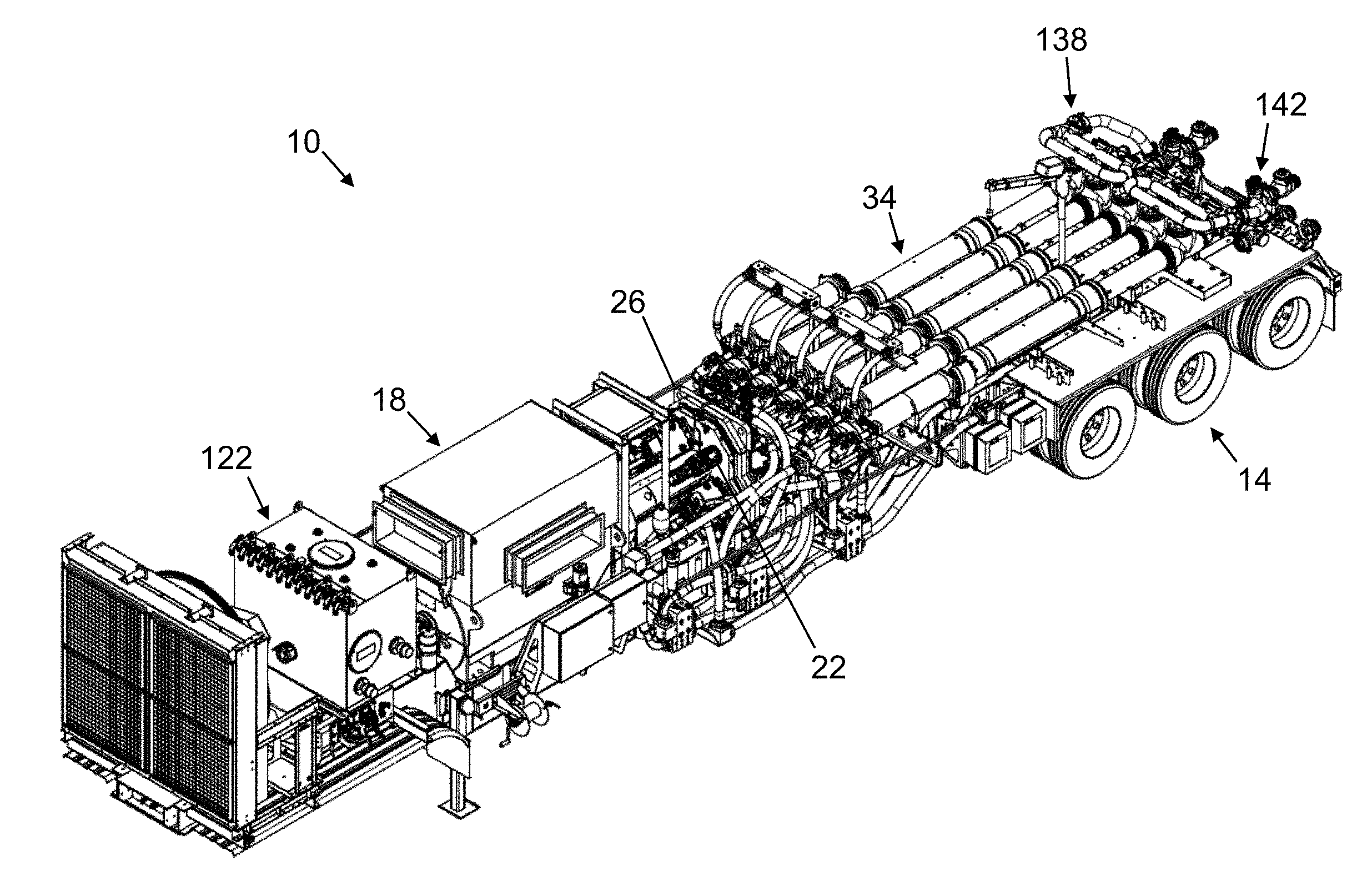
[0027] FIG. 1 depicts a first perspective view of one embodiment of the present well service pump systems.
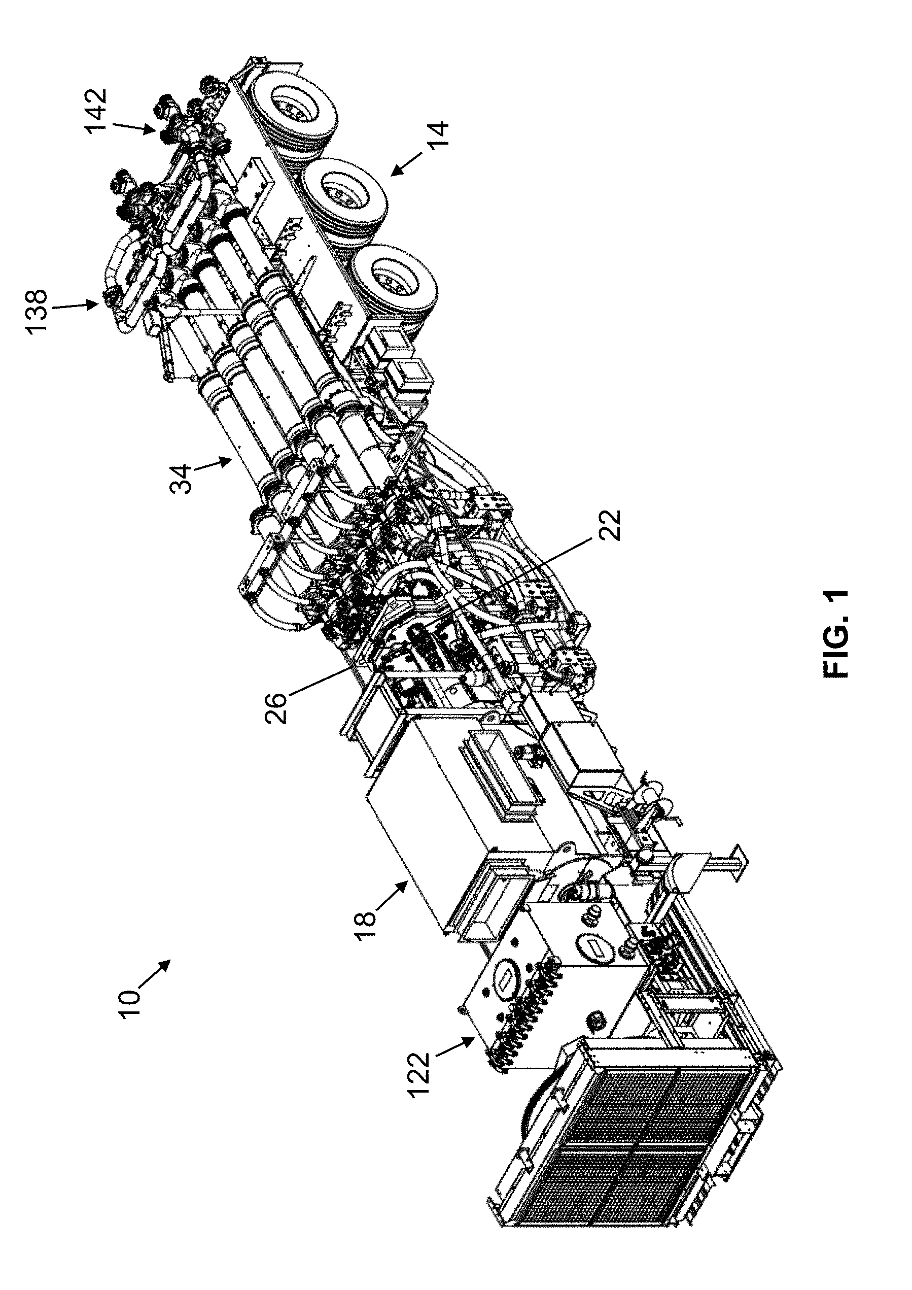
[0028] FIG. 2 depicts a second perspective view of the system of FIG. 1.
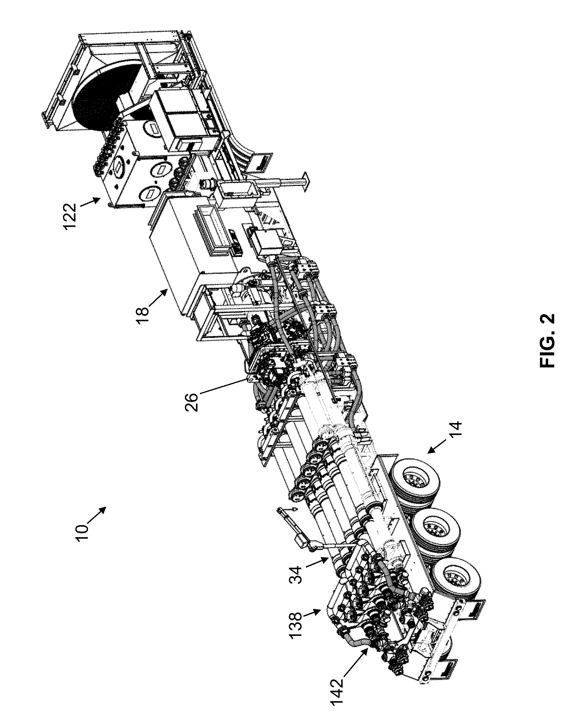
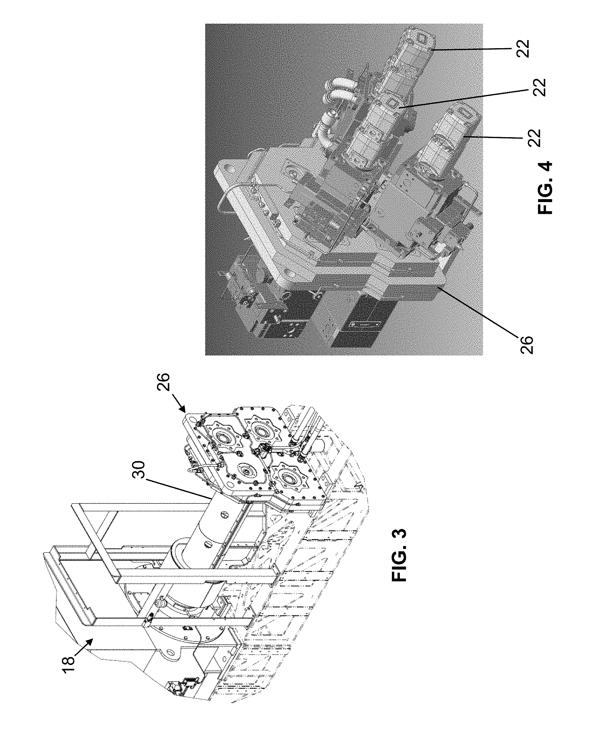
[0029] FIGS. 3 and 4 depict perspective views of various components of the system of FIG. 1.
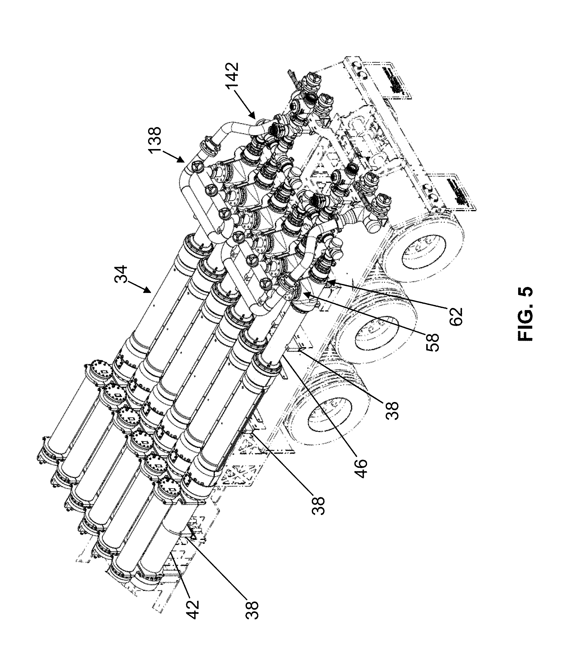
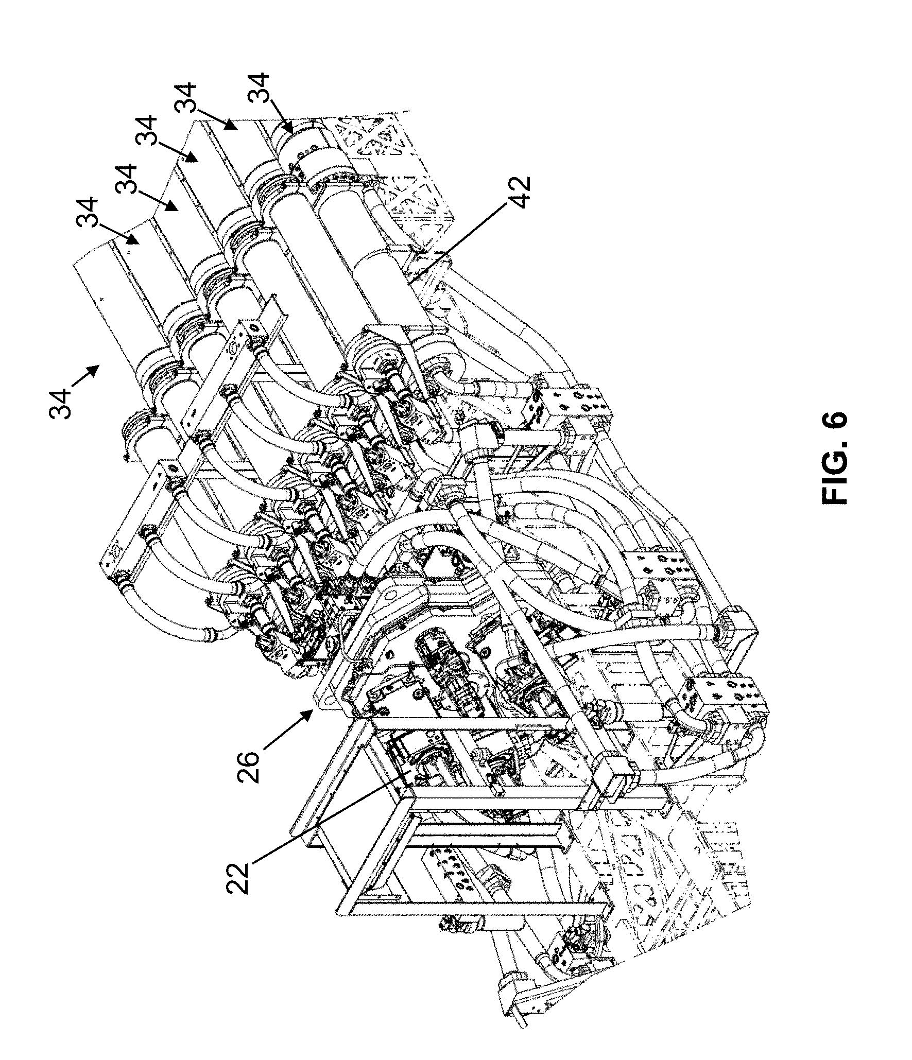
[0030] FIGS. 5 and 6 depict first and second perspective views of working pump assemblies suitable for use with some embodiments of the system of FIG. 1.
[0031] FIG. 7 depicts a cross-sectional side view of an embodiment of the working pump assemblies of FIGS. 5 and 6.
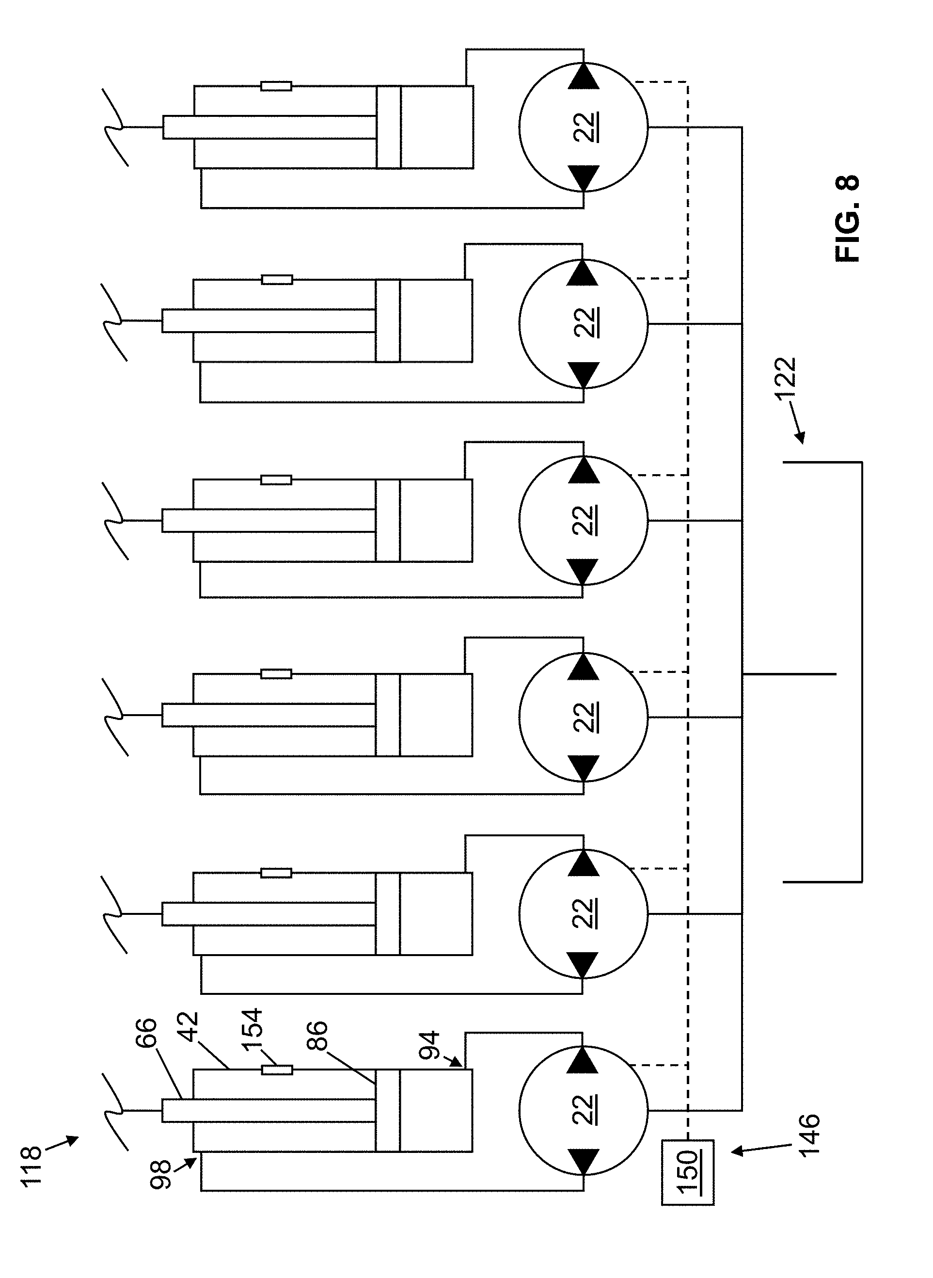
[0032] FIG. 8 depicts a schematic of a closed-loop hydraulic circuit, suitable for use with some embodiments of the system of FIG. 1.
DETAILED DESCRIPTION OF ILLUSTRATIVE EMBODIMENTS
[0033] The following drawings illustrate by way of example and not limitation. For the sake of brevity and clarity, every feature of a given structure is not always labeled in every figure in which that structure appears. Identical reference numbers do not necessarily indicate an identical structure. Rather, the same reference number may be used to indicate a similar feature or a feature with similar functionality, as may non-identical reference numbers. The figures are drawn to scale (unless otherwise noted), meaning the sizes of the depicted elements are accurate relative to each other for at least the embodiment depicted in the figures.
[0034] Referring now to the figures, and more particularly, to FIGS. 1 and 2, shown therein and designated by reference numeral 10 is an embodiment of the present well service pump systems for delivering working fluid at high pressure to a well. As shown, system 10 can be coupled to and carried by a vehicle 14 (e.g., a truck trailer) for transportation to and from work sites. In some embodiments, a system (e.g., 10) can be coupled to a skid frame that can then be loaded and offloaded from a vehicle (e.g., 14).
[0035] As shown, system 10 includes a motor 18, which is configured to drive a plurality of hydraulic pumps 22 (FIG. 3) to direct fluid as described in further detail below. Motor 18 can include one or more sources of mechanical energy, such as a diesel engine, gasoline engine, and/or an electric motor. In this embodiment, system 10 includes a pump drive 26, which is coupled to motor 18 (via driveline 30) and each pump 22. Pump drive 26 is configured to transfer mechanical energy from motor 18 to each pump 22 one at a time or two or more at a time. As shown, each pump 22 is mounted directly onto pump drive 26.
[0036] System 10 includes a plurality of working pump assemblies 34, each of which are coupled to and actuatable by a respective pump 22 to deliver working fluid at a high pressure to a well. As shown, system 10 can include any suitable number of working pump assemblies 34, such as two, three, four, five, six, seven, eight, nine, or ten assemblies. As shown, each assembly 34 can be mounted on a transport vehicle (e.g., 14) by one or more vibration-dampening mounts 38.
[0037] Referring additionally to FIGS. 5-7, one embodiment of the present working pump assemblies 34 is shown. As shown, assembly 34 includes a hydraulic ram cylinder 42 and a working fluid end cylinder 46. Working fluid end cylinder 46 includes a plunger rod 50 disposed within a chamber 54 defined by the fluid end cylinder. Plunger rod 50 is configured to reciprocate within chamber 54 to draw in working fluid into fluid end cylinder 46 via an inlet 58 and expel working fluid under high pressure to the well via an outlet 62. As shown in FIG. 7, hydraulic ram cylinder 42 has a ram piston rod 66 disposed within a chamber 70 defined by the ram cylinder. Ram piston rod 66 is coupled to plunger rod 50 to actuate the plunger rod and supply the working fluid under pressure. For example, assembly 34 includes a coupling member 74, such as a bracket, coupled between piston rod 66 and plunger rod 50 such that linear and/or rotational movement of the piston rod causes a matching linear and/or rotational movement of the plunger rod. Further, coupling member 74 is configured to connect piston rod 66 and plunger rod 50 such that the rods are axially aligned relative to one another.
[0038] Plunger rod 50 has an outer diameter that is smaller than an inner diameter of a cylindrical inner sidewall 78 of working fluid end cylinder 46. As such, plunger rod 50 is received in spaced-apart fashion from sidewall 78 so that abrasive fluids may be pumped without undue wear on the plunger rod and/or sidewalls. For example, an annular space between an outer surface of plunger rod 50 and inner sidewall 78 of working fluid end cylinder 46 is larger than the largest expected transverse dimension of any particle in the working fluid to prevent any single particle in the working fluid from simultaneously contacting the outer surface of the plunger and the inner sidewall of the working fluid end cylinder.
[0039] In the embodiment shown, plunger rod 50 is sealed within fluid end cylinder 46 by an end seal 82 that provides a tight seal around an outer surface of the plunger rod and assists with maintaining alignment of the plunger rod relative to the fluid end cylinder. For example, end seal 82 comprises a hydraulic seal that can be pressurized via a port extending through fluid end cylinder 46. Plunger rod 50 can have a length (measured from end seal 82 to a distal end of the plunger rod within chamber 54 of fluid end cylinder 46) that exceeds 12 inches (e.g., exceeds 40 inches and/or is between 50 inches and 60 inches, such as 48 inches). The maximum length of plunger rod 50 that extends into chamber 54 of fluid end cylinder 46 is termed a stroke length of the plunger rod.
[0040] Hydraulic ram cylinder 42 includes a ram piston 86 (FIG. 7) coupled to ram piston rod 66 and disposed within hydraulic ram cylinder 42. Contrary to plunger rod 50, ram piston 86 includes an outer diameter that fits closely and in a substantially sealed relationship with a cylindrical inner sidewall 90 of hydraulic ram cylinder 42. Ram piston 86 is configured to be actuatable to reciprocate within ram cylinder 42 such that the piston, via its connection to piston rod 66, can cause plunger rod 50 to move accordingly within fluid end cylinder 46. For example, ram cylinder 42 comprises a first hydraulic port 94 on a first side of ram piston 86 and a second hydraulic port 98 on a second side of the piston. Each hydraulic port 94, 98 is configured to receive hydraulic fluid from a respective pump 22 to actuate ram piston 86 such that the piston (via piston rod 66 and coupling member 74) move plunger rod 50 in a first direction 102 to expel working fluid from fluid end cylinder 46 during a forward stroke of the plunger rod and in a second direction 106 to draw working fluid into the fluid end cylinder during a return stroke of the plunger rod. For example, in the depicted embodiment, when plunger rod 50 is in the forward stroke, the plunger rod occupies a majority of the volume of chamber 54, thereby reducing the volume available for working fluid within the chamber and thus forcing the working fluid out of fluid end cylinder 46 via outlet 62.
[0041] Ram piston 86 has a piston surface area 110 upon which hydraulic fluid in chamber 70 can act to move the ram piston, and thus piston rod 66, in first direction 102 and plunger rod 50 has a piston surface area 114 upon which working fluid in chamber 54 can act to move the plunger rod in second direction 106. In this embodiment, piston surface area 110 of at least one ram piston 86 is greater than, such as approximately two or more times greater than, piston surface area of plunger rod 50.
[0042] Each pump 22 is configured to be driven by motor 18 to supply a hydraulic fluid under high pressure to first hydraulic port 94 and second hydraulic port 98 of a respective ram cylinder 42. As shown in FIG. 8, each pump 22 can be fluidly coupled to a respective working fluid pump assembly 34 using a closed-loop hydraulic circuit 118. Further, each pump 22 can operate bi-directionally to actuate ram piston 86 in both first direction 102 and second direction 106. For example, each pump 22 is coupled to a respective ram cylinder 42 such that the pump is in fluid communication with each of first hydraulic port 94 and second hydraulic port 98 of the ram cylinder to pump hydraulic fluid from the second hydraulic port directly into the first hydraulic port to actuate ram piston 86 to drive plunger rod 50 in first direction 102 (forward stroke) and from the first hydraulic port directly into the second hydraulic port to actuate the ram piston to drive the plunger rod in second direction 106 (return stroke). By using a closed-loop hydraulic circuit 118 to actuate ram piston 86, and thereby actuate plunger rod 50, less hydraulic fluid is required for actuating assembly 34, as compared to a system (e.g., 10) having an open-loop hydraulic circuit.
[0043] At least one pump 22 can comprise a fixed-displacement hydraulic pump. In some embodiments, at least one pump (e.g., 22) can comprise a variable-displacement hydraulic pump. Each pump 22 direct fluid to ports 94, 98 at a variable flow rate.
[0044] In some embodiments, system 10 may include a hydraulic fluid reservoir 122 configured to be in fluid communication with each pump 22 to compensate for leakage and/or other operational losses of hydraulic fluid in the system.
[0045] As shown, system 10 includes a working fluid end block 126 that comprises, for each assembly 34, an inlet 58 having an inlet check valve 130 fluidly coupled to chamber 54 of fluid end cylinder 46 and configured to permit working fluid to be drawn into the fluid end cylinder but prevent working fluid from exiting the fluid end cylinder through the inlet check valve. In this embodiment, for at least one assembly 34, working fluid directed to inlet 58 can flow from an elevated tank and/or through a pump, such that the working fluid is pressured when it enters chamber 54 of fluid end cylinder 46 through inlet valve 130, thereby urging plunger rod 50 in its return stroke. In operation, inlet check valve 130 prevents working fluid from exiting chamber 54 through inlet 58, thereby enabling working fluid to be pressurized in chamber 54 of fluid end cylinder 46 during the forward stroke of plunger rod 50.
[0046] In this embodiment, end block 126 comprises, for each assembly 34, outlet 62 having an outlet check valve 218 fluidly coupled to chamber 54 of fluid end cylinder 46 and configured to permit working fluid to exit the fluid end cylinder while preventing working fluid from being drawn into the fluid end cylinder through the outlet check valve. In operation, outlet check valve 134 prevents working fluid that is pressurized downstream of the outlet check valve from entering chamber 54 of fluid end cylinder 46 during the return stroke of plunger rod 50 of assembly 34 and during the forward stroke of a plunger rod (e.g., 50) of one or more of the other working fluid pump assemblies (e.g., 34) of system 10.
[0047] As shown, system 10 comprises a suction manifold 138 fluidly coupled to each inlet check valve 130 of end block 126 to distribute working fluid to each of the inlet check valves in parallel. System 10 comprises a discharge manifold 142 coupled to each outlet check valve 134 of end block 126 to collect working fluid from each of the outlet check valves in parallel.
[0048] System 10 comprises a control system 146 having at least one processor 150, one or more of which is configured to control the operation of each pump 22. Control system 146, and thus processor(s) 150 can be electronically coupled to each pump 22 via wired or wireless connection. Processor(s) 150 can be configured to control a flowrate and/or direction of hydraulic fluid flowing between each pump and its respective ram cylinder 42. For example, processor(s) 150 can be configured to control each pump 22 such that it directs hydraulic fluid, at any suitable flowrate, in a first direction from second hydraulic port 98 to first hydraulic port 94 and a second direction from the first hydraulic port to the second hydraulic port. Processor(s) 150 can be configured to control the frequency and sequence at which each pump 22 alternates the direction hydraulic fluid between the first and second directions such that system 10, via collective operation of the pumps, delivers a continuous and pulseless output flow of working fluid from fluid end cylinders 46 to the well, as described in paragraphs [0067]-[0069] and FIG. 16 of U.S. Publication 2015/0192117, which is hereby incorporated by reference in its entirety.
[0049] In this embodiment, the length and rate at which each ram piston 86 completes its forward and return strokes can be adjusted by one or more parameters of system 10. For example, with the aid of one or more sensors 154 configured to collect data indicative of ram piston 86 relative to ram cylinder 42, the length and rate of the forward and return strokes of each ramp piston can be adjusted by control system 146, which can vary the pressure and/or the rate at which hydraulic fluid is delivered to and removed from each ram cylinder 42. For example, assuming that hydraulic fluid is delivered at a pressure that is sufficient to move ram piston 86, the faster the hydraulic fluid is delivered to first hydraulic port 94 and/or removed from chamber 70 via second hydraulic port 98 by pump 22, the faster the ram piston will complete its forward stroke. Conversely, if it is more advantageous for the return stroke to be completed faster (have a shorter duration) than the forward stroke, pump 22 can be controlled to more quickly deliver hydraulic fluid to second hydraulic port 98 and/or remove hydraulic fluid from chamber 70 via first hydraulic port 94.
[0050] The length and rate of the forward and return strokes of each ramp piston 86 can be adjusted to increase pump efficiency and/or reduce cyclic fatigue. For example, to increase pump efficiency, ram cylinder 42 and/or fluid end cylinder 46 can be elongated to permit ram piston 86 and/or plunger rod 50 additional travel within respective chambers 70, 54, thereby allowing for more working fluid to be drawn into fluid end cylinder's chamber and for more working fluid to be expelled from the fluid end chamber into the well for every stroke, as compared to shorter ram cylinders and/or fluid end cylinders. Further, the longer stroke length can significantly reduce the number of strokes required to pump a given volume, and thereby reduce the rate at which plunger rod 50 must cycle, reducing fatigue and extending fluid end life. For further example, the return and forward stroke of each ram piston 86 can be controlled (e.g., by control system 146) to prevent contact between the ram piston and opposing interior end walls 158 of ram cylinder 42. That is, when ram piston 86 reciprocates within ram cylinder 42 during and between the forward and return strokes, the ram piston is, at all times, spaced a distance from a first interior end wall 158 of the ram cylinder and a second interior end wall 158 of the ram cylinder opposite the first end wall.
[0051] Some embodiments of the present methods include delivering a working fluid to a well with a well service pump system (e.g., 10) comprising: at least two working fluid pump assemblies (e.g., 34), each comprising: a working fluid end cylinder (e.g., 46) having a plunger rod (e.g., 50) configured to reciprocate within the fluid end cylinder; and a hydraulic ram cylinder (e.g., 42) having a ram piston (e.g., 86) configured to reciprocate within the hydraulic ram cylinder and a piston rod (e.g., 66) coupled to the ram piston and coupled to the plunger rod of the working fluid end cylinder; wherein the hydraulic ram cylinder includes a first hydraulic port (e.g., 94) on a first side of the ram piston and a second hydraulic port (e.g., 98) on a second side of the ram piston; a plurality of bi-directional pumps (e.g., 22), each fluidly coupled to a respective one of the working fluid pump assemblies (e.g., 34); wherein delivering the working fluid comprises: actuating the ram piston of the hydraulic ram cylinder to move the plunger rod of the working fluid end cylinder: in a first direction (e.g., 102) to expel working fluid from the fluid end cylinder during a forward stroke of the plunger rod, and in a second direction (e.g., 106) to draw working fluid into the fluid end cylinder during a return stroke of the plunger rod; and directing hydraulic fluid, via the bi-directional pump: from the second hydraulic port directly into the first hydraulic port to actuate the ram piston to drive the plunger rod in the first direction; and from the first hydraulic port directly into the second hydraulic port to actuate the ram piston to drive the plunger rod in the second direction. Some embodiments of the present methods additionally include actuating a motor (e.g., 18) to drive each of the bi-directional pumps to direct fluid to the first and second ports. In some embodiments of the present methods, the motor comprises an electric motor and/or a combustion engine. In some embodiments of the present methods, at least one of the hydraulic pumps comprises a fixed-displacement hydraulic pump.
[0052] The above specification and examples provide a complete description of the structure and use of illustrative embodiments. Although certain embodiments have been described above with a certain degree of particularity, or with reference to one or more individual embodiments, those skilled in the art could make numerous alterations to the disclosed embodiments without departing from the scope of this invention. As such, the various illustrative embodiments of the methods and systems are not intended to be limited to the particular forms disclosed. Rather, they include all modifications and alternatives falling within the scope of the claims, and embodiments other than the one shown may include some or all of the features of the depicted embodiment. For example, elements may be omitted or combined as a unitary structure, and/or connections may be substituted. Further, where appropriate, aspects of any of the examples described above may be combined with aspects of any of the other examples described to form further examples having comparable or different properties and/or functions, and addressing the same or different problems. Similarly, it will be understood that the benefits and advantages described above may relate to one embodiment or may relate to several embodiments. For example, embodiments of the present methods and systems may be practiced and/or implemented using different structural configurations, materials, ionically conductive media, monitoring methods, and/or control methods.
[0053] The claims are not intended to include, and should not be interpreted to include, means-plus- or step-plus-function limitations, unless such a limitation is explicitly recited in a given claim using the phrase(s) "means for" or "step for," respectively
* * * * *
D00000
D00001
D00002
D00003
D00004
D00005
D00006
D00007
XML
uspto.report is an independent third-party trademark research tool that is not affiliated, endorsed, or sponsored by the United States Patent and Trademark Office (USPTO) or any other governmental organization. The information provided by uspto.report is based on publicly available data at the time of writing and is intended for informational purposes only.
While we strive to provide accurate and up-to-date information, we do not guarantee the accuracy, completeness, reliability, or suitability of the information displayed on this site. The use of this site is at your own risk. Any reliance you place on such information is therefore strictly at your own risk.
All official trademark data, including owner information, should be verified by visiting the official USPTO website at www.uspto.gov. This site is not intended to replace professional legal advice and should not be used as a substitute for consulting with a legal professional who is knowledgeable about trademark law.