Super-power Five-cylinder Plunger Pump
Cui; Haiping ; et al.
U.S. patent application number 16/834419 was filed with the patent office on 2020-10-22 for super-power five-cylinder plunger pump. The applicant listed for this patent is YANTAI JEREH PETROLEUM EQUIPMENT & TECHNOLOGIES CO., LTD.. Invention is credited to Haiping Cui, Wenping Cui, Hong Liu, Jixin Wang, Xiaosong Wei.
| Application Number | 20200332788 16/834419 |
| Document ID | / |
| Family ID | 1000004752006 |
| Filed Date | 2020-10-22 |


| United States Patent Application | 20200332788 |
| Kind Code | A1 |
| Cui; Haiping ; et al. | October 22, 2020 |
SUPER-POWER FIVE-CYLINDER PLUNGER PUMP
Abstract
The present invention discloses a super-power five-cylinder plunger pump, including a power end assembly, a hydraulic end assembly and a reduction gearbox assembly. The power end assembly is designed as a segmented structure including a crankcase, a crosshead case and a spacer frame. One end of the crosshead case is connected to the crankcase, and the other end of the crosshead case is connected to the spacer frame. The hydraulic end assembly is disposed at an end of the spacer frame and is connected to the crankcase through bolts sequentially passing through the spacer frame and the crosshead case. The reduction gearbox assembly is connected to the crankcase. A crankshaft in the crankcase is forged from alloy steel and includes six axle journals and five bellcranks. One bellcrank is disposed between every two adjacent axle journals, and the distance between the center of rotation of the bellcrank and the center of rotation of the crankshaft is 110 to 160 mm. Beneficial Effects: The super-power five-cylinder plunger pump has a rated input power of 5000 hp to solve the problem that there is no existing plunger pump of a specification matching high-power electric motors in electric drive fracturing, and solve the conflict between the limited well-site conditions in the oil and gas fields and the need of multiple matched fracturing equipment.
| Inventors: | Cui; Haiping; (Yantai, CN) ; Liu; Hong; (Yantai, CN) ; Wang; Jixin; (Yantai, CN) ; Cui; Wenping; (Yantai, CN) ; Wei; Xiaosong; (Yantai, CN) | ||||||||||
| Applicant: |
|
||||||||||
|---|---|---|---|---|---|---|---|---|---|---|---|
| Family ID: | 1000004752006 | ||||||||||
| Appl. No.: | 16/834419 | ||||||||||
| Filed: | March 30, 2020 |
| Current U.S. Class: | 1/1 |
| Current CPC Class: | F04B 39/121 20130101; F04B 1/00 20130101 |
| International Class: | F04B 39/12 20060101 F04B039/12; F04B 1/00 20060101 F04B001/00 |
Foreign Application Data
| Date | Code | Application Number |
|---|---|---|
| Apr 19, 2019 | CN | 201910319527.3 |
Claims
1. A super-power five-cylinder plunger pump, comprising a power end assembly, a hydraulic end assembly and a reduction gearbox assembly, wherein the power end assembly is designed as a segmented structure comprising a crankcase, a crosshead case and a spacer frame, one end of the crosshead case is connected to the crankcase through bolts, and the other end of the crosshead case is connected to the spacer frame through bolts, the hydraulic end assembly is disposed at an end of the spacer frame and is connected to the crankcase through bolts sequentially passing through the spacer frame and the crosshead case, the reduction gearbox assembly is connected to the crankcase through bolts, a crankshaft in the crankcase is forged from alloy steel and comprises six axle journals and five bellcranks, one bellcrank is disposed between every two adjacent axle journals, and the distance between the center of rotation of the bellcrank and the center of rotation of the crankshaft is 110 to 160 mm.
2. The super-power five-cylinder plunger pump according to claim 1, wherein an input angle of the reduction gearbox assembly can be adjusted according to input requirements.
3. The super-power five-cylinder plunger pump according to claim 1, wherein the reduction gearbox assembly comprises a planetary reduction gearbox and a parallel reduction gearbox; the parallel reduction gearbox and the planetary reduction gearbox both employ bevel gear transmission; the planetary reduction gearbox comprises one sun gear, four planetary gears and one gear ring, the four planetary gears form a planetary gear mechanism, the sun gear is located at the center of the planetary gear mechanism, the planetary gears and the adjacent sun gear and gear ring are in a normally engaged state; the parallel reduction gearbox comprises a pinion and a bull gear, the pinion is connected to an input end, the bull gear is coaxial with the sun gear of the planetary reduction gearbox, and the reduction gearbox assembly has a transmission ratio of 6.5:1 to 15:1.
4. The super-power five-cylinder plunger pump according to claim 1, wherein a support column of an arch structure is disposed on the spacer frame.
5. The super-power five-cylinder plunger pump according to claim 1, wherein a crosshead mechanism is disposed in the crosshead case, a connecting rod mechanism is disposed in the crankcase and the crosshead case, one end of the connecting rod mechanism is connected to the crankshaft, and the other end of the connecting rod mechanism is connected to the crosshead mechanism, the connecting rod mechanism comprises a connecting rod cap, a connecting rod bearing bush and a connecting rod body, the connecting rod cap is connected to the connecting rod body through bolts, the connecting rod bearing bush is located in a cylindrical space formed by the connecting rod cap being connected to the connecting rod body, each of two sides of the connecting rod bearing bush is provided with a flange structure, and the flange structure has a large width-to-diameter ratio.
Description
TECHNICAL FIELD
[0001] The present invention relates to the field of oil and gas drilling and exploitation equipment, and specifically to a super-power five-cylinder plunger pump.
BACKGROUND
[0002] With the continuous development of ultrahigh-pressure, ultra-deep wells and horizontal wells in oil and gas fields, working conditions are becoming harsher. As a result, high-pressure high-displacement operations are needed, imposing higher requirements on plunger pumps. A plunger pump which can output high power and high pressure is required in order to enable a single fracturing equipment to output high pressure and high displacement. Especially for the exploitation of unconventional oils and gases such as shale gas, the working conditions are harsh, and long-time, high-displacement, high-pressure operations are required. A higher frequency of operations indicates higher requirements on the fracturing equipment and also on the plunger pump, which is the core component of the fracturing equipment. Electric fracturing driven by electric motors has emerged in recent years. Electric motors with high power, for example, a rated power of 3000 kW, 4000 kW, 5000 kW, 6000 kW, etc., may be used. However, currently there is no plunger pump of a specification matching such high-power electric motors. Fracturing pumps common in the market mainly include 2800 HP five-cylinder plunger pumps, 3000 HP three-cylinder plunger pumps, 3300 HP five-cylinder plunger pumps and 4000 HP three-cylinder plunger pumps. 2800 HP five-cylinder plunger pumps are mainly deployed on Model 2500 fracturing trucks, which currently are the most commonly used equipment in fracturing but have the disadvantages of low displacement for single equipment in the case of high-pressure operations. For the exploitation of shale gas, more than ten fracturing trucks need to work at the same time in order to reach the required total displacement, and such a large number of fracturing trucks working at the same time occupy much space in the well-sites, resulting in a conflict with the limited well-site conditions in the oil and gas fields. 4000 HP three-cylinder plunger pumps are generally deployed on 3100 HP fracturing trucks. However, the 4000 HP plunger pump is a three-cylinder pump providing a displacement much lower than that of a 2800 HP five-cylinder pump. When the same plunger specification and the same number of strokes are used, the displacement of a 4000 HP plunger pump is only 82.54% of that of a 2800 HP five-cylinder pump. Deploying 2800 HP plunger pumps and 4000 HP plunger pumps on electric drive fracturing equipment is just like using a big horse to drag a small wagon, failing to present the advantages of electric drive fracturing. Therefore, it is necessary to develop a high-power plunger pump suitable for use in the newly-developing electric drive fracturing equipment.
SUMMARY
[0003] To overcome the deficiencies in the prior art, an objective of the present invention is to provide a super-power five-cylinder plunger pump, which has a rated input power of 5000 hp to solve the problem that there is no existing plunger pump of a specification matching high-power electric motors in electric drive fracturing, and solve the conflict between the limited well-site conditions in the oil and gas fields and the need of multiple matched fracturing equipment.
[0004] The objective of the present invention is achieved by the following technical measures: A super-power five-cylinder plunger pump, including a power end assembly, a hydraulic end assembly and a reduction gearbox assembly, wherein the power end assembly is designed as a segmented structure including a crankcase, a crosshead case and a spacer frame, one end of the crosshead case is connected to the crankcase through bolts, the other end of the crosshead case is connected to the spacer frame through bolts, the hydraulic end assembly is disposed at an end of the spacer frame and is connected to the crankcase through bolts sequentially passing through the spacer frame and the crosshead case, the reduction gearbox assembly is connected to the crankcase through bolts, a crankshaft in the crankcase is forged from alloy steel and includes six axle journals and five bellcranks, one bellcrank is disposed between every two adjacent axle journals, and the distance between the center of rotation of the bellcrank and the center of rotation of the crankshaft is 110 to 160 mm.
[0005] Further, an input angle of the reduction gearbox assembly can be adjusted according to input requirements.
[0006] Further, the reduction gearbox assembly includes a planetary reduction gearbox and a parallel reduction gearbox; the parallel reduction gearbox and the planetary reduction gearbox both employ bevel gear transmission; the planetary reduction gearbox includes one sun gear, four planetary gears and one gear ring, the four planetary gears form a planetary gear mechanism, the sun gear is located at the center of the planetary gear mechanism, the planetary gears and the adjacent sun gear and gear ring are in a normally engaged state; the parallel reduction gearbox includes a pinion and a bull gear, the pinion is connected to an input end, the bull gear is coaxial with the sun gear of the planetary reduction gearbox, and the reduction gearbox assembly has a transmission ratio of 6.5:1 to 15:1.
[0007] Further, a support column of an arch structure is disposed on the spacer frame.
[0008] Further, a crosshead mechanism is disposed in the crosshead case, a connecting rod mechanism is disposed in the crankcase and the crosshead case, one end of the connecting rod mechanism is connected to the crankshaft, the other end of the connecting rod mechanism is connected to the crosshead mechanism, the connecting rod mechanism includes a connecting rod cap, a connecting rod bearing bush and a connecting rod body, the connecting rod cap is connected to the connecting rod body through bolts, the connecting rod bearing bush is located in a cylindrical space formed by the connecting rod cap being connected to the connecting rod body, each of two sides of the connecting rod bearing bush is provided with a flange structure, and the flange structure has a large width-to-diameter ratio.
[0009] Compared with the prior art, the present invention has the following beneficial effects:
[0010] 1. The super-power five-cylinder plunger pump has a braking power of 5000 hp and a maximum output power of up to 4500 hp, which is equivalent to a combination of two 2500 HP pumps. Such a high-power, large-displacement design is applicable to various complex working conditions and can reduce the number of equipment required on site, save space on site and reduce equipment costs.
[0011] 2. The segmented design makes the entire structure of the power end assembly compact and easier to manufacture, thereby facilitating the assembly and maintenance of the entire pump. The use of high-strength steel plates and the reasonable structural designs meet the strength and stiffness requirements of the cases. For example, designing the support column of the spacer frame as an arch structure increases the bearing strength and meet the strength and stiffness requirements of the power end assembly for use under heavy load. The segmented design facilitates the assembly and maintenance and reduces the manufacturing costs as well as the weight of the crankcase.
[0012] 3. The use of the 10 inches long-stroke design and the five-cylinder design offers the following advantages: The 10 inches long-stroke design can meet the requirements of high-displacement operations, reduce the number of strokes required for the pump, and extend the service life of various parts. The design of the five-cylinder structure increases the output displacement of the plunger pump. Compared with a three-cylinder pump, the five-cylinder pump runs stably without vibration, thereby reducing the vibration of the entire pump and extending the service life.
[0013] 4. The reduction gearbox assembly uses the planetary reduction gearbox and the parallel reduction gearbox in combination to obtain a large transmission ratio. The transmission ratio may be up to 6.5:1 to 15:1. A large speed ratio can reduce an input torque and improve the service life of the reduction gearbox, thereby effectively ensuring the matching between turbo-engine drive and electric-motor drive. The large reduction transmission ratio can reduce the number of strokes of the plunger pump, and reduce the number of fatigue cycles for various rotary parts, thereby extending the service life of various parts. Moreover, an input angle of the reduction gearbox assembly can be adjusted according to input requirements, thereby satisfying the multi-angle adjustment and adapting various mounting requirements.
[0014] 5. The increase in the size of the bellcrank of the crankshaft ensures that the plunger pump can output higher pressure.
[0015] 6. Because the connecting rod bearing bush has flange structures at two sides and the flange structure has a width-to-diameter ratio, thus enabling a higher bearing capacity and a good positioning effect.
[0016] The present invention will be described in detail below with reference to the accompanying drawings and specific implementations.
BRIEF DESCRIPTION OF THE DRAWINGS
[0017] FIG. 1 is a schematic structural diagram of the present invention.
[0018] FIG. 2 is a schematic structural diagram of a power end assembly according to the present invention.
[0019] FIG. 3 is a schematic structural diagram of a reduction gearbox assembly according to the present invention.
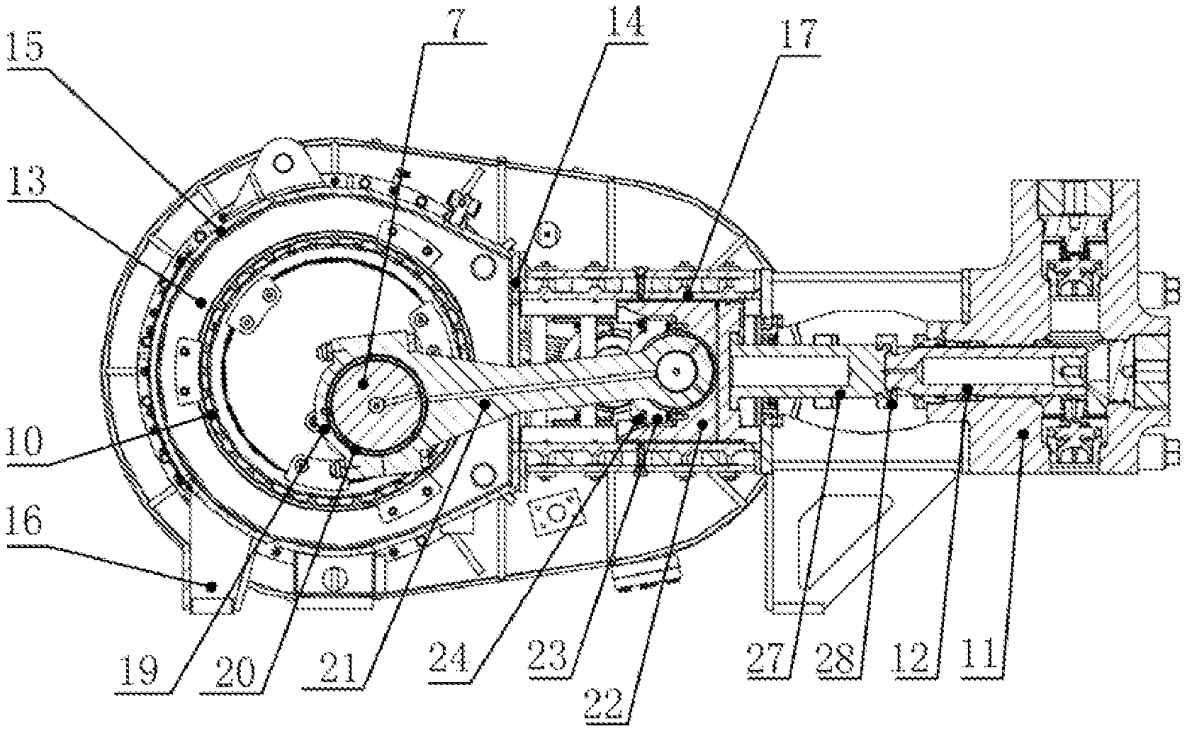
[0020] FIG. 4 is a cross-sectional view of the present invention.
[0021] FIG. 5 is a schematic structural diagram illustrating connection between a connecting rod mechanism and a crosshead mechanism according to the present invention.
[0022] FIG. 6 is a schematic structural diagram of a crankshaft according to the present invention.
[0023] FIG. 7 is a schematic structural diagram of a connecting rod bearing bush according to the present invention.
[0024] FIG. 8 is a schematic structural diagram of a parallel reduction gearbox according to the present invention.
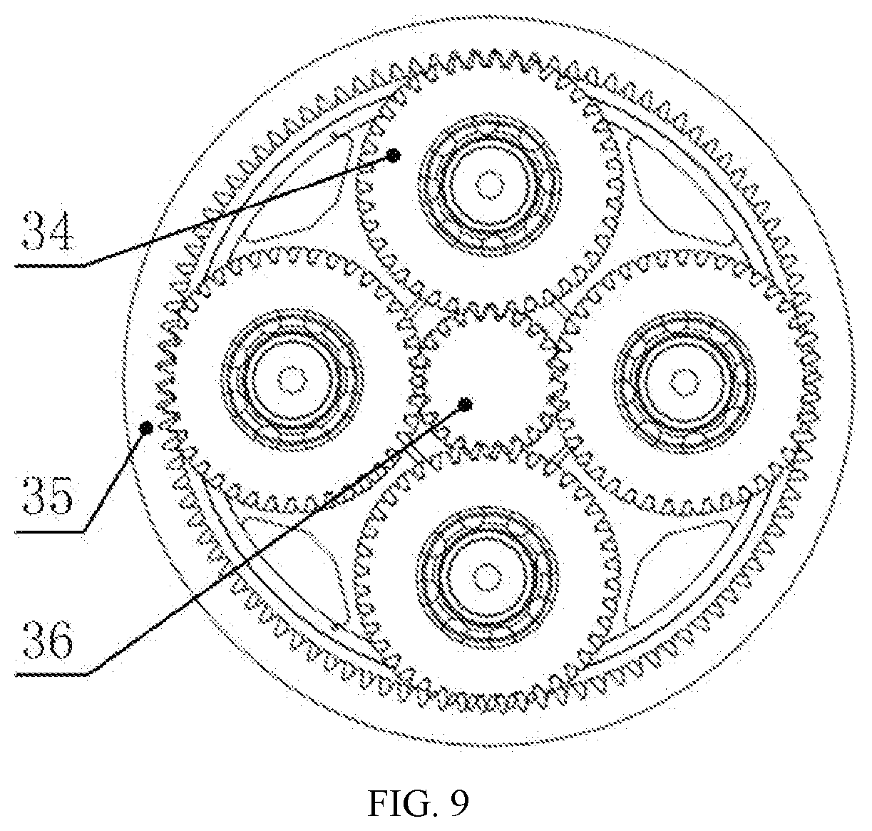
[0025] FIG. 9 is a schematic structural diagram of a planetary reduction gearbox according to the present invention.
[0026] Wherein: 1. power end assembly; 2. hydraulic end assembly; 3. reduction gearbox assembly; 4. crankcase; 5. crosshead case; 6. spacer frame; 7. crankshaft; 8. axle journal; 9. bellcrank; 10. cylindrical roller shaft; 11. valve housing; 12. plunger; 13. bearing seat; 14. front end plate; 15. cover plate; 16. supporting leg; 17. slide rail; 18. support column; 19. connecting rod cap; 20. connecting rod bearing bush; 21. connecting rod body; 22. crosshead; 23. crosshead gland; 24. crosshead connecting screw; 25. crosshead guide plate; 26. guide plate bolt; 27. pull rod; 28. clamp; 29. planetary reduction gearbox; 30. parallel reduction gearbox; 31. flange structure; 32. bull gear; 33. pinion; 34. planetary gear; 35. gear ring; and 36. sun gear.
DESCRIPTION OF THE EMBODIMENTS
[0027] As shown in FIGS. 1 to 9, an embodiment provides a super-power five-cylinder plunger pump, including a power end assembly 1, a hydraulic end assembly 2 and a reduction gearbox assembly 3. The power end assembly 1 is designed as a segmented structure. The segmented design makes the entire structure of the power end assembly 1 compact and easier to manufacture, thereby facilitating the assembly and maintenance of the entire pump and reducing the manufacturing costs. The power end assembly 1 includes a crankcase 4, a crosshead case 5 and a spacer frame 6. One end of the crosshead case 5 is connected to the crankcase 4 through hexagon bolts, and the other end of the crosshead case 5 is connected to the spacer frame 6 through bolts. The hydraulic end assembly 2 is disposed at an end of the spacer frame 6 and is connected to the crankcase 4 through bolts sequentially passing through the spacer frame 6 and the crosshead case 5. The reduction gearbox assembly 3 is connected to the crankcase 4 through bolts. A crankshaft 7 in the crankcase 4 is forged from alloy steel and includes six axle journals 8 and five bellcranks 9, one bellcrank 9 being disposed between every two adjacent axle journals 8, to form a five-cylinder structure. The design of the five-cylinder structure increases the output displacement of the plunger pump. Compared with a three-cylinder pump, the five-cylinder pump runs stably without vibration, thereby reducing the vibration of the entire pump and extending the service life. The distance between the bellcrank 9 and the center of rotation of the crankshaft 7 is 110 to 160 mm, ensuring that the plunger pump can output higher pressure to achieve a long stroke of up to 10 inches, thereby meeting the requirements of high-displacement operations, reducing the number of strokes of the pump, and extending the service life of various parts.
[0028] The hydraulic end assembly 2 includes a valve housing 11 and a plunger 12. The plunger 12 is disposed in the valve housing 11. The crankcase 4 is formed by welding steel plates. Six bearing seats 13, a front end plate 14, a cover plate 15, a supporting leg 16, and the like are mainly combined and welded together. After welding is completed, the bearing seat 20 and the front end plate 21 are formed through fine finishing. The crosshead case 5 is formed by welding steel plates. An arc-shaped slide rail 17 is fixed on the crosshead case 5. The arc-shaped slide rail 17 is forged from alloy steel. A support column 18 of an arch structure is disposed on the spacer frame 6 to increase the supporting strength. Each of the crosshead case 5 and the spacer frame 6 is provided with a through hole. The valve housing 11 at the hydraulic end is connected to the crankcase 4 through bolts sequentially passing through the spacer frame 6 and the crosshead case 5. A cylindrical roller shaft 10 is mounted on the axle journals 8. An outer ring of the cylindrical roller shaft 10 is mounted on the bearing seats 13.
[0029] A crosshead mechanism is disposed in the crosshead case 5. A connecting rod mechanism is disposed in the crankcase 4 and the crosshead case 5. One end of the connecting rod mechanism is connected to the crankshaft 7, and the other end of the connecting rod mechanism is connected to the crosshead mechanism. The connecting rod mechanism includes a connecting rod cap 19, a connecting rod bearing bush 20 and a connecting rod body 21. The connecting rod cap 19 is connected to the connecting rod body 21 through bolts. The connecting rod bearing bush 20 is located in a cylindrical space formed by the connecting rod cap 19 being connected to the connecting rod body 21. Each of two sides of the connecting rod bearing bush 20 is provided with a flange structure 31. The flange structure has a large width-to-diameter ratio, thereby providing a higher bearing capacity and a desirable positioning effect. The crosshead mechanism includes a crosshead 22, a crosshead gland 23, crosshead connecting screws 24, a crosshead guide plate 25 and guide plate bolts 26. The connecting rod body 21, the connecting rod cap 19, the crosshead 22 and the crosshead gland 23 are forged from alloy steel. One end of the connecting rod mechanism is connected to the bellcrank 9, and the other end of the connecting rod mechanism is connected to the crosshead 22 through the crosshead gland 23. The crosshead guide plate 25 is fixed on the crosshead 22 through the guide plate bolts 26. The crosshead guide plate 25 is arc-shaped and has an oil groove on the surface thereof. The crosshead 22 is connected to the plunger 12 of the hydraulic end assembly 2 through a pull rod 27 and a clamp 28. Further, the crosshead 22 is connected to the pull rod 27 through screws.
[0030] An output end of the reduction gearbox assembly is connected to the crankshaft 7. The reduction gearbox assembly includes a planetary reduction gearbox 29 and a parallel reduction gearbox 30. The parallel reduction gearbox 30 and the planetary reduction gearbox 29 both employ bevel gear transmission. The planetary reduction gearbox 29 includes one sun gear 36, four planetary gears 34 and one gear ring 35. The four planetary gears 34 form a planetary gear mechanism. The sun gear 36 is located at the center of the planetary gear mechanism. The planetary gears 34 and the adjacent sun gear 36 and gear ring 35 are in a normally engaged state. The parallel reduction gearbox 30 includes a bull gear 32 and a pinion 33. The pinion 33 is connected to an input end. The bull gear 32 is coaxial with the sun gear 36 of the planetary reduction gearbox 29. A rotational speed input at the input end is transferred to the bull gear 32 through the pinion 33 to achieve primary speed reduction, and the reduced speed is transferred to the sun gear 36 through the bull gear 32 and then transferred to the planetary gear 34 through the sun gear 36 to achieve secondary speed reduction, thereby obtaining a large transmission ratio. The transmission ratio may be up to 6.5:1 to 15:1. The planetary reduction gearbox 29 uses four uniformly distributed planetary gears 34 to transfer both motion and power at the same time. A centrifugal inertia force generated from the revolution of the four planetary gears 34 offsets the radial component of a counterforce between tooth contours, to reduce the force received by the main shaft and achieve high power transmission. A large speed ratio can reduce the input torque and extend the service life of the reduction gearbox, thereby effectively ensuring the matching between turbo-engine drive and electric-motor drive. A large reduction ratio can reduce the number of strokes of the plunger pump, and reduce the number of fatigue cycles for various rotary parts, thereby extending the service life of various parts. Moreover, an input angle of the reduction gearbox assembly can be adjusted according to input requirements, thereby satisfying the multi-angle adjustment and adapting various mounting requirements.
[0031] The reduction gearbox assembly 3 drives the crankshaft 7 to rotate. The crankshaft 7 rotates in the bearing supported by the bearing seat 13. The crankshaft 7 drives the connecting rod body 21. The connecting rod body 21 drives the crosshead 22. The crosshead 22 reciprocally moves in the arc-shaped slide rail 17 of the crosshead case 5. The crosshead 22 drives, through the pull rod 27, the plunger 12 to reciprocally move in the valve housing 11 of the hydraulic end assembly 2, to take up and discharge liquid.
[0032] It will be appreciated to persons skilled in the art that the present invention is not limited to the foregoing embodiments, which together with the context described in the specification are only used to illustrate the principle of the present invention. Various changes and improvements may be made to the present invention without departing from the spirit and scope of the present invention. All these changes and improvements shall fall within the protection scope of the present invention. The protection scope of the present invention is defined by the appended claims and equivalents thereof
* * * * *
D00000
D00001
D00002
D00003
D00004
D00005
XML
uspto.report is an independent third-party trademark research tool that is not affiliated, endorsed, or sponsored by the United States Patent and Trademark Office (USPTO) or any other governmental organization. The information provided by uspto.report is based on publicly available data at the time of writing and is intended for informational purposes only.
While we strive to provide accurate and up-to-date information, we do not guarantee the accuracy, completeness, reliability, or suitability of the information displayed on this site. The use of this site is at your own risk. Any reliance you place on such information is therefore strictly at your own risk.
All official trademark data, including owner information, should be verified by visiting the official USPTO website at www.uspto.gov. This site is not intended to replace professional legal advice and should not be used as a substitute for consulting with a legal professional who is knowledgeable about trademark law.