Multi-fluid, High Pressure, Modular Pump
Gilje; Tom-Reidar
U.S. patent application number 15/791323 was filed with the patent office on 2019-04-25 for multi-fluid, high pressure, modular pump. The applicant listed for this patent is Marine Technologies LLC. Invention is credited to Tom-Reidar Gilje.
| Application Number | 20190120031 15/791323 |
| Document ID | / |
| Family ID | 66169744 |
| Filed Date | 2019-04-25 |


View All Diagrams
| United States Patent Application | 20190120031 |
| Kind Code | A1 |
| Gilje; Tom-Reidar | April 25, 2019 |
MULTI-FLUID, HIGH PRESSURE, MODULAR PUMP
Abstract
A multi-fluid, high pressure pump with a modular configuration, capable of converting hydraulic power from a source may be capable of pumping nearly any type of fluid. The modular configuration may provide for individual sub-pump modules to be independently controlled by being individually network addressed, which allows for disabling a sub-pump module while continuing to operate the remaining sub-pump modules. In an embodiment, control of the sub-pump modules may be recomputed by evenly spacing a remaining number of sub-pump modules along a single period of a sine wave. Spare sub-pump modules may be included on a pump, thereby enable a spare sub-pump module to be added to the operable sub-pump modules so that full power of the pump may be available even after a sub-pump module fails.
| Inventors: | Gilje; Tom-Reidar; (Figgjo, NO) | ||||||||||
| Applicant: |
|
||||||||||
|---|---|---|---|---|---|---|---|---|---|---|---|
| Family ID: | 66169744 | ||||||||||
| Appl. No.: | 15/791323 | ||||||||||
| Filed: | October 23, 2017 |
| Current U.S. Class: | 1/1 |
| Current CPC Class: | E21B 41/0007 20130101; F04B 49/22 20130101; E21B 43/129 20130101; F04B 41/06 20130101; E21B 43/01 20130101; F04B 47/08 20130101; F04B 9/10 20130101; F04B 49/065 20130101 |
| International Class: | E21B 43/12 20060101 E21B043/12; E21B 41/00 20060101 E21B041/00; E21B 43/01 20060101 E21B043/01; F04B 49/06 20060101 F04B049/06; F04B 49/22 20060101 F04B049/22; F04B 9/10 20060101 F04B009/10; F04B 41/06 20060101 F04B041/06; F04B 47/08 20060101 F04B047/08 |
Claims
1. A pump, comprising: a plurality of sub-pump modules configured to physically and electrically connect to one another; a controller configured to: determine a number of sub-pump modules that are connected to one another; compute a control signal based on the number of sub-pump modules that are connected to one another; and communicate the control signal to the sub-pump modules to cause the sub-pump modules to pump fluid in a coordinated manner.
2. The pump according to claim 1, wherein said controller is further configured to adjust flow and pressure by adjusting the control signal to adjust speed of a piston within each of said sub-pump modules.
3. The pump according to claim 1, wherein the control signal is representative of a sine wave, wherein control signal values to be applied to each of said respective sub-pump modules are equally spaced along a single period of the sine wave.
4. The pump according to claim 1, wherein each of said sub-pump modules includes a valve connector that is configured to connect to a corresponding valve connector on a neighboring sub-pump module.
5. The pump according to claim 4, wherein each of said sub-pump modules includes a first valve connector disposed on a first side wall and a second valve connector disposed on a second side wall, the first and second valve connectors being identical for each of said sub-pump modules such that the first and second side wall connectors mate with one another.
6. The pump according to claim 4, wherein said valve connector is configured to enable a compensation fluid used to maintain pressure within the sub-pump modules to pass therebetween.
7. The pump according to claim 1, wherein each of said sub-pump modules, in being electrically connected to one another, include a plurality of electrical conductors that contact one another for data signals and electrical power to be communicated amongst said sub-pump modules.
8. The pump according to claim 1, wherein said controller is configured to: determine that a sub-pump module has a failure; and recompute the control signal based on a number of remaining operable sub-pump modules.
9. The pump according to claim 1, wherein said controller is further configured to: determine that a sub-pump module has failed; and engage an available sub-pump module connected to said plurality of sub-pump modules, but not currently being controlled to operate.
10. The pump according to claim 1, wherein each sub-pump module is assigned a unique address amongst said sub-pump modules arranged in a cluster configuration, the control signal being communicated to each of said sub-pump modules based on the respective unique address such that synchronization of said sub-pump modules results in a coordinated operation of said respective sub-pump modules.
11. The pump according to claim 10, wherein the cluster configuration is a serial line of said sub-pump modules.
12. The pump according to claim 1, further comprising a chassis onto which said sub-pump modules are positioned.
13. The pump according to claim 1, wherein each of said sub-pump modules include a bracket configured to receive a rod that is slidably engageable between at least two brackets of adjacent sub-pump modules to align said sub-pump modules.
14. The pump according to claim 1, wherein each of said sub-pump modules includes: a housing that defines the first fluid side in which a first fluid resides; and a pressure sensor configured to sense pressure within said housing of said respective sub-pump module.
15. The pump according to claim 1, wherein each of said sub-pump modules further include: a piston; and a pump controller configured to receive piston position commands from said controller, and to control position of said piston based on the received piston position command.
16. The pump according to claim 15, further comprising a remote computing system configured to receive telemetry data from said sub-pump modules and to display at least a portion of the telemetry data, the telemetry data including position of each respective piston and sensed pressure on at least an input and output side of the piston.
17. The pump according to claim 1, wherein said controller is further configured to: receive a sub-pump module failure signal indicative that a sub-pump has failed; and automatically recompute the control signal to exclude the failed sub-pump module, thereby enabling the pump to continue operating without the failed sub-pump module.
18. The pump according to claim 1, wherein said controller is further configured to, responsive to receiving a sub-pump failure signal indicative that a sub-pump has failed, prevent further control signals from being communicated to the failed sub-pump module, thereby disabling the failed sub-pump module.
19. The pump according to claim 18, wherein said controller is further configured to automatically generate an ordered list of network addresses associated with the sub-pump modules, the order of the sub-pump modules being based on physical relative alignment of the sub-pump modules.
20. The pump according to claim 1, wherein said controller includes: a processing unit; an input/output (I/O) unit in communication with said processing unit; and a communications bus over which said processing unit communicates via said I/O unit with said sub-pump modules.
21. The pump according to claim 20, wherein the communications bus is a serial bus over which each of said sub-pump modules are connected in a daisy chain configuration.
22-55. (canceled)
Description
BACKGROUND OF THE INVENTION
[0001] High-pressure pumps, such as sub-sea pumps, have to operate in extremely difficult environments under pressures and temperatures that are far more harsh than pumps designed to operate at atmospheric or surface pressures. As understood in the art of deep sea drilling, in the event that the pump has a failure, the pump has to be raised to the surface for repair or replacement. Such repair or replacement can be expensive not only for the reparation and replacement, but also as a result of having to shut down operations, such as drilling or exploration operations, at which the high-pressure pump is being used. Other pumps that operate in less harsh environments may suffer similar failures and repercussions, but high-pressure pumps are often used in ways that the time and cost to stop operations, repair, and/or replace the pumps can be high.
[0002] Many subsea tools/installations and/or operations are operated with fluids, pressure, or flow that a standard work class Remote Operated Vehicle (ROB) or other standard hydraulic power sources is not capable of supplying or use. Traditionally, operating deep sea tools have been operated with custom-made ROV skids/backpacks, valve-packs, boosters, relief valves, etc. The total package typically includes of many moving parts that are exposed to fluids and usage in which the moving parts are not designed to operate or even be exposed. As a result, the deep sea tools increase a risk of spill and breakdown. As such, there is a need for a pump that limits exposure of moving parts and supporting equipment that are not exposed to environmental conditions and is more resilient to avoid having to be shut down or replaced in the event of a failure of a part of the pump.
SUMMARY OF THE INVENTION
[0003] To reduce or eliminate a situation where a sub-sea pump has to be repaired or replaced during production operations, a multi-fluid, high pressure pump with a modular configuration, capable of converting hydraulic power from a source, capable of pumping nearly any type of fluid (e.g., seawater, glycol, hydraulic oil etc. or contaminated fluid), and that allows for self-repair and reconfiguration may be provided. In an embodiment, the modular pump includes individual modular pistons or sub-pump modules (sub-pumps) that may be mechanically, electrically, and fluidly connected to other modular pistons so as to form a multi-piston pump. Cavities within a housing of the sub-pumps may be fluid filled, thereby being able to sustain deep sea or subsea pressures. Each of the sub-pumps may be network addressed, and controlled by a control signal from a local or remote controller that causes each of the pistons to be activated based on a sinusoidal curve. For example, if the pump has eight modular pistons, then each of the pistons may be programmatically spaced for controlling stroke timing at 45 degrees apart from one another. Different numbers of pistons may be programmed to have different spacing or timing.
[0004] In the event of a failure of one of the sub-pumps, such as a failure of a seal of the piston, the associated sub-pump may be considered disabled by a controller and the remaining sub-pumps may be realigned for stroke timing purposes along the sinusoidal curve. By removing the failed piston by the controller, the pump may be weakened in terms of pumping pressure, but be capable of operating without repair or replacement (i.e., the pump itself is not fully disabled). In an embodiment, the pump may be configured with one or more spare sub-pumps, thereby enabling the pump to turn on and configure the one or more spare sub-pumps as part of the pump operations relative to the other sub-pumps (i.e., in physical and timing relationship). By having spare sub-pump(s), the loss of a number of sub-pumps that are the same or fewer than the number of spare sub-pumps allows the pump to continue operating at maximum capacity. As an example, if eight sub-pumps are used to perform pumping and two sub-pumps are configured on the pump as spares, up to two of the eight sub-pumps may fail and the pump may continue operating at full eight sub-pump capacity. In an embodiment, all ten modular sub-pumps may be utilized when initially deployed, and in the event of a sub-pump failure, that sub-pump may be taken offline and the remaining sub-pumps may cause a controller to reconfigure control communications (e.g., determine updated relative positioning of the sub-pumps) such that operation of the pump continues. However, by maintaining spare sub-pumps, essentially new sub-pumps may be added to replace failed sub-pumps.
[0005] A pump may include a plurality of sub-pump modules configured to physically and electrically connect to one another. A controller may be configured to (i) determine a number of sub-pump modules that are connected to one another, (ii) compute a control signal based on a number of sub-pump modules that are connected to one another, and (iii) communicate the control signal to the sub-pump modules to cause the sub-pump modules to pump fluid in a coordinated manner.
[0006] One embodiment of a method of operating a pump may include determining a number of sub-pump modules that are connected to one another. A control signal may be computed based on the number of sub-pump modules that are determined to be connected to one another. The control signal may be communicated to the sub-pump modules to cause the sub-pump modules to pump fluid in a coordinated manner.
[0007] An embodiment of a method of manufacturing a pump may include aligning a first sub-pump module with a second sub-pump module, where the first and second sub-pump modules including first and second respective housings. A first fluid connector member attached to the first housing of the first sub-pump module may be connected to a second fluid connector member attached to the second housing of a second sub-pump module, thereby enabling fluid to flow between the first and second housings of the first and second sub-pump modules. A first electrical connector member of the first sub-pump module may be connected to a second electrical connector member of the second sub-pump module, thereby enabling electrical signals to be communicated between the first and second sub-pump modules.
[0008] One embodiment of a method of operating a pump may include controlling multiple sub-pump modules to operate in a coordinated manner. In response to determining that one of the sub-pump modules has failed, (i) disabling the failed sub-pump module, (ii) activating a spare sub-pump module, and (iii) configuring the spare sub-pump module physically and electrically relative to other sub-pump modules that are still operational to operate the spare sub-pump module and other sub-pump modules that are still operational in the coordinated manner.
BRIEF DESCRIPTION OF THE DRAWINGS
[0009] Illustrative embodiments of the present invention are described in detail below with reference to the attached drawing figures, which are incorporated by reference herein and wherein:
[0010] FIG. 1A-1E are a set of illustrations of an illustrative multi-fluid, high-pressure modular pump;
[0011] FIG. 2 is an illustration of an illustrative pump in which a single sub-pump is being removed from the pump;
[0012] FIGS. 3A-3E are illustrations of a disassembly process for disassembling the pump of FIG. 1 so as to remove a sub-pump for replacement;
[0013] FIGS. 4A-4D are illustrations of different views of an illustrative sub-pump or sub-pump section;
[0014] FIGS. 5A-5C are illustrations of a primary connection module or section of a primary side of the pump of FIG. 1 depicting connecting members for communicating fluid and electrical signals when operating the pump;
[0015] FIGS. 6A-6C of a secondary side of the pump of FIG. 1 depicting connecting members for communicating fluid and electrical signals when operating the pump;
[0016] FIGS. 7A and 7B are illustrations of a pump with sub-pumps that are independently controlled;
[0017] FIG. 8 is an illustration of an illustrative process for operating a modular pump; and
[0018] FIG. 9 is a flow diagram of an illustrative process for manufacturing a pump that may include aligning a first sub-pump module with a second sub-pump module.
DETAILED DESCRIPTION OF THE INVENTION
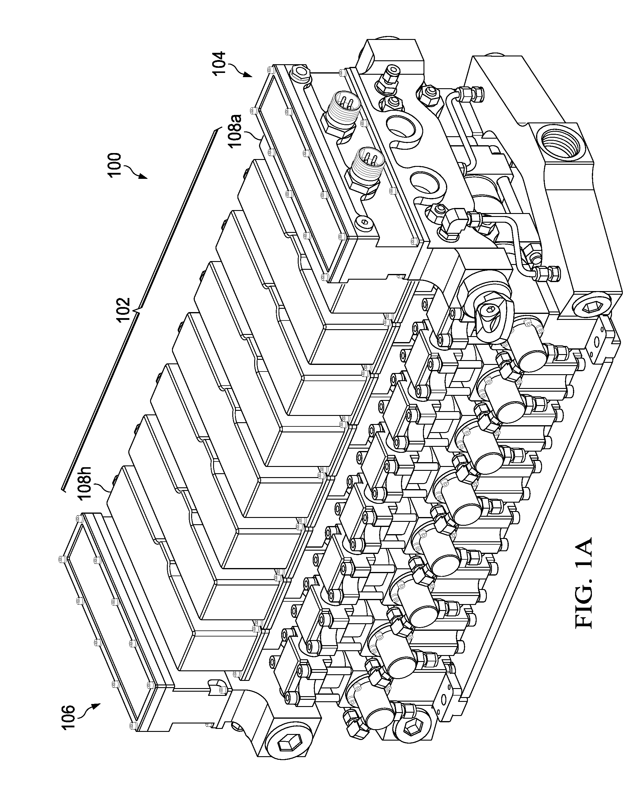
[0019] With regard to FIG. 1A, an illustration of an illustrative multi-fluid, high-pressure modular pump 100 is shown. The modular pump 100 may include a pump section 102 along with a primary connection section 104 and secondary connection section 106. The pump section 102 may include multiple sub-pumps 108a-108h (collectively 108) that are used to pump fluid. As shown, the pump section 102 includes eight sub-pumps 108, but it should be understood that two or more sub-pumps may be utilized to provide the functionality of a modular pump in accordance with the principles described herein. Each of the sub-pumps 108 may be connected to one another, as further described herein. The number of sub-pumps to be used is generally based on an amount and type fluid to be pumped, and available power (e.g., hydraulic power), and output needs (e.g., flow, pressure). The pump 100 may be pressure compensated by inclusion of internal fluid, such as oil, so as to be suitable for use at 4000 meter water depth. For dual media pumping possibilities, the primary connection section module 104 and secondary connection module 106 may be used.
[0020] In operation, the modular pump 100 may be configured as a dual media pump, where the pump 100 may be provided supply oil and auxiliary (aux) oil that are separated, thereby enabling two completely independent circuits with separate flow and pressure controls that may be selected and/or controlled remotely. It should be understood that the pump 100 may alternatively be configured with one circuit or more than two circuits. The supply oil and aux oil may be the same or different type, and the sub-pumps 108 that are being operated by the respective oils may operate independently at the same or different speeds and pressures.
[0021] The modular pump 100 may be configured to convert hydraulic power from a source, such as a hydraulic power unit (HPU) or work class remotely operated vehicle (ROV) over to a secondary media that can be nearly any type of fluid. Because hydraulic power is used to drive a certain number of sub-pumps 108, the modular pump 100 may output a certain amount of force to pump an external fluid. If the number of sub-pumps 108 changes, then a proportional amount of power for pumping the external fluid is changed, as further described herein.
[0022] With regard to FIG. 1B, an illustration of a top view of the pump 100 of FIG. 1A depicting different illustrative sections of the pump 100 is shown. The pump section 102 is formed of multiple pumps 108 that are sandwiched between the primary connection section 104 and secondary connection section 106. The sub-pumps 108 are modular, and may be individually controlled, thereby enabling the pump 100 to continue operating, albeit at a lower power level, as further described herein.
[0023] In an embodiment, each of the sub-pumps 108 may have control electronics that have different electronic network addresses, such as Ethernet addresses. A remote controller (not shown) may be configured to control operation of each sub-pump 108 using the respective network addresses. Control signals may address each of the respective sub-pumps 108 to coordinate operation thereof (e.g., evenly spaced in a sine wave manner relative to one another). The sine wave may have a frequency that the sub-pumps are able to operate. In the event of a failure of one of the sub-pumps 108, then the controller may stop controlling operation of the failed sub-pump and re-coordinate the other operable sub-pumps 108, thereby enabling the pump 108 to continue operation. A determination as to whether a sub-pump has a failure may include determining whether a sensed parameter, such as input pressure or output pressure, is outside of a specification (e.g., higher or lower than a predetermined pressure value or range).
[0024] In an embodiment, the primary connection section 104 may operates as a control module for the multi-fluid high pressure pump 100, where the primary connection section 104 may (i) measure input/output pressure and (ii) calculate speed and position of the sub-pumps 108 so as to output drive signals to control the sub-pumps 108. In an embodiment, the primary connection section 104 may control up to 12 sub-pumps 108 plus one end section. A controller of the primary connection section 104 may include a smart feature that senses (i) how many sub-pumps 108 are connected, and (ii) if a secondary connection section 106 is installed with the pump 100.
[0025] In an embodiment, the pump 100 may have the certain specifications for operation within high pressure locations, such as sub-sea locations.
TABLE-US-00001 Electrical Data Nom. Voltage 20 . . . 30 VDC Nom. Power 10.6 W Nom. Current 0.44 A Max. Power 250 W Max. Current 10.5 A Communication Ethernet or RS-232
TABLE-US-00002 Hydraulic Data Number of function lines Depending on configuration, 1 or 2 output possible Pump Description Dual media pump, supply oil and aux oil is separated. Seals between supply oil and aux oil are continually monitored, any potential leak will give a warning/alarm. Maximum Supply BAR 275 BAR pressure (PSI) (4000 PSI) Maximum Operating BAR 275 BAR (PSI) (4000 PSI) Max Return Line BAR 120 BAR Pressure (PSI) (1740 PSI) Maximum comp. pressure BAR 0.7 BAR (PSI) (10.15 PSI) Aux Max pressure BAR 350 BAR (PSI) (5076 PSI) Aux Max return BAR 7 BAR to -28 BAR (under pressure, (PSI) suction operation subsea) (101.5 PSI to -406 PSI) Supply Fluid Hydraulic oil 22/32, tellus oil or Royal Purple Aux Fluids Hydraulic oil, Water-Glycol, seawater**
TABLE-US-00003 Section Performance data 1.36 Ratio Section Input (other ratios Max input pressure 275 bar possible) Max input flow 50 l/m Output Max output pressure 350 bar Max output flow 35 l/m 1.36 Ratio 8 Input cylinder pump Max input pressure 275 bar (other assemblies Max input flow 400 l/m possible) Output Max output pressure 350 bar Max output flow 280 l/m
[0026] It should be understood that the specifications are illustrative, and that other specifications for electrical, hydraulic, and pressure specifications may be provided by the pump 100.
[0027] With regard to FIG. 1C, an illustration of the pump of FIG. 1A showing illustrative lift points 110a and 110b (collectively 110) for lifting the pump is shown. The lift points 110 are mounted to the primary and secondary connection sections 104 and 106, respectively. The lift points 110 are disposed in opposing positions, and provide for balancing of the pump 100 when evenly lifted by the lift points 110. It should be understood that the lift points 110 are illustrative, and that alternative configurations of lift points are also contemplated.
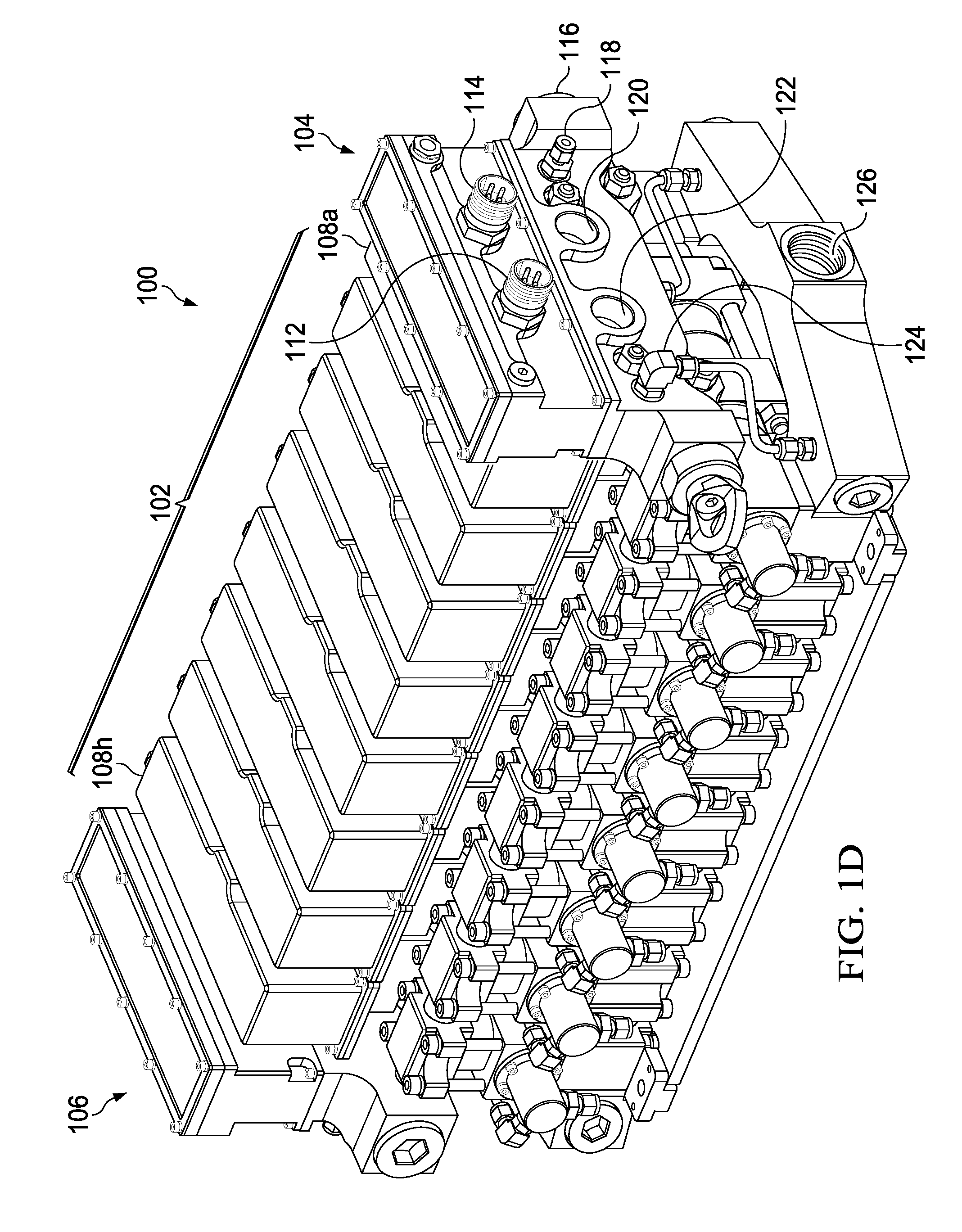
[0028] With regard to FIG. 1D, an illustration of the pump 100 of FIG. 1A depicting connection members of the primary connection section 104 for communicating fluid and electrical signals when operating the pump is shown. The connection members of the primary connection section 104 may include an electric connector 112 for communicating electrical power and signal communications. An electric connector 114 for daisy chain and flow meter communications may also be positioned on the primary connection section 104. A pressure connector 116 may be used for a liquid media 2 to enter into the sub-pumps 108. A compensator connector 118 may provide for compensation of pressure on components and cavities within the primary and secondary connection sections 104 and 106 and sub-pumps 108. A pressure connector 120 may enable liquid media 1 to enter into the sub-pumps 108. A return connector 122 may enable a return of liquid media. A seal drain connector 124 may be provided for draining media 1. A suction connector 126 for extracting media 1 from the pump 100 may be provided. The various connectors may be configured to support fluid types, electrical signals, or otherwise under the pressures and temperatures in which the pump 100 may be utilized.
[0029] With regard to FIG. 1E, an illustration of the pump 100 of FIG. 1A depicting connection members of the secondary connection section 106 for communicating fluid and electrical signals when operating the pump is shown. The connection members of the secondary connection section 106 may include an electric connector 128 for measuring an external flowmeter 1 and electric connector 130 for measuring an external flowmeter 2. A seal drain connector for media 2 may be provided. A pressure connector 134 may enable liquid media 1 to enter into the sub-pumps 108. A return connector 122 may enable a return of liquid media 2. A compensator connector 138 may provide for compensation of pressure within the secondary connection section 106 and one or more of the sub-pumps 108. A pressure connector 140 for media 2 may be used to support liquid media 2 to enter the sub-pumps 108. A section connector 142 for suctioning out media 2 from the sub-pumps 108 is also provided. The various connectors may be configured to support fluid types, electrical signals, or otherwise under the pressures and temperatures in which the pump 100 may be utilized.
[0030] With regard to FIG. 2, an illustration of an illustrative pump 200 with modular sub-pumps in which a single sub-pump is being removed is shown. The pump 200 includes a pump section 202, primary connection section 204, and secondary connection section 206. Sub-pumps 208a-208h (collectively 208) may be individually removed from the pump 200 by separating the primary connection section 204 and secondary connection section 206 from the pump 200. The pump 200 may be disposed on a spacer plate 210 that may be part of a chassis 211 that supports the sub-pumps 208. Rods 212a-212d (collectively 212), which may be threaded, may be used to align the sub-pumps 208. Various fastening hardware, such as nuts and bolts, may be removed from the primary connection section 204 and secondary connection 206 to separate those components from the pump 200, which enables the rods 212 to be extracted from the sub-pumps 208, so that an individual sub-pump 208e may be separated from neighboring sub-pumps 208d and 208f by disconnecting connectors 214 from a neighboring sub-pump 208f. Another connector 216 that may support electrical communications, mechanical connection, and fluid communications may also be disconnected from neighboring sub-pump 208. Although not shown, a corresponding connector to the connector 216 may be disposed on the sub-pump 208f to enable electrical signals and compensation fluid to pass between the sub-pumps 208e and 208f.
[0031] The fluid communications may include pressure compensation fluid, such as oil, that may be used to fill one or more cavity of the sub-pump to prevent high pressures in a high-pressure environment in which the pump 200 is to operate from crushing the cavities and/or components therein. Once the sub-pump 208e is removed, another sub-pump may replace the sub-pump 208e or the pump 200 may be reconfigured with only seven of the sub-pumps 208 by connecting sub-pump 208f and 208d. Thereafter, operation of the sub-pumps 208 may be reconfigured electronically by a controller operating in the primary connection section 106 that may automatically determine a total number and relative position of remaining sub-pumps 208.
[0032] The primary connection section 204 and secondary connection section 206 may include respective manifolds 218 and 220 that includes cavities through which fluids and electrical conductors may pass to enable one or more fluids and electrical communication signals to be supplied or otherwise communicated to the sub-pumps 208. The fluids may include fluids under high pressure to operate the sub-pumps 208, and the electrical conductors of connectors 222, 224, and 226 may provide for both control signaling and telemetry data collected by sensors (e.g., pressure sensors, flow rate sensors, temperature sensors, position sensors, etc.) to be monitored remotely.
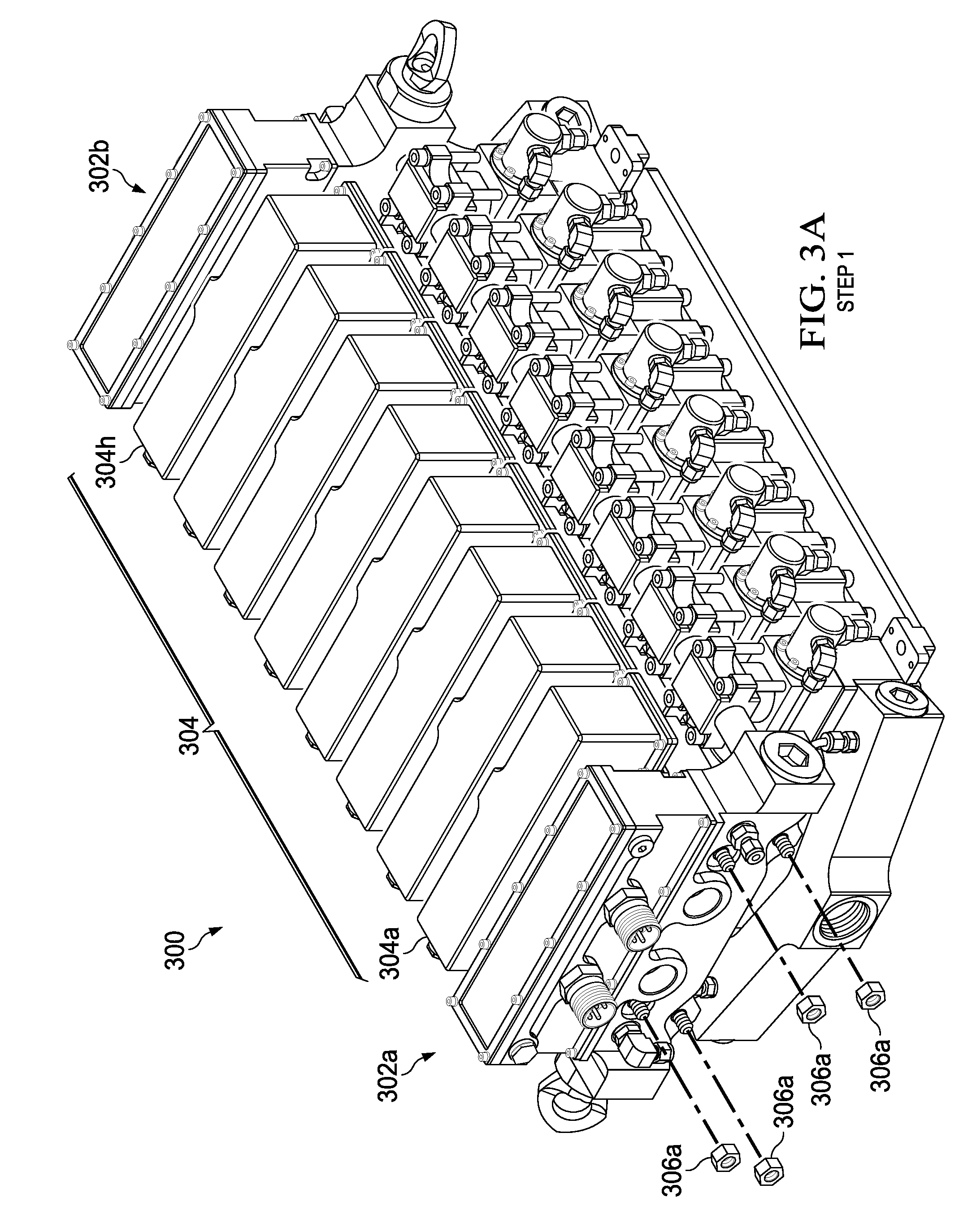
[0033] With regard to FIGS. 3A-3E, illustrations of a disassembly process for disabling an illustrative pump 300 so as to remove a sub-pump for replacement are shown. The process may start at Step 1, where the pump 300 that is fully assembled is shown. The pump 300 may include a primary connection section 302a and secondary connection section 302b. An alternative configuration of the pump may include just the primary connection section 302a or more than two connection sections. The primary and secondary connection sections 302a and 302b define opposing ends of the pump between which a pump section 304 formed of sub-pumps 304a-304h (collectively 304). The first step of the disassembly process is shown at Step 1, where nuts 306a or other fastening members at the primary connection section 302a that connect to rods 308 (see FIG. 3B) may be loosened. Nuts 306b at the secondary connection section 302b may also be loosened and separated from the rods 308. The rods 308 may be connected to brackets that are attached to the sub-pumps 304.
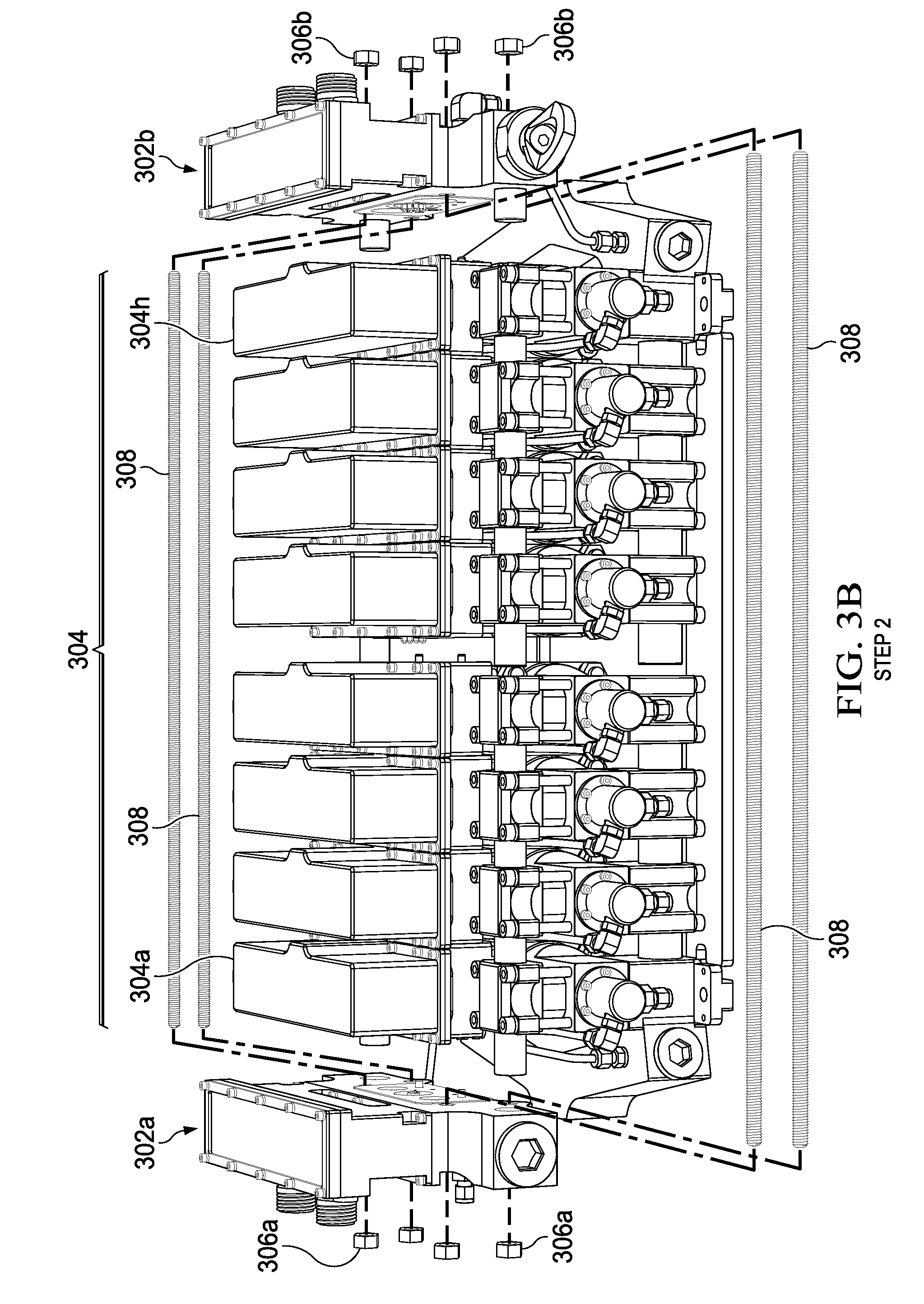
[0034] At Step 2 in FIG. 3B, once the nuts 306a and 306b are removed, the primary and secondary connection sections 302a and 302b may be pulled or slid outward axially along the rods 308. The rods 308, which may engage the sub-pumps 304 to provide support therefor, may be withdrawn partially or completely so that a sub-pump, in this case sub-pump 304d, that may be damaged may be removed.
[0035] In Step 3 of FIG. 3C, the sub-pumps 304a-304c are shown to be pulled away from connection or alignment members that may extend between sub-pump 304d, and sub-pumps 304e-304h are shown to be pulled away from sub-pump 304d in the opposite direction. Sub-pumps 304c and 304e may be separated a distance sufficient to enable clearance of connection and/or alignment members 310a and 310b between the sub-pumps 304c/304d and 304d/304e to enable removal of sub-pump 304d without contacting sub-pumps 304c or 304d or associated hardware, as shown at Step 4 in FIG. 3D. The connection and/or alignment members 310a and 310b may be used for fluid flow of media 1 and/or media 2 used to operate the pump 300. In an embodiment, non-fluid functional connection members (not shown), guides, or other alignment mechanisms, may be utilized to connect or align sub-pumps 304 that are adjacent to one another.
[0036] With regard to FIG. 3E, Step 5 may include multiple processes, including replacing the damaged sub-pump, in this case sub-module 304d, with a replacement sub-pump module 304d'. Because the sub-pumps 304 may have the same or similar configurations, and be individually and remotely addressable and controllable via communications signals, the sub-pump 304d' may simply be positioned where the damaged sub-pump 304d was previously positioned. That is, no pre-configuration of the sub-pump 304d' is needed as the sub-pump 304d' may be configured and reconfigured for control purposes during operation or in a set-up process. Once the replacement sub-pump 304d' is in the position of the removed sub-pump 304d, a reverse of Step 4 through Step 1 may be performed such that the sub-pumps 304c and 304e are engaged with sub-pump 304d' by engaging the connection and alignment members 310a and 310b, the rods 308 are reengaged with the sub-pumps 304a-304c, 304d', and 304e-304h and tightened using the nuts 306a and 306b. The hydraulics and electric power connections may be reengaged, and power may be turned on.
[0037] Because the pump 300 and controller, either local or remote, may be configured to be self-configuring (e.g., provide identifiers of sub-pumps 304 and positioning thereof), communications by the controller to control the pump may automatically determine number of sub-pumps 304 and physical alignment of each relative to one another, thereby enabling control signals to timely control operation of each of the sub-pumps 304. It should be understood that if more or fewer sub-pumps 304 are provided (e.g., 6, 7, 9, or 10 sub-pumps), then pump 300 may be configured or self-configured through communications signals, such as network address requests, with each of the sub-pumps 304. As the sub-pumps 304 may be configured in a serial manner, the positions of the sub-pumps 304 may be determined by inspecting an order of network addresses added to a data packet, set of data packets, or other communications protocol, as understood in the art. In an embodiment, a serial bus, such as a controller area network (CAN) bus or any other communications bus, may be utilized.
[0038] With regard to FIGS. 4A-4D, illustrations of different views of an illustrative sub-pump or pump section 400 are shown. With regard to FIG. 4A, an illustration of an illustrative sub-pump 400 is shown as a complete unit. The sub-pump 400 may include an electronics and valve section 402 and a piston section 404. The electronics and valve section 402 may include a local motherboard or printed circuit board (PCB), controller electronics (e.g., processor) disposed on the PCB, communications electronics, and/or any other electronics used to support control and collection and distribution of telemetry data of the sub-pump 400. Also within the electronics and valve section 402 may be an electronically controlled valve that is used to control the flow of fluid to drive a piston within the piston section 404. The sub-pump module 400 may be controlled by the pump motherboard located in the electronics and valve section 402. In controlling the sub-pump module 400, the motherboard may be configured with a controller to control speed and/or position of a piston (see FIG. 4B) in the piston section 404 of the sub-pump 400.
[0039] In an embodiment, the sub-pump 400 may include a connector 406 that supports multiple connection functions, including (i) an electrical connection function and (ii) a fluid connection function. The electrical connection function may provide for power and data communications to be made between sub-pumps, and the fluid connection function may provide for compensation fluid. The compensation fluid may be oil or other viscous material used to fill cavities of the sub-pump 400 to protect the sub-pump 400 from being crushed when at depths under the ocean or in other high-pressure locations. The connector 406 may support serial communications or parallel communications, and may be a standard or proprietary communications bus. In enabling fluid communications, the connector 406 may mate with an opposing connector from an adjacent sub-pump, primary connection section (for example, 104 of FIG. 1), or secondary connection section (for example, 106 of FIG. 1).
[0040] A centralized or remote controller, which may be positioned within the primary connection section 104 of FIG. 1 that is in communication with each of the sub-pumps via the communications bus of the connector 406 or otherwise may cause each of the sub-pumps to be coordinated relative to one another. The sub-pump 400 may be configured with a closed loop controller that is executed by a controller or processor on the motherboard, and used to regulate position of the piston (see FIG. 4B) at a given speed. A pressure sensor (see FIG. 4C) may constantly monitor a seal status (e.g., leak or no leak), and report the status of the seal back to a monitoring system inclusive of a graphical user interface (GUI) that may display a number of different parameters, including piston speed, piston position, piston pressure, seal status (e.g., leakage), and so forth, thereby providing an operator with an indication of the various parameters along with a notification, warning, and eventual alert or alarm if the leakage increases. In an embodiment, the alarm may cause the pump to automatically shut down or be taken out-of-service by issuing a command to the motherboard of the sub-pump 400. In an embodiment, an alarm signal may cause and the sub-pump 400 to automatically, semi-automatically, or manually via a remote controller be taken out of service. The pump may automatically compensate for a missing sub-pump by synchronizing and adjusting the speed of the remaining sub-pumps.
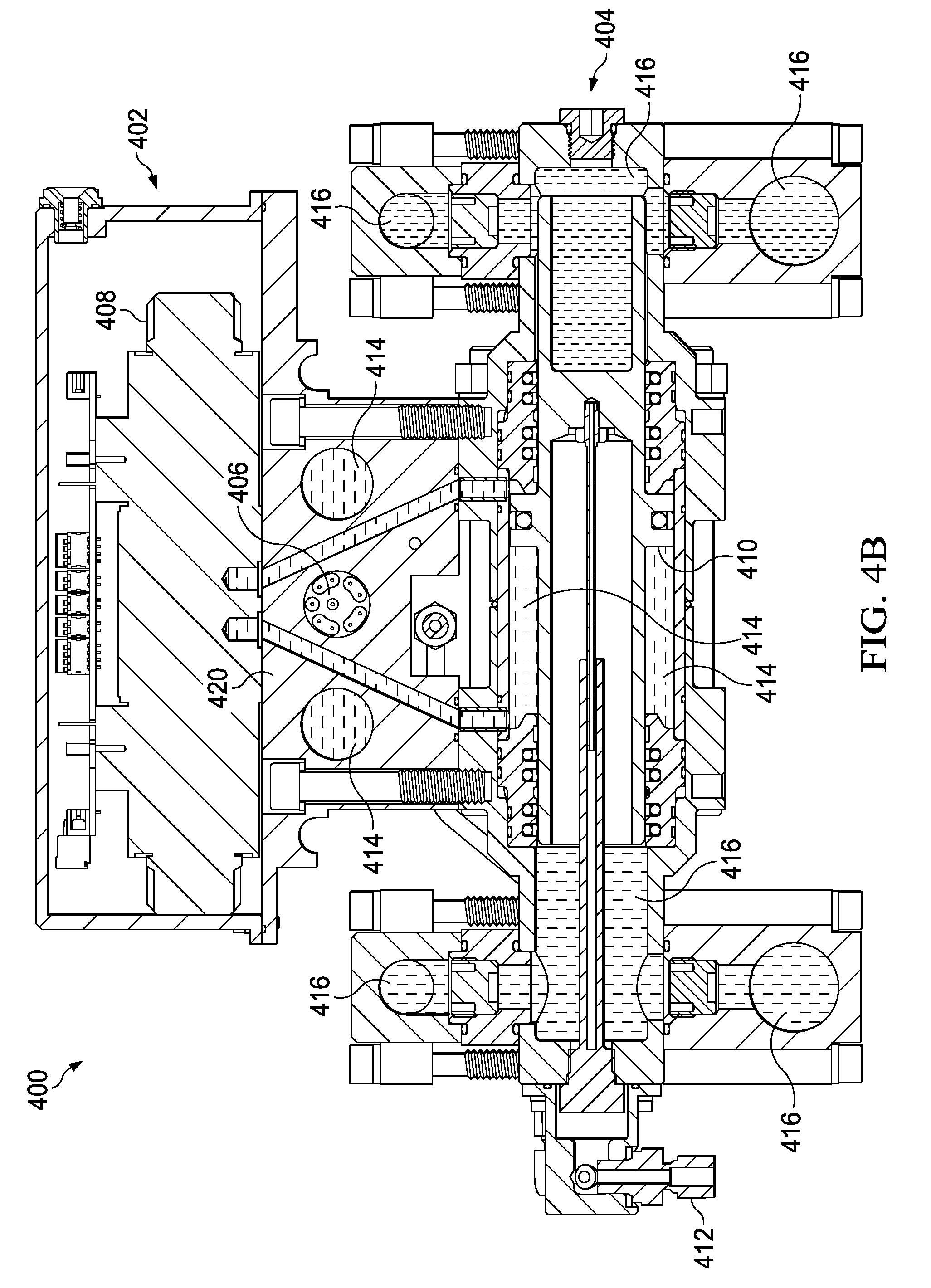
[0041] With regard to FIG. 4B, a side, sectional view of the sub-pump section or sub-pump 400 of FIG. 4A that depicts internal components of the sub-pump 400 is shown. A proportional valve 408 may be disposed within the electronics and valve section 402 that is controlled to enable hydraulic control of a piston 410 within the pump section 404. It should be understood that other types of valves, such as solenoid or servo valves may be utilized, as well. A position sensor 412 may be used to sense position of the piston 410 so as to provide positional feedback to a motherboard within the electronics and valve section 402 of the sub-pump 400. Primary (input/power) side fluid 414 may pass through various apertures of the sub-pump 400, and may be received via a primary connection section 104. Secondary (output) side fluid 416 may pass through various apertures of the sub-pump 400 for outputting the fluid from the sub-pump 400. It should be understood that the fluid 414 and 416 is different (or at least positioned in different locations) than compensation oil used to counter pressure within a high pressure operation.
[0042] The electrical and fluid connector 406 is shown to be disposed on a sidewall 420 of the sub-pump 400. The connector 406 may be configured with electrical conductors to conduct electrical power and data signals for use by the sub-pump 400. That is, electrical power may be used to power electronics and electromechanical devices, such as the proportional valve 408, on the sub-pump 400, and the data signals may be used to control operation of the sub-pump 400, including opening and closing the valve 408, communicating data for controlling operation (e.g., communicating timing, position, speed, notification, or other information) and providing telemetry data of sensed operation and failure situations to and from the sub-pump 400. The data signals may be serial data or parallel data using any communications protocol, as understood in the art. In an embodiment, the connection may be configured to operate as part of a CAN bus. Other data buses may be utilized, as well.
[0043] With regard to FIG. 4C, an illustration of internal components of the valve section 402 of the sub-pump 400 of FIG. 4A is shown. A leak pressure sensor 422 may be used to sense leak pressure of the valve 408 of the sub-pump 400. In particular, the leak pressure sensor 422 is used to monitor seals between supply oil and auxiliary oil in the sub-pump 400, and any potential leak sensed by the leak pressure sensor 422 produces a warning/alarm signal. A valve printed circuit board (PCB) 424 may be used to control operation of the valve 408. In controlling operation of the valve 408, circuitry (e.g., digital and/or analog circuits) may be used to control valve position that controls fluid flow and fluid direction that controls operation of a piston (see FIG. 4D) of the sub-pump 400.
[0044] With regard to FIG. 4D, a side (opposite side of FIG. 4B), sectional view of the sub-pump 400 of FIG. 4A that depicts internal components of the sub-pump 400 is shown. The valve 408 is shown to be connected to two sides, an A side and a B side for enabling fluid to be directed to drive the piston 410. A position sensor 412 may have a position sensor arm 426 that is part of or added to the piston 410 to measure position of the piston 410. It should be understood that alternative configurations of the sub-pump 400 may be utilized to provide the same or similar functionality, and that the embodiment shown herein is illustrative.
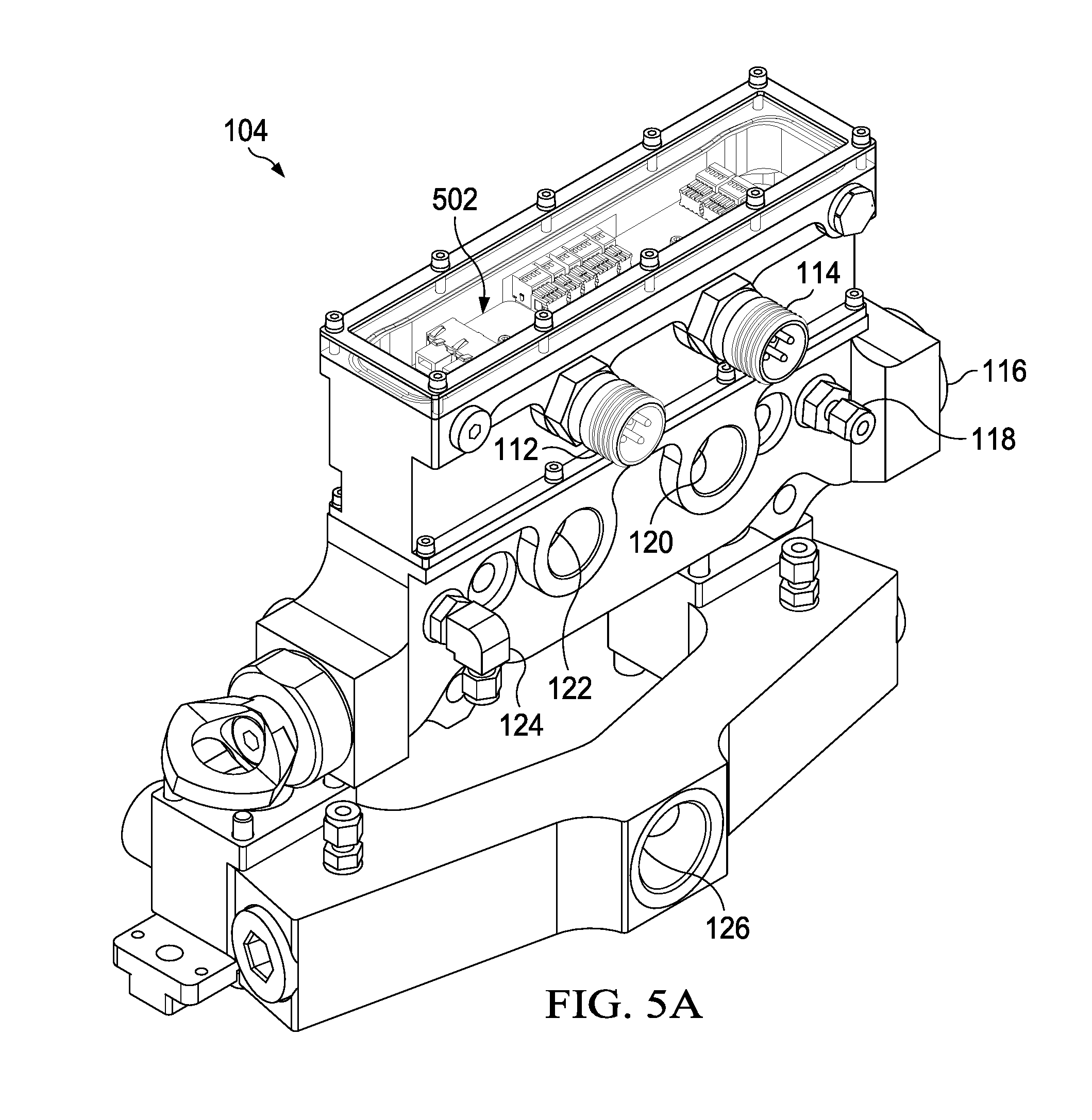
[0045] With regard to FIGS. 5A-5C, illustrations of a primary connection module or section 104 of a primary side of the pump of FIG. 1 depicting connection members for communicating fluid and electrical signals when operating the pump are shown. The primary connection module 104 may be configured with a control module of the pump 100, and be configured to measure input/output pressures, and calculate speed and position of the sub-pump modules, such as sub-pump modules 108, to produce output flow and pressure of the pump 100.
[0046] The primary connection section 104 may include a controller 502 positioned on a motherboard or PCB that may be configured to control up to 12 sub-pumps plus a secondary connection section 106. The controller 502 may be configured to automatically sense (i) how many sub-pumps 108 (FIG. 1) are connected, and (ii) if a secondary end section 106 is installed in the pump 100. The controller 502 may include a processing unit and other electronics (not shown) that may be configured to communicate with and control or coordinate operation of the sub-pumps 108. For example, the controller 502 may be configured to generate a control signal that establishes timing for each of the sub-pumps of each of the sub-pumps 108 to stroke using a proportional value, for example. The controller signal may be sinusoidal signal, and specific values that are equally spaced along the sinusoidal signal may be used to control the sub-pumps. For example, if a pump has eight sub-pumps 108, as shown in FIG. 1, values that are spaced along the sinusoidal signal every 360 degrees/8 sub-pumps=45 degrees may be used to drive the cylinders of the sub-pumps 108. If the number of sub-pumps 108 changes due to a sub-pump failing, for example, then the controller 502 of the primary connection section 104 may automatically recalculate the control signals or data points on the sinusoidal signal by dividing 360 degrees by the number of sub-pumps (e.g., 7 sub-pumps) so that the control signals remain equally spaced and the pump operates normally, albeit with less power.
[0047] With regard to FIG. 5B, an illustration of a bottom view of the primary connection section 104 is shown. The primary connection section 104 may include an aux return pressure sensor 504, supply pressure sensor 506, return pressure sensor 508, and aux pressure sensor 510. The controller 502 may receive pressure signals from each of pressure sensors 504, 506, 508, and 510 to monitor the pressure of the fluids being used for driving the sub-pumps 108. The pressure signals may be processed by the controller 502 to control operation of values and motion of pistons along with monitoring for a change in operation of the individual sub-pumps.
[0048] With regard to FIG. 5C, an illustration of a top view of the primary connection section 104 showing the controller 502 that is disposed on a motherboard. In an embodiment, the motherboard and controller 502 may be the same or similar to the motherboard in each of the sub-pumps. To communicate with the sub-pumps, the primary connection section 104 may include an electrical and fluid connector, such as the connector 406 of FIG. 4A. Fluid that passes into the primary connection section 104 may be passed through each of the consecutive sub-pumps via the connector 406, thereby enabling an operator or manufacturer to pressure compensate each of the sub-pumps without having to individually fill each sub-pump with compensation fluid (e.g., oil).
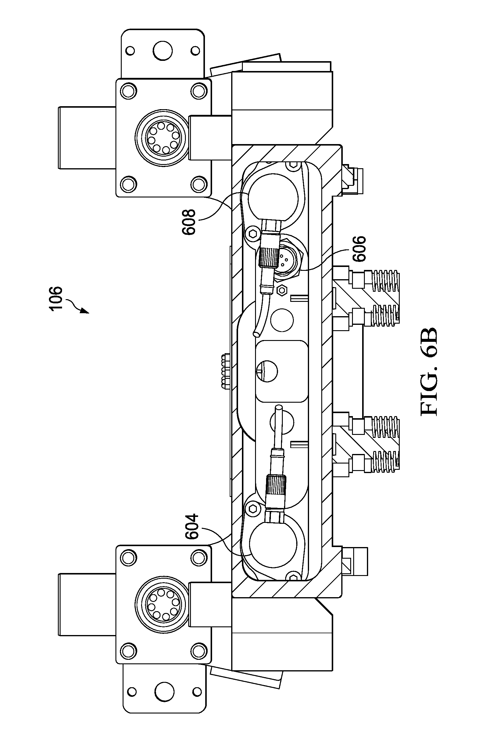
[0049] With regard to FIG. 6A-6C, illustrations of the secondary connection section or module 106 of FIG. 1A are shown. FIG. 6A is an illustration of the secondary connection section or module (SCM) 106, and as with the primary connection module 104, the secondary connection module 106 may include a controller 602 positioned on a motherboard or PCB that may be configured to control up to 12 sub-pumps plus a secondary connection section 106. In operation, however, the controllers 502 and 602 would split controlling different ones of the sub-modules on the pump. The controller 602 may provide for the same or similar functions as the primary connection module, such as automatically sensing how many sub-pumps 108 (FIG. 1) are connected. The controller 602 may include a processing unit and other electronics (not shown) that may be configured to communicate with and control or coordinate operation of the sub-pumps 108. Other functionality of the primary connection section 104 may be supported by the secondary connection section 106, as well. As shown in FIG. 6B, the secondary connection section 106 may include an aux return pressure sensor 604, aux pressure sensor 606, and a com/seawater pressure sensor 608.
[0050] The secondary connection section 106 may be used when the pump is configured to operate with two different aux media simultaneously. By installing the secondary connection section 106 to enable splitting the pump between the pump sections (e.g., four sub-pumps 108a-108d operate to pump independent of four sub-pumps 108e-108h), the pump is configured with two completely independent circuits with separate flow and pressure controls. In an embodiment, controlling the primary and secondary connection sections 104 and 106 may be performed remotely, such as via a graphical user interface on a ship or elsewhere. By producing two flow and pressure controls, the pump may be used to drive two fluids for performing two different functions.
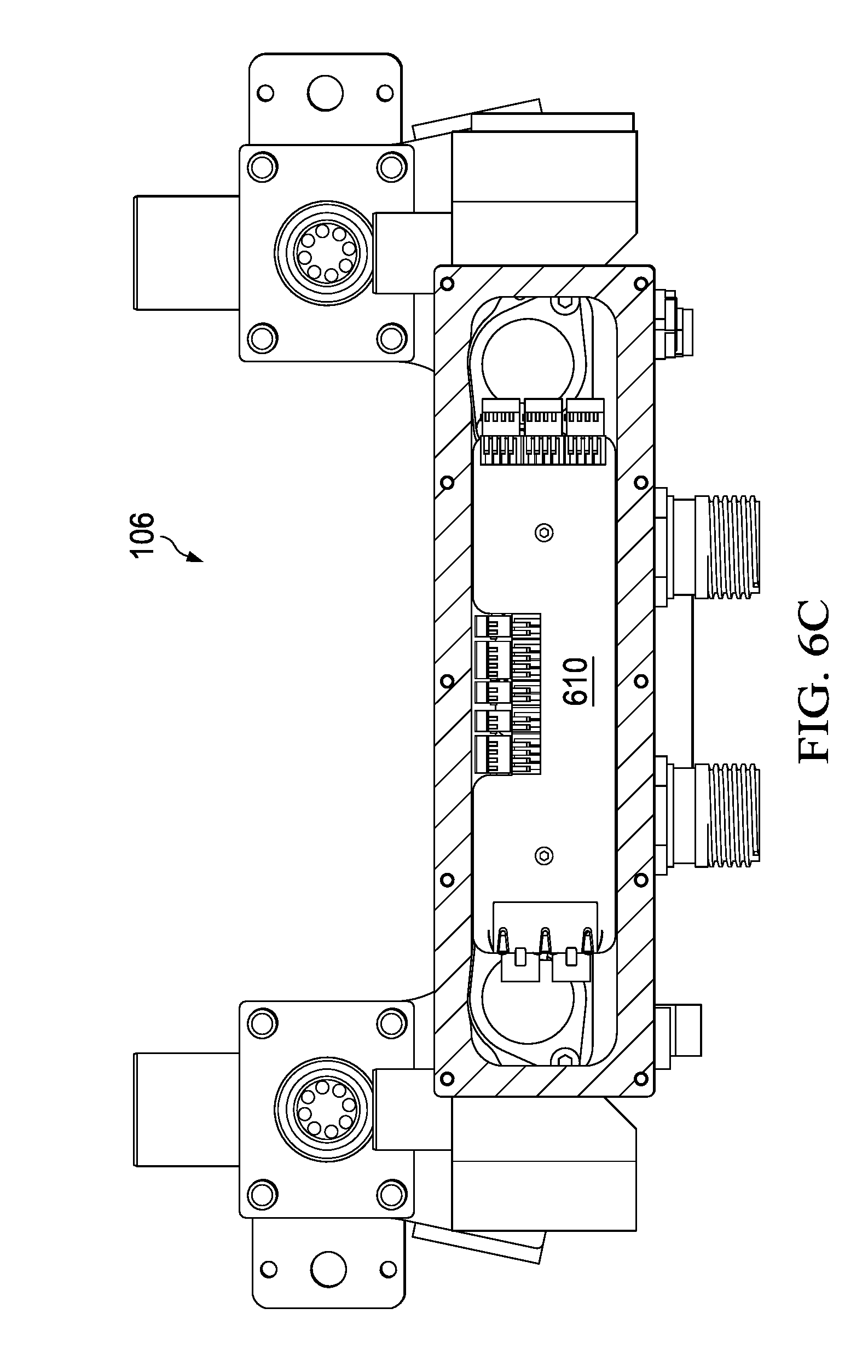
[0051] Moreover, the secondary connection section 106 may measure aux pressure and return pressure on media 2, and provide feedback to the primary connection section 104. The secondary connection section 106 may also have a connector for two optional external flowmeters, one analog that operates between 4-20 mA and/or two digital flowmeters. As shown in FIG. 6C, a motherboard 610 on which a controller may be operating is shown to be located in a center top area of the secondary connection section 106. The motherboard 610 and controller may be the same or similar to the motherboard and controller of the sub-pumps, as previously described. Of course, the controller may be configured in a manner that is the same or similar to that of the primary connection section 104, but function to provide for aux control functionality.
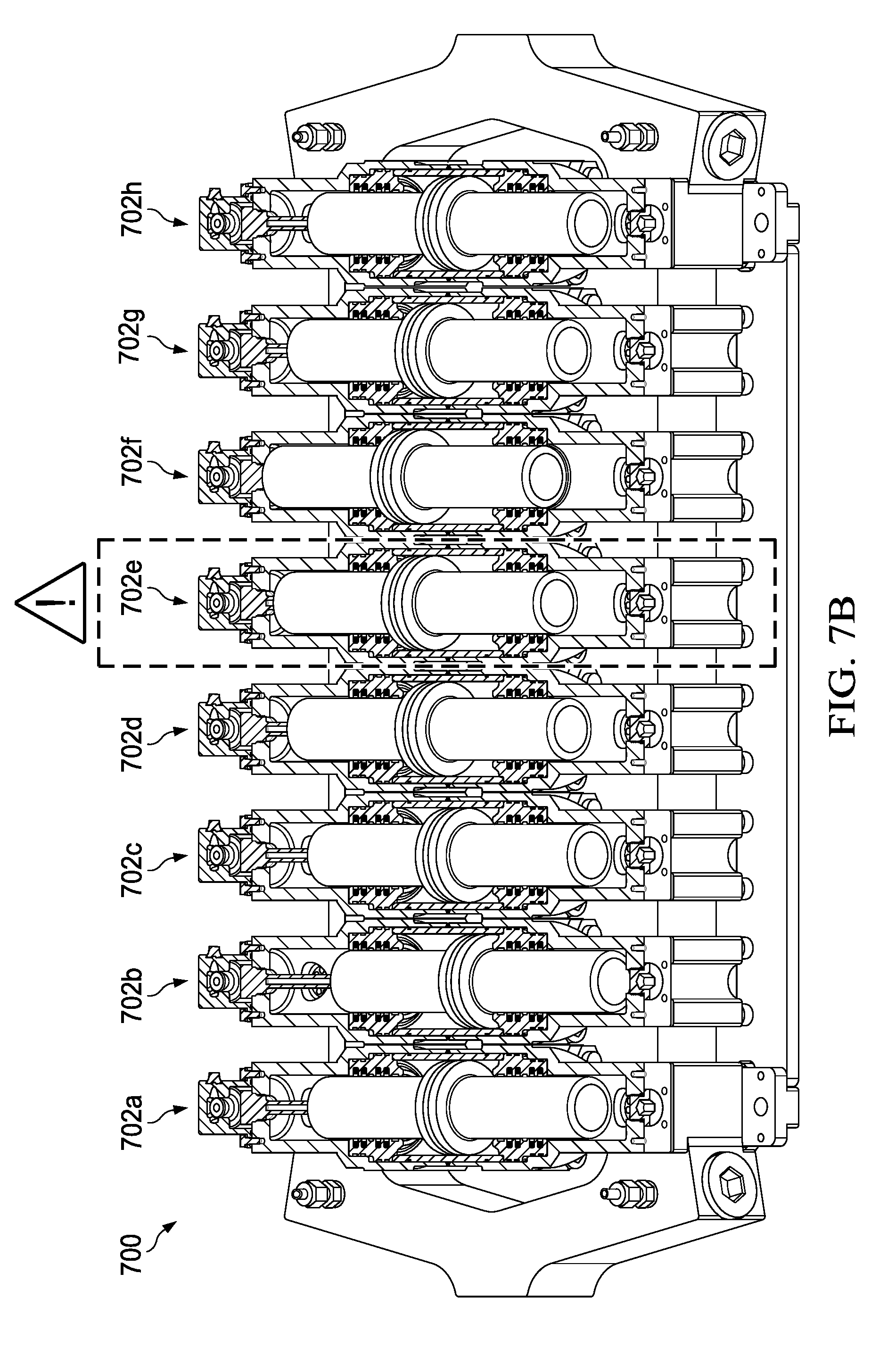
[0052] With regard to FIGS. 7A and 7B, illustrations of a pump 700 with sub-pumps 702a-702h (collectively 702) that are independently controlled, as previously described, are shown. Pistons 704a-704h (collectively 704) are shown to be at different positions P.sub.a-P.sub.h, where each position is an equally spaced value on a sinusoidal wave, as previously described. The positions of the pistons 704 may be calculated by a controller in a primary connection section if the pistons 704 are each being controlled by the primary connection section 104 or the secondary connection section 106 if a portion (e.g., pistons 704e-704h) of the pistons 704 are being controlled by a controller of the secondary connection section.
[0053] With regard to FIG. 7B, the set of pistons 700 of FIG. 7A are shown. As understood in the art, seals of pistons have the ability to fail, where a seal failure enables fluid to leak from one side of the seal to the other. When a seal fails, the sub-pump, in this case sub-pump 702e, is deemed to have failed and is to be shut down. When a sub-pump 702e is shut down, the remaining sub-pumps 702a-702d and 702f-702h may continue to operate, but the controller of the pump may be instructed to or automatically recalculate timing of the sub-pumps (e.g., 360 degrees/7 remaining sub-pumps) for controlling the remaining sub-pumps. In an alternative embodiment, the number of sub-pumps may be ten, and in response to a failure of the sub-pump 702e, one of the spare sub-pumps may be selectably turned on. In turning on a spare sub-pump, the controller may automatically determine available sub-pumps (e.g., all sub-pumps except for sub-pump 702e), determine relative physical alignment of the sub-pumps to be used, compute control signals based on the available sub-pumps on a sinusoidal signal as previously described, and initiate controlling the sub-pumps with the computed control signals.
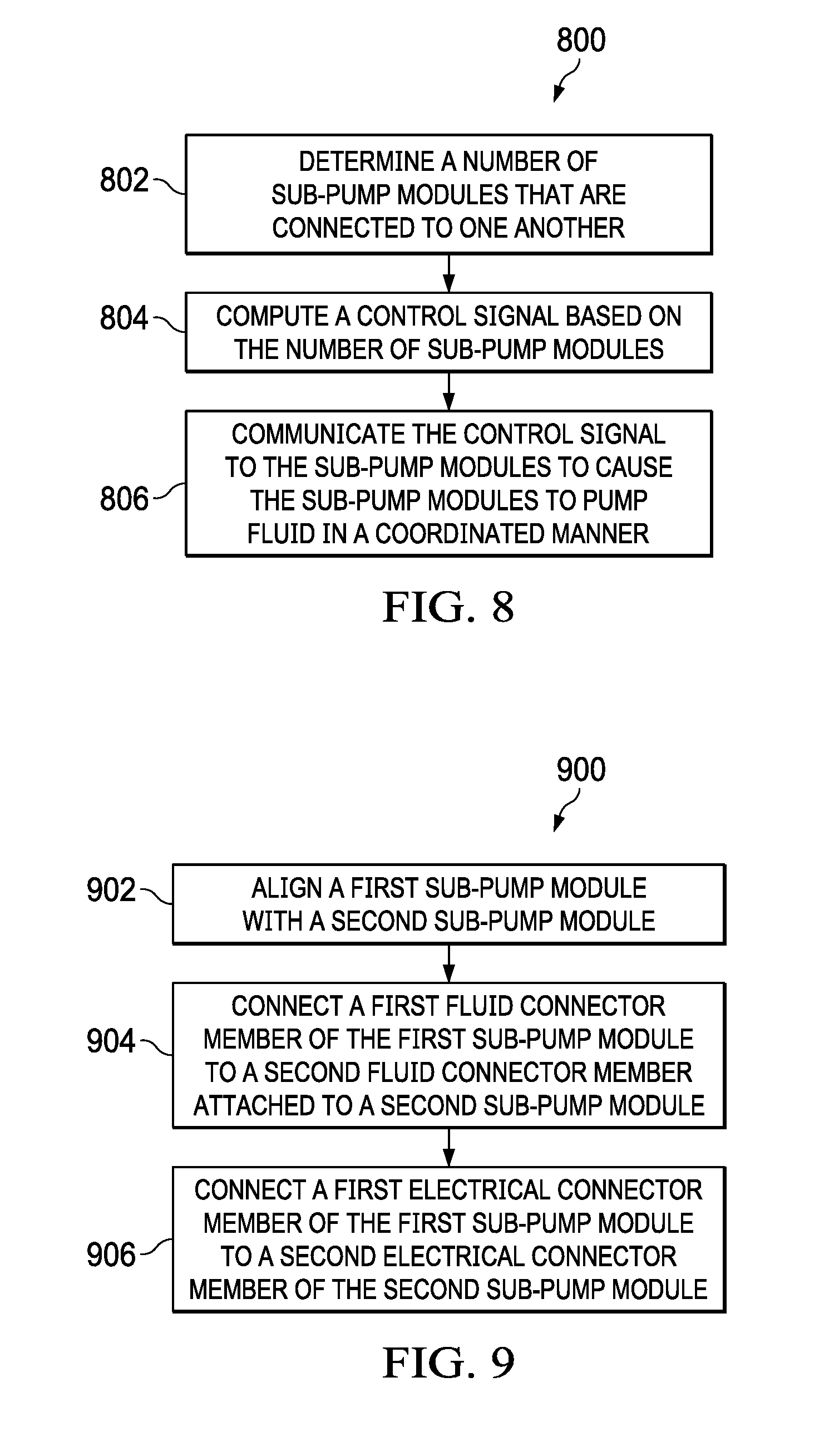
[0054] With regard to FIG. 8, an illustration of an illustrative process 800 for operating a modular pump is shown. The process 800 may start at step 802, where a determination of a number of sub-pump modules that are connected to one another may be made. The determination may be made automatically by receiving communication signals from each of the sub-pump modules. The communication signals may include a network address associated with each of the sub-pump modules. In an embodiment, the network addresses may be ordered in the same physical relation to respective sub-pump modules (e.g., P.sub.1, P.sub.2, . . . , P.sub.8). At step 804, a control signal based on the number of sub-pump modules that are determined to be connected to one another may be computed. The control signal may be computed as a function of a sine wave or sinusoidal signal. In computing the control signal, a single period (i.e., 360 degrees) may be divided by a number of sub-pump modules. At step 806, the control signal may be communicated to the sub-pump modules to cause the sub-pump modules to pump fluid in a coordinated manner. The coordinated manner may cause pistons of each of the sub-pump modules to be physically aligned in the shape of a sine wave.
[0055] Determining a number of sub-pump modules that are connected to one another may include automatically determining a number of sub-pump modules that are connected to one another. A determination of relative position of each of the sub-pumps to enable the control signal to cause the sub-pump modules to pump the second fluid in the coordinated manner may be made, where the determination of relative position is automatically performed. In an embodiment, adjustment of flow and pressure may be performed by adjusting the control signal to adjust speed of a piston within each of said sub-pump modules. Computing the control signal may include computing a sine wave, and wherein computing the sine wave includes computing control signal values on the sine wave that are equally spaced along a single period of the sine wave to be applied to respective sub-pump modules for control thereof.
[0056] In an embodiment, a determination of a number of sub-pump modules that are connected to one another may be performed by automatically determining whether a valve connector of a first sub-pump module is connected to a corresponding valve connector on a second sub-pump module based on communications signals over conductors of the valve connectors. A fluid used to maintain pressure within housings of the respective sub-pump modules may be enabled to pass therebetween via the valve connectors. Automatically determining a number of sub-pump modules may include automatically determining different network addresses for each of the respective sub-pump modules.
[0057] Electrical power and data may be communicated between successive sub-pump modules. A determination that a sub-pump module has a failure may be made, and in response thereto, the control signal may be automatically recomputed to exclude the failed sub-pump module, thereby enabling the pump to continue operating without the failed sub-pump module. Responsive to receiving a sub-pump module failure signal indicative that a sub-pump has failed, further control signals may be prevented from being communicated to the failed sub-pump module, thereby disabling the failed sub-pump. An ordered list of network addresses associated with the sub-pump modules may be automatically generated, where the order of the sub-pump modules may be based on physical relative alignment of the sub-pump modules.
[0058] The control signal may be communicated to each of the sub-pump modules based on network addresses associated with respective physical relative alignment of the sub-pump modules such that synchronization of the sub-pump modules results in a coordinated operation of the respective sub-pump modules. Pressure may be sensed within a housing of a sub-pump module to ensure that the sub-pump module is maintaining pressure for operation. Telemetry data may be communicated from the sub-pump modules to a remote system via a communications network for display of at least a portion of the telemetry data, where the telemetry data may include (i) alignment of an actuator of the sub-pump modules and (ii) pressure.
[0059] With regard to FIG. 9, a flow diagram of an illustrative process 900 for manufacturing a pump may include aligning a first sub-pump module with a second sub-pump module at step 902. The first and second sub-pump modules may include first and second respective housings. At step 904, a first fluid connector member attached to the first housing of the first sub-pump module may be connected to a second fluid connector member attached to the second housing of a second sub-pump module, thereby enabling fluid to flow between the first and second housings of the first and second sub-pump modules. At step 906, a first electrical connector member of the first sub-pump module may be connected to a second electrical connector member of the second sub-pump module, thereby enabling electrical signals to be communicated between the first and second sub-pump modules.
[0060] Aligning the first and second sub-pump modules may include disposing a rail between the first and second sub-pump modules. Connecting the first and second fluid connector members and connecting the first and second electrical connectors to one another may include sliding the first and second sub-pump modules along the rail to cause the fluid connectors and electrical connectors to engage. Enabling fluid to flow may include enabling compensation fluid to flow from a housing of the first sub-pump module to a housing of the second sub-pump module, thereby enabling the pump to operate in high-pressure environments.
[0061] The first and second sub-pump modules may be mounted onto a chassis. The process 900 may further include connecting at least eight sub-pump modules to one another. The process 900 may further include assigning a network address to each of the sub-pump modules, and automatically determining network addresses of each of the sub-pump modules connected to form the pump.
[0062] A control signal to be applied to the sub-pump modules may be generated, and the control signal may be communicated to the sub-pump modules to test operation thereof. A control signal may be generated by dividing a sinusoidal period by a number of sub-pump modules used to form the pump, and control signal values across a single sinusoidal period to the respective sub-pump modules, thereby causing operation of the sub-pump modules to be coordinated during operation.
[0063] In an embodiment, multiple sub-pump modules may be connected together. A subset of the plurality of sub-pump modules may be selected to form the pump. The non-selected sub-pump modules may be set to be spares in the event that any of the selected subset of sub-pump modules fail.
[0064] A controller may further be configured to automatically determine if any of the sub-pump modules fail. In response to determining that a sub-pump module failed, a spare sub-pump module may be selected to replace the failed sub-pump module. Usage of the failed sub-pump module may be disabled (e.g., cease further communications or control with the failed sub-pump). The control signal may be recomputed by including the selected spare sub-pump module, and the sub-pump modules may be controlled with the recomputed control signal.
[0065] A controller may be configured to communicate a control signal via the electrical connectors between the first and second sub-pump modules, where the control signal may cause the first and second sub-pump modules to be coordinated to pump a fluid. The fluid connector members and the electrical connector members may be connected simultaneously as a result of the connectors being integrated with one another. In an alternative embodiment, the fluid connector members and the electrical connector members includes may include connecting a first dual connector member inclusive of both fluid and electrical connectors with a second dual connector member inclusive of both fluid and electrical connector members. In an embodiment, a first dual connector member may be connected with a second dual connector member by connecting a first dual connector member inclusive of a nozzle configured to dispense oil with a second dual connector member inclusive of a receptacle configured to receive the nozzle to receive oil therefrom.
[0066] The foregoing method descriptions and the process flow diagrams are provided merely as illustrative examples and are not intended to require or imply that the steps of the various embodiments must be performed in the order presented. As will be appreciated by one of skill in the art, the steps in the foregoing embodiments may be performed in any order. Words such as "then," "next," etc. are not intended to limit the order of the steps; these words are simply used to guide the reader through the description of the methods. Although process flow diagrams may describe the operations as a sequential process, many of the operations may be performed in parallel or concurrently. In addition, the order of the operations may be re-arranged. A process may correspond to a method, a function, a procedure, a subroutine, a subprogram, etc. When a process corresponds to a function, its termination may correspond to a return of the function to the calling function or the main function.
[0067] The various illustrative logical blocks, modules, circuits, and algorithm steps described in connection with the embodiments disclosed here may be implemented as electronic hardware, computer software, or combinations of both. To clearly illustrate this interchangeability of hardware and software, various illustrative components, blocks, modules, circuits, and steps have been described above generally in terms of their functionality. Whether such functionality is implemented as hardware or software depends upon the particular application and design constraints imposed on the overall system. Skilled artisans may implement the described functionality in varying ways for each particular application, but such implementation decisions should not be interpreted as causing a departure from the scope of the present invention.
[0068] Embodiments implemented in computer software may be implemented in software, firmware, middleware, microcode, hardware description languages, or any combination thereof. A code segment or machine-executable instructions may represent a procedure, a function, a subprogram, a program, a routine, a subroutine, a module, a software package, a class, or any combination of instructions, data structures, or program statements. A code segment may be coupled to and/or in communication with another code segment or a hardware circuit by passing and/or receiving information, data, arguments, parameters, or memory contents. Information, arguments, parameters, data, etc. may be passed, forwarded, or transmitted via any suitable means including memory sharing, message passing, token passing, network transmission, etc.
[0069] The actual software code or specialized control hardware used to implement these systems and methods is not limiting of the invention. Thus, the operation and behavior of the systems and methods were described without reference to the specific software code being understood that software and control hardware can be designed to implement the systems and methods based on the description here.
[0070] When implemented in software, the functions may be stored as one or more instructions or code on a non-transitory computer-readable or processor-readable storage medium. The steps of a method or algorithm disclosed here may be embodied in a processor-executable software module which may reside on a computer-readable or processor-readable storage medium. A non-transitory computer-readable or processor-readable media includes both computer storage media and tangible storage media that facilitate transfer of a computer program from one place to another. A non-transitory processor-readable storage media may be any available media that may be accessed by a computer. By way of example, and not limitation, such non-transitory processor-readable media may comprise RAM, ROM, EEPROM, CD-ROM or other optical disk storage, magnetic disk storage or other magnetic storage devices, or any other tangible storage medium that may be used to store desired program code in the form of instructions or data structures and that may be accessed by a computer or processor. Disk and disc, as used here, include compact disc (CD), laser disc, optical disc, digital versatile disc (DVD), floppy disk, and Blu-ray disc where disks usually reproduce data magnetically, while discs reproduce data optically with lasers. Combinations of the above should also be included within the scope of computer-readable media. Additionally, the operations of a method or algorithm may reside as one or any combination or set of codes and/or instructions on a non-transitory processor-readable medium and/or computer-readable medium, which may be incorporated into a computer program product.
[0071] The previous description is of a preferred embodiment for implementing the invention, and the scope of the invention should not necessarily be limited by this description. The scope of the present invention is instead defined by the following claims.
* * * * *
D00000
D00001
D00002
D00003
D00004
D00005
D00006
D00007
D00008
D00009
D00010
D00011
D00012

D00013
D00014

D00015

D00016
D00017

D00018

D00019

D00020
D00021
D00022

D00023
D00024
XML
uspto.report is an independent third-party trademark research tool that is not affiliated, endorsed, or sponsored by the United States Patent and Trademark Office (USPTO) or any other governmental organization. The information provided by uspto.report is based on publicly available data at the time of writing and is intended for informational purposes only.
While we strive to provide accurate and up-to-date information, we do not guarantee the accuracy, completeness, reliability, or suitability of the information displayed on this site. The use of this site is at your own risk. Any reliance you place on such information is therefore strictly at your own risk.
All official trademark data, including owner information, should be verified by visiting the official USPTO website at www.uspto.gov. This site is not intended to replace professional legal advice and should not be used as a substitute for consulting with a legal professional who is knowledgeable about trademark law.