Systems and methods for exchanging fracturing components of a hydraulic fracturing unit
Yeung , et al. March 23, 2
U.S. patent number 10,954,770 [Application Number 16/946,171] was granted by the patent office on 2021-03-23 for systems and methods for exchanging fracturing components of a hydraulic fracturing unit. This patent grant is currently assigned to BJ Energy Solutions, LLC. The grantee listed for this patent is BJ Energy Solutions, LLC. Invention is credited to Joseph Foster, Ricardo Rodriguez-Ramon, Tony Yeung.


| United States Patent | 10,954,770 |
| Yeung , et al. | March 23, 2021 |
Systems and methods for exchanging fracturing components of a hydraulic fracturing unit
Abstract
Systems and methods for exchanging fracturing components of a hydraulic fracturing unit and may include an exchangeable fracturing component section to facilitate quickly exchanging a fracturing component of a hydraulic fracturing unit. The fracturing component section may include a section frame including a base, and a fracturing component connected to the base. The fracturing component section also may include a component electrical assembly and a component fluid assembly connected to the section frame. The fracturing component section further may include a coupling plate connected to the section frame. The fracturing component section also may include one or more of a plurality of quick-connect electrical couplers or a plurality of quick-connect fluid couplers connected to a coupling plate. The quick-connect electrical and fluid couplers may be positioned to receive respective electrical and fluid connections of the component electrical and fluid assemblies and connect to other portions of the hydraulic fracturing unit.
| Inventors: | Yeung; Tony (Tomball, TX), Rodriguez-Ramon; Ricardo (Tomball, TX), Foster; Joseph (Tomball, TX) | ||||||||||
|---|---|---|---|---|---|---|---|---|---|---|---|
| Applicant: |
|
||||||||||
| Assignee: | BJ Energy Solutions, LLC
(Houston, TX) |
||||||||||
| Family ID: | 1000004940087 | ||||||||||
| Appl. No.: | 16/946,171 | ||||||||||
| Filed: | June 9, 2020 |
| Current U.S. Class: | 1/1 |
| Current CPC Class: | E21B 47/095 (20200501); E21B 47/008 (20200501); E21B 41/005 (20130101); E21B 43/267 (20130101); E21B 47/07 (20200501); E21B 43/2607 (20200501); E21B 49/0875 (20200501) |
| Current International Class: | E21B 41/00 (20060101); E21B 47/095 (20120101); E21B 47/008 (20120101); E21B 47/07 (20120101); E21B 43/267 (20060101); E21B 43/26 (20060101); E21B 49/08 (20060101) |
References Cited [Referenced By]
U.S. Patent Documents
| 2498229 | February 1950 | Adler |
| 3191517 | June 1965 | Solzman |
| 3257031 | June 1966 | Dietz |
| 3378074 | April 1968 | Kiel |
| 3739872 | June 1973 | McNair |
| 3773438 | November 1973 | Hall et al. |
| 3791682 | February 1974 | Mitchell |
| 3796045 | March 1974 | Foster |
| 3820922 | June 1974 | Buse et al. |
| 4010613 | March 1977 | McInerney |
| 4031407 | June 1977 | Reed |
| 4086976 | May 1978 | Holm et al. |
| 4222229 | September 1980 | Uram |
| 4269569 | May 1981 | Hoover |
| 4311395 | January 1982 | Douthitt et al. |
| 4357027 | November 1982 | Zeitlow |
| 4402504 | September 1983 | Christian |
| 4457325 | July 1984 | Green |
| 4470771 | September 1984 | Hall et al. |
| 4574880 | March 1986 | Handke |
| 4754607 | July 1988 | Mackay |
| 4782244 | November 1988 | Wakimoto |
| 4796777 | January 1989 | Keller |
| 4913625 | April 1990 | Gerlowski |
| 4983259 | January 1991 | Duncan |
| 4990058 | February 1991 | Eslinger |
| 5537813 | July 1996 | Davis et al. |
| 5553514 | September 1996 | Walkowc |
| 5560195 | October 1996 | Anderson et al. |
| 5622245 | April 1997 | Reik |
| 5651400 | July 1997 | Corts et al. |
| 5678460 | October 1997 | Walkowc |
| 5717172 | February 1998 | Griffin, Jr. et al. |
| 5983962 | November 1999 | Gerardot |
| 6041856 | March 2000 | Thrasher et al. |
| 6050080 | April 2000 | Horner |
| 6071188 | June 2000 | O'Neill et al. |
| 6123751 | September 2000 | Nelson et al. |
| 6129335 | October 2000 | Yokogi |
| 6145318 | November 2000 | Kaplan et al. |
| 6279309 | August 2001 | Lawlor, II et al. |
| 6321860 | November 2001 | Reddoch |
| 6334746 | January 2002 | Nguyen et al. |
| 6530224 | March 2003 | Conchieri |
| 6543395 | April 2003 | Green |
| 6655922 | December 2003 | Flek |
| 6765304 | July 2004 | Baten et al. |
| 6786051 | September 2004 | Kristich et al. |
| 6851514 | February 2005 | Han et al. |
| 6859740 | February 2005 | Stephenson et al. |
| 6901735 | June 2005 | Lohn |
| 7065953 | June 2006 | Kopko |
| 7222015 | May 2007 | Davis et al. |
| 7388303 | June 2008 | Seiver |
| 7545130 | June 2009 | Latham |
| 7552903 | June 2009 | Dunn et al. |
| 7563076 | July 2009 | Brunet et al. |
| 7627416 | December 2009 | Batenburg et al. |
| 7677316 | March 2010 | Butler et al. |
| 7721521 | May 2010 | Kunkle et al. |
| 7730711 | June 2010 | Kunkle et al. |
| 7845413 | December 2010 | Shampine et al. |
| 7900724 | March 2011 | Promersberger et al. |
| 7921914 | April 2011 | Bruins et al. |
| 7938151 | May 2011 | Hockner |
| 7980357 | July 2011 | Edwards |
| 8083504 | December 2011 | Williams et al. |
| 8186334 | May 2012 | Ooyama |
| 8196555 | June 2012 | Ikeda et al. |
| 8316936 | November 2012 | Roddy et al. |
| 8414673 | April 2013 | Raje et al. |
| 8506267 | August 2013 | Gambier et al. |
| 8575873 | November 2013 | Peterson et al. |
| 8616005 | December 2013 | Cousino, Sr. et al. |
| 8621873 | January 2014 | Robertson et al. |
| 8672606 | March 2014 | Glynn et al. |
| 8714253 | May 2014 | Sherwood et al. |
| 8770329 | July 2014 | Spitler |
| 8789601 | July 2014 | Broussard et al. |
| 8794307 | August 2014 | Coquilleau et al. |
| 8851441 | October 2014 | Acuna et al. |
| 8905056 | December 2014 | Kendrick |
| 8973560 | March 2015 | Krug |
| 8997904 | April 2015 | Cryer et al. |
| 9032620 | May 2015 | Frassinelli et al. |
| 9057247 | June 2015 | Kumar et al. |
| 9103193 | August 2015 | Coli et al. |
| 9121257 | September 2015 | Coli et al. |
| 9140110 | September 2015 | Coli |
| 9187982 | November 2015 | Dehring et al. |
| 9212643 | December 2015 | Deliyski |
| 9341055 | May 2016 | Weightman et al. |
| 9346662 | May 2016 | Van Vliet et al. |
| 9366114 | June 2016 | Coli et al. |
| 9376786 | June 2016 | Numasawa |
| 9394829 | July 2016 | Cabeen et al. |
| 9395049 | July 2016 | Vicknair et al. |
| 9401670 | July 2016 | Minato et al. |
| 9410410 | August 2016 | Broussard et al. |
| 9410546 | August 2016 | Jaeger et al. |
| 9429078 | August 2016 | Crowe et al. |
| 9493997 | November 2016 | Liu et al. |
| 9512783 | December 2016 | Veilleux et al. |
| 9534473 | January 2017 | Morris et al. |
| 9546652 | January 2017 | Yin |
| 9550501 | January 2017 | Ledbetter |
| 9556721 | January 2017 | Jang et al. |
| 9562420 | February 2017 | Morris et al. |
| 9570945 | February 2017 | Fischer |
| 9579980 | February 2017 | Cryer et al. |
| 9587649 | March 2017 | Oehring |
| 9611728 | April 2017 | Oehring |
| 9617808 | April 2017 | Liu et al. |
| 9638101 | May 2017 | Crowe et al. |
| 9638194 | May 2017 | Wiegman et al. |
| 9650871 | May 2017 | Oehring et al. |
| 9656762 | May 2017 | Kamath et al. |
| 9689316 | June 2017 | Crom |
| 9739130 | August 2017 | Young |
| 9764266 | September 2017 | Carter |
| 9777748 | October 2017 | Lu et al. |
| 9803467 | October 2017 | Tang et al. |
| 9803793 | October 2017 | Davi et al. |
| 9809308 | November 2017 | Aguilar et al. |
| 9829002 | November 2017 | Crom |
| 9840897 | December 2017 | Larson |
| 9840901 | December 2017 | Oering et al. |
| 9850422 | December 2017 | Lestz et al. |
| 9856131 | January 2018 | Moffitt |
| 9863279 | January 2018 | Laing et al. |
| 9869305 | January 2018 | Crowe et al. |
| 9879609 | January 2018 | Crowe et al. |
| 9893500 | February 2018 | Oehring et al. |
| 9893660 | February 2018 | Peterson et al. |
| 9920615 | March 2018 | Zhang et al. |
| 9945365 | April 2018 | Hernandez et al. |
| 9964052 | May 2018 | Millican et al. |
| 9970278 | May 2018 | Broussard et al. |
| 9981840 | May 2018 | Shock |
| 9995102 | June 2018 | Dillie et al. |
| 9995218 | June 2018 | Oehring et al. |
| 10008880 | June 2018 | Vicknair et al. |
| 10018096 | July 2018 | Wallimann et al. |
| 10020711 | July 2018 | Oehring et al. |
| 10029289 | July 2018 | Wendorski et al. |
| 10030579 | July 2018 | Austin et al. |
| 10036238 | July 2018 | Oehring |
| 10040541 | August 2018 | Wilson et al. |
| 10060349 | August 2018 | Morales Ivarez |
| 10082137 | September 2018 | Graham |
| 10100827 | October 2018 | Devan et al. |
| 10107084 | October 2018 | Coli et al. |
| 10107085 | October 2018 | Coli et al. |
| 10114061 | October 2018 | Frampton et al. |
| 10119381 | November 2018 | Oehring et al. |
| 10134257 | November 2018 | Zhang et al. |
| 10151244 | December 2018 | Giancotti et al. |
| 10174599 | January 2019 | Shampine et al. |
| 10184397 | January 2019 | Austin et al. |
| 10196258 | February 2019 | Kalala et al. |
| 10221856 | March 2019 | Hernandez et al. |
| 10227854 | March 2019 | Glass |
| 10227855 | March 2019 | Coli et al. |
| 10246984 | April 2019 | Payne et al. |
| 10247182 | April 2019 | Zhang et al. |
| 10254732 | April 2019 | Oehring et al. |
| 10267439 | April 2019 | Pryce et al. |
| 10280724 | May 2019 | Hinderliter |
| 10287943 | May 2019 | Schiltz |
| 10303190 | May 2019 | Shock |
| 10316832 | June 2019 | Byrne |
| 10317875 | June 2019 | Pandurangan |
| 10337402 | July 2019 | Austin et al. |
| 10358035 | July 2019 | Cryer |
| 10371012 | August 2019 | Davis et al. |
| 10374485 | August 2019 | Morris et al. |
| 10378326 | August 2019 | Morris et al. |
| 10393108 | August 2019 | Chong et al. |
| 10407990 | September 2019 | Oehring et al. |
| 10408031 | September 2019 | Oehring et al. |
| 10415348 | September 2019 | Zhang |
| 10415557 | September 2019 | Crowe et al. |
| 10415562 | September 2019 | Kajita |
| RE47695 | November 2019 | Case et al. |
| 10465689 | November 2019 | Crom |
| 10526882 | January 2020 | Oehring et al. |
| 10563649 | February 2020 | Zhang et al. |
| 10577910 | March 2020 | Stephenson |
| 10598258 | March 2020 | Oehring et al. |
| 10610842 | April 2020 | Chong |
| 10711787 | July 2020 | Darley |
| 10738580 | August 2020 | Fischer et al. |
| 10753153 | August 2020 | Fischer et al. |
| 10753165 | August 2020 | Fischer et al. |
| 10794165 | October 2020 | Fischer et al. |
| 10794166 | October 2020 | Reckels et al. |
| 10801311 | October 2020 | Cui et al. |
| 10815764 | October 2020 | Yeung et al. |
| 10815978 | October 2020 | Glass |
| 10830032 | November 2020 | Zhang et al. |
| 10865624 | December 2020 | Cui et al. |
| 10865631 | December 2020 | Zhang et al. |
| 10907459 | February 2021 | Yeung et al. |
| 2004/0016245 | January 2004 | Pierson |
| 2004/0187950 | September 2004 | Cohen et al. |
| 2005/0139286 | June 2005 | Poulter |
| 2005/0226754 | October 2005 | Orr et al. |
| 2006/0260331 | November 2006 | Andreychuk |
| 2007/0029090 | February 2007 | Andreychuk et al. |
| 2007/0066406 | March 2007 | Keller et al. |
| 2007/0107981 | May 2007 | Sicotte |
| 2007/0181212 | August 2007 | Fell |
| 2007/0277982 | December 2007 | Shampine et al. |
| 2007/0295569 | December 2007 | Manzoor et al. |
| 2008/0098891 | May 2008 | Feher |
| 2008/0161974 | July 2008 | Alston |
| 2008/0264625 | October 2008 | Ochoa |
| 2008/0264649 | October 2008 | Crawford |
| 2009/0064685 | March 2009 | Busekros et al. |
| 2009/0124191 | May 2009 | Van Becelaere et al. |
| 2010/0071899 | March 2010 | Coquilleau et al. |
| 2010/0218508 | September 2010 | Brown et al. |
| 2010/0300683 | December 2010 | Looper |
| 2010/0310384 | December 2010 | Stephenson et al. |
| 2011/0054704 | March 2011 | Karpman et al. |
| 2011/0085924 | April 2011 | Shampine et al. |
| 2011/0197988 | August 2011 | Van Vliet et al. |
| 2011/0241888 | October 2011 | Lu et al. |
| 2011/0265443 | November 2011 | Ansari |
| 2011/0272158 | November 2011 | Neal |
| 2012/0048242 | March 2012 | Sumilla et al. |
| 2012/0199001 | August 2012 | Chillar et al. |
| 2012/0310509 | December 2012 | Pardo et al. |
| 2013/0068307 | March 2013 | Hains et al. |
| 2013/0087945 | April 2013 | Kusters et al. |
| 2013/0284455 | October 2013 | Kajaria et al. |
| 2013/0300341 | November 2013 | Gillette |
| 2013/0306322 | November 2013 | Sanborn |
| 2014/0013768 | January 2014 | Laing et al. |
| 2014/0044517 | February 2014 | Saha et al. |
| 2014/0048253 | February 2014 | Andreychuk |
| 2014/0090742 | April 2014 | Coskrey et al. |
| 2014/0130422 | May 2014 | Laing et al. |
| 2014/0147291 | May 2014 | Burnette |
| 2014/0277772 | September 2014 | Lopez et al. |
| 2014/0290266 | October 2014 | Veilleux, Jr. et al. |
| 2014/0318638 | October 2014 | Harwood et al. |
| 2015/0078924 | March 2015 | Zhang et al. |
| 2015/0101344 | April 2015 | Jarrier et al. |
| 2015/0114652 | April 2015 | Lestz et al. |
| 2015/0135659 | May 2015 | Jarrier et al. |
| 2015/0159553 | June 2015 | Kippel et al. |
| 2015/0192117 | July 2015 | Bridges |
| 2015/0204148 | July 2015 | Liu et al. |
| 2015/0204322 | July 2015 | Iund et al. |
| 2015/0211512 | July 2015 | Wiegman et al. |
| 2015/0217672 | August 2015 | Shampine et al. |
| 2015/0275891 | October 2015 | Chong et al. |
| 2015/0369351 | December 2015 | Hermann et al. |
| 2016/0032703 | February 2016 | Broussard et al. |
| 2016/0102581 | April 2016 | Del Bono |
| 2016/0105022 | April 2016 | Oehring et al. |
| 2016/0108713 | April 2016 | Dunaeva et al. |
| 2016/0177675 | June 2016 | Morris et al. |
| 2016/0186671 | June 2016 | Austin et al. |
| 2016/0215774 | July 2016 | Oklejas et al. |
| 2016/0230525 | August 2016 | Lestz et al. |
| 2016/0244314 | August 2016 | Van Vliet et al. |
| 2016/0248230 | August 2016 | Tawy et al. |
| 2016/0253634 | September 2016 | Thomeer et al. |
| 2016/0273346 | September 2016 | Tang et al. |
| 2016/0290114 | October 2016 | Oehring et al. |
| 2016/0319650 | November 2016 | Oehring et al. |
| 2016/0348479 | December 2016 | Oehring et al. |
| 2016/0369609 | December 2016 | Morris et al. |
| 2017/0009905 | January 2017 | Arnold |
| 2017/0016433 | January 2017 | Chong et al. |
| 2017/0030177 | February 2017 | Oehring et al. |
| 2017/0038137 | February 2017 | Turney |
| 2017/0074076 | March 2017 | Joseph et al. |
| 2017/0082110 | March 2017 | Lammers |
| 2017/0089189 | March 2017 | Norris et al. |
| 2017/0145918 | May 2017 | Oehring et al. |
| 2017/0218727 | August 2017 | Oehring et al. |
| 2017/0226839 | August 2017 | Broussard et al. |
| 2017/0227002 | August 2017 | Mikulski et al. |
| 2017/0234165 | August 2017 | Kersey et al. |
| 2017/0234308 | August 2017 | Buckley |
| 2017/0248034 | August 2017 | Dzieciol et al. |
| 2017/0275149 | September 2017 | Schmidt |
| 2017/0292409 | October 2017 | Aguilar et al. |
| 2017/0302135 | October 2017 | Cory |
| 2017/0305736 | October 2017 | Haile et al. |
| 2017/0334448 | November 2017 | Schwunk |
| 2017/0350471 | December 2017 | Steidl et al. |
| 2017/0370199 | December 2017 | Witkowski et al. |
| 2018/0034280 | February 2018 | Pedersen |
| 2018/0038328 | February 2018 | Louven et al. |
| 2018/0041093 | February 2018 | Miranda |
| 2018/0045202 | February 2018 | Crom |
| 2018/0038216 | March 2018 | Zhang et al. |
| 2018/0058171 | March 2018 | Roesner et al. |
| 2018/0156210 | June 2018 | Oehring et al. |
| 2018/0172294 | June 2018 | Owen |
| 2018/0183219 | June 2018 | Oehring et al. |
| 2018/0186442 | July 2018 | Maier |
| 2018/0187662 | July 2018 | Hill et al. |
| 2018/0223640 | August 2018 | Keihany et al. |
| 2018/0224044 | August 2018 | Penney |
| 2018/0229998 | August 2018 | Shock |
| 2018/0258746 | September 2018 | Broussard et al. |
| 2018/0266412 | September 2018 | Stokkevag et al. |
| 2018/0278124 | September 2018 | Oehring et al. |
| 2018/0283102 | October 2018 | Cook |
| 2018/0283618 | October 2018 | Cook |
| 2018/0284817 | October 2018 | Cook et al. |
| 2018/0291781 | October 2018 | Pedrini |
| 2018/0298731 | October 2018 | Bishop |
| 2018/0298735 | October 2018 | Conrad |
| 2018/0307255 | October 2018 | Bishop |
| 2018/0328157 | November 2018 | Bishop |
| 2018/0334893 | November 2018 | Oehring |
| 2018/0363435 | December 2018 | Coll et al. |
| 2018/0363436 | December 2018 | Coli et al. |
| 2018/0363437 | December 2018 | Coli et al. |
| 2018/0363438 | December 2018 | Coli et al. |
| 2019/0003272 | January 2019 | Morris et al. |
| 2019/0003329 | January 2019 | Morris et al. |
| 2019/0010793 | January 2019 | Hinderliter |
| 2019/0063341 | February 2019 | Davis |
| 2019/0067991 | February 2019 | Davis et al. |
| 2019/0071992 | March 2019 | Feng |
| 2019/0072005 | March 2019 | Fisher et al. |
| 2019/0078471 | March 2019 | Braglia et al. |
| 2019/0091619 | March 2019 | Huang |
| 2019/0106316 | April 2019 | Van Vliet et al. |
| 2019/0106970 | April 2019 | Oehring |
| 2019/0112908 | April 2019 | Coli et al. |
| 2019/0112910 | April 2019 | Oehring et al. |
| 2019/0119096 | April 2019 | Haile et al. |
| 2019/0120024 | April 2019 | Dehring et al. |
| 2019/0120031 | April 2019 | Gilje |
| 2019/0120134 | April 2019 | Goleczka |
| 2019/0128247 | May 2019 | Douglas, III |
| 2019/0131607 | May 2019 | Gillette |
| 2019/0136677 | May 2019 | Shampine et al. |
| 2019/0153843 | May 2019 | Headrick et al. |
| 2019/0154020 | May 2019 | Glass |
| 2019/0264667 | May 2019 | Byrne |
| 2019/0178234 | June 2019 | Beisel |
| 2019/0178235 | June 2019 | Coskrey et al. |
| 2019/0185312 | June 2019 | Bush et al. |
| 2019/0203572 | July 2019 | Morris et al. |
| 2019/0204021 | July 2019 | Morris et al. |
| 2019/0217258 | July 2019 | Bishop |
| 2019/0226317 | July 2019 | Payne et al. |
| 2019/0245348 | August 2019 | Hinderliter et al. |
| 2019/0249652 | August 2019 | Stephenson et al. |
| 2019/0249754 | August 2019 | Oehring et al. |
| 2019/0257297 | August 2019 | Bolting et al. |
| 2019/0277295 | September 2019 | Clyburn et al. |
| 2019/0316447 | October 2019 | Oehring et al. |
| 2019/0316456 | October 2019 | Beisel et al. |
| 2019/0323337 | October 2019 | Glass et al. |
| 2019/0330923 | October 2019 | Gable et al. |
| 2019/0331117 | October 2019 | Gable et al. |
| 2019/0338762 | November 2019 | Curry et al. |
| 2019/0345920 | November 2019 | Surjaatmadja et al. |
| 2019/0356199 | November 2019 | Morris et al. |
| 2020/0003205 | January 2020 | Stokkevag et al. |
| 2020/0040878 | February 2020 | Morris |
| 2020/0049136 | February 2020 | Stephenson |
| 2020/0049153 | February 2020 | Headrick et al. |
| 2020/0071998 | March 2020 | Oehring et al. |
| 2020/0088202 | March 2020 | Sigmar et al. |
| 2020/0095854 | March 2020 | Hinderliter |
| 2020/0132058 | April 2020 | Mollatt |
| 2020/0141219 | May 2020 | Oehring et al. |
| 2020/0141907 | May 2020 | Meck et al. |
| 2020/0166026 | May 2020 | Marica |
| 2020/0206704 | July 2020 | Chong |
| 2020/0224645 | July 2020 | Buckley |
| 2020/0256333 | August 2020 | Surjaatmadja |
| 2020/0263498 | August 2020 | Fischer et al. |
| 2020/0263525 | August 2020 | Reid |
| 2020/0263526 | August 2020 | Fischer et al. |
| 2020/0263527 | August 2020 | Fischer et al. |
| 2020/0263528 | August 2020 | Fischer et al. |
| 2020/0309113 | October 2020 | Hunter et al. |
| 2020/0325752 | October 2020 | Clark et al. |
| 2020/0325760 | October 2020 | Markham |
| 2020/0325761 | October 2020 | Williams |
| 2020/0332784 | October 2020 | Zhang et al. |
| 2020/0332788 | October 2020 | Cui et al. |
| 2020/0340313 | October 2020 | Fischer et al. |
| 2020/0340340 | October 2020 | Oehring et al. |
| 2020/0340344 | October 2020 | Reckels et al. |
| 2020/0340404 | October 2020 | Stockstill |
| 2020/0347725 | November 2020 | Morris et al. |
| 2020/0392826 | December 2020 | Cui et al. |
| 2020/0398238 | December 2020 | Zhong et al. |
| 2020/0400000 | December 2020 | Ghasripoor et al. |
| 2020/0400005 | December 2020 | Han et al. |
| 2020/0408071 | December 2020 | Li et al. |
| 2020/0408144 | December 2020 | Feng et al. |
| 2020/0408147 | December 2020 | Zhang et al. |
| 2876687 | May 2014 | CA | |||
| 2693567 | Sep 2014 | CA | |||
| 2876687 | Apr 2019 | CA | |||
| 2779054 | May 2006 | CN | |||
| 2890325 | Apr 2007 | CN | |||
| 200964929 | Oct 2007 | CN | |||
| 101323151 | Dec 2008 | CN | |||
| 201190660 | Feb 2009 | CN | |||
| 201190892 | Feb 2009 | CN | |||
| 201190893 | Feb 2009 | CN | |||
| 101414171 | Apr 2009 | CN | |||
| 201215073 | Apr 2009 | CN | |||
| 201236650 | May 2009 | CN | |||
| 201275542 | Jul 2009 | CN | |||
| 201275801 | Jul 2009 | CN | |||
| 201333385 | Oct 2009 | CN | |||
| 201443300 | Apr 2010 | CN | |||
| 201496415 | Jun 2010 | CN | |||
| 201501365 | Jun 2010 | CN | |||
| 201507271 | Jun 2010 | CN | |||
| 101323151 | Jul 2010 | CN | |||
| 201560210 | Aug 2010 | CN | |||
| 201581862 | Sep 2010 | CN | |||
| 201610728 | Oct 2010 | CN | |||
| 201610751 | Oct 2010 | CN | |||
| 201618530 | Nov 2010 | CN | |||
| 201661255 | Dec 2010 | CN | |||
| 101949382 | Jan 2011 | CN | |||
| 201756927 | Mar 2011 | CN | |||
| 101414171 | May 2011 | CN | |||
| 102128011 | Jul 2011 | CN | |||
| 102140898 | Aug 2011 | CN | |||
| 102155172 | Aug 2011 | CN | |||
| 202000930 | Oct 2011 | CN | |||
| 202055781 | Nov 2011 | CN | |||
| 202082265 | Dec 2011 | CN | |||
| 202100216 | Jan 2012 | CN | |||
| 202100217 | Jan 2012 | CN | |||
| 202100815 | Jan 2012 | CN | |||
| 202124340 | Jan 2012 | CN | |||
| 202140051 | Feb 2012 | CN | |||
| 202140080 | Feb 2012 | CN | |||
| 202144789 | Feb 2012 | CN | |||
| 202144943 | Feb 2012 | CN | |||
| 202149354 | Feb 2012 | CN | |||
| 102383748 | Mar 2012 | CN | |||
| 202156297 | Mar 2012 | CN | |||
| 202158355 | Mar 2012 | CN | |||
| 202163504 | Mar 2012 | CN | |||
| 202165236 | Mar 2012 | CN | |||
| 202180866 | Apr 2012 | CN | |||
| 202181875 | Apr 2012 | CN | |||
| 202187744 | Apr 2012 | CN | |||
| 202191854 | Apr 2012 | CN | |||
| 202250008 | May 2012 | CN | |||
| 101885307 | Jul 2012 | CN | |||
| 102562020 | Jul 2012 | CN | |||
| 202326156 | Jul 2012 | CN | |||
| 202370773 | Aug 2012 | CN | |||
| 202417397 | Sep 2012 | CN | |||
| 202417461 | Sep 2012 | CN | |||
| 102729335 | Oct 2012 | CN | |||
| 202463955 | Oct 2012 | CN | |||
| 202463957 | Oct 2012 | CN | |||
| 202467739 | Oct 2012 | CN | |||
| 202467801 | Oct 2012 | CN | |||
| 202531016 | Nov 2012 | CN | |||
| 202544794 | Nov 2012 | CN | |||
| 102825039 | Dec 2012 | CN | |||
| 202578592 | Dec 2012 | CN | |||
| 202579164 | Dec 2012 | CN | |||
| 202594808 | Dec 2012 | CN | |||
| 202594928 | Dec 2012 | CN | |||
| 202596615 | Dec 2012 | CN | |||
| 202596616 | Dec 2012 | CN | |||
| 102849880 | Jan 2013 | CN | |||
| 102889191 | Jan 2013 | CN | |||
| 202641535 | Jan 2013 | CN | |||
| 202645475 | Jan 2013 | CN | |||
| 202666716 | Jan 2013 | CN | |||
| 202669645 | Jan 2013 | CN | |||
| 202669944 | Jan 2013 | CN | |||
| 202671336 | Jan 2013 | CN | |||
| 202673269 | Jan 2013 | CN | |||
| 202751982 | Feb 2013 | CN | |||
| 102963629 | Mar 2013 | CN | |||
| 202767964 | Mar 2013 | CN | |||
| 202789791 | Mar 2013 | CN | |||
| 202789792 | Mar 2013 | CN | |||
| 202810717 | Mar 2013 | CN | |||
| 202827276 | Mar 2013 | CN | |||
| 202833093 | Mar 2013 | CN | |||
| 202833370 | Mar 2013 | CN | |||
| 102140898 | Apr 2013 | CN | |||
| 202895467 | Apr 2013 | CN | |||
| 202935798 | May 2013 | CN | |||
| 202935816 | May 2013 | CN | |||
| 202970631 | Jun 2013 | CN | |||
| 103223315 | Jul 2013 | CN | |||
| 203050598 | Jul 2013 | CN | |||
| 103233714 | Aug 2013 | CN | |||
| 103233715 | Aug 2013 | CN | |||
| 103245523 | Aug 2013 | CN | |||
| 103247220 | Aug 2013 | CN | |||
| 103253839 | Aug 2013 | CN | |||
| 103277290 | Sep 2013 | CN | |||
| 103321782 | Sep 2013 | CN | |||
| 203170270 | Sep 2013 | CN | |||
| 203172509 | Sep 2013 | CN | |||
| 203175778 | Sep 2013 | CN | |||
| 203175787 | Sep 2013 | CN | |||
| 102849880 | Oct 2013 | CN | |||
| 203241231 | Oct 2013 | CN | |||
| 203244941 | Oct 2013 | CN | |||
| 203244942 | Oct 2013 | CN | |||
| 203303798 | Nov 2013 | CN | |||
| 102155172 | Dec 2013 | CN | |||
| 102729335 | Dec 2013 | CN | |||
| 103420532 | Dec 2013 | CN | |||
| 203321792 | Dec 2013 | CN | |||
| 203412658 | Jan 2014 | CN | |||
| 203420697 | Feb 2014 | CN | |||
| 203480755 | Mar 2014 | CN | |||
| 103711437 | Apr 2014 | CN | |||
| 203531815 | Apr 2014 | CN | |||
| 203531871 | Apr 2014 | CN | |||
| 203531883 | Apr 2014 | CN | |||
| 203556164 | Apr 2014 | CN | |||
| 203558809 | Apr 2014 | CN | |||
| 203559861 | Apr 2014 | CN | |||
| 203559893 | Apr 2014 | CN | |||
| 203560189 | Apr 2014 | CN | |||
| 102704870 | May 2014 | CN | |||
| 203611843 | May 2014 | CN | |||
| 203612531 | May 2014 | CN | |||
| 203612843 | May 2014 | CN | |||
| 203614062 | May 2014 | CN | |||
| 203614388 | May 2014 | CN | |||
| 203621045 | Jun 2014 | CN | |||
| 203621046 | Jun 2014 | CN | |||
| 203621051 | Jun 2014 | CN | |||
| 203640993 | Jun 2014 | CN | |||
| 203655221 | Jun 2014 | CN | |||
| 103899280 | Jul 2014 | CN | |||
| 103923670 | Jul 2014 | CN | |||
| 203685052 | Jul 2014 | CN | |||
| 203716936 | Jul 2014 | CN | |||
| 103990410 | Aug 2014 | CN | |||
| 103993869 | Aug 2014 | CN | |||
| 203754009 | Aug 2014 | CN | |||
| 203754025 | Aug 2014 | CN | |||
| 203754341 | Aug 2014 | CN | |||
| 203756614 | Aug 2014 | CN | |||
| 203770264 | Aug 2014 | CN | |||
| 203784519 | Aug 2014 | CN | |||
| 203784520 | Aug 2014 | CN | |||
| 104057864 | Sep 2014 | CN | |||
| 203819819 | Sep 2014 | CN | |||
| 203823431 | Sep 2014 | CN | |||
| 203835337 | Sep 2014 | CN | |||
| 104074500 | Oct 2014 | CN | |||
| 203876633 | Oct 2014 | CN | |||
| 203876636 | Oct 2014 | CN | |||
| 203877364 | Oct 2014 | CN | |||
| 203877365 | Oct 2014 | CN | |||
| 203877375 | Oct 2014 | CN | |||
| 203877424 | Oct 2014 | CN | |||
| 203879476 | Oct 2014 | CN | |||
| 203879479 | Oct 2014 | CN | |||
| 203890292 | Oct 2014 | CN | |||
| 203899476 | Oct 2014 | CN | |||
| 203906206 | Oct 2014 | CN | |||
| 104150728 | Nov 2014 | CN | |||
| 104176522 | Dec 2014 | CN | |||
| 104196464 | Dec 2014 | CN | |||
| 104234651 | Dec 2014 | CN | |||
| 203971841 | Dec 2014 | CN | |||
| 203975450 | Dec 2014 | CN | |||
| 204020788 | Dec 2014 | CN | |||
| 204021980 | Dec 2014 | CN | |||
| 204024625 | Dec 2014 | CN | |||
| 204051401 | Dec 2014 | CN | |||
| 204060661 | Dec 2014 | CN | |||
| 104260672 | Jan 2015 | CN | |||
| 104314512 | Jan 2015 | CN | |||
| 204077478 | Jan 2015 | CN | |||
| 204077526 | Jan 2015 | CN | |||
| 204078307 | Jan 2015 | CN | |||
| 204083051 | Jan 2015 | CN | |||
| 204113168 | Jan 2015 | CN | |||
| 104340682 | Feb 2015 | CN | |||
| 104358536 | Feb 2015 | CN | |||
| 104369687 | Feb 2015 | CN | |||
| 104402178 | Mar 2015 | CN | |||
| 104402185 | Mar 2015 | CN | |||
| 104402186 | Mar 2015 | CN | |||
| 204209819 | Mar 2015 | CN | |||
| 204224560 | Mar 2015 | CN | |||
| 204225813 | Mar 2015 | CN | |||
| 204225839 | Mar 2015 | CN | |||
| 104533392 | Apr 2015 | CN | |||
| 104563938 | Apr 2015 | CN | |||
| 104563994 | Apr 2015 | CN | |||
| 104563995 | Apr 2015 | CN | |||
| 104563998 | Apr 2015 | CN | |||
| 104564033 | Apr 2015 | CN | |||
| 204257122 | Apr 2015 | CN | |||
| 204283610 | Apr 2015 | CN | |||
| 204283782 | Apr 2015 | CN | |||
| 204297682 | Apr 2015 | CN | |||
| 204299810 | Apr 2015 | CN | |||
| 103223315 | May 2015 | CN | |||
| 104594857 | May 2015 | CN | |||
| 104595493 | May 2015 | CN | |||
| 104612647 | May 2015 | CN | |||
| 104612928 | May 2015 | CN | |||
| 104632126 | May 2015 | CN | |||
| 204325094 | May 2015 | CN | |||
| 204325098 | May 2015 | CN | |||
| 204326983 | May 2015 | CN | |||
| 204326985 | May 2015 | CN | |||
| 204344040 | May 2015 | CN | |||
| 204344095 | May 2015 | CN | |||
| 104727797 | Jun 2015 | CN | |||
| 204402414 | Jun 2015 | CN | |||
| 204402423 | Jun 2015 | CN | |||
| 204402450 | Jun 2015 | CN | |||
| 103247220 | Jul 2015 | CN | |||
| 104803568 | Jul 2015 | CN | |||
| 204436360 | Jul 2015 | CN | |||
| 204457524 | Jul 2015 | CN | |||
| 204472485 | Jul 2015 | CN | |||
| 204473625 | Jul 2015 | CN | |||
| 204477303 | Jul 2015 | CN | |||
| 204493095 | Jul 2015 | CN | |||
| 204493309 | Jul 2015 | CN | |||
| 103253839 | Aug 2015 | CN | |||
| 104820372 | Aug 2015 | CN | |||
| 104832093 | Aug 2015 | CN | |||
| 104863523 | Aug 2015 | CN | |||
| 204552723 | Aug 2015 | CN | |||
| 204553866 | Aug 2015 | CN | |||
| 204571831 | Aug 2015 | CN | |||
| 204703814 | Oct 2015 | CN | |||
| 204703833 | Oct 2015 | CN | |||
| 204703834 | Oct 2015 | CN | |||
| 105092401 | Nov 2015 | CN | |||
| 103233715 | Dec 2015 | CN | |||
| 103790927 | Dec 2015 | CN | |||
| 105207097 | Dec 2015 | CN | |||
| 204831952 | Dec 2015 | CN | |||
| 204899777 | Dec 2015 | CN | |||
| 102602323 | Jan 2016 | CN | |||
| 105240064 | Jan 2016 | CN | |||
| 204944834 | Jan 2016 | CN | |||
| 205042127 | Feb 2016 | CN | |||
| 205172478 | Apr 2016 | CN | |||
| 103993869 | May 2016 | CN | |||
| 105536299 | May 2016 | CN | |||
| 105545207 | May 2016 | CN | |||
| 205260249 | May 2016 | CN | |||
| 103233714 | Jun 2016 | CN | |||
| 104340682 | Jun 2016 | CN | |||
| 205297518 | Jun 2016 | CN | |||
| 205298447 | Jun 2016 | CN | |||
| 205391821 | Jul 2016 | CN | |||
| 205400701 | Jul 2016 | CN | |||
| 103277290 | Aug 2016 | CN | |||
| 104260672 | Aug 2016 | CN | |||
| 205477370 | Aug 2016 | CN | |||
| 205479153 | Aug 2016 | CN | |||
| 205503058 | Aug 2016 | CN | |||
| 205503068 | Aug 2016 | CN | |||
| 205503089 | Aug 2016 | CN | |||
| 105958098 | Sep 2016 | CN | |||
| 205599180 | Sep 2016 | CN | |||
| 205599180 | Sep 2016 | CN | |||
| 106121577 | Nov 2016 | CN | |||
| 205709587 | Nov 2016 | CN | |||
| 104612928 | Dec 2016 | CN | |||
| 106246120 | Dec 2016 | CN | |||
| 205805471 | Dec 2016 | CN | |||
| 106321045 | Jan 2017 | CN | |||
| 205858306 | Jan 2017 | CN | |||
| 106438310 | Feb 2017 | CN | |||
| 205937833 | Feb 2017 | CN | |||
| 104563994 | Mar 2017 | CN | |||
| 206129196 | Apr 2017 | CN | |||
| 104369687 | May 2017 | CN | |||
| 106715165 | May 2017 | CN | |||
| 106761561 | May 2017 | CN | |||
| 105240064 | Jun 2017 | CN | |||
| 206237147 | Jun 2017 | CN | |||
| 206287832 | Jun 2017 | CN | |||
| 206346711 | Jul 2017 | CN | |||
| 104563995 | Sep 2017 | CN | |||
| 107120822 | Sep 2017 | CN | |||
| 107143298 | Sep 2017 | CN | |||
| 107159046 | Sep 2017 | CN | |||
| 107188018 | Sep 2017 | CN | |||
| 206496016 | Sep 2017 | CN | |||
| 104564033 | Oct 2017 | CN | |||
| 107234358 | Oct 2017 | CN | |||
| 107261975 | Oct 2017 | CN | |||
| 206581929 | Oct 2017 | CN | |||
| 104820372 | Dec 2017 | CN | |||
| 105092401 | Dec 2017 | CN | |||
| 107476769 | Dec 2017 | CN | |||
| 107520526 | Dec 2017 | CN | |||
| 206754664 | Dec 2017 | CN | |||
| 107605427 | Jan 2018 | CN | |||
| 106438310 | Feb 2018 | CN | |||
| 107654196 | Feb 2018 | CN | |||
| 107656499 | Feb 2018 | CN | |||
| 107728657 | Feb 2018 | CN | |||
| 206985503 | Feb 2018 | CN | |||
| 207017968 | Feb 2018 | CN | |||
| 107859053 | Mar 2018 | CN | |||
| 207057867 | Mar 2018 | CN | |||
| 207085817 | Mar 2018 | CN | |||
| 105545207 | Apr 2018 | CN | |||
| 107883091 | Apr 2018 | CN | |||
| 107902427 | Apr 2018 | CN | |||
| 107939290 | Apr 2018 | CN | |||
| 107956708 | Apr 2018 | CN | |||
| 207169595 | Apr 2018 | CN | |||
| 207194873 | Apr 2018 | CN | |||
| 207245674 | Apr 2018 | CN | |||
| 108034466 | May 2018 | CN | |||
| 108036071 | May 2018 | CN | |||
| 108087050 | May 2018 | CN | |||
| 207380566 | May 2018 | CN | |||
| 108103483 | Jun 2018 | CN | |||
| 108179046 | Jun 2018 | CN | |||
| 108254276 | Jul 2018 | CN | |||
| 108311535 | Jul 2018 | CN | |||
| 207583576 | Jul 2018 | CN | |||
| 207634064 | Jul 2018 | CN | |||
| 207648054 | Jul 2018 | CN | |||
| 207650621 | Jul 2018 | CN | |||
| 108371894 | Aug 2018 | CN | |||
| 207777153 | Aug 2018 | CN | |||
| 108547601 | Sep 2018 | CN | |||
| 108547766 | Sep 2018 | CN | |||
| 108555826 | Sep 2018 | CN | |||
| 108561098 | Sep 2018 | CN | |||
| 108561750 | Sep 2018 | CN | |||
| 108590617 | Sep 2018 | CN | |||
| 207813495 | Sep 2018 | CN | |||
| 207814698 | Sep 2018 | CN | |||
| 207862275 | Sep 2018 | CN | |||
| 108687954 | Oct 2018 | CN | |||
| 207935270 | Oct 2018 | CN | |||
| 207961582 | Oct 2018 | CN | |||
| 207964530 | Oct 2018 | CN | |||
| 108789848 | Nov 2018 | CN | |||
| 108868675 | Nov 2018 | CN | |||
| 208086829 | Nov 2018 | CN | |||
| 208089263 | Nov 2018 | CN | |||
| 108979569 | Dec 2018 | CN | |||
| 109027662 | Dec 2018 | CN | |||
| 109058092 | Dec 2018 | CN | |||
| 208179454 | Dec 2018 | CN | |||
| 208179502 | Dec 2018 | CN | |||
| 208260574 | Dec 2018 | CN | |||
| 109114418 | Jan 2019 | CN | |||
| 109141990 | Jan 2019 | CN | |||
| 208313120 | Jan 2019 | CN | |||
| 208330319 | Jan 2019 | CN | |||
| 208342730 | Jan 2019 | CN | |||
| 208430982 | Jan 2019 | CN | |||
| 208430986 | Jan 2019 | CN | |||
| 109404274 | Mar 2019 | CN | |||
| 109429610 | Mar 2019 | CN | |||
| 109491318 | Mar 2019 | CN | |||
| 109515177 | Mar 2019 | CN | |||
| 109526523 | Mar 2019 | CN | |||
| 109534737 | Mar 2019 | CN | |||
| 208564504 | Mar 2019 | CN | |||
| 208564516 | Mar 2019 | CN | |||
| 208564525 | Mar 2019 | CN | |||
| 208564918 | Mar 2019 | CN | |||
| 208576026 | Mar 2019 | CN | |||
| 208576042 | Mar 2019 | CN | |||
| 208650818 | Mar 2019 | CN | |||
| 208669244 | Mar 2019 | CN | |||
| 109555484 | Apr 2019 | CN | |||
| 109682881 | Apr 2019 | CN | |||
| 208730959 | Apr 2019 | CN | |||
| 208735264 | Apr 2019 | CN | |||
| 208746733 | Apr 2019 | CN | |||
| 208749529 | Apr 2019 | CN | |||
| 208750405 | Apr 2019 | CN | |||
| 208764658 | Apr 2019 | CN | |||
| 109736740 | May 2019 | CN | |||
| 109751007 | May 2019 | CN | |||
| 208868428 | May 2019 | CN | |||
| 208870761 | May 2019 | CN | |||
| 109869294 | Jun 2019 | CN | |||
| 109882144 | Jun 2019 | CN | |||
| 109882372 | Jun 2019 | CN | |||
| 209012047 | Jun 2019 | CN | |||
| 209100025 | Jul 2019 | CN | |||
| 110080707 | Aug 2019 | CN | |||
| 110118127 | Aug 2019 | CN | |||
| 110124574 | Aug 2019 | CN | |||
| 110145277 | Aug 2019 | CN | |||
| 110145399 | Aug 2019 | CN | |||
| 110152552 | Aug 2019 | CN | |||
| 110155193 | Aug 2019 | CN | |||
| 110159225 | Aug 2019 | CN | |||
| 110159432 | Aug 2019 | CN | |||
| 110159432 | Aug 2019 | CN | |||
| 110159433 | Aug 2019 | CN | |||
| 110208100 | Sep 2019 | CN | |||
| 110252191 | Sep 2019 | CN | |||
| 110284854 | Sep 2019 | CN | |||
| 110284972 | Sep 2019 | CN | |||
| 209387358 | Sep 2019 | CN | |||
| 110374745 | Oct 2019 | CN | |||
| 209534736 | Oct 2019 | CN | |||
| 110425105 | Nov 2019 | CN | |||
| 110439779 | Nov 2019 | CN | |||
| 110454285 | Nov 2019 | CN | |||
| 110454352 | Nov 2019 | CN | |||
| 110467298 | Nov 2019 | CN | |||
| 110469312 | Nov 2019 | CN | |||
| 110469314 | Nov 2019 | CN | |||
| 110469405 | Nov 2019 | CN | |||
| 110469654 | Nov 2019 | CN | |||
| 110485982 | Nov 2019 | CN | |||
| 110485983 | Nov 2019 | CN | |||
| 110485984 | Nov 2019 | CN | |||
| 110486249 | Nov 2019 | CN | |||
| 110500255 | Nov 2019 | CN | |||
| 110510771 | Nov 2019 | CN | |||
| 110513097 | Nov 2019 | CN | |||
| 209650738 | Nov 2019 | CN | |||
| 209653968 | Nov 2019 | CN | |||
| 209654004 | Nov 2019 | CN | |||
| 209654022 | Nov 2019 | CN | |||
| 209654128 | Nov 2019 | CN | |||
| 209656622 | Nov 2019 | CN | |||
| 107849130 | Dec 2019 | CN | |||
| 108087050 | Dec 2019 | CN | |||
| 110566173 | Dec 2019 | CN | |||
| 110608030 | Dec 2019 | CN | |||
| 110617187 | Dec 2019 | CN | |||
| 110617188 | Dec 2019 | CN | |||
| 110617318 | Dec 2019 | CN | |||
| 209740823 | Dec 2019 | CN | |||
| 209780827 | Dec 2019 | CN | |||
| 209798631 | Dec 2019 | CN | |||
| 209799942 | Dec 2019 | CN | |||
| 209800178 | Dec 2019 | CN | |||
| 209855723 | Dec 2019 | CN | |||
| 209855742 | Dec 2019 | CN | |||
| 209875063 | Dec 2019 | CN | |||
| 110656919 | Jan 2020 | CN | |||
| 107520526 | Feb 2020 | CN | |||
| 110787667 | Feb 2020 | CN | |||
| 110821464 | Feb 2020 | CN | |||
| 110833665 | Feb 2020 | CN | |||
| 110848028 | Feb 2020 | CN | |||
| 210049880 | Feb 2020 | CN | |||
| 210049882 | Feb 2020 | CN | |||
| 210097596 | Feb 2020 | CN | |||
| 210105817 | Feb 2020 | CN | |||
| 210105818 | Feb 2020 | CN | |||
| 210105993 | Feb 2020 | CN | |||
| 110873093 | Mar 2020 | CN | |||
| 210139911 | Mar 2020 | CN | |||
| 110947681 | Apr 2020 | CN | |||
| 111058810 | Apr 2020 | CN | |||
| 111075391 | Apr 2020 | CN | |||
| 210289931 | Apr 2020 | CN | |||
| 210289932 | Apr 2020 | CN | |||
| 210289933 | Apr 2020 | CN | |||
| 210303516 | Apr 2020 | CN | |||
| 211412945 | Apr 2020 | CN | |||
| 111089003 | May 2020 | CN | |||
| 111151186 | May 2020 | CN | |||
| 111167769 | May 2020 | CN | |||
| 111169833 | May 2020 | CN | |||
| 111173476 | May 2020 | CN | |||
| 111185460 | May 2020 | CN | |||
| 111185461 | May 2020 | CN | |||
| 111188763 | May 2020 | CN | |||
| 111206901 | May 2020 | CN | |||
| 111206992 | May 2020 | CN | |||
| 111206994 | May 2020 | CN | |||
| 210449044 | May 2020 | CN | |||
| 210460875 | May 2020 | CN | |||
| 210522432 | May 2020 | CN | |||
| 210598943 | May 2020 | CN | |||
| 210598945 | May 2020 | CN | |||
| 210598946 | May 2020 | CN | |||
| 210599194 | May 2020 | CN | |||
| 210599303 | May 2020 | CN | |||
| 210600110 | May 2020 | CN | |||
| 111219326 | Jun 2020 | CN | |||
| 111350595 | Jun 2020 | CN | |||
| 210660319 | Jun 2020 | CN | |||
| 210714569 | Jun 2020 | CN | |||
| 210769168 | Jun 2020 | CN | |||
| 210769169 | Jun 2020 | CN | |||
| 210769170 | Jun 2020 | CN | |||
| 210770133 | Jun 2020 | CN | |||
| 210825844 | Jun 2020 | CN | |||
| 210888904 | Jun 2020 | CN | |||
| 210888905 | Jun 2020 | CN | |||
| 210889242 | Jun 2020 | CN | |||
| 111397474 | Jul 2020 | CN | |||
| 111412064 | Jul 2020 | CN | |||
| 111441923 | Jul 2020 | CN | |||
| 111441925 | Jul 2020 | CN | |||
| 111503517 | Aug 2020 | CN | |||
| 111515898 | Aug 2020 | CN | |||
| 111594059 | Aug 2020 | CN | |||
| 111594062 | Aug 2020 | CN | |||
| 111594144 | Aug 2020 | CN | |||
| 211201919 | Aug 2020 | CN | |||
| 211201920 | Aug 2020 | CN | |||
| 211202218 | Aug 2020 | CN | |||
| 111608965 | Sep 2020 | CN | |||
| 111664087 | Sep 2020 | CN | |||
| 111677476 | Sep 2020 | CN | |||
| 111677647 | Sep 2020 | CN | |||
| 111692064 | Sep 2020 | CN | |||
| 111692065 | Sep 2020 | CN | |||
| 211384571 | Sep 2020 | CN | |||
| 211397553 | Sep 2020 | CN | |||
| 211397677 | Sep 2020 | CN | |||
| 211500955 | Sep 2020 | CN | |||
| 211524765 | Sep 2020 | CN | |||
| 4241614 | Jun 1994 | DE | |||
| 102012018825 | Mar 2014 | DE | |||
| 0835983 | Apr 1998 | EP | |||
| 1378683 | Jan 2004 | EP | |||
| 2143916 | Jan 2010 | EP | |||
| 2613023 | Jul 2013 | EP | |||
| 3095989 | Nov 2016 | EP | |||
| 3211766 | Aug 2017 | EP | |||
| 3354866 | Aug 2018 | EP | |||
| 1438172 | Jun 1976 | GB | |||
| S57135212 | Feb 1984 | JP | |||
| 20020026398 | Apr 2002 | KR | |||
| 13562 | Apr 2000 | RU | |||
| 1993020328 | Oct 1993 | WO | |||
| 2006025886 | Mar 2006 | WO | |||
| 2009023042 | Feb 2009 | WO | |||
| 2012139380 | Oct 2012 | WO | |||
| 2013185399 | Dec 2013 | WO | |||
| 2015158020 | Oct 2015 | WO | |||
| 2016033983 | Mar 2016 | WO | |||
| 2016078181 | May 2016 | WO | |||
| 2016101374 | Jun 2016 | WO | |||
| 2016112590 | Jul 2016 | WO | |||
| 2017213848 | Dec 2017 | WO | |||
| 2018031029 | Feb 2018 | WO | |||
| 2018038710 | Mar 2018 | WO | |||
| 2018044293 | Mar 2018 | WO | |||
| 2018044307 | Mar 2018 | WO | |||
| 2018071738 | Apr 2018 | WO | |||
| 2018101909 | Jun 2018 | WO | |||
| 2018101912 | Jun 2018 | WO | |||
| 2018106210 | Jun 2018 | WO | |||
| 2018106225 | Jun 2018 | WO | |||
| 2018106252 | Jun 2018 | WO | |||
| 2018156131 | Aug 2018 | WO | |||
| 2018075034 | Oct 2018 | WO | |||
| 2018187346 | Oct 2018 | WO | |||
| 2018031031 | Feb 2019 | WO | |||
| 2019045691 | Mar 2019 | WO | |||
| 2019060922 | Mar 2019 | WO | |||
| 2019126742 | Jun 2019 | WO | |||
| 2019147601 | Aug 2019 | WO | |||
| 2019169366 | Sep 2019 | WO | |||
| 2019200510 | Oct 2019 | WO | |||
| 2019210417 | Nov 2019 | WO | |||
| 2020018068 | Jan 2020 | WO | |||
| 2020072076 | Apr 2020 | WO | |||
| 2020104088 | May 2020 | WO | |||
| 2020131085 | Jun 2020 | WO | |||
| 2020211083 | Oct 2020 | WO | |||
| 2020211086 | Oct 2020 | WO | |||
Other References
|
ResearchGate, Answer by Byron Woolridge, found at https://www.researchgate.net/post/How_can_we_improve_the_efficiency_of_th- e_gas_turbine_cycles, Jan. 1, 2013. cited by applicant . Filipovi , Ivan, Preliminary Selection of Basic Parameters of Different Torsional Vibration Dampers Intended for use in Medium-Speed Diesel Engines, Transactions of Famena XXXVI-3 (2012). cited by applicant . Marine Turbine Technologies, 1 MW Power Generation Package, http://marineturbine.com/power-generation, 2017. cited by applicant . Business Week: Fiber-optic cables help tacking, cablinginstall.com. Jul. 12, 2013. https://www.cablinginstall.com/cable/article/16474208/businessw- eek-fiberoptic-cables-help-fracking. cited by applicant . Fracking companies switch to electric motors to power pumps, iadd-intl.org. Jun. 27, 2019. https://www.iadd-intl.org/articles/fracking-companies-switch-to-electric-- motors-to-power-pumps/. cited by applicant . The Leader in Frac Fueling, suncoastresources.com. Jun. 29, 2015. https://web.archive.org/web/20150629220609/https://www.suncoastresources.- com/oilfield/fueling-services/. cited by applicant . Mobile Fuel Delivery, atlasoil.com. Mar. 6, 2019. https://www.atlasoil.com/nationwide-fueling/onsite-and-mobile-fueling. cited by applicant . Frac Tank Hose (FRAC), 4starhose.com. Accessed: Nov. 10, 2019. http://www.4starhose.com/product/frac_tank_hose_frac.aspx. cited by applicant . PLOS ONE, Dynamic Behavior of Reciprocating Plunger Pump Discharge Valve Based on Fluid Structure Interaction and Experimental Analysis. Oct. 21, 2015. cited by applicant . FMC Technologies, Operation and Maintenance Manual, L06 Through L16 Triplex Pumps Doc No. OMM50000903 Rev: E p. 1 of 66. Aug. 27, 2009. cited by applicant . Gardner Denver Hydraulic Fracturing Pumps GD 3000 https://www.gardnerdenver.com/en-us/pumps/triplex-ftracking-pump-gd-3000. cited by applicant . Lekontsev, Yu M., et al. "Two-side sealer operation." Journal of Mining Science 49.5 (2013): 757-762. cited by applicant . Tom Hausfeld, GE Power & Water, and Eldon Schelske, Evolution Well Services, TM2500+ Power for Hydraulic Fracturing. cited by applicant . FTS International's Dual Fuel Hydraulic Fracturing Equipment Increases Operational Efficiencies, Provides Cost Benefits, Jan. 3, 2018. cited by applicant . CNG Delivery, Fracturing with natural gas, dual-fuel drilling with CNG, Aug. 22, 2019. cited by applicant . PbNG, Natural Gas Fuel for Drilling and Hydraulic Fracturing, Diesel Displacement / Dual Fuel & Bi-Fuel, May 2014. cited by applicant . Integrated Flow, Skid-mounted Modular Process Systems, https://ifsolutions.com/. cited by applicant . Cameron, A Schlumberger Company, Frac Manifold Systems, 2016. cited by applicant . ZSi-Foster, Energy | Solar | Fracking | Oil and Gas, https://www.zsi-foster.com/energy-solar-fracking-oil-and-gas.html. cited by applicant . JBG Enterprises, Inc., WS-Series Blowout Prevention Safety Coupling--Quick Release Couplings, http://www.jgbhose.com/products/WS-Series-Blowout-Prevention-Safety-Coupl- ing.asp. cited by applicant . Halliburton, Vessel-based Modular Solution (VMS), 2015. cited by applicant . Chun, M. K., H. K. Song, and R. Lallemand. "Heavy duty gas turbines in petrochemical plants: Samsung's Daesan plant (Korea) beats fuel flexibility records with over 95% hydrogen in process gas." Proceedings of PowerGen Asia Conference, Singapore. 1999. cited by applicant . Wolf, Jurgen J., and Marko A. Perkavec. "Safety Aspects and Environmental Considerations for a 10 MW Cogeneration Heavy Duty Gas Turbine Burning Coke Oven Gas with 60% Hydrogen Content." ASME 1992 International Gas Turbine and Aeroengine Congress and Exposition. American Society of Mechanical Engineers Digital Collection, 1992. cited by applicant . Ginter, Timothy, and Thomas Bouvay. "Uprate options for the MS7001 heavy duty gas turbine." GE paper GER-3808C, GE Energy 12 (2006). cited by applicant . Chaichan, Miqdam Tariq. "The impact of equivalence ratio on performance and emissions of a hydrogen-diesel dual fuel engine with cooled exhaust gas recirculation." International Journal of Scientific & Engineering Research 6.6 (2015): 938-941. cited by applicant . Ecob, David J., et al. "Design and Development of a Landfill Gas Combustion System for the Typhoon Gas Turbine." ASME 1996 International Gas Turbine and Aeroengine Congress and Exhibition. American Society of Mechanical Engineers Digital Collection, 1996. cited by applicant . II-VI Marlow Industries, Thermoelectric Technologies in Oil, Gas, and Mining Industries, blog.marlow.com (Jul. 24, 2019). cited by applicant . B.M. Mahlalela, et al., .Electric Power Generation Potential Based on Waste Heat and Geothermal Resources in South Africa, pangea.stanford.edu (Feb. 11, 2019). cited by applicant . Department of Energy, United States of America, The Water-Energy Nexus: Challenges and Opportunities ourenergypolicy.org (Jun. 2014). cited by applicant . Ankit Tiwari, Design of a Cooling System for a Hydraulic Fracturing Equipment, The Pennsylvania State University, The Graduate School, College of Engineering, 2015. cited by applicant . Jp Yadav et al., Power Enhancement of Gas Turbine Plant by Intake Air Fog Cooling, Jun. 2015. cited by applicant . Mee Industries: Inlet Air Fogging Systems for Oil, Gas and Petrochemical Processing, Verdict Media Limited Copyright 2020. cited by applicant . M. Ahmadzadehtalatapeh et al.Performance enhancement of gas turbine units by retrofitting with inlet air cooling technologies (IACTs): an hour-by-hour simulation study, Journal of the Brazilian Society of Mechanical Sciences and Engineering, Mar. 2020. cited by applicant . Advances in Popular Torque-Link Solution Offer OEMs Greater Benefit, Jun. 21, 2018. cited by applicant . Emmanuel Akita et al., Mewbourne College of Earth & Energy, Society of Petroleum Engineers; Drilling Systems Automation Technical Section (DSATS); 2019. cited by applicant . PowerShelter Kit II, nooutage.com, Sep. 6, 2019. cited by applicant . EMPengineering.com, HEMP Resistant Electrical Generators / Hardened Structures HEMP/GMD Shielded Generators, Virginia. cited by applicant . Blago Minovski, Coupled Simulations of Cooling and Engine Systems for Unsteady Analysis of the Benefits of Thermal Engine Encapsulation, Department of Applied Mechanics, Chalmers University of Technology ,G{umlaut over (0)}oteborg, Sweden 2015. cited by applicant . J. Porteiro et al., Feasibility of a new domestic CHP trigeneration with heat pump: II. Availability analysis. Design and development, Applied Thermal Engineering 24 (2004) 1421-1429. cited by applicant . Europump and Hydrualic Institute, Variable Speed Pumping: A Guide to Successful Applications, Elsevier Ltd, 2004. cited by applicant . Capstone Turbine Corporation, Capstone Receives Three Megawatt Order from Large Independent Oil & Gas Company in Eagle Ford Shale Play, Dec. 7, 2010. cited by applicant . Wikipedia, Westinghouse Combustion Turbine Systems Division, https://en.wikipedia.org/wiki/Westinghouse_Combustion_Turbine_Systems_Div- ision, circa 1960. cited by applicant . Wikipedia,Union Pacific GTELs, https://en.wikipedia.org/wiki/Union_Pacific_GTELs, circa 1950. cited by applicant . HCI JET Frac, Screenshots from YouTube, Dec. 11, 2010. https://www.youtube.com/watch?v=6HjXkdbFaFQ. cited by applicant . AFD Petroleum Ltd., Automated Hot Zone, Frac Refueling System, Dec. 2018. cited by applicant . Eygun, Christiane, et al., URTeC: 2687987, Mitigating Shale Gas Developments Carbon Footprint: Evaluating and Implementing Solutions in Argentina, Copyright 2017, Unconventional Resources Technology Conference. cited by applicant . Walzel, Brian, Hart Energy, Oil, Gas Industry Discovers Innovative Solutions to Environmental Concerns, Dec. 10, 2018. cited by applicant . Frac Shack, Bi-Fuel FracFueller brochure, 2011. cited by applicant . Pettigrew, Dana, et al., High Pressure Multi-Stage Centrifugal Pump for 10,000 psi Frac Pump--HPHPS FRAC Pump, Copyright 2013, Society of Petroleum Engineers, SPE 166191. cited by applicant . Elle Seybold, et al., Evolution of Dual Fuel Pressure Pumping for Fracturing: Methods, Economics, Field Trial Results and Improvements in Availability of Fuel, Copyright 2013, Society of Petroleum Engineers, SPE 166443. cited by applicant . Wallace, E.M., Associated Shale Gas: From Flares to Rig Power, Copyright 2015, Society of Petroleum Engineers, SPE-173491-MS. cited by applicant . Williams, C.W. (Gulf Oil Corp. Odessa Texas), The Use of Gas-turbine Engines in an Automated High-Pressure Water-Injection Stations; American Petroleum Institute; API-63-144 (Jan. 1, 1963). cited by applicant . Neal, J.C. (Gulf Oil Corp. Odessa Texas), Gas Turbine Driven Centrifugal Pumps for High Pressure Water Injection; American Institute of Mining, Metallurgical and Petroleum Engineers, Inc.; SPE-1888 (1967). cited by applicant . Porter, John A. (Solar Division International Harvester Co.), Modern Industrial Gas Turbines for the Oil Field; American Petroleum Institute; Drilling and Production Practice; API-67-243 (Jan. 1, 1967). cited by applicant . Cooper et al., Jet Frac Porta-Skid--A New Concept in Oil Field Service Pump Equipments[sic]; Halliburton Services; SPE-2706 (1969). cited by applicant . Ibragimov, E.S., Use of gas-turbine engines in oil field pumping units; Chem Petrol Eng; (1994) 30: 530. https://doi.org/10.1007/BF01154919. (Translated from Khimicheskaya i Neftyanoe Mashinostroenie, No. 11, pp. 24-26, Nov. 1994.). cited by applicant . Kas'yanov et al., Application of gas-turbine engines in pumping units complexes of hydraulic fracturing of oil and gas reservoirs; Exposition Oil & Gas; (Oct. 2012) (published in Russian). cited by applicant . AFGlobal Corporation, Durastim Hydraulic Fracturing Pump, A Revolutionary Design for Continuous Duty Hydraulic Fracturing, 2018. cited by applicant. |
Primary Examiner: Buck; Matthew R
Attorney, Agent or Firm: Womble Bond Dickinson (US) LLP
Claims
What is claimed is:
1. An exchangeable fracturing component section to facilitate quickly exchanging a fracturing component of a hydraulic fracturing unit, the hydraulic fracturing unit including a gas turbine engine, a driveshaft to connect to a hydraulic fracturing pump, a transmission connected to the gas turbine engine for driving the driveshaft and thereby the hydraulic fracturing pump, the fracturing component section comprising: a section frame including a base and one or more frame members connected to and extending from the base; a fracturing component connected to and being supported by the base; a component electrical assembly connected to the section frame and positioned to provide one or more of electrical power, electrical controls, or electrical monitoring components associated with operation of the fracturing component; a component fluid assembly connected to the section frame and positioned to provide one or more of lubrication, cooling, hydraulic function, or fuel to operate the fracturing component; and a coupling plate connected to the section frame; a plurality of quick-connect electrical couplers connected to the coupling plate, the quick-connect electrical couplers configured to receive respective electrical connections of the component electrical assembly and electrically connect to other portions of the hydraulic fracturing unit; and a plurality of quick-connect fluid couplers connected to the coupling plate, the quick-connect fluid couplers configured to receive respective fluid connections of the component fluid assembly and to provide fluid flow to other portions of the hydraulic fracturing unit.
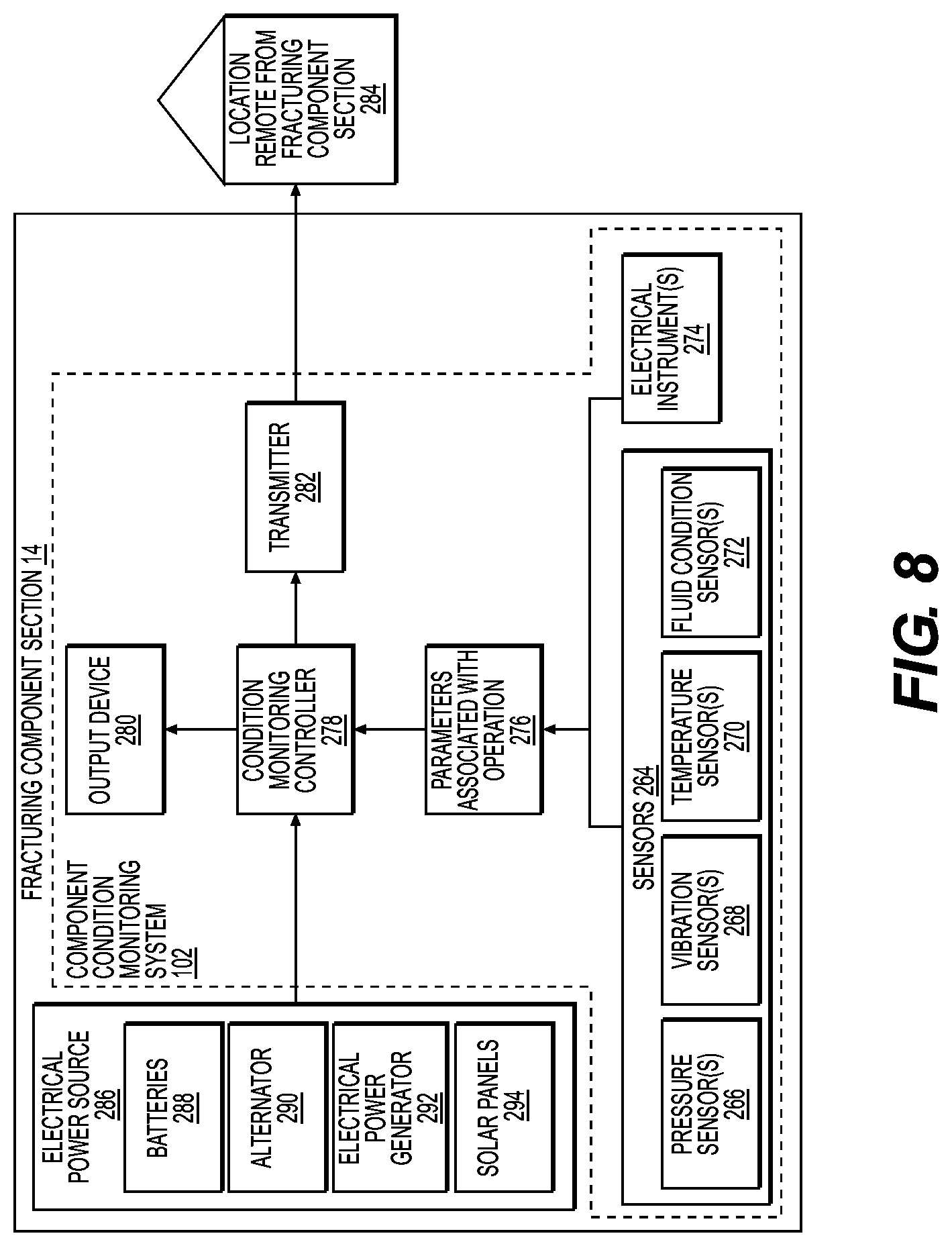
2. The fracturing component section of claim 1, further comprising a component condition monitoring system electrically connected to the fracturing component section, the component condition monitoring system comprising a condition monitoring controller configured to: receive one or more signals from one or more of a plurality of sensors or a plurality of electrical instruments positioned to generate signals indicative of operating parameters associated with operation of the fracturing component; and generate condition signals indicative of one or more of approaching maintenance due to be performed, predicted component damage, predicted component failure, existing component damage, existing component failure, irregularities of component operation, or operation exceeding rated operation.
3. The fracturing component section of claim 2, wherein the condition monitoring controller is configured to: receive signals from one or more of a pressure sensor, a vibration sensor, a temperature sensor, or a fluid condition sensor; and identify one or more of excessive pressure, excessive vibration, excessive temperature, fluid contamination, or fluid degradation.
4. The fracturing component section of claim 2, wherein the component condition monitoring system further comprises one or more of: an output device configured to communicate with an on-site operator of the hydraulic fracturing unit; or a transmitter configured to transmit signals to a location remote from the hydraulic fracturing unit indicative of one or more of approaching maintenance due to be performed, predicted component damage, predicted component failure, existing component damage, existing component failure, irregularities of component operation, or operation exceeding rated operation.
5. The fracturing component section of claim 1, wherein the base of the section frame defines a plurality of holes for receiving fasteners to secure the section frame to a platform to at least partially support the fracturing component section, and the fracturing component section further comprises a plurality of clamp locks positioned to secure the section frame to the platform to at least partially support the fracturing component section.
6. The fracturing component section of claim 1, wherein the base comprises opposing guide rails to align the fracturing component section with another fracturing component section, the opposing guide rails defining one or more recesses to receive a fork of a fork truck.
7. The fracturing component section of claim 1, wherein: the one or more frame members comprise a proximate end connected to the base; the one or more frame members extend transversely with respect to the base; the section frame further comprises one or more cross-members spaced from the base and connected to and extending between the one or more frame members; and the fracturing component section further comprises one or more lifting eyes connected to one or more of the one or more frame members or the one or more cross-members.
8. The fracturing component section of claim 1, wherein the fracturing component comprises one or more of a hydraulic fracturing pump to pump fracturing fluid, an internal combustion engine to supply power to a hydraulic fracturing pump, or a transmission to connect an output of an internal combustion engine to a driveshaft of a hydraulic fracturing pump.
9. The fracturing component section of claim 1, further comprising a plurality of shock mounts and bolts connecting the fracturing component to the section frame.
10. The fracturing component section of claim 1, wherein the component electrical assembly comprises one or more of: electrical instrumentation associated with the fracturing component, the electrical instrumentation comprising one or more of one or more pressure sensors, one or more temperature sensors, one or more vibration sensors, or one or more fluid condition sensors; one or more terminal units electrically connected to the electrical instrumentation, the one or more terminal units comprising a multi-pin receptacle to connect to a supervisory control system; a self-contained electrical power source, the electrical power source comprising one or more of one or more rechargeable batteries, one or more alternators, one or more electrical power generators, or one or more solar panels; or a component controller positioned to receive signals from the electrical instrumentation and at least partially control operation of the fracturing component.
11. The fracturing component section of claim 10, wherein the component electrical assembly further comprises one or more of: a user interface electrically connected to the component controller to facilitate input and access to information associated with operation of the fracturing component; or one or more of a transmitter or a receiver electrically connected to the component controller to facilitate communication between the component controller and a location remote from the hydraulic fracturing unit.
12. The fracturing component section of claim 1, wherein the component fluid assembly comprises one or more of: a component lubrication assembly connected to the section frame and positioned to provide lubrication to operate the fracturing component, the component lubrication assembly comprising one or more of one or more lubrication pumps, one or more lubricant coolers, one more lubricant filters, or one or more packing greasers; a component cooling assembly connected to the section frame and positioned to provide coolant to operate the fracturing component, the component cooling assembly comprising one or more of one or more radiators, one or more coolant lines, one or more coolant reservoirs, or one or more coolant pumps; a component hydraulic assembly connected to the section frame and positioned to provide hydraulic functions to operate the fracturing component; or a component fuel assembly connected to the section frame and positioned to provide fuel flow to operate the fracturing component.
13. The fracturing component section of claim 1, wherein the plurality of quick-connect electrical couplers comprise multi-pin receptacles and wherein the coupling plate is connected to the section frame at a location that facilitates access to the plurality of quick-connect electrical couplers and fluid couplers.
14. The fracturing component section of claim 1, the quick-connect fluid couplers comprising one or more of quick-connect lubricant couplers, quick-connect cooling system couplers, quick-connect hydraulic system couplers, or quick-connect fuel couplers.
15. The fracturing component section of claim 14, further comprising a plurality of check-valves associated with at least some of the quick-connect fluid couplers to prevent fluid flow from the quick-connect fluid couplers upon disconnection from another quick-connect fluid coupler.
16. The fracturing component section of claim 1, wherein the fracturing component comprises a hydraulic fracturing pump to pump fracturing fluid, and the fracturing component section further comprises one or more of a lubrication pump, a lube filter, a plunger greasing system, a lubricant cooler, a pulsation damper, suction iron, or high-pressure discharge iron.
17. The fracturing component section of claim 1, wherein the fracturing component comprises an internal combustion engine to supply power to a hydraulic fracturing pump, and the fracturing component section further comprises one or more of an exhaust assembly, air inlet ports, fuel lines, communications lines, hydraulic connections, or pneumatic connections.
18. The fracturing component section of claim 1, wherein the fracturing component comprises a transmission to connect an output of an internal combustion engine to a hydraulic fracturing pump, and the fracturing component section further comprises one or more of a lubrication pump, a lubrication heat exchanger, a transmission communication module, circuit sensors, or instrumentation associated with operation of the transmission.
19. A hydraulic fracturing unit comprising: a platform; the fracturing component section of claim 1 connected to the platform, the fracturing component section comprising a first fracturing component section comprising: a first section frame comprising a first base; and a first fracturing component connected to the first base, the first fracturing component comprising a transmission to connect an output of an internal combustion engine to a hydraulic fracturing pump; and a second fracturing component section comprising: a second section frame comprising a second base connected to the platform and to support a second fracturing component; and a second fracturing component connected to the second base, the second fracturing component comprising one or more of a hydraulic fracturing pump to pump fracturing fluid or an internal combustion engine to supply power to a hydraulic fracturing pump, one or more of the first fracturing component section or the second fracturing component section being positioned, such that the first fracturing component and the second fracturing component are substantially aligned for connection to one another when the first fracturing component section and the second fracturing component section are positioned adjacent one another.
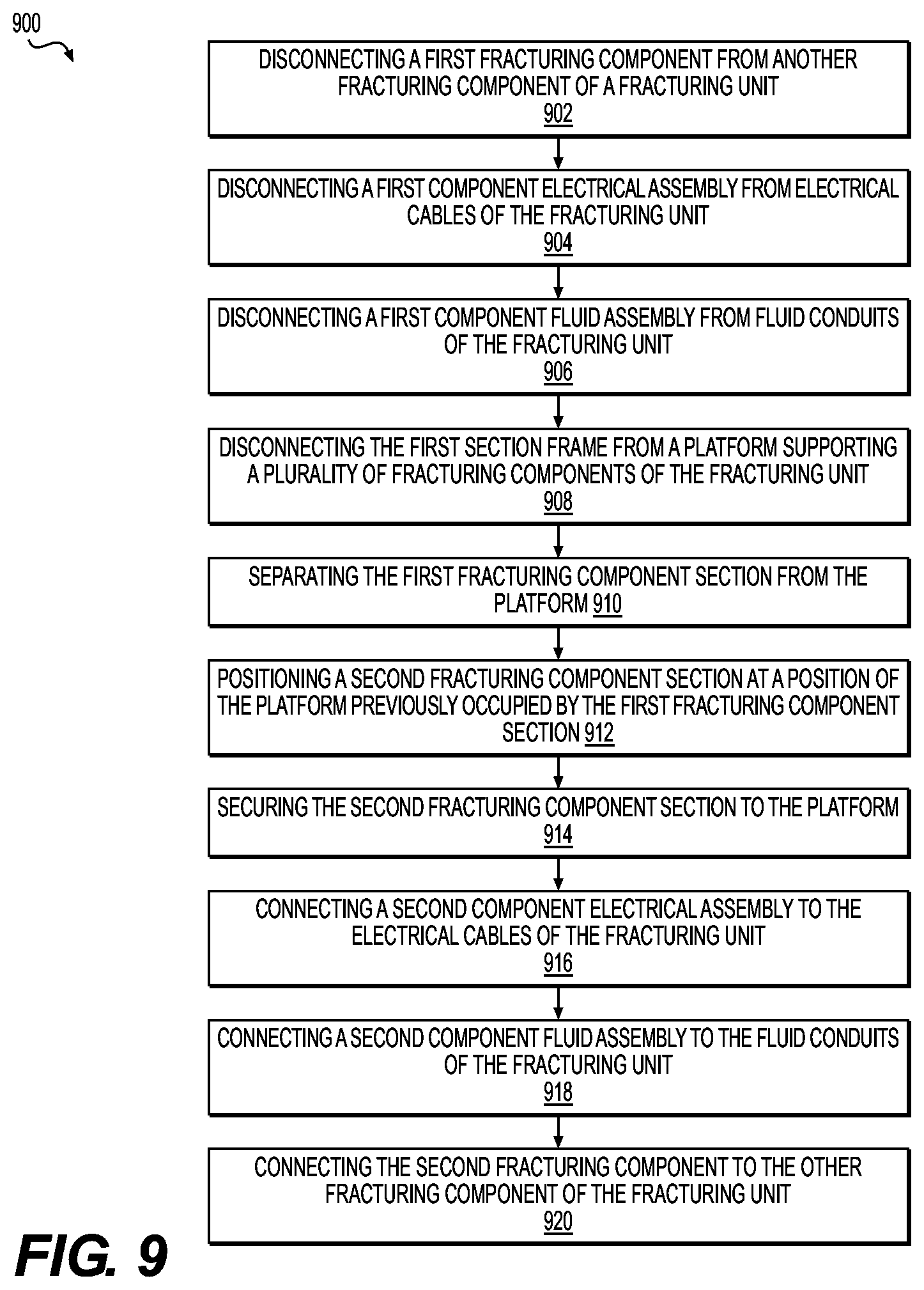
20. A method to exchange a first fracturing component of a hydraulic fracturing unit for a second fracturing component in the hydraulic fracturing unit, the hydraulic fracturing unit including a turbine engine, a driveshaft to connect to a hydraulic fracturing pump, a gearbox connected to the turbine engine for driving the driveshaft and thereby the hydraulic fracturing pump, the method comprising: disconnecting the first fracturing component from another fracturing component of the hydraulic fracturing unit, the first fracturing component being connected to a first section frame comprising a first base to support the first fracturing component, the first fracturing component and the first section frame at least partially forming a first fracturing component section; disconnecting a first component electrical assembly from electrical cables of the hydraulic fracturing unit, the first component electrical assembly being connected to the first section frame and positioned to provide one or more of electrical power, electrical controls, or electrical monitoring components associated with operation of the first fracturing component; disconnecting a first component fluid assembly from fluid conduits of the hydraulic fracturing unit, the first component fluid assembly being connected to the first section frame and positioned to provide one or more of lubrication, cooling, hydraulic function, or fuel to operate the first fracturing component; disconnecting the first section frame from a platform supporting a plurality of fracturing components of the hydraulic fracturing unit; separating the first fracturing component section from the platform; positioning a second fracturing component section at a position of the platform previously occupied by the first fracturing component section, the second fracturing component section comprising a second section frame and the second fracturing component connected to and supported by the second section frame; securing the second fracturing component section to the platform; connecting a second component electrical assembly to the electrical cables of the hydraulic fracturing unit, the second component electrical assembly being connected to the second section frame and positioned to provide one or more of electrical power, electrical controls, or electrical monitoring components associated with operation of the second fracturing component; connecting a second component fluid assembly to the fluid conduits of the hydraulic fracturing unit, the second component fluid assembly being connected to the second section frame and positioned to provide one or more of lubrication, cooling, hydraulic function, or fuel to operate the second fracturing component; and connecting the second fracturing component to the other fracturing component of the hydraulic fracturing unit, wherein disconnecting the first component electrical assembly from the electrical cables of the hydraulic fracturing unit comprises disconnecting the electrical cables of the hydraulic fracturing unit from a plurality of first quick-connect electrical couplers connected to a first coupling plate, the first coupling plate being connected to the first section frame, the plurality of first quick-connect electrical couplers being electrically connected to respective electrical connections of the first component electrical assembly and the first coupling plate and plurality of first quick-connect electrical couplers being part of the first fracturing component section; and the first fracturing component section further comprises: disconnecting the first component fluid assembly from the fluid conduits of the hydraulic fracturing unit comprises disconnecting the fluid conduits of the hydraulic fracturing unit from a plurality of first quick-connect fluid couplers connected to the first coupling plate, the plurality of first quick-connect fluid couplers being connected to respective fluid conduits of the first component fluid assembly, the plurality of first quick-connect fluid couplers being part of the first fracturing component section.
21. The method of claim 20, wherein: connecting the second component electrical assembly to the electrical cables of the hydraulic fracturing unit comprises connecting the electrical cables of the hydraulic fracturing unit to a plurality of second quick-connect electrical couplers connected to a second coupling plate, the second coupling plate being connected to the second section frame, the plurality of second quick-connect electrical couplers being electrically connected to respective electrical connections of the second component electrical assembly and the second coupling plate and plurality of second quick-connect electrical couplers being part of the second fracturing component section.
22. The method of claim 20, wherein: connecting the second component fluid assembly to the fluid conduits of the hydraulic fracturing unit comprises connecting the fluid conduits of the hydraulic fracturing unit to a plurality of second quick-connect fluid couplers connected to a second coupling plate, the second coupling plate being connected to the second section frame, the plurality of second quick-connect fluid couplers being connected to respective fluid conduits of the second component fluid assembly and the second coupling plate and plurality of second quick-connect fluid couplers being part of the second fracturing component section.
23. The method of claim 20, wherein the first fracturing component and the second fracturing component each comprise one of a hydraulic fracturing pump to pump fracturing fluid, an internal combustion engine to supply power to a hydraulic fracturing pump, or a transmission to connect an output of an internal combustion engine to a hydraulic fracturing pump.
24. The method claim 20, wherein: the first fracturing component comprises an internal combustion engine to supply power to a hydraulic fracturing pump; and disconnecting the first fracturing component from another fracturing component of the hydraulic fracturing unit comprises disconnecting an output shaft of the internal combustion engine from a driveshaft of a transmission.
25. The method of claim 20, wherein: the first fracturing component comprises a transmission to connect an output of an internal combustion engine to a hydraulic fracturing pump; and disconnecting the first fracturing component from another fracturing component of the hydraulic fracturing unit comprises: disconnecting a driveshaft of the transmission from an output shaft of an internal combustion engine; and disconnecting an output shaft of the transmission from a driveshaft of a hydraulic fracturing pump.
26. The method of claim 20, wherein: the first fracturing component comprises a hydraulic fracturing pump; and disconnecting the first fracturing component from another fracturing component of the hydraulic fracturing unit comprises disconnecting a driveshaft of the hydraulic fracturing pump from an output shaft of a transmission.
27. The method of claim 20, wherein disconnecting the first section frame from the platform comprises one or more of: removing a plurality of fasteners securing the first section frame to the platform; or unlocking a plurality of clamp locks securing the first section frame to the platform.
28. The method of claim 20, wherein separating the first fracturing component section from the platform comprises one of: engaging lifting eyes connected to the first section frame and lifting the first fracturing component section from the platform; or passing forks of a fork truck through one or more recesses in the first section frame and separating the first fracturing component section from the platform.
29. An exchangeable fracturing component section to facilitate quickly exchanging a fracturing component section of a hydraulic fracturing unit, the fracturing component section comprising: a section frame including a base and one or more frame members connected to and extending from the base; a fracturing component connected to and being supported by the base; a component electrical assembly connected to the section frame and positioned to provide one or more of electrical power, electrical controls, or electrical monitoring components associated with operation of the fracturing component; a component fluid assembly connected to the section frame and positioned to provide one or more of lubrication, cooling, hydraulic function, or fuel to operate the fracturing component; and a coupling plate connected to the section frame; a plurality of quick-connect electrical couplers connected to the coupling plate, the quick-connect electrical couplers configured to receive respective electrical connections of the component electrical assembly and electrically connect to other fracturing component sections of the hydraulic fracturing unit; and a plurality of quick-connect fluid couplers connected to the coupling plate, the quick-connect fluid couplers configured to receive respective fluid connections of the component fluid assembly and to provide fluid flow to other fracturing component sections of the hydraulic fracturing unit.
Description
TECHNICAL FIELD
The present disclosure relates to systems and methods for exchanging fracturing components of a hydraulic fracturing unit and, more particularly, to systems and methods for exchanging fracturing component sections including fracturing components of a hydraulic fracturing unit.
BACKGROUND
Fracturing is an oilfield operation that stimulates production of hydrocarbons, such that the hydrocarbons may more easily or readily flow from a subsurface formation to a well. For example, a fracturing system may be configured to fracture a formation by pumping a fracturing fluid into a well at high pressure and high flow rates. Some fracturing fluids may take the form of a slurry including water, proppants, and/or other additives, such as thickening agents and/or gels. The slurry may be forced via one or more pumps into the formation at rates faster than can be accepted by the existing pores, fractures, faults, or other spaces within the formation. As a result, pressure builds rapidly to the point where the formation may fail and may begin to fracture. By continuing to pump the fracturing fluid into the formation, existing fractures in the formation are caused to expand and extend in directions farther away from a well bore, thereby creating flow paths to the well bore. The proppants may serve to prevent the expanded fractures from closing when pumping of the fracturing fluid is ceased or may reduce the extent to which the expanded fractures contract when pumping of the fracturing fluid is ceased. Once the formation is fractured, large quantities of the injected fracturing fluid are allowed to flow out of the well, and the production stream of hydrocarbons may be obtained from the formation.
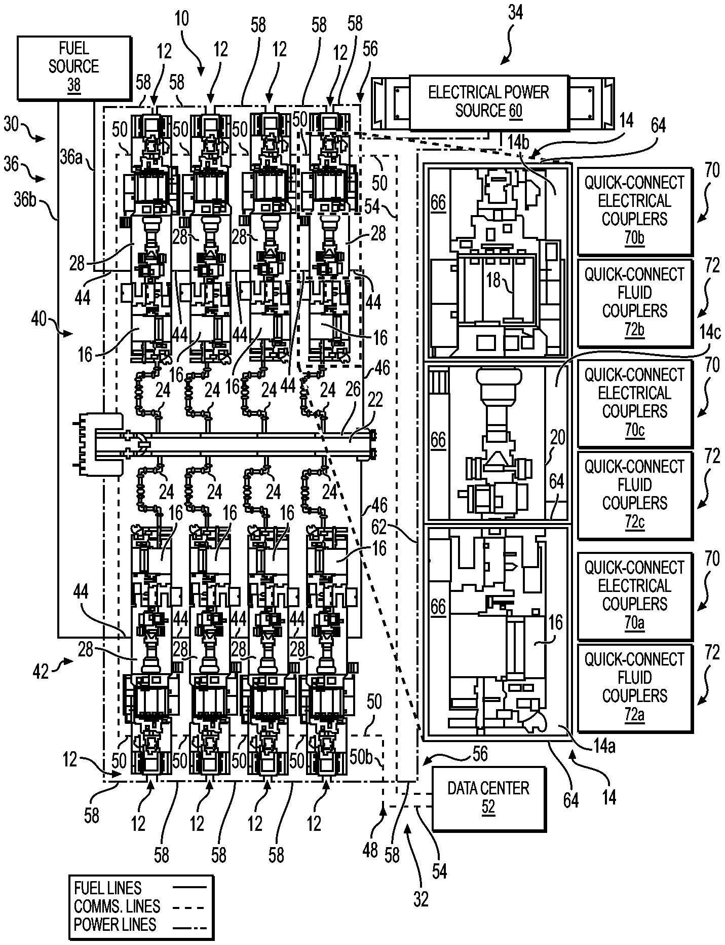
Prime movers may be used to supply power to hydraulic fracturing pumps for pumping the fracturing fluid into the formation. For example, a plurality of internal combustion engines may each be mechanically connected to a corresponding hydraulic fracturing pump via a transmission and operated to drive the hydraulic fracturing pump. The internal combustion engine, hydraulic fracturing pump, transmission, and auxiliary components associated with the internal combustion engine, hydraulic fracturing pump, and transmission may be connected to a common platform or trailer for transportation and set-up as a hydraulic fracturing unit at the site of a fracturing operation, which may include up to a dozen or more of such hydraulic fracturing units operating together to perform the fracturing operation.
A hydraulic fracturing operation is demanding on equipment, which often results in components of the hydraulic fracturing operation becoming worn, broken, or in need of maintenance, service, or, in some instances, replacement. Some maintenance issues are relatively minor and can be quickly remedied on-site. However, other maintenance issues may require separation of the affected component from the hydraulic fracturing unit and transport to an off-site location for service. In some instances, an affected component may require replacement. Many hydraulic fracturing unit components are large, heavy, and cumbersome to separate from the hydraulic fracturing unit. In addition, many of the hydraulic fracturing unit components operate with the assistance of numerous auxiliary components that may often include complex electrical and fluid systems, such as electrical components, wiring harnesses, fuel lines, hydraulic lines, lubrication lines, and cooling lines. Thus, if a hydraulic fracturing unit component requires separation from the hydraulic fracturing unit, it is often a difficult and complex process to separate the affected component from the remainder of the hydraulic fracturing unit, requiring the disconnection of numerous electrical and fluid components and lines. As a result, it may be required to interrupt a fracturing operation for a lengthy period of time in order to separate a fracturing component from its corresponding hydraulic fracturing unit and install a replacement component, increasing down-time and reducing the efficiency and profitability of the fracturing operation.
Accordingly, Applicant has recognized a need for systems and methods that provide greater efficiency and/or reduced down-time when performing a fracturing operation. The present disclosure may address one or more of the above-referenced drawbacks, as well as other possible drawbacks.
SUMMARY
The present disclosure generally is directed to systems and methods for exchanging fracturing components of a hydraulic fracturing unit. For example, in some embodiments, an exchangeable fracturing component section to facilitate quickly exchanging a fracturing component of a hydraulic fracturing unit. The hydraulic fracturing unit may include a gas turbine engine, a driveshaft to connect to a hydraulic fracturing pump, a transmission connected to the gas turbine engine for driving the driveshaft and thereby the hydraulic fracturing pump. The fracturing component section may include a section frame including a base and one or more frame members connected to and extending from the base. The fracturing component section further may include a fracturing component connected to and being supported by the base. The fracturing component section also may include a component electrical assembly connected to the section frame and positioned to provide one or more of electrical power, electrical controls, or electrical monitoring components associated with operation of the fracturing component. The fracturing component section still further may include a component fluid assembly connected to the section frame and positioned to provide one or more of lubrication, cooling, hydraulic function, or fuel to operate the fracturing component. The fracturing component section may still further include a coupling plate connected to the section frame. The fracturing component section also may include a plurality of quick-connect electrical couplers connected to the coupling plate and/or a plurality of quick-connect fluid couplers connected to the coupling plate. The quick-connect electrical couplers may be positioned to receive respective electrical connections of the component electrical assembly and electrically connect to other portions of the hydraulic fracturing unit. The quick-connect fluid couplers may be positioned to receive respective fluid connections of the component fluid assembly and to provide fluid flow to other portions of the hydraulic fracturing unit.
According some embodiments, a hydraulic fracturing unit may include a first fracturing component section including a first section frame including a first base and a first fracturing component connected to the first base. The first fracturing component may include a transmission to connect an output of an internal combustion engine to a hydraulic fracturing pump. The hydraulic fracturing unit also may include a second fracturing component section. The second fracturing component section may include a second section frame including a second base for supporting a second fracturing component. The second fracturing component section also may include a second fracturing component connected to the second base. The second fracturing component may include one or more of a hydraulic fracturing pump to pump fracturing fluid or an internal combustion engine to supply power to a hydraulic fracturing pump. The first fracturing component section and/or the second fracturing component section may be positioned, such that the first fracturing component and the second fracturing component are substantially aligned for connection to one another when the first fracturing component section and the second fracturing component section are positioned adjacent one another.
According to some embodiments, a method to exchange a first fracturing component of a hydraulic fracturing unit for a second fracturing component in a hydraulic fracturing unit. The hydraulic fracturing unit may include a gas turbine engine, a driveshaft to connect to a hydraulic fracturing pump, a transmission connected to the gas turbine engine for driving the driveshaft and thereby the hydraulic fracturing pump. The method may include disconnecting the first fracturing component from another fracturing component of the hydraulic fracturing unit. The first fracturing component may be connected to a first section frame including a first base for supporting the first fracturing component. The first fracturing component and the first section frame may comprise a first fracturing component section. The method also may include disconnecting a first component electrical assembly from electrical cables of the hydraulic fracturing unit. The first component electrical assembly may be connected to the first section frame and positioned to provide one or more of electrical power, electrical controls, or electrical monitoring components associated with operation of the first fracturing component. The method further may include disconnecting a first component fluid assembly from fluid conduits of the hydraulic fracturing unit. The first component fluid assembly may be connected to the first section frame and positioned to provide one or more of lubrication, cooling, hydraulic function, or fuel to operate the first fracturing component. The method further may include disconnecting the first section frame from a platform supporting a plurality of fracturing components of the hydraulic fracturing unit, and separating the first fracturing component section from the platform. The method still further may include positioning a second fracturing component section at a position of the platform previously occupied by the first fracturing component section. The second fracturing component section may include a second section frame and the second fracturing component connected to and supported by the second section frame. The method also may include securing the second fracturing component section to the platform, and connecting a second component electrical assembly to the electrical cables of the hydraulic fracturing unit. The second component electrical assembly may be connected to the second section frame and positioned to provide one or more of electrical power, electrical controls, or electrical monitoring components associated with operation of the second fracturing component. The method additionally may include connecting a second component fluid assembly to the fluid conduits of the hydraulic fracturing unit. The second component fluid assembly may be connected to the second section frame and positioned to provide one or more of lubrication, cooling, hydraulic function, or fuel to operate the second fracturing component. The method further may include connecting the second fracturing component to the other fracturing component of the hydraulic fracturing unit.
Still other aspects and advantages of these exemplary embodiments and other embodiments, are discussed in detail herein. Moreover, it is to be understood that both the foregoing information and the following detailed description provide merely illustrative examples of various aspects and embodiments, and are intended to provide an overview or framework for understanding the nature and character of the claimed aspects and embodiments. Accordingly, these and other objects, along with advantages and features of the present invention herein disclosed, will become apparent through reference to the following description and the accompanying drawings. Furthermore, it is to be understood that the features of the various embodiments described herein are not mutually exclusive and may exist in various combinations and permutations.
BRIEF DESCRIPTION OF THE DRAWINGS
The accompanying drawings, which are included to provide a further understanding of the embodiments of the present disclosure, are incorporated in and constitute a part of this specification, illustrate embodiments of the present disclosure, and together with the detailed description, serve to explain principles of the embodiments discussed herein. No attempt is made to show structural details of this disclosure in more detail than can be necessary for a fundamental understanding of the embodiments discussed herein and the various ways in which they can be practiced. According to common practice, the various features of the drawings discussed below are not necessarily drawn to scale. Dimensions of various features and elements in the drawings can be expanded or reduced to more clearly illustrate embodiments of the disclosure.
FIG. 1 schematically illustrates an example hydraulic fracturing system including a plurality of hydraulic fracturing units, including a detailed schematic view of example hydraulic fracturing component sections according to an embodiment of the disclosure.
FIG. 2A is a perspective view of an example fracturing component section according to an embodiment of the disclosure.
FIG. 2B is perspective view of the example fracturing component section shown in FIG. 2A shown from a different side according to an embodiment of the disclosure.
FIG. 2C is perspective view of the example fracturing component section shown in FIG. 2A shown from a different side according to an embodiment of the disclosure.
FIG. 3A is a side section view of an example shock mount for mounting a fracturing component to a section frame of a fracturing component section according to an embodiment of the disclosure.
FIG. 3B is a top view of the example shock mount shown in FIG. 3A according to an embodiment of the disclosure.
FIG. 4 is a perspective view of an example coupling plate including a plurality of quick-connect fluid couplers connected to the coupling plate according to an embodiment of the disclosure.
FIG. 5A is a side section view of an example receptacle of a quick-connect fluid coupler for connecting to a coupling plate according to an embodiment of the disclosure.
FIG. 5B is a side section view of an example plug for connection to the quick-connect fluid coupler receptacle shown in FIG. 5B according to an embodiment of the disclosure.
FIG. 6 is a schematic diagram of an example electrical control system for a plurality of example fracturing component sections, including an example supervisory control system according to an embodiment of the disclosure.
FIG. 7A is a schematic diagram of a male and female pair of an example quick-connect electrical coupler according to an embodiment of the disclosure.
FIG. 7B is a schematic diagram of a male and female pair of another example quick-connect electrical coupler according to an embodiment of the disclosure.
FIG. 7C is a schematic diagram of a male and female pair of another example quick-connect electrical coupler according to an embodiment of the disclosure.
FIG. 8 is a schematic diagram of an example component condition monitoring system for a fracturing component section according to an embodiment of the disclosure.
FIG. 9 is a block diagram of an example method for exchanging a first fracturing component of a fracturing system for a second fracturing component according to an embodiment of the disclosure.
FIG. 10 is a block diagram of an example method for monitoring a condition of a fracturing component section according to an embodiment of the disclosure.
DETAILED DESCRIPTION
The drawings like numerals to indicate like parts throughout the several views, the following description is provided as an enabling teaching of exemplary embodiments, and those skilled in the relevant art will recognize that many changes may be made to the embodiments described. It also will be apparent that some of the desired benefits of the embodiments described can be obtained by selecting some of the features of the embodiments without utilizing other features. Accordingly, those skilled in the art will recognize that many modifications and adaptations to the embodiments described are possible and may even be desirable in certain circumstances. Thus, the following description is provided as illustrative of the principles of the embodiments and not in limitation thereof.
The phraseology and terminology used herein is for the purpose of description and should not be regarded as limiting. As used herein, the term "plurality" refers to two or more items or components. The terms "comprising," "including," "carrying," "having," "containing," and "involving," whether in the written description or the claims and the like, are open-ended terms, i.e., to mean "including but not limited to," unless otherwise stated. Thus, the use of such terms is meant to encompass the items listed thereafter, and equivalents thereof, as well as additional items. The transitional phrases "consisting of" and "consisting essentially of," are closed or semi-closed transitional phrases, respectively, with respect to any claims. Use of ordinal terms such as "first," "second," "third," and the like in the claims to modify a claim element does not by itself connote any priority, precedence, or order of one claim element over another or the temporal order in which acts of a method are performed, but are used merely as labels to distinguish one claim element having a certain name from another element having a same name (but for use of the ordinal term) to distinguish claim elements.
FIG. 1 schematically illustrates an embodiment of a hydraulic fracturing system 10 including a plurality of hydraulic fracturing units 12, and includes a detailed schematic view of a plurality of hydraulic fracturing component sections 14 according to embodiments of the disclosure. The example hydraulic fracturing system 10 shown in FIG. 1 includes a plurality (or fleet) of hydraulic fracturing units 12 configured to pump a fracturing fluid into a well at high pressure and high flow rates, so that a subterranean formation may fail and begin to fracture in order to promote hydrocarbon production from the well.
In some embodiments, one or more of the hydraulic fracturing units 12 may include a fracturing pump 16 driven by an internal combustion engine 18 (e.g., a gas turbine engine (GTE) and/or diesel engine). In some embodiments, each of the hydraulic fracturing units 12 include directly driven turbine (DDT) hydraulic fracturing pumps 16, in which the hydraulic fracturing pumps 16 are connected to one or more GTEs that supply power to the respective hydraulic fracturing pump 16 for supplying fracturing fluid at high pressure and high flow rates to a formation. For example, a GTE may be connected to a respective hydraulic fracturing pump 16 via a transmission 20 (e.g., a reduction transmission) connected to a drive shaft, which, in turn, is connected to a driveshaft or input flange of a respective hydraulic fracturing pump 16 (e.g., a reciprocating hydraulic fracturing pump). Other types of engine-to-pump arrangements are contemplated.
In some embodiments, one or more of the internal combustion engines 18 may be a dual-fuel or bi-fuel GTE, for example, capable of being operated using of two or more different types of fuel, such as natural gas and diesel fuel, although other types of fuel are contemplated. For example, a dual-fuel or bi-fuel GTE may be capable of being operated using a first type of fuel, a second type of fuel, and/or a combination of the first type of fuel and the second type of fuel. For example, the fuel may include compressed natural gas (CNG), natural gas, field gas, pipeline gas, methane, propane, butane, and/or liquid fuels, such as, for example, diesel fuel (e.g., #2 Diesel), bio-diesel fuel, bio-fuel, alcohol, gasoline, gasohol, aviation fuel, and other fuels as will be understood by those skilled in the art. Gaseous fuels may be supplied by CNG bulk vessels, a gas compressor, a liquid natural gas vaporizer, line gas, and/or well-gas produced natural gas. Other types and sources of fuel and associated fuel supply sources are contemplated. The one or more internal combustion engines 18 may be operated to provide horsepower to drive via a transmission connected to one or more of the hydraulic fracturing pumps 16 to safely and successfully fracture a formation during a well stimulation project or fracturing operation.
Although not shown in FIG. 1, as will be understood by those skilled in the art, the hydraulic fracturing system 10 may include a plurality of water tanks for supplying water for a fracturing fluid, one or more chemical tanks for supplying gels or agents for adding to the fracturing fluid, and a plurality of proppant tanks (e.g., sand tanks) for supplying proppants for the fracturing fluid. The hydraulic fracturing system 10 may also include a hydration unit for mixing water from the water tanks and gels and/or agents from the chemical tank to form a mixture, for example, gelled water. The hydraulic fracturing system 10 may also include a blender, which receives the mixture from the hydration unit and proppants via conveyers from the proppant tanks. The blender may mix the mixture and the proppants into a slurry to serve as fracturing fluid for the hydraulic fracturing system 10. Once combined, the slurry may be discharged through low-pressure hoses, which convey the slurry into two or more low-pressure lines in a frac manifold 22, as shown in FIG. 1. Low-pressure lines in the frac manifold 22 feed the slurry to the plurality of hydraulic fracturing pumps 16 shown in FIG. 1 through low-pressure suction hoses.
In the example embodiment shown, each of the plurality hydraulic fracturing units 12 includes an internal combustion engine 18. Each of the internal combustion engines 18 supplies power via a transmission 20 for each of the hydraulic fracturing units 12 to operate a hydraulic fracturing pump 16. The hydraulic fracturing pumps 16 are driven by the internal combustion engines 18 of the respective hydraulic fracturing units 12 and discharge the slurry (e.g., the fracturing fluid including the water, agents, gels, and/or proppants) at high pressure and/or a high flow rates through individual high-pressure discharge lines 24 into two or more high-pressure flow lines 26, sometimes referred to as "missiles," on the frac manifold 22. The flow from the flow lines 26 is combined at the frac manifold 22, and one or more of the flow lines 26 provide flow communication with a manifold assembly, sometimes referred to as a "goat head." The manifold assembly delivers the slurry into a wellhead manifold, sometimes referred to as a "zipper manifold" or a "frac manifold." The wellhead manifold may be configured to selectively divert the slurry to, for example, one or more well heads via operation of one or more valves. Once the fracturing process is ceased or completed, flow returning from the fractured formation discharges into a flowback manifold, and the returned flow may be collected in one or more flowback tanks.
In the embodiment shown in FIG. 1, one or more of the components of the hydraulic fracturing system 10 may be configured to be portable, so that the hydraulic fracturing system 10 may be transported to a well site, assembled, operated for a relatively short period of time, at least partially disassembled, and transported to another location of another well site for use. In the example shown in FIG. 1, each of the hydraulic fracturing pumps 16 and internal combustion engines 18 of a respective hydraulic fracturing unit 12 may be connected to (e.g., mounted on) a platform 28. In some embodiments, the platform 28 may be, or include, a trailer (e.g., a flat-bed trailer) and/or a truck body to which the components of a respective hydraulic fracturing unit 12 may be connected. For example, the components may be carried by trailers and/or incorporated into trucks, so that they may be more easily transported between well sites.
As shown in FIG. 1, the hydraulic fracturing system 10 includes an example system for supplying fuel 30, an example system for enabling communications 32, and an example system for conveying electric power 34 associated with operation of the hydraulic fracturing units 12 according to an embodiment of the disclosure. The example systems 30, 32, and/or 34 shown in FIG. 1 may sometimes be referred to as a "daisy-chain" arrangement. Other arrangements are contemplated, such as "hub-and-spoke," combination "daisy-chain" and "hub-and-spoke," and modifications thereof.
In the embodiment shown in FIG. 1, the system for supplying fuel 30 includes a main fuel line 36 configured to supply fuel from a fuel source 38 to the plurality of hydraulic fracturing units 12. The hydraulic fracturing units 12 are arranged into a first bank 40 of hydraulic fracturing units 12 and a second bank 42 of hydraulic fracturing units 12, and the main fuel line 36 includes a first main fuel line 36a configured to supply fuel to the first bank 40 of hydraulic fracturing units 12 and a second main fuel line 36b configured to supply fuel to the second bank 42 of the hydraulic fracturing units 12.
In the embodiment shown in FIG. 1, a manifold line 44 defines a flow path for supplying fuel to each of the internal combustion engines 18 of a respective hydraulic fracturing unit 12. In the example arrangement shown, a first one of the manifold lines 44 may be positioned to provide fluid flow between the main fuel line 36 and a first one of the internal combustion engines 18 in each of the first and second banks 40 and 42 of the hydraulic fracturing units 12, while the manifold lines 44 between the remaining hydraulic fracturing units 12 of each of the first and second banks 40 and 42 provides fluid flow between an upstream hydraulic fracturing unit 12 and a downstream hydraulic fracturing unit 12. The manifold lines 44 may each provide fluid flow to a respective internal combustion engine 18 of each of the hydraulic fracturing units 12, for example, via a fuel line providing fluid flow from each of the manifold lines 44. As shown in FIG. 1, in some embodiments, fuel that reaches the end of the first bank 40 of the hydraulic fracturing units 12 remote from the fuel source 38 and/or fuel that reaches the end of the second bank 42 of the hydraulic fracturing units 12 remote from the fuel source 38 may be combined and/or transferred between the first bank 40 and the second bank 42, for example, via a transfer line 46 configured to provide fluid flow between the first bank 40 and the second bank 42. For example, unused fuel supplied to either of the first bank 40 or the second bank 42 of hydraulic fracturing units 12 may be passed to the other bank of the two banks via the transfer line 46, thereby sharing fuel between the first and second banks 40 and 42.
As shown in FIG. 1, a communications cable assembly 48 including a length of communications cable 50 may be connected to each of the hydraulic fracturing units 12 and configured to enable data communications between the respective hydraulic fracturing unit 12 and a data center 52 located at a position remote from the hydraulic fracturing units 12 or one or more additional hydraulic fracturing units 12. For example, as shown FIG. 1, a data center communications cable 54 may provide a communications link between the data center 52 and a first one of the hydraulic fracturing units 12 of each of the first and second banks 40 and 42. The hydraulic fracturing unit 12 may include a length of communications cable 50 that extends to a next one of the hydraulic fracturing units 12 in each of the first and second banks 40 and 42, and that hydraulic fracturing unit 12 may include a length of communications cable 50 that extends to a next one of the hydraulic fracturing units 12. In some embodiments, each of the hydraulic fracturing units 12 may include a length of communications cable 50 for extending to a next one of the hydraulic fracturing units 12. In this example fashion, each of the hydraulic fracturing units 12 may be linked to one another and to the data center 52. As shown in FIG. 1, in some embodiments, a last-in-line hydraulic fracturing unit 12 of each of the first and second banks 40 and 42 may include a length of communications cable 50 that runs to the data center 52, thus resulting in a continuous communications link, by which one or more of the hydraulic fracturing units 12 may be in communication with the data center 52. In some embodiments, the data center 52 may be configured to transmit communications signals and/or receive communications signals, and the communications signals may include data indicative of operation of one or more of the plurality of hydraulic fracturing units 12, including, for example, parameters associated with operation of the hydraulic fracturing pumps 16 and/or the internal combustion engines 18, as well as additional data related to other parameters associated with operation and/or testing of one or more of the hydraulic fracturing units 12.
In some embodiments, the communications cable 50 may include a first end configured to be connected to a first unit interface connected to a respective hydraulic fracturing unit 12. The length of communications cable 50 may also include a second end configured to be connected to a data center interface of the data center 52 or a second unit interface connected to another one of the hydraulic fracturing units 12. One or more of the first end or the second end of the length of communications cable 50 may include or be provided with a quick-connect electrical coupler configured to be connected to one or more of the first unit interface or the data center interface, for example, as discussed herein with respect to FIGS. 7A-7C.
As shown in FIG. 1, a power cable assembly 56 including a length of power cable 58 may be connected to one or more (e.g., each) of the hydraulic fracturing units 12 and configured to convey electric power between the hydraulic fracturing units 12 and a remote electrical power source 60 or one or more additional hydraulic fracturing units 12 of the hydraulic fracturing system 10. The electrical power source 60 may be located remotely, such that the electrical power source 60 is not mechanically connected directly to the platform 28 of one or more of the hydraulic fracturing units 12. In some embodiments, the electrical power source 60 may include one or more of one or more power generation devices and/or one or more batteries. For example, the electrical power source 60 may include one or more gensets (e.g., including an internal combustion engine-driven electrical generator) and/or one or more electric power storage devices, such as, for example, one or more batteries.
As shown in FIG. 1, a length of power cable 58 may be connected to each of the hydraulic fracturing units 12, and each of the lengths of power cable 58 may be configured to be connected to a next-in-line hydraulic fracturing unit 12 of each of the first and second banks 40 and 42 of the hydraulic fracturing units 12. In some embodiments, the length of power cable 58 may extend from one hydraulic fracturing unit 12 to another hydraulic fracturing unit 12 other than a next-in-line hydraulic fracturing unit 12. One or more of the lengths of power cable 58 may include a first end including a quick-connect electrical coupler, such as a power plug configured to be received in a power receptacle, for example, as discussed herein with respect to FIGS. 7A-7C.
As shown in FIG. 1, each of the hydraulic fracturing units 12 in the embodiment shown includes a length of power cable 58. In some such examples, each of the hydraulic fracturing units 12 may supply and/or generate its own electric power, for example, by operation of a generator connected to the internal combustion engine 18 and/or to another source of mechanical power, such as another gas turbine engine or reciprocating-piston engine (e.g., a diesel engine). In the example configuration shown in FIG. 1, the lengths of power cable 58 run between each of the hydraulic fracturing units 12, thus connecting all the hydraulic fracturing units 12 to one another, such that power may be shared among at least some or all of the hydraulic fracturing units 12. Thus, if one or more of the hydraulic fracturing units 12 is unable to generate its own electric power or is unable to generate a sufficient amount of electric power to meet its operation requirements, electric power from one or more of the remaining hydraulic fracturing units 12 may be used to mitigate or overcome the electric power deficit. As shown, additional lengths of power cable 58 may be included in the system for conveying electric power 34 to supply electric power between the first and second two banks 40 and 42 of the hydraulic fracturing units 12.
As shown in FIG. 1, the electrical power source 60 may be electrically coupled to one or more of the first bank 40 or the second bank 42 of the hydraulic fracturing units 12 via an additional length of power cable 62, and in some embodiments, the first bank 40 and the second bank 42 of hydraulic fracturing units 12 may be electrically coupled to one another via additional lengths of power cable 62. In at least some such examples, even if one or more of the hydraulic fracturing units 12 lacks electric power, electric power may be supplied to that particular hydraulic fracturing unit 12 via power cables 58 and/or 62, thereby providing an ability to continue operations of the hydraulic fracturing units 12.
As shown in FIG. 1, the example hydraulic fracturing system 10 includes hydraulic fracturing units 12 including example fracturing component sections 14 according to embodiments of the disclosure. In some embodiments, the fracturing component sections 14 may facilitate quickly exchanging a first fracturing component of a hydraulic fracturing unit 12 for another fracturing component of the same or similar type as the as the first fracturing component. For example, this may facilitate quickly exchanging a fracturing component in need of repair or replacement for another fracturing component of the same or similar type, for example, for exchanging a hydraulic fracturing pump 16, an internal combustion engine 18, and/or a transmission 20, for another respective replacement hydraulic fracturing pump, internal combustion engine, and/or transmission. Other component types are contemplated. In some embodiments, the fracturing component section 14 may include auxiliary systems used to operate the fracturing component of the respective fracturing component section 14, such as, electrical systems, hydraulic systems, pneumatic systems, and/or fluid systems, such as lubrication systems, cooling systems, and/or fuel system components. For example, for a fracturing component section 14 including a hydraulic fracturing pump 16, at least a portion of the electrical systems, hydraulic systems, pneumatic systems, and/or fluid systems, such as lubrication systems, and/or cooling systems necessary to control and/or monitor operation of the hydraulic fracturing pump 16 may be included as part of the corresponding fracturing component section 14. This may render it more efficient and/or reduce the time required for removing the affected fracturing component if it becomes necessary, for example, to service or replace the fracturing component.
In the embodiments shown in FIG. 1, one or more of the hydraulic fracturing units 12 may include one or more fracturing component sections 14, including a first fracturing component section 14a including a hydraulic fracturing pump 16, a second fracturing component section 14b including an internal combustion engine 18, and a third fracturing component section 14c including a transmission 20. Fracturing component sections 14 including other fracturing unit components are contemplated.
In the embodiments shown in FIG. 1, the first, second, and third fracturing component sections 14a, 14b, and 14c, each include a section frame 64 including a base 66 for supporting the corresponding fracturing component (e.g., the hydraulic fracturing pump 16, the internal combustion engine 18, or the transmission 20) and one or more frame members 68 connected to and extending from the base 66 (see, e.g., FIGS. 2A, 2B, and 2C). The one or more fracturing components associated with the fracturing component section 14 may be connected to the base 66. As mentioned above, one or more of the fracturing component sections 14 may include a component electrical assembly connected to the section frame 64 and positioned to provide one or more of electrical power, electrical controls, or electrical monitoring components associated with operation of the fracturing component included on the fracturing component section 14, depending on, for example, the type of fracturing component included the fracturing component section. In some embodiments, the fracturing component sections 14 may also include a component fluid assembly connected to the section frame 64 and positioned to provide one or more of lubrication, cooling, hydraulic function, or fuel to operate the included fracturing component, depending on, for example, the type of fracturing component included the fracturing component section 14.
As shown in FIG. 1, one or more of the fracturing component sections 14a, 14b, or 14c may include a plurality of quick-connect electrical couplers 70, individually identified in FIG. 1 as 70a, 70b, and 70c, and/or a plurality of quick-connect fluid couplers 72, individually identified in FIG. 1 as 72a, 72b, and 72c. As explained in more detail herein with respect to FIG. 4, the quick-connect electrical couplers 70 and/or the quick-connect fluid couplers 72 may be connected to one or more coupling plates 74 (FIG. 4) to provide a convenient location on the respective fracturing component section 14 for connecting and disconnecting electrical cables and/or fluid lines of the hydraulic fracturing unit 12 or hydraulic fracturing system 10. For example, the quick-connect electrical couplers 70 and/or a coupling plate 74 to which the quick-connect electrical couplers 70 are connected may be positioned to receive respective electrical connections of the component electrical assembly and electrically connect to other portions of the hydraulic fracturing unit 12 and/or other parts of the hydraulic fracturing system 10. In some embodiments, the quick-connect fluid couplers 72 and/or a coupling plate 74 to which the quick-connect fluid couplers 72 are connected may be positioned to receive respective fluid connections of the component fluid assembly and to provide fluid flow to other portions of the hydraulic fracturing unit 12 and/or other parts of the hydraulic fracturing system 10.
FIGS. 2A, 2B, and 2C are perspective views of an example fracturing component section 14 according to an embodiment of the disclosure. In the example shown, the fracturing component section 14 includes an example hydraulic fracturing pump 16. As shown in FIGS. 2A, 2B, and 2C, the fracturing component section 14 may include a section frame 64 including a base 66 for supporting the hydraulic fracturing pump 16 and one or more frame members 68 (e.g., uprights) connected to and extending from the base 66. For example, as shown, the base 66 includes two pairs of opposing guide rails 76 forming a rectangular support for supporting the hydraulic fracturing pump 16. In some embodiments, the base 66 may include one or more transverse members 78 extending between at least one pair of the opposing guide rails 76. One or more of the opposing guide rails 76 may be sized and/or configured to assist with alignment of the section frame 64 (i.e., the fracturing component section 14) with respect to the platform 28 supporting the fracturing component section 14 and/or with alignment of the section frame 64 relative to one or more adjacent fracturing component sections 14. Some embodiments of the opposing guide rails 76 may be formed from I-beams and/or C-channels. As shown, some of the guide rails 76 may include one or more recesses 80 (e.g., apertures) configured to receive a fork of a fork truck to facilitate separating the fracturing component section 14 from the platform 28 and/or the remainder of the hydraulic fracturing unit 12. In some embodiments, the recesses 80 may be located in guide rails 76 accessible from the side of the platform 28. In some embodiments, the recesses 80 may be on all opposing guide rails 76.
As shown in FIGS. 2A, 2B, and 2C, some embodiments of the section frame 64 may include opposing pairs of cross-members 82 extending between distal ends of the frame members 68, for example, such that the section frame 64 generally forms a cubic frame or rectangular prism frame. In some embodiments, at one or more (e.g., each) of the corners formed by the frame members 68 and the cross-members 82, the section frame 64 may include a lifting eye 84 to facilitate separating the fracturing component section 14 from the platform 28 and/or the remainder of the hydraulic fracturing unit 12. In some embodiments of the section frame 64, reinforcement elements, such as gussets, to stiffen the section frame 64 may be provided at one or more of the corners formed by intersections of the base 66, the frame members 68, the transverse members 78, and/or the cross-members 82.
As shown in FIGS. 2A, 2B, and 2C, the example fracturing component section 14 includes an example hydraulic fracturing pump 16. The hydraulic fracturing pump 16 shown includes a power end 86, a fluid end 88, and a driveshaft 90 for connecting to an output of a transmission 20 or an output of an internal combustion engine 18, which may be the output of a reduction transmission connected to the output shaft the internal combustion engine 18. The transmission 20 and/or the internal combustion engine 18 may be mounted on a section frame 64 and be part of an adjacent fracturing component section 14 with respect to the fracturing component section 14 including a hydraulic fracturing pump 16.
The embodiment of fracturing component section 14 shown in FIGS. 2A, 2B, and 2C includes auxiliary components for facilitating operation, control, and/or monitoring of the operation of the hydraulic fracturing pump 16. Auxiliary components may include lubrication pumps, lubrication filters, a plunger packing greasing system, lubrication coolers, pulsation dampers, suction components, high-pressure discharge components, and instrumentation related to operation of the hydraulic fracturing pump 16. For example, the fracturing component section 14 shown in FIGS. 2A, 2B, and 2C includes lubrication coolers 92, a packing greater 94, lubrication pumps 96, a suction manifold for drawing-in fracturing fluid 98, and a discharge manifold 100 for discharging fracturing fluid at high pressure and high flow rates.
In some embodiments, the fracturing component section 14 may also include a component condition monitoring system 102 for monitoring parameters related to operation of the fracturing component section 14, as shown in FIGS. 2A, 2B, and 2C. As explained in more detail herein with respect to FIG. 8, the component condition monitoring system 102 may be configured to receive one or more signals from a plurality of sensors and/or a plurality of electrical instruments connected to the fracturing component section 14 and generate one or more condition signals indicative of operating parameters associated with operation of the fracturing component included in the fracturing component section 14 (e.g., a hydraulic fracturing pump 16, an internal combustion engine 18, and/or a transmission 20).
In some embodiments, the fracturing component section 14 may be connected to the platform 28 of the hydraulic fracturing unit 12 via fasteners and/or locks. For example, the section frame 64 (e.g., the base 66) may include a plurality of holes for receiving fasteners to secure the section frame 64 to the platform 28 to secure the fracturing component section 14 to the platform 28 and/or to at least partially support the fracturing component section 14. In some embodiments, the fracturing component section 14 may also, or alternatively, include a plurality of clamp locks positioned to secure the section frame 64 to the platform 28 to secure the fracturing component section 14 to the platform 28 to at least partially support the fracturing component section 14.
Although the example fracturing component section 14 shown in FIGS. 2A, 2B, and 2C includes a hydraulic fracturing pump 16 and related auxiliary components, fracturing component sections 14 including other types of fracturing components and their related auxiliary components are contemplated, such as prime movers for driving hydraulic fracturing pumps or electrical generators supplying electrical power to electric motors for driving featuring pumps (e.g., diesel engines and/or GTEs), and transmissions 20 and related auxiliary components. For example, a fracturing component section 14 may include a prime mover, such as a GTE, which may be a dual-fuel and/or dual-shaft GTE cantilever-mounted to a reduction gearbox, lubrication pumps, heat exchangers to cool lubrication, a prime mover communication module, and/or circuit sensors and instrumentation associated with the prime mover. In another example, a fracturing component section 14 may include a transmission including a multi-gear transmission, lubrication pumps, heat exchangers to cool lubrication, a transmission communication module, and/or circuit sensors and instrumentation associated with the transmission. Other types of the fracturing components for fracturing component sections are contemplated.
FIGS. 3A and 3B are a side section view and a top view of an example shock mount 104 for mounting a fracturing component to a section frame 64 of a fracturing component section 14 according to an embodiment of the disclosure. The shock mount 104 may be configured to secure the fracturing component to the base 66 of the section frame 64 and absorb vibrations and shock generated during transportation and operation of the fracturing component.
For example, as shown in FIGS. 3A and 3B, the shock mount may include a base plate 106 configured to be connected to an upper surface of the base 66 of the section frame 64, an upper plate 108 configured to be connected to the fracturing component, and an absorbing portion 110 between the base plate 106 and the upper plate 108 and configured to absorb shock and vibration. The base plate 106 may include one or more securement flanges 112, each including one or more holes 114 through which bolts may be received to secure the shock mount 104 to the base 66 of the section frame 64. The base plate 106 may also include a circular embossment 116 including a fastener hole 118 configured to receive therein a fastener (e.g., a bolt) for securing the fracturing component to the shock mount 104. The upper plate 108 also includes a sleeve hole 120 in which a sleeve 122 is received and connected. The sleeve 122 extends from the sleeve hole 120 through the fastener hole 118 of the embossment 116 of the base plate 106. A circular flange 124 prevents the sleeve 122 from pulling out of the fastener hole 118, but permits the sleeve 122 to reciprocate within the fastener hole 118 as the absorbing portion 110 compresses and expands as load changes on the shock mount 104, thereby absorbing shock and vibration transmitted between the base 66 of the section frame 64 and the fracturing component mounted to the section frame 64.
FIG. 4 is a perspective view of a coupling plate 74 including a plurality of quick-connect fluid couplers 72 connected to the coupling plate 74 according to embodiments of the disclosure. In some embodiments, the coupling plate 72 may be connected to the section frame 64 at a location easily accessible to facilitate access to quick-connect electrical couplers 70 and/or quick-connect fluid couplers 72 connected to the coupling plate 74. For example, the coupling plate 74 may be mounted to the base 66, the frame members 68, and the cross-members 82 with the quick-connect electrical and/or fluid couplers 70 or 72 facing outward away from the fracturing component mounted to the base 66. In some embodiments, the fracturing component section 14 may include more than one coupling plate 74, such as one or more coupling plates 74 for quick-connect electrical couplers 70 and one or more coupling plates 74 for quick-connect fluid couplers 72. The one or more coupling plates 74 may facilitate ease of connecting and disconnecting electrical lines and/or fluid lines from other portions of the hydraulic fracturing unit 12 and/or other portions of the hydraulic fracturing system 10 with electrical lines and/or fluid lines of the fracturing component section 14.
FIG. 5A is a side section view of an example receptacle 126 of a quick-connect fluid coupler 72 for connecting to a coupling plate 74 according to an embodiment of the disclosure, and FIG. 5B is a side section view of an example plug 128 for connection to the quick-connect fluid coupler receptacle 126 shown in FIG. 5A according to an embodiment of the disclosure. The receptacle 126 may be connected to the coupler plate 74 and configured to receive and retain in a fluid-tight manner a fluid line from the fracturing component section 14 to which the coupling plate 74 is connected. The plug 128 may be configured to receive a fluid line from the hydraulic fracturing unit 12 to which the fracturing component section 14 is connected or a fluid line from the hydraulic fracturing system 10. The receptacle 126 and the plug 128 may be configured such that the plug 128 is easily inserted into, and easily separated from, the receptacle 126 for connecting a fluid line from the fracturing component section 14 to a fluid line of the hydraulic fracturing unit 12 or the hydraulic fracturing system 10. In some embodiments, the receptacle 126 and/or the plug 128 are configured, such that when a plug 128 received in the receptacle 126 is removed to disconnect the fluid lines, fluid does not leak from the receptacle 126 and/or the plug 128.
As shown in FIG. 5A, the receptacle 126 includes a hollow cylindrical socket body 130 receiving therein a valve guide 132 and a valve 134. The valve 134 includes an O-ring 136 for sealing the valve 134 against a conical interior surface of the socket body 130. The socket body 130 also includes a cylindrical interior surface 138 including an annular recess receiving an O-ring 140. The receptacle 126 includes a fluid line connection end 142 having interior threads for connecting to a fluid line of the fracturing component section 14. On an exterior surface of the socket body 130, a spring-loaded sleeve 144 including a spring 146 is provided. The plug 128 includes a plug body 148 defining a cylindrical interior surface 150 receiving therein a valve guide 152, a valve 154, and a spring 156 between the valve guide 152 and the valve 154. The plug body 148 includes a fluid line connection end 158 having interior threads for connecting to a fluid line of the hydraulic fracturing unit 12 or the hydraulic fracturing system 10. The plug body 148 has an exterior surface 160 including an annular recess 162. When connecting a fluid line from the hydraulic fracturing unit 12 or the hydraulic fracturing system 10, the sleeve 144 of the receptacle 126 is pushed back toward the fluid line connection end 142 exposing locking balls 164, and the plug 128 is inserted into the receptacle 126, such that the annular recess 162 of the plug 128 is captured by the locking balls 164 of the receptacle 126. The sleeve 144 is moved back into position away from the fluid line connection end 142 (e.g., via the spring 146) holding the locking balls 164 in the annular recess 162 of the plug 128, thereby holding the receptacle 126 and the plug 128 together. In this condition, the valve 134 of the plug 126 and the valve 154 unseat to thereby allow fluid to flow between the plug 128 and the receptacle 126. When the plug 128 is disconnected from the receptacle 126, the sleeve 144 is pushed back to allow the locking balls 164 to release the annular recess 162 of the plug 128 to be separated from the locking balls 164. In this condition, the valves 134 and 154 return to their respective seats, acting as check valves such that fluid in the fluid line of the fracturing component section 14 connected to the receptacle 126 is not leaked from the receptacle 126, and such that fluid from the fluid line connected to the plug 128 is not leaked from the plug 128. Other types and configurations of quick-connect fluid couplers 72 are contemplated.
FIG. 6 is a schematic diagram of an embodiment of an electrical control system 166 for a plurality of example fracturing component sections 14, including an example supervisory control system 168 according to an embodiment of the disclosure. As shown in FIG. 6, the hydraulic fracturing unit 12 includes a fracturing component section 14a for a hydraulic fracturing pump 16, a fracturing component section 14b for an internal combustion engine 18, such as a diesel engine or a GTE, a fracturing component section 14c for a transmission 20, and an auxiliary system 170 for suppling electrical power and hydraulic power and/or operations for the hydraulic fracturing unit 12. In some embodiments, for example as shown, for each of the fracturing component section 14a, the fracturing component section 14b, the fracturing component section 14c, and the auxiliary system 170 of the hydraulic fracturing unit 12, all of the electrical instrumentation and electrical control may be connected and in communication with the supervisory control system 168 via a respective single sub-system communications cable 172, identified respectively as 172a, 172b, 172c, and 172d. Thus, when separating one or more of the fracturing component sections 14a, 14b, and/or 14c from the hydraulic fracturing unit 12, only a single sub-system communications cable 172 may be disconnected from the fracturing component section 14 being separated, as explained in more detail herein.
As shown in FIG. 6, the fracturing component section 14a including the hydraulic fracturing pump 16 includes a plurality of sensors configured to generate signals indicative of parameters associated with operation of the hydraulic fracturing pump 16. For example, the sensors may include a suction pressure sensor 174 configured to generate signals indicative of the pressure associated with the hydraulic fracturing pump 16 drawing fracturing fluid into the hydraulic fracturing pump 16, a discharge pressure sensor 176 configure to generate one or more signals indicative of the pressure at which fracturing fluid is being discharged from the hydraulic fracturing pump 16, a lubrication pressure sensor 178 configured to generate one or more signals indicative of the pressure of lubricant in a lubrication system associated with the hydraulic fracturing pump 16, a lubrication temperature sensor 180 configured to generate one or more signals indicative of the temperature of the lubricant, a vibration sensor 181 configured to generate signals indicative of a frequency and/or magnitude of vibration associated with operation of the hydraulic fracturing pump 16, a grease pump sensor 182 configured to generate one or more signals indicative of operation of a grease pump configured to supply lubricant to the hydraulic fracturing pump 16, a cooler temperature sensor 184 configured to generate one or more signals indicative of the temperature of coolant of a coolant system associated with the hydraulic fracturing pump 16, and/or a grease pressure sensor 186 configured to generate one or more signals indicative of the pressure of grease pumped by the grease pump. Other sensor types are contemplated.
As shown in FIG. 6, in some embodiments, each of the sensors may be in communication with a fracturing pump terminal unit 188 via a single sensor communications cable 190, which, in turn, may be in communication with the supervisory control system 168 via a single sub-systems communication cable 172a. The supervisory control system 168, in some embodiments, may be in communication with the data center 52 via the communications cable 50 and/or the data center communications cable 54 (see FIG. 1). For example, each of the sensors may be connected to respective terminations in the fracturing pump terminal unit 188, which is connected to the fracturing component section 14a of the hydraulic fracturing pump 16 (e.g., to the section frame 64, for example, as shown in FIGS. 2A, 2B, and 2C). For example, each of the single sensor communications cables 190 may pass through a respective punch-out of the fracturing pump terminal unit 188 and be connected to terminations in the enclosed interior of the fracturing pump terminal unit 188, for example, via individual pin connectors (e.g., quarter-turn pin connectors). Those connections may be connected to a terminal rail inside the enclosed interior, and each of the connections to the terminal rail may be connected to a single quick connect electrical coupler 70, such as a female multi-pin plug (see, e.g., FIGS. 7A, 7B, and 7C). The single female multi-pin plug may be coupled to the supervisory control system 166 of the fracturing component section 14a via the single sub-system communications cable 172a.
Thus, in some embodiments, when the fracturing component section 14a of the hydraulic fracturing pump 16 is separated from the hydraulic fracturing unit 12, only a single sub-system communications cable 172a may be disconnected from the fracturing pump terminal unit 188 to disconnect the electrical components of the fracturing component section 14a from the supervisory control system 168 of the hydraulic fracturing unit 12. This may result in reducing the time and complexity associated with separating the fracturing component section 14a from the remainder of the hydraulic fracturing unit 12.
In some embodiments, as shown in FIG. 6, the fracturing component section 14c including the transmission 20 includes a plurality of sensors configured to generate signals indicative of parameters associated with operation of the transmission 18. For example, the sensors may include a lubrication pressure sensor 192 configured to generate one or more signals indicative of the pressure of a lubricant in a lubrication system associated with the transmission 20, a lubrication temperature sensor 194 configured to generate one or more signals indicative of the temperature of the lubricant associated with the transmission 20, a vibration sensor 196 configured to generate signals indicative of a frequency and/or magnitude of vibration associated with operation of the transmission 20, a cooler temperature sensor 198 configured to generate one or more signals indicative of the temperature of a coolant of a coolant system associated with the transmission 20, and/or a grease pump sensor 200 configured to generate one or more signals indicative of operation of a grease pump configured to supply lubricant to the transmission 20. Other sensor types are contemplated. In addition, the fracturing component section 14c associated with the transmission 20 may also include a transmission control module 202 configured to control operation of the transmission 20 and generate one or more signals indicative of operation of the transmission 20.
As shown in FIG. 6, in some embodiments, each of the sensors may be in communication with a transmission terminal unit 204 via a single transmission communications cable 206, which, in turn, may be in communication with the supervisory control system 168 via a single sub-systems communication cable 172b. For example, each of the sensors associated with the transmission 192 through 200 and the transmission control module 202 may be connected to respective terminations in the transmission terminal unit 204, which is connected to the fracturing component section 14c of the transmission 20 (e.g., to the section frame 64 in a manner similar to the manner shown in FIGS. 2A, 2B, and 2C). For example, each of the single sensor communications cables 206 may pass through a respective punch-out of the transmission terminal unit 204 and be connected to terminations in the enclosed interior of the transmission terminal unit 204, for example, via individual pin connectors (e.g., quarter-turn pin connectors). Those connections may be connected to a terminal rail inside the enclosed interior, and each of the connections to the terminal rail may be connected to a single quick connect electrical coupler 70, such as a female multi-pin plug (see, e.g., FIGS. 7A, 7B, and 7C). The single female multi-pin plug may be coupled to the supervisory control system 166 of the fracturing component section 14b via the single sub-system communications cable 172c.
Thus, in some embodiments, when the fracturing component section 14b of the transmission 20 is separated from the hydraulic fracturing unit 12, only a single sub-system communications cable 172c may be disconnected from the transmission terminal unit 204 to disconnect the electrical components of the fracturing component section 14c from the supervisory control system 168 of the hydraulic fracturing unit 12. This may result in reducing the time and complexity associated with separating the fracturing component section 14c from the remainder of the hydraulic fracturing unit 12.
In some embodiments, as shown in FIG. 6, the fracturing component section 14b including the internal combustion engine 18 includes a plurality of sensors configured to generate signals indicative of parameters associated with operation of the internal combustion engine 18. In some embodiments, the sensors may be incorporated into an engine control module 207. For example, the sensors may include a lubrication pressure sensor configured to generate one or more signals indicative of the pressure of a lubricant in a lubrication system associated with the internal engine 18, a lubrication temperature sensor configured to generate one or more signals indicative of the temperature of the lubricant associated with the internal combustion engine 18, a vibration sensor configured to generate signals indicative of a frequency and/or magnitude of vibration associated with operation of the internal combustion engine 18, and/or a cooler temperature sensor configured to generate one or more signals indicative of the temperature of a coolant of a coolant system associated with the internal combustion engine 18. Other sensor types are contemplated.
As shown in FIG. 6, in some embodiments, the engine control module 207 may be in communication with an engine terminal unit 208 via a single communications cable 210, which, in turn, may be in communication with the supervisory control system 168 via a single sub-systems communication cable 172b. For example, the engine control module 207 may be connected to a terminal in the engine terminal unit 208, which is connected to the fracturing component section 14b of the internal combustion engine 18 (e.g., to the section frame 64 in a manner similar to the manner shown in FIGS. 2A, 2B, and 2C). For example, communications cable 210 may pass through a punch-out of the engine terminal unit 208 and be connected to a terminal in the enclosed interior of the engine terminal unit 208, for example, via a pin connector (e.g., quarter-turn pin connector). That connection may be connected to a terminal rail inside the enclosed interior, and the connection to the terminal rail may be connected to a single quick connect electrical coupler 70, such as a female multi-pin plug (see, e.g., FIGS. 7A, 7B, and 7C). The single female multi-pin plug may be coupled to the supervisory control system 166 of the fracturing component section 14b via the single sub-system communications cable 172b.
Thus, in some embodiments, when the fracturing component section 14b of the internal combustion engine 18 is separated from the hydraulic fracturing unit 12, only a single sub-system communications cable 172b may be disconnected from the engine terminal unit 208 to disconnect the electrical components of the fracturing component section 14b from the supervisory control system 168 of the hydraulic fracturing unit 12. This may result in reducing the time and complexity associated with separating the fracturing component section 14b from the remainder of the hydraulic fracturing unit 12.
In some embodiments, as shown in FIG. 6, the auxiliary system 170 of the hydraulic fracturing unit 12 may include a hydraulic system including one or more hydraulic pumps 212 connected to the hydraulic fracturing unit 12 and associated hydraulic circuit components for operation of the hydraulic fracturing unit 12. In some embodiments, the auxiliary system 170 may also include an auxiliary engine 214 connected to the hydraulic fracturing unit 12 and configured to supply power for operation of the hydraulic system and/or operation of an electrical system of the hydraulic fracturing unit 12. For example, the auxiliary engine 214 may drive the one or more hydraulic pumps 212 and/or an electrical power generation device.
In some embodiments, the auxiliary system 170 may include a plurality of sensors configured to generate signals indicative of parameters associated with operation of the auxiliary system 170. For example, the sensors may include a hydraulic system pressure sensor 216 configured to generate one or more signals indicative of the pressure of hydraulic fluid of the hydraulic system, a hydraulic system temperature sensor 218 configured to generate one or more signals indicative of the temperature of the hydraulic fluid, a lubrication level sensor 220 configured to generate one or more signals indicative of a lubrication level of a lubrication system associated with the auxiliary system 170, and a lubrication reservoir temperature sensor 221 configured to generate one or more signals indicative of the temperature of lubricant in the lubricant reservoir. Other sensor types are contemplated.
In some embodiments, the auxiliary system 170 may also include a plurality of sensors configured to generate signals indicative of parameters associated with operation of the auxiliary engine 214. In some embodiments, the sensors may be incorporated into an auxiliary engine control module 222. For example, the sensors may include one or more of a lubrication pressure sensor configured to generate one or more signals indicative of the pressure of a lubricant in a lubrication system associated with the auxiliary engine 214, a lubrication temperature sensor configured to generate one or more signals indicative of the temperature of the lubricant associated with the auxiliary engine 214, a vibration sensor configured to generate signals indicative of a frequency and/or magnitude of vibration associated with operation of the auxiliary engine 214, and a cooler temperature sensor configured to generate one or more signals indicative of the temperature of a coolant of a coolant system associated with the auxiliary engine 214. Other sensor types associated with the auxiliary engine 214 are contemplated. In some embodiments, the auxiliary system 170 may also include one or more hydraulic pump sensors configured to generate one or more signals indicative of operation of the one or more hydraulic pumps 212.
As shown in FIG. 6, in some embodiments, each of the sensors associated with the auxiliary system 170 may be in communication with an auxiliary terminal unit 224 via a single auxiliary communications cable 226, which, in turn, may be in communication with the supervisory control system 168 via a single sub-systems communication cable 172d. The auxiliary engine control module 222 and the hydraulic pump(s) 212 may be connected to the supervisory control system 168 via sub-systems communications cables 226. For example, each of the sensors associated with the auxiliary system 170, the auxiliary engine control module 222, and the hydraulic pump(s) 212 may be connected to respective terminations in the auxiliary terminal unit 224, which is connected to the hydraulic fracturing unit 12 (e.g., to the platform 28). For example, each of the sensor communications cables 226 may pass through a respective punch-out of the auxiliary terminal unit 224 and be connected to terminations in the enclosed interior of the auxiliary terminal unit 224, for example, via individual pin connectors (e.g., quarter-turn pin connectors). Those connections may be connected to a terminal rail inside the enclosed interior, and each of the connections to the terminal rail may be connected to a single quick connect electrical coupler 70, such as a female multi-pin plug (see, e.g., FIGS. 7A, 7B, and 7C). The single female multi-pin plug may be coupled to the supervisory control system 168 of the hydraulic fracturing unit 12 via the single sub-system communications cable 172d.
FIGS. 7A, 7B, and 7C are schematic diagrams of male and female pairs of an example quick-connect electrical couplers 70 according to embodiments of the disclosure. As shown in FIG. 7A, the quick-connect electrical couplers 70 may include a female plug 228 and a cooperating male plug 230 configured to engage the female plug 228 to electrically connect an electrical cable connected to the female plug 228 with an electrical cable connected to the male plug 230, for example, one or more of the electrical cables from the sensors and/or components of the electrical system 166 to a terminal unit of a corresponding fracturing component section 14 and/or the auxiliary system 170 (e.g., the terminal units 188, 204, 208, and/or 224 shown in FIG. 6). In some embodiments, the female plug 228 may be electrically connected to a cable connecting the female plug 228 to the terminal rail in the interior of an associated terminal unit, and the male plug 230 may be connected to one of the sub-system communications cables 172 between the terminal unit and the supervisory control system 168. In some examples, the male plug 230 may be engaged with the female plug 228 to electrically connect the associated terminal unit to the supervisory control system 168.
In the example shown in FIG. 7A, the female plug 228 of the example quick-connect electrical coupler 70 may include seven pins 232, identified as 232a, 232b, 232c, 232d, 232e, 232f, and 232g, and the male plug 230 may include seven pins 234, identified as 234a, 234b, 234c, 234d, 234e, 234f, and 234g configured to be electrically coupled to the seven pins 232 of the female plug 228. The embodiment shown also includes an alignment portion 236 in the male plug 230 and an alignment portion 238 in the female plug 228 configured to ensure that the male plug 230 and the female plug 228 are engaged with the pins 232 and 234 correctly connected, for example, so that pin 232a and pin 234a engage one another, pin 232b and pin 234b engage one another, pin 232c and pin 234c engage one another, pin 232d and pin 234d engage one another, pin 232e and pin 234e engage one another, pin 232f and pin 234f engage one another, and pin 232g and pin 234g engage one another. In the embodiment shown in FIG. 7A, the alignment portions 236 and 238 are recesses having a semi-circular cross-section. Other configurations and/or cross-sections are contemplated, for example, as shown in FIG. 7B.
As shown in FIG. 7B, the example quick-connect electrical couplers 70 may include a female plug 240 and a cooperating male plug 242 configured to engage the female plug 240 to electrically connect an electrical cable connected to the female plug 240 with an electrical cable connected to the male plug 242, such as one or more of the electrical cables from the sensors and/or components of the electrical system 166 (FIG. 6) to a terminal unit of a corresponding fracturing component section 14 and/or the auxiliary system 170 (e.g., the terminal units 188, 204, 208, and/or 224 shown in FIG. 6). In some embodiments, the female plug 240 may be electrically connected to a cable connecting the female plug 240 to the terminal rail in the interior of an associated terminal unit, and the male plug 242 may be connected to one of the sub-system communications cables 172 between the terminal unit and the supervisory control system 168. The male plug 242 may be engaged with the female plug 240 to electrically connect the associated terminal unit to the supervisory control system 168.
In the example shown in FIG. 7B, the female plug 240 of the example quick-connect electrical coupler 70 may include seven pins 244, identified as 244a, 244b, 244c, 244d, 244e, 244f, and 244g, and the male plug 242 may include seven pins 246, identified as 246a, 246b, 246c, 246d, 246e, 246f, and 246g configured to be electrically coupled to the seven pins 244 of the female plug 240. The example shown also includes an alignment portion 248 and an alignment portion 250 configured to ensure the male plug 242 and the female plug 240 are engaged with the pins 244 and 246 correctly connected, for example, so that pin 244a and pin 246a engage one another, pin 244b and pin 246b engage one another, pin 244c and pin 246c engage one another, pin 244d and pin 246d engage one another, pin 244e and pin 246e engage one another, pin 244f and pin 246f engage one another, and pin 244g and pin 246g engage one another. In the embodiment shown in FIG. 7B, the alignment portions 248 and 250 have a substantially square-shaped cross-section. Other configurations and/or cross-sections are contemplated, for example, as shown in FIG. 7A.
As shown in FIG. 7C, the quick-connect electrical couplers 70 may include a female plug 252 and a cooperating male plug 254 configured to engage the female plug 252 to electrically connect an electrical cable connected to the female plug 252 with an electrical cable connected to the male pug 254, for example, one or more of the electrical cables from the sensors and/or components of the electrical system 166 (FIG. 6) to a terminal unit of a corresponding fracturing component section 14 and/or the auxiliary system 170 (e.g., the terminal units 188, 204, 208, and/or 224 shown in FIG. 6). In some embodiments, the female plug 252 may be electrically connected to a cable connecting the female plug 252 to the terminal rail in the interior of an associated terminal unit, and the male plug 254 may be connected to one of the sub-system communications cables 172 between the terminal unit and the supervisory control system 168. The male plug 254 may be engaged with the female plug 252 to electrically connect the associated terminal unit to the supervisory control system 168.
In the example shown in FIG. 7C, the female plug 252 of the example quick-connect electrical coupler 70 may include three pins 256, identified as 256a, 256b, and 256c, and the male plug 254 may include three pins 258, identified as 258a, 258b, and 258c configured to be electrically coupled to the three pins 256 of the female plug 252. The example shown also includes an alignment portion 260 and an alignment portion 262 configured to ensure that the male plug 254 and the female plug 252 are correctly connected, for example, so that pin 256a and pin 258a engage one another, pin 256b and pin 258b engage one another, and pin 256c and pin 258c engage one another. In the example shown in FIG. 7C, the alignment portions 260 and 262 have a substantially square-shaped cross-section. Other configurations and/or cross-sections are contemplated, for example, as shown in FIG. 7A.
FIG. 8 is a schematic diagram of a component condition monitoring system 102 for a fracturing component section 14 according to an embodiment of the disclosure. As noted with respect to FIGS. 2A, 2B, and 2C, the component condition monitoring system 102 may in some embodiments be connected one or more of the fracturing component sections 14 and/or the hydraulic fracturing unit 12, depending on, for example, the portion of the hydraulic fracturing unit 12 monitored by the component condition monitoring system 102. For example, a component condition monitoring system 102 may be connected the to the fracturing component section 14a of the hydraulic fracturing pump 16, the fracturing component section 14b of the internal combustion engine 18, the fracturing component section 14c of the transmission 20, and/or the auxiliary system 170. In some embodiments, the component condition monitoring system 102 may be configured to monitor and/or store information relating to the status one or more of the components and/or systems of a hydraulic fracturing unit 12 or, more specifically, one of the fracturing component sections 14 and/or the auxiliary system 170. Examples of conditions related to the fracturing components and/or auxiliary system 170 may include high continuous vibration, fluid contamination, overheating of lubrication systems and/or cooling systems, lack of grease packing pressure and packing failures, as well as iron failures and consumable failures associated with the fluid end 88 of the hydraulic fracturing pump 16 (FIGS. 2A, 2B, and 2C), such as valve failures and valve seat failures. The component condition monitoring system 102, in some embodiments, may monitor the fracturing component section 14 and/or auxiliary systems 170, factoring irregularities within sets of parameters that could be an indication of a failure, imminent failure, and/or condition indicating maintenance, repair, and/or replacement should be performed. In some instances, an operator of the hydraulic fracturing system 12 may be notified via an output device, such as a display including a graphical user interface. In some embodiments, the component condition monitoring system 102 may include a transmitter and/or receiver (e.g., a transceiver) configured to communicate an operational status to a location remote from the hydraulic fracturing unit 12 and/or remote from the hydraulic fracturing system 10, such as an off-site fracturing operation management facility and/or a service center.
In the embodiment shown in FIG. 8, the component condition monitoring system 102 may include a plurality of sensors 264, such as pressure sensor(s) 266, vibration sensor(s) 268, temperature sensor(s) 270, and/or fluid condition sensor(s) 272, and/or electrical instruments 274 associated with the fracturing component module 14 (and/or the auxiliary system 170) and configured to generate signals indicative of parameters 268 associated with operation of components associated with the fracturing component section 14, for example, as described with respect to FIG. 6. For example, with respect to operation of a hydraulic fracturing pump, such parameters 276 may include hydraulic fracturing pump suction pressure, hydraulic fracturing pump discharge pressure, lubricant pressure, lubricant temperature, vibration associated with operation of the hydraulic fracturing pump, grease pump operation, grease pressure, and/or hydraulic fracturing pump cooler temperature. With respect to operation of a transmission, the parameters 276 may include lubricant pressure, lubricant temperature, vibration associated with operation of the transmission 20, transmission cooler temperature, parameters related to information generated by the transmission control module 202, and/or operation of the grease pump 200. With respect to operation of the internal combustion engine 18, the parameters 276 may include parameters related to information generated by the engine control module 206, as well as other engine-related parameters. With respect to operation of the auxiliary system 170, the parameters 266 may include pressure of the hydraulic system, temperature of the hydraulic system fluid, lubricant level, lubricant reservoir temperature, parameters related to operation of the hydraulic pump(s) 212, and/or parameters related to information generated by the auxiliary engine control module 222.
The component condition monitoring system 102 may include a condition monitoring controller 278 configured to receive the parameters 276 from the sensors 264 and/or the electrical instruments 274. In some embodiments, one or more the sensors 264 and/or electrical instruments 274 may not be part of the component condition monitoring system 102, but may instead merely communicate with the condition monitoring controller 278, for example, via communications lines and/or wirelessly according to communication protocols. Based at least in part on the parameters 276, the condition monitoring controller 278 may be configured to generate condition signals indicative of one or more of, for example, approaching maintenance due to be performed, predicted component damage, predicted component failure, existing component damage, existing component failure, irregularities of component operation, and/or operation exceeding rated operation. In some embodiments, the condition monitoring controller 278 may be configured to identify one or more of excessive pressure, excessive vibration, excessive temperature, fluid contamination, or fluid degradation associated with the fracturing component section 14 and/or the auxiliary system 170.
The condition monitoring controller 278 may be configured to communicate, via an output device 280 in communication with the condition monitoring controller 278, with an on-site operator of the fracturing component section 14 and/or auxiliary system 170, one or more of approaching maintenance due to be performed, predicted component damage, predicted component failure, existing component damage, existing component failure, irregularities of component operation, or operation exceeding rated operation. In some embodiments, the condition monitoring controller 278 may be configured to communicate, via the output device 280, with an on-site operator of the fracturing component section 14 and/or auxiliary system 170, excessive pressure, excessive vibration, excessive temperature, fluid contamination, and/or fluid degradation associated with the fracturing component section 14 and/or the auxiliary system 170. The output device 280 may include a display device including a graphical user interface, and/or an audible and/or visual alarm system configured to notify an operator of the information from the component condition monitoring system. In some embodiments, the component condition monitoring system 102 may include a transmitter 282 configured communicate condition signals to a location 284 remote from the fracturing component section 14 and/or the auxiliary system 170 indicative of the one or more of approaching maintenance due to be performed, component damage, predicted component failure, existing component damage, existing component failure, irregularities of component operation, and/or operation exceeding rated operation.
Some embodiments of the component condition monitoring system 102 and/or the condition monitoring controller 278 may be supplied with electrical power for operation via electrical power generated by the hydraulic fracturing unit 12 and/or the auxiliary system 170. As shown in FIG. 8, the component condition monitoring system 102 and/or the condition monitoring controller 278 may be supplied with electrical power for operation via an electrical power source 286, which may include, for example, one or more of batteries 288 (e.g., rechargeable batteries), an alternator 290, for example driven by the auxiliary engine 214 (see FIG. 6), an electrical power generation device 292 (e.g., a generator) driven by the auxiliary engine 214, and/or one or more solar panels 294. Other sources of electrical power are contemplated.
In some embodiments, the component condition monitoring system 102 may be incorporated into the supervisory control system 168. In some embodiments, the component condition monitoring system 102 may be independent from the supervisory control system 168. Some embodiments of the component condition monitoring system 102 may facilitate determining or estimating the operational condition of a fracturing component section 14, the auxiliary system 170, and/or the hydraulic fracturing unit 12, which may be displayed via the output device 280. For example, a newly-assembled and/or tested fracturing component section 14 including new and/or refurbished components may provide a baseline for the operational condition of the fracturing component section 14, the auxiliary system 170, and/or the hydraulic fracturing unit 12. Relative to the baseline operational condition, when abnormal operational parameters are detected, for example, by the condition monitoring controller 278, the condition monitoring controller 278 may indicate such abnormalities. For example, elevated vibrations associated with operation of the hydraulic fracturing pump 16 could be an indication of potential damage in the power end 86 (see FIG. 2A) due to wear and/or abrupt pumping conditions, a failure in the fluid end 88 related to consumables such as valves and/or valve seats. Elevated pressure in a lubrication system may be indicative of flow restrictions, for example, from collapsed fluid lines, clogged filters, and/or clogged spray nozzles. Reduced pressure in in the grease system may be indicative of a packing failure. Reduced cooling temperatures leaving lubrication radiators may be indicative of a reduced ability to cool fluid from clogged radiators (e.g., coolers). In some embodiments, the condition monitoring controller 278 may be configured to record time of operation and notify an operator that the fracturing component section 14, the auxiliary system 170, and/or the hydraulic fracturing unit 12 is approaching a service interval and/or a planned overhaul. In some embodiments, at least a portion of this data may be collected and/or stored in a total pump profile for association with an identifier (e.g., a number or code) unique to the fracturing component section 14, the auxiliary system 170, and/or the hydraulic fracturing unit 12. In some such examples, when a fracturing component section 14 (e.g., including a hydraulic fracturing pump 16) is replaced or exchanged, variables associated with the replaced or exchanged fracturing component may be incorporated into an overall score associated with an operational condition of the hydraulic fracturing unit 12, for example, with higher scores indicative of a relatively higher operational condition of the hydraulic fracturing unit 12.
FIG. 9 is a block diagram of an example method 900 for exchanging a first fracturing component of a hydraulic fracturing unit for a second fracturing component according to an embodiment of the disclosure, illustrated as a collection of blocks in a logical flow graph, which represent a sequence of operations. For example, if a hydraulic fracturing pump, engine, or transmission of a hydraulic fracturing unit is no longer operating properly, requires maintenance or service, or is imminently due for scheduled maintenance that requires removal of the fracturing component from the hydraulic fracturing unit, it may be exchanged for another fracturing component of the same type (i.e., a hydraulic fracturing pump, engine, or transmission). As noted previously herein, such an exchange is often complex and time consuming, resulting in significant down-time and inefficiencies of the affected fracturing operation.
FIG. 9 is a flow diagram of an embodiment of a method 900 for exchanging a first fracturing component of a hydraulic fracturing unit for a second fracturing component, for example, associated with a hydraulic fracturing system, according to an embodiment of the disclosure.
The example method 900, at 902, may include disconnecting the first fracturing component from another fracturing component of the hydraulic fracturing unit. In some embodiments, the first fracturing component may be connected to a first section frame including a first base for supporting the first fracturing component, and the first fracturing component and the first section frame may at least partially form a first fracturing component section. For example, the first fracturing component may include an internal combustion engine to supply power to a hydraulic fracturing pump, and disconnecting the internal combustion engine from a transmission connecting the internal combustion engine to a hydraulic fracturing pump may include disconnecting an output shaft of the internal combustion engine from a driveshaft of a transmission. In some embodiments, the first fracturing component may include a transmission to connect an output of an internal combustion engine to a driveshaft of a hydraulic fracturing pump, and disconnecting the transmission from the hydraulic fracturing pump may include (1) disconnecting a driveshaft of the transmission from an output shaft of an internal combustion engine, and (2) disconnecting an output shaft of the transmission from a driveshaft of the hydraulic fracturing pump. In some embodiments, the first fracturing component may include a hydraulic fracturing pump, and disconnecting the hydraulic fracturing pump from the transmission may include disconnecting a driveshaft shaft of the hydraulic fracturing pump from an output shaft of the transmission.
At 904, the example method 900 further may include disconnecting a first component electrical assembly from electrical cables of the hydraulic fracturing unit and/or a fracturing system including a plurality of fracturing units. For example, the first component electrical assembly may be connected to the first section frame and positioned to provide one or more of electrical power, electrical controls, or electrical monitoring components associated with operation of the first fracturing component. For example, the first fracturing component section may include a first coupling plate connected to the first section frame, and a plurality of first quick-connect electrical couplers may be connected to the first coupling plate. The plurality of first quick-connect electrical couplers may be electrically connected to respective electrical connections of the first component electrical assembly. Disconnecting the first component electrical assembly from the electrical cables of the hydraulic fracturing unit and/or fracturing system may include, for example, disconnecting the electrical cables of the hydraulic fracturing unit and/or fracturing system from the plurality of first quick-connect electrical couplers connected to the first coupling plate.
At 906, the example method 900 also may include disconnecting a first component fluid assembly from fluid conduits of the hydraulic fracturing unit and/or fracturing system. The first component fluid assembly may be connected to the first section frame and positioned to provide one or more of lubrication, cooling, hydraulic function, or fuel to operate the first fracturing component. For example, the first fracturing component section may include a first coupling plate connected to the first section frame and a plurality of first quick-connect fluid couplers connected to the first coupling plate. The first quick-connect fluid couplers may be connected to respective fluid conduits of the first component fluid assembly. In some such examples, disconnecting the first component fluid assembly from the fluid conduits of the hydraulic fracturing unit and/or fracturing system may include disconnecting the fluid conduits of the hydraulic fracturing unit and/or fracturing system from the plurality of first quick-connect fluid couplers connected to the first coupling plate.
The example method 900, at 908, further may include disconnecting the first section frame of the first fracturing component section from a platform supporting a plurality of fracturing components of the hydraulic fracturing unit. In some embodiments, this may include removing a plurality of fasteners securing the first section frame to the platform and/or unlocking a plurality of clamp locks securing the first section frame to the platform.
The example method 900, at 910, also may include separating the first fracturing component section from the platform. In some embodiments, this may include engaging lifting eyes connected to the first section frame, for example, with a crane and lifting the first fracturing component section from the platform, and/or passing forks of a fork truck through one or more recesses in the first section frame and separating the first fracturing component section from the platform.
At 912, the example method 900 also may include positioning a second fracturing component section at a position of the platform previously occupied by the first fracturing component section. The second fracturing component section may include a second section frame and the second fracturing component connected to and supported by the second section frame. In some embodiments, positioning a second fracturing component section may include engaging lifting eyes connected to the second section frame of the second component fracturing section with a crane and lifting the second fracturing component section into position on the platform, and/or passing forks of a fork truck through one or more recesses in the second section frame and moving the second fracturing component section into position on the platform.
At 914, the example method 900 may further include securing the second fracturing component section to the platform. For example, this may include aligning the second section frame with a section frame of one or more adjacent section frames of adjacent fracturing component sections, for example, using guide rails of the second section frame to align the second section frame with a section frame of the one or more adjacent section frames. This may also include using a plurality of fasteners to secure the second section frame to the platform and/or locking a plurality of clamp locks to secure the second section frame to the platform.
The example method 900, at 916 still further may include connecting a second component electrical assembly to the electrical cables of the hydraulic fracturing unit and/or the fracturing system. For example, the second component electrical assembly may be connected to the second section frame and positioned to provide one or more of electrical power, electrical controls, or electrical monitoring components associated with operation of the second fracturing component. In some embodiments, the second fracturing component section may include a second coupling plate connected to the second section frame and a plurality of second quick-connect electrical couplers connected to the second coupling plate. The plurality of second quick-connect electrical couplers may be electrically connected to respective electrical connections of the second component electrical assembly. In some embodiments, connecting the second component electrical assembly to the electrical cables of the hydraulic fracturing unit and/or fracturing system may include connecting the electrical cables of the hydraulic fracturing unit and/or fracturing system to the plurality of second quick-connect electrical couplers connected to the second coupling plate.
At 918, the example method 900 also may include connecting a second component fluid assembly to the fluid conduits of the hydraulic fracturing unit and/or the fracturing system. Some embodiments of the second component fluid assembly may be connected to the second section frame and positioned to provide lubrication, cooling, hydraulic function, and/or fuel to operate the second fracturing component. In some embodiments, the second fracturing component section may also include a second coupling plate connected to the second section frame and a plurality of second quick-connect fluid couplers connected to the second coupling plate. The second quick-connect fluid couplers may be connected to respective fluid conduits of the second component fluid assembly. In some such examples, connecting the second component fluid assembly to the fluid conduits of the hydraulic fracturing unit and/or fracturing system may include connecting the fluid conduits of the hydraulic fracturing unit and/or fracturing system to the plurality of second quick-connect fluid couplers connected to the second coupling plate.
The example method 900, at 920, further may include connecting the second fracturing component to the other fracturing component of the hydraulic fracturing unit. In some embodiments, this may depend on the type of fracturing components being connected to one another. For example, the first fracturing component may include an internal combustion engine to supply power to a hydraulic fracturing pump, and connecting the internal combustion engine and the other fracturing component may include connecting a transmission connecting the internal combustion engine to a hydraulic fracturing pump. Connecting the internal combustion engine to the transmission may include connecting the output shaft of the internal combustion engine to a driveshaft of a transmission. In some embodiments, the first fracturing component may include a transmission to connect an output of an internal combustion engine to a hydraulic fracturing pump, and connecting the transmission to the hydraulic fracturing pump may include (1) connecting a driveshaft of the transmission to the output shaft of the internal combustion engine, and (2) connecting the output shaft of the transmission to the driveshaft of the hydraulic fracturing pump. In some embodiments, the first fracturing component may include a hydraulic fracturing pump, and connecting the hydraulic fracturing pump to the transmission may include connecting the driveshaft of the hydraulic fracturing pump to the output shaft of the transmission.
FIG. 10 is a block diagram of an embodiment of a method 1000 for monitoring a condition of a fracturing component section including a section frame and a fracturing component connected to the section frame, and as illustrated as a collection of blocks in a logical flow graph, which represent a sequence of operations that may be implemented in hardware, software, or a combination thereof. In the context of software, the blocks represent computer-executable instructions stored on one or more computer-readable storage media that, when executed by one or more processors, perform the recited operations. Generally, computer-executable instructions include routines, programs, objects, components, data structures, and the like that perform particular functions or implement particular data types. The order in which the operations are described is not intended to be construed as a limitation, and any number of the described blocks can be combined in any order and/or in parallel to implement the methods.
FIG. 10 is a flow diagram of an example method 1000 to monitoring a condition of a fracturing component section including a section frame and a fracturing component connected to the section frame, for example, as described herein. For example, the fracturing component section may include a plurality of sensors and/or a plurality of electrical instruments configured to generate one or more signals indicative of operation of the fracturing component and/or auxiliary components connected to the fracturing component section for facilitating operation of the fracturing component. In some embodiments, the method 1000 may be performed semi- or fully-autonomously, for example, via a condition monitoring controller and/or a supervisory control system. The method 1000 may be utilized in association with various systems, such as, for example, the example hydraulic fracturing system 10 shown in FIG. 1.
The example method 1000, at 1002, may include receiving, via a condition monitoring controller, one or more signals from one or more of the plurality of sensors or the plurality of electrical instruments. In some embodiments, the one or more of a plurality of sensors or a plurality of electrical instruments may be configured to connect to the fracturing component section and generate one or more signals indicative of operating parameters associated with operation of the fracturing component and/or auxiliary components associated with the fracturing component, for example, as described herein with respect to FIG. 6.
At 1004, the example method 1000 further may include determining, for example, via the condition monitoring controller, whether the one or more signals indicate the fracturing component of the fracturing component section has reached a threshold time of operation. For example, the threshold time of operation may be a predetermined and/or calculated time period of operation of the fracturing component at the end of which maintenance and/or service may be performed. For example, for a hydraulic fracturing pump, scheduled maintenance or service may be performed that replaces the valves and/or valve seats of the fluid end of a reciprocating hydraulic fracturing pump. In some embodiments, the time of operation may be predetermined, for example, based at least in part on the size and/or type of hydraulic fracturing pump, the power output of the internal combustion engine connected to the hydraulic fracturing pump, the content of the fracturing fluid pumped by the hydraulic fracturing pump, and/or relevant historical data. In some embodiments, the time of operation may be calculated during operation of the fracturing component based at least in part on correlation tables, correlation graphs, and/or empirically- and/or theoretically-derived formulas, for example, relating to operational parameters, such as the power output and/or work performed by the internal combustion engine during operation, the average and/or maximum engine speed, the amount of fuel used by the internal combustion engine, the volume and/or flow rate (the average and/or maximum flow rates) of fracturing fluid pumped, the type and/or content of the fracturing fluid, the average and/or maximum coolant temperature, the average and/or maximum lubricant temperature and/or pressure, the condition of the lubricant, and/or the type(s) of fuel(s) used to operate the internal combustion engine, etc.
If, at 1004, it has been determined that the fracturing component has reached the threshold of time of operation, at 1006, the example method 1000 may include generating, for example, via the condition monitoring controller, one or more signals (e.g., condition signals) indicative of approaching maintenance due to be performed, for example, on the fracturing component of the fracturing component section.
If, at 1004, it has been determined that the fracturing component has not reached the threshold time of operation, the example method 1000 may include skipping to 1010.
At 1008, the example method 1000 also may include causing, for example, via the condition monitoring controller, an output device and/or a transmitter in communication with a remote facility to provide an indication of maintenance (or service) due to be performed on the fracturing component. For example, the method may include causing a display device at the hydraulic fracturing component and/or on-site at the hydraulic fracturing operation to display the indication of maintenance or service due to be performed. This may include displaying the indication on a computer screen, a laptop screen, a smart phone, a computer tablet, and/or a purpose-built hand-held computing/receiving device and/or a screen connected to the hydraulic fracturing unit. In some embodiments, the indication may be transmitted to a remote facility, such as a management facility and/or service facility. In some embodiments, the condition monitoring controller may include, and/or be in communication with, a transmitter (or transceiver) configured to communicate via a communications link (hard-wired and/or wireless) to a remotely located fracturing operation management facility or service or maintenance facility, which may be monitoring and/or controlling operation of the hydraulic fracturing unit and/or the fracturing component section, for example, as described herein with respect to FIG. 8. In some embodiments, the indication may include an audible alarm and/or a visual alarm, such as the sounding of a horn and/or the illumination of a light to draw attention to the indication.
If, at 1004, it has been determined that the fracturing component has not reached the threshold time of operation, or following 1008, at 1010, the example method 1000 may include determining, for example, via the condition monitoring controller, whether the one or more signals indicate a problem with operation of the fracturing component and/or auxiliary components of the fracturing component section. For example, the one or more signals may include signals indicative of excessive pressure, excessive vibration, excessive temperature, fluid contamination, and/or fluid degradation associated with operation of the fracturing component and/or auxiliary components of the fracturing component section, for example, as described herein with respect to FIG. 8.
If, at 1010, it has been determined that the one or more signals indicate a problem with operation of the fracturing component and/or auxiliary components of the fracturing component section, at 1012, the example method 1000 further may include generating, for example, via the condition monitoring controller, one or more signals indicative of the problem. For example, the one or more signals may include signals (e.g., condition signals) indicative of predicted component damage, predicted component failure, existing component damage, existing component failure, irregularities of component operation, and/or operation exceeding rated operation. For example, the condition monitoring controller may be configured to generate the one or more condition signals, as described herein with respect to FIG. 8.
If, at 1010, it has been determined that the fracturing component and auxiliary components of the fracturing component section are not experiencing a problem, the example method 1000 may return to 1002 to re-start the method 1000.
At 1014, the example method 1000 also may include causing, for example, via the condition monitoring controller, an output device and/or a transmitter in communication with a remote facility to provide an indication of maintenance (or service) due to be performed on the fracturing component. For example, the method may include causing a display device at the hydraulic fracturing component and/or on-site at the hydraulic fracturing operation to display the indication of maintenance or service due to be performed, which may include repair or replacement of the fracturing component and/or the one or more auxiliary components indicated as exhibiting a problem. This may include displaying the indication on a computer screen, a laptop screen, a smart phone, a computer tablet, and/or a purpose-built hand-held computing/receiving device and/or a screen connected to the hydraulic fracturing unit. In some embodiments, the indication may be transmitted to a remote facility, such as a fracturing operation management facility or service or maintenance facility, which may be monitoring and/or controlling operation of the hydraulic fracturing unit and/or the fracturing component section, for example, as described herein with respect to FIG. 8. In some embodiments, the indication may include an audible alarm and/or a visual alarm, such as the sounding of a horn and/or the illumination of a light to draw attention to the indication.
In some embodiments, following 1014, the fracturing component section may be exchanged for another fracturing component section including the same, or similar, type of fracturing component (e.g., the same or similar type of hydraulic fracturing pump, transmission, or internal combustion engine), for example, as described herein with respect to FIGS. 1-8. This may reduce the complexity and/or down-time associated with replacing the affected fracturing component (or auxiliary components) or removing the affected fracturing component from the hydraulic fracturing unit, transporting the affected fracturing component to an off-site maintenance or service facility (e.g., a repair facility), repairing or replacing the affected fracturing component, transporting it back to the site of the fracturing operation, and re-installing the fracturing component on the hydraulic fracturing unit. Rather, in some embodiments, a second fracturing component section including a replacement fracturing component for the affected fracturing component may be exchanged for the fracturing component section including the affected fracturing component (or auxiliary component), which may involve reduced complexity and time relative to the previously described repair/replacement procedure.
If, at 1010, it has been determined that the fracturing component and auxiliary components of the fracturing component section are not experiencing a problem, or following 1014, the example method 1000, at 1016 and 1018, may include returning to 1002 to re-start the method 1000. In this example manner, the component condition monitoring controller may monitor the operational condition of the components of a fracturing component section, including the fracturing component and the auxiliary components, identify any scheduled maintenance requirements, identify any problems with operation and/or the condition of the fracturing component and/or auxiliary components, and/or provide an indication of such maintenance and/or problems, on-site and/or to an off-site facility.
It should be appreciated that subject matter presented herein may be implemented as a computer process, a computer-controlled apparatus, a computing system, or an article of manufacture, such as a computer-readable storage medium. While the subject matter described herein is presented in the general context of program modules that execute on one or more computing devices, those skilled in the art will recognize that other implementations may be performed in combination with other types of program modules. Generally, program modules include routines, programs, components, data structures, and other types of structures that perform particular tasks or implement particular abstract data types.
Those skilled in the art will also appreciate that aspects of the subject matter described herein may be practiced on or in conjunction with other computer system configurations beyond those described herein, including multiprocessor systems, microprocessor-based or programmable consumer electronics, minicomputers, mainframe computers, handheld computers, mobile telephone devices, tablet computing devices, special-purposed hardware devices, network appliances, and the like.
The condition monitoring controller 278 (see, e.g., FIG. 8) may include one or more industrial control systems (ICS), such as supervisory control and data acquisition (SCADA) systems, distributed control systems (DCS), and/or programmable logic controllers (PLCs). For example, the controller 80 may include one or more processors, which may operate to perform a variety of functions, as set forth herein. In some embodiments, the processor(s) may include a central processing unit (CPU), a graphics processing unit (GPU), both CPU and GPU, or other processing units or components. Additionally, at least some of the processor(s) may possess local memory, which also may store program modules, program data, and/or one or more operating systems. The processor(s) may interact with, or include, computer-readable media, which may include volatile memory (e.g., RAM), non-volatile memory (e.g., ROM, flash memory, miniature hard drive, memory card, or the like), or some combination thereof. The computer-readable media may be non-transitory computer-readable media. The computer-readable media may be configured to store computer-executable instructions, which when executed by a computer, perform various operations associated with the processor(s) to perform the operations described herein.
Example embodiments of the condition monitoring controller 278 may be provided as a computer program item including a non-transitory machine-readable storage medium having stored thereon instructions (in compressed or uncompressed form) that may be used to program a computer (or other electronic device) to perform processes or methods described herein. The machine-readable storage medium may include, but is not limited to, hard drives, floppy diskettes, optical disks, CD-ROMs, DVDs, read-only memories (ROMs), random access memories (RAMs), EPROMs, EEPROMs, flash memory, magnetic or optical cards, solid-state memory devices, or other types of media/machine-readable medium suitable for storing electronic instructions. Further, example embodiments may also be provided as a computer program item including a transitory machine-readable signal (in compressed or uncompressed form). Examples of machine-readable signals, whether modulated using a carrier or not, include, but are not limited to, signals that a computer system or machine hosting or running a computer program can be configured to access, including signals downloaded through the Internet or other networks.
Having now described some illustrative embodiments of the disclosure, it should be apparent to those skilled in the art that the foregoing is merely illustrative and not limiting, having been presented by way of example only. Numerous modifications and other embodiments are within the scope of one of ordinary skill in the art and are contemplated as falling within the scope of the disclosure. In particular, although many of the examples presented herein involve specific combinations of method acts or system elements, it should be understood that those acts and those elements may be combined in other ways to accomplish the same objectives. Those skilled in the art should appreciate that the parameters and configurations described herein are exemplary and that actual parameters and/or configurations will depend on the specific application in which the systems and techniques of the invention are used. Those skilled in the art should also recognize or be able to ascertain, using no more than routine experimentation, equivalents to the specific embodiments of the disclosure. It is, therefore, to be understood that the embodiments described herein are presented by way of example only and that, within the scope of any appended claims and equivalents thereto, the embodiments of the disclosure may be practiced other than as specifically described.
Furthermore, the scope of the present disclosure shall be construed to cover various modifications, combinations, additions, alterations, etc., above and to the above-described embodiments, which shall be considered to be within the scope of this disclosure. Accordingly, various features and characteristics as discussed herein may be selectively interchanged and applied to other illustrated and non-illustrated embodiment, and numerous variations, modifications, and additions further can be made thereto without departing from the spirit and scope of the present invention as set forth in the appended claims.
* * * * *
References
-
researchgate.net/post/How_can_we_improve_the_efficiency_of_the_gas_turbine_cycles
-
marineturbine.com/power-generation
-
cablinginstall.com/cable/article/16474208/businessweek-fiberoptic-cables-help-fracking
-
iadd-intl.org/articles/fracking-companies-switch-to-electric-motors-to-power-pumps
-
suncoastresources.com/oilfield/fueling-services
-
atlasoil.com/nationwide-fueling/onsite-and-mobile-fueling
-
4starhose.com/product/frac_tank_hose_frac.aspx
-
gardnerdenver.com/en-us/pumps/triplex-ftracking-pump-gd-3000
-
ifsolutions.com
-
zsi-foster.com/energy-solar-fracking-oil-and-gas.html
-
jgbhose.com/products/WS-Series-Blowout-Prevention-Safety-Coupling.asp
-
en.wikipedia.org/wiki/Westinghouse_Combustion_Turbine_Systems_Division
-
-
youtube.com/watch?v=6HjXkdbFaFQ
-
doi.org/10.1007/BF01154919
D00000
D00001
D00002
D00003
D00004
D00005
D00006
D00007
D00008
D00009
XML
uspto.report is an independent third-party trademark research tool that is not affiliated, endorsed, or sponsored by the United States Patent and Trademark Office (USPTO) or any other governmental organization. The information provided by uspto.report is based on publicly available data at the time of writing and is intended for informational purposes only.
While we strive to provide accurate and up-to-date information, we do not guarantee the accuracy, completeness, reliability, or suitability of the information displayed on this site. The use of this site is at your own risk. Any reliance you place on such information is therefore strictly at your own risk.
All official trademark data, including owner information, should be verified by visiting the official USPTO website at www.uspto.gov. This site is not intended to replace professional legal advice and should not be used as a substitute for consulting with a legal professional who is knowledgeable about trademark law.